Prediction of NOx Concentration at SCR Inlet Based on BMIFS ...
Upload
khangminh22Category
view
1download
0
PNEG-2072
Bio-Dri II™ with Actuated Inlet Door
Installation and Operation Manual
PNEG-2072Version: 10.0
Date: 03-22-21

2 PNEG-2072 Bio-Dri II™ with Actuated Inlet Door
Models:
System APBD2-L32L2 with VHD2-24AP-LP heater
System APBD2-L32N2 with VHD2-24AP-NG heater
All information, illustrations, photos and specifications in this manual are based on the latestinformation available at the time of publication. The right is reserved to make changes at anytime without notice.

Table of Contents
PNEG-2072 Bio-Dri II™ with Actuated Inlet Door 3
ContentsChapter 1 Safety .....................................................................................................................................................5
Safety Guidelines ...................................................................................................................................5Fuel Warning ..........................................................................................................................................5Power Warning .......................................................................................................................................5Proper Use of Product ............................................................................................................................5Cautionary Symbols Definitions .............................................................................................................6Safety Cautions ......................................................................................................................................7Safety Sign-Off Sheet ..........................................................................................................................10
Chapter 2 Decals ..................................................................................................................................................11Decal Locations ....................................................................................................................................12Heater Access Door Decals .................................................................................................................12
Chapter 3 Overview .............................................................................................................................................13
Chapter 4 Building Specifications ......................................................................................................................16Bio-Dri II™ Single Building Layout .......................................................................................................16Bio-Dri II™ Sensor and Accessories Location .....................................................................................18Bio-Dri II™ Building Rough Opening Detail .........................................................................................20
Chapter 5 Heater Installation and Operation .....................................................................................................21Heater Specifications ...........................................................................................................................21Determining Maximum and Minimum Inlet Pressures ..........................................................................21Machine to Earth Ground .....................................................................................................................21Previously Installed Units .....................................................................................................................21Fuel Connection ...................................................................................................................................22Propane Vapor Models ........................................................................................................................22Natural Gas Models .............................................................................................................................22CSA Heater Electrical Installation ........................................................................................................22Heater Service .....................................................................................................................................23Heater Direction and Alignment ...........................................................................................................23LP and NG Bio-Dri II™ Heater Parts ....................................................................................................24Bio-Dri II™ Heater Control Box Sub-Assembly (HF-8431) ..................................................................27
Chapter 6 Assembly ............................................................................................................................................29Duct Assembly .....................................................................................................................................29Installing the Duct Support Stands .......................................................................................................31Exhaust Extension Assembly ...............................................................................................................34Fan and Heater Assembly ....................................................................................................................37Gas Piping Layout ................................................................................................................................41Inlet Door Assembly Instructions ..........................................................................................................43Inlet Door Adjustment Instructions .......................................................................................................45
Chapter 7 Installation ..........................................................................................................................................47Laser Truck Positioning Sensor Installation .........................................................................................47Laser Truck Positioning Sensor Parts ..................................................................................................49Laser Truck Positioning Sensor Adjustment Instructions .....................................................................50Installing the Walkthrough Door Contacts ............................................................................................51Installing the Overhead Door Contacts ................................................................................................52Installing the Pull Cable Emergency Stop ............................................................................................53Installing the Air Temperature Sensors ................................................................................................53Installing the Auxiliary Temperature Sensors .......................................................................................55

Table of Contents
4 PNEG-2072 Bio-Dri II™ with Actuated Inlet Door
Chapter 8 Wiring Diagrams .................................................................................................................................57120V Power ..........................................................................................................................................5724V Power ............................................................................................................................................58Externally Sourced ...............................................................................................................................59Safety Circuit ........................................................................................................................................61PLC Inputs ...........................................................................................................................................62PLC Outputs .........................................................................................................................................63Analog Inputs .......................................................................................................................................64RTD Inputs ...........................................................................................................................................65Analog Outputs ....................................................................................................................................66Panel Layout ........................................................................................................................................67
Chapter 9 Wiring Hook-Up Diagrams .................................................................................................................68Bio-Dri II™ Cycle Start/Stop Control (AP-5279) ...................................................................................68Centrifugal Fan Starter Contactor (AP-5277) .......................................................................................69Trailer Surface Temperature Sensor (AP-5500) ..................................................................................70RTD Temperature Sensor for Ducts and Air Mixing Chamber (AP-4072) ............................................71Room High Temperature Limit and Cycle Start Warning Buzzer .........................................................72Door Contacts for up to 2 Man Doors ..................................................................................................73Overhead Door Safety Limit Switch .....................................................................................................74Pull Cord Emergency Stop ...................................................................................................................75Laser Truck Positioning Sensor (AP-5415) ..........................................................................................76Infrared (IR) Temperature Sensor for Trailer Sides .............................................................................77Heater for IR Temperature Sensor Enclosure ......................................................................................78Indicator Lights (Red, Green and Amber) ............................................................................................79Overhead Door Wiring .........................................................................................................................79Building Lights and Contactor (AP-5278) .............................................................................................80Air Inlet Door Actuator (AP-5300) ........................................................................................................8136" Galvanized Box Fan for Circulation (GBD3619-HH) ......................................................................8224" Heater with Mod Valve (VHD2-24AP-LP or VHD2-24AP-NG) .......................................................83Wiring Alarm Contacts to Alert of a System Shut Down ......................................................................84Computer/Manual Switch (AP-5904) ....................................................................................................85
Chapter 10 Component Setup .............................................................................................................................87Setting the Thermometer Sensor .......................................................................................................87Testing the Safety Circuits ..................................................................................................................88CR30 Safety Relay Input Function .....................................................................................................88CR30 Safety Relay LED Lights ..........................................................................................................89
Chapter 11 Operator Section ..............................................................................................................................90Installing the Bio-Dri II™ Software ......................................................................................................90Configuring the Bio-Dri II™ System ....................................................................................................93Understanding the Bio-Dri II™ Building Indicator Lights and Buzzer .................................................99Operating the Bio-Dri II™ System ....................................................................................................100
Chapter 12 Troubleshooting .............................................................................................................................109
Chapter 13 Warranty ..........................................................................................................................................111
PNEG-2072 Bio-Dri II™ with Actuated Inlet Door 5
1. Safety
Safety GuidelinesSafety guidelines are general-to-specific safety rules that must be followed at all times. This manual is written to help you understand safe operating procedures and problems that can be encountered by the operator and other personnel when using this equipment. Read and save these instructions.
As owner or operator, you are responsible for understanding the requirements, hazards, and precautions that exist and to inform others as required. Unqualified persons must stay out of the work area at all times.
Alterations must not be made to the equipment. Alterations can produce dangerous situations resulting in SERIOUS INJURY or DEATH.
This equipment must be installed in accordance with the current installation codes and applicable regulations, which must be carefully followed in all cases. Authorities having jurisdiction must be consulted before installations are made.
When necessary, you must consider the installation location relative to electrical, fuel and water utilities.
Personnel operating or working around equipment must read this manual. This manual must be delivered with equipment to its owner. Failure to read this manual and its safety instructions is a misuse of the equipment.
Fuel Warning
Power WarningBe sure power is disconnected and locked out before installation. Failure to do so may cause serious injury or death.
IMPORTANT: Heater must be interlocked with fan for safe operation.
IMPORTANT: Thermostat must be installed for safe operation.
Proper Use of ProductThis product is intended for drying livestock trailers. Any other use is a misuse of this product. This product has sharp edges. These sharp edges may cause serious injury. To avoid injury handle sharp edges with caution and use proper protective clothing and equipment at all times. Guards are removed for illustration only. All guards must be in place before and during operation.
WARNING
Do not use propane tanks which have previously been used for ammonia unlessthey have been purged according to procedures of the National LP Association.
Be sure fuel supply system complies with all local codes for LP gas installations.DO NOT USE FLAME FOR LEAK TESTING.
ST-0001-4

1. Safety
6 PNEG-2072 Bio-Dri II™ with Actuated Inlet Door
Cautionary Symbols Definitions
Cautionary symbols appear in this manual and on product decals. The symbols alert the user of potential safety hazards, prohibited activities and mandatory actions. To help you recognize this information, we use the symbols that are defined below.
DANGER
WARNING
CAUTION
NOTICE
This symbol indicates an imminently hazardous situation which, if not avoided, will result in serious injury or death.
This symbol indicates a potentially hazardous situation which, if not avoided, can result in serious injury or death.
This symbol indicates a potentially hazardous situation which, if not avoided, can result in minor or moderate injury.
This symbol is used to address practices not related to personal injury.
This symbol indicates a general hazard.
This symbol indicates a prohibited activity.
This symbol indicates a mandatory action.
ST-0005-2

1. Safety
PNEG-2072 Bio-Dri II™ with Actuated Inlet Door 7
Safety Cautions
Use Personal Protective Equipment
Eye Protection
Hearing Protection
Hand Protection
Head Protection
Respiratory Protection
Foot Protection
Fall Protection
• Use appropriate personal protective equipment:
• Wear clothing appropriate to the job.
• Remove all jewelry.
• Tie long hair up and back.ST-0004-1
Follow Safety Instructions
• Warning: If the information in the manual is not followed exactly, a fire or explosion can result, causing property damage, personal injury or loss of life.
• Carefully read all safety messages in this manual and safety signs on your machine. Keep signs in good condition. Replace missing or damaged safety signs. Be sure new equipment components and repair parts include the current safety signs. Replacement safety signs are available from the manufacturer.
• Learn how to operate the machine and how to use controls properly. Do not let anyone operate without instruction.
• If you do not understand any part of this manual or need assistance, contact your dealer.
• Retain these instructions for future reference.ST-0025-3

1. Safety
8 PNEG-2072 Bio-Dri II™ with Actuated Inlet Door
For Your Safety
• If you smell gas:
1. Open windows.
2. Don’t touch electrical switches.
3. Extinguish any open flames.
4. Immediately call your gas supplier.
• The use and storage of gasoline and other flammable vapors and liquids in open containers in the vicinity of this appliance is hazardous.
• Improper installation, adjustment, alteration, service or maintenance can cause property damage, injury or death. Read the installation, operating and maintenance instructions thoroughly before installing or servicing this equipment.
ST-0012-1
Install and Operate Electrical Equipment Properly
• Electrical controls must be installed by a qualified electrician and must meet the standards set by the National Electric Code, Canadian Electrical Code and all local and state codes.
• Electrical components, wiring, conduit and junction boxes must be suitable for temperatures in excess of 250°F (121°C).
• Lock-out power source before making adjustments, cleaning, or maintaining equipment.
ST-0015-2
ST-0016-2
Install and Operate Gas-Fired Equipment Properly
• Gas-fired equipment should be installed by a qualified pipe fitter and must conform with local codes.
• For Canada: The equipment shall be installed in accordance with the Natural Gas and Propane Installation Code, CSA B149.1, or the Propane Storage and Handling Code, CSA B149.2, or applicable provincial regulations, which should be carefully followed in all cases. Authorities having jurisdiction should be consulted before installations are made.
• For the United States: The equipment shall be installedin accordance with the National Fuel Gas Code ANSI Z223.1/NFPA 54.

1. Safety
PNEG-2072 Bio-Dri II™ with Actuated Inlet Door 9
Inhalation and Hot Surface Hazards
• Building doors are to remain open at all times when personnel are inside the building. All doors must be equipped with functioning interlocks that prevent operation of the heater when a door is opened.
• Never start drying cycle while people or animals are inside the building or trailer. Make sure everyone is clear of the area.
• Never enter the building or the trailer while the drying cycle is in progress. Temperatures inside the building will reach 175°F (79°C) and carbon monoxide levels will reach deadly levels. Do not enter the building or trailer for any reason while the drying cycle is in progress.
• Do not enter the building or trailer until the purge cycle is completely finished and the building and trailer have been cleared of all toxic fumes.
• Surfaces can be hot. Do not touch. Burns will result.
ST-0013-2
> 250°F(121°C)> 250°F(121°C)
Protect Your Equipment
• Temperatures at the outlet to the duct work can exceed 250°F (121°C). It is the responsibility of the operator to make sure that all surfaces that come in contact with the heated air are capable of tolerating temperatures in excess of 250°F (121°C).
• Do not leave the tractor in building during bake cycle.Remove tractor from building.
Building Trailer Building Trailer
Tractor
ST-0014-1

1. Safety
10 PNEG-2072 Bio-Dri II™ with Actuated Inlet Door
Safety Sign-Off Sheet
Below is a sign-off sheet that can be used to verify that all personnel have read and understood the safety instructions. This sign-off sheet is provided for your convenience and personal record keeping.
Date Employee Name Supervisor Name
Maintain Equipment and Work Area
• Understand service procedures before doing work.
• Keep area clean and dry.
• Do not service equipment while it is operating. Disconnect and lock-out power and fuel supply before entering equipment or before performing maintenance.
• Keep your equipment in proper working condition. Replace worn or broken parts immediately.
• Depressurize the fuel train before disassembling for service.
• Allow the fan to operate for 20 minutes with the burner off to purge products of combustion and to cool the components before entering.
• Check regularly for any developing gas plumbing leaks. Do not operate the dryer if any gas leak is detected. Shut down and repair before further operation.
ST-0030-2
ST-0007

PNEG-2072 Bio-Dri II™ with Actuated Inlet Door 11
2. Decals
The safety decals on your equipment are safety indicators which must be carefully read and understood by all personnel involved in the installation, operation, service and maintenance of the equipment.
To replace a damaged or missing decal, contact us to receive a free replacement.
GSI Decals1004 E. Illinois St.Assumption, IL. 62510Phone: 1-217-226-4421
Location Decal No. Decal Description
Building entry/exit points
DC-1851Heat and gas danger decal
Heater duct DC-2430Hot surface
warning decal
Fan/Heater unit DC-2330Read manual warning decal
Fan/Heater unit DC-2331Flammable vapor
warning decal
Failure to heed these warnings willresult in serious injury or death.
DC-1851
Deadly gases and intense heat beyond door.Purge cycle must be ran to exhaust gases
prior to entering the building.
DO NOT ENTER this buildingwhile system is in operation.
DANGER
GSI Group 217-226-4421
DC-2430
WARNING
GSI Group 217-226-4421
AVERTISSEMENT
HOT SURFACES
Panels are hot during equipment operation. May cause severe burns.
DO NOT TOUCH.
SURFACES TRÈS CHAUDESLes portes deviennent très chaudes lorsque le chauffage fonctionne. Cette chaleur peut causer de graves blessures.
NE PAS TOUCHER.
AVERTISSEMENTWARNING
GSI Group 217-226-4421 DC-2330
Improper installation, adjustment, alteration, service or maintenance can cause property damage, injury ordeath. Read the installation, operating and maintenance instructions thoroughly before installing or servicing this equipment.
Une installation, un réglage,
ou une réparation incorrects peuvent entraîner des dommages, des blessures, voire la mort. Lisez attentivement les instructions d'installation, d'opération et d'entretien avant d'installer ou de réparer cet équipement.
AVERTISSEMENTWARNING
GSI Group 217-226-4421 DC-2331
The use and storage of gasoline and other
liquids in open containers in the vicinity of this appliance is hazardous.
Il est dangereux d'utiliser ou de stocker de l'essence ou tout autre liquide ou
dans des contenants ouverts à proximité de cet appareil.

2. Decals
12 PNEG-2072 Bio-Dri II™ with Actuated Inlet Door
Decal LocationsATTENTION: Decals should be placed as Shown below, at eye level. If a decal has been damaged or is missing, contact the manufacturer for a free replacement decal.
Heater Access Door Decals
Location Decal No. Decal Description
Above AccessDoor on Heater
HousingDC-1949
Warning Rotating Blade, CE, CSA
Harmonized
Above AccessDoor on Heater
HousingDC-1959
Warning Fire (Small), CE, CSA
Harmonized
Above AccessDoor on Heater
HousingDC-1971
Air Flow, CE, CSA Harmonized
Single building
Trailer
Stay clear of rotatingblade. Blade could start automatically. Can cause serious injury. Disconnectpower before servicing.
Restez éloigné de la lame tournante. La lame peut se mettre en marche automatiquement. Peut causer de sérieuses blessures. Vérouillez le courant avant l’entretien.
WARNING AVERTISSEMENT
DC-1949GSI Group Inc. 217-226-4421
DC-1959
Flame and pressure beyond door can cause serious injury. Do not operate with service door removed.Keep head and hands clear.
La flamme et la pression au-delà de la porte peuvent causerdes dommages sérieux. Ne pas fairefonctionner si la portede service est enlevée. Gardez les mains et la tête éloignés.
WARNING
GSI Group 217-226-4421
AVTERISSEMENT
AIRFLOW
AIRFLOW
CIRCULATION D’AIR
CIRCULATION D’AIR
DC-1971

PNEG-2072 Bio-Dri II™ with Actuated Inlet Door 13
3. Overview
The main function of the Bio-Dri II™ is to heat a trailer to a specific temperature and keep it at that temperature for a set period of time. The system is comprised of two (2) 10 HP centrifugal fans (F), two (2) upstream modulated heaters (E), two (2) air inlet doors with actuator (D), duct assembly (C), two (2) portable 36" circulation fans (B), three (3) 39" galvanized shutters (A), two (2) Infrared temperature sensors (G), three (3) RTD air temperature sensors (H) and one RTD surface temperature sensor (I). (See Figure 3A.)
All trailers/equipment inside of building should be capable of withstanding temperatures above 250°.
Refer to the manuals supplied with each component of the system for safety and maintenance information for that component.
Figure 3A System Overview
Ref # Description Qty
A 39" Galvanized Shutters 3
B Portable 36" Circulation Fans 2
C Duct Assembly 1
D Air Inlet Doors with Actuator 2
E Upstream Modulated Heaters 2
F 10 HP Centrifugal Fans 2
G Infrared Temperature Sensor 2
H RTD Air Temperature Sensor 3
I RTD Surface Temperature Sensor 1
A
B
C
B
EF
H
G
I
DH
G

3. Overview
14 PNEG-2072 Bio-Dri II™ with Actuated Inlet Door
When the system is started, it begins a pre-heat mode, which brings the trailer surface temperature to the set surface temperature. (See Figure 3B.)
Figure 3B Pre-Heat Mode
Once the surface temperature is reached, Bake Mode starts and ends when the Bake Cycle Time expires. Bake Mode keeps the trailer at the set temperature for the allotted amount of time. (See Figure 3C.)
Figure 3C Bake Mode
Fans - ON / Burners - ON / Inlets - RECYCLE / Shutters - CLOSED
Begins when Start button is depressed ends when desired surface temp is reached.
Fans - ON / Burners - ON / Inlets - RECYCLE / Shutters - CLOSED
Begins when desired surface temp is reached ends when bake cycle time expires.
3. Overview
PNEG-2072 Bio-Dri II™ with Actuated Inlet Door 15
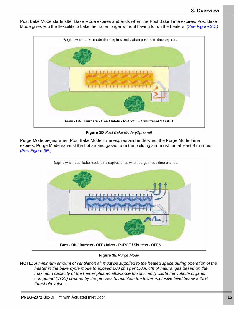
Post Bake Mode starts after Bake Mode expires and ends when the Post Bake Time expires. Post Bake Mode gives you the flexibility to bake the trailer longer without having to run the heaters. (See Figure 3D.)
Figure 3D Post Bake Mode (Optional)
Purge Mode begins when Post Bake Mode Time expires and ends when the Purge Mode Time expires. Purge Mode exhaust the hot air and gases from the building and must run at least 8 minutes. (See Figure 3E.)
Figure 3E Purge Mode
NOTE: A minimum amount of ventilation air must be supplied to the heated space during operation of the heater in the bake cycle mode to exceed 200 cfm per 1,000 cfh of natural gas based on the maximum capacity of the heater plus an allowance to sufficiently dilute the volatile organic compound (VOC) created by the process to maintain the lower explosive level below a 25% threshold value.
Begins when bake mode time expires ends when post bake time expires.
Fans - ON / Burners - OFF / Inlets - RECYCLE / Shutters-CLOSED
Begins when post bake mode time expires ends when purge mode time expires.
Fans - ON / Burners - OFF / Inlets - PURGE / Shutters - OPEN

16 PNEG-2072 Bio-Dri II™ with Actuated Inlet Door
4. Building Specifications
Bio-Dri II™ Single Building Layout
Figure 4A
Controls must be located in a separate building not connected to the trailer room or the air mixing chamber.DANGER
NOTE: The parts pointed out on this page are listed on Page 17.

4. Building Specifications
PNEG-2072 Bio-Dri II™ with Actuated Inlet Door 17
Bio-Dri II™ Single Building Layout (Continued)
Ref # Description
A 18'-0" Minimum
B Trailer
C 5'-0" Hold this Dimension
D 39" Shutters R.O. 39-5/8" x 39-5/8" (3)
E 12' Door Both Ends
F Air Mixing Chamber
G 5'-10" Minimum
HOffice building for controls (suggestion for placement and size) controls must be in a separate building not connected to the trailer room and be heated to above freezing in the winter.
I 1'-7" Floor height difference over the length of the trailer 4" rise per 10' run (2°).
J The floor in this area must be flat for the duct to roll evenly.
K 10 HP Fans (2)
L Re-Circulating Inlet Door Rough Opening
M Fresh Air Purge Inlet Door Rough Opening
N 3'' From Inside Wall
WARNING
The office building for controls must be separate from all other structures suchthat the products of combustion that accumulate in the Bio-Dri II™ building during operation cannot enter neighboring or adjoining structures where people orlivestock may be present.

4. Building Specifications
18 PNEG-2072 Bio-Dri II™ with Actuated Inlet Door
Bio-Dri II™ Sensor and Accessories Location
Figure 4B
NOTE: The parts pointed out on this page are listed on Page 19.

4. Building Specifications
PNEG-2072 Bio-Dri II™ with Actuated Inlet Door 19
Bio-Dri II™ Sensor and Accessories Location (Continued)
Ref # Description
A 6' Approximately
B Infrared Sensor #1 Front Left (Standard)
C Infrared Sensor #2 Rear Right (Standard)
D Infrared Sensor #3 Front Right (Optional)
E Infrared Sensor #4 Rear Left (Optional)
F Install high-limit temperature thermodiscs with enclosure in the middle of the room.
G Man Door Contact
H Install enclosure with sensor and heater on outside of wall. Install sensor head on inside as shown.
I Connection Box for the Surface Sensor (AP-5500)
J Laser Truck Positioning Sensor (AP-5415). Install 7' above floor.
K Cable must run the length of the building.
L E-Stop with Cable Pull 42" above Floor
MInstall (1) AP-4072 air sensor through 7/8" diameter hole (provided) in each exhaust extension side AP-3942A with sensor probe protruding into duct. Secure with FH-1309 nut.
N Overhead Door Contact (Both Doors)
OInstall (1) AP-4072 air sensor through 7/8" diameter hole (provided) in inlet mounting plate AP-3940 between heaters with sensor probe protruding into air mixing chamber. Secure with FH-1309 nut.
P Red Indicator Light Outside Building
Q Linear Actuator Assembly (AP-5300A)
R Air Inlet Door (AP-5292)
SThese inside indicator lights must be visible from semi-driver rear view mirror when pulling trailer into position.
T
Indicator lights Inside buildingAmber - TopRed - MiddleGreen - Bottom
U Laptop Computer (Not Provided)
V Fan Starter, Enclosed (AP-5277) (2)
W Building Lighting Contactor (AP-5278)
X Button Enclosure Start/Stop/Reset (AP-5279)
Y Main PLC Control Panel (AP-5280C)
Z 10 HP Fans Stacked on Top of each Other (2)
AA 14' Minimum level floor for ducting caster wheels to roll over.
AB 1° Slope for Water Run Off
AC Mount water drain here.

4. Building Specifications
20 PNEG-2072 Bio-Dri II™ with Actuated Inlet Door
Bio-Dri II™ Building Rough Opening Detail
Figure 4C
Ref # Description
A Stub Wall for Inlet Chamber
B Duct Mounting Plate Rough Opening Detail
C Inlet Mounting Plate Rough Opening Detail

PNEG-2072 Bio-Dri II™ with Actuated Inlet Door 21
5. Heater Installation and Operation
Heater Specifications
NOTE: Refer to the heater rating plate for determining the minimum gas supply pressure for obtaining the maximum gas capacity for which this heater is specified.
Determining Maximum and Minimum Inlet PressuresThe inlet supply pressure should be verified by shutting off the manual supply valve ahead of the regulator, removing the 1/4" plug in from the tee upstream of the regulator and installing a pressure gauge. The manual supply valve can then be turned back to the open position. Read the pressure on the gauge. The gauge can either remain permanently installed or it can be replaced with the 1/4" plug.
Machine to Earth GroundIt is very important that a machine to earth ground rod be installed at the fan. This is true even if there is a ground at the pole 15' away. This ground needs to be as close to the fan as possible, but no more than 8' away. The ground rod should be connected to the fan control panel with at least a #6 solid bare copper ground wire or in accordance with local requirements. The machine to earth ground provides additional safety if there is a short. It also provides the grounding necessary for long life and operation of the solid state circuit boards used on control circuits and the electronic ignition systems.
Previously Installed UnitsIt is recommended that previously installed units be checked to see that a machine to earth ground has been installed by an electrician.
24"
All Models
Inside Diameter 24-1/4"
Bole Circle Diameter 25-3/4"
Length 36"
High Temp BTU Rating 2,100,000
Low Temp BTU Rating 500,000
Propane
Maximum Fuel Flow (CFH) 1050
Orifice 1/4
Operating Pressure Range 2-10 PSI
Min Line Size 1"
Natural Gas
Maximum Fuel Flow (CFH) 2210
Orifice 5/16
Operating Pressure Range 1-7 PSI
Min Line Size 1"

5. Heater Installation and Operation
22 PNEG-2072 Bio-Dri II™ with Actuated Inlet Door
Fuel Connection
NOTE: Heater and individual shut off valve must be disconnected from the gas supply piping system during any pressure testing of the system at test pressures in excess of 1/2 PSI. The heater must be isolated from the gas supply piping by closing its individual manual shut off valve during any pressure testing of the gas supply piping system at test pressures equal to or less than 1/2 PSI.
Propane Vapor Models1. Propane vapor models are designed to run directly off of supply tank or from a separate
external vaporizer.
2. Run proper size line (See Specifications on Page 21) to pipe train on heater. Have a qualified gas service person inspect installation to be sure everything is installed according to local codes and ordinances. As part of the installation, the gas pipe installer must place a manual shut off valve in an appropriate location that allows access to the valve to shut off fuel to the heater in case of a fire or explosion at the heater.
3. After installation is complete check all connections for leaks.
Natural Gas Models1. Natural gas models are similar to vapor models, but have a larger orifice to accommodate lower
pressure, sometimes found with natural gas.
2. Run proper size line (See Specifications on Page 21) to pipe train on heater. Have a qualified gas service person inspect installation to be sure everything is installed according to local codes and ordinances. As part of the installation, the gas pipe installer must place a manual shut off valve in an appropriate location that allows access to the valve to shut off fuel to the heater in case of a fire or explosion at the heater.
3. After installation is complete check all connections for leaks.
NOTE: Annual leakage tests and gas tightness checks for safety shut off valves should be performed for all fuel models.
CSA Heater Electrical Installation
Standard electrical safety practices and codes should be used when working with a heater. Refer to the National Electric Code Standard Handbook by the National Fire Protection Association. A qualified electrician should make all wiring installations.
IMPORTANT: It is recommended that a low temperature limit control be installed in areas where freeze-up protection is needed in the event of burner shut down.
WARNING
Do not use propane tanks which have previously been used for ammonia unless they have been purged according to procedures of the national LP association.
Investigate to be sure that the fuel supply system complies with all local codes for LP gas installations.
WARNINGAlways disconnect and lock out power before working on or around heater.

5. Heater Installation and Operation
PNEG-2072 Bio-Dri II™ with Actuated Inlet Door 23
Heater Power Connection1. Connect power to fan control box.
2. Make field connections in fan box as shown in Figure 9AE on Page 83.
NOTE: Please refer to Figure 9AE on Page 83 for the Bio-Dri II™ Heater Wiring Diagram andPage 84 for the Terminal Connections.
Heater ServiceAll heaters are constructed of durable weather-resistant materials, so a minimum amount of service should be required. Before the unit is started for the first time each season there are a few items that need to be checked out. All damaged parts should be repaired or replaced.
1. Disconnect and lock out power to fan/heater. Open control box lid and inspect all components for moisture, vibration or rodent damage. Inspect and tighten all loose terminal connections. Replace any damaged wiring.
2. Remove burner orifice tube and inspect for dirt or foreign material. Clean out if necessary.
3. Inspect holes in burner ring for possible corrosion or plugging with dirt or rust. Clean if necessary.
4. Be sure primary air inlet screen is intact and clean for proper burn.
5. Check perforated ring on natural gas models to be sure it is clean and no holes are plugged.
6. Inspect flame sensor and ignitor and adjust or replace if necessary.
Heater Direction and Alignment
Figure 5A
WARNINGAlways disconnect and lock out power before working on or around heater.
Ref # Description
ARotate each heater until burnerand orifice pipe are vertical.
B Air Flow Direction

5. Heater Installation and Operation
24 PNEG-2072 Bio-Dri II™ with Actuated Inlet Door
LP and NG Bio-Dri II™ Heater Parts
NOTE: The parts pointed out on this page are listed on Page 26.

5. Heater Installation and Operation
PNEG-2072 Bio-Dri II™ with Actuated Inlet Door 25
LP and NG Bio-Dri II™ Heater Parts (Continued)
NOTE: The parts pointed out on this page are listed on Page 26.
NOTE: NG Heater shown.

5. Heater Installation and Operation
26 PNEG-2072 Bio-Dri II™ with Actuated Inlet Door
LP and NG Bio-Dri II™ Heater Parts List
Ref # Part # Description
1 D03-0881 Valve, Relief - 15-50 PSI Spring LP, 1" NPT
2 D03-0838 Valve, 1" NPT Full Port, Lever, CSA, Brass
3 THH-4137 Tee, 1" x 1" x 1" SCH 40 Black
4 THH-4059 Nipple, 1" x 5-1/2" SCH 40 Black
5 D08-0022 Gauge, Pressure 0-15# Liquid Filled
6 THH-4152 Tee, 1" x 1" x 1/4" SCH 40 Black
7 HF-8424 1" Ball Valve for Use With Bulimo Mod Actuator
8 THH-4115 Elbow, 1"-90° SCH 40 Black
9 THH-4037 Nipple, 1" x 2-1/2" SCH 40 Black
10D03-1163 Regulator, 1.5" NPT, Sensus, NG, 2-4.5 PSI
D03-0880 Regulator, LP 5-20 PSI Spring, 0.5 Orifice, 3/4" NPT
11 D03-0935 Tee, 1" x 1" x 1/4" SCH 80 Black
12 D08-0007 Reducer, 1-1/2" x 1" Hex Bushing
13 THH-4163 Tee, 1" x 1/4" x 1" SCH 40 Black
14 HH-7026 Orifice Pipe 3/4" x 5-1/2"
15 D08-0014 Plug, Hex Head, Black Steel, 1" NPT
16 401-5503-8 Plumbing Mounting Bracket
17 D03-1139 Valve Actuator, 24 VDC, Enclosure-Nema X
18406-2433-0 Orifice Plug, 1/2" NPT x 0.313" (NG)
406-2430-6 Orifice Plug, 1/2" NPT x 0.188" (LP)
19 D03-0880 Regulator, LP 5-20 PSI Spring, 3/4" NPT
20 056-2224-6 Valve, Solenoid 1" NPT 115V Din 25 PSI Max Asco Rebuild Kit #31891
21 HF-8412 Bio-Dri II™ Pipe Train Support Bracket
22 HF-7103 24"-26" Flame Diverter
23 HF-983 18", 24" and 28" Collector
24 HH-3572 Casting, Heater 24" and 26" Gun
25 HF-7104 24"-26" Diverter Collar
26 HF-7464 Reducer, 3"-1-1/2" Conc Weld
27 HH-1650 Spark Plug
28 HF-7465 Bracket, Air Switch Venturi
29 HF-8437 Air Switch Venturi Ext Mounting Bracket, Bio-Dri II™ Heater
30 HF-7454 High-Limit Box Body
31 HF-7455 High-Limit Box Lid
32 D03-1168 Quanta UV Flame Sensor
33 THH-4064 Conduit, 1/2" Aluminum LRL Cond Body
34 HF-8431 Bio-Dri II™ Heater Control Box Sub-Assembly (See Parts Breakdown Chart on Page 28.)
N/S HH-7054 Cone, 24"/26"/28" Burner S.S. (LP Only) - Not Shown

5. Heater Installation and Operation
PNEG-2072 Bio-Dri II™ with Actuated Inlet Door 27
Bio-Dri II™ Heater Control Box Sub-Assembly (HF-8431)
NOTE: The parts pointed out on this page are listed on Page 28.
Top view
Front view

5. Heater Installation and Operation
28 PNEG-2072 Bio-Dri II™ with Actuated Inlet Door
Bio-Dri II™ Heater Control Box Sub-Assembly (HF-8431) Parts
Ref # Part # Description Qty
1 HF-8419 Bio-Dri II™ Control Box Back Plate 1
2 C-8838 Enclosure, Heater Non-Metalic 14 x 12 x 7 NEMA 4X VYNC RVJ 1
3 HF-4624-DWH Fenwal, Flame Board - CSA Version 15 Sec Purge, 3 Retries 1
4 GT3-1457 Single Pole Cofi Ignition Transformer CE Rated 1
5 C-8718 Single Pole Midget Fuse Block 1
6 056-2245-1 Switch, Air Pressure AA-A2-4-3 1
7 C-8715 1-1/2" x 13/32" Fuse Puller 1
8 TF-2049 High Pressure Gas Switch, ASCO 8-25 PSI 1
9 TF-1279 Switch, Emergency Stop Operator 080TER Emergency Stop/2 N.C. GE 230V 1
10 90-0009 Lamp, Oil Tight 1/4" Tab 120V Amber 3
11 E160-1137 Lug, Ground,#TA-2 (CSA) 3
12 S-7192 Screw, TCSF #8-32 x 5/8" PHP ZN 2
13 S-10176 Screw, TCSF #10-32 x 1-3/4" PHP ZN 2
14 S-8976 Screw, MS #10-32 x 3/8" PHP ZN Grade 2 4
15 FLX-3914 Timer, D.O.M. 1-1023 Sec Time Delay 1
16 406-2195-5 Din Rail x 9" 1
17 S-7124 Screw, TCSF #8-32 x 1" PHP 5
18 D01-0533 Terminal, Entrelec End Stop 3
19 D01-0534 Terminal, Entrelec Ground Block 1
20 GT3-1164 Relay, Base, SPDT Magnetron Relay, Allied #850-0803 3
21 GT3-1163 Relay, Control, SPDT 120 VAC Coil, Allied #850-0740 3
22 D01-0532 Terminal, Blank End Protector Grey 2
N/S C-8719 Slow Blow 3A Midget Fuse 500 VAC, 10 KA I.R. 2
N/S S-2786 Screw, TCSF #8-32 x 3/8" PHP ZN 4
N/S D01-0531 Terminal, Block Entrelec 4 MM 22-10 AWG 17
N/S C-8717 Push Mount Cable Tie Assembly 6
N/S DC-1957 Decal, Tag, Attention, CE, CSA Harmonized (Check for Loose Wires) 1
N/S D63-0013 Block, Contact N.C. G.E. (Use D63-0013AB for Allen-Bradley) 1
N/S S-9111 Screw, TCSF #6-32 x 3/4" PHP ZN 2
N/S HH-7046 Crimp, Disconnect 0.187" Female 4
N/S D03-0099 Adapter, Tab 0.187" x 0.187" 2
N/S 048-1042-0 Plug, Hole 3/8" 1
N/S D03-0230 Jumper, (Entrelec) #168/516/25 2
N/S E305-0275 Wire, 5" (18 WHT) E106-1016, E106-1016 2'

PNEG-2072 Bio-Dri II™ with Actuated Inlet Door 29
6. Assembly
Duct Assembly
Assembling the Top Duct
1. Attach duct vanes (C) to the duct exit large side (A) and duct exit small side (B) using two (2) flange bolts (D) and flange nuts (E) per each duct vane. (See Figure 6A.)
Figure 6A
2. Attach the duct inlet large side (F) to the duct exit large side (A) and attach duct inlet small side (G) to the duct exit small side (B). Use three (3) 5/16" x 3/4" flange bolts (D) and flange nuts (E) per each duct side. (See Figure 6B.)
Figure 6B
Ref # Part # Description
A AP-3925 Duct Exit Large Side
B AP-3924 Duct Exit Small Side
C AP-3929 Duct Vane (3)
D S-6606 5/16" x 3/4" Flange Bolt (6)
E S-3611 5/16" Flange Nut (6)
Ref # Part # Description Ref # Part # Description
A AP-3925 Duct Exit Large Side E S-3611 5/16" Flange Nut (6)
B AP-3924 Duct Exit Small Side F AP-3923 Duct Inlet Large Side
D S-6606 5/16" x 3/4" Flange Bolt (6) G AP-3922 Duct Inlet Small Side

6. Assembly
30 PNEG-2072 Bio-Dri II™ with Actuated Inlet Door
3. Attach duct exit top/bottoms (K) to the tops and bottoms of the duct exit large side (A) and duct exit small side (B) using four (4) 5/16" x 3/4" flange bolts (D) and flange nuts (E). Note the location of bolts for this step, some holes will not be used until future steps. (See Figure 6C.)
4. Attach duct inlet top/bottoms (L) to the tops and bottoms of the duct inlet large side (F) and duct inlet small side (G) using four (4) 5/16" x 3/4" flange bolts (D) and flange nuts (E). Note location of bolts for this step, some holes will not be used until future steps. (See Figure 6C.)
5. Insert tabs on both duct middle top/bottoms (H) under duct inlet top and bottoms (L) and duct exit top and bottom (K) and attach to duct tops and sides using sixteen (16) 5/16" x 3/4" flange bolts (D) and flange nuts (E). (See Figure 6C.)
6. Attach four (4) duct support horizontals (I) to duct top/bottoms and duct sides using two (2) 5/16" x 3/4" flange bolts (D) and flange nuts (E) per each horizontal support. (See Figure 6C.)
7. Attach pivot angle top (J) and pivot angle bottom (M) to the end of the inlet sides using four (4) 5/16" x 3/4" flange bolts (D) and flange nuts (E) per each angle. (See Figure 6C.)
Figure 6C
Assembling the Bottom Duct
1. Repeat Steps 1-7 on Pages 29 and 30 to assemble the bottom duct assembly.
Ref # Part # Description Ref # Part # Description
A AP-3925 Duct Exit Large Side H AP-3927 Duct Middle Top/Bottom (2)
B AP-3924 Duct Exit Small Side I AP-3937 Duct Support Horizontal (4)
D S-6606 5/16" x 3/4" Flange Bolts J AP-3931 Pivot Angle Top
E S-3611 5/16" Flange Nut K AP-3928 Duct Exit Top/Bottom (2)
F AP-3923 Duct Inlet Large Side L AP-3926 Duct Inlet Top/Bottom (2)
G AP-3922 Duct Inlet Small Side M AP-3932 Pivot Angle Bottom

6. Assembly
PNEG-2072 Bio-Dri II™ with Actuated Inlet Door 31
Installing the Duct Support Stands1. Attach duct support left vertical (A) and duct support right vertical (B) to the four (4) duct support
horizontals (C) using eight (8) 5/16" x 3/4" flange bolts (D) and 5/16" flange nuts (E). (See Figure 6D.) Repeat the same for opposite end (EXIT end).
NOTE: The floor area that the duct work will be rolling on must be level.
Figure 6D
Ref # Part # Description
A AP-3935 Duct Support Left Vertical (2)
B AP-3936 Duct Support Right Vertical (2)
C AP-3937 Duct Support Horizontal (4)
D S-6606 5/16" x 3/4" Flange Bolt
E S-3611 5/16" Flange Nut

6. Assembly
32 PNEG-2072 Bio-Dri II™ with Actuated Inlet Door
2. Attach duct support big crosses (H) to duct support left vertical (A) and duct support right vertical (B) using four (4) 5/16" x 3/4" flange bolt (D) and 5/16" flange nut (E). Attach duct support small crosses (I) and caster assembly exit (F) to vertical supports as shown using six (6) 5/16" x 3/4" flange bolt (D) and flange nut (E) as shown. (See Figure 6F on Page 33.) Repeat on inlet side with caster assembly inlet (G). (See Figures 6E below and 6F on Page 33.)
Figure 6E
Ref # Part # Description
A AP-3935 Duct Support Left Vertical
B AP-3936 Duct Support Right Vertical
F AP-4049 Caster Assembly Exit
G AP-4048 Caster Assembly Inlet
H AP-3938 Duct Support Big Cross
I AP-3939 Duct Support Small Cross

6. Assembly
PNEG-2072 Bio-Dri II™ with Actuated Inlet Door 33
Figure 6F
Ref # Part # Description
A AP-3935 Duct Support Left Vertical
B AP-3936 Duct Support Right Vertical
D S-6606 5/16" x 3/4" Flange Bolt
E S-3611 5/16" Flange Nut
F AP-4049 Caster Assembly Exit (Includes two (2) base angles and two (2) casters.)
G AP-4048 Caster Assembly Inlet (Includes two (2) base angles and two (2) casters.)
H AP-3938 Duct Support Big Cross (2)
I AP-3939 Duct Support Small Cross (2)
Standard EXIT caster to supports
Standard INLET caster to supports

6. Assembly
34 PNEG-2072 Bio-Dri II™ with Actuated Inlet Door
Exhaust Extension Assembly
NOTE: See building specification section on Page 16 for installing duct and inlet mounting plates to building (A and B).
1. Attach four (4) exhaust extension sides (B and E) to the duct mounting plate (A) using three (3) 5/16" x 3/4" flange bolts (C) and 5/16" flange nuts (D) per each side. (See Figure 6G.)
Figure 6G
Ref # Part # Description
A AP-3930 Duct Mounting Plate
B AP-3942A Exhaust Extension Sides with Holes for Sensor Mounting (2)
C S-6606 5/16" x 3/4" Flange Bolt
D S-3611 5/16" Flange Nut
E AP-3942 Exhaust Extension Sides (2)
NOTE: Exhaust extension sides mount to the “flanged” side of the duct mounting plate.

6. Assembly
PNEG-2072 Bio-Dri II™ with Actuated Inlet Door 35
2. Attach four (4) exhaust extension top/bottoms (F) to exhaust extension sides (B and E) using eight (8) 5/16" x 3/4" flange bolts (C) and 5/16" flange nuts (D) per each side. (See Figure 6H.)
Figure 6H
Ref # Part # Description
B AP-3942A Exhaust Extension Sides with Holes for Sensor Mounting (2)
C S-6606 5/16" x 3/4" Flange Bolt
D S-3611 5/16" Flange Nut
E AP-3942 Exhaust Extension Sides (2)
F AP-3941 Exhaust Extension Top/Bottom (4)

6. Assembly
36 PNEG-2072 Bio-Dri II™ with Actuated Inlet Door
3. Fasten the four (4) exhaust extension top/bottoms (F) to the duct mounting plate (A) using eight (8) 5/16" x 3/4" flange bolt (C) and 5/16" flange nut (D). (See Figure 6I.)
Figure 6I
4. Attach duct pivot brackets (G) to duct mounting plate (A) using three (3) 5/16" x 3/4" flange bolt (C) and 5/16" flange nut (D) per each bracket. (See Figure 6J.)
Figure 6J
5. Follow duct mounting plate rough opening detail on Page 20 and attach exhaust extension assembly to the outside of the rough opening using 3/8" x 3" lag screw (S-9046). The flanges on the duct mounting plate will face outward and J-channel for the outside metal will butt up against the flanges. (NOTE: Different hardware may need to be used depending on the type of building materials used.)
Ref # Part # Description
A AP-3930 Duct Mounting Plate
C S-6606 5/16" x 3/4" Flange Bolt
D S-3611 5/16" Flange Nut
F AP-3941 Exhaust Extension Top/Bottom (4)
Ref # Part # Description
A AP-3930 Duct Mounting Plate
C S-6606 5/16" x 3/4" Flange Bolt
D S-3611 5/16" Flange Nut
G AP-3933 Duct Pivot Brackets

6. Assembly
PNEG-2072 Bio-Dri II™ with Actuated Inlet Door 37
Fan and Heater Assembly
NOTE: The heater inlet shall be located in accordance with the applicable building code or mechanical code for ventilation air.
1. Attach three (3) fan support middles (B) to fan support sides (A) using twelve (12) 5/16" x 3/4" flange bolt (C) and 5/16" flange nut (D) per each side. (See Figure 6K.)
Figure 6K
2. Remove all the feet from both fan housings feet and re-install six (6) of the feet onto the fan support assembly (P) and two (2) of the feet onto the fan motor support (A). (See Figures 6L and 6M on Pages 38 and 39.)
3. Attach fan assembly to the fan support assembly using six (6) 5/16" x 3/4" flange bolts (C) and 5/16" flange nuts (D). NOTE: Middle hole will need to be drilled through bottom flange in fan.
4. Attach top fan to the bottom fan using six (6) 5/16" x 3/4" flange bolts (C) and 5/16" flange nuts (D). NOTE: Middle holes do not exist and need to be drilled through both fan flanges.
Ref # Part # Description
A AP-3943 Fan Support Side (2)
B AP-5350 Fan Support Middle (3)
C S-6606 5/16" x 3/4" Flange Bolt
D S-3611 5/16" Flange Nut

6. Assembly
38 PNEG-2072 Bio-Dri II™ with Actuated Inlet Door
5. Attach two (2) fan motor support verticals (E) to three (3) fan motor support horizontals (F) using twelve (12) 5/16" x 3/4" flange bolt (C) and 5/16" flange nut (D). Then, attach the fan motor support assembly to the fan housing using eight (8) 5/16" x 3/4" flange bolts (C) and 5/16" flange nuts (D). (See Figure 6L.)
Figure 6L
6. Attach the exhaust extension assembly to the fan housings using ten (10) 5/16" x 3/4" flange bolts (C) and 5/16" flange nuts (D) per each duct. (See Figure 6M on Page 39.)
7. Follow inlet mounting plate rough opening detail on Page 20 and attach inlet mounting plate (K) to the building using 3/8" x 3" lag bolt (S-9046). (NOTE: Different hardware may need to be used depending on the type of building materials used.)
8. Remove grills from fans and attach heater mounting plates (J) to the fan housings using the hardware that held the fan grills. (See Figure 6M on Page 39.)
9. Attach the heaters to the heater mounting plates (J) using eight (8) 5/16" x 3/4" flange bolts (C) and 5/16" flange nuts (D) per each heater. (See Figure 6M on Page 39.)
Ref # Part # Description
C S-6606 5/16" x 3/4" Flange Bolt
D S-3611 5/16" Flange Nut
E AP-3946 Fan Motor Support Vertical (2)
F AP-3945 Fan Motor Support Horizontal (3)
G Support Feet

6. Assembly
PNEG-2072 Bio-Dri II™ with Actuated Inlet Door 39
10. Attach the heaters to the inlet mounting plates (K) and grill guard (R) using eight (8) 5/16" x 3/4" flange bolts (C) and 5/16" flange nuts (D) per each heater (O). (See Figure 6M.)
Use 5/16" x 3/4" flange bolts (C) and 5/16" flange nuts (D) for all hardware, except where noted.
Figure 6M
NOTE: Lower heater not shown for clarity.
Ref # Part # Description
H AP-3933 Duct Pivot Brackets (2)
I AP-3930 Duct Mounting Plate
J C-7936-27 Heater Mounting Plate (Use fan grill hardware.)
K AP-3940 Inlet Mounting Plate
L Exhaust Extension Assembly
M Fan Assembly
N Field Drill Holes
O Heater
P Fan Support Assembly
Q Re-locate feet from fan to fan support assembly.
R Grill Guard
6. Assembly
40 PNEG-2072 Bio-Dri II™ with Actuated Inlet Door
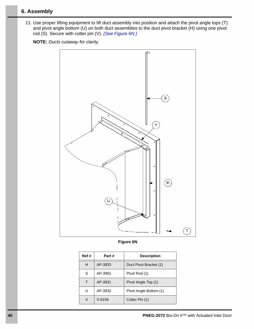
11. Use proper lifting equipment to lift duct assembly into position and attach the pivot angle tops (T) and pivot angle bottom (U) on both duct assemblies to the duct pivot bracket (H) using one pivot rod (S). Secure with cotter pin (V). (See Figure 6N.)
NOTE: Ducts cutaway for clarity.
Figure 6N
Ref # Part # Description
H AP-3933 Duct Pivot Bracket (1)
S AP-3991 Pivot Rod (1)
T AP-3931 Pivot Angle Top (1)
U AP-3932 Pivot Angle Bottom (1)
V S-9159 Cotter Pin (1)

6. Assembly
PNEG-2072 Bio-Dri II™ with Actuated Inlet Door 41
Gas Piping Layout
1. Main shut-off valve must be supplied by the customer.
2. Hook-up wiring diagrams for heaters on Page 83.
Vapor Propane Gas Pipe Layout (Guidelines Only)
Figure 6O
Ref # Description
A To upper burner 2.1 million BTU/HR 15 PSI required at burner.
B To lower burner 2.1 million BTU/HR 15 PSI required at burner.
C 1" Gas Hose
D 1-1/2" Gas Pipe
E 5/8" Gas Pipe
F 1000 Gallon Tanks 18-20 PSI at Tanks (4)
G Manual Shutoff Valve (Supplied by Customer)

6. Assembly
42 PNEG-2072 Bio-Dri II™ with Actuated Inlet Door
Natural Gas Pipe Layout (Guidelines Only)
Figure 6P
Ref # Description
A To upper burner 2.1 million BTU/HR 10 PSI required at burner.
B To lower burner 2.1 million BTU/HR 10 PSI required at burner.
C 1" Gas Hose
D 2" Gas Pipe
E Manual Shutoff Valve (Customer Supplied)
F To Natural Gas Supply

6. Assembly
PNEG-2072 Bio-Dri II™ with Actuated Inlet Door 43
Inlet Door Assembly Instructions
1. Construct frame and rough opening for inlet door according to Figure 4A on Page 16. Ensure that the inside surface of both rough openings is 3'' from the inside corner of the door hinge according to detail. (See Figure 6Q.)
2. Assemble two (2) hinges (B) to top and bottom of door (A), using bolt (C) and nylock nut (D). With two (2) persons, lift door and hinges over rough opening on inside of air mixing chamber and center vertically. Ensure that the corner of the hinges are against the inside corner of the framing as shown in Figure 6Q. Secure door and hinges to frame with four (4) lag screws (E) through each of the four (4) hinges (B) and into the framing.
Figure 6Q
3. According to Figure 6R on Page 44. Install long diagonal brace (G) to inside of rough opening closest to hinge. Ensure it is centered vertically within the rough opening and secure with four (4) lag screws (E) into the framing. Also vertically centered on opposite side of rough opening, install short straight brace (H) and secure with four (4) lag screws (E) into the framing.
4. Install the tubular brace (J) to the lower hole on the outer face of the short straight brace (H). Rotate the tubular brace downward to about 45° until the bottom end fits inside the rough opening. Secure with a lag screw (E) to the framing.
5. Install the bottom anchor plate (I) between diagonal and straight braces, using four (4) bolts (L) and four (4) nylock nuts (M).
6. Lay linear actuator (F) on top of bottom anchor plate (I) and connect rod end of actuator to pivot hole in door. Secure rod connection with bolt (N) and nylock nut (D).
7. Lay top anchor plate (I) on top of linear actuator (F), diagonal brace (G) and straight brace (H), then install long pivot bolt (K) through top anchor plate, actuator and bottom anchor plate. Secure with nylock nut (D). Align top anchor plate mounting holes with diagonal brace and straight brace. Secure with four (4) bolts (L) and four (4) nylock nuts (M).
Ref # Part # Description Qty Ref # Part # Description Qty
A AP-5292 Inlet Door 4' x 6' Black 1 D S-8260 Nylock Nut 1/2''-13 ZN Grade 5 2
B AP-5291 Inlet Door Pivot Frame Support - Hinge 4 E S-7308 Lag Screw 3/8'' x 2'' HH ZN 16
C S-7935 Bolt, HHCS 1/2''-13 x 1'' ZN Grade 5 2
Inside corner for door hinge
3'' Critical
3'' C
ritica
l

6. Assembly
44 PNEG-2072 Bio-Dri II™ with Actuated Inlet Door
Inlet Door Assembly Instructions (Continued)
Figure 6R
Ref # Part # Description Qty
D S-8260 Nylock Nut 1/2''-13 ZN Grade 5 2
E S-7308 Lag Screw 3/8'' x 2'' HH ZN 9
F AP-5300 Linear Actuator Assembly for Inlet Door 1
G AP-5301 Brace, Diagonal for Linear Actuator 1
H AP-5302 Brace, Straight for Linear Actuator 1
I AP-5303 Plate, Anchor for Linear Actuator 2
J AP-4488-24 Brace for Linear Actuator 1
K S-8232 Bolt, HHCS 1/2''-13 x 4-1/2'' ZN Grade 5 1
L S-4275 Bolt, 5/16''-18 x 3/4 ZN Grade 5 9
M S-7382 Nylock Nut 5/16''-18 ZN Grade 5 9
N S-7876 Bolt, HHCS 1/2''-13 X 1-3/4'' ZN Grade 5 1
O D03-0177 Rubber Grommet 11/16" I.D. x 1" O.D.
P 6 mm Allen Wrench (Not Provided)

6. Assembly
PNEG-2072 Bio-Dri II™ with Actuated Inlet Door 45
Inlet Door Adjustment Instructions
1. Prior to adjustments the linear actuator must be wired up to the PLC panel and capable of operation. Please refer to Figure 9AB on Page 81 for wiring diagram. Once wired up, the two (2) dial switches on the controls on the outside of the PLC panel can be used to operate the linear actuator. One dial switch is used to go between Auto, Off and Hand (Manual). When in manual mode, the other dial switch has two (2) operating positions: Purge and Re-Cycle. When in purge, the linear actuator will attempt to extend a full 24'' until the internal limit switch shuts it off. When in Re-Cycle, the linear actuator will attempt to retract until the external limit switch shown in Figure 6S on Page 46, shutsit off.
2. Change the switch position on the outside of the PLC panel to manual Mode/Purge and let the linear actuator extend the full 24'' until the unit comes to a stop. There will probably be a 1'' to 2'' gap remaining between the door and the framing in the Purge position. Remove the eight (8) plastic plugs on top of the linear actuator to provide access to the allen head screws underneath. Loosen all eight (8) allen head screws on top of the actuator with a 6 mm allen wrench (P) not provided. Loosen each screw approximately 5 complete turns.
3. Rotate the door counterclockwise slightly, until the 1'' to 2'' gap between the door and the framing in the Purge position is closed up. As the door is rotated, the linear actuator will slide inside the housing to the correct adjustment position. Tighten the eight (8) allen head screws securely. Replace the eight (8) plastic plugs in the top of the linear actuator.
4. Refer to Figure 6S on Page 46. Change the switch position on the outside of the PLC panel to Manual/Re-Cycle and let the linear actuator retract until the external limit switch (A) strikes the actuator bracket (D) and the unit comes to a stop. There will probably be a 1'' to 2'' gap remaining between the door and the framing in the Re-Cycle position. Change the switch position on the outside of the PLC panel from manual to off.
5. Using a 1/2'' Wrench (G), loosen the nylock nuts (F) on the U-Bolt (E) and slide the actuator bracket (D) forward towards the rod end of the linear actuator approximately 1/4''. Tighten the nylock nuts (F) on the U-Bolt (E). Change the switch position on the outside of the PLC panel from Off to Manual. The linear actuator will retract slightly until the external limit switch causes it to shut off. Ensure that the 1'' to 2'' gap between the door and the framing in the Re-Cycle position is closed up. If not, repeat this step until the door gap is closed.
6. Change the dial switches on the outside of the PLC panel to Auto/Re-Cycle. The inlet door is now ready for normal operation. In normal operation, when the Bio-Dri II™ is not running, the inlet door should remain in Re-Cycle position in order to keep birds and debris from entering the air mixing chamber. When the Bio-Dri II™ is in Pre-Bake mode, Bake mode or Post Bake mode, the inlet door should be in Re-Cycle position in order to allow the hot air to Re-Cycle through the system. The only time the inlet door should be in Purge position, is during the 8 minute purge time at the end of the cycle, in order to clear out deadly gas fumes and quickly cool the room down, prior to safe entry.

6. Assembly
46 PNEG-2072 Bio-Dri II™ with Actuated Inlet Door
Inlet Door Adjustment Instructions (Continued)
Figure 6S
Ref # Part # Description Qty
A TD-101463 Limit Switch 1
B AP-5388 Bracket, Limit Switch Mounting 1
C S-10171 U-Bolt, 5/16''-18 for 1-1/4" Pipe ZN 1
D AP-5389 Actuator Bracket 1
E 326-1047-9 U-Bolt, 5/16''-18 x 1-3/8'' x 2-3/1'' 1
F S-7382 Nylock Nut 5/16''-18 ZN Grade 5 4
G 1/2'' Wrench (Not Provided)

PNEG-2072 Bio-Dri II™ with Actuated Inlet Door 47
7. Installation
Laser Truck Positioning Sensor Installation
1. Install laser truck positioning sensor (A) on wall opposite air duct. The sensor should be located 7' above floor and 40'' forward of air duct when folded out in operating position. (See Figure 7A.)
Figure 7A
2. Mark both inside and outside walls (B) according to the above dimensions. Make two (2) marks 4'' apart. With “Hole Saw”, drill two (2) holes (C), one at each mark. Each hole should be at least 2-1/2'' diameter. The holes must penetrate completely through both walls as shown in Figure 7B.
Figure 7B
Ref # Part # Description
A AP-5415 Laser Truck Positioning Sensor
Ref # Description
B Inside and Outside Walls
C Drill Two (2) Holes (2-1/2" Minimum Diameter)

7. Installation
48 PNEG-2072 Bio-Dri II™ with Actuated Inlet Door
3. From the outside of the building, install the laser truck positioning sensor PVC tubing through the wall toward the inside of the building as shown in Figure 7C.
Figure 7C
4. Using the sheet metal screws (E) provided with the sensor, anchor the mounting plate (D) to the siding on the outside of the wall as shown in Figure 7D.
Figure 7D
Ref # Description
D Mounting Plate
E Sheet Metal Screws

7. Installation
PNEG-2072 Bio-Dri II™ with Actuated Inlet Door 49
Laser Truck Positioning Sensor Parts
Figure 7E
Laser Truck Positioning Sensor Parts List
Ref # Part # Description Qty
1 AP-5418-PVC PVC Pipe, 2.362" O.D. x 2.000" I.D. x 15" Long 2
2 AP-5526 Laser - Tube Mounting Bracket 2
3 AP-0583 Hose Clamp, SAE 36 - Stainless Steel 1-13/16" - 2-3/4" 2
4 AP-5527 Laser Sensor Mounting Angle 4
5 S-8008 Screw, MS #8-32 x 2'' 4
6 S-6525 Hex Nut #8-32 ZN Grade 2 4
7 S-995 Screw, MS #10-24 x 1'' PHP SS 12
8 S-7931 Hex Nut #10-24 12
9 AP-5530 Laser Sensor Enclosure Backplate 1
10 S-4490S Saddle 2
11 S-4490U U-Bolt 2
12 S-3611 Flange Nut 5/16''-18 YDP Grade 2 4
13 70-0253-TPS Enclosure 8" x 10" for Laser Sensors 1
14 AP-5531 Plate, Laser Sensor Wall Mount 1
15 S-7419 Screw, SDS #10-16 x 1-1/4'' HWH SS 410 4
16 AP-5413 Laser Photoelectric Distance Sensor 2
17 AP-5413C 4 Pin Connector (5M) for Laser Distance Sensor 2

7. Installation
50 PNEG-2072 Bio-Dri II™ with Actuated Inlet Door
Laser Truck Positioning Sensor Adjustment Instructions
1. Prior to adjustments the laser truck positioning sensor must be wired up to the PLC panel and capable of operation. Please refer to Figure 9R on Page 76 for wiring diagram. Once wired up and with no trailer inside the Bio-Dri II™ room, fold the air duct out in operating position as shown in Figure 7A on Page 47.
2. Assure that the laser light beam passes through the center of the PVC tubes without reflecting off of the sides of the tubes. If properly adjusted, two (2) superimposed dots from the laser beams should appear on the opposite wall. A line connecting these dots should be horizontal. The dots should be spaced approximately 4'' apart.
3. If the dots are not spaced properly, loosen one of the hose clamps (A) as shown in Figure 7F. Then twist the laser side to side or up and down accordingly, until the superimposed dots are spaced correctly, then tighten hose clamp.
Figure 7F
Ref # Description
A Hose Clamp

7. Installation
PNEG-2072 Bio-Dri II™ with Actuated Inlet Door 51
Installing the Walkthrough Door Contacts
Door contacts must be installed onto each walkthrough door.
IMPORTANT: The door contact side surfaces must align flush and parallel and the facing surfaces must be within a maximum of 1/4" apart. The writing on the face of each door contact must be in the same orientation.
1. Install one door contact mounting bracket (A) to the door using the horizontal slots.
2. Install one door contact mounting bracket (A) to the door jamb (G) using the vertical slots.
3. Install the moving door contact (E) to the bracket installed on the door.
4. Install the fixed door contact (F) to the bracket installed on the door jamb (G).
NOTE: The contact cord must be mounted on the bottom.
5. Use the slots to adjust sensors and brackets as needed to align properly. (See Figure 7G.)
Figure 7G
Ref # Part # Description Ref # Description
A AP-5363 Man Door Contactor Bracket (2) E Door Contactor - Moving (1)
B S-7419 Screw, SDS #10-16 x 1-1/4" HWH (4) F Door Contactor - Fixed (1)
C 2FH0775 Screw, MS #8-32 x 3/4" PHS ZN (4) G Walk Through Door Jamb (1)
D S-6525 Hex Nut #8-32 ZN Grade 2 (4) H Walk Through Door (1)
Exploded ISO view
Front view
Assembled ISO view

7. Installation
52 PNEG-2072 Bio-Dri II™ with Actuated Inlet Door
Installing the Overhead Door Contacts
Door contacts must be installed onto each overhead door. (See Figure 7H.)
IMPORTANT: The door contact side surfaces must align flush and parallel and the facing surfaces must be within a maximum of 1/4" apart. The writing on the face of each door contact must be in the same orientation.
1. Install the jamb bracket (B) to the overhead door jamb (G).
2. Install the door bracket (A) to the door.
3. Install the moving door contact to the bracket installed on the door.
4. Install the fixed door contact to the bracket installed on the door jamb.
NOTE: The contact cord must be mounted on the bottom.
5. Use the slots to adjust sensors and brackets as needed to align properly.
Figure 7H
Ref # Part # Description Ref # Part # Description
A AP-5994 Safety Limit Switch Door Mounting Bracket (1) F S-8861 #10-24 Nylock Nut SS (4)
B AP-5995 Safety Limit Switch Jam Mounting Bracket (1) G Overhead Door Jam (1)
C S-7419 Screw, SDS #10-16 x 1-1/4" HWH (6) H Overhead Door (1)
D AP-5996 Safety Limit Switch for Bio-Dri II™ Overhead Doors (1) I Door Track
E S-9407 Screw, MS #10-24 x 1-3/4" PHP SS (4)

7. Installation
PNEG-2072 Bio-Dri II™ with Actuated Inlet Door 53
Installing the Pull Cable Emergency Stop
1. Install the eye screws 42" from the floor the length of the building along both walls. Space the eye screws 10' apart. Route the cable around doors by installing pulleys as necessary.
2. Connect the cable to emergency stop using cable clamps.
3. Pull cable taught without triggering the pull cord mechanism and fasten to the end eye screw. Adjust the turnbuckle to provide the proper pretention in the cable that will center the arrow in the indicator dial.
4. Pull the cord to ensure it triggers the emergency stop at varying points along the building.
Installing the Air Temperature Sensors
Exhaust RTD Temperature Sensors
The two (2) RTD sensors are installed on the exhauster extension sides, one in the upper duct and one in the lower duct. The modulation valves on each heater will automatically adjust to maintain these two (2) sensors to a temperature of 250° F.
To install the RTD air temperature sensor (AP-4072): (See Figure 7I.)
1. Insert the (AP-4072) RTD air sensor through the 7/8" diameter hole (provided) in each exhaust extension side (AP-3942A) with the sensor probe protruding into the duct.
2. Secure with (FH-1309) nut.
Figure 7I RTD Air Temperature Sensor (AP-4072)
A
A
Ref # Description
A RTD Air Temperature Sensors

7. Installation
54 PNEG-2072 Bio-Dri II™ with Actuated Inlet Door
Air Mixing Chamber RTD Sensor
The air mixing chamber RTD temperature sensor is used to cycle the heaters ON and OFF. When the mixing chamber temperature reaches 175°F, the heaters shut off. The temperature will then begin to drop and when it falls to 170°F, the heaters will turn back ON again. This process will continue throughout the pre-heat and bake cycles, maintaining the air mixing chamber temperature between 170°F-175°F.
NOTE: The air mixing chamber temperature High and Low limits are adjustable, but require either ADMIN or AP level access.
To install the chamber room RTD sensor: (See Figure 7J.)
1. Insert the (AP-4072) air sensor through the 7/8" diameter hole (provided) in the inlet mounting plate (AP-3940) located between the heaters. Ensure the sensor probe protrudes into the air mixing chamber.
2. Secure with (FH-1309) nut.
Figure 7J Air Mixing Chamber RTD Sensors
Ref # Description
A Air Mixing Chamber RTD Sensors
A

7. Installation
PNEG-2072 Bio-Dri II™ with Actuated Inlet Door 55
Installing the Auxiliary Temperature Sensors
Surface Temperature Sensor
The surface temperature sensor is considered to be the most accurate of the auxiliary temperature sensors. Once the trailer is pulled into position in the building, the operator must remove the surface sensor from where it hangs on the wall (with 20' cord) and place it in the rear, right hand, corner of the trailer. This is considered to be the most difficult part of the trailer to heat up and therefore, the last section of the trailer to reach temperature. It must be carefully placed on the floor of the trailer, so that the red indicator light is illuminated, signaling the PLC the sensor is in place prior to starting the cycle. The set temperature of this sensor is usually 160°F, but can be adjusted.
To install and adjust the surface temperature sensor: (See Figure 7K.)
1. Locate the surface temperature sensor junction box next to the truck positioning sensors in the building.
2. Wire the surface sensor junction box into the main PLC panel according to the wiring diagram on Page 70.
NOTE: The proximity switch in the sensor can be disabled in the control if it is not working properly.
Figure 7K Surface sensor located in trailer corner.
7. Installation
56 PNEG-2072 Bio-Dri II™ with Actuated Inlet Door
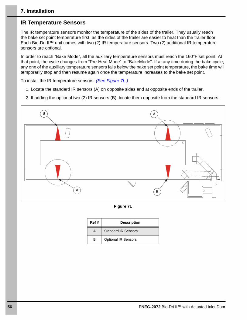
IR Temperature Sensors
The IR temperature sensors monitor the temperature of the sides of the trailer. They usually reach the bake set point temperature first, as the sides of the trailer are easier to heat than the trailer floor. Each Bio-Dri II™ unit comes with two (2) IR temperature sensors. Two (2) additional IR temperature sensors are optional.
In order to reach “Bake Mode”, all the auxiliary temperature sensors must reach the 160°F set point. At that point, the cycle changes from “Pre-Heat Mode” to “BakeMode”. If at any time during the bake cycle, any one of the auxiliary temperature sensors falls below the bake set point temperature, the bake time will temporarily stop and then resume again once the temperature increases to the bake set point.
To install the IR temperature sensors: (See Figure 7L.)
1. Locate the standard IR sensors (A) on opposite sides and at opposite ends of the trailer.
2. If adding the optional two (2) IR sensors (B), locate them opposite from the standard IR sensors.
Figure 7L
Ref # Description
A Standard IR Sensors
B Optional IR Sensors
A B
B A

PNEG-2072 Bio-Dri II™ with Actuated Inlet Door 57
8. Wiring Diagrams
120V Power
8. Wiring Diagrams
58 PNEG-2072 Bio-Dri II™ with Actuated Inlet Door
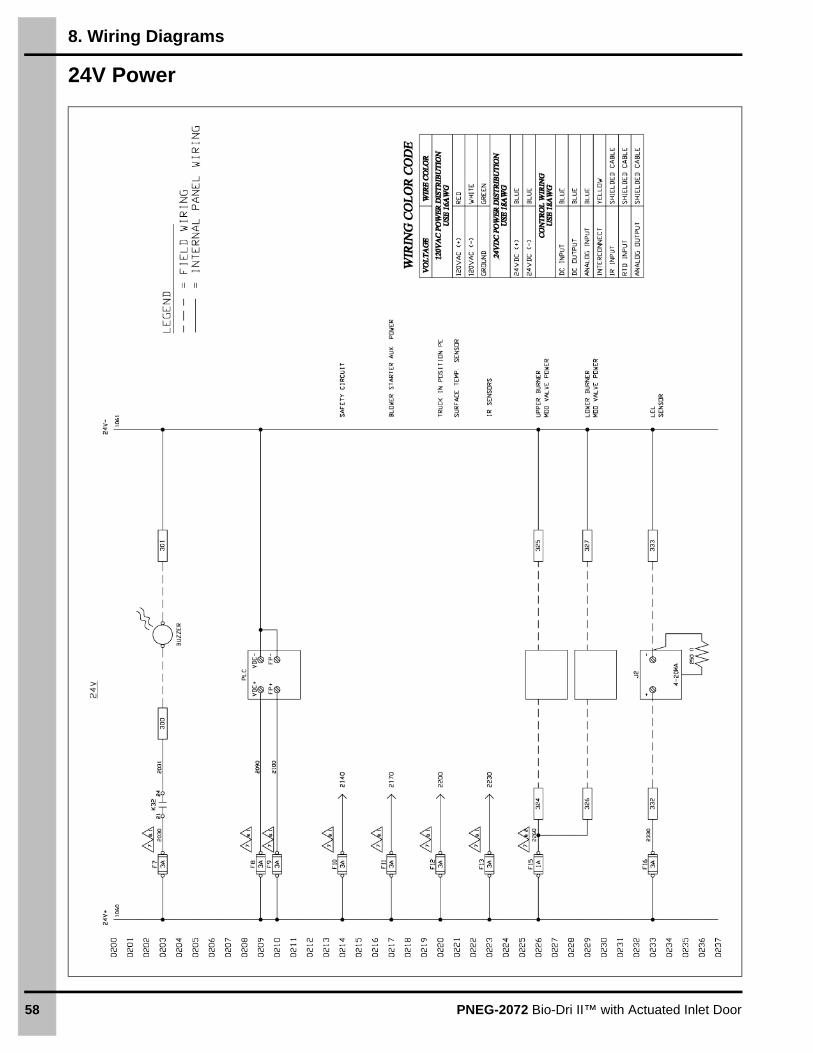
24V Power

8. Wiring Diagrams
PNEG-2072 Bio-Dri II™ with Actuated Inlet Door 59
Externally Sourced

8. Wiring Diagrams
60 PNEG-2072 Bio-Dri II™ with Actuated Inlet Door
Externally Sourced (Continued)

8. Wiring Diagrams
PNEG-2072 Bio-Dri II™ with Actuated Inlet Door 61
Safety Circuit

8. Wiring Diagrams
62 PNEG-2072 Bio-Dri II™ with Actuated Inlet Door
PLC Inputs

8. Wiring Diagrams
PNEG-2072 Bio-Dri II™ with Actuated Inlet Door 63
PLC Outputs
8. Wiring Diagrams
64 PNEG-2072 Bio-Dri II™ with Actuated Inlet Door
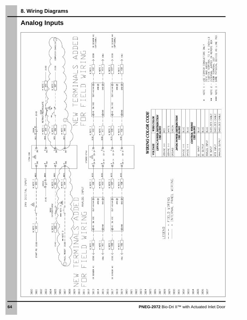
Analog Inputs

8. Wiring Diagrams
PNEG-2072 Bio-Dri II™ with Actuated Inlet Door 65
RTD Inputs

8. Wiring Diagrams
66 PNEG-2072 Bio-Dri II™ with Actuated Inlet Door
Analog Outputs

8. Wiring Diagrams
PNEG-2072 Bio-Dri II™ with Actuated Inlet Door 67
Panel Layout
Holes can only be drilled through the bottom of the control box. Do not drill holes through the back of the panel or sides.WARNING

68 PNEG-2072 Bio-Dri II™ with Actuated Inlet Door
9. Wiring Hook-Up Diagrams
Bio-Dri II™ Cycle Start/Stop Control (AP-5279)
Figure 9A Front View
Figure 9B Inside View
170 171 172 173 174 175 188 189 190 320 321 322 323

9. Wiring Hook-Up Diagrams
PNEG-2072 Bio-Dri II™ with Actuated Inlet Door 69
Centrifugal Fan Starter Contactor (AP-5277)
Figure 9C Front View Figure 9D Inside View
Figure 9E Centrifugal Fan Motor Wiring Diagram
A
D
E
208V-230V or 460V
F
To motor (See Figure 9E.)
B C
L2L1 L3
T1 T2 T3
Ref # Upper Fan Lower Fan
A 202 207
B 200 205
C 201 206
D 302 304
E 303 305
F 203 208
Line Line
OR
10 HP Centrifugal fan motor
Low voltage(208-230 VAC, 3 PH)
High voltage(460 VAC, 3 PH)
10 HP Centrifugal fan motor

9. Wiring Hook-Up Diagrams
70 PNEG-2072 Bio-Dri II™ with Actuated Inlet Door
Trailer Surface Temperature Sensor (AP-5500)
Figure 9F Trailer Surface Temperature Sensor (AP-5500)
Figure 9G Wiring Diagram for Trailer Surface Temperature Sensor (AP-5500)

9. Wiring Hook-Up Diagrams
PNEG-2072 Bio-Dri II™ with Actuated Inlet Door 71
RTD Temperature Sensor for Ducts and Air Mixing Chamber (AP-4072)
Figure 9H RTD Temperature Sensor for Ducts
Ref # Wire Color Upper Duct Lower Duct Mixing Chamber
A Red 421 426 431
B Red 422 427 432
C White 420 425 430
A
B C

9. Wiring Hook-Up Diagrams
72 PNEG-2072 Bio-Dri II™ with Actuated Inlet Door
Room High Temperature Limit and Cycle Start Warning Buzzer
Figure 9I Room High Temperature Limit Buzzer Front View
Figure 9J Room High Temperature Limit and Cycle Start Warning Buzzer
180
180 182
181300
301

9. Wiring Hook-Up Diagrams
PNEG-2072 Bio-Dri II™ with Actuated Inlet Door 73
Door Contacts for up to 2 Man Doors
NOTE: Only three (3) are supplied.
Figure 9K Door Contacts
Figure 9L Door Contacts Wires
* If Man Door 2 is not used, place jumper across terminals 150 to 151 and 152 to 153.
Ref # Wire Color Man Door 1 Man Door 2 *
A Gray 140 150
B Pink 141 151
C Brown 142 152
D White 143 153
E Yellow Not Used
F Red Not Used
G Green Not Used
H Blue Not Used
E
A
B
G
H F
C
D

9. Wiring Hook-Up Diagrams
74 PNEG-2072 Bio-Dri II™ with Actuated Inlet Door
Overhead Door Safety Limit Switch
Figure 9M Front View
Figure 9N Inside View
Ref # Overhead Door Entrance Overhead Door Exit
A 120 130
B 121 131
C 122 132
D 123 133
B D
A C

9. Wiring Hook-Up Diagrams
PNEG-2072 Bio-Dri II™ with Actuated Inlet Door 75
Pull Cord Emergency Stop
Figure 9O Front View
Figure 9P Inside View
Ref # E-Stop Side 1 E-Stop Side 2
A 100 110
B 101 111
C 102 112
D 103 113
A
C
B
D

9. Wiring Hook-Up Diagrams
76 PNEG-2072 Bio-Dri II™ with Actuated Inlet Door
Laser Truck Positioning Sensor (AP-5415)
Figure 9Q Laser Truck Positioning Sensor (AP-5415)
Figure 9R Wiring for Laser Truck Positioning Sensor (AP-5415)
Ref # Rear Sensor Front Sensor
A 310 313
B 312 315
C 311 314

9. Wiring Hook-Up Diagrams
PNEG-2072 Bio-Dri II™ with Actuated Inlet Door 77
Infrared (IR) Temperature Sensor for Trailer Sides
Figure 9S Front View
Figure 9T Inside View
Ref # Front Left IR #1 Rear Right IR #2 Front Right IR #3 Rear Left IR #4
A 400 405 412 417
B 401 406 413 418
C 402 407 410 415
D 403 408 411 416
A
B
D
C

9. Wiring Hook-Up Diagrams
78 PNEG-2072 Bio-Dri II™ with Actuated Inlet Door
Heater for IR Temperature Sensor Enclosure
Figure 9U Temperature Sensor Enclosure
Figure 9V Heater for IR Temperature Sensor
Ref # Front Left IR Rear Right IR Front Right IR Rear Left IR
A 220 222 224 226
B 221 223 225 227
A
B

9. Wiring Hook-Up Diagrams
PNEG-2072 Bio-Dri II™ with Actuated Inlet Door 79
Indicator Lights (Red, Green and Amber)
Figure 9W Indicator Lights Figure 9X Light
Overhead Door Wiring
Figure 9Y
Wire the “Up” Button of each overhead door in parallel with the terminals in the PLC panel as shown below.
A B
Ref # Red Light Outside Red Light Inside Green Light Inside Amber Light Inside
A 215 215 216 217
B 218 218 218 218
Overhead entrance door Overhead exit door
Up/Open
Stop
Down/CloseDown/Close
Up/Open
Stop
Down/Close
Ref # Overhead Door Terminal # in PLC Panel
A Entrance 48
B Entrance 49
C Exit 50
D Exit 51
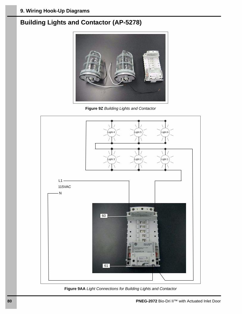
9. Wiring Hook-Up Diagrams
80 PNEG-2072 Bio-Dri II™ with Actuated Inlet Door
Building Lights and Contactor (AP-5278)
Figure 9Z Building Lights and Contactor
Figure 9AA Light Connections for Building Lights and Contactor
60
61
Light 1Light 2Light 3
Light 4 Light 5 Light 6
L1
115VAC
N

9. Wiring Hook-Up Diagrams
PNEG-2072 Bio-Dri II™ with Actuated Inlet Door 81
Air Inlet Door Actuator (AP-5300)
Figure 9AB Wiring Diagram for Air Inlet Door Actuator
Re
f #
Fu
nc
tio
nW
ire
Co
lor
Term
ina
l #
AR
e-C
ycle
Bla
ck23
BP
urg
eR
ed24
CC
om
mo
nO
rang
e32
8
DN
.O.
Blu
e32
9
L111
5 V
AC
Pow
er
22
Neu
tra
lW
hite
GN
DG
reen

9. Wiring Hook-Up Diagrams
82 PNEG-2072 Bio-Dri II™ with Actuated Inlet Door
36" Galvanized Box Fan for Circulation (GBD3619-HH)
Figure 9AC 36" Galvanized Box Fan
Figure 9AD Box Fan Wiring Hook-Up Diagram
BOX FANMOTOR 1
BOX FANMOTOR 2

9. Wiring Hook-Up Diagrams
PNEG-2072 Bio-Dri II™ with Actuated Inlet Door 83
24" Heater with Mod Valve (VHD2-24AP-LP or VHD2-24AP-NG)
Figure 9AE Bio-Dri II™ Heater Wiring Diagram
GND LUG
MOD VALVE VALVE #2 VALVE #1
FENWAL35-755216-111
TRIAL FOR IGNITION = 4 SECPREPURGE = 15 SECINTERPURGE = 15 SECTRIES FOR IGNITION = 3
S1 FLAME SENSOR
HS1 IGNITION 110 VAC
L1 110 VAC IN
TH THERMOSTAT
L2 NEUTRAL
V1 VALVE 110 VAC
V2 VALVE AC NEUTRAL
HS2 IGNITION NEUTRAL
B.GND BURNER GROUND
HIGH PRESSURE SWITCH
C N.O. N.C.
SET TIMER FOR 2 SEC.
MADE IN USA
INPUT LOAD
SOLID STATE
TIME DELAY
FLX
-391
4
GAS PRESSURE TIME DELAY
GN
DG
ND
L1N
110
VA
CP
OW
ER
S
UP
PLY
BU
RN
ER
PO
WE
R F
RO
M C
ON
TR
OL
BU
RN
ER
PO
WE
R T
O C
ON
TR
OL
BU
RN
ER
C
ON
TR
OL
GA
S
VA
LVE
P
OW
ER
VA
LVE
2 P
OW
ER
VA
LVE
1 P
OW
ER
V1
TO
MA
IN C
ON
TR
OL
MO
D
VA
LVE
IN
PU
TS
CO
M
24 V
DC
+
2-1
0 V
DC
BURNER ON LIGHT
AIRFLOW OK LIGHT
AIRFLOW FAULT LIGHT
N.C.
N.O.
COM
AIR PROVING SWITCH
UV
FL
AM
E
SE
NS
OR
RE
DB
LA
CK
YE
LL
OW
OR
AN
GE
TEMPERATUREHIGH-LIMITS
E-STOP
FUSEC-8719
COFI IGNITIONTRANSFORMER
See Page 84 for terminal connection table.

9. Wiring Hook-Up Diagrams
84 PNEG-2072 Bio-Dri II™ with Actuated Inlet Door
Terminal Connection Table
Wiring Alarm Contacts to Alert of a System Shut DownA set of contacts are provided in the main PLC panel that can be wired to a remote alarm signal device (not provided) such as a light, buzzer or phone dialer. Any time the Bio-Dri II™ system shuts down for any reason during a cycle, the contacts in the PLC panel will close, causing the signal device to alarm the operator at a remote location.
Wire the alarm signal device to the PLC panel contacts as shown in Figure 9AF.
Figure 9AF
Burner Control Box Terminal Main Control Box Terminal Additional Notes
Upper Burner
3 30
4 29
8 70 Jumper Terminal 70 to 72 and 72 to 79
9 71
10 73
14 440
15 324
16 441 and 325
Lower Burner
3 26
4 25
8 74 Jumper Terminal 74 to 76 and 76 to 78
9 75
10 77
14 445
15 326
16 446 and 327

9. Wiring Hook-Up Diagrams
PNEG-2072 Bio-Dri II™ with Actuated Inlet Door 85
Computer/Manual Switch (AP-5904)
For new PLC panels with terminals 318, 319, 334, 335, 336, and 337.
Figure 9AG
For existing PLC panels built prior to June 2019.
Figure 9AH
318 334
Jumper wire
337
336
319
1734-IB8
IN 0 IN 1
IN 2 IN 3
IN 4 IN 5
IN 6 IN 7
PLC Output 0
Wire1061
Wire2100
JumperWire
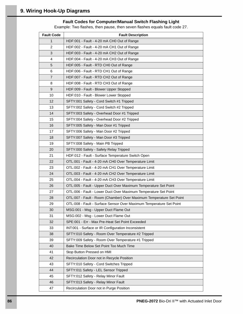
9. Wiring Hook-Up Diagrams
86 PNEG-2072 Bio-Dri II™ with Actuated Inlet Door
Fault Codes for Computer/Manual Switch Flashing LightExample: Two flashes, then pause, then seven flashes equals fault code 27.
Fault Code Fault Description
1 HDF:001 - Fault - 4-20 mA CH0 Out of Range
2 HDF:002 - Fault - 4-20 mA CH1 Out of Range
3 HDF:003 - Fault - 4-20 mA CH2 Out of Range
4 HDF:004 - Fault - 4-20 mA CH3 Out of Range
5 HDF:005 - Fault - RTD CH0 Out of Range
6 HDF:006 - Fault - RTD CH1 Out of Range
7 HDF:007 - Fault - RTD CH2 Out of Range
8 HDF:008 - Fault - RTD CH3 Out of Range
9 HDF:009 - Fault - Blower Upper Stopped
10 HDF:010 - Fault - Blower Lower Stopped
12 SFTY:001 Safety - Cord Switch #1 Tripped
13 SFTY:002 Safety - Cord Switch #2 Tripped
14 SFTY:003 Safety - Overhead Door #1 Tripped
15 SFTY:004 Safety - Overhead Door #2 Tripped
16 SFTY:005 Safety - Man Door #1 Tripped
17 SFTY:006 Safety - Man Door #2 Tripped
18 SFTY:007 Safety - Man Door #3 Tripped
19 SFTY:008 Safety - Main PB Tripped
20 SFTY:000 Safety - Safety Relay Tripped
21 HDF:012 - Fault - Surface Temperature Switch Open
22 OTL:001 - Fault - 4-20 mA CH0 Over Temperature Limit
23 OTL:002 - Fault - 4-20 mA CH1 Over Temperature Limit
24 OTL:003 - Fault - 4-20 mA CH2 Over Temperature Limit
25 OTL:004 - Fault - 4-20 mA CH3 Over Temperature Limit
26 OTL:005 - Fault - Upper Duct Over Maximum Temperature Set Point
27 OTL:006 - Fault - Lower Duct Over Maximum Temperature Set Point
28 OTL:007 - Fault - Room (Chamber) Over Maximum Temperature Set Point
29 OTL:008 - Fault - Surface Sensor Over Maximum Temperature Set Point
30 MSG:001 - Msg - Upper Duct Flame Out
31 MSG:002 - Msg - Lower Duct Flame Out
32 SPE:001 - Err - Max Pre-Heat Set Point Exceeded
33 INT:001 - Surface or IR Configuration Inconsistent
38 SFTY:010 Safety - Room Over Temperature #2 Tripped
39 SFTY:009 Safety - Room Over Temperature #1 Tripped
40 Bake Time Below Set Point Too Much Time
41 Stop Button Pressed on HMI
42 Recirculation Door not in Recycle Position
43 SFTY:010 Safety - Cord Switches Tripped
44 SFTY:011 Safety - LEL Sensor Tripped
45 SFTY:012 Safety - Relay Minor Fault
46 SFTY:013 Safety - Relay Minor Fault
47 Recirculation Door not in Purge Position

PNEG-2072 Bio-Dri II™ with Actuated Inlet Door 87
10. Component Setup
Setting the Thermometer Sensor
Press the MODE key to choose the feature and the UP and DOWN keys to choose the parameters for that feature.
1. Press the MODE key until the feature MV5 is displayed to select the output signal. Press the UP or DOWN key to change the parameter to 4 to 20.
2. Press the MODE key until the feature “U” is displayed. Press the DOWN key to change the temperature unit to °F.
3. Press the MODE key until one bar “/” is displayed. Press the UP or DOWN key to set the temperature for the lower alarm limit to -58°F.
4. The display light should change from blue to green, indicating it is not in alarm state. After 10 seconds, it will time out and go back to the normal display. (See Figure 10A.)
Figure 10A

10. Component Setup
88 PNEG-2072 Bio-Dri II™ with Actuated Inlet Door
Testing the Safety Circuits
Once the Bio-Dri II™ wiring is complete between the control panel and all safety circuits, using a multi-meter, check continuity across all of the safety circuits shown on Page 61. The circuits should be checked with the power to the control panel OFF and with each door shut and the contacts aligned, (See Pages 51 and 52) or in the case of a pull cord switch, the switch must be in the reset position. In the case of the E-Stop button, it must be pulled out prior to checking continuity.
There are two (2) individual contacts for each door, Pull Cord Switch or E-Stop button. Both circuits are normally closed and should show “continuity”. For example, on the top wiring diagram on Page 61, “CS1” refers to Pull Cord Switch 1, and “CS2” refers to Pull Cord Switch 2. When Pull Cord Switch 1 (CS1) is reset, check continuity across terminals 100 and 101 for the top normally closed circuit. Check continuity across terminals 102 and 103 for the bottom normally closed circuit. Repeat this process of checking continuity for CS2 (Pull Cord Switch 2), OD1 (Overhead Door 1 - Entry Door), OD2 (Overhead Door 2 - Exit Door), MD1 (Man Door 1), MD2 (Man Door 2) and E-Stop (E-Stop button on Cycle Start/Stop Panel). If there is no MD2 (Man Door 2), be sure to place a jumper wire across both normally closed circuits.
CR30 Safety Relay Input Function
CR30 Input (LED #)
Safety Function CR30 Terminal #
0 Pull Cord Switch 1 and Pull Cord Switch 2 00 and 01
1 Overhead Door 1 - Entry Door 02 and 03
2 Overhead Door 2 - Exit Door 04 and 05
3 Man Door 1 06 and 07
4 Man Door 2 08 and 09
5 E-Stop (Emergency Stop Button on Cycle Start/Stop Panel) 10 and 11
6 Room Upper Thermal Limits 14
7 Lower Explosive Limits (LEL Gas Detection Sensor if used) 15
8 Reset Button (on Cycle Start/Stop Panel) 17
9 Feedback Contacts 16

10. Component Setup
PNEG-2072 Bio-Dri II™ with Actuated Inlet Door 89
CR30 Safety Relay LED Lights
Any time the power is turned ON to the main PLC panel, the CR30 safety relay “PWR” and “RUN” LED’s should be “ON”, and the “COM” LED should be flickering indicating communication. The “FAULT” LED should never be “ON”, unless the CR30 safety relay is inoperable.
The top LED lights on the CR30 safety relay indicate the input state of the safety system according to the chart in on Page 88. If a specific safety function is satisfied, the corresponding input LED light will be “ON”. If it is not satisfied, the LED light will be “OFF”. Use this feature to diagnose any problems with the safety system. As an example, if all input LED’s are “ON” except LED #2, this means that the door contacts for Overhead Door 2 - exit door are not closed. Make sure this overhead door is closed and contacts are aligned properly. (See “Important” on Page 52.) All ten (10) input LED’s must be on before the Bio-Dri II™ can operate.
The bottom LED lights on the CR30 safety relay indicate the output state of the safety system. Only the top three (3) outputs 0, 1 and 2 are used. If these three (3) output LED’s are not “ON”, the Bio-Dri II™ cannot operate. Check to make sure all ten (10) input LED’s are “ON” first. Then push the blue “Reset” button on the cycle Start/Stop Panel. These three (3) output LED’s should now be “ON”, and the Bio-Dri II™ can be started. (See Figure 10B.)
Figure 10B
Ref # Description
A Input LED’s
B Output LED’s
A
B

90 PNEG-2072 Bio-Dri II™ with Actuated Inlet Door
11. Operator Section
Installing the Bio-Dri II™ Software
Installing the PLC Software
The software for the PLC is located on the supplied SD card.
1. Turn OFF the power to the PLC control.
2. Insert the SD card (A) into the SD card slot on the PLC.
3. Turn ON power to the PLC control. The PLC is updated when all the lights turn green.
4. Remove the SD card (A) from the PLC. NOTE: Do not leave the SD card (A) in the PLC or it will reload every time the power is cycled, reverting all settings to the default.
Figure 11A
Updating the PLC Software
Updates to the software may be available for download from the website.
Before you begin
1. Make sure the SD card is formatted to FAT32. (32 Bit file allocation table.)
2. Make sure to have a computer with an SD card port.
3. Make sure the computer has access to the internet.
To download .zip file:
1. Insert the SD card into the SD card port on the computer.
2. Go to www.automatedproductionsystems.com/downloads.
3. Right click on the software link and select download to the SD card.
IMPORTANT: Do not remove the SD card until the file transfer is complete.
4. Once the file is downloaded, eject the SD card from the computer.
5. Install the updated software to the PLC.
A
Ref # Description
A SD Card

11. Operator Section
PNEG-2072 Bio-Dri II™ with Actuated Inlet Door 91
Installing the Oracle VM Virtual Box Software
1. Insert the USB thumb drive into the USB slot on the computer.
2. Navigate to the thumb drive and open the file “instructions.txt”.
3. Follow the instructions listed in the “instructions.txt” file.
NOTE: This process will take 20 to 40 minutes depending on the computer speed.
Starting the Virtual Machine
After installing the virtual box software, you now have to open the Bio-Dri Virtual Machine. A Virtual Machine emulates a computer, but it will look like a software window on the host computer.
1. To start the Biodri software, click on the Desktop Icon. (See Figure 11B.)
Figure 11B
2. Upon initial setup, you will need to set the network to be used. Select Change Network Settings. (See Figure 11C.)
Figure 11C

11. Operator Section
92 PNEG-2072 Bio-Dri II™ with Actuated Inlet Door
3. In the settings window, select Network.
4. From the Adapter 1 Tab, select the network connection from the “Name” drop down list. NOTE: The network name will be different for each computer. In most cases, you want to choose the wired connection. To help identify the wired connection, look for “Ethernet” in the name. To identify a wireless connection, you can look for the adapter with the “-N” in the name that identifies a wireless protocol. (See Figures 11D and 11E.)
Figure 11D Wireless Connection
Figure 11E Wired Connection
5. Click ok.
6. When the Virtual Machine opens, a notification may pop up. To close these notifications, select the “Do not show again” icon on the right.
7. To shut down the virtual machine. Select “Start - Shutdown”

11. Operator Section
PNEG-2072 Bio-Dri II™ with Actuated Inlet Door 93
Powering on the Bio-Dri II™ System
After the unit components have been installed and the building is clear of personnel and livestock, you can turn ON the power to the system.
1. Make sure the Emergency Stop buttons on the main control box is in the fully-retracted position (unlocked).
2. Once the button is flashing, push the Start button.
NOTE: The amber light will flash and a pulsing buzzer will sound for 15 seconds to warn that the system is about to start.
Configuring the Bio-Dri II™ SystemThe system must be configured before any baking process can be started. The data entered during the configuration process will be the ranges the system will use as maximum and minimum settings.
To log in for daily operation:
1. From the Initial Log In screen, click Log In.
a. User name: User
b. Password: (no password, enter nothing here)
Figure 11F Initial Log In Screen
To configure the ADMIN system settings, you will need to log out and log back in using the ADMIN log in account information.
1. From the Initial Log In screen, click Log In.
a. User name: Admin
b. Password: biodri
NOTE: When you are finished configuring the system settings, you will need to log out and log back in using the USER log in account information.

11. Operator Section
94 PNEG-2072 Bio-Dri II™ with Actuated Inlet Door
To configure the system settings:
Figure 11G System Configure Screen (ADMIN Level Access)
1. From the Home screen, click System Configure.
a. System Name - Enter the e-mail address that is unique to the Bio-Dri II™ System.
b. Data Logging (ON or OFF) - Click the button to toggle data logging ON or OFF.
c. Data Log to File - Click the button to toggle the data log file ON or OFF. Turning this ON will create a log file on the local hard drive.
d. Data Log to Database - Click the button to toggle data log to database ON or OFF. Turning this ON will create a log file to a database server.
e. E-mail Addresses: Enter the e-mail address and phone number that will receive notifications via e-mail and text.
NOTE: Make sure the phone number entered can receive texts and contains the correct suffix for the cell phone service provider that is being used.

11. Operator Section
PNEG-2072 Bio-Dri II™ with Actuated Inlet Door 95
To configure the E-mail Server settings:
Figure 11H E-Mail Server Screen
1. From the System Configure screen, click E-Mail Server Settings.
a. Server Name or IP - Enter the server name or the IP address of the server.
b. User name - Enter the user name for the account.
c. Password - Enter the password for the account.
d. IP Port - Enter the IP address for the account.
e. Secure Connection Req. - Check the box if a secure connection is required.
f. To recieve a “pass” or “fail” text message, enter the phone number in the box.
NOTE: Ensure the correct suffix is added to the end of the number for the cell phone service provider that is being used. For example, a Verizon customer would look like this: [email protected]. The suffix will vary for each cell phone service provider.
Figure 11I E-Mail Pass/Fail Examples
Cycle Completed Successfully
Unit IDTrailer NumberTrailer TypeUser NameCycle ID
Start Time 2015/3/20 20:512015/3/20 21:1725m 22s7m 22s16010m 00s0m 00s0m 00s8m 00s
End TimeTotal Cycle TimePreheat Duration
Bake Duration
Post-Bake DurationPurge Duration
Bake Time Below Setpoint
Trailer Temperature
System Name1Drop DeckAP764075087
Cycle Failed
Unit IDTrailer NumberTrailer TypeUser NameCycle ID
Start Time 2015/5/13 14:072015/5/13 14:2113m 35s13m 35s1600m 00s0m 00s0m 00s0m 00s
End TimeTotal Cycle TimePreheat Duration
Bake Duration
Post-Bake DurationPurge Duration
Bake Time Below Setpoint
Trailer Temperature
System Name2t2BIODRI921350853

11. Operator Section
96 PNEG-2072 Bio-Dri II™ with Actuated Inlet Door
Configuring the Analog Sensors
The system must be configured before any baking process can be started. The data entered during the configuration process will be the ranges the system will use as maximum and minimum settings.
To configure the analog sensors:
Figure 11J Analog Configuration Screen (ADMIN Level Access)
1. From the Home screen, click Analog Sensor Configure.
2. Enter the Temperature (RTD) Channel Configurations:
a. Upper Duct RTD always Installed.
b. Lower Duct RTD always Installed.
c. Chamber RTD always Installed.
d. Surface Temperature RTD Installed - Select Yes or No.
e. STOP Process if Surface Temp Pressure Switch is Not Set - Select Yes or No.
3. Enter the IR Sensor Configuration.
a. IR Sensor #1 (Front Left) Installed - Select Yes or No.
b. IR Sensor #2 (Rear Right) Installed - Select Yes or No.
c. IR Sensor #3 (Front Right) Installed - Select Yes or No.
d. IR Sensor #4 (Rear Left) Installed - Select Yes or No.

11. Operator Section
PNEG-2072 Bio-Dri II™ with Actuated Inlet Door 97
Configuring a New TrailerEach trailer will need to be entered into the system to be assigned a trailer number and to configure the settings for that trailer. These settings only need to be configured once; the system will remember the settings when the trailer ID number is entered.
Figure 11K Trailer Information Screen (ADMIN Level Access)
1. From the home screen, click Edit Trailer Data.
2. Enter the new trailer number and click Lookup Trailer.
NOTE: A message will appear stating that the trailer number does not exist and you will need to select a trailer type or enter the data for the new trailer type.
3. From the drop down menu, select the trailer type. If the trailer type exists, the information fields will fill in with the correct parameters for that trailer type.
4. If the trailer type does not exist, enter the trailer type into the Name field and set the following parameters:
a. Surface Temperature Set Point - The required surface temperature that the trailer surface must maintain during the Bake Mode. The temperature setting can range between 100° to 200°F (38° to 93°C).
b. Bake Mode Duration (min.) - The duration of time in minutes that the trailer is required to maintain the surface temperature set point. The time can be set between 0 and 99 minutes.
c. Post Bake Mode Duration (min.) - The duration of time in minutes that is desired to continue baking the trailing after the heaters have stopped. The time can be set between 0 and 999 minutes.
d. Purge Mode Duration (min.) - The duration of time in minutes required to purge the gases and hot air from the building. The time can be set between 8 and 99 minutes.
e. Circulation Fan Post Bake Mode - Check this box to use the fans to circulate the air during the post bake cycle.
f. Upper Blower - Check this box to turn ON the upper fan and heater. For a short trailer, this may need to be unchecked.
g. Lower Blower - Check this box to turn ON the lower fan and heater. For a tall trailer, this may need to be unchecked.
h. IR Sensor 1 - Check this box to mark the front left sensor.
i. IR Sensor 2 - Check this box to mark the rear right sensor.
j. IR Sensor 3 - Check this box to mark the front right sensor (if used).
k. IR Sensor 4 - Check this box to mark the rear left sensor (if used).
l. Surface Sensor - Check this box to mark there is a surface sensor.
5. Click Save.

11. Operator Section
98 PNEG-2072 Bio-Dri II™ with Actuated Inlet Door
To configure the AP system settings, you will need to log out and log back in using the AP System log in information located with the software documentation.
Figure 11L Home Screen (AP Level Access)
1. From the Home screen, click AP System Configure.
2. Enter the Adjustable Set Points:
Figure 11M AP System Configuration Screen (AP Level Access)

11. Operator Section
PNEG-2072 Bio-Dri II™ with Actuated Inlet Door 99
3. Enter the Economizer Functions: This function turns the burners OFF temporarily if all the chosen trailer sensors are satisfied according to the settings listed below.
a. Economizer Function: This setting turns the features ON and OFF.
b. To difference the above surface set point to enable economizer mode.
c. To difference the above surface set point to disable economizer mode
Understanding the Bio-Dri II™ Building Indicator Lights and Buzzer
Green and Red Lights (Truck Positioning Indicator)
When a truck and trailer are moved into an empty Bio-Dri II™ building, as the truck first pulls into the bay and blocks both front and rear truck positioning sensors, the Bio-Dri II™ will switch to “Truck Positioning Mode”, which will last for 2 minutes.
The green light will turn ON, indicating that the driver should continue to pull the truck and trailer forward.
If the driver pulls the truck and trailer too far forward, both front and rear truck positioning sensors will be open and the red light will flash, indicating that the driver should back up.
When the truck and trailer are in the correct position, the front sensor will be blocked and the rear sensor will be open and the red light will remain on solid, indicating that the driver should stop.
Amber Light and Buzzer (Start Warning Indicator)
When the “Cycle Start” button is pushed, the start cycle will count down from 15 seconds. The amber light and buzzer will pulse during this countdown as an alarm to anyone that might accidently be inside. After the 15 seconds countdown, the centrifugal fans will start to begin the cycle.
Red Light (Cycle Run Indicator)
When the Bio-Dri II™ cycle starts the red light will turn ON and remain ON until the cycle is complete or alarms out for any reason.
Green and Red Lights (Cycle Pass/Fail Indicator)
After a cycle is complete without fail, the green light will turn ON and remain ON for up to 30 minutes and the red light will turn OFF, indicating a Pass Cycle. If a cycle fails to complete, the red light will turn ON and begin to flash for up to 30 minutes, indicating a Fail Cycle.
Green Light (Surface Sensor in place Indicator)
After a cycle is complete, if the green light is flashing, it indicates that the surface sensor has not been removed from the back of the trailer. After removing the surface sensor, the green light should remain ON solid for up to 30 minutes after the cycle.

11. Operator Section
100 PNEG-2072 Bio-Dri II™ with Actuated Inlet Door
Operating the Bio-Dri II™ System
Positioning the Trailer
The trailer must be correctly positioned in order for it to be baked properly. The positioning lights will signal you when the trailer is in the correct location.
1. Move the trailer into the baking chamber and follow the signal lights to determine when the trailer is in the correct position.
a. Green Light - Keep moving trailer forward until the red light is illuminated.
b. Red Light - Stop, the trailer is in position.
c. Red Flashing Light - Move trailer backwards until the red light stops flashing.
2. Remove the tractor from the building.
Placing the RTD Temperature Surface Sensor on the Trailer
The RTD temperature surface sensor is used to measure the surface temperature of the trailer. One sensor is provided, with a 20' cord.
1. Place the sensor on the trailer.
a. Place at the back right corner of trailer. It must be resting upright and perfectly flat, so the proximity switch is activated, in order to monitor an accurate temperature. The Bio-Dri II™ will not start if the surface sensor proximity switch is not activated.
b. The indicator LED on the top of the surface sensor will be dimly illuminated, if there is electrical power to the sensor. The indicator LED will be brightly illuminated, if the sensor is properly placed on the floor.
WARNING
Do not leave the tractor attached to the trailer. It must be removed from the baking chamber.
CAUTION
Remember to remove the surface sensor from the back of the trailer before removing the trailer from the building, to prevent damage to the surface sensor.

11. Operator Section
PNEG-2072 Bio-Dri II™ with Actuated Inlet Door 101
Figure 11N Surface sensor located in trailer corner.
Figure 11O
Ref # Description
A Surface Temperature Sensor Location
B Front of Trailer
C Rear of Trailer

11. Operator Section
102 PNEG-2072 Bio-Dri II™ with Actuated Inlet Door
Emergency Stop
In an Emergency, to stop the process, do one of the following:
1. Press any of the Emergency Stop button on the cycle start/stop panel.
2. Pull the E-stop cord in the building or push the E-stop button on the pull-cord control panel.
3. Open a door.
Stopping a Drying Cycle
Every time the system is stopped for any reason, the Purge Cycle must operate for 8 minutes before you can start a new cycle.
To stop a drying cycle:
1. From the Start Process Screen, click STOP.
Figure 11P Start Process Screen
NOTE: The drying cycle will also stop if the system enters into an alarm state or in the event of a safety interlock interruption.

11. Operator Section
PNEG-2072 Bio-Dri II™ with Actuated Inlet Door 103
Heater Modulation Gas Valve Calibration
When starting up the Bio-Dri II™ for the first time, the modulation gas valve for each heater must be calibrated. This can only be accomplished when logged into the Bio-Dri II™ program under the “AP” level user security setting. A trailer must be parked in the Bio-Dri II™ building prior to calibration. The air inlet door must be in the “Recycle” position.
The maximum opening of the gas modulation valve is the % opening that will result in a 130°F temperature rise. The minimum opening of the modulation valve is the % opening that will result in a 75°F temperature rise. Temperature rise is the temperature increase of the air as it passes through each heater. This is obtained by subtracting the chamber temperature from the duct temperature. This is shown on the “Temperature Monitor” screen as “RISE” below the temperature bar for both the upper duct and lower duct. The term “OUT” is considered to be the current % opening of each gas modulation valve. This is shown on the “Temperature Monitor” screen as “OUT” below the temperature bar and the “RISE”. Note the location of the “MAX” and “MIN” below the temperature bars, just beneath the “OUT”.
After logging into the computer under the “AP” level user, go to the “Process Start” page. From the “Process Start” page, click “Temp Indicators”. Move the “Temp Indicators” page over to the right so it can be viewed simultaneously with the “Process Start” page.
Read the present value (PV) of the upper duct, lower duct and chamber temperature. They should all be reading the same within a few degrees and should match closely with the actual ambient temperature outside. If not, check and correct the wiring between all three (3) of these RTD temperature air sensors.
Changing the Gas Modulation Valve “MAX” and “MIN” % Open Settings
Before checking polarity of the gas modulation valve actuators, change the “MAX” and “MIN” % open settings for each duct to 100% open. By changing them both to the same setting, it forces the gas modulation valve to move to that position immediately. To change the setting, click on the value to highlight it and then enter the new value. You must press the Enter button on the keyboard each time a value is changed to save the new value. You should see the “OUT” value change to this new value that was entered.
Checking Polarity of the Gas Modulation Valve Actuators
The Bio-Dri II™ is now ready to start for the first time. Refer to “Starting the Cycle” on Page 105. The fans will start first in a staggered fashion and if the heaters then ignite at 100% open, the polarity of the gas modulation valve actuator is correct. If they do not ignite, make sure all gas valves in the gas supply line and heater pipe train are turned ON. If they still do not ignite, the polarity of the gas modulation valves may be backwards. To change the polarity remove the orange cover from the gas modulation valve actuator to expose the polarity switch. This is the black dial with the screwdriver slot. With a screwdriver, turn the dial from “1” to “0”. (See Figure 11Q on Page 104.) The heaters will always attempt to ignite three (3) times. If they do not ignite by the third attempt, the heaters will lock out. To reset them, re-cycle power by pushing in the E-Stop button on the front of the heater control box for 30 seconds. Then, pull the E-Stop button back out and it will attempt to ignite three (3) more times. Once both fans and heaters have started, the pressure regulators should be adjusted immediately. Adjust to 7 PSI for natural gas or 10 PSI for vapor propane.

11. Operator Section
104 PNEG-2072 Bio-Dri II™ with Actuated Inlet Door
Figure 11Q
Adjusting the Maximum % Open Setting of each Gas Modulation Valve to 130°F Temp Rise
Begin by changing the “MAX” and “MIN” % open settings to 60% for each duct. Next, monitor the temperature rise of each duct as shown on the “Temperature Monitor” screen and adjust the “MAX” and “MIN” % open settings together until 130°F temperature rise is achieved. This process must be done quickly within the first 5 minutes, before the duct temperature goes over 270°F causing the system to overheat and shut down. If the “RISE” is higher than 130°F, lower the setting for “MAX” and “MIN” % open to 55%. Wait 10 seconds for the temperature rise to stabilize. If still too high, lower the “MAX” and “MIN” % open another 5%. Remember to adjust both the “MAX” and “MIN” % open settings to the same value, in order to force the gas modulation valves to immediately move to that position. Once a 130°F temperature rise is achieved for both ducts, the “MAX” % open setting is complete. Do not expect the value for the upper and lower ducts to be the same due to slight variations in the assembly of the gas modulation valves. Record this value on paper for the “MAX” % open setting of each duct.
Adjusting the Minimum % Open Setting of each Gas Modulation Valve to 75°F Temp Rise
Next, adjust the “MAX” and “MIN”% open value to 10% lower than the “MAX” setting from above. Wait 20 seconds for the temperature rise to stabilize. If the “RISE” is higher than 75°F, lower the setting for “MAX” and “MIN” % open by 5%. Wait 10 seconds for the temperature rise to stabilize. Remember to adjust both the “MAX” and “MIN” % open setting to the same value, in order to force the gas modulation valves to immediately move to that position. Once a 75°F temperature rise is achieved for both ducts, the “MIN” % open setting is complete. Do not expect the value for the upper and lower ducts to be the same due to slight variations in the assembly of the gas modulation valves. Record this value on paper for the “MIN” % open setting of each duct.
Final Maximum and Minimum % Open Setting of each Gas Modulation Valve
Change the “MAX” % open setting of each duct to the final value recorded from the Maximum % Open Adjustment above. Change the “MIN” % open setting of each duct to the final value recorded from the minimum % open adjustment above.

11. Operator Section
PNEG-2072 Bio-Dri II™ with Actuated Inlet Door 105
The heater modulation gas valve calibration is now complete. The “MAX” and “MIN” % open values can be slightly reduced at any time to prevent occasional overheat situations. The “MIN” % open values can be slightly increased at any time if problems with heater re-ignition occur after reaching maximum chamber temperature. However, increasing “MIN” % open values may result in an overheat situation. It is better to look for the root cause of heater re-ignition problems, which could be caused by faulty UV flame sensor, igniter, air proving switch or tubing and possible insufficient fresh air.
Starting the Cycle
Before you begin:
• Make sure the surface sensor is correctly located.
• Enter the trailer identification number.
• Make sure the E-Stop is in the operating position.
• Make sure the START button is flashing to indicate everything is ready.
1. Press the START button.
Monitoring the TemperaturesThe temperature monitor displays the current temperatures of the sensors and their set points.
To view the current temperatures:
Figure 11R Current Temperature Monitor
1. From the Process Start Page, click Temp Indicators.
NOTE: Definition of the Screen Terms.
PV = Preset Value
MAX = Maximum duct temperature. If the temperature increases to more than the set maximum value, the system will shut down and go into alarm mode.
SP = Chamber set point or surface temperature set point.
NOTE: You can expand the window to view the Temperature Monitor and the Time Settings screens next to the Process Start Page.
DANGERNever start a cycle while people or animals are inside of the building or the vehicle. Make sure everyone is out of the building.

11. Operator Section
106 PNEG-2072 Bio-Dri II™ with Actuated Inlet Door
Monitoring the Cycle Process Time
The Process Time Monitor displays the modes of the current baking cycle and the time elapsed for each mode.
To view the current status of the cycle process:
Figure 11S Process Time View
1. From the Process Start Page, click Process Time View.
NOTE: You can expand the window to view the Temperature Monitor and the Time Settings screens next to the Process Start Page.
Figure 11T Screen Layout for Monitoring

11. Operator Section
PNEG-2072 Bio-Dri II™ with Actuated Inlet Door 107
Viewing Current Settings
The current settings page will show you the information for the current trailer that is selected.
To view the current settings:
Figure 11U Current Settings
1. From the Process Start Page, click the Current Settings button.
Changing the Time of the Current Process
You can override the set times for the Bake and Post-Bake modes. The Purge mode can only be set to a minimum of 8 minutes.
To override the current settings:
Figure 11V Time Override
1. From the Process Start Page, click Process Time Edit.
2. Enter the desired time for the override for the Bake and Post-Bake modes and click enter. (They use the computer keyboard.)

11. Operator Section
108 PNEG-2072 Bio-Dri II™ with Actuated Inlet Door
Clearing an Alarm
Alarms occur when there is an error detected by the system. Alarms are displayed at the bottom of the Startup screen.
To clear an alarm:
Figure 11W Acknowledging an Alarm
1. Read the Alarm Code and refer to the troubleshooting section on Page 109 to identify any physical action needed to clear the alarm.
2. Once the alarm has been addressed, click the alarm at the bottom of the screen and hit the check mark to acknowledge the alarm.

PNEG-2072 Bio-Dri II™ with Actuated Inlet Door 109
12. Troubleshooting
Hardware Failure HDF:xxx
Safety SFTY:xxx
Code Message Description Solution 1 Solution 2
HDF:001 4-20 CH 0 Out of range4-20 CH-0 Reading is out of range (open circuit).
Check physical connections. Replace sensor
HDF:002 4-20 CH 1 Out of range4-20 CH-1 Reading is out of range (open circuit).
Check physical connections. Replace sensor
HDF:003 4-20 CH 2 Out of range4-20 CH-2 Reading is out of range (open circuit).
Check physical connections. Replace sensor
HDF:004 4-20 CH 3 Out of range4-20 CH-3 Reading is out of range (open circuit).
Check physical connections. Replace sensor
HDF:005 RTD CH 0 Out of rangeRTD CH-0 Reading is out of range (open circuit).
Check physical connections. Replace sensor
HDF:006 RTD CH 1 Out of rangeRTD CH-1 Reading is out of range (open circuit).
Check physical connections. Replace sensor
HDF:007 RTD CH 2 Out of rangeRTD CH-2 Reading is out of range (open circuit).
Check physical connections. Replace sensor
HDF:008 RTD CH 3 Out of rangeRTD CH-3 Reading is out of range (open circuit).
Check physical connections. Replace sensor
HDF:009Centrifugal fan upper stopped.
The upper fan is reporting a stop condition.
Verify fan operation. None
HDF:010Centrifugal fan lower stopped.
The lower fan is reporting a stop condition.
Verify fan operation. None
HDF:011 Safety interlock.The safety interlock signal to input 0 has been lost.
Verify state of all safetydevices.
Check physicalconnections.
HDF:012Fault - Surface temp pressure switch open.
Surface temp pressure switch open.
Verify aux. sensor is onsurface.
Check physicalconnections.
Code Message Description Solution 1 Solution 2
SFTY:000 Safety relay trippedA safety relay has been tripped.
Ensure all the safety relays are working properly.
None
SFTY:001 Cord switch #1 trippedSafety cord #1 has been tripped.
Verify the cord connected to the E-stop is retracted.
None
SFTY:002 Cord switch #2 trippedSafety cord #2 has been tripped.
Verify the cord connected to the E-stop is retracted.
None
SFTY:003Overhead door #1 tripped
Overhead door contact #1 is not aligned.
Verify the door is closed and the contacts are aligned.
Replace door contacts
SFTY:004Overhead door #2 tripped
Overhead door contact #2 is not aligned.
Verify the door is closed and the contacts are aligned.
Replace door contacts
SFTY:005 Man door #1 trippedMan door contact #1 is not aligned.
Verify the door is closed and the contacts are aligned.
Replace door contacts
SFTY:006 Man door #2 trippedMan door contact #2 is not aligned.
Verify the door is closed and the contacts are aligned.
Replace door contacts
SFTY:007 Man door #3 trippedMan door contact #3 is not aligned.
Verify the door is closed and the contacts are aligned.
Replace door contacts
SFTY:008 Main PB tripped Main power breaker is tripped.Verify the E-stop is fully retracted.
None
SFTY:009Room overtemperature tripped
The room temperature high-limit has been exceeded.
Raise the set point for the room temperature high-limit.
Replace the sensor

12. Troubleshooting
110 PNEG-2072 Bio-Dri II™ with Actuated Inlet Door
Interlock INT:xxx
Message MSG:xxx
Set Point Exceeded SPE:xxx
Over Temperature Limit OTL:xxx
Code Message Description Solution 1 Solution 2
INT:001Interlock - Setting incompatibility.
A setting mismatch has been detected.
Verify channel enable/disable 4-20 and RTD match the hardware setup.
None
Code Message Description Solution 1 Solution 2
MSG:001 Upper duct flame outThe flame out upper signal has been received.
Verify operation of connected equipment.
None
MSG:002 Lower duct flame outThe flame out lower signal has been received.
Verify operation of connected equipment.
None
Code Message Description Solution 1 Solution 2
SPE:001ERR-MAX pre-heat run time set point exceeded.
The process has timed out prior to reaching surface temperature set point.
Increase the run time set point.
Verify integrity of chamber and heating equipment.
Code Message Description Solution 1 Solution 2
OTL:0014-20 mA CH 0 Over temp limit.
4-20 mA CH 0 has exceeded 200°.Reset after cool down below set point.
Verify set points and heating equipment.
OTL:0024-20 mA CH 1 Over temp limit.
4-20 mA CH 1 has exceeded 200°.Reset after cool down below set point.
Verify set points and heating equipment.
OTL:0034-20 mA CH 2 Over temp limit.
4-20 mA CH 2 has exceeded 200°.Reset after cool down below 200°.
Verify set points and heating equipment.
OTL:0044-20 mA CH 3 Over temp limit.
4-20 mA CH 3 has exceeded 200°.Reset after cool down below 200°.
Verify set points and heating equipment.
OTL:005RTD CH 0 Over temp limit.
RTD CH 0 has exceeded the MAX upper duct set point.
Reset after cool down below 200°.
Verify set points and heating equipment.
OTL:006RTD CH 1 Over temp limit.
RTD CH 1 has exceeded the MAX lower duct set point.
Reset after cool down below 200°.
Verify set points and heating equipment.
OTL:007RTD CH 2 Over temp limit.
RTD CH 2 has exceeded 200°.Reset after cool down below 200°.
Verify set points and heating equipment.
OTL:008RTD CH 3 Over temp limit.
RTD CH 3 has exceeded 200°.Reset after cool down below 200°.
Verify set points and heating equipment.

PNEG-2072 Bio-Dri II™ with Actuated Inlet Door 111
13. Warranty
Limited Warranty - Protein Products
The GSI Group, LLC. (“GSI”) warrants products which it manufactures, to be free of defects in materials and workmanship under normal usage and conditions for a period of 12 months from the date of purchase (or, if shipped by vessel, 14 months from the date of arrival at the port of discharge). If, in GSI’s sole judgment, a product is found to have a defect in materials and/or workmanship, GSI will, at its own option and expense, repair or replace the product or refund the purchase price. This Limited Warranty is subject to extension and other terms as set forth below.
Warranty Enhancements:
The warranty period for the following products is enhanced as shown below and is in lieu of (and not in addition to) the above stated warranty period.
Conditions and Limitations:THERE ARE NO WARRANTIES THAT EXTEND BEYOND THE LIMITED WARRANTY DESCRIPTION SET FORTH HEREIN; SPECIFICALLY, GSI DISCLAIMS ANY AND ALL OTHER WARRANTIES OF ANY KIND, EXPRESS OR IMPLIED, INCLUDING, WITHOUT LIMITATION, WARRANTIES OF MERCHANTABILITY OR FITNESS FOR A PARTICULAR PURPOSE OR USE IN CONNECTION WITH: (I) ANY PRODUCT MANUFACTURED OR SOLD BY GSI, OR (II) ANY ADVICE, INSTRUCTION, RECOMMENDATION OR SUGGESTION PROVIDED BY AN AGENT, REPRESENTATIVE OR EMPLOYEE OF GSI REGARDING OR RELATED TO THE CONFIGURATION, INSTALLATION, LAYOUT, SUITABILITY FOR A PARTICULAR PURPOSE, OR DESIGN OF SUCH PRODUCTS.
The sole and exclusive remedy for any claimant is set forth in this Limited Warranty and shall not exceed the amount paid for the product purchased. This Warranty only covers the value of the warranted parts and equipment, and does not cover labor charges for removing or installing defective parts, shipping charges with respect to such parts, any applicable sales or other taxes, or any other charges or expenses not specified in this Warranty. GSI shall not be liable for any other direct, indirect, incidental or consequential damages, including, without limitation, loss of anticipated profits or benefits. Expenses incurred by or on behalf of a claimant without prior written authorization from the GSI warranty department shall not be reimbursed. This warranty is not transferable and applies only to the original end user. GSI shall have no obligation or responsibility for any representations or warranties made by or on behalf of any dealer, agent or distributor. Prior to installation, the end user bears all responsibility to comply with federal, state and local codes which apply to the location and installation of the products.
This Limited Warranty extends solely to products sold by GSI and does not cover any parts, components or materials used in conjunction with the product, that are not sold by GSI. GSI assumes no responsibility for claims resulting from construction defects, unauthorized modifications, corrosion or other cosmetic issues caused by storage, application or environmental conditions. Modifications to products not specifically delineated in the manual accompanying the product at initial sale will void all warranties. This Limited Warranty shall not extend to products or parts which have been damaged by negligent use, misuse, alteration, accident or which have been improperly/inadequately maintained.
Service Parts:
GSI warrants, subject to all other conditions described in this Warranty, Service Parts which it manufactures for a period of 12 months from the date of purchase, unless specified in Enhancements above. Parts not manufactured by GSI will carry the Manufacturer’s Warranty.
Product Warranty Period
AP® Fans Performer Series Direct Drive Fan Motor 3 Years * Warranty prorated from material list price:0 to 3 years - no material cost to end user3 to 5 years - end user pays 25%
5 to 7 years - end user pays 50%
7 to 10 years - end user pays 75%
** Warranty prorated from material list price:0 to 3 years - no material cost to end user3 to 5 years - end user pays 75%
AP® and Cumberland® Flex-Flo/Pan Feeding System Motors 2 Years
Electronic Controls All Protein controls manufactured by GSI24 Months from datecode on part
Cumberland®
Feeding and WateringSystems
Feeder System Pan Assemblies 5 Years, Prorated **
Feed Tubes (1.75" and 2.00") 10 Years, Prorated *
Centerless Augers 10 Years, Prorated *
Watering Nipples 10 Years, Prorated *
(Protein Limited Warranty_REV01_06 November 2018)

Copyright © 2021 by The GSI Group, LLCPrinted in the USA
This equipment shall be installed in accordance with the current installation codes and applicable
regulations, which should be carefully followed in all cases. Authorities having jurisdiction should be
consulted before installations are made.
1004 E. Illinois St. Assumption, IL 62510-0020
Phone: 1-217-226-4421 Fax: 1-217-226-4420
www.automatedproduction.com
CN-362952
Copyright © 2022 FDOKUMEN