VF Series M9000 Electrically and D-3000 Pneumatically Actuated ...
30
Product Bulletin VF Series No. 1 Issue Date January 26, 2005 © 2005 Johnson Controls, Inc. 1 VF Series M9000 Electrically and D-3000 Pneumatically Actuated Standard-Pressure, Standard-Temperature Butterfly Valves VF Series M9000 Electrically and D-3000 Pneumatically Actuated Standard-Pressure, Standard-Temperature Butterfly Valves are designed specifically for a wide range of Heating, Ventilating, and Air Conditioning (HVAC) applications including two-position and modulating control of hot, chilled, or condenser water, and 50/50 glycol solutions. These valves are also bidirectional, allowing positive shutoff with the flow in either direction. Two-way configurations are available in sizes from 2 through 6 in. for M9000 Electrically Actuated, and 2 through 10 in. for D-3000 Pneumatically Actuated assemblies. Three-way assemblies have two valves that are linked together and mounted on a flanged, cast-iron tee. Three-way configurations are available in sizes from 2 through 6 in. for M9000 Electrically Actuated and 2 through 8 in. for D-3000 Pneumatically Actuated assemblies. M9000 Electrically Actuated models are available with or without a rugged, factory-installed weather shield. M9000 Electrically Actuated non-spring return, non-weather shield models feature an integral handle for manual positioning of the valve, independent of a power supply. Figure 1: VF Series M9000 Electrically and D-3000 Pneumatically Actuated Standard-Pressure, Standard-Temperature Butterfly Valves Features and Benefits Low Seating/Unseating Torques Reduce actuator torque and size requirements, particularly with lower-pressure rated valves Bubble-Tight Shutoff Provides positive closure when needed Pre-Assembled Actuators Reduce assembly costs Compatible with All Types of ANSI 125/150 Slip-On and Weld-Neck Flanges Allows configuration in the field, with readily available standard fittings M9000 Electric Actuators Available with or without a Rugged, Factory-Installed Weather Shield Provide protection from the elements in outside applications M9000 Electric Actuators Available with or without End Switches Provide adjustable switch points for positive indication or operation of auxiliary equipment D-3000 Pneumatic Actuators Available with or without a Pneumatic Positioner Provide precise valve positioning Code No. LIT-977202 www.johnsoncontrols.com
-
Upload
khangminh22 -
Category
Documents
-
view
0 -
download
0
Transcript of VF Series M9000 Electrically and D-3000 Pneumatically Actuated ...

Product Bulletin VF Series No. 1 Issue Date January 26, 2005
© 2005 Johnson Controls, Inc. 1
VF Series M9000 Electrically and D-3000 Pneumatically Actuated Standard-Pressure, Standard-Temperature Butterfly Valves
VF Series M9000 Electrically and D-3000 Pneumatically Actuated Standard-Pressure, Standard-Temperature Butterfly Valves are designed specifically for a wide range of Heating, Ventilating, and Air Conditioning (HVAC) applications including two-position and modulating control of hot, chilled, or condenser water, and 50/50 glycol solutions. These valves are also bidirectional, allowing positive shutoff with the flow in either direction.
Two-way configurations are available in sizes from 2 through 6 in. for M9000 Electrically Actuated, and 2 through 10 in. for D-3000 Pneumatically Actuated assemblies. Three-way assemblies have two valves that are linked together and mounted on a flanged, cast-iron tee. Three-way configurations are available in sizes from 2 through 6 in. for M9000 Electrically Actuated and 2 through 8 in. for D-3000 Pneumatically Actuated assemblies.
M9000 Electrically Actuated models are available with or without a rugged, factory-installed weather shield. M9000 Electrically Actuated non-spring return, non-weather shield models feature an integral handle for manual positioning of the valve, independent of a power supply.
Figure 1: VF Series M9000 Electrically and D-3000 Pneumatically Actuated
Standard-Pressure, Standard-Temperature Butterfly Valves
Features and Benefits
Low Seating/Unseating Torques Reduce actuator torque and size requirements, particularly with lower-pressure rated valves
Bubble-Tight Shutoff Provides positive closure when needed
Pre-Assembled Actuators Reduce assembly costs
Compatible with All Types of ANSI 125/150 Slip-On and Weld-Neck Flanges
Allows configuration in the field, with readily available standard fittings
M9000 Electric Actuators Available with or without a Rugged, Factory-Installed Weather Shield
Provide protection from the elements in outside applications
M9000 Electric Actuators Available with or without End Switches
Provide adjustable switch points for positive indication or operation of auxiliary equipment
D-3000 Pneumatic Actuators Available with or without a Pneumatic Positioner
Provide precise valve positioning
Code No. LIT-977202 www.johnsoncontrols.com

Table 1: Ordering Data V F Butterfly 1 2 Valve 4 Disk Type/ 4 = Standard Disk Without Weather Shield 3 Actuator 5 = Standard Disk With Weather Shield Enclosure 6 = Undercut Disk without Weather Shield 2 Body Type 2 = Two-Way, Normally Open (N.O.) 4 4 = Two-Way, Normally Closed (N.C.) 8 = Three-Way 3 Flange 3 = ANSI Class 125/150, Fully Lugged 5 1 Flow 1 = Modified Equal Percentage 6 Characteristics C Valve Size A = 2 in. (With Four Mounting Lugs) 7 B = 2-1/2 in. (With Four Mounting Lugs) C = 3 in. (With Four Mounting Lugs) D = 4 in. (With Eight Mounting Lugs) E = 5 in. (With Eight Mounting Lugs) F = 6 in. (With Eight Mounting Lugs) G = 8 in. (With Eight Mounting Lugs) H = 10 in. (With Twelve Mounting Lugs) A Valve Style A = Two-Way 8 D = Three-Way, Style “D” (See E = Three-Way, Style “E” Figure 4 for F = Three-Way, Style “F” three-way valve G = Three-Way, Style “G” body styles.)
+ + = Factory-Mounted Actuator 9
1 2 3 4 5 6 7 8 9 10 11 12 13 14 15 = Field
V F 4 2 3 1 C A +
Butterfly Valve Assembly
Example: Two-way 3 in. ANSI Class 125/150 Valve
For a replacement valve body, configure the appropriate code number from the first eight fields in Table 1; the existing actuator-to-valve linkage will need to be reused.
2 VF Series M9000 Electrically and D-3000 Pneumatically Actuated Standard-Pressure, Standard-Temperature Butterfly Valves Product Bulletin

Table 2: Ordering Data – Adding a Factory Mounted Actuator V F 4 2 3 1 C A + + = Factory-Mounted Actuator 1 2 3 4 5 6 7 8 9 2 = Tandem Actuators 9 1 6 Factory 916 = M9116 Non-Spring Return
10 11 12 Mounted 924 = M9124 Non-Spring Return Electric 926 = M9216 Spring Return Open Actuator 946 = M9216 Spring Return Closed (M9216-AGA-2 and M9216-AGC-2 are NOT available
in a tandem mount configuration.)
G Control A = Floating 13 B = On/Off G = Proportional with 0-10 VDC Feedback
G Voltage G = 24 VAC 14 C Auxiliary A = None 15 Switches C = Two Auxiliary Switches 3 1 5 3 Factory 3153 = D-3153 10 11 12 13 Mounted 3244 = D-3244 Pneumatic 3246 = D-3246 Actuator P Accessories P= D-9502 Pneumatic Positioner 14 Blank = None
1 2 3 4 5 6 7 8 9 10 11 12 13 14 15 = Field
V F 4 2 3 1 C A + 9 1 6 G G C
Butterfly Valve Assembly
Example: Two-way normally open valve without weather shield, 3 in., with proportional, non-spring return electric actuator, 0 to 10 VDC feedback and two auxiliary switches
For a replacement valve body, configure the appropriate code number from the first eight fields in Table 1; the existing actuator-to-valve linkage will need to be reused.
Refer to the appropriate actuator product bulletin for additional actuator details.
VF Series M9000 Electrically and D-3000 Pneumatically Actuated Standard-Pressure, Standard-Temperature 3 Butterfly Valves Product Bulletin
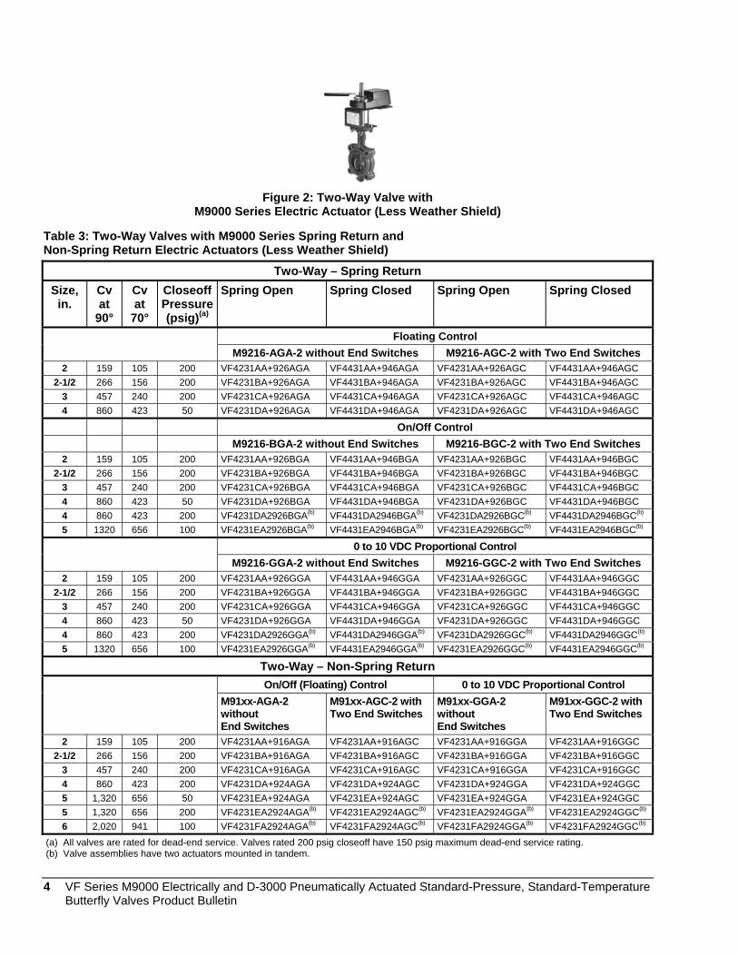
Figure 2: Two-Way Valve with
M9000 Series Electric Actuator (Less Weather Shield)
Table 3: Two-Way Valves with M9000 Series Spring Return and Non-Spring Return Electric Actuators (Less Weather Shield)
Two-Way – Spring Return Size,
in. Cv at
90°
Cv at
70°
Closeoff Pressure (psig)(a)
Spring Open Spring Closed Spring Open Spring Closed
Floating Control M9216-AGA-2 without End Switches M9216-AGC-2 with Two End Switches
2 159 105 200 VF4231AA+926AGA VF4431AA+946AGA VF4231AA+926AGC VF4431AA+946AGC 2-1/2 266 156 200 VF4231BA+926AGA VF4431BA+946AGA VF4231BA+926AGC VF4431BA+946AGC
3 457 240 200 VF4231CA+926AGA VF4431CA+946AGA VF4231CA+926AGC VF4431CA+946AGC 4 860 423 50 VF4231DA+926AGA VF4431DA+946AGA VF4231DA+926AGC VF4431DA+946AGC
On/Off Control M9216-BGA-2 without End Switches M9216-BGC-2 with Two End Switches
2 159 105 200 VF4231AA+926BGA VF4431AA+946BGA VF4231AA+926BGC VF4431AA+946BGC 2-1/2 266 156 200 VF4231BA+926BGA VF4431BA+946BGA VF4231BA+926BGC VF4431BA+946BGC
3 457 240 200 VF4231CA+926BGA VF4431CA+946BGA VF4231CA+926BGC VF4431CA+946BGC 4 860 423 50 VF4231DA+926BGA VF4431DA+946BGA VF4231DA+926BGC VF4431DA+946BGC 4 860 423 200 VF4231DA2926BGA(b) VF4431DA2946BGA(b) VF4231DA2926BGC(b) VF4431DA2946BGC(b)
5 1320 656 100 VF4231EA2926BGA(b) VF4431EA2946BGA(b) VF4231EA2926BGC(b) VF4431EA2946BGC(b)
0 to 10 VDC Proportional Control M9216-GGA-2 without End Switches M9216-GGC-2 with Two End Switches
2 159 105 200 VF4231AA+926GGA VF4431AA+946GGA VF4231AA+926GGC VF4431AA+946GGC 2-1/2 266 156 200 VF4231BA+926GGA VF4431BA+946GGA VF4231BA+926GGC VF4431BA+946GGC
3 457 240 200 VF4231CA+926GGA VF4431CA+946GGA VF4231CA+926GGC VF4431CA+946GGC 4 860 423 50 VF4231DA+926GGA VF4431DA+946GGA VF4231DA+926GGC VF4431DA+946GGC 4 860 423 200 VF4231DA2926GGA(b) VF4431DA2946GGA(b) VF4231DA2926GGC(b) VF4431DA2946GGC(b)
5 1320 656 100 VF4231EA2926GGA(b) VF4431EA2946GGA(b) VF4231EA2926GGC(b) VF4431EA2946GGC(b)
Two-Way – Non-Spring Return On/Off (Floating) Control 0 to 10 VDC Proportional Control
M91xx-AGA-2 without End Switches
M91xx-AGC-2 with Two End Switches
M91xx-GGA-2 without End Switches
M91xx-GGC-2 with Two End Switches
2 159 105 200 VF4231AA+916AGA VF4231AA+916AGC VF4231AA+916GGA VF4231AA+916GGC 2-1/2 266 156 200 VF4231BA+916AGA VF4231BA+916AGC VF4231BA+916GGA VF4231BA+916GGC
3 457 240 200 VF4231CA+916AGA VF4231CA+916AGC VF4231CA+916GGA VF4231CA+916GGC 4 860 423 200 VF4231DA+924AGA VF4231DA+924AGC VF4231DA+924GGA VF4231DA+924GGC 5 1,320 656 50 VF4231EA+924AGA VF4231EA+924AGC VF4231EA+924GGA VF4231EA+924GGC 5 1,320 656 200 VF4231EA2924AGA(b) VF4231EA2924AGC(b) VF4231EA2924GGA(b) VF4231EA2924GGC(b)
6 2,020 941 100 VF4231FA2924AGA(b) VF4231FA2924AGC(b) VF4231FA2924GGA(b) VF4231FA2924GGC(b)
(a) All valves are rated for dead-end service. Valves rated 200 psig closeoff have 150 psig maximum dead-end service rating. (b) Valve assemblies have two actuators mounted in tandem. 4 VF Series M9000 Electrically and D-3000 Pneumatically Actuated Standard-Pressure, Standard-Temperature
Butterfly Valves Product Bulletin

Figure 3: Three-Way Valve with
M9000 Series Electric Actuator (Less Weather Shield)
Table 4: Three-Way Valves with M9000 Series Spring Return and Non-Spring Return Electric Actuators (Less Weather Shield)
Three-Way – Spring Return(a)
On/Off Control Proportional Control Size, in.
Cv at
90°
Cv at
70°
Closeoff Pressure (psig)(b) M9216-BGA-2
without End Switches
M9216-BGC-2 with Two End Switches
M9216-GGA-2 without End Switches
M9216-GGC-2 with Two End Switches
2 159 105 200 VF4831AD+926BGA VF4831AD+926BGC VF4831AD+926GGA VF4831AD+926GGC 2-1/2 266 156 200 VF4831BD+926BGA VF4831BD+926BGC VF4831BD+926GGA VF4831BD+926GGC
3 457 240 150 VF4831CD+926BGA VF4831CD+926BGC VF4831CD+926GGA VF4831CD+926GGC 4 860 423 175 VF4831DD2926BGA(c) VF4831DD2926BGC(c) VF4831DD2926GGA(c) VF4831DD2926GGC(c)
Floating Control M9216-AGA-2 without End Switches
M9216-AGC-2 with Two End Switches
2 159 105 200 VF4831AD+926AGA VF4831AD+926AGC 2-1/2 266 156 200 VF4831BD+926AGA VF4831BD+926AGC
3 457 240 150 VF4831CD+926AGA VF4831CD+926AGC
Three-Way – Non-Spring Return On/Off (Floating) Control 0 to 10 VDC Proportional Control M91xx-AGA-2
without End Switches M91xx-AGC-2 with Two End Switches
M91xx-GGA-2 without End Switches
M91xx-GGC-2 with Two End Switches
2 159 105 200 VF4831AD+916AGA VF4831AD+916AGC VF4831AD+916GGA VF4831AD+916GGC 2-1/2 266 156 200 VF4831BD+916AGA VF4831BD+916AGC VF4831BD+916GGA VF4831BD+916GGC
3 457 240 150 VF4831CD+916AGA VF4831CD+916AGC VF4831CD+916GGA VF4831CD+916GGC 4 860 423 100 VF4831DD+924AGA VF4831DD+924AGC VF4831DD+924GGA VF4831DD+924GGC 5 1320 656 150 VF4831ED2924AGA(c) VF4831ED2924AGC(c) VF4831ED2924GGA(c) VF4831ED2924GGC(c) 6 2,020 941 100 VF4831FD2924AGA(c) VF4831FD2924AGC(c) VF4831FD2924GGA(c) VF4831FD2924GGC(c)
(a) Code numbers listed above are three-way valves, Style D. For Styles E, F, or G change the D in the eighth digit of the code number to the desired style. Example: VFxxxxxE+xxxxxx, VFxxxxxF+xxxxxx, VFxxxxxG+xxxxxx.
(b) All valves are rated for dead-end service. Valves rated for 150 to 200 psig closeoff have 150 psig maximum dead-end service rating. (c) Valve assemblies have two actuators mounted in tandem.
N.C.
Style D
N.O.
N.O.
Style E
N.C.
Style F
N.O.
N.C.
Style G
N.C. fig4
N.O.
Figure 4: Three-Way Valve Body Styles
VF Series M9000 Electrically and D-3000 Pneumatically Actuated Standard-Pressure, Standard-Temperature 5 Butterfly Valves Product Bulletin

Figure 5: Two-Way Valve with
M9000 Series Electric Actuator (With Weather Shield)
Table 5: Two-Way Valves with M9000 Series Spring Return and Non-Spring Return Electric Actuators (With Weather Shield)
Two-Way – Spring Return Size,
in. Cv at
90°
Cv at
70°
Closeoff Pressure (psig)(a)
Spring Open Spring Closed Spring Open Spring Closed
Floating Control M9216-AGA-2 without End Switches M9216-AGC-2 with Two End Switches
2 159 105 200 VF5231AA+926AGA VF5431AA+946AGA VF5231AA+926AGC VF5431AA+946AGC 2-1/2 266 156 200 VF5231BA+926AGA VF5431BA+946AGA VF5231BA+926AGC VF5431BA+946AGC
3 457 240 200 VF5231CA+926AGA VF5431CA+946AGA VF5231CA+926AGC VF5431CA+946AGC 4 860 423 50 VF5231DA+926AGA VF5431DA+946AGA VF5231DA+926AGC VF5431DA+946AGC
On/Off Control M9216-BGA-2 without End Switches M9216-BGC-2 with Two End Switches
2 159 105 200 VF5231AA+926BGA VF5431AA+946BGA VF5231AA+926BGC VF5431AA+946BGC 2-1/2 266 156 200 VF5231BA+926BGA VF5431BA+946BGA VF5231BA+926BGC VF5431BA+946BGC
3 457 240 200 VF5231CA+926BGA VF5431CA+946BGA VF5231CA+926BGC VF5431CA+946BGC 4 860 423 50 VF5231DA+926BGA VF5431DA+946BGA VF5231DA+926BGC VF5431DA+946BGC 4 860 423 200 VF5231DA2926BGA(b) VF5431DA2946BGA(b) VF5231DA2926BGC(b) VF5431DA2946BGC(b)
5 1320 656 100 VF5231EA2926BGA(b) VF5431EA2946BGA(b) VF5231EA2926BGC(b) VF5431EA2946BGC(b)
0 to 10 VDC Proportional Control M9216-GGA-2 without End Switches M9216-GGC-2 with Two End Switches
2 159 105 200 VF5231AA+926GGA VF5431AA+946GGA VF5231AA+926GGC VF5431AA+946GGC 2-1/2 266 156 200 VF5231BA+926GGA VF5431BA+946GGA VF5231BA+926GGC VF5431BA+946GGC
3 457 240 200 VF5231CA+926GGA VF5431CA+946GGA VF5231CA+926GGC VF5431CA+946GGC 4 860 423 50 VF5231DA+926GGA VF5431DA+946GGA VF5231DA+926GGC VF5431DA+946GGC 4 860 423 200 VF5231DA2926GGA(b) VF5431DA2946GGA(b) VF5231DA2926GGC(b) VF5431DA2946GGC(b)
5 1320 656 100 VF5231EA2926GGA(b) VF5431EA2946GGA(b) VF5231EA2926GGC(b) VF5431EA2946GGC(b)
Two-Way – Non-Spring Return On/Off (Floating) Control 0 to 10 VDC Proportional Control M91xx-AGA-2
without End Switches
M91xx-AGC-2 with Two End Switches
M91xx-GGA-2 without End Switches
M91xx-GGC-2 with Two End Switches
2 159 105 200 VF5231AA+916AGA VF5231AA+916AGC VF5231AA+916GGA VF5231AA+916GGC 2-1/2 266 156 200 VF5231BA+916AGA VF5231BA+916AGC VF5231BA+916GGA VF5231BA+916GGC
3 457 240 200 VF5231CA+916AGA VF5231CA+916AGC VF5231CA+916GGA VF5231CA+916GGC 4 860 423 200 VF5231DA+924AGA VF5231DA+924AGC VF5231DA+924GGA VF5231DA+924GGC 5 1,320 656 50 VF5231EA+924AGA VF5231EA+924AGC VF5231EA+924GGA VF5231EA+924GGC 5 1,320 656 200 VF5231EA2924AGA(b) VF5231EA2924AGC(b) VF5231EA2924GGA(b) VF5231EA2924GGC(b)
6 2,020 941 100 VF5231FA2924AGA(b) VF5231FA2924AGC(b) VF5231FA2924GGA(b) VF5231FA2924GGC(b)
(a) All valves are rated for dead-end service. Valves rated 200 psig closeoff have 150 psig maximum dead-end service rating. (b) Valve assemblies have two actuators mounted in tandem.
6 VF Series M9000 Electrically and D-3000 Pneumatically Actuated Standard-Pressure, Standard-Temperature Butterfly Valves Product Bulletin

Figure 6: Three-Way Valve with
M9000 Series Electric Actuator (With Weather Shield)
Table 6: Three-Way Valves with M9000 Series Spring Return and Non-Spring Return Electric Actuators (With Weather Shield)
Three-Way – Spring Return(a)
On/Off Control Proportional Control Size, in.
Cv at
90°
Cv at
70°
Closeoff Pressure (psig)(b) M9216-BGA-2
without End Switches
M9216-BGC-2 with Two End Switches
M9216-GGA-2 without End Switches
M9216-GGC-2 with Two End Switches
2 159 105 200 VF5831AD+926BGA VF5831AD+926BGC VF5831AD+926GGA VF5831AD+926GGC 2-1/2 266 156 200 VF5831BD+926BGA VF5831BD+926BGC VF5831BD+926GGA VF5831BD+926GGC
3 457 240 150 VF5831CD+926BGA VF5831CD+926BGC VF5831CD+926GGA VF5831CD+926GGC 4 860 423 175 VF5831DD2926BGA(c) VF5831DD2926BGC(c) VF5831DD2926GGA(c) VF5831DD2926GGC(c)
Floating Control M9216-AGA-2 without End Switches
M9216-AGC-2 with Two End Switches
2 159 105 200 VF5831AD+926AGA VF5831AD+926AGC 2-1/2 266 156 200 VF5831BD+926AGA VF5831BD+926AGC
3 457 240 150 VF5831CD+926AGA VF5831CD+926AGC
Three-Way – Non-Spring Return On/Off (Floating) Control 0 to 10 VDC Proportional Control
M91xx-AGA-2 without End Switches
M91xx-AGC-2 with Two End Switches
M91xx-GGA-2 without End Switches
M91xx-GGC-2 with Two End Switches
2 159 105 200 VF5831AD+916AGA VF5831AD+916AGC VF5831AD+916GGA VF5831AD+916GGC 2-1/2 266 156 200 VF5831BD+916AGA VF5831BD+916AGC VF5831BD+916GGA VF5831BD+916GGC
3 457 240 150 VF5831CD+916AGA VF5831CD+916AGC VF5831CD+916GGA VF5831CD+916GGC 4 860 423 100 VF5831DD+924AGA VF5831DD+924AGC VF5831DD+924GGA VF5831DD+924GGC 5 1320 656 150 VF5831ED2924AGA(c) VF5831ED2924AGC(c) VF5831ED2924GGA(c) VF5831ED2924GGC(c)
6 2,020 941 100 VF5831FD2924AGA(c) VF5831FD2924AGC(c) VF5831FD2924GGA(c) VF5831FD2924GGC(c)
(a) Code numbers listed above are three-way valves, Style D. For Styles E, F, or G change the D in the eighth digit of the code number to the desired style. Example: VFxxxxxE+xxxxxx, VFxxxxxF+xxxxxx, VFxxxxxG+xxxxxx.
(b) All valves are rated for dead-end service. Valves rated for 150 to 200 psig closeoff have 150 psig maximum dead-end service rating. (c) Valve assemblies have two actuators mounted in tandem.
N.C.
Style D
N.O.
N.O.
Style E
N.C.
Style F
N.O.
N.C.
Style G
N.C. fig7
N.O.
Figure 7: Three-Way Valve Body Styles
VF Series M9000 Electrically and D-3000 Pneumatically Actuated Standard-Pressure, Standard-Temperature 7 Butterfly Valves Product Bulletin

Figure 8: Two-Way
D-3000 Series Pneumatic Actuator
Table 7: Two-Way Valves with D-3000 Series Spring Return Pneumatic Actuators On/Off (Proportional) Control Proportional Control
(With Positioner) Size,
in. Cv at 70° Closeoff
Pressure (psig) Spring Closed Spring Open Spring Closed Spring Open
Two-Way Butterfly Valve Assemblies – 175 psig Closeoff Pressure – Rated for 150 psig Dead-End Service
2 105 175 VF4431AA+3153 VF4231AA+3153 VF4431AA+3153P VF4231AA+3153P 2-1/2 156 175 VF4431BA+3153 VF4231BA+3153 VF4431BA+3153P VF4231BA+3153P
3 240 175 VF4431CA+3153 VF4231CA+3153 VF4431CA+3153P VF4231CA+3153P 4 423 175 VF4431DA+3244 VF4231DA+3244 VF4431DA+3244P VF4231DA+3244P 5 656 175 VF4431EA+3246 VF4231EA+3246 VF4431EA+3246P VF4231EA+3246P 6 941 175 VF4431FA+3246 VF4231FA+3246 VF4431FA+3246P VF4231FA+3246P 8 1,660 175 VF4431GA23246* VF4231GA23246* VF4431GA23246P* VF4231GA23246P*
Two-Way Butterfly Valve Assemblies – 50 psig Closeoff Pressure – Rated for 50 psig Dead-End Service4 423 50 VF6431DA+3153 VF6231DA+3153 VF6431DA+3153P VF6231DA+3153P 5 656 50 VF6431EA+3244 VF6231EA+3244 VF6431EA+3244P VF6231EA+3244P 6 941 50 VF6431FA+3246 VF6231FA+3246 VF6431FA+3246P VF6231FA+3246P 8 1,660 50 VF6431GA+3246 VF6231GA+3246 VF6431GA+3246P VF6231GA+3246P 10 2,560 50 VF6431HA23246* VF6231HA23246* VF6431HA23246P* VF6231HA23246P*
* Valve assemblies have two actuators mounted in tandem.
8 VF Series M9000 Electrically and D-3000 Pneumatically Actuated Standard-Pressure, Standard-Temperature Butterfly Valves Product Bulletin

Figure 9: Three-Way
D-3000 Series Pneumatic Actuator
Table 8: Three-Way Valves with D-3000 Series Spring Return Pneumatic Actuators Actuator Size,
in. Cv at 70° Closeoff
Pressure (psig)
On/Off Control* Proportional Control (With Positioner)*
Three-Way Assemblies – 175 psig Closeoff Pressure – 150 psig Dead-End Service 2 105 175 VF4831AD+3153 VF4831AD+3153P
2-1/2 156 175 VF4831BD+3244 VF4831BD+3244P 3 240 175 VF4831CD+3244 VF4831CD+3244P 4 423 175 VF4831DD+3246 VF4831DD+3246P 5 656 175 VF4831ED+3246 VF4831ED+3246P 6 941 175 VF4831FD23246** VF4831FD23246P**
Three-Way Assemblies – 50 psig Closeoff Pressure – 50 psig Dead-End Service 4 423 50 VF6831DD+3244 VF6831DD+3244P 5 656 50 VF6831ED+3246 VF6831ED+3246P 6 941 50 VF6831FD+3246 VF6831FD+3246P 8 1,660 50 VF6831GD23246** VF6831GD23246P**
* Code numbers listed above are three-way valves, Style D. For Styles E, F, or G change the D in the eighth digit of the code number to the desired style. Example: VFxxxxxE+xxxxxx, VFxxxxxF+xxxxxx, VFxxxxxG+xxxxxx.
** Valve assemblies have two actuators mounted in tandem.
N.C.
Style D
N.O.
N.O.
Style E
N.C.
Style F
N.O.
N.C.
Style G
N.C. fig10
N.O.
Figure 10: Three-Way Valve Body Styles
VF Series M9000 Electrically and D-3000 Pneumatically Actuated Standard-Pressure, Standard-Temperature 9 Butterfly Valves Product Bulletin
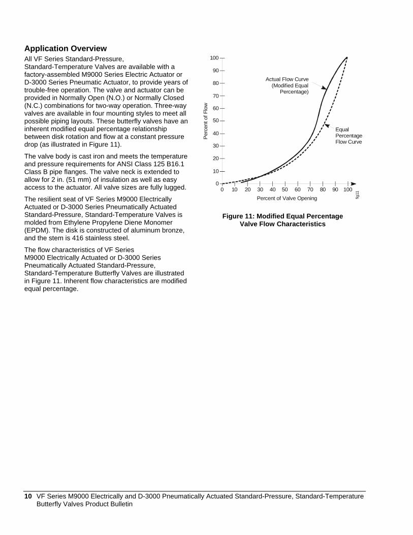
Application Overview All VF Series Standard-Pressure, Standard-Temperature Valves are available with a factory-assembled M9000 Series Electric Actuator or D-3000 Series Pneumatic Actuator, to provide years of trouble-free operation. The valve and actuator can be provided in Normally Open (N.O.) or Normally Closed (N.C.) combinations for two-way operation. Three-way valves are available in four mounting styles to meet all possible piping layouts. These butterfly valves have an inherent modified equal percentage relationship between disk rotation and flow at a constant pressure drop (as illustrated in Figure 11).
The valve body is cast iron and meets the temperature and pressure requirements for ANSI Class 125 B16.1 Class B pipe flanges. The valve neck is extended to allow for 2 in. (51 mm) of insulation as well as easy access to the actuator. All valve sizes are fully lugged.
The resilient seat of VF Series M9000 Electrically Actuated or D-3000 Series Pneumatically Actuated Standard-Pressure, Standard-Temperature Valves is molded from Ethylene Propylene Diene Monomer (EPDM). The disk is constructed of aluminum bronze, and the stem is 416 stainless steel.
The flow characteristics of VF Series M9000 Electrically Actuated or D-3000 Series Pneumatically Actuated Standard-Pressure, Standard-Temperature Butterfly Valves are illustrated in Figure 11. Inherent flow characteristics are modified equal percentage.
100
90
80
70
60
50
40
30
20
10
00 10 20 30 40 50 60 70 80 90 100
Percent of Valve OpeningPe
rcen
t of F
low
Actual Flow Curve(Modified Equal
Percentage)
EqualPercentageFlow Curve
fig11
Figure 11: Modified Equal Percentage Valve Flow Characteristics
10 VF Series M9000 Electrically and D-3000 Pneumatically Actuated Standard-Pressure, Standard-Temperature Butterfly Valves Product Bulletin
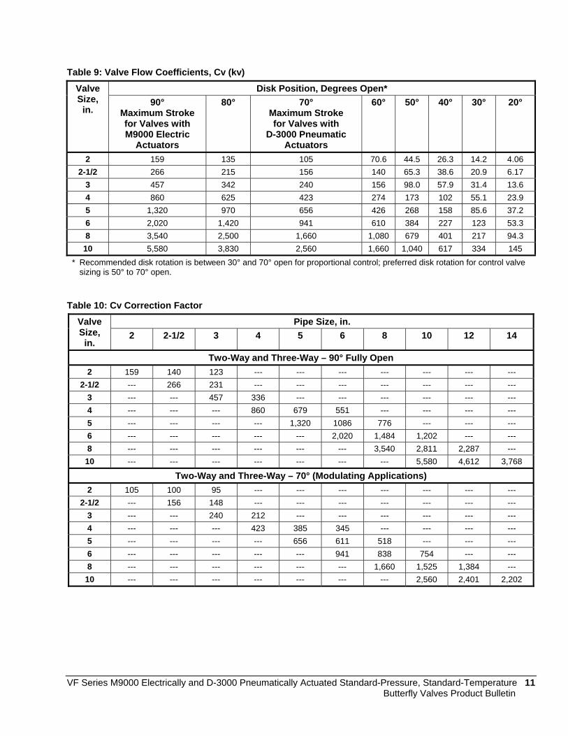
Table 9: Valve Flow Coefficients, Cv (kv) Disk Position, Degrees Open* Valve
Size, in.
90° Maximum Stroke for Valves with M9000 Electric
Actuators
80° 70° Maximum Stroke for Valves with
D-3000 Pneumatic Actuators
60° 50° 40° 30° 20°
2 159 135 105 70.6 44.5 26.3 14.2 4.06 2-1/2 266 215 156 140 65.3 38.6 20.9 6.17
3 457 342 240 156 98.0 57.9 31.4 13.6 4 860 625 423 274 173 102 55.1 23.9 5 1,320 970 656 426 268 158 85.6 37.2 6 2,020 1,420 941 610 384 227 123 53.3 8 3,540 2,500 1,660 1,080 679 401 217 94.3 10 5,580 3,830 2,560 1,660 1,040 617 334 145
* Recommended disk rotation is between 30° and 70° open for proportional control; preferred disk rotation for control valve sizing is 50° to 70° open.
Table 10: Cv Correction Factor Pipe Size, in. Valve
Size, in.
2 2-1/2 3 4 5 6 8 10 12 14
Two-Way and Three-Way – 90° Fully Open 2 159 140 123 --- --- --- --- --- --- ---
2-1/2 --- 266 231 --- --- --- --- --- --- --- 3 --- --- 457 336 --- --- --- --- --- --- 4 --- --- --- 860 679 551 --- --- --- --- 5 --- --- --- --- 1,320 1086 776 --- --- --- 6 --- --- --- --- --- 2,020 1,484 1,202 --- --- 8 --- --- --- --- --- --- 3,540 2,811 2,287 --- 10 --- --- --- --- --- --- --- 5,580 4,612 3,768
Two-Way and Three-Way – 70° (Modulating Applications) 2 105 100 95 --- --- --- --- --- --- ---
2-1/2 --- 156 148 --- --- --- --- --- --- --- 3 --- --- 240 212 --- --- --- --- --- --- 4 --- --- --- 423 385 345 --- --- --- --- 5 --- --- --- --- 656 611 518 --- --- --- 6 --- --- --- --- --- 941 838 754 --- --- 8 --- --- --- --- --- --- 1,660 1,525 1,384 --- 10 --- --- --- --- --- --- --- 2,560 2,401 2,202
VF Series M9000 Electrically and D-3000 Pneumatically Actuated Standard-Pressure, Standard-Temperature 11 Butterfly Valves Product Bulletin
Product Guidelines Please be sure to read the following information carefully before installing a VF Series M9000 Electrically Actuated or D-3000 Series Pneumatically Actuated Standard-Pressure, Standard-Temperature Butterfly Valve Assembly:
Be sure that the pipeline and flange faces are clean. Pipe scale, metal chips, weld slag, and weld rods can obstruct disk movement and damage the disk and seat.
The resilient seat of the valve is equipped with molded O-rings on the face of the seat; do not use gaskets.
The valves should be handled by the extended valve neck only. Heavier valves may require a nylon sling to be used as a hoist around the valve neck and/or cast-iron tee (on three-way assemblies). Never pick up a valve by the actuator, mounting bracket, or interconnecting linkage.
Most VF Series M9000 Electrically Actuated or D-3000 Series Pneumatically Actuated Standard-Pressure, Standard-Temperature Butterfly Valve Assemblies are shipped with the disk in the near-closed position (approximately 10° open).
Refer to the M9108, M9116, M9124, and M9132 Series Electric Non-Spring Return Actuators Installation Instructions (Part No. 34-636-399) for proper actuator wiring and commissioning.
Refer to the M9216 Series Electric Spring Return Actuators Installation Bulletin (Part No. 34-636-461) for proper actuator wiring and commissioning.
Refer to the D-3153 Pneumatic Actuator Product Bulletin (LIT-2681054P) for proper installation and commissioning.
Refer to the D-3240 Series Pneumatic Piston Actuators Product Bulletin (LIT-2681055P) for proper installation and commissioning.
12 VF Series M9000 Electrically and D-3000 Pneumatically Actuated Standard-Pressure, Standard-Temperature Butterfly Valves Product Bulletin

Table 11: Representative Maximum Shipping Weights for VF4000, VF5000, and VF6000 Series Butterfly Valve and Actuator Assemblies*
Shipping Weight, lb (kg)
Valve Size,
in.
M9000 Electrically Actuated Without
Weather Shield With
Weather Shield
D-3000 Pneumatically Actuated
Shipping Weight, lb (kg)
Two-Way Valve Assemblies M9116-GGx-2 (+916GGx) 22 (10) 26 (11.8) 2 M9216-GGx-2 (+926GGx) 24 (10.9) 31 (14.1)
One D-3153 (+3153) 26 (11.8)
M9116-GGx-2 (+916GGx) 23.5 (10.7) 27.5 (12.5) 2-1/2 M9216-GGx-2 (+926GGx) 25.5 (9.1) 32.5 (14.7)
One D-3153 (+3153) 27 (12.2)
M9116-GGx-2 (+916GGx) 24.5 (11.1) 28.5 (12.9) 3 M9216-GGA-2 (+926GGA) 26.5 (12) 33.5 (15.2)
One D-3153 (+3153) 30 (13.6)
M9124-GGA-2 (+924GGA) 30 (13.6) 35 (15.9) One D-3244 (+3244) 54 (24.5) M9216-GGx-2 (+926GGx) 35 (15.9) 39 (17.7) One D-3153 (+3153) 44 (20)
4
Two M9216-GGA-2 (2926GGA)
44 (20) 48 (21.8) --- ---
M9124-GGA-2 (+924GGA) 34 (15.4) 56 (25.4) One D-3246 (+3246) 89 (40.4) Two M9124-GGA-2 (2924GGA)
40 (18.1) 60 (27.2) One D-3244 (+3244) 77 (34.9) 5
Two M9216-GGA-2 (2926GGA)
48 (21.8) 66 (29.9) --- ---
6 Two M9124-GGA-2 (2924GGA)
46 (20.9) 62 (28.1) One D-3246 (+3246) 129 (58.5)
Two D-3246s (23246) 206 (93.4) 8 --- --- --- One D-3246 (+3246) 138 (62.6)
10 --- --- --- Two D-3246s (23246) 227 (103)
Three-Way Valve Assemblies M9116-GGA-2 (+916GGA) 60 (27.2) 63 (28.6) 2 M9216-GGA-2 (+926GGA) 63 (28.6) 70 (31.8)
One D-3153 (+3153) 62 (28.1)
M9116-GGA-2 (+916GGA) 69 (31.3) 73 (33.1) 2-1/2
M9216-GGA-2 (+926GGA) 73 (33.1) 80 (36.3) One D-3244 (+3244) 82 (37.2)
M9116-GGA-2 (+916GGA) 80 (36.3) 84 (38.1) 3
M9216-GGA-2 (+926GGA) 84 (38.1) 91 (41.3) One D-3244 (+3244) 92 (41.7)
M9124-GGA-2 (+924GGA) 120 (54.4) 124 (56.2) One D-3246 (+3246) 151 (68.5) 4 Two M9216-GGA-2
(2926GGA) 132 (59.9) 136 (61.7) One D-3244 (+3244) 142 (64.4)
5 Two M9124-GGA-2 (2924GGA)
148 (67.1) 151 (68.5) One D-3246 (+3246) 186 (84.3)
Two D-3246s (23246) 370 (168) 6
Two M9124-GGA-2 (2924GGA)
183 (83) 186 (84.4) One D-3246 (+3246) 311 (141)
8 --- --- --- Two D-3246s (23246) 397 (180) * The above shipping weights are only approximate, and are based on the heaviest valve, actuator, and accessory combination available
for each size.
VF Series M9000 Electrically and D-3000 Pneumatically Actuated Standard-Pressure, Standard-Temperature 13 Butterfly Valves Product Bulletin
F
EH
F
C D
A Sleeve
SingleDesign
G
EH
C D
G
EH
CD
G
B Chord
Two-Way Assemblies: M9116, M9124 Non-Spring Return andM9216 Spring Return Electric Actuators
(With Weather Shield)
TandemDesign
Two-Way Assemblies: M9116, M9124 Non-Spring Return andM9216 Spring Return Electric Actuators
(Less Weather Shield)
fig12
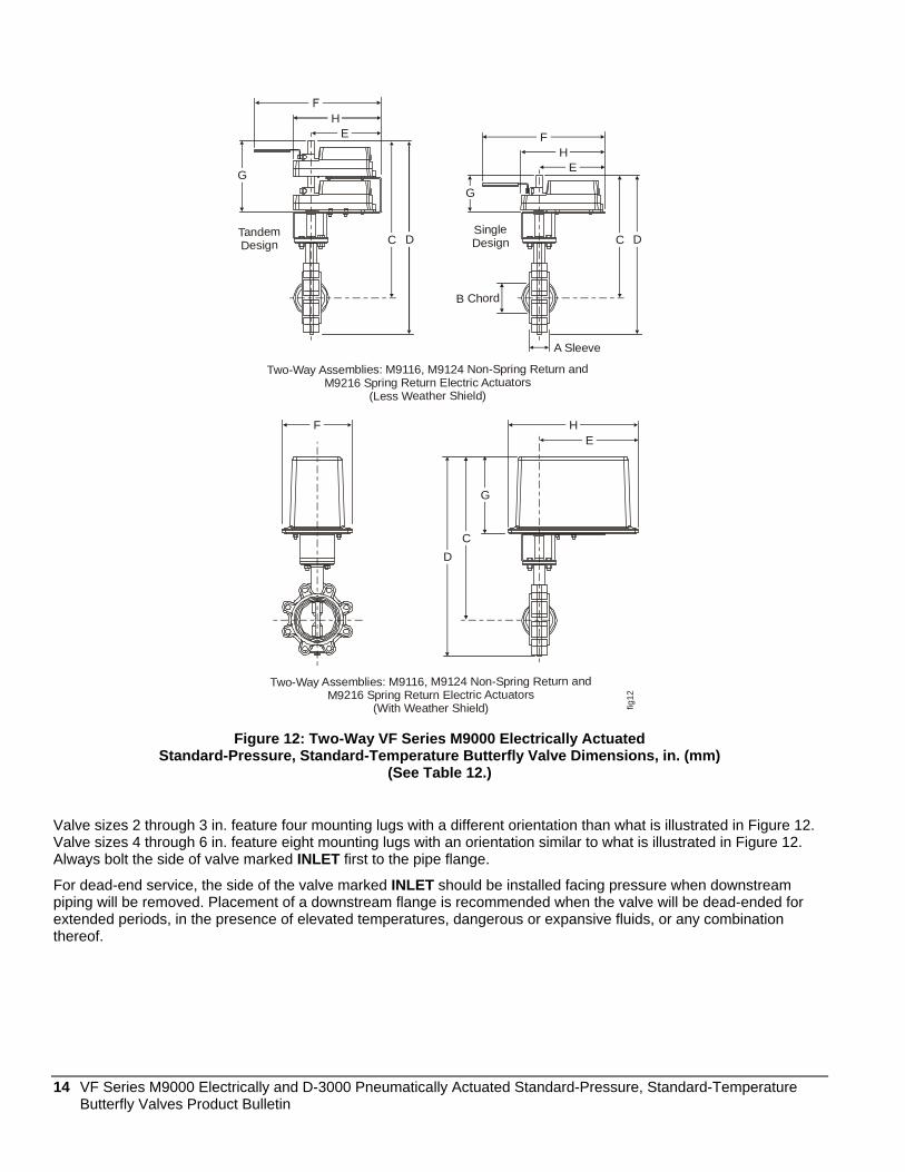
Figure 12: Two-Way VF Series M9000 Electrically Actuated Standard-Pressure, Standard-Temperature Butterfly Valve Dimensions, in. (mm)
(See Table 12.)
Valve sizes 2 through 3 in. feature four mounting lugs with a different orientation than what is illustrated in Figure 12. Valve sizes 4 through 6 in. feature eight mounting lugs with an orientation similar to what is illustrated in Figure 12. Always bolt the side of valve marked INLET first to the pipe flange.
For dead-end service, the side of the valve marked INLET should be installed facing pressure when downstream piping will be removed. Placement of a downstream flange is recommended when the valve will be dead-ended for extended periods, in the presence of elevated temperatures, dangerous or expansive fluids, or any combination thereof.
14 VF Series M9000 Electrically and D-3000 Pneumatically Actuated Standard-Pressure, Standard-Temperature Butterfly Valves Product Bulletin

Table 12: Two-Way VF Series M9000 Electrically Actuated Standard-Pressure, Standard-Temperature Butterfly Valve Dimensions, in. (mm)
Lug Data Valve Size,
in.
A B C D E F G H J
Bolt Circle,
in. (mm)
No. of Holes
Threads UNC-2B
Clearance Required
for Actuator Removal
Two-Way Assemblies with M9116 and M9124 Series Non-Spring Return Electric Actuators (Less Weather Shield) 2 1.81
(46) 1.49 (38)
13.1 (333)
16.2 (411)
5.75 (146)
12-1/2 (318)
4.5 (114)
7.14 (181)
4 (102)
4.75 (121)
4 5/8–11 5 (127)
2-1/2 1.94 (49)
2.01 (51)
13.6 (345)
17 (432)
5.75 (146)
12-1/2 (318)
4.5 (114)
7.14 (181)
4 (102)
5.5 (140)
4 5/8–11 5 (127)
3 2.19 (56)
2.64 (67)
13.8 (351)
17.6 (447)
5.75 (146)
12-1/2 (318)
4.5 (114)
7.14 (181)
4 (102)
6 (152)
4 5/8–11 5 (127)
4 2.19 (56)
3.67 (93)
14.6 (371)
18.9 (480)
5.75 (146)
12-1/2 (318)
4.5 (114)
7.14 (181)
4 (102)
7.5 (191)
8 5/8–11 5 (127)
5 2.31 (59)
4.71 (120)
15.1 (384)
20.0 (508)
5.75 (146)
12-1/2 (318)
4.5 (114)
7.14 (181)
4 (102)
8.5 (216)
8 3/4–10 5 (127)
6* 2.31 (59)
5.66 (144)
18.9 (480)
24.3 (617)
8.31 (211)
15 (381)
8.75 (222)
9.7 (246)
4 (102)
9.5 (241)
8 3/4–10 5 (127)
Two-Way Assemblies with M9216 Series Spring Return Electric Actuators (Less Weather Shield) 2 1.81
(46) 1.49 (38)
13.1 (333)
16.2 (411)
7.81 (198)
--- 4.5 (114)
10 (254)
4.91 (125)
4.75 (121)
4 5/8–11 6 (152)
2-1/2 1.94 (49)
2.01 (51)
13.6 (345)
17.0 (432)
7.81 (198)
--- 4.5 (114)
10 (254)
4.91 (125)
5.5 (140)
4 5/8–11 6 (152)
3 2.19 (56)
2.64 (67)
13.8 (351)
17.6 (447)
7.81 (198)
--- 4.5 (114)
10 (254)
4.91 (125)
6 (152)
4 5/8–11 6 (152)
4 2.19 (56)
3.67 (93)
14.6 (371)
18.9 (480)
7.81 (198)
--- 4.5 (114)
10 (254)
4.91 (125)
7.5 (191)
8 5/8–11 6 (152)
5* 2.31 (59)
4.71 (120)
19.2 (488)
24.1 (612)
8.31 (211)
--- 8.75 (222)
10.44 (265)
4.91 (125)
8.5 (216)
8 3/4–10 6 (152)
Two-Way Assemblies with M9116 and M9124 Series Non-Spring Return, and M9216 Series Spring Return Electric Actuators with Weather Shield
2 1.81 (46)
1.49 (38)
17.8 (452)
20.9 (531)
11.9 (302)
--- 9 (229)
15.5 (394)
8.25 (210)
4.75 (121)
4 5/8–11 6 (152)
2-1/2 1.94 (49)
2.01 (51)
18.3 (465)
21.5 (546)
11.9 (302)
--- 9 (229)
15.5 (394)
8.25 (210)
5.5 (140)
4 5/8–11 6 (152)
3 1.94 (49)
2.64 (67)
18.5 (470)
22.3 (566)
11.9 (302)
--- 9 (229)
15.5 (394)
8.25 (210)
6 (152)
4 5/8–11 6 (152)
4 2.19 (56)
3.67 (93)
19.3 (490)
23.5 (597)
11.9 (302)
--- 9 (229)
15.5 (394)
8.25 (210)
7.5 (191)
8 5/8–11 6 (152)
5 2.31 (59)
4.71 (120)
19.8 (503)
24.5 (622)
11.9 (302)
--- 9 (229)
15.5 (394)
8.25 (210)
8.5 (216)
8 3/4–10 6 (152)
6* 2.31 (59)
5.66 (144)
20.3 (516)
25.5 (648)
11.9 (302)
--- 9 (229)
15.5 (394)
8.25 (210)
9.5 (241)
8 3/4–10 6 (152)
* Valve assemblies have two actuators mounted in tandem.
VF Series M9000 Electrically and D-3000 Pneumatically Actuated Standard-Pressure, Standard-Temperature 15 Butterfly Valves Product Bulletin

JK
L
EH
C DG E
HF
C D
A
G
BChord
EH
CD
G
SingleDesign
Three-Way Assemblies: M9116, M9124 Non-Spring Return andM9216 Spring Return Electric Actuators
(With Weather Shield)
TandemDesign
Three-Way Assemblies: M9116, M9124 Non-Spring Return andM9216 Spring Return Electric Actuators
(Less Weather Shield)
fig13
Figure 13: Three-Way VF Series M9000 Electrically Actuated
Standard-Pressure, Standard-Temperature Butterfly Valve Dimensions, in. (mm) (See Table 13.)
Valve sizes 2 through 3 in. feature four mounting lugs with a different orientation than what is illustrated in Figure 13. Valve sizes 4 through 6 in. feature eight mounting lugs with an orientation similar to what is illustrated in Figure 13.
Three-way valve assemblies are supplied with the INLET side of the valves bolted to the pipe tee. If it is necessary to make changes, always bolt the side of valve marked INLET first to the pipe flange.
For dead-end service, the side of the valve marked INLET should be installed facing pressure when downstream piping will be removed. Placement of a downstream flange is recommended when the valve will be dead-ended for extended periods, in the presence of elevated temperatures, dangerous or expansive fluids, or any combination thereof.
16 VF Series M9000 Electrically and D-3000 Pneumatically Actuated Standard-Pressure, Standard-Temperature Butterfly Valves Product Bulletin

Table 13: Three-Way VF Series M9000 Electrically Actuated Standard-Pressure, Standard-Temperature Butterfly Valve Dimensions, in. (mm)
Lug Data Valve Size,
in.
A B C D E F G H J K L Bolt
Circle, in.
(mm)
No. of Holes
Threads UNC-2B
Three-Way Assemblies with M9116 and M9124 Series Non-Spring Return Electric Actuators (Less Weather Shield) 2 1.75
(44.5) 1.5 (38)
13.1 (333)
16.2 (411)
5.75 (146)
12.5 (318)
4.5 (114)
7.14 (181)
4.5 (114)
6.25 (159)
--- 4.75 (121)
4 5/8–11
2-1/2 1.88 (47.8)
2.01 (51)
13.6 (345)
17.3 (439)
5.75 (146)
12.5 (318)
4.5 (114)
7.14 (181)
5 (127)
6.88 (175)
--- 5.5 (140)
4 5/8–11
3 1.88 (47.8)
2.64 (67)
13.8 (351)
17.6 (447)
5.75 (146)
12.5 (318)
4.5 (114)
7.14 (181)
5.5 (140)
7.39 (188)
--- 6 (152)
4 5/8–11
4 2.13 (54.0)
3.67 (93)
14.6 (371)
19.2 (488)
5.75 (146)
12.5 (318)
4.5 (114)
7.14 (181)
6.5 (165)
8.63 (219)
--- 7.5 (191)
8 5/8–11
5 2.25 (57.2)
4.71 (120)
15.1 (383)
20.3 (516)
5.75 (146)
12.5 (318)
4.5 (114)
7.14 (181)
7.5 (191)
9.75 (248)
--- 8.5 (216)
8 3/4-10
6 2.25 (57.2)
5.66 (144)
18.9 (480)
24.6 (625)
8.31 (211)
--- 8.75 (222)
9.7 (246)
8 (203)
10.25 (260)
--- 9.5 (241)
8 3/4-10
Three-Way Assemblies with M9216 Series Spring Return Electric Actuators (Less Weather Shield) 2 1.75
(44.5) 1.5 (38)
13.1 (333)
16.2 (411)
7.81 (198)
--- 4.5 (114)
10 (254)
4.5 (114)
6.25 (159)
--- 4.75 (121)
4 5/8–11
2-1/2 1.88 (47.8)
2.01 (51)
13.6 (345)
17.3 (439)
7.81 (198)
--- 4.5 (114)
10 (254)
5 (127)
6.88 (175)
--- 5.5 (140)
4 5/8–11
3 1.88 (47.8)
2.64 (67)
13.8 (351)
17.6 (447)
7.81 (198)
--- 4.5 (114)
10 (254)
5.5 (140)
7.39 (188)
--- 6 (152)
4 5/8–11
4 2.13 (54.0)
3.67 (93)
14.6 (371)
19.2 (488)
7.81 (198)
--- 4.5 (114)
10 (254)
6.5 (165)
8.63 (219)
--- 7.5 (191)
8 5/8–11
5 2.25 (57.2)
4.71 (120)
15.1 (383)
24.3 (617)
8.31 (211)
--- 8.75 (222)
10.44 (265)
7.5 (191)
9.75 (248)
--- 8.5 (216)
8 3/4-10
Three-Way Assemblies with M9116 and M9124 Series Non-Spring Return, and M9216 Series Spring Return Electric Actuators with Weather Shield
2 1.75 (44.5)
1.5 (38)
17.8 (452)
20.9 (531)
11.9 (302)
--- 9 (229)
15.5 (394)
--- 6.25 (159)
8.25 (210)
4.75 (121)
4 5/8–11
2-1/2 1.88 (47.8)
2.01 (51)
18.3 (465)
21.8 (554)
11.9 (302)
--- 9 (229)
15.5 (394)
--- 6.88 (175)
8.25 (210)
5.5 (140)
4 5/8–11
3 1.88 (47.8)
2.64 (67)
18.5 (470)
22.3 (566)
11.9 (302)
--- 9 (229)
15.5 (394)
--- 7.39 (188)
8.25 (210)
6 (152)
4 5/8–11
4 2.13 (54.0)
3.67 (93)
19.3 (490)
23.8 (605)
11.9 (302)
--- 9 (229)
15.5 (394)
--- 8.63 (219)
8.25 (210)
7.5 (191)
8 5/8–11
5 2.25 (57.2)
4.71 (120)
19.8 (503)
24.8 (630)
11.9 (302)
--- 9 (229)
15.5 (394)
--- 9.75 (248)
8.25 (210)
8.5 (216)
8 3/4-10
6 2.25 (57.2)
5.66 (144)
20.3 (516)
25.8 (655)
11.9 (302)
--- 9 (229)
15.5 (394)
--- 10.25 (260)
8.25 (210)
9.5 (241)
8 3/4-10
The clearance required for actuator removal on three-way assemblies is the same clearance required for actuator removal on two-way assemblies; see Table 12 for more details.
VF Series M9000 Electrically and D-3000 Pneumatically Actuated Standard-Pressure, Standard-Temperature 17 Butterfly Valves Product Bulletin

C
Dfig
14ASleeve
F
H G
BChord
A
Sleeve fig15
D
C
F Typical
H
G Typical
BChord
Figure 14: Single Pneumatic Piston Actuator
Assembled on a Two-Way Butterfly Valve (See Table 14.)
Figure 15: Dual Tandem Pneumatic Piston Actuators Assembled on a Two-Way Butterfly Valve
(See Table 14.)
Valve sizes 2 through 3 in. feature four mounting lugs. Valve sizes 4 through 8 in. feature eight mounting lugs. Valves 10 in. in size have 12 mounting lugs. Always bolt the side of valve marked INLET first to the pipe flange.
For dead-end service, the side of the valve marked INLET should be installed facing pressure when downstream piping will be removed. Placement of a downstream flange is recommended when the valve will be dead-ended for extended periods, in the presence of elevated temperatures, dangerous or expansive fluids, or any combination thereof.
18 VF Series M9000 Electrically and D-3000 Pneumatically Actuated Standard-Pressure, Standard-Temperature Butterfly Valves Product Bulletin

Table 14: Overall Dimensions of D-3153, D-3244, and D-3246 Series Pneumatic Piston Actuators Assembled on Two-Way VF4000 and VF6000 Series Butterfly Valves, in. (mm)
Valve Size, in.
Actuator A B C D E F G H
2 1.81 (46)
1.49 (38)
3.14 (79.8)
12.84 (326.0)
10.33 (262.4)
14.06 (357)
5.68 (144)
9.06 (230)
2-1/2 1.94 (49)
2.01 (51)
3.40 (86.4)
13.34 (339)
10.83 (275.0)
14.06 (357)
5.68 (144)
9.06 (230)
3 1.94 (49)
2.64 (67)
3.77 (95.6)
13.59 (345.0)
11.08 (281)
14.06 (357)
5.68 (144)
9.06 (230)
D-3153
2.19 (55.6)
3.67 (93)
4.26 (108.2)
14.37 (364)
11.83 (300)
14.06 (357)
5.68 (144)
9.06 (230)
4
2.19 (55.6)
3.67 (93)
4.26 (108.2)
15.41 (391)
12.88 (327)
17.75 (451)
6.70 (170)
11.20 (285)
D-3244
2.31 (58.6)
4.71 (119.6)
4.89 (124.2)
15.91 (404)
13.38 (340)
17.75 (451)
6.70 (170)
11.20 (285)
5
2.31 (58.6)
4.71 (119.6)
4.89 (124.2)
15.72 (399)
13.56 (344.5)
22.80 (579)
8.22 (209)
13.67 (347)
6 2.31 (58.6)
5.66 (143.7)
5.41 (137.4)
16.22 (410)
14.06 (357)
22.80 (579)
8.22 (209)
13.67 (347)
D-3246
2.53 (64.3)
7.72 (196)
6.54 (166.0)
16.72 (425)
14.56 (370)
22.80 (579)
8.22 (209)
13.67 (347)
8
2.53 (64.3)
7.72 (196)
6.54 (166.0)
17.60 (447)
15.44 (392)
22.80 (579)
8.22 (209)
16.44 (418)
10
Tandem D-3246
2.85 (72.4)
9.70 (246.2)
7.83 (198.9)
18.78 (477)
16.62 (422)
22.80 (579)
8.22 (209)
16.44 (418)
VF Series M9000 Electrically and D-3000 Pneumatically Actuated Standard-Pressure, Standard-Temperature 19 Butterfly Valves Product Bulletin

D
CChord
A
B fig16
J
H
G
fig17
FE
D
A
B
CChord
J
H
G Typical
Figure 16: Single
Pneumatic Piston Actuator Assembled on a Three-Way Butterfly Valve
(See Table 15.)
Figure 17: Dual Tandem Pneumatic Piston Actuators
Assembled on a Three-Way Butterfly Valve (See Table 15.)
Valve sizes 2 through 3 in. feature four mounting lugs. Valve sizes 4 through 8 in. feature eight mounting lugs. Valves 10 in. in size have 12 mounting lugs. Always bolt the side of valve marked INLET first to the pipe flange.
Three-way valve assemblies are supplied with the INLET side of the valves bolted to the pipe tee. If it is necessary to make changes, always bolt the side of valve marked INLET first to the pipe flange.
For dead-end service, the side of the valve marked INLET should be installed facing pressure when downstream piping will be removed. Placement of a downstream flange is recommended when the valve will be dead-ended for extended periods, in the presence of elevated temperatures, dangerous or expansive fluids, or any combination thereof.
20 VF Series M9000 Electrically and D-3000 Pneumatically Actuated Standard-Pressure, Standard-Temperature Butterfly Valves Product Bulletin

Table 15: Overall Dimensions of D-3153, D-3244, and D-3246 Series Pneumatic Piston Actuators Assembled on Three-Way VF4000 and VF6000 Series Butterfly Valves, in. (mm)
Valve Size,
in.
Actuator A B C D E F G H J
2 D-3153 6.25 (159)
10.75 (273)
1.49 (38)
3.00 (76)
12.84 (326)
10.33 (262)
14.06 (357)
5.68 (144)
11.93 (303)
2-1/2 6.88 (175)
11.88 (302)
2.01 (51)
3.50 (89)
14.41 (366)
11.88 (302)
17.75 (451)
6.70 (170)
13.58 (345)
3 7.38 (185)
12.88 (327)
2.64 (67)
3.75 (950
14.66 (372)
12.13 (308)
17.75 (451)
6.70 (170)
14.08 (358)
D-3244
8.36 (219)
15.13 (384)
3.67 (93)
4.50 (114)
15.41 (391)
12.88 (327)
17.75 (451)
6.70 (170)
15.33 (389)
4
8.36 (219)
15.13 (384)
3.67 (93)
4.50 (114)
15.22 (386)
13.06 (332)
22.80 (579)
8.22 (209)
16.58 (421)
5 9.75 (248)
17.25 (438)
4.71 (119.6)
5.00 (127)
15.72 (399)
13.56 (344)
22.80 (579)
8.22 (209)
17.97 (456)
D-3246
10.25 (261)
18.25 (463)
5.66 (143.7)
5.50 (140)
16.22 (410)
14.06 (357)
22.80 (579)
8.22 (209)
18.47 (496)
6
10.25 (261)
18.25 (463)
5.66 (143.7)
5.50 (140)
16.22 (412)
14.06 (357)
22.80 (579)
8.22 (209)
18.47 (469)
8
Tandem D-3246
11.44 (291)
20.44 (519)
7.72 (196.2)
6.75 (171)
17.60 (447)
15.44 (392)
22.80 (579)
8.22 (209)
19.66 (499)
VF Series M9000 Electrically and D-3000 Pneumatically Actuated Standard-Pressure, Standard-Temperature 21 Butterfly Valves Product Bulletin

Table 16: Replacement Actuators Code Number Description
Electric Spring and Non-Spring Return Actuators M9116-AGA-2 Electric Motor Actuator, Non-Spring Return, 140 lb⋅in, Floating Control, 24 VAC/VDC Input, No
End Switches (Cannot be Used in Tandem Configurations) M9116-AGC-2 Electric Motor Actuator, Non-Spring Return, 140 lb⋅in, Floating Control, 24 VAC/VDC Input, Two
End Switches (Cannot be Used in Tandem Configurations) M9116-GGA-2 Electric Motor Actuator, Non-Spring Return, 140 lb⋅in, Proportional Control, 0 (2) to 10 VDC or
0 (4) to 20 mA Input, 0 (2) to 10 VDC Feedback, No End Switches M9116-GGC-2 Electric Motor Actuator, Non-Spring Return, 140 lb⋅in, Proportional Control, 0 (2) to 10 VDC or
0 (4) to 20 mA Input, 0 (2) to 10 VDC Feedback, Two End Switches M9124-AGA-2 Electric Motor Actuator, Non-Spring Return, 210 lb⋅in, Floating Control, 24 VAC/VDC Input, No
End Switches M9124-AGC-2 Electric Motor Actuator, Non-Spring Return, 210 lb⋅in, Floating Control, 24 VAC/VDC Input, Two
End Switches M9124-GGA-2 Electric Motor Actuator, Non-Spring Return, 210 lb⋅in, Proportional Control, 0 (2) to 10 VDC or
0 (4) to 20 mA Input, 0 (2) to 10 VDC Feedback, No End Switches M9124-GGC-2 Electric Motor Actuator, Non-Spring Return, 210 lb⋅in, Proportional Control, 0 (2) to 10 VDC or
0 (4) to 20 mA Input, 0 (2) to 10 VDC Feedback, Two End Switches M9216-AGA-2 Electric Motor Actuator, Spring Return, 140 lb⋅in, Floating Control, 24 VAC/VDC Input, No End
Switches (Cannot be Used in Tandem Configurations) M9216-AGC-2 Electric Motor Actuator, Spring Return, 140 lb⋅in, Floating Control, 24 VAC/VDC Input, Two End
Switches (Cannot be Used in Tandem Configurations) M9216-BGA-2 Electric Motor Actuator, Spring Return, 140 lb⋅in, On/Off Control, 24 VAC/VDC Input, No End
Switches M9216-BGC-2 Electric Motor Actuator, Spring Return, 140 lb⋅in, On/Off Control, 24 VAC/VDC Input, Two End
Switches M9216-GGA-2 Electric Motor Actuator, Spring Return, 140 lb⋅in, Proportional Control, 0 (2) to 10 VDC or 0 (4) to
20 mA Input, 0 (2) to 10 VDC Feedback, No End Switches M9216-GGC-2 Electric Motor Actuator, Spring Return, 140 lb⋅in, Proportional Control, 0 (2) to 10 VDC or 0 (4) to
20 mA Input, 0 (2) to 10 VDC Feedback, Two End Switches
Pneumatic Spring Return Actuators D-3153-5120 Pneumatic Piston Actuator with Positioner, for Use with 2, 2-1/2, or 3 in. 175 or 150 psig Valves
or 4 in. 50 psig Valves D-3153-5130 Pneumatic Piston Actuator without Positioner, for Use with 2, 2-1/2, or 3 in. 175 or 150 psig
Valves or 4 in. 50 psig Valves D-3244-5100 Pneumatic Piston Actuator with Positioner, for Use with 4 in. 175 or 150 psig Valves or 5 in.
50 psig Valves D-3244-5110 Pneumatic Piston Actuator without Positioner, for Use with 4 in. 175 or 150 psig Valves or 5 in.
50 psig Valves D-3246-5100 Pneumatic Piston Actuator with Positioner, for Use with 5 or 6 in. 175 or 150 psig Valves or 6, 8,
or 10 in. 50 psig Valves D-3246-5110 Pneumatic Piston Actuator without Positioner, for Use with 5 or 6 in. 175 or 150 psig Valves or
6, 8, or 10 in. (Requires Two Actuators) 50 psig Valves
22 VF Series M9000 Electrically and D-3000 Pneumatically Actuated Standard-Pressure, Standard-Temperature Butterfly Valves Product Bulletin

Table 17: Mounting Kits for Field Mounting D-3000 Series, Pneumatic Piston Actuators on Two-Way VF4000 and VF6000 Series Butterfly Valves Mounting Kit* Code Number
Description
VF4-D3000-201 D-3153-51x0 Actuator Mounting Kit for 2, 2-1/2, or 3 in. 175 psig Valves VF4-D3000-202 D-3513-51x0 Actuator Mounting Kit for 4 in. 50 psig Valves VF4-D3000-203 D-3244-51x0 Actuator Mounting Kit for 4 in. 175 psig and 5 in. 50 psig Valves VF4-D3000-204 D-3246-51x0 Actuator Mounting Kit for 5 in. for 175 psig Valves VF4-D3000-205 D-3246-51x0 Actuator Mounting Kit for 6 in. 50 or 175 psig Valves VF4-D3000-206 D-3246-51x0 Actuator Mounting Kit for 8 in. 50 psig Valves VF4-D3000-207 D-3246-51x0 Actuator Mounting Kit for 8 in. 175 psig Valves
(Includes Parts for Mounting Two Actuators) VF4-D3000-208 D-3246-51x0 Actuator Mounting Kit for 10 in. 50 psig Valves
(Includes Parts for Mounting Two Actuators) * The mounting kits contain a mounting bracket, crankarm, sleeve adaptor, a clevis kit, and all necessary
hardware for completing actuator field mounting D-3000 Series Actuator to bare stem VF4000 and VF6000 Series Valves date coded 0501 or later (manufactured 2005 or later).
VF Series M9000 Electrically and D-3000 Pneumatically Actuated Standard-Pressure, Standard-Temperature 23 Butterfly Valves Product Bulletin

Table 18: Conversion Kits for Changing the Configuration of VF4000 and VF6000 Series Three-Way Valve Assemblies with D-3000 Series Pneumatic Piston Actuators
Valve Size Existing Assembly Desired Assembly Conversion Kit* VF4831AE or VF4831AF VF4-D3000-301 VF4831AD
VF4831AG VF4-D3000-302 VF4831AD VF4-D3000-303
VF4831AF See Note
VF4831AE
VF4831AG VF4-D3000-304 VF4831AD VF4-D3000-303
VF4831AE See Note
VF4831AF
VF4831AG VF4-D3000-304
VF4831AD VF4-D3000-305
2 in.
VF4831AG
VF4831AE or VF4831AF VF4-D3000-301 VF4831BE or VF4831BF VF4-D3000-301 VF4831BD
VF4831BG VF4-D3000-302
VF4831BD VF4-D3000-303 VF4831BF See Note
VF4831BE
VF4831BG VF4-D3000-304
VF4831BD VF4-D3000-303 VF4831BE See Note
VF4831BF
VF4831BG VF4-D3000-304 VF4831BD VF4-D3000-305
2-1/2 in.
VF4831BG
VF4831BE or VF4831BF VF4-D3000-301
VF4831CE or VF4831CF VF4-D3000-306 VF4831CD
VF4831CG VF4-D3000-307
VF4831CD VF4-D3000-308
VF4831CF See Note
VF4831CE
VF4831CG VF4-D3000-309
VF4831CD VF4-D3000-308
VF4831CE See Note
VF4831CF
VF4831CG VF4-D3000-309
VF4831CD VF4-D3000-310
3 in.
VF4831CG VF4831CE or VF4831CF VF4-D3000-306
Continued on next page . . . * The conversion kit includes the necessary levers and threaded rod. These kits are designed for VF4000
and VF6000 Series Valves date coded 0501 or later (manufactured 2005 or later).
Note: A conversion kit is not required when converting between Styles E and F; simply switch the valve with the actuator and bracket to the opposite flange, and adjust the valves to the desired normally open and normally closed positions.
24 VF Series M9000 Electrically and D-3000 Pneumatically Actuated Standard-Pressure, Standard-Temperature Butterfly Valves Product Bulletin

Valve Size (Cont.)
Existing Assembly Desired Assembly Conversion Kit*
VF4831DE or VF4831DF VF4-D3000-306 VF4831DD
VF4831DG VF4-D3000-307 VF4831DD VF4-D3000-308 VF4831DF See Note
VF4831DE
VF4831DG VF4-D3000-309 VF4831DD VF4-D3000-308 VF4831DE See Note
VF4831DF
VF4831DG VF4-D3000-309 VF4831DD VF4-D3000-310 VF4831DG VF4831DE or VF4831DF VF4-D3000-306 VF6831DE or VF6831DF VF4-D3000-306 VF6831DD VF6831DG VF4-D3000-307 VF6831DD VF4-D3000-308 VF6831DF See Note
VF6831DE
VF6831DG VF4-D3000-309 VF6831DD VF4-D3000-308 VF6831DE See Note
VF6831DF
VF6831DG VF4-D3000-309 VF6831DD VF4-D3000-310
4 in.
VF6831DG VF6831DE or VF6831DF VF4-D3000-306 VF4831EE or VF4831EF VF4-D3000-311 VF4831ED VF4831EG VF4-D3000-312 VF4831ED VF4-D3000-313 VF4831EF See Note
VF4831EE
VF4831EG VF4-D3000-314 VF4831ED VF4-D3000-313 VF4831EE See Note
VF4831EF
VF4831EG VF4-D3000-314 VF4831ED VF4-D3000-315 VF4831EG VF4831EE or VF4831EF VF4-D3000-311 VF6831EE or VF6831EF VF4-D3000-311 VF6831ED VF6831EG VF4-D3000-312 VF6831ED VF4-D3000-313 VF6831EF See Note
VF6831EE
VF6831EG VF4-D3000-314 VF6831ED VF4-D3000-313 VF6831EE See Note
VF6831EF
VF6831EG VF4-D3000-314 VF6831ED VF4-D3000-315
5 in.
VF6831EG VF6831EE or VF6831EF VF4-D3000-311
Continued on next page . . . * The conversion kit includes the necessary levers and threaded rod. These kits are designed for VF4000
and VF6000 Series Valves date coded 0501 or later (manufactured 2005 or later).
Note: A conversion kit is not required when converting between styles E and F; simply switch the valve with the actuator and bracket to the opposite flange, and adjust the valves to the desired normally open and normally closed positions.
VF Series M9000 Electrically and D-3000 Pneumatically Actuated Standard-Pressure, Standard-Temperature 25 Butterfly Valves Product Bulletin

Valve Size (Cont.)
Existing Assembly Desired Assembly Conversion Kit*
VF4831FE or VF4831FF VF4-D3000-311 VF4831FD
VF4831FG VF4-D3000-312
VF4831FD VF4-D3000-313 VF4831FF See Note
VF4831FE
VF4831FG VF4-D3000-314
VF4831FD VF4-D3000-313 VF4831FE See Note
VF4831FF
VF4831FG VF4-D3000-314 VF4831FD VF4-D3000-315 VF4831FG
VF4831FE or VF4831FF VF4-D3000-311
VF6831FE or VF6831FF VF4-D3000-311 VF6831FD VF6831FG VF4-D3000-312
VF6831FD VF4-D3000-313
VF6831FF See Note
VF6831FE
VF6831FG VF4-D3000-314
VF6831FD VF4-D3000-313
VF6831FE See Note
VF6831FF
VF6831FG VF4-D3000-314
VF6831FD VF4-D3000-315
6 in.
VF6831FG
VF6831FE or VF6831FF VF4-D3000-311 VF6831GE or VF6831GF VF4-D3000-316 VF6831GD
VF6831GG VF4-D3000-317
VF6831GD VF4-D3000-318 VF6831GF See Note
VF6831GE
VF6831GG VF4-D3000-319 VF6831GD VF4-D3000-318
VF6831GE See Note
VF6831GF
VF6831GG VF4-D3000-319 VF6831GD VF4-D3000-320
8 in.
VF6831GG
VF6831GE or VF6831GF VF4-D3000-316
* The conversion kit includes the necessary levers and threaded rod. These kits are designed for VF4000 and VF6000 Series Valves date coded 0501 or later (manufactured 2005 or later).
Note: A conversion kit is not required when converting between styles E and F; simply switch the valve with the actuator and bracket to the opposite flange, and adjust the valves to the desired normally open and normally closed positions.
26 VF Series M9000 Electrically and D-3000 Pneumatically Actuated Standard-Pressure, Standard-Temperature Butterfly Valves Product Bulletin

Table 19: D-3000 Replacement Brackets Pneumatic Actuator Bracket Kit* D-3153 VF4-D3000-601 D-3244 VF4-D3000-602 D-3246 VF4-D3000-603 Two D-3246 VF4-D3000-604 * For VF4000 and VF6000 Series Valves date coded 0501 or later (manufactured 2005 or
later).
Table 20: D-3000 Replacement Crankarms Pneumatic Actuator Crankarm Kit* Master Lever, Three-Way, Styles “D” and “G” and Two-Way with Tandem D-3246
VF4-D3000-610
Master Lever, Three-Way, Styles “E and “F” VF4-D3000-611 Slave Lever, Three-Way Style “D” VF4-D3000-612 Slave Lever, Three-Way Style “E” and “F” VF4-D3000-613 Slave Lever, Three-Way Style “G” VF4-D3000-614 Two-Way with One D-3000 Series Actuator VF4-D3000-615 * For VF4000 and VF6000 Series Valves date coded 0501 or later (manufactured 2005 or
later).
Table 21: D-3000 Replacement Sleeve Adaptors Valve Size Sleeve Adaptor Kit* 2, 2-1/2, and 3 in. VF4-D3000-620 4 and 5 in. VF4-D3000-621 6 in. VF4-D3000-622 8 in. VF4-D3000-623 * For VF4000 and VF6000 Series Valves date coded 0501 or later (manufactured 2005 or
later).
Table 22: Clevis Kits for Field Repair of D-3153, D-3244, and D-3246 Series Pneumatic Actuators Pneumatic Actuator Clevis Kit* D-3153 VF4-D3000-630 D-3244 VF4-D3000-631 D-3246 VF4-D3000-632 Three-Way Tandem Actuators VF4-D3000-633 * Clevis kit includes clevis, clevis pin, and clevis hair pin. These kits are designed for
VF4000 and VF6000 Series Valves date coded 0501 or later (manufactured 2005 or later).
VF Series M9000 Electrically and D-3000 Pneumatically Actuated Standard-Pressure, Standard-Temperature 27 Butterfly Valves Product Bulletin

Table 23: Mounting Kits for Field Mounting M9000 Series Electric Actuators on VF4000 Series Butterfly Valves
Mounting Kit Code Number*
Valve Size Actuator
Two-Way Valve Assemblies VF4-M9000-120 2, 2-1/2, and 3 in. M9116 VF4-M9000-121 4 and 5 in. M9124 VF4-M9000-122 6 in. Tandem M9124 VF4-M9000-123 2, 2-1/2, and 3 in. M9216 VF4-M9000-124 4 in. M9216 VF4-M9000-125 5 in. Tandem M9216
Three-Way Valve Assemblies VF4-M9000-130 2, 2-1/2 and 3 in. M9116 VF4-M9000-131 4 in. M9124 VF4-M9000-132 5 in. Tandem M9124 VF4-M9000-133 6 in. Tandem M9124 VF4-M9000-134 2, 2-1/2, and 3 in. M9216 VF4-M9000-135 4 in. Tandem M9216 * Mounting kit includes all brackets and hardware to mount M9000 Series Actuators to a bare stem
VF4000 Series Valve date coded 0501 or later (manufactured 2005 or later).
Table 24: Weather Shield Kits for Field Installation on VF4000 Series Valves with M9000 Series Electric Actuators
Mounting Kit Code Number*
Valve Size Actuator
Two-Way Valve Assemblies VF4-M9000-140 2, 2-1/2, and 3 in. M9116 VF4-M9000-141 4 and 5 in. M9124 VF4-M9000-142 6 in Tandem M9124 VF4-M9000-143 2, 2-1/2, and 3 in. M9216 VF4-M9000-144 4 in. M9216 VF4-M9000-145 5 in. Tandem M9216
Three-Way Valve Assemblies VF4-M9000-150 2, 2-1/2, and 3 in. M9116 VF4-M9000-151 4 in. M9124 VF4-M9000-152 5 in. Tandem M9124 VF4-M9000-153 6 in. Tandem M9124 VF4-M9000-154 2, 2-1/2, and 3 in. M9216 VF4-M9000-155 4 in. Tandem M9216 * Weather shield kit includes weather shield and all necessary hardware for installation on an existing
VF4000 Series Valve and M9000 Series Actuator assembly date coded 0501 or later (manufactured 2005 or later).
28 VF Series M9000 Electrically and D-3000 Pneumatically Actuated Standard-Pressure, Standard-Temperature Butterfly Valves Product Bulletin

Table 25: M9000 Replacement Brackets Actuator Code Number* M9116 or M9124 VF4-M9000-640 Tandem M9124 (Also Requires VF4-M9000-640) VF4-M9000-641 M9216 VF4-M9000-642 Tandem M9216 (Also Requires VF4-M9000-642) VF4-M9000-643 M9116 or M9124 with Weather Shield VF4-M9000-644 M9216 with Weather Shield VF4-M9000-645 * For VF4000 and VF5000 Series Valves date coded 0501 or later (manufactured 2005 or
later).
Table 26: Replacement Levers for Three-Way Valve Assemblies with M9000 Series Actuators
Valve Size Code Number* 2, 2-1/2, and 3 in. VF4-M9000-650 4 and 5 in. VF4-M9000-651 6 in. VF4-M9000-652 * For VF4000 and VF5000 Series Valves date coded 0501 or later (manufactured 2005 or
later).
Table 27: Replacement Couplers for Valve Assemblies with M9000 Series Actuators
Valve Size Actuator Code Number* Two-Way Valve Assemblies
2, 2-1/2, and 3 in. M9116 or M9216 VF4-M9000-660 4 and 5 in. M9124 4 in. M9216
VF4-M9000-661
6 in. Tandem M9124 VF4-M9000-662 5 in. Tandem M9216 VF4-M9000-663
Three-Way Valve Assemblies 2, 2-1/2, and 3 in. M9116 or M9216 VF4-M9000-670 4 in. M9124 VF4-M9000-671 5 in. Tandem M9124 4 in. Tandem M9216
VF4-M9000-672
6 in. Tandem M9124 VF4-M9000-673 * For VF4000 and VF5000 Series Valves date coded 0501 or later (manufactured 2005 or
later).
Table 28: Rod End Kit for Three-Way Valve Assemblies with M9000 Series Actuators
Valve Size Code Number* Three-Way, All Sizes VF4-M9000-680
* For VF4000 and VF5000 Series Valves date coded 0501 or later (manufactured 2005 or later).
VF Series M9000 Electrically and D-3000 Pneumatically Actuated Standard-Pressure, Standard-Temperature 29 Butterfly Valves Product Bulletin

Technical Specifications* Product VF Series M9000 Electrically and D-3000 Pneumatically Actuated
Standard-Pressure, Standard-Temperature Butterfly Valves Service Hot, Chilled, or Condenser Water, and 50/50 Glycol Solutions
(Not Designed for Use in Steam Applications) Models and Ordering Data See Tables 1 through 8. Body Styles and Sizes Two-Way and Three-Way, 2 through 10 in., Fully Lugged Fluid Temperature Limits -30 to 250°F (-34 to 121°C) Maximum Closeoff Pressure
See Tables 3 through 8. (All Valves are Rated for Dead-End Service; Maximum Dead-End Pressure Rating is 150 psig)
Maximum Fluid Velocity 30 ft/Second (9 m/Second) Rangeability 80:1 Minimum Leakage Bubble Tight, Bidirectional Shutoff
Rated for Dead-End Service (Uni-Directional); Inlet Must Face Pressure Flow Characteristics Modified Equal Percentage (See Figure 11.) Flow Coefficients (Cv) See Tables 9 and 10.
Body Cast Iron, ASTM A126 CL B Tee (Three-Way Valves Only)
Cast Iron
Disk Aluminum Bronze, ASTM B148 Seal and Liner
Ethylene Propylene Diene Monomer (EPDM)
Stem 416 Stainless Steel
Materials
Bearings Reinforced Polytetrafluoroethylene (RPTFE) Ambient Storage Temperature Limits
-20 to 150°F (-29 to 66°C); Preferably 40 to 85°F (4 to 29°C)
Weather Shield Rating NEMA 4 Representative Maximum Valve and Actuator Assembly Shipping Weights
See Table 11.
Valve None available; for a Replacement Valve Body, configure the appropriate code number from the first eight fields in Table 1.
Repair Parts
Actuators and Brackets
See Tables 16 through 28.
* Refer to the appropriate actuator product bulletin for actuator specifications. All information included in this product bulletin is for valves date coded 0501 or later (manufactured 2005 or later).
The performance specifications are nominal and conform to acceptable industry standards. For application at conditions beyond these specifications, consult the local Johnson Controls office. Johnson Controls, Inc. shall not be liable for damages resulting from misapplication or misuse of its products.
Controls Group 507 E. Michigan Street P.O. Box 423 Published in U.S.A.Milwaukee, WI 53201 www.johnsoncontrols.com
30 VF Series M9000 Electrically and D-3000 Pneumatically Actuated Standard-Pressure, Standard-Temperature Butterfly Valves Product Bulletin