Mechanical pressure switches Product overview - VF Automatika Kft.
53
18 Mechanical pressure switches Product overview Typ HCD DPS DCM DNM Ex-DCM Ex-DNM DNS VNS Ex-DNS Ex-VNS DDCM Ex-DDCM VCM VNM Ex-VCM Ex-VNM DWAM DWAMV SDBAM DBS FD DGM Ex-DGM DWR Ex-DWR Medium* Air and fuel gases Air and non- aggressive gases Non-aggressive liquids and gases Non-aggressive liquids and gases Aggressive liquids and gases Aggressive liquids and gases Liquids and gases Liquids and gases Liquids and gases Liquids and gases Steam and hot water Liquids and gases Liquid gases Fuel gases Fuel gases Steam, hot water, fuel gases and liquid fuels Steam, hot water, fuel gases and liquid fuels Pressure ranges 0.2 mbar to 150 mbar 20 Pa to 2500 Pa 1 bar to 63 bar 1 bar to 63 bar -1 bar to 16 bar -1bar to 16 bar 4 mbar to 16 bar 4 mbar to 16 bar -1...0.5 bar -1 bar to 0.5 bar 0.1 bar to 32 bar 0.1 bar to 40 bar 3 bar to 16 bar 15 mbar to 1.6 bar 15 mbar to 1.6 bar 0.1 bar to 40 bar 0.1 bar to 40 bar European Directive EN/2009/142/EG EN/2009/142/EG RL 2006/95/EG ATEX 94/9/EG RL 2006/95/EG ATEX 94/9/EG RL 2006/95/EG ATEX 94/9/EG RL 2006/95/EG ATEX 94/9/EG DGR 97/23/EG DGR 97/23/EG ATEX 94/9/EG DGR 97/23/EG ATEX 94/9/EG EU/2009/142/EG ATEX 94/9/EG EU/2009/142/EG DGR 97/23/EG ATEX 94/9/EG DGR 97/23/EG Testing basis DIN EN1854 DIN EN1854 DIN EN60730 DIN EN60730, DIN EN60079 DIN EN60730 DIN EN60730, DIN EN60079... DIN EN60730 DIN EN60730, DIN EN60079 DIN EN60730 DIN EN60730, DIN EN60079 VdTÜV Memo Pressure 100, DIN EN12952-11, DIN EN12953-9 VdTÜV Memo Pressure 100, DIN EN 1854, EN 13611 DIN EN12952-11, DIN EN12953-9 VdTÜV Memo Pressure 100, DIN EN 764-7 DIN EN1854, DIN EN13611 DIN EN1854, DIN EN13611, DIN EN60079 VdTÜV Memo Pressure 100, DIN EN1854, DIN EN12952-11, DIN EN12953-9 VdTÜV Memo Pressure 100, DIN EN1854, DIN EN12952-11, DIN EN12953-9, DIN EN60079 Comments Differential pressure monitor Differential pressure monitor Mechanical pressure switches Mechanical Ex-Pressure switches Vacuum switches with 1.4571 stainless steel sensors Ex-Pressure-/ Ex-Vacuum switches with 1.4571 stainless steel sensors Differential pressure monitor Ex-Differential pressure monitor Vacuum switches Ex-Vacuum switches Pressure monitors and pressure limiters Self-monitoring pressure sensors to be combined with isolating amplifiers Self-monitoring pressure sensors to be combined with isolating amplifiers Pressure monitors Suitable for fuel gases Ex-Pressure monitors especially suitable for fuel gases Pressure switches "of special construction" tested with 2 million cycles. Ex-Pressure switches "of special construction" tested with 2 million cycles Page 71 72 40 65 41– 42 66 43 67 44 68 53 54 – 56 57 58 70 59 – 60 69 * Materials in contact with medium are listed in the datasheets. The test on media resistance is gererally up to the planner or technical decision maker.
-
Upload
khangminh22 -
Category
Documents
-
view
6 -
download
0
Transcript of Mechanical pressure switches Product overview - VF Automatika Kft.

18 M e c h a n i c a l p r e s s u r e s w i t c h e s Product overview
Typ
HCD
DPS
DCMDNM
Ex-DCMEx-DNM
DNSVNS
Ex-DNSEx-VNS
DDCM
Ex-DDCM
VCMVNM
Ex-VCMEx-VNM
DWAMDWAMVSDBAM
DBS
FD
DGM
Ex-DGM
DWR
Ex-DWR
Medium*
Air and fuel gases
Air and non-aggressive gases
Non-aggressive liquids and gases
Non-aggressive liquids and gases
Aggressive liquids and gases
Aggressive liquids and gases
Liquids and gases
Liquids and gases
Liquids and gases
Liquids and gases
Steam and hot water
Liquids and gases
Liquid gases
Fuel gases
Fuel gases
Steam, hot water, fuel gases and liquid fuels
Steam, hot water, fuel gases and liquid fuels
Pressureranges
0.2 mbar to 150 mbar
20 Pa to 2500 Pa
1 bar to 63 bar
1 bar to 63 bar
-1 bar to 16 bar
-1bar to 16 bar
4 mbar to 16 bar
4 mbar to 16 bar
-1...0.5 bar
-1 bar to 0.5 bar
0.1 bar to 32 bar
0.1 bar to40 bar
3 bar to 16 bar
15 mbar to 1.6 bar
15 mbar to 1.6 bar
0.1 bar to40 bar
0.1 bar to40 bar
EuropeanDirective EN/2009/142/EG
EN/2009/142/EG
RL 2006/95/EG
ATEX 94/9/EG
RL 2006/95/EG
ATEX 94/9/EG
RL 2006/95/EG
ATEX 94/9/EG
RL 2006/95/EG
ATEX 94/9/EG
DGR 97/23/EG
DGR 97/23/EGATEX 94/9/EG
DGR 97/23/EGATEX 94/9/EG
EU/2009/142/EG
ATEX 94/9/EGEU/2009/142/EG
DGR 97/23/EG
ATEX 94/9/EGDGR 97/23/EG
Testing basis
DIN EN1854
DIN EN1854
DIN EN60730
DIN EN60730,DIN EN60079
DIN EN60730
DIN EN60730,DIN EN60079...
DIN EN60730
DIN EN60730,DIN EN60079
DIN EN60730
DIN EN60730,DIN EN60079
VdTÜV Memo Pressure 100, DIN EN12952-11, DIN EN12953-9
VdTÜV Memo Pressure 100, DIN EN 1854, EN 13611 DIN EN12952-11, DIN EN12953-9
VdTÜV Memo Pressure 100, DIN EN 764-7
DIN EN1854,DIN EN13611
DIN EN1854,DIN EN13611,DIN EN60079
VdTÜV Memo Pressure 100, DIN EN1854, DIN EN12952-11,DIN EN12953-9
VdTÜV Memo Pressure 100, DIN EN1854, DIN EN12952-11, DIN EN12953-9, DIN EN60079
Comments
Differential pressure monitor
Differential pressure monitor
Mechanical pressure switches
Mechanical Ex-Pressure switches
Vacuum switches with 1.4571 stainless steel sensors
Ex-Pressure-/Ex-Vacuum switches with 1.4571 stainless steel sensors
Differential pressure monitor
Ex-Differential pressure monitor
Vacuum switches
Ex-Vacuum switches
Pressure monitors and pressure limiters
Self-monitoring pressure sensors to be combined with isolating amplifiers
Self-monitoring pressure sensors to be combined with isolating amplifiers
Pressure monitorsSuitable for fuel gases
Ex-Pressure monitors especially suitable for fuel gases
Pressure switches "of special construction" tested with 2 million cycles.
Ex-Pressure switches "of special construction" tested with 2 million cycles
Page
71
72
40
65
41– 42
66
43
67
44
68
53
54 – 56
57
58
70
59 – 60
69
* Materials in contact with medium are listed in the datasheets. The test on media resistance is gererally up to the planner or technical decision maker.

19
Acc
esso
ries
Pre
ssur
e sw
itch
esP
ress
ure
tran
smit
ters
The
rmo
stat
sT
emp
erat
ure
sens
ors
Flo
w m
oni
tors
So
leno
id v
alve
s
M e c h a n i c a l p r e s s u r e s w i t c h e s Technical features/Advantages
M e c h a n i c a l p r e s s u r e s w i t c h e sTechn ica l f ea tu res / Advan tages
Wall mounting or directly on the pressure line
Switching element (microswitch)
Lead sealable setpoint adjustment
Setting spindle locking element
Terminal connection or plug connection to DIN EN175301 Form A
Stainless steel sensor housing
Stainless steel bellows with internal stop
Pressure connectionG 1/2" externalG 1/4" internal
Centring pin
Diecast aluminium housing IP 54 or IP 65 version also available

20 M e c h a n i c a l p r e s s u r e s w i t c h e s Definitions
D e f i n i t i o n s
Pressure da taOverpressure Pressure over the relevant atmospheric pressure. The reference point is
atmospheric pressure.
Vacuum Pressure under the relevant atmospheric pressure. The reference point is atmospheric pressure.
Absolute pressure Overpressure relative to absolute vacuum.
Differential pressure Difference in pressure between 2 pressure measuring points.
Relative pressure Overpressure or vacuum relative to atmospheric pressure.
Pressure da ta i n a l l FEMA documents re fe rs to re la t i ve p ressu re .
That is to say, it concerns pressure differentials relative to atmospheric pressure. Overpressures have a positive sign, vacuums a negative sign.
Permissible working pressure (maximum permissible pressure)The maximum working pressure is defined as the upper limit at which the operation, switching reliability and water tightness are in no way impaired (for values see Product summary).
Bursting pressure (test pressure)Type-tested products undergo a pressure test certified by TÜV affirming that the bursting pressure reaches at least the values mentioned in the Product summary. During the pressure tests the measuring bellows are permanently deformed, but the pressurized parts do not leak or burst. The bursting pressure is usually a multiple of the permissible working pressure.
Setting rangePressure range in which the cutoff pressure can be set with the setting spindle.
Pressure units
Important:All pressure data refers to overpressures or vacuums relative to atmospheric pressure.Overpressures have a positive sign, vacuums a negative sign.
Unit bar mbar Pa kPa MPa (psi) Ib/m2
1 bar 1 1000 105 100 0.1 14.51 mbar 0.001 1 100 0.1 10-4 0.01451 Pa 10-5 0.01 1 0.001 10-6 1.45 · 10-4
1 kPa 0,01 10 1000 1 0.001 0,1451 MPa 10 104 106 1000 1 145
In FEMA documents pressures are stated in bar or mbar.
Pressure data for a pressure switchbased on the example of DWR625:Setting range: 0.5-6 barPerm. working pressure: 20 barBursting pressure: >100 bar

21
Acc
esso
ries
Pre
ssur
e sw
itch
esP
ress
ure
tran
smit
ters
The
rmo
stat
sT
emp
erat
ure
sens
ors
Flo
w m
oni
tors
So
leno
id v
alve
s
M e c h a n i c a l p r e s s u r e s w i t c h e s Definitions
D e f i n i t i o n s
Swi tch ing d i f f e ren t i a lThe switching differential (hysteresis) is the difference in pressure between the switching point (SP) and the reset point (RSP) of a pressure switch. Switching differential tolerances occur due to tolerances in the microswitches, springs and pressure bellows. Therefore the data in the product summaries always refers to average values. In the case of limiter functions the switching differential has no significance, as one is only interested in the switching point at which cutoff occurs, not the reset point. For a controller function, i. e. in the case of pressure switches used to switch a burner, pump etc. on and off, a pressure switch with an adjustable switching differential should be chosen. The switching frequency of the burner or pump can be varied by changing the switching differential.
Adjustable switching differential/ calibrationIn the case of pressure switches with adjustable switching differential, the hysteresis can be set within the specified limits. The switching point (SP) and reset point (RSP) are precisely definable. When setting the pressure switch, the switching differential situation and the type of factory calibration must be taken into account. Some pressure switches (e.g. minimum pressure monitors of the DCM series) are calibrated under "falling" pressure, i.e. switching under falling pressure takes place at the scale value with the switching differential being above it. The device switches back at scale value + switching differential. If the pressure switch is calibrated under rising pressure, switching takes place at the scale value and the device switches back at scale value - switching differential (see direction of action). The calibration method is indicated in the data sheets.
Di rec t ion o f ac t ion
In principle, any pressure switch can be used for both maximum pressure and minimum pressure monitoring. This excludes pressure limiters, whose direction of action (maximum or minimum) is predefined. The only thing to remember is that the scale reading may deviate by the amount of the switching differential. See example at bottom left: The scale value is 2.8 bar.
Maximum pressure monitoringWith rising pressure, switching takes place once the preset switching pressure is reached (SP). The reset point (RSP) is lower by the amount of the switching differential.
Minimum pressure monitoringWith falling pressure, switching takes place once the preset switching pressure is reached (SP). The reset point (RSP) is higher by the amount of the switching differential.
Direction of action in vacuum rangeIt is particularly important to define the direction of action in the vacuum range. Rising does not mean a rising vacuum, but rising pressure (as viewed from absolute "0"). "Falling" pressure means a rising vacuum. For example: Vacuum switch set to -0.6 bar falling means: Switching (SP) takes place under falling pressure (rising vacuum) at -0.6 bar. The reset point is higher by the amount of the switching differential (e.g. at -0.55 bar).
Set t i ng a p ressu re sw i tch
To define the switching point of a pressure switch exactly, it is necessary to determine the direction of action in addition to the pressure. "Rising" means that switching takes place at the set value when the pressure rises. The reset point is then lower by the amount of the switching differential. "Falling" means exactly the opposite.
Please note when specifying the setting of a pressure switch:In addition to the switching point it is also necessary to specify the direction of action (falling or rising).
Example for selection of a pressure switch:A pump is to be turned on at 2.8 bar and off again at 4.2 bar. Chosen type: DCMV6 according to data sheet DCM. Setting: Scale pointer to 2.8 bar (lower switching point). Switching differential to 1.4 bar (set according to pressure gauge). Cutoff point: 2.8 bar +1.4 bar = 4.2 bar.
Maximum pressure monitoringRSP = SP – xd
Minimum pressure monitoringRSP = SP + xd

22 M e c h a n i c a l p r e s s u r e s w i t c h e s General description
Operating modeThe pressure prevailing in the sensor housing (1) acts on the measuring bellows (2). Changes in pres sure lead to movements of the measuring bellows (2) which are transmitted via a thrust pin (4) to the connecting bridge (5). The connecting bridge is frictionlessly mounted on hardened points (6). When the pressure rises the connecting bridge (5) moves upwards and operates the microswitch (7). A counter-force is provided by the spring (8), whose pre-tension can be modified by the adjusting screw (9) (switching point adjustment). Turning the setting spindle (9) moves the running nut (10) and modifies the pre-tension of the spring (8). The screw (11) is used to calibrate the microswitch in the factory. The counter pressure spring (12) ensures stable switching behaviour, even at low setting values.
Pressure sensorsApart from a few exceptions in the low-pressure range, all pressure sensors have measuring bellows, some made of copper alloy, but the majority of high-quality stainless steel. Measured on the basis of permitted values, the measuring bellows are exposed to a minimal load and perform only a small lifting movement. This results in a long service life with little switching point drift and high operating reliability. Furthermore, the stroke of the bellows is limited by an internal stop so that the forces resulting from the overpressure cannot be transmitted to the switching device. The parts of the sensor in contact with the medium are welded together without filler metals. The sensors contain no seals. Copper bellows, which are used only for low pressure ranges, are soldered to the sensor housing. The sensor housing and all parts of the sensor in contact with the medium can also be made entirely from stainless steel 1.4571 (DNS series). Precise material data can be found in the individual data sheets.
Pressure connectionThe pressure connection on all pressure switches is executed in accordance with DIN 16288 (pressure gauge connection G 1/2A). If desired, the connection can also be made with a G 1/4 internal thread in accordance with ISO 228 Part 1. Maximum screw-in depth on the G 1/4 internal thread = 9 mm.
Centring pinIn the case of connection to the G 1/2 external thread with seal in the thread (i.e. without the usual stationary seal on the pressure gauge connection), the accompanying centring pin is not needed. Differential pressure switches have 2 pressure connections (max. and min.), each of which are to be connected to a G 1/4 internal thread.
1 = Pressure connection 2 = Measuring bellows 3 = Sensor housing 4 = Thrust pin 5 = Connecting bridge 6 = Pivot points 7 = Microswitch or other
switching elements 8 = Setting spring 9 = Setting spindle (switching
point adjustment) 10 = Running nut (switching point
indicator) 11 = Microswitch calibration
screw (factory calibration) 12 = Counter pressure spring

23
Acc
esso
ries
Pre
ssur
e sw
itch
esP
ress
ure
tran
smit
ters
The
rmo
stat
sT
emp
erat
ure
sens
ors
Flo
w m
oni
tors
So
leno
id v
alve
s
M e c h a n i c a l p r e s s u r e s w i t c h e s Principal technical data
P r i n c i p a l t e c h n i c a l d a t a
Valid for all pressure switches of the DCM, DNM, DWAM, DWAMV, SDBAM, VCM, VNM, DNM, DWR, DGM, DNS and DDCM series that have a microswitch. The technical data of type-tested units may differ slightly (please refer to particular type sheet). Standard versionPlug connection Terminal connection
…200 …300
Switch housingPressure connection
Switching function and connection scheme(applies only to version with microswitch)Switching capacity(for microswitches with a silver contact)
Mounting positionProtection class (in vertical position)Electrical connectionCabel entryAmbient temperature
Switching point
Hysteresis
Medium temperatureRelative humidity
Vacuum
Repetition accuracy of switching pointsVibration resistanceMechanical durability(pressure sensor)
Electronical durability(microswitch)Isolation values
Oil and grease-free
Diecast aluminium GDAISi 12G 1/2" external thread (pressure gauge connection) and G 1/4" internal thread.1/4" internal thread for DDCM differential pressure switchesFloating changeover contact.With rising pressuresingle pole switchingfrom 3–1 to 3–2.8 A at 250 VAC5 A at 250 VAC inductive8 A at 24 VDC0.3 A at 250 VDCmin. 10 mA, 12 VDCPreferably vertical (see technical data sheet)IP 54
Plug connectionPg 11–25 to +70 °C (exceptions: DWAM, DWAMV, SDBAM series –20 to +70 °C DGM and FD series: –25 to +60 °CDCM4016, 4025, 1000, VCM4156: –15 to +60 °C)Adjustable using the setting spindle (for 300 device:after removing switch housing cover)Adjustable or not adjustable (see Product Summary)Max. 70 °C, briefly 85 °C15 to 95 % (non-condensing)
Diecast aluminium GDAISi 12G 1/2" external thread (pressure gauge connection) and G 1/4" internal thread.1/4" internal thread for DDCM differential pressure switchesFloating changeover contact.With rising pressuresingle pole switchingfrom 3–1 to 3–23 A at 250 VAC2 A at 250 VAC inductive3 A at 24 VDC0.1 A at 250 VDCmin. 2 mA, 24 VDCVerticalIP 65
Terminal connectionM 16 x 1.5–25 to +70 °C (exceptions: DWAM, DWAMV, SDBAM series –20 to +70 °C DGM and FD series: –25 to +60 °CDCM4016, 4025, 1000, VCM4156: –15 to +60 °C)Adjustable using the setting spindle once the switch housing cover is removedAdjustable or not adjustable (see Product Summary)Max. 70 °C, briefly 85 °C15 to 95 % (non-condensing)
Higher medium temperatures are possible provided the above limits for the switching device are ensured by suitable measures (e.g. siphon). All pressure switches can operate under vacuum. This will not damage the device (exception DCM1000).< 1 % of the working range (for pressure ranges > 1 bar).
No significant deviations up to 4 g.With sinusoidal pressure application and room temperature, 10 x 106 switching cycles. The expected life depends to a very large extent on the type of pressure application, therefore this figure can serve only as a rough estimate. With pulsating pressure or pressure impacts in hydraulic systems, pressure surge reduction is recommended.100.000 switching cycles at nominal current 8 A, 250 VAC.A reduced contact load increases the number of possible switching cycles.Overvoltage category III, contamination class 3, reference surge voltage 4000 V. Conformity to DIN VDE 0110 is confirmed.The parts of all pressure switches in contact with the medium are oil and grease-free (except the HCD…and DPS…series). The sensors are hermetically sealed and contain no seals (also see ZF1979, special packing).

24 M e c h a n i c a l p r e s s u r e s w i t c h e s Principal technical data
P r i n c i p a l t e c h n i c a l d a t a
Valid for all pressure of the DCM, VCM, DNM, DWR, DGM, DNS and DDCM series that have a microswitch. The technical data of type-tested units may differ slightly (please refer to particular type sheet).
Ex-i-version
…500
Switch housingPressure connection
Switching function and connection scheme (applies only to version with microswitch)Switching capacity
Mounting positionProtection class (in vertical position)Explosion protectionCodeEC Type Examination Certificate NumberElectrical connectionCabel entryAmbient temperature
Medium temperatureRelative humiditySwitching pointHysteresisVacuum
Repetition accuracy of switching pointsVibration resistanceMechanical durability(pressure sensor)
Electronical durability(microswitch)Isolation values
Oil and grease-free
Diecast aluminium GDAISi 12G 1/2" external thread (pressure gauge connection) and G 1/4" internal thread.1/4" internal thread for DDCM differential pressure switchesFloating changeover contact.With rising pressuresingle pole switchingfrom 3–1 to 3–2max.: 100mA, 24VDCmin.: 2mA, 5VDC
VerticalIP 65
II 1/2G Ex ia IIC T6 Ga/Gb II 1/2D Ex ia IIIC T80 °CIBExU12ATEX1040
Terminal connectionM 16 x 1.5–25 to +60 °C (exceptions: DWAM, DWAMV, SDBAM series –20 to +60 °C DGM and FD series: –25 to +60 °CDCM4016, 4025, 1000, VCM4156: –15 to +60 °C)Max. 60 °C15 to 95 % (non-condensing)After removing switch housing coverNot adjustable
Diecast aluminium GDAISi 12G 1/2" external thread (pressure gauge connection) and G 1/4" internal thread.1/4" internal thread for DDCM differential pressure switchesFloating changeover contact.With rising pressuresingle pole switchingfrom 3–1 to 3–23 A at 250 VAC2 A at 250 VAC inductive3 A at 24 VDC0.1 A at 250 VDCmin. 2 mA, 24 VDCVerticalIP 65
II 2G Ex d e IIC T6 Gb II 1/2D Ex ta/tb IIIC T80 °C Da/DbIBExU12ATEX1040
Terminal connectionM 16 x 1.5–20 to +60 °C
Max. 60 °C15 to 95 % (non-condensing)After removing switch housing coverNot adjustable
Higher medium temperatures are possible provided the above limits for the switching device are ensured by suitable measures (e.g. siphon). All pressure switches can operate under vacuum. This will not damage the device.< 1 % of the working range (for pressure ranges > 1 bar).
No significant deviations up to 4 g.With sinusoidal pressure application and room temperature, 10 x 106 switching cycles. The expected life depends to a very large extent on the type of pressure application, therefore this figure can serve only as a rough estimate. With pulsating pressure or pressure impacts in hydraulic systems, pressure surge reduction is recommended.100.000 switching cycles at nominal current 8 A, 250 VAC.A reduced contact load increases the number of possible switching cycles.Overvoltage category III, contamination class 3, reference surge voltage 4000 V. Conformity to DIN VDE 0110 is confirmed.The parts of all pressure switches in contact with the medium are oil and grease-free (except the HCD…and DPS…series). The sensors are hermetically sealed and contain no seals (also see ZF1979, special packing).
version (Ex-d)
…700

25
Acc
esso
ries
Pre
ssur
e sw
itch
esP
ress
ure
tran
smit
ters
The
rmo
stat
sT
emp
erat
ure
sens
ors
Flo
w m
oni
tors
So
leno
id v
alve
s
M e c h a n i c a l p r e s s u r e s w i t c h e s Dimensioned drawings
D i m e n s i o n e d d r a w i n g s o f s w i t c h h o u s i n g s ( m m )
Housing 200 (plug connection)1 Housing 300 (terminal connection)2
Housing 500 (terminal connection Ex-i) Housing 700 (terminal connection Ex-d)3 4
10 11
D i m e n s i o n e d d r a w i n g s o f p r e s s u r e s e n s o r s ( m m )
hex24

26
12
hex Dimensioned hex drawing
16 22 17 24 18 30 19 32
13
16
20
19
M e c h a n i c a l p r e s s u r e s w i t c h e s Dimensioned drawings
D i m e n s i o n e d d r a w i n g s o f p r e s s u r e s e n s o r s ( m m )
hex22
hex22
hex41
1514
hex41
21

27
Acc
esso
ries
Pre
ssur
e sw
itch
esP
ress
ure
tran
smit
ters
The
rmo
stat
sT
emp
erat
ure
sens
ors
Flo
w m
oni
tors
So
leno
id v
alve
s
M e c h a n i c a l p r e s s u r e s w i t c h e s Setting instructions
S e t t i n g i n s t r u c t i o n s
Fac to ry ca l ib ra t ion o f p ressu re sw i tches
In view of tolerances in the characteristics of sensors and springs, and due to friction in the switching kinematics, slight discrepancies between the setting value and the switching point are unavoidable.The pressure switches are therefore calibrated in the factory in such a way that the setpoint adjustment and the actual switching pressure correspond as closely as possible in the middle of the range. Possible deviations are equally distributed on both sides.The device is calibrated either for falling pressure (calibration at lower switching point) or for rising pressure (calibration at higher switching point), depending on the principal application of the type series in question.Where the pressure switch is used at other than the basic calibration, the actual switching point moves relative to the set switching point by the value of the average switching differential. As FEMA pressure switches have very small switching differentials, the customer can ignore this where the switching pressure is set only roughly. If a very precise switching point is needed, this must be calibrated and checked in accordance with normal practice using a pressure gauge.
1. Calibration at lower switching point 2. Calibration at upper switching pointSetpoint xS corresponds to the lower switching Setpoint xS corresponds to the upper switching point, the upper switching point xO is higher point, the lower switching point xU is lower by the amount of the switching differential xd. by the amount of the switching differential xd.
The chosen calibration type is indicated in the technical data for the relevant type series.
Set t i ng sw i tch ing p ressu res
Prior to adjustment, the securing pin above the scale must be loosened by not more than 2 turns and retightened after setting. The switching pressure is set via the spindle. The set switching pressure is shown by the scale. To set the switching points accurately it is necessary to use a pressure gauge.
Changing the swi tch ing d i f fe rent ia l (only for switching device with suffix "V", ZF203)
By means of setscrew within the spindle. The lower switching point is not changed by the differential adjustment; only the upper switching point is shifted by the differential. One turn of the differential screw changes the switching differential by about 1/4 of the total differential range. The switching differential is the hysteresis, i.e. the difference in pressure between the switching point and the reset point.
Lead sea l i ng o f se t t i ng sp ind le (for plug connection housing 200 only)
The setting spindle for setting the desired value and switching differential can be covered and sealed with sealing parts available as accessories (type designation: P2) consisting of a seal plate and capstan screw. The sealing parts may be fitted subsequently. The painted calibration screws are likewise covered.
Clockwise: lower switching pressure Anticlockwise: higher switching pressure
Clockwise: greater diffe-rence Anticlockwise: smaller diffe-rence
Direction of action of setting spindle
With pressure switches from the DWAMV and DWR...-203 series, the direction of action of the differential screw is reversed.

28 M e c h a n i c a l p r e s s u r e s w i t c h e s Pressure switch with locking of switching state (reclosing lockout)
Pressure switch with switching state locking ( reclosing lockout )
In the case of limiter functions, the switching state must be retained and locked, and it may be unlocked and the system restarted only after the cause of the safety shutdown has been eliminated. There are two ways of doing this:
1. Mechanical locking inside the pressure switchInstead of a microswitch with automatic reset, limiters contain a "bi-stable" microswitch. If the pressure reaches the value set on the scale, the microswitch trips over and remains in this position. The lock can be released by pressing the unlocking button (identified by a red dot on the scale side of the switching device). The lock can operate with rising or falling pressure, depending on the version. The device can only be unlocked when the pressure has been reduced (or increased) by the amount of the predefined switching differential. When selecting a pressure limiter, it is necessary to distinguish between maximum and minimum pressure monitoring. Ex-d versions cannot be equipped with internal locking.
Maximum pressure limitation Minimum pressure limitation
Switching and interlock- Switching and interlocking ing with rising pressure. with falling pressure. Additional function Additional function ZF205. ZF206.
Connection of control Connection of control current circuit to current circuit to terminals 1 and 3. terminals 2 and 3.
2. External electrical interlock in the control cabinet (suggested circuits)A pressure monitor (microswitch with automatic reset) can also be used as a limiter if an electrical interlock is added. For pressure limitation in steam and hot water boilers, an external interlock is only permitted if it has been ascertained that the pressure monitor is "of special construction".
Maximum pressure limitation Minimum pressure limitationwith external interlock with external interlock
Where the above lock circuit is used, the requirements of DIN 57 116/VDE 0116 are met if the electrical equipment (such as contactors or relays) of the external interlock circuit satisfy VDE 0660 or VDE 0435.

29
Acc
esso
ries
Pre
ssur
e sw
itch
esP
ress
ure
tran
smit
ters
The
rmo
stat
sT
emp
erat
ure
sens
ors
Flo
w m
oni
tors
So
leno
id v
alve
s
M e c h a n i c a l p r e s s u r e s w i t c h e s Explanation of type designations – type codes
E x p l a n a t i o n o f t y p e d e s i g n a t i o n s – t y p e c o d e s
The type designations of FEMA pressure switches consist of a combination of letters followed by a number denoting the setting range. Additional functions and version variants are indicated by an extra code which is separated from the basic type by a hyphen. Ex versions (explosion protection Ex-d) are identified by the prefix "Ex" in front of the type designation.
Basic version With additional function Ex version(based on the example of DCM series)DCMXXX DCMXXX-YYY Ex-DCMXXX
DCM Series code (e. g. DCM)XXX Codes for pressure rangeYYY Code for additional functionEx Code for Ex-version
Which additional function fits with which pressure switch?
Plug connection, 200 series
Additional function ZF
Terminal connection, 300/500 series
Additional function ZF
203 213 217 301 307 513 574 575 351 576 577DCM/VCM •1 • •1 • •1 • VNM/DNS/VNS • • • • • • DWAM • • • • •DDCM • • • DWR • • • • • •DGM • • • • •
•available 1 except DCM4016, DCM4025, VCM4156 and DCM1000
Combination of several additional functions not possible!
Ex versions (Ex-d) can only be supplied in basic form.Additional functions are not possible.
DCMXXX Basic version with plug connection housingDCMXXX-2... Basic version with plug connection housingDCMXXX-3... Terminal connection housing (300)Ex-DCMXXX Ex-d switching device (700)DCMXXX-5... Ex-ia version (500)
Switch housing version

30 M e c h a n i c a l p r e s s u r e s w i t c h e s Additonal functions/Connecting schemes
P r e s s u r e s w i t c h e s a n d p r e s s u r e m o n i t o r sAdditional functions / Connection schemes
Plug connection, Terminal connection, Connection scheme 200 series (IP 54) 300 series (IP 65)
Standard version (plug connection)Micro switch, single pole switching, switching differential not adjustable
Terminal connection ZF301 housing (300)
Unit with adjustable ZF203 switching differential
Maximum pressure limiter ZF205 with reclosing lockout Interlocking with rising pressuresee DWR series
Minimum pressure limiter ZF206 with reclosing lockout Interlocking with falling pressure see DWR series

31
Acc
esso
ries
Pre
ssur
e sw
itch
esP
ress
ure
tran
smit
ters
The
rmo
stat
sT
emp
erat
ure
sens
ors
Flo
w m
oni
tors
So
leno
id v
alve
s
M e c h a n i c a l p r e s s u r e s w i t c h e s Additonal functions/Connecting schemes
The prices shown are additional prices compared to the basic device of the 200 series (plug connection).* Connection schemes for switching schemes, see page 36. Please state interval when ordering! Example for ordering: DCM10-217A-S. Additional text: switching scheme A4
Example for ordering: How to order:DCM 6 – 205 Pressure switch Code of additional function DCM6-205 (e.g. maximum limiter) or DCM6 with ZF205 Code for pressure range Sensor system
Two micro switches, switching ZF307 in parallel or in succession. Fixed switching differential, only possible with terminal connection housing.State the switching differential (not possible with all pressure switches). (See page 34 + 35).
Two micro switches, 1 plug ZF217 * switching in succession, no adjustable switching differential. State the switching scheme * (not possible with all pressure switches). (See page 34 – 37). Connection scheme selection, see page 36
Gold-plated silver contact, ZF213 single pole switching (not available with adjustable switching differential).
Switching capacity:max. 24 VDC, 100 mA,min. 5 VDC, 2 mA
Switch Housing with ZF351 surface protection (chemical version)
Plug connection Terminal connection Connection scheme 200 series (IP 54) 300 series (IP 65)

32 M e c h a n i c a l p r e s s u r e s w i t c h e s Additonal functions/Connecting schemes
P r e s s u r e s w i t c h e s a n d p r e s s u r e m o n i t o r sAdd i t iona l f unc t ions fo r Ex- i -equ ipment
· Housing (500) with terminal connection (IP 65), "blue" cable entry and terminals.· Also available with resistor combination for line break and short-circuit monitoring (with isolating amplifier).
Important: All pressure switches with the ZF5… additional functions listed here can only be operated in combination with a suitable isolating amplifier.
Additional information:Our pressure switches and thermostats are considered to be "simple electrical equipment" within the meaning of standard EN60079-11: 2007. Testing is not mandatory for this type of equipment.
ATEX-Certificate: please see page 10 – 13
!
i
Additional functions for Ex-ia-equipment Connection scheme Gold-plated contact ZF513 single pole switching, fixed hysteresis, not adjustableSwitching capacity:max. 24 VDC, 100 mA, min. 5 VDC, 2 mAFor the power supply circuit:Ui 24 V DCIi 100 mACi 1 nFLi 100 µH
Versions with resistor combination for line break and short-circuit monitoring in control current circuit, see DBS series, pages 54 – 56:
For the power supply circuit:Ui 14 V DCRi 1500 OhmCi 1 nFLi 100 µH
Normally closed contact with resistor ZF574combination, for minimum pressure monitoring, gold-plated contact, plastic-coated housing (chemical version).
Normally closed contact with reclosing ZF575lockout and resistor combination, for minimum pressure monitoring, plastic-coated housing (chemical version).
Normally closed contact with resistor ZF576 combination, for maximum pressure monitoring, gold-plated contact, plastic-coated housing (chemical version).
Normally closed contact with reclosing ZF577lockout and resistor combination, for maximum pressure monitoring, plastic-coated housing (chemical version).
see
DBS series
pages 54 – 56
II 1/2G Ex ia IIC T6 Ga/GbII 1/2D Ex ia IIIC T80 °C
DWAM6-576
i

33
Acc
esso
ries
Pre
ssur
e sw
itch
esP
ress
ure
tran
smit
ters
The
rmo
stat
sT
emp
erat
ure
sens
ors
Flo
w m
oni
tors
So
leno
id v
alve
s
M e c h a n i c a l p r e s s u r e s w i t c h e s Service functions
S e r v i c e f u n c t i o n s
Devices with service functions will be produced according to the customer’s specifications.The system requires that these product combinations are identified in such a way as to prevent any possibility of confusion. These combinations are characterised by a product code with the suffix "-S" on the packaging label as well as separate labels with barcodes for each service function.
Service functions are available for the following type series (including Ex versions):Pressure switches: DCM, DNM, DNS, VNS, VCM, VNM, DDCM, DWR, DWAM, DWAMV, SDBAM, DGM, FD
Order ing dev ices w i th se rv ice func t ions
Example:Ordering 1 DCM6, set at 4 bar rising, identified with code PSH008 as requested by the customer and acceptance test certificate 3.1.The order confirmation contains: 1 DCM6-S ("S" is need for factory = following lines belong to this item) 1 ZF1970: set to 4 bar rising 1 ZF1978: PSH008 1 AZ3.1B1
Included items: Labels with barcodes on the packaging: Pack contents: 1 DCM6 (without "S" suffix) marked DCM6-S 1 ZF1970: set to 4 bar rising ZF1970: set to 4 bar rising 1 ZF1978: PSH008 ZF1978: PSH008 1 AZ3.1 will be sent by extra post AZ3.1B1 1 Installation and operating instructions
Service functions Plug connection Terminal connection Ex-i/
200 series 300 series Ex-d
Adjustment according to customer’s instruction: one switching point ZF1970* ZF1970* ZF1970* two switching points or defined switching differential ZF1972* ZF1972* – Adjustment and lead sealing according to customer’s instruction: one switching point ZF1971* – – two switching points or defined switching differential ZF1973* – – Labelling of units according to customer‘s ZF1978 ZF1978 ZF1978 instruction with sticker Special packing for oil and grease-free storage ZF1979 ZF1979 ZF1979 Test reports according to EN 10 204Certificate 2.2 based on non-specific specimen test WZ2.2 WZ2.2 WZ2.2 Inspection test certificate 3.1 based on specific test AZ3.1B1 AZ3.1B1 AZ3.1B1 Inspection test certificate for FV separating diaphragms AZ3.1-V AZ3.1-V AZ3.1-V
* Switching point adjustment: Please specify switching point and direction of action (rising or falling pressure).

34 M e c h a n i c a l p r e s s u r e s w i t c h e s S2 type series
Switching scheme Switching device Ordering position Additional text
A1 A DCM6-217A-S Switching scheme A1A2 C DCM6-217C-S Switching scheme A2A3 C DCM6-217C-S Switching scheme A3A4 A DCM6-217A-S Switching scheme A4B1 B DCM6-217B-S Switching scheme B1B2 D DCM6-217D-S Switching scheme B2B3 D DCM6-217D-S Switching scheme B3B4 B DCM6-217B-S Switching scheme B4C1 B DCM6-217B-S Switching scheme C1C2 D DCM6-217D-S Switching scheme C2C3 D DCM6-217D-S Switching scheme C3C4 B DCM6-217B-S Switching scheme C4D1 A DCM6-217A-S Switching scheme D1D2 C DCM6-217C-S Switching scheme D2D3 C DCM6-217C-S Switching scheme D3D4 A DCM6-217A-S Switching scheme D4
Note on ordering additional function ZF217
FEMA pressure switches of the DCM (except DCM1000, DCM4016 and DCM4025), VCM (except VCM4156), VNM, DNS, VNS series can be equipped with 2 microswitches.
This is not possible with any other type series or with Ex versions.
Technical data
Standard equipment The standard equipment of every two-stage pressure switch includes a switching device with 2 microswitches, both single-pole switching. Switch I monitors the low pressure, switch II the higher pressure. The setting ranges indicated in the data sheets for the basic types apply to the two-stage pressure switches as well. It should be noted that the switching differentials of the individual microswitches may not be exactly the same due to component tolerances.
Switching differenceThe switching interval of the two microswitches is the difference (in bar or mbar) between the switching points of the two micro switches. Example for ZF307:When the pressure rises (e.g. 2.8 bar), a two-stage pressure switch turns on a warning light, and if the pressure continues to rise (e.g. 3.2 bar) the system shuts down. The switching interval is 3.2-2.8 = 0.4 bar. The following applies to all versions: The switching interval remains constant over the whole setting range of the pressure switch. If the switching pressure setting is changed with the setting spindle, the switching interval does not change - the switching points are moved in parallel.
Switching differential The switching differential, i.e. the hysteresis of the individual micro switches, corresponds to the values of the relevant basic version referred to in the Product summary. In the case of two-stage pressure switches, the switching differential of the individual micro switches is not adjustable.
Versions Two-stage pressure switches are available in three different versions, each identified by a ZF number. The versions differ in terms of their connection schemes and electrical connection types (terminal or plug connection).
S 2 t y p e s e r i e sPressure sw i tches w i th 2 m ic rosw i tches - t echn ica l da ta
The applicable data sheet for the basic types contains the technical data for the two-stage pressure switches. This includes all limits of use, such as temperature, maximum pressure, mounting position, protection class, electrical data etc. The principal dimensions are the same as for single-stage pressure switches with comparable pressure ranges and design features.
ZF307 Factory settingaccording to customer’s instructionSwitching difference fixed
Terminal connection(All terminals of both microswitches are accessible (6 terminals)
2 x single-pole switching
1. Basic type with ZF 307 2. Switching points I
and II, with direction of action in each case (rising or falling pressure)
Example: DCM16-307 Switching point I: 10 bar falling Switching point II: 12 bar falling or switching interval only.
ZF217 Adjustablevia adjustment knobs I and II in accordance with "Switching difference" table
Plug connectionin accordance with DIN EN175301 (3-prong + earth conductor) Function-appropriate internal wiring in accordance with "Switching functions" table
Example selection in accordance with "Switching schemes" table, page 36.
1. Basic type with ZF217
2. Switching scheme For example: DCM16-217/B 4 Since all values are adjustable within the specified limits, no further data is required.
Additional Switching difference Electrical Connection Ordering function between the two connection diagram information required micro switches

35
Acc
esso
ries
Pre
ssur
e sw
itch
esP
ress
ure
tran
smit
ters
The
rmo
stat
sT
emp
erat
ure
sens
ors
Flo
w m
oni
tors
So
leno
id v
alve
s
M e c h a n i c a l p r e s s u r e s w i t c h e s S2 type series
S 2 t y p e s e r i e s ( s e l e c t i o n )ZF217 p ressu re sw i tches w i th two m ic rosw i tches and sw i tch ing d i f f e rence
Switching dif ference of two-stage pressure switches (ZF217, ZF307) Type series S2 ZF217 ZF307 Higher pressure Lower pressure min. switching max. switching difference (mean values) difference Type Factory Switching scheme Switching scheme Switching scheme default A1/A3/B2/B4 A2/A4/C2/C4 B1/B3/D1/D3 C1/C3/D2/D4 + ZF307
DCM06 40 mbar 165 mbar 190 mbar 140 mbarDCM025 20 mbar 140 mbar 160 mbar 120 mbarDCM1 40 mbar 240 mbar 280 mbar 200 mbarDCM3 0.1 bar 0.65 bar 0.75 bar 0.55 barDCM6 0.15 bar 0.95 bar 1.2 bar 0.8 barDCM10 0.25 bar 1.6 bar 1.85 bar 1.35 barDCM16 0.3 bar 2.0 bar 2.3 bar 1.7 barDCM25 0.6 bar 4.0 bar 4.6 bar 3.4 barDCM40 0.9 bar 6.0 bar 6.9 bar 5.1 barDCM63 1.3 bar 8.5 bar 9.8 bar 7.2 barDNM025 35 mbar 215 mbar 240 mbar 180 mbarVCM095 40 mbar 300 mbar 340 mbar 260 mbarVCM101 40 mbar 260 mbar 300 mbar 220 mbarVCM301 20 mbar 100 mbar 120 mbar 80 mbarVNM111 50 mbar 310 mbar 360 mbar 260 mbar
Swi tch ing dev ices w i th ad jus tab le sw i tch ing d i f f e renceAdditional function ZF217 On switching devices with additional function ZF217, the switching differene is continuously adjustable via two adjustment knobs I and II accessible from outside. The maximum possible switching difference is stated in the "Switching difference" table.Turning adjustment knob I clockwise produces a lower switching point for microswitch ITurning adjustment knob II anticlockwise produces a higher switching point for microswitch IIAdjustment knobs I and II have an internal stop to prevent the micro switches from being adjusted beyond the effective range.
Adding together the adjustments on knobs I and II results in the switching difference between the two micro switches. Changes made with the setting spindle do not affect the switching difference. The switching difference remains constant over the whole setting range of the spindle. The two switching points are moved up or down in parallel.
Recommended adjustment method for switching devices with ZF2171. Set adjustment knobs I and II to their basic positions.
Turn adjustment knob I anticlockwise as far as possible. Turn adjustment knob II clockwise as far as possible.
2. Adjust the setting spindle S by the scale to a value midway between the desired upper and lower switching points.
3. With pressure applied, set the lower switching point with adjustment knob I.4. In the same way as in step 3, set the upper switching point with adjustment knob II.5. If the desired upper and lower switching points cannot be reached, turn the setting spindle S in
the appropriate direction and repeat steps 3 and 4.

36 M e c h a n i c a l p r e s s u r e s w i t c h e s S2 type series
S 2 t y p e s e r i e sTwo-s tage p ressu re sw i tches , sw i tch ing schemes fo r ZF217
Function-appropriate internal configuration of microswitches I and II, switching scheme selection table. The switch position shown corresponds to the pressureless state. On the horizontal axis is the switching function of microswitch I (A–D); on the vertical axis is the switching function of microswitch II (1–4). At the intersection is the switching scheme which satisfies both conditions (e.g. A 2).
Information required when ordering:As well as the basic type (e.g. DCM10) and the switching scheme (e.g. A 2), for factory setting it is also necessary to indicate the switching points and direction of action: Example: DCM 10-217C-S, switching scheme: A2, Switch I: 6.5 bar falling, Switch II: 7.5 bar rising.
Microswitch I (lower switching point)
falling, close rising, close falling, open rising, open
falli
ng, c
lose
risi
ng, c
lose
falli
ng, o
pen
risi
ng, o
pen
Mic
rosw
itch
II (u
pp
er s
witc
hing
po
int)

37
Acc
esso
ries
Pre
ssur
e sw
itch
esP
ress
ure
tran
smit
ters
The
rmo
stat
sT
emp
erat
ure
sens
ors
Flo
w m
oni
tors
So
leno
id v
alve
s
M e c h a n i c a l p r e s s u r e s w i t c h e s S2 type series
S 2 t y p e s e r i e sExamples o f use fo r two-s tage p ressu re sw i tches
Pressure monitoring and controlling can be greatly simplified by using pressure monitors with two built-in microswitches which can be made to operate one after the other under rising or falling pressure. For example, minimum and maximum pressure monitoring can be achieved with only one pressure switch, doing away with the need for a second pressure switch (including the cost of installation). Step switching, e.g. pressure-dependent control of a two-stage pump, is of course also possible using this special series.
Example 1 :
RequirementPressure holding devices and automatic expansion valves usually have a gas cushion whose pressure must be kept constant within a certain range. If the pressure is too low, a compressor is switched on. If the pressure is too high, a solenoid valve must be opened to vent the gas. Between these two levels is a neutral zone, in which the compressor and the solenoid valve are at rest.
SolutionAll pressure switches of types DCM, DNS, each with additional function ZF217 and switching scheme A 2, are suitable. All pressure ranges listed in the technical documents are possible. Example for ordering: see page 24
Switching function / connection scheme Switch I: With falling pressure, contact 1–2 closes (compressor on)
With rising pressure, contact 1–2 opens (compressor off)
Switch II: With rising pressure, contact 2–3 closes (valve open) With falling pressure, contact 2–3 opens (valve closed). In between there is a neutral zone in which the compressor is not switched on and the solenoid coil is not energized (off position).
Example 2 :
RequirementIn a process engineering system, the pressure in a nitrogen line has to be monitored. A green signal lamp indicates that the pressure in the line is between 2.2 and 2.6 bar. If the pressure goes below 2.2 bar or above 2.6 bar, the indicator lamp goes out and the system shuts down.
SolutionThe first contact of a DCM3–307 pressure switch with 2 microswitches opens under falling pressure at 2.2 bar; the second microswitch opens under rising pressure at 2.6 bar. If the pressure is >2.2 bar or <2.6 bar, the circuit is closed via both microswitches and the signal lamp is lit.
Minimum and maximum pressu-re monitoring in a nitrogen line
For pressure-dependent control of automatic expansion valves and pressure holding devices

38 M e c h a n i c a l p r e s s u r e s w i t c h e s Liquids and gases
This universal pressure switch can be used in general mechanical engineering and the printing machine industry, as well as in pneumatics and hydraulics.
➔ p.40➔ p.65
D C M / D N MMechan ica l p ressu re sw i tches
DCM025
Liquids and gases
Pressure switches of the DNS series are suitable for monitoring and controlling pressures in chemical plants, process engineering and any situation where the pressure of aggressive liquids and gases must be monitored. All components of the sensor system are made of high-quality stainless steel (1.4571) and welded using the latest methods without filler metals. The pressure sensor is gasket-free plasma-welded. ➔ p.41 – 42 ➔ p.66
D N S / V N SPressure and vacuum sw i tches w i th s ta in less s tee l sensors ( 1 .4571 )
DNS6-351
Liquids and gases
FEMA differential pressure monitors are suitable for monitoring and controlling differential pressures, flow monitoring and automatic supervision of filter systems. A double chamber system with stainless steel bellows or Perbunan diaphragm detects the difference between the two applied pressures. The desired switching pressure is continuously adjustable within the ranges mentioned in the product summary. All differential pressure monitors can also be used in the vacuum range. The switching differential is not adjustable.
➔ p.43 ➔ p.67
D D C MDi f fe ren t i a l p ressu re sw i tches
DDCM252
Liquids and gases
FEMA negative pressure switches detect the pressure difference relative to atmospheric pressure. All data relating to the switching pressure ranges and thus also the scale divisions on the switching devices are to be understood as the difference in pressure between the relevant atmospheric pressure and the set switching pressure. The "zero" reference point on the scale of the unit corresponds to the relevant atmospheric pressure.
➔ p.44➔ p.68
V C M / V N MNegat i ve p ressu re sw i tches ( vacuum sw i tches )
VCM301
Liquids and gases

39
Acc
esso
ries
Pre
ssur
e sw
itch
esP
ress
ure
tran
smit
ters
The
rmo
stat
sT
emp
erat
ure
sens
ors
Flo
w m
oni
tors
So
leno
id v
alve
s
M e c h a n i c a l p r e s s u r e s w i t c h e s 10 selection criteria
1 0 s e l e c t i o n c r i t e r i a
Steam, hot water, fuel gases, air, flue gases,liquid gas, liquid fuels, other media
Stainless steel, non-ferrous metals, plastics (e.g. Perbunan). Are all sensor materials resistant to the medium? Oil and grease-free for oxygen?
Is type approval (TÜV, DVGW, ATEX, etc.) required for the intended application?
Monitors, limiters. Safety-engineered pressure limiters.
Is the maximum pressure or minimum pressure to be monitored? Does the pressure switch have a controller function (e.g. turns pump on and off)?
The desired setting range can be found in the Product Summaries.
The adjustable switching differential is only important in the case of pressure switches with a controller function. For limiter functions the switching differential (hysteresis) has no significance
The maximum working pressure listed in the tables must be equal to or greater than the maxi-mum system pressure
Medium temperature / ambient temperature / protection class / humidity / Ex-zone / Outdoor installation – protective measures
Size, installation position, installation method, pressure connection with seal
Switching element / changeover contact / normally closed contact / normally open contact / switching capacity / interlocking / gold contacts / contactless signal transmission
This list of criteria does not claim to be complete .However, all items must be checked. The stated sequence is expedient but not mandatory .
1 Medium
2 Type approval
3 Function
5 Setting range
1a Sensor material
4 Direction of action
Switching differential6 for controllers/monitors only
7 Maximum working pressure
8 Environmental conditions
9 Type of construction/ size Pressure connection
10 Electrical data Switching capacity
CHECKLIST

40
sProtection Class: IP 54
M e c h a n i c a l p r e s s u r e s w i t c h e s Liquids and gases
This universal pressure switch can be used in general mechanical engineering and the printing machine industry, as well as in pneumatics and hydraulics.
SIL 2 according IEC 61508-2
D C M / D N MPressure sw i tches and p ressu re mon i to rs fo r ove rp ressu re
DCM25
Switching 250 VAC 250 VDC 24 VDCcapacity (ohm) (ind) (ohm) (ohm)Normal 8 A 5 A 0.3 A 8 A
Type Setting range Switching Max. Materials in- Dimen- differential permissible contact with sioned (mean values) pressure medium drawing
Switching differential not adjustable page 25 + 26DCM4016 1…16 mbar 2 mbar 1 bar Perbunan 1 + 11 DCM4025 4…25 mbar 2 mbar 1 bar + 1.4301 DCM1000 10…100 mbar 12 mbar 10 bar Perbunan + MS 1 + 10 DCM025 0.04…0.25 bar 0.03 bar 6 bar Cu + Ms DCM06 0.1…0,6 bar 0.04 bar 6 bar Cu + Ms 1 + 14 DCM1 0.2…1,6 bar 0.04 bar 6 bar Cu + Ms DNM025 0.04…0.25 bar 0.03 bar 6 bar 1 + 15 DCM506 15…60 mbar 10 mbar 12 bar 1 + 12 DCM3 0.2…2.5 bar 0.1 bar 16 bar Sensor DCM6 0.5…6 bar 0.15 bar 16 bar housing DCM625 0.5…6 bar 0.25 bar 25 bar 1.4104 DCM10 1…10 bar 0,3 bar 25 bar + DCM16 3…16 bar 0.5 bar 25 bar Pressure DCM25 4…25 bar 1.0 bar 60 bar bellow DCM40 8…40 bar 1.3 bar 60 bar 1.4571 DCM63 16…63 bar 2.0 bar 130 bar
Switching differential adjustableDCMV025 0.04…0.25 bar 0.03…0.4 bar 6 bar DCMV06 0.1…0.6 bar 0.04…0.5 bar 6 bar Cu + Ms 1 + 14 DCMV1 0.2…1.6 bar 0.07…0.55 bar 6 bar DCMV3 0.2…2.5 bar 0.15…1.5 bar 16 bar Sensor DCMV6 0.5…6 bar 0.25…2.0 bar 16 bar housing DCMV625 0.5…6 bar 0.25…2.0 bar 25 bar 1.4104 DCMV10 1…10 bar 0.5…2.8 bar 25 bar + DCMV16 3…16 bar 0.7…3.5 bar 25 bar Pressure DCMV25 4…25 bar 1.3…6.0 bar 60 bar bellow DCMV40 8…40 bar 2.6…6.6 bar 60 bar 1.4571 1 + 16 DCMV63 16…63 bar 3.0…10 bar 130 bar
For smaller pressure ranges see also VCM, DGM, HCD and DPS sheets. For additional functions refer page 30 – 32.
CalibrationThe DCM series is calibrated for falling pressure. This means that the adjustable switching pressure on the scale corresponds to the switching point at falling pressure. The reset point is higher by the amount of the switching differential. (See also page 27, 1. Calibration at lower switching point).
1 + 18
1 + 18
1 + 17
1 + 17
1 + 16
-DCM/DNMsee page 65
Technical data
Pressure connectionExternal thread G 1/2 (pressure gauge connection) according to DIN 16 288 and inter-nal thread G 1/4 according to ISO 228 Part 1.
Switching deviceRobust housing (200) made of seawater-resistant diecast aluminium GD Al Si 12.
Protection classIP 54, in vertical position.
Pressure sensor materialsDNM025…DCM63 Metal bellows: 1.4571
Sensor housing: 1.4104DCM025 – DCM 1 Metal bellows: Cu Sensor
housing: Cu + MsDCM4016/ Diaphragm: PerbunanDCM4025 Sensor housing: 1.4301DCM1000 Diaphragm: Perbunan
Sensor housing: BrassMounting positionVertically upright and horizontal. DCM4016 and 4025 vertically upright.
Ambient temp. at switching device–25…+70 °C, except: DCM4016, 4025, 1000: –15…+60 °C
Max. medium temperatureThe maximum medium temperature at the pressure sensor must not exceed the permitted ambient temperature at the switching device. Temperatures may reach 85°C for short periods). Higher medium temperatures are possible provided the above limit values for the switching device are ensured by suitable measures (e.g. siphon).
MountingDirectly on the pressure line (pressure gauge connection) or on a flat surface with two 4 mm Ø screws.
Switching pressureAdjustable from outside with screwdriver.
Switching differentialNot adjustable with DCM and types. Adjustable from outside with DCMV types. For values see Product Summary.
Contact arrangementSingle-pole changeover switch.

41
Acc
esso
ries
Pre
ssur
e sw
itch
esP
ress
ure
tran
smit
ters
The
rmo
stat
sT
emp
erat
ure
sens
ors
Flo
w m
oni
tors
So
leno
id v
alve
s
sProtection Class: IP 54
M e c h a n i c a l p r e s s u r e s w i t c h e s Liquids and gases
Pressure switches of the DNS series are suitable for monitoring and controlling pressures in chemical plants, process engineering and any situation where the pressure of aggressive liquids and gases must be monitored.
All components of the sensor system are made of high-quality stainless steel (1.4571) and welded using the latest methods without filler metals. The pressure sensor is gasket-free plasma-welded.
D N S / V N SPressure sw i tches and vacuum sw i tches w i th s ta in less s tee l sensors ( 1 .4571 )
DNS3-201
Product Summary
Type Setting range Switching Max. Dimen- differential permissible sioned (mean values) pressure drawing
Switching differential not adjustable page 25 + 26VNS301-201 -250…+100 mbar 45 mbar 3 bar VNS111-201 -1*…+0.1 bar 50 mbar 6 bar DNS025-201 0.04…0.25 bar 30 mbar 6 bar 1 + 15 DNS06-201 0.1…0.6 bar 40 mbar 6 bar DNS1-201 0.2…1.6 bar 60 mbar 6 bar DNS3-201 0.2…2.5 bar 0.1 bar 16 bar DNS6-201 0.5…6 bar 0.15 bar 16 bar 1 + 18 DNS10-201 1…10 bar 0.3 bar 16 bar DNS16-201 3…16 bar 0.5 bar 25 bar 1 + 16
Switching differential adjustableVNS301–203 –250…+100 mbar 70 –300 mbar 3 bar VNS111–203 –1*…+0.1 bar 90 –550 mbar 6 bar DNS025–203 0.04…0.25 bar 60 –300 mbar 6 bar 1 + 15 DNS06–203 0.1…0.6 bar 80 –400 mbar 6 bar DNS1–203 0.2…1.6 bar 100 –600 mbar 6 bar DNS3–203 0.2…2.5 bar 0.15– 1.5 bar 16 bar DNS6–203 0.5…6 bar 0.25– 2.0 bar 16 bar DNS10–203 1…10 bar 0.45– 2.5 bar 16 bar DNS16–203 3…16 bar 0.8– 3.5 bar 25 bar
* At very high vacuums, close to the theoretical maximum of –1 bar, the switch may not be usable in view of the special conditions of vacuum engineering. However, the pressure switch itself will not be damaged at maximum vacuum.
CalibrationThe DNS and VNS series are calibrated for falling pressure. This means that the adjustable switching pressure on the scale corresponds to the switching point at falling pressure. The reset point is higher by the amount of the switching differential. (See also page 27, 1. Calibration at lower switching point).
-DNS/VNS see page 66
1 + 16
1 + 18
Technical data
Pressure connectionExternal thread G 1/2 (pressure gauge connection) according to DIN 16 288 and internal thread G 1/4 according to ISO 228 Part 1.
Switching deviceRobust housing (200) made of seawater-resistant diecast aluminium GD Al Si 12.
Protection classIP 54, in vertical position.
Pressure sensor materialsPressure bellows and all parts in contact with medium. X 6 Cr Ni Mo Ti 17122 Material no. 1.4571
Mounting positionVertically upright and horizontal.
Max. ambient temperature at switching device–25…+70 °C.
Max. medium temperatureThe maximum medium temperature at the pressure sensor must not exceed the permitted ambient temperature at the switching device. Temperatures may reach 85°C for short periods. Higher medium temperatures are possible provided the above limit values for the switching device are ensured by suitable measures (e.g. siphon).
MountingDirectly on the pressure line (pressure gauge connection) or on a flat surface with two 4 mm Ø screws.
Switching pressureAdjustable from outside with screwdriver.
Switching differentialFor values see Product Summary.
Contact arrangementSingle-pole changeover switch.
Plastic coatingThe diecast aluminium housing in GD Al Si is chromated and stove-enamelled with resistant plastic. Corrosion tests with 3% saline solution and 30 temperature changes from +10 to +80°C showed no surface changes after 20 days.
Switching 250 VAC 250 VDC 24 VDCcapacity (ohm) (ind) (ohm) (ohm)Normal 8 A 5 A 0.3 A 8 A
SIL 2 according IEC 61508-2

42
s
M e c h a n i c a l p r e s s u r e s w i t c h e s Liquids and gases
Protection Class: IP 65
Technical data
Pressure connection External thread G 1/2" (pressure gauge connection) according to DIN 16 288 and internal thread G 1/4" according to ISO 228 Part 1
Switching device Robust housing (300) made of seawater- resistant diecast aluminium GD Al Si 12
Protection class IP 65, in vertical position Pressure sensor Pressure bellows and materials all parts in contact with medium X 6 Cr Ni Mo Ti 17122
Material no. 1.4571Mounting position Vertically upright and
horizontalMax. ambienttemperatureat switching device –25 to +70 °CMax. medium The maximum medium temperature temperature at the pressure sensor must not exceed the permitted ambient temperature at the switching device. Temperatures may reach 85 °C for short periods. Higher medium temperatures are possible provided the upper limit at the switching device is ensured by suitable measures (e.g. siphon).Plastic coating The diecast aluminium
housing in GD Al Si is chromated and stove-enamelled with resistant plastic. Corrosion tests with 3% saline solution and 30 temperature changes from +10 to +80°C showed no surface changes after 20 days
Contact arrangement Single-pole changeover switch
DNS6-351
* At very high vacuums, close to the theoretical maximum of –1 bar, the switch may not be usable in view of the special conditions of vacuum engineering. However, the pressure switch itself will not be damaged at maximum vacuum.
CalibrationThe DNS and VNS series are calibrated for falling pressure. This means that the adjustable switching pressure on the scale corresponds to the switching point at falling pressure. The reset point is higher by the amount of the switching differential. (See also page 27, 1. Calibration at lower switching point).
DNS/VNS see page 66
Chemical version (switching housing with surface protection)Pressure switches of the DNS series are suitable for monitoring and controlling pressures in chemical plants, process engineering and any situation where the pressure of aggressive
liquids and gases must be monitored. All components of the sensor system are made from high-quality stainless steel (1.4571) and welded using the latest methods without filler metals. The pressure sensor is gasket free plasma welded.
D N S / V N SPressure and vacuum sw i tches w i th s ta in less s tee l sensors ( 1 .4571 )
Switching 250 VAC 250 VDC 24 VDCcapacity (ohm) (ind) (ohm) (ohm)Normal 8 A 5 A 0.3 A 8 A
Type Setting range Switching Max. Dimen- differential permissible sioned (mean value) pressure drawing
Hysteresis not adjustable page 25 + 26VNS301-351 -250…+100 mbar 45 mbar 3 bar VNS111-351 -1*…+0,1 bar 50 mbar 6 bar DNS025-351 0,04…0,25 bar 30 mbar 6 bar 2 + 15 DNS06-351 0,1…0,6 bar 40 mbar 6 bar DNS1-351 0,2…1,6 bar 60 mbar 6 bar DNS3-351 0,2…2,5 bar 0,1 bar 16 bar DNS6-351 0,5…6 bar 0,15 bar 16 bar DNS10-351 1…10 bar 0,3 bar 16 bar DNS16-351 3…16 bar 0,5 bar 25 bar
2 + 18
2 + 16
SIL 2 according IEC 61508-2

43
Acc
esso
ries
Pre
ssur
e sw
itch
esP
ress
ure
tran
smit
ters
The
rmo
stat
sT
emp
erat
ure
sens
ors
Flo
w m
oni
tors
So
leno
id v
alve
s
sProtection Class: IP 54/65
M e c h a n i c a l p r e s s u r e s w i t c h e s Liquids and gases
FEMA differential pressure monitors are suitable for monitoring and controlling differential pressures, flow monitoring and automatic control of filter systems. A double chamber system with stainless steel bellows or Perbunan diaphragm detects the difference between the two applied pressures.
The desired switching pressure is continuously adjustable within the ranges mentioned in the product summary. All differential pressure monitors can also be used in the vacuum range. The switching differential is not adjustable.
D D C MDi f fe ren t i a l p ressu re sw i tches
DDCM252
Type Setting range Switching Max.** Materials in Dimen- (differenttial differential permissible contact with sioned pressure (mean values) pressure medium drawing
Switching differential not adjustable page 25 + 26DDCM252* 4…25 mbar 2 mbar 0,5 bar DDCM662* 10…60 mbar 15 mbar 1,5 bar Aluminium 1 + 20 DDCM1602* 20…160 mbar 20 mbar 3 bar + Perbunan DDCM6002* 100…600 mbar 35 mbar 3 bar DDCM014 –0.1…0.4 bar 0.15 bar 15 bar DDCM1 0.2…1.6 bar 0.13 bar 15 bar Stainless steel DDCM4* 1…4 bar 0.20 bar 25 bar 1.4305 + DDCM6 0.5…6 bar 0.20 bar 15 bar 1.4571 1 + 21 DDCM16 3…16 bar 0.60 bar 25 bar
* without graduation (only ± scale) set according to pressure gauge** also loadable on one sideFor more differential pressure monitors, see the HCD and DPS series, page 71 and 72.
For accessories, see VKD… and MAU8…, on pages 152 and 153.+
Pump monitoring application example
The differential pressure switch (e.g. DDCM1) monitors differential pressure through the pump. The system shuts down if values fall below an adjustable switching threshold. Pump monitoring does not depend on the static pressure in the system.
CalibrationThe DDCM series are calibrated for falling pressure. This means that the adjustable pressure on the scale corresponds to the switching point at falling pressure. The reset point is higher by the amount of the switching differential. (See also page 23, 1. Callibration at lower switching point).
DDCM see page 67
Technical data
Pressure connectionInternal thread G 1/4
Switching deviceRobust housing (200) made of seawater-resistant diecast aluminium GD Al Si 12.
Protection classIP 54, in vertical position.
Pressure sensor materialsDDCM014–16: Pressure bellows of 1.4571 Sensor housing of 1.4305. DDCM252–6002: Perbunan diaphragm. Aluminium sensor housing.
Mounting positionvertically upright.
Ambient temperature at switching device–25…+70 °C
Max. medium temperatureThe maximum medium temperature at the pressure sensor must not exceed the permitted ambient temperature at the switching device. Temperatures may reach 85°C for short periods). Higher medium temperatures are possible provided the above limit values for the switching device are ensured by suitable measures (e.g. siphon).
MountingDirectly on the pressure line or on a flat surface with two 4 mm Ø screws. Note the connection of pressurized lines: P (+) = high pressureS (–) = low pressure
Switching pressureAdjustable from outside with screwdriver.
Switching differentialNot adjustable. For values see Product Summary.
Switching 250 VAC 250 VDC 24 VDCcapacity (ohm) (ind) (ohm) (ohm)Normal 8 A 5 A 0.3 A 8 A
SIL 2 according IEC 61508-2

44
sProtection Class: IP 54
M e c h a n i c a l p r e s s u r e s w i t c h e s Liquids and gases
FEMA negative pressure switches detect the pressure difference relative to atmospheric pressure. All data relating to the switching pressure ranges and thus also the scale divisions on the switching devices are to be understood
as the difference in pressure between the relevant atmospheric pressure and the set switching pressure. The "zero" reference point on the scale of the unit corresponds to the relevant atmospheric pressure.
V C M / V N MNegat i ve p ressu re sw i tches ( vacuum sw i tches )
VCM301
Product summary
Type Setting range Switching Max. Dimen- (differential differential permissible sioned pressure) (mean values) pressure drawing
Switching differential not adjustable page 25 + 26VCM4156 –15…+6 mbar 2 mbar 1 bar 1 + 11 VCM301 –250…+100 mbar 25 mbar 1.5 bar 1 + 13 VNM301 –250…+100 mbar 45 mbar 3 bar 1 + 15 VCM101 –1*…+0.1 bar 45 mbar 3 bar 1 + 14 VCM095 –0.9…+0.5 bar 50 mbar 3 bar 1 + 14 VNM111 –1*…+0.1 bar 50 mbar 6 bar 1 + 15
Switching differential adjustable VCMV301 –250…+100 mbar 30 – 200 mbar 1,5 bar 1 + 13 VCMV101 –1*…+0.1 bar 80 – 350 mbar 3 bar 1 + 14 VCMV095 –0.9…+0.5 bar 90 – 400 mbar 3 bar 1 + 14 VNMV301 –250...+100 bar 70 – 450 mbar 3 bar 1 + 15 VNMV111 –1*…+0.1 bar 90 – 650 mbar 6 bar 1 + 15
* At very high vacuums, close to the theoretical maximum of –1 bar, the switch may not be usable in view of the special conditions of vacuum engineering. However, the pressure switch itself will not be damaged at maximum vacuum.
For additional functions refer to page 30 – 32.For smaller pressure ranges see also HCD and DPS data sheets, page 71 and 72.
CalibrationThe VCM and VNM series are calibrated for falling pressure. This means that the adjustable switching pressure on the scale corresponds to the switching point at falling pressure. The reset point is higher by the amount of the switching differential. (See also page 27, 1. Calibration at lower switching point).
VCM/VNM see page 68
Technical data
Pressure connectionExternal thread G 1/2 (pressure gauge connection) according to DIN 16 288 and internal thread G 1/4 according to ISO 228 Part 1.
Switching deviceRobust housing (200) made of seawater-resistant diecast aluminium GD Al Si 12.
Protection classIP 54, in vertical position.
Pressure sensor materialsVNM111 and Metal bellows: 1.4571VNM301: Sensor housing: 1.4104VCM095, 101 Metal bellows of CuZnand 301: Sensor housing of CuZnVCM4156: Perbunan diaphragm
sensor housing: 1.4301
Mounting positionVertically upright and horizontal. VCM4156 vertically upright.
Ambient temp. at switching device–25…+70 °C
ExeptionVCM4156 –15…+60 °C
Max. medium temperatureThe maximum medium temperature at the pressure sensor must not exceed the permitted ambient temperature at the switching device. Temperatures may reach 85°C for short periods. Higher medium temperatures are possible provided the above limit values for the switching device are ensured by suitable measures (e.g. siphon).
MountingDirectly on the pressure line (pressure gauge connection) or on a flat surface with two 4 mm Ø screws.
Switching pressureAdjustable from outside with screwdriver.
Switching differentialNot adjustable with VCM types. Adjustable with VCMV type. For values see Product Summary.
Contact arrangementSingle-pole changeover switch.
Switching 250 VAC 250 VDC 24 VDCcapacity (ohm) (ind) (ohm) (ohm)Normal 8 A 5 A 0.3 A 8 A
SIL 2 according IEC 61508-2

45
Acc
esso
ries
Pre
ssur
e sw
itch
esP
ress
ure
tran
smit
ters
The
rmo
stat
sT
emp
erat
ure
sens
ors
Flo
w m
oni
tors
So
leno
id v
alve
s
M e c h a n i c a l p r e s s u r e s w i t c h e s Tested to PE Directive 97/23 EC/Product overview
D W A M , D W A M V , S D B A MPressure mon i to rs / p ressu re l im i te rs
DWAM1
These series are particularly suitable for maximum pressure monitoring in steam and hot water systems. These pressure switch are "of special construction", with self-monitoring pressure sensor, built in accordance with Pressure Equipment Directive PED 97/23/EC. They can be used as pressure monitors or a pressure limiters for maximum pressure monitoring (systems in accordance with TRD 604 and DIN EN 12828) and are available with or without switching differential adjustment.
➔ p.53
D B SPressure mon i to rs / p ressu re l im i te rs
DWAM6-576
In many ways, safety-engineered pressure limiters offer a higher degree of safety compared with standard pressure switches and are therefore especially suitable for chemical process engineering and thermal installations in which safety is an especially critical factor in pressure monitoring. Pressure switches can also be used in Ex zones (zones 0, 1, 2 and 20, 21, 22) and, in all cases, require an isolating amplifier. The isolating amplifier is also responsible for monitoring lines for short-circuit and line break and therefore offers an additional safety advantage – even in non-Ex zones. For Ex applications, the isolating amplifier must be installed outside the Ex zone. The lines between the isolating amplifier and the pressure switch are monitored for short-circuit and line break.
➔ p.54 – 56
F DMax imum pressu re l im i te rs fo r l i qu id gas i ns ta l l a t ions
FD16-326
Tested to PE Directive97/23 EC
Pressure limiters of the FD series are constructed in accordance with the special directives for liquid gas engineering. The requirements of TRB 801 Appendix II §12 are met. All parts coming into contact with the medium are made from stainless steel 1.4104 and 1.4571. The pressure sensor was designed to be "self-monitoring" to exceed the requirements of TRB , i. e. should the measuring bellows rupture, the pressure sensor switches off towards the safe side. The pressure sensor thus complies with "of special construction" in the sense of VdTÜV Memorandum "Pressure 100". Pressure limiters are used in intrinsically safe control circuits (Ex protection Ex-i). By using an isolating amplifier, the control circuit is also monitored for line break and short-circuit. ➔ p.57
Tested to PE Directive97/23 EC
Tested to PE Directive 97/23 EC
Rated according to SIL
Rated according to SIL
Rated according to SIL

46 M e c h a n i c a l p r e s s u r e s w i t c h e s Product overview
DVGW tested to DIN EN1854:2006. Gas pressure monitors are suitable for all gases in accordance with DVGW Worksheet G 260 and for air.
➔ p.58➔ p.70
D G MPressure mon i to rs fo r fue l gases
DGM310A
Tested to ATEX 94/9 EC
Especially suitable as a pressure monitor or pressure limiter for fuel gases (DVGW Worksheet G 260 to DIN EN1854) and liquid fuels (e.g. fuel oil), as well as for steam systems according to TRBS and hot water systems to DIN EN 12828. The DWR is used to monitor maximum and minimum pressures. These pressure switches are "of special construction" and have been tested with 2 million operating cycles.
➔ p.59 – 60 ➔ p.69
D W RPressure mon i to rs / l im i te rs
DWR625
Tested to PED 97/23 ECTested to ATEX 94/9 EC
Rated according to SIL
Rated according to SIL

47
Acc
esso
ries
Pre
ssur
e sw
itch
esP
ress
ure
tran
smit
ters
The
rmo
stat
sT
emp
erat
ure
sens
ors
Flo
w m
oni
tors
So
leno
id v
alve
s
M e c h a n i c a l p r e s s u r e s w i t c h e s Pressure switches of "special design"
Pressure monitoring and pressure limiting in
· Steam boilers · Hot water heating systems· District heating systems · Gas installations· Oil pipelines · Firing systems· Liquid gas installations etc.
is extremely important with regard to safety.
P r e s s u r e s w i t c h e s " o f s p e c i a l c o n s t r u c t i o n "Def in i t i ons and in fo rmat ion
Component tes t i ng
Pressure monitoring devices for safety-critical applications must work reliably and be tested according to the relevant directives in each case. The reliability of pressure monitors and pressure limiters must be certified by a component test which is performed by the testing agencies responsible in each case (e.g. TÜV and DVGW). The following section deals with the FEMA product range for safety-critical pressure monitoring in thermal and process engineering systems.
Spec ia l cons t ruc t ion
The term "of special construction" originates from the VdTÜV Memorandum "Pressure 100", issue 07.2006, which defines the requirements for pressure monitors and pressure limiters for steam boilers and hot water systems. Originally used only for pressure monitoring in the area of steam and hot water, the "special construction" characteristic is increasingly used as a quality and safety argument for other applications as well. The following section describes the requirements for pressure limiters "of special construction". Recommendations for the correct selection of pressure limiters are given by reference to safety analyses.
Def in i t i ons o f the VdTÜV Memorandum "Pressu re 100" :
Pressure monitors (DW)Pressure monitors are devices which switch off the heating system on exceeding and / or falling below a predefined pressure limit and release the heating system again only after a change in pressure .
Pressure limiters (DB)Pressure limiters are devices which switch off the heating system on exceeding and / or falling below a predefined pressure limit and lock it to prevent automatic restarting.
Pressure limiters "of special construction" (SDB)Pressure limiters "of special construction" perform the same tasks as pressure limiters. In addition they must satisfy the extended safety requirements of section 3.4 (of "Pressure 100").
TÜV
DVGW

48
Safe cond i t i on
According to DIN VDE 0660, Part 209, the safe condition of the system is reached if a cut-off command is present at the output contact which means that in the safe condition, the microswitch in the pressure limiter is actuated (opened) and the control circuit is interrupted. Series connected switching devices must react in the same way. The operating mode of the safety pressure limitation thus corresponds to the closed circuit principle.
Additional requirements for pressure l imiters "of special construction"Section 3.4 of VdTÜV Memorandum "Pressure 100":Pressure limiters "of special construction" must, in the event of a breakage in the mechanical part of the measuring element, lead to cut-off and interlock of the heating. This requirement is also fulfilled if the mechanical part of the measuring element is calculated for vibrating stress or has withstood a test with 2 million operating cycles and the pressurized parts of the measuring element are made of corrosion-resistant materials. (Abbreviated except from VdTÜV Memorandum "Pressure 100").
Therefore there are two possible ways of meeting the requirements for pressure limiters "of special construction":a) By a self-monitoring pressure sensor which is designed so that a breakage in the mechanical part of
the measuring element leads to cut-off to the safe side (see Fig. 1) b) By certification of endurance testing with 2 million operating cycles during the component test (see
Fig. 2)
a) Self-monitoring pressure sensor with safety diaphragm (for maximum pressure monitoring only)
Fig. 1 is a cross-sectional diagram of a pressure sensor which fulfils the "special construction" requirements. The measuring chamber is bordered by the housing (1), base (2) and measuring bellows (3). All parts are made of stainless steel and are welded together without filler metals. When the pressure rises the measuring bellows (3) moves upwards, supported by the back pressure spring (5). The setpoint spring installed in the switching device acts as a counterforce. A transfer bolt (6) which transfers the pressure-dependent movements of the measuring bellows (3) to the switching device located above is placed on the inside of the base. A plastic diaphragm (7), which is not in contact with the medium and in normal operation follows the movements of the measuring bellows but itself has no influence on the position of the bellows, is clamped in the upper part of the transfer bolt. On breakage of the measuring bellows (3), the medium can escape into the interior of the bellows. The medium pressure is now on the underside of the diaphragm (PL). An additional force is generated because of the far larger effective area of the diaphragm compared with the bellows, and this pushes the transfer bolt (6) upwards. This results in cut-off to the safe side. The cut-off condition thus achieved is normally interlocked electrically or mechanically, so that the system also remains cut off when the pressure drops again. The plastic diaphragm (7) is not a pressure-bearing part; it has no function in normal operation and is effective only if a leakage occurs to the measuring bellows. Safety diaphragms of the described design are permissible up to 32 bar. This should be sufficient for most applications.
b) Pressure sensors with certification of 2 million operating cycles (DWR series)In this design it is assumed that the pressure sensors which have withstood dynamic loading of 2 million operating cycles during component testing can be considered as reliable elements. They do not have an additional safety device in the sensor. Although the units are produced and tested with very great care, maximum pressure limiters without additional safety device can lead to dangerous conditions if errors which cannot be detected in the tests occur due to secondary effects. These may be caused by hole corrosion due to deposited metal particles on the (usually very thin-walled) bellows of the pressure sensor, material defects in the pressure bellows or a broken weld seam. Despite careful production and testing, a residual risk remains in the case of maximum pressure monitoring. It is ultimately up to the user and operator of the systems themselves to decide on the degree of safety to which pressure vessels should be monitored.
Pressure sensors without safety diaphragm are self monitoring when used in minimum pressure monitoring applications.
Fig. 2Pressure limiter without safety diaphragm (not self-monitoring for maximum pressure) DWR…
Fig. 1Self-monitoring maximum pressure limiter with safety diaphragm DWAM…, DWAMV…, SDBAM…
8
321
5
76
M e c h a n i c a l p r e s s u r e s w i t c h e s Pressure switches "of special construction"

49
Acc
esso
ries
Pre
ssur
e sw
itch
esP
ress
ure
tran
smit
ters
The
rmo
stat
sT
emp
erat
ure
sens
ors
Flo
w m
oni
tors
So
leno
id v
alve
s
S a f e t y a n a l y s i s f o r m a x i m u m p r e s s u r e m o n i t o r i n g
Observ ing the d i rec t ion o f ac t ion
The preceding description and safety considerations relate to the monitoring of maximum pressure. The safe side here means: The energy supply is cut off (e.g. burner is turned off) to avoid a further pressure rise. Minimum pressure monitoring requires an entirely different approach. The safe side here means: Preventing the pressure from falling further (for example: hot water systems with external pressure retention or monitoring of water level in heating systems). Based on a safety analysis, a pressure limiter without safety diaphragm is clearly the best option. In the event of leakage in the sensor, "low pressure" is signalled and the system switches over to the safe side. A pressure sensor without safety diaphragm is therefore "of special construction" within the meaning of Memorandum "Pressure 100", if it is used as a minimum pressure limiter. On the other hand, it is clear from the above that pressure sensors with safety diaphragms, which offer considerable advantages in maximum pressure monitoring, should never be used for minimum pressure monitoring. Incorrect use can create a dangerous condition. It is therefore essential for users and planners to observe the direction of action when selecting pressure limiters.In summary it may be said:Pressure limiters "of special construction" with safety diaphragms (self-monitoring pressure sensors) offer the highest degree of safety in maximum pressure monitoring. Such devices must not however be used for minimum pressure monitoring. Pressure limiters "of special construction" with certification of 2 million operating cycles are self-monitoring in the case of minimum pressure monitoring, even without a safety diaphragm. In the case of maximum pressure monitoring, however, a residual risk remains.
Safe ty ana lys i s fo r max imum pressu re mon i to r ing
If one considers the switch positions in the possible operating conditions, the difference compared with pressure sensors "of special construction" becomes clear. The left column shows normal operation in which the switch connects terminals 3 and 1. The cut-off condition when pressure is too high is shown in column 2. The control circuit is interrupted via terminals 3 and 1. The difference in safety terms is clear from column 3, which shows the switch position in the event of a leak in the pressure sensor. With a safety-engineered sensor the control circuit is interrupted, whereas in the case of a sensor without a safety diaphragm the control circuit remains closed, and thus a "dangerous condition" can arise.
Devices with safety diaphragm (DWAM, DWAMV, SDBAM)In pressure limiters "of special construction" which are equipped with safety sensors, different operating conditions occur in the following switch positions:
Device without safety diaphragm"Special construction" must also be proven by an endurance test with 2 million operating cycles. In the case of breakage/leakage (e.g. material defect, fault in weld seams, hole corrosion), the system does not cut off to the safe side (no self-monitoring).
In the different operating conditions the following switch positions occur in the case of maximum pressure monitoring: In the event of leakage in the pressure sensor, the pressure monitors/limiters according to b) are not safe. A "dangerous condition" can arise.
1Normal operation
Control circuit closed
2 Limit exceeded
Control circuit interrupted
3 Leakage in pressure sensor
Control circuit interrupted
Normal operation
Control circuit closed
Limit exceeded
Control circuit interrupted
Leakage in pressure sensor
Control circuit interrupted Dangerous
condition!
M e c h a n i c a l p r e s s u r e s w i t c h e s Pressure switches "of special construction"

50
F u r t h e r o b s e r v a t i o n s a n d s u m m a r y
Min imum pressu re
All minimum pressure monitors and minimum pressure limiters are self-monitoring within the meaning of "Pressure 100" (with or without safety diaphragm).
Pressure limiters must interlock the cut-off stateMemorandum "Pressure 100" specifies that pressure limiters must cut off and interlock against automatic restarting. For this purpose, pressure limiters are offered with integrated mechanical interlock (reclosing lockout). The direction of action is also important in the selection of the interlock. Depending on the direction of action it is necessary to determine whether the interlock should operate on rising (maximum pressure monitoring) or falling (minimum pressure monitoring) pressure.
External interlock is also possibleA pressure monitor can become a pressure limiter if an electrical interlock is connected in series. The figures on page 22 show suggested interlock circuits for maximum pressure and minimum pressure monitoring. The direction of action must be observed when deciding the circuit. For the combination of pressure monitor with external interlock to be considered as a limiter "of special construction", the pressure monitor itself must satisfy the "special construction" requirements.
Other cons ide ra t ions
"Special construction" — not just for steam and hot water systemsAccording to current standards, pressure limiters "of special construction" are mandatory for steam boilers according to TRBS and for heating systems according to DIN EN12828. It is clearly advantageous to transfer the positive experience from pressure monitoring of steam boilers to other applications. In the interest of greater safety it is desirable to incorporate the requirements for pressure limiters "of special construction" used in safety-critical monitoring applications into other standards as well. This applies particularly to applications in the field of gas, which are covered by DIN EN1854, and liquid fuels, covered by DIN EN764-7.
For even greater safety: Positive opening contactsIn maximum pressure monitoring, safety can be further increased through additional measures. The microswitches, normally equipped with a spring contact, can be fitted with positive opening contact (to protect against contact sticking).
Line break and short-circuit monitoringThe power supply to the pressure limiter is monitored for short-circuit and interruption by an external isolating amplifier. In the case of faults in the power supply, the system cuts off to the safe side. Ex-d and Ex-i versions, where applicable combined with sensors "of special construction", open up a wide range of possibilities in the field of Ex-applications for process engineering systems and gas engineering. See DBS-series.
Summary
It is apparent that safety can be improved significantly and numerous causes for the occurrence of dangerous conditions can be eliminated through the appropriate use of technical measures. However, it is also apparent that a residual risk remains. Careful planning and conscientious maintenance and testing of existing systems are absolutely essential for reliable pressure monitoring on pipelines and pressure vessels.
M e c h a n i c a l p r e s s u r e s w i t c h e s Pressure switches "of special construction"

51
Acc
esso
ries
Pre
ssur
e sw
itch
esP
ress
ure
tran
smit
ters
The
rmo
stat
sT
emp
erat
ure
sens
ors
Flo
w m
oni
tors
So
leno
id v
alve
s
M e c h a n i c a l p r e s s u r e s w i t c h e s Pressure switches "of special construction"
S t a n d a r d s – D i r e c t i v e s – C o m p o n e n t t e s t s
Steam and hot waterPressure monitors and pressure limiters for steam and hot water in systems to DIN EN12828 and TRBS. Series DA and DWR.
Fuel gasesPressure monitors and limiters for fuel gases in accordance with DVGW Worksheet G 260. Series DGM and DWR.
Liquid fuelsPressure monitors and pressure limiters for liquid fuels (heating oil) Series DWR.
Safety-engineered pressure limitersFor safety-critical pressure monitoring in liquid gas systems, chemical and process engineering systems.
Pressure Equipment Directive 97/23/ECPressure monitors and limiters to DIN EN12952-11 and DIN EN12953-9
-versionsFor Ex-areas Zones 1 and 2, as well as 21 and 22 all pressure switches can be supplied in pressure-proof encapsulated design.All intrinsically safe devices are for the Ex-Zones 0, 1, 2, 20, 21 and 22. For intrinsically safe control circuits (Ex protection class Ex-i), pressure switches with gold plated silver contact, and the blue terminals and cable entries customary in Ex-i areas can be supplied. In addition to the pressure switch, an isolating amplifier which transfers the control commands of the pressure switch from an intrinsically safe control circuit (Ex-i) to a non-intrinsically safe active circuit is required
VdTÜVPressure 100
DVGWDIN EN1854
TÜVDIN EN764-7
TÜV, Pressure 100
PED 97/23/EC
ATEX 94/9/EC
Medium
Plant directives
Directives for component testing
Type series DWAM, SDBAM DWR…
DWR…DGM…
DWR… FD…DWAM…
Steam Hot water Fuel gasesDVGW Worksheet
G260
Liquid fuels(fuel oil)
Pressure vessels(e.g. for
liquefied gas)
DIN EN 12828 +TRBS
VdTÜVPressure
100 + DIN EN12952-11 +
DIN EN12953-9
DIN EN 1854 +DIN EN13611
VdTÜVPressure
100 +DIN EN764-7
VdTÜVPressure
100 +DIN EN764-7

52
S e l e c t i o n a c c o r d i n g t o f u n c t i o n a n d a p p l i c a t i o n
E q u i p m e n t o f a b o i l e r w i t h p r e s s u r e m o n i t o r a n d p r e s s u r e l i m i t e r
…The code number for the pressure range must be inserted here (see datasheets). A final number of 2… (e.g. DWR…-205) means a plug connector according to DIN EN175301.
DWR seriesThe DWR series covers all the applications mentioned above.
DWAM-, DWAMV-, SDBAM-series (self-monitoring sensor)DWAM, DWAMV and SDBAM are only suitable for maximum pressure monitoring. They offer additional safety due to the safety diaphragm (self monitoring sensor). They are TÜV-tested for steam and hot water, but thanks to the self-monitoring sensor can also be recommended for other, particularly safety-critical applications (e.g. in process engineering).
Sensors of the DWR series are self-monitoring when used in minimum pressure monitoring applications.
Pressure limiter with internal interlock
Pressure monitor
Application Steam and Fuel gases Heating oil Other hot water to DVGW- and other media systems to Worksheet liquidFunction TRBS G 260 fuels and DIN EN12828
Pressure monitoring DWAM… DGM… DWR… DWAM…Pressure regulation DWAMV… DWR… DWR…-203 DWAMV…(e.g. burner or DWR… DWR…-203 DWR…pump control) DWR…-203 DWR…-203Maximum pressurelimitation SDBAM… DGM…-205 DWR…-205 SDBAM…with internal interlock DWR…-205 DWR…-205 DWR…-205with external DWAM… DGM… DWAM…interlock DWR… DWR… DWR… DWR…Minimum pressurelimitation DWR…-206 DGM…-206 DWR…-206 DWR…-206with internal interlock DWR…-206with external DWR… DGM…interlock DWR… DWR… DWR…
(check compatibili-ty with the materi-als used)
DWAM… or DWR… (without adjustable switching differential) or(better, because switching differential adjustable) DWAMV… or DWR…–203
SDBAM… or DWR…–205 (with internal interlock, unlocking button on the pressure limiter) orDWAM… or DWR… (with external interlock in the control cabinet) Suggested connection for the external interlock, see page 28.
Pressure monitor for burner control:
Pressure limiter for safety monitoring:
Pressure monitor DWAM… or DWR…
Pressure limiter SDBAM… or DWR…-205
M e c h a n i c a l p r e s s u r e s w i t c h e s Pressure switches "of special construction"

53
Acc
esso
ries
Pre
ssur
e sw
itch
esP
ress
ure
tran
smit
ters
The
rmo
stat
sT
emp
erat
ure
sens
ors
Flo
w m
oni
tors
So
leno
id v
alve
s
sProtection Class: IP 54
M e c h a n i c a l p r e s s u r e s w i t c h e s Tested to PE Directive 97/23/EC
These series are particularly suitable for maximum pressure monitoring in steam andhot-water systems. The pressure switch is "of special construction", with a self-monitoring pressure sensor, built in accordance with Pressure Equipment Directive PED 97/23/EC.
It can be used as a pressure monitor or a pressure limiter for maximum pressure monitoring (systems in accordance with TRBS DIN EN12828) systems in accordance with DIN EN12952-11 and DIN EN12953-9 and is available with or without adjustment.
D W A M , D W A M V , S D B A MPressure mon i to rs / p ressu re l im i te rs
DWAM1
tested
Type Setting range Switching Max. Dimen- differential permissible sioned (mean values) pressure drawing Pressure monitors without differential adjustmentfor max. pressure monitoring* page 25 + 26DWAM06 0.1…0.6 bar 0.04 bar 5 bar DWAM1 0.2…1.6 bar 0.05 bar 5 bar 1 + 15 DWAM6 1.2…6 bar 0.2 bar 10 bar DWAM625 1.2…6 bar 0.25 bar 20 bar DWAM16 3…16 bar 0.4 bar 20 bar 1 + 19 DWAM32 6…32 bar 1.2 bar 45 bar
Pressure monitors with differential adjustment for max. pressure monitoringDWAMV1 0.2…1.6 bar 0.12…0.6 bar 5 bar DWAMV6 1.2…6 bar 0.4…1.5 bar 10 bar DWAMV16 3…16 bar 0,8…2,5 bar 20 bar DWAMV32 6…32 bar 2.5…6.0 bar 45 bar
Pressure limiters for maximum pressure monitoring (with internal interlock) Pressure change for unlockingSDBAM1 0.2…1.6 bar 0.12 bar 5 bar SDBAM2,5 0.4…2.5 bar 0.15 bar 5 bar 1 + 15 SDBAM6 1.2…6 bar 0.4 bar 10 bar SDBAM625 1.2…6 bar 0.6 bar 20 bar SDBAM16 3…16 bar 0.8 bar 20 bar SDBAM32 6…32 bar 3.0 bar 45 bar
* If a downstream external interlock is added, DWAM... pressure monitors can also be used as pressure limiters (see page 55).
Product Summary Maximum pressure monitoring ( ) (for other pressure ranges see DWR series)
Steam Systems according to TRD 604Hot water Systems according to DIN EN12828VdTÜV Memorandum "Pressure 100"
Pressure monitor / Pressure limiter
For maximum pressure monitoring only"Of special construction" (self-monitoring sensor withsafety diaphragm)
Component tested for
Testing basis
Function
Directing of action
Sensor
1 + 19
1 + 15
1 + 19
· Sealing device P2 is included for SDBAM limiters and can also be retrofitted to pressure monitors on request. See sealing P2.
· DWAM... also available in Ex-i equipment. See DBS series.
Minimum pressure controls– Minimum pressure monitor: DWR… page 59– Minimum pressure limiter: DWR…-206 page 60
Technical data
Pressure connectionExternal thread G 1/2 (pressure gauge connection) to DIN 16 288 and internal thread G 1/4 to ISO 228 Part 1.
Switching deviceRugged housing (200) made of seawater-resistant diecast aluminium.
MaterialsPressure bellows: Material no. 1.4571 Sensor housing: Material no. 1.4104 Switch housing: GD AI Si 12 according to DIN 1725
Mounting positionVertically upright and horizontal.
Ambient temperature at switching device–20 to +70°C.
Medium temperature –20 to +70°C.The maximum medium temperature at the pressure sensor must not exceed the permitted ambient temperature at the switching device. Temperatures may reach 85°C for short periods. Higher medium temperatures are possible provided the upper limit at the switching device is ensured by suitable measures (e.g. siphon).
MountingDirectly on the pressure line (pressure gauge connection) or on a flat surface with two 4 mm Ø screws.
Calibration for maximum pressure switchThe pressure monitors and safety pressure limiting devices are calibrated so that, under rising pressure, switching takes place at the defined switching pressure. The reset point under falling pressure is lower by the amount of the switching differential, or, in the case of pressure limiting devices, by the fall in pressure specified in the table. The scale value corresponds to the upper switching point.
Switching differentialSee Product Summary.
Contact arrangementSingle-pole changeover switch.
Sealing P2Generally available for SDBAM limiters.
Bursting pressureFor all types ≥ 100 bar. Verified by TÜV test.
Switching 250 VAC 250 VDC 24 VDCcapacity (ohm) (ind) (ohm) (ohm)Normal 8 A 5 A 0.3 A 8 A
SIL 2 according IEC 61508-2
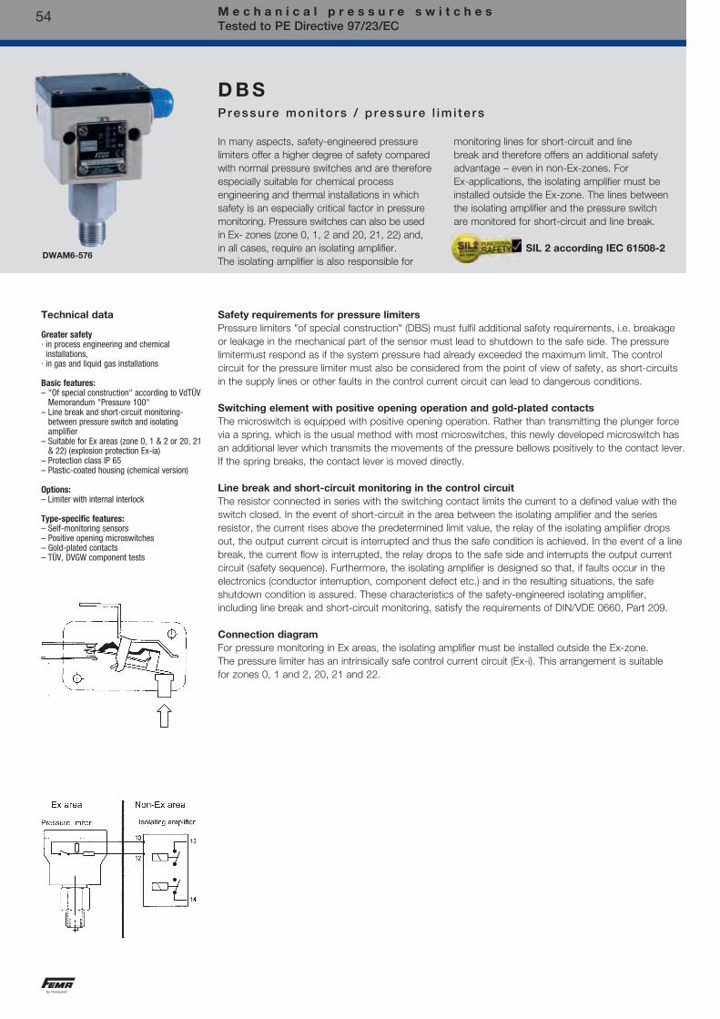
54 M e c h a n i c a l p r e s s u r e s w i t c h e s Tested to PE Directive 97/23/EC
In many aspects, safety-engineered pressure limiters offer a higher degree of safety compared with normal pressure switches and are therefore especially suitable for chemical process engineering and thermal installations in which safety is an especially critical factor in pressure monitoring. Pressure switches can also be used in Ex- zones (zone 0, 1, 2 and 20, 21, 22) and, in all cases, require an isolating amplifier. The isolating amplifier is also responsible for
monitoring lines for short-circuit and line break and therefore offers an additional safety advantage – even in non-Ex-zones. For Ex-applications, the isolating amplifier must be installed outside the Ex-zone. The lines between the isolating amplifier and the pressure switch are monitored for short-circuit and line break.
D B SPressure mon i to rs / p ressu re l im i te rs
DWAM6-576
Technical data
Greater safety · in process engineering and chemical
installations, · in gas and liquid gas installations
Basic features:– "Of special construction" according to VdTÜV
Memorandum "Pressure 100"– Line break and short-circuit monitoring-
between pressure switch and isolating amplifier
– Suitable for Ex areas (zone 0, 1 & 2 or 20, 21 & 22) (explosion protection Ex-ia)
– Protection class IP 65– Plastic-coated housing (chemical version)
Options:– Limiter with internal interlock
Type-specific features:– Self-monitoring sensors– Positive opening microswitches– Gold-plated contacts– TÜV, DVGW component tests
Safety requirements for pressure limitersPressure limiters "of special construction" (DBS) must fulfil additional safety requirements, i.e. breakage or leakage in the mechanical part of the sensor must lead to shutdown to the safe side. The pressure limiter must respond as if the system pressure had already exceeded the maximum limit. The control circuit for the pressure limiter must also be considered from the point of view of safety, as short-circuits in the supply lines or other faults in the control current circuit can lead to dangerous conditions.
Switching element with positive opening operation and gold-plated contactsThe microswitch is equipped with positive opening operation. Rather than transmitting the plunger force via a spring, which is the usual method with most microswitches, this newly developed microswitch has an additional lever which transmits the movements of the pressure bellows positively to the contact lever. If the spring breaks, the contact lever is moved directly.
Line break and short-circuit monitoring in the control circuitThe resistor connected in series with the switching contact limits the current to a defined value with the switch closed. In the event of short-circuit in the area between the isolating amplifier and the series resistor, the current rises above the predetermined limit value, the relay of the isolating amplifier drops out, the output current circuit is interrupted and thus the safe condition is achieved. In the event of a line break, the current flow is interrupted, the relay drops to the safe side and interrupts the output current circuit (safety sequence). Furthermore, the isolating amplifier is designed so that, if faults occur in the electronics (conductor interruption, component defect etc.) and in the resulting situations, the safe shutdown condition is assured. These characteristics of the safety-engineered isolating amplifier, including line break and short-circuit monitoring, satisfy the requirements of DIN/VDE 0660, Part 209.
Connection diagramFor pressure monitoring in Ex areas, the isolating amplifier must be installed outside the Ex-zone. The pressure limiter has an intrinsically safe control current circuit (Ex-i). This arrangement is suitable for zones 0, 1 and 2, 20, 21 and 22.
SIL 2 according IEC 61508-2

55
Acc
esso
ries
Pre
ssur
e sw
itch
esP
ress
ure
tran
smit
ters
The
rmo
stat
sT
emp
erat
ure
sens
ors
Flo
w m
oni
tors
So
leno
id v
alve
s
sProtection Class: IP 65
M e c h a n i c a l p r e s s u r e s w i t c h e s Tested to PE Directive 97/23/EC
S a f e t y - e n g i n e e r e d m a x i m u mp r e s s u r e m o n i t o r s
Max imum pressu re mon i to rsSensor "of special construction", self-monitoring via safety diaphragm, type-tested according to VdTÜV Memorandum "Pressure 100". SIL2 according IEC 61508-2
Versions:ZF 577: Maximum pressure limiter (with internal interlock) Microswitch not positive opening, contacts: silver alloy other equimpent like DWAM…576.Max. pressure limiter DWAM1-577 (isn´t in article master data). Please use DWAM2,5-577.
Versions:ZF 577: Maximum pressure limiter (with internal interlock) Microswitch not positive opening, contacts: silver alloy other equimpent like DWR… 576
CalibrationDevices of the DWR-576 and DWAM-576 series are calibrated for rising pressure. This means that the adjustable switching pressure on the scale corresponds to the switching point at rising pressure. The reset point is lower by the amount of the switching differential. (See also page 27, 2. Calibration at upper switching point).
Max imum pressu re mon i to rsSensor "of special construction" made from stainless steel. (Component testing with 2 million operating cycles). Component tests: VdTÜV Memorandum "Pressure 100", DIN EN1854 (fuel gases), DIN EN764-7, systems in accordance to DIN EN12952-11 and DIN EN12953-9. SIL 2 according ICE 61508-2
Type Setting range Switching Max. Dimen- differential permissible sioned (mean values) pressure drawing page 25 + 26DWAM06-576 0.1…0.6 bar 0.04 bar 5 bar DWAM1-576 0.2…1.6 bar 0.05 bar 5 bar DWAM2,5-576 0.4…2.5 bar 0.07 bar 5 bar 2 + DWAM6-576 1.2…6 bar 0.2 bar 10 bar 15 DWAM625-576 1.2…6 bar 0.25 bar 20 bar DWAM16-576 3…16 bar 0.4 bar 20 bar 2 + DWAM32-576 6…32 bar 1.2 bar 45 bar 19
Type Setting range Switching Max. Dimen- differential permissible sioned (mean values) pressure drawing
page 25 + 26DWR06-576 0,1…0,6 bar 0,04 bar 6 bar 2 + DWR1-576 0,2…1,6 bar 0,06 bar 6 bar 15 DWR3-576 0,2…2,5 bar 0,1 bar 16 bar 2 + DWR6-576 0,5…6 bar 0,2 bar 16 bar 18 DWR625-576 0,5…6 bar 0,25 bar 25 bar 2 + DWR16-576 3…16 bar 0,5 bar 25 bar 17 DWR25-576 4…25 bar 1,0 bar 63 bar 2 + DWR40-576 10…40 bar 1,3 bar 63 bar 16
tested
DVGW TÜV
Technical data
Pressure connectionExternal thread G 1/2 (pressure gauge connection) according to DIN 16 288 and interval thread G 1/4 to ISO 228 Part 1.
Switch housing 500Diecast aluminium GD AI Si 12. Aluminium housing coated with resistant plastic.
Mounting positionVertically upright.
Protection class IP 65.
Ex protective categoryEx-i (only when used in conjunction with suitable isolating amplifier).
Component testing See table on page 52.
Pressure sensor materialsHousing: 1.4104 Pressure bellows: 1.4571 All parts fully welded.
Ambient temperature DWAM: –20°C to +60°C, DWR: –25°C to +60°C. At ambient temperatures at or below 0°C, ensure that condensation cannot occur in the sensor or in the switching device.
Max. temperature of medium at sensor + 60°C.
Outdoor installationsProtect the device against direct atmospheric influences. Provide a protective cover.
Max. working pressureSee Product Summary
Switching pressure settingAdjustable with the setting spindle after removing the terminal box.
MountingWith suitable weld-on connections and union nuts or with pressure gauge screw union G 1/2.
Power supply circuitUi 14 V DCRi 1500 OhmCi 1 nFLi 100 µH
Connection diagrams
…576
…577

56
sProtection Class: IP 65
M e c h a n i c a l p r e s s u r e s w i t c h e s Tested to PE Directive 97/23/EC
Technical data
Switching elementSee table opposite.
Connecting diagrams
…574 …575
The other technical data correspond to the devices for maximum pressure monitoring (page 51).
For the power supply circuit:Ui 14 V DCRi 1500 OhmCi 1 nFLi 100 µH
CalibrationThe DWR-574 series is calibrated for falling pressure. This means that the adjustable switching pressure on the scale corresponds to the switching point at falling pressure. The reset point is higher by the amount of the switching differential. (See also page 27, 1. Calibration at lower switching point).
Versions:ZF 575: Minimum pressure limiters (with internal interlock)Switching contacts: silver alloy other equipment like DWR… 574
Safety-engineered minimum pressure monitorsSensor "of special construction made from stainless steel. (self-monitoring and component testing with 2 million operating cycles). Component tests: VdTÜV Memorandum "Pressure 100", DIN EN3398 (fuel gases) DIN EN764-7, systems in accordance to DIN EN12952-11 and DIN EN12953-9SIL2 according IEC 61508-2
Features of safety-engineered pressure monitors and pressure limiters
Devices Component Features Options testing
Maximum pressure monitoringFD16-326 1 + 3 n n n n n FD16-327 1 + 3 n n n n DWAM…576 1 + 4 n n n n n n DWAM…577 1 + 4 n n n n n
DWR…576 1 + 2 + 3 + 4 n n n n n DWR…577 1 + 2 + 3 + 4 n n n n
Minimum pressure monitoringDWR…574 1 + 2 + 3 + 4 n n n n DWR…575 1 + 2 + 3 + 4 n n n n
1 =
VdT
ÜV
Mem
oran
dum
"P
ress
ure
100"
2 =
DIN
EN
1854
3 =
DIN
EN
764-
7
4 =
DIN
EN
1295
2-11
/DIN
EN
1295
3-9
Res
isto
r co
mbi
natio
n fo
r lin
e br
eak
and
shor
t-ci
rcui
t m
onito
ring
Ex-
ia-v
ersi
on fo
r in
trin
sica
lly s
afe
cont
rol c
ircui
ts
Sel
f-m
onito
ring
pres
sure
sen
sor
Pla
stic
-coa
ted
hous
ing
Che
mic
al v
ersi
onP
ositi
ve o
peni
ngm
icro
switc
hes
Gol
d-pl
ated
co
ntac
ts
Lim
iter
with
inte
rnal
inte
rlock
Che
mic
al v
ersi
on
tested
DVGW TÜV
Type Setting range Switching Max. Dimen- differential permissible sioned (mean values) pressure drawing page 25 + 26DWR06-574 0.1…0.6 bar 0.04 bar 6 bar 2 + DWR1-574 0.2…1.6 bar 0.06 bar 6 bar 15 DWR3-574 0.2…2.5 bar 0.1 bar 16 bar 2 + DWR6-574 0.5…6 bar 0.2 bar 16 bar 18 DWR625-574 0.5…6 bar 0.25 bar 25 bar 2 + DWR16-574 3…16 bar 0.5 bar 25 bar 17 DWR25-574 4…25 bar 1.0 bar 63 bar 2 + DWR40-574 8…40 bar 1.3 bar 63 bar 16

57
Acc
esso
ries
Pre
ssur
e sw
itch
esP
ress
ure
tran
smit
ters
The
rmo
stat
sT
emp
erat
ure
sens
ors
Flo
w m
oni
tors
So
leno
id v
alve
s
sProtection Class: IP 65
M e c h a n i c a l p r e s s u r e s w i t c h e s Tested to PE Directive 97/23/EC
Pressure limiters of the FD series are constructed in accordance with the special directives for liquid gas engineering. The requirements of TRB 801 Appendix II §12 are met. All parts coming into contact with the medium are made of stainless steel 1.4104 and 1.4571. The pressure sensor was designed to be "self-monitoring" to exceed the requirements of TRB , i. e. should the measuring bellows rupture, the pressure sensor switches
off towards the safe side. The pressure sensor thus complies with "of special construction" in the sense of VdTÜV Memorandum "Pressure 100". Pressure limiters are used in intrinsically safe control circuits (Ex-protection Ex-i). By using an isolating amplifier, the control circuit is also monitored for line break and short-circuit.
F DMax imum pressu re l im i te rs fo r l i qu id gas i ns ta l l a t ions
FD16-326 SIL 2 according IEC 61508-2
Product Summary
page 25 + 26FD16–326 3...16 bar 0.5 Extern 2 + 19 FD16–327 3...16 bar 2.5 Intern 2 + 19
Type Setting range Switching Interlock Dimensioned differential drawing
Defeat:E = External, i.e. in control cabinet via relay with latching I = Internal, i.e. locally at pressure limiter
For the power supply circuitUi 14 V DCRi 1500 OhmCi 1 nFLi 100 µH
Internal circuit
FD 16-326 Single-pole changeover switch with resistor combination
for line break and short-circuit monitoring. (External interlock in control cabinet necessary).
FD 16-327 Single-pole changeover switch with mechanical
switching state interlock on reaching maximum pressure and with resistor combination for line break and short-circuit monitoring.
Please note: FD pressure limiters must never be connected directly to mains voltage. They must only be used in conjunction with isolating amplifier.
tested
Technical data
Pressure connection External thread G 1/2 (pressure gauge connection) according to DIN 16 288 and internal thread G 1/4 to ISO 228 Part 1.
Switch housing 300 Diecast aluminium GD Al Si 12.
Protection class: IP 65
Mounting position: Vertically upright
Explosion protection Ex-i (only when used in conjunction with isolating amplifier).
TÜV testing station identifying mark see Product Summary.
Pressure sensor materialsHousing: 1.4104, Pressure bellows: 1.4571 All parts fully welded. Perbunan safety diaphragm (not in contact with medium).
Ambient temperature –25°C to +60°C.At ambient temperatures below 0°C, ensure that condensation cannot occur in the sensor or in the switching device.
Max. medium temperature: +60°C.
Outdoor installationsProtect the device against direct atmospheric influences. Provide a suitable protective cover.
Max. permissible working pressure: 40 bar.
Switching pressure: 5–16 bar. Adjustable with the setting spindle after removing the terminal box.
CalibrationThe FD16-316 and FD16-327 series are calibrated for rising pressure. This means that the adjustable switching pressure on the scale corresponds to the switching point at rising pressure. The reset point is lower by the amount of the switching differential. (See also page 23, 2. Calibration at upper switching point).
Interlock after cutoutInternal interlock on FD16–327. Interlock defeat: after pressure reduction of approx. 2.5 bar by pressing the red button (with tool) on the scale side of the pressure switch.
External interlock on FD16–326.Interlock defeat: After pressure reduction of approx. 0.5 bar. Press unlocking button in control cabinet .
Line break and short-circuit monitoringOn types FD16–326 and FD16–327 used in conjunction with isolating amplifier, the control circuit is monitored for short-circuit and line break. The resistor combination incorporated into the pressure switch ensures that a defined current flows at all times during normal operation. In the event of short-circuit or line break, the current level changes and the relay drops out to the safe side.

58
sProtection Class: IP 54
M e c h a n i c a l p r e s s u r e s w i t c h e s Tested to PE Directive 97/23/EC
DGM310A
DVGW tested to DIN EN1854 Gas pressure monitors are suitable for all gases in accordance with DVGW Worksheet G260 and for air.
SIL 2 according IEC 61508-2
D G MPressure mon i to rs fo r fue l gases
DVGW TÜV
Fuel gases according to DVGW Worksheet G 260DIN EN1854Pressure monitor
For maximum and minimum pressure monitoring
Component tested for Testing basis Function
Direction of action
Product SummaryType Setting range Switching Max. Materials Dimen- differential working in contact sioned (mean values) pressure with medium drawing
p. 25 + 26DGM306A 15…60 mbar 6 mbar 0.8 bar CU + Ms DGM310A 20…100 mbar 7 mbar 0.8 bar CU + Ms 1 + 13 DGM325A 40…250 mbar 10 mbar 0.8 bar CU + Ms DGM06A 100…600 mbar 25 mbar 2 bar CU + Ms 1 + 14 DGM1A 0.2…1.6 bar 40 mbar 3 bar CU + Ms DGM506 15…60 mbar 8 mbar 5 bar 1.4104 DGM516 40…160 mbar 12 mbar 5 bar 1.4104 1 +12 DGM525 100…250 mbar 20 mbar 5 bar 1.4104
CalibrationThe DGM series is calibrated for rising pressure. This means that the adjustable switching pressure on the scale corresponds to the switching point at rising pressure. The reset point is lower by the amount of the switching differential. (See also page 27, 2. Calibration at upper switching point).
For other pressure ranges see type series DWR, page 59.
Ex-i version (intrinsically safe)As above, but with additional function ZF513 (Ex-i). Example for ordering: DGM516-513
-DGM see page 70
Technical data
Pressure connectionExternal thread G 1/2 to DIN 16 288 and internal thread G 1/4 to ISO 228 Part 1 (permissible up to 4 bar).
Switching deviceSeawater-resistant diecast aluminium GD AI Si 12.
Protection classIP 54 for vertical installation position.
Pressure sensor materialsSee Product Summary
Ambient temperature –25 to +60°C. At ambient temperatures below 0°C, ensure that condensation cannot occur in the sensor or in the switching device.
Maximum working pressureSee Product Summary
MountingEither directly on the pipe or with two 4 mm ø screws on the wall surface.
Mounting positionVertically upright and horizontal.
SettingContinuously adjustable via the setting spindle with a screwdriver. The set switching pressure is visible in the scale window.
Sealing P2On request (can be fitted later).
Switching differentialsLargely independent of the set switching pressure. Not adjustable. For values see Product Summary.
Pressure measuring connectionCare must be taken to ensure that a pressure measuring connection is available in a suitable place on the gas appliance.
Switching 250 VAC 250 VDC 24 VDCcapacity (ohm) (ind) (ohm) (ohm)Normal 8 A 5 A 0.3 A 8 A

59
Acc
esso
ries
Pre
ssur
e sw
itch
esP
ress
ure
tran
smit
ters
The
rmo
stat
sT
emp
erat
ure
sens
ors
Flo
w m
oni
tors
So
leno
id v
alve
s
sProtection Class: IP 54
M e c h a n i c a l p r e s s u r e s w i t c h e s Tested to PE Directive 97/23/EC
Especially suitable as a pressure monitor or pressure limiter for fuel gases (DVGW Worksheet G 260) and liquid fuels (e.g. fuel oil), as well as for steam systems according to TRD 604 and hot-water systems to DIN EN12828, systems in accordance to DIN EN12952-11
and DIN EN12953-9. The DWR is used to monitor maximum and minimum pressures.This pressure switch is "of special construction" and has been tested with 2 million operating cycles. TÜV and DVGW tests exists.
D W RPressure mon i to rs
DWR625
tested
DVGW TÜV
Product Summary
Type Setting range Switching Maximum Dimen- differential working sioned (mean values) pressure drawing
Pressure monitors without differential adjustment p. 25 + 26DWR06 0.1…0.6 bar 0.04 bar 6 bar 1 + 15 DWR1 0.2…1.6 bar 0.06 bar DWR3 0.2…2.5 bar 0.1 bar 16 bar 1 + 18 DWR6 0.5…6 bar 0.2 bar DWR625 0.5…6 bar 0.25 bar 25 bar 1 + 17 DWR16 3…16 bar 0.5 bar DWR25 4…25 bar 1.0 bar 63 bar 1 + 16 DWR40 8…40 bar 1.3 bar
Switching differential adjustableDWR06–203 0.1…0.6 bar 0.08…0.5 bar 6 bar 1 + 15 DWR1–203 0.2…1.6 bar 0.15…0.6 bar DWR3–203 0.2…2.5 bar 0.17…1.2 bar 16 bar 1 + 18 DWR6–203 0.5…6 bar 0.3…1.4 bar DWR625–203 0.5…6 bar 0.4…2.5 bar 25 bar 1 + 17 DWR16–203 3…16 bar 0.75…3.15 bar DWR25–203 4…25 bar 1.3…6.0 bar 63 bar 1 + 16 DWR40–203 8…40 bar 2.3…6.6 bar
Steam Systems according to TRBSHot water Systems according to DIN EN12828Fuel gases DVGW Worksheet G 260Pressure tank DIN EN764-7Pressure monitor or pressure limiter(with external interlock)For maximum and minimum pressure monitoring (DWFS, SDBFS)"of special construction" by testing with 2 million cycles.
Component tested for
Function
Direction of action
Sensor
-DWR see page 69
Technical data
Pressure connectionExternal thread G 1/2 (pressure gauge connection) to DIN 16 288 and internal thread G 1/4 to ISO 228 Part 1 (for gas applications internal thread permissible only up to 4 bar).
Switching deviceRugged housing (200) made of seawater-resistant diecast aluminium.
MaterialsPressure bellows: Material no. 1.4571 Sensor housing: Material no. 1.4104 Switch housing: GD AI Si 12 (DIN 1725)
Mounting positionVertically upright and horizontal.
Ambient temperature at switching device–25 to +70°C, Medium temperature –25 to +70°C. The maximum medium temperature at the pressure sensor must not exceed the permitted ambient temperature at the switching device. Temperatures may reach 85°C for short periods. Higher medium temperatures are possible provided the above limit values for the switching device are ensured by suitable measures (e.g. siphon).
MountingDirectly on the pressure line (pressure gauge connection) or on a flat surface with two 4 mm Ø screws.
CalibrationThe DWR series is calibrated for rising pressure. This means that the adjustable switching pressure on the scale corresponds to the switching point at rising pressure. The reset point is lower by the amount of the switching differential. (See also page 27, 2. Calibration at upper switching point). In version ...-203 the switching differential is adjustable. The basic calibration is maintained.
Bursting pressureFor all types ≥ 100 bar, verified by TÜV test.
Switching differential For values see Product Summary.
Contact arrangement Single pole changeover switch.
Protection class IP 54 according to DIN 40 050
Switching 250 VAC 250 VDC 24 VDCcapacity (ohm) (ind) (ohm) (ohm)Normal 8 A 5 A 0.3 A 8 A
SIL 2 according IEC 61508-2

60
s
M e c h a n i c a l p r e s s u r e s w i t c h e s Tested to PE Directive 97/23/EC
Protection Class: IP 54
Especially suitable as a pressure limiter for fuel gases (DVGW Worksheet G 260) and liquid fuels (e.g. fuel oil), as well as for steam systems according to TRBS and hot-water systems to DIN EN12828, systems in accordance to DIN EN12952-11 and DIN EN12953-9.
The DWR-205/-206 is used to limit maximum and minimum pressures and has an internal interlock.
D W RPressure l im i te rs
DWR625-205
Steam System according to TRBSHot water System according to DIN EN12828Fuel gases DVGW Worksheet G 260Pressure tank DIN EN764-7
Pressure limiter (with internal interlock)
For maximum and minimum pressure monitoring (SDBFS)
"Of special construction" by testing with 2 million cycles.
Component tested for
Function
Direction of action
Sensor
* Maximum working pressure and dimensions as for type series DWR. Pressure monitors DWR… (page 59) can also be used as maximum pressure and minimum pressure limiters with external interlock. You will find other maximum pressure limiters with safety sensor, type series SDBAM…, on page 53. Types DWAM… can also be used with external interlock as maximum pressure limiters.
Important: When selecting the limiter, it is necessary to decide whether the device is to be used for maximum or minimum pressure monitoring. The direction of action cannot be reversed at the pressure limiter.
Product SummaryType Setting range Switching Maximum Dimen- differential working sioned (mean values) pressure drawing Maximum pressure limiters page 25 + 26DWR06–205 0.1…0.6 bar 0.06 bar 6 bar 1 + 15 DWR1–205 0.2…1.6 bar 0.09 bar DWR3–205 0.2…2.5 bar 0.20 bar 16 bar 1 + 18 DWR6–205 0.5…6 bar 0.30 bar DWR625–205 0.5…6 bar 0.50 bar 25 bar 1 + 17 DWR16–205 3…16 bar 0.70 bar DWR25–205 4…25 bar 1.4 bar 63 bar 1 + 16 DWR40–205 8…40 bar 2.3 bar
Minimum pressure limitersDWR06–206 0.1…0.6 bar 0.06 bar 6 bar 1 + 15 DWR1–206 0.2…1.6 bar 0.09 bar DWR3–206 0.2…2.5 bar 0.20 bar 16 bar 1 + 18 DWR6–206 0.5…6 bar 0.30 bar DWR625–206 0.5…6 bar 0.50 bar 25 bar 1 + 17 DWR16–206 3…16 bar 0.70 bar DWR25–206 4…25 bar 1.4 bar 63 bar 1 + 16 DWR40–206 8…40 bar 2.3 bar
tested
DVGW TÜV
Technical data
Pressure connectionExternal thread G 1/2 (pressure gauge connection) to DIN 16 288 and internal thread G 1/4 to ISO 228 Part 1 (for gas applications internal thread permissible only up to 4 bar).
Switching deviceRugged housing (200) made of seawater-resistant diecast aluminium.
MaterialsPressure bellows: Material no. 1.4571 Sensor housing: Material no. 1.4104 Switch housing: GD AI Si 12 (DIN 1725)
Mounting position Vertically upright and horizontal.
Ambient temperature at switching device–25…+70°C
Medium temperature –25…+70°C.The medium temperature at the pressure sensor must not exceed the permitted ambient temperature at the switching device. Temperatures may reach 85°C for short periods. Higher medium temperatures are possible provided the above limit values for the switching device are ensured by suitable measures (e.g. siphon).
MountingDirectly on the pressure line (pressure gauge connection) or on a flat surface with two 4 mm Ø screws.
CalibrationThe DWR-205 series is calibrated for rising pressure. This means that the adjustable switching pressure on the scale corresponds to the switching point at rising pressure. The reset point is lower by the amount of the switching differential. (See also page 17, 2. Calibration at upper switching point). The DWR-206 series is calibrated for falling pressure. This means that the adjustable switching pressure on the scale corresponds to the switching point at falling pressure. The reset point is higher by the amount of the switching differential. (See also page 17, 1. Calibration at lower switching point).
Bursting pressure For all types ≥ 100 bar,verified by TÜV test.
Switching differential For values see Product Summary.Contact arrangement Single pole changeover switch.
Protection class IP 54 according to DIN 40 050
Sealing P2On request (can be fitted later).
Switching 250 VAC 250 VDC 24 VDCcapacity (ohm) (ind) (ohm) (ohm)Normal 8 A 5 A 0.3 A 8 A
SIL 2 according IEC 61508-2

61
Acc
esso
ries
Pre
ssur
e sw
itch
esP
ress
ure
tran
smit
ters
The
rmo
stat
sT
emp
erat
ure
sens
ors
Flo
w m
oni
tors
So
leno
id v
alve
s
Bas ic p r inc ip le
The basic principle of explosion protection is that:
a) combustible materials (gas, vapour, mist or dust) in dangerous quantities b) air (or oxygen) c) ignition sources
must not occur in the same place.
The permanent or temporary occurrence of explosive mixtures as per a) and b) is often unavoidable, therefore when operating electrical installations care must be taken to ensure that no ignition sources can occur.
In order to accomplish this, standards have been legislated in Europe serving as a basis for various different types of ignition protection. These standards have been recognized in all European countries. Equipment for the reliable prevention of the ignition of ambient explosive gas mixtures must be constructed according to these standards.
In addition to ISO9000ff applies to the production monitoring, the ISO/IEC 80079-34 for ex-protected areas.
These standards are based on European Directive 94/9/EC (ATEX). The goal of this regulation is the harmonization of statutory regulations EN60079 in the area of explosion protection as well as the elimination of trade barriers between Member States. This Directive provides for the harmonization of all standards relevant to the construction of equipment with ignition protection.
The most impor tan t t ypes o f i gn i t i on p ro tec t ion fo r FEMA produc ts a re as fo l l ows :
"Ex-d" pressure-proof encapsulation EN 60079-1"Ex-e" enhanced safety EN 60079-7"Ex-t" protection via housing EN 60079-31"Ex-i" intrinsically safety EN 60079-11
Pressure switchesSpecially designed FEMA Ex-protected pressure switches are available for use in ex-protection areas. They conform to these standards and are type-tested (Ex-d, Ex-e, Ex-t) and/or have been technically prepared for these areas (Ex-i).
"Ex-d" Pressure-Proof EncapsulationSwitch components and other electrical functional units capable of igniting explosive gas mixtures are encapsulated in a housing which will survive the explosive pressure of an internal explosion and the special design of which prevents the transference of this explosion to the ambient atmosphere.
"Ex-e" Enhanced SafetyThis type of ignition protection pertains to the special design of the terminal connection housing. The connection area is grouted and thus specially separated from the microswitch. A type-tested terminal block, a type-tested cable gland, and the IP65 Protection Degree all ensure an enhanced safety of "Ex-e" in the connection housing.
"Ex-t" Protection via HousingThis type of ignition protection pertains to dust-explosion protection and is based upon the reliable protection of ignition sources against atmospheric dust. For FEMA pressure switches and thermostats for use in dust explosion-protected areas, a Protection Degree of IP65 is required. Together with devices according to "Ex-d" and "Ex-e," devices with "Ex-t" protection are approved for use in gaseous and dust-laden atmospheres.
"Ex-i" Intrinsically SafetyThe equipment employed in explosion-relevant areas are components of inherently-safe electrical circuits. An electrical circuit is inherently safe if the amount of energy it contains is so small that no spark or other thermal effect can arise. This reliably prevents the ignition of explosive gas mixtures in the proximity of this equipment. In the context of this Directive, pressure switches and thermostats containing no switching components with energy-storage effects are referred to as "simple electrical equipment."
The Term "Simple Electrical Equipment"Through the use of simple microswitches without additional capacitive or inductive components means that our "Ex-i" pressure switches and thermostats are classified as "simple electrical equipment." The testing and certification of such equipment is not required by Directive 94/9/EC. However, in explosion-relevant areas requiring "Ex-ia" explosion protection, they may be employed only together with E.C. type-tested isolating amplifiers. All of the devices which we manufacture explicitly for use in such areas are equipped with microswitches with gold contacts, an earthing terminal and are marked for easier identification with a blue cable gland.
G e n e r a l i n f o r m a t i o n a b o u t e x p l o s i o n p r o t e c t i o n

62
G e n e r a l i n f o r m a t i o n a b o u t e x p l o s i o n p r o t e c t i o n
Zone c lass i f i ca t ion
Explosion risk areas are grouped into zones according to the likelihood of a dangerous explosive atmosphere according to EN 1127-1 occurring. When assessing the explosion hazard, i.e. when identifying explosion risk areas, the "Guidelines for the Avoidance of Danger due to Explosive Atmospheres with Examples (ExRL)" of the German Insurance Association for the Chemical Industry must be taken into account. If the situation concerns a special case or if doubts exist as to the definition of explosion risk areas, the matter shall be decided by the supervisory authorities (Trade Supervisory Office, where applicable with the assistance of the Insurance Association or the Technical Control Boards. In Zones 0 (20) and 1 (21), only electrical equipment for which a type test certificate has been issued by a recognized testing agency may be used. In Zone 0 (20), however, only equipment expressly authorized for that zone may be used. Equipment approved for use in Zones 0 (20) and 1 (21) may also be used in Zone 2 (22). Under the new European Directive 94/9 EC (ATEX 100a), a distinction is made between gas atmospheres and dust atmospheres. This results in the following zone classifications:
Zone 0 Zone 0 (gas) is a place in which a dangerous explosive atmosphere is present continuously or for long periods. This normally includes only the interior of containers or the interior of apparatus (evaporators, reaction vessels etc.), if the conditions of Zone 0 are fulfilled. Continuous danger > 1000 hours/year.
Zone 1 occasionally Zone 1 (gas) is a place in which a dangerous explosive atmosphere can be expected to occur occasionally in normal operation. This may include the immediate vicinity of Zone 0. Occasional danger = 10 to 1000 hours/year.
Zone 2 Zone 2 (gas) is a place in which a dangerous explosive atmosphere can be expected to occur only rarely and then only for short periods. This may include areas surrounding Zones 0 and/or 1. Danger only under abnormal operating conditions < 10 hours/year.
Zone 20 Zone 20 (dust) is a place in which a dangerous explosive atmosphere in the form of a cloud of dust in air is present continuously or for long periods, and in which dust deposits of unknown or excessive thickness may be formed. Dust deposits on their own do not form a Zone 20. Continuous danger > 1000 hours/year.
Zone 21 occasionally Zone 21 (dust) is a place in which a dangerous explosive atmosphere in the form of a cloud of dust in air may occasion-ally occur in normal operation, and in which deposits or layers of inflammable dust may generally be present. This may also include the immediate vicinity of Zone 20. Occasional danger = 10 to 1000 hours/year.
Zone 22 Zone 22 (dust ) is a place in which a dangerous explosive atmosphere may be expected to occur only rarely and then only
for short periods. This may include areas in the vicinity of Zones 20 and 21. Danger only under abnormal operating conditions < 10 hours/year.
Gas
Dus
t
continuously or for long periods
seldom and for short periods
continuously or for long periods
seldom and for short periods
M e c h a n i c a l p r e s s u r e s w i t c h e s Tested to ATEX 94/9/EC

63
Acc
esso
ries
Pre
ssur
e sw
itch
esP
ress
ure
tran
smit
ters
The
rmo
stat
sT
emp
erat
ure
sens
ors
Flo
w m
oni
tors
So
leno
id v
alve
s
CE 0035 II 1/2D Ex ta/tb IIIC T80°C Da/Db
European StandardNo. of supervisory bodyEx-Protection SymbolEquipment group IICategroy 2 for Zone 1Application D for dust Ex symbols as per IECIgnition protection Ex-t a/b for Da (sensor) / Db for switching deviceExplosion group for Dust IIICTemperature classEPL Protection level
G e n e r a l i n f o r m a t i o n a b o u t e x p l o s i o n p r o t e c t i o n
Temperature class Ignition temperature Maximum surface temperature °C °C °C T1 > 450 450 T2 > 300 300 T3 > 200 200 T4 > 135 135 T5 > 100 100 T6 > 85 85
Exp los ion g roupThe requirements for explosion-protected equipment depend on the gases and/or vapours present on the equipment and on the dusts lying on, adhering to and/or surrounding the equipment. This affects the gap dimensions required for pressure-proof encapsulation and, in the case of intrinsically safe circuits, the maximum permitted current and voltage values. Gases, vapours and dusts are therefore subdivided into various explosion groups. The danger of the gases rises from explosion group IIA to IIC. The requirements for electrical equipment in these explosion groups increase accordingly. Electrical equipment approved for IIC may also be used for all other explosion groups.
Tempera tu re c lass
The maximum surface temperature of an item of equipment must always be lower than the ignition temperature of the gas, vapour or dust mixture. The temperature class is therefore a measure of the maximum surface temperature of an item of equipment.
Mark ing o f Exp los ion-Pro tec ted E lec t r i ca l Equ ipment
In addition to the usual data (manufacturer, model, serial number, electrical data), the explosion-protection information is likewise to be included in the marking.According to Directive 94/9/EC (ATEX), in compliance with the IEC recommendation and the currently valid standards, the following forms of identification are to be followed.
Example fo r FEMA Pressu re Sw i tch and Thermosta ts w i th "Ex-de" Ign i t i on P ro tec t ion
M e c h a n i c a l p r e s s u r e s w i t c h e s Tested to ATEX 94/9/EC
Zone (Gas-Ex) EPL Zone (Staub-Ex) EPL Protection Level
0 Ga 20 Da highest1 Gb 21 Db high2 Gc 22 Dc standard
Example: Ex d e IIC T6 Gb:Device is designed for Zone 1 for gas group IIC and gas equipment protection level "high level of protection".
Equ ipment P ro tec t ion Leve l (EPL )
In addition to the afore mentioned types of ignition protection, the new norms IEC and EN60079ff have introduced the corresponding Equipment Protection Levels (EPL).

64
E x d e v i c e sPressure mon i to r ing i n exp los ion r i sk a reas , Zones 1 , 2 and 20 , 21 , 22
Specially equipped pressure switches can also be used in explosion risk areas Zone 1, 2 and 20, 21, 22. The following alternatives are possible:
1. Type of ignition protection Ex-d, Ex-e and Ex-t:The pressure switch with protection type "Flameproof Ex-d and Increased Safety Ex-e" can be used with the switch device in hazardous areas of zone 1 and 2 for flammable gas mixtures. For use in dust atmospheres, the protection is "protected by enclosure Ex-t".The switching device may be used in hazardous areas of zones 21 and 22 for explosive dusts. In addition, for the dust – explosion protection zone 20 on the sensor (device screwed into container walls, which may occur in the interior permanent dust atmosphere).The permissible values for switching voltage, switching capacity and ambient temperature please refer to the detailed description of the Ex equipment, and the installation and operating instructions. In addition, please note the general rules for the use and installation of equipment in hazardous atmosphere.Special circuits, as well as versions with adjustable switching differential or internal interlock (reclosing lock) are not possible.
2. Ignition protection Ex-iAll pressure switches with features for intrinsically safe circuits can be used with the switching device in hazardous areas Zone 1 and 2 (Gas) and zones 21 and 22 (Dust). In addition, the sensor in hazardous areas Zone 0 (Gas) and 20 (Dust) may be screwed. (Inside tank = defined as zone 0 or zone 20). A circuit is considered to be "intrinsically safe" if the amount of energy conveyed therein is not capable of generating an ignitable sparks. This pressure switch can only be operated in combination with a suitable isolating switching amplifier, which is approved for the type Ex-i. Suitable variants must be selected for this pressure switch with resistor combination for line and short circuit monitoring. Because of the low voltages and currents in intrinsically safe circuits, micro switches with gold contacts are used for pressure monitors with automatic reset. For limiter (with internal interlock) micro switches with silver contacts are used. FEMA pressure switches for use in intrinsically safe circuits are marked by blue terminals and cable entries. In addition, the pressure switch has been tested by a "notified body". The units get a serial number and the nameplate inform about the ignition protection and registration number.
Ignition protection for pressure monitoring in Zones 0 (20), 1 (21) and 2 (22)
Trennschalter-verstärker
Pressure-proof encapsulation Ex-d (EN 60079-0:2009)Enhanced safety Ex-e (EN 60079-7:2007)Protection via housing Ex-t (EN60079-31:2009)
Ignition protection type:s 0035 II 2G Ex db eb IIC T6s 0035 II 2D Ex tb IIIC IP65 T85ºCATEX approval for the completeswitching devicePressure switches with a silver contact
Switching capacity: max. 3 A, 250 VAC min. 2mA, 24 VDC
The pressure switch can be installedwithin the Ex-Zone.
Ex-area
Isolatingamplifier
Ex-area
M e c h a n i c a l p r e s s u r e s w i t c h e s Tested to ATEX 94/9/EC
Intrinsically safeD …-513 + isolating amplifierD …574,576 + isolating amplifier
Ignition protection type:s 0035 II 1/2G Ex ia T6 Ga/Gbs 0035 II 1/2D Ex ia IIIC T85ºCATEX approval for the completeswitching devicePressure switches with gold-plated contacts (monitors) Pressure switches with silver-plated contacts (monitors)Rate value without resistor combination …-513 /…-563: Ui: 24VDC Ii: 100mACi: 1nF Li: 100µHRate value with resistor combination …-574 / …-575 / …-576 / …-577: Ui: 14VDC Ri: 1500 OhmCi: 1nF Li: 100µHPressure switch will be installed in Ex-ZoneThe isolating amplifier must be installed outside the Ex-Zone.

65
Acc
esso
ries
Pre
ssur
e sw
itch
esP
ress
ure
tran
smit
ters
The
rmo
stat
sT
emp
erat
ure
sens
ors
Flo
w m
oni
tors
So
leno
id v
alve
s
E x - D C M / E x - D N M II 2G Ex d e IIC T6 Gb
II 1/2D Ex ta/tb IIIC T80 ºC Da/Db
Ex-DNM10
Type Setting Switching Max. Materials in Dimen- range differential permissible contact with sioned (mean values) pressure medium drawing
Switching differential not adjustable page 25 + 26Ex-DCM4016 1…16 mbar 2 mbar 1 bar Perbunan 4 + 11 Ex-DCM4025 4…25 mbar 2 mbar 1 bar + 1.4301 4 + 11
For other Ex-devices, see type series VCM, DNS, DDCM, DWR, DGM.
Type Setting Switching Max. Dimen- range differential permissible sioned (mean values) pressure drawing
Ex-DNM10 1…10 bar 0.3 bar 25 bar 4 + 17 Ex-DNM63 16…63 bar 1.0 bar 130 bar 4 + 16
Product Summary
CalibrationThe Ex-DCM/Ex-DNM series is calibrated for falling pressure. This means that the adjustable switching pressure on the scale corresponds to the switching point at falling pressure. The reset point is higher by the amount of the switching differential. (See also page 27, 1. Calibration at lower switching point).
Technical data
Pressure connectionExternal thread G 1/2 (pressure gauge connection) according to DIN 16 288 and internal thread G 1/4 according to ISO 228 Part 1.
Switching deviceRobust housing (700) made of seawater-resistant diecast aluminium GD Al Si 12.
Protection classIP 65, in vertical position.
Pressure sensor materialsEx-DNM Metal bellows: 1.4571
Sensor housing: 1.4104Ex-DCM4016/ Diaphragm: PerbunanEx-DCM4025 Sensor housing: 1.4301
Mounting positionVertically upright.
Ambient temp. at switching device–20…+60 °C
Max. medium temperatureThe maximum medium temperature at the pressure sensor must not exceed the permitted ambient temperature at the switching device. Higher medium temperatures are possible provided the above limit values for the switching device are ensured by suitable measures (e.g. siphon).
MountingDirectly on the pressure line (pressure gauge connection) or on a flat surface with two 4 mm Ø screws.
Switching pressureAdjustable from outside with screwdriver.
Contact arrangementSingle-pole changeover switch.
Switching 250 VAC 250 VDC 24 VDCcapacity (ohm) (ind) (ohm) (ohm)Ex-d 3 A 2 A 0.03 A 3 A
SIL 2 according IEC 61508-2
M e c h a n i c a l p r e s s u r e s w i t c h e s Tested to ATEX 94/9/EC
sProtection Class: IP 65

66
4 + 18
4 + 16
Ex-DNS3
Product Summary
Type Setting range Switching Max. Dimen- differential permissible sioned (mean values) pressure drawing
Switching differential not adjustable page 25 + 26Ex-VNS301 –250…+100 mbar 45 mbar 3 bar Ex-VNS111 –1*…+0.1 bar 50 mbar 6 bar Ex-DNS025 0.04…0.25 bar 30 mbar 6 bar 4 + 15 Ex-DNS06 0.1…0.6 bar 40 mbar 6 bar Ex-DNS1 0.2…1.6 bar 60 mbar 6 bar Ex-DNS3 0.2…2.5 bar 0.1 bar 16 bar Ex-DNS6 0.5…6 bar 0.15 bar 16 bar Ex-DNS10 1…10 bar 0.3 bar 16 bar Ex-DNS16 3…16 bar 0.5 bar 25 bar
* At very high vacuums, close to the theoretical maximum of –1 bar, the switch may not be usable in view of the special conditions of vacuum engineering. However, the pressure switch itself will not be damaged at maximum vacuum.
CalibrationThe Ex-DNS and Ex-VNS series are calibrated for falling pressure. This means that the adjustable switching pressure on the scale corresponds to the switching point at falling pressure. The reset point is higher by the amount of the switching differential. (See also page 27, 1. Calibration at lower switching point).
Technical data
Pressure connectionExternal thread G 1/2 (pressure gauge connection) according to DIN 16 288 and internal thread G 1/4 according to ISO 228 Part 1.
Switching deviceRobust housing (700) made of seawater-resistant diecast aluminium GD Al Si 12.
Protection classIP 65
Pressure sensor materialsPressure bellows and all parts in contact with medium. X 6 Cr Ni Mo Ti 17122 Material no. 1.4571
Mounting positionVertically upright.
Max. ambient temperature at switching device–20…+60 °C.
Max. medium temperatureThe maximum medium temperature at the pressure sensor must not exceed the permitted ambient temperature at the switching device. Higher medium temperatures are possible provided the above limit values for the switching device are ensured by suitable measures (e.g. siphon).
MountingDirectly on the pressure line (pressure gauge connection) or on a flat surface with two 4 mm Ø screws.
Switching pressureAdjustable from outside with screwdriver.
Contact arrangementSingle-pole changeover switch.
Plastic coatingThe diecast aluminium housing in GD Al Si is chromated and stove-enamelled with resistant plastic. Corrosion tests with 3% saline solution and 30 temperature changes from +10 to +80°C showed no surface changes after 20 days.
Switching 250 VAC 250 VDC 24 VDCcapacity (ohm) (ind) (ohm) (ohm)Ex-d 3 A 2 A 0.03 A 3 A
SIL 2 according IEC 61508-2
E x - D N S / E x - V N S II 2G Ex d e IIC T6 Gb
II 1/2D Ex ta/tb IIIC T80 ºC Da/Db
Protection Class: IP 65s
M e c h a n i c a l p r e s s u r e s w i t c h e s Tested to ATEX 94/9/EC

67
Acc
esso
ries
Pre
ssur
e sw
itch
esP
ress
ure
tran
smit
ters
The
rmo
stat
sT
emp
erat
ure
sens
ors
Flo
w m
oni
tors
So
leno
id v
alve
s
Ex-DDCM1 (stainless steel sensor)
E x - D D C M II 2G Ex d e IIC T6 Gb
II 1/2D Ex ta/tb IIIC T80 ºC Da/Db
Switching 250 VAC 250 VDC 24 VDCcapacity (ohm) (ind) (ohm) (ohm)Ex-d 3 A 2 A 0.03 A 3 A
Type Setting range Switching Max.** Materials in Dimen- (differential differential permissible contact with sioned pressure) (mean values) pressure medium drawing
Switching differential not adjustable page 25 + 26Ex-DDCM252* 4…25 mbar 2 mbar 0.5 bar Ex-DDCM662* 10…60 mbar 15 mbar 1.5 bar Aluminium 4 + 20 Ex-DDCM1602* 20…160 mbar 20 mbar 3 bar + Perbunan Ex-DDCM6002* 100…600 mbar 35 mbar 3 bar Ex-DDCM014* -0.1…0.4 bar 0.15 bar 15 bar Ex-DDCM1 0.2…1.6 bar 0.13 bar 15 bar stainless steel Ex-DDCM4* 1…4 bar 0.2 bar 25 bar 1.4305 + 4 + 21 Ex-DDCM6 0.5…6 bar 0.2 bar 15 bar 1.4571 Ex-DDCM16 3…16 bar 0.6 bar 25 bar
* without graduation (only ± scale) set according to pressure gauge.** also loadable on one side
Accessories: · Threaded joint with male adapter union G 1/4"/8 mm MAU8/Ms and MAU8/Nst page 153· Valve combinations VKD3 and VKD5, page 152
CalibrationThe Ex-DDCM series is calibrated for falling pressure. This means that the adjustable switching pressure on the scale corresponds to the switching point at falling pressure. The reset point is higher by the amount of the switching differential. (See also page 27, 1. Calibration at lower switching point).
+
Pump monitoring application example
The differential pressure switch (e.g. Ex-DDCM1) monitors differential pressure through the pump. The system shuts down if values fall below an adjustable switching threshold. Pump monitoring does not depend on the static pressure in the system.
Technical data
Pressure connectionInternal thread G 1/4
Switching deviceRobust housing (700) made of seawater-resistant diecast aluminium GD Al Si 12.
Protection classIP 65
Pressure sensor materialsEx-DDCM014–16: Ex-Pressure bellows of 1.4571 Sensor housing of 1.4305. DDCM252–6002: Perbunan diaphragm. Aluminium sensor housing.
Mounting positionvertically upright.
Ambient temperature at switching device–20…+60 °C
Max. medium temperatureThe maximum medium temperature at the pressure sensor must not exceed the permitted ambient temperature at the switching device. Higher medium temperatures are possible provided the above limit values for the switching device are ensured by suitable measures (e.g. siphon).
MountingDirectly on the pressure line or on a flat surface with two 4 mm Ø screws. Note the connection of pressurized lines: P (+) = high pressureS (–) = low pressure
Switching pressureAdjustable from outside with screwdriver.
SIL 2 according IEC 61508-2
Protection Class: IP 65s
M e c h a n i c a l p r e s s u r e s w i t c h e s Tested to ATEX 94/9/EC

68
Ex-VNM111
E x - V C M / E x - V N M II 2G Ex d e IIC T6 Gb
II 1/2D Ex ta/tb IIIC T80 ºC Da/Db
Technical data
Pressure connectionExternal thread G 1/2 (pressure gauge connection) according to DIN 16 288 and internal thread G 1/4 according to ISO 228 Part 1.
Switching deviceRobust housing (700) made of seawater-resistant diecast aluminium GD Al Si 12.
Protection classIP 65
Pressure sensor materialsEx-VNM111 and Metal bellows: 1.4571Ex-VNM301: Sensor housing: 1.4104Ex-VCM095, 101 Metal bellows of Cu Znand 301: Sensor housing of CuZnEx-VCM4156: Perbunan diaphragm
sensor housing: 1.4301
Mounting positionVertically upright.
Ambient temp. at switching device–20…+60 °C
Max. medium temperatureThe maximum medium temperature at the pressure sensor must not exceed the permitted ambient temperature at the switching device. Higher medium temperatures are possible provided the above limit values for the switching device are ensured by suitable measures (e.g. siphon).
MountingDirectly on the pressure line (pressure gauge connection) or on a flat surface with two 4 mm Ø screws.
Switching pressureAdjustable from outside with screwdriver.
Contact arrangementSingle-pole changeover switch.
Switching 250 VAC 250 VDC 24 VDCcapacity (ohm) (ind) (ohm) (ohm)Ex-d 3 A 2 A 0.03 A 3 A
* At very high vacuums, close to the theoretical maximum of –1 bar, the switch may not be usable in view of the special conditions of vacuum engineering. However, the pressure switch itself will not be damaged at maximum vacuum.
CalibrationThe Ex-VCM and Ex-VNM series are calibrated for falling pressure. This means that the adjustable switching pressure on the scale corresponds to the switching point at falling pressure. The reset point is higher by the amount of the switching differential. (See also page 27, 1. Calibration at lower switching point).
Product Summary
Type Setting range Switching Max. Dimen- differential permissible sioned (mean values) pressure drawing
Switching differential not adjustable page 25 + 26Ex-VCM4156 –15…+6 mbar 2 mbar 1 bar 4 + 11 Ex-VCM301 –250…+100 mbar 25 mbar 1.5 bar 4 + 13 Ex-VNM301 –250…+100 mbar 45 mbar 3 bar 4 + 15 Ex-VCM101 –1*…+0.1 bar 45 mbar 3 bar 4 + 14 Ex-VCM095 –0.9…+0.5 bar 50 mbar 3 bar 4 + 14 Ex-VNM111 –1*…+0.1 bar 50 mbar 6 bar 4 + 15
SIL 2 according IEC 61508-2
M e c h a n i c a l p r e s s u r e s w i t c h e s Tested to ATEX 94/9/EC
Protection Class: IP 65s

69
Acc
esso
ries
Pre
ssur
e sw
itch
esP
ress
ure
tran
smit
ters
The
rmo
stat
sT
emp
erat
ure
sens
ors
Flo
w m
oni
tors
So
leno
id v
alve
s
E x - D W R II 2G Ex d e IIC T6 Gb
II 1/2D Ex ta/tb IIIC T80 ºC Da/Db
Ex-DWR25
Component tested for
Function
Direction of action
Sensor
Steam Systems according to TRD 604Hot water Systems according to DIN EN12828Fuel gases DVGW Worksheet G 260Pressure tank DIN EN764-7
Pressure monitor or pressure limiter(with external interlock)For maximum and minimum pressuremonitoring (DWFS, SDBFS)"of special construction" by testing with 2 million cycles.
Product SummaryType Setting range Switching Maximum Dimen- differential working sioned (mean values) pressure drawing
Switching differential not adjustable page 25 + 26Ex-DWR06 0.1…0.6 bar 0.04 bar 6 bar 4 + 15 Ex-DWR1 0.2…1.6 bar 0.06 bar Ex-DWR3 0.2…2.5 bar 0.1 bar 16 bar 4 + 18 Ex-DWR6 0.5…6 bar 0.2 bar Ex-DWR625 0.5…6 bar 0.25 bar 25 bar 4 + 17 Ex-DWR16 3…16 bar 0.5 bar Ex-DWR25 4…25 bar 1.0 bar 63 bar 4 + 16 Ex-DWR40 8…40 bar 1.3 bar
Technical data
Pressure connectionExternal thread G 1/2 (pressure gauge connection) to DIN 16 288 and internal thread G 1/4 to ISO 228 Part 1 (for gas applications internal thread permissible only up to 4 bar).
Switching deviceRugged housing (700) made of seawater-resistant diecast aluminium.
MaterialsPressure bellows: Material no. 1.4571 Sensor housing: Material no. 1.4104 Switch housing: GD AI Si 12 (DIN 1725)
Mounting positionVertically upright
Ambient temperature at switching device–20 to +60°C.Medium temperature –25 to +60°C. The maximum medium temperature at the pressure sensor must not exceed the permitted ambient temperature at the switching device. Higher medium temperatures are possible provided the above limit values for the switching device are ensured by suitable measures (e.g. siphon).
MountingDirectly on the pressure line (pressure gauge connection) or on a flat surface with two 4 mm Ø screws.
CalibrationThe DWR series is calibrated for rising pressure. This means that the adjustable switching pressure on the scale corresponds to the switching point at rising pressure. The reset point is lower by the amount of the switching differential. (See also page 27, 2. Calibration at upper switching point).
Bursting pressureFor all types ≥ 100 bar, verified by TÜV test.
Contact arrangement Single pole changeover switch.
Protection class IP 65, only vertically upright
Ex protectionEEx de IIC T6
Switching 250 VAC 250 VDC 24 VDCcapacity (ohm) (ind) (ohm) (ohm)Ex-d 3 A 2 A 0.03 A 3 A
SIL 2 according IEC 61508-2
M e c h a n i c a l p r e s s u r e s w i t c h e s Tested to ATEX 94/9/EC
Protection Class: IP 65s tested
DVGW TÜV

70
E x - D G M II 2G Ex d e IIC T6 Gb
II 1/2D Ex ta/tb IIIC T80 ºC Da/Db
Ex-DGM525
Technical data
Pressure connectionExternal thread G 1/2 to DIN 16 288 and internal thread G 1/4 to ISO 228 Part 1 (permissible up to 4 bar).
Switching deviceSeawater-resistant diecast aluminium GD AI Si 12.
Protection classIP 65
Pressure sensor materialsSee Product Summary
Ambient temperature –20 to +60°C. At ambient temperatures below 0°C, ensure that condensation cannot occur in the sensor or in the switching device.
Maximum working pressureSee Product Summary
MountingEither directly on the pipe or with two 4 mm ø screws on the wall surface.
Mounting positionVertically upright
SettingContinuously adjustable via the setting spindle with a screwdriver. The set switching pressure is visible in the scale window.
Switching differentialsLargely independent of the set switching pressure. Not adjustable. For values see Product Summary.
Pressure measuring connectionCare must be taken to ensure that a pressure measuring connection is available in a suitable place on the gas appliance.
Fuel gases according to DVGW Worksheet G 260 DIN EN1854Pressure monitor
For maximum and minimum pressure monitoring
Component tested for Testing basis Function
Direction of action
Product SummaryType Setting range Switching Max. Materials Dimen- differential working in contact sioned (mean values) pressure with medium drawing
page 25 + 26Ex-DGM506 15…60 mbar 10 mbar 5 bar 1.4104 Ex-DGM516 40…160 mbar 12 mbar 5 bar 1.4104 4 + 12 Ex-DGM525 100…250 mbar 20 mbar 5 bar 1.4104
CalibrationThe Ex-DGM series is calibrated for rising pressure. This means that the adjustable switching pressure on the scale corresponds to the switching point at rising pressure. The reset point is lower by the amount of the switching differential. (See also page 27, 2. Calibration at upper switching point).
For other pressure ranges see type series DWR, page 69
Switching 250 VAC 250 VDC 24 VDCcapacity (ohm) (ind) (ohm) (ohm)Ex-d 3 A 2 A 0.03 A 3 A
SIL 2 according IEC 61508-2
M e c h a n i c a l p r e s s u r e s w i t c h e s Tested to ATEX 94/9/EC
Protection Class: IP 65s
DVGW tested