Simulation, Control, and Evaluation of Actuated Car Doors
220
Lehrstuhl f¨ ur Steuerungs- und Regelungstechnik Technische Universit¨at M¨ unchen Univ.-Prof. Dr.-Ing./Univ. Tokio Martin Buss Simulation, Control, and Evaluation of Actuated Car Doors Michael Strolz Vollst¨andiger Abdruck der von der Fakult¨ at f¨ ur Elektrotechnik und Informationstechnik der Technischen Universit¨at M¨ unchen zur Erlangung des akademischen Grades eines Doktor-Ingenieurs (Dr.-Ing.) genehmigten Dissertation. Vorsitzender: Univ.-Prof. Dr.-Ing. Thomas Eibert Pr¨ ufer der Dissertation: 1. Univ.-Prof. Dr.-Ing./Univ. Tokio Martin Buss 2. Univ.-Prof. Dr.-Ing. Michael Z¨ah Die Dissertation wurde am 22.06.2010 bei der Technischen Universit¨at M¨ unchen einge- reicht und durch die Fakult¨ at f¨ ur Elektrotechnik und Informationstechnik am 07.12.2010 angenommen.
-
Upload
khangminh22 -
Category
Documents
-
view
2 -
download
0
Transcript of Simulation, Control, and Evaluation of Actuated Car Doors

Lehrstuhl fur Steuerungs- und Regelungstechnik
Technische Universitat Munchen
Univ.-Prof. Dr.-Ing./Univ. Tokio Martin Buss
Simulation, Control, and Evaluation ofActuated Car Doors
Michael Strolz
Vollstandiger Abdruck der von der Fakultat fur Elektrotechnik und Informationstechnik
der Technischen Universitat Munchen zur Erlangung des akademischen Grades eines
Doktor-Ingenieurs (Dr.-Ing.)
genehmigten Dissertation.
Vorsitzender: Univ.-Prof. Dr.-Ing. Thomas Eibert
Prufer der Dissertation:
1. Univ.-Prof. Dr.-Ing./Univ. Tokio Martin Buss
2. Univ.-Prof. Dr.-Ing. Michael Zah
Die Dissertation wurde am 22.06.2010 bei der Technischen Universitat Munchen einge-
reicht und durch die Fakultat fur Elektrotechnik und Informationstechnik am 07.12.2010
angenommen.


Foreword
This thesis is a result of three-and-a-half years of work in the group of Prof. Martin Buss
at the Institute of Automatic Control Engineering (LSR) at TU Munchen.
First of all, I would like to thank my thesis advisor Prof. Martin Buss for providing me
with an excellent and stimulating working environment. It was a great experience to get
this generous freedom for research and at the same time advice and encouragement.
I was privileged to work together with a lot of talented and interested researchers who
helped me to develop and realize my ideas and projects. Many thanks go to my colleagues,
especially Dr.-Ing. Angelika Peer, Raphaela Groten, Dr.-Ing. Marc Ueberle, Matthias Al-
thoff, and Klaas Klasing for their theoretical and to Dr.-Ing. Ulrich Unterhinninghofen,
Jens Holldampf, and Nikolay Stefanov for their practical support and discussions. I also
would like to thank Christian Scharfenberger, Adel Olaf Sabbah, and all other PhD stu-
dents involved in the research project MechaTUM for the great collaboration and the
successful realization of our versatile actuated door-seat system.
Thanks go also to Florian Soldner at BMW AG and to Dr.-Ing. Patrick Kuhl and
Michael Graf at BMW Forschung und Technik GmbH for their support in the realization
and evaluation of hardware and controllers. Furthermore, I would like to thank the non-
scientific staff of the LSR, especially Mr. Gradl, Mr. Kubick, Mr. Stober and Mr. Lowitz
for the realization of hardware and Mr. Jaschik for the software support.
Most of the work described in this thesis is a result of my intense collaboration and
discussion with the students I supervised. Specifically, I would like to thank the ones who
significantly contributed to my research:
• Hamza Ben Rached (controllers [209], SSD evaluation [149], working student)
• Yuxiang Chen (multi-threaded path planning [45], working student)
• Andreas Domel (path planning [66, 67], working student)
• Claudia Ehinger (development of the one-DOF door simulator [74])
• Yueming Fan (VRP of the TLD [85])
• Anh Cuong Hoang (collision detection [119], SSD evaluation [149], working student)
• Kong Huang (controller for the TLD prototype [123])
• Alexander Mortl (controller for the door prototype with one DOF [178])
• Quirin Muhlbauer (VR simulation, intention recognition [182])
• Mingjing Ren (evaluation of the one-DOF door simulator [212])
• Amir Solhjoo (further improvement and evaluation of the TLD [230])
• Tobias Stadler (multi-threaded collision detection [235])
Finally, I thank my family and friends for their tolerance and unconditional support.
Munich, June 2010 Michael Strolz
III

IV

Contents
1 Introduction 1
1.1 Problem Definitions and Challenges . . . . . . . . . . . . . . . . . . . . . . 3
1.2 Main Contributions and Outline of this Thesis . . . . . . . . . . . . . . . . 4
2 Virtual Reality Prototyping (VRP) by Active Admittance Control (AAC) 6
2.1 History and State of the Art of Virtual Reality Prototyping (VRP) . . . . 6
2.1.1 History of Virtual Reality Research . . . . . . . . . . . . . . . . . . 6
2.1.2 Definition and Issues of VRP . . . . . . . . . . . . . . . . . . . . . 7
2.1.3 State of the Art of VRP without Haptic Interaction . . . . . . . . . 9
2.1.4 State of the Art of VRP with Haptic Interaction . . . . . . . . . . . 10
2.2 Modeling of Mechatronic Systems as Active Admittance (AA) . . . . . . . 12
2.2.1 Structure of an AA . . . . . . . . . . . . . . . . . . . . . . . . . . . 12
2.2.2 Overview of Potentially Relevant Elements and Properties . . . . . 13
2.2.3 Reduced AA for VRP in Early Development Stages . . . . . . . . . 15
2.3 Haptic Rendering by Active Admittance Control (AAC) . . . . . . . . . . 16
2.3.1 General Structure of AAC . . . . . . . . . . . . . . . . . . . . . . . 16
2.3.2 Controller Design and Stability Issues . . . . . . . . . . . . . . . . . 17
2.3.3 Exemplary Application of AAC to a Pivotable Sliding Door . . . . 20
2.4 Summary . . . . . . . . . . . . . . . . . . . . . . . . . . . . . . . . . . . . 21
3 Generic Methods for the Haptic Support of Human-System-Interaction 22
3.1 Intention Recognition: Determination and Support of the Intended Motion 23
3.1.1 State of the Art . . . . . . . . . . . . . . . . . . . . . . . . . . . . . 23
3.1.2 Design of a Combination of Static and Dynamic Virtual Fixtures . 24
3.2 Path Planning: Determination and Support of Collision-Free Motion . . . . 27
3.2.1 State of the Art . . . . . . . . . . . . . . . . . . . . . . . . . . . . . 28
3.2.2 SamPP, a New Sampling-Based Path Planning Library . . . . . . . 29
3.2.3 Benchmark Results for SamPP . . . . . . . . . . . . . . . . . . . . 33
3.2.4 Generalized OR Paradigm . . . . . . . . . . . . . . . . . . . . . . . 41
3.2.5 Conclusion . . . . . . . . . . . . . . . . . . . . . . . . . . . . . . . . 46
3.3 Collision Avoidance: Reducing the Risk of a Collision . . . . . . . . . . . . 48
3.3.1 Performance Benchmark of Collision Detection Libraries . . . . . . 49
3.3.2 Multi-Threaded Collision Detection . . . . . . . . . . . . . . . . . . 50
3.3.3 Collision Avoidance . . . . . . . . . . . . . . . . . . . . . . . . . . . 53
3.4 Summary . . . . . . . . . . . . . . . . . . . . . . . . . . . . . . . . . . . . 56
V

Contents
4 VRP of Actuated Car Doors: Control, Simulation, and Evaluation 57
4.1 VRP of Actuated Car Doors with Several DOF . . . . . . . . . . . . . . . 57
4.1.1 Generic VRP Test Bed . . . . . . . . . . . . . . . . . . . . . . . . . 57
4.1.2 Comparison of Five Different Car Door Kinematics . . . . . . . . . 62
4.1.3 Free-Flying Door (FFD): Preferred Guidance Depends on Person . 63
4.1.4 Pivotable-Sliding Door (PSD): Dynamics Should be Adaptable . . . 66
4.1.5 Two-Link Door (TLD): Haptic User Support is Beneficial . . . . . . 68
4.1.6 Summary . . . . . . . . . . . . . . . . . . . . . . . . . . . . . . . . 75
4.2 VRP of Car Doors with One Rotational DOF . . . . . . . . . . . . . . . . 77
4.2.1 Modeling and Specification Issues . . . . . . . . . . . . . . . . . . . 77
4.2.2 Performance Specification of the Haptic Device . . . . . . . . . . . 84
4.2.3 Design of the Haptic Device . . . . . . . . . . . . . . . . . . . . . . 86
4.2.4 Evaluation of the Transparency of the Haptic Rendering . . . . . . 88
4.2.5 Additional Evaluations and Results . . . . . . . . . . . . . . . . . . 92
4.2.6 Simulation and Evaluation of a Semi-Actuated Car Door . . . . . . 94
4.2.7 Summary . . . . . . . . . . . . . . . . . . . . . . . . . . . . . . . . 97
5 Control and Evaluation of Two Physical Prototypes of Actuated Car Doors 99
5.1 Two-Link Door Prototype with Two Actuated DOF . . . . . . . . . . . . . 99
5.1.1 System Description . . . . . . . . . . . . . . . . . . . . . . . . . . . 100
5.1.2 Closed-Loop Position Control . . . . . . . . . . . . . . . . . . . . . 104
5.1.3 Transfer and Modification of the Controller Developed by VRP . . 104
5.1.4 Experimental Evaluation . . . . . . . . . . . . . . . . . . . . . . . . 109
5.1.5 Summary . . . . . . . . . . . . . . . . . . . . . . . . . . . . . . . . 113
5.2 Close-to-Series Door Prototype with One Actuated DOF . . . . . . . . . . 115
5.2.1 Measurement of the User Interaction Force . . . . . . . . . . . . . . 116
5.2.2 System Description . . . . . . . . . . . . . . . . . . . . . . . . . . . 120
5.2.3 Automatic Door Operation . . . . . . . . . . . . . . . . . . . . . . . 124
5.2.4 Manual Door Operation: Prearrangements . . . . . . . . . . . . . . 127
5.2.5 Manual Door Operation: Control Schemes . . . . . . . . . . . . . . 131
5.2.6 Manual Door Operation: Evaluation . . . . . . . . . . . . . . . . . 135
5.2.7 Summary . . . . . . . . . . . . . . . . . . . . . . . . . . . . . . . . 137
6 Conclusion and Future Work 139
6.1 Concluding Remarks . . . . . . . . . . . . . . . . . . . . . . . . . . . . . . 139
6.2 Future Work . . . . . . . . . . . . . . . . . . . . . . . . . . . . . . . . . . . 142
A State of the Art of Unactuated Car Doors 145
B Technical Details Related to the AAC of Car Doors 146
B.1 EOM of Several Simulated Car Doors . . . . . . . . . . . . . . . . . . . . . 146
B.1.1 Car Door Body and Free-Flying Door (FFD) . . . . . . . . . . . . . 146
B.1.2 Pivotable Sliding Door (PSD) . . . . . . . . . . . . . . . . . . . . . 148
B.1.3 Two-Link Door (TLD) . . . . . . . . . . . . . . . . . . . . . . . . . 148
B.2 Typical Opening Paths of Some Car Doors . . . . . . . . . . . . . . . . . . 149
VI

Contents
B.3 Autolev Code . . . . . . . . . . . . . . . . . . . . . . . . . . . . . . . . . . 150
B.3.1 Autolev Code of the TLD VRP Simulation . . . . . . . . . . . . . . 150
B.3.2 Autolev Code of the TLD Prototype . . . . . . . . . . . . . . . . . 152
B.4 System Analysis of the TLD Prototype . . . . . . . . . . . . . . . . . . . . 155
C Feedback-Linearized Position Controller for ViSHaRD10 156
C.1 Computed Torque (CT) Control . . . . . . . . . . . . . . . . . . . . . . . . 156
C.2 Feedforward+PD (FFPD) Control . . . . . . . . . . . . . . . . . . . . . . . 158
D Technical Details Related to Collision Avoidance and Path Planning 159
D.1 Obstacle Detection System provided by RCS (TU Munchen) . . . . . . . . 159
D.2 Benchmark Scenarios for Obstacle Detection and Collision Avoidance . . . 160
D.2.1 Scenarios for the Camera Mounted on the Door Mirror . . . . . . . 160
D.2.2 Scenarios for the Camera Mounted on the Inner Edge of the Door . 161
D.3 VRML Models of the Exemplary Car Door Body . . . . . . . . . . . . . . 162
D.4 SamPP: Representation of Kinematics . . . . . . . . . . . . . . . . . . . . 163
E Notes on the QoS of the Communication Infrastructure 164
E.1 Selection of Ethernet and the UDP Protocol . . . . . . . . . . . . . . . . . 164
E.2 Heuristic Evaluation of the UDP-Based Communication . . . . . . . . . . . 164
E.2.1 Evaluation in the Absence of Disturbances . . . . . . . . . . . . . . 165
E.2.2 Evaluation in the Presence of Disturbances . . . . . . . . . . . . . . 165
F Detailed Evaluation Results 167
F.1 Evaluation of the VRP Simulation of the PSD . . . . . . . . . . . . . . . . 167
F.2 Evaluation of the VRP Simulation of the TLD . . . . . . . . . . . . . . . . 170
F.3 Evaluation of the TLD Prototype . . . . . . . . . . . . . . . . . . . . . . . 175
G Technical Details Related to the TLD Prototype 181
Bibliography 187
VII

Notations
Abbreviations
3DD 3D data provided by the obstacle detection system
AA active admittance
AAC active admittance control
C-space configuration space of a robot
CT computed torque
CAD computer aided design
COG center of gravity
COS coordinate system
CDL collision detection library
DD direct drive
DFLD double-four-link door
DH Denavit-Hartenberg notation
DMU digital mock-up
DOF degrees of freedom
DVF dynamic virtual fixture
EE end-effector
EOM equations of motion
FFPD feedforward+pd control
fps frames per second
FTS force-torque-sensor
HMD head-mounted display
HIP haptic interaction point
HSI human-system interaction
JND just noticeable difference
LTI linear, time-invariant
PMU physical mock-up
PRM probabilistic road map
PSD pivotable-sliding door
PWM pulse width modulation
QoS quality of service
RP rapid prototyping
RRT rapidly-exploring random tree
SSD swing-sliding door
SVF static virtual fixture
TLD two-link door
VIII

Notations
UDP user datagram protocol
VE virtual environment (also known as “virtual world”)
VF virtual fixture
ViSHaRD10 Virtual Scenario Haptic Rendering Device with 10 actuated DOF
VMU virtual mock-up
VR virtual reality
VRP virtual reality prototyping
VW virtual wall
Conventions
Scalars, Vectors, and Matrices
Scalars are denoted by upper and lower case letters in italic type.
Vectors are denoted by bold lower case letters, as the vector x is composed of elements xi.
Matrices are denoted by bold upper case letters, as the matrix M is composed of elements
Mij (ith row, jth column).
x , X scalar
x vector
X matrix
f (·) scalar function
f(·) vector function
x, x equivalent to ddtx and d2
dt2x
XT transposed of X
X−1 inverse of X
Subscripts and Superscriptsxmax maximum value of x
xmin minimum value of x
xr reference, commanded, or desired value of x
x estimated or predicted value of x
x∗ measurement value of x
‖x‖ Euclidean norm of x
‖x‖p p-norm of x
xx, xy, xz component of x in x-, y- and z-direction
Symbols
A system matrix
B input matrix
C output matrix
C(q, q) joint space Coriolis and centrifugal terms
c stiffness
IX

Notations
D feedthrough matrix
d damping coefficient
E energy
E unity matrix
e error
f frequency
f force (generalized Cartesian space force, i.e.
f = [Fx, Fy, Fz, Tx, Ty, Tz]T )
fG force resulting from gravity
fF force resulting from friction
fu force exerted by user
fu,r reference for fufas assistive force for the haptic support of HSI
Fx , Fy , Fz Cartesian space force components in x-, y- and z-direction
around x-, y- and z-axis
G(s) transfer function
H(q) joint space inertia matrix
I c 95% confidence interval
I zz Inertia with respect to the z-axis
I Inertia
J Jacobian
Kp , Ki , Kd matrices of proportional, integral and derivative control coefficients
k control coefficient
l link length
M(x) Cartesian space inertia matrix
m link mass
N(x, x) Cartesian space Coriolis and centrifugal terms
n number of rotational DOF of a robot
o number of translational DOF of a robot
P probability
q joint position (generalized joint space position, i.e.
q = [q1 . . . qn+o]T )
q, q joint velocity and acceleration
qr reference joint position
qr , qr reference joint velocity and acceleration
T time constant
Tx , Ty , Tz Cartesian space torque components
t time
u control input vector
w weighting factor for the robot joints
x state vector
x position (generalized Cartesian space position, i.e.
x = [x, y, z, α, β, γ]T )
x, x velocity and acceleration
X

Notations
x∗ measurement of x
xu position of HIP
xr reference position
xr , xr reference velocity and acceleration
y control output vector
µ friction coefficient
σσσE ,i signals from external devices
σσσE ,o signals to external devices
σσσin arbitrary input signals for the AA
σσσS simulated sensor signals
τττ torque (generalized joint space torque, i.e.
τττ = [τ1 . . . τn, fn+1 . . . fn+o]T )
τττ as,c assistive torque based on collision avoidance
τττ as,i assistive torque based on intention recognition
τττ as,p assistive torque based on path planning
τττA torque resulting from actuation
τττF torque resulting from friction
τττG torque resulting from gravity
τττ r reference actuator torque computed by the controller
τττu torque given by JT fuτττ ∗u torque given by JT f∗u
XI

Abstract
This thesis describes the simulation, control, and evaluation of actuated car doors with one
or more degrees of freedom (DOF). Virtual Reality Prototyping (VRP) with haptic feed-
back is proposed for the efficient development and evaluation of such doors. As universal
framework for the haptic simulation and the controller development of actuated mecha-
nisms, Active Admittance Control (AAC) is introduced. AAC enables an efficient and safe
development of system functionalities, for instance support methods for a comfortable hap-
tic interaction between a human user and the system. Generic interaction support methods
such as intention recognition, path planning, and collision avoidance are developed. On
this foundation, for a variety of novel actuated car doors simulation models and controllers
are developed. They are evaluated by user studies at VRP test beds. Important findings
are that the simulated dynamics of the doors should be adapted to the individual user, and
that the proposed support methods are indeed effective. In consequence, the simulated car
doors are rated positively by the participants. The VRP results are transferred to physical
prototypes with one and two actuated DOF. The ease of this transfer highlights the ad-
vantages of the VRP approach. Comprehensive user studies reveal both the effectiveness
of the proposed support methods in practice and the predominant appreciation of the two
actuated car door prototypes.
Zusammenfassung
Die vorliegende Arbeit beschreibt die Simulation, Regelung und Evaluation aktuierter
Fahrzeugturen mit einem oder mehreren Freiheitsgraden (FHG). Fur deren effiziente Ent-
wicklung und Untersuchung wird Virtual Reality Prototyping (VRP) mit haptischem
Feedback vorgeschlagen. Dazu wird die Aktive Admittanzregelung (AAC) eingefuhrt, die
einen universellen Ansatz zur haptischen Simulation und zur Reglerentwicklung aktuier-
ter Mechanismen darstellt. Die AAC ermoglicht eine effiziente und sichere Entwicklung
der Systemfunktionalitaten, beispielsweise von Unterstutzungsmethoden, die eine komfor-
table haptische Interaktion zwischen Bediener und System ermoglichen. Es werden ge-
nerische Unterstutzungsmethoden entwickelt, z.B. Intentionserkennung, Pfadplanung und
Kollisionsvermeidung. Auf dieser Grundlage werden fur eine Vielzahl neuartiger, aktuier-
ter Fahrzeugturen Simulationsmodelle und Regler entwickelt. Sie werden durch Proban-
denstudien an zwei VRP-Versuchsstanden evaluiert. Wichtige Erkenntnisse sind, dass die
simulierte Turdynamik an den jeweiligen Benutzer angepasst werden sollte und dass die
Unterstutzungsmethoden tatsachlich effektiv sind. Entsprechend werden die simulierten
Turen von den Probanden positiv bewertet. Die VRP-Ergebnisse werden auf Prototy-
pen mit einem bzw. zwei FHG ubertragen. Die Einfachheit dieses Transfers unterstreicht
die Vorteile des VRP-Ansatzes. Umfangreiche Benutzerstudien belegen nicht nur die Ef-
fektivitat der Unterstutzungsmethoden in der Praxis, sondern auch ein hohes Maß an
Wertschatzung der beiden aktuierten Fahrzeugturen durch die Probanden.

1 Introduction
More and more actuated systems nowadays come with advanced functionality provided by
software. The conventional development process for such mechatronic products exhibits
“Build–Test–Refine” loops, see for example the design guideline VDI 2206 [263] for mecha-
tronic systems which introduces the concept of iterating “macro cycles”. Each macro cycle
includes the construction of a “physical mock-up” (prototype). This intermediate result
serves as a means for the evaluation of the current design. Based on the evaluation results,
potential for the improvement of basic elements, subsystems, or the overall system can be
recognized and then realized in the next iteration of the product design.
The construction of a physical prototype is usually very time consuming, expensive, and
prone to errors. A means to increase the quality of physical prototypes and to speed up
the overall process is Rapid Prototyping (RP), which has became very popular in industry
in the last 15 years [26]. RP comprises different technologies for generating prototypes
from 3D CAD data, most of which are printing or selective laser-sintering of a specific
material [161, 281]. However, this comes with sub-optimal mechanical properties, e.g. a
significantly reduced stiffness when compared to a conventionally crafted prototype [161].
Furthermore, RP only provides mechanical parts or rather chunky mechatronic elements
(“Molded Interconnect Devices”) [88]. Thus, it does not solve the problem of achieving a
realistic physical setup of a mechatronic system per se. This holds especially for complex
mechatronic systems which feature a lot of interdependencies between their mechanical,
electrical, and electronic components. Finally, a very important shortcoming of RP is that
it does not enable an interactive design approach, which means that design modifications
necessitate further builds [46].
According to [206], up to 70% of the total life cycle costs of a product are committed
by decisions made in the early stages of design. Thus, for the validation of functionalities
and properties of mechatronic systems the use of computer simulation rather than physical
prototypes is about to become the preferred choice [20, 281]. Furthermore, a substantial
increase in productivity can be achieved with Virtual Reality Prototyping (VRP) [21].
Zachmann noted that the key advantage is “intuitive, direct manipulation of the digital
mock-up by the human” [278] and added:
The vision and the goal [is to] be able to do without any physical prototypes
at all. [278]
This motivates the investigation and enhancement of the VRP of mechatronic systems.
One example of such a system is an actuated car door with more than one DOF, which
may improve the comfort during ingress and egress even in narrow parking situations.
Such doors pose considerable design issues when compared to conventional ones, which
depend on the shape of both door and vehicle, the kinematic and dynamic properties, and
ultimately on their control and operation. Thus, the design, control, and evaluation of
1

1 Introduction
actuated car doors with one or more DOF using VRP technology was investigated. The
research was performed within the MechaTUM project established by TU Munchen and
the BMW Group. This project aimed at decreasing the level of discomfort during car
ingress and egress, respectively.
At the beginning of our studies, we conducted some preliminary experiments on car
doors with two unactuated DOF [244] on a Virtual Reality (VR) test bed with haptic
feedback. They revealed that users did not find the operation of unactuated car doors
with several DOF to be intuitive and convenient. For instance, the dynamics of the links
of a pivotable sliding door (PSD) led to a behavior that users were unable to fully antici-
pate. This showed the need for improving the haptic interaction between mechanism and
user. The most promising modality to achieve such an improvement is haptics, specifically
kinesthetic feedback, which requires the use of actuators and a controller. For car doors
with more than one DOF, this universal configuration has been filed as a patent by us
[242]. The corresponding controller should provide an intuitive and comfortable handling
of the car door, paving the way for using any number of actuated DOF, which could be
desirable in the future.
If a door is equipped with actuators, it is straightforward to use them for additional
purposes. For instance, the actuation can be used to adapt the car door to meet the users’
demands. This is a key advantage of an actuated car door in comparison to a conventional
one as it enables an individually optimized behavior of the door for each user. However, the
most important additional task of an actuated door might be to prevent collisions. This is
especially true for a door with several DOF, because many kinematic configurations bear
the possibility of self-collision (between door and car body) in addition to a collision with
other objects. Hence, we suggest the use of path planning to prevent collisions a-priori
as well as the use of a generic reactive collision avoidance. Thus, the following coarse
specification of the functionality of actuated car doors could be derived:
1. Manual and automatic operation
2. Reactive support methods (collision avoidance)
3. Proactive support methods (haptic motion guidance)
4. Customizable, intuitive, and high-quality haptic sensation to users
These goals and specifications require an equipment which comprises force and position
sensing capabilities as well as an obstacle detection system. VRP with haptic feedback
was deemed to be essential for the development, simulation, and evaluation of such car
doors and of complex actuated mechanisms in general – especially since the methods and
controllers should be applied to a variety of different door concepts.
Our concept of the generic VRP of actuated car doors is shown in Fig. 1.1. The desired
physical target system (left hand side) includes a car door with actuation, various sensors,
obstacle detection, supportive methods, and an interaction controller. The car door should
be operated automatically by a controller as well as manually by a human user within
various realistic environments. The VRP system (right hand side) has to provide a realistic
simulation of these scenarios, especially with respect to the interaction between user and
car door.
2

1.1 Problem Definitions and Challenges
Cameras,Obstacle Obstacle
Support
Methods
Interaction
Controller
ActuatedMechanism,Environment
UserUserPhysica
lTarg
etSystem
Virtu
alReality
Sim
ulation
Simulated
SimulatedClosed-LoopCtrl. System
Visual
Interface
Simulated3D Envi-ronment
Haptic
Interface
Detection Detection
Model
Results
Figure 1.1: Virtual Reality Prototyping (VRP) of manually-operated actuated mechanisms:Based on a model of the physical target system, the actuated mechanism andits overall control are simulated in a virtual environment and iteratively improved.Finally, the results (methods, parameters, etc.) are transferred to the real system.
1.1 Problem Definitions and Challenges
Actuated Car Doors: The overwhelming majority of currently sold cars come with con-
ventional car doors with one unactuated rotational or translational DOF (see Appendix A).
Several actuated car doors with one (rotational or sliding) DOF have been filed as a patent
and published. Most concepts focused on the automatic operation of such doors:
• Supervisory systems: Blocking of the movement of the car door in the event of an
imminent collision [271, 87]
• Automatic systems: Automated procedure for unlocking the door [17] or for opening
and closing the door [111, 143]
Only a few publications considered haptic interaction explicitly, e.g. [163, 234]. However,
no comprehensive evaluation of these concepts was conducted. Thus, it is not known if
they provide a handling of the car door which is significantly better for humans.
Lately, a two-DOF kinematic has been proposed to enable a sliding door movement
without the necessity for exterior rails [19]. However, it also aimed at one-DOF movements,
and it does not include interaction control. Actuated car doors with more than one DOF
have initially been filed as patent [242] and introduced [244] by us. Beforehand, there were
no kinematical concepts, no control schemes, and no evaluations for such car doors.
Haptic Simulation of Actuated Mechanisms: For developing and evaluating the sup-
port methods and the interaction controller for actuated mechanisms, the haptic and visual
modalities are essential. A high-quality interactive visualization can be realized rather eas-
ily for example by using a commercially available head-mounted display with head tracking
3

1 Introduction
as visual display. In contrast, a generic high-quality haptic simulation of the manual oper-
ation of a mechanism is more complicated, because many requirements have to be fulfilled:
1. Kinesthetic haptic device with a very large workspace (≥ 1m2 for the example of
many car door kinematics)
2. End-effector that replicates the tactile properties expected by the user (e.g. the feel
of a car door handle)
3. Closed-loop control bandwidth that is above the bandwidth of the typical user inter-
action with a car door
4. Force/torque and position sensors that acquire the HSI with a high resolution
5. Precise model of the car door, including its actuation
With respect to developing a framework for the VRP of actuated mechanisms, the most
important issue was the generic modeling and representation of the desired physical target
system. This is key for simulating and haptically rendering mechatronic systems.
Although several methods for the haptic rendering of large mechanisms have been pro-
posed (compare [37, 49] for the simulation of conventional car doors), there were no haptic
control schemes which explicitly take the actuation of a mechanism into account. How-
ever, a realistic haptic simulation must include the actuation effects. This would require
the identification, modeling, and rendering of the elements that have a significant influence
on the actuation.
Haptic User Assistance: A lot of publications in the vivid research area of haptic user
assistance deal with providing haptic guidance by so-called Virtual Fixtures (VF). VF
usually represent permitted motions in the workspace of a haptic device. Furthermore,
methods have been introduced that estimate the intention of the user in a haptic interaction
scenario. Finally, path planners have been utilized to enable the calculation of desired,
collision-free motions. However, these methods have usually not been applied to actuated
mechanisms in an interactive, real-time manner.
1.2 Main Contributions and Outline of this Thesis
The main goal of this thesis is to comprehensively investigate the simulation, control,
and evaluation of actuated mechanisms with the example of car doors with one or more
degrees of freedom (DOF). Following the concept of Virtual Reality Prototyping (VRP),
concepts and functionalities are developed and evaluated based on simulations rather than
on physical prototypes. Finally, the results are applied to real prototypes to validate the
simulations in practice.
In Chap. 2, we describe our contribution of a generic, straightforward admittance control
scheme for the haptic rendering of actuated mechanisms, introducing the concept of Active
Admittance (AA). An AA extends the conventional admittance control by modeling the
actuation and the movable parts of the mechanism separately. This allows for an efficient
iterative design and evaluation of an actuated mechanism and its individual elements,
specifically the controller and its functionalities/methods. The practicability of Active
4

1.2 Main Contributions and Outline of this Thesis
Admittance Control (AAC) is demonstrated by haptically rendering a car door with two
actuated DOF.
In Chap. 3, AAC is used as a framework for the integration of assistive functions into
the simulation of actuated mechanisms. The development and implementation of intention
recognition, path planning, and collision avoidance is described. They enable a haptic
support of the user by force-feedback in real-time (response time < 30ms for typical
scenarios), resulting in an intuitive and safe manual operation of actuated mechanisms.
Furthermore, they can be utilized for their safe automatic operation as well.
The VRP of actuated car doors with more than one DOF is described in Chap. 4, includ-
ing the development, simulation, control, and evaluation of such doors. The concept and
corresponding technologies have been filed as a patent by us in [242]. We develop a generic
VRP test bed for car doors with arbitrary kinematics as well as a specific high-fidelity door
simulator with one rotational DOF. Using these tools, basic research is conducted for a
variety of car doors to investigate which dynamics and controllers are preferred by human
users.
To verify our results and to put them into practice, we developed the controller for the
prototype of an actuated Two-Link Car Door (TLD) in the framework of MechaTUM.
Its hardware setup, control of manual and automatic operation, and successful evaluation
are described in Sec. 5.1. Furthermore, in Sec. 5.2 we developed and investigated force
measurement concepts for car doors with one DOF, which also has been filed as patent by
us [245]. Furthermore, we implemented a variety of controllers for the manual operation
of a close-to-series actuated car door with one rotational DOF. The evaluation results
show that a superior manual handling of the car door is achieved which is intuitive and
convenient.
In Chap. 6, the main results of this thesis are summarized, and future directions of
research are proposed.
5

2 Virtual Reality Prototyping (VRP) by Active
Admittance Control (AAC)
Virtual Reality Prototyping (VRP) with haptic feedback offers great benefits in the de-
velopment process of actuated systems. However, little research has yet been carried out
in the field of haptic rendering of actuated mechanisms. Our contribution is a generic,
straightforward admittance control scheme for the haptic rendering of actuated mecha-
nisms, introducing the Active Admittance (AA). It extends the conventional admittance
control by modeling the actuation and the movable parts of the mechanism separately.
This allows for an efficient iterative design and evaluation of an actuated mechanism and
its individual elements. The practicability of Active Admittance Control (AAC) is demon-
strated by haptically rendering a car door with two actuated degrees of freedom (DOF).
2.1 History and State of the Art of Virtual Reality
Prototyping (VRP)
2.1.1 History of Virtual Reality Research
Two of the most important pioneers in the field of virtual reality (VR) are Douglas Engel-
bart and Ivan Sutherland. Engelbart became famous for inventing the computer mouse,
which was a result of his visionary “bootstrapping” for innovation processes [76, 77] com-
prising a “strategic approach and set of organizing principles [...] designed to accelerate
progress toward his goal” [68]. Sutherland published his idea of “The Ultimate Display” in
1965 [246, 248]. This advanced computer display interfaces human senses with a computer,
enabling the experience of full immersion in a virtual (computer-generated) world – it even
comprises a kinesthetic display with force-feedback capability [117]. His vision has been
paraphrased by Brooks as follows:
Don’t think of that thing as a screen, think of it as a window, a window
through which one looks into a virtual world. The challenge to computer graph-
ics is to make that virtual world look real, sound real, move and respond to
interaction in real time, and even feel real. [33]
However, it took more than 20 years to design the first hardware setups that enabled a
reasonable degree of immersion, and an additional 10 years to establish industrial use of
such tools. The rapid development of VR technology in the late 1990s is evident from the
comparison of the states of the art in 1994 and 1999, given by Brooks [33]. Furthermore,
it was supported by the huge variety of VR technology that already was available in the
late 1990s [275]. The biggest driver of this process has been the computer and consumer
6

2.1 History and State of the Art of Virtual Reality Prototyping (VRP)
Figure 2.1: Number of results for various IEEExplore [124] metadata search terms, where thenumber corresponds to a time range from 1950 until the respective year.
electronics market, which provided the technology for designing human-system interfaces
that enable a highly realistic immersion into a VE. For instance, while the concept of
Sutherland’s original head-mounted display (HMD) [247] proposed in 1968 was very ad-
vanced already, it took almost 40 years until electronics hardware became fast enough to
calculate photo-realistic images of complex VEs.
The tremendous increase of computing power and the advancement in computer science
unlocked new fields and possibilities of VR research. The steep, sometimes exponential
increase of corresponding publications in recent years can clearly be seen in Fig. 2.1.
2.1.2 Definition and Issues of VRP
Nowadays, the field of virtual reality and virtual prototyping is broad, and a lot of dif-
ferent terms and definitions have been established. The most influential definitions of a
virtual prototype and virtual prototyping were given in [61] and have been published by
Garcia et al.:
Virtual prototype: A computer-based simulation of a system or subsystem
with a degree of functional realism comparable to a physical prototype. [94]
Virtual prototyping: The process of using a virtual prototype, in lieu of
a physical prototype, for index and evaluation of specific characteristics of a
candidate design. [94]
7

2 Virtual Reality Prototyping (VRP) by Active Admittance Control (AAC)
Throughout this thesis, the more specific definition of Virtual Reality Prototyping by
Kerttula et al. is used:
Virtual Reality Prototyping (VRP): A prototyping process in which a
product or product concept, its behavior and usage situation is simulated as
realistically as possible using computer models and virtual reality techniques.
[135]
Ideally, VRP is so realistic that a human user gains a fully immersive experience and
cannot discriminate it from reality (transparency that equals 1 [108]). Therefore, important
aspects are the simulated features of the virtual prototype as well as the degree of realism
of its rendering which depends on the quality of the employed interfaces [252].
2.1.2.1 Features of a Virtual Prototype
A physical prototype has a vast number of intrinsic and extrinsic features and properties
which can be modeled and simulated by virtual prototyping techniques. Of special inter-
est in VRP are features related to the interaction between the virtual prototype and its
environment, which include one or more interacting humans. Thus, important features are
[252]:
1. Functional behavior: The functional behavior of the virtual prototype can be modeled
by implementing a functional description of the target product.
2. Mechanical properties: The virtual prototype will have a number of mechanical prop-
erties that can be modeled.
3. Haptic feedback: It is determined by object hardness, weight, surface, temperature,
etc. and can be categorized as follows [35]:
a) force feedback
b) tactile feedback
c) proprioceptive feedback
4. Audio properties: A virtual prototype can have a number of audio properties (e.g.
sound resulting from specific impact with another object).
5. Graphical qualities: The virtual prototype must resemble the appearance of the
target product.
6. Virtual environment (VE): A virtual prototype can be simulated within a model of
its (typical) environment, the VE.
2.1.2.2 Technological Issues
For general VR systems, four technologies have been identified as crucial [33, 72, 36]:
1. Interfaces (visual, aural, haptic) that immerse the user in the virtual world and that
block out contradictory sensory impressions from the real world
2. Graphics rendering system for generating the visual feedback at f ≥ 20 fps
3. Tracking system for measuring the position and orientation of the head and limbs of
the user
8

2.1 History and State of the Art of Virtual Reality Prototyping (VRP)
4. Database system for building and maintaining models of the virtual world
Furthermore, four auxiliary technologies are thought to be important [33]:
5. Synthesized sound, including directional sound and simulated sound fields
6. Display of synthesized forces and other haptic sensations to the kinesthetic senses
7. Devices by which the user specifies interactions with virtual objects
8. Interaction techniques that substitute for the real interactions possible with the phys-
ical world
In 1999, Brooks [33] pointed out a number of challenges that remain both in the enabling
technologies and in the systems engineering and human factors disciplines. Four important
ones are:
1. Getting latency down to acceptable levels
2. Producing satisfactory haptic augmentation for VR illusions
3. Interacting most effectively with virtual worlds (e.g. manipulation and wayfinding)
4. Measuring the illusion of presence and its operational effectiveness
This leads to the conclusion that current VR technology needs significant further im-
provement. Additionally, as noted by Zachmann,
it is understood that there is no single combination of devices which is best
for all applications. Certain characteristics are inherent to the devices, at least
they will prevail for a long time. These imply several different types of VR,
distinguished mainly by the (characteristics of the) output device [...]. [278]
2.1.3 State of the Art of VRP without Haptic Interaction
A good overview of the state of the art of the non-haptic simulation of mechatronic sys-
tems is given in [75]. Initially, the simulation models were purely graphical representations.
Later on, these “Digital Mock-Ups” (DMU) were enriched by additional product and engi-
neering information, boosting Product Lifecycle Management [236]. Powerful Computer-
Aided Design (CAD) tools such as CATIA V5 and COMSOL enabled the calculation and
graphical rendering of many physical effects [280]. Furthermore, a variety of engineering
software for the simulation of mechatronic systems (or parts of them) has been released,
such as MATLAB/Simulink/Stateflow, SIMPACK, Dymola, etc. Multi Domain Simula-
tion is a recent trend in VRP [86, 56, 90, 136, 153, 266], and therefore tools focused on
only one engineering area are combined with others to enable the control and simulation
of mechatronic systems, e.g. LabView (control, electronics) and SolidWorks (mechanics)
[187]. However, often these tools and combinations are not used in an interactive fashion,
but rather for the unidirectional simulation of certain predefined scenarios or functional-
ities (compare e.g. [277]). Examples of the application of VRP without haptic feedback
include such diverse areas as electronics design [135, 136], active suspension in vehicles
[175], the simulation of exoskeleton control [225], digital actors [130], robot motion control
simulation [165, 151], and mechanism design [274]. For the latter, a generic methodology
has been developed in [171].
9

2 Virtual Reality Prototyping (VRP) by Active Admittance Control (AAC)
There have been some attempts at and progress in creating interactive DMUs; see
Sec. 2.1. This is generally known as Virtual (Reality) Prototyping (VRP) [94, 58], and
accordingly the term “Virtual Mock-Up” (VMU) is used to distinguish its interactive
simulation model from the conventional DMU approach.
In VRP, the user interface may feature a combination of different modalities. A straight-
forward approach for the interactive simulation of mechanisms is the use of haptic inter-
action. The haptic feedback enables the designers and engineers to explore the kinematic
and the dynamic properties of the system, without requiring a physical prototype. This
way, the effects of changing the system parameters can be perceived instantaneously.
As noted in [37], one major advantage of haptically-enhanced VRP is that already in
the early stages of design comparable and repeatable user tests can be performed. In
the following, we focus on haptic interaction and specifically on the kinesthetic haptic
rendering of mechatronic systems.
2.1.4 State of the Art of VRP with Haptic Interaction
In Chap. 1 and Sec. 2.1, a short overview of the development of VR and VRP has been
given. In the following, the history and state of the art of haptic rendering and of haptically-
enhanced VRP is described.
The most important foundation of haptic interaction was laid by Hogan: In 1985,
he introduced the impedance control paradigm [120], which he subsequently utilized for
controlling the haptic interaction between a human and a robot [184, 121]. Since then,
the haptic rendering of unactuated mechanisms has been investigated in detail. Besides
impedance control, admittance control has become very popular. As it masks the natural
dynamics of haptic devices to the user, it is often the preferred choice, especially when large
haptic devices are needed to display a broad workspace [257]. Thereby, even industrial
manipulators exhibiting high inertia can be used for haptic rendering [101, 37].
A generic framework for interactive simulation of physical systems was introduced in
[270]. The key contribution was a modularized description of the constrained dynamics
of a system. This enables an efficient combination and simulation of objects, constraints,
and forces. Even its potential application to mechanism construction has been discussed.
In [100], a combined simulation and experimental apparatus for the haptic rendering
and investigation of dynamical models has been proposed. Specifically, the consideration of
changing kinematic constraints with numerical integration methods for mechanical system
simulation has been advanced. Thereby, high-bandwidth haptic feedback for interaction
with a keyboard was achieved.
In [185], the rendering problem is divided into two separate tasks: One is to prevent
the violation of kinematic constraints, and the other is to display the dynamics only in the
directions where motion is allowed. In order to satisfy these requirements, first (penalty)
torques are calculated based on each requirement. These torques are summed up and
applied to the haptic interface. To calculate the dynamic component of the overall torque,
the use of the pseudo-inverse is proposed, which allows for a very elegant formulation for
the case of an open kinematic chain [185]:
τττ = J(JTJ)−1 [H(q)q +C(q, q) + τττG ] (2.1)
10

2.1 History and State of the Art of Virtual Reality Prototyping (VRP)
User
x
xfu
JT
F/T-
Sensor
f∗u Admittanceqr
τττu
Pos. Controlled
Haptic Device
Figure 2.2: Conventional admittance control scheme where the measured user interaction forcef∗u is input to the admittance (i.e. the simulated dynamics).
where J and H(q) are the Jacobian and the joint space inertial matrices of the open
chain, and C(q, q) and τττG are vectors representing the joint space Coriolis, centrifugal,
and gravity components.
A similar approach of task separation was used in [37] by distinguishing “Constrained
Space” and “Mechanism Space”. The rendering of stiff virtual walls is improved with
respect to [185] by switching from an admittance to an impedance control scheme when
constraint violation in specified directions of the Mechanism Space occurs. Similarly, in
[25] a virtual proxy is used to haptically display the kinematical constraint.
One of the first implementations of a system for accurately simulating the kinematic
and dynamic properties of a large mechanism is known from Clover et al. [49]. The method
they propose consists of mapping the measured user interaction f∗u from local sensor-based
coordinates to generalized coordinates and applying them to the equations of motion of
the mechanism. The desired motion is then mapped to the joint space of the haptic
interfaces, and an independent joint controller finally provides an accurate position and
velocity adjustment. This admittance control scheme is considered to be the most intuitive
way of simulating the dynamics of a mechanism, because the user interaction fu results in a
motion x of the robot that is equivalent to the motion a physical instance of this mechanism
would exhibit. The principal structure of the control scheme is given in Fig. 2.2.
Thus, haptic rendering of mechanisms has a long tradition and has been investigated in
detail; compare also [11, 14, 100, 221, 69]. Even some applications to automotive mecha-
nisms have been reported [37, 48, 16]. Besides the consideration of kinematic constraints,
the identification of physical properties such as kinematics, inertia, and friction has been
a central issue for deriving an accurate virtual model.
There have been some extensions to the haptic rendering of actuated mechanisms, es-
pecially in the area of steer-by-wire systems. However, they are mainly focused on con-
siderations related to tele-operation [27, 193] and on HIL simulations, i.e. the hardware is
included physically rather than model-based into the haptic rendering [28, 215, 24].
Summarizing, to the best of our knowledge there were no general applicable haptic
control schemes which explicitly take into account the actuation of a simulated mechanism.
By presenting the method of Active Admittance Control (AAC) [244], we bridge this gap.
11

2 Virtual Reality Prototyping (VRP) by Active Admittance Control (AAC)
2.2 Modeling of Mechatronic Systems as Active
Admittance (AA)
Typically, mechatronic systems include actuated mechanisms. Thus, they can be charac-
terized by their actuation on the one hand and all other properties on the other hand. We
define “actuation” as follows:
Actuation: The entirety of all elements and properties of a system that are
involved in the calculation and creation of forces and torques by actuators, τττA.
2.2.1 Structure of an AA
According to our definition of actuation, the actuator properties have to be separated
carefully into two fields: Every property that only affects the creation of a τττA is part of
the actuation, while all others are not. One example is the winding of an electrical drive:
Its material, geometric layout, etc. define its inductivity, but only the latter is considered
to be part of the actuation. Without limitation of generality, we term these actuation
properties of a drive “electrical properties” in the following, while “mechanical properties”
includes all other properties that might be of relevance for its modeling.
Thus, the main components of the actuation of a mechatronic system are
• Sensors
• Controller, including
– I/O interfaces
– Communication from and to external devices
– Control algorithms
– Computing platform and operating system
• Power electronics and power supply
• Actuators: “electrical properties” (force generation)
while other important components of the system include, but are not limited to
• Actuator: “mechanical properties”
• Transmissions
• Other mechanical parts of the mechanism
According to our definition, the physical properties of the movable parts of the mechatronic
system are not part of the actuation. They are usually modeled in the form of equations of
motion (EOM). The motion of the movable parts of the system is calculated by considering
τττA and all other internal and external forces and torques as input to its EOM. Based on
this, the overall model of the haptic properties of a mechatronic system can be built. This
is called Active Admittance (AA), and its structure is displayed in Fig. 2.3.
Analogous to a conventional admittance (compare Fig. 2.2), the measurement of the
user interaction f∗u is used as an input for the calculation of the motion of the simulated
system, qr . Another input is the actuation effect τττA, which may depend on a variety
12

2.2 Modeling of Mechatronic Systems as Active Admittance (AA)
JT
f∗u τττA Equations
of Motion
qr
qr
τττ∗u
σσσin
Model of the
Actuation
Figure 2.3: Active Admittance (AA): A generic model of the haptically relevant properties ofa non-infinite-dimensional mechatronic system for use in a haptic simulation.
f∗u
qr
qr
...
... SensorsσσσS
Controllerτττ r Power Electronics,
Power Supply
E
(elec. pr.)Actuators τττAD/A,
DI, ...A/D,DO, ...
LAN,LAN,
I2C, ...I2C, ...
σσσE ,i σσσE ,oExternal
Devices
Figure 2.4: Model of the actuation of a mechatronic system: The actuation effect τττA is aresult of a variety of properties of the interconnected system elements.
of sensor signals as well as on communication data exchanged with external devices. In
Fig. 2.4, a comprehensive model of the actuation of a mechatronic system is given, which
is generic with respect to its haptic properties. Main properties of its components are
discussed in the following.
For a realistic simulation and haptic rendering of a mechatronic system it is vital to
identify and model its actuation and EOM with sufficient accuracy. This necessitates the
identification of the elements and properties that have a significant influence on the (haptic)
behavior of the actuated mechanism. This knowledge about the “haptic contribution” of
the individual elements enables the specification of a proper level of detail of the AA.
2.2.2 Overview of Potentially Relevant Elements and Properties
An ideal AA would contain all properties of the mechatronic system which affect its haptic
simulation. Obviously, every property that affects the stability of the haptic interaction
between a human user and the mechatronic system has influence on the haptic behavior.
And this necessitates a comprehensive model of the human-system-interaction (HSI), be-
cause the user can vary for example a manual haptic interaction from moving the device
with a very firm grip to unhanding it. Furthermore, all factors that potentially affect the
closed-loop control bandwidth of the mechatronic device would have to be considered.
Some general rules for this assessment can be derived from the research in haptic render-
ing, especially from stability-related issues. An abundance of research in haptics has dealt
with stability issues, and numerous sources of instability have been identified. For instance,
it is well known that the stability of a haptic simulation depends on the sampling rate and
13

2 Virtual Reality Prototyping (VRP) by Active Admittance Control (AAC)
the sensor resolution [50]. Besides basically all factors that affect the closed-loop control
bandwidth of a mechatronic device, they contain properties of the virtual environment
(VE) as well as the interaction with the human user, which can vary greatly.
Based on [258] we try to give a comprehensive overview of the elements affecting the
haptic rendering of a typical mechatronic system to a human user by a haptic device. The
typically most important elements are marked in italic bold font.
1. Sensors:
• Discretization/Quantization [50, 4, 65]
• Accuracy
• Noise
• Bandwidth [105]
2. Process Interfaces:
• A/D and D/A: Conversion rate, noise, saturation [50, 102]
• DIO and PWM: Timing
3. External devices: See “Process Interfaces”, “Communication”, and “Controller”
4. Communication via bus systems: Speed, buffering, packet loss [118]
5. Controller [172, 7, 65, 105]
• Operating platform:
– Sampling rate [4, 103]
– Quality of “real-time” processing
• Implementation of the control algorithm:
– Filtering of input signals :
∗ Low-pass filtering [50]
∗ Calculation of derivative
– Dynamics defined by the controller :
∗ Simulated mass, damping, stiffness [207]
∗ Simulated wrench [244]
– Control signal saturation [102]
6. Power electronics: Bandwidth, saturation
7. Power supply: Voltage drop, ripple
8. Actuators (“electrical properties”) [80]:
• Bandwidth (given by inductivity, resistance, and back-EMF)
• Saturation
• Output capability: Nominal, maximum
9. Mechanical properties:
• Structural stiffness of joints and links, especially:
– Stiffness between EE and force/torque sensor [200]
– Stiffness between sensors and actuators [79]
• Friction:
14

2.2 Modeling of Mechatronic Systems as Active Admittance (AA)
– Coulomb friction [207]
– Stiction [207, 254, 158]
10. Haptic user interaction as seen from device [39, 173, 121, 108]
• Mass, damping, stiffness
• Grasp force [205]
2.2.3 Reduced AA for VRP in Early Development Stages
Especially in an early stage of product development, there is no detailed model of the
desired system – in fact, it is yet to be developed. Thus, only a part of the potentially
haptically relevant properties listed in subsection 2.2.2 are given.
Based on the desired evidence of the haptic modality of the VRP, the individual prop-
erties that are thought to have the biggest impact on the haptic interaction have to be
iteratively derived and added to the simulation model. In many cases the rather slow
dynamics of the actuators dominate the overall dynamics of the system, while the time
consumption of the data acquisition, signal processing, power electronics, and power sup-
ply may be negligible. For an early stage of product development, these considerations
lead to a simplified and yet sufficient AA of typical mechatronic systems. Its actuation
part is shown in Fig. 2.5, and the process of modeling its individual elements is briefly
explained in the following:
• Sensors: Some of the sensor signals σσσS that are inputs for the controller may be
derived from real sensors that are already part of the haptic interface or can be
combined with it, e.g. position or force sensors. They are mapped onto the simulated
system with respect to resolution, etc. The other sensor signals have to be simulated.
• Controller, and its communication with external devices: The control scheme of the
actuated mechanism can usually be modeled very easily, as it typically already is
a mathematical expression. The same holds for the signal processing of external
devices. However, during the VRP process, an efficient, iterative refinement of con-
troller and external software is desired. Thus, with respect to them and in contrast
to hardware related issues, the primary concern of AAC in this stage is not a very
detailed modeling but their efficient development. The interfacing electronics and
bus systems are usually specified very well, so a thorough analysis can be performed
to identify the elements which significantly limit the bandwidth of the overall system.
These have to be subsequently included in the simulation model.
• Electrical properties of the actuators: Usually, the bandwidth of the power electronics
and the actuators sufficiently describe the transfer function G(s) = τττA/τττ r .
• Equations of motion: Typically, EOM are given as a set of differential equations of
second order, corresponding to mass-spring-damper systems. Knowing the kinematic
and dynamic parameters of the mechanism and its actuators, and having defined
the user interaction ports, the EOM can be calculated using dedicated software
packages [99]. However, non-linear effects require special consideration, compare e.g.
the friction compensation used in [257].
15

2 Virtual Reality Prototyping (VRP) by Active Admittance Control (AAC)
f∗uqr... Sensors
σσσS τττ r(elec. pr.)Actuators τττAD/A,
DI, ...A/D,DO, ...
Controller,
Ext. Dev.
Figure 2.5: Reduced model of the actuation for an early stage of product development: Com-munication delays are neglected, controller and external devices are simulated inone module, and the power supply is idealized.
User
x
xfu
JT
JT
JT
F/T-
Sensor
f∗u τττA Equations
of Motion
qr
qr
qr τττuτττ∗u τττ∗u
Pos. Controlled
Haptic Device
σσσin
Model of the
Actuation
Figure 2.6: Active Admittance Control (AAC): Based on a model of the actuation (seeFig. 2.4) and the mechanical properties, a realistic haptic simulation of the mecha-tronic system is achieved.
After it has been modeled as an AA, the actuated mechanism can be haptically rendered
by an admittance-type haptic device using Active Admittance Control. In combination
with the gradually more detailed product information, this enables the iterative VRP and
refinement of the mechatronic system.
2.3 Haptic Rendering by Active Admittance Control
(AAC)
Active Admittance Control (AAC)1 is the haptic rendering of mechatronic systems modeled
by an Active Admittance (AA). After describing the general structure of AAC, we discuss
the corresponding controller design as well as stability issues arising from it. Finally, we
demonstrate its straightforward applicability by the example of a novel car door.
2.3.1 General Structure of AAC
We introduced the concept of the AA by separating the admittance into two parts, one
which represents the actuation and therefore actively changes the energy of the overall
system, and the other that represents the equations of motion of the actuated mechanism.
1Despite the similar wording, AAC is completely different to the “active impedance control” proposed2009 in [54], which is simply an improved position controller.
16

2.3 Haptic Rendering by Active Admittance Control (AAC)
Based on a model of the most relevant elements of the actuation, τττA can be calculated. It
is acting in parallel with JT f∗u on the EOM of the simulated mechanism. In analogy to con-
ventional admittance control, this results in a simulated motion qr which is displayed by a
kinesthetic haptic device. The position-based rendering is achieved by an inner closed-loop
position controller. To compensate for environmental forces and to reduce the apparent
dynamics of the haptic device, force feedforward [103] and feedback linearization should be
utilized. A thorough investigation of state of the art control schemes for admittance-type
haptic devices is given in [257].
2.3.2 Controller Design and Stability Issues
2.3.2.1 General Problem
One of the main reasons for the VRP of mechatronic systems is the possibility to implement
and test the controller of the system iteratively. An important aspect is that both the
simulated system itself and the haptic device which is used to render this system to the
user have to be stable. This is the reason why all properties that are crucial for the stability
of haptic rendering have to be considered in AAC.
In addition to sources of instability (“energy leaks”) that admittance control imple-
mentations exhibit in general, AAC can increase the energy of the overall haptic control
system or parts of it by applying the actuation wrench τττA. For example, if one task of
the controller was to prevent a mechanism from colliding with other objects, the controller
would calculate a wrench counteracting such a collision. The wrench results in a change in
the motion of the mechanism and is thereby indirectly displayed to the user at the haptic
interaction point (HIP). It can be useful as a haptic support in many applications, ranging
from giving only partial information to the user (via a small and temporary signal) to
determining the motion of the system (by applying τττA ≫ τττu ,max).
At first sight, one might argue that there is no big difference in adding an additional
term τττA to the user interaction τττu before applying it to a “conventional” passive ad-
mittance/impedance/VE in terms of stability. Unfortunately, this does not hold true in
general: Given a simulation that contains a very dynamical and/or powerful actuator and
a suitable controller, it is obvious that the bandwidth and/or the magnitude of τττA can be
dominating over any possible interaction of a human. Thus, two fundamental problems of
AAC control design become evident:
1. Functionality: How to develop a suitable controller within the AAC framework?
2. Stability: How to achieve and ensure a robust, stable haptic interaction?
2.3.2.2 Functionality: Derived from Shared and Supervisory Control
The AAC structure is similar to some shared or supervisory control schemes; compare for
example [159, 22, 251, 8, 237, 224] in which a human user and a controller are interacting
with a common intermediary object. A difference lies in the point of view and the goal:
While shared control directly deals with the control design of a physical system (intermedi-
ary object is real), AAC is used as a framework for the control design (intermediary object
17

2 Virtual Reality Prototyping (VRP) by Active Admittance Control (AAC)
is a simulation model). In other words, AAC can be used to develop a system commanded
by a shared control scheme, but not vice versa.
Anyway, the theory of shared and supervisory control may be used to derive control
algorithms for the controller of the mechatronic system. An example are haptic support
functionalities, which are investigated in detail in Chap. 3.
After the functionality-driven control design, the controller has to be examined with
respect to its applicability for both the desired target system and for its haptic rendering
by AAC with a haptic device.
2.3.2.3 Stability: Based on Haptic Control Methodology
A lot of research has been carried out to examine the influence of the hardware and the
control law of haptic devices on the stability of haptic rendering; see for example [6, 65].
Most of it considers the admittance to be a linear, time-invariant (LTI) set of differential
equations, which definitely does not hold true in general for AAC. An extension to nonlinear
VEs can be found in [172, 109].
One popular way is to connect the simulation model to the haptic rendering via a
so-called virtual coupling; compare for instance [5]. In 2009, Griffith stated:
Traditional frequency-domain techniques that assess stability robustness in
terms of gain margin and phase margin are not sufficient to address human-in-
the-loop stability problems. This problem is more appropriately treated in the
framework of coupled stability [...]. An effective, commonly employed approach
that ensures coupled stability is to design the controller such that the closed-
loop dynamics rendered to the user through the haptic device remain passive
for all user interactions. Then if the human user also remains passive, the
coupled system is guaranteed to be stable. [105]
This statement is based on a remarkable result which was achieved by Colgate in 1988
[51]: He found a “necessary and sufficient condition to ensure the stability of a linear
manipulator coupled at a single interaction port to a linear, passive environment”. Based
on this, he showed that it “is possible to extend this stability result to include active linear
systems provided that the active terms are not state-dependent”. This means that any
state-independent controller can stably be simulated by AAC – provided, that the haptic
rendering loop itself is stable for conventional admittance control.
However, for the overwhelming majority of closed-loop control systems, one or more
measured or estimated system states are an integral part of the controller. For instance, to
achieve a reactive collision avoidance or to calculate a trajectory for actuated mechanisms,
the kinematical configuration of the mechanism has inevitably to be considered. Thus, to
the best of our knowledge there is no rule or paradigm that generically guarantees stability
while not restricting the functionality of the system.
For limiting the effect of the active haptic support, bounds for the effective torque
acting on the EOM, the simulated motion, and/or the total energy of the EOM may
be introduced. A promising approach seems to be the utilization of elements similar to
passivity observers [110, 109, 216]. Furthermore, output limiters could be utilized [150],
18

2.3 Haptic Rendering by Active Admittance Control (AAC)
Reset Rating
Is system
free of instability and
vibration?
No need to modify
interaction controller
Is no system
state part of the control
algorithm?
Is expected
energy injection comparably
small?
Proceed according
to [51]Implement a virtual
coupler [105]
Implement other
limiters [110, 152]
NO
NO
NO
YES
YES
YES
Figure 2.7: Flowchart describing the selection of appropriate controller restrictions for a sim-ulated, actuated mechanism.
which for instance limit force and velocity simultaneously [152]. Another option is to
adjust dissipating parameters as described in [70]. However, all of these approaches rely
on bounding or “passifying” the influence of the active user support to some extent, which
counteracts the desired functionality.
Thus, none of these approaches is suited or desired for the generic control design of
actuated systems. Rather, the control design has to carefully consider the specific goals
and restrictions of the mechatronic system to choose the appropriate control structure. In
the following, we propose a guideline for this process.
2.3.2.4 Guideline for the AAC Controller Design
In control design, it is a common goal to avoid overly conservative restrictions. Thus, the
goal is to select the least conservative approach for the stability of the haptically rendered
simulated mechanism based on the current state of the art (see subsection 2.3.2.3).
We propose a selection procedure for the overall controller structure and implementation
of the simulated mechanism according to the flowchart given in Fig. 2.7: Changes may be
necessary if instabilities or vibrations occur. If the controller of the desired system does not
include any system state, the approach described by [51] is the best choice (see its stability
proof). Otherwise, either a virtual coupling as for example described by [105] or limiting
elements such as adjustable dampers [70], energy observers in analogy to [110], or limiters
for both effort and flow [152] should be utilized to achieve a stable haptic interaction.
Both the coarse test and the fine-tuning of the control parameters can be efficiently
performed by VRP based on the AAC. This is commonly an iterative process, especially
since during the product development process the model described by the AA is gradually
refined. The interactive haptic simulation supports this concurrent engineering of mechan-
ical, electrical, and control design, resulting in an efficient and effective product design of
actuated systems.
19

2 Virtual Reality Prototyping (VRP) by Active Admittance Control (AAC)
+
q1
q2x′x′
y′y′
Link A
DOOR
CarCar
M1
M2
HIP
l1
lHIP
IZZτ1
τ2
Figure 2.8: Sketch of the kinematics (l.) and dynamics (r.) of an Pivotable Sliding Car Door(PSD) described in generalized coordinates.
2.3.3 Exemplary Application of AAC to a Pivotable Sliding Door
Active admittance control (AAC) is exemplarily applied to the control and haptic rendering
of a novel car door concept, the Actuated Pivotable Sliding Car Door (PSD). This door
concept is expected to be desirable for car drivers as it combines the convenience of a
sliding door with the general customer acceptance of a swing door [244].
The proposed PSD consists of an actuated slider (Link A) on which an actuated “con-
ventional” car door (DOOR) is mounted; see Fig. 2.8. Thus, the system can be described
by the generalized coordinates q1 and q2. To keep the example simple, only the outer door
handle is used as an interaction port. Thus, the location of the haptic interaction point
(HIP) in Fig. 2.8 determines the mapping of the measured user force f∗u into the mechanism
space given by q1 and q2.
A simple functionality is defined for the controller of the door: It should react with a
torque τcoll if an upper or lower border of q1 and/or q2 is violated. Thereby, a collision
between the car door and the car bodywork must be prevented. According to the guideline
described in subsection 2.3.2.4, one or more limiting elements have to be inserted. We
decide to limit the reaction torque to τcoll ≤ τcoll,max. In combination with the system-
inherent damping, this will ensure a BIBO stable behavior no matter whether in contact
with the human operator or not.
DC drives with time constants T1 and T2 have been chosen as actuators. We assume
that the dimensionless transfer function of the encoders, the power electronics, and the
transmissions equals ≈ 1. Furthermore, we assume that the friction effects of both joints
are dominated by Coulomb friction, which can be described by the coefficients µ1 and µ2.
The equations of motion of the PSD are given below.
(
m1 +m2 m2l2 sinφ
m2l2 sinφ m2l22 + IZZ
)(
x
φ
)
+
(
µ1x +m2l2 cosφφ2
µ2φ
)
=
(
f1 + fIxτ2 + τIz + lIP (fIx sinφ+ fIy cosφ)
)
(2.2)
20

2.4 Summary
Solving these equations for q, the simulated states of the mechanism can be calculated.
Finally, these states are mapped to the joint space of the haptic device (ViSHaRD10
[259]) and fed to its position controller.
The implementation of an active admittance representing the PSD turned out to be
straightforward. Some preliminary experiments have been conducted using the parameters
noted in Tab. B.4. Both the kinematic and dynamic properties were displayed correctly,
and the simulated controller effectively prevented a violation of the predefined joint limits.
A detailed description of the VRP framework that has been used is given in Sec. 4.1.
During the evaluation of the PSD, the system-inherent coupling between the two DOF
which can be seen from Eq. (2.2) posed a problem: Users were not able to fully anticipate
the behavior of the car door. Thus, an assistance function should be developed to improve
the usability of the car door. This is described in detail in Chap. 3.
2.4 Summary
In this chapter a comprehensive review of the history and state of the art of Virtual Reality
Prototyping (VRP) has been given. VRP with haptic feedback offers great benefits in the
development process of actuated systems. The importance of haptic feedback for the
VRP of mechatronic mechanisms has been made clear. A comprehensive overview of the
haptically relevant properties of mechatronic systems has been compiled.
Conventionally in haptic rendering, passive VEs are used which represent mechanical
mass-spring-damper systems without consideration of actuation. We proposed an extended
admittance model, the Active Admittance (AA). It includes models of all significant ele-
ments of the actuation loop, particularly the sensors, the controller, the actuators, and the
transmission. Based on this, the actuation wrench τττA is calculated. Both the actuation and
the user wrench τττu act on the model of the mechanical body of the mechatronic system,
which is given in generalized coordinates. This leads to motion of the simulated actuated
mechanism that can be displayed by a haptic device.
The controller design and stability issues of AAC were discussed. Two central issues
have been identified: The development of the functionality of the interaction controller,
and its robust, stable behavior and haptic rendering. Due to the analogy of human and
controller affecting the same object, functionality aspects and methodologies can be derived
from shared and supervisory control. Stability considerations are based on the abundant
research on the control of haptic interfaces. However, no common approach is suited or
desired for the generic control design of actuated systems. Rather, the control design
has to carefully consider the specific goals and restrictions of the mechatronic system to
choose the appropriate control structure. Therefore, a guideline is proposed to help in the
identification of the least conservative control structure.
The active admittance control has successfully been demonstrated by modeling and
haptically rendering a novel actuated car door with two DOF.
21

3 Generic Methods for the Haptic Support of
Human-System-Interaction
Haptic feedback enables the support of human users during the interaction with a virtual,
shared, and/or remote environment. In 2009, Abbink stated in [2]:
Compared with unassisted control, subjects can significantly and substan-
tially improve their manual control task performance with haptic feedback.
This is desirable for a broad range of applications, where the limited capabilities of humans
should be improved. Successful applications include training of students and employees,
robotic surgery, and tele-operation in general; compare [83, 183, 195].
A variety of concepts have been developed to achieve an effective haptic support for the
human-system-interaction (HSI) in specific scenarios. Currently, the most influential and
important one is the concept of Virtual Fixtures (VF). Initially it has been proposed by
Rosenberg as a static, rail-like support to reduce the DOF of human motion [213, 214]; see
Fig. 3.1. Since then, a lot of extensions and variations of this concept have been developed,
some of which even provide a dynamic, situation-dependent haptic support:
• Static Virtual Fixtures (SVF) [213]
– Kinematic constraint: Simulated position equals VF [3, 60]
– Kinematic pseudo-constraint: Virtual Wall (VW) [138]
• Dynamic Virtual Fixtures (DVF) [211, 97]
– Based on intention recognition [160]
– Based on path planning [13, 34, 132]
Figure 3.1: Illustration of the effect of an output-limited virtual fixture (on the right) on thehaptic interaction with a virtual object [182].
In order to achieve an advanced support of the haptic interaction between a human
user and an actuated mechanism, based on the VF technique, generic methods should be
developed and investigated. At the example of simulated and real actuated car doors, they
should provide a significant improvement of the usability. Thus, even for unconventional
door kinematics and a demanding environment with obstacles, no significant level of dis-
comfort should arise during the manual operation. The best way to achieve this goal was
seen in a combination of proactive and reactive haptic support functionalities:
22

3.1 Intention Recognition: Determination and Support of the Intended Motion
1. Intention Recognition (proactive): Based on static or online computed preferred goal
configurations or motions, intention recognition can be utilized. On this foundation,
the user can be supported haptically in a proactive manner.
2. Path Planning (proactive): In dynamic environments, the use of predefined paths/VF
such as described in [154] is potentially dangerous. The remedy is to utilize an online
path planner to determine possible collision-free motions. Haptic guidance could be
based on path guidance of other domains; see for example [31].
3. Collision Avoidance (reactive): Even if a path planner determined collision-free tra-
jectories for the haptic support, there is a risk of collision between the user, the
interaction object, and the environment. Reactive real-time collision avoidance can
prevent this from happening.
The combination of these different approaches can easily be realized using the active
admittance control structure described in Chap. 2: All assistance functionalities contribute
to the general actuation effect τττA which is displayed to the human user via haptic feedback.
This is described with the implementation of the overall system in Sec. 4.1. In this chapter,
our methods, implementations and results in the areas of intention recognition (Sec. 3.1),
path planning (Sec. 3.2), and collision avoidance (Sec. 3.3) are described.
3.1 Intention Recognition: Determination and Support of
the Intended Motion
As stated in subsection 2.3.3, the mechanics of a car door with more than one DOF caused a
high level of discomfort during the manual operation of the door. Therefore, active haptic
support that recognizes the user’s intent and assists his or her movements is expected
to be beneficial. We developed an approach which combines intention recognition with
Static Virtual Fixtures (SVF) and Dynamic Virtual Fixtures (DVF). It is described in the
following, while its evaluation by a user study is described in subsection 4.1.3.
3.1.1 State of the Art
Intention recognition has a tradition in artificial intelligence research [125]. In recent years,
the focus shifted from natural language processing to image analysis. In haptics, intention
recognition is about to become well-established.
Some approaches utilized Hidden Markov Models (HMM), a probabilistic technique
designed to recognize transitions between different predefined states. In [89], the frequency
spectrum of the measured user interaction force f∗u was used as input signal of an HMM,
which enabled a coarse distinction between some intended motions. [276] trained an HMM
with velocity information to be able to discriminate whether a certain path was intended
to be followed or left by the user. Similarly, [1] proposed a Layered HMM to model human
skill. After a training of this model, it enabled the support of repetitive tasks.
In [47], f∗u was directly used to derive the desired motion of a user within a walking sup-
port system. [70] proposed using the derivative of f∗u for intention recognition, because the
user will usually exert force in the direction of his or her intended motion. [55] found that
23

3 Generic Methods for the Haptic Support of Human-System-Interaction
point-to-point motions are characterized by a bell-shaped velocity profile. They utilized
this to support this motion after a triggering event, but did not propose a corresponding
intention recognition. However, [227] for example utilized it for a minimum-jerk based
intention recognition.
[62] used a probabilistic framework based on Bayes’ rule to decide which one of a number
of possible motions the user intended to choose. Its input is the motion of a wheelchair.
3.1.2 Design of a Combination of Static and Dynamic Virtual
Fixtures
For each given mechanism model, ergonomic and usability studies can be conducted to
determine the most suitable, intuitive, and comfortable opening and closing motions (con-
figurations, paths, or trajectories). Without loss of generality, we term these motions in
the following “paths”; the proposed methodology could also be applied to trajectories.
Evidently, the actuated mechanism should support the human user in choosing and
performing one of these favorable motions. To achieve this for the example of an actuated
car door, its controller has to comprise different functionalities:
1. Favorable paths have to be known. They can be directly derived from a teach in at
the actuated car door. Alternatively, they have to be computed online.
2. If the user is already on a favorable path, he or she should be supported in staying on
it (respectively in following it). This is the common idea of Virtual Fixtures (VF).
3. However, the user should also be enabled to leave the VF if he or she intends this.
4. If the user is not on a favorable path, he or she should be supported in reaching the
best one with respect to his or her current state.
5. Additionally, the transition from one favorable path to another should be supported.
An enabling technique for this is intention recognition. This can be based on mea-
surements of the motion of the door (q,q) and the interaction force fu ; compare [1, 40].
Furthermore, predefined static paths have to be displayed, and situation-dependent dy-
namic paths have to be calculated.
In the following, we discriminate between two operational modes: Static VF, which are
applied when the user is following one of the predefined favorable paths, and Dynamic VF,
which are applied when the user is moving outside/between favorable paths.
3.1.2.1 Static VF for the Support of Predefined Motion
It is assumed that two or more favorable paths are given by a list of subsequent nodes,
which describe position and orientation x of the haptic interaction point (HIP) in world
coordinates. To achieve a VF-like haptic interaction and at the same time enable the
transition from one static path to another at a crossing, static force fields are calculated
for each path. To achieve a good trade-off between rigidity of the VF on the one hand and
flexibility for desired deviating motions on the other hand, the force fields are composed
of two terms: A Laplace distribution to achieve a sufficient fixation, and a normal distri-
bution to nonetheless enable a smooth transition. These force fields are weighted using a
24

3.1 Intention Recognition: Determination and Support of the Intended MotionPSfrag
(a) (b)
ki ,j+1
gi
gi
ki
ki
ki ,j
ki ,j
dj
dj
gg
xx
Figure 3.2: Target points for a user approaching a predefined path [182]. In (a) the user ismoving towards a path, while in (b) the user’s movement is parallel to a path.
probabilistic approach, the Bayes’ theorem [62]:
Pk(xe|fu ,k,xk) ∝ PUser(fu ,k|xe,xk)Pk(xe|xk) (3.1)
where xk describes the HIP and fu ,k the user signal (interaction force) at time step k.
Three probabilities have to be considered:
• Pk(xe|xk) is the a-priori distribution, based on the position and orientation of the
door handle. From the controller’s point of view, it denotes the probability that a
user aims to reach the configuration xe for a given xk. User signals and previous
positions (e.g. xk−1) are not taken into account.
• PUser(fu |xe,xk) denotes the model of the user, which is the probability to observe
the user signals fu , if the user really wants to approach the configuration xe. xk is
taken into account for this calculation.
• Pk(xe|fu ,xk) is the a-posteriori distribution over all possible intentions of the user,
after all user signals fu have been taken into account.
Thus, the static force fields are weighted based on their corresponding probability. For
the SVF mode, the assistive effect τττ as,i equals the sum of all these static force fields. It is
haptically displayed to the user via AAC (compare Chap. 2).
3.1.2.2 Dynamic VF for the Support of Spontaneous Motion
The computation of weighting factors described in subsection 3.1.2.1 is suitable for the
comfortable haptic rendering of predefined paths. However, it does not allow a path to be
temporarily left in order to reach another one. Thus, dynamic guidance leading from one
path to another should enhance the SVF.
To compute the intention of the user, a probability is assigned to each predefined path.
This probability is described using a Gaussian distribution and depends on a distance
measurement between the user and the path. For the distance measurement, the Eu-
clidean distance between the two Cartesian points and the Euclidean distance between the
two quaternions [59] describing the rotations is used. Quaternions are used to represent
the orientation as they provide several advantages, such as exhibiting no singularities in
25

3 Generic Methods for the Haptic Support of Human-System-Interaction
Figure 3.3: Algorithm for updating the Dynamic VF.
comparison to other representations like Euler angles. The intention recognition uses this
probability and the movement of the door handle to estimate the aim of the user.
Fig. 3.2 shows how a possible target point gi is computed. The distance dj between the
position x of the user and a predefined path i is calculated, and a search window (ki ,j to
ki ,j+1 ) whose size corresponds to dj is created on the path i. This can be seen in Fig. 3.2,
where in (a) the window is larger than in (b).
The direction of the user’s movement g is used to compute the target gi within the
search window of the respective path i. In Fig. 3.2 (b), the movement is parallel to the
path and consequently would lead to a point outside the window. However, instead the
nearest point gi on the path is chosen, such that the user will finally reach the path.
After the targets have been calculated for each path, a heuristic measure is applied to
distinguish between the potential targets and the estimate of the user’s desired target:
If the user is moving towards a target, this target will be rewarded, otherwise it will
be punished. Furthermore, the closest-point target, and the target whose distance is
decreasing the quickest get a reward. After all possible targets have been rewarded or
punished, the target with the highest rating is selected and a force field leading to the
target is computed; compare Fig. 3.3. This computation is done in analogy to the static
force field described in subsection 3.1.2.1.
Thus, the intention of the user is estimated from the “haptic signals” x and f∗u . Based
on this, the parameters for the creation of the force field as well as the weighting of each
path are derived. Furthermore, it is used to adjust the parameters of the corresponding
virtual walls (VW). The combination of all these results in the haptic intention support
effect τττ as,i . In fact, it represents a part of the actuation effect τττA of the AAC of the
simulated door. Thus, it acts parallel to the user on the mechanical model of the door
(compare subsection 2.2.3), and is thereby experienced as haptic support.
The evaluation of the haptic support based on intention recognition is described in
subsection 4.1.3.
26

3.2 Path Planning: Determination and Support of Collision-Free Motion
3.2 Path Planning: Determination and Support of
Collision-Free Motion
A variety of concepts have been developed to achieve effective haptic support of the user
in specific scenarios (see Chap. 3). However, most of these methods do not enable an
adaptive support of the motion from a user within a (real or virtual) environment, which
would be desirable in many situations. Especially when dynamical obstacles are involved
or when the desired motion of the human is not known beforehand, an online computation
of this support is essential, which should be based on a fast and effective determination of
feasible motions.
In contrast to most other methods, sampling-based path planning is applicable to ar-
bitrary scenarios and enables a solution to be found, providing one exists at all. Thus,
it seems to be ideally suited for a generic framework that is able to deal with various
kinematics, such as for instance a virtual prototyping test bed for the haptic evaluation
of mechanisms requires. With such a test bed, the path planner could directly be coupled
to the haptic rendering of a virtual scene to assist a user in approaching a target. Until
the public release of OOPSMP [203, 204] in 2007, OpenRAVE [64, 63] in 2008, and of PP
[140, 141] in 2009, there has been no easy-to-use1, powerful generic path planning software.
This motivated the development of SamPP, a sampling-based path planning library with
implementations of the most important algorithms. It can be used for nearly arbitrary rigid
robots and environments. By performing numerous benchmarks, we prove the effectiveness
and efficiency of SamPP. It is shown that a single-threaded version of the path planning
can be used for real-time support of the haptic interaction at actuated mechanisms. Note
that we did not pursue a kinodynamic motion planning approach [168] due to the lack of
obstacle-tracking at our hardware setups.
Furthermore, we enhance the path planning performance for unknown or dynamical
environments significantly by the OR-Parallelization of different path planning programs.
This Generalized OR Paradigm is a novel concept. We show by numeric simulation that
for the case of dynamic environments the likelihood of a worst-case path planning result
is lower with our approach. Thus, the quality of haptic interaction control based on path
planning can be achieved and improved. When computational limitations vanish in the
future, a brute-force application of the Generalized OR Paradigm will enable path planning
within the global minimum of the response time.
For the near future, we highlight four promising research directions to exploit the concept
of Generalized OR-Parallelization in current hardware setups:
1. Combination of different algorithms to achieve a synergy of their individual advan-
tages
2. Concurrent use of different parameter sets of path planning algorithms
3. Online adaptation of these parameter sets
4. Online adaptation of the types and numbers of parallel executed planning threads
1This excludes the Motion Strategy Library [148] of Steve LaValle, which has not been updated since2003.
27

3 Generic Methods for the Haptic Support of Human-System-Interaction
3.2.1 State of the Art
Especially when (real or virtual) environments with dynamical obstacles are involved or
when the desired motion of the human is not known beforehand, an online computation
of a collision-free path is essential. In this area, path planning has been an active field of
research especially in the past 15 years, and a variety of methods have been proposed.
A major drawback of many path planning algorithms is their lack of generality in terms
of the existence of local minima. For instance, artificial potential fields which have been
proposed for the assistance of haptic manipulation in the nano-scale [262, 34] are prone to
produce local minima in many handling scenarios.
With the recent introduction of sampling-based methods [133, 146], these limitations
have been overcome, and high-dimensional path planning problems have been solved ef-
ficiently. In generally in sampling-based path planning, the geometry of both robot and
workspace is considered based on discrete samples of the configuration of a robot. Various
methodologies exist for the creation of these samples, which greatly influence the properties
of the path planner depending on a given scenario. For the generated samples, a collision
check is performed, often by openly available collision detection libraries as for example
the ones evaluated in [241]. The result is subsequently used by a path planning algorithm,
which exclusively works in the configuration space (C-space) of the robot. To find a path
for the robot, a local planner has to check whether two samples can be quasi-continuously
connected without a collision.
Based on this, different strategies exist to find a path in the C-space: While single-query
planners such as Rapidly-exploring Random Trees (RRT) [146] create a path specifically for
a given start and goal configuration, multi-query planners such as Probabilistic Roadmaps
(PRM) [133] proceed in two steps. In the processing step, a number of samples is connected
to form a road map. In the query step, the given start and goal configurations have to be
connected to the road map. If this succeeds and if the road map is connected, a solution
surely exists and a suitable, optimized path can be found by a graph search. A very detailed
introduction and state of the art of sampling-based path planning is given in [147].
It has been noted that some sampling-based path planning algorithms are (at least
partially) embarrassingly parallel [12]. This means that the path planning time can be
drastically reduced by implementing the algorithm in a parallel manner and running it on
suitable hardware. Impressive demonstrations of this are given in [43, 202], where a nearly
linear speedup for an increasing number of processors has been reported.
Recently, it has been shown that another way of speeding up sampling-based path
planning is to run a number of path planning queries in parallel on suitable hardware
[140]. It has been pointed out that with this OR paradigm the probability that none of
the n queries finds a solution within a predefined time t is given by
1− Pn (t) = (1− P1 (t))n (3.2)
where P1 denotes the probability that one query finds a solution within t [43].
Obviously, this probability decreases rapidly with an increasing number of queries. How-
ever, as noted by Calisi [38], due to variations in the path planning environment there may
be no single planner that will perform well in all possible situations. He added:
28

3.2 Path Planning: Determination and Support of Collision-Free Motion
[A]n ideal motion planner would be a meta-planner using a suite of more spe-
cialized planners to cooperatively solve a motion planning problem. It would
automatically apply the best-suited planner for each distinct region in the plan-
ning space and would produce regional solutions that could be composed to
solve the overall motion planning instance. [38]
Furthermore, not only the choice of the algorithm itself but also its parameterization is a
critical issue, because it drastically affects the performance of the path planning.
3.2.2 SamPP, a New Sampling-Based Path Planning Library
In this section, we introduce SamPP [66], a generic software library for sampling-based
path planning for rigid robots within arbitrary environments. After describing the overall
structure of the software and the representation of robot and environment, we present the
implemented algorithms and experimental evaluations. Additionally, we compare SamPP
with the recently released open source software library OpenRAVE [64, 63].
3.2.2.1 Concept and Structure
SamPP has been intended to be part of a robotics control framework. Therefore, it was
written in C++ (cross-platform) in an object-oriented manner as an API which is to be
used in a client program. Using a specific parameter file which describes the path planning
task at hand, a SAMPP object is instantiated there, and the path planning is executed.
A path planning task is fully defined by the description of the robot and its environment
as well as the start and goal configuration of the path.
To solve the task, an algorithm and its parameterization have to be chosen. The algo-
rithm needs a 3D representation of the path planning scenario to perform collision check-
ing, which is built based on the description of robot and environment. Accordingly, we
structured the software architecture into the following components:
1. ROBOT: Parametrized description of the kinematics and the 3D shape of the robot
2. ENVIRONMENT: Parametrized description of the 3D shape of all potential obstacles
within the path planning scenario
3. WORLD COLLISION and WORLD VISUALIZATION: Structure representing the
3D scenario for the collision checking and the visualization engine
4. PLANNER: Selection and parametrization of the path planning algorithm
5. SAMPP: Path planning object based on previous components
This way, a path planning query is performed by instantiating an SAMPP object, which
will execute path planning based on a chosen parameter set.
3.2.2.2 Representation of the Robot
The central consideration of sampling-based path planning is to find a collision-free path
for the robot in the configuration space (C-space) of the robot. The C-space depends
on the specific kinematics of the robot, i.e. the number, the type, and the limitations
29

3 Generic Methods for the Haptic Support of Human-System-Interaction
q1
y
„A"„B"
„DOOR"
x
A1>
A2>
„Z"
A=B
N=CARJ1N=CARJ2N=Z, N=T
Joints: (rot: q1, trans: q2)Links: (A = B = L250)
(Z = L200)
q2
Figure 3.4: Swing-Sliding Car Door (SSD) exhibiting both a rotational and a translation DOF,parallel links, and a closed kinematic chain.
of its joints. The motion of every rigid kinematic can be described by a combination of
rotational and translational DOF. Even if a mechanism possesses different joints, e.g. a
non-prismatic translational one, the position and orientation of all links could be expressed
using additional virtual rotational and/or translational joints. This also holds for parallel
links, where fewer overall DOF exist than the single joints would exhibit in sum.
To give a better understanding of the problems involved with creating a scheme for
the representation of arbitrary robots, consider the robotic application of a car door with
the two DOF (q1, q2) depicted in Fig. 3.4. While the parts A and DOOR form an open
tree-structured kinematic, due to the parallel mechanism the motion of the car door parts
B and Z depend on (q1, q2). Thus, besides expressing rotational and translational DOF
and their limitations, we need to express the potential dependencies inherent to parallel
mechanisms.
By introducing dependent joints (dependent variables/dependent DOF), the problem
of nonlinear and parallel kinematic configurations can be solved. For many real-world
applications, a simple solution where the dependent joint configuration is calculated from
the linear interpolation of predefined lookup table data is sufficient. This requires for
every dependent joint the creation of a file that stores the lookup table. A common
way to represent kinematic chains is to use the Denavit-Hartenberg notation (DH), where
subsequently frames are created that describe a transformation from the base to the single
links of the robot. This concept can be extended by introducing a parent for every frame,
such that more than one child frame can be related to a frame. Thus, we build a tree
structure, where each path represents a DH-like series of frames, which in combination with
the dependent joints allows for the representation of parallel kinematics. This results in
an intuitive tree-like robot description that can handle not only arbitrary open kinematic
chains, but also kinematics with simple closed chains. A detailed specification of the
representation of kinematics in SamPP is given in D.4.
Beside the kinematics, it is necessary to define parameters that take into account the
influence of the single joints on the overall robot to ensure efficient and effective path
planning. The path planner needs to rate motions of the robot. A common measure
for this is the change of the kinematic configuration of the robot, which results from the
single joint displacements. In serial kinematic structures, a displacement of a joint near
to the base usually has a significantly bigger impact on the displacement of the overall
30

3.2 Path Planning: Determination and Support of Collision-Free Motion
robot. This motivates the introduction of a cost function that punishes big displacements,
thereby allowing the path planner to work efficiently. Right now, we use a simple constant
weighting factor w for the individual joints to achieve this goal. The weighting has to be
chosen heuristically based on the scenario at hand.
Furthermore, a discretization has to be defined for the single DOF, because the path
planning algorithm works in a discrete space, while the environment is continuous. The
discretization ∆q defines a lower bound which enables planning that can be considered
quasi-continuously. The distance of two states is calculated based on the simple L1 metric,
thus all joint deviations are multiplied with their respective weight w and summed up,
such that∑
w(qk − qk−1) results. If this sum is smaller than the threshold∑
w(∆q)
(minimum cost), no collision is considered to be feasible when moving from state k − 1 to
state k, and thus no collision check is performed. This means that, if the discretization is
too coarse, the calculated path may not be collision-free. However, if the discretization is
very fine, the efficiency of the path planning is significantly reduced. Thus, it is crucial to
provide a parametrization that is appropriate for the example at hand.
For enabling collision checks and visualization, besides the kinematics a graphical 3D
representation of the single robot parts is also essential. Attention has to be paid to
the handling of transformations and 3D data: The collision detection library and the
visualization library may have different methods of handling files and transformations.
3.2.2.3 Representation of the Environment
In contrast to the usually rigid and fixed robot kinematics, the environment may have
to be altered during runtime because of moving obstacles. If obstacles are detected by
sensors, they are often handled without semantic knowledge, i.e. shape primitives are used
to describe a convex hull over their respective 3D geometry; compare [241]. Based on the
assumption that only such shape primitives would be important in the modification of the
environment during runtime, we defined data structures and accordingly transformation
matrices for them. Thus, the environment objects can be altered, removed, or new ones
can be inserted during runtime. Sometimes it is more efficient to transform the objects
than to create a new one.
3.2.2.4 Rapidly-Exploring Random Tree (RRT) Algorithms
Rapidly-exploring random Trees (RRTs, originally proposed in [146]) are the most popular
Single Query planning algorithms. A particularly successful modification is the bidirec-
tional RRT, which is pursued in our implementations: Instead of growing a tree from the
start to the goal configuration, two trees are grown towards each other [145].
There exist several expansion strategies for growing the tree. In the “classical” approach,
the RRT is grown exactly one discretization step towards a randomly generated sample.
This can be extended by defining an upper bound for the expansion, for instance five
discretization steps. In contrast, the “visibility” approach iterates discretization steps
towards the sample as long as the sample is not reached and no collision has been detected.
We implemented these strategies, denoted as RRT-cla and RRT-vis in the following. Both
algorithms require the start and the goal state as inputs. An optional parameter timeout
31

3 Generic Methods for the Haptic Support of Human-System-Interaction
enables the definition of a maximum duration for the path planning to quit the path
planning for overly complex or even unsolvable problems. For an efficient handling of the
search for nearest neighbors, we used kd-Trees and the open-source library ANN [180, 179].
3.2.2.5 Probabilistic Roadmap (PRM) Algorithms and their Parameterizations
PRM algorithms exhibit two phases: The processing step, where the probabilistic road
map is built, and the query step, which consists of connecting the start and the goal state
to the road map and a consecutive search for the optimal path between them. Analogous
to the RRT implementations, we implemented algorithms with “classical” and “visibility”
expansion strategies: PRM-cla and PRM-vis.
The goal of building the map (processing) is to get a road map that provides a good
coverage of the C-space. This can be heavily influenced by several parameters, which will
be introduced in the following.
PrmMaxConnDist: Maximum distance between two states. This parameter de-
fines to which extent the path planner behaves classically (low values, near resolution)
or visibility-based (high values) while building the map.
As mentioned in subsection 3.2.2.4, the efficacy strongly depends on the environment at
hand. Thus, with this parameter the path planning can be tuned for a class of scenarios.
For instance, when rather dense environments have to be considered, a low value would be
a good choice.
PrmInitialStates: Number of initial states which are randomly sampled before the
algorithm tries to connect them. If all initial states are connected (or if the timeout
condition is triggered), the building of the map is stopped.
The higher the PrmInitialStates, the higher the probability of a dense road map. In
turn, this makes it more likely that the start and goal states can be connected with the
road map in the query stage. However, a high number leads to a more complex road map
which inhibits the path search. One way of finding a good setting can be to start with a
rather low value. If it turns out that the start and/or goal state cannot be connected with
the map, this number can adaptively be increased. Note that this functionality would have
to be provided by the client program.
PrmMaxConnNumb: Maximum number of connections between a new collision-free
state and the road map. The higher this value, the better is the conjunction of the map,
which tends to result in a smoother path and a longer path query. In many applications,
a value of up to ten leads to good results.
PrmCleanMapRate: Rate of deletion of non-connected states. If a state is near an
obstacle, it may be very difficult to connect it to the road map, which slows down the
connection of the map. Therefore, the non-connected states are deleted with this rate.
If this value is inappropriately low, it may be very difficult to build a map in a dense
environment, because relevant states are deleted before being connected to the road map.
Thus, this parameter is best only used if a relatively free C-space is assumed.
PrmMapRateExam: Rate of examination of the number of road maps. If the C-space
is divided by obstacles such that not all states can be connected to one road map, some
kind of timeout has to stop the attempt of the (infeasible) connection of the different road
maps. This is done by examining the number of road maps at a constant rate. If the
32

3.2 Path Planning: Determination and Support of Collision-Free Motion
number did not change within one time interval, it is assumed that the different road maps
cannot be connected, and the processing stage is terminated.
PrmMaxSampNumb: Maximum number of random samples. If this value is set, the
processing stage is terminated after this number of samples has been reached. After the
road map has been built, path planning queries can be executed. This involves firstly
connecting the start and the goal state to the (same) road map. If this succeeded, one is
sure that the states are connected, and a graph search such as the famous A* algorithm
can be performed to find the optimal path. Otherwise, no path can be found, and an error
is returned. Furthermore, a timeout results in an error, too.
3.2.3 Benchmark Results for SamPP
In the following, several benchmarks for SamPP are introduced and discussed. For all
programs and scenarios, a PC with AMD AthlonTM 64 X2 Dual Core 5200+, 2 GB RAM
and the operating system Linux Release 2.6.22-ipipe KDE 3.5.7 was used. Only one of the
two cores was used, and all programs were run 20 times.
In the results, min and max denote the minimum and maximum, and σ and E the
standard deviation and expectation values of the path planning duration and the path
length of the 20 runs, respectively.
3.2.3.1 Application to ViSHaRD10
Sampling-based path planning is superior to other path planning techniques especially if
the number of DOF is high. To evaluate the efficiency of SamPP with respect to this,
a scenario involving ViSHaRD10 [259] was developed. ViSHaRD10 is a robot with 10
rotational DOF, as shown in Fig. 3.5. Its special kinematic configuration does not allow
a direct DH transformation from one joint to another for the joints 5, 8, and 9. Thus, for
each of these joints two additional rigid joints were used such that the robot kinematics
could be described. As VRML model of these pseudo joints, very small cubes were used,
which are completely surrounded by neighboring joint models. Thus, they influence neither
the path planning nor the visualization.
The single joints of ViSHaRD10 are constrained by the wiring. We considered a re-
striction to [−1.2π, 1.2π] as appropriate to avoid damage, and applied this to every joint
description. Furthermore, we had to find a suitable weighting for the joints. We did this
for every single joint by using the maximum absolute worst-case displacement of all robot
parts caused by a movement of this joint. These displacements were further used to define
the resolution for each joint.
The robot exhibits the highest versatility in the horizontal plane. Thus, a path planning
scenario involving lots of motions in this plane was assumed to be most difficult, as it can
constrain a high number of joints. For the evaluation, we used two scenarios.
Scenario 1 consisted of two narrow, parallel walls around the robot. The path plan-
ning task is to move the fully extended robot (q1..10 = 0) to the opposite, fully stretched
configuration (q1 = π, q2..10 = 0).
Scenario 2 is an extension of Scenario 1, where one additional short wall is placed exactly
in the middle of the other two walls. This is shown in Fig. 3.5 (r.). The start configuration
33

3 Generic Methods for the Haptic Support of Human-System-Interaction
WallWallWall
ViSHaRD10
Figure 3.5: VRML model of ViSHaRD10 (l.) and path planning Scenario 2 with three walls(r.).
is given by (q1 = π, q2 = −π, q3..10 = 0), the goal configuration by (q1 = −π, q2 = π,
q3..10 = 0).
Due to the high number of dimensions, PRM algorithms are not appropriate for a fast
single-shot query, because a good coverage of the C-space would require a very large number
of states, such that the graph search on the road map would be much slower than a single
query method. Thus, we only consider the two RRT algorithms RRT-cla and RRT-vis for
these scenarios. The benchmark results are given in Tab. 3.1.
Table 3.1: Path planning benchmark results for Scenario 1 and Scenario 2.
Algorithm min max σ E
RRT-cla 0.471 6.435 1.475 2.618Duration[s] RRT-vis 0.086 1.309 0.422 0.387
RRT-cla 65.0 97.0 9.4 77.2Scenario 1(two walls) Path length
[NORM] RRT-vis 112.0 360.0 61.4 218.4
RRT-cla 2.099 7.438 1.127 3.537Duration[s] RRT-vis 3.026 43.079 11.659 17.125
RRT-cla 92.0 188.0 35.1 125.9Scenario 2(three walls) Path length
[NORM] RRT-vis 164.0 432.0 62.0 290.9
The environment of the first scenario with two walls is not very narrow in joint space.
Therefore, RRT-vis outperforms RRT-cla in the duration measures by a factor of approxi-
mately 3 to 6. The differences in the normalized path lengths clearly show that, despite the
post-processing of the path the faster, RRT-vis produced costs whose average was three
times higher than the RRT-cla. This shows one dilemma of sampling-based path planning:
By choosing an appropriate algorithm and by tuning parameters, a trade-off has to be
found for the scenario at hand.
In the second scenario, the third wall leads to a very narrow area in the C-space. This
34

3.2 Path Planning: Determination and Support of Collision-Free Motion
limits the advantage of the RRT-vis, and consequently leads to a rather slow path planning
when compared to RRT-cla. Again, the RRT-vis produces a much shorter path. For such
an environment, the classic method is the best option.
Thus, by applying SamPP to a robot with 10 DOF, we have shown that the implemen-
tations RRT-vis and RRT-cla are able to plan a path in a relatively short time. In two
complex scenarios, the RRT-cla exhibited a maximum planning time of 7.4 s. Furthermore,
it found relatively short paths when compared to the visibility based method. This has
also been visually observed when executing the planned path on the robot.
3.2.3.2 Preliminary Remarks on the Application to Different Car Doors
We apply SamPP to some car doors with two DOF and investigate the effect of different
environments etc. As model of the car door, a VRML file with 31728 polygons was used
(similar to Fig. D.6, the obstacles were represented as approximated spheres with 400
polygons each. The goal of the path planning is to provide a collision-free path from a
fully closed position to a given open position. The following methods are investigated:
• RRT-vis: Visibility-based RRT implementation
• RRT-cla: Classic RRT implementation
• PRM-vis-P/Q: Processing/query stage of PRM-vis
• PRM-cla-5P/5Q: Processing/query stage of PRM-cla with five nearest neighbors
• PRM-cla-10P/10Q: Processing/query stage of PRM-cla with 10 nearest neighbors
3.2.3.3 Application to a Double-Four-Link Car Door (Two DOF)
In Scenario 3, a car door with two serial links named Double-Four-Link Door is considered.
Its kinematics is depicted in Fig. 3.6 (r.). Though exhibiting four links and six joints, it
only has two rotational DOF. Furthermore, due to the symmetry of the links, the door
performs no rotation in world coordinates.
We consider three different environments which consist of three spheres as is shown
in Fig. 3.6 (r.). The configuration space constrained by the environment is depicted in
Fig. 3.6 (l., c.). The C-space consists of three non-connected areas. As both the start and
the goal state are located in area B, a path can be found. Area A represents sphere 2
and, in combination with area C, forms a narrow corridor. This surely is the bottleneck
for the path planning. If sphere 2 is varied only a little bit (∆x = 0.01m nearer to the
car, which has a length of l = 1.30m), the corridor significantly narrows. In contrast, if
sphere 2 is varied a little bit more (∆x = 0.10m further away from the car), it is out of
the workspace of the door and thus has no influence on the path planning; see Fig. 3.6 (l.,
a.). Area B is now a very large free space, and path planning should accordingly be very
fast. This example illustrates how extremely small variations in the configuration of the
obstacles can affect path planning.
For all configurations of sphere 2 (“very narrow”, “narrow”, and “broad”), all path
planning methods were evaluated. The results are summarized in Tab. 3.2. For configura-
tion “very narrow”, RRT-cla performs best. The PRM methods are considerably slower in
the processing stage, but excel in the variations PRM-cla-10Q and PRM-vis in the query
35

3 Generic Methods for the Haptic Support of Human-System-Interaction
A
A
A
C
C
B
B
B
Figure 3.6: Scenario 3, given by a Double-Four-Link Door within three obstacles (l.). A slightvariation of the position of obstacle 2 narrows the passage between start andgoal configuration in the C-space significantly (r.): “broad”, “narrow” and “verynarrow” configurations are depicted.
stage. If many queries are to be performed on such a kind of environment, PRM seems to
be a good choice.
Interestingly, PRM-cla-10 is faster than PRM-cla-5 and PRM-vis. The reason for this
must be that choosing five nearest neighbors leads to a road map which is too dense, while
PRM-vis is to coarse. Thus, for every environment there is a range of connection lengths
for which the planning performs best. In this particular case, by chance we found a good
balance, as both a higher and a lower value perform worse.
With respect to the length (cost) of the paths, there is no great difference between
the planners for all three scenarios – see the example given in Tab. 3.2, Scenario 3 “very
narrow”. From the results for configuration “narrow”, one can see that the RRT methods
give a similar expectancy value, while exhibiting a significantly different variance. The
reason for this is that the RRT-vis sometimes “by chance” quickly finds a path through
the narrow passage, but besides that works less efficiently in such a scenario. In contrast,
from the PRM methods the PRM-vis performs best. This is due to the funnel-shaped
C-space; if this was maze-like, the results most likely would have been much worse.
While there has been a strong improvement in the time duration, the path lengths seem
not to significantly differ from the ones of the “very narrow” ones.
36

3.2 Path Planning: Determination and Support of Collision-Free Motion
Table 3.2: Path planning benchmark results for Scenario 3 with variation of obstacle position.
Algorithm min max σ E
RRT-cla 20 31 3 24RRT-vis 3 9 2 5
PRM-cla-5P 22 48 8 35PRM-cla-5Q 7 17 3 11PRM-cla-10P 25 49 7 34PRM-cla-10Q 6 18 3 10PRM-vis-P 41 118 21 67
Scenario 3(broad)
Duration[ms]
PRM-vis-Q 4 13 2 6
RRT-cla 33 49 4 38RRT-vis 13 102 21 35
PRM-cla-5P 198 396 54 266PRM-cla-5Q 17 48 8 25PRM-cla-10P 117 160 31 231PRM-cla-10Q 7 15 3 22PRM-vis-P 86 187 26 120
Scenario 3(narrow)
Duration[ms]
PRM-vis-Q 4 17 4 9
RRT-cla 31 66 8 44RRT-vis 21 375 95 115
PRM-cla-5P 314 517 80 404PRM-cla-5Q 27 60 24 114PRM-cla-10P 240 382 40 275PRM-cla-10Q 14 38 6 23PRM-vis-P 374 548 102 448
Duration[ms]
PRM-vis-Q 10 23 4 16RRT-cla 39 42 0.9 40.5RRT-vis 39 46 2.0 41.1
PRM-cla-5P 39 43 1.1 40.3PRM-cla-10P 39 43 1.1 40.5
Scenario 3(very narr.)
Length[NORM]
PRM-vis 39 42 0.8 40.3
37

3 Generic Methods for the Haptic Support of Human-System-Interaction
3.2.3.4 Application to a Two-Link Car Door (Two DOF)
In Scenario 4, SamPP has been applied to the Two-Link Door (TLD) which is depicted in
Fig. 3.7 (l.). The environment consists of four spheres. The main problem in doing this
is circumventing sphere 2 and reaching the state which is near the spheres 3 and 4. The
C-space of this path planning problem is very narrow, as can be seen in Fig. 3.7 (r.). In
area A both the start and the goal configuration is contained, thus a valid path can be
found. The representation of sphere 2 forms a long and narrow passage from the start
state.
C
BA
Figure 3.7: Scenario 4: Fully closed position (l.), fully opened position (m.) and depiction ofnarrow passage in the C-space of the Two-Link Car Door.
Table 3.3: Path planning benchmark results for Scenario 4
Algorithm min max σ E
RRT-cla 11 43 8 24RRT-vis 3 19 5 9
PRM-cla-5P 75 168 23 103PRM-cla-5Q 6 17 3 11PRM-cla-10P 87 169 29 130PRM-cla-10Q 6 22 4 11PRM-vis-P 91 169 22 127
Duration[ms]
PRM-vis-Q 4 19 4 9RRT-cla 19 44 7.5 36.8RRT-vis 36 62 7.2 54.0
PRM-cla-5P 39 47 2.2 42.3PRM-cla-10P 37 47 2.3 41.8
Scenario 4(very narr.)
Length[NORM]
PRM-vis 32 62 6.4 46.0
The RRT methods perform the path planning considerably faster than the PRM meth-
ods. The RRT-vis exhibits an expectation value of 9ms, thereby even undercutting the
expectation value of the PRM queries. If the corridor in the C-space had not been straight
but curved, the PRM-cla would have been better. All PRM methods require a maximum
of more than 150ms for building the map. This makes them unsuitable for real-time ap-
plications in scenarios like these. The path lengths exhibit a significant variance for all
methods, which is a hint that the path post-processing performs very poorly for scenarios
like these. Thus, it might be beneficial to improve this algorithm.
38

3.2 Path Planning: Determination and Support of Collision-Free Motion
3.2.3.5 Application to Car Doors with Two DOF in the Presence of Many Obstacles
When interfacing the path planner with a sensor system [241], a much higher number
of primitive objects will be used to represent obstacles in the workspace of the door.
This motivated evaluating the influence of the number of obstacles on the path planner.
We replaced the spheres of the environment (which represented vertical pillars) with 100
spheres each. This increase in the number of obstacles barely affects the C-space. From
Tab. 3.4, it clearly can be seen that the RRT methods provide a much better performance
than the PRMs for a single query. The reason is their reduced demand for collision checks:
The PRMs suffer from the many collision queries that have to be performed when building
the map. However, the maximum query time of the PRMs is significantly shorter than
that of the RRT-vis. Thus, it is not possible to give a clear recommendation on whether
to use PRMs or RRTs in a scenario with a high number of obstacles. In static scenarios, a
combination might be a good choice: Two computers can be used, one running PRM-vis,
the other RRT-vis. While the road map is built, only RRT-vis results are used for path
planning. After that, as long as the environment does not change, both RRT-vis and a
PRM-query are started simultaneously, and the faster result is used. For the evaluation
scenarios, this would lead to a maximum time consumption for the “parallel query” of 68
ms, which is fast enough to be used in a haptic assistance task.
Table 3.4: Path planning benchmark results for modified Scenario 3 and Scenario 4 with 400obstacles.
Algorithm min max σ E
RRT-vis 39 548 117 190PRM-vis-P 142 2084 382 1704
ModifiedScenario 3(400 obst.)
Duration[ms]
PRM-vis-Q 16 66 11 41
RRT-vis 20 117 21 42PRM-vis-P 2497 2926 106 2643
ModifiedScenario 4(400 obst.)
Duration[ms]
PRM-vis-Q 31 68 8 41
3.2.3.6 Short Performance Comparison to OpenRAVE
We wanted to find out whether our implementation of sampling-based path planning al-
gorithms had a performance that is comparable to implementations of other researchers.
Recently, the professional, open-source path planning library OpenRAVE [64] was released.
Its RRT algorithms seemed to be suitable for benchmarking our implementations of RRT-
cla and RRT-vis. We initially installed OpenRAVE on the same Linux system that had
been used for the evaluation of SamPP. We ran the same scenarios which we described in
the previous sections. The performance was very poor when compared to SamPP: All time
measures were by approximately one order of magnitude worse than the ones for SamPP.
For instance, the average time of the bidirectional RRT was 32.04 s (≫ 0.39 s of our RRT-
vis) for Scenario 1 and 146ms (≫ 9ms of our RRT-vis) for Scenario 4. We could not
explain this discrepancy, so we installed OpenRAVE on a virtual Linux system (Ubuntu)
39

3 Generic Methods for the Haptic Support of Human-System-Interaction
which was running on a Windows system (Windows XP, 2 GB RAM) and repeated the
evaluation. Despite the fact that the virtual Linux most likely increases the computational
overhead, the results here were much closer to the ones of SamPP. For instance, the av-
erage and minimum times of the bidirectional RRT was 2.45 s/0.53 s ( 0.39s/ 0.09s of our
RRT-vis) for Scenario 1 and 12ms/5ms (> 9ms/> 3ms of our RRT-vis) for Scenario 4.
While these comparisons do not enable a fair overall judgment of the path planning
performance (different system configuration, heavy dependence on specific scenarios), they
nonetheless lead to the following conclusions:
1. We were not able to identify the reason for the poor performance of OpenRAVE on
the first system. Thus, we advise potential users of OpenRAVE or other complex
path planning libraries to benchmark the software on different systems to minimize
the risk of running it in a very suboptimal configuration.
2. SamPP is comparable to professional state-of-the-art implementations of sampling-
based path planning algorithms, such as OpenRAVE or PP.
3.2.3.7 Remarks and Summary
We evaluated the performance of SamPP for executing path planning for a 10 DOF robot
and for different two-DOF car doors within a (in terms of the configuration space) very
demanding environment. Due to the RRT and PRM algorithms, SamPP is able to solve a
variety of path planning problems efficiently. For the case of 300 to 400 obstacles, almost
the “worst-case” placed in the workspace of these car doors, we found typical mean values
for the path planning time in the area of 50ms for RRTs, 1500ms for building a PRM,
and 30ms for PRM queries. The evaluation results for Scenario 3 and Scenario 4 show
that the performance of SamPP is indeed sufficient for the haptic real-time assistance of a
human in various scenarios with two DOF. Independently of the planning algorithm, the
path post-processing seems to work quite well if there are no overly narrow passages in the
C-space of the robot. Note that the performance heavily depends on the environment at
hand. The environments that we used for the evaluation often exhibited an uncluttered,
rather free C-space. This promotes the visibility based methods.
However, it has been shown that there is no “one size fits all” solution: Depending
on the environment at hand, variations of the parameter setting may decrease or increase
the performance of the path planner. Furthermore, we observed that a comparison of the
performance of PRM methods for fixed processing times showed that a larger road map
leads to longer query response times, and that a reduction in the number of initial states
proved to give better results for our scenario. It is relatively hard to find an appropriate
number of initial sample states for simple environments of the robot. The road map has to
sufficiently cover the C-space to provide a very high probability that the start and the end
goal can be connected to the map. A large and complex road map, in turn, cannot quickly
be evaluated by a graph search algorithm. This problem cannot occur when using an RRT
method, because the planner is focused on connecting a start configuration as efficiently as
possible with the goal configuration, such that no “overly complex” connection structure
results. For rather simple scenarios, the total planning time of RRT-cla is faster than a
query on a road map. For such cases, it does not make sense to use PRMs at all.
40

3.2 Path Planning: Determination and Support of Collision-Free Motion
3.2.4 Generalized OR Paradigm
3.2.4.1 Problem: There is no Best Algorithm
It was already highlighted that there is no overall best-performing path planning algorithm,
because the kinematics of the robot and the structure of the environment have a huge
impact on the level of difficulty of the path planning task. To clarify this, in Tab. 3.5 a
composition of the fastest planners is given for slight modifications of Scenario 3.
Table 3.5: Composition of the fastest planners for modifications of Scenario 3.
Algorithm min max σ E
RRT-cla 20 31 3 24RRT-vis 3 9 2 5
PRM-vis-P 41 118 21 67Scenario 3(broad)
Duration[ms]
PRM-vis-Q 4 13 2 6
RRT-cla 33 49 4 38RRT-vis 13 102 21 35
PRM-vis-P 86 187 26 120Scenario 3(narrow)
Duration[ms]
PRM-vis-Q 4 17 4 9
RRT-cla 31 66 8 44RRT-vis 21 375 95 115
PRM-vis-P 374 548 102 448Scenario 3(very narr.)
Duration[ms]
PRM-vis-Q 10 23 4 16
RRT-vis 39 548 117 190PRM-vis-P 142 2084 382 1704
ModifiedScenario 3(400 obst.)
Duration[ms]
PRM-vis-Q 16 66 11 41
To show that this problem also exists with other path planners and more complex
scenarios, another series of benchmarks was performed for the path planning library PP
[141]. We chose the corresponding standard scenario of a dual-arm robot within a kitchen.
We added five spheres to the scenario and defined start and goal position such that the
problem could not easily be solved; compare Fig. 3.8. We then iteratively performed
benchmarks for a different number of parallel path planning threads and an increasing
distance of sphere 1 to the robot (d = 1.0m to d = 1.5m).
The result is depicted in Fig. 3.9. It can clearly be seen that for different threshold levels
(l: 50th, m: 90th, r: 95th percentile) the relative performance of the different algorithms
depends on the position of the “moving” sphere. For instance, while the RDT implemen-
tation performs worst for d = 1.0m, it performs best for d = 1.5m. This corresponds to
a more significant decrease of the time tPRDT,90th(90th percentile) in general and a lower
value of tPRDT,1.4m,90ththan for instance the BiRDT implementation exhibits; see Fig. 3.10.
41

3 Generic Methods for the Haptic Support of Human-System-Interaction
Figure 3.8: Screenshot of the benchmark scenario used for investigating the path planningperformance of different algorithms of PP [141].
1.0 1.1 1.2 1.3 1.4 1.50
0.1
0.2
0.3
0.4
0.5
0.6
0.7
Position of sphere
Tim
e co
nsum
ptio
n [s
]
BiRDTBiRDTvRDTRDTv
1.0 1.1 1.2 1.3 1.4 1.50
0.5
1
1.5
2
Position of sphere
BiRDTBiRDTvRDTRDTv
1.0 1.1 1.2 1.3 1.4 1.50
0.5
1
1.5
2
2.5
3
Position of sphere
BiRDTBiRDTvRDTRDTv
Figure 3.9: Evolution of the fastest path planning times for the scenario depicted in Fig. 3.8and four different algorithms of PP with thresholds of the 50th (l.), the 90th (m.),and the 95th (r.) percentile; the bigger the position of sphere 5, the better theresults.
0 0.5 10
0.5
1
0 0.5 10
0.5
1
0 0.5 10
0.5
1
0 0.5 10
0.5
1
PBiR
DT,d=1.1
PBiR
DT,d=1.4
PRDT,d=1.1
PRDT,d=1.4
Figure 3.10: Detail of the benchmark shown in Fig. 3.9: While the BiRDT implementationshows better results than the RDT implementation for a low position of (d =1.1m), it outperforms the RDT implementation at a higher position (d = 1.4m).
42

3.2 Path Planning: Determination and Support of Collision-Free Motion
3.2.4.2 Solution: Parallelization of Different Algorithms (Generalized OR Paradigm)
As already explained in the introduction, two research directions have been proposed in
the past to speed up complex path planning problems:
1. Parallelization of subtasks of path planning algorithm:
Decreasing the time consumption of specific path planning algorithms
2. OR-parallelization of a specific path planning algorithm:
Increasing likelihood of a fast result by executing several instances of one planner
We propose a promising third alternative:
3. OR-parallelization of different path planning algorithms:
Increasing likelihood of a fast result by executing a number of instances of different
planners and/or planner parameterizations
To denote this principle mathematically, we extend Eq. (3.2) [82, 43] to the Generalized
OR Paradigm.
3.2.4.3 Generalized OR Paradigm: Definition and General Remarks
Let Pi(t) be the probability that a specific program i running on a single processor will find
a solution within time t , and let Pi,k(t) be the corresponding probability of k instances of
this specific program running in parallel on different processors will find a solution within
time t . Furthermore, let the random variable T j1 be the time it would take processor
pj to find a solution, if allowed to run to completion, where the T j1 s are independent and
identically distributed. Then, the probability 1−Pi,k(t) that the solution time for program
i running on k processors will exceed t is just the probability that none of the k processors
will find a solution within time t :
1− Pi,k(t) = (1− Pi(t))k (3.3)
Accordingly, the overall probability that none of the N different (differ with respect to
to the path planning algorithm and/or the parametrization of the algorithm) programs
running on kN dedicated processors will find a solution within time t is:
1− P (t) = (1− P1(t))k1(1− P2(t))
k2 ...(1− PN(t))kN (3.4)
Thus, the overall probability that at least one of the N different programs running on kNprocessors will find a solution within time t is:
P (t) = 1− (1− P1(t))k1(1− P2(t))
k2 ...(1− PN(t))kN (3.5)
If at least one of the different programs has a probability Pi(t) > 0 and is run in a massively
parallel fashion (ki →∞), P (t)→ 1.
However, for each program there is a theoretical and practical minimum bound for the
best-case execution time tBC,i which depends on the algorithm, its parameterization, and
the respective scenario. If there is no detailed previous knowledge about the scenario, it
43

3 Generic Methods for the Haptic Support of Human-System-Interaction
can not be predicted a priori which program will exhibit the global minimum tBC where
P (t) = 0 ∀ t < tBC . For achieving tBC , all planners with all possible parameterizations
(including infinitely small discretization steps of variables) would have to be executed with
an infinite number of instances each in parallel.
In the far future, when computing resources virtually are not limited any more, this
brute-force approach might indeed enable to determine the globally time-optimal solution
of a path planning problem. However, in current hardware setups the computing resources
are limited, such that a trade-off is necessary to exploit the potential advantage of the
Generalized OR Paradigm.
In the following, the case of a limited number of programs executed in a OR paral-
lel manner is considered. The effect of our approach can be shown by the evolution of
the probabilities of some random processes and their combinations. Several sequences of
random numbers were generated based on an exponential distribution function. They are
characterized by an exponential coefficient (8, 10, 9, 11 in our case) and a static time
offset (0.30s, 0.15s, 0.25s, 0.18s) to represent the characteristics of different path planner
evaluations.
0 0.2 0.4 0.6 0.8 10
0.5
1
0 0.2 0.4 0.6 0.8 10
0.5
1
0 0.2 0.4 0.6 0.8 10
0.5
1
Time [s]
0 0.2 0.4 0.6 0.8 10
0.5
1
0 0.2 0.4 0.6 0.8 10
0.5
1
0 0.2 0.4 0.6 0.8 10
0.5
1
Time [s]
Alg. 1
(66 incr.)
Comb.
(2x33 incr.)
Alg. 2
(66 incr.)
Figure 3.11: Evolution of the probability of finding a collision-free path. The arrow indicatesthat for an increasing number of programs, the probability approaches a stepfunction.
For example, in Fig. 3.11 the probability of finding a collision-free path is depicted as a
function of time and of number of programs. The arrow in the upper left axis indicates that
for an increasing number of parallel path planning programs, the probability approaches a
step function at time t = t offset+ t calc,min which due to the probabilistical completeness of
sampling-based path planning would be achieved for an infinite number of simultaneously
starting programs. The upper and lower axes show four different occurrences of path
planning probability functions for 1 to 66 programs running in parallel. In the middle
44

3.2 Path Planning: Determination and Support of Collision-Free Motion
axis, the combinations of 33 of the upper and 33 of the lower algorithms are depicted.
Note that in both cases a speedup with respect to the worse performing algorithm is
achieved.
Based on Eq. (3.4), the general conclusion can be drawn that from an algorithmic point
of view the performance of the overall sampling-based path planning will always increase if
additional planners are started, because each planner contributes to the overall probability.
In the following, we point out four advantages and research directions arising from this.
3.2.4.4 Potential Advantage 1: Synergy of the Advantages of PRMs and RRTs
Often, path planning queries can be more quickly calculated for existing PRMs than for
single-shot RRTs. However, building the PRM requires a significant amount of time, which
limits their application. The best option might be to build one or more road maps while
path planning queries are answered by other algorithms. Then, as long as the environment
does not change significantly, the typically very efficient PRM queries can be performed.
This way, the advantages of both PRMs and RRTs can be utilized. For the example given
in Tab. 3.5, combinations of RRT-cla, RRT-vis, and PRM-vis could drastically reduce the
worst-case maximum duration of path planning both during and after building a PRM.
In Fig. 3.12, the performance of the parallel execution of RRT-cla and RRT-vis is given
for Scenario 3. As had been expected from the results of Tab. 3.5, the RRT-vis was better
in the broad configuration space and the RRT-cla in the very narrow one. Due to this com-
bination, the poor performance of the RRT-cla in the very narrow case is barely noticeable
when compared to parallel executions of only RRT-vis. This underlines the increase of the
reliability which is inherently achieved by the Generalized OR-parallelization.
Figure 3.12: Decreasing the worst case computation time per run [ms] by increasing the num-ber of RRT-based path planner pairs for Scenario 3 (“broad”, l. and “verynarrow”, r.).
45

3 Generic Methods for the Haptic Support of Human-System-Interaction
3.2.4.5 Potential Advantage 2: Utilization of Different Parameterizations of
Algorithms
The choice of the parameters of an algorithm drastically influences its performance (see
also subsection 3.2.2.5). One of the big problems with the parameterization is that due to
the infinite combinations of robots and environments, most planners will perform badly
for at least some “pathological” cases, for example where the C-space is extremely dense.
However, the default parameter set of for instance a PRM planner might not be designed
for solving this particular case, but to perform well in the majority of the planning tasks.
Using our approach, well-proven default and purpose-built parameter sets can be used for
arbitrary scenarios.
3.2.4.6 Potential Advantage 3: Adaptive Parameterization of the Algorithms
In addition to the utilization of different parameter sets for path planning algorithms,
these parameters should be adapted online. In the previous sections, we pointed out that
especially the performance of PRM planners relies on appropriate parameters such as the
number of initial states or the desired density of the map. Based on PRM performance
criteria such as query time and query success, these parameters can be adaptively balanced.
3.2.4.7 Potential Advantage 4: Advanced Adaptive OR-Parallelization Scheme
If there are enough processing resources that all relevant planning algorithms can be ex-
ecuted simultaneously, an advanced adaptive OR-parallelization can be realized: Based
on the evolution of the path planning duration of the individual algorithms, the candi-
date(s) with the highest likelihood of fast path planning results is identified online and
subsequently started more often than the other planners. Alternatively, the k-processor
prediction method proposed in [44] can be utilized to gain an estimate of the path plan-
ning performance. Based on the definition of specific criteria, an optimization of the OR-
parallelization can be performed. This optimization should take into account the quality of
the estimation of the path planning durations; for example it has to ensure that sufficient
“non-optimal” algorithms are running.
3.2.5 Conclusion
Until recently, there had been no easy-to-use, powerful generic path planning software.
Thus, the sampling-based path planning library SamPP was developed [66] and subse-
quently improved, enhanced, and evaluated. At first, we gave an overview of SamPP and
its most fundamental aspects of it.
For the evaluation of SamPP, firstly it was successfully applied to a path planning
scenario involving a robot with 10 DOF. This proved its ability to solve a high-dimensional
path planning scenario. Secondly, it was applied to different car door kinematics with two
DOF, where it shows a superior performance (typical maximum path planning duration
≤ 20ms). For the case of 300 to 400 obstacles, nearly “worst-case” placed in the workspace
of these car doors, we found typical mean values for the path planning time in the area
of 50ms for RRTs, 1500ms for building a PRM, and 30ms for PRM queries. Thirdly,
46

3.2 Path Planning: Determination and Support of Collision-Free Motion
the influence of the parameterization of the path planning algorithms is discussed and
recommendations for the parameter tuning are given. A comparison with the state of
the art, open-source sampling-based path planning library OpenRAVE reveals that the
performance of SamPP is indeed very high.
The evaluation results show that the performance of SamPP is indeed sufficient for
the haptic real-time assistance of a human in various scenarios with two DOF even with
single-threaded applications. This has been evaluated successfully by a user study which
is described in subsection 4.1.5.
Furthermore, we enhanced the path planning performance for unknown or dynamical
environments significantly by the OR-parallelization of different path planning queries.
This Generalized OR Paradigm is a novel concept that to the best of our knowledge has
not been proposed beforehand. In the future, it will enable path planning within the
globally minimum time span by massively-parallel brute-force computation of all known
path planning algorithms with finely discretized parameter sets.
To exploit the advantages of the Generalized OR Paradigm in the near future on current
hardware, four promising research directions have been proposed: The combination of
different algorithms (e.g. RRTs and PRMs), the concurrent use of different parameter
sets of path planning algorithms, the online adaptation of these parameter sets to the
respective environment, and the online adaptation of the types and numbers of parallel
executed planning threads to the respective problem.
47

3 Generic Methods for the Haptic Support of Human-System-Interaction
3.3 Collision Avoidance: Reducing the Risk of a Collision
Actuated car doors should be equipped with a collision avoidance system for several rea-
sons:
1. During manual operation of the car door, the user can be prevented from inadver-
tently damaging the door. This is especially helpful if there are obstacles in the
workspace of the door that the user did not see. Furthermore, it provides a high
convenience in narrow parking lots, as the user does not have to worry too much
about how wide the door can be opened.
2. It gives additional safety for the automatic car door operation. Though the com-
manded motion of the door given by the controller should be collision-free due to
path planning, this is not necessarily the case:
a) Sensor noise or the limited capabilities of the implemented algorithms can lead
to a path which indeed was never collision-free.
b) The collision-free path is so close to an obstacle that a potential position devia-
tion arising from the non-linear door dynamics is sufficient to cause a collision.
c) There is no guarantee at all that the environment did not change since the
determination of the “collision-free” path.
Collision avoidance with respect to obstacles as well as self-collisions has a long history in
robotics. Common approaches include artificial potential fields [137], the collision Jacobian
[131], certainty grids [176], and the virtual force field method [29]. However, it has been
shown that these methods exhibit limitations, for instance the possibility of oscillations
[144]. Furthermore, these algorithms are often not applicable to scenarios with a very high
number of obstacles. This assumption is backed by our observation that no description of
such a collision avoidance method has been proposed for problems involving a very high
number of obstacles.
Current approaches focus on the tracking or prediction of obstacles, e.g. by Kalman
filtering [272, 127, 167] or by the use of special-purpose vision systems. For instance, visual-
servoing enables operation in the image plane, such that there is no need for handling 3D
data (3DD) at all [177]. However, the method is not generic, requires specific hardware, and
cannot be applied to car doors practically – their geometry would require a lot of vision
systems. Another interesting approach formulates obstacle avoidance as a constrained
optimization problem [30]. However, this cannot be solved easily in real-time for a very
high number of obstacles by current standard computing hardware [169]. This is especially
important for this work because collision avoidance is part of the haptic rendering loop.
As a work-around to this problem, multi-rate techniques have been proposed. Some-
times, this includes the generation of a “local model” with a very limited number of nodes
to achieve a stiff real-time haptic interaction [128, 53]. For instance, [196] proposed using
a virtual coupling to interconnect a fast “haptic thread” with a slow “contact thread”.
This is also a typical example of how the haptic rendering of objects or a generic collision
avoidance is achieved: A collision detection method calculates repulsive forces with respect
to the given configuration.
48

3.3 Collision Avoidance: Reducing the Risk of a Collision
Computer 1: Computer 2: Computer 3:
Obstacle Detection Collision Detection Car Door Controller3DD CD
Effective Rate > 100Hz
Effective Rate ≈ 10Hz
q q
Figure 3.13: Implementation of a typical multi-rate architecture for an automotive obstacleavoidance system.
Collision detection is widely used in computer graphics and VR simulations. For a sur-
vey of collision detection see [157]. To achieve a high performance index for the collision
avoidance system, collision detection has to be very efficient. Numerous comparisons have
been made between collision detection algorithms as well as between their implementa-
tions (see [42, 279]). They all point out that the performance greatly depends on the
respective scenario, e.g. the number, size, arrangement, and representation of the objects.
Representative problems for the comparison of different implementations are given in [256].
Our specific benchmark scenarios were characterized by the following (see Ap-
pendix D.2):
• Relevant object: Moving car door body and kinematics
• Relevant obstacles: High, but limited number of 3D primitives (≤ 1000 cubes)
Based on the 3DD provided by the obstacle detection system, a potential collision
between the car door and other objects should be counteracted by the actuation of the
car door. In our setup, an obstacle detection system is used which can operate both on
simulated and real images (see Appendix D.1 and [241] for details). In Fig. 3.13, the
overall architecture of the obstacle avoidance system for car doors is displayed. As the
camera is attached to the car door, the car door state q is required to calculate the 3DD,
which is given in world coordinates x. Based on the 3DD, collision detection is performed.
The corresponding collision data CD is transmitted to the car door controller via UDP
communication; see subsection 4.1.1 and Appendix E.
In the following, we examine different collision detection libraries for a realistic car
door scenario. After that, we describe the implementation of a multi-threaded collision
detection. Based on this, a variety of state-of-the-art collision avoidance methods can be
utilized.
3.3.1 Performance Benchmark of Collision Detection Libraries
A variety of collision detection libraries (CDLs) have been developed in recent years. Most
of them are implementations of the Separating Axes Theorem [104], the GJK algorithm
[98], or the Lin-Canny algorithm [156]. Besides using different algorithms, they significantly
differ in terms of the internal object representation: the bounding volumes (BV) and the
bounding volume hierarchy (BVH).
An overview of relevant CDLs is given in Tab. 3.6 (left). All these CDLs can be used
to check whether 3D objects intersect. Some of the CDLs can perform not only collision
49

3 Generic Methods for the Haptic Support of Human-System-Interaction
detection (CD) between two or more objects, but can also compute the penetration depth
(PD) and/or the minimal distance (MD) between them. The additional information that is
provided by the PD and MD data are the location and the proximity between two objects.
This information is very valuable for collision avoidance, because it enables the direct
calculation of an appropriate assistance effect fas . Currently, the only libraries providing
both PD and MD are BULLET [57] and SOLID [261].
To benchmark the CDLs, a realistic scenario had to be defined. The preconditions and
assumptions for the overall collision avoidance were as follows:
• The position and orientation of the car door are known.
• The objects are static or moving slowly (maximum velocity: pedestrian speed).
• There is no object tracking. Only the low-level information (primitives) of the vision
system is available.
• All current primitives (maximum number: 1000) computed by the vision system are
provided to the respective CDL.
A quasi-static benchmark scenario accounting for these points has been defined, con-
taining a bounding volume of the car door with 64 vertices, 10 oriented boxes that bound
the left hand side of the car body, and 100 primitives representing two objects: a cylindrical
one (like a lamppost) and an asymmetric one (like a bush).
Most CDLs do not support the use of spheres, so oriented cubes (Or. Cube) have
been chosen for the bounding boxes of the feature points detected by the vision system;
compare Appendix D.1. Every CDL has been benchmarked using the defined scenario by
performing 10,000 consecutive runs. The position and orientation of both the door and
the objects were randomized each time. A Linux system with an Intel Pentium M 1.76
GHz and 512 MB RAM served as a test bed. The minimum, mean, and maximum time
of all runs was calculated and stored; see Tab. 3.6 (right).
The safety of the overall system is determined by the maximum time consumption that
can occur, so in our case this is the most relevant factor. It turned out that SOLID
outperformed all other libraries (both in maximum and mean time consumption). Besides
the efficiency of the modified GJK algorithm relative to the defined scenario, a major
reason for the fast execution of the single runs is due to the efficient way objects are
handled by SOLID. One reason for the poor performance of other libraries results from
their computationally expensive scene building. The only other library that also showed
a good performance and is not restricted to CD is Bullet [57]. In the future, Bullet might
become an interesting alternative to SOLID, because it is a rapidly advancing Open Source
project, while SOLID is no longer enhanced.
It should be noted that the speed can further be increased by porting the algorithm
to a FPGA design. For instance, [208] report a speed-up of factor 4 when compared to a
state-of-the-art software intersection test.
3.3.2 Multi-Threaded Collision Detection
For the collision detection, we chose to determine the minimum distance/penetration depth
for each individual geometrical primitive using SOLID. Thus, the collision detection prob-
50

3.3 Collision Avoidance: Reducing the Risk of a Collision
Table 3.6: Collision Detection Libraries (CDLs): Overview and Benchmark Results.
Library Properties Benchmark: Maximum Time Consumption [ms]
Name, Version, Link Algorithm Obstacle CD only CD & PD CD & MD
Bullet, 2.61, [201] GJK (mod.) Or. Cube x 32.03 32.03
ColDet, 1.1, [188] Sep. Axis Pyramid 24.19 x x
ODE, 0.9, [229] Sep. Axis Or. Cube 24.32 x x
PQP, 1.3, [189] Sep. Axis Or. Cube 32.15 x 33.61
QuickCD, 1.0, [142] Sep. Axis Pyramid >100 x x
RAPID, 2.01, [190] Sep. Axis Or. Cube 35.47 x x
SOLID, 3.5.6, [260] GJK (mod.) Or. Cube 19.48 24.65 21.64
SWIFT++, 1.2, [191] LC (mod.) Or. Cube 56.31 x 98.27
V-Clip, 1.0, [174] LC (mod.) Or. Cube 82.15 x 82.15
V-COLLIDE, 1.1, [192] Sep. Axis Or. Cube >100 x x
lem is “embarrassingly parallel”. We intended to exploit this fact by a multi-threaded
implementation whose algorithm is given in Alg. 1.
We initialize the program by setting up the UDP connections and building the scene as
a 3D world in SOLID. For this, we use an approximate 3D VRML model of the car door
and the predefined maximum number of primitives. After that, we copy this world for
each of the n POSIX threads – a mere instantiation is not sufficient, because all threads
would operate on the same 3D data.
In the main loop, the most current 3DD and q is used to update each of the n 3D worlds
after all obstacles have been reset to the default location outside the workspace of the car
door. After all of the threads finished the collision check for their portion of the obstacles,
the worst of all collision states CS is picked as the collision data CD to be sent to the car
door controller.
The effectiveness of our approach can be seen from the benchmark results given in
Tab. 3.7: By increasing the number of collision threads, we achieved a significant decrease
of the minimum, maximum, and average computation time. Using six parallel threads, a
worst-case computation time < 5ms was achieved. In practice, this enables a real-time
haptic collision avoidance support.
The benchmark was performed 100 times on a 32-core 64-bit computer with 128 GB
RAM. The benchmark scenario was a car door with two DOF within a randomized number
of obstacles within or near the workspace of the door. Their position as well as the
configuration q of the car door was randomized, too.
51

3 Generic Methods for the Haptic Support of Human-System-Interaction
Algorithm 1 Multi-Threaded Collision Detection.
Require: n > 01: udpFromCamera.initialize(); udpFromCamera.run()2: udpFromCarDoor.initialize(); udpFromCarDoor.run()3: udpToCarDoor.initialize(); udpToCarDoor.run()4: Q← 0 {car door configuration}5: 3DD ← 0 {3D obstacle information}6: CS ← 0 {collision states}7: CD ← 0 {final collision data}
8: solid.world.initialize(Q, 3DD)
9: for i = 1 to n do10: collision[n].initialize(solid.world)11: end for
12: loop {use last received data q and x to calculate CS}13: Q← udpFromCarDoor.q14: 3DD ← udpFromCamera.3DD15: num3DD ← max(size(3DD))16: len3DD ← (int)num3DD/n
17: for i = 1 to n do18: collision[n].q ← Q19: collision[n].x← default20: collision[n].x← X(((i− 1)len3DD) : min(i(len3DD − 1), num3DD))21: collision[n].solid.world.update()22: collision[n].run()23: end for
24: while not all collision threads finished do25: sleep(10us)26: end while
27: CD ← worstCaseCollisionState(CS)28: udpToCarDoor.data← CD29: udpToCarDoor.send()30: end loop
Table 3.7: Performance evaluation of the multi-threaded collision detection (measure: t [ms]).
CD Threads min max σ E
1 3.00 15.59 0.38 14.032 7.34 8.73 0.10 7.393 2.93 7.30 0.12 6.034 0.27 5.42 0.33 4.986 0.24 4.95 0.41 3.51
52

3.3 Collision Avoidance: Reducing the Risk of a Collision
3.3.3 Collision Avoidance
3.3.3.1 Basics and preconditions for the deceleration of car doors
The goal is collision avoidance which counteracts a contact situation between the car door
and external obstacles. Similar to the notation of [131], this problem can be formulated
in the state space notation as a switching to the maximum deceleration at the time-step
t = t0. If the switching event occurs right on the critical switching surface, the door will
stop at time te right at the critical position qcrit:
(
q
q
)
=
(
−qmaxt+ q0
−qmax
2t2 + q0t+ q0
)
−→
(
0
qcrit
)
=
(
−qmaxte + q0
−qmax
2t2e + q0te + q0
)
(3.6)
If we assume that |q| is bounded by qmax, the worst-case deceleration duration is given
by te,wc =qmax
qmax. Thereby, the worst case angle where the full deceleration torque has to
be applied is given by
qe,wc = −1
2
q2max
qmax
+qmaxq
0
qmax
+ q0 (3.7)
and the corresponding worst case motion between the application of the full deceleration
torque and the actual stop of the door is
∆qwc = qe,wc − q0 = −1
2
q2max
qmax
+qmaxq
0
qmax
|q0=qmax=
1
2
q2max
qmax
. (3.8)
However, additionally the dynamics of the overall control loop have to be considered,
especially the dead time tdel given by communication and computation of the collision
avoidance loop. This is described in the following over-approximation:
∆qwc,tot = tdelqwc −→ ∆qwc = tdelqwc +1
2
q2max
qmax
(3.9)
For a typical hardware setup of the prototype of an electro-mechanically actuated car
door (see Fig. 3.14), the following components and time consumptions have to be considered
(loop from sending current state to applying decelerating torque):
➊ tUdp ≈ 2ms : Delay of UDP connection, possibly packet loss
➋ tCam ≈ 60ms : Duration of 3DD determination (based on sensor data)
➌ tUdp ≈ 2ms : Delay of UDP connection, possibly packet loss
➍ tColl ≈ 5ms : Duration of collision detection and output calculation
➎ tUdp ≈ 2ms : Delay of UDP connection, possibly packet loss
➏ tSim ≈ 1ms : Clock frequency of simulated controller
➐ tAdc ≈ 0ms : A/D conversion time
➑ tPow ≈ 1ms : Bandwidth of inverter
➒ tAct ≈ 3ms : Bandwidth of actuator
−→ ∆ttotal ≈ 3 · tUDP + tCam + tColl + tAct ≈ 75ms (3.10)
53

3 Generic Methods for the Haptic Support of Human-System-Interaction
ControllerPower Electronics,
Power Supply (elec. pr.)Actuators τττAA/D,
DO, ...
LAN,
LAN,LAN,
I2C, ...
I2C, ...I2C, ...External
Devices
Obstacle
Detection Detection
Collision
➊
➋ ➌ ➍
➎
➏ ➐ ➑ ➒
Figure 3.14: Relevant elements of the AAC-based collision avoidance implementation: Theactuation effect τττA heavily depends on the structure and the time consumptionof the individual elements of the overall system.
Obviously, with a time share of ≈ 80% the bottleneck of this loop is the obstacle
detection system. This can be overcome by passing the system state q directly from the
door controller to the collision detection system. We assume the typical case that the
obstacles are static or moving slowly. Then, the motion of the car door has much more
impact on the collision situation so that we can pass the state of the car door directly to
the collision detection. This results in a speed-up of factor 6:
∆ttotal ≈ 2 · tUDP + tColl + tAct ≈ 13ms (3.11)
In our setup, advanced methods to deal with lag as for example proposed in [278] can-
not be used, because in general there is no a-priori knowledge about the real or virtual
environment.
3.3.3.2 Overview of Applicable Collision Avoidance Methods
The fast determination (< 5ms) of the distance or the penetration of a car door and
potential obstacles enables a variety of different methods for avoiding a collision. In the
following, we give an overview of potential approaches and implementations.
Based on the multi-threaded collision detection described in subsection 3.3.2 and the
preconditions given in subsection 3.3.3.1, high-performance collision avoidance can be im-
plemented using one of the following methods:
1. Virtual repulsive force using Jacobian:
Based on the worst-case distance or the penetration vector of the collision check,
a virtual force is applied on the model of the car door at the respective collision
location. This can easily be implemented based on the Jacobian of the car door.
54

3.3 Collision Avoidance: Reducing the Risk of a Collision
The virtual force has to be large enough to decelerate the approach such that no
collision occurs.
2. Collision Jacobian, see [131]:
This collision-avoidance method supposes the use of homogeneous 3D shapes, which
is not the case for car doors. However, it could either be modified accordingly, or
the 3D shape of the car door could be over-approximated to form a homogeneous 3D
shape.
3. Speed-dependent adaptation of the obstacle bounding box size:
The bounding boxes provided by the obstacle detection system (3DD) are increased
by an additional safety margin r = f(∆qwc, q). Thus, a collision is indicated as
soon as a critical configuration can possibly occur. This is an indirect and very
conservative approach, as it operates on worst-case assumptions.
4. Direction-based adaptation of car door bounding box:
Similar to the adaption of the obstacle bounding box size, the bounding box of the
door can be adjusted by an additional safety margin. However, this can hardly be
done in real-time for complex shapes. A remedy is the use of precomputed convex
hulls of the moving door, which requires appropriate safety margins as well as a
transformation according to the current door position and orientation.
5. Parallel collision detection for several car door bounding boxes:
Precomputed convex hulls of the door can also be used for another collision detection
method: A finite number of car door bounding boxes with different safety margin can
be checked for collision in parallel. The safety margins of the largest non-colliding
bounding box can then be used to compute the upper limits for the motion of the
door.
The above methods can be implemented with different characteristics, for instance:
1. Deceleration or full stop: The collision avoidance decelerates the door such that no
collision occurs. A variation is the application of a full-stop in dangerous situations,
such that for instance the human user necessarily notices the controller action.
2. Impact diminishing: If there is no chance to prevent the collision, at least the impact
could be diminished by minimizing the collision velocity between obstacle and impact
location at the car door.
3. Active avoidance: In combination with a kinodynamic motion planner, even an active
avoidance could be implemented which in some situations even applies an accelerating
torque to prevent a collision from happening.
A detailed investigation of these methods and approaches is beyond the scope of this thesis.
Our own implementations are described in subsection 4.1.3, in subsection 4.2.6.2, and in
subsection 5.2.3.4.
55

3 Generic Methods for the Haptic Support of Human-System-Interaction
3.4 Summary
To achieve an intuitive, convenient, and safe operation of actuated car doors with arbitrary
kinematics, three generic support methods have been investigated.
For mechanisms with more than one DOF, preferable paths or trajectories can for
example be predefined, e.g. based on ergonomic investigations or on optimality criteria
(minimum jerk, time, etc.). These motions can be utilized as Static Virtual Fixtures. Our
advanced implementation combines these Static Virtual Fixtures with Dynamic Virtual
Fixtures to achieve intuitive manual handling and to enable the operator to switch between
predefined paths. This is supported by an online estimation of the intention of the user
and a subsequent calculation and update of the Dynamic Virtual Fixture which guides the
motion towards the predefined path with the highest likelihood.
Especially in the presence of obstacles, predefined paths must not be used without ad-
ditional measures. One possibility is to compute collision-free paths online, which necessi-
tates a near real-time path planner. This can be used as the foundation of Dynamic Virtual
Fixtures during manual operation, or as controller input during automatic operation. We
developed a suitable generic path planning library and showed that the performance is
sufficient for a real-time haptic support. Furthermore, we proposed the Generalized OR
Paradigm, which enables an advanced adaptation and optimization of multi-threaded path
planning.
We described why collision avoidance is a prerequisite for both manual and automatic
operation of a car door. With our multi-threaded approach, we achieved response times of
≈ 13ms, enabling real-time haptic support and the use of bounding boxes which are tight
approximations. Furthermore, several implementation approaches have been described.
One or more of these three methods can easily be integrated into AAC schemes, by
applying their respective supportive effect fas in parallel to the human user input f∗u exerted
on the virtual model (EOM) of the car door. Our applications of these methods with
simulated car doors as well as with hardware prototypes are described in Chap. 4 and
Chap. 5.
56

4 VRP of Actuated Car Doors: Control,
Simulation, and Evaluation
Even the design of “conventional” rotational car doors with one DOF is a challenging
task; compare Appendix A. For instance, while the mass of the car door body should be
minimized to reduce overall power consumption, its rotational inertia resulting from the
distribution of the mass is a design parameter for which no concrete guideline exists. The
same holds for the choice of other elements and properties that affect the haptic interac-
tion. In practice, engineers try to balance all factors based on best practices and personal
experience. This procedure is not viable for car doors with more than one DOF, because
there is no previous knowledge, and the overall dynamics resulting from the coupling of
the single DOF can be very complicated. Additionally, the complexity increases when
actuated car doors are to be developed, because the implementation of controllers offers
a broad range of design alternatives. This necessitates appropriate tools for enabling an
efficient and effective design of the car door and its controller.
Our approach is to utilize VRP with haptic feedback to develop, simulate, control, and
evaluate new door concepts (compare Chap. 2). To achieve this efficiently and effectively,
we had to develop a generic VRP test bed for car doors with arbitrary kinematics (Sec. 4.1)
as well as a high-fidelity door simulator with one rotational DOF (Sec. 4.2). Using these
tools, basic research is conducted for a variety of car doors to investigate which dynamics,
controllers, and support methods (compare Chap. 3) are preferred by human users.
4.1 VRP of Actuated Car Doors with Several DOF
In this section, we describe a generic VRP test bed for the high-fidelity multi-modal sim-
ulation of actuated systems. We subsequently use this system to simulate different car
doors with more than one DOF by Active Admittance Control (AAC, see Sec. 2.3), and
to develop suitable controllers for them. On this foundation, a variety of user studies
and evaluations were performed, enabling a rating of the doors in terms of, for example,
usability and attractiveness without the need for any physical prototypes. To the best of
our knowledge, this is the first time that actuated car doors with more than one DOF
have been investigated. This assumption is supported by the fact that no patents or other
publications prior to [242, 244] are known which deal with providing more than one DOF
for manual car door operation.
4.1.1 Generic VRP Test Bed
Our main concern is to develop actuated car doors which provide a superior haptic in-
teraction for the users by utilizing haptic simulations. In Chap. 2, the history and the
57

4 VRP of Actuated Car Doors: Control, Simulation, and Evaluation
basics of VRP with haptic feedback have been described. The haptic rendering of a virtual
prototype depends on three criteria:
1. Accurate model of the virtual prototype (see subsection 2.2)
2. Appropriate interfaces, e.g. the haptic device
3. Advanced controller for rendering the model on the haptic device
This necessitates a high-fidelity haptic rendering device and a corresponding algorithm,
because otherwise no qualified judgment of the simulated mechanism can be gained. Hard-
ware issues are described in subsection 4.1.1.1; the controller for the haptic rendering is
discussed in subsection 4.1.1.3. Furthermore, a networked system had to be set up which
enables the simulation of all parts of the desired actuated system (compare Fig. 1.1).
Thereby, computing-intensive applications such as obstacle detection, collision avoidance,
and path planning are interconnected with the real-time haptic simulation. This enables
the possibilities provided by Active Admittance Control (AAC) to be fully exploited.
4.1.1.1 Haptic Rendering: Hardware
An ideal haptic device for the rendering of arbitrary mechanisms displays the simulated
mechanism as if it were a real mechanism such that the user cannot detect any difference
between the two [7]. A variety of requirements have to be met to reach the so-called
transparency [259]. For the realistic rendering of large mechanisms, in particular the
following properties are crucial:
• Large Workspace (≫ 0.1m3) and sufficient number of actuated DOF
• High output capability (F ≫ 25N, τ ≫ 1Nm)
• High mechanical rigidity and control stiffness
There exist very few devices that exhibit these properties [166]. The ViSHaRD10 [259],
which is used in this work and is displayed in Fig. 4.1, is one of them: It perfectly meets
the requirements by providing a peak force of 170 N and a peak torque (pitch/yaw) of 13
Nm in a cylindrical, singularity-free six DOF workspace of ∅1.7m× 0.6m. In contrast, a
standard industrial robot which could be a prospective interface in terms of stiffness and
output capability fails in providing favorable dynamics and poses serious safety issues.
Active Admittance Control (AAC) aims at the kinesthetic haptic simulation. This
corresponds to the motion and pose of the limbs of the human user. Besides this, users
perceive tactile feedback when touching an object. Thus, to minimize confusion, the haptic
interface should not only render the dynamics of a car door kinesthetically, but also should
render the corresponding tactile feel of the surface. In fact, the end-effector would ideally be
the interfacing part, such as a car door handle. Therefore, we had an inner and outer door
handle manufactured out of a real car door to serve as end-effector of the ViSHaRD10.
These are depicted in Fig. 4.2.
4.1.1.2 System Architecture
The VRP system aims at realistically rendering a mechatronic system that will be in-
tegrated into the car communication architecture. Therefore, at a first glance it seems
58

4.1 VRP of Actuated Car Doors with Several DOF
Figure 4.1: VRP test bed for the high-fidelity haptic rendering of actuated car doors. Thevirtual scene is visualized by a projector. For an improved immersion, an HMDwith a head tracking system to show the correct perspective can be used.
Figure 4.2: Inner (l.) and outer (r.) car door handles modified for use as end-effectors at thegeneric VRP test bed.
59

4 VRP of Actuated Car Doors: Control, Simulation, and Evaluation
Computer 1:
Obstacle Detection
Computer 2:Path Planning
Computer 3:
Collision Detection
Computer 4:Visual Rendering
Computer 5:
Controller
Computer 6:External Ctrl (GUI)
3DD
3DD
q
q
q
Figure 4.3: Architecture of the overall networked system for the VRP of actuated cardoors where the computing-intense tasks have been separated from the car doorcontroller/simulator.
reasonable to make use of a fast communication medium that is already being used in cars
such as FlexRay or MOST.
However, in contrast to an Ethernet-based communication they are rather complicated
to use in our hardware setup. As we are only in a proof-of-concept stage, and as Ethernet
is expected to find its way into the automotive mass production [210], using Ethernet with
UDP or TCP seemed a sensible option. While TCP enables a safe communication without
packet loss, UDP is considerably faster due to the lack of communication overhead. Thus,
UDP has been the preferred choice in many real-time control applications, enabling a
comparatively good QoS if many high-frequency connections have to be established.
The UDP-based architecture of the overall VRP test bed is shown in Fig. 4.3. We
performed numerous tests to verify that a high QoS is achieved even if a high network load
occurs. Even for demanding data exchange situations, we got very satisfying results (full
details are provided in Appendix E). This means that we do not have to consider QoS
issues in the following.
4.1.1.3 Haptic Rendering: Feedback-Linearized Position Control
To achieve a high degree of transparency in the display of the simulated dynamics of the
virtual prototype, the dynamics of the haptic device have to be masked toward the human
user. There are several approaches for doing this; see for example [258] for an overview.
We implemented three joint-based controllers: a conventional PD controller, a computed
torque (CT) controller, and a combined feedforward+PD (FFPD) controller. Implementa-
tion issues are described for the CT controller (see Appendix C.1) as well as for the FFPD
controller (see Appendix C.2). The three controllers are compared with respect to three
criteria: 1) Robustness with respect to the minimally renderable mass and inertia, 2) the
motion tracking error, and 3) the subjective quality of the haptic rendering.
Robustness: One performance measure of admittance-type haptic devices is the mini-
mally renderable mass and inertia [258]. We asked participants to iteratively try to cause
60

4.1 VRP of Actuated Car Doors with Several DOF
0.02
0.005 15
e[rad
]
t [s]
0.1
0.05 15
e[rad
]
t [s]
Figure 4.4: Motion tracking error in joint 4 of ViSHaRD10 for critical damping in all joints(l.) and heuristically tuned damping (r.) according to Tab. C.2 and Tab. C.1[209].
instability of the haptic interaction while decreasing the simulated mass and inertia in a
six DOF setting. The resulting minimum values are given in Tab. 4.1.
These values are a little bit higher than the findings of Ueberle, who reported a min-
imum mass of diag{6, 7, 2} and a minimum inertia of diag{0.03, 0.02, 0.01} for resolved
acceleration control [257]. This difference is due to the fact that our end-effector exhibits
a higher inertia when compared to the lightweight cylindrical one used in [257]. Inertias
between the force sensing unit and the human user are known to affect the stability of
haptic rendering; compare [200].
Table 4.1: Stability: Minimally renderable mass and inertia.
Controller Minimum mass [kg] Minimum inertia [kgm2]
PD diag{10, 12, 7} diag{0.05, 0.05, 0.03}
CT diag{9, 10, 5} diag{0.08, 0.03, 0.01}
FFPD diag{6, 7, 2} diag{0.03, 0.02, 0.01}
Motion Tracking Error: For a given user interaction force f∗u(t), the joint error is deter-
mined. Generally, the FFPD implementation exhibited a smaller error than the PD and
CT implementations. The reason lies in the fact that the PD-action of the CT controller
is filtered by the estimated mass matrix. In Fig. 4.4, the joint 4 error is displayed.
Subjective Quality of the Haptic Rendering: We asked several subjects to subjectively
compare the quality of the haptic rendering for the three control schemes for different
interaction motions and forces. The only difference they noted was the lower stiffness in
the wrist joints for the FFPD controller.
Conclusion: The FFPD controller provides a smaller tracking error and lower render-
able masses/inertias than the CT controller. However, for critical damping it exhibits
vibrations in the wrist joint and thus deteriorates haptic rendering if the stiffness is not
61

4 VRP of Actuated Car Doors: Control, Simulation, and Evaluation
decreased. Therefore, our solution is a combination of both control approaches: We apply
a CT controller to the four wrist joints and a FFPD controller to all other joints. The
reference controller parameters are given in Tab. C.2 and Tab. C.1. However, for our spe-
cial case of the simulation of actuated car doors with typical masses/inertias higher than
20 kg/10 kgm2, the perceived difference is almost negligible.
4.1.2 Comparison of Five Different Car Door Kinematics
Within the framework of MechaTUM [92], a variety of car door concepts were developed
at the department of Micro Technology and Medical Device Technology (MIMED) of the
TU Munchen. Some of them are depicted in Fig. 4.5.
Figure 4.5: Different car door concepts investigated at the institute MIMED (TU Munchen),including pivotable door sills (1,2), two-DOF doors (3,4), and a sliding door (5)[220].
Based on objective and subjective measures, a preselection had been performed. Two
favorable concepts turned out to be a Two-Link Door (TLD) and a Swing-Sliding Door
(SSD); compare the sketches given in Fig. B.1. For a heuristic evaluation of the appreciation
of variations of these doors, five scenarios were set up at the VRP test bed:
• Scenario 1 (one DOF): Unactuated sliding door
• Scenario 2 (one DOF): TLD with the restriction q2 = q1• Scenario 3 (one DOF): TLD with the restriction q2 = 5q1• Scenario 4 (one DOF): SSD with the restriction q2 = 0 for q1 < q1,max = π/2
• Scenario 5 (two DOF): SSD as given in Fig. B.1
The evaluation has been conducted together with Adel Olaf Sabbah from the Institute of
Ergonomics of the TU Munchen. We worked with 18 participants, most of whom were
male scientists or students at the TU Munchen. They had to rate each of the randomized
scenarios on a CP10 scale, i.e. from 1 (“very bad”) to 10 points (“very good”). The results
are given in Tab. 4.2.
Besides the absolute rating given by the participants, the relative order of the door
concepts is given. This measure is calculated from the absolute ratings and corresponds
to the preference of a door concept (neutral value: 3.00).
Obviously, scenario 2 is clearly preferred in this setup, and it is also absolutely rated very
well. This result supported the decision to choose the TLD door concept as a demonstrator
for the MechaTUM project. Its realization was based on our preparations given in Sec. 2.3
and subsection 4.1.5 and is described in Sec. 5.1.
62

4.1 VRP of Actuated Car Doors with Several DOF
Figure 4.6: Simulation of a Free-Flying Car Door (FFD) used for the explorative user study:(a) shows a subject interacting with the haptic device ViSHaRD10, (b) thevisual scene, and (c) the favorable paths used to haptically support the user [182].
4.1.3 Free-Flying Door (FFD): Preferred Guidance Depends on
Person
The simulation of a “free-flying” car door (parameters: see Appendix B.1.1) with five
corresponding favorable paths (conventional swinging door, sliding door, three variations
of wing doors) was implemented for the haptic device ViSHaRD10 (see Fig. 4.6 (a)), and
a corresponding, coarse 3D visualization was developed (see Fig. 4.6 (b)). The favorable
paths are displayed in Fig. 4.6 (c). The inertial parameters of the door were chosen to
equal a BMW 6 Series driver’s door; additional kinematical constraints and friction were
not considered.
To assess the practicability and effectiveness of our approach, an explorative user study
was conducted. It was not designed to get statistically significant results, but to give an
initial impression of the acceptance of the car door simulation and its control. This should
enable the identification of problems and further improvements. The study consisted of
four parts (fixed order):
1. Introduction and familiarization of the participant
2. General rating of the simulated car door:
a) “How would you rate the usability of the car door in general?”
b) “How good does the operation of the swing door feel to you?”
c) “How good does the operation of the sliding door feel to you?”
d) “How easy is it for you to reach a desired path?”
e) “How easy is it for you to transit from one path to another?”
3. Rating of five parameter variations (V1-V5, randomized order):
a) “How would you rate the force threshold for leaving a path?”
63

4 VRP of Actuated Car Doors: Control, Simulation, and Evaluation
b) “How good is the guidance along a path?” (Static Virtual Fixture)
c) “How good is the guidance between two paths?” (Dynamic Virtual Fixture)
4. Selection of preferred variation and remarks
The scale for all quantitative assessments was the same: ‘good‘ (1), ‘quite good‘ (2), ‘quite
bad‘ (3) and ‘bad‘ (4). The personal characteristics of the participants and the quantitative
results are given in Tab. 4.3. The small number, the similar age, and the similar scientific
background of the participants does not allow a generalization of the results. However,
very interesting tendencies could be recognized:
• The rating of the overall impression and the sliding door indicates that people like
the idea and the feel of the proposed door.
• While the male participants rated the path arrival and departure as ‘quite good‘, the
female participants rated it worse.
• There is a parameter variation (V2) whose force threshold was rated as ‘quite good‘
by both men and women.
• There is a parameter variation (V4) whose Static VF was rated well by both men
and women.
• The Dynamic VF is rated very different: While the male participants strongly pre-
ferred the V1 setting, the female participants strongly preferred V5.
• Out of the six men, 50% preferred the V1 setting in general. All women preferred
V5.
• All women stated that they preferred V5 because it required the minimum effort
(small rendered stiffness).
• On average, the male participants preferred controller parameters which yielded a
higher stiffness of the VF.
• Due to a strong correlation between gender and height, it is not clear which of these
characteristics effects the preferences.
Although the experiments were confined to 10 subjects, there is a strong indication that
an individual setting of the control parameters of an actuated car door can significantly
increase user acceptance. Thus, we propose determining different sets of controller pa-
rameters optimized for respective user groups. In the field, based on these sets and a
categorization of the user, the optimized parameter set can be chosen for the car door
controller. This method and the intention recognition itself were two of the aspects filed
for patent in [242].
64

4.1 VRP of Actuated Car Doors with Several DOF
Table 4.2: Absolute and relative rating of the five door simulations by 18 participants [220].
Measure Scenario 1 Scenario 2 Scenario 3 Scenario 4 Scenario 5
Absolute mean 5.72 7.83 6.72 6.11 6.94
(1 to 10) st.dev. 2.35 1.10 2.02 1.68 1.43
Relative mean 2.00 3.28 2.39 2.22 2.67
(1 to 5) st.dev. 1.33 0.83 1.04 1.00 1.08
Table 4.3: Evaluation results for the experimental user study on the car door simulation basedon Static and Dynamic Virtual Fixtures.
Users
Gender (Count) Men (6) Women (4) Total (10)
Age 27.7 (1.2) 26.8 (2.4) 27.3 (1.7)
Height 1.80 (7.9) 1.74 (4.1) 1.77 (7.0)
General
Overall Impr. 1.5 (0.5) 1.5 (0.6) 1.5 (0.5)
Swing Door 1.8 (1.0) 2.5 (0.6) 2.1 (0.9)
Sliding Door 1.2 (0.4) 1.5 (0.6) 1.3 (0.5)
Path Arrival 2.0 (0.9) 2.5 (0.6) 2.2 (0.8)
Path Departure 2.0 (0.9) 2.8 (1.3) 2.3 (1.1)
V1-V5:
Variation
ofCon
trollerParam
eters
Force Thres.
V1 2.7 (1.2) 2.5 (1.3) 2.6 (1.1)
V2 2.0 (0.9) 2.0 (0.8) 2.0 (0.8)
V3 3.5 (0.8) 3.3 (0.5) 3.4 (0.7)
V4 3.2 (1.2) 4.0 (0.0) 3.5 (1.0)
V5 2.5 (1.2) 1.5 (1.0) 2.1 (1.2)
Static VF
V1 1.8 (0.8) 1.5 (1.0) 1.7 (0.8)
V2 1.5 (1.2) 2.5 (1.0) 1.9 (1.2)
V3 2.2 (1.2) 2.0 (1.4) 2.1 (1.2)
V4 1.7 (1.2) 1.5 (0.6) 1.6 (1.0)
V5 1.8 (0.8) 1.5 (0.6) 1.7 (0.7)
Dynamic VF
V1 1.3 (0.5) 2.5 (0.6) 1.8 (0.8)
V2 2.2 (1.2) 2.3 (1.0) 2.2 (1.0)
V3 2.3 (0.8) 2.5 (0.6) 2.4 (0.7)
V4 2.0 (1.3) 3.0 (1.4) 2.4 (1.3)
V5 2.2 (0.8) 1.8 (1.0) 2.0 (0.8)
Preferred Variation V1 (0.5) V5 (0.0) V5 (0.5)
65

4 VRP of Actuated Car Doors: Control, Simulation, and Evaluation
4.1.4 Pivotable-Sliding Door (PSD): Dynamics Should be Adaptable
The PSD has already been introduced in subsection 2.3.3. Its kinematic configuration
is depicted in Fig. B.1. A problem of this door concept is the coupling between the
translational and the rotational DOF, which results in a poor usability of the mechanism.
This can be overcome by compensating the real dynamics by a feedback-linearized position
controller and implementing suitable virtual dynamics, i.e. defining the dynamics that are
to be rendered by the actuation of the PSD.
Thus, an interesting question in the mechanical and the controller design of the PSD
is how the real and/or haptically rendered dynamic parameters (mass/inertia, damping)
should be chosen and whether this makes any significant difference for the human user
interaction. We investigated this by a user study where the PSD had to be manually
operated at the VRP test bed in three different modes; see also Fig. 4.7:
1. Pure swinging or sliding (brown, dotted)
2. Swinging or sliding in two-DOF mode (blue, solid)
3. Combined swing-sliding motion (red, dashed)
x
y
x
y
Figure 4.7: Haptic rendering of the PSD: The door handle can be moved in the combinedwork space of the PSD and the ViSHaRD10 (blue background). Possible con-figurations are depicted (l.) and (r.). In the middle, the three different modes forthe manual operation are given.
4.1.4.1 Part 1: Individual Parameter Selection for Pure Swinging and Sliding
Motion
In a first step, the participants had to iteratively choose the mass and damping of each
link in turn for a one-DOF motion. Thus, 50% of the participants started with a sliding
motion and adjusted mA and µA before switching to the swinging motion and adjusting
mDOOR and µDOOR. As default start parameter set, a dynamic subjectively chosen was
used because it was expected to be nearer to the users’ wishes than the reference set derived
from the EOM of the mechanism. The reference sets and the corresponding mean values of
the individually adjusted dynamics are given in Tab. 4.4 (“Part 1”); details can be found
in Tab. F.1 and Tab. F.2. Obviously, the choice of the parameters depended heavily on
the order of their adaptation: The participants starting with a swinging motion chose far
lower masses and frictions than the ones starting with a sliding motion.
66

4.1 VRP of Actuated Car Doors with Several DOF
Table 4.4: Reference and preferred dynamics of the PSD. Details and standard deviations aregiven in Tab. F.1, Tab. F.2, and Tab. F.3.
mA mDOOR Σm µA µDOOR
Reference 1 (mechanism) 4.00 34.80 38.80 0.04 0.04
Reference 2 (subjective) 4.00 12.00 16.00 0.15 2.00
Part 1: Sliding F. (mean of 7 users) 3.00 17.16 20.16 0.56 8.16
Part 1: Swinging F. (mean of 7 users) 1.83 12.30 14.13 0.14 5.00
Part 1: Overall (mean of 14 users) 2.41 14.73 17.14 0.35 6.58
Part 2: Overall (mean of 14 users) 1.13 20.26 21.39 1.34 9.01
4.1.4.2 Part 2: Adjustment of the Parameter Selection for Motions with Two DOF
Based on this individual parameter setting derived by a one-DOF motion, the participants
were to make a further adjustment by subjectively optimizing the interaction for two-DOF
motions. The results are given in Tab. 4.4 (“Part 2”) and Tab. F.4. This can be interpreted
as follows: The participants wanted to maximize the controllability of the car door at their
interaction point. Thus, they reduced the mass and increased the damping of the sliding
DOF significantly, such that they can operate both DOF with a similar effort.
4.1.4.3 Part 3: Rating of the Adjusted Parameters in Relation to Two Reference
Settings
Finally, the participants rated their individual parameter setting as well as the two prede-
fined parameter sets for all three types of motion (Sl = one-DOF sliding, Sw = one-DOF
swinging, CO = two-DOF motion). The scale ranged from 0 (extremely bad) to 10 (ex-
tremely good). The detailed results are given in Tab. F.5; the mean values can be seen from
Tab. 4.5. Based on these rating, we calculated the best-case overall rating of the individu-
ally preferred parameters, which is denoted by Σmax = max(Sl) + max(Sw) + max(Co).
This value would be achieved if the parameter setting is selected situation-dependently for
each user.
Table 4.5: PSD experiment part 3: Rating of all three parameter sets for three types of motionon a scale from 0 to 10. The overall rating of the individually preferred parametersis denoted by Σmax. Details and standard deviations are given in Tab. F.5.
Parameters Individual Reference 1 Reference 2 Σmax
Rating: mean 7.55 5.36 6.02 23.80
Rating: st.dev. 1.38 1.92 1.60 2.28
It is clear that the individual parameter settings outperform the predefined reference
settings significantly. Furthermore, the rating leads to an approval factor of 23.830
= 0.79
with respect to the maximum rating sum of 30. This indicates that the users are really
67

4 VRP of Actuated Car Doors: Control, Simulation, and Evaluation
content with the door dynamics if these are adapted with respect to the user and the mode
of operation.
As already observed in subsection 4.1.3, there is no parameter setting which satisfies all
users best. A clear indicator for this is the large standard deviation of the individualized
dynamical parameters in Tab. F.1, Tab. F.2, and Tab. F.4.
Thus, an adaptation of the rendered dynamics with respect to the user and the motion
of the door is highly recommendable for car doors with unusual kinematics such as the
PSD. This has also been filed as a patent [242].
We found one correlation between the personal characteristics of the participants and
their preferred dynamical parameters: Tall participants tended to choose higher mass-
es/inertias, while shorter participants tended to choose lower ones. This could be utilized
for a simple adaptation of the interaction behavior of an actuated car door: Based on a
determination of the user height (car key or camera system) and parameter sets optimized
for the 20th, the 50th and the 80th percentile of the typical user height, the appropriated
parameter set can be interpolated.
4.1.5 Two-Link Door (TLD): Haptic User Support is Beneficial
In the following, the controllers for the automatic and manual operation of a TLD are
described and evaluated. The implementation was done at the VRP introduced in subsec-
tion 4.1.1, and the overall structure of the system can be seen in Fig. 4.3.
We performed a thorough, large-scale user study to gain an insight into the preferred
dynamics and controllers for the manual operation of the TLD. Specifically, we wanted to
test our hypotheses, namely that the perceived dynamics of a car door do make a difference
and that users appreciate haptic support functionalities.
4.1.5.1 Controller for the Automatic Door Operation
Triggering of Automatic Operation: A finite state machine was developed for the high-
level control of the car door. Its default super-state is manual operation; an automatic
opening or closing operation has to be triggered by a remote signal. The automatic op-
eration mode is left as soon as either the desired position has been reached or a manual
interaction has been sensed.
Path Planning: After the triggering of the automatic operation, the current and the
desired door configurations are sent to the path planning computer. Only after a collision-
free path has been returned by it does the door controller calculate the corresponding
trajectory and execute the motion control in real-time.
Motion Controller: For the computation of a suitable trajectory based on the collision-
free path, at first a standard cubic trajectory planner has been utilized. However, it did
not consider the limited actuation bandwidth and user-centered velocity and acceleration
limits. Thus, we iteratively implemented and tuned the corresponding limits in the trajec-
tory generation, until the resulting motions were deemed to be approved by novice users of
the car door. Furthermore, we extended the trajectory generation such that current states
68

4.1 VRP of Actuated Car Doors with Several DOF
were used as constraints, which enabled an online motion execution without intermediary
stop.
For the execution of the desired trajectory, both an independent joint PD controller and
a resolved acceleration controller (based on the EOM of the TLD; see Appendix B.1.3)
were implemented. Due to the compensation of external disturbances, the latter provided
a far better interaction performance.
Collision Avoidance: The car door motion executed by the motion controller has been
monitored by a reactive collision avoidance: The car door configuration was continuously
sent to the simulated obstacle detection system (structure: see Fig. 4.3) and the collision
detection computer. When the collision detection computer indicated a potential collision,
the motion controller commanded a full stop. After the stop of the system, another request
was sent to the path planning computer to determine a collision-free motion based on
current data.
4.1.5.2 Controller for the Manual Door Operation
Virtual Walls: To prevent damage to the car chassis, q1 has to be restricted. We chose
0 = q1,min ≤ q1 ≤ q1,max = π/2 (4.1)
which was expected to be suitable for the realization of this door concept. For an effective
self-collision avoidance, q2 had to be limited, too. We chose the lower bound such that the
door cannot exceed a parallel order with respect to the car chassis. An upper bound of
q2,max = 0 seemed sensible to avoid door configurations with a very small entrance areas;
see also [92]. Thus, we chose
− q1 = q2,min ≤ q2 ≤ q2,max = 0 (4.2)
These constraints had been implemented as joint-space Virtual Walls (see Fig. 4.8).
In some situations, it might nonetheless be preferred by the user to deactivate these
limits. Thus, intention recognition can be implemented to trigger the temporary deactiva-
tion of one or more of the Virtual Walls (VW). For instance, the restriction for q2 could
be deactivated if the user exerts a large torque for a certain timespan. After the deactiva-
tion, a monitoring of the conditions Eq. (4.1) and Eq. (4.2) can be used for triggering the
reactivation of the Virtual Walls.
Adaptive Damping: In addition to the Virtual Walls, a prior damping area has been
implemented to provide a smooth manual operation; see also Fig. 4.8. The reason is that
otherwise the closing motion is typically perceived as a hard impact on the “parallelism
VW”. This impact is counteracted by speed- and direction-dependent adaptive damping,
which was designed to provide a smooth interaction for both slow and high speeds.
Coupling Compensation: The VW implementation led to large accelerations of q1 when
closing the door from a configuration near the kinematical singularity. This is due to the
69

4 VRP of Actuated Car Doors: Control, Simulation, and Evaluation
A
O
DOOR
Virtual Wall
Damping
A
O
DOOR
A
O
DOOR
Closing Assistance
Coupling Compensation
Motion Constraints
fu
fas
q2
q1
τττacc
τττVW
τττVF
Figure 4.8: Three methods for the control and support of the manual interaction at the TLD:1) The motion is constrained by Virtual Walls and Damping Areas; 2) a compen-sation controller damps coupling effects; 3) the closing of the door is supportedby a Virtual Fixture in joint 1 and a supportive force fas at the HIP.
0.4 0.5 0.6 0.7
−100
0
100
200
q
t
Link ADOOR
0.4 0.6 0.8
−20
−10
0
10
20
q
t
Link ADOOR
Figure 4.9: Effect of the coupling compensation when closing the door: The originally largeacceleration (l.) is drastically reduced (r.) [212].
70

4.1 VRP of Actuated Car Doors with Several DOF
O
Stiff VWSoft VWDamping
Obstacle
START
GOAL
PATH
Figure 4.10: Real-time haptic interaction support by Static Virtual Fixtures (SVF) and Dy-namic Virtual Fixtures (DVF) based on collision avoidance and path planning.
coupling of Link A and DOOR, and especially the disproportion of the mass/inertia of
Link A with respect to the DOOR. We counteracted this effect by a coupling compen-
sation, reducing τττ acc and thereby q significantly. This can be seen from the exemplary
measurements given in Fig. 4.9.
Closing Assistance: The closing and locking of the door is supported by a small sup-
portive force fas if the user moves the virtual door into a predefined proximity of the
closing position. This is further improved by the application of a moderate Virtual Fix-
ture (q2,r = 0) to joint 2; see Fig. 4.8.
Path Guidance: As depicted in Fig. 4.10, the user was supported by a small force to
follow the collision-free path to the goal configuration. This has been implemented as
Dynamic Virtual Fixture similar to subsection 3.1.2.2. At the desired goal configuration,
an additional point fixture [160] is applied to assist the user in positioning the door.
Collision Avoidance Support: A multi-staged collision avoidance approach has been
implemented for the real-time support of the haptic interaction. Three different-sized
bounding boxes are used to distinguish between three levels of danger of a collision; see
Fig. 4.10.
If the bounding box of the door enters the least critical overapproximation of an obstacle,
a unidirectional damping is applied. Optionally, a perpendicular motion in this damping
field is supported proactively by a simple intention estimation.
If the bounding box approaches the next clearance level, a repulsive spring force is
additionally exerted. Finally, if the door gets very near to an obstacle, a stiff virtual wall
is applied to prevent a collision. This multi-staged approach proved to be a good trade-off
between usability and safety of the interaction in the presence of obstacles.
71

4 VRP of Actuated Car Doors: Control, Simulation, and Evaluation
Figure 4.11: Screenshot of the scenario used for the evaluation of path planning and collisionavoidance support during the TLD experiment.
4.1.5.3 Setup and Participants of the Experiment
The proposed controllers should be investigated with respect to a slightly varied parameter
setting of the TLD simulation: The link length had to be reduced from lA = 0.45m to
lA = 0.24m in order to achieve a mechanically more robust construction and to meet
close-to-production requirements (see Chap. 5.1.3 for more details). Besides these reference
parameters, a “light” and a “heavy” car door parameter set were used to investigate the
influence of these dynamics on the operator. The values are given in Tab. F.6.
In the Active Admittance, we introduced an output saturation of 30Nm for each actu-
ator to account for a realistic automotive hardware setup. This has a strong effect on the
perception of the supportive functions: Even “stiff virtual walls” such as the ones used for
the joint constraints can now be easily overcome by the operator, because the minimum
renderable force is rather low: fmin = 30Nm/(lA + lDOOR) = 22.4N. However, a lot of
other hardware properties were still idealized, such as the structural stiffness of the door,
the dynamics of the power electronics and the like.
We defined two different 3D scenes, one with an obstacle for the investigation of path
planning and collision avoidance (see Fig. 4.11), and one without. The selection of the
3D scenes as well as the current simulation parameters was performed by a graphical
user interface (GUI) operated by one of the supervisors of the experiment. The GUI was
designed such that each experimental condition could be activated quickly over just one
selection field, minimizing the risk of a mix-up of parameters. This was very important
due to the large number of randomized conditions.
20 people (12 men, 19 right-handed) participated in the experiment. All of them had
previous experience in robotics experiments, so they were familiar with the evaluation on
a VRP test bed. The personal characteristics of the participants are given in Tab. F.7.
There were two different types of rating tasks:
1. Absolute rating: The participants had to rate their impression of the manual car
door operation on a scale from 0 (extremely bad) to 10 (extremely good).
72

4.1 VRP of Actuated Car Doors with Several DOF
2. Relative rating: The participants had to compare the manual operation of a car door
with a reference simulation from -3 (much worse) via 0 (equal) to +3 (much better).
4.1.5.4 Experiment: 33 Randomized Tasks, Rating Scales, and Relevant Results
In the following, the seven parts of the experiment and their 33 corresponding tasks and
rating scales are briefly described. The parts and their corresponding tasks were ran-
domized. Each task was combined with a rating request, thus we got 33 answers to our
questions Q1–Q33 in the course of the experiment.
The answers are summarized in Tab. F.8 and Tab. F.9. In Tab. F.10, their correlation
with the personal characteristics of the participants is given. Based on this data, the results
of the experiment are derived. These are numbered and denoted in the form “RXX:”.
Part A: Rating of the Reference Parameter Set (Pure Mechanics) [0 to 10]
1. . . . overall usability of the door
2. . . . operability of the door
3. . . . end positioning elements when fully opening/closing the door
4. . . . characteristics of the closing motion
R01: Q1–Q4 got similar neutral ratings (e.g. Q1:5.85).
R02: Rating of the end positioning elements strongly depends on height and weight
(corr(Q3,H)=0.69).
Part B: Rating of the Reference/Light/Heavy Parametrized Mechanics for Rotation
and Translation Separately [MIXED]
R03: The light door was rated best. It significantly outperformed the heavy door (Q7:+0.95
compared to Q9:-0.10).
R04: The older the participant, the lower the rating of the light door (corr(Q7,AGE)=-
0.37).
R05: The heavier the participant, the higher the rating of the heavy door
(corr(Q9,W)=0.34).
Part C: Rating of Controller Modules by Comparison to Pure Mechanics [-3 to 3]
11. . . . overall usability of coupling compensation
12. . . . closing with coupling compensation
13. . . . overall usability of coupling compensation + closing assistance
14. . . . closing with coupling compensation + closing assistance
15. . . . overall usability of coupling compensation + adaptive damping
16. . . . closing with coupling compensation + adaptive damping
R06: Coupling compensation proved to be very helpful (Q11:+0.9).
R07: Adding the adaptive damping did not bring a significant advantage (Q15:+0.9).
R08: Adding the closing assistance significantly lowered the approval (Q13:+0.35).
73

4 VRP of Actuated Car Doors: Control, Simulation, and Evaluation
R09: The taller/heavier the participant, the higher the approval of the closing assistance
(corr(Q11,H)=+0.34) and the lower the approval of the adaptive damping (corr(Q15,H)=-
0.28).
Part D: Rating of the Collision Avoidance (Controller Active, no Path Planning
Support) [MIXED]
For each of the three settings (1) no support; 2) damping and VW; 3) full support) three
tasks had to be performed:
23. . . . overall usability of the door
24. . . . collision impact effect
25. . . .moving the door around the obstacle
R10: An excellent rating is achieved by the full support (damping, VW, proactive move-
ment support) (Q23:+0.65 better than the very good rating Q17:7.25).
R11: The heavier the participant, the lower the approval of the full support
(corr(Q23,W)=-0.39).
Part E: Rating of the Collision Avoidance Scenario with all Supportive Functionalities
Enabled [-3 to 3]
26. . . . with medium supportive path force (2.0N)
27. . . . with low supportive path force (1.2N)
28. . . . with high supportive path force (3.4N)
29. . . . with low supportive path force (1.2N) and closing assistance
R12: The low path guidance is rated very well (Q27:+0.85).
R13: The combination of low path guidance and closing assistance even exceeds this
(Q29:+0.95).
R14: The taller/heavier the participant, the worse the rating of Q29 (corr(Q29,H)=-0.32).
R15: The medium path guidance gets a good rating (Q26:+0.55), but polarizes men and
women (corr(Q26,Gender)=+0.36).
Part F: Rating of the Light/Medium/Heavy Parametrized Mechanics with all Sup-
portive Functionalities Enabled [-3 to 3]
R16: The light mechanism clearly outperforms the others and gets a very good absolute
rating (Q30:7.25).
Part G: Rating of the Reference Parametrized Door with all Supportive Functionalities
Enabled [-3 to 3]
R17: The overall rating of the fully functional actuated car door is excellent (Q33:+1.30).
R18: The taller/heavier the participant, the better the rating of Q33 (corr(Q33,W)=+0.62).
The distribution of the ratings of some important questions as well as a short explanation
are given in Fig. 4.12.
74

4.1 VRP of Actuated Car Doors with Several DOF
Cou
nt o
f R
atin
gs
0
2
4
6
8
10
12
3 2 1 0 -1 -2 -3
Q11
Q15
0
2
4
6
8
10
12
3 2 1 0 -1 -2 -3
Q29
Q33
0
2
4
6
8
10
12
3 2 1 0 -1 -2 -3
Q7
Q8
Figure 4.12: Count of the answers to some relative rating tasks: The “light” door is ap-preciated very much (l: Q7,Q8). The coupling compensation (m: Q11,Q15)is valued. The path guidance is appreciated very much (r: Q29), and 85% ofthe participants prefer the fully-functional support when compared to a purelymechanic door (r: Q33).
4.1.5.5 Experiment: Statistical Analysis
Two-sample t-tests (19 DOF) revealed that the light door simulation F7/F8 is significantly
preferred to the reference setting F5/F6 (F7/F5: t = 2.81, p = 0.001; F8/F6: t = 1.99,
p = 0.03) and to the heavy door simulation F9/F10 (F7/F9: t = 2.81, p = 0.006; F8/F10:
t = 3.9, p < 0.001).
The predominant approval of the real-time path guidance, which is based on the path
planner described in Sec. 3.2, could also be verified: 70% of the participants preferred F29
to F1, while only 10% did not. Thus, the path planning support indeed brings a significant
advantage to users when they handle a novel car door such as the TLD. Another finding
is that a low path guidance force of 1.2N was significantly preferred to a higher force of
3.4N (two-sample t-test with 19 DOF for F27/F28: t = 5.96, p < 0.001).
An interesting question is whether the significant correlations of weight/height with
several ratings are subject to the measure weight/height or to gender. Neither an ANOVA
nor an ANOCVA showed significance for gender. Height and weight are heavily correlated.
Thus, the measure “height” is seen as the independent variable significantly effecting the
rating of many scenarios.
Finally, an ANOVA verified the statistical significance of the preference for the fully-
functional support: F(1,18) = 11.2, pQ33 = 0.0018.
4.1.6 Summary
In this section, we proposed a VRP test bed with haptic feedback comprising automo-
tive end-effectors and several networked computers to distribute computing tasks such as
obstacle detection, collision avoidance, and path planning. We used the VRP test bed
to evaluate five preliminary door concepts. The result was that a Two-Link Door (TLD)
is the preferred concept. We investigated it in more detail together with two other door
concepts, a Free-Flying Door (FFD) and a Pivotable-Sliding Door (PSD).
An evaluation of the FFD combined with the intention recognition described in Sec. 3.1
75

4 VRP of Actuated Car Doors: Control, Simulation, and Evaluation
revealed that the ten participants liked the door simulation itself, whereas opinions on the
haptic guidance based on intention recognition were polarized. It became evident that the
preference for haptic support strongly depends on personal characteristics. For instance,
all women preferred a “light” car door, while men did not. Thus, door dynamics do indeed
matter.
During our investigation of the preferred dynamics of a PSD it became evident that these
strongly depend on the movement of the door (swinging/sliding/combined) and on personal
characteristics. The best ratings were achieved for the individually selected parameter
sets. This is a clear indication that the car door dynamics should indeed be adaptable
with respect to the current user as well as on the manual operation situation.
We developed a variety of controller modules for a TLD. A comprehensive evaluation
with 20 participants revealed interesting facts:
1. The height/weight has a very strong influence on the preferred dynamics, but the
gender does not.
2. Not all supportive functions are approved by participants: For instance, while the
coupling compensation is liked very much, the closing assistance is not.
3. The collision avoidance support is appreciated very much.
4. The path planning support is rated very well for rather low guidance forces (1.2N).
5. The lighter door simulations were preferred when compared to heavier doors, and
get an excellent rating when combined with all assistive functions.
These are very important findings which enable the user-centered design of both unactu-
ated and actuated car doors with more than one DOF. Based on the evaluation results,
we strongly recommend determining the height of the user and to use it as input to an
adaptable car door controller. The following general conclusion can be drawn:
Door dynamics do matter. An adaptive controller has to be used to provide
a superior manual interaction. The adaptation should be based on situation
and user, specifically his or her height.
Overall it can be stated that VRP is indeed very useful for both the development and
the evaluation of car door concepts. We are the first and, up to now, the only ones to
investigate the simulation, control, and evaluation of actuated car doors with more than
one DOF. Most of our recommendations have also been filed as a patent [245].
76

4.2 VRP of Car Doors with One Rotational DOF
4.2 VRP of Car Doors with One Rotational DOF
In Sec. 4.1, we proposed the VRP of car doors using a versatile haptic device, the
ViSHaRD10. This device (as well as other general-purpose haptic devices with more
than one DOF) enables a quick display of different car door kinematics. However, being a
general-purpose device, it is not task-optimized. For instance, each additional DOF with
respect to the generalized coordinates of the simulated mechanism leads to an avoidable
performance loss: The limited stiffness of the oversized linkage as well as the limited con-
trol stiffness of the additional joints. This may prevent a very realistic haptic simulation of
car doors, limiting the informative value of the simulation results. Therefore, we intended
to develop a dedicated, task-optimized haptic device for the high-fidelity rendering of car
doors with one rotational DOF.
An ideal haptic device displays a virtual object such that the user cannot detect any
difference between simulation and reality [7]. To ensure a high degree of this so-called
transparency, a variety of requirements have to be met in the design of a haptic device [259].
One major issue is the workspace and the force output capability of the haptic device.
Obviously, the simulation of a rotational car door requires a comparably large workspace
(> 1m2). Due to the rather hard mechanical constraints of real car doors, very stiff
Virtual Walls (VW) need to be simulated (see also Chap. 3). Thus, both a large force
output capability and a high mechanical stiffness are mandatory.
To achieve a high-fidelity haptic rendering of a car door, a lot of issues have to be
taken into account; compare subsection 4.1.1. Some requirements can be achieved quite
easily by using parts of a conventional car door handle and mounting them rigidly to an
appropriate force sensor. In contrast, modeling the car door accurately, deriving the specific
requirements for the design of the haptic device, and ultimately designing it properly
is much harder. This is a difference compared to other investigations on high-fidelity
rotational one DOF rendering, such as [11, 52, 81, 170].
In the following, we solve these problems and design a haptic device that indeed enables
the high-fidelity rendering of a car door with one DOF. For this purpose, a detailed and
accurate car door model is developed and validated. Based on this and on knowledge of
the haptic user interaction, the requirements for the door simulator are derived. They are
fulfilled by a very stiff mechanical construction and a high-fidelity rotational direct drive.
We conduct an extensive user study with 17 participants to evaluate the quality of the
haptic rendering. Furthermore, we evaluate the rendering of an inclined door, evaluate the
preferred effort of manual interaction, and simulate and evaluate a semi-actuated car door.
4.2.1 Modeling and Specification Issues
For the design of a task-optimized haptic device, the main requirements have to be iden-
tified and fulfilled. This requires knowledge of the dynamics that have to be rendered as
well as the human user interaction. Thus, we derive the performance specification for the
haptic device based on a detailed model of the door and a characterization of the user
interaction.
77

4 VRP of Actuated Car Doors: Control, Simulation, and Evaluation
4.2.1.1 User Interaction with a Car Door
We performed various tests and measurements to assess the haptic interaction between a
car door and the human user. In our setup, it turned out that the maximum force exerted
by the user, fU,max, is predominantly below 90N. Such large forces are exclusively applied
to the outer rim or upper corner of the door when the user closes the door with a push.
This means that even for long car doors1, the typical maximum torque exerted by the user
is τU,max = fU,max × rmax ≤ 100Nm.
According to [32], kinesthetic interaction usually involves frequencies below 20Hz. We
assume that this holds for the interaction of a human with a car door2. Power spectra
of force and position measurements of typical interaction scenarios at car doors back this
assumption.
4.2.1.2 Generic Model of rotational Car Doors
One way to model the car door is to consider all its haptically relevant properties and
sub-elements as an impedance, resulting in the internal torque τdoor,i:
τdoor,i = τD(ϕ, ϕ) + τF (ϕ, ϕ) + τG(ϕ, θ, ξ) + τV (ϕ, ϕ) +
τP (ϕ, ϕ) + τE(ϕ, ϕ) + τA(ϕ, ϕ, τdoor,e, t) + τr,i(ϕ, ϕ) (4.3)
where ϕ is the rotational DOF, τD(ϕ, ϕ) is the characteristic torque exerted by the door
detent, τF (ϕ, ϕ) describes the friction in the door hinge, τG(ϕ, θ, ξ) is the influence of
gravity (depending on the inclination (θ, ξ) of the hinge relative to gravity), τV (ϕ, ϕ),
τP (ϕ, ϕ), and τE(ϕ, ϕ) are the contributions of the air ventilation, the rubber packing, and
the mechanical end positioning elements of the door, τA(ϕ, ϕ, τdoor,e, t) is the torque exerted
by the (optional) actuator, and τr,i(ϕ, ϕ) are residual internal effects. The external torque
is given by
τdoor,e = τU(t) + τW (ϕ, ϕ, t) + τr,e(ϕ, ϕ, t) (4.4)
where τU(t) describes the user interaction torque, τW (ϕ, ϕ, t) is the torque exerted by air
resistance and wind, and τr,e(ϕ, ϕ, t) are residual external effects. τdoor = τdoor,i + τdoor,e is
the sum of all torques that act on the rotational DOF. Consequently, the overall dynamics
of the car door is given by τdoor = ϕIzz, where Izz is the inertia of the door related to
the rotational hinge. In the following, modeling errors and disturbances will be ignored
(τr,i = τr,e = τW = 0, τdoor,e = τU(t)).
Except the optional actuation torque τA, the door model can be derived by measure-
ments and analytical considerations (see [238] for details). In the following, we clarify why
τA does not have to be modeled exactly for the performance specification of the haptic
device.
1Assumption about maximum perpendicular distance between hinge and interaction point at car door:rmax = 1.1m.
2Especially when rapidly closing the door, much higher frequencies occur due to an impact, but then theuser lets the door loose such that there is no haptic interaction at the time of impact.
78

4.2 VRP of Car Doors with One Rotational DOF
4.2.1.3 Characterization of the (Optional) Actuation
One key advantage of the haptic device was seen in the simulation of actuated car doors,
because different actuation and controller concepts can rapidly be evaluated. An important
question was whether the addition of an actuation model (see [244]) would affect the
performance specification significantly.
In contrast to the other torque components, τA highly depends on the implementation
at hand, because the door designer has a relatively free choice of both actuator technology
and functionality given. However, the actuator dynamics will be limited, and each realistic
actuation concept would also increase the effective inertia Izz and friction of the door.
Consider this for two promising actuation concepts:
• DC motor with gearbox (compare [240, 164, 162]): Due to the gearbox, the overall
inertia and friction of the system is increased significantly, which makes it easier to
render the mechanical model. Additionally, τA is expected to exhibit a rather low
bandwidth and power output, because the automotive industry is very cost sensitive.
• Magneto-rheological dampers (compare [163, 269, 265]): The additional inertia is
negligible. However, due to cost considerations, a permanent magnet will be used.
This introduces a damping which cannot fully be compensated by the electro-
magnet [269, 15]. Furthermore, the bandwidth is typically below 50Hz (com-
pare [15]).
Thus, even for the worst-case scenario of reference steps commanded by the simulated
controller, τA will be rather limited in terms of power and bandwidth. For this reason, we
omit it in the following considerations.
4.2.1.4 Gravity
In general, the door hinge is not aligned with the effective direction of gravity. It exhibits
an inclination (θ, ξ) that depends both on the construction of the door hinge and the tilt
of the car body. This results in a gravitational torque τG, which acts to minimize the
potential energy. To model this torque, we calculate the shortest distance between the
center of gravity (CG) and the rotational axis, which gives the lever lCG. From this, we
can derive the effective lever for gravity, leff = lCGcos(π2− ϕ− ξ), and then calculate the
gravity torque:
τG(ϕ, θ, ξ) = mgleff (ϕ, ξ)sin(θ) (4.5)
4.2.1.5 Friction
The door hinge exhibits several friction effects. Measurements revealed that the dry fric-
tion τF,D is predominant, while the static friction τF,S plays only a minor role. The friction
can easily be modeled as a constant for every simulation step k:
If ϕk−1 = 0 and |∑
τk− τF (ϕ, ϕ)k| > |τF,S|, or if ϕk−1 6= 0 and |∑
τk− τF (ϕ, ϕ)k| > |τF,D|,
the door will move, thus τF,k = τF,D and ϕk 6= 0. Otherwise, the door will not move, thus
ϕk = 0 and ϕk = ϕk−1.
79

4 VRP of Actuated Car Doors: Control, Simulation, and Evaluation
Door detent
CarHinge
Door
Figure 4.13: Location (l.) and mechanical scheme (r.) of the door detent of a BMW 3 Seriescar door (courtesy of BMW AG).
0 0.2 0.4 0.6 0.8 1
−40
−30
−20
−10
0
10
20
30
40
RP 1 RP 2 RP 3
open[mean]close
τ D[N
m]
ϕ[rad]
Figure 4.14: Measurement of the door detent torque τD while opening and closing the doorwith constant velocity ϕ. From the mean value (solid line) it can easily be seenthat the detent provides three rest positions (RP) for placing the door.
4.2.1.6 Door Detent
The door detent is located between the door and the front pillar of the car, as can be
seen in Fig. 4.13. It is a mechanical component which is meant to bring an open car door
into one of three rest positions, thereby holding the door even at moderate inclinations to
provide a comfortable access to the car. This is achieved by means of a combination of a
spring and a mechanical profile, resulting in a characteristic torque τD which is depicted
in Fig. 4.14.
Friction effects (mainly dry friction) account for different τD when opening and closing,
which can be seen by comparing them to the mean value (solid line). Accordingly, the
door detent has been modeled as a separate look-up table for both movement directions.
4.2.1.7 Air Ventilation
While the aerodynamic drag of the car door is negligible, the influence of the air ventilation
of the car is not: Especially when the door is opened or closed with a high velocity
(ϕ > 0.5 rad/s) with the external door handle, the resisting torque τV (ϕ, ϕ) resulting from
80

4.2 VRP of Car Doors with One Rotational DOF
0.02 0.04 0.06 0.08 0.1 0.12 0.140
0.2
0.4
0.6
0.8
1
0
20
40
60
−ϕ[rad
/s]
ϕ [rad]
Figure 4.15: Calculated air ventilation torque τV [Nm] based on measurements with differentclosing speeds ϕ.
the decompression or compression of the air inside the car is significant.
For the sake of simplicity, in the following we assume that all car doors and all windows
are fully closed, which gives the τV,max(ϕ, ϕ). As soon as the car door presses against the
rubber packing, the compressed air can only vanish through the ventilation slots of the
car. Thereby, the design of air ventilation has a strong influence on the dynamics of the
car door, especially for large velocities.
To quantify this effect, the pressure p(ϕ, ϕ) within the car was measured while the
door was closed with different velocities ϕ. We assume that the pressure acts homoge-
neously on the inner surface area A of the car door, whose center exhibits a perpendicular
distance rA to the hinge axes. Accordingly, we model the effective torque caused by air
compression/decompression as
τV = p(ϕ, ϕ)A× rA (4.6)
This enabled an experimental identification: For different constant velocities x, we mea-
sured p and ϕ. From these measurements, which are partly displayed in Fig. 4.15, we
derived a look-up table for τV .
4.2.1.8 Rubber Packing
The car door protects the driver not only from collision impacts, but also from precipitation
and noise. By effectively sealing the door, a rubber packing accounts for this. Towards the
car door, the packing acts like a nonlinear spring with τP depending heavily on position
and mildly on velocity. Thus, the identification was done by measuring the static force at
the external door handle for different ϕ.
4.2.1.9 Maximum Opening Angle
There is a so-called “maximum” opening angle ϕmax for the car door. Larger angles are
counteracted by mechanical end positioning elements, which exhibit a spring-like behavior.
The spring constant was determined by applying a constant torque on the car door and
measuring the corresponding angle.
81

4 VRP of Actuated Car Doors: Control, Simulation, and Evaluation
0 0.2 0.4 0.6 0.8 1 1.2 1.4 1.6
−75
−50
−25
0
25
50
τ[N
m]
τUmeas
τS+13
τS
τS−13
t [s]
Figure 4.16: Measurement of typical user interaction torque τU when closing the door witha fast motion and resulting internal door torque τdoor,i (simulation) for a modelscaling factor of 0.87 (τS−13), 1.00 (τM), and 1.13 (τS+13).
4.2.1.10 Validation of the Door Model
For the validation of the updated model of the car door, we measured the interaction
(τUmeas, ϕmeas) with a car door that was rapidly closed by a human. Consecutively, we
used τUmeas as input for our door model, which was initialized with the start state of
the real door (ϕ = 0, ϕ = 1.087 rad). In addition to the calculation of the motion for
the standard simulation denoted by S, we varied the internal torque contribution τdoor,iby ±13%. τU and the three different simulated torques are displayed in Fig. 4.16. The
resulting simulated motions and their deviation from the measurement ϕmeas are given
in Fig. 4.17. The end of the user interaction is displayed by the red vertical line.
Obviously, while the variations of ±13% show a strong deviation, ϕS and ϕmeas are very
close for a significant time. Only at the end of the closing there is a slight difference. The
force measurement is not responsible for this deviation, as it occurred more than 0.2 s after
the force signal settled at zero. So there might be a minor error in the model of the door.
However, compared to the manufacturing tolerances of car doors (e.g. Coulomb friction in
the door hinges: τF,C = 4Nm± 2Nm), this error is insignificant. Thus, we have a reliable
dynamical model for the performance specification and the simulation of the car door.
4.2.1.11 Selection of Admittance Control
The model of the car door can be haptically rendered by an impedance or an admittance
control scheme. Admittance control would require the calculation of the reference acceler-
ation ϕref of the car door based on the simulated state (ϕref , ϕref ) and the measurement
of the user interaction τU as
ϕref = (τdoor,i(ϕ, ϕ, τU , t, θ, ξ) + τU) /Izz (4.7)
Impedance control would require the calculation of the reference user interaction torque
τref based on the measurement of the state (ϕ, ϕ) and the acceleration ϕ.
Admittance control is usually the preferred option when an inertia Izz,sim has to be
rendered which deviates significantly from the inertia of the device Izz,dev [258]. Car doors
82

4.2 VRP of Car Doors with One Rotational DOF
0 0.2 0.4 0.6 0.8 1 1.2 1.4 1.60
0.2
0.4
0.6
0.8
1
0 0.2 0.4 0.6 0.8 1 1.2 1.4 1.6
−0.06−0.04−0.02
00.020.040.06
ϕ[rad
]
ϕS+13
ϕS
ϕS−13
∆ϕ[rad
] ∆ϕS+13
∆ϕS
∆ϕS−13
t [s]
t [s]
ϕmeas
Figure 4.17: Resulting motion for a τUmeas: Measurement (thick dashed line) and simulationfor a model scaling factor of 0.87 (ϕS−13), 1.00 (ϕM), and 1.13 (ϕS+13). ∆ϕdenotes the difference between measurement and simulation.
Model of
Model of
Actuation
Mechanics
τA
τM
τU
∑
τ 1IZZ
ϕref MotionController
τref
Human
Force Sensor
Current-Ctrl.Haptic Device
ϕ
Figure 4.18: Modified active admittance control scheme for the haptic rendering of rotationalcar doors. The inclusion of the actuation is indicated by the dashed lines.
exhibit a much higher inertia than a typical haptic device, so we chose admittance control.
A further benefit is that due to its underlying motion control loop it counteracts unmodeled
dynamics of the haptic device.
In accordance with Sec. 2.3 and specifically Fig. 2.6, we used an active admittance
control scheme for modeling and haptically rendering the car door. Due to the partitioning
of the overall torque at this car door given in Eq. (4.3), we can sum-up all effective torques
in τEOM = τU + τdoor,i acting on the inertia of the car door, Izz. Thus, we end up with
the implementation depicted in Fig. 4.18 where the user torque τU acts in parallel with
the contributions of the actuation τA and the mechanical elements τM = τdoor,i − τA on
the inertia Izz of the simulated door, providing the reference motion ϕref . Note that
the motion controller should include feedback-linearization (e.g. compensation of τU) as
well as feedforward-control (e.g. resolved acceleration control) in order to provide a good
performance [258]; compare also subsection 4.1.1.3.
83

4 VRP of Actuated Car Doors: Control, Simulation, and Evaluation
4.2.2 Performance Specification of the Haptic Device
The main requirements for the haptic device and its drive lay in the areas of current-control
bandwidth, mechanical properties, torque output, and motion measurement.
4.2.2.1 Current-Control Bandwidth
A realistic simulation in the admittance display mode requires a step in the reference
acceleration to be propagated to the current-controller of the haptic device. A typical PD
position controller would not be suitable for this, because the step would be significantly
shaped by a rather slow motion control loop (typical: ω0 ≤ 50Hz). Rather, a feedforward
control has to be used. We propose the advanced control scheme shown in Fig. 4.18.
Based on (4.7), the reference acceleration ϕref is calculated. It is tracked by a PD position
controller with acceleration feedforward. Additionally, a feedback compensation linearizes
the current-controlled plant. Thus, a stiff position control can be realized (see also [257]).
Which conditions have to be satisfied in order that the effective acceleration ϕ caused
by ∆τref is almost the same for reality and simulation (Fig. 4.18)? Obviously, the closed
current-control loop of the haptic device should not be slower than that of the actuated
door. However, if the actuated car door exhibits much more damping (due to friction)
than the drive of the haptic device, this condition can be relaxed. We chose a lower limit
of 500Hz for the current-control bandwidth.
4.2.2.2 Maximum Speed
According to measurements, the maximum speed of the tip of the car door is ≈ 4m/s in
world coordinates. It occurs when the user applies a force at the very end of the door,
thus when r > 0.8m. This means that the maximum rotational speed ϕmax that has to be
displayed by the haptic device is ϕmax < 5 rad/s < 1RPS.
4.2.2.3 Maximum Torque Output
The peak torque output capability of the drive, denoted by τmax, has to be at least 100Nm
to compensate τU if necessary. However, such a high torque has to be displayed for a very
short time only (tτmax< 0.1 s), so the rated torque may be considerably smaller. Note that
τmax should not be exceedingly high, because it diminishes safety. Thus, a trade-off has to
be found. For our case, we considered an upper bound of 150Nm as appropriate.
4.2.2.4 Necessity to Use a Direct Drive
For many applications, including haptic rendering, relatively high torques and low velocities
are desired when compared to the properties of standard electric motors. Thus, gearboxes
between motor and load (often with transmission rates ≫ 1) are usually used to adapt
these properties accordingly. Unfortunately, they introduce additional dynamics to the
system. Depending on the respective gear concept, the most significant effects may be
backlash, elasticity, and/or friction. Each of these effects can be detrimental for realistic
haptic rendering.
84

4.2 VRP of Car Doors with One Rotational DOF
In many practical haptic scenarios, only minor forces/torques (≤ 10N/≤ 1Nm) have
to be displayed to the user. This means that the influence of the physical elasticity of
the gear may not be perceptible to the user, which allows the use of “zero-backlash” gears
like the well-known Harmonic Drive. However, in our scenario 100Nm ≤ τmax ≤ 150Nm
is required. If we used a rather elastic gearbox, this torque would cause a significant
contortion between end-effector and drive, immediately destroying the haptic illusion. If
we used a gearbox which exhibits backlash, this backlash would become noticeable due to
the long rod. Therefore, the use of a gearbox would inhibit high-fidelity haptic rendering,
so the best way was to pass on a transmission and couple the load directly to the motor,
which then is called Direct Drive (DD). Previous research has shown that DDs are suitable
for achieving a high-fidelity control of a robot; compare for instance [79, 80]. While different
types of motors can be used as a DD, the most common one is the brushless permanent
magnet synchronous motor (PMSM, brushless DC ). Such PMSM-DDs usually provide a
very good dynamic response due to a small electrical time constant and the “missing”
mechanical transmission components, as well as high torque at stall.
4.2.2.5 Configuration
PMSM-DDs are available in two configurations: “frameless” and “standalone”. If the
motor is to be an integral part of the device (which is often the case for machine tools),
the motor should be delivered “frameless”, i.e. without housing and bearing. This means
that the machine designer is responsible for the integration, which includes aspects such as
providing sufficient heat dissipation, selecting an appropriate feedback device, and achiev-
ing a stiff construction with low friction. In contrast, “standalone” motors are complete
servo motors which can be directly mounted on the load. These sometimes come with
very stable bearings which resist more than the load we require. This is a key advantage,
because then there is no need for mounting an external bearing, which would be prone to
introduce backlash and unknown friction to the drive. Therefore, it is desirable to use a
“standalone” DD with a sufficiently stable bearing.
4.2.2.6 Mechanical Rigidity
A high-fidelity rendering of a car door requires a very stiff display of all non-simulated
DOF. As every DOF of a robot introduces additional elasticities, amongst other detri-
mental effects, this motivates the building of a robot with only one rotational DOF. This
requires that the DOF exhibits the same orientation as the hinge of the simulated car
door. Furthermore, it should be possible to use various interaction points and adequate
end-effectors, for instance the outer or the inner door handle. This can be achieved by
mounting a stiff rod with a length rrod = 1.1m on a rotational drive, enabling the rendering
of even very long doors. Various end-effectors can then be attached to the rod to simulate
different interaction points.
The rod and the drive should withstand at least moderate unwanted forces exerted by
the user orthogonally to the DOF. Even for a moderate force of fU = 20N acting at the
very end of the rod causes an axial load of fL = (mrod+mee)g+fU < 100N and a moment
load of τL = 220Nm.
85

4 VRP of Actuated Car Doors: Control, Simulation, and Evaluation
Table 4.6: Overview of Some Rotational Direct Drives for High-Fidelity Haptic Rendering.Danaher M. NSK Parker Parker YASKAWA
DH101A YSB5120 190ST2M DR5300A SGMCS-80M
Units Min. S600 M-ESB-YSB C3S150V4 DR5000A SGDH-15AE
Max. Torque Nm ≥100 120 120 119 300 240
Max. Rot. Speed RPS ≥1 5.0 3 8.3 5.0 5.0
Position Res. bit >15 20 ≈20 16 ≈19 20
Abs. Pos. Acc. arc sec - ±27 ±150 ±600 ±45 ±15
Repeatability arc sec - ±1.2 ±1.6 ±5.0 ±1.3
Max. Axial Load N ≥500 52000 19600 25000 3991 9000
Max. Mom. Load Nm ≥100 437 400 20 180
Inertia kgm2 ≤1 0.069 0.010 0.340 0.063
4.2.2.7 Position Measurement
According to [129], humans have a spatial resolution of up to 5µm. Given a maximum
lever length of 1.1m, an ideal haptic device would therefore require at least a positioning
accuracy and repeatability of < 1 arcsec and thus a position resolution of ≫ 20 bit. For
our case, a lower rotational resolution of about 16 bit should be sufficient, because the
handling of a car door does not involve precise positioning. However, a higher resolution
enables a higher angular stiffness of the motion-controlled direct drives, so resolutions of
up to 20 bit are recommended [122].
4.2.3 Design of the Haptic Device
4.2.3.1 Selection of a Suitable Direct Drive
It was a surprisingly difficult task to find a DD that fulfilled all requirements. Many
otherwise interesting PMSM-DDs (e.g. ALXION 145 STK or Intellidrives SRT-67) were
not available in a standalone configuration (without bearing). Furthermore, most of the
motors come with either far too low or far too high torques, so τmax was also a major
constraint. Other issues were the position resolution and the maximum moment load.
Finally, we identified some suitable PMSM-DDs, which may also be of interest for
other haptic applications: the DH101A of Danaher Motion, the YSB5120 of NSK, and
the 190ST2M of Parker. As can be seen in Tab. 4.6, these motors fulfill our requirements.
When we learned that the 190ST2M exhibits a superb low friction and a very low torque
ripple, we chose it despite the fact that the other two alternatives might have provided a
similar behavior.
4.2.3.2 Motion and Force Sensors
To improve the quality of the position resolution, we mounted an additional 16-bit incre-
mental encoder to the 190ST2M, which is originally equipped with a resolver. In combi-
nation with quadrature-encoder technology, this enabled a resolution of 18 bit.
A precise measurement of the interaction force up to 100 N is mandatory to achieve
a high-fidelity haptic rendering. We chose the 85040 from burster, which was mounted
between the end of the rod and the door handle.
86

4.2 VRP of Car Doors with One Rotational DOF
Figure 4.19: Setup of the high-fidelity haptic car door simulator with visual feedback (l.)and the corresponding user-friendly GUI for interactively changing simulationparameters.
4.2.3.3 Safety Measures
The haptic device had to be designed to ensure a safe operation because it is not only to
be used by professionals, but also by participants of user studies. Therefore, a variety of
safety measures have been implemented:
• Emergency sensors: Mechanical switches ensure that the device does not hit the
mechanical bounds. Additionally, an automatic vigilance device and an emergency
stop switch enable manual emergency braking.
• Software: The driver unit as well as the real-time control model monitor a variety of
signals. If one of them triggers an emergency, the power stage of the driver unit is
disabled and emergency braking is performed.
• Braking: In the event of emergency, the movement of the drive has to be stopped very
quickly. We chose the INTORQ 14.115 in combination with an additional high-speed
switchgear. This gives a breaking time of tstop ≈ 45ms.
• Mechanical bounds: As the angle is confined to ∆φ ≤ π2, a mechanical construction
is used to set a hard motion limit.
4.2.3.4 Mechanical Construction
The very stiff mechanical construction featuring the safety construction and the end-
effector with the force sensor is displayed in Fig. 4.19 (l.). In its background, a large
87

4 VRP of Actuated Car Doors: Control, Simulation, and Evaluation
visual display enables a high-quality graphical rendering of the virtual door. The right
picture shows the graphical user interface (GUI) that we designed in order to enable an
easy, interactive modification of simulation parameters for the people working with the
simulator.
4.2.4 Evaluation of the Transparency of the Haptic Rendering
The realization and evaluation of highly transparent haptic rendering has a long tradi-
tion; compare for example the psychophysical research regarding the perception of spatial
and temporal torque variation for the manual interaction at rotational knobs [250] or on
thresholds for the detection of dynamic changes in a rotary switches [273].
To evaluate the quality of our haptic simulation we conducted a user-experiment com-
paring the dynamics of the simulated door to those from a real door. We raised the
following research questions (Q) in this context:
1. Can participants detect the difference between the real door and the simulation?
2. Is there a negative trend in subjective perception with decreasing quality of the haptic
simulation?
3. Do the users note small variations in the haptic simulation (±13%)?
4.2.4.1 Evaluation of the Door Simulator by a User Study
We wanted to achieve a direct comparison of the haptic simulation with the corresponding
real car door (BMW 3 Series). For our investigations, besides the door model described in
this thesis (denoted as S) we also used four variations of it. The variations were achieved
by scaling the internal door torque:
τdoor,iS(k−1)= kτdoor,i, where k = {0.61, 0.74, 0.87, 1.13} (4.8)
These variations are denoted as S−13, S−26, and S−39 (negative scalings) and S+13 (positive
scaling) in the following. The three negative scalings were introduced to investigate the
trend in subjective ratings with decreasing quality of the simulation model. The positive
scaling was used to investigate the small change of S−13 also in the opposite direction S+13.
In this way we gain information on the symmetry of the effects of parameter changes. We
were interested if participants can already detect the lower quality of the simulation model
in this interval (the torque variation can be seen in Fig. 4.17). Because we wanted to
avoid unnecessary workload, we did not introduce the positive variations 26% and 39%.
Additionally to the five comparisons between the real door and the simulations mentioned
above, the participants compared the real door with itself (denoted as R) to have a reference
of the perceptual capacities of the users.
Each participant had to judge all six comparisons (repeated measurement design) twice,
resulting in 12 trials. In this way we gained insights into intrapersonal reliability (difference
between two judgments of the same condition) and increased the overall reliability of the
data set. We asked participants to describe the perceived difference of each of the six
condition-pairs on a four-point scale:
88

4.2 VRP of Car Doors with One Rotational DOF
Figure 4.20: Experimental setup: Real door (l.) and haptic device (r.) with equally adjustedfeet positioning elements for the blindfolded participants.
1. I feel no difference at all.
2. I feel rather no difference.
3. I feel rather a difference.
4. I feel a difference.
The two middle levels were included to enable a non-binary decision, because we assumed
that this further increases the reliability. Additionally, the participants expressed a more
detailed description of the perceived level of identity of two conditions by rating it on a
10-point scale (10≡ absolutely identical, 0≡ absolutely not identical).
The experimental setup with the haptic device right to the real door can be seen
in Fig. 4.20. To eliminate confounding auditory or visual information, participants were
blind-folded throughout the whole experiment and wore headphones playing pink noise
during the actual door/simulation-testing. Because the two setups could not be moved
around, we guided the participants along confusing trajectories between the experimental
trials. In this way, the spatial information about which door was the real one was removed.
The real door was equipped with the same door handle as the haptic device to avoid a
difference in the geometrical information. This was additionally ensured by the fact that
participants wore thick rubber gloves to impair the tactile perception.
Furthermore, we randomized the order of the presented comparisons, so any information
learned through the experiment would influence the trials in the same way when results
are averaged. To ensure that the leverage and the resulting dynamic configurations do
not disturb the perception of the door dynamics, we standardized the feet positions of the
participants in each trial (polystyrene elements in front of the setups, see Fig. 4.20).
One remaining challenge to control unwanted influences on the actual kinesthetic per-
ception of the door dynamics was a small vibration found in all simulator conditions. This
89

4 VRP of Actuated Car Doors: Control, Simulation, and Evaluation
Table 4.7: Percentages of answers on the four-point scale of perceived difference between thesix conditions and the real door.
condition R S+13 S S−13 S−26 S−39
No difference (%) 91.7 8.3 0.0 0.0 8.3 0.0Rather no difference (%) 8.3 0.0 33.3 41.7 0.0 0.0Rather a difference (%) 0.0 25.0 33.3 25.0 8.3 0.0Difference (%) 0.0 66.7 33.3 33.3 83.3 100.0
could be decreased in future implementations by reducing the current ripple caused by the
PWM stage [186, 23] or by applying an advanced Direct Torque Control scheme [96, 198].
We counteracted the vibration in two ways: a) participants were explicitly instructed that
vibrations had to be ignored and b) we used a small shaker to cause a similar vibration
at the real door. A comparison of the power spectrum of the two test stands revealed
differences in the vibration frequencies and amplitudes. However, in a pretest with three
participants only one reported a perception of the vibration differences.
Seventeen participants (8 females; age: 26 ± 5.8) took part in the experiment. First,
they were instructed about the task. Then, they were blindfolded and led to the exper-
imental setup where we introduced all six conditions to them. Thus, the participants
knew the amount of differences beforehand and had a reference for their judgments. The
participants were trained by guidance to move the door in a standardized fashion (in
terms of velocity and angle range): They had to make two slow and two fast movements
across two distinctive rest positions of the door detent (approximately corresponds to
0.25 rad≤ ϕ ≤ 0.95 rad). This pattern was kept constant when participants performed
the movement alone in the actual experiment. Then, the experimenter only guided the
participants’ preferred hand to the door handles.
4.2.4.2 Results
One male participant had to be excluded from the analysis because he did not give task-
relevant answers (his values in both scales were more than three standard deviations away
from the mean value). For the remaining 12 participants Tab. 4.7 reports the percentages
of answers on the four-point scale for felt differences between the six conditions with the
real door (based on all data points, i.e. 24 values).
It can be seen that participants did not always recognize the real door compared to itself
which reflects a general inaccuracy in the judgments. However, it is obvious that the haptic
simulation model (S) was not comparable with the real door in subjective perception. If
the quality of the simulation model was reduced, the difference to the real door was more
clearly perceived. An exception is the S−13 condition which was rated even better than S.
A similar pattern can be found when illustrating the subjective rating on the 10-point
scale (see Fig. 4.21). This analysis is based on the mean values per person and condition.
This transformation is necessary to allow for inference statistic analysis which demands
independence of data points [91], which cannot be guaranteed with repeated measures for
the same condition. We conducted a one-factorial repeated measurement ANOVA (analysis
of variance) to test for an influence on the door-comparisons presented on the subjective
90

4.2 VRP of Car Doors with One Rotational DOF
0
2
4
6
8
10
Mean±
2StandardErrors
R S−39S−26S−13SS+13
Figure 4.21: Mean values per participant on the 10-point scale: The real condition is correctlyperceived as identical with itself, whereas with decreased quality of the hapticsimulation the two conditions are judged less identical.
Table 4.8: Bonferroni adjusted post-hoc tests for the differences between experimental con-ditions and the real door (significant differences on a 5% level are marked with*).
Condition R S+13 S S−13 S−26 S−39
R - 0.000* 0.000* 0.000* 0.000* 0.000*S+13 0.000* - 0.610 31.000 0.174 0.040*S 0.000* 0.610 - 1.000 0.002* 0.001*S−13 0.000* 1.000 1.000 - 0.044* 0.002*S−26 0.000* 0.174 0.002* 0.044* - 1.000S−39 0.000* 0.040* 0.001* 0.002* 1.000 -
judgment on the 10-point scale. A significantly big effect of this factor was found: F(5,
55) = 39.06; p< 0.001; partial η2 = 0.780. Therefore, we report the Bonferroni-adjusted
pairwise comparisons of the six different conditions in Tab. 4.8. As expected from the
previous analysis, the real door is rated significantly more frequently identical to itself than
any other condition. The S−39 condition and S−26% condition were judged significantly less
identical with the real door than any other condition. However, there were no significant
differences found between the comparison with S and the ± 13% deviation. Participants
did not note differences within this interval. This may explain, why the S−13 condition is
rated better than S in the first analysis.
4.2.4.3 Discussion
In relation to our research questions we can summarize the results as follows: Participants
can clearly detect the difference between the haptic simulation model and the real door in
33.3% of the cases and were unsure in 66.6% of the cases (two middle levels of four-point
scale; compare Tab. 4.7). However, they never misjudged the simulation for the real door
91

4 VRP of Actuated Car Doors: Control, Simulation, and Evaluation
(Q1). To gain deeper insights into the subjective perception of the differences we introduced
a 10-point scale judging how identical two presented conditions (one of them always the
real door) were. Descriptive results show a clear trend of subjective judgment worsening
with decreasing quality (in terms of lower scaling parameter k) of the haptic simulation.
Hence, participants could actually perceive these differences in simulations (Q2). However,
the inference statistic analysis revealed that the differences within 13% deviation around
the simulation model are not significant, meaning that descriptive differences cannot be
generated on a larger population (Q3).
We have to assume that the difference can be felt somewhere between -13% and -
26% deviation from S. To estimate the exact value here can be the subject of more
elaborated evaluations of the haptic simulation. One possible explanation for the perceived
difference between the real door and the haptic simulation model can be seen in the different
vibrations of the two test stands, which may have provided information to the participants
regarding which one they were judging.
For the quality of the haptic simulation the current results hint that there is room for
improvement. This is in accordance with a recent investigation on the perception of a
haptically rendered knob, where one conclusion was that the rendering of detents should
technically be improved [249]. At this state of development, fine differences in parameters
(within a 13% interval) should not be tested with the haptic simulation, whereas bigger
deviations can be investigated.
4.2.5 Additional Evaluations and Results
Besides the investigation of the transparency of haptic rendering for conventional doors,
the experiment partly described in Sec. 4.2.4.1 aimed at some additional research questions:
• Does the transparency perception change if the door and the simulator are inclined?
• Does an increase of the energy consumption of the manual door operation significantly
affect the usability?
• Is a negative-damping support provided by an actuation appreciated by users?
These topics formed the latter part of the experiment described. The results are briefly
described in the following.
4.2.5.1 Transparency of the Rendering of Inclined Doors
To investigate the transparency of the rendering of inclined doors, the whole setup was
modified to correspond to an inclination of 3.5◦ and 5.0◦. This was achieved by lifting the
frame at which the real car door was attached to, which necessitated an adjustment of the
height of the ground level the participants walked on as well as the height of the simulator.
The inclination setup can be seen in Fig. 4.22.
In the reference simulations, the corresponding inclination was defined. Additionally,
we defined one lower and one higher inclination to enable a comparison.
The inclination part of the experiment was conducted the same way as described in
subsection 4.2.4.1. The corresponding results are depicted in Fig. 4.23. Obviously, for
both inclinations the real condition was no longer discriminated clearly from the best
92

4.2 VRP of Car Doors with One Rotational DOF
Figure 4.22: Experimental hardware setup for the investigation of the transparency of thehaptic rendering of an inclined car door.
0
2
4
6
8
10
Mean±
2StandardErrors
R+3.5◦ S+0.0◦ S+3.5◦ S+5.0◦
0
2
4
6
8
10Mean±
2StandardErrors
R+5.0◦ S+3.5◦ S+5.0◦ S+6.0◦
Figure 4.23: Mean values on the 10-point scale for the inclined setup: The real condition is notdiscriminated clearly from simulations. This can be seen from the interferenceof the intervals for R+3.5◦ and S+3.5◦ (l.) and for R+5.0◦ and S+5.0◦/S+6.0◦ (r.).
simulations when compared to Fig. 4.21, because the intervals for R+3.5◦ and S+3.5◦ as well
as R+5.0◦ and S+5.0◦/S+6.0◦ interfere. This is mainly due to the fact that the gravity effect
on the manual operation is a load for the operator and makes it harder for him or her to
feel small differences.
4.2.5.2 Preferred Effort: Variation of Friction and Door Detent
After the inclination part of the experiment, we asked the participants to compare varia-
tions of the door simulation to the reference simulation S. Our intention was to get a coarse
impression of the preferred effort of the manual operation of a car door. The hypothesis
was that a heuristic finding in the automotive industry is true: Small and medium efforts
are well accepted by users, but large efforts are not.
For this purpose, we set up six simulations. In three simulations (SxC,1.0D), we varied the
93

4 VRP of Actuated Car Doors: Control, Simulation, and Evaluation
Rating S0C,1.0D S5C,1.0D S8C,1.0D S0C,1.2D S5C,1.2D S8C,1.2D
Much w.
Worse
Neutral
Better
Much b.
Figure 4.24: Evaluation of the preferred effort: Count of the ratings for the opening motion.
Rating S0C,1.0D S5C,1.0D S8C,1.0D S0C,1.2D S5C,1.2D S8C,1.2D
Much w.
Worse
Neutral
Better
Much b.
Figure 4.25: Evaluation of the preferred effort: Count of the ratings for the closing motion.
Coulomb friction to equal 0/5/8 Nm. In three more simulations (SxC,1.2D), we additionally
increased the door detent torque by 20%. The rating scale ranged from 2 (“much better”)
to -2 (“much worse”). The evaluation results are given in Fig. 4.24 (opening motion) and
Fig. 4.25 (closing motion) by the count of the corresponding ratings.
There is a significant tendency in the results for both the opening and the closing effort:
The larger the Coulomb friction and the larger the door detent torque, the lower the
appreciation by the participants. Accordingly, the door simulation providing the minimum
effort, S0C,1.0D, was rated best.
Another interesting finding is that the acceptance of a high effort depends on the mode
of operation: Obviously, it is more disturbing for closing motions. This is due to the fact
that people tend to close doors with a push, while the opening motion is typically slower.
This fact should be exploited in the controller design of actuated car doors: Instead
of searching for an overall trade-off for the rendered dynamics, the dynamics should be
adapted for each mode of operation individually. Based on the result displayed in Fig. 4.25,
a high potential for increasing the level of comfort of the user is especially seen in supporting
the closing process.
4.2.6 Simulation and Evaluation of a Semi-Actuated Car Door
In [163], an actuated car door comprising an electro-rheological damper has been proposed.
This damper is a semi-active actuator as it only can be used to decelerate the door. Thus,
on the one hand its capability to render specific door dynamics is very limited, because it
cannot increase the kinetic energy of the door. On the other hand, the intrinsic passivity
of this adaptive damper makes it interesting for the automotive industry due to safety
concerns.
94

4.2 VRP of Car Doors with One Rotational DOF
Figure 4.26: Actuated door proposed in [163]: Characteristics of the electro-rheological actu-ator (l.) and measured deceleration trajectories (r.).
4.2.6.1 Hardware Model
Besides the characteristic diagram given in Fig. 4.26 (l.), a model of the damper was
provided in [163]: Due to the large inductance of the electric circuit, the actuation was
approximated by a low-pass with time constant of T = 0.01 s and an adjustable gain.
Our intention was to investigate the haptics of a BMW 3 Series door combined with
such an adaptive damper. Thus, we applied the model of the adaptive damper to the door
model described in subsection 4.2.1.2.
4.2.6.2 Deceleration, Collision Avoidance, and Variable Door Detent
In [163], a deceleration algorithm, a simple collision avoidance, and a variable door detent
were introduced. Corresponding measured deceleration trajectories can be seen in Fig. 4.26
(r.). However, the whole control structure is aimed at the automatic control, not at a
manual operation of the car door. Accordingly, no test of the manual operation of an
actively damped car door has been performed in [163] or, to the best of our knowledge, in
any other publication. In the following, we describe our experience with collision avoidance
and door detent implementations for the haptic simulation of the car door.
Our implementation of the collision avoidance presented in [163] worked well for stan-
dard scenarios; compare Fig. 4.27. However, if a user moves the door very quickly, the
counteracting torque is not sufficient to stop the door before an obstacle. To improve this,
we propose a variation of the collision avoidance, where the decelerating torque of the
adaptive damper is applied in a PWM manner (see Fig. 4.28). This effectively conveyed
to users that they should not further accelerate the door, effectively preventing collisions.
The disadvantage of this method is that less kinetic energy is dissipated. However, as long
as the user operates the door manually, his or her impact on the motion of the door is
much more important.
Thus, a promising approach is to combine both methods: As long as the user oper-
ates the door, the PWM method should applied, and in all other cases the more energy-
dissipating conventional method should be applied. This worked well at the car door sim-
ulator, where the interaction force was used as a measure to distinguish between manual
95

4 VRP of Actuated Car Doors: Control, Simulation, and Evaluation
0
20
40
60
9.5 10.0 10.5 11.0 11.5 12.0 12.5
−40
−20
0
20
40
t
ϕ[◦]
τ
ϕref
ϕstop
τdetτuser
Figure 4.27: Collision avoidance method 1 (example: ϕstop = 48◦): The braking torque islimited to τdet,max = 60Nm and is applied only for ϕref > 30◦.
0
20
40
2.0 3.0 4.0 5.0 6.0
−40
−20
0
20
40
t
ϕ[◦]
τ
τdetτuserτdet,ref
Figure 4.28: Collision avoidance method 2 (example: ϕstop = 48◦): The braking torque islimited to τdet,max = 60Nm and is applied in a PWM manner with T = 0.1 sonly for ϕref > 30◦.
96

4.2 VRP of Car Doors with One Rotational DOF
Rating SDD,1.0,o SDD,0.8,o SDD,1.2,o SDD,1.0,c SDD,0.8,c SDD,1.2,c
Much w.
Worse
Neutral
Better
Much b.
Figure 4.29: Results of the evaluation of the simulated variable door detent.
and automatic operation.
The variable car door detent proposed in [163] is similar to the one proposed by us in
[240]: If the door detent is activated, a virtual fixture counteracts a motion of the door until
a predefined force or velocity threshold is exceeded; see also Fig. 5.21. We implemented
this for the adaptive damper simulation.
4.2.6.3 Evaluation of the Variable Door Detent
In the comprehensive evaluation as described in subsection 4.2.4 and subsection 4.2.5, the
last part was to rate a car door simulation without a mechanical door detent, but with
the active variable door detent. Due to the absence of the mechanical door detent, the
only dissipating element was the Coulomb friction of the door hinge. Thus, the door could
easily be moved after the variable door detent was unlocked.
The evaluation of the door detent was undertaken according to the evaluation of the
preferred effort (subsection 4.2.5.2). The participants compared three variations of the
variable door detent against the reference simulation S: the reference implementation
SDD,1.0 and two versions with a lower SDD,0.8 and a higher SDD,1.2 force threshold for the
deactivation of the variable door detent. The results can be seen in Fig. 4.29.
Obviously, the best rating was achieved by the highest force threshold (SDD,1.2) for both
the opening and closing motion. However, even this setting polarized the participants,
with five disapproving the manual interaction during closing and seven the one during
opening the door. We think that the predominant reason for the disapprovement was
the unexpected low friction, as this led to a larger-than-expected acceleration of the door.
Some participants stated that they were concerned about this behavior.
It should be noted that there was a positive learning effect: Between the first and the
last opening motion, the average rating improved by 0.31 points; the average rating of
the closing motion even improved by 0.46 points. This is a clear indication that some
users began to like the manual door operation after they had got used to it. Many user
comments made during and after the experiment support this observation.
4.2.7 Summary
We derived the basics for the performance specification of the haptic car door simulator
with one rotational DOF based on the analysis of a typical worst-case user interaction
and a detailed model of a car door. It was pointed out that the promising inclusion of
97

4 VRP of Actuated Car Doors: Control, Simulation, and Evaluation
actuation effects into the haptic rendering of car doors does not impose serious additional
restrictions. Furthermore, a very detailed model for a BMW 3 Series driver’s car door was
derived and implemented. The accuracy of the overall model was shown by comparing the
simulated motion with measurements. In the performance specification we concluded that
a one-DOF setup consisting of a direct drive with a high mechanical stiffness, a maximum
torque output of 100 Nm≤ τmax ≤ 150 Nm, and a high control bandwidth have to be used.
We compiled appropriate direct drives, selected one and created a backlash-free, very
stiff haptic device to which various end-effectors can be attached. Accurate force and
position sensors enable a high-fidelity rendering. Various measures ensure a safe operation
of the device. To ensure an efficient and safe use of the car door simulator at BMW Group,
a 15-page manual has been developed. It explains some basics, presents the architecture
of the hardware and software, and provides a step-by-step guidance for operating the door
simulator.
To evaluate the quality of the door simulation, an extensive user study with 17 partici-
pants was conducted. We found that the participants can distinguish between simulation
and reality. However, the standard model of the car door is rated rather similar to reality,
and linear deviations from the standard model were rated linearly decreasing. An impor-
tant result is that the haptic simulation can reliably be used to evaluate different door
concepts if the difference between them is at least in the area of 13% to 26%, or 5 Nm to
10 Nm, respectively. However, if the door was inclined, the participants could no longer
clearly discriminate between reality and simulation.
When we investigated the preferred efforts for the manual operation of the door, we
found that the larger the Coulomb friction and the larger the door detent torque, the lower
the appreciation by the participants. This was more evident for closing motions, because
people tend to close doors with a push, while the opening motion is typically slower. This
fact should be exploited in the controller design of actuated car doors: Instead of searching
for an overall trade-off for the rendered dynamics, the dynamics should be adapted for each
mode of operation individually.
Finally, we simulated a car door actuated by an electro-rheological damper. A user
study showed that an active variable door detent rendered by this door polarized the
participants. Further improvements, especially the inclusion of a suitable friction, could
raise the approval of this assistance function.
98

5 Control and Evaluation of Two Physical
Prototypes of Actuated Car Doors
Actuated car doors with more than one degree of freedom (DOF) have been filed as a
patent [242], investigated, and evaluated by us for the first time. We utilized Virtual
Reality Prototyping (VRP, described in Chap. 2) to develop and haptically simulate a
variety of actuated car doors (Sec. 4.1), for instance a Two-Link Car Door (TLD). The
implemented, generic functionalities include intention recognition (Sec. 3.1), path planning
(Sec. 3.2), collision avoidance (Sec. 3.3), and an adaptation of rendered dynamics. Several
user studies showed benefits and a significant user approval of the proposed concepts.
To put these results into practice and to verify them, together with the institutes RCS
and MiMed (TU Munchen) we developed the prototype of an actuated TLD within the
research project MechaTUM. Our research questions were whether and to what extent the
VRP implementations could be transferred to the prototype, and if the haptic support of
the door operation is appreciated as much as could be expected from the VRP evalua-
tion results (see subsection 4.1.5). The control and very positive evaluation of the TLD
prototype are described in Sec. 5.1.
However, a series development of this TLD for the automotive mass market would raise
several difficulties, for instance in the domain of mechanical engineering (stiffness, weight,
and wear issues). In fact, a major reason for the predominance of conventional car doors is
that this is a mature technology which enables a cheap, reliable, and relatively light weight
construction. This motivated the design of a close-to-series actuated car door.
A prototype of an actuated car door with one rotational DOF was developed by BMW
Forschung und Technik GmbH. We developed and investigated force measurement con-
cepts (patent pending [245]) for such a conventional car door structure. Furthermore, we
implemented a variety of controllers for the manual operation of this door. Together with
the successful user study, these issues are described in Sec. 5.2.
5.1 Two-Link Door Prototype with Two Actuated DOF
The TLD prototype and the overall structure of the controlled system are described in
subsection 5.1.1. An identification reveals the existence of three elasticities, one of which
is highly nonlinear. For the five generalized coordinates, no full state controller can be
achieved. Therefore, in subsection 5.1.2 a combination of position and damping controllers
is implemented which enables a sufficient automatic door operation. In subsection 5.1.3,
the transfer of the overall structure and the implemented methods used for the VRP
simulation described in Sec. 4.1 is discussed. An interesting result is that the control
solution developed on the VRP test bed is indeed applicable to the real-world prototype
without major modifications. Both manual and automatic operation of the prototype are
99

5 Control and Evaluation of Two Physical Prototypes of Actuated Car Doors
Figure 5.1: Setup of the prototype of the TLD, featuring two omni-directional cameras (m:mounted on top of the door mirror, r: mounted at the car door edge) provided byRCS (TU Munchen) for enabling collision avoidance and clamping protection.
evaluated with very positive results in two user studies with a total of 51 participants (see
subsection 5.1.4.2).
5.1.1 System Description
The mechanical design and realization of the TLD prototype was performed at the insti-
tute MiMed (TU Munchen). It was decided to use a conventional car door body and a
corresponding car chassis frame. To achieve a stable and at the same time compact con-
struction, the link length between joint 1 and joint 2 was chosen to be only 0.24m. This is
significantly less than the 0.45m of the VRP simulation, resulting in a reduced workspace.
To enable a backlash-free haptic interaction, drives consisting of a DC motor (maxon
RE40) and a Harmonic Drive transmission (CSG-14-100-2UH) were chosen. While these
are (almost) backlash-free, due to their “FlexSpine” they come with a limited stiffness. In
addition to this elasticity, the shafts connecting transmissions and structure were expected
to exhibit another non-negligible elasticity.
5.1.1.1 Elasticity
We performed the following experiment to identify the joint stiffness: The joint config-
uration was fixed to q = (π4, 0)T by the brakes of the DC motors. The corresponding
work space coordinates of joint 1, joint 2, and the outer door handle (haptic interaction
point, HIP) were measured by using a high-accuracy 3D meter, the FaroArmTM Quantum
(accuracy: ±1.6e−5 m). Afterwards, a constant external force was exerted at the HIP. The
work space coordinates of joint 1, joint 2, and the HIP were measured again.
The results enabled the determination of the overall joint stiffness: k jnt = 1305 Nm/rad.
Furthermore, they revealed that there is another significant elasticity in the system: The
structure of the car door body, and in particular its connection with drive 2. The overall
car door body stiffness measured in the experiment resulted in kdoor = 2763 Nm/rad.
Unfortunately, more thorough investigations revealed that this car door body stiffness
100

5.1 Two-Link Door Prototype with Two Actuated DOF
0 0.4 0.8 1.2 1.60
10
20
30
ττ τ[N
m]
lHIP [m]
τSG1,mτSG1,iτSG2,mτSG2,i
0 4 8 12 16
−5
5
15
25
−Fy[N
]
t [s]
Fy,SGFy,FTS
Figure 5.2: Validation of force and joint torque measurement of strain gauges (SG) and force-torque-sensor (FTS): τSG1,i = 20Nm was applied by motor 1 while the brake ofdrive 2 was engaged and the HIP was varied. The resulting τSG2,m closely matchesthe predicted value τSG2,i (l.). However, the strain-gauge based reconstruction ofa user interaction force Fy exhibits significant noise and a limited bandwidth (r.).
kdoor is highly nonlinear, and that it could not be sufficiently approximated by a spring
model. The reason was found in the mechanical structure of the mounting of joint 2, which
snapped to one direction when an effective torque of τsnap ≈ 20Nm was applied to joint 2.
5.1.1.2 Measurement of the Joint Torques
The advanced control of flexible mechanisms requires the measurement of joint states
(compare [231, 232]). In our hardware setup, we did not have the possibility to measure
the joint displacement caused by elasticity directly. However, we were able to apply strain
gauges to the drive shafts. The location of the strain gauges on the shaft was identical for
both drives, but did not represent the center of the shaft distortion. After compensating for
this eccentricity, a linear measurement of the joint torques and the elastic joint distortion
was achieved. This can be seen in Fig. 5.2 (l.), where the measurements exhibit a very
close relation with the predicted theoretical values for a given measurement setup.
5.1.1.3 Measurement of the User Interaction Force
For a direct transfer and comparison of the results of the research conducted by Virtual
Reality Prototyping (see Sec. 4.1), it was expected to be necessary to develop a comparable
measurement of the user interaction force fu . At the VRP test bed, a six-DOF force-torque-
sensor (FTS) had been utilized. As the development of the TLD prototype was seen as
a proof-of-concept rather than a close-to-series product development, hardware cost was
no constraint. Thus, a similar FTS was integrated into the car door body such that a
modified external door handle could be mounted on it. This can be seen in Fig. 5.3.
After compensating for gravity and the offset from the COS, a high-quality measurement
101

5 Control and Evaluation of Two Physical Prototypes of Actuated Car Doors
Figure 5.3: CAD drawings showing how the FTS was integrated into the car door body.
Car Door Body
DC Motor 2
Shaft, Transm.
Link
Unknown Nonlin. Stiffness of Mounting and Car Door Body
q1
η1
η2q2
η3
Figure 5.4: Transmission of force within the TLD prototype (l.) and its approximation asmass-spring-damper model with five generalized coordinates (r.).
of force and torque was achieved (e <2%). While applying a user force at the external
door handle, the FTS measurement was compared to a strain-gauge based reconstruction
of the force. As can be seen in Fig. 5.2 (r.), the FTS is indeed necessary to achieve a
high-quality force determination.
5.1.1.4 Dynamical Model and Control Issues
The elasticities of the TLD mechanism displayed in Fig. 5.4 (l.) have been identified
in subsection 5.1.1.1. Obviously, in addition to the two DOF given by the drives, three
generalized displacement variables describe the configuration of the flexible mechanism.
This leads to the approximate mass-spring-damper scheme of the TLD given by Fig. 5.4
(r.) and the corresponding state vector x = (q1, q1, η1, η1, η2, η2, q2, q2, η3, η3)T .
The system matrix A and the input matrix B of the prototype have been calculated by
102

5.1 Two-Link Door Prototype with Two Actuated DOF
an approximate dynamics model in Autolev, which is described in Appendix B.3.2. The
(normalized) output matrix C is determined by the availability of (raw and filtered) sensor
signals for all states but door position and velocity:
A =
−d/I dr1 0 0 k jnt/I dr1 0 0 0 0 0 0
1 0 0 0 0 0 0 0 0 0
d/I dr1 0 0 −k jntc3 0 k jnt/I link −d c1 0 0 0
0 0 1 0 0 0 0 0 0 0
0 0 0 k jnt/I link 0 −k jntc4 −d c2 0 0 0
0 0 0 0 1 0 0 0 0 0
0 0 0 0 0 k jnt/I dr2 −d c5 0 0 kdoor/Imnt
0 0 0 0 0 0 1 0 0 0
0 0 0 0 0 0 d/Imnt 0 0 −kdoorc60 0 0 0 0 0 0 0 1 0
(5.1)
B =
1/I dr1 0
0 0
−1/I dr1 c10 0
0 c20 0
0 c50 0
0 −1/Imnt
0 0
, C =
1 0 0 0 0 0 0 0 0 0
0 1 0 0 0 0 0 0 0 0
0 0 1 0 0 0 0 0 0 0
0 0 0 1 0 0 0 0 0 0
0 0 0 0 1 0 0 0 0 0
0 0 0 0 0 1 0 0 0 0
0 0 0 0 0 0 1 0 0 0
0 0 0 0 0 0 0 1 0 0
0 0 0 0 0 0 0 0 0 0
0 0 0 0 0 0 0 0 0 0
(5.2)
where d is the damping and friction of the drives, k jnt and kdoor are the stiffness of the
joints and door, I dr1 and I dr2 the inertia of the drives, I link , Imnt , and I door , the inertia of
link, the door mounting, and the door, and cx are constants:
c0 = (I link + I dr2 + Imnt)
c1 = (I dr2 I door + Imnt(I dr2 + Imnt + I door)− (I dr2 + Imnt)(Imnt + I door))/c0
c2 = ((I dr2 + Imnt)(Imnt + I door)− I dr2 I door − Imnt(I link + I dr2 + Imnt + I door))/c0
c3 = (I dr1 + I link )/(I dr1 I link)
c4 = (I link + I dr2 )/(I link I dr2 )
c5 = (I dr2 + Imnt)/(I dr2 Imnt)
c6 = (Imnt + I door )/(ImntI door)
The numerical values and a short system analysis are given in Appendix B.4. The analysis
revealed that the system is not fully controllable and observable in practice:
• The controllability matrix is ill-conditioned (rank=8), because the dynamics of the
overall system is predominantly determined by the inertia of the door body. Its
103

5 Control and Evaluation of Two Physical Prototypes of Actuated Car Doors
acceleration requires high torques, which significantly affect the other system states
due to the elasticities and the low inertia of the linkages.
• Due to the absence of a sensor for the motion of the door, the output matrix and
the observability matrix do not have full rank (rank=8).
Thus, a full state control can not be achieved. Furthermore, there were a number of
additional problems affecting the controller design:
1. Due to limited resources, no detailed parameter identification could be performed.
This holds especially for kdoor , the highly nonlinear spring characteristics of the car
door body (see subsection 5.1.1.1).
2. The linkage displayed in Fig. 5.4 did not exhibit an ideal warp resistance. Thus, load
changes resulted in a distortion of the relative position of the upper and lower link.
3. The maximum torque of the drives was limited to < 30Nm, which is rather small
with respect to the inertia of the door.
5.1.2 Closed-Loop Position Control
To achieve an automatic operation of the car door prototype (overview of the system and
signals: see Fig. G.1), a closed-loop position control was mandatory. The general problem
of the position control of an elastic mechanism has been an active field of research for
decades. A comprehensive overview is given in [197].
In [9, 10], a thorough investigation of the state space control of robots with elastic
joints has been conducted. For instance, it has been shown that a measurement of the
elastic joint distortion is indeed a suitable signal for this purpose. However, the proposed
control methods were based on several assumptions that were not given in our case: The
configuration differs significantly with respect to the unactuated mass given by the link
between drive 1 and drive 2 (see Fig. 5.4), and the system is neither fully controllable in
practice nor fully observable.
As a detailed study of the high-performance position control of the TLD was beyond
the scope of this thesis, we implemented a simple controller for the reduced state vector
xred = (q1, q1, η1, η1, η2, η2, q2, q2)T . A stiff position control of the drives and a medium
damping of the elastic deformation of the joints was achieved. The excitation of the
elastic modes was effectively suppressed by notch filters for the corresponding resonance
frequencies.
As the bandwidth of the overall position control was rather low (< 1.5 rad/s), it was
unsuitable for the position-based admittance control of the manual interaction at the car
door. However, it was sufficient for the automatic operation of the door.
5.1.3 Transfer and Modification of the Controller Developed by VRP
In subsection 4.1.5, a simulation with controllers for the automatic and manual operation
of the TLD has been developed and evaluated on a VRP test bed. An important goal of
VRP is to be suitable for the development of solutions which can directly be transferred to
real-world problems. Thus, an interesting question was whether this could be achieved in
104

5.1 Two-Link Door Prototype with Two Actuated DOF
Figure 5.5: Cartesian workspace of the TLD prototype (lL = 0.24m) with respect to the outerhandle of the driver’s door: The upper and lower bounds are displayed togetherwith the swept volume on the left side, the resulting workspace for the outer doorhandle on the right side (dashed green area). The thick solid lines indicate thecharacteristics of a conventional door, the largest area on the right side (blue) thecharacteristics of the original TLD VRP simulation (lL = 0.45m).
our case, especially since there were major differences between the TLD VRP simulation
and the real-world prototype (see also subsection 5.1.1):
• The length of the link between car door body and the car was 0.24m instead of 0.45m.
This results in a significant reduction of the Cartesian workspace; see Fig. 5.5.
• The prototype possessed significant elasticities, one of which was heavily nonlinear.
This resulted in a higher compliance of the door than the VRP simulation exhibited
during the manual interaction with the stopped TLD.
• The inertias, masses, and frictions were different. For instance, due to demounted
elements like electric window lift and door lock, the car door body of the prototype
possessed a smaller mass and inertia than the simulation (15 kg + 3 kg < 26 kg,
10.5 kgm2 < 14.38 kgm2).
However, it turned out that the methods and controllers developed by VRP technology
in subsection 4.1.5 could be easily transferred to and integrated into the TLD prototype:
1. The structure of the overall networked system depicted in Fig. 4.3 could be preserved.
We just exchanged the simulation of the obstacle detection based on a virtual scene
with a real obstacle detection system which comprised two omni-directional cameras
provided by the institute RCS (TU Munchen). The first camera was mounted on
top of the driver’s door mirror, monitoring the outer workspace of the door, and
the second camera was attached to the inner side of the door to detect clamping
situations (Fig. 5.1).
105

5 Control and Evaluation of Two Physical Prototypes of Actuated Car Doors
2. The model of the door was naturally substituted by its physical instance. This
means that the inputs of the Active Admittance (AA) were replaced by available
sensor signals, and the reference actuation torque τττA,r was directly commanded to
the drives of the prototype (see Fig. G.1).
3. Based on the additional signals and requirements, the simple state machine that had
been used in subsection 4.1.5 to determine the control mode of the door had to be
enhanced:
a) To enable an intuitive interaction of the human user with the door, the con-
troller should switch to a manual control mode whenever a manual interaction is
detected by the force sensing. Vice versa, automatic opening and closing should
be instantaneously triggerable by a remote control.
b) To achieve a sufficient quality of the clamping detection by the inner door vision
system, a one-DOF motion of the door was required. Thus, a linear static
virtual fixture (SVF) for (q1 = [0...0.2 rad], q2 = 0) has been defined for manual
operation.
A simplified version of the state machine in shown in Fig. G.2.
4. Analogously to the SVF for manual operation, the workspace of the path planner
was reduced. The only other change that had to be made was the adjustment of the
kinematics model (link length).
5. The collision avoidance did not have to be changed.
6. The controller for the manual operation (subsection 4.1.5.2) could be directly trans-
ferred. Due to the different properties of the simulation and the prototype, this had
not been expected. However, the haptic support was subjectively perceived rather
similarly between the VRP test bed and the prototype. This may be due to the
fact that not only the prototype, but also the haptic device ViSHaRD10 exhibits
structural and joint elasticity, damping the display of supportive forces.
In summary, only minor modifications of the control framework and implemented methods
were necessary, which clearly shows the practicality and effectiveness of our VRP approach
(see also Fig. 1.1).
The operation of the TLD is displayed in several figures. In Fig. 5.6, the automatic
operation and support of the ingress triggered by a remote control is showed. A special
feature of the MechaTUM setup was an actuated seat which additionally helped to decrease
the level of discomfort during egress and ingress (see also Fig. G.3). Another feature that
has not been discussed is clamping protection, which is shown in Fig. G.4 and Fig. G.5.
Fig. 5.7 shows the automatic operation based on path planning for a very demanding
scenario which exhibited small corridors in the workspace of the door. Finally, Fig. G.6
gives an impression of the dynamic obstacle detection system developed by the institute
RCS.
106

5.1 Two-Link Door Prototype with Two Actuated DOF
Figure 5.6: Automatic operation of the overall MechaTUM prototype: After the door hasopened wide enough, the actuated seat emerges to the individually optimizedingress position. As soon as a load is recognized by the seat, it returns to itsinterior position, and the door can be automatically closed.
107

5 Control and Evaluation of Two Physical Prototypes of Actuated Car Doors
Figure 5.7: Example of the path planning based automatic operation of the door: If there areobstacles in the workspace of the door, the results of a path planner are input tothe controller to automatically open the door if a collision-free path exists. Thisworks even in very complex scenarios, such as the one depicted here.
108

5.1 Two-Link Door Prototype with Two Actuated DOF
5.1.4 Experimental Evaluation
In close collaboration with Olaf Adel Sabbah of the institute LfE (TU Munchen), we
prepared and designed two user studies for the evaluation of the prototype.
The first user study was conducted by the LfE and aimed at the evaluation of the
overall MechaTUM prototype shown in Fig. 5.1 and Fig. 5.6, i.e. the actuated door, the
actuated seat, and the combination of both. Eleven users participated in the experiment,
all of whom had a professional background in ergonomics. Thus, this was far from being
a representative study, but was thought to provide a deep insight into the overall level
of comfort of the system. The details related to the TLD prototype are discussed in
subsection 5.1.5 and compared to the second user study.
The second user study was intended to serve as a representative evaluation of the at-
tractiveness of the actuated car door to potential customers. It is described in detail in
the following.
5.1.4.1 Design of the User Study
Research Questions and Hypotheses: First of all, we wanted to find out whether the
proposed TLD prototype is appreciated by potential customers. Furthermore, user feed-
back should help to identify potential for future improvements to the system. Finally,
we wanted to validate our research hypotheses: 1) The support functionality significantly
improves the comfort of use. 2) People appreciate the supported manual as well as the
automatic operation of the door, and the door is desirable to them.
Methods: For evaluating the attractiveness (arousal of desire) of interactive products,
a special questionnaire was developed by Hassenzahl et al.: The AttrakDiffTM [115, 114].
It consists of semantic pairs of polarizing adjectives, enabling the rating of the pragmatic
(practicability) and hedonic (joy of use) quality of a product as well as its attractiveness.
Thus, this was seen as the ideal tool for gathering insights into the perception of the novel
actuated car door and its approval by the participants.
Furthermore, we wanted to gain a quantitative measure for the level of discomfort of
using the door. For this, the well-known NASA task load index (NASA-TLX) [113, 112]
was chosen. It helps to determine the “load” of a task, distinguishing the six categories
“mental”, “physical”, and “temporal” demand, “performance”, “effort”, and “frustration”.
Scenarios for Door Operation: The most demanding ingress/egress situation was seen in
the configuration given in Fig. 5.8 (l.): An obstacle is placed such that the car door has to
be moved around it. This situation was expected to give the best contrast between different
modes of operation. The investigation of the following modes was deemed to be essential:
Unsupported manual door operation (deactivated motors), manual door operation with
haptic support, and automatic door operation.
Evaluation Sheet: Due to the use of the AttrakDiff and NASA TLX methods, the ques-
tionnaires for the three scenarios/tasks were in part predefined. Data related to the par-
ticipants (gender, age, etc.) and their attitude towards and experience of the use of cars
109

5 Control and Evaluation of Two Physical Prototypes of Actuated Car Doors
(driver’s licence, identification, etc.) should be gathered to enable a detailed analysis of
the evaluation results. The final questionnaire can be seen in Appendix F.3.
5.1.4.2 Experiment
The large-scale experiment was conducted at an open day of TU Munchen, which was
attended by an audience sufficiently representative of potential customers of cars.
Overall, 40 people participated in the experiment, most of them in small groups of two
to five. 70% of the participants were male, the average age was 32 years (±15 years), and
the average body height 1.77m (±0.09m). 50% of the participants possessed a driver’s
licence for more than 5 years, and more than 50% drove more than 10,000 km per year
themselves. 60% stated that they had a high or very high identification with their car,
and accordingly only 37.5% stated that cars are just a means of transportation for them.
The duration of the experiment was approximately 20–25 minutes. Its progression is
described below:
1. The car door prototype was briefly introduced to the participants. It was explained
that the goal of the study was the rating of different modes of operation of the door.
2. The participants received the evaluation sheet (see Appendix F.3) and a pencil. They
were asked to fill out the personal characteristics section (page 1).
3. Task 1 (MECH ): The unsupported manual operation of the door was demonstrated
by opening the door by moving it around the obstacle. The participants were asked
to do this themselves and evaluate it afterwards by the two corresponding tables in
the evaluation sheet.
4. Task 2 (SUPP): Analogously to task 1, the supported manual operation of the door
was demonstrated and evaluated.
5. Task 3 (AUTO): Analogously to task 1, the automatic operation of the door triggered
by the remote controller was demonstrated and evaluated.
6. After the three tasks, the participants were asked to make general remarks on the
door and the experiment (page 8).
The order of the tasks was intentionally not randomized: The participants started with
the mode of operation that was closest to what they were used to, namely task MECH,
the manual operation of a purely mechanical door. A start with the task SUPP or AUTO
would have required a trial phase before the tasks, which was not possible during the
limited time of evaluation.
5.1.4.3 Results, Analysis, and Discussion Related to NASA TLX
The results related to NASA TLX are given in Tab. 5.1. It can be clearly seen that the
load of the unsupported operation of the door (task MECH ) was rated as medium to high:
In all six categories, values above the median of the rating scale were given, and the overall
load was rated with 36.9 out of 60 maximum points.
In contrast, the load of the other two tasks (SUPP and AUTO) was rated with only
24.9 and 23.0 out of 60 maximum points. This is due to a drastically reduced effort, which
110

5.1 Two-Link Door Prototype with Two Actuated DOF
was caused by a lower physical demand and a more quickly and better operation of the
door.
By performing two-sample t-tests (39 DOF), the significance of this improvement is
shown both for the supported manual operation (p < 0.001) and the automatic operation
(p < 0.001). Thus, hypothesis 1 is accepted: The support functionality indeed significantly
improves the level of comfort of use.
Table 5.1: Results of the NASA TLX questionnaire for the three tasks (scale: 0.5 (very lowload) to 10 (very high load)).
Task Perf. Temp. Frust. Mental Effort Phys. OVERALL
MECHmean 5.30 6.68 6.26 5.54 6.69 6.46 36.9
st.dev. 2.63 2.54 2.86 2.69 2.26 2.48 15.3
SUPPmean 7.70 3.76 3.30 4.03 3.14 2.95 24.9
st.dev. 2.12 1.99 2.08 2.33 1.98 1.46 11.6
AUTOmean 7.79 6.59 3.96 1.96 1.48 1.26 23.0
st.dev. 2.45 3.21 2.85 2.12 1.39 1.05 12.1
Interestingly, the criterion “performance” (in German: “Aufgabenerfullung”) was rated
badly, preventing an even better overall rating. In our opinion, this was due to uncertainty
among the participants of whether they did operate the door correctly rather than whether
they did it successfully. In fact, all of them did open the door successfully and could get
into the car. Thus, we are convinced that the rating of this category has been influenced
by an insufficient description of the aspect that should be rated.
Another anomaly had been expected: The negative rating of the temporal demand of
the automatic door operation. As was described in subsection 5.1.2, the automatic motion
of the door was rather slow due to the limited position-control bandwidth.
Interestingly and in accordance to our findings described in subsection 4.1.5.5, no sig-
nificant influence of gender has been detected. Instead, the body height appears to be
a predominant factor: A correlation analysis reveals the tendencies that the taller the
participant,
• the worse the rating of all load categories during task MECH
• the worse the performance rating during task SUPP
• the less frustration during task SUPP
As already stated in Sec. 4.1, this motivates the adaptation of the car door controller to
the body height of the respective human operator.
5.1.4.4 Results Related to AttrakDiff
The evaluation results gained by the AttrakDiff questionnaire are displayed in detail in
Fig. F.1, where for all three tasks the mean of the 28 adjective pairs is given. Based on
this, the AttrakDiff measures have been calculated. They are given in Tab. 5.2 and are
discussed in the following:
111

5 Control and Evaluation of Two Physical Prototypes of Actuated Car Doors
Table 5.2: Results of the AttrakDiff questionnaire for the three tasks (scale: -3 (very low) to3 (very high)).
Task PQ HQ-I HQ-S ATT
MECHmean -0.76 0.28 1.35 -0.10
st.dev. 1.75 1.68 1.36 1.80
SUPPmean 0.70 1.28 1.58 1.28
st.dev. 1.50 1.18 1.06 1.32
AUTOmean 0.69 1.32 1.49 1.32
st.dev. 1.62 1.36 1.39 1.48
1. PQ: On average, the pragmatic quality was rated negatively for task MECH (no
haptic support) and positively for task SUPP and task AUTO. This had been ex-
pected, and it is in accordance with the negative rating of task MECH of the NASA
TLX; compare subsection 5.1.4.3. The standard deviation is rather high for all three
tasks.
2. HQ-I: The hedonic quality with respect to identity was rated high for task SUPP
and task AUTO. This indicates that the participants see the actuated car door as a
positive status symbol rather than as something they would be embarrassed to be
associated with.
3. HQ-S: Interestingly, the hedonic quality with respect to stimulation (and all of its
seven adjective pairs) were very similar for all three tasks. Thus, the actuation did
not influence the perceived stimulation.
4. ATT: The attractiveness was rated neutral for task MECH, but very positive for
task SUPP and task AUTO. This indicates that the actuation is indeed a desirable
feature of the TLD.
Thus, while there are no big differences in the hedonic quality of the three modes of
operation, the pragmatic quality and the attractiveness of the TLD is significantly higher
if the actuators are used.
For a more detailed analysis of the rating of technical and ergonomical aspects, we
identified the corresponding most relevant adjective pairs in Fig. F.1. Not surprisingly,
most of them were of the group PQ rather than of HQ-I, HQ-S, or ATT. They are discussed
in the following, where task MECH → task SUPP clarifies the improvement of the mean
rating of task SUPP with respect to MECH :
• Simple/complicated (“einfach”) (PQ): −1.18→ 0.98
• Practical/impractical (“praktisch”) (PQ): 0.20→ 1.73
• Straightforward/cumbersome (“direkt”) (PQ): −1.18→ 0.88
• Predictable/unpredictable (“vorhersagbar”) (PQ): −0.30→ 0.85
• Manageable/unruly (“handhabbar”) (PQ): −1.05→ 0.98
• Pleasant/unpleasant (“angenehm”) (ATT): −1.00→ 1.60
These ratings clearly show the benefit of the haptic user assistance.
112

5.1 Two-Link Door Prototype with Two Actuated DOF
Task 2 (40)
1
D
O
F
Task 2 (11)
Task 1 (51)
Figure 5.8: Scenario for the evaluation of the TLD prototype (l.) and corresponding AttrakDiffresults for the manual door operation (r.).
A correlation analysis indicated that there was one personal factor that dominated the
rating of these six aspects: The more the participants saw automobiles just as a means
of transportation (“pragmatic users”), the higher their rating for both task MECH and
task SUPP. ANOVAs revealed that this tendency is statistically significant for task SUPP,
but not for task MECH. For instance, the task SUPP ratings of “simple” (F(1,40) =
3.96, p < 0.001) and of “pleasant” (F(1,40) = 3.96, p < 0.001) were significant while the
corresponding task MECH ratings were not.
Indeed, the “pragmatic users” rated the six aforementioned aspects on average slightly
better than the other users (−0.71 and 1.32 compared to −0.95 and 1.03 for task
MECH /task SUPP). However, the relative improvement from task MECH to task SUPP
was the same for both groups (1.98 compared to 2.03). This means that the actuation
support of the TLD prototype improved the usability significantly and equally for both
groups.
5.1.5 Summary
Despite the fact that the VRP simulation model was quite different from the physical
prototype, most of the methods and controllers of the virtual prototype could easily be
transferred to the physical prototype. This clearly indicates the effectiveness of the VRP
approach for actuated mechanisms.
To summarize and compare the results gained by our user study and the one conducted
with ergonomics experts by LfE, the results for the manual door operation are consolidated
in one diagram which is depicted in Fig. 5.8 (r.). The centers of the boxes represent the
mean values of the hedonic and pragmatic quality, while the size of the boxes is determined
by the standard deviation.
113

5 Control and Evaluation of Two Physical Prototypes of Actuated Car Doors
If we locked the second DOF, the door could not be opened wide enough to access the
car. Thus, the usability would have been rated very badly (indicated by box “1DOF”).
With both DOF free, but unactuated, the users could manually move the door around
the obstacle (task MECH ). They generally rated the usability poorly, because it is not easy
to move the door in such a situation (compare subsection 5.1.4.4). There was virtually no
difference between the rating of the first group (11 experts in ergonomics) and our second
group (40 participants). This leads to one common box for task MECH based on the
results of 51 users.
However, when we activated the control of the door (task SUPP), the door was rated
much better: Both groups rated the pragmatic quality more positive. While the second
group did rate the hedonic quality already positively, the first group rated it even better
and much more homogeneously: The standard deviations were very small, revealing a
common sense of the ergonomics experts that the door provides both a high hedonic and
a high pragmatic quality.
It is remarkable that even for such a “worst-case” parking situation a good usability has
been achieved with the haptic support provided by the controller of the actuated car door.
An analysis of the adjective pairs related to technical and ergonomical aspects provided
further evidence that the actuation support of the TLD prototype is indeed necessary to
achieve a convenient and intuitive manual interaction.
114

5.2 Close-to-Series Door Prototype with One Actuated DOF
5.2 Close-to-Series Door Prototype with One Actuated
DOF
Conventional car doors with one rotational DOF exhibit a considerable discomfort to the
user in some situations, for example while parking in a small lot or on a steep incline. Due
to the usual constant rest positions given by door detent, the user may have to fix the door
manually during egress to prevent damage to the door and adjacent cars. For moderate
inclinations, this specific problem has recently been overcome by employing a (purely
mechanical) variable door detent [234]. Using an actuator instead of such a mechanical
door detent, the level of comfort and the safety of operation of the door can be increased;
compare the functionalities described in Chap. 4.
In the past, a lot of different actuated car doors with one (rotational or sliding) DOF
have been filed as patents and published. However, most concepts focused on the automatic
operation of such doors: Supervisory systems were used to block the movement of the car
door in the event of a possible collision [271, 87], and some automatic systems provide
a procedure for unlocking the door [17] or for opening and closing the door [111, 143].
For instance, in [163] a vehicle door system comprising a magneto-rheological actuator is
proposed. It allows the adjustment of the damping, thereby enabling several functionalities
like a variable door detent, deceleration, and a limitation of the door opening. While this
actuator has the benefit of being inherently safe, unfortunately it is only semi-active and
cannot be used for creating an accelerating torque. This prevents both versatile haptic
feedback and automatic opening/closing of the door.
Only a few considered haptic interaction explicitly. In [107], a door is described that
is moved by an actuator, dependent on several sensor signals like inclination of the car,
the force between actuator and door, and information about obstacles in the workspace
of the door. A different approach to modify the dynamics of the door are impedance or
admittance control schemes, where motion sensors are used to measure the acceleration
of the car door (see also [218]). Several control systems are described that use one or
more force sensors in the inner and/or the outer door handle [253, 93, 139]. They claim
to achieve a force-controlled motion of the car door such that the haptic interaction feels
somehow convenient to the user. As the force sensors are not collocated with the actuator,
this assumes that the user must operate the door at one or more predefined interaction
points (e.g. the outer door handle). This is a disadvantage for everyday situations where
many people touch the door at various locations (e.g. at its upper corner).
While these approaches contain valuable ideas, neither a detailed description of the ac-
tual implementation nor an evaluation of the haptic interaction with these systems has
been given before our publications [239, 240]. Furthermore, they did not comprise a com-
bination of automatic and manual handling of the door with effective collision prevention.
Thus, it is not clear whether these systems would provide a benefit for the user and if they
would be appreciated.
We discuss the development, control, and evaluation of a conventional car door enhanced
by actuation, focusing on the haptic interaction between the human and the car door. A
vision-based system for the determination of the haptic interaction point (HIP) is proposed
to measure the interaction force. By means of low-cost, state-of-the-art actuators, sensors,
115

5 Control and Evaluation of Two Physical Prototypes of Actuated Car Doors
and control technology, a conventional car door is redesigned to enhance safety and comfort
to the user. Besides an automatic control, four different impedance control concepts were
implemented and evaluated on an experimental vehicle using rapid prototyping hardware.
The evaluation results show that a superior manual handling of the car door is achieved
that is intuitive and convenient.
5.2.1 Measurement of the User Interaction Force
5.2.1.1 Basics of the Measurement of Interaction Forces at a Car Door
A force determination is highly desirable for the control of the manual interaction of an
actuated car door. It can either be the main input to the controller or be used in parallel
with motion information. For admittance control implementations it is mandatory, and
even impedance control implementations benefit significantly from it [258].
During our course of research, we observed that there are three main intentional areas
of interaction at a car door: At the inner door handle, at the outer door handle, and
at the outer rim (full-framed doors) or just below the door window (frameless doors)1.
In each area, the points of the effective haptic interaction greatly depend on the specific
situation (obstacles, narrow parking lot, inclination, etc.) and the user (height, weight,
force output, habits, etc.). Furthermore, they are stochastically distributed both inter-
and intra-personally. This makes the precise force measurement at car doors a compelling
task. To assist the user in all phases of door operation, a force determination is desired
for all three areas.
The interaction between user and car door leads to a specific pressure distribution,
which leads to strain and deformation and may result in a change of the overall motion
of the door. The physical effects pressure, deformation, and acceleration can often be
measured by an immense number of available sensors [95, 126]. This enables an indirect
determination of the interaction force.
Broadly speaking, sensors for the determination of an interaction force can be cate-
gorized into deformation-based and acceleration-based; compare [268]. We intended to
investigate the use of promising sensors of both categories. For a selection of appropriate
sensor types, popular sensor classes have been evaluated based on four criteria:
1. How good is the achievable measurement quality under realistic conditions (temper-
ature, humidity, vibration, etc.)?
2. Is the thermal and mechanical robustness sufficient for the requirements of the au-
tomotive industry?
3. How much effort will it cost to establish the sensors in large-scale production?
4. What are the expected costs for large-scale production (≥ 100,000/year)?
After discussions with experts in the automotive industry, we rated the sensors subjec-
tively. The results are given in Tab. 5.3 (++: very positive, 0: neutral, --: very negative,
x: no information).
1The fourth major area is at the inner door side, where many people use their elbow to push the door openbefore egress. However, this is not guided intentional motion, so we do not consider force measurementsfor this area further.
116

5.2 Close-to-Series Door Prototype with One Actuated DOF
Table 5.3: Overview of potentially applicable force sensors and their rating with respect tofour important aspects.
Sensor type Measurement Robustness Integration Overall costs
Deformation Resistive + ++ - -
Capacitive/ind. + + -- +
Magneto-elastic x - - x
Piezo-electrical + + ++ -
Acc. Acc. (relative) ++ - -- --
Acc. (absolute) + ++ ++ -
Angle/velocity + + + +
5.2.1.2 Determination of the HIP (Patent Pending)
For all motion-based force measurement schemes, knowledge about the haptic interaction
point (HIP) is essential. If it is known whether the user is inside or outside the car, a rough
assumption of the HIP could be utilized: If the user is outside the car, he or she will most
likely interact with the car door somewhere between the external door handle and the rim
of the door. This can be approximated as
lo,u,est =1
2(lo,u,max + lo,u,min)) ≈ 1.2m with ei =
lo,u,max − lo,u,estlo,u,est
≈ 0.1 (5.3)
where lo,u,est, lo,u,max and lo,u,min are the estimated, maximum, and minimum distance of
the HIP from the axis of rotation and ei is the estimation error. This error in the motion-
based force determination would be acceptable for most haptic control schemes. However,
if this scheme is applied to the inner side of the door, the error is much larger:
li,u,est =1
2(li,u,max + li,u,min)) ≈ 0.7m with ei =
li,u,max − li,u,estli,u,est
≈ 0.4 (5.4)
This is not acceptable if a high-quality haptic interaction is to be achieved. Thus, at
least the inner side would require additional sensors for the determination of the HIP at
all relevant locations of the inner side of the car door. This would come with significant
hardware and integration costs.
However, there is a way to achieve this without additional hardware and thus with
negligible cost: The use of cameras which are anyway part of the car. As can be seen from
current research [106, 264, 84, 219, 155, 228] as well as from industrial activities [255],
there is a significant trend to use cameras for the monitoring of both outer and inner side
of vehicles.
For instance, the hardware of the system described in [219] would be well-suited for
monitoring the interaction at the outer side of the car door body, especially in the area
of the external door handle. This can be achieved by integrating a camera into the outer
mirror. The principle which has been filed as a patent by us in [245] is displayed in Fig. 5.9.
117

5 Control and Evaluation of Two Physical Prototypes of Actuated Car Doors
X
Car Body
ActuatedDoor Body
Handle
Acceleration
Camera
Current
ϕ
Joint(Inertia I zz )
SensorHIP
Figure 5.9: Camera-based system for the determination of the user interaction force at a cardoor filed as a patent in [245].
X1230 mm
FG=98,1N
Figure 5.10: Test bed for validating acceleration measurements at a car door.
5.2.1.3 Acceleration-Based Measurement of the Interaction Force
A very detailed model of the dynamics of a car door was derived in subsection 4.2.1.2. If
the acceleration and the haptic interaction point (HIP) are known (see subsection 5.2.1.2),
the interaction force fu can easily be determined by these equations2.
An actuated car door needs position feedback to be effectively controlled. By differ-
entiating and filtering this signal, the acceleration can be determined. However, due to
the limited resolution and noise, the filtered acceleration signal is expected to exhibit an
unacceptable phase lag.
Thus, a dedicated acceleration sensor has to be used. Combined with position feedback,
an extended Kalman filter can be implemented to provide high-quality motion feedback.
We tested this for a low-cost acceleration sensor (BG 2166.10.31 [181]) on a test bed
with position feedback, which is depicted in Fig. 5.10. In our experiments, the sensor
(bandwidth: 20 Hz) combined with a Butterworth filter of 3rd grade provided a very good
acceleration signal.
2Inclination parts are already part of many cars, so the gravity effect can be calculated from availablesensor data without the need for additional sensors
118

5.2 Close-to-Series Door Prototype with One Actuated DOF
Figure 5.11: Typical mechanical stress when the door is pulled at the external door handle (l.)and placement of the five strain gauges (r.) used for the measurements given inFig. 5.12.
5.2.1.4 Local Effects-Based Measurement of the Interaction Force
In Tab. 5.3, several sensors for the force determination based on local deformations or
pressure have been compiled. Two sensor classes are investigated in the following: strain
gauges and piezo-resistive foil sensors.
Strain Gauges: These can be used to gather the local deformation of a substrate. An
FEM-analysis depicted in Fig. 5.11 (l.) revealed the location of the maximum stress for a
load acting on the external door handle, and another one the stress for a push at a location
on the upper right of the car door. Based on this information, five promising locations
for the placement of strain gauges have been identified – see the red cuboids in Fig. 5.11
(r.). Accordingly, strain gauges have been applied to a test bed. For the measurement, a
carrier frequency setup (225Hz) was utilized. By a precise spring scale, we applied a force
of 40N on an area of 50mm2 for all nodes of the raster which can be seen in Fig. 5.11 (r.).
The corresponding output of all five strain gauges is given in Fig. 5.12. As expected, SG3
and SG4 provided the highest outputs and thus the best SNR. However, there is a strong
nonlinear dependence from the HIP. Thus, the HIP has to be known. The most promising
way to achieve this is the vision-based determination described in subsection 5.2.1.2. An-
other option would be the usage of a lot of strain gauges, which would enable reasoning
on the HIP. However, this is most likely too expensive for realistic setups. Further exper-
iments revealed that the signal of SG4 is similar to the acceleration for closing motions,
but not for opening motions where the movable mechanism of the external door handle
results in a nonlinear stress evolution. Thus, the accuracy is rather limited.
Piezo-Resistive Foil Sensors: On the inner side of car doors, the typical HIPs (inner door
handle, elbow-area) are usually coated with leather, textile, or plastics. Thus, flexible foil
sensors are predestined for the measurement of user interaction. Twenty piezo-resistive foil
sensor pads were applied to the inner door handle. A study with 19 participants revealed
that two pads would be sufficient to determine the principal load at the door handle.
119

5 Control and Evaluation of Two Physical Prototypes of Actuated Car Doors
1
2
3
4
5
6
7
8
91 2 3 4 5 6 7 8 9
SG1
−0.6
−0.4
−0.2
0
0.2
0.4
0.61
2
3
4
5
6
7
8
91 2 3 4 5 6 7 8 9
SG2
−0.6
−0.4
−0.2
0
0.2
0.4
0.61
2
3
4
5
6
7
8
91 2 3 4 5 6 7 8 9
SG3
−0.6
−0.4
−0.2
0
0.2
0.4
0.6
1
2
3
4
5
6
7
8
91 2 3 4 5 6 7 8 9
SG4
−0.6
−0.4
−0.2
0
0.2
0.4
0.61
2
3
4
5
6
7
8
91 2 3 4 5 6 7 8 9
SG5
−0.6
−0.4
−0.2
0
0.2
0.4
0.61
2
3
4
5
6
7
8
91 2 3 4 5 6 7 8 9
(Position)
Outer
Door
Area
Handle
Figure 5.12: Output of the five strain gauges for a load of 40N applied to all nodes of theraster given in Fig. 5.11.
However, the accuracy was limited (±40%), and there are unsolved problems such as the
reaction to a heavy load resulting from a firm grip of the handle. Thus, this concept is not
very promising.
5.2.1.5 Conclusion
Based on the findings described in this subsection, we conclude that the most promising
sensor concept for the determination of the interaction force at a one-DOF car door is
given by a combination of motion sensors with a camera-based determination of the HIP.
Both from a technical and an economical point of view, an actuated car door should be
equipped with a position and acceleration sensor to achieve an effective determination of
position, velocity, and acceleration, which in turn can be used to determine the interaction
force which is necessary for some haptic control schemes.
5.2.2 System Description
In the following, the hardware setup of an actuated car door developed and built by BMW
Forschung und Technik GmbH is described. Models are derived for the mechanism and its
actuation.
5.2.2.1 Hardware Setup
The complete experimental setup of the actuated car door can be seen in Fig. 5.13. A
close-to-production linear actuator is integrated in the hollow space of the door, forming
120

5.2 Close-to-Series Door Prototype with One Actuated DOF
Figure 5.13: Hardware scheme of the car door, showing the actuator, the sensors, and theaxes A, B, and C (side view of this passenger’s car door).
the kinematic configuration which is displayed in Fig. 5.14. The actuator is attached to
a stiff location (B) near the middle of the door, so that a high stiffness is achieved and
that the actuation force does not distort the door structure. Additionally, mounting of the
actuator is realized between the rigid front column of the car and a separate door flange
designed for high stiffness and low bearing backlash.
As no vision system was integrated in the door, the measurement of interaction force
could not be done based on acceleration measurement alone. Thus, for the high-bandwidth
determination of the interaction force, which is required by some control schemes, a one-
DOF force sensor was used. It was placed in series with the driving rod of the actuator.
With respect to a potential future mass production of the actuated car door, relatively
inexpensive sensors were used:
• Analog (high-precision potentiometer at door hinge) and digital3 (incremental en-
coder at the motor shaft, 480 counts/rev) position sensors (resolution of each:
∆ϕ ≈ 0.06◦)
• Translational acceleration sensor (one DOF, near external door handle, resolution
∆x < 0.001 g)
Furthermore, several peripheral sensors are included in the test rig. The inclination of
the car is measured by a two-axes acceleration sensor which is oriented in the horizontal
plane. A new mechatronic door lock supports automatic opening and closing of the door.
Proprietary systems for obstacle detection in the workspace of the door and detection of
door touch by user, both based on ultrasonic transducers, are included in the test rig for
demonstration purposes. Though the sensors and the overall collision detection system
are not discussed in this thesis, we suppose that it provides the maximum, collision-free
3Due to its collocation with the actuator, we used the digital sensor to achieve a high-bandwidth motioncontrol.
121

5 Control and Evaluation of Two Physical Prototypes of Actuated Car Doors
x
la
A
B
B’xϕ
l(x)
ϕ0
C
COG
lc lm
Figure 5.14: Kinematics of the actuated front passenger door with prismatic actuator (topview).
opening angle ϕobs of the car door (assumption: no fast-moving obstacles). The control
system is developed using MATLAB/Simulink and executed in real-time on a dSPACE
AutoBox equipped with appropriate interface cards.
5.2.2.2 Mechanical Modeling
Due to the high stiffness of the door and the rigid structure of the actuation, the door
system is assumed to be ideally stiff. This leads to a simple kinematic model with three
rotational joints A (door hinge), B (actuator, at door), and C (actuator, at front column),
which is displayed in Fig. 5.14.
For the control design, the mapping between joint space and workspace (forward/in-
verse kinematics) has to be known. The angle of the door ϕ is defined as the workspace
coordinate, while x denotes the coordinate of the actuator (closed door: x0 = 0). With
the geometrical parameters la, lc, and lm, the forward kinematics are given by
ϕ = f(x) = arccos
(
l2a + l2c − (lm + x)2
2lalc
)
− ϕ0 (5.5)
and the inverse kinematics are given by
x = f−1(ϕ) =√
l2a + l2c − 2lalc cos(ϕ+ ϕ0)− lm (5.6)
where ϕ0 = f(la, lc, lm) = const. Due to deliberate mechanical design, ϕ and x are rather
linearly linked for 0 ≤ ϕ ≤ 1.28 rad (and 0 ≤ x ≤ 0.09m, respectively), which can also
be seen from the Taylor series expansion of Eq. (5.6). This, in turn, provides an almost
linear mapping from the actuator force Fa to the workspace torque τa, which is important
for avoiding excessive actuator requirements. The mapping is described by the Jacobian
J(s)T = J(s) =Fa
τa=
dϕ
dx. (5.7)
122

5.2 Close-to-Series Door Prototype with One Actuated DOF
Although this is not an intuitive notation, it reflects the fact that the joint space is given
by x, while ϕ describes the workspace.
The dynamic behavior of the actuated car door can be described by its equations of
motion:
M(ϕ)ϕ+N(ϕ, ϕ) +G(ϕ, γr, γp) + τf (ϕ, ϕ) = τa − τext, (5.8)
where M is the inertia of the moving parts, N the Coriolis and centrifugal forces, G the
gravitational forces. τext is an external torque (induced for example by the user) which acts
besides the actuation torque τa. It should be noted that G is determined by the inclination
of both the car and the door hinge. The overall inclination of the door is given by γr (roll)
and γp (pitch).
The torque resulting from friction is given by
τf (ϕ, ϕ) = τf1 + J−1Ff2, (5.9)
where τf1 is the friction of the door hinge and Ff2 is the friction of the actuator. The
modeling and compensation of friction is a well explored field; see [18, 71]. In our hardware
setup, measurements revealed that τf1 can accurately be modeled by a pure Coulomb
friction term in our hardware setup. Furthermore, it turned out that it is sufficient to take
the nonlinear friction of the actuator Ff2 only implicitly into account, which is described
in subsection 5.2.2.3. Thus, more advanced methods for the handling of friction (as for
instance described in [116]) were not necessary.
5.2.2.3 Modeling of the Actuation
The actuator consists of a brushed DC motor and a transmission, which is a combination
of a planetary drive and a spindle (overall transmission ratio r).
Using standard, low-cost equipment, a high-bandwidth current control scheme can be
implemented. For this reason, we set an explicit modeling of the electrical part aside and
assume both an ideal current control (I = Ir) and a constant ratio cm of motor current I
and motor torque τm, which gives τm = cmI.
To derive the transfer function of the actuator, we performed an experimental identi-
fication: The motor was controlled to a constant speed nm. While measuring nm and I,
we applied different constant forces Fa on the linear rod. The identification revealed that
I can be modeled as a combination of two terms, one proportional to Fa and the other
nonlinearly depending on the velocity x:
I = f(Fa, x) =1
cmη(τm, nm)rFa + I0(x), (5.10)
where η(τm, nm) denotes the degree of efficiency of the transmission and I0(x) is the arma-
ture current without external actuator load (Fa = 0). It should be noted that η(τm, nm)
is relatively low, and that it heavily depends on the direction of power flow, i.e. whether
the motor accelerates or decelerates the door. I0(x) is proportional to the friction of the
actuator Ff2, which contains both a Coulomb and a viscous component, as can be seen
123

5 Control and Evaluation of Two Physical Prototypes of Actuated Car Doors
− 6 −3 0 3 6−1
−0.5
0
0.5
1
−4800 −2400 0 2400 4800−3
−2
−1
0
1
2
3I 0[A
]
nm[RPM] nm[RPM]
Figure 5.15: Speed-dependent friction component I0 of motor current I (l: full-scale view, r:zoom that clarifies Coulomb friction influence).
in Fig. 5.15. Based on this identification, we built a look-up table that is displayed in
Fig. 5.16. Depending on the desired force Fa and the motor speed nm, the corresponding
motor current I is chosen by linear interpolation. To avoid discontinuities, a finite slope
was chosen for the transition from small negative to small positive values of nm.
5.2.3 Automatic Door Operation
5.2.3.1 Discrete State Control
To enable various modes of manual and automatic operation of the car door, a discrete
state controller coordinating the complete system was developed. It consists of discrete
system states with dedicated regulating actions, e.g. choice of the valid control structure,
setting the brake, or triggering the automatic door lock. The state transitions represent
the inputs from user control elements (e.g. various buttons for the door operation) and the
collision and touch sensor system. An overview of the implemented modes of operation is
given in Tab. 5.4, while Fig. 5.17 shows the implemented state machine, which consists of
the modes of operation (lower case) and the user-induced transitions (upper case).
To make the state flow of the door more clear, a possible sequence of operation could look
like this: The door is initially in mode Ready (rdy) at standstill waiting for inputs. Now
the user pushes a control element to trigger the signal AO and the door will enter the mode
Auto Open (ao). During the opening motion, the user again pushes a control element or
simply touches the door, triggering the signal TOUCH. The door will immediately perform
a Regular Stop (rs) and return to the mode Ready when Regular Stop indicates FINISH.
If the user is still in touch with the door and thus TOUCH is on, the Hand Mode (hd) will
be entered right afterwards, enabling further manual operation of the door.
5.2.3.2 Trajectory Planning
In order to get a smooth, well-defined motion of the door, a trajectory planner is used.
It calculates the reference signals (ϕr, ϕr, ϕr) for the position control of the door, which
is a transition of the door from an actual state (ϕ0, ϕ0) to an end state (ϕe, ϕe) with
a transition duration ∆t. ∆t is found with respect to the maximum acceleration of the
124

5.2 Close-to-Series Door Prototype with One Actuated DOF
−4000
400800
−24000
2400
−15
−10
−5
0
5
10
15
I[A
]
nm [RPM] Fa [N]
Figure 5.16: Look-up table for the calculation of the motor torque τm = cmI based on themotor speed nm and the desired actuator force Fa.
Table 5.4: Modes of operation of the door and related user signals (lower case indicatesSTATE, upper case indicates transition).
Mode name (state) Description (triggering signal condition)
Ready (rdy) idle (FINISH received from previous mode)
Auto Open (ao) open completely (AO is triggered)
Auto Close (ac) close completely (AC is triggered)
Auto Push Open (apo) open slowly (APO is pushed)
Auto Push Close (apc) close slowly (APC is pushed)
Push Stop (ps) stop (APO/APC has been released)
Regular Stop (rs) stop regularly (new triggering signal)
Emergency Stop (es) stop short (EMERGENCY is triggered)
Hand Mode (hd) manual, power-assisted operation (TOUCH)
125

5 Control and Evaluation of Two Physical Prototypes of Actuated Car Doors
rdy
aoapo
rs
apc ac
eshd
AO
AO
AC
AO|AC|APO|APC|TOUCHAPO
!APO
ACFINISHAO|AC|APO|APC|TOUCH
APC!APC
TOUCH
!TOUCH
EMER
GEN
CY
ps
FINISH
FINISH
FINISH
Figure 5.17: State machine controlling the (manual or automatic) mode of operation of thedoor.
actuator. Another important input is the maximum allowed opening angle ϕobs, which is
determined by the collision sensor system. If no obstacles are present in the workspace of
the door, obviously ϕobs = ϕmax holds.
Depending on the active discrete state, different polynomials and boundary conditions
are used for path interpolation, such as quadratic or cubic polynomials. The reference
trajectory is then fed to the motion controlled door, as can be seen in Fig. 5.18.
5.2.3.3 Motion control
As already mentioned, a high-bandwidth current controller was used. Based on the look-up
table displayed in Fig. 5.16, a well-defined actuation torque τa can be generated. This, in
turn, allows the realization of a motion-control loop.
As shown in Fig. 5.18, the motion control is realized by a PD controller with acceleration
feedforward [258]. This gives the desired acceleration
ϕc = ϕr +Kp(ϕr − ϕ) +Kd(ϕr − ϕ), (5.11)
where Kp and Kd are the PD control gains. The kinetic model of the door (Eq. (5.8)) is
used for feedback linearization:
τa,c = M(ϕ)ϕc +N(ϕ, ϕ) +G(ϕ) + τf (ϕ, ϕ). (5.12)
Thus, N , G, and τf are compensated and ϕc ≈ ϕ [258]. To avoid oscillations, which could
confuse the user, and at the same time to have a fast system response, critical damping is
chosen by setting Kd = 2√
Kp, where Kp is experimentally chosen. For a Lyapunov proof
of stability, see [223, 233].
We tried to increase the quality of (ϕ,ϕ) by employing the acceleration sensor mentioned
in subsection 5.2.2.1. The output of this sensor depends on the inclination of the car door
and is therefore nonlinearly coupled with the signal of the position sensors. Therefore,
126

5.2 Close-to-Series Door Prototype with One Actuated DOF
State control
Mode
Trajectory
planning PD
controller
Inverse
dynamicsDrive
Car door
mechanics
ϕobs
ϕr
ϕr ϕc τa,c τa ϕ
Figure 5.18: Motion control with state control and trajectory planning.
an Extended Kalman Filter (EKF) has been developed according to [267] to estimate the
state of the system. To implement it, both the process and the measurement noise were
quantified: The variance of the acceleration signal was 5.63 · 10−5 m2/s4, and the variance
of the position signal given by the potentiometer was 3.06 · 10−8 rad2.
The validation of the EKF at the experimental door under motion control revealed a
quite smooth velocity signal, but also a significant phase lag between the estimated and
the measured position. This can be explained by the limited stiffness of the door and the
backlash of the actuation, which were idealized in the model.
The phase lag caused low-frequent oscillations of the door. Thus, only the encoder was
used for state feedback to keep the elasticity of the mechanical structure out of the loop.
5.2.3.4 Safety Aspects
During the door operation, the safety of the user and others involved in the workspace of
the door has to be ensured. This applies to the automatic door operation in particular,
since motions of the door are not directly induced by physical interaction. Furthermore,
they might have been unintentionally caused by the user or might happen unexpectedly
to others.
The discrete state controller comprises an emergency state implementing a simple bang-
bang controller which can be triggered during the automatic closing of the door. Addi-
tionally, the error signal of the motion control is monitored. It reflects the unmodeled
disturbances, including the user interaction. If the error exceeds a predefined threshold
during automatic mode, the actuator is disabled. Furthermore, this signal could be used
to switch from ready to the hand mode.
5.2.4 Manual Door Operation: Prearrangements
Based on the models of the mechanics and the actuation, a controller for the manual
operation of the car door can be implemented. Before doing so, we explain why we focused
on impedance control schemes. In addition, we present two common components of them.
5.2.4.1 Selection of Impedance Control
With the use of kinesthetic feedback technology, we want to achieve a superior haptic
interaction of the car door: Defined dynamic properties should be displayed with high
quality. This includes defining the relation between the force F and motion x of a rigid
127

5 Control and Evaluation of Two Physical Prototypes of Actuated Car Doors
body, which can be done either by an impedance Z = Fxor an admittance Y = x
F. Accord-
ingly, such “virtual dynamics” are usually rendered by an impedance or an admittance
controlled haptic device, see also Chap. 2.
Impedance control does not require an explicit measurement of the interaction torque
τext. This is a great benefit, because the reliable measurement of the interaction force with
a car door is complex and expensive if no camera is utilized; see subsection 5.2.1 and [243].
For haptic rendering, all following control concepts in this chapter contain consistently
the same virtual door impedance and thus are denoted as impedance control. To achieve
a high-bandwidth impedance control, the dynamics of the car door are partially compen-
sated, see subsection 5.2.4.2. The desired impedance is formed by superposition of the
individual functional contributions explained in subsection 5.2.4.3.
5.2.4.2 Model Feedforward
Due to the lack of direct measurement of the user interaction force, the dynamic properties
of the door cannot be shaped within a closed control loop when using impedance control.
Therefore, based on Eq. (5.8) we do a feedforward compensation of the dynamics of the
door:
τfwd = M(ϕ)ϕ+ N(ϕ, ϕ) + G(ϕ) + τf2(ϕ, ϕ). (5.13)
While it was possible to fully compensate N(ϕ, ϕ) and G(ϕ, ϕ), M(ϕ) could only be
compensated in part (≈ 40%) due to stability problems. It should be noted that this
compensation requires an explicit measurement of ϕ. Furthermore, the friction of the door
hinge τf1 is not compensated to maintain stability, whereas Ff2 is implicitly compensated
by using the look-up table in Fig. 5.16.
Due to the compensation of G(ϕ, ϕ), the inclination of the car does not affect the
perceived dynamics of the car door. This is assumed to provide a convenient handling of
the door even if the car is inclined, because the user will not have to counteract gravity
himself. Furthermore, it enables the use of even a large angle of inclination of the door
hinge without affecting the level of comfort of the user. Thereby, one important constraint
in the design of a car door is not relevant for actuated car doors.
5.2.4.3 Synthesis of the Virtual Door Impedance
Using an appropriate impedance in the control scheme, many different functionalities can
be realized (compare also Chap. 3 and Chap. 4):
• Prevention of a position drift due to disturbances
• Reliable positioning at low velocities (ϕ ≈ 0)
• Smooth overcoming of the stick friction
• Active motion support, especially in the case of a freely swinging door operation (e.g.
full opening)
• Collision avoidance
This motivated the implementation of various effects like a variable door stop (by con-
trolling online-calculated references similar to [163] and subsection 4.2.6.2), a variable
128

5.2 Close-to-Series Door Prototype with One Actuated DOF
Negative imp.Negative imp. Positive impedance
−ϕth ϕth ϕ
τdmp
τ+dmp
−τ−dmp
Residual frictionVirtual impedance
Synthetic damping
Figure 5.19: Synthetic damping (dotted), given by the residual friction (dashed) and the addedvirtual impedance (solid).
damping, a stepless door notch (subsection 4.2.6.2), and an active closing support. The
overall virtual door impedance that we defined is given by
τimp(ϕ, ϕ, ϕobs) = τstp(ϕ, ϕ, ϕobs) + τdmp(ϕ) + τnch(ϕ, ϕ) + τlck(ϕ, ϕ) (5.14)
which obviously is a superposition of four different impedances. In the following, these
impedance modules, which provide an active user assistance, are described.
Synthetic Damping Variable damping is a key element in providing situation-dependent
support. At standstill, increased damping can help the user to overcome the breakaway
torque (static friction) in a smooth manner. Furthermore, it could support the positioning
of the door at low velocities. At higher velocities, when the user is thought to intend a full
opening or closing of the door, negative damping can support this motion.
To set up such variable damping, a continuous virtual damping has to be defined that
takes into account the residual friction of the door, i.e. the part of the physical friction
that has not been compensated by the motion control (see Fig. 5.19, dashed line). We
propose a virtual impedance with the damping characteristics
τdmp(ϕ) = sign(ϕ) ·min
[
|ϕ| − ϕth
ϕth
τ−dmp, τ+dmp
]
, (5.15)
where τ−dmp and τ+dmp are positive torque constants and ϕth is the threshold velocity. τ+dmp is
an upper limit for the support of fast movements of the door, and τ−dmp is a measure for the
synthesized static friction which the human has to overcome to move the door. To avoid
chattering-like effects for noisy measurements of ϕ ≈ 0, we implemented this damping with
a finite slope. This gave the virtual damping shown in Fig. 5.19 (solid line), which adds
up with the residual friction (dashed line) to the overall synthetic damping (dotted line).
The synthetic damping appropriately supports the user by impeding or supporting the
motion of the door. In particular, moderate and fast motions are supported by a small
negative damping (similar to conventional friction compensation). This is a simple form
of intention recognition.
Note that the velocity threshold ϕth has to be tuned carefully and that the transi-
tions between the intervals of impedance should be continuous to achieve a smooth haptic
129

5 Control and Evaluation of Two Physical Prototypes of Actuated Car Doors
x
x
ϕ
ϕ
(ϕ0, ϕ0)
(ϕobs, 0)
ϕ = const. ∆ϕ ϕ2 = 2ϕ(ϕobs − ϕ)
Free space
Impedance
Figure 5.20: Variable door stop in the state space.
feedback for the user.
Variable Door Stop To provide a safe and smooth deceleration of the door based on the
maximum opening angle ϕobs determined by the collision detection system, a variable door
stop similar to [163] was developed. It monitors the door in state space. With a given
constant deceleration of the door ϕ, the trajectory
ϕ2 = 2ϕ(ϕobs − ϕ) (5.16)
just leading into the desired end state (ϕobs, 0) separates the state space into two areas
rendered as free space and impedance. In Fig. 5.20 a possible trajectory of the door state
is shown. Starting from an initial state (ϕ0, ϕ0), the door is in free space movement. If
ϕobs is likely to be violated and thus the door state intersects the deceleration trajectory
(Eq. (5.16)), the active impedance control law
τstp(ϕ, ϕ, ϕobs) = Kp(ϕr − ϕ) +Kd(ϕr − ϕ) (5.17)
is applied, where Kp and Kd are the active PD control gains. With (ϕr, ϕr) being the
reference state determined by Eq. (5.16), the door state is controlled to decelerate by the
impedance given in Eq. (5.17).
After that, a stiff virtual wall (PD controller) counteracts a violation of ϕobs for a certain
time period. Finally, a pure D controller renders a viscous damping, which enables the user
to move the (damped) door even into the potential unsafe area. This might be necessary
in the case of an erroneous collision detection.
It is noticeable that a user might interact during the deceleration process. If the user
intends to slow down or even reverse the door by himself, the velocity error signal exceeds
some limit ∆ϕ and the impedance can be retracted (see Fig. 5.20, dashed trajectory
branch).
Stepless Door Notch Furthermore, to prevent a drift of the door at standstill (due to
wind, sensor noise, etc.), the physical static friction is enhanced by a stepless door notch
130

5.2 Close-to-Series Door Prototype with One Actuated DOF
ϕ
τnch
τ ′nch
ϕr
2∆ϕ
ϕ = 0
Figure 5.21: Characteristics of the door notch for ϕ→ 0.
functionality. It is given by the active impedance
τnch(ϕ, ϕ) = Kp(ϕr − ϕ)−Kdϕ (5.18)
which is hooked up in the actual position ϕr of the door on engage, i.e. at ϕr = ϕ = 0 (see
Fig. 5.21). Kp and Kd are control gains subject to the state of the door. The door notch
can smoothly be released by modifying Kp and Kd according to a displacement |∆ϕ|.
Locking Support If the user tries to close the car door with insufficient velocity (or kinetic
energy), the door lock cannot engage. If the velocity is inappropriately high, a noise and
mechanical wear will occur. For this reason, we propose an active impedance that ensures
a well-defined door velocity for a reliable lock operation just before the mechatronic door
lock catches the door:
τlck(ϕ, ϕ) = Kd(ϕr − ϕ). (5.19)
This is a pure velocity feedback control with gainKd, and the velocity reference ϕr is chosen
to meet the door lock requirements. Engagement of the controller is done depending on
the state of the door.
5.2.5 Manual Door Operation: Control Schemes
The main goal was to achieve a haptic interaction with the car door that is appreciated
by the user. We wanted to realize this by the virtual door impedance defined in subsec-
tion 5.2.4.3. As motivated in subsection 5.2.4.1, impedance control was the best choice for
this.
We found four promising, well-established impedance control concepts and implemented
them such that they were heuristically stable for all relevant user interactions. In a subjec-
tive manner, their performance was evaluated experimentally, and the according hardware
effort was analyzed.
5.2.5.1 Impedance Control without Force Feedback
A simple implementation of impedance control is to employ open-loop control of the actu-
ator force:
Fa,r = J (τimp + τfwd) , (5.20)
131
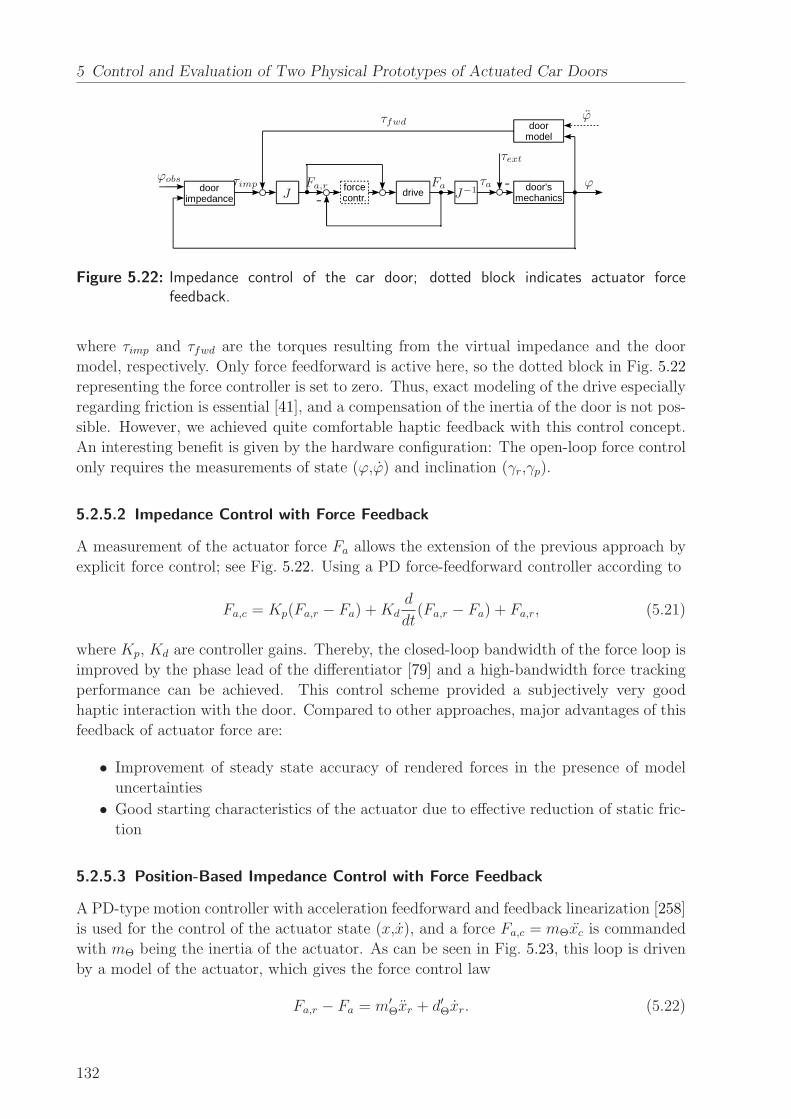
5 Control and Evaluation of Two Physical Prototypes of Actuated Car Doors
forcecontr. drive door's
mechanicsdoor
impedance
doormodel
ϕobs τimp
τfwd
Fa,r FaJ J−1
τa
τext
ϕ
ϕ
Figure 5.22: Impedance control of the car door; dotted block indicates actuator forcefeedback.
where τimp and τfwd are the torques resulting from the virtual impedance and the door
model, respectively. Only force feedforward is active here, so the dotted block in Fig. 5.22
representing the force controller is set to zero. Thus, exact modeling of the drive especially
regarding friction is essential [41], and a compensation of the inertia of the door is not pos-
sible. However, we achieved quite comfortable haptic feedback with this control concept.
An interesting benefit is given by the hardware configuration: The open-loop force control
only requires the measurements of state (ϕ,ϕ) and inclination (γr,γp).
5.2.5.2 Impedance Control with Force Feedback
A measurement of the actuator force Fa allows the extension of the previous approach by
explicit force control; see Fig. 5.22. Using a PD force-feedforward controller according to
Fa,c = Kp(Fa,r − Fa) +Kd
d
dt(Fa,r − Fa) + Fa,r, (5.21)
where Kp, Kd are controller gains. Thereby, the closed-loop bandwidth of the force loop is
improved by the phase lead of the differentiator [79] and a high-bandwidth force tracking
performance can be achieved. This control scheme provided a subjectively very good
haptic interaction with the door. Compared to other approaches, major advantages of this
feedback of actuator force are:
• Improvement of steady state accuracy of rendered forces in the presence of model
uncertainties
• Good starting characteristics of the actuator due to effective reduction of static fric-
tion
5.2.5.3 Position-Based Impedance Control with Force Feedback
A PD-type motion controller with acceleration feedforward and feedback linearization [258]
is used for the control of the actuator state (x,x), and a force Fa,c = mΘxc is commanded
with mΘ being the inertia of the actuator. As can be seen in Fig. 5.23, this loop is driven
by a model of the actuator, which gives the force control law
Fa,r − Fa = m′Θxr + d′Θxr. (5.22)
132

5.2 Close-to-Series Door Prototype with One Actuated DOF
actuatoradmittance drive door's
mechanicsdoor
impedance
doormodel
positioncontroller
ϕobs τimp
τfwd
Fa,r FaJ J−1
τa
τext
ϕ
ϕ
xr
xJ−1
xcmΘ
Fa,c
Figure 5.23: Position-based impedance control with force feedback.
dooradmittance
drive door'smechanics
doorimpedance
doormodel
positioncontroller
inversedynamics
observer
ϕobs τimp
τext τa,c − τext
τa
τext
ϕ
ϕ
ϕr ϕc τa,c
Figure 5.24: Position-based impedance control with force observer.
It thereby requires the measurement of the actuator force Fa. m′Θ and d′Θ are the pa-
rameters of this admittance, which can be chosen by the system designer. They directly
affect the overall dynamic perceived by the user. Reasonable values for mass and damping
were found to be 0.5mΘ ≤ m′Θ ≤ 1.5mΘ and d′Θ = 500 Ns/m. Due to the constant, rather
low damping, the overall damping characteristics are close to the virtual door impedance
described in subsection 5.2.4.3.
The benefits of this scheme are:
• Improved rejection of unmodeled friction effects of the actuator by use of a high gain
motion control
• Possibility to render an increased inertia of the door without a measurement of ϕ
Unfortunately, due to the inherent gear backlash of the drive, this control concept yielded
a rather limited performance.
5.2.5.4 Position-Based Impedance Control with Force Observer
A combination of the virtual impedance defined in subsection 5.2.4.3 and an admittance
model of the door is proposed. This defines the overall system dynamics, as can be seen
in Fig. 5.24.
Again, a motion controller similar to [258] has been used, leaving out only the acceler-
ation feedforward. Similar to Eq. (5.22) an admittance
τimp − τext = Θ′Dϕr + d′Dϕr (5.23)
133

5 Control and Evaluation of Two Physical Prototypes of Actuated Car Doors
is set up now, where Θ′D and d′D are the desired inertia and damping of the actuated car
door, respectively. Reasonable values are given by 0.5ΘD ≤ Θ′D ≤ 1.5ΘD and a rather low
damping d′D = 2 Nms/rad.
The external interaction force τext needed to drive the admittance (Eq. (5.23)) can be
estimated by an observer [194, 78]. Therefore, a model of the inverse dynamics of the door
is used (see (Eq. (5.8))).
For the correct estimation of interaction force (τext = τext) we assume that τa,c = τaholds, so no explicit measurement of the actuator force is conducted. This relation given
by the drive model has been validated for the control scheme in subsection 5.2.5.1 by means
of the force sensor. However, the observer requires the measurement of the acceleration ϕ.
Advantages of this observer-based approach are:
• Possibility to model the global inertia and damping of the door with respect to the
workspace coordinate ϕ
• Effective suppression of nonlinearities (e.g. friction of door and actuator)
However, the performance was rather limited. The reason for this is that the actuation
and the measurement of acceleration were not collocated, as also mentioned in [79]. The
finite structural stiffness of the mechanical elements in between accounts for higher-order
dynamics, which have been neglected in the observer model.
5.2.5.5 Summary
The best (subjectively measured) performance of all four implementations was achieved by
the impedance control with force feedback (subsection 5.2.5.2). A low gain loop explicitly
closed on the actuator force improves force tracking performance, which directly affects
the quality of haptic rendering. By measuring the actuator force at the output, the (time-
varying) friction of a (low cost) actuator can be compensated effectively. The control
scheme requires the measurement of position, acceleration, and actuator force, and thus is
rather costly when compared to the three alternative control concepts. Nonetheless, as it
yielded the subjectively best haptic sensation, we chose it as the reference setting for the
evaluation described in subsection 5.2.6.
From a performance point of view, the most promising alternative would be the use
of impedance control without force feedback. Thus, the force sensor could be omitted,
significantly lowering the cost of the overall system.
Stability problems arising from high-gain control loops can be avoided using these two
schemes. However, the rendering of high impedances such as the door stop requires ac-
cordingly high controller gains. The control gains for the state feedback are limited in
practice due to several nonlinearities:
• Backlash of the transmission
• Finite stiffness of the mechanical structure
• Current limit of the actuator
This results in a rather low bandwidth of the position tracking, which is the main reason
for the poor performance of the position-based control schemes. Technically, it would
134

5.2 Close-to-Series Door Prototype with One Actuated DOF
have been no problem to use a better transmission and a more powerful actuator. This
surely would result in a much better performance of the position-based control schemes,
possibly making them an interesting alternative. However, as a good performance could
be achieved with the impedance control of our low-cost hardware setup, we believe that a
good trade-off between performance and costs has indeed been found.
5.2.6 Manual Door Operation: Evaluation
We experimentally evaluated the manual door operation through a user study with 16
participants. The results indicate that the haptic interaction with this actuated car door
is indeed appreciated by the users.
5.2.6.1 Design of the User Study
Selection of the Evaluation Parameters The most relevant parameters for the haptic
interaction with the actuated car door were expected to be rendered mass, damping, de-
celeration, and the parameters of the variable door stop (conventional door: M ≈ 26 kg,
Ff1 ≈ 3Nm). The graduations described in Tab. 5.5 were thought to allow a quantitative
assessment of the influence of these parameters on the haptic perception of the door. They
contain a combination which provided a very good haptic interaction during the develop-
ment of the control concept: ‘natural‘ mass (m2), ‘low‘ damping (d2), stepless door notch
‘active‘, ‘high‘ deceleration, ‘high‘ stop damping and ‘short‘ release time. This combination
was used as reference setting in the user study.
Table 5.5: Evaluation parameters for the user study. The reference settings are given in bold.
Parameters Graduations
rel. mass M ′
M‘low‘, m1: 0.6 ‘nat.‘, m2: 1.0 ‘high‘, m3: 1.4
damp.τ+
dmp
ϕth[Nms/rad] ‘none‘, d1: 0 ‘low‘, d2: 5 ‘high‘, d3: 8
door notch τnch ‘inactive‘ ‘active‘
decel. ϕmax[rad/s2] ‘low‘: 1.00 ‘high‘: 1.75
damping Kd ‘low‘: 75 ‘high‘: 150
release time tr[s] ‘long‘: 1.5 ‘short‘: 0.5
Design of an Evaluation Sheet Based on Tab. 5.5, an evaluation sheet was designed.
The first part consisted of four questions which should give the general impression of the
users: general usability (Q1), manual operation of the door (Q2), equivalence of desired and
actual motion (Q3), and the behavior at door stop (Q4). Possible answers were good (3),
rather good (2), rather bad (1), and bad (0)).
The second part was designed to allow a full-factorial analysis of the influence of mass
and damping on the haptic interaction with the door. This is done by allowing the par-
ticipant to judge on each setting, e.g. m1d3, in comparison to the reference setting m2d2.
Possible answers were as follows: much better (2), better (1), no difference (0), worse (-1),
and much worse (-2).
135

5 Control and Evaluation of Two Physical Prototypes of Actuated Car Doors
Table 5.6: Evaluation results for the actuated car door based on a user study with 16participants.
mean st.dev. mean st.dev.
Q1 2.56 0.61 m1d1 -1.06 1.03
Q2 2.44 0.70 m1d2 -0.31 1.21
Q3 2.63 0.60 m1d3 -0.19 1.13
Q4 2.38 0.78 m2d1 -0.31 0.68
Q5 -0.31 1.04 m2d2 - -
Q6 -0.88 1.11 m2d3 0.06 1.03
Q7 -1.00 1.06 m3d1 -0.56 1.06
Q8 0.13 1.17 m3d2 -0.38 0.99
Q9 2.50 0.71 m3d3 -0.25 1.25
The third part consisted of four questions, each going along with one variation of τnch,
ϕ, tr, and Kd: Preferable without stepless door notch (Q5), with lower deceleration (Q6),
with longer time for deactivating door stop (Q7), and with low damping (Q8)? These
questions could be answered on a scale of five steps, analogous to the second part.
The evaluation finished with Q9, which equals Q1.
5.2.6.2 Experiment and Results
We had 16 participants (15 male). Their mean age was 42.4 years (σ = 11.06), and only
one participant was not right-handed. All participants were employees of BMW. The
group therefore certainly was not statistically matched to the general population of car
door users. Indeed, we expected to get much more critical ratings on the performance of
the actuated door, because many of these automotive experts are focused on achieving the
best customer acceptance for the individual car parts they design. This group therefore
promised to give valuable insights into how the actuated car door performs and whether
it would be accepted by potential customers.
The participants conducted the experiment in the order given by the evaluation sheet.
We intentionally did not randomize the order of the questions in the first part, because
Q1 and Q2 should be answered right before the user could significantly adapt to the novel
door. This gives a valid estimate of the first impression of the door, which is considered
to be an important criterion for customer acceptance in the automotive industry. In the
second part, we randomized the order of the mass-damping-settings to prevent a bias of
the evaluation by learning effects. After this part, every participant had operated the door
for more than 15 minutes. Therefore, we assumed that each user had got used to the door
by then, such that no significant adaption would take place in part 3. Accordingly, Q5–Q8
were not randomized.
While the participants moved the door with the respective controller parameter setting,
an investigator asked them the questions, operated the control elements, and filled out the
the evaluation sheet. This might have slightly biased the evaluation of Q1–Q4 and Q9.
However, we believe that this is not relevant because of the professional participants. The
results of the evaluation are displayed in Tab. 5.6.
136

5.2 Close-to-Series Door Prototype with One Actuated DOF
5.2.6.3 Analysis and Discussion of the User Study
As can be seen from the mean values of Q1–Q4, people liked the actuated car door and
its features. Only a few participants rated aspects to be “rather bad”, and no-one rated
any aspect to be “bad”. This suggests that the proposed concept would be accepted by
customers.
The comparison of different mass and damping settings revealed that m2d2 and m2d3
were liked most. To analyze the results in detail, at first a two-factorial ANOVA (Analysis
of Variance) was used. The 3x3 design that has been chosen allows the analysis of the influ-
ence of mass and damping (independent variables) on the rating of the manual operation of
the car door (dependent variables). p = 0.05 was used as threshold of significance. Under
consideration of the sphericity, the mass showed to be not significant (F (1.314, 15) = 1.019,
p > 0.05, η2 = 0.64). The damping proved to be significant (F (2, 15) = 6.818, p < 0.05).
The interaction of both factors was not significant (F (4, 60) = 0.815, p > 0.05).
A pairwise comparison of all graduations of the damping according to the Bonferroni
correction showed only for one pair a significant difference: ‘no damping‘ and ‘high damp-
ing‘ (t(15) = 0.521, p < 0.05). Thus, regardless of the mass, high damping positively
influences the haptic interaction with the car door in our setup.
Opinions on the stepless door notch were divided, see the results for Q5 in Tab. 5.6: Half
the participants liked this functionality, while the other half reported that it disturbed the
operation of the door. This corresponds to the evaluation result of the variable door detent
described in Chap. 4.2.6.3. Thus, the simulation result provided a reliable prediction of
the rating of such an effect at a real door.
The mean values of Q6 and Q7 revealed that the deceleration should indeed be high
and that the time for releasing the door right after a stop should be short, just as in the
reference parametrization. However, according to Q8, there is no clear tendency on the
variation of the damping Kd.
A statistical evaluation revealed that two factors of the variable door stop were signif-
icant when comparing the reference setting with the alternative setting: the deceleration
(t(15) = 8.05, p < 0.05) and the release time (t(15) = 3.651, p < 0.05).
Interestingly, there were no significant differences in the general estimation of the actu-
ated car door at the beginning and the end of the experiment: Q1 and Q9 lead to similar,
very good results. Of the 16 participants, a majority – 10 people – rated the door with the
best value of the given graduations, and a further 4 rated it with the second best. This
approval of 87.5% of the participants suggests that the actuated car door is not only liked
right from the start by the users, but also after people get used to it.
5.2.7 Summary
We investigated a variety of sensor concepts for the determination of the interaction force
at one-DOF rotational car doors. Based on our findings, the most promising concept is
given by a combination of motion sensors with a camera-based determination of the HIP.
The latter has been filed as a patent in [245]. Both from a technical and an economical
point of view, an actuated car door should be equipped with a position and acceleration
sensor to achieve an effective determination of position, velocity, and acceleration, which
137

5 Control and Evaluation of Two Physical Prototypes of Actuated Car Doors
in turn can be used to determine the interaction force which is necessary for some haptic
control schemes.
We showed a way to design an actuated car door such that potential customers like it
both at first contact and after getting used to it. Furthermore, due to its clever mechanical
concept, it can be built into conventional car doors without great modifications. The main
components of the door are a linear drive, a current-controlled amplifier, and sensors for
position, acceleration, and actuator force.
While this setup enables an advanced automatic door operation, our main focus here
was the control and evaluation of the manual door operation. We implemented and tested
four different impedance control schemes. The impedance control with force feedback was
the best choice for this door for several reasons. We used this control scheme to render
specified impedances, i.e. haptic effects that are meant to support the user while he or she
operates the door. One such effect was a variable door detent that allows the placing of
the door at a desired location where it is fixed by a position controller.
A major advantage is the possibility to vary the dynamic properties of the door (mass,
damping, and “synthetic” haptic effects). Indeed, an evaluation with 16 participants re-
vealed that some of the controller parameters had a statistically significant influence on the
feeling of the users. For example, higher damping was clearly preferred to a low damping.
The most important result of the evaluation was that a majority of 87.5% of the partic-
ipants liked the car door, with 62.5% giving the highest grading. This approval was found
both at the first contact of the participants with the novel door, and after they got used
to it. From this we reason that the customer acceptance of our actuated car door would
be relatively high and hence it would be promising to market such doors.
It should be noted that these positive results were successfully validated in a follow-up
study conducted by Michael Graf at BMW Forschung und Technik GmbH which is de-
scribed in [240]. The goal was to find out which elements of the overall system contributed
to this approval, and to what extent. This information would be helpful in evaluating the
trade-off between hardware effort and user satisfaction. 19 different configurations were
presented, including a full- and semi-active control mode of the actuator and a collision
avoidance scenario. The configurations should be rated on a scale from 1 (very bad) to 6
(very good). Eighteen men and 9 women with an average age of 38.7 years (σ = 11) partic-
ipated in the experiment. The analysis of the user study revealed that the fully-actuated
car door provides the best handling. After the evaluation, 89% of the participants told
that they generally appreciated the actuated door, and 89% the collision avoidance.
138

6 Conclusion and Future Work
This thesis described many aspects of the simulation, haptic control, and evaluation of
actuated mechanisms using the example of car doors with one or more degrees of free-
dom (DOF). We were the first to propose concepts and controllers for actuated car doors
with more than one DOF and filed a corresponding generic patent [242]. Furthermore, a
promising force determination method has also been filed as a patent [245], and advanced
methods and controllers have been developed for several virtual and physical car door
prototypes. Our extensive evaluations revealed a predominant approval of and desire for
car doors with one and two actuated DOF. Based on our results, the automotive industry
can confidently start to develop actuated car doors for the mass market.
6.1 Concluding Remarks
Virtual Reality Prototyping by Active Admittance Control
Virtual Reality Prototyping (VRP) with haptic feedback offers great benefits in the de-
velopment process of actuated systems. By introducing the Active Admittance (AA), we
proposed a generic, straightforward admittance control scheme for the haptic rendering of
actuated mechanisms. It extends the conventional admittance control by modeling the ac-
tuation and the movable parts of the mechanism separately. The actuation includes models
of all significant elements of the actuation loop, particularly the sensors, the controller,
the actuators, and the transmission. The modeling of these components is supported by
a comprehensive overview of the haptically relevant properties of mechatronic systems.
Based on the AA, the actuation effect and the resulting simulated motion is calculated
and can be displayed by a haptic device. The controller design and stability issues of
Active Admittance Control (AAC) have been discussed. Due to the analogy of human
and controller effecting the same object, functionality aspects and methodologies can be
derived from shared and supervisory control. Stability considerations are based on the
abundant research on the control of haptic interfaces. However, no common approach is
suited or desired for the generic control design of actuated systems. Rather, the control de-
sign has to carefully consider the specific goals and restrictions of the mechatronic system
in order to choose the appropriate control structure. Therefore, a guideline is proposed to
help in the identification of the least conservative control structure. AAC has successfully
been demonstrated by modeling and haptically rendering a novel actuated car door with
two DOF.
Generic Methods for the Haptic Support of Human-System-Interaction
AAC is also very well suited for the integration of assistive functions in the controller of
the simulated system. In Chap. 3, to achieve an intuitive, convenient, and safe operation
of actuated car doors with arbitrary kinematics, three generic support methods have been
139

6 Conclusion and Future Work
developed. For mechanisms with more than one DOF, preferable paths or trajectories can
be predefined offline, e.g. based on ergonomic investigations or on optimality criterion.
These motions can be utilized as Static Virtual Fixtures. Our advanced implementation
combines these Static Virtual Fixtures with Dynamic Virtual Fixtures to achieve an in-
tuitive manual handling and to enable the operator to switch between predefined paths.
This is supported by an online estimation of the intention of the user and a subsequent
calculation and update of the Dynamic Virtual Fixture which guides the motion towards
the predefined path with the highest likelihood. Especially in the presence of obstacles,
predefined paths must not be used without additional measures. One possibility is to
compute collision-free paths online, which necessitates a near real-time path planner. This
can be used as the foundation of Dynamic Virtual Fixtures during manual operation, or as
controller input during automatic operation. We developed a suitable generic path planner
and showed that the performance is sufficient for a real-time haptic support. Furthermore,
we proposed the Generalized OR Paradigm, which enables an advanced adaptation and
optimization of multi-threaded path planning. It has been described why collision avoid-
ance is a prerequisite for both manual and automatic operation of a car door. Through our
multi-threaded approach, we achieved response times of ≈ 13ms, enabling a real-time hap-
tic support and the use of bounding boxes which are tight approximations. Furthermore,
several implementation approaches have been described. The proposed support methods
can easily be integrated into AAC schemes by applying their respective supportive effect in
parallel to the human user input exerted on the virtual model (EOM) of the car door. Our
applications of these methods to simulated car doors as well as to hardware prototypes
have been described in Chap. 4 and Chap. 5.
VRP of Actuated Car Doors in General
Up to now, there have been no concrete guidelines for the design of the dynamics of an
actuated car door. In practice, the engineers try to balance all factors based on best
practices and personal experience. This is not viable for car doors with more than one
DOF, because there is no previous knowledge, and the overall dynamics resulting from the
coupling of the single DOF can be very complicated. The complexity increases even further
when actuated car doors are to be developed – the design of a controller that provides a
desired haptic interaction characteristic necessitates appropriate tools. Our approach is
to utilize VRP with haptic feedback to develop, simulate, control, and evaluate new door
concepts.
VRP of Actuated Car Doors with Several DOF
In Sec. 4.1, we proposed a VRP test bed with haptic feedback comprising automotive end-
effectors and several networked computers to distribute computing tasks such as obstacle
detection, collision avoidance, and path planning. We used the VRP test bed to evaluate
five preliminary door concepts. The result was that a Two-Link Door (TLD) is the pre-
ferred concept. We investigated it in more detail together with two other door concepts, a
Free-Flying Door (FFD) and a Pivotable-Sliding Door (PSD). An evaluation of the FFD
combined with the intention recognition described in Sec. 3.1 revealed that the ten par-
ticipants liked the door simulation itself, whereas the haptic guidance based on intention
140

6.1 Concluding Remarks
recognition resulted in polarized opinions. It became evident that the preference for haptic
support strongly depends on personal characteristics. For instance, all the women preferred
a “light” car door, while the men did not. This indicates that door dynamics indeed do
matter. During our investigation of the preferred dynamics of a PSD it became evident
that these dynamics strongly depend on the movement of the door (swinging/sliding/com-
bined) and on personal characteristics. The best ratings were achieved for the individually
selected parameter sets. This is a clear indication that the car door dynamics should be
adaptable with respect to the current user as well as to the manual operation situation.
We developed a variety of controller modules for a TLD. A comprehensive evaluation with
20 participants revealed that: 1) The height/weight of the user has a very strong influence
on the preferred dynamics, but the gender has not. 2) Most, but not all of the supportive
functions are approved by participants. 3) The haptic support given by collision avoidance
and path planning is appreciated very much. 4) Light doors were preferred and received
an excellent rating when combined with all assistive functions. These are very important
findings which enable the user-centered design of both unactuated and actuated car doors
with more than one DOF. Based on the evaluation results, we strongly recommend deter-
mining the height of the user and to use this information as input to an adaptable car door
controller. We draw the conclusion that door dynamics do matter and that an adaptive
controller has to be used to provide a superior manual interaction. The adaptation should
be based on situation and user, specifically his or her height. Overall it can be stated
that VRP is indeed very useful for both the development and the evaluation of car door
concepts.
VRP of Car Doors with One Rotational DOF
Car doors with one rotational DOF are dominating the market today, and they will be
important also in the future. For the design of a high-fidelity haptic device for the sim-
ulation of car doors with one rotational DOF, in Sec. 4.2 the basics for the performance
specification based on the analysis of a typical worst-case user interaction and a detailed
model of a car door have been derived. It was pointed out that the promising inclusion of
actuation effects in the haptic rendering of car doors does not impose significant additional
restrictions. Furthermore, a very detailed model for a BMW 3 Series driver’s car door has
been derived and implemented. The accuracy of the overall model was shown by comparing
the simulated motion with measurements. In the performance specification we concluded
that a one-DOF hardware setup consisting of a direct drive with a high mechanical stiff-
ness, torque output, and a high control bandwidth have to be provided. We created a
backlash-free, very stiff haptic device to which various end-effectors can be attached. Ac-
curate force and position sensors enable a high-fidelity rendering. Various measures ensure
safe operation of the device. An extensive user study with 17 participants was conducted.
We found that the participants can distinguish between simulation and reality. However,
the standard model of the car door is rated rather similarly to reality, and linear deviations
from the standard model were rated linearly decreasing. An important result is that the
haptic simulation can reliably be used to evaluate different door concepts if the difference
between them is at least in the area of 13% to 26%, or 5 Nm to 10 Nm, respectively. When
we investigated the preferred efforts for the manual operation of the door, we found that
141

6 Conclusion and Future Work
the larger the Coulomb friction and the larger the door detent torque, the lower is the ap-
preciation by the participants. This was more evident for closing motions, because people
tend to close doors with a push, while the opening motion is typically slower. This fact
should be exploited in the controller design of actuated car doors: Instead of searching for
an overall trade-off for the rendered dynamics, the dynamics should be adapted for each
mode of operation individually.
Control and Evaluation of an Actuated TLD Prototype
To put these results from simulation into practice, together with MiMed (TU Munchen)
we developed the prototype of an actuated Two-Link Car Door (TLD) in the framework
of MechaTUM. The prototype’s hardware setup, control of manual and automatic opera-
tion, and successful evaluation are described in Sec. 5.1. It utilizes a variety of assistive
functions described in this thesis: A state machine providing a joint seat/door action,
path planning, collision avoidance, and clamping protection during manual and automatic
operation. Results of the large-scale AttrakDiff evaluation of the manual operation of the
TLD prototype were presented: Even in a complicated usage scenario, a good usability
was achieved with the haptic support provided by the controller of the actuated car door –
the level of discomfort was significantly decreased. The rating of ergonomics experts leads
to the conclusion that such a door is indeed “desired”, exhibiting both a high hedonic and
pragmatic quality. This is an excellent result for such a worst-case parking situation.
Control and Evaluation of an Actuated Conventional Car Door Prototype
Furthermore, in Sec. 5.2 we developed and investigated force measurement concepts for
rotational car doors with one DOF which have in part been filed as a patent in [245],
and we investigated the advanced control of a close-to-mass-production actuated car door
provided by BMW Forschung und Technik GmbH. By utilizing a linear, non-backdrivable
actuator and various sensors, both automatic and manual door operations are enabled. A
discrete state controller ensures a safe operation of the door, including automatic opening
and closing. The realization of a supportive, high-quality haptic interaction with the car
door for the manual operation is the principal part of our work. Due to the impracticality
of a direct measurement of the user interaction force at a car door, we chose impedance
control to render the desired dynamics. The impedance was designed to provide a conve-
nient, intuitive, and safe manual handling of the door. We implemented and tested four
different impedance control schemes, of which impedance control with actuator force feed-
back performed best. Two experimental evaluations with 16 and 27 participants revealed
a predominant approval of the actuated car door.
6.2 Future Work
The investigation of the VRP-based simulation, control, and evaluation of actuated mech-
anisms with more than one DOF was in many aspects virgin soil. While we tried to get
the big picture, not all relevant aspects could be investigated by in-depth studies. Possible
extensions of this work and promising research directions are pointed out in the following:
142

6.2 Future Work
• Active Admittance Control (AAC): A thorough investigation of AAC should be con-
ducted with respect to the robust stability of the overall haptic simulation. In the
end, specific design guidelines should be derived to guarantee a robustly stable design
of the controllers of haptically simulated mechatronic systems.
• Virtual Reality Prototyping (VRP): The ideal of a truly transparent rendering re-
quires hardware and software that overcomes the current limitations. Potential is
especially seen in the hardware-driven increase of motion control bandwidth. For
instance, the one-DOF car door simulator could further be enhanced by replacing
the current direct drive by an even more dynamical one.
• Path planning: As pointed out in this thesis, the proposed Generalized OR-
Parallelization could be utilized by several approaches to achieve a real-time path
planning even in complex and changing environments:
– Combination of different algorithms (e.g. RRTs and PRMs) to achieve a synergy
of their individual advantages
– Concurrent use of different parameter sets of path planning algorithms
– Online adaptation of these parameter sets to the respective environment
– Online adaptation of the types and numbers of parallel executed planning
threads to the respective environment
Ultimately, when computing resources are virtually not limited any more, the parallel
execution of a large number of all known path planning algorithms with all possible
parameterizations will enable the determination of a collision-free trajectory within
a timespan near the global minimum.
• Psychology of the haptic interaction at car doors: More detailed psychological studies
should be conducted to determine the preferred dynamics and assistive functions of
actuated mechanisms. Specifically, guidelines for user studies should be provided
that enable a valid determination of the preferred dynamics of a mechanism even if
it possesses complex kinematics.
• Safety: The most critical issue for making actuated car doors a success in the au-
tomotive industry is seen in the area of safety. It will require a lot of effort to set
up appropriate guidelines for the design and operation of novel doors, and finally to
implement this functionality during the serial development of cars.
However, we are confident that these challenges will be met. In the future, VRP with
haptic feedback will be established in industrial design, and actuated car doors providing
a superior manual interaction will find their way into automotive mass production.
143


A State of the Art of Unactuated Car Doors
Even in the design of conventional car doors, there are a variety of typical challenges:
• Reducing weight of the door is mandatory to lower the overall power consumption
of the car.
• However, the inertia I zz of the car door should usually not be reduced significantly.
From an ergonomical point of view, the velocity of the car door should not have
to be very high to achieve a complete closing of the door after a push by the user:
q ≤ qerg,crit . This means that there is a lower bound for the inertia in terms of the
kinetic energy E kin,crit which is necessary for a full closing of the door: I zz ≥2E
kin,crit
qerg,crit2 .
• No experiments are known which indicate whether users prefer the usual, a higher,
or a lower inertia of the door.
In the automotive mass market, up to now the following one-DOF car doors prevail:
1. Front-/Roof-Hinged Swing Doors
a) Rotational axis at the A-pillar of the car chassis (>98% market share in 2009)
b) Rotational axis at the roof (e.g. Mercedes-Benz SLS AMG)
2. Rearwards-Opening Sliding Doors
Due to safety concerns, most other types of car doors have disappeared. Regulations
issued by the Economic Commission for Europe, specifically the ECE R11.03, defined and
limited the design possibilities [73, 222]. Based on these, rear-hinged rear doors have been
re-introduced by the Rolls Royce Phantom in 2003 and the Opel Meriva in 2010. The
various measures for providing safety of the overall door system are described in [222].
This gives an impression of how tedious even the development of close-to-conventional car
doors is, which is the main reason for the slow development of alternative door concepts.
Lately, a two-DOF kinematic has been proposed to enable a sliding door movement
without the necessity for exterior rails [19]. However, it also aimed at one-DOF movements.
145

B Technical Details Related to the AAC of Car
Doors
B.1 EOM of Several Simulated Car Doors
Generally, the dynamics of a rigid mechanism can be expressed be the canonical equation
H(q)q +C(q, q)q + τττG(q) + τττF (q, q) = τττA + JT f (B.1)
where H(q) represents the joint space inertia, C(q, q)q the joint space Coriolis and cen-
trifugal terms, τττG(q) and τττF (q, q) the gravity and friction effect, τττA the actuation and
JT f the external forces and torques acting on the mechanism.
During our course of research, we simulated a variety of different car door kinematics
with more than one DOF. Some kinematics are depicted in Fig. B.1, and they will be
shortly described with their respective EOM in the following. In the sketches of the
kinematics, some relevant parameters as well as the minimal coordinates are indicated to
give a better understanding of the model. Without loss of generality, all DOF are assumed
to be orthogonal with respect to gravity, such that no gravity wrench is acting on the
mechanisms.
B.1.1 Car Door Body and Free-Flying Door (FFD)
Throughout the thesis, the same model of the car door body has been used for all more-
than-one-DOF simulations: The driver’s door of a BMW 6 Coupe. Its VRML model is
depicted in Fig. D.6, and the most relevant geometrical (with respect to the car COS) and
dynamic parameters are given in the following.
Table B.1: Geometrical parameters: Location of COG and hinge
x y z
COG (window closed) 1.3384 -0.7919 0.4261
COG (window opened) 1.2634 -0.7613 0.3590
Middle of upper door hinge 0.6959 -0.8495 0.4574
Middle of lower door hinge 0.6931 -0.8578 0.1375
Door hinge used for coarse simulations 0.6940 -0.8530
146

B.1 EOM of Several Simulated Car Doors
xVis10
yVis10
O PSD
xVis10
yVis10
H
DOOR
A
A
H
O
q2 DOOR
TLD
O
C
DFLD
xVis10
yVis10
DOOR
O
DOOR
xVis10
yVis10
SSD
H
H
A
B
A
B
Figure B.1: Overview of the two-DOF car doors simulated at the VRP test bed: 1) Pivotable-Sliding Door (PSD), 2) Two-Link Door (TLD), 3) Double-Four-Link Door(DFLD), 4) Swing-Sliding Door (SSD). The door body DOOR is the same asthe one described in Appendix B.1.1. The fully closed position of the door is indi-cated by the solid blue line. The renderable workspace for the haptic interactionpoint H in x-y-coordinates is given by the ViSHaRD10 is depicted in dashedline.
147

B Technical Details Related to the AAC of Car Doors
Table B.2: Geometrical parameters: Levers
Lever from COG to door hinge lCOG[m] 0.65
Lever from HIP to door hinge lHIP [m] 1.10
Table B.3: Dynamic parameters
Mass m[kg] 26.0
Inertia with respect to door hinge I zz [kgm2] 14.38
Coulomb friction of the door hinge µ[Ns/rad] 1.5±50%
IHinge =
3.71 1.09 5.42
1.09 17.70 0.64
5.42 0.64 14.38
(B.2)
ICOG =
1.35 0.09 0.45
0.09 4.59 0.21
0.46 0.21 3.46
(B.3)
B.1.2 Pivotable Sliding Door (PSD)
The parameters of the Pivotable Sliding Door (PSD) simulated in subsection 2.3.3 and
subsection 4.1.4 is given in Tab. B.4.
Table B.4: Parameters of the simulated PSD
m1 [kg] m2 [kg] IZZ
[
kg
m2
]
lIP [m] l2 [m] µ1
[
Nsm
]
µ2
[
Nsrad
]
T1 [ms] T2 [ms]
6.0 24 3.2 1.2 0.58 1.5 2.5 4.0 5.0
B.1.3 Two-Link Door (TLD)
The proposed Two-Link Door (TLD) consisting of one rotation link and the car door body
is shown in Fig. B.1. One side of the rotation link A is set on the car body through a hinge
axis. The other side will be combined with the car door through a hinge axis. When the
user opens and closes the door, both links will be rotated round its hinge axis.
148

B.2 Typical Opening Paths of Some Car Doors
link m [kg] l [m] I zz [kgm2] µ[Ns/rad]
A 0.715 0.45 0.00368 2Door 26.0 1.10 14.38 1.5
Table B.5: Parameters of the TLD used for the VRP.
Using the Autolev TLD model given in Appendix B.3.1, the EOM have been derived:
(
MTLD11 0
0 MTLD22
)(
q1q2
)
+
(
CTLD11 CTLD12
CTLD21 CTLD22
)(
q1q2
)
=
(
TTLD11 TTLD12 TTLD13 TTLD14 TTLD15
TTLD21 TTLD22 TTLD23 TTLD24 TTLD25
)
fIXfIYτIPτAτT
(B.4)
where MTLDxx= f(q1, q2), TTLDxx
= f(q1, q2) and CTLDxx= f(q1, q2, q1, q2).
With the help of the acceleration, the equation of movement of the end-effector will be
determined through the Jacobian.
XV is10 = lAq1 sin(q1) + lDOOR(q1 + q2) sin(q1 + q2)
YV is10 = −lAq1 cos(q1)− lDOOR(q1 + q2) cos(q1 + q2)
ϑV is10 = q1 + q2
(B.5)
B.2 Typical Opening Paths of Some Car Doors
−0.4−0.3−0.2−0.100.10.2
0.15
0.2
0.25
0.3
0.35
0.4
x [m]
y [
m]
Simulated Path
−0.4−0.3−0.2−0.100.10.20.3
0
0.1
0.2
0.3
0.4
x [m]
y [
m]
Simulated Path
−0.4−0.3−0.2
−0.3
−0.2
−0.1
0
0.1
0.2
0.3
0.4
x [m]
y [
m]
Simulated Path
Figure B.2: Typical opening path for the PSD (l.) and the TLD (transmission ratio: 1 (m.)and 5 (r.)) [85].
149

B Technical Details Related to the AAC of Car Doors
B.3 Autolev Code
B.3.1 Autolev Code of the TLD VRP Simulation
%------------------------------------------------------------------
% File: tld_simulation.al
% Problem: VRP simulation of the idealized TLD
% Author: Michael Strolz, [email protected]
%------------------------------------------------------------------
% Declarations
NEWTONIAN N
FRAMES E
BODIES A, T
POINTS AT, IP
%------------------------------------------------------------------
% Variables
VARIABLES q{2}’
VARIABLES U{2}’
VARIABLES TAU_ACT_A
VARIABLES TAU_ACT_T
VARIABLES F_I_X, F_I_Y
VARIABLES TAU_I_Z
%------------------------------------------------------------------
% Constants, Mass, Inertia
CONSTANTS MU_H_AE, MU_H_AT % Static Friction
CONSTANTS MU_R_AE, MU_R_AT % Dynamic Friction
CONSTANTS L_A
CONSTANTS L_AtoT
CONSTANTS L_TtoIP
MASS A=M_A, T=M_T
INERTIA A, 0, 0, I_A_zz
INERTIA T, 0, 0, I_T_zz
%------------------------------------------------------------------
% Geometry relating unit vectors, Position vectors
SIMPROT(N, E, 3, 0)
SIMPROT(N, A, 3, q1)
SIMPROT(A, T, 3, q2)
P_Eo_AT> = -L_A*A1> % Position vector from Eo to AT
P_AT_To> = -L_AtoT*T1> % Position vector from AT to To
P_Eo_Ao> = 0.5*P_Eo_AT> % Position vector from Eo to Ao
P_AT_IP> = P_AT_To> - L_TtoIP*T1> % Position vector from AT to IP
q1’ = U1;
q2’ = U2;
%------------------------------------------------------------------
% Angular velocities
W_E_N> = 0>
W_A_N> = U1*A3>
W_T_A> = U2*T3>
%------------------------------------------------------------------
% Velocities
V_Eo_N> = 0>
v2pts(N, A, Eo, Ao)
150

B.3 Autolev Code
v2pts(N, A, Eo, AT)
v2pts(N, T, AT, To)
v2pts(N, T, AT, IP)
%------------------------------------------------------------------
% Forces and Torques
FORCE_IP> += (F_I_X*N1> + F_I_Y*N2>)
Torque(E/A, - MU_R_AE*W_A_E> + TAU_ACT_A*A3>)
Torque(A/T, - MU_R_AT*W_T_A> + TAU_ACT_T*T3> + TAU_I_Z*T3>)
%------------------------------------------------------------------
% Equations of motion
ZERO = FR() + FRSTAR()
KE()
KANE()
%------------------------------------------------------------------
% Reformed result
solve( ZERO, U1’, U2’)
%------------------------------------------------------------------
% Save output
Save tld_simulation.all
%------------------------------------------------------------------
% End of file
151

B Technical Details Related to the AAC of Car Doors
B.3.2 Autolev Code of the TLD Prototype
%--------------------------------------------------------------------
% File: tld_prototype.al
% Problem: Dynamics of the elastic TLD prototype
% Author: Michael Strolz, [email protected]
%--------------------------------------------------------------------
% Newtonian, bodies, points
Newtonian N
Points O
Bodies B1, B2, B3, B4, B5
Points S1, S2, S3, S4, S5
Points S1cog, S2cog, S3cog, S4cog, S5cog
%--------------------------------------------------------------------
% Declarations and parameters (partly estimated)
MotionVariables’ Q1’’, Q2’’, Q3’’, Q4’’, Q5’’
Constants L_B1 = 0.0
Constants L_B2 = 0.24
Constants L_B3 = 0.0
Constants L_B4 = 0.0
Constants L_B5 = 1.10
Constants L_B1cog = 0.0
Constants L_B2cog = 0.12
Constants L_B3cog = 0.0
Constants L_B4cog = 0.0
Constants L_B5cog = 0.65
Constants M_B1 = 0.5
Constants M_B2 = 2.2
Constants M_B3 = 0.5
Constants M_B4 = 3.0
Constants M_B5 = 15.0
Constants IZZ_B1 = 0.0015
Constants IZZ_B2 = 0.0002
Constants IZZ_B3 = 0.0015
Constants IZZ_B4 = 0.5
Constants IZZ_B5 = 10.0
Constants STIFFNESS_Q2 = 1305
Constants STIFFNESS_Q3 = 1305
Constants STIFFNESS_Q5 = 2763
Constants DAMPING_Q1 = 1.5
Constants DAMPING_Q4 = 1.5
Variables TORQUE_ACT_Q1
Variables TORQUE_ACT_Q4
%--------------------------------------------------------------------
% Mass, inertia
Mass B1 = M_B1
Mass B2 = M_B2
Mass B3 = M_B3
Mass B4 = M_B4
Mass B5 = M_B5
Inertia B1, 0,0,IZZ_B1,0,0,0
Inertia B2, 0,0,IZZ_B2,0,0,0
Inertia B3, 0,0,IZZ_B3,0,0,0
Inertia B4, 0,0,IZZ_B4,0,0,0
152

B.3 Autolev Code
Inertia B5, 0,0,IZZ_B5,0,0,0
%--------------------------------------------------------------------
% Geometry relating unit vectors
Simprot( N, B1, 3, Q1 )
Simprot( B1, B2, 3, Q2 )
Simprot( B2, B3, 3, Q3 )
Simprot( B3, B4, 3, Q4 )
Simprot( B4, B5, 3, Q5 )
%--------------------------------------------------------------------
% Position vectors from origin(n-1) to origin(n)/COG(n)
P_O_S1> = L_B1 * B11>
P_S1_S2> = L_B2 * B21>
P_S2_S3> = L_B3 * B31>
P_S3_S4> = L_B4 * B41>
P_S4_S5> = L_B5 * B51>
P_O_S1cog> = L_B1cog * B11>
P_S1_S2cog> = L_B2cog * B21>
P_S2_S3cog> = L_B3cog * B31>
P_S3_S4cog> = L_B4cog * B41>
P_S4_S5cog> = L_B5cog * B51>
%--------------------------------------------------------------------
% Angular velocities
W_B1_N> = Q1’*B13>
W_B2_B1> = Q2’*B23>
W_B3_B2> = Q3’*B33>
W_B4_B3> = Q4’*B43>
W_B5_B4> = Q5’*B53>
%--------------------------------------------------------------------
% Angular velocities referring to Newtonian frame
W_B2_N> = W_B1_N> + W_B2_B1>
W_B3_N> = W_B2_N> + W_B3_B2>
W_B4_N> = W_B3_N> + W_B4_B3>
W_B5_N> = W_B4_N> + W_B5_B4>
%--------------------------------------------------------------------
% Angular accelerations referring to Newtonian frame
A_B1O_N> = DT(W_B1_N>, N)
A_B2O_N> = DT(W_B2_N>, N)
A_B3O_N> = DT(W_B3_N>, N)
A_B4O_N> = DT(W_B4_N>, N)
A_B5O_N> = DT(W_B5_N>, N)
%--------------------------------------------------------------------
% Linear velocities
V_O_N> = 0>
v2pts(N,B1,O,S1)
v2pts(N,B1,O,S1cog)
v2pts(N,B2,S1,S2)
v2pts(N,B2,S1,S2cog)
v2pts(N,B3,S2,S3)
v2pts(N,B3,S2,S3cog)
v2pts(N,B4,S3,S4)
v2pts(N,B4,S3,S4cog)
v2pts(N,B5,S4,S5)
v2pts(N,B5,S4,S5cog)
153

B Technical Details Related to the AAC of Car Doors
V_B1O_N> = V_S1cog_N>
V_B2O_N> = V_S2cog_N>
V_B3O_N> = V_S3cog_N>
V_B4O_N> = V_S4cog_N>
V_B5O_N> = V_S5cog_N>
%--------------------------------------------------------------------
% Linear accelerations
A_O_N> = 0>
a2pts(N,B1,O,S1)
a2pts(N,B1,O,S1cog)
a2pts(N,B2,S1,S2)
a2pts(N,B2,S1,S2cog)
a2pts(N,B3,S2,S3)
a2pts(N,B3,S2,S3cog)
a2pts(N,B4,S3,S4)
a2pts(N,B4,S3,S4cog)
a2pts(N,B5,S4,S5)
a2pts(N,B5,S4,S5cog)
%--------------------------------------------------------------------
% Torques
Torque( N/B1, -DAMPING_Q1*Q1’*B13> + TORQUE_ACT_Q1*B13>)
Torque(B1/B2, -STIFFNESS_Q2*Q2*B23>)
Torque(B2/B3, -STIFFNESS_Q3*Q3*B33>)
Torque(B3/B4, -DAMPING_Q4*Q4’*B43> + TORQUE_ACT_Q4*B43>)
Torque(B4/B5, -STIFFNESS_Q5*Q5*B53>)
%--------------------------------------------------------------------
% Equations of motion
Zero = Fr() + FrStar()
KE()
Kane( )
%--------------------------------------------------------------------
% Reformed result
solve( ZERO, Q1’’, Q2’’, Q3’’, Q4’’, Q5’’)
%--------------------------------------------------------------------
% Save output
Save tld_prototype.all
%--------------------------------------------------------------------
% End of file
154

B.4 System Analysis of the TLD Prototype
B.4 System Analysis of the TLD Prototype
In this section, fundamental properties of the TLD prototype are described.
System Matrix:
A = 106
−0.0010 0 0 0.8700 0 0 0 0 0 0
0.0000 0 0 0 0 0 0 0 0 0
0.0010 0 0 −7.3950 0 6.5250 0 0 0 0
0 0 0.0000 0 0 0 0 0 0 0
0 0 0 6.5250 0 −7.3950 0.0000 0 0 0
0 0 0 0 0.0000 0 0 0 0 0
0 0 0 0 0 0.8700 −0.0010 0 0 0.0055
0 0 0 0 0 0 0.0000 0 0 0
0 0 0 0 0 0 0.0000 0 0 −0.0058
0 0 0 0 0 0 0 0 0.0000 0
(B.6)
Eigenvalues of A and their condition:
eig(A) = 103
0
0
−0.0146 + 3.7270i
−0.0146− 3.7270i
−0.1733 + 0.7903i
−0.1733− 0.7903i
−0.6243
−0.0000 + 0.0761i
−0.0000− 0.0761i
−1.0030
, condeig(A) = 103
0.0010
0.0010
1.8709
1.8709
0.7017
0.7017
0.6295
0.0381
0.0381
0.1058
(B.7)
Input matrix:
B =
666.6667 0
0 0
−666.6667 0
0 0
0 −0.0002
0 0
0 668.6667
0 0
0 −2.0000
0 0
(B.8)
155

C Feedback-Linearized Position Controller for
ViSHaRD10
C.1 Computed Torque (CT) Control
One of the first and best-known model based control concepts for robot manipulators is
Computed Torque (CT) control depicted in Fig. C.1. The closed-loop dynamics resulting
from the control law
τ = M(q)(qd +Kpe+Kde) + C(q, q)q+ g(q) (C.1)
and
Kp = diag {w21, ..., w
2n} (C.2)
Kd = diag {2ξ1w1, ..., 2ξnwn} (C.3)
where wi and ξi are the bandwidth and the damping for joint qi [259, 223] are described
by linear differential equations [134].
Typically, the highest possible bandwidth wi,max and a critical damping ξi = 1 , i =
1, .., n are chosen [226]. wi,max depends on the resonant modes given by the elasticity of
the joints and links of the robot [199]. This is usually done empirically by an iterative
process: The bandwidth is increased, while ξi is adapted to the corresponding critical
damping.
At theViSHaRD10, the critical damping parameters that were found for the individual
joints resulted in an overall inconvenient high-frequency vibrations of the SCARA joints
1-4. This can be seen in Fig. C.2.
The practical case of critical damping is achieved with ξ1,2,3,4 = 0.4. Tab. C.1 shows all
empirically determined controller parameters.
RobotM(q)
qqd
qd
qd
+
..
.
+
-
KpKd
+
g(q)
+
-
+ q.
C(q,q).
~
~~
Figure C.1: Computed Torque (CT) control scheme [209].
156

C.1 Computed Torque (CT) Control
200 300 400 500 600 700
−100
−50
0
50
100
t[ms]
Tau[
Nm
]
Computed TorquePD
Figure C.2: SCARA torque τq3 for the “critical” damping, compared to the torque resultingfrom a PD controller [209].
joint Kp,i ξ1 400 0.42 400 0.43 400 0.44 500 0.45 500 16 900 17 900 18 4000 19 2000 110 2000 1
Table C.1: CT controller: Empirically determined controller parameters.
157

C Feedback-Linearized Position Controller for ViSHaRD10
C.2 Feedforward+PD (FFPD) Control
The Feedforward+PD (FFPD) control scheme is given by the control law
τ = M(qd)qd + C(qd, qd)qd + g(qd) +Kpe+Kde (C.4)
where e = qd − q and Kp, Kd ∈ ℜn×n are symmetric, positive definite matrices.
Obviously, due to the model-based approach Fig. C.3 exhibits a very similar structure
to Fig. C.1. However, it leads to very different theoretical and practical issues; compare
the Lyapunov-based stability proof [134, 217]. Stability is achieved only if the positive
definite matrices Kp and Kd exceed a critical lower limit. They can be derived by a model
of the robot manipulator and the maximum values of velocity and acceleration. The latter
information is not given for a haptic interface, so we chose the same practical approach for
determining the controller parameters as described in Appendix C.1.
While the critical damping of the CT approach exhibited problems in the SCARA
joints, in the FFPD approach oscillations occurred in the wrist joints. They vanished for
ξ8,9,10 = 0.1. Of course, this comes with a significant overshoot, which per se is not desirable
in haptic rendering. However, when rendering rather large masses/inertias, this was not
perceived by several users. Tab. C.2 shows the final empirically determined controller
parameters.
RobotM(qd)
C(qd ,qd) g(qd)
q
qqd
qd
qd
++
++
..
.
.
.
Kd Kp
++ +
+ -
+ -
~
~~
Figure C.3: Feedforward+PD (FFPD) Control Scheme [209].
joint Kp,i ξ
1 700 1
2 600 1
3 700 1
4 1000 1
5 500 1
6 900 1
7 900 1
8 2000 0.1
9 2000 0.1
10 1000 0.1
Table C.2: FFPD controller: Empirically determined controller parameters.
158

D Technical Details Related to Collision
Avoidance and Path Planning
D.1 Obstacle Detection System provided by RCS
(TU Munchen)
A description of the obstacle detection developed by Christian Scharfenberger at the insti-
tute RCS (TU Munchen) is given in [241]. In the following, the most important assump-
tions, features, and interfaces are presented.
The vision system processes images to identify (up to several hundred) feature points
in the region of interest. Based on these, a 3D model of the workspace of the car door
is generated. It consists of primitive bounding boxes (e.g. spheres) with the center of
each locating a feature point. The dimension of each primitive varies with the predicted
position of the point. If the position cannot be determined exactly in case of noise or other
disturbances, then the volume of the primitive is increased. Thus, due to the uncertainties
of the vision system, the 3DD varies both in the number and the size of the primitives
bounding the objects in the workspace of the door. Fig. D.1 illustrates the process of
model generation using simulated images.
Figure D.1: Generating a disparity map with a pair of rectified images from a calibrated camerasystem. Based on this map, a 3D model of the workspace for collision avoidanceis provided, consisting of primitives (e.g. spheres) [241].
159

D Technical Details Related to Collision Avoidance and Path Planning
D.2 Benchmark Scenarios for Obstacle Detection and
Collision Avoidance
In collaboration with RCS (TU Munchen) and BMW Group, six benchmark scenarios have
been defined for the obstacle detection and the collision avoidance. These are named and
in part displayed in the following.
D.2.1 Scenarios for the Camera Mounted on the Door Mirror
D.2.1.1 Scenario 1: Wall
Figure D.2: Scenario 1: Wall in parallel to the driver’s door.
D.2.1.2 Scenario 2: Pillar
Figure D.3: Scenario 1: Pillar or lamppost in the workspace of the driver’s door.
160

D.2 Benchmark Scenarios for Obstacle Detection and Collision Avoidance
D.2.1.3 Scenario 3: Bunch
Figure D.4: Scenario 3: Obstacle with a complex shape, e.g. a bunch of flowers.
D.2.1.4 Scenario 4: Parking Lot
Figure D.5: Scenario 4: Parking lot, i.e. another car in parallel to the driver’s door.
D.2.2 Scenarios for the Camera Mounted on the Inner Edge of the
Door
In addition to the four scenarios previously described, two scenarios have been included to
verify the clamping protection of actuated car doors:
• Scenario 5: Clamping of hand of user outside of car
• Scenario 6: Clamping of foot of user inside of car
161

D Technical Details Related to Collision Avoidance and Path Planning
D.3 VRML Models of the Exemplary Car Door Body
Figure D.6: Original VRML model of a car door featuring 97148 vertices [119].
Figure D.7: Reduced VRML models of Fig. D.6, featuring 93 (l.) and 64 (r.) vertices [119].
Figure D.8: Convex swept volume VRML models for different one-DOF opening motions [119].
162

D.4 SamPP: Representation of Kinematics
D.4 SamPP: Representation of Kinematics
In robotics, it is often convenient to divide the configuration space in the configuration of
the (usually) movable robot base on the one hand and the configuration of the joints of
the manipulator on the other hand. The base configuration can generically be described
by a transformation with respect to a world coordinate frame (maximum number of DOF:
6). This equals a sequence of three translational and three rotational joints, all of which
are independent of each other. Thus, the base configuration can be expressed by a subset
of the generic joint parameters.
Our generic definition of joint parameters is briefly described in the following:
• ID: Unique number of robot part (foundation of the overall kinematic tree)
• PARENT: ID of the predecessor robot part in the kinematic tree
• REFJOINT: [only if joint is of type dependent:] ID of reference joint
• TYPE: description of the DOF of the robot part
– RIGID: the robot part represents no DOF
– TRANS: translational DOF
– TRANS CSTR: constrained translational DOF
– TRANS DPT: no DOF, translational motion depends on REFJOINT
– ROT: unconstrained rotational DOF
– ROT CSTR: constrained rotational DOF
– ROT DPT: no DOF, rotational motion depends on REFJOINT
• MIN: [only if joint is of type CSTR:] minimum value of DOF
• MAX: [only if joint is of type CSTR:] maximum value of DOF
• DH A: DH parameter (translation along x-axis)
• DH D: DH parameter (translation along z-axis)
• DH ALPHA: DH parameter (rotation around x-axis)
• DH THETA: DH parameter (rotation around z-axis)
• WEIGHT: weighting factor for this DOF
Accordingly, the base parameters are the subset without ID labels, joint type DPT, and
the Denavit-Hartenberg (DH) parameters.
163

E Notes on the QoS of the Communication
Infrastructure
In the following, the choice of UPD as the communication protocol for the networked VRP
system is discussed, and its QoS is heuristically evaluated in terms of packet loss.
E.1 Selection of Ethernet and the UDP Protocol
The communication between the different computers is based on Ethernet. In haptic ren-
dering architectures, instead of the TCP protocol, UDP is used to achieve the utmost
performance. This comes with the risk of a non-restorable packet loss. However, in practi-
cal implementations the safety of the overall system is much more endangered by the packet
loss prevention mechanism of TCP, which can cause a major time delay, than by the loss of
one or two packets in a row. It has only be taken care that important signals are sent more
than one time. Preferably, important signals are sent a constant rate no matter whether a
update of the corresponding variables occurred or not. This has been implemented using
separate, constant-rate communication threads for each network connection.
Given the proposed communication architecture and a 100 MBit-Ethernet, there should
be no overload and thus no significant loss of data: If we assume a communication overhead
of approx. 50 Byte and a maximum data amount of 20 double values, the maximum UDP
packet size is below 250Byte. If 10 communication threads are running with a frequency
of 1 kHz, this makes a maximum communication load of
250Byte · 1 kHz
100MBit/s= 0.02 (E.1)
This is rather light load which is not supposed to degrade QoS. However, we decided to
verify this assumption empirically.
E.2 Heuristic Evaluation of the UDP-Based
Communication
To quantify the real QoS in our network, we performed a heuristic evaluation based on
several combinations of UDP connections, frequency and disturbance load in the network.
This tests are described in the following chapters.
164

E.2 Heuristic Evaluation of the UDP-Based Communication
E.2.1 Evaluation in the Absence of Disturbances
For a first coarse examination, we implemented 10 UDP-connections both in C++ and in
Simulink using a communication library. The results are shown in Tab. E.1 and Tab. E.2,
where f is the chosen UDP frequency, Nc is the number of network connections, Ns and
Nl are the number of sent and lost UDP packets, and Nl/Ns is the lost packet ratio. As
can be seen, the lost packet ratio was very small in this evaluation.
Nc x f Ns Nl Nl /Ns (%)3385504 134 0.0040
10 x 5kHz 3363037 122 0.00403185023 799 0.02503468267 30 0.0009
10 x 1kHz 3296312 60 0.00203305564 21 0.0006
Table E.1: Data loss for a native C++ application (∆t = 10min).
Nc x f Ns Nl Nl /Ns (%)2096833 1793 0.086
7 x 1kHz 2095208 1669 0.0802096263 1916 0.0912997039 3295 0.10
10 x 1kHz 2996041 3456 0.122996087 3528 0.11
Table E.2: Data loss for a Simulink application (∆t = 5min).
E.2.2 Evaluation in the Presence of Disturbances
The following scenarios were defined for the evaluation of the influence of network or
computer load:
1. No additional network or computer load
2. Booting another disk-less Linux computer in the same subnet after 1/5/6/8 minutes
3. Copying large data on one of the computers
The error rate that we found was typically between Nl/Ns = 0.1% and Nl/Ns = 0.5%.
A critical factor of a networked system is the maximum time consumption for receiving
an updated value. This means that it is usually much more critical to miss 10 data packets
in a row than to miss 1000 data packets individually. Therefore, we analyzed the lost
packets with respect to their consecutiveness. We found that typically 90% to 95% of all
errors that occur are individual ones. The probability of five or more consecutive errors is
below 0.002%. This can be seen in Fig. E.1 and Fig. E.2.
165

E Notes on the QoS of the Communication Infrastructure
0 1 2 3 4 5 6 7 8 90
10
20
30
40
50
60
70
80
90
Index of Connection
Num
ber
of E
rror
s
260093%
84396%
319294%
157195%
175291%
61189%
50790%
36592%
123456789...
Figure E.1: Number of consecutive errors for each connection: The upper number gives thetotal number of lost packets (Nl), while the lower percentage gives the share ofthe non-consecutive errors in relation to all lost packets (typically 90% to 95%).
0 1 2 3 4 5 6 7 8 9 10 11 12 13 140
10
20
30
40
50
60
70
80
90
Number of Consecutive Errors
Num
ber
of E
rror
s
C2 >> C5C2 >> C4C2 >> C1C1 >> C5C1 >> C4C5 >> C2C4 >> C2C6 >> C2
Figure E.2: Sorted data of Fig. E.1: Obviously, in comparison to Ns ≈ 3000000 it is a rareevent that more than five consecutive errors occur (below 0.002%).
166

F Detailed Evaluation Results
F.1 Evaluation of the VRP Simulation of the PSD
In this section, details related to the results described in subsection 4.1.4 are given.
Table F.1: PSD Experiment part 1: Individually selected parameters of the seven participantsthat did the sliding motion first and the swinging motion thereafter.
mA mDOOR Σm µA µDOOR
Sliding F. 1 0.40 4.60 5.00 0.00 2.50
Sliding F. 2 0.40 23.00 23.40 0.10 5.00
Sliding F. 3 2.00 11.50 13.50 0.40 5.00
Sliding F. 4 12.00 22.50 34.50 0.75 6.00
Sliding F. 5 1.20 22.50 23.70 1.05 4.60
Sliding F. 6 4.00 18.00 22.00 0.15 22.00
Sliding F. 7 1.00 18.00 19.00 1.50 12.00
mean 3.00 17.16 20.16 0.56 8.16
st.dev. 4.16 6.86 9.20 0.56 6.78
Table F.2: PSD Experiment part 1: Individually selected parameters of the seven participantsthat did the swinging motion first and the sliding motion thereafter.
mA mDOOR Σm µA µDOOR
Swinging F. 1 0.40 4.60 5.00 0.04 5.00
Swinging F. 2 2.00 11.50 13.50 0.12 10.00
Swinging F. 3 0.40 11.50 11.90 0.00 0.00
Swinging F. 4 1.00 13.50 14.50 0.30 8.00
Swinging F. 5 4.00 18.00 22.00 0.45 2.00
Swinging F. 6 1.00 13.50 14.50 0.00 2.00
Swinging F. 7 4.00 13.50 17.50 0.08 8.00
mean 1.83 12.30 14.13 0.14 5.00
st.dev. 1.58 4.03 5.20 0.17 3.79
167

F Detailed Evaluation Results
Table F.3: PSD Experiment part 1: Overall average and standard deviation of the 14 partici-pants that did the swinging and sliding motion consecutively.
mA mDOOR Σm µA µDOOR
mean 2.41 14.73 17.14 0.35 6.58
st.dev. 3.08 5.96 7.83 0.45 5.52
Table F.4: PSD Experiment part 2: Final parameter setting adapted by the participants duringtwo-DOF motions based on their previous individual setting described in Tab. F.1and Tab. F.2.
mA mDOOR Σm µA µDOOR
Person 1 0.80 2.30 3.10 0.06 1.00
Person 2 0.40 4.60 5.00 0.40 5.00
Person 3 0.80 9.20 10.00 0.02 1.50
Person 4 0.80 23.00 23.80 0.12 10.00
Person 5 0.80 11.50 12.30 0.80 5.00
Person 6 0.80 23.00 23.80 0.10 15.00
Person 7 1.20 48.00 49.20 0.15 20.00
Person 8 1.00 12.00 13.00 1.20 12.00
Person 9 1.00 36.00 37.00 0.03 6.00
Person 10 1.20 48.00 49.20 0.60 4.60
Person 11 1.00 18.00 19.00 0.15 4.00
Person 12 1.00 12.00 13.00 13.50 22.00
Person 13 1.00 18.00 19.00 1.50 12.00
Person 14 4.00 18.00 22.00 0.15 8.00
mean 1.13 20.26 21.39 1.34 9.01
st.dev. 0.85 14.47 14.60 3.53 6.51
168

F.1 Evaluation of the VRP Simulation of the PSD
Table F.5: PSD Experiment part 3: Rating of all three parameter sets for three types of motion(Sl = one-DOF sliding, Sw = one-DOF swinging, Co = two-DOF motion) on ascale from 0 (extremely bad) to 10 (extremely good). The overall rating of theindividually preferred parameters is denoted by Σmax = max(Sl) + max(Sw) +max(Co).
Parameters Individual Reference 1 Reference 2
Sl Sw Co Sl Sw Co Sl Sw Co Σmax
Person 1 9 9 8 5 6 5 5 6 5 26
Person 2 9 9 10 4 6 3 1 6 4 28
Person 3 9 6 8 7 5 7 8 6 8 23
Person 4 6 8 7 5 8 7 7 9 4 23
Person 5 8 7 8 4 6 5 4 5 5 23
Person 6 5 7 6 4 7 5 7 7 7 21
Person 7 7 9 8 2 3 2 7 6 7 24
Person 8 8 8 8 8 6 7 4 6 5 24
Person 9 3 8 5 3 9 6 8 7 8 25
Person 10 6 7 7 4 3 4 7 8 8 23
Person 11 7 8 9 8 6 8 3 6 4 25
Person 12 9 9 9 7 2 1 7 6 5 27
Person 13 7 8 8 7 6 5 5 7 6 23
Person 14 6 7 7 7 6 6 6 7 6 21
mean 7.07 7.86 7.71 5.36 5.64 5.07 5.64 6.57 5.86 23.80
st.dev. 1.77 0.95 1.27 1.95 1.91 2.02 2.06 1.02 1.51 2.28
mean 7.55 5.36 6.02
st.dev. 1.38 1.92 1.60
169

F Detailed Evaluation Results
F.2 Evaluation of the VRP Simulation of the TLD
In this section, details related to the results described in subsection 4.1.5 are given.
Table F.6: Three parameter sets for the simulated dynamics of the TLD experiment (comparethe original parameter set, Tab. B.3).
Par. Set Link m[kg] l [m] I zz [kgm2] µ[Ns
rad]
Light A 0.90 0.24 0.0217 0.18
Door Door 18.2 1.10 7.19 0.21
Reference A 1.28 0.24 0.0217 0.2
Door Door 26.0 1.10 14.38 0.3
Heavy A 3.58 0.24 0.0217 0.8
Door Door 37.1 1.10 17.20 0.9
170

F.2 Evaluation of the VRP Simulation of the TLD
Table F.7: Personal characteristics of the participants of the TLD experiment conducted atthe VRP test bed, where “Hand=r?” indicates if the right hand has been used tomanually operate the car door simulation.
Person Height Weight Hand=r? Age Gender=m?
1 1.80 70 0 26 1
2 1.85 95 1 22 1
3 1.85 70 1 23 1
4 1.65 60 1 22 0
5 1.80 70 0 25 1
6 1.79 66 1 28 1
7 1.83 78 1 25 1
8 1.80 90 0 26 1
9 1.72 60 0 31 1
10 1.70 70 0 24 1
11 1.69 61 1 27 0
12 1.60 50 1 27 0
13 1.84 72 0 31 1
14 1.57 41 1 27 0
15 1.75 70 0 27 0
16 1.70 70 0 26 0
17 1.71 65 1 27 0
18 1.80 68 1 24 0
19 1.81 100 0 25 1
20 1.76 80 0 26 1
mean 1.75 70.3 0.5 26.0 0.6
st.dev. 0.08 13.88 0.51 2.42 0.50
171

FDetailed
Evalu
ationResu
lts
Table
F.8:Raw
data
oftheTLD
experim
entcon
ducted
attheVRPtest
bed
(part
1of
2).
Area Mech. Ref. Door Movement of Pure Mechanics Controller ModulesScale/R. [0–10] [0–10] [-3–3], R:F5/F6 [-3–3], R:F1Question F1 F2 F3 F4 F5 F6 F7 F8 F9 F10 F11 F12 F13 F14 F15 F16
1 6 6 4 8 5 8 2 2 2 -2 1 1 0 -1 2 22 6 7 6 5 7 8 0 1 2 -1 1 2 2 0 1 23 8 7 6 6 7 8 1 1 1 -2 1 3 1 0 0 34 6 7 3 4 8 5 2 1 -1 -1 1 1 0 1 2 35 8 9 8 7 7 4 2 2 -1 -2 2 2 0 0 0 06 7 5 4 6 7 4 0 1 -2 -3 0 -2 -2 -1 0 27 4 4 5 3 5 3 3 3 2 1 2 2 -1 1 0 -18 4 3 4 5 4 6 0 0 2 -1 0 -1 1 1 0 -39 4 2 6 3 7 4 1 -1 -1 1 1 2 1 1 2 -110 5 5 5 3 4 2 2 1 -2 -2 2 1 2 -1 2 211 7 9 6 7 6 5 1 0 0 -1 -1 0 0 0 -1 112 7 7 5 8 5 4 1 1 0 -2 0 0 -2 -1 0 -313 7 4 7 8 8 4 -1 -1 -2 -2 1 1 1 1 0 114 5 6 3 4 6 5 0 0 -1 -1 0 0 1 -1 2 215 5 8 5 10 7 5 2 -1 1 1 3 3 1 0 1 216 5 7 3 5 6 4 2 0 3 1 1 1 0 0 1 117 8 4 6 8 10 10 -2 -2 -3 -3 0 2 0 1 2 218 5 6 7 2 7 6 2 2 -2 -3 1 1 1 1 2 219 5 6 5 4 8 7 0 1 -1 -1 1 1 1 1 1 120 5 7 6 3 4 4 1 0 1 0 1 1 0 0 2 2
mean 5.85 5.95 5.20 5.45 6.40 5.30 0.95 0.55 -0.10 -1.15 0.90 1.05 0.35 0.15 0.95 1.00st.dev. 1.35 1.88 1.40 2.24 1.57 2.00 1.23 1.23 1.74 1.35 0.91 1.23 1.09 0.81 1.00 1.75
172

F.2
Evalu
ationof
theVRPSim
ulation
oftheTLD
Table
F.9:Raw
data
oftheTLD
experim
entcon
ducted
attheVRPtest
bed
(part
2of
2).
Area Collision Avoidance Path Planning All Modules FULLScale/R. [0–10] [-3–3], R:F17/F18/F19 [-3–3], R:F19 [0–10] R:1Question F17 F18 F19 F20 F21 F22 F23 F24 F25 F26 F27 F28 F29 F30 F31 F32 F33
1 8 7 8 0 0 -1 2 -1 1 2 3 -2 2 8 6 4 22 8 8 8 0 2 -2 0 1 1 1 2 1 -1 8 7 9 23 8 6 8 1 -2 1 1 -1 2 -1 2 -2 0 9 7 7 34 7 8 9 1 2 -1 0 3 -1 1 2 -1 2 8 9 7 25 7 6 9 2 -1 -1 1 1 1 2 -2 -3 2 9 10 6 16 9 5 6 0 1 -2 1 2 1 2 2 0 2 7 8 4 17 6 5 3 1 1 1 1 1 2 0 2 -1 -1 5 6 6 28 5 7 3 -1 -1 -1 -1 -1 -1 0 2 2 1 7 5 6 29 8 3 6 0 -1 0 0 -1 1 1 1 -3 1 7 8 6 2
10 5 7 5 2 0 -1 2 0 2 1 1 -1 2 4 7 0 111 8 6 8 1 0 1 2 -2 2 0 1 -2 1 8 8 7 112 6 1 6 0 0 -1 1 0 -1 -1 0 -2 0 6 5 3 -113 8 5 3 0 2 0 0 2 1 1 0 -1 0 6 6 5 014 6 7 6 0 -2 -1 1 2 2 1 0 -1 1 6 5 3 -215 8 3 10 3 -2 1 1 -1 3 1 -2 -1 0 8 3 6 116 8 3 7 -1 2 -2 1 2 0 -1 0 -2 2 8 6 10 217 7 8 2 1 0 -2 1 0 1 1 3 1 2 8 9 8 218 8 5 6 2 0 1 -1 0 -1 -2 1 -3 1 8 9 4 119 8 7 7 0 1 -1 0 0 1 -1 0 -2 1 7 7 7 220 7 8 8 -1 2 -1 0 2 -2 3 -1 -1 1 8 4 7 2
mean 7.25 5.75 6.40 0.55 0.20 -0.60 0.65 0.45 0.75 0.55 0.85 -1.20 0.95 7.25 6.75 5.75 1.30st.dev. 1.12 2.00 2.26 1.10 1.40 1.10 0.88 1.39 1.33 1.28 1.46 1.36 1.00 1.29 1.83 2.29 1.17
173

F Detailed Evaluation Results
Table F.10: Correlation of the personal and the raw data of the TLD experiment conductedat the VRP test bed.
Height Weight Age Gender
Height 1.00
Weight 0.76 1.00
Age -0.14 -0.32 1.00
Gender 0.69 0.58 0.03 1.00
F1 0.05 -0.24 -0.03 -0.09
F2 -0.14 -0.10 -0.44 -0.36
F3 0.47 0.19 0.11 0.27
F4 0.00 -0.16 0.31 -0.21
F5 0.10 -0.04 0.09 -0.25
F6 0.26 0.25 -0.26 -0.08
F7 -0.01 -0.08 -0.37 -0.03
F8 0.29 0.17 -0.57 0.29
F9 0.22 0.34 -0.26 0.13
F10 -0.08 0.13 0.13 -0.02
F11 0.34 0.27 -0.22 0.25
F12 0.28 0.15 -0.23 0.03
F13 0.22 0.34 -0.21 0.17
F14 0.36 0.40 0.03 0.03
F15 -0.28 -0.13 -0.13 -0.15
F16 0.09 -0.05 -0.35 -0.12
F26 0.01 -0.04 0.21 0.36
F27 0.16 0.07 -0.21 0.13
F28 0.11 0.33 -0.10 0.11
F29 -0.32 -0.25 0.04 -0.15
F30 0.24 0.11 -0.23 -0.16
F31 0.10 -0.08 -0.21 0.00
F32 0.27 0.40 -0.15 -0.09
F33 0.59 0.62 -0.37 0.39
174

F.3 Evaluation of the TLD Prototype
F.3 Evaluation of the TLD Prototype
In this section, details related to the questionnaire and the results described in Sec. 5.1 are
given.
In the questionnaire, the pages 4/5 and 6/7 were equal to the pages 2/3 except for
the heading, which was “Modus 2: Manuelle Turbedienung mit Servo-Unterstutzung” and
“Modus 3: Voll-Automatische Turbewegung uber Fernbedienung”, respectively.
Fig. F.1 shows the detailed results gathered by the AttrakDiff questionnaire.
175

F Detailed Evaluation Results
TECHNISCHE UNIVERSITÄT MÜNCHEN
LEHRSTUHL FÜR STEUERUNGS- UND REGELUNGSTECHNIK ORDINARIUS: UNIV.-PROF. DR.-ING./UNIV. TOKIO MARTIN BUSS
EXTRAORDINARIA: UNIV.-PROF. DR.-ING. SANDRA HIRCHE
Seite 1 von 8
Fragebogen für Besucher am Tag der offenen Tür:
Bewertung der neuen Autotür
Optionale Angaben
Geschlecht: männlich weiblich
Alter: _________ Jahre
Größe: _________ cm
Führerschein: seit weniger als 5 Jahren seit mehr als 5 Jahren
Wie viele km pro Jahr fahren Sie?
weniger als 5.000 5.000 –10.000 10.000 – 20.000 mehr als 20.000
Sie fahren derzeit:
immer den gleichen PKW, nämlich folgendes Modell: _____________________ verschiedene PKW
Ich kann mich mit Fahrzeugen gut identifizieren.
stimme zu stimme nicht zu
Für mich sind Fahrzeuge nur Fortbewegungsmittel.
stimme zu stimme nicht zu
176

F.3 Evaluation of the TLD Prototype
TECHNISCHE UNIVERSITÄT MÜNCHEN
LEHRSTUHL FÜR STEUERUNGS- UND REGELUNGSTECHNIK ORDINARIUS: UNIV.-PROF. DR.-ING./UNIV. TOKIO MARTIN BUSS
EXTRAORDINARIA: UNIV.-PROF. DR.-ING. SANDRA HIRCHE
Seite 2 von 8
Modus 1: Manuelle Türbedienung ohne Servo-Unterstützung
Beurteilung A: Beanspruchung durch die Türbedienung
Beurteilung B: Subjektive Bewertung der Türbedienung
Nachfolgend finden Sie Wortpaare, mit deren Hilfe Sie eine Beurteilung der Fahrzeugtür vornehmen können. Sie stellen jeweils extreme Gegensätze dar, zwischen denen eine Abstufung möglich ist. Denken Sie nicht lange über die Wortpaare nach, sondern geben Sie bitte die Einschätzung ab, die Ihnen spontan in den Sinn kommt.
Niedrig Hoch
Geistige Anforderung
Niedrig Hoch
Körperliche Anforderung
Niedrig Hoch
Zeitliche Anforderung
Niedrig Hoch
Aufgabenerfüllung
Niedrig Hoch
Anstrengung
Niedrig Hoch
Frustration
177

F Detailed Evaluation Results
TECHNISCHE UNIVERSITÄT MÜNCHEN
LEHRSTUHL FÜR STEUERUNGS- UND REGELUNGSTECHNIK ORDINARIUS: UNIV.-PROF. DR.-ING./UNIV. TOKIO MARTIN BUSS
EXTRAORDINARIA: UNIV.-PROF. DR.-ING. SANDRA HIRCHE
Seite 3 von 8
Bitte geben Sie für die Türbedienung jeweils Ihre persönliche Einschätzung ab.
menschlich technisch
isolierend verbindend
angenehm unangenehm
originell konventionell
einfach kompliziert
fachmännisch laienhaft
hässlich schön
sympathisch unsympathisch
umständlich direkt
stilvoll stillos
voraussagbar unberechenbar
minderwertig wertvoll
ausgrenzend einbeziehend
nicht vorzeigbar vorzeigbar
zurückweisend einladend
phantasielos kreativ
gut schlecht
verwirrend übersichtlich
abstoßend anziehend
mutig vorsichtig
innovativ konservativ
lahm fesselnd
harmlos herausfordernd
motivierend entmutigend
praktisch unpraktisch
neuartig herkömmlich
widerspenstig handhabbar
bringt mich den trennt mich von Leuten Leuten näher
178

F.3 Evaluation of the TLD Prototype
TECHNISCHE UNIVERSITÄT MÜNCHEN
LEHRSTUHL FÜR STEUERUNGS- UND REGELUNGSTECHNIK ORDINARIUS: UNIV.-PROF. DR.-ING./UNIV. TOKIO MARTIN BUSS
EXTRAORDINARIA: UNIV.-PROF. DR.-ING. SANDRA HIRCHE
Seite 8 von 8
Anmerkung und Verbesserungsvorschläge
Zur Tür ________________________________________________________________________________________________________________________________________________________________________________________________________________________________________________________________________________________________
Zum Sitz ________________________________________________________________________________________________________________________________________________________________________________________________________________________________________________________________________________________________
Zum Gesamtsystem ________________________________________________________________________________________________________________________________________________________________________________________________________________________________________________________________________________________________
Zum Fragebogen ________________________________________________________________________________________________________________________________________________________________________________________________________________________________________________________________________________________________
Vielen Dank für Ihre Unterstützung!
179

F Detailed Evaluation Results
Figure F.1: Detailed results of the study described in subsection 5.1.4 gathered by the At-trakDiff questionnaire. From left to right seven adjectives represent each thepragmatic quality (PQ), the hedonic qualities for identity and stimulation (HQ-I,HQ-S), and the attractiveness (ATT).
180

G Technical Details Related to the TLD
Prototype
τr,1τSG,1
q1
τr,2τSG,2
q2
cam1
f∗u
cam2
σS1σS2σocc
σuiUI
Con
trollerSystem
Joint 1
Joint 2
Camera 1
FTS
Camera 2
Seat
Figure G.1: Overview of the signals of the complete TLD prototype hardware setup.
181

G Technical Details Related to the TLD Prototype
CLOSING REGION
AUTOMATIC OPERATION
State 7Automatic
Closing
State 8Automatic Opening
MANUAL OPERATION
State 5Manual at
Door Handle
State 6Manual atDoor Body
State 9IDLE
Remote C.
State 3Automatic Swinging
State 2Manual
Swinging
State 1Fully
Closed
State 4Stopp for Clamping Protection
Ext. Force
Ext. Force
Standstill && No Ext. Force
Remote C.
Automatic Operation Finished
Ext. Force
Remote C.
Motion into Closing Region
Motioninto Closing Region
Remote C.
Transition from 1DOF to 2DOF Motion
Ext. Force
Transition from 1DOF to 2DOF
Motion
Remote C. Ext. Force
Closing Position
No Clamping &&
Remote C.
Ext. Force
Clamp. Clamp.
Figure G.2: Simplified state machine for the automatic and manual operation of the TLDprototype. Outside the “Closing Region”, which necessitates special precautionssuch as 1-DOF motion to avoid clamping and self-collisions, the door is either inautomatic, manual, or idle operation. The most relevant transitions are triggeredby measured external user forces and signals from a remote controller.
182

Figure G.3: Movement of the seat system provided by MiMed (TU Munchen). The seat isused to decrease the level of discomfort during ingress and egress by supportingthe desired motion of the driver entering/leaving the car.
183

G Technical Details Related to the TLD Prototype
Figure G.4: Clamping protection: If the door-frame monitoring system provided by RCS(TU Munchen) detects a partial occlusion, it sets a warning flag in the datapacket sent to the door controller which triggers an impediment of closing mo-tions. In the upper left figure, the red frame indicates a clamping threat causedby the driver’s foot. The door cannot be closed before the threat ceases to exist.
184

Figure G.5: Additional example of the clamping protection described in Fig. G.4: Even asmall occlusion as for instance a few fingers is detected, and the door controllereffectively counteracts a closing of the door.
185

G Technical Details Related to the TLD Prototype
Figure G.6: Example of the obstacle-detection based adaptive automatic opening: Boundingboxes (blue) are generated for all 3D volume covered by potential obstacles. Theeffectiveness can be seen from the “tracking” of the dynamically moved obstacle.Based on this 3D data, the path planner and collision avoidance of the doorcontroller provide a collision-free automatic opening of the door.
186

Bibliography
[1] D. Aarno and D. Kragic. Layered HMM for motion intention recognition. In Proceed-
ings of the IEEE/RSJ International Conference on Intelligent Robots and Systems
(IROS 2006), October 9 - 15 2006.
[2] D.A. Abbink and M. Mulder. Exploring the dimensions of haptic feedback support
in manual control. Journal of Computing and Information Science in Engineering,
9(1):1–10, 2009.
[3] J.J. Abbott, G.D. Hager, and A.M. Okamura. Steady-hand teleoperation with virtual
fixtures. In Proceedings of the IEEE International Workshop on Robot and Human
Interactive Communication, Millbrae, California, USA, 2003.
[4] J.J. Abbott and A.M. Okamura. Effects of position quantization and sampling rate
on virtual-wall passivity. IEEE Transactions On Robotics, 21(5):952–964, 2005.
[5] A. Abdossalami and S. Sirouspour. Adaptive control for improved transparency in
haptic simulations. IEEE Transactions on Haptics, 2(1):2–14, 2009.
[6] R.J. Adams and B. Hannaford. Stable haptic interaction with virtual environments.
IEEE Transactions on Robotics and Automation, 15(3):465–474, 1999.
[7] R.J. Adams and B. Hannaford. Control law design for haptic interfaces to virtual
reality. IEEE Transactions on Control Systems Technology, 10(1):3–13, 2002.
[8] P. Aigner and B. McCarragher. Shared control framework applied to a robotic aid
for the blind. IEEE Control Systems Magazine, 19(2):40–46, 1999.
[9] A. Albu-Schaeffer. Regelung von Robotern mit elastischen Gelenken am Beispiel der
DLR-Leichtbauarme. PhD thesis, TU Munchen, 2001.
[10] A. Albu-Schaeffer, C. Ott, and G. Hirzinger. A unified passivity-based control frame-
work for position, torque and impedance control of flexible joint robots. The Inter-
national Journal of Robotics Research, 26(1):23–39, 2007.
[11] B. Allotta, V. Colla, and G. Bioli. A mechatronic device for simulating push-buttons
and knobs. In 1999 IEEE International Conference on Multimedia Computing and
Systems, volume 1, pages 636–642, 1999.
[12] N.M. Amato and L.K. Dale. Probabilistic roadmap methods are embarrassingly
parallel. In Proceedings of 1999 IEEE International Conference on Robotics and
Automation, volume 1, pages 688–694, 1999.
187

Bibliography
[13] M. Ammi and A. Ferreira. Robotic assisted micromanipulation system using virtual
fixtures and metaphors. In Proceedings of the IEEE International Conference on
Robotics and Automation (ICRA 2007), pages 454–460, 2007.
[14] H.H. Amor, S. Turki, and T. Soriano. Modelling the behaviour of a mechatronic
system in a virtual prototyping environment. In Enabling Technologies for the New
Knowledge Society: ITI 3rd International Conference on Information and Commu-
nications Technology, pages 209–218, 2005.
[15] J. An and D.-S. Kwon. Modeling of a magnetorheological actuator including magnetic
hysteresis. Journal of Intelligent Material Systems and Structures, 14:539–602, 2003.
[16] M. Angerilli, A. Frisoli, F. Salsedo, S. Marcheschi, and M. Bergamasco. Haptic
simulation of an automotive manual gearshift. In Proceedings of the 10th IEEE
International Workshop on Robot and Human Interactive Communication, pages
170–175, 2001.
[17] H. Apprich. Device for opening and closing a sliding door, in particular for vehicles.
EP0900323B1, 2005.
[18] B. Armstrong-Helouvry and P. Dupont. Friction modeling for control. In American
Control Conference (ACC 1993), pages 1905–1909, 1993.
[19] P. Aschauer and A. Loibl. Fahrzeug, insbesondere Kraftfahrzeug, mit zumindest
einer Tur. DE102005010674A1, 2006.
[20] A. Attridge, M.A. Williams, and C. Tennant. The role of physical modelling in
the design verification stage of the automotive NPI process in the premium sector.
International Journal of Automotive Technology and Management, 7(1):32–54, 2007.
[21] P. Avss, S. Prasant, and R. Jain. Virtual prototyping increases productivity – a case
study. In International Symposium on VLSI Design, Automation and Test (VLSI-
DAT 2009), pages 96–101, 2009.
[22] P.G. Backes and K.S. Tso. Umi: an interactive supervisory and shared control system
for telerobotics. In Proceedings of 1990 IEEE International Conference on Robotics
and Automation, volume 2, pages 1096–1101, 1990.
[23] K. Basu, J. Prasad, and G. Narayanan. Minimization of torque ripple in pwm ac
drives. IEEE Transactions on Industrial Electronics, 56(2):553–558, 2009.
[24] A. Baviskar, J.R. Wagner, D.M. Dawson, D. Braganza, and P. Setlur. An adjustable
steer-by-wire haptic-interface tracking controller for ground vehicles. IEEE Trans-
actions on Vehicular Technology, 58(2):546–554, 2009.
[25] M. Beenakkers, D. Constantinescu, and M. Steinbuch. Haptic manipulation of virtual
linkages with kinematic loops. In Proceedings of the IEEE/ASME International
Conference on Advanced Intelligent Mechatronics (AIM 2007), pages 1–6, 2007.
188

Bibliography
[26] A. Bernard and A. Fischer. New trends on rapid product development. Annals of
the CIRP, 51(2):635–652, 2002.
[27] C. Bernard, S. Bolognani, L. Peretti, and M. Zigliotto. Steering chain hil simulator for
steer-by-wire systems. In 12th International Power Electronics and Motion Control
Conference (EPE-PEMC 2006), pages 1784–1789, 2006.
[28] M. Bertoluzzo, G. Buja, and R. Menis. Control schemes for steer-by-wire systems.
IEEE Industrial Electronics Magazin, 1(1):20–27, 2007.
[29] J. Borenstein and Y. Koren. Real-time obstacle avoidance for fast mobile robots.
IEEE Transactions on Systems, Man, and Cybernetics, 19(5):1179–1187, 1989.
[30] P. Bosscher and D. Hedman. Real-time collision avoidance algorithm for robotic
manipulators. In IEEE International Conference on Technologies for Practical Robot
Applications (TePRA 2009), pages 113–122, 2009.
[31] M. Breivik and T.I. Fossen. Guidance laws for planar motion control. In Proceedings
of the IEEE Conference on Decision and Control (CDC 2008), Cancun, Mexiko,
December 2008.
[32] T.L. Brooks. Telerobotic response requirements. In IEEE International Conference
on Systems, Man and Cybernetics, pages 113–120, 1990.
[33] F.P. Brooks Jr. What’s real about virtual reality?’. IEEE Computer Graphics and
Applications, 19(6):16–27, 1999.
[34] I. Bukusoglu, C. Basdogan, A. Kiraz, and A. Kurt. Haptic manipulation of micro-
spheres using optical tweezers under the guidance of artificial force fields. Presence,
17(4):344–364, 2008.
[35] G.C. Burdea. Haptic feedback for virtual reality (keynote). In Proceedings of Inter-
national Workshop on Virtual Prototyping, pages 87–96, Laval, France, May 1999.
[36] G.C. Burdea and P. Coiffet. Virtual Reality Technology. Wiley, New York, USA,
1994.
[37] P. Buttolo, P. Stewart, and A. Marsan. A haptic hybrid controller for virtual pro-
totyping of vehicle mechanisms. In Proceedings of the 10th Symposium on Haptic
Interfaces for Virtual Environment and Teleoperator Systems, pages 249–254, 2002.
[38] D. Calisi. Motion planning, reactive methods, and learning techniques for mobile
robot navigation, 2010 (accessed May 13, 2010).
http://www.dis.uniroma1.it/~dottoratoii/db/relazioni/relaz_calisi_2.pdf.
[39] S.C. Cannon and G.I. Zahalak. The mechanical behavior of active human skeletal
muscle in small oscillations. Journal of Biomechanics, 15:111–121, 1982.
[40] S. Carberry. Techniques for plan recognition. In User Modeling and User-Adapted
Interaction. Kluwer Academic Publishers, 2001.
189

Bibliography
[41] C.R. Carignan and K.R. Cleary. Closed-loop force control for haptic simulation of
virtual environments. In Haptics-e, volume 1, February 23 2000.
[42] S. Caselli, M. Reggiani, and M. Mazzoli. Exploiting advanced collision detection
libraries in a probabilistic motion planner. In WSCG, pages 103–110, 2002.
[43] D. Challou, D. Boley, M. Gini, and V. Kumar. A parallel formulation of informed
randomized search for robot motion planning problems. In Proceedings of 1995 IEEE
International Conference on Robotics and Automation, volume 1, pages 709–714,
1995.
[44] D. Challou, M. Gini, V. Kumar, and G. Karypis. Predicting the performance of
randomized parallel search: An application to robot motion planning. Journal of
Intelligent and Robotic Systems, 38:31–53, 2003.
[45] Y. Chen and T. Lin. Weiterentwicklung und Evaluation einer Sampling-basierten
Pfadplanungs-Bibliothek. Interdisciplinary Project, supervised by M. Strolz, Insti-
tute of Automatic Control Engineering, TU Munchen, 2009.
[46] C.K. Chua, S.H. Teh, and R.L. Gay. Rapid prototyping versus virtual prototyping
in product design and manufacturing. International Journal of Advanced Manufac-
turing Technology, 15:597–603, 1999.
[47] O.Y. Chuy, Y. Hirata, Zhidong Wang, and K. Kosuge. A control approach based
on passive behavior to enhance user interaction. IEEE Transactions on Robotics,
23(5):899–908, 2007.
[48] C.L. Clover. A control-system architecture for robots used to simulate dynamic force
and moment interaction between humans and virtual objects. IEEE Transactions on
Systems, Man, and Cybernetics, Part C: Applications and Reviews, 29(4):481–493,
1999.
[49] C.L. Clover, G.R. Luecke, J.J. Troy, and W.A. McNeely. Dynamic simulation of vir-
tual mechanisms with haptic feedback using industrial robotics equipment. In Pro-
ceedings of the IEEE International Conference on Robotics and Automation (ICRA
1997), volume 1, pages 724–730, 1997.
[50] J.E. Colgate and J.M. Brown. Factors affecting the z-width of a haptic display.
In Proceedings of the IEEE International Conference on Robotics and Automation
(ICRA 1994), pages 3205–3210, Los Alamitos, CA, 1994.
[51] J.E. Colgate and N. Hogan. Robust control of dynamically interacting systems.
International Journal of Control, 48(1):65 – 88, July 1988.
[52] M.B. Colton and J.M. Hollerbach. Reality-based haptic force models of buttons
and switches. In Proceedings of the IEEE International Conference on Robotics and
Automation (ICRA 2007), pages 497–502, 2007.
190

Bibliography
[53] D. Constantinescu, S.E. Salcudean, and E.A. Croft. Haptic manipulation of serial-
chain virtual mechanisms. Dynamic Systems, Measurement, and Control, 128(1):65–
74, March 2006.
[54] R. Cortesao, B. Zenowich, R. Araujo, and W. Townsend. Robotic comanipulation
with active impedance control. In Proceedings of the World Conference on Innovative
VR 2009 (WINVR09), Chalon-sur-Saone, France, Feb 26-26 2009.
[55] B. Corteville, E. Aertbelien, H. Bruyninckx, J. De Schutter, and H. Van Brussel.
Human-inspired robot assistant for fast point-to-point movements. In E. Aertbelien,
editor, Proceedings of the IEEE International Conference on Robotics and Automa-
tion (ICRA 2007), pages 3639–3644, 2007.
[56] D. Cottet. Industry perspective on multi domain simulations and virtual prototyping.
In 11th Workshop on Control and Modeling for Power Electronics (COMPEL 2008),
pages 1–6, 2008.
[57] E. Coumans. Bullet 2.55 Physics User Manual. Technical report,
http://bulletphysics.com, 2007.
[58] F. Dai and M. Goebel. Virtual prototyping - an approach using VR techniques. In
In proceedings of 1994 ASME International Computers in Engineering (CIE) Con-
ference, pages 311–316, Minneapolis, USA, September 11-14 1994.
[59] E.B. Dam, M. Koch, and M. Lillholm. Quaternions, interpolation and animation.
Technical Report DIKU-TR-98/5, University of Copenhagen, July 1998.
[60] B.L. Davies, S.J. Harris, W.J. Lin, R.D. Hibberd, R. Middleton, and J.C. Cobb.
Active compliance in robotic surgery–the use of force control as a dynamic con-
straint. Proceedings of the Institution of Mechanical Engineers, Part H: Journal of
Engineering in Medicine, 211(4):285–292, 1997.
[61] Defense Modeling and Simulation Office (DMSO). The expanding role of modeling
and simulation in the acquisition process. Briefing, p. 12., November 1992.
[62] E. Demeester, N. Nuttin, D. Vanhooydonck, and H.V. Brussel. Assessing the user’s
intent using Bayes’ rule: application to wheelchair control. In Proceedings of the 1st
International Workshop on Advanced in Service Robotics, pages 117–124, Bardolino,
Italy, March 2003.
[63] R. Diankov. OpenRAVE, 2010 (accessed May 13, 2010).
http://openrave.programmingvision.com/.
[64] R. Diankov and J. Kuffner. Openrave: A planning architecture for autonomous
robotics.pdf. Technical report, Robotics Institute, Carnegie Mellon University, Pitts-
burgh, Pennsylvania 15213, 2008.
[65] N. Diolaiti, G. Niemeyer, F. Barbagli, and J.K. Salisbury. Stability of haptic ren-
dering: Discretization, quantization, time delay, and coulomb effects. IEEE Trans-
actions on Robotics, 22(2):256–268, 2006.
191

Bibliography
[66] A. Domel. Entwicklung eines Pfadplaners fur einen Virtual Reality-Versuchsstand.
Studienarbeit, supervised by M. Strolz and K. Klasing, Institute of Automatic
Control Engineering, TU Munchen, 2007.
[67] A. Domel. Inbetriebnahme, Weiterentwicklung und Evaluation einer Pfadplanungs-
Bibliothek an einem VR-Versuchsstand. Interdisciplinary Project, supervised by
M. Strolz, Institute of Automatic Control Engineering, TU Munchen, 2008.
[68] Doug Engelbart Institute. Doug’s vision highlights, 2010 (accessed May 13, 2010).
http://www.dougengelbart.org/about/vision-highlights.html.
[69] P. Drews and M. Weyrich. A system for digital mock-up’s and virtual prototype
design in industry: ‘the virtual workbench’. In Proceedings of the IEEE International
Symposium on Industrial Electronics (ISIE ’97), volume 3, pages 1292–1296, 1997.
[70] V. Duchaine and C. Gosselin. Safe, stable and intuitive control for physical human-
robot interaction. In Proceedings of the IEEE International Conference on Robotics
and Automation (ICRA 2009), pages 3383–3388, 2009.
[71] Pierre Dupont and Brian Armstrong-Helouvry. Compensation techniques for servos
with friction. In American Control Conference (ACC 1993), pages 1915–1919, 1993.
[72] N. Durlach and A. Mavor. Virtual Reality and Technological Challenges. National
Academy Press., Washington, D.C, 1995.
[73] Economic Commision for Europe (ECE). Uniform Provisions Concerning the Ap-
proval of Vehicles with Regard to Door Latches and Door Retention Components,
1981.
[74] C. Ehinger. Entwicklung eines VR-Versuchsstands zur Simulation von
Fahrzeugturen. Master’s thesis, supervised by M. Strolz, Institute of Automatic
Control Engineering, TU Munchen, 2008.
[75] O. Enge. Analyse und Synthese elektromechanischer Systeme. PhD thesis, TU Chem-
nitz, 2005.
[76] D.C. Engelbart. Augmenting human intellect: A conceptual framework (summary
report). Technical report, Stanford Research Institute, 1962.
[77] D.C. Engelbart. Vistas in Information Handling, chapter A Conceptual Framework
for the Augmentation of Man’s Intellect, pages 1–29. Spartan Books, Washington,
D. C., 1963.
[78] K.S. Eom, I.H. Suh, W.K. Chung, and S.R. Oh. Disturbance observer based force
control of robot manipulator without force sensor. In Proceedings of the IEEE In-
ternational Conference on Robotics and Automation (ICRA 1998), pages 3012–3017,
Leuven, Belgium, May 1998.
192

Bibliography
[79] S.D. Eppinger and W.P. Seering. Understanding bandwidth limitations in robot
force control. In Proceedings of the IEEE International Conference on Robotics and
Automation (ICRA 1987), volume 4, pages 904–909, 1987.
[80] S.D. Eppinger and W.P. Seering. Three dynamic problems in robot force control.
IEEE Transactions on Robotics and Automation, 8(6):751–758, 1992.
[81] H. Erdelyi and D. Talaba. Virtual prototyping of a car turn-signal switch using
haptic feedback. Engineering with Computers, 2009.
[82] W. Ertel. Or-parallel theorem proving with random competition. In Proceedings
of the International Conference on Logic Programming and Automated Reasoning,
number 624 in Lecture Notes In Computer Science. Springer-Verlag, 1992.
[83] H. Esen. Training in Virtual Environments via a Hybrid Dynamic Trainer Model.
PhD thesis, TU Munchen, 2007.
[84] X. Fan, B.C. Yin, and Y.F. Sun. Yawning detection for monitoring driver fatigue.
In International Conference on Machine Learning and Cybernetics, volume 2, pages
664–668, 2007.
[85] Y. Fan. Development and simulation of the open- and closed-loop control of a class
of actuated car doors with several degrees-of-freedom. Master’s thesis, supervised by
M. Strolz, Institute of Automatic Control Engineering, TU Munchen, 2008.
[86] T. Farkas, A. Hinnerichs, and C. Neumann. A distributed approach for multi-domain
simulation of mechatronic systems. In 12th IEEE International Workshop on Future
Trends of Distributed Computing Systems (FTDCS ’08), pages 185–191, 2008.
[87] M. Fehse. Fahrerassistenzvorrichtung. DE102004005225A1, 2005.
[88] K. Feldmann, J. Heyer, M. Romer, and A. Kunze, editors. MID 2006, 6. International
Congress Molded Interconnect Devices. Meisenbach Verlag Bamberg, 2006.
[89] V. Fernandez, C. Balaguer, D. Blanco, and M.A. Salichs. Active human-mobile
manipulator cooperation through intention recognition. In Proceedings of the IEEE
International Conference on Robotics and Automation (ICRA 2001), volume 3, pages
2668–2673, 2001.
[90] G. Ferretti, G.A. Magnani, and P. Rocco. Virtual prototyping of mechatronic sys-
tems. Annual Reviews in Control, 28:193–206, 2004.
[91] A. Field. Discovering Statistics Using SPSS. Sage Publications Ltd, 2009.
[92] M. Fischer, C. Richter, S. Braun, D. Hellenbrand, O. Sabbah, C. Scharfenberger,
M. Strolz, P. Kuhl, and G. Farber. Multidisciplinary development of new door
and seat concepts as part of an ergonomic ingress/egress support system. In FISITA
2008, World Automotive Congress, Munich, Germany, September 14-19 2008.
193

Bibliography
[93] T. Ganz and J. Appel. Manuell betatigtes Antriebssystem fur ein motorisch verstell-
bares Schließteil eines Fahrzeugs. DE19911592A1, 2000.
[94] A.B. Garcia, R.P. Gocke, and N.P. Johnson. Virtual prototyping: Concept to pro-
duction. Technical report, Defense Systems Management College Press, Fort Belvoir,
USA, 1994.
[95] H.J. Gevatter and U. Grunhaupt. Handbuch der Mess- und Automatisierungstechnik
in der Produktion. Springer, Berlin, 2006.
[96] T. Geyer, G. Papafotiou, and M. Morari. Model predictive direct torque control - Part
I: Concept, algorithm and analysis. IEEE Transactions on Industrial Electronics,
56(6):1894–1905, 2009.
[97] T.L. Gibo, L.N. Verner, D.D. Yuh, and A.M. Okamura. Design considerations and
human-machine performance of moving virtual fixtures. In Proceedings of the IEEE
International Conference on Robotics and Automation (ICRA 2009), Kobe, Japan,
May 2009.
[98] E.G. Gilbert, D.W. Johnson, and S.S Keerthi. A fast procedure for computing the
distance between complex objects in three-dimensional space. IEEE Transactions
on Robotics and Automation, 4(2):193–203, 1988.
[99] R.B. Gillespie and J.E. Colgate. A survey of multibody dynamics for virtual en-
vironments. In Proceedings of the ASME Dynamic Systems and Control Division,
volume 61, pages 45–54, Dallas, Texas, USA, November 17-18 1997.
[100] R.B. Gillespie and M. Cutkosky. Interactive dynamics with haptic display. In Pro-
ceedings of the ASME Winter Annual Meeting, volume 49, pages 65–72, New Orleans,
USA, 1993.
[101] G.D. Glosser and W.S. Newman. The implementation of a natural admittance con-
troller on an industrial manipulator. In Proceedings of the IEEE International Con-
ference on Robotics and Automation (ICRA 1994), volume 2, pages 1209–1215, 1994.
[102] J. Gonzalez and G. Widmann. Investigations of nonlinearities in the force control of
real robots. IEEE Transactions on Systems, Man, and Cybernetics, 22(5):1183–1193,
1992.
[103] J. Gonzalez and G. Widmann. A force commanded impedance control scheme for
robots with hard nonlinearities. IEEE Transactions on Control Systems Technology,
3(4):398–408, 1995.
[104] S. Gottschalk, M. Lin, and D. Manocha. OBB-Tree: A hierarchical structure for
rapid interference detection. In In proceedings of SIGGRAPH, 1996.
[105] P.G. Griffiths and R.B. Gillespie. Recovering haptic performance by relaxing pas-
sivity requirements. In Proceedings of the Third Joint EuroHaptics Conference and
Symposium on Haptic Interfaces for Virtual Environment and Teleoperator Systems
(WorldHaptics 2009), Salt Lake City, USA, March 2009.
194

Bibliography
[106] L. Hagenmayer, P. van den Hurk, S. Nikolaou, and E. Beklaris. Development and
Application of a Universal, Multimodal Hypovigilance-Management-System, volume
4555/2007 of Lecture Notes in Computer Science. Springer, Berlin/Heidelberg, 2007.
[107] J. Halbritter. Operating device for vehicle door. DE19927871A1, 1999.
[108] B. Hannaford. A design framework for teleoperators with kinesthetic feedback. IEEE
Transactions on Robotics and Automation, 5(4):426–434, 1989.
[109] B. Hannaford and J.-H. Ryu. Time-domain passivity control of haptic interfaces.
IEEE Transactions on Robotics and Automation, 18(1):1–10, 2002.
[110] B. Hannaford and J.H. Ryu. Time domain passivity control of haptic interfaces. In
Proceedings of the 2001 IEEE International Conference on Robotics and Automation
(ICRA 2001), Seoul, Korea, 21-26 May 2001.
[111] T. Harada, T. Inada, K. Matsumura, N. Kaneda, and O. Michihira. Control device
for opening/closing body of vehicle. JP002003206675A, 2003.
[112] S. G. Hart. NASA-Task Load Index (NASA-TLX); 20 years later. In Proceedings
of the Human Factors and Ergonomics Society 50th Annual Meeting, pages 904–908,
Santa Monica, CA, USA, 2006.
[113] S. G. Hart and L. E. Stavenland. Development of NASA-TLX (Task Load Index):
Results of empirical and theoretical research. In P. A. Hancock and N. Meshkati,
editors, Human Mental Workload, pages 139–183. Elsevier, 1988.
[114] M. Hassenzahl. The interplay of beauty, goodness and usability in interactive prod-
ucts. Human Computer Interaction, 19:319–349, 2004.
[115] M. Hassenzahl, M. Burmester, and F. Koller. AttrakDiff: Ein Fragebogen zur Mes-
sung wahrgenommener hedonischer und pragmatischer Qualitat. In Tagungsbeitrage
der dritten Konferenz Mensch & Computer, pages 187–196, Stuttgart, January 2003.
[116] V. Hayward and J.M. Cruz-Hernandez. Parameter sensitivity analysis for design
and control of force transmission systems. ASME Journal of Dynamics Systems,
Measurement and Control, 120(2):241–249, June 1998.
[117] H.D. Hellige. Mensch-Computer-Interface. Zur Geschichte und Zukunft der Com-
puterbedienung, chapter Paradigmenwandel der Computer-Bedienung aus technikhis-
torischer Perspektive, page 46ff. transcript Verlag, 2008.
[118] S. Hirche. Haptic telepresence in packet switched communication networks. PhD
thesis, TU Muenchen, 2005.
[119] A.C. Hoang. Realisierung einer Kollisionsvermeidung fur ein VR-System. Studien-
arbeit, supervised by M. Strolz, Institute of Automatic Control Engineering, TU
Munchen, 2007.
195

Bibliography
[120] N. Hogan. Impedance control: An approach to manipulation. parts 1-3. J Dyn Syst
Measure Control, 107:1–24, 1985.
[121] N. Hogan. Controlling impedance at the man/machine interface. In Proceedings
of the IEEE International Conference on Robotics and Automation (ICRA 1989),
volume 3, pages 1626–1631, 1989.
[122] A. Holzknecht. Direct drive torque motors for machine tool applications. Technical
report, ETEL S.A., 2002.
[123] K. Huang. Implementierung und Evaluation der Steuerung und Regelung einer
Fahrzeugtur mit zwei aktuierten Freiheitsgraden. Master’s thesis, supervised by
M. Strolz, Institute of Automatic Control Engineering, TU Munchen, 2009.
[124] IEEE. IEEEXplore digital library, 2010 (accessed May 13, 2010).
http://ieeexplore.ieee.org/.
[125] A. Imura, T. Takagi, and T. Yamaguchi. Intention recognition using conceptual fuzzy
sets. In Second IEEE International Conference on Fuzzy Systems, 1993, volume 2,
pages 762–767, 1993.
[126] The Institute of Measurement and Control. Guide to the Measurement of Force,
1998.
[127] R. Jiang, X. Tian, L. Xie, and Y. Chen. A robot collision avoidance scheme based on
the moving obstacle motion prediction. In ISECS International Colloquium on Com-
puting, Communication, Control, and Management (CCCM ’08), volume 2, pages
341–345, 2008.
[128] D.E. Johnson, P. Willemsen, and E. Cohen. A haptic system for virtual prototyping
of polygonal models. In Proceedings of the ASME Design Engineering Technical
Conference (DETC 2004), Salt Lake City, USA, September 28-October 2 2004.
[129] L.A. Jones and I.W. Hunter. Differential thresholds for limb movement measured
using adaptive techniques. Perception & Psycholphysics, 52(4):529–535, 1992.
[130] P. Jorissen, M. Wijnants, and M. Lamotte. Dynamic interactions in physically re-
alistic collaborative virtual environments. IEEE Transactions on Visualization and
Computer Graphics, 11(6):649–660, 2005.
[131] H. Kaneko, T. Arai, K. Inoue, and Y. Mae. Real-time obstacle avoidance for robot
arm using collision jacobian. In Proceedings of the 1999 IEEE/RSJ International
Conference on Intelligent Robots and Systems (IROS 99), volume 2, pages 617–622,
1999.
[132] A. Kapoor, M. Li, and R.H. Taylor. A constrained optimization approach to vir-
tual fixtures for multi-handed tasks. In Proceedings of the 2007 IEEE International
Conference on Robotics and Automation, Orlando, Florida, May 2007.
196

Bibliography
[133] L.E. Kavraki, P. Svestka, J.-C. Latombe, and M.H. Overmars. Probabilistic
roadmaps for path planning in high-dimensional configuration spaces. IEEE Trans-
actions on Robotics and Automation, 12(4):566–580, 1996.
[134] R.V. Kelly and A.L. Santibanez. Control of Robot Manipulators in Joint Space.
Springer, 2005.
[135] M. Kerttula, M. Salmela, and M. Heikkinen. Virtual reality prototyping - a frame-
work for the development of electronics and telecommunication products. In Proceed-
ings of the 8th IEEE International Workshop on Rapid System Prototyping, pages
2–11, 1997.
[136] M. Kerttula and T. Tokkonen. Virtual design of multiengineering electronics systems.
Computer, 34(11):71–79, 2001.
[137] O. Khatib. Real-time obstacle avoidance for manipulators and mobile robots. The
International Journal of Robotics Research, 5(1):90–99, 1986.
[138] R. Kikuuwe, N. Takesue, and H. Fujimoto. A control framework to generate
nonenergy-storing virtual fixtures: Use of simulated plasticity. IEEE Transactions
On Robotics, 24(4):781–, August 2008.
[139] T. Kiyoshi and K. Mitsuhiro. Car door opening/closing device. JP09317323A, 1997.
[140] K. Klasing. Parallelized sampling-based path planning for tree-structured rigid
robots. Technical Report TR-LSR-2009-03-01-Klasing, Institute of Automatic Con-
trol Engineering, TU Munchen, March 2009.
[141] K. Klasing. PP, a simple sampling-based path planning library, 2010 (accessed May
13, 2010).
http://www.lsr.ei.tum.de/research/software/pp/.
[142] J.T. Klosowski. Efficient Collision Detection for Interactive 3D Graphics and Virtual
Environments. PhD thesis, State University of New York at Stony Brook, 1998.
[143] M. Kobayashi. Door opening and closing device for vehicle. JP002005226296A, 2005.
[144] Y. Koren and J. Borenstein. Potential field methods and their inherent limitations for
mobile robot navigation. In Proceedings of the 1991 IEEE International Conference
on Robotics and Automation, pages 1398–1404, 1991.
[145] J.J. Kuffner and S.M. LaValle. RRT-Connect: An efficient approach to single-query
path planning. In Proceedings of 2000 IEEE International Conference on Robotics
and Automation (ICRA 2000), volume 2, pages 995–1001, 2000.
[146] S.M. LaValle. Rapidly-exploring random trees: A new tool for path planning. TR
98-11, Computer Science Dept., Iowa State University, Oct. 1998.
[147] S.M. LaValle. Planning Algorithms. Cambridge University Press, 2006.
197

Bibliography
[148] S.M. LaValle. Motion strategy library, 2010 (accessed June 12, 2010).
http://msl.cs.uiuc.edu/msl/.
[149] H.N. Le, A.C. Hoang, and H.B. Rached. Entwicklung der Steuerung und Regelung
einer intelligenten aktuierten Schwenk-Schiebe-Tur. Interdisciplinary Project, su-
pervised by M. Strolz, Institute of Automatic Control Engineering, TU Munchen,
2009.
[150] K. Lee and D.Y. Lee. Adjusting output-limiter for stable haptic rendering in virtual
environments. IEEE Transactions On Control Systems Technology, 17(4):768–779,
July 2009.
[151] P.U. Lee, D.C. Ruspini, and O. Khatib. Dynamic simulation of interactive robotic
environment. In Proceedings of the IEEE International Conference on Robotics and
Automation (ICRA 1994), number 2, pages 1147–1152, 1994.
[152] S. Lee and H.S. Lee. Intelligent control of manipulators interacting with an uncertain
environment based on generalized impedance. In Proceedings of the 1991 IEEE
International Symposium on Intelligent Control, pages 61–66, 1991.
[153] B.H. Li, X. Chai, W. Zhu, Y. Di, X. Song, X. Yan, P. Wang, B. Hou, G. Shi,
and X. Wang. The recent research on virtual prototyping engineering for complex
products. In Proceedings of the 8th International Conference on Computer Supported
Cooperative Work in Design, volume 2, pages 18–25 Vol.2, 2004.
[154] M. Li, M. Ishii, and R. H. Taylor. Spatial motion constraints using virtual fixtures
generated by anatomy. IEEE Transactions on Robotics, 23(1):4–19, 2007.
[155] S. Li. Monitoring around a vehicle by a spherical image sensor. IEEE Transactions
on Intelligent Transportation Systems, 7(4):541–550, 2006.
[156] M.C. Lin and J.F. Canny. A fast algorithm for incremental distance calculation. In
Proceedings of the 1991 IEEE International Conference on Robotics and Automation,
volume 2, pages 1008–1014, 1991.
[157] M.C. Lin and S. Gottschalk. Collision detection between geometric models: A survey.
In IMA Conference on Mathematics of Surfaces, 1998.
[158] Z. Lu and A.A. Goldenberg. Robust impedance control and force regulation: Theory
and experiments. The International Journal of Robotics Research, 14(3):225–254,
1995.
[159] R. Lumia, J.C. Fiala, and A.J. Wavering. An architecture to support autonomy,
teleoperation, and shared control. In Proceedings of the 1988 IEEE International
Conference on Systems, Man, and Cybernetics, volume 1, pages 472–476, 1988.
[160] K.M. Lynch, C. Liu, A.S. Rensen, S. Kim, M. Peshkin, T. Tickel, D. Hannon, and
K. Shiels. Motion guides for assisted manipulation. International Journal of Robotics
Research, 21(1):27–43, 2002.
198

Bibliography
[161] W. Ma and P.K. Venuvinod. Rapid Prototyping: Laser-Based and Other Technolo-
gies. Springer Netherlands, 1 edition, 2003.
[162] J. Maas and C. Graf. Control schemes for a force-actuated vehicle door assistant.
In Proceedings of the IEEE/ASME International Conference on Advanced Intelligent
Mechatronics (AIM 2009), pages 1695–1700, 2009.
[163] J. Maas and S. Kern. Mechatronic vehicle door assistant. In Proceedings of the
IEEE/ASME International Conference on Advanced Intelligent Mechatronics (AIM
2007), pages 1–5, 2007.
[164] J. Maas, R. Kieneke, and C. Graf. Force-actuated vehicle door assistant. In VDI
Mechatronik 2009, Wiesloch, Germany, May 12-13 2009.
[165] S.M. Malik, J. Lin, and A.A. Goldenberg. Virtual prototyping for conceptual design
of a tracked mobile robot. In Canadian Conference on Electrical and Computer
Engineering (CCECE ’06), pages 2349–2352, 2006.
[166] J. Martin and J. Savall. Mechanisms for haptic torque feedback. In Proceedings
of the First Joint EuroHaptics Conference and Symposium on Haptic Interfaces for
Virtual Environment and Teleoperator Systems (WorldHaptics 2005), 2005.
[167] L. Martinez-Gomez and T. Fraichard. Collision avoidance in dynamic environments:
An ics-based solution and its comparative evaluation. In Proceedings of the IEEE
International Conference on Robotics and Automation (ICRA 2009), pages 100–105,
2009.
[168] A.A. Masoud. Kinodynamic motion planning: A novel type of nonlinear, passive
damping forces and advantages. IEEE Robotics and Automation Magazine, pages
85–99, March 2010.
[169] J. Mattingley and S. Boyd. Real-time convex optimization in signal processing. To
Appear In IEEE Signal Processing Magazine, Special Issue On Convex Optimization
For Signal Processing, May 2010, 2010.
[170] G. Mauter and S. Katzki. The application of operational haptics in automotive
engineering. Global Automotive Manufacturing and Technology, pages 78–80, 2003.
[171] A.A. Mezentsev. A methodology of complicated mechanical systems virtual proto-
typing. In IEEE International Joint Symposia on Intelligence and Systems, pages
208–214, 1996.
[172] B.E. Miller, J.E. Colgate, and R.A. Freeman. Guaranteed stability of haptic systems
with nonlinear virtual environments. IEEE Transactions on Robotics and Automa-
tion, 16(6):712–719, 2000.
[173] M. Minsky, M. Ouh-Young, O. Steele, F.P. Brooks, and M. Behensky. Feeling and
seeing: issues in force display. Comput. Graph., 24(2):235–243, 1990.
199

Bibliography
[174] Mitsubishi Electric. V-Clip collision detection library, 2010 (accessed May 13, 2010).
http://www.merl.com/projects/vclip/.
[175] M. Montazeri, M. Soleymani, and N. Mehrabi. Application of virtual prototyping
for optimization of fuzzy-based active suspension system. In 5th International Sym-
posium on Mechatronics and Its Applications (ISMA 2008), pages 1–6, 2008.
[176] H.P. Moravec and A Elfes. High resolution maps from wide angle sonar. In ICRA,
pages 116–121, 1985.
[177] S. Morikawa, T. Senoo, A. Namiki, and M. Ishikawa. Realtime collision avoidance
using a robot manipulator with light-weight small high-speed vision systems. In Pro-
ceedings of the IEEE International Conference on Robotics and Automation (ICRA
2007), 2007.
[178] A. Mortl. Regelkonzepte zur kraftabhangigen Bewegung einer aktuierten
Fahrzeugtur. Master’s thesis, supervised by M. Strolz, Institute of Automatic
Control Engineering, TU Munchen, 2007.
[179] D.M. Mount. ANN: A library for approximate nearest neighbor searching, 2010
(accessed May 13, 2010).
http://www.cs.umd.edu/~mount/ANN/.
[180] D.M. Mount and S. Arya. ANN: A library for approximate nearest neighbor search-
ing. In Proceedings of Center for Geometric Computing Second Ann. Fall Workshop
Computational Geometry, 1997.
[181] M+S Mikrotechnik und Sensorik GmbH, Heinrich-Hertz-Strase 8, 07629 Hermsdorf.
Acceleration Transducer 2g BG 2166.
[182] Q. Muhlbauer. VR-Simulation und Regelung einer aktuierten Fahrzeugtur. Master’s
thesis, supervised by M. Strolz, Institute of Automatic Control Engineering, TU
Munchen, 2007.
[183] M. Mulder, D.A. Abbink, and E.R. Boer. The effect of haptic guidance on curve ne-
gotiation behavior of young, experienced drivers. In IEEE International Conference
on Systems, Man and Cybernetics (SMC 2008), pages 804–809, 2008.
[184] F.A. Mussa-Ivaldi, N Hogan, and N Bizzi. Neural, mechanical, and geometric factors
subserving arm posture in humans. Journal of Neuroscience, 5:2732–2743, 1985.
[185] A. Nahvi, D.D. Nelson, J.M. Hollerbach, and D.E. Johnson. Haptic manipulation
of virtual mechanisms from mechanical CAD designs. In Proceedings of the IEEE
International Conference on Robotics and Automation (ICRA 1998), volume 1, pages
375–380, 1998.
[186] G. Narayanan, V.T. Ranganathan, D. Zhao, H.K. Krishnamurthy, and R. Ayya-
nar. Space vector based hybrid PWM techniques for reduced current ripple. IEEE
Transactions on Industrial Electronics, 55(4):1614–1627, 2008.
200

Bibliography
[187] National Instruments. NI LabVIEW-SolidWorks mechatronics toolkit, 2010 (ac-
cessed May 13, 2010).
http://zone.ni.com/devzone/cda/tut/p/id/6183.
[188] N.N. ColDet 3D collision detection, 2010 (accessed May 13, 2010).
http://sourceforge.net/projects/coldet/.
[189] N.N. PQP - A proximity query package, 2010 (accessed May 13, 2010).
http://gamma.cs.unc.edu/SSV/.
[190] N.N. RAPID - Robust and accurate polygon interference detection, 2010 (accessed
May 13, 2010).
http://gamma.cs.unc.edu/OBB/.
[191] N.N. SWIFT++ - Speedy walking via improved feature testing for non-convex ob-
jects, 2010 (accessed May 13, 2010).
http://gamma.cs.unc.edu/SWIFT++/.
[192] N.N. V-COLLIDE, 2010 (accessed May 13, 2010).
http://gamma.cs.unc.edu/V-COLLIDE/.
[193] D. Odenthal, T. Bunte, H.D. Heitzer, and C. Eicker. How to make steer-by-wire feel
like power steering. In 15th Triennial World Congress of the International Federation
of Automatic Control, Barcelona, Spain, 21-26 July 2002.
[194] K. Ohishi, M. Miyazaki, and M. Fujita. Hybrid control of force and position without
force sensor. In Proceedings of the IEEE International Conference on Industrial
Electronics, Control and Instrumentation, pages 670–675, San Diego, CA, November
1992.
[195] M.K. O’Malley, A. Gupta, M. Gen, and Y. Li. Shared control in haptic systems for
performance enhancement and training. Journal of Dynamic Systems, Measurement,
and Control, 128(1):75–86, March 2006.
[196] M.A. Otaduy and M.C. Lin. A modular haptic rendering algorithm for stable and
transparent 6-dof manipulation. IEEE Transactions On Robotics, 22(4):751–762,
2006.
[197] S. Ozgoli and D. Taghirad. A survey on the control of flexible joint robots. Asian
Journal of Control, 8(4):332–344, 2006.
[198] G. Papafotiou, J. Kley, K. Papadopoulos, P. Bohren, and M. Morari. Model pre-
dictive direct torque control - Part II: Implementation and experimental evaluation.
IEEE Transactions on Industrial Electronics, 56(6):1906–1915, 2009.
[199] R.P. Paul. Robot Manipulators. MIT Press, 1981.
[200] A. Peer. Design and Control of Admittance-Type Telemanipulation Systems. PhD
thesis, TU Munchen, 2008.
201

Bibliography
[201] Physics Simulation Forum. Bullet physics library, 2010 (accessed May 13, 2010).
http://www.bulletphysics.com/.
[202] E. Plaku, K.E. Bekris, B.Y. Chen, A.M. Ladd, and L.E. Kavraki. Sampling-based
roadmap of trees for parallel motion planning. IEEE Transactions on Robotics,
21(4):597–608, 2005.
[203] E. Plaku, K.E. Bekris, and L. Kavraki. OOPS for motion planning: An online open-
source programming system. In Proceedings of the IEEE International Conference
on Robotics and Automation (ICRA 2007), pages 3711–3716, Rome, Italy, 2007.
[204] E. Plaku and L. Kavraki. OOPSMP: An object-oriented programming system for
motion planning, 2010 (accessed June 19, 2010).
http://kavrakilab.org/OOPSMP/index.html.
[205] J. Podobnik and M. Munih. Haptic interaction stability with respect to grasp force.
Ieee Transactions On Systems, Man, And Cybernetics - Part C: Applications And
Reviews, 37(6):1214–1222, 2007.
[206] M.J. Pratt. Virtual Prototyping - Virtual environments and the product design pro-
cess, chapter Virtual prototypes and product models in mechanical engineering.
Chapman & Hall, 1995.
[207] H. Qian and J. DeSchutter. The role of damping and low pass filtering in the stability
of discrete time implemented robot force control. In Proceedings of the 1992 IEEE
International Conference on Robotics and Automation, pages 1368–1373, 1992.
[208] A. Raabe, S. Hochgurtel, J. Anlauf, and G. Zachmann. Space-efficient fpga-
accelerated collision detection for virtual prototyping. In Proceedings of Design,
Automation and Test in Europe (DATE ’06), volume 2, 2006.
[209] H.B. Rached. Regelungskonzepte fur die Simulation einer aktuierten Fahrzeugtur
mit einem Roboterarm. Bachelor Thesis, supervised by M. Strolz, Institute of
Automatic Control Engineering, TU Munchen, 2008.
[210] M. Rahmani, W. Hintermaier, R. Mueller-Rathgeber, and E. Steinbach. Error de-
tection capabilities of automotive network technologies and ethernet - a comparative
study. In IEEE Intelligent Vehicles Symposium, pages 674–679, Istanbul, Turkey,
June 2007.
[211] J. Ren, R.V. Patel, and K.A. McIsaac. Dynamic 3-d virtual fixtures for minimally in-
vasive beating heart procedures. IEEE Transactions On Medical Imaging, 27(8):1061,
August 2008.
[212] M. Ren. Weiterentwicklung und Evaluation eines Tursimulators. Master’s thesis,
supervised by M. Strolz, Institute of Automatic Control Engineering, TU Munchen,
2009.
202

Bibliography
[213] L.B. Rosenberg. Virtual fixtures: Perceptual tools for telerobotic manipulation.
In 1993 IEEE Virtual Reality Annual International Symposium, pages 76–82, Sept.
1993.
[214] L.B. Rosenberg. Virtual Fixtures: Perceptual Overlays Enhance Operator Perfor-
mance in Telepresence Tasks. PhD thesis, Dept. Mech. Eng., Stanford University,
1994.
[215] J.H. Ryu and H. Kim. Virtual environment for developing electronic power steering
and steer-by-wire systems. In Proceedings of the 1999 IEEE/RSJ International Con-
ference on Intelligent Robots and Systems (IROS ’99), volume 3, pages 1374–1379,
1999.
[216] J.H. Ryu, D.S. Kwon, and B. Hannaford. Stability guaranteed control: time domain
passivity approach. IEEE Transactions on Control Systems Technology, 12(6):860–
868, 2004.
[217] V. Santibanez and R. Kelly. Pd control with feedforward compensation for robot
manipulators: analysis and experimentation. Robotica, 19:11–19, 2001.
[218] K. Sasajima, K. Nagase, and T. Kuribayashi. Vehicle door operating apparatus.
US005804937A, 1998.
[219] C. Scharfenberger, S. Chakraborty, and G. Farber. Robust image processing for an
omnidirectional camera-based smart car door. In IEEE/ACM/IFIP 7th Workshop
on Embedded Systems for Real-Time Multimedia (ESTIMedia 2009), pages 106–115,
2009.
[220] C. Scharfenberger, C. Daniilidis, M. Fischer, D. Hellenbrand, P. Kuhl,
C. Richter, O. Sabbah, M. Strolz, and G. Farber. Multidisziplinare Entwick-
lung von neuen Turkonzepten als ein Teil einer ergonomisch optimierten Ein-
/Ausstiegsunterstutzung. In OEM Forum Fahrzeugturen und -klappen, VDI-Bericht
2064, 2009.
[221] D. Schramm, D. Franitza, and W. Lalo. Virtual prototyping and real-time simulation
of heavy equipment manipulators including elastic deformations and hydraulics. In
22nd International Symposium on Automation and Robotics in Construction (ISARC
2005), Ferrara, Italy, September 11-14 2005.
[222] P. Schussler and G. Heim. Stepping out in style - the Opel Meriva door concept.
ATZ - autotechnology, 10(3):12–17, 2010.
[223] L. Sciavicco and B. Siciliano. Modeling and Control of Robot Manipulators. Springer,
2001.
[224] T.B. Sheridan. Telerobotics, Automation, and Human Supervisory Control. M.I.T.
Press, 1992.
203

Bibliography
[225] P. Shi, Y. Zhang, and X. Yang. Lower extremity exoskeleton control and stability
analysis based on virtual prototyping technique. In 2008 International Conference
on Computer Science and Software Engineering, volume 1, pages 1131–1134, 2008.
[226] B. Siciliano and O. Khatib, editors. Springer Handbook of Robotics. Springer, 2008.
[227] C. Smith and H.I. Christensen. A minimum jerk predictor for teleoperation with
variable time delay. In IEEE/RSJ International Conference on Intelligent Robots
and Systems (IROS 2009), pages 5621–5627, 2009.
[228] P. Smith, M. Shah, and N. da Vitoria Lobo. Determining driver visual attention with
one camera. IEEE Transactions on Intelligent Transportation Systems, 4(4):205–218,
2003.
[229] R. Smith. Open dynamics engine, 2010 (accessed May 13, 2010).
http://www.ode.org/.
[230] A. Solhjoo. Further development and implementation of the control of a car door
with two actuated degrees-of-freedom. Master’s thesis, supervised by M. Strolz,
Institute of Automatic Control Engineering, TU Munchen, 2009.
[231] M. Spong. Modeling and control of elastic joint robots. IEEE Journal of Robotics
and Automation, 3(4):291–300, 1987.
[232] M. Spong. Variable structure control of flexible joint manipulators. IEEE Journal
of Robotics and Automation, 3:57–64, 1988.
[233] M. W. Spong. Motion control of robot manipulators. In W.S. Levine, editor, The
Control Handbook, pages 1339–1350. CRC Press, Boca Raton, 1996.
[234] Stabilus. DORSTOP G2 Stepless Door Positioning System. Customer Satisfaction
+ Press Releases 2005/2006, May 2006.
[235] T. Stadler. Untersuchung und Weiterentwicklung eines Systems zur Regelung von
Fahrzeugturen. Interdisciplinary Project, supervised by M. Strolz, Institute of
Automatic Control Engineering, TU Munchen, 2009.
[236] J. Stark. Product Lifecycle Management: 21st century Paradigm for Product Reali-
sation. Springer, 1 edition, 2004.
[237] M. Steele and R.B. Gillespie. Shared control between human and machine: Using a
haptic interface to aid in land vehicle guidance. In Proceedings of the Human Factors
and Ergonomics Society 45th Annual Meeting, pages 1671–1675, 2001.
[238] M. Strolz, C. Ehinger, and M. Buss. Design of a haptic device for the high-
fidelity rendering of conventional car doors. In Proceedings of the 2nd International
Conference on Human System Interaction, Catania, Italy, May 2009.
204

Bibliography
[239] M. Strolz, A. Mortl, M. Graf, and M. Buss. Control of an actuated car door
providing outstanding haptic interaction. In Proceedings of the First Joint EuroHap-
tics Conference and Symposium on Haptic Interfaces for Virtual Environment and
Teleoperator Systems (WorldHaptics 2005), Salt Lake City, UT, USA, March 18-20
2009.
[240] M. Strolz, A. Mortl, M. Graf, and M. Buss. Development, control, and evaluation
of an actuated car door. IEEE Transactions on Haptics, 2(3):170–180, 2009.
[241] M. Strolz, Q. Muhlbauer, C. Scharfenberger, G. Farber, and M. Buss. Towards
a generic control system for actuated car doors with arbitrary degrees of freedom.
In Proceedings of IEEE Intelligent Vehicles Symposium (IV 2008), pages 391–397,
Eindhoven, The Netherlands, June 2008.
[242] M. Strolz, M.W. Ueberle, Q. Muhlbauer, and M. Buss. Tur, insbesondere
Fahrzeugtur, mit wenigstens zwei kinematischen Freiheitsgraden und Verfahren zu
ihrer Betatigung. DE102007062473A1, 2009.
[243] M. Strolz, G. Vasilev, and M. Buss. Sensor system for the determination of the in-
teraction force at a vehicle door. In Sensoren und Messsysteme 2008, 14. Fachtagung
Ludwigsburg, VDI-Berichte 2011, pages 811–820. VDI-Verlag Dusseldorf, 2008.
[244] M. Strolz and M. Buss. Haptic rendering of actuated mechanisms by active admit-
tance control. In Manuel Ferre, editor, Haptics: Perception, Devices and Scenarios,
volume 5024 of LNCS, pages 712–717. Springer, 2008.
[245] M. Strolz and M. Buss. Tur, insbesondere Fahrzeugtur, und Verfahren zu ihrer
Betatigung. DE102007062472A1, 2009.
[246] I.E. Sutherland. The ultimate display. In Proceedings of IFIP Congress, volume 2,
pages 506–508, 1965.
[247] I.E. Sutherland. A head-mounted three-dimensional display. In Proceedings of
AFIPS, volume 33, pages 757–764, 1968.
[248] I.E. Sutherland. Computer displays. Scientific American, 222:57–81, 1970.
[249] C. Swindells, K.E. MacLean, and K.S. Booth. Designing for feel: Contrasts between
human and automated parametric capture of knob physics. IEEE Transactions on
Haptics, page Accepted for publication, 2009.
[250] H.Z. Tan, Shuo Yang, Z. Pizlo, P. Buttolo, and M. Johnston. Manual detection of
spatial and temporal torque variation through a rotary switch. IEEE Transactions
on Haptics, 1(2):96–107, 2008.
[251] T.J. Tarn. Human/machine sharing control for intelligent mechatronic systems. In
Proceedings of the IEEE/ASME International Conference on Advanced Intelligent
Mechatronics (AIM 1997), pages 57–, 1997.
205

Bibliography
[252] The ViPERS Group. ViPERS - virtual prototyping, 2010 (accessed May 13, 2010).
http://www.kingston.ac.uk/ViPERS/virtualprototyping.htm.
[253] N. Tomohiko and S. Hiroyuki. Opening and closing device of door for vehicle.
JP05112128A, 1993.
[254] W. Townsend and J. Salisbury. The effect of coulomb friction and stiction on force
control. In Proceedings of the 1987 IEEE International Conference on Robotics and
Automation, pages 883–889, 1987.
[255] B. Trefflich. Videogestutzte Uberwachung der Fahreraufmerksamkeit und Adaption
von Fahrerassistenzsystemen. PhD thesis, Technischen Universitat Ilmenau, 2009.
[256] S. Trenkel, R. Weller, and G. Zachmann. A benchmarking suite for static collision
detection algorithms. In Vaclav Skala, editor, International Conference in Central
Europe on Computer Graphics, Visualization and Computer Vision (WSCG), Plzen,
Czech Republic, 29 January–1 February 2007. Union Agency.
[257] M.W. Ueberle. Design, Control, and Evaluation of a Family of Kinesthetic Haptic
Interfaces. PhD thesis, TU Munchen, 2006.
[258] M.W. Ueberle and M. Buss. Control of kinesthetic haptic interfaces. In Proceedings
of the IEEE/RSJ International Conference on Intelligent Robots and Systems (IROS
2004), Workshop on Touch and Haptics, Sendai, Japan, 2004.
[259] M.W. Ueberle, N. Mock, and M. Buss. ViSHaRD10, a novel hyper-redundant haptic
interface. In Proceedings of the 12th International Symposium on Haptic Interfaces
for Virtual Environment and Teleoperator Systems, pages 58–65, 27-28 March 2004.
[260] G. van Bergen. SOLID - Software library for interference detection, 2010 (accessed
May 13, 2010).
http://www.win.tue.nl/~gino/solid/index1.html.
[261] G. van den Bergen. Collision Detection in Interactive 3D Environments. The Morgan
Kaufmann Series in Interactive 3D Technology. Morgan Kaufmann, 2003.
[262] A. Varol, I. Gunev, and C Basdogan. A virtual reality toolkit for path planning
and manipulation at nano-scale. In Proceedings of the 14 th IEEE Symposium on
Haptic Interfaces for Virtual Environments and Teleoperator Systems, pages 485–
489, Washington D.C., March 25-27 2006.
[263] VDI-EKV. Design methodology for mechatronic systems (VDI-Richtlinie 2206),
2004.
[264] E. Wahlstrom, O. Masoud, and N. Papanikolopoulos. Vision-based methods for
driver monitoring. In Proceedings of Intelligent Transportation Systems, volume 2,
pages 903–908, 2003.
206

Bibliography
[265] J. Wang and G. Meng. Magnetorheological fluid devices: Principles, characteristics
and applications in mechanical engineering. Proceedings of the I MECH E / Part L
Journal of Materials: Design and Applications, 215(3):165–174, 2001.
[266] Z. Wang, Z. Liu, J. Tan, Y. Fu, and C. Wan. A virtual environment simulator for
mechanical system dynamics with online interactive control. Advances in Engineering
Software, 37:631–642, 2006.
[267] G. Welch and G. Bishop. An introduction to the kalman filter. Technical Report TR
95-041, University of North Carolina at Chapel Hill, July 2006.
[268] R.M. White. A sensor classification scheme. IEEE Transactions on Ultrasonics,
Ferroelectrics and Frequency Control, 34(2):124–126, 1987.
[269] A. Wiehe, S. Kern, and J. Maas. Rotatory MRF-Actuator for an Automotive Door
Assistent.pdf. at - Automatisierungstechnik, 56(3):155–164, 2008.
[270] A. Witkin, M. Gleicher, and W. Welch. Interactive dynamics. In Proceedings of the
Symposium on Interactive 3D graphics, pages 11–21, Snowbird, Utah, United States,
1990. ACM.
[271] S. Wust and E. Catrin. Kraftfahrzeug. DE102004027457A1, 2005.
[272] Y. Yagi, S. Kawato, and S. Tsuji. Collision avoidance using omnidirectional image
sensor (copis). In Proceedings of the IEEE International Conference on Robotics and
Automation (ICRA 1991), volume 1, pages 910–915, 1991.
[273] S. Yang, H.Z. Tan, P. Buttolo, M.R. Johnston, and Z. Pizlo. Thresholds for dynamic
changes in a rotary switch. In Proceedings of EuroHaptics 2003, pages 343–350, 2003.
[274] X. Yang, T. Mei, M. Luo, and S. Chen. Virtual prototyping of tilting and lifting
mechanism in iter tractor. In International Conference on Information and Automa-
tion (ICIA 2008), pages 650–655, 2008.
[275] C. Youngblut, R.E. Johnson, S.H. Nash, S.H. Wienclaw, and C.A. Will. IDA paper P-
3186: Review of virtual environment interface technology. Technical report, Institute
for Defense Analyses, March 1996.
[276] W. Yu, R. Dubey, and N. Pernalete. Telemanipulation enhancement through user’s
motion intention recognition and fixture assistance. In Proceedings of the IEEE/RSJ
International Conference on Intelligent Robots and Systems (IROS 2004), Workshop
on Touch and Haptics, pages 2235–2240, Sendai, Japan, 2004.
[277] F. Yun, W. Zheng, T. Jianrong, and W. Changjiang. Positioning and driving virtual
prototyping with metaphors in dynamic analysis. Simulation Modelling Practice and
Theory, 14:527–540, 2006.
[278] G. Zachmann. Virtual Reality in Assembly Simulation - Collision Detection, Simu-
lation Algorithms, and Interaction Techniques. PhD thesis, Technische Universitat
Darmstadt, 2000.
207

Bibliography
[279] G. Zachmann. Optimizing the collision detection pipeline. In Proceedings of the First
International Game Technology Conference (GTEC), January 2001.
[280] N.G. Zamani and J.M. Weaver. CATIA V5 Tutorials. Mechanism Design & Anima-
tion Release 18. Schroff Development Corporation, 2009.
[281] F. Zorriassatine, C. Wykes, R. Parkin, and N. Gindy. A survey of virtual prototyping
techniques for mechanical product development. Proceedings of the Institution of
Mechanical Engineers, Part B: Journal of Engineering Manufacture, 217(4):513–530,
2003.
208