VF-W Series - Bonfiglioli
300
PRODUCTS & SOLUTIONS VF-W Series IE2-IE3 Wormgears
-
Upload
khangminh22 -
Category
Documents
-
view
0 -
download
0
Transcript of VF-W Series - Bonfiglioli

PRODUCTS &SOLUTIONS
HEADQUARTERSBonfiglioli Riduttori S.p.A.Via Giovanni XXIII, 7/A40012 Lippo di Calderara di RenoBologna (Italy)tel: +39 051 647 3111fax: +39 051 647 [email protected]
We have a relentless commitment to excellence, innovation and sustainability. Our team creates, distributes and services world-class power transmission and drive solutions to keep the world in motion.
VF-W SeriesIE2-IE3
Wormgears
VF-W
IE2-
IE3
Serie
sEN
G


1 / 296
RevisionsRefer to page 296 for the catalogue revision index. Visit www.bonfiglioli.com to search for catalogues with up-to-date revisions.
Chapter Description Page Chapter Description Page
GENERAL INFORMATION 2
1 Symbols and units of measure 2
2 Definitions 3
3 Allowed temperature limits 6
4 Selection 7
5 Verification 9
6 Installation 9
7 Lubrication 11
8 Storage 139 Conditions of supply 13
WORMGEARS 15
10 Design features 15
11 Versions 16
12 Arrangements 1713 Designation 2014 Gearbox options 22
15 Mounting position and terminal box orientation
26
16 Overhung loads 35
17 Thrust loads 36
18 Efficiency 39
19 Non-reversing 39
20 Angular backlash 41
21 Gearmotor rating charts 42
22 Speed reducer rating charts 69
23 Ratio distribution for VF/VF, VF/W, W/VF series gearboxes
91
24 Motor availability 92
25 Moment of inertia 95
26 Dimensions for gearmotors an gear units with IEC motor interface.
107
27 DImensions for gear units with solid input shaft 167
28 Accessories 171
29 Customer’ shaft 173
30 Torque limiter 174
VF-EP / W-EP - GEARBOXES AND GEARMOTORS FOR CORROSIVE AND ASEPTIC ENVIRONMENTS 177
31 Main benefits of the EPp (enhanced protection) series 177
32 Designation 18033 Gearbox options 18234 Motor options 182
35 Others information about gearbox and gearmotor
183
36 The accessories for the _EP series 183
RVS LIMIT-STOP DEVICE 185
37 General information 18538 Ordering codes 18639 Designation 18740 Gearmotor selection 18841 Dimensions 19142 Options 195
ELECTRIC MOTORS 196
M1 Symbols and units of measurement 196M2 Introduction 197M3 General characteristics 199M4 Motor designation 201M5 Variants and options 204M6 Mechanical features 206M7 Electrical characteristics 211M8 Asynchronous brake motors 220M9 DC brake motors type BN_FD and M_FD 221
M10 AC brake motors type BN_FA and M_FA 225M11 Brake release systems 228M12 Options 230M13 Tables of motors correlation 242M14 Motor rating charts BX-MX 246M15 Motors dimensions BX-MX 250M16 Motor rating charts BE-ME 252M17 Motors dimensions BE-ME 266M18 Motor rating charts BN-M 269M19 Motors dimensions BN-M 286

2 / 296
GENERAL INFORMATION
1 SYMBOLS AND UNITS OF MEASUREMENT
1 value applies to input shaft
2 value applies to output shaft
Symbols Units of Measure
Description
AN 1, 2 [N] Permissible axial force
fs – Service factor
fT – Thermal factor
fTP – Temperature factor
i – Gear ratio
I – Cyclic duration factor
JC [Kgm2] Mass moment of inertia to be driven
JM [Kgm2] Motor mass moment of inertia
JR [Kgm2] Mass moment of inertia for the gear unit
K – Mass acceleration factor
Kr – Transmission element factor
M 1, 2 [Nm] Torque
Mc 1, 2 [Nm] Calculated torque
Mn 1, 2 [Nm] Rated torque
Mr 1, 2 [Nm] Torque demand
Symbols Units of Measure
Description
n 1, 2 [min-1] Speed
P 1, 2 [kW] Power
PN 1, 2 [kW] Rated power
PR 1, 2 [kW] Power demand
RC 1, 2 [N] Calculated radial force
RN 1, 2 [N] Permissible overhung load
S – Safety factor
ta [°C] Ambient temperature
ts [°C] Surface temperature
to [°C] Oil temperature
tf [min] Work time under constant load
tr [min] Rest time
ηd – Dynamic effi ciency
ηs – Static effi ciency
This symbol indicates important technical information.
This symbol indicates situations of danger which, if ignored, may result in risks to personal health and safety.
The symbol shows the page the information can be sorted from.
This symbol refers to the angle the overhung load applies (viewing from drive end).
kg
Symbol refers to weight of gearmotors and speed reducers.Figure for gearmotors incorporates the weight of the 4-pole motor and for life lubricated units, where applicable, the weight of the oil.
2.2 POWER
Rated input power Pn1 [kW]The parameter can be found in the gearbox rating charts and represents the kW that can be safely transmitted to the gearbox, based on input speed n1 and service factor fs= 1.
2 DEFINITIONS
2.1 TORQUE
Rated torque Mn2 [Nm]The torque that can be transmitted continuously through the output shaft, with the gear unit operated under a service factor fs = 1.Rating is speed sensitive.
Required torque Mr2 [Nm]The torque demand based on application requirement. It is recommended to be equal to or less than torque Mn2 the gearbox under study is rated for.Calculated torque Mc2 [Nm]Computational torque value to be used when selecting the gearbox.It is calculated considering the required torque Mr2 and service factor fs , as per the relationship here after:
Mc2 = Mr2 fs Mn2 (1)
This symbol indicates important technical information.
This symbol indicates situations of danger which, if ignored, may result in risks to personal health and safety.
The symbol shows the page the information can be sorted from.
This symbol refers to the angle the overhung load applies (viewing from drive end).
kg
Symbol refers to weight of gearmotors and speed reducers.Figure for gearmotors incorporates the weight of the 4-pole motor and for life lubricated units, where applicable, the weight of the oil.

3 / 296
GENERAL INFORMATION
1 SYMBOLS AND UNITS OF MEASUREMENT
1 value applies to input shaft
2 value applies to output shaft
Symbols Units of Measure
Description
AN 1, 2 [N] Permissible axial force
fs – Service factor
fT – Thermal factor
fTP – Temperature factor
i – Gear ratio
I – Cyclic duration factor
JC [Kgm2] Mass moment of inertia to be driven
JM [Kgm2] Motor mass moment of inertia
JR [Kgm2] Mass moment of inertia for the gear unit
K – Mass acceleration factor
Kr – Transmission element factor
M 1, 2 [Nm] Torque
Mc 1, 2 [Nm] Calculated torque
Mn 1, 2 [Nm] Rated torque
Mr 1, 2 [Nm] Torque demand
Symbols Units of Measure
Description
n 1, 2 [min-1] Speed
P 1, 2 [kW] Power
PN 1, 2 [kW] Rated power
PR 1, 2 [kW] Power demand
RC 1, 2 [N] Calculated radial force
RN 1, 2 [N] Permissible overhung load
S – Safety factor
ta [°C] Ambient temperature
ts [°C] Surface temperature
to [°C] Oil temperature
tf [min] Work time under constant load
tr [min] Rest time
ηd – Dynamic effi ciency
ηs – Static effi ciency
This symbol indicates important technical information.
This symbol indicates situations of danger which, if ignored, may result in risks to personal health and safety.
The symbol shows the page the information can be sorted from.
This symbol refers to the angle the overhung load applies (viewing from drive end).
kg
Symbol refers to weight of gearmotors and speed reducers.Figure for gearmotors incorporates the weight of the 4-pole motor and for life lubricated units, where applicable, the weight of the oil.
2.2 POWER
Rated input power Pn1 [kW]The parameter can be found in the gearbox rating charts and represents the kW that can be safely transmitted to the gearbox, based on input speed n1 and service factor fs= 1.
2 DEFINITIONS
2.1 TORQUE
Rated torque Mn2 [Nm]The torque that can be transmitted continuously through the output shaft, with the gear unit operated under a service factor fs = 1.Rating is speed sensitive.
Required torque Mr2 [Nm]The torque demand based on application requirement. It is recommended to be equal to or less than torque Mn2 the gearbox under study is rated for.Calculated torque Mc2 [Nm]Computational torque value to be used when selecting the gearbox.It is calculated considering the required torque Mr2 and service factor fs , as per the relationship here after:
Mc2 = Mr2 fs Mn2 (1)
This symbol indicates important technical information.
This symbol indicates situations of danger which, if ignored, may result in risks to personal health and safety.
The symbol shows the page the information can be sorted from.
This symbol refers to the angle the overhung load applies (viewing from drive end).
kg
Symbol refers to weight of gearmotors and speed reducers.Figure for gearmotors incorporates the weight of the 4-pole motor and for life lubricated units, where applicable, the weight of the oil.

4 / 296
Static effi ciency [ηS]Effi ciency applicable at start-up of the gearbox. Although this is generally not a signifi cant factor for helical gears, it may be instead critical when selecting worm gearmotors operating under intermittent duty (e.g. Hoisting).
It may be worth highlighting that values of rated torque Mn2 given in the catalogue take the dynamic effi ciency into consideration. Values of ηd are calculated for gearboxes after a suffi ciently long run-ning-in period.After the running-in period the surface temperature in operation reduces and fi nally stabilises.The operating temperature is affected by both the duty and the ambient temperature, refer to chapter “ALLOWED TEMPERATURE LIMITS” for information about the permitted values. If however, surface temperatures are to be expected near the upper limit, it is recommended that oil seals in Fluoro elas-tomer compound are specifi ed at the time of order through option PV.
2.5 MOMENT OF INERTIA Jr [kgm2]
Moments of inertia specifi ed in the catalogue refer to the input shaft of the gear unit and, as such, they can be simply added to the inertia of the motor, when this is combined.
d2
1=
PP (2)
2.4 GEAR RATIO [ i ]
The value for the gear ratio is referred to with the letter [ i ] and calculated through the relationshipof the input speed n1 to the output speed n2:
i = nn
1
2(3)
2.3 EFFICIENCY
Dynamic effi ciency [ηd]The dynamic effi ciency is the relationship of power delivered at output shaft P2 to power applied at input shaft P1:
2.6 SERVICE FACTOR [ fs ]
This factor is the numeric value describing reducer service duty. It takes into consideration, with una-voidable approximation, daily operating conditions, load variations and overloads connected with re-ducer application. In the graph below, after selecting proper “daily working hours” column, the service factor is given by intersecting the number of starts per hour and one of the K1, K2 or K3 curves. K_ curves are linked with the service nature (approximately: uniform, medium and heavy) through the ac-celeration factor of masses K, connected to the ratio between driven masses and motor inertia values.Regardless to the value given for the service factor, we would like to remind that in some applications, which for example involve lifting of parts, failure of the reducer may expose the operators to the risk of injuries.If in doubt, please contact Bonfi glioli’s Technical Service.
Acceleration factor of masses, [ K ]
This parameter serves for selecting the right curve for the type of load. The value is given by the fol-lowing ratio:
K = JJ
c
m(4)
Starts per hour
JcJm
K =
Jc =Moment of inertia of driven masses referred to motor drive shaft
Jm = Motor moment of inertia
K ≤ 0,25 K1 Uniform load
0.25 < K ≤ 3 K2 Moderate shock load
3 < K ≤ 10 K3 Heavy shock load
K > 10 please contact Bonfi glioli’s Technical Service

5 / 296
Static effi ciency [ηS]Effi ciency applicable at start-up of the gearbox. Although this is generally not a signifi cant factor for helical gears, it may be instead critical when selecting worm gearmotors operating under intermittent duty (e.g. Hoisting).
It may be worth highlighting that values of rated torque Mn2 given in the catalogue take the dynamic effi ciency into consideration. Values of ηd are calculated for gearboxes after a suffi ciently long run-ning-in period.After the running-in period the surface temperature in operation reduces and fi nally stabilises.The operating temperature is affected by both the duty and the ambient temperature, refer to chapter “ALLOWED TEMPERATURE LIMITS” for information about the permitted values. If however, surface temperatures are to be expected near the upper limit, it is recommended that oil seals in Fluoro elas-tomer compound are specifi ed at the time of order through option PV.
2.5 MOMENT OF INERTIA Jr [kgm2]
Moments of inertia specifi ed in the catalogue refer to the input shaft of the gear unit and, as such, they can be simply added to the inertia of the motor, when this is combined.
d2
1=
PP (2)
2.4 GEAR RATIO [ i ]
The value for the gear ratio is referred to with the letter [ i ] and calculated through the relationshipof the input speed n1 to the output speed n2:
i = nn
1
2(3)
2.3 EFFICIENCY
Dynamic effi ciency [ηd]The dynamic effi ciency is the relationship of power delivered at output shaft P2 to power applied at input shaft P1:
2.6 SERVICE FACTOR [ fs ]
This factor is the numeric value describing reducer service duty. It takes into consideration, with una-voidable approximation, daily operating conditions, load variations and overloads connected with re-ducer application. In the graph below, after selecting proper “daily working hours” column, the service factor is given by intersecting the number of starts per hour and one of the K1, K2 or K3 curves. K_ curves are linked with the service nature (approximately: uniform, medium and heavy) through the ac-celeration factor of masses K, connected to the ratio between driven masses and motor inertia values.Regardless to the value given for the service factor, we would like to remind that in some applications, which for example involve lifting of parts, failure of the reducer may expose the operators to the risk of injuries.If in doubt, please contact Bonfi glioli’s Technical Service.
Acceleration factor of masses, [ K ]
This parameter serves for selecting the right curve for the type of load. The value is given by the fol-lowing ratio:
K = JJ
c
m(4)
Starts per hour
JcJm
K =
Jc =Moment of inertia of driven masses referred to motor drive shaft
Jm = Motor moment of inertia
K ≤ 0,25 K1 Uniform load
0.25 < K ≤ 3 K2 Moderate shock load
3 < K ≤ 10 K3 Heavy shock load
K > 10 please contact Bonfi glioli’s Technical Service

6 / 296
3 ALLOWED TEMPERATURE LIMITS
ta
tau min -30°C -10°C
tau Max +50°C +40°C
tas min -40°C -10°C
tas Max +50°C +50°C
ts
ts min -25°C -10°C
tsc min -10°C -5°C
ts Max +100°C +100°C (@)
to
to Max +95°C +95°C (@)
Description / Condition
Maximum oil temperature during continuous operation
Oil temperature
Value (*)Synthetic
OilMineral
Oil
Surface temperature
Minimum gearbox surface temperature starting with partial load (#)
Minimum gearbox surface temperature starting with full load
Maximum casing surface temperature during continuous operation(measured next to the gearbox input)
Ambient temperature
Minimum operating ambient temperature
Maximum operating ambient temperature
Minimum storage ambient temperature
Maximum storage ambient temperature
Symbols
(*) = Refer to the table “Selection of the optimal oil viscosity” for further information about minimum and maximum values of different oil viscosity. For values of ta < -20°C and ts, to > 80 °C, choose (as permitted in the pro-duct confi guration stage) the sealing type of the most suitable material to the type of application. If needed contact Bonfi glioli Technical Service.
(@) = Continuous operation it is not advised if ts and to range is 80°C to 95 °C.
(#) = For full load start-up it is recommended to ramp-up and provide for greater absorption of the motor. If needed, contact Bonfi glioli Technical Service.
4 SELECTION
4.1 Selecting a gearmotor
a) Determine service factor fs as formerly specifi ed.
b) Determine power required at gearbox input shaft:
c) Consult the gearmotor rating charts and locate the table corresponding to normalised power Pn:
P = M n9550r1
r2 2
d[kW] (5)
Pn Pr1 (6)
Unless otherwise specifi ed, power Pn of motors indicatedin the catalogue refers to continuous duty S1.For motors used in conditions other than S1, the type of duty required by reference to CEI 2-3/IEC 34-1 Standards must be mentioned. For duties from S2 to S8 in particular and for motor frame 132 or smaller, extra power output can be obtained with respect to continuous duty.Accordingly the following condition must be satisfi ed:
The adjusting factor fm can be obtained from table here after.
Intermittence ratio
tf = work time at constant load
tr = rest time
P Pfn
r1
m(7)
I = tt + t
f
f r100 (8)
Cycle duration[min]
Cyclic duration factor(l)
Please contact us
DUTY
* Cycle duration, in any event, must be 10 minutes or less. If it is longer, please contact our Technical Service.
S2 S3* S4 - S8
10 30 60 25% 40% 60%
fm 1.35 1.15 1.05 1.25 1.15 1.1

7 / 296
3 ALLOWED TEMPERATURE LIMITS
ta
tau min -30°C -10°C
tau Max +50°C +40°C
tas min -40°C -10°C
tas Max +50°C +50°C
ts
ts min -25°C -10°C
tsc min -10°C -5°C
ts Max +100°C +100°C (@)
to
to Max +95°C +95°C (@)
Description / Condition
Maximum oil temperature during continuous operation
Oil temperature
Value (*)Synthetic
OilMineral
Oil
Surface temperature
Minimum gearbox surface temperature starting with partial load (#)
Minimum gearbox surface temperature starting with full load
Maximum casing surface temperature during continuous operation(measured next to the gearbox input)
Ambient temperature
Minimum operating ambient temperature
Maximum operating ambient temperature
Minimum storage ambient temperature
Maximum storage ambient temperature
Symbols
(*) = Refer to the table “Selection of the optimal oil viscosity” for further information about minimum and maximum values of different oil viscosity. For values of ta < -20°C and ts, to > 80 °C, choose (as permitted in the pro-duct confi guration stage) the sealing type of the most suitable material to the type of application. If needed contact Bonfi glioli Technical Service.
(@) = Continuous operation it is not advised if ts and to range is 80°C to 95 °C.
(#) = For full load start-up it is recommended to ramp-up and provide for greater absorption of the motor. If needed, contact Bonfi glioli Technical Service.
4 SELECTION
4.1 Selecting a gearmotor
a) Determine service factor fs as formerly specifi ed.
b) Determine power required at gearbox input shaft:
c) Consult the gearmotor rating charts and locate the table corresponding to normalised power Pn:
P = M n9550r1
r2 2
d[kW] (5)
Pn Pr1 (6)
Unless otherwise specifi ed, power Pn of motors indicatedin the catalogue refers to continuous duty S1.For motors used in conditions other than S1, the type of duty required by reference to CEI 2-3/IEC 34-1 Standards must be mentioned. For duties from S2 to S8 in particular and for motor frame 132 or smaller, extra power output can be obtained with respect to continuous duty.Accordingly the following condition must be satisfi ed:
The adjusting factor fm can be obtained from table here after.
Intermittence ratio
tf = work time at constant load
tr = rest time
P Pfn
r1
m(7)
I = tt + t
f
f r100 (8)
Cycle duration[min]
Cyclic duration factor(l)
Please contact us
DUTY
* Cycle duration, in any event, must be 10 minutes or less. If it is longer, please contact our Technical Service.
S2 S3* S4 - S8
10 30 60 25% 40% 60%
fm 1.35 1.15 1.05 1.25 1.15 1.1

8 / 296
Next, refer to the appropriate Pn section within the gearmotor selection charts and locate the unit that features the desired output speed n2, or closest to, along with a safety factor S that meets or exceeds the applicable service factor fs.
S fs (9)
The safety factor is so defi ned:
S =MM
=PP
n2
2
n1
1(10)
As standard, gear and motor Combinations are implemented with 2, 4 and 6 pole motors, 50 Hz sup-plied.Should the drive speed be different from 2800, 1400 or 900 min-1, base the selection on the gear unit nominal rating.
c) Determine the required gear ratio:
d) Consult the «Speed reducer rating charts» and locate the frame size that, for drive speed n1 and gear ratio closest to [i] features a rated torque Mn2 that satisfi es the following condition:
Check applicability of the electric motor selected at chapter: «Motor availability».
Mc2 Mr2 fs (11)
i = nn
1
2(12)
Mn2 Mc2 (13)
4.2 Selecting a speed reducer
a) Determine service factor fs.
b) Determine the computational torque Mc2:
5 VERIFICATION
After the selection of the speed reducer, or gearmotor, is complete it is recommended that the follow-ing verifi cations are Conducted:
a) Maximum torqueThe maximum torque (intended as instantaneous peak load) applicable to the gearbox must not, in general, exceed 150% of rated torque Mn2. Upon evaluation and approval of Bonfi glioli Technical Ser-vice peak values up to 300% may be admitted. For three-phase switch-pole motors, it is recommended to pay attention to the switching torque which is generated when switching from high to low speed, because it could be signifi cantly higher than maximum torque.A simple, economical way to minimize overloading is to power only two phases of the motor during switch-over (power-up time on two phases can be controlled with a time-relay):
b) Radial loadsMake sure that radial forces applying on input and/or output shaft are within permittend catalogue values. If they were higher consider designing a different bearing arrangement before switching to a larger gear unit.Catalogue values for rated overhung loads refer to mid-point of shaft under study.Should application point of the overhung load be localised further out the revised loading capability must be adjusted as per instructions given in this manual.
c) Thrust loadsActual thrust load must be found within 20% of the equivalent overhung load capacity.Should an extremely high thrust, or a combination of radial and axial load apply, consult Bonfi glioli Technical Service.
d) Starts per hourFor duties featuring a high number of switches the actual starting capability in loaded condition [Z] must be calculated.Actual number of starts per hour must be lower than value so calculated.
6 INSTALLATION
6.1 General instructions
a) Make sure that the gearbox is securely bolted to avoid vibrations in operation. If shocks or over-loads are expected, fi t hydraulic couplings, clutches, torque limiters, etc.
Mg2 = 0.5 x Mg3
Mg2
Mg3
Switching torque
Switching torque with two phase power-up
Switching torque with three-phase power-up

9 / 296
Next, refer to the appropriate Pn section within the gearmotor selection charts and locate the unit that features the desired output speed n2, or closest to, along with a safety factor S that meets or exceeds the applicable service factor fs.
S fs (9)
The safety factor is so defi ned:
S =MM
=PP
n2
2
n1
1(10)
As standard, gear and motor Combinations are implemented with 2, 4 and 6 pole motors, 50 Hz sup-plied.Should the drive speed be different from 2800, 1400 or 900 min-1, base the selection on the gear unit nominal rating.
c) Determine the required gear ratio:
d) Consult the «Speed reducer rating charts» and locate the frame size that, for drive speed n1 and gear ratio closest to [i] features a rated torque Mn2 that satisfi es the following condition:
Check applicability of the electric motor selected at chapter: «Motor availability».
Mc2 Mr2 fs (11)
i = nn
1
2(12)
Mn2 Mc2 (13)
4.2 Selecting a speed reducer
a) Determine service factor fs.
b) Determine the computational torque Mc2:
5 VERIFICATION
After the selection of the speed reducer, or gearmotor, is complete it is recommended that the follow-ing verifi cations are Conducted:
a) Maximum torqueThe maximum torque (intended as instantaneous peak load) applicable to the gearbox must not, in general, exceed 150% of rated torque Mn2. Upon evaluation and approval of Bonfi glioli Technical Ser-vice peak values up to 300% may be admitted. For three-phase switch-pole motors, it is recommended to pay attention to the switching torque which is generated when switching from high to low speed, because it could be signifi cantly higher than maximum torque.A simple, economical way to minimize overloading is to power only two phases of the motor during switch-over (power-up time on two phases can be controlled with a time-relay):
b) Radial loadsMake sure that radial forces applying on input and/or output shaft are within permittend catalogue values. If they were higher consider designing a different bearing arrangement before switching to a larger gear unit.Catalogue values for rated overhung loads refer to mid-point of shaft under study.Should application point of the overhung load be localised further out the revised loading capability must be adjusted as per instructions given in this manual.
c) Thrust loadsActual thrust load must be found within 20% of the equivalent overhung load capacity.Should an extremely high thrust, or a combination of radial and axial load apply, consult Bonfi glioli Technical Service.
d) Starts per hourFor duties featuring a high number of switches the actual starting capability in loaded condition [Z] must be calculated.Actual number of starts per hour must be lower than value so calculated.
6 INSTALLATION
6.1 General instructions
a) Make sure that the gearbox is securely bolted to avoid vibrations in operation. If shocks or over-loads are expected, fi t hydraulic couplings, clutches, torque limiters, etc.
Mg2 = 0.5 x Mg3
Mg2
Mg3
Switching torque
Switching torque with two phase power-up
Switching torque with three-phase power-up

10 / 296
b) Before being paint coated, any machined surfaces and the outer face of the oil seals must be pro-tected to prevent paint drying out the rubber and jeopardising the sealing function.
c) Parts fi tted on the gearbox output shaft must be machined to ISO H7 tolerance to prevent interfer-ence fi ts that could damage the gearbox itself. Further, to mount or remove such parts, use suitable pullers or extraction devices using the tapped hole located at the top of the shaft extension.
d) Mating surfaces must be cleaned and treated with suitable protective products before mounting to avoid oxidation and, as a result, seizure of parts.
e) Prior to putting the gear unit into operation make sure that the equipment that incorporates the same complies with the current revision of the Machines Directive 2006/42/CE.
f) Before starting up the machine, make sure that oil level is suitable for the mounting position speci-fi ed for the gear unit and the viscosity is adequate.
g) For outdoor installation provide adequate guards in order to protect the drive from rainfalls as well as direct sun radiation.
6.2 Commissioning of W gear units
Gear units type W63, W75 and W86 feature a side cover carrying a blank plug for transportation pur-poses.Prior to putting the gearbox into service the blank plug must be replaced by the breather plug that is supplied with each unit.See fi gure below:
Note that the blind plug MUST BE LEFT IN PLACE when the reducer is fi tted in mounting posi-tion B6.
7 LUBRICATION
Life lubricated gearboxes do not require any periodical oil changes.Refer to the User’s Manual available at www.bonfi glioli.com for indications about checking the oil level and its replacement for other types of gearboxes. Do not mix mineral oils with synthetic oils and/or different brands.However, oil level should be checked at regular intervals and topped up as required.Check monthly if unit operates under intermittent duty, more frequently if duty is continuous.
7.1 Selection of the optimal oil viscosity (data relating to Shell Oils)
320 VG
220 VG
150 VG
320 VG
220 VG
150 VG
460 VG
320 VG
220 VG
150 VG
-40 -35 -30
*
-25
**
*
-20
*
-15
**
-10
*
-5
*
0
*
+5 +10 +15 +20 +25 +30 +35 +40 +45 +50
suitabililty seals check standard seals provided in the catalog
Operating ambient temperature [C°]
Recommended operating limits
Allowed operating limits.
Forbidden operating limits.
* = It is recommended to ramp-up and to provide for greater absorption of the motor. If needed and in the event of impulse loads, contact Bonfi glioli Technical Service.
Synthetic oil (PAO)
Synthetic oil (PAG)
Mineral oil
Spl
ash
lubr
icat
ion

11 / 296
b) Before being paint coated, any machined surfaces and the outer face of the oil seals must be pro-tected to prevent paint drying out the rubber and jeopardising the sealing function.
c) Parts fi tted on the gearbox output shaft must be machined to ISO H7 tolerance to prevent interfer-ence fi ts that could damage the gearbox itself. Further, to mount or remove such parts, use suitable pullers or extraction devices using the tapped hole located at the top of the shaft extension.
d) Mating surfaces must be cleaned and treated with suitable protective products before mounting to avoid oxidation and, as a result, seizure of parts.
e) Prior to putting the gear unit into operation make sure that the equipment that incorporates the same complies with the current revision of the Machines Directive 2006/42/CE.
f) Before starting up the machine, make sure that oil level is suitable for the mounting position speci-fi ed for the gear unit and the viscosity is adequate.
g) For outdoor installation provide adequate guards in order to protect the drive from rainfalls as well as direct sun radiation.
6.2 Commissioning of W gear units
Gear units type W63, W75 and W86 feature a side cover carrying a blank plug for transportation pur-poses.Prior to putting the gearbox into service the blank plug must be replaced by the breather plug that is supplied with each unit.See fi gure below:
Note that the blind plug MUST BE LEFT IN PLACE when the reducer is fi tted in mounting posi-tion B6.
7 LUBRICATION
Life lubricated gearboxes do not require any periodical oil changes.Refer to the User’s Manual available at www.bonfi glioli.com for indications about checking the oil level and its replacement for other types of gearboxes. Do not mix mineral oils with synthetic oils and/or different brands.However, oil level should be checked at regular intervals and topped up as required.Check monthly if unit operates under intermittent duty, more frequently if duty is continuous.
7.1 Selection of the optimal oil viscosity (data relating to Shell Oils)
320 VG
220 VG
150 VG
320 VG
220 VG
150 VG
460 VG
320 VG
220 VG
150 VG
-40 -35 -30
*
-25*
**
-20*
-15
**
-10
*
-5
*
0
*
+5 +10 +15 +20 +25 +30 +35 +40 +45 +50
suitabililty seals check standard seals provided in the catalog
Operating ambient temperature [C°]
Recommended operating limits
Allowed operating limits.
Forbidden operating limits.
* = It is recommended to ramp-up and to provide for greater absorption of the motor. If needed and in the event of impulse loads, contact Bonfi glioli Technical Service.
Synthetic oil (PAO)
Synthetic oil (PAG)
Mineral oil
Spl
ash
lubr
icat
ion

12 / 296
7.2 Lubrication for W and VF
Frame sizes VF 27 ... VF 49, W 63 ... W 86 are supplied by the factory, or by authorized dealers, al-ready fi lled with “long life” synthetic oil. On request, these units can be supplied unlubricated, in which case, the option SO must be specifi ed on the order. The applicability of the option is described in the chapter “GEARBOX OPTIONS”.Unless otherwise specifi ed, units type VF 130 ... VF 250 and W 110 are generally supplied unlubri-cated at it is the customer’ responsibility to fi ll them with oil prior to putting them into operation. By requesting the LO option at the time of order, these units will be factory fi lled with synthetic lubricant in the quantity relevant to the mounting position that was specifi ed in the purchase order. The applicabili-ty of the option is described in the chapter “GEARBOX OPTIONS”.Double worm gears type VF/VF, VF/W and W/VF consist of two separate units, independently lubricated.For the reference charts of oil plugs placement and quantity of lubricant, refer to the Installation, Oper-ation and Maintenance Manual (available on www.bonfi glioli.com).In the absence of contamination, the “long life” synthetic lubricant supplied by the factory, does not require periodical changes throughout the lifetime of the gear unit.
8 STORAGE
Observe the following instructions to ensure correct storage of the products:
a) Do not store outdoors, in areas exposed to weather or with excessive humidity.
b) Always place boards, wood or other material between the products and the fl oor.The gearboxes should not have direct contact with the fl oor.
c) In case of long-term storage all machined surfaces such as fl anges, shafts and couplings must be coated with a suitable rust inhibiting product (Mobilarma 248 or equivalent).Furthermore gear units must be placed with the fi ll plug in the highest position and fi lled up with oil.Before putting the units into operation the appropriate quantity, and type, of oil must be restored.
9 CONDITIONS OF SUPPLY
Gear units are supplied as follows:
a) confi gured for installation in the mounting position specifi ed at the time of order;
b) tested to manufacturer specifi cations;c) mating machined surfaces come unpainted;
d) nuts and bolts for mounting motors are provided;
e) shafts are protected during transportation by plastic caps;
f) supplied with lifting lug (where applicable).

13 / 296
7.2 Lubrication for W and VF
Frame sizes VF 27 ... VF 49, W 63 ... W 86 are supplied by the factory, or by authorized dealers, al-ready fi lled with “long life” synthetic oil. On request, these units can be supplied unlubricated, in which case, the option SO must be specifi ed on the order. The applicability of the option is described in the chapter “GEARBOX OPTIONS”.Unless otherwise specifi ed, units type VF 130 ... VF 250 and W 110 are generally supplied unlubri-cated at it is the customer’ responsibility to fi ll them with oil prior to putting them into operation. By requesting the LO option at the time of order, these units will be factory fi lled with synthetic lubricant in the quantity relevant to the mounting position that was specifi ed in the purchase order. The applicabili-ty of the option is described in the chapter “GEARBOX OPTIONS”.Double worm gears type VF/VF, VF/W and W/VF consist of two separate units, independently lubricated.For the reference charts of oil plugs placement and quantity of lubricant, refer to the Installation, Oper-ation and Maintenance Manual (available on www.bonfi glioli.com).In the absence of contamination, the “long life” synthetic lubricant supplied by the factory, does not require periodical changes throughout the lifetime of the gear unit.
8 STORAGE
Observe the following instructions to ensure correct storage of the products:
a) Do not store outdoors, in areas exposed to weather or with excessive humidity.
b) Always place boards, wood or other material between the products and the fl oor.The gearboxes should not have direct contact with the fl oor.
c) In case of long-term storage all machined surfaces such as fl anges, shafts and couplings must be coated with a suitable rust inhibiting product (Mobilarma 248 or equivalent).Furthermore gear units must be placed with the fi ll plug in the highest position and fi lled up with oil.Before putting the units into operation the appropriate quantity, and type, of oil must be restored.
9 CONDITIONS OF SUPPLY
Gear units are supplied as follows:
a) confi gured for installation in the mounting position specifi ed at the time of order;
b) tested to manufacturer specifi cations;c) mating machined surfaces come unpainted;
d) nuts and bolts for mounting motors are provided;
e) shafts are protected during transportation by plastic caps;
f) supplied with lifting lug (where applicable).

14 / 296

15 / 296
WORMGEARS
10 DESIGN FEATURES 10.1
Key features common to all Bonfiglioli worm gears
− Symmetrical hollow output shaft for facilitated mounting of the gear unit and plug-in shafts (af-ter-sales kit only) on either side.− Ground finished wormshafts and precise machining lend optimal efficiency and extremely low noise in operation.− Numerous product configurations allow for foot, flange or shaft mounting. Torque arm is available as an option.− Extensive customisation possible through the range of standard options available.
10.2 Key features of VF-style worm gears
− Die cast aluminium gear cases for VF27, VF30, VF44 and VF49. Sturdy cast iron for VF130 through VF250. The latter group is paint coated with thermo setting epoxy powder.
10.3 Key features of W-style worm gears
− Rigid monobloc gear case made from Aluminium.− The cubic shape of the gear case and machining of all sides lend extreme flexibility for the installa-tion of the gearbox and ancillary devices.− The integral gearmotor configuration is lightweight, compact and price effective.− Input shaft oil seal of W63, W75 and W86 units is located internally, and made from a Fluoro elasto-mer compound for improved durability and extended lifetime.

16 / 296
CW1 CCW1 CW2 CCW2 CW3 CCW3 CW4 CCW4
U
UF_UFC_UFRC_
N
A
V
F1FA1FC1FR1
F2FA2FC2FR2
P1
P2
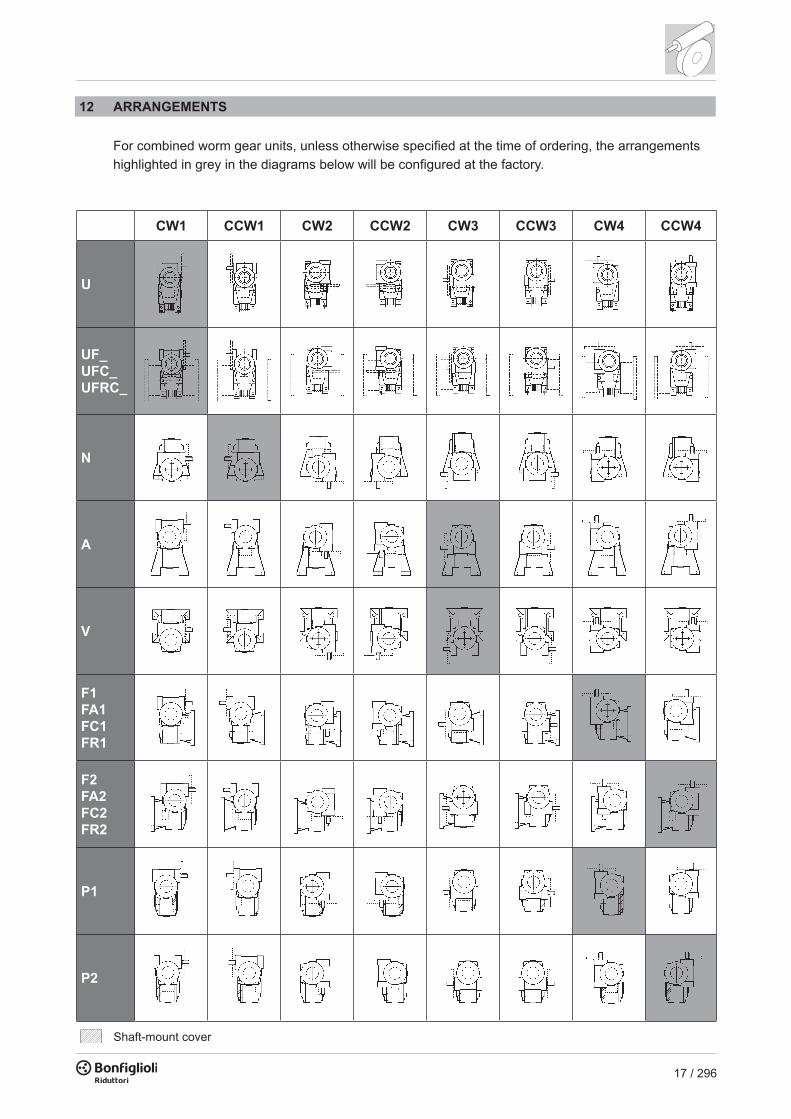
Shaft-mount cover
VF_ W_
N VF 27 ... VF 250
U W 63 ... W 110A VF 27 ... VF 250
V VF 27 ... VF 250
UF W 63 ... W 110
UF 1 UF 2
F VF 27 ... VF 185
FA VF 44 ... VF 49F 1
FA 1F 2
FA 2
FC
FR
VF 130 ... VF 185
VF 130 ... VF 185FC 1FR 1
FC 2FR 2
UFCR W 75
UFC 1 UFC 2UFCR 2
UFC W 63 ... W 110
UFCR 1
VF 30 ... VF 250P
P1 = P2 VF 30 ... VF 49VF 210, VF 250
P 1 P 2(VF 130...VF 185)(VF 30...VF 250)
U VF 30 ... VF 49
Foot mounted, underdriven
Foot mounted, overdriven
Foot mounted, wormshaft vertical
Short fl ange
Short fl ange and reinforced bearings
Side cover for shaft mounting
Foot mount
Universal gear case
Standard mounting fl ange
Mounting fl ange reduced in length and diameter
Mounting fl ange reduced in length
Standard fl ange
Extended output fl ange
11 VERSIONS
For combined gearboxes VF/VF, VF/W and W/VF, the versions refer to the second gearbox (machine side).
17 / 296
CW1 CCW1 CW2 CCW2 CW3 CCW3 CW4 CCW4
U
UF_UFC_UFRC_
N
A
V
F1FA1FC1FR1
F2FA2FC2FR2
P1
P2
Shaft-mount cover
VF_ W_
N VF 27 ... VF 250
U W 63 ... W 110A VF 27 ... VF 250
V VF 27 ... VF 250
UF W 63 ... W 110
UF 1 UF 2
F VF 27 ... VF 185
FA VF 44 ... VF 49F 1
FA 1F 2
FA 2
FC
FR
VF 130 ... VF 185
VF 130 ... VF 185FC 1FR 1
FC 2FR 2
UFCR W 75
UFC 1 UFC 2UFCR 2
UFC W 63 ... W 110
UFCR 1
VF 30 ... VF 250P
P1 = P2 VF 30 ... VF 49VF 210, VF 250
P 1 P 2(VF 130...VF 185)(VF 30...VF 250)
U VF 30 ... VF 49
Foot mounted, underdriven
Foot mounted, overdriven
Foot mounted, wormshaft vertical
Short fl ange
Short fl ange and reinforced bearings
Side cover for shaft mounting
Foot mount
Universal gear case
Standard mounting fl ange
Mounting fl ange reduced in length and diameter
Mounting fl ange reduced in length
Standard fl ange
Extended output fl ange
12 ARRANGEMENTS For combined worm gear units, unless otherwise specified at the time of ordering, the arrangements highlighted in grey in the diagrams below will be configured at the factory.

18 / 296
CW1CCW1
CW2CCW2 CW3 CCW3 CW4
CCW4
VF/VF30/44 A, N, V, P1 63B14 63B14 63B14 63B14 63B14F-FA
VF/VF30/49 A, N, V, P1 63B14 63B14 63B14 63B14 63B14F-FA
VF/W30/63 U 63B5-63B14 63B5-63B14 63B5-63B14 63B5-63B14 63B5-63B14UF-UFC
VF/W44/75 U 71B5-71B14 71B5-71B14 71B5-71B14 71B5-71B14 71B5-71B14UF-UFC-UFCR
VF/W44/86 U 71B5-71B14 71B5-71B14 71B5-71B14 71B5-71B14 71B5-71B14UF-UFC
VF/W49/110 U 80B5-80B14 80B5-80B14 80B5-80B14 80B5-80B14 80B5-80B14UF-UFC
W/VF63/130
N 71B5-90B14 90B5-90B14 71B5-90B14 71B5-90B14 71B5-90B14A 90B5-90B14 71B5-90B14 90B5-90B14 90B5-90B14 90B5-90B14V 90B5-90B14 —F1
90B5-90B14 71B5-90B14 90B5-90B14 71B5-90B14 90B5-90B14FC1-FR1P1 90B5-90B14F2
90B5-90B14 71B5-90B14 71B5-90B14 90B5-90B14 90B5-90B14FC2-FR2P2 90B5-90B14
W/VF86/150
N 112B5-112B14 112B5-112B14 71B5-112B14 71B5-112B14 71B5-112B14A 112B5-112B14 90B5-112B14 112B5-112B14 112B5-112B14 112B5-112B14V 112B5-90B14 112B5-90B14 71B5-112B14F1
112B5-112B14 71B5-90B14 112B5-112B14 71B5-90B14 112B5-112B14FC1-FR1P1 90B5-112B14 112B5-112B14F2
112B5-112B14 71B5-90B14 71B5-90B14 112B5-112B14 112B5-112B14FC2-FR2P2 90B5-112B14 112B5-112B14
W/VF86/185
N 112B5-112B14 112B5-112B14 90B5-112B14 90B5-112B14 90B5-112B14A 90B5-112B14 112B5-112B14 112B5-112B14 112B5-112B14V 112B5-90B14 90B5-112B14 90B5-112B14F1
112B5-112B14 90B5-112B14 112B5-112B14 90B5-112B14 112B5-112B14FC1-FR1P1 112B5-112B14F2
112B5-112B14 90B5-112B14 90B5-112B14 112B5-112B14 112B5-112B14FC2-FR2P2 112B5-112B14
VF/VF130/210
N # 132B5 # # #A
132B5 # 132B5 132B5 132B5VP
VF/VF130/250
N # 132B5 # # #A
132B5#
132B5 132B5 132B5V 132B5P #
# Consult our Technical Service
For units with the HS input (free shaft), all the mounting options shown are available. For units with the P (IEC), certain mounting options can be obtained only by using IEC flanges (B5 or B14) of the same size or smaller than those shown in following table.

19 / 296
CW1CCW1
CW2CCW2 CW3 CCW3 CW4
CCW4
VF/VF30/44 A, N, V, P1 63B14 63B14 63B14 63B14 63B14F-FA
VF/VF30/49 A, N, V, P1 63B14 63B14 63B14 63B14 63B14F-FA
VF/W30/63 U 63B5-63B14 63B5-63B14 63B5-63B14 63B5-63B14 63B5-63B14UF-UFC
VF/W44/75 U 71B5-71B14 71B5-71B14 71B5-71B14 71B5-71B14 71B5-71B14UF-UFC-UFCR
VF/W44/86 U 71B5-71B14 71B5-71B14 71B5-71B14 71B5-71B14 71B5-71B14UF-UFC
VF/W49/110 U 80B5-80B14 80B5-80B14 80B5-80B14 80B5-80B14 80B5-80B14UF-UFC
W/VF63/130
N 71B5-90B14 90B5-90B14 71B5-90B14 71B5-90B14 71B5-90B14A 90B5-90B14 71B5-90B14 90B5-90B14 90B5-90B14 90B5-90B14V 90B5-90B14 —F1
90B5-90B14 71B5-90B14 90B5-90B14 71B5-90B14 90B5-90B14FC1-FR1P1 90B5-90B14F2
90B5-90B14 71B5-90B14 71B5-90B14 90B5-90B14 90B5-90B14FC2-FR2P2 90B5-90B14
W/VF86/150
N 112B5-112B14 112B5-112B14 71B5-112B14 71B5-112B14 71B5-112B14A 112B5-112B14 90B5-112B14 112B5-112B14 112B5-112B14 112B5-112B14V 112B5-90B14 112B5-90B14 71B5-112B14F1
112B5-112B14 71B5-90B14 112B5-112B14 71B5-90B14 112B5-112B14FC1-FR1P1 90B5-112B14 112B5-112B14F2
112B5-112B14 71B5-90B14 71B5-90B14 112B5-112B14 112B5-112B14FC2-FR2P2 90B5-112B14 112B5-112B14
W/VF86/185
N 112B5-112B14 112B5-112B14 90B5-112B14 90B5-112B14 90B5-112B14A 90B5-112B14 112B5-112B14 112B5-112B14 112B5-112B14V 112B5-90B14 90B5-112B14 90B5-112B14F1
112B5-112B14 90B5-112B14 112B5-112B14 90B5-112B14 112B5-112B14FC1-FR1P1 112B5-112B14F2
112B5-112B14 90B5-112B14 90B5-112B14 112B5-112B14 112B5-112B14FC2-FR2P2 112B5-112B14
VF/VF130/210
N # 132B5 # # #A
132B5 # 132B5 132B5 132B5VP
VF/VF130/250
N # 132B5 # # #A
132B5#
132B5 132B5 132B5V 132B5P #
# Consult our Technical Service
12.1 Terminal box position
CW1 CCW1
CW3 CCW3CW2 CCW2CW4 CCW4
N N
N
NN
N
N
S SS
SS
S
S
E E
E
E
E
E
E
W WW
W
W
W
W
N
S
E W

20 / 296
W 63 L1 UF1— S2 .....24GEAR UNIT
.....— B3
GEAR TYPVF, W Worm gearboxVFR, WR Helical-worm gear unitVF/VF, VF/W, W/VF Combined gearbox
GEAR FRAME SIZE VF 27, 30, 44, 49, 130, 150, 185, 210, 250 VF/VF 30/44, 30/49, 130/210, 130/250VFR 44, 49, 130, 150, 185, 210, 250 VF/W 30/63, 44/75, 44/86, 49/110W, WR 63, 75, 86, 110 W/VF 63/130, 86/150, 86/185
TORQUE LIMITERVF, VFRW, WR L1, L2 VF/VF LF
VERSION
GEAR RATIO
INPUT CONFIGURATION
VF VFR W WR VF/VF VF/W W/VF
P(IEC)P27 (VF 27 only),
P56...P225P63,
P80...P160P71...P132 P63...P112 P56, P63,
P90...P132P56...P80 P71...P112
S_M M
S44 (VFR 44 only) S1...S3 S1...S3
HS
B5 (VF 30...VF 250, VFR 49...VFR 250, W, WR)B14 (VF 30…VF 49, W)
MOTOR MOUNTING
MOUNTING POSITION
VF 27...VF 49VFR 44, VFR 49 B3
W, WRVF 130...VF 250VFR 130...VFR 250
B3 (default), B6, B7, B8, V5, V6
VF/VFVF/WW/VF
B3 (default), B6, B7, B8, V5, V6
MOUNTING ARRANGEMENT
VF/VF, VF/W, W/VF CW (1, 2, 3, 4)CCW (1, 2, 3, 4)
OPTIONS
SHAFT BORE
W 75VF/W 44/75 D30 (default), D28 (on request)
13 DESIGNATION
MOTOR BRAKE
BN
MOTOR TYPEM = compact 3-phaseBN = IEC 3-phase
ME = compact 3-phase, class IE2BE = IEC 3-phase, class IE2
MX = compact 3-phase, class IE3BX = IEC 3-phase, class IE3
63A 4 230/400-50 IP54 CLF ..... W FD 3.5 R SB 220 SA .....
MOTOR SIZE1SC ... 3LB (compact motor)56A ... 180L (IEC motor) BN 27, BN 44 (special motors)
POLE NUMBER 2, 4, 6, 2/4, 2/6, 2/8, 2/12, 4/6, 4/8
MOTOR MOUNTING — (compact motor)B5, B14 (IEC - motor)
VOLTAGE - FREQUENCY
DEGREE OF PROTECTIONIP55 standard (IP54 - brake motor)
INSULATION CLASSCL F standardCL H option
TERMINAL BOX POSITIONW (default), N, E, S
OPTIONS
BRAKE HAND RELEASER, RM
RECTIFIER TYPEAC/DCNB, SB, NBR, SBR
BRAKE TYPEFD (d.c. brake)FA (a.c. brake)
BRAKE TORQUE
BRAKESUPPLY

21 / 296
W 63 L1 UF1— S2 .....24GEAR UNIT
.....— B3
GEAR TYPVF, W Worm gearboxVFR, WR Helical-worm gear unitVF/VF, VF/W, W/VF Combined gearbox
GEAR FRAME SIZE VF 27, 30, 44, 49, 130, 150, 185, 210, 250 VF/VF 30/44, 30/49, 130/210, 130/250VFR 44, 49, 130, 150, 185, 210, 250 VF/W 30/63, 44/75, 44/86, 49/110W, WR 63, 75, 86, 110 W/VF 63/130, 86/150, 86/185
TORQUE LIMITERVF, VFRW, WR L1, L2 VF/VF LF
VERSION
GEAR RATIO
INPUT CONFIGURATION
VF VFR W WR VF/VF VF/W W/VF
P(IEC)P27 (VF 27 only),
P56...P225P63,
P80...P160P71...P132 P63...P112 P56, P63,
P90...P132P56...P80 P71...P112
S_M M
S44 (VFR 44 only) S1...S3 S1...S3
HS
B5 (VF 30...VF 250, VFR 49...VFR 250, W, WR)B14 (VF 30…VF 49, W)
MOTOR MOUNTING
MOUNTING POSITION
VF 27...VF 49VFR 44, VFR 49 B3
W, WRVF 130...VF 250VFR 130...VFR 250
B3 (default), B6, B7, B8, V5, V6
VF/VFVF/WW/VF
B3 (default), B6, B7, B8, V5, V6
MOUNTING ARRANGEMENT
VF/VF, VF/W, W/VF CW (1, 2, 3, 4)CCW (1, 2, 3, 4)
OPTIONS
SHAFT BORE
W 75VF/W 44/75 D30 (default), D28 (on request)
MOTOR BRAKE
BN
MOTOR TYPEM = compact 3-phaseBN = IEC 3-phase
ME = compact 3-phase, class IE2BE = IEC 3-phase, class IE2
MX = compact 3-phase, class IE3BX = IEC 3-phase, class IE3
63A 4 230/400-50 IP54 CLF ..... W FD 3.5 R SB 220 SA .....
MOTOR SIZE1SC ... 3LB (compact motor)56A ... 180L (IEC motor) BN 27, BN 44 (special motors)
POLE NUMBER 2, 4, 6, 2/4, 2/6, 2/8, 2/12, 4/6, 4/8
MOTOR MOUNTING — (compact motor)B5, B14 (IEC - motor)
VOLTAGE - FREQUENCY
DEGREE OF PROTECTIONIP55 standard (IP54 - brake motor)
INSULATION CLASSCL F standardCL H option
TERMINAL BOX POSITIONW (default), N, E, S
OPTIONS
BRAKE HAND RELEASER, RM
RECTIFIER TYPEAC/DCNB, SB, NBR, SBR
BRAKE TYPEFD (d.c. brake)FA (a.c. brake)
BRAKE TORQUE
BRAKESUPPLY

22 / 296
LO
B3 B6 B7 B8 V5 V6W 110 U-UF-UFC X X X XVF 130 A-N-P-F-FC X X X XVF 130 V X X X XVF 130 FR X XVF 150 A-N-P-F-FC X X X XVF 150 V X X X XVF 150 FR X XVF 185 A-N-P-F-FC X X X XVF 185 V X X X XVF 185 FR X XVF 210 A-N-P X XVF 210 V X XVF 250 A-N-P X XVF 250 V X X
Mounting position
14 GEARBOX OPTIONS SO Gear units VF 27 ... VF 49, W 63 ... W 86, usually factory filled with oil, are, in this case, supplied unlubricated.
LO Gearboxes VF 130…VF 250 and W 110, usually supplied unlubricated, to be filled with synthetic oil currently used by BONFIGLIOLI RIDUTTORI according to the mounting position specified. The applicability of the LO option is described in the table below.
RB Double-ended input shaft at non-drive- end (with the exception of VF 27).
F F1 F2 F3 F4 V
VFVFRVF/VF
30 9 10.2 3 20 50 —44 11 12.5 4 30 56 —49 16 18 5 40 65 M6
WWRVF/W
63 18 20.5 6 40 74 M675 19 21.5 6 40 88.5 M686 25 28 8 50 101.5 M8110 25 28 8 60 127.5 M8
VFVFRW/VF
130 30 33 8 60 160 M8150 35 38 10 65 185 M8185 40 43 12 70 214.5 M8210 48 51.5 14 82 185 M16x40250 55 59 16 82 228 M16x40
28
10.5
1.1
VF 44, VFR 44
Extended input shaft dimensions (options RB and RBO)

23 / 296
LO
B3 B6 B7 B8 V5 V6W 110 U-UF-UFC X X X XVF 130 A-N-P-F-FC X X X XVF 130 V X X X XVF 130 FR X XVF 150 A-N-P-F-FC X X X XVF 150 V X X X XVF 150 FR X XVF 185 A-N-P-F-FC X X X XVF 185 V X X X XVF 185 FR X XVF 210 A-N-P X XVF 210 V X XVF 250 A-N-P X XVF 250 V X X
Mounting position
VV Fluoro elastomer oil seal on input shaft. The option is available for W110 and for units of the VF series, barring all VF 30’s c/w option RB and VF 30_HS.
PV Oil seals from Fluoro elastomer compound on both the input and the output shaft, barring all VF 30’s c/w option RB and VF 30_HS.
KA VF_A interchangeability kit. Option is available for units W 63 to W 110.
KV VF_V interchangeability kit (barring W + option RB and W 110 in B6 mounting position). Option is available for units W 63 to W 110.
F F1 F2 F3 F4 V
VFVFRVF/VF
30 9 10.2 3 20 50 —44 11 12.5 4 30 56 —49 16 18 5 40 65 M6
WWRVF/W
63 18 20.5 6 40 74 M675 19 21.5 6 40 88.5 M686 25 28 8 50 101.5 M8110 25 28 8 60 127.5 M8
VFVFRW/VF
130 30 33 8 60 160 M8150 35 38 10 65 185 M8185 40 43 12 70 214.5 M8210 48 51.5 14 82 185 M16x40250 55 59 16 82 228 M16x40
28
10.5
1.1
VF 44, VFR 44
Extended input shaft dimensions (options RB and RBO)
RBO Double-ended input shaft at N.D.E. of 2nd gearbox (combined execution only)
A and P versions of VF 210 and VF 250 feature the fan cooling as a standard, however forced ventila-tion is not feasible should the RB option be specified.

24 / 296
AO AO
AO
A NV
AO AO
F2F1
AO Output shaft on side opposite to standard (VF 27).
SURFACE PROTECTION
When no specific protection class is requested, the painted (ferrous) surfaces of gearboxes are pro-tected to at least corrosivity class C2 (UNI EN ISO 12944-2). For improved resistance to atmospheric corrosion, gearboxes can be delivered with C3 and C4 surface protection, obtained by painting the complete gearbox.
C3 120°C C3
C4 120°C C4
SURFACE PROTECTION Typical environments Maximum surface
temperatureCorrosivity class according to
UNI EN ISO 12944-2
Urban and industrial environments with up to 100% relative humidity(medium air pollution)
Industrial areas, coastal areas, chemical plant, with up to 100% relative humidity(high air pollution)
Gearboxes with optional protection to class C3 or C4 are available in a choice of colours. If no specific colour is requested (see the “PAINTING” option) gearboxes are finished in RAL 7042. Gearboxes can also be supplied with surface protection for corrosivity class C5 according to UNI EN ISO 12944-2. Contact our Technical Service for further details.
PAINTING
Gearboxes with optional protection to class C3 or C4 are available in the colours listed in the following table.
RAL7042* 7042
RAL5010 5010
RAL9005 9005
RAL9006 9006
RAL9010 9010
PAINTING Colour RAL number
Traffi c Grey A
Gentian Blue
Jet Black
White Aluminium
Pure White
* Gearboxes are supplied in this standard colour if no other colour is specifi ed.

25 / 296
RAL7042* 7042
RAL5010 5010
RAL9005 9005
RAL9006 9006
RAL9010 9010
PAINTING Colour RAL number
Traffi c Grey A
Gentian Blue
Jet Black
White Aluminium
Pure White
* Gearboxes are supplied in this standard colour if no other colour is specifi ed.
NOTE – “PAINTING” options can only be specified in conjunction with “SURFACE PROTECTION” options.
CERTIFICATES
AC - Certificate of compliance The document certifies the compliance of the product with the purchase order and the construction in conformity with the applicable procedures of the Bonfiglioli Quality System.
CC - Inspection certificate The document entails checking on order compliance, the visual inspection of external conditions and of mating dimensions. Checking on main functional parameters in unloaded conditions is also performed along with oil seal proofing, both in static and in running conditions. Units inspected are sampled within the shipping batch and marked individually.
Motor options For more detailed information please consult the Electric Motor section in this book.

26 / 296
The following pages describe the mounting positions of VF and W series gearboxes.
In the case of VF/VF, VF/W and W/VF gearbox combinations, mounting positions refer to the second (machine side) gearbox. Refer to the “Mounting version” chapter for details of the first (input side) gearbox.
_HS _S - _P (IEC)
U
B3
V6B6
B7 V5
B8
VF 27 _ ... VF 49 _ VFR 44 _ , VFR 49 _
N
B3
V6B6
B7 V5
B8
V
B3
V6B6
B7 V5
B8
P
B3
V6B6
B7 V5
B8
F
B3
V6B6
B7 V5
B8
A
B3
V6B6
B7 V5
B8
Base mounting position.Gearboxes are plated only for base mounting position (B3). They can nevertheless also be installed in any of the derived positions (B6, B7, B8, V5, V6). Mounting position may not be changed after installation.
15 MOUNTING POSITION AND TERMINAL BOX ANGULAR LOCATION Location of motor terminal box can be specified by viewing the motor from the fan side; standard loca-tion is shown in black (W).
The terminal box positions indicated do not apply to VFR 44. Please refer to page 21 and pages 112-113 for designation and identification of design version.
Angular location of the brake release lever.
Unless otherwise specified, brake motors have the manual device side located, 90° apart from termi-nal box. Different angles can be specified through the relevant options available.

27 / 296
_HS _S - _P (IEC)
U
B3
V6B6
B7 V5
B8
VF 27 _ ... VF 49 _ VFR 44 _ , VFR 49 _
N
B3
V6B6
B7 V5
B8
V
B3
V6B6
B7 V5
B8
P
B3
V6B6
B7 V5
B8
F
B3
V6B6
B7 V5
B8
A
B3
V6B6
B7 V5
B8
Base mounting position.Gearboxes are plated only for base mounting position (B3). They can nevertheless also be installed in any of the derived positions (B6, B7, B8, V5, V6). Mounting position may not be changed after installation.

28 / 296
B3
B6
B7
_HS _S - _P (IEC)
B8
V5
V6
W 63 U ... W 110 U WR 63 U ... WR 110 U
B3
B6
B7
_HS _S - _P (IEC)
B8
V5
V6
W 63 UF/UFC ... W 110 UF/UFC WR 63 UF/UFC ... WR 110 UF/UFC

29 / 296
B3
B6
B7
_HS _S - _P (IEC)
B8
V5
V6
W 63 U ... W 110 U WR 63 U ... WR 110 U
B3
B6
B7
_HS _S - _P (IEC)
B8
V5
V6
W 63 UF/UFC ... W 110 UF/UFC WR 63 UF/UFC ... WR 110 UF/UFC

30 / 296
B3
B6
B7
_HS _P (IEC)
B8
V5
V6
VF 130 A ... VF 250 A VFR 130 A ... VFR 250 A
B3
B6
B7
_HS _P (IEC)
B8
V5
V6
VF 130 N ... VF 250 N VFR 130 N ... VFR 250 N

31 / 296
B3
B6
B7
_HS _P (IEC)
B8
V5
V6
VF 130 A ... VF 250 A VFR 130 A ... VFR 250 A
B3
B6
B7
_HS _P (IEC)
B8
V5
V6
VF 130 N ... VF 250 N VFR 130 N ... VFR 250 N

32 / 296
B3
B6
B7
_HS _P (IEC)
B8
V5
V6
VF 130 V ... VF 250 V VFR 130 V ... VFR 250 V
B3
B6
B7
_HS _P (IEC)
B8
V5
V6
VF 130 P ... VF 250 P VFR 130 P ... VFR 250 P

33 / 296
B3
B6
B7
_HS _P (IEC)
B8
V5
V6
VF 130 V ... VF 250 V VFR 130 V ... VFR 250 V
B3
B6
B7
_HS _P (IEC)
B8
V5
V6
VF 130 P ... VF 250 P VFR 130 P ... VFR 250 P

34 / 296
B3
B6
B7
_HS _P (IEC)
B8
V5
V6
VF 130 F ... VF 250 F VFR 130 F ... VFR 250 F

35 / 296
B3
B6
B7
_HS _P (IEC)
B8
V5
V6
VF 130 F ... VF 250 F VFR 130 F ... VFR 250 F 16 OVERHUNG LOADS 16.1
Calculating the resulting overhung load
External transmissions keyed onto input and/or output shaft generate loads that act radially onto same shaft. Resulting shaft loading must be compatible with both the bearing and the shaft capacity. Namely shaft loading (Rc1 for input shaft, Rc2 for output shaft), must be equal or lower than admissible overhung load capacity for shaft under study (Rn1 for input shaft, Rn2 for output shaft). OHL capability listed in the rating chart section. In the formulas given below, index (1) applies to parameters relating to input shaft, whereas index (2) refers to output shaft. The load generated by an external transmission can be calculated with close approximation by the following equation:
16.2 Overhung loading verification
Kr = 1
Rc =2000 x M x Kr
d
M [Nm]
Kr = 1.25 d [mm]
Kr = 1.5 - 2.0
Rc Rn Rx = Rna
b xRc Rx

36 / 296
Rn2 max[N]a b
VF 27 56 44 600VF 30 60 45 1700VF 44 - VFR 44 - VF/VF 30/44 71 51 2500VF 49 - VFR 49 - VF/VF 30/49 99 69 3450W 63 - WR 63 - VF/W 30/63 132 102 5000W 75 - WR 75 - VF/W 44/75 139 109 6200W 86 - WR 86 - VF/W 44/86 149 119 7000W 110 - WR 110 - VF/W 49/110 173 136 8000VF 130 - VFR 130 - W/VF 63/130 182 142 13800VF 150 - VFR 150 - W/VF 86/150 198 155 16000VF 185 - VFR 185 - W/VF 86/185 220 170 19500VF 210 - VFR 210 - W/VF 130/210 268 203 34500VF 250 - VFR 250 - W/VF 130/250 334 252 52000
Output shaft
16.3 Load location factor
17 THRUST LOADS Permissible thrust loads on input [An1] and output [An2] shafts are obtained from the radial loading for the shaft under consideration [Rn1] and [Rn2] through the following equation:
The thrust loads calculated through these formulas apply to thrust forces occurring at the same time as rated radial loads. In the only case that no overhung load acts on the shaft the value of the admissible thrust load [An] amounts to 50% of rated OHL [Rn] on same shaft. Where thrust loads exceed permissible value or largely prevail over radial loads, contact Bonfiglioli Riduttori for an in-depth analysis of the application.
An1 = Rn1 0,2
An2 = Rn2 0,2(14)
10000
12000
14000
16000
18000
20000
22000
24000
26000
28000
30000
32000
34000
36000
38000
7 10 15 20 30 46 64 100
VF 130FRVF 150FRVF 185FR
VF 130 FR, VF 150 FR, VF 185 FR(A+ , CW) (A- , CCW)
A(+
) [N
]
10000
12000
14000
16000
18000
20000
22000
24000
26000
28000
30000
32000
34000
36000
38000
7 10 15 20 30 46 64 100
VF 130FRVF 150FRVF 185FR
VF 130 FR, VF 150 FR, VF 185 FR(A+ , CCW) (A- , CW)
A (-)
[N]
Compressive load
Pull load
Clockwise rotation
Counterclockwise rotation

37 / 296
Rn2 max[N]a b
VF 27 56 44 600VF 30 60 45 1700VF 44 - VFR 44 - VF/VF 30/44 71 51 2500VF 49 - VFR 49 - VF/VF 30/49 99 69 3450W 63 - WR 63 - VF/W 30/63 132 102 5000W 75 - WR 75 - VF/W 44/75 139 109 6200W 86 - WR 86 - VF/W 44/86 149 119 7000W 110 - WR 110 - VF/W 49/110 173 136 8000VF 130 - VFR 130 - W/VF 63/130 182 142 13800VF 150 - VFR 150 - W/VF 86/150 198 155 16000VF 185 - VFR 185 - W/VF 86/185 220 170 19500VF 210 - VFR 210 - W/VF 130/210 268 203 34500VF 250 - VFR 250 - W/VF 130/250 334 252 52000
Output shaft
10000
12000
14000
16000
18000
20000
22000
24000
26000
28000
30000
32000
34000
36000
38000
7 10 15 20 30 46 64 100
VF 130FRVF 150FRVF 185FR
VF 130 FR, VF 150 FR, VF 185 FR(A+ , CW) (A- , CCW)
A(+
)[N
]
10000
12000
14000
16000
18000
20000
22000
24000
26000
28000
30000
32000
34000
36000
38000
7 10 15 20 30 46 64 100
VF 130FRVF 150FRVF 185FR
VF 130 FR, VF 150 FR, VF 185 FR(A+ , CCW) (A- , CW)
A (-)
[N]
Compressive load
Pull load
Clockwise rotation
Counterclockwise rotation
17.1 Maximum axial loading for FR version
The FR version is designed to meet the requirements of applications entailing very high axial loads. It is available for units size 130, 150 and 185.This version, within the same external dimensions as the FC version, is capable of bearing axial loads (well above those of the standard versions) indicated in the table below referred to the output shaft, gear ratio [i] and +/- direction of rotation.

38 / 296
280 400 600 760 960 1200 1520 1800 2560 3200
W/VF 63/110 FR (A+ , CW) (A- , CCW) W/VF 63/110 FR (A+ , CCW) (A- , CW)
18000
18500
18250
18750
19000
19250
19500
19750
20000
20250
A[N
]
18000
17000
16000
15000
19000
20000
21000
22000
23000
24000
25000
26000
27000
28000
200 225 300 345 460 529 690 920 1380 1840 2944
W/VF 86/150 FR (A+ , CW) (A- , CCW) W/VF 86/150 FR (A+ , CCW) (A- , CW)
A[N
]
280 400 600 800 920 1200 1600 1840 2560 3200
W/VF 86/185 FR (A+ , CW) (A- , CCW) W/VF 86/185 FR (A+ , CCW) (A- , CW)
20000
20500
21000
21500
22000
22500
23000
23500
24000
24500
25000
25500
26000
26500
27000
27500
28000
28500
A[N
]

39 / 296
18 EFFICIENCY Efficiency [η] depends on the following parameters: - helix angle of gearing - driving speed - running-in of gearing
In this connection, remember that the optimum value is reached after several hours of running-in and is reached later on in steady-state operating gearboxes as shown in the table below. Therefore, in applications calling for intermittent duty (e.g. hoisting, drives, etc.), motor power must be adequately increased to compensate for the gearbox’s low efficiency at start-up. Torque values Mn2 indicated in the catalogue are calculated by considering the steady-state perfor-mance of the gearboxes. The diagram shows indicatively the time required to reach the maximum value of dynamic efficiency.
19 NON-REVERSING Some applications may require occasionally the gearbox to be back-driven by the load through the output shaft, some others instead require the gearbox to lock and hold the load when electric power switches off. The factor affecting reversibility of worm gears the most is the efficiency with more precisely static efficiency ηs affecting static reversibility and dynamic efficiency ηd affecting dynamic reversibility. Generally only gear ratios i=64 and higher offer locking properties with the grater ratios being totally non reversible.

40 / 296
19.1 Static non-reversing
In this condition the gear units cannot be driven back from the output shaft, however slow running- back may still occur if the worm gears are subject to vibrations. The theoretical condition for the static non-reversing to occur is:
the ηs value for each worm gear can be found in the respective rating chart. The opposite situation, i.e. static reversibility applies, theoretically when:
19.2 Dynamic non-reversing
The load-holding capability is dependent on drive speed, dynamic efficiency and, if any, vibrations. The result of non-reversibility is the locking of the output shaft is no longer driven. Partial or total non reversibility should be taken into consideration particularly when high inertia loads are driven, because of the considerable overloads that may apply to the gearbox.
s 0.4 - 0.5 (15)
s 0.5 (16)
d 0.5 (17)
d 0.5 (18)
Where ηd is the value for the dynamic efficiency of the gear unit in the actual operating conditions. Value can be found in the speed reducer rating chart. The opposite condition, i.e. dynamic reversing is physically possible when:
Table below is a guideline to the various degrees of reversibility for each drive size and gear ratio (data refer to the worm gearing only). Values for reversibility are indicative as this may be affected by vibrations, operating temperature, lubricating conditions, gear wear, etc.
As it is virtually impossible to provide and guarantee total non reversing, we recommend the use of an external brake with sufficient capability to prevent vibrations induced starting, where these circumstances are required.
VF W VF
27 30 44 49 63 75 86 110 130 150 185 210 250
— — 7 7 7 7 7 7 7 7 7 7 7
710
710
1014
1014
101215
1015
10152023
10152023
10152023
10152023
101520
101520
101520
152030
152030
202835
18242836
19243038
20253040
30404656
30404656
3040465664
3040465664
30405060
304050
30405060
4060
4060
466070
456070
456480
506080
6480
100
6480
100
80100
80100
80100
6080100
80100
70 70 100 80100 100 100 — — — — — — —
Backdriving
Static reversing
Dynamic reversing
yes yes
yes yes
uncertain yes
no low
no no
Δγ [’ ] Δγ [rad]VF 30 33’ ± 10’ 0.00873 ± 0.00291VF 44 25’ ± 7’ 0.00728 ± 0.00145VFR 44 30’ ± 10’ 0.00873 ± 0.00291VF 49 22’ ± 7’ 0.00728 ± 0.00145VFR 49 30’ ± 10’ 0.00873 ± 0.00291
W 63 20’ ± 4’ 0.00582 ± 0.00145WR 63 25’ ± 5’ 0.00728 ± 0.00145W 75 18’ ± 4’ 0.00582 ± 0.00145WR 75 22’ ± 5’ 0.00640 ± 0.00145W 86 15’ ± 4’ 0.00436 ± 0.00145WR 86 20’ ± 5’ 0.00582 ± 0.00145W 110 9’ ± 2’ 0.00436 ± 0.00145WR 110 18’ ± 5’ 0.00524 ± 0.00145
VF 130 12’ ± 3’ 0.00349 ± 0.00087VFR 130 15’ ± 3’ 0.00436 ± 0.00087VF 150 12’ ± 3’ 0.00349 ± 0.00087VFR 150 15’ ± 3’ 0.00436 ± 0.00087VF 185 10’ ± 3’ 0.00291 ± 0.00087VFR 185 13’ ± 3’ 0.00378 ± 0.00087
VF 210VFR 210VF 250VFR 250
Angular backlash (input shaft locked)
Consult factory

41 / 296
VF W VF
27 30 44 49 63 75 86 110 130 150 185 210 250
— — 7 7 7 7 7 7 7 7 7 7 7
710
710
1014
1014
101215
1015
10152023
10152023
10152023
10152023
101520
101520
101520
152030
152030
202835
18242836
19243038
20253040
30404656
30404656
3040465664
3040465664
30405060
304050
30405060
4060
4060
466070
456070
456480
506080
6480
100
6480
100
80100
80100
80100
6080
100
80100
70 70 100 80100 100 100 — — — — — — —
Backdriving
Static reversing
Dynamic reversing
yes yes
yes yes
uncertain yes
no low
no no
20 ANGULAR BACKLASH The following chart shows indicative values for the angular backlash at output shaft of W gear units (input blocked). Measurement is taken with 5 Nm torque applying to output shaft.
Δγ [’ ] Δγ [rad]VF 30 33’ ± 10’ 0.00873 ± 0.00291VF 44 25’ ± 7’ 0.00728 ± 0.00145VFR 44 30’ ± 10’ 0.00873 ± 0.00291VF 49 22’ ± 7’ 0.00728 ± 0.00145VFR 49 30’ ± 10’ 0.00873 ± 0.00291
W 63 20’ ± 4’ 0.00582 ± 0.00145WR 63 25’ ± 5’ 0.00728 ± 0.00145W 75 18’ ± 4’ 0.00582 ± 0.00145WR 75 22’ ± 5’ 0.00640 ± 0.00145W 86 15’ ± 4’ 0.00436 ± 0.00145WR 86 20’ ± 5’ 0.00582 ± 0.00145W 110 9’ ± 2’ 0.00436 ± 0.00145WR 110 18’ ± 5’ 0.00524 ± 0.00145
VF 130 12’ ± 3’ 0.00349 ± 0.00087VFR 130 15’ ± 3’ 0.00436 ± 0.00087VF 150 12’ ± 3’ 0.00349 ± 0.00087VFR 150 15’ ± 3’ 0.00436 ± 0.00087VF 185 10’ ± 3’ 0.00291 ± 0.00087VFR 185 13’ ± 3’ 0.00378 ± 0.00087
VF 210VFR 210VF 250VFR 250
Angular backlash (input shaft locked)
Consult factory

42 / 296
21 GEARMOTOR RATING CHARTS
0.04 kWn2 M2 S i Rn2 IEC
min-1 Nm N IE1 IE1
19.3 9 1.0 70 600 VF 27_70 P27 BN27A4 10722.5 8 1.1 60 600 VF 27_60 P27 BN27A4 10734 6 1.4 40 600 VF 27_40 P27 BN27A4 10745 5 1.7 30 600 VF 27_30 P27 BN27A4 10768 4 2.2 20 600 VF 27_20 P27 BN27A4 10790 3 2.8 15 600 VF 27_15 P27 BN27A4 107
135 2 3.8 10 600 VF 27_10 P27 BN27A4 107193 2 5.5 7 600 VF 27_7 P27 BN27A4 107
0.06 kWn2 M2 S i Rn2 IEC
min-1 Nm N IE1 IE1
0.59 203 1.0 2280 5000 VF/W 30/63_2280 P56 BN56A4 1250.89 155 1.4 1520 5000 VF/W 30/63_1520 P56 BN56A4 1251.1 122 1.7 1200 5000 VF/W 30/63_1200 P56 BN56A4 1251.5 115 1.8 900 5000 VF/W 30/63_900 P56 BN56A4 1251.9 113 1.9 720 5000 VF/W 30/63_720 P56 BN56A4 1252.5 85 1.1 540 3450 VF/VF 30/49_540 P56 BN56A4 1202.8 50 1.0 500 5000 VFR 44_500 S44 BN44B4 1123.2 73 1.3 420 3450 VF/VF 30/49_420 P56 BN56A4 1204.0 54 1.0 350 5000 VFR 44_350 S44 BN44B4 1124.3 53 1.8 315 3450 VF/VF 30/49_315 P56 BN56A4 1204.5 59 1.0 300 2500 VFR 44_300 S44 BN44B4 1125.8 50 1.2 230 2500 VFR 44_230 S44 BN44B4 1127.7 42 1.5 175 2500 VFR 44_175 S44 BN44B4 1129.6 36 1.4 140 2500 VFR 44_140 S44 BN44B4 112
13.4 29 1.8 100 2500 VFR 44_100 S44 BN44B4 11219.1 22 1.8 70 2500 VFR 44_70 S44 BN44B4 11219.3 14 1.1 70 1600 VF 30_70 P56 BN56A4 10822.5 13 1.5 60 1600 VF 30_60 P56 BN56A4 10834 10 0.9 40 600 VF 27_40 P27 BN27B4 10734 10 1.9 40 1650 VF 30_40 P56 BN56A4 108
The selection of motors without brake takes into account the requirements of Regulation EC 640/2009 (see section M of this catalogue). When the motor rated power is below 0.75kW, BN/M motors can be provided. Considering that the Regulation EC 640/2009 shall not apply to the motors equipped with brake, the brakemotor selection takes into account BN/M motors only, without taking into account the rated pow-er BX, BE, MX and ME brakemotors are available on request.
0.06 kWn2 M2 S i Rn2 IEC
min-1 Nm N IE1 IE1
45 8 1.1 30 600 VF 27_30 P27 BN27B4 10745 8 2.4 30 1340 VF 30_30 P56 BN56A4 10868 6 1.5 20 600 VF 27_20 P27 BN27B4 10768 6 2.9 20 1180 VF 30_20 P56 BN56A4 10890 5 1.9 15 600 VF 27_15 P27 BN27B4 10790 5 3.7 15 1080 VF 30_15 P56 BN56A4 108
135 4 2.6 10 590 VF 27_10 P27 BN27B4 107135 3 4.7 10 950 VF 30_10 P56 BN56A4 108193 2 3.6 7 530 VF 27_7 P27 BN27B4 107193 2 6.4 7 840 VF 30_7 P56 BN56A4 108
0.09 kWn2 M2 S i Rn2 IEC
min-1 Nm N IE1 IE1
0.31 574 1.8 2800 8000 VF/W 49/110_2800 P63 BN63A6 1370.42 579 1.0 2116 7000 VF/W 44/86_2116 P63 BN63A6 1330.43 505 2.1 2070 8000 VF/W 49/110_2070 P63 BN63A6 1370.48 503 1.1 1840 7000 VF/W 44/86_1840 P63 BN63A6 1330.53 485 2.2 1656 8000 VF/W 49/110_1656 P63 BN63A6 1370.64 377 1.5 1380 7000 VF/W 44/86_1380 P63 BN63A6 1330.65 369 2.8 1350 8000 VF/W 49/110_1350 P63 BN63A6 1370.73 363 1.1 1200 5750 VF/W 44/75_1200 P63 BN63A6 1290.81 316 3.3 1080 8000 VF/W 49/110_1080 P63 BN63A6 1370.89 232 0.9 1520 5000 VF/W 30/63_1520 P56 BN56B4 1250.96 323 1.2 920 5750 VF/W 44/75_920 P63 BN63A6 1290.96 332 1.7 920 7000 VF/W 44/86_920 P63 BN63A6 1330.98 255 0.9 900 5000 VF/W 30/63_900 P63 BN63A6 1251.1 183 1.1 1200 5000 VF/W 30/63_1200 P56 BN56B4 1251.2 225 1.0 720 5000 VF/W 30/63_720 P63 BN63A6 1251.3 267 1.5 700 5750 VF/W 44/75_700 P63 BN63A6 1291.3 253 2.2 700 7000 VF/W 44/86_700 P63 BN63A6 1331.5 172 1.2 900 5000 VF/W 30/63_900 P56 BN56B4 1251.7 210 1.9 525 5750 VF/W 44/75_525 P63 BN63A6 1291.7 200 2.8 525 7000 VF/W 44/86_525 P63 BN63A6 1331.9 170 1.2 720 5000 VF/W 30/63_720 P56 BN56B4 1252.2 164 2.4 400 5750 VF/W 44/75_400 P63 BN63A6 1292.2 160 3.4 400 7000 VF/W 44/86_400 P63 BN63A6 1332.4 145 1.4 570 5000 VF/W 30/63_570 P56 BN56B4 1252.9 111 1.2 300 5000 WR 63_300 P63 BN63A6 1242.9 120 1.7 300 6200 WR 75_300 P63 BN63A6 1282.9 132 2.4 300 7000 WR 86_300 P63 BN63A6 1323.0 117 1.8 450 5000 VF/W 30/63_450 P56 BN56B4 1253.2 110 0.9 420 3450 VF/VF 30/49_420 P56 BN56B4 1203.7 101 1.4 240 5000 WR 63_240 P63 BN63A6 1243.7 105 2.1 240 6200 WR 75_240 P63 BN63A6 1283.7 117 2.6 240 7000 WR 86_240 P63 BN63A6 1324.2 84 0.9 210 3450 VFR 49_210 P63 BN63A6 1184.3 80 1.2 315 3450 VF/VF 30/49_315 P56 BN56B4 1204.3 84 2.5 315 5000 VF/W 30/63_315 P56 BN56B4 1254.6 88 1.7 192 5000 WR 63_192 P63 BN63A6 1244.9 79 0.9 180 3450 VFR 49_180 P63 BN63A6 1184.9 90 3.1 180 6200 WR 75_180 P63 BN63A6 1285.2 94 4.2 168 7000 WR 86_168 P63 BN63A6 1325.5 62 1.0 245 2500 VF/VF 30/44_245 P56 BN56B4 1146.5 66 1.2 135 3450 VFR 49_135 P63 BN63A6 1186.5 71 2.5 135 5000 WR 63_135 P63 BN63A6 1247.7 63 1.0 175 2900 VFR 44_175 S44 BN44C4 1127.7 65 3.1 114 5000 WR 63_114 P63 BN63A6 1248.1 58 1.4 108 3450 VFR 49_108 P63 BN63A6 1188.8 41 1.3 100 3300 VF 49_100 P63 BN63A6 1169.6 54 0.9 140 2900 VFR 44_140 S44 BN44C4 1129.8 55 3.8 90 5000 WR 63_90 P63 BN63A6 124
10.5 48 1.9 84 3450 VFR 49_84 P63 BN63A6 11811.0 37 1.6 80 3300 VF 49_80 P63 BN63A6 11612.2 45 1.8 72 3450 VFR 49_72 P63 BN63A6 11812.2 48 4.0 72 5000 WR 63_72 P63 BN63A6 12412.6 35 1.1 70 2300 VF 44_70 P63 BN63A6 11012.6 34 1.8 70 3300 VF 49_70 P63 BN63A6 11613.4 43 1.2 100 2900 VFR 44_100 S44 BN44C4 112

43 / 296
0.04 kWn2 M2 S i Rn2 IEC
min-1 Nm N IE1 IE1
19.3 9 1.0 70 600 VF 27_70 P27 BN27A4 10722.5 8 1.1 60 600 VF 27_60 P27 BN27A4 10734 6 1.4 40 600 VF 27_40 P27 BN27A4 10745 5 1.7 30 600 VF 27_30 P27 BN27A4 10768 4 2.2 20 600 VF 27_20 P27 BN27A4 10790 3 2.8 15 600 VF 27_15 P27 BN27A4 107
135 2 3.8 10 600 VF 27_10 P27 BN27A4 107193 2 5.5 7 600 VF 27_7 P27 BN27A4 107
0.06 kWn2 M2 S i Rn2 IEC
min-1 Nm N IE1 IE1
0.59 203 1.0 2280 5000 VF/W 30/63_2280 P56 BN56A4 1250.89 155 1.4 1520 5000 VF/W 30/63_1520 P56 BN56A4 1251.1 122 1.7 1200 5000 VF/W 30/63_1200 P56 BN56A4 1251.5 115 1.8 900 5000 VF/W 30/63_900 P56 BN56A4 1251.9 113 1.9 720 5000 VF/W 30/63_720 P56 BN56A4 1252.5 85 1.1 540 3450 VF/VF 30/49_540 P56 BN56A4 1202.8 50 1.0 500 5000 VFR 44_500 S44 BN44B4 1123.2 73 1.3 420 3450 VF/VF 30/49_420 P56 BN56A4 1204.0 54 1.0 350 5000 VFR 44_350 S44 BN44B4 1124.3 53 1.8 315 3450 VF/VF 30/49_315 P56 BN56A4 1204.5 59 1.0 300 2500 VFR 44_300 S44 BN44B4 1125.8 50 1.2 230 2500 VFR 44_230 S44 BN44B4 1127.7 42 1.5 175 2500 VFR 44_175 S44 BN44B4 1129.6 36 1.4 140 2500 VFR 44_140 S44 BN44B4 112
13.4 29 1.8 100 2500 VFR 44_100 S44 BN44B4 11219.1 22 1.8 70 2500 VFR 44_70 S44 BN44B4 11219.3 14 1.1 70 1600 VF 30_70 P56 BN56A4 10822.5 13 1.5 60 1600 VF 30_60 P56 BN56A4 10834 10 0.9 40 600 VF 27_40 P27 BN27B4 10734 10 1.9 40 1650 VF 30_40 P56 BN56A4 108
0.06 kWn2 M2 S i Rn2 IEC
min-1 Nm N IE1 IE1
45 8 1.1 30 600 VF 27_30 P27 BN27B4 10745 8 2.4 30 1340 VF 30_30 P56 BN56A4 10868 6 1.5 20 600 VF 27_20 P27 BN27B4 10768 6 2.9 20 1180 VF 30_20 P56 BN56A4 10890 5 1.9 15 600 VF 27_15 P27 BN27B4 10790 5 3.7 15 1080 VF 30_15 P56 BN56A4 108
135 4 2.6 10 590 VF 27_10 P27 BN27B4 107135 3 4.7 10 950 VF 30_10 P56 BN56A4 108193 2 3.6 7 530 VF 27_7 P27 BN27B4 107193 2 6.4 7 840 VF 30_7 P56 BN56A4 108
0.09 kWn2 M2 S i Rn2 IEC
min-1 Nm N IE1 IE1
0.31 574 1.8 2800 8000 VF/W 49/110_2800 P63 BN63A6 1370.42 579 1.0 2116 7000 VF/W 44/86_2116 P63 BN63A6 1330.43 505 2.1 2070 8000 VF/W 49/110_2070 P63 BN63A6 1370.48 503 1.1 1840 7000 VF/W 44/86_1840 P63 BN63A6 1330.53 485 2.2 1656 8000 VF/W 49/110_1656 P63 BN63A6 1370.64 377 1.5 1380 7000 VF/W 44/86_1380 P63 BN63A6 1330.65 369 2.8 1350 8000 VF/W 49/110_1350 P63 BN63A6 1370.73 363 1.1 1200 5750 VF/W 44/75_1200 P63 BN63A6 1290.81 316 3.3 1080 8000 VF/W 49/110_1080 P63 BN63A6 1370.89 232 0.9 1520 5000 VF/W 30/63_1520 P56 BN56B4 1250.96 323 1.2 920 5750 VF/W 44/75_920 P63 BN63A6 1290.96 332 1.7 920 7000 VF/W 44/86_920 P63 BN63A6 1330.98 255 0.9 900 5000 VF/W 30/63_900 P63 BN63A6 1251.1 183 1.1 1200 5000 VF/W 30/63_1200 P56 BN56B4 1251.2 225 1.0 720 5000 VF/W 30/63_720 P63 BN63A6 1251.3 267 1.5 700 5750 VF/W 44/75_700 P63 BN63A6 1291.3 253 2.2 700 7000 VF/W 44/86_700 P63 BN63A6 1331.5 172 1.2 900 5000 VF/W 30/63_900 P56 BN56B4 1251.7 210 1.9 525 5750 VF/W 44/75_525 P63 BN63A6 1291.7 200 2.8 525 7000 VF/W 44/86_525 P63 BN63A6 1331.9 170 1.2 720 5000 VF/W 30/63_720 P56 BN56B4 1252.2 164 2.4 400 5750 VF/W 44/75_400 P63 BN63A6 1292.2 160 3.4 400 7000 VF/W 44/86_400 P63 BN63A6 1332.4 145 1.4 570 5000 VF/W 30/63_570 P56 BN56B4 1252.9 111 1.2 300 5000 WR 63_300 P63 BN63A6 1242.9 120 1.7 300 6200 WR 75_300 P63 BN63A6 1282.9 132 2.4 300 7000 WR 86_300 P63 BN63A6 1323.0 117 1.8 450 5000 VF/W 30/63_450 P56 BN56B4 1253.2 110 0.9 420 3450 VF/VF 30/49_420 P56 BN56B4 1203.7 101 1.4 240 5000 WR 63_240 P63 BN63A6 1243.7 105 2.1 240 6200 WR 75_240 P63 BN63A6 1283.7 117 2.6 240 7000 WR 86_240 P63 BN63A6 1324.2 84 0.9 210 3450 VFR 49_210 P63 BN63A6 1184.3 80 1.2 315 3450 VF/VF 30/49_315 P56 BN56B4 1204.3 84 2.5 315 5000 VF/W 30/63_315 P56 BN56B4 1254.6 88 1.7 192 5000 WR 63_192 P63 BN63A6 1244.9 79 0.9 180 3450 VFR 49_180 P63 BN63A6 1184.9 90 3.1 180 6200 WR 75_180 P63 BN63A6 1285.2 94 4.2 168 7000 WR 86_168 P63 BN63A6 1325.5 62 1.0 245 2500 VF/VF 30/44_245 P56 BN56B4 1146.5 66 1.2 135 3450 VFR 49_135 P63 BN63A6 1186.5 71 2.5 135 5000 WR 63_135 P63 BN63A6 1247.7 63 1.0 175 2900 VFR 44_175 S44 BN44C4 1127.7 65 3.1 114 5000 WR 63_114 P63 BN63A6 1248.1 58 1.4 108 3450 VFR 49_108 P63 BN63A6 1188.8 41 1.3 100 3300 VF 49_100 P63 BN63A6 1169.6 54 0.9 140 2900 VFR 44_140 S44 BN44C4 1129.8 55 3.8 90 5000 WR 63_90 P63 BN63A6 124
10.5 48 1.9 84 3450 VFR 49_84 P63 BN63A6 11811.0 37 1.6 80 3300 VF 49_80 P63 BN63A6 11612.2 45 1.8 72 3450 VFR 49_72 P63 BN63A6 11812.2 48 4.0 72 5000 WR 63_72 P63 BN63A6 12412.6 35 1.1 70 2300 VF 44_70 P63 BN63A6 11012.6 34 1.8 70 3300 VF 49_70 P63 BN63A6 11613.4 43 1.2 100 2900 VFR 44_100 S44 BN44C4 112

44 / 296
0.09 kWn2 M2 S i Rn2 IEC
min-1 Nm N IE1 IE1
14.7 32 1.4 60 2300 VF 44_60 P63 BN63A6 11014.7 34 1.7 60 3300 VF 49_60 P63 BN63A6 11616.3 36 2.2 54 3450 VFR 49_54 P63 BN63A6 11819.1 33 1.2 70 2900 VFR 44_70 S44 BN44C4 11219.1 27 1.8 46 2300 VF 44_46 P63 BN63A6 11019.6 26 2.7 45 3300 VF 49_45 P63 BN63A6 11621.0 30 2.8 42 3360 VFR 49_42 P63 BN63A6 11822.0 22 0.9 40 1560 VF 30_40 P63 BN63A6 10822.5 19 1.0 60 1600 VF 30_60 P56 BN56B4 10824.4 22 3.4 36 3300 VF 49_36 P63 BN63A6 11625.1 22 2.2 35 2300 VF 44_35 P63 BN63A6 11029.3 18 1.2 30 1440 VF 30_30 P63 BN63A6 10831 18 2.7 28 2300 VF 44_28 P63 BN63A6 11034 15 1.2 40 1410 VF 30_40 P56 BN56B4 10844 14 1.5 20 1230 VF 30_20 P63 BN63A6 10844 14 3.1 20 2300 VF 44_20 P63 BN63A6 11045 12 1.6 30 1290 VF 30_30 P56 BN56B4 10859 11 1.8 15 1170 VF 30_15 P63 BN63A6 10868 9 1.9 20 1140 VF 30_20 P56 BN56B4 10869 9 1.0 20 600 VF 27_20 P27 BN27C4 10788 8 2.3 10 1050 VF 30_10 P63 BN63A6 10890 7 2.5 15 1050 VF 30_15 P56 BN56B4 10892 7 1.3 15 600 VF 27_15 P27 BN27C4 107
126 6 3.2 7 920 VF 30_7 P63 BN63A6 108135 5 3.1 10 920 VF 30_10 P56 BN56B4 108138 5 1.7 10 565 VF 27_10 P27 BN27C4 107193 4 4.3 7 820 VF 30_7 P56 BN56B4 108197 4 2.5 7 510 VF 27_7 P27 BN27C4 107
0.12 kWn2 M2 S i Rn2 IEC
min-1 Nm N IE1 IE1
0.31 775 1.4 2800 8000 VF/W 49/110_2800 P63 BN63B6 1370.47 588 1.7 2800 8000 VF/W 49/110_2800 P63 BN63A4 1370.53 654 1.6 1656 8000 VF/W 49/110_1656 P63 BN63B6 1370.62 518 1.0 2116 7000 VF/W 44/86_2116 P63 BN63A4 1330.63 507 2.0 2070 8000 VF/W 49/110_2070 P63 BN63A4 1370.71 483 1.0 1840 7000 VF/W 44/86_1840 P63 BN63A4 1330.79 435 2.3 1656 8000 VF/W 49/110_1656 P63 BN63A4 1370.95 386 1.3 1380 7000 VF/W 44/86_1380 P63 BN63A4 1330.97 354 2.8 1350 8000 VF/W 49/110_1350 P63 BN63A4 1371.2 293 3.4 1080 8000 VF/W 49/110_1080 P63 BN63A4 1371.4 322 1.1 920 5750 VF/W 44/75_920 P63 BN63A4 1291.4 322 1.6 920 7000 VF/W 44/86_920 P63 BN63A4 1331.5 236 0.9 900 5000 VF/W 30/63_900 P63 BN63A4 1251.8 233 0.9 720 5000 VF/W 30/63_720 P63 BN63A4 1251.9 257 1.4 700 5750 VF/W 44/75_700 P63 BN63A4 1291.9 239 2.1 700 7000 VF/W 44/86_700 P63 BN63A4 1332.3 199 1.1 570 5000 VF/W 30/63_570 P63 BN63A4 1252.5 202 1.8 525 5750 VF/W 44/75_525 P63 BN63A4 1292.5 193 2.6 525 7000 VF/W 44/86_525 P63 BN63A4 1332.9 150 0.9 300 5000 WR 63_300 P63 BN63B6 1242.9 162 1.2 300 6200 WR 75_300 P63 BN63B6 1282.9 178 1.7 300 7000 WR 86_300 P63 BN63B6 1322.9 161 1.3 450 5000 VF/W 30/63_450 P63 BN63A4 1253.3 161 2.3 400 5750 VF/W 44/75_400 P63 BN63A4 1293.3 143 3.5 400 7000 VF/W 44/86_400 P63 BN63A4 1333.6 136 1.0 240 5000 WR 63_240 P63 BN63B6 1243.6 142 1.5 240 6200 WR 75_240 P63 BN63B6 1283.6 142 1.6 240 5000 VF/W 30/63_240 P63 BN63B6 1253.6 158 2.0 240 7000 WR 86_240 P63 BN63B6 1324.2 110 0.9 315 3450 VF/VF 30/49_315 P63 BN63A4 1204.2 116 1.8 315 5000 VF/W 30/63_315 P63 BN63A4 1254.4 108 1.2 300 5000 WR 63_300 P63 BN63A4 1244.4 115 1.6 300 6200 WR 75_300 P63 BN63A4 1284.4 129 2.1 300 7000 WR 86_300 P63 BN63A4 1324.4 134 2.8 300 5750 VF/W 44/75_300 P63 BN63A4 1294.8 121 2.3 180 6200 WR 75_180 P63 BN63B6 1285.2 126 3.1 168 7000 WR 86_168 P63 BN63B6 1325.2 125 3.0 250 5750 VF/W 44/75_250 P63 BN63A4 129
0.12 kWn2 M2 S i Rn2 IEC
min-1 Nm N IE1 IE1
5.5 94 1.0 240 3450 VF/VF 30/49_240 P63 BN63A4 1205.5 97 1.4 240 5000 WR 63_240 P63 BN63A4 1245.5 103 2.1 240 6200 WR 75_240 P63 BN63A4 1285.5 99 2.1 240 5000 VF/W 30/63_240 P63 BN63A4 1255.5 111 2.7 240 7000 WR 86_240 P63 BN63A4 1325.8 109 2.9 150 6200 WR 75_150 P63 BN63B6 1286.4 89 0.9 135 3300 VFR 49_135 P63 BN63B6 1186.4 96 1.9 135 5000 WR 63_135 P63 BN63B6 1246.8 86 1.8 192 5000 WR 63_192 P63 BN63A4 1247.3 76 0.9 180 3300 VFR 49_180 P63 BN63A4 1187.3 87 2.7 180 6200 WR 75_180 P63 BN63A4 1288.7 55 0.9 100 3300 VF 49_100 P63 BN63B6 1169.7 64 1.4 135 3450 VFR 49_135 P63 BN63A4 1189.7 68 2.5 135 5000 WR 63_135 P63 BN63A4 124
10.9 50 1.2 80 3300 VF 49_80 P63 BN63B6 11611.5 61 3.0 114 5000 WR 63_114 P63 BN63A4 12412.1 55 1.5 108 3450 VFR 49_108 P63 BN63A4 11813.1 41 1.2 100 3150 VF 49_100 P63 BN63A4 11614.5 43 1.1 60 2300 VF 44_60 P63 BN63B6 11015.3 53 3.6 57 5000 WR 63_57 P63 BN63B6 12415.6 46 1.9 84 3450 VFR 49_84 P63 BN63A4 11816.4 36 1.5 80 3150 VF 49_80 P63 BN63A4 11618.2 42 1.8 72 3430 VFR 49_72 P63 BN63A4 11818.7 34 0.9 70 3300 VF 44_70 P63 BN63A4 11018.7 33 1.7 70 3150 VF 49_70 P63 BN63A4 11621.8 30 1.3 60 2300 VF 44_60 P63 BN63A4 11021.8 30 1.9 60 3150 VF 49_60 P63 BN63A4 11624.3 34 2.2 54 3140 VFR 49_54 P63 BN63A4 11828.5 25 1.5 46 2300 VF 44_46 P63 BN63A4 11029.0 24 0.9 30 1360 VF 30_30 P63 BN63B6 10829.1 25 2.6 45 3040 VF 49_45 P63 BN63A4 11631 27 2.9 42 2920 VFR 49_42 P63 BN63A4 11833 21 0.9 40 1360 VF 30_40 P63 BN63A4 10836 21 3.3 36 2830 VF 49_36 P63 BN63A4 11637 21 1.9 35 2300 VF 44_35 P63 BN63A4 11044 17 1.2 30 1250 VF 30_30 P63 BN63A4 10847 17 2.2 28 2300 VF 44_28 P63 BN63A4 11058 15 1.4 15 1130 VF 30_15 P63 BN63B6 10862 14 2.7 14 2150 VF 44_14 P63 BN63B6 11066 13 1.4 20 1110 VF 30_20 P63 BN63A4 10866 13 2.9 20 2100 VF 44_20 P63 BN63A4 11087 10 1.8 15 1020 VF 30_15 P63 BN63A4 10894 10 2.9 14 1870 VF 44_14 P63 BN63A4 110
124 8 2.4 7 900 VF 30_7 P63 BN63B6 108131 7 2.3 10 900 VF 30_10 P63 BN63A4 108138 6 1.1 20 560 VF 27_20 P27 BN27C2 107138 7 2.2 20 840 VF 30_20 P56 BN56B2 108183 5 1.4 15 520 VF 27_15 P27 BN27C2 107187 5 3.1 7 810 VF 30_7 P63 BN63A4 108275 4 2.0 10 460 VF 27_10 P27 BN27C2 107275 4 3.4 10 740 VF 30_10 P56 BN56B2 108393 3 2.8 7 410 VF 27_7 P27 BN27C2 107393 3 4.7 7 660 VF 30_7 P56 BN56B2 108
0.18 kWn2 M2 S i Rn2 IEC
min-1 Nm N IE1 IE1
0.28 978 1.9 3200 13800 W/VF 63/130_3200 P71 BN71A6 1430.28 1345 3.3 3200 19500 W/VF 86/185_3200 P71 BN71A6 1550.31 1406 1.9 2944 16000 W/VF 86/150_2944 P71 BN71A6 1490.35 1027 1.8 2560 13800 W/VF 63/130_2560 P71 BN71A6 1430.35 1320 3.3 2560 19500 W/VF 86/185_2560 P71 BN71A6 1550.47 875 1.1 2800 8000 VF/W 49/110_2800 P63 BN63B4 1370.49 1265 2.1 1840 16000 W/VF 86/150_1840 P71 BN71A6 1490.50 894 2.1 1800 13800 W/VF 63/130_1800 P71 BN71A6 1430.54 949 1.1 1656 8000 VF/W 49/110_1656 P71 BN71A6 1370.59 871 2.1 1520 13800 W/VF 63/130_1520 P71 BN71A6 1430.64 755 1.3 2070 8000 VF/W 49/110_2070 P63 BN63B4 1370.65 1054 2.6 1380 16000 W/VF 86/150_1380 P71 BN71A6 1490.75 733 2.5 1200 13800 W/VF 63/130_1200 P71 BN71A6 1430.80 647 1.5 1656 8000 VF/W 49/110_1656 P63 BN63B4 137

45 / 296
0.09 kWn2 M2 S i Rn2 IEC
min-1 Nm N IE1 IE1
14.7 32 1.4 60 2300 VF 44_60 P63 BN63A6 11014.7 34 1.7 60 3300 VF 49_60 P63 BN63A6 11616.3 36 2.2 54 3450 VFR 49_54 P63 BN63A6 11819.1 33 1.2 70 2900 VFR 44_70 S44 BN44C4 11219.1 27 1.8 46 2300 VF 44_46 P63 BN63A6 11019.6 26 2.7 45 3300 VF 49_45 P63 BN63A6 11621.0 30 2.8 42 3360 VFR 49_42 P63 BN63A6 11822.0 22 0.9 40 1560 VF 30_40 P63 BN63A6 10822.5 19 1.0 60 1600 VF 30_60 P56 BN56B4 10824.4 22 3.4 36 3300 VF 49_36 P63 BN63A6 11625.1 22 2.2 35 2300 VF 44_35 P63 BN63A6 11029.3 18 1.2 30 1440 VF 30_30 P63 BN63A6 10831 18 2.7 28 2300 VF 44_28 P63 BN63A6 11034 15 1.2 40 1410 VF 30_40 P56 BN56B4 10844 14 1.5 20 1230 VF 30_20 P63 BN63A6 10844 14 3.1 20 2300 VF 44_20 P63 BN63A6 11045 12 1.6 30 1290 VF 30_30 P56 BN56B4 10859 11 1.8 15 1170 VF 30_15 P63 BN63A6 10868 9 1.9 20 1140 VF 30_20 P56 BN56B4 10869 9 1.0 20 600 VF 27_20 P27 BN27C4 10788 8 2.3 10 1050 VF 30_10 P63 BN63A6 10890 7 2.5 15 1050 VF 30_15 P56 BN56B4 10892 7 1.3 15 600 VF 27_15 P27 BN27C4 107
126 6 3.2 7 920 VF 30_7 P63 BN63A6 108135 5 3.1 10 920 VF 30_10 P56 BN56B4 108138 5 1.7 10 565 VF 27_10 P27 BN27C4 107193 4 4.3 7 820 VF 30_7 P56 BN56B4 108197 4 2.5 7 510 VF 27_7 P27 BN27C4 107
0.12 kWn2 M2 S i Rn2 IEC
min-1 Nm N IE1 IE1
0.31 775 1.4 2800 8000 VF/W 49/110_2800 P63 BN63B6 1370.47 588 1.7 2800 8000 VF/W 49/110_2800 P63 BN63A4 1370.53 654 1.6 1656 8000 VF/W 49/110_1656 P63 BN63B6 1370.62 518 1.0 2116 7000 VF/W 44/86_2116 P63 BN63A4 1330.63 507 2.0 2070 8000 VF/W 49/110_2070 P63 BN63A4 1370.71 483 1.0 1840 7000 VF/W 44/86_1840 P63 BN63A4 1330.79 435 2.3 1656 8000 VF/W 49/110_1656 P63 BN63A4 1370.95 386 1.3 1380 7000 VF/W 44/86_1380 P63 BN63A4 1330.97 354 2.8 1350 8000 VF/W 49/110_1350 P63 BN63A4 1371.2 293 3.4 1080 8000 VF/W 49/110_1080 P63 BN63A4 1371.4 322 1.1 920 5750 VF/W 44/75_920 P63 BN63A4 1291.4 322 1.6 920 7000 VF/W 44/86_920 P63 BN63A4 1331.5 236 0.9 900 5000 VF/W 30/63_900 P63 BN63A4 1251.8 233 0.9 720 5000 VF/W 30/63_720 P63 BN63A4 1251.9 257 1.4 700 5750 VF/W 44/75_700 P63 BN63A4 1291.9 239 2.1 700 7000 VF/W 44/86_700 P63 BN63A4 1332.3 199 1.1 570 5000 VF/W 30/63_570 P63 BN63A4 1252.5 202 1.8 525 5750 VF/W 44/75_525 P63 BN63A4 1292.5 193 2.6 525 7000 VF/W 44/86_525 P63 BN63A4 1332.9 150 0.9 300 5000 WR 63_300 P63 BN63B6 1242.9 162 1.2 300 6200 WR 75_300 P63 BN63B6 1282.9 178 1.7 300 7000 WR 86_300 P63 BN63B6 1322.9 161 1.3 450 5000 VF/W 30/63_450 P63 BN63A4 1253.3 161 2.3 400 5750 VF/W 44/75_400 P63 BN63A4 1293.3 143 3.5 400 7000 VF/W 44/86_400 P63 BN63A4 1333.6 136 1.0 240 5000 WR 63_240 P63 BN63B6 1243.6 142 1.5 240 6200 WR 75_240 P63 BN63B6 1283.6 142 1.6 240 5000 VF/W 30/63_240 P63 BN63B6 1253.6 158 2.0 240 7000 WR 86_240 P63 BN63B6 1324.2 110 0.9 315 3450 VF/VF 30/49_315 P63 BN63A4 1204.2 116 1.8 315 5000 VF/W 30/63_315 P63 BN63A4 1254.4 108 1.2 300 5000 WR 63_300 P63 BN63A4 1244.4 115 1.6 300 6200 WR 75_300 P63 BN63A4 1284.4 129 2.1 300 7000 WR 86_300 P63 BN63A4 1324.4 134 2.8 300 5750 VF/W 44/75_300 P63 BN63A4 1294.8 121 2.3 180 6200 WR 75_180 P63 BN63B6 1285.2 126 3.1 168 7000 WR 86_168 P63 BN63B6 1325.2 125 3.0 250 5750 VF/W 44/75_250 P63 BN63A4 129
0.12 kWn2 M2 S i Rn2 IEC
min-1 Nm N IE1 IE1
5.5 94 1.0 240 3450 VF/VF 30/49_240 P63 BN63A4 1205.5 97 1.4 240 5000 WR 63_240 P63 BN63A4 1245.5 103 2.1 240 6200 WR 75_240 P63 BN63A4 1285.5 99 2.1 240 5000 VF/W 30/63_240 P63 BN63A4 1255.5 111 2.7 240 7000 WR 86_240 P63 BN63A4 1325.8 109 2.9 150 6200 WR 75_150 P63 BN63B6 1286.4 89 0.9 135 3300 VFR 49_135 P63 BN63B6 1186.4 96 1.9 135 5000 WR 63_135 P63 BN63B6 1246.8 86 1.8 192 5000 WR 63_192 P63 BN63A4 1247.3 76 0.9 180 3300 VFR 49_180 P63 BN63A4 1187.3 87 2.7 180 6200 WR 75_180 P63 BN63A4 1288.7 55 0.9 100 3300 VF 49_100 P63 BN63B6 1169.7 64 1.4 135 3450 VFR 49_135 P63 BN63A4 1189.7 68 2.5 135 5000 WR 63_135 P63 BN63A4 124
10.9 50 1.2 80 3300 VF 49_80 P63 BN63B6 11611.5 61 3.0 114 5000 WR 63_114 P63 BN63A4 12412.1 55 1.5 108 3450 VFR 49_108 P63 BN63A4 11813.1 41 1.2 100 3150 VF 49_100 P63 BN63A4 11614.5 43 1.1 60 2300 VF 44_60 P63 BN63B6 11015.3 53 3.6 57 5000 WR 63_57 P63 BN63B6 12415.6 46 1.9 84 3450 VFR 49_84 P63 BN63A4 11816.4 36 1.5 80 3150 VF 49_80 P63 BN63A4 11618.2 42 1.8 72 3430 VFR 49_72 P63 BN63A4 11818.7 34 0.9 70 3300 VF 44_70 P63 BN63A4 11018.7 33 1.7 70 3150 VF 49_70 P63 BN63A4 11621.8 30 1.3 60 2300 VF 44_60 P63 BN63A4 11021.8 30 1.9 60 3150 VF 49_60 P63 BN63A4 11624.3 34 2.2 54 3140 VFR 49_54 P63 BN63A4 11828.5 25 1.5 46 2300 VF 44_46 P63 BN63A4 11029.0 24 0.9 30 1360 VF 30_30 P63 BN63B6 10829.1 25 2.6 45 3040 VF 49_45 P63 BN63A4 11631 27 2.9 42 2920 VFR 49_42 P63 BN63A4 11833 21 0.9 40 1360 VF 30_40 P63 BN63A4 10836 21 3.3 36 2830 VF 49_36 P63 BN63A4 11637 21 1.9 35 2300 VF 44_35 P63 BN63A4 11044 17 1.2 30 1250 VF 30_30 P63 BN63A4 10847 17 2.2 28 2300 VF 44_28 P63 BN63A4 11058 15 1.4 15 1130 VF 30_15 P63 BN63B6 10862 14 2.7 14 2150 VF 44_14 P63 BN63B6 11066 13 1.4 20 1110 VF 30_20 P63 BN63A4 10866 13 2.9 20 2100 VF 44_20 P63 BN63A4 11087 10 1.8 15 1020 VF 30_15 P63 BN63A4 10894 10 2.9 14 1870 VF 44_14 P63 BN63A4 110
124 8 2.4 7 900 VF 30_7 P63 BN63B6 108131 7 2.3 10 900 VF 30_10 P63 BN63A4 108138 6 1.1 20 560 VF 27_20 P27 BN27C2 107138 7 2.2 20 840 VF 30_20 P56 BN56B2 108183 5 1.4 15 520 VF 27_15 P27 BN27C2 107187 5 3.1 7 810 VF 30_7 P63 BN63A4 108275 4 2.0 10 460 VF 27_10 P27 BN27C2 107275 4 3.4 10 740 VF 30_10 P56 BN56B2 108393 3 2.8 7 410 VF 27_7 P27 BN27C2 107393 3 4.7 7 660 VF 30_7 P56 BN56B2 108
0.18 kWn2 M2 S i Rn2 IEC
min-1 Nm N IE1 IE1
0.28 978 1.9 3200 13800 W/VF 63/130_3200 P71 BN71A6 1430.28 1345 3.3 3200 19500 W/VF 86/185_3200 P71 BN71A6 1550.31 1406 1.9 2944 16000 W/VF 86/150_2944 P71 BN71A6 1490.35 1027 1.8 2560 13800 W/VF 63/130_2560 P71 BN71A6 1430.35 1320 3.3 2560 19500 W/VF 86/185_2560 P71 BN71A6 1550.47 875 1.1 2800 8000 VF/W 49/110_2800 P63 BN63B4 1370.49 1265 2.1 1840 16000 W/VF 86/150_1840 P71 BN71A6 1490.50 894 2.1 1800 13800 W/VF 63/130_1800 P71 BN71A6 1430.54 949 1.1 1656 8000 VF/W 49/110_1656 P71 BN71A6 1370.59 871 2.1 1520 13800 W/VF 63/130_1520 P71 BN71A6 1430.64 755 1.3 2070 8000 VF/W 49/110_2070 P63 BN63B4 1370.65 1054 2.6 1380 16000 W/VF 86/150_1380 P71 BN71A6 1490.75 733 2.5 1200 13800 W/VF 63/130_1200 P71 BN71A6 1430.80 647 1.5 1656 8000 VF/W 49/110_1656 P63 BN63B4 137

46 / 296
0.18 kWn2 M2 S i Rn2 IEC
min-1 Nm N IE1 IE1
0.94 642 2.9 960 13800 W/VF 63/130_960 P71 BN71A6 1430.98 527 1.9 1350 8000 VF/W 49/110_1350 P63 BN63B4 1370.98 756 3.6 920 16000 W/VF 86/150_920 P71 BN71A6 1491.2 537 3.4 760 13800 W/VF 63/130_760 P71 BN71A6 1431.2 436 2.3 1080 8000 VF/W 49/110_1080 P63 BN63B4 1371.4 479 1.0 920 7000 VF/W 44/86_920 P63 BN63B4 1331.7 391 1.4 525 7000 VF/W 44/86_525 P71 BN71A6 1331.8 375 2.7 720 8000 VF/W 49/110_720 P63 BN63B4 1371.9 356 1.4 700 7000 VF/W 44/86_700 P63 BN63B4 1332.3 321 1.2 400 5750 VF/W 44/75_400 P71 BN71A6 1292.3 313 1.8 400 7000 VF/W 44/86_400 P71 BN71A6 1332.3 344 3.1 400 8000 VF/W 49/110_400 P71 BN71A6 1372.4 288 3.5 540 8000 VF/W 49/110_540 P63 BN63B4 1372.5 301 1.2 525 5750 VF/W 44/75_525 P63 BN63B4 1292.5 287 1.7 525 7000 VF/W 44/86_525 P63 BN63B4 1333.0 258 1.2 300 7000 WR 86_300 P71 BN71A6 1323.0 264 1.5 300 5750 VF/W 44/75_300 P71 BN71A6 1293.0 275 2.1 300 8000 WR 110_300 P71 BN71A6 1363.0 241 2.3 300 7000 VF/W 44/86_300 P71 BN71A6 1333.0 269 3.9 300 8000 VF/W 49/110_300 P71 BN71A6 1373.3 240 1.5 400 5750 VF/W 44/75_400 P63 BN63B4 1293.3 214 2.3 400 7000 VF/W 44/86_400 P63 BN63B4 1333.8 206 1.1 240 6200 WR 75_240 P71 BN71A6 1283.8 229 1.4 240 7000 WR 86_240 P71 BN71A6 1323.8 243 2.4 240 8000 WR 110_240 P71 BN71A6 1363.9 233 2.4 230 7000 VF/W 44/86_230 P71 BN71A6 1334.2 172 1.2 315 5000 VF/W 30/63_315 P63 BN63B4 1254.4 172 1.0 300 6200 WR 75_300 P63 BN63B4 1284.4 191 1.4 300 7000 WR 86_300 P63 BN63B4 1324.4 199 1.9 300 5750 VF/W 44/75_300 P63 BN63B4 1294.4 176 2.8 300 7000 VF/W 44/86_300 P63 BN63B4 1334.7 202 1.9 192 7000 WR 86_192 P71 BN71A6 1325.0 175 1.6 180 6200 WR 75_180 P71 BN71A6 1285.3 186 2.0 250 5750 VF/W 44/75_250 P63 BN63B4 1295.4 183 2.1 168 7000 WR 86_168 P71 BN71A6 1325.5 144 0.9 240 5000 WR 63_240 P63 BN63B4 1245.5 153 1.4 240 6200 WR 75_240 P63 BN63B4 1285.5 147 1.4 240 5000 VF/W 30/63_240 P63 BN63B4 1255.5 166 1.8 240 7000 WR 86_240 P63 BN63B4 1325.7 162 3.1 230 7000 VF/W 44/86_230 P63 BN63B4 1336.0 158 2.0 150 6200 WR 75_150 P71 BN71A6 1286.5 161 2.7 138 7000 WR 86_138 P71 BN71A6 1326.9 128 1.2 192 5000 WR 63_192 P63 BN63B4 1246.9 145 2.3 192 7000 WR 86_192 P63 BN63B4 1327.3 129 1.8 180 6200 WR 75_180 P63 BN63B4 1287.5 138 2.4 120 6200 WR 75_120 P71 BN71A6 1287.9 131 2.7 168 7000 WR 86_168 P63 BN63B4 1327.9 126 1.6 114 5000 WR 63_114 P71 BN71A6 1248.8 113 2.3 150 6200 WR 75_150 P63 BN63B4 1289.0 88 1.4 100 5000 W 63_100 S1 M1SC6 122 W 63_100 P71 BN71A6 1249.0 96 1.7 100 6200 W 75_100 S1 M1SC6 126 W 75_100 P71 BN71A6 1279.0 105 2.4 100 7000 W 86_100 S1 M1SC6 130 W 86_100 P71 BN71A6 1319.8 102 1.7 135 5000 WR 63_135 P63 BN63B4 124
10.0 107 1.9 90 5000 WR 63_90 P71 BN71A6 12411.0 98 3.1 120 6200 WR 75_120 P63 BN63B4 12811.3 79 1.6 80 5000 W 63_80 S1 M1SC6 122 W 63_80 P71 BN71A6 12411.3 83 2.4 80 6200 W 75_80 S1 M1SC6 126 W 75_80 P71 BN71A6 12711.3 90 3.1 80 7000 W 86_80 S1 M1SC6 130 W 86_80 P71 BN71A6 13111.6 91 2.0 114 5000 WR 63_114 P63 BN63B4 12412.0 100 3.3 75 6200 WR 75_75 P71 BN71A6 12812.2 82 1.0 108 3450 VFR 49_108 P63 BN63B4 11814.7 75 2.5 90 5000 WR 63_90 P63 BN63B4 12415.0 61 1.1 60 3000 VF 49_60 P71 BN71A6 11615.0 60 1.1 180 3300 VFR 49_180 P63 BN63A2 11815.7 68 1.3 84 3420 VFR 49_84 P63 BN63B4 11816.5 54 1.0 80 3150 VF 49_80 P63 BN63B4 11618.3 63 1.2 72 3270 VFR 49_72 P63 BN63B4 11818.3 66 2.8 72 5000 WR 63_72 P63 BN63B4 12418.9 49 1.1 70 3150 VF 49_70 P63 BN63B4 11620.0 50 1.4 135 3280 VFR 49_135 P63 BN63A2 11820.0 54 2.9 45 5000 W 63_45 P71 BN71A6 12422.0 45 0.9 60 2300 VF 44_60 P63 BN63B4 11022.0 45 1.3 60 3150 VF 49_60 P63 BN63B4 11623.2 54 3.3 57 4910 WR 63_57 P63 BN63B4 12424.4 50 1.5 54 3010 VFR 49_54 P63 BN63B4 11828.7 38 1.0 46 2500 VF 44_46 P63 BN63B4 110
0.18 kWn2 M2 S i Rn2 IEC
min-1 Nm N IE1 IE1
29.3 37 1.8 45 2300 VF 49_45 P63 BN63B4 11631 40 1.9 42 2810 VFR 49_42 P63 BN63B4 11832 36 1.4 28 2290 VF 44_28 P71 BN71A6 11037 31 2.2 36 2760 VF 49_36 P63 BN63B4 11638 31 1.3 35 2430 VF 44_35 P63 BN63B4 11047 26 1.5 28 2270 VF 44_28 P63 BN63B4 11047 26 2.9 28 2560 VF 49_28 P63 BN63B4 11655 23 2.7 24 2430 VF 49_24 P63 BN63B4 11666 19 0.9 20 1040 VF 30_20 P63 BN63B4 10866 20 1.9 20 2040 VF 44_20 P63 BN63B4 11073 18 3.2 18 2230 VF 49_18 P63 BN63B4 11677 16 1.8 35 1970 VF 44_35 P63 BN63A2 11088 15 1.2 15 960 VF 30_15 P63 BN63B4 10894 15 2.0 14 1830 VF 44_14 P63 BN63B4 110
132 11 1.5 10 860 VF 30_10 P63 BN63B4 108132 11 2.7 10 1640 VF 44_10 P63 BN63B4 110189 8 2.1 7 770 VF 30_7 P63 BN63B4 108193 7 2.9 14 1470 VF 44_14 P63 BN63A2 110270 5 2.2 10 710 VF 30_10 P63 BN63A2 108386 4 3.1 7 640 VF 30_7 P63 BN63A2 108
0.25 kWn2 M2 S i Rn2 IEC
min-1 Nm N IE1 IE1
0.28 1358 1.4 3200 13800 W/VF 63/130_3200 P71 BN71B6 1430.28 1868 2.4 3200 19500 W/VF 86/185_3200 P71 BN71B6 1550.31 1952 1.4 2944 16000 W/VF 86/150_2944 P71 BN71B6 1490.43 945 1.9 3200 13800 W/VF 63/130_3200 P71 BN71A4 1430.43 1334 3.1 3200 19500 W/VF 86/185_3200 P71 BN71A4 1550.47 1380 1.9 2944 16000 W/VF 86/150_2944 P71 BN71A4 1490.49 1562 2.8 1840 19500 W/VF 86/185_1840 P71 BN71B6 1550.54 1022 1.8 2560 13800 W/VF 63/130_2560 P71 BN71A4 1430.54 1289 3.3 2560 19500 W/VF 86/185_2560 P71 BN71A4 1550.65 1464 1.8 1380 16000 W/VF 86/150_1380 P71 BN71B6 1490.66 1006 1.0 2070 8000 VF/W 49/110_2070 P71 BN71A4 1370.75 1214 2.1 1840 16000 W/VF 86/150_1840 P71 BN71A4 1490.75 1019 1.8 1200 13800 W/VF 63/130_1200 P71 BN71B6 1430.76 875 2.1 1800 13800 W/VF 63/130_1800 P71 BN71A4 1430.83 863 1.2 1656 8000 VF/W 49/110_1656 P71 BN71A4 1370.90 845 2.1 1520 13800 W/VF 63/130_1520 P71 BN71A4 1430.98 1049 2.6 920 16000 W/VF 86/150_920 P71 BN71B6 1491.0 1006 2.6 1380 16000 W/VF 86/150_1380 P71 BN71A4 1491.0 703 1.4 1350 8000 VF/W 49/110_1350 P71 BN71A4 1371.1 708 2.5 1200 13800 W/VF 63/130_1200 P71 BN71A4 1431.2 746 2.5 760 13800 W/VF 63/130_760 P71 BN71B6 1431.3 581 1.7 1080 8000 VF/W 49/110_1080 P71 BN71A4 1371.3 860 3.1 690 16000 W/VF 86/150_690 P71 BN71B6 1491.4 617 2.9 960 13800 W/VF 63/130_960 P71 BN71A4 1431.7 544 1.9 540 8000 VF/W 49/110_540 P71 BN71B6 1371.7 543 1.0 525 7000 VF/W 44/86_525 P71 BN71B6 1331.8 515 3.5 760 13800 W/VF 63/130_760 P71 BN71A4 1431.9 500 2.0 720 8000 VF/W 49/110_720 P71 BN71A4 1372.0 474 1.1 700 7000 VF/W 44/86_700 P71 BN71A4 1332.5 384 2.6 540 8000 VF/W 49/110_540 P71 BN71A4 1372.6 383 1.3 525 7000 VF/W 44/86_525 P71 BN71A4 1333.0 366 1.1 300 5750 VF/W 44/75_300 P71 BN71B6 1293.0 382 1.5 300 8000 WR 110_300 P71 BN71B6 1363.0 374 2.8 300 8000 VF/W 49/110_300 P71 BN71B6 1373.4 319 1.2 400 5750 VF/W 44/75_400 P71 BN71A4 1293.4 285 1.8 400 7000 VF/W 44/86_400 P71 BN71A4 1333.4 313 3.2 400 8000 VF/W 49/110_400 P71 BN71A4 1373.8 318 1.0 240 7000 WR 86_240 P71 BN71B6 1323.8 337 1.7 240 8000 WR 110_240 P71 BN71B6 1363.9 323 1.7 230 7000 VF/W 44/86_230 P71 BN71B6 1333.9 311 3.4 230 8000 VF/W 49/110_230 P71 BN71B6 1374.6 255 1.1 300 7000 WR 86_300 P71 BN71A4 1324.6 266 1.4 300 5750 VF/W 44/75_300 P71 BN71A4 1294.6 266 2.1 300 8000 WR 110_300 P71 BN71A4 1364.6 234 2.1 300 7000 VF/W 44/86_300 P71 BN71A4 1334.7 280 1.4 192 7000 WR 86_192 P71 BN71B6 132

47 / 296
0.18 kWn2 M2 S i Rn2 IEC
min-1 Nm N IE1 IE1
0.94 642 2.9 960 13800 W/VF 63/130_960 P71 BN71A6 1430.98 527 1.9 1350 8000 VF/W 49/110_1350 P63 BN63B4 1370.98 756 3.6 920 16000 W/VF 86/150_920 P71 BN71A6 1491.2 537 3.4 760 13800 W/VF 63/130_760 P71 BN71A6 1431.2 436 2.3 1080 8000 VF/W 49/110_1080 P63 BN63B4 1371.4 479 1.0 920 7000 VF/W 44/86_920 P63 BN63B4 1331.7 391 1.4 525 7000 VF/W 44/86_525 P71 BN71A6 1331.8 375 2.7 720 8000 VF/W 49/110_720 P63 BN63B4 1371.9 356 1.4 700 7000 VF/W 44/86_700 P63 BN63B4 1332.3 321 1.2 400 5750 VF/W 44/75_400 P71 BN71A6 1292.3 313 1.8 400 7000 VF/W 44/86_400 P71 BN71A6 1332.3 344 3.1 400 8000 VF/W 49/110_400 P71 BN71A6 1372.4 288 3.5 540 8000 VF/W 49/110_540 P63 BN63B4 1372.5 301 1.2 525 5750 VF/W 44/75_525 P63 BN63B4 1292.5 287 1.7 525 7000 VF/W 44/86_525 P63 BN63B4 1333.0 258 1.2 300 7000 WR 86_300 P71 BN71A6 1323.0 264 1.5 300 5750 VF/W 44/75_300 P71 BN71A6 1293.0 275 2.1 300 8000 WR 110_300 P71 BN71A6 1363.0 241 2.3 300 7000 VF/W 44/86_300 P71 BN71A6 1333.0 269 3.9 300 8000 VF/W 49/110_300 P71 BN71A6 1373.3 240 1.5 400 5750 VF/W 44/75_400 P63 BN63B4 1293.3 214 2.3 400 7000 VF/W 44/86_400 P63 BN63B4 1333.8 206 1.1 240 6200 WR 75_240 P71 BN71A6 1283.8 229 1.4 240 7000 WR 86_240 P71 BN71A6 1323.8 243 2.4 240 8000 WR 110_240 P71 BN71A6 1363.9 233 2.4 230 7000 VF/W 44/86_230 P71 BN71A6 1334.2 172 1.2 315 5000 VF/W 30/63_315 P63 BN63B4 1254.4 172 1.0 300 6200 WR 75_300 P63 BN63B4 1284.4 191 1.4 300 7000 WR 86_300 P63 BN63B4 1324.4 199 1.9 300 5750 VF/W 44/75_300 P63 BN63B4 1294.4 176 2.8 300 7000 VF/W 44/86_300 P63 BN63B4 1334.7 202 1.9 192 7000 WR 86_192 P71 BN71A6 1325.0 175 1.6 180 6200 WR 75_180 P71 BN71A6 1285.3 186 2.0 250 5750 VF/W 44/75_250 P63 BN63B4 1295.4 183 2.1 168 7000 WR 86_168 P71 BN71A6 1325.5 144 0.9 240 5000 WR 63_240 P63 BN63B4 1245.5 153 1.4 240 6200 WR 75_240 P63 BN63B4 1285.5 147 1.4 240 5000 VF/W 30/63_240 P63 BN63B4 1255.5 166 1.8 240 7000 WR 86_240 P63 BN63B4 1325.7 162 3.1 230 7000 VF/W 44/86_230 P63 BN63B4 1336.0 158 2.0 150 6200 WR 75_150 P71 BN71A6 1286.5 161 2.7 138 7000 WR 86_138 P71 BN71A6 1326.9 128 1.2 192 5000 WR 63_192 P63 BN63B4 1246.9 145 2.3 192 7000 WR 86_192 P63 BN63B4 1327.3 129 1.8 180 6200 WR 75_180 P63 BN63B4 1287.5 138 2.4 120 6200 WR 75_120 P71 BN71A6 1287.9 131 2.7 168 7000 WR 86_168 P63 BN63B4 1327.9 126 1.6 114 5000 WR 63_114 P71 BN71A6 1248.8 113 2.3 150 6200 WR 75_150 P63 BN63B4 1289.0 88 1.4 100 5000 W 63_100 S1 M1SC6 122 W 63_100 P71 BN71A6 1249.0 96 1.7 100 6200 W 75_100 S1 M1SC6 126 W 75_100 P71 BN71A6 1279.0 105 2.4 100 7000 W 86_100 S1 M1SC6 130 W 86_100 P71 BN71A6 1319.8 102 1.7 135 5000 WR 63_135 P63 BN63B4 124
10.0 107 1.9 90 5000 WR 63_90 P71 BN71A6 12411.0 98 3.1 120 6200 WR 75_120 P63 BN63B4 12811.3 79 1.6 80 5000 W 63_80 S1 M1SC6 122 W 63_80 P71 BN71A6 12411.3 83 2.4 80 6200 W 75_80 S1 M1SC6 126 W 75_80 P71 BN71A6 12711.3 90 3.1 80 7000 W 86_80 S1 M1SC6 130 W 86_80 P71 BN71A6 13111.6 91 2.0 114 5000 WR 63_114 P63 BN63B4 12412.0 100 3.3 75 6200 WR 75_75 P71 BN71A6 12812.2 82 1.0 108 3450 VFR 49_108 P63 BN63B4 11814.7 75 2.5 90 5000 WR 63_90 P63 BN63B4 12415.0 61 1.1 60 3000 VF 49_60 P71 BN71A6 11615.0 60 1.1 180 3300 VFR 49_180 P63 BN63A2 11815.7 68 1.3 84 3420 VFR 49_84 P63 BN63B4 11816.5 54 1.0 80 3150 VF 49_80 P63 BN63B4 11618.3 63 1.2 72 3270 VFR 49_72 P63 BN63B4 11818.3 66 2.8 72 5000 WR 63_72 P63 BN63B4 12418.9 49 1.1 70 3150 VF 49_70 P63 BN63B4 11620.0 50 1.4 135 3280 VFR 49_135 P63 BN63A2 11820.0 54 2.9 45 5000 W 63_45 P71 BN71A6 12422.0 45 0.9 60 2300 VF 44_60 P63 BN63B4 11022.0 45 1.3 60 3150 VF 49_60 P63 BN63B4 11623.2 54 3.3 57 4910 WR 63_57 P63 BN63B4 12424.4 50 1.5 54 3010 VFR 49_54 P63 BN63B4 11828.7 38 1.0 46 2500 VF 44_46 P63 BN63B4 110
0.18 kWn2 M2 S i Rn2 IEC
min-1 Nm N IE1 IE1
29.3 37 1.8 45 2300 VF 49_45 P63 BN63B4 11631 40 1.9 42 2810 VFR 49_42 P63 BN63B4 11832 36 1.4 28 2290 VF 44_28 P71 BN71A6 11037 31 2.2 36 2760 VF 49_36 P63 BN63B4 11638 31 1.3 35 2430 VF 44_35 P63 BN63B4 11047 26 1.5 28 2270 VF 44_28 P63 BN63B4 11047 26 2.9 28 2560 VF 49_28 P63 BN63B4 11655 23 2.7 24 2430 VF 49_24 P63 BN63B4 11666 19 0.9 20 1040 VF 30_20 P63 BN63B4 10866 20 1.9 20 2040 VF 44_20 P63 BN63B4 11073 18 3.2 18 2230 VF 49_18 P63 BN63B4 11677 16 1.8 35 1970 VF 44_35 P63 BN63A2 11088 15 1.2 15 960 VF 30_15 P63 BN63B4 10894 15 2.0 14 1830 VF 44_14 P63 BN63B4 110
132 11 1.5 10 860 VF 30_10 P63 BN63B4 108132 11 2.7 10 1640 VF 44_10 P63 BN63B4 110189 8 2.1 7 770 VF 30_7 P63 BN63B4 108193 7 2.9 14 1470 VF 44_14 P63 BN63A2 110270 5 2.2 10 710 VF 30_10 P63 BN63A2 108386 4 3.1 7 640 VF 30_7 P63 BN63A2 108
0.25 kWn2 M2 S i Rn2 IEC
min-1 Nm N IE1 IE1
0.28 1358 1.4 3200 13800 W/VF 63/130_3200 P71 BN71B6 1430.28 1868 2.4 3200 19500 W/VF 86/185_3200 P71 BN71B6 1550.31 1952 1.4 2944 16000 W/VF 86/150_2944 P71 BN71B6 1490.43 945 1.9 3200 13800 W/VF 63/130_3200 P71 BN71A4 1430.43 1334 3.1 3200 19500 W/VF 86/185_3200 P71 BN71A4 1550.47 1380 1.9 2944 16000 W/VF 86/150_2944 P71 BN71A4 1490.49 1562 2.8 1840 19500 W/VF 86/185_1840 P71 BN71B6 1550.54 1022 1.8 2560 13800 W/VF 63/130_2560 P71 BN71A4 1430.54 1289 3.3 2560 19500 W/VF 86/185_2560 P71 BN71A4 1550.65 1464 1.8 1380 16000 W/VF 86/150_1380 P71 BN71B6 1490.66 1006 1.0 2070 8000 VF/W 49/110_2070 P71 BN71A4 1370.75 1214 2.1 1840 16000 W/VF 86/150_1840 P71 BN71A4 1490.75 1019 1.8 1200 13800 W/VF 63/130_1200 P71 BN71B6 1430.76 875 2.1 1800 13800 W/VF 63/130_1800 P71 BN71A4 1430.83 863 1.2 1656 8000 VF/W 49/110_1656 P71 BN71A4 1370.90 845 2.1 1520 13800 W/VF 63/130_1520 P71 BN71A4 1430.98 1049 2.6 920 16000 W/VF 86/150_920 P71 BN71B6 1491.0 1006 2.6 1380 16000 W/VF 86/150_1380 P71 BN71A4 1491.0 703 1.4 1350 8000 VF/W 49/110_1350 P71 BN71A4 1371.1 708 2.5 1200 13800 W/VF 63/130_1200 P71 BN71A4 1431.2 746 2.5 760 13800 W/VF 63/130_760 P71 BN71B6 1431.3 581 1.7 1080 8000 VF/W 49/110_1080 P71 BN71A4 1371.3 860 3.1 690 16000 W/VF 86/150_690 P71 BN71B6 1491.4 617 2.9 960 13800 W/VF 63/130_960 P71 BN71A4 1431.7 544 1.9 540 8000 VF/W 49/110_540 P71 BN71B6 1371.7 543 1.0 525 7000 VF/W 44/86_525 P71 BN71B6 1331.8 515 3.5 760 13800 W/VF 63/130_760 P71 BN71A4 1431.9 500 2.0 720 8000 VF/W 49/110_720 P71 BN71A4 1372.0 474 1.1 700 7000 VF/W 44/86_700 P71 BN71A4 1332.5 384 2.6 540 8000 VF/W 49/110_540 P71 BN71A4 1372.6 383 1.3 525 7000 VF/W 44/86_525 P71 BN71A4 1333.0 366 1.1 300 5750 VF/W 44/75_300 P71 BN71B6 1293.0 382 1.5 300 8000 WR 110_300 P71 BN71B6 1363.0 374 2.8 300 8000 VF/W 49/110_300 P71 BN71B6 1373.4 319 1.2 400 5750 VF/W 44/75_400 P71 BN71A4 1293.4 285 1.8 400 7000 VF/W 44/86_400 P71 BN71A4 1333.4 313 3.2 400 8000 VF/W 49/110_400 P71 BN71A4 1373.8 318 1.0 240 7000 WR 86_240 P71 BN71B6 1323.8 337 1.7 240 8000 WR 110_240 P71 BN71B6 1363.9 323 1.7 230 7000 VF/W 44/86_230 P71 BN71B6 1333.9 311 3.4 230 8000 VF/W 49/110_230 P71 BN71B6 1374.6 255 1.1 300 7000 WR 86_300 P71 BN71A4 1324.6 266 1.4 300 5750 VF/W 44/75_300 P71 BN71A4 1294.6 266 2.1 300 8000 WR 110_300 P71 BN71A4 1364.6 234 2.1 300 7000 VF/W 44/86_300 P71 BN71A4 1334.7 280 1.4 192 7000 WR 86_192 P71 BN71B6 132

48 / 296
0.25 kWn2 M2 S i Rn2 IEC
min-1 Nm N IE1 IE1
5.5 247 1.5 250 5750 VF/W 44/75_250 P71 BN71A4 1295.7 204 1.1 240 6200 WR 75_240 P71 BN71A4 1285.7 221 1.4 240 7000 WR 86_240 P71 BN71A4 1325.7 233 2.4 240 8000 WR 110_240 P71 BN71A4 1366.0 216 2.3 230 7000 VF/W 44/86_230 P71 BN71A4 1336.0 219 1.4 150 6200 WR 75_150 P71 BN71B6 1286.7 193 0.9 135 5000 WR 63_135 P71 BN71B6 1247.2 193 1.7 192 7000 WR 86_192 P71 BN71A4 1327.2 200 3.1 192 8000 WR 110_192 P71 BN71A4 1367.6 172 1.4 180 6200 WR 75_180 P71 BN71A4 1287.9 175 1.1 114 5000 WR 63_114 P71 BN71B6 1248.2 175 2.0 168 7000 WR 86_168 P71 BN71A4 1329.0 122 1.0 100 5000 W 63_100 S1 M1SD6 1229.0 133 1.2 100 6200 W 75_100 S1 M1SD6 126 W 75_100 P71 BN71B6 1279.0 146 1.7 100 7000 W 86_100 S1 M1SD6 130 W 86_100 P71 BN71B6 1319.2 151 1.7 150 6200 WR 75_150 P71 BN71A4 128
10.0 151 2.7 138 7000 WR 86_138 P71 BN71A4 13210.0 160 2.3 90 6200 WR 75_90 P71 BN71B6 12810.2 136 1.3 135 5000 WR 63_135 P71 BN71A4 12411.3 110 1.1 80 5000 W 63_80 S1 M1SD6 12211.3 115 1.7 80 6200 W 75_80 S1 M1SD6 126 W 75_80 P71 BN71B6 12711.3 125 2.2 80 7000 W 86_80 S1 M1SD6 130 W 86_80 P71 BN71B6 13111.5 131 2.3 120 6200 WR 75_120 P71 BN71A4 12811.5 138 2.8 120 7000 WR 86_120 P71 BN71A4 13212.1 121 1.5 114 5000 WR 63_114 P71 BN71A4 12413.8 89 1.3 100 5000 W 63_100 P71 BN71A4 12413.8 96 1.6 100 6200 W 75_100 P71 BN71A4 12713.8 102 2.2 100 7000 W 86_100 P71 BN71A4 13115.3 100 1.9 90 5000 WR 63_90 P71 BN71A4 12415.3 108 3.0 90 6200 WR 75_90 P71 BN71A4 12817.2 78 1.5 80 5000 W 63_80 P71 BN71A4 12417.2 82 2.2 80 6200 W 75_80 P71 BN71A4 12717.2 89 2.9 80 7000 W 86_80 P71 BN71A4 13118.3 95 3.1 75 6200 WR 75_75 P71 BN71A4 12819.1 88 2.1 72 5000 WR 63_72 P71 BN71A4 12421.5 68 1.8 64 5000 W 63_64 P71 BN71A4 12422.9 68 3.0 60 6200 W 75_60 P71 BN71A4 12724.1 72 2.5 57 4780 WR 63_57 P71 BN71A4 12431 52 2.8 45 4550 W 63_45 P71 BN71A4 12431 59 3.0 45 4460 WR 63_45 P71 BN71A4 12432 50 1.0 28 2300 VF 44_28 P71 BN71B6 11036 46 3.4 38 4320 W 63_38 P71 BN71A4 12437 44 1.6 36 2670 VF 49_36 P71 BN71A4 11638 43 0.9 35 2300 VF 44_35 P71 BN71A4 11038 49 3.3 36 4160 WR 63_36 P71 BN71A4 12445 39 1.1 20 2190 VF 44_20 P71 BN71B6 11047 36 1.1 28 2190 VF 44_28 P71 BN71A4 11047 36 2.1 28 2480 VF 49_28 P71 BN71A4 11655 33 1.9 24 2360 VF 49_24 P71 BN71A4 11664 29 1.3 14 1980 VF 44_14 P71 BN71B6 11064 29 2.5 14 2260 VF 49_14 P71 BN71B6 11666 28 1.4 20 1970 VF 44_20 P71 BN71A4 11073 25 2.3 18 2170 VF 49_18 P71 BN71A4 11677 23 1.3 35 1930 VF 44_35 P63 BN63B2 11090 22 1.8 10 1780 VF 44_10 P71 BN71B6 11090 22 2.9 10 2040 VF 49_10 P71 BN71B6 11694 21 1.4 14 1770 VF 44_14 P71 BN71A4 11094 21 3.2 14 2010 VF 49_14 P71 BN71A4 116
113 17 2.8 24 1930 VF 49_24 P63 BN63B2 116129 16 2.5 7 1590 VF 44_7 P71 BN71B6 110132 15 1.9 10 1590 VF 44_10 P71 BN71A4 110135 14 1.0 20 840 VF 30_20 P63 BN63B2 108180 11 1.3 15 780 VF 30_15 P63 BN63B2 108189 11 2.7 7 1420 VF 44_7 P71 BN71A4 110270 8 1.6 10 690 VF 30_10 P63 BN63B2 108270 8 2.9 10 1300 VF 44_10 P63 BN63B2 110386 5 2.2 7 620 VF 30_7 P63 BN63B2 108
0.37 kWn2 M2 S i Rn2 IEC
min-1 Nm N IE1 IE1
0.28 2734 1.6 3200 19500 W/VF 86/185_3200 P80 BN80A6 1550.31 2858 0.9 2944 16000 W/VF 86/150_2944 P80 BN80A6 1490.36 2684 1.6 2560 19500 W/VF 86/185_2560 P80 BN80A6 1550.43 1403 1.3 3200 13800 W/VF 63/130_3200 P71 BN71B4 1430.43 1981 2.1 3200 19500 W/VF 86/185_3200 P71 BN71B4 1550.47 2050 1.3 2944 16000 W/VF 86/150_2944 P71 BN71B4 1490.54 1519 1.2 2560 13800 W/VF 63/130_2560 P71 BN71B4 1430.54 1915 2.2 2560 19500 W/VF 86/185_2560 P71 BN71B4 1550.60 1771 1.0 1520 13800 W/VF 63/130_1520 P80 BN80A6 1430.66 2143 1.3 1380 16000 W/VF 86/150_1380 P80 BN80A6 1490.74 1803 1.4 1840 16000 W/VF 86/150_1840 P71 BN71B4 1490.74 1614 2.6 1840 19500 W/VF 86/185_1840 P71 BN71B4 1550.76 1300 1.4 1800 13800 W/VF 63/130_1800 P71 BN71B4 1430.86 1444 2.9 1600 19500 W/VF 86/185_1600 P71 BN71B4 1550.90 1255 1.4 1520 13800 W/VF 63/130_1520 P71 BN71B4 1430.99 1357 3.2 920 19500 W/VF 86/185_920 P80 BN80A6 1551.0 1495 1.7 1380 16000 W/VF 86/150_1380 P71 BN71B4 1491.0 1045 1.0 1350 8000 VF/W 49/110_1350 P71 BN71B4 1371.1 1052 1.7 1200 13800 W/VF 63/130_1200 P71 BN71B4 1431.3 864 1.2 1080 8000 VF/W 49/110_1080 P71 BN71B4 1371.3 1259 2.1 690 16000 W/VF 86/150_690 P80 BN80A6 1491.4 916 2.0 960 13800 W/VF 63/130_960 P71 BN71B4 1431.5 1068 2.4 920 16000 W/VF 86/150_920 P71 BN71B4 1491.7 797 1.3 540 8000 VF/W 49/110_540 P80 BN80A6 1371.7 1068 2.5 529 16000 W/VF 86/150_529 P80 BN80A6 1491.8 764 2.4 760 13800 W/VF 63/130_760 P71 BN71B4 1431.9 743 1.3 720 8000 VF/W 49/110_720 P71 BN71B4 1372.0 890 2.9 690 16000 W/VF 86/150_690 P71 BN71B4 1492.3 619 2.9 600 13800 W/VF 63/130_600 P71 BN71B4 1432.5 571 1.8 540 8000 VF/W 49/110_540 P71 BN71B4 1372.6 750 3.5 529 16000 W/VF 86/150_529 P71 BN71B4 1493.0 559 1.0 300 8000 WR 110_300 P80 BN80A6 1363.0 571 1.8 300 13800 VFR 130_300 P80 BN80A6 1403.0 547 1.9 300 8000 VF/W 49/110_300 P80 BN80A6 1373.4 423 1.2 400 7000 VF/W 44/86_400 P71 BN71B4 1333.4 464 2.2 400 8000 VF/W 49/110_400 P71 BN71B4 1373.8 494 1.2 240 8000 WR 110_240 P80 BN80A6 1363.8 503 2.4 240 13800 VFR 130_240 P80 BN80A6 1404.0 455 2.3 230 8000 VF/W 49/110_230 P80 BN80A6 1374.6 395 1.4 300 8000 WR 110_300 P71 BN71B4 1364.6 348 1.4 300 7000 VF/W 44/86_300 P71 BN71B4 1334.6 371 2.7 300 8000 VF/W 49/110_300 P71 BN71B4 1374.7 410 1.0 192 7000 WR 86_192 P80 BN80A6 1324.7 425 1.6 192 8000 WR 110_192 P80 BN80A6 1364.7 432 3.0 192 13800 VFR 130_192 P80 BN80A6 1405.4 372 1.0 168 7000 WR 86_168 P80 BN80A6 1325.4 391 2.0 168 8000 WR 110_168 P80 BN80A6 1365.4 391 3.4 168 13800 VFR 130_168 P80 BN80A6 1405.7 328 0.9 240 7000 WR 86_240 P71 BN71B4 1325.7 347 1.6 240 8000 WR 110_240 P71 BN71B4 1366.0 320 1.6 230 7000 VF/W 44/86_230 P71 BN71B4 1336.0 308 3.2 230 8000 VF/W 49/110_230 P71 BN71B4 1376.1 320 1.0 150 6200 WR 75_150 P80 BN80A6 1286.6 327 1.3 138 7000 WR 86_138 P80 BN80A6 1326.6 338 2.4 138 8000 WR 110_138 P80 BN80A6 1367.1 287 1.1 192 7000 WR 86_192 P71 BN71B4 1327.1 297 2.1 192 8000 WR 110_192 P71 BN71B4 1367.6 294 1.5 120 7000 WR 86_120 P80 BN80A6 1327.6 303 2.9 120 8000 WR 110_120 P80 BN80A6 1367.6 255 0.9 180 6200 WR 75_180 P71 BN71B4 1288.2 260 1.4 168 7000 WR 86_168 P71 BN71B4 1328.2 273 2.6 168 8000 WR 110_168 P71 BN71B4 1369.1 214 1.2 100 7000 W 86_100 S1 M1LA6 130 W 86_100 P80 BN80A6 1319.1 224 1.2 150 6200 WR 75_150 P71 BN71B4 1289.9 224 1.8 138 7000 WR 86_138 P71 BN71B4 1329.9 235 3.0 138 8000 WR 110_138 P71 BN71B4 136
10.1 234 1.6 90 6200 WR 75_90 P80 BN80A6 12811.4 168 1.2 80 6200 W 75_80 S1 M1LA6 126 W 75_80 P80 BN80A6 12711.4 183 1.5 80 7000 W 86_80 S1 M1LA6 130 W 86_80 P80 BN80A6 131

49 / 296
0.25 kWn2 M2 S i Rn2 IEC
min-1 Nm N IE1 IE1
5.5 247 1.5 250 5750 VF/W 44/75_250 P71 BN71A4 1295.7 204 1.1 240 6200 WR 75_240 P71 BN71A4 1285.7 221 1.4 240 7000 WR 86_240 P71 BN71A4 1325.7 233 2.4 240 8000 WR 110_240 P71 BN71A4 1366.0 216 2.3 230 7000 VF/W 44/86_230 P71 BN71A4 1336.0 219 1.4 150 6200 WR 75_150 P71 BN71B6 1286.7 193 0.9 135 5000 WR 63_135 P71 BN71B6 1247.2 193 1.7 192 7000 WR 86_192 P71 BN71A4 1327.2 200 3.1 192 8000 WR 110_192 P71 BN71A4 1367.6 172 1.4 180 6200 WR 75_180 P71 BN71A4 1287.9 175 1.1 114 5000 WR 63_114 P71 BN71B6 1248.2 175 2.0 168 7000 WR 86_168 P71 BN71A4 1329.0 122 1.0 100 5000 W 63_100 S1 M1SD6 1229.0 133 1.2 100 6200 W 75_100 S1 M1SD6 126 W 75_100 P71 BN71B6 1279.0 146 1.7 100 7000 W 86_100 S1 M1SD6 130 W 86_100 P71 BN71B6 1319.2 151 1.7 150 6200 WR 75_150 P71 BN71A4 128
10.0 151 2.7 138 7000 WR 86_138 P71 BN71A4 13210.0 160 2.3 90 6200 WR 75_90 P71 BN71B6 12810.2 136 1.3 135 5000 WR 63_135 P71 BN71A4 12411.3 110 1.1 80 5000 W 63_80 S1 M1SD6 12211.3 115 1.7 80 6200 W 75_80 S1 M1SD6 126 W 75_80 P71 BN71B6 12711.3 125 2.2 80 7000 W 86_80 S1 M1SD6 130 W 86_80 P71 BN71B6 13111.5 131 2.3 120 6200 WR 75_120 P71 BN71A4 12811.5 138 2.8 120 7000 WR 86_120 P71 BN71A4 13212.1 121 1.5 114 5000 WR 63_114 P71 BN71A4 12413.8 89 1.3 100 5000 W 63_100 P71 BN71A4 12413.8 96 1.6 100 6200 W 75_100 P71 BN71A4 12713.8 102 2.2 100 7000 W 86_100 P71 BN71A4 13115.3 100 1.9 90 5000 WR 63_90 P71 BN71A4 12415.3 108 3.0 90 6200 WR 75_90 P71 BN71A4 12817.2 78 1.5 80 5000 W 63_80 P71 BN71A4 12417.2 82 2.2 80 6200 W 75_80 P71 BN71A4 12717.2 89 2.9 80 7000 W 86_80 P71 BN71A4 13118.3 95 3.1 75 6200 WR 75_75 P71 BN71A4 12819.1 88 2.1 72 5000 WR 63_72 P71 BN71A4 12421.5 68 1.8 64 5000 W 63_64 P71 BN71A4 12422.9 68 3.0 60 6200 W 75_60 P71 BN71A4 12724.1 72 2.5 57 4780 WR 63_57 P71 BN71A4 12431 52 2.8 45 4550 W 63_45 P71 BN71A4 12431 59 3.0 45 4460 WR 63_45 P71 BN71A4 12432 50 1.0 28 2300 VF 44_28 P71 BN71B6 11036 46 3.4 38 4320 W 63_38 P71 BN71A4 12437 44 1.6 36 2670 VF 49_36 P71 BN71A4 11638 43 0.9 35 2300 VF 44_35 P71 BN71A4 11038 49 3.3 36 4160 WR 63_36 P71 BN71A4 12445 39 1.1 20 2190 VF 44_20 P71 BN71B6 11047 36 1.1 28 2190 VF 44_28 P71 BN71A4 11047 36 2.1 28 2480 VF 49_28 P71 BN71A4 11655 33 1.9 24 2360 VF 49_24 P71 BN71A4 11664 29 1.3 14 1980 VF 44_14 P71 BN71B6 11064 29 2.5 14 2260 VF 49_14 P71 BN71B6 11666 28 1.4 20 1970 VF 44_20 P71 BN71A4 11073 25 2.3 18 2170 VF 49_18 P71 BN71A4 11677 23 1.3 35 1930 VF 44_35 P63 BN63B2 11090 22 1.8 10 1780 VF 44_10 P71 BN71B6 11090 22 2.9 10 2040 VF 49_10 P71 BN71B6 11694 21 1.4 14 1770 VF 44_14 P71 BN71A4 11094 21 3.2 14 2010 VF 49_14 P71 BN71A4 116
113 17 2.8 24 1930 VF 49_24 P63 BN63B2 116129 16 2.5 7 1590 VF 44_7 P71 BN71B6 110132 15 1.9 10 1590 VF 44_10 P71 BN71A4 110135 14 1.0 20 840 VF 30_20 P63 BN63B2 108180 11 1.3 15 780 VF 30_15 P63 BN63B2 108189 11 2.7 7 1420 VF 44_7 P71 BN71A4 110270 8 1.6 10 690 VF 30_10 P63 BN63B2 108270 8 2.9 10 1300 VF 44_10 P63 BN63B2 110386 5 2.2 7 620 VF 30_7 P63 BN63B2 108
0.37 kWn2 M2 S i Rn2 IEC
min-1 Nm N IE1 IE1
0.28 2734 1.6 3200 19500 W/VF 86/185_3200 P80 BN80A6 1550.31 2858 0.9 2944 16000 W/VF 86/150_2944 P80 BN80A6 1490.36 2684 1.6 2560 19500 W/VF 86/185_2560 P80 BN80A6 1550.43 1403 1.3 3200 13800 W/VF 63/130_3200 P71 BN71B4 1430.43 1981 2.1 3200 19500 W/VF 86/185_3200 P71 BN71B4 1550.47 2050 1.3 2944 16000 W/VF 86/150_2944 P71 BN71B4 1490.54 1519 1.2 2560 13800 W/VF 63/130_2560 P71 BN71B4 1430.54 1915 2.2 2560 19500 W/VF 86/185_2560 P71 BN71B4 1550.60 1771 1.0 1520 13800 W/VF 63/130_1520 P80 BN80A6 1430.66 2143 1.3 1380 16000 W/VF 86/150_1380 P80 BN80A6 1490.74 1803 1.4 1840 16000 W/VF 86/150_1840 P71 BN71B4 1490.74 1614 2.6 1840 19500 W/VF 86/185_1840 P71 BN71B4 1550.76 1300 1.4 1800 13800 W/VF 63/130_1800 P71 BN71B4 1430.86 1444 2.9 1600 19500 W/VF 86/185_1600 P71 BN71B4 1550.90 1255 1.4 1520 13800 W/VF 63/130_1520 P71 BN71B4 1430.99 1357 3.2 920 19500 W/VF 86/185_920 P80 BN80A6 1551.0 1495 1.7 1380 16000 W/VF 86/150_1380 P71 BN71B4 1491.0 1045 1.0 1350 8000 VF/W 49/110_1350 P71 BN71B4 1371.1 1052 1.7 1200 13800 W/VF 63/130_1200 P71 BN71B4 1431.3 864 1.2 1080 8000 VF/W 49/110_1080 P71 BN71B4 1371.3 1259 2.1 690 16000 W/VF 86/150_690 P80 BN80A6 1491.4 916 2.0 960 13800 W/VF 63/130_960 P71 BN71B4 1431.5 1068 2.4 920 16000 W/VF 86/150_920 P71 BN71B4 1491.7 797 1.3 540 8000 VF/W 49/110_540 P80 BN80A6 1371.7 1068 2.5 529 16000 W/VF 86/150_529 P80 BN80A6 1491.8 764 2.4 760 13800 W/VF 63/130_760 P71 BN71B4 1431.9 743 1.3 720 8000 VF/W 49/110_720 P71 BN71B4 1372.0 890 2.9 690 16000 W/VF 86/150_690 P71 BN71B4 1492.3 619 2.9 600 13800 W/VF 63/130_600 P71 BN71B4 1432.5 571 1.8 540 8000 VF/W 49/110_540 P71 BN71B4 1372.6 750 3.5 529 16000 W/VF 86/150_529 P71 BN71B4 1493.0 559 1.0 300 8000 WR 110_300 P80 BN80A6 1363.0 571 1.8 300 13800 VFR 130_300 P80 BN80A6 1403.0 547 1.9 300 8000 VF/W 49/110_300 P80 BN80A6 1373.4 423 1.2 400 7000 VF/W 44/86_400 P71 BN71B4 1333.4 464 2.2 400 8000 VF/W 49/110_400 P71 BN71B4 1373.8 494 1.2 240 8000 WR 110_240 P80 BN80A6 1363.8 503 2.4 240 13800 VFR 130_240 P80 BN80A6 1404.0 455 2.3 230 8000 VF/W 49/110_230 P80 BN80A6 1374.6 395 1.4 300 8000 WR 110_300 P71 BN71B4 1364.6 348 1.4 300 7000 VF/W 44/86_300 P71 BN71B4 1334.6 371 2.7 300 8000 VF/W 49/110_300 P71 BN71B4 1374.7 410 1.0 192 7000 WR 86_192 P80 BN80A6 1324.7 425 1.6 192 8000 WR 110_192 P80 BN80A6 1364.7 432 3.0 192 13800 VFR 130_192 P80 BN80A6 1405.4 372 1.0 168 7000 WR 86_168 P80 BN80A6 1325.4 391 2.0 168 8000 WR 110_168 P80 BN80A6 1365.4 391 3.4 168 13800 VFR 130_168 P80 BN80A6 1405.7 328 0.9 240 7000 WR 86_240 P71 BN71B4 1325.7 347 1.6 240 8000 WR 110_240 P71 BN71B4 1366.0 320 1.6 230 7000 VF/W 44/86_230 P71 BN71B4 1336.0 308 3.2 230 8000 VF/W 49/110_230 P71 BN71B4 1376.1 320 1.0 150 6200 WR 75_150 P80 BN80A6 1286.6 327 1.3 138 7000 WR 86_138 P80 BN80A6 1326.6 338 2.4 138 8000 WR 110_138 P80 BN80A6 1367.1 287 1.1 192 7000 WR 86_192 P71 BN71B4 1327.1 297 2.1 192 8000 WR 110_192 P71 BN71B4 1367.6 294 1.5 120 7000 WR 86_120 P80 BN80A6 1327.6 303 2.9 120 8000 WR 110_120 P80 BN80A6 1367.6 255 0.9 180 6200 WR 75_180 P71 BN71B4 1288.2 260 1.4 168 7000 WR 86_168 P71 BN71B4 1328.2 273 2.6 168 8000 WR 110_168 P71 BN71B4 1369.1 214 1.2 100 7000 W 86_100 S1 M1LA6 130 W 86_100 P80 BN80A6 1319.1 224 1.2 150 6200 WR 75_150 P71 BN71B4 1289.9 224 1.8 138 7000 WR 86_138 P71 BN71B4 1329.9 235 3.0 138 8000 WR 110_138 P71 BN71B4 136
10.1 234 1.6 90 6200 WR 75_90 P80 BN80A6 12811.4 168 1.2 80 6200 W 75_80 S1 M1LA6 126 W 75_80 P80 BN80A6 12711.4 183 1.5 80 7000 W 86_80 S1 M1LA6 130 W 86_80 P80 BN80A6 131

50 / 296
0.37 kWn2 M2 S i Rn2 IEC
min-1 Nm N IE1 IE1
11.4 195 1.6 120 6200 WR 75_120 P71 BN71B4 12811.4 204 1.9 120 7000 WR 86_120 P71 BN71B4 13212.0 179 1.0 114 5000 WR 63_114 P71 BN71B4 12412.1 204 1.6 75 6200 WR 75_75 P80 BN80A6 12813.2 196 2.0 69 7000 WR 86_69 P80 BN80A6 13213.7 142 1.1 100 6200 W 75_100 S1 M1SD4 126 W 75_100 P71 BN71B4 12713.7 152 1.5 100 7000 W 86_100 S1 M1SD4 130 W 86_100 P71 BN71B4 13114.2 139 1.0 64 5000 W 63_64 S1 M1LA6 122 W 63_64 P80 BN80A6 12415.2 140 1.5 60 6200 W 75_60 S1 M1LA6 126 W 75_60 P80 BN80A6 12715.2 149 1.3 90 5000 WR 63_90 P71 BN71B4 12415.2 160 2.0 90 6200 WR 75_90 P71 BN71B4 12815.2 156 2.8 90 7000 WR 86_90 P71 BN71B4 13216.3 144 2.3 56 7000 W 86_56 S1 M1LA6 130 W 86_56 P80 BN80A6 13117.1 116 1.0 80 5000 W 63_80 S1 M1SD4 122 W 63_80 P71 BN71B4 12417.1 122 1.5 80 6200 W 75_80 S1 M1SD4 126 W 75_80 P71 BN71B4 12717.1 132 1.9 80 7000 W 86_80 S1 M1SD4 130 W 86_80 P71 BN71B4 13118.3 141 2.1 75 6200 WR 75_75 P71 BN71B4 12819.0 130 1.4 72 4830 WR 63_72 P71 BN71B4 12419.9 133 2.8 69 7000 WR 86_69 P71 BN71B4 13220.2 136 2.6 45 6200 WR 75_45 P80 BN80A6 12821.4 101 1.2 64 4870 W 63_64 S1 M1SD4 122 W 63_64 P71 BN71B4 12421.4 112 2.5 64 7000 W 86_64 S1 M1SD4 130 W 86_64 P71 BN71B4 13122.8 101 2.0 60 6200 W 75_60 S1 M1SD4 126 W 75_60 P71 BN71B4 12722.8 119 2.5 60 6200 WR 75_60 P71 BN71B4 12822.8 119 3.2 60 7000 WR 86_60 P71 BN71B4 13224.0 107 1.7 57 4540 WR 63_57 P71 BN71B4 12424.5 101 3.0 56 7000 W 86_56 S1 M1SD4 130 W 86_56 P71 BN71B4 13127.4 88 2.5 50 6200 W 75_50 S1 M1SD4 126 W 75_50 P71 BN71B4 12730 73 0.9 45 2680 VF 49_45 P71 BN71B4 11630 78 1.9 45 4400 W 63_45 S1 M1SD4 122 W 63_45 P71 BN71B4 12430 88 2.0 45 4250 WR 63_45 P71 BN71B4 12430 93 3.2 45 5880 WR 75_45 P71 BN71B4 12834 74 3.4 40 5820 W 75_40 S1 M1SD4 126 W 75_40 P71 BN71B4 12736 69 2.3 38 4180 W 63_38 S1 M1SD4 122 W 63_38 P71 BN71B4 12438 62 1.1 36 2530 VF 49_36 P71 BN71B4 11638 73 2.2 36 3980 WR 63_36 P71 BN71B4 12446 57 2.8 30 3900 W 63_30 S1 M1SD4 122 W 63_30 P71 BN71B4 12449 51 1.4 28 2360 VF 49_28 P71 BN71B4 11657 46 1.4 24 2250 VF 49_24 P71 BN71B4 11657 48 3.2 24 3650 W 63_24 S1 M1SD4 122 W 63_24 P71 BN71B4 12465 42 1.7 14 1940 VF 49_14 P80 BN80A6 11669 40 1.0 20 1870 VF 44_20 P71 BN71B4 11072 40 3.8 19 3400 W 63_19 S1 M1SD4 122 W 63_19 P71 BN71B4 12476 36 1.6 18 2080 VF 49_18 P71 BN71B4 11679 33 0.9 35 1860 VF 44_35 P71 BN71A2 11091 32 2.0 10 1930 VF 49_10 P80 BN80A6 11698 29 1.0 14 1690 VF 44_14 P71 BN71B4 11098 29 2.2 14 1940 VF 49_14 P71 BN71B4 116
117 24 2.0 24 1880 VF 49_24 P71 BN71A2 116137 22 1.3 10 1520 VF 44_10 P71 BN71B4 110137 22 2.7 10 1750 VF 49_10 P71 BN71B4 116138 21 1.4 20 1570 VF 44_20 P71 BN71A2 110153 19 2.3 18 1720 VF 49_18 P71 BN71A2 116196 16 1.9 7 1360 VF 44_7 P71 BN71B4 110196 16 3.5 7 1570 VF 49_7 P71 BN71B4 116275 11 2.0 10 1260 VF 44_10 P71 BN71A2 110393 8 2.8 7 1120 VF 44_7 P71 BN71A2 110
0.55 kWn2 M2 S i Rn2 IEC
min-1 Nm N IE1 IE1
0.29 4019 1.1 3200 19500 W/VF 86/185_3200 P80 BN80B6 1550.36 3946 1.1 2560 19500 W/VF 86/185_2560 P80 BN80B6 1550.43 2902 1.4 3200 19500 W/VF 86/185_3200 P80 BN80A4 1550.47 3004 0.9 2944 16000 W/VF 86/150_2944 P80 BN80A4 149
0.55 kWn2 M2 S i Rn2 IEC
min-1 Nm N IE1 IE1
0.50 3362 1.3 1840 19500 W/VF 86/185_1840 P80 BN80B6 1550.54 2805 1.5 2560 19500 W/VF 86/185_2560 P80 BN80A4 1550.76 2642 1.0 1840 16000 W/VF 86/150_1840 P80 BN80A4 1490.76 2364 1.8 1840 19500 W/VF 86/185_1840 P80 BN80A4 1550.77 1905 0.9 1800 13800 W/VF 63/130_1800 P80 BN80A4 1430.87 2116 2.0 1600 19500 W/VF 86/185_1600 P80 BN80A4 1550.91 1838 1.0 1520 13800 W/VF 63/130_1520 P80 BN80A4 1431.0 1996 2.2 920 19500 W/VF 86/185_920 P80 BN80B6 1551.0 2190 1.2 1380 16000 W/VF 86/150_1380 P80 BN80A4 1491.2 1542 1.2 1200 13800 W/VF 63/130_1200 P80 BN80A4 1431.2 1542 2.7 1200 19500 W/VF 86/185_1200 P80 BN80A4 1551.3 1852 1.5 690 16000 W/VF 86/150_690 P80 BN80B6 1491.4 1342 1.3 960 13800 W/VF 63/130_960 P80 BN80A4 1431.5 1564 1.7 920 16000 W/VF 86/150_920 P80 BN80A4 1491.5 1460 2.9 920 19500 W/VF 86/185_920 P80 BN80A4 1551.5 1473 3.0 600 19500 W/VF 86/185_600 P80 BN80B6 1551.7 1300 3.2 800 19500 W/VF 86/185_800 P80 BN80A4 1551.7 1570 1.7 529 16000 W/VF 86/150_529 P80 BN80B6 1491.8 1120 1.6 760 13800 W/VF 63/130_760 P80 BN80A4 1432.0 1304 2.0 690 16000 W/VF 86/150_690 P80 BN80A4 1492.3 1028 1.0 400 8000 VF/W 49/110_400 P80 BN80B6 1372.3 907 2.0 600 13800 W/VF 63/130_600 P80 BN80A4 1432.6 837 1.2 540 8000 VF/W 49/110_540 P80 BN80A4 1372.6 1099 2.4 529 16000 W/VF 86/150_529 P80 BN80A4 1493.0 956 2.7 460 16000 W/VF 86/150_460 P80 BN80A4 1493.1 839 1.2 300 13800 VFR 130_300 P80 BN80B6 1403.1 805 1.3 300 8000 VF/W 49/110_300 P80 BN80B6 1373.5 680 1.5 400 8000 VF/W 49/110_400 P80 BN80A4 1373.5 665 2.7 400 13800 W/VF 63/130_400 P80 BN80A4 1433.8 740 1.6 240 13800 VFR 130_240 P80 BN80B6 1404.0 670 1.6 230 8000 VF/W 49/110_230 P80 BN80B6 1374.0 756 3.4 345 16000 W/VF 86/150_345 P80 BN80A4 1494.6 578 0.9 300 8000 WR 110_300 P80 BN80A4 1364.6 601 1.5 300 13800 VFR 130_300 P80 BN80A4 1404.6 544 1.8 300 8000 VF/W 49/110_300 P80 BN80A4 1374.8 625 1.1 192 8000 WR 110_192 P80 BN80B6 1365.0 529 3.4 280 13800 W/VF 63/130_280 P80 BN80A4 1435.8 508 1.1 240 8000 WR 110_240 P80 BN80A4 1365.8 517 2.2 240 13800 VFR 130_240 P80 BN80A4 1406.0 452 2.2 230 8000 VF/W 49/110_230 P80 BN80A4 1376.7 504 3.0 138 13800 VFR 130_138 P80 BN80B6 1407.2 435 1.4 192 8000 WR 110_192 P80 BN80A4 1367.2 443 2.7 192 13800 VFR 130_192 P80 BN80A4 1407.7 432 1.0 120 7000 WR 86_120 P80 BN80B6 1328.3 381 0.9 168 7000 WR 86_168 P80 BN80A4 1328.3 400 1.8 168 8000 WR 110_168 P80 BN80A4 1368.3 406 3.0 168 13800 VFR 130_168 P80 BN80A4 1409.2 325 1.5 100 8000 W 110_100 S2 M2SA6 134 W 110_100 P80 BN80B6 135
10.1 329 1.2 138 7000 WR 86_138 P80 BN80A4 13210.1 344 2.1 138 8000 WR 110_138 P80 BN80A4 13610.2 344 1.1 90 6200 WR 75_90 P80 BN80B6 12811.5 269 1.0 80 7000 W 86_80 S2 M2SA6 130 W 86_80 P80 BN80B6 13111.6 286 1.1 120 6200 WR 75_120 P80 BN80A4 12811.6 299 1.3 120 7000 WR 86_120 P80 BN80A4 13211.6 308 2.6 120 8000 WR 110_120 P80 BN80A4 13612.3 300 1.1 75 6200 WR 75_75 P80 BN80B6 12813.3 288 1.4 69 7000 WR 86_69 P80 BN80B6 13213.3 295 2.5 69 8000 WR 110_69 P80 BN80B6 13613.8 225 1.0 100 7000 W 86_100 S1 M1LA4 130 W 86_100 P80 BN80A4 13115.4 235 1.4 90 6200 WR 75_90 P80 BN80A4 12815.4 228 1.9 90 7000 WR 86_90 P80 BN80A4 13215.4 238 3.5 90 8000 WR 110_90 P80 BN80A4 13616.4 211 1.5 56 7000 W 86_56 S2 M2SA6 130 W 86_56 P80 BN80B6 13117.3 180 1.0 80 6200 W 75_80 S1 M1LA4 126 W 75_80 P80 BN80A4 12717.3 195 1.3 80 7000 W 86_80 S1 M1LA4 130 W 86_80 P80 BN80A4 13118.5 207 1.4 75 6200 WR 75_75 P80 BN80A4 12820.1 196 1.9 69 7000 WR 86_69 P80 BN80A4 13220.1 201 3.2 69 8000 WR 110_69 P80 BN80A4 13620.4 162 1.0 45 4540 W 63_45 S2 M2SA6 122 W 63_45 P80 BN80B6 12421.6 166 1.7 64 7000 W 86_64 S1 M1LA4 130 W 86_64 P80 BN80A4 13123.0 148 1.3 60 6200 W 75_60 S1 M1LA4 126 W 75_60 P80 BN80A4 12723.0 162 2.2 40 7000 W 86_40 S2 M2SA6 130 W 86_40 P80 BN80B6 13123.2 175 1.7 60 6040 WR 75_60 P80 BN80A4 12823.2 175 2.2 60 7000 WR 86_60 P80 BN80A4 13224.2 143 1.2 38 4340 W 63_38 S2 M2SA6 122 W 63_38 P80 BN80B6 12424.6 149 2.0 56 7000 W 86_56 S1 M1LA4 130 W 86_56 P80 BN80A4 131

51 / 296
0.37 kWn2 M2 S i Rn2 IEC
min-1 Nm N IE1 IE1
11.4 195 1.6 120 6200 WR 75_120 P71 BN71B4 12811.4 204 1.9 120 7000 WR 86_120 P71 BN71B4 13212.0 179 1.0 114 5000 WR 63_114 P71 BN71B4 12412.1 204 1.6 75 6200 WR 75_75 P80 BN80A6 12813.2 196 2.0 69 7000 WR 86_69 P80 BN80A6 13213.7 142 1.1 100 6200 W 75_100 S1 M1SD4 126 W 75_100 P71 BN71B4 12713.7 152 1.5 100 7000 W 86_100 S1 M1SD4 130 W 86_100 P71 BN71B4 13114.2 139 1.0 64 5000 W 63_64 S1 M1LA6 122 W 63_64 P80 BN80A6 12415.2 140 1.5 60 6200 W 75_60 S1 M1LA6 126 W 75_60 P80 BN80A6 12715.2 149 1.3 90 5000 WR 63_90 P71 BN71B4 12415.2 160 2.0 90 6200 WR 75_90 P71 BN71B4 12815.2 156 2.8 90 7000 WR 86_90 P71 BN71B4 13216.3 144 2.3 56 7000 W 86_56 S1 M1LA6 130 W 86_56 P80 BN80A6 13117.1 116 1.0 80 5000 W 63_80 S1 M1SD4 122 W 63_80 P71 BN71B4 12417.1 122 1.5 80 6200 W 75_80 S1 M1SD4 126 W 75_80 P71 BN71B4 12717.1 132 1.9 80 7000 W 86_80 S1 M1SD4 130 W 86_80 P71 BN71B4 13118.3 141 2.1 75 6200 WR 75_75 P71 BN71B4 12819.0 130 1.4 72 4830 WR 63_72 P71 BN71B4 12419.9 133 2.8 69 7000 WR 86_69 P71 BN71B4 13220.2 136 2.6 45 6200 WR 75_45 P80 BN80A6 12821.4 101 1.2 64 4870 W 63_64 S1 M1SD4 122 W 63_64 P71 BN71B4 12421.4 112 2.5 64 7000 W 86_64 S1 M1SD4 130 W 86_64 P71 BN71B4 13122.8 101 2.0 60 6200 W 75_60 S1 M1SD4 126 W 75_60 P71 BN71B4 12722.8 119 2.5 60 6200 WR 75_60 P71 BN71B4 12822.8 119 3.2 60 7000 WR 86_60 P71 BN71B4 13224.0 107 1.7 57 4540 WR 63_57 P71 BN71B4 12424.5 101 3.0 56 7000 W 86_56 S1 M1SD4 130 W 86_56 P71 BN71B4 13127.4 88 2.5 50 6200 W 75_50 S1 M1SD4 126 W 75_50 P71 BN71B4 12730 73 0.9 45 2680 VF 49_45 P71 BN71B4 11630 78 1.9 45 4400 W 63_45 S1 M1SD4 122 W 63_45 P71 BN71B4 12430 88 2.0 45 4250 WR 63_45 P71 BN71B4 12430 93 3.2 45 5880 WR 75_45 P71 BN71B4 12834 74 3.4 40 5820 W 75_40 S1 M1SD4 126 W 75_40 P71 BN71B4 12736 69 2.3 38 4180 W 63_38 S1 M1SD4 122 W 63_38 P71 BN71B4 12438 62 1.1 36 2530 VF 49_36 P71 BN71B4 11638 73 2.2 36 3980 WR 63_36 P71 BN71B4 12446 57 2.8 30 3900 W 63_30 S1 M1SD4 122 W 63_30 P71 BN71B4 12449 51 1.4 28 2360 VF 49_28 P71 BN71B4 11657 46 1.4 24 2250 VF 49_24 P71 BN71B4 11657 48 3.2 24 3650 W 63_24 S1 M1SD4 122 W 63_24 P71 BN71B4 12465 42 1.7 14 1940 VF 49_14 P80 BN80A6 11669 40 1.0 20 1870 VF 44_20 P71 BN71B4 11072 40 3.8 19 3400 W 63_19 S1 M1SD4 122 W 63_19 P71 BN71B4 12476 36 1.6 18 2080 VF 49_18 P71 BN71B4 11679 33 0.9 35 1860 VF 44_35 P71 BN71A2 11091 32 2.0 10 1930 VF 49_10 P80 BN80A6 11698 29 1.0 14 1690 VF 44_14 P71 BN71B4 11098 29 2.2 14 1940 VF 49_14 P71 BN71B4 116
117 24 2.0 24 1880 VF 49_24 P71 BN71A2 116137 22 1.3 10 1520 VF 44_10 P71 BN71B4 110137 22 2.7 10 1750 VF 49_10 P71 BN71B4 116138 21 1.4 20 1570 VF 44_20 P71 BN71A2 110153 19 2.3 18 1720 VF 49_18 P71 BN71A2 116196 16 1.9 7 1360 VF 44_7 P71 BN71B4 110196 16 3.5 7 1570 VF 49_7 P71 BN71B4 116275 11 2.0 10 1260 VF 44_10 P71 BN71A2 110393 8 2.8 7 1120 VF 44_7 P71 BN71A2 110
0.55 kWn2 M2 S i Rn2 IEC
min-1 Nm N IE1 IE1
0.29 4019 1.1 3200 19500 W/VF 86/185_3200 P80 BN80B6 1550.36 3946 1.1 2560 19500 W/VF 86/185_2560 P80 BN80B6 1550.43 2902 1.4 3200 19500 W/VF 86/185_3200 P80 BN80A4 1550.47 3004 0.9 2944 16000 W/VF 86/150_2944 P80 BN80A4 149
0.55 kWn2 M2 S i Rn2 IEC
min-1 Nm N IE1 IE1
0.50 3362 1.3 1840 19500 W/VF 86/185_1840 P80 BN80B6 1550.54 2805 1.5 2560 19500 W/VF 86/185_2560 P80 BN80A4 1550.76 2642 1.0 1840 16000 W/VF 86/150_1840 P80 BN80A4 1490.76 2364 1.8 1840 19500 W/VF 86/185_1840 P80 BN80A4 1550.77 1905 0.9 1800 13800 W/VF 63/130_1800 P80 BN80A4 1430.87 2116 2.0 1600 19500 W/VF 86/185_1600 P80 BN80A4 1550.91 1838 1.0 1520 13800 W/VF 63/130_1520 P80 BN80A4 1431.0 1996 2.2 920 19500 W/VF 86/185_920 P80 BN80B6 1551.0 2190 1.2 1380 16000 W/VF 86/150_1380 P80 BN80A4 1491.2 1542 1.2 1200 13800 W/VF 63/130_1200 P80 BN80A4 1431.2 1542 2.7 1200 19500 W/VF 86/185_1200 P80 BN80A4 1551.3 1852 1.5 690 16000 W/VF 86/150_690 P80 BN80B6 1491.4 1342 1.3 960 13800 W/VF 63/130_960 P80 BN80A4 1431.5 1564 1.7 920 16000 W/VF 86/150_920 P80 BN80A4 1491.5 1460 2.9 920 19500 W/VF 86/185_920 P80 BN80A4 1551.5 1473 3.0 600 19500 W/VF 86/185_600 P80 BN80B6 1551.7 1300 3.2 800 19500 W/VF 86/185_800 P80 BN80A4 1551.7 1570 1.7 529 16000 W/VF 86/150_529 P80 BN80B6 1491.8 1120 1.6 760 13800 W/VF 63/130_760 P80 BN80A4 1432.0 1304 2.0 690 16000 W/VF 86/150_690 P80 BN80A4 1492.3 1028 1.0 400 8000 VF/W 49/110_400 P80 BN80B6 1372.3 907 2.0 600 13800 W/VF 63/130_600 P80 BN80A4 1432.6 837 1.2 540 8000 VF/W 49/110_540 P80 BN80A4 1372.6 1099 2.4 529 16000 W/VF 86/150_529 P80 BN80A4 1493.0 956 2.7 460 16000 W/VF 86/150_460 P80 BN80A4 1493.1 839 1.2 300 13800 VFR 130_300 P80 BN80B6 1403.1 805 1.3 300 8000 VF/W 49/110_300 P80 BN80B6 1373.5 680 1.5 400 8000 VF/W 49/110_400 P80 BN80A4 1373.5 665 2.7 400 13800 W/VF 63/130_400 P80 BN80A4 1433.8 740 1.6 240 13800 VFR 130_240 P80 BN80B6 1404.0 670 1.6 230 8000 VF/W 49/110_230 P80 BN80B6 1374.0 756 3.4 345 16000 W/VF 86/150_345 P80 BN80A4 1494.6 578 0.9 300 8000 WR 110_300 P80 BN80A4 1364.6 601 1.5 300 13800 VFR 130_300 P80 BN80A4 1404.6 544 1.8 300 8000 VF/W 49/110_300 P80 BN80A4 1374.8 625 1.1 192 8000 WR 110_192 P80 BN80B6 1365.0 529 3.4 280 13800 W/VF 63/130_280 P80 BN80A4 1435.8 508 1.1 240 8000 WR 110_240 P80 BN80A4 1365.8 517 2.2 240 13800 VFR 130_240 P80 BN80A4 1406.0 452 2.2 230 8000 VF/W 49/110_230 P80 BN80A4 1376.7 504 3.0 138 13800 VFR 130_138 P80 BN80B6 1407.2 435 1.4 192 8000 WR 110_192 P80 BN80A4 1367.2 443 2.7 192 13800 VFR 130_192 P80 BN80A4 1407.7 432 1.0 120 7000 WR 86_120 P80 BN80B6 1328.3 381 0.9 168 7000 WR 86_168 P80 BN80A4 1328.3 400 1.8 168 8000 WR 110_168 P80 BN80A4 1368.3 406 3.0 168 13800 VFR 130_168 P80 BN80A4 1409.2 325 1.5 100 8000 W 110_100 S2 M2SA6 134 W 110_100 P80 BN80B6 135
10.1 329 1.2 138 7000 WR 86_138 P80 BN80A4 13210.1 344 2.1 138 8000 WR 110_138 P80 BN80A4 13610.2 344 1.1 90 6200 WR 75_90 P80 BN80B6 12811.5 269 1.0 80 7000 W 86_80 S2 M2SA6 130 W 86_80 P80 BN80B6 13111.6 286 1.1 120 6200 WR 75_120 P80 BN80A4 12811.6 299 1.3 120 7000 WR 86_120 P80 BN80A4 13211.6 308 2.6 120 8000 WR 110_120 P80 BN80A4 13612.3 300 1.1 75 6200 WR 75_75 P80 BN80B6 12813.3 288 1.4 69 7000 WR 86_69 P80 BN80B6 13213.3 295 2.5 69 8000 WR 110_69 P80 BN80B6 13613.8 225 1.0 100 7000 W 86_100 S1 M1LA4 130 W 86_100 P80 BN80A4 13115.4 235 1.4 90 6200 WR 75_90 P80 BN80A4 12815.4 228 1.9 90 7000 WR 86_90 P80 BN80A4 13215.4 238 3.5 90 8000 WR 110_90 P80 BN80A4 13616.4 211 1.5 56 7000 W 86_56 S2 M2SA6 130 W 86_56 P80 BN80B6 13117.3 180 1.0 80 6200 W 75_80 S1 M1LA4 126 W 75_80 P80 BN80A4 12717.3 195 1.3 80 7000 W 86_80 S1 M1LA4 130 W 86_80 P80 BN80A4 13118.5 207 1.4 75 6200 WR 75_75 P80 BN80A4 12820.1 196 1.9 69 7000 WR 86_69 P80 BN80A4 13220.1 201 3.2 69 8000 WR 110_69 P80 BN80A4 13620.4 162 1.0 45 4540 W 63_45 S2 M2SA6 122 W 63_45 P80 BN80B6 12421.6 166 1.7 64 7000 W 86_64 S1 M1LA4 130 W 86_64 P80 BN80A4 13123.0 148 1.3 60 6200 W 75_60 S1 M1LA4 126 W 75_60 P80 BN80A4 12723.0 162 2.2 40 7000 W 86_40 S2 M2SA6 130 W 86_40 P80 BN80B6 13123.2 175 1.7 60 6040 WR 75_60 P80 BN80A4 12823.2 175 2.2 60 7000 WR 86_60 P80 BN80A4 13224.2 143 1.2 38 4340 W 63_38 S2 M2SA6 122 W 63_38 P80 BN80B6 12424.6 149 2.0 56 7000 W 86_56 S1 M1LA4 130 W 86_56 P80 BN80A4 131

52 / 296
0.55 kWn2 M2 S i Rn2 IEC
min-1 Nm N IE1 IE1
27.6 129 1.7 50 5960 W 75_50 S1 M1LA4 126 W 75_50 P80 BN80A4 12730 128 2.7 46 7000 W 86_46 S1 M1LA4 130 W 86_46 P80 BN80A4 13131 115 1.3 45 4140 W 63_45 S1 M1LA4 122 W 63_45 P80 BN80A4 12431 136 2.2 45 5580 WR 75_45 P80 BN80A4 12831 133 2.9 45 7000 WR 86_45 P80 BN80A4 13235 110 2.3 40 5610 W 75_40 S1 M1LA4 126 W 75_40 P80 BN80A4 12735 114 2.9 40 7000 W 86_40 S1 M1LA4 130 W 86_40 P80 BN80A4 13136 101 1.5 38 3950 W 63_38 S1 M1LA4 122 W 63_38 P80 BN80A4 12440 105 3.3 23 7000 W 86_23 S2 M2SA6 130 W 86_23 P80 BN80B6 13146 84 1.9 30 3700 W 63_30 S1 M1LA4 122 W 63_30 P80 BN80A4 12446 88 3.1 30 5150 W 75_30 S1 M1LA4 126 W 75_30 P80 BN80A4 12746 95 2.9 30 4950 WR 75_30 P80 BN80A4 12849 76 1.0 28 2170 VF 49_28 P80 BN80A4 11655 76 3.3 25 4880 W 75_25 S1 M1LA4 126 W 75_25 P80 BN80A4 12758 69 0.9 24 2080 VF 49_24 P80 BN80A4 11658 71 2.2 24 3480 W 63_24 S1 M1LA4 122 W 63_24 P80 BN80A4 12466 62 1.1 14 1960 VF 49_14 P80 BN80B6 11673 59 2.6 19 3260 W 63_19 S1 M1LA4 122 W 63_19 P80 BN80A4 12477 53 1.1 18 1930 VF 49_18 P80 BN80A4 11692 47 1.4 10 1800 VF 49_10 P80 BN80B6 11692 47 3.2 15 3050 W 63_15 S1 M1LA4 122 W 63_15 P80 BN80A4 12499 43 1.5 14 1810 VF 49_14 P80 BN80A4 116
115 39 3.6 12 2850 W 63_12 S1 M1LA4 122 W 63_12 P80 BN80A4 124117 35 1.3 24 1800 VF 49_24 P71 BN71B2 116131 35 3.7 7 2700 W 63_7 S2 M2SA6 122 W 63_7 P80 BN80B6 124138 32 1.8 10 1650 VF 49_10 P80 BN80A4 116141 30 1.0 20 1490 VF 44_20 P71 BN71B2 110156 28 1.6 18 1650 VF 49_18 P71 BN71B2 116197 23 2.4 7 1480 VF 49_7 P80 BN80A4 116281 16 1.4 10 1210 VF 44_10 P71 BN71B2 110281 16 2.7 10 1390 VF 49_10 P71 BN71B2 116401 12 1.9 7 1080 VF 44_7 P71 BN71B2 110
0.75 kWn2 M2 S i Rn2 IEC
min-1 Nm N IE2 IE3 IE2 IE3
0.29 4867 1.3 3200 34500 VF/VF 130/210_3200 P90 BE90S6 1600.29 4623 1.9 3200 52000 VF/VF 130/250_3200 P90 BE90S6 1660.37 4672 1.4 2560 34500 VF/VF 130/210_2560 P90 BE90S6 1600.37 4478 2.0 2560 52000 VF/VF 130/250_2560 P90 BE90S6 1660.45 3852 1.1 3200 19500 W /VF 86/185_3200 P80 BE80B4 BX80B4 1550.51 4478 1.0 1840 19500 W /VF 86/185_1840 P90 BE90S6 1550.51 3918 1.6 1840 34500 VF/VF 130/210_1840 P90 BE90S6 1600.51 4058 2.3 1840 52000 VF/VF 130/250_1840 P90 BE90S6 1660.56 3724 1.1 2560 19500 W /VF 86/185_2560 P80 BE80B4 BX80B4 1550.78 3138 1.3 1840 19500 W /VF 86/185_1840 P80 BE80B4 BX80B4 1550.90 2809 1.5 1600 19500 W /VF 86/185_1600 P80 BE80B4 BX80B4 1551.0 2659 1.6 920 19500 W /VF 86/185_920 P90 BE90S6 1551.2 2046 0.9 1200 13800 W /VF 63/130_1200 P80 BE80B4 BX80B4 1431.2 2046 2.0 1200 19500 W /VF 86/185_1200 P80 BE80B4 BX80B4 1551.4 2466 1.1 690 16000 W /VF 86/150_690 P90 BE90S6 1491.5 1781 1.0 960 13800 W /VF 63/130_960 P80 BE80B4 BX80B4 1431.5 2076 1.2 920 16000 W /VF 86/150_920 P80 BE80B4 BX80B4 1491.5 1938 2.1 920 19500 W /VF 86/185_920 P80 BE80B4 BX80B4 1551.8 2092 1.3 529 16000 W /VF 86/150_529 P90 BE90S6 1491.8 1725 2.4 800 19500 W /VF 86/185_800 P80 BE80B4 BX80B4 1551.8 1486 1.2 760 13800 W /VF 63/130_760 P80 BE80B4 BX80B4 1432.0 1730 1.5 690 16000 W /VF 86/150_690 P80 BE80B4 BX80B4 1492.3 1204 1.5 600 13800 W /VF 63/130_600 P80 BE80B4 BX80B4 1432.3 1354 3.1 600 19500 W /VF 86/185_600 P80 BE80B4 BX80B4 1552.7 1460 1.7 529 16000 W /VF 86/150_529 P80 BE80B4 BX80B4 1493.1 1269 2.0 460 16000 W /VF 86/150_460 P80 BE80B4 BX80B4 1493.1 1140 1.2 300 16000 VFR 150_300 P90 BE90S6 1463.1 1141 2.1 300 19500 VFR 185_300 P90 BE90S6 1523.6 903 1.1 400 8000 VF/W 49/110_400 P80 BE80B4 BX80B4 1373.6 882 2.0 400 13800 W /VF 63/130_400 P80 BE80B4 BX80B4 1433.9 986 1.2 240 13800 VFR 130_240 P90 BE90S6 1403.9 986 1.7 240 16000 VFR 150_240 P90 BE90S6 1463.9 986 2.9 240 19500 VFR 185_240 P90 BE90S6 152
0.75 kWn2 M2 S i Rn2 IEC
min-1 Nm N IE2 IE3 IE2 IE3
4.2 1004 2.6 345 16000 W /VF 86/150_345 P80 BE80B4 BX80B4 1494.8 797 1.1 300 13800 VFR 130_300 P80 BE80B4 BX80B4 1404.8 723 1.4 300 8000 VF/W 49/110_300 P80 BE80B4 BX80B4 1374.8 873 3.0 300 16000 W /VF 86/150_300 P80 BE80B4 BX80B4 1494.9 862 2.3 192 16000 VFR 150_192 P90 BE90S6 1465.1 702 2.6 280 13800 W /VF 63/130_280 P80 BE80B4 BX80B4 1435.6 767 1.0 168 8000 WR 110_168 P90 BE90S6 1365.6 661 1.2 168 16000 VFR 150_168 P90 BE90S6 1465.9 394 1.9 240 13800 VFR 130_240 P80 BE80B4 BX80B4 1406.2 267 1.3 230 8000 VF/W 49/110_230 P80 BE80B4 BX80B4 1376.8 661 1.2 138 8000 WR 110_138 P90 BE90S6 1366.8 672 2.3 138 13800 VFR 130_138 P90 BE90S6 1407.4 577 1.1 192 8000 WR 110_192 P80 BE80B4 BX80B4 1367.5 587 2.0 192 13800 VFR 130_192 P80 BE80B4 BX80B4 1408.5 530 1.3 168 8000 WR 110_168 P80 BE80B4 BX80B4 1368.5 539 2.2 168 13800 VFR 130_168 P80 BE80B4 BX80B4 1409.4 434 1.1 100 8000 W110_100 S3 ME3SA6 134 W 110_100 P90 BE90S6 1359.4 448 1.7 100 13200 VF 130_100 P90 BE90S6 138
10.4 436 0.9 138 7000 WR 86_138 P80 BE80B4 BX80B4 13210.4 455 1.6 138 8000 WR 110_138 P80 BE80B4 BX80B4 13610.3 464 3.0 138 13800 VFR 130_138 P80 BE80B4 BX80B4 14011.8 372 1.4 80 8000 W110_80 S3 ME3SA6 134 W 110_80 P90 BE90S6 13511.8 390 2.5 80 13200 VF 130_80 P90 BE90S6 13812.0 397 1.0 120 7000 WR 86_120 P80 BE80B4 BX80B4 13212.0 409 1.9 120 8000 WR 110_120 P80 BE80B4 BX80B4 13612.0 403 3.5 120 13800 VFR 130_120 P80 BE80B4 BX80B4 14013.6 394 1.9 69 8000 WR 110_69 P90 BE90S6 13614.3 311 1.5 100 8000 W110_100 S2 ME2SB4 MX2SB4 134 W 110_100 P80 BE80B4 BX80B4 13514.7 307 1.0 64 7000 W86_64 S3 ME3SA6 130 W 86_64 P90 BE90S6 13114.7 331 3.2 64 13200 VF 130_64 P90 BE90S6 13815.9 312 1.0 90 6200 WR 75_90 P80 BE80B4 BX80B4 12815.9 302 1.5 90 7000 WR 86_90 P80 BE80B4 BX80B4 13215.9 316 2.6 90 8000 WR 110_90 P80 BE80B4 BX80B4 13616.8 281 1.2 56 7000 W86_56 S3 ME3SA6 130 W 86_56 P90 BE90S6 13116.8 289 2.2 56 8000 W110_56 S3 ME3SA6 134 W 110_56 P90 BE90S6 13517.9 257 1.0 80 7000 W86_80 S2 ME2SB4 MX2SB4 130 W 86_80 P80 BE80B4 BX80B4 13117.9 265 1.8 80 8000 W110_80 S2 ME2SB4 MX2SB4 134 W 110_80 P80 BE80B4 BX80B4 13518.8 239 1.0 50 6200 W75_50 S3 ME3SA6 126 W 75_50 P90 BE90S6 BE90S6 12719.1 275 1.1 75 5980 WR 75_75 P80 BE80B4 BX80B4 12820.7 260 1.5 69 7000 WR 86_69 P80 BE80B4 BX80B4 13220.7 267 2.4 69 8000 WR 110_69 P80 BE80B4 BX80B4 13620.9 267 1.3 45 6010 WR 75_45 P90 BE90S6 12822.4 219 1.3 64 7000 W86_64 S2 ME2SB4 MX2SB4 130 W 86_64 P80 BE80B4 BX80B4 13122.4 225 2.4 64 8000 W110_64 S2 ME2SB4 MX2SB4 134 W 110_64 P80 BE80B4 BX80B4 13523.5 207 1.3 40 5930 W75_40 S3 ME3SA6 126 W 75_40 P90 BE90S6 12723.8 196 1.0 60 5960 W75_60 S2 ME2SB4 MX2SB4 126 W 75_60 P80 BE80B4 BX80B4 12723.8 231 1.3 60 5640 WR 75_60 P80 BE80B4 BX80B4 12823.8 231 1.6 60 7000 WR 86_60 P80 BE80B4 BX80B4 13223.8 238 2.8 60 8000 WR 110_60 P80 BE80B4 BX80B4 13625.5 197 1.5 56 7000 W86_56 S2 ME2SB4 MX2SB4 130 W 86_56 P80 BE80B4 BX80B4 13125.5 202 3.0 56 8000 W110_56 S2 ME2SB4 MX2SB4 134 W 110_56 P80 BE80B4 BX80B4 13528.6 171 1.3 50 5670 W75_50 S2 ME2SB4 MX2SB4 126 W 75_50 P80 BE80B4 BX80B4 12730.6 169 2.0 46 7000 W86_46 S2 ME2SB4 MX2SB4 130 W 86_46 P80 BE80B4 BX80B4 13130.6 171 3.5 46 8000 W110_46 S2 ME2SB4 MX2SB4 134 W 110_46 P80 BE80B4 BX80B4 13532 151 1.0 45 3860 W63_45 S2 ME2SB4 MX2SB4 122 W 63_45 P80 BE80B4 BX80B4 12432 180 1.6 45 5250 WR 75_45 P80 BE80B4 BX80B4 12832 176 2.2 45 7000 WR 86_45 P80 BE80B4 BX80B4 13236 144 1.8 40 5370 W75_40 S2 ME2SB4 MX2SB4 126 W 75_40 P80 BE80B4 BX80B4 12736 150 2.2 40 7000 W86_40 S2 ME2SB4 MX2SB4 130 W 86_40 P80 BE80B4 BX80B4 13138 133 1.2 38 3700 W63_38 S2 ME2SB4 MX2SB4 122 W 63_38 P80 BE80B4 BX80B4 12441 140 2.5 23 7000 W86_23 S3 ME3SA6 130 W 86_23 P90 BE90S6 13148 112 1.4 30 3490 W63_30 S2 ME2SB4 MX2SB4 122 W 63_30 P80 BE80B4 BX80B4 12448 126 2.2 30 4680 WR 75_30 P80 BE80B4 BX80B4 12848 116 2.3 30 4950 W75_30 S2 ME2SB4 MX2SB4 126 W 75_30 P80 BE80B4 BX80B4 12748 115 3.3 30 7000 W86_30 S2 ME2SB4 MX2SB4 130 W 86_30 P80 BE80B4 BX80B4 13157 100 2.5 25 4700 W75_25 S2 ME2SB4 MX2SB4 126 W 75_25 P80 BE80B4 BX80B4 12760 94 1.7 24 3290 W63_24 S2 ME2SB4 MX2SB4 122 W 63_24 P80 BE80B4 BX80B4 12462 94 3.4 23 7000 W86_23 S2 ME2SB4 MX2SB4 130 W 86_23 P80 BE80B4 BX80B4 13172 83 3.0 20 4400 W75_20 S2 ME2SB4 MX2SB4 126 W 75_20 P80 BE80B4 BX80B4 12775 77 1.9 19 3100 W63_19 S2 ME2SB4 MX2SB4 122 W 63_19 P80 BE80B4 BX80B4 12495 63 2.4 15 2910 W63_15 S2 ME2SB4 MX2SB4 122 W 63_15 P80 BE80B4 BX80B4 124
102 57 1.1 14 1690 VF 49_14 P80 BE80B4 BX80B4 116

53 / 296
0.55 kWn2 M2 S i Rn2 IEC
min-1 Nm N IE1 IE1
27.6 129 1.7 50 5960 W 75_50 S1 M1LA4 126 W 75_50 P80 BN80A4 12730 128 2.7 46 7000 W 86_46 S1 M1LA4 130 W 86_46 P80 BN80A4 13131 115 1.3 45 4140 W 63_45 S1 M1LA4 122 W 63_45 P80 BN80A4 12431 136 2.2 45 5580 WR 75_45 P80 BN80A4 12831 133 2.9 45 7000 WR 86_45 P80 BN80A4 13235 110 2.3 40 5610 W 75_40 S1 M1LA4 126 W 75_40 P80 BN80A4 12735 114 2.9 40 7000 W 86_40 S1 M1LA4 130 W 86_40 P80 BN80A4 13136 101 1.5 38 3950 W 63_38 S1 M1LA4 122 W 63_38 P80 BN80A4 12440 105 3.3 23 7000 W 86_23 S2 M2SA6 130 W 86_23 P80 BN80B6 13146 84 1.9 30 3700 W 63_30 S1 M1LA4 122 W 63_30 P80 BN80A4 12446 88 3.1 30 5150 W 75_30 S1 M1LA4 126 W 75_30 P80 BN80A4 12746 95 2.9 30 4950 WR 75_30 P80 BN80A4 12849 76 1.0 28 2170 VF 49_28 P80 BN80A4 11655 76 3.3 25 4880 W 75_25 S1 M1LA4 126 W 75_25 P80 BN80A4 12758 69 0.9 24 2080 VF 49_24 P80 BN80A4 11658 71 2.2 24 3480 W 63_24 S1 M1LA4 122 W 63_24 P80 BN80A4 12466 62 1.1 14 1960 VF 49_14 P80 BN80B6 11673 59 2.6 19 3260 W 63_19 S1 M1LA4 122 W 63_19 P80 BN80A4 12477 53 1.1 18 1930 VF 49_18 P80 BN80A4 11692 47 1.4 10 1800 VF 49_10 P80 BN80B6 11692 47 3.2 15 3050 W 63_15 S1 M1LA4 122 W 63_15 P80 BN80A4 12499 43 1.5 14 1810 VF 49_14 P80 BN80A4 116
115 39 3.6 12 2850 W 63_12 S1 M1LA4 122 W 63_12 P80 BN80A4 124117 35 1.3 24 1800 VF 49_24 P71 BN71B2 116131 35 3.7 7 2700 W 63_7 S2 M2SA6 122 W 63_7 P80 BN80B6 124138 32 1.8 10 1650 VF 49_10 P80 BN80A4 116141 30 1.0 20 1490 VF 44_20 P71 BN71B2 110156 28 1.6 18 1650 VF 49_18 P71 BN71B2 116197 23 2.4 7 1480 VF 49_7 P80 BN80A4 116281 16 1.4 10 1210 VF 44_10 P71 BN71B2 110281 16 2.7 10 1390 VF 49_10 P71 BN71B2 116401 12 1.9 7 1080 VF 44_7 P71 BN71B2 110
0.75 kWn2 M2 S i Rn2 IEC
min-1 Nm N IE2 IE3 IE2 IE3
0.29 4867 1.3 3200 34500 VF/VF 130/210_3200 P90 BE90S6 1600.29 4623 1.9 3200 52000 VF/VF 130/250_3200 P90 BE90S6 1660.37 4672 1.4 2560 34500 VF/VF 130/210_2560 P90 BE90S6 1600.37 4478 2.0 2560 52000 VF/VF 130/250_2560 P90 BE90S6 1660.45 3852 1.1 3200 19500 W /VF 86/185_3200 P80 BE80B4 BX80B4 1550.51 4478 1.0 1840 19500 W /VF 86/185_1840 P90 BE90S6 1550.51 3918 1.6 1840 34500 VF/VF 130/210_1840 P90 BE90S6 1600.51 4058 2.3 1840 52000 VF/VF 130/250_1840 P90 BE90S6 1660.56 3724 1.1 2560 19500 W /VF 86/185_2560 P80 BE80B4 BX80B4 1550.78 3138 1.3 1840 19500 W /VF 86/185_1840 P80 BE80B4 BX80B4 1550.90 2809 1.5 1600 19500 W /VF 86/185_1600 P80 BE80B4 BX80B4 1551.0 2659 1.6 920 19500 W /VF 86/185_920 P90 BE90S6 1551.2 2046 0.9 1200 13800 W /VF 63/130_1200 P80 BE80B4 BX80B4 1431.2 2046 2.0 1200 19500 W /VF 86/185_1200 P80 BE80B4 BX80B4 1551.4 2466 1.1 690 16000 W /VF 86/150_690 P90 BE90S6 1491.5 1781 1.0 960 13800 W /VF 63/130_960 P80 BE80B4 BX80B4 1431.5 2076 1.2 920 16000 W /VF 86/150_920 P80 BE80B4 BX80B4 1491.5 1938 2.1 920 19500 W /VF 86/185_920 P80 BE80B4 BX80B4 1551.8 2092 1.3 529 16000 W /VF 86/150_529 P90 BE90S6 1491.8 1725 2.4 800 19500 W /VF 86/185_800 P80 BE80B4 BX80B4 1551.8 1486 1.2 760 13800 W /VF 63/130_760 P80 BE80B4 BX80B4 1432.0 1730 1.5 690 16000 W /VF 86/150_690 P80 BE80B4 BX80B4 1492.3 1204 1.5 600 13800 W /VF 63/130_600 P80 BE80B4 BX80B4 1432.3 1354 3.1 600 19500 W /VF 86/185_600 P80 BE80B4 BX80B4 1552.7 1460 1.7 529 16000 W /VF 86/150_529 P80 BE80B4 BX80B4 1493.1 1269 2.0 460 16000 W /VF 86/150_460 P80 BE80B4 BX80B4 1493.1 1140 1.2 300 16000 VFR 150_300 P90 BE90S6 1463.1 1141 2.1 300 19500 VFR 185_300 P90 BE90S6 1523.6 903 1.1 400 8000 VF/W 49/110_400 P80 BE80B4 BX80B4 1373.6 882 2.0 400 13800 W /VF 63/130_400 P80 BE80B4 BX80B4 1433.9 986 1.2 240 13800 VFR 130_240 P90 BE90S6 1403.9 986 1.7 240 16000 VFR 150_240 P90 BE90S6 1463.9 986 2.9 240 19500 VFR 185_240 P90 BE90S6 152
0.75 kWn2 M2 S i Rn2 IEC
min-1 Nm N IE2 IE3 IE2 IE3
4.2 1004 2.6 345 16000 W /VF 86/150_345 P80 BE80B4 BX80B4 1494.8 797 1.1 300 13800 VFR 130_300 P80 BE80B4 BX80B4 1404.8 723 1.4 300 8000 VF/W 49/110_300 P80 BE80B4 BX80B4 1374.8 873 3.0 300 16000 W /VF 86/150_300 P80 BE80B4 BX80B4 1494.9 862 2.3 192 16000 VFR 150_192 P90 BE90S6 1465.1 702 2.6 280 13800 W /VF 63/130_280 P80 BE80B4 BX80B4 1435.6 767 1.0 168 8000 WR 110_168 P90 BE90S6 1365.6 661 1.2 168 16000 VFR 150_168 P90 BE90S6 1465.9 394 1.9 240 13800 VFR 130_240 P80 BE80B4 BX80B4 1406.2 267 1.3 230 8000 VF/W 49/110_230 P80 BE80B4 BX80B4 1376.8 661 1.2 138 8000 WR 110_138 P90 BE90S6 1366.8 672 2.3 138 13800 VFR 130_138 P90 BE90S6 1407.4 577 1.1 192 8000 WR 110_192 P80 BE80B4 BX80B4 1367.5 587 2.0 192 13800 VFR 130_192 P80 BE80B4 BX80B4 1408.5 530 1.3 168 8000 WR 110_168 P80 BE80B4 BX80B4 1368.5 539 2.2 168 13800 VFR 130_168 P80 BE80B4 BX80B4 1409.4 434 1.1 100 8000 W110_100 S3 ME3SA6 134 W 110_100 P90 BE90S6 1359.4 448 1.7 100 13200 VF 130_100 P90 BE90S6 138
10.4 436 0.9 138 7000 WR 86_138 P80 BE80B4 BX80B4 13210.4 455 1.6 138 8000 WR 110_138 P80 BE80B4 BX80B4 13610.3 464 3.0 138 13800 VFR 130_138 P80 BE80B4 BX80B4 14011.8 372 1.4 80 8000 W110_80 S3 ME3SA6 134 W 110_80 P90 BE90S6 13511.8 390 2.5 80 13200 VF 130_80 P90 BE90S6 13812.0 397 1.0 120 7000 WR 86_120 P80 BE80B4 BX80B4 13212.0 409 1.9 120 8000 WR 110_120 P80 BE80B4 BX80B4 13612.0 403 3.5 120 13800 VFR 130_120 P80 BE80B4 BX80B4 14013.6 394 1.9 69 8000 WR 110_69 P90 BE90S6 13614.3 311 1.5 100 8000 W110_100 S2 ME2SB4 MX2SB4 134 W 110_100 P80 BE80B4 BX80B4 13514.7 307 1.0 64 7000 W86_64 S3 ME3SA6 130 W 86_64 P90 BE90S6 13114.7 331 3.2 64 13200 VF 130_64 P90 BE90S6 13815.9 312 1.0 90 6200 WR 75_90 P80 BE80B4 BX80B4 12815.9 302 1.5 90 7000 WR 86_90 P80 BE80B4 BX80B4 13215.9 316 2.6 90 8000 WR 110_90 P80 BE80B4 BX80B4 13616.8 281 1.2 56 7000 W86_56 S3 ME3SA6 130 W 86_56 P90 BE90S6 13116.8 289 2.2 56 8000 W110_56 S3 ME3SA6 134 W 110_56 P90 BE90S6 13517.9 257 1.0 80 7000 W86_80 S2 ME2SB4 MX2SB4 130 W 86_80 P80 BE80B4 BX80B4 13117.9 265 1.8 80 8000 W110_80 S2 ME2SB4 MX2SB4 134 W 110_80 P80 BE80B4 BX80B4 13518.8 239 1.0 50 6200 W75_50 S3 ME3SA6 126 W 75_50 P90 BE90S6 BE90S6 12719.1 275 1.1 75 5980 WR 75_75 P80 BE80B4 BX80B4 12820.7 260 1.5 69 7000 WR 86_69 P80 BE80B4 BX80B4 13220.7 267 2.4 69 8000 WR 110_69 P80 BE80B4 BX80B4 13620.9 267 1.3 45 6010 WR 75_45 P90 BE90S6 12822.4 219 1.3 64 7000 W86_64 S2 ME2SB4 MX2SB4 130 W 86_64 P80 BE80B4 BX80B4 13122.4 225 2.4 64 8000 W110_64 S2 ME2SB4 MX2SB4 134 W 110_64 P80 BE80B4 BX80B4 13523.5 207 1.3 40 5930 W75_40 S3 ME3SA6 126 W 75_40 P90 BE90S6 12723.8 196 1.0 60 5960 W75_60 S2 ME2SB4 MX2SB4 126 W 75_60 P80 BE80B4 BX80B4 12723.8 231 1.3 60 5640 WR 75_60 P80 BE80B4 BX80B4 12823.8 231 1.6 60 7000 WR 86_60 P80 BE80B4 BX80B4 13223.8 238 2.8 60 8000 WR 110_60 P80 BE80B4 BX80B4 13625.5 197 1.5 56 7000 W86_56 S2 ME2SB4 MX2SB4 130 W 86_56 P80 BE80B4 BX80B4 13125.5 202 3.0 56 8000 W110_56 S2 ME2SB4 MX2SB4 134 W 110_56 P80 BE80B4 BX80B4 13528.6 171 1.3 50 5670 W75_50 S2 ME2SB4 MX2SB4 126 W 75_50 P80 BE80B4 BX80B4 12730.6 169 2.0 46 7000 W86_46 S2 ME2SB4 MX2SB4 130 W 86_46 P80 BE80B4 BX80B4 13130.6 171 3.5 46 8000 W110_46 S2 ME2SB4 MX2SB4 134 W 110_46 P80 BE80B4 BX80B4 13532 151 1.0 45 3860 W63_45 S2 ME2SB4 MX2SB4 122 W 63_45 P80 BE80B4 BX80B4 12432 180 1.6 45 5250 WR 75_45 P80 BE80B4 BX80B4 12832 176 2.2 45 7000 WR 86_45 P80 BE80B4 BX80B4 13236 144 1.8 40 5370 W75_40 S2 ME2SB4 MX2SB4 126 W 75_40 P80 BE80B4 BX80B4 12736 150 2.2 40 7000 W86_40 S2 ME2SB4 MX2SB4 130 W 86_40 P80 BE80B4 BX80B4 13138 133 1.2 38 3700 W63_38 S2 ME2SB4 MX2SB4 122 W 63_38 P80 BE80B4 BX80B4 12441 140 2.5 23 7000 W86_23 S3 ME3SA6 130 W 86_23 P90 BE90S6 13148 112 1.4 30 3490 W63_30 S2 ME2SB4 MX2SB4 122 W 63_30 P80 BE80B4 BX80B4 12448 126 2.2 30 4680 WR 75_30 P80 BE80B4 BX80B4 12848 116 2.3 30 4950 W75_30 S2 ME2SB4 MX2SB4 126 W 75_30 P80 BE80B4 BX80B4 12748 115 3.3 30 7000 W86_30 S2 ME2SB4 MX2SB4 130 W 86_30 P80 BE80B4 BX80B4 13157 100 2.5 25 4700 W75_25 S2 ME2SB4 MX2SB4 126 W 75_25 P80 BE80B4 BX80B4 12760 94 1.7 24 3290 W63_24 S2 ME2SB4 MX2SB4 122 W 63_24 P80 BE80B4 BX80B4 12462 94 3.4 23 7000 W86_23 S2 ME2SB4 MX2SB4 130 W 86_23 P80 BE80B4 BX80B4 13172 83 3.0 20 4400 W75_20 S2 ME2SB4 MX2SB4 126 W 75_20 P80 BE80B4 BX80B4 12775 77 1.9 19 3100 W63_19 S2 ME2SB4 MX2SB4 122 W 63_19 P80 BE80B4 BX80B4 12495 63 2.4 15 2910 W63_15 S2 ME2SB4 MX2SB4 122 W 63_15 P80 BE80B4 BX80B4 124
102 57 1.1 14 1690 VF 49_14 P80 BE80B4 BX80B4 116

54 / 296
1.1 kWn2 M2 S i Rn2 IEC
min-1 Nm N IE2 IE3 IE2 IE3
0.30 7126 0.9 3200 34500 VF/VF 130/210_3200 P100 BE100M6 1600.30 6769 1.3 3200 52000 VF/VF 130/250_3200 P100 BE100M6 1660.37 6841 0.9 2560 34500 VF/VF 130/210_2560 P100 BE100M6 1600.37 6555 1.4 2560 52000 VF/VF 130/250_2560 P100 BE100M6 1660.45 5213 1.2 3200 34500 VF/VF 130/210_3200 P90 BE90S4 BX90S4 1600.45 4975 1.8 3200 52000 VF/VF 130/250_3200 P90 BE90S4 BX90S4 1660.51 6965 0.9 1840 34500 VF/VF 130/210_1840 P100 BE100M6 1600.51 5941 1.5 1840 52000 VF/VF 130/250_1840 P100 BE100M6 1660.56 4549 1.4 2560 34500 VF/VF 130/210_2560 P90 BE90S4 BX90S4 1600.56 4738 1.9 2560 52000 VF/VF 130/250_2560 P90 BE90S4 BX90S4 1660.78 4631 0.9 1840 19500 W /VF 86/185_1840 P90 BE90S4 BX90S4 1550.78 4768 1.3 1840 34500 VF/VF 130/210_1840 P90 BE90S4 BX90S4 1600.78 4223 2.1 1840 52000 VF/VF 130/250_1840 P90 BE90S4 BX90S4 1660.90 4146 1.0 1600 19500 W /VF 86/185_1600 P90 BE90S4 BX90S4 1551.0 3892 1.1 920 19500 W /VF 86/185_920 P100 BE100M6 1551.2 3020 1.4 1200 19500 W /VF 86/185_1200 P90 BE90S4 BX90S4 1551.5 2860 1.4 920 19500 W /VF 86/185_920 P90 BE90S4 BX90S4 1551.8 2547 1.6 800 19500 W /VF 86/185_800 P90 BE90S4 BX90S4 1552.0 2554 1.0 690 16000 W /VF 86/150_690 P90 BE90S4 BX90S4 1492.3 1777 1.0 600 13800 W /VF 63/130_600 P90 BE90S4 BX90S4 1432.3 1999 2.1 600 19500 W /VF 86/185_600 P90 BE90S4 BX90S4 1552.7 2154 1.2 529 16000 W /VF 86/150_529 P90 BE90S4 BX90S4 1493.1 1873 1.4 460 16000 W /VF 86/150_460 P90 BE90S4 BX90S4 1493.2 1670 1.4 300 19500 VFR 185_300 P100 BE100M6 1523.6 1303 1.4 400 13800 W /VF 63/130_400 P90 BE90S4 BX90S4 1433.6 1422 2.9 400 19500 W /VF 86/185_400 P90 BE90S4 BX90S4 1553.9 1443 1.1 240 16000 VFR 150_240 P100 BE100M6 1463.9 1443 1.9 240 19500 VFR 185_240 P100 BE100M6 1524.2 1481 1.7 345 16000 W /VF 86/150_345 P90 BE90S4 BX90S4 1494.8 1206 1.1 300 16000 VFR 150_300 P90 BE90S4 BX90S4 1464.8 1221 1.9 300 19500 VFR 185_300 P90 BE90S4 BX90S4 1524.8 1289 2.0 300 16000 W /VF 86/150_300 P90 BE90S4 BX90S4 1494.9 1240 1.0 192 13800 VFR 130_192 P100 BE100M6 1405.1 1037 1.7 280 13800 W /VF 63/130_280 P90 BE90S4 BX90S4 1435.9 1012 1.1 240 13800 VFR 130_240 P90 BE90S4 BX90S4 1405.9 1030 1.5 240 16000 VFR 150_240 P90 BE90S4 BX90S4 1465.9 1049 2.6 240 19500 VFR 185_240 P90 BE90S4 BX90S4 1526.3 1050 2.4 225 16000 W /VF 86/150_225 P90 BE90S4 BX90S4 1496.8 983 1.5 138 13800 VFR 130_138 P100 BE100M6 1406.8 983 2.3 138 16000 VFR 150_138 P100 BE100M6 1467.2 947 2.7 200 16000 W /VF 86/150_200 P90 BE90S4 BX90S4 1497.5 867 1.4 192 13800 VFR 130_192 P90 BE90S4 BX90S4 1407.5 881 1.9 192 16000 VFR 150_192 P90 BE90S4 BX90S4 1467.9 869 1.0 120 8000 WR 110_120 P100 BE100M6 1368.0 866 3.4 180 19500 VFR 185_180 P90 BE90S4 BX90S4 1528.5 796 1.5 168 13800 VFR 130_168 P90 BE90S4 BX90S4 1408.5 808 2.1 168 16000 VFR 150_168 P90 BE90S4 BX90S4 1469.5 657 1.2 100 13200 VF 130_100 P100 BE100M6 138
0.75 kWn2 M2 S i Rn2 IEC
min-1 Nm N IE2 IE3 IE2 IE3
119 47 1.0 24 1710 VF 49_24 P80 BE80A2 116119 51 2.7 12 2740 W63_12 S2 ME2SB4 MX2SB4 122 W 63_12 P80 BE80B4 BX80B4 124134 46 2.8 7 2590 W 63_7 P90 BE90S6 124143 42 1.4 10 1540 VF 49_10 P80 BE80B4 BX80B4 116143 43 3.3 10 2600 W63_10 S2 ME2SB4 MX2SB4 122 W 63_10 P80 BE80B4 BX80B4 124190 32 3.9 15 2440 W 63_15 S2 ME2SA2 122 W 63_15 P80 BE80A2 124204 30 1.8 7 1400 VF 49_7 P80 BE80B4 BX80B4 116204 31 3.9 7 2340 W63_7 S2 ME2SB4 MX2SB4 122 W 63_7 P80 BE80B4 BX80B4 124285 21 2.1 10 1340 VF 49_10 P80 BE80A2 116407 15.5 2.7 7 1200 VF 49_7 P80 BE80A2 116
1.1 kWn2 M2 S i Rn2 IEC
min-1 Nm N IE2 IE3 IE2 IE3
10.3 674 1.1 138 8000 WR 110_138 P90 BE90S4 BX90S4 13610.3 685 1.9 138 13800 VFR 130_138 P90 BE90S4 BX90S4 14010.3 695 2.8 138 16000 VFR 150_138 P90 BE90S4 BX90S4 14610.5 661 1.4 90 8000 WR 110_90 P100 BE100M6 13611.8 570 1.6 80 13200 VF 130_80 P100 BE100M6 13812.0 604 1.3 120 8000 WR 110_120 P90 BE90S4 BX90S4 13612.0 595 2.3 120 13800 VFR 130_120 P90 BE90S4 BX90S4 14012.0 604 3.3 120 16000 VFR 150_120 P90 BE90S4 BX90S4 14614.3 459 1.0 100 8000 W110_100 S3 ME3SA4 MX3SA4 134 W 110_100 P90 BE90S4 BX90S4 13514.3 518 1.1 100 12600 VF 130_100 P90 BE90S4 BX90S4 13815.9 467 1.8 90 8000 WR 110_90 P90 BE90S4 BX90S4 13615.9 473 3.1 90 13800 VFR 130_90 P90 BE90S4 BX90S4 14017.9 391 1.2 80 8000 W110_80 S3 ME3SA4 MX3SA4 134 W 110_80 P90 BE90S4 BX90S4 13517.9 403 2.2 80 12600 VF 130_80 P90 BE90S4 BX90S4 13820.5 353 1.0 46 7000 W86_46 S3 ME3LA6 130 W 86_46 P100 BE100M6 13120.5 373 3.1 46 13200 VF 130_46 P100 BE100M6 13820.7 383 1.0 69 7000 WR 86_69 P90 BE90S4 BX90S4 13220.7 394 1.6 69 8000 WR 110_69 P90 BE90S4 BX90S4 13620.7 388 3.3 69 13800 VFR 130_69 P90 BE90S4 BX90S4 14022.4 332 1.6 64 8000 W110_64 S3 ME3SA4 MX3SA4 134 W 110_64 P90 BE90S4 BX90S4 13522.4 336 2.7 64 12600 VF 130_64 P90 BE90S4 BX90S4 13823.6 316 1.1 40 7000 W86_40 S3 ME3LA6 130 W 86_40 P100 BE100M6 13123.8 342 1.1 60 7000 WR 86_60 P90 BE90S4 BX90S4 13223.8 351 1.9 60 8000 WR 110_60 P90 BE90S4 BX90S4 13625.5 290 1.0 56 7000 W86_56 S3 ME3SA4 MX3SA4 130 W 86_56 P90 BE90S4 BX90S4 13125.5 299 2.0 56 8000 W110_56 S3 ME3SA4 MX3SA4 134 W 110_56 P90 BE90S4 BX90S4 13525.5 303 3.1 56 12600 VF 130_56 P90 BE90S4 BX90S4 13831 249 1.4 46 7000 W86_46 S3 ME3SA4 MX3SA4 130 W 86_46 P90 BE90S4 BX90S4 13131 252 2.4 46 8000 W110_46 S3 ME3SA4 MX3SA4 134 W 110_46 P90 BE90S4 BX90S4 13532 266 1.1 45 5010 WR 75_45 P90 BE90S4 BX90S4 12832 259 1.5 45 7000 WR 86_45 P90 BE90S4 BX90S4 13232 266 2.7 45 8000 WR 110_45 P90 BE90S4 BX90S4 13636 213 1.2 40 4980 W75_40 S3 ME3SA4 MX3SA4 126 W 75_40 P90 BE90S4 BX90S4 12736 222 1.5 40 7000 W86_40 S3 ME3SA4 MX3SA4 130 W 86_40 P90 BE90S4 BX90S4 13136 225 3.0 40 8000 W110_40 S3 ME3SA4 MX3SA4 134 W 110_40 P90 BE90S4 BX90S4 13538 214 1.3 38 4790 WR 75_37.5 P90 BE90S4 BX90S4 12841 205 1.6 23 7000 W86_23 S3 ME3LA6 130 W 86_23 P100 BE100M6 13141 204 1.7 35 7000 WR 86_34.5 P90 BE90S4 BX90S4 13248 165 1.0 30 3130 W 63_30 P90 BE90S4 BX90S4 12448 186 1.5 30 4530 WR 75_30 P90 BE90S4 BX90S4 12848 171 1.6 30 4640 W75_30 S3 ME3SA4 MX3SA4 126 W 75_30 P90 BE90S4 BX90S4 12748 183 1.9 30 7000 WR 86_30 P90 BE90S4 BX90S4 13248 169 2.2 30 7000 W86_30 S3 ME3SA4 MX3SA4 130 W 86_30 P90 BE90S4 BX90S4 13157 148 1.7 25 4420 W75_25 S3 ME3SA4 MX3SA4 126 W 75_25 P90 BE90S4 BX90S4 12759 138 1.1 24 2990 W 63_24 P90 BE90S4 BX90S4 12462 140 2.3 23 7000 W86_23 S3 ME3SA4 MX3SA4 130 W 86_23 P90 BE90S4 BX90S4 13172 123 2.0 20 4160 W75_20 S3 ME3SA4 MX3SA4 126 W 75_20 P90 BE90S4 BX90S4 12772 124 2.6 20 7000 W86_20 S3 ME3SA4 MX3SA4 130 W 86_20 P90 BE90S4 BX90S4 13176 113 1.3 19 2840 W 63_19 P90 BE90S4 BX90S4 12495 92 1.6 15 2690 W 63_15 P90 BE90S4 BX90S4 12495 95 2.6 15 3850 W75_15 S3 ME3SA4 MX3SA4 126 W 75_15 P90 BE90S4 BX90S4 12795 95 3.4 15 6820 W86_15 S3 ME3SA4 MX3SA4 130 W 86_15 P90 BE90S4 BX90S4 131
119 75 1.9 12 2550 W 63_12 P90 BE90S4 BX90S4 124143 64 2.2 10 2440 W 63_10 P90 BE90S4 BX90S4 124143 65 3.5 10 3420 W75_10 S3 ME3SA4 MX3SA4 126 W 75_10 P90 BE90S4 BX90S4 127189 47 2.6 15 2330 W63_15 S2 ME2SB2 122 W 63_15 P80 BE80B2 124204 45 2.6 7 2210 W 63_7 P90 BE90S4 BX90S4 124236 38 3.3 12 2190 W63_12 S2 ME2SB2 122 W 63_12 P80 BE80B2 124283 32 3.9 10 2080 W63_10 S2 ME2SB2 122 W 63_10 P80 BE80B2 124

55 / 296
1.1 kWn2 M2 S i Rn2 IEC
min-1 Nm N IE2 IE3 IE2 IE3
0.30 7126 0.9 3200 34500 VF/VF 130/210_3200 P100 BE100M6 1600.30 6769 1.3 3200 52000 VF/VF 130/250_3200 P100 BE100M6 1660.37 6841 0.9 2560 34500 VF/VF 130/210_2560 P100 BE100M6 1600.37 6555 1.4 2560 52000 VF/VF 130/250_2560 P100 BE100M6 1660.45 5213 1.2 3200 34500 VF/VF 130/210_3200 P90 BE90S4 BX90S4 1600.45 4975 1.8 3200 52000 VF/VF 130/250_3200 P90 BE90S4 BX90S4 1660.51 6965 0.9 1840 34500 VF/VF 130/210_1840 P100 BE100M6 1600.51 5941 1.5 1840 52000 VF/VF 130/250_1840 P100 BE100M6 1660.56 4549 1.4 2560 34500 VF/VF 130/210_2560 P90 BE90S4 BX90S4 1600.56 4738 1.9 2560 52000 VF/VF 130/250_2560 P90 BE90S4 BX90S4 1660.78 4631 0.9 1840 19500 W /VF 86/185_1840 P90 BE90S4 BX90S4 1550.78 4768 1.3 1840 34500 VF/VF 130/210_1840 P90 BE90S4 BX90S4 1600.78 4223 2.1 1840 52000 VF/VF 130/250_1840 P90 BE90S4 BX90S4 1660.90 4146 1.0 1600 19500 W /VF 86/185_1600 P90 BE90S4 BX90S4 1551.0 3892 1.1 920 19500 W /VF 86/185_920 P100 BE100M6 1551.2 3020 1.4 1200 19500 W /VF 86/185_1200 P90 BE90S4 BX90S4 1551.5 2860 1.4 920 19500 W /VF 86/185_920 P90 BE90S4 BX90S4 1551.8 2547 1.6 800 19500 W /VF 86/185_800 P90 BE90S4 BX90S4 1552.0 2554 1.0 690 16000 W /VF 86/150_690 P90 BE90S4 BX90S4 1492.3 1777 1.0 600 13800 W /VF 63/130_600 P90 BE90S4 BX90S4 1432.3 1999 2.1 600 19500 W /VF 86/185_600 P90 BE90S4 BX90S4 1552.7 2154 1.2 529 16000 W /VF 86/150_529 P90 BE90S4 BX90S4 1493.1 1873 1.4 460 16000 W /VF 86/150_460 P90 BE90S4 BX90S4 1493.2 1670 1.4 300 19500 VFR 185_300 P100 BE100M6 1523.6 1303 1.4 400 13800 W /VF 63/130_400 P90 BE90S4 BX90S4 1433.6 1422 2.9 400 19500 W /VF 86/185_400 P90 BE90S4 BX90S4 1553.9 1443 1.1 240 16000 VFR 150_240 P100 BE100M6 1463.9 1443 1.9 240 19500 VFR 185_240 P100 BE100M6 1524.2 1481 1.7 345 16000 W /VF 86/150_345 P90 BE90S4 BX90S4 1494.8 1206 1.1 300 16000 VFR 150_300 P90 BE90S4 BX90S4 1464.8 1221 1.9 300 19500 VFR 185_300 P90 BE90S4 BX90S4 1524.8 1289 2.0 300 16000 W /VF 86/150_300 P90 BE90S4 BX90S4 1494.9 1240 1.0 192 13800 VFR 130_192 P100 BE100M6 1405.1 1037 1.7 280 13800 W /VF 63/130_280 P90 BE90S4 BX90S4 1435.9 1012 1.1 240 13800 VFR 130_240 P90 BE90S4 BX90S4 1405.9 1030 1.5 240 16000 VFR 150_240 P90 BE90S4 BX90S4 1465.9 1049 2.6 240 19500 VFR 185_240 P90 BE90S4 BX90S4 1526.3 1050 2.4 225 16000 W /VF 86/150_225 P90 BE90S4 BX90S4 1496.8 983 1.5 138 13800 VFR 130_138 P100 BE100M6 1406.8 983 2.3 138 16000 VFR 150_138 P100 BE100M6 1467.2 947 2.7 200 16000 W /VF 86/150_200 P90 BE90S4 BX90S4 1497.5 867 1.4 192 13800 VFR 130_192 P90 BE90S4 BX90S4 1407.5 881 1.9 192 16000 VFR 150_192 P90 BE90S4 BX90S4 1467.9 869 1.0 120 8000 WR 110_120 P100 BE100M6 1368.0 866 3.4 180 19500 VFR 185_180 P90 BE90S4 BX90S4 1528.5 796 1.5 168 13800 VFR 130_168 P90 BE90S4 BX90S4 1408.5 808 2.1 168 16000 VFR 150_168 P90 BE90S4 BX90S4 1469.5 657 1.2 100 13200 VF 130_100 P100 BE100M6 138
0.75 kWn2 M2 S i Rn2 IEC
min-1 Nm N IE2 IE3 IE2 IE3
119 47 1.0 24 1710 VF 49_24 P80 BE80A2 116119 51 2.7 12 2740 W63_12 S2 ME2SB4 MX2SB4 122 W 63_12 P80 BE80B4 BX80B4 124134 46 2.8 7 2590 W 63_7 P90 BE90S6 124143 42 1.4 10 1540 VF 49_10 P80 BE80B4 BX80B4 116143 43 3.3 10 2600 W63_10 S2 ME2SB4 MX2SB4 122 W 63_10 P80 BE80B4 BX80B4 124190 32 3.9 15 2440 W 63_15 S2 ME2SA2 122 W 63_15 P80 BE80A2 124204 30 1.8 7 1400 VF 49_7 P80 BE80B4 BX80B4 116204 31 3.9 7 2340 W63_7 S2 ME2SB4 MX2SB4 122 W 63_7 P80 BE80B4 BX80B4 124285 21 2.1 10 1340 VF 49_10 P80 BE80A2 116407 15.5 2.7 7 1200 VF 49_7 P80 BE80A2 116
1.1 kWn2 M2 S i Rn2 IEC
min-1 Nm N IE2 IE3 IE2 IE3
10.3 674 1.1 138 8000 WR 110_138 P90 BE90S4 BX90S4 13610.3 685 1.9 138 13800 VFR 130_138 P90 BE90S4 BX90S4 14010.3 695 2.8 138 16000 VFR 150_138 P90 BE90S4 BX90S4 14610.5 661 1.4 90 8000 WR 110_90 P100 BE100M6 13611.8 570 1.6 80 13200 VF 130_80 P100 BE100M6 13812.0 604 1.3 120 8000 WR 110_120 P90 BE90S4 BX90S4 13612.0 595 2.3 120 13800 VFR 130_120 P90 BE90S4 BX90S4 14012.0 604 3.3 120 16000 VFR 150_120 P90 BE90S4 BX90S4 14614.3 459 1.0 100 8000 W110_100 S3 ME3SA4 MX3SA4 134 W 110_100 P90 BE90S4 BX90S4 13514.3 518 1.1 100 12600 VF 130_100 P90 BE90S4 BX90S4 13815.9 467 1.8 90 8000 WR 110_90 P90 BE90S4 BX90S4 13615.9 473 3.1 90 13800 VFR 130_90 P90 BE90S4 BX90S4 14017.9 391 1.2 80 8000 W110_80 S3 ME3SA4 MX3SA4 134 W 110_80 P90 BE90S4 BX90S4 13517.9 403 2.2 80 12600 VF 130_80 P90 BE90S4 BX90S4 13820.5 353 1.0 46 7000 W86_46 S3 ME3LA6 130 W 86_46 P100 BE100M6 13120.5 373 3.1 46 13200 VF 130_46 P100 BE100M6 13820.7 383 1.0 69 7000 WR 86_69 P90 BE90S4 BX90S4 13220.7 394 1.6 69 8000 WR 110_69 P90 BE90S4 BX90S4 13620.7 388 3.3 69 13800 VFR 130_69 P90 BE90S4 BX90S4 14022.4 332 1.6 64 8000 W110_64 S3 ME3SA4 MX3SA4 134 W 110_64 P90 BE90S4 BX90S4 13522.4 336 2.7 64 12600 VF 130_64 P90 BE90S4 BX90S4 13823.6 316 1.1 40 7000 W86_40 S3 ME3LA6 130 W 86_40 P100 BE100M6 13123.8 342 1.1 60 7000 WR 86_60 P90 BE90S4 BX90S4 13223.8 351 1.9 60 8000 WR 110_60 P90 BE90S4 BX90S4 13625.5 290 1.0 56 7000 W86_56 S3 ME3SA4 MX3SA4 130 W 86_56 P90 BE90S4 BX90S4 13125.5 299 2.0 56 8000 W110_56 S3 ME3SA4 MX3SA4 134 W 110_56 P90 BE90S4 BX90S4 13525.5 303 3.1 56 12600 VF 130_56 P90 BE90S4 BX90S4 13831 249 1.4 46 7000 W86_46 S3 ME3SA4 MX3SA4 130 W 86_46 P90 BE90S4 BX90S4 13131 252 2.4 46 8000 W110_46 S3 ME3SA4 MX3SA4 134 W 110_46 P90 BE90S4 BX90S4 13532 266 1.1 45 5010 WR 75_45 P90 BE90S4 BX90S4 12832 259 1.5 45 7000 WR 86_45 P90 BE90S4 BX90S4 13232 266 2.7 45 8000 WR 110_45 P90 BE90S4 BX90S4 13636 213 1.2 40 4980 W75_40 S3 ME3SA4 MX3SA4 126 W 75_40 P90 BE90S4 BX90S4 12736 222 1.5 40 7000 W86_40 S3 ME3SA4 MX3SA4 130 W 86_40 P90 BE90S4 BX90S4 13136 225 3.0 40 8000 W110_40 S3 ME3SA4 MX3SA4 134 W 110_40 P90 BE90S4 BX90S4 13538 214 1.3 38 4790 WR 75_37.5 P90 BE90S4 BX90S4 12841 205 1.6 23 7000 W86_23 S3 ME3LA6 130 W 86_23 P100 BE100M6 13141 204 1.7 35 7000 WR 86_34.5 P90 BE90S4 BX90S4 13248 165 1.0 30 3130 W 63_30 P90 BE90S4 BX90S4 12448 186 1.5 30 4530 WR 75_30 P90 BE90S4 BX90S4 12848 171 1.6 30 4640 W75_30 S3 ME3SA4 MX3SA4 126 W 75_30 P90 BE90S4 BX90S4 12748 183 1.9 30 7000 WR 86_30 P90 BE90S4 BX90S4 13248 169 2.2 30 7000 W86_30 S3 ME3SA4 MX3SA4 130 W 86_30 P90 BE90S4 BX90S4 13157 148 1.7 25 4420 W75_25 S3 ME3SA4 MX3SA4 126 W 75_25 P90 BE90S4 BX90S4 12759 138 1.1 24 2990 W 63_24 P90 BE90S4 BX90S4 12462 140 2.3 23 7000 W86_23 S3 ME3SA4 MX3SA4 130 W 86_23 P90 BE90S4 BX90S4 13172 123 2.0 20 4160 W75_20 S3 ME3SA4 MX3SA4 126 W 75_20 P90 BE90S4 BX90S4 12772 124 2.6 20 7000 W86_20 S3 ME3SA4 MX3SA4 130 W 86_20 P90 BE90S4 BX90S4 13176 113 1.3 19 2840 W 63_19 P90 BE90S4 BX90S4 12495 92 1.6 15 2690 W 63_15 P90 BE90S4 BX90S4 12495 95 2.6 15 3850 W75_15 S3 ME3SA4 MX3SA4 126 W 75_15 P90 BE90S4 BX90S4 12795 95 3.4 15 6820 W86_15 S3 ME3SA4 MX3SA4 130 W 86_15 P90 BE90S4 BX90S4 131
119 75 1.9 12 2550 W 63_12 P90 BE90S4 BX90S4 124143 64 2.2 10 2440 W 63_10 P90 BE90S4 BX90S4 124143 65 3.5 10 3420 W75_10 S3 ME3SA4 MX3SA4 126 W 75_10 P90 BE90S4 BX90S4 127189 47 2.6 15 2330 W63_15 S2 ME2SB2 122 W 63_15 P80 BE80B2 124204 45 2.6 7 2210 W 63_7 P90 BE90S4 BX90S4 124236 38 3.3 12 2190 W63_12 S2 ME2SB2 122 W 63_12 P80 BE80B2 124283 32 3.9 10 2080 W63_10 S2 ME2SB2 122 W 63_10 P80 BE80B2 124

56 / 296
1.5 kWn2 M2 S i Rn2 IEC
min-1 Nm N IE2 IE3 IE2 IE2
0.30 9240 1.0 3200 52000 VF/VF 130/250_3200 P100 BE100LA6 1660.37 8948 1.0 2560 52000 VF/VF 130/250_2560 P100 BE100LA6 1660.45 7012 0.9 3200 34500 VF/VF 130/210_3200 P90 BE90LA4 BX90LA4 1600.45 6693 1.3 3200 52000 VF/VF 130/250_3200 P90 BE90LA4 BX90LA4 1660.51 8109 1.1 1840 52000 VF/VF 130/250_1840 P100 BE100LA6 1660.56 6120 1.0 2560 34500 VF/VF 130/210_2560 P90 BE90LA4 BX90LA4 1600.56 6375 1.4 2560 52000 VF/VF 130/250_2560 P90 BE90LA4 BX90LA4 1660.78 6415 1.0 1840 34500 VF/VF 130/210_1840 P90 BE90LA4 BX90LA4 1600.78 5681 1.6 1840 52000 VF/VF 130/250_1840 P90 BE90LA4 BX90LA4 1661.0 4893 1.3 920 34500 VF/VF 130/210_920 P100 BE100LA6 1601.0 4893 1.9 920 52000 VF/VF 130/250_920 P100 BE100LA6 1661.2 4064 1.0 1200 19500 W /VF 86/185_1200 P90 BE90LA4 BX90LA4 1551.2 4620 1.4 800 34500 VF/VF 130/210_800 P100 BE100LA6 1601.2 4863 1.9 800 52000 VF/VF 130/250_800 P100 BE100LA6 1661.5 3849 1.1 920 19500 W /VF 86/185_920 P90 BE90LA4 BX90LA4 1551.6 3921 1.7 600 34500 VF/VF 130/210_600 P100 BE100LA6 1601.6 3921 2.3 600 52000 VF/VF 130/250_600 P100 BE100LA6 1661.8 3426 1.2 800 19500 W /VF 86/185_800 P90 BE90LA4 BX90LA4 1552.4 2689 1.5 600 19500 W /VF 86/185_600 P90 BE90LA4 BX90LA4 1552.4 2918 2.2 400 34500 VF/VF 130/210_400 P100 BE100LA6 1602.4 2857 3.2 400 52000 VF/VF 130/250_400 P100 BE100LA6 1662.7 2898 0.9 529 16000 W /VF 86/150_529 P90 BE90LA4 BX90LA4 1493.1 2520 1.0 460 16000 W /VF 86/150_460 P90 BE90LA4 BX90LA4 1493.2 2280 1.0 300 19500 VFR 185_300 P100 BE100LA6 1523.2 2234 1.6 300 34500 VFR 210_300 P100 BE100LA6 1583.2 2370 2.2 300 52000 VFR 250_300 P100 BE100LA6 1643.4 2128 3.0 280 34500 VF/VF 130/210_280 P100 BE100LA6 1603.5 1753 1.0 400 13800 W /VF 63/130_400 P90 BE90LA4 BX90LA4 1433.5 1913 2.2 400 19500 W /VF 86/185_400 P90 BE90LA4 BX90LA4 1553.9 1969 0.9 240 16000 VFR 150_240 P100 BE100LA6 1463.9 1969 1.4 240 19500 VFR 185_240 P100 BE100LA6 1523.9 1969 2.2 240 34500 VFR 210_240 P100 BE100LA6 1584.2 1993 1.3 345 16000 W /VF 86/150_345 P90 BE90LA4 BX90LA4 1494.8 1643 1.4 300 19500 VFR 185_300 P90 BE90LA4 BX90LA4 1524.8 1733 1.5 300 16000 W /VF 86/150_300 P90 BE90LA4 BX90LA4 1494.9 1721 1.1 192 16000 VFR 150_192 P100 BE100LA6 1465.1 1394 1.3 280 13800 W /VF 63/130_280 P90 BE90LA4 BX90LA4 1435.1 1450 2.9 280 19500 W /VF 86/185_280 P90 BE90LA4 BX90LA4 1555.3 1641 2.0 180 19500 VFR 185_180 P100 BE100LA6 1525.3 1477 3.3 180 34500 VFR 210_180 P100 BE100LA6 1585.6 1532 0.9 168 13800 VFR 130_168 P100 BE100LA6 1406.0 1386 1.1 240 16000 VFR 150_240 P90 BE90LA4 BX90LA4 1466.0 1411 1.9 240 19500 VFR 185_240 P90 BE90LA4 BX90LA4 1526.4 1412 1.8 225 16000 W /VF 86/150_225 P90 BE90LA4 BX90LA4 1497.2 1275 2.0 200 16000 W /VF 86/150_200 P90 BE90LA4 BX90LA4 1497.4 1167 1.0 192 13800 VFR 130_192 P90 BE90LA4 BX90LA4 1407.4 1185 1.4 192 16000 VFR 150_192 P90 BE90LA4 BX90LA4 1467.9 1166 2.6 180 19500 VFR 185_180 P90 BE90LA4 BX90LA4 1528.5 1071 1.1 168 13800 VFR 130_168 P90 BE90LA4 BX90LA4 1408.5 1087 1.6 168 16000 VFR 150_168 P90 BE90LA4 BX90LA4 1469.5 927 1.2 100 15500 VF 150_100 P100 BE100LA6 1449.5 942 2.1 100 19500 VF 185_100 P100 BE100LA6 1509.5 1001 3.3 150 16000 VFR 185_150 P90 BE90LA4 BX90LA4 152
10.3 921 1.4 138 13800 VFR 130_138 P90 BE90LA4 BX90LA4 14010.3 934 2.1 138 16000 VFR 150_138 P90 BE90LA4 BX90LA4 14610.5 902 1.0 90 8000 WR 110_90 P100 BE100LA6 13610.5 998 3.2 90 19500 VFR 185_90 P100 BE100LA6 15211.8 778 1.2 80 13200 VF 130_80 P100 BE100LA6 13811.8 790 1.7 80 15500 VF 150_80 P100 BE100LA6 14411.9 816 1.0 120 8000 WR 110_120 P90 BE90LA4 BX90LA4 13612.0 801 1.7 120 13800 VFR 130_120 P90 BE90LA4 BX90LA4 14012.0 813 2.4 120 16000 VFR 150_120 P90 BE90LA4 BX90LA4 14613.7 787 1.0 69 8000 WR 110_69 P100 BE100LA6 13613.7 776 1.9 69 13800 VFR 130_69 P100 BE100LA6 14013.7 776 2.6 69 16000 VFR 150_69 P100 BE100LA6 146
1.5 kWn2 M2 S i Rn2 IEC
min-1 Nm N IE2 IE3 IE2 IE2
14.8 671 2.2 64 15500 VF 150_64 P100 BE100LA6 14415.9 627 1.3 90 8000 WR 110_90 P90 BE90LA4 BX90LA4 13615.9 636 2.3 90 13800 VFR 130_90 P90 BE90LA4 BX90LA4 14015.9 645 3.1 90 16000 VFR 150_90 P90 BE90LA4 BX90LA4 14616.9 578 1.1 56 8000 W110_56 S3 ME3LB6 134 W 110_56 P100 BE100LA6 13516.9 595 1.8 56 13200 VF 130_56 P100 BE100LA6 13816.9 604 2.5 56 15500 VF 150_56 P100 BE100LA6 14417.8 542 1.6 80 12600 VF 130_80 P90 BE90LA4 BX90LA4 13820.5 497 1.3 46 8000 W110_46 S3 ME3LB6 134 W 110_46 P100 BE100LA6 13520.5 518 3.4 46 15500 VF 150_46 P100 BE100LA6 14420.7 529 1.2 69 8000 WR 110_69 P90 BE90LA4 BX90LA4 13620.7 523 2.4 69 13800 VFR 130_69 P90 BE90LA4 BX90LA4 14020.7 529 3.5 69 16000 VFR 150_69 P90 BE90LA4 BX90LA4 14622.3 446 1.2 64 8000 W110_64 S3 ME3SB4 MX3SB4 134 W 110_64 P90 BE90LA4 BX90LA4 13522.3 453 2.0 64 12600 VF 130_64 P90 BE90LA4 BX90LA4 13823.6 444 2.7 40 13200 VF 130_40 P100 BE100LA6 13823.8 473 1.4 60 8000 WR 110_60 P90 BE90LA4 BX90LA4 13623.8 466 2.9 60 13800 VFR 130_60 P90 BE90LA4 BX90LA4 14025.6 402 1.5 56 8000 W110_56 S3 ME3SB4 MX3SB4 134 W 110_56 P90 BE90LA4 BX90LA4 13525.6 407 2.3 56 12600 VF 130_56 P90 BE90LA4 BX90LA4 13831 334 1.0 46 7000 W86_46 S3 ME3SB4 MX3SB4 130 W 86_46 P90 BE90LA4 BX90LA4 13131 339 1.8 46 8000 W110_46 S3 ME3SB4 MX3SB4 134 W 110_46 P90 BE90LA4 BX90LA4 13531 348 3.1 46 12600 VF 130_46 P90 BE90LA4 BX90LA4 13832 350 1.1 45 7000 WR 86_45 P90 BE90LA4 BX90LA4 13232 359 2.0 45 8000 WR 110_45 P90 BE90LA4 BX90LA4 13635 299 1.1 40 7000 W86_40 S3 ME3SB4 MX3SB4 130 W 86_40 P90 BE90LA4 BX90LA4 13135 303 2.2 40 8000 W110_40 S3 ME3SB4 MX3SB4 134 W 110_40 P90 BE90LA4 BX90LA4 13538 292 0.9 25 4330 W75_25 S3 ME3LB6 126 W 75_25 P100 BE100LA6 12738 287 0.9 38 4330 WR 75_37.5 P90 BE90LA4 BX90LA4 12841 279 1.2 23 7000 W86_23 S3 ME3LB6 130 W 86_23 P100 BE100LA6 13141 275 1.3 35 7000 WR 86_34.5 P90 BE90LA4 BX90LA4 13248 251 1.1 30 4130 WR 75_30 P90 BE90LA4 BX90LA4 12848 230 1.2 30 4270 W75_30 S3 ME3SB4 MX3SB4 126 W 75_30 P90 BE90LA4 BX90LA4 12748 245 1.4 30 7000 WR 86_30 P90 BE90LA4 BX90LA4 13248 227 1.6 30 7000 W86_30 S3 ME3SB4 MX3SB4 130 W 86_30 P90 BE90LA4 BX90LA4 13148 230 3.1 30 8000 W110_30 S3 ME3SB4 MX3SB4 134 W 110_30 P90 BE90LA4 BX90LA4 13557 199 1.3 25 4100 W75_25 S3 ME3SB4 MX3SB4 126 W 75_25 P90 BE90LA4 BX90LA4 12762 188 1.7 23 7000 W86_23 S3 ME3SB4 MX3SB4 130 W 86_23 P90 BE90LA4 BX90LA4 13162 190 2.8 23 8000 W110_23 S3 ME3SB4 MX3SB4 134 W 110_23 P90 BE90LA4 BX90LA4 13572 166 1.5 20 3880 W75_20 S3 ME3SB4 MX3SB4 126 W 75_20 P90 BE90LA4 BX90LA4 12772 168 1.9 20 7000 W86_20 S3 ME3SB4 MX3SB4 130 W 86_20 P90 BE90LA4 BX90LA4 13172 168 3.4 20 8000 W110_20 S3 ME3SB4 MX3SB4 134 W 110_20 P90 BE90LA4 BX90LA4 13575 153 1.0 19 2550 W 63_19 P90 BE90LA4 BX90LA4 12495 124 1.2 15 2450 W 63_15 P90 BE90LA4 BX90LA4 12495 127 2.0 15 3630 W75_15 S3 ME3SB4 MX3SB4 126 W 75_15 P90 BE90LA4 BX90LA4 12795 128 2.4 15 6520 WR 86_15 P90 BE90LA4 BX90LA4 13295 127 2.6 15 6610 W86_15 S3 ME3SB4 MX3SB4 130 W 86_15 P90 BE90LA4 BX90LA4 131
120 102 1.4 12 2340 W 63_12 P90 BE90LA4 BX90LA4 124135 94 2.2 7 3150 W75_7 S3 ME3LB6 126 W 75_7 P100 BE100LA6 127143 85 1.6 10 2250 W 63_10 P90 BE90LA4 BX90LA4 124143 87 2.6 10 3250 W75_10 S3 ME3SB4 MX3SB4 126 W 75_10 P90 BE90LA4 BX90LA4 127143 87 3.3 10 5850 W86_10 S3 ME3SB4 MX3SB4 130 W 86_10 P90 BE90LA4 BX90LA4 131190 65 1.9 15 2200 W 63_15 P90 BE90SA2 124190 67 3.4 15 3120 W75_15 S3 ME3SA2 126 W 75_15 P90 BE90SA2 127204 62 1.9 7 2060 W 63_7 P90 BE90LA4 BX90LA4 124204 63 3.1 7 2920 W75_7 S3 ME3SB4 MX3SB4 126 W 75_7 P90 BE90LA4 BX90LA4 127204 62 4.0 7 5240 W86_7 S3 ME3SB4 MX3SB4 130 W 86_7 P90 BE90LA4 BX90LA4 131238 52 2.4 12 2080 W 63_12 P90 BE90SA2 124286 44 2.8 10 1980 W63_10 S3 ME3SA2 122 W 63_10 P90 BE90SA2 124

57 / 296
1.5 kWn2 M2 S i Rn2 IEC
min-1 Nm N IE2 IE3 IE2 IE2
0.30 9240 1.0 3200 52000 VF/VF 130/250_3200 P100 BE100LA6 1660.37 8948 1.0 2560 52000 VF/VF 130/250_2560 P100 BE100LA6 1660.45 7012 0.9 3200 34500 VF/VF 130/210_3200 P90 BE90LA4 BX90LA4 1600.45 6693 1.3 3200 52000 VF/VF 130/250_3200 P90 BE90LA4 BX90LA4 1660.51 8109 1.1 1840 52000 VF/VF 130/250_1840 P100 BE100LA6 1660.56 6120 1.0 2560 34500 VF/VF 130/210_2560 P90 BE90LA4 BX90LA4 1600.56 6375 1.4 2560 52000 VF/VF 130/250_2560 P90 BE90LA4 BX90LA4 1660.78 6415 1.0 1840 34500 VF/VF 130/210_1840 P90 BE90LA4 BX90LA4 1600.78 5681 1.6 1840 52000 VF/VF 130/250_1840 P90 BE90LA4 BX90LA4 1661.0 4893 1.3 920 34500 VF/VF 130/210_920 P100 BE100LA6 1601.0 4893 1.9 920 52000 VF/VF 130/250_920 P100 BE100LA6 1661.2 4064 1.0 1200 19500 W /VF 86/185_1200 P90 BE90LA4 BX90LA4 1551.2 4620 1.4 800 34500 VF/VF 130/210_800 P100 BE100LA6 1601.2 4863 1.9 800 52000 VF/VF 130/250_800 P100 BE100LA6 1661.5 3849 1.1 920 19500 W /VF 86/185_920 P90 BE90LA4 BX90LA4 1551.6 3921 1.7 600 34500 VF/VF 130/210_600 P100 BE100LA6 1601.6 3921 2.3 600 52000 VF/VF 130/250_600 P100 BE100LA6 1661.8 3426 1.2 800 19500 W /VF 86/185_800 P90 BE90LA4 BX90LA4 1552.4 2689 1.5 600 19500 W /VF 86/185_600 P90 BE90LA4 BX90LA4 1552.4 2918 2.2 400 34500 VF/VF 130/210_400 P100 BE100LA6 1602.4 2857 3.2 400 52000 VF/VF 130/250_400 P100 BE100LA6 1662.7 2898 0.9 529 16000 W /VF 86/150_529 P90 BE90LA4 BX90LA4 1493.1 2520 1.0 460 16000 W /VF 86/150_460 P90 BE90LA4 BX90LA4 1493.2 2280 1.0 300 19500 VFR 185_300 P100 BE100LA6 1523.2 2234 1.6 300 34500 VFR 210_300 P100 BE100LA6 1583.2 2370 2.2 300 52000 VFR 250_300 P100 BE100LA6 1643.4 2128 3.0 280 34500 VF/VF 130/210_280 P100 BE100LA6 1603.5 1753 1.0 400 13800 W /VF 63/130_400 P90 BE90LA4 BX90LA4 1433.5 1913 2.2 400 19500 W /VF 86/185_400 P90 BE90LA4 BX90LA4 1553.9 1969 0.9 240 16000 VFR 150_240 P100 BE100LA6 1463.9 1969 1.4 240 19500 VFR 185_240 P100 BE100LA6 1523.9 1969 2.2 240 34500 VFR 210_240 P100 BE100LA6 1584.2 1993 1.3 345 16000 W /VF 86/150_345 P90 BE90LA4 BX90LA4 1494.8 1643 1.4 300 19500 VFR 185_300 P90 BE90LA4 BX90LA4 1524.8 1733 1.5 300 16000 W /VF 86/150_300 P90 BE90LA4 BX90LA4 1494.9 1721 1.1 192 16000 VFR 150_192 P100 BE100LA6 1465.1 1394 1.3 280 13800 W /VF 63/130_280 P90 BE90LA4 BX90LA4 1435.1 1450 2.9 280 19500 W /VF 86/185_280 P90 BE90LA4 BX90LA4 1555.3 1641 2.0 180 19500 VFR 185_180 P100 BE100LA6 1525.3 1477 3.3 180 34500 VFR 210_180 P100 BE100LA6 1585.6 1532 0.9 168 13800 VFR 130_168 P100 BE100LA6 1406.0 1386 1.1 240 16000 VFR 150_240 P90 BE90LA4 BX90LA4 1466.0 1411 1.9 240 19500 VFR 185_240 P90 BE90LA4 BX90LA4 1526.4 1412 1.8 225 16000 W /VF 86/150_225 P90 BE90LA4 BX90LA4 1497.2 1275 2.0 200 16000 W /VF 86/150_200 P90 BE90LA4 BX90LA4 1497.4 1167 1.0 192 13800 VFR 130_192 P90 BE90LA4 BX90LA4 1407.4 1185 1.4 192 16000 VFR 150_192 P90 BE90LA4 BX90LA4 1467.9 1166 2.6 180 19500 VFR 185_180 P90 BE90LA4 BX90LA4 1528.5 1071 1.1 168 13800 VFR 130_168 P90 BE90LA4 BX90LA4 1408.5 1087 1.6 168 16000 VFR 150_168 P90 BE90LA4 BX90LA4 1469.5 927 1.2 100 15500 VF 150_100 P100 BE100LA6 1449.5 942 2.1 100 19500 VF 185_100 P100 BE100LA6 1509.5 1001 3.3 150 16000 VFR 185_150 P90 BE90LA4 BX90LA4 152
10.3 921 1.4 138 13800 VFR 130_138 P90 BE90LA4 BX90LA4 14010.3 934 2.1 138 16000 VFR 150_138 P90 BE90LA4 BX90LA4 14610.5 902 1.0 90 8000 WR 110_90 P100 BE100LA6 13610.5 998 3.2 90 19500 VFR 185_90 P100 BE100LA6 15211.8 778 1.2 80 13200 VF 130_80 P100 BE100LA6 13811.8 790 1.7 80 15500 VF 150_80 P100 BE100LA6 14411.9 816 1.0 120 8000 WR 110_120 P90 BE90LA4 BX90LA4 13612.0 801 1.7 120 13800 VFR 130_120 P90 BE90LA4 BX90LA4 14012.0 813 2.4 120 16000 VFR 150_120 P90 BE90LA4 BX90LA4 14613.7 787 1.0 69 8000 WR 110_69 P100 BE100LA6 13613.7 776 1.9 69 13800 VFR 130_69 P100 BE100LA6 14013.7 776 2.6 69 16000 VFR 150_69 P100 BE100LA6 146
1.5 kWn2 M2 S i Rn2 IEC
min-1 Nm N IE2 IE3 IE2 IE2
14.8 671 2.2 64 15500 VF 150_64 P100 BE100LA6 14415.9 627 1.3 90 8000 WR 110_90 P90 BE90LA4 BX90LA4 13615.9 636 2.3 90 13800 VFR 130_90 P90 BE90LA4 BX90LA4 14015.9 645 3.1 90 16000 VFR 150_90 P90 BE90LA4 BX90LA4 14616.9 578 1.1 56 8000 W110_56 S3 ME3LB6 134 W 110_56 P100 BE100LA6 13516.9 595 1.8 56 13200 VF 130_56 P100 BE100LA6 13816.9 604 2.5 56 15500 VF 150_56 P100 BE100LA6 14417.8 542 1.6 80 12600 VF 130_80 P90 BE90LA4 BX90LA4 13820.5 497 1.3 46 8000 W110_46 S3 ME3LB6 134 W 110_46 P100 BE100LA6 13520.5 518 3.4 46 15500 VF 150_46 P100 BE100LA6 14420.7 529 1.2 69 8000 WR 110_69 P90 BE90LA4 BX90LA4 13620.7 523 2.4 69 13800 VFR 130_69 P90 BE90LA4 BX90LA4 14020.7 529 3.5 69 16000 VFR 150_69 P90 BE90LA4 BX90LA4 14622.3 446 1.2 64 8000 W110_64 S3 ME3SB4 MX3SB4 134 W 110_64 P90 BE90LA4 BX90LA4 13522.3 453 2.0 64 12600 VF 130_64 P90 BE90LA4 BX90LA4 13823.6 444 2.7 40 13200 VF 130_40 P100 BE100LA6 13823.8 473 1.4 60 8000 WR 110_60 P90 BE90LA4 BX90LA4 13623.8 466 2.9 60 13800 VFR 130_60 P90 BE90LA4 BX90LA4 14025.6 402 1.5 56 8000 W110_56 S3 ME3SB4 MX3SB4 134 W 110_56 P90 BE90LA4 BX90LA4 13525.6 407 2.3 56 12600 VF 130_56 P90 BE90LA4 BX90LA4 13831 334 1.0 46 7000 W86_46 S3 ME3SB4 MX3SB4 130 W 86_46 P90 BE90LA4 BX90LA4 13131 339 1.8 46 8000 W110_46 S3 ME3SB4 MX3SB4 134 W 110_46 P90 BE90LA4 BX90LA4 13531 348 3.1 46 12600 VF 130_46 P90 BE90LA4 BX90LA4 13832 350 1.1 45 7000 WR 86_45 P90 BE90LA4 BX90LA4 13232 359 2.0 45 8000 WR 110_45 P90 BE90LA4 BX90LA4 13635 299 1.1 40 7000 W86_40 S3 ME3SB4 MX3SB4 130 W 86_40 P90 BE90LA4 BX90LA4 13135 303 2.2 40 8000 W110_40 S3 ME3SB4 MX3SB4 134 W 110_40 P90 BE90LA4 BX90LA4 13538 292 0.9 25 4330 W75_25 S3 ME3LB6 126 W 75_25 P100 BE100LA6 12738 287 0.9 38 4330 WR 75_37.5 P90 BE90LA4 BX90LA4 12841 279 1.2 23 7000 W86_23 S3 ME3LB6 130 W 86_23 P100 BE100LA6 13141 275 1.3 35 7000 WR 86_34.5 P90 BE90LA4 BX90LA4 13248 251 1.1 30 4130 WR 75_30 P90 BE90LA4 BX90LA4 12848 230 1.2 30 4270 W75_30 S3 ME3SB4 MX3SB4 126 W 75_30 P90 BE90LA4 BX90LA4 12748 245 1.4 30 7000 WR 86_30 P90 BE90LA4 BX90LA4 13248 227 1.6 30 7000 W86_30 S3 ME3SB4 MX3SB4 130 W 86_30 P90 BE90LA4 BX90LA4 13148 230 3.1 30 8000 W110_30 S3 ME3SB4 MX3SB4 134 W 110_30 P90 BE90LA4 BX90LA4 13557 199 1.3 25 4100 W75_25 S3 ME3SB4 MX3SB4 126 W 75_25 P90 BE90LA4 BX90LA4 12762 188 1.7 23 7000 W86_23 S3 ME3SB4 MX3SB4 130 W 86_23 P90 BE90LA4 BX90LA4 13162 190 2.8 23 8000 W110_23 S3 ME3SB4 MX3SB4 134 W 110_23 P90 BE90LA4 BX90LA4 13572 166 1.5 20 3880 W75_20 S3 ME3SB4 MX3SB4 126 W 75_20 P90 BE90LA4 BX90LA4 12772 168 1.9 20 7000 W86_20 S3 ME3SB4 MX3SB4 130 W 86_20 P90 BE90LA4 BX90LA4 13172 168 3.4 20 8000 W110_20 S3 ME3SB4 MX3SB4 134 W 110_20 P90 BE90LA4 BX90LA4 13575 153 1.0 19 2550 W 63_19 P90 BE90LA4 BX90LA4 12495 124 1.2 15 2450 W 63_15 P90 BE90LA4 BX90LA4 12495 127 2.0 15 3630 W75_15 S3 ME3SB4 MX3SB4 126 W 75_15 P90 BE90LA4 BX90LA4 12795 128 2.4 15 6520 WR 86_15 P90 BE90LA4 BX90LA4 13295 127 2.6 15 6610 W86_15 S3 ME3SB4 MX3SB4 130 W 86_15 P90 BE90LA4 BX90LA4 131
120 102 1.4 12 2340 W 63_12 P90 BE90LA4 BX90LA4 124135 94 2.2 7 3150 W75_7 S3 ME3LB6 126 W 75_7 P100 BE100LA6 127143 85 1.6 10 2250 W 63_10 P90 BE90LA4 BX90LA4 124143 87 2.6 10 3250 W75_10 S3 ME3SB4 MX3SB4 126 W 75_10 P90 BE90LA4 BX90LA4 127143 87 3.3 10 5850 W86_10 S3 ME3SB4 MX3SB4 130 W 86_10 P90 BE90LA4 BX90LA4 131190 65 1.9 15 2200 W 63_15 P90 BE90SA2 124190 67 3.4 15 3120 W75_15 S3 ME3SA2 126 W 75_15 P90 BE90SA2 127204 62 1.9 7 2060 W 63_7 P90 BE90LA4 BX90LA4 124204 63 3.1 7 2920 W75_7 S3 ME3SB4 MX3SB4 126 W 75_7 P90 BE90LA4 BX90LA4 127204 62 4.0 7 5240 W86_7 S3 ME3SB4 MX3SB4 130 W 86_7 P90 BE90LA4 BX90LA4 131238 52 2.4 12 2080 W 63_12 P90 BE90SA2 124286 44 2.8 10 1980 W63_10 S3 ME3SA2 122 W 63_10 P90 BE90SA2 124

58 / 296
2.2 kWn2 M2 S i Rn2 IEC
min-1 Nm N IE2 IE3 IE2 IE3
0.45 9879 0.9 3200 52000 VF/VF 130/250_3200 P100 BE100LA4 BX100LA4 1660.56 9408 0.9 2560 52000 VF/VF 130/250_2560 P100 BE100LA4 BX100LA4 1660.78 8385 1.1 1840 52000 VF/VF 130/250_1840 P100 BE100LA4 BX100LA4 1660.89 7527 1.2 1600 52000 VF/VF 130/250_1600 P100 BE100LA4 BX100LA4 1661.0 6884 0.9 920 34500 VF/VF 130/210_920 P112 BE112M6 1601.0 6884 1.4 920 52000 VF/VF 130/250_920 P112 BE112M6 1661.2 6174 1.0 1200 34500 VF/VF 130/210_1200 P100 BE100LA4 BX100LA4 1601.2 6174 1.4 1200 52000 VF/VF 130/250_1200 P100 BE100LA4 BX100LA4 1661.5 5004 1.2 920 34500 VF/VF 130/210_920 P100 BE100LA4 BX100LA4 1601.5 5004 1.8 920 52000 VF/VF 130/250_920 P100 BE100LA4 BX100LA4 1661.8 4821 1.3 800 34500 VF/VF 130/210_800 P100 BE100LA4 BX100LA4 1601.8 4940 1.8 800 52000 VF/VF 130/250_800 P100 BE100LA4 BX100LA4 1662.4 3969 1.0 600 19500 W /VF 86/185_600 P100 BE100LA4 BX100LA4 1552.4 3792 1.6 600 34500 VF/VF 130/210_600 P100 BE100LA4 BX100LA4 1602.4 3881 2.3 600 52000 VF/VF 130/250_600 P100 BE100LA4 BX100LA4 1663.2 3143 1.2 300 34500 VFR 210_300 P112 BE112M6 1583.2 3335 1.6 300 52000 VFR 250_300 P112 BE112M6 1643.5 2823 1.5 400 19500 W /VF 86/185_400 P100 BE100LA4 BX100LA4 1553.5 2940 2.1 400 34500 VF/VF 130/210_400 P100 BE100LA4 BX100LA4 1603.5 2882 3.1 400 52000 VF/VF 130/250_400 P100 BE100LA4 BX100LA4 1664.0 2771 1.0 240 19500 VFR 185_240 P112 BE112M6 1524.0 2771 1.6 240 34500 VFR 210_240 P112 BE112M6 1584.0 2873 2.0 240 52000 VFR 250_240 P112 BE112M6 1644.8 2426 0.9 300 19500 VFR 185_300 P100 BE100LA4 BX100LA4 1524.8 2426 1.4 300 34500 VFR 210_300 P100 BE100LA4 BX100LA4 1584.8 2514 2.0 300 52000 VFR 250_300 P100 BE100LA4 BX100LA4 1645.1 2141 1.9 280 19500 W /VF 86/185_280 P100 BE100LA4 BX100LA4 1555.1 2141 2.9 280 34500 VF/VF 130/210_280 P100 BE100LA4 BX100LA4 1605.7 2191 0.9 168 16000 VFR 150_168 P112 BE112M6 1466.0 2082 1.3 240 19500 VFR 185_240 P100 BE100LA4 BX100LA4 1526.0 2082 1.8 240 34500 VFR 210_240 P100 BE100LA4 BX100LA4 1586.0 2152 2.5 240 52000 VFR 250_240 P100 BE100LA4 BX100LA4 1647.4 1750 1.0 192 16000 VFR 150_192 P100 BE100LA4 BX100LA4 1467.9 1720 1.7 180 19500 VFR 185_180 P100 BE100LA4 BX100LA4 1527.9 1694 2.5 180 34500 VFR 210_180 P100 BE100LA4 BX100LA4 1587.9 1773 3.5 180 52000 VFR 250_180 P100 BE100LA4 BX100LA4 1648.0 1616 0.9 120 13800 VFR 130_120 P112 BE112M6 1408.5 1605 1.1 168 16000 VFR 150_168 P100 BE100LA4 BX100LA4 1469.5 1478 2.2 150 19500 VFR 185_150 P100 BE100LA4 BX100LA4 1529.5 1478 3.0 150 34500 VFR 210_150 P100 BE100LA4 BX100LA4 1589.6 1326 1.5 100 19000 VF 185_100 P112 BE112M6 150
10.3 1360 1.0 138 13800 VFR 130_138 P100 BE100LA4 BX100LA4 14010.3 1379 1.4 138 16000 VFR 150_138 P100 BE100LA4 BX100LA4 14610.6 1404 2.3 90 19500 VFR 185_90 P112 BE112M6 15210.6 1385 3.3 90 34500 VFR 210_90 P112 BE112M6 15811.9 1111 1.3 80 15500 VF 150_80 P112 BE112M6 14411.9 1129 2.1 80 19000 VF 185_80 P112 BE112M6 15012.0 1182 1.2 120 13800 VFR 130_120 P100 BE100LA4 BX100LA4 14012.0 1200 1.6 120 16000 VFR 150_120 P100 BE100LA4 BX100LA4 14612.0 1235 2.9 120 19500 VFR 185_120 P100 BE100LA4 BX100LA4 15212.0 1235 4.1 120 34500 VFR 210_120 P100 BE100LA4 BX100LA4 15813.8 1091 1.4 69 13800 VFR 130_69 P112 BE112M6 14013.8 1091 1.9 69 16000 VFR 150_69 P112 BE112M6 14614.3 956 1.2 100 14700 VF 150_100 P100 BE100LA4 BX100LA4 14414.3 956 2.0 100 18000 VF 185_100 P100 BE100LA4 BX100LA4 15014.9 931 1.2 64 13200 VF 130_64 P112 BE112M6 13815.9 939 1.6 90 13800 VFR 130_90 P100 BE100LA4 BX100LA4 14015.9 953 2.0 90 16000 VFR 150_90 P100 BE100LA4 BX100LA4 14615.9 911 2.8 60 19000 VF 185_60 P112 BE112M6 15015.9 1005 2.7 90 19500 VFR 185_90 P100 BE100LA4 BX100LA4 15217.1 838 1.3 56 13200 VF 130_56 P112 BE112M6 13817.8 800 1.1 80 12600 VF 130_80 P100 BE100LA4 BX100LA4 13817.8 812 1.5 80 14700 VF 150_80 P100 BE100LA4 BX100LA4 144
2.2 kWn2 M2 S i Rn2 IEC
min-1 Nm N IE2 IE3 IE2 IE3
17.8 812 2.6 80 18000 VF 185_80 P100 BE100LA4 BX100LA4 15020.7 771 1.7 69 13800 VFR 130_69 P100 BE100LA4 BX100LA4 14020.7 781 2.3 69 16000 VFR 150_69 P100 BE100LA4 BX100LA4 14620.8 718 1.6 46 13200 VF 130_46 P112 BE112M6 13820.8 728 2.4 46 15500 VF 150_46 P112 BE112M6 14421.2 762 1.1 45 8000 WR 110_45 P112 BE112M6 13622.3 668 1.4 64 12600 VF 130_64 P100 BE100LA4 BX100LA4 13822.3 678 1.9 64 14700 VF 150_64 P100 BE100LA4 BX100LA4 14423.8 697 1.0 60 8000 WR 110_60 P100 BE100LA4 BX100LA4 13623.8 688 1.9 60 13800 VFR 130_60 P100 BE100LA4 BX100LA4 14023.8 697 2.7 60 16000 VFR 150_60 P100 BE100LA4 BX100LA4 14623.8 653 3.4 60 18000 VF 185_60 P100 BE100LA4 BX100LA4 15023.9 631 1.2 40 8000 W 110_40 P112 BE112M6 BE112M6 13525.6 593 1.0 56 8000 W110_56 S3 ME3LA4 MX3LA4 134 W 110_56 P100 BE100LA4 BX100LA4 13525.6 601 1.6 56 12600 VF 130_56 P100 BE100LA4 BX100LA4 13825.6 609 2.2 56 14200 VF 150_56 P100 BE100LA4 BX100LA4 14431 500 1.2 46 8000 W110_46 S3 ME3LA4 MX3LA4 134 W 110_46 P100 BE100LA4 BX100LA4 13531 514 2.0 46 12600 VF 130_46 P100 BE100LA4 BX100LA4 13831 521 2.9 46 14700 VF 150_46 P100 BE100LA4 BX100LA4 14432 529 1.3 45 8000 WR 110_45 P100 BE100LA4 BX100LA4 13631 543 3.1 45 16000 VFR 150_45 P100 BE100LA4 BX100LA4 14635 447 1.5 40 8000 W110_40 S3 ME3LA4 MX3LA4 134 W 110_40 P100 BE100LA4 BX100LA4 13535 447 2.4 40 12600 VF 130_40 P100 BE100LA4 BX100LA4 13835 453 3.4 40 14700 VF 150_40 P100 BE100LA4 BX100LA4 14442 398 2.6 23 13200 VF 130_23 P112 BE112M6 13848 335 1.1 30 7000 W86_30 S3 ME3LA4 MX3LA4 130 W 86_30 P100 BE100LA4 BX100LA4 13148 339 2.1 30 8000 W110_30 S3 ME3LA4 MX3LA4 134 W 110_30 P100 BE100LA4 BX100LA4 13548 348 3.0 30 12600 VF 130_30 P100 BE100LA4 BX100LA4 13862 277 1.2 23 6990 W86_23 S3 ME3LA4 MX3LA4 130 W 86_23 P100 BE100LA4 BX100LA4 13162 280 1.9 23 8000 W110_23 S3 ME3LA4 MX3LA4 134 W 110_23 P100 BE100LA4 BX100LA4 13562 280 3.1 23 12600 VF 130_23 P100 BE100LA4 BX100LA4 13872 244 1.0 20 3410 W75_20 S3 ME3LA4 MX3LA4 126 W 75_20 P100 BE100LA4 BX100LA4 12772 247 1.3 20 6730 W86_20 S3 ME3LA4 MX3LA4 130 W 86_20 P100 BE100LA4 BX100LA4 13172 247 2.3 20 8000 W110_20 S3 ME3LA4 MX3LA4 134 W 110_20 P100 BE100LA4 BX100LA4 13595 187 1.3 15 3240 W75_15 S3 ME3LA4 MX3LA4 126 W 75_15 P100 BE100LA4 BX100LA4 12795 187 1.8 15 6270 W86_15 S3 ME3LA4 MX3LA4 130 W 86_15 P100 BE100LA4 BX100LA4 13195 185 3.2 15 8000 W110_15 S3 ME3LA4 MX3LA4 134 W 110_15 P100 BE100LA4 BX100LA4 135
136 133 1.6 7 2780 W 75_7 P112 BE112M6 127136 133 2.0 7 5540 W 86_7 P112 BE112M6 131143 129 1.8 10 2940 W75_10 S3 ME3LA4 MX3LA4 126 W 75_10 P100 BE100LA4 BX100LA4 127143 129 2.2 10 5590 W86_10 S3 ME3LA4 MX3LA4 130 W 86_10 P100 BE100LA4 BX100LA4 131191 98 2.3 15 2920 W75_15 S3 ME3LA2 126 W 75_15 P90 BE90L2 127191 93 1.3 15 1980 W 63_15 P90 BE90L2 124204 93 2.1 7 2660 W75_7 S3 ME3LA4 MX3LA4 126 W 75_7 P100 BE100LA4 BX100LA4 127204 92 2.7 7 5030 W86_7 S3 ME3LA4 MX3LA4 130 W 86_7 P100 BE100LA4 BX100LA4 131239 75 1.6 12 1890 W 63_12 P90 BE90L2 124287 66 3.0 10 2610 W75_10 S3 ME3LA2 126 W 75_10 P90 BE90L2 127287 63 1.9 10 1820 W 63_10 P90 BE90L2 124409 48 3.6 7 2350 W75_7 S3 ME3LA2 126 W 75_7 P90 BE90L2 127409 46 2.3 7 1660 W 63_7 P90 BE90L2 124
3 kWn2 M2 S i Rn2 IEC
min-1 Nm N IE2 IE3 IE2 IE3
0.90 10403 0.9 1600 52000 VF/VF 130/250_1600 P100 BE100LB4 BX100LB4 1661.0 9813 0.9 920 52000 VF/VF 130/250_920 P132 BE132S6 1661.2 8534 1.1 1200 52000 VF/VF 130/250_1200 P100 BE100LB4 BX100LB4 1661.5 6917 0.9 920 34500 VF/VF 130/210_920 P100 BE100LB4 BX100LB4 1601.5 6917 1.3 920 52000 VF/VF 130/250_920 P100 BE100LB4 BX100LB4 166

59 / 296
2.2 kWn2 M2 S i Rn2 IEC
min-1 Nm N IE2 IE3 IE2 IE3
0.45 9879 0.9 3200 52000 VF/VF 130/250_3200 P100 BE100LA4 BX100LA4 1660.56 9408 0.9 2560 52000 VF/VF 130/250_2560 P100 BE100LA4 BX100LA4 1660.78 8385 1.1 1840 52000 VF/VF 130/250_1840 P100 BE100LA4 BX100LA4 1660.89 7527 1.2 1600 52000 VF/VF 130/250_1600 P100 BE100LA4 BX100LA4 1661.0 6884 0.9 920 34500 VF/VF 130/210_920 P112 BE112M6 1601.0 6884 1.4 920 52000 VF/VF 130/250_920 P112 BE112M6 1661.2 6174 1.0 1200 34500 VF/VF 130/210_1200 P100 BE100LA4 BX100LA4 1601.2 6174 1.4 1200 52000 VF/VF 130/250_1200 P100 BE100LA4 BX100LA4 1661.5 5004 1.2 920 34500 VF/VF 130/210_920 P100 BE100LA4 BX100LA4 1601.5 5004 1.8 920 52000 VF/VF 130/250_920 P100 BE100LA4 BX100LA4 1661.8 4821 1.3 800 34500 VF/VF 130/210_800 P100 BE100LA4 BX100LA4 1601.8 4940 1.8 800 52000 VF/VF 130/250_800 P100 BE100LA4 BX100LA4 1662.4 3969 1.0 600 19500 W /VF 86/185_600 P100 BE100LA4 BX100LA4 1552.4 3792 1.6 600 34500 VF/VF 130/210_600 P100 BE100LA4 BX100LA4 1602.4 3881 2.3 600 52000 VF/VF 130/250_600 P100 BE100LA4 BX100LA4 1663.2 3143 1.2 300 34500 VFR 210_300 P112 BE112M6 1583.2 3335 1.6 300 52000 VFR 250_300 P112 BE112M6 1643.5 2823 1.5 400 19500 W /VF 86/185_400 P100 BE100LA4 BX100LA4 1553.5 2940 2.1 400 34500 VF/VF 130/210_400 P100 BE100LA4 BX100LA4 1603.5 2882 3.1 400 52000 VF/VF 130/250_400 P100 BE100LA4 BX100LA4 1664.0 2771 1.0 240 19500 VFR 185_240 P112 BE112M6 1524.0 2771 1.6 240 34500 VFR 210_240 P112 BE112M6 1584.0 2873 2.0 240 52000 VFR 250_240 P112 BE112M6 1644.8 2426 0.9 300 19500 VFR 185_300 P100 BE100LA4 BX100LA4 1524.8 2426 1.4 300 34500 VFR 210_300 P100 BE100LA4 BX100LA4 1584.8 2514 2.0 300 52000 VFR 250_300 P100 BE100LA4 BX100LA4 1645.1 2141 1.9 280 19500 W /VF 86/185_280 P100 BE100LA4 BX100LA4 1555.1 2141 2.9 280 34500 VF/VF 130/210_280 P100 BE100LA4 BX100LA4 1605.7 2191 0.9 168 16000 VFR 150_168 P112 BE112M6 1466.0 2082 1.3 240 19500 VFR 185_240 P100 BE100LA4 BX100LA4 1526.0 2082 1.8 240 34500 VFR 210_240 P100 BE100LA4 BX100LA4 1586.0 2152 2.5 240 52000 VFR 250_240 P100 BE100LA4 BX100LA4 1647.4 1750 1.0 192 16000 VFR 150_192 P100 BE100LA4 BX100LA4 1467.9 1720 1.7 180 19500 VFR 185_180 P100 BE100LA4 BX100LA4 1527.9 1694 2.5 180 34500 VFR 210_180 P100 BE100LA4 BX100LA4 1587.9 1773 3.5 180 52000 VFR 250_180 P100 BE100LA4 BX100LA4 1648.0 1616 0.9 120 13800 VFR 130_120 P112 BE112M6 1408.5 1605 1.1 168 16000 VFR 150_168 P100 BE100LA4 BX100LA4 1469.5 1478 2.2 150 19500 VFR 185_150 P100 BE100LA4 BX100LA4 1529.5 1478 3.0 150 34500 VFR 210_150 P100 BE100LA4 BX100LA4 1589.6 1326 1.5 100 19000 VF 185_100 P112 BE112M6 150
10.3 1360 1.0 138 13800 VFR 130_138 P100 BE100LA4 BX100LA4 14010.3 1379 1.4 138 16000 VFR 150_138 P100 BE100LA4 BX100LA4 14610.6 1404 2.3 90 19500 VFR 185_90 P112 BE112M6 15210.6 1385 3.3 90 34500 VFR 210_90 P112 BE112M6 15811.9 1111 1.3 80 15500 VF 150_80 P112 BE112M6 14411.9 1129 2.1 80 19000 VF 185_80 P112 BE112M6 15012.0 1182 1.2 120 13800 VFR 130_120 P100 BE100LA4 BX100LA4 14012.0 1200 1.6 120 16000 VFR 150_120 P100 BE100LA4 BX100LA4 14612.0 1235 2.9 120 19500 VFR 185_120 P100 BE100LA4 BX100LA4 15212.0 1235 4.1 120 34500 VFR 210_120 P100 BE100LA4 BX100LA4 15813.8 1091 1.4 69 13800 VFR 130_69 P112 BE112M6 14013.8 1091 1.9 69 16000 VFR 150_69 P112 BE112M6 14614.3 956 1.2 100 14700 VF 150_100 P100 BE100LA4 BX100LA4 14414.3 956 2.0 100 18000 VF 185_100 P100 BE100LA4 BX100LA4 15014.9 931 1.2 64 13200 VF 130_64 P112 BE112M6 13815.9 939 1.6 90 13800 VFR 130_90 P100 BE100LA4 BX100LA4 14015.9 953 2.0 90 16000 VFR 150_90 P100 BE100LA4 BX100LA4 14615.9 911 2.8 60 19000 VF 185_60 P112 BE112M6 15015.9 1005 2.7 90 19500 VFR 185_90 P100 BE100LA4 BX100LA4 15217.1 838 1.3 56 13200 VF 130_56 P112 BE112M6 13817.8 800 1.1 80 12600 VF 130_80 P100 BE100LA4 BX100LA4 13817.8 812 1.5 80 14700 VF 150_80 P100 BE100LA4 BX100LA4 144
2.2 kWn2 M2 S i Rn2 IEC
min-1 Nm N IE2 IE3 IE2 IE3
17.8 812 2.6 80 18000 VF 185_80 P100 BE100LA4 BX100LA4 15020.7 771 1.7 69 13800 VFR 130_69 P100 BE100LA4 BX100LA4 14020.7 781 2.3 69 16000 VFR 150_69 P100 BE100LA4 BX100LA4 14620.8 718 1.6 46 13200 VF 130_46 P112 BE112M6 13820.8 728 2.4 46 15500 VF 150_46 P112 BE112M6 14421.2 762 1.1 45 8000 WR 110_45 P112 BE112M6 13622.3 668 1.4 64 12600 VF 130_64 P100 BE100LA4 BX100LA4 13822.3 678 1.9 64 14700 VF 150_64 P100 BE100LA4 BX100LA4 14423.8 697 1.0 60 8000 WR 110_60 P100 BE100LA4 BX100LA4 13623.8 688 1.9 60 13800 VFR 130_60 P100 BE100LA4 BX100LA4 14023.8 697 2.7 60 16000 VFR 150_60 P100 BE100LA4 BX100LA4 14623.8 653 3.4 60 18000 VF 185_60 P100 BE100LA4 BX100LA4 15023.9 631 1.2 40 8000 W 110_40 P112 BE112M6 BE112M6 13525.6 593 1.0 56 8000 W110_56 S3 ME3LA4 MX3LA4 134 W 110_56 P100 BE100LA4 BX100LA4 13525.6 601 1.6 56 12600 VF 130_56 P100 BE100LA4 BX100LA4 13825.6 609 2.2 56 14200 VF 150_56 P100 BE100LA4 BX100LA4 14431 500 1.2 46 8000 W110_46 S3 ME3LA4 MX3LA4 134 W 110_46 P100 BE100LA4 BX100LA4 13531 514 2.0 46 12600 VF 130_46 P100 BE100LA4 BX100LA4 13831 521 2.9 46 14700 VF 150_46 P100 BE100LA4 BX100LA4 14432 529 1.3 45 8000 WR 110_45 P100 BE100LA4 BX100LA4 13631 543 3.1 45 16000 VFR 150_45 P100 BE100LA4 BX100LA4 14635 447 1.5 40 8000 W110_40 S3 ME3LA4 MX3LA4 134 W 110_40 P100 BE100LA4 BX100LA4 13535 447 2.4 40 12600 VF 130_40 P100 BE100LA4 BX100LA4 13835 453 3.4 40 14700 VF 150_40 P100 BE100LA4 BX100LA4 14442 398 2.6 23 13200 VF 130_23 P112 BE112M6 13848 335 1.1 30 7000 W86_30 S3 ME3LA4 MX3LA4 130 W 86_30 P100 BE100LA4 BX100LA4 13148 339 2.1 30 8000 W110_30 S3 ME3LA4 MX3LA4 134 W 110_30 P100 BE100LA4 BX100LA4 13548 348 3.0 30 12600 VF 130_30 P100 BE100LA4 BX100LA4 13862 277 1.2 23 6990 W86_23 S3 ME3LA4 MX3LA4 130 W 86_23 P100 BE100LA4 BX100LA4 13162 280 1.9 23 8000 W110_23 S3 ME3LA4 MX3LA4 134 W 110_23 P100 BE100LA4 BX100LA4 13562 280 3.1 23 12600 VF 130_23 P100 BE100LA4 BX100LA4 13872 244 1.0 20 3410 W75_20 S3 ME3LA4 MX3LA4 126 W 75_20 P100 BE100LA4 BX100LA4 12772 247 1.3 20 6730 W86_20 S3 ME3LA4 MX3LA4 130 W 86_20 P100 BE100LA4 BX100LA4 13172 247 2.3 20 8000 W110_20 S3 ME3LA4 MX3LA4 134 W 110_20 P100 BE100LA4 BX100LA4 13595 187 1.3 15 3240 W75_15 S3 ME3LA4 MX3LA4 126 W 75_15 P100 BE100LA4 BX100LA4 12795 187 1.8 15 6270 W86_15 S3 ME3LA4 MX3LA4 130 W 86_15 P100 BE100LA4 BX100LA4 13195 185 3.2 15 8000 W110_15 S3 ME3LA4 MX3LA4 134 W 110_15 P100 BE100LA4 BX100LA4 135
136 133 1.6 7 2780 W 75_7 P112 BE112M6 127136 133 2.0 7 5540 W 86_7 P112 BE112M6 131143 129 1.8 10 2940 W75_10 S3 ME3LA4 MX3LA4 126 W 75_10 P100 BE100LA4 BX100LA4 127143 129 2.2 10 5590 W86_10 S3 ME3LA4 MX3LA4 130 W 86_10 P100 BE100LA4 BX100LA4 131191 98 2.3 15 2920 W75_15 S3 ME3LA2 126 W 75_15 P90 BE90L2 127191 93 1.3 15 1980 W 63_15 P90 BE90L2 124204 93 2.1 7 2660 W75_7 S3 ME3LA4 MX3LA4 126 W 75_7 P100 BE100LA4 BX100LA4 127204 92 2.7 7 5030 W86_7 S3 ME3LA4 MX3LA4 130 W 86_7 P100 BE100LA4 BX100LA4 131239 75 1.6 12 1890 W 63_12 P90 BE90L2 124287 66 3.0 10 2610 W75_10 S3 ME3LA2 126 W 75_10 P90 BE90L2 127287 63 1.9 10 1820 W 63_10 P90 BE90L2 124409 48 3.6 7 2350 W75_7 S3 ME3LA2 126 W 75_7 P90 BE90L2 127409 46 2.3 7 1660 W 63_7 P90 BE90L2 124
3 kWn2 M2 S i Rn2 IEC
min-1 Nm N IE2 IE3 IE2 IE3
0.90 10403 0.9 1600 52000 VF/VF 130/250_1600 P100 BE100LB4 BX100LB4 1661.0 9813 0.9 920 52000 VF/VF 130/250_920 P132 BE132S6 1661.2 8534 1.1 1200 52000 VF/VF 130/250_1200 P100 BE100LB4 BX100LB4 1661.5 6917 0.9 920 34500 VF/VF 130/210_920 P100 BE100LB4 BX100LB4 1601.5 6917 1.3 920 52000 VF/VF 130/250_920 P100 BE100LB4 BX100LB4 166

60 / 296
3 kWn2 M2 S i Rn2 IEC
min-1 Nm N IE2 IE3 IE2 IE3
1.8 6665 0.9 800 34500 VF/VF 130/210_800 P100 BE100LB4 BX100LB4 1601.8 6827 1.3 800 52000 VF/VF 130/250_800 P100 BE100LB4 BX100LB4 1662.5 5242 1.2 600 34500 VF/VF 130/210_600 P100 BE100LB4 BX100LB4 1602.5 5364 1.7 600 52000 VF/VF 130/250_600 P100 BE100LB4 BX100LB4 1663.2 4755 1.1 300 52000 VFR 250_300 P132 BE132S6 1643.6 3901 1.1 400 19500 W /VF 86/185_400 P100 BE100LB4 BX100LB4 1553.6 4064 1.6 400 34500 VF/VF 130/210_400 P100 BE100LB4 BX100LB4 1603.6 3983 2.3 400 52000 VF/VF 130/250_400 P100 BE100LB4 BX100LB4 1664.0 3950 1.1 240 34500 VFR 210_240 P132 BE132S6 1584.0 4096 1.4 240 52000 VFR 250_240 P132 BE132S6 1644.8 3353 1.0 300 34500 VFR 210_300 P100 BE100LB4 BX100LB4 1584.8 3475 1.4 300 52000 VFR 250_300 P100 BE100LB4 BX100LB4 1645.1 2958 1.4 280 19500 W /VF 86/185_280 P100 BE100LB4 BX100LB4 1555.1 2958 2.1 280 34500 VF/VF 130/210_280 P100 BE100LB4 BX100LB4 1605.1 3015 3.0 280 52000 VF/VF 130/250_280 P100 BE100LB4 BX100LB4 1666.0 2877 1.0 240 19500 VFR 185_240 P100 BE100LB4 BX100LB4 1526.0 2877 1.4 240 34500 VFR 210_240 P100 BE100LB4 BX100LB4 1586.0 2975 1.8 240 52000 VFR 250_240 P100 BE100LB4 BX100LB4 1648.0 2377 1.3 180 19500 VFR 185_180 P100 BE100LB4 BX100LB4 1528.0 2341 1.8 180 34500 VFR 210_180 P100 BE100LB4 BX100LB4 1588.0 2450 2.6 180 52000 VFR 250_180 P100 BE100LB4 BX100LB4 1649.6 2042 1.6 150 19500 VFR 185_150 P100 BE100LB4 BX100LB4 1529.6 1859 1.6 100 33000 VF 210_100 P132 BE132S6 1569.6 2042 2.2 150 34500 VFR 210_150 P100 BE100LB4 BX100LB4 1589.6 1920 2.5 100 50000 VF 250_100 P132 BE132S6 1629.6 2042 3.2 150 52000 VFR 250_150 P100 BE100LB4 BX100LB4 164
10.4 1907 1.0 138 16000 VFR 150_138 P100 BE100LB4 BX100LB4 14611.9 1609 1.5 80 19000 VF 185_80 P132 BE132S6 15011.9 1585 2.1 80 33000 VF 210_80 P132 BE132S6 15612.1 1634 0.9 120 13800 VFR 130_120 P100 BE100LB4 BX100LB4 14012.1 1658 1.2 120 16000 VFR 150_120 P100 BE100LB4 BX100LB4 14612.1 1707 2.1 120 19500 VFR 185_120 P100 BE100LB4 BX100LB4 15212.1 1707 2.9 120 34500 VFR 210_120 P100 BE100LB4 BX100LB4 15812.1 1731 4.0 120 52000 VFR 250_120 P100 BE100LB4 BX100LB4 16414.4 1321 0.9 100 14700 VF 150_100 P100 BE100LB4 BX100LB4 14414.4 1321 1.4 100 18000 VF 185_100 P100 BE100LB4 BX100LB4 15015.9 1298 2.0 60 19000 VF 185_60 P132 BE132S6 15015.9 1280 2.9 60 33000 VF 210_60 P132 BE132S6 15616.0 1298 1.2 90 13800 VFR 130_90 P100 BE100LB4 BX100LB4 14016.0 1317 1.5 90 16000 VFR 150_90 P100 BE100LB4 BX100LB4 14616.0 1390 2.0 90 19500 VFR 185_90 P100 BE100LB4 BX100LB4 15216.0 1390 2.9 90 34500 VFR 210_90 P100 BE100LB4 BX100LB4 15818.0 1122 1.1 80 14700 VF 150_80 P100 BE100LB4 BX100LB4 14418.0 1122 1.9 80 18000 VF 185_80 P100 BE100LB4 BX100LB4 15020.8 1066 1.2 69 13800 VFR 130_69 P100 BE100LB4 BX100LB4 14020.8 1080 1.7 69 16000 VFR 150_69 P100 BE100LB4 BX100LB4 14622.5 923 1.0 64 12600 VF 130_64 P100 BE100LB4 BX100LB4 13822.5 936 1.4 64 14700 VF 150_64 P100 BE100LB4 BX100LB4 14424.0 951 1.4 60 13800 VFR 130_60 P100 BE100LB4 BX100LB4 14024.0 963 2.0 60 16000 VFR 150_60 P100 BE100LB4 BX100LB4 14624.0 902 2.5 60 18000 VF 185_60 P100 BE100LB4 BX100LB4 15025.7 831 1.2 56 12600 VF 130_56 P100 BE100LB4 BX100LB4 13825.7 842 1.6 56 14700 VF 150_56 P100 BE100LB4 BX100LB4 14428.8 772 3.2 50 18000 VF 185_50 P100 BE100LB4 BX100LB4 15032 710 1.5 46 12600 VF 130_46 P100 BE100LB4 BX100LB4 13832 720 2.2 46 14700 VF 150_46 P100 BE100LB4 BX100LB4 14432 720 1.0 45 8000 WR 110_45 P100 BE100LB4 BX100LB4 13632 750 2.3 45 16000 VFR 150_45 P100 BE100LB4 BX100LB4 14636 608 1.1 40 8000 W110_40 S3 ME3LB4 MX3LB4 134 W 110_40 P100 BE100LB4 BX100LB4 13536 618 1.8 40 12600 VF 130_40 P100 BE100LB4 BX100LB4 13836 626 2.5 40 14700 VF 150_40 P100 BE100LB4 BX100LB4 14442 568 1.0 23 8000 W 110_23 P132 BE132S6 13542 568 1.8 23 13200 VF 130_23 P132 BE132S6 138
3 kWn2 M2 S i Rn2 IEC
min-1 Nm N IE2 IE3 IE2 IE3
48 462 1.5 30 8000 W110_30 S3 ME3LB4 MX3LB4 134 W 110_30 P100 BE100LB4 BX100LB4 13548 482 2.2 30 12600 VF 130_30 P100 BE100LB4 BX100LB4 13848 488 2.8 30 14700 VF 150_30 P100 BE100LB4 BX100LB4 14448 518 2.9 30 16000 VFR 150_30 P100 BE100LB4 BX100LB4 14662 382 1.4 23 8000 W110_23 S3 ME3LB4 MX3LB4 134 W 110_23 P100 BE100LB4 BX100LB4 13562 388 2.3 23 12600 VF 130_23 P100 BE100LB4 BX100LB4 13862 388 3.3 23 14700 VF 150_23 P100 BE100LB4 BX100LB4 14472 336 1.0 20 6240 W86_20 S3 ME3LB4 MX3LB4 130 W 86_20 P100 BE100LB4 BX100LB4 13172 336 1.7 20 8000 W110_20 S3 ME3LB4 MX3LB4 134 W 110_20 P100 BE100LB4 BX100LB4 13573 341 2.6 20 12600 VF 130_20 P100 BE100LB4 BX100LB4 13896 259 1.0 15 2800 W75_15 S3 ME3LB4 MX3LB4 126 W 75_15 P100 BE100LB4 BX100LB4 12796 259 1.3 15 5890 W86_15 S3 ME3LB4 MX3LB4 130 W 86_15 P100 BE100LB4 BX100LB4 13196 256 2.4 15 8000 W110_15 S3 ME3LB4 MX3LB4 134 W 110_15 P100 BE100LB4 BX100LB4 13596 262 3.5 15 11800 VF 130_15 P100 BE100LB4 BX100LB4 138
125 197 3.4 23 11000 VF 130_23 P100 BE100L2 138144 179 1.3 10 2600 W75_10 S3 ME3LB4 MX3LB4 126 W 75_10 P100 BE100LB4 BX100LB4 127144 179 1.6 10 5300 W86_10 S3 ME3LB4 MX3LB4 130 W 86_10 P100 BE100LB4 BX100LB4 131144 177 3.1 10 8000 W110_10 S3 ME3LB4 MX3LB4 134 W 110_10 P100 BE100LB4 BX100LB4 135192 131 1.7 15 2680 W75_15 S3 ME3LB2 126 W 75_15 P100 BE100L2 127192 130 2.3 15 5070 W86_15 S3 ME3LB2 130 W 86_15 P100 BE100L2 131206 128 1.5 7 2380 W75_7 S3 ME3LB4 MX3LB4 126 W 75_7 P100 BE100LB4 BX100LB4 127206 127 2.0 7 4780 W86_7 S3 ME3LB4 MX3LB4 130 W 86_7 P100 BE100LB4 BX100LB4 131288 90 2.3 10 2430 W75_10 S3 ME3LB2 126 W 75_10 P100 BE100L2 127288 90 2.9 10 4510 W86_10 S3 ME3LB2 130 W 86_10 P100 BE100L2 131411 64 2.7 7 2190 W75_7 S3 ME3LB2 126 W 75_7 P100 BE100L2 127411 64 3.5 7 4040 W86_7 S3 ME3LB2 130 W 86_7 P100 BE100L2 131
4 kWn2 M2 S i Rn2 IEC
min-1 Nm N IE2 IE3 IE2 IE2
1.5 9157 1.0 920 52000 VF/VF 130/250_920 P112 BE112M4 BX112M4 1661.9 9039 1.0 800 52000 VF/VF 130/250_800 P112 BE112M4 BX112M4 1662.5 6941 0.9 600 34500 VF/VF 130/210_600 P112 BE112M4 BX112M4 1602.5 7102 1.3 600 52000 VF/VF 130/250_600 P112 BE112M4 BX112M4 1663.7 5380 1.2 400 34500 VF/VF 130/210_400 P112 BE112M4 BX112M4 1603.7 5273 1.7 400 52000 VF/VF 130/250_400 P112 BE112M4 BX112M4 1664.0 5348 1.1 240 52000 VFR 250_240 P132 BE132MA6 1644.8 4600 1.1 300 52000 VFR 250_300 P112 BE112M4 BX112M4 1645.2 3917 1.1 280 19500 W /VF 86/185_280 P112 BE112M4 BX112M4 1555.2 3917 1.6 280 34500 VF/VF 130/210_280 P112 BE112M4 BX112M4 1605.2 3992 2.3 280 52000 VF/VF 130/250_280 P112 BE112M4 BX112M4 1665.4 3867 1.3 180 34500 VFR 210_180 P132 BE132MA6 1585.4 4440 1.5 180 52000 VFR 250_180 P132 BE132MA6 1646.1 3809 1.0 240 34500 VFR 210_240 P112 BE112M4 BX112M4 1586.1 3938 1.4 240 52000 VFR 250_240 P112 BE112M4 BX112M4 1648.1 3147 1.0 180 19500 VFR 185_180 P112 BE112M4 BX112M4 1528.1 3099 1.4 180 34500 VFR 210_180 P112 BE112M4 BX112M4 1588.1 3244 1.9 180 52000 VFR 250_180 P112 BE112M4 BX112M4 1649.7 2427 1.2 100 33000 VF 210_100 P132 BE132MA6 1569.7 2507 1.9 100 50000 VF 250_100 P132 BE132MA6 1629.8 2704 1.2 150 19500 VFR 185_150 P112 BE112M4 BX112M4 1529.8 2704 1.7 150 34500 VFR 210_150 P112 BE112M4 BX112M4 1589.8 2704 2.4 150 52000 VFR 250_150 P112 BE112M4 BX112M4 164
12.1 2195 0.9 120 16000 VFR 150_120 P112 BE112M4 BX112M4 14612.1 2260 1.6 120 19500 VFR 185_120 P112 BE112M4 BX112M4 15212.1 2260 2.2 120 34500 VFR 210_120 P112 BE112M4 BX112M4 15812.1 2292 3.1 120 52000 VFR 250_120 P112 BE112M4 BX112M4 16414.6 1749 1.1 100 18000 VF 185_100 P112 BE112M4 BX112M4 15016.1 1695 1.5 60 19000 VF 185_60 P132 BE132MA6 15016.1 1671 2.2 60 33000 VF 210_60 P132 BE132MA6 156

61 / 296
3 kWn2 M2 S i Rn2 IEC
min-1 Nm N IE2 IE3 IE2 IE3
1.8 6665 0.9 800 34500 VF/VF 130/210_800 P100 BE100LB4 BX100LB4 1601.8 6827 1.3 800 52000 VF/VF 130/250_800 P100 BE100LB4 BX100LB4 1662.5 5242 1.2 600 34500 VF/VF 130/210_600 P100 BE100LB4 BX100LB4 1602.5 5364 1.7 600 52000 VF/VF 130/250_600 P100 BE100LB4 BX100LB4 1663.2 4755 1.1 300 52000 VFR 250_300 P132 BE132S6 1643.6 3901 1.1 400 19500 W /VF 86/185_400 P100 BE100LB4 BX100LB4 1553.6 4064 1.6 400 34500 VF/VF 130/210_400 P100 BE100LB4 BX100LB4 1603.6 3983 2.3 400 52000 VF/VF 130/250_400 P100 BE100LB4 BX100LB4 1664.0 3950 1.1 240 34500 VFR 210_240 P132 BE132S6 1584.0 4096 1.4 240 52000 VFR 250_240 P132 BE132S6 1644.8 3353 1.0 300 34500 VFR 210_300 P100 BE100LB4 BX100LB4 1584.8 3475 1.4 300 52000 VFR 250_300 P100 BE100LB4 BX100LB4 1645.1 2958 1.4 280 19500 W /VF 86/185_280 P100 BE100LB4 BX100LB4 1555.1 2958 2.1 280 34500 VF/VF 130/210_280 P100 BE100LB4 BX100LB4 1605.1 3015 3.0 280 52000 VF/VF 130/250_280 P100 BE100LB4 BX100LB4 1666.0 2877 1.0 240 19500 VFR 185_240 P100 BE100LB4 BX100LB4 1526.0 2877 1.4 240 34500 VFR 210_240 P100 BE100LB4 BX100LB4 1586.0 2975 1.8 240 52000 VFR 250_240 P100 BE100LB4 BX100LB4 1648.0 2377 1.3 180 19500 VFR 185_180 P100 BE100LB4 BX100LB4 1528.0 2341 1.8 180 34500 VFR 210_180 P100 BE100LB4 BX100LB4 1588.0 2450 2.6 180 52000 VFR 250_180 P100 BE100LB4 BX100LB4 1649.6 2042 1.6 150 19500 VFR 185_150 P100 BE100LB4 BX100LB4 1529.6 1859 1.6 100 33000 VF 210_100 P132 BE132S6 1569.6 2042 2.2 150 34500 VFR 210_150 P100 BE100LB4 BX100LB4 1589.6 1920 2.5 100 50000 VF 250_100 P132 BE132S6 1629.6 2042 3.2 150 52000 VFR 250_150 P100 BE100LB4 BX100LB4 164
10.4 1907 1.0 138 16000 VFR 150_138 P100 BE100LB4 BX100LB4 14611.9 1609 1.5 80 19000 VF 185_80 P132 BE132S6 15011.9 1585 2.1 80 33000 VF 210_80 P132 BE132S6 15612.1 1634 0.9 120 13800 VFR 130_120 P100 BE100LB4 BX100LB4 14012.1 1658 1.2 120 16000 VFR 150_120 P100 BE100LB4 BX100LB4 14612.1 1707 2.1 120 19500 VFR 185_120 P100 BE100LB4 BX100LB4 15212.1 1707 2.9 120 34500 VFR 210_120 P100 BE100LB4 BX100LB4 15812.1 1731 4.0 120 52000 VFR 250_120 P100 BE100LB4 BX100LB4 16414.4 1321 0.9 100 14700 VF 150_100 P100 BE100LB4 BX100LB4 14414.4 1321 1.4 100 18000 VF 185_100 P100 BE100LB4 BX100LB4 15015.9 1298 2.0 60 19000 VF 185_60 P132 BE132S6 15015.9 1280 2.9 60 33000 VF 210_60 P132 BE132S6 15616.0 1298 1.2 90 13800 VFR 130_90 P100 BE100LB4 BX100LB4 14016.0 1317 1.5 90 16000 VFR 150_90 P100 BE100LB4 BX100LB4 14616.0 1390 2.0 90 19500 VFR 185_90 P100 BE100LB4 BX100LB4 15216.0 1390 2.9 90 34500 VFR 210_90 P100 BE100LB4 BX100LB4 15818.0 1122 1.1 80 14700 VF 150_80 P100 BE100LB4 BX100LB4 14418.0 1122 1.9 80 18000 VF 185_80 P100 BE100LB4 BX100LB4 15020.8 1066 1.2 69 13800 VFR 130_69 P100 BE100LB4 BX100LB4 14020.8 1080 1.7 69 16000 VFR 150_69 P100 BE100LB4 BX100LB4 14622.5 923 1.0 64 12600 VF 130_64 P100 BE100LB4 BX100LB4 13822.5 936 1.4 64 14700 VF 150_64 P100 BE100LB4 BX100LB4 14424.0 951 1.4 60 13800 VFR 130_60 P100 BE100LB4 BX100LB4 14024.0 963 2.0 60 16000 VFR 150_60 P100 BE100LB4 BX100LB4 14624.0 902 2.5 60 18000 VF 185_60 P100 BE100LB4 BX100LB4 15025.7 831 1.2 56 12600 VF 130_56 P100 BE100LB4 BX100LB4 13825.7 842 1.6 56 14700 VF 150_56 P100 BE100LB4 BX100LB4 14428.8 772 3.2 50 18000 VF 185_50 P100 BE100LB4 BX100LB4 15032 710 1.5 46 12600 VF 130_46 P100 BE100LB4 BX100LB4 13832 720 2.2 46 14700 VF 150_46 P100 BE100LB4 BX100LB4 14432 720 1.0 45 8000 WR 110_45 P100 BE100LB4 BX100LB4 13632 750 2.3 45 16000 VFR 150_45 P100 BE100LB4 BX100LB4 14636 608 1.1 40 8000 W110_40 S3 ME3LB4 MX3LB4 134 W 110_40 P100 BE100LB4 BX100LB4 13536 618 1.8 40 12600 VF 130_40 P100 BE100LB4 BX100LB4 13836 626 2.5 40 14700 VF 150_40 P100 BE100LB4 BX100LB4 14442 568 1.0 23 8000 W 110_23 P132 BE132S6 13542 568 1.8 23 13200 VF 130_23 P132 BE132S6 138
3 kWn2 M2 S i Rn2 IEC
min-1 Nm N IE2 IE3 IE2 IE3
48 462 1.5 30 8000 W110_30 S3 ME3LB4 MX3LB4 134 W 110_30 P100 BE100LB4 BX100LB4 13548 482 2.2 30 12600 VF 130_30 P100 BE100LB4 BX100LB4 13848 488 2.8 30 14700 VF 150_30 P100 BE100LB4 BX100LB4 14448 518 2.9 30 16000 VFR 150_30 P100 BE100LB4 BX100LB4 14662 382 1.4 23 8000 W110_23 S3 ME3LB4 MX3LB4 134 W 110_23 P100 BE100LB4 BX100LB4 13562 388 2.3 23 12600 VF 130_23 P100 BE100LB4 BX100LB4 13862 388 3.3 23 14700 VF 150_23 P100 BE100LB4 BX100LB4 14472 336 1.0 20 6240 W86_20 S3 ME3LB4 MX3LB4 130 W 86_20 P100 BE100LB4 BX100LB4 13172 336 1.7 20 8000 W110_20 S3 ME3LB4 MX3LB4 134 W 110_20 P100 BE100LB4 BX100LB4 13573 341 2.6 20 12600 VF 130_20 P100 BE100LB4 BX100LB4 13896 259 1.0 15 2800 W75_15 S3 ME3LB4 MX3LB4 126 W 75_15 P100 BE100LB4 BX100LB4 12796 259 1.3 15 5890 W86_15 S3 ME3LB4 MX3LB4 130 W 86_15 P100 BE100LB4 BX100LB4 13196 256 2.4 15 8000 W110_15 S3 ME3LB4 MX3LB4 134 W 110_15 P100 BE100LB4 BX100LB4 13596 262 3.5 15 11800 VF 130_15 P100 BE100LB4 BX100LB4 138
125 197 3.4 23 11000 VF 130_23 P100 BE100L2 138144 179 1.3 10 2600 W75_10 S3 ME3LB4 MX3LB4 126 W 75_10 P100 BE100LB4 BX100LB4 127144 179 1.6 10 5300 W86_10 S3 ME3LB4 MX3LB4 130 W 86_10 P100 BE100LB4 BX100LB4 131144 177 3.1 10 8000 W110_10 S3 ME3LB4 MX3LB4 134 W 110_10 P100 BE100LB4 BX100LB4 135192 131 1.7 15 2680 W75_15 S3 ME3LB2 126 W 75_15 P100 BE100L2 127192 130 2.3 15 5070 W86_15 S3 ME3LB2 130 W 86_15 P100 BE100L2 131206 128 1.5 7 2380 W75_7 S3 ME3LB4 MX3LB4 126 W 75_7 P100 BE100LB4 BX100LB4 127206 127 2.0 7 4780 W86_7 S3 ME3LB4 MX3LB4 130 W 86_7 P100 BE100LB4 BX100LB4 131288 90 2.3 10 2430 W75_10 S3 ME3LB2 126 W 75_10 P100 BE100L2 127288 90 2.9 10 4510 W86_10 S3 ME3LB2 130 W 86_10 P100 BE100L2 131411 64 2.7 7 2190 W75_7 S3 ME3LB2 126 W 75_7 P100 BE100L2 127411 64 3.5 7 4040 W86_7 S3 ME3LB2 130 W 86_7 P100 BE100L2 131
4 kWn2 M2 S i Rn2 IEC
min-1 Nm N IE2 IE3 IE2 IE2
1.5 9157 1.0 920 52000 VF/VF 130/250_920 P112 BE112M4 BX112M4 1661.9 9039 1.0 800 52000 VF/VF 130/250_800 P112 BE112M4 BX112M4 1662.5 6941 0.9 600 34500 VF/VF 130/210_600 P112 BE112M4 BX112M4 1602.5 7102 1.3 600 52000 VF/VF 130/250_600 P112 BE112M4 BX112M4 1663.7 5380 1.2 400 34500 VF/VF 130/210_400 P112 BE112M4 BX112M4 1603.7 5273 1.7 400 52000 VF/VF 130/250_400 P112 BE112M4 BX112M4 1664.0 5348 1.1 240 52000 VFR 250_240 P132 BE132MA6 1644.8 4600 1.1 300 52000 VFR 250_300 P112 BE112M4 BX112M4 1645.2 3917 1.1 280 19500 W /VF 86/185_280 P112 BE112M4 BX112M4 1555.2 3917 1.6 280 34500 VF/VF 130/210_280 P112 BE112M4 BX112M4 1605.2 3992 2.3 280 52000 VF/VF 130/250_280 P112 BE112M4 BX112M4 1665.4 3867 1.3 180 34500 VFR 210_180 P132 BE132MA6 1585.4 4440 1.5 180 52000 VFR 250_180 P132 BE132MA6 1646.1 3809 1.0 240 34500 VFR 210_240 P112 BE112M4 BX112M4 1586.1 3938 1.4 240 52000 VFR 250_240 P112 BE112M4 BX112M4 1648.1 3147 1.0 180 19500 VFR 185_180 P112 BE112M4 BX112M4 1528.1 3099 1.4 180 34500 VFR 210_180 P112 BE112M4 BX112M4 1588.1 3244 1.9 180 52000 VFR 250_180 P112 BE112M4 BX112M4 1649.7 2427 1.2 100 33000 VF 210_100 P132 BE132MA6 1569.7 2507 1.9 100 50000 VF 250_100 P132 BE132MA6 1629.8 2704 1.2 150 19500 VFR 185_150 P112 BE112M4 BX112M4 1529.8 2704 1.7 150 34500 VFR 210_150 P112 BE112M4 BX112M4 1589.8 2704 2.4 150 52000 VFR 250_150 P112 BE112M4 BX112M4 164
12.1 2195 0.9 120 16000 VFR 150_120 P112 BE112M4 BX112M4 14612.1 2260 1.6 120 19500 VFR 185_120 P112 BE112M4 BX112M4 15212.1 2260 2.2 120 34500 VFR 210_120 P112 BE112M4 BX112M4 15812.1 2292 3.1 120 52000 VFR 250_120 P112 BE112M4 BX112M4 16414.6 1749 1.1 100 18000 VF 185_100 P112 BE112M4 BX112M4 15016.1 1695 1.5 60 19000 VF 185_60 P132 BE132MA6 15016.1 1671 2.2 60 33000 VF 210_60 P132 BE132MA6 156

62 / 296
4 kWn2 M2 S i Rn2 IEC
min-1 Nm N IE2 IE3 IE2 IE2
16.1 1719 3.2 60 50000 VF 250_60 P132 BE132MA6 16216.3 1719 0.9 90 13800 VFR 130_90 P112 BE112M4 BX112M4 14016.3 1743 1.1 90 16000 VFR 150_90 P112 BE112M4 BX112M4 14616.3 1840 1.5 90 19500 VFR 185_90 P112 BE112M4 BX112M4 15216.3 1840 2.2 90 34500 VFR 210_90 P112 BE112M4 BX112M4 15816.3 1888 3.2 90 52000 VFR 250_90 P112 BE112M4 BX112M4 16418.3 1485 1.4 80 18000 VF 185_80 P112 BE112M4 BX112M4 15021.0 1355 1.3 46 15500 VF 150_46 P132 BE132MA6 14421.2 1411 0.9 69 13800 VFR 130_69 P112 BE112M4 BX112M4 14021.2 1429 1.3 69 16000 VFR 150_69 P112 BE112M4 BX112M4 14621.4 1433 3.4 45 34500 VFR 210_45 P132 BE132MA6 15822.8 1240 1.1 64 14700 VF 150_64 P112 BE112M4 BX112M4 14424.1 1162 1.0 40 13200 VF 130_40 P132 BE132MA6 13824.1 1193 3.6 40 33000 VF 210_40 P132 BE132MA6 15624.4 1259 1.1 60 13800 VFR 130_60 P112 BE112M4 BX112M4 14024.4 1275 1.5 60 16000 VFR 150_60 P112 BE112M4 BX112M4 14624.4 1194 1.9 60 18000 VF 185_60 P112 BE112M4 BX112M4 15024.4 1307 2.5 60 19500 VFR 185_60 P112 BE112M4 BX112M4 15224.4 1291 3.6 60 34500 VFR 210_60 P112 BE112M4 BX112M4 15826.1 1100 0.9 56 12500 VF 130_56 P112 BE112M4 BX112M4 13826.1 1115 1.2 56 14700 VF 150_56 P112 BE112M4 BX112M4 14429.2 1022 2.4 50 18000 VF 185_50 P112 BE112M4 BX112M4 15032 940 1.1 46 12600 VF 130_46 P112 BE112M4 BX112M4 13832 953 1.6 46 14700 VF 150_46 P112 BE112M4 BX112M4 14432 967 2.5 30 19000 VF 185_30 P132 BE132MA6 15032 955 3.5 30 33000 VF 210_30 P132 BE132MA6 15633 993 1.7 45 16000 VFR 150_45 P112 BE112M4 BX112M4 14633 1017 2.8 45 19500 VFR 185_45 P112 BE112M4 BX112M4 15236 762 0.9 80 12600 VF 130_80 P112 BE112M2 13837 818 1.3 40 12600 VF 130_40 P112 BE112M4 BX112M4 13837 829 1.9 40 14700 VF 150_40 P112 BE112M4 BX112M4 14442 741 1.4 23 13200 VF 130_23 P132 BE132MA6 13842 750 2.0 23 13200 VF 150_23 P132 BE132MA6 14445 635 1.1 64 12600 VF 130_64 P112 BE112M2 13848 624 1.1 30 8000 W 110_30 P112 BE112M4 BX112M4 13548 638 1.6 30 12600 VF 130_30 P112 BE112M4 BX112M4 13848 646 2.1 30 14700 VF 150_30 P112 BE112M4 BX112M4 14448 686 2.2 30 16000 VFR 150_30 P112 BE112M4 BX112M4 14663 515 1.0 23 8000 W 110_23 P112 BE112M4 BX112M4 13563 480 1.6 46 12600 VF 130_46 P112 BE112M2 13864 514 1.7 23 12600 VF 130_23 P112 BE112M4 BX112M4 13864 514 2.5 23 14700 VF 150_23 P112 BE112M4 BX112M4 14472 454 1.3 20 8000 W 110_20 P112 BE112M4 BX112M4 13573 452 2.0 20 12400 VF 130_20 P112 BE112M4 BX112M4 13896 344 1.0 15 5410 W 86_15 P112 BE112M4 BX112M4 13196 340 1.8 15 8000 W 110_15 P112 BE112M4 BX112M4 13597 346 3.4 10 12700 VF 150_10 P132 BE132MA6 14498 347 2.7 15 11400 VF 130_15 P112 BE112M4 BX112M4 138
144 238 1.0 10 2160 W 75_10 P112 BE112M4 BX112M4 127144 238 1.2 10 4940 W 86_10 P112 BE112M4 BX112M4 131144 235 2.3 10 7840 W 110_10 P112 BE112M4 BX112M4 135146 237 3.3 10 10100 VF 130_10 P112 BE112M4 BX112M4 138193 174 1.3 15 2400 W 75_15 P112 BE112M2 127193 172 1.7 15 4820 W 86_15 P112 BE112M2 131206 173 1.1 7 1900 W 75_7 P112 BE112M4 BX112M4 127206 171 1.5 7 4490 W 86_7 P112 BE112M4 BX112M4 131206 171 3.0 7 7040 W 110_7 P112 BE112M4 BX112M4 135290 119 1.7 10 2210 W 75_10 P112 BE112M2 127290 119 2.2 10 4320 W 86_10 P112 BE112M2 131414 84 2.0 7 2010 W 75_7 P112 BE112M2 127414 84 2.7 7 3890 W 86_7 P112 BE112M2 131
5.5 kWn2 M2 S i Rn2
IE2 IE3
IEC
min-1 Nm N IE2 IE3
2.4 9630 0.9 600 52000 VF/VF 130/250_600 P132 BE132S4 BX132S4 1663.4 7714 1.2 280 52000 VF/VF 130/250_280 P160 BE160MA6 1663.7 7295 0.9 400 34500 VF/VF 130/210_400 P132 BE132S4 BX132S4 1603.7 7149 1.3 400 52000 VF/VF 130/250_400 P132 BE132S4 BX132S4 1665.2 5311 1.2 280 34500 VF/VF 130/210_280 P132 BE132S4 BX132S4 1605.2 5413 1.7 280 52000 VF/VF 130/250_280 P132 BE132S4 BX132S4 1665.4 6029 1.1 180 52000 VFR 250_180 P160 BE160MA6 1646.4 5024 1.0 150 34500 VFR 210_150 P160 BE160MA6 1586.4 5105 1.3 150 52000 VFR 250_150 P160 BE160MA6 1648.1 4202 1.0 180 34500 VFR 210_180 P132 BE132S4 BX132S4 1588.1 4399 1.4 180 52000 VFR 250_180 P132 BE132S4 BX132S4 1649.7 3296 0.9 100 33000 VF 210_100 P160 BE160MA6 1569.7 3666 1.2 150 34500 VFR 210_150 P132 BE132S4 BX132S4 1589.7 3666 1.8 150 52000 VFR 250_150 P132 BE132S4 BX132S4 164
12.1 2809 1.1 80 33000 VF 210_80 P160 BE160MA6 15612.1 2895 1.7 80 50000 VF 250_80 P160 BE160MA6 16212.2 3064 1.6 120 34500 VFR 210_120 P132 BE132S4 BX132S4 15812.2 3108 2.3 120 52000 VFR 250_120 P132 BE132S4 BX132S4 16414.6 2371 1.1 100 31500 VF 210_100 P132 BE132S4 BX132S4 15614.6 2590 1.4 100 19500 VFR 185_100 P132 BE132S4 BX132S4 15214.6 2480 1.5 100 47000 VF 250_100 P132 BE132S4 BX132S4 16216.1 2301 1.1 60 19000 VF 185_60 P160 BE160MA6 15016.1 2268 1.6 60 33000 VF 210_60 P160 BE160MA6 15616.1 2334 2.4 60 50000 VF 250_60 P160 BE160MA6 16216.2 2495 1.6 90 34500 VFR 210_90 P132 BE132S4 BX132S4 15816.2 2561 2.3 90 52000 VFR 250_90 P132 BE132S4 BX132S4 16418.3 2013 1.1 80 18000 VF 185_80 P132 BE132S4 BX132S4 15018.3 2013 1.4 80 31500 VF 210_80 P132 BE132S4 BX132S4 15618.3 2072 1.9 80 47000 VF 250_80 P132 BE132S4 BX132S4 16219.5 2106 1.3 75 19500 VFR 185_75 P132 BE132S4 BX132S4 15221.0 1839 0.9 46 15500 VF 150_46 P160 BE160MA6 14421.4 1945 2.5 45 34500 VFR 210_45 P160 BE160MA6 15821.4 1993 3.4 45 52000 VFR 250_45 P160 BE160MA6 16424.1 1599 1.1 40 15500 VF 150_40 P160 BE160MA6 14424.3 1620 1.4 60 18000 VF 185_60 P132 BE132S4 BX132S4 15024.3 1598 1.9 60 31500 VF 210_60 P132 BE132S4 BX132S4 15624.3 1751 2.7 60 34500 VFR 210_60 P132 BE132S4 BX132S4 15824.3 1663 2.7 60 47000 VF 250_60 P132 BE132S4 BX132S4 16224.3 1773 4.0 60 52000 VFR 250_60 P132 BE132S4 BX132S4 16429.2 1430 1.3 50 15940 VFR 150_50 P132 BE132S4 BX132S4 14629.2 1386 1.8 50 18000 VF 185_50 P132 BE132S4 BX132S4 15029.2 1477 2.2 50 19500 VFR 185_50 P132 BE132S4 BX132S4 15229.2 1386 2.4 50 31500 VF 210_50 P132 BE132S4 BX132S4 15629.2 1386 3.2 50 47000 VF 250_50 P132 BE132S4 BX132S4 16231 1292 1.2 46 14700 VF 150_46 P132 BE132S4 BX132S4 14432 1248 1.0 30 13200 VF 130_30 P160 BE160MA6 13832 1362 3.0 45 34500 VFR 210_45 P132 BE132S4 BX132S4 15837 1109 1.0 40 12600 VF 130_40 P132 BE132S4 BX132S4 13837 1123 1.4 40 14700 VF 150_40 P132 BE132S4 BX132S4 14437 1138 2.3 40 18000 VF 185_40 P132 BE132S4 BX132S4 15037 1138 3.1 40 31500 VF 210_40 P132 BE132S4 BX132S4 15639 1101 1.5 38 15400 VFR 150_37.5 P132 BE132S4 BX132S4 14639 1149 2.4 38 19500 VFR 185_37.5 P132 BE132S4 BX132S4 15242 1006 1.0 23 13000 VF 130_23 P160 BE160MA6 13842 1019 1.4 23 15300 VF 150_23 P160 BE160MA6 14449 864 1.2 30 12600 VF 130_30 P132 BE132S4 BX132S4 13849 875 1.6 30 14700 VF 150_30 P132 BE132S4 BX132S4 14449 908 2.2 30 18000 VF 185_30 P132 BE132S4 BX132S4 15049 908 3.4 30 31500 VF 210_30 P132 BE132S4 BX132S4 15659 775 1.9 25 13400 VFR 150_25 P132 BE132S4 BX132S4 14659 784 3.3 25 19500 VFR 185_25 P132 BE132S4 BX132S4 15264 673 0.9 15 8000 W 110_15 P160 BE160MA6 13564 696 1.3 23 12100 VF 130_23 P132 BE132S4 BX132S4 13864 696 1.8 23 14000 VF 150_23 P132 BE132S4 BX132S4 14473 605 0.9 20 8000 W 110_20 P132 BE132S4 BX132S4 135

63 / 296
4 kWn2 M2 S i Rn2 IEC
min-1 Nm N IE2 IE3 IE2 IE2
16.1 1719 3.2 60 50000 VF 250_60 P132 BE132MA6 16216.3 1719 0.9 90 13800 VFR 130_90 P112 BE112M4 BX112M4 14016.3 1743 1.1 90 16000 VFR 150_90 P112 BE112M4 BX112M4 14616.3 1840 1.5 90 19500 VFR 185_90 P112 BE112M4 BX112M4 15216.3 1840 2.2 90 34500 VFR 210_90 P112 BE112M4 BX112M4 15816.3 1888 3.2 90 52000 VFR 250_90 P112 BE112M4 BX112M4 16418.3 1485 1.4 80 18000 VF 185_80 P112 BE112M4 BX112M4 15021.0 1355 1.3 46 15500 VF 150_46 P132 BE132MA6 14421.2 1411 0.9 69 13800 VFR 130_69 P112 BE112M4 BX112M4 14021.2 1429 1.3 69 16000 VFR 150_69 P112 BE112M4 BX112M4 14621.4 1433 3.4 45 34500 VFR 210_45 P132 BE132MA6 15822.8 1240 1.1 64 14700 VF 150_64 P112 BE112M4 BX112M4 14424.1 1162 1.0 40 13200 VF 130_40 P132 BE132MA6 13824.1 1193 3.6 40 33000 VF 210_40 P132 BE132MA6 15624.4 1259 1.1 60 13800 VFR 130_60 P112 BE112M4 BX112M4 14024.4 1275 1.5 60 16000 VFR 150_60 P112 BE112M4 BX112M4 14624.4 1194 1.9 60 18000 VF 185_60 P112 BE112M4 BX112M4 15024.4 1307 2.5 60 19500 VFR 185_60 P112 BE112M4 BX112M4 15224.4 1291 3.6 60 34500 VFR 210_60 P112 BE112M4 BX112M4 15826.1 1100 0.9 56 12500 VF 130_56 P112 BE112M4 BX112M4 13826.1 1115 1.2 56 14700 VF 150_56 P112 BE112M4 BX112M4 14429.2 1022 2.4 50 18000 VF 185_50 P112 BE112M4 BX112M4 15032 940 1.1 46 12600 VF 130_46 P112 BE112M4 BX112M4 13832 953 1.6 46 14700 VF 150_46 P112 BE112M4 BX112M4 14432 967 2.5 30 19000 VF 185_30 P132 BE132MA6 15032 955 3.5 30 33000 VF 210_30 P132 BE132MA6 15633 993 1.7 45 16000 VFR 150_45 P112 BE112M4 BX112M4 14633 1017 2.8 45 19500 VFR 185_45 P112 BE112M4 BX112M4 15236 762 0.9 80 12600 VF 130_80 P112 BE112M2 13837 818 1.3 40 12600 VF 130_40 P112 BE112M4 BX112M4 13837 829 1.9 40 14700 VF 150_40 P112 BE112M4 BX112M4 14442 741 1.4 23 13200 VF 130_23 P132 BE132MA6 13842 750 2.0 23 13200 VF 150_23 P132 BE132MA6 14445 635 1.1 64 12600 VF 130_64 P112 BE112M2 13848 624 1.1 30 8000 W 110_30 P112 BE112M4 BX112M4 13548 638 1.6 30 12600 VF 130_30 P112 BE112M4 BX112M4 13848 646 2.1 30 14700 VF 150_30 P112 BE112M4 BX112M4 14448 686 2.2 30 16000 VFR 150_30 P112 BE112M4 BX112M4 14663 515 1.0 23 8000 W 110_23 P112 BE112M4 BX112M4 13563 480 1.6 46 12600 VF 130_46 P112 BE112M2 13864 514 1.7 23 12600 VF 130_23 P112 BE112M4 BX112M4 13864 514 2.5 23 14700 VF 150_23 P112 BE112M4 BX112M4 14472 454 1.3 20 8000 W 110_20 P112 BE112M4 BX112M4 13573 452 2.0 20 12400 VF 130_20 P112 BE112M4 BX112M4 13896 344 1.0 15 5410 W 86_15 P112 BE112M4 BX112M4 13196 340 1.8 15 8000 W 110_15 P112 BE112M4 BX112M4 13597 346 3.4 10 12700 VF 150_10 P132 BE132MA6 14498 347 2.7 15 11400 VF 130_15 P112 BE112M4 BX112M4 138
144 238 1.0 10 2160 W 75_10 P112 BE112M4 BX112M4 127144 238 1.2 10 4940 W 86_10 P112 BE112M4 BX112M4 131144 235 2.3 10 7840 W 110_10 P112 BE112M4 BX112M4 135146 237 3.3 10 10100 VF 130_10 P112 BE112M4 BX112M4 138193 174 1.3 15 2400 W 75_15 P112 BE112M2 127193 172 1.7 15 4820 W 86_15 P112 BE112M2 131206 173 1.1 7 1900 W 75_7 P112 BE112M4 BX112M4 127206 171 1.5 7 4490 W 86_7 P112 BE112M4 BX112M4 131206 171 3.0 7 7040 W 110_7 P112 BE112M4 BX112M4 135290 119 1.7 10 2210 W 75_10 P112 BE112M2 127290 119 2.2 10 4320 W 86_10 P112 BE112M2 131414 84 2.0 7 2010 W 75_7 P112 BE112M2 127414 84 2.7 7 3890 W 86_7 P112 BE112M2 131
5.5 kWn2 M2 S i Rn2
IE2 IE3
IEC
min-1 Nm N IE2 IE3
2.4 9630 0.9 600 52000 VF/VF 130/250_600 P132 BE132S4 BX132S4 1663.4 7714 1.2 280 52000 VF/VF 130/250_280 P160 BE160MA6 1663.7 7295 0.9 400 34500 VF/VF 130/210_400 P132 BE132S4 BX132S4 1603.7 7149 1.3 400 52000 VF/VF 130/250_400 P132 BE132S4 BX132S4 1665.2 5311 1.2 280 34500 VF/VF 130/210_280 P132 BE132S4 BX132S4 1605.2 5413 1.7 280 52000 VF/VF 130/250_280 P132 BE132S4 BX132S4 1665.4 6029 1.1 180 52000 VFR 250_180 P160 BE160MA6 1646.4 5024 1.0 150 34500 VFR 210_150 P160 BE160MA6 1586.4 5105 1.3 150 52000 VFR 250_150 P160 BE160MA6 1648.1 4202 1.0 180 34500 VFR 210_180 P132 BE132S4 BX132S4 1588.1 4399 1.4 180 52000 VFR 250_180 P132 BE132S4 BX132S4 1649.7 3296 0.9 100 33000 VF 210_100 P160 BE160MA6 1569.7 3666 1.2 150 34500 VFR 210_150 P132 BE132S4 BX132S4 1589.7 3666 1.8 150 52000 VFR 250_150 P132 BE132S4 BX132S4 164
12.1 2809 1.1 80 33000 VF 210_80 P160 BE160MA6 15612.1 2895 1.7 80 50000 VF 250_80 P160 BE160MA6 16212.2 3064 1.6 120 34500 VFR 210_120 P132 BE132S4 BX132S4 15812.2 3108 2.3 120 52000 VFR 250_120 P132 BE132S4 BX132S4 16414.6 2371 1.1 100 31500 VF 210_100 P132 BE132S4 BX132S4 15614.6 2590 1.4 100 19500 VFR 185_100 P132 BE132S4 BX132S4 15214.6 2480 1.5 100 47000 VF 250_100 P132 BE132S4 BX132S4 16216.1 2301 1.1 60 19000 VF 185_60 P160 BE160MA6 15016.1 2268 1.6 60 33000 VF 210_60 P160 BE160MA6 15616.1 2334 2.4 60 50000 VF 250_60 P160 BE160MA6 16216.2 2495 1.6 90 34500 VFR 210_90 P132 BE132S4 BX132S4 15816.2 2561 2.3 90 52000 VFR 250_90 P132 BE132S4 BX132S4 16418.3 2013 1.1 80 18000 VF 185_80 P132 BE132S4 BX132S4 15018.3 2013 1.4 80 31500 VF 210_80 P132 BE132S4 BX132S4 15618.3 2072 1.9 80 47000 VF 250_80 P132 BE132S4 BX132S4 16219.5 2106 1.3 75 19500 VFR 185_75 P132 BE132S4 BX132S4 15221.0 1839 0.9 46 15500 VF 150_46 P160 BE160MA6 14421.4 1945 2.5 45 34500 VFR 210_45 P160 BE160MA6 15821.4 1993 3.4 45 52000 VFR 250_45 P160 BE160MA6 16424.1 1599 1.1 40 15500 VF 150_40 P160 BE160MA6 14424.3 1620 1.4 60 18000 VF 185_60 P132 BE132S4 BX132S4 15024.3 1598 1.9 60 31500 VF 210_60 P132 BE132S4 BX132S4 15624.3 1751 2.7 60 34500 VFR 210_60 P132 BE132S4 BX132S4 15824.3 1663 2.7 60 47000 VF 250_60 P132 BE132S4 BX132S4 16224.3 1773 4.0 60 52000 VFR 250_60 P132 BE132S4 BX132S4 16429.2 1430 1.3 50 15940 VFR 150_50 P132 BE132S4 BX132S4 14629.2 1386 1.8 50 18000 VF 185_50 P132 BE132S4 BX132S4 15029.2 1477 2.2 50 19500 VFR 185_50 P132 BE132S4 BX132S4 15229.2 1386 2.4 50 31500 VF 210_50 P132 BE132S4 BX132S4 15629.2 1386 3.2 50 47000 VF 250_50 P132 BE132S4 BX132S4 16231 1292 1.2 46 14700 VF 150_46 P132 BE132S4 BX132S4 14432 1248 1.0 30 13200 VF 130_30 P160 BE160MA6 13832 1362 3.0 45 34500 VFR 210_45 P132 BE132S4 BX132S4 15837 1109 1.0 40 12600 VF 130_40 P132 BE132S4 BX132S4 13837 1123 1.4 40 14700 VF 150_40 P132 BE132S4 BX132S4 14437 1138 2.3 40 18000 VF 185_40 P132 BE132S4 BX132S4 15037 1138 3.1 40 31500 VF 210_40 P132 BE132S4 BX132S4 15639 1101 1.5 38 15400 VFR 150_37.5 P132 BE132S4 BX132S4 14639 1149 2.4 38 19500 VFR 185_37.5 P132 BE132S4 BX132S4 15242 1006 1.0 23 13000 VF 130_23 P160 BE160MA6 13842 1019 1.4 23 15300 VF 150_23 P160 BE160MA6 14449 864 1.2 30 12600 VF 130_30 P132 BE132S4 BX132S4 13849 875 1.6 30 14700 VF 150_30 P132 BE132S4 BX132S4 14449 908 2.2 30 18000 VF 185_30 P132 BE132S4 BX132S4 15049 908 3.4 30 31500 VF 210_30 P132 BE132S4 BX132S4 15659 775 1.9 25 13400 VFR 150_25 P132 BE132S4 BX132S4 14659 784 3.3 25 19500 VFR 185_25 P132 BE132S4 BX132S4 15264 673 0.9 15 8000 W 110_15 P160 BE160MA6 13564 696 1.3 23 12100 VF 130_23 P132 BE132S4 BX132S4 13864 696 1.8 23 14000 VF 150_23 P132 BE132S4 BX132S4 14473 605 0.9 20 8000 W 110_20 P132 BE132S4 BX132S4 135

64 / 296
7.5 kWn2 M2 S i Rn2
IE2 IE3
IEC
min-1 Nm N IE2 IE2
3.6 9554 0.9 400 52000 VF/VF 130/250_400 P132 BE132MA4 BX132MA4 1665.2 7097 0.9 280 34500 VF/VF 130/210_280 P132 BE132MA4 BX132MA4 1605.2 7233 1.2 280 52000 VF/VF 130/250_280 P132 BE132MA4 BX132MA4 1666.4 7014 1.0 150 52000 VFR 250_150 P160 BE160MB6 1648.0 5878 1.0 120 34500 VFR 210_120 P160 BE160MB6 1588.1 5879 1.1 180 52000 VFR 250_180 P132 BE132MA4 BX132MA4 1649.7 4676 1.0 100 50000 VF 250_100 P160 BE160MB6 1629.7 4899 1.3 150 52000 VFR 250_150 P132 BE132MA4 BX132MA4 164
10.7 4809 0.9 90 34500 VFR 210_90 P160 BE160MB6 15812.1 3978 1.3 80 50000 VF 250_80 P160 BE160MB6 16212.1 4094 1.2 120 34500 VFR 210_120 P132 BE132MA4 BX132MA4 15812.1 4153 1.7 120 52000 VFR 250_120 P132 BE132MA4 BX132MA4 16414.6 3461 1.0 100 19500 VFR 185_100 P132 BE132MA4 BX132MA4 15214.6 3314 1.1 100 47000 VF 250_100 P132 BE132MA4 BX132MA4 16216.1 3117 1.2 60 33000 VF 210_60 P160 BE160MB6 15616.2 3334 1.2 90 34500 VFR 210_90 P132 BE132MA4 BX132MA4 15816.2 3422 1.7 90 52000 VFR 250_90 P132 BE132MA4 BX132MA4 16418.2 2691 1.1 80 31500 VF 210_80 P132 BE132MA4 BX132MA4 15618.2 2769 1.4 80 47000 VF 250_80 P132 BE132MA4 BX132MA4 16219.4 2815 1.0 75 19500 VFR 185_75 P132 BE132MA4 BX132MA4 15221.4 2672 1.8 45 34500 VFR 210_45 P160 BE160MB6 15821.4 2739 2.5 45 52000 VFR 250_45 P160 BE160MB6 16424.3 2164 1.0 60 18000 VF 185_60 P132 BE132MA4 BX132MA4 15024.3 2135 1.4 60 31500 VF 210_60 P132 BE132MA4 BX132MA4 15624.3 2340 2.0 60 31500 VFR 210_60 P132 BE132MA4 BX132MA4 15824.3 2223 2.0 60 47000 VF 250_60 P132 BE132MA4 BX132MA4 16224.3 2369 3.0 60 52000 VFR 250_60 P132 BE132MA4 BX132MA4 16429.1 1911 1.0 50 14100 VFR 150_50 P132 BE132MA4 BX132MA4 14629.1 1852 1.3 50 18000 VF 185_50 P132 BE132MA4 BX132MA4 15029.1 1974 1.6 50 19500 VFR 185_50 P132 BE132MA4 BX132MA4 15229.1 1852 1.7 50 31500 VF 210_50 P132 BE132MA4 BX132MA4 15629.1 1852 2.4 50 47000 VF 250_50 P132 BE132MA4 BX132MA4 16231 1727 0.9 46 14700 VF 150_46 P132 BE132MA4 BX132MA4 14432 1821 2.2 45 34500 VFR 210_45 P132 BE132MA4 BX132MA4 15832 1842 3.5 45 48800 VFR 250_45 P132 BE132MA4 BX132MA4 16436 1501 1.0 40 14700 VF 150_40 P132 BE132MA4 BX132MA4 14436 1521 1.7 40 18000 VF 185_40 P132 BE132MA4 BX132MA4 15036 1521 2.3 40 31500 VF 210_40 P132 BE132MA4 BX132MA4 15636 1541 3.2 40 47000 VF 250_40 P132 BE132MA4 BX132MA4 16238 1471 1.1 38 13200 VFR 150_37.5 P132 BE132MA4 BX132MA4 14638 1536 1.8 38 18300 VFR 185_37.5 P132 BE132MA4 BX132MA4 15249 1155 0.9 30 11900 VF 130_30 P132 BE132MA4 BX132MA4 13849 1170 1.1 30 14200 VF 150_30 P132 BE132MA4 BX132MA4 14449 1214 1.6 30 18000 VF 185_30 P132 BE132MA4 BX132MA4 15049 1214 2.6 30 31500 VF 210_30 P132 BE132MA4 BX132MA4 156
5.5 kWn2 M2 S i Rn2
IE2 IE3
IEC
min-1 Nm N IE2 IE3
73 613 1.5 20 11700 VF 130_20 P132 BE132S4 BX132S4 13873 613 2.1 20 13500 VF 150_20 P132 BE132S4 BX132S4 14497 454 1.3 15 8000 W 110_15 P132 BE132S4 BX132S4 13597 471 2.0 15 12800 VF 130_15 P132 BE132S4 BX132S4 13897 476 2.4 15 12400 VF 150_15 P132 BE132S4 BX132S4 144
127 354 1.9 23 10400 VF 130_23 P132 BE132SA2 138127 354 2.7 23 11800 VF 150_23 P132 BE132SA2 144146 313 1.8 10 7330 W 110_10 P132 BE132S4 BX132S4 135146 321 2.5 10 9680 VF 130_10 P132 BE132S4 BX132S4 138146 321 3.3 10 11000 VF 150_10 P132 BE132S4 BX132S4 144195 234 2.3 15 7060 W 110_15 P132 BE132SA2 135209 227 2.2 7 6600 W 110_7 P132 BE132S4 BX132S4 135209 227 3.3 7 8650 VF 130_7 P132 BE132S4 BX132S4 138293 160 3.0 10 6290 W 110_10 P132 BE132SA2 135293 162 3.6 10 8110 VF 130_10 P132 BE132SA2 138418 113 4.0 7 5640 W 110_7 P132 BE132SA2 135418 114 4.9 7 7230 VF 130_7 P132 BE132SA2 138
7.5 kWn2 M2 S i Rn2
IE2 IE3
IEC
min-1 Nm N IE2 IE2
49 1257 3.1 30 33400 VFR 210_30 P132 BE132MA4 BX132MA4 15849 1228 3.3 30 4440 VF 250_30 P132 BE132MA4 BX132MA4 16259 1036 1.4 25 11000 VFR 150_25 P132 BE132MA4 BX132MA4 14659 1048 2.4 25 16700 VFR 185_25 P132 BE132MA4 BX132MA4 15264 931 0.9 23 11200 VF 130_23 P132 BE132MA4 BX132MA4 13864 931 1.3 23 13200 VF 150_23 P132 BE132MA4 BX132MA4 14464 958 2.3 15 16700 VF 185_15 P160 BE160MB6 15073 819 1.1 20 10800 VF 130_20 P132 BE132MA4 BX132MA4 13873 819 1.6 20 12700 VF 150_20 P132 BE132MA4 BX132MA4 14497 614 1.0 15 7370 W 110_15 P132 BE132MA4 BX132MA4 13597 629 1.4 15 10200 VF 130_15 P132 BE132MA4 BX132MA4 13897 636 1.8 15 11700 VF 150_15 P132 BE132MA4 BX132MA4 144
127 479 1.4 23 9900 VF 130_23 P132 BE132SB2 138127 479 2.0 23 11400 VF 150_23 P132 BE132SB2 144138 462 2.5 7 10200 VF 150_7 P160 BE160MB6 144146 424 1.3 10 6720 W 110_10 P132 BE132MA4 BX132MA4 135146 429 1.8 10 9150 VF 130_10 P132 BE132MA4 BX132MA4 138146 429 2.4 10 10500 VF 150_10 P132 BE132MA4 BX132MA4 144195 320 1.7 15 6660 W 110_15 P132 BE132SB2 135208 304 1.6 7 6100 W 110_7 P132 BE132MA4 BX132MA4 135208 304 2.4 7 8210 VF 130_7 P132 BE132MA4 BX132MA4 138208 307 3.3 7 9400 VF 150_7 P132 BE132MA4 BX132MA4 144293 215 2.2 10 5980 W 110_10 P132 BE132SB2 135293 217 2.8 10 7840 VF 130_10 P132 BE132SB2 138418 153 2.9 7 5380 W 110_7 P132 BE132SB2 135418 154 3.6 7 7010 VF 130_7 P132 BE132SB2 138
9.2 kWn2 M2 S i Rn2
IE2 IE3
IEC
min-1 Nm N IE2 IE3
5.1 9054 1.0 280 52000 VF/VF 130/250_280 P132 BE132MB4 1669.7 6132 1.1 150 52000 VFR 250_150 P132 BE132MB4 BX160MA4 164
12.1 5198 1.3 120 52000 VFR 250_120 P132 BE132MB4 BX160MA4 16414.5 4149 0.9 100 47000 VF 250_100 P132 BE132MB4 BX160MA4 16216.1 4173 1.0 90 34500 VFR 210_90 P132 BE132MB4 BX160MA4 15816.1 4283 1.4 90 52000 VFR 250_90 P132 BE132MB4 BX160MA4 16418.1 3368 0.9 80 31500 VF 210_80 P132 BE132MB4 BX160MA4 15618.1 3466 1.1 80 47000 VF 250_80 P132 BE132MB4 BX160MA4 16224.2 2672 1.1 60 31500 VF 210_60 P132 BE132MB4 BX160MA4 15624.2 2929 1.6 60 34500 VFR 210_60 P132 BE132MB4 BX160MA4 15824.2 2782 1.6 60 47000 VF 250_60 P132 BE132MB4 BX160MA4 16224.2 2965 2.4 60 51900 VFR 250_60 P132 BE132MB4 BX160MA4 16429.0 2319 1.1 50 18000 VF 185_50 P132 BE132MB4 BX160MA4 15029.0 2471 1.3 50 18600 VFR 185_50 P132 BE132MB4 15229.0 2319 1.4 50 31500 VF 210_50 P132 BE132MB4 BX160MA4 15629.0 2319 1.9 50 47000 VF 250_50 P132 BE132MB4 BX160MA4 16232 2279 1.8 45 34500 VFR 210_45 P132 BE132MB4 BX160MA4 15832 2306 2.8 45 48000 VFR 250_45 P132 BE132MB4 BX160MA4 16436 1904 1.4 40 18000 VF 185_40 P132 BE132MB4 BX160MA4 15036 1904 1.8 40 31500 VF 210_40 P132 BE132MB4 BX160MA4 15636 1928 2.5 40 47000 VF 250_40 P132 BE132MB4 BX160MA4 16238 1884 0.9 38 11900 VFR 150_37.5 P132 BE132MB4 14638 1922 1.5 38 17200 VFR 185_37.5 P132 BE132MB4 15248 1464 0.9 30 11300 VF 150_30 P132 BE132MB4 BX160MA4 14448 1519 1.3 30 17900 VF 185_30 P132 BE132MB4 BX160MA4 15048 1519 2.0 30 31500 VF 210_30 P132 BE132MB4 BX160MA4 15648 1574 2.4 30 32600 VFR 210_30 P132 BE132MB4 BX160MA4 15848 1538 2.6 30 43900 VF 250_30 P132 BE132MB4 BX160MA4 16248 1574 3.8 30 42800 VFR 250_30 P132 BE132MB4 BX160MA4 16458 1297 1.2 25 11200 VFR 150_25 P132 BE132MB4 14658 1312 2.0 25 15800 VFR 185_25 P132 BE132MB4 15263 1165 1.1 23 12500 VF 150_23 P132 BE132MB4 BX160MA4 14473 1025 0.9 20 10100 VF 130_20 P132 BE132MB4 BX160MA4 13873 1025 1.3 20 12100 VF 150_20 P132 BE132MB4 14473 1037 3.0 20 30400 VF 210_20 P132 BE132MB4 BX160MA4 15697 787 1.2 15 9560 VF 130_15 P132 BE132MB4 13897 796 1.4 15 11200 VF 150_15 P132 BE132MB4 BX160MA4 144
127 601 1.1 23 9510 VF 130_23 P132 BE132MB2 138

65 / 296
7.5 kWn2 M2 S i Rn2
IE2 IE3
IEC
min-1 Nm N IE2 IE2
3.6 9554 0.9 400 52000 VF/VF 130/250_400 P132 BE132MA4 BX132MA4 1665.2 7097 0.9 280 34500 VF/VF 130/210_280 P132 BE132MA4 BX132MA4 1605.2 7233 1.2 280 52000 VF/VF 130/250_280 P132 BE132MA4 BX132MA4 1666.4 7014 1.0 150 52000 VFR 250_150 P160 BE160MB6 1648.0 5878 1.0 120 34500 VFR 210_120 P160 BE160MB6 1588.1 5879 1.1 180 52000 VFR 250_180 P132 BE132MA4 BX132MA4 1649.7 4676 1.0 100 50000 VF 250_100 P160 BE160MB6 1629.7 4899 1.3 150 52000 VFR 250_150 P132 BE132MA4 BX132MA4 164
10.7 4809 0.9 90 34500 VFR 210_90 P160 BE160MB6 15812.1 3978 1.3 80 50000 VF 250_80 P160 BE160MB6 16212.1 4094 1.2 120 34500 VFR 210_120 P132 BE132MA4 BX132MA4 15812.1 4153 1.7 120 52000 VFR 250_120 P132 BE132MA4 BX132MA4 16414.6 3461 1.0 100 19500 VFR 185_100 P132 BE132MA4 BX132MA4 15214.6 3314 1.1 100 47000 VF 250_100 P132 BE132MA4 BX132MA4 16216.1 3117 1.2 60 33000 VF 210_60 P160 BE160MB6 15616.2 3334 1.2 90 34500 VFR 210_90 P132 BE132MA4 BX132MA4 15816.2 3422 1.7 90 52000 VFR 250_90 P132 BE132MA4 BX132MA4 16418.2 2691 1.1 80 31500 VF 210_80 P132 BE132MA4 BX132MA4 15618.2 2769 1.4 80 47000 VF 250_80 P132 BE132MA4 BX132MA4 16219.4 2815 1.0 75 19500 VFR 185_75 P132 BE132MA4 BX132MA4 15221.4 2672 1.8 45 34500 VFR 210_45 P160 BE160MB6 15821.4 2739 2.5 45 52000 VFR 250_45 P160 BE160MB6 16424.3 2164 1.0 60 18000 VF 185_60 P132 BE132MA4 BX132MA4 15024.3 2135 1.4 60 31500 VF 210_60 P132 BE132MA4 BX132MA4 15624.3 2340 2.0 60 31500 VFR 210_60 P132 BE132MA4 BX132MA4 15824.3 2223 2.0 60 47000 VF 250_60 P132 BE132MA4 BX132MA4 16224.3 2369 3.0 60 52000 VFR 250_60 P132 BE132MA4 BX132MA4 16429.1 1911 1.0 50 14100 VFR 150_50 P132 BE132MA4 BX132MA4 14629.1 1852 1.3 50 18000 VF 185_50 P132 BE132MA4 BX132MA4 15029.1 1974 1.6 50 19500 VFR 185_50 P132 BE132MA4 BX132MA4 15229.1 1852 1.7 50 31500 VF 210_50 P132 BE132MA4 BX132MA4 15629.1 1852 2.4 50 47000 VF 250_50 P132 BE132MA4 BX132MA4 16231 1727 0.9 46 14700 VF 150_46 P132 BE132MA4 BX132MA4 14432 1821 2.2 45 34500 VFR 210_45 P132 BE132MA4 BX132MA4 15832 1842 3.5 45 48800 VFR 250_45 P132 BE132MA4 BX132MA4 16436 1501 1.0 40 14700 VF 150_40 P132 BE132MA4 BX132MA4 14436 1521 1.7 40 18000 VF 185_40 P132 BE132MA4 BX132MA4 15036 1521 2.3 40 31500 VF 210_40 P132 BE132MA4 BX132MA4 15636 1541 3.2 40 47000 VF 250_40 P132 BE132MA4 BX132MA4 16238 1471 1.1 38 13200 VFR 150_37.5 P132 BE132MA4 BX132MA4 14638 1536 1.8 38 18300 VFR 185_37.5 P132 BE132MA4 BX132MA4 15249 1155 0.9 30 11900 VF 130_30 P132 BE132MA4 BX132MA4 13849 1170 1.1 30 14200 VF 150_30 P132 BE132MA4 BX132MA4 14449 1214 1.6 30 18000 VF 185_30 P132 BE132MA4 BX132MA4 15049 1214 2.6 30 31500 VF 210_30 P132 BE132MA4 BX132MA4 156
5.5 kWn2 M2 S i Rn2
IE2 IE3
IEC
min-1 Nm N IE2 IE3
73 613 1.5 20 11700 VF 130_20 P132 BE132S4 BX132S4 13873 613 2.1 20 13500 VF 150_20 P132 BE132S4 BX132S4 14497 454 1.3 15 8000 W 110_15 P132 BE132S4 BX132S4 13597 471 2.0 15 12800 VF 130_15 P132 BE132S4 BX132S4 13897 476 2.4 15 12400 VF 150_15 P132 BE132S4 BX132S4 144
127 354 1.9 23 10400 VF 130_23 P132 BE132SA2 138127 354 2.7 23 11800 VF 150_23 P132 BE132SA2 144146 313 1.8 10 7330 W 110_10 P132 BE132S4 BX132S4 135146 321 2.5 10 9680 VF 130_10 P132 BE132S4 BX132S4 138146 321 3.3 10 11000 VF 150_10 P132 BE132S4 BX132S4 144195 234 2.3 15 7060 W 110_15 P132 BE132SA2 135209 227 2.2 7 6600 W 110_7 P132 BE132S4 BX132S4 135209 227 3.3 7 8650 VF 130_7 P132 BE132S4 BX132S4 138293 160 3.0 10 6290 W 110_10 P132 BE132SA2 135293 162 3.6 10 8110 VF 130_10 P132 BE132SA2 138418 113 4.0 7 5640 W 110_7 P132 BE132SA2 135418 114 4.9 7 7230 VF 130_7 P132 BE132SA2 138
7.5 kWn2 M2 S i Rn2
IE2 IE3
IEC
min-1 Nm N IE2 IE2
49 1257 3.1 30 33400 VFR 210_30 P132 BE132MA4 BX132MA4 15849 1228 3.3 30 4440 VF 250_30 P132 BE132MA4 BX132MA4 16259 1036 1.4 25 11000 VFR 150_25 P132 BE132MA4 BX132MA4 14659 1048 2.4 25 16700 VFR 185_25 P132 BE132MA4 BX132MA4 15264 931 0.9 23 11200 VF 130_23 P132 BE132MA4 BX132MA4 13864 931 1.3 23 13200 VF 150_23 P132 BE132MA4 BX132MA4 14464 958 2.3 15 16700 VF 185_15 P160 BE160MB6 15073 819 1.1 20 10800 VF 130_20 P132 BE132MA4 BX132MA4 13873 819 1.6 20 12700 VF 150_20 P132 BE132MA4 BX132MA4 14497 614 1.0 15 7370 W 110_15 P132 BE132MA4 BX132MA4 13597 629 1.4 15 10200 VF 130_15 P132 BE132MA4 BX132MA4 13897 636 1.8 15 11700 VF 150_15 P132 BE132MA4 BX132MA4 144
127 479 1.4 23 9900 VF 130_23 P132 BE132SB2 138127 479 2.0 23 11400 VF 150_23 P132 BE132SB2 144138 462 2.5 7 10200 VF 150_7 P160 BE160MB6 144146 424 1.3 10 6720 W 110_10 P132 BE132MA4 BX132MA4 135146 429 1.8 10 9150 VF 130_10 P132 BE132MA4 BX132MA4 138146 429 2.4 10 10500 VF 150_10 P132 BE132MA4 BX132MA4 144195 320 1.7 15 6660 W 110_15 P132 BE132SB2 135208 304 1.6 7 6100 W 110_7 P132 BE132MA4 BX132MA4 135208 304 2.4 7 8210 VF 130_7 P132 BE132MA4 BX132MA4 138208 307 3.3 7 9400 VF 150_7 P132 BE132MA4 BX132MA4 144293 215 2.2 10 5980 W 110_10 P132 BE132SB2 135293 217 2.8 10 7840 VF 130_10 P132 BE132SB2 138418 153 2.9 7 5380 W 110_7 P132 BE132SB2 135418 154 3.6 7 7010 VF 130_7 P132 BE132SB2 138
9.2 kWn2 M2 S i Rn2
IE2 IE3
IEC
min-1 Nm N IE2 IE3
5.1 9054 1.0 280 52000 VF/VF 130/250_280 P132 BE132MB4 1669.7 6132 1.1 150 52000 VFR 250_150 P132 BE132MB4 BX160MA4 164
12.1 5198 1.3 120 52000 VFR 250_120 P132 BE132MB4 BX160MA4 16414.5 4149 0.9 100 47000 VF 250_100 P132 BE132MB4 BX160MA4 16216.1 4173 1.0 90 34500 VFR 210_90 P132 BE132MB4 BX160MA4 15816.1 4283 1.4 90 52000 VFR 250_90 P132 BE132MB4 BX160MA4 16418.1 3368 0.9 80 31500 VF 210_80 P132 BE132MB4 BX160MA4 15618.1 3466 1.1 80 47000 VF 250_80 P132 BE132MB4 BX160MA4 16224.2 2672 1.1 60 31500 VF 210_60 P132 BE132MB4 BX160MA4 15624.2 2929 1.6 60 34500 VFR 210_60 P132 BE132MB4 BX160MA4 15824.2 2782 1.6 60 47000 VF 250_60 P132 BE132MB4 BX160MA4 16224.2 2965 2.4 60 51900 VFR 250_60 P132 BE132MB4 BX160MA4 16429.0 2319 1.1 50 18000 VF 185_50 P132 BE132MB4 BX160MA4 15029.0 2471 1.3 50 18600 VFR 185_50 P132 BE132MB4 15229.0 2319 1.4 50 31500 VF 210_50 P132 BE132MB4 BX160MA4 15629.0 2319 1.9 50 47000 VF 250_50 P132 BE132MB4 BX160MA4 16232 2279 1.8 45 34500 VFR 210_45 P132 BE132MB4 BX160MA4 15832 2306 2.8 45 48000 VFR 250_45 P132 BE132MB4 BX160MA4 16436 1904 1.4 40 18000 VF 185_40 P132 BE132MB4 BX160MA4 15036 1904 1.8 40 31500 VF 210_40 P132 BE132MB4 BX160MA4 15636 1928 2.5 40 47000 VF 250_40 P132 BE132MB4 BX160MA4 16238 1884 0.9 38 11900 VFR 150_37.5 P132 BE132MB4 14638 1922 1.5 38 17200 VFR 185_37.5 P132 BE132MB4 15248 1464 0.9 30 11300 VF 150_30 P132 BE132MB4 BX160MA4 14448 1519 1.3 30 17900 VF 185_30 P132 BE132MB4 BX160MA4 15048 1519 2.0 30 31500 VF 210_30 P132 BE132MB4 BX160MA4 15648 1574 2.4 30 32600 VFR 210_30 P132 BE132MB4 BX160MA4 15848 1538 2.6 30 43900 VF 250_30 P132 BE132MB4 BX160MA4 16248 1574 3.8 30 42800 VFR 250_30 P132 BE132MB4 BX160MA4 16458 1297 1.2 25 11200 VFR 150_25 P132 BE132MB4 14658 1312 2.0 25 15800 VFR 185_25 P132 BE132MB4 15263 1165 1.1 23 12500 VF 150_23 P132 BE132MB4 BX160MA4 14473 1025 0.9 20 10100 VF 130_20 P132 BE132MB4 BX160MA4 13873 1025 1.3 20 12100 VF 150_20 P132 BE132MB4 14473 1037 3.0 20 30400 VF 210_20 P132 BE132MB4 BX160MA4 15697 787 1.2 15 9560 VF 130_15 P132 BE132MB4 13897 796 1.4 15 11200 VF 150_15 P132 BE132MB4 BX160MA4 144
127 601 1.1 23 9510 VF 130_23 P132 BE132MB2 138

66 / 296
11 kWn2 M2 S i Rn2
IE2 IE3
IEC
min-1 Nm N IE2 IE2
12.3 6130 1.1 120 52000 VFR 250_120 P160 BE160M4 BX160MB4 16416.3 5051 1.2 90 52000 VFR 250_90 P160 BE160M4 BX160MB4 16418.4 4087 0.9 80 47000 VF 250_80 P160 BE160M4 BX160MB4 16224.5 3151 0.9 60 31500 VF 210_60 P160 BE160M4 BX160MB4 15624.5 3454 1.3 60 34500 VFR 210_60 P160 BE160M4 BX160MB4 15824.5 3281 1.4 60 47000 VF 250_60 P160 BE160M4 BX160MB4 16224.5 3496 2.0 60 50900 VFR 250_60 P160 BE160M4 BX160MB4 16429.4 2734 1.2 50 31500 VF 210_50 P160 BE160M4 BX160MB4 15629.4 2734 1.6 50 47000 VF 250_50 P160 BE160M4 BX160MB4 16233 2688 1.5 45 34500 VFR 210_45 P160 BE160M4 BX160MB4 15833 2720 2.3 45 47100 VFR 250_45 P160 BE160M4 BX160MB4 16437 2245 1.2 40 18500 VF 185_40 P160 BE160M4 BX160MB4 15037 2245 1.5 40 31500 VF 210_40 P160 BE160M4 BX160MB4 15637 2273 2.1 40 47000 VF 250_40 P160 BE160M4 BX160MB4 16249 1791 1.1 30 17200 VF 185_30 P160 BE160M4 BX160MB4 15049 1791 1.7 30 31500 VF 210_30 P160 BE160M4 BX160MB4 15649 1856 2.0 30 31800 VFR 210_30 P160 BE160M4 BX160MB4 15849 1813 2.2 30 43400 VF 250_30 P160 BE160M4 BX160MB4 16249 1856 3.2 30 42100 VFR 250_30 P160 BE160M4 BX160MB4 16474 1209 1.1 20 11400 VF 150_20 P160 BE160M4 BX160MB4 14474 1223 1.8 20 15600 VF 185_20 P160 BE160M4 BX160MB4 15074 1223 2.5 20 30000 VF 210_20 P160 BE160M4 BX160MB4 15698 939 1.2 15 10600 VF 150_15 P160 BE160M4 BX160MB4 14498 950 1.9 15 14200 VF 185_15 P160 BE160M4 BX160MB4 15098 950 3.0 15 27700 VF 210_15 P160 BE160M4 BX160MB4 156
147 630 2.7 20 13300 VF 185_20 P160 BE160MA2 150147 633 1.6 10 9670 VF 150_10 P160 BE160M4 BX160MB4 144196 478 2.9 15 12200 VF 185_15 P160 BE160MA2 150210 454 2.2 7 8660 VF 150_7 P160 BE160M4 BX160MB4 144294 323 2.4 10 8440 VF 150_10 P160 BE160MA2 144420 228 3.3 7 7530 VF 150_7 P160 BE160MA2 144
9.2 kWn2 M2 S i Rn2
IE2 IE3
IEC
min-1 Nm N IE2 IE3
127 601 1.6 23 11000 VF 150_23 P132 BE132MB2 144145 531 1.0 10 6210 W 110_10 P132 BE132MB4 135145 537 1.5 10 8690 VF 130_10 P132 BE132MB4 138145 537 2.0 10 16100 VF 150_10 P132 BE132MB4 BX160MA4 144195 396 1.4 15 6320 W 110_15 P132 BE132MB2 135207 380 1.3 7 5670 W 110_7 P132 BE132MB4 135207 380 1.9 7 7820 VF 130_7 P132 BE132MB4 138207 384 2.6 7 9030 VF 150_7 P132 BE132MB4 BX160MA4 144292 271 1.8 10 5720 W 110_10 P132 BE132MB2 135292 274 2.2 10 7620 VF 130_10 P132 BE132MB2 138292 274 2.9 10 8690 VF 150_10 P132 BE132MB2 144417 192 2.3 7 5170 W 110_7 P132 BE132MB2 135417 194 2.9 7 6820 VF 130_7 P132 BE132MB2 138
15 kWn2 M2 S i Rn2
IE2 IE3
IEC
min-1 Nm N IE2 IE3
24.5 4474 1.0 60 47000 VF 250_60 P160 BE160L4 BX160LA4 16224.5 4768 1.5 60 48700 VFR 250_60 P160 BE160L4 BX160LA4 16429.4 3728 0.9 50 31500 VF 210_50 P160 BE160L4 BX160LA4 15629.4 3728 1.2 50 47000 VF 250_50 P160 BE160L4 BX160LA4 16232 3665 1.1 45 33200 VFR 210_45 P160 BE160L4 BX160LA4 15832 3709 1.7 45 45200 VFR 250_45 P160 BE160L4 BX160LA4 16437 3061 0.9 40 16600 VF 185_40 P160 BE160L4 BX160LA4 15037 3061 1.1 40 31500 VF 210_40 P160 BE160L4 BX160LA4 15637 3100 1.5 40 45900 VF 250_40 P160 BE160L4 BX160LA4 16249 2443 1.2 30 31500 VF 210_30 P160 BE160L4 BX160LA4 156
18.5 kWn2 M2 S i Rn2
IE2 IE3
IEC
min-1 Nm N IE2 IE2
29.4 4560 1.0 50 47000 VF 250_50 P180 BE180M4 BX180M4 16237 3745 0.9 40 31500 VF 210_40 P180 BE180M4 BX180M4 15637 3792 1.3 40 44900 VF 250_40 P180 BE180M4 BX180M4 16249 2988 1.0 30 31200 VF 210_30 P180 BE180M4 BX180M4 15649 3024 1.3 30 41500 VF 250_30 P180 BE180M4 BX180M4 16274 2040 1.1 20 13200 VF 185_20 P180 BE180M4 BX180M4 15074 2040 1.5 20 28300 VF 210_20 P180 BE180M4 BX180M4 15674 2064 2.1 20 37400 VF 250_20 P180 BE180M4 BX180M4 16298 1584 1.2 15 12200 VF 185_15 P180 BE180M4 BX180M4 15098 1584 1.8 15 26200 VF 210_15 P180 BE180M4 BX180M4 15698 1584 2.5 15 34500 VF 250_15 P180 BE180M4 BX180M4 162
147 1068 1.7 10 11400 VF 185_10 P180 BE180M4 BX180M4 150147 1068 2.5 10 23400 VF 210_10 P180 BE180M4 BX180M4 156147 1080 3.4 10 37800 VF 250_10 P180 BE180M4 BX180M4 162196 805 1.1 15 8260 VF 150_15 P160 BE160L2 144210 756 2.3 7 10100 VF 185_7 P180 BE180M4 BX180M4 150210 756 3.0 7 21200 VF 210_7 P180 BE180M4 BX180M4 156295 543 1.5 10 7550 VF 150_10 P160 BE160L2 144421 384 2.0 7 6760 VF 150_7 P160 BE160L2 144
15 kWn2 M2 S i Rn2
IE2 IE3
IEC
min-1 Nm N IE2 IE3
49 2531 1.5 30 30000 VFR 210_30 P160 BE160L4 BX160LA4 15849 2473 1.6 30 42400 VF 250_30 P160 BE160L4 BX160LA4 16249 2531 2.4 30 40600 VFR 250_30 P160 BE160L4 BX160LA4 16474 1668 1.4 20 14300 VF 185_20 P160 BE160L4 BX160LA4 15074 1668 1.9 20 29100 VF 210_20 P160 BE160L4 BX160LA4 15674 1688 2.6 20 38100 VF 250_20 P160 BE160L4 BX160LA4 16298 1280 0.9 15 9360 VF 150_15 P160 BE160L4 BX160LA4 14498 1295 1.4 15 13200 VF 185_15 P160 BE160L4 BX160LA4 15098 1295 2.2 15 27000 VF 210_15 P160 BE160L4 BX160LA4 15698 1295 3.1 15 35100 VF 250_15 P160 BE160L4 BX160LA4 162
147 855 2.0 20 12700 VF 185_20 P160 BE160MB2 150147 863 1.2 10 8720 VF 150_10 P160 BE160L4 BX160LA4 144147 873 3.0 10 24000 VF 210_10 P160 BE160L4 BX160LA4 156196 649 2.1 15 11600 VF 185_15 P160 BE160MB2 150196 649 3.3 15 22700 VF 210_15 P160 BE160MB2 156210 618 1.6 7 7840 VF 150_7 P160 BE160L4 BX160LA4 144294 437 1.8 10 7960 VF 150_10 P160 BE160MB2 144420 309 2.4 7 7120 VF 150_7 P160 BE160MB2 144
22 kWn2 M2 S i Rn2
IE2 IE3
IEC
min-1 Nm N IE2 IE3
37 4501 1.1 40 43900 VF 250_40 P180 BE180L4 BX180L4 16249 3546 0.9 30 30200 VF 210_30 P180 BE180L4 BX180L4 15649 3589 1.1 30 44700 VF 250_30 P180 BE180L4 BX180L4 16274 2421 0.9 20 12200 VF 185_20 P180 BE180L4 BX180L4 15074 2421 1.3 20 27500 VF 210_20 P180 BE180L4 BX180L4 15674 2450 1.8 20 36700 VF 250_20 P180 BE180L4 BX180L4 16299 1880 1.0 15 11300 VF 185_15 P180 BE180L4 BX180L4 15099 1880 1.5 15 25500 VF 210_15 P180 BE180L4 BX180L4 15699 1880 2.1 15 33900 VF 250_15 P180 BE180L4 BX180L4 162
148 1267 1.4 10 10700 VF 185_10 P180 BE180L4 BX180L4 150148 1267 2.1 10 22900 VF 210_10 P180 BE180L4 BX180L4 156148 1282 2.9 10 30300 VF 250_10 P180 BE180L4 BX180L4 162210 898 1.9 7 9510 VF 185_7 P180 BE180L4 BX180L4 150210 898 2.5 7 20800 VF 210_7 P180 BE180L4 BX180L4 156210 908 3.5 7 27500 VF 250_7 P180 BE180L4 BX180L4 162

67 / 296
11 kWn2 M2 S i Rn2
IE2 IE3
IEC
min-1 Nm N IE2 IE2
12.3 6130 1.1 120 52000 VFR 250_120 P160 BE160M4 BX160MB4 16416.3 5051 1.2 90 52000 VFR 250_90 P160 BE160M4 BX160MB4 16418.4 4087 0.9 80 47000 VF 250_80 P160 BE160M4 BX160MB4 16224.5 3151 0.9 60 31500 VF 210_60 P160 BE160M4 BX160MB4 15624.5 3454 1.3 60 34500 VFR 210_60 P160 BE160M4 BX160MB4 15824.5 3281 1.4 60 47000 VF 250_60 P160 BE160M4 BX160MB4 16224.5 3496 2.0 60 50900 VFR 250_60 P160 BE160M4 BX160MB4 16429.4 2734 1.2 50 31500 VF 210_50 P160 BE160M4 BX160MB4 15629.4 2734 1.6 50 47000 VF 250_50 P160 BE160M4 BX160MB4 16233 2688 1.5 45 34500 VFR 210_45 P160 BE160M4 BX160MB4 15833 2720 2.3 45 47100 VFR 250_45 P160 BE160M4 BX160MB4 16437 2245 1.2 40 18500 VF 185_40 P160 BE160M4 BX160MB4 15037 2245 1.5 40 31500 VF 210_40 P160 BE160M4 BX160MB4 15637 2273 2.1 40 47000 VF 250_40 P160 BE160M4 BX160MB4 16249 1791 1.1 30 17200 VF 185_30 P160 BE160M4 BX160MB4 15049 1791 1.7 30 31500 VF 210_30 P160 BE160M4 BX160MB4 15649 1856 2.0 30 31800 VFR 210_30 P160 BE160M4 BX160MB4 15849 1813 2.2 30 43400 VF 250_30 P160 BE160M4 BX160MB4 16249 1856 3.2 30 42100 VFR 250_30 P160 BE160M4 BX160MB4 16474 1209 1.1 20 11400 VF 150_20 P160 BE160M4 BX160MB4 14474 1223 1.8 20 15600 VF 185_20 P160 BE160M4 BX160MB4 15074 1223 2.5 20 30000 VF 210_20 P160 BE160M4 BX160MB4 15698 939 1.2 15 10600 VF 150_15 P160 BE160M4 BX160MB4 14498 950 1.9 15 14200 VF 185_15 P160 BE160M4 BX160MB4 15098 950 3.0 15 27700 VF 210_15 P160 BE160M4 BX160MB4 156
147 630 2.7 20 13300 VF 185_20 P160 BE160MA2 150147 633 1.6 10 9670 VF 150_10 P160 BE160M4 BX160MB4 144196 478 2.9 15 12200 VF 185_15 P160 BE160MA2 150210 454 2.2 7 8660 VF 150_7 P160 BE160M4 BX160MB4 144294 323 2.4 10 8440 VF 150_10 P160 BE160MA2 144420 228 3.3 7 7530 VF 150_7 P160 BE160MA2 144
9.2 kWn2 M2 S i Rn2
IE2 IE3
IEC
min-1 Nm N IE2 IE3
127 601 1.6 23 11000 VF 150_23 P132 BE132MB2 144145 531 1.0 10 6210 W 110_10 P132 BE132MB4 135145 537 1.5 10 8690 VF 130_10 P132 BE132MB4 138145 537 2.0 10 16100 VF 150_10 P132 BE132MB4 BX160MA4 144195 396 1.4 15 6320 W 110_15 P132 BE132MB2 135207 380 1.3 7 5670 W 110_7 P132 BE132MB4 135207 380 1.9 7 7820 VF 130_7 P132 BE132MB4 138207 384 2.6 7 9030 VF 150_7 P132 BE132MB4 BX160MA4 144292 271 1.8 10 5720 W 110_10 P132 BE132MB2 135292 274 2.2 10 7620 VF 130_10 P132 BE132MB2 138292 274 2.9 10 8690 VF 150_10 P132 BE132MB2 144417 192 2.3 7 5170 W 110_7 P132 BE132MB2 135417 194 2.9 7 6820 VF 130_7 P132 BE132MB2 138
15 kWn2 M2 S i Rn2
IE2 IE3
IEC
min-1 Nm N IE2 IE3
24.5 4474 1.0 60 47000 VF 250_60 P160 BE160L4 BX160LA4 16224.5 4768 1.5 60 48700 VFR 250_60 P160 BE160L4 BX160LA4 16429.4 3728 0.9 50 31500 VF 210_50 P160 BE160L4 BX160LA4 15629.4 3728 1.2 50 47000 VF 250_50 P160 BE160L4 BX160LA4 16232 3665 1.1 45 33200 VFR 210_45 P160 BE160L4 BX160LA4 15832 3709 1.7 45 45200 VFR 250_45 P160 BE160L4 BX160LA4 16437 3061 0.9 40 16600 VF 185_40 P160 BE160L4 BX160LA4 15037 3061 1.1 40 31500 VF 210_40 P160 BE160L4 BX160LA4 15637 3100 1.5 40 45900 VF 250_40 P160 BE160L4 BX160LA4 16249 2443 1.2 30 31500 VF 210_30 P160 BE160L4 BX160LA4 156
18.5 kWn2 M2 S i Rn2
IE2 IE3
IEC
min-1 Nm N IE2 IE2
29.4 4560 1.0 50 47000 VF 250_50 P180 BE180M4 BX180M4 16237 3745 0.9 40 31500 VF 210_40 P180 BE180M4 BX180M4 15637 3792 1.3 40 44900 VF 250_40 P180 BE180M4 BX180M4 16249 2988 1.0 30 31200 VF 210_30 P180 BE180M4 BX180M4 15649 3024 1.3 30 41500 VF 250_30 P180 BE180M4 BX180M4 16274 2040 1.1 20 13200 VF 185_20 P180 BE180M4 BX180M4 15074 2040 1.5 20 28300 VF 210_20 P180 BE180M4 BX180M4 15674 2064 2.1 20 37400 VF 250_20 P180 BE180M4 BX180M4 16298 1584 1.2 15 12200 VF 185_15 P180 BE180M4 BX180M4 15098 1584 1.8 15 26200 VF 210_15 P180 BE180M4 BX180M4 15698 1584 2.5 15 34500 VF 250_15 P180 BE180M4 BX180M4 162
147 1068 1.7 10 11400 VF 185_10 P180 BE180M4 BX180M4 150147 1068 2.5 10 23400 VF 210_10 P180 BE180M4 BX180M4 156147 1080 3.4 10 37800 VF 250_10 P180 BE180M4 BX180M4 162196 805 1.1 15 8260 VF 150_15 P160 BE160L2 144210 756 2.3 7 10100 VF 185_7 P180 BE180M4 BX180M4 150210 756 3.0 7 21200 VF 210_7 P180 BE180M4 BX180M4 156295 543 1.5 10 7550 VF 150_10 P160 BE160L2 144421 384 2.0 7 6760 VF 150_7 P160 BE160L2 144
15 kWn2 M2 S i Rn2
IE2 IE3
IEC
min-1 Nm N IE2 IE3
49 2531 1.5 30 30000 VFR 210_30 P160 BE160L4 BX160LA4 15849 2473 1.6 30 42400 VF 250_30 P160 BE160L4 BX160LA4 16249 2531 2.4 30 40600 VFR 250_30 P160 BE160L4 BX160LA4 16474 1668 1.4 20 14300 VF 185_20 P160 BE160L4 BX160LA4 15074 1668 1.9 20 29100 VF 210_20 P160 BE160L4 BX160LA4 15674 1688 2.6 20 38100 VF 250_20 P160 BE160L4 BX160LA4 16298 1280 0.9 15 9360 VF 150_15 P160 BE160L4 BX160LA4 14498 1295 1.4 15 13200 VF 185_15 P160 BE160L4 BX160LA4 15098 1295 2.2 15 27000 VF 210_15 P160 BE160L4 BX160LA4 15698 1295 3.1 15 35100 VF 250_15 P160 BE160L4 BX160LA4 162
147 855 2.0 20 12700 VF 185_20 P160 BE160MB2 150147 863 1.2 10 8720 VF 150_10 P160 BE160L4 BX160LA4 144147 873 3.0 10 24000 VF 210_10 P160 BE160L4 BX160LA4 156196 649 2.1 15 11600 VF 185_15 P160 BE160MB2 150196 649 3.3 15 22700 VF 210_15 P160 BE160MB2 156210 618 1.6 7 7840 VF 150_7 P160 BE160L4 BX160LA4 144294 437 1.8 10 7960 VF 150_10 P160 BE160MB2 144420 309 2.4 7 7120 VF 150_7 P160 BE160MB2 144
22 kWn2 M2 S i Rn2
IE2 IE3
IEC
min-1 Nm N IE2 IE3
37 4501 1.1 40 43900 VF 250_40 P180 BE180L4 BX180L4 16249 3546 0.9 30 30200 VF 210_30 P180 BE180L4 BX180L4 15649 3589 1.1 30 44700 VF 250_30 P180 BE180L4 BX180L4 16274 2421 0.9 20 12200 VF 185_20 P180 BE180L4 BX180L4 15074 2421 1.3 20 27500 VF 210_20 P180 BE180L4 BX180L4 15674 2450 1.8 20 36700 VF 250_20 P180 BE180L4 BX180L4 16299 1880 1.0 15 11300 VF 185_15 P180 BE180L4 BX180L4 15099 1880 1.5 15 25500 VF 210_15 P180 BE180L4 BX180L4 15699 1880 2.1 15 33900 VF 250_15 P180 BE180L4 BX180L4 162
148 1267 1.4 10 10700 VF 185_10 P180 BE180L4 BX180L4 150148 1267 2.1 10 22900 VF 210_10 P180 BE180L4 BX180L4 156148 1282 2.9 10 30300 VF 250_10 P180 BE180L4 BX180L4 162210 898 1.9 7 9510 VF 185_7 P180 BE180L4 BX180L4 150210 898 2.5 7 20800 VF 210_7 P180 BE180L4 BX180L4 156210 908 3.5 7 27500 VF 250_7 P180 BE180L4 BX180L4 162

68 / 296
30 kWn2 M2 S i Rn2
IE...
IEC
IE...min-1 Nm N
147 1754 2,1 10 29200 VF 250_10 P200 IEC200L4 166210 1228 1,9 7 19700 VF 210_7 P200 IEC200L4 160210 1242 2,6 7 26600 VF 250_7 P200 IEC200L4 166295 874 2,3 10 19000 VF 210_10 P200 IEC200LA2 160421 619 2,8 7 17200 VF 210_7 P200 IEC200LA2 160
37 kWn2 M2 S i Rn2
IE...
IEC
IE...min-1 Nm N
74 4107 1,1 20 22800 VF 250_20 P225 IEC225S4 16699 3152 0,9 15 22600 VF 210_15 P225 IEC225S4 16099 3152 1,3 15 31400 VF 250_15 P225 IEC225S4 166
148 2125 1,2 10 20500 VF 210_10 P225 IEC225S4 160148 2149 1,7 10 28300 VF 250_10 P225 IEC225S4 166211 1504 1,5 7 18800 VF 210_7 P225 IEC225S4 160211 1521 2,1 7 25800 VF 250_7 P225 IEC225S4 166296 1074 1,9 10 18400 VF 210_10 P200 IEC200L2 160296 1086 2,6 10 24500 VF 250_10 P200 IEC200L2 166423 760 2,3 7 16800 VF 210_7 P200 IEC200L2 160
45 kWn2 M2 S i Rn2
IE...
IEC
IE...min-1 Nm N
74 4994 0,9 20 32300 VF 250_20 P225 IEC225M4 16699 3833 1 15 30100 VF 250_15 P225 IEC225M4 166
148 2584 1 10 19200 VF 210_10 P225 IEC225M4 160148 2613 1,4 10 27300 VF 250_10 P225 IEC225M4 166211 1829 1,3 7 17800 VF 210_7 P225 IEC225M4 160211 1850 1,7 7 25000 VF 250_7 P225 IEC225M4 166296 1307 1,5 10 17800 VF 210_10 P200 IEC225M2 160296 1321 2,1 10 24000 VF 250_10 P200 IEC225M2 166423 925 1,9 7 16200 VF 210_7 P200 IEC225M2 160423 935 2,6 7 21800 VF 250_7 P200 IEC225M2 166
VF 2713 Nm
iηS
%
n2
min-1
Mn2
NmPn1
kWRn1
NRn2
Nηd
%
n2
min-1
Mn2
NmPn1
kWRn1
NRn2
Nηd
%n1 = 2800 min-1 n1 = 1400 min-1
VF 2
7
VF 27_7 7 67 400 7 0.34 — 330 86 200 9 0.23 35 410 83VF 27_10 10 62 280 7 0.24 — 400 84 140 9 0.16 30 500 80VF 27_15 15 54 187 7 0.17 — 480 79 93 9 0.12 — 600 75VF 27_20 20 49 140 7 0.14 — 540 76 70 9 0.09 — 600 71VF 27_30 30 38 93 7 0.10 — 600 69 47 9 0.07 — 600 62VF 27_40 40 33 70 7 0.08 — 600 64 35 9 0.06 — 600 57VF 27_60 60 26 47 7 0.06 — 600 56 23.3 9 0.04 — 600 49VF 27_70 70 24 40 7 0.06 — 600 53 20.0 9 0.04 — 600 45
n1 = 900 min-1 n1 = 500 min-1
VF 27_7 7 67 129 10 0.17 90 480 81 71 11 0.11 90 600 79VF 27_10 10 62 90 11 0.13 20 570 78 50 12 0.08 90 600 76VF 27_15 15 54 60 11 0.09 — 600 72 33 12 0.06 90 600 69VF 27_20 20 49 45 11 0.08 — 600 68 25.0 12 0.05 90 600 65VF 27_30 30 38 30.0 11 0.06 — 600 59 16.7 13 0.04 — 600 55VF 27_40 40 33 22.5 11 0.05 — 600 54 12.5 13 0.04 — 600 50VF 27_60 60 26 15.0 11 0.04 — 600 45 8.3 12 0.02 — 600 41VF 27_70 70 24 12.9 10 0.03 — 600 42 7.1 11 0.02 — 600 38
VF 3024 Nm
iηS
%
n2
min-1
Mn2
NmPn1
kWRn1
NRn2
Nηd
%
n2
min-1
Mn2
NmPn1
kWRn1
NRn2
Nηd
%n1 = 2800 min-1 n1 = 1400 min-1
VF 3
0
VF 30_7 7 69 400 12 0.58 120 510 87 200 16 0.41 140 630 84VF 30_10 10 64 280 12 0.41 70 620 85 140 16 0.30 80 770 81VF 30_15 15 56 187 14 0.34 — 720 81 93 18 0.24 — 910 76VF 30_20 20 51 140 14 0.26 — 820 78 70 18 0.19 — 1030 73VF 30_30 30 41 93 15 0.21 — 960 71 47 20 0.15 — 1200 65VF 30_40 40 36 70 14 0.16 — 1090 66 35 19 0.12 — 1360 60VF 30_60 60 29 47 14 0.12 — 1270 59 23.3 19 0.09 — 1590 51VF 30_70 70 26 40 11 0.08 — 1380 55 20.0 15 0.07 — 1600 48
n1 = 900 min-1 n1 = 500 min-1
VF 30_7 7 69 129 18 0.30 150 730 82 71 20 0.19 150 920 81VF 30_10 10 64 90 18 0.22 150 900 79 50 20 0.14 150 1120 77VF 30_15 15 56 60 20 0.17 — 1060 74 33 22 0.11 150 1320 71VF 30_20 20 51 45 20 0.14 — 1200 70 25.0 22 0.09 150 1490 67VF 30_30 30 41 30 22 0.12 — 1400 61 16.7 24 0.07 — 1700 58VF 30_40 40 36 23 20 0.09 — 1590 56 12.5 22 0.06 — 1700 53VF 30_60 60 29 15 20 0.07 — 1650 48 8.3 22 0.05 — 1700 44VF 30_70 70 26 13 17 0.05 — 1700 45 7.0 19 0.04 — 1700 41
(–) Contact our technical service department advising radial load data (rotation direction, load angle, offset)
168
168
167
167
The technical information shall be considered as indicative, the configurations should be matching the data provided by motors manufacturers on rated powers greater than 22 kW.

69 / 296
30 kWn2 M2 S i Rn2
IE...
IEC
IE...min-1 Nm N
147 1754 2,1 10 29200 VF 250_10 P200 IEC200L4 166210 1228 1,9 7 19700 VF 210_7 P200 IEC200L4 160210 1242 2,6 7 26600 VF 250_7 P200 IEC200L4 166295 874 2,3 10 19000 VF 210_10 P200 IEC200LA2 160421 619 2,8 7 17200 VF 210_7 P200 IEC200LA2 160
37 kWn2 M2 S i Rn2
IE...
IEC
IE...min-1 Nm N
74 4107 1,1 20 22800 VF 250_20 P225 IEC225S4 16699 3152 0,9 15 22600 VF 210_15 P225 IEC225S4 16099 3152 1,3 15 31400 VF 250_15 P225 IEC225S4 166
148 2125 1,2 10 20500 VF 210_10 P225 IEC225S4 160148 2149 1,7 10 28300 VF 250_10 P225 IEC225S4 166211 1504 1,5 7 18800 VF 210_7 P225 IEC225S4 160211 1521 2,1 7 25800 VF 250_7 P225 IEC225S4 166296 1074 1,9 10 18400 VF 210_10 P200 IEC200L2 160296 1086 2,6 10 24500 VF 250_10 P200 IEC200L2 166423 760 2,3 7 16800 VF 210_7 P200 IEC200L2 160
45 kWn2 M2 S i Rn2
IE...
IEC
IE...min-1 Nm N
74 4994 0,9 20 32300 VF 250_20 P225 IEC225M4 16699 3833 1 15 30100 VF 250_15 P225 IEC225M4 166
148 2584 1 10 19200 VF 210_10 P225 IEC225M4 160148 2613 1,4 10 27300 VF 250_10 P225 IEC225M4 166211 1829 1,3 7 17800 VF 210_7 P225 IEC225M4 160211 1850 1,7 7 25000 VF 250_7 P225 IEC225M4 166296 1307 1,5 10 17800 VF 210_10 P200 IEC225M2 160296 1321 2,1 10 24000 VF 250_10 P200 IEC225M2 166423 925 1,9 7 16200 VF 210_7 P200 IEC225M2 160423 935 2,6 7 21800 VF 250_7 P200 IEC225M2 166
VF 2713 Nm
iηS
%
n2
min-1
Mn2
NmPn1
kWRn1
NRn2
Nηd
%
n2
min-1
Mn2
NmPn1
kWRn1
NRn2
Nηd
%n1 = 2800 min-1 n1 = 1400 min-1
VF 2
7
VF 27_7 7 67 400 7 0.34 — 330 86 200 9 0.23 35 410 83VF 27_10 10 62 280 7 0.24 — 400 84 140 9 0.16 30 500 80VF 27_15 15 54 187 7 0.17 — 480 79 93 9 0.12 — 600 75VF 27_20 20 49 140 7 0.14 — 540 76 70 9 0.09 — 600 71VF 27_30 30 38 93 7 0.10 — 600 69 47 9 0.07 — 600 62VF 27_40 40 33 70 7 0.08 — 600 64 35 9 0.06 — 600 57VF 27_60 60 26 47 7 0.06 — 600 56 23.3 9 0.04 — 600 49VF 27_70 70 24 40 7 0.06 — 600 53 20.0 9 0.04 — 600 45
n1 = 900 min-1 n1 = 500 min-1
VF 27_7 7 67 129 10 0.17 90 480 81 71 11 0.11 90 600 79VF 27_10 10 62 90 11 0.13 20 570 78 50 12 0.08 90 600 76VF 27_15 15 54 60 11 0.09 — 600 72 33 12 0.06 90 600 69VF 27_20 20 49 45 11 0.08 — 600 68 25.0 12 0.05 90 600 65VF 27_30 30 38 30.0 11 0.06 — 600 59 16.7 13 0.04 — 600 55VF 27_40 40 33 22.5 11 0.05 — 600 54 12.5 13 0.04 — 600 50VF 27_60 60 26 15.0 11 0.04 — 600 45 8.3 12 0.02 — 600 41VF 27_70 70 24 12.9 10 0.03 — 600 42 7.1 11 0.02 — 600 38
VF 3024 Nm
iηS
%
n2
min-1
Mn2
NmPn1
kWRn1
NRn2
Nηd
%
n2
min-1
Mn2
NmPn1
kWRn1
NRn2
Nηd
%n1 = 2800 min-1 n1 = 1400 min-1
VF 3
0
VF 30_7 7 69 400 12 0.58 120 510 87 200 16 0.41 140 630 84VF 30_10 10 64 280 12 0.41 70 620 85 140 16 0.30 80 770 81VF 30_15 15 56 187 14 0.34 — 720 81 93 18 0.24 — 910 76VF 30_20 20 51 140 14 0.26 — 820 78 70 18 0.19 — 1030 73VF 30_30 30 41 93 15 0.21 — 960 71 47 20 0.15 — 1200 65VF 30_40 40 36 70 14 0.16 — 1090 66 35 19 0.12 — 1360 60VF 30_60 60 29 47 14 0.12 — 1270 59 23.3 19 0.09 — 1590 51VF 30_70 70 26 40 11 0.08 — 1380 55 20.0 15 0.07 — 1600 48
n1 = 900 min-1 n1 = 500 min-1
VF 30_7 7 69 129 18 0.30 150 730 82 71 20 0.19 150 920 81VF 30_10 10 64 90 18 0.22 150 900 79 50 20 0.14 150 1120 77VF 30_15 15 56 60 20 0.17 — 1060 74 33 22 0.11 150 1320 71VF 30_20 20 51 45 20 0.14 — 1200 70 25.0 22 0.09 150 1490 67VF 30_30 30 41 30 22 0.12 — 1400 61 16.7 24 0.07 — 1700 58VF 30_40 40 36 23 20 0.09 — 1590 56 12.5 22 0.06 — 1700 53VF 30_60 60 29 15 20 0.07 — 1650 48 8.3 22 0.05 — 1700 44VF 30_70 70 26 13 17 0.05 — 1700 45 7.0 19 0.04 — 1700 41
(–) Contact our technical service department advising radial load data (rotation direction, load angle, offset)
168
168
167
167
22 SPEED REDUCER RATING CHARTS

70 / 296
VF 44 - VF/VF 30/4455 Nm
iηS
%
n2
min-1
Mn2
NmPn1
kWRn1
NRn2
Nηd
%
n2
min-1
Mn2
NmPn1
kWRn1
NRn2
Nηd
%n1 = 2800 min-1 n1 = 1400 min-1
VF 4
4
VF 44_7 7 71 400 22 1.1 220 950 88 200 29 0.71 220 1180 86VF 44_10 10 66 280 22 0.74 220 1150 87 140 29 0.51 220 1430 84VF 44_14 14 60 200 22 0.55 220 1340 84 100 29 0.37 220 1680 81VF 44_20 20 55 140 29 0.52 220 1490 81 70 39 0.37 220 1860 77VF 44_28 28 45 100 29 0.40 220 1710 76 50 39 0.29 220 2140 71VF 44_35 35 42 80 29 0.33 220 1870 73 40 39 0.25 220 2300 68VF 44_46 46 37 61 29 0.27 220 2080 69 30.0 39 0.19 220 2300 63VF 44_60 60 32 47 29 0.22 220 2290 65 23.3 39 0.16 220 2300 58VF 44_70 70 30 40 22 0.15 220 2300 62 20.0 29 0.11 220 2300 55VF 44_100 100 24 28 21 0.11 220 2300 55 14.0 28 0.09 220 2300 47
n1 = 900 min-1 n1 = 500 min-1
VF 44_7 7 71 129 39 0.63 220 1300 85 71 45 0.41 220 1610 83VF 44_10 10 66 90 39 0.45 220 1610 82 50 45 0.29 220 1980 80VF 44_14 14 60 64 39 0.34 220 1890 78 36 50 0.25 220 2280 76VF 44_20 20 55 45 45 0.29 220 2160 74 25.0 50 0.18 220 2500 72VF 44_28 28 45 32 49 0.24 220 2300 67 17.9 55 0.16 220 2500 64VF 44_35 35 42 25.7 49 0.20 220 2300 64 14.3 55 0.14 220 2500 60VF 44_46 46 37 19.6 49 0.17 220 2300 59 10.9 50 0.10 220 2500 55VF 44_60 60 32 15.0 45 0.13 200 2300 54 8.3 50 0.09 220 2500 50VF 44_70 70 30 12.9 39 0.10 220 2300 51 7.1 45 0.07 220 2500 47VF 44_100 100 24 9.0 30 0.06 220 2300 43 5.0 32 0.04 220 2500 39
70 Nm
iηS
%
n2
min-1
Mn2
NmPn1
kWRn1
NRn2
Nηd
%
n2
min-1
Mn2
NmPn1
kWRn1
NRn2
Nηd
%n1 = 1400 min-1 n1 = 900 min-1
VF/V
F 30
/44
VF/VF 30/44 _245 245 29 5.7 60 0.09 140 2500 40 3.7 70 0.07 150 2500 38VF/VF 30/44 _350 350 27 4.0 60 0.07 80 2500 36 2.6 70 0.05 150 2500 38VF/VF 30/44 _420 420 25 3.3 60 0.06 — 2500 35 2.1 70 0.04 — 2500 39VF/VF 30/44 _560 560 23 2.5 60 0.05 — 2500 31 1.6 70 0.04 — 2500 29VF/VF 30/44 _700 700 21 2.0 60 0.04 — 2500 31 1.3 70 0.03 — 2500 31VF/VF 30/44 _840 840 18 1.7 60 0.04 — 2500 26 1.1 70 0.03 — 2500 26VF/VF 30/44 _1120 1120 16 1.3 60 0.03 — 2500 26 0.80 70 0.02 — 2500 29VF/VF 30/44 _1680 1680 13 0.83 60 0.02 — 2500 26 0.54 70 0.02 — 2500 20VF/VF 30/44 _2100 2100 12 0.67 60 0.02 — 2500 21 0.43 70 0.02 — 2500 16
(–) Contact our technical service department advising radial load data (rotation direction, load angle, offset)
168
170
168
VF 49 - VFR 4988 Nm
iηS
%
n2
min-1
Mn2
NmPn1
kWRn1
NRn2
Nηd
%
n2
min-1
Mn2
NmPn1
kWRn1
NRn2
Nηd
%n1 = 2800 min-1 n1 = 1400 min-1
VF 4
9
VF 49_7 7 70 400 41 2.0 400 950 88 200 54 1.3 400 1170 86VF 49_10 10 65 280 44 1.5 400 1140 86 140 59 1.0 400 1410 84VF 49_14 14 59 200 49 1.2 400 1310 84 100 65 0.90 400 1630 81VF 49_18 18 55 156 44 0.87 400 1520 82 78 59 0.60 400 1890 78VF 49_24 24 50 117 47 0.73 400 1670 79 58 63 0.50 400 2110 75VF 49_28 28 43 100 56 0.78 400 1740 75 50 74 0.55 400 2170 71VF 49_36 36 39 78 52 0.59 400 1970 72 39 69 0.42 400 2460 67VF 49_45 45 35 62 49 0.46 400 2180 69 31 65 0.33 400 2725 63VF 49_60 60 30 47 44 0.34 400 2480 64 23.3 59 0.25 400 3100 58VF 49_70 70 28 40 41 0.28 400 2650 61 20.0 55 0.21 400 3150 54VF 49_80 80 25 35 41 0.25 400 2780 59 17.5 54 0.19 400 3150 52VF 49_100 100 22 28.0 37 0.20 400 3050 54 14.0 49 0.13 400 3150 47
n1 = 900 min-1 n1 = 500 min-1
VF 49_7 7 70 129 61 0.97 400 1370 85 71 74 0.67 400 1670 83VF 49_10 10 65 90 64 0.75 400 1670 82 50 74 0.49 400 2060 80VF 49_14 14 59 64 71 0.61 400 1920 78 36 78 0.39 400 2400 75VF 49_18 18 55 50 68 0.47 400 2190 75 27.8 74 0.30 400 2730 72VF 49_24 24 50 38 68 0.36 400 2480 71 20.8 74 0.24 400 3090 68VF 49_28 28 43 32 82 0.41 400 2540 67 17.9 88 0.26 400 3180 63VF 49_36 36 39 25.0 75 0.31 400 2880 63 13.9 80 0.20 400 3450 59VF 49_45 45 35 20.0 71 0.25 400 3190 59 11.1 78 0.17 400 3450 55VF 49_60 60 30 15.0 64 0.19 400 3300 53 8.3 69 0.12 400 3450 49VF 49_70 70 28 12.9 60 0.16 400 3300 50 7.1 69 0.11 400 3450 46VF 49_80 80 25 11.3 58 0.14 400 3300 47 6.3 59 0.09 400 3450 43VF 49_100 100 22 9.0 52 0.11 400 3300 42 5.0 59 0.08 400 3450 38
95 Nm
iηS
%
n2
min-1
Mn2
NmPn1
kWRn1
NRn2
Nηd
%
n2
min-1
Mn2
NmPn1
kWRn1
NRn2
Nηd
%n1 = 2800 min-1 n1 = 1400 min-1
VFR
49
VFR 49 _42 42 58 67 71 0.65 230 1920 76 33 78 0.37 230 2500 74VFR 49 _54 54 54 52 68 0.50 230 2180 74 25.9 74 0.28 230 2830 71VFR 49 _72 72 49 39 68 0.40 230 2470 70 19.4 74 0.22 230 3190 67VFR 49 _84 84 42 33 82 0.44 230 2520 66 16.6 88 0.25 230 3290 62VFR 49 _108 108 38 25.9 75 0.33 230 2860 62 12.9 80 0.19 230 3450 58VFR 49 _135 135 34 20.7 71 0.27 230 3160 58 10.3 88 0.18 230 3450 54VFR 49 _180 180 29 15.6 64 0.20 230 3300 52 7.7 69 0.12 230 3450 48VFR 49 _210 210 27 13.3 60 0.17 230 3300 49 6.6 69 0.11 230 3450 45VFR 49 _240 240 25 11.7 58 0.15 230 3300 46 5.8 59 0.09 230 3450 42VFR 49 _300 300 22 9.3 52 0.12 230 3300 41 4.7 59 0.08 230 3450 37
n1 = 900 min-1 n1 = 500 min-1
VFR 49 _42 42 58 21.4 82 0.26 230 2960 72 11.9 90 0.16 230 3450 70VFR 49 _54 54 54 16.7 79 0.20 230 3330 69 9.3 83 0.12 230 3450 67VFR 49 _72 72 49 12.5 79 0.16 230 3450 64 6.9 83 0.10 230 3450 62VFR 49 _84 84 42 10.7 91 0.17 230 3450 59 6.0 95 0.10 230 3450 57VFR 49 _108 108 38 8.3 84 0.13 230 3450 55 4.6 90 0.08 230 3450 52VFR 49 _135 135 34 6.7 82 0.11 230 3450 50 3.7 90 0.07 230 3450 48VFR 49 _180 180 29 5.0 75 0.09 230 3450 45 2.8 78 0.05 230 3450 42VFR 49 _210 210 27 4.3 75 0.08 230 3450 41 2.4 78 0.05 230 3450 39VFR 49 _240 240 25 3.8 64 0.06 230 3450 39 2.1 68 0.04 230 3450 36VFR 49 _300 300 22 3.0 63 0.06 230 3450 34 1.7 65 0.04 230 3450 32
168
169
168
169

71 / 296
VF 44 - VF/VF 30/4455 Nm
iηS
%
n2
min-1
Mn2
NmPn1
kWRn1
NRn2
Nηd
%
n2
min-1
Mn2
NmPn1
kWRn1
NRn2
Nηd
%n1 = 2800 min-1 n1 = 1400 min-1
VF 4
4
VF 44_7 7 71 400 22 1.1 220 950 88 200 29 0.71 220 1180 86VF 44_10 10 66 280 22 0.74 220 1150 87 140 29 0.51 220 1430 84VF 44_14 14 60 200 22 0.55 220 1340 84 100 29 0.37 220 1680 81VF 44_20 20 55 140 29 0.52 220 1490 81 70 39 0.37 220 1860 77VF 44_28 28 45 100 29 0.40 220 1710 76 50 39 0.29 220 2140 71VF 44_35 35 42 80 29 0.33 220 1870 73 40 39 0.25 220 2300 68VF 44_46 46 37 61 29 0.27 220 2080 69 30.0 39 0.19 220 2300 63VF 44_60 60 32 47 29 0.22 220 2290 65 23.3 39 0.16 220 2300 58VF 44_70 70 30 40 22 0.15 220 2300 62 20.0 29 0.11 220 2300 55VF 44_100 100 24 28 21 0.11 220 2300 55 14.0 28 0.09 220 2300 47
n1 = 900 min-1 n1 = 500 min-1
VF 44_7 7 71 129 39 0.63 220 1300 85 71 45 0.41 220 1610 83VF 44_10 10 66 90 39 0.45 220 1610 82 50 45 0.29 220 1980 80VF 44_14 14 60 64 39 0.34 220 1890 78 36 50 0.25 220 2280 76VF 44_20 20 55 45 45 0.29 220 2160 74 25.0 50 0.18 220 2500 72VF 44_28 28 45 32 49 0.24 220 2300 67 17.9 55 0.16 220 2500 64VF 44_35 35 42 25.7 49 0.20 220 2300 64 14.3 55 0.14 220 2500 60VF 44_46 46 37 19.6 49 0.17 220 2300 59 10.9 50 0.10 220 2500 55VF 44_60 60 32 15.0 45 0.13 200 2300 54 8.3 50 0.09 220 2500 50VF 44_70 70 30 12.9 39 0.10 220 2300 51 7.1 45 0.07 220 2500 47VF 44_100 100 24 9.0 30 0.06 220 2300 43 5.0 32 0.04 220 2500 39
70 Nm
iηS
%
n2
min-1
Mn2
NmPn1
kWRn1
NRn2
Nηd
%
n2
min-1
Mn2
NmPn1
kWRn1
NRn2
Nηd
%n1 = 1400 min-1 n1 = 900 min-1
VF/V
F 30
/44
VF/VF 30/44 _245 245 29 5.7 60 0.09 140 2500 40 3.7 70 0.07 150 2500 38VF/VF 30/44 _350 350 27 4.0 60 0.07 80 2500 36 2.6 70 0.05 150 2500 38VF/VF 30/44 _420 420 25 3.3 60 0.06 — 2500 35 2.1 70 0.04 — 2500 39VF/VF 30/44 _560 560 23 2.5 60 0.05 — 2500 31 1.6 70 0.04 — 2500 29VF/VF 30/44 _700 700 21 2.0 60 0.04 — 2500 31 1.3 70 0.03 — 2500 31VF/VF 30/44 _840 840 18 1.7 60 0.04 — 2500 26 1.1 70 0.03 — 2500 26VF/VF 30/44 _1120 1120 16 1.3 60 0.03 — 2500 26 0.80 70 0.02 — 2500 29VF/VF 30/44 _1680 1680 13 0.83 60 0.02 — 2500 26 0.54 70 0.02 — 2500 20VF/VF 30/44 _2100 2100 12 0.67 60 0.02 — 2500 21 0.43 70 0.02 — 2500 16
(–) Contact our technical service department advising radial load data (rotation direction, load angle, offset)
168
170
168
VF 49 - VFR 4988 Nm
iηS
%
n2
min-1
Mn2
NmPn1
kWRn1
NRn2
Nηd
%
n2
min-1
Mn2
NmPn1
kWRn1
NRn2
Nηd
%n1 = 2800 min-1 n1 = 1400 min-1
VF 4
9
VF 49_7 7 70 400 41 2.0 400 950 88 200 54 1.3 400 1170 86VF 49_10 10 65 280 44 1.5 400 1140 86 140 59 1.0 400 1410 84VF 49_14 14 59 200 49 1.2 400 1310 84 100 65 0.90 400 1630 81VF 49_18 18 55 156 44 0.87 400 1520 82 78 59 0.60 400 1890 78VF 49_24 24 50 117 47 0.73 400 1670 79 58 63 0.50 400 2110 75VF 49_28 28 43 100 56 0.78 400 1740 75 50 74 0.55 400 2170 71VF 49_36 36 39 78 52 0.59 400 1970 72 39 69 0.42 400 2460 67VF 49_45 45 35 62 49 0.46 400 2180 69 31 65 0.33 400 2725 63VF 49_60 60 30 47 44 0.34 400 2480 64 23.3 59 0.25 400 3100 58VF 49_70 70 28 40 41 0.28 400 2650 61 20.0 55 0.21 400 3150 54VF 49_80 80 25 35 41 0.25 400 2780 59 17.5 54 0.19 400 3150 52VF 49_100 100 22 28.0 37 0.20 400 3050 54 14.0 49 0.13 400 3150 47
n1 = 900 min-1 n1 = 500 min-1
VF 49_7 7 70 129 61 0.97 400 1370 85 71 74 0.67 400 1670 83VF 49_10 10 65 90 64 0.75 400 1670 82 50 74 0.49 400 2060 80VF 49_14 14 59 64 71 0.61 400 1920 78 36 78 0.39 400 2400 75VF 49_18 18 55 50 68 0.47 400 2190 75 27.8 74 0.30 400 2730 72VF 49_24 24 50 38 68 0.36 400 2480 71 20.8 74 0.24 400 3090 68VF 49_28 28 43 32 82 0.41 400 2540 67 17.9 88 0.26 400 3180 63VF 49_36 36 39 25.0 75 0.31 400 2880 63 13.9 80 0.20 400 3450 59VF 49_45 45 35 20.0 71 0.25 400 3190 59 11.1 78 0.17 400 3450 55VF 49_60 60 30 15.0 64 0.19 400 3300 53 8.3 69 0.12 400 3450 49VF 49_70 70 28 12.9 60 0.16 400 3300 50 7.1 69 0.11 400 3450 46VF 49_80 80 25 11.3 58 0.14 400 3300 47 6.3 59 0.09 400 3450 43VF 49_100 100 22 9.0 52 0.11 400 3300 42 5.0 59 0.08 400 3450 38
95 Nm
iηS
%
n2
min-1
Mn2
NmPn1
kWRn1
NRn2
Nηd
%
n2
min-1
Mn2
NmPn1
kWRn1
NRn2
Nηd
%n1 = 2800 min-1 n1 = 1400 min-1
VFR
49
VFR 49 _42 42 58 67 71 0.65 230 1920 76 33 78 0.37 230 2500 74VFR 49 _54 54 54 52 68 0.50 230 2180 74 25.9 74 0.28 230 2830 71VFR 49 _72 72 49 39 68 0.40 230 2470 70 19.4 74 0.22 230 3190 67VFR 49 _84 84 42 33 82 0.44 230 2520 66 16.6 88 0.25 230 3290 62VFR 49 _108 108 38 25.9 75 0.33 230 2860 62 12.9 80 0.19 230 3450 58VFR 49 _135 135 34 20.7 71 0.27 230 3160 58 10.3 88 0.18 230 3450 54VFR 49 _180 180 29 15.6 64 0.20 230 3300 52 7.7 69 0.12 230 3450 48VFR 49 _210 210 27 13.3 60 0.17 230 3300 49 6.6 69 0.11 230 3450 45VFR 49 _240 240 25 11.7 58 0.15 230 3300 46 5.8 59 0.09 230 3450 42VFR 49 _300 300 22 9.3 52 0.12 230 3300 41 4.7 59 0.08 230 3450 37
n1 = 900 min-1 n1 = 500 min-1
VFR 49 _42 42 58 21.4 82 0.26 230 2960 72 11.9 90 0.16 230 3450 70VFR 49 _54 54 54 16.7 79 0.20 230 3330 69 9.3 83 0.12 230 3450 67VFR 49 _72 72 49 12.5 79 0.16 230 3450 64 6.9 83 0.10 230 3450 62VFR 49 _84 84 42 10.7 91 0.17 230 3450 59 6.0 95 0.10 230 3450 57VFR 49 _108 108 38 8.3 84 0.13 230 3450 55 4.6 90 0.08 230 3450 52VFR 49 _135 135 34 6.7 82 0.11 230 3450 50 3.7 90 0.07 230 3450 48VFR 49 _180 180 29 5.0 75 0.09 230 3450 45 2.8 78 0.05 230 3450 42VFR 49 _210 210 27 4.3 75 0.08 230 3450 41 2.4 78 0.05 230 3450 39VFR 49 _240 240 25 3.8 64 0.06 230 3450 39 2.1 68 0.04 230 3450 36VFR 49 _300 300 22 3.0 63 0.06 230 3450 34 1.7 65 0.04 230 3450 32
168
169
168
169

72 / 296
100 Nm
iηS
%
n2
min-1
Mn2
NmPn1
kWRn1
NRn2
Nηd
%
n2
min-1
Mn2
NmPn1
kWRn1
NRn2
Nηd
%n1 = 1400 min-1 n1 = 900 min-1
VF/V
F 30
/49
VF/VF 30/49_240 240 32 5.8 95 0.13 80 3450 45 3.8 100 0.09 150 3450 44VF/VF 30/49_315 315 24 4.4 95 0.11 140 3450 40 2.9 100 0.07 150 3450 43VF/VF 30/49_420 420 24 3.3 95 0.08 — 3450 41 2.1 100 0.06 — 3450 37VF/VF 30/49_540 540 22 2.6 95 0.07 — 3450 37 1.7 100 0.05 — 3450 35VF/VF 30/49_720 720 20 1.9 95 0.05 — 3450 39 1.3 100 0.04 — 3450 33VF/VF 30/49_900 900 18 1.6 95 0.05 — 3450 31 1.0 100 0.04 — 3450 26VF/VF 30/49_1120 1120 15 1.3 95 0.04 — 3450 31 0.80 100 0.03 — 3450 28VF/VF 30/49_1440 1440 14 0.97 95 0.04 — 3450 24 0.63 100 0.03 — 3450 22VF/VF 30/49_2160 2160 11 0.65 95 0.03 — 3450 21 0.42 100 0.02 — 3450 22VF/VF 30/49_2700 2700 10 0.52 95 0.03 — 3450 17 0.33 100 0.02 — 3450 17
VF/VF 30/49
(–) Contact our technical service department advising radial load data (rotation direction, load angle, offset)
170
W 63 - WR 63190 Nm
iηS
%
n2
min-1
Mn2
NmPn1
kWRn1
NRn2
Nηd
%
n2
min-1
Mn2
NmPn1
kWRn1
NRn2
Nηd
%n1 = 2800 min-1 n1 = 1400 min-1
W 6
3
W 63_7 7 70 400 105 4.9 480 1010 90 200 120 2.9 480 1550 88W 63_10 10 66 280 125 4.2 370 1360 88 140 140 2.4 480 1840 86W 63_12 12 63 233 125 3.5 435 1540 87 117 140 2.0 480 2070 85W 63_15 15 59 187 125 2.8 410 1770 86 93 150 1.8 480 2280 83W 63_19 19 55 147 130 2.4 310 1990 84 74 150 1.4 480 2600 81W 63_24 24 52 117 130 1.9 370 2250 82 58 155 1.2 480 2890 78W 63_30 30 44 93 125 1.6 440 2540 78 47 160 1.1 460 3170 74W 63_38 38 40 74 130 1.3 330 2800 75 37 155 0.85 480 3580 70W 63_45 45 37 62 130 1.2 380 3020 73 31 145 0.71 480 3920 67W 63_64 64 31 44 110 0.75 480 3650 67 21.9 125 0.47 480 4680 61W 63_80 80 27 35 100 0.59 480 4050 62 17.5 115 0.38 480 5000 56W 63_100 100 23 28 100 0.51 480 4420 58 14.0 115 0.33 480 5000 51
n1 = 900 min-1 n1 = 500 min-1
W 63_7 7 70 129 130 2.0 480 1870 87 71 140 1.2 480 2420 84W 63_10 10 66 90 150 1.7 480 2220 84 50 165 1.1 480 2830 81W 63_12 12 63 75 150 1.4 480 2480 82 42 165 0.92 480 3140 79W 63_15 15 59 60 160 1.3 480 2740 80 33 180 0.83 480 3430 76W 63_19 19 55 47 160 1.0 480 3100 78 26.3 180 0.68 480 3860 73W 63_24 24 52 38 165 0.86 480 3440 75 20.8 185 0.58 480 4280 70W 63_30 30 44 30 170 0.76 480 3770 70 16.7 190 0.52 480 4690 64W 63_38 38 40 23.7 165 0.62 480 4240 66 13.2 185 0.42 480 5000 61W 63_45 45 37 20.0 155 0.52 480 4630 63 11.1 170 0.34 480 5000 58W 63_64 64 31 14.1 135 0.35 480 5000 56 7.8 150 0.24 480 5000 51W 63_80 80 27 11.3 125 0.28 480 5000 52 6.3 135 0.19 480 5000 46W 63_100 100 23 9.0 120 0.25 480 5000 46 5.0 130 0.17 480 5000 41
220 Nm
iηS
%
n2
min-1
Mn2
NmPn1
kWRn1
NRn2
Nηd
%
n2
min-1
Mn2
NmPn1
kWRn1
NRn2
Nηd
%n1 = 2800 min-1 n1 = 1400 min-1
WR
63
WR 63_21 21 69 133 130 2.1 180 1840 87 67 140 1.2 320 2510 84WR 63_30 30 65 93 150 1.7 300 2180 84 47 165 1.0 320 2920 81WR 63_36 36 62 78 150 1.5 320 2430 82 39 165 0.85 320 3240 79WR 63_45 45 58 62 160 1.3 320 2690 80 31 180 0.77 320 3540 76WR 63_57 57 54 49 160 1.1 320 3050 78 24.6 180 0.63 320 3980 73WR 63_72 72 51 39 165 0.90 320 3390 75 19.4 185 0.54 320 4410 70WR 63_90 90 44 31 170 0.79 320 3710 70 15.6 190 0.48 320 4830 64WR 63_114 114 39 24.6 165 0.62 320 4170 68 12.3 185 0.39 320 5000 61WR 63_135 135 36 20.7 155 0.53 320 4560 63 10.4 170 0.32 320 5000 58WR 63_192 192 30 14.6 135 0.37 320 5000 56 7.3 150 0.22 320 5000 51WR 63_240 240 26 11.7 125 0.29 320 5000 52 5.8 135 0.18 320 5000 46WR 63_300 300 22 9.3 120 0.25 320 5000 46 4.7 130 0.15 320 5000 41
n1 = 900 min-1 n1 = 500 min-1
WR 63_21 21 69 43 155 0.85 320 2960 82 23.8 170 0.53 320 3750 80WR 63_30 30 65 30 180 0.72 320 3470 79 16.7 200 0.45 320 4360 77WR 63_36 36 62 25.0 180 0.61 320 3830 77 14.0 200 0.40 320 4790 74WR 63_45 45 58 20.0 190 0.54 320 4230 74 11.1 200 0.33 320 5000 71WR 63_57 57 54 15.8 190 0.44 320 4740 71 8.8 200 0.27 320 5000 68WR 63_72 72 51 12.5 190 0.37 320 5000 68 6.9 190 0.22 320 5000 64WR 63_90 90 44 10.0 205 0.35 320 5000 62 5.6 220 0.22 320 5000 58WR 63_114 114 39 7.9 200 0.29 320 5000 58 4.4 210 0.18 320 5000 54WR 63_135 135 36 6.7 180 0.23 320 5000 54 3.7 190 0.15 320 5000 50WR 63_192 192 30 4.7 150 0.16 320 5000 47 2.6 150 0.10 320 5000 43WR 63_240 240 26 3.8 140 0.13 320 5000 43 2.1 140 0.08 320 5000 39WR 63_300 300 22 3.0 130 0.11 320 5000 38 1.7 130 0.07 320 5000 34
168
169
168
169

73 / 296
100 Nm
iηS
%
n2
min-1
Mn2
NmPn1
kWRn1
NRn2
Nηd
%
n2
min-1
Mn2
NmPn1
kWRn1
NRn2
Nηd
%n1 = 1400 min-1 n1 = 900 min-1
VF/V
F 30
/49
VF/VF 30/49_240 240 32 5.8 95 0.13 80 3450 45 3.8 100 0.09 150 3450 44VF/VF 30/49_315 315 24 4.4 95 0.11 140 3450 40 2.9 100 0.07 150 3450 43VF/VF 30/49_420 420 24 3.3 95 0.08 — 3450 41 2.1 100 0.06 — 3450 37VF/VF 30/49_540 540 22 2.6 95 0.07 — 3450 37 1.7 100 0.05 — 3450 35VF/VF 30/49_720 720 20 1.9 95 0.05 — 3450 39 1.3 100 0.04 — 3450 33VF/VF 30/49_900 900 18 1.6 95 0.05 — 3450 31 1.0 100 0.04 — 3450 26VF/VF 30/49_1120 1120 15 1.3 95 0.04 — 3450 31 0.80 100 0.03 — 3450 28VF/VF 30/49_1440 1440 14 0.97 95 0.04 — 3450 24 0.63 100 0.03 — 3450 22VF/VF 30/49_2160 2160 11 0.65 95 0.03 — 3450 21 0.42 100 0.02 — 3450 22VF/VF 30/49_2700 2700 10 0.52 95 0.03 — 3450 17 0.33 100 0.02 — 3450 17
VF/VF 30/49
(–) Contact our technical service department advising radial load data (rotation direction, load angle, offset)
170
W 63 - WR 63190 Nm
iηS
%
n2
min-1
Mn2
NmPn1
kWRn1
NRn2
Nηd
%
n2
min-1
Mn2
NmPn1
kWRn1
NRn2
Nηd
%n1 = 2800 min-1 n1 = 1400 min-1
W 6
3
W 63_7 7 70 400 105 4.9 480 1010 90 200 120 2.9 480 1550 88W 63_10 10 66 280 125 4.2 370 1360 88 140 140 2.4 480 1840 86W 63_12 12 63 233 125 3.5 435 1540 87 117 140 2.0 480 2070 85W 63_15 15 59 187 125 2.8 410 1770 86 93 150 1.8 480 2280 83W 63_19 19 55 147 130 2.4 310 1990 84 74 150 1.4 480 2600 81W 63_24 24 52 117 130 1.9 370 2250 82 58 155 1.2 480 2890 78W 63_30 30 44 93 125 1.6 440 2540 78 47 160 1.1 460 3170 74W 63_38 38 40 74 130 1.3 330 2800 75 37 155 0.85 480 3580 70W 63_45 45 37 62 130 1.2 380 3020 73 31 145 0.71 480 3920 67W 63_64 64 31 44 110 0.75 480 3650 67 21.9 125 0.47 480 4680 61W 63_80 80 27 35 100 0.59 480 4050 62 17.5 115 0.38 480 5000 56W 63_100 100 23 28 100 0.51 480 4420 58 14.0 115 0.33 480 5000 51
n1 = 900 min-1 n1 = 500 min-1
W 63_7 7 70 129 130 2.0 480 1870 87 71 140 1.2 480 2420 84W 63_10 10 66 90 150 1.7 480 2220 84 50 165 1.1 480 2830 81W 63_12 12 63 75 150 1.4 480 2480 82 42 165 0.92 480 3140 79W 63_15 15 59 60 160 1.3 480 2740 80 33 180 0.83 480 3430 76W 63_19 19 55 47 160 1.0 480 3100 78 26.3 180 0.68 480 3860 73W 63_24 24 52 38 165 0.86 480 3440 75 20.8 185 0.58 480 4280 70W 63_30 30 44 30 170 0.76 480 3770 70 16.7 190 0.52 480 4690 64W 63_38 38 40 23.7 165 0.62 480 4240 66 13.2 185 0.42 480 5000 61W 63_45 45 37 20.0 155 0.52 480 4630 63 11.1 170 0.34 480 5000 58W 63_64 64 31 14.1 135 0.35 480 5000 56 7.8 150 0.24 480 5000 51W 63_80 80 27 11.3 125 0.28 480 5000 52 6.3 135 0.19 480 5000 46W 63_100 100 23 9.0 120 0.25 480 5000 46 5.0 130 0.17 480 5000 41
220 Nm
iηS
%
n2
min-1
Mn2
NmPn1
kWRn1
NRn2
Nηd
%
n2
min-1
Mn2
NmPn1
kWRn1
NRn2
Nηd
%n1 = 2800 min-1 n1 = 1400 min-1
WR
63
WR 63_21 21 69 133 130 2.1 180 1840 87 67 140 1.2 320 2510 84WR 63_30 30 65 93 150 1.7 300 2180 84 47 165 1.0 320 2920 81WR 63_36 36 62 78 150 1.5 320 2430 82 39 165 0.85 320 3240 79WR 63_45 45 58 62 160 1.3 320 2690 80 31 180 0.77 320 3540 76WR 63_57 57 54 49 160 1.1 320 3050 78 24.6 180 0.63 320 3980 73WR 63_72 72 51 39 165 0.90 320 3390 75 19.4 185 0.54 320 4410 70WR 63_90 90 44 31 170 0.79 320 3710 70 15.6 190 0.48 320 4830 64WR 63_114 114 39 24.6 165 0.62 320 4170 68 12.3 185 0.39 320 5000 61WR 63_135 135 36 20.7 155 0.53 320 4560 63 10.4 170 0.32 320 5000 58WR 63_192 192 30 14.6 135 0.37 320 5000 56 7.3 150 0.22 320 5000 51WR 63_240 240 26 11.7 125 0.29 320 5000 52 5.8 135 0.18 320 5000 46WR 63_300 300 22 9.3 120 0.25 320 5000 46 4.7 130 0.15 320 5000 41
n1 = 900 min-1 n1 = 500 min-1
WR 63_21 21 69 43 155 0.85 320 2960 82 23.8 170 0.53 320 3750 80WR 63_30 30 65 30 180 0.72 320 3470 79 16.7 200 0.45 320 4360 77WR 63_36 36 62 25.0 180 0.61 320 3830 77 14.0 200 0.40 320 4790 74WR 63_45 45 58 20.0 190 0.54 320 4230 74 11.1 200 0.33 320 5000 71WR 63_57 57 54 15.8 190 0.44 320 4740 71 8.8 200 0.27 320 5000 68WR 63_72 72 51 12.5 190 0.37 320 5000 68 6.9 190 0.22 320 5000 64WR 63_90 90 44 10.0 205 0.35 320 5000 62 5.6 220 0.22 320 5000 58WR 63_114 114 39 7.9 200 0.29 320 5000 58 4.4 210 0.18 320 5000 54WR 63_135 135 36 6.7 180 0.23 320 5000 54 3.7 190 0.15 320 5000 50WR 63_192 192 30 4.7 150 0.16 320 5000 47 2.6 150 0.10 320 5000 43WR 63_240 240 26 3.8 140 0.13 320 5000 43 2.1 140 0.08 320 5000 39WR 63_300 300 22 3.0 130 0.11 320 5000 38 1.7 130 0.07 320 5000 34
168
169
168
169

74 / 296
230 Nm
iηS
%
n2
min-1
Mn2
NmPn1
kWRn1
NRn2
Nηd
%
n2
min-1
Mn2
NmPn1
kWRn1
NRn2
Nηd
%n1 = 1400 min-1 n1 = 900 min-1
VF/W
30/
63
VF/W 30/63_240 240 33 5.8 210 0.27 80 5000 47 3.8 230 0.20 150 5000 45VF/W 30/63_315 315 26 4.4 210 0.23 140 5000 42 2.9 230 0.17 150 5000 41VF/W 30/63_450 450 25 3.1 210 0.17 — 5000 41 2.0 230 0.11 — 5000 42VF/W 30/63_570 570 22 2.5 210 0.14 — 5000 40 1.6 230 0.11 — 5000 36VF/W 30/63_720 720 21 1.9 210 0.12 — 5000 37 1.3 230 0.09 — 5000 32VF/W 30/63_900 900 18 1.6 210 0.11 — 5000 30 1.0 230 0.08 — 5000 29VF/W 30/63_1200 1200 16 1.2 210 0.11 — 5000 24 0.75 230 0.07 — 5000 25VF/W 30/63_1520 1520 14 0.92 210 0.08 — 5000 24 0.59 230 0.06 — 5000 23VF/W 30/63_2280 2280 12 0.61 210 0.06 — 5000 21 0.39 230 0.04 — 5000 23VF/W 30/63_2700 2700 11 0.52 210 0.05 — 5000 22 0.33 230 0.04 — 5000 19
VF/W 30/63
(–) Contact our technical service department advising radial load data (rotation direction, load angle, offset)
170
W 75 - WR 75320 Nm
iηS
%
n2
min-1
Mn2
NmPn1
kWRn1
NRn2
Nηd
%
n2
min-1
Mn2
NmPn1
kWRn1
NRn2
Nηd
%n1 = 2800 min-1 n1 = 1400 min-1
W 7
5
W 75_7 7 71 400 170 7.8 750 700 91 200 190 4.4 750 1530 90W 75_10 10 67 280 205 6.7 750 1610 90 140 230 3.8 750 2240 88W 75_15 15 60 187 225 5.0 750 2120 88 93 250 2.9 750 2870 85W 75_20 20 56 140 225 3.8 750 2550 86 70 250 2.2 750 3410 83W 75_25 25 52 112 225 3.2 750 2900 83 56 250 1.8 750 3840 80W 75_30 30 45 93 240 2.9 750 3100 81 47 270 1.7 750 4090 77W 75_40 40 40 70 225 2.1 750 3660 77 35 255 1.3 750 4770 72W 75_50 50 36 56 195 1.6 750 4180 73 28.0 220 0.95 750 5410 68W 75_60 60 33 47 180 1.3 750 4610 70 23.3 200 0.75 750 5960 65W 75_80 80 28 35 160 0.90 750 5310 65 17.5 180 0.56 750 6200 59W 75_100 100 25 28.0 135 0.65 750 5960 61 14.0 150 0.40 750 6200 55
n1 = 900 min-1 n1 = 500 min-1
W 75_7 7 71 129 205 3.1 750 2120 88 71 225 2.0 750 2940 86W 75_10 10 67 90 250 2.7 750 2700 86 50 275 1.7 750 3480 84W 75_15 15 60 60 270 2.0 750 3440 83 33 295 1.3 750 4380 80W 75_20 20 56 45 270 1.6 750 4050 80 25.0 295 1.0 750 5120 77W 75_25 25 52 36 270 1.3 750 4550 77 20.0 295 0.85 750 5720 73W 75_30 30 45 30 290 1.2 750 4860 74 16.7 320 0.81 750 6080 69W 75_40 40 40 22.5 275 1.0 750 5630 68 12.5 305 0.63 750 6200 63W 75_50 50 36 18.0 235 0.70 750 6200 63 10.0 260 0.47 750 6200 58W 75_60 60 33 15.0 215 0.56 750 6200 60 8.3 235 0.37 750 6200 55W 75_80 80 28 11.3 195 0.43 750 6200 54 6.3 215 0.29 750 6200 49W 75_100 100 25 9.0 160 0.30 750 6200 50 5.0 180 0.21 750 6200 44
420 Nm
iηS
%
n2
min-1
Mn2
NmPn1
kWRn1
NRn2
Nηd
%
n2
min-1
Mn2
NmPn1
kWRn1
NRn2
Nηd
%n1 = 2800 min-1 n1 = 1400 min-1
WR
75
WR 75_21 21 70 133 205 3.3 500 2030 88 67 225 1.8 500 3060 86WR 75_30 30 66 93 250 2.8 500 2640 86 47 275 1.6 500 3610 84WR 75_45 45 59 62 270 2.1 500 3380 83 31 295 1.2 500 4530 80WR 75_60 60 55 47 270 1.6 500 3980 80 23.3 295 0.94 500 5280 77WR 75_75 75 51 37 270 1.4 500 4480 77 18.7 295 0.79 500 5890 73WR 75_90 90 44 31 290 1.3 500 4780 74 15.6 320 0.76 500 6200 69WR 75_120 120 39 23.3 275 1.0 500 5540 68 11.7 305 0.59 500 6200 63WR 75_150 150 35 18.7 235 0.73 500 6200 63 9.3 260 0.44 500 6200 58WR 75_180 180 32 15.6 215 0.58 500 6200 60 7.8 235 0.35 500 6200 55WR 75_240 240 27 11.7 195 0.44 500 6200 54 5.8 215 0.27 500 6200 49WR 75_300 300 24 9.3 160 0.31 500 6200 50 4.7 180 0.20 500 6200 44
n1 = 900 min-1 n1 = 500 min-1
WR 75_21 21 70 43 245 1.3 500 3660 85 23.8 270 0.82 500 4660 82WR 75_30 30 66 30 330 1.3 500 4070 82 16.7 370 0.81 500 5160 80WR 75_45 45 59 20.0 350 0.94 500 5180 78 11.1 400 0.62 500 6200 75WR 75_60 60 55 15.0 330 0.69 500 6180 75 8.3 370 0.45 500 6200 71WR 75_75 75 51 12.0 330 0.59 500 6200 70 6.7 350 0.37 500 6200 66WR 75_90 90 44 10.0 370 0.58 500 6200 67 5.6 420 0.39 500 6200 63WR 75_120 120 39 7.5 330 0.43 500 6200 60 4.2 380 0.30 500 6200 56WR 75_150 150 35 6.0 310 0.35 500 6200 55 3.3 350 0.24 500 6200 51WR 75_180 180 32 5.0 280 0.29 500 6200 51 2.8 320 0.20 500 6200 47WR 75_240 240 27 3.8 220 0.19 500 6200 45 2.1 280 0.15 500 6200 41WR 75_300 300 24 3.0 200 0.15 500 6200 41 1.7 260 0.12 500 6200 37
168
169
168
169

75 / 296
230 Nm
iηS
%
n2
min-1
Mn2
NmPn1
kWRn1
NRn2
Nηd
%
n2
min-1
Mn2
NmPn1
kWRn1
NRn2
Nηd
%n1 = 1400 min-1 n1 = 900 min-1
VF/W
30/
63
VF/W 30/63_240 240 33 5.8 210 0.27 80 5000 47 3.8 230 0.20 150 5000 45VF/W 30/63_315 315 26 4.4 210 0.23 140 5000 42 2.9 230 0.17 150 5000 41VF/W 30/63_450 450 25 3.1 210 0.17 — 5000 41 2.0 230 0.11 — 5000 42VF/W 30/63_570 570 22 2.5 210 0.14 — 5000 40 1.6 230 0.11 — 5000 36VF/W 30/63_720 720 21 1.9 210 0.12 — 5000 37 1.3 230 0.09 — 5000 32VF/W 30/63_900 900 18 1.6 210 0.11 — 5000 30 1.0 230 0.08 — 5000 29VF/W 30/63_1200 1200 16 1.2 210 0.11 — 5000 24 0.75 230 0.07 — 5000 25VF/W 30/63_1520 1520 14 0.92 210 0.08 — 5000 24 0.59 230 0.06 — 5000 23VF/W 30/63_2280 2280 12 0.61 210 0.06 — 5000 21 0.39 230 0.04 — 5000 23VF/W 30/63_2700 2700 11 0.52 210 0.05 — 5000 22 0.33 230 0.04 — 5000 19
VF/W 30/63
(–) Contact our technical service department advising radial load data (rotation direction, load angle, offset)
170
W 75 - WR 75320 Nm
iηS
%
n2
min-1
Mn2
NmPn1
kWRn1
NRn2
Nηd
%
n2
min-1
Mn2
NmPn1
kWRn1
NRn2
Nηd
%n1 = 2800 min-1 n1 = 1400 min-1
W 7
5
W 75_7 7 71 400 170 7.8 750 700 91 200 190 4.4 750 1530 90W 75_10 10 67 280 205 6.7 750 1610 90 140 230 3.8 750 2240 88W 75_15 15 60 187 225 5.0 750 2120 88 93 250 2.9 750 2870 85W 75_20 20 56 140 225 3.8 750 2550 86 70 250 2.2 750 3410 83W 75_25 25 52 112 225 3.2 750 2900 83 56 250 1.8 750 3840 80W 75_30 30 45 93 240 2.9 750 3100 81 47 270 1.7 750 4090 77W 75_40 40 40 70 225 2.1 750 3660 77 35 255 1.3 750 4770 72W 75_50 50 36 56 195 1.6 750 4180 73 28.0 220 0.95 750 5410 68W 75_60 60 33 47 180 1.3 750 4610 70 23.3 200 0.75 750 5960 65W 75_80 80 28 35 160 0.90 750 5310 65 17.5 180 0.56 750 6200 59W 75_100 100 25 28.0 135 0.65 750 5960 61 14.0 150 0.40 750 6200 55
n1 = 900 min-1 n1 = 500 min-1
W 75_7 7 71 129 205 3.1 750 2120 88 71 225 2.0 750 2940 86W 75_10 10 67 90 250 2.7 750 2700 86 50 275 1.7 750 3480 84W 75_15 15 60 60 270 2.0 750 3440 83 33 295 1.3 750 4380 80W 75_20 20 56 45 270 1.6 750 4050 80 25.0 295 1.0 750 5120 77W 75_25 25 52 36 270 1.3 750 4550 77 20.0 295 0.85 750 5720 73W 75_30 30 45 30 290 1.2 750 4860 74 16.7 320 0.81 750 6080 69W 75_40 40 40 22.5 275 1.0 750 5630 68 12.5 305 0.63 750 6200 63W 75_50 50 36 18.0 235 0.70 750 6200 63 10.0 260 0.47 750 6200 58W 75_60 60 33 15.0 215 0.56 750 6200 60 8.3 235 0.37 750 6200 55W 75_80 80 28 11.3 195 0.43 750 6200 54 6.3 215 0.29 750 6200 49W 75_100 100 25 9.0 160 0.30 750 6200 50 5.0 180 0.21 750 6200 44
420 Nm
iηS
%
n2
min-1
Mn2
NmPn1
kWRn1
NRn2
Nηd
%
n2
min-1
Mn2
NmPn1
kWRn1
NRn2
Nηd
%n1 = 2800 min-1 n1 = 1400 min-1
WR
75
WR 75_21 21 70 133 205 3.3 500 2030 88 67 225 1.8 500 3060 86WR 75_30 30 66 93 250 2.8 500 2640 86 47 275 1.6 500 3610 84WR 75_45 45 59 62 270 2.1 500 3380 83 31 295 1.2 500 4530 80WR 75_60 60 55 47 270 1.6 500 3980 80 23.3 295 0.94 500 5280 77WR 75_75 75 51 37 270 1.4 500 4480 77 18.7 295 0.79 500 5890 73WR 75_90 90 44 31 290 1.3 500 4780 74 15.6 320 0.76 500 6200 69WR 75_120 120 39 23.3 275 1.0 500 5540 68 11.7 305 0.59 500 6200 63WR 75_150 150 35 18.7 235 0.73 500 6200 63 9.3 260 0.44 500 6200 58WR 75_180 180 32 15.6 215 0.58 500 6200 60 7.8 235 0.35 500 6200 55WR 75_240 240 27 11.7 195 0.44 500 6200 54 5.8 215 0.27 500 6200 49WR 75_300 300 24 9.3 160 0.31 500 6200 50 4.7 180 0.20 500 6200 44
n1 = 900 min-1 n1 = 500 min-1
WR 75_21 21 70 43 245 1.3 500 3660 85 23.8 270 0.82 500 4660 82WR 75_30 30 66 30 330 1.3 500 4070 82 16.7 370 0.81 500 5160 80WR 75_45 45 59 20.0 350 0.94 500 5180 78 11.1 400 0.62 500 6200 75WR 75_60 60 55 15.0 330 0.69 500 6180 75 8.3 370 0.45 500 6200 71WR 75_75 75 51 12.0 330 0.59 500 6200 70 6.7 350 0.37 500 6200 66WR 75_90 90 44 10.0 370 0.58 500 6200 67 5.6 420 0.39 500 6200 63WR 75_120 120 39 7.5 330 0.43 500 6200 60 4.2 380 0.30 500 6200 56WR 75_150 150 35 6.0 310 0.35 500 6200 55 3.3 350 0.24 500 6200 51WR 75_180 180 32 5.0 280 0.29 500 6200 51 2.8 320 0.20 500 6200 47WR 75_240 240 27 3.8 220 0.19 500 6200 45 2.1 280 0.15 500 6200 41WR 75_300 300 24 3.0 200 0.15 500 6200 41 1.7 260 0.12 500 6200 37
168
169
168
169

76 / 296
WR 75 - VF/W 44/75370 Nm
iηS
%
n2
min-1
Mn2
NmPn1
kWRn1
NRn2
Nηd
%
n2
min-1
Mn2
NmPn1
kWRn1
NRn2
Nηd
%n1 = 2800 min-1 n1 = 1400 min-1
WR
75_
P90
B5
WR 75_15 15 66 187 220 4.9 — 1960 89 93 250 2.9 — 2640 86WR 75_22.5 22.5 59 124 240 3.7 — 2530 86 62 270 2.1 — 3380 83WR 75_30 30 55 93 240 2.8 — 3020 84 47 270 1.7 — 3980 80WR 75_37.5 37.5 51 75 240 2.3 — 3410 81 37 270 1.4 — 4480 77WR 75_45 45 44 62 255 2.1 — 3660 79 31 290 1.3 — 4780 74WR 75_60 60 39 47 240 1.6 — 4290 74 23.3 275 1.0 — 5540 68WR 75_75 75 35 37 210 1.2 — 4860 70 18.7 235 0.74 — 6200 63WR 75_90 90 32 31 190 0.93 — 4460 67 15.6 215 0.59 — 6200 60WR 75_120 120 27 23.3 170 0.69 — 4960 61 11.7 195 0.44 — 6200 54WR 75_150 150 24 18.7 145 0.49 — 5150 58 9.3 160 0.32 — 6200 50
n1 = 900 min-1 n1 = 500 min-1
WR 75_15 15 66 60 275 2.1 — 3150 84 33 330 1.4 — 3850 82WR 75_22.5 22.5 59 40 295 1.6 — 4010 80 22.2 350 1.0 — 4920 78WR 75_30 30 55 30 295 1.2 — 4710 77 16.7 330 0.77 — 5890 75WR 75_37.5 37.5 51 24 295 1.0 — 5280 73 13.3 330 0.66 — 6200 70WR 75_45 45 44 20 320 0.98 — 5610 69 11.1 370 0.64 — 6200 67WR 75_60 60 39 15 305 0.77 — 6200 63 8.3 330 0.48 — 6200 60WR 75_75 75 35 12 260 0.57 — 6200 58 6.7 310 0.39 — 6200 55WR 75_90 90 32 10 235 0.45 — 6200 55 5.6 280 0.32 — 6200 52WR 75_120 120 27 7.5 215 0.35 — 6200 49 4.2 220 0.21 — 6200 46WR 75_150 150 24 6.0 180 0.26 — 6200 44 3.3 200 0.17 — 6200 41
400 Nm
iηS
%
n2
min-1
Mn2
NmPn1
kWRn1
NRn2
Nηd
%
n2
min-1
Mn2
NmPn1
kWRn1
NRn2
Nηd
%n1 = 1400 min-1 n1 = 900 min-1
VF/W
44/
75
VF/W 44/75_250 250 34 5.6 370 0.38 220 4560 57 3.6 400 0.29 220 4660 52VF/W 44/75_300 300 30 4.7 370 0.35 220 5160 51 3.0 400 0.27 220 5150 46VF/W 44/75_400 400 26 3.5 370 0.29 220 6200 46 2.3 400 0.22 220 6200 42VF/W 44/75_525 525 25 2.7 370 0.23 220 6200 44 1.7 400 0.18 220 6200 41VF/W 44/75_700 700 24 2.0 370 0.18 220 6200 42 1.3 400 0.14 220 6200 39VF/W 44/75_920 920 21 1.5 370 0.15 — 6200 40 1.0 400 0.11 60 6200 36VF/W 44/75_1200 1200 18 1.2 370 0.12 — 6200 37 0.75 400 0.10 220 6200 31VF/W 44/75_1500 1500 17 0.93 370 0.10 220 6200 37 0.60 400 0.09 220 6200 29VF/W 44/75_2100 2100 14 0.67 370 0.09 220 6200 30 0.43 400 0.07 220 6200 24VF/W 44/75_2800 2800 12 0.50 370 0.07 220 6200 26 0.32 400 0.06 220 6200 22
(–) Contact our technical service department advising radial load data (rotation direction, load angle, offset)
169
169
170
W 86 - WR 86440 Nm
iηS
%
n2
min-1
Mn2
NmPn1
kWRn1
NRn2
Nηd
%
n2
min-1
Mn2
NmPn1
kWRn1
NRn2
Nηd
%n1 = 2800 min-1 n1 = 1400 min-1
W 8
6
W 86_7 7 71 400 225 10.4 850 2930 91 200 250 5.9 850 3920 89W 86_10 10 67 280 260 8.5 850 3490 90 140 290 4.8 850 4620 88W 86_15 15 60 187 295 6.6 850 4200 87 93 330 3.8 850 5510 85W 86_20 20 60 140 285 4.9 850 4900 86 70 320 2.8 850 6380 84W 86_23 23 58 122 285 4.3 850 5250 85 61 320 2.5 850 6800 82W 86_30 30 45 93 320 3.9 850 5740 81 47 370 2.4 850 7000 76W 86_40 40 45 70 295 2.7 850 6670 79 35 330 1.6 850 7000 75W 86_46 46 43 61 305 2.5 850 7000 77 30 340 1.5 850 7000 73W 86_56 56 39 50 265 1.8 850 7000 75 25.0 300 1.1 850 7000 70W 86_64 64 37 44 250 1.6 850 7000 73 21.9 280 0.94 850 7000 68W 86_80 80 33 35 225 1.2 850 7000 69 17.5 255 0.73 850 7000 64W 86_100 100 29 28.0 205 0.92 850 7000 65 14.0 230 0.57 850 7000 59
n1 = 900 min-1 n1 = 500 min-1
W 86_7 7 71 129 270 4.1 850 4670 88 71 295 2.6 850 5890 85W 86_10 10 67 90 310 3.4 850 5500 86 50 345 2.2 850 6860 82W 86_15 15 60 60 355 2.7 850 6520 82 33 390 1.7 850 7000 78W 86_20 20 60 45 345 2.0 850 7000 81 25.0 380 1.3 850 7000 77W 86_23 23 58 39 345 1.8 850 7000 80 21.7 380 1.2 850 7000 75W 86_30 30 45 30 400 1.7 850 7000 73 16.7 440 1.1 850 7000 67W 86_40 40 45 22.5 355 1.2 850 7000 71 12.5 390 0.77 850 7000 66W 86_46 46 43 19.6 365 1.1 850 7000 69 10.9 405 0.73 850 7000 63W 86_56 56 39 16.1 325 0.83 850 7000 66 8.9 355 0.55 850 7000 60W 86_64 64 37 14.1 300 0.70 850 7000 63 7.8 330 0.47 850 7000 58W 86_80 80 33 11.3 275 0.55 850 7000 59 6.3 305 0.38 850 7000 53W 86_100 100 29 9.0 250 0.43 850 7000 55 5.0 275 0.29 850 7000 49
550 Nm
iηS
%
n2
min-1
Mn2
NmPn1
kWRn1
NRn2
Nηd
%
n2
min-1
Mn2
NmPn1
kWRn1
NRn2
Nηd
%n1 = 2800 min-1 n1 = 1400 min-1
WR
86
WR 86_21 21 70 133 270 4.3 500 4590 88 67 295 2.4 500 6070 85WR 86_30 30 66 93 310 3.5 500 5410 86 47 345 2.1 500 7000 82WR 86_45 45 59 62 355 2.8 500 6420 82 31 390 1.6 500 7000 78WR 86_60 60 59 47 345 2.1 500 7000 81 23.3 380 1.2 500 7000 77WR 86_69 69 57 41 345 1.8 500 7000 80 20.3 380 1.1 500 7000 75WR 86_90 90 44 31 400 1.8 500 7000 73 15.6 440 1.1 500 7000 67WR 86_120 120 44 23.3 355 1.2 500 7000 71 11.7 390 0.72 500 7000 66WR 86_138 138 42 20.3 365 1.1 500 7000 69 10.1 405 0.68 500 7000 63WR 86_168 168 38 16.7 325 0.86 500 7000 66 8.3 355 0.52 500 7000 60WR 86_192 192 36 14.6 300 0.73 500 7000 63 7.3 330 0.43 500 7000 58WR 86_240 240 32 11.7 275 0.57 500 7000 59 5.8 305 0.35 500 7000 53WR 86_300 300 28 9.3 250 0.44 500 7000 55 4.7 275 0.27 500 7000 49
n1 = 900 min-1 n1 = 500 min-1
WR 86_21 21 70 43 325 1.8 500 7000 83 23.8 355 1.1 500 7000 81WR 86_30 30 66 30 375 1.5 500 7000 81 16.7 415 0.93 500 7000 78WR 86_45 45 59 20.0 450 1.2 500 7000 76 11.1 500 0.80 500 7000 73WR 86_60 60 59 15.0 430 0.90 500 7000 75 8.3 440 0.53 500 7000 72WR 86_69 69 57 13.0 390 0.73 500 7000 73 7.2 400 0.43 500 7000 70WR 86_90 90 44 10.0 500 0.82 500 7000 64 5.6 550 0.53 500 7000 60WR 86_120 120 44 7.5 440 0.55 500 7000 63 4.2 470 0.35 500 7000 59WR 86_138 138 42 6.5 430 0.48 500 7000 61 3.6 440 0.30 500 7000 56WR 86_168 168 38 5.4 390 0.38 500 7000 57 3.0 410 0.24 500 7000 53WR 86_192 192 36 4.7 390 0.35 500 7000 55 2.6 410 0.22 500 7000 50WR 86_240 240 32 3.8 310 0.24 500 7000 50 2.1 320 0.15 500 7000 46WR 86_300 300 28 3.0 310 0.22 500 7000 45 1.7 320 0.14 500 7000 41
168
169
168
169

77 / 296
WR 75 - VF/W 44/75370 Nm
iηS
%
n2
min-1
Mn2
NmPn1
kWRn1
NRn2
Nηd
%
n2
min-1
Mn2
NmPn1
kWRn1
NRn2
Nηd
%n1 = 2800 min-1 n1 = 1400 min-1
WR
75_
P90
B5
WR 75_15 15 66 187 220 4.9 — 1960 89 93 250 2.9 — 2640 86WR 75_22.5 22.5 59 124 240 3.7 — 2530 86 62 270 2.1 — 3380 83WR 75_30 30 55 93 240 2.8 — 3020 84 47 270 1.7 — 3980 80WR 75_37.5 37.5 51 75 240 2.3 — 3410 81 37 270 1.4 — 4480 77WR 75_45 45 44 62 255 2.1 — 3660 79 31 290 1.3 — 4780 74WR 75_60 60 39 47 240 1.6 — 4290 74 23.3 275 1.0 — 5540 68WR 75_75 75 35 37 210 1.2 — 4860 70 18.7 235 0.74 — 6200 63WR 75_90 90 32 31 190 0.93 — 4460 67 15.6 215 0.59 — 6200 60WR 75_120 120 27 23.3 170 0.69 — 4960 61 11.7 195 0.44 — 6200 54WR 75_150 150 24 18.7 145 0.49 — 5150 58 9.3 160 0.32 — 6200 50
n1 = 900 min-1 n1 = 500 min-1
WR 75_15 15 66 60 275 2.1 — 3150 84 33 330 1.4 — 3850 82WR 75_22.5 22.5 59 40 295 1.6 — 4010 80 22.2 350 1.0 — 4920 78WR 75_30 30 55 30 295 1.2 — 4710 77 16.7 330 0.77 — 5890 75WR 75_37.5 37.5 51 24 295 1.0 — 5280 73 13.3 330 0.66 — 6200 70WR 75_45 45 44 20 320 0.98 — 5610 69 11.1 370 0.64 — 6200 67WR 75_60 60 39 15 305 0.77 — 6200 63 8.3 330 0.48 — 6200 60WR 75_75 75 35 12 260 0.57 — 6200 58 6.7 310 0.39 — 6200 55WR 75_90 90 32 10 235 0.45 — 6200 55 5.6 280 0.32 — 6200 52WR 75_120 120 27 7.5 215 0.35 — 6200 49 4.2 220 0.21 — 6200 46WR 75_150 150 24 6.0 180 0.26 — 6200 44 3.3 200 0.17 — 6200 41
400 Nm
iηS
%
n2
min-1
Mn2
NmPn1
kWRn1
NRn2
Nηd
%
n2
min-1
Mn2
NmPn1
kWRn1
NRn2
Nηd
%n1 = 1400 min-1 n1 = 900 min-1
VF/W
44/
75
VF/W 44/75_250 250 34 5.6 370 0.38 220 4560 57 3.6 400 0.29 220 4660 52VF/W 44/75_300 300 30 4.7 370 0.35 220 5160 51 3.0 400 0.27 220 5150 46VF/W 44/75_400 400 26 3.5 370 0.29 220 6200 46 2.3 400 0.22 220 6200 42VF/W 44/75_525 525 25 2.7 370 0.23 220 6200 44 1.7 400 0.18 220 6200 41VF/W 44/75_700 700 24 2.0 370 0.18 220 6200 42 1.3 400 0.14 220 6200 39VF/W 44/75_920 920 21 1.5 370 0.15 — 6200 40 1.0 400 0.11 60 6200 36VF/W 44/75_1200 1200 18 1.2 370 0.12 — 6200 37 0.75 400 0.10 220 6200 31VF/W 44/75_1500 1500 17 0.93 370 0.10 220 6200 37 0.60 400 0.09 220 6200 29VF/W 44/75_2100 2100 14 0.67 370 0.09 220 6200 30 0.43 400 0.07 220 6200 24VF/W 44/75_2800 2800 12 0.50 370 0.07 220 6200 26 0.32 400 0.06 220 6200 22
(–) Contact our technical service department advising radial load data (rotation direction, load angle, offset)
169
169
170
W 86 - WR 86440 Nm
iηS
%
n2
min-1
Mn2
NmPn1
kWRn1
NRn2
Nηd
%
n2
min-1
Mn2
NmPn1
kWRn1
NRn2
Nηd
%n1 = 2800 min-1 n1 = 1400 min-1
W 8
6
W 86_7 7 71 400 225 10.4 850 2930 91 200 250 5.9 850 3920 89W 86_10 10 67 280 260 8.5 850 3490 90 140 290 4.8 850 4620 88W 86_15 15 60 187 295 6.6 850 4200 87 93 330 3.8 850 5510 85W 86_20 20 60 140 285 4.9 850 4900 86 70 320 2.8 850 6380 84W 86_23 23 58 122 285 4.3 850 5250 85 61 320 2.5 850 6800 82W 86_30 30 45 93 320 3.9 850 5740 81 47 370 2.4 850 7000 76W 86_40 40 45 70 295 2.7 850 6670 79 35 330 1.6 850 7000 75W 86_46 46 43 61 305 2.5 850 7000 77 30 340 1.5 850 7000 73W 86_56 56 39 50 265 1.8 850 7000 75 25.0 300 1.1 850 7000 70W 86_64 64 37 44 250 1.6 850 7000 73 21.9 280 0.94 850 7000 68W 86_80 80 33 35 225 1.2 850 7000 69 17.5 255 0.73 850 7000 64W 86_100 100 29 28.0 205 0.92 850 7000 65 14.0 230 0.57 850 7000 59
n1 = 900 min-1 n1 = 500 min-1
W 86_7 7 71 129 270 4.1 850 4670 88 71 295 2.6 850 5890 85W 86_10 10 67 90 310 3.4 850 5500 86 50 345 2.2 850 6860 82W 86_15 15 60 60 355 2.7 850 6520 82 33 390 1.7 850 7000 78W 86_20 20 60 45 345 2.0 850 7000 81 25.0 380 1.3 850 7000 77W 86_23 23 58 39 345 1.8 850 7000 80 21.7 380 1.2 850 7000 75W 86_30 30 45 30 400 1.7 850 7000 73 16.7 440 1.1 850 7000 67W 86_40 40 45 22.5 355 1.2 850 7000 71 12.5 390 0.77 850 7000 66W 86_46 46 43 19.6 365 1.1 850 7000 69 10.9 405 0.73 850 7000 63W 86_56 56 39 16.1 325 0.83 850 7000 66 8.9 355 0.55 850 7000 60W 86_64 64 37 14.1 300 0.70 850 7000 63 7.8 330 0.47 850 7000 58W 86_80 80 33 11.3 275 0.55 850 7000 59 6.3 305 0.38 850 7000 53W 86_100 100 29 9.0 250 0.43 850 7000 55 5.0 275 0.29 850 7000 49
550 Nm
iηS
%
n2
min-1
Mn2
NmPn1
kWRn1
NRn2
Nηd
%
n2
min-1
Mn2
NmPn1
kWRn1
NRn2
Nηd
%n1 = 2800 min-1 n1 = 1400 min-1
WR
86
WR 86_21 21 70 133 270 4.3 500 4590 88 67 295 2.4 500 6070 85WR 86_30 30 66 93 310 3.5 500 5410 86 47 345 2.1 500 7000 82WR 86_45 45 59 62 355 2.8 500 6420 82 31 390 1.6 500 7000 78WR 86_60 60 59 47 345 2.1 500 7000 81 23.3 380 1.2 500 7000 77WR 86_69 69 57 41 345 1.8 500 7000 80 20.3 380 1.1 500 7000 75WR 86_90 90 44 31 400 1.8 500 7000 73 15.6 440 1.1 500 7000 67WR 86_120 120 44 23.3 355 1.2 500 7000 71 11.7 390 0.72 500 7000 66WR 86_138 138 42 20.3 365 1.1 500 7000 69 10.1 405 0.68 500 7000 63WR 86_168 168 38 16.7 325 0.86 500 7000 66 8.3 355 0.52 500 7000 60WR 86_192 192 36 14.6 300 0.73 500 7000 63 7.3 330 0.43 500 7000 58WR 86_240 240 32 11.7 275 0.57 500 7000 59 5.8 305 0.35 500 7000 53WR 86_300 300 28 9.3 250 0.44 500 7000 55 4.7 275 0.27 500 7000 49
n1 = 900 min-1 n1 = 500 min-1
WR 86_21 21 70 43 325 1.8 500 7000 83 23.8 355 1.1 500 7000 81WR 86_30 30 66 30 375 1.5 500 7000 81 16.7 415 0.93 500 7000 78WR 86_45 45 59 20.0 450 1.2 500 7000 76 11.1 500 0.80 500 7000 73WR 86_60 60 59 15.0 430 0.90 500 7000 75 8.3 440 0.53 500 7000 72WR 86_69 69 57 13.0 390 0.73 500 7000 73 7.2 400 0.43 500 7000 70WR 86_90 90 44 10.0 500 0.82 500 7000 64 5.6 550 0.53 500 7000 60WR 86_120 120 44 7.5 440 0.55 500 7000 63 4.2 470 0.35 500 7000 59WR 86_138 138 42 6.5 430 0.48 500 7000 61 3.6 440 0.30 500 7000 56WR 86_168 168 38 5.4 390 0.38 500 7000 57 3.0 410 0.24 500 7000 53WR 86_192 192 36 4.7 390 0.35 500 7000 55 2.6 410 0.22 500 7000 50WR 86_240 240 32 3.8 310 0.24 500 7000 50 2.1 320 0.15 500 7000 46WR 86_300 300 28 3.0 310 0.22 500 7000 45 1.7 320 0.14 500 7000 41
168
169
168
169

78 / 296
WR 86 - VF/W 44/86500 Nm
iηS
%
n2
min-1
Mn2
NmPn1
kWRn1
NRn2
Nηd
%
n2
min-1
Mn2
NmPn1
kWRn1
NRn2
Nηd
%n1 = 2800 min-1 n1 = 1400 min-1
WR
86_
P90
B5
WR 86_15 15 66 187 275 6.1 — 4130 88 93 310 3.5 — 5410 86WR 86_22.5 22.5 59 124 315 4.8 — 4920 86 62 355 2.8 — 6420 82WR 86_30 30 59 93 305 3.5 — 5720 85 47 345 2.1 — 7000 81WR 86_34.5 34.5 57 81 305 3.1 — 6110 84 41 345 1.8 — 7000 80WR 86_45 45 44 62 350 3.0 — 6640 77 31 400 1.8 — 7000 73WR 86_60 60 44 47 315 2.0 — 7000 77 23.3 355 1.2 — 7000 71WR 86_69 69 42 41 325 1.8 — 7000 75 20.3 365 1.1 — 7000 69WR 86_84 84 38 33 285 1.4 — 7000 72 16.7 325 0.86 — 7000 66WR 86_96 96 36 29.2 265 1.2 — 7000 70 14.6 300 0.73 — 7000 63WR 86_120 120 32 23.3 240 0.88 — 7000 67 11.7 275 0.57 — 7000 59WR 86_150 150 28 18.7 220 0.69 — 7000 62 9.3 250 0.44 — 7000 55
n1 = 900 min-1 n1 = 500 min-1
WR 86_15 15 66 60 345 2.6 — 6330 82 33 375 1.6 — 7000 81WR 86_22.5 22.5 59 40 390 2.1 — 7000 78 22.2 450 1.4 — 7000 76WR 86_30 30 59 30 380 1.6 — 7000 77 16.7 430 1.0 — 7000 75WR 86_34.5 34.5 57 26.1 380 1.4 — 7000 75 14.5 390 0.81 — 7000 73WR 86_45 45 44 20.0 440 1.4 — 7000 67 11.1 500 0.91 — 7000 64WR 86_60 60 44 15.0 390 0.93 — 7000 66 8.3 440 0.61 — 7000 63WR 86_69 69 42 13.0 405 0.88 — 7000 63 7.2 430 0.53 — 7000 61WR 86_84 84 38 10.7 355 0.66 — 7000 60 6.0 390 0.43 — 7000 57WR 86_96 96 36 9.4 330 0.56 — 7000 58 5.2 390 0.39 — 7000 55WR 86_120 120 32 7.5 305 0.45 — 7000 53 4.2 310 0.27 — 7000 50WR 86_150 150 28 6.0 275 0.35 — 7000 49 3.3 310 0.24 — 7000 46
550 Nm
iηS
%
n2
min-1
Mn2
NmPn1
kWRn1
NRn2
Nηd
%
n2
min-1
Mn2
NmPn1
kWRn1
NRn2
Nηd
%n1 = 1400 min-1 n1 = 900 min-1
VF/W
44/
86
VF/W 44/86_230 230 38 6.1 500 0.59 220 7000 54 3.9 550 0.43 220 7000 53VF/W 44/86_300 300 30 4.7 500 0.54 220 7000 45 3.0 550 0.41 220 7000 42VF/W 44/86_400 400 30 3.5 500 0.45 220 7000 41 2.3 550 0.32 220 7000 41VF/W 44/86_525 525 25 2.7 500 0.33 220 7000 42 1.7 550 0.25 220 7000 39VF/W 44/86_700 700 25 2.0 500 0.27 220 7000 39 1.3 550 0.20 220 7000 37VF/W 44/86_920 920 22 1.5 500 0.20 220 7000 40 1.0 550 0.15 — 7000 37VF/W 44/86_1380 1380 17 1.0 500 0.17 220 7000 32 0.65 550 0.13 — 7000 28VF/W 44/86_1840 1840 17 0.76 500 0.13 220 7000 30 0.49 550 0.10 — 7000 28VF/W 44/86_2116 2116 16 0.66 500 0.12 220 7000 28 0.43 550 0.09 220 7000 28VF/W 44/86_2760 2760 14 0.51 500 0.11 — 7000 24 0.33 550 0.08 220 7000 24
(–) Contact our technical service department advising radial load data (rotation direction, load angle, offset)
169
169
170
W 110 - WR 110830 Nm
iηS
%
n2
min-1
Mn2
NmPn1
kWRn1
NRn2
Nηd
%
n2
min-1
Mn2
NmPn1
kWRn1
NRn2
Nηd
%n1 = 2800 min-1 n1 = 1400 min-1
W 1
10
W 110_7 7 71 400 445 20.7 1200 3710 90 200 500 11.8 1200 5020 89W 110_10 10 67 280 490 16.1 1200 4650 89 140 550 9.3 1200 6190 87W 110_15 15 60 187 535 12.0 1200 5770 87 93 600 7.0 1200 7590 84W 110_20 20 61 140 510 8.7 1200 6790 86 70 570 5.0 1200 8000 84W 110_23 23 59 122 480 7.1 1200 7430 86 61 540 4.1 1200 8000 83W 110_30 30 45 93 625 7.5 1200 7780 81 47 700 4.4 1200 8000 77W 110_40 40 46 70 595 5.5 1200 8000 80 35 670 3.2 1200 8000 76W 110_46 46 44 61 535 4.3 1200 8000 79 30 600 2.6 1200 8000 74W 110_56 56 41 50 535 3.7 1200 8000 76 25.0 600 2.2 1200 8000 72W 110_64 64 38 44 470 2.9 1200 8000 74 21.9 530 1.7 1200 8000 70W 110_80 80 34 35 420 2.2 1200 8000 71 17.5 470 1.3 1200 8000 66W 110_100 100 30 28.0 410 1.8 1200 8000 67 14.0 460 1.1 1200 8000 62
n1 = 900 min-1 n1 = 500 min-1
W 110_7 7 71 129 540 8.3 1200 6040 88 71 595 5.2 1200 7680 86W 110_10 10 67 90 590 6.5 1200 7410 86 50 655 4.1 1200 8000 84W 110_15 15 60 60 645 4.9 1200 8000 83 33 710 3.1 1200 8000 80W 110_20 20 61 45 615 3.5 1200 8000 82 25.0 675 2.2 1200 8000 79W 110_23 23 59 39 580 2.9 1200 8000 81 21.7 640 1.9 1200 8000 77W 110_30 30 45 30 755 3.2 1200 8000 74 16.7 830 2.1 1200 8000 70W 110_40 40 46 22.5 720 2.3 1200 8000 73 12.5 795 1.5 1200 8000 68W 110_46 46 44 19.6 645 1.9 1200 8000 71 10.9 710 1.2 1200 8000 66W 110_56 56 41 16.1 645 1.6 1200 8000 68 8.9 710 1.1 1200 8000 63W 110_64 64 38 14.1 570 1.3 1200 8000 65 7.8 630 0.86 1200 8000 60W 110_80 80 34 11.3 505 0.98 1200 8000 61 6.3 560 0.65 1200 8000 56W 110_100 100 30 9.0 495 0.82 1200 8000 57 5.0 545 0.56 1200 8000 51
1000 Nm
iηS
%
n2
min-1
Mn2
NmPn1
kWRn1
NRn2
Nηd
%
n2
min-1
Mn2
NmPn1
kWRn1
NRn2
Nηd
%n1 = 2800 min-1 n1 = 1400 min-1
WR
110
WR 110_21 21 70 133 540 8.6 700 5930 88 67 595 4.8 700 7950 86WR 110_30 30 66 93 590 6.7 700 7280 86 47 655 3.8 700 8000 84WR 110_45 45 59 62 645 5.1 700 8000 83 31 710 2.9 700 8000 80WR 110_60 60 60 47 615 3.7 700 8000 82 23.3 675 2.1 700 8000 79WR 110_69 69 58 41 580 3.0 700 8000 81 20.3 640 1.8 700 8000 77WR 110_90 90 44 31 755 3.3 700 8000 74 15.6 830 1.9 700 8000 70WR 110_120 120 45 23.3 720 2.4 700 8000 73 11.7 795 1.4 700 8000 68WR 110_138 138 43 20.3 645 1.9 700 8000 71 10.1 710 1.1 700 8000 66WR 110_168 168 40 16.7 645 1.7 700 8000 68 8.3 710 0.98 700 8000 63WR 110_192 192 37 14.6 570 1.3 700 8000 65 7.3 630 0.80 700 8000 60WR 110_240 240 33 11.7 505 1.0 700 8000 61 5.8 560 0.61 700 8000 56WR 110_300 300 29 9.3 495 0.85 700 8000 57 4.7 545 0.52 700 8000 51
n1 = 900 min-1 n1 = 500 min-1
WR 110_21 21 70 43 645 3.4 700 8000 84 23.8 715 2.2 700 8000 82 WR 110_30 30 66 30 710 2.8 700 8000 81 16.7 785 1.7 700 8000 79 WR 110_45 45 59 20.0 870 2.4 700 8000 77 11.1 950 1.5 700 8000 75 WR 110_60 60 60 15.0 800 1.6 700 8000 77 8.3 850 1.0 700 8000 74 WR 110_69 69 58 13.0 750 1.4 700 8000 75 7.2 820 0.86 700 8000 72 WR 110_90 90 44 10.0 900 1.4 700 8000 66 5.6 1000 0.94 700 8000 62 WR 110_120 120 45 7.5 870 1.1 700 8000 65 4.2 950 0.68 700 8000 61 WR 110_138 138 43 6.5 800 0.87 700 8000 63 3.6 900 0.58 700 8000 59 WR 110_168 168 40 5.4 775 0.72 700 8000 60 3.0 800 0.45 700 8000 55 WR 110_192 192 37 4.7 685 0.59 700 8000 57 2.6 720 0.37 700 8000 53 WR 110_240 240 33 3.8 590 0.44 700 8000 53 2.1 620 0.28 700 8000 48 WR 110_300 300 29 3.0 570 0.37 700 8000 48 1.7 600 0.24 700 8000 44
168
169
168
169

79 / 296
WR 86 - VF/W 44/86500 Nm
iηS
%
n2
min-1
Mn2
NmPn1
kWRn1
NRn2
Nηd
%
n2
min-1
Mn2
NmPn1
kWRn1
NRn2
Nηd
%n1 = 2800 min-1 n1 = 1400 min-1
WR
86_
P90
B5
WR 86_15 15 66 187 275 6.1 — 4130 88 93 310 3.5 — 5410 86WR 86_22.5 22.5 59 124 315 4.8 — 4920 86 62 355 2.8 — 6420 82WR 86_30 30 59 93 305 3.5 — 5720 85 47 345 2.1 — 7000 81WR 86_34.5 34.5 57 81 305 3.1 — 6110 84 41 345 1.8 — 7000 80WR 86_45 45 44 62 350 3.0 — 6640 77 31 400 1.8 — 7000 73WR 86_60 60 44 47 315 2.0 — 7000 77 23.3 355 1.2 — 7000 71WR 86_69 69 42 41 325 1.8 — 7000 75 20.3 365 1.1 — 7000 69WR 86_84 84 38 33 285 1.4 — 7000 72 16.7 325 0.86 — 7000 66WR 86_96 96 36 29.2 265 1.2 — 7000 70 14.6 300 0.73 — 7000 63WR 86_120 120 32 23.3 240 0.88 — 7000 67 11.7 275 0.57 — 7000 59WR 86_150 150 28 18.7 220 0.69 — 7000 62 9.3 250 0.44 — 7000 55
n1 = 900 min-1 n1 = 500 min-1
WR 86_15 15 66 60 345 2.6 — 6330 82 33 375 1.6 — 7000 81WR 86_22.5 22.5 59 40 390 2.1 — 7000 78 22.2 450 1.4 — 7000 76WR 86_30 30 59 30 380 1.6 — 7000 77 16.7 430 1.0 — 7000 75WR 86_34.5 34.5 57 26.1 380 1.4 — 7000 75 14.5 390 0.81 — 7000 73WR 86_45 45 44 20.0 440 1.4 — 7000 67 11.1 500 0.91 — 7000 64WR 86_60 60 44 15.0 390 0.93 — 7000 66 8.3 440 0.61 — 7000 63WR 86_69 69 42 13.0 405 0.88 — 7000 63 7.2 430 0.53 — 7000 61WR 86_84 84 38 10.7 355 0.66 — 7000 60 6.0 390 0.43 — 7000 57WR 86_96 96 36 9.4 330 0.56 — 7000 58 5.2 390 0.39 — 7000 55WR 86_120 120 32 7.5 305 0.45 — 7000 53 4.2 310 0.27 — 7000 50WR 86_150 150 28 6.0 275 0.35 — 7000 49 3.3 310 0.24 — 7000 46
550 Nm
iηS
%
n2
min-1
Mn2
NmPn1
kWRn1
NRn2
Nηd
%
n2
min-1
Mn2
NmPn1
kWRn1
NRn2
Nηd
%n1 = 1400 min-1 n1 = 900 min-1
VF/W
44/
86
VF/W 44/86_230 230 38 6.1 500 0.59 220 7000 54 3.9 550 0.43 220 7000 53VF/W 44/86_300 300 30 4.7 500 0.54 220 7000 45 3.0 550 0.41 220 7000 42VF/W 44/86_400 400 30 3.5 500 0.45 220 7000 41 2.3 550 0.32 220 7000 41VF/W 44/86_525 525 25 2.7 500 0.33 220 7000 42 1.7 550 0.25 220 7000 39VF/W 44/86_700 700 25 2.0 500 0.27 220 7000 39 1.3 550 0.20 220 7000 37VF/W 44/86_920 920 22 1.5 500 0.20 220 7000 40 1.0 550 0.15 — 7000 37VF/W 44/86_1380 1380 17 1.0 500 0.17 220 7000 32 0.65 550 0.13 — 7000 28VF/W 44/86_1840 1840 17 0.76 500 0.13 220 7000 30 0.49 550 0.10 — 7000 28VF/W 44/86_2116 2116 16 0.66 500 0.12 220 7000 28 0.43 550 0.09 220 7000 28VF/W 44/86_2760 2760 14 0.51 500 0.11 — 7000 24 0.33 550 0.08 220 7000 24
(–) Contact our technical service department advising radial load data (rotation direction, load angle, offset)
169
169
170
W 110 - WR 110830 Nm
iηS
%
n2
min-1
Mn2
NmPn1
kWRn1
NRn2
Nηd
%
n2
min-1
Mn2
NmPn1
kWRn1
NRn2
Nηd
%n1 = 2800 min-1 n1 = 1400 min-1
W 1
10
W 110_7 7 71 400 445 20.7 1200 3710 90 200 500 11.8 1200 5020 89W 110_10 10 67 280 490 16.1 1200 4650 89 140 550 9.3 1200 6190 87W 110_15 15 60 187 535 12.0 1200 5770 87 93 600 7.0 1200 7590 84W 110_20 20 61 140 510 8.7 1200 6790 86 70 570 5.0 1200 8000 84W 110_23 23 59 122 480 7.1 1200 7430 86 61 540 4.1 1200 8000 83W 110_30 30 45 93 625 7.5 1200 7780 81 47 700 4.4 1200 8000 77W 110_40 40 46 70 595 5.5 1200 8000 80 35 670 3.2 1200 8000 76W 110_46 46 44 61 535 4.3 1200 8000 79 30 600 2.6 1200 8000 74W 110_56 56 41 50 535 3.7 1200 8000 76 25.0 600 2.2 1200 8000 72W 110_64 64 38 44 470 2.9 1200 8000 74 21.9 530 1.7 1200 8000 70W 110_80 80 34 35 420 2.2 1200 8000 71 17.5 470 1.3 1200 8000 66W 110_100 100 30 28.0 410 1.8 1200 8000 67 14.0 460 1.1 1200 8000 62
n1 = 900 min-1 n1 = 500 min-1
W 110_7 7 71 129 540 8.3 1200 6040 88 71 595 5.2 1200 7680 86W 110_10 10 67 90 590 6.5 1200 7410 86 50 655 4.1 1200 8000 84W 110_15 15 60 60 645 4.9 1200 8000 83 33 710 3.1 1200 8000 80W 110_20 20 61 45 615 3.5 1200 8000 82 25.0 675 2.2 1200 8000 79W 110_23 23 59 39 580 2.9 1200 8000 81 21.7 640 1.9 1200 8000 77W 110_30 30 45 30 755 3.2 1200 8000 74 16.7 830 2.1 1200 8000 70W 110_40 40 46 22.5 720 2.3 1200 8000 73 12.5 795 1.5 1200 8000 68W 110_46 46 44 19.6 645 1.9 1200 8000 71 10.9 710 1.2 1200 8000 66W 110_56 56 41 16.1 645 1.6 1200 8000 68 8.9 710 1.1 1200 8000 63W 110_64 64 38 14.1 570 1.3 1200 8000 65 7.8 630 0.86 1200 8000 60W 110_80 80 34 11.3 505 0.98 1200 8000 61 6.3 560 0.65 1200 8000 56W 110_100 100 30 9.0 495 0.82 1200 8000 57 5.0 545 0.56 1200 8000 51
1000 Nm
iηS
%
n2
min-1
Mn2
NmPn1
kWRn1
NRn2
Nηd
%
n2
min-1
Mn2
NmPn1
kWRn1
NRn2
Nηd
%n1 = 2800 min-1 n1 = 1400 min-1
WR
110
WR 110_21 21 70 133 540 8.6 700 5930 88 67 595 4.8 700 7950 86WR 110_30 30 66 93 590 6.7 700 7280 86 47 655 3.8 700 8000 84WR 110_45 45 59 62 645 5.1 700 8000 83 31 710 2.9 700 8000 80WR 110_60 60 60 47 615 3.7 700 8000 82 23.3 675 2.1 700 8000 79WR 110_69 69 58 41 580 3.0 700 8000 81 20.3 640 1.8 700 8000 77WR 110_90 90 44 31 755 3.3 700 8000 74 15.6 830 1.9 700 8000 70WR 110_120 120 45 23.3 720 2.4 700 8000 73 11.7 795 1.4 700 8000 68WR 110_138 138 43 20.3 645 1.9 700 8000 71 10.1 710 1.1 700 8000 66WR 110_168 168 40 16.7 645 1.7 700 8000 68 8.3 710 0.98 700 8000 63WR 110_192 192 37 14.6 570 1.3 700 8000 65 7.3 630 0.80 700 8000 60WR 110_240 240 33 11.7 505 1.0 700 8000 61 5.8 560 0.61 700 8000 56WR 110_300 300 29 9.3 495 0.85 700 8000 57 4.7 545 0.52 700 8000 51
n1 = 900 min-1 n1 = 500 min-1
WR 110_21 21 70 43 645 3.4 700 8000 84 23.8 715 2.2 700 8000 82 WR 110_30 30 66 30 710 2.8 700 8000 81 16.7 785 1.7 700 8000 79 WR 110_45 45 59 20.0 870 2.4 700 8000 77 11.1 950 1.5 700 8000 75 WR 110_60 60 60 15.0 800 1.6 700 8000 77 8.3 850 1.0 700 8000 74 WR 110_69 69 58 13.0 750 1.4 700 8000 75 7.2 820 0.86 700 8000 72 WR 110_90 90 44 10.0 900 1.4 700 8000 66 5.6 1000 0.94 700 8000 62 WR 110_120 120 45 7.5 870 1.1 700 8000 65 4.2 950 0.68 700 8000 61 WR 110_138 138 43 6.5 800 0.87 700 8000 63 3.6 900 0.58 700 8000 59 WR 110_168 168 40 5.4 775 0.72 700 8000 60 3.0 800 0.45 700 8000 55 WR 110_192 192 37 4.7 685 0.59 700 8000 57 2.6 720 0.37 700 8000 53 WR 110_240 240 33 3.8 590 0.44 700 8000 53 2.1 620 0.28 700 8000 48 WR 110_300 300 29 3.0 570 0.37 700 8000 48 1.7 600 0.24 700 8000 44
168
169
168
169

80 / 296
1050 Nm
iηS
%
n2
min-1
Mn2
NmPn1
kWRn1
NRn2
Nηd
%
n2
min-1
Mn2
NmPn1
kWRn1
NRn2
Nηd
%n1 = 1400 min-1 n1 = 900 min-1
VF/W
49/
110
VF/W 49/110_230 230 38 6.1 1000 1.2 400 8000 52 3.9 1050 0.84 400 8000 51VF/W 49/110_300 300 29 4.7 1000 1.0 400 8000 48 3.0 1050 0.70 400 8000 47VF/W 49/110_400 400 30 3.5 1000 0.81 400 8000 45 2.3 1050 0.55 400 8000 45VF/W 49/110_540 540 25 2.6 1000 0.66 400 8000 41 1.7 1050 0.48 400 8000 38VF/W 49/110_720 720 24 1.9 1000 0.51 400 8000 40 1.3 1050 0.36 400 8000 38VF/W 49/110_1080 1080 18 1.3 1000 0.44 400 8000 31 0.83 1050 0.28 400 8000 30VF/W 49/110_1350 1350 16 1.0 1000 0.36 400 8000 30 0.67 1050 0.26 400 8000 28VF/W 49/110_1656 1656 17 0.85 1000 0.30 400 8000 30 0.54 1050 0.20 400 8000 30VF/W 49/110_2070 2070 15 0.68 1000 0.25 400 8000 28 0.43 1050 0.19 400 8000 25VF/W 49/110_2800 2800 13 0.50 1000 0.22 400 8000 24 0.32 1050 0.17 400 8000 21
VF/W 49/110
170
VF 130 - VFR 1301500 Nm
iηS
%
n2
min-1
Mn2
NmPn1
kWRn1
NRn2
Nηd
%
n2
min-1
Mn2
NmPn1
kWRn1
NRn2
Nηd
%n1 = 2800 min-1 n1 = 1400 min-1
VF 1
30
VF 130_7 7 71 400 555 25 1500 4930 91 200 740 17.4 1500 5990 89 VF 130_10 10 67 280 593 19.3 1500 6210 90 140 790 13.3 1500 7620 88 VF 130_15 15 63 187 690 15.3 1500 7390 88 93 920 10.6 1500 9100 86 VF 130_20 20 59 140 675 11.4 1500 8670 87 70 900 8.0 1500 10700 84 VF 130_23 23 57 122 668 9.9 1500 9300 86 61 890 6.9 1500 11500 83 VF 130_30 30 49 93 788 9.3 1040 10100 83 47 1050 6.6 — 12500 79 VF 130_40 40 44 70 825 7.6 — 11400 80 35 1100 5.4 — 12600 76 VF 130_46 46 45 61 788 6.3 1290 12200 80 30.0 1050 4.5 — 12600 76 VF 130_56 56 42 50 720 4.8 1500 12600 78 25.0 960 3.4 940 12600 73 VF 130_64 64 39 44 698 4.2 1500 12600 76 21.9 930 3.0 1220 12600 71 VF 130_80 80 35 35 660 3.3 1500 12600 73 17.5 880 2.4 1500 12600 68 VF 130_100 100 31 28 585 2.5 1500 12600 70 14.0 780 1.8 1500 12600 64
n1 = 900 min-1 n1 = 500 min-1
VF 130_7 7 71 129 850 13.0 1500 6980 88 71 1000 8.8 1500 8670 86 VF 130_10 10 67 90 900 9.9 1500 8900 87 50 1100 6.9 1500 10800 84 VF 130_15 15 63 60 1080 8.1 1500 10490 84 33 1350 5.9 1500 12600 81 VF 130_20 20 59 45 1050 6.1 1500 12400 82 25.0 1350 4.6 1500 13800 79 VF 130_23 23 57 39 1050 5.4 1500 13200 81 21.7 1300 3.9 1500 13800 77 VF 130_30 30 49 30.0 1250 5.2 — 13200 77 16.7 1500 3.7 — 13800 72 VF 130_40 40 44 22.5 1200 3.9 — 13200 73 12.5 1400 2.8 — 13800 68 VF 130_46 46 45 19.6 1150 3.3 490 13200 73 10.9 1350 2.3 1270 13800 68 VF 130_56 56 42 16.1 1080 2.7 1500 13200 70 8.9 1200 1.8 1500 13800 65 VF 130_64 64 39 14.1 1050 2.4 1500 13200 68 7.8 1200 1.6 1500 13800 62 VF 130_80 80 35 11.3 950 1.8 1500 13200 64 6.3 1150 1.3 1500 13800 58 VF 130_100 100 31 9.0 800 1.3 1500 13200 59 5.0 900 0.91 1500 13800 54
1800 Nm
iηS
%
n2
min-1
Mn2
NmPn1
kWRn1
NRn2
Nηd
%
n2
min-1
Mn2
NmPn1
kWRn1
NRn2
Nηd
%n1 = 2800 min-1 n1 = 1400 min-1
VFR
130
VFR 130 _60 60 58 47 1050 6.4 1000 12400 81 23.3 1350 4.3 1000 13800 78 VFR 130 _69 69 56 41 1050 5.6 1000 13200 80 20.3 1300 3.7 1000 13800 76 VFR 130 _90 90 48 31 1250 5.4 1000 13200 76 15.6 1500 3.5 1000 13800 71 VFR 130 _120 120 43 23.3 1200 4.1 1000 13200 72 11.7 1400 2.6 1000 13800 67 VFR 130 _138 138 44 20.3 1150 3.4 1000 13200 72 10.1 1350 2.2 1000 13800 67 VFR 130 _168 168 41 16.7 1080 2.7 1000 13200 69 8.3 1200 1.6 1000 13800 64 VFR 130 _192 192 38 14.6 1050 2.4 1000 13200 67 7.3 1200 1.5 1000 13800 61 VFR 130 _240 240 34 11.7 950 1.9 1000 13200 63 5.8 1150 1.2 1000 13800 57 VFR 130 _300 300 30 9.3 800 1.4 1000 13200 58 4.7 900 0.83 1000 13800 53
n1 = 900 min-1 n1 = 500 min-1
VFR 130 _60 60 58 15.0 1450 3.1 1000 13800 75 8.3 1600 1.9 1000 13800 74 VFR 130 _69 69 56 13.0 1450 2.7 1000 13800 74 7.2 1550 1.6 1000 13800 72 VFR 130 _90 90 48 10.0 1600 2.5 1000 13800 68 5.6 1800 1.6 1000 13800 66 VFR 130 _120 120 43 7.5 1600 2.0 1000 13800 63 4.2 1800 1.3 1000 13800 61 VFR 130 _138 138 44 6.5 1500 1.6 1000 13800 64 3.6 1600 1.0 1000 13800 61 VFR 130 _168 168 41 5.4 1350 1.3 1000 13800 60 3.0 1450 0.78 1000 13800 58 VFR 130 _192 192 38 4.7 1300 1.1 1000 13800 58 2.6 1400 0.70 1000 13800 55 VFR 130 _240 240 34 3.8 1200 0.87 1000 13800 54 2.1 1250 0.54 1000 13800 51 VFR 130 _300 300 30 3.0 1000 0.64 1000 13800 49 1.7 1100 0.41 1000 13800 47
(–) Contact our technical service department advising radial load data (rotation direction, load angle, offset)
168
169
168
169

81 / 296
1050 Nm
iηS
%
n2
min-1
Mn2
NmPn1
kWRn1
NRn2
Nηd
%
n2
min-1
Mn2
NmPn1
kWRn1
NRn2
Nηd
%n1 = 1400 min-1 n1 = 900 min-1
VF/W
49/
110
VF/W 49/110_230 230 38 6.1 1000 1.2 400 8000 52 3.9 1050 0.84 400 8000 51VF/W 49/110_300 300 29 4.7 1000 1.0 400 8000 48 3.0 1050 0.70 400 8000 47VF/W 49/110_400 400 30 3.5 1000 0.81 400 8000 45 2.3 1050 0.55 400 8000 45VF/W 49/110_540 540 25 2.6 1000 0.66 400 8000 41 1.7 1050 0.48 400 8000 38VF/W 49/110_720 720 24 1.9 1000 0.51 400 8000 40 1.3 1050 0.36 400 8000 38VF/W 49/110_1080 1080 18 1.3 1000 0.44 400 8000 31 0.83 1050 0.28 400 8000 30VF/W 49/110_1350 1350 16 1.0 1000 0.36 400 8000 30 0.67 1050 0.26 400 8000 28VF/W 49/110_1656 1656 17 0.85 1000 0.30 400 8000 30 0.54 1050 0.20 400 8000 30VF/W 49/110_2070 2070 15 0.68 1000 0.25 400 8000 28 0.43 1050 0.19 400 8000 25VF/W 49/110_2800 2800 13 0.50 1000 0.22 400 8000 24 0.32 1050 0.17 400 8000 21
VF/W 49/110
170
VF 130 - VFR 1301500 Nm
iηS
%
n2
min-1
Mn2
NmPn1
kWRn1
NRn2
Nηd
%
n2
min-1
Mn2
NmPn1
kWRn1
NRn2
Nηd
%n1 = 2800 min-1 n1 = 1400 min-1
VF 1
30
VF 130_7 7 71 400 555 25 1500 4930 91 200 740 17.4 1500 5990 89 VF 130_10 10 67 280 593 19.3 1500 6210 90 140 790 13.3 1500 7620 88 VF 130_15 15 63 187 690 15.3 1500 7390 88 93 920 10.6 1500 9100 86 VF 130_20 20 59 140 675 11.4 1500 8670 87 70 900 8.0 1500 10700 84 VF 130_23 23 57 122 668 9.9 1500 9300 86 61 890 6.9 1500 11500 83 VF 130_30 30 49 93 788 9.3 1040 10100 83 47 1050 6.6 — 12500 79 VF 130_40 40 44 70 825 7.6 — 11400 80 35 1100 5.4 — 12600 76 VF 130_46 46 45 61 788 6.3 1290 12200 80 30.0 1050 4.5 — 12600 76 VF 130_56 56 42 50 720 4.8 1500 12600 78 25.0 960 3.4 940 12600 73 VF 130_64 64 39 44 698 4.2 1500 12600 76 21.9 930 3.0 1220 12600 71 VF 130_80 80 35 35 660 3.3 1500 12600 73 17.5 880 2.4 1500 12600 68 VF 130_100 100 31 28 585 2.5 1500 12600 70 14.0 780 1.8 1500 12600 64
n1 = 900 min-1 n1 = 500 min-1
VF 130_7 7 71 129 850 13.0 1500 6980 88 71 1000 8.8 1500 8670 86 VF 130_10 10 67 90 900 9.9 1500 8900 87 50 1100 6.9 1500 10800 84 VF 130_15 15 63 60 1080 8.1 1500 10490 84 33 1350 5.9 1500 12600 81 VF 130_20 20 59 45 1050 6.1 1500 12400 82 25.0 1350 4.6 1500 13800 79 VF 130_23 23 57 39 1050 5.4 1500 13200 81 21.7 1300 3.9 1500 13800 77 VF 130_30 30 49 30.0 1250 5.2 — 13200 77 16.7 1500 3.7 — 13800 72 VF 130_40 40 44 22.5 1200 3.9 — 13200 73 12.5 1400 2.8 — 13800 68 VF 130_46 46 45 19.6 1150 3.3 490 13200 73 10.9 1350 2.3 1270 13800 68 VF 130_56 56 42 16.1 1080 2.7 1500 13200 70 8.9 1200 1.8 1500 13800 65 VF 130_64 64 39 14.1 1050 2.4 1500 13200 68 7.8 1200 1.6 1500 13800 62 VF 130_80 80 35 11.3 950 1.8 1500 13200 64 6.3 1150 1.3 1500 13800 58 VF 130_100 100 31 9.0 800 1.3 1500 13200 59 5.0 900 0.91 1500 13800 54
1800 Nm
iηS
%
n2
min-1
Mn2
NmPn1
kWRn1
NRn2
Nηd
%
n2
min-1
Mn2
NmPn1
kWRn1
NRn2
Nηd
%n1 = 2800 min-1 n1 = 1400 min-1
VFR
130
VFR 130 _60 60 58 47 1050 6.4 1000 12400 81 23.3 1350 4.3 1000 13800 78 VFR 130 _69 69 56 41 1050 5.6 1000 13200 80 20.3 1300 3.7 1000 13800 76 VFR 130 _90 90 48 31 1250 5.4 1000 13200 76 15.6 1500 3.5 1000 13800 71 VFR 130 _120 120 43 23.3 1200 4.1 1000 13200 72 11.7 1400 2.6 1000 13800 67 VFR 130 _138 138 44 20.3 1150 3.4 1000 13200 72 10.1 1350 2.2 1000 13800 67 VFR 130 _168 168 41 16.7 1080 2.7 1000 13200 69 8.3 1200 1.6 1000 13800 64 VFR 130 _192 192 38 14.6 1050 2.4 1000 13200 67 7.3 1200 1.5 1000 13800 61 VFR 130 _240 240 34 11.7 950 1.9 1000 13200 63 5.8 1150 1.2 1000 13800 57 VFR 130 _300 300 30 9.3 800 1.4 1000 13200 58 4.7 900 0.83 1000 13800 53
n1 = 900 min-1 n1 = 500 min-1
VFR 130 _60 60 58 15.0 1450 3.1 1000 13800 75 8.3 1600 1.9 1000 13800 74 VFR 130 _69 69 56 13.0 1450 2.7 1000 13800 74 7.2 1550 1.6 1000 13800 72 VFR 130 _90 90 48 10.0 1600 2.5 1000 13800 68 5.6 1800 1.6 1000 13800 66 VFR 130 _120 120 43 7.5 1600 2.0 1000 13800 63 4.2 1800 1.3 1000 13800 61 VFR 130 _138 138 44 6.5 1500 1.6 1000 13800 64 3.6 1600 1.0 1000 13800 61 VFR 130 _168 168 41 5.4 1350 1.3 1000 13800 60 3.0 1450 0.78 1000 13800 58 VFR 130 _192 192 38 4.7 1300 1.1 1000 13800 58 2.6 1400 0.70 1000 13800 55 VFR 130 _240 240 34 3.8 1200 0.87 1000 13800 54 2.1 1250 0.54 1000 13800 51 VFR 130 _300 300 30 3.0 1000 0.64 1000 13800 49 1.7 1100 0.41 1000 13800 47
(–) Contact our technical service department advising radial load data (rotation direction, load angle, offset)
168
169
168
169
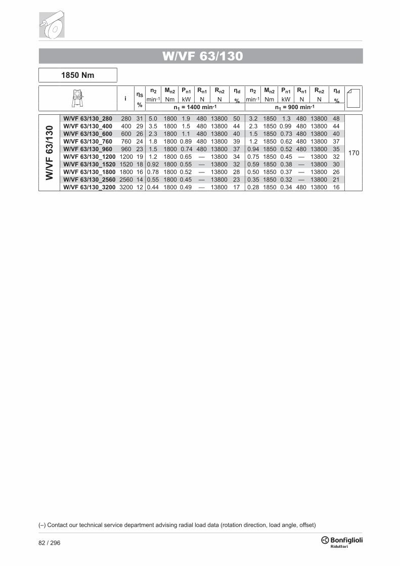
82 / 296
1850 Nm
iηS
%
n2
min-1
Mn2
NmPn1
kWRn1
NRn2
Nηd
%
n2
min-1
Mn2
NmPn1
kWRn1
NRn2
Nηd
%n1 = 1400 min-1 n1 = 900 min-1
W/V
F 63
/130
W/VF 63/130_280 280 31 5.0 1800 1.9 480 13800 50 3.2 1850 1.3 480 13800 48W/VF 63/130_400 400 29 3.5 1800 1.5 480 13800 44 2.3 1850 0.99 480 13800 44W/VF 63/130_600 600 26 2.3 1800 1.1 480 13800 40 1.5 1850 0.73 480 13800 40W/VF 63/130_760 760 24 1.8 1800 0.89 480 13800 39 1.2 1850 0.62 480 13800 37W/VF 63/130_960 960 23 1.5 1800 0.74 480 13800 37 0.94 1850 0.52 480 13800 35W/VF 63/130_1200 1200 19 1.2 1800 0.65 — 13800 34 0.75 1850 0.45 — 13800 32W/VF 63/130_1520 1520 18 0.92 1800 0.55 — 13800 32 0.59 1850 0.38 — 13800 30W/VF 63/130_1800 1800 16 0.78 1800 0.52 — 13800 28 0.50 1850 0.37 — 13800 26W/VF 63/130_2560 2560 14 0.55 1800 0.45 — 13800 23 0.35 1850 0.32 — 13800 21W/VF 63/130_3200 3200 12 0.44 1800 0.49 — 13800 17 0.28 1850 0.34 480 13800 16
W/VF 63/130
(–) Contact our technical service department advising radial load data (rotation direction, load angle, offset)
170
VF 150 - VFR 1502000 Nm
iηS
%
n2
min-1
Mn2
NmPn1
kWRn1
NRn2
Nηd
%
n2
min-1
Mn2
NmPn1
kWRn1
NRn2
Nηd
%n1 = 2800 min-1 n1 = 1400 min-1
VF 1
50
VF 150_7 7 72 400 750 35 2200 5010 91 200 1000 24 2200 6040 90 VF 150_10 10 68 280 788 25 2200 6630 90 140 1050 17.5 2200 8120 88 VF 150_15 15 64 187 863 19.0 2200 8110 89 93 1150 13.1 2200 9990 87 VF 150_20 20 59 140 975 16.4 2200 9170 87 70 1300 11.3 2200 11300 84 VF 150_23 23 57 122 953 14.1 2200 9940 86 61 1270 9.8 2200 12300 83 VF 150_30 30 48 93 1028 12.1 2200 11100 83 47 1370 8.5 2200 13700 80 VF 150_40 40 44 70 1155 10.5 2200 12300 81 35 1540 7.4 830 14700 77 VF 150_46 46 45 61 1163 9.2 2200 13100 81 30.0 1550 6.5 1400 14700 77 VF 150_56 56 42 50 1028 6.8 2200 14600 79 25.0 1370 4.9 2200 14700 74 VF 150_64 64 39 44 998 5.9 2200 14700 77 21.9 1330 4.2 2200 14700 72 VF 150_80 80 35 35 938 4.6 2200 14700 74 17.5 1250 3.4 2200 14700 69 VF 150_100 100 31 28 863 3.6 2200 14700 71 14.0 1150 2.6 2200 14700 65
n1 = 900 min-1 n1 = 500 min-1
VF 150_7 7 72 129 1150 17.6 2200 7040 89 71 1400 12.2 2200 8560 87 VF 150_10 10 68 90 1200 13.0 2200 9480 87 50 1500 9.4 2200 11400 85 VF 150_15 15 64 60 1350 10.0 2200 11500 85 33 1700 7.3 2200 13800 83 VF 150_20 20 59 45 1500 8.6 2200 13100 83 25.0 1900 6.4 2200 15700 80 VF 150_23 23 57 39 1500 7.6 2200 14200 82 21.7 1850 5.5 2200 16000 78 VF 150_30 30 48 30.0 1600 6.5 2200 15500 77 16.7 1950 4.8 2200 16000 73 VF 150_40 40 44 22.5 1750 5.6 1150 15500 74 12.5 2000 3.9 2200 16000 69 VF 150_46 46 45 19.6 1750 4.9 2100 15500 74 10.9 2000 3.4 2200 16000 69 VF 150_56 56 42 16.1 1500 3.7 2200 15500 71 8.9 1750 2.6 2200 16000 66 VF 150_64 64 39 14.1 1450 3.2 2200 15500 69 7.8 1700 2.3 2200 16000 63 VF 150_80 80 35 11.3 1350 2.5 2200 15500 65 6.3 1550 1.8 2200 16000 59 VF 150_100 100 31 9.0 1150 1.8 2200 15500 61 5.0 1300 1.3 2200 16000 55
2600 Nm
iηS
%
n2
min-1
Mn2
NmPn1
kWRn1
NRn2
Nηd
%
n2
min-1
Mn2
NmPn1
kWRn1
NRn2
Nηd
%n1 = 2800 min-1 n1 = 1400 min-1
VFR
150
VFR 150 _45 45 63 62 1350 10.6 1500 11600 84 31 1700 6.8 1500 14600 82 VFR 150 _60 60 58 47 1500 9.0 1500 13100 82 23.3 1900 5.9 1500 16000 79 VFR 150 _69 69 56 41 1500 7.9 1500 14100 81 20.3 1850 5.1 1500 16000 77 VFR 150 _90 90 47 31 1600 6.9 1500 15500 76 15.6 1950 4.4 1500 16000 72 VFR 150 _120 120 43 23.3 1750 5.9 1500 15500 73 11.7 2000 3.6 1500 16000 68 VFR 150 _138 138 44 20.3 1750 5.1 1500 15500 73 10.1 2000 3.1 1500 16000 68 VFR 150 _168 168 41 16.7 1500 3.8 1500 15500 70 8.3 1750 2.4 1500 16000 65 VFR 150 _192 192 38 14.6 1450 3.3 1500 15500 68 7.3 1700 2.1 1500 16000 62 VFR 150 _240 240 34 11.7 1350 2.6 1500 15500 64 5.8 1550 1.6 1500 16000 58 VFR 150 _300 300 30 9.3 1150 1.9 1500 15500 60 4.7 1300 1.2 1500 16000 54
n1 = 900 min-1 n1 = 500 min-1
VFR 150 _45 45 63 20.0 1950 5.2 1500 16000 79 11.1 2100 3.2 1500 16000 78 VFR 150 _60 60 58 15.0 2100 4.4 1500 16000 76 8.3 2300 2.7 1500 16000 74 VFR 150 _69 69 56 13.0 2050 3.8 1500 16000 74 7.2 2200 2.3 1500 16000 72 VFR 150 _90 90 47 10.0 2200 3.4 1500 16000 69 5.6 2400 2.1 1500 16000 66 VFR 150 _120 120 43 7.5 2300 2.8 1500 16000 64 4.2 2600 1.8 1500 16000 62 VFR 150 _138 138 44 6.5 2200 2.4 1500 16000 64 3.6 2400 1.5 1500 16000 62 VFR 150 _168 168 41 5.4 1950 1.8 1500 16000 61 3.0 2100 1.1 1500 16000 59 VFR 150 _192 192 38 4.7 1900 1.6 1500 16000 59 2.6 2000 1.0 1500 16000 56 VFR 150 _240 240 34 3.8 1700 1.2 1500 16000 54 2.1 1800 0.76 1500 16000 52 VFR 150 _300 300 30 3.0 1350 0.85 1500 16000 50 1.7 1450 0.54 1500 16000 47
168
169
168
169

83 / 296
1850 Nm
iηS
%
n2
min-1
Mn2
NmPn1
kWRn1
NRn2
Nηd
%
n2
min-1
Mn2
NmPn1
kWRn1
NRn2
Nηd
%n1 = 1400 min-1 n1 = 900 min-1
W/V
F 63
/130
W/VF 63/130_280 280 31 5.0 1800 1.9 480 13800 50 3.2 1850 1.3 480 13800 48W/VF 63/130_400 400 29 3.5 1800 1.5 480 13800 44 2.3 1850 0.99 480 13800 44W/VF 63/130_600 600 26 2.3 1800 1.1 480 13800 40 1.5 1850 0.73 480 13800 40W/VF 63/130_760 760 24 1.8 1800 0.89 480 13800 39 1.2 1850 0.62 480 13800 37W/VF 63/130_960 960 23 1.5 1800 0.74 480 13800 37 0.94 1850 0.52 480 13800 35W/VF 63/130_1200 1200 19 1.2 1800 0.65 — 13800 34 0.75 1850 0.45 — 13800 32W/VF 63/130_1520 1520 18 0.92 1800 0.55 — 13800 32 0.59 1850 0.38 — 13800 30W/VF 63/130_1800 1800 16 0.78 1800 0.52 — 13800 28 0.50 1850 0.37 — 13800 26W/VF 63/130_2560 2560 14 0.55 1800 0.45 — 13800 23 0.35 1850 0.32 — 13800 21W/VF 63/130_3200 3200 12 0.44 1800 0.49 — 13800 17 0.28 1850 0.34 480 13800 16
W/VF 63/130
(–) Contact our technical service department advising radial load data (rotation direction, load angle, offset)
170
VF 150 - VFR 1502000 Nm
iηS
%
n2
min-1
Mn2
NmPn1
kWRn1
NRn2
Nηd
%
n2
min-1
Mn2
NmPn1
kWRn1
NRn2
Nηd
%n1 = 2800 min-1 n1 = 1400 min-1
VF 1
50
VF 150_7 7 72 400 750 35 2200 5010 91 200 1000 24 2200 6040 90 VF 150_10 10 68 280 788 25 2200 6630 90 140 1050 17.5 2200 8120 88 VF 150_15 15 64 187 863 19.0 2200 8110 89 93 1150 13.1 2200 9990 87 VF 150_20 20 59 140 975 16.4 2200 9170 87 70 1300 11.3 2200 11300 84 VF 150_23 23 57 122 953 14.1 2200 9940 86 61 1270 9.8 2200 12300 83 VF 150_30 30 48 93 1028 12.1 2200 11100 83 47 1370 8.5 2200 13700 80 VF 150_40 40 44 70 1155 10.5 2200 12300 81 35 1540 7.4 830 14700 77 VF 150_46 46 45 61 1163 9.2 2200 13100 81 30.0 1550 6.5 1400 14700 77 VF 150_56 56 42 50 1028 6.8 2200 14600 79 25.0 1370 4.9 2200 14700 74 VF 150_64 64 39 44 998 5.9 2200 14700 77 21.9 1330 4.2 2200 14700 72 VF 150_80 80 35 35 938 4.6 2200 14700 74 17.5 1250 3.4 2200 14700 69 VF 150_100 100 31 28 863 3.6 2200 14700 71 14.0 1150 2.6 2200 14700 65
n1 = 900 min-1 n1 = 500 min-1
VF 150_7 7 72 129 1150 17.6 2200 7040 89 71 1400 12.2 2200 8560 87 VF 150_10 10 68 90 1200 13.0 2200 9480 87 50 1500 9.4 2200 11400 85 VF 150_15 15 64 60 1350 10.0 2200 11500 85 33 1700 7.3 2200 13800 83 VF 150_20 20 59 45 1500 8.6 2200 13100 83 25.0 1900 6.4 2200 15700 80 VF 150_23 23 57 39 1500 7.6 2200 14200 82 21.7 1850 5.5 2200 16000 78 VF 150_30 30 48 30.0 1600 6.5 2200 15500 77 16.7 1950 4.8 2200 16000 73 VF 150_40 40 44 22.5 1750 5.6 1150 15500 74 12.5 2000 3.9 2200 16000 69 VF 150_46 46 45 19.6 1750 4.9 2100 15500 74 10.9 2000 3.4 2200 16000 69 VF 150_56 56 42 16.1 1500 3.7 2200 15500 71 8.9 1750 2.6 2200 16000 66 VF 150_64 64 39 14.1 1450 3.2 2200 15500 69 7.8 1700 2.3 2200 16000 63 VF 150_80 80 35 11.3 1350 2.5 2200 15500 65 6.3 1550 1.8 2200 16000 59 VF 150_100 100 31 9.0 1150 1.8 2200 15500 61 5.0 1300 1.3 2200 16000 55
2600 Nm
iηS
%
n2
min-1
Mn2
NmPn1
kWRn1
NRn2
Nηd
%
n2
min-1
Mn2
NmPn1
kWRn1
NRn2
Nηd
%n1 = 2800 min-1 n1 = 1400 min-1
VFR
150
VFR 150 _45 45 63 62 1350 10.6 1500 11600 84 31 1700 6.8 1500 14600 82 VFR 150 _60 60 58 47 1500 9.0 1500 13100 82 23.3 1900 5.9 1500 16000 79 VFR 150 _69 69 56 41 1500 7.9 1500 14100 81 20.3 1850 5.1 1500 16000 77 VFR 150 _90 90 47 31 1600 6.9 1500 15500 76 15.6 1950 4.4 1500 16000 72 VFR 150 _120 120 43 23.3 1750 5.9 1500 15500 73 11.7 2000 3.6 1500 16000 68 VFR 150 _138 138 44 20.3 1750 5.1 1500 15500 73 10.1 2000 3.1 1500 16000 68 VFR 150 _168 168 41 16.7 1500 3.8 1500 15500 70 8.3 1750 2.4 1500 16000 65 VFR 150 _192 192 38 14.6 1450 3.3 1500 15500 68 7.3 1700 2.1 1500 16000 62 VFR 150 _240 240 34 11.7 1350 2.6 1500 15500 64 5.8 1550 1.6 1500 16000 58 VFR 150 _300 300 30 9.3 1150 1.9 1500 15500 60 4.7 1300 1.2 1500 16000 54
n1 = 900 min-1 n1 = 500 min-1
VFR 150 _45 45 63 20.0 1950 5.2 1500 16000 79 11.1 2100 3.2 1500 16000 78 VFR 150 _60 60 58 15.0 2100 4.4 1500 16000 76 8.3 2300 2.7 1500 16000 74 VFR 150 _69 69 56 13.0 2050 3.8 1500 16000 74 7.2 2200 2.3 1500 16000 72 VFR 150 _90 90 47 10.0 2200 3.4 1500 16000 69 5.6 2400 2.1 1500 16000 66 VFR 150 _120 120 43 7.5 2300 2.8 1500 16000 64 4.2 2600 1.8 1500 16000 62 VFR 150 _138 138 44 6.5 2200 2.4 1500 16000 64 3.6 2400 1.5 1500 16000 62 VFR 150 _168 168 41 5.4 1950 1.8 1500 16000 61 3.0 2100 1.1 1500 16000 59 VFR 150 _192 192 38 4.7 1900 1.6 1500 16000 59 2.6 2000 1.0 1500 16000 56 VFR 150 _240 240 34 3.8 1700 1.2 1500 16000 54 2.1 1800 0.76 1500 16000 52 VFR 150 _300 300 30 3.0 1350 0.85 1500 16000 50 1.7 1450 0.54 1500 16000 47
168
169
168
169

84 / 296
2700 Nm
iηS
%
n2
min-1
Mn2
NmPn1
kWRn1
NRn2
Nηd
%
n2
min-1
Mn2
NmPn1
kWRn1
NRn2
Nηd
%n1 = 1400 min-1 n1 = 900 min-1
W/V
F 86
/150
W/VF 86/150_200 200 29 7.0 2600 3.0 850 16000 64 4.5 2700 2.1 850 16000 61W/VF 86/150_225 225 26 6.2 2600 2.7 850 16000 63 4.0 2700 1.9 850 16000 60W/VF 86/150_300 300 26 4.7 2600 2.2 850 16000 58 3.0 2700 1.5 850 16000 57W/VF 86/150_345 345 26 4.1 2600 1.9 850 16000 58 2.6 2700 1.3 850 16000 57W/VF 86/150_460 460 26 3.0 2600 1.5 850 16000 55 2.0 2700 1.0 850 16000 55W/VF 86/150_529 529 26 2.6 2600 1.3 850 16000 55 1.7 2700 0.93 850 16000 52W/VF 86/150_690 690 26 2.0 2600 1.1 850 16000 50 1.3 2700 0.78 850 16000 47W/VF 86/150_920 920 26 1.5 2600 0.92 850 16000 45 0.98 2700 0.64 850 16000 43W/VF 86/150_1380 1380 19 1.0 2600 0.66 850 16000 42 0.65 2700 0.46 850 16000 40W/VF 86/150_1840 1840 19 0.76 2600 0.55 850 16000 38 0.49 2700 0.38 850 16000 36W/VF 86/150_2944 2944 16 0.48 2600 0.48 850 16000 27 0.31 2700 0.35 850 16000 25
W/VF 86/150
170
VF 185 - VFR 1853600 Nm
iηS
%
n2
min-1
Mn2
NmPn1
kWRn1
NRn2
Nηd
%
n2
min-1
Mn2
NmPn1
kWRn1
NRn2
Nηd
%n1 = 2800 min-1 n1 = 1400 min-1
VF 1
85
VF 185_7 7 72 400 1313 60 2800 4670 91 200 1750 41 2800 5570 90 VF 185_10 10 68 280 1365 44 2800 7390 90 140 1820 30 2800 8960 89 VF 185_15 15 66 187 1388 30 2800 9460 89 93 1850 21 2800 11600 88 VF 185_20 20 59 140 1703 28 2800 10500 88 70 2270 19.6 2800 12900 85 VF 185_30 30 54 93 1485 16.9 2800 13700 86 47 1980 11.8 2800 16900 83 VF 185_40 40 44 70 1973 17.6 — 14500 82 35 2630 12.4 — 17900 78 VF 185_50 50 41 56 1875 13.7 — 16300 80 28.0 2500 9.8 — 18000 76 VF 185_60 60 39 47 1703 10.7 2800 18000 78 23.3 2270 7.6 770 18000 74 VF 185_80 80 33 35 1590 7.8 2800 18000 75 17.5 2120 5.6 1140 18000 69 VF 185_100 100 30 28.0 1425 5.8 2800 18000 72 14.0 1900 4.3 2800 18000 65
n1 = 900 min-1 n1 = 500 min-1
VF 185_7 7 72 129 2000 30 2800 7120 89 71 2450 21 2800 8730 88 VF 185_10 10 68 90 2150 23 2800 10200 88 50 2600 16.0 2800 12500 86 VF 185_15 15 66 60 2250 16.4 2800 13100 86 33 2800 11.8 2800 15700 84 VF 185_20 20 59 45 2750 15.6 2800 14600 84 25.0 3300 10.9 2800 17900 81 VF 185_30 30 54 30.0 2400 9.4 2800 19000 81 16.7 2800 6.5 2800 19500 77 VF 185_40 40 44 22.5 3100 9.7 — 19000 76 12.5 3600 6.8 — 19500 71 VF 185_50 50 41 18.0 2900 7.6 — 19000 73 10.0 3300 5.2 — 19500 68 VF 185_60 60 39 15.0 2600 5.8 700 19000 71 8.3 3000 4.2 2800 19500 66 VF 185_80 80 33 11.3 2400 4.3 1770 19000 66 6.3 2800 3.2 2800 19500 60 VF 185_100 100 30 9.0 2000 3.0 2800 19000 62 5.0 2300 2.1 2800 19500 56
4200 Nm
iηS
%
n2
min-1
Mn2
NmPn1
kWRn1
NRn2
Nηd
%
n2
min-1
Mn2
NmPn1
kWRn1
NRn2
Nηd
%n1 = 2800 min-1 n1 = 1400 min-1
VFR
185
VFR 185 _90 90 53 31 2400 9.9 1700 19000 80 15.6 2800 6.0 1700 19500 76 VFR 185 _120 120 43 23.3 3100 10.2 1700 19000 75 11.7 3600 6.3 1700 19500 70 VFR 185 _150 150 40 18.7 2900 7.9 1700 19000 72 9.3 3300 4.8 1700 19500 67 VFR 185 _180 180 38 15.6 2600 6.1 1700 19000 70 7.8 3000 3.8 1700 19500 65 VFR 185 _240 240 32 11.7 2400 4.5 1700 19000 65 5.8 2800 2.9 1700 19500 59 VFR 185 _300 300 29 9.3 2000 3.2 1700 19000 61 4.7 2300 2.0 1700 19500 55
n1 = 900 min-1 n1 = 500 min-1
VFR 185 _90 90 53 10.0 3200 4.6 1700 19500 73 5.6 3500 2.9 1700 19500 71 VFR 185 _120 120 43 7.5 3800 4.5 1700 19500 66 4.2 4200 2.9 1700 19500 63 VFR 185 _150 150 40 6.0 3400 3.4 1700 19500 63 3.3 3700 2.2 1700 19500 60 VFR 185 _180 180 38 5.0 3300 2.9 1700 19500 60 2.8 3600 1.8 1700 19500 57 VFR 185 _240 240 32 3.8 2800 2.0 1700 19500 54 2.1 2900 1.2 1700 19500 53 VFR 185 _300 300 29 3.0 2400 1.5 1700 19500 50 1.7 2500 0.91 1700 19500 48
(–) Contact our technical service department advising radial load data (rotation direction, load angle, offset)
168
169
168
169

85 / 296
2700 Nm
iηS
%
n2
min-1
Mn2
NmPn1
kWRn1
NRn2
Nηd
%
n2
min-1
Mn2
NmPn1
kWRn1
NRn2
Nηd
%n1 = 1400 min-1 n1 = 900 min-1
W/V
F 86
/150
W/VF 86/150_200 200 29 7.0 2600 3.0 850 16000 64 4.5 2700 2.1 850 16000 61W/VF 86/150_225 225 26 6.2 2600 2.7 850 16000 63 4.0 2700 1.9 850 16000 60W/VF 86/150_300 300 26 4.7 2600 2.2 850 16000 58 3.0 2700 1.5 850 16000 57W/VF 86/150_345 345 26 4.1 2600 1.9 850 16000 58 2.6 2700 1.3 850 16000 57W/VF 86/150_460 460 26 3.0 2600 1.5 850 16000 55 2.0 2700 1.0 850 16000 55W/VF 86/150_529 529 26 2.6 2600 1.3 850 16000 55 1.7 2700 0.93 850 16000 52W/VF 86/150_690 690 26 2.0 2600 1.1 850 16000 50 1.3 2700 0.78 850 16000 47W/VF 86/150_920 920 26 1.5 2600 0.92 850 16000 45 0.98 2700 0.64 850 16000 43W/VF 86/150_1380 1380 19 1.0 2600 0.66 850 16000 42 0.65 2700 0.46 850 16000 40W/VF 86/150_1840 1840 19 0.76 2600 0.55 850 16000 38 0.49 2700 0.38 850 16000 36W/VF 86/150_2944 2944 16 0.48 2600 0.48 850 16000 27 0.31 2700 0.35 850 16000 25
W/VF 86/150
170
VF 185 - VFR 1853600 Nm
iηS
%
n2
min-1
Mn2
NmPn1
kWRn1
NRn2
Nηd
%
n2
min-1
Mn2
NmPn1
kWRn1
NRn2
Nηd
%n1 = 2800 min-1 n1 = 1400 min-1
VF 1
85
VF 185_7 7 72 400 1313 60 2800 4670 91 200 1750 41 2800 5570 90 VF 185_10 10 68 280 1365 44 2800 7390 90 140 1820 30 2800 8960 89 VF 185_15 15 66 187 1388 30 2800 9460 89 93 1850 21 2800 11600 88 VF 185_20 20 59 140 1703 28 2800 10500 88 70 2270 19.6 2800 12900 85 VF 185_30 30 54 93 1485 16.9 2800 13700 86 47 1980 11.8 2800 16900 83 VF 185_40 40 44 70 1973 17.6 — 14500 82 35 2630 12.4 — 17900 78 VF 185_50 50 41 56 1875 13.7 — 16300 80 28.0 2500 9.8 — 18000 76 VF 185_60 60 39 47 1703 10.7 2800 18000 78 23.3 2270 7.6 770 18000 74 VF 185_80 80 33 35 1590 7.8 2800 18000 75 17.5 2120 5.6 1140 18000 69 VF 185_100 100 30 28.0 1425 5.8 2800 18000 72 14.0 1900 4.3 2800 18000 65
n1 = 900 min-1 n1 = 500 min-1
VF 185_7 7 72 129 2000 30 2800 7120 89 71 2450 21 2800 8730 88 VF 185_10 10 68 90 2150 23 2800 10200 88 50 2600 16.0 2800 12500 86 VF 185_15 15 66 60 2250 16.4 2800 13100 86 33 2800 11.8 2800 15700 84 VF 185_20 20 59 45 2750 15.6 2800 14600 84 25.0 3300 10.9 2800 17900 81 VF 185_30 30 54 30.0 2400 9.4 2800 19000 81 16.7 2800 6.5 2800 19500 77 VF 185_40 40 44 22.5 3100 9.7 — 19000 76 12.5 3600 6.8 — 19500 71 VF 185_50 50 41 18.0 2900 7.6 — 19000 73 10.0 3300 5.2 — 19500 68 VF 185_60 60 39 15.0 2600 5.8 700 19000 71 8.3 3000 4.2 2800 19500 66 VF 185_80 80 33 11.3 2400 4.3 1770 19000 66 6.3 2800 3.2 2800 19500 60 VF 185_100 100 30 9.0 2000 3.0 2800 19000 62 5.0 2300 2.1 2800 19500 56
4200 Nm
iηS
%
n2
min-1
Mn2
NmPn1
kWRn1
NRn2
Nηd
%
n2
min-1
Mn2
NmPn1
kWRn1
NRn2
Nηd
%n1 = 2800 min-1 n1 = 1400 min-1
VFR
185
VFR 185 _90 90 53 31 2400 9.9 1700 19000 80 15.6 2800 6.0 1700 19500 76 VFR 185 _120 120 43 23.3 3100 10.2 1700 19000 75 11.7 3600 6.3 1700 19500 70 VFR 185 _150 150 40 18.7 2900 7.9 1700 19000 72 9.3 3300 4.8 1700 19500 67 VFR 185 _180 180 38 15.6 2600 6.1 1700 19000 70 7.8 3000 3.8 1700 19500 65 VFR 185 _240 240 32 11.7 2400 4.5 1700 19000 65 5.8 2800 2.9 1700 19500 59 VFR 185 _300 300 29 9.3 2000 3.2 1700 19000 61 4.7 2300 2.0 1700 19500 55
n1 = 900 min-1 n1 = 500 min-1
VFR 185 _90 90 53 10.0 3200 4.6 1700 19500 73 5.6 3500 2.9 1700 19500 71 VFR 185 _120 120 43 7.5 3800 4.5 1700 19500 66 4.2 4200 2.9 1700 19500 63 VFR 185 _150 150 40 6.0 3400 3.4 1700 19500 63 3.3 3700 2.2 1700 19500 60 VFR 185 _180 180 38 5.0 3300 2.9 1700 19500 60 2.8 3600 1.8 1700 19500 57 VFR 185 _240 240 32 3.8 2800 2.0 1700 19500 54 2.1 2900 1.2 1700 19500 53 VFR 185 _300 300 29 3.0 2400 1.5 1700 19500 50 1.7 2500 0.91 1700 19500 48
(–) Contact our technical service department advising radial load data (rotation direction, load angle, offset)
168
169
168
169

86 / 296
4400 Nm
iηS
%
n2
min-1
Mn2
NmPn1
kWRn1
NRn2
Nηd
%
n2
min-1
Mn2
NmPn1
kWRn1
NRn2
Nηd
%n1 = 1400 min-1 n1 = 900 min-1
W/V
F 86
/185
W/VF 86/185_280 280 31 5.0 4200 4.2 850 19500 52 3.2 4400 3.0 850 19500 49W/VF 86/185_400 400 29 3.5 4200 3.2 850 19500 48 2.3 4400 2.3 850 19500 45W/VF 86/185_600 600 26 2.3 4200 2.3 850 19500 45 1.5 4400 1.6 850 19500 43W/VF 86/185_800 800 26 1.8 4200 1.8 850 19500 43 1.1 4400 1.3 850 19500 40W/VF 86/185_920 920 26 1.5 4200 1.6 850 19500 42 1.0 4400 1.2 850 19500 38W/VF 86/185_1200 1200 20 1.2 4200 1.5 850 19500 34 0.75 4400 0.99 850 19500 35W/VF 86/185_1600 1600 20 0.88 4200 1.1 850 19500 35 0.56 4400 0.79 850 19500 33W/VF 86/185_1840 1840 19 0.76 4200 0.98 850 19500 34 0.49 4400 0.70 850 19500 32W/VF 86/185_2560 2560 16 0.55 4200 0.83 850 19500 29 0.35 4400 0.60 850 19500 27W/VF 86/185_3200 3200 15 0.44 4200 0.80 850 19500 24 0.28 4400 0.59 850 19500 22
W/VF 86/185
170
VF 210 - VFR 2105000 Nm
iηS
%
n2
min-1
Mn2
NmPn1
kWRn1
NRn2
Nηd
%
n2
min-1
Mn2
NmPn1
kWRn1
NRn2
Nηd
%n1 = 2800 min-1 n1 = 1400 min-1
VF 2
10
VF 210_7 7 71 400 1725 79 5300 14000 91 200 2300 54 5300 16700 90 VF 210_10 10 69 280 1988 65 5300 16300 90 140 2650 44 5300 19500 89 VF 210_15 15 63 187 2138 47 5300 19700 89 93 2850 32 5300 23700 88 VF 210_20 20 57 140 2325 39 4970 22000 87 70 3100 27 1100 26600 85 VF 210_30 30 51 93 2288 26 5300 25900 85 47 3050 18.5 1760 31500 83 VF 210_40 40 42 70 2625 23 — 28300 81 35 3500 17.0 — 31500 78 VF 210_50 50 39 56 2475 18.4 — 31000 79 28.0 3300 13.0 — 31500 76 VF 210_60 60 36 47 2363 15.0 — 31500 77 23.3 3015 10.0 — 31500 73 VF 210_80 80 31 35 2175 10.9 — 31500 73 17.5 2900 7.7 — 31500 69 VF 210_100 100 27 28 2025 8.5 950 31500 70 14.0 2700 6.0 — 31500 65
n1 = 900 min-1 n1 = 500 min-1
VF 210_7 7 71 129 2700 41 5300 18800 89 71 3400 29 5300 21800 88 VF 210_10 10 69 90 3150 34 5300 21900 88 50 3800 23 5300 26000 87 VF 210_15 15 63 60 3300 24 5300 27000 86 33 4100 17.2 5300 31800 84 VF 210_20 20 57 45 3800 22 — 29900 83 25.0 4700 15.4 — 34500 81 VF 210_30 30 51 30.0 3400 13.4 3750 33000 80 16.7 4000 9.3 5300 34500 77 VF 210_40 40 42 22.5 4300 13.5 — 33000 75 12.5 5000 9.4 — 34500 71 VF 210_50 50 39 18.0 4000 10.5 — 33000 72 10.0 4500 7.1 — 34500 68 VF 210_60 60 36 15.0 3720 8.5 — 33000 70 8.3 4300 6.0 — 34500 65 VF 210_80 80 31 11.3 3300 6.0 — 33000 65 6.3 3900 4.4 — 34500 60 VF 210_100 100 27 9.0 3000 4.6 — 33000 61 5.0 3400 3.4 1470 34500 56
6300 Nm
iηS
%
n2
min-1
Mn2
NmPn1
kWRn1
NRn2
Nηd
%
n2
min-1
Mn2
NmPn1
kWRn1
NRn2
Nηd
%n1 = 2800 min-1 n1 = 1400 min-1
VFR
210
VFR 210 _30 30 68 93 3150 36 1800 22100 87 47 3800 21.8 2200 27400 86 VFR 210 _45 45 62 62 3300 25 1800 27000 85 31 4100 16.2 2200 33200 83 VFR 210 _60 60 56 47 3800 22 1800 29900 82 23.0 4700 14.5 2200 34500 80 VFR 210 _90 90 50 31 3400 14.1 1800 33000 79 15.6 4000 8.6 2200 34500 76 VFR 210 _120 120 41 23.3 4300 14.3 1800 33000 74 11.7 5000 8.8 2200 34500 70 VFR 210 _150 150 38 18.7 4000 11.1 1800 33000 71 9.3 4500 6.6 2200 34500 67 VFR 210 _180 180 35 15.6 3720 8.8 1800 33000 69 7.8 4300 5.5 2200 34500 64 VFR 210 _240 240 30 11.7 3300 6.3 1800 33000 64 5.8 3900 4.1 2200 34500 59 VFR 210 _300 300 26 9.3 3000 4.9 1800 33000 60 4.7 3400 3.0 2200 34500 55
n1 = 900 min-1 n1 = 500 min-1
VFR 210 _30 30 68 30.0 4800 18.1 2300 30100 84 16.7 5500 11.8 2650 34500 82 VFR 210 _45 45 62 20.0 4900 12.9 2300 34500 80 11.1 5600 8.4 2650 34500 78 VFR 210 _60 60 56 15.0 5400 11.1 2300 34500 77 8.3 6000 7.1 2650 34500 74 VFR 210 _90 90 50 10.0 4600 6.7 2300 34500 72 5.6 5150 4.3 2650 34500 70 VFR 210 _120 120 41 7.5 5900 7.1 2300 34500 66 4.2 6300 4.4 2650 34500 63 VFR 210 _150 150 38 6.0 5300 5.4 2300 34500 62 3.3 5900 3.5 2650 34500 59 VFR 210 _180 180 35 5.0 4900 4.4 2300 34500 59 2.8 5400 2.8 2650 34500 56 VFR 210 _240 240 30 3.8 4400 3.2 2300 34500 54 2.1 4800 2.1 2650 34500 50 VFR 210 _300 300 26 3.0 3600 2.3 2300 34500 49 1.7 4000 1.5 2650 34500 46
(–) Contact our technical service department advising radial load data (rotation direction, load angle, offset)
168
169
168
169

87 / 296
4400 Nm
iηS
%
n2
min-1
Mn2
NmPn1
kWRn1
NRn2
Nηd
%
n2
min-1
Mn2
NmPn1
kWRn1
NRn2
Nηd
%n1 = 1400 min-1 n1 = 900 min-1
W/V
F 86
/185
W/VF 86/185_280 280 31 5.0 4200 4.2 850 19500 52 3.2 4400 3.0 850 19500 49W/VF 86/185_400 400 29 3.5 4200 3.2 850 19500 48 2.3 4400 2.3 850 19500 45W/VF 86/185_600 600 26 2.3 4200 2.3 850 19500 45 1.5 4400 1.6 850 19500 43W/VF 86/185_800 800 26 1.8 4200 1.8 850 19500 43 1.1 4400 1.3 850 19500 40W/VF 86/185_920 920 26 1.5 4200 1.6 850 19500 42 1.0 4400 1.2 850 19500 38W/VF 86/185_1200 1200 20 1.2 4200 1.5 850 19500 34 0.75 4400 0.99 850 19500 35W/VF 86/185_1600 1600 20 0.88 4200 1.1 850 19500 35 0.56 4400 0.79 850 19500 33W/VF 86/185_1840 1840 19 0.76 4200 0.98 850 19500 34 0.49 4400 0.70 850 19500 32W/VF 86/185_2560 2560 16 0.55 4200 0.83 850 19500 29 0.35 4400 0.60 850 19500 27W/VF 86/185_3200 3200 15 0.44 4200 0.80 850 19500 24 0.28 4400 0.59 850 19500 22
W/VF 86/185
170
VF 210 - VFR 2105000 Nm
iηS
%
n2
min-1
Mn2
NmPn1
kWRn1
NRn2
Nηd
%
n2
min-1
Mn2
NmPn1
kWRn1
NRn2
Nηd
%n1 = 2800 min-1 n1 = 1400 min-1
VF 2
10
VF 210_7 7 71 400 1725 79 5300 14000 91 200 2300 54 5300 16700 90 VF 210_10 10 69 280 1988 65 5300 16300 90 140 2650 44 5300 19500 89 VF 210_15 15 63 187 2138 47 5300 19700 89 93 2850 32 5300 23700 88 VF 210_20 20 57 140 2325 39 4970 22000 87 70 3100 27 1100 26600 85 VF 210_30 30 51 93 2288 26 5300 25900 85 47 3050 18.5 1760 31500 83 VF 210_40 40 42 70 2625 23 — 28300 81 35 3500 17.0 — 31500 78 VF 210_50 50 39 56 2475 18.4 — 31000 79 28.0 3300 13.0 — 31500 76 VF 210_60 60 36 47 2363 15.0 — 31500 77 23.3 3015 10.0 — 31500 73 VF 210_80 80 31 35 2175 10.9 — 31500 73 17.5 2900 7.7 — 31500 69 VF 210_100 100 27 28 2025 8.5 950 31500 70 14.0 2700 6.0 — 31500 65
n1 = 900 min-1 n1 = 500 min-1
VF 210_7 7 71 129 2700 41 5300 18800 89 71 3400 29 5300 21800 88 VF 210_10 10 69 90 3150 34 5300 21900 88 50 3800 23 5300 26000 87 VF 210_15 15 63 60 3300 24 5300 27000 86 33 4100 17.2 5300 31800 84 VF 210_20 20 57 45 3800 22 — 29900 83 25.0 4700 15.4 — 34500 81 VF 210_30 30 51 30.0 3400 13.4 3750 33000 80 16.7 4000 9.3 5300 34500 77 VF 210_40 40 42 22.5 4300 13.5 — 33000 75 12.5 5000 9.4 — 34500 71 VF 210_50 50 39 18.0 4000 10.5 — 33000 72 10.0 4500 7.1 — 34500 68 VF 210_60 60 36 15.0 3720 8.5 — 33000 70 8.3 4300 6.0 — 34500 65 VF 210_80 80 31 11.3 3300 6.0 — 33000 65 6.3 3900 4.4 — 34500 60 VF 210_100 100 27 9.0 3000 4.6 — 33000 61 5.0 3400 3.4 1470 34500 56
6300 Nm
iηS
%
n2
min-1
Mn2
NmPn1
kWRn1
NRn2
Nηd
%
n2
min-1
Mn2
NmPn1
kWRn1
NRn2
Nηd
%n1 = 2800 min-1 n1 = 1400 min-1
VFR
210
VFR 210 _30 30 68 93 3150 36 1800 22100 87 47 3800 21.8 2200 27400 86 VFR 210 _45 45 62 62 3300 25 1800 27000 85 31 4100 16.2 2200 33200 83 VFR 210 _60 60 56 47 3800 22 1800 29900 82 23.0 4700 14.5 2200 34500 80 VFR 210 _90 90 50 31 3400 14.1 1800 33000 79 15.6 4000 8.6 2200 34500 76 VFR 210 _120 120 41 23.3 4300 14.3 1800 33000 74 11.7 5000 8.8 2200 34500 70 VFR 210 _150 150 38 18.7 4000 11.1 1800 33000 71 9.3 4500 6.6 2200 34500 67 VFR 210 _180 180 35 15.6 3720 8.8 1800 33000 69 7.8 4300 5.5 2200 34500 64 VFR 210 _240 240 30 11.7 3300 6.3 1800 33000 64 5.8 3900 4.1 2200 34500 59 VFR 210 _300 300 26 9.3 3000 4.9 1800 33000 60 4.7 3400 3.0 2200 34500 55
n1 = 900 min-1 n1 = 500 min-1
VFR 210 _30 30 68 30.0 4800 18.1 2300 30100 84 16.7 5500 11.8 2650 34500 82 VFR 210 _45 45 62 20.0 4900 12.9 2300 34500 80 11.1 5600 8.4 2650 34500 78 VFR 210 _60 60 56 15.0 5400 11.1 2300 34500 77 8.3 6000 7.1 2650 34500 74 VFR 210 _90 90 50 10.0 4600 6.7 2300 34500 72 5.6 5150 4.3 2650 34500 70 VFR 210 _120 120 41 7.5 5900 7.1 2300 34500 66 4.2 6300 4.4 2650 34500 63 VFR 210 _150 150 38 6.0 5300 5.4 2300 34500 62 3.3 5900 3.5 2650 34500 59 VFR 210 _180 180 35 5.0 4900 4.4 2300 34500 59 2.8 5400 2.8 2650 34500 56 VFR 210 _240 240 30 3.8 4400 3.2 2300 34500 54 2.1 4800 2.1 2650 34500 50 VFR 210 _300 300 26 3.0 3600 2.3 2300 34500 49 1.7 4000 1.5 2650 34500 46
(–) Contact our technical service department advising radial load data (rotation direction, load angle, offset)
168
169
168
169

88 / 296
6500 Nm
iηS
%
n2
min-1
Mn2
NmPn1
kWRn1
NRn2
Nηd
%
n2
min-1
Mn2
NmPn1
kWRn1
NRn2
Nηd
%n1 = 1400 min-1 n1 = 900 min-1
VF/V
F 13
0/21
0 VF/VF 130/210_280 280 30 5.0 6300 6.3 1500 34500 52 3.2 6500 4.4 1500 34500 50VF/VF 130/210_400 400 28 3.5 6300 4.6 1500 34500 50 2.3 6500 3.2 1500 34500 48VF/VF 130/210_600 600 26 2.3 6300 3.6 1500 34500 43 1.5 6500 2.4 1500 34500 43VF/VF 130/210_800 800 25 1.8 6300 2.8 1500 34500 41 1.1 6500 2.0 1500 34500 38VF/VF 130/210_920 920 24 1.5 6300 2.7 1500 34500 37 1.0 6500 1.9 1500 34500 35VF/VF 130/210_1200 1200 21 1.2 6300 2.2 — 34500 35 0.75 6500 1.5 — 34500 34VF/VF 130/210_1600 1600 18 0.88 6300 1.8 — 34500 32 0.56 6500 1.2 — 34500 32VF/VF 130/210_1840 1840 19 0.76 6300 1.7 — 34500 30 0.49 6500 1.2 490 34500 28VF/VF 130/210_2560 2560 16 0.55 6300 1.5 1220 34500 24 0.35 6500 1.0 1500 34500 24VF/VF 130/210_3200 3200 15 0.44 6300 1.3 1500 34500 22 0.28 6500 0.96 1500 34500 20
VF/VF 130/210
(–) Contact our technical service department advising radial load data (rotation direction, load angle, offset)
170
VF 250 - VFR 2507100 Nm
iηS
%
n2
min-1
Mn2
NmPn1
kWRn1
NRn2
Nηd
%
n2
min-1
Mn2
NmPn1
kWRn1
NRn2
Nηd
%n1 = 2800 min-1 n1 = 1400 min-1
VF 2
50
VF 250_7 7 71 400 2400 109 7000 18300 92 200 3200 75 7000 21900 91 VF 250_10 10 69 280 2775 89 7000 21100 91 140 3700 61 7000 25300 90 VF 250_15 15 64 187 3000 65 7000 25100 90 93 4000 45 7000 30300 88 VF 250_20 20 59 140 3338 56 7000 28000 88 70 4450 38 7000 33900 86 VF 250_30 30 53 93 3000 34 7000 33400 86 47 4000 23 7000 40600 84 VF 250_40 40 41 70 3600 32 4680 36200 82 35 4800 22 — 44000 79 VF 250_50 50 36 56 3375 25 6370 39500 79 28.0 4500 17.0 — 47000 76 VF 250_60 60 38 47 3375 20.6 7000 42100 80 23.3 4500 15.0 — 47000 76 VF 250_80 80 32 35 2925 14.1 7000 47000 76 17.5 3900 10.0 — 47000 71 VF 250_100 100 29 28 2738 11.0 7000 47000 73 14.0 3650 7.8 3010 47000 68
n1 = 900 min-1 n1 = 500 min-1
VF 250_7 7 71 129 4150 63 7000 23700 90 71 5200 44 7000 27600 88 VF 250_10 10 69 90 4800 51 7000 27600 89 50 6000 36 7000 32300 87 VF 250_15 15 64 60 5300 39 7000 33200 87 33 6400 27 7000 39500 85 VF 250_20 20 59 45 5950 33 1640 37200 85 25.0 7100 24 1910 44400 82 VF 250_30 30 53 30.0 5500 21 7000 44900 81 16.7 6000 14.7 7000 52000 79 VF 250_40 40 41 22.5 6500 20.0 — 48800 76 12.5 7000 13.6 — 52000 72 VF 250_50 50 36 18.0 6200 16.2 — 50000 73 10.0 6500 11.1 — 52000 68 VF 250_60 60 38 15.0 5600 12.2 — 50000 72 8.3 6300 8.6 4350 52000 68 VF 250_80 80 32 11.3 5200 9.3 — 50000 67 6.3 5400 6.8 7000 52000 62 VF 250_100 100 29 9.0 4800 7.2 3010 50000 63 5.0 5000 5.3 4160 52000 58
9000 Nm
iηS
%
n2
min-1
Mn2
NmPn1
kWRn1
NRn2
Nηd
%
n2
min-1
Mn2
NmPn1
kWRn1
NRn2
Nηd
%n1 = 2800 min-1 n1 = 1400 min-1
VFR
250
VFR 250 _30 30 68 93 4800 54 2800 27800 89 47 6000 34 3500 34000 86 VFR 250 _45 45 63 62 5300 41 2800 33300 87 31 6400 25 3500 41300 84 VFR 250 _60 60 58 47 5950 35 2800 37200 85 23.0 7100 21 3500 46100 81 VFR 250 _90 90 52 31 5500 22 2800 44700 81 15.6 6000 12.6 3500 52000 78 VFR 250 _120 120 40 23.3 6500 21.3 2800 48500 76 11.7 7000 12.1 3500 52000 71 VFR 250 _150 150 35 18.7 6200 16.9 2800 50000 73 9.3 6500 9.5 3500 52000 67 VFR 250 _180 180 37 15.6 5600 12.9 2800 50000 72 7.8 6300 7.7 3500 52000 67 VFR 250 _240 240 31 11.7 5200 9.7 2800 50000 67 5.8 5400 5.4 3500 52000 61 VFR 250 _300 300 28 9.3 4800 7.6 2800 50000 63 4.7 5000 4.3 3500 52000 57
n1 = 900 min-1 n1 = 500 min-1
VFR 250 _30 30 68 30.0 6500 24 3700 39600 84 16.7 7600 16.1 4200 47600 83 VFR 250 _45 45 63 20.0 6800 17.5 3700 48000 82 11.1 7900 11.6 3500 52000 80 VFR 250 _60 60 58 15.0 7600 15.2 3700 52000 79 8.3 8600 9.9 3500 52000 76 VFR 250 _90 90 52 10.0 6500 9.3 3700 52000 74 5.6 7400 6.1 3500 52000 71 VFR 250 _120 120 40 7.5 7500 8.8 3700 52000 67 4.2 9000 6.2 3500 52000 64 VFR 250 _150 150 35 6.0 7000 7.0 3700 52000 63 3.3 8600 5.1 3500 52000 59 VFR 250 _180 180 37 5.0 6700 5.7 3700 52000 62 2.8 7600 3.8 3500 52000 59 VFR 250 _240 240 31 3.8 5800 4.1 3700 52000 56 2.1 6500 2.7 3500 52000 52 VFR 250 _300 300 28 3.0 5300 3.2 3700 52000 52 1.7 6000 2.2 3500 52000 48
(–) Contact our technical service department advising radial load data (rotation direction, load angle, offset)
168
169
168
169

89 / 296
6500 Nm
iηS
%
n2
min-1
Mn2
NmPn1
kWRn1
NRn2
Nηd
%
n2
min-1
Mn2
NmPn1
kWRn1
NRn2
Nηd
%n1 = 1400 min-1 n1 = 900 min-1
VF/V
F 13
0/21
0 VF/VF 130/210_280 280 30 5.0 6300 6.3 1500 34500 52 3.2 6500 4.4 1500 34500 50VF/VF 130/210_400 400 28 3.5 6300 4.6 1500 34500 50 2.3 6500 3.2 1500 34500 48VF/VF 130/210_600 600 26 2.3 6300 3.6 1500 34500 43 1.5 6500 2.4 1500 34500 43VF/VF 130/210_800 800 25 1.8 6300 2.8 1500 34500 41 1.1 6500 2.0 1500 34500 38VF/VF 130/210_920 920 24 1.5 6300 2.7 1500 34500 37 1.0 6500 1.9 1500 34500 35VF/VF 130/210_1200 1200 21 1.2 6300 2.2 — 34500 35 0.75 6500 1.5 — 34500 34VF/VF 130/210_1600 1600 18 0.88 6300 1.8 — 34500 32 0.56 6500 1.2 — 34500 32VF/VF 130/210_1840 1840 19 0.76 6300 1.7 — 34500 30 0.49 6500 1.2 490 34500 28VF/VF 130/210_2560 2560 16 0.55 6300 1.5 1220 34500 24 0.35 6500 1.0 1500 34500 24VF/VF 130/210_3200 3200 15 0.44 6300 1.3 1500 34500 22 0.28 6500 0.96 1500 34500 20
VF/VF 130/210
(–) Contact our technical service department advising radial load data (rotation direction, load angle, offset)
170
VF 250 - VFR 2507100 Nm
iηS
%
n2
min-1
Mn2
NmPn1
kWRn1
NRn2
Nηd
%
n2
min-1
Mn2
NmPn1
kWRn1
NRn2
Nηd
%n1 = 2800 min-1 n1 = 1400 min-1
VF 2
50
VF 250_7 7 71 400 2400 109 7000 18300 92 200 3200 75 7000 21900 91 VF 250_10 10 69 280 2775 89 7000 21100 91 140 3700 61 7000 25300 90 VF 250_15 15 64 187 3000 65 7000 25100 90 93 4000 45 7000 30300 88 VF 250_20 20 59 140 3338 56 7000 28000 88 70 4450 38 7000 33900 86 VF 250_30 30 53 93 3000 34 7000 33400 86 47 4000 23 7000 40600 84 VF 250_40 40 41 70 3600 32 4680 36200 82 35 4800 22 — 44000 79 VF 250_50 50 36 56 3375 25 6370 39500 79 28.0 4500 17.0 — 47000 76 VF 250_60 60 38 47 3375 20.6 7000 42100 80 23.3 4500 15.0 — 47000 76 VF 250_80 80 32 35 2925 14.1 7000 47000 76 17.5 3900 10.0 — 47000 71 VF 250_100 100 29 28 2738 11.0 7000 47000 73 14.0 3650 7.8 3010 47000 68
n1 = 900 min-1 n1 = 500 min-1
VF 250_7 7 71 129 4150 63 7000 23700 90 71 5200 44 7000 27600 88 VF 250_10 10 69 90 4800 51 7000 27600 89 50 6000 36 7000 32300 87 VF 250_15 15 64 60 5300 39 7000 33200 87 33 6400 27 7000 39500 85 VF 250_20 20 59 45 5950 33 1640 37200 85 25.0 7100 24 1910 44400 82 VF 250_30 30 53 30.0 5500 21 7000 44900 81 16.7 6000 14.7 7000 52000 79 VF 250_40 40 41 22.5 6500 20.0 — 48800 76 12.5 7000 13.6 — 52000 72 VF 250_50 50 36 18.0 6200 16.2 — 50000 73 10.0 6500 11.1 — 52000 68 VF 250_60 60 38 15.0 5600 12.2 — 50000 72 8.3 6300 8.6 4350 52000 68 VF 250_80 80 32 11.3 5200 9.3 — 50000 67 6.3 5400 6.8 7000 52000 62 VF 250_100 100 29 9.0 4800 7.2 3010 50000 63 5.0 5000 5.3 4160 52000 58
9000 Nm
iηS
%
n2
min-1
Mn2
NmPn1
kWRn1
NRn2
Nηd
%
n2
min-1
Mn2
NmPn1
kWRn1
NRn2
Nηd
%n1 = 2800 min-1 n1 = 1400 min-1
VFR
250
VFR 250 _30 30 68 93 4800 54 2800 27800 89 47 6000 34 3500 34000 86 VFR 250 _45 45 63 62 5300 41 2800 33300 87 31 6400 25 3500 41300 84 VFR 250 _60 60 58 47 5950 35 2800 37200 85 23.0 7100 21 3500 46100 81 VFR 250 _90 90 52 31 5500 22 2800 44700 81 15.6 6000 12.6 3500 52000 78 VFR 250 _120 120 40 23.3 6500 21.3 2800 48500 76 11.7 7000 12.1 3500 52000 71 VFR 250 _150 150 35 18.7 6200 16.9 2800 50000 73 9.3 6500 9.5 3500 52000 67 VFR 250 _180 180 37 15.6 5600 12.9 2800 50000 72 7.8 6300 7.7 3500 52000 67 VFR 250 _240 240 31 11.7 5200 9.7 2800 50000 67 5.8 5400 5.4 3500 52000 61 VFR 250 _300 300 28 9.3 4800 7.6 2800 50000 63 4.7 5000 4.3 3500 52000 57
n1 = 900 min-1 n1 = 500 min-1
VFR 250 _30 30 68 30.0 6500 24 3700 39600 84 16.7 7600 16.1 4200 47600 83 VFR 250 _45 45 63 20.0 6800 17.5 3700 48000 82 11.1 7900 11.6 3500 52000 80 VFR 250 _60 60 58 15.0 7600 15.2 3700 52000 79 8.3 8600 9.9 3500 52000 76 VFR 250 _90 90 52 10.0 6500 9.3 3700 52000 74 5.6 7400 6.1 3500 52000 71 VFR 250 _120 120 40 7.5 7500 8.8 3700 52000 67 4.2 9000 6.2 3500 52000 64 VFR 250 _150 150 35 6.0 7000 7.0 3700 52000 63 3.3 8600 5.1 3500 52000 59 VFR 250 _180 180 37 5.0 6700 5.7 3700 52000 62 2.8 7600 3.8 3500 52000 59 VFR 250 _240 240 31 3.8 5800 4.1 3700 52000 56 2.1 6500 2.7 3500 52000 52 VFR 250 _300 300 28 3.0 5300 3.2 3700 52000 52 1.7 6000 2.2 3500 52000 48
(–) Contact our technical service department advising radial load data (rotation direction, load angle, offset)
168
169
168
169

90 / 296
9200 Nm
iηS
%
n2
min-1
Mn2
NmPn1
kWRn1
NRn2
Nηd
%
n2
min-1
Mn2
NmPn1
kWRn1
NRn2
Nηd
%n1 = 1400 min-1 n1 = 900 min-1
VF/V
F 13
0/25
0 VF/VF 130/250_280 280 29 5.0 9000 8.9 1500 52000 53 3.2 9200 6.1 1500 52000 51VF/VF 130/250_400 400 27 3.5 9000 6.7 1500 52000 49 2.3 9200 4.6 1500 52000 47VF/VF 130/250_600 600 26 2.3 9000 5.0 1500 52000 44 1.5 9200 3.4 1500 52000 43VF/VF 130/250_800 800 24 1.8 9000 3.9 1500 52000 42 1.1 9200 2.7 1500 52000 40VF/VF 130/250_920 920 23 1.5 9000 3.9 1500 52000 37 0.98 9200 2.7 1500 52000 35VF/VF 130/250_1200 1200 20 1.2 9000 3.1 — 52000 35 0.75 9200 2.2 — 52000 33VF/VF 130/250_1600 1600 18 0.88 9000 2.6 — 52000 32 0.56 9200 1.8 — 52000 30VF/VF 130/250_1840 1840 18 0.76 9000 2.3 — 52000 31 0.49 9200 1.6 490 52000 29VF/VF 130/250_2560 2560 16 0.55 9000 2.1 1500 52000 25 0.35 9200 1.5 1500 52000 23VF/VF 130/250_3200 3200 14 0.44 9000 2.0 1500 52000 21 0.28 9200 1.4 1500 52000 19
VF/VF 130/250
(–) Contact our technical service department advising radial load data (rotation direction, load angle, offset)
170
i max
VF/VF 30/44 245 350 420 560 700 840 1120 1680 2100 6000
VF 30 7 10 15 20 20 30 40 60 60 60VF 44 35 35 28 28 35 28 28 28 35 100
VF/VF 30/49 240 315 420 540 720 900 1120 1440 2160 2700 6000
VF 30 10 7 15 15 20 20 40 40 60 60 60VF 49 24 45 28 36 36 45 28 36 36 45 100VF/W 30/63 240 315 450 570 720 900 1200 1520 2280 2700 7000VF 30 10 7 15 15 30 30 40 40 60 60 70W 63 24 45 30 38 24 30 30 38 38 45 100VF/W 44/75 250 300 400 525 700 920 1200 1500 2100 2800 10000VF 44 10 10 10 35 35 46 60 60 70 70 100W 75 25 30 40 15 20 20 20 25 30 40 100
VF/W 44/86 230 300 400 525 700 920 1380 1840 2116 2760 10000
VF 44 10 10 10 35 35 46 46 46 46 60 100W 86 23 30 40 15 20 20 30 40 46 46 100
VF/W 49/110 230 300 400 540 720 1080 1350 1656 2070 2800 10000
VF 49 10 10 10 18 36 36 45 36 45 70 100W 110 23 30 40 30 20 30 30 46 46 40 100W/VF 63/130 280 400 600 760 960 1200 1520 1800 2560 3200 10000W 63 7 10 15 19 24 30 38 45 64 80 100VF 130 40 40 40 40 40 40 40 40 40 40 100W/VF 86/150 200 225 300 345 460 529 690 920 1380 1840 2944 10000W 86 10 15 15 15 20 23 23 23 46 46 64 100VF 150 20 15 20 23 23 23 30 40 30 40 46 100W/VF 86/185 280 400 600 800 920 1200 1600 1840 2560 3200 10000W 86 7 10 15 20 23 30 40 46 64 80 100VF 185 40 40 40 40 40 40 40 40 40 40 100VF/VF 130/210 280 400 600 800 920 1200 1600 1840 2560 3200 10000VF 130 7 10 15 20 23 30 40 46 64 80 100VF 210 40 40 40 40 40 40 40 40 40 40 100VF/VF 130/250 280 400 600 800 920 1200 1600 1840 2560 3200 10000VF 130 7 10 15 20 23 30 40 46 64 80 100VF 250 40 40 40 40 40 40 40 40 40 40 100
Ratios

91 / 296
9200 Nm
iηS
%
n2
min-1
Mn2
NmPn1
kWRn1
NRn2
Nηd
%
n2
min-1
Mn2
NmPn1
kWRn1
NRn2
Nηd
%n1 = 1400 min-1 n1 = 900 min-1
VF/V
F 13
0/25
0 VF/VF 130/250_280 280 29 5.0 9000 8.9 1500 52000 53 3.2 9200 6.1 1500 52000 51VF/VF 130/250_400 400 27 3.5 9000 6.7 1500 52000 49 2.3 9200 4.6 1500 52000 47VF/VF 130/250_600 600 26 2.3 9000 5.0 1500 52000 44 1.5 9200 3.4 1500 52000 43VF/VF 130/250_800 800 24 1.8 9000 3.9 1500 52000 42 1.1 9200 2.7 1500 52000 40VF/VF 130/250_920 920 23 1.5 9000 3.9 1500 52000 37 0.98 9200 2.7 1500 52000 35VF/VF 130/250_1200 1200 20 1.2 9000 3.1 — 52000 35 0.75 9200 2.2 — 52000 33VF/VF 130/250_1600 1600 18 0.88 9000 2.6 — 52000 32 0.56 9200 1.8 — 52000 30VF/VF 130/250_1840 1840 18 0.76 9000 2.3 — 52000 31 0.49 9200 1.6 490 52000 29VF/VF 130/250_2560 2560 16 0.55 9000 2.1 1500 52000 25 0.35 9200 1.5 1500 52000 23VF/VF 130/250_3200 3200 14 0.44 9000 2.0 1500 52000 21 0.28 9200 1.4 1500 52000 19
VF/VF 130/250
(–) Contact our technical service department advising radial load data (rotation direction, load angle, offset)
170
i max
VF/VF 30/44 245 350 420 560 700 840 1120 1680 2100 6000
VF 30 7 10 15 20 20 30 40 60 60 60VF 44 35 35 28 28 35 28 28 28 35 100
VF/VF 30/49 240 315 420 540 720 900 1120 1440 2160 2700 6000
VF 30 10 7 15 15 20 20 40 40 60 60 60VF 49 24 45 28 36 36 45 28 36 36 45 100VF/W 30/63 240 315 450 570 720 900 1200 1520 2280 2700 7000VF 30 10 7 15 15 30 30 40 40 60 60 70W 63 24 45 30 38 24 30 30 38 38 45 100VF/W 44/75 250 300 400 525 700 920 1200 1500 2100 2800 10000VF 44 10 10 10 35 35 46 60 60 70 70 100W 75 25 30 40 15 20 20 20 25 30 40 100
VF/W 44/86 230 300 400 525 700 920 1380 1840 2116 2760 10000
VF 44 10 10 10 35 35 46 46 46 46 60 100W 86 23 30 40 15 20 20 30 40 46 46 100
VF/W 49/110 230 300 400 540 720 1080 1350 1656 2070 2800 10000
VF 49 10 10 10 18 36 36 45 36 45 70 100W 110 23 30 40 30 20 30 30 46 46 40 100W/VF 63/130 280 400 600 760 960 1200 1520 1800 2560 3200 10000W 63 7 10 15 19 24 30 38 45 64 80 100VF 130 40 40 40 40 40 40 40 40 40 40 100W/VF 86/150 200 225 300 345 460 529 690 920 1380 1840 2944 10000W 86 10 15 15 15 20 23 23 23 46 46 64 100VF 150 20 15 20 23 23 23 30 40 30 40 46 100W/VF 86/185 280 400 600 800 920 1200 1600 1840 2560 3200 10000W 86 7 10 15 20 23 30 40 46 64 80 100VF 185 40 40 40 40 40 40 40 40 40 40 100VF/VF 130/210 280 400 600 800 920 1200 1600 1840 2560 3200 10000VF 130 7 10 15 20 23 30 40 46 64 80 100VF 210 40 40 40 40 40 40 40 40 40 40 100VF/VF 130/250 280 400 600 800 920 1200 1600 1840 2560 3200 10000VF 130 7 10 15 20 23 30 40 46 64 80 100VF 250 40 40 40 40 40 40 40 40 40 40 100
Ratios
23 RATIO DISTRIBUTION FOR VF/VF, VF/W, W/VF SERIES GEARBOXES
The ratio combinations that are listed in the chart are those recommended by the manufacturer. If requested, the Bonfiglioli Technical Service will consider feasibility of combinations that are not list-ed, as long as these are lower in value than maximum ratio listed in the chart.

92 / 296
VFR 44 VFR 49 WR 63 WR 75 WR 86 WR 110 VFR 130 VFR 150 VFR 185 VFR 210 VFR 250
S44 — 70...500 — — — — — — — — — —
P63 B5 — 30...300 21...300 21...300 21...300 — — — — — —
P71 B5 — — 21...300 21...300 21...300 21...300 — — — — —
P80 B5 — — — 21...300 21...300 21...300 30...300 — — — —
P90 B5 — — — 15...150 15...150 21...300 30...300 30...300 (37.5;50)
30...300 (37.5;50) (75;100)
— —
P100 B5 — — — — — 21...300 30...300 # 30...300 (37.5;50)
30...300 (37.5;50) (75;100)
30...300 30...300
P112 B5 — — — — — 21...300 30...300 # 30...300 (37.5;50)
30...300 (37.5;50) (75;100)
30...300 30...300
P132 B5 — — — — — — — 25...50 # (30;45)
25...100 # (30;45) (60;90)
30...300 30...300
P160 B5 — — — — — — — — — 30...300 # 30...300 #
Gear ratio of the helical pre-stage i = 1.5
# Motor-gearbox combinations marked with [#] feature a lowered key, supplied with the gearbox.
VF 27 VF 30 VF 44 VF 49 W 63 W 75 W 86 W 110 VF 130 VF 150 VF 185 VF 210 VF 250
P27 — 7...70 — — — — — — — — — — — —
P56B5
— 7...70 — — — — — — — — — — —B14
P63B5
— 7...60 7...100 7...100 — — — — — — — — —B14
P71B5
— — 7...35 7...60 7...100 7...100 7...100 — — — — — —B14 — —
P80B5
— — — 7...28 7...100 7...100 7...100 7...100 — — — — —B14
P90B5
— — — — 7...30 7...100 7...100 7...100 46...100 — — — —B14 —
P100B5
— — — — — 7...100 7...100 7...100 7...80 23...100 50...100 — —B14 — — —
P112B5
— — — — — 7...100 7...100 7...100 7...80 23...100 50...100 — —B14 — — —P132 B5 — — — — — — — 7...100 7...40 # 7...46 30...80 7...100 7...100
P160 B5 — — — — — — — — — 7...20 # 15...40 7...100 7...100
P180 B5 — — — — — — — — — — 7...20 # 7...100 7...100
P200 B5 — — — — — — — — — — — 7...100 7...100
P225 B5 — — — — — — — — — — — 7...100 7...100
24 MOTOR AVAILABILITY 24.1
Motors to IEC standard
Motor-gearbox combinations resulting from charts are purely based on geometrical compatibility. When selecting a gearmotor, refer to procedure specified at para: “Selection” and observe particularly the condition S ≥ fs.
# Motor-gearbox combinations marked with [#] feature a lowered key, supplied with the reducer.
VF/VF 30/44
VF/VF30/49
VF/W30/63
VF/W44/75
VF/W44/86
VF/W49/110
W/VF63/130
W/VF86/150
W/VF86/185
VF/VF130/210
VF/VF130/250
P56 B5 245...2100 240...2700 240...2700 — — — — — — — —B14
P63 B5 245...2100 240...2700 240...2700 250...2800 230...2760 230...2800 — — — — —B14
P71 B5 — — — 250...700 230...700 230...2400 280...3200 200...2944 280...3200 — —B14 — —P80 B5 — — — — — 230...540 280...3200 200...2944 280...3200 — —B14
P90 B5 — — — — — — 280...1200 200...2944 280...3200 280...3200 280...3200B14 — —
P100 B5 — — — — — — — 200...2944 280...3200 280...3200 280...3200B14 — —
P112 B5 — — — — — — — 200...2944 280...3200 280...3200 280...3200B14 — —
P132 B5 — — — — — — — — — 280...1600 # 280...1600 #
IEC_ BE BXBN
(IM B5) (IM B14)
P63 P71 P80 P90 P100 P112 P132 P160 P180 P200 P225
BN BN BN BE BX BN BE BX BN BE BX BN BE BX BN BE BX BN BE BX BN BE BX BN IEC
[kW]
2p 0.37 0.75 1.5 1.1 — 2.2 2.2 — 4 3 — 4 4 — 9.2 9.2 — 18.5 18.5 — 22 — — 30 45
4p 0.25 0.55 1.1 0.75 0.75 1.85 1.5 1.5 3 3 3 4 4 4 9.2 9.2 7.5 15 15 15 22 22 22 30 47
6p 0.12 0.37 0.75 — — 1.1 0.75 — 1.85 1.5 — 2.2 2.2 — 5.5 4 — 11 7.5 — 15 — — 18.5 30

93 / 296
VFR 44 VFR 49 WR 63 WR 75 WR 86 WR 110 VFR 130 VFR 150 VFR 185 VFR 210 VFR 250
S44 — 70...500 — — — — — — — — — —
P63 B5 — 30...300 21...300 21...300 21...300 — — — — — —
P71 B5 — — 21...300 21...300 21...300 21...300 — — — — —
P80 B5 — — — 21...300 21...300 21...300 30...300 — — — —
P90 B5 — — — 15...150 15...150 21...300 30...300 30...300 (37.5;50)
30...300 (37.5;50) (75;100)
— —
P100 B5 — — — — — 21...300 30...300 # 30...300 (37.5;50)
30...300 (37.5;50) (75;100)
30...300 30...300
P112 B5 — — — — — 21...300 30...300 # 30...300 (37.5;50)
30...300 (37.5;50) (75;100)
30...300 30...300
P132 B5 — — — — — — — 25...50 # (30;45)
25...100 # (30;45) (60;90)
30...300 30...300
P160 B5 — — — — — — — — — 30...300 # 30...300 #
Gear ratio of the helical pre-stage i = 1.5
# Motor-gearbox combinations marked with [#] feature a lowered key, supplied with the gearbox.
# Motor-gearbox combinations marked with [#] feature a lowered key, supplied with the reducer.
VF/VF 30/44
VF/VF30/49
VF/W30/63
VF/W44/75
VF/W44/86
VF/W49/110
W/VF63/130
W/VF86/150
W/VF86/185
VF/VF130/210
VF/VF130/250
P56 B5 245...2100 240...2700 240...2700 — — — — — — — —B14
P63 B5 245...2100 240...2700 240...2700 250...2800 230...2760 230...2800 — — — — —B14
P71 B5 — — — 250...700 230...700 230...2400 280...3200 200...2944 280...3200 — —B14 — —P80 B5 — — — — — 230...540 280...3200 200...2944 280...3200 — —B14
P90 B5 — — — — — — 280...1200 200...2944 280...3200 280...3200 280...3200B14 — —
P100 B5 — — — — — — — 200...2944 280...3200 280...3200 280...3200B14 — —
P112 B5 — — — — — — — 200...2944 280...3200 280...3200 280...3200B14 — —
P132 B5 — — — — — — — — — 280...1600 # 280...1600 #
24.2 Compact motor
24.3 Maximum installable power on input P_
� M1 M2 - ME2 - MX2 ME3 - MX3
W 63 7 ... 100 7 ... 100W 75 7 ... 100 7 ... 100 7 ... 100W 86 7 ... 100 7 ... 100 7 ... 100W 110 7 ... 100 7 ... 100
� M1 ME2 - MX2 ME3 - MX3
W/VF 63/130 280 ... 3200 280 ... 3200
W/VF 86/150 200 ... 2944 200 ... 2944 200 ... 2944
W/VF 86/185 280 ... 3200 280 ... 3200 280 ... 3200
24.4 Motors not to IEC standard
For coupling with non-normalized electric motors, the motor coupling end of VF and W speed reducers may be configured with hybrid (i.e., non IEC) input shaft and flange combinations. Shaft and flange combinations are illustrated below. The table shows the diameters in millimetres for each selection.
IEC_ BE BXBN
(IM B5) (IM B14)
P63 P71 P80 P90 P100 P112 P132 P160 P180 P200 P225
BN BN BN BE BX BN BE BX BN BE BX BN BE BX BN BE BX BN BE BX BN BE BX BN IEC
[kW]
2p 0.37 0.75 1.5 1.1 — 2.2 2.2 — 4 3 — 4 4 — 9.2 9.2 — 18.5 18.5 — 22 — — 30 45
4p 0.25 0.55 1.1 0.75 0.75 1.85 1.5 1.5 3 3 3 4 4 4 9.2 9.2 7.5 15 15 15 22 22 22 30 47
6p 0.12 0.37 0.75 — — 1.1 0.75 — 1.85 1.5 — 2.2 2.2 — 5.5 4 — 11 7.5 — 15 — — 18.5 30

94 / 296
80 90 105 120 140 160 200
VF 309 7 ≤ i ≤ 70 7 ≤ i ≤ 70
11 7 ≤ i ≤ 60 7 ≤ i ≤ 60
VF 44
HS 7 ≤ i ≤ 100 7 ≤ i ≤ 100 7 ≤ i ≤ 100 7 ≤ i ≤ 100
11 7 ≤ i ≤ 100 7 ≤ i ≤ 100
14 7 ≤ i ≤ 35 7 ≤ i ≤ 35
VF 49
HS 7 ≤ i ≤ 100 7 ≤ i ≤ 100 7 ≤ i ≤ 100 7 ≤ i ≤ 100 7 ≤ i ≤ 100 7 ≤ i ≤ 100
11 7 ≤ i ≤ 100 7 ≤ i ≤ 100 7 ≤ i ≤ 100 7 ≤ i ≤ 100
14 7 ≤ i ≤ 60 7 ≤ i ≤ 60 7 ≤ i ≤ 60 7 ≤ i ≤ 60
19 7 ≤ i ≤ 28 7 ≤ i ≤ 28 7 ≤ i ≤ 28 7 ≤ i ≤ 28
W 63 19 7 ≤ i ≤ 100
W 75
14 7 ≤ i ≤ 100
19 7 ≤ i ≤ 100 7 ≤ i ≤ 100
24 7 ≤ i ≤ 100 7 ≤ i ≤ 100
W 86
14 7 ≤ i ≤ 100
19 7 ≤ i ≤ 100 7 ≤ i ≤ 100
24 7 ≤ i ≤ 100 7 ≤ i ≤ 100
W 11019 7 ≤ i ≤ 100
24 7 ≤ i ≤ 100
Standard arrangement
The following table lists available configurations, as well as their limited ranges of gear ratios.
Some hybrid shaft/flange combinations are also possible for VF reduction units with center distance greater than 130 mm. Please contact Bonfiglioli Technical Service. The table above report possible configurations strictly based on geometric criteria. To determine the compatibility of a motor-gear unit assembly in terms of mechanical factors, dou-ble-check the selected configuration against the rating charts for power/speed. Be sure to avoid those combinations that yield a safety factor S < 0.9.
VF 27
i
J (•10-4) [kgm2]
HSP27
VF 2
7
VF 27_7 7 0.02 — — — — 0.02
VF 27_10 10 0.01 — — — — 0.01
VF 27_15 15 0.01 — — — — 0.01
VF 27_20 20 0.01 — — — — 0.01
VF 27_30 30 0.01 — — — — 0.01
VF 27_40 40 0.01 — — — — 0.01
VF 27_60 60 0.01 — — — — 0.01
VF 27_70 70 0.01 — — — — 0.01
VF 30
i
J (•10-4) [kgm2]
HSP56 P63
VF 3
0VF 30_7 7 0.08 0.07 — — — 0.04
VF 30_10 10 0.07 0.06 — — — 0.03
VF 30_15 15 0.07 0.06 — — — 0.03
VF 30_20 20 0.06 0.06 — — — 0.03
VF 30_30 30 0.06 0.06 — — — 0.03
VF 30_40 40 0.06 0.06 — — — 0.03
VF 30_60 60 0.06 0.05 — — — 0.02
VF 30_70 70 0.06 — — — — 0.02
Values of the moment of inertia refer to compact gearmotors, less the motor inertia. To obtain the overall moment of inertia for the gearmotor just add the value of the inertia for the specifi c com-pact motor, given in the relevant rating chart.
Values refer to gearmotors, IEC style, less the motor.
Values refer to speed redu-cers (solid input shaft).
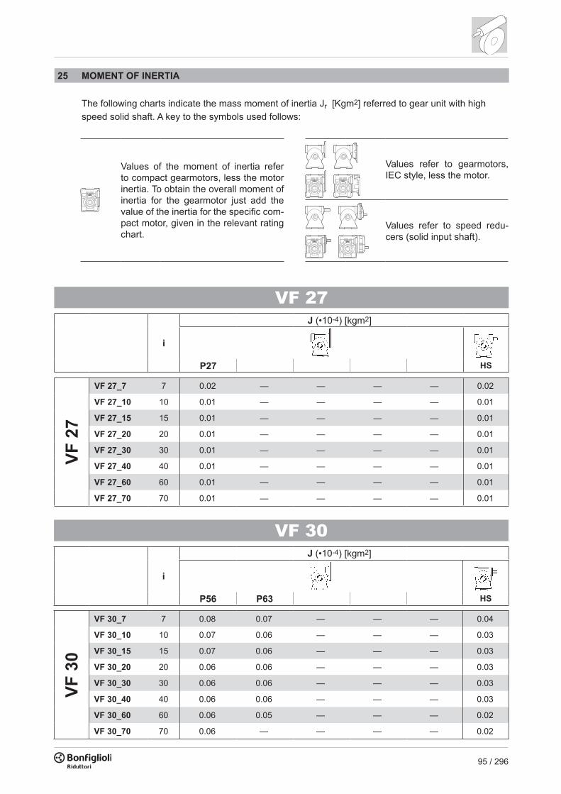
95 / 296
80 90 105 120 140 160 200
VF 309 7 ≤ i ≤ 70 7 ≤ i ≤ 70
11 7 ≤ i ≤ 60 7 ≤ i ≤ 60
VF 44
HS 7 ≤ i ≤ 100 7 ≤ i ≤ 100 7 ≤ i ≤ 100 7 ≤ i ≤ 100
11 7 ≤ i ≤ 100 7 ≤ i ≤ 100
14 7 ≤ i ≤ 35 7 ≤ i ≤ 35
VF 49
HS 7 ≤ i ≤ 100 7 ≤ i ≤ 100 7 ≤ i ≤ 100 7 ≤ i ≤ 100 7 ≤ i ≤ 100 7 ≤ i ≤ 100
11 7 ≤ i ≤ 100 7 ≤ i ≤ 100 7 ≤ i ≤ 100 7 ≤ i ≤ 100
14 7 ≤ i ≤ 60 7 ≤ i ≤ 60 7 ≤ i ≤ 60 7 ≤ i ≤ 60
19 7 ≤ i ≤ 28 7 ≤ i ≤ 28 7 ≤ i ≤ 28 7 ≤ i ≤ 28
W 63 19 7 ≤ i ≤ 100
W 75
14 7 ≤ i ≤ 100
19 7 ≤ i ≤ 100 7 ≤ i ≤ 100
24 7 ≤ i ≤ 100 7 ≤ i ≤ 100
W 86
14 7 ≤ i ≤ 100
19 7 ≤ i ≤ 100 7 ≤ i ≤ 100
24 7 ≤ i ≤ 100 7 ≤ i ≤ 100
W 11019 7 ≤ i ≤ 100
24 7 ≤ i ≤ 100
Standard arrangement
25 MOMENT OF INERTIA The following charts indicate the mass moment of inertia Jr [Kgm2] referred to gear unit with high speed solid shaft. A key to the symbols used follows:
VF 27
i
J (•10-4) [kgm2]
HSP27
VF 2
7
VF 27_7 7 0.02 — — — — 0.02
VF 27_10 10 0.01 — — — — 0.01
VF 27_15 15 0.01 — — — — 0.01
VF 27_20 20 0.01 — — — — 0.01
VF 27_30 30 0.01 — — — — 0.01
VF 27_40 40 0.01 — — — — 0.01
VF 27_60 60 0.01 — — — — 0.01
VF 27_70 70 0.01 — — — — 0.01
VF 30
i
J (•10-4) [kgm2]
HSP56 P63
VF 3
0
VF 30_7 7 0.08 0.07 — — — 0.04
VF 30_10 10 0.07 0.06 — — — 0.03
VF 30_15 15 0.07 0.06 — — — 0.03
VF 30_20 20 0.06 0.06 — — — 0.03
VF 30_30 30 0.06 0.06 — — — 0.03
VF 30_40 40 0.06 0.06 — — — 0.03
VF 30_60 60 0.06 0.05 — — — 0.02
VF 30_70 70 0.06 — — — — 0.02
Values of the moment of inertia refer to compact gearmotors, less the motor inertia. To obtain the overall moment of inertia for the gearmotor just add the value of the inertia for the specifi c com-pact motor, given in the relevant rating chart.
Values refer to gearmotors, IEC style, less the motor.
Values refer to speed redu-cers (solid input shaft).

96 / 296
VF 44 - VFR 44
i
J (•10-4) [kgm2]
HSS44 P63 P71
VF 4
4
VF 44_7 7 — 0.29 0.27 — — 0.18
VF 44_10 10 — 0.24 0.22 — — 0.14
VF 44_14 14 — 0.23 0.21 — — 0.12
VF 44_20 20 — 0.19 0.18 — — 0.09
VF 44_28 28 — 0.21 0.19 — — 0.11
VF 44_35 35 — 0.19 0.18 — — 0.09
VF 44_46 46 — 0.18 — — — 0.08
VF 44_60 60 — 0.17 — — — 0.07
VF 44_70 70 — 0.17 — — — 0.07
VF 44_100 100 — 0.17 — — — 0.07
VFR
44
VFR 44_70 70 0.21 — — — — —
VFR 44_100 100 0.20 — — — — —
VFR 44_140 140 0.20 — — — — —
VFR 44_175 175 0.20 — — — — —
VFR 44_230 230 0.20 — — — — —
VFR 44_300 300 0.20 — — — — —
VFR 44_350 350 0.20 — — — — —
VFR 44_500 500 0.20 — — — — —
VF 49 - VFR 49
i
J (•10-4) [kgm2]
HSP63 P71 P80
VF 4
9
VF 49_7 7 0.69 0.67 0.61 — — 0.42
VF 49_10 10 0.61 0.60 0.53 — — 0.34
VF 49_14 14 0.58 0.57 0.5 — — 0.31
VF 49_18 18 0.54 0.53 0.46 — — 0.27
VF 49_24 24 0.52 0.5 0.44 — — 0.24
VF 49_28 28 0.56 0.54 0.48 — — 0.28
VF 49_36 36 0.53 0.51 — — — 0.25
VF 49_45 45 0.51 0.49 — — — 0.24
VF 49_60 60 0.50 0.48 — — — 0.23
VF 49_70 70 0.50 — — — — 0.22
VF 49_80 80 0.49 — — — — 0.22
VF 49_100 100 0.49 — — — — 0.22
VFR
49
VFR 49_30 30 0.74 — — — — 0.94
VFR 49_42 42 0.73 — — — — 0.93
VFR 49_54 54 0.73 — — — — 0.93
VFR 49_72 72 0.73 — — — — 0.93
VFR 49_84 84 0.73 — — — — 0.93
VFR 49_108 108 0.73 — — — — 0.93
VFR 49_135 135 0.73 — — — — 0.93
VFR 49_180 180 0.73 — — — — 0.93
VFR 49_210 210 0.72 — — — — 0.92
VFR 49_240 240 0.72 — — — — 0.92
VFR 49_300 300 0.72 — — — — 0.92

97 / 296
VF 44 - VFR 44
i
J (•10-4) [kgm2]
HSS44 P63 P71
VF 4
4
VF 44_7 7 — 0.29 0.27 — — 0.18
VF 44_10 10 — 0.24 0.22 — — 0.14
VF 44_14 14 — 0.23 0.21 — — 0.12
VF 44_20 20 — 0.19 0.18 — — 0.09
VF 44_28 28 — 0.21 0.19 — — 0.11
VF 44_35 35 — 0.19 0.18 — — 0.09
VF 44_46 46 — 0.18 — — — 0.08
VF 44_60 60 — 0.17 — — — 0.07
VF 44_70 70 — 0.17 — — — 0.07
VF 44_100 100 — 0.17 — — — 0.07
VFR
44
VFR 44_70 70 0.21 — — — — —
VFR 44_100 100 0.20 — — — — —
VFR 44_140 140 0.20 — — — — —
VFR 44_175 175 0.20 — — — — —
VFR 44_230 230 0.20 — — — — —
VFR 44_300 300 0.20 — — — — —
VFR 44_350 350 0.20 — — — — —
VFR 44_500 500 0.20 — — — — —
VF 49 - VFR 49
i
J (•10-4) [kgm2]
HSP63 P71 P80
VF 4
9
VF 49_7 7 0.69 0.67 0.61 — — 0.42
VF 49_10 10 0.61 0.60 0.53 — — 0.34
VF 49_14 14 0.58 0.57 0.5 — — 0.31
VF 49_18 18 0.54 0.53 0.46 — — 0.27
VF 49_24 24 0.52 0.5 0.44 — — 0.24
VF 49_28 28 0.56 0.54 0.48 — — 0.28
VF 49_36 36 0.53 0.51 — — — 0.25
VF 49_45 45 0.51 0.49 — — — 0.24
VF 49_60 60 0.50 0.48 — — — 0.23
VF 49_70 70 0.50 — — — — 0.22
VF 49_80 80 0.49 — — — — 0.22
VF 49_100 100 0.49 — — — — 0.22
VFR
49
VFR 49_30 30 0.74 — — — — 0.94
VFR 49_42 42 0.73 — — — — 0.93
VFR 49_54 54 0.73 — — — — 0.93
VFR 49_72 72 0.73 — — — — 0.93
VFR 49_84 84 0.73 — — — — 0.93
VFR 49_108 108 0.73 — — — — 0.93
VFR 49_135 135 0.73 — — — — 0.93
VFR 49_180 180 0.73 — — — — 0.93
VFR 49_210 210 0.72 — — — — 0.92
VFR 49_240 240 0.72 — — — — 0.92
VFR 49_300 300 0.72 — — — — 0.92

98 / 296
W 63 - WR 63
i
J (•10-4) [kgm2]
HSS1 S2 S3 P63 P71 P80 P90
W 6
3
W 63_7 7 3.4 3.6 — — 3.5 3.5 3.5 — — 3.6
W 63_10 10 3.1 3.3 — — 3.2 3.3 3.2 — — 3.3
W 63_12 12 3.1 3.3 — — 3.1 3.2 3.1 — — 3.3
W 63_15 15 3.0 3.2 — — 3.0 3.1 3.0 — — 3.2
W 63_19 19 2.9 3.1 — — 2.9 3.0 2.9 — — 3.1
W 63_24 24 2.8 3.1 — — 2.9 3.0 2.9 — — 3.0
W 63_30 30 2.9 3.1 — — 2.9 3.0 2.9 — — 3.1
W 63_38 38 2.8 3.1 — — 2.9 3.0 2.9 — — 3.0
W 63_45 45 2.8 3.0 — — 2.9 2.9 2.9 — — 3.0
W 63_64 64 2.8 3.0 — — 2.8 2.9 2.8 — — 3.0
W 63_80 80 2.8 3.0 — — 2.8 2.9 2.8 — — 3.0
W 63_100 100 2.8 3.0 — — 2.8 2.9 2.8 — — 2.9
WR
63
WR 63_21 21 — — — 0.84 0.83 — — — — 0.81
WR 63_30 30 — — — 0.81 0.80 — — — — 0.78
WR 63_36 36 — — — 0.81 0.80 — — — — 0.77
WR 63_45 45 — — — 0.80 0.79 — — — — 0.76
WR 63_57 57 — — — 0.79 0.78 — — — — 0.75
WR 63_72 72 — — — 0.78 0.77 — — — — 0.74
WR 63_90 90 — — — 0.79 0.78 — — — — 0.75
WR 63_114 114 — — — 0.78 0.77 — — — — 0.74
WR 63_135 135 — — — 0.78 0.77 — — — — 0.74
WR 63_192 192 — — — 0.77 0.76 — — — — 0.74
WR 63_240 240 — — — 0.77 0.76 — — — — 0.74
WR 63_300 300 — — — 0.77 0.76 — — — — 0.73
W 75 - WR 75
i
J (•10-4) [kgm2]
HSS1 S2 S3 P63 P71 P80 P90 P100 P112
W 7
5
W 75_7 7 6.9 6.6 6.6 — 6.9 7.0 6.9 6.9 6.9 7.3
W 75_10 10 6.4 6.1 6.1 — 6.4 6.4 6.3 5.7 5.7 6.8
W 75_15 15 6.1 5.8 5.8 — 6.1 6.1 6.0 5.3 5.3 6.5
W 75_20 20 5.9 5.6 5.6 — 5.9 5.9 5.9 5.2 5.2 6.3
W 75_25 25 5.9 5.6 5.6 — 6.0 6.0 5.9 5.2 5.2 6.3
W 75_30 30 5.9 5.6 5.6 — 5.9 5.9 5.9 5.2 5.2 6.3
W 75_40 40 5.9 5.6 5.6 — 5.9 5.9 5.8 5.2 5.2 6.3
W 75_50 50 5.9 5.6 5.6 — 5.9 5.9 5.8 5.1 5.1 6.2
W 75_60 60 5.8 5.5 5.5 — 5.8 5.9 5.8 5.1 5.1 6.2
W 75_80 80 5.8 5.5 5.5 — 5.8 5.8 5.8 5.1 5.1 6.2
W 75_100 100 5.8 5.5 5.5 — 5.8 5.8 5.7 5.0 5.0 6.2
WR
75
WR 75_21 21 — — — 1.2 1.2 2.1 — — — 1.9
WR 75_30 30 — — — 1.1 1.1 2.1 — — — 1.1
WR 75_45 45 — — — 1.1 1.1 2.0 — — — 1.1
WR 75_60 60 — — — 1.1 1.1 2.0 — — — 1.0
WR 75_75 75 — — — 1.1 1.1 2.0 — — — 1.0
WR 75_90 90 — — — 1.1 1.1 2.0 — — — 1.0
WR 75_120 120 — — — 1.1 1.1 2.0 — — — 1.0
WR 75_150 150 — — — 1.1 1.1 2.0 — — — 1.0
WR 75_180 180 — — — 1.1 1.1 2.0 — — — 1.0
WR 75_240 240 — — — 1.1 1.1 2.0 — — — 1.0
WR 75_300 300 — — — 1.1 1.1 2.0 — — — 1.0
i
J (•10-4) [kgm2]
P90
WR
75_
P90
B5
WR 75_15 15 6.0WR 75_22.5 22.5 5.9WR 75_30 30 5.8WR 75_37.5 37.5 5.8WR 75_45 45 5.8WR 75_60 60 5.8WR 75_75 75 5.8WR 75_90 90 5.7WR 75_120 120 5.7WR 75_150 150 5.7

99 / 296
W 63 - WR 63
i
J (•10-4) [kgm2]
HSS1 S2 S3 P63 P71 P80 P90
W 6
3
W 63_7 7 3.4 3.6 — — 3.5 3.5 3.5 — — 3.6
W 63_10 10 3.1 3.3 — — 3.2 3.3 3.2 — — 3.3
W 63_12 12 3.1 3.3 — — 3.1 3.2 3.1 — — 3.3
W 63_15 15 3.0 3.2 — — 3.0 3.1 3.0 — — 3.2
W 63_19 19 2.9 3.1 — — 2.9 3.0 2.9 — — 3.1
W 63_24 24 2.8 3.1 — — 2.9 3.0 2.9 — — 3.0
W 63_30 30 2.9 3.1 — — 2.9 3.0 2.9 — — 3.1
W 63_38 38 2.8 3.1 — — 2.9 3.0 2.9 — — 3.0
W 63_45 45 2.8 3.0 — — 2.9 2.9 2.9 — — 3.0
W 63_64 64 2.8 3.0 — — 2.8 2.9 2.8 — — 3.0
W 63_80 80 2.8 3.0 — — 2.8 2.9 2.8 — — 3.0
W 63_100 100 2.8 3.0 — — 2.8 2.9 2.8 — — 2.9
WR
63
WR 63_21 21 — — — 0.84 0.83 — — — — 0.81
WR 63_30 30 — — — 0.81 0.80 — — — — 0.78
WR 63_36 36 — — — 0.81 0.80 — — — — 0.77
WR 63_45 45 — — — 0.80 0.79 — — — — 0.76
WR 63_57 57 — — — 0.79 0.78 — — — — 0.75
WR 63_72 72 — — — 0.78 0.77 — — — — 0.74
WR 63_90 90 — — — 0.79 0.78 — — — — 0.75
WR 63_114 114 — — — 0.78 0.77 — — — — 0.74
WR 63_135 135 — — — 0.78 0.77 — — — — 0.74
WR 63_192 192 — — — 0.77 0.76 — — — — 0.74
WR 63_240 240 — — — 0.77 0.76 — — — — 0.74
WR 63_300 300 — — — 0.77 0.76 — — — — 0.73
W 75 - WR 75
i
J (•10-4) [kgm2]
HSS1 S2 S3 P63 P71 P80 P90 P100 P112
W 7
5
W 75_7 7 6.9 6.6 6.6 — 6.9 7.0 6.9 6.9 6.9 7.3
W 75_10 10 6.4 6.1 6.1 — 6.4 6.4 6.3 5.7 5.7 6.8
W 75_15 15 6.1 5.8 5.8 — 6.1 6.1 6.0 5.3 5.3 6.5
W 75_20 20 5.9 5.6 5.6 — 5.9 5.9 5.9 5.2 5.2 6.3
W 75_25 25 5.9 5.6 5.6 — 6.0 6.0 5.9 5.2 5.2 6.3
W 75_30 30 5.9 5.6 5.6 — 5.9 5.9 5.9 5.2 5.2 6.3
W 75_40 40 5.9 5.6 5.6 — 5.9 5.9 5.8 5.2 5.2 6.3
W 75_50 50 5.9 5.6 5.6 — 5.9 5.9 5.8 5.1 5.1 6.2
W 75_60 60 5.8 5.5 5.5 — 5.8 5.9 5.8 5.1 5.1 6.2
W 75_80 80 5.8 5.5 5.5 — 5.8 5.8 5.8 5.1 5.1 6.2
W 75_100 100 5.8 5.5 5.5 — 5.8 5.8 5.7 5.0 5.0 6.2
WR
75
WR 75_21 21 — — — 1.2 1.2 2.1 — — — 1.9
WR 75_30 30 — — — 1.1 1.1 2.1 — — — 1.1
WR 75_45 45 — — — 1.1 1.1 2.0 — — — 1.1
WR 75_60 60 — — — 1.1 1.1 2.0 — — — 1.0
WR 75_75 75 — — — 1.1 1.1 2.0 — — — 1.0
WR 75_90 90 — — — 1.1 1.1 2.0 — — — 1.0
WR 75_120 120 — — — 1.1 1.1 2.0 — — — 1.0
WR 75_150 150 — — — 1.1 1.1 2.0 — — — 1.0
WR 75_180 180 — — — 1.1 1.1 2.0 — — — 1.0
WR 75_240 240 — — — 1.1 1.1 2.0 — — — 1.0
WR 75_300 300 — — — 1.1 1.1 2.0 — — — 1.0
i
J (•10-4) [kgm2]
P90
WR
75_
P90
B5
WR 75_15 15 6.0WR 75_22.5 22.5 5.9WR 75_30 30 5.8WR 75_37.5 37.5 5.8WR 75_45 45 5.8WR 75_60 60 5.8WR 75_75 75 5.8WR 75_90 90 5.7WR 75_120 120 5.7WR 75_150 150 5.7

100 / 296
W 86 - WR 86
i
J (•10-4) [kgm2]
HSS1 S2 S3 P63 P71 P80 P90 P100
W 8
6
W 86_7 7 9.7 9.4 9.4 — 9.7 9.7 9.6 9.6 — 10.1
W 86_10 10 8.4 8.1 8.1 — 8.4 8.4 8.3 7.7 — 8.9
W 86_15 15 7.7 7.4 7.4 — 7.7 7.7 7.7 7.0 — 8.2
W 86_20 20 6.9 6.6 6.6 — 6.9 7.0 6.9 6.2 — 7.4
W 86_23 23 6.8 6.5 6.5 — 6.8 6.9 6.8 6.1 — 7.3
W 86_30 30 7.3 7.0 7.0 — 7.3 7.3 7.3 6.6 — 7.8
W 86_40 40 6.7 6.4 6.4 — 6.7 6.7 6.6 6.0 — 7.2
W 86_46 46 6.7 6.4 6.4 — 6.7 6.7 6.6 5.9 — 7.1
W 86_56 56 6.6 6.3 6.3 — 6.6 6.7 6.6 5.9 — 7.1
W 86_64 64 6.6 6.3 6.3 — 6.6 6.6 6.5 5.9 — 7.1
W 86_80 80 6.6 6.3 6.3 — 6.6 6.6 6.5 5.9 — 7.1
W 86_100 100 6.4 6.1 6.1 — 6.4 6.5 6.4 5.7 — 6.9
WR
86
WR 86_21 21 — — — 1.5 1.5 2.4 — — — 2.2
WR 86_30 30 — — — 1.4 1.3 2.3 — — — 1.3
WR 86_45 45 — — — 1.3 1.3 2.2 — — — 1.2
WR 86_60 60 — — — 1.2 1.2 2.1 — — — 1.2
WR 86_69 69 — — — 1.2 1.2 2.1 — — — 1.1
WR 86_90 90 — — — 1.2 1.2 2.2 — — — 1.2
WR 86_120 120 — — — 1.2 1.2 2.1 — — — 1.1
WR 86_138 138 — — — 1.2 1.2 2.1 — — — 1.1
WR 86_168 168 — — — 1.2 1.2 2.1 — — — 1.1
WR 86_192 192 — — — 1.2 1.1 2.1 — — — 1.1
WR 86_240 240 — — — 1.2 1.1 2.1 — — — 1.1
WR 86_300 300 — — — 1.1 1.1 2.1 — — — 1.1
i
J (•10-4) [kgm2]
P90
WR
86_
P90
B5
WR 86_15 15 6.9WR 86_22.5 22.5 6.6WR 86_30 30 6.3WR 86_34.5 34.5 6.2WR 86_45 45 6.4WR 86_60 60 6.2WR 86_69 69 6.1WR 86_84 84 6.1WR 86_96 96 6.0WR 86_120 120 6.0WR 86_150 150 5.9
W 110 - WR 110
i
J (•10-4) [kgm2]
HSS1 S2 S3 P63 P71 P80 P90 P100 P132
W 1
10
W 110_7 7 — 22 22 — — 23 23 23 28 23
W 110_10 10 — 19 19 — — 19 19 24 24 20
W 110_15 15 — 17 17 — — 17 17 22 22 17
W 110_20 20 — 14 14 — — 14 14 19 19 15
W 110_23 23 — 14 14 — — 14 14 19 19 15
W 110_30 30 — 15 15 — — 16 16 20 20 16
W 110_40 40 — 13 13 — — 14 14 19 19 14
W 110_46 46 — 13 13 — — 13 13 18 18 14
W 110_56 56 — 13 13 — — 13 13 18 18 14
W 110_64 64 — 13 13 — — 13 13 18 18 14
W 110_80 80 — 13 13 — — 13 13 18 18 14
W 110_100 100 — 13 13 — — 13 13 18 18 14
WR
110
WR 110_21 21 — — — — 3.0 9.0 8.8 8.9 — 9.2
WR 110_30 30 — — — — 2.5 8.6 8.4 8.4 — 8.8
WR 110_45 45 — — — — 2.3 8.3 8.2 8.2 — 8.5
WR 110_60 60 — — — — 2.0 8.1 7.9 7.9 — 8.3
WR 110_69 69 — — — — 2.0 8.0 7.9 7.9 — 8.2
WR 110_90 90 — — — — 2.2 8.2 8.1 8.1 — 8.4
WR 110_120 120 — — — — 1.9 8.0 7.8 7.9 — 8.2
WR 110_138 138 — — — — 1.9 8.0 7.8 7.8 — 8.2
WR 110_168 168 — — — — 1.9 8.0 7.8 7.8 — 8.1
WR 110_192 192 — — — — 1.9 7.9 7.8 7.8 — 8.1
WR 110_240 240 — — — — 1.9 7.9 7.8 7.8 — 8.1
WR 110_300 300 — — — — 1.9 7.9 7.8 7.8 — 8.1
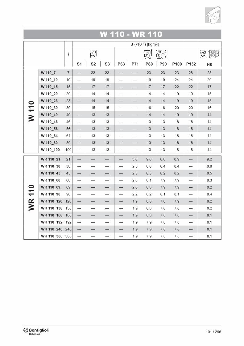
101 / 296
W 86 - WR 86
i
J (•10-4) [kgm2]
HSS1 S2 S3 P63 P71 P80 P90 P100
W 8
6
W 86_7 7 9.7 9.4 9.4 — 9.7 9.7 9.6 9.6 — 10.1
W 86_10 10 8.4 8.1 8.1 — 8.4 8.4 8.3 7.7 — 8.9
W 86_15 15 7.7 7.4 7.4 — 7.7 7.7 7.7 7.0 — 8.2
W 86_20 20 6.9 6.6 6.6 — 6.9 7.0 6.9 6.2 — 7.4
W 86_23 23 6.8 6.5 6.5 — 6.8 6.9 6.8 6.1 — 7.3
W 86_30 30 7.3 7.0 7.0 — 7.3 7.3 7.3 6.6 — 7.8
W 86_40 40 6.7 6.4 6.4 — 6.7 6.7 6.6 6.0 — 7.2
W 86_46 46 6.7 6.4 6.4 — 6.7 6.7 6.6 5.9 — 7.1
W 86_56 56 6.6 6.3 6.3 — 6.6 6.7 6.6 5.9 — 7.1
W 86_64 64 6.6 6.3 6.3 — 6.6 6.6 6.5 5.9 — 7.1
W 86_80 80 6.6 6.3 6.3 — 6.6 6.6 6.5 5.9 — 7.1
W 86_100 100 6.4 6.1 6.1 — 6.4 6.5 6.4 5.7 — 6.9
WR
86
WR 86_21 21 — — — 1.5 1.5 2.4 — — — 2.2
WR 86_30 30 — — — 1.4 1.3 2.3 — — — 1.3
WR 86_45 45 — — — 1.3 1.3 2.2 — — — 1.2
WR 86_60 60 — — — 1.2 1.2 2.1 — — — 1.2
WR 86_69 69 — — — 1.2 1.2 2.1 — — — 1.1
WR 86_90 90 — — — 1.2 1.2 2.2 — — — 1.2
WR 86_120 120 — — — 1.2 1.2 2.1 — — — 1.1
WR 86_138 138 — — — 1.2 1.2 2.1 — — — 1.1
WR 86_168 168 — — — 1.2 1.2 2.1 — — — 1.1
WR 86_192 192 — — — 1.2 1.1 2.1 — — — 1.1
WR 86_240 240 — — — 1.2 1.1 2.1 — — — 1.1
WR 86_300 300 — — — 1.1 1.1 2.1 — — — 1.1
i
J (•10-4) [kgm2]
P90
WR
86_
P90
B5
WR 86_15 15 6.9WR 86_22.5 22.5 6.6WR 86_30 30 6.3WR 86_34.5 34.5 6.2WR 86_45 45 6.4WR 86_60 60 6.2WR 86_69 69 6.1WR 86_84 84 6.1WR 86_96 96 6.0WR 86_120 120 6.0WR 86_150 150 5.9
W 110 - WR 110
i
J (•10-4) [kgm2]
HSS1 S2 S3 P63 P71 P80 P90 P100 P132
W 1
10
W 110_7 7 — 22 22 — — 23 23 23 28 23
W 110_10 10 — 19 19 — — 19 19 24 24 20
W 110_15 15 — 17 17 — — 17 17 22 22 17
W 110_20 20 — 14 14 — — 14 14 19 19 15
W 110_23 23 — 14 14 — — 14 14 19 19 15
W 110_30 30 — 15 15 — — 16 16 20 20 16
W 110_40 40 — 13 13 — — 14 14 19 19 14
W 110_46 46 — 13 13 — — 13 13 18 18 14
W 110_56 56 — 13 13 — — 13 13 18 18 14
W 110_64 64 — 13 13 — — 13 13 18 18 14
W 110_80 80 — 13 13 — — 13 13 18 18 14
W 110_100 100 — 13 13 — — 13 13 18 18 14
WR
110
WR 110_21 21 — — — — 3.0 9.0 8.8 8.9 — 9.2
WR 110_30 30 — — — — 2.5 8.6 8.4 8.4 — 8.8
WR 110_45 45 — — — — 2.3 8.3 8.2 8.2 — 8.5
WR 110_60 60 — — — — 2.0 8.1 7.9 7.9 — 8.3
WR 110_69 69 — — — — 2.0 8.0 7.9 7.9 — 8.2
WR 110_90 90 — — — — 2.2 8.2 8.1 8.1 — 8.4
WR 110_120 120 — — — — 1.9 8.0 7.8 7.9 — 8.2
WR 110_138 138 — — — — 1.9 8.0 7.8 7.8 — 8.2
WR 110_168 168 — — — — 1.9 8.0 7.8 7.8 — 8.1
WR 110_192 192 — — — — 1.9 7.9 7.8 7.8 — 8.1
WR 110_240 240 — — — — 1.9 7.9 7.8 7.8 — 8.1
WR 110_300 300 — — — — 1.9 7.9 7.8 7.8 — 8.1

102 / 296
VF 130 - VFR 130
i
J (•10-4) [kgm2]
HSP80 P90 P100 P112 P132
VF 1
30
VF 130_7 7 — — 36 36 35 31
VF 130_10 10 — — 27 27 25 22
VF 130_15 15 — — 20 20 18 15
VF 130_20 20 — — 17 17 15 11
VF 130_23 23 — — 16 16 14 11
VF 130_30 30 — — 17 17 15 12
VF 130_40 40 — — 15 15 14 9.9
VF 130_46 46 — 14 14 14 — 8.2
VF 130_56 56 — 13 13 13 — 7.8
VF 130_64 64 — 13 13 13 — 7.4
VF 130_80 80 — 13 12 12 — 7.0
VF 130_100 100 — 13 — — — 8.9
VFR
130
VFR 130_30 30 5.3 5.3 5.2 5.2 — 5.7
VFR 130_45 45 4.5 4.5 4.4 4.4 — 4.9
VFR 130_60 60 4.2 4.1 4.1 4.1 — 4.6
VFR 130_69 69 4.1 4.0 4.0 4.0 — 4.5
VFR 130_90 90 4.2 4.1 4.1 4.1 — 4.6
VFR 130_120 120 4.0 3.9 4.0 4.0 — 4.4
VFR 130_138 138 3.8 3.8 3.7 3.7 — 4.2
VFR 130_168 168 3.8 3.7 3.7 3.7 — 4.1
VFR 130_192 192 3.7 3.7 3.6 3.6 — 4.1
VFR 130_240 240 3.7 3.6 3.6 3.6 — 4.1
VFR 130_300 300 3.9 3.8 3.8 3.8 — 4.3
VF 150 - VFR 150
i
J (•10-4) [kgm2]
HSP90 P100 P112 P132
VF 1
50
VF 150_7 7 — — — 58 50
VF 150_10 10 — — — 44 35
VF 150_15 15 — — — 29 21
VF 150_20 20 — — — 27 19
VF 150_23 23 — 28 28 26 17
VF 150_30 30 — 31 31 29 21
VF 150_40 40 — 26 26 24 16
VF 150_46 46 — 24 24 22 13
VF 150_56 56 25 24 24 — 13
VF 150_64 64 24 23 23 — 12
VF 150_80 80 23 22 22 — 11
VF 150_100 100 23 22 22 — 11
VFR
150
VFR 150_25 25 — — — 15 —
VFR 150_30 30 10 10 10 — 11
VFR 150_37.5 37.5 — — — 13 —
VFR 150_45 45 8.8 8.8 8.8 — 9.7
VFR 150_50 50 — — — 12 —
VFR 150_60 60 8.3 8.3 8.3 — 9.2
VFR 150_69 69 8.4 8.4 8.4 — 9.3
VFR 150_90 90 8.7 8.7 8.7 — 9.7
VFR 150_120 120 8.2 8.2 8.2 — 9.2
VFR 150_138 138 7.9 7.9 7.9 — 8.9
VFR 150_168 168 7.9 7.9 7.9 — 8.9
VFR 150_192 192 7.8 7.8 7.8 — 8.8
VFR 150_240 240 7.7 7.7 7.7 — 8.6
VFR 150_300 300 7.7 7.7 7.7 — 8.6

103 / 296
VF 130 - VFR 130
i
J (•10-4) [kgm2]
HSP80 P90 P100 P112 P132
VF 1
30
VF 130_7 7 — — 36 36 35 31
VF 130_10 10 — — 27 27 25 22
VF 130_15 15 — — 20 20 18 15
VF 130_20 20 — — 17 17 15 11
VF 130_23 23 — — 16 16 14 11
VF 130_30 30 — — 17 17 15 12
VF 130_40 40 — — 15 15 14 9.9
VF 130_46 46 — 14 14 14 — 8.2
VF 130_56 56 — 13 13 13 — 7.8
VF 130_64 64 — 13 13 13 — 7.4
VF 130_80 80 — 13 12 12 — 7.0
VF 130_100 100 — 13 — — — 8.9
VFR
130
VFR 130_30 30 5.3 5.3 5.2 5.2 — 5.7
VFR 130_45 45 4.5 4.5 4.4 4.4 — 4.9
VFR 130_60 60 4.2 4.1 4.1 4.1 — 4.6
VFR 130_69 69 4.1 4.0 4.0 4.0 — 4.5
VFR 130_90 90 4.2 4.1 4.1 4.1 — 4.6
VFR 130_120 120 4.0 3.9 4.0 4.0 — 4.4
VFR 130_138 138 3.8 3.8 3.7 3.7 — 4.2
VFR 130_168 168 3.8 3.7 3.7 3.7 — 4.1
VFR 130_192 192 3.7 3.7 3.6 3.6 — 4.1
VFR 130_240 240 3.7 3.6 3.6 3.6 — 4.1
VFR 130_300 300 3.9 3.8 3.8 3.8 — 4.3
VF 150 - VFR 150
i
J (•10-4) [kgm2]
HSP90 P100 P112 P132
VF 1
50
VF 150_7 7 — — — 58 50
VF 150_10 10 — — — 44 35
VF 150_15 15 — — — 29 21
VF 150_20 20 — — — 27 19
VF 150_23 23 — 28 28 26 17
VF 150_30 30 — 31 31 29 21
VF 150_40 40 — 26 26 24 16
VF 150_46 46 — 24 24 22 13
VF 150_56 56 25 24 24 — 13
VF 150_64 64 24 23 23 — 12
VF 150_80 80 23 22 22 — 11
VF 150_100 100 23 22 22 — 11
VFR
150
VFR 150_25 25 — — — 15 —
VFR 150_30 30 10 10 10 — 11
VFR 150_37.5 37.5 — — — 13 —
VFR 150_45 45 8.8 8.8 8.8 — 9.7
VFR 150_50 50 — — — 12 —
VFR 150_60 60 8.3 8.3 8.3 — 9.2
VFR 150_69 69 8.4 8.4 8.4 — 9.3
VFR 150_90 90 8.7 8.7 8.7 — 9.7
VFR 150_120 120 8.2 8.2 8.2 — 9.2
VFR 150_138 138 7.9 7.9 7.9 — 8.9
VFR 150_168 168 7.9 7.9 7.9 — 8.9
VFR 150_192 192 7.8 7.8 7.8 — 8.8
VFR 150_240 240 7.7 7.7 7.7 — 8.6
VFR 150_300 300 7.7 7.7 7.7 — 8.6

104 / 296
VF 185 - VFR 185
i
J (•10-4) [kgm2]
HSP90 P100 P112 P132 P160 P180
VF 1
85
VF 185_7 7 — — — — — 146 128
VF 185_10 10 — — — — — 108 91
VF 185_15 15 — — — — 70 88 50
VF 185_20 20 — — — — 69 66 48
VF 185_30 30 — — — 58 54 — 34
VF 185_40 40 — — — 63 61 — 41
VF 185_50 50 — 59 59 58 — — 35
VF 185_60 60 — 55 55 53 — — 31
VF 185_80 80 — 52 52 51 — — 28
VF 185_100 100 — 51 51 — — — 27
VFR
185
VFR 185_25 25 — — — 24 — — —
VFR 185_30 30 17 17 17 — — — 18
VFR 185_37.5 37.5 — — — 17 — — —
VFR 185_45 45 12 12 12 — — — 13
VFR 185_50 50 — — — 17 — — —
VFR 185_60 60 12 12 12 — — — 13
VFR 185_75 75 — — — 15 — — —
VFR 185_90 90 10 10 10 — — — 11
VFR 185_100 100 — — — 16 — — —
VFR 185_120 120 11 11 11 — — — 12
VFR 185_150 150 10 10 10 — — — 11
VFR 185_180 180 9.9 9.9 9.9 — — — 11
VFR 185_240 240 9.6 9.6 9.6 — — — 11
VFR 185_300 300 9.5 9.4 9.4 — — — 10
VF 210 - VFR 210
i
J (•10-4) [kgm2]
HSP100 P112 P132 P160 P180 P200 P225
VF 2
10
VF 210_7 7 — — 286 286 286 286 286 286
VF 210_10 10 — — 177 177 177 177 177 177
VF 210_15 15 — — 120 120 120 120 120 120
VF 210_20 20 — — 116 116 116 116 116 116
VF 210_30 30 — — 81 81 81 81 81 81
VF 210_40 40 — — 98 98 98 98 98 98
VF 210_50 50 — — 84 84 84 84 84 84
VF 210_60 60 — — 75 75 75 75 75 75
VF 210_80 80 — — 68 68 68 68 68 68
VF 210_100 100 — — 63 63 63 63 63 63
VFR
210
VFR 210_30 30 48 48 47 47 — — — 51
VFR 210_45 45 41 41 41 41 — — — 45
VFR 210_60 60 41 41 41 40 — — — 45
VFR 210_90 90 37 37 37 36 — — — 41
VFR 210_120 120 39 39 39 38 — — — 43
VFR 210_150 150 37 37 37 37 — — — 41
VFR 210_180 180 36 36 36 36 — — — 40
VFR 210_240 240 36 36 36 35 — — — 39
VFR 210_300 300 35 35 35 34 — — — 39

105 / 296
VF 185 - VFR 185
i
J (•10-4) [kgm2]
HSP90 P100 P112 P132 P160 P180
VF 1
85
VF 185_7 7 — — — — — 146 128
VF 185_10 10 — — — — — 108 91
VF 185_15 15 — — — — 70 88 50
VF 185_20 20 — — — — 69 66 48
VF 185_30 30 — — — 58 54 — 34
VF 185_40 40 — — — 63 61 — 41
VF 185_50 50 — 59 59 58 — — 35
VF 185_60 60 — 55 55 53 — — 31
VF 185_80 80 — 52 52 51 — — 28
VF 185_100 100 — 51 51 — — — 27
VFR
185
VFR 185_25 25 — — — 24 — — —
VFR 185_30 30 17 17 17 — — — 18
VFR 185_37.5 37.5 — — — 17 — — —
VFR 185_45 45 12 12 12 — — — 13
VFR 185_50 50 — — — 17 — — —
VFR 185_60 60 12 12 12 — — — 13
VFR 185_75 75 — — — 15 — — —
VFR 185_90 90 10 10 10 — — — 11
VFR 185_100 100 — — — 16 — — —
VFR 185_120 120 11 11 11 — — — 12
VFR 185_150 150 10 10 10 — — — 11
VFR 185_180 180 9.9 9.9 9.9 — — — 11
VFR 185_240 240 9.6 9.6 9.6 — — — 11
VFR 185_300 300 9.5 9.4 9.4 — — — 10
VF 210 - VFR 210
i
J (•10-4) [kgm2]
HSP100 P112 P132 P160 P180 P200 P225
VF 2
10
VF 210_7 7 — — 286 286 286 286 286 286
VF 210_10 10 — — 177 177 177 177 177 177
VF 210_15 15 — — 120 120 120 120 120 120
VF 210_20 20 — — 116 116 116 116 116 116
VF 210_30 30 — — 81 81 81 81 81 81
VF 210_40 40 — — 98 98 98 98 98 98
VF 210_50 50 — — 84 84 84 84 84 84
VF 210_60 60 — — 75 75 75 75 75 75
VF 210_80 80 — — 68 68 68 68 68 68
VF 210_100 100 — — 63 63 63 63 63 63
VFR
210
VFR 210_30 30 48 48 47 47 — — — 51
VFR 210_45 45 41 41 41 41 — — — 45
VFR 210_60 60 41 41 41 40 — — — 45
VFR 210_90 90 37 37 37 36 — — — 41
VFR 210_120 120 39 39 39 38 — — — 43
VFR 210_150 150 37 37 37 37 — — — 41
VFR 210_180 180 36 36 36 36 — — — 40
VFR 210_240 240 36 36 36 35 — — — 39
VFR 210_300 300 35 35 35 34 — — — 39

106 / 296
VF 250 - VFR 250
i
J (•10-4) [kgm2]
HSP100 P112 P132 P160 P180 P200 P225
VF 2
50
VF 250_7 7 — — 620 620 620 620 620 620
VF 250_10 10 — — 387 387 387 387 387 387
VF 250_15 15 — — 266 266 266 266 266 266
VF 250_20 20 — — 242 242 242 242 242 242
VF 250_30 30 — — 184 184 184 184 184 184
VF 250_40 40 — — 241 241 241 241 241 241
VF 250_50 50 — — 240 240 240 240 240 240
VF 250_60 60 — — 158 158 158 158 158 158
VF 250_80 80 — — 160 160 160 160 160 160
VF 250_100 100 — — 149 149 149 149 149 149
VFR
250
VFR 250_30 30 71 71 71 70 — — — 75
VFR 250_45 45 58 58 57 57 — — — 61
VFR 250_60 60 55 55 55 54 — — — 58
VFR 250_90 90 48 48 48 48 — — — 52
VFR 250_120 120 55 55 54 54 — — — 58
VFR 250_150 150 55 55 54 54 — — — 58
VFR 250_180 180 46 46 45 45 — — — 49
VFR 250_240 240 46 46 45 45 — — — 49
VFR 250_300 300 45 45 44 44 — — — 48
VF 27...BN27
Pn n Mn ηCOSφ
In IsIn
MsMn
MaMn
Jm(·10-4)kgm2
LB AC ADkW min-1 Nm % A
(400V)BN 27A4 0.04 1350 0.28 36 0.57 0.28 2.3 2.0 1.8 0.56 2.8 152 103 76BN 27B4 0.06 1360 0.42 39 0.57 0.39 2.5 2.2 1.9 0.76 3.1 152 103 76BN 27C4 0.09 1380 0.63 46 0.65 0.43 2.8 2.3 1.9 1.49 3.3 175 112 94
54.5
54.5
54.5
V
N
A
F_

107 / 296
VF 250 - VFR 250
i
J (•10-4) [kgm2]
HSP100 P112 P132 P160 P180 P200 P225
VF 2
50
VF 250_7 7 — — 620 620 620 620 620 620
VF 250_10 10 — — 387 387 387 387 387 387
VF 250_15 15 — — 266 266 266 266 266 266
VF 250_20 20 — — 242 242 242 242 242 242
VF 250_30 30 — — 184 184 184 184 184 184
VF 250_40 40 — — 241 241 241 241 241 241
VF 250_50 50 — — 240 240 240 240 240 240
VF 250_60 60 — — 158 158 158 158 158 158
VF 250_80 80 — — 160 160 160 160 160 160
VF 250_100 100 — — 149 149 149 149 149 149
VFR
250
VFR 250_30 30 71 71 71 70 — — — 75
VFR 250_45 45 58 58 57 57 — — — 61
VFR 250_60 60 55 55 55 54 — — — 58
VFR 250_90 90 48 48 48 48 — — — 52
VFR 250_120 120 55 55 54 54 — — — 58
VFR 250_150 150 55 55 54 54 — — — 58
VFR 250_180 180 46 46 45 45 — — — 49
VFR 250_240 240 46 46 45 45 — — — 49
VFR 250_300 300 45 45 44 44 — — — 48
VF 27...BN27
Pn n Mn ηCOSφ
In IsIn
MsMn
MaMn
Jm(·10-4)kgm2
LB AC ADkW min-1 Nm % A
(400V)BN 27A4 0.04 1350 0.28 36 0.57 0.28 2.3 2.0 1.8 0.56 2.8 152 103 76BN 27B4 0.06 1360 0.42 39 0.57 0.39 2.5 2.2 1.9 0.76 3.1 152 103 76BN 27C4 0.09 1380 0.63 46 0.65 0.43 2.8 2.3 1.9 1.49 3.3 175 112 94
54.5
54.5
54.5
V
N
A
F_
26 DIMENSIONS FOR GEARMOTORS AN GEAR UNITS WITH IEC MOTOR INTERFACE

108 / 296
VF 30...P (IEC)
V
N
A
P
16.3
Acr1566341153216-29954536.pdf 1 11/01/20 09:35
C
M
Y
CM
MY
CY
CMY
K
P56 B14
n° 3
VF 30...P (IEC)
16.3
Acr15663411532165550585.pdf 1 11/01/20 09:36
C
M
Y
CM
MY
CY
CMY
K
U
F_
P56 B14
n° 3
M M1 M2 N N1 N2 N3 N4
VF 30 P56 B5 9 10.4 3 120 100 80 7 7
1.1VF 30 P56 B14 9 10.4 3 80 65 50 7 5.5VF 30 P63 B5 11 12.8 4 140 115 95 8 9.5VF 30 P63 B14 11 12.8 4 90 75 60 6 5.5

109 / 296
VF 30...P (IEC)
V
N
A
P
16.3
Acr1566341153216-29954536.pdf 1 11/01/20 09:35
C
M
Y
CM
MY
CY
CMY
K
P56 B14
n° 3
VF 30...P (IEC)
16.3
Acr15663411532165550585.pdf 1 11/01/20 09:36
C
M
Y
CM
MY
CY
CMY
K
U
F_
P56 B14
n° 3
M M1 M2 N N1 N2 N3 N4
VF 30 P56 B5 9 10.4 3 120 100 80 7 7
1.1VF 30 P56 B14 9 10.4 3 80 65 50 7 5.5VF 30 P63 B5 11 12.8 4 140 115 95 8 9.5VF 30 P63 B14 11 12.8 4 90 75 60 6 5.5

110 / 296
VF 44...P (IEC)
� ��
����
�� ��
V
N
A
P
VF 44...P (IEC)
� ��
����
�� ��
U
FA_
F_
M M1 M2 N N1 N2 N3 N4
VF 44 P63 B5 11 12.8 4 140 115 95 10 9.5
2.0VF 44 P71 B5 14 16.3 5 160 130 110 10 9.5VF 44 P63 B14 11 12.8 4 90 75 60 8 5.5VF 44 P71 B14 14 16.3 5 105 85 70 10 7

111 / 296
VF 44...P (IEC)
� ��
����
�� ��
V
N
A
P
VF 44...P (IEC)
� ��
����
�� ��
U
FA_
F_
M M1 M2 N N1 N2 N3 N4
VF 44 P63 B5 11 12.8 4 140 115 95 10 9.5
2.0VF 44 P71 B5 14 16.3 5 160 130 110 10 9.5VF 44 P63 B14 11 12.8 4 90 75 60 8 5.5VF 44 P71 B14 14 16.3 5 105 85 70 10 7

112 / 296
VFR 44...BN 44
� ��
����
�� ��
V
N
A
P
VFR 44...BN 44
�
�
�
�
�
�
�
�
�
�
�
�
��
����
����
��
��
����
����
���
���
����
����
�
�
�
�
����
��
�����
���
���
��
����
����
����
�
����
����
��
��
���
���
��
��
��
����
����
����
��
��
��
����� ��
����
����� ��
��
���
����
����
��
��
��
������
����
���
��
���
��
� ��
����
�� ��
U
FA_
F_
Pn n Mn ηCOSφ
In IsIn
MsMn
MaMn
Jm(·10-4)
kgm2
LB AC ADkW min-1 Nm % A
(400V)BN 44B4 0.06 1380 0.42 40 0.58 0.38 2.4 2.3 1.9 1.22 4.7 168 112 94BN 44C4 0.09 1380 0.63 46 0.65 0.43 2.8 2.3 2 1.49 4.6 168 112 94

113 / 296
VFR 44...BN 44
� ��
����
�� ��
V
N
A
P
VFR 44...BN 44
�
�
�
�
�
�
�
�
�
�
�
�
��
����
����
��
��
����
����
���
���
����
����
�
�
�
�
����
��
�����
���
���
��
����
����
����
�
����
����
��
��
���
���
��
��
��
����
����
����
��
��
��
����� ��
����
����� ��
��
���
����
����
��
��
��
������
����
���
��
���
��
� ��
����
�� ��
U
FA_
F_
Pn n Mn ηCOSφ
In IsIn
MsMn
MaMn
Jm(·10-4)
kgm2
LB AC ADkW min-1 Nm % A
(400V)BN 44B4 0.06 1380 0.42 40 0.58 0.38 2.4 2.3 1.9 1.22 4.7 168 112 94BN 44C4 0.09 1380 0.63 46 0.65 0.43 2.8 2.3 2 1.49 4.6 168 112 94

114 / 296
VF/VF 30/44...P (IEC)
FA_
F_
A
P56 B14
n° 3
VF/VF 30/44...P (IEC)
Acr15663411532167002835.pdf 1 11/01/20 09:56
C
M
Y
CM
MY
CY
CMY
K
Acr156634115321611214791.pdf 1 11/01/20 09:49
C
M
Y
CM
MY
CY
CMY
K
Acr1566341153216-24921666.pdf 1 11/01/20 09:47
C
M
Y
CM
MY
CY
CMY
K
U
P
P56 B14
n° 3
M M1 M2 N N1 N2 N3 N4
VF/VF 30/44 P56 B14 9 10.4 3 80 65 50 7 5.5 3.5VF/VF 30/44 P63 B14 11 12.8 4 90 75 60 6 5.5

115 / 296
VF/VF 30/44...P (IEC)
FA_
F_
A
P56 B14
n° 3
VF/VF 30/44...P (IEC)
Acr15663411532167002835.pdf 1 11/01/20 09:56
C
M
Y
CM
MY
CY
CMY
K
Acr156634115321611214791.pdf 1 11/01/20 09:49
C
M
Y
CM
MY
CY
CMY
K
Acr1566341153216-24921666.pdf 1 11/01/20 09:47
C
M
Y
CM
MY
CY
CMY
K
U
P
P56 B14
n° 3
M M1 M2 N N1 N2 N3 N4
VF/VF 30/44 P56 B14 9 10.4 3 80 65 50 7 5.5 3.5VF/VF 30/44 P63 B14 11 12.8 4 90 75 60 6 5.5

116 / 296
VF 49...P (IEC)
V
N
A
P
VF 49...P (IEC)
U
FA_
F_
� ��
����
�� ��
M M1 M2 N N1 N2 N3 N4
VF 49 P63 B5 11 12.8 4 140 115 95 10.5 9.5
3.0
VF 49 P71 B5 14 16.3 5 160 130 110 10.5 9.5VF 49 P80 B5 19 21.8 6 200 165 130 10 11.5VF 49 P63 B14 11 12.8 4 90 75 60 7 6VF 49 P71 B14 14 16.3 5 105 85 70 10.5 6.5VF 49 P80 B14 19 21.8 6 120 100 80 10 7

117 / 296
VF 49...P (IEC)
V
N
A
P
VF 49...P (IEC)
U
FA_
F_
� ��
����
�� ��
M M1 M2 N N1 N2 N3 N4
VF 49 P63 B5 11 12.8 4 140 115 95 10.5 9.5
3.0
VF 49 P71 B5 14 16.3 5 160 130 110 10.5 9.5VF 49 P80 B5 19 21.8 6 200 165 130 10 11.5VF 49 P63 B14 11 12.8 4 90 75 60 7 6VF 49 P71 B14 14 16.3 5 105 85 70 10.5 6.5VF 49 P80 B14 19 21.8 6 120 100 80 10 7

118 / 296
VFR 49...P (IEC)
V
N
A
P
VFR 49...P (IEC)
� ��
����
�� ��U
FA_
F_
M M1 M2 N N1 N2 N3 N4
VFR 49 P63 B5 11 12.8 4 140 115 95 11 M8 x 19 5.0
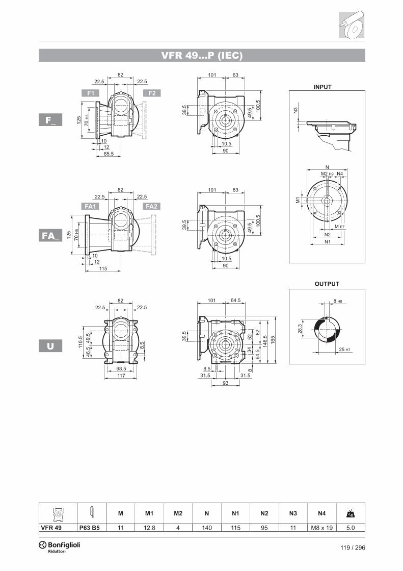
119 / 296
VFR 49...P (IEC)
V
N
A
P
VFR 49...P (IEC)
� ����
��
�� ��U
FA_
F_
M M1 M2 N N1 N2 N3 N4
VFR 49 P63 B5 11 12.8 4 140 115 95 11 M8 x 19 5.0

120 / 296
VF/VF 30/49...P (IEC)
FA_
F_
A
P56 B14
n° 3
VF/VF 30/49...P (IEC)
U
P
P56 B14
n° 3
Acr1566341153216104181047.pdf 1 11/01/20 10:58
C
M
Y
CM
MY
CY
CMY
K
M M1 M2 N N1 N2 N3 N4
VF/VF 30/49 P56 B14 9 10.4 3 80 65 50 7 5.5 4.5VF/VF 30/49 P63 B14 11 12.8 4 90 75 60 6 5.5

121 / 296
VF/VF 30/49...P (IEC)
FA_
F_
A
P56 B14
n° 3
VF/VF 30/49...P (IEC)
U
P
P56 B14
n° 3
Acr1566341153216104181047.pdf 1 11/01/20 10:58
C
M
Y
CM
MY
CY
CMY
K
M M1 M2 N N1 N2 N3 N4
VF/VF 30/49 P56 B14 9 10.4 3 80 65 50 7 5.5 4.5VF/VF 30/49 P63 B14 11 12.8 4 90 75 60 6 5.5

122 / 296
W 63...M/ME/MX
����
��
��
��
����
����
����
�
����
�
����
���
����
���
������
��� ���
��
��
��
�����
��
��
����
����
����
���
��
���
��
���
���
��
��
���
���
���
���
��
��
�
��
��
��
�
��
����
��
����
���
���
�
����
���
���
��
�
�
�
�
�
�����
���
��
���
��
��
�
�
���
��
��
����
���
����
���
� ��
����
�� ��
UFC_
UF_
U
M/ME/MX M...FDM...FA M...FD M...FA
AC H L AD LF R AD R AD
W 63 S1 M1 138 204 289 108 13 350 15 103 135 124 108W 63 S2 M2S 156 213 317 119 17 393 20 129 146 134 119W 63 S2 ME2S 156 213 317 119 17 — — — — — —W 63 S2 MX2S 156 213 371 119 23 — — — — — —
* On both sides
W 63...P (IEC)
�
�� �� ��
��
� ��
��
��
���
��
�����
���� ��
��
�
����
�
����
���
����
���
������
��� ���
��
��
��
�����
��
��
����
����
����
���
��
���
��
���
���
��
��
���
���
���
���
�� ��
����
���
���
�
���
��
���
��
���
��
��
�
�
����
��
�
�
����
���
����
���
� ��
����
�� ��
UFC_
UF_
U
M M1 M2 N N1 N2 N3 N4 P
W 63 P71 B5 14 16.3 5 160 130 110 11 9 95 6.3W 63 P80 B5 19 21.8 6 200 165 130 12 11.5 102 6.5W 63 P90 B5 24 27.3 8 200 165 130 12 11.5 102 6.4W 63 P71 B14 14 16.3 5 105 85 70 11 6.5 95 6.1W 63 P80 B14 19 21.8 6 120 100 80 11 6.5 102 6.3W 63 P90 B14 24 27.3 8 140 115 95 11 8.5 102 6.3

123 / 296
W 63...M/ME/MX
����
��
��
��
����
����
����
�
����
�
����
���
����
���
������
��� ���
��
��
��
�����
��
��
����
����
����
���
��
���
��
���
���
��
��
���
���
���
���
��
��
�
��
��
��
�
��
����
��
����
���
���
�
����
���
���
�
�
�
�
�
�
�
�����
���
��
���
��
��
�
�
���
��
��
����
���
����
���
� ��
����
�� ��
UFC_
UF_
U
M/ME/MX M...FDM...FA M...FD M...FA
AC H L AD LF R AD R AD
W 63 S1 M1 138 204 289 108 13 350 15 103 135 124 108W 63 S2 M2S 156 213 317 119 17 393 20 129 146 134 119W 63 S2 ME2S 156 213 317 119 17 — — — — — —W 63 S2 MX2S 156 213 371 119 23 — — — — — —
* On both sides
W 63...P (IEC)
�
�� �� ��
��
� ��
��
��
���
��
�����
���� ��
��
�
����
�
����
���
����
���
������
��� ���
��
��
��
�����
��
��
����
����
����
���
��
���
��
���
���
��
��
���
���
���
���
�� ��
����
���
���
�
�����
���
��
���
��
��
�
�
����
��
�
�
����
���
����
���
� ��
����
�� ��
UFC_
UF_
U
M M1 M2 N N1 N2 N3 N4 P
W 63 P71 B5 14 16.3 5 160 130 110 11 9 95 6.3W 63 P80 B5 19 21.8 6 200 165 130 12 11.5 102 6.5W 63 P90 B5 24 27.3 8 200 165 130 12 11.5 102 6.4W 63 P71 B14 14 16.3 5 105 85 70 11 6.5 95 6.1W 63 P80 B14 19 21.8 6 120 100 80 11 6.5 102 6.3W 63 P90 B14 24 27.3 8 140 115 95 11 8.5 102 6.3

124 / 296
WR 63...P (IEC)
��� �� ��
��
� ��
����
����
�����
���� ��
��
�
����
�
����
���
����
���
��
��
��
��� ���
��
��
��
�����
��
��
����
����
����
���
��
���
��
���
���
��
��
���
���
���
���
���
��
��
���
���
��
�����
���
��
���
��
��
�
�
�
�
����
��
�
�
����
���
����
���
� ��
����
�� ��
UFC_
UF_
U
M M1 M2 N N1 N2 N3 N4 P P1
WR 63 P63 B5 11 12.8 4 140 115 95 10 M8x10 133.5 11.42 7.1WR 63 P71 B5 14 16.3 5 160 130 110 10 M8x10 133.5 11.42
* On both sides
UFC_
UF_
U
P56 B14
n° 3
VF/W 30/63...P (IEC)
M M1 M2 N N1 N2 N3 N4
VF/W 30/63 P56 B5 9 10.4 3 120 100 80 7 7
8.0VF/W 30/63 P63 B5 11 12.8 4 140 115 95 8 9.5VF/W 30/63 P56 B14 9 10.4 3 80 65 50 7 5.5VF/W 30/63 P63 B14 11 12.8 4 90 75 60 6 5.5
* On both sides

125 / 296
WR 63...P (IEC)
��� �� ��
��
� ��
����
����
�����
���� ��
��
�
����
�
����
���
����
���
��
��
��
��� ���
��
��
��
�����
��
��
����
����
����
���
��
���
��
���
���
��
��
���
���
���
���
���
��
��
���
���
�
����
��
���
��
���
��
��
�
�
�
�
����
��
�
�
����
���
����
���
� ��
����
�� ��
UFC_
UF_
U
M M1 M2 N N1 N2 N3 N4 P P1
WR 63 P63 B5 11 12.8 4 140 115 95 10 M8x10 133.5 11.42 7.1WR 63 P71 B5 14 16.3 5 160 130 110 10 M8x10 133.5 11.42
* On both sides
UFC_
UF_
U
P56 B14
n° 3
VF/W 30/63...P (IEC)
M M1 M2 N N1 N2 N3 N4
VF/W 30/63 P56 B5 9 10.4 3 120 100 80 7 7
8.0VF/W 30/63 P63 B5 11 12.8 4 140 115 95 8 9.5VF/W 30/63 P56 B14 9 10.4 3 80 65 50 7 5.5VF/W 30/63 P63 B14 11 12.8 4 90 75 60 6 5.5
* On both sides

126 / 296
W 75...M/ME/MX
C 41_UD1 D2 D3 G T S
FA 130 165 200 11 3.5 11FB 180 215 250 14 4 13
����
��
��
��
��
����
����
����
�
����
����
���
���
�������
����� �����
��
��
��
�����
��
��
��
��
��
���
��
���
��
���
���
����
����
���
���
���
���
���
��
�
��
��
��
�
��
���
���
���
�
����
���
���
��
�
�
�
�
�
���������
���
��
���
��
��
�
�
���
��
��
�����
������
���
���
���
���
���������
���
���������
���
� ��
����
�� ��
� ��
����
�� ��
���������������
�����������������
UFC_
UF_
U
UFCR_#
M/ME/MX M...FDM...FA M...FD M...FA
AC H L AD LF R AD R AD
W 75 S1 M1 138 231 308 108 16.0 369 18.2 103 135 124 108W 75 S2 ME2S 156 240 333 119 18.5 — — — — — —W 75 S2 MX2S 156 240 377 119 23.6 — — — — — —W 75 S3 ME3S 195 258.5 376 142 27.1 — — — — — —W 75 S3 MX3S 195 258.5 408 142 31.1 — — — — — —W 75 S3 ME3L 195 258.5 408 142 32.6 — — — — — —W 75 S3 MX3L 195 258.5 452 142 38.6 — — — — — —
* On both sides # Reduced fl ange
W 75...P (IEC)
�
�� �� ��
��
� ��
��
��
���
��
�����
����
��
����
����
�
����
����
���
���
�������
����� �����
��
��
��
�����
��
��
��
��
��
���
��
���
��
���
���
����
����
���
���
���
���
���
��
����
���
���
�
�����
����
���
��
���
��
��
�
�
����
��
�
�
���
����
�
���
�
���
��� ���
���������
���������
� ��
����
�� ��
� ��
����
�� ��
�����������������
���������������
UF_
U
UFC_
UFCR_#
M M1 M2 N N1 N2 N3 N4 P
W 75 P71 B5 14 16.3 5 160 130 110 11 9 112 9.5W 75 P80 B5 19 21.8 6 200 165 130 12 11.5 112 9.7W 75 P90 B5 24 27.3 8 200 165 130 12 11.5 112 9.6W 75 P100 B5 28 31.3 8 250 215 180 13 12.5 120 9.7W 75 P112 B5 28 31.3 8 250 215 180 13 12.5 120 9.7W 75 P80 B14 19 21.8 6 120 100 80 7.5 6.5 112 9.4W 75 P90 B14 24 27.3 8 140 115 95 7.5 8.5 112 9.4W 75 P100 B14 28 31.3 8 160 130 110 10 8.5 120 9.5W 75 P112 B14 28 31.3 8 160 130 110 10 8.5 120 9.5
* On both sides # Reduced fl ange

127 / 296
W 75...M/ME/MX
C 41_UD1 D2 D3 G T S
FA 130 165 200 11 3.5 11FB 180 215 250 14 4 13
����
��
��
��
��
����
����
����
�
����
����
���
���
�������
����� �����
��
��
��
�����
��
��
��
��
��
���
��
���
��
���
���
����
����
���
���
���
���
���
��
�
��
��
��
�
��
���
���
���
�
����
���
���
�
�
�
�
�
�
�
���������
���
��
���
��
��
�
�
���
��
��
�����
������
���
���
���
���
���������
���
���������
���
� ��
����
�� ��
� ��
����
�� ��
���������������
�����������������
UFC_
UF_
U
UFCR_#
M/ME/MX M...FDM...FA M...FD M...FA
AC H L AD LF R AD R AD
W 75 S1 M1 138 231 308 108 16.0 369 18.2 103 135 124 108W 75 S2 ME2S 156 240 333 119 18.5 — — — — — —W 75 S2 MX2S 156 240 377 119 23.6 — — — — — —W 75 S3 ME3S 195 258.5 376 142 27.1 — — — — — —W 75 S3 MX3S 195 258.5 408 142 31.1 — — — — — —W 75 S3 ME3L 195 258.5 408 142 32.6 — — — — — —W 75 S3 MX3L 195 258.5 452 142 38.6 — — — — — —
* On both sides # Reduced fl ange
W 75...P (IEC)
�
�� �� ��
��
� ��
��
��
���
��
�����
����
��
����
����
�
����
����
���
���
�������
����� �����
��
��
��
�����
��
��
��
��
��
���
��
���
��
���
���
����
����
���
���
���
���
���
��
����
���
���
�
���������
���
��
���
��
��
�
�
����
��
�
�
���
����
�
���
�
���
��� ���
���������
���������
� ��
����
�� ��
� ��
����
�� ��
�����������������
���������������
UF_
U
UFC_
UFCR_#
M M1 M2 N N1 N2 N3 N4 P
W 75 P71 B5 14 16.3 5 160 130 110 11 9 112 9.5W 75 P80 B5 19 21.8 6 200 165 130 12 11.5 112 9.7W 75 P90 B5 24 27.3 8 200 165 130 12 11.5 112 9.6W 75 P100 B5 28 31.3 8 250 215 180 13 12.5 120 9.7W 75 P112 B5 28 31.3 8 250 215 180 13 12.5 120 9.7W 75 P80 B14 19 21.8 6 120 100 80 7.5 6.5 112 9.4W 75 P90 B14 24 27.3 8 140 115 95 7.5 8.5 112 9.4W 75 P100 B14 28 31.3 8 160 130 110 10 8.5 120 9.5W 75 P112 B14 28 31.3 8 160 130 110 10 8.5 120 9.5
* On both sides # Reduced fl ange

128 / 296
WR 75...P (IEC)
��� �� ��
��
� ��
����
����
�����
����
��
����
����
�
����
����
���
���
�������
����� �����
��
��
��
�����
��
��
��
��
��
���
��
���
��
���
���
����
����
���
���
���
���
���
��
� ��
���
���
��
���������
���
��
���
��
��
�
�
�
�
����
��
�
�
���
����
�
���
�
���
���������
���������
��� ���
� ��
����
�� ��
� ��
����
�� ��
�����������������
���������������
UF_
U
UFC_
UFCR_#
M M1 M2 N N1 N2 N3 N4 P P1
WR 75 P63 B5 11 12.8 4 140 115 95 10 M8x10 152 23.53 10.6WR 75 P71 B5 14 16.3 5 160 130 110 10 M8x10 152 23.53 10.7WR 75 P80 B5 19 21.8 6 200 165 130 12 M10x13 163.5 11 11.5WR 75 P90 B5 24 27.3 8 200 165 130 12 M10x13 163.5 11 11.6
* On both sides # Reduced fl ange
VF/W 44/75...P (IEC)
� ��
����
�� ��
� ��
����
�� ��
�����������������
���������������
�����
UF_
U
UFC_
UFCR_#
M M1 M2 N N1 N2 N3 N4
VF/W 44/75 P63 B5 11 12.8 4 140 115 95 10 9.5
12.5VF/W 44/75 P71 B5 14 16.3 5 160 130 110 10 9.5VF/W 44/75 P63 B14 11 12.8 4 90 75 60 8 5.5VF/W 44/75 P71 B14 14 16.3 5 105 85 70 10 7
* On both sides # Reduced fl ange
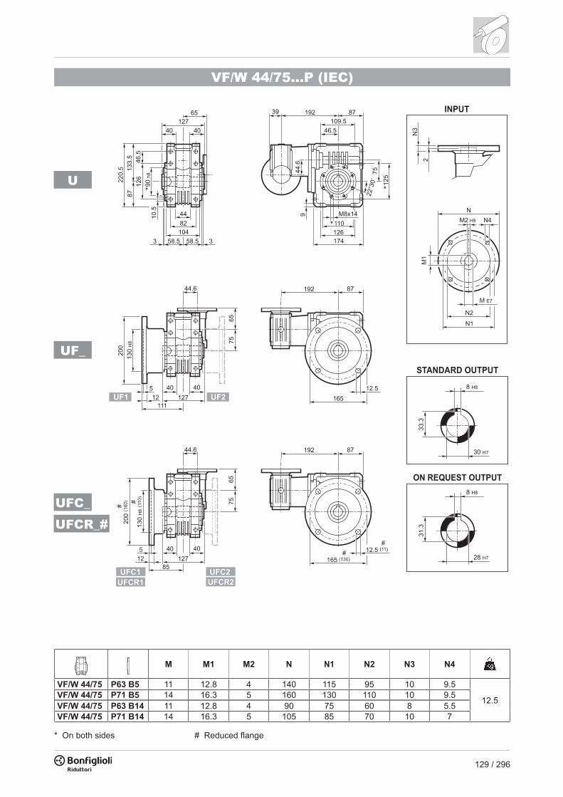
129 / 296
WR 75...P (IEC)
��� �� ��
��
� ��
����
����
�����
����
��
����
����
�
����
����
���
���
�������
����� �����
��
��
��
�����
��
��
��
��
��
���
��
���
��
���
���
����
����
���
���
���
���
���
��
� ��
���
���
�
������
����
���
��
���
��
��
�
�
�
�
����
��
�
�
���
����
�
���
�
���
���������
���������
��� ���
� ��
����
�� ��
� ��
����
�� ��
�����������������
���������������
UF_
U
UFC_
UFCR_#
M M1 M2 N N1 N2 N3 N4 P P1
WR 75 P63 B5 11 12.8 4 140 115 95 10 M8x10 152 23.53 10.6WR 75 P71 B5 14 16.3 5 160 130 110 10 M8x10 152 23.53 10.7WR 75 P80 B5 19 21.8 6 200 165 130 12 M10x13 163.5 11 11.5WR 75 P90 B5 24 27.3 8 200 165 130 12 M10x13 163.5 11 11.6
* On both sides # Reduced fl ange
VF/W 44/75...P (IEC)
� ��
����
�� ��
� ��
����
�� ��
�����������������
���������������
�����
UF_
U
UFC_
UFCR_#
M M1 M2 N N1 N2 N3 N4
VF/W 44/75 P63 B5 11 12.8 4 140 115 95 10 9.5
12.5VF/W 44/75 P71 B5 14 16.3 5 160 130 110 10 9.5VF/W 44/75 P63 B14 11 12.8 4 90 75 60 8 5.5VF/W 44/75 P71 B14 14 16.3 5 105 85 70 10 7
* On both sides # Reduced fl ange

130 / 296
W 86...M/ME/MX
��
���
��
��
��
����
����
����
����
����
�
����
����
���
�
���
��������
������� �������
��
��
��
�����
��
��
���
���
���
���
��
���
��
���
���
����
����
���
���
���
���
���
��
�
��
��
��
�
��
����
�
����
���
���
�
����
�
���
���
���
�
�
�
�
�
�����
���
�����
���
��
��
�
�
���
��
��
����
���
����
���
�� ��
����
�� ��
UFC_
UF_
U
M/ME/MX M...FDM...FA M...FD M...FA
AC H L AD LF R AD R AD
W 86 S1 M1 138 256 324 108 20.1 385 22.3 103 135 124 108W 86 S2 M2S 156 265 349 119 22.6 425 25.7 129 146 134 119W 86 S2 ME2S 156 265 349 119 22.6 — — — — — —W 86 S2 MX2S 156 265 393 119 27.7 — — — — — —W 86 S3 ME3S 195 283.5 392 142 31.2 — — — — — —W 86 S3 MX3S 195 283.5 424 142 34.2 — — — — — —W 86 S3 ME3L 195 283.5 424 142 36.7 — — — — — —W 86 S3 MX3L 195 283.5 468 142 42.7 — — — — — —
* On both sides
W 86...P (IEC)
��
UFC_
UF_
U
M M1 M2 N N1 N2 N3 N4 P
W 86 P71 B5 14 16.3 5 160 130 110 11 9 128 13.6W 86 P80 B5 19 21.8 6 200 165 130 12 11.5 128 13.8W 86 P90 B5 24 27.3 8 200 165 130 12 11.5 128 13.7W 86 P100 B5 28 31.3 8 250 215 180 13 12.5 136 13.8W 86 P112 B5 28 31.3 8 250 215 180 13 12.5 136 13.8W 86 P80 B14 19 21.8 6 120 100 80 7.5 6.5 128 13.5W 86 P90 B14 24 27.3 8 140 115 95 7.5 8.5 128 13.5W 86 P100 B14 28 31.3 8 160 130 110 10 8.5 136 13.6W 86 P112 B14 28 31.3 8 160 130 110 10 8.5 136 13.6
* On both sides

131 / 296
W 86...M/ME/MX
��
���
��
��
��
����
����
����
����
����
�
����
����
���
�
���
��������
������� �������
��
��
��
�����
��
��
���
���
���
���
��
���
��
���
���
����
����
���
���
���
���
���
��
�
��
��
��
�
��
����
�
����
���
���
�
����
�
���
���
��
�
�
�
�
�
�
�����
���
�����
���
��
��
�
�
���
��
��
����
���
����
���
�� ��
����
�� ��
UFC_
UF_
U
M/ME/MX M...FDM...FA M...FD M...FA
AC H L AD LF R AD R AD
W 86 S1 M1 138 256 324 108 20.1 385 22.3 103 135 124 108W 86 S2 M2S 156 265 349 119 22.6 425 25.7 129 146 134 119W 86 S2 ME2S 156 265 349 119 22.6 — — — — — —W 86 S2 MX2S 156 265 393 119 27.7 — — — — — —W 86 S3 ME3S 195 283.5 392 142 31.2 — — — — — —W 86 S3 MX3S 195 283.5 424 142 34.2 — — — — — —W 86 S3 ME3L 195 283.5 424 142 36.7 — — — — — —W 86 S3 MX3L 195 283.5 468 142 42.7 — — — — — —
* On both sides
W 86...P (IEC)
��
UFC_
UF_
U
M M1 M2 N N1 N2 N3 N4 P
W 86 P71 B5 14 16.3 5 160 130 110 11 9 128 13.6W 86 P80 B5 19 21.8 6 200 165 130 12 11.5 128 13.8W 86 P90 B5 24 27.3 8 200 165 130 12 11.5 128 13.7W 86 P100 B5 28 31.3 8 250 215 180 13 12.5 136 13.8W 86 P112 B5 28 31.3 8 250 215 180 13 12.5 136 13.8W 86 P80 B14 19 21.8 6 120 100 80 7.5 6.5 128 13.5W 86 P90 B14 24 27.3 8 140 115 95 7.5 8.5 128 13.5W 86 P100 B14 28 31.3 8 160 130 110 10 8.5 136 13.6W 86 P112 B14 28 31.3 8 160 130 110 10 8.5 136 13.6
* On both sides

132 / 296
WR 86...P (IEC)
��� �� ��
��
� ��
����
����
�����
���
�� ����
����
����
�
����
����
���
�
���
��������
������� �������
��
��
��
�����
��
��
���
���
���
���
��
���
��
���
���
����
����
���
���
������
���
��
�� �
�
���
���
���
�����
���
�����
���
��
��
�
�
�
�
����
��
�
�
����
���
����
���
�� ��
����
�� ��
UFC_
UF_
U
M M1 M2 N N1 N2 N3 N4 P P1
WR 86 P63 B5 11 12.8 4 140 115 95 10 M8x10 168 35.4 14.3WR 86 P71 B5 14 16.3 5 160 130 110 10 M8x10 168 35.4 14.4WR 86 P80 B5 19 21.8 6 200 165 130 12 M10x13 179.5 22.9 15.2WR 86 P90 B5 24 27.3 8 200 165 130 12 M10x13 179.5 22.9 15.3
* On both sides
VF/W 44/86... P (IEC)
�� ��
����
�� ��
UFC_
UF_
U
M M1 M2 N N1 N2 N3 N4
VF/W 44/86 P63 B5 11 12.8 4 140 115 95 10 9.5
16.6VF/W 44/86 P71 B5 14 16.3 5 160 130 110 10 9.5VF/W 44/86 P63 B14 11 12.8 4 90 75 60 8 5.5VF/W 44/86 P71 B14 14 16.3 5 105 85 70 10 7
* On both sides

133 / 296
WR 86...P (IEC)
��� �� ��
��
� ��
����
����
�����
���
�� ����
����
����
�
����
����
���
�
���
��������
������� �������
��
��
��
�����
��
��
���
���
���
���
��
���
��
���
���
����
����
���
���
������
���
��
�� �
�
���
���
��
����
��
���
�����
���
��
��
�
�
�
�
����
��
�
�
����
���
����
���
�� ��
����
�� ��
UFC_
UF_
U
M M1 M2 N N1 N2 N3 N4 P P1
WR 86 P63 B5 11 12.8 4 140 115 95 10 M8x10 168 35.4 14.3WR 86 P71 B5 14 16.3 5 160 130 110 10 M8x10 168 35.4 14.4WR 86 P80 B5 19 21.8 6 200 165 130 12 M10x13 179.5 22.9 15.2WR 86 P90 B5 24 27.3 8 200 165 130 12 M10x13 179.5 22.9 15.3
* On both sides
VF/W 44/86... P (IEC)
�� ��
����
�� ��
UFC_
UF_
U
M M1 M2 N N1 N2 N3 N4
VF/W 44/86 P63 B5 11 12.8 4 140 115 95 10 9.5
16.6VF/W 44/86 P71 B5 14 16.3 5 160 130 110 10 9.5VF/W 44/86 P63 B14 11 12.8 4 90 75 60 8 5.5VF/W 44/86 P71 B14 14 16.3 5 105 85 70 10 7
* On both sides

134 / 296
W 110...M/ME/MX
���
��
��
��
��
����
�
����
���
���
��
���
����
���
�
���
��������
����� �����
��
��
��
�����
��
��
���
���
���
���
��
���
��
���
���
��
��
���
���
���
���
���
��
�
��
��
��
�
��
����
�
����
���
���
�
����
�
���
���
���
�
�
�
�
�
�����
���
�����
�����
��
��
��
��
���
��
�
�
����
���
����
���
�� ��
����
�� ��
UFC_
UF_
U
M/ME/MX M...FDM...FA M...FD M...FA
AC H L AD LF R AD R AD
W 110 S2 M2S 156 313 364 119 38 440 41 129 146 134 119W 110 S2 ME2S 156 313 364 119 38 — — — — — —W 110 S2 MX2S 156 313 408 119 43.1 — — — — — —W 110 S3 ME3S 195 332 407 142 47.5 — — — — — —W 110 S3 MX3S 195 332 440 142 50.5 — — — — — —W 110 S3 ME3L 195 332 439 142 53 — — — — — —W 110 S3 MX3L 195 332 483 142 59 — — — — — —* On both sides
W 110...P (IEC)
��
UFC_
UF_
U
M M1 M2 N N1 N2 N3 N4 P
W 110 P80 B5 19 21.8 6 200 165 130 — M10x12 143 28W 110 P90 B5 24 27.3 8 200 165 130 — M10x12 143 28W 110 P100 B5 28 31.3 8 250 215 180 13 13 151 29W 110 P112 B5 28 31.3 8 250 215 180 13 13 151 29W 110 P132 B5 38 41.3 10 300 265 230 16 14 226 31W 110 P80 B14 19 21.8 6 120 100 80 7.5 7 143 27.5W 110 P90 B14 24 27.3 8 140 115 95 6.5 9 143 27.5W 110 P100 B14 28 31.3 8 160 130 110 13 9 151 27W 110 P112 B14 28 31.3 8 160 130 110 13 9 151 27
* On both sides

135 / 296
W 110...M/ME/MX
���
��
��
��
��
����
�
����
���
���
��
���
����
���
�
���
��������
����� �����
��
��
��
�����
��
��
���
���
���
���
��
���
��
���
���
��
��
���
���
���
���
���
��
�
��
��
��
�
��
����
�
����
���
���
�
����
�
���
���
��
�
�
�
�
�
�
�����
���
�����
�����
��
��
��
��
���
��
�
�
����
���
����
���
�� ��
����
�� ��
UFC_
UF_
U
M/ME/MX M...FDM...FA M...FD M...FA
AC H L AD LF R AD R AD
W 110 S2 M2S 156 313 364 119 38 440 41 129 146 134 119W 110 S2 ME2S 156 313 364 119 38 — — — — — —W 110 S2 MX2S 156 313 408 119 43.1 — — — — — —W 110 S3 ME3S 195 332 407 142 47.5 — — — — — —W 110 S3 MX3S 195 332 440 142 50.5 — — — — — —W 110 S3 ME3L 195 332 439 142 53 — — — — — —W 110 S3 MX3L 195 332 483 142 59 — — — — — —
* On both sides
W 110...P (IEC)
��
UFC_
UF_
U
M M1 M2 N N1 N2 N3 N4 P
W 110 P80 B5 19 21.8 6 200 165 130 — M10x12 143 28W 110 P90 B5 24 27.3 8 200 165 130 — M10x12 143 28W 110 P100 B5 28 31.3 8 250 215 180 13 13 151 29W 110 P112 B5 28 31.3 8 250 215 180 13 13 151 29W 110 P132 B5 38 41.3 10 300 265 230 16 14 226 31W 110 P80 B14 19 21.8 6 120 100 80 7.5 7 143 27.5W 110 P90 B14 24 27.3 8 140 115 95 6.5 9 143 27.5W 110 P100 B14 28 31.3 8 160 130 110 13 9 151 27W 110 P112 B14 28 31.3 8 160 130 110 13 9 151 27
* On both sides

136 / 296
WR 110...P (IEC)
��� �� ��
��
� ��
����
����
�����
���
�� ����
�
��
���
��
���
���
���
��������
����� �����
��
��
��
�����
��
��
���
���
���
��
���
��
���
���
��
���
���
���
���
��
�� �
�
���
���
���
�����
���
�����
�����
��
��
��
��
�
����
��
�
�
����
���
����
���
�� ��
����
�� ��
���
��
���
�
UFC_
UF_
U
M M1 M2 N N1 N2 N3 N4 P P1
WR 110 P71 B5 14 16.3 5 160 130 110 10 M8x14 185 58.6 30.5WR 110 P80 B5 19 21.8 6 200 165 130 14 M10x15 204 21.1 31WR 110 P90 B5 24 27.3 8 200 165 130 14 M10x15 204 21.1 31WR 110 P100 B5 28 31.3 8 250 215 180 14 M12x13 213 21.1 32WR 110 P112 B5 28 31.3 8 250 215 180 14 M12x13 213 21.1 32
* On both sides
VF/W 49/110...P (IEC)
�� ��
����
�� ��
UFC_
UF_
U
M M1 M2 N N1 N2 N3 N4
VF/W 49/110 P63 B5 11 12.8 4 140 115 95 10.5 9.5
33
VF/W 49/110 P71 B5 14 16.3 5 160 130 110 10.5 9.5VF/W 49/110 P80 B5 19 21.8 6 200 165 130 10 11.5VF/W 49/110 P63 B14 11 12.8 4 90 75 60 7 6VF/W 49/110 P71 B14 14 16.3 5 105 85 70 10.5 6.5VF/W 49/110 P80 B14 19 21.8 6 120 100 80 10 7
* On both sides

137 / 296
WR 110...P (IEC)
��� �� ��
��
� ��
����
����
�����
���
�� ����
�
��
���
��
���
���
���
��������
����� �����
��
��
��
�����
��
��
���
���
���
��
���
��
���
���
��
���
���
���
���
��
�� �
�
���
���
��
����
��
���
�����
�����
��
��
��
��
�
����
��
�
�
����
���
����
���
�� ��
����
�� ��
���
��
���
�
UFC_
UF_
U
M M1 M2 N N1 N2 N3 N4 P P1
WR 110 P71 B5 14 16.3 5 160 130 110 10 M8x14 185 58.6 30.5WR 110 P80 B5 19 21.8 6 200 165 130 14 M10x15 204 21.1 31WR 110 P90 B5 24 27.3 8 200 165 130 14 M10x15 204 21.1 31WR 110 P100 B5 28 31.3 8 250 215 180 14 M12x13 213 21.1 32WR 110 P112 B5 28 31.3 8 250 215 180 14 M12x13 213 21.1 32
* On both sides
VF/W 49/110...P (IEC)
�� ��
����
�� ��
UFC_
UF_
U
M M1 M2 N N1 N2 N3 N4
VF/W 49/110 P63 B5 11 12.8 4 140 115 95 10.5 9.5
33
VF/W 49/110 P71 B5 14 16.3 5 160 130 110 10.5 9.5VF/W 49/110 P80 B5 19 21.8 6 200 165 130 10 11.5VF/W 49/110 P63 B14 11 12.8 4 90 75 60 7 6VF/W 49/110 P71 B14 14 16.3 5 105 85 70 10.5 6.5VF/W 49/110 P80 B14 19 21.8 6 120 100 80 10 7
* On both sides

138 / 296
VF 130...P (IEC)
�� ��
����
�� ��
V
N
A
VF 130...P (IEC)
P_
F_
FC_
FR_
M M1 M2 N N1 N2 N3 N4
VF130 P90 B5 24 27.3 8 200 165 130 17 11
49VF130 P100 B5 28 31.3 8 250 215 180 17 13VF130 P112 B5 28 31.3 8 250 215 180 17 13VF130 P132 B5 38 40.1# 10 300 265 230 17 13
# Lowered key

139 / 296
VF 130...P (IEC)
�� ��
����
�� ��
V
N
A
VF 130...P (IEC)
P_
F_
FC_
FR_
M M1 M2 N N1 N2 N3 N4
VF130 P90 B5 24 27.3 8 200 165 130 17 11
49VF130 P100 B5 28 31.3 8 250 215 180 17 13VF130 P112 B5 28 31.3 8 250 215 180 17 13VF130 P132 B5 38 40.1# 10 300 265 230 17 13
# Lowered key

140 / 296
VFR 130...P (IEC)
�� ��
����
�� ��
V
N
A
VFR 130...P (IEC)
P_
F_
FC_
FR_
M M1 M2 N N1 N2 N3 N4
VFR 130 P80 B5 19 K6 21.8 6 200 165 130 12 M10x25
57VFR 130 P90 B5 24 K6 27.3 8 200 165 130 12 M10x25VRF 130 P100 B5 28 J6 29.1# 8 250 215 180 13 M12x35VRF 130 P112 B5 28 J6 29.1# 8 250 215 180 13 M12x35
# Lowered key

141 / 296
VFR 130...P (IEC)
�� ��
����
�� ��
V
N
A
VFR 130...P (IEC)
P_
F_
FC_
FR_
M M1 M2 N N1 N2 N3 N4
VFR 130 P80 B5 19 K6 21.8 6 200 165 130 12 M10x25
57VFR 130 P90 B5 24 K6 27.3 8 200 165 130 12 M10x25VRF 130 P100 B5 28 J6 29.1# 8 250 215 180 13 M12x35VRF 130 P112 B5 28 J6 29.1# 8 250 215 180 13 M12x35
# Lowered key

142 / 296
W/VF 63/130...M/ME/MX
A
FC_
FR_
F_
P_
M/ME/MX M...FDM...FA M...FD M...FA
AC L AD LF R AD R AD
W/VF 63/130 S1 M1 138 419 108 63 480 65 103 135 124 108W/VF 63/130 S2 ME2S 156 447 119 68 — — — — — —W/VF 63/130 S2 MX2S 156 491 119 73.1 — — — — — —
W/VF 63/130...P (IEC)
P_
A
FC_
F_
��
FR_
M M1 M2 N N1 N2 N3 N4 P
W/VF 63/130 P71 B5 14 16.3 5 160 130 110 11 9 95
57
W/VF 63/130 P80 B5 19 21.8 6 200 165 130 12 11.5 102W/VF 63/130 P90 B5 24 27.3 8 200 165 130 12 11.5 102W/VF 63/130 P71 B14 14 16.3 5 105 85 70 11 6.5 95W/VF 63/130 P80 B14 19 21.8 6 120 100 80 11 6.5 102W/VF 63/130 P90 B14 24 27.3 8 140 115 95 11 8.5 102

143 / 296
W/VF 63/130...M/ME/MX
A
FC_
FR_
F_
P_
M/ME/MX M...FDM...FA M...FD M...FA
AC L AD LF R AD R AD
W/VF 63/130 S1 M1 138 419 108 63 480 65 103 135 124 108W/VF 63/130 S2 ME2S 156 447 119 68 — — — — — —W/VF 63/130 S2 MX2S 156 491 119 73.1 — — — — — —
W/VF 63/130...P (IEC)
P_
A
FC_
F_
��
FR_
M M1 M2 N N1 N2 N3 N4 P
W/VF 63/130 P71 B5 14 16.3 5 160 130 110 11 9 95
57
W/VF 63/130 P80 B5 19 21.8 6 200 165 130 12 11.5 102W/VF 63/130 P90 B5 24 27.3 8 200 165 130 12 11.5 102W/VF 63/130 P71 B14 14 16.3 5 105 85 70 11 6.5 95W/VF 63/130 P80 B14 19 21.8 6 120 100 80 11 6.5 102W/VF 63/130 P90 B14 24 27.3 8 140 115 95 11 8.5 102

144 / 296
VF 150...P (IEC)
�� ��
����
�� ��V
N
A
VF 150...P (IEC)
P_
F_
FC_
FR_
M M1 M2 N N1 N2 N3 N4
VF 150 P100 B5 28 31.3 8 250 215 180 11 13
60VF 150 P112 B5 28 31.3 8 250 215 180 11 13VF 150 P132 B5 38 41.3 10 300 265 230 16 13VF 150 P160 B5 42 44.6# 12 350 300 250 18 18
# Lowered key

145 / 296
VF 150...P (IEC)
�� ��
����
�� ��V
N
A
VF 150...P (IEC)
P_
F_
FC_
FR_
M M1 M2 N N1 N2 N3 N4
VF 150 P100 B5 28 31.3 8 250 215 180 11 13
60VF 150 P112 B5 28 31.3 8 250 215 180 11 13VF 150 P132 B5 38 41.3 10 300 265 230 16 13VF 150 P160 B5 42 44.6# 12 350 300 250 18 18
# Lowered key

146 / 296
VFR 150...P (IEC)
�� ��
����
�� ��V
N
A
P_
F_
FC_
FR_
VFR 150...P (IEC)
M M1 M2 N N1 N2 N3 N4
VFR 150 P90 B5 24 K6 27.3 8 200 165 130 13 M10x25
71VRF 150 P100 B5 28 K6 31.3 8 250 215 180 13 M12x35VRF 150 P112 B5 28 J6 31.3 8 250 215 180 13 M12x35VFR 150 P132 B5 38 J6 39.6# 10 300 265 230 13 M12x35
# Lowered key

147 / 296
VFR 150...P (IEC)
�� ��
����
�� ��V
N
A
P_
F_
FC_
FR_
VFR 150...P (IEC)
M M1 M2 N N1 N2 N3 N4
VFR 150 P90 B5 24 K6 27.3 8 200 165 130 13 M10x25
71VRF 150 P100 B5 28 K6 31.3 8 250 215 180 13 M12x35VRF 150 P112 B5 28 J6 31.3 8 250 215 180 13 M12x35VFR 150 P132 B5 38 J6 39.6# 10 300 265 230 13 M12x35
# Lowered key

148 / 296
P_
A
FC_
FR_
F_
W/VF 86/150...M/ME/MX
M/ME/MX M...FDM...FA M...FD M...FA
AC L AD LF R AD R AD
W/VF 86/150 S1 M1 138 474 108 82 385 84 103 135 124 108W/VF 86/150 S2 ME2S 156 499 119 86 — — — — — —W/VF 86/150 S2 MX2S 156 543 119 91.1 — — — — — —W/VF 86/150 S3 ME3S 195 542 142 92.5 — — — — — —W/VF 86/150 S3 MX3S 195 574 142 95.5 — — — — — —W/VF 86/150 S3 ME3L 195 574 142 98 — — — — — —W/VF 86/150 S3 MX3L 195 618 142 104 — — — — — —
��
A
FC_
FR_
F_
P_
W/VF 86/150...P (IEC)
M M1 M2 N N1 N2 N3 N4 P
W/VF 86/150 P71 B5 14 16.3 5 160 130 110 11 9 128
75
W/VF 86/150 P80 B5 19 21.8 6 200 165 130 12 11.5 128W/VF 86/150 P90 B5 24 27.3 8 200 165 130 12 11.5 128W/VF 86/150 P100 B5 28 31.3 8 250 215 180 13 12.5 136W/VF 86/150 P112 B5 28 31.3 8 250 215 180 13 12.5 136W/VF 86/150 P80 B14 19 21.8 6 120 100 80 7.5 6.5 128W/VF 86/150 P90 B14 24 27.3 8 140 115 95 7.5 8.5 128W/VF 86/150 P100 B14 28 31.3 8 160 130 110 10 8.5 136W/VF 86/150 P112 B14 28 31.3 8 160 130 110 10 8.5 136

149 / 296
P_
A
FC_
FR_
F_
W/VF 86/150...M/ME/MX
M/ME/MX M...FDM...FA M...FD M...FA
AC L AD LF R AD R AD
W/VF 86/150 S1 M1 138 474 108 82 385 84 103 135 124 108W/VF 86/150 S2 ME2S 156 499 119 86 — — — — — —W/VF 86/150 S2 MX2S 156 543 119 91.1 — — — — — —W/VF 86/150 S3 ME3S 195 542 142 92.5 — — — — — —W/VF 86/150 S3 MX3S 195 574 142 95.5 — — — — — —W/VF 86/150 S3 ME3L 195 574 142 98 — — — — — —W/VF 86/150 S3 MX3L 195 618 142 104 — — — — — —
��
A
FC_
FR_
F_
P_
W/VF 86/150...P (IEC)
M M1 M2 N N1 N2 N3 N4 P
W/VF 86/150 P71 B5 14 16.3 5 160 130 110 11 9 128
75
W/VF 86/150 P80 B5 19 21.8 6 200 165 130 12 11.5 128W/VF 86/150 P90 B5 24 27.3 8 200 165 130 12 11.5 128W/VF 86/150 P100 B5 28 31.3 8 250 215 180 13 12.5 136W/VF 86/150 P112 B5 28 31.3 8 250 215 180 13 12.5 136W/VF 86/150 P80 B14 19 21.8 6 120 100 80 7.5 6.5 128W/VF 86/150 P90 B14 24 27.3 8 140 115 95 7.5 8.5 128W/VF 86/150 P100 B14 28 31.3 8 160 130 110 10 8.5 136W/VF 86/150 P112 B14 28 31.3 8 160 130 110 10 8.5 136

150 / 296
�� ��
����
�� ��V
N
A
VF 185...P (IEC)
�� ��
����
�� ��P_
F_
FC_
FR_
VF 185...P (IEC)
M M1 M2 N N1 N2 N3 N4
VF 185 P100 B5 28 31.3 8 250 215 180 16 13
94VF 185 P112 B5 28 31.3 8 250 215 180 16 13VF 185 P132 B5 38 41.3 10 300 265 230 16 13VF 185 P160 B5 42 45.3 12 350 300 250 18 18VF 185 P180 B5 48 51.2# 14 350 300 250 18 18
# Lowered key

151 / 296
�� ��
����
�� ��V
N
A
VF 185...P (IEC)
�� ��
����
�� ��P_
F_
FC_
FR_
VF 185...P (IEC)
M M1 M2 N N1 N2 N3 N4
VF 185 P100 B5 28 31.3 8 250 215 180 16 13
94VF 185 P112 B5 28 31.3 8 250 215 180 16 13VF 185 P132 B5 38 41.3 10 300 265 230 16 13VF 185 P160 B5 42 45.3 12 350 300 250 18 18VF 185 P180 B5 48 51.2# 14 350 300 250 18 18
# Lowered key

152 / 296
�� ��
����
�� ��V
N
A
VFR 185...P (IEC)
P_
F_
FC_
FR_
VFR 185...P (IEC)
M M1 M2 N N1 N2 N3 N4
VFR 185 P90 B5 24 K6 27.3 8 200 165 130 13 M10x25
110VRF 185 P100 B5 28 K6 31.3 8 250 215 180 13 M12x35VRF 185 P112 B5 28 K6 31.3 8 250 215 180 13 M12x35VFR 185 P132 B5 38 J6 39.6# 10 300 265 230 13 M12x35
# Lowered key

153 / 296
�� ��
����
�� ��V
N
A
VFR 185...P (IEC)
P_
F_
FC_
FR_
VFR 185...P (IEC)
M M1 M2 N N1 N2 N3 N4
VFR 185 P90 B5 24 K6 27.3 8 200 165 130 13 M10x25
110VRF 185 P100 B5 28 K6 31.3 8 250 215 180 13 M12x35VRF 185 P112 B5 28 K6 31.3 8 250 215 180 13 M12x35VFR 185 P132 B5 38 J6 39.6# 10 300 265 230 13 M12x35
# Lowered key

154 / 296
FC_
P_
FR_
F_
A
W/VF 86/185...M/ME/MX
M/ME/MX M...FDM...FA M...FD M...FA
AC L AD LF R AD R AD
W/VF 86/185 S1 M1 138 509 108 116 570 118 103 135 124 108W/VF 86/185 S2 ME2S 156 534 119 120 — — — — — —W/VF 86/185 S2 MX2S 156 578 119 125.1 — — — — — —W/VF 86/185 S3 ME3S 195 577 142 126.5 — — — — — —W/VF 86/185 S3 MX3S 195 609 142 129.5 — — — — — —W/VF 86/185 S3 ME3L 195 609 142 132 — — — — — —W/VF 86/185 S3 MX3L 195 653 142 138 — — — — — —
��
FC_
A
FR_
F_
P_
W/VF 86/185...P (IEC)
M M1 M2 N N1 N2 N3 N4 P
W/VF 86/185 P71 B5 14 16.3 5 160 130 110 11 9 128
109
W/VF 86/185 P80 B5 19 21.8 6 200 165 130 12 11.5 128W/VF 86/185 P90 B5 24 27.3 8 200 165 130 12 11.5 128W/VF 86/185 P100 B5 28 31.3 8 250 215 180 13 12.5 136W/VF 86/185 P112 B5 28 31.3 8 250 215 180 13 12.5 136W/VF 86/185 P80 B14 19 21.8 6 120 100 80 7.5 6.5 128W/VF 86/185 P90 B14 24 27.3 8 140 115 95 7.5 8.5 128W/VF 86/185 P100 B14 28 31.3 8 160 130 110 10 8.5 136W/VF 86/185 P112 B14 28 31.3 8 160 130 110 10 8.5 136

155 / 296
FC_
P_
FR_
F_
A
W/VF 86/185...M/ME/MX
M/ME/MX M...FDM...FA M...FD M...FA
AC L AD LF R AD R AD
W/VF 86/185 S1 M1 138 509 108 116 570 118 103 135 124 108W/VF 86/185 S2 ME2S 156 534 119 120 — — — — — —W/VF 86/185 S2 MX2S 156 578 119 125.1 — — — — — —W/VF 86/185 S3 ME3S 195 577 142 126.5 — — — — — —W/VF 86/185 S3 MX3S 195 609 142 129.5 — — — — — —W/VF 86/185 S3 ME3L 195 609 142 132 — — — — — —W/VF 86/185 S3 MX3L 195 653 142 138 — — — — — —
��
FC_
A
FR_
F_
P_
W/VF 86/185...P (IEC)
M M1 M2 N N1 N2 N3 N4 P
W/VF 86/185 P71 B5 14 16.3 5 160 130 110 11 9 128
109
W/VF 86/185 P80 B5 19 21.8 6 200 165 130 12 11.5 128W/VF 86/185 P90 B5 24 27.3 8 200 165 130 12 11.5 128W/VF 86/185 P100 B5 28 31.3 8 250 215 180 13 12.5 136W/VF 86/185 P112 B5 28 31.3 8 250 215 180 13 12.5 136W/VF 86/185 P80 B14 19 21.8 6 120 100 80 7.5 6.5 128W/VF 86/185 P90 B14 24 27.3 8 140 115 95 7.5 8.5 128W/VF 86/185 P100 B14 28 31.3 8 160 130 110 10 8.5 136W/VF 86/185 P112 B14 28 31.3 8 160 130 110 10 8.5 136

156 / 296
�� ����
��
�� ��
A
N
VF 210...P (IEC)
�� ��
����
�� ��
V
P
VF 210...P (IEC)
F2 M M1 M2 N N1 N2 N3 N4
VF 210 P132 B5 485 38 41.3 10 300 265 230 25 M12
210VF 210 P160 B5 460 42 45.3 12 350 300 250 22 18VF 210 P180 B5 460 48 51.8 14 350 300 250 22 18VF 210 P200 B5 485 55 59.3 16 400 350 300 25 M16VF 210 P225 B5 490 60 64.4 18 450 400 350 22 18 #
# N° 8 holes at 45°
Fan cooling as standard on versions A and P.P(IEC) arrangements come complete with gear coupling enclosed in the bell housing.

157 / 296
�� ��
����
�� ��
A
N
VF 210...P (IEC)
�� ��
����
�� ��
V
P
VF 210...P (IEC)
F2 M M1 M2 N N1 N2 N3 N4
VF 210 P132 B5 485 38 41.3 10 300 265 230 25 M12
210VF 210 P160 B5 460 42 45.3 12 350 300 250 22 18VF 210 P180 B5 460 48 51.8 14 350 300 250 22 18VF 210 P200 B5 485 55 59.3 16 400 350 300 25 M16VF 210 P225 B5 490 60 64.4 18 450 400 350 22 18 #
# N° 8 holes at 45°
Fan cooling as standard on versions A and P.P(IEC) arrangements come complete with gear coupling enclosed in the bell housing.

158 / 296
�� ����
��
�� ��
A
N
VFR 210...P (IEC)
�� ��
����
�� ��
V
P
VFR 210...P (IEC)
M M1 M2 N N1 N2 N3 N4
VRF 210 P100 B5 28 K6 31.3 8 250 215 180 13 M12x35
185VRF 210 P112 B5 28 K6 31.3 8 250 215 180 13 M12x35VFR 210 P132 B5 38 J6 41.3 10 300 265 230 13 M12x35VFR 210 P160 B5 42 J6 44.3# 12 350 300 250 18 M16x60
# Lowered key
Fan cooling as standard on versions A and P.

159 / 296
�� ��
����
�� ��
A
N
VFR 210...P (IEC)
�� ��
����
�� ��
V
P
VFR 210...P (IEC)
M M1 M2 N N1 N2 N3 N4
VRF 210 P100 B5 28 K6 31.3 8 250 215 180 13 M12x35
185VRF 210 P112 B5 28 K6 31.3 8 250 215 180 13 M12x35VFR 210 P132 B5 38 J6 41.3 10 300 265 230 13 M12x35VFR 210 P160 B5 42 J6 44.3# 12 350 300 250 18 M16x60
# Lowered key
Fan cooling as standard on versions A and P.

160 / 296
�� ����
��
�� ��
A
P
VF/VF 130/210...P (IEC)
M M1 M2 N N1 N2 N3 N4
VF/VF 130/210 P90 B5 24 27.3 8 200 165 130 17 11
225VF/VF 130/210 P100 B5 28 31.3 8 250 215 180 17 13VF/VF 130/210 P112 B5 28 31.3 8 250 215 180 17 13VF/VF 130/210 P132 B5 38 40.1# 10 300 265 230 17 13
# Lowered key
Fan cooling as standard on versions A and P.

161 / 296
�� ��
����
�� ��
A
P
VF/VF 130/210...P (IEC)
M M1 M2 N N1 N2 N3 N4
VF/VF 130/210 P90 B5 24 27.3 8 200 165 130 17 11
225VF/VF 130/210 P100 B5 28 31.3 8 250 215 180 17 13VF/VF 130/210 P112 B5 28 31.3 8 250 215 180 17 13VF/VF 130/210 P132 B5 38 40.1# 10 300 265 230 17 13
# Lowered key
Fan cooling as standard on versions A and P.

162 / 296
�� ����
���
��� ��
A
N
VF 250...P (IEC)
�� ��
����
�
��� ��
V
P
VF 250...P (IEC)
F2 M M1 M2 N N1 N2 N3 N4
VF 250 P132 B5 531 38 41.3 10 300 265 230 25 M12
310VF 250 P160 B5 506 42 45.3 12 350 300 250 22 18VF 250 P180 B5 506 48 51.8 14 350 300 250 22 18VF 250 P200 B5 531 55 59.3 16 400 350 300 25 M16VF 250 P225 B5 536 60 64.4 18 450 400 350 22 18#
# N° 8 holes at 45°
Fan cooling as standard on versions A and P.P(IEC) arrangements come complete with gear coupling enclosed in the bell housing.

163 / 296
�� ��
����
�
��� ��
A
N
VF 250...P (IEC)
�� ��
����
�
��� ��
V
P
VF 250...P (IEC)
F2 M M1 M2 N N1 N2 N3 N4
VF 250 P132 B5 531 38 41.3 10 300 265 230 25 M12
310VF 250 P160 B5 506 42 45.3 12 350 300 250 22 18VF 250 P180 B5 506 48 51.8 14 350 300 250 22 18VF 250 P200 B5 531 55 59.3 16 400 350 300 25 M16VF 250 P225 B5 536 60 64.4 18 450 400 350 22 18#
# N° 8 holes at 45°
Fan cooling as standard on versions A and P.P(IEC) arrangements come complete with gear coupling enclosed in the bell housing.

164 / 296
�� ����
���
��� ��
A
N
VFR 250...P (IEC)
�� ��
����
�
��� ��
V
P
VFR 250...P (IEC)
M M1 M2 N N1 N2 N3 N4
VRF 250 P100 B5 28 K6 31.3 8 250 215 180 13 M12x35
295VRF 250 P112 B5 28 K6 31.3 8 250 215 180 13 M12x35VFR 250 P132 B5 38 J6 41.3 10 300 265 230 13 M12x35VFR 250 P160 B5 42 J6 44.3# 12 350 300 250 18 M16x60
# Lowered key
Fan cooling as standard on versions A and P.

165 / 296
�� ��
����
�
��� ��
A
N
VFR 250...P (IEC)
�� ��
����
�
��� ��
V
P
VFR 250...P (IEC)
M M1 M2 N N1 N2 N3 N4
VRF 250 P100 B5 28 K6 31.3 8 250 215 180 13 M12x35
295VRF 250 P112 B5 28 K6 31.3 8 250 215 180 13 M12x35VFR 250 P132 B5 38 J6 41.3 10 300 265 230 13 M12x35VFR 250 P160 B5 42 J6 44.3# 12 350 300 250 18 M16x60
# Lowered key
Fan cooling as standard on versions A and P.

166 / 296
�� ��
����
�
��� ��
A
P
VF/VF 130/250...P (IEC)
M M1 M2 N N1 N2 N3 N4
VF/VF 130/250 P 90 B5 24 27.3 8 200 165 130 17 11
325VF/VF 130/250 P100 B5 28 31.3 8 250 215 180 17 13VF/VF 130/250 P112 B5 28 31.3 8 250 215 180 17 13VF/VF 130/250 P132 B5 38 40.1# 10 300 265 230 17 13
# Lowered key
Fan cooling as standard on versions A and P.
VF 27...HS
10.2
9 h6
M3x9
3UNI 6604
43
43
43
5.5
5.55.5
5.540
5440
4070
7570
70
7
7h6
7h6
7 h6
7h6
7
7
52
52
52
99
47
87
4520
20
20
20
45
45
45
27
27
278.2
7 h6
M3x9
3UNI 6604
VF 27_A..HS VF 27_N..HS
VF 27_V..HS VF 27_F2..HS43
5.55475
7h6
47
20 45
27
VF 27_F1..HS
VF 27_HS 0.73
Dimensions common to the other confi gurations can be found at page 107.
Input shaftOutput shaft

167 / 296
�� ��
����
�
��� ��
A
P
VF/VF 130/250...P (IEC)
M M1 M2 N N1 N2 N3 N4
VF/VF 130/250 P 90 B5 24 27.3 8 200 165 130 17 11
325VF/VF 130/250 P100 B5 28 31.3 8 250 215 180 17 13VF/VF 130/250 P112 B5 28 31.3 8 250 215 180 17 13VF/VF 130/250 P132 B5 38 40.1# 10 300 265 230 17 13
# Lowered key
Fan cooling as standard on versions A and P.
VF 27...HS
10.2
9 h6
M3x9
3UNI 6604
43
43
43
5.5
5.55.5
5.540
5440
4070
7570
70
7
7h6
7h6
7 h6
7h6
7
7
52
52
52
99
47
87
4520
20
20
20
45
45
45
27
27
278.2
7 h6
M3x9
3UNI 6604
VF 27_A..HS VF 27_N..HS
VF 27_V..HS VF 27_F2..HS43
5.55475
7h6
47
20 4527
VF 27_F1..HS
VF 27_HS 0.73
Dimensions common to the other confi gurations can be found at page 107.
Input shaftOutput shaft
27 DIMENSIONS FOR GEAR UNITS WITH SOLID INPUT SHAFT

168 / 296
W_UF/UFC/UFCR..HSW_U..HS
VF_P..HS VF_FA/FC/FR/F..HS
VF_A..HS VF_N..HSVF_V..HS
VF_U..HS
28
10.5
1.1
VF 44_HS , VF 44 U_HS
VF...HS - W..HS
A B B1 B2 F F1 F2 F3 F4 G V
VF 30_HS 30 14 H7 16.3 5 9 h6 10.2 3 20 50 55 — 1.1VF 30 U HS 47VF 44_HS 44.6 18 H7 20.8 6 11 h6 12.5 4 30 54 72 — 2.0VF 44 U HS 55VF 49_HS 49.5 25 H7 28.3 8 16 h6 18 5 40 65 82 M6x16 3.0VF 49 U HS 64.5W 63_HS 62.17 25 H7 28.3 8 18 h6 20.5 6 40 110.5 72.5 M6x16 6.4W 75_HS 75 30(28) H7 33.3(31.3) 8 19 h6 21.5 6 40 128 87 M6x16 10.0W 86_HS 86.9 35 H7 38.3 10 25 h6 28 8 50 144 100 M8x19 14.1W 110_HS 110.1 42 H7 45.3 12 25 h6 28 8 60 168 125 M8x19 27VF 130_HS 130 45 H7 48.8 14 30 h6 33 8 60 160 195 M8x20 49VF 150_HS 150 50 H7 53.8 14 35 h6 38 10 65 185 220 M8x20 60VF 185_HS 185.4 60 H7 64.4 18 40 h6 43 12 70 214.5 254 M8x20 94VF 210_HS 210 90 H7 95.4 25 48 h6 51.5 14 110 230 335 M16x40 175VF 250_HS 250 110 G7 116.4 28 55 h6 59 16 110 275.5 380 M16x40 275
Dimensions common to the other confi gurations can be found from page 108 to 163.
Output shaft
Input shaft
WR_UF/UFC/UFCR..HSWR_U..HS
VFR_A..HS VFR_N..HS VFR_V..HS
VFR_P..HS VFR_FA/FC/FR/F..HS VFR_U..HS
VFR...HS - WR...HS
A A1 B B1 B2 F F1 F2 F3 F4 G V
VFR 49_HS 49.5 10 25 H7 28.3 8 11 h6 12.5 4 23 110 82 M4x10 5VFR 49 U HS 64.5WR 63_HS 62.17 11.42 25 H7 28.3 8 14 h6 16 5 30 138 72.5 M5x12.5 7.1WR 75_HS 75 11 30(28) H7 33.3(31.3) 8 19 h6 21.5 6 40 162 87 M6x16 11.1WR 86_HS 86.9 22.9 35 H7 38.3 10 19 h6 21.5 6 40 178 100 M6x16 14.7WR 110_HS 110.1 21.1 42 H7 45.3 12 24 h6 27 8 50 201 125 M8x19 34VFR 130_HS 130 45 45 H7 48.8 14 24 h6 27 8 50 228 195 M8x20 57VFR 150_HS 150 53 50 H7 53.8 14 28 h6 31 8 60 280 220 M8x20 71VFR 185_HS 185.4 88.4 60 H7 64.4 18 28 h6 31 8 60 310 254 M8x20 110VFR 210_HS 210 92 90 H7 95.4 25 38 h6 41 10 80 335 335 M10x25 185VFR 250_HS 250 132 110 G7 116.4 28 38 h6 41 10 80 383 380 M10x25 295
Dimensions common to the other confi gurations can be found from page 118 to 165.
Output shaft
Input shaft

169 / 296
W_UF/UFC/UFCR..HSW_U..HS
VF_P..HS VF_FA/FC/FR/F..HS
VF_A..HS VF_N..HSVF_V..HS
VF_U..HS
28
10.5
1.1
VF 44_HS , VF 44 U_HS
VF...HS - W..HS
A B B1 B2 F F1 F2 F3 F4 G V
VF 30_HS 30 14 H7 16.3 5 9 h6 10.2 3 20 50 55 — 1.1VF 30 U HS 47VF 44_HS 44.6 18 H7 20.8 6 11 h6 12.5 4 30 54 72 — 2.0VF 44 U HS 55VF 49_HS 49.5 25 H7 28.3 8 16 h6 18 5 40 65 82 M6x16 3.0VF 49 U HS 64.5W 63_HS 62.17 25 H7 28.3 8 18 h6 20.5 6 40 110.5 72.5 M6x16 6.4W 75_HS 75 30(28) H7 33.3(31.3) 8 19 h6 21.5 6 40 128 87 M6x16 10.0W 86_HS 86.9 35 H7 38.3 10 25 h6 28 8 50 144 100 M8x19 14.1W 110_HS 110.1 42 H7 45.3 12 25 h6 28 8 60 168 125 M8x19 27VF 130_HS 130 45 H7 48.8 14 30 h6 33 8 60 160 195 M8x20 49VF 150_HS 150 50 H7 53.8 14 35 h6 38 10 65 185 220 M8x20 60VF 185_HS 185.4 60 H7 64.4 18 40 h6 43 12 70 214.5 254 M8x20 94VF 210_HS 210 90 H7 95.4 25 48 h6 51.5 14 110 230 335 M16x40 175VF 250_HS 250 110 G7 116.4 28 55 h6 59 16 110 275.5 380 M16x40 275
Dimensions common to the other confi gurations can be found from page 108 to 163.
Output shaft
Input shaft
WR_UF/UFC/UFCR..HSWR_U..HS
VFR_A..HS VFR_N..HS VFR_V..HS
VFR_P..HS VFR_FA/FC/FR/F..HS VFR_U..HS
VFR...HS - WR...HS
A A1 B B1 B2 F F1 F2 F3 F4 G V
VFR 49_HS 49.5 10 25 H7 28.3 8 11 h6 12.5 4 23 110 82 M4x10 5VFR 49 U HS 64.5WR 63_HS 62.17 11.42 25 H7 28.3 8 14 h6 16 5 30 138 72.5 M5x12.5 7.1WR 75_HS 75 11 30(28) H7 33.3(31.3) 8 19 h6 21.5 6 40 162 87 M6x16 11.1WR 86_HS 86.9 22.9 35 H7 38.3 10 19 h6 21.5 6 40 178 100 M6x16 14.7WR 110_HS 110.1 21.1 42 H7 45.3 12 24 h6 27 8 50 201 125 M8x19 34VFR 130_HS 130 45 45 H7 48.8 14 24 h6 27 8 50 228 195 M8x20 57VFR 150_HS 150 53 50 H7 53.8 14 28 h6 31 8 60 280 220 M8x20 71VFR 185_HS 185.4 88.4 60 H7 64.4 18 28 h6 31 8 60 310 254 M8x20 110VFR 210_HS 210 92 90 H7 95.4 25 38 h6 41 10 80 335 335 M10x25 185VFR 250_HS 250 132 110 G7 116.4 28 38 h6 41 10 80 383 380 M10x25 295
Dimensions common to the other confi gurations can be found from page 118 to 165.
Output shaft
Input shaft

170 / 296
VF/VF_A..HSW/VF_A..HS
VF/VF_P..HSW/VF_P..HS
VF/VF_P..HSW/VF_P..HS
28
10.5
1.1
VF/W 44/75_HSVF/W 44/86_HS
VF/VF...HS - VF/W...HS - W/VF...HS
A A1 B B1 B2 F F1 F2 F3 F4 G V
VF/VF 30/44_HS 44.6 30 18 H7 20.8 6 9 h6 10.2 3 20 50 72 — 3.5VF/VF 30/44 U HS 55VF/VF 30/49_HS 49.5 30 25 H7 28.3 8 9 h6 10.2 3 20 50 82 — 4.5VF/VF 30/49 U HS 64.5VF/W 30/63_HS 62.17 30 25 H7 28.3 8 9 h6 10.2 3 20 50 100 — 7.5VF/W 44/75_HS 75 44.6 30 (28) H7 33.3 (31.3) 8 11 h6 12.5 4 30 54 115 — 16.1VF/W 44/86_HS 86.9 44.6 35 H7 38.3 10 11 h6 12.5 4 30 54 142 — 42VF/W 49/110_HS 110.0 49.5 42 H7 45.3 12 16 h6 18 5 40 65 170 M6x16 46W/VF 63/130_HS 130 62.17 45 H7 48.8 14 18 h6 20.5 6 40 110.5 72.5 M6x16 74W/VF 86/150_HS 150 86.9 50 H7 53.8 14 25 h6 28 8 50 144 100 M8x19 108W/VF 86/185_HS 185.4 86.9 60 H7 64.4 18 25 h6 28 8 50 144 100 M8x19 109VF/VF 130/210_HS 210 130 90 H7 95.4 25 30 h6 33 8 60 160 335 M8 225VF/VF 130/250_HS 250 130 110 G7 116.4 28 30 h6 33 8 60 160 380 M8 325
Dimensions common to the other confi gurations can be found from page 114 to 166.
Output shaft Input shaft
C D D1 E F1 F2 M N V X YVFVFRVF/VF
30 30 14 14 35 5 16 61 96 M5x13 5 2044 40 18 18 45 6 20.5 70 115 M6x16 5 3049 60 25 25 65 8 28 89 154 M8x19 5 50
WWRVF/W
63 60 25 25 65 8 28 127 192 M8x19 5 5075_D28 60 28 30 65 8 31 134 199 M8x20 5 5075_D30 60 30 30 65 8 33 134 199 M10x22 5 5086 60 35 35 65 10 38 149 214 M10x22 5 50110 75 42 42 80 12 45 164 244 M12x28 7.5 60
VFVFRW/VF
130 80 45 45 85 14 48.5 176 261 M12x32 5 70150 85 50 50 93 14 53.5 185 278 M16x40 7.5 70185 100 60 60 110 18 64 200 310 M16x40 10 80210 130 90 90 140 25 95 255 395 M20x50 5 120250 165 110 110 175 28 116 315 490 M24x64 15 140
C D D1 E F F1 F2 L V X YVFVFRVF/VF
30 30 14 14 32.5 55 5 16 120 M5x13 5 2044 40 18 18 42.7 64 6 20.5 149.4 M6x16 5 3049 60 25 25 63.2 82 8 28 208.4 M8x19 5 50
WWRVF/W
63 60 25 25 63.2 120 8 28 246.4 M8x19 5 5075_D28 60 28 30 64 127 8 31 255 M8x20 5 5075_D30 60 30 30 64 127 8 33 255 M10x22 5 5086 60 35 35 64 140 10 38 268 M10x22 5 50110 75 42 42 79.3 155 12 45 313.5 M12x28 7.5 60
VFVFRW/VF
130 80 45 45 84.7 165 14 48.5 334.5 M12x32 5 70150 85 50 50 90 175 14 53.5 355 M16x40 7.5 70185 100 60 60 105 190 18 64 400 M16x40 10 80210 130 90 90 140 260 25 95 540 M20x50 5 120250 165 110 110 175 320 28 116 670 M24x64 15 140
VF W VF 30 - VF 44 - VF 49
A B C D E F G H IVFVFRVF/VF
30 100 40 157.5 50 65 7 14 8 444 100 40 157.5 50 65 7 14 8 449 100 55 172.5 68 94 7 14 8 4
WWRVF/W
63 150 55 233 75 90 9 20 10 675 200 63 300 90 110 9 25 20 686 200 80 318 110 130 11 25 20 6110 250 100 388 130 165 13 25 20 6
VFVFRW/VF
130 300 125 470 180 215 13 30 25 6150 300 125 470 180 215 15 30 25 6185 350 150 545 230 265 17 30 25 6210 350 175 625 250 300 19 60 50 8250 400 225 725 350 400 19 60 50 10
Without vibration-dampening bushing

171 / 296
VF/VF_A..HSW/VF_A..HS
VF/VF_P..HSW/VF_P..HS
VF/VF_P..HSW/VF_P..HS
28
10.5
1.1
VF/W 44/75_HSVF/W 44/86_HS
VF/VF...HS - VF/W...HS - W/VF...HS
A A1 B B1 B2 F F1 F2 F3 F4 G V
VF/VF 30/44_HS 44.6 30 18 H7 20.8 6 9 h6 10.2 3 20 50 72 — 3.5VF/VF 30/44 U HS 55VF/VF 30/49_HS 49.5 30 25 H7 28.3 8 9 h6 10.2 3 20 50 82 — 4.5VF/VF 30/49 U HS 64.5VF/W 30/63_HS 62.17 30 25 H7 28.3 8 9 h6 10.2 3 20 50 100 — 7.5VF/W 44/75_HS 75 44.6 30 (28) H7 33.3 (31.3) 8 11 h6 12.5 4 30 54 115 — 16.1VF/W 44/86_HS 86.9 44.6 35 H7 38.3 10 11 h6 12.5 4 30 54 142 — 42VF/W 49/110_HS 110.0 49.5 42 H7 45.3 12 16 h6 18 5 40 65 170 M6x16 46W/VF 63/130_HS 130 62.17 45 H7 48.8 14 18 h6 20.5 6 40 110.5 72.5 M6x16 74W/VF 86/150_HS 150 86.9 50 H7 53.8 14 25 h6 28 8 50 144 100 M8x19 108W/VF 86/185_HS 185.4 86.9 60 H7 64.4 18 25 h6 28 8 50 144 100 M8x19 109VF/VF 130/210_HS 210 130 90 H7 95.4 25 30 h6 33 8 60 160 335 M8 225VF/VF 130/250_HS 250 130 110 G7 116.4 28 30 h6 33 8 60 160 380 M8 325
Dimensions common to the other confi gurations can be found from page 114 to 166.
Output shaft Input shaft
C D D1 E F1 F2 M N V X YVFVFRVF/VF
30 30 14 14 35 5 16 61 96 M5x13 5 2044 40 18 18 45 6 20.5 70 115 M6x16 5 3049 60 25 25 65 8 28 89 154 M8x19 5 50
WWRVF/W
63 60 25 25 65 8 28 127 192 M8x19 5 5075_D28 60 28 30 65 8 31 134 199 M8x20 5 5075_D30 60 30 30 65 8 33 134 199 M10x22 5 5086 60 35 35 65 10 38 149 214 M10x22 5 50110 75 42 42 80 12 45 164 244 M12x28 7.5 60
VFVFRW/VF
130 80 45 45 85 14 48.5 176 261 M12x32 5 70150 85 50 50 93 14 53.5 185 278 M16x40 7.5 70185 100 60 60 110 18 64 200 310 M16x40 10 80210 130 90 90 140 25 95 255 395 M20x50 5 120250 165 110 110 175 28 116 315 490 M24x64 15 140
C D D1 E F F1 F2 L V X YVFVFRVF/VF
30 30 14 14 32.5 55 5 16 120 M5x13 5 2044 40 18 18 42.7 64 6 20.5 149.4 M6x16 5 3049 60 25 25 63.2 82 8 28 208.4 M8x19 5 50
WWRVF/W
63 60 25 25 63.2 120 8 28 246.4 M8x19 5 5075_D28 60 28 30 64 127 8 31 255 M8x20 5 5075_D30 60 30 30 64 127 8 33 255 M10x22 5 5086 60 35 35 64 140 10 38 268 M10x22 5 50110 75 42 42 79.3 155 12 45 313.5 M12x28 7.5 60
VFVFRW/VF
130 80 45 45 84.7 165 14 48.5 334.5 M12x32 5 70150 85 50 50 90 175 14 53.5 355 M16x40 7.5 70185 100 60 60 105 190 18 64 400 M16x40 10 80210 130 90 90 140 260 25 95 540 M20x50 5 120250 165 110 110 175 320 28 116 670 M24x64 15 140
VF W VF 30 - VF 44 - VF 49
A B C D E F G H IVFVFRVF/VF
30 100 40 157.5 50 65 7 14 8 444 100 40 157.5 50 65 7 14 8 449 100 55 172.5 68 94 7 14 8 4
WWRVF/W
63 150 55 233 75 90 9 20 10 675 200 63 300 90 110 9 25 20 686 200 80 318 110 130 11 25 20 6110 250 100 388 130 165 13 25 20 6
VFVFRW/VF
130 300 125 470 180 215 13 30 25 6150 300 125 470 180 215 15 30 25 6185 350 150 545 230 265 17 30 25 6210 350 175 625 250 300 19 60 50 8250 400 225 725 350 400 19 60 50 10
Without vibration-dampening bushing
28 ACCESSORIES 28.1
Plug-in output shaft
28.2 Torque arm

172 / 296
A H M N O P R S T U
W 63 - WR 63 100 27.5 111 95 11 8 135 145 56.5 15.5
W 75 - WR 75 115 28 115 120 11 9 139 174 56.5 15.5
W 86 - WR 86 142 42 146 140 11 11 170 200 69 20
W 110 - WR 110 170 45 181 200 13 14 210 250 69 20
A B C
W 63 - WR 63 26.5 29 Ø35
W 75 - WR 75 24.5 27 Ø54
W 86 - WR 86 26.5 29 Ø71
W 110 - WR110 27.5 30 Ø89
28.3 VF-interchangeable foot kits KA, KV
28.4 Safety cover

173 / 296
A H M N O P R S T U
W 63 - WR 63 100 27.5 111 95 11 8 135 145 56.5 15.5
W 75 - WR 75 115 28 115 120 11 9 139 174 56.5 15.5
W 86 - WR 86 142 42 146 140 11 11 170 200 69 20
W 110 - WR 110 170 45 181 200 13 14 210 250 69 20
A B C
W 63 - WR 63 26.5 29 Ø35
W 75 - WR 75 24.5 27 Ø54
W 86 - WR 86 26.5 29 Ø71
W 110 - WR110 27.5 30 Ø89
29 CUSTOMER’S SHAFT Make the driven shaft to be coupled to the gear unit’s output shaft from a good quality steel, respect-ing the dimensions given in the table. A device such as that illustrated below should also be installed to secure the shaft axially. Take care to verify and dimension the various components to suit the needs of the application.
�
VF 30 - VF 44
A1 A2 A3 B B1 B2 C D E F G R S
UNI 6604
VF 30 ≥ 19 14 f7 13 53 18.5 16 40 6.5 6.5 16 5 h9 0.5 1.5 5x5x40 A
VF 44 ≥ 23 18 f7 17 62 22.5 17 50 6 6 20.5 6 h9 0.5 1.5 6x6x50 A
VF 49 ≥ 30 25 f7 24 80 20.5 39 20 2 2 28 8 h9 1 1.5 8x7x20 A
W 63 ≥ 30 25 f7 24 118 38 42 35 2 2 28 8 h9 1 1.5 8x7x35 A
W 75≥ 35 28 f7 27 125 38 49 40 2 2 31 8 h9 1 1.5 8x7x40 A
≥ 35 30 f7 29 125 38 49 40 2 2 33 8 h9 1 1.5 8x7x40 A
W 86 ≥ 42 35 f7 34 138 43 52 40 2 2 38 10 h9 1.5 1.5 10x8x40 A
W 110 ≥ 48 42 f7 41 153 43 67 50 2 2 45 12 h9 1.5 2 12x8x50 A
VF 130 ≥ 52 45 f7 44 163 50.5 62 60 2.5 2.5 48.5 14 h9 2.5 2 14x9x60 A
VF 150 ≥ 57 50 f7 49 173 53 67 70 2.5 2.5 53.5 14 h9 2.5 2 14x9x70 A
VF 185 ≥ 68 60 f7 59 188 63 62 80 2.5 2.5 64 18 h9 2.5 2 18x11x80 A
VF 210 ≥ 99 90 f7 89 258 83 92 80 3 3 95 25 h9 2.5 2.5 25x14x80 A
VF 250 ≥ 121 110 h7 109 318 83 152 80 3 3 116 28 h9 2.5 2.5 28x16x80 A

174 / 296
30 TORQUE LIMITER 30.1
Description
The friction-based torque limiter, available for wormgears type VF44 - VF49 and W63…W110, is de-signed to protect the transmission from accidental overloads which could damage the drive elements. Against conventional external torque limiters, this versatile solution lends the following advantages: • unchanged external dimensions against standard same model standard units • maintenance-free, as the system is permanently lubed • slip torque can be easily adjusted by means of a simple manual operation from the outside of the gearbox • slipping, even if continuous, does not create any damage or wear to the mechanical parts, since slipping parts are constantly separated by an oil film.
We advise against installing this device to lifting equipment.
30.2 Operating principle
The torque limiter basically consists of a double tapered clutch with active surfaces machined on (bronze) worm wheel and hub of output shaft (nodular cast iron GS400/12). Bore of output shaft al-lows shaft mounting of gear unit onto driven machine. Active surfaces of the torque limiter are pressed against each other by thrust generated by adequately proportioned spring washers. Transmissible torque is proportional to axial force applied by the springs and adjustment of torque setting is easily conducted manually through an external ring nut.
30.3 Protection of the machine from overloads
The torque limiter, properly adjusted in function of the torque necessary for the driven equipment, pro-tects all mechanical components of the transmission avoiding any damage due to overloads.
30.4 Reversing of a self-locking unit
In some applications it may be desired to rotate the output shaft while machine is not operating. Such a situation is not always possible with high-ratio self-locking worm gears. Using the torque limiter it is possible to conduct such operation untightening the ring nut.
L1
N A V UF1
FC1FR1FA1
F2FC2FR2
FA2**
P1P2
VFVF/VF*
** VF 49
U UF1UFC1
UF2UFC2 UFCR1 UFCR2
WVF/W*
L2
N A V UF1
FC1FR1
FA1**
F2FC2FR2FA2
P1P2
VFVF/VF*
** VF 49
U UF1UFC1
UF2UFC2 UFCR1 UFCR2
WVF/W*
* On double worm gear units the torque limiter is fi tted on 2nd reducer (larger size) for the L1 or L2 confi gurations.Same is fi tted on 1st reducer (smaller) when the LF confi guration is specifi ed.
C Q Q1 Q2 P S B H7 B1 H7 t1 b L D h6 E F1 F2 M N V X YVF 44L 79 32 32 12 48 42.5 18 11 20.8 6 40 18 45 6 20.5 86 131 M6x16 5 30
VF 49L 105 41 51 15 63.5 66.5 25 14 28.3 8 60 25 65 8 28 114.5 179.5 M8x19 5 40
W 63L 145 60 40 40 100 77 25 - 28.3 8 60 25 65 8 28 152 217 M8x19 5 50
W 75L_D30 154.5 63.5 40 40 104 100 30 - 33.3 8 60 30 65 8 33 161.5 226.5 M10x22 5 50
W 86L 170 70 50 45 113 119 35 - 38.3 10 60 35 65 10 38 179 244 M10x22 5 50
W 110L 191 77.5 55 45 133 134 42 - 45.3 12 75 42 80 12 45 200 280 M12x28 7.5 60
Torque limiter Single output shaft

175 / 296
L1
N A V UF1
FC1FR1FA1
F2FC2FR2
FA2**
P1P2
VFVF/VF*
** VF 49
U UF1UFC1
UF2UFC2 UFCR1 UFCR2
WVF/W*
L2
N A V UF1
FC1FR1
FA1**
F2FC2FR2FA2
P1P2
VFVF/VF*
** VF 49
U UF1UFC1
UF2UFC2 UFCR1 UFCR2
WVF/W*
* On double worm gear units the torque limiter is fi tted on 2nd reducer (larger size) for the L1 or L2 confi gurations.Same is fi tted on 1st reducer (smaller) when the LF confi guration is specifi ed.
30.5 VF…L, W…L
Unless otherwise specified VF…L gear units are supplied with ring nut on the left hand side (L1), view-ing from the electric motor and gearbox in the B3 mounting position.
LF
VF/W 44/75 44/86 49/110W/VF 63/130 86/150 86/185
30.6 Dimensions
VF...L W...L VF_L
W_L
C Q Q1 Q2 P S B H7 B1 H7 t1 b L D h6 E F1 F2 M N V X YVF 44L 79 32 32 12 48 42.5 18 11 20.8 6 40 18 45 6 20.5 86 131 M6x16 5 30
VF 49L 105 41 51 15 63.5 66.5 25 14 28.3 8 60 25 65 8 28 114.5 179.5 M8x19 5 40
W 63L 145 60 40 40 100 77 25 - 28.3 8 60 25 65 8 28 152 217 M8x19 5 50
W 75L_D30 154.5 63.5 40 40 104 100 30 - 33.3 8 60 30 65 8 33 161.5 226.5 M10x22 5 50
W 86L 170 70 50 45 113 119 35 - 38.3 10 60 35 65 10 38 179 244 M10x22 5 50
W 110L 191 77.5 55 45 133 134 42 - 45.3 12 75 42 80 12 45 200 280 M12x28 7.5 60
Torque limiter Single output shaft

176 / 296
30.7 Slip torque setting
A preliminary slip torque setting is conducted at the factory. Reference is made to torque rating Mn2 [n1=1400] of the captioned VF or W gear unit. Here below the operations performed at the factory for the initial adjustment are listed. Same steps, with the exception of step (2), must be followed when a different torque setting is required.
1. Ring nut is tightened until spring washers are sufficiently loaded that manual rotation is hardly possible.
2. By means of an engraver marks are made, in identical (angular) position, on both the ring nut and the hollow shaft. Setting will then be referred to as the zero-point for the consequent slip torque adjustment, through turning of the ring nut.
3. Ring nut is then turned of the number of turns, or fraction of, corresponding to nominal torque rating Mn2 of the captioned gear unit. In this case the diagram shown here under refers as to the propor-tion between number of turns and transmissible torque. Same diagram comes handy for customised torque adjustments, should these be required with time.
100
1/400
1/2 3/4 1 1 1/4 2 1/4 3 1/41 1/2 2 1/2 3 1/21 3/4 2 3/4 3 3/42 3
200
300
400
500
600
700
800
900
1000
700 Nm
370 Nm
270 Nm
160 Nm95 Nm
39 Nm
W110
W86
W75
W63
VF49VF44
N. of ring nut turns
Torq
ue [
Nm
]

177 / 296
W-EPVF-EP
Perfectly suited forthe food & beverage industries Corrosion resistant
Resisting the harshest environments
Can be cleaned/sanitized with most detergents
VF-EP / W-EP - GEARBOXES AND GEARMOTORS FOR CORROSIVE AND ASEPTIC ENVIRONMENTS
31 MAIN BENEFITS OF THE EP (Enhanced Protection) SERIES All companies involved in food and beverage, chemical and pharma industries can now rely on a newly designed range of gearmotors tailored to effectively operate in the extremely hygienic and harsh environments characterizing these sectors.
MAIN FEATURES
Standard: • Stainless steel hollow shaft, mounting hardware and tag • Completely sealed gearbox (unvented) • Unused tapped holes closed with button plugs • Specific vents for water draining • Motor protection IP56 • C5 Corrosion protection or FDA&NSF approved food grade paintings Main Options: • Wash down duty oil seals • NSF (H1) and FDA approved food grade lubricant

178 / 296
W-EPVF-EP
ARRANGEMENT FOR THE GEAR UNIT
The speed reducer is fully sealed to minimise contamination of the environment.
Stainless steel output shaft - AISI 316.
Stainless steel nameplate and bolts.
Dedicated housing design to facilitatewater draining
In option is available lubricant H1-class synthetic oil registred by NSF for the food-processing and pharmaceutical industries . In compliance with FDA for incidental food contact.
Availabilty of washdown duty double lip oil seals with stainless steel frame.
Exterior surfaces are primed and paint fi nished with a two-part epoxy coating, FDA and NSF approved (depending on color choice) for incidental food contact.
Button plugs for unused mounting holes.
ARRANGEMENT FOR THE MOTOR
Motor with protection class IP 56 is a standard feature. Stainless steel nameplate and bolts.Tropicalized windings undergo double impregnation followed by double baking.
Life-lubed shielded bearings. Sealed terminal box with Nitrile gaskets. Front and rear endshields feature four holes with screw plugs to drain condensation. Extra sealing for the motorgearbox coupling area.
Chemically inert fan.
MAIN BENEFITS OF THE EP VERSION
Thanks to the completely sealed gearbox housing, surface paintings and protection, gearmotors of the EP series ensures risk free operation in harsh and hygienic environments and facilitate the gearmotor sanitizing processes. The whole gearmotor, indeed, is protected through a high performances multi-layered epoxy coating with elevated resistance to corrosion and abrasion. Two different finishing coatings can be selected:
• The first one guarantee C5 corrosion protection class according to ISO 9223 and it is available as standard in RAL9006
• The second one is specifically dedicated to the food&beverage industry and registered by NSF and FDA as compatible for the utilization in incidental food contact areas as well as for drinking water contact. Furthermore, besides an improved corrosion resistance, this painting is also resistant to most of the detergents commonly used in food&beverage industries.
NOTE: This finishing is automatically selected when the specified colors for the gearmotor is Light Blue*(PLB) or White*(PWH). *Note: No RAL color can be specified as panting is organic based. Finally, the EP Gearmotor can be further tailored to specific requirements through various options and mounting accessories. Frame sizes available in EP version: 44 (excepted VFR), 49, 63, 75, 86. Available EP motors: 0,12 to 4 kW, both compact type and IEC, 2, 4 and 6 poles.

179 / 296
W-EPVF-EP
ARRANGEMENT FOR THE GEAR UNIT
The speed reducer is fully sealed to minimise contamination of the environment.
Stainless steel output shaft - AISI 316.
Stainless steel nameplate and bolts.
Dedicated housing design to facilitatewater draining
In option is available lubricant H1-class synthetic oil registred by NSF for the food-processing and pharmaceutical industries . In compliance with FDA for incidental food contact.
Availabilty of washdown duty double lip oil seals with stainless steel frame.
Exterior surfaces are primed and paint fi nished with a two-part epoxy coating, FDA and NSF approved (depending on color choice) for incidental food contact.
Button plugs for unused mounting holes.
ARRANGEMENT FOR THE MOTOR
Motor with protection class IP 56 is a standard feature. Stainless steel nameplate and bolts.Tropicalized windings undergo double impregnation followed by double baking.
Life-lubed shielded bearings. Sealed terminal box with Nitrile gaskets. Front and rear endshields feature four holes with screw plugs to drain condensation. Extra sealing for the motorgearbox coupling area.
Chemically inert fan.

180 / 296
W-EPVF-EP
GEAR UNIT
W-EP 63 U 30 P90 B3B14 PWH ....—
OPTIONS
GEAR TYPEVF-EPW-EP
— (blank)R (helical-worm gear unit VF-EP 44)
GEAR FRAME SIZE VF-EP: 44, 49W-EP: 63, 75, 86
GEAR RATIO
MOTOR MOUNTINGB5, B14 (IEC standard)
VERSION
INPUT CONFIGURATIONVF-EP VF-EP R W-EP W-EP R
P(IEC)
P63...P80 P63 P71...P112 P63...P90
S_M
S1...S3
MOUNTING POSITIONVF-EP 44VF-EP 49 B3
W-EP 63W-EP 75W-EP 86
B3 (default), B6, B7, B8, V5, V6
PAINTINGNP* unpainted
PWH(FDA & NSF Compliant)
PLB(FDA & NSF Compliant)
RAL9006(Highly corrosion resistant C5)
32 DESIGNATION
ME-EP = 3-phase integral, class IE2BE-EP = 3-phase IEC, class IE2
MOTOR
BE-EP
MOTOR TYPEM-EP = 3-phase integralBN-EP = 3-phase IEC
80B 4 B14 230/400-50 CLF ........
MOTOR SIZE1SC ... 3LC (integral motors)63 ... 112 (IEC motors)
POLE NUMBER2, 4, 6,
VOLTAGE-FREQUENCY
INSULATION CLASSCL F standardCL H option
TERMINAL BOX POSITIONW (default), N, E, S
VERSION — (integral motor)B5, B14 (IEC motor)
OPTIONS
PWH
PAINTINGNP* unpainted
PWH(FDA & NSF Compliant)
PLB(FDA & NSF Compliant)
RAL9006(Highly corrosion resistant C5)
* Note: If the gearbox is requested in NP (Unpainted) version with torque arm, the latter is provided coated with a light grey primer completely over-paintable.

181 / 296
W-EPVF-EP
GEAR UNIT
W-EP 63 U 30 P90 B3B14 PWH ....—
OPTIONS
GEAR TYPEVF-EPW-EP
— (blank)R (helical-worm gear unit VF-EP 44)
GEAR FRAME SIZE VF-EP: 44, 49W-EP: 63, 75, 86
GEAR RATIO
MOTOR MOUNTINGB5, B14 (IEC standard)
VERSION
INPUT CONFIGURATIONVF-EP VF-EP R W-EP W-EP R
P(IEC)
P63...P80 P63 P71...P112 P63...P90
S_M
S1...S3
MOUNTING POSITIONVF-EP 44VF-EP 49 B3
W-EP 63W-EP 75W-EP 86
B3 (default), B6, B7, B8, V5, V6
PAINTINGNP* unpainted
PWH(FDA & NSF Compliant)
PLB(FDA & NSF Compliant)
RAL9006(Highly corrosion resistant C5)
ME-EP = 3-phase integral, class IE2BE-EP = 3-phase IEC, class IE2
MOTOR
BE-EP
MOTOR TYPEM-EP = 3-phase integralBN-EP = 3-phase IEC
80B 4 B14 230/400-50 CLF ........
MOTOR SIZE1SC ... 3LC (integral motors)63 ... 112 (IEC motors)
POLE NUMBER2, 4, 6,
VOLTAGE-FREQUENCY
INSULATION CLASSCL F standardCL H option
TERMINAL BOX POSITIONW (default), N, E, S
VERSION — (integral motor)B5, B14 (IEC motor)
OPTIONS
PWH
PAINTINGNP* unpainted
PWH(FDA & NSF Compliant)
PLB(FDA & NSF Compliant)
RAL9006(Highly corrosion resistant C5)

182 / 296
W-EPVF-EP 33 GEARBOX OPTIONS
PX Wash down duty oil seals for the output shaft. The particular oil seals, offered as an option, make the gearmotor suitable for arduous environments where frequent washdowns occur, often with high-pres-sure hot water, together with sanitizing agents. The stainless steel screen and the low friction PTFE double lip design provide an extended life and improved sealing function even under extreme condi-tions with the presence of aggressive media.
PV Fluoro elastomer rings on output shaft. Stainless steel loading spring.
UH1 Food grade synthetic lubricant. The gearbox is factory filled with “long life” lubricant, approved for inci-dental food contact and registered as H1 by the NSF for the food and pharma industry, it also satisfy the FDA 21 CFR Sec. 178.3570 norms. It’s polyglycol-based synthetic nature, not only extends the application range from temperatures of –25 °C to +150 °C, but does not require periodical oil change thus, with the absence of contamination, the gearbox is virtually maintenance-free.
CERTIFICATES
AC - Certificate of compliance The document certifies the compliance of the product with the purchase order and the construction in conformity with the applicable procedures of the Bonfiglioli Quality System.
CC - Inspection certificate The document entails checking on order compliance, the visual inspection of external conditions and of mating dimensions. Checking on main functional parameters in unloaded conditions is also performed along with oil seal proofing, both in static and in running conditions. Units inspected are sampled within the shipping batch and marked individually.
34 MOTOR OPTIONS The available options for for all EP motors are: D3, E3, K1, H1, NH1, RC, RV, ACM, CC, CUS, S2, S3, S9.
For more detailed information please consult the Electric Motor section in this book.
C D D1 E F1 F2 M N V X Y
VF-EP 44 40 18 18 45 6 20.5 70 115 M6x16 5 30
VF-EP 49VF-EP R 49 60 25 25 65 8 28 89 154 M8x19 5 50
W-EP 63W-EP R 63 60 25 25 65 8 28 127 192 M8x19 5 50
W-EP 75W-EP R 75 60 30 30 65 8 33 134 199 M10x22 5 50
W-EP 86W-EP R 86 60 35 35 65 10 38 149 214 M10x22 5 50
C D D1 E F F1 F2 L V X Y
VF-EP 44 40 18 18 42.7 64 6 20.5 149.4 M6x16 5 30
VF-EP 49VF-EP R 49 60 25 25 63.2 82 8 28 208.4 M8x19 5 50
W-EP 63W-EP R 63 60 25 25 63.2 120 8 28 246.4 M8x19 5 50
W-EP 75W-EP R 75 60 30 30 64 127 8 33 255 M10x22 5 50
W-EP 86W-EP R 86 60 35 35 64 140 10 38 268 M10x22 5 50

183 / 296
W-EPVF-EP
C D D1 E F1 F2 M N V X Y
VF-EP 44 40 18 18 45 6 20.5 70 115 M6x16 5 30
VF-EP 49VF-EP R 49 60 25 25 65 8 28 89 154 M8x19 5 50
W-EP 63W-EP R 63 60 25 25 65 8 28 127 192 M8x19 5 50
W-EP 75W-EP R 75 60 30 30 65 8 33 134 199 M10x22 5 50
W-EP 86W-EP R 86 60 35 35 65 10 38 149 214 M10x22 5 50
C D D1 E F F1 F2 L V X Y
VF-EP 44 40 18 18 42.7 64 6 20.5 149.4 M6x16 5 30
VF-EP 49VF-EP R 49 60 25 25 63.2 82 8 28 208.4 M8x19 5 50
W-EP 63W-EP R 63 60 25 25 63.2 120 8 28 246.4 M8x19 5 50
W-EP 75W-EP R 75 60 30 30 64 127 8 33 255 M10x22 5 50
W-EP 86W-EP R 86 60 35 35 64 140 10 38 268 M10x22 5 50
35 OTHERS INFORMATION ABOUT GEARBOX AND GEARMOTOR Mounting positions, technical data, motor availability,moments of inertia and dimensions of VF-EP e W-EP series don't change among equivalent VF and W product series. In the same way, information about all EP motors don't change among equivalent series motors. All of these information can be obtained in the related chapters of this catalogue.
36 THE ACCESSORIES FOR THE _EP SERIES Depending on the mounting pattern, the gearbox can be complemented with the following pieces of equipment: - AISI 316 stainless steel plug-in solid shaft, both single and double projection - epoxy paint coated torque arm (specify the acronym among those shown in the related figure) - safety cover for the unused hollow shaft area – plastic type for W63, W75 and W86 units, metal type nitrile coated for VF 44 and VF 49, with stainless steel fasteners. IP 56 protection achieved after assembling.
36.1 Plug-in output shaft

184 / 296
W-EPVF-EP
VF-EP 44 ; VF-EP 49 W-EP 63 ; W-EP 75 ; W-EP 86
A B C
W-EP 63 P 26.5 29 Ø35
W-EP 75 P 24.5 27 Ø54
W-EP 86 P 26.5 29 Ø71
VF-EP 44 ; VF-EP 49 W-EP 63 ; W-EP 75 ; W-EP 86
A B C D E F G H I
VF-EP 44 100 40 157.5 50 65 7 14 8 4VF-EP 49VF-EP R 49 100 55 172.5 68 94 7 14 8 4
W-EP 63W-EP R 63 150 55 233 75 90 9 20 10 6
W-EP 75W-EP R 75 200 63 300 90 110 9 25 20 6
W-EP 86W-EP R 86 200 80 318 110 130 11 25 20 6
Without vibration-dampeningbushing
Painting:NP (unpainted)PWHPLBRAL 9006
Painting:NP (unpainted)PWHPLBRAL 9006
36.2 Torque arm
36.3 Safety cover

185 / 296
RVS LIMIT-STOP DEVICE
37 GENERAL INFORMATION The limit-stop device type RVS has been designed to fit Bonfiglioli Riduttori worm gearmotors to ope-rate: • Green house windows and shades • Remote-controlled gates • Hopper frame windows • Dosing devices for the livestock farming industry • Butterfly valves
Worm gearmotors equipped with the RVS limit switch device are suitable for linear and rotary intermit-tent duty applications requiring accurate and repetitive positioning. For the applications listed above, typically light duty, worm gear-motors should only be selected from relevant selection charts, given at paragraph 40. The drive selection will then comply with both the application duty and the max. peripheral speed con-straints of the limit-switch device. The configuration is complete when the limit-switch device RVS is flanged onto the gearmotor through the relevant assembly kit (see next page). Configuration kits are available for worm gears type VF 49, W 63, W 75, and W 86 only. Please note that RVS devices will only fit F-flanged VF 49 and FC-flanged W worm gears. RVS mounting side is opposite to flange.
37.1 Technical features
The working principle of the limit-stop device is based on the differential movement of two pairs of wheels – each equipped with a cam – and the relative operation of precision micro-switches that stop and reverse motion through relays (to be fitted by the installer). Travel end positions, normally the open and closed positions of application frame, are easily set using a common Allen key after gearmotor installation. Once adjusted, the unit will retain its settings over time for guaranteed motion repeatability. In its basic version, the RVS limit-stop unit comes with a pair of approx. 1-m long cables. Internal wiring is made at the factory. The RVS unit is available in the following variants:
RVS ME: the limit switch features a 6-stud terminal box for external wiring of cables wiring of cables to main relais.
RVS DM: features a double set of micro-switches, connected in series, for absolute reliability where applicable regional standards or regulations call for a redundant design.

186 / 296
W R 75 UFC1 D30 B3 ....240 P71OPTIONS
B5
GEAR TYPE
W
VF
HELICAL REDUCTION/R
FRAME SIZEVF: 49W: 63, 75, 86
VERSIONVF: FW: UFC
F (1, 2) UFC (1, 2)
SHAFT BORED30 (W75 alone)
GEAR RATIO
INPUT TYPEVF: P (IEC)W: S_, P (IEC)
IEC MOTOR MOUNTINGB5B14
MOUNTING POSITIONB3 (default), B6, B7, B8, V5, V6
S1 ... S3
P63 ... P90
P63, P71 BN K
RVS ME DM: features the combination of the two options described above.
Regardless to the variant the RVS limit switch device offers the following features: - Extremely quite operation - Space efficiency - Ease of installation and setting - Overall protection IP55 - Adjustment range within a maximum of 43 revolutions of drive shaft.
38 ORDERING CODES Determine which device or variant best suits the specific application and locate the part number in the table below:
RVS RVS ME RVS DM RVS ME DM
cod. 193312025 cod. 193312026 cod. 193312027 cod. 193312028
Select also the part number of the specific configuration kit for the speed reducer the limit-stop device is to be installed to:
cod. 192860001 cod. 192860002 cod. 192860003 cod. 192860004
VF 49 F - VFR 49 F W 63 UFC - WR 63 UFC W 75 UFC - WR 75 UFC W 86 UFC - WR 86 UFC

187 / 296
39 DESIGNATION Ordering code for RVS acceptable VF and W gear units.
W R 75 UFC1 D30 B3 ....240 P71OPTIONS
B5
GEAR TYPE
W
VF
HELICAL REDUCTION/R
FRAME SIZEVF: 49W: 63, 75, 86
VERSIONVF: FW: UFC
F (1, 2) UFC (1, 2)
SHAFT BORED30 (W75 alone)
GEAR RATIO
INPUT TYPEVF: P (IEC)W: S_, P (IEC)
IEC MOTOR MOUNTINGB5B14
MOUNTING POSITIONB3 (default), B6, B7, B8, V5, V6
S1 ... S3
P63 ... P90
P63, P71 BN K

188 / 296
0.37 kW
n2min-1
M2Nm
i IEC
IE1 IE1
4.7 382 300 WR 86_300 P71 BN71B45.8 306 240 WR 75_240 P71 BN71B47.3 290 192 WR 86_192 P71 BN71B47.8 257 180 WR 75_180 P71 BN71B49.3 226 150 WR 75_150 P71 BN71B4
10.4 204 135 WR 63_135 P71 BN71B412.3 181 114 WR 63_114 P71 BN71B414.0 133 100 W 63_100 P71 BN71B4 W 63_100 S1 M1SD417.5 108 80 VF 49_80 P71 BN71B420.0 98.3 70 VF 49_70 P71 BN71B4
23.3 90.5 60 VF 49_60 P71 BN71B4
0.55 kW
n2min-1
M2Nm
i IEC
IE1 IE1
4.7 559 300 WR 86_300 P80 BN80A45.8 483 240 WR 86_240 P80 BN80A47.3 423 192 WR 86_192 P80 BN80A47.8 376 180 WR 75_180 P80 BN80A48.3 383 168 WR 86_168 P80 BN80A4
9.3 331 150 WR 75_150 P80 BN80A410.1 330 138 WR 86_138 P80 BN80A411.7 287 120 WR 75_120 P80 BN80A414.0 194 100 W 63_100 P80 BN80A4 W 63_100 S1 M1LA417.5 170 80 W 63_80 P80 BN80A4 W 63_80 S1 M1LA4
21.9 148 64 W 63_64 P80 BN80A4 W 63_64 S1 M1LA423.3 148 60 W 75_60 P80 BN80A4 W 75_60 S1 M1LA4
0.75 kW
n2min-1
M2Nm
i IEC
IE2 IE2
7.4 557 192 WR 86_192 P80 BE80B48.5 504 168 WR 86_168 P80 BE80B49.5 435 150 WR 75_150 P80 BE80B4
10.3 436 138 WR 86_138 P80 BE80B411.9 378 120 WR 75_120 P80 BE80B4
14.3 275 100 W 75_100 P80 BE80B4 W 75_100 S2 ME2SB417.9 236 80 W 75_80 P80 BE80B4 W 75_80 S2 ME2SB422.3 195 64 W 63_64 P80 BE80B4 W 63_64 S2 ME2SB423.8 196 60 W 75_60 P80 BE80B4 W 75_60 S2 ME2SB4
0.12 kW
n2min-1
M2Nm
i IEC
IE1 IE1
4.7 98 300 VFR 49_300 P63 BN63A45.8 89 240 VFR 49_240 P63 BN63A46.7 83 210 VFR 49_210 P63 BN63A47.8 76 180 VFR 49_180 P63 BN63A4
10.4 64 135 VFR 49_135 P63 BN63A4
14.0 41 100 VF 49_100 P63 BN63A417.5 37 80 VF 49_80 P63 BN63A420.0 34 70 VF 49_70 P63 BN63A423.3 31 60 VF 49_60 P63 BN63A4
0.18 kW
n2min-1
M2Nm
i IEC
IE1 IE1
7.8 112 180 VFR 49_180 P63 BN63B410.4 95 135 VFR 49_135 P63 BN63B414.0 61 100 VF 49_100 P63 BN63B417.5 54 80 VF 49_80 P63 BN63B420.0 49 70 VF 49_70 P63 BN63B4
23.3 45 60 VF 49_60 P63 BN63B4
0.25 kW
n2min-1
M2Nm
i IEC
IE1 IE1
4.7 214 300 WR 63_300 P71 BN71A45.8 192 240 WR 63_240 P71 BN71A47.3 170 192 WR 63_192 P71 BN71A4
10.4 136 135 WR 63_135 P71 BN71A412.3 121 114 WR 63_114 P71 BN71A4
14.0 82 100 VF 49_100 P71 BN71A417.5 72 80 VF 49_80 P71 BN71A420.0 66 70 VF 49_70 P71 BN71A423.3 61 60 VF 49_60 P71 BN71A4
40 GEARMOTOR SELECTION

189 / 296
0.37 kW
n2min-1
M2Nm
i IEC
IE1 IE1
4.7 382 300 WR 86_300 P71 BN71B45.8 306 240 WR 75_240 P71 BN71B47.3 290 192 WR 86_192 P71 BN71B47.8 257 180 WR 75_180 P71 BN71B49.3 226 150 WR 75_150 P71 BN71B4
10.4 204 135 WR 63_135 P71 BN71B412.3 181 114 WR 63_114 P71 BN71B414.0 133 100 W 63_100 P71 BN71B4 W 63_100 S1 M1SD417.5 108 80 VF 49_80 P71 BN71B420.0 98.3 70 VF 49_70 P71 BN71B4
23.3 90.5 60 VF 49_60 P71 BN71B4
0.55 kW
n2min-1
M2Nm
i IEC
IE1 IE1
4.7 559 300 WR 86_300 P80 BN80A45.8 483 240 WR 86_240 P80 BN80A47.3 423 192 WR 86_192 P80 BN80A47.8 376 180 WR 75_180 P80 BN80A48.3 383 168 WR 86_168 P80 BN80A4
9.3 331 150 WR 75_150 P80 BN80A410.1 330 138 WR 86_138 P80 BN80A411.7 287 120 WR 75_120 P80 BN80A414.0 194 100 W 63_100 P80 BN80A4 W 63_100 S1 M1LA417.5 170 80 W 63_80 P80 BN80A4 W 63_80 S1 M1LA4
21.9 148 64 W 63_64 P80 BN80A4 W 63_64 S1 M1LA423.3 148 60 W 75_60 P80 BN80A4 W 75_60 S1 M1LA4
0.75 kW
n2min-1
M2Nm
i IEC
IE2 IE2
7.4 557 192 WR 86_192 P80 BE80B48.5 504 168 WR 86_168 P80 BE80B49.5 435 150 WR 75_150 P80 BE80B4
10.3 436 138 WR 86_138 P80 BE80B411.9 378 120 WR 75_120 P80 BE80B4
14.3 275 100 W 75_100 P80 BE80B4 W 75_100 S2 ME2SB417.9 236 80 W 75_80 P80 BE80B4 W 75_80 S2 ME2SB422.3 195 64 W 63_64 P80 BE80B4 W 63_64 S2 ME2SB423.8 196 60 W 75_60 P80 BE80B4 W 75_60 S2 ME2SB4
0.12 kW
n2min-1
M2Nm
i IEC
IE1 IE1
4.7 98 300 VFR 49_300 P63 BN63A45.8 89 240 VFR 49_240 P63 BN63A46.7 83 210 VFR 49_210 P63 BN63A47.8 76 180 VFR 49_180 P63 BN63A4
10.4 64 135 VFR 49_135 P63 BN63A4
14.0 41 100 VF 49_100 P63 BN63A417.5 37 80 VF 49_80 P63 BN63A420.0 34 70 VF 49_70 P63 BN63A423.3 31 60 VF 49_60 P63 BN63A4
0.18 kW
n2min-1
M2Nm
i IEC
IE1 IE1
7.8 112 180 VFR 49_180 P63 BN63B410.4 95 135 VFR 49_135 P63 BN63B414.0 61 100 VF 49_100 P63 BN63B417.5 54 80 VF 49_80 P63 BN63B420.0 49 70 VF 49_70 P63 BN63B4
23.3 45 60 VF 49_60 P63 BN63B4
0.25 kW
n2min-1
M2Nm
i IEC
IE1 IE1
4.7 214 300 WR 63_300 P71 BN71A45.8 192 240 WR 63_240 P71 BN71A47.3 170 192 WR 63_192 P71 BN71A4
10.4 136 135 WR 63_135 P71 BN71A412.3 121 114 WR 63_114 P71 BN71A4
14.0 82 100 VF 49_100 P71 BN71A417.5 72 80 VF 49_80 P71 BN71A420.0 66 70 VF 49_70 P71 BN71A423.3 61 60 VF 49_60 P71 BN71A4

190 / 296
VF 49_F - VFR 49_F
M M1 M2 N N1 N2 N3 N4
VF 49_P 63 11 12.8 4 140 115 95 10.5 9.5
VF 49_P 71 14 16.3 5 160 130 110 10.5 9.5
VFR 49_P 63 11 12.8 4 140 115 95 11 M8x19
1.1 kW
n2min-1
M2Nm
i IEC
IE2 IE2
10.4 643 138 WR 86_138 P90 BE90S411.9 586 120 WR 86_120 P90 BE90S414.3 437 100 W 86_100 P90 BE90S4 W 86_100 S3 ME2SA417.9 379 80 W 86_80 P90 BE90S4 W 86_80 S3 ME3SA422.3 322 64 W 86_64 P90 BE90S4 W 86_60 S3 ME3SA4
1.5 kW
n2min-1
M2Nm
i IEC
IE2 IE2
11.9 792 120 WR 86_120 P90 BE90LA417.9 512 80 W 86_80 P90 BE90LA4 W 86_80 S3 ME3SB422.3 435 64 W 86_64 P90 BE90LA4 W 86_60 S3 ME3SB4
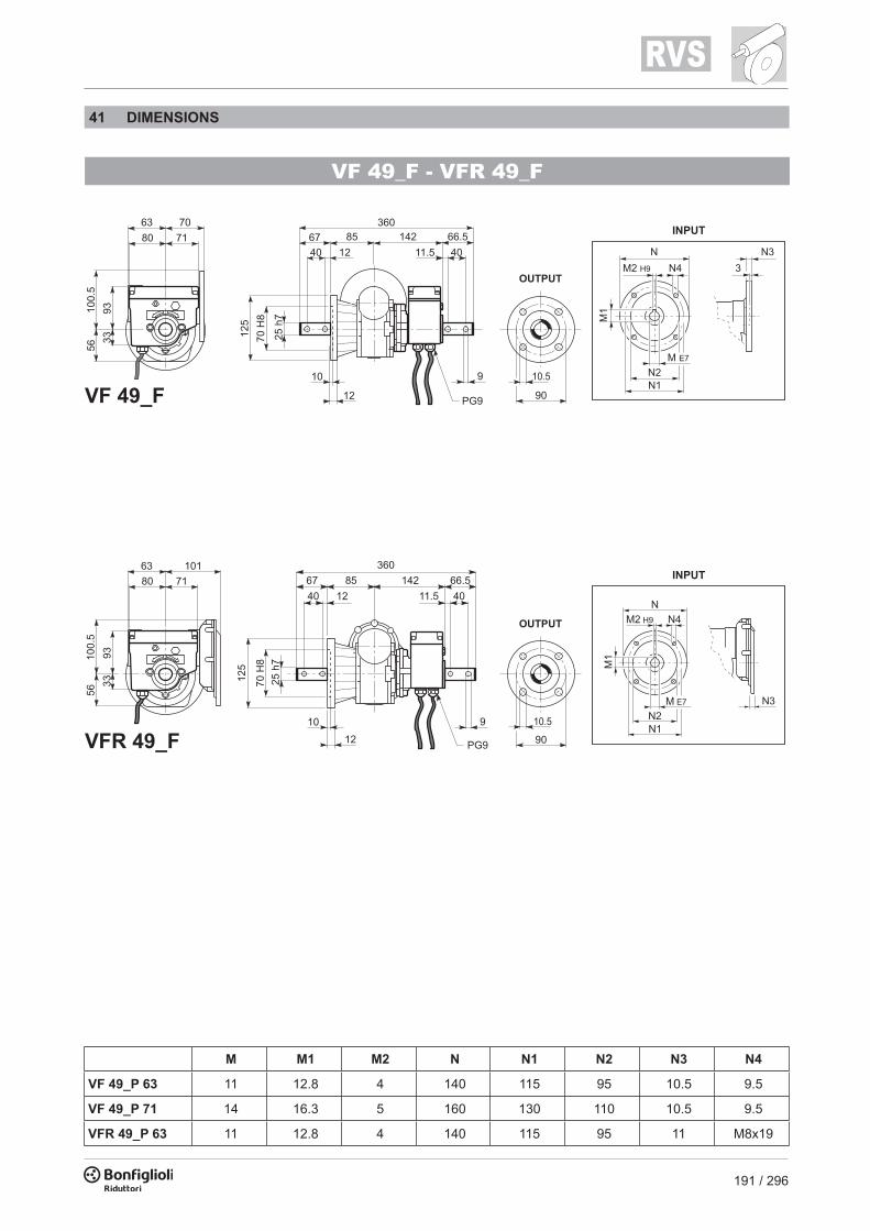
191 / 296
VF 49_F - VFR 49_F
M M1 M2 N N1 N2 N3 N4
VF 49_P 63 11 12.8 4 140 115 95 10.5 9.5
VF 49_P 71 14 16.3 5 160 130 110 10.5 9.5
VFR 49_P 63 11 12.8 4 140 115 95 11 M8x19
41 DIMENSIONS1.1 kW
n2min-1
M2Nm
i IEC
IE2 IE2
10.4 643 138 WR 86_138 P90 BE90S411.9 586 120 WR 86_120 P90 BE90S414.3 437 100 W 86_100 P90 BE90S4 W 86_100 S3 ME2SA417.9 379 80 W 86_80 P90 BE90S4 W 86_80 S3 ME3SA422.3 322 64 W 86_64 P90 BE90S4 W 86_60 S3 ME3SA4
1.5 kW
n2min-1
M2Nm
i IEC
IE2 IE2
11.9 792 120 WR 86_120 P90 BE90LA417.9 512 80 W 86_80 P90 BE90LA4 W 86_80 S3 ME3SB422.3 435 64 W 86_64 P90 BE90LA4 W 86_60 S3 ME3SB4

192 / 296
W 75 UFC_M/ME - W 75 UFC - WR 75 UFC
M M1 M2 N N1 N2 N3 N4 P P1
W 75_P 71 14 16.3 5 160 130 110 11 9 112 -
W 75_P 80 19 21.8 6 200 165 130 12 11.5 112 -
W 75_P 90 24 27.3 8 200 165 130 12 11.5 112 -
WR 75_P 63 11 12.8 4 140 115 95 10 M8x10 152 23.53
WR 75_P 71 14 16.3 5 160 130 110 10 M8x10 152 23.53
WR 75_P 80 19 21.8 6 200 165 130 12 M10x13 163.5 11
WR 75_P 90 24 27.3 8 200 165 130 12 M10x13 163.5 11
C D DA DB E F L
W 75_S1 M1L 138 14 16 M5 30 5 308
W 75_S2 ME2S 156 19 21.5 M6 40 6 333
W 75_S3 ME3S 193 28 31 M10 60 8 376
W 75_S3 ME3L 193 28 31 M10 60 8 408
W 63 UFC_M/ME - W 63 UFC - WR 63 UFC
M M1 M2 N N1 N2 N3 N4 P P1
W 63_P 71 14 16.3 5 160 130 110 11 9 95 -
W 63_P 80 19 21.8 6 200 165 130 12 11.5 102 -
W 63_P 90 24 27.3 8 200 165 130 12 11.5 102 -
WR 63_P 63 11 12.8 4 140 115 95 10 M8x10 133.5 11.42
WR 63_P 71 14 16.3 5 160 130 110 10 M8x10 133.5 11.42
C D DA DB E F L
W 63_S1 M1L 138 14 16 M5 30 5 289
W 63_S2 ME2S 156 19 21.5 M6 40 6 317

193 / 296
W 75 UFC_M/ME - W 75 UFC - WR 75 UFC
M M1 M2 N N1 N2 N3 N4 P P1
W 75_P 71 14 16.3 5 160 130 110 11 9 112 -
W 75_P 80 19 21.8 6 200 165 130 12 11.5 112 -
W 75_P 90 24 27.3 8 200 165 130 12 11.5 112 -
WR 75_P 63 11 12.8 4 140 115 95 10 M8x10 152 23.53
WR 75_P 71 14 16.3 5 160 130 110 10 M8x10 152 23.53
WR 75_P 80 19 21.8 6 200 165 130 12 M10x13 163.5 11
WR 75_P 90 24 27.3 8 200 165 130 12 M10x13 163.5 11
C D DA DB E F L
W 75_S1 M1L 138 14 16 M5 30 5 308
W 75_S2 ME2S 156 19 21.5 M6 40 6 333
W 75_S3 ME3S 193 28 31 M10 60 8 376
W 75_S3 ME3L 193 28 31 M10 60 8 408
W 63 UFC_M/ME - W 63 UFC - WR 63 UFC
M M1 M2 N N1 N2 N3 N4 P P1
W 63_P 71 14 16.3 5 160 130 110 11 9 95 -
W 63_P 80 19 21.8 6 200 165 130 12 11.5 102 -
W 63_P 90 24 27.3 8 200 165 130 12 11.5 102 -
WR 63_P 63 11 12.8 4 140 115 95 10 M8x10 133.5 11.42
WR 63_P 71 14 16.3 5 160 130 110 10 M8x10 133.5 11.42
C D DA DB E F L
W 63_S1 M1L 138 14 16 M5 30 5 289
W 63_S2 ME2S 156 19 21.5 M6 40 6 317

194 / 296
Version with terminal box
Four microswitch version
W 86 UFC_M/ME - W 86 UFC - WR 86 UFC
M M1 M2 N N1 N2 N3 N4 P P1
W 86_P 71 14 16.3 5 160 130 110 11 9 128 -
W 86_P 80 19 21.8 6 200 165 130 12 11.5 128 -
W 86_P 90 24 27.3 8 200 165 130 12 11.5 128 -
WR 86_P 63 11 12.8 4 140 115 95 10 M8x10 168 35.4
WR 86_P 71 14 16.3 5 160 130 110 10 M8x10 168 35.4
WR 86_P 80 19 21.8 6 200 165 130 12 M10x13 179.5 22.9
WR 86_P 90 24 27.3 8 200 165 130 12 M10x13 179.5 22.9
C D DA DB E F L
W 86_S1 M1L 138 14 16 M5 30 5 324
W 86_S2 ME2S 156 19 21.5 M6 40 6 349
W 86_S3 ME3S 193 28 31 M10 60 8 392
W 86_S3 ME3L 193 28 31 M10 60 8 424

195 / 296
Version with terminal box
Four microswitch version
42 OPTIONS Limit switch modifications
W 86 UFC_M/ME - W 86 UFC - WR 86 UFC
M M1 M2 N N1 N2 N3 N4 P P1
W 86_P 71 14 16.3 5 160 130 110 11 9 128 -
W 86_P 80 19 21.8 6 200 165 130 12 11.5 128 -
W 86_P 90 24 27.3 8 200 165 130 12 11.5 128 -
WR 86_P 63 11 12.8 4 140 115 95 10 M8x10 168 35.4
WR 86_P 71 14 16.3 5 160 130 110 10 M8x10 168 35.4
WR 86_P 80 19 21.8 6 200 165 130 12 M10x13 179.5 22.9
WR 86_P 90 24 27.3 8 200 165 130 12 M10x13 179.5 22.9
C D DA DB E F L
W 86_S1 M1L 138 14 16 M5 30 5 324
W 86_S2 ME2S 156 19 21.5 M6 40 6 349
W 86_S3 ME3S 193 28 31 M10 60 8 392
W 86_S3 ME3L 193 28 31 M10 60 8 424

196 / 296
Symbols Units of Measure Description
cosφ – Power factor
η – Effi ciency
fm – Power adjusting factor
I – Cyclic duration factor
IN [A] Rated current
IS [A] Locked rotor current
JC [Kgm2] Load moment of inertia
JM [Kgm2] Moment of inertia
Kc – Torque factor
Kd – Load factor
KJ – Inertia factor
MA [Nm] Mean breakaway torque
MB [Nm] Brake torque
MN [Nm] Rated torque
ML [Nm] Counter-torque during acceleration
MS [Nm] Starting torque
Symbols Units of Measure Description
n [min-1] Rated speed
PB [W] Power drawn by the brake at 20°C
Pn [kW] Motor rated power
Pr [kW] Required power
t1 [ms] Brake response time with one-way rectifi er
t1s [ms] Brake response time with electronic-controlled rectifi er
t2 [ms] Brake reaction time with a.c. disconnect
t2c [ms] Brake reaction time with a.c. and d.c. disconnect
ta [°C] Ambient temperature
tf [min] Work time at constant load
tr [min] Rest time
W [J] Braking work between service interval
Wmax [J] Maximum brake work for each braking
Z [1/h] Permissible starting frequency, loaded
Z0 [1/h] Max. permissible unloaded starting frequency (I = 50%)
ELECTRIC MOTORS
M1 SYMBOLS AND UNITS OF MEASUREMENT
PremiumEfficiency
HighEfficiency
LowEfficiency
IEC Motors NEMA Motors
HighEfficiency
StandardEfficiency
IE2IE2
IE1IE1
IE3IE3 NEMAPremium
NEMAHigh
Efficiency
M2 INTRODUCTION
Effi ciency classes and test methods Effi ciency classes characterise the effi ciency with which an electric motor converts electrical energy into mechanical energy. In Europe, the energy effi ciency of low voltage electric motors used to be classifi ed using the voluntary Eff1/Eff2/Eff3 system. Outside Europe, other countries used to apply their own national systems, often very different to the European system. This uncertainty in standards led manufacturers to develop a harmonised international standard, and push for the issue of IEC (International Electrotechnical Commission) standard IEC 60034-30-1, “Effi ciency classes of single-speed, three-phase, cage-induction motors (IE code)”.
This new standard:- defi nes new classes of effi ciency - IE1 (standard effi ciency)- IE2 (high effi ciency)- IE3 (premium effi ciency)- provides a common, international reference system for the classifi cation of electric motors- and for national legislation - introduces a new effi ciency measurement method in conformity with standard IEC 60034-1-2:2007
The following table shows the correspondence among the main classes.

197 / 296
Symbols Units of Measure Description
cosφ – Power factor
η – Effi ciency
fm – Power adjusting factor
I – Cyclic duration factor
IN [A] Rated current
IS [A] Locked rotor current
JC [Kgm2] Load moment of inertia
JM [Kgm2] Moment of inertia
Kc – Torque factor
Kd – Load factor
KJ – Inertia factor
MA [Nm] Mean breakaway torque
MB [Nm] Brake torque
MN [Nm] Rated torque
ML [Nm] Counter-torque during acceleration
MS [Nm] Starting torque
Symbols Units of Measure Description
n [min-1] Rated speed
PB [W] Power drawn by the brake at 20°C
Pn [kW] Motor rated power
Pr [kW] Required power
t1 [ms] Brake response time with one-way rectifi er
t1s [ms] Brake response time with electronic-controlled rectifi er
t2 [ms] Brake reaction time with a.c. disconnect
t2c [ms] Brake reaction time with a.c. and d.c. disconnect
ta [°C] Ambient temperature
tf [min] Work time at constant load
tr [min] Rest time
W [J] Braking work between service interval
Wmax [J] Maximum brake work for each braking
Z [1/h] Permissible starting frequency, loaded
Z0 [1/h] Max. permissible unloaded starting frequency (I = 50%)
ELECTRIC MOTORS
M1 SYMBOLS AND UNITS OF MEASUREMENT
PremiumEfficiency
HighEfficiency
LowEfficiency
IEC Motors NEMA Motors
HighEfficiency
StandardEfficiency
IE2IE2
IE1IE1
IE3IE3 NEMAPremium
NEMAHigh
Efficiency
M2 INTRODUCTION
Effi ciency classes and test methods Effi ciency classes characterise the effi ciency with which an electric motor converts electrical energy into mechanical energy. In Europe, the energy effi ciency of low voltage electric motors used to be classifi ed using the voluntary Eff1/Eff2/Eff3 system. Outside Europe, other countries used to apply their own national systems, often very different to the European system. This uncertainty in standards led manufacturers to develop a harmonised international standard, and push for the issue of IEC (International Electrotechnical Commission) standard IEC 60034-30-1, “Effi ciency classes of single-speed, three-phase, cage-induction motors (IE code)”.
This new standard:- defi nes new classes of effi ciency - IE1 (standard effi ciency)- IE2 (high effi ciency)- IE3 (premium effi ciency)- provides a common, international reference system for the classifi cation of electric motors- and for national legislation - introduces a new effi ciency measurement method in conformity with standard IEC 60034-1-2:2007
The following table shows the correspondence among the main classes.

198 / 296
European Commission regulation 640/2009 IEC standard 60034-30-1 establishes technical guidelines for effi ciency classifi cation but does not impose any legal requirements for the adoption of any particular effi ciency class. These are laid down by European Directives and national laws.The EC Regulation applying Directive 2005/32/EC was adopted on the 22nd July 2009. This establishes the legal requirements and eco-compatible design criteria for electric motors, and imposes minimum effi ciency limits according to the following schedule:▪ 16/06/2011: Electric motors must have a minimum effi ciency level equivalent to class IE2▪ 01/01/2015: Electric motors with a rated power output between 7.5 kW and 375 kW must have▪ a minimum effi ciency level corresponding to IE3, or to IE2 if controlled by an inverter.▪ 01/01/2017: Electric motors with a rated power output between 0.75 kW and 375 kW must have▪ a minimum effi ciency level corresponding to IE3, or to IE2 if controlled by an inverter.
Scope and exclusionsEC Regulation 640/2009 applies to 2, 4, and 6 pole, single-speed, three-phase, 50 Hz or 60 Hz, cage-induction motors with rated outputs of 0.75 kW to 375 kW, and rated voltage up to 1000 V, designed for continuous duty (S1).
The regulation does not apply to:- brakemotors- motors designed to function immersed in liquid- motors that are fully integrated in a product (like a gearbox, pump, fan), so that it is not possible- to test the performance of the motor independently of that of the product.- motors expressly designed to function:▪ at altitudes above 4000 metres a.s.l.;▪ in ambient temperatures above 60 °C;▪ at maximum operating temperatures above 400 °C;▪ in ambient temperatures below -30 °C (all motors) or below 0 °C (water-cooled motors);▪ with incoming liquid coolants at temperatures below 0 °C or above 32 °C;▪ in potentially explosive atmospheres as defi ned by Directive 2014/34/EU.
(F01)
DIN VDE 0530 GermanyBS5000 / BS4999 Great BritainAS 1359 AustraliaNBNC 51 - 101 BelgiumNEK - IEC 34 NorwayNF C 51 FranceOEVE M 10 AustriaSEV 3009 SwitzerlandNEN 3173 NetherlandsSS 426 01 01 Sweden
Title CEI IEC
General requirements for rotating electrical machines CEI EN 60034-1 IEC 60034-1
Terminal markings and direction of rotation of rotating machines CEI 2-8 IEC 60034-8
Methods of cooling for electrical machines CEI EN 60034-6 IEC 60034-6
Dimensions and output ratings for rotating electrical machines EN 50347 IEC 60072
Classifi cation of degree of protection provided by enclosures for rotating machines CEI EN 60034-5 IEC 60034-5
Noise limits CEI EN 60034-9 IEC 60034-9
Classifi cation of type of construction and mounting arrangements CEI EN 60034-7 IEC 60034-7
Rated voltage for low voltage mains power CEI 8-6 IEC 60038
Vibration level of electric machines CEI EN 60034-14 IEC 60034-14
Effi ciency classes of single-speed, three-phase, cage-induction motors (IE code) CEI EN 60034-30-1 IEC 60034-30-1
Standard method for determining losses and effi ciency from tests CEI EN 60034-2-1 IEC 60034-2-1
The motors also comply with foreign standards adapted to IEC 60034-1 as shown here below.
(F02)
M3 GENERAL CHARACTERISTICS
M3.1 Production range
The asynchronous three-phase electric motors BX, BE, BN, MX, ME and M of BONFIGLIOLI RIDUTTORI’s production, are available in basic designs IMB5 and IMB14 and derived versions.Motors are the enclosed type with outer fan and cage-tipe rotor for use in industrial environments.Standard versions of BX-BE/MX-ME motors are 230/400V Δ/Y (400/690V Δ/Y in sizes BX-BE 160 and BX- BE 180), 50 Hz motors, with a tolerance of ±10%. Standard BN/M motors are designed to operate from a rated voltage 230/400V Δ/Y (400/690V Δ/Y for frame sizes BN 160 through BN 200) 50 Hz, with ±10% tolerance.
M3.2 Standards
The motors described in this catalogue are manufactured to the applicable standards shown in the following table.

199 / 296
European Commission regulation 640/2009 IEC standard 60034-30-1 establishes technical guidelines for effi ciency classifi cation but does not impose any legal requirements for the adoption of any particular effi ciency class. These are laid down by European Directives and national laws.The EC Regulation applying Directive 2005/32/EC was adopted on the 22nd July 2009. This establishes the legal requirements and eco-compatible design criteria for electric motors, and imposes minimum effi ciency limits according to the following schedule:▪ 16/06/2011: Electric motors must have a minimum effi ciency level equivalent to class IE2▪ 01/01/2015: Electric motors with a rated power output between 7.5 kW and 375 kW must have▪ a minimum effi ciency level corresponding to IE3, or to IE2 if controlled by an inverter.▪ 01/01/2017: Electric motors with a rated power output between 0.75 kW and 375 kW must have▪ a minimum effi ciency level corresponding to IE3, or to IE2 if controlled by an inverter.
Scope and exclusionsEC Regulation 640/2009 applies to 2, 4, and 6 pole, single-speed, three-phase, 50 Hz or 60 Hz, cage-induction motors with rated outputs of 0.75 kW to 375 kW, and rated voltage up to 1000 V, designed for continuous duty (S1).
The regulation does not apply to:- brakemotors- motors designed to function immersed in liquid- motors that are fully integrated in a product (like a gearbox, pump, fan), so that it is not possible- to test the performance of the motor independently of that of the product.- motors expressly designed to function:▪ at altitudes above 4000 metres a.s.l.;▪ in ambient temperatures above 60 °C;▪ at maximum operating temperatures above 400 °C;▪ in ambient temperatures below -30 °C (all motors) or below 0 °C (water-cooled motors);▪ with incoming liquid coolants at temperatures below 0 °C or above 32 °C;▪ in potentially explosive atmospheres as defi ned by Directive 2014/34/EU.
(F01)
DIN VDE 0530 GermanyBS5000 / BS4999 Great BritainAS 1359 AustraliaNBNC 51 - 101 BelgiumNEK - IEC 34 NorwayNF C 51 FranceOEVE M 10 AustriaSEV 3009 SwitzerlandNEN 3173 NetherlandsSS 426 01 01 Sweden
Title CEI IEC
General requirements for rotating electrical machines CEI EN 60034-1 IEC 60034-1
Terminal markings and direction of rotation of rotating machines CEI 2-8 IEC 60034-8
Methods of cooling for electrical machines CEI EN 60034-6 IEC 60034-6
Dimensions and output ratings for rotating electrical machines EN 50347 IEC 60072
Classifi cation of degree of protection provided by enclosures for rotating machines CEI EN 60034-5 IEC 60034-5
Noise limits CEI EN 60034-9 IEC 60034-9
Classifi cation of type of construction and mounting arrangements CEI EN 60034-7 IEC 60034-7
Rated voltage for low voltage mains power CEI 8-6 IEC 60038
Vibration level of electric machines CEI EN 60034-14 IEC 60034-14
Effi ciency classes of single-speed, three-phase, cage-induction motors (IE code) CEI EN 60034-30-1 IEC 60034-30-1
Standard method for determining losses and effi ciency from tests CEI EN 60034-2-1 IEC 60034-2-1
The motors also comply with foreign standards adapted to IEC 60034-1 as shown here below.
(F02)
M3 GENERAL CHARACTERISTICS
M3.1 Production range
The asynchronous three-phase electric motors BX, BE, BN, MX, ME and M of BONFIGLIOLI RIDUTTORI’s production, are available in basic designs IMB5 and IMB14 and derived versions.Motors are the enclosed type with outer fan and cage-tipe rotor for use in industrial environments.Standard versions of BX-BE/MX-ME motors are 230/400V Δ/Y (400/690V Δ/Y in sizes BX-BE 160 and BX- BE 180), 50 Hz motors, with a tolerance of ±10%. Standard BN/M motors are designed to operate from a rated voltage 230/400V Δ/Y (400/690V Δ/Y for frame sizes BN 160 through BN 200) 50 Hz, with ±10% tolerance.
M3.2 Standards
The motors described in this catalogue are manufactured to the applicable standards shown in the following table.

200 / 296
M3.3 Directives 2006/95/EC (LVD) and 2004/108/EC (EMC)
BX, BE, BN, MX, ME and M motors meet the requirements of Directives 2006/95/EC (Low Voltage Directive) and 2004/108/EC (Electromagnetic Compatibility Directive) and their name plates bear the CE mark.As for the EMC Directive, construction is in accordance with standards CEI EN 60034-1, EN 61000-6-2, EN 61000-6-4.Motors with FD brakes, when fi tted with the suitable capacitive fi lter at rectifi er input (option CF), meet the emission limits required by Standard EN 61000-6-3:2007 “Electromagnetic compatibility - Generic Emission Standard - Part 6-3 Residential, commercial and light industrial environment”.Motors also meet the requirements of standard CEI EN 60204-1 “Electrical equipment of machines”.The responsibility for fi nal product safety and compliance with applicable directives rests with the manufacturer or the assembler who incorporate the motors as component parts.
M3.4 EU Directive 2012/19/EU - Information on disposal
(F03)
-0.15 (1 - η) P ≤ 50kW Effi ciency
-(1 - cosφ)/6 min 0.02 max 0.07 Power factor
±20% * Slip
+20% Locked rotor current
-15% +25% Locked rotor torque
-10% Max. torque
(*) ± 30% for motors with Pn < 1 kW
DIN VDE 0530 GermanyBS5000 / BS4999 Great BritainAS 1359 AustraliaNBNC 51 - 101 BelgiumNEK - IEC 34 NorwayNF C 51 FranceOEVE M 10 AustriaSEV 3009 SwitzerlandNEN 3173 NetherlandsSS 426 01 01 Sweden
This product should not be mixed with general household waste. Disposal has to be carried out in conformity with EU Directive 2012/19/EU where established, and in accordance to national regulations.Fulfi ll disposal in accordance with any other legislation in force throughout the country.
M3.5 Tolerances
As per the Norms CEI EN 60034-1, applicable the tolerances here below apply to the following quantities.
W
TERMINAL BOX POSITION(compact motor only)W (default), N, E, S
MOTOR BRAKE
BX
MOTOR TYPEBX = IEC 3-phase, class IE3
132SB 4 230/400-50 IP55 CLF FD 7.5 R SB 220SA .....
MOTOR SIZE80B ... 180L (IEC motor)2SB ... 5LA (compact motor)
POLE NUMBER4
DEGREE OF PROTECTIONIP55 standard (IP56 - option)IP54, IP55 brake motor
INSULATION CLASSCL F standardCL H option
OPTIONS
BRAKE HAND RELEASER, RM
RECTIFIER TYPEAC/DCNB, SB, NBR, SBR
BRAKE TYPEFD (d.c. brake)FA (a.c. brake)
BRAKE TORQUE
BRAKE SUPPLY
B5
MOTOR MOUNTING− compact motorIM B5 - IM V1, IM V3IM B14 - IM V18, IM V19
VOLTAGE - FREQUENCY50Hz 60Hz
230/400 V∆/Y - 50Hz(BX 80 ... 132 - MX2 ... MX4)
230/460 VY/Y - 60Hz(BX 90 ... 132 - MX3, MX4)
290/500 V∆/Y - 50Hz(BX 80 ... 132 - MX2 ... MX4)
230/460 V∆∆/∆ - 60Hz(BX 160 ... 180 - MX5)
400/690 V∆/Y - 50Hz(BX 160 ... 180 - MX5)
330/575 V∆/Y - 60Hz(BX 90 ... 180 - MX3 ... MX5)
290/500 V∆/Y - 50Hz(BX 160 ... 180 - MX5)
265/460 V∆/Y - 60Hz(BX 90 ... 132 - MX3, MX4)
460/800 V∆/Y - 60Hz(BX 160 ... 180 - MX5)
MX = compact 3-phase, class IE3
M4 MOTOR DESIGNATION

201 / 296
M3.3 Directives 2006/95/EC (LVD) and 2004/108/EC (EMC)
BX, BE, BN, MX, ME and M motors meet the requirements of Directives 2006/95/EC (Low Voltage Directive) and 2004/108/EC (Electromagnetic Compatibility Directive) and their name plates bear the CE mark.As for the EMC Directive, construction is in accordance with standards CEI EN 60034-1, EN 61000-6-2, EN 61000-6-4.Motors with FD brakes, when fi tted with the suitable capacitive fi lter at rectifi er input (option CF), meet the emission limits required by Standard EN 61000-6-3:2007 “Electromagnetic compatibility - Generic Emission Standard - Part 6-3 Residential, commercial and light industrial environment”.Motors also meet the requirements of standard CEI EN 60204-1 “Electrical equipment of machines”.The responsibility for fi nal product safety and compliance with applicable directives rests with the manufacturer or the assembler who incorporate the motors as component parts.
M3.4 EU Directive 2012/19/EU - Information on disposal
(F03)
-0.15 (1 - η) P ≤ 50kW Effi ciency
-(1 - cosφ)/6 min 0.02 max 0.07 Power factor
±20% * Slip
+20% Locked rotor current
-15% +25% Locked rotor torque
-10% Max. torque
(*) ± 30% for motors with Pn < 1 kW
DIN VDE 0530 GermanyBS5000 / BS4999 Great BritainAS 1359 AustraliaNBNC 51 - 101 BelgiumNEK - IEC 34 NorwayNF C 51 FranceOEVE M 10 AustriaSEV 3009 SwitzerlandNEN 3173 NetherlandsSS 426 01 01 Sweden
This product should not be mixed with general household waste. Disposal has to be carried out in conformity with EU Directive 2012/19/EU where established, and in accordance to national regulations.Fulfi ll disposal in accordance with any other legislation in force throughout the country.
M3.5 Tolerances
As per the Norms CEI EN 60034-1, applicable the tolerances here below apply to the following quantities.
W
TERMINAL BOX POSITION(compact motor only)W (default), N, E, S
MOTOR BRAKE
BX
MOTOR TYPEBX = IEC 3-phase, class IE3
132SB 4 230/400-50 IP55 CLF FD 7.5 R SB 220SA .....
MOTOR SIZE80B ... 180L (IEC motor)2SB ... 5LA (compact motor)
POLE NUMBER4
DEGREE OF PROTECTIONIP55 standard (IP56 - option)IP54, IP55 brake motor
INSULATION CLASSCL F standardCL H option
OPTIONS
BRAKE HAND RELEASER, RM
RECTIFIER TYPEAC/DCNB, SB, NBR, SBR
BRAKE TYPEFD (d.c. brake)FA (a.c. brake)
BRAKE TORQUE
BRAKE SUPPLY
B5
MOTOR MOUNTING− compact motorIM B5 - IM V1, IM V3IM B14 - IM V18, IM V19
VOLTAGE - FREQUENCY50Hz 60Hz
230/400 V∆/Y - 50Hz(BX 80 ... 132 - MX2 ... MX4)
230/460 VY/Y - 60Hz(BX 90 ... 132 - MX3, MX4)
290/500 V∆/Y - 50Hz(BX 80 ... 132 - MX2 ... MX4)
230/460 V∆∆/∆ - 60Hz(BX 160 ... 180 - MX5)
400/690 V∆/Y - 50Hz(BX 160 ... 180 - MX5)
330/575 V∆/Y - 60Hz(BX 90 ... 180 - MX3 ... MX5)
290/500 V∆/Y - 50Hz(BX 160 ... 180 - MX5)
265/460 V∆/Y - 60Hz(BX 90 ... 132 - MX3, MX4)
460/800 V∆/Y - 60Hz(BX 160 ... 180 - MX5)
MX = compact 3-phase, class IE3
M4 MOTOR DESIGNATION

202 / 296
MOTOR
ME = compact 3-phase, class IE2
BE
MOTOR TYPEBE = IEC 3-phase, class IE2
90LA
MOTOR SIZE80B ... 180L (IEC motor)2SA ... 5LA (compact motor)
4
POLE NUMBER2, 4, 6
230/400-50
VOLTAGE - FREQUENCY
IP55
DEGREE OF PROTECTIONIP55 standard (IP56 - option)
CLF B5
INSULATION CLASSCL F standardCL H option
.....
OPTIONS
MOTOR MOUNTING− compact motorIM B5 - IM V1, IM V3IM B14 - IM V18, IM V19
W
TERMINAL BOX POSITION(compact motor only)W (default), N, E, S
Description Default Option Page
Voltage
Protection class
Insulation class
Design version
230/400/50
BX - BE - BN - MX - ME - M IP 55 IP 56BX_FD - BX_FA - BN_FD - BN_FAMX_FD - MX_FA - M_FD - M_FA IP 54 IP 55
CLF CLH
BX - BE - BN B5B5 R
B14B14 R
Default values.
MOTOR BRAKE
BN
MOTOR TYPEBN = IEC 3-phase
90LA 4 230/400-50 IP55 CLF B5 W FD 7.5 R SB 220SA .....
MOTOR SIZE56A ... 200LA (IEC motor)0B ... 5SB (compact motor)
POLE NUMBER2, 4, 6, 2/4, 2/6, 2/8, 2/12, 4/6, 4/8
VOLTAGE - FREQUENCY
DEGREE OF PROTECTIONIP55 standard (IP56 - option)IP54, IP55 brake motor
INSULATION CLASSCL F standardCL H option
TERMINAL BOX POSITION(compact motor only)W (default), N, E, S
OPTIONS
BRAKE HAND RELEASER, RM
RECTIFIER TYPEAC/DCNB, SB, NBR, SBR
BRAKE TYPEFD (d.c. brake)FA (a.c. brake)
BRAKE TORQUE
BRAKE SUPPLY
MOTOR MOUNTING− compact motorIM B5 - IM V1, IM V3IM B14 - IM V18, IM V19
M = IEC compact 3-phase

203 / 296
MOTOR
ME = compact 3-phase, class IE2
BE
MOTOR TYPEBE = IEC 3-phase, class IE2
90LA
MOTOR SIZE80B ... 180L (IEC motor)2SA ... 5LA (compact motor)
4
POLE NUMBER2, 4, 6
230/400-50
VOLTAGE - FREQUENCY
IP55
DEGREE OF PROTECTIONIP55 standard (IP56 - option)
CLF B5
INSULATION CLASSCL F standardCL H option
.....
OPTIONS
MOTOR MOUNTING− compact motorIM B5 - IM V1, IM V3IM B14 - IM V18, IM V19
W
TERMINAL BOX POSITION(compact motor only)W (default), N, E, S
Description Default Option Page
Voltage
Protection class
Insulation class
Design version
230/400/50
BX - BE - BN - MX - ME - M IP 55 IP 56BX_FD - BX_FA - BN_FD - BN_FAMX_FD - MX_FA - M_FD - M_FA IP 54 IP 55
CLF CLH
BX - BE - BN B5B5 R
B14B14 R
Default values.
MOTOR BRAKE
BN
MOTOR TYPEBN = IEC 3-phase
90LA 4 230/400-50 IP55 CLF B5 W FD 7.5 R SB 220SA .....
MOTOR SIZE56A ... 200LA (IEC motor)0B ... 5SB (compact motor)
POLE NUMBER2, 4, 6, 2/4, 2/6, 2/8, 2/12, 4/6, 4/8
VOLTAGE - FREQUENCY
DEGREE OF PROTECTIONIP55 standard (IP56 - option)IP54, IP55 brake motor
INSULATION CLASSCL F standardCL H option
TERMINAL BOX POSITION(compact motor only)W (default), N, E, S
OPTIONS
BRAKE HAND RELEASER, RM
RECTIFIER TYPEAC/DCNB, SB, NBR, SBR
BRAKE TYPEFD (d.c. brake)FA (a.c. brake)
BRAKE TORQUE
BRAKE SUPPLY
MOTOR MOUNTING− compact motorIM B5 - IM V1, IM V3IM B14 - IM V18, IM V19
M = IEC compact 3-phase

204 / 296
M5 VARIANTS AND OPTIONS
M5.1 Variants
Description Default Option Page
Voltage
Protection class
Insulation class
Design version
230/400/50
BX - BE - BN - MX - ME - M IP 55 IP 56BX_FD - BX_FA - BN_FD - BN_FAMX_FD - MX_FA - M_FD - M_FA IP 54 IP 55
CLF CLH
BX - BE - BN B5B5 R
B14B14 R
Default values.
D3 K1 E3 BX - BE - BNMX - ME - M
PN BNM
EN1 EN2 EN3 EN4 EN5 EN6 BX - BE - BNMX - ME - M
H1 NH1 BX - BE - BNMX - ME - M
TP BX - BE - BNMX - ME - M
PS BX - BE - BNMX - ME - M
RV BX - BE - BNMX - ME - M
RC TC BX - BE - BNMX - ME - M
U1 U2* BX - BE - BNMX - ME - M
CUS BX - BE - BNMX - ME - M
BIS BE
CCC BE - BNME - M
CON BX - BE - BNMX - ME - M
C_ BX - BE - BNMX - ME - M
RAL BX - BE - BNMX - ME - M
ACM BX - BE - BNMX - ME - M
CC BX - BE - BNMX - ME - M
AL AR MX - ME - M
S2 S3 S9 BNM
Description Catalogue numbers Availability Page
Thermal protective devices
50 Hz normalized power
Feedback devices
Anti-condensate heaters
Tropicalized windings
Double-extended shaft
Rotor balancing grade B
External mechanical protections
Forced ventilation
Certifi cation CSA/UL
Bureau of IndiandStandard Certifi cation
China Compulsory Certifi cation
Plug connector
Surface protection
Painting
Certifi cates
Inspection certifi cate
Backstop device
Type of duty
* Only for motors BN and M
M5.2 Options
(F04)
(F05)
211
215 216
206
207
230 231
238 239
237 238
235
239
236
213
235
234
213
241
215
242
231
242
235
216
241
215
R RM BX - BNMX - M
AB AA AC AD BX - BNMX - M
NB NBR SB SBR BX - BNMX - M
F1 BNM
CF BX - BNMX - M
...SA ...SD BX - BNMX - M
MSW BX - BNMX - M
IC BX - BNMX - M
Description Catalogue numbers Availability Page
Brake torque Refer to the specifi c brake type
Manual release lever
Release lever orientation
DC brake rectifi er
Soft-start fl ywheel
Capacitive fi lter
Brake separate power supply (*)
Brake functionality check
Additional cable entry for brake motors
(*) Specify voltage.
Default values.
1
2
3
4
5
6
BONFIGLIOLI Motor type Serial number Rated voltage
Motor code Type of duty: S1 Continuous duty IE Class, Effi ciency at: 4/4 - 3/4 - 2/4 load
M5.3 Brake-related options
M5.4 Example of identifi cation nameplate
(F06)
223 226
222 226
230
229
228
234
230
234
222

205 / 296
M5 VARIANTS AND OPTIONS
M5.1 Variants
Description Default Option Page
Voltage
Protection class
Insulation class
Design version
230/400/50
BX - BE - BN - MX - ME - M IP 55 IP 56BX_FD - BX_FA - BN_FD - BN_FAMX_FD - MX_FA - M_FD - M_FA IP 54 IP 55
CLF CLH
BX - BE - BN B5B5 R
B14B14 R
Default values.
D3 K1 E3 BX - BE - BNMX - ME - M
PN BNM
EN1 EN2 EN3 EN4 EN5 EN6 BX - BE - BNMX - ME - M
H1 NH1 BX - BE - BNMX - ME - M
TP BX - BE - BNMX - ME - M
PS BX - BE - BNMX - ME - M
RV BX - BE - BNMX - ME - M
RC TC BX - BE - BNMX - ME - M
U1 U2* BX - BE - BNMX - ME - M
CUS BX - BE - BNMX - ME - M
BIS BE
CCC BE - BNME - M
CON BX - BE - BNMX - ME - M
C_ BX - BE - BNMX - ME - M
RAL BX - BE - BNMX - ME - M
ACM BX - BE - BNMX - ME - M
CC BX - BE - BNMX - ME - M
AL AR MX - ME - M
S2 S3 S9 BNM
Description Catalogue numbers Availability Page
Thermal protective devices
50 Hz normalized power
Feedback devices
Anti-condensate heaters
Tropicalized windings
Double-extended shaft
Rotor balancing grade B
External mechanical protections
Forced ventilation
Certifi cation CSA/UL
Bureau of IndiandStandard Certifi cation
China Compulsory Certifi cation
Plug connector
Surface protection
Painting
Certifi cates
Inspection certifi cate
Backstop device
Type of duty
* Only for motors BN and M
M5.2 Options
(F04)
(F05)
211
215 216
206
207
230 231
238 239
237 238
235
239
236
213
235
234
213
241
215
242
231
242
235
216
241
215
R RM BX - BNMX - M
AB AA AC AD BX - BNMX - M
NB NBR SB SBR BX - BNMX - M
F1 BNM
CF BX - BNMX - M
...SA ...SD BX - BNMX - M
MSW BX - BNMX - M
IC BX - BNMX - M
Description Catalogue numbers Availability Page
Brake torque Refer to the specifi c brake type
Manual release lever
Release lever orientation
DC brake rectifi er
Soft-start fl ywheel
Capacitive fi lter
Brake separate power supply (*)
Brake functionality check
Additional cable entry for brake motors
(*) Specify voltage.
Default values.
1
2
3
4
5
6
BONFIGLIOLI Motor type Serial number Rated voltage
Motor code Type of duty: S1 Continuous duty IE Class, Effi ciency at: 4/4 - 3/4 - 2/4 load
M5.3 Brake-related options
M5.4 Example of identifi cation nameplate
(F06)
223 226
222 226
230
229
228
234
230
234
222

206 / 296
M6 MECHANICAL FEATURES
M6.1 Versions
EC-normalised BX, BE and BN motors are available in the design versions as indicated in the table below here after as per Standards EN 60034-7 (BX/BE), CEI EN 60034-14 (BN).
Mounting versions are:
IM B5 (basic)IM V1, IM V3 (derived)IM B14 (basic)IM V18, IM V19 (derived)
IM B5 design motors can be installed in positions IM V1 and IM V3; IM B14 design motors can be installed in positions IM V18 and IM V19.In such cases, the basic design IM B5 or IM B14 is indicated on the motor name plate.In design versions with a vertically located motor and shaft downwards, it is recommended to request the drip cover (always necessary for brake motors). This facility, included in the option list should be specifi ed when ordering as it does not come as a standard device
(F07)
The following chart provides an overview of the degrees of protection available.In addition to the degree of protection specifi ed when ordering, motors to be installed outdoors require protection against direct sunlight and also – when they are to be installed vertically down – a drip cover to prevent the ingress of water and solid particles (option RC).
Flange output motors are also available with reduced coupling dimensions, as indicated in the table below - executions B5R, B14R. Their use in combination with gearboxes must be however coherent with the maximum installable power on gearboxes themselves (see chapter “Motor availability”). In case this condition is not met need to contact the Technical Service for the checking of the combination.
M6.2 Degree of protection
(1) fl ange with through holes(2) fl ange with threaded holes
BN/BE71
BX/BE/BN 80
BX/BE/BN 90
BX/BE/BN 100
BX/BE/BN 112
BX/BE/BN 132
DxE - Ø
B5R (1) 11x23 - 140 14x30 - 160 19x40 - 200 24x50 - 200 24x50 - 200 28x60 - 250
B14R (2) 11x23 - 90 14x30 - 105 19x40 - 120 24x50 - 140 — —
(F08)
IP..
IP 54 IP 55 IP 56
BX - BE - BN MX - ME - M standard
BX_FDBX_FABN_FDBN_FA
MX_FDMX_FA M_FDM_FA
standard
on request
on request
(F09)

207 / 296
M6 MECHANICAL FEATURES
M6.1 Versions
EC-normalised BX, BE and BN motors are available in the design versions as indicated in the table below here after as per Standards EN 60034-7 (BX/BE), CEI EN 60034-14 (BN).
Mounting versions are:
IM B5 (basic)IM V1, IM V3 (derived)IM B14 (basic)IM V18, IM V19 (derived)
IM B5 design motors can be installed in positions IM V1 and IM V3; IM B14 design motors can be installed in positions IM V18 and IM V19.In such cases, the basic design IM B5 or IM B14 is indicated on the motor name plate.In design versions with a vertically located motor and shaft downwards, it is recommended to request the drip cover (always necessary for brake motors). This facility, included in the option list should be specifi ed when ordering as it does not come as a standard device
(F07)
The following chart provides an overview of the degrees of protection available.In addition to the degree of protection specifi ed when ordering, motors to be installed outdoors require protection against direct sunlight and also – when they are to be installed vertically down – a drip cover to prevent the ingress of water and solid particles (option RC).
Flange output motors are also available with reduced coupling dimensions, as indicated in the table below - executions B5R, B14R. Their use in combination with gearboxes must be however coherent with the maximum installable power on gearboxes themselves (see chapter “Motor availability”). In case this condition is not met need to contact the Technical Service for the checking of the combination.
M6.2 Degree of protection
(1) fl ange with through holes(2) fl ange with threaded holes
BN/BE71
BX/BE/BN 80
BX/BE/BN 90
BX/BE/BN 100
BX/BE/BN 112
BX/BE/BN 132
DxE - Ø
B5R (1) 11x23 - 140 14x30 - 160 19x40 - 200 24x50 - 200 24x50 - 200 28x60 - 250
B14R (2) 11x23 - 90 14x30 - 105 19x40 - 120 24x50 - 140 — —
(F08)
IP..
IP 54 IP 55 IP 56
BX - BE - BN MX - ME - M standard
BX_FDBX_FABN_FDBN_FA
MX_FDMX_FA M_FDM_FA
standard
on request
on request
(F09)

208 / 296
IP 54 IP 55 IP 56
BX - BE - BN MX - ME - M standard
BX_FDBX_FABN_FDBN_FA
MX_FDMX_FA M_FDM_FA
standard
on request
on request
M6.3 Cooling
The motors are externally ventilated (IC 411 to CEI EN 60034-6) and are equipped with a plastic fan working in both directions.The motors must be installed allowing suffi cient space between fan cowl and the nearest wall to ensure free air intake and allow access for maintenance purposes on motor and brake, if supplied.Independent, forced air ventilation (IC 416) can be supplied on request (option U1).This solution enables to increase the motor duty factor when driven by an inverter and operating at reduced speed.
M6.4 Direction of rotation
Rotation is possible in both directions. If terminals U1, V1 and W1 are connected to line phases L1,L2 and L3, clockwise rotation (looking from drive end) is obtained. For counterclockwise rotation, switch two phases.
M6.5 Noise
Noise levels, measured using the method prescribed by ISO 1680 Standards, are within the maximum levels specifi ed by Standards CEI EN 60034-9.
0 0
1 1
2 2
3 3
4 4
5 5
6 6
7
8
IP 5 5
∅ 50 mm
∅ 12 mm
∅ 2,5 mm
∅ 1 mm
Not protected Not protected
Protected against extraneous solid bodies having Ø ≥ 50 mm
Protected against vertical water drips
Protected against extraneous solid bodies having Ø ≥ 12.5 mm
Protected against vertical water drips inclined up to 15°
Protected against extraneous solid bodies having Ø ≥ 2.5 mm Protected against rain
Protected against extraneous solid bodies having Ø ≥ 1.0 mm Protected against water splashes
Protected against dust Protected against jets of water
No dust ingress Protected against powerful jets of water
Protected against the effects of temporary immersion
Protected against the effects of continuous immersion
M6.6 Vibrations and balancing
Rotor shafts are balanced with half key fi tted and fall within the vibration class N, as per Standard CEI EN 60034-14.
M6.7 Terminal box
Terminal board features 6 studs for eyelet terminal connection (9 studs execution for US voltage “Dual Voltage”). A ground terminal is also supplied for earthing of the equipment. Terminals number and type are shown in the following table.For brake power supply, please read par. 8 (brake FD), 9 (brake FA).Brakemotors house the a.c./d.c. rectifi er (factory pre-wired) inside the terminal box.Wiring instructions are provided either in the box or in the user manual.
(F10)
BX 80, BX 90BE 80, BE 90 BN 56 ... BN 90
MX2, MX3ME2M05 ... M2
6 M4 2.5
BX 100 ... BX 132BE 100 ... BE 132BN 100 ... BN 160MR
MX3, MX4ME3, ME4M3 ... M4
6 M5 6
BX 160 - BE 160 ... BE 180MBN 160M ... BN 180M
ME5MX5 - M5 6 M6 16
BX 180 - BE 180LBN 180L ... BN 200L
__ 6 M8 25
BX 80 ... BX 132BE 80 ... BE 132BN 63 ... BN 160MR
MX2 ... MX4ME2 ... ME4M05 ... M4
9 M4 6
BX 160 ... BX 180BE 160 ... BE 180BN 160M ... BN 200L
MX5ME5M5
9 M6 16
No.of terminals
Terminal threads Wiremax cross section area sqmm2
(F11)
BN 63 M05 2 x M20 x 1.5 13BN 71 - BE 71 M1 2 x M25 x 1.5 17BX 80, BX 90 - BE 80, BE 90BN 80, BN 90
MX2, MX3 - ME2M2 2 x M25 x 1.5 17
BX 100, BX 112 - BE 100, BE 112BN 100
MX3, MX4 - ME3M3
2 x M32 x 1.5 21172 x M25 x 1.5
BN 112 _ 2 x M32 x 1.5 21172 x M25 x 1.5
BX 132 - BE 132BN 132...BN 160MR
MX4 - ME4M4 4 x M32 x 1.5 21
BX 160 - BE 160, BX 180 - BE 180BN 160M...BN 200L
MX5 - ME5M5 2 x M40 x 1.5 28
Cable gland and dimensionsMaximum cable
diameter allowed [mm]
1 Hole oneach side
2 Holes oneach side
Pivoting,4 x 90°
DE NDE
BX, BE, BN BX, BE, BN BN_FDBN_FA
BN 200LBX 200BX 200K
6312 2Z C36312/C3
6310 2Z C36210/C3* 6310 2RS C3
BX 225BX 225K 6313/C3* 6212/C3* -BX 250BX 250K 6315/C3* 6213/C3* -BX 280BX 280K 6316/C3* 6316/C3* -BX 315BX 315K 6319/C3** 6316/C3** -BX 355BX 355K 6322/C3** 6316/C3** -
*Note: Regreasable bearings with M6x1 Greasing Device**Note: Regreasable bearings with M10x1 Greasing Device
M6.8 Cable entry
The holes used to bring cables to terminal boxes use metric threads in accordance with standard EN 50262 as indicated in the table here after.

209 / 296
IP 54 IP 55 IP 56
BX - BE - BN MX - ME - M standard
BX_FDBX_FABN_FDBN_FA
MX_FDMX_FA M_FDM_FA
standard
on request
on request
M6.3 Cooling
The motors are externally ventilated (IC 411 to CEI EN 60034-6) and are equipped with a plastic fan working in both directions.The motors must be installed allowing suffi cient space between fan cowl and the nearest wall to ensure free air intake and allow access for maintenance purposes on motor and brake, if supplied.Independent, forced air ventilation (IC 416) can be supplied on request (option U1).This solution enables to increase the motor duty factor when driven by an inverter and operating at reduced speed.
M6.4 Direction of rotation
Rotation is possible in both directions. If terminals U1, V1 and W1 are connected to line phases L1,L2 and L3, clockwise rotation (looking from drive end) is obtained. For counterclockwise rotation, switch two phases.
M6.5 Noise
Noise levels, measured using the method prescribed by ISO 1680 Standards, are within the maximum levels specifi ed by Standards CEI EN 60034-9.
0 0
1 1
2 2
3 3
4 4
5 5
6 6
7
8
IP 5 5
∅ 50 mm
∅ 12 mm
∅ 2,5 mm
∅ 1 mm
Not protected Not protected
Protected against extraneous solid bodies having Ø ≥ 50 mm
Protected against vertical water drips
Protected against extraneous solid bodies having Ø ≥ 12.5 mm
Protected against vertical water drips inclined up to 15°
Protected against extraneous solid bodies having Ø ≥ 2.5 mm Protected against rain
Protected against extraneous solid bodies having Ø ≥ 1.0 mm Protected against water splashes
Protected against dust Protected against jets of water
No dust ingress Protected against powerful jets of water
Protected against the effects of temporary immersion
Protected against the effects of continuous immersion
M6.6 Vibrations and balancing
Rotor shafts are balanced with half key fi tted and fall within the vibration class N, as per Standard CEI EN 60034-14.
M6.7 Terminal box
Terminal board features 6 studs for eyelet terminal connection (9 studs execution for US voltage “Dual Voltage”). A ground terminal is also supplied for earthing of the equipment. Terminals number and type are shown in the following table.For brake power supply, please read par. 8 (brake FD), 9 (brake FA).Brakemotors house the a.c./d.c. rectifi er (factory pre-wired) inside the terminal box.Wiring instructions are provided either in the box or in the user manual.
(F10)
BX 80, BX 90BE 80, BE 90 BN 56 ... BN 90
MX2, MX3ME2M05 ... M2
6 M4 2.5
BX 100 ... BX 132BE 100 ... BE 132BN 100 ... BN 160MR
MX3, MX4ME3, ME4M3 ... M4
6 M5 6
BX 160 - BE 160 ... BE 180MBN 160M ... BN 180M
ME5MX5 - M5 6 M6 16
BX 180 - BE 180LBN 180L ... BN 200L
__ 6 M8 25
BX 80 ... BX 132BE 80 ... BE 132BN 63 ... BN 160MR
MX2 ... MX4ME2 ... ME4M05 ... M4
9 M4 6
BX 160 ... BX 180BE 160 ... BE 180BN 160M ... BN 200L
MX5ME5M5
9 M6 16
No.of terminals
Terminal threads Wiremax cross section area sqmm2
(F11)
BN 63 M05 2 x M20 x 1.5 13BN 71 - BE 71 M1 2 x M25 x 1.5 17BX 80, BX 90 - BE 80, BE 90BN 80, BN 90
MX2, MX3 - ME2M2 2 x M25 x 1.5 17
BX 100, BX 112 - BE 100, BE 112BN 100
MX3, MX4 - ME3M3
2 x M32 x 1.5 21172 x M25 x 1.5
BN 112 _ 2 x M32 x 1.5 21172 x M25 x 1.5
BX 132 - BE 132BN 132...BN 160MR
MX4 - ME4M4 4 x M32 x 1.5 21
BX 160 - BE 160, BX 180 - BE 180BN 160M...BN 200L
MX5 - ME5M5 2 x M40 x 1.5 28
Cable gland and dimensionsMaximum cable
diameter allowed [mm]
1 Hole oneach side
2 Holes oneach side
Pivoting,4 x 90°
DE NDE
BX, BE, BN BX, BE, BN BN_FDBN_FA
BN 200LBX 200BX 200K
6312 2Z C36312/C3
6310 2Z C36210/C3* 6310 2RS C3
BX 225BX 225K 6313/C3* 6212/C3* -BX 250BX 250K 6315/C3* 6213/C3* -BX 280BX 280K 6316/C3* 6316/C3* -BX 315BX 315K 6319/C3** 6316/C3** -BX 355BX 355K 6322/C3** 6316/C3** -
*Note: Regreasable bearings with M6x1 Greasing Device**Note: Regreasable bearings with M10x1 Greasing Device
M6.8 Cable entry
The holes used to bring cables to terminal boxes use metric threads in accordance with standard EN 50262 as indicated in the table here after.

210 / 296
M6.9 Bearings
Life lubricated preloaded radial ball bearings are used, types are shown in the chart here under.Calculated endurance lifetime L10h, as per ISO 281, in unloaded condition, exceeds 40000 hrs.DE = drive endNDE = non drive end
DE NDE
BX, BE, BN BX, BE, BN BN_FDBN_FA
BN 56 6201 2Z C3 6201 2Z C3 –BN 63 6201 2Z C3 6201 2Z C3 6201 2RS C3BN 71 - BE 71 6202 2Z C3 6202 2Z C3 6202 2RS C3BX 80 - BE 80BN 80 6204 2Z C3 6204 2Z C3 6204 2RS C3
BX 90 - BE 90BN 90 6205 2Z C3 6205 2Z C3 6305 2RS C3
BX 100 - BE 100BN 100 6206 2Z C3 6206 2Z C3 6206 2RS C3
BX 112 - BE 112BN 112 6306 2Z C3 6306 2Z C3 6306 2RS C3
BX 132 - BE 132BN 132 6308 2Z C3 6308 2Z C3 6308 2RS C3
BN 160MR 6309 2Z C3 6308 2Z C3 6308 2RS C3BX 160M/LBE 160M/LBN 160M/L
6309 2Z C3 6309 2Z C3 6309 2RS C3
BN 180M 6310 2Z C3 6309 2Z C3 6309 2RS C3BX 180M/LBE 180M/LBN 180L
6310 2Z C3 6310 2Z C3 6310 2RS C3
BN 200L 6312 2Z C3 6310 2Z C3 6310 2RS C3
DE NDEMX, ME, M M M_FD, M_FA
M05 6004 2Z C3 6201 2Z C3 6201 2RS C3M1 6004 2Z C3 6202 2Z C3 6202 2RS C3MX2 - ME2 - M2 6007 2Z C3 6204 2Z C3 6204 2RS C3MX3 - ME3 - M3 6207 2Z C3 6206 2Z C3 6206 2RS C3MX4 - ME4 - M4 6309 2Z C3 6308 2Z C3 6308 2RS C3MX5 - ME5 - M5 6309 2Z C3 6309 2Z C3 6309 2RS C3
(F12)
(F13)
Vmot± 10 %
3 ~
IE3 BX 80 ... BX 132 MX2 ... MX4 230 / 400 V - Δ/Y - 50 HzBX 160, BX 180 MX 5 400 / 690 V - Δ/Y - 50 Hz
IE2BE 71 … 132 ME2 … ME4
230 / 400 V - Δ/Y - 50 Hz460 V Y - 60 Hz¹
400 / 690 V - Δ/Y - 50 Hz
BE 160, BE 180 ME5 400 / 690 V - Δ/Y - 50 Hz460 V Δ - 60 Hz¹
IE1BN 56 … BN 132 M0 … M4
230 / 400 V - Δ/Y - 50 Hz400 / 690 V - Δ/Y - 50 Hz
460 V Y - 60 Hz
BN 160 … BN 200 M5 400 / 690 V - Δ/Y - 50 Hz460 V Δ - 60 Hz
Effi ciency class Confi guration
standardstandardstandardstandard
At request, carries no extra chargestandardstandardstandard
At request, carries no extra chargestandardstandardstandard
1 4 pole motor only
The only rated voltage for motors type et 50 Hz and all double speed motors is 400 V.Applicable tolerances as per CEI EN 60034-1.
The table below shows the wiring options available.
M7 ELECTRICAL CHARACTERISTICS
M7.1 Voltage
Single speed motors are provided in standard execution either for nominal voltage 230 / 400 V Δ/Y, 50 Hz, or 400 / 690 V Δ/Y, 50 Hz, with a voltage tolerance of ± 10%, according to what is specifi ed on the below table.On all the motors BN and M, for which the voltage / frequency confi guration is not included on the below table, the voltage tolerance is reduced down to ± 5%.For the operation out of the tolerance boundaries, the temperature may exceed by 10 K the limit provided by the adopted insulation class.The motors are suitable for operation on distribution European grid with voltage complying with the pubblication IEC 60038.
2 BE 80 … BE 160, BN 63 … BN 200
Δ / Y (2)4 BX 80 ... BX 180
BE 80 … BE 180, BN 56 … BN 200 6 BE 90 … BE 160, BN 63 … BN 200 8 BN 71 … BN 132 2/4 BN 63 … BN 132 Δ / YY (Dahlander)2/6 BN 71 … BN 132
Y / Y2/8 BN 71 … BN 132 2/12 BN 80 … BN 132 4/6 BN 71 … BN 132 4/8 BN 80 … BN 132 Δ / YY (Dahlander)
Number of poles Winding connection
(Two windings)
(²) Motors with voltage in ratio 2 (ex. 230/460 - 60) will be equipped with a 9 pin terminal box with winding connection either Δ Δ/ Δ or YY / Y (except 6 pole BN 63 Δ / Y)
(F14)
Pn [kW]
2P 4P 6P 8P (*)
BN 100LM3LA
3.5 – – –BN 100LA – 2.5 1.8 0.9BN 100LB M3LB 4.7 3.5 2.2 1.3BN 112M – 4.7 4.7 2.5 1.8– M3LC – 4.7 2.5 –BN 132S
M4SA– 6.5 3.5 2.5
BN 132SA 6.5 – – –BN 132SB M4SB 8.7 – – –BN 132M
M4LA11 – – 3.5
BN 132MA – 8.7 4.6 –BN 132MB M4LB – 11 6.5 –BN 160MR M4LC 12.5 12.5 – –BN 160M M5SA – – 8.6 –BN 160MB – 17.5 – – –– M5SB 17.5 17.5 – –BN 160L – 21.5 17.5 12.6 –– M5SC 21.5 – – –BN 180M M5LA 24.5 21.5 – –BN 180L – – 25.3 17.5 –BN 200L – – 34 – –BN 200LA – 34 – 22 –
Pn [kW]
2P 4P 6P 8P (*)
BN 56A – – 0.07 – –
BN 56B M0B – 0.1 – –
BN 63A M05A 0.21 0.14 0.1 –
BN 63B M05B 0.3 0.21 0.14 –
BN 63C M05C 0.45 0.3 – –
BN 71A – 0.45 0.3 0.21 0.1
– M1SC – – 0.21 –
BN 71B M05SD 0.65 0.45 0.3 0.14
BN 71C M1LA 0.9 0.65 0.45 –
BN 80A – 0.9 0.65 0.45 0.21
BN 80B M2SA 1.3 0.9 0.65 0.30
BN 80C M2SB 1.8 1.3 0.9 –
BN 90S–
– 1.3 0.9 0.45
BN 90SA 1.8 – – –
BN 90SB 2.2 – – –
BN 90LM3SA
2.5 – 1.3 0.65
BN 90LA – 1.8 – –
BN 90LB – – 2.2 – –
(*) Excluded M_ motors
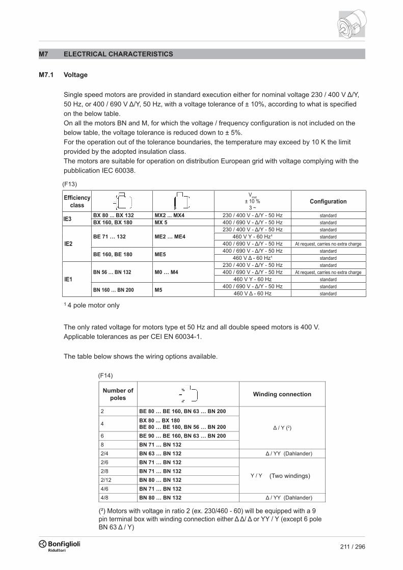
211 / 296
M6.9 Bearings
Life lubricated preloaded radial ball bearings are used, types are shown in the chart here under.Calculated endurance lifetime L10h, as per ISO 281, in unloaded condition, exceeds 40000 hrs.DE = drive endNDE = non drive end
DE NDE
BX, BE, BN BX, BE, BN BN_FDBN_FA
BN 56 6201 2Z C3 6201 2Z C3 –BN 63 6201 2Z C3 6201 2Z C3 6201 2RS C3BN 71 - BE 71 6202 2Z C3 6202 2Z C3 6202 2RS C3BX 80 - BE 80BN 80 6204 2Z C3 6204 2Z C3 6204 2RS C3
BX 90 - BE 90BN 90 6205 2Z C3 6205 2Z C3 6305 2RS C3
BX 100 - BE 100BN 100 6206 2Z C3 6206 2Z C3 6206 2RS C3
BX 112 - BE 112BN 112 6306 2Z C3 6306 2Z C3 6306 2RS C3
BX 132 - BE 132BN 132 6308 2Z C3 6308 2Z C3 6308 2RS C3
BN 160MR 6309 2Z C3 6308 2Z C3 6308 2RS C3BX 160M/LBE 160M/LBN 160M/L
6309 2Z C3 6309 2Z C3 6309 2RS C3
BN 180M 6310 2Z C3 6309 2Z C3 6309 2RS C3BX 180M/LBE 180M/LBN 180L
6310 2Z C3 6310 2Z C3 6310 2RS C3
BN 200L 6312 2Z C3 6310 2Z C3 6310 2RS C3
DE NDEMX, ME, M M M_FD, M_FA
M05 6004 2Z C3 6201 2Z C3 6201 2RS C3M1 6004 2Z C3 6202 2Z C3 6202 2RS C3MX2 - ME2 - M2 6007 2Z C3 6204 2Z C3 6204 2RS C3MX3 - ME3 - M3 6207 2Z C3 6206 2Z C3 6206 2RS C3MX4 - ME4 - M4 6309 2Z C3 6308 2Z C3 6308 2RS C3MX5 - ME5 - M5 6309 2Z C3 6309 2Z C3 6309 2RS C3
(F12)
(F13)
Vmot± 10 %
3 ~
IE3 BX 80 ... BX 132 MX2 ... MX4 230 / 400 V - Δ/Y - 50 HzBX 160, BX 180 MX 5 400 / 690 V - Δ/Y - 50 Hz
IE2BE 71 … 132 ME2 … ME4
230 / 400 V - Δ/Y - 50 Hz460 V Y - 60 Hz¹
400 / 690 V - Δ/Y - 50 Hz
BE 160, BE 180 ME5 400 / 690 V - Δ/Y - 50 Hz460 V Δ - 60 Hz¹
IE1BN 56 … BN 132 M0 … M4
230 / 400 V - Δ/Y - 50 Hz400 / 690 V - Δ/Y - 50 Hz
460 V Y - 60 Hz
BN 160 … BN 200 M5 400 / 690 V - Δ/Y - 50 Hz460 V Δ - 60 Hz
Effi ciency class Confi guration
standardstandardstandardstandard
At request, carries no extra chargestandardstandardstandard
At request, carries no extra chargestandardstandardstandard
1 4 pole motor only
The only rated voltage for motors type et 50 Hz and all double speed motors is 400 V.Applicable tolerances as per CEI EN 60034-1.
The table below shows the wiring options available.
M7 ELECTRICAL CHARACTERISTICS
M7.1 Voltage
Single speed motors are provided in standard execution either for nominal voltage 230 / 400 V Δ/Y, 50 Hz, or 400 / 690 V Δ/Y, 50 Hz, with a voltage tolerance of ± 10%, according to what is specifi ed on the below table.On all the motors BN and M, for which the voltage / frequency confi guration is not included on the below table, the voltage tolerance is reduced down to ± 5%.For the operation out of the tolerance boundaries, the temperature may exceed by 10 K the limit provided by the adopted insulation class.The motors are suitable for operation on distribution European grid with voltage complying with the pubblication IEC 60038.
2 BE 80 … BE 160, BN 63 … BN 200
Δ / Y (2)4 BX 80 ... BX 180
BE 80 … BE 180, BN 56 … BN 200 6 BE 90 … BE 160, BN 63 … BN 200 8 BN 71 … BN 132 2/4 BN 63 … BN 132 Δ / YY (Dahlander)2/6 BN 71 … BN 132
Y / Y2/8 BN 71 … BN 132 2/12 BN 80 … BN 132 4/6 BN 71 … BN 132 4/8 BN 80 … BN 132 Δ / YY (Dahlander)
Number of poles Winding connection
(Two windings)
(²) Motors with voltage in ratio 2 (ex. 230/460 - 60) will be equipped with a 9 pin terminal box with winding connection either Δ Δ/ Δ or YY / Y (except 6 pole BN 63 Δ / Y)
(F14)
Pn [kW]
2P 4P 6P 8P (*)
BN 100LM3LA
3.5 – – –BN 100LA – 2.5 1.8 0.9BN 100LB M3LB 4.7 3.5 2.2 1.3BN 112M – 4.7 4.7 2.5 1.8– M3LC – 4.7 2.5 –BN 132S
M4SA– 6.5 3.5 2.5
BN 132SA 6.5 – – –BN 132SB M4SB 8.7 – – –BN 132M
M4LA11 – – 3.5
BN 132MA – 8.7 4.6 –BN 132MB M4LB – 11 6.5 –BN 160MR M4LC 12.5 12.5 – –BN 160M M5SA – – 8.6 –BN 160MB – 17.5 – – –– M5SB 17.5 17.5 – –BN 160L – 21.5 17.5 12.6 –– M5SC 21.5 – – –BN 180M M5LA 24.5 21.5 – –BN 180L – – 25.3 17.5 –BN 200L – – 34 – –BN 200LA – 34 – 22 –
Pn [kW]
2P 4P 6P 8P (*)
BN 56A – – 0.07 – –
BN 56B M0B – 0.1 – –
BN 63A M05A 0.21 0.14 0.1 –
BN 63B M05B 0.3 0.21 0.14 –
BN 63C M05C 0.45 0.3 – –
BN 71A – 0.45 0.3 0.21 0.1
– M1SC – – 0.21 –
BN 71B M05SD 0.65 0.45 0.3 0.14
BN 71C M1LA 0.9 0.65 0.45 –
BN 80A – 0.9 0.65 0.45 0.21
BN 80B M2SA 1.3 0.9 0.65 0.30
BN 80C M2SB 1.8 1.3 0.9 –
BN 90S–
– 1.3 0.9 0.45
BN 90SA 1.8 – – –
BN 90SB 2.2 – – –
BN 90LM3SA
2.5 – 1.3 0.65
BN 90LA – 1.8 – –
BN 90LB – – 2.2 – –
(*) Excluded M_ motors

212 / 296
2 BE 80 … BE 160, BN 63 … BN 200
Δ / Y (2)4 BX 80 ... BX 180
BE 80 … BE 180, BN 56 … BN 200 6 BE 90 … BE 160, BN 63 … BN 200 8 BN 71 … BN 132 2/4 BN 63 … BN 132 Δ / YY (Dahlander)2/6 BN 71 … BN 132
Y / Y2/8 BN 71 … BN 132 2/12 BN 80 … BN 132 4/6 BN 71 … BN 132 4/8 BN 80 … BN 132 Δ / YY (Dahlander)
Number of poles Winding connection
(Two windings)
(²) Motors with voltage in ratio 2 (ex. 230/460 - 60) will be equipped with a 9 pin terminal box with winding connection either Δ Δ/ Δ or YY / Y (except 6 pole BN 63 Δ / Y)
M7.2 Frequency
Rated output power BN / M for 60 Hz operation is shown in the following diagram.
(F15)
Pn [kW]
2P 4P 6P 8P (*)
BN 100LM3LA
3.5 – – –BN 100LA – 2.5 1.8 0.9BN 100LB M3LB 4.7 3.5 2.2 1.3BN 112M – 4.7 4.7 2.5 1.8– M3LC – 4.7 2.5 –BN 132S
M4SA– 6.5 3.5 2.5
BN 132SA 6.5 – – –BN 132SB M4SB 8.7 – – –BN 132M
M4LA11 – – 3.5
BN 132MA – 8.7 4.6 –BN 132MB M4LB – 11 6.5 –BN 160MR M4LC 12.5 12.5 – –BN 160M M5SA – – 8.6 –BN 160MB – 17.5 – – –– M5SB 17.5 17.5 – –BN 160L – 21.5 17.5 12.6 –– M5SC 21.5 – – –BN 180M M5LA 24.5 21.5 – –BN 180L – – 25.3 17.5 –BN 200L – – 34 – –BN 200LA – 34 – 22 –
Pn [kW]
2P 4P 6P 8P (*)
BN 56A – – 0.07 – –
BN 56B M0B – 0.1 – –
BN 63A M05A 0.21 0.14 0.1 –
BN 63B M05B 0.3 0.21 0.14 –
BN 63C M05C 0.45 0.3 – –
BN 71A – 0.45 0.3 0.21 0.1
– M1SC – – 0.21 –
BN 71B M05SD 0.65 0.45 0.3 0.14
BN 71C M1LA 0.9 0.65 0.45 –
BN 80A – 0.9 0.65 0.45 0.21
BN 80B M2SA 1.3 0.9 0.65 0.30
BN 80C M2SB 1.8 1.3 0.9 –
BN 90S–
– 1.3 0.9 0.45
BN 90SA 1.8 – – –
BN 90SB 2.2 – – –
BN 90LM3SA
2.5 – 1.3 0.65
BN 90LA – 1.8 – –
BN 90LB – – 2.2 – –
(*) Excluded M_ motors
BX / BE / MX / ME motors are available at 60 Hz on a 4 pole confi guration only, and their power rating is the same as their 50 Hz counterpart. Double speed BN / M motors supplied at 60 Hz will have an increase of nominal power, referred to 50 Hz, equal to 15%, whereas double speed BX / BE / MX / ME motors are not available. If a nominal power rating, equal to the normalised nominal power rating at 50 Hz, was requested to be on a nameplate of a motor meant to be voltage supplied at 60 Hz, the PN option shall be specifi ed on the motor designation. Motors normally designed for a 50 Hz frequency may be used on a 60 Hz operating grid, but the related data shall be updated according to the following table. Motors designated for 50 Hz operation show on the nameplate also the values for 60 Hz operation (excluding motors in CUS execution and brake motors). See the following table.
50 Hz 60 Hz
V - 50 Hz V - 60 Hz Pn - 60 Hz Mn, Ma/Mn - 60 Hz n [min-1] - 60 Hz
BE/ME230/400 Δ/Y 265 - 460 Δ Y
1 0.83 1.2400/690 Δ/Y 460 Δ
BN/M230/400 Δ/Y
220 - 240 Δ380 - 415 Y
400/690 Δ/Y 380 - 415 Δ
BN/M230/400 Δ/Y
265 - 280 Δ1.15 1 1.2440 - 480 Y
400/690 Δ/Y 440 - 480 Δ
(F16)
M7.3 Ambient temperature
Catalogue rating values are calculated for 50 Hz operation and for standard ambient conditions (temperature 40 °C; elevation ≤ 1000 m a.s.l.) as per the CEI EN 60034-1 Standards.The motors can be used within the 40 - 60 °C temperature range with rated power output adjusted by factors given in the table below.
(F17)
40° 45° 50° 55° 60°
100% 95% 90% 85% 80%
Ambient temperature (°C)
Permitted power as a % of rated power
Should a derating factor higher than 15% apply please consult factory.
M7.4 50 HZ normalized power
With this option, motor name plate includes 50 Hz normalized power information even when motor is designated for operation with 60 Hz power mains. For 60 Hz supplies along with voltages 230/460V and 575V the PN option is applied by default.
CUS
PN
M7.5 Motors for USA and Canada
CUS option is available in NEMA Design C execution for BN, BE, M, ME motors, and NEMA Design B for BX motors, with regards to the electrical features. Motors are certifi ed in compliance with CSA (Canadian Standard) C22.2 N° 100 and UL (Underwriters Laboratory) UL 1004-1 standards, as stated on UL fi le E308649.BN, BE, M, ME motors nameplates show the below marks:
Vmot
60 Hz
208 V 200 V
240 V 230 V
480 V 460 V
600 V 575 V
Frequency Mains voltage
BX, MX motors nameplates show the below marks and are certifi ed in compliance with the energy effi ciency standards in effect in the USA and Canada, respectively provided by DOE (10 CFR Part 431) and NRCan (Energy Effi ciency Regulations), tested according to CSA C390 standard.

213 / 296
2 BE 80 … BE 160, BN 63 … BN 200
Δ / Y (2)4 BX 80 ... BX 180
BE 80 … BE 180, BN 56 … BN 200 6 BE 90 … BE 160, BN 63 … BN 200 8 BN 71 … BN 132 2/4 BN 63 … BN 132 Δ / YY (Dahlander)2/6 BN 71 … BN 132
Y / Y2/8 BN 71 … BN 132 2/12 BN 80 … BN 132 4/6 BN 71 … BN 132 4/8 BN 80 … BN 132 Δ / YY (Dahlander)
Number of poles Winding connection
(Two windings)
(²) Motors with voltage in ratio 2 (ex. 230/460 - 60) will be equipped with a 9 pin terminal box with winding connection either Δ Δ/ Δ or YY / Y (except 6 pole BN 63 Δ / Y)
M7.2 Frequency
Rated output power BN / M for 60 Hz operation is shown in the following diagram.
(F15)
Pn [kW]
2P 4P 6P 8P (*)
BN 100LM3LA
3.5 – – –BN 100LA – 2.5 1.8 0.9BN 100LB M3LB 4.7 3.5 2.2 1.3BN 112M – 4.7 4.7 2.5 1.8– M3LC – 4.7 2.5 –BN 132S
M4SA– 6.5 3.5 2.5
BN 132SA 6.5 – – –BN 132SB M4SB 8.7 – – –BN 132M
M4LA11 – – 3.5
BN 132MA – 8.7 4.6 –BN 132MB M4LB – 11 6.5 –BN 160MR M4LC 12.5 12.5 – –BN 160M M5SA – – 8.6 –BN 160MB – 17.5 – – –– M5SB 17.5 17.5 – –BN 160L – 21.5 17.5 12.6 –– M5SC 21.5 – – –BN 180M M5LA 24.5 21.5 – –BN 180L – – 25.3 17.5 –BN 200L – – 34 – –BN 200LA – 34 – 22 –
Pn [kW]
2P 4P 6P 8P (*)
BN 56A – – 0.07 – –
BN 56B M0B – 0.1 – –
BN 63A M05A 0.21 0.14 0.1 –
BN 63B M05B 0.3 0.21 0.14 –
BN 63C M05C 0.45 0.3 – –
BN 71A – 0.45 0.3 0.21 0.1
– M1SC – – 0.21 –
BN 71B M05SD 0.65 0.45 0.3 0.14
BN 71C M1LA 0.9 0.65 0.45 –
BN 80A – 0.9 0.65 0.45 0.21
BN 80B M2SA 1.3 0.9 0.65 0.30
BN 80C M2SB 1.8 1.3 0.9 –
BN 90S–
– 1.3 0.9 0.45
BN 90SA 1.8 – – –
BN 90SB 2.2 – – –
BN 90LM3SA
2.5 – 1.3 0.65
BN 90LA – 1.8 – –
BN 90LB – – 2.2 – –
(*) Excluded M_ motors
BX / BE / MX / ME motors are available at 60 Hz on a 4 pole confi guration only, and their power rating is the same as their 50 Hz counterpart. Double speed BN / M motors supplied at 60 Hz will have an increase of nominal power, referred to 50 Hz, equal to 15%, whereas double speed BX / BE / MX / ME motors are not available. If a nominal power rating, equal to the normalised nominal power rating at 50 Hz, was requested to be on a nameplate of a motor meant to be voltage supplied at 60 Hz, the PN option shall be specifi ed on the motor designation. Motors normally designed for a 50 Hz frequency may be used on a 60 Hz operating grid, but the related data shall be updated according to the following table. Motors designated for 50 Hz operation show on the nameplate also the values for 60 Hz operation (excluding motors in CUS execution and brake motors). See the following table.
50 Hz 60 Hz
V - 50 Hz V - 60 Hz Pn - 60 Hz Mn, Ma/Mn - 60 Hz n [min-1] - 60 Hz
BE/ME230/400 Δ/Y 265 - 460 Δ Y
1 0.83 1.2400/690 Δ/Y 460 Δ
BN/M230/400 Δ/Y
220 - 240 Δ380 - 415 Y
400/690 Δ/Y 380 - 415 Δ
BN/M230/400 Δ/Y
265 - 280 Δ1.15 1 1.2440 - 480 Y
400/690 Δ/Y 440 - 480 Δ
(F16)
M7.3 Ambient temperature
Catalogue rating values are calculated for 50 Hz operation and for standard ambient conditions (temperature 40 °C; elevation ≤ 1000 m a.s.l.) as per the CEI EN 60034-1 Standards.The motors can be used within the 40 - 60 °C temperature range with rated power output adjusted by factors given in the table below.
(F17)
40° 45° 50° 55° 60°
100% 95% 90% 85% 80%
Ambient temperature (°C)
Permitted power as a % of rated power
Should a derating factor higher than 15% apply please consult factory.
M7.4 50 HZ normalized power
With this option, motor name plate includes 50 Hz normalized power information even when motor is designated for operation with 60 Hz power mains. For 60 Hz supplies along with voltages 230/460V and 575V the PN option is applied by default.
CUS
PN
M7.5 Motors for USA and Canada
CUS option is available in NEMA Design C execution for BN, BE, M, ME motors, and NEMA Design B for BX motors, with regards to the electrical features. Motors are certifi ed in compliance with CSA (Canadian Standard) C22.2 N° 100 and UL (Underwriters Laboratory) UL 1004-1 standards, as stated on UL fi le E308649.BN, BE, M, ME motors nameplates show the below marks:
Vmot
60 Hz
208 V 200 V
240 V 230 V
480 V 460 V
600 V 575 V
Frequency Mains voltage
BX, MX motors nameplates show the below marks and are certifi ed in compliance with the energy effi ciency standards in effect in the USA and Canada, respectively provided by DOE (10 CFR Part 431) and NRCan (Energy Effi ciency Regulations), tested according to CSA C390 standard.

214 / 296
Vmot
60 Hz
208 V 200 V
240 V 230 V
480 V 460 V
600 V 575 V
Frequency Mains voltage
(F18)
CUS option is applicable onto 50 Hz operating motors as well (motors BX, MX excluded).
Motors with voltage in ratio 2 (e.g. 230/460-60; 220/440-60) feature, as standard, a 9-stud terminal board. For same executions, as well as for 575V-60Hz supply, the nominal rating is coincident with the correspondent 50Hz rating.For DC brake motors type FD, the rectifi er is connected to a single-phase 230 VAC supply voltage in the motor terminal box.Brake power supply for brake motors is as follows:
NOTES:1. Starting from June, 1st 2016, CUS motors whose effi ciency is below IE3 (i.e. “Premium Effi ciency”) cannot be any longer sold in the USA and Canada, unless one or more of the following conditions apply: • Double speed motors; • Motors plated for a non - continuous duty (<80%); • Motors intended to be operated through variable frequency drive only (properly equipped with “Inverter Duty Only” label, or similar).
2. BX 100, MX3LA and MX3LB motors are available for the USA only and not for Canada, and the related marks reported on the nameplates are the following:
The CUS option does not apply to servo-ventilated motors.US power mains voltages and the corresponding rated voltages to be specifi ed for the motor are indicated in the following table:
Power supply
Connected to terminal box 1~230V c.a.Separate power supply
Separate power supply
BX_FD - BN_FDMX_FD - M_FD
BX_FA - BN_FAMX_FA - M_FA
230V Δ 230SA
460V Y 460SA
(F19)
BE motor with BIS option are available with the following nominal Voltage/Frequency combinations:
M7.7 China Compulsory Certifi cation
CCC option is not currently available for IE3 motors.CCC option is not currently available for servo - ventilated motors.
CCC
M7.8 Insulation class
CL FBonfi glioli motors use class F insulating materials (enamelled wire, insulators, impregnation resins) as compare to the standard motor. In standard motors, stator windings over temperature normally stays below the 80 K limit corresponding to class B over temperature. A careful selection of insulating components makes the motors compatible with tropical climates and normal vibration. For applications involving the presence of aggressive chemicals or high humidity, contact Bonfi glioli Engineering for assistance with product selection.
M7.6 Motors certifi ed for India
Low voltage motors ≥0.37kW manufactured or imported in India must be certifi ed from Bureau of Indian Standard and provided with a mark certifying motor compliance to IS 12615 standard.BE motors with power from 0.37 to 3.7kW included are avaiable with the above mentioned certifi cation and, when BIS option is selected, are provided with the nameplate reporting the following logo:
BIS
Vmot
71 ≤ BE ≤112 230/400 - 50 Hz
(F20)
Electric motors destined for sale in the People’s Republic of China have to be certifi ed under the CCC (China Compulsory Certifi cation) system. BN motors of up to 7 Nm in rated torque are available with CCC certifi cation and a special nameplate bearing the mark shown below:

215 / 296
Vmot
60 Hz
208 V 200 V
240 V 230 V
480 V 460 V
600 V 575 V
Frequency Mains voltage
(F18)
CUS option is applicable onto 50 Hz operating motors as well (motors BX, MX excluded).
Motors with voltage in ratio 2 (e.g. 230/460-60; 220/440-60) feature, as standard, a 9-stud terminal board. For same executions, as well as for 575V-60Hz supply, the nominal rating is coincident with the correspondent 50Hz rating.For DC brake motors type FD, the rectifi er is connected to a single-phase 230 VAC supply voltage in the motor terminal box.Brake power supply for brake motors is as follows:
NOTES:1. Starting from June, 1st 2016, CUS motors whose effi ciency is below IE3 (i.e. “Premium Effi ciency”) cannot be any longer sold in the USA and Canada, unless one or more of the following conditions apply: • Double speed motors; • Motors plated for a non - continuous duty (<80%); • Motors intended to be operated through variable frequency drive only (properly equipped with “Inverter Duty Only” label, or similar).
2. BX 100, MX3LA and MX3LB motors are available for the USA only and not for Canada, and the related marks reported on the nameplates are the following:
The CUS option does not apply to servo-ventilated motors.US power mains voltages and the corresponding rated voltages to be specifi ed for the motor are indicated in the following table:
Power supply
Connected to terminal box 1~230V c.a.Separate power supply
Separate power supply
BX_FD - BN_FDMX_FD - M_FD
BX_FA - BN_FAMX_FA - M_FA
230V Δ 230SA
460V Y 460SA
(F19)
BE motor with BIS option are available with the following nominal Voltage/Frequency combinations:
M7.7 China Compulsory Certifi cation
CCC option is not currently available for IE3 motors.CCC option is not currently available for servo - ventilated motors.
CCC
M7.8 Insulation class
CL FBonfi glioli motors use class F insulating materials (enamelled wire, insulators, impregnation resins) as compare to the standard motor. In standard motors, stator windings over temperature normally stays below the 80 K limit corresponding to class B over temperature. A careful selection of insulating components makes the motors compatible with tropical climates and normal vibration. For applications involving the presence of aggressive chemicals or high humidity, contact Bonfi glioli Engineering for assistance with product selection.
M7.6 Motors certifi ed for India
Low voltage motors ≥0.37kW manufactured or imported in India must be certifi ed from Bureau of Indian Standard and provided with a mark certifying motor compliance to IS 12615 standard.BE motors with power from 0.37 to 3.7kW included are avaiable with the above mentioned certifi cation and, when BIS option is selected, are provided with the nameplate reporting the following logo:
BIS
Vmot
71 ≤ BE ≤112 230/400 - 50 Hz
(F20)
Electric motors destined for sale in the People’s Republic of China have to be certifi ed under the CCC (China Compulsory Certifi cation) system. BN motors of up to 7 Nm in rated torque are available with CCC certifi cation and a special nameplate bearing the mark shown below:

216 / 296
(F21)
Safety margin
Max. ambienttemperature
Increase allowed by the temperature
CL H
Motors manufactured in insulation class H are available at request.Not available for motors in compliance with CSA e UL standards (CUS option).
M7.9 Type of duty
Unless otherwise specifi ed, catalogue motor power refers to continuous duty S1. Any operating conditions other than S1 duty must be identifi ed in accordance with duty cycle defi nitions laid down in standards CEI EN 60034-1. For duty cycles S2 and S3, the power increase co-effi cient reported in the following table may be used. Please note that the table provided below applies to single-speed motors. As an alternative to S1 continuous duty, one of the following values can be specifi ed at the product confi guration stage: S2, S3 or S9. The motor nameplate will be marked with an increased power rating to suit the type of duty, and with specifi c electrical data and a duty type of S2-30 min, S3-70% or S9 respectively.For further details, contact Bonfi glioli s Technical Service. Please contact Bonfi glioli Engineering for the power increase coeffi cients applicable to switch-pole motors.
(F22)
S2 S3 * S4 - S9
10 30 (*) 60 25% 40% 70% (*)fm 1.35 1.15 1.05 1.25 1.15 1.1
Type of duty
Duration (min) Intermittence (I)Contact us
* Cycle duration must, in any event, be equal to or less than 10 minutes; if this time is exceeded, plea-se contact our Technical Service.(*) Default values from options (tab. F05).
I =t
t tf
f r
. 100 (01)
tfP
t
[kW]
[C°]
t
M7.9.1 Cyclic duration factor:
tf = work time under constant loadtr = rest time
M7.9.2 Limited duration duty S2
This type of duty is characterized by operation at constant load for a limited time, which is shorter than the time required to reach thermal equilibrium, followed by a rest period of suffi cient duration to restore ambient temperature in the motor.
M7.9.3 Periodical intermittent duty S3:
This type of duty is characterized by a sequence of identical operation cycles, each including a constant load operation period and a rest period. For this type of duty, the starting current does not signifi cantly infl uence overtemperature.
tt
tf
c
rP
t
[kW]
[C°]
t

217 / 296
(F21)
Safety margin
Max. ambienttemperature
Increase allowed by the temperature
CL H
Motors manufactured in insulation class H are available at request.Not available for motors in compliance with CSA e UL standards (CUS option).
M7.9 Type of duty
Unless otherwise specifi ed, catalogue motor power refers to continuous duty S1. Any operating conditions other than S1 duty must be identifi ed in accordance with duty cycle defi nitions laid down in standards CEI EN 60034-1. For duty cycles S2 and S3, the power increase co-effi cient reported in the following table may be used. Please note that the table provided below applies to single-speed motors. As an alternative to S1 continuous duty, one of the following values can be specifi ed at the product confi guration stage: S2, S3 or S9. The motor nameplate will be marked with an increased power rating to suit the type of duty, and with specifi c electrical data and a duty type of S2-30 min, S3-70% or S9 respectively.For further details, contact Bonfi glioli s Technical Service. Please contact Bonfi glioli Engineering for the power increase coeffi cients applicable to switch-pole motors.
(F22)
S2 S3 * S4 - S9
10 30 (*) 60 25% 40% 70% (*)fm 1.35 1.15 1.05 1.25 1.15 1.1
Type of duty
Duration (min) Intermittence (I)Contact us
* Cycle duration must, in any event, be equal to or less than 10 minutes; if this time is exceeded, plea-se contact our Technical Service.(*) Default values from options (tab. F05).
I =t
t tf
f r
. 100 (01)
tfP
t
[kW]
[C°]
t
M7.9.1 Cyclic duration factor:
tf = work time under constant loadtr = rest time
M7.9.2 Limited duration duty S2
This type of duty is characterized by operation at constant load for a limited time, which is shorter than the time required to reach thermal equilibrium, followed by a rest period of suffi cient duration to restore ambient temperature in the motor.
M7.9.3 Periodical intermittent duty S3:
This type of duty is characterized by a sequence of identical operation cycles, each including a constant load operation period and a rest period. For this type of duty, the starting current does not signifi cantly infl uence overtemperature.
tt
tf
c
rP
t
[kW]
[C°]
t

218 / 296
M7.10 Inverter-controlled motors
The electric motors Bonfi glioli may be used in combination with PWM inverters with rated voltage at transformer input up to 500 V.Standard motors use a phase insulating system with separators, class 2 enamelled wire and class H impregnation resins (1600V peak-to-peak voltage pulse capacity and rise edge ts > 0.1µs at motor terminals). Typical torque/speed curves referred to S1 duty for motors with base frequency fb = 50 Hz is are reported in the table below.Because ventilation is somewhat impaired in operation at lower frequencies (about 30 Hz), standard motors with incorporated fan (IC411) require adequate torque derating or - alternately - the addition of a separate supply fan cooling.Above base frequency, upon reaching the maximum output voltage of the inverter, the motor enters a steady-power fi eld of operation, and shaft torque drops with ratio (f/fb).As motor maximum torque decreases with (f/fb)2, the allowed overloading must be reduced progressively.
The following table reports the mechanical speed limit for motors operating above rated frequency:(F23)
Separate cooling
Self cooling
(F24) n [min-1]
2p 4p 6p
≤ BE 112 - BN 112 ME2, ME3M05 ... M3 5200 4000 3000
≥ BE 132 - BN 132 ME4, ME5M4, M5 4500 4000 3000
BX 80 ... BX 180 MX2 ... MX5 4000
Above rated speed, motors generate increased mechanical vibration and fan noise. Class B rotor balancing is highly recommended in these applications. Installing a separate supply fan cooling may also be advisable. Remote-controlled fan and brake (if fi tted) must always be connected direct to mains power supply.
M7.11 Permissible starts per hour, Z
The rating charts of brakemotors lend the permitted number of starts Z0, based on 50% intermittence and for unloaded operation.The catalogue value represents the maximum number of starts per hour for the motor without exceeding the rated temperature for the insulation class F.To give a practical example for an application characterized by inertia Jc, drawing power Pr and requiring mean torque at start-up ML the actual number of starts per hour for the motor can be calculated approximately through the following equation:
If actual starts per hour is within permitted value (Z) it may be worth checking that braking work is compatible with brake (thermal) capacity Wmax also given in tables (F31), (F39) and dependent on the number of switches (c/h).
(F25)
=K JJ m
J m
+ Jc
=K d
=K c Ma
Ma - ML
where:
inertia factor
torque factor
load factor, see the following table
Z =K J
Z K K0 c d (02)

219 / 296
M7.10 Inverter-controlled motors
The electric motors Bonfi glioli may be used in combination with PWM inverters with rated voltage at transformer input up to 500 V.Standard motors use a phase insulating system with separators, class 2 enamelled wire and class H impregnation resins (1600V peak-to-peak voltage pulse capacity and rise edge ts > 0.1µs at motor terminals). Typical torque/speed curves referred to S1 duty for motors with base frequency fb = 50 Hz is are reported in the table below.Because ventilation is somewhat impaired in operation at lower frequencies (about 30 Hz), standard motors with incorporated fan (IC411) require adequate torque derating or - alternately - the addition of a separate supply fan cooling.Above base frequency, upon reaching the maximum output voltage of the inverter, the motor enters a steady-power fi eld of operation, and shaft torque drops with ratio (f/fb).As motor maximum torque decreases with (f/fb)2, the allowed overloading must be reduced progressively.
The following table reports the mechanical speed limit for motors operating above rated frequency:(F23)
Separate cooling
Self cooling
(F24) n [min-1]
2p 4p 6p
≤ BE 112 - BN 112 ME2, ME3M05 ... M3 5200 4000 3000
≥ BE 132 - BN 132 ME4, ME5M4, M5 4500 4000 3000
BX 80 ... BX 180 MX2 ... MX5 4000
Above rated speed, motors generate increased mechanical vibration and fan noise. Class B rotor balancing is highly recommended in these applications. Installing a separate supply fan cooling may also be advisable. Remote-controlled fan and brake (if fi tted) must always be connected direct to mains power supply.
M7.11 Permissible starts per hour, Z
The rating charts of brakemotors lend the permitted number of starts Z0, based on 50% intermittence and for unloaded operation.The catalogue value represents the maximum number of starts per hour for the motor without exceeding the rated temperature for the insulation class F.To give a practical example for an application characterized by inertia Jc, drawing power Pr and requiring mean torque at start-up ML the actual number of starts per hour for the motor can be calculated approximately through the following equation:
If actual starts per hour is within permitted value (Z) it may be worth checking that braking work is compatible with brake (thermal) capacity Wmax also given in tables (F31), (F39) and dependent on the number of switches (c/h).
(F25)
=K JJ m
J m
+ Jc
=K d
=K c Ma
Ma - ML
where:
inertia factor
torque factor
load factor, see the following table
Z =K J
Z K K0 c d (02)

220 / 296
=K JJ m
J m
+ Jc
=K d
=K c Ma
Ma - ML
where:
inertia factor
torque factor
load factor, see the following table
(F26)
When voltage is interrupted, pressure springs push the armature plate against the brake disc. The disc becomes trapped between the armature plate and motor shield and stops the shaft from rotation.When the coil is energized, a magnetic fi eld strong enough to overcome spring action attracts the armature plate, so that the brake disc – which is integral with the motor shaft – is released.
M8.2 Most signifi cant features
High braking torques (normally Mb ≈ 2 Mn), braking torque adjustment. Steel brake disc with double friction lining (low-wear, asbestos-free lining). Hexagonal seat on motor shaft fan end (N.D.E.) for manual rotation (not compatible with options PS, RC, TC, U1, U2, EN1, EN2, EN3, EN4, EN5, EN6). Manual release lever (options R and RM for FD; option R for FA). Corrosion-proof treatment on all brake surfaces. Insulation class F.
Key:
brake disc
disc carrier
pressure plate
brake coil
motor rear shield
brake springs
M8 ASYNCHRONOUS BRAKE MOTORS
M8.1 Operation
Versions with incorporated brake use spring-applied DC (FD option) or AC (FA options) brakes.All brakes are designed to provide fail-safe operation, meaning that they are applied by spring-action in the event of power failure.
V-ring at N.D.E. of motor shaft
dust and water-proof rubber boot
stainless steel ring placed between motor shieldand brake disc
stainless steel hub
stainless steel brake disc
IP 54 IP 55
(F27) (F28)
M9 DC BRAKE MOTORS TYPE BX_FD, BN_FD, MX_FD and M_FD
Frame sizes: BX 80 ... BX 180L - BN 63 … BN 200L / MX2SB ... MX5LA - M05 ... M5 BE/ME motors may be available equipped with the FD brake, for further information please contact our Technical Department.
Direct current toroidal-coil electromagnetic brake bolted onto motor shield. Preloading springs provide axial positioning of magnet body.Brake disc slides axially on steel hub shrunk onto motor shaft with anti-vibration device.Brake torque factory setting is indicated in the corresponding motor rating charts. Braking torque may be modifi ed by changing the type and/or number of springs.At request, motors may be equipped with manual release lever with automatic return (R) or system for holding brake in the released position (RM).See variant at paragraph “BRAKE RELEASE SYSTEMS” for available release lever locations.FD brakes ensure excellent dynamic performance with low noise. DC brake operating characteristics may be optimized to meet application requirements by choosing from the various rectifi er/power supply and wiring connection options available.For applications involving lifting and/or high hourly energy dissipation, contact Bonfi glioli’s Technical Service.
M9.1 Degree of protection
Standard protection class is IP54.Brake motor FD is also available in protection class IP55, which mandates the following variants:
2, 4, 6 P 1 speedBN_FD / M_FD
Vmot ± 10%
3 ~
VB ± 10%
1 ~BX 80…BX 132BN 63…BN 132
MX2...MX4M05...M4LB 230/400 V – 50 Hz 230 V
BX 160…BX 180BN 160…BN 200
MX5M4LC...M5 400/690 V – 50 Hz 400 V
brake connectedto terminal board
power supply
standard
standard
separate power supply
specify VB SA o VB SD
specify VB SA o VB SD
2/4, 2/6, 2/8, 2/12, 4/6, 4/8 P 2 speedBN_FD / M_FDVmot
± 10%3 ~
VB± 10%
1 ~
BN 63…BN 132 M05...M4LB 400 V – 50 Hz 230 V
brake connected to terminal board
power supplyseparate power supply
specify VB SA o VB SD
BN 63 M05 FD 02
NB SBR
NBR
SBBN 71 M1 FD 03
FD 53
BX 80 - BN 80 MX2 - M2 FD 04
BX 90S - BN 90S — FD 14
BX 90L - BN 90L — FD 05
BX 100 - BN 100MX3 - M3
FD 15
— FD 55
SB SBR
BX 112 - BN 112 — FD 06S
BX 132 - BN 132 - BN 160MR MX4 - M4FD 56FD 06FD 07
BX 160 - BN 160L - BN 180M MX5 - M5 FD 08
BX 180 - BN 180L - BN 200M — FD 09(*) t2c < t2r < t2
brakestandard on request

221 / 296
=K JJ m
J m
+ Jc
=K d
=K c Ma
Ma - ML
where:
inertia factor
torque factor
load factor, see the following table
(F26)
When voltage is interrupted, pressure springs push the armature plate against the brake disc. The disc becomes trapped between the armature plate and motor shield and stops the shaft from rotation.When the coil is energized, a magnetic fi eld strong enough to overcome spring action attracts the armature plate, so that the brake disc – which is integral with the motor shaft – is released.
M8.2 Most signifi cant features
High braking torques (normally Mb ≈ 2 Mn), braking torque adjustment. Steel brake disc with double friction lining (low-wear, asbestos-free lining). Hexagonal seat on motor shaft fan end (N.D.E.) for manual rotation (not compatible with options PS, RC, TC, U1, U2, EN1, EN2, EN3, EN4, EN5, EN6). Manual release lever (options R and RM for FD; option R for FA). Corrosion-proof treatment on all brake surfaces. Insulation class F.
Key:
brake disc
disc carrier
pressure plate
brake coil
motor rear shield
brake springs
M8 ASYNCHRONOUS BRAKE MOTORS
M8.1 Operation
Versions with incorporated brake use spring-applied DC (FD option) or AC (FA options) brakes.All brakes are designed to provide fail-safe operation, meaning that they are applied by spring-action in the event of power failure.
V-ring at N.D.E. of motor shaft
dust and water-proof rubber boot
stainless steel ring placed between motor shieldand brake disc
stainless steel hub
stainless steel brake disc
IP 54 IP 55
(F27) (F28)
M9 DC BRAKE MOTORS TYPE BX_FD, BN_FD, MX_FD and M_FD
Frame sizes: BX 80 ... BX 180L - BN 63 … BN 200L / MX2SB ... MX5LA - M05 ... M5 BE/ME motors may be available equipped with the FD brake, for further information please contact our Technical Department.
Direct current toroidal-coil electromagnetic brake bolted onto motor shield. Preloading springs provide axial positioning of magnet body.Brake disc slides axially on steel hub shrunk onto motor shaft with anti-vibration device.Brake torque factory setting is indicated in the corresponding motor rating charts. Braking torque may be modifi ed by changing the type and/or number of springs.At request, motors may be equipped with manual release lever with automatic return (R) or system for holding brake in the released position (RM).See variant at paragraph “BRAKE RELEASE SYSTEMS” for available release lever locations.FD brakes ensure excellent dynamic performance with low noise. DC brake operating characteristics may be optimized to meet application requirements by choosing from the various rectifi er/power supply and wiring connection options available.For applications involving lifting and/or high hourly energy dissipation, contact Bonfi glioli’s Technical Service.
M9.1 Degree of protection
Standard protection class is IP54.Brake motor FD is also available in protection class IP55, which mandates the following variants:
2, 4, 6 P 1 speedBN_FD / M_FD
Vmot ± 10%
3 ~
VB ± 10%
1 ~BX 80…BX 132BN 63…BN 132
MX2...MX4M05...M4LB 230/400 V – 50 Hz 230 V
BX 160…BX 180BN 160…BN 200
MX5M4LC...M5 400/690 V – 50 Hz 400 V
brake connectedto terminal board
power supply
standard
standard
separate power supply
specify VB SA o VB SD
specify VB SA o VB SD
2/4, 2/6, 2/8, 2/12, 4/6, 4/8 P 2 speedBN_FD / M_FDVmot
± 10%3 ~
VB± 10%
1 ~
BN 63…BN 132 M05...M4LB 400 V – 50 Hz 230 V
brake connected to terminal board
power supplyseparate power supply
specify VB SA o VB SD
BN 63 M05 FD 02
NB SBR
NBR
SBBN 71 M1 FD 03
FD 53
BX 80 - BN 80 MX2 - M2 FD 04
BX 90S - BN 90S — FD 14
BX 90L - BN 90L — FD 05
BX 100 - BN 100MX3 - M3
FD 15
— FD 55
SB SBR
BX 112 - BN 112 — FD 06S
BX 132 - BN 132 - BN 160MR MX4 - M4FD 56FD 06FD 07
BX 160 - BN 160L - BN 180M MX5 - M5 FD 08
BX 180 - BN 180L - BN 200M — FD 09(*) t2c < t2r < t2
brakestandard on request

222 / 296
M9.2 FD brake power supply
A rectifi er accommodated inside the terminal box feeds the DC brake coil. Wiring connection across rectifi er and brake coil is performed at the factory.On all single-pole motors, rectifi er is connected to the motor terminal board.Rectifi er standard power supply voltage VB is as indicated in the following table, regardless of mains frequency:
Switch-pole motors feature a separate power supply line for the brake with rectifi er input voltage VB as indicated in the table below:
(F29) 2, 4, 6 P 1 speedBN_FD / M_FD
Vmot ± 10%
3 ~
VB ± 10%
1 ~BX 80…BX 132BN 63…BN 132
MX2...MX4M05...M4LB 230/400 V – 50 Hz 230 V
BX 160…BX 180BN 160…BN 200
MX5M4LC...M5 400/690 V – 50 Hz 400 V
brake connectedto terminal board
power supply
standard
standard
separate power supply
specify VB SA o VB SD
specify VB SA o VB SD
The diode half-wave rectifi er (VDC ≈ 0,45 x VAC) is available in versions NB, SB, NBR e SBR, as detailed in the table below:
(F30) 2/4, 2/6, 2/8, 2/12, 4/6, 4/8 P 2 speedBN_FD / M_FDVmot
± 10%3 ~
VB± 10%
1 ~
BN 63…BN 132 M05...M4LB 400 V – 50 Hz 230 V
brake connected to terminal board
power supplyseparate power supply
specify VB SA o VB SD
BN 63 M05 FD 02
NB SBR
NBR
SBBN 71 M1 FD 03
FD 53
BX 80 - BN 80 MX2 - M2 FD 04
BX 90S - BN 90S — FD 14
BX 90L - BN 90L — FD 05
BX 100 - BN 100MX3 - M3
FD 15
— FD 55
SB SBR
BX 112 - BN 112 — FD 06S
BX 132 - BN 132 - BN 160MR MX4 - M4FD 56FD 06FD 07
BX 160 - BN 160L - BN 180M MX5 - M5 FD 08
BX 180 - BN 180L - BN 200M — FD 09(*) t2c < t2r < t2
brakestandard on request
(F31)
W Pt1 t1 s t2 t2c [ J ]
6 4 2 [ms] [ms] [ms] [ms] 10 s/h 100 s/h 1000 s/h [MJ] [W]FD02 – 3.5 1.75 30 15 80 9 4500 1400 180 15 17FD03 5 3.5 1.75 50 20 100 12
7000 1900 230 25 24FD53 7.5 5 2.5 60 30 100 12FD04
15 10 5 80 35 140 15 10000 3100 350 30 33FD14FD05 40 26 13 130 65 170 20
18000 4500 500 50 45FD15 40 26 13 130 65 170 20FD55 55 37 18 – 65 170 20FD06S 60 40 20 – 80 220 25 20000 4800 550 70 55FD56
–75 37
–90 250 20
29000 7400 800 80 65FD06 100 50 100 250 20FD07 150 100 50 – 120 200 25 40000 9300 1000 130 65FD08* 250 200 170 – 140 350 30 60000 14000 1500 230 100FD09** 400 300 200 – 200 450 40 70000 15000 1700 230 120
Brake torque Mb [Nm]springs
Brake Release Braking Wmax per brake operation
* brake torque values obtained with 9, 7 and 6 springs, respectively
** brake torque values obtained with 12, 9 and 6 springs, respectively
t1 = brake release time with half-wave rectifi ert1s = brake release time with over-energizing rectifi ert2 = brake engagement time with AC line interruption and separate power
supply t2c = brake engagement time with AC and DC line interruption – Values for t1,
t1s, t2, t2c indicated in the tab. (F37) are referred to brake set at maximum torque, medium air gap and rated voltage
Wmax = max energy per brake operationW = braking energy between two successive air gap adjustmentsPb = brake power absorption at 20 °CMb = static braking torque (±15%s/h = starts per hour
(F32)
Rectifi er SB with electronic energizing control over-energizes the electromagnet upon power-up to cut brake release response time and then switches to normal half-wave operation once the brake has been released.
Use of the SB rectifi er is mandatory in the event of:- high number of operations per hour- reduced brake release response time- brake is exposed to extreme thermal stress
Rectifi ers NBR or SBR are available for applications requiring quick brake intervention (braking condition reinstatement) response. These rectifi ers complement the NB and SB types as their electronic circuit incorporates a static switch that de-energizes the brake quickly in the event voltage is missing.This arrangement ensures short brake release response time with no need for additional external wiring and contacts.Optimum performance of rectifi ers NBR and SBR is achieved with separate brake power supply. Versions available: 230Vac ±10%, 400Vac ± 10%, 50/60 Hz (with power supply); 100Vdc ±10%, 180Vdc ± 10% (with SD option).
M9.3 FD brake technical specifi cations
The table below reports the technical specifi cations of DC brakes FD.

223 / 296
M9.2 FD brake power supply
A rectifi er accommodated inside the terminal box feeds the DC brake coil. Wiring connection across rectifi er and brake coil is performed at the factory.On all single-pole motors, rectifi er is connected to the motor terminal board.Rectifi er standard power supply voltage VB is as indicated in the following table, regardless of mains frequency:
Switch-pole motors feature a separate power supply line for the brake with rectifi er input voltage VB as indicated in the table below:
(F29) 2, 4, 6 P 1 speedBN_FD / M_FD
Vmot ± 10%
3 ~
VB ± 10%
1 ~BX 80…BX 132BN 63…BN 132
MX2...MX4M05...M4LB 230/400 V – 50 Hz 230 V
BX 160…BX 180BN 160…BN 200
MX5M4LC...M5 400/690 V – 50 Hz 400 V
brake connectedto terminal board
power supply
standard
standard
separate power supply
specify VB SA o VB SD
specify VB SA o VB SD
The diode half-wave rectifi er (VDC ≈ 0,45 x VAC) is available in versions NB, SB, NBR e SBR, as detailed in the table below:
(F30) 2/4, 2/6, 2/8, 2/12, 4/6, 4/8 P 2 speedBN_FD / M_FDVmot
± 10%3 ~
VB± 10%
1 ~
BN 63…BN 132 M05...M4LB 400 V – 50 Hz 230 V
brake connected to terminal board
power supplyseparate power supply
specify VB SA o VB SD
BN 63 M05 FD 02
NB SBR
NBR
SBBN 71 M1 FD 03
FD 53
BX 80 - BN 80 MX2 - M2 FD 04
BX 90S - BN 90S — FD 14
BX 90L - BN 90L — FD 05
BX 100 - BN 100MX3 - M3
FD 15
— FD 55
SB SBR
BX 112 - BN 112 — FD 06S
BX 132 - BN 132 - BN 160MR MX4 - M4FD 56FD 06FD 07
BX 160 - BN 160L - BN 180M MX5 - M5 FD 08
BX 180 - BN 180L - BN 200M — FD 09(*) t2c < t2r < t2
brakestandard on request
(F31)
W Pt1 t1 s t2 t2c [ J ]
6 4 2 [ms] [ms] [ms] [ms] 10 s/h 100 s/h 1000 s/h [MJ] [W]FD02 – 3.5 1.75 30 15 80 9 4500 1400 180 15 17FD03 5 3.5 1.75 50 20 100 12
7000 1900 230 25 24FD53 7.5 5 2.5 60 30 100 12FD04
15 10 5 80 35 140 15 10000 3100 350 30 33FD14FD05 40 26 13 130 65 170 20
18000 4500 500 50 45FD15 40 26 13 130 65 170 20FD55 55 37 18 – 65 170 20FD06S 60 40 20 – 80 220 25 20000 4800 550 70 55FD56
–75 37
–90 250 20
29000 7400 800 80 65FD06 100 50 100 250 20FD07 150 100 50 – 120 200 25 40000 9300 1000 130 65FD08* 250 200 170 – 140 350 30 60000 14000 1500 230 100FD09** 400 300 200 – 200 450 40 70000 15000 1700 230 120
Brake torque Mb [Nm]springs
Brake Release Braking Wmax per brake operation
* brake torque values obtained with 9, 7 and 6 springs, respectively
** brake torque values obtained with 12, 9 and 6 springs, respectively
t1 = brake release time with half-wave rectifi ert1s = brake release time with over-energizing rectifi ert2 = brake engagement time with AC line interruption and separate power
supply t2c = brake engagement time with AC and DC line interruption – Values for t1,
t1s, t2, t2c indicated in the tab. (F37) are referred to brake set at maximum torque, medium air gap and rated voltage
Wmax = max energy per brake operationW = braking energy between two successive air gap adjustmentsPb = brake power absorption at 20 °CMb = static braking torque (±15%s/h = starts per hour
(F32)
Rectifi er SB with electronic energizing control over-energizes the electromagnet upon power-up to cut brake release response time and then switches to normal half-wave operation once the brake has been released.
Use of the SB rectifi er is mandatory in the event of:- high number of operations per hour- reduced brake release response time- brake is exposed to extreme thermal stress
Rectifi ers NBR or SBR are available for applications requiring quick brake intervention (braking condition reinstatement) response. These rectifi ers complement the NB and SB types as their electronic circuit incorporates a static switch that de-energizes the brake quickly in the event voltage is missing.This arrangement ensures short brake release response time with no need for additional external wiring and contacts.Optimum performance of rectifi ers NBR and SBR is achieved with separate brake power supply. Versions available: 230Vac ±10%, 400Vac ± 10%, 50/60 Hz (with power supply); 100Vdc ±10%, 180Vdc ± 10% (with SD option).
M9.3 FD brake technical specifi cations
The table below reports the technical specifi cations of DC brakes FD.

224 / 296
The brake pad wear depends on the operating/ambient conditions (temperature, humidity, angular speed, specifi ca pressure); Therefore the declared wear rate must be considered as indicative.
M9.4 FD brake connections
On standard single-pole motors, the rectifi er is connected to the motor terminal board at the factory.For switch-pole motors and where a separate brake power supply is required, connection to rectifi er must comply with brake voltage VB stated in motor name plate.Because the load is of the inductive type, brake control and DC line interruption must use contacts from the usage class AC-3 to IEC 60947-4-1.
Table (F32) – Brake power supply from motor terminals and AC line interruption Delayed stop time t2 and function of motor time constants.Mandatory when soft-start/stops are required.Table (F33) – Brake coil with separate power supply and AC line interruptionNormal stop time independent of motor.Achieved stop times t2 are indicated in the table (F31).Table (F34) – Brake coil power supply from motor terminals and AC/DC line interruption.Quick stop with operation times t2c as per table (F31).Table (F35) – Brake coil with separate power supply and AC/DC line interruption.Stop time decreases by values t2c indicated in the table (F31).
The brake may be voltage supplied directly from the motor terminal box (from tab. F32 to tab. F35) only if the nominal voltage of the brake is the same as the smaller voltage of the motor.
(F33) (F34) (F35) (F36)
coil coil coil coil
Start Stop Stop Stop StopStart Start Start
M10 AC BRAKE MOTORS TYPE BX_FA, BN_FA, MX_FA and M_FA
Frame sizes: BX 80 ... BX 160L - BN 63 … BN 180M / MX2SB ... MX5LA - M05 ... M5
IP 54 IP 55
(F37) (F38)
Electromagnetic brake operates from three-phase alternated current power supply and is bolted onto conveyor shield. Preloading springs provide axial positioning of magnet body.Steel brake disc slides axially on steel hub shrunk onto motor shaft with anti-vibration device.Brake torque factory setting is indicated in the corresponding motor rating charts.Spring preloading screws provide stepless braking torque adjustment.Torque adjustment range is 30% MbMAX < Mb < MbMAX (where MbMAX is maximum braking torque as shown in tab. (F39).Thanks to their high dynamic characteristics, FA brakes are ideal for heavy-duty applications as well as applications requiring frequent stop/starts and very fast response time.Motors may be equipped with manual release lever with automatic return (R) at request. See variant at paragraph “BRAKE RELEASE SYSTEMS” for available release lever locations.For applications involving lifting and/or high hourly energy dissipation, contact Bonfi glioli’s Technical Service.
M10.1 Degree of protection
Standard protection class is IP54.Brake motor FA is also available in protection class IP55, which mandates the following variants:
V-ring at N.D.E. of motor shaft
dust and water-proof rubber boot
O-ring
Wmax W PMb t1 t2 [ J ]
[Nm] [ms] [ms] 10 s/h 100 s/h 1000 s/h [MJ] [VA]FA 02 3.5 4 20 4500 1400 180 15 60FA 03 7.5 4 40 7000 1900 230 25 80FA 04
15 6 60 10000 3100 350 30 110FA 14FA 05
40 8 90 18000 4500 500 50 250FA 15FA 06S 60 16 120 20000 4800 550 70 470FA 06 75 16 140 29000 7400 800 80 550FA 07 150 16 180 40000 9300 1000 130 600FA 08 250 20 200 60000 14000 1500 230 1200
Brake torqueBrake Release Braking
Mb = max static braking torque (±15%)t1 = brake release timet2 = brake engagement timeWmax = max energy per brake operation (brake thermal
capacity)W = braking energy between two successive air gap
adjustmentsPb = power drawn by brake at 20° (50 Hz)s/h = starts per hour
NOTEValues t1 and t2 in the table refer to a brake set at rated torque, medium air gap and rated voltage.

225 / 296
The brake pad wear depends on the operating/ambient conditions (temperature, humidity, angular speed, specifi ca pressure); Therefore the declared wear rate must be considered as indicative.
M9.4 FD brake connections
On standard single-pole motors, the rectifi er is connected to the motor terminal board at the factory.For switch-pole motors and where a separate brake power supply is required, connection to rectifi er must comply with brake voltage VB stated in motor name plate.Because the load is of the inductive type, brake control and DC line interruption must use contacts from the usage class AC-3 to IEC 60947-4-1.
Table (F32) – Brake power supply from motor terminals and AC line interruption Delayed stop time t2 and function of motor time constants.Mandatory when soft-start/stops are required.Table (F33) – Brake coil with separate power supply and AC line interruptionNormal stop time independent of motor.Achieved stop times t2 are indicated in the table (F31).Table (F34) – Brake coil power supply from motor terminals and AC/DC line interruption.Quick stop with operation times t2c as per table (F31).Table (F35) – Brake coil with separate power supply and AC/DC line interruption.Stop time decreases by values t2c indicated in the table (F31).
The brake may be voltage supplied directly from the motor terminal box (from tab. F32 to tab. F35) only if the nominal voltage of the brake is the same as the smaller voltage of the motor.
(F33) (F34) (F35) (F36)
coil coil coil coil
Start Stop Stop Stop StopStart Start Start
M10 AC BRAKE MOTORS TYPE BX_FA, BN_FA, MX_FA and M_FA
Frame sizes: BX 80 ... BX 160L - BN 63 … BN 180M / MX2SB ... MX5LA - M05 ... M5
IP 54 IP 55
(F37) (F38)
Electromagnetic brake operates from three-phase alternated current power supply and is bolted onto conveyor shield. Preloading springs provide axial positioning of magnet body.Steel brake disc slides axially on steel hub shrunk onto motor shaft with anti-vibration device.Brake torque factory setting is indicated in the corresponding motor rating charts.Spring preloading screws provide stepless braking torque adjustment.Torque adjustment range is 30% MbMAX < Mb < MbMAX (where MbMAX is maximum braking torque as shown in tab. (F39).Thanks to their high dynamic characteristics, FA brakes are ideal for heavy-duty applications as well as applications requiring frequent stop/starts and very fast response time.Motors may be equipped with manual release lever with automatic return (R) at request. See variant at paragraph “BRAKE RELEASE SYSTEMS” for available release lever locations.For applications involving lifting and/or high hourly energy dissipation, contact Bonfi glioli’s Technical Service.
M10.1 Degree of protection
Standard protection class is IP54.Brake motor FA is also available in protection class IP55, which mandates the following variants:
V-ring at N.D.E. of motor shaft
dust and water-proof rubber boot
O-ring
Wmax W PMb t1 t2 [ J ]
[Nm] [ms] [ms] 10 s/h 100 s/h 1000 s/h [MJ] [VA]FA 02 3.5 4 20 4500 1400 180 15 60FA 03 7.5 4 40 7000 1900 230 25 80FA 04
15 6 60 10000 3100 350 30 110FA 14FA 05
40 8 90 18000 4500 500 50 250FA 15FA 06S 60 16 120 20000 4800 550 70 470FA 06 75 16 140 29000 7400 800 80 550FA 07 150 16 180 40000 9300 1000 130 600FA 08 250 20 200 60000 14000 1500 230 1200
Brake torqueBrake Release Braking
Mb = max static braking torque (±15%)t1 = brake release timet2 = brake engagement timeWmax = max energy per brake operation (brake thermal
capacity)W = braking energy between two successive air gap
adjustmentsPb = power drawn by brake at 20° (50 Hz)s/h = starts per hour
NOTEValues t1 and t2 in the table refer to a brake set at rated torque, medium air gap and rated voltage.

226 / 296
(F39)
BX 80…BX 132BN 63…BN 132
BX 160BN 160…BN 180
230Δ / 400Y V ±10% – 50 Hz 400Δ/ 690Y V ±10% – 50 Hz
265Δ / 460Y ±10% - 60 Hz 460Y – 60 Hz
BN 63…BN 132
230Δ / 400Y V ±10% – 50 Hz
460Y - 60 Hz
single-pole motor
switch-pole motors(separate power supply line)
Wmax W PMb t1 t2 [ J ]
[Nm] [ms] [ms] 10 s/h 100 s/h 1000 s/h [MJ] [VA]FA 02 3.5 4 20 4500 1400 180 15 60FA 03 7.5 4 40 7000 1900 230 25 80FA 04
15 6 60 10000 3100 350 30 110FA 14FA 05
40 8 90 18000 4500 500 50 250FA 15FA 06S 60 16 120 20000 4800 550 70 470FA 06 75 16 140 29000 7400 800 80 550FA 07 150 16 180 40000 9300 1000 130 600FA 08 250 20 200 60000 14000 1500 230 1200
Brake torqueBrake Release Braking
Mb = max static braking torque (±15%)t1 = brake release timet2 = brake engagement timeWmax = max energy per brake operation (brake thermal
capacity)W = braking energy between two successive air gap
adjustmentsPb = power drawn by brake at 20° (50 Hz)s/h = starts per hour
NOTEValues t1 and t2 in the table refer to a brake set at rated torque, medium air gap and rated voltage.
(F40)
M10.2 FA brake power supply
In single speed motors, power supply is brought to the brake coil direct from the motor terminal box. As a result, brake voltage and motor voltage are the same. In this case, brake voltage indication may be omitted in the designation.Switch-pole motors and motors with separate brake power supply feature an auxiliary terminal board with 6 terminals for connection to brake line. In both cases, brake voltage indication in the designation is mandatory.The following table reports standard AC brake power supply ratings for single- and switch-pole motors:
Unless otherwise specifi ed, standard brake power supply is 230Δ /400Y V - 50 Hz.
Special voltages in the 24…690 V, 50-60 Hz range are available at request.
M10.3 Technical specifi cations of FA brakes
Switch-pole motors and, at request, single-pole motors with separate power supply are equipped with an auxiliary terminal board with 6 terminals for brake connection.In this version, motors feature a larger terminal box. See diagram below:
Motor terminal board Brake
(F41)
The brake pad wear depends on the operating/ambient conditions (temperature, humidity, angular speed, specifi ca pressure); Therefore the declared wear rate must be considered as indicative.
M10.4 FA brake connections
The diagram below shows the wiring when brake is connected directly to same power supply of the motor:
(F42)
Motor terminal board Auxiliaryterminal board
Brake

227 / 296
(F39)
BX 80…BX 132BN 63…BN 132
BX 160BN 160…BN 180
230Δ / 400Y V ±10% – 50 Hz 400Δ/ 690Y V ±10% – 50 Hz
265Δ / 460Y ±10% - 60 Hz 460Y – 60 Hz
BN 63…BN 132
230Δ / 400Y V ±10% – 50 Hz
460Y - 60 Hz
single-pole motor
switch-pole motors(separate power supply line)
Wmax W PMb t1 t2 [ J ]
[Nm] [ms] [ms] 10 s/h 100 s/h 1000 s/h [MJ] [VA]FA 02 3.5 4 20 4500 1400 180 15 60FA 03 7.5 4 40 7000 1900 230 25 80FA 04
15 6 60 10000 3100 350 30 110FA 14FA 05
40 8 90 18000 4500 500 50 250FA 15FA 06S 60 16 120 20000 4800 550 70 470FA 06 75 16 140 29000 7400 800 80 550FA 07 150 16 180 40000 9300 1000 130 600FA 08 250 20 200 60000 14000 1500 230 1200
Brake torqueBrake Release Braking
Mb = max static braking torque (±15%)t1 = brake release timet2 = brake engagement timeWmax = max energy per brake operation (brake thermal
capacity)W = braking energy between two successive air gap
adjustmentsPb = power drawn by brake at 20° (50 Hz)s/h = starts per hour
NOTEValues t1 and t2 in the table refer to a brake set at rated torque, medium air gap and rated voltage.
(F40)
M10.2 FA brake power supply
In single speed motors, power supply is brought to the brake coil direct from the motor terminal box. As a result, brake voltage and motor voltage are the same. In this case, brake voltage indication may be omitted in the designation.Switch-pole motors and motors with separate brake power supply feature an auxiliary terminal board with 6 terminals for connection to brake line. In both cases, brake voltage indication in the designation is mandatory.The following table reports standard AC brake power supply ratings for single- and switch-pole motors:
Unless otherwise specifi ed, standard brake power supply is 230Δ /400Y V - 50 Hz.
Special voltages in the 24…690 V, 50-60 Hz range are available at request.
M10.3 Technical specifi cations of FA brakes
Switch-pole motors and, at request, single-pole motors with separate power supply are equipped with an auxiliary terminal board with 6 terminals for brake connection.In this version, motors feature a larger terminal box. See diagram below:
Motor terminal board Brake
(F41)
The brake pad wear depends on the operating/ambient conditions (temperature, humidity, angular speed, specifi ca pressure); Therefore the declared wear rate must be considered as indicative.
M10.4 FA brake connections
The diagram below shows the wiring when brake is connected directly to same power supply of the motor:
(F42)
Motor terminal board Auxiliaryterminal board
Brake

228 / 296
M11 BRAKE RELEASE SYSTEMS
R
RM(F44)
On brake motors type FD, if the option RM is specifi ed, the release device may be locked in the ”release” position by tightening the lever until its end becomes engaged with a brake housing projection.The availability for the various disengagement devices is charted here below:
Spring-applied brakes type FD and FA may be equipped with optional manual release devices. These are typically used for manually releasing the brake before servicing any machine or plant parts operated by the motor.
(F43)
A return spring brings the release lever back in the original position.
(F45)
R RM
BX_FD
BN_FD
BX 80 ... BX 180
BN 63 ... BN 200
BX 80 ... BX 132BN 63 ... BN 132
FD07
MX_FD
M_FD
MX2 ... MX5
M05 ... M5
MX2 ... MX4
M05 ... M4LA
BX_FA
BN_FA
BX 80 ... BX 160
BN 63 ... BN 180M
MX_FA
M_FA
MX2 ... MX5
M05 ... M5
M11.1 Release lever orientation
Unless otherwise specifi ed, the release lever is located 90° away from the terminal box – identifi ed by letters [AB] in the diagram below – in a clockwise direction on both options R and RM.Alternative lever positions [AA], [AC] and [AD] are also possible when the corresponding option is specifi ed:
(F46)
AA
AC
AD
M11.2 Separate brake supply
...SA
...SD
The brake coil is directly fed through an independent line, separately from the motor.In this case the rated voltage for the coil must be specifi ed, e.g.230SA. The option is applicable to all motors with brake type FD and FA.
The brake coil is directly fed with DC current and the rectifi er is out of the scope for supply.The rated voltage for the coil must be specifi ed, e.g. 24SD.
BN 63 M05 0.69 0.00063BN 71 M1 1.13 0.00135BN 80 M2 1.67 0.00270BN 90 S - BN 90 L – 2.51 0.00530BN 100 M3 3.48 0.00840BN 112 – 4.82 0.01483BN 132 S - BN 132 M M4 6.19 0.02580
Main data for fl ywheel of motore type: BN_FD, M_FD
Fly-wheel weight[Kg]
Fly-wheel inertia[Kgm2]

229 / 296
M11 BRAKE RELEASE SYSTEMS
R
RM(F44)
On brake motors type FD, if the option RM is specifi ed, the release device may be locked in the ”release” position by tightening the lever until its end becomes engaged with a brake housing projection.The availability for the various disengagement devices is charted here below:
Spring-applied brakes type FD and FA may be equipped with optional manual release devices. These are typically used for manually releasing the brake before servicing any machine or plant parts operated by the motor.
(F43)
A return spring brings the release lever back in the original position.
(F45)
R RM
BX_FD
BN_FD
BX 80 ... BX 180
BN 63 ... BN 200
BX 80 ... BX 132BN 63 ... BN 132
FD07
MX_FD
M_FD
MX2 ... MX5
M05 ... M5
MX2 ... MX4
M05 ... M4LA
BX_FA
BN_FA
BX 80 ... BX 160
BN 63 ... BN 180M
MX_FA
M_FA
MX2 ... MX5
M05 ... M5
M11.1 Release lever orientation
Unless otherwise specifi ed, the release lever is located 90° away from the terminal box – identifi ed by letters [AB] in the diagram below – in a clockwise direction on both options R and RM.Alternative lever positions [AA], [AC] and [AD] are also possible when the corresponding option is specifi ed:
(F46)
AA
AC
AD
M11.2 Separate brake supply
...SA
...SD
The brake coil is directly fed through an independent line, separately from the motor.In this case the rated voltage for the coil must be specifi ed, e.g.230SA. The option is applicable to all motors with brake type FD and FA.
The brake coil is directly fed with DC current and the rectifi er is out of the scope for supply.The rated voltage for the coil must be specifi ed, e.g. 24SD.
BN 63 M05 0.69 0.00063BN 71 M1 1.13 0.00135BN 80 M2 1.67 0.00270BN 90 S - BN 90 L – 2.51 0.00530BN 100 M3 3.48 0.00840BN 112 – 4.82 0.01483BN 132 S - BN 132 M M4 6.19 0.02580
Main data for fl ywheel of motore type: BN_FD, M_FD
Fly-wheel weight[Kg]
Fly-wheel inertia[Kgm2]

230 / 296
R RM
BX_FD
BN_FD
BX 80 ... BX 180
BN 63 ... BN 200
BX 80 ... BX 132BN 63 ... BN 132
FD07
MX_FD
M_FD
MX2 ... MX5
M05 ... M5
MX2 ... MX4
M05 ... M4LA
BX_FA
BN_FA
BX 80 ... BX 160
BN 63 ... BN 180M
MX_FA
M_FA
MX2 ... MX5
M05 ... M5
M12 OPTIONS
M12.1 Soft-start / stop
M12.2 Capacitive fi lter
F1
CF
In addition to the standard protection provided by the magneto-thermal device, motors can be supplied with built-in thermal probes to protect the winding against overheating caused, by insuffi cient ventilation or by an intermittent duty.This additional protection should always be specifi ed for servoventilated motors (IC416).
An optional fl ywheel - option F1 - is available for applications requiring soft starting or stopping. The fl ywheel’s added inertia uses up kinetic energy during starting and returns it back during braking, thus catering for more progressive and gradual shock loads. The optional fl ywheel is available for brake motors type BN_FD with specifi c characteristics as detailed in the table below:
An optional capacitive fi lter is available for brake motors type FD only. When the suitable capacitive fi lter is installed upstream of the rectifi er (option CF), motors comply with the emission limits required by standard EN61000-6-3:2007“ Electromagnetic Compatibility – Generic Emission Standard – Part 6-3: Residential, commercial and light industrial environment”.
M12.3 Thermal protective devices
E3M12.4 Thermistors
These are semi-conductors having rapid resistance variation when they are close to the rated switch off temperature (150 °C). Variations of the R = f(T) characteristic are specifi ed under DIN 44081, IEC 34-11 Standards. Positive temperature coeffi cient thermistors are normally used (also known as PTC “cold conductor resistors”). Thermistors cannot control relays directly and must be connected to a suitable disconnect device. Thus protected, three PTCs connected in series are installed in the winding, the terminals of which are located on the auxiliary terminal-board.
(F47)
BN 63 M05 0.69 0.00063BN 71 M1 1.13 0.00135BN 80 M2 1.67 0.00270BN 90 S - BN 90 L – 2.51 0.00530BN 100 M3 3.48 0.00840BN 112 – 4.82 0.01483BN 132 S - BN 132 M M4 6.19 0.02580
Main data for fl ywheel of motore type: BN_FD, M_FD
Fly-wheel weight[Kg]
Fly-wheel inertia[Kgm2]
K1The design characteristics of this sub-group of PTC thermistors allow them to be used as positive temperature coeffi cient sensors with variable resistance.Functioning temperature range: 0°C ... +260°C.Thermistors cannot control relays directly and must be connected to a suitable disconnect device.Terminals (polarised) for 1 x KTY 84-130 are provided on an auxiliary terminal strip.
These types of protective devices house a bimetal disk. When the rated switch off temperature (150 °C) is reached, the disk switches the contacts from their initial rest position.As temperature falls, the disk and the contacts automatically return to rest position.Three bimetallic thermostates connected in series are usually employed, with normally closed contacts. The terminals are located on an auxiliary terminal-board.
D3
CONThree types of connectors (CON 1, CON 2, CON 3) are provided; they can be mounted in two different positions: right side of terminal box cover (C1D, C2D, C3D); left side of terminal box cover (C1S, C2S, C3S).The option CON is applicable to single speed BN and M motors (2, 4, 6, 8 poles), and BX / BE and MX / ME motors on the sizes specifi ed on the following table. All double speed motors are excluded.The connectors CON 1 / CON 2 are available for BX-BE/MX-ME and BN/M motors without brake and for brakemotors equipped with DC brake type FD, for the motor sizes listed below.The male connector (with pins) is mounted on the motor, the female connector is not provided. With CON option, the winding connection is always Y.With option U1 “forced ventilation”, the fan unit supply is available inside the separate terminal box fi xed to fan cover.With options EN1...EN6, the encoder connection is made by a cable not connected to the motor plug connector.The CON option is not applicable to brakemotors equipped with AC brake type FA.The CON option is not available when at least one of the next options are selected: the U2, CUS, IC.
M12.6 Plug connector
M12.5 Bimetallic thermostates

231 / 296
R RM
BX_FD
BN_FD
BX 80 ... BX 180
BN 63 ... BN 200
BX 80 ... BX 132BN 63 ... BN 132
FD07
MX_FD
M_FD
MX2 ... MX5
M05 ... M5
MX2 ... MX4
M05 ... M4LA
BX_FA
BN_FA
BX 80 ... BX 160
BN 63 ... BN 180M
MX_FA
M_FA
MX2 ... MX5
M05 ... M5
M12 OPTIONS
M12.1 Soft-start / stop
M12.2 Capacitive fi lter
F1
CF
In addition to the standard protection provided by the magneto-thermal device, motors can be supplied with built-in thermal probes to protect the winding against overheating caused, by insuffi cient ventilation or by an intermittent duty.This additional protection should always be specifi ed for servoventilated motors (IC416).
An optional fl ywheel - option F1 - is available for applications requiring soft starting or stopping. The fl ywheel’s added inertia uses up kinetic energy during starting and returns it back during braking, thus catering for more progressive and gradual shock loads. The optional fl ywheel is available for brake motors type BN_FD with specifi c characteristics as detailed in the table below:
An optional capacitive fi lter is available for brake motors type FD only. When the suitable capacitive fi lter is installed upstream of the rectifi er (option CF), motors comply with the emission limits required by standard EN61000-6-3:2007“ Electromagnetic Compatibility – Generic Emission Standard – Part 6-3: Residential, commercial and light industrial environment”.
M12.3 Thermal protective devices
E3M12.4 Thermistors
These are semi-conductors having rapid resistance variation when they are close to the rated switch off temperature (150 °C). Variations of the R = f(T) characteristic are specifi ed under DIN 44081, IEC 34-11 Standards. Positive temperature coeffi cient thermistors are normally used (also known as PTC “cold conductor resistors”). Thermistors cannot control relays directly and must be connected to a suitable disconnect device. Thus protected, three PTCs connected in series are installed in the winding, the terminals of which are located on the auxiliary terminal-board.
(F47)
BN 63 M05 0.69 0.00063BN 71 M1 1.13 0.00135BN 80 M2 1.67 0.00270BN 90 S - BN 90 L – 2.51 0.00530BN 100 M3 3.48 0.00840BN 112 – 4.82 0.01483BN 132 S - BN 132 M M4 6.19 0.02580
Main data for fl ywheel of motore type: BN_FD, M_FD
Fly-wheel weight[Kg]
Fly-wheel inertia[Kgm2]
K1The design characteristics of this sub-group of PTC thermistors allow them to be used as positive temperature coeffi cient sensors with variable resistance.Functioning temperature range: 0°C ... +260°C.Thermistors cannot control relays directly and must be connected to a suitable disconnect device.Terminals (polarised) for 1 x KTY 84-130 are provided on an auxiliary terminal strip.
These types of protective devices house a bimetal disk. When the rated switch off temperature (150 °C) is reached, the disk switches the contacts from their initial rest position.As temperature falls, the disk and the contacts automatically return to rest position.Three bimetallic thermostates connected in series are usually employed, with normally closed contacts. The terminals are located on an auxiliary terminal-board.
D3
CONThree types of connectors (CON 1, CON 2, CON 3) are provided; they can be mounted in two different positions: right side of terminal box cover (C1D, C2D, C3D); left side of terminal box cover (C1S, C2S, C3S).The option CON is applicable to single speed BN and M motors (2, 4, 6, 8 poles), and BX / BE and MX / ME motors on the sizes specifi ed on the following table. All double speed motors are excluded.The connectors CON 1 / CON 2 are available for BX-BE/MX-ME and BN/M motors without brake and for brakemotors equipped with DC brake type FD, for the motor sizes listed below.The male connector (with pins) is mounted on the motor, the female connector is not provided. With CON option, the winding connection is always Y.With option U1 “forced ventilation”, the fan unit supply is available inside the separate terminal box fi xed to fan cover.With options EN1...EN6, the encoder connection is made by a cable not connected to the motor plug connector.The CON option is not applicable to brakemotors equipped with AC brake type FA.The CON option is not available when at least one of the next options are selected: the U2, CUS, IC.
M12.6 Plug connector
M12.5 Bimetallic thermostates

232 / 296
CON 2BX 80 ... BX 132 / MX2, MX3 / BE 71 ... BE 132 / ME2 ... ME4
BN 63 … BN 160MR / M05 ... M4
Harting Han ModularHan EMC 10B
3 x 36A / 6 x 16A500 Vac
Option
Motor size
Type of connectorHousing with 2 leversModule typeNumbers of pins - nominal currentVoltageContact connection Crimping contacts
Module C + Module E + Module E
Connector view
(F49)
CON 3BX 80 ... BX 132M / MX2, MX3 / BN 63 … BN 160MR / M05 ... M4
Harting Han ModularHan EMC 10B
3 x 36A / 6 + 6 x 16A500 Vac
OptionMotor size
Type of connectorHousing with 2 leversModule typeNumbers of pins - nominal currentVoltageContact connection Crimping contacts
Module C + Module E + Module E
Connector view
(F50)
CON 1BX 80 ... BX 112 / MX2, MX3 / BE 71 ... BE 112 / ME2, ME3
BN 63 … BN 112 / M05 ... M3
Harting Han 10ESHan EMC 10B
10 x 16A500 Vac
Option
Motor size
Type of connectorHousing with 2 levers
Numbers of pins - nominal currentVoltageContact connection Screw terminals
Connector view
(F48)
Specifi cations Connector orientation
(F51)
V
AD (mm) AF (mm) AH (mm) LL (mm) V(*) (mm)
BN 63 M05 136 110 45 165 4.5BN 71 - BE 71 M1 149 110 45 165 15.5BX 80 - BE 80 - BN 80 MX2 - ME2 - M2 160 110 45 165 16.5BX 90 - BE 90 - BN 90 MX3 162 110 45 165 31.5BX 100 - BE 100 - BN 100 MX3 - ME3 - M3 171 110 45 165 37.5BX 112 - BE 112 - BN 112 MX4 186 110 45 165 39BX 132 - BE 132 - BN 132 MX4 - ME4 - M4 210 140 45 188 45.5BN 160MR _ 210 140 45 188 161
Motors without brake dimensions
(*) Dimension valid only for motors BX, BE and BN.
(F52)
V
AD (mm) AF (mm) AH (mm) LL (mm) V(*) (mm)
BN 63 M05 136 110 45 165 4.5BN 71 M1 149 110 45 165 1.5BX 80 - BN 80 MX2 - M2 160 110 45 165 18.5BX 90 - BN 90 — 162 110 45 165 39.5BX 100 - BN 100 MX3 - M3 171 110 45 165 63.5BX 112 - BN 112 — 186 110 45 165 75BX 132 - BN 132 MX4 - M4 210 140 45 188 122BN 160MR — 210 140 45 188 161
Motors with FD brake dimensions
(*) Dimension valid only for motors BN.and BX
(F53)
A: Plate f xing screws
B: Setting screws
C: Actuator control pin

233 / 296
CON 2BX 80 ... BX 132 / MX2, MX3 / BE 71 ... BE 132 / ME2 ... ME4
BN 63 … BN 160MR / M05 ... M4
Harting Han ModularHan EMC 10B
3 x 36A / 6 x 16A500 Vac
Option
Motor size
Type of connectorHousing with 2 leversModule typeNumbers of pins - nominal currentVoltageContact connection Crimping contacts
Module C + Module E + Module E
Connector view
(F49)
CON 3BX 80 ... BX 132M / MX2, MX3 / BN 63 … BN 160MR / M05 ... M4
Harting Han ModularHan EMC 10B
3 x 36A / 6 + 6 x 16A500 Vac
OptionMotor size
Type of connectorHousing with 2 leversModule typeNumbers of pins - nominal currentVoltageContact connection Crimping contacts
Module C + Module E + Module E
Connector view
(F50)
CON 1BX 80 ... BX 112 / MX2, MX3 / BE 71 ... BE 112 / ME2, ME3
BN 63 … BN 112 / M05 ... M3
Harting Han 10ESHan EMC 10B
10 x 16A500 Vac
Option
Motor size
Type of connectorHousing with 2 levers
Numbers of pins - nominal currentVoltageContact connection Screw terminals
Connector view
(F48)
Specifi cations Connector orientation
(F51)
V
AD (mm) AF (mm) AH (mm) LL (mm) V(*) (mm)
BN 63 M05 136 110 45 165 4.5BN 71 - BE 71 M1 149 110 45 165 15.5BX 80 - BE 80 - BN 80 MX2 - ME2 - M2 160 110 45 165 16.5BX 90 - BE 90 - BN 90 MX3 162 110 45 165 31.5BX 100 - BE 100 - BN 100 MX3 - ME3 - M3 171 110 45 165 37.5BX 112 - BE 112 - BN 112 MX4 186 110 45 165 39BX 132 - BE 132 - BN 132 MX4 - ME4 - M4 210 140 45 188 45.5BN 160MR _ 210 140 45 188 161
Motors without brake dimensions
(*) Dimension valid only for motors BX, BE and BN.
(F52)
V
AD (mm) AF (mm) AH (mm) LL (mm) V(*) (mm)
BN 63 M05 136 110 45 165 4.5BN 71 M1 149 110 45 165 1.5BX 80 - BN 80 MX2 - M2 160 110 45 165 18.5BX 90 - BN 90 — 162 110 45 165 39.5BX 100 - BN 100 MX3 - M3 171 110 45 165 63.5BX 112 - BN 112 — 186 110 45 165 75BX 132 - BN 132 MX4 - M4 210 140 45 188 122BN 160MR — 210 140 45 188 161
Motors with FD brake dimensions
(*) Dimension valid only for motors BN.and BX
(F53)
A: Plate f xing screws
B: Setting screws
C: Actuator control pin

234 / 296
V
AD (mm) AF (mm) AH (mm) LL (mm) V(*) (mm)
BN 63 M05 136 110 45 165 4.5BN 71 - BE 71 M1 149 110 45 165 15.5BX 80 - BE 80 - BN 80 MX2 - ME2 - M2 160 110 45 165 16.5BX 90 - BE 90 - BN 90 MX3 162 110 45 165 31.5BX 100 - BE 100 - BN 100 MX3 - ME3 - M3 171 110 45 165 37.5BX 112 - BE 112 - BN 112 MX4 186 110 45 165 39BX 132 - BE 132 - BN 132 MX4 - ME4 - M4 210 140 45 188 45.5BN 160MR _ 210 140 45 188 161
Motors without brake dimensions
(*) Dimension valid only for motors BX, BE and BN.
V
AD (mm) AF (mm) AH (mm) LL (mm) V(*) (mm)
BN 63 M05 136 110 45 165 4.5BN 71 M1 149 110 45 165 1.5BX 80 - BN 80 MX2 - M2 160 110 45 165 18.5BX 90 - BN 90 — 162 110 45 165 39.5BX 100 - BN 100 MX3 - M3 171 110 45 165 63.5BX 112 - BN 112 — 186 110 45 165 75BX 132 - BN 132 MX4 - M4 210 140 45 188 122BN 160MR — 210 140 45 188 161
Motors with FD brake dimensions
(*) Dimension valid only for motors BN.and BX
M12.7 Control of brake operation
The microswitch can be set in order to obtain from it a signal related to the attraction/release of anchor plate, or it can be set in order to give feedback when the air gap reaches the maximum value.MSW option is available for brakes FD03...FD09.The microswitch is provided with three lead wires (NC, NO, COM). The next fi gure shown the main components of the brake equipped with microswitch.
MSW
(F54)
A: Plate f xing screws
B: Setting screws
C: Actuator control pin
IC
M12.8 Additional cable entry for brakemotors
The terminal box cover of brakemotors BX 80 ... BX 132 - BN 63...BN 160MR/ MX2...MX4 - M05...M4 is provided with two additional cable entry M16 x 1.5 (one cable entry per side).The terminal box cover of brakemotors BX 160 ... BX 180 - BN 160...BN 200 / MX5 - M5 is provided with an additional cable entry M16 x 1.5 next to the cable entry used for the brake.
M12.9 Anti-condensation heaters
Where an application involves high humidity or extreme temperature fl uctuation, motors may be equipped with an anti-condensate heater.A single-phase power supply is available in the auxiliary terminal board inside the main terminal box.Values for the absorbed power are listed here below:
H1 NH1
AL AR
Warning!Always remove power supply to the anti-condensante heater before operating the motor.
(F55) H1 NH11~ 230V ± 10% 1~ 115V ± 10%
P [W] P [W]BX 80BE 80BN 56 ... BN 80
10 10
BX 90 ... BX 132BE 90 ... BE 132MBBN 90 ... BN 160MR
25 25
BX 160, BX 180BE 160, BE 180BN 160, BN 200
50 50
M12.10 Tropicalization
TPWhen option TP is specifi ed, motor windings receive additional protection for operation in high humidity and temperature conditions.
M12.11 Second shaft extension
M12.12 Backstop device
For applications where backdriving must be avoided, motors equipped with an anti run-back device can be used (available for the MX/ME and M series only). While allowing rotation in the direction required, this device operates instantaneously in case of a power failure, preventing the shaft from running back. The anti run-back device is life lubricated with special grease for this specifi c application. When ordering, customers should indicate the required rotation direction, AL or AR.Never use the anti run-back device to prevent reverse rotation caused by faulty electrical connection. Table (F56) shows rated and maximum locking torques for the anti run-back devices. A diagram of the device can be seen in Table (F57). Overall dimensis are same as the corresponding brake motor. The direction of free rotation is described in the “MOTOR OPTIONS” section of specifi cally dedicated sections to gear units.
PS
(F56)
PS
This option is not compatible with variants RC, TC, U1, U2, EN1, EN2, EN3, EN4, EN5, EN6.For shaft dimensions please see motor dimensions tables.

235 / 296
V
AD (mm) AF (mm) AH (mm) LL (mm) V(*) (mm)
BN 63 M05 136 110 45 165 4.5BN 71 - BE 71 M1 149 110 45 165 15.5BX 80 - BE 80 - BN 80 MX2 - ME2 - M2 160 110 45 165 16.5BX 90 - BE 90 - BN 90 MX3 162 110 45 165 31.5BX 100 - BE 100 - BN 100 MX3 - ME3 - M3 171 110 45 165 37.5BX 112 - BE 112 - BN 112 MX4 186 110 45 165 39BX 132 - BE 132 - BN 132 MX4 - ME4 - M4 210 140 45 188 45.5BN 160MR _ 210 140 45 188 161
Motors without brake dimensions
(*) Dimension valid only for motors BX, BE and BN.
V
AD (mm) AF (mm) AH (mm) LL (mm) V(*) (mm)
BN 63 M05 136 110 45 165 4.5BN 71 M1 149 110 45 165 1.5BX 80 - BN 80 MX2 - M2 160 110 45 165 18.5BX 90 - BN 90 — 162 110 45 165 39.5BX 100 - BN 100 MX3 - M3 171 110 45 165 63.5BX 112 - BN 112 — 186 110 45 165 75BX 132 - BN 132 MX4 - M4 210 140 45 188 122BN 160MR — 210 140 45 188 161
Motors with FD brake dimensions
(*) Dimension valid only for motors BN.and BX
M12.7 Control of brake operation
The microswitch can be set in order to obtain from it a signal related to the attraction/release of anchor plate, or it can be set in order to give feedback when the air gap reaches the maximum value.MSW option is available for brakes FD03...FD09.The microswitch is provided with three lead wires (NC, NO, COM). The next fi gure shown the main components of the brake equipped with microswitch.
MSW
(F54)
A: Plate f xing screws
B: Setting screws
C: Actuator control pin
IC
M12.8 Additional cable entry for brakemotors
The terminal box cover of brakemotors BX 80 ... BX 132 - BN 63...BN 160MR/ MX2...MX4 - M05...M4 is provided with two additional cable entry M16 x 1.5 (one cable entry per side).The terminal box cover of brakemotors BX 160 ... BX 180 - BN 160...BN 200 / MX5 - M5 is provided with an additional cable entry M16 x 1.5 next to the cable entry used for the brake.
M12.9 Anti-condensation heaters
Where an application involves high humidity or extreme temperature fl uctuation, motors may be equipped with an anti-condensate heater.A single-phase power supply is available in the auxiliary terminal board inside the main terminal box.Values for the absorbed power are listed here below:
H1 NH1
AL AR
Warning!Always remove power supply to the anti-condensante heater before operating the motor.
(F55) H1 NH11~ 230V ± 10% 1~ 115V ± 10%
P [W] P [W]BX 80BE 80BN 56 ... BN 80
10 10
BX 90 ... BX 132BE 90 ... BE 132MBBN 90 ... BN 160MR
25 25
BX 160, BX 180BE 160, BE 180BN 160, BN 200
50 50
M12.10 Tropicalization
TPWhen option TP is specifi ed, motor windings receive additional protection for operation in high humidity and temperature conditions.
M12.11 Second shaft extension
M12.12 Backstop device
For applications where backdriving must be avoided, motors equipped with an anti run-back device can be used (available for the MX/ME and M series only). While allowing rotation in the direction required, this device operates instantaneously in case of a power failure, preventing the shaft from running back. The anti run-back device is life lubricated with special grease for this specifi c application. When ordering, customers should indicate the required rotation direction, AL or AR.Never use the anti run-back device to prevent reverse rotation caused by faulty electrical connection. Table (F56) shows rated and maximum locking torques for the anti run-back devices. A diagram of the device can be seen in Table (F57). Overall dimensis are same as the corresponding brake motor. The direction of free rotation is described in the “MOTOR OPTIONS” section of specifi cally dedicated sections to gear units.
PS
(F56)
PS
This option is not compatible with variants RC, TC, U1, U2, EN1, EN2, EN3, EN4, EN5, EN6.For shaft dimensions please see motor dimensions tables.

236 / 296
(mm/s)
n [min-1]BX 80 ≤ H ≤ BX 180LBE 80 ≤ H ≤ BE 180LBN 56 ≤ H ≤ BN 200
A 600 < n < 3600 1.6B 600 < n < 3600 0.70
Limits of the vibration velocityAngular velocityVibration level
Values are obtained from measurements on freely suspended motor during noload operation; tolerance ±10%.
RV
M12.13 Rotor balancing
Where low noise is a priority requirement, the option RV ensures reduced vibration in accordance with vibration class B. The table below reports effective velocity of vibration for normal (A) and B grade balancing.
[Nm] [Nm] [min-1]
M1 6 10 750
ME2M2 16 27 650
ME3M3 54 92 520
MX4 - ME4M4 110 205 430
Rated locking torque
Max. locking torque Release speed
(F57) (F58)
(F59)
M12.14 Ventilation
Motors are cooled through outer air blow (IC 411 according to CEI EN 60034-6) and are equipped with a plastic radial fan, which operates in both directions. Ensure that fan cover is installed at a suitable distance from the closest wall so to allow air circulation and servicing of motor and brake, if fi tted.On request, motors can be supplied with independently power-supplied forced ventilation system starting from BN 71, M1, BE 80, ME2, BX 80 and MX2 size.Motor is cooled by an axial fan with independent power supply and fi tted on the fan cover (IC 416 cooling system).This version is used in case of motor driven by inverter so that steady torque operation is possible even at low speed or when high starting frequencies are needed.Brake motors of motors with rear shaft projection (PS option) are excluded.
(F60)
Δ L1 Δ L2
BN 71 M1 93 32
BX 80 - BE 80 - BN 80 MX2 - ME2 - M2 127 55
BX 90 - BE 90 - BN 90 MX3 131 48
BX 100 - BE 100 - BN 100 MX3 - ME3 - M3 119 28
BX 112 - BE 112 - BN 112 MX4 130 31
BX 132 - BE 132 - BN 132 MX4 - ME4 - M4 161 51
BX 160 - BE 160, BX 180 - BE 180 MX5 - ME5 184 -
Extra length for servoventilated motors
ΔL1 = extra length to LB value of corresponding standard motor.
ΔL2 = extra length to LB value of corresponding brake motor.
This variant has two different models, called U1 and U2, having the same longitudinal size. Longer side of fan cover (DL) is specifi ed for both models in the table below. Overall dimension can be reckoned from motor size table.
Fan wiring terminals are housed in a separate terminal box.In brake motors of size BN 71 ... BN 160MR, M1 ... M4L, with U1 model, the release lever cannot be positioned to AA.The option is not applicable to motors compliant with the CSA and UL norms (option CUS).
U1
(F61)
V a.c.±10%
Hz P[W]
I[A]
BN 71 M1
1 ~ 230
50 / 60
22 0.12
BX 80 - BE 80BN 80
MX2 - ME2M2 22 0.12
BX 90 - BE 90BN 90 MX3 40 0.30
BX 100 - BE 100BN 100
MX3 - ME3M3 50 0.25
BX 112 - BE 112BN 112 MX4
3 ~ 230Δ / 400Y
50 0.26 / 0.15
BX 132 - BE 132BN 132 ... BN 160MR
MX4 - ME4M4L 110 0.38 / 0.22
BX 160 - BE 160BN 160M ... BN 180M
MX5 - ME5M5
50180 1.25 / 0.72
BX 180 - BE 180BN 180L ... BN 200L
_ 250 1.51 / 0.87

237 / 296
(mm/s)
n [min-1]BX 80 ≤ H ≤ BX 180LBE 80 ≤ H ≤ BE 180LBN 56 ≤ H ≤ BN 200
A 600 < n < 3600 1.6B 600 < n < 3600 0.70
Limits of the vibration velocityAngular velocityVibration level
Values are obtained from measurements on freely suspended motor during noload operation; tolerance ±10%.
RV
M12.13 Rotor balancing
Where low noise is a priority requirement, the option RV ensures reduced vibration in accordance with vibration class B. The table below reports effective velocity of vibration for normal (A) and B grade balancing.
[Nm] [Nm] [min-1]
M1 6 10 750
ME2M2 16 27 650
ME3M3 54 92 520
MX4 - ME4M4 110 205 430
Rated locking torque
Max. locking torque Release speed
(F57) (F58)
(F59)
M12.14 Ventilation
Motors are cooled through outer air blow (IC 411 according to CEI EN 60034-6) and are equipped with a plastic radial fan, which operates in both directions. Ensure that fan cover is installed at a suitable distance from the closest wall so to allow air circulation and servicing of motor and brake, if fi tted.On request, motors can be supplied with independently power-supplied forced ventilation system starting from BN 71, M1, BE 80, ME2, BX 80 and MX2 size.Motor is cooled by an axial fan with independent power supply and fi tted on the fan cover (IC 416 cooling system).This version is used in case of motor driven by inverter so that steady torque operation is possible even at low speed or when high starting frequencies are needed.Brake motors of motors with rear shaft projection (PS option) are excluded.
(F60)
Δ L1 Δ L2
BN 71 M1 93 32
BX 80 - BE 80 - BN 80 MX2 - ME2 - M2 127 55
BX 90 - BE 90 - BN 90 MX3 131 48
BX 100 - BE 100 - BN 100 MX3 - ME3 - M3 119 28
BX 112 - BE 112 - BN 112 MX4 130 31
BX 132 - BE 132 - BN 132 MX4 - ME4 - M4 161 51
BX 160 - BE 160, BX 180 - BE 180 MX5 - ME5 184 -
Extra length for servoventilated motors
ΔL1 = extra length to LB value of corresponding standard motor.
ΔL2 = extra length to LB value of corresponding brake motor.
This variant has two different models, called U1 and U2, having the same longitudinal size. Longer side of fan cover (DL) is specifi ed for both models in the table below. Overall dimension can be reckoned from motor size table.
Fan wiring terminals are housed in a separate terminal box.In brake motors of size BN 71 ... BN 160MR, M1 ... M4L, with U1 model, the release lever cannot be positioned to AA.The option is not applicable to motors compliant with the CSA and UL norms (option CUS).
U1
(F61)
V a.c.±10%
Hz P[W]
I[A]
BN 71 M1
1 ~ 230
50 / 60
22 0.12
BX 80 - BE 80BN 80
MX2 - ME2M2 22 0.12
BX 90 - BE 90BN 90 MX3 40 0.30
BX 100 - BE 100BN 100
MX3 - ME3M3 50 0.25
BX 112 - BE 112BN 112 MX4
3 ~ 230Δ / 400Y
50 0.26 / 0.15
BX 132 - BE 132BN 132 ... BN 160MR
MX4 - ME4M4L 110 0.38 / 0.22
BX 160 - BE 160BN 160M ... BN 180M
MX5 - ME5M5
50180 1.25 / 0.72
BX 180 - BE 180BN 180L ... BN 200L
_ 250 1.51 / 0.87

238 / 296
AQ ΔV
BN 63 M05 118 24
BN 71 M1 134 27
BX 80 - BE 80BN 80
MX2 - ME2M2 152 25
BX 90 - BE 90BN 90 MX3 168 30
BX 100 - BE 100BN 100
MX3 - ME3M3 190 28
BX 112 - BE 112BN 112 MX4 211 32
BX 132 - BE 132BN 132...BN 160MR
MX4 - ME4M4 254 32
BX 160 - BE 160BN 160M...BN 180M
MX5 - ME5M5 302 36
BX 180 - BE 180BN 180L...BN 200L — 340 36
M12.15 Rain canopy
RCThe rain canopy protects the motor from dripping and avoids the ingress of solid bodies. It is recommended when motor is installed in a vertical position with the shaft downwards.Relevant dimensions are indicated in the table below.The drip cover is not compatible with variants PS, EN1, EN2, EN3, EN4, EN5, EN6.
(F63)
Fan terminals are wired in the motor terminal box.The U2 option does not apply to motors BX, BE, MX, ME and to motors with option CUS (compliant to norms CSA and UL).
U2
(F62)
V a.c.±10%
Hz P[W]
I[A]
BN 71 M1
1 ~ 230
50 / 60
22 0.12
BN 80 M2 22 0.12
BN 90 _ 40 0.30
BN 100 M3
3 ~ 230Δ / 400Y
40 0.26 / 0.09
BN 112 _ 50 0.26 / 0.15
BN 132 ... BN 160MR M4L 110 0.38 / 0.22
TCOption TC is a cover variant for textile industry environments, where lint may obstruct the fan grid and prevent a regular fl ow of cooling air.This option is not compatible with variants EN1, EN2, EN3, EN4, EN5, EN6, PS, U1, U2.Overall dimensions are the same as drip cover type RC.TC option is not available for BX motors.
M12.16 Textile canopy
M12.17 Feedback units
Motors may be combined with six different types of encoders to achieve feedback circuits.Confi gurations with double-extended shaft (PS) and rain canopy (RC, TC) are not compatible with encoder installation.
EN1Incremental encoder, VIN = 5 V, line-driver output RS 422.
Incremental encoder, VIN = 12-30 V, push-pull output 12-30 V
EN3
(F64)
EN1 EN2 EN3 EN4 EN5 EN6TTL/RS 422 TTL/RS 422 HTL/push-pull Sinus 0.5 VPP HIPERFACE® HIPERFACE®
[V] 4...6 10...30 12...30 4.4...5.5 7...12 7...12[V] 5 5 12...30 — — —[mA] 120 100 100 40 80 80
1024— — — — 15 bit 15 bit— — — — — 12 bit
6 (A, B, Z + 6 (cos-, cos+, sin-, sin+, Z, Z) — —
[kHz] 600 200[min-1] 6000 (9000 min-1
[°C] -30 ... +100IP 65
InterfacePower supply voltageOutput voltageNo-load operating currentNo. of pulses per revolutionSteps per revolution
inverted signals)
for 10 s )
Revolutions
No. of signals
Max. output frequency
Temperature rangeMax. speed
Protection class
Absolute encoder multiturn, HIPERFACE® interface, VIN = 7-12 V.
EN4
EN5
EN6
Encoder sin/cos, VIN = 4.5-5.5 V, output Sinus 0.5VPP.
Absolute encoder singleturn, HIPERFACE® interface, VIN = 7-12 V.
EN2Incremental encoder, VIN = 10-30 V, line-driver output RS 422.

239 / 296
AQ ΔV
BN 63 M05 118 24
BN 71 M1 134 27
BX 80 - BE 80BN 80
MX2 - ME2M2 152 25
BX 90 - BE 90BN 90 MX3 168 30
BX 100 - BE 100BN 100
MX3 - ME3M3 190 28
BX 112 - BE 112BN 112 MX4 211 32
BX 132 - BE 132BN 132...BN 160MR
MX4 - ME4M4 254 32
BX 160 - BE 160BN 160M...BN 180M
MX5 - ME5M5 302 36
BX 180 - BE 180BN 180L...BN 200L — 340 36
M12.15 Rain canopy
RCThe rain canopy protects the motor from dripping and avoids the ingress of solid bodies. It is recommended when motor is installed in a vertical position with the shaft downwards.Relevant dimensions are indicated in the table below.The drip cover is not compatible with variants PS, EN1, EN2, EN3, EN4, EN5, EN6.
(F63)
Fan terminals are wired in the motor terminal box.The U2 option does not apply to motors BX, BE, MX, ME and to motors with option CUS (compliant to norms CSA and UL).
U2
(F62)
V a.c.±10%
Hz P[W]
I[A]
BN 71 M1
1 ~ 230
50 / 60
22 0.12
BN 80 M2 22 0.12
BN 90 _ 40 0.30
BN 100 M3
3 ~ 230Δ / 400Y
40 0.26 / 0.09
BN 112 _ 50 0.26 / 0.15
BN 132 ... BN 160MR M4L 110 0.38 / 0.22
TCOption TC is a cover variant for textile industry environments, where lint may obstruct the fan grid and prevent a regular fl ow of cooling air.This option is not compatible with variants EN1, EN2, EN3, EN4, EN5, EN6, PS, U1, U2.Overall dimensions are the same as drip cover type RC.TC option is not available for BX motors.
M12.16 Textile canopy
M12.17 Feedback units
Motors may be combined with six different types of encoders to achieve feedback circuits.Confi gurations with double-extended shaft (PS) and rain canopy (RC, TC) are not compatible with encoder installation.
EN1Incremental encoder, VIN = 5 V, line-driver output RS 422.
Incremental encoder, VIN = 12-30 V, push-pull output 12-30 V
EN3
(F64)
EN1 EN2 EN3 EN4 EN5 EN6TTL/RS 422 TTL/RS 422 HTL/push-pull Sinus 0.5 VPP HIPERFACE® HIPERFACE®
[V] 4...6 10...30 12...30 4.4...5.5 7...12 7...12[V] 5 5 12...30 — — —[mA] 120 100 100 40 80 80
1024— — — — 15 bit 15 bit— — — — — 12 bit
6 (A, B, Z + 6 (cos-, cos+, sin-, sin+, Z, Z) — —
[kHz] 600 200[min-1] 6000 (9000 min-1
[°C] -30 ... +100IP 65
InterfacePower supply voltageOutput voltageNo-load operating currentNo. of pulses per revolutionSteps per revolution
inverted signals)
for 10 s )
Revolutions
No. of signals
Max. output frequency
Temperature rangeMax. speed
Protection class
Absolute encoder multiturn, HIPERFACE® interface, VIN = 7-12 V.
EN4
EN5
EN6
Encoder sin/cos, VIN = 4.5-5.5 V, output Sinus 0.5VPP.
Absolute encoder singleturn, HIPERFACE® interface, VIN = 7-12 V.
EN2Incremental encoder, VIN = 10-30 V, line-driver output RS 422.

240 / 296
EN1, EN2, EN3, EN4, EN5, EN6
BX 80 ... BX 180LBE 71 ... BE 180L
MX2 ... MX5LME2S ... ME5L
BN 63 ... BN 200L M05 ... M5BX 80_FD ... BX 180_FDBN 63_FD ... BN 200L_FD
MX2_FD ... MX5_FDM05_FD ... M5_FD
BX 80_FA ... BX 160_FABN 63_FA ... BN 200L_FA
MX2_FA ... MX5_FAM05_FA ... M5_FA
If the encoder device (option EN_) is specifi ed on motors BX 80 ... BX 132 - MX2 ... MX4 - BE 80 ... BE 132 - ME2 ... ME4 - BN 71 ... BN 160MR - M1 ... M4, along with the independent fan cooling (options U1, U2), the extra length of motor is coincident with that of the correspondent U1 and U2 execution.
EN_ + U1
L3BX 160 - BE 160 - BN 160M...BN 180M MX5 - ME5 - M5 72BX 180 - BE 180 - BN 180L...BN 200L _ 82BX 160_FD - BN 160M_FD...BN 180M_FD MX5_FD - M5_FD 35BX 180_FD - BN 180L_FD...BN 200L_FD _ 41
U1
(F65)
(F66)Motors with optional protection to class C3 or C4 are available in a choice of colours. If no specifi c colour is requested (see the “PAINTING” option) motors are fi nished in RAL 7042.Motors can also be supplied with surface protection for corrosivity class C5 according to UNI EN ISO 12944-2. Contact our Technical Service for further details.
RAL
M12.19 Painting
Gearboxes with optional protection to class C3 or C4 are available in the colours listed in the following table.
RAL7042* 7042
RAL5010 5010
RAL9005 9005
RAL9006 9006
RAL9010 9010
PAINTING Colour RAL number
Traffi c Grey A
Gentian Blue
Jet Black
White Aluminium
Pure White
* Gearboxes are supplied in this standard colour if no other colour is specifi ed.
(F68)
When no specifi c protection class is requested, the painted (ferrous) surfaces of motors are protected to at least corrosivity class C2 (UNI EN ISO 12944-2). For improved resistance to atmospheric corrosion, motors can be delivered with C3 and C4 surface protection.
C3 120°C C3
C4 120°C C4
SURFACE PROTECTION Typical environments Maximum surface
temperatureCorrosivity class according to
UNI EN ISO 12944-2
Urban and industrial environments with up to 100% relative humidity(medium air pollution)
Industrial areas, coastal areas, chemical plant, with up to 100% relative humidity(high air pollution)
C_
(F67)
M12.18 Surface protection
NOTE – “PAINTING” options can only be specifi ed in conjunction with “SURFACE PROTECTION” options.

241 / 296
EN1, EN2, EN3, EN4, EN5, EN6
BX 80 ... BX 180LBE 71 ... BE 180L
MX2 ... MX5LME2S ... ME5L
BN 63 ... BN 200L M05 ... M5BX 80_FD ... BX 180_FDBN 63_FD ... BN 200L_FD
MX2_FD ... MX5_FDM05_FD ... M5_FD
BX 80_FA ... BX 160_FABN 63_FA ... BN 200L_FA
MX2_FA ... MX5_FAM05_FA ... M5_FA
If the encoder device (option EN_) is specifi ed on motors BX 80 ... BX 132 - MX2 ... MX4 - BE 80 ... BE 132 - ME2 ... ME4 - BN 71 ... BN 160MR - M1 ... M4, along with the independent fan cooling (options U1, U2), the extra length of motor is coincident with that of the correspondent U1 and U2 execution.
EN_ + U1
L3BX 160 - BE 160 - BN 160M...BN 180M MX5 - ME5 - M5 72BX 180 - BE 180 - BN 180L...BN 200L _ 82BX 160_FD - BN 160M_FD...BN 180M_FD MX5_FD - M5_FD 35BX 180_FD - BN 180L_FD...BN 200L_FD _ 41
U1
(F65)
(F66)Motors with optional protection to class C3 or C4 are available in a choice of colours. If no specifi c colour is requested (see the “PAINTING” option) motors are fi nished in RAL 7042.Motors can also be supplied with surface protection for corrosivity class C5 according to UNI EN ISO 12944-2. Contact our Technical Service for further details.
RAL
M12.19 Painting
Gearboxes with optional protection to class C3 or C4 are available in the colours listed in the following table.
RAL7042* 7042
RAL5010 5010
RAL9005 9005
RAL9006 9006
RAL9010 9010
PAINTING Colour RAL number
Traffi c Grey A
Gentian Blue
Jet Black
White Aluminium
Pure White
* Gearboxes are supplied in this standard colour if no other colour is specifi ed.
(F68)
When no specifi c protection class is requested, the painted (ferrous) surfaces of motors are protected to at least corrosivity class C2 (UNI EN ISO 12944-2). For improved resistance to atmospheric corrosion, motors can be delivered with C3 and C4 surface protection.
C3 120°C C3
C4 120°C C4
SURFACE PROTECTION Typical environments Maximum surface
temperatureCorrosivity class according to
UNI EN ISO 12944-2
Urban and industrial environments with up to 100% relative humidity(medium air pollution)
Industrial areas, coastal areas, chemical plant, with up to 100% relative humidity(high air pollution)
C_
(F67)
M12.18 Surface protection
NOTE – “PAINTING” options can only be specifi ed in conjunction with “SURFACE PROTECTION” options.

242 / 296
RAL7042* 7042
RAL5010 5010
RAL9005 9005
RAL9006 9006
RAL9010 9010
PAINTING Colour RAL number
Traffi c Grey A
Gentian Blue
Jet Black
White Aluminium
Pure White
* Gearboxes are supplied in this standard colour if no other colour is specifi ed.
C3 120°C C3
C4 120°C C4
SURFACE PROTECTION Typical environments Maximum surface
temperatureCorrosivity class according to
UNI EN ISO 12944-2
Urban and industrial environments with up to 100% relative humidity(medium air pollution)
Industrial areas, coastal areas, chemical plant, with up to 100% relative humidity(high air pollution)
IE1 IE2 IE3 IE1 IE2 IE3
Pn [kW]
0.060.090.120.18 BN 63A 2 M 05A 20.25 BN 63B 2 M 05B 20.37 BN 71A 2 M 05C 20.55 BN 71B 2 M 1SD 2
0.75BN 71C 2
BE 80A 2 M 1LA 2 ME 2SA 2BN 80A 2
1.1 BN 80B 2 BE 80B 2 M 2SA 2 ME 2SB 21.5 BN 90SA 2 BE 90SA 2 M 2SB 21.85 BN 90SB 22.2 BN 90L 2 BE 90L 2 M 3SA 23 BN 100L 2 BE 100L 2 M 3LA 2 ME 3LB 24 BN 112M 2 BE 112M 2 M 3LB 25.5 BN 132SA 2 BE 132SA 2 M 4SA 2 ME 4SA 27.5 BN 132SB 2 BE 132SB 2 M 4SB 2 ME 4LA 29.2 BN 132M 2 BE 132MB 2 M 4LA 2 ME 4LB 2
11BN 160MR 2
BE 160MA 2 M 4LC 2 ME 5SA 2BN 160M 2
15 BN 160MB 2 BE 160MB 2 M 5SB 2 ME 5SB 218.5 BN 160L 2 BE 160L 2 M 5SC 2 ME 5LA 222 BN 180M 2 M 5LA 230 BN 200LA 2
2 pole
Effi ciency class
ACM
CC
M12.20 Certifi cates
Certifi cate of compliance of motorsThe document certifi es the compliance of the product with the purchase order and the construction in conformity with the applicable procedures of the Bonfi glioli Quality System.
Inspection certifi cate The document entails checking on order compliance, the visual inspection of external conditions and instrumental testing of the electrical characteristics in unloaded conditions. Units inspected are sampled within the shipping batch and marked individually.
(F69)
M13 TABLES OF MOTORS CORRELATION
M13.1 50 Hz Motors
IE1 IE2 IE3 IE1 IE2 IE3
Pn [kW]
0.06 BN 56A 40.09 BN 56B 4 M 0B 40.12 BN 63A 4 M 05A 40.18 BN 63B 4 M 05B 4
0.25BN 63C 4
M 05C 4BN 71A 4
0.37 BN 71B 4 M 1SD 4
0.55BN 71C 4
M 1LA 4BN 80A 4
0.75 BN 80B 4 BE 80B 4 BX 80B 4 M 2SA 4 ME 2SB 4 MX 2SB 4
1.1BN 80C 4
BE 90S 4 BX 90S 4 M 2SB 4 ME 3SA 4 MX 3SA 4BN 90S 4
1.5 BN 90LA 4 BE 90LA 4 BX 90LA 4 M 3SA 4 ME 3SB 4 MX 3SB 41.85 BN 90LB 42.2 BN 100LA 4 BE 100LA 4 BX 100LA 4 M 3LA 4 ME 3LA 4 MX 3LA 43 BN 100LB 4 BE 100LB 4 BX 100LB 4 M 3LB 4 ME 3LB 4 MX 3LB 44 BN 112M 4 BE 112M 4 BX 112M 4 M 3LC 4 ME 4SA 4 MX 4SA 45.5 BN 132S 4 BE 132S 4 BX 132SB 4 M 4SA 4 ME 4SB 4 MX 4SB 47.5 BN 132MA 4 BE 132MA 4 BX 132MA 4 M 4LA 4 ME 4LA 4 MX 4LA 49.2 BN 132MB 4 BE 132MB 4 BX 160MA 4 M 4LB 4 ME 4LB 4 MX 5SA 4
11BN 160MR 4
BE 160M 4 BX 160MB 4 M 4LC 4 ME 5SA 4 MX 5SB 4BN 160M 4
15 BN 160L 4 BE 160L 4 BX 160L 4 M 5SB 4 ME 5LA 4 MX 5LA 418.5 BN 180M 4 BE 180M 4 BX 180M 4 M 5LA 422 BN 180L 4 BE 180L 4 BX 180L 430 BN 200L 4
IE1 IE2 IE3 IE1 IE2 IE3
Pn [kW]
0.060.09 BN 63A 6 M 05A 60.12 BN 63B 6 M 05B 60.18 BN 71A 6 M 1SC 6
0.25BN 71B 6
M 1SD 6BN 71C 6
0.37 BN 80A 6 M 1LA 60.55 BN 80B 6 M 2SA 6
0.75BN 80C 6
BE 90S 6 M 2SB 6BN 90S 6
1.1 BN 90L 6 BE 100M 6 M 3SA 6 ME 3LA 61.5 BN 100LA 6 BE 100LA 6 M 3LA 6 ME 3LB 61.85 BN 100LB 6 M 3LB 62.2 BN 112M 6 BE 112M 6 M 3LC 63 BN 132S 6 BE 132S 6 M 4SA 6 ME 4SB 64 BN 132MA 6 BE 132MA 6 M 4LA 6 ME 4LA 65.5 BN 132MB 6 BE 160MA 6 M 4LB 6 ME 5SA 67.5 BN 160M 6 BE 160MB 6 M 5SA 6 ME 5SB 69.211 BN 160L 6 M 5SB 615 BN 180L 618.5 BN 200LA 62230
4 pole
Effi ciency class
6 pole
Effi ciency class
(F70)
(F71)

243 / 296
RAL7042* 7042
RAL5010 5010
RAL9005 9005
RAL9006 9006
RAL9010 9010
PAINTING Colour RAL number
Traffi c Grey A
Gentian Blue
Jet Black
White Aluminium
Pure White
* Gearboxes are supplied in this standard colour if no other colour is specifi ed.
C3 120°C C3
C4 120°C C4
SURFACE PROTECTION Typical environments Maximum surface
temperatureCorrosivity class according to
UNI EN ISO 12944-2
Urban and industrial environments with up to 100% relative humidity(medium air pollution)
Industrial areas, coastal areas, chemical plant, with up to 100% relative humidity(high air pollution)
IE1 IE2 IE3 IE1 IE2 IE3
Pn [kW]
0.060.090.120.18 BN 63A 2 M 05A 20.25 BN 63B 2 M 05B 20.37 BN 71A 2 M 05C 20.55 BN 71B 2 M 1SD 2
0.75BN 71C 2
BE 80A 2 M 1LA 2 ME 2SA 2BN 80A 2
1.1 BN 80B 2 BE 80B 2 M 2SA 2 ME 2SB 21.5 BN 90SA 2 BE 90SA 2 M 2SB 21.85 BN 90SB 22.2 BN 90L 2 BE 90L 2 M 3SA 23 BN 100L 2 BE 100L 2 M 3LA 2 ME 3LB 24 BN 112M 2 BE 112M 2 M 3LB 25.5 BN 132SA 2 BE 132SA 2 M 4SA 2 ME 4SA 27.5 BN 132SB 2 BE 132SB 2 M 4SB 2 ME 4LA 29.2 BN 132M 2 BE 132MB 2 M 4LA 2 ME 4LB 2
11BN 160MR 2
BE 160MA 2 M 4LC 2 ME 5SA 2BN 160M 2
15 BN 160MB 2 BE 160MB 2 M 5SB 2 ME 5SB 218.5 BN 160L 2 BE 160L 2 M 5SC 2 ME 5LA 222 BN 180M 2 M 5LA 230 BN 200LA 2
2 pole
Effi ciency class
ACM
CC
M12.20 Certifi cates
Certifi cate of compliance of motorsThe document certifi es the compliance of the product with the purchase order and the construction in conformity with the applicable procedures of the Bonfi glioli Quality System.
Inspection certifi cate The document entails checking on order compliance, the visual inspection of external conditions and instrumental testing of the electrical characteristics in unloaded conditions. Units inspected are sampled within the shipping batch and marked individually.
(F69)
M13 TABLES OF MOTORS CORRELATION
M13.1 50 Hz Motors
IE1 IE2 IE3 IE1 IE2 IE3
Pn [kW]
0.06 BN 56A 40.09 BN 56B 4 M 0B 40.12 BN 63A 4 M 05A 40.18 BN 63B 4 M 05B 4
0.25BN 63C 4
M 05C 4BN 71A 4
0.37 BN 71B 4 M 1SD 4
0.55BN 71C 4
M 1LA 4BN 80A 4
0.75 BN 80B 4 BE 80B 4 BX 80B 4 M 2SA 4 ME 2SB 4 MX 2SB 4
1.1BN 80C 4
BE 90S 4 BX 90S 4 M 2SB 4 ME 3SA 4 MX 3SA 4BN 90S 4
1.5 BN 90LA 4 BE 90LA 4 BX 90LA 4 M 3SA 4 ME 3SB 4 MX 3SB 41.85 BN 90LB 42.2 BN 100LA 4 BE 100LA 4 BX 100LA 4 M 3LA 4 ME 3LA 4 MX 3LA 43 BN 100LB 4 BE 100LB 4 BX 100LB 4 M 3LB 4 ME 3LB 4 MX 3LB 44 BN 112M 4 BE 112M 4 BX 112M 4 M 3LC 4 ME 4SA 4 MX 4SA 45.5 BN 132S 4 BE 132S 4 BX 132SB 4 M 4SA 4 ME 4SB 4 MX 4SB 47.5 BN 132MA 4 BE 132MA 4 BX 132MA 4 M 4LA 4 ME 4LA 4 MX 4LA 49.2 BN 132MB 4 BE 132MB 4 BX 160MA 4 M 4LB 4 ME 4LB 4 MX 5SA 4
11BN 160MR 4
BE 160M 4 BX 160MB 4 M 4LC 4 ME 5SA 4 MX 5SB 4BN 160M 4
15 BN 160L 4 BE 160L 4 BX 160L 4 M 5SB 4 ME 5LA 4 MX 5LA 418.5 BN 180M 4 BE 180M 4 BX 180M 4 M 5LA 422 BN 180L 4 BE 180L 4 BX 180L 430 BN 200L 4
IE1 IE2 IE3 IE1 IE2 IE3
Pn [kW]
0.060.09 BN 63A 6 M 05A 60.12 BN 63B 6 M 05B 60.18 BN 71A 6 M 1SC 6
0.25BN 71B 6
M 1SD 6BN 71C 6
0.37 BN 80A 6 M 1LA 60.55 BN 80B 6 M 2SA 6
0.75BN 80C 6
BE 90S 6 M 2SB 6BN 90S 6
1.1 BN 90L 6 BE 100M 6 M 3SA 6 ME 3LA 61.5 BN 100LA 6 BE 100LA 6 M 3LA 6 ME 3LB 61.85 BN 100LB 6 M 3LB 62.2 BN 112M 6 BE 112M 6 M 3LC 63 BN 132S 6 BE 132S 6 M 4SA 6 ME 4SB 64 BN 132MA 6 BE 132MA 6 M 4LA 6 ME 4LA 65.5 BN 132MB 6 BE 160MA 6 M 4LB 6 ME 5SA 67.5 BN 160M 6 BE 160MB 6 M 5SA 6 ME 5SB 69.211 BN 160L 6 M 5SB 615 BN 180L 618.5 BN 200LA 62230
4 pole
Effi ciency class
6 pole
Effi ciency class
(F70)
(F71)

244 / 296
M13.2 60 Hz Motors
IE1 IE2 IE3 IE1 IE2 IE3
Pn [kW]
0.060.090.120.18 BN 63A 2 M 05A 20.25 BN 63B 2 M 05B 20.37 BN 71A 2 M 05C 20.55 BN 71B 2 M 1SD 2
0.75 BN 71C 2M 1LA 2
BN 80A 21.1 BN 80B 2 M 2SA 21.5 BN 90SA 2 M 2SB 21.85 BN 90SB 22.2 BN 90L 2 M 3SA 23 BN 100L 2 M 3LA 23.7 BN 112M 2 M 3LB 25.5 BN 132SA 2 M 4SA 27.5 BN 132SB 2 M 4SB 29.2 BN 132M 2 M 4LA 2
11 BN 160MR 2M 4LC 2
BN 160M 215 BN 160MB 2 M 5SB 218.5 BN 160L 2 M 5SC 222 BN 180M 2 M 5LA 230 BN 200LA 2
IE1 IE2 IE3 IE1 IE2 IE3
Pn [kW]
0.06 BN 56A 40.09 BN 56B 4 M 0B 40.12 BN 63A 4 M 05A 40.18 BN 63B 4 M 05B 4
0.25 BN 63C 4M 05C 4
BN 71A 40.37 BN 71B 4 M 1SD 4
0.55 BN 71C 4M 1LA 4
BN 80A 40.75 BN 80B 4 BE 80B 4 BX 90SR 4 M 2SA 4 ME 2SB 4 MX 2SB 4
1.1 BN 80C 4BE 90S 4 BX 90S 4 M 2SB 4 ME 3SA 4 MX 3SA 4
BN 90S 41.5 BN 90LA 4 BE 90LA 4 BX 90LA 4 M 3SA 4 ME 3SB 4 MX 3SB 41.85 BN 90LB 42.2 BN 100LA 4 BE 100LA 4 BX 100LA 4 M 3LA 4 ME 3LA 4 MX 3LA 43 BN 100LB 4 BE 100LB 4 BX 100LB 4 M 3LB 4 ME 3LB 4 MX 3LB 43.7 BN 112M 4 BE 112M 4 BX 112M 4 M 3LC 4 ME 4SA 4 MX 4SA 45.5 BN 132S 4 BE 132S 4 BX 132SB 4 M 4SA 4 ME 4SB 4 MX 4SB 47.5 BN 132MA 4 BE 132MA 4 BX 132MA 4 M 4LA 4 ME 4LA 4 MX 4LA 49.2 BN 132MB 4 BE 132MB 4 BX 160MA 4 M 4LB 4 ME 4LB 4 MX 5SA 4
11 BN 160MR 4BE 160M 4 BX 160MB 4 M 4LC 4 ME 5SA 4 MX 5SB 4
BN 160M 415 BN 160L 4 BE 160L 4 BX 160L 4 M 5SB 4 ME 5LA 4 MX 5LA 418.5 BN 180M 4 BE 180M 4 BX 180M 4 M 5LA 422 BN 180L 4 BE 180L 4 BX 180L 430 BN 200L 4
2 pole
Effi ciency class
4 pole
Effi ciency class
(F72)
(F73)
IE1 IE2 IE3 IE1 IE2 IE3
Pn [kW]
0.060.09 BN 63A 6 M 05A 60.12 BN 63B 6 M 05B 60.18 BN 71A 6 M 1SC 6
0.25 BN 71B 6M 1SD 6
BN 71C 60.37 BN 80A 6 M 1LA 60.55 BN 80B 6 M 2SA 6
0.75 BN 80C 6M 2SB 6
BN 90S 61.1 BN 90L 6 M 3SA 61.5 BN 100LA 6 M 3LA 61.85 BN 100LB 6 M 3LB 62.2 BN 112M 6 M 3LC 63 BN 132S 6 M 4SA 63.7 BN 132MA 6 M 4LA 65.5 BN 132MB 6 M 4LB 67.5 BN 160M 6 M 5SA 69.211 BN 160L 6 M 5SB 615 BN 180L 618.5 BN 200LA 62230
6 pole
Effi ciency class
(F74)

245 / 296
M13.2 60 Hz Motors
IE1 IE2 IE3 IE1 IE2 IE3
Pn [kW]
0.060.090.120.18 BN 63A 2 M 05A 20.25 BN 63B 2 M 05B 20.37 BN 71A 2 M 05C 20.55 BN 71B 2 M 1SD 2
0.75 BN 71C 2M 1LA 2
BN 80A 21.1 BN 80B 2 M 2SA 21.5 BN 90SA 2 M 2SB 21.85 BN 90SB 22.2 BN 90L 2 M 3SA 23 BN 100L 2 M 3LA 23.7 BN 112M 2 M 3LB 25.5 BN 132SA 2 M 4SA 27.5 BN 132SB 2 M 4SB 29.2 BN 132M 2 M 4LA 2
11 BN 160MR 2M 4LC 2
BN 160M 215 BN 160MB 2 M 5SB 218.5 BN 160L 2 M 5SC 222 BN 180M 2 M 5LA 230 BN 200LA 2
IE1 IE2 IE3 IE1 IE2 IE3
Pn [kW]
0.06 BN 56A 40.09 BN 56B 4 M 0B 40.12 BN 63A 4 M 05A 40.18 BN 63B 4 M 05B 4
0.25 BN 63C 4M 05C 4
BN 71A 40.37 BN 71B 4 M 1SD 4
0.55 BN 71C 4M 1LA 4
BN 80A 40.75 BN 80B 4 BE 80B 4 BX 90SR 4 M 2SA 4 ME 2SB 4 MX 2SB 4
1.1 BN 80C 4BE 90S 4 BX 90S 4 M 2SB 4 ME 3SA 4 MX 3SA 4
BN 90S 41.5 BN 90LA 4 BE 90LA 4 BX 90LA 4 M 3SA 4 ME 3SB 4 MX 3SB 41.85 BN 90LB 42.2 BN 100LA 4 BE 100LA 4 BX 100LA 4 M 3LA 4 ME 3LA 4 MX 3LA 43 BN 100LB 4 BE 100LB 4 BX 100LB 4 M 3LB 4 ME 3LB 4 MX 3LB 43.7 BN 112M 4 BE 112M 4 BX 112M 4 M 3LC 4 ME 4SA 4 MX 4SA 45.5 BN 132S 4 BE 132S 4 BX 132SB 4 M 4SA 4 ME 4SB 4 MX 4SB 47.5 BN 132MA 4 BE 132MA 4 BX 132MA 4 M 4LA 4 ME 4LA 4 MX 4LA 49.2 BN 132MB 4 BE 132MB 4 BX 160MA 4 M 4LB 4 ME 4LB 4 MX 5SA 4
11 BN 160MR 4BE 160M 4 BX 160MB 4 M 4LC 4 ME 5SA 4 MX 5SB 4
BN 160M 415 BN 160L 4 BE 160L 4 BX 160L 4 M 5SB 4 ME 5LA 4 MX 5LA 418.5 BN 180M 4 BE 180M 4 BX 180M 4 M 5LA 422 BN 180L 4 BE 180L 4 BX 180L 430 BN 200L 4
2 pole
Effi ciency class
4 pole
Effi ciency class
(F72)
(F73)
IE1 IE2 IE3 IE1 IE2 IE3
Pn [kW]
0.060.09 BN 63A 6 M 05A 60.12 BN 63B 6 M 05B 60.18 BN 71A 6 M 1SC 6
0.25 BN 71B 6M 1SD 6
BN 71C 60.37 BN 80A 6 M 1LA 60.55 BN 80B 6 M 2SA 6
0.75 BN 80C 6M 2SB 6
BN 90S 61.1 BN 90L 6 M 3SA 61.5 BN 100LA 6 M 3LA 61.85 BN 100LB 6 M 3LB 62.2 BN 112M 6 M 3LC 63 BN 132S 6 M 4SA 63.7 BN 132MA 6 M 4LA 65.5 BN 132MB 6 M 4LB 67.5 BN 160M 6 M 5SA 69.211 BN 160L 6 M 5SB 615 BN 180L 618.5 BN 200LA 62230
6 pole
Effi ciency class
(F74)

246 / 296
BX-M
X
M14 MOTOR RATING CHARTS BX-MX4
P15
00 m
in-1
- S
150
Hz
- IE3
FDFA
P n n
Mn
In40
0V
η%
co
s ϕ
I sM
sM
aK
VAJ m
IM B
5M
odM
bJ m
IM B
5M
odM
bJ m
IM B
5I n
Mn
Mn
code
x 10
-4
x 10-4
x 10-4
kW
min
-1
Nm
A
100%
75%
50%
kgm
2 Nm
kgm
2Nm
kgm
2
0.75
BX
80B
414
255.
01.
6182
.583
.983
.20.
816.
52.
01.
8J
3516
FD 0
415
3719
.9FA
04
1537
19.8
1.1
BX
90S
414
257.
42.
4484
.184
.182
.00.
776.
93.
42.
2J
2716
FD 1
415
2920
.2FA
14
1529
20.1
1.5
BX
90LA
414
2010
.13.
385
.386
.284
.90.
786.
33.
11.
9J
3117
FD 0
526
3523
FA 0
526
3523
.7
2.2
BX
100L
A4
1445
14.5
5.1
86.7
86.2
84.0
0.72
7.2
3.6
2.4
K58
24FD
15
4062
31FA
15
4062
31
3B
X 10
0LB
414
4519
.86.
787
.787
.786
.00.
747.
63.
92.
6K
7329
FD 1
540
7736
FA 1
540
7736
4B
X 11
2M4
1445
268.
188
.688
.987
.60.
88.
13.
82.
5J
130
38FD
06S
6013
948
FA 0
6S60
139
50
5.5
BX
132S
B4
1460
3610
.689
.689
.288
.80.
838.
23.
62.
3J
310
57FD
56
7532
070
FA 0
675
320
71
7.5
BX
132M
A4
1460
4915
.090
.490
.990
.20.
808.
43.
82.
5K
360
67FD
06
100
370
80FA
07
100
370
85
9.2
BX
160M
A4
1465
6017
.891
.092
.191
.70.
827.
93.
62.
1J
650
95FD
08
170
725
125
FA 0
817
072
512
4
11B
X 16
0MB
414
6572
20.5
91.4
92.9
92.5
0.84
7.8
3.4
1.9
J78
011
0FD
08
170
855
140
FA 0
817
085
513
9
15B
X 16
0L4
1465
9828
.192
.193
.292
.60.
829.
04.
12.
3K
890
121
FD 0
820
096
515
1FA
08
200
965
150
18.5
BX
180M
414
8011
932
.992
.694
.193
.10.
8511
.32.
62.
3M
1560
155
FD 0
930
017
6019
5
22B
X 18
0L4
1475
142
38.2
93.0
93.6
92.8
0.88
10.2
2.5
2.0
L16
6016
3FD
09
300
1860
203
d.c.
bra
kea.
c. b
rake
Not
e: fo
r mor
e de
tails
on
the
avai
labl
e en
ergy
cer
tifi c
atio
ns lo
ok a
t the
cat
alog
’s d
edic
ated
sec
tion.
4 P
1800
min
-1 -
S1
60 H
z - N
ema
Prem
ium
FDFA
P n n
Mn
In46
0V
η%
co
s ϕ
I sM
sM
aK
VAJ m
IM B
5M
odM
bJ m
IM B
5M
odM
bJ m
IM B
5I n
Mn
Mn
code
x 10
-4
x 10
-4x
10-4
kW
min
-1
Nm
A
100%
75%
50%
kgm
2 Nm
kgm
2Nm
kgm
2
0.75
BX
90SR
417
554.
11.
4885
.586
.483
.90.
738.
03.
72.
5L
2716
FD 1
415
2920
.2FA
14
1529
20.1
1.1
BX
90S
417
406.
02.
1586
.585
.983
.00.
748.
24.
12.
8K
2716
FD 1
415
2920
.2FA
14
1529
20.1
1.5
BX
90LA
417
358.
32.
9186
.586
.584
.40.
757.
43.
62.
5K
3117
FD 0
526
3523
FA 0
526
3523
.7
2.2
BX
100L
A4
1760
11.9
4.4
89.5
88.6
86.2
0.71
9.9
4.8
3.6
N73
29FD
15
4077
36FA
15
4077
36
3B
X 10
0LB
417
5016
.45.
989
.588
.986
.70.
719.
14.
43.
3M
7329
FD 1
540
7736
FA 1
540
7736
3.7
BX
112M
417
6020
6.7
89.5
89.5
89.1
0.77
10.4
4.7
3.4
M13
038
FD 0
6S60
139
48FA
06S
6013
950
5.5
BX
132S
B4
1770
309.
991
.792
.090
.20.
7610
.75.
14.
6N
410
77FD
56
7542
090
FA 0
675
420
91
7.5
BX
132M
A4
1770
4113
.491
.791
.389
.70.
7611
.04.
94.
4N
410
77FD
06
100
420
90FA
07
100
420
95
9.2
BX
160M
A4
1770
5015
.692
.492
.591
.60.
89.
14.
12.
6L
650
95FD
08
170
725
125
FA 0
817
072
512
4
11B
X 16
0MB
417
7059
18.2
92.4
92.9
92.0
0.82
9.3
4.0
2.4
L78
011
0FD
08
170
855
140
FA 0
817
085
513
9
15B
X 16
0L4
1770
8124
.593
.093
.592
.50.
8110
.94.
82.
8M
890
121
FD 0
820
096
515
1FA
08
200
965
150
18.5
BX
180M
417
8099
28.6
93.6
94.5
93.2
0.85
13.0
2.9
2.7
N15
6015
5FD
09
300
1760
195
22B
X 18
0L4
1775
118
33.1
93.6
94.2
93.1
0.87
11.5
2.8
2.4
M16
6016
3FD
09
300
1860
203
d.c.
bra
kea.
c. b
rake
Not
e: fo
r mor
e de
tails
on
the
avai
labl
e en
ergy
cer
tifi c
atio
ns lo
ok a
t the
cat
alog
’s d
edic
ated
sec
tion.

247 / 296
BX-M
X
M14 MOTOR RATING CHARTS BX-MX
4 P
1500
min
-1 -
S1
50 H
z - I
E3
FDFA
P n n
Mn
In40
0V
η%
co
s ϕ
I sM
sM
aK
VAJ m
IM B
5M
odM
bJ m
IM B
5M
odM
bJ m
IM B
5I n
Mn
Mn
code
x 10
-4
x 10-4
x 10-4
kW
min
-1
Nm
A
100%
75%
50%
kgm
2 Nm
kgm
2Nm
kgm
2
0.75
BX
80B
414
255.
01.
6182
.583
.983
.20.
816.
52.
01.
8J
3516
FD 0
415
3719
.9FA
04
1537
19.8
1.1
BX
90S
414
257.
42.
4484
.184
.182
.00.
776.
93.
42.
2J
2716
FD 1
415
2920
.2FA
14
1529
20.1
1.5
BX
90LA
414
2010
.13.
385
.386
.284
.90.
786.
33.
11.
9J
3117
FD 0
526
3523
FA 0
526
3523
.7
2.2
BX
100L
A4
1445
14.5
5.1
86.7
86.2
84.0
0.72
7.2
3.6
2.4
K58
24FD
15
4062
31FA
15
4062
31
3B
X 10
0LB
414
4519
.86.
787
.787
.786
.00.
747.
63.
92.
6K
7329
FD 1
540
7736
FA 1
540
7736
4B
X 11
2M4
1445
268.
188
.688
.987
.60.
88.
13.
82.
5J
130
38FD
06S
6013
948
FA 0
6S60
139
50
5.5
BX
132S
B4
1460
3610
.689
.689
.288
.80.
838.
23.
62.
3J
310
57FD
56
7532
070
FA 0
675
320
71
7.5
BX
132M
A4
1460
4915
.090
.490
.990
.20.
808.
43.
82.
5K
360
67FD
06
100
370
80FA
07
100
370
85
9.2
BX
160M
A4
1465
6017
.891
.092
.191
.70.
827.
93.
62.
1J
650
95FD
08
170
725
125
FA 0
817
072
512
4
11B
X 16
0MB
414
6572
20.5
91.4
92.9
92.5
0.84
7.8
3.4
1.9
J78
011
0FD
08
170
855
140
FA 0
817
085
513
9
15B
X 16
0L4
1465
9828
.192
.193
.292
.60.
829.
04.
12.
3K
890
121
FD 0
820
096
515
1FA
08
200
965
150
18.5
BX
180M
414
8011
932
.992
.694
.193
.10.
8511
.32.
62.
3M
1560
155
FD 0
930
017
6019
5
22B
X 18
0L4
1475
142
38.2
93.0
93.6
92.8
0.88
10.2
2.5
2.0
L16
6016
3FD
09
300
1860
203
d.c.
bra
kea.
c. b
rake
Not
e: fo
r mor
e de
tails
on
the
avai
labl
e en
ergy
cer
tifi c
atio
ns lo
ok a
t the
cat
alog
’s d
edic
ated
sec
tion.
4 P
1800
min
-1 -
S1
60 H
z - N
ema
Prem
ium
FDFA
P n n
Mn
In46
0V
η%
co
s ϕ
I sM
sM
aK
VAJ m
IM B
5M
odM
bJ m
IM B
5M
odM
bJ m
IM B
5I n
Mn
Mn
code
x 10
-4
x 10
-4x
10-4
kW
min
-1
Nm
A
100%
75%
50%
kgm
2 Nm
kgm
2Nm
kgm
2
0.75
BX
90SR
417
554.
11.
4885
.586
.483
.90.
738.
03.
72.
5L
2716
FD 1
415
2920
.2FA
14
1529
20.1
1.1
BX
90S
417
406.
02.
1586
.585
.983
.00.
748.
24.
12.
8K
2716
FD 1
415
2920
.2FA
14
1529
20.1
1.5
BX
90LA
417
358.
32.
9186
.586
.584
.40.
757.
43.
62.
5K
3117
FD 0
526
3523
FA 0
526
3523
.7
2.2
BX
100L
A4
1760
11.9
4.4
89.5
88.6
86.2
0.71
9.9
4.8
3.6
N73
29FD
15
4077
36FA
15
4077
36
3B
X 10
0LB
417
5016
.45.
989
.588
.986
.70.
719.
14.
43.
3M
7329
FD 1
540
7736
FA 1
540
7736
3.7
BX
112M
417
6020
6.7
89.5
89.5
89.1
0.77
10.4
4.7
3.4
M13
038
FD 0
6S60
139
48FA
06S
6013
950
5.5
BX
132S
B4
1770
309.
991
.792
.090
.20.
7610
.75.
14.
6N
410
77FD
56
7542
090
FA 0
675
420
91
7.5
BX
132M
A4
1770
4113
.491
.791
.389
.70.
7611
.04.
94.
4N
410
77FD
06
100
420
90FA
07
100
420
95
9.2
BX
160M
A4
1770
5015
.692
.492
.591
.60.
89.
14.
12.
6L
650
95FD
08
170
725
125
FA 0
817
072
512
4
11B
X 16
0MB
417
7059
18.2
92.4
92.9
92.0
0.82
9.3
4.0
2.4
L78
011
0FD
08
170
855
140
FA 0
817
085
513
9
15B
X 16
0L4
1770
8124
.593
.093
.592
.50.
8110
.94.
82.
8M
890
121
FD 0
820
096
515
1FA
08
200
965
150
18.5
BX
180M
417
8099
28.6
93.6
94.5
93.2
0.85
13.0
2.9
2.7
N15
6015
5FD
09
300
1760
195
22B
X 18
0L4
1775
118
33.1
93.6
94.2
93.1
0.87
11.5
2.8
2.4
M16
6016
3FD
09
300
1860
203
d.c.
bra
kea.
c. b
rake
Not
e: fo
r mor
e de
tails
on
the
avai
labl
e en
ergy
cer
tifi c
atio
ns lo
ok a
t the
cat
alog
’s d
edic
ated
sec
tion.

248 / 296
BX-M
X
4 P
1500
min
-1 -
S1
50 H
z - I
E3
FDFA
P n n
Mn
In40
0V
η%
co
s ϕ
I sM
sM
aK
VAJ m
IM B
5M
odM
bJ m
IM B
5M
odM
bJ m
IM B
5I n
Mn
Mn
code
x 10
-4
x 10
-4x
10-4
kW
min
-1
Nm
A
100%
75%
50%
kgm
2 Nm
kgm
2Nm
kgm
2
0.75
MX
2SB
414
255.
01.
6182
.583
.983
.20.
816.
52.
01.
8J
3516
FD 0
415
3719
.9FA
04
1537
19.8
1.1
MX
3SA
414
457.
32.
4684
.185
.583
.50.
756.
73.
02.
0J
3517
FD 1
515
2624
FA 1
515
2624
1.5
MX
3SB
414
459.
93.
385
.386
.885
.40.
756.
73.
12.
0J
4320
FD 1
526
4727
FA 1
526
4727
2.2
MX
3LA
414
4514
.55.
186
.786
.284
.00.
727.
23.
62.
4K
5824
FD 1
540
6231
FA 1
540
6231
3M
X 3L
B4
1445
19.8
6.7
87.7
87.7
86.0
0.74
7.6
3.9
2.6
K73
29FD
15
4077
36FA
15
4077
36
4M
X 4S
A4
1460
267.
888
.689
.988
.70.
828.
13.
72.
5J
225
45FD
56
7523
558
FA 0
675
235
59
5.5
MX
4SB
414
6036
10.6
89.6
89.9
88.8
0.83
8.2
3.6
2.3
J31
057
FD 5
675
320
70FA
06
7532
071
7.5
MX
4LA
414
6049
15.0
90.4
90.9
90.2
0.80
8.4
3.8
2.5
K36
067
FD 0
610
037
080
FA 0
710
037
085
9.2
MX
5SA
414
6560
17.8
91.0
92.1
91.7
0.82
7.9
3.6
2.1
J65
095
FD 0
817
072
512
5FA
08
170
725
124
11M
X 5S
B4
1465
7220
.591
.492
.992
.50.
847.
83.
41.
9J
780
110
FD 0
817
085
514
0FA
08
170
855
139
15M
X 5L
A4
1465
9828
.192
.193
.292
.60.
829.
04.
12.
3K
890
121
FD 0
820
096
515
1FA
08
200
965
150
d.c.
bra
kea.
c. b
rake
4 P
1800
min
-1 -
S1
60 H
z - I
E3
FDFA
P n n
Mn
In46
0V
η%
co
s ϕ
I sM
sM
aK
VAJ m
IM B
5M
odM
bJ m
IM B
5M
odM
bJ m
IM B
5I n
Mn
Mn
code
x 10
-4
x 10
-4x
10-4
kW
min
-1
Nm
A
100%
75%
50%
kgm
2 Nm
kgm
2Nm
kgm
2
0.75
MX
2SB
417
554.
11.
4885
.586
.483
.90.
738.
03.
72.
5L
2716
FD 1
415
2920
.2FA
14
1529
20.1
1.1
MX
3SA
417
556.
02.
1986
.586
.083
.00.
737.
93.
32.
5L
3517
FD 1
515
2624
FA 1
515
2624
1.5
MX
3SB
417
558.
22.
9686
.587
.285
.00.
728.
53.
72.
9L
4320
FD 1
526
4727
FA 1
526
4727
2.2
MX
3LA
417
6011
.94.
489
.588
.686
.20.
719.
94.
83.
6N
7329
FD 1
540
7736
FA 1
540
7736
3M
X 3L
B4
1750
16.4
5.9
89.5
88.9
86.7
0.71
9.1
4.4
3.3
M73
29FD
15
4077
36FA
15
4077
36
3.7
MX
4SA
417
7020
.06.
689
.589
.887
.70.
789.
94.
73.
4M
225
45FD
56
7523
558
FA 0
675
235
59
5.5
MX
4SB
417
7030
9.9
91.7
92.0
90.2
0.76
10.7
5.1
4.6
N41
077
FD 5
675
420
90FA
06
7542
091
7.5
MX
4LA
417
7041
13.4
91.7
91.3
89.7
0.76
11.0
4.9
4.4
N41
077
FD 0
610
042
090
FA 0
710
042
095
9.2
MX
5SA
417
7050
15.6
92.4
92.5
91.6
0.8
9.1
4.1
2.6
L65
095
FD 0
817
072
512
5FA
08
170
725
124
11M
X 5S
B4
1770
5918
.292
.492
.992
.00.
829.
34.
02.
4L
780
110
FD 0
817
085
514
0FA
08
170
855
139
15M
X 5L
A4
1770
8124
.593
.093
.592
.50.
8110
.94.
82.
8M
890
121
FD 0
820
096
515
1FA
08
200
965
150
d.c.
bra
kea.
c. b
rake

249 / 296
BX-M
X
4 P
1500
min
-1 -
S1
50 H
z - I
E3
FDFA
P n n
Mn
In40
0V
η%
co
s ϕ
I sM
sM
aK
VAJ m
IM B
5M
odM
bJ m
IM B
5M
odM
bJ m
IM B
5I n
Mn
Mn
code
x 10
-4
x 10
-4x
10-4
kW
min
-1
Nm
A
100%
75%
50%
kgm
2 Nm
kgm
2Nm
kgm
2
0.75
MX
2SB
414
255.
01.
6182
.583
.983
.20.
816.
52.
01.
8J
3516
FD 0
415
3719
.9FA
04
1537
19.8
1.1
MX
3SA
414
457.
32.
4684
.185
.583
.50.
756.
73.
02.
0J
3517
FD 1
515
2624
FA 1
515
2624
1.5
MX
3SB
414
459.
93.
385
.386
.885
.40.
756.
73.
12.
0J
4320
FD 1
526
4727
FA 1
526
4727
2.2
MX
3LA
414
4514
.55.
186
.786
.284
.00.
727.
23.
62.
4K
5824
FD 1
540
6231
FA 1
540
6231
3M
X 3L
B4
1445
19.8
6.7
87.7
87.7
86.0
0.74
7.6
3.9
2.6
K73
29FD
15
4077
36FA
15
4077
36
4M
X 4S
A4
1460
267.
888
.689
.988
.70.
828.
13.
72.
5J
225
45FD
56
7523
558
FA 0
675
235
59
5.5
MX
4SB
414
6036
10.6
89.6
89.9
88.8
0.83
8.2
3.6
2.3
J31
057
FD 5
675
320
70FA
06
7532
071
7.5
MX
4LA
414
6049
15.0
90.4
90.9
90.2
0.80
8.4
3.8
2.5
K36
067
FD 0
610
037
080
FA 0
710
037
085
9.2
MX
5SA
414
6560
17.8
91.0
92.1
91.7
0.82
7.9
3.6
2.1
J65
095
FD 0
817
072
512
5FA
08
170
725
124
11M
X 5S
B4
1465
7220
.591
.492
.992
.50.
847.
83.
41.
9J
780
110
FD 0
817
085
514
0FA
08
170
855
139
15M
X 5L
A4
1465
9828
.192
.193
.292
.60.
829.
04.
12.
3K
890
121
FD 0
820
096
515
1FA
08
200
965
150
d.c.
bra
kea.
c. b
rake
4 P
1800
min
-1 -
S1
60 H
z - I
E3
FDFA
P n n
Mn
In46
0V
η%
co
s ϕ
I sM
sM
aK
VAJ m
IM B
5M
odM
bJ m
IM B
5M
odM
bJ m
IM B
5I n
Mn
Mn
code
x 10
-4
x 10
-4x
10-4
kW
min
-1
Nm
A
100%
75%
50%
kgm
2 Nm
kgm
2Nm
kgm
2
0.75
MX
2SB
417
554.
11.
4885
.586
.483
.90.
738.
03.
72.
5L
2716
FD 1
415
2920
.2FA
14
1529
20.1
1.1
MX
3SA
417
556.
02.
1986
.586
.083
.00.
737.
93.
32.
5L
3517
FD 1
515
2624
FA 1
515
2624
1.5
MX
3SB
417
558.
22.
9686
.587
.285
.00.
728.
53.
72.
9L
4320
FD 1
526
4727
FA 1
526
4727
2.2
MX
3LA
417
6011
.94.
489
.588
.686
.20.
719.
94.
83.
6N
7329
FD 1
540
7736
FA 1
540
7736
3M
X 3L
B4
1750
16.4
5.9
89.5
88.9
86.7
0.71
9.1
4.4
3.3
M73
29FD
15
4077
36FA
15
4077
36
3.7
MX
4SA
417
7020
.06.
689
.589
.887
.70.
789.
94.
73.
4M
225
45FD
56
7523
558
FA 0
675
235
59
5.5
MX
4SB
417
7030
9.9
91.7
92.0
90.2
0.76
10.7
5.1
4.6
N41
077
FD 5
675
420
90FA
06
7542
091
7.5
MX
4LA
417
7041
13.4
91.7
91.3
89.7
0.76
11.0
4.9
4.4
N41
077
FD 0
610
042
090
FA 0
710
042
095
9.2
MX
5SA
417
7050
15.6
92.4
92.5
91.6
0.8
9.1
4.1
2.6
L65
095
FD 0
817
072
512
5FA
08
170
725
124
11M
X 5S
B4
1770
5918
.292
.492
.992
.00.
829.
34.
02.
4L
780
110
FD 0
817
085
514
0FA
08
170
855
139
15M
X 5L
A4
1770
8124
.593
.093
.592
.50.
8110
.94.
82.
8M
890
121
FD 0
820
096
515
1FA
08
200
965
150
d.c.
bra
kea.
c. b
rake

250 / 296
BX-M
X
M15 MOTORS DIMENSIONS BX-MX
BX - IM B5 - CE/CCC
DB
GC
FADA
P DN
T
V LLE LB EA
LLC
AC
LA
DB
GA
F
AF
45°
MS
AD
DDA
EEA DB GA
GCF
FA M N P S T LA AC L LB LC AD AF LL V
BX 80 B 1914(1)
4030(1)
M6M5(1)
21.516(1)
65(1)
165 130 200 11.5 3.5 11.5
156 320 280 351 119 74 80 38
BX 90 S24
19(1)50
40(1)M8
M6(1)27
21.5 (1)8
6(1) 176 326 276 368 133
98 98
44BX 90 LA
BX 100 LA
2824(1)
6050(1)
M10M8(1)
3127(1)
88(1) 215 180 250
14 4
14 195 410 350 462 142 50BX 100 LB
BX 112 M 15 219 430 370 482 157 52
BX 132 SB38
28(1)80
60(1)M12
M10(1)41
31(1)108(1) 265 230 300 20 258
493 413 556193 118 118 58
BX 132 MA 528 448 591
BX 160 MA
4238(1)
11080(1)
M16M12(1)
4541(1)
1210(1)
300 250 350 18.5 5
15 310
596 486 680
245
187 187
51BX 160 MB640 530 724
BX 160 L
BX 180 M48
42(1)110
110(1)M16
M16(1)51.545(1)
1412(1) 18 348 708 598 823 261 52
BX 180 L
N.B.: 1) These values refer to the rear shaft end (PS).
Shaft Flange Motor
BX - IM B14 - CE/CCC
DDA
EEA DB GA
GCF
FA M N P S T AC L LB LC AD AF LL V
BX 80 B 1914(1)
430(1)
M6 M5(1)
21.5 16(1)
65(1) 100 80 120 M6
3
156 320 280 351 119 74 80 38
BX 90 S24
19(1)50
40(1)M8
M6(1)27
21.5 (1)8
6(1) 115 95 140
M8
176 326 276 368 133
98 98
44BX 90 LA
BX 100 LA
2824(1)
6050(1)
M10 M8(1)
3127(1)
88(1) 130 110 160 3.5
195 410 350 462 142 50BX 100 LB
BX 112 M 219 430 370 482 157 52
BX 132 SB 3828(1)
8060(1)
M12 M10(1)
4131(1)
108(1) 165 130 200 M10 4 258 493 413 556 193 118 118 58
DB
GC
FADA
P N D
T
V LLE LB EA
LLC
AC
DB
GA
F
AF
45°
M
S
AD
Shaft Housing Motor
N.B.: 1) These values refer to the rear shaft end (PS).

251 / 296
BX-M
X
M15 MOTORS DIMENSIONS BX-MX
BX - IM B5 - CE/CCC
DB
GC
FADA
P DN
T
V LLE LB EA
LLC
AC
LA
DB
GA
F
AF
45°
MS
AD
DDA
EEA DB GA
GCF
FA M N P S T LA AC L LB LC AD AF LL V
BX 80 B 1914(1)
4030(1)
M6M5(1)
21.516(1)
65(1)
165 130 200 11.5 3.5 11.5
156 320 280 351 119 74 80 38
BX 90 S24
19(1)50
40(1)M8
M6(1)27
21.5 (1)8
6(1) 176 326 276 368 133
98 98
44BX 90 LA
BX 100 LA
2824(1)
6050(1)
M10M8(1)
3127(1)
88(1) 215 180 250
14 4
14 195 410 350 462 142 50BX 100 LB
BX 112 M 15 219 430 370 482 157 52
BX 132 SB38
28(1)80
60(1)M12
M10(1)41
31(1)108(1) 265 230 300 20 258
493 413 556193 118 118 58
BX 132 MA 528 448 591
BX 160 MA
4238(1)
11080(1)
M16M12(1)
4541(1)
1210(1)
300 250 350 18.5 5
15 310
596 486 680
245
187 187
51BX 160 MB640 530 724
BX 160 L
BX 180 M48
42(1)110
110(1)M16
M16(1)51.545(1)
1412(1) 18 348 708 598 823 261 52
BX 180 L
N.B.: 1) These values refer to the rear shaft end (PS).
Shaft Flange Motor
BX - IM B5 - CE/CCC
DB
GC
FADA
P DN
T
V LLE LB EA
LLC
AC
LA
DB
GA
F
AF
45°
MS
AD
DDA
EEA DB GA
GCF
FA M N P S T LA AC L LB LC AD AF LL V
BX 80 B 1914(1)
4030(1)
M6M5(1)
21.516(1)
65(1)
165 130 200 11.5 3.5 11.5
156 320 280 351 119 74 80 38
BX 90 S24
19(1)50
40(1)M8
M6(1)27
21.5 (1)8
6(1) 176 326 276 368 133
98 98
44BX 90 LA
BX 100 LA
2824(1)
6050(1)
M10M8(1)
3127(1)
88(1) 215 180 250
14 4
14 195 410 350 462 142 50BX 100 LB
BX 112 M 15 219 430 370 482 157 52
BX 132 SB38
28(1)80
60(1)M12
M10(1)41
31(1)108(1) 265 230 300 20 258
493 413 556193 118 118 58
BX 132 MA 528 448 591
BX 160 MA
4238(1)
11080(1)
M16M12(1)
4541(1)
1210(1)
300 250 350 18.5 5
15 310
596 486 680
245
187 187
51BX 160 MB640 530 724
BX 160 L
BX 180 M48
42(1)110
110(1)M16
M16(1)51.545(1)
1412(1) 18 348 708 598 823 261 52
BX 180 L
N.B.: 1) These values refer to the rear shaft end (PS).
Shaft Flange Motor
BX - IM B14 - CE/CCC
DDA
EEA DB GA
GCF
FA M N P S T AC L LB LC AD AF LL V
BX 80 B 1914(1)
430(1)
M6 M5(1)
21.5 16(1)
65(1) 100 80 120 M6
3
156 320 280 351 119 74 80 38
BX 90 S24
19(1)50
40(1)M8
M6(1)27
21.5 (1)8
6(1) 115 95 140
M8
176 326 276 368 133
98 98
44BX 90 LA
BX 100 LA
2824(1)
6050(1)
M10 M8(1)
3127(1)
88(1) 130 110 160 3.5
195 410 350 462 142 50BX 100 LB
BX 112 M 219 430 370 482 157 52
BX 132 SB 3828(1)
8060(1)
M12 M10(1)
4131(1)
108(1) 165 130 200 M10 4 258 493 413 556 193 118 118 58
DB
GC
FADA
P N D
T
V LLE LB EA
LLC
AC
DB
GA
F
AF
45°
M
S
AD
Shaft Housing Motor
N.B.: 1) These values refer to the rear shaft end (PS).

252 / 296
BX-M
X
DDA
EEA DB GA
GCF
FA M N P S T LA AC L LB LC AD AF LL VR ES
(2)FD FA
BX 80 B 1914(1)
4030(1)
M6M5(1)
21.5 16(1)
65(1)
165 130 200 11.5 3.5 11.5
156 392 352 423 143 98 133 25129 134
5
BX 90 S24
19(1)50
40(1)M8
M6(1)27
21.5 (1)8
6(1) 176 410 360 452 146
110 165
32
6
BX 90 LA
160 160BX 100 LA
2824(1)
6050(1)
M10 M8(1)
3127(1)
88(1) 215 180 250
14 4
14 195 502 442 554 155 37
BX 100 LB
BX 112 M 15 219 527 467 579 170 39 199 198
BX 132 SB38
28(1)80
60(1)M12
M10(1)41
31(1)108(1) 265 230 300 16 258
603 523 667210 140 188 46 204
200
BX 132 MA 627 547 690 226
BX 160 MA
4238(1)
11080(1)
M16 M12(1)
4541(1)
1210(1)
300 250 350 18.5 5
15 310
736 626 820
245
187 187
51 266 247
—
BX 160 MB780 670 864
BX 160 L
BX 180 M48
42(1)110
110(1)M16
M16(1)51.5 45(1)
1412(1) 18 348 866 756 981 261 52 305 —
BX 180 L
BX - IM B5 - FD/FA - CE/CCC
TLA
NP
LC
EA
ESR
DA
FA
GC
S
M
AD
AF
45°
Shaft Flange Motor
N.B.: 1) These values refer to the rear shaft end (PS). 2) “ES” hexagon is not present with PS option
BX - IM B14 - FD/FA - CE/CCC
DDA
EEA DB GA
GCF
FA M N P S T AC L LB LC AD AF LL VR ES
(2)FD FA
BX 80 B 1914(1)
4030(1)
M6M5(1)
21.516(1)
65(1) 100 80 120 M6
3
156 392 352 423 143 98 133 25129 134
5
BX 90 S24
19(1)50
40(1)M8
M6(1)27
21.5 (1)8
6(1) 115 95 140
M8
176 410 360 452 146
110 165
32
6
BX 90 LA
160 160BX 100 LA
2824(1)
6050(1)
M10M8(1)
3127(1)
88(1) 130 110 160 3.5
195 502 442 554 155 37BX 100 LB
BX 112 M 219 527 467 579 170 39 199 198
BX 132 SB38
28(1)80
60(1)M12
M10(1)41
31(1)108(1) 165 130 200 M10 4 258
603 523 667210 140 188 46 204
200
BX 132 MA 627 547 690 226
T
NP
LC
EA
ES
R
DA
FA 45°
GC
AD
AF
S
M
Shaft Housing Motor
N.B.: 1) These values refer to the rear shaft end (PS). 2) “ES” hexagon is not present with PS option

253 / 296
BX-M
X
DDA
EEA DB GA
GCF
FA M N P S T LA AC L LB LC AD AF LL VR ES
(2)FD FA
BX 80 B 1914(1)
4030(1)
M6M5(1)
21.5 16(1)
65(1)
165 130 200 11.5 3.5 11.5
156 392 352 423 143 98 133 25129 134
5
BX 90 S24
19(1)50
40(1)M8
M6(1)27
21.5 (1)8
6(1) 176 410 360 452 146
110 165
32
6
BX 90 LA
160 160BX 100 LA
2824(1)
6050(1)
M10 M8(1)
3127(1)
88(1) 215 180 250
14 4
14 195 502 442 554 155 37
BX 100 LB
BX 112 M 15 219 527 467 579 170 39 199 198
BX 132 SB38
28(1)80
60(1)M12
M10(1)41
31(1)108(1) 265 230 300 16 258
603 523 667210 140 188 46 204
200
BX 132 MA 627 547 690 226
BX 160 MA
4238(1)
11080(1)
M16 M12(1)
4541(1)
1210(1)
300 250 350 18.5 5
15 310
736 626 820
245
187 187
51 266 247
—
BX 160 MB780 670 864
BX 160 L
BX 180 M48
42(1)110
110(1)M16
M16(1)51.5 45(1)
1412(1) 18 348 866 756 981 261 52 305 —
BX 180 L
BX - IM B5 - FD/FA - CE/CCC
TLA
NP
LC
EA
ES
R
DA
FA
GC
S
M
AD
AF
45°
Shaft Flange Motor
N.B.: 1) These values refer to the rear shaft end (PS). 2) “ES” hexagon is not present with PS option
BX - IM B14 - FD/FA - CE/CCC
DDA
EEA DB GA
GCF
FA M N P S T AC L LB LC AD AF LL VR ES
(2)FD FA
BX 80 B 1914(1)
4030(1)
M6M5(1)
21.516(1)
65(1) 100 80 120 M6
3
156 392 352 423 143 98 133 25129 134
5
BX 90 S24
19(1)50
40(1)M8
M6(1)27
21.5 (1)8
6(1) 115 95 140
M8
176 410 360 452 146
110 165
32
6
BX 90 LA
160 160BX 100 LA
2824(1)
6050(1)
M10M8(1)
3127(1)
88(1) 130 110 160 3.5
195 502 442 554 155 37BX 100 LB
BX 112 M 219 527 467 579 170 39 199 198
BX 132 SB38
28(1)80
60(1)M12
M10(1)41
31(1)108(1) 165 130 200 M10 4 258
603 523 667210 140 188 46 204
200
BX 132 MA 627 547 690 226
T
NPLC
EA
ESR
DA
FA 45°
GC
AD
AF
S
M
Shaft Housing Motor
N.B.: 1) These values refer to the rear shaft end (PS). 2) “ES” hexagon is not present with PS option

254 / 296
BX-M
X
BX - IM B5 - CUS
DB
GC
FADA
P DN
T
V LLE LB EA
LLC
AC
LA
DB
GA
F
AF
45°
MS
AD
DDA
EEA DB GA
GCF
FA M N P S T LA AC L LB LC AD AF LL V
BX 90SR19
19(1)40
40(1)M6
M6(1)21.5
21.5(1)6
6(1) 165 130 200 11.5 3.5 11.5 176 316 276 358 133
98 98
44
BX 90LA
BX 100LA
2824(1)
6050(1)
M10M8(1)
3127(1)
88(1) 215 180 250
14 4
14 195 410 350 462 142 50
BX 100LB
BX 112M 15 219 430 370 482 157 52
BX 132SB38
28(1)80
60(1)M12
M10(1)41
31(1)108(1) 265 230 300 20 258 552 472 615 193 118 118 58
BX 132MA
BX 160MA
4238(1)
11080(1)
M16M12(1)
4541(1)
1210(1)
300 250 350 18.5 5
15 310
596 486 680
245
187 187
51BX 160MB640 530 724
BX 160L
BX 180M48
42(1)110
110(1)M16
M16(1)51.545(1)
1412(1) 18 348 708 598 823 261 52
BX 180L
Shaft Flange Motor
N.B.: 1) These values refer to the rear shaft end (PS).
BX - IM B14 - CUS
DDA
EEA DB GA
GCF
FA M N P S T AC L LB LC AD AF LL V
BX 90 SR 1919(1)
4040(1)
M6M6(1)
21.521.5(1)
66(1) 100 80 120 M6
3 176
316
276
358
133
98 98
44BX 90 S24
19(1)50
40(1)M8
M6(1)27
21.5 (1)8
6(1) 115 95 140
M8
326 368BX 90 LA
BX 100 LA
2824(1)
6050(1)
M10M8(1)
3127(1)
88(1) 130 110 160 3.5
195 410 350 462 142 50BX 100 LB
BX 112 M 219 430 370 482 157 52
BX 132 SB38
28(1)80
60(1)M12
M10(1)41
31(1)108(1) 165 130 200 M10 4 258 552 472 615 193 118 118 58
BX 132 MA
DB
GC
FADA
P N D
T
V LLE LB EA
LLC
AC
DB
GA
F
AF
45°
M
S
AD
Shaft Housing Motor
N.B.: 1) These values refer to the rear shaft end (PS).

255 / 296
BX-M
X
BX - IM B5 - CUS
DB
GC
FADA
P DN
T
V LLE LB EA
LLC
AC
LA
DB
GA
F
AF
45°
MS
AD
DDA
EEA DB GA
GCF
FA M N P S T LA AC L LB LC AD AF LL V
BX 90SR19
19(1)40
40(1)M6
M6(1)21.5
21.5(1)6
6(1) 165 130 200 11.5 3.5 11.5 176 316 276 358 133
98 98
44
BX 90LA
BX 100LA
2824(1)
6050(1)
M10M8(1)
3127(1)
88(1) 215 180 250
14 4
14 195 410 350 462 142 50
BX 100LB
BX 112M 15 219 430 370 482 157 52
BX 132SB38
28(1)80
60(1)M12
M10(1)41
31(1)108(1) 265 230 300 20 258 552 472 615 193 118 118 58
BX 132MA
BX 160MA
4238(1)
11080(1)
M16M12(1)
4541(1)
1210(1)
300 250 350 18.5 5
15 310
596 486 680
245
187 187
51BX 160MB640 530 724
BX 160L
BX 180M48
42(1)110
110(1)M16
M16(1)51.545(1)
1412(1) 18 348 708 598 823 261 52
BX 180L
Shaft Flange Motor
N.B.: 1) These values refer to the rear shaft end (PS).
BX - IM B14 - CUS
DDA
EEA DB GA
GCF
FA M N P S T AC L LB LC AD AF LL V
BX 90 SR 1919(1)
4040(1)
M6M6(1)
21.521.5(1)
66(1) 100 80 120 M6
3 176
316
276
358
133
98 98
44BX 90 S24
19(1)50
40(1)M8
M6(1)27
21.5 (1)8
6(1) 115 95 140
M8
326 368BX 90 LA
BX 100 LA
2824(1)
6050(1)
M10M8(1)
3127(1)
88(1) 130 110 160 3.5
195 410 350 462 142 50BX 100 LB
BX 112 M 219 430 370 482 157 52
BX 132 SB38
28(1)80
60(1)M12
M10(1)41
31(1)108(1) 165 130 200 M10 4 258 552 472 615 193 118 118 58
BX 132 MA
DB
GC
FADA
P N D
T
V LLE LB EA
LLC
AC
DB
GA
F
AF
45°
M
S
AD
Shaft Housing Motor
N.B.: 1) These values refer to the rear shaft end (PS).
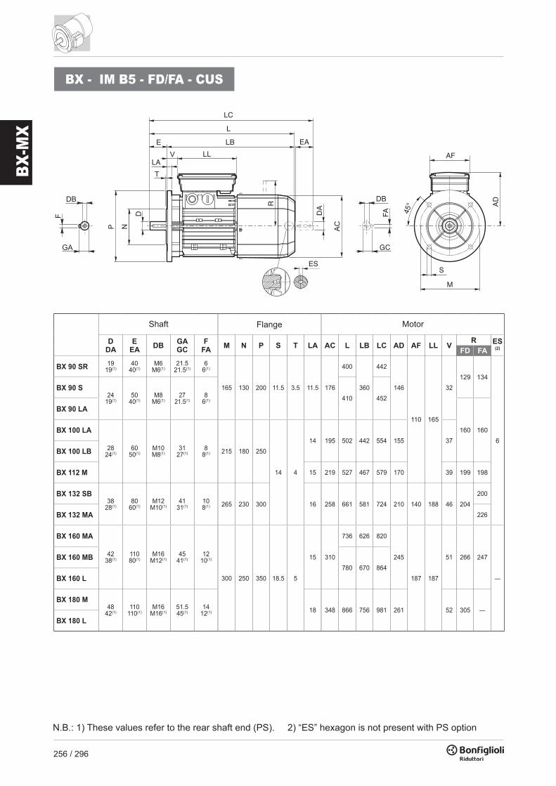
256 / 296
BX-M
X
DDA
EEA DB GA
GCF
FA M N P S T LA AC L LB LC AD AF LL VR ES
(2)FD FA
BX 90 SR 1919(1)
4040(1)
M6M6(1)
21.521.5(1)
66(1)
165 130 200 11.5 3.5 11.5 176
400
360
442
146
110 165
32129 134
6
BX 90 S24
19(1)50
40(1)M8
M6(1)27
21.5(1)8
6(1) 410 452
BX 90 LA
160 160BX 100 LA
2824(1)
6050(1)
M10M8(1)
3127(1)
88(1) 215 180 250
14 4
14 195 502 442 554 155 37
BX 100 LB
BX 112 M 15 219 527 467 579 170 39 199 198
BX 132 SB38
28(1)80
60(1)M12
M10(1)41
31(1)108(1) 265 230 300 16 258 661 581 724 210 140 188 46 204
200
BX 132 MA 226
BX 160 MA
4238(1)
11080(1)
M16M12(1)
4541(1)
1210(1)
300 250 350 18.5 5
15 310
736 626 820
245
187 187
51 266 247
—
BX 160 MB780 670 864
BX 160 L
BX 180 M48
42(1)110
110(1)M16
M16(1)51.545(1)
1412(1) 18 348 866 756 981 261 52 305 —
BX 180 L
BX - IM B5 - FD/FA - CUS
TLA
NPLC
EA
ESR
DA
FA
GC
S
M
AD
AF
45°
Shaft Flange Motor
N.B.: 1) These values refer to the rear shaft end (PS). 2) “ES” hexagon is not present with PS option
BX - IM B14 - FD/FA - CUS
DDA
EEA DB GA
GCF
FA M N P S T AC L LB LC AD AF LL VR
ES (2)
FD FA
BX 90 SR 1919(1)
4040(1)
M6M6(1)
21.521.5(1)
66(1) 100 80 120 M6
3 176
400
360
442
146
110 165
32129 134
6
BX 90 S24
19(1)50
40(1)M8
M6(1)27
21.5 (1)8
6(1) 115 95 140
M8
410 452BX 90 LA
160 160BX 100 LA
2824(1)
6050(1)
M10M8(1)
3127(1)
88(1) 130 110 160 3.5
195 502 442 554 155 37BX 100 LB
BX 112 M 219 527 467 579 170 39 199 198
BX 132 SB38
28(1)80
60(1)M12
M10(1)41
31(1)108(1) 165 130 200 M10 4 258 661 581 724 210 140 188 46 204
200
BX 132 MA 226
T
NP
LC
EA
ES
R
DA
FA 45°
GC
AD
AF
S
M
Shaft Housing Motor
N.B.: 1) These values refer to the rear shaft end (PS). 2) “ES” hexagon is not present with PS option

257 / 296
BX-M
X
DDA
EEA DB GA
GCF
FA M N P S T LA AC L LB LC AD AF LL VR ES
(2)FD FA
BX 90 SR 1919(1)
4040(1)
M6M6(1)
21.521.5(1)
66(1)
165 130 200 11.5 3.5 11.5 176
400
360
442
146
110 165
32129 134
6
BX 90 S24
19(1)50
40(1)M8
M6(1)27
21.5(1)8
6(1) 410 452
BX 90 LA
160 160BX 100 LA
2824(1)
6050(1)
M10M8(1)
3127(1)
88(1) 215 180 250
14 4
14 195 502 442 554 155 37
BX 100 LB
BX 112 M 15 219 527 467 579 170 39 199 198
BX 132 SB38
28(1)80
60(1)M12
M10(1)41
31(1)108(1) 265 230 300 16 258 661 581 724 210 140 188 46 204
200
BX 132 MA 226
BX 160 MA
4238(1)
11080(1)
M16M12(1)
4541(1)
1210(1)
300 250 350 18.5 5
15 310
736 626 820
245
187 187
51 266 247
—
BX 160 MB780 670 864
BX 160 L
BX 180 M48
42(1)110
110(1)M16
M16(1)51.545(1)
1412(1) 18 348 866 756 981 261 52 305 —
BX 180 L
BX - IM B5 - FD/FA - CUS
TLA
NP
LC
EA
ES
R
DA
FA
GC
S
M
AD
AF
45°
Shaft Flange Motor
N.B.: 1) These values refer to the rear shaft end (PS). 2) “ES” hexagon is not present with PS option
BX - IM B14 - FD/FA - CUS
DDA
EEA DB GA
GCF
FA M N P S T AC L LB LC AD AF LL VR
ES (2)
FD FA
BX 90 SR 1919(1)
4040(1)
M6M6(1)
21.521.5(1)
66(1) 100 80 120 M6
3 176
400
360
442
146
110 165
32129 134
6
BX 90 S24
19(1)50
40(1)M8
M6(1)27
21.5 (1)8
6(1) 115 95 140
M8
410 452BX 90 LA
160 160BX 100 LA
2824(1)
6050(1)
M10M8(1)
3127(1)
88(1) 130 110 160 3.5
195 502 442 554 155 37BX 100 LB
BX 112 M 219 527 467 579 170 39 199 198
BX 132 SB38
28(1)80
60(1)M12
M10(1)41
31(1)108(1) 165 130 200 M10 4 258 661 581 724 210 140 188 46 204
200
BX 132 MA 226
T
NPLC
EA
ESR
DA
FA 45°
GC
AD
AF
S
M
Shaft Housing Motor
N.B.: 1) These values refer to the rear shaft end (PS). 2) “ES” hexagon is not present with PS option

258 / 296
BX-M
X
MX
DA EA DB GC FA AC LB LC AF LL J AD
MX 2SB 14 30 M5 16 5 156 246 278 74 80 44 119
MX 3SA
24 50 M8 27
8
195
265 317
98 98 53.5 142MX 3SB
MX 3LA305 357
MX 3LB
MX 4SA
28 60 M10 31 258361 424
118 118 64.5 193MX 4SB
MX 4LA 396 459
MX 5SA
38 80 M12 41 10 310
418 502
187 187 77 245MX 5SB462 546
MX 5LA
DB
GC
FA DA
LL
LB EALC
AC
JAF
AD
Rear shaft end Motor
MX - FD/FA
DA EA DB GC FA AC LB LC AF LL J AD RFD FA ES (1)
MX 2SB 14 30 M5 16 5 156 318 349 98 133 9 143 129 134 5
MX 3SA
24 50 M8 27
8
195
355 407
110 165
7
155 160 160
6
MX 3SB
MX 3LA397 450
MX 3LB
MX 4SA
28 60 M10 31 258470 534
140 188 210 204200
MX 4SB
MX 4LA 494 558 226
MX 5SA
38 80 M12 41 10 310
558 644
187 187 17 245 266 247 —MX 5SB602 686
MX 5LA
AD
AF
LC
J
EA
ES
R
DA
FA
GC
Rear shaft end Motor
N.B.:1) “ES” hexagon is not present with PS option

259 / 296
BX-M
X
MX
DA EA DB GC FA AC LB LC AF LL J AD
MX 2SB 14 30 M5 16 5 156 246 278 74 80 44 119
MX 3SA
24 50 M8 27
8
195
265 317
98 98 53.5 142MX 3SB
MX 3LA305 357
MX 3LB
MX 4SA
28 60 M10 31 258361 424
118 118 64.5 193MX 4SB
MX 4LA 396 459
MX 5SA
38 80 M12 41 10 310
418 502
187 187 77 245MX 5SB462 546
MX 5LA
DB
GC
FA DA
LL
LB EALC
AC
JAF
AD
Rear shaft end Motor
MX - FD/FA
DA EA DB GC FA AC LB LC AF LL J AD RFD FA ES (1)
MX 2SB 14 30 M5 16 5 156 318 349 98 133 9 143 129 134 5
MX 3SA
24 50 M8 27
8
195
355 407
110 165
7
155 160 160
6
MX 3SB
MX 3LA397 450
MX 3LB
MX 4SA
28 60 M10 31 258470 534
140 188 210 204200
MX 4SB
MX 4LA 494 558 226
MX 5SA
38 80 M12 41 10 310
558 644
187 187 17 245 266 247 —MX 5SB602 686
MX 5LA
AD
AF
LC
J
EA
ES
R
DA
FA
GC
Rear shaft end Motor
N.B.:1) “ES” hexagon is not present with PS option

260 / 296
BX-M
X
MX - CUS
DA EA DB GC FA AC LB LC AF LL J AD
MX 2SB 14 30 M5 16 5 176 262 293
98 98
79 133
MX 3SA
24 50 M8 27
8
195
265 317
53.5 142MX 3SB
MX 3LA305 357
MX 3LB
MX 4SA
28 60 M10 31 258
361 424
118 118 64.5 193MX 4SB420 483
MX 4LA
MX 5SA
38 80 M12 41 10 310
418 502
187 187 77 245MX 5SB462 546
MX 5LA
DB
GC
FA DA
LL
LB EALC
AC
JAF
AD
Rear shaft end Motor
MX - FD/FA - CUS
DA EA DB GC FA AC LB LC AF LL J AD RFD FA ES (1)
MX 2SB 14 30 M5 16 5 176 347 379
110 165
-17 146 129 134
6
MX 3SA
24 50 M8 27
8
195
355 407
7
155 160 160MX 3SB
MX 3LA397 450
MX 3LB
MX 4SA
28 60 M10 31 258
470 534
140 188 210 204200
MX 4SB528 592
MX 4LA 226
MX 5SA
38 80 M12 41 10 310
558 644
187 187 17 245 266 247 —MX 5SB602 686
MX 5LA
AD
AF
LC
J
EA
ES
R
DA
FA
GC
Rear shaft end Motor
N.B.:1) “ES” hexagon is not present with PS option

261 / 296
BX-M
X
MX - CUS
DA EA DB GC FA AC LB LC AF LL J AD
MX 2SB 14 30 M5 16 5 176 262 293
98 98
79 133
MX 3SA
24 50 M8 27
8
195
265 317
53.5 142MX 3SB
MX 3LA305 357
MX 3LB
MX 4SA
28 60 M10 31 258
361 424
118 118 64.5 193MX 4SB420 483
MX 4LA
MX 5SA
38 80 M12 41 10 310
418 502
187 187 77 245MX 5SB462 546
MX 5LA
DB
GC
FA DA
LL
LB EALC
AC
JAF
AD
Rear shaft end Motor
MX - FD/FA - CUS
DA EA DB GC FA AC LB LC AF LL J AD RFD FA ES (1)
MX 2SB 14 30 M5 16 5 176 347 379
110 165
-17 146 129 134
6
MX 3SA
24 50 M8 27
8
195
355 407
7
155 160 160MX 3SB
MX 3LA397 450
MX 3LB
MX 4SA
28 60 M10 31 258
470 534
140 188 210 204200
MX 4SB528 592
MX 4LA 226
MX 5SA
38 80 M12 41 10 310
558 644
187 187 17 245 266 247 —MX 5SB602 686
MX 5LA
AD
AF
LC
J
EA
ES
R
DA
FA
GC
Rear shaft end Motor
N.B.:1) “ES” hexagon is not present with PS option

262 / 296
BE-M
E
4 P 1500 min-1 - S1 50 Hz - IE2
Pn n Mn In400V
η% cos ϕ Is Ms Ma Jm IM B5In Mn Mn x 10-4
kW min-1 Nm A 100% 75% 50% kgm2
0.37 BE 71B 4 1385 2.55 1.05 70.1 69.3 64.2 0.75 4.0 2.3 2.2 6.9 5.9
0.55 BE 80A 4 1405 3.7 1.41 75.1 74.9 71.2 0.76 4.3 2.2 1.9 15 8.2
0.75 BE 80B 4 1430 5.0 1.65 81.0 80.5 78.0 0.81 6.1 3.2 3.0 28 12.2
1.1 BE 90S 4 1430 7.4 2.53 82.5 82.0 79.5 0.76 6.3 2.9 2.8 28 13.6
1.5 BE 90LA 4 1430 10.0 3.5 83.5 83.0 80.0 0.74 5.9 3.1 3.0 34 15.1
2.2 BE 100LA 4 1430 14.7 4.9 85.4 85.0 84.0 0.76 5.8 3.0 2.8 54 22
3 BE 100LB 4 1420 20 6.6 85.5 86.0 85.5 0.77 5.9 2.8 2.6 61 24
4 BE 112M 4 1440 27 8.3 87.0 87.0 86.0 0.80 6.5 2.8 2.8 105 32
5.5 BE 132S 4 1460 36 11.1 88.5 88.5 87.5 0.81 7.3 2.9 2.9 270 53
7.5 BE 132MA 4 1460 49 14.8 89.0 89.0 88.5 0.82 6.9 2.9 2.8 319 59
9.2 BE 132MB 4 1460 60 18.1 89.5 89.5 88.5 0.82 6.9 2.9 3.0 360 70
11 BE 160M 4 1465 72 21.5 91.0 91.3 90.5 0.81 6.5 2.8 2.6 650 99
15 BE 160L 4 1465 98 28.7 90.8 91.0 90.5 0.83 6.5 2.6 2.3 790 115
18.5 BE 180M 4 1465 121 35 91.6 92.0 91.3 0.83 6.5 2.6 2.5 1250 135
22 BE 180L 4 1465 143 41 91.6 91.8 91.4 0.84 6.8 2.7 2.6 1650 157
2 P 3000 min-1 - S1 50 Hz - IE2
Pn n Mn In400V
η% cos ϕ Is Ms Ma Jm IM B5In Mn Mn x 10-4
kW min-1 Nm A 100% 75% 50% kgm2
0.75 BE 80A 2 2860 2.5 1.65 80.0 79.6 76.4 0.83 6.8 3.8 3.5 9.0 9.51.1 BE 80B 2 2845 3.7 2.35 81.5 82.2 79.9 0.83 6.9 3.8 3.1 11.4 11.3
1.5 BE 90SA 2 2865 5.0 3.2 81.3 80.7 78.1 0.82 6.8 3.6 2.8 12.5 12.32.2 BE 90L 2 2870 7.3 4.7 83.2 83.1 80.8 0.82 6.9 3.1 2.9 16.7 14
3 BE 100L 2 2880 9.9 6.2 84.6 84.6 83.7 0.83 7.3 3.5 3.1 39 23
4 BE 112M 2 2920 13.1 8.2 85.8 85.5 84.3 0.82 7.9 3.5 3.1 57 28
5.5 BE 132SA 2 2925 18.0 10.6 87.0 85.0 81.7 0.86 8.5 3.6 3.3 145 427.5 BE 132SB 2 2935 24 14.3 88.1 87.4 84.7 0.86 8.8 3.9 3.6 178 539.2 BE 132MB 2 2920 30 16.4 88.8 86.5 84.2 0.91 8.4 3.7 3.3 210 65
11 BE 160MA 2 2940 36 20.0 89.4 89.5 88.0 0.89 8.1 3.0 2.9 340 8415 BE 160MB 2 2950 49 27.2 90.5 90.5 89.5 0.88 8.5 3.0 2.8 420 97
18.5 BE 160L 2 2945 60 32 90.9 90.5 89.8 0.91 7.7 2.9 2.7 490 109
M16 MOTOR RATING CHARTS BE-ME
(*) Power /size relation not standardized
6 P 1000 min-1 - S1 50 Hz - IE2
Pn n Mn In400V
η% cos ϕ Is Ms Ma Jm IM B5In Mn Mn x 10-4
kW min-1 Nm A 100% 75% 50% kgm2
0.75 BE 90S 6 935 7.7 2.06 75.9 75.9 73.0 0.69 5.1 3.1 2.9 33 15
1.1 BE 100M 6 (*) 945 11.1 2.75 78.1 76.2 73.0 0.74 4.9 2.2 1.9 82 22
1.5 BE 100LA 6 945 15.2 3.9 79.8 77.5 74.0 0.72 5.6 2.5 2.3 95 24
2.2 BE 112M 6 950 22 5.2 81.8 81.8 79.3 0.74 5.2 2.6 2.3 168 32
3 BE 132S 6 955 30 6.6 83.3 83.3 82.4 0.79 6.1 2.1 1.9 295 44
4 BE 132MA 6 965 40 8.7 84.6 85.0 83.1 0.79 6.9 2.2 2.0 383 56
5.5 BE 160MA 6 (*) 965 54 11.6 87.0 87.0 86.4 0.79 6.6 2.5 2.3 740 83
7.5 BE 160MB 6 (*) 965 74 15.0 88.0 88.0 87.2 0.82 6.6 2.3 2.1 970 103

263 / 296
BE-M
E
4 P 1500 min-1 - S1 50 Hz - IE2
Pn n Mn In400V
η% cos ϕ Is Ms Ma Jm IM B5In Mn Mn x 10-4
kW min-1 Nm A 100% 75% 50% kgm2
0.37 BE 71B 4 1385 2.55 1.05 70.1 69.3 64.2 0.75 4.0 2.3 2.2 6.9 5.9
0.55 BE 80A 4 1405 3.7 1.41 75.1 74.9 71.2 0.76 4.3 2.2 1.9 15 8.2
0.75 BE 80B 4 1430 5.0 1.65 81.0 80.5 78.0 0.81 6.1 3.2 3.0 28 12.2
1.1 BE 90S 4 1430 7.4 2.53 82.5 82.0 79.5 0.76 6.3 2.9 2.8 28 13.6
1.5 BE 90LA 4 1430 10.0 3.5 83.5 83.0 80.0 0.74 5.9 3.1 3.0 34 15.1
2.2 BE 100LA 4 1430 14.7 4.9 85.4 85.0 84.0 0.76 5.8 3.0 2.8 54 22
3 BE 100LB 4 1420 20 6.6 85.5 86.0 85.5 0.77 5.9 2.8 2.6 61 24
4 BE 112M 4 1440 27 8.3 87.0 87.0 86.0 0.80 6.5 2.8 2.8 105 32
5.5 BE 132S 4 1460 36 11.1 88.5 88.5 87.5 0.81 7.3 2.9 2.9 270 53
7.5 BE 132MA 4 1460 49 14.8 89.0 89.0 88.5 0.82 6.9 2.9 2.8 319 59
9.2 BE 132MB 4 1460 60 18.1 89.5 89.5 88.5 0.82 6.9 2.9 3.0 360 70
11 BE 160M 4 1465 72 21.5 91.0 91.3 90.5 0.81 6.5 2.8 2.6 650 99
15 BE 160L 4 1465 98 28.7 90.8 91.0 90.5 0.83 6.5 2.6 2.3 790 115
18.5 BE 180M 4 1465 121 35 91.6 92.0 91.3 0.83 6.5 2.6 2.5 1250 135
22 BE 180L 4 1465 143 41 91.6 91.8 91.4 0.84 6.8 2.7 2.6 1650 157
2 P 3000 min-1 - S1 50 Hz - IE2
Pn n Mn In400V
η% cos ϕ Is Ms Ma Jm IM B5In Mn Mn x 10-4
kW min-1 Nm A 100% 75% 50% kgm2
0.75 BE 80A 2 2860 2.5 1.65 80.0 79.6 76.4 0.83 6.8 3.8 3.5 9.0 9.51.1 BE 80B 2 2845 3.7 2.35 81.5 82.2 79.9 0.83 6.9 3.8 3.1 11.4 11.3
1.5 BE 90SA 2 2865 5.0 3.2 81.3 80.7 78.1 0.82 6.8 3.6 2.8 12.5 12.32.2 BE 90L 2 2870 7.3 4.7 83.2 83.1 80.8 0.82 6.9 3.1 2.9 16.7 14
3 BE 100L 2 2880 9.9 6.2 84.6 84.6 83.7 0.83 7.3 3.5 3.1 39 23
4 BE 112M 2 2920 13.1 8.2 85.8 85.5 84.3 0.82 7.9 3.5 3.1 57 28
5.5 BE 132SA 2 2925 18.0 10.6 87.0 85.0 81.7 0.86 8.5 3.6 3.3 145 427.5 BE 132SB 2 2935 24 14.3 88.1 87.4 84.7 0.86 8.8 3.9 3.6 178 539.2 BE 132MB 2 2920 30 16.4 88.8 86.5 84.2 0.91 8.4 3.7 3.3 210 65
11 BE 160MA 2 2940 36 20.0 89.4 89.5 88.0 0.89 8.1 3.0 2.9 340 8415 BE 160MB 2 2950 49 27.2 90.5 90.5 89.5 0.88 8.5 3.0 2.8 420 97
18.5 BE 160L 2 2945 60 32 90.9 90.5 89.8 0.91 7.7 2.9 2.7 490 109
M16 MOTOR RATING CHARTS BE-ME
(*) Power /size relation not standardized
6 P 1000 min-1 - S1 50 Hz - IE2
Pn n Mn In400V
η% cos ϕ Is Ms Ma Jm IM B5In Mn Mn x 10-4
kW min-1 Nm A 100% 75% 50% kgm2
0.75 BE 90S 6 935 7.7 2.06 75.9 75.9 73.0 0.69 5.1 3.1 2.9 33 15
1.1 BE 100M 6 (*) 945 11.1 2.75 78.1 76.2 73.0 0.74 4.9 2.2 1.9 82 22
1.5 BE 100LA 6 945 15.2 3.9 79.8 77.5 74.0 0.72 5.6 2.5 2.3 95 24
2.2 BE 112M 6 950 22 5.2 81.8 81.8 79.3 0.74 5.2 2.6 2.3 168 32
3 BE 132S 6 955 30 6.6 83.3 83.3 82.4 0.79 6.1 2.1 1.9 295 44
4 BE 132MA 6 965 40 8.7 84.6 85.0 83.1 0.79 6.9 2.2 2.0 383 56
5.5 BE 160MA 6 (*) 965 54 11.6 87.0 87.0 86.4 0.79 6.6 2.5 2.3 740 83
7.5 BE 160MB 6 (*) 965 74 15.0 88.0 88.0 87.2 0.82 6.6 2.3 2.1 970 103

264 / 296
BE-M
E
2 P 3000 min-1 - S1 50 Hz - IE2
Pn n Mn In400V
η% cos ϕ Is Ms Ma Jm IM B9In Mn Mn x 10-4
kW min-1 Nm A 100% 75% 50% kgm2
0.75 ME 2SA 2 2860 2.5 1.63 80.0 79.6 76.4 0.83 6.8 3.8 3.5 9.0 8.8
1.1 ME 2SB 2 2845 3.7 2.35 81.5 82.2 79.9 0.83 6.9 3.8 3.1 11.4 10.6
1.5 ME 3SA 2 2845 5.0 3.2 81.3 79.0 76.0 0.84 6.1 2.9 2.7 24 15.5
2.2 ME 3LA 2 2895 7.3 4.8 83.2 83.2 81.5 0.80 6.3 2.7 2.5 31 18.7
3 ME 3LB 2 2880 9.9 6.2 84.6 84.6 83.7 0.83 7.3 3.5 3.1 39 22
4 ME 4SA 2 2900 13.2 7.8 85.8 84.5 82.2 0.87 7.0 2.9 2.8 101 33
5.5 ME 4SB 2 2925 18.0 10.6 87.0 85.0 81.7 0.86 8.5 3.6 3.3 145 40
7.5 ME 4LA 2 2935 24 14.3 88.1 87.4 84.7 0.86 8.8 3.9 3.6 178 51
9.2 ME 4LB 2 2920 30 16.4 88.8 86.5 84.2 0.91 8.4 3.7 3.3 210 60
11 ME 5SA 2 2940 36 20.0 89.4 89.5 88.0 0.89 8.1 3.0 2.9 340 70
15 ME 5SB 2 2950 49 27.2 90.5 90.5 89.5 0.88 8.5 3 2.8 420 83
18.5 ME 5LA 2 2945 60 32 90.9 90.5 89.8 0.91 7.7 2.9 2.7 490 95
4 P 1500 min-1 - S1 50 Hz - IE2
Pn n Mn In400V
η% cos ϕ Is Ms Ma Jm IM B9In Mn Mn x 10-4
kW min-1 Nm A 100% 75% 50% kgm2
0.75 ME 2SB 4 1430 5.0 1.65 81.0 80.5 78.0 0.81 6.1 3.2 3 28 10.9
1.1 ME 3SA 4 1430 7.4 2.60 82.5 82.0 79.0 0.74 5.5 2.5 2.8 34 15.5
1.5 ME 3SB 4 1420 10.1 3.48 84.0 84.0 83.0 0.74 6.2 2.9 2.9 40 17
2.2 ME 3LA 4 1430 14.7 4.89 85.4 85.0 84.0 0.76 5.8 3 2.8 54 21
3 ME 3LB 4 1420 20 6.58 85.5 86.0 85.5 0.77 5.9 2.8 2.6 61 23
4 ME 4SA 4 1440 27 8.25 87.5 86.8 84.0 0.80 7.1 3.0 3.1 213 42
5.5 ME 4SB 4 1460 36 11.07 88.5 88.5 87.5 0.81 7.3 2.9 2.9 270 51
7.5 ME 4LA 4 1460 49 14.83 89.0 89.0 88.5 0.82 6.9 2.9 2.8 319 57
9.2 ME 4LB 4 1460 60 18.09 89.5 89.5 88.5 0.82 6.9 2.9 3 360 65
11 ME 5SA 4 1465 72 21.54 91.0 91.3 90.5 0.81 6.5 2.8 2.6 650 85
15 ME 5LA 4 1465 98 28.73 90.8 91.0 90.5 0.83 6.5 2.6 2.3 790 101
(*) Power /size relation not standardized
6 P 1000 min-1 - S1 50 Hz - IE2
Pn n Mn In400V
η% cos ϕ Is Ms Ma Jm IM B9In Mn Mn x 10-4
kW min-1 Nm A 100% 75% 50% kgm2
0.75 ME 3SA 6 940 7.6 1.98 75.9 75.0 70.7 0.72 4.7 2.2 2.0 33 17
1.1 ME 3LA 6 (*) 945 11.1 2.75 78.1 76.2 73.0 0.74 4.9 2.2 1.9 82 21
1.5 ME 3LB 6 945 15.2 3.8 79.8 77.5 74.0 0.72 5.6 2.5 2.3 95 23
2.2 ME 4SA 6 955 22 4.9 81.8 81.8 80.0 0.80 5.7 1.9 1.7 216 34
3 ME 4SB 6 955 30 6.6 83.3 83.3 82.4 0.79 6.1 2.1 1.9 295 43
4 ME 4LA 6 965 40 8.6 84.6 85 83.1 0.79 6.9 2.2 2 383 54
5.5 ME 5SA 6 (*) 965 54 11.6 87.0 87.0 86.4 0.79 6.6 2.5 2.3 740 69
7.5 ME 5SB 6 (*) 965 74 15.0 88.0 88.0 87.2 0.82 6.6 2.3 2.1 970 89

265 / 296
BE-M
E
2 P 3000 min-1 - S1 50 Hz - IE2
Pn n Mn In400V
η% cos ϕ Is Ms Ma Jm IM B9In Mn Mn x 10-4
kW min-1 Nm A 100% 75% 50% kgm2
0.75 ME 2SA 2 2860 2.5 1.63 80.0 79.6 76.4 0.83 6.8 3.8 3.5 9.0 8.8
1.1 ME 2SB 2 2845 3.7 2.35 81.5 82.2 79.9 0.83 6.9 3.8 3.1 11.4 10.6
1.5 ME 3SA 2 2845 5.0 3.2 81.3 79.0 76.0 0.84 6.1 2.9 2.7 24 15.5
2.2 ME 3LA 2 2895 7.3 4.8 83.2 83.2 81.5 0.80 6.3 2.7 2.5 31 18.7
3 ME 3LB 2 2880 9.9 6.2 84.6 84.6 83.7 0.83 7.3 3.5 3.1 39 22
4 ME 4SA 2 2900 13.2 7.8 85.8 84.5 82.2 0.87 7.0 2.9 2.8 101 33
5.5 ME 4SB 2 2925 18.0 10.6 87.0 85.0 81.7 0.86 8.5 3.6 3.3 145 40
7.5 ME 4LA 2 2935 24 14.3 88.1 87.4 84.7 0.86 8.8 3.9 3.6 178 51
9.2 ME 4LB 2 2920 30 16.4 88.8 86.5 84.2 0.91 8.4 3.7 3.3 210 60
11 ME 5SA 2 2940 36 20.0 89.4 89.5 88.0 0.89 8.1 3.0 2.9 340 70
15 ME 5SB 2 2950 49 27.2 90.5 90.5 89.5 0.88 8.5 3 2.8 420 83
18.5 ME 5LA 2 2945 60 32 90.9 90.5 89.8 0.91 7.7 2.9 2.7 490 95
4 P 1500 min-1 - S1 50 Hz - IE2
Pn n Mn In400V
η% cos ϕ Is Ms Ma Jm IM B9In Mn Mn x 10-4
kW min-1 Nm A 100% 75% 50% kgm2
0.75 ME 2SB 4 1430 5.0 1.65 81.0 80.5 78.0 0.81 6.1 3.2 3 28 10.9
1.1 ME 3SA 4 1430 7.4 2.60 82.5 82.0 79.0 0.74 5.5 2.5 2.8 34 15.5
1.5 ME 3SB 4 1420 10.1 3.48 84.0 84.0 83.0 0.74 6.2 2.9 2.9 40 17
2.2 ME 3LA 4 1430 14.7 4.89 85.4 85.0 84.0 0.76 5.8 3 2.8 54 21
3 ME 3LB 4 1420 20 6.58 85.5 86.0 85.5 0.77 5.9 2.8 2.6 61 23
4 ME 4SA 4 1440 27 8.25 87.5 86.8 84.0 0.80 7.1 3.0 3.1 213 42
5.5 ME 4SB 4 1460 36 11.07 88.5 88.5 87.5 0.81 7.3 2.9 2.9 270 51
7.5 ME 4LA 4 1460 49 14.83 89.0 89.0 88.5 0.82 6.9 2.9 2.8 319 57
9.2 ME 4LB 4 1460 60 18.09 89.5 89.5 88.5 0.82 6.9 2.9 3 360 65
11 ME 5SA 4 1465 72 21.54 91.0 91.3 90.5 0.81 6.5 2.8 2.6 650 85
15 ME 5LA 4 1465 98 28.73 90.8 91.0 90.5 0.83 6.5 2.6 2.3 790 101
(*) Power /size relation not standardized
6 P 1000 min-1 - S1 50 Hz - IE2
Pn n Mn In400V
η% cos ϕ Is Ms Ma Jm IM B9In Mn Mn x 10-4
kW min-1 Nm A 100% 75% 50% kgm2
0.75 ME 3SA 6 940 7.6 1.98 75.9 75.0 70.7 0.72 4.7 2.2 2.0 33 17
1.1 ME 3LA 6 (*) 945 11.1 2.75 78.1 76.2 73.0 0.74 4.9 2.2 1.9 82 21
1.5 ME 3LB 6 945 15.2 3.8 79.8 77.5 74.0 0.72 5.6 2.5 2.3 95 23
2.2 ME 4SA 6 955 22 4.9 81.8 81.8 80.0 0.80 5.7 1.9 1.7 216 34
3 ME 4SB 6 955 30 6.6 83.3 83.3 82.4 0.79 6.1 2.1 1.9 295 43
4 ME 4LA 6 965 40 8.6 84.6 85 83.1 0.79 6.9 2.2 2 383 54
5.5 ME 5SA 6 (*) 965 54 11.6 87.0 87.0 86.4 0.79 6.6 2.5 2.3 740 69
7.5 ME 5SB 6 (*) 965 74 15.0 88.0 88.0 87.2 0.82 6.6 2.3 2.1 970 89

266 / 296
BE-M
E
M17 MOTORS DIMENSIONS BE-ME
BE - IM B5
DB
GC
FADA
P DN
T
V LLE LB EA
LLC
AC
LA
DB
GA
F
AF
45°
MS
AD
DDA
EEA DB GA
GCF
FA M N P S T LA AC L LB LC AD AF LL V
BE 71 14 30 M5 16 5 130 110 160 9.5
3.5
10 138 249 219 281 10874 80
37
BE 80 19 40 M6 21.5 6
165 130 200 11.5 11.5
156 274 234 315 119 38
BE 90 S24 50 M8 27
8
176 326 276 378 133
98 98
44BE 90 L
BE 10028 60 M10 31 215 180 250
14 4
14 195 367 307 429 142 50
BE 112 15 219 385 325 448 157 52
BE 132 S
38 80 M12 41 10 265 230 300 20 258493 413 576
193 118 118 58BE 132 MA
BE 132 MB 528 448 611
BE 160 M42
38(1)11080(1)
M16M12(1)
4541(1)
1210(1)
300 250 350 18.5 5
15 310596 486 680
245
187 187
51BE 160 L 640 530 724
BE 180 M48
42(1)110
110(1)M16
M16(1)51.545(1)
1412(1) 18 348 708 598 823 261 52
BE 180 L
N.B.:1) These values refer to the rear shaft end.
Shaft Flange Motor
BE - IM B14
DDA
EEA DB GA
GCF
FA M N P S T AC L LB LC AD AF LL V
BE 71 14 30 M5 16 5 85 70 105M6
2.5 138 249 219 281 10874 80
37
BE 80 19 40 M6 21.5 6 100 80 120
3
156 274 234 315 119 38
BE 90 S24 50 M8 27
8
115 95 140
M8
176 326 276 378 133
98 98
44BE 90 L
BE 10028 60 M10 31 130 110 160 3.5
195 367 307 429 142 50
BE 112 219 385 325 448 157 52
BE 132 S
38 80 M12 41 10 165 130 200 M10 4 258493 413 576
193 118 118 58BE 132 MA
BE 132 MB 528 448 611
DB
GC
FADA
P N D
T
V LLE LB EA
LLC
AC
DB
GA
F
AF
45°
M
S
AD
Shaft Flange Motor

267 / 296
BE-M
E
M17 MOTORS DIMENSIONS BE-ME
BE - IM B5
DB
GC
FADA
P DN
T
V LLE LB EA
LLC
AC
LA
DB
GA
F
AF
45°
MS
AD
DDA
EEA DB GA
GCF
FA M N P S T LA AC L LB LC AD AF LL V
BE 71 14 30 M5 16 5 130 110 160 9.5
3.5
10 138 249 219 281 10874 80
37
BE 80 19 40 M6 21.5 6
165 130 200 11.5 11.5
156 274 234 315 119 38
BE 90 S24 50 M8 27
8
176 326 276 378 133
98 98
44BE 90 L
BE 10028 60 M10 31 215 180 250
14 4
14 195 367 307 429 142 50
BE 112 15 219 385 325 448 157 52
BE 132 S
38 80 M12 41 10 265 230 300 20 258493 413 576
193 118 118 58BE 132 MA
BE 132 MB 528 448 611
BE 160 M42
38(1)11080(1)
M16M12(1)
4541(1)
1210(1)
300 250 350 18.5 5
15 310596 486 680
245
187 187
51BE 160 L 640 530 724
BE 180 M48
42(1)110
110(1)M16
M16(1)51.545(1)
1412(1) 18 348 708 598 823 261 52
BE 180 L
N.B.:1) These values refer to the rear shaft end.
Shaft Flange Motor
BE - IM B5
DB
GC
FADA
P DN
T
V LLE LB EA
LLC
AC
LA
DB
GA
F
AF
45°
MS
AD
DDA
EEA DB GA
GCF
FA M N P S T LA AC L LB LC AD AF LL V
BE 71 14 30 M5 16 5 130 110 160 9.5
3.5
10 138 249 219 281 10874 80
37
BE 80 19 40 M6 21.5 6
165 130 200 11.5 11.5
156 274 234 315 119 38
BE 90 S24 50 M8 27
8
176 326 276 378 133
98 98
44BE 90 L
BE 10028 60 M10 31 215 180 250
14 4
14 195 367 307 429 142 50
BE 112 15 219 385 325 448 157 52
BE 132 S
38 80 M12 41 10 265 230 300 20 258493 413 576
193 118 118 58BE 132 MA
BE 132 MB 528 448 611
BE 160 M42
38(1)11080(1)
M16M12(1)
4541(1)
1210(1)
300 250 350 18.5 5
15 310596 486 680
245
187 187
51BE 160 L 640 530 724
BE 180 M48
42(1)110
110(1)M16
M16(1)51.545(1)
1412(1) 18 348 708 598 823 261 52
BE 180 L
N.B.:1) These values refer to the rear shaft end.
Shaft Flange Motor
BE - IM B14
DDA
EEA DB GA
GCF
FA M N P S T AC L LB LC AD AF LL V
BE 71 14 30 M5 16 5 85 70 105M6
2.5 138 249 219 281 10874 80
37
BE 80 19 40 M6 21.5 6 100 80 120
3
156 274 234 315 119 38
BE 90 S24 50 M8 27
8
115 95 140
M8
176 326 276 378 133
98 98
44BE 90 L
BE 10028 60 M10 31 130 110 160 3.5
195 367 307 429 142 50
BE 112 219 385 325 448 157 52
BE 132 S
38 80 M12 41 10 165 130 200 M10 4 258493 413 576
193 118 118 58BE 132 MA
BE 132 MB 528 448 611
DB
GC
FADA
P N D
T
V LLE LB EA
LLC
AC
DB
GA
F
AF
45°
M
S
AD
Shaft Flange Motor

268 / 296
BE-M
E
ME
DA EA DB FA GC AC LB LC AF LL J AD
ME 2S 19 40 M6 6 21.5 156 202 245 74 80 44 119
ME 3S28 60 M10 8 31 195
230 29398 98 53.5 142
ME 3L 262 325
ME 4S
38 80 M12 10 41
258361 444
118 118 64.5 193ME 4L
ME 4LB 396 479
ME 5S310
418 502187 187 77 245
ME 5L 462 546
DB
GC
FA DA
LL
LB EALC
AC
JAF
AD
Rear shaft end Motor
2P30
00 m
in-1
- S1
50 H
z
FDFA
P nn
Mn
IE1
ηη
ηcosφ
InIs In
Ms
Mn
Ma
Mn
J mIM
B5
Mod
Mb
Z oJ m
IM B
5M
odM
bZ o
J mIM
B5
(100
%)
(75%
)(5
0%)
400V
x 10-4
1/h
x 10-4
1/h
x 10-4
kWm
in-1
Nm%
%%
Akg
m2
NmNB
SBkg
m2
Nmkg
m2
0.18
BN 63
A 2
2730
0.63
○59
.956
.951
.90.
770.
563.
02.
12.
02.
03.
5FD
021.
7539
0048
002.
65.
2FA
021.
7548
002.
65.
0
0.25
BN 63
B 2
2740
0.87
○66
.064
.864
.80.
760.
723.
32.
32.
32.
33.
9FD
021.
7539
0048
003.
05.
6FA
021.
7548
003.
05.
4
0.37
BN 63
C2
2800
1.26
○69
.166
.866
.80.
780.
993.
92.
62.
63.
35.
1FD
023.
536
0045
003.
96.
8FA
023.
545
003.
96.
6
0.37
BN 71
A2
2820
1.25
○73
.873
.070
.60.
760.
954.
82.
82.
63.
55.
4FD
033.
530
0041
004.
68.
1FA
033.
542
004.
67.
8
0.55
BN 71
B 2
2820
1.86
○76
.075
.874
.80.
761.
375.
02.
92.
84.
16.
2FD
035
2900
4200
5.3
8.9
FA 03
542
005.
38.
6
0.75
BN 71
C2
2810
2.6
○76
.676
.276
.20.
761.
865.
13.
12.
85.
07.
3FD
035
1900
3300
6.1
10.0
FA 03
536
006.
19.
7
0.75
BN 80
A 2
2810
2.6
•76
.275
.568
.30.
811.
754.
82.
62.
27.
88.
6FD
045
1700
3200
9.4
12.5
FA 04
532
009.
412
.4
1.1
BN 80
B2
2800
3.8
•76
.476
.275
.00.
812.
574.
82.
82.
49.
09.
5FD
0410
1500
3000
10.6
13.4
FA 04
1030
0010
.613
.3
1.5
BN 80
C2
2800
5.1
•79
.179
.577
.20.
813.
44.
92.
72.
411
.411
.3FD
0415
1300
2600
13.0
15.2
FA 04
1526
0013
.015
.1
1.5
BN 90
SA2
2870
5.0
•82
.081
.578
.10.
803.
45.
92.
72.
612
.512
.3FD
1415
900
2200
14.1
16.5
FA 14
1522
0014
.116
.4
1.85
BN 90
SB2
2880
6.1
•82
.582
.075
.40.
804.
06.
22.
92.
616
.714
FD 14
1590
022
0018
.318
.2FA
1415
2200
18.3
18.1
2.2
BN 90
L2
2880
7.3
•82
.782
.180
.80.
804.
86.
32.
92.
716
.714
FD 05
2690
022
0021
20FA
0526
2200
2120
.7
3BN
100L
228
6010
.0•
81.5
81.3
77.4
0.79
6.7
5.6
2.6
2.2
3120
FD 15
2670
016
0035
26FA
1526
1600
3527
4BN
100L
B2
2870
13.3
•83
.183
.077
.80.
808.
75.
82.
72.
539
23FD
1540
450
900
4329
FA 15
4010
0043
30
4BN
112M
229
0013
.2•
85.5
84.5
83.0
0.82
8.2
6.9
3.0
2.9
5728
FD 06
S40
—95
066
39FA
06S
4095
066
40
5.5
BN 13
2SA
228
9018
.2•
84.7
84.5
81.2
0.84
11.2
5.9
2.6
2.2
101
35FD
0650
—60
011
248
FA 06
5060
011
249
7.5
BN 13
2SB
229
0025
•86
.586
.384
.40.
8514
.76.
42.
62.
214
542
FD 06
50—
550
154
55FA
0650
550
154
56
9.2
BN 13
2M
229
3030
•87
.086
.583
.60.
8617
.76.
72.
82.
317
853
FD 56
75—
430
189
66FA
0675
430
189
67
11BN
160M
R2
2920
36•
87.6
87.0
86.0
0.88
20.6
6.9
2.9
2.5
210
65
15BN
160M
B2
2930
49•
89.6
89.4
88.0
0.86
28.1
7.1
2.6
2.3
340
84
18.5
BN 16
0L2
2930
60•
90.4
90.1
89.0
0.86
347.
62.
72.
342
097
22BN
180M
229
3072
•89
.989
.789
.50.
8840
7.8
2.6
2.4
490
109
30BN
200L
A2
2930
98•
90.7
90.1
87.6
0.89
547.
82.
72.
977
014
0
○ =
n.a.
• = IE
1
d.c.
bra
kea.
c. b
rake
M18 MOTOR RATING CHARTS BN-M

269 / 296
BN-M
ME
DA EA DB FA GC AC LB LC AF LL J AD
ME 2S 19 40 M6 6 21.5 156 202 245 74 80 44 119
ME 3S28 60 M10 8 31 195
230 29398 98 53.5 142
ME 3L 262 325
ME 4S
38 80 M12 10 41
258361 444
118 118 64.5 193ME 4L
ME 4LB 396 479
ME 5S310
418 502187 187 77 245
ME 5L 462 546
DB
GC
FA DA
LL
LB EALC
AC
JAF
AD
Rear shaft end Motor
2P30
00 m
in-1
- S1
50 H
z
FDFA
P nn
Mn
IE1
ηη
ηcosφ
InIs In
Ms
Mn
Ma
Mn
J mIM
B5
Mod
Mb
Z oJ m
IM B
5M
odM
bZ o
J mIM
B5
(100
%)
(75%
)(5
0%)
400V
x 10-4
1/h
x 10-4
1/h
x 10-4
kWm
in-1
Nm%
%%
Akg
m2
NmNB
SBkg
m2
Nmkg
m2
0.18
BN 63
A 2
2730
0.63
○59
.956
.951
.90.
770.
563.
02.
12.
02.
03.
5FD
021.
7539
0048
002.
65.
2FA
021.
7548
002.
65.
0
0.25
BN 63
B 2
2740
0.87
○66
.064
.864
.80.
760.
723.
32.
32.
32.
33.
9FD
021.
7539
0048
003.
05.
6FA
021.
7548
003.
05.
4
0.37
BN 63
C2
2800
1.26
○69
.166
.866
.80.
780.
993.
92.
62.
63.
35.
1FD
023.
536
0045
003.
96.
8FA
023.
545
003.
96.
6
0.37
BN 71
A2
2820
1.25
○73
.873
.070
.60.
760.
954.
82.
82.
63.
55.
4FD
033.
530
0041
004.
68.
1FA
033.
542
004.
67.
8
0.55
BN 71
B 2
2820
1.86
○76
.075
.874
.80.
761.
375.
02.
92.
84.
16.
2FD
035
2900
4200
5.3
8.9
FA 03
542
005.
38.
6
0.75
BN 71
C2
2810
2.6
○76
.676
.276
.20.
761.
865.
13.
12.
85.
07.
3FD
035
1900
3300
6.1
10.0
FA 03
536
006.
19.
7
0.75
BN 80
A 2
2810
2.6
•76
.275
.568
.30.
811.
754.
82.
62.
27.
88.
6FD
045
1700
3200
9.4
12.5
FA 04
532
009.
412
.4
1.1
BN 80
B2
2800
3.8
•76
.476
.275
.00.
812.
574.
82.
82.
49.
09.
5FD
0410
1500
3000
10.6
13.4
FA 04
1030
0010
.613
.3
1.5
BN 80
C2
2800
5.1
•79
.179
.577
.20.
813.
44.
92.
72.
411
.411
.3FD
0415
1300
2600
13.0
15.2
FA 04
1526
0013
.015
.1
1.5
BN 90
SA2
2870
5.0
•82
.081
.578
.10.
803.
45.
92.
72.
612
.512
.3FD
1415
900
2200
14.1
16.5
FA 14
1522
0014
.116
.4
1.85
BN 90
SB2
2880
6.1
•82
.582
.075
.40.
804.
06.
22.
92.
616
.714
FD 14
1590
022
0018
.318
.2FA
1415
2200
18.3
18.1
2.2
BN 90
L2
2880
7.3
•82
.782
.180
.80.
804.
86.
32.
92.
716
.714
FD 05
2690
022
0021
20FA
0526
2200
2120
.7
3BN
100L
228
6010
.0•
81.5
81.3
77.4
0.79
6.7
5.6
2.6
2.2
3120
FD 15
2670
016
0035
26FA
1526
1600
3527
4BN
100L
B2
2870
13.3
•83
.183
.077
.80.
808.
75.
82.
72.
539
23FD
1540
450
900
4329
FA 15
4010
0043
30
4BN
112M
229
0013
.2•
85.5
84.5
83.0
0.82
8.2
6.9
3.0
2.9
5728
FD 06
S40
—95
066
39FA
06S
4095
066
40
5.5
BN 13
2SA
228
9018
.2•
84.7
84.5
81.2
0.84
11.2
5.9
2.6
2.2
101
35FD
0650
—60
011
248
FA 06
5060
011
249
7.5
BN 13
2SB
229
0025
•86
.586
.384
.40.
8514
.76.
42.
62.
214
542
FD 06
50—
550
154
55FA
0650
550
154
56
9.2
BN 13
2M
229
3030
•87
.086
.583
.60.
8617
.76.
72.
82.
317
853
FD 56
75—
430
189
66FA
0675
430
189
67
11BN
160M
R2
2920
36•
87.6
87.0
86.0
0.88
20.6
6.9
2.9
2.5
210
65
15BN
160M
B2
2930
49•
89.6
89.4
88.0
0.86
28.1
7.1
2.6
2.3
340
84
18.5
BN 16
0L2
2930
60•
90.4
90.1
89.0
0.86
347.
62.
72.
342
097
22BN
180M
229
3072
•89
.989
.789
.50.
8840
7.8
2.6
2.4
490
109
30BN
200L
A2
2930
98•
90.7
90.1
87.6
0.89
547.
82.
72.
977
014
0
○ =
n.a.
• = IE
1
d.c.
bra
kea.
c. b
rake
M18 MOTOR RATING CHARTS BN-M

270 / 296
BN-M
4P15
00 m
in-1
- S
150
Hz
FDFA
P nn
Mn
IE1
ηη
ηcosφ
InIs In
Ms
Mn
Ma
Mn
J mIM
B5
Mod
Mb
Z oJ m
IM B
5M
odM
bZ o
J mIM
B5
(100
%)
(75%
)(5
0%)
400V
x 10
-41/
hx
10-4
1/h
x 10
-4
kWm
in-1
Nm%
%%
Akg
m2
NmNB
SBkg
m2
Nmkg
m2
0.06
BN 5
6A4
1340
0.43
○46
.844
.241
.30.
650.
282.
62.
32.
01.
53.
10.
09BN
56B
413
500.
64○
51.7
47.6
42.9
0.60
0.42
2.6
2.5
2.4
1.5
3.1
0.12
BN 6
3A4
1350
0.85
○59
.856
.247
.00.
620.
472.
61.
91.
82.
03.
5FD
02
1.75
1000
013
000
2.6
5.2
FA 0
21.
7513
000
2.6
5.0
0.18
BN 6
3B4
1320
1.30
○54
.852
.952
.50.
670.
712.
62.
22.
02.
33.
9FD
02
3.5
1000
013
000
3.0
5.6
FA 0
23.
513
000
3.0
5.4
0.25
BN 6
3C4
1340
1.78
○65
.365
.057
.90.
690.
802.
72.
11.
93.
35.
1FD
02
3.5
7800
1000
03.
96.
8FA
02
3.5
1000
03.
96.
6
0.25
BN 7
1A4
1380
1.73
○63
.762
.259
.10.
730.
783.
31.
91.
75.
85.
1FD
03
3.5
7700
1100
06.
97.
8FA
03
3.5
1100
06.
97.
50.
37BN
71B
413
702.
6○
66.8
66.7
63.0
0.76
1.05
3.7
2.0
1.9
6.9
5.9
FD 0
35
6000
9400
8.0
8.6
FA 0
35.
094
008.
08.
30.
55BN
71C
413
803.
8○
69.0
68.9
68.8
0.74
1.55
4.1
2.3
2.3
9.1
7.3
FD 5
37.
543
0087
0010
.210
.0FA
03
7.5
8700
10.2
9.7
0.55
BN 8
0A4
1390
3.8
○72
.071
.369
.70.
771.
434.
12.
32.
015
8.2
FD 0
410
4100
8000
16.6
12.1
FA 0
410
8000
16.6
12.0
0.75
BN 8
0B4
1400
5.1
•75
.074
.569
.30.
781.
854.
92.
72.
520
9.9
FD 0
415
4100
7800
2213
.8FA
04
1578
0022
13.7
1.1
BN 8
0C4
1400
7.5
•75
.576
.270
.40.
782.
75.
12.
82.
525
11.3
FD 0
415
2600
5300
2715
.2FA
04
1553
0027
15.1
1.1
BN 9
0S4
1390
7.6
•76
.576
.272
.20.
772.
704.
62.
62.
221
12.2
FD 1
415
4800
8000
2316
.4FA
14
1580
0023
16.3
1.5
BN 9
0LA
414
1010
.2•
78.7
78.5
74.9
0.77
3.6
5.3
2.8
2.4
2813
.6FD
05
2634
0060
0032
19.6
FA 0
526
6000
3220
.31.
85BN
90L
B4
1390
12.7
•78
.678
.977
.20.
794.
35.
12.
82.
630
15.1
FD 0
526
3200
5900
3421
.1FA
05
2659
0034
21.8
2.2
BN 1
00LA
414
1014
.9•
81.1
81.4
79.9
0.75
5.2
4.5
2.2
2.0
4018
FD 1
540
2600
4700
4425
FA 1
540
4700
4425
3BN
100
LB4
1410
20•
82.6
83.8
83.7
0.77
6.8
5.0
2.3
2.2
5422
FD 1
540
2400
4400
5828
FA 1
540
4400
5829
4BN
112M
414
3027
•84
.484
.281
.60.
818.
45.
62.
72.
598
30FD
06S
60—
1400
107
40FA
06S
6021
0010
742
5.5
BN 1
32S
414
4036
•84
.784
.882
.50.
8111
.65.
52.
32.
221
344
FD 5
675
—10
5022
357
FA 0
675
1200
223
587.
5BN
132
MA
414
4050
•86
.086
.385
.30.
8115
.55.
72.
52.
427
053
FD 0
610
0—
950
280
66FA
07
100
1000
280
719.
2BN
132
MB
414
4061
•88
.488
.687
.50.
8118
.85.
92.
72.
531
959
FD 0
715
0—
900
342
75FA
07
150
900
342
77
11BN
160
MR
414
4073
•87
.687
.886
.00.
8122
.46.
02.
72.
536
070
FD 0
715
0—
850
382
86FA
07
150
850
382
8815
BN 1
60L
414
6098
•88
.788
.588
.40.
8130
6.0
2.3
2.1
650
99FD
08
200
—75
072
512
9FA
08
200
750
710
128
18.5
BN 1
80M
414
6012
1•
89.3
89.5
89.2
0.81
376.
22.
62.
579
011
5FD
08
250
—70
086
514
5FA
08
250
700
850
144
22BN
180
L4
1460
144
•89
.990
.090
.00.
8044
6.4
2.5
2.5
1250
135
FD 0
930
0—
400
1450
175
30BN
200
L4
1460
196
•91
.491
.791
.00.
8059
7.1
2.7
2.8
1650
157
FD 0
940
0—
300
1850
197
○ =
n.a.
• = IE
1
d.c.
bra
kea.
c. b
rake
6P10
00 m
in-1
- S
150
Hz
FDFA
P nn
Mn
IE1
ηη
ηcosφ
InIs In
Ms
Mn
Ma
Mn
J mIM
B5
Mod
Mb
Z oJ m
IM B
5M
odM
bZ o
J mIM
B5
(100
%)
(75%
)(5
0%)
400V
x 10
-41/
hx
10-4
1/h
x 10
-4
kWm
in-1
Nm%
%%
Akg
m2
NmNB
SBkg
m2
Nmkg
m2
0.09
BN 6
3A
688
00.
98○
41.0
41.0
32.9
0.53
0.60
2.1
2.1
1.8
3.4
4.6
FD 0
23.
590
0014
000
4.0
6.3
FA 0
23.
514
000
4.0
6.1
0.12
BN 6
3B
687
01.
32○
45.0
44.0
41.8
0.60
0.64
2.1
1.9
1.7
3.7
4.9
FD 0
23.
590
0014
000
4.3
6.6
FA 0
23.
514
000
4.3
6.4
0.18
BN 7
1A6
900
1.91
○55
.055
.551
.00.
690.
682.
61.
91.
78.
45.
5FD
03
581
0013
500
9.5
8.2
FA 0
35.
013
500
9.5
7.9
0.25
BN 7
1B
690
02.
70○
62.0
58.5
51.4
0.71
0.82
2.6
1.9
1.7
10.9
6.7
FD 0
35
7800
1300
012
9.4
FA 0
35.
013
000
129.
1
0.37
BN 7
1C6
910
3.9
○66
.060
.053
.30.
691.
173.
02.
42.
012
.97.
7FD
53
7.5
5100
9500
1410
.4FA
03
7.5
9500
1410
.1
0.37
BN 8
0A
691
03.
9○
68.0
67.4
63.3
0.68
1.15
3.2
2.2
2.0
219.
9FD
04
1052
0085
0023
13.8
FA 0
410
8500
2313
.7
0.55
BN 8
0B6
920
5.7
○70
.069
.864
.30.
681.
673.
92.
62.
225
11.3
FD 0
415
4800
7200
2715
.2FA
04
1572
0027
15.1
0.75
BN 8
0C6
920
7.8
•70
.070
.064
.40.
652.
383.
82.
52.
228
12.2
FD 0
415
3400
6400
3016
.1FA
04
1564
0030
16.0
0.75
BN 9
0S6
920
7.8
•70
.069
.064
.20.
682.
273.
82.
42.
226
12.6
FD 1
415
3400
6500
2816
.8FA
14
1565
0028
16.7
1.1
BN 9
0L6
920
11.4
•72
.972
.669
.10.
693.
23.
92.
32.
033
15FD
05
2627
0050
0037
21FA
05
2650
0037
22
1.5
BN 1
00LA
694
015
.2•
75.2
74.2
70.3
0.72
4.0
4.1
2.1
2.0
8222
FD 1
540
1900
4100
8628
FA 1
540
4100
8629
1.85
BN 1
00LB
693
019
.0•
76.6
72.8
62.6
0.73
4.8
4.6
2.1
2.0
9524
FD 1
540
1700
3600
9930
FA 1
540
3600
9931
2.2
BN 11
2M6
940
22•
78.5
79.0
76.5
0.73
5.5
4.8
2.2
2.0
168
32FD
06S
60—
2100
177
42FA
06S
6021
0017
744
3BN
132
S6
940
30•
79.7
77.0
75.1
0.76
7.1
5.1
1.9
1.8
216
36FD
56
75—
1400
226
49FA
06
7514
0022
650
4BN
132
MA
695
040
•81
.481
.579
.50.
779.
25.
52.
01.
829
545
FD 0
610
0—
1200
305
58FA
07
100
1200
318
63
5.5
BN 1
32M
B6
945
56•
83.1
80.9
79.1
0.78
12.2
6.1
2.1
1.9
383
56FD
07
150
—10
5040
672
FA 0
715
010
5040
674
7.5
BN 1
60M
695
575
•85
.085
.084
.80.
8115
.75.
92.
22.
074
083
FD 0
817
0—
900
815
112
FA 0
817
090
081
511
3
11BN
160
L6
960
109
•86
.486
.585
.90.
8122
.76.
62.
52.
397
010
3FD
08
200
—80
010
4513
3FA
08
200
800
1045
133
15BN
180
L6
970
148
•87
.788
.087
.30.
8230
6.2
2.0
2.4
1550
130
FD 0
930
0—
600
1750
170
18.5
BN 2
00LA
696
018
4•
88.6
88.0
87.3
0.81
375.
92.
02.
317
0014
5FD
09
400
—45
019
0018
5
○ =
n.a.
• = IE
1
d.c.
bra
kea.
c. b
rake
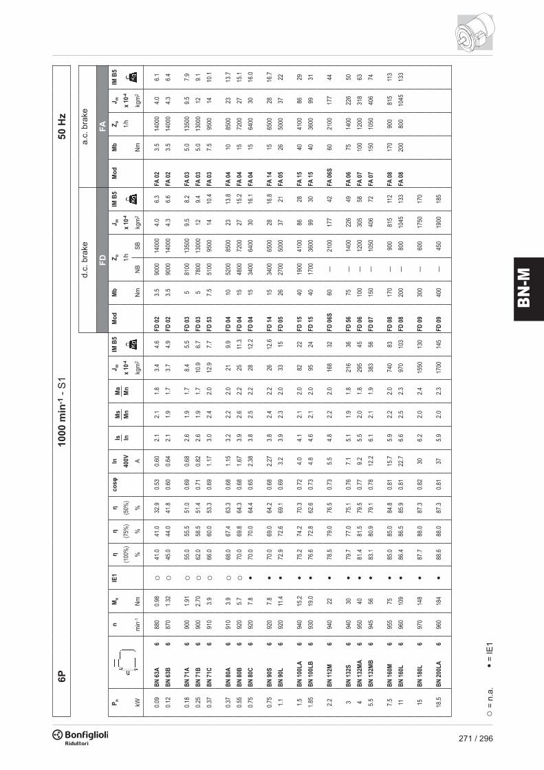
271 / 296
BN-M
4P15
00 m
in-1
- S
150
Hz
FDFA
P nn
Mn
IE1
ηη
ηcosφ
InIs In
Ms
Mn
Ma
Mn
J mIM
B5
Mod
Mb
Z oJ m
IM B
5M
odM
bZ o
J mIM
B5
(100
%)
(75%
)(5
0%)
400V
x 10
-41/
hx
10-4
1/h
x 10
-4
kWm
in-1
Nm%
%%
Akg
m2
NmNB
SBkg
m2
Nmkg
m2
0.06
BN 5
6A4
1340
0.43
○46
.844
.241
.30.
650.
282.
62.
32.
01.
53.
10.
09BN
56B
413
500.
64○
51.7
47.6
42.9
0.60
0.42
2.6
2.5
2.4
1.5
3.1
0.12
BN 6
3A4
1350
0.85
○59
.856
.247
.00.
620.
472.
61.
91.
82.
03.
5FD
02
1.75
1000
013
000
2.6
5.2
FA 0
21.
7513
000
2.6
5.0
0.18
BN 6
3B4
1320
1.30
○54
.852
.952
.50.
670.
712.
62.
22.
02.
33.
9FD
02
3.5
1000
013
000
3.0
5.6
FA 0
23.
513
000
3.0
5.4
0.25
BN 6
3C4
1340
1.78
○65
.365
.057
.90.
690.
802.
72.
11.
93.
35.
1FD
02
3.5
7800
1000
03.
96.
8FA
02
3.5
1000
03.
96.
6
0.25
BN 7
1A4
1380
1.73
○63
.762
.259
.10.
730.
783.
31.
91.
75.
85.
1FD
03
3.5
7700
1100
06.
97.
8FA
03
3.5
1100
06.
97.
50.
37BN
71B
413
702.
6○
66.8
66.7
63.0
0.76
1.05
3.7
2.0
1.9
6.9
5.9
FD 0
35
6000
9400
8.0
8.6
FA 0
35.
094
008.
08.
30.
55BN
71C
413
803.
8○
69.0
68.9
68.8
0.74
1.55
4.1
2.3
2.3
9.1
7.3
FD 5
37.
543
0087
0010
.210
.0FA
03
7.5
8700
10.2
9.7
0.55
BN 8
0A4
1390
3.8
○72
.071
.369
.70.
771.
434.
12.
32.
015
8.2
FD 0
410
4100
8000
16.6
12.1
FA 0
410
8000
16.6
12.0
0.75
BN 8
0B4
1400
5.1
•75
.074
.569
.30.
781.
854.
92.
72.
520
9.9
FD 0
415
4100
7800
2213
.8FA
04
1578
0022
13.7
1.1
BN 8
0C4
1400
7.5
•75
.576
.270
.40.
782.
75.
12.
82.
525
11.3
FD 0
415
2600
5300
2715
.2FA
04
1553
0027
15.1
1.1
BN 9
0S4
1390
7.6
•76
.576
.272
.20.
772.
704.
62.
62.
221
12.2
FD 1
415
4800
8000
2316
.4FA
14
1580
0023
16.3
1.5
BN 9
0LA
414
1010
.2•
78.7
78.5
74.9
0.77
3.6
5.3
2.8
2.4
2813
.6FD
05
2634
0060
0032
19.6
FA 0
526
6000
3220
.31.
85BN
90L
B4
1390
12.7
•78
.678
.977
.20.
794.
35.
12.
82.
630
15.1
FD 0
526
3200
5900
3421
.1FA
05
2659
0034
21.8
2.2
BN 1
00LA
414
1014
.9•
81.1
81.4
79.9
0.75
5.2
4.5
2.2
2.0
4018
FD 1
540
2600
4700
4425
FA 1
540
4700
4425
3BN
100
LB4
1410
20•
82.6
83.8
83.7
0.77
6.8
5.0
2.3
2.2
5422
FD 1
540
2400
4400
5828
FA 1
540
4400
5829
4BN
112M
414
3027
•84
.484
.281
.60.
818.
45.
62.
72.
598
30FD
06S
60—
1400
107
40FA
06S
6021
0010
742
5.5
BN 1
32S
414
4036
•84
.784
.882
.50.
8111
.65.
52.
32.
221
344
FD 5
675
—10
5022
357
FA 0
675
1200
223
587.
5BN
132
MA
414
4050
•86
.086
.385
.30.
8115
.55.
72.
52.
427
053
FD 0
610
0—
950
280
66FA
07
100
1000
280
719.
2BN
132
MB
414
4061
•88
.488
.687
.50.
8118
.85.
92.
72.
531
959
FD 0
715
0—
900
342
75FA
07
150
900
342
77
11BN
160
MR
414
4073
•87
.687
.886
.00.
8122
.46.
02.
72.
536
070
FD 0
715
0—
850
382
86FA
07
150
850
382
8815
BN 1
60L
414
6098
•88
.788
.588
.40.
8130
6.0
2.3
2.1
650
99FD
08
200
—75
072
512
9FA
08
200
750
710
128
18.5
BN 1
80M
414
6012
1•
89.3
89.5
89.2
0.81
376.
22.
62.
579
011
5FD
08
250
—70
086
514
5FA
08
250
700
850
144
22BN
180
L4
1460
144
•89
.990
.090
.00.
8044
6.4
2.5
2.5
1250
135
FD 0
930
0—
400
1450
175
30BN
200
L4
1460
196
•91
.491
.791
.00.
8059
7.1
2.7
2.8
1650
157
FD 0
940
0—
300
1850
197
○ =
n.a.
• = IE
1
d.c.
bra
kea.
c. b
rake
6P10
00 m
in-1
- S
150
Hz
FDFA
P nn
Mn
IE1
ηη
ηcosφ
InIs In
Ms
Mn
Ma
Mn
J mIM
B5
Mod
Mb
Z oJ m
IM B
5M
odM
bZ o
J mIM
B5
(100
%)
(75%
)(5
0%)
400V
x 10
-41/
hx
10-4
1/h
x 10
-4
kWm
in-1
Nm%
%%
Akg
m2
NmNB
SBkg
m2
Nmkg
m2
0.09
BN 6
3A
688
00.
98○
41.0
41.0
32.9
0.53
0.60
2.1
2.1
1.8
3.4
4.6
FD 0
23.
590
0014
000
4.0
6.3
FA 0
23.
514
000
4.0
6.1
0.12
BN 6
3B
687
01.
32○
45.0
44.0
41.8
0.60
0.64
2.1
1.9
1.7
3.7
4.9
FD 0
23.
590
0014
000
4.3
6.6
FA 0
23.
514
000
4.3
6.4
0.18
BN 7
1A6
900
1.91
○55
.055
.551
.00.
690.
682.
61.
91.
78.
45.
5FD
03
581
0013
500
9.5
8.2
FA 0
35.
013
500
9.5
7.9
0.25
BN 7
1B
690
02.
70○
62.0
58.5
51.4
0.71
0.82
2.6
1.9
1.7
10.9
6.7
FD 0
35
7800
1300
012
9.4
FA 0
35.
013
000
129.
1
0.37
BN 7
1C6
910
3.9
○66
.060
.053
.30.
691.
173.
02.
42.
012
.97.
7FD
53
7.5
5100
9500
1410
.4FA
03
7.5
9500
1410
.1
0.37
BN 8
0A
691
03.
9○
68.0
67.4
63.3
0.68
1.15
3.2
2.2
2.0
219.
9FD
04
1052
0085
0023
13.8
FA 0
410
8500
2313
.7
0.55
BN 8
0B6
920
5.7
○70
.069
.864
.30.
681.
673.
92.
62.
225
11.3
FD 0
415
4800
7200
2715
.2FA
04
1572
0027
15.1
0.75
BN 8
0C6
920
7.8
•70
.070
.064
.40.
652.
383.
82.
52.
228
12.2
FD 0
415
3400
6400
3016
.1FA
04
1564
0030
16.0
0.75
BN 9
0S6
920
7.8
•70
.069
.064
.20.
682.
273.
82.
42.
226
12.6
FD 1
415
3400
6500
2816
.8FA
14
1565
0028
16.7
1.1
BN 9
0L6
920
11.4
•72
.972
.669
.10.
693.
23.
92.
32.
033
15FD
05
2627
0050
0037
21FA
05
2650
0037
22
1.5
BN 1
00LA
694
015
.2•
75.2
74.2
70.3
0.72
4.0
4.1
2.1
2.0
8222
FD 1
540
1900
4100
8628
FA 1
540
4100
8629
1.85
BN 1
00LB
693
019
.0•
76.6
72.8
62.6
0.73
4.8
4.6
2.1
2.0
9524
FD 1
540
1700
3600
9930
FA 1
540
3600
9931
2.2
BN 11
2M6
940
22•
78.5
79.0
76.5
0.73
5.5
4.8
2.2
2.0
168
32FD
06S
60—
2100
177
42FA
06S
6021
0017
744
3BN
132
S6
940
30•
79.7
77.0
75.1
0.76
7.1
5.1
1.9
1.8
216
36FD
56
75—
1400
226
49FA
06
7514
0022
650
4BN
132
MA
695
040
•81
.481
.579
.50.
779.
25.
52.
01.
829
545
FD 0
610
0—
1200
305
58FA
07
100
1200
318
63
5.5
BN 1
32M
B6
945
56•
83.1
80.9
79.1
0.78
12.2
6.1
2.1
1.9
383
56FD
07
150
—10
5040
672
FA 0
715
010
5040
674
7.5
BN 1
60M
695
575
•85
.085
.084
.80.
8115
.75.
92.
22.
074
083
FD 0
817
0—
900
815
112
FA 0
817
090
081
511
3
11BN
160
L6
960
109
•86
.486
.585
.90.
8122
.76.
62.
52.
397
010
3FD
08
200
—80
010
4513
3FA
08
200
800
1045
133
15BN
180
L6
970
148
•87
.788
.087
.30.
8230
6.2
2.0
2.4
1550
130
FD 0
930
0—
600
1750
170
18.5
BN 2
00LA
696
018
4•
88.6
88.0
87.3
0.81
375.
92.
02.
317
0014
5FD
09
400
—45
019
0018
5
○ =
n.a.
• = IE
1
d.c.
bra
kea.
c. b
rake

272 / 296
BN-M
8P75
0 m
in-1
- S
150
Hz
FDFA
P nn
Mn
ηcosφ
InIs In
Ms
Mn
Ma
Mn
J mIM
B5
Mod
Mb
Z oJ m
IM B
5M
odM
bZ o
J mIM
B5
400V
x 10
-41/
hx
10-4
1/h
x 10
-4
kWm
in-1
Nm%
Akg
m2
NmNB
SBkg
m2
Nmkg
m2
0.09
BN 7
1A8
680
1.26
470.
590.
472.
32.
42.
310
.96.
7FD
03
3.5
9000
1600
012
.09.
4FA
03
3.5
1600
012
.09.
10.
12BN
71B
868
01.
6951
0.59
0.58
2.1
2.3
2.2
12.9
7.7
FD 0
35.
090
0016
000
14.0
10.4
FA 0
35.
016
000
14.0
10.1
0.18
BN 8
0A
869
02.
4951
0.60
0.85
2.4
2.2
2.2
158.
2FD
04
5.0
6500
1100
016
.612
.1FA
04
5.0
1100
016
.612
.00.
25BN
80B
868
03.
5154
0.63
1.06
2.4
2.0
1.9
209.
9FD
04
10.0
6000
1000
022
13.8
FA 0
410
.010
000
2313
.7
0.37
BN 9
0S8
675
5.2
580.
601.
532.
62.
32.
126
12.6
FD 1
415
.048
0075
0028
16.8
FA 1
415
.075
0028
16.7
0.55
BN 9
0L8
670
7.8
620.
602.
132.
62.
22.
033
15FD
05
2640
0064
0037
21FA
05
2664
0037
22
0.75
BN 1
00LA
870
010
.268
0.63
2.53
3.4
1.9
1.7
8222
FD 1
526
2800
4800
8628
FA 1
526
4800
8629
1.1
BN 1
00LB
870
015
.068
0.64
3.65
3.2
1.7
1.7
9524
FD 1
540
2500
4000
9930
FA 1
540
4000
9931
1.5
BN 1
12M
871
020
.271
0.66
4.6
3.7
1.8
1.9
168
32FD
06S
60—
3000
177
42FA
06S
6030
0017
744
2.2
BN 1
32S
871
029
.675
0.66
6.4
3.8
1.8
2.0
295
45FD
56
75—
2300
305
58FA
06
7523
0030
556
3BN
132
MA
871
040
.476
0.69
8.3
3.9
1.6
1.8
370
53FD
06
100
—19
0039
469
FA 0
710
019
0040
674
d.c.
bra
kea.
c. b
rake
2/4P
3000
/150
0 m
in-1
- S
150
Hz
FDFA
P nn
Mn
ηcosφ
InIs In
Ms
Mn
Ma
Mn
J mIM
B5
Mod
Mb
Z oJ m
IM B
5M
odM
bZ o
J mIM
B5
400V
x 10
-41/
hx
10-4
1/h
x 10
-4
kWm
in-1
Nm%
Akg
m2
NmNB
SBkg
m2
Nmkg
m2
0.20
BN 6
3B2
2700
0.71
550.
820.
643.
52.
11.
92.
94.
4FD
02
3.5
2200
2600
3.5
6.1
FA 0
23.
526
003.
55.
90.
154
1350
1.06
490.
670.
662.
61.
81.
740
0051
0051
00
0.28
BN 7
1A2
2700
0.99
560.
820.
882.
91.
91.
74.
74.
4FD
03
3.5
2100
2400
5.8
7.1
FA 0
33.
524
005.
86.
80.
204
1370
1.39
590.
720.
683.
11.
81.
738
0048
0048
000.
37BN
71B
227
401.
2956
0.82
1.16
3.5
1.8
1.8
5.8
5.1
FD 0
35.
014
0021
006.
97.
8FA
03
5.0
2100
6.9
7.5
0.25
413
901.
7260
0.73
0.82
3.3
2.0
1.9
2900
4200
4200
0.45
BN 7
1C2
2780
1.55
630.
851.
213.
81.
81.
86.
95.
9FD
03
5.0
1400
2100
8.0
8.6
FA 0
35.
021
008.
08.
30.
304
1400
2.0
630.
730.
943.
62.
01.
929
0042
0042
00
0.55
BN 8
0A2
2800
1.9
630.
851.
483.
91.
71.
715
8.2
FD 0
45.
016
0023
0017
12.1
FA 0
45.
023
0016
.612
.00.
374
1400
2.5
670.
791.
014.
11.
81.
930
0040
0040
000.
75BN
80B
227
802.
665
0.85
1.96
3.8
1.9
1.8
209.
9FD
04
1014
0016
0022
13.8
FA 0
410
1600
2213
.70.
554
1400
3.8
680.
811.
443.
91.
71.
727
0036
0036
00
1.1
BN 9
0S2
2790
3.8
710.
822.
734.
72.
32.
021
12.2
FD 1
410
1500
1600
2316
.4FA
14
1016
0023
16.3
0.75
413
905.
266
0.79
2.08
4.6
2.4
2.2
2300
2800
2800
1.5
BN 9
0L2
2780
5.2
700.
853.
644.
52.
42.
128
14.0
FD 0
526
1050
1200
3220
FA 0
526
1200
3221
1.1
413
907.
673
0.81
2.69
4.7
2.5
2.2
1600
2000
2000
2.2
BN 1
00LA
228
007.
572
0.85
5.2
4.5
2.0
1.9
4018
.3FD
15
2660
090
044
25FA
15
2690
044
251.
54
1410
10.2
730.
793.
84.
72.
02.
013
0023
0023
003.
5BN
100
LB2
2850
11.7
800.
847.
55.
42.
22.
161
25FD
15
4050
090
065
31FA
15
4090
065
322.
54
1420
16.8
820.
805.
55.
22.
22.
210
0021
0021
00
4BN
112M
228
8013
.379
0.83
8.8
6.1
2.4
2.0
9830
FD 0
6S60
—70
010
740
FA 0
6S60
700
107
423.
34
1420
22.2
800.
807.
45.
12.
12.
0—
1200
1200
5.5
BN 1
32S
228
9018
.280
0.87
11.4
5.9
2.4
2.0
213
44FD
56
75—
350
223
57FA
06
7535
022
358
4.4
414
4029
820.
849.
25.
32.
22.
0—
900
900
7.5
BN 1
32M
A2
2900
2582
0.87
15.2
6.5
2.4
2.0
270
53FD
06
100
—35
028
066
FA 0
710
035
029
371
64
1430
4084
0.85
12.1
5.8
2.3
2.1
—90
090
09.
2BN
132
MB
229
2030
830.
8618
.66.
02.
62.
231
959
FD 0
715
0—
300
342
75FA
07
150
300
342
777.
34
1440
4885
0.85
14.6
5.5
2.3
2.1
—80
080
0
d.c.
bra
kea.
c. b
rake

273 / 296
BN-M
8P75
0 m
in-1
- S
150
Hz
FDFA
P nn
Mn
ηcosφ
InIs In
Ms
Mn
Ma
Mn
J mIM
B5
Mod
Mb
Z oJ m
IM B
5M
odM
bZ o
J mIM
B5
400V
x 10
-41/
hx
10-4
1/h
x 10
-4
kWm
in-1
Nm%
Akg
m2
NmNB
SBkg
m2
Nmkg
m2
0.09
BN 7
1A8
680
1.26
470.
590.
472.
32.
42.
310
.96.
7FD
03
3.5
9000
1600
012
.09.
4FA
03
3.5
1600
012
.09.
10.
12BN
71B
868
01.
6951
0.59
0.58
2.1
2.3
2.2
12.9
7.7
FD 0
35.
090
0016
000
14.0
10.4
FA 0
35.
016
000
14.0
10.1
0.18
BN 8
0A
869
02.
4951
0.60
0.85
2.4
2.2
2.2
158.
2FD
04
5.0
6500
1100
016
.612
.1FA
04
5.0
1100
016
.612
.00.
25BN
80B
868
03.
5154
0.63
1.06
2.4
2.0
1.9
209.
9FD
04
10.0
6000
1000
022
13.8
FA 0
410
.010
000
2313
.7
0.37
BN 9
0S8
675
5.2
580.
601.
532.
62.
32.
126
12.6
FD 1
415
.048
0075
0028
16.8
FA 1
415
.075
0028
16.7
0.55
BN 9
0L8
670
7.8
620.
602.
132.
62.
22.
033
15FD
05
2640
0064
0037
21FA
05
2664
0037
22
0.75
BN 1
00LA
870
010
.268
0.63
2.53
3.4
1.9
1.7
8222
FD 1
526
2800
4800
8628
FA 1
526
4800
8629
1.1
BN 1
00LB
870
015
.068
0.64
3.65
3.2
1.7
1.7
9524
FD 1
540
2500
4000
9930
FA 1
540
4000
9931
1.5
BN 1
12M
871
020
.271
0.66
4.6
3.7
1.8
1.9
168
32FD
06S
60—
3000
177
42FA
06S
6030
0017
744
2.2
BN 1
32S
871
029
.675
0.66
6.4
3.8
1.8
2.0
295
45FD
56
75—
2300
305
58FA
06
7523
0030
556
3BN
132
MA
871
040
.476
0.69
8.3
3.9
1.6
1.8
370
53FD
06
100
—19
0039
469
FA 0
710
019
0040
674
d.c.
bra
kea.
c. b
rake
2/4P
3000
/150
0 m
in-1
- S
150
Hz
FDFA
P nn
Mn
ηcosφ
InIs In
Ms
Mn
Ma
Mn
J mIM
B5
Mod
Mb
Z oJ m
IM B
5M
odM
bZ o
J mIM
B5
400V
x 10
-41/
hx
10-4
1/h
x 10
-4
kWm
in-1
Nm%
Akg
m2
NmNB
SBkg
m2
Nmkg
m2
0.20
BN 6
3B2
2700
0.71
550.
820.
643.
52.
11.
92.
94.
4FD
02
3.5
2200
2600
3.5
6.1
FA 0
23.
526
003.
55.
90.
154
1350
1.06
490.
670.
662.
61.
81.
740
0051
0051
00
0.28
BN 7
1A2
2700
0.99
560.
820.
882.
91.
91.
74.
74.
4FD
03
3.5
2100
2400
5.8
7.1
FA 0
33.
524
005.
86.
80.
204
1370
1.39
590.
720.
683.
11.
81.
738
0048
0048
000.
37BN
71B
227
401.
2956
0.82
1.16
3.5
1.8
1.8
5.8
5.1
FD 0
35.
014
0021
006.
97.
8FA
03
5.0
2100
6.9
7.5
0.25
413
901.
7260
0.73
0.82
3.3
2.0
1.9
2900
4200
4200
0.45
BN 7
1C2
2780
1.55
630.
851.
213.
81.
81.
86.
95.
9FD
03
5.0
1400
2100
8.0
8.6
FA 0
35.
021
008.
08.
30.
304
1400
2.0
630.
730.
943.
62.
01.
929
0042
0042
00
0.55
BN 8
0A2
2800
1.9
630.
851.
483.
91.
71.
715
8.2
FD 0
45.
016
0023
0017
12.1
FA 0
45.
023
0016
.612
.00.
374
1400
2.5
670.
791.
014.
11.
81.
930
0040
0040
000.
75BN
80B
227
802.
665
0.85
1.96
3.8
1.9
1.8
209.
9FD
04
1014
0016
0022
13.8
FA 0
410
1600
2213
.70.
554
1400
3.8
680.
811.
443.
91.
71.
727
0036
0036
00
1.1
BN 9
0S2
2790
3.8
710.
822.
734.
72.
32.
021
12.2
FD 1
410
1500
1600
2316
.4FA
14
1016
0023
16.3
0.75
413
905.
266
0.79
2.08
4.6
2.4
2.2
2300
2800
2800
1.5
BN 9
0L2
2780
5.2
700.
853.
644.
52.
42.
128
14.0
FD 0
526
1050
1200
3220
FA 0
526
1200
3221
1.1
413
907.
673
0.81
2.69
4.7
2.5
2.2
1600
2000
2000
2.2
BN 1
00LA
228
007.
572
0.85
5.2
4.5
2.0
1.9
4018
.3FD
15
2660
090
044
25FA
15
2690
044
251.
54
1410
10.2
730.
793.
84.
72.
02.
013
0023
0023
003.
5BN
100
LB2
2850
11.7
800.
847.
55.
42.
22.
161
25FD
15
4050
090
065
31FA
15
4090
065
322.
54
1420
16.8
820.
805.
55.
22.
22.
210
0021
0021
00
4BN
112M
228
8013
.379
0.83
8.8
6.1
2.4
2.0
9830
FD 0
6S60
—70
010
740
FA 0
6S60
700
107
423.
34
1420
22.2
800.
807.
45.
12.
12.
0—
1200
1200
5.5
BN 1
32S
228
9018
.280
0.87
11.4
5.9
2.4
2.0
213
44FD
56
75—
350
223
57FA
06
7535
022
358
4.4
414
4029
820.
849.
25.
32.
22.
0—
900
900
7.5
BN 1
32M
A2
2900
2582
0.87
15.2
6.5
2.4
2.0
270
53FD
06
100
—35
028
066
FA 0
710
035
029
371
64
1430
4084
0.85
12.1
5.8
2.3
2.1
—90
090
09.
2BN
132
MB
229
2030
830.
8618
.66.
02.
62.
231
959
FD 0
715
0—
300
342
75FA
07
150
300
342
777.
34
1440
4885
0.85
14.6
5.5
2.3
2.1
—80
080
0
d.c.
bra
kea.
c. b
rake

274 / 296
BN-M
2/6P
3000
/100
0 m
in-1
- S
3 60
/40%
50 H
z
FDFA
P nn
Mn
ηcosφ
InIs In
Ms
Mn
Ma
Mn
J mIM
B5
Mod
Mb
Z oJ m
IM B
5M
odM
bZ o
J mIM
B5
400V
x 10
-41/
hx
10-4
1/h
x 10
-4
kWm
in-1
Nm%
Akg
m2
NmNB
SBkg
m2
Nmkg
m2
0.25
BN 7
1A2
2850
0.84
600.
820.
734.
31.
91.
86.
95.
9FD
03
1.75
1500
1700
8.0
8.6
FA 0
32.
517
008.
08.
30.
086
910
0.84
430.
700.
382.
11.
41.
510
000
1300
013
000
0.37
BN 7
1B2
2880
1.23
620.
801.
084.
41.
91.
89.
17.
3FD
03
3.5
1000
1300
10.2
10.0
FA 0
33.
513
0010
.29.
70.
126
900
1.27
440.
730.
542.
41.
41.
590
0011
000
1100
0
0.55
BN 8
0A2
2800
1.88
630.
861.
474.
51.
91.
720
9.9
FD 0
45.
015
0018
0022
13.8
FA 0
45.
018
0022
13.7
0.18
693
01.
8552
0.65
0.77
3.3
2.0
1.9
4100
6300
6300
0.75
BN 8
0B2
2800
2.6
660.
871.
894.
31.
81.
625
11.3
FD 0
45.
017
0019
0027
15.2
FA 0
45.
019
0027
15.1
0.25
693
02.
654
0.67
1.00
3.2
1.7
1.8
3800
6000
6000
1.10
BN 9
0L2
2860
3.7
670.
842.
824.
72.
11.
928
14.0
FD 0
513
1400
1600
3220
FA 0
513
1600
3221
0.37
692
03.
859
0.71
1.27
3.3
1.6
1.6
3400
5200
5200
1.5
BN 1
00LA
228
805
730.
843.
535.
11.
92.
040
18.3
FD 1
513
1000
1200
4424
FA 1
513
1200
4425
0.55
694
05.
664
0.67
1.85
3.5
1.7
1.8
2900
4000
4000
2.2
BN 1
00LB
229
007.
277
0.85
4.9
5.9
2.0
2.0
6125
FD 1
526
700
900
6531
FA 1
526
900
6532
0.75
695
07.
567
0.64
2.5
3.3
1.9
1.8
2100
3000
3000
3BN
112M
229
009.
978
0.87
6.4
6.3
2.0
2.1
9830
FD 0
6S40
—10
0010
740
FA 0
6S40
1000
107
321.
16
950
11.1
720.
643.
43.
91.
81.
8—
2600
2600
4.5
BN 1
32S
229
1014
.878
0.84
9.9
5.8
1.9
1.8
213
44FD
56
37—
500
223
57FA
06
3750
022
358
1.5
696
014
.974
0.67
4.4
4.2
1.9
2.0
—21
0021
005.
5BN
132
M2
2920
18.0
780.
8711
.76.
22.
11.
927
053
FD 5
650
—40
028
066
FA 0
650
400
280
672.
26
960
2277
0.71
5.8
4.3
2.1
2.0
—19
0019
00
d.c.
bra
kea.
c. b
rake
2/8P
3000
/750
min
-1 -
S3
60/4
0%50
Hz
FDFA
P nn
Mn
ηcosφ
InIs In
Ms
Mn
Ma
Mn
J mIM
B5
Mod
Mb
Z oJ m
IM B
5M
odM
bZ o
J mIM
B5
400V
x 10
-41/
hx
10-4
1/h
x 10
-4
kWm
in-1
Nm%
Akg
m2
NmNB
SBkg
m2
Nmkg
m2
0.25
BN 7
1A2
2790
0.86
610.
870.
683.
91.
81.
910
.96.
7FD
03
1.75
1300
1400
129.
4FA
03
2.5
1400
129.
10.
068
680
0.84
310.
610.
462.
01.
81.
910
000
1300
013
000
0.37
BN 7
1B2
2800
1.26
630.
860.
993.
91.
81.
912
.97.
7FD
03
3.5
1200
1300
1410
.4FA
03
3.5
1300
1410
.10.
098
670
1.28
340.
750.
511.
81.
41.
595
0013
000
1300
0
0.55
BN 8
0A2
2830
1.86
660.
861.
404.
42.
12.
020
9.9
FD 0
45.
015
0018
0022
13.8
FA 0
45.
018
0022
13.7
0.13
869
01.
8041
0.64
0.72
2.3
1.6
1.7
5600
8000
8000
0.75
BN 8
0B2
2800
2.6
680.
881.
814.
62.
12.
025
11.3
FD 0
410
1700
1900
2715
.2FA
04
1019
0027
15.1
0.18
869
02.
543
0.66
0.92
2.3
1.6
1.7
4800
7300
7300
1.10
BN 9
0L2
2830
3.7
630.
843.
004.
52.
11.
928
14.0
FD 0
513
1400
1600
3220
FA 0
513
1600
3221
0.28
869
03.
948
0.63
1.34
2.4
1.8
1.9
3400
5100
5100
1.5
BN 1
00LA
228
805.
069
0.85
3.69
4.7
1.9
1.8
4018
.3FD
15
1310
0012
0044
25FA
15
1312
0044
250.
378
690
5.1
460.
631.
842.
11.
61.
633
0050
0050
002.
4BN
100
LB2
2900
7.9
750.
825.
65.
42.
12.
061
25FD
15
2655
070
065
31FA
15
2670
065
320.
558
700
7.5
540.
582.
52.
61.
81.
820
0035
0035
00
3BN
112M
229
009.
976
0.87
6.5
6.3
2.1
1.9
9830
FD 0
6S40
—90
010
740
FA 0
6S40
900
107
420.
758
690
10.4
600.
652.
82.
51.
61.
6—
2900
2900
4BN
132
S2
2870
13.3
730.
849.
45.
62.
32.
421
344
FD 5
637
—50
022
357
FA 0
637
500
223
581
869
013
.866
0.62
3.5
2.9
1.9
1.8
—35
0035
005.
5BN
132
M2
2870
18.3
750.
8412
.66.
12.
42.
527
053
FD 0
650
—40
028
066
FA 0
650
400
280
671.
58
690
2168
0.63
5.1
2.9
1.9
1.9
—24
0024
00
d.c.
bra
kea.
c. b
rake

275 / 296
BN-M
2/6P
3000
/100
0 m
in-1
- S
3 60
/40%
50 H
z
FDFA
P nn
Mn
ηcosφ
InIs In
Ms
Mn
Ma
Mn
J mIM
B5
Mod
Mb
Z oJ m
IM B
5M
odM
bZ o
J mIM
B5
400V
x 10
-41/
hx
10-4
1/h
x 10
-4
kWm
in-1
Nm%
Akg
m2
NmNB
SBkg
m2
Nmkg
m2
0.25
BN 7
1A2
2850
0.84
600.
820.
734.
31.
91.
86.
95.
9FD
03
1.75
1500
1700
8.0
8.6
FA 0
32.
517
008.
08.
30.
086
910
0.84
430.
700.
382.
11.
41.
510
000
1300
013
000
0.37
BN 7
1B2
2880
1.23
620.
801.
084.
41.
91.
89.
17.
3FD
03
3.5
1000
1300
10.2
10.0
FA 0
33.
513
0010
.29.
70.
126
900
1.27
440.
730.
542.
41.
41.
590
0011
000
1100
0
0.55
BN 8
0A2
2800
1.88
630.
861.
474.
51.
91.
720
9.9
FD 0
45.
015
0018
0022
13.8
FA 0
45.
018
0022
13.7
0.18
693
01.
8552
0.65
0.77
3.3
2.0
1.9
4100
6300
6300
0.75
BN 8
0B2
2800
2.6
660.
871.
894.
31.
81.
625
11.3
FD 0
45.
017
0019
0027
15.2
FA 0
45.
019
0027
15.1
0.25
693
02.
654
0.67
1.00
3.2
1.7
1.8
3800
6000
6000
1.10
BN 9
0L2
2860
3.7
670.
842.
824.
72.
11.
928
14.0
FD 0
513
1400
1600
3220
FA 0
513
1600
3221
0.37
692
03.
859
0.71
1.27
3.3
1.6
1.6
3400
5200
5200
1.5
BN 1
00LA
228
805
730.
843.
535.
11.
92.
040
18.3
FD 1
513
1000
1200
4424
FA 1
513
1200
4425
0.55
694
05.
664
0.67
1.85
3.5
1.7
1.8
2900
4000
4000
2.2
BN 1
00LB
229
007.
277
0.85
4.9
5.9
2.0
2.0
6125
FD 1
526
700
900
6531
FA 1
526
900
6532
0.75
695
07.
567
0.64
2.5
3.3
1.9
1.8
2100
3000
3000
3BN
112M
229
009.
978
0.87
6.4
6.3
2.0
2.1
9830
FD 0
6S40
—10
0010
740
FA 0
6S40
1000
107
321.
16
950
11.1
720.
643.
43.
91.
81.
8—
2600
2600
4.5
BN 1
32S
229
1014
.878
0.84
9.9
5.8
1.9
1.8
213
44FD
56
37—
500
223
57FA
06
3750
022
358
1.5
696
014
.974
0.67
4.4
4.2
1.9
2.0
—21
0021
005.
5BN
132
M2
2920
18.0
780.
8711
.76.
22.
11.
927
053
FD 5
650
—40
028
066
FA 0
650
400
280
672.
26
960
2277
0.71
5.8
4.3
2.1
2.0
—19
0019
00
d.c.
bra
kea.
c. b
rake
2/8P
3000
/750
min
-1 -
S3
60/4
0%50
Hz
FDFA
P nn
Mn
ηcosφ
InIs In
Ms
Mn
Ma
Mn
J mIM
B5
Mod
Mb
Z oJ m
IM B
5M
odM
bZ o
J mIM
B5
400V
x 10
-41/
hx
10-4
1/h
x 10
-4
kWm
in-1
Nm%
Akg
m2
NmNB
SBkg
m2
Nmkg
m2
0.25
BN 7
1A2
2790
0.86
610.
870.
683.
91.
81.
910
.96.
7FD
03
1.75
1300
1400
129.
4FA
03
2.5
1400
129.
10.
068
680
0.84
310.
610.
462.
01.
81.
910
000
1300
013
000
0.37
BN 7
1B2
2800
1.26
630.
860.
993.
91.
81.
912
.97.
7FD
03
3.5
1200
1300
1410
.4FA
03
3.5
1300
1410
.10.
098
670
1.28
340.
750.
511.
81.
41.
595
0013
000
1300
0
0.55
BN 8
0A2
2830
1.86
660.
861.
404.
42.
12.
020
9.9
FD 0
45.
015
0018
0022
13.8
FA 0
45.
018
0022
13.7
0.13
869
01.
8041
0.64
0.72
2.3
1.6
1.7
5600
8000
8000
0.75
BN 8
0B2
2800
2.6
680.
881.
814.
62.
12.
025
11.3
FD 0
410
1700
1900
2715
.2FA
04
1019
0027
15.1
0.18
869
02.
543
0.66
0.92
2.3
1.6
1.7
4800
7300
7300
1.10
BN 9
0L2
2830
3.7
630.
843.
004.
52.
11.
928
14.0
FD 0
513
1400
1600
3220
FA 0
513
1600
3221
0.28
869
03.
948
0.63
1.34
2.4
1.8
1.9
3400
5100
5100
1.5
BN 1
00LA
228
805.
069
0.85
3.69
4.7
1.9
1.8
4018
.3FD
15
1310
0012
0044
25FA
15
1312
0044
250.
378
690
5.1
460.
631.
842.
11.
61.
633
0050
0050
002.
4BN
100
LB2
2900
7.9
750.
825.
65.
42.
12.
061
25FD
15
2655
070
065
31FA
15
2670
065
320.
558
700
7.5
540.
582.
52.
61.
81.
820
0035
0035
00
3BN
112M
229
009.
976
0.87
6.5
6.3
2.1
1.9
9830
FD 0
6S40
—90
010
740
FA 0
6S40
900
107
420.
758
690
10.4
600.
652.
82.
51.
61.
6—
2900
2900
4BN
132
S2
2870
13.3
730.
849.
45.
62.
32.
421
344
FD 5
637
—50
022
357
FA 0
637
500
223
581
869
013
.866
0.62
3.5
2.9
1.9
1.8
—35
0035
005.
5BN
132
M2
2870
18.3
750.
8412
.66.
12.
42.
527
053
FD 0
650
—40
028
066
FA 0
650
400
280
671.
58
690
2168
0.63
5.1
2.9
1.9
1.9
—24
0024
00
d.c.
bra
kea.
c. b
rake

276 / 296
BN-M
2/12
P30
00/5
00 m
in-1
- S
3 60
/40%
50 H
z
FDFA
P nn
Mn
ηcosφ
InIs In
Ms
Mn
Ma
Mn
J mIM
B5
Mod
Mb
Z oJ m
IM B
5M
odM
bZ o
J mIM
B5
400V
x 10
-41/
hx
10-4
1/h
x 10
-4
kWm
in-1
Nm%
Akg
m2
NmNB
SBkg
m2
Nmkg
m2
0.55
BN 8
0B2
2820
1.86
640.
891.
394.
21.
61.
725
11.3
FD 0
45.
010
0013
0027
15.2
FA 0
45.
013
0027
15.1
0.09
1243
02.
030
0.63
0.69
1.8
1.9
1.8
8000
1200
012
000
0.75
BN
90L
227
902.
656
0.89
2.17
4.2
1.8
1.7
2612
.6FD
05
1310
0011
5030
18.6
FA 0
513
1150
3019
.30.
1212
430
2.7
260.
631.
061.
71.
41.
646
0063
0063
00
1.10
BN 1
00LA
228
503.
765
0.85
2.87
4.5
1.6
1.8
4018
.3FD
15
1370
090
044
25FA
15
1390
044
250.
1812
430
4.0
260.
541.
851.
51.
31.
540
0060
0060
001.
5BN
100
LB2
2900
4.9
670.
863.
765.
61.
91.
954
22FD
15
1370
090
058
28FA
15
1390
058
290.
2512
440
5.4
360.
462.
181.
81.
71.
838
0050
0050
00
2BN
112M
229
006.
674
0.88
4.43
6.5
2.1
2.0
9830
FD 0
6S20
—80
010
740
FA 0
6S20
800
107
420.
312
460
6.2
460.
432.
192.
02.
12.
0—
3400
3400
3BN
132
S2
2920
9.8
740.
876.
76.
82.
31.
921
344
FD 5
637
—45
022
357
FA 0
637
450
223
580.
512
470
10.2
510.
433.
32.
01.
71.
6—
3000
3000
4BN
132
M2
2920
13.1
750.
898.
65.
92.
42.
327
053
FD 5
637
—40
028
066
FA 0
637
400
280
670.
712
460
14.5
530.
444.
31.
91.
71.
6—
2800
2800
d.c.
bra
kea.
c. b
rake
4/6P
1500
/100
0 m
in-1
- S
150
Hz
FDFA
P nn
Mn
ηcosφ
InIs In
Ms
Mn
Ma
Mn
J mIM
B5
Mod
Mb
Z oJ m
IM B
5M
odM
bZ o
J mIM
B5
400V
x 10
-41/
hx
10-4
1/h
x 10
-4
kWm
in-1
Nm%
Akg
m2
NmNB
SBkg
m2
Nmkg
m2
0.22
BN 7
1B4
1410
1.5
640.
740.
673.
91.
81.
99.
17.
3FD
03
3.5
2500
3500
10.2
10.0
FA 0
33.
535
0010
.29.
70.
136
920
1.4
430.
670.
652.
31.
61.
750
0090
0090
00
0.30
BN 8
0A4
1410
2.0
610.
820.
873.
51.
31.
515
8.2
FD 0
45.
025
0031
0016
.612
.1FA
04
5.0
3100
16.6
12.0
0.20
693
02.
154
0.66
0.81
3.2
1.9
2.0
4000
6000
6000
0.40
BN 8
0B4
1430
2.7
630.
751.
223.
91.
81.
820
9.9
FD 0
410
1800
2300
2213
.8FA
04
1023
0022
13.7
0.26
693
02.
755
0.70
0.97
2.7
1.5
1.6
3600
5500
5500
0.55
BN 9
0S4
1420
3.7
700.
781.
454.
52.
01.
921
12.2
FD 1
410
1500
2100
2316
.1FA
14
1021
0023
16.3
0.33
693
03.
462
0.70
1.10
3.7
2.3
2.0
2500
4100
4100
0.75
BN 9
0L4
1420
5.0
740.
781.
884.
31.
91.
828
14FD
05
1314
0020
0032
20FA
05
1320
0032
210.
456
920
4.7
660.
711.
393.
32.
01.
923
0036
0036
00
1.1
BN 1
00LA
414
507.
274
0.79
2.72
5.0
1.7
1.9
8222
FD 1
526
1400
2000
8628
FA 1
526
2000
8629
0.8
695
08.
065
0.69
2.57
4.1
1.9
2.1
2100
3300
3300
1.5
BN 1
00LB
414
509.
975
0.79
3.65
5.1
1.7
1.9
9525
FD 1
526
1300
1800
9931
FA 1
526
1800
9932
1.1
695
011
.172
0.68
3.24
4.3
2.0
2.1
2000
3000
3000
2.3
BN 11
2M4
1450
15.2
750.
785.
75.
21.
81.
916
832
FD 0
6S40
—16
0017
742
FA 0
6S40
1600
177
441.
56
960
14.9
730.
724.
14.
92.
02.
0—
2400
2400
3.1
BN 1
32S
414
6020
830.
836.
55.
92.
12.
021
344
FD 5
637
—12
0022
357
FA 0
637
1200
223
582
696
020
770.
754.
94.
52.
12.
1—
1900
1900
4.2
BN 1
32M
A4
1460
2784
0.82
8.8
5.9
2.1
2.2
270
53FD
06
50—
900
280
66FA
06
5090
028
067
2.6
696
026
790.
726.
64.
32.
02.
0—
1500
1500
d.c.
bra
kea.
c. b
rake

277 / 296
BN-M
2/12
P30
00/5
00 m
in-1
- S
3 60
/40%
50 H
z
FDFA
P nn
Mn
ηcosφ
InIs In
Ms
Mn
Ma
Mn
J mIM
B5
Mod
Mb
Z oJ m
IM B
5M
odM
bZ o
J mIM
B5
400V
x 10
-41/
hx
10-4
1/h
x 10
-4
kWm
in-1
Nm%
Akg
m2
NmNB
SBkg
m2
Nmkg
m2
0.55
BN 8
0B2
2820
1.86
640.
891.
394.
21.
61.
725
11.3
FD 0
45.
010
0013
0027
15.2
FA 0
45.
013
0027
15.1
0.09
1243
02.
030
0.63
0.69
1.8
1.9
1.8
8000
1200
012
000
0.75
BN
90L
227
902.
656
0.89
2.17
4.2
1.8
1.7
2612
.6FD
05
1310
0011
5030
18.6
FA 0
513
1150
3019
.30.
1212
430
2.7
260.
631.
061.
71.
41.
646
0063
0063
00
1.10
BN 1
00LA
228
503.
765
0.85
2.87
4.5
1.6
1.8
4018
.3FD
15
1370
090
044
25FA
15
1390
044
250.
1812
430
4.0
260.
541.
851.
51.
31.
540
0060
0060
001.
5BN
100
LB2
2900
4.9
670.
863.
765.
61.
91.
954
22FD
15
1370
090
058
28FA
15
1390
058
290.
2512
440
5.4
360.
462.
181.
81.
71.
838
0050
0050
00
2BN
112M
229
006.
674
0.88
4.43
6.5
2.1
2.0
9830
FD 0
6S20
—80
010
740
FA 0
6S20
800
107
420.
312
460
6.2
460.
432.
192.
02.
12.
0—
3400
3400
3BN
132
S2
2920
9.8
740.
876.
76.
82.
31.
921
344
FD 5
637
—45
022
357
FA 0
637
450
223
580.
512
470
10.2
510.
433.
32.
01.
71.
6—
3000
3000
4BN
132
M2
2920
13.1
750.
898.
65.
92.
42.
327
053
FD 5
637
—40
028
066
FA 0
637
400
280
670.
712
460
14.5
530.
444.
31.
91.
71.
6—
2800
2800
d.c.
bra
kea.
c. b
rake
4/6P
1500
/100
0 m
in-1
- S
150
Hz
FDFA
P nn
Mn
ηcosφ
InIs In
Ms
Mn
Ma
Mn
J mIM
B5
Mod
Mb
Z oJ m
IM B
5M
odM
bZ o
J mIM
B5
400V
x 10
-41/
hx
10-4
1/h
x 10
-4
kWm
in-1
Nm%
Akg
m2
NmNB
SBkg
m2
Nmkg
m2
0.22
BN 7
1B4
1410
1.5
640.
740.
673.
91.
81.
99.
17.
3FD
03
3.5
2500
3500
10.2
10.0
FA 0
33.
535
0010
.29.
70.
136
920
1.4
430.
670.
652.
31.
61.
750
0090
0090
00
0.30
BN 8
0A4
1410
2.0
610.
820.
873.
51.
31.
515
8.2
FD 0
45.
025
0031
0016
.612
.1FA
04
5.0
3100
16.6
12.0
0.20
693
02.
154
0.66
0.81
3.2
1.9
2.0
4000
6000
6000
0.40
BN 8
0B4
1430
2.7
630.
751.
223.
91.
81.
820
9.9
FD 0
410
1800
2300
2213
.8FA
04
1023
0022
13.7
0.26
693
02.
755
0.70
0.97
2.7
1.5
1.6
3600
5500
5500
0.55
BN 9
0S4
1420
3.7
700.
781.
454.
52.
01.
921
12.2
FD 1
410
1500
2100
2316
.1FA
14
1021
0023
16.3
0.33
693
03.
462
0.70
1.10
3.7
2.3
2.0
2500
4100
4100
0.75
BN 9
0L4
1420
5.0
740.
781.
884.
31.
91.
828
14FD
05
1314
0020
0032
20FA
05
1320
0032
210.
456
920
4.7
660.
711.
393.
32.
01.
923
0036
0036
00
1.1
BN 1
00LA
414
507.
274
0.79
2.72
5.0
1.7
1.9
8222
FD 1
526
1400
2000
8628
FA 1
526
2000
8629
0.8
695
08.
065
0.69
2.57
4.1
1.9
2.1
2100
3300
3300
1.5
BN 1
00LB
414
509.
975
0.79
3.65
5.1
1.7
1.9
9525
FD 1
526
1300
1800
9931
FA 1
526
1800
9932
1.1
695
011
.172
0.68
3.24
4.3
2.0
2.1
2000
3000
3000
2.3
BN 11
2M4
1450
15.2
750.
785.
75.
21.
81.
916
832
FD 0
6S40
—16
0017
742
FA 0
6S40
1600
177
441.
56
960
14.9
730.
724.
14.
92.
02.
0—
2400
2400
3.1
BN 1
32S
414
6020
830.
836.
55.
92.
12.
021
344
FD 5
637
—12
0022
357
FA 0
637
1200
223
582
696
020
770.
754.
94.
52.
12.
1—
1900
1900
4.2
BN 1
32M
A4
1460
2784
0.82
8.8
5.9
2.1
2.2
270
53FD
06
50—
900
280
66FA
06
5090
028
067
2.6
696
026
790.
726.
64.
32.
02.
0—
1500
1500
d.c.
bra
kea.
c. b
rake

278 / 296
BN-M
4/6P
1500
/100
0 m
in-1
- S
150
Hz
FDFA
P nn
Mn
ηcosφ
InIs In
Ms
Mn
Ma
Mn
J mIM
B5
Mod
Mb
Z oJ m
IM B
5M
odM
bZ o
J mIM
B5
400V
x 10
-41/
hx
10-4
1/h
x 10
-4
kWm
in-1
Nm%
Akg
m2
NmNB
SBkg
m2
Nmkg
m2
0.22
BN 7
1B4
1410
1.5
640.
740.
673.
91.
81.
99.
17.
3FD
03
3.5
2500
3500
10.2
10.0
FA 0
33.
535
0010
.29.
70.
136
920
1.4
430.
670.
652.
31.
61.
750
0090
0090
00
0.30
BN 8
0A4
1410
2.0
610.
820.
873.
51.
31.
515
8.2
FD 0
45.
025
0031
0016
.612
.1FA
04
5.0
3100
16.6
12.0
0.20
693
02.
154
0.66
0.81
3.2
1.9
2.0
4000
6000
6000
0.40
BN 8
0B4
1430
2.7
630.
751.
223.
91.
81.
820
9.9
FD 0
410
1800
2300
2213
.8FA
04
1023
0022
13.7
0.26
693
02.
755
0.70
0.97
2.7
1.5
1.6
3600
5500
5500
0.55
BN 9
0S4
1420
3.7
700.
781.
454.
52.
01.
921
12.2
FD 1
410
1500
2100
2316
.1FA
14
1021
0023
16.3
0.33
693
03.
462
0.70
1.10
3.7
2.3
2.0
2500
4100
4100
0.75
BN 9
0L4
1420
5.0
740.
781.
884.
31.
91.
828
14FD
05
1314
0020
0032
20FA
05
1320
0032
210.
456
920
4.7
660.
711.
393.
32.
01.
923
0036
0036
00
1.1
BN 1
00LA
414
507.
274
0.79
2.72
5.0
1.7
1.9
8222
FD 1
526
1400
2000
8628
FA 1
526
2000
8629
0.8
695
08.
065
0.69
2.57
4.1
1.9
2.1
2100
3300
3300
1.5
BN 1
00LB
414
509.
975
0.79
3.65
5.1
1.7
1.9
9525
FD 1
526
1300
1800
9931
FA 1
526
1800
9932
1.1
695
011
.172
0.68
3.24
4.3
2.0
2.1
2000
3000
3000
2.3
BN 11
2M4
1450
15.2
750.
785.
75.
21.
81.
916
832
FD 0
6S40
—16
0017
742
FA 0
6S40
1600
177
441.
56
960
14.9
730.
724.
14.
92.
02.
0—
2400
2400
3.1
BN 1
32S
414
6020
830.
836.
55.
92.
12.
021
344
FD 5
637
—12
0022
357
FA 0
637
1200
223
582
696
020
770.
754.
94.
52.
12.
1—
1900
1900
4.2
BN 1
32M
A4
1460
2784
0.82
8.8
5.9
2.1
2.2
270
53FD
06
50—
900
280
66FA
06
5090
028
067
2.6
696
026
790.
726.
64.
32.
02.
0—
1500
1500
d.c.
bra
kea.
c. b
rake
4/8P
1500
/750
min
-1 -
S1
50 H
z
FDFA
P nn
Mn
ηcosφ
InIs In
Ms
Mn
Ma
Mn
J mIM
B5
Mod
Mb
Z oJ m
IM B
5M
odM
bZ o
J mIM
B5
400V
x 10
-41/
hx
10-4
1/h
x 10
-4
kWm
in-1
Nm%
Akg
m2
NmNB
SBkg
m2
Nmkg
m2
0.37
BN 8
0A4
1400
2.5
630.
821.
033.
31.
41.
415
8.2
FD 0
410
2300
3500
16.6
12.1
FA 0
410
3500
16.6
12.0
0.18
869
02.
544
0.60
0.98
2.2
1.5
1.6
4500
7000
7000
0.55
BN 8
0B4
1390
3.8
650.
861.
423.
81.
71.
620
9.9
FD 0
410
2200
2900
2213
.8FA
04
1029
0022
13.7
0.30
867
04.
349
0.65
1.36
2.3
1.7
1.8
4200
6500
6500
0.65
BN 9
0S4
1390
4.5
730.
851.
514.
01.
91.
928
13.6
FD 1
415
2300
2800
3017
.8FA
14
1528
0030
17.7
0.35
869
04.
849
0.57
1.81
2.5
2.1
2.2
3500
6000
6000
0.9
BN 9
0L4
1370
6.3
730.
872.
053.
81.
81.
830
15.1
FD 0
526
1700
2100
3421
FA 0
526
2100
3422
0.5
867
07.
157
0.62
2.04
2.4
2.1
2.0
2500
4200
4200
1.30
BN 1
00LA
414
208.
772
0.83
3.14
4.3
1.7
1.8
8222
FD 1
540
1300
1700
8628
FA 1
540
1700
8629
0.70
870
09.
658
0.64
2.72
2.8
1.8
1.8
2000
3400
3400
1.8
BN 1
00LB
414
2012
.169
0.87
4.3
4.2
1.6
1.7
9525
FD 1
540
1200
1700
9931
FA 1
540
1700
9932
0.9
870
012
.362
0.63
3.3
3.2
1.7
1.8
1600
2600
2600
2.2
BN 11
2M4
1440
14.6
770.
854.
95.
31.
81.
816
832
FD 0
6S60
—12
0017
742
FA 0
6S60
1200
177
431.
28
710
16.1
700.
633.
93.
31.
91.
8—
2000
2000
3.6
BN 1
32S
414
4024
800.
827.
96.
52.
11.
929
545
FD 5
675
—10
0030
558
FA 0
675
1000
305
591.
88
720
2472
0.55
6.6
4.6
1.9
2.0
—14
0014
004.
6BN
132
M4
1450
3081
0.83
9.9
6.5
2.2
1.9
383
56FD
06
100
—10
0039
369
FA 0
710
010
0040
674
2.3
872
031
730.
548.
44.
42.
32.
0—
1300
1300
d.c.
bra
kea.
c. b
rake
2P30
00 m
in-1
- S
150
Hz
FDFA
P nn
Mn
IE1
ηη
ηcosφ
InIs In
Ms
Mn
Ma
Mn
J mIM
B5
Mod
Mb
Z oJ m
IM B
5M
odM
bZ o
J mIM
B5
(100
%)
(75%
)(5
0%)
400V
x 10
-41/
hx
10-4
1/h
x 10
-4
kWm
in-1
Nm%
%%
Akg
m2
NmNB
SBkg
m2
Nmkg
m2
0.18
M 0
5A2
2730
0.63
○59
.956
.951
.90.
770.
563.
02.
12.
02.
03.
2FD
02
1.75
3900
4800
2.6
4.9
FA 0
21.
7548
002.
64.
7
0.25
M 0
5B2
2740
0.87
○66
.064
.864
.80.
760.
723.
32.
32.
32.
33.
6FD
02
1.75
3900
4800
3.0
5.3
FA 0
21.
7548
003.
05.
1
0.37
M 0
5C2
2800
1.26
○69
.166
.866
.80.
780.
993.
92.
62.
63.
34.
8FD
02
3.5
3600
4500
3.9
6.5
FA 0
23.
545
003.
96.
3
0.55
M 1
SD2
2820
1.86
○76
.075
.874
.80.
761.
375.
02.
92.
84.
15.
8FD
03
529
0042
005.
38.
5FA
03
542
005.
38.
2
0.75
M 1
LA2
2810
2.6
○76
.676
.276
.20.
761.
865.
13.
12.
85.
06.
9FD
03
519
0033
006.
19.
6FA
03
533
006.
19.
3
1.1
M 2
SA2
2800
3.8
•76
.476
.275
.00.
812.
574.
82.
82.
49.
08.
8FD
04
1015
0030
0010
.611
.9FA
04
1030
0010
.612
.6
1.5
M 2
SB2
2800
5.1
•79
.179
.577
.20.
813.
44.
92.
72.
411
.410
.6FD
04
1513
0026
0013
.09.
9FA
04
1526
0013
.014
.4
2.2
M 3
SA2
2880
7.3
•82
.782
.181
.00.
804.
86.
32.
92.
724
15.5
FD 1
526
1100
2400
2822
FA 1
526
2400
2823
3M
3LA
228
6010
.0•
81.5
81.3
77.4
0.79
6.7
5.6
2.6
2.2
3118
.7FD
15
2670
016
0035
25FA
15
2616
0035
26
4M
3LB
228
7013
.3•
83.1
83.0
77.8
0.80
8.7
5.8
2.7
2.5
3922
FD 1
540
450
900
4328
FA 1
540
900
4329
5.5
M 4
SA2
2890
18.2
•84
.784
.581
.20.
8411
.25.
92.
62.
210
133
FD 0
650
—60
011
246
FA 0
650
600
112
47
7.5
M 4
SB2
2900
25•
86.5
86.3
84.4
0.85
14.7
6.4
2.6
2.2
145
40FD
06
50—
550
154
53FA
06
5055
015
454
9.2
M 4
LA2
2930
30•
87.0
86.5
83.6
0.86
17.7
6.7
2.8
2.3
178
51FD
56
75—
430
189
64FA
06
7543
018
965
11M
4LC
229
2036
•87
.687
.086
.00.
8820
.66.
92.
92.
521
060
15M
5SB
229
3049
•89
.689
.488
.00.
8628
.17.
12.
62.
334
070
18.5
M 5
SC2
2930
60•
90.4
90.1
89.0
0.86
347.
62.
72.
342
083
22M
5LA
229
3072
•89
.989
.789
.50.
8840
7.8
2.6
2.4
490
95
○ =
n.a.
• = IE
1
d.c.
bra
kea.
c. b
rake

279 / 296
BN-M
4/6P
1500
/100
0 m
in-1
- S
150
Hz
FDFA
P nn
Mn
ηcosφ
InIs In
Ms
Mn
Ma
Mn
J mIM
B5
Mod
Mb
Z oJ m
IM B
5M
odM
bZ o
J mIM
B5
400V
x 10
-41/
hx
10-4
1/h
x 10
-4
kWm
in-1
Nm%
Akg
m2
NmNB
SBkg
m2
Nmkg
m2
0.22
BN 7
1B4
1410
1.5
640.
740.
673.
91.
81.
99.
17.
3FD
03
3.5
2500
3500
10.2
10.0
FA 0
33.
535
0010
.29.
70.
136
920
1.4
430.
670.
652.
31.
61.
750
0090
0090
00
0.30
BN 8
0A4
1410
2.0
610.
820.
873.
51.
31.
515
8.2
FD 0
45.
025
0031
0016
.612
.1FA
04
5.0
3100
16.6
12.0
0.20
693
02.
154
0.66
0.81
3.2
1.9
2.0
4000
6000
6000
0.40
BN 8
0B4
1430
2.7
630.
751.
223.
91.
81.
820
9.9
FD 0
410
1800
2300
2213
.8FA
04
1023
0022
13.7
0.26
693
02.
755
0.70
0.97
2.7
1.5
1.6
3600
5500
5500
0.55
BN 9
0S4
1420
3.7
700.
781.
454.
52.
01.
921
12.2
FD 1
410
1500
2100
2316
.1FA
14
1021
0023
16.3
0.33
693
03.
462
0.70
1.10
3.7
2.3
2.0
2500
4100
4100
0.75
BN 9
0L4
1420
5.0
740.
781.
884.
31.
91.
828
14FD
05
1314
0020
0032
20FA
05
1320
0032
210.
456
920
4.7
660.
711.
393.
32.
01.
923
0036
0036
00
1.1
BN 1
00LA
414
507.
274
0.79
2.72
5.0
1.7
1.9
8222
FD 1
526
1400
2000
8628
FA 1
526
2000
8629
0.8
695
08.
065
0.69
2.57
4.1
1.9
2.1
2100
3300
3300
1.5
BN 1
00LB
414
509.
975
0.79
3.65
5.1
1.7
1.9
9525
FD 1
526
1300
1800
9931
FA 1
526
1800
9932
1.1
695
011
.172
0.68
3.24
4.3
2.0
2.1
2000
3000
3000
2.3
BN 11
2M4
1450
15.2
750.
785.
75.
21.
81.
916
832
FD 0
6S40
—16
0017
742
FA 0
6S40
1600
177
441.
56
960
14.9
730.
724.
14.
92.
02.
0—
2400
2400
3.1
BN 1
32S
414
6020
830.
836.
55.
92.
12.
021
344
FD 5
637
—12
0022
357
FA 0
637
1200
223
582
696
020
770.
754.
94.
52.
12.
1—
1900
1900
4.2
BN 1
32M
A4
1460
2784
0.82
8.8
5.9
2.1
2.2
270
53FD
06
50—
900
280
66FA
06
5090
028
067
2.6
696
026
790.
726.
64.
32.
02.
0—
1500
1500
d.c.
bra
kea.
c. b
rake
4/8P
1500
/750
min
-1 -
S1
50 H
z
FDFA
P nn
Mn
ηcosφ
InIs In
Ms
Mn
Ma
Mn
J mIM
B5
Mod
Mb
Z oJ m
IM B
5M
odM
bZ o
J mIM
B5
400V
x 10
-41/
hx
10-4
1/h
x 10
-4
kWm
in-1
Nm%
Akg
m2
NmNB
SBkg
m2
Nmkg
m2
0.37
BN 8
0A4
1400
2.5
630.
821.
033.
31.
41.
415
8.2
FD 0
410
2300
3500
16.6
12.1
FA 0
410
3500
16.6
12.0
0.18
869
02.
544
0.60
0.98
2.2
1.5
1.6
4500
7000
7000
0.55
BN 8
0B4
1390
3.8
650.
861.
423.
81.
71.
620
9.9
FD 0
410
2200
2900
2213
.8FA
04
1029
0022
13.7
0.30
867
04.
349
0.65
1.36
2.3
1.7
1.8
4200
6500
6500
0.65
BN 9
0S4
1390
4.5
730.
851.
514.
01.
91.
928
13.6
FD 1
415
2300
2800
3017
.8FA
14
1528
0030
17.7
0.35
869
04.
849
0.57
1.81
2.5
2.1
2.2
3500
6000
6000
0.9
BN 9
0L4
1370
6.3
730.
872.
053.
81.
81.
830
15.1
FD 0
526
1700
2100
3421
FA 0
526
2100
3422
0.5
867
07.
157
0.62
2.04
2.4
2.1
2.0
2500
4200
4200
1.30
BN 1
00LA
414
208.
772
0.83
3.14
4.3
1.7
1.8
8222
FD 1
540
1300
1700
8628
FA 1
540
1700
8629
0.70
870
09.
658
0.64
2.72
2.8
1.8
1.8
2000
3400
3400
1.8
BN 1
00LB
414
2012
.169
0.87
4.3
4.2
1.6
1.7
9525
FD 1
540
1200
1700
9931
FA 1
540
1700
9932
0.9
870
012
.362
0.63
3.3
3.2
1.7
1.8
1600
2600
2600
2.2
BN 11
2M4
1440
14.6
770.
854.
95.
31.
81.
816
832
FD 0
6S60
—12
0017
742
FA 0
6S60
1200
177
431.
28
710
16.1
700.
633.
93.
31.
91.
8—
2000
2000
3.6
BN 1
32S
414
4024
800.
827.
96.
52.
11.
929
545
FD 5
675
—10
0030
558
FA 0
675
1000
305
591.
88
720
2472
0.55
6.6
4.6
1.9
2.0
—14
0014
004.
6BN
132
M4
1450
3081
0.83
9.9
6.5
2.2
1.9
383
56FD
06
100
—10
0039
369
FA 0
710
010
0040
674
2.3
872
031
730.
548.
44.
42.
32.
0—
1300
1300
d.c.
bra
kea.
c. b
rake
2P30
00 m
in-1
- S
150
Hz
FDFA
P nn
Mn
IE1
ηη
ηcosφ
InIs In
Ms
Mn
Ma
Mn
J mIM
B5
Mod
Mb
Z oJ m
IM B
5M
odM
bZ o
J mIM
B5
(100
%)
(75%
)(5
0%)
400V
x 10
-41/
hx
10-4
1/h
x 10
-4
kWm
in-1
Nm%
%%
Akg
m2
NmNB
SBkg
m2
Nmkg
m2
0.18
M 0
5A2
2730
0.63
○59
.956
.951
.90.
770.
563.
02.
12.
02.
03.
2FD
02
1.75
3900
4800
2.6
4.9
FA 0
21.
7548
002.
64.
7
0.25
M 0
5B2
2740
0.87
○66
.064
.864
.80.
760.
723.
32.
32.
32.
33.
6FD
02
1.75
3900
4800
3.0
5.3
FA 0
21.
7548
003.
05.
1
0.37
M 0
5C2
2800
1.26
○69
.166
.866
.80.
780.
993.
92.
62.
63.
34.
8FD
02
3.5
3600
4500
3.9
6.5
FA 0
23.
545
003.
96.
3
0.55
M 1
SD2
2820
1.86
○76
.075
.874
.80.
761.
375.
02.
92.
84.
15.
8FD
03
529
0042
005.
38.
5FA
03
542
005.
38.
2
0.75
M 1
LA2
2810
2.6
○76
.676
.276
.20.
761.
865.
13.
12.
85.
06.
9FD
03
519
0033
006.
19.
6FA
03
533
006.
19.
3
1.1
M 2
SA2
2800
3.8
•76
.476
.275
.00.
812.
574.
82.
82.
49.
08.
8FD
04
1015
0030
0010
.611
.9FA
04
1030
0010
.612
.6
1.5
M 2
SB2
2800
5.1
•79
.179
.577
.20.
813.
44.
92.
72.
411
.410
.6FD
04
1513
0026
0013
.09.
9FA
04
1526
0013
.014
.4
2.2
M 3
SA2
2880
7.3
•82
.782
.181
.00.
804.
86.
32.
92.
724
15.5
FD 1
526
1100
2400
2822
FA 1
526
2400
2823
3M
3LA
228
6010
.0•
81.5
81.3
77.4
0.79
6.7
5.6
2.6
2.2
3118
.7FD
15
2670
016
0035
25FA
15
2616
0035
26
4M
3LB
228
7013
.3•
83.1
83.0
77.8
0.80
8.7
5.8
2.7
2.5
3922
FD 1
540
450
900
4328
FA 1
540
900
4329
5.5
M 4
SA2
2890
18.2
•84
.784
.581
.20.
8411
.25.
92.
62.
210
133
FD 0
650
—60
011
246
FA 0
650
600
112
47
7.5
M 4
SB2
2900
25•
86.5
86.3
84.4
0.85
14.7
6.4
2.6
2.2
145
40FD
06
50—
550
154
53FA
06
5055
015
454
9.2
M 4
LA2
2930
30•
87.0
86.5
83.6
0.86
17.7
6.7
2.8
2.3
178
51FD
56
75—
430
189
64FA
06
7543
018
965
11M
4LC
229
2036
•87
.687
.086
.00.
8820
.66.
92.
92.
521
060
15M
5SB
229
3049
•89
.689
.488
.00.
8628
.17.
12.
62.
334
070
18.5
M 5
SC2
2930
60•
90.4
90.1
89.0
0.86
347.
62.
72.
342
083
22M
5LA
229
3072
•89
.989
.789
.50.
8840
7.8
2.6
2.4
490
95
○ =
n.a.
• = IE
1
d.c.
bra
kea.
c. b
rake

280 / 296
BN-M
4P15
00 m
in-1
- S
150
Hz
FDFA
P nn
Mn
IE1
ηη
ηcosφ
InIs In
Ms
Mn
Ma
Mn
J mIM
B5
Mod
Mb
Z oJ m
IM B
5M
odM
bZ o
J mIM
B5
(100
%)
(75%
)(5
0%)
400V
x 10
-41/
hx
10-4
1/h
x 10
-4
kWm
in-1
Nm%
%%
Akg
m2
NmNB
SBkg
m2
Nmkg
m2
0.09
M 0
B4
1350
0.64
○51
.747
.642
.90.
600.
422.
62.
52.
41.
52.
9
0.12
M 0
5A4
1350
0.85
○59
.856
.247
.00.
620.
472.
61.
91.
82.
03.
2FD
02
1.75
1000
013
000
2.6
4.9
FA 0
21.
7513
000
2.6
4.7
0.18
M 0
5B4
1320
1.30
○54
.852
.952
.50.
670.
712.
62.
22.
02.
33.
6FD
02
3.5
1000
013
000
3.0
5.3
FA 0
23.
513
000
3.0
5.1
0.25
M 0
5C4
1340
1.78
○65
.365
.057
.90.
690.
802.
72.
11.
93.
34.
8FD
02
3.5
7800
1000
03.
96.
5FA
02
3.5
1000
03.
96.
3
0.37
M 1
SD4
1370
2.6
○66
.866
.763
.00.
761.
053.
72.
01.
96.
95.
5FD
03
560
0094
008.
08.
2FA
03
594
008.
07.
9
0.55
M 1
LA4
1380
3.8
○69
.068
.968
.80.
741.
554.
12.
32.
39.
16.
9FD
53
7.5
4300
8700
10.2
9.6
FA 0
37.
587
0010
.29.
3
0.75
M 2
SA4
1400
5.1
•75
.074
.569
.30.
781.
854.
92.
72.
520
9.2
FD 0
415
4100
7800
2213
.1FA
04
1578
0022
13.0
1.1
M 2
SB4
1400
7.5
•76
.476
.270
.40.
782.
665.
12.
82.
525
10.6
FD 0
415
2600
5300
2714
.5FA
04
1553
0027
14.4
1.5
M 3
SA4
1410
10.2
•79
.680
.579
.30.
773.
54.
62.
12.
134
15.5
FD 1
526
2800
4900
3822
FA 1
526
4900
3823
2.2
M 3
LA4
1410
14.9
•81
.181
.479
.90.
755.
24.
52.
22.
040
17FD
15
4026
0047
0044
24FA
15
4047
0044
24
3M
3LB
414
1020
•82
.683
.883
.70.
776.
85.
02.
32.
254
21FD
15
4024
0044
0058
27FA
15
4044
0058
28
4M
3LC
414
0027
○82
.783
.180
.50.
789.
04.
72.
32.
261
23FD
55
55—
1300
6529
FA 1
540
1300
6530
5.5
M 4
SA4
1440
36•
84.7
84.8
82.5
0.81
11.6
5.5
2.3
2.2
213
42FD
56
75—
1050
223
55FA
06
7510
5022
356
7.5
M 4
LA4
1440
50•
86.0
86.3
85.3
0.81
15.5
5.7
2.5
2.4
270
51FD
06
100
—95
028
064
FA 0
710
095
028
065
9.2
M 4
LB4
1440
61•
88.4
88.6
87.5
0.81
18.8
5.9
2.7
2.5
319
57FD
07
150
—90
034
273
FA 0
715
090
034
275
11M
4LC
414
4073
•87
.687
.886
.00.
8122
.46.
02.
72.
536
065
FD 0
715
0—
850
382
81FA
07
150
850
382
83
15M
5SB
414
6098
•88
.788
.588
.40.
8130
.16.
02.
32.
165
085
FD 0
820
0—
750
725
115
FA 0
820
075
071
011
4
18.5
M 5
LA4
1460
121
•89
.389
.589
.20.
8137
6.2
2.6
2.5
790
101
FD 0
825
0—
700
865
131
FA 0
825
070
085
013
0
○ =
n.a.
• = IE
1
d.c.
bra
kea.
c. b
rake
6P10
00 m
in-1
- S
150
Hz
FDFA
P nn
Mn
IE1
ηη
ηcosφ
InIs In
Ms
Mn
Ma
Mn
J mIM
B5
Mod
Mb
Z oJ m
IM B
5M
odM
bZ o
J mIM
B5
(100
%)
(75%
)(5
0%)
400V
x 10
-41/
hx
10-4
1/h
x 10
-4
kWm
in-1
Nm%
%%
Akg
m2
NmNB
SBkg
m2
Nmkg
m2
0.09
M 0
5A6
880
0.98
○41
.041
.032
.90.
530.
602.
12.
11.
83.
44.
3FD
02
3.5
9000
1400
04.
06.
0FA
02
3.5
1400
04.
05.
8
0.12
M 0
5B6
870
1.32
○45
.044
.041
.80.
600.
642.
11.
91.
73.
74.
6FD
02
3.5
9000
1400
04.
36.
3FA
02
3.5
1400
04.
36.
1
0.18
M 1
SC6
900
1.91
○55
.055
.551
.00.
690.
682.
61.
91.
78.
45.
1FD
03
581
0013
500
9.5
7.8
FA 0
35
1350
09.
57.
5
0.25
M 1
SD6
900
2.7
○62
.058
.551
.40.
710.
822.
61.
91.
710
.96.
3FD
03
578
0013
000
129.
0FA
03
513
000
128.
7
0.37
M 1
LA6
910
3.9
○66
.060
.053
.30.
691.
173.
02.
42.
012
.97.
3FD
53
7.5
5100
9500
1410
.0FA
03
7.5
9500
149.
7
0.55
M 2
SA6
920
5.7
○70
.069
.864
.30.
681.
673.
92.
62.
225
10.6
FD 0
415
4800
7200
2714
.5FA
04
1572
0027
14.4
0.75
M 2
SB6
920
7.8
•70
.070
.064
.40.
652.
383.
82.
52.
228
11.5
FD 0
415
3400
6400
3015
.4FA
04
1564
0030
15.3
1.1
M 3
SA6
920
11.4
•75
.074
.072
.00.
722.
94.
32.
01.
833
17FD
15
2627
0050
0037
23FA
15
2650
0037
24
1.5
M 3
LA6
940
15.2
•75
.274
.270
.30.
724.
04.
12.
12.
082
21FD
15
4019
0041
0086
27FA
15
4041
0086
28
1.85
M 3
LB6
930
19.0
•76
.672
.862
.60.
734.
84.
62.
12.
095
23FD
15
4017
0036
0099
29FA
15
4036
0099
30
2.2
M 3
LC6
930
23•
77.7
76.8
72.4
0.71
5.8
4.7
2.3
2.1
9523
FD 5
555
—19
0099
29FA
15
4019
0099
30
3M
4SA
694
030
•79
.777
.075
.10.
767.
15.
11.
91.
821
634
FD 5
675
—14
0022
647
FA 0
675
1400
226
48
4M
4LA
695
040
•81
.481
.579
.50.
779.
25.
52.
01.
829
543
FD 0
610
0—
1200
305
56FA
07
100
1200
305
57
5.5
M 4
LB6
945
56•
83.1
80.9
79.1
0.78
12.2
6.1
2.1
1.9
383
54FD
07
150
—10
5040
670
FA 0
715
010
5040
672
7.5
M 5
SA6
955
75•
85.0
85.0
84.8
0.81
15.7
5.9
2.2
2.0
740
69FD
08
170
—90
081
598
FA 0
817
090
080
098
11M
5SB
696
010
9•
86.4
86.5
85.9
0.81
22.7
6.6
2.5
2.3
970
89FD
08
200
—80
010
4511
9FA
08
200
800
1030
118
○ =
n.a.
• = IE
1
d.c.
bra
kea.
c. b
rake

281 / 296
BN-M
4P15
00 m
in-1
- S
150
Hz
FDFA
P nn
Mn
IE1
ηη
ηcosφ
InIs In
Ms
Mn
Ma
Mn
J mIM
B5
Mod
Mb
Z oJ m
IM B
5M
odM
bZ o
J mIM
B5
(100
%)
(75%
)(5
0%)
400V
x 10
-41/
hx
10-4
1/h
x 10
-4
kWm
in-1
Nm%
%%
Akg
m2
NmNB
SBkg
m2
Nmkg
m2
0.09
M 0
B4
1350
0.64
○51
.747
.642
.90.
600.
422.
62.
52.
41.
52.
9
0.12
M 0
5A4
1350
0.85
○59
.856
.247
.00.
620.
472.
61.
91.
82.
03.
2FD
02
1.75
1000
013
000
2.6
4.9
FA 0
21.
7513
000
2.6
4.7
0.18
M 0
5B4
1320
1.30
○54
.852
.952
.50.
670.
712.
62.
22.
02.
33.
6FD
02
3.5
1000
013
000
3.0
5.3
FA 0
23.
513
000
3.0
5.1
0.25
M 0
5C4
1340
1.78
○65
.365
.057
.90.
690.
802.
72.
11.
93.
34.
8FD
02
3.5
7800
1000
03.
96.
5FA
02
3.5
1000
03.
96.
3
0.37
M 1
SD4
1370
2.6
○66
.866
.763
.00.
761.
053.
72.
01.
96.
95.
5FD
03
560
0094
008.
08.
2FA
03
594
008.
07.
9
0.55
M 1
LA4
1380
3.8
○69
.068
.968
.80.
741.
554.
12.
32.
39.
16.
9FD
53
7.5
4300
8700
10.2
9.6
FA 0
37.
587
0010
.29.
3
0.75
M 2
SA4
1400
5.1
•75
.074
.569
.30.
781.
854.
92.
72.
520
9.2
FD 0
415
4100
7800
2213
.1FA
04
1578
0022
13.0
1.1
M 2
SB4
1400
7.5
•76
.476
.270
.40.
782.
665.
12.
82.
525
10.6
FD 0
415
2600
5300
2714
.5FA
04
1553
0027
14.4
1.5
M 3
SA4
1410
10.2
•79
.680
.579
.30.
773.
54.
62.
12.
134
15.5
FD 1
526
2800
4900
3822
FA 1
526
4900
3823
2.2
M 3
LA4
1410
14.9
•81
.181
.479
.90.
755.
24.
52.
22.
040
17FD
15
4026
0047
0044
24FA
15
4047
0044
24
3M
3LB
414
1020
•82
.683
.883
.70.
776.
85.
02.
32.
254
21FD
15
4024
0044
0058
27FA
15
4044
0058
28
4M
3LC
414
0027
○82
.783
.180
.50.
789.
04.
72.
32.
261
23FD
55
55—
1300
6529
FA 1
540
1300
6530
5.5
M 4
SA4
1440
36•
84.7
84.8
82.5
0.81
11.6
5.5
2.3
2.2
213
42FD
56
75—
1050
223
55FA
06
7510
5022
356
7.5
M 4
LA4
1440
50•
86.0
86.3
85.3
0.81
15.5
5.7
2.5
2.4
270
51FD
06
100
—95
028
064
FA 0
710
095
028
065
9.2
M 4
LB4
1440
61•
88.4
88.6
87.5
0.81
18.8
5.9
2.7
2.5
319
57FD
07
150
—90
034
273
FA 0
715
090
034
275
11M
4LC
414
4073
•87
.687
.886
.00.
8122
.46.
02.
72.
536
065
FD 0
715
0—
850
382
81FA
07
150
850
382
83
15M
5SB
414
6098
•88
.788
.588
.40.
8130
.16.
02.
32.
165
085
FD 0
820
0—
750
725
115
FA 0
820
075
071
011
4
18.5
M 5
LA4
1460
121
•89
.389
.589
.20.
8137
6.2
2.6
2.5
790
101
FD 0
825
0—
700
865
131
FA 0
825
070
085
013
0
○ =
n.a.
• = IE
1
d.c.
bra
kea.
c. b
rake
6P10
00 m
in-1
- S
150
Hz
FDFA
P nn
Mn
IE1
ηη
ηcosφ
InIs In
Ms
Mn
Ma
Mn
J mIM
B5
Mod
Mb
Z oJ m
IM B
5M
odM
bZ o
J mIM
B5
(100
%)
(75%
)(5
0%)
400V
x 10
-41/
hx
10-4
1/h
x 10
-4
kWm
in-1
Nm%
%%
Akg
m2
NmNB
SBkg
m2
Nmkg
m2
0.09
M 0
5A6
880
0.98
○41
.041
.032
.90.
530.
602.
12.
11.
83.
44.
3FD
02
3.5
9000
1400
04.
06.
0FA
02
3.5
1400
04.
05.
8
0.12
M 0
5B6
870
1.32
○45
.044
.041
.80.
600.
642.
11.
91.
73.
74.
6FD
02
3.5
9000
1400
04.
36.
3FA
02
3.5
1400
04.
36.
1
0.18
M 1
SC6
900
1.91
○55
.055
.551
.00.
690.
682.
61.
91.
78.
45.
1FD
03
581
0013
500
9.5
7.8
FA 0
35
1350
09.
57.
5
0.25
M 1
SD6
900
2.7
○62
.058
.551
.40.
710.
822.
61.
91.
710
.96.
3FD
03
578
0013
000
129.
0FA
03
513
000
128.
7
0.37
M 1
LA6
910
3.9
○66
.060
.053
.30.
691.
173.
02.
42.
012
.97.
3FD
53
7.5
5100
9500
1410
.0FA
03
7.5
9500
149.
7
0.55
M 2
SA6
920
5.7
○70
.069
.864
.30.
681.
673.
92.
62.
225
10.6
FD 0
415
4800
7200
2714
.5FA
04
1572
0027
14.4
0.75
M 2
SB6
920
7.8
•70
.070
.064
.40.
652.
383.
82.
52.
228
11.5
FD 0
415
3400
6400
3015
.4FA
04
1564
0030
15.3
1.1
M 3
SA6
920
11.4
•75
.074
.072
.00.
722.
94.
32.
01.
833
17FD
15
2627
0050
0037
23FA
15
2650
0037
24
1.5
M 3
LA6
940
15.2
•75
.274
.270
.30.
724.
04.
12.
12.
082
21FD
15
4019
0041
0086
27FA
15
4041
0086
28
1.85
M 3
LB6
930
19.0
•76
.672
.862
.60.
734.
84.
62.
12.
095
23FD
15
4017
0036
0099
29FA
15
4036
0099
30
2.2
M 3
LC6
930
23•
77.7
76.8
72.4
0.71
5.8
4.7
2.3
2.1
9523
FD 5
555
—19
0099
29FA
15
4019
0099
30
3M
4SA
694
030
•79
.777
.075
.10.
767.
15.
11.
91.
821
634
FD 5
675
—14
0022
647
FA 0
675
1400
226
48
4M
4LA
695
040
•81
.481
.579
.50.
779.
25.
52.
01.
829
543
FD 0
610
0—
1200
305
56FA
07
100
1200
305
57
5.5
M 4
LB6
945
56•
83.1
80.9
79.1
0.78
12.2
6.1
2.1
1.9
383
54FD
07
150
—10
5040
670
FA 0
715
010
5040
672
7.5
M 5
SA6
955
75•
85.0
85.0
84.8
0.81
15.7
5.9
2.2
2.0
740
69FD
08
170
—90
081
598
FA 0
817
090
080
098
11M
5SB
696
010
9•
86.4
86.5
85.9
0.81
22.7
6.6
2.5
2.3
970
89FD
08
200
—80
010
4511
9FA
08
200
800
1030
118
○ =
n.a.
• = IE
1
d.c.
bra
kea.
c. b
rake

282 / 296
BN-M
2/4P
3000
/150
0 m
in-1
- S
150
Hz
FDFA
P nn
Mn
ηcosφ
InIs In
Ms
Mn
Ma
Mn
J mIM
B5
Mod
Mb
Z oJ m
IM B
5M
odM
bZ o
J mIM
B5
400V
x 10
-41/
hx
10-4
1/h
x 10
-4
kWm
in-1
Nm%
Akg
m2
NmNB
SBkg
m2
Nmkg
m2
0.20
M 0
5A
227
000.
7155
0.82
0.64
3.5
2.1
1.9
2.9
4.1
FD 0
23.
522
0026
003.
55.
8FA
02
3.5
2600
3.5
5.6
0.15
413
501.
0649
0.67
0.66
2.6
1.8
1.7
4000
5100
5100
0.28
M 1
SB
227
000.
9956
0.82
0.88
2.9
1.9
1.7
4.7
4.0
FD 0
33.
521
0024
005.
86.
7FA
03
3.5
2400
5.8
6.4
0.20
413
701.
3959
0.68
1.02
3.1
1.8
1.7
3800
4800
4800
0.37
M 1
SC
227
401.
2956
0.82
1.16
3.5
1.8
1.8
5.8
4.7
FD 0
35
1400
2100
6.9
7.4
FA 0
35
2100
6.9
7.1
0.25
413
901.
7260
0.73
0.82
3.3
2.0
1.9
2900
4200
4200
0.45
M 1
SD
227
801.
5563
0.85
1.21
3.8
1.8
1.8
6.9
5.5
FD 0
35
1400
2100
8.0
8.2
FA 0
35
2100
8.0
7.9
0.30
414
002.
063
0.74
0.93
3.8
2.1
1.9
2900
4200
4200
0.55
M 1
LA
228
001.
973
0.79
1.38
4.2
2.0
1.8
9.1
6.9
FD 0
35
1600
2200
10.2
9.6
FA 0
35
2200
10.2
9.3
0.37
414
002.
568
0.72
1.09
3.9
2.2
2.0
3300
4600
4600
0.75
M 2
SA
227
802.
665
0.85
1.96
3.8
1.9
1.8
209.
2FD
04
1014
0016
0022
13.1
FA 0
410
1600
2213
.00.
554
1400
3.8
680.
811.
443.
91.
71.
727
0036
0036
001.
1M
2SB
2
2730
3.9
650.
862.
843.
92.
01.
925
10.7
FD 0
410
1200
1500
2714
.5FA
04
1015
0027
14.5
0.75
414
105.
175
0.81
1.78
4.5
2.1
2.0
2300
3100
3100
1.5
M 3
SA
228
305.
174
0.83
3.5
4.7
2.1
2.0
3415
.5FD
15
2670
010
0038
22FA
15
2610
0038
231.
14
1420
7.4
770.
782.
64.
32.
12.
016
0026
0026
002.
2M
3LA
2
2800
7.5
720.
855.
24.
52.
01.
940
17FD
15
2660
090
044
24FA
15
2690
044
241.
54
1410
10.2
730.
793.
84.
72.
02.
013
0023
0023
003.
5M
3LB
2
2850
11.7
800.
847.
55.
42.
22.
161
23FD
15
4050
090
065
29FA
15
4090
065
302.
54
1420
16.8
820.
805.
55.
22.
22.
210
0021
0021
00
4.8
M 4
SA
229
0015
.881
0.88
9.7
6.0
2.0
1.9
213
42FD
06
50—
400
233
55FA
06
5040
023
356
3.8
414
3025
.481
0.84
8.1
5.2
2.1
2.1
—95
095
05.
5M
4SB
2
2890
18.2
800.
8711
.45.
92.
42.
021
342
FD 5
675
—35
022
355
FA 0
675
350
223
564.
44
1440
2982
0.84
9.2
5.3
2.2
2.0
—90
090
07.
5M
4LA
2
2900
2582
0.87
15.2
6.5
2.4
2.0
270
51FD
06
100
—35
028
064
FA 0
710
035
028
065
64
1430
4084
0.85
12.1
5.8
2.3
2.1
—95
095
09.
2M
4LB
2
2920
3083
0.86
18.6
6.0
2.6
2.2
319
57FD
07
150
—30
034
273
FA 0
715
030
034
275
7.3
414
4048
850.
8514
.65.
52.
32.
1—
800
800
d.c.
bra
kea.
c. b
rake
2/6P
3000
/100
0 m
in-1
- S
3 60
/40%
50 H
z
FDFA
P nn
Mn
ηcosφ
InIs In
Ms
Mn
Ma
Mn
J mIM
B5
Mod
Mb
Z oJ m
IM B
5M
odM
bZ o
J mIM
B5
400V
x 10
-41/
hx
10-4
1/h
x 10
-4
kWm
in-1
Nm%
Akg
m2
NmNB
SBkg
m2
Nmkg
m2
0.25
M 1
SA
228
500.
8460
0.82
0.73
4.3
1.9
1.8
6.9
5.5
FD 0
31.
7515
0017
008.
08.
2FA
03
1.75
1700
8.0
7.9
0.08
691
00.
8443
0.70
0.38
2.1
1.4
1.5
1000
013
000
1300
0
0.37
M 1
LA
228
801.
2362
0.80
1.08
4.4
1.9
1.8
9.1
6.9
FD 0
33.
510
0013
0010
.29.
6FA
03
3.5
1300
10.2
9.3
0.12
690
01.
2744
0.73
0.54
2.4
1.4
1.5
9000
1100
011
000
0.55
M 2
SA
228
001.
8863
0.86
1.47
4.5
1.9
1.7
209.
2FD
04
515
0018
0022
13.1
FA 0
45
1800
2213
.0
0.18
693
01.
8552
0.65
0.77
3.3
2.0
1.9
4100
6300
6300
0.75
M 2
SB
228
002.
666
0.87
1.89
4.3
1.8
1.6
2510
.6FD
04
517
0019
0027
14.5
FA 0
45
1900
2714
.4
0.25
693
02.
654
0.67
1.00
3.2
1.7
1.8
3800
6000
6000
1.1
M 3
SA
228
703.
771
0.82
2.73
4.9
1.8
1.9
3415
.5FD
15
1310
0013
0038
22FA
15
1313
0038
23
0.37
693
03.
863
0.70
1.21
3.1
1.5
1.8
3500
5000
5000
1.5
M 3
LA
228
805.
073
0.84
3.53
5.1
1.9
2.0
4017
FD 1
513
1000
1200
4424
FA 1
513
1200
4424
0.55
694
05.
664
0.67
1.85
3.5
1.7
1.8
2900
4000
4000
2.2
M 3
LB
229
007.
277
0.85
4.9
5.9
2.0
2.0
6123
FD 1
526
700
900
6529
FA 1
526
900
6530
0.75
695
07.
567
0.64
2.5
3.3
1.9
1.8
2100
3000
3000
3M
4SA
2
2910
9.9
740.
886.
65.
62.
02.
117
036
FD 5
637
—60
018
248
FA 0
637
600
182
50
1.1
696
010
.973
0.68
3.2
4.5
2.2
2.0
—22
0022
00
4.5
M 4
SB
229
1014
.878
0.84
9.9
5.8
1.9
1.8
213
42FD
56
37—
500
223
55FA
06
3750
022
356
1.5
696
014
.974
0.67
4.4
4.2
1.9
2.0
—21
0021
00
5.5
M 4
LA
229
2018
.078
0.87
11.7
6.2
2.1
1.9
270
51FD
06
50—
400
280
64FA
06
5040
028
065
2.2
696
022
770.
715.
84.
32.
12.
0—
1900
1900
d.c.
bra
kea.
c. b
rake

283 / 296
BN-M
2/4P
3000
/150
0 m
in-1
- S
150
Hz
FDFA
P nn
Mn
ηcosφ
InIs In
Ms
Mn
Ma
Mn
J mIM
B5
Mod
Mb
Z oJ m
IM B
5M
odM
bZ o
J mIM
B5
400V
x 10
-41/
hx
10-4
1/h
x 10
-4
kWm
in-1
Nm%
Akg
m2
NmNB
SBkg
m2
Nmkg
m2
0.20
M 0
5A
227
000.
7155
0.82
0.64
3.5
2.1
1.9
2.9
4.1
FD 0
23.
522
0026
003.
55.
8FA
02
3.5
2600
3.5
5.6
0.15
413
501.
0649
0.67
0.66
2.6
1.8
1.7
4000
5100
5100
0.28
M 1
SB
227
000.
9956
0.82
0.88
2.9
1.9
1.7
4.7
4.0
FD 0
33.
521
0024
005.
86.
7FA
03
3.5
2400
5.8
6.4
0.20
413
701.
3959
0.68
1.02
3.1
1.8
1.7
3800
4800
4800
0.37
M 1
SC
227
401.
2956
0.82
1.16
3.5
1.8
1.8
5.8
4.7
FD 0
35
1400
2100
6.9
7.4
FA 0
35
2100
6.9
7.1
0.25
413
901.
7260
0.73
0.82
3.3
2.0
1.9
2900
4200
4200
0.45
M 1
SD
227
801.
5563
0.85
1.21
3.8
1.8
1.8
6.9
5.5
FD 0
35
1400
2100
8.0
8.2
FA 0
35
2100
8.0
7.9
0.30
414
002.
063
0.74
0.93
3.8
2.1
1.9
2900
4200
4200
0.55
M 1
LA
228
001.
973
0.79
1.38
4.2
2.0
1.8
9.1
6.9
FD 0
35
1600
2200
10.2
9.6
FA 0
35
2200
10.2
9.3
0.37
414
002.
568
0.72
1.09
3.9
2.2
2.0
3300
4600
4600
0.75
M 2
SA
227
802.
665
0.85
1.96
3.8
1.9
1.8
209.
2FD
04
1014
0016
0022
13.1
FA 0
410
1600
2213
.00.
554
1400
3.8
680.
811.
443.
91.
71.
727
0036
0036
001.
1M
2SB
2
2730
3.9
650.
862.
843.
92.
01.
925
10.7
FD 0
410
1200
1500
2714
.5FA
04
1015
0027
14.5
0.75
414
105.
175
0.81
1.78
4.5
2.1
2.0
2300
3100
3100
1.5
M 3
SA
228
305.
174
0.83
3.5
4.7
2.1
2.0
3415
.5FD
15
2670
010
0038
22FA
15
2610
0038
231.
14
1420
7.4
770.
782.
64.
32.
12.
016
0026
0026
002.
2M
3LA
2
2800
7.5
720.
855.
24.
52.
01.
940
17FD
15
2660
090
044
24FA
15
2690
044
241.
54
1410
10.2
730.
793.
84.
72.
02.
013
0023
0023
003.
5M
3LB
2
2850
11.7
800.
847.
55.
42.
22.
161
23FD
15
4050
090
065
29FA
15
4090
065
302.
54
1420
16.8
820.
805.
55.
22.
22.
210
0021
0021
00
4.8
M 4
SA
229
0015
.881
0.88
9.7
6.0
2.0
1.9
213
42FD
06
50—
400
233
55FA
06
5040
023
356
3.8
414
3025
.481
0.84
8.1
5.2
2.1
2.1
—95
095
05.
5M
4SB
2
2890
18.2
800.
8711
.45.
92.
42.
021
342
FD 5
675
—35
022
355
FA 0
675
350
223
564.
44
1440
2982
0.84
9.2
5.3
2.2
2.0
—90
090
07.
5M
4LA
2
2900
2582
0.87
15.2
6.5
2.4
2.0
270
51FD
06
100
—35
028
064
FA 0
710
035
028
065
64
1430
4084
0.85
12.1
5.8
2.3
2.1
—95
095
09.
2M
4LB
2
2920
3083
0.86
18.6
6.0
2.6
2.2
319
57FD
07
150
—30
034
273
FA 0
715
030
034
275
7.3
414
4048
850.
8514
.65.
52.
32.
1—
800
800
d.c.
bra
kea.
c. b
rake
2/6P
3000
/100
0 m
in-1
- S
3 60
/40%
50 H
z
FDFA
P nn
Mn
ηcosφ
InIs In
Ms
Mn
Ma
Mn
J mIM
B5
Mod
Mb
Z oJ m
IM B
5M
odM
bZ o
J mIM
B5
400V
x 10
-41/
hx
10-4
1/h
x 10
-4
kWm
in-1
Nm%
Akg
m2
NmNB
SBkg
m2
Nmkg
m2
0.25
M 1
SA
228
500.
8460
0.82
0.73
4.3
1.9
1.8
6.9
5.5
FD 0
31.
7515
0017
008.
08.
2FA
03
1.75
1700
8.0
7.9
0.08
691
00.
8443
0.70
0.38
2.1
1.4
1.5
1000
013
000
1300
0
0.37
M 1
LA
228
801.
2362
0.80
1.08
4.4
1.9
1.8
9.1
6.9
FD 0
33.
510
0013
0010
.29.
6FA
03
3.5
1300
10.2
9.3
0.12
690
01.
2744
0.73
0.54
2.4
1.4
1.5
9000
1100
011
000
0.55
M 2
SA
228
001.
8863
0.86
1.47
4.5
1.9
1.7
209.
2FD
04
515
0018
0022
13.1
FA 0
45
1800
2213
.0
0.18
693
01.
8552
0.65
0.77
3.3
2.0
1.9
4100
6300
6300
0.75
M 2
SB
228
002.
666
0.87
1.89
4.3
1.8
1.6
2510
.6FD
04
517
0019
0027
14.5
FA 0
45
1900
2714
.4
0.25
693
02.
654
0.67
1.00
3.2
1.7
1.8
3800
6000
6000
1.1
M 3
SA
228
703.
771
0.82
2.73
4.9
1.8
1.9
3415
.5FD
15
1310
0013
0038
22FA
15
1313
0038
23
0.37
693
03.
863
0.70
1.21
3.1
1.5
1.8
3500
5000
5000
1.5
M 3
LA
228
805.
073
0.84
3.53
5.1
1.9
2.0
4017
FD 1
513
1000
1200
4424
FA 1
513
1200
4424
0.55
694
05.
664
0.67
1.85
3.5
1.7
1.8
2900
4000
4000
2.2
M 3
LB
229
007.
277
0.85
4.9
5.9
2.0
2.0
6123
FD 1
526
700
900
6529
FA 1
526
900
6530
0.75
695
07.
567
0.64
2.5
3.3
1.9
1.8
2100
3000
3000
3M
4SA
2
2910
9.9
740.
886.
65.
62.
02.
117
036
FD 5
637
—60
018
248
FA 0
637
600
182
50
1.1
696
010
.973
0.68
3.2
4.5
2.2
2.0
—22
0022
00
4.5
M 4
SB
229
1014
.878
0.84
9.9
5.8
1.9
1.8
213
42FD
56
37—
500
223
55FA
06
3750
022
356
1.5
696
014
.974
0.67
4.4
4.2
1.9
2.0
—21
0021
00
5.5
M 4
LA
229
2018
.078
0.87
11.7
6.2
2.1
1.9
270
51FD
06
50—
400
280
64FA
06
5040
028
065
2.2
696
022
770.
715.
84.
32.
12.
0—
1900
1900
d.c.
bra
kea.
c. b
rake

284 / 296
BN-M
2/8P
3000
/750
min
-1 -
S3
60/4
0%50
Hz
FDFA
P nn
Mn
ηcosφ
InIs In
Ms
Mn
Ma
Mn
J mIM
B5
Mod
Mb
Z oJ m
IM B
5M
odM
bZ o
J mIM
B5
400V
x 10
-41/
hx
10-4
1/h
x 10
-4
kWm
in-1
Nm%
Akg
m2
NmNB
SBkg
m2
Nmkg
m2
0.37
M 1
LA
228
001.
2663
0.86
0.99
3.9
1.8
1.9
12.9
7.3
FD 0
33.
512
0013
0014
10.0
FA 0
33.
513
0014
9.7
0.09
867
01.
2834
0.75
0.51
1.8
1.4
1.5
9500
1300
013
000
0.55
M 2
SA
228
301.
8666
0.86
1.40
4.4
2.1
2.0
209.
2FD
04
515
0018
0022
13.1
FA 0
45
1800
2213
.0
0.13
869
01.
8041
0.64
0.72
2.3
1.6
1.7
5600
8000
8000
0.75
M 2
SB
228
002.
668
0.88
1.81
4.6
2.1
2.0
2510
.6FD
04
1017
0019
0027
14.5
FA 0
410
1900
2714
.4
0.18
869
02.
543
0.66
0.92
2.3
1.6
1.7
4800
7300
7300
1.1
M 3
SA
228
703.
769
0.84
2.74
4.6
1.8
1.7
3415
.5FD
15
1310
0013
0038
22FA
15
1313
0038
23
0.28
869
03.
944
0.56
1.64
2.3
1.4
1.7
3400
5000
5000
1.5
M 3
LA
228
805.
069
0.85
3.69
4.7
1.9
1.8
4017
FD 1
513
1000
1200
4424
FA 1
513
1200
4424
0.37
869
05.
146
0.63
1.84
2.1
1.6
1.6
3300
5000
5000
2.4
M 3
LB
229
007.
975
0.82
5.6
5.4
2.1
2.0
6123
FD 1
526
550
700
6529
FA 1
526
700
6530
0.55
870
07.
554
0.58
2.5
2.6
1.8
1.8
2000
3500
3500
3M
4SA
2
2920
9.8
720.
857.
15.
62.
01.
816
236
FD 5
637
—60
018
248
FA 0
637
600
182
50
0.75
871
010
.161
0.64
2.8
3.0
1.7
1.8
—34
0034
00
4M
4SB
2
2870
13.3
730.
849.
45.
62.
32.
421
342
FD 5
637
—50
022
355
FA 0
637
500
223
56
18
690
13.8
660.
623.
52.
91.
91.
8—
3500
3500
5.5
M 4
LA
228
7018
.375
0.84
12.6
6.1
2.4
2.5
270
51FD
06
50—
400
280
64FA
06
5040
028
065
1.5
869
021
680.
635.
12.
91.
91.
9—
2400
2400
d.c.
bra
kea.
c. b
rake
2/12
P30
00/5
00 m
in-1
- S
3 60
/40%
50 H
z
FDFA
P nn
Mn
ηcosφ
InIs In
Ms
Mn
Ma
Mn
J mIM
B5
Mod
Mb
Z oJ m
IM B
5M
odM
bZ o
J mIM
B5
400V
x 10
-41/
hx
10-4
1/h
x 10
-4
kWm
in-1
Nm%
Akg
m2
NmNB
SBkg
m2
Nmkg
m2
0.55
M 2
SA
228
201.
8664
0.89
1.39
4.2
1.6
1.7
2510
.6FD
04
510
0013
0027
14.5
FA 0
45
1300
2714
.4
0.09
1243
02.
030
0.63
0.69
1.8
1.9
1.8
8000
1200
012
000
0.75
M 3
SA2
2900
2.5
650.
812.
065.
21.
92.
134
15.5
FD 1
513
700
900
3822
FA 1
513
900
3823
0.12
1246
02.
533
0.43
1.22
1.9
1.3
1.6
5000
7000
7000
1.1
M 3
LA
228
503.
765
0.85
2.87
4.5
1.6
1.8
4017
FD 1
513
700
900
4424
FA 1
513
900
4424
0.18
1243
04.
026
0.54
1.85
1.5
1.3
1.5
4000
6000
6000
1.5
M 3
LB
229
004.
967
0.86
3.76
5.6
1.9
1.9
5421
FD 1
513
700
900
5827
FA 1
513
900
5828
0.25
1244
05.
436
0.46
2.18
1.8
1.7
1.8
3800
5000
5000
2M
3LC
2
2850
6.7
700.
844.
94.
91.
81.
761
23FD
55
18—
700
6529
FA 1
518
700
6530
0.3
1245
06.
438
0.47
2.4
1.7
1.6
1.7
—35
0035
00
3M
4SA
2
2920
9.8
740.
876.
76.
82.
31.
921
342
FD 5
637
—45
022
355
FA 0
637
450
223
56
0.5
1247
010
.251
0.43
3.3
2.0
1.7
1.6
—30
0030
00
4M
4LA
2
2920
13.1
750.
898.
65.
92.
42.
327
051
FD 5
637
—40
028
064
FA 0
637
400
280
65
0.7
1246
014
.553
0.44
4.3
1.9
1.7
1.6
—28
0028
00
d.c.
bra
kea.
c. b
rake

285 / 296
BN-M
2/8P
3000
/750
min
-1 -
S3
60/4
0%50
Hz
FDFA
P nn
Mn
ηcosφ
InIs In
Ms
Mn
Ma
Mn
J mIM
B5
Mod
Mb
Z oJ m
IM B
5M
odM
bZ o
J mIM
B5
400V
x 10
-41/
hx
10-4
1/h
x 10
-4
kWm
in-1
Nm%
Akg
m2
NmNB
SBkg
m2
Nmkg
m2
0.37
M 1
LA
228
001.
2663
0.86
0.99
3.9
1.8
1.9
12.9
7.3
FD 0
33.
512
0013
0014
10.0
FA 0
33.
513
0014
9.7
0.09
867
01.
2834
0.75
0.51
1.8
1.4
1.5
9500
1300
013
000
0.55
M 2
SA
228
301.
8666
0.86
1.40
4.4
2.1
2.0
209.
2FD
04
515
0018
0022
13.1
FA 0
45
1800
2213
.0
0.13
869
01.
8041
0.64
0.72
2.3
1.6
1.7
5600
8000
8000
0.75
M 2
SB
228
002.
668
0.88
1.81
4.6
2.1
2.0
2510
.6FD
04
1017
0019
0027
14.5
FA 0
410
1900
2714
.4
0.18
869
02.
543
0.66
0.92
2.3
1.6
1.7
4800
7300
7300
1.1
M 3
SA
228
703.
769
0.84
2.74
4.6
1.8
1.7
3415
.5FD
15
1310
0013
0038
22FA
15
1313
0038
23
0.28
869
03.
944
0.56
1.64
2.3
1.4
1.7
3400
5000
5000
1.5
M 3
LA
228
805.
069
0.85
3.69
4.7
1.9
1.8
4017
FD 1
513
1000
1200
4424
FA 1
513
1200
4424
0.37
869
05.
146
0.63
1.84
2.1
1.6
1.6
3300
5000
5000
2.4
M 3
LB
229
007.
975
0.82
5.6
5.4
2.1
2.0
6123
FD 1
526
550
700
6529
FA 1
526
700
6530
0.55
870
07.
554
0.58
2.5
2.6
1.8
1.8
2000
3500
3500
3M
4SA
2
2920
9.8
720.
857.
15.
62.
01.
816
236
FD 5
637
—60
018
248
FA 0
637
600
182
50
0.75
871
010
.161
0.64
2.8
3.0
1.7
1.8
—34
0034
00
4M
4SB
2
2870
13.3
730.
849.
45.
62.
32.
421
342
FD 5
637
—50
022
355
FA 0
637
500
223
56
18
690
13.8
660.
623.
52.
91.
91.
8—
3500
3500
5.5
M 4
LA
228
7018
.375
0.84
12.6
6.1
2.4
2.5
270
51FD
06
50—
400
280
64FA
06
5040
028
065
1.5
869
021
680.
635.
12.
91.
91.
9—
2400
2400
d.c.
bra
kea.
c. b
rake
2/12
P30
00/5
00 m
in-1
- S
3 60
/40%
50 H
z
FDFA
P nn
Mn
ηcosφ
InIs In
Ms
Mn
Ma
Mn
J mIM
B5
Mod
Mb
Z oJ m
IM B
5M
odM
bZ o
J mIM
B5
400V
x 10
-41/
hx
10-4
1/h
x 10
-4
kWm
in-1
Nm%
Akg
m2
NmNB
SBkg
m2
Nmkg
m2
0.55
M 2
SA
228
201.
8664
0.89
1.39
4.2
1.6
1.7
2510
.6FD
04
510
0013
0027
14.5
FA 0
45
1300
2714
.4
0.09
1243
02.
030
0.63
0.69
1.8
1.9
1.8
8000
1200
012
000
0.75
M 3
SA2
2900
2.5
650.
812.
065.
21.
92.
134
15.5
FD 1
513
700
900
3822
FA 1
513
900
3823
0.12
1246
02.
533
0.43
1.22
1.9
1.3
1.6
5000
7000
7000
1.1
M 3
LA
228
503.
765
0.85
2.87
4.5
1.6
1.8
4017
FD 1
513
700
900
4424
FA 1
513
900
4424
0.18
1243
04.
026
0.54
1.85
1.5
1.3
1.5
4000
6000
6000
1.5
M 3
LB
229
004.
967
0.86
3.76
5.6
1.9
1.9
5421
FD 1
513
700
900
5827
FA 1
513
900
5828
0.25
1244
05.
436
0.46
2.18
1.8
1.7
1.8
3800
5000
5000
2M
3LC
2
2850
6.7
700.
844.
94.
91.
81.
761
23FD
55
18—
700
6529
FA 1
518
700
6530
0.3
1245
06.
438
0.47
2.4
1.7
1.6
1.7
—35
0035
00
3M
4SA
2
2920
9.8
740.
876.
76.
82.
31.
921
342
FD 5
637
—45
022
355
FA 0
637
450
223
56
0.5
1247
010
.251
0.43
3.3
2.0
1.7
1.6
—30
0030
00
4M
4LA
2
2920
13.1
750.
898.
65.
92.
42.
327
051
FD 5
637
—40
028
064
FA 0
637
400
280
65
0.7
1246
014
.553
0.44
4.3
1.9
1.7
1.6
—28
0028
00
d.c.
bra
kea.
c. b
rake

286 / 296
BN-M
DDA
EEA DB GA
GCF
FA M N P S T LA AC L LB LC AD AF LL V
BN 56 9 20 M3 10.2 3 100 80 120 73
8 110 185 165 207 91
74 80
34
BN 63 11 23 M4 12.5 4 115 95 1409.5 10
121 207 184 232 95 26
BN 71 14 30 M5 16 5 130 110 160
3.5
138 249 219 281 108 37
BN 80 19 40 M6 21.5 6165 130 200 11.5 11.5
156 274 234 315 119 38
BN 90 24 50 M8 27
8
176 326 276 378 133
98 98
44
BN 10028 60 M10 31 215 180 250
14 4
14 195 367 307 429 142 50
BN 112 15 219 385 325 448 157 52
BN 132 38 80 M12 41 10 265 230 300 20258
493 413 576193 118 118
58
BN 160 MR
4238(1)
11080(1) M16
M12(1)
4541(1)
1210(1)
300 250 35018.5 5
15
562 452 645 218
BN 160 M310 596 486 680
245
187 187
51BN 160 L
BN 180 M 4838(1)
110110(1)
51.541(1)
1410(1) 310 640 530 724
BN 180 L 4842(1)
M16M16(1)
51.545(1)
1412(1)
18 348708 598 823
26152
BN 200 L 5542(1)
M20M16(1)
5945(1)
1612(1) 350 300 400 722 612 837 66
DB
GC
FADA
P DN
T
V LLE LB EA
LLC
AC
LA
DB
GA
F
AF
45°
MS
AD
BN - IM B5
NOTE:1) These values refer to the rear shaft end.
Shaft Flange Motor
M19 MOTORS DIMENSIONS BN-M
Shaft Flange Motor
DB
GC
FADA
P N D
T
V LLE LB EA
LLC
AC
DB
GA
F
AF
45°
M
S
AD
BN - IM B14
DDA
EEA DB GA
GCF
FA M N P S T AC L LB LC AD AF LL V
BN 56 9 20 M3 10.2 3 65 50 80M5
2.5
110 185 165 207 91
74 80
34
BN 63 11 23 M4 12.5 4 75 60 90 121 207 184 232 95 26
BN 71 14 30 M5 16 5 85 70 105M6
138 249 219 281 108 37
BN 80 19 40 M6 21.5 6 100 80 1203
156 274 234 315 119 38
BN 90 24 50 M8 27
8
115 95 140
M8
176 326 276 378 133
98 98
44
BN 10028 60 M10 31 130 110 160 3.5
195 367 307 429 142 50
BN 112 219 385 325 448 157 52
BN 132 38 80 M12 41 10 165 130 200 M10 4 258 493 413 576 193 118 118 58
Shaft Flange Motor

287 / 296
BN-M
DDA
EEA DB GA
GCF
FA M N P S T LA AC L LB LC AD AF LL V
BN 56 9 20 M3 10.2 3 100 80 120 73
8 110 185 165 207 91
74 80
34
BN 63 11 23 M4 12.5 4 115 95 1409.5 10
121 207 184 232 95 26
BN 71 14 30 M5 16 5 130 110 160
3.5
138 249 219 281 108 37
BN 80 19 40 M6 21.5 6165 130 200 11.5 11.5
156 274 234 315 119 38
BN 90 24 50 M8 27
8
176 326 276 378 133
98 98
44
BN 10028 60 M10 31 215 180 250
14 4
14 195 367 307 429 142 50
BN 112 15 219 385 325 448 157 52
BN 132 38 80 M12 41 10 265 230 300 20258
493 413 576193 118 118
58
BN 160 MR
4238(1)
11080(1) M16
M12(1)
4541(1)
1210(1)
300 250 35018.5 5
15
562 452 645 218
BN 160 M310 596 486 680
245
187 187
51BN 160 L
BN 180 M 4838(1)
110110(1)
51.541(1)
1410(1) 310 640 530 724
BN 180 L 4842(1)
M16M16(1)
51.545(1)
1412(1)
18 348708 598 823
26152
BN 200 L 5542(1)
M20M16(1)
5945(1)
1612(1) 350 300 400 722 612 837 66
DB
GC
FADA
P DN
T
V LLE LB EA
LLC
AC
LA
DB
GA
F
AF
45°
MS
AD
BN - IM B5
NOTE:1) These values refer to the rear shaft end.
Shaft Flange Motor
M19 MOTORS DIMENSIONS BN-M
Shaft Flange Motor
DB
GC
FADA
P N D
T
V LLE LB EA
LLC
AC
DB
GA
F
AF
45°
M
S
AD
BN - IM B14
DDA
EEA DB GA
GCF
FA M N P S T AC L LB LC AD AF LL V
BN 56 9 20 M3 10.2 3 65 50 80M5
2.5
110 185 165 207 91
74 80
34
BN 63 11 23 M4 12.5 4 75 60 90 121 207 184 232 95 26
BN 71 14 30 M5 16 5 85 70 105M6
138 249 219 281 108 37
BN 80 19 40 M6 21.5 6 100 80 1203
156 274 234 315 119 38
BN 90 24 50 M8 27
8
115 95 140
M8
176 326 276 378 133
98 98
44
BN 10028 60 M10 31 130 110 160 3.5
195 367 307 429 142 50
BN 112 219 385 325 448 157 52
BN 132 38 80 M12 41 10 165 130 200 M10 4 258 493 413 576 193 118 118 58
Shaft Flange Motor

288 / 296
BN-M
TLA
NP
LC
EA
ESR
DA
FA
GC
S
M
AD
AF
45°
BN_FD ; IM B5
DDA
EEA DB GA
GCF
FA M N P S T LA AC L LB LC AD AF LL V R ES
BN 63 11 23 M4 12.5 4 115 95 140 9.5 310
121 272 249 297 122
98 133
14 96
5BN 71 14 30 M5 16 5 130 110 160 9.5
3.5
138 310 280 342 135 25 103
BN 80 19 40 M6 21.5 6
165 130 200 11.5 11.5
156 346 306 388 146 41129
BN 90 S24 50 M8 27
8
176 409 359 461149
110
165 39
6
BN 90 L 146160
BN 10028 60 M10 31 215 180 250
14 4
14 195 458 398 521 158 165 62
BN 112 15 219 484 424 547 173 165 73 199
BN 132 38 80 M12 41 10 265 230 300 20258
603 523 686210 140 188
46 204(2)
BN 160 MR42
38(1)
11080(1)
M16M12(1)
4541(1)
1210(1)
300 250 350 18.55
15
672 562 755 161 226
BN 160 M
310736 626 820
245
187 187
51 266
—
BN 160 L 4238(1)
BN 180 M 4838(1)
51.541(1)
1410(1) 780 670 864
BN 180 L 4842(1) 110
110(1)
M16M16(1)
51.545(1)
1412(1)
18 348866 756 981
26152
305BN 200 L 55
42(1)M20
M16(1)59
45(1)16
12(1) 350 300 400 18.5 878 768 993 64
NOTE:1) These values refer to the rear shaft end.2) For FD07 brake value R=226.
ES hexagon is not supplied with PS option.
Shaft Flange Motor
T
NP
LC
EA
ES
R
DA
FA 45°
GC
AD
AF
S
M
BN_FD ; IM B14
DDA
EEA DB GA
GCF
FA M N P S T AC L LB LC AD AF LL V R ES
BN 63 11 23 M4 12.5 4 75 60 90 M52.5
121 272 249 297 122
98 133
14 96
5BN 71 14 30 M5 16 5 85 70 105M6
138 310 280 342 135 25 103
BN 80 19 40 M6 21.5 6 100 80 120
3
156 346 306 388 146 41 129
BN 90 S24 50 M8 27
8
115 95 140
M8
176 409 359 461149
110 165
39129
6
BN 90 L 146160
BN 10028 60 M10 31 130 110 160 3.5
195 458 398 521 158 62
BN 112 219 484 424 547 173 73 199
BN 132 38 80 M12 41 10 165 130 200 M10 4 258 603 523 686 210 140 188 46 204(1)
Shaft Flange Motor
NOTE: 1) For FD07 brake value R=226.
ES hexagon is not supplied with PS option.

289 / 296
BN-M
TLA
NP
LC
EA
ES
R
DA
FA
GC
S
M
AD
AF
45°
BN_FD ; IM B5
DDA
EEA DB GA
GCF
FA M N P S T LA AC L LB LC AD AF LL V R ES
BN 63 11 23 M4 12.5 4 115 95 140 9.5 310
121 272 249 297 122
98 133
14 96
5BN 71 14 30 M5 16 5 130 110 160 9.5
3.5
138 310 280 342 135 25 103
BN 80 19 40 M6 21.5 6
165 130 200 11.5 11.5
156 346 306 388 146 41129
BN 90 S24 50 M8 27
8
176 409 359 461149
110
165 39
6
BN 90 L 146160
BN 10028 60 M10 31 215 180 250
14 4
14 195 458 398 521 158 165 62
BN 112 15 219 484 424 547 173 165 73 199
BN 132 38 80 M12 41 10 265 230 300 20258
603 523 686210 140 188
46 204(2)
BN 160 MR42
38(1)
11080(1)
M16M12(1)
4541(1)
1210(1)
300 250 350 18.55
15
672 562 755 161 226
BN 160 M
310736 626 820
245
187 187
51 266
—
BN 160 L 4238(1)
BN 180 M 4838(1)
51.541(1)
1410(1) 780 670 864
BN 180 L 4842(1) 110
110(1)
M16M16(1)
51.545(1)
1412(1)
18 348866 756 981
26152
305BN 200 L 55
42(1)M20
M16(1)59
45(1)16
12(1) 350 300 400 18.5 878 768 993 64
NOTE:1) These values refer to the rear shaft end.2) For FD07 brake value R=226.
ES hexagon is not supplied with PS option.
Shaft Flange Motor
T
NP
LC
EA
ESR
DA
FA 45°
GC
AD
AF
S
M
BN_FD ; IM B14
DDA
EEA DB GA
GCF
FA M N P S T AC L LB LC AD AF LL V R ES
BN 63 11 23 M4 12.5 4 75 60 90 M52.5
121 272 249 297 122
98 133
14 96
5BN 71 14 30 M5 16 5 85 70 105M6
138 310 280 342 135 25 103
BN 80 19 40 M6 21.5 6 100 80 120
3
156 346 306 388 146 41 129
BN 90 S24 50 M8 27
8
115 95 140
M8
176 409 359 461149
110 165
39129
6
BN 90 L 146160
BN 10028 60 M10 31 130 110 160 3.5
195 458 398 521 158 62
BN 112 219 484 424 547 173 73 199
BN 132 38 80 M12 41 10 165 130 200 M10 4 258 603 523 686 210 140 188 46 204(1)
Shaft Flange Motor
NOTE: 1) For FD07 brake value R=226.
ES hexagon is not supplied with PS option.

290 / 296
BN-M
TLA
NP
LC
EA
ESR
DA
FA
GC
S
M
AD
AF
45°
DDA
EEA DB GA
GCF
FA M N P S T LA AC L LB LC AD AF LL V R ES
BN 63 11 23 M4 12.5 4 115 95 1409.5
310
121 272 249 297 95
74 80
26 116
5BN 71 14 30 M5 16 5 130 110 160
3.5
138 310 280 342 108 68 124
BN 80 19 40 M6 21.5 6165 130 200 11.5 11.5
156 346 306 388 119 83 134
BN 90 24 50 M8 27
8
176 409 359 461 133
98 98
95160
6
BN 10028 60 M10 31 215 180 250
14 4
14 195 458 398 521 142 119
BN 112 15 219 484 424 547 157 128 198
BN 132 38 80 M12 41 10 265 230 300 20258
603 523 686 210 140 188 46 200(2)
BN 160 MR
4238(1) 110
80(1)M16
M12(1)
4541(1)
1210(1)
300 250 350 18.5 5 15
672 562 755 193 118 118 218 217
BN 160 M
310736 626 820
245 187 187 51 247 —BN 160 L
BN 180 M 4838(1)
51.541(1)
1410(1) 780 670 864
BN_FA - IM B5
Shaft
NOTE:1) These values refer to the rear shaft end.2) For FA07 brake value R=217.
Dimensions AD, AF, LL and V, relevant to terminal box of motors BN…FA featuring the separate brake supply (option SA), are coincident with corresponding dimensions of same-size BN…FD motors
ES hexagon is not supplied with PS option.
Flange Motor
T
NP
LC
EA
ES
R
DA
FA 45°
GC
AD
AF
S
M
BN_FA - IM B14
DDA
EEA DB GA
GCF
FA M N P S T AC L LB LC AD AF LL V R ES
BN 63 11 23 M4 12.5 4 75 60 90 M52.5
121 272 249 119 95
74 80
26 116
5BN 71 14 30 M5 16 5 85 70 105M6
138 310 280 342 108 68 124
BN 80 19 40 M6 21.5 6 100 80 1203
156 346 306 388 119 83 134
BN 90 24 50 M8 27
8
115 95 140
M8
176 409 359 461 133
98 98
95160
6BN 100
28 60 M10 31 130 110 160 3.5195 458 398 521 142 119
BN 112 219 484 424 547 157 128 198
BN 132 38 80 M12 41 10 165 130 200 M10 4 258 603 523 686 210 140 188 46 200(1)
NOTE: 1) For FA07 brake value R=217.
Dimensions AD, AF, LL and V, relevant to terminal box of motors BN…FA featuring the separate brake supply (option SA), are coincident with corresponding dimensions of same-size BN…FD motors
ES hexagon is not supplied with PS option.
Shaft Flange Motor

291 / 296
BN-M
TLA
NP
LC
EA
ES
R
DA
FA
GC
S
M
AD
AF
45°
DDA
EEA DB GA
GCF
FA M N P S T LA AC L LB LC AD AF LL V R ES
BN 63 11 23 M4 12.5 4 115 95 1409.5
310
121 272 249 297 95
74 80
26 116
5BN 71 14 30 M5 16 5 130 110 160
3.5
138 310 280 342 108 68 124
BN 80 19 40 M6 21.5 6165 130 200 11.5 11.5
156 346 306 388 119 83 134
BN 90 24 50 M8 27
8
176 409 359 461 133
98 98
95160
6
BN 10028 60 M10 31 215 180 250
14 4
14 195 458 398 521 142 119
BN 112 15 219 484 424 547 157 128 198
BN 132 38 80 M12 41 10 265 230 300 20258
603 523 686 210 140 188 46 200(2)
BN 160 MR
4238(1) 110
80(1)M16
M12(1)
4541(1)
1210(1)
300 250 350 18.5 5 15
672 562 755 193 118 118 218 217
BN 160 M
310736 626 820
245 187 187 51 247 —BN 160 L
BN 180 M 4838(1)
51.541(1)
1410(1) 780 670 864
BN_FA - IM B5
Shaft
NOTE:1) These values refer to the rear shaft end.2) For FA07 brake value R=217.
Dimensions AD, AF, LL and V, relevant to terminal box of motors BN…FA featuring the separate brake supply (option SA), are coincident with corresponding dimensions of same-size BN…FD motors
ES hexagon is not supplied with PS option.
Flange Motor
T
NP
LC
EA
ES
R
DA
FA 45°
GC
AD
AF
S
M
BN_FA - IM B14
DDA
EEA DB GA
GCF
FA M N P S T AC L LB LC AD AF LL V R ES
BN 63 11 23 M4 12.5 4 75 60 90 M52.5
121 272 249 119 95
74 80
26 116
5BN 71 14 30 M5 16 5 85 70 105M6
138 310 280 342 108 68 124
BN 80 19 40 M6 21.5 6 100 80 1203
156 346 306 388 119 83 134
BN 90 24 50 M8 27
8
115 95 140
M8
176 409 359 461 133
98 98
95160
6BN 100
28 60 M10 31 130 110 160 3.5195 458 398 521 142 119
BN 112 219 484 424 547 157 128 198
BN 132 38 80 M12 41 10 165 130 200 M10 4 258 603 523 686 210 140 188 46 200(1)
NOTE: 1) For FA07 brake value R=217.
Dimensions AD, AF, LL and V, relevant to terminal box of motors BN…FA featuring the separate brake supply (option SA), are coincident with corresponding dimensions of same-size BN…FD motors
ES hexagon is not supplied with PS option.
Shaft Flange Motor

292 / 296
BN-M
AD
AF
LC
LB
J
EA
FA
GC
M
DA EA DB FA GC AC LB LC AF LL J AD
M 0 9 20 M3 3 10.2 110 133 155
74 80
42 91
M 05 11 23 M4 4 12.5 121 165 191 48 95
M 1 14 30 M5 5 16 138 187 219 45 108
M 2 S 19 40 M6 6 21.5 156 202 245 44 119
M 3 S28 60 M10 8 31 195
230 29398 98 53.5 142
M 3 L 262 325
M 4
38 80 M12 10 41
258361 444
118 118 64.5 193M 4 LC 396 479
M 5 S310
418 502187 187 77 245
M 5 L 462 546
Rear shaft end Motor
AD
AF
LC
J
EA
ES
R
DA
FA
GC
M_FD
DA EA DB FA GC AC LB LC AF LL J AD R ES
M 05 11 23 M4 4 12.5 121 231 256
98 133
48 122 96
5M 1 14 30 M5 5 16 138 248 280 73 135 103
M 2 S 19 40 M6 6 21.5 156 272 314 88 146 129
M 3 S28 60 M10 8 31 195
326 389110 165 124.5 158 160
6M 3 L 353 416
M 4
38 80 M12 10 41
258470 553
140 188185.5
210204 (1)
M 4 LC 495 578 64.5 226
M 5 S310
558 642187 187 77 245 266 —
M 5 L 602 686
Rear shaft end Motor
NOTE: 1) For FD07 brake value R=226.
ES hexagon is not supplied with PS option.

293 / 296
BN-M
AD
AF
LC
LB
J
EA
FA
GC
M
DA EA DB FA GC AC LB LC AF LL J AD
M 0 9 20 M3 3 10.2 110 133 155
74 80
42 91
M 05 11 23 M4 4 12.5 121 165 191 48 95
M 1 14 30 M5 5 16 138 187 219 45 108
M 2 S 19 40 M6 6 21.5 156 202 245 44 119
M 3 S28 60 M10 8 31 195
230 29398 98 53.5 142
M 3 L 262 325
M 4
38 80 M12 10 41
258361 444
118 118 64.5 193M 4 LC 396 479
M 5 S310
418 502187 187 77 245
M 5 L 462 546
Rear shaft end MotorAD
AF
LC
J
EA
ES
R
DA
FA
GC
M_FD
DA EA DB FA GC AC LB LC AF LL J AD R ES
M 05 11 23 M4 4 12.5 121 231 256
98 133
48 122 96
5M 1 14 30 M5 5 16 138 248 280 73 135 103
M 2 S 19 40 M6 6 21.5 156 272 314 88 146 129
M 3 S28 60 M10 8 31 195
326 389110 165 124.5 158 160
6M 3 L 353 416
M 4
38 80 M12 10 41
258470 553
140 188185.5
210204 (1)
M 4 LC 495 578 64.5 226
M 5 S310
558 642187 187 77 245 266 —
M 5 L 602 686
Rear shaft end Motor
NOTE: 1) For FD07 brake value R=226.
ES hexagon is not supplied with PS option.

294 / 296
BN-M
AD
AF
LC
J
EA
ES
R
DA
FA
GC
M_FA
DA EA DB FA GC AC LB LC AF LL J AD R ES
M 05 11 23 M4 4 12.5 121 231 256
74 80
48 95 116
5M 1 14 30 M5 5 16 138 248 280 73 108 124
M 2 S 19 40 M6 6 21.5 156 272 314 88 119 134
M 3 S28 60 M10 8 31 195
326 38998 98 124.5 142 160
6M 3 L 353 416
M 4
38 80
M14
10 41
258470 553
140 188185.5
210200 (1)
M 4 LC 495 578 64.5 217
M 5 SM12 310
558 642187 187 77 245 247 —
M 5 L 602 686
NOTE: 1) For FA07 brake value R=217.
Dimensions AD, AF, LL and V, relevant to terminal box of motors M…FA featuring the separate brake supply (option SA), are coincident with corresponding dimensions of same-size M…FD motors
ES hexagon is not supplied with PS option.
Rear shaft end Motor

295 / 296
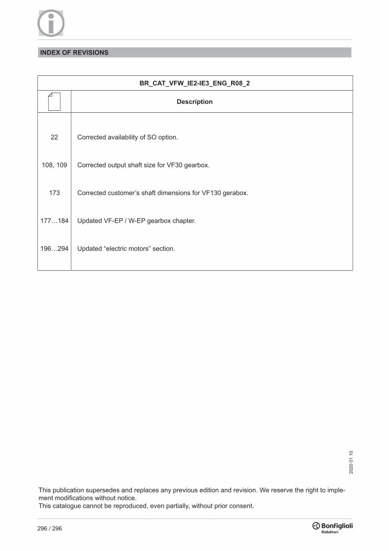
296 / 296
22
Corrected availability of SO option.
108, 109 Corrected output shaft size for VF30 gearbox.
173
Corrected customer’s shaft dimensions for VF130 gerabox.
177…184
Updated VF-EP / W-EP gearbox chapter.
196…294
Updated “electric motors” section.
INDEX OF REVISIONS
BR_CAT_VFW_IE2-IE3_ENG_R08_2
Description
This publication supersedes and replaces any previous edition and revision. We reserve the right to imple-ment modifications without notice. This catalogue cannot be reproduced, even partially, without prior consent.
2020
01
10


PRODUCTS &SOLUTIONS
HEADQUARTERSBonfiglioli Riduttori S.p.A.Via Giovanni XXIII, 7/A40012 Lippo di Calderara di RenoBologna (Italy)tel: +39 051 647 3111fax: +39 051 647 [email protected]
We have a relentless commitment to excellence, innovation and sustainability. Our team creates, distributes and services world-class power transmission and drive solutions to keep the world in motion.
VF-W SeriesIE2-IE3
Wormgears
VF-W
IE2-
IE3
Serie
sEN
G


![vf[ky Hkkjrh; vk;qfoZKku laLFkku] iVuk Corrigendum - AIIMS ...](https://static.fdokumen.com/doc/165x107/631a41301e5d335f8d0b7fb5/vfky-hkkjrh-vkqfozkku-lalfkku-ivuk-corrigendum-aiims-.jpg)