DRI-STEEM Models GTS and GTS-DI
36
READ AND SAVE THESE INSTRUCTIONS DRI-STEEM Models GTS and GTS-DI GAS-TO-STEAM HUMIDIFIERS User's/Installation Instructions and Maintenance Operations Manual For Toll-Free Technical Support, Call: 1-800-328-4447 This manual must be left with the owner and should be accessible for reference. ® ® WARNING: If the information in this manual is not followed exactly, a fire or explosion may result causing property damage, personal injury, or loss of life. • Do not store or use gasoline or other flammable vapors and liquids in the vicinity of this or any other appliance. WHAT TO DO IF YOU SMELL GAS • Do not try to light any appliance. • Do not touch any electrical switch; do not use any phone in your building. • Immediately call your gas supplier from an off-site phone. Follow the gas supplier's instructions. • If you cannot reach your gas supplier, call the fire department. • Installation and service must be performed by a qualified installer, service agency, or the gas supplier.
-
Upload
khangminh22 -
Category
Documents
-
view
0 -
download
0
Transcript of DRI-STEEM Models GTS and GTS-DI

READ AND SAVE THESE INSTRUCTIONS
DRI-STEEM ModelsGTS and GTS-DIGAS-TO-STEAM HUMIDIFIERS
User's/Installation Instructionsand
Maintenance Operations Manual
For Toll-Free TechnicalSupport, Call: 1-800-328-4447
This manual must be left with the owner and should be accessible for reference.
® ®
WARNING: If the information in this manualis not followed exactly, a fire or explosionmay result causing property damage,personal injury, or loss of life.
• Do not store or use gasoline or other flammable vapors andliquids in the vicinity of this or any other appliance.
WHAT TO DO IF YOU SMELL GAS• Do not try to light any appliance.
• Do not touch any electrical switch; do not use anyphone in your building.
• Immediately call your gas supplier from an off-sitephone. Follow the gas supplier's instructions.
• If you cannot reach your gas supplier, call the firedepartment.
• Installation and service must be performed by a qualifiedinstaller, service agency, or the gas supplier.
GTS-IOM-1298.pdf 1 11/17/2009 3:56:56 PM

2
TO THE PURCHASER AND THE INSTALLERThank you for purchasing DRI-STEEM Model GTS® equipment. We have designed and built this equipment to give youtotal satisfaction and many years of trouble-free service. Proper installation and operating practices will assure you ofachieving that objective. We therefore urge you to become familiar with the contents of this manual.
DRI-STEEM Humidifier Company
GTS Program Code Nomenclature ...................................... 3
Models GTS and GTS-DI Humidifiers .................................. 4
Safety Precautions ................................................................ 5
InstallationPrecautions ................................................................ 6Required Clearance..................................................... 6Locating the Humidifier .............................................. 7Supply Water and Drain Overflow Connections ........ 7Drain Piping and Material ........................................... 8Make-up Water Piping and Material .......................... 8Vapor Hose Piping ..................................................... 8Gas Piping ................................................................. 9Gas Leak Testing ....................................................... 9Electrical .................................................................... 10Combustion and Ventilation Air .................................. 10Venting Guidelines (Stack Connection) ..................... 11
Specifications and Capacities ............................................. 13
Dimensions ........................................................................... 14
Piping Diagrams: Gas, Water, and Drain ........................... 15
Mounting the Humidifier ..................................................... 16
Steam Supply Connection Methods ................................... 17
Dispersion Tube Installation ............................................... 18
RAPID-SORB® Assembly and InstallationHorizontal Duct Installation .....................................19Vertical Duct Installation .........................................20
ULTRA-SORB® Installation .................................................. 20
AREA-TYPE Application ...................................................... 21
Start-up and Operation ........................................................ 22
MaintenanceGTS (Standard Model Only) ...................................... 23GTS-DI Model Only ................................................... 23Both GTS and GTS-DI ............................................... 24Air Shutter Adjustment Procedure ............................. 25
Replacement Parts ............................................................... 26
Wiring Diagrams .................................................................. 28
Caution Labels ..................................................................... 32
Gas Control Valve ................................................................ 33
Maintenance Service Record .............................................. 34
Two-Year Limited Warranty ................................................ 36
TABLE OF CONTENTS
GTS-IOM-1298.pdf 2 11/17/2009 3:56:59 PM

3
How many tanks are in the system(1-6)
What type of control does the unit haveS - Single stagedE - Externally stagedZ - Zone valveT - TPX – Slave
M – Master
Does the unit have VAVV - YesO - No
Does the unit have temperature compensationT - YesO - No
Humidity sensor typeC - 0-135 OHM humidistat ElectricD - 6-9 VDC humidistatF - 1-10 VDC humidistatE - 4-20 mA humidistatX - 4-20 mA transmitterS - SlaveN - None (On/Off)
P – 0-135 OHM humidstat Pneumatic
Burner size5-50 MBH7-75 MBH1-100 MBH6-67.5 MBH
Burner quantity1 - One staged2 - Two staged4 - Four staged5 - One modulating6 - Two modulating8 - Four modulating
Water level controlD - DI with manual drainE - DI with auto drain (end of season)M - Probe with manual drainA - Probe with auto drain
GTS PROGRAM CODE NOMENCLATURE
GTS PROGRAM CODE NOMENCLATURE
1 T OO X 7 8 A (Example)
GTS-IOM-1298.pdf 3 11/17/2009 3:56:59 PM
4
GTS® AND GTS-DI HUMIDIFIERS
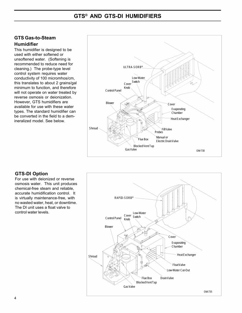
GTS Gas-to-SteamHumidifierThis humidifier is designed to beused with either softened orunsoftened water. (Softening isrecommended to reduce need forcleaning.) The probe-type levelcontrol system requires waterconductivity of 100 micromhos/cm,this translates to about 2 grains/galminimum to function, and thereforewill not operate on water treated byreverse osmosis or deionization.However, GTS humidifiers areavailable for use with these watertypes. The standard humidifier canbe converted in the field to a dem-ineralized model. See below.
OM-735
OM-730
GTS-DI OptionFor use with deionized or reverseosmosis water. This unit produceschemical-free steam and reliable,accurate humidification control. Itis virtually maintenance-free, withno wasted water, heat, or downtime.The DI unit uses a float valve tocontrol water levels.
Gas ValveBlocked Vent Tap
Flue BoxManual orElectric Drain Valve
ProbesFill Valve
Heat Exchanger
EvaporatingChamber
CoverBlower
ULTRA-SORB®
CoverKnob
Control Panel
Shroud
Low-WaterSwitch
Gas ValveBlocked Vent Tap
Flue Box Drain Valve
Low-Water Cut-Out
Float Valve
Heat Exchanger
EvaporatingChamber
Cover
Blower
Control PanelCoverKnob
Low-WaterSwitch
Shroud
RAPID-SORB®
GTS-IOM-1298.pdf 4 11/17/2009 3:56:59 PM

5
SAFETY PRECAUTIONS
WARNING:Improper installation, adjustment, alteration, service,maintenance, or use can cause carbon monoxidepoisoning, an explosion, fire, electrical shock, or otherconditions which may cause personal injury or propertydamage. Consult a qualified installer, service agency,local gas supplier, or your distributor or branch forinformation or assistance. The qualified installer oragency must use only factory authorized and listed kitsor accessories when modifying this product. A failureto follow this warning can cause electrical shock, fire,personal injury, or death.
• Inspect humidifier and accessories upon arrival fordamaged, missing, or improper parts. If there is aproblem, call DRI-STEEM.
• Application of this humidifier should have specialattention given to vent sizing and material, gas inputrate, and unit sizing. Improper installation or misappli-cation of the humidifier can require excessive servicingor cause permanent component failure.
• When working on equipment, observe precautions inthis literature, tags, and labels attached to or shippedwith the unit and other safety precautions that mayapply. Wear safety glasses and work gloves. Have fireextinguisher available during start-up, adjustmentprocedures, and service calls.
• Do not use this appliance if any part has been underwater. Immediately call a qualified service technician toinspect the appliance and to replace any part of thecontrol system and any gas control which has beenunder water.
• Do not lift humidifier by gas controls, gas manifold,fire box, or control shroud.
• Should overheating occur, or the gas supply fail toshut off, shut off the manual gas valve to the appliancebefore shutting off the electrical supply.
GTS-IOM-1298.pdf 5 11/17/2009 3:57:02 PM

6
INSTALLATION
Precautions• The installation must conform to the requirements ofthe authority having jurisdiction or, in the absence ofsuch requirements, to the National Fuel Gas Code,ANSI Z223.1 (latest edition). In Canada, the installationof this unit must comply with local plumbing or wastewater codes and other applicable codes and with thecurrent code CAN/CGS-B149.1 "Installation Code forNatural Gas Burning Appliances and Equipment" orCAN/CGA-B149.2, "Installation Code for PropaneBurning Applications and Equipment."
• Do not install in potentially explosive or flammableatmospheres laden with grain dust, sawdust, or similarairborne materials.
• Installation of humidifier in high humidity or salt wateratmospheres will cause accelerated corrosion, resultingin a reduction of the normal life-span of the unit.
• To prevent premature heat exchanger failure, do notlocate ANY gas-fired unit in areas where chlorinated,halogenated or acid vapors are present in the atmo-sphere.
• Locate the humidifier in an area clear of combustiblematerials, gasoline, and other flammable vapors andliquids.
• Do not locate units in tightly sealed rooms or smallcompartments without provision for adequate combustionair and venting. Combustion air must be supplied to theroom through a minimum of two permanent openings inthe wall, at least one near the bottom. The openingsshould provide one square inch of free area per 1000BTUH input rating of the unit with a minimum of 100square inches for each opening, whichever is greater.See table 10-1 and information on pages 10 and 11 foradditional details.
Required Clearance:For recommended service and maintenance purposes thefollowing clearances should be maintained:
• Heat exchanger removal - front, 30"• Burner shroud removal - front, 24"• Control cabinet - left side, 36"• Drain valve - right side, 12"• Clean-out tray - rear, 30" (not applicable with DI/RO systems)• Cover removal - top, 18"• Distance from vent box to combustible floor - 30"
GTS clearance recommendationsControl cabinet, 36" Cover, 18"
Cleanout tray,
30"
Drain valve, 12"
Heat exchanger, 30"
30"
Burnershroud,24"
Floor
GTS-IOM-1298.pdf 6 11/17/2009 3:57:02 PM

7
INSTALLATION
Important:• Remove all shipping brackets and materials beforeoperating the humidifier.
• Humidifier flue gases must be vented to the outsideatmosphere.
• Power supply disconnect switch must be in the offposition while making wiring connections to preventelectrical shock and equipment damage. All units mustbe wired in strict accordance with wiring diagram furnishedwith this unit.
• Turn off all gas while installing the run-out and manualshut-off valve for the humidifier.
Locating the Humidifier• Provide a level, solid foundation for the humidifier.Locate the humidifier as near as possible to chimney oroutside wall so that the flue pipe from the humidifier isshort and direct. The location should also be such thatthe gas ignition system components are protected fromwater during humidifier operation and service.
• The humidifier should be installed in a location awayfrom drafts and properly protected. If installed in aseparate room, follow the instructions concerningcombustion and ventilation air.
• The humidifier should be located in an area whereleakage from the tank or its connections will not resultin damage to the adjacent structure or to lower floors ofthe structure. When such locations cannot be avoided,it is recommended that a suitable drain pan, adequatelydrained, be installed under the humidifier. The pan mustnot restrict combustion air flow.
• The humidifier must not be installed on carpeting, tile,or other combustible material other than wood flooring(indoor application only).
• Install humidifier so electrical components are pro-tected from water.
• The appliance must be kept free and clear of insulat-ing materials when located in an insulated space.Insulating material may be combustible. Inspection ofthe appliance area must be performed when the appli-ance is installed, or when insulation is added.
Supply Water and Drain OverflowConnectionsIMPORTANT: The humidifier is shipped with the auto-matic drain valve locked in the manual open position.This position reduces the possibility of damaging thevalve seat from the heat of sweating the drain connectionduring installation. After the drain connection has beencompleted the "manual open" lever position must be resetto the auto position. Failure to close the drain valve willnot allow the tank to fill.
Regardless of the type of water used, the followinggeneral instructions must be followed:
• Union connections must be made at the humidifier onthe cold water supply and drain/overflow lines.
• A shut-off valve should be provided in the supply waterline to isolate the humidifier from the water system whileservicing.
• If the water pressure is above 60 psi and/or waterhammer would be objectionable, a pressure reducingvalve or shock arrester should be installed.
• A 3/4” opening is provided in the humidifier tank toaccommodate skim and/or overflow protection. A waterseal is required on the drain/overflow connection and a 1”air gap should be provided prior to a building drain. (Note:Follow local code requirements regarding size of drainpipe.) The water seal must be piped to hold steam in thehumidifier and also provide a pressure relief if the steamoutlet becomes clogged. (See diagram on page 15)
• Insulating unions or bushings must be used to makeconnections between copper and other dissimilar metalfittings, such as galvanized steel. These insulatingfittings are required to minimize electrolytic corrosion,which results from the direct connection of dissimilarmetals in a water system.
• Before beginning ignition sequence of the humidifier at anew installation, be sure the humidifier tank is full of waterand the water is free to flow into the tank.
GTS-IOM-1298.pdf 7 11/17/2009 3:57:03 PM

8
Figure 8-1: Piping method recommended whenobstruction prevents dispersion tube from beingcontinuously pitched back to humidifier
INSTALLATION
Figure 8-2: Piping method recommended whenhumidifier must be mounted higher than the duct
OM-749
Obstruction
¾" Tubing
Funnel orFloor Drain*
4" Min. 5" Min.
As part of the fill valve assembly, the needle valverestricts the rush of cold water entering the evaporatingchamber during the fill cycle. Adjusting the supply waterflow with the needle valve will reduce fill cycle noisefrom the collapsing steam head in the humidifier. Ad-justing the needle valve will also reduce the drop inoutput during a fill cycle. Care must be taken to notreduce the fill rate below the humidifier's capacity, this itwill cause a low-water shutdown.
Vapor Hose PipingWhen a vapor hose and stainless steel dispersiontubes are used, they should be pitched back to thehumidifier. A minimum slope of 2" per foot (with no “lowspots”) is recommended. When this is not possible dueto duct elevation or an obstruction, alternate arrange-ments may be used as shown in figures 8-1 and 8-2below.
Any condensate that forms in the vapor hose must beremoved. Preferably, it should be returned to an opendrain with a water seal of sufficient height to contain theduct static pressure, as shown in figure 8-1.
Notes:• The GTS typically requires multiple dispersion tubes.* Refer to local codes for drain pipe size requirements.
OM-750
GTS
Duct
Drain Piping and MaterialDrain piping diagrams are provided on page 15. If non-metallic pipe or hose is used, it must be capable ofwithstanding temperatures up to 212°F.
To prevent steam from escaping out the drain line, awater seal must be provided in the drain line of sufficientheight to contain the pressure developed within thehumidifier and steam dispersion system. To determinethe proper height of the water seal, see table 15-1 onpage 15.
Make-up Water Piping and MaterialMake-up water piping diagrams are provided on page 15.Minimum make-up water pressure must be 25 psig.When non-metallic water piping is used, it must be ratedto withstand 212°F or greater temperature. If not, thefinal 3 feet connected to the humidifier should be metallicand should not be insulated.
GTS
Duct
Inline Tee(1½" Dia. - Part # 162710)(2" Dia. - Part # 162712)
Inline Tee(1½" Dia. - Part # 162710)(2" Dia. - Part # 162712)
GTS-IOM-1298.pdf 8 11/17/2009 3:57:03 PM

9
INSTALLATION
Gas Piping(See "Gas Piping" diagram on page 15.)
CAUTION:Gas pressure to humidifier controls must neverexceed 14” W.C. (1/2 psi). A 1/8" inch NPT pluggedtapping, accessible for test gauge connection, mustbe installed immediately upstream of the gas supplyconnection to the appliance.
• Piping installation must be in accordance with localcodes, and ANSI Z233.1, “National Fuel Gas Code,” orCAN/CGA-B149 in Canada. Do not use flexible connec-tors.
• Piping to units should conform with local and nationalrequirements for type and volume and gas handled, andpressure drop allowed in the line. Refer to table 9-1 and9-2 to determine the cubic feet per hour (cfh) for thetype of gas and size of unit to be installed. Using thisvalue and the length of pipe necessary, determine thepipe diameter. Where several units are served by thesame main, the total capacity, gas flow (cfh), and lengthof main must be considered. Avoid pipe sizes smallerthan 1/2”. Table 9-1 allows for the usual number offittings with a 0.3” W.C. pressure drop.
• After threading and reaming the ends, inspect pipingand remove loose dirt and chips.
• Support piping so that no strains are imposed on unitor controls.
• Use two wrenches when connecting piping to unitcontrols.
• Provide a drip pocket before each unit and in the linewhere low spots cannot be avoided.
• Take-off to unit should come from top orside of main to avoid trapping conden-sate.
• Piping subject to wide temperaturevariations should be insulated.
• Pitch piping up toward unit at least1/4” per 15’ of horizontal run.
• Compounds used on threaded joints ofgas piping must be resistant to theharmful action of liquefied petroleumgases.
• Purge air before lighting unit bydisconnecting piping at gas control. Inno case should line be purged intoheat exchanger.
• After installation, check field pipingand humidifier gas train for gas leaks.
• Do not use soap solution, or open flame on humidifiergas train. A gas leak detector is recommended.
• Install a ground joint union and a manual shut-off valveimmediately upstream of the unit including a 1/8” NPTplugged tapping accessible for test gauge connection.Plugged tappings for test gauges are located on all gasvalves.
• Allow at least 5 feet of piping between any highpressure regulator and unit pipe connection.
Gas Leak Testing• When leak testing the gas supply piping system, thehumidifier and its gas shut-off valve must be disconnectedduring any pressure testing in excess of 14” W.C. (½ psi).The humidifier must be isolated from the gas supply pipingsystem by closing its field-installed manual shut-off valveduring any pressure testing equal to or greater than 14"W.C. (½ psi).
• Check gas supply pressure with all burners running atinlet pressure tap of combination gas control. (See page33) The recommended supply pressure should be 7"W.C. on natural gas or 11" W.C. on LP gas. Purging ofgas piping should be performed as described in ANSIZ223.1 (latest edition) or, in Canada, in CAN/CGA-B149codes.
• Minimum supply pressure. Natural - 4½" W.C.LP - 10" W.C.
• Single stage gas valves GTS™-300, 150, and 75 outletpressure (manifold) should be factory set at 3 1/2" w.c. fornatural, 9" w.c. for L.P. This pressure can be checked onthe combination gas valve at the out pressure tap (seepage 33).
Lengthof Pipe
Feet
Gas Flow in Piping (Cu. Ft. per Hr.)(At pressure drop of 0.3 in. water.
Specific gravity = 0.60)
Iron Pipe Size (NPT) Inches
1/2 3/4 1 1-1/4 1-1/2
10 132 278 520 1050 1600
20 92 190 350 730 1100
30 73 152 285 590 890
40 63 130 245 500 760
50 56 115 215 440 670
60 50 105 195 400 610
70 46 96 180 370 560
80 43 90 170 350 530
90 40 84 160 320 490
100 38 79 150 305 460
Table 9-2: SpecificGravity ConversionFactorsMultiplying factor to be usedwith table 9-1 when thespecific gravity of gas is otherthan 0.60.
Natural Gas
SpecificGravity Factor
0.55 1.04
0.60 1.00
0.65 0.962
Propane Gas
SpecificGravity Factor
1.50 0.633
1.53 0.626
1.60 0.612
Table 9-1: Gas Pipe Capacities for GasPressures of .5 PSIG or Less
GTS-IOM-1298.pdf 9 11/17/2009 3:57:03 PM

10
INSTALLATION
• Two stage gas valves (used on GTS® 400, 200 and 100)have a 10 second high fire stage and then drop to anormal fire stage. Factory settings for natural gas are 5"w.c. high, 3 1/2" w.c. normal. Factory settings for L.P. gasare 8" w.c. high, 6" w.c. low. These pressures can bechecked on the combination gas valve at the out pressuretap (see page 33).
Electrical
CAUTION:Do not connect aluminum wire between disconnectswitch and humidifier. Use only copper wire.
WARNING:The cabinet must have an uninterrupted or unbrokenground according to National Electrical Code, ANSI/NFPA70 and Canadian Electrical Code, CSA C22.1, or localcodes to minimize personal injury if an electrical faultshould occur. This may consist of electrical wire orconduit approved for electrical ground when installed inaccordance with existing electrical codes. Do not use gaspiping as an electrical ground.
• GTS Humidifiers should be supplied with 120-volt AC,60-Hz, 15-amp separately fused electrical service. TheGTS humidifier is equipped with a transformer to stepdown the voltage to 24 VAC control voltage.
• When installed, the GTS humidifier must be electricallygrounded in accordance with local codes or, in the ab-sence of local codes, with the National Electrical CodeANSI/NFPA No. 70-1987. The electrical conductors shallbe Type MTW (105°C) AWG #14 wire for line voltage(120V), with BLACK WIRE for HOT; WHITE WIRE forNEUTRAL, GREEN WIRE for GROUND; and #18 gaugefor control wiring. All electrical components and wiringmust be protected from mechanical damage and water.The control system requires an earth ground for properoperation.
• The humidifier is adjusted for correct performance. Donot alter fan or operate motors at reduced speed.
• The current characteristics, and capacity requirementsshould be checked against the nameplates. All wiringmust be in accordance with all governing codes, and withGTS wiring diagram located inside the control cabinet.See table 13-1 for information on the various models.
• See page 14 for recommended knockout locations forthe electrical power supply and control wiring connectionson the control cabinet.
• See separate publication for the specific controllerfurnished with this specific GTS humidifier.
Combustion and Ventilation Air
CAUTION:Air for combustion must not be contaminated byhalogen compounds, which include fluoride, chloride,bromide and iodide. These elements are found inaerosol sprays, detergents, bleaches, cleaning sol-vents, salts, air fresheners, and other householdproducts.
CAUTION:The operation of exhaust fans, kitchen ventilationfans, clothes dryers, or fireplaces could create anegative pressure condition at the humidifier. Make-up air must be provided for the ventilation devices, inaddition to that required by the humidifier.
• All fuel burning equipment must be supplied with air forcombustion of the fuel. Sufficient air MUST be providedto ensure there will not be a negative pressure in theequipment room or space.
• Provisions for adequate combustion and ventilation airmust be provided in accordance with Section 5.3, Air forCombustion and Ventilation, of the National Fuel GasCode, ANSI Z223.1-1988, or applicable provisions of thelocal building codes. Canadian installations must beinstalled in accordance with sections 7.2, 7.3, and 7.4 ofthe CAN/CGA.B149 Installation Codes, and all authoritieshaving jurisdiction.
Confined Space - All airfrom inside the building;conventional frame.Brick or stoneconstruction with normalinfiltration. (Can only berarely used with largerinput units.)
Two openings, 1 squareinch per opening per1000 BTU/hr. input.*
The minimum free areaof opening is 100 squareinches.
Confined Space - All airfrom outside the buildingthrough air ducts.
Two openings, 2 ducts, 1square inch per openingper 2000 BTU/hr. input.*
Confined Space - All airfrom outside thebuilding, through wallopenings only (noducts.)
Two openings, 1 squareinch per opening per4000 BTU/hr. input.*
Unconfined Space - Allair from outside thebuilding.
Same as confinedspace, all air fromoutside the building.*
Table 10-1: Location of Humidifier and Required AirOpenings to Confined Space
*Note the minimum dimension of any opening is threeinches.
GTS-IOM-1298.pdf 10 11/17/2009 3:57:03 PM

11
INSTALLATION
levels of insulation when penetrating a combustible walldepending on vent temperatures.
• This humidifier must not be connected to a chimney flueservicing a separate appliance designed to burn solidfuel.
• Never connect this humidifier to a chimney serving afireplace, unless the fireplace opening is permanentlysealed off.
• The recommended vent system for the GTS-300, 150,and 75 humidifier is constructed of Type B double-wallvent pipe (UL or CUL listed). Type B vent is rated for400°F plus ambient temperature. A minimum 1-inchclearance is required between Type B vent and combus-tible materials. Field expertise has shown that ventingthrough a properly sized Type B vent significantlyreduces the occurrence of vent condensation.
• It may be necessary to add insulation to Type B double-wall vent and to single-wall vent connector, if allowed bylocal codes, in some applications. When insulation isrequired, it must be at least 1-inch thick fiberglass with foilbacking. Using permanent foil tape, attach insulation tovent pipe. Both the foil tape and fiberglass insulationmust be suitable for temperatures up to 450°F.
• Insulation must be added to any vent connector whichwill be exposed to ambient temperatures of 30°F or less,especially any application using single-wall vent pipe as aconnector.
• Do not insulate vent pipe exposed to outdoor weatherconditions (i.e. above roof lines).
• Venting into an unlined masonry or concrete chimney isprohibited by code.
• If this humidifier is connected to a lined, masonrychimney, the chimney must be sized and installed accord-ing to the provisions of the National Fuel Gas Code, orCanadian CAN/CGA.B149 requirements. Vent connectorsfrom the humidifier to the chimney should be made withinsulated Type C single-wall vent pipe or Type B ventpipe for GTS-300, 150, and 75. The GTS-400, 200 and100 is approved for single wall vent only.
• Installation of the vent pipe should be as directly aspossible, with a minimum number of turns or elbows.
• Rigidly support the vent pipe every 5 feet or less withhangers or straps to ensure that there will be no move-ment after installation. The humidifier vent box should notbe supporting the weight of the vent piping.
• For proper and safe operation this appliance needs airfor combustion and ventilation. DO NOT block orobstruct air openings on the appliance, spaces around theappliance, or air openings communicating with the appli-ance area.
• DO NOT block the flow of combustion and ventilationair. To provide for necessary oxygen for proper combus-tion, opening must be provided to allow outside air to enterthe space in which the heater is located. Enclosedspaces, such as equipment rooms, must be vented at theblower for combustion air. The size of air openings mustbe based on all gas-burning equipment installed in thespace involved. Four types of locations, and the require-ments of each, are outlined in table 10-1, on page 10.
Vertical and Horizontal Venting Guidelines(Stack Connection)
• The GTS® is a fan assisted category 1 appliance.
• The purpose of venting the gas humidifier is to com-pletely remove all products of combustion and ventilationgases to the outside air, without condensation in thestack.
• When connecting the humidifier to a gas vent or chim-ney, the installation shall be in accordance with Part 7,Venting of Equipment, of the National Fuel Gas Code,ANSI Z223.1, or Section 7, Venting Systems and AirSupply Appliances, of the CAN/CGA B149 InstallationCodes, the local building codes, and the ventmanufacturer's instructions.
• Do not reduce the vent diameter, and avoid short turnsin the vent piping. Use the same size stack as the ventfurnished with the humidifier. Maintain a minimumupward slope of 1/4-inch-per-linear foot on all horizontalruns. Maintain proper support of vent connections andjoints. Observe clearances (in accordance with appli-cable codes) from all combustible materials, and obtainan approved cap for the stack outlet. The bottom of thecap must be one stack diameter above the top of thestack.
• Inspect for proper and tight construction. Any restric-tions or obstructions must be removed. An existingchimney may require cleaning.
• Chimney or vent must extend at least 3 feet above itspassage through a roof and at least 2 feet above any ridgewithin 10 feet of the chimney. (Local codes apply.)
• Minimum clearance from the vent connector to combus-tible material is 6 inches unless the combustible materialsare protected in accordance with applicable codes. Therecommended vent system for the GTS-400, 200 and100 humidifiers is constructed of Type C single wall ventpipe (UL or CUL listed). Type C vent requires varying
GTS-IOM-1298.pdf 11 11/17/2009 3:57:03 PM

12
• No portion of the vent system shall extend into, or passthrough, any circulation air duct or plenum.
• The Type B vent system shall terminate above the roofsurface per the National Fuel Gas Code or CAN/CGA.B149 requirements, and shall include a UL or CULlisted vent cap or roof assembly, unless prohibited bylocal codes.
• This humidifier may be commonly vented with otherlisted gas-fired appliances. Total input rates of all appli-ances will determine the vent size.
• All vent pipe passing through floors, ceilings, and wallsmust be installed with the proper clearances from combus-tible material, and be fire-stopped according to theNational Fuel Gas Code requirements and CanadianStandards CAN/CGA.B149.
• In replacement installation, where an existing ventsystem may be used, the vent system must be inspectedfor condition, size, type of vent material, and height tomeet the requirements in these instructions. If theexisting vent system is too large, condensation couldoccur, causing corrosion of the vent system. Installing areplacement vent system may be required. When con-necting the humidifier to a gas vent or chimney, theinstallations shall be in accordance with Part 7, Venting ofEquipment, of the National Fuel Gas Code, ANSI Z223.1,or Section 7, Venting Systems and Air Supply Appliances,of the CAN/CGA B149 Installation Codes, the localbuilding codes, and the vent manufacturer's instructions.
• For all applications, the horizontal length of the vent andvent connector must not exceed the height of the ventsystem.
Special Horizontal Venting Requirements• Distances from the vent terminal adjacent publicwalkways, buildings, and openable windows and buildingopenings should be consistent with the National Fuel GasCode, ANSI Z223.1, and/or CAN/CGA B149 InstallationCodes.
• The vent terminal and air intake locations must be atsufficient height above ground level to prevent blocking byexpected snowfall.
• Building materials should be protected from degrada-tion by flue gases.
• A minimum horizontal clearance of 4 feet (1.22m) fromelectric meters, gas meters, regulators, and reliefequipment must be maintained.
INSTALLATION
• 60' maximum, 10' minimum equivalent length of vent pipe.
• A vent box pressure of -.01" w.c. is specified and set byadjusting power venter and barometric damper, with allburners running.
• Maximum of 4 elbows
• Vent pipe is single wall or B vent for GTS-300, 150, 75.
• Vent pipe is single wall only on GTS-400, 200, and 100.
Equipment Required for Horizontal Venting• Power Venter: Field controls, see above table formodel numbers.
• Barometric Damper: Field controls model # MG-1 (5").
• Vent Terminal: Field controls, see above table formodel numbers.
Power VenterBarometricDraft Control
GTS HumidifierX
X
Air Intake
3½ Feet Minimum
VentHood
Note: Refer to power venter manual for clearance requirements relative tocombustion air openings.
Figure 12-1: GTS Venting
ledoM™STG htgneLtnelaviuqEwoblE/epiPtneVfo
lanimreTtneVrebmuNledoM
rewoPretneV
cirtemoraBrepmaD
004-STG '7 )"5(5-1-HWS 006-OVP"5 "5003-STG '7 )"5(5-1-HWS 006-OVP"5 "5
002,051,001,57-STG '6 )"4(4-1-HWS 003-OVP"4 "5
Recommended Value forX Approximately 12"
GTS-IOM-1298.pdf 12 11/17/2009 3:57:03 PM

13
Modelnumber
Steamcapacityper hour
in lbs.(kg.)
*MBHinput
Heatingstages
Vent sizein inches
(mm)
Operatingweightin lbs.(kg.)
Shippingweightin lbs.(kg.)
115 volt, 60 Hz Performance derate impact
Fullload
amps
Max.fusesize
Vertical vent Horizontal vent
Naturalgas
LPgas
Naturalgas
LPgas
GTS-75 55(25) 75 1 5
(130)400
(180)230
(105) 2.5 15 0% 10% 10% 10%
GTS-100 75(34) 100 1 5
(130)400
(180)230
(105) 2.5 15 0% 4% 0% 4%
GTS-150 110(50) 150 2 5
(130)525
(240)300
(135) 3.5 15 0% 10% 10% 10%
GTS-200 150(68) 200 2 5
(130)525
(240)300
(135) 3.5 15 0% 4% 0% 4%
GTS-300 225(102) 300 4 7
(180)775
(350)400(180) 5.0 15 0% 10% 10% 10%
GTS-400 300(136) 400 4 7
(180)800
(365)425(195) 5.0 15 0% 4% 0% 4%
SPECIFICATIONS AND CAPACITIES
Table 13-1: Specifications
* Altitude adjustment note for Canada:Altitude in feet Percent of listed input0-2000 100%2000-4500 90%
* Altitude adjustment note for United States:100% up to 2000'4% derate/1000' over 2000'
Capacity Notes• Approximately 172 BTU’s are required to raise thetemperature of one pound of water from 40° to 212° F.
• An additional 970 BTU’s are required to change onepound of water to water vapor.
• The ¾" rigid foil faced fiberglass insulation on allsurfaces of evaporating chamber increases unit efficiencyby approximately 2%.
• Another factor to consider is condensation steam lossfrom hoses and tubes. Use the following steam lossguidelines:
- vapor hose: 0.15 lbs/ft/hr- insulated pipe: 0.05 lbs/ft/hr- dispersion tubes: 0.50 lbs/ft/hr
GTS-IOM-1298.pdf 13 11/17/2009 3:57:03 PM

14
DescriptionGTS®-75GTS-100
(One burner)
GTS-150GTS-200
(Two burner)
GTS-300GTS-400
(Four burner)
A Floor stand width 19" 19" 27½"
B Overall length 54¼" 54¼" 54¼"
C Height of evaporating chamber 17¾" 23½" 25¼"
D Distance from steam outlet to side of unit 9¼" 9¼" 13½"
E Overall width 27" 27" 37½"
F Height of control cabinet 20" 20" 24"
G Shroud height 20" 25¾" 27½"
H Distance from top of shroud to gas inlet 11¾" 11" 14"
J Gas inlet ½" NPT ¾" NPT 1" NPT
K Distance from flue to side of unit 6¼" 6¼" 6½"
L Distance from flue to front of tank 3¾" 3¾" 4¾"
M Flue diameter 5" 5" 7"
N Distance from floor to bottom of tank 28½" 22¾" 21"
DIMENSIONS
Figure 14-1: Dimensions
B
H
G
J
ED
K
C
A
Front View
Clean-out tray
¼” NPT Fill
M
Top View
RecommendedZTU cord locationknockout
F
NRecommendedlow voltagecontrol wiringknockout
¾” Copperdrain
Table 14-1: Dimensions
Recommendedpower supplyknockout
Side View Side View
L
GTS-IOM-1298.pdf 14 11/17/2009 3:57:03 PM
15
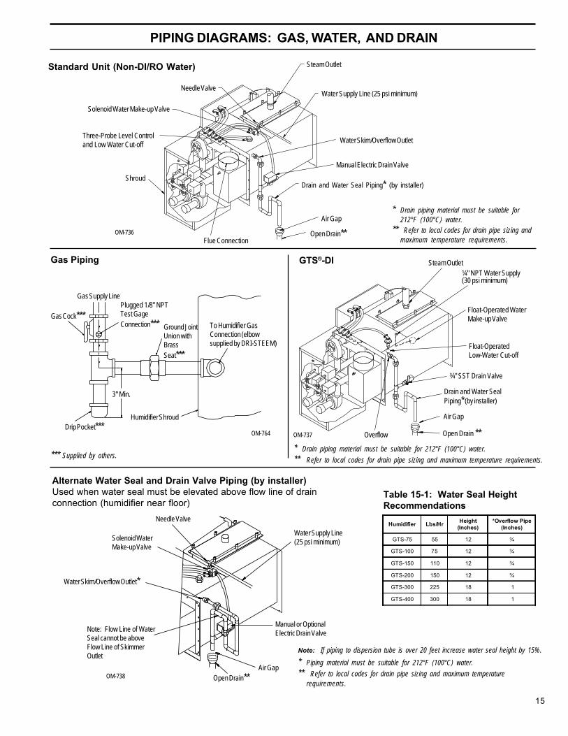
Needle ValveHumidifier Lbs/Hr Height
(Inches)*Overflow Pipe
(Inches)
GTS-75 55 12 ¾
GTS-100 75 12 ¾
GTS-150 110 12 ¾
GTS-200 150 12 ¾
GTS-300 225 18 1
GTS-400 300 18 1
PIPING DIAGRAMS: GAS, WATER, AND DRAIN
OM-736
Water Supply Line (25 psi minimum)
GTS®-DIGas Piping
Gas Supply Line
Drip Pocket***
3" Min.
Plugged 1/8" NPTTest GageConnection***
Humidifier Shroud
OM-764
*** Supplied by others.
To Humidifier GasConnection (elbowsupplied by DRI-STEEM)
Standard Unit (Non-DI/RO Water) Steam Outlet
Air GapOM-738
Alternate Water Seal and Drain Valve Piping (by installer)Used when water seal must be elevated above flow line of drainconnection (humidifier near floor)
OM-737
Steam Outlet¼" NPT Water Supply(30 psi minimum)
Float-Operated WaterMake-up Valve
Open Drain **
Air Gap
¾" SST Drain Valve
Open Drain**
Manual or OptionalElectric Drain Valve
Water Supply Line(25 psi minimum)
Flue Connection
Float-OperatedLow-Water Cut-off
Manual Electric Drain Valve
Water Skim/Overflow Outlet
Solenoid WaterMake-up Valve
Note: Flow Line of WaterSeal cannot be aboveFlow Line of SkimmerOutlet
Air Gap
Open Drain**
Shroud
Three-Probe Level Controland Low Water Cut-off
Solenoid Water Make-up Valve
Needle Valve
Water Skim/Overflow Outlet*
Drain and Water Seal Piping* (by installer)
Drain and Water SealPiping* (by installer)
Gas Cock***Ground JointUnion withBrassSeat***
Overflow
Table 15-1: Water Seal HeightRecommendations
* Drain piping material must be suitable for212°F (100°C) water.
** Refer to local codes for drain pipe sizing andmaximum temperature requirements.
* Drain piping material must be suitable for 212°F (100°C) water.
** Refer to local codes for drain pipe sizing and maximum temperature requirements.
Note: If piping to dispersion tube is over 20 feet increase water seal height by 15%.
* Piping material must be suitable for 212°F (100°C) water.
** Refer to local codes for drain pipe sizing and maximum temperaturerequirements.
GTS-IOM-1298.pdf 15 11/17/2009 3:57:04 PM

16
MOUNTING THE HUMIDIFIER
For proper operation of the electrode-probe, water-levelcontrol and the skimmer system, the humidifier must bemounted level left to right and front to rear.
Proper access (18" minimum) for periodic removal of thetop cover is recommended. In most cases, scale that
forms on the heat exchanger continuously flakes off as itforms and settles to the bottom. A clean-out tray on thefloor of the tank may be removed periodically through theback clean-out opening.
Trapeze(GTS 75 & 100 only)
Note:The trapeze bars will span the width of the tank and should be resting against thefront and rear tank flanges. Holes should be drilled in overhead support to providevertical installation of threaded rod. Double nuts are recommended below thetrapeze bars and above the overhead support. Unit must be installed level in alldirections and clearances must be provided according to the nameplate (rating plate)on the humidifier.
Figure 16-1: Mounting Support Methods
OM-763
Double Nut
Vent
Angle iron supported on rooftrusses or other overheadstructure capable of holdingweight (field provided)
3/8" Threaded Rod
Rear TankFlange
Angle IronTrapeze Bars
Front Tank Flange
Vent
3 MountingHoles Requiring1/4" x 20 Bolts
Support Legs
Floor Stand
GTS-IOM-1298.pdf 16 11/17/2009 3:57:04 PM

17
STEAM SUPPLY CONNECTION METHODS
OM-743
Vapor hose. See table 18-2 for sizing. (Pitch back min. 2" per foot to humidifier with supportsto prevent sagging.) Maximum length 10'. Humidifier must be mounted level.
Stainless steel dispersion tube in middle of duct. Pitch as shownin figure 18-1. Typically, GTS® requires multipledispersion tubes. See table 18-2 on page 18 forcapacities.
OM-733
Figure 17-2: Steam Supply Using Pipe or Tubing(Flange option available)Pipe Insulation Recommended
Figure 17-1: Steam Supply Using Vapor Hose
GTS-IOM-1298.pdf 17 11/17/2009 3:57:04 PM

18
Vapor HoseCopper or Stainless
Steel Tubing orSchedule 40 Steel Pipe
HoseI.D.
10 Feet (**)Developed
Lengthin Feet(**)
TubingO.D.
20 Feet (**)Developed
Lengthin Feet(**)
lbs/hr kg/hr lbs/hr kg/hr1 ½" 150 68 1 ½" 140 642" 250 113 2" 210 95-- -- -- 3" 410 186-- -- -- 4" 700 318-- -- -- 5" 1300 590-- -- -- 6" 2100 953
TubeDiameter
CapacityA B
WithDrain
1½" 57 lbs/hr 3.25" 1.51"
2" 85 lbs/hr 5.00" 2.03"
DISPERSION TUBE INSTALLATION
A
"B" Dia. (TYP)
.25" Dia. (TYP)
A
.625 Dia.3.25"
3.25"
¼" NPT Coupling Movable Duct Plate (Can be mounted within limits of 2.5".)
½" O.D.Copper(condensate drain)
Pre-molded HighTemperature ResinSteam Tubelets
OM-351
Figure 18-1: Single Tube
* Based on total pressure drop inpiping/hose of 5" (12.65mm) W.C.
** For developed length add 50% tomeasured length for pipe fittings.Note: To minimize loss of humidifiercapacity and efficiency, the tubing/piping should be insulated.
Piping/Hose Sizing from the GTS® to a RAPID-SORB® panelTable 18-2: Maximum Steam Carrying Capacity*
Figure 18-2: MultipleTube with CondensateWasted to Floor Drain
*Refer to localcodes for drain pipesizing requirements.OM-747
Dispersion Tube
Duct
Dispersion Tube
½" O.D. Condensate Drain Tube
Condensate DrainTube (by others (3/4" minimum))
Floor Drain*
6"Min.
Water Seal(5" approx.)
GTS® Humidifier
1-½" Dia. Vapor Hose orHard Tubing
Dispersion Tube Installation with Condensate Drain(over 28 pph per dispersion tube)
Vapor Hose• Vapor hose should be supported to
prevent sags or low spots and tomaintain a minimum pitch of 2" perfoot back to the humidifier.
• For mounting the humidifier abovethe level of dispersion tube, see figure8-2 on page 8.
Failure to follow the above recommen-dation may result in excessive backpressures being imposed on the humidi-fier. This in turn may lead to dispersiontube(s) spitting, lost water seals orleaking gaskets. When the distancebetween humidifier and the dispersiontube(s) exceeds 10 feet, consult factoryfor special recommendations.
Rigid Piping• Vapor piping should have a minimum
I.D. equal to the cover outlet of thehumidifier.
• A minimum pitch of 2" per foot back tothe humidifier should be maintained.
• 90° elbows are not recommended, usetwo 45° elbows one foot apart instead.
• Thin-wall tubing will heat up faster andcause less start-up loss than heavy-wall pipe.
• Insulating the rigid piping willreduce the loss in output caused bycondensation.
Tube Mounting• Mount dispersion tubes pitched
as stated above.• Tubelets must discharge perpendic-
ular to air flow.* Return line piping material must be
suitable for 212°F (100°C) water.
Min. Condensate Drain Line Sizes• One or two tubes: 3/4" I.D.• Three or more tubes: 1" I.D.
¼"/ft Pitch
Table 18-1: Dispersion Tube Capacities
SupportBracket
GTS-IOM-1298.pdf 18 11/17/2009 3:57:04 PM

19
RAPID-SORB® ASSEMBLY AND INSTALLATION
Horizontal Duct Installation1. Unpack shipment and verify receipt of allRAPID-SORB® components with packing list. Reportany shortages to the DRI-STEEM factory immediately.
2. Provide necessary access in and around duct work.
3. Locate 1" x 1½" stainless steel channel inside theduct. Hang the channel from the top of the duct, cen-tered between duct side walls, with the two mountingholes provided.
4. If hose cuffs are used, slide cuffs over the open endof each tube. Install a pair of hose clamps on each tube.
5. Note direction of air flow within duct, then arrangeeach dispersion tube so steam will blow perpendicular tothe air flow. Use the hex bolts provided to attach tubesto overhead 1" x 1½" channel. Do not secure. If theheader is outside the duct punch-out necessary clear-ance holes in the base of the duct to slide dispersiontubes up from bottom.
For a Header Inside the Duct (See figure 19-1):6. Punch or cut out necessary clearance holes forRAPID-SORB header. Slide header into the duct,position header and slide the dispersion tube hose cuffsor slip couplings over the header dispersion tubenipples.
7. Position the header so vertical dispersion tubes areperpendicular to duct and pitch the header to condensatedrain. Secure header to the mounting bracket. Useescutcheon plates to secure header where it enters theduct.
8. Check that the dispersion tubes release steam perpen-dicular to the air flow. Secure tubes to the overheadchannel. Secure the channel to the duct, position hosecuffs or slip couplings over tube and header tube nipples,and secure.
For a Header Outside the Duct (See figure 19-2):6. Position header under dispersion tubes, then slidehose cuffs or slip couplings over header dispersion tubenipples.
7. Position the header so dispersion tubes are perpen-dicular to duct and pitch the header to condensate drain.Secure dispersion tubes in place with the tube escutch-eon plates provided.
8. Check the position of the tubes for steam releaseperpendicular to the air flow. Secure tubes to the over-head channel, and secure channel to the duct. Withheader pitched to condensate drain, slip hose cuffs orslip couplings over tube nipples and secure.
9. Connect a condensate drain to the header, provide thewater trap as shown, and run to open drain, sizedaccording to governing codes.
10. Attach the header steam supply connector to mainheader using the hose cuff and clamps provided, but donot secure.
11. Route the necessary number of vapor hoses or pipesfrom the humidifier tank, position connector to acceptthe hoses or pipes and secure.
Note: Refer to page 18 for vapor hose information onrouting and for alternate vapor hose installation methods.
Figure 19-1: RAPID-SORB UnitHeader Inside Duct
Figure 19-2: RAPID-SORB UnitHeader Under Duct
1" x 1-1/2"S.S.T. Channel
Nut andBolt
Duct orCasing
OM-101 OM-748
Dispersion Tube
OrificedTubelets
Slip Couplingor Hose Cuff
Optional CompanionFlange or ThreadedConnection for Hard Piping
CondensateDrain,3/4" NPTHeader
3/4" CopperAir Gap
*Open Drain
6"Min.
5" Min.
Pitch 1/8" per foot (minimum)
Top of Ductor Casing
DispersionTube
MountingChannel
OrificedTubelets
Hex HeadBolt
View A-ASlip Couplingor Hose Cuff
GTSHumidifier
Header
*Open Drain
Air Gap
CondensateDrain, 3/4" NPT
3/4" Copper 5" Min.6" Min.
MountingBracket
EscutcheonPlate
Duct
1" x 1-1/2" S.S.T.Channel (by DRI-STEEM)
* Refer to local codes for drain pipe sizing and maximum temperaturerequirements.
* Refer to local codes for drain pipesizing and maximum temperaturerequirements.
Pitch 1/8"per foottowarddrain (min)
Hose Cuffand Clamps
GTS-IOM-1298.pdf 19 11/17/2009 3:57:05 PM

20
RAPID-SORB® ASSEMBLY AND INSTALLATION
Figure 20-3: Elevation ViewTube with Drain
Figure 20-1: Plan View
SteamSupply
1/8" per footpitch minimum
Drain5" Min.
6" Min.
Recommended 2" perfoot pitch
Figure 20-2: Elevation ViewTube without Drain
Recommended 1/4"per foot pitch
Airflow
1/4" NPT
Condensate Drain
5" Min.6" Min.
3/4" NPT Coupling
5" Min.
Open Drain
Airflow
ULTRA-SORB® INSTALLATION
See the ULTRA-SORB Installation Instructions andMaintenance Operation Manual.
Vertical Duct InstallationInstall the RAPID-SORB with dispersion tubes and headerpitched to condensate drain as shown in figures 20-1,20-2, and 20-3.
See "Instructions for Horizontal Duct" for additionalinformation, as applicable.
OM-700
Piping (by others)
GTS-IOM-1298.pdf 20 11/17/2009 3:57:05 PM

21
GTS® AREA-TYPE HUMIDIFIER
AREA-TYPE Humidifier ApplicationInformationThe operating characteristics of AREA-TYPE steamhumidifiers should be considered when selecting humidi-fier capacities and choosing mounting locations.
Steam discharge from the humidifier quickly cools andturns to visible, warm, microscopic drops or particles ofwater (fog) which are lighter than air.
Should this fog contact any solid surface (columns,beams, ceiling, pipes, etc.) before it disappears, it maycollect and drip, as water.
The greater the space relative humidity, the higher andfarther the "fog" will carry and rise in the space beforedisappearing.
The table at right states the vertical (rise), horizontal(throw), and width (spread) dimensions that can beexpected with the Area-Type humidifiers.
To avoid steam impingement on surrounding areas, thesedimensions should be observed.
Note: The AREA-TYPE fan and brackets are shippedseparately and field installed on the GTS. After mount-ing the fan, you need to remove the plug from the end ofthe cord and terminate the wires to terminals #20 and #21in the control cabinet.
SpaceTemp.
SpaceR.H.
50PPH
100PPH
150PPH
225PPH
300PPH
60°F
30%
Rise 1 ft. 4 ft. 6 ft. 7 ft. 9 ft.
Spread 2 ft. 4 ft. 5 ft. 7 ft. 9 ft.
Throw 6 ft. 10 ft. 12 ft. 13 ft. 17 ft.
40%
Rise 1 ft. 4 ft. 6 ft. 8 ft. 10 ft.
Spread 2 ft. 4 ft. 5 ft. 7 ft. 10 ft.
Throw 6 ft. 10 ft. 12 ft. 14 ft. 18 ft.
50%
Rise 1 ft. 4 ft. 6 ft. 8 ft. 10 ft.
Spread 2.5 ft. 5 ft. 5 ft. 7 ft. 10 ft.
Throw 6 ft. 10 ft. 12 ft. 14 ft. 18 ft.
70°F
30%
Rise 1 ft. 3 ft. 4 ft. 5 ft. 7 ft.
Spread 1.5 ft. 3 ft. 4 ft. 5 ft. 7 ft.
Throw 4 ft. 8 ft. 10 ft. 11 ft. 14 ft.
40%Rise 1 ft. 3 ft. 4 ft. 5 ft. 7 ft.
Spread 2 ft. 3 ft. 4 ft. 5 ft. 7 ft.
Throw 4 ft. 8 ft. 11 ft. 12 ft. 15 ft.
50%
Rise 1 ft. 3 ft. 4 ft. 5 ft. 7 ft.
Spread 2 ft. 3 ft. 4 ft. 5 ft. 7 ft.
Throw 4 ft. 8 ft. 11 ft. 12 ft. 16 ft.
Table 21-1 Minimum Distance for Rise,Spread and Throw
Figure 21-1 AREA-TYPE Fan
Fan SpecificationsMotor ..................... 120V, 50/60 Hz (18", 45.7 cm)Blade diameter ....... 18" (45.7 cm)Speeds .................. 3Control ................... Rotary Switch
Speed High Medium Low
CFM 5350 4180 3010
M3/s 2.52 1.97 1.42
RPM 1600 1275 950
Amps 1.65 1.27 .95
Watts 194 148 110
dB A 67 58 49
GTS-IOM-1298.pdf 21 11/17/2009 3:57:05 PM

22
START-UP AND OPERATION
IntroductionAfter the system has been properly installed and con-nected to gas, electrical, water supplies, and controls itmay then be started.
Start-up and Checkout ProceduresMountingCheck mounting to see that unit is level and securelysupported before filling with water.
Piping (Gas)Verify that all field and humidifier gas piping has beentested for leaks. (Soap and water are not recommendednear gas valves.)
Piping (Steam, Drain, Water Supply)Verify that all piping connections have been completedas recommended and that water pressure is available.
ElectricalVerify that all wiring connections have been made inaccordance with all local codes and the enclosed GTS®
wiring diagram.
ControlsBefore proceeding with the start-up and operation, verifythat all control wiring has been completed as specifiedand required for correct and safe operation of the GTSHumidifier.
For your particular control system, refer to the manualthat was enclosed with the product shipment.
Also see the separate Installation Instructions andMaintenance Operations Manual for the Controls for theGTS and GTS-DI Gas-to-Steam Humidifiers.
Caution: Only qualified personnel should performthe start-up procedure.
Outline of OperationThe GTS is a gas-fired humidifier that burns eithernatural or propane gas to generate steam for humidifica-tion. The unit consists of one or more burners which arefitted into a heat exchanger. This heat exchanger is, inturn, submerged in a tank of water. When there is a callfor humidity, the burners fire and generate steam untilthe call for humidity ends. The GTS is compatible withall types of DRI-STEEM dispersion devices includingRAPID-SORB® and ULTRA-SORB®.
Safety SystemsThe GTS humidifier has a number of systems andsafeguards to ensure proper operation:
• First, when there is a call for humidity, all of thecombustion blowers must start. Each combustionblower contains a centrifugal switch that closeswhen the motor reaches a certain speed. If any oneof the switches fails to close, the GTS will notoperate.
• Once the blowers are running, there is a normallyclosed pressure switch that senses the back pres-sure on the blowers. This pressure switch tests fora blocked flue condition. If the flue becomesobstructed, this pressure switch will open, shuttingdown the humidifier.
• During operation, the water level in the tank ismonitored by a probe system for standard waterunits and a low water float for DI/RO units. Thesewater monitors tie into the microcontroller in thecontrol cabinet. If the water level ever drops belowa safe point, the humidifier is shut down.
• The water level in the tank is also monitored by aredundant low water system that runs independentof the microcontroller. This system is tied directlyinto the power source for the burners. If this systemdetects a low water condition, the humidifier is shutdown.
• In addition to monitoring the water level, there is atemperature sensor located above one of the topburners. If the water level drops too low and boththe main and redundant low water sensors fail todetect it, the temperature sensor will shut thehumidifier down before an unsafe condition arises.
• For standard water systems, an additional low watersafety system exists. The microcontroller keepstrack of approximately how much water has left thetank in the form of steam. If this total amountexceeds a preset limit without the fill valve beingenergized, a low water condition is assumed and thehumidifier is shut down. Each time the fill valve isenergized, the total is reset to zero. (This system isnot implemented on a DI/RO humidifier because thefill valve is not of the electric-solenoid type. On aDI/RO tank, a mechanical fill valve maintains theproper water level. This fill valve runs independentof the microcontroller. Therefore, there is no way toreset the steam total to zero as the tank fills.)
GTS-IOM-1298.pdf 22 11/17/2009 3:57:05 PM
23
For high performance, and to minimize possible equip-ment failure, it is essential that periodic maintenanceand inspections be performed on this appliance.
GTS® Standard Model OnlyUsing softened water will significantly reduce mineralbuild-up in the humidifier. When softened water is notavailable, the GTS is designed to deal with water hard-ness in one of two ways depending on the degree ofhardness. For light to moderate hardness (up to 10grains per gallon), using the surface water skim timefeature with annual cleaning is recommended. For highmineral content water (above 10 grains per gallon), aperiodic drain and flush through the motorized drainvalve, in addition to the surface water skim time feature,is recommended. The frequency of cleaning will dependon water condition and evaporation load.
The humidifier and piping should be inspected for waterand gas leaks at least annually, all safety devices in thecontrol circuit should be cycled on and off to verify thatthey are functioning.
Seasonally or as RequiredCleaning Evaporating Chamber - Slide the clean-outtray out and dispose of any loose scale that has col-lected in the tray. This should be done before the build-up reaches the underside of the heat exchanger.Cleaning Water Level Probes - Disconnect the plugand cable assembly and unscrew the probe holder fromthe GTS unit. The scale will easily flake off from thesensing portion. The sensing portion (bottom 3/8") of theprobe should be brushed clean with stainless steel wool.Cleaning Low Water Cut-Out ProbeRemove the humidifier cover and inspect the probe rodfor mineral accumulation. The rod comes from the top ofthe tank near the back. The probe should be brushedclean with stainless steel wool.Cleaning Skim Overflow Fitting - Loosen deposits witha long tool, such as a screwdriver. Proper skimmerdrainage should be verified by a weekly visual inspec-tion. Water should drain from skimmer drain pipe aftereach fill cycle. (For cleaning piping, disconnect andflush out. If mineral deposits have restricted the flow,replace piping.)Blower Motor - Lubrication port is not provided, there-fore lubrication is not recommended.Remove Dust - Using a vacuum, remove all dust fromthe areas around the motor and vent fan (s) and thelouvers that provide air to the shrouded area.
MAINTENANCE
Summer MaintenanceAfter the humidification season, a complete inspectionand cleaning of the probe control, skimmer, and waterchamber is recommended. After cleaning, the unitshould remain empty until humidification is required.
Adjusting the Surface Skim Bleed-Off QuantityThe skim time determines the quantity of water skimmedwith each fill cycle. The skim time is field adjustableusing the microprocessor.
Each time the GTS refills, it fills to an elevation near thelip of the skim overflow fitting. A portion of the refillwater then flows to drain carrying the minerals floatingon the water with it. This reduces the mineral concen-tration, thereby reducing the frequency of cleaningneeded.
The heated water that flows to drain is a cost ofoperation. Cleaning the humidifier is also an operationalcost. Therefore, it is recommended that the userobserve and adjust the skimming quantity. By doing so,a balance between minimizing mineral build-up andconserving hot water can be achieved.
GTS-DI Model OnlyThe humidifier and piping should be inspected for waterand gas leaks at least annually. Also, all safety devicesin the control cabinet should be cycled on and off toverify that they are functioning.Make-up Water PipingUse cold or hot makeup water. Even though the GTShas an internal 1" air gap, some local codes may requirea vacuum breaker.Caution: Minimum water supply pressure is 25 psi.Cleaning Evaporating ChamberAs long as mineral-free water is used in the GTS, nocleaning or flushing of the evaporating chamber shouldbe necessary.Blower Motor - Lubrication port is not provided, thereforelubrication is not recommended.Remove Dust - Using a vacuum, remove all dust from theareas around the motor and vent fan (s) and the louversthat provide air to the shrouded area.Summer MaintenanceAfter the humidification season, inspect floats and waterchamber, drain and rinse. Empty unit.Caution: Label all areas prior to disconnection whenservicing controls, wiring errors can cause improper anddangerous operation.
CAUTION: When performing maintenance on theGTS, always place main electrical power discon-nect switch in the off position and close manualwater and gas valves.
GTS-IOM-1298.pdf 23 11/17/2009 3:57:05 PM

24
MAINTENANCE
• Remove loose deposits and residue that falls into rearheader with a vacuum cleaner and hose extension.• Inspect 2" return tubes and clean if necessary.• Run thin brush between turbulator and tube wall on all
four sides.• Reinstall burner assemblies and gaskets; vent box
andgasket; all electrical wiring; gas train shroud; andpressure switch connections.
2. Burner: The burner surface is a self cleaningceramic fabric which does not require cleaning ormaintenance.
3. INSPECTION RECOMMENDATIONS by user every30 days. Appliance system should be inspectedonce a year by a qualified service person.• Flue passageways external to the appliance such
as vent connector and chimney to be clear andfree of obstructions.
• Vent connector is in place, sloping upward and isphysically sound without holes or excessivecorrosion.
• Physical support of the appliance is sound withoutsagging cracks, gaps...between floor stand legsand tank flanges, or between trapeze bars andtank bottom.
• Verify there are no obvious signs of deteriorationof the appliance.
• Burner flame will operate blue or orange in color -up to a ¼" from the surface of the burner. Seefigure 24-1.
• See "Cleaning Water Level Probes" and "CleaningLow Water Cut-Out Probe" on page 23.
2 1/4" Dia. Burner
Flame may appear blue atstart-up, then turn orangeafter heat-up
OM-847
When servicing or repairing this equipment, use onlyDRI-STEEM approved service replacement parts. Acomplete replacement parts list are on pages 26 and27. Refer to the rating plate on the unit for completeunit model number, serial number and company ad-dress. Any substitution of parts or controls not ap-proved by DRI-STEEM will be at owner's risk and willvoid the warranty.
Both GTS® and GTS-DIInspecting the Burner Assemblies and HeatExchanger Tubes1. Note: Soot and carbon deposits may indicate a
combustion problem that needs to be corrected.Consult the factory.
This is not regular maintenance, but if the heatexchanger tubes contain carbon deposits, soot orother residue, clean as follows:
• Turn off gas, electrical power, and water supply.• Remove gas train shroud.• Disconnect wiring to blowers, flame sensors, gas
valves, and ignition controllers.• Remove burner assemblies (each assembly is
mounted with four bolts).• Remove vent box.• Use a four-inch flue brush with a 28" extension and
reversible drill. Work brush in and out of all four firetubes.
Figure 24-1: Burner Assembly Flame
GTS-IOM-1298.pdf 24 11/17/2009 3:57:05 PM

25
MAINTENANCE
Air Shutter Adjustment ProcedureIt is very important that each burner assembly ignite andburn with an orange (infrared) flame within 2 minutes ofignition. The air shutters have been factory set, but noignition or a blue flame indicates that an air shutteradjustment is necessary per this procedure.*
If, during regular maintenance or at any other time, it isfound that a burner does not ignite or the burner flame isnot orange, the following procedure must be used.
1. Remove electrical power from the GTS and manuallyclose off the gas valves by turning the gas valve knobto “OFF” as shown in figure 33-1.
2. Open the gas valve for the burner needing adjustmentby turning the gas valve knob to “ON” and restoreelectrical power.
3. Generate a call for humidity. If your GTS® has ahumidity transmitter, adjust the desired humidity onthe Zone Terminal Control Unit keypad (Set % RH) tobe 10% higher than the actual humidity (Actual % RH).If your GTS is equipped with a humidistat, adjust thehumidistat setpoint to 10% above the actual humiditylevel. If your GTS is being controlled by an energymanagement system, use it to generate a call forhumidity.
4. The burner will try to fire in about 30 to 60 seconds.Ignition will be tried three times, if ignition is notachieved, remove the call for humidity, slightly closethe air shutter on the respective blower and reinstatethe call for humidity. Repeat this process until ignitionoccurs. (An alternative to removing and reinstatingthe call for humidity is to remove and reinstate the24VAC power to the respective G750 ignition control-ler for the burner being adjusted. To do this, discon-nect the wire at the terminal marked “THS” for about 5seconds and then reconnect it. See figure 25-1. Theburner will then repeat the ignition sequence. Thelayout of the G750 ignition controllers is the same asthe layout of the burners, that is, upper left burner isupper left G750 ignition controller, etc.)
5. After ignition is achieved, open the air shutter in 1/16”to 1/8” perimeter increments until the orange glowdisappears and only the blue flame remains.NOTE: Always allow at least two minutes betweenadjustments to allow burner color to stabilize.
6. Once the orange glow has stopped and only the blueflame remains, the air should be reset to the last airshutter setting prior to the burner turning blue.Observe this setting for a minimum of two minutes toverify that the orange glow returns to the burner.
7. Remove and reinstate the call for humidity. Verify theburner ignition.
8. Repeat this sequence of steps on all the burners thatwill not light or fail to glow orange.
9. Turn all gas valves to the “ON” position.
NOTE:• When the infrared burner glows orange, it is said to
have “gone infrared.” This is the burner’s mostefficient mode of operation.
• The time it takes for the burner to glow orange maybe longer than 2 minutes if the water in the tank iscold.
• The lock nut at the center of the blower air shuttershould be tightened after each shutter adjustment.
• Closing the air shutter too far will result in improperburner operation.
* If no ignition occurs, first verify the hot surface ignitoris glowing during an ignition cycle. If a glow is not seenthrough the sight glass prior to the gas valve openingthen the hot surface ignitor needs to be replaced.
Figure 25-1: Typical Ignition Controller
THS
OM-854
GTS-IOM-1298.pdf 25 11/17/2009 3:57:05 PM
26
REPLACEMENT PARTS
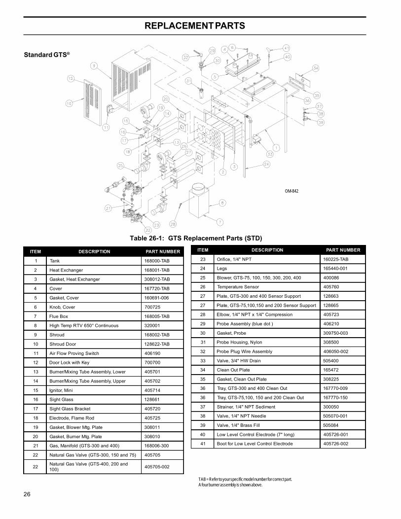
Standard GTS®
OM-842
Table 26-1: GTS Replacement Parts (STD)
ITEM DESCRIPTION PART NUMBER
1 Tank 168000-TAB
2 Heat Exchanger 168001-TAB
3 Gasket, Heat Exchanger 308012-TAB
4 Cover 167720-TAB
5 Gasket, Cover 160691-006
6 Knob, Cover 700725
7 Flue Box 168005-TAB
8 High Temp RTV 650° Continuous 320001
9 Shroud 168002-TAB
10 Shroud Door 128622-TAB
11 Air Flow Proving Switch 406190
12 Door Lock with Key 700700
13 Burner/Mixing Tube Assembly, Lower 405701
14 Burner/Mixing Tube Assembly, Upper 405702
15 Ignitor, Mini 405714
16 Sight Glass 128661
17 Sight Glass Bracket 405720
18 Electrode, Flame Rod 405725
19 Gasket, Blower Mtg. Plate 308011
20 Gasket, Burner Mtg. Plate 308010
21 Gas, Manifold (GTS-300 and 400) 168006-300
22 Natural Gas Valve (GTS-300, 150 and 75) 405705
22 Natural Gas Valve (GTS-400, 200 and100) 405705-002
TAB = Refer to your specific model number for correct part.A four burner assembly is shown above.
ITEM DESCRIPTION PART NUMBER
23 Orifice, 1/4" NPT 160225-TAB
24 Legs 165440-001
25 Blower, GTS-75, 100, 150, 300, 200, 400 400086
26 Temperature Sensor 405760
27 Plate, GTS-300 and 400 Sensor Support 128663
27 Plate, GTS-75,100,150 and 200 Sensor Support 128665
28 Elbow, 1/4" NPT x 1/4" Compression 405723
29 Probe Assembly (blue dot ) 406210
30 Gasket, Probe 309750-003
31 Probe Housing, Nylon 308500
32 Probe Plug Wire Assembly 406050-002
33 Valve, 3/4" HW Drain 505400
34 Clean Out Plate 165472
35 Gasket, Clean Out Plate 308225
36 Tray, GTS-300 and 400 Clean Out 167770-009
36 Tray, GTS-75,100, 150 and 200 Clean Out 167770-150
37 Strainer, 1/4" NPT Sediment 300050
38 Valve, 1/4" NPT Needle 505070-001
39 Valve, 1/4" Brass Fill 505084
40 Low Level Control Electrode (7" long) 405726-001
41 Boot for Low Level Control Electrode 405726-002
GTS-IOM-1298.pdf 26 11/17/2009 3:57:05 PM

27
REPLACEMENT PARTS
GTS®-DI
OM-843
Table 27-1: GTS Replacement Parts (DI)
ITEM DESCRIPTION PART NUMBER
1 Tank 16800-TAB
2 Heat Exchanger 168001-TAB
3 Gasket, Heat Exchanger 308012-TAB
4 Cover 167720-TAB
5 Gasket, Cover 160691-006
6 Knob, Cover 700725
7 Flue Box 168005-TAB
8 High Temp RTV 650° Continuous 320001
9 Shroud 168002-TAB
10 Shroud Door 128622-TAB
11 Air Flow Proving Switch 406190
12 Door Lock with Key 700700
13 Burner/Mixing Tube Assembly, Lower 405701
14 Burner/Mixing Tube Assembly, Upper 405702
15 Ignitor, Mini 405714
16 Sight Glass 128661
17 Sight Glass Bracket 405720
18 Electrode, Flame Rod 405725
19 Gasket, Blower Mtg. Plate 308011
TAB = Refer to your specific model number for correct part.A four burner assembly is shown above.
ITEM DESCRIPTION PART NUMBER
20 Gasket, Burner Mtg. Plate 308010
21 Gas, Manifold (GTS-300 and 400 only) 168006-300
22 Natural Gas Valve (GTS-300, 150, and 75) 405705
22 Natural Gas Valve (GTS-400, 200, and 100) 405705-002
23 Orifice, 1/4" NPT 160225-TAB
24 Legs 165440-001
25 Blower, GTS-75, 100, 150, 200, 300, and 400 400086
26 Temperature Sensor 405760
27 Plate, GTS-300 and 400 Sensor Support 128663
27 Plate, GTS-75,100, 150, and 200 Sensor Support 128665
28 Elbow, 1/4" NPT x 1/4" Compression 405723
29 Low Water Tube 167785
30 Gasket, Low Water Tube 309750-003
31 DI Housing, Nylon 167780
32 Low Water Assembly, Redundant 180997
33 Valve, 3/4" Sweat Brass 505011
34 Clean Out Plate 165470
35 Gasket, Clean Out Plate 308225
36 Float Valve Assembly, GTS-DI 505250
37 Low Water Float Switch 408420-001
GTS-IOM-1298.pdf 27 11/17/2009 3:57:07 PM

28
WIRING DIAGRAM(Refer to as built diagram in the control cabinet)
GTS® Wiring Schematic
GTS-IOM-1298.pdf 28 11/17/2009 3:57:07 PM

29
WIRING DIAGRAM(Refer to as built diagram in the control cabinet)
GTS® Wiring Schematic
GTS-IOM-1298.pdf 29 11/17/2009 3:57:08 PM

30
WIRING DIAGRAM(Refer to as built diagram in the control cabinet)
GTS-IOM-1298.pdf 30 11/17/2009 3:57:08 PM

31
WIRING DIAGRAM(Refer to as built diagram in the control cabinet)
GTS-IOM-1298.pdf 31 11/17/2009 3:57:09 PM

32
6. Turn clockwise to “OFF”. If knob is in “ON”turn clockwise to “OFF.”
7. Wait five (5) minutes to clear out any gas. If you then smellgas, STOP! Follow “B” in the safety information above onthis label. If you don’t smell gas, go to next step.
8. Turn gas control knob clockwise to “ON.”
9. Replace control access panel.
10. Turn on all electric power to the appliance.
11. Set humidistat to desired setting.
12. If the appliance will not operate, follow the instructions “ToTurn Off Gas To Appliance” and call your service technicianor gas supplier.
1. STOP! Read the safety information above on this label.
2. Set the humidistat to lowest setting.
3. Turn off all electric power to the appliance.
4. This appliance is equipped with an ignition device whichautomatically lights the burner. Do not try to light the burnerby hand.
5. Remove control access panel.
If you do not follow these instructions exactly, a fire or explosionmay result causing property damage, personal injury or loss of life.WARNING
OPERATING INSTRUCTIONS
GAS CONTROL KNOB
36E Series
TO TURN OFF GAS TO APPLIANCE
FOR YOUR SAFETY READ BEFORE OPERATING
A. This appliance does not have a pilot. It is equipped withan ignition device which automatically lights the burner. Donot try to light the burner by hand.
B. BEFORE OPERATING smell all around the appliance area forgas. Be sure to smell next to the floor because some gasis heavier than air and will settle on the floor.
FOR YOUR SAFETY“WHAT TO DO IF YOU SMELL GAS”
• Do not try to light any appliance.• Do not touch any electrical switch; do not use any phonein your building.• Immediately call your gas supplier from a neighbor’s
phone. Follow the gas supplier’s instructions.• If you cannot reach your gas supplier, call the fire
department.
C. Use only your hand to turn the gas control knob. Neveruse tools. If the knob will not turn by hand, don’t try torepair it, call a qualified service technician. Force orattempted repair may result in a fire or explosion.
D. Do not use this appliance if any part has been under water.Immediately call a qualified service technician to inspect theappliance and to replace any part of the control system andany gas control which has been under water.
1. Set the humidistat to lowest setting.
2. Turn off all electric power to the appliance if service is to beperformed.
3. Remove control access panel.
4. Turn gas control knob counterclockwise to “OFF.”
5. Replace control access panel.
!
GTS-IOM-1298.pdf 32 11/17/2009 3:57:09 PM

33
Figure 33-1: Gas Control Valve forGTS® 300, 150 and 75
GAS CONTROL VALVE
Inlet Pressure Tap
OM-836
Outlet (manifold) Pressure Tap
PressureAdjustment
"ON", "OFF"Gas ControlKnob
Top View
Terminals
Figure 33-2: Gas Control Valve forGTS® 400, 200 and 100
TerminalConnections
Inlet Pressure Tap
OM-836A
High Fine Pressure GasAdjustment
Outlet (manifold)Pressure Tap
Normal Pressure(gas adjust undertime delay)
"ON", "OFF"Gas ControlKnob
Top View
Terminals
Time delay
GTS-IOM-1298.pdf 33 11/17/2009 3:57:09 PM

34
DATEINSPECTED PERSONNEL OBSERVATION ACTION PERFORMED
MAINTENANCE SERVICE RECORD
GTS-IOM-1298.pdf 34 11/17/2009 3:57:09 PM

35
DATEINSPECTED PERSONNEL OBSERVATION ACTION PERFORMED
MAINTENANCE SERVICE RECORD
GTS-IOM-1298.pdf 35 11/17/2009 3:57:09 PM

36
TWO-YEAR LIMITED WARRANTY
DRI-STEEM Humidifier Company (“DRI-STEEM”) warrants to the original user that its products will be freefrom defects in materials and workmanship for a period of two (2) years after installation or twenty-seven(27) months from the date DRI-STEEM ships such product, whichever date is the earlier.
If any DRI-STEEM product is found to be defective in material or workmanship during the applicablewarranty period, DRI-STEEM’s entire liability, and the purchaser’s sole and exclusive remedy, shall bethe repair or replacement of the defective product, or the refund of the purchase price, at DRI-STEEM’selection. DRI-STEEM shall not be liable for any costs or expenses, whether direct or indirect, associated withthe installation, removal or reinstallation of any defective product.
DRI-STEEM’s limited warranty shall not be effective or actionable unless there is compliance with all installa-tion and operating instructions furnished by DRI-STEEM, or if the products have been modified or alteredwithout the written consent of DRI-STEEM, or if such products have been subject to accident, misuse,mishandling, tampering, negligence or improper maintenance. Any warranty claim must be submitted toDRI-STEEM in writing within the stated warranty period.
DRI-STEEM’s limited warranty is made in lieu of, and DRI-STEEM disclaims all other warranties, whetherexpress or implied, including but not limited to any IMPLIED WARRANTY OF MERCHANTABILITY, ANYIMPLIED WARRANTY OF FITNESS FOR A PARTICULAR PURPOSE, any implied warranty arising out of acourse of dealing or of performance, custom or usage of trade.
DRI-STEEM SHALL NOT, UNDER ANY CIRCUMSTANCES BE LIABLE FOR ANY DIRECT, INDIRECT,INCIDENTAL, SPECIAL OR CONSEQUENTIAL DAMAGES (INCLUDING, BUT NOT LIMITED TO, LOSS OFPROFITS, REVENUE OR BUSINESS) OR DAMAGE OR INJURY TO PERSONS OR PROPERTY IN ANYWAY RELATED TO THE MANUFACTURE OR THE USE OF ITS PRODUCTS. The exclusion applies regard-less of whether such damages are sought based on breach of warranty, breach of contract, negligence, strictliability in tort, or any other legal theory, even if DRI-STEEM has notice of the possibilityof such damages.
By purchasing DRI-STEEM’s products, the purchaser agrees to the terms and conditions of this limitedwarranty.
Form No. GTSOM-1298 Copyright © 1998 DRI-STEEM Humidifier Company, Inc. Printed in U.S.A.
Printed on recycled paper with agribased inPrinted on recycled paper. Minimum10% Post Consumer Waste.
Continuous product improvement is a policy of DRI-STEEM Humidifier Company therefore,product features and specifications are subject to change without notice.
DRI-STEEM, GTS, RAPID-SORB, ULTRA-SORB, VAPOR-LOGIC and VAPOR-LOGIC2 are Registered Trademarks of the DRI-STEEM Humidifier Company.TEFLON is a Registered Trademark of Dupont.
14949 Technology Drive • Eden Prairie, MN 55344Phone: (612) 949-2415 • Fax: (612) 949-2933E-Mail: [email protected] • Web: www.dristeem.comInternational Office:Bell Place, Bell Lane • Syresham, Brackley • NN13 5HP, U.K.Phone: +44 1280 850122Fax: +44 1280 850124E-Mail: [email protected]
GTS-IOM-1298.pdf 36 11/17/2009 3:57:09 PM