Char nitrogen conversion: implications to emissions from coal-fired utility boilers
Upload
independentCategory
view
4download
0
Oviedo ICCS&T 2011. Extended Abstract
1
Entrained-Flow Gasification of Coal under Slagging Conditions: Properties of Solid Wastes and Relevance of Char-Wall Interaction Phenomena
Fabio Montagnaro1, Paola Brachi1 and Piero Salatino2
1 Dipartimento di Chimica, Università degli Studi di Napoli Federico II, Complesso Universitario del Monte di Sant’Angelo, 80126 Napoli (Italy), T: +39 081 674029; F: +39 081 674090; E: [email protected]
2 Dipartimento di Ingegneria Chimica, Università degli Studi di Napoli Federico II; Istituto di Ricerche sulla Combustione, Consiglio Nazionale delle Ricerche, Piazzale Vincenzo Tecchio 80, 80125 Napoli (Italy), T: +39 081 7682258; F: +39 081 5936936; E: [email protected]
Abstract
The aim of this paper is to investigate the properties of solid wastes generated from an
industrial-scale pressurized entrained-flow gasifier, by means of a combination of
experimental techniques: elemental, granulometric and X-ray diffraction analyses,
scanning electron microscopy and energy dispersive X-ray analysis. The results are
critically discussed in the light of the different regimes of char-slag micromechanical
interaction and of the different phases that are established in the gasification chamber.
The discussion allows to give useful insights concerning the properties and partitioning
of carbon among the three main sources (coarse slag, slag fines, fly ash) of solid
residues coming from the gasifier: in particular, differences between coarse slag and
slag fines are highlighted, though these wastes are generated from the same main-
stream. Furthermore, it is observed that residual carbon in slag granules is present in a
segregated embedded form, while slag fines are composed of both porous (high-carbon)
and compact (low-carbon) material. Altogether, the properties of the three residues are
consistent with a mechanistic framework of the bulk-to-wall transfer and partitioning of
solids during entrained-flow gasification of coal developed in a recently published
theoretical paper.

Oviedo ICCS&T 2011. Extended Abstract
2
1. Overview
Entrained-flow coal gasifiers of new generation are characterized by operating conditions
(high operating temperatures and multi-stage feedings of coal and gaseous reactants)
aimed at favoring ash migration/deposition onto the reactor walls, whence the molten ash
(slag) flows and is eventually drained at the bottom of the gasifier [1,2]. Detailed studies
concerning the fate of char particles as they impinge the wall slag layer have been only
recently developed [3–6]. In a recently published paper, Montagnaro and Salatino [7]
addressed the relative importance of the parallel pathways of coal conversion associated
with entrained-flow of carbon particles in a lean-dispersed gas phase vs. segregated flow
of char particles in a dense-dispersed phase in the near-wall region of the gasifier. Char
segregation in the dense-dispersed phase is promoted by bulk-to-wall particle migration
and by inelastic interaction of char particles with the molten slag wall layer. By taking
into account characteristics such as char density, particle diameter and impact velocity,
slag viscosity, interfacial particle-slag tension, theoretical criteria for either char particle
entrapment inside or carbon-coverage of the wall ash layer have been developed. This is
represented in Figure 1, which depicts the following plausible regimes of char-slag
micromechanical interaction: regime E) (entrapment), in which char particles reaching the
slag surface become permanently embedded into the molten layer and further course of
combustion/gasification is hindered; regime S) (segregation), in which char particles
reaching the wall adhere to the slag layer’s surface without being fully engulfed, so that
the progress of combustion/gasification is permitted; regime SC) (segregation and
coverage), in which the coverage of the slag layer with carbon particles is extensive. In
this last regime a dense-dispersed annular phase is established in the close proximity of
the wall ash layer, where the excess impinging char particles which cannot be
accommodated on the slag surface accumulate. This phase is likely to be characterized by
a velocity that is intermediate between that of the fast lean-dispersed phase and that of the
slowly moving wall molten ash layer. This feature is beneficial to C conversion as it gives
rise to a longer mean residence time of carbon particles belonging to this phase.
Consistently, a schematic diagram of the entrained-flow gasifier is presented in Figure 2
in which, in particular, the presence of three different sources of solid wastes is
underlined, that is: slag phase, yielding coarse slag granules upon interaction with the
quench bath at the bottom of the gasifier; dense-dispersed phase, giving rise to slag fines
upon interaction with the quench bath; lean-dispersed phase, giving rise to fly ash
escaping the gasifier in the gas stream.

Oviedo ICCS&T 2011. Extended Abstract
3
syn‐gasfly ash (WFLY) slag (WSLAG)
lean‐dispersed
dense‐dispersed
char, sootslag
devolatilization/combustion zonecoal (WF)
O2 (WOX)H2O (WS)
syn‐gasslag fines (WSF)
Figure 1 (left). Regimes of C-slag micromechanical interaction (E=entrapment; S=segregation; SC=segregation and coverage). Figure 2 (right). Outline of flow patterns in the entrained-flow gasification chamber (the symbol ‘W’ stands for mass flow rates). 2. Rationale of the present investigation
This investigation was stimulated by the operational experience from an industrial-scale
pressurized (25 bar; cf. [8,9]) entrained-flow gasifier, operated in the slagging regime (at
temperatures around 1700–1900 K; cf. [9,10]). The gasification chamber has an internal
diameter of 3.8 m and a length of 13 m. Mass feeding ratios are: WOX/WF=0.8;
WS/WF=0.1 (see Figure 2). Solid fuel feed rate is WF=30 kg s–1 and, typically, the solid
fuel is a 50:50 coal:pet coke mixture. Practical operation of the gasifier revealed a value
of the mass ratio WFLY/(WSLAG+WSF) smaller than expected at the design stage (circa 0.1
vs. 0.4; cf. [9,11]). This was primarily ascribed to an unexpectedly large value of the mass
flow rate of slag fines (WSF) leaving the quench bath. Moreover, C content in fly ash
resulted rather limited (circa 5%; cf. [11]), while that in slag fines was reported to be quite
high. Finally, a non-negligible organic fraction was detected in the slag waste (cf. [12]),
and this appears consistent with findings reported, for similar systems, by other authors
[13–15]. In this paper, results concerning characterization of solid residues from the
industrial-scale gasifier were interpreted in the light of the different regimes of char-slag
micromechanical interaction (Figure 1) and of the different phases that are established in
the gasification chamber (Figure 2), as presented in the Overview. In this context, it is
useful to remind that the solid waste other than fly ash is quenched in a water bath
generating, besides the slag (sometimes referred to as coarse slag), a black water whence
slag fines are recovered by filtration [13]. The different thermal/conversion history of

Oviedo ICCS&T 2011. Extended Abstract
4
these two solid wastes is likely to strongly influence their properties, in particular as far as
carbon content, morphology and further reactivity is concerned. Only recently did the
question concerning the differences between coarse and fine slag receive consideration:
the reader is referred, for example, to the works [13–15].
3. Materials and experimental techniques
Coarse slag and slag fines samples were generated in the ELCOGAS entrained-flow
gasifier located in Puertollano, Ciudad Real (Spain). This material was provided in the
summer of 2009 and, due to the considerable amount of wastes produced by the plant and
to the variability of the operating conditions of the gasifier, it might not be fully
representative of the ash generated by the industrial gasifier during normal operation.
Coarse slag and slag fines were characterized by: carbon elemental analysis, performed
by a LECO CHN-2000 instrument; granulometric analysis, performed by either a Malvern
Instruments Master Sizer 2000 laser granulometer (operated down to a minimum particle
size of 0.02 μm) or mechanical sieving (in 10 size ranges between 0 and 9.5 mm); X-ray
diffraction (XRD) analysis, performed by a Bruker D2 Phaser diffractometer (operated at
diffraction angles ranging between 10 and 60°2θ with a scan velocity equal to 0.02°2θ s–1);
scanning electron microscopy (SEM), performed by a FEI Inspect microscope equipped
with an energy dispersive X-ray (EDX) probe (operated up to magnifications of 3000×).
4. Experimental results
A preliminary elemental analysis on coarse slag and slag fines revealed no appreciable
carbon content (for the former) and a carbon content as high as 57.4% (for the latter).
Figures 3 and 4 show absolute and cumulative particle size distributions for slag and slag
fines, respectively. Due to the much coarser size of the slag material, the particle size
analysis for this waste was carried out by mechanical sieving instead of laser
granulometry. From Figure 3, it can be observed that slag particles size extended over a
broad range, with maximum size equal to about 9 mm (cf. [12]). Nonetheless, a very
distinct peak for the absolute distribution could be appreciated at 1.7 mm; the mean
Sauter diameter for this distribution was equal to 1.18 mm. Finally, a median value (d50)
of 1.27 mm was obtained from the cumulative distribution. Slag fines were characterized
by much smaller values of particle size (Figure 4): particles coarser than 700 μm were not
observed, the peak and the Sauter diameter for this distribution were equal to 100 and 20
Oviedo ICCS&T 2011. Extended Abstract
5
μm, respectively, and the d50-value for the cumulative distribution was 72 μm.
Particle diameter, mm
0 1 2 3 4 5 6 7 8 9
Abs
olut
e si
ze d
istri
butio
n, -
0.0
0.1
0.2
0.3
0.4
0.5
0.6
peak=1.7 mmSauter=1.18 mm
Particle diameter, mm
0 1 2 3 4 5 6 7 8 9
Cum
ulat
ive
size
dis
tribu
tion,
-
0.0
0.1
0.2
0.3
0.4
0.5
0.6
0.7
0.8
0.9
1.0
d50=1.27 mm
Particle diameter, μm
0 100 200 300 400 500 600 700
Abs
olut
e si
ze d
istri
butio
n, -
0.00
0.01
0.02
0.03
0.04
0.05
0.06
peak=100 μmSauter=20 μm
Particle diameter, μm
0 100 200 300 400 500 600 700
Cum
ulat
ive
size
dis
tribu
tion,
-
0.0
0.1
0.2
0.3
0.4
0.5
0.6
0.7
0.8
0.9
1.0
d50=72 μm
Figure 3 (upper row) and Figure 4 (lower row). Absolute (left) and cumulative (right) particle size distributions for coarse slag (Figure 3) and slag fines (Figure 4).
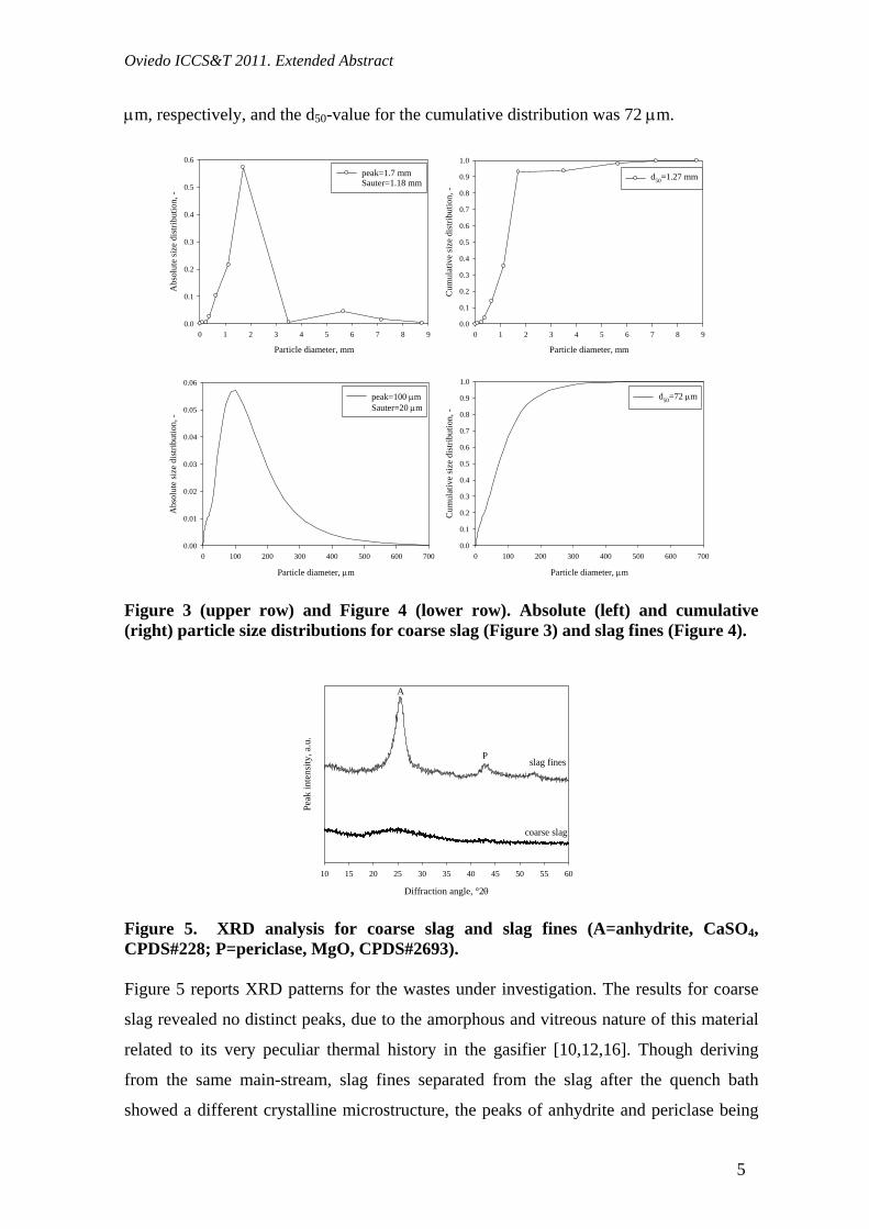
Diffraction angle, °2θ
10 15 20 25 30 35 40 45 50 55 60
Peak
inte
nsity
, a.u
.
A
P
coarse slag
slag fines
Figure 5. XRD analysis for coarse slag and slag fines (A=anhydrite, CaSO4, CPDS#228; P=periclase, MgO, CPDS#2693). Figure 5 reports XRD patterns for the wastes under investigation. The results for coarse
slag revealed no distinct peaks, due to the amorphous and vitreous nature of this material
related to its very peculiar thermal history in the gasifier [10,12,16]. Though deriving
from the same main-stream, slag fines separated from the slag after the quench bath
showed a different crystalline microstructure, the peaks of anhydrite and periclase being
Oviedo ICCS&T 2011. Extended Abstract
6
clearly recognizable. While elemental analysis on coarse slag did not indicate the
presence of carbon in this material, interestingly, different results were obtained when
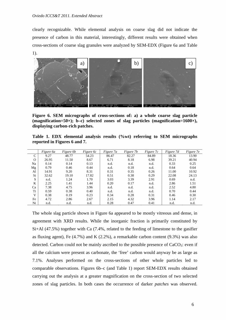
cross-sections of coarse slag granules were analyzed by SEM-EDX (Figure 6a and Table
1).
Figure 6. SEM micrographs of cross-sections of: a) a whole coarse slag particle (magnification=50×); b–c) selected zones of slag particles (magnification=1600×), displaying carbon-rich patches. Table 1. EDX elemental analysis results (%wt) referring to SEM micrographs reported in Figures 6 and 7.
Figure 6a Figure 6b Figure 6c Figure 7a Figure 7b Figure 7c Figure 7d Figure 7e C 9.27 48.77 54.23 86.47 82.27 84.89 18.36 13.90 O 26.95 11.50 8.67 6.71 8.18 6.98 39.21 40.94
Na 0.14 0.14 0.13 n.d. n.d. n.d. 0.33 0.25 Mg 0.79 0.46 0.44 n.d. 0.18 n.d. 0.64 0.64 Al 14.91 9.20 8.31 0.31 0.35 0.26 11.00 10.92 Si 32.62 19.10 17.82 0.51 0.38 0.29 22.08 24.13 S n.d. 1.24 1.70 3.03 3.39 2.91 0.69 n.d. K 2.25 1.41 1.44 0.20 0.17 n.d. 2.86 1.51
Ca 7.38 4.75 3.96 n.d. n.d. n.d. 2.52 4.80 Ti 0.59 0.38 0.40 n.d. n.d. n.d. 0.70 0.44 V 0.38 0.19 0.23 0.34 0.28 0.31 0.46 0.30
Fe 4.72 2.86 2.67 2.15 4.32 3.96 1.14 2.17 Ni n.d. n.d. n.d. 0.28 0.47 0.41 n.d. n.d. The whole slag particle shown in Figure 6a appeared to be mostly vitreous and dense, in
agreement with XRD results. While the inorganic fraction is primarily constituted by
Si+Al (47.5%) together with Ca (7.4%, related to the feeding of limestone to the gasifier
as fluxing agent), Fe (4.7%) and K (2.2%), a remarkable carbon content (9.3%) was also
detected. Carbon could not be mainly ascribed to the possible presence of CaCO3: even if
all the calcium were present as carbonate, the ‘free’ carbon would anyway be as large as
7.1%. Analyses performed on the cross-sections of other whole particles led to
comparable observations. Figures 6b–c (and Table 1) report SEM-EDX results obtained
carrying out the analysis at a greater magnification on the cross-section of two selected
zones of slag particles. In both cases the occurrence of darker patches was observed.
a) b) c)

Oviedo ICCS&T 2011. Extended Abstract
7
Pointwise quantitative EDX results refer to these regions: C-contents as high as 48.8–
54.2% were obtained. This finding contributes to the assessment of the relevance of
carbon entrapment (regime E), Figure 1) in slag particles. It is worth noting that elemental
analysis did not show the presence of any organic fraction and this was essentially so
because C was permanently entrapped into the slag matrix in a way that could not have
been disclosed by thermal analysis. Only the cutting procedure associated with the SEM-
EDX analysis of granules cross-sections was able to disclose the unreacted carbon, which
appeared to be somewhat segregated (in the patches) with respect to the inorganic slag
matrix. By taking into account that quantitative results relevant to Figure 6a referred to
the cross-section of a slag particle, an average carbon content around 3–4% was estimated
for this waste. Figure 7 and Table 1 report the results of the SEM-EDX analysis
performed on whole slag fines particles. In particular, particles having prevailing either
porous (Figures 7a–c) or compact (Figures 7d–e) structures were observed. In any case,
the carbon content was larger than the value obtained from the inspection of coarse slag
particles, in line with results of elemental analysis. This is particularly evident for porous
particles (Figures 7a–c): C-content ranged between 82.3 and 86.5%, and Fe (2.2–4.3%)
and S (2.9–3.4%) could also be appreciated. Thus, these particles should be mainly
associated with unreacted char present in the dense-dispersed phase (Figure 2) giving rise
to slag fines upon impingement on the quench bath. On the other hand, dense particles
(Figures 7d–e) display morphological and chemical features that are closer to those of
coarse slag particles, at least as far as SEM-EDX results are concerned: C-content ranged
between 13.9 and 18.4%, the Si+Al-fraction was as high as 33.1–35.0% and Ca (2.5–
4.8%), K (1.5–2.9%) and Fe (1.1–2.2%) could also be detected. It is also highlighted that
elements such as Na, Mg, Al, Si, K, Ca and Ti, while revealed in smaller amounts (or not
revealed at all) in high-C porous slag fines, were present in larger percentages in both
coarse slag and low-C dense slag fines particles. The opposite is true for S and Ni. The
results are consistent with the previously-reported C-content of slag fines (about 57%),
obtained by standard elemental analysis carried out on waste containing both high-C
porous and low-C dense materials. Moreover, the more compact slag fines should be
regarded as having intermediate properties between porous slag fines and coarse slag: this
observation, jointly with XRD results, highlights again the establishment of a dense-
dispersed phase that, together with the slag phase, generates both streams: slag and slag
fines (Figure 2).

Oviedo ICCS&T 2011. Extended Abstract
8
Figure 7. SEM micrographs of different whole slag fines particles: a)–c) at magnification=1600×; d)–e) at magnification=3000×. 5. Critical discussion
It has been observed that the slag fines, generated in high amount in the gasifier (cf.
Section 2), are very rich in carbon (cf. elemental and SEM-EDX analysis results). This is
believed to be a clue in favor of the existence of a dense-dispersed phase (regime SC),
Figures 1 and 2), which would be the source of high-C slag fines upon interaction with
the quench bath. On the other hand, the slag waste presented a non-negligible content of
carbon, mostly entrapped (in a segregated fashion) into the slag matrix. This would be
consistent with the occasional establishment of regime E). It is interesting to analyze these
findings in the light of results recently published by Li et al. [5,6]. These authors
investigated the char-slag transition during entrained-flow oxidation of coal particles,
observing a distinct transition from porous/non-sticky char to fluid/sticky slag occurring
at temperatures above the ash flow temperature only when carbon conversion exceeded a
certain threshold (around 90%). This means that the coexistence of regimes SC) –as the
prevailing regime– and E) might be possible. If one assumes, based on Montagnaro and
Salatino’s findings [7], that regime SC) is the dominant regime under typical operating
conditions of entrained-flow gasifiers, then some char particles belonging to the dense-
dispersed phase and in the late burn-off stage could well be permanently embodied into
the slag layer, according to Li et al.’s findings [5,6]. Although the carbon content of these
a) b) c)
d) e)

Oviedo ICCS&T 2011. Extended Abstract
9
particles is likely to be modest, it is anyway not negligible and could possibly justify the
estimated C-value of 3–4%. As far as fly ash is concerned, its carbon content (5%) was
unexpectedly small. This finding can be interpreted by considering that bulk-to-wall
transfer of char/ash particles is dominated by the inertial mechanism associated with
turbophoresis and centrifugal forces due to swirl/tangential flow. This mechanism would
make wall transfer of coarser particles more effective than transfer of fines [7].
Considering, as reported by Wu et al. [13], that the carbon content of coarser particles is
generally higher, this mechanism would imply a more effective transfer of carbon to the
wall, as compared with ash transfer. These two aspects (coexistence of regimes and
preferential mass transfer) could explain why fly ash resulted selectively C-depleted and
why slag fines did show such a large mass flow rate and C-content, contrary to the
expectations. Moreover, it is recalled that part of the fly ash might derive by nucleation
and growth of fine (carbon-free) inorganic particles from the gas phase under the
extremely high temperature conditions experienced by the fuel in the flame region of the
oxidizer. This would further justify the comparatively small carbon content of fly ash.
6. Conclusions
The properties and partitioning of carbon among the three main sources (coarse slag, slag
fines, fly ash) of solid residues coming from an industrial-scale entrained-flow coal
gasifier have been characterized by a combination of experimental techniques. The carbon
content of slag fines is very large, in the order of 60%. The carbon content of fly ash is
around 5%. The carbon content of slag granules as assessed by standard elemental
analysis techniques is negligible, but combined microscopy and EDX analysis of the
granules’ cross-sections indicates that residual carbon is present in slag granules as
segregated embedded carbon-rich patches, amounting to about 3% by mass of the sample.
The properties of these three types of residues are consistent with a mechanistic
framework of entrained-flow gasification of coal developed by the authors, which
considers the bulk-to-wall transfer of solids and the establishment of segregated phases in
the near-wall region of the gasifier.
Acknowledgement
The authors wish to express their gratitude to Mr. F. García Peña, Dr. A. M. Mozos and Dr. P. Coca
(ELCOGAS, Spain) for having supplied raw materials and for useful discussion. Dr. M. Urciuolo and
Mr. S. Russo (IRC-CNR, Italy) are gratefully acknowledged for their support in solid characterization.

Oviedo ICCS&T 2011. Extended Abstract
10
References
[1] Walsh PM, Sarofim AF, Beér JM. Fouling of convection heat exchangers by lignitic coal ash. Energy
Fuel 1992;6:709–15.
[2] Shimizu T, Tominaga H. A model of char capture by molten slag surface under high-temperature
gasification conditions. Fuel 2006;85:170–8.
[3] Wang XH, Zhao DQ, He LB, Jiang LQ, He Q, Chen Y. Modeling of a coal-fired slagging combustor:
development of a slag submodel. Combust Flame 2007;149:249–60.
[4] Shannon GN, Rozelle PL, Pisupati SV, Sridhar S. Conditions for entrainment into a FeOX containing
slag for a carbon-containing particle in an entrained coal gasifier. Fuel Process Technol 2008;89:1379–85.
[5] Li S, Whitty KJ. Investigation of coal char-slag transition during oxidation: effect of temperature and
residual carbon. Energy Fuel 2009;23:1998–2005.
[6] Li S, Wu Y, Whitty KJ. Ash deposition behavior during char-slag transition under simulated gasification
conditions. Energy Fuel 2010;24:1868–76.
[7] Montagnaro F, Salatino P. Analysis of char-slag interaction and near-wall particle segregation in
entrained-flow gasification of coal. Combust Flame 2010;157:874–83.
[8] Seggiani M. Modelling and simulation of time varying slag flow in a Prenflo entrained-flow gasifier.
Fuel 1998;77:1611–21.
[9] Álvarez-Rodríguez R, Clemente-Jul C, Martín-Rubí JA. Behaviour of the elements introduced with the
fuels in their distribution and immobilization between the coal-petroleum coke IGCC solid products. Fuel
2007;86:2081–9.
[10] Aineto M, Acosta A, Rincón JM, Romero M. Thermal expansion of slag and fly ash from coal
gasification in IGCC power plant. Fuel 2006;85:2352–8.
[11] Font O, Moreno N, Díez S, Querol X, López-Soler A, Coca P, García Peña F. Differential behaviour of
combustion and gasification fly ash from Puertollano Power Plants (Spain) for the synthesis of zeolites and
silica extraction. J Hazard Mater 2009;166:94–102.
[12] Acosta A, Aineto M, Iglesias I, Romero M, Rincón JM. Physico-chemical characterization of slag
waste coming from GICC thermal power plant. Mater Lett 2001;50:246–50.
[13] Wu T, Gong M, Lester E, Wang F, Zhou Z, Yu Z. Characterisation of residual carbon from entrained-
bed coal water slurry gasifiers. Fuel 2007;86:972–82.
[14] Xu S, Zhou Z, Gao X, Yu G, Gong X. The gasification reactivity of unburned carbon present in
gasification slag from entrained-flow gasifier. Fuel Process Technol 2009;90:1062–70.
[15] Zhao X, Zeng C, Mao Y, Li W, Peng Y, Wang T, Eiteneer B, Zamansky V, Fletcher T. The surface
characteristics and reactivity of residual carbon in coal gasification slag. Energy Fuel 2010;24:91–4.
[16] Song W, Tang L, Zhu X, Wu Y, Rong Y, Zhu Z, Koyama S. Fusibility and flow properties of coal ash
and slag. Fuel 2009;88:297–304.
Copyright © 2022 FDOKUMEN