kerwa coal block project block-korba, district-korba, chhattisgarh
Upload
khangminh22Category
view
1download
0
COAL TO METHANOL PROJECT AT DANKUNI COAL COMPLEX, WEST BENGAL ON BUILD OWN
OPERATE (BOO) BASIS, CIL
DOC. NO. REV
PNMM/ PC-176/E-4001
0
SHEET 1 OF 1
COAL INDIA LIMITED, KOLKATA
TENDER DOCUMENT
FOR SETTING-UP OF
COAL TO METHANOL (C2M) PROJECT THROUGH COAL GASIFICATION ROUTE ON BUILD-OWN-OPERATE (BOO) BASIS AT DANKUNI COAL COMPLEX WEST BENGAL, INDIA
(TENDER NO.: PNMM/PC-176/E-4001 dated 24.09.2020)
PREPARED & ISSUED BY
PROJECTS & DEVELOPMENT INDIA LTD. (A Govt. Of India Enterprise)
PDIL BHAWAN, A-14, SECTOR-1,
NOIDA-201301 U.P. (INDIA).
24.09. 2020

COAL TO METHANOL PROJECT AT DANKUNI COAL
COMPLEX, WEST BENGAL ON BUILD OWN OPERATE (BOO) BASIS
MASTER INDEX
PNMM/PC-176/E-4001
0
DOC. NO. REV.
SHEET 1 OF 3
SUBJECT : COAL TO METHANOL (C2M) PROJECT THROUGH COAL GASIFICATION ROUTE ON
BUILD-OWN-OPERATE (BOO) BASIS AT DANKUNI COAL COMPLEX WEST BENGAL, INDIA.
(Tender No.: PNMM/PC-176/E-4001 DATED 24.09.2020)
Volume-I, COMMERCIAL
SECTION No. DESCRIPTION
SECTION 1.0 INVITATION FOR BID
SECTION 2.0 PRE-QUALIFICATION CRITERIA
SECTION 3.0 EXHIBITS
SECTION 4.0 SUBMISSION OF BID
SECTION 5.0 INSTRUCTIONS TO BIDDER
SECTION 6.0 CONDITIONS OF CONTRACT
SECTION 7.0 ANNEXURES
ANNEX.-1.1 BID FORM
ANNEX.-1.2 PREAMBLE TO PRICE SCHEDULE/BOQ/SCHUDULE OF PRICES
ANNEX.-1.3 COMMERCIAL QUESTIONNAIRE
ANNEX.-1.4 CONTENTS OF BID AND CHECK LIST
ANNEX.-1.5 FORMAT FOR BIDDER’S QUERIES FOR PRE BID DISCUSSION
ANNEX.-1.6 FORMAT OF LETTER OF WAIVER OF CONDITIONS/DEVIATIONS
ANNEX.-1.7 BIDDER’S PROPOSED SCHEDULE
ANNEX.-1.8 FORMAT FOR AUTHORISATION TO DSC HOLDER
ANNEX.-1.9 PROFORMA OF CERTIFICATE OF NON-INVOLVEMENT OF INDIAN AGENT
ANNEX.-1.10 PUBLIC PROCUREMENT (PREFERENCE TO MAKE IN INDIA) POLICY
ANNEX.-1.11 FORMAT FOR POWER OF ATTORNEY (POA)
ANNEX.-1.12 FORMAT FOR CONSORTIUM AGREEMENT
ANNEX.-1.13 FORMAT FOR DECLARATION DECLARATION REGARDING BANNED/BLACKLISTED/DELISTING AND LIQUIDATION, COURT RECEIVERSHIP

COAL TO METHANOL PROJECT AT DANKUNI COAL
COMPLEX, WEST BENGAL ON BUILD OWN OPERATE (BOO) BASIS
MASTER INDEX
PNMM/PC-176/E-4001
0
DOC. NO. REV.
SHEET 2 OF 3
ANNEX.-1.14 PERFORMA OF SOLVENCY CERTIFICATE
ANNEX.-1.15 FORMAT OF UNDERTAKING FROM TPIA
ANNEX.-1.16 INTEGRITY PACT
ANNEX.-1.17 PROFORMA OF BANK GUARANTEE FOR EARNEST MONEY DEPOSIT (EMD)
ANNEX-1.18 PROFORMA OF BANK GUARANTEE FOR SECURITY DEPOSIT/ PERFORMANCE BANK GUARANTEE
ANNEX-1.19 LIST OF CIL APPROVED BANKS
ANNEX-1.20 FORM FOR CONTRACT AGREEMENT
ANNEX-1.21 FORMAT OF LAND LEASE
ANNEX-1.22 FORMAT FOR FINANCIAL DETAILS OF HOLDING COMPANY
ANNEX-1.23 PROVISION FOR PROCUREMENT FROM A BIDDER WHICH SHARES A LAND BORDER WITH INDIA

COAL TO METHANOL PROJECT AT DANKUNI COAL
COMPLEX, WEST BENGAL ON BUILD OWN OPERATE (BOO) BASIS
MASTER INDEX
PNMM/PC-176/E-4001
0
DOC. NO. REV.
SHEET 3 OF 3
Volume-II, TECHNICAL
SECTION NO. DESCRIPTION
GENERAL
SECTION 1.1 PROJECT DESCRIPTION
SECTION 1.2 SCOPE OF WORK
SECTION 1.3 PROJECT EXECUTION PLAN
SECTION 1.4 DESIGN BASIS
SECTION 1.5 RAW MATERIAL AND UTILITY SPECIFICATION
SECTION 1.6 PROCESS DESIGN GUIDELINES
ENGINEERING SPECIFICATIONS
SECTION 1.7 PRESSURE VESSELS
SECTION 1.8 MACHINERY
SECTION 1.9 PIPING
SECTION 1.10 ELECTRICAL
SECTION 1.11 INSTRUMENTATION
SECTION 1.12 CIVIL
SECTION 1.13 MATERIAL HANDLING
TECHNICAL REQUIREMENTS/DATA
SECTION 1.13 SAFETY, HEALTH & ENVIRONMENT
SECTION 1.14 QUALITY ASSURANCE PLAN
SECTION 1.15 DRAWINGS & DOCUMENTS
SECTION 1.16 TECHNICAL INFORMATION
SECTION 1.17 SPARE PARTS

COAL TO METHANOL PROJECT AT DANKUNI COAL COMPLEX, WEST BENGAL ON BUILD OWN
OPERATE (BOO) BASIS, CIL
DOC. NO. REV
PNMM/ PC-176/E-4001
0
SHEET 1 OF 1
COAL INDIA LIMITED, KOLKATA
TENDER DOCUMENT (Volume-I , COMMERCIAL)
FOR SETTING-UP OF
COAL TO METHANOL (C2M) PROJECT THROUGH COAL GASIFICATION ROUTE ON BUILD-OWN-OPERATE (BOO) BASIS AT DANKUNI COAL COMPLEX WEST BENGAL, INDIA
(TENDER NO.: PNMM/PC-176/E-4001)
PREPARED & ISSUED BY
PROJECTS & DEVELOPMENT INDIA LTD. (A Govt. Of India Enterprise)
PDIL BHAWAN, A-14, SECTOR-1,
NOIDA-201301 U.P. (INDIA).
24.09. 2020


COAL TO METHANOL PROJECT AT DANKUNI
COAL COMPLEX, WEST BENGAL ON BUILD OWN OPERATE (BOO) BASIS
PRE-QUALIFICATION CRITERIA (PQC)
PNMM/PC-176/E-4001/2.0 0
DOC. NO. REV.
SHEET 1 OF 7
All rights reserved
VOLUME-I, COMMERCIAL
SECTION 2.0
PRE-QUALIFICATION CRITERIA (PQC)

COAL TO METHANOL PROJECT AT DANKUNI
COAL COMPLEX, WEST BENGAL ON BUILD OWN OPERATE (BOO) BASIS
PRE-QUALIFICATION CRITERIA (PQC)
PNMM/PC-176/E-4001/2.0 0
DOC. NO. REV.
SHEET 2 OF 7
All rights reserved
1.0 ELIGIBLEBIDDERS
1.1 SOLE BIDDER OR A JOINT VENTURE OR ACONSORTIUM
1.1.1 Bids may be submitted by a Bidder who is a sole Bidder or a joint venture company (JV) or a consortium of members along with a lead member (“Consortium”). However, [except in case of a sole Bidder], the successful Bidder emerged through tendering process should be a company incorporated in India prior to award of tender (LOA).
1.1.2 The Bidder which has completed 3 (three) financial years from the date of commencement
of business shall fulfill each eligibility criteria as defined in Clause 2.0below.
1.1.3 In case the Bidder is a newly formed JV which has not completed 3 (three) financial years from the date of commencement of business, then either the said JV shall fulfill each eligibility criteria or any one constituent member of such a JV shall fulfill each eligibility criteria. If the bid is received with the proposal that one constituent member fulfills each eligibility criteria then this member shall be clearly identified and it shall assume all obligations under the contract and provide such comfort letter/ guarantees as may be required by Owner. The guarantee shall cover inter alia the commitment of the member to complete the entire work in all respects and in a timely fashion, being bound by all the obligations under the contract, an undertaking to provide all necessary technical and financial support to the JV to ensure completion of the contract when awarded, an undertaking not to withdraw from the JV till completion of the work, etc.
The provisions of Cl. No. 1.1.3 above shall also apply for a Consortium bid. The leader of the Consortium shall fulfill each eligibility criteria and assume all obligations and guarantee as mentioned above.
1.1.4 A JV/Consortium once established at the time of submitting the Bid shall not be allowed to
be altered with respect to constituting members of the JV/Consortium till the successful performance guarantee test run (PGTR). If during the evaluation of bids, a JV/ Consortium proposes any alteration/ changes in the orientation of JV/ Consortium or replacements or inclusions or exclusions of any partner(s)/ member(s) which had originally submitted the bid, bid from such a JV/ Consortium Company shall be liable forrejection.
1.1.5 The total number of Consortium members including their leader shall not exceed 4(four).
All the members/shareholders of the JV and the members/shareholders of the newly incorporated company (in case of a Consortium) shall sign the contract and shall be jointly and severally liable for the entire assignment.
2.0 PRE-QUALIFICATIONCRITERIA
2.1 TECHNOLOGYCRITERIA
2.1.1 Coal Gasification Technology:
The following 3 nos. of Coal gasification technologies had been shortlisted for Raw Syn-Gas from Coal feed stock: (i) M/s Shell Technology, Singapore (Now taken over by AirProducts) (ii) M/s GE (Power), the USA (Now taken over byAir Products) (iii) M/s Choren Industrietechnik GmbH, Germany

COAL TO METHANOL PROJECT AT DANKUNI
COAL COMPLEX, WEST BENGAL ON BUILD OWN OPERATE (BOO) BASIS
PRE-QUALIFICATION CRITERIA (PQC)
PNMM/PC-176/E-4001/2.0 0
DOC. NO. REV.
SHEET 3 OF 7
All rights reserved
Any other Coal gasification technology suppliers who fulfill the eligibility criteria as per EOI, published in 2017 by M/s CIL may be licensed subject to approval of CIL/PDIL. The Bidder either on his own or with the support from a reputed Gasification Process Licenser should be capable of providing/ arranging Process License and Basic Design Package of proven performance for Coal Gasifiers for gasifying Coal/feedstock (ash content ranging from 18% to 30.%) on commercial basis, for supply of Methanol Synthesis Gas.
The Coal Gasifiers / Gasification technology proposed by Bidder shall have reference of at least one plant having one or multiple (Max. 2 nos.) Coal Gasifiers with a total coal capacity of 1800 Metric Tonnes Per Day (MTPD) operating successfully on commercial basis with coal/feedstock, for at least one continuous year. However, it will be sole responsibility of the Bidder that the Coal Gasifier / Gasification technology proposed by him based on above criteria, is suitable for the quality of Coal to be specified in the NIT.
Bidder to note that Marketing of any by-product formation by selected Coal Gasification Technology apart from Methanol Synthesis Gas will be Bidder’s responsibility.
Bidder has to submit letter of support / MOU from the Process Licensor for technology tie up for the proposed Coal Gasification technology. In case of his own technology, the Bidder shall submit a self- declaration.
Bidder shall submit documentary proof for Licensor’s plant, issued by plant owner / Technology Licensor’s certificate regarding the same.
Technology once selected and offered by the Bidder cannot be changed during the Construction Period including commissioning &PGT. However, innovations / modification / alteration in technology can be allowed during Operation Period, subject to acceptance of its proneness by CIL on the basis of availability of reference plants fulfilling aforesaid criteria.
2.1.2 Gas Cleaning, Purification, Methanol Synthesis Gas Generation and Methanol
Production (Methanol Synthesis &Purification):
The Bidder either on his own or with the support from a reputed Process Licenser should be capable of providing/ arranging Process License and Basic Design Package for the proposed Gas cleaning, Purification, Methanol Synthesis Gas Generation and Methanol production (Methanol Synthesis &Purification). The Gas Cleaning, Purification, Methanol Synthesis Gas and Liquid Methanol (grade AA, i.e. above 99.85% purity) Generation technology proposed by Bidder shall have reference of at least one plant processing Methanol Synthesis gas from the gasifier and generating minimum 1200 MTPD of Liquid Methanol of grade AA, i.e. above 99.85% purity operated successfully for one continuous year in the last 10 years reckoned from the last day of the preceding month in which the bids are opened.
Bidder has to submit letter of support / MOU from the Process Licensor for technology tie up for the proposed Syn-Gas cleaning, Purification, Methanol Synthesis Gas Generation and Methanol Plant. In case of his own technology, the Bidder shall submit a self-declaration.
Bidder shall submit documentary proof for Licensor’s plant, issued by plant owner / technology licensor’s certificate regarding the same.
Technology once selected and offered by the Bidder cannot be changed during Construction Period including commissioning &PGT. However, innovations / modification / alteration in technology can be allowed during Operation Period, subject to acceptance of its proneness by

COAL TO METHANOL PROJECT AT DANKUNI
COAL COMPLEX, WEST BENGAL ON BUILD OWN OPERATE (BOO) BASIS
PRE-QUALIFICATION CRITERIA (PQC)
PNMM/PC-176/E-4001/2.0 0
DOC. NO. REV.
SHEET 4 OF 7
All rights reserved
CIL on the basis of availability of reference plants fulfilling aforesaid criteria.
Bidder may tie up with any of the following commercially successful Methanol Process Licensors: Haldor Topsøe Casale Lurgi ICI Johnson Matthey
2.1.3 For establishing that the Technology to be adopted by the Bidder as per Clause Nos. 2.1.1
and 2.1.2 above is a proven one, the Bidder shall provide details of at least one latest commercial plant which has operated successfully for at least one continuous year in the last 10 years period reckoned from the last day of the preceding month in which the bids are opened. Bidder shall submit documentary proof for the Licensor’s Plant issued by plant owner’s / technology licensor’s certificate / letter regarding the same
2.2 EXPERIENCECRITERIA
2.2.1 The Bidder should be an established BOO Operator and should possess experience of
having successfully built Plants on BOO (Build, Own and Operate) basis in any one or more in the field of Coal gasification, Coal to Liquid, Coal to Chemical, Oil&Gas, Refinery, Hydrocarbon, Petrochemicals, Ammonia, Fertilizer and Methanol. Such plant should have been in satisfactory commercial operation for a continuous minimum period of one year in the last 10 years period reckoned from the last day of the preceding month in which the bids are opened.
2.2.2 In the aforesaid plant, the Bidder should have owned and operated for at least one year, a
process unit with a minimum capacity to produce 100,000 Nm3/hr either Ammonia Syn-Gas or Methanol Syn-Gas or Pure H2. Bidder to submit the documentary proof thereof.
2.2.3 Documentary proof consisting of detailed work order indicating scope of work, along with
completion/ acceptance certificate and 1 year successful operation certificate issued by the owner will have to be submitted by the Bidder in support of fulfilling these criteria. The completion / acceptance certificate shall clearly indicate the LOA / work order number, Name of work, contract value, scope of work, contract period and actual date of completion. The certificate should clearly mention whether the Bidder was the sole party or a member of JV / Consortium who has carried out the assignment. Further, in cases other than sole party, the roles and responsibilities of the Bidder should be clearly indicated.
2.2.4 The Bidder, meeting the requirement as per Clause 2.2.1 above, must have owned or
constructed atleast one Chemical Plant in any one of the field of Coal Gasification, Coal to Liquid, Coal to Chemical, Oil & Gas, Refinery, Hydrocarbon, Petrochemicals, Ammonia, Fertilizer and Methanol in last 10 (ten) years reckoned from the last day of the preceding month in which the bids are opened in the following manner:
Completed one work costing not less than INR 44 billion or equivalent foreign currency
Or
Completed two works each costing not less than INR 28 billion or equivalent foreign currency
Or Completed three works each costing not less than INR 22 billion or equivalent foreign currency

COAL TO METHANOL PROJECT AT DANKUNI
COAL COMPLEX, WEST BENGAL ON BUILD OWN OPERATE (BOO) BASIS
PRE-QUALIFICATION CRITERIA (PQC)
PNMM/PC-176/E-4001/2.0 0
DOC. NO. REV.
SHEET 5 OF 7
All rights reserved
Note: Wherever mentioned in the entire NIT, the “equivalent foreign currency” shall be arrived by using the conversion rate as per RBI reference rate or the rates published RBI authorised website, as on the date of opening of bids.
2.2.5 To meet the criteria at Cl. no. 2.2.4 above, Bidder shall submit documentary proof such as
Copy of Work Order/ relevant Extract of Work Order and Completion / Acceptance Certificate. The Completion / Acceptance Certificate shall clearly indicate the LOA/Work Order No., ‘Name of Work', ‘Contract Value', Scope of Work, ‘Contract Period' ‘Executed Value’ and actual date of completion.
2.2.6 For Cl. no. 2.2.1 and 2.2.4, a Job executed by a Bidder for its own plant/ project cannot be
considered as experience for the purpose of meeting PQC of the tender. However, jobs executed for Subsidiary/Fellow subsidiary / Holding company will be considered as experience for the purpose of meeting PQC subject to submission of tax paid invoice (s) duly certified by Statutory Auditor of the Bidder towards payments of statutory tax in support of the job executed for Subsidiary/Fellow subsidiary/ Holding company. Such Bidders to submit these documents in addition to the documents specified to meet PQC.
2.3 FINANCIALCRITERIA
2.3.1 Average Annual Financial Turnover
a) The Average Annual Financial Turnover of the Bidder during the last 3 (three) preceding financial years i.e. 2019-20, 2018-2019, and 2017-2018 or calendar years 2019, 2018 and 2017 should be at least INR 17 billion or equivalent foreign currency.
b) The Average Annual Financial Turnover of the each member of the Consortium/JV for the
last 3 (three) preceding financial years i.e. 2019-20, 2018-2019, and 2017-2018 or calendar years 2019, 2018 and 2017 should be at least INR 8 billion or equivalent foreign currency.
2.3.2 Net Worth of the Bidder/each member of the Consortium or JV should be positive as on 31
March 2020 or calendar year 31 December 2019 as applicable.
2.3.3 The Bidder will submit Solvency certificate not more than 6 (six) months old from the last date of submission of tender from their Banker for a value not less than INR 19 billion or equivalent foreign currency OR financing/credit limits from bank of value not less than INR 19 billion or equivalent foreign currency valid as on date of issue of Tender OR minimum Credit ratings of “A” or equivalent from Rating Agencies registered with SEBI viz; ICRA/CRISIL/CARE/India Ratings(Fitch)/Brickwork Ratings/SMERA or Foreign reputed institutions like Moody, S&P, Fitch.
2.3.4 To meet the criteria (2.3.1 & 2.3.2) above, Bidder shall submit audited financial statements
(balance sheet and profit & loss account) of the company for the last three (3) financial years i.e. 2019-20, 2018-2019, and 2017-2018 or calendar years 2019, 2018 and2017 as applicable, along with the duly filled up form for ‘Pre- Qualification Criteria (PQC) in favour of Financial Criteria’ as set out in Exhibit 3.
Note:
i. For PQ criteria in respect of Order value/Turn Over/ Net worth, in case PQ Criteria
indicated by the BIDDERs is in foreign currency, RBI reference rate on the date of opening of technical bid shall be considered for conversion of the foreign currency into INR

COAL TO METHANOL PROJECT AT DANKUNI
COAL COMPLEX, WEST BENGAL ON BUILD OWN OPERATE (BOO) BASIS
PRE-QUALIFICATION CRITERIA (PQC)
PNMM/PC-176/E-4001/2.0 0
DOC. NO. REV.
SHEET 6 OF 7
All rights reserved
ii. In case a Bidder does not satisfy the financial criteria w.r.t. Annual Turnover & Net
worth as above, on its own, then the holding company would be required to meet the stipulated turnover requirements, provided that the net worth of such holding company as on the last day of the preceding financial year is at least equal to or more than the paid-up share capital of the holding company. In such an event, the Bidder would be required to furnish along with its bid, a letter of undertaking from the holding company, supported by board resolution, as per the prescribed format (Annexure1.22), pledging unconditional and irrevocable financial support for the execution of the Contract Agreement by the Bidder in case of award.
iii. In case a Consortium member does not satisfy the financial criteria w.r.t. Annual Turnover & Net worth as above, on its own, then the holding company of such member would be required to meet the stipulated turnover requirements, provided that the net worth of such holding company as on the last day of the preceding financial year is at least equal to or more than the paid-up share capital of the holding company. In such an event, the member would be required to furnish along with its bid, a letter of undertaking from the holding company, supported by board resolution, as per the prescribed format (Annexure-1.22), pledging unconditional and irrevocable financial support for the execution of the Contract Agreement by the member in case of award to the Consortium.
iv. Further, the Bidder/any of the promoter of JV/ any consortium Member should not be on
‘Holiday’/’Negative list’ by CIL or Public Sector Project Management Consultant (like EIL, MECON, PDIL due to “poor performance” or “corrupt and fraudulent practices”) or banned/blacklisted by Government department/ Public Sector on due date of submission of bid. Further Bidder has to submit declaration as per Annexure-1.13 Offer submitted by such Bidder shall not be considered for opening/evaluation/Award.
2.4 AUTHENTICATION OF ALL DOCUMENTS SUBMITTED AGAINST PQC
2.4.1 Technical Criteria of PQC:
All documents in support of Technical PQC furnished by the BIDDERs shall be verified and certified by any one of the following independent third party inspection agency:
a) Société Générale de Surveillance(SGS) b) Gulf Lloyds Industrial Services (India) Pvt. Ltd.(GLISPL) c) International Certification Services(ICS) d) Bureau Veritas (Ind.) Pvt. Ltd(BVIS) e) DNVGL f) UV Rheinland (India) Pvt. Ltd. g) TUV SUD South Asia Pvt. Ltd. h) TUV India Pvt. Ltd. (TUV Nord Goup) i) Intertek India Pvt. Ltd. j) Moody International (India) Pvt. Ltd. k) RINA India Pvt. Ltd. l) Competent Inspectorate and Consultants LLP
COAL TO METHANOL PROJECT AT DANKUNI
COAL COMPLEX, WEST BENGAL ON BUILD OWN OPERATE (BOO) BASIS
PRE-QUALIFICATION CRITERIA (PQC)
PNMM/PC-176/E-4001/2.0 0
DOC. NO. REV.
SHEET 7 OF 7
All rights reserved
m) ABS Industrial Verification (India) Pvt. Ltd.
All charges of the Third party for verification and certification shall be borne by the Bidder. TPIA will provide in addition a certificate towards verification and certification of documents pertaining to Technical PQC as per proforma attached as Annexure-1.15.
2.4.2 FINANCIAL CRITERIA OFPQC:
Bidder shall submit “Details of financial capability of Bidder” in prescribed format in prescribed format (Exhibit–3) of tender document, duly signed and stamped by a Chartered Accountant / Certified Public Accountant (CPA). Further:
(a) For Indian Bidders, copy of audited annual financial statements submitted in bid shall
be duly certified / attested by Notary Public with legible stamp.
(b) For Foreign Bidders, copy of audited annual financial statements submitted in bid shall be certified true copies, duly signed, dated and stamped by an official, authorized for this purpose in Indian Embassy / High Commission in Bidder’s country. However, member countries of Hague Convention 1961, supporting document pertaining to financial PQC Apostille affixed by competent authorities designated by the government of Bidder’s country shall also be acceptable.
Note: In case, Bidder submits ‘details of financial capability of Bidder’ in prescribed format in
support of financial criteria of PQC duly signed and stamped by its Statutory Auditor, authentication of audited financial statements as mentioned at Sl. No. 2.4.2 (a) and 2.4.2 (b) above may not be necessary.
COAL TO METHANOL PROJECT AT DANKUNI COAL COMPLEX, WEST BENGAL ON BUILD OWN OPERATE
(BOO) BASIS
DOC. NO. REV
PNMM/ PC-176/E- 4001/3.0
0
SHEET 1 OF 10
VOLUME-I, COMMERCIAL
SECTION 3.0
EXHIBITS

COAL TO METHANOL PROJECT AT DANKUNI COAL COMPLEX, WEST BENGAL ON BUILD OWN OPERATE
(BOO) BASIS
DOC. NO. REV
PNMM/ PC-176/E- 4001/3.0
0
SHEET 2 OF 10
LIST OF EXHIBITS
EXHIBITS:
EXHIBIT – 1 In favour of Technology Criteria.
EXHIBIT – 2 In favour of Experience Criteria.
EXHIBIT – 3 In favour of Financial Criteria
COAL TO METHANOL PROJECT AT DANKUNI COAL COMPLEX, WEST BENGAL ON BUILD OWN OPERATE
(BOO) BASIS
DOC. NO. REV
PNMM/ PC-176/E- 4001/3.0
0
SHEET 3 OF 10
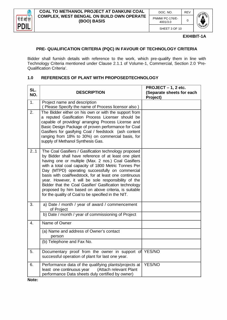
EXHIBIT-1A
PRE- QUALIFICATION CRITERIA (PQC) IN FAVOUR OF TECHNOLOGY CRITERIA
Bidder shall furnish details with reference to the work, which pre-qualify them in line with Technology Criteria mentioned under Clause 2.1.1 of Volume-1, Commercial, Section 2.0 ‘Pre- Qualification Criteria’.
1.0 REFERENCES OF PLANT WITH PROPOSEDTECHNOLOGY
SL. NO.
DESCRIPTION
PROJECT – 1, 2 etc. (Separate sheets for each Project)
1. Project name and description ( Please Specify the name of Process licensor also )
2. The Bidder either on his own or with the support from a reputed Gasification Process Licenser should be capable of providing/ arranging Process License and Basic Design Package of proven performance for Coal Gasifiers for gasifying Coal / feedstock (ash content ranging from 18% to 30%) on commercial basis, for supply of Methanol Synthesis Gas.
2..1 The Coal Gasifiers / Gasification technology proposed by Bidder shall have reference of at least one plant having one or multiple (Max. 2 nos.) Coal Gasifiers with a total coal capacity of 1800 Metric Tonnes Per Day (MTPD) operating successfully on commercial basis with coal/feedstock, for at least one continuous year. However, it will be sole responsibility of the Bidder that the Coal Gasifier/ Gasification technology proposed by him based on above criteria, is suitable for the quality of Coal to be specified in the NIT.
3. a) Date / month / year of award / commencement of Project
b) Date / month / year of commissioning of Project
4. Name of Owner
(a) Name and address of Owner’s contact person
(b) Telephone and Fax No.
5. Documentary proof from the owner in support of successful operation of plant for last one year.
YES/NO
6. Performance data of the qualifying plants/projects at least one continuous year (Attach relevant Plant performance Data sheets duly certified by owner)
YES/NO
Note:

COAL TO METHANOL PROJECT AT DANKUNI COAL COMPLEX, WEST BENGAL ON BUILD OWN OPERATE
(BOO) BASIS
DOC. NO. REV
PNMM/ PC-176/E- 4001/3.0
0
SHEET 4 OF 10
1. Bidder shall furnish the details as above of Projects which they consider suitable for
their pre-qualification. CIL / PDIL reserve the right not to evaluate any other Project details.
2. Bidder to note that PQC form shall be filled as per the Proformas as stated, along with
wherever applicable, copies of work order, completion certificates.
3. Bidder to note that non-submission of relevant supporting documents may lead to rejection of their PQ bid. It is to be ensured that all relevant supporting documents shall be submitted along with the PQ bid in the first instance itself. Pre-qualification may be completed based on the details so furnished without seeking any subsequent additional information.
STAMP & SIGNATUREOFBIDDER : NAMEOFBIDDER : DATE :

COAL TO METHANOL PROJECT AT DANKUNI COAL COMPLEX, WEST BENGAL ON BUILD OWN OPERATE
(BOO) BASIS
DOC. NO. REV
PNMM/ PC-176/E- 4001/3.0
0
SHEET 5 OF 10
EXHIBIT-1B
PRE- QUALIFICATION CRITERIA (PQC) IN FAVOUR OF TECHNOLOGY CRITERIA (GAS CLEANING, PURIFICATION, METHANOL SYNTHESIS GAS GENERATION and METHANOL PRODUCTION (METHANOL SYNTHESIS & PURIFICATION):
Bidder shall furnish details with reference to the work, which pre-qualify them in line with Technology Criteria mentioned under Clause under Clause 2.1.2 of Volume-1, Commercial, Section 2.0 ‘Pre- Qualification Criteria’.
2.0 REFERENCES OF PLANT WITH PROPOSEDTECHNOLOGY
SL. NO.
DESCRIPTION
PROJECT – 1, 2 etc. (Separate sheets for each Project)
1. Project name and description ( Please Specify the name of Process licensor also )
2. The Bidder either on his own or with the support from a reputed Process Licenser should be capable of providing/arranging Process License and Basic Design Package for the proposed Gas cleaning, Purification, Methanol Synthesis Gas Generation and Methanol production (Methanol Synthesis &Purification). The Gas Cleaning, Purification, Methanol Synthesis Gas and Liquid Methanol (grade AA, i.e. above 99.85% purity) Generation technology proposed by Bidder shall have reference of at least one plant processing Methanol Synthesis gas from the gasifier and generating minimum 1200 MTPD of Liquid Methanol of grade AA, i.e. above 99.85%purity.
3. c) Date / month / year of award / commencement of Project
d) Date / month / year of commissioning of Project
4. Name of Owner
(a) Name and address of Owner’s contact person
(b) Telephone and Fax No.
5. Documentary proof from the owner in support of successful operation of plant for last one year.
YES/NO
6. Performance data of the qualifying plants/projects at least one continuous year (Attach relevant Plant performance Data sheets duly certified by owner)
YES/NO
Note:
1. BiddershallfurnishthedetailsasaboveofProjectswhichtheyconsidersuitablefortheirpre-qualification.CIL/PDIL reserve the right not to evaluate any other Project details.
2. Bidder to note that PQC form shall be filled as per the Proforma as stated, along with
wherever applicable, copies of work order, completion certificates.
3. Bidder to note that non-submission of relevant supporting documents may lead

COAL TO METHANOL PROJECT AT DANKUNI COAL COMPLEX, WEST BENGAL ON BUILD OWN OPERATE
(BOO) BASIS
DOC. NO. REV
PNMM/ PC-176/E- 4001/3.0
0
SHEET 6 OF 10
to rejection of their PQ bid. It is to be ensured that all relevant supporting documents shall be submitted along with the PQ bid in the first instance itself. Pre-qualification may be completed based on the details so furnished without seeking any subsequent additionalinformation.
STAMP & SIGNATUREOFBIDDER : NAMEOFBIDDER : DATE :

COAL TO METHANOL PROJECT AT DANKUNI COAL COMPLEX, WEST BENGAL ON BUILD OWN OPERATE
(BOO) BASIS
DOC. NO. REV
PNMM/ PC-176/E- 4001/3.0
0
SHEET 7 OF 10
EXHIBIT-2
PRE- QUALIFICATION CRITERIA (PQC) IN FAVOUR OF EXPERIEN E CRITERIA:
Bidder shall furnish details with reference to the work, which pre-qualify them in line with experience criteria mentioned under Clause under Clause 2.2 of Volume-1, Commercial, Section 2.0 ‘Pre- Qualification Criteria’.
(MARK √ FOR APPLICABILITYINBOX )
1.0 EXPERIENCE AS BOO Operator
SL. No.
Description Details
1. Name of Project, Location 2. Description of work
3 Experience of having successfully Build Plants on BOO (Build, Own and Operate) basis in any one or more of the field of Coal gasification, Oil, Gas, Refinery, Hydrocarbon, Air Separation or Fertilizer and Methanol. Such plant should have been in satisfactory commercial operation for a continuous minimum period of one year in the last 10 years period. Bidder should have owned and operated at least for one year, a process unit with a minimum capacity to produce 100,000 Nm3/hr Either Ammonia Syn. gas or Methanol or Pure O2 or Pure N2. Bidder to submit the documentary proof thereof
4. Name of Owner, Postal Address, Phone / Fax No. / E- mail
5. Name of Consultant / Postal Address, Phone / Fax No. / E-mail.
6 Date of Commercial Operation of the Plant by BOO operator:
7.0 Document Furnished 8.1 Copy of work order / Contract Agreement enclosed YES / NO
8.2 A certificate from the Owner that the Plant is put into commercial operation by the BOO Operator.
YES / NO

COAL TO METHANOL PROJECT AT DANKUNI COAL COMPLEX, WEST BENGAL ON BUILD OWN OPERATE
(BOO) BASIS
DOC. NO. REV
PNMM/ PC-176/E- 4001/3.0
0
SHEET 8 OF 10
2.0 DETAILS OF PROJECTREFERENCES
SL. NO.
DESCRIPTION
PROJECT – 1, 2 etc. (Separate sheets for each Project)
1. Project name and description (In the field of Coal gasification, Coal to Liquid, Coal to Chemical, Oil & Gas, Refinery, Hydrocarbon, Petrochemicals, Ammonia, Fertilizer and Methanolin last 10 (ten) years)
2. (a) Awarded contract value (INR /equivalent foreign currency)
Completed one work costing not less than INR 44 billion or equivalent foreign currency.
Or
Completed two works each costing not less than INR 28 billion or equivalent foreign currency,
Or
Completed three works each costing not less than INR 22 billion or equivalent foreign currency,
(b) Final executed contract value (INR / equivalent foreign currency)
(c) Exchange rate considered for contract
3. Name of Owner
(a) Name and address of Owner’s contact Person
(b) Telephone and Fax No. (c) Mobile No. (d )Email
4. (a) Date / month / year of award / commencement of Project
(b) Date / month / year of scheduled Commissioning of Project.
(c) Date / month / year ofactual commissioning of Project.
5. Basis of work As a Single Bidder/JV/Consortium
6. Whether document submitted in support viz. copies of work order and completion certificate identifying the successful commissioning of project for ascertaining BQC.
YES/NO

COAL TO METHANOL PROJECT AT DANKUNI COAL COMPLEX, WEST BENGAL ON BUILD OWN OPERATE
(BOO) BASIS
DOC. NO. REV
PNMM/ PC-176/E- 4001/3.0
0
SHEET 9 OF 10
Note:
1. Bidder shall furnish the experience details as above of Projects which they consider suitable for their pre-qualification. CIL/PDIL reserves the right not to evaluate any other Projectdetails.
2. Bidder to note that PQC form shall be filled as per the Proformas as stated, along with wherever applicable, copies of work order and completioncertificates.
3. Bidder to note that non-submission of relevant supporting documents may lead to rejection of their PQ bid. It is to be ensured that all relevant supporting documents shall be submitted along with the PQ bid in the first instance itself. Pre-qualification may be completed based on the details so furnished without seeking any subsequent additionalinformation.
4. For PQ criteria in respect of Order value, in case PQ Criteria indicated by the bidders is in foreign currency, RBI reference rate on the date of opening of technical bid shall be considered for conversion of the foreign currency intoINR.
STAMP & SIGNATUREOFBIDDER : NAMEOFBIDDER : DATE :

COAL TO METHANOL PROJECT AT DANKUNI COAL
COMPLEX, WEST BENGAL ON BUILD OWN OPERATE (BOO) BASIS
DOC. NO. REV
PNMM/ PC-176/E-4001/3.0
0
SHEET 10 OF 10
EXHIBIT-3
PRE- QUALIFICATION CRITERIA (PQC) IN FAVOUR OF FINANCIAL CRITERIA
FORMAT FOR CHARTERED ACCOUNTANT CERTIFICATE
We have verified the Annual Accounts and other relevant records of M/s………………..(Name of the Bidder) and certify the following:
A. ANNUAL TURNOVER OF LAST 3YEARS: Year Amount (Currency) Year 1: Year 2: Year 3:
B. FINANCIAL DATA FOR LAST AUDITED FINANCIAL YEAR: Description Year Amount (Currency) 1. Current Assets 2. Current Liabilities Working Capital (Current Assets-Current liabilities)
NetWorth(Paid up share Capital and Free Reserves & Surplus)
Name of Audit Firm: [Signature of Authorized Signatory] Chartered Accountant Name: Date: Designation:
Seal: Membership No.:
Instructions:
1. The financial year would be the same as one normally followed by the Bidder for its Annual Report.
2. The Bidder shall provide the audited annual financial statements as required for this PQ document. Failure to do so would result in the Proposal being considered as non-responsive.
3. This certificate is to be submitted on the letter head of Chartered Accountant. 4. For PQ criteria in respect of Turn Over / Net worth, in case PQ Criteria
indicated by the bidders is in foreign currency, RBI reference rate on the date of opening of technical bid shall be considered for conversion of the foreign currency into INR.

COAL TO METHANOL PROJECT AT DANKUNI
COAL COMPLEX, WEST BENGAL ON BUILD OWN OPERATE (BOO) BASIS
SUBMISSION OF BID
PNMM/PC-176/E-4001/4.0 0
DOC. NO. REV.
SHEET 1 OF 4
All rights reserved
VOLUME-I, COMMERCIAL
SECTION 4.0
SUBMISSION OF BID

COAL TO METHANOL PROJECT AT DANKUNI
COAL COMPLEX, WEST BENGAL ON BUILD OWN OPERATE (BOO) BASIS
SUBMISSION OF BID
PNMM/PC-176/E-4001/4.0 0
DOC. NO. REV.
SHEET 2 OF 4
All rights reserved
From: M/s………………………………… To: M/s COAL INDIA LIMITED, Coal Bhawan, Action Area-1A, New Town, Kolkata - 700 156 (W.B.)
1. I/We hereby tender for design, build, own, lease, operate and maintain Methanol Production
Plant(s) on BOO basis, transfer required product(s) for storage and marketing of the entire quantity of methanol produced in the plant during the contracted period for CIL/or its subsidiary at Dankuni Coal Complex, West Bengal, India as per Terms and Conditions specified in TENDER NO : PNMM/PC-176/E-4001 Price Format quoted by me/us are in accordance with Invitation for Bid, Instructions to Bidders, Schedule of Prices and other documents and papers, all as detailed in the Bidding documents.
2. It has been explained to me/us that the date of commencement of first delivery of Methanol is the essence of the Contract Agreement. I/We agree that in the case of failure on my/our part to strictly observe the Time Schedule, I/We shall pay compensation to CIL as per provisions and stipulations contained in the Contract Documents and I/We agree to recovery being made as specified therein.
3. I/ We acknowledge that Owner will be relying on the information provided in the Bid and the documents accompanying such Bid for the Project, and I/we certify that all information provided in the Bid is true, complete and correct; nothing has been omitted which renders such information misleading; and all documents accompanying such Bid are true copies of their respective originals.
4. I/ We shall make available to the Owner any additional information it may find necessary or require to supplement or authenticate my/ our Bid.
5. I/ We acknowledge the right of the Owner to reject my/our Bid without assigning any reason or otherwise and hereby waive, to the fullest extent permitted by applicable law, my/our right to challenge the same on any account whatsoever.
6. I/ We declare that:
a. I/ we have examined and have no reservations to the Tender Documents, including any addendum issued by the Owner;
b. I/ we are eligible to submit a bid and in particular, do not have any Conflict of Interest; c. I/we have not directly or indirectly or through an agent engaged or indulged in any corrupt,
fraudulent, coercive practice or restrictive practice, in respect of any tender or request for bid issued by or any agreement entered into with the Owner or any other public sector enterprise or any GOI/SG entity;

COAL TO METHANOL PROJECT AT DANKUNI
COAL COMPLEX, WEST BENGAL ON BUILD OWN OPERATE (BOO) BASIS
SUBMISSION OF BID
PNMM/PC-176/E-4001/4.0 0
DOC. NO. REV.
SHEET 3 OF 4
All rights reserved
d. My/ our Bid shall be valid for a minimum period of [180 (one hundred and eighty) days] from the Bid Due Date, as extended from time to time, in accordance with the Bidding Documents, and it shall remain binding upon me/ us and may be accepted at any time before the expiration of that period; and
e. If my/ our Bid is accepted, we undertake to complete the Project in accordance with the
Contract Agreement and other Tender Documents.
7. I/ We certify that in regard to matters other than security and integrity of the country, we/ any member or any of our/ their associates have not been convicted by a court of law or indicted or adverse orders passed by a regulatory authority which could cast a doubt on our ability to undertake the Project or which relates to a grave offence that outrages the moral sense of the community.
8. I/ We further certify that in regard to matters relating to security and integrity of the country, we/ any member or any of our/ their associates have not been charge-sheeted by any agency of the Government or convicted by a court of law.
9. I/ We further certify that no investigation by a regulatory authority is pending either against us/ any member or against our/ their associates or against our chief executive officer or any of our directors/ managers/ employees.
10. I/ We undertake that in case due to any change in facts or circumstances during the Bidding process, we are attracted by the provisions of disqualification in terms of the provisions of the Tender Document, I/ we shall intimate the Owner of the same immediately.
11. I/We agree to pay the Earnest Money Deposit and Security Deposit (if awarded the job) and accept the terms and conditions laid down in the memorandum below in thisrespect.
MEMORANDUM (a) General Description of Work: Installation of Coal Gasification and Methanol Plant on
Build, Own & Operate (BOO) Basis for CIL at Dankuni Coal Complex, West Bengal, India and Supply & marketing of Methanol to third party consumer.
(b) Earnest Money Deposit (EMD): INR 550 million or equivalent USD The Earnest Money is payable in the manner set outin para 5 below.
(c) Security Deposit (SD) : As per Clause 23.0 of Sec 5.0, Instruction To Bidder.
12. Should this tender be accepted, I/We hereby agree to sign the Agreement(s) with CIL and
abide by and fulfill all terms and conditions referred to above and in the Agreement and in default thereof, to forfeit and pay to CIL or its successors or its authorized nominees such sums of money as are stipulated in conditions contained in Bidding Documents.
13. I/We hereby pay the Earnest Money Deposit (EMD) of Rs.____________ (Rupees ) in Bank Guarantee No.________________ssued by ___________________(name and office of the State Bank of India or any Nationalised Bank) in favour of Coal Indian Limited, Kolkata.
OR

COAL TO METHANOL PROJECT AT DANKUNI
COAL COMPLEX, WEST BENGAL ON BUILD OWN OPERATE (BOO) BASIS
SUBMISSION OF BID
PNMM/PC-176/E-4001/4.0 0
DOC. NO. REV.
SHEET 4 OF 4
All rights reserved
I/We hereby pay the Earnest Money Deposit(EMD) of Rs. (Rupees ) Crossed Demand Draft No., issued by ________________(name and address Bank) in favour of Indian Coal Indian Limited, Kolkata.
14. If I/We fail to commence the work specified in the Memorandum in Para (3) above, or I/We fail to deposit the amount of Security Deposit (SD) specified in the Memorandum in (3) above, I/We agree CIL or its successors without prejudice to any other right or remedy be at liberty to forfeit the said Earnest Money Deposit(EMD) in full. CIL shall also be at liberty to cancel the Notification of Award if I/We fail to deposit the Security Deposit (SD) as aforesaid or to execute an Agreement or to start WORK as stipulated in the Bidding Documents.
15. I/ We hereby authorise the Owner to seek reference/clarifications from my/our bankers.
16. I/ We hereby irrevocably waive any right or remedy which we may have at any stage at law or howsoever otherwise arising to challenge or question any decision taken by the Owner in connection with the selection of Bidders, or in connection with the selection/ bidding process itself, in respect of the Project and the terms and implementation thereof.
17. I/ We agree and undertake to abide by all the terms and conditions of the Tender Documents.
18. I/ We undertake to execute the Contract Agreement within 60 (sixty) days from the date of issue of the LOA, if the Project is awarded to me/ us.
19. I/We enclose herewith complete technical and commercial details as per the
requirement of this Bidding Document as well as other supporting documents to facilitate evaluation of the bid.
Dated the__________day of_____020 Witness: Name in Block Letters: Address:
Yours faithfully, Signature of Bidder(s) with the
Seal of the Firm.
Name and Designation of authorised person signing the tender on behalf of the Bidder(s).
COAL TO METHANOL PROJECT AT DANKUNI COAL COMPLEX, WEST BENGAL ON BUILD
OWN OPERATE (BOO) BASIS
INSTRUCTIONS TO BIDDERS
PNMM/PC-176/E-4001 /5.0 0
DOC. NO. REV.
SHEET 1 OF 27
All rights reserved
VOLUME-I, COMMERCIAL
SECTION 5.0
INSTRUCTIONS TO BIDDERS

COAL TO METHANOL PROJECT AT DANKUNI COAL COMPLEX, WEST BENGAL ON BUILD
OWN OPERATE (BOO) BASIS
INSTRUCTIONS TO BIDDERS
PNMM/PC-176/E-4001 /5.0 0
DOC. NO. REV.
SHEET 2 OF 27
All rights reserved
CONTENTS
Sl. No. DESCRIPTION
1.0 INTRODUCTION 2.0 SCOPE OF PROPOSAL 3.0 TIME SCHEDULE 4.0 ELIGIBLE BIDDERS 5.0 SIGNATURE ON BIDS 6.0 PRE-BID MEETING 7.0 BIDDING DOCUMENTS/TENDER DOCUMENTS 8.0 AMENDMENT OF BIDDING DOCUMENTS 9.0 MODIFICATION AND WITHDRAWAL OF BIDS
10.0 COST OF BIDs 11.0 LANGUAGE OF THE BID 12.0 BID SUBMISSION 13.0 PREPARATION/ SUBMISSION OF BIDS 14.0 DEADLINE FOR SUBMISSION OF BIDS 15.0 OPENING OF BIDS 16.0 BID CURRENCIES 17.0 EARNEST MONEY DEPOSIT (EMD) 18.0 VALIDITY OF BID 19.0 POLICY FOR BID UNDER CONSIDERATION
20.0 DEPUTATION OF REPRESENTATIVE FOR TECHNICAL & COMMERCIAL DISCUSSIONS
21.0 EVALUATION AND COMPARISON OF BIDS 22.0 TAXES & DUTIES 23.0 SECURITY DEPOSIT/PERFORMANCE BANK GUARANTEE 24.0 CONTRACT AGREEMENT 25.0 NOTIFICATION OF AWARD 26.0 SIGNING OF CONTRACT 27.0 GENERAL INSTRUCTIONS 28.0 CONTACTING OWNER 29.0 OWNER’S RIGHT TO ACCEPT/REJECT BIDS 30.0 INTEGRITY PACT 31.0 PUBLIC PROCUREMENT (PREFERENCE TO MAKE IN INDIA) POLICY
32.0 PROVISION FOR PROCUREMENT FROM A BIDDER WHICH SHARES A LAND BORDER WITH INDIA

COAL TO METHANOL PROJECT AT DANKUNI COAL COMPLEX, WEST BENGAL ON BUILD
OWN OPERATE (BOO) BASIS
INSTRUCTIONS TO BIDDERS
PNMM/PC-176/E-4001 /5.0 0
DOC. NO. REV.
SHEET 3 OF 27
All rights reserved
PREAMBLE
Coal is the most important and abundant fossil fuel in India. It accounts for 55% of the country's energy need. The country's industrial heritage was built upon indigenous coal. Indian coal offers a unique eco-friendly fuel source to domestic energy market for the next century and beyond. Hard coal deposits, spread over 27 major coalfields, are mainly confined to eastern and south central parts of the country. The lignite reserves stand at a level around 36 billion tonnes, of which 90 % occur in the southern state of Tamil Nadu. Coal deposits in India are mainly distributed along the present day river valleys. Major coal deposits are confined to south and south eastern quadrant of the country. Coal deposits are of drift origin and high in extraneous ash content. There are 44 known coalfields located in the peninsular India containing 95% of total resources. Total estimated geological resource of coal, as on April 01’ 14 is 302 billion tonnes, out of which about 114 billion tonnes is of ‘proven’ category. The Ministry of Coal has the overall responsibility of determining policies and strategies in respect of exploration and development of coal and lignite reserves, sanctioning of important projects of high value and for deciding all related issues. Under the administrative control of the Ministry, these key functions are exercised through the Public Sector Undertakings, namely, Coal India Ltd. and its subsidiaries and Neyveli Lignite Corporation Limited. Other than Coal India Ltd. and Neyveli Lignite Corporation Ltd., the Ministry of Coal has also a joint venture with Government of Andhra Pradesh called Singareni Collieries Company Limited. Government of Andhra Pradesh holds 51% equity and Government of India holds 49 % equity. Coal India Limited has decided to venture into a vertical integration of business initiatives other than its conventional coal business with necessary approval of the Board and has come up with the intention of setting up of “Coal to Methanol plant of 2050 MTPD capacity at its Dankuni Coal Complex (DCC)” The objective of such ventures is to explore additional utilization of Indian coal, which is available in abundance. In pursuit of implementing one of such initiatives, the premises of Dankuni Coal Complex (DCC), at a distance of 25 km from Kolkata, has been identified as a strategic location for initially setting up a 2050 MTPD capacity Coal to Methanol (C2M) plant by utilizing the low ash, high Calorific Value thermal coal from Ranigunj coalfields. The Plant is proposed to operate as two separate units, a Coal Gasification Island
1.0 INTRODUCTION 1.1 Coal India Limited (CIL) was incorporated on 01st November 1975 with nationalization of private
coal mines by Govt. of India. With a modest production of 79 MT at the year of its inception, CIL today is the single largest coal producer in the world having produced nearly 607 MT.
CIL is a Schedule ‘A’ Maharatna CPSE under the administrative jurisdiction of Ministry of Coal, Government of India, with its registered and corporate office located at Kolkata (India). It operates through its subsidiaries spread over eight states (provinces) in India namely Jharkhand, West Bengal, Orissa, Chhattisgarh, Madhya Pradesh, Uttar Pradesh, Maharashtra and Assam.
CIL has a foreign subsidiary in Mozambique namely, Coal India Africana Limited (CIAL). Mahanadi Coalfields Limited has four subsidiary companies and one JV company. South Eastern Coalfields Limited has two subsidiary companies, and Central Coalfields Limited has one subsidiary company.

COAL TO METHANOL PROJECT AT DANKUNI COAL COMPLEX, WEST BENGAL ON BUILD
OWN OPERATE (BOO) BASIS
INSTRUCTIONS TO BIDDERS
PNMM/PC-176/E-4001 /5.0 0
DOC. NO. REV.
SHEET 4 OF 27
All rights reserved
During 2019-20, CIL and its subsidiaries produced 602.15 MT of coal. During the FY 2019-20, the gross sales about 17.8 bn, PBT and PAT of CIL were approx.INR 240.713 bn and 167.003 bn respectively.
CIL intends to diversify into a new “Coal to Chemical” business domain by converting the high calorific value, low ash thermal coal into synthesis gas (CO+H2) and downstream chemicals. In pursuit of implementing this new strategy, the premises of the existing Dankuni Coal Complex (DCC) have been identified as the geo-strategic location for setting up a Coal to Methanol Complex on Build Own Operate basis (BOO) by using the good quality Indian coal from Raniganj coalfields.
1.2 COAL-TO-METHANOL PROJECT AT DANKUNI COAL COMPLEX (DCC)
Dankuni Coal Complex (DCC) is an existing Low Temperature Coal Carbonisation (LTC) Plant of CIL and is currently being run on lease basis by South Eastern Coalfields Limited (SECL), a wholly owned subsidiary of CIL. DCC was set up under the recommendation of the Fuel Policy Committee of 1974, to meet the growing needs of “Environmental Friendly Fuel” to meet requirements of domestics & industrial sectors. The commercial production of the plant started in May1990. Today, DCC is engaged in processing and supplying of Coal gas and Coal products (coke) by using non-coking coal. CIL intends to set-up a Coal (Indian Coal) to Methanol Plant at its existing premises of Dankuni Coal Complex at Dankuni West Bengal utilizing coal from Ranigunj coalfields as a basic raw material for the production of 2050 Metric Tonnes per Day (MTPD) Methanol. Pre-Feasibilities Studies have been completed(Project). Currently, pre-project activities are under progress at the Project Site.
1.3 Owner has retained Projects & Development India Ltd. (PDIL) as Consultant for selection
of Build Own Operate (BOO) Operator for the project.
1.4 Project execution Philosophy: Coal to Methanol Complex shall be set up on Build Own Operate (BOO) basis with storage of the entire quantity of methanol produced in the proposed plant during its contracted period. The Bidders shall be responsible for selecting / sourcing of coal gasification technology, basic and detail engineering, procurement, installation, commissioning and operating the Coal to Methanol Complex for the entire life of the project.
1.5 SOLE BIDDER OR A JOINT VENTURE OR A CONSORTIUM 1.5.1 Bids may be submitted by a Bidder who is a sole Bidder or a JV or a Consortium. , [except in case
of Sole Bidder], the successful Bidder emerged through tendering process should be a company incorporated in India prior to award of Work.
1.5.2 The Bidder which has completed 3 (three) financial years from the date of commencement of business shall fulfill each eligibility criteria of PQC.
1.5.3 In case the Bidder is a newly formed JV which has not completed 3 (three) financial years from the date of commencement of business, then either the said JV shall fulfill each eligibility criteria or any one constituent member of such a JV shall fulfill each eligibility criteria. If the bid is received with the proposal that one constituent member fulfills each eligibility criteria then this member shall be clearly identified and it shall assume all obligations under the contract and provide such comfort Letter/ Guarantees as may be required by Owner. The Guarantee shall cover inter alia the commitment of the member to complete the entire work in all respects and in a timely fashion, being bound by all the obligations under the contract, an undertaking to provide all necessary technical and financial support to the JV to ensure completion of the contract when awarded, an undertaking not to withdraw from the JV till completion of the work, etc.

COAL TO METHANOL PROJECT AT DANKUNI COAL COMPLEX, WEST BENGAL ON BUILD
OWN OPERATE (BOO) BASIS
INSTRUCTIONS TO BIDDERS
PNMM/PC-176/E-4001 /5.0 0
DOC. NO. REV.
SHEET 5 OF 27
All rights reserved
The Provisions of Cl. No. 1.5.3 above shall also apply for a Consortium bid. The leader of the Consortium may fulfill each eligibility criteria and assume all obligations and guarantee as mentioned above.
1.5.4 A JV/Consortium Company once established at the time of submitting the Bid shall not be allowed to be altered with respect to constituting members of the JV/Consortium till the successful PGTR . If during the evaluation of bids, a JV/ Consortium proposes any alteration/ changes in the orientation of JVC/ Consortium or replacements or inclusions or exclusions of any partner(s)/ member(s) which had originally submitted the bid, bid from such a JV/ Consortium Company shall be liable for rejection.
1.5.5 The total number of Consortium members including their leader shall not exceed 4 (four).
1.5.6 All the members of the JV shall sign the contract and shall be jointly and severally liable for the entire assignment.
1.6 ONE BID PER BIDDER
1.6.1 A Bidder shall on no account submit more than one bid either directly or indirectly. 1.6.2 A Bidder shall be deemed to have submitted an indirect bid if (i) the Bidder is a JV/Consortium
member in an another independent bid or (ii) a group/subsidiary (partly or wholly owned) of the Bidderis participating as a direct or JV / Consortium member in an another independent bid.
Also, in case of several subsidiary companies of a single holding/parent company, then the participation may be allowed in the following cases:
1.6.2.1 Only one of the holding/subsidiary / group companies shall be allowed to bid whether as a Sole Bidder
or as member of a JV /Consortium, 1.6.2.2 Two or more group companies may be allowed to participate if they are Partners in the same and
single JV/Consortium. 1.6.3 If a Bidder makes more than one bid and/or directly or indirectly participates in another bid (in the
manner set out in Clause 1.6.1 and 1.6.2), all the bids of the Bidder, including the bid of the Bidder in whose bid the first named Bidder has directly or indirectly participated, may be considered as cartel bids and may be rejected. If the factum of such bid(s) is discovered after the notification of award, the resultant contract shall be liable to be terminated.
1.7 GENERAL INSTRUCTIONS
1.7.1 Bidders must review the Bidding Documents as a whole, and ensure that their Bids are as per the
terms of the Bidding Documents. CIL/Owner retains the right to modify the terms of the Bidding Documents and/ or any of the sections/ attachments/ formats thereto at any time prior to the Bid Due Date.
1.7.2 Once a Bid is submitted no changes will be permitted to be made by the Bidder except as permitted under the Bidding Documents.
1.7.3 Words and expressions beginning with capital letters used in this NIT without being defined shall have the same meaning as assigned to them in the Contract Agreement or the other Bidding Documents.

COAL TO METHANOL PROJECT AT DANKUNI COAL COMPLEX, WEST BENGAL ON BUILD
OWN OPERATE (BOO) BASIS
INSTRUCTIONS TO BIDDERS
PNMM/PC-176/E-4001 /5.0 0
DOC. NO. REV.
SHEET 6 OF 27
All rights reserved
2.0 SCOPE OF WORK: 2.1 CIL intends to setup a Coal-to-Methanol Plant on Build Own Operate (BOO) Basis for life of the
plant (expected period 25 years). The scope shall be as defined in the Tender documents and shall broadly cover the following - Design, Build, Own, Operate & Maintain Production Plant(s), transfer required product(s) , storage of the entire quantity of methanol produced in the proposed plant during its contracted period will also be the responsibility of the BOO Operator.
2.2 Location of the Project Site
CIL intends to set up at the Project its existing premises of Dankuni Coal Complex (DCC) at Dankuni, West Bengal (India).
The proposed Project is situated by the side of Durgapur Expressway in the north and Janai Road railway station of the grand chord line in the south at Dankuni village of Hooghly District of West Bengal, India. The Project site, adjacent to the Kolkata – Durgapur Expressway, is at a distance of about 25 km by road from Kolkata. Kolkata Airport is the nearest Airport to the proposed project site which is about 20 km.
2.3 Site Visit 2.3.1 The Bidder is advised to visit and examine the site of works and its surroundings and obtain for
itself on its own responsibility all information that may be necessary for preparing the bid and entering into the Contract Agreement. Claims of any kind due to variation or ignorance of site conditions and environmental conditions will not be eligible in any circumstances.
2.3.2 The Bidder and any of its personnel or authorized representatives will be granted permission by Owner to enter upon its premises and lands for the purpose of such inspection. It is understood that as an implicit condition of such permission, the Bidder, its personnel and/or authorized representative(s) shall be understood to have released and indemnified Owner and its personnel from and against all liability in respect thereof and to have assumed all responsibility for personal injury (whether fatal or otherwise), loss of or damage to person or property and any other loss, damage, cost and expenses incurred as a result of such visit, including those sustained by any negligence or other act of tort on the part of Owner and/or its personnel and consultants. During such visits the Bidder shall abide by all the rules and regulations, as applicable.
2.3.3 The date of the site visit is to be confirmed by respective Bidder in consultation with the concerned officer indicated in the Invitation For Bid.
3.0 TIME SCHEDULE 3.1 Bidder shall be required to complete the Work under the Contract Agreement so as to achieve the
Guaranteed Completion Date in accordance with the following milestones:
a) MECHANICAL COMPLETION 36 (thirty six) Months from Effective Date of Contract Agreement
b) COMMISSIONING 41 (forty one) Months from Effective Date of Contract Agreement
3.2 The “Effective Date of Contract Agreement (EDC)” shall be the date of issuance of Letter of
Award (LOA)/ Notification of Award by the Owner.

COAL TO METHANOL PROJECT AT DANKUNI COAL COMPLEX, WEST BENGAL ON BUILD
OWN OPERATE (BOO) BASIS
INSTRUCTIONS TO BIDDERS
PNMM/PC-176/E-4001 /5.0 0
DOC. NO. REV.
SHEET 7 OF 27
All rights reserved
4.0 ELIGIBLE BIDDERS
4.1 The Bidder is not put on ‘Holiday’ by CIL or any of the JV partner/subsidiary of Owner or Public- Sector Project Management Consultant (like PDIL only due to “poor performance” or “corrupt and fraudulent practices”) or banned/blacklisted by GOI/SG department/ Public Sector on due date of submission of bid or during the process of evaluation of bids. Further, neither Bidder nor their allied agency/(ies) (as defined in the Procedure for Action in case of Corrupt/Fraudulent/Collusive/ Coercive Practices) are on banning list of CIL or any of the JV partner/subsidiary of Owner. In case there is any change in status of the declaration prior to award of contract, the same has to be promptly informed to CIL/PDIL/Owner by the Bidder. It shall be the sole responsibility of the Bidder to inform about their status regarding above on due date of submission of bid and during the course of finalization of the tender. Concealment of the facts shall tantamount to misrepresentation of facts and shall lead to rejection of the bid.
4.2 The Bidder should not be under any liquidation court receivership or similar proceedings on due date of submission of bid. In case there is any change in status of the declaration prior to award of contract, the same has to be promptly informed to CIL/PDIL/Owner by the Bidder.
It shall be the sole responsibility of the Bidder to inform CIL/Ownertheir status on above on due date of submission of bid and during the course of finalization of the tender. Concealment of the facts shall tantamount to misrepresentation of facts and shall lead to rejection of the Bid.
4.3 Bidder shall not be affiliated with a firm orentity:
i. that has provided consulting services related to the Work to the Owner during the preparatory stages of the work or of the project of which the works/services forms a part of, or
ii. that has been hired (proposed to be hired) by the Owner as an engineer/ consultant for the Project.
4.4 Pursuant to qualification criteria set forth in the Tender Document, the Bidder shall furnish all
necessary supporting documentary evidence to establish Bidder’s claim of meeting qualification criteria.
5.0 SIGNATURE ON BIDS 5.1 The Bid must contain the name, designation and place of business of the person or persons
making the Bid and must be signed and sealed, on each page, by the Bidder with his usual signature. The names of all persons signing should also be typed or printed below the signature. The Bidder shall submit authority letter / power of attorney/ board resolution in favour of the authorized signatory(s) of the Bid. The Bidder's name stated on the proposal shall be the exact legal name of the Bidder
5.2 Bids by bodies corporate/ limited companies must be signed with the legal name of the
corporation/limited company by the president, managing director or by the company secretary or any other person or persons holding power of attorney for signing their Bid.

COAL TO METHANOL PROJECT AT DANKUNI COAL COMPLEX, WEST BENGAL ON BUILD
OWN OPERATE (BOO) BASIS
INSTRUCTIONS TO BIDDERS
PNMM/PC-176/E-4001 /5.0 0
DOC. NO. REV.
SHEET 8 OF 27
All rights reserved
5.3 In case of a Single Bidder, power of attorney issued by the board of directors/ CEO / MD / Company Secretary of the Bidder/ all partners in case of Partnership firm/Proprietor in favour of the authorised employee(s) of the Bidder, in respect of the particular tender for signing the Bid and all subsequent communications, agreements, documents etc. pertaining to the tender and to act and take any and all decision on behalf of the Bidder, is to be submitted.
5.4 The authorized employee(s) of the Bidder shall be signing the bid and any consequence
resulting due to such signing shall be binding on the Bidder. 5.5 Bid by a Consortium/JV must be signed by all members of the Consortium/JV. In case of
Consortium, the exact legal names of all the members of the Consortium shall be stated and leader of Consortium shall be clearly indicated.
In case of a Consortium/JV, power of attorney (POA) issued by board of directors/ CEO / MD / C&MD/ company secretary of the Consortium leader as well as Consortium member(s) of the Consortium, in favour of the authorised employee(s), for signing the documents on behalf of each of the members, in respect of this particular tender, to sign the Bid and all subsequent communications, agreements, documents etc. Pertaining to the tender and act and take any and all decision on behalf of the Consortium, are to be submitted. Power of Attorney shall be as per law of land; Format of POA as per Annexure 1.11.
5.6 Bid shall contain no cuttings, erasures or overwriting except as necessary to correct errors made by the Bidder in which case each such corrections or other changes in the Bid documents shall carry the initials of the person(s) signing the Bid.
6.0 PRE-BID MEETING 6.1 The Bidder may submit any queries/clarification/information pertaining to bidding documents in
writing delivered by hand or by Fax or by E-mail as per Annexure-1.5 enclosed in the bidding documents so as to reach PDIL not later than the date specified in the Invitation For Bid. Queries/ Clarifications/ Information sought in any other manner shall not be responded to.
6.2 The Bidder or his authorised representative(s), is advised to attend a pre-bid meeting as indicated in the Invitation For Bid. A maximum of 2 (two) representatives of each Bidder shall be allowed to participate on production of an authority letter from the Bidder. The purpose of the meeting will be to clarify issues and to answer questions on any matter pertaining to the Tender conditions that may be raised at that stage by Bidders. CIL/Owner shall endeavour to provide clarifications and such further information as it may, in its sole discretion, consider appropriate for facilitating a fair, transparent and competitive bidding process. Any clarifications provided in the pre-bid conference are only indicative and Bidders will only be entitled to rely on the clarifications subsequently provided in writing by the Owner.
6.3 The Owner’s responses to Bidder’s queries/clarifications raised will be furnished as expeditiously as possible. Any modification of the Tender Documents which may become necessary as a result of the pre-bid meeting/conference shall be issued as Addendum/Amendment/Corrigendum.
6.4 Non-attendance of Bidders at the pre-bid conference will not be a cause for disqualification of the Bidder and it shall be presumed that the Bidder does not require any clarification.
7.0 BIDDING DOCUMENTS/TENDER DOCUMENTS
7.1 The Bidder is expected to examine the Bidding Documents/Tender Documents, including all
instructions, Forms, terms and conditions of Contract, specifications, drawings and other
COAL TO METHANOL PROJECT AT DANKUNI COAL COMPLEX, WEST BENGAL ON BUILD
OWN OPERATE (BOO) BASIS
INSTRUCTIONS TO BIDDERS
PNMM/PC-176/E-4001 /5.0 0
DOC. NO. REV.
SHEET 9 OF 27
All rights reserved
documents and to fully familiarize itself with the requirements of the Bidding Documents. Failure to furnish all the information required by the Bidding Documents or the submission of a bid not substantially responsive to the Bidding Documents in every respect may result in the rejection of the Bid.
In case of any inconsistency, in the interpretation of meaning of any part of this Tender
Documents, the Bidder shall give his best endeavor to resolve the inconsistency by expressing his assumption through his proposal to Owner.
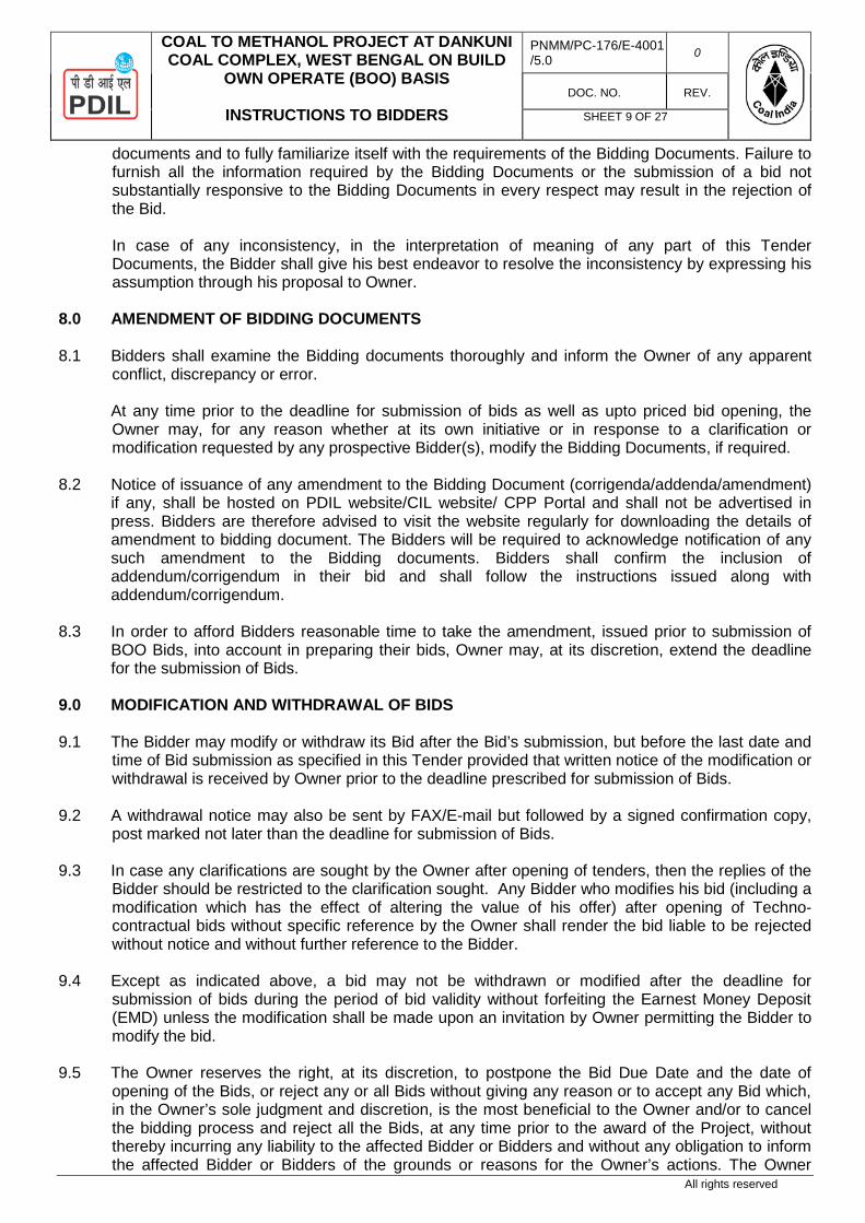
8.0 AMENDMENT OF BIDDING DOCUMENTS 8.1 Bidders shall examine the Bidding documents thoroughly and inform the Owner of any apparent
conflict, discrepancy or error. At any time prior to the deadline for submission of bids as well as upto priced bid opening, the Owner may, for any reason whether at its own initiative or in response to a clarification or modification requested by any prospective Bidder(s), modify the Bidding Documents, if required.
8.2 Notice of issuance of any amendment to the Bidding Document (corrigenda/addenda/amendment) if any, shall be hosted on PDIL website/CIL website/ CPP Portal and shall not be advertised in press. Bidders are therefore advised to visit the website regularly for downloading the details of amendment to bidding document. The Bidders will be required to acknowledge notification of any such amendment to the Bidding documents. Bidders shall confirm the inclusion of addendum/corrigendum in their bid and shall follow the instructions issued along with addendum/corrigendum.
8.3 In order to afford Bidders reasonable time to take the amendment, issued prior to submission of BOO Bids, into account in preparing their bids, Owner may, at its discretion, extend the deadline for the submission of Bids.
9.0 MODIFICATION AND WITHDRAWAL OF BIDS 9.1 The Bidder may modify or withdraw its Bid after the Bid’s submission, but before the last date and
time of Bid submission as specified in this Tender provided that written notice of the modification or withdrawal is received by Owner prior to the deadline prescribed for submission of Bids.
9.2 A withdrawal notice may also be sent by FAX/E-mail but followed by a signed confirmation copy, post marked not later than the deadline for submission of Bids.
9.3 In case any clarifications are sought by the Owner after opening of tenders, then the replies of the Bidder should be restricted to the clarification sought. Any Bidder who modifies his bid (including a modification which has the effect of altering the value of his offer) after opening of Techno-contractual bids without specific reference by the Owner shall render the bid liable to be rejected without notice and without further reference to the Bidder.
9.4 Except as indicated above, a bid may not be withdrawn or modified after the deadline for submission of bids during the period of bid validity without forfeiting the Earnest Money Deposit (EMD) unless the modification shall be made upon an invitation by Owner permitting the Bidder to modify the bid.
9.5 The Owner reserves the right, at its discretion, to postpone the Bid Due Date and the date of opening of the Bids, or reject any or all Bids without giving any reason or to accept any Bid which, in the Owner’s sole judgment and discretion, is the most beneficial to the Owner and/or to cancel the bidding process and reject all the Bids, at any time prior to the award of the Project, without thereby incurring any liability to the affected Bidder or Bidders and without any obligation to inform the affected Bidder or Bidders of the grounds or reasons for the Owner’s actions. The Owner

COAL TO METHANOL PROJECT AT DANKUNI COAL COMPLEX, WEST BENGAL ON BUILD
OWN OPERATE (BOO) BASIS
INSTRUCTIONS TO BIDDERS
PNMM/PC-176/E-4001 /5.0 0
DOC. NO. REV.
SHEET 10 OF 27
All rights reserved
further reserves the right to negotiate with any or all the Bidders in relation to their Bids. Any such action shall not be called into question and the Bidders shall have no claim or cause of Action in that regard against the Owner or its officers, employees, consultants, agents, successors or assignees for rejection of its bids. Neither the Owner nor its employees or advisers shall entertain any claim of any nature, whatsoever, including without limitation, any claim seeking costs, expenses or damages in relation to the preparation or submission of Bids.
9.6 The Owner does not bind itself to accept the lowest Bid and reserves the right to reject any or all
the Bids without assigning any reasons whatsoever and also to split up the work between two or more Bidders or accept the Bid in part and not in its entirety, at its sole discretion.
10.0 COST OF BIDs
The Bidder shall bear all costs associated with the preparation and submission of the Bid, and Owner will, in no case be responsible or liable for these costs, regardless of the conduct or outcome of the bidding process.
11.0 LANGUAGE OF THE BID
The bid prepared by the BIDDERs and all correspondence and documents relating to the Bid exchanged by the Bidder and the Company shall be written in the English language and all units shall be in Metric system. In case a supporting document, certificate, documentary evidence etc. accompanying the Bid such as copies of purchase orders, experience certificates, printed literature, etc. furnished by the Bidder is in a language other than English, the same should be accompanied by an English Translation, duly authorized by the Chamber of Commerce of the Bidders’ country, in which case, for the purpose of interpretation of the bid, the English translation shall govern. Supporting materials, which are not translated into English, may not be considered. For the purpose of interpretation and evaluation of the Bid, the English language translation shall prevail.
12.0 BID SUBMISSION
12.1 Bidders are requested for the captioned item in complete accordance with bidding documents/attachments.
12.2 Bidder can download the Tender document from PDIL Website http://pdilin.com or from Govt.
Website https://etenders.gov.in/eprocure/app. 12.3 Bidders are requested to submit e-bids electronically on the CPP Portal
(URL: https://etenders.gov.in/eprocure/app ) only in accordance with Tender document. 12.4 The following documents in addition to uploading the bid on CPP Portal
(https://etenders.gov.in/eprocure/app) shall also be submitted in Original (in physical form) within 7 (seven) days from the bid due date provided the scanned copies of the same have been uploaded on CPP Portal (https://etenders.gov.in/eprocure/app) by the Bidder along with e-bid within the due date and time to the address mentioned in Clause no. 2.0 (M) of IFB:-
i) EMD/Bid Security ii) Power of Attorney iii) Pre-Signed Integrity Pact iv) Original Letter of TPI as per Annexure-1.15 v) Letter of No Deviation as per Annexure-1.6.

COAL TO METHANOL PROJECT AT DANKUNI COAL COMPLEX, WEST BENGAL ON BUILD
OWN OPERATE (BOO) BASIS
INSTRUCTIONS TO BIDDERS
PNMM/PC-176/E-4001 /5.0 0
DOC. NO. REV.
SHEET 11 OF 27
All rights reserved
12.5 The Originals of the Documents as desired under Cover -1 shall be submitted as per the
following: The ENVELOPE shall be superscribed with the words-
“BID FOR COAL TO METHANOL PROJECT AT DANKUNI COAL COMPLEX, WEST BENGAL, INDIA TENDER No.: PNMM/PC-176/E-4001 Dated 25.09.2020. Due date and time for Bid Submission: ……….., 16:00 Hrs (IST)”. The complete name of bidder with address shall be mentioned at the bottom left portion of envelope.
ENVELOPE shall be submitted at: Projects & Development India Limited, (Materials Management Department) P.D.I.L Bhawan, A-14, Sector-1, Noida-201301(UP) ,India Fax no.:0120-2529801 Kind Attention: Mr. P.R.Sahu Addl. General Manager (MM) Tel no. : 0120-2544063 E-mail: [email protected] / [email protected] / [email protected], The envelopes without above details on the covers shall be opened at Bidder's risk.
13.0 PREPARATION/ SUBMISSION OF BIDS 13.1 The Bidder is expected to examine all instructions, forms, terms and conditions in the Tender
Document. The Tender Document together with all its attachments thereto, shall be considered to be read, understood and accepted by the Bidders. Failure to furnish all information required or submission of a Bid not responsive to the Tender Document in every respect will be at the Bidder’s risk and may result in the rejection of the Bid.
13.2 Submission of Bids: Bids shall be submitted as detailed below:
1. Bidders to submit the bids online through the Central Public Procurement Portal for e-Procurement
at https://etenders.gov.in/eprocure/app. No other mode of Bidding shall be allowed. 2. Possession of valid Digital Signature Certificate (DSC) and enrollment/registration of the
contractors/bidders on the e-procurement / e-tender portal is a prerequisite for e-tendering. 3. Bidder should do the enrollment in the e-procurement site using the “Click here to Enroll” option
available on the home page. Portal enrollment is generally free of charge. During enrollment/registration, the bidders should provide the correct/true information including valid email_id. All the correspondence shall be made directly with the contractors/bidders through email_id provided.

COAL TO METHANOL PROJECT AT DANKUNI COAL COMPLEX, WEST BENGAL ON BUILD
OWN OPERATE (BOO) BASIS
INSTRUCTIONS TO BIDDERS
PNMM/PC-176/E-4001 /5.0 0
DOC. NO. REV.
SHEET 12 OF 27
All rights reserved
4. Bidder need to login to the site thro’ their user ID/ password chosen during enrollment/registration. 5. Then the Digital Signature Certificate (Class II or class III Certificates with signing key usage)
issued by SIFY / TCS / nCode / eMudra or any certifying authority recognized by CCA India on eToken / SmartCard, should be registered.
6. The DSC that is registered only should be used by the bidder and should ensure safety of the
same.
7. Contractor/Bidder may go through the ITB / tenders published on the site and download he required ITB documents/schedules for the tenders he/she is interested.
8. After downloading /getting the ITB / Tender document / schedules, the Bidder should go through them carefully and then submit the documents as asked, otherwise bid will be rejected.
9. If there are any clarifications, this may be obtained online through’ the tender site, or thro’ the
contact details. Bidder should take into account the corrigendum published before submitting the bids online.
10. Bidder then logs in to the site through the secured log in by giving the user id/ password chosen
during enrolment/registration and then by giving the password of the eToken / Smart Card to access DSC.
11. Bidder selects the tender which he / she is interested in by using the search option & then moves it to the ‘my tenders’ folder.
12. From my tender folder, he / she selects the tender to view all the details indicated. 13. It is construed that the Bidder has read all the terms and conditions before submitting their offer.
Bidder should go through the tender schedules carefully and upload the documents as asked; otherwise, the bid will be rejected.
14. Bidder, in advance, should get ready the bid documents to be submitted as indicated in the tender
document/schedule and generally, they can be in PDF/xls/rar/zip/dwf formats. If there is more than one document, they can be clubbed together and can be provided in the requested format. Each document to be uploaded through online for the tenders should be less than 2 MB. If any document is more than 2MB, it can be reduced through zip/rar and the same can be uploaded, permitted. Bidder Bid documents may be scanned with 100 dpi with black and white option. However of the file size is less than 1 MB the transaction uploading time will be very fast.
15. If there are any clarifications, this may be obtained through the sites, or during the pre-bid meeting
if any. Bidder should take into account the corrigendum published from time to time before submitting the online bids.
16. The Bidders can update well in advance, the documents such as certificates, annual report details
etc., under My Space option and these can be selected as per tender requirements and then send along with bid documents during bid submission, this will facilitate the bid submission process faster by reducing upload time of bids.
17. Bidder should submit the EMD as specified in the tender. The original should be posted/couriered/given in person to the TIA, within the bid submission due date & time for the tender. Scanned copy of the instrument should be uploaded as part of the offer.
18. While submitting the bids online, the bidder reads the terms & conditions and accepts the same to
proceed further to submit the bid packets/Covers.

COAL TO METHANOL PROJECT AT DANKUNI COAL COMPLEX, WEST BENGAL ON BUILD
OWN OPERATE (BOO) BASIS
INSTRUCTIONS TO BIDDERS
PNMM/PC-176/E-4001 /5.0 0
DOC. NO. REV.
SHEET 13 OF 27
All rights reserved
19. The bidder has to select the payment option as offline to pay the EMD as applicable and enter
details of the instruments. 20. The details of the DD / any other accepted instrument, physically sent, should tally with the details
available in the scanned copy and the data entered during bid submission time. Otherwise submitted bid will not be acceptable.
21. The Bidder has to digitally sign and upload the required bid documents one by one as indicated.
Bidders to note that the very act of using DSC for downloading the bids and uploading their offers shall be deemed to be a confirmation that they have read all sections and pages of the bid document including General conditions of contract without any exception and have understood the entire document and are clear about the requirements of the tender requirements.
22. The Bidder has to upload the relevant files required as indicated in the cover content. In case of
any irrelevant files, the bid will be rejected. 23. If the price bid format is provided in a spread sheet file like BoQ_xxxx.xls, the rates offered should
be entered in the allotted space only and uploaded after filling the relevant columns. The Price Bid / BOQ template must not be modified / replaced by the bidder; else the bid submitted is liable to be rejected for the tender.
24. The Bidders are requested to submit the bids through online e-tendering system to the TIA well
before the bid submission end date & time (as per Server System Clock). the TIA will not be held responsible for any sort of delay or the difficulties faced during the submission of bids online by the bidders at the eleventh hour.
25. After the bid submission (i.e. after Clicking “Freeze Bid Submission” in the portal), the
acknowledgement number, given by the system should be printed by the bidder and kept as a record of evidence for online submission of bid for the particular tender and will also act as an entry pass to participate in the bid opening date.
26. The time settings fixed in the server side & displayed at the top of the tender site, will be valid for
all actions of requesting, bid submission, bid opening etc., in the e-tender system. The bidders should follow this time during bid submission.
27. All the data being entered by the bidders would be encrypted using PKI encryption techniques to
ensure the secrecy of the data. The data entered will not viewable by unauthorized persons during id submission & not be viewable by any one until the time of bid opening.
28. Any bid document that is uploaded to the server is subjected to symmetric encryption using a
system generated symmetric key. Further this key is subjected to asymmetric encryption using buyers/bid openers public keys. Overall, the uploaded tender documents become readable only after the tender opening by the authorized bid openers.
29. The confidentiality of the bids is maintained since the secured Socket Layer 128 confidentiality
technology is used. Date storage encryption of sensitive fields is done. 30. The Bidder should logout of the tendering system using the normal logout option available at the
top right hand corner and not by selecting the (X) exit option in the browser. 31. For any queries regarding e-tendering process, the bidders are requested to contact as provided in
the tender document. Parallel for any further queries, the bidders are asked to contact over phone: 1-800-233-7315 or send a mail over to [email protected].

COAL TO METHANOL PROJECT AT DANKUNI COAL COMPLEX, WEST BENGAL ON BUILD
OWN OPERATE (BOO) BASIS
INSTRUCTIONS TO BIDDERS
PNMM/PC-176/E-4001 /5.0 0
DOC. NO. REV.
SHEET 14 OF 27
All rights reserved
13.3 Tender for the present work shall be submitted online through CPP e-tender portal. The required documents are to be uploaded in respective Cover-1 & Cover-2 as listed in subsequent paras. However, original hard copy of Cover-1 Documents to be submitted as per Cl. No. 12.5 above . For price bid, tenderer shall use Cover-3 (Price Bid). All rates shall be quoted in the Excel format -BoQ (password protected) provided and no other format is acceptable. Bidders are required to download the BOQ file, open it and complete the unprotected cells with their respective financial quotes and other details (such as name of the bidder). No other cells should be changed. Once the details have been completed, the bidder should save it and submit it online, without changing the filename, tampering/modification in BOQ file. The Price Bids of the tenderers will have no condition. The Price Bid which is incomplete and not submitted as per instruction given in Annexure-1.2 (Preamble to Price Bid/BOQ) will be rejected.
13.4 Once the contractor has uploaded the digitally signed file of tender documents along with unconditional acceptance Letter as an attachment, he is not permitted to upload any additional files / or put any remark(s) / condition(s) along with the Tender Documents.
13.5 In case the condition 13.3 & 13.4 above is found violated, the tender shall be rejected and Owner shall without prejudice to any other right or remedy be at liberty to forfeit the earnest money. The tenderer shall submit tender documents in the CPP e-tender portal only on or before the due date and time for submission of tender specified in Tender Document. The details of the data / documents to be submitted in respective Bid are as below:
13.6 Following 3 Covers shall be submitted through online at CPP e-tender portal by the bidder:
Cover-1:- It shall contain duly filled & signed scanned copy of the following. a. EMD/Bid Security b. Power of Attorney c. Pre-Signed Integrity Pact d. Original Letter of TPI as per Annexure-1.15 e. Letter of No Deviation as per Annexure-1.6.
Cover-2:- To be submitted in Two parts and shall contain duly filled & signed scanned copy of the following:
PART-I:
Pre-Qualification Bid: (Refer. Section 2.0, VOLUME-I, COMMERCIAL)
i) Letter of submission and synopsis of the proposal ii) Organization Profile covering (a) Name & address of the organization with telephone, fax,
e.mail nos. with contact persons (b) history & structure of the organizations with names of directors & chief executives of bidder (in case of single bidder/JV) / all members of Consortium (in case of Consortium bid).
iii) Copy of Article of Association of the Company or Board Resolution mentioning Chairman/ Chief Executive Officer / Managing Director of the Company of bidder (in case of single bidder/JV) / all members of Consortium (in case of consortium bid).
iv) Power of Attorney of Bid Signatory from the competent authority as per Annexure-1.11 v) Consortium Agreement as per Annexure-1.12 (if applicable). vi) Bidder has to submit letter of support I MOU from the Process Licensor for technology tie up
for the proposed Coal Gasification technology. In case of his own technology, the bidder shall submit a self-declaration.
vii) Bidder has to submit letter of support / MOU from the Process Licensor for technology tie up for the proposed Syn-Gas cleaning, Purification, Methanol Synthesis Gas Generation and Methanol Plant. ln case of his own technology, the bidder shall submit a self-declaration.

COAL TO METHANOL PROJECT AT DANKUNI COAL COMPLEX, WEST BENGAL ON BUILD
OWN OPERATE (BOO) BASIS
INSTRUCTIONS TO BIDDERS
PNMM/PC-176/E-4001 /5.0 0
DOC. NO. REV.
SHEET 15 OF 27
All rights reserved
viii) Bidder Pre-qualification Criteria in favour of Technology Criteria as per Exhibit-1A and Exhibit 1B along with Copies of documentary proof in support of prequalification requirement.
ix) Bidder Pre-qualification Criteria in favour of Experience Criteria as per Exhibit-2 along with Copies of documentary proof in support of prequalification requirement.
x) Bidder Pre-qualification Criteria in favour of Financial criteria as per Exhibit-3 along with documentary proof in support of prequalification requirement.
xi) Solvency Certificate from Bidders’ bankers as per Annexure- 1.14 Date of issue of this certificate should not be more than 6 (six) months old from the date of issue of Tender.
xii) A declaration shall be submitted to the effect that Bidder/JV/Consortium members shall not be under liquidation, court receivership or similar proceedings as per Annexure-1.13.
xiii) Undertaking from TPIA as per Annexure-1.15. xiv) Format for Financial Details of Holding Company as per Annexure-1.22
PART-II: Technical and Unpriced Commercial Bid shall contain following Sections: SECTION-I i. Bid Form as per Annexure-1.1 ii. Preamble to SOR (BOQ / Price Bid/Price Schedule) as per annexure 1.2 iii. Commercial Questionnaire as per Annexure-1.3 iv. Contents of Bid and Check List as per Annexure-1.4.
v. Format for bidder's queries for Pre Bid Discussion as per Annexure-1.5.
vi. Letter of Waiver of Conditions/Deviations as per Annexure-1.6
vii. Bidder’s Proposed Schedule as per Annexure-1.7
viii. Authorisation to DSC holder as per Annexure-1.8
ix.
A copy of BOQ, uploaded by Bidder in the Portal keeping price blank (hiding the price) and in place indicating "Quoted" or "√ ", as a confirmation of price quoted against each head, shall be submitted.
x. Certificate of Non-Involvement of Indian Agent as per Annexure-1.9
xi.
Public Procurement (Preference To Make In India) Policy Undertaking as per Annexure 1.10.
xii.
Provision for Procurement from a bidder which shares a land border with India as per Annexure1.23
xiii.
Complete Bidding Document and all technical and commercial amendments/addendums if any issued, digitally signed as a token of having received and read all parts of the bidding document and having accepted and considered the same in preparing their bid
SECTION-II i.
Technical Details/ documents specified under “Technical Information Required along with Bid”
ii.
Any other information required in the Bidding Documents or considered relevant by the Bidder.
For convenience, the Bid shall be compiled in the form of Specific Sections conforming to the above. In case of non-submission of above documents or submission of incomplete documents, the Owner reserves the right not to evaluate such offers further and not to enter into correspondence in this regard after opening the Techno-commercial Unpriced Bid.
Cover-3: (PRICE BID)

COAL TO METHANOL PROJECT AT DANKUNI COAL COMPLEX, WEST BENGAL ON BUILD
OWN OPERATE (BOO) BASIS
INSTRUCTIONS TO BIDDERS
PNMM/PC-176/E-4001 /5.0 0
DOC. NO. REV.
SHEET 16 OF 27
All rights reserved
13.7 The Prices are to be submitted strictly as per the Excel format as indicated in the Bid document
(BOQ / Schedule of Rate /Price Bid) of the Tender documents. CIL/PDIL shall not be responsible for any failure on the part of the bidder to follow the instructions.
13.8 Bidders are advised NOT to mention Rebate/Discount separately, either in the BOQ / Price Bid format or anywhere else in the offer. In case Bidder(s) intend to offer any Rebate/Discount, they should include the same in the item rate(s) itself under the “BOQ / Price Bid” and indicate the discounted unit rate(s) only.
13.9 If any unconditional rebate has been offered in the quoted rate the same shall be considered in arriving at evaluated price. However no cognizance shall be taken for any conditional discount for the purpose of evaluation of the bids.
13.10 In case, it is observed that any of the Bidder(s) has/have offered suo-moto Discount/Rebate after opening of unpriced bid but before opening of price bids such discount /rebate(s) shall not be considered for evaluation. However, in the event of the bidder emerging as the lowest evaluated bidder without considering the discount/rebate(s), then such discount/rebate(s) offered by the bidder shall be considered for Award of Work and the same will be conclusive and binding on the bidder.
13.11 In the event as a result of techno-commercial discussions or pursuant to seeking clarifications /
confirmations from bidders, while evaluating the un-priced part of the bid, any of the bidders submits a sealed envelope stating that it contains revised prices; such bidder(s) will be requested to withdraw the revised prices failing which the bid will not be considered for further evaluation.
14.0 DEADLINE FOR SUBMISSION OF BIDS 14.1 Bids must be submitted through e-tender mode on CPP portal not later than the date and time
specified in the IFB (Invitation For Bid).
14.2 The Owner may extend this deadline for the submission of Bids by amending the Tender Documents in accordance with provisions of Tender. In such case all rights and obligations of the Owner and Bidders under this Tender shall be subject to the extended deadline.
14.3 Documents received to address other than one specifically stipulated in the tender document will
not be considered for evaluation/opening/award if not received to the specified destination within stipulated date & time.
15.0 OPENING OF BIDS 15.1 Owner will open Bids (online) in the presence of Bidder’s representatives who choose to attend
at Date and time specified on cover page of Tender or as informed by Owner. The Bidder’s representative(s) present during the Bids opening shall sign a “Bids opening Status” sheet evidencing their attendance.
15.2 The Bidder’s name, presence or absence of the requisite EMD and such other details, as the
Owner at its discretion may consider appropriate, will be announced during Bids opening. 15.3 The Bids shall be opened and evaluated in two stages: 15.3.1 Stage-I: Opening & Review of EMD, Pre-Qualification Bid, Technical and Un-priced
Commercial Bids

COAL TO METHANOL PROJECT AT DANKUNI COAL COMPLEX, WEST BENGAL ON BUILD
OWN OPERATE (BOO) BASIS
INSTRUCTIONS TO BIDDERS
PNMM/PC-176/E-4001 /5.0 0
DOC. NO. REV.
SHEET 17 OF 27
All rights reserved
On the date of Public Bid opening as indicated on the Invitation for Bid of this Tender, cover containing EMD, Power of Attorney, Integrity Pact, TPI letter and Letter of No Deviation shall be opened and reviewed. The Owner will review the bank guarantee (BG)/DD/banker’s cheque submitted by Bidder against EMD, with respect to:
a. its value b. validity c. issuing Bank. d. The format attached with the tender document. e. Whether the BG has been issued in favour of the bidding company
In case, the Bidder has not submitted the EMD or the BG submitted by the Bidder is not as per the requirement of Tender Document with respect to the above mentioned parameters, the Bids submitted by them may be rejected.
If the EMD submitted by the Bidder is found to be in order with respect to above mentioned
parameters but if there is a minor deviation with respect to the format enclosed with the Tender, the Owner may at its discretion inform the Bidder who shall have to rectify the same before the date of opening of the Price Bid. In case the Bidder fails to rectify the EMD, it’s Bids will be rejected.
Thereafter, Owner will open Pre-Qualification Bid, technical and un-priced commercial Bids of those Bidders, whose EMD, is found to be in order as described here above. Owner/Consultant will first review Pre-qualification bid. Technical and Un-priced Commercial Bids shall be evaluated only for those bidders whose bid is found to be Pre-qualified based on Pre-qualification Criteria.
15.3.2 Bidders must submit the original "EMD, Power of Attorney, Integrity Pact, TPI letter and Letter of
No Deviation as specified in the Tender Document to the address mentioned in IFB, in a sealed envelope, superscribing the details of Tender Document (i.e. tender number & tender for) within 7 (Seven) days from the date of un-priced bid opening.
15.3.3 Stage – II: Opening of Price Bid The date of the opening of the Price Bid shall be intimated only to technically and commercially
acceptable Bidders. The price bids of such shortlisted Bidders will be opened in the presence of Bidder’s representative who chooses to attend the opening of price bid event on the date and time to be intimated. The bidder’s name, bid price and such other details as the Owner at its discretion may consider appropriate, will be announced at the opening of price bids.
15.3.4 If the Bids as judged by the Owner are unresponsive, the Tender may be declared void and a new
procedure for selection of CONTRACTOR as deemed appropriate by Owner may be adopted.
16.0 BID CURRENCIES
Bidders must submit bid in Indian Rupees only.
17.0 EARNEST MONEY DEPOSIT (EMD) 17.1 Bids must be accompanied with 'Earnest Money Deposit (EMD) / Bid Security' in the form of
'demand draft' or 'banker's cheque' or 'bank guarantee' (BG). The amount of EMD shall be as indicated in the Invitation For Bid. Currency of EMD shall be in INR.

COAL TO METHANOL PROJECT AT DANKUNI COAL COMPLEX, WEST BENGAL ON BUILD
OWN OPERATE (BOO) BASIS
INSTRUCTIONS TO BIDDERS
PNMM/PC-176/E-4001 /5.0 0
DOC. NO. REV.
SHEET 18 OF 27
All rights reserved
17.1.1 In case EMD is submitted in form of BG (BG should be Structured Financial
Messaging System (SFMS) enabled BG), then the EMD offered shall be an irrevocable BG, issued by any bank appearing in the list of Owner approved banks,(Annexure-1.19), on a stamp paper of appropriate value. Proforma of the BG for EMD is enclosed as Annexure-1.17.
17.1.2 The BG shall be valid for a period of Bid Validity plus 9 (nine) months. The
BG shall be extended suitably if there is a delay in awarding the contract. The relevant extension shall be on Bidders’ account.
Or
In case EMD is submitted in form of DD/Bankers Cheque, then the EMD should be in favour of M/s Coal India Limited payable at Kolkata or value as outlined in the Invitation For Bid for this Tender.
EMD will not carry any interest.
17.2 Any Bid not accompanied with EMD shall be rejected by the Owner/Consultant as being non-
responsive. 17.3 The EMD of unsuccessful Bidders will be returned by Owner without any interest to the
unsuccessful Bidders as promptly as possible on acceptance of Bid of the successful Bidder or when the bidding process is cancelled by Owner, whichever is earlier. Where EMD has been paid by demand draft, the refund thereof shall be in the form of demand draft or NEFT in favor of the unsuccessful Bidder(s). Bidders may indicate the name and address in whose favour the said demand draft shall be drawn by the Owner for refund failing which it shall be drawn in the name of the Bidder and shall be mailed to the address given on the Transmittal Letter.
17.4 The successful Bidder's EMD will be discharged upon the Bidder accepting and signing the
Contract Agreement and furnishing the Security Deposit cum Performance Bank Guarantee. 17.5 The EMD shall be forfeited and appropriated by Owner as mutually agreed loss and damage
payable to Owner for, inter alia, time, cost and effort of Owner in regard to the Tender without prejudice to any other right or remedy to Owner under the following conditions:
a) If a Bidder withdraws his Bid during the validity or agreed extension validity period duly
agreed by the bidder b) In case of Cartel of bids as per Clause 1.6 of Instruction to Bidders, EMD should be
forfeited. c) If the bid is varied or modified in a manner not acceptable to the Owner during the validity
or agreed extension validity period duly agreed by the bidder d) Any effort by the bidder to influence the Owner on bid evaluation, bid comparison or
contract award decision. e) Violates any other condition, mentioned elsewhere in the Tender Document, which may
lead to forfeiture of EMD. f) If a Bidder has indulged in corrupt/fraudulent /collusive/ coercive practice. g) In the case of a successful Bidder, if the Bidder fails to sign the Contract Agreement in
accordance with Signing of Contract OR
If the successful bidder is seeking modifications to the agreed terms and conditions after issue of Letter of Award (LOA) /Notification of Award and prior to signing of the Contract.
COAL TO METHANOL PROJECT AT DANKUNI COAL COMPLEX, WEST BENGAL ON BUILD
OWN OPERATE (BOO) BASIS
INSTRUCTIONS TO BIDDERS
PNMM/PC-176/E-4001 /5.0 0
DOC. NO. REV.
SHEET 19 OF 27
All rights reserved
OR
If the successful bidder fails to furnish Security cum Performance Bank Guarantee as per provisions stipulated in bidding document.
The Bidder, by submitting its bid pursuant to this Tender Document, shall be deemed to have acknowledged and confirmed that the Owner will suffer loss and damage on account of withdrawal of its bid or for any other default by the Bidder during the period of validity of Bid as specified in the Tender Document. No relaxation of any kind on Bid Security shall be given to any Bidder.
17.6 In addition, upon the occurrence of any of the above set out conditions, the defaulting Bidder
shall be debarred and black-listed from participating in any bids/tenders floated by CIL/TIA and/or its subsidiaries for a minimum period of [1 (one) year] from the date of getting declared as debarred/black-listed. It is further clarified that the decision of the Owner in relation to occurrence of the any of the above set out conditions shall be final and binding.
17.7 Micro and Small Enterprises (MSEs) as defined in MSE Procurement Policy issued by
Department of Micro, Small and Medium Enterprises (MSME) will be exempt from the payment of earnest money. Such bidders will have to upload the scanned copy of the documents in support of their claim for exemption of EMD during submission of bid online.
18.0 VALIDITY OF BID 18.1 The submission of any bid connected with these documents and specifications shall constitute
an agreement that the Bidder shall have no cause of action or claim against the Owner for rejection of his bid. The Owner shall always be at liberty to reject or accept any bid or bids at his sole discretion and any such action will not be called into question and the Bidder shall have no claim in that regard against the Owner.
18.2 The bids should be kept valid for acceptance for a period of 9 (Nine) Months from the date of
opening of Technical and Unpriced Commercial Bids. A Bid valid for shorter period may be rejected by the Owner as being non-responsive.
Under the exceptional circumstances, prior to expiry of the original Bid validity period, the Owner may request the Bidder for a specified extension in the period of validity. The request and the responses thereto shall be made in writing or by telefax or by E-mail.
18.3 In the event of Owner seeking extension of period of validity of the Bids, the validity of EMD shall
also be suitably extended.
18.4 A Bidder agreeing to the request of Owner seeking extension will not be required nor permitted to modify his bid, and will be required to extend the validity of his EMD correspondingly. However, Bidders request for revision/adjustment of Priced Bid under such circumstances will not be considered by the OWNER. The provisions of Clause-17.0 regarding discharge and forfeiture of EMD shall continue to apply during the extended period of Bid Validity.
19.0 POLICY FOR BID UNDER CONSIDERATION Bids shall be deemed to be "Under Consideration" immediately after they are opened and until such time that the official intimation of award / rejection is made by the Owner to the Bidders. While the bids are under consideration, bidders and/or their representatives or other interested parties are advised to refrain from contacting by any means, the Owner and/or his employees / representatives on matters related to the bids under consideration.

COAL TO METHANOL PROJECT AT DANKUNI COAL COMPLEX, WEST BENGAL ON BUILD
OWN OPERATE (BOO) BASIS
INSTRUCTIONS TO BIDDERS
PNMM/PC-176/E-4001 /5.0 0
DOC. NO. REV.
SHEET 20 OF 27
All rights reserved
The Owner, if necessary will obtain clarifications on the bids by requesting for such information from any or all the Bidders, either in writing or through personnel contact as may be necessary. The Bidder will not be permitted to change the substance of the bid after the bid had been opened.
20.0 DEPUTATION OF REPRESENTATIVE FOR TECHNICAL & COMMERCIAL DISCUSSIONS
20.1 After opening of the Bids, to assist in the examination, evaluation and comparison of Bids, Owner may, at its discretion, ask the Bidder for clarification on its Bid. The request for such clarification and the response shall be in writing either through fax or email. Further Owner may ask Bidder to visit Owner's/PDIL’s office for technical, commercial or financial clarifications. Bidder is expected to undertake such visits and participate in such meetings as and when called by the Owner. All costs related to such visits shall be borne by Bidder.
20.2 While evaluating the techno-commercial bids, if in the opinion of Owner and/or consultant
appointed by the Owner certain additions / deletions / modifications in the tender conditions become inevitable, then the Owner/consultant shall discuss with all the participating bidders and finalize a common addition/deletion/modifications list. The Bidders shall also be asked to submit the ‘Letter of Waiver’ as per Annexure 1.6 of bid document taking cognizance of the common addition / deletion / modification list.
21.0 EVALUATION AND COMPARISON OF BIDS
21.1 Price evaluation of commercially and technically acceptable offers will be carried to arrive at the lowest evaluated price for selection of successful bidder and who shall be considered for Notification of Award.
21.2 For evaluation and comparison of Prices, BOO operation shall be considered under Tolling Model.
21.2.1 Accordingly, Net Present Value (NPV) for supply of Methanol will be carried out for 25 (twenty five) years of operation subsequent to First Delivery Date, considering 7920 hrs operation per year and at discount rate* based on the following formula: * Discount Rate shall be considered as the YTM% p.a. (Annualized) of GSEC Rate for a tenure of
28-29 years plus 150 bps (risk premium) as on the day of opening of tender.
Total Cash flow (Discounted @10% for 25 years) = CC Methanol x Q Methanol + PROM Coal x Q ROM
Coal + ∑(PUtilitiesX Qutilities) Where : CC Methanol = Conversion Charge of Methanol in Rupees per MT Q Methanol = Quantity of Methanol in MT per year P ROM Coal= Price of Raw Coal in Rupees per MT Q ROM Coal = Quantity of Raw Coal in MT per year P Utilities = Price of Utilities (Power & Raw water) Qutilities= Quantity of utilities (Power & Raw water)
QMethanol, PROM Coal and P Utilities provided by Owner shall be as indicated in Section 6.0 Conditions of Contract.

COAL TO METHANOL PROJECT AT DANKUNI COAL COMPLEX, WEST BENGAL ON BUILD
OWN OPERATE (BOO) BASIS
INSTRUCTIONS TO BIDDERS
PNMM/PC-176/E-4001 /5.0 0
DOC. NO. REV.
SHEET 21 OF 27
All rights reserved
CCMethanol, QRaw Coal and Qutilities to be indicated by bidder as per Schedule of Prices/BOQ in the Price Bid. CCMethanol shall be the sum of fixed and Variable Price as per cl. No. 21.4 item no. A, i) & ii).
21.2.2 Also, Yearly Cash out flows on account of the Methanol purchased will be worked out for the
following: For 1st year of operation - 90% of the installed capacity For 2nd year of operation - 95% of the installed capacity From 3rd year onwards till 25th year (i.e. for remaining 23 years) - 100% of the installed capacity. The quantity of Methanol mentioned above is exclusively for the purpose of NPV evaluation. However, during the actual operation of plant, Owner, reserves the right to receive any amount of Methanol subject to above respective yearly capacity utilization of plants depending upon requirement .
21.3 Net Present Value (NPV) analysis shall be carried out for 25 (twenty five) years of operation
subsequent to First Delivery Date, considering respective capacity utilization per year (assuming 330 (three hundred and thirty) days) and at discount rate* as mentioned above. The NPV of Prices so obtained on the first delivery date (i.e. 41 (forty one) Months from EDC) shall be further discounted to arrive at the present value on the date of EDC. The total least cash outflow so obtained shall be the selecting criteria for Bidder for the award of Work.
21.4 Yearly Cash flows for the Products / By Products / Utilities delivered by BOO Operator and Feed &
utilities provided by Owner, as identified in the above formula, will be worked out for NPV evaluation purpose as per the following guidelines.
A PRODUCTS Supply of Methanol of specified quality and quantity, as per Guaranteed
ratio/quantities as quoted in the Price Bid, shall be on chargeable basis and Owner shall pay for this to the Bidder. Pricing formula for Supply of Methanol shall comprise of following components:
i) Fixed Monthly Charge for the Methanol The Fixed Monthly charge (in Rupees ) shall have three components ;
1) Constant amount (towards ROI of the BOO Operator); 2) Component related to WPI for manufactured Products (towards
maintenance cost & other overheads). 3) Component related to CPI for industrial workers (towards manpower cost).
Fixed Monthly Charge shall be calculated on the basis of the following formula: FMCM = FMCBM x [XMROI + XMWPI x (WPIN / WPIO) + (XMCPI x (CPIN / CPIO)] Where, FMCM = Fixed Monthly Charge computed on account of Methanol delivered to Owner and will remain valid for that month, it will be released on pro- rata basis from first delivery date upto the end of the month and thereafter on monthly basis every month (e.g. If the first delivery date is 15th January, then FMCM will be computed on pro-rata basis from 15thJanuary to

COAL TO METHANOL PROJECT AT DANKUNI COAL COMPLEX, WEST BENGAL ON BUILD
OWN OPERATE (BOO) BASIS
INSTRUCTIONS TO BIDDERS
PNMM/PC-176/E-4001 /5.0 0
DOC. NO. REV.
SHEET 22 OF 27
All rights reserved
31.01.2020.and from February onwards it will be computed in Calendar monthly basis) FMCBM = Base monthly charge as per the Letter of Award XMROI = Constant Component on account of Return On Investment (which will not be adjusted due to inflation) XMWPI = Constant Component related to “Wholesale Price Index for ManufacturedProducts” XMCPI = Constant Component related to “Consumer Price Index for Industrial Labour” WPIN = Average Wholesale Price Index as per RBI for Manufactured Products for the month prior to Billing month or latest available as on thatdate. WPIO= AverageWholesalePriceIndexasperRBIforManufactured Products
for the month of submission of Bid or latest available as on thatdate. CPIN= Average Consumer Price Index for Industrial workers as last
declared by Reserve Bank of India for the month prior to billing month.
CPIO = Consumer Price Index for Industrial workers for the month of FOA
(Fax of Acceptance) / LOI(Letter of Intent)or last published month before LOA.
The Constant Component - XMROI , XMWPI &XMCPI to be quoted by the Bidder in the Schedule of Rate / BOQ .
Note-1: [XMROI + XMWPI + XMCPI =100%]
ii) Variable charge per MT of Methanol Variable Charge per MT of Methanol = AM x (WPIN / WPIO)
Where,
AM = is to be submitted in the Price Bid, as per Schedule of Prices/BOQ WPIN = Average Wholesale Price Index as per RBI for Manufactured Products
for the month prior to Billing month or latest available as on that date. WPIO= Average Whole sale Price Index as per RBI for Manufactured
Products for the month of submission of Bid or latest available as on that date.
Note:
Percent change in WPI/CPI for future years is to be considered based on percent change in WPI/CPI for manufactured products in last five years from

COAL TO METHANOL PROJECT AT DANKUNI COAL COMPLEX, WEST BENGAL ON BUILD
OWN OPERATE (BOO) BASIS
INSTRUCTIONS TO BIDDERS
PNMM/PC-176/E-4001 /5.0 0
DOC. NO. REV.
SHEET 23 OF 27
All rights reserved
the date of opening of commercial offer. Cash flows for the components related to WPI/CPI will be increased for the 25 years period at the rate of derived percent change of WPI/CPI per year in the NPV working.
B FEED & UTILITIES PROVIDED BY Owner
Feed & Utilities as per the Guaranteed Quantity, as quoted by the Bidder shall be considered for evaluation. Yearly cash flow on account of feed & utilities provided by Owner at their battery limit will be worked out on the basis of Unit rate of feed & Utilities mentioned below:
Note:
1. For evaluation, Percent change in WPI for Coal for future years will be applied based on average percentage change per annum in WPI for minerals during last five years from the date of bid closing date. Cash flow for the Coal will be increased for 25 years period at the rate of derived percent change of WPI per year in the NPV working.
2. For evaluation, Percent change in WPI for Raw water, Power for future
years will be applied based on average percentage change per annum in WPI for manufactured Products during last five years from the date of bid closing date. Cash flow for the raw water, power will be increased for 25 years period at the rate of derived percent change of WPI per year in the NPV working.
22.0 TAXES & DUTIES 22.1 The Monthly Charges are currently subject to Goods and Service Tax (GST). Bidders should
quote the charges exclusive of GST. 22.2 For the purpose of evaluation, GST on all the charges will be calculated considering the Present
prevalent rate of 12% (Twelve percent) against applicable HSN code 9988. 22.3 In actual operation, Owner shall reimburse the GST paid by the BOO operator on the services
performed by the BOO operator under the Contract, subject to the BOO operator providing to Owner, appropriate documents/Tax Invoice.
23.0 SECURITY DEPOSIT/PERFORMANCE BANK GUARANTEE (SD/PBG) 23.1 Within 30 (thirty) days from the date of Letter of Award by Owner, for faithful performance of its
Contractual obligation, the successful Bidder shall provide to Owner a bank guarantee for an amount equal to 5% (five percent) of the aggregate cost of Methanol Conversion Charge (without escalation) for the Contract Period as security deposit / performance bank guarantee (“Security Deposit (SD)/ Performance Bank Guarantee (PBG)”). This SD/PBG will be valid for the Contract
Feed & Utilities Price /Unit
1. ROM Coal @ Rs 5127 /MT
2. Power @ Rs 5.77 per KWH
3. Raw Water @ Rs.4.50 /M3

COAL TO METHANOL PROJECT AT DANKUNI COAL COMPLEX, WEST BENGAL ON BUILD
OWN OPERATE (BOO) BASIS
INSTRUCTIONS TO BIDDERS
PNMM/PC-176/E-4001 /5.0 0
DOC. NO. REV.
SHEET 24 OF 27
All rights reserved
Period plus 6 (six) months. In case, the Contract Agreement is renewed the SD / PBG shall be valid for the renewed period plus 6 (six)months.
23.2 During the Operation Phase, deduction of Security Deposit shall be done @ 5% from every
running account bill for the 1st 12 (twelve) month after commencement of production (date of first delivery of methanol). The aggregate amount of SD so deducted for 12 (twelve) months shall be refunded back to BOO Operator, subject to the condition that BOO Operator shall submit a BG of an equivalent value valid for entire life of Contract. This BG shall be valid for the Contract Period plus 6 (six) months. Further, BOO Operator shall have to furnish additional BG in case of the value of annualised conversion cost has increased over the annualised value of the 1st year @ 5% of the difference value at the start of the 2nd year and same arrangement is to be repeated for every subsequent years for the Contract Period plus 6 (six) months. In case, the contract is renewed the SD / PBG shall be valid for the renewed period plus 6 (six)months
23.3 The BG shall be issued by Nationalized/Scheduled Indian Bank or an Indian Branch of a Foreign
Bank acceptable to Owner. The BG shall be strictly in the prescribed format enclosed in the Bidding Documents. Each page of the BG must be stamped & signed by the authorized signatory (ies) of the Bank. Corrections, if any, must also be initialed by the authorized signatory(ies) of the Bank. The Bank is required to send a copy of the BG(s) in confirmation directly at the address of Owner.
23.4 BOO Operator shall for due and faithful performance of its obligation during Contract Period
provides to Owner a BG towards Security as above. Till such time the BOO Operator provides to Owner the Security Deposit as above, the Earnest Money Deposit (EMD) shall remain in full force and effect. Failure of the BOO Operator to provide the Security Deposit in accordance with this clause, shall entitle Owner to terminate this Agreement without being liable in any manner whatsoever to the BOO Operator and to appropriate the Earnest Money Deposit (EMD) as the pre estimated compensation for the cost, time and effort by Owner involved in the bidding.
23.5 Owner shall not be liable to pay any bank charges, commission or interest on the amount of
Security Deposit. 24.0 CONTRACT AGREEMENT 24.1 The Contract Documents shall comprise of the following:
a) Contract Agreement b) Land Lease Agreement c) The Notification of Award/Letter of Award. d) The Detailed Letter of Acceptance (DLOA) including Statement of Agreed Variations, if any,
and accepted Price-Schedule. e) Amendments, if any, issued to the Bidding Documents. f) Original Bidding Documents issued with its enclosures. g) Integrity Pact (IP) signed between the Owner and the Bidder/BOO Operator.
24.2 A statement of agreed variations shall be prepared based on the finally agreed deviations, if any,
to the Bidding Documents. All other correspondence and terms and conditions or other stipulations forming part of the offer prior to issue of Letter of Award shall be treated as null &void.
24.3 Any deviations or stipulations made and accepted by Owner after LOA shall be treated as
amendment(s) to the Contract Documents and shall be governed by the conditions relating to amendment of Contract

COAL TO METHANOL PROJECT AT DANKUNI COAL COMPLEX, WEST BENGAL ON BUILD
OWN OPERATE (BOO) BASIS
INSTRUCTIONS TO BIDDERS
PNMM/PC-176/E-4001 /5.0 0
DOC. NO. REV.
SHEET 25 OF 27
All rights reserved
25.0 NOTIFICATION OF AWARD/LETTER OF AWARD 25.1 Prior to the expiry of ‘Period of Bid Validity’, Notification of Award for acceptance of the Bid will be
intimated to the successful Bidder by Owner either by E-mail /Letter or like means defined as the “Letter of Award (LOA) / Notification of Award”. The Contract Agreement shall enter into force on the date of LOA and the same shall be binding on Owner and successful Bidder/BOO Operator/Contractor. The Notification of Award/LOA will constitute the formation of a Contract. The Detailed Letter of Acceptance shall be issued thereafter incorporating terms & conditions of Tender Document, Corrigendum, Clarification(s), Bid and agreed variation(s)/acceptable deviation(s), if any. Owner may choose to issue Notification of Award in form of Detailed Letter of Acceptance without issuing LOA and in such case the Contract Agreement shall become valid, binding and enforceable on the date of Detailed Letter of Acceptance only.
25.2 Contract Period shall commence from the date of "Notification of Award" or as mentioned in the Notification of Award. The "Notification of Award" will constitute the formation of a contract, until the contract has been affected pursuant to signing of Contract Agreement as per ITB:Clause-32.
25.3 The successful Bidder on receipt of Notification of Award shall within 'fifteen [15 (fifteen)] days' of issuance of the same, shall sign and return the acknowledged copy to Owner.
25.4 Upon the successful Bidder's / Contractor's furnishing of ‘SECURITY DEPOSIT/PERFORMANCE BANK GUARANTEE”, pursuant to "ITB: Clause-23.0", CIL will promptly discharge his 'Earnest Money / Bid Security', pursuant to "ITB:Clause-17.0"
26.0 SIGNING OF CONTRACT
The successful bidder shall be required to execute a formal Contract Agreement and Lease Agreement with Owner as per the proforma enclosed with the Bidding Documents (subject to any applicable amendments as set out in the Statement of Agreed Variations) within 60 (sixty) days from the date of Notification of Award on a non-judicial stamp paper of Kolkata State (India) and of appropriate value. The cost of non-judicial stamp paper shall be borne by the Bidder. In the event of failure on part of the successful bidder to sign the Contract Agreement and Lease Agreement within the above stipulated period, the EMD shall be forfeited and the acceptance of the Tender shall be considered as cancelled. It is hereby clarified that for the purposes of the Contract and the Lease Agreement, CIL, shall have the right to nominate any of its subsidiaries or a special purpose vehicle / joint venture nominated by CIL (“CIL Nominee”), in which case the successful bidder shall execute the Contract Agreement and Lease Agreement with such CIL Nominee.
27.0 GENERAL INSTRUCTIONS
27.1 Suitability of Plant
Before submitting his bid the Bidder shall ensure that compliance with any requirements of the specification would not render the plant unsuitable in any respect for the purposes mentioned or inherent in the Specification. Should the Bidder consider that compliance with any requirements of the Specification would render the plant unsuitable, he shall submit a proposal or proposals for

COAL TO METHANOL PROJECT AT DANKUNI COAL COMPLEX, WEST BENGAL ON BUILD
OWN OPERATE (BOO) BASIS
INSTRUCTIONS TO BIDDERS
PNMM/PC-176/E-4001 /5.0 0
DOC. NO. REV.
SHEET 26 OF 27
All rights reserved
modifying the requirements and shall include these in the "Schedule of Deviations” from the specification.
27.2 TRANSFER OF TENDER DOCUMENTS/PROPOSAL
Transfer of Bid submitted by one BIDDER to another is not permitted. No alteration in the essence of a Bid, once submitted, shall be permitted.
27.3 Owner reserves the right to verify all statements/information submitted to confirm the Bidder’s
claim on experience on the performance of equipment offered and capabilities of the Bidder to perform the Scope of Work. Owner may inspect similar facilities built by the Bidder. Bidder shall co-ordinate and arrange for visit. However all expenses of such visit of Owner’s officials / Owner’s representative will be borne by Owner.
27.4 Owner shall not entertain any correspondence with any Bidder on acceptance or rejection of any Bid.
27.5 Oral statements made by the Bidder at any time regarding any matter including quality, or arrangement of the equipment or any other matter will not be considered and will not be binding on the Owner.
27.6 Standard catalogue pages and other documents of the Bidder may be used in the Bid to provide additional information and data as deemed necessary by the Bidder.
27.7 Bidder will furnish the Bid with all relevant information’s as called for. Bids with incomplete information are liable for rejection.
27.8 The Bid shall be submitted in line with clause wise compliance of this Tender.
27.9 Pre Bid Queries/clarifications shall be submitted as per Annexure1.5.
27.10 If at any later date, it is found that documents, information and data submitted by the Bidder in the Bid, and based on which the Bidder has been considered eligible or successful or has been awarded the contract is incorrect or false to the extent that had the correct or true information been made available to the Owner at the time of Bid evaluation, the bid would have been declared ineligible or unsuccessful, the Bidder shall be forthwith disqualified or, as the case may be, the contract awarded based on such incorrect or false information shall be cancelled and the EMD/PBG shall be liable to be forfeited.
28.0 CONTACTING Owner
A Bidder shall not contact the Owner on any matter relating to his bid from the time of priced bid opening to the time that the contract is awarded, unless requested to do in writing. Any effort by a bidder to influence the Owner in the Owner’s decisions in respect of bid evaluation or contract award will result in the rejection of that bidder’s bid.
29.0 OWNER’S RIGHT TO ACCEPT/REJECT BIDS 29.1 The Owner reserves the right to accept or reject any bid and to annul the bidding process and
reject all bids at any time prior to award of contract without thereby incurring any liability to the affected bidder(s) or any obligation to inform the affected bidder(s) of the ground of Owner’s action.
29.2 It is observed that many bidders indulge in trading in contracts by entering into undisclosed back-to- back arrangements for the whole or a substantial portion of a Contractor’s obligations under the
COAL TO METHANOL PROJECT AT DANKUNI COAL COMPLEX, WEST BENGAL ON BUILD
OWN OPERATE (BOO) BASIS
INSTRUCTIONS TO BIDDERS
PNMM/PC-176/E-4001 /5.0 0
DOC. NO. REV.
SHEET 27 OF 27
All rights reserved
contract. Consequently, if a Bidder proposes to enter into any such arrangements upon a successful award of work or has in place any such arrangement which will become operative upon the award of work, the bidder must make a complete disclosure of such arrangement or proposed arrangement in its proposal, and all provisions applicable to sub-contractor(s) in terms of bidding documents shall apply to such arrangements.
29.3 If the existence of such an undisclosed arrangement is reasonably apprehended by the Owner in the case of a bidder, the Owner may reject such bidder’s bid as not responsive.
29.4 If such an undisclosed arrangement is discovered after the award of work, such arrangement(s)
shall be deemed to constitute an assignment of contract and a ground of termination pursuant to the provisions of termination under the Conditions of Contract.
30.0 INTEGRITY PACT
Bidders are required to unconditionally accept the "Integrity Pact (IP)", as per Annexure 1.16, (executed on plain paper) and submit the same duly signed on all pages by the bidder's authorized signatory along with the bid. Bidder's failure to comply with the aforesaid requirement regarding submission of 'Integrity Pact (IP)' shall lead to outright rejection of the Bid and in such case the Bids shall not be opened.
31.0 PUBLIC PROCUREMENT (PREFERENCE TO MAKE IN INDIA)POLICY
Purchase preference to Central government public sector Undertaking, Local Content (PP-LC) bidders and Micro and Small Enterprises (MSEs) shall be allowed as per Government instructions in vogue. The “PUBLIC PROCUREMENT (PREFERENCE TO MAKE IN INDIA) POLICY” is enclosed as Annexure 1.10.
32.0 PROVISION FOR PROCUREMENT FROM A BIDDER WHICH SHARES A LAND BORDER WITH INDIA Inline with Department of Expenditure’s O.M. No. F.6/18/2019-PPD dated 23.07.2020 and Order (Public Procurement No. 1) dated 23.07.2020 and subsequent orders, bidder to submit Certificate as per Form I & II enclosed asAnnexure1.23.

PROJECTS & DEVELOPMENT INDIA LTD
PNMM/PC-176/E-4001/6.0
0
DOC. NO. REV
SHEET 1 OF 56
All rights reserved
Volume - I, COMMERCIAL
SECTION 6.0
CONDITIONS OF CONTRACT

COAL TO METHANOL PROJECT AT DANKUNI COAL COMPLEX, WEST BENGAL ON BUILD OWN OPERATE
(BOO) BASIS
CONDITIONS OF CONTRACT
PNMM/PC-176/E-4001/6.0 0
DOC. NO. REV
SHEET 2 OF 56
All rights reserved
INDEX
ARTICLE NO. DESCRIPTION SHEET NO.
ARTICLE - 1 DEFINITIONS
ARTICLE - 2 INTERPRETATION / DEFINED TERMS
ARTICLE - 3 BUILD
ARTICLE - 4 OWN AND LEASE
ARTICLE - 5 OPERATE
ARTICLE - 6 SUPPLY
ARTICLE - 7 QUANTITY
ARTICLE - 8 SPECIFICTIONS
ARTICLE - 9 OPERATING / SYSTEM PARAMETERS
ARTICLE - 10 INSTALLATION AND FIRST DELIVERY
ARTICLE - 11 IMPLEMENTATION PLAN
ARTICLE - 12 TIME SCHEDULE & DURATION OF AGREEMENT
ARTICLE - 13 BOO Operator’s SCOPE OF WORK AND RELATED OBLIGATIONS
ARTICLE - 14 Owner’s OBLIGATION
ARTICLE - 15 PRICES AND ADJUSTMENT OF PRICES
ARTICLE - 16 GUARANTEES
ARTICLE - 17 TAXES AND DUTIES
ARTICLE - 18 PLANT START-UP AND PLANNED SHUTDOWN
ARTICLE - 19 CONTINGENCIES
ARTICLE - 20 INSURANCE
ARTICLE - 21 SAFETY, HEALTH AND LIABILITY APPORTIONMENT
ARTICLE - 22 CONFIDENTIALITY
ARTICLE - 23 PRODUCTION PLANT SITE(S)
ARTICLE - 24 ENVIRONMENTAL CONDITIONS
ARTICLE - 25 UTILITIES
ARTICLE - 26 LIQUIDATED DAMAGES
ARTICLE - 27 PENALTY AND RISK PURCHASE

COAL TO METHANOL PROJECT AT DANKUNI COAL COMPLEX, WEST BENGAL ON BUILD OWN OPERATE
(BOO) BASIS
CONDITIONS OF CONTRACT
PNMM/PC-176/E-4001/6.0 0
DOC. NO. REV
SHEET 3 OF 56
All rights reserved
ARTICLE - 28 LIABILITY
ARTICLE - 29 TEMPORARY TAKEOVER OF THE PLANT BY Owner
ARTICLE - 30 TERMINATION AND TAKEOVER
ARTICLE - 31 FORCE MAJEURE
ARTICLE - 32 ARBITRATION
ARTICLE - 33 REPRESENTATIONS AND WARRANTIES
ARTICLE - 34 BREACH OF TERMS
ARTICLE - 35 STATUTORY APPROVAL
ARTICLE - 36 CO-ORDINATION COMMITTEE
ARTICLE - 37 JURISDICTION AND GOVERNING LAW
ARTICLE - 38 NOTICES
ARTICLE - 39 NON ASSIGNABILITY
ARTICLE - 40 PUBLICITY
ARTICLE - 41 HEADINGS
ARTICLE - 42 WAIVER
ARTICLE - 43 CONTRACT DOCUMENTS
ARTICLE - 44 ENTIRE CONTRACT
ARTICLE - 45 GENERAL PROVISIONS
ARTICLE - 46 GOVERNMENT OF INDIA - EXCLUSION OF LIABILITY

COAL TO METHANOL PROJECT AT DANKUNI COAL COMPLEX, WEST BENGAL ON BUILD OWN OPERATE
(BOO) BASIS
CONDITIONS OF CONTRACT
PNMM/PC-176/E-4001/6.0 0
DOC. NO. REV
SHEET 4 OF 56
All rights reserved
ARTICLE- 1.0: DEFINITIONS
The following words and expressions as used in the Agreement (as hereinafter defined) shall have the meanings hereof assigned to them except where the context otherwise requires:
“Applicable Law” means any statute, law, regulation, ordinance, rule, judgment,
rule of law, order, decree, clearance, approval, directive, guideline, policy, requirement, or other governmental restriction or any similar form of decision, or determination by, or any interpretation or administration of any of the foregoing by, any statutory or regulatory authority whether in effect as of the Bid Date or thereafter and in each case as amended, in any relevant jurisdiction.
“Basic Design Package”
means the diagrams, drawings, design data, equipment lists, major equipment specifications, engineering standards, and other documents, information, and materials prepared by Process Licensor.
“Bid” mean the documents in their entirety comprised in the bid submitted by the selected Bidder in response to the Tender Documents in accordance with the provisions thereof and "Bids" shall mean the bids submitted by any and all pre-qualified Bidders.
“Bidder” means any single person or entity or(including a Consortium) who submits a Bid pursuant to the Tender Documents.
“Bidding Document / Tender Document”
means this document (including the Conditions to Contract) along with any subsequent amendments made from time to time.
“BOO Operator” means the Successful Bidder. The Successful Bidder shall install “Production Plant” based on coal gasification on a site licensed by the Owner at Dankuni, Hoogly District, West Bengal (India) as per the requirements and specifications mentioned on mutually agreed terms. The Successful Bidder shall install the facilities, own, operate and maintain the same under the terminology and conditions commonly known as Build-Own- Operate (BOO),and supply the Products and By-products as per terms and conditions set out in this bidding document.
“Best Operating Practices”
means those procedures, practices, methods, techniques and standards as changed from time to time, that are generally accepted for generation of Methanol operation internationally taking into account conditions in India and commonly used in best utility engineering and operations to design, construct, test, operate and maintain equipment lawfully, safely, efficiently and economically as applicable to Methanol Plant of the size, services and type similar to such plants operating worldwide and generally conform to the statutory requirement, manufacturers' specifications and maintenance guidelines followed for these Plants.

COAL TO METHANOL PROJECT AT DANKUNI COAL COMPLEX, WEST BENGAL ON BUILD OWN OPERATE
(BOO) BASIS
CONDITIONS OF CONTRACT
PNMM/PC-176/E-4001/6.0 0
DOC. NO. REV
SHEET 5 OF 56
All rights reserved
“By-product" means any product acceptable to Owner, in the production
plant other than Methanol,like elemental Sulphur.
“Construction Period” means a period of 41 (forty one) months from the Effective Date which includes 36 months for Mechanical Completion and 5 months for Commissioning.
“Contract Period” means the tenure of the Project, comprising of the Construction Period and the Operations Period.
“Dimensions" means the dimension as per metric system.
“Effective Date/ Effective Date of Contract (EDC)”
means the date of issue of Letter of Award by Owner.
“Feed and Utilities Delivery Point”
means the Railway Wagon/ Truck Lorry receipt point for Feed (Coal) where weight of the coal will be checked and received by BOO Operator. Delivery point for Utilities shall be flange(s)/ points (for power) where BOO Operator shall connect for receiving the feed and Utilities. Feed and Utilities Delivery Point shall be the pointoutside the battery limit of BOO Operator.BOO Operator also accepts title to and risk of loss of Feed and Utilities after the Delivery Point.
“Feed Stock” means Coal of specification specified in Volume II, Section 1.4,Design Basis at Annexure-1 supplied by Owner at the Battery Limit of BOO operator.
"First Delivery Date” means the date on which the delivery of Product commences, subject to delivering at least Methanol (2050 MTPD), (corresponding to availability of Coal) to Owner, at delivery point, for an uninterrupted period of 72 (seventy two) hours.
“Fixed Monthly Charge” means the fixed monthly charge specified in Preamble to Schedule of Price for Methanol, as escalated from time to time in accordance with the provisions of Article 15.0 hereof.
“Gasification Process Licensor”
Means who makes a proposal for the technology which not only includes the description of the process and its performances, the cost of the license, process design package as well as proprietary equipment.
"GOI" means the Government of India including any and / or all ministries thereof and /or departments thereof having duly constituted authorities to grant approvals under any applicable statutes, rules and regulations enforced from time to time.
“Guaranteed Quantity” means Guaranteed Production of Methanol (corresponding to availability of Coal) as set out under Volume II, Section 1.4, Design Basis.
“Installed Capacity” means the output of the Production Plant under conditions of continuous maximum loading.

COAL TO METHANOL PROJECT AT DANKUNI COAL COMPLEX, WEST BENGAL ON BUILD OWN OPERATE
(BOO) BASIS
CONDITIONS OF CONTRACT
PNMM/PC-176/E-4001/6.0 0
DOC. NO. REV
SHEET 6 OF 56
All rights reserved
“Instantaneous” means the average of all readings of any single flow meter over 3 (three) minutes period.
“Interface Diagram” means a block-and-line diagram representing the logical interfaces that connect components within a system or system segment.
“Letter Of Award(LOA)/ Notification Of Award”
means based on the offer of BOO Operator, Owner issues its acceptance to the said offer requesting BOO Operator to start executing the jobs in terms of the Agreement(s) to be signed within 60 (sixty) days from the date of LOA.
“License” means shall mean any consent, license, approval, registration, notarization, endorsement, waiver, filing, relaxation, no-objection, exemption, permit, corporate resolution or other authorization of any nature which is required to be granted by any statutory or regulatory authority or other government authority in accordance with Applicable Law for: (a) the execution of the Contract; (b) fulfilling the Works; and(e) completing all other obligations under the Tender Documents, as may be necessary for the BOO Operator.
“Material Adverse Effect” meansany act or event that materially and adversely affects the ability of either Party to perform any of its obligations under and in accordance with the provisions of this Agreement.
“Methanol” means the Product of specified parameters (quantity, quality and pressure and temperature at Delivery point) as mentioned in Volume II, Section 1.4, Design Basis and produced in the Production Plant installed by BOO operator and delivered to Owner at Delivery point.
“MIS” means Management Information System.
“Monthly” with respect to a billing cycle means after every 30 (thirty) days in a month of 30(thirty) days, after 31 (thirty-one) days in a month of 31 (thirty-one) days, after 28 (twenty eight) days in a month of 28 (twenty eight) days, and after 29 (twenty nine) days in a month of 29 (twenty nine) days.
“Notification date for Production Plant readiness”
means when BOO Operator’s Supply System is capable of delivering at least Methanol (2050 MTPD), for an uninterrupted period of 72 (seventy two)hours, BOO Operator will so notify Owner in writing, and the date of such notice will be the notification date for Production Plant readiness.
“Operations Period” means a period of 25 (twenty five) years commencing from the First Delivery Date.
“Owner” means:(a) Coal India Limited a Schedule ‘A’ Maharatna CPSE under the administrative jurisdiction of Ministry of Coal, Government of India, registered in India under the Indian Companies Act-1956, with its Registered and Corporate office located at COAL BHAWAN, Premises No.:04,MAR, Plot No.

COAL TO METHANOL PROJECT AT DANKUNI COAL COMPLEX, WEST BENGAL ON BUILD OWN OPERATE
(BOO) BASIS
CONDITIONS OF CONTRACT
PNMM/PC-176/E-4001/6.0 0
DOC. NO. REV
SHEET 7 OF 56
All rights reserved
AF-III, Action Area-1A New Town, Rajarhat, Kolkata-700156 (India) and shall include its successors and assigns; or (b) any of subsidiary of Coal India Limited or a special purpose vehicle / joint venture nominated by Coal India to enter into the Contract/Agreement with the successful Bidder (“CIL Nominee”).
“Party” mean a party (BOO Operator or Owner) to the Agreement.
“Plant availability factor or On-stream Factor (OSF)”
means percentage of supplied quantity to the requested quantity in a year excluding the period of planned shutdown and periods on account of Force Majeure conditions in that year.
“Pressure” means the pressure (gauge pressure) of the Product, Feed and Utilities.
“Process License” Means A license is an official permission or permit to do, use, or own something.
“Product" means Methanol.
“Product Delivery Point” means the Railway Wagon Rail Receipt point, where the measurement of the Product so produced shall be taken. Owner also accepts title to and risk of loss of product after the Delivery Point.
“Production Plant" means the following plant, at Owner’s designated land set up by the BOO Operator: A brand new Methanol Production Plant based on Coal gasification technology with its necessary ancillary facilities consisting of but not limited to Coal gasification section, By- products recovery section (if any), Downstream gas processing units from Coal Gasification, Methanol Plant, Heat recovery & steam generation, Ash handling system, Cooling Tower, DMW Plant, Instrument Air Plant, Inert Gas (N2) Generation Plant (if required), Effluent Treatment Plant etc. and to be designed, engineered, financed and installed by BOO Operator on site allocated to BOO Operator under license for use from Owner. The BOO Operator shall operate, monitor and maintain the Production Plant for the production and supply of Methanol , of Quantity and Specifications, specified in Volume II, Section 1.4, Design Basis and any acceptable By-Products, to Owner, at Delivery Point. The Production Plant shall also include all Ancillary Equipment, Utilities System and Interconnecting Pipelines up-to Delivery Point. The Production Plant shall have a minimum design life of 25 years and shall have design characteristics as set forth in Volume II, Section 1.4, Design Basis.
“Production Plant Site" means the plot of land located at the site of Owner's Plant, which will be allocated to BOO Operator by Owner under lease for use as per Lease Agreement attached as Draft for Lease Agreement of Volume I, Sec. 1.21, Draft Project Agreements, for the BOO Operator's Production Plant as
COAL TO METHANOL PROJECT AT DANKUNI COAL COMPLEX, WEST BENGAL ON BUILD OWN OPERATE
(BOO) BASIS
CONDITIONS OF CONTRACT
PNMM/PC-176/E-4001/6.0 0
DOC. NO. REV
SHEET 8 OF 56
All rights reserved
provided in Article 23. The Production Plant Site, location and boundaries are described in Volume II, Section 1.1, Project Description.
“Purity” means the purity of the Methanol as per the parameters specified in Volume II, Section 1.4, Design Basis.
“Requested Quantity” means Owner’s Normal demand for Methanol as set out under Article-7 and under Volume II, Section 1.4, Design Basis.
“Scheduled Outage" means a planned interruption of Production Plant that (i) is not a unscheduled Outage, (ii) has been scheduled and allowed by Owner in accordance with Article-18 hereof, and is for inspection, testing, corrective maintenance, repairs, replacement or improvement as the case may be, together with any other maintenance measures that the BOO Operator, plans to carry out during the scheduled period of the relevant year on the basis of Best Operating Practices.
“SG" means the West Bengal State Government including any and / or all ministries thereof and /or departments thereof having duly constituted authorities to grant approvals under any applicable statutes, rules and regulations enforced from time to time.
“Shortfall” means the difference between the Requested Quantity and quantity supplied by BOO Operator to Owner during any relevant period case the Requested Quantity is higher than the Guaranteed Quantity, then the Shortfall will be computed as the “Guaranteed Quantity minus the Quantity supplied by BOO Operator to Owner during any relevant period”.
“Shut Down” means the total duration between stoppage of Methanol upto resumption of supply of Methanol.
"Specifications" means, the Technical Specifications, Schedules, statements of technical data, Performance Characteristics, Values and all such particulars.
“Successful Commissioning for Production Plant”
mean when the Production Plant shall give a level of output not less than Contracted Quantity of Methanol at specified parameters as specified in Article-7, 8 &12 respectively.
“TIA” means the Projects & Development India Limited.
“Unscheduled Outage” mean an unplanned interruption of Production Plant that has not been scheduled in advance and notified by the BOO Operator to Owner that (i) this is not a Scheduled Outage and (ii) is for the purpose of performing work on specific components, which should not, in the opinion of the BOO Operator, be postponed until the next Scheduled Outage.
“Variable Charges” means the applicable Variable Charges of Methanol as specified in Preamble to Schedule of Price, as escalated from time to time in accordance with the provisions of Article 15.0 hereof.

COAL TO METHANOL PROJECT AT DANKUNI COAL COMPLEX, WEST BENGAL ON BUILD OWN OPERATE
(BOO) BASIS
CONDITIONS OF CONTRACT
PNMM/PC-176/E-4001/6.0 0
DOC. NO. REV
SHEET 9 OF 56
All rights reserved
1.1 Units for measurements
a) Normal Cubic Meter" or "Nm3" used as a measure, which are in gaseous form
would occupy a volume of one cubic meter at 0 degrees Celsius temperature and 1 atmospheric pressure (equal to 1.0133 bar and 273.15 K). Such quantity is herein referred to as "Normal Cubic Meter" or"Nm3".
b) “Nm3/h" used as a measure of Gaseous fluid shall mean an instantaneous rate of
flow which would be equivalent to 1 (one) Nm3 if continued for a one (1) hour period at required pressure.
c) “Tonne" used as a measure of Steam means 1000 Kg of Steam. d) Tonne/hr (T/h)" used as a measure of Steam shall mean an instantaneous rate of
flow which would be equivalent to 1 (one) Tonne of Steam if continued for 1 (one) hour period at required pressure and temperature.
ARTICLE- 2: INTERPRETATION AND DISCLAIMERS
2.1 Interpretation In the Agreement:
a) the paragraph headings and numbering are for convenience only and shall be
ignored in the interpretation of the Agreement. b) the singular includes the plural and vice- versa c) reference to any Agreement, enactment, ordinance or regulations includes any
amendment or replacement thereof in whole or in part d) reference to Articles, paragraphs and Annexures are, unless the context otherwise
requires, references to Articles, paragraphs and Annexures respectively, of the Agreement
e) the words "include" and "including" shall be deemed to be followed by "without
limitation" or "but not limited to" whether or not they are followed by such phrases or words of like import and export.
f) terms defined in Article-1 shall have the meanings ascribed thereto in that Article
when used elsewhere in the Agreement. g) references to Applicable Laws or any provision thereof shall include amendment or
re-enactment or consolidation of such Applicable Laws or any provision thereof so far as such amendment or re-enactment or consolidation applies or is capable of applying to any transaction entered into hereunder.
h) references to laws of the State, laws of India or Indian law or regulation having the
force of law shall include the laws, acts, ordinances, rules, regulations, bye laws or notifications which have the force of law in the territory of India and as from time to time may be amended, modified, supplemented, extended or re-enacted.
i) references to a "person" and words denoting a natural person shall be construed as

COAL TO METHANOL PROJECT AT DANKUNI COAL COMPLEX, WEST BENGAL ON BUILD OWN OPERATE
(BOO) BASIS
CONDITIONS OF CONTRACT
PNMM/PC-176/E-4001/6.0 0
DOC. NO. REV
SHEET 10 OF 56
All rights reserved
a reference to any individual, firm, company, corporation, society, trust, government, state or agency of a state or any association or partnership (whether or not having separate legal personality) of two or more of the above and shall include successors and assigns.
j) the table of contents, headings or sub-headings in this Agreement are for
convenience of reference only and shall not be used in, and shall not affect, the construction or interpretation of this Agreement.
k) the words "include" and "including" are to be construed without limitation and shall
be deemed to be followed by "without limitation" or "but not limited to" whether or not they are followed by such phrases.
l) references to "construction" or "building" include, unless the context otherwise
requires, investigation, design, developing, engineering, procurement, delivery, transportation, installation, processing, fabrication, testing, commissioning and other activities incidental to the construction, and "construct" or "build" shall be construed accordingly.
m) references to "development" include, unless the context otherwise requires,
construction, renovation, refurbishing, augmentation, upgradation and other activities incidental thereto, and "develop" shall be construed accordingly.
n) references to "excavation" include, unless the context otherwise requires, cutting,
scooping or digging out a part of solid mass comprising earth, rocks, coal and other materials with the objective of segregating coal from earth, rocks and other materials for lifting and transportation thereof to the Coal Depot or Delivery Point, and "excavate" shall be construed accordingly.
o) any reference to any period of time shall mean a reference to that according to
Indian Standard Time. p) any reference to "hour" shall mean a period of 60 (sixty) minutes. q) any reference to "day" shall mean a reference to a calendar day. r) references to a "business day" shall be construed as a reference to a day (other
than a Sunday or a public holiday) on which Owner is open for general business in the State in which the Project is situated.
s) any reference to "month" shall mean a reference to a calendar month as per the
Gregorian calendar. t) references to any date, period or Project Milestone shall mean and include such
date, period or Project Milestone as may be extended pursuant to this Agreement. u) any reference to any period commencing "from" a specified day or date and "till" or
"until" a specified day or date shall include both such days or dates; provided that if the last day of any period computed under this Agreement is not a business day, then the period shall run until the end of the next business day.
v) references to the "winding-up", "dissolution", "insolvency", or "reorganisation" of a
company or corporation shall be construed so as to include any equivalent or analogous proceedings under the law of the jurisdiction in which such company or

COAL TO METHANOL PROJECT AT DANKUNI COAL COMPLEX, WEST BENGAL ON BUILD OWN OPERATE
(BOO) BASIS
CONDITIONS OF CONTRACT
PNMM/PC-176/E-4001/6.0 0
DOC. NO. REV
SHEET 11 OF 56
All rights reserved
corporation is incorporated or any jurisdiction in which such company or corporation carries on business including the seeking of liquidation, winding-up, re-organisation, dissolution, arrangement, protection or relief of debtors.
w) save and except as otherwise provided in this Agreement, any reference, at any
time, to any agreement, deed, instrument, licence or document of any description shall be construed as reference to that agreement, deed, instrument, licence or other document as amended, varied, supplemented, modified or suspended at the time of such reference; provided that this sub-clause (w) shall not operate so as to increase liabilities or obligations of the Owner hereunder or pursuant hereto in any manner whatsoever.
x) any agreement, consent, approval, authorisation, notice, communication,
information or report required under or pursuant to this Agreement from or by any Party shall be valid and effective only if it is in writing under the hand of a duly authorised representative of such Party in this behalf and not otherwise.
y) the Schedules and Recitals to this Agreement form an integral part of this
Agreement and will be in full force and effect as though they were expressly set out in the body of this Agreement.
z) references to Recitals, Articles, Clauses, Sub-clauses, Provisos or Schedules in
this Agreement shall, except where the context otherwise requires, mean references to Recitals, Articles, Clauses, Sub-clauses, Provisos and Schedules of, or to, this Agreement, references to an Annex shall, subject to anything to the contrary specified therein, be construed as a reference to an Annex to the Schedule in which such reference occurs, and references to a Paragraph shall, subject to anything to the contrary specified therein, be construed as a reference to a Paragraph of the Schedule or Annex, as the case may be, in which such reference appears.
aa) the damages payable by either Party to the other, as set forth in this
Agreement, whether on per diem basis or otherwise, are mutually agreed genuine pre-estimated loss and damage likely to be suffered and incurred by the Party entitled to receive the same and are not by way of penalty (the "Damages").
bb) time shall be of the essence in the performance of the Parties' respective
obligations. If any time period specified herein is extended, such extended time shall also be of the essence.
cc) in the event of any disagreement or dispute between the BOO Operator and the
Owner regarding the materiality or reasonableness of any matter including any event, occurrence, circumstance, change, fact, information, document, authorisation, proceeding, act, omission, claims, breach, default or otherwise, the opinion of the Owner as to the materiality or reasonableness of any of the foregoing shall be final and binding on the BOO Operator.
dd) where any statement in this Agreement is qualified by the expression “to the
knowledge” or “to the best of the knowledge or information or belief” or any similar expression, that statement shall, save as expressly provided to the contrary herein, be deemed to mean that it has been made after due and careful inquiry by the person making such statement.
ee) If there is any conflict between any provision of the main body of the Agreement

COAL TO METHANOL PROJECT AT DANKUNI COAL COMPLEX, WEST BENGAL ON BUILD OWN OPERATE
(BOO) BASIS
CONDITIONS OF CONTRACT
PNMM/PC-176/E-4001/6.0 0
DOC. NO. REV
SHEET 12 OF 56
All rights reserved
and any provision in the schedules or attachments then the former shall prevail. ff) No provisions of the Tender Documents shall be interpreted in favour of, or against,
any Party by reason of the extent to which such Party or its counsel participated in the drafting hereof or by reason of the extent to which any such provision is inconsistent with any prior draft hereof.
2.2 Disclaimers
(a) The BOO Operator acknowledges that prior to the execution of the Contract
Agreement, the BOO Operator has, after a complete and careful examination, made an independent evaluation of the Contract Documents, Project site, existing structures, local conditions, physical qualities of ground, subsoil and geology and all information provided by the CIL/Owner or obtained, procured or gathered otherwise, and has determined to its satisfaction the accuracy or otherwise thereof and the nature and extent of difficulties, risks and hazards as are likely to arise or may be faced by it in the course of performance of its obligations hereunder. CIL/Owner makes no representation whatsoever, express, implicit or otherwise, regarding the accuracy, adequacy, correctness, reliability and/ or completeness of any assessment, assumption, statement or information provided by it and the BOO Operator confirms that it shall have no claim whatsoever against the Authority in this regard.
(b) The BOO Operator acknowledges and hereby accepts the risk of inadequacy,
mistake or error in or relating to any of the matters set forth in Article 2.2(a) above and hereby acknowledges and agrees that CIL/Owner shall not be liable for the same in any manner whatsoever to the BOO Operator or any person claiming through or under any of them.
(c) The Parties agree that any mistake or error in or relating to any of the matters set
forth in Article 2.2(a) above shall not vitiate this Agreement or render it voidable. (d) In the event that either Party becomes aware of any mistake or error relating to any
of the matters set forth in Article 2.2(a), that Party shall immediately notify the other Party, specifying the mistake or error; provided however, that a failure on part of CIL/Owner to give any notice pursuant to this Article shall not prejudice the disclaimer of CIL/Owner contained in this Article and shall not in any manner shift to CIL/Owner any risks assumed by the BOO Operator pursuant to the Contract Agreement.
(e) Except as otherwise provided in these Contract Documents, all risks relating to the
Project shall be borne by the BOO Operator and CIL/Owner shall not be liable in any manner for such risks or the consequences thereof.
ARTICLE-3 : BUILD
3.1 BOO Operator shall install the Production Plant for supply of Methanol to Owner as per the terms of the Agreement within the stipulated period from the date of issue of LOA under the Agreement and subject to the schedule mentioned in Article 12.2 herein below.
3.2 The BOO Operator shall submit, Specifications of flow meters for Product, feed and utilities and energy meter for power, to be installed at the Delivery Point of Production Plant, to Owner

COAL TO METHANOL PROJECT AT DANKUNI COAL COMPLEX, WEST BENGAL ON BUILD OWN OPERATE
(BOO) BASIS
CONDITIONS OF CONTRACT
PNMM/PC-176/E-4001/6.0 0
DOC. NO. REV
SHEET 13 OF 56
All rights reserved
for their review prior to their procurement. Any disagreement on these specifications will be settled mutually between Owner and BOO Operator.
3.3 The BOO Operator shall obtain all Licenses, for construction, installation & commissioning of
the Production Plant as required before start of construction as well as from time to time from the appropriate authorities at local, state and national level for operations of the Plant.
3.4 The BOO Operator shall ensure implementation of efficient 'Project Management and Quality Assurance Systems during Construction Period.
3.5 The construction and commissioning of the Production Plant shall be under periodical
inspection of representatives of Owner. 3.6 The BOO Operator shall adhere to the schedule of commissioning of the Production Plant and
in no case the BOO Operator shall delay in commissioning the Plant due to any reason whatsoever other than Force Majeure and subject to Owner fulfilling its obligations under the Agreement.
3.7 In the event of any delay in commissioning of the Production Plant, the BOO Operator shall
compensate Owner for the loss suffered by Owner in the form of liquidated damages in accordance with Art. 26 of the Conditions of Contract.
3.8 The BOO Operator shall follow all the norms and regulation under Central Pollution Control Board / State Pollution Control Board. BOO Operator shall take all necessary permissions/certificates in this regard as applicable from the appropriate authority.
3.9 The BOO Operator shall follow all statutory provisions including labour laws and Industrial
Laws for installation of the Production Plant and in no case the employees / workers engaged bytheBOOOperatordirectlyorindirectlyshallbetheemployeeofOwnerandclaimforthe same. For violation of any of the provisions by the BOO Operator and / or its representatives, Owner shall be indemnified against any claim / demand made by any authority.
3.10 The BOO Operator shall ensure that all the personnel / employees, contractors, contract labours/ workers engaged by them in operating the Production Plant for continuous supply of Methanol and acceptable By-Products, if any and shall follow all the safety rules as applicable.
3.11 Methanol and acceptable By Products, if any, shall be provided by the BOO Operator at
Delivery Point of Production Plant. Pipelines from BOO Operator’s Production Plant to the Delivery Point located at the boundary limit of the Production Plant site shall be installed and maintained by the BOO Operator at its own expense.
3.12 BOO Operator shall at its own expense provide meters for measuring Methanol and
acceptable By Products and maintain, repair and replace the meter as stipulated in Article – 9. The meter shall at all times remain the property of BOO Operator. The total volume of supply of Methanol and acceptable By Products shall be measured by these meters. The meters shall be integrating type online Coriolis Mass Flowmeter with accuracy of ± 0.05% and measurement of Methanol will be in mass and volume, the unit of which shall be the cubic metre andMT.
3.13 BOO Operator shall also at its own expense provide meters for measuring Coal, Raw water
and Energy Meter for Power and maintain, repair and replace the meters as stipulated in Article – 9. The Meters shall at all times remain the property of BOO Operator.

COAL TO METHANOL PROJECT AT DANKUNI COAL COMPLEX, WEST BENGAL ON BUILD OWN OPERATE
(BOO) BASIS
CONDITIONS OF CONTRACT
PNMM/PC-176/E-4001/6.0 0
DOC. NO. REV
SHEET 14 OF 56
All rights reserved
3.14 The BOO Operator shall comply with all Applicable Laws and applicable Licenses (including renewals as required) in the performance of its obligations under this Agreement.
3.15 The BOO Operator shall discharge its obligations in accordance with standard industry practice and as a reasonable and prudent person.
ARTICLE – 4: OWN
4.1 Production Plant along with all other systems, pipelines, metering system, etc. installed by the
BOO Operator to meet its obligations under the Agreement, shall be the property of the BOO Operator at all times during the entire Contract Period and the Owner shall not create liens, mortgages or charges over property of BOO Operator.
4.2 The BOO Operator shall take all necessary steps for registration, obtaining License from the appropriate authority for owning the Production Plant under its own management.
4.3 The BOO Operator shall notify Owner regarding readiness of Production Plant. Owner will
thereafter decide upon the date for carrying out a test run for capacity and product quality demonstration as defined in the tender elsewhere and notify the same to the BOO Operator. Duration of this test and modalities of this test run shall be mutually agreed upon in writing with the BOO Operator. If BOO Operator fails to demonstrate the performance with respect to capacity and product quality(ies), the BOO Operator will be given an opportunity for corrective engineering till the performance is demonstrated through subsequent test runs.
Owner will provide all the feed / Utilities under Owner’s scope at cost including taxes and duties to the BOO Operator for the Commissioning /First test run and all subsequent test runs.
ARTICLE– 5: OPERATE
5.1 The BOO Operator shall ensure that the Production Plant is completed and fully operational within the aforesaid time schedule and capable of delivering Methanol to Owner at required parameters.
5.2 The BOO Operator shall engage its personnel / employees and workers directly or / and indirectly through contractors for operating and maintaining the Production Plant. BOO Operator should ensure that only qualified and trained manpower is given the responsibility of operation of the Production Plant.
5.3 The personnel / employees or workers engaged in the Production Plant by the BOO Operator
for operating the same shall in no way be the employee of Owner. 5.4 BOO Operator shall arrange to procure all necessary Licenses on wherever required, and
Owner shall render all necessary assistance to BOO Operator, including providing relevant documents, and certificates, to enable BOO Operator to obtain such Licenses.
5.5 The authorized representatives of Owner shall have free access to BOO Operator’s Plant
during erection, commissioning of Production Plant and during the operation phase also till the completion of contractual period.

COAL TO METHANOL PROJECT AT DANKUNI COAL COMPLEX, WEST BENGAL ON BUILD OWN OPERATE
(BOO) BASIS
CONDITIONS OF CONTRACT
PNMM/PC-176/E-4001/6.0 0
DOC. NO. REV
SHEET 15 OF 56
All rights reserved
5.6 Representatives of BOO Operator and Owner shall meet to co-ordinate, as far as reasonably possible for chalking out Scheduled Maintenance of the Production Plant.
ARTICLE– 6: SUPPLY
6.1 From the First Delivery Date as defined in Article 10.5 and thereafter, continuously during the Operations Period and in accordance with the stipulations of the Agreement, the BOO Operator shall operate the Production Plant to supply Methanol as per conditions given in Volume II, Section 1.4, Design Basis.
6.2 Representatives of BOO Operator and the Owner shall meet to co-ordinate, as far as reasonably possible for chalking out Scheduled requirement Methanol.
6.3 Owner shall notify BOO Operator to rectify the quality of Methanol, in case, it falls below the contracted quality as given in Volume II, Section 1.4, Design Basis of the Agreement which needs to be complied by the BOO Operator.
6.4 BOO Operator and Owner shall adopt and comply with operational and communication
guidelines as mutually agreed from time to time.
ARTICLE- 7 : QUANTITY
7.1 BOO Operator will deliver requested/ targeted Quantity of Methanol (corresponding to availability of Coal ) as per the specified quality specification given in Vol II, Section 1.4 at delivery point(s) as set forthbelow:
Methanol Plant : 2050 MTPD Continuous Normal requirement : 85.4 Mt/hr (100%) Maximum requirement: : 94 Mt/hr (110%) Minimum requirement: : 42.7 Mt/hr (50%)
7.2 Delivery point of the Product shall be considered at the Railway Wagon/ Truck Lorry
Receipt point and the measurement of the product delivered to the Owner shall be measured at this point.
7.3 BOO Operator shall use all efforts to deliver Products and acceptable By Products, if any, at the requested quantity. BOO Operator will record in its operating records requested quantity and changes thereto requested by Owner’s representative, the quantity of Product delivered to Owner and any curtailed hours. Access to such records shall be made available to Owner on an ongoing basis. BOO Operator shall adjust the approximate rate of delivery of Products as requested by an authorized representative of Owner in a timely manner.
7.4 BOO Operator shall use all efforts to deliver Products and acceptable By Products, if
any, at the requested quantity. BOO Operator will record in its operating records requested quantity and changes thereto requested by Owner’s representative, the quantity of Product delivered to Owner, and any curtailed hours. Access to such records shall be made available to Owner on an ongoing basis. BOO Operator shall adjust the approximate rate of delivery of Products as requested by an authorized representative of Owner in a timely manner.
7.5 Owner will provide to BOO Operator the following information regarding the

COAL TO METHANOL PROJECT AT DANKUNI COAL COMPLEX, WEST BENGAL ON BUILD OWN OPERATE
(BOO) BASIS
CONDITIONS OF CONTRACT
PNMM/PC-176/E-4001/6.0 0
DOC. NO. REV
SHEET 16 OF 56
All rights reserved
estimated Product requirements of Owner’s Plant:
(a) By March 15th of each year, Owner will provide BOO Operator with an estimate of the requirements of Methanol for the following financial year (1st April to 31st March of next year);
(b) By the 26th day of each Month, Owner will provide BOO Operator with an estimate of the daily quantity of Methanol from BOO Operator during the next month.
(c) By 8.00(hrs) IST each day, Owner will update with its requirement of Methanol for the next 24 (twenty-four) hours to BOO Operator. These updated requirements will be considered as Requested Quantity for thatday.
At its option, Owner will provide such estimates to BOO Operator electronically or in writing.
7.6 In case of “Shortfall” in supply of Methanol during the period of Agreement, the penalty
on account of such “Shortfall” in quantity shall be made as set forth in Article-27 and subsequent amendments hereof.
7.7 BOO Operator’s Production Plant will include facilities to store Coal, Sulphur and Fly
as/Slag as mentioned in Volume II, Section 1.4, Design Basis.
ARTICLE- 8 : SPECIFICATIONS
8.1 BOO OPERATOR BOO Operator agrees to convert Coal to be supplied by Owner, into Methanol subject to the Specifications and other terms and conditions set forth in this Article-8. Owner's responsibility of supplying Coal as per the specifications indicated in Volume II, Section 1.4, Design Basis will end at the Delivery Point.
8.2 Coal Specification: Owner will deliver or cause to be delivered Coal to BOO Operator at Delivery Point (i.e. the transfer of Title / custody of Raw Coal from Owner to BOO Operator shall be at the point where the wagon(s) is emptied / unloaded from a BOBR-type wagon in to Bottom Hopper / Screen Vibrator) of Production Plant meeting the specifications as indicated in Volume II, Section 1.4, Design Basis.
8.3 Methanol Specification: BOO Operator represents and warrants that maximum requirement of Methanol will be delivered provided that Owner has delivered or caused to be delivered required Coal meeting the applicable Specifications as indicated in Volume II, Section 1.4, Design Basis. BOO Operator's responsibility of supplying Methanol, as per the specifications indicated in Volume II, Section 1.4, Design Basis will end at the Delivery Point to Owner. If Owner has delivered Coal which does not conform to its respective Specifications, the impact of such variation in Coal quality on Methanol specification and other impacts on Production Plant will be mutually agreed between the Owner and BOO Operator.

COAL TO METHANOL PROJECT AT DANKUNI COAL COMPLEX, WEST BENGAL ON BUILD OWN OPERATE
(BOO) BASIS
CONDITIONS OF CONTRACT
PNMM/PC-176/E-4001/6.0 0
DOC. NO. REV
SHEET 17 OF 56
All rights reserved
8.4 In case Methanol do not conform to the foregoing specifications the same may be
rejected by Owner by providing BOO Operator with verbal notice and subsequent written confirmation by e-mail within 24 (twenty four) hours of delivery thereof and no payment will be made for the Product so rejected. Any rejected Product shall be deemed to be Product not delivered for the purposes of Article 27 hereof. Any quantity received after verbal notice for rejection will be considered as non-receipt till such time the quality of Product is not conforming to specifications. The price for any off-spec product used before rejection will be mutually agreed. Both Parties shall have the right to verify and confirm on line data. In case of any difference, result from a mutually agreed third party laboratory will be final and binding in such cases. Forthwith upon becoming aware of the fact that the Product does not conform to the specifications, BOO Operator shall at its cost, take such steps as may be necessary to remedy the situation.
ARTICLE-9 : OPERATING / SYSTEM PARAMETERS 9.1 Installed & turn down capacity, specification of Methanol Start-up periods shall be as
per Volume II, Section 1.4, Design Basis.
9.2 METERINGEQUIPMENT
BOO Operator shall at its own expense install all flow meters shown in Interface Diagram in Technical part, Volume-II for measuring Methanol & Raw water, and energy meter for Power. All meters shall be installed close to Delivery Point in BOO Operator’s Production Plant.
9.2.1 The metering equipment for the purpose of billing/ recording for Methanol, Raw
Water, Construction Water & Energy Meter for Power will be under the custody of BOO Operator. Meters shall be designed, installed and operated in accordance with recognized international standards viz. API MPMS, AGA etc. The locking arrangement for the metering equipment shall be mutually agreed between the parties. The payment shall be made based on joint reading of BOO Operator’s metering equipments on monthly basis or at a frequency mutually agreed between BOO Operator and Owner and monthly invoice based on such reading shall be raised by BOO Operator at an agreed cut off date of the month.
Accuracy Table for BOO Operator The type and minimum accuracy of the meters to be installed by the BOO Operator shall conform to the Table-1.0 given below:Table 1.0
Description Recommended Measurement method / Flow Meter
Applicable Standards
Unit Limits of Accuracy (of Flow Rate) (Instrument Accuracy)
Repeatability
Coal (Raw) Complete Automatic Microprocessor Based Smart Belt Weigher System
Refer Note C
Tonnes /hr
+/- 0.25 % of range
+/-0.2%
Construction Magnetic Flow Meter API m3/hr +/- 0.5 % +/-

COAL TO METHANOL PROJECT AT DANKUNI COAL COMPLEX, WEST BENGAL ON BUILD OWN OPERATE
(BOO) BASIS
CONDITIONS OF CONTRACT
PNMM/PC-176/E-4001/6.0 0
DOC. NO. REV
SHEET 18 OF 56
All rights reserved
water / Raw Water
0.5%
Treated Effluent
Orifice Plate ISO 5167 m3/hr
+/- 0.5 %
+/-0.5%
The above measurements shall be utilized for custody transfer. All the measurement data shall be accumulated including any verification or proving (as applicable) computed in the respective stream flow computers using Pulse Signal in the control room in an audit trail environment as per the requirements of API MPMS 21. Custody HMI system shall be only for acquiring data, reporting, trending, alarming, net fiscal accounting etc. No data computation shall be performed in the Custody HMI system for the purpose of billing. The complete system shall have redundant Ethernet architecture including stream flow computer and Windows HMI. A Custody HMI system shall also to be provided in Owner Control Room (Location of Control room to be decided during Kick-Off Meeting) for acquiring data, reporting, trending, alarming, net fiscal accounting etc. For all liquid measurement, applicable certificate of approval from concerned Government body viz. Weight and Measures etc. shall be obtained by BOO operator for the flow meter, provers and the stream flow computers etc. If any such statutory approval is also required for gas flow measurement, then the same shall be obtained by BOO operator. Preferably common, in-situ field proving shall be provided for the CO+2H2 measurement lines as per listed standards with the criteria of field repeatability verification for 5 successive runs as per relevant API MPMS standards with necessary applicable corrections tables. Density measurement shall be as per relevant chapters of API MPMS standard. One set of calibration facility as per relevant API MPMS standard shall also to be provided by BOO operator for in-situ provers. All gas flow measurement points shall be in full compliance to the respective standards including design, selection, installation, field verification guidelines. In-situ field performance testing shall be performed at field operating conditions for Methanol as listed in respective AGA standard (Section 9.2) with a reference module in-built. The complete as system shall be built such that common influences as listed do not affect the field performance of the meter. During the Contract Period for BOO operation, custody transfer system shall be updated from time to time by BOO operator w.r.t. requirements of latest revision of API MPMS/AGA or any other relevant standards. Any cost arising out of the above updation of custody transfer system will be mutually agreed at that point of time.
9.2.2 Owner may also install additional metering equipment for the Products at its battery limit.
Owner will maintain and operate such metering equipment to measure and calculate the quantities of Product delivered to Owner. The metering equipment will remain the property of Owner at all times.
9.2.3 BOO Operator, at its expense, will test and calibrate BOO Operator's metering equipment at an interval of 6(six) months or within interval as per manufacturer's recommendation in presence of Owner's representative. Periodic joint calibration shall be carried out at, mutually agreed upon date. BOO Operator shall provide all the testing / calibrating equipment / standard gas during the joint calibration of the meters. The BOO Operator shall also provide the calibration certificates of each of the calibrating equipment duly certified from reputed organization with traceability of the calibration Certificate to National Physical Laboratory (NPL)/ National Test House/ National Institute of Standards and Technology (NIST), USA.

COAL TO METHANOL PROJECT AT DANKUNI COAL COMPLEX, WEST BENGAL ON BUILD OWN OPERATE
(BOO) BASIS
CONDITIONS OF CONTRACT
PNMM/PC-176/E-4001/6.0 0
DOC. NO. REV
SHEET 19 OF 56
All rights reserved
In addition, at the request of Owner, with reasonable advance notice, BOO Operator will test the metering equipment in the presence of Owner's representatives, and if the metering equipment is found on such test to be accurate, OWNER will pay BOO Operator the cost and expense of such test, but on such test if found to be inaccurate, then the cost and expense of such test and of correcting the inaccuracy in the metering equipment will be borne by BOO Operator. If on any test, the metering equipment is found to be inaccurate, a correcting invoice will be rendered to cover the actual amount of Product, Feed and Utilities exchanged between BOO Operator and Owner. If on any test of the metering equipment, the measurement of accuracy and repeatability is within limits as specified in the above Table-1.0, the meter will be considered accurate.
9.2.4 During any period when a meter is not operating within limits of accuracy and repeatability as
specified in the above Table-1.0 of the measured data, rate of Product/ Feed/ Utilities deemed to be supplied shall be agreed by the parties based either on the readings obtained from the calibration meter and/ or the average of flows before the meter ceased to operate.
ARTICLE-10: INSTALLATION AND FIRST DELIVERY
10.1 BOO Operator, at its expense, will construct, operate and maintain the Production Plant on the Production Plant site, which Owner shall allocate to BOO Operator under a lease for use for the purpose of setting up the Production Plant for the period required for the construction of the Production Plant plus 25 years from the date of First Delivery of Methanol and acceptable By-Products (unless terminated earlier as per the provisions of the Agreement) and during extension period of the Agreement as may be agreed between the BOO Operator and Owner. The Production Plant will remain the property of BOO Operator at all times and may be removed by BOO Operator within 12 (twelve) months of the expiry or termination of the Agreement. Should the BOO Operator fail to remove the Production Plant or any part thereof from the Leased site or to vacate the site within the said 12 (twelve) month period, the BOO Operators Production Plant (or such part thereof as remains un- removed) and the BOO operator's property whatsoever remaining on the Production Plant Site shall vest in Owner free from any mortgage, charge, pledge, hypothecation or other encumbrance or third party rights whatsoever and/or liabilities whatsoever, and Owner shall be entitled to take such measures as it considers necessary (including but not limited to measures under the Public Premises (Eviction of Unauthorized Occupants) Act,1971) for the eviction of all BOO Operator's or third party personnel or their agents or representatives from the site.
10.1.1 BOO Operator shall use the leased land for setting up the Production Plant only pursuant to the Agreement and not for any other purpose, including any other commercial activity, or residential purpose.
10.1.2 Owner and BOO Operator shall execute, in addition to any other agreement that
may be required, the following agreements:
i) Land Lease Agreement (for Production Plant Site); ii) Contract Agreement
on the lines of the Draft Formats as prescribed by Owner and annexed hereto as in Volume I, Commercial, Draft Lease Agreements.
10.2 As part of the Production Plant, BOO Operator shall also install, own and maintain the
facilities for Methanol Plant as follows: a. Coal Handling System including Crushing-Milling-Drying unit

COAL TO METHANOL PROJECT AT DANKUNI COAL COMPLEX, WEST BENGAL ON BUILD OWN OPERATE
(BOO) BASIS
CONDITIONS OF CONTRACT
PNMM/PC-176/E-4001/6.0 0
DOC. NO. REV
SHEET 20 OF 56
All rights reserved
b. Air Separation unit c. Coal Gasification Including Purification unit d. Ash Handling e. Methanol Plant (2050 MTPD) along with storage & loading facilities f. Associated Offsite and Utilities facilities
10.3 When BOO Operator’s Supply System is capable of delivering at least 2050 MTPD of
Methanol of (corresponding to availability of Coal) to Owner for an uninterrupted period of 72 (seventy-two) hours, BOO Operator will so notify Owner in writing, and the date of such notice will be the Notification date for Production Plant readiness. If this notification date for Production Plant readiness is before agreed Time Schedule, BOO Operator shall not be eligible for any Prices set forth in Article-15.0.
10.4 BOO Operator assures Owner that subject to Owner meeting its obligations contained
in Articles 23 and 25, the Production Plant shall be installed and commissioned by BOO Operator so as to ensure that the First Delivery of Product takes place as per Time Schedule indicated in Article 12.2 of the Agreement. The date on which the delivery of Product commences, subject to delivering at least 2050 MTPD of Methanol (corresponding to availability of Coal) to Owner for an uninterrupted period of 72 (seventy-two) hours, is referred to herein as "First Delivery Date” for purpose of the Agreement.
10.5 Should Owner fail to supply feedstock/utilities by the date set forth in the schedules,
contained in Articles 12.2, 23 & 25 or should Owner be unable to receive the Product through no fault of BOO Operator, First Delivery shall be deemed to take place after 3 (three) months from the Time Schedule indicated elsewhere in the Agreement or actual delivery whichever occurs first as per requirement of Owner. BOO Operator will invoice Owner, and Owner will pay the Fixed Monthly Charges as set forth and adjusted under Article 15, plus the amount of any taxes as set forth in Article 17, effective such date of First Delivery.
10.6 BOO Operator recognises and acknowledges the fact that a delay by it in making the First
Delivery of Products within the time stipulated in Article 12.2, would result in damages that are difficult or impossible to determine with certainty and have, therefore, in good faith, estimated as fair compensation in the form of Liquidated Damages as set forth in Article-26.
10.7 Owner reserves the right to reschedule (i.e. postponement) the first delivery date within 12
(twelve) months from date of issue of Letter of Award, and such rescheduling can be for a maximum period of 6 (six) months. On such re-scheduling, the re-scheduled date shall be the date of First Delivery of Product under the Agreement and Owner will not pay any charges (including Monthly Fixed Charges) during this period site.
ARTICLE-11 : IMPLEMENTATION PLAN
11.1 BOO Operator shall complete the installation, testing and commissioning of the Production
Plant so as to start delivering Methanol and acceptable By Products, if any, to Owner at required parameters by agreed Time Schedule.
11.2 It is clearly understood between the parties that the BOO Operator shall be solely responsible
for the completion of the Production Plant in time for its successful, sustained integrated operation and maintenance, subject to the terms and conditions of the Agreement.

COAL TO METHANOL PROJECT AT DANKUNI COAL COMPLEX, WEST BENGAL ON BUILD OWN OPERATE
(BOO) BASIS
CONDITIONS OF CONTRACT
PNMM/PC-176/E-4001/6.0 0
DOC. NO. REV
SHEET 21 OF 56
All rights reserved
11.3 Within one month of Effective Date of the Agreement the BOO Operator shall submit an
Implementation schedule giving milestones of scheduled progress on monthly basis.
ARTICLE-12 : TIME SCHEDULE & DURATION OF AGREEMENT
12.1 The Agreement shall come into effect from the date of the Letter of Award subject to the provisions of Article 12.3 hereof. Unless priorly terminated in accordance with the terms of the Agreement, the Agreement shall remain in force for a period of 25 (twenty five) years from the First Delivery Date of Methanol (corresponding to availability of Coal) with the right of Owner to review the technical capability and soundness of the Production Plant and upon its satisfaction to extend the Contract Period by another 5 (five) years or more on mutually agreed terms and conditions.
12.2 The first delivery Methanol (corresponding to availability of Coal) shall be made within a period of 41 (forty one) months from the date of issue of Letter of Award unless rescheduled under Article 10.8 hereof. Owner shall provide the physical possession of the land for Production Plant within 3 (three) months from the date of LOA. The schedule of providing Raw water and Power for commissioning shall be decided based on mutual agreement between Owner and successful Bidder.
12.3 In the event that production in BOO Operator's Production Plant is suspended on account of Force Majeure, the duration of the Agreement shall be extended by such period as mutually agreed between BOO Operator and Owner, provided that the Agreement is not terminated as a result of such Force Majeure in accordance with the provisions of the Agreement.
ARTICLE-13 : BOO OPERATOR’S SCOPE OF WORK AND RELATED OBLIGATIONS
13.1 The scope of work of the BOO Operator shall be to Build, Own, Operate and Maintain
Production Plant and supply Methanol (corresponding to availability of Coal) to Owner as per provisions of various clauses of the Agreement.
13.2 The BOO Operator shall set up the Production Plant to meet the demand of Methanol as specified in the Agreement. The facilities to be provided by the BOO Operator shall be so designed as to ensure continuous and reliable supply of Methanol at all times at the parameter(s) of flow, purity and pressure/temperature specified in Volume II Technical Part of Tender.
13.3 The BOO Operator shall notify Owner regarding the readiness of Production Plant for commissioning. All inputs required for commissioning and operating the Production Plant (excluding feed stock, except fluxant, Raw water and power) as detailed in Volume II, Section 1.5, Delivery Point Interface including consumables, spare parts, catalyst, chemicals and supplies & services etc. shall be arranged by the BOO Operator at his own cost and without dependence on Owner. For First Commissioning and till the completion of first test run for capacity and product quality demonstration of Production Plant, Owner shall supply feedstock, raw water and Power. Within 4 (four) days of continuous availability of defined coal feed, BOO Operator shall commence the first test run to demonstrate capacity and product quality. Modalities and format for this test run shall be mutually agreed upon in writing with the BOO Operator at least 3 (three) months before First Delivery Date. Product supplied till the first test run shall be free of

COAL TO METHANOL PROJECT AT DANKUNI COAL COMPLEX, WEST BENGAL ON BUILD OWN OPERATE
(BOO) BASIS
CONDITIONS OF CONTRACT
PNMM/PC-176/E-4001/6.0 0
DOC. NO. REV
SHEET 22 OF 56
All rights reserved
cost to Owner. If BOO operator fails to demonstrate the performance w.r.t. capacity and product quality (ies), the BOO operator will be given an opportunity for remedial action till the performance is demonstrated through subsequent test runs. Only after the demonstration of the plant with respect to capacity and product quality, it will be considered that the First Delivery by the BOO Operator is achieved. However, the date on which the supply of Methanol commence at Guaranteed Rate & quality from the BOO Operator’s Production Plant from the feed coal supplied by Owner, will be considered as the date of commissioning only for the purpose of Liquidated Damages for Production Plant as per Article 26.3.
13.4 The BOO Operator shall ensure that Best Operating Practice is followed in the
Production Plant by well experienced and competent management team. Quality Assurance System; Health, Environment & Safety policies etc. with performance reporting system as elaborated elsewhere in the Agreement shall be followed.
13.5 Safety, Health & Environment (SHE)
The BOO Operator shall have a formal and effective SHE management system. SHE performance shall be reported to Owner on regular basis.
13.6 Quality Management System
The BOO Operator’s Production Plant shall have formal Quality Management System. Quality assurance Records and Documentation shall be shared with Owner.
13.7 Other Services 13.7.1 Daily log-sheets and trend chart of monitoring of quality as well as quantity of Methanol
and acceptable By-Products, if any, monitored by the BOO Operator by suitable measuring equipment shall be made available to Owner. Online information on major parameters of Production Plant shall be made available by the BOO Operator through DCS in main control rooms as per Owner’s requirement.
13.7.2 In case the BOO OPERATOR wishes to make an improvement in the Production Plant involving additional investment or otherwise during the tenure of Contract, BOO OPERATOR will present the implications of the proposal to OWNER and implement such improvement after mutual consent.
ARTICLE-14 : OWNER’S OBLIGATION
14.1 Owner shall permit BOO Operator& their authorized personnel with access to Metering Unit (if any) installed within Owner’s property at all times, including the right to cross Owner’s property by designated routes as necessary, on need basis.
14.2 Owner shall keep the BOO Operator informed about any changes in the Product requirement, turndown schedules, shutdown schedules and other matters which may affect the operation of the Production Plant of the BOO Operator.
14.3 Owner shall make regular payments to the BOO Operator as per the provisions of the Agreement.

COAL TO METHANOL PROJECT AT DANKUNI COAL COMPLEX, WEST BENGAL ON BUILD OWN OPERATE
(BOO) BASIS
CONDITIONS OF CONTRACT
PNMM/PC-176/E-4001/6.0 0
DOC. NO. REV
SHEET 23 OF 56
All rights reserved
14.4 Owner shall supply free of cost Raw Coal, Raw Water, Power as required by the BOO
Operator for production of Methanol.
14.5 BOO Operator shall treat liquid effluent generated within its Plant Battery Limit during normal/ worst / start-up/ shutdown operation, BOO Operator shall make all endeavour to limit the discharges within the design values as will be confirmed by the BOO Operator during detail design. BOO operator shall indicate in their Technical Bid the type of effluents, quality, quantity and the treatment required before disposal as per the Environmental Regulation.
14.6 Owner shall fulfill its obligations as mentioned in Article 23.
14.7 Failure by Owner to comply with its obligations in Article 14 in accordance with the agreed time schedule shall result in extension of the schedule for First Delivery of Methanol set forth in Article 12.2 by an equivalent period of the delay by Owner in complying with any such obligation.
ARTICLE-15: PRICES AND ADJUSTMENT/REGULATION OF PRICES
15.1 Prices and Adjustment/Regulation of Prices of product
Upon First Delivery of Product and thereafter as promptly as possible after the end of each monthly billing period, BOO Operator will read the metering equipment installed pursuant to Article 9.0 to determine the quantity of Product delivered to Owner during such billing period. BOO Operator will inform Owner of the time of such readings and Owner may have a representative present during such readings. Based upon such readings, BOO Operator will invoice Owner and Owner will pay BOO Operator those charges as per the relevant formula of this Article 15. Owner will have the option to receive any amount, subject to guaranteed figures, of Methanol throughout the agreement. The claim by BOO Operator for Fixed monthly charge and Variable charge is admissible only after submission of following documents in triplicate:
a. Payment records of the operation / maintenance crews with PF/ ESI and other
challans etc. b. Submission of payment documents related to taxes, duties and levies etc. c. Proof of payment of Income Tax by BOO Operator for their operation/
maintenance crew as per applicable Income Tax Laws. d. Proof of obtaining all required statutory clearances. e. Annual Medical Fitness record of operation / maintenance crew.
BOO Operator will submit all the documents mentioned above along with the first invoice and thereafter on annual basis or at every renewal.
15.1.1 Adjustment/ Regulation of Prices (Conversion charge) for Methanol: The conversion charge
of Methanol shall comprise of two components: i) Fixed Monthly charge ii) Variable Charge

COAL TO METHANOL PROJECT AT DANKUNI COAL COMPLEX, WEST BENGAL ON BUILD OWN OPERATE
(BOO) BASIS
CONDITIONS OF CONTRACT
PNMM/PC-176/E-4001/6.0 0
DOC. NO. REV
SHEET 24 OF 56
All rights reserved
15.1.1.1 Fixed Monthly charge for Methanol
The Fixed Monthly charge shall have three components:
1) Constant amount (towards ROI of the BOO Operator); 2) Component related to WPI for manufactured Products (towards maintenance
cost & other overheads). 3) Component related to CPI for industrial workers (towards manpowercost).
Fixed Monthly Charge shall be calculated on the basis of the following formula: FMCM = FMCBM x [XMROI + XMWPI x (WPIN / WPIO) + XMCPI x (CPIN / CPIO)]
Where,
FMCM = Fixed Monthly Charge computed on account of Methanol delivered to Owner and will remain valid for that month, it will be released on pro-rata basis from first delivery date upto the end of the month and thereafter on monthly basis every month (e.g. If the first delivery date is 15th January, then FMCM will be computed on pro-rata basis from 15th January to 31.01.2020.and from February onwards it will be computed in Calendar monthly basis)
FMCBM = Base monthly charge as per the Letter of Award
XMROI = Constant Component on account of Return On Investment (which will not be adjusted due to
inflation) XMWPI = Constant Component related to “Wholesale Price Index for Manufactured Products” XMCPI = Constant Component related to “Consumer Price Index for Industrial Labour” WPIN = Average Wholesale Price Index as per RBI for Manufactured Products for the month prior to
Billing month or latest available as on that date.
WPIO = Average Whole sale Price Index as per RBI for Manufactured Products for the month of submission of Bid or latest available as on that date.
CPIN = Average Consumer Price Index for Industrial workers as last declared by Reserve Bank of
India for the month prior to billing month. CPIO = Consumer Price Index for Industrial workers for the month of Letter of Award or last published
month before LOA.
The Constant Component XMROI , XMWPI & XMCPI to be quoted by the Bidder in the Schedule of Rate / BOQ .
The Bidder will quote FMCBM, XMROI, XMWPI and XMCPI for Methanol in the Price Bid, Table-1: Table for values for Fixed Monthly charge for Methanol
(To be indicated in the Price Bid)
S.No Price Factors Values to be quoted by the Bidder

COAL TO METHANOL PROJECT AT DANKUNI COAL COMPLEX, WEST BENGAL ON BUILD OWN OPERATE
(BOO) BASIS
CONDITIONS OF CONTRACT
PNMM/PC-176/E-4001/6.0 0
DOC. NO. REV
SHEET 25 OF 56
All rights reserved
Note: 1) XMROI + XMWPI + XMCPI = 100%
2) The price adjustment /regulation under the formula referred in Article- 15.1.1.1, will be
made on monthly basis commencing from the First Delivery of the Product 15.1.1.2 Variable charge per MT of Methanol
Variable Charge per MT of Methanol = ABM x (WPIN / WPIO) Where, ABM = is to be submitted in the Price Bid, as per Schedule of Prices/BOQ WPIN = Average Wholesale Price Index as per RBI for Manufactured Products for the month prior to
Billing month or latest available as on that date.
WPIO = Average Whole sale Price Index as per RBI for Manufactured Products for the month of submission of Bid or latest available as on that date.
Table-1: Table for values for Variable charge per MT of Methanol
S.No Price Factors Values to be quoted by the Bidder 1.0 ABM (Rs. / MT of Methanol)
To be indicated in the Schedule of Price/BOQ
Note: The price adjustment /regulation under the formula referred in Article- 15.1.1.2, will be made on monthly basis commencing from the First Delivery of the Product.15.2.
Subject to the provisions of Article 15.1 hereof, BOO Operator will Invoice Owner the Fixed monthly charge and Variable Charge for the Product supplied and as adjusted as per Article 15.1.1.1 and Article 15.1.1.2. Such invoice will be payable within the 30 (thirty) days of its submission.
15.2 The Fixed monthly base charge and Variable Monthly base charge for Methanol shall remain
fixed for the entire Agreement except for variation/adjustment in the Product Prices as per the Article 15.1.1.1 and Article 15.1.1.2. Price for Methanol shall be paid based on the actual quantity of Methanol supplied by BOO Operator to owner.
15.3 However, if no Methanol is lifted by Owner, no Variable Charges shall be payable for Methanol. Only the Fixed monthly charges hall be payable subject to the provisions of Article 15.1.1.1 hereof.
15.4 Regulation/Adjustment of Prices of Feed/ Utilities
1.0 FMCBM (Rs./ Month) S.No Price Factors Values to be quoted by the Bidder
2.0 XMROI (Note-1) To be indicated in the Schedule of Price/BOQ 3.0 XMWPI (Note-1 )
4.0 XMCPI(Note-1 )

COAL TO METHANOL PROJECT AT DANKUNI COAL COMPLEX, WEST BENGAL ON BUILD OWN OPERATE
(BOO) BASIS
CONDITIONS OF CONTRACT
PNMM/PC-176/E-4001/6.0 0
DOC. NO. REV
SHEET 26 OF 56
All rights reserved
15.4.1 Upon First Delivery of Product and thereafter as promptly as possible after the end of each
monthly billing period, BOO Operator will read the metering equipment installed pursuant to Article 9.0 to determine the quantity of Feed / Utilities delivered to BOO Operator during such billing period. BOO Operator will inform Owner of the time of such readings and Owner may have a representative present during such readings. Based upon such readings, the adjustment amount based on the unit rates as set forth below in Table-3 will be worked in case of deviations beyond the allowable limit of guaranteed ratio.
Table-3 Sl. No.
Feed / Utility Unit Unit Rate
1. ROM Coal MT @ Rs 5127 /MT
2. Power Kwh @ Rs 5.77 per KWH
3. Raw Water M3 @ Rs.4.50 /M3
15.4.2 Regulation/Adjustment of Prices for Coal
During the period of Agreement, Coal Price for the category being supplied by Owner, appearing at the website of Coal India Limited, will be applicable for the billing cycle period for working out the adjustment amount in case of deviations beyond the allowable limit of guaranteed ratio.
15.4.3 Regulation/Adjustment of Prices for Power
During the period of Agreement, the Power charge will be considered as per actual Power tariff applicable for the billing cycle period for working out the adjustment amount in case of deviations beyond the allowable limit of guaranteed ratio.
15.4.4 Regulation/Adjustment of Prices for Raw Water
During the period of Agreement, the prices of Raw Water will be applicable for the billing cycle period as follows: Price of Raw Water CRW = ABW x (WPIN / WPIO)
Where, CRW = The charge of Raw Water per M3 for billing month ABW = The base charge of Raw Water as indicted at table above. WPIN = Average Wholesale Price Index as per RBI for Manufactured Products for the month prior to
Billing month or latest available as on that date.
WPIO = Average Whole sale Price Index as per RBI for Manufactured Products for the month of submission of Bid or latest available as on that date

COAL TO METHANOL PROJECT AT DANKUNI COAL COMPLEX, WEST BENGAL ON BUILD OWN OPERATE
(BOO) BASIS
CONDITIONS OF CONTRACT
PNMM/PC-176/E-4001/6.0 0
DOC. NO. REV
SHEET 27 OF 56
All rights reserved
15.5 Subject to the provisions of Article 15.4 hereof, OWNER will work out the adjustment amount in case of deviations beyond the allowable limit of guaranteed ratio and the same shall be adjusted against the payment towards Conversion charges. For arriving at on any commercial impact with respect to deviations in Feed and utilities consumption ratios with respect to Methanol the following will be considered: Computation of feed utilities and product transfer between OWNER and BOO OPERATOR will be carried out on daily basis (08-00 hrs of the day to 08-00 hrs of the next day) based on the meter reading as agreed. The daily consumption will cumulated for each calendar month (08-00 hrs. of the 1st day of the calendar month to 08-00 hrs of the first day of the succeeding calendar month) the calculated monthly quantities will be equated for unit supply of Methanol. The deviation with respect to guarantee will be the difference between the actual consumptions and the guaranteed value.
15.6 The unit rate of Feed/Utility supplied by OWNER as specified in Article 15.5 shall be for the entire Agreement Feed.
ARTICLE-16 : GUARANTEES
16.1 BIDDER shall furnish guarantee for Production Plant as specified under the following heads.
- Agreed date of supply of Methanol - Capacity - Ratios for Consumption of Feed and Utilities and other Chemical/ Catalyst Quality of the
product(s) - Plant Availability Factor
16.2 Agreed date of supply of Methanol: BIDDER shall guarantee supply of Methanol as per guaranteed capacity and quality, by
agreed date of supply of Methanol as defined in Article 12.0.
16.3 Capacity:
BIDDER shall guarantee supply of Methanol as per following: Methanol – 2050 MTPD (minimum)
16.4 Consumption:
As per Schedule of Prices.
If the actual consumption is within the following specified limits, there will be no financial adjustment. Financial value of any performance inferior to the guaranteed ratios will be debited to the BOO Operator, subject to the following:
Coal (Feed/ fuel) consumption : Within + 1.0% of Guaranteed ratio Raw water : Within + 1 % of Guaranteed ratio
Power : Within + 1 % of Guaranteed ratio 16.5 Quality of the Product:

COAL TO METHANOL PROJECT AT DANKUNI COAL COMPLEX, WEST BENGAL ON BUILD OWN OPERATE
(BOO) BASIS
CONDITIONS OF CONTRACT
PNMM/PC-176/E-4001/6.0 0
DOC. NO. REV
SHEET 28 OF 56
All rights reserved
BIDDER to guarantee supply of Methanol as per the following quality:
Methanol : 99.85 % (minimum)
16.6 Plant Availability:
BIDDER shall guarantee minimum Plant Availability Factor for Production Plant as 98.5%.
16.7 Ash Content:
24% ash content in coal shall be the basis of design for Coal Gasification plant along with all associated facilities to generate Methanol Syn. gas, Methanol Plant (2050 MTPD), Steam Generation Plant and all associated offsite & utilities etc. Bidders shall also furnish the Guaranteed specific coal consumption (in Metric Tonnes of coal per tonne of Methanol) at different levels of ash content as specified in clause no. 2.3 of Section 1.4 of Volume-II Technical part of Tender document.
ARTICLE-17: TAXES AND DUTIES
17.1 Bidder to quote the Fixed Monthly Charge and Variable charge as per Article 15 exclusive of
taxes and duties. Bidder have to discharge statutory obligations like GST and other taxes and duties applicable on the assessable value. It shall be the obligation of the Bidders to satisfy the tax authorities on valuation aspects.
17.2 The Conversion charge (fixed monthly charge and the variable charge) shall be subject to GST. The Bidders should quote the above charges exclusive of GST. For the purpose of evaluation, the quotes of GST on the Conversion charges will be considered at the present prevalent rate of 12% (Twelve percent) against applicable HSN code 9988. There will not be any other taxes and duty leviable on feed and utilities as the same shall be supplied free of cost during execution of the Contract. In actual operation Owner shall reimburse the GST paid by the BOO operator on the services performed by the BOO operator under the Contract Documents, subject to the BOO operator providing to Owner, appropriate documents/Tax Invoice.
17.3 If at any time during the Contract Period any tax or any other duty, cess, imposed or levy is newly imposed on BOO Operator by any governmental authority chargeable on the Conversion charges or on the production or delivery of Methanol to Owner hereunder, then Owner will reimburse BOO Operator therefore, to the extent applicable to deliveries to Owner hereunder, on submission of the relevant invoices & proper documentary evidence.
17.4 If at any time during the term of the Agreement any new law, ordinance, rule, or regulation (collectively, "Law") is in effect or is enacted or promulgated by any governmental or quasi- governmental authority, including any new Law relating to the emission or release of greenhouse gases, that increases BOO Operator’s costs incurred in the production, transportation, or delivery of Methanol to Owner hereunder, including any costs arising from any modification made by BOO Operator with respect to (a) the Production Plant, (b) the Metering Equipment, or (c) BOO Operator’s operation of the Production Plant (any such increased costs being hereinafter referred to as "New Costs"), the impact of such New Costs,

COAL TO METHANOL PROJECT AT DANKUNI COAL COMPLEX, WEST BENGAL ON BUILD OWN OPERATE
(BOO) BASIS
CONDITIONS OF CONTRACT
PNMM/PC-176/E-4001/6.0 0
DOC. NO. REV
SHEET 29 OF 56
All rights reserved
effective as of the date such Law causes BOO Operator to incur any New Costs, shall be suitably adjusted in the monthly fixed charges upon mutual agreement between Owner and the BOO Operator provided that Owner is satisfied with the effort of BOO Operator to minimize or mitigate the effect of any such Law on the operation of the Production Plant (including without limitation through the filing of available judicial challenges to any such Law) and shall consult with Owner for purposes of determining the most cost effective way of complying with any such Law.
17.5 BOO Operator should have Permanent Account Number (PAN) as per provisions of Indian Income Tax Act. Income tax will be deducted at source under section 194 C and Section 195 read with section 197 from the payments to Indian / Non-residential parties respectively at the prevailing rates as per income Tax Act 1961 / DTAA. Deduction at lower rate on nil rate has to be substantiated by submitting certificate under section 197 from the income tax authority by the BOO Operator.
17.6 BOO Operator shall bear and pay all corporate income taxes and/or turnover taxes, if any, based upon or measured by its net income, and all taxes imposed on corporations on account of their existence or their right to transact business. BOO Operator shall pay all duties, taxes and levies associated with the procurement of BOO Operator’s equipments, catalysts, chemicals, consumables, their transportation to the site and erection & commissioning on the site.
17.7 Please note that the responsibility of payment of GST (CGST & SGST or IGST or UTGST) lies with the BOO Operator only. BOO Operator providing taxable service shall issue tax Invoice/ Bill, as the case may be as per rules/ regulation of GST. Further, returns and details required to be filled under GST laws & rules should be timely filed by Service Provider with requisite details.
17.8 In case the GST rating of vendor on the GST portal / Govt. official website is negative / black listed, then the bids may be rejected by CIL. Further, in case rating of bidder is negative / black listed after award of work, then Owner shall not be obligated or liable to pay or reimburse GST to such Bidder/Vendor and shall also be entitled to deduct /recover such GST along with all penalties / interest, if any, incurred by CIL.
17.9 BOO Operator shall issue tax invoices, file appropriate returns, and deposit the applicable GST to the account of appropriate Government within the time limit prescribed under the GST Law. In the event of any default, BOO Operator shall be liable to pay the amount, if so imposed on Owner due to such default.
17.10 Owner will deduct GST at source at the applicable rates in case transactions under the CONTRACT are liable to GST deduction at source as per the prevailing provisions of GST Law.
17.11 Further, Section 171 of CGST Act, 2017 provides that “any reduction in rate of tax on any supply of goods or services or the benefit of input tax credit shall be passed on to the recipient by way of commensurate reduction in prices”. Accordingly, Bidders are required to ensure compliance to the anti-profiteering clause under GST law.
17.12 There will be no materials under the scope of the Contract Agreement which will be consigned to Owner, unless otherwise specifically mentioned elsewhere in the tender. The Owner will not issue / provide Road permits/e-way bill to the Contactor except in respect of material directly purchased by the Owner.
ARTICLE-18 : PLANT START-UP AND PLANNED SHUT DOWN

COAL TO METHANOL PROJECT AT DANKUNI COAL COMPLEX, WEST BENGAL ON BUILD OWN OPERATE
(BOO) BASIS
CONDITIONS OF CONTRACT
PNMM/PC-176/E-4001/6.0 0
DOC. NO. REV
SHEET 30 OF 56
All rights reserved
18.1 Plant Start-Up
For the first year i.e. 365 (three hundred sixty five) days of operation from the first supply of Methanol, maximum 4 (four) nos. of unplanned shutdowns will be allowed for Production Plant. However, during subsequent years (after the 1st year) the maximum 2 (two) nos. of unplanned shutdowns will be allowed for Production Plant.
18.2 Plant Shut Down
BOO Operator may require from time to time to shutdown the production facilities of the Production Plant for such period of time as may be necessary for BOO Operator to make ordinary repairs and for maintenance consistent with proper operation. However, such planned shutdown (turn – around) shall be limited to about 25 (twenty five) days at a stretch each year. BOO Operator will design all the equipment/ steam generators etc. those requires mandatory statutory inspection for a minimum run length of 2 years.
In addition, the Production Plant will be planned for shutdown to meet the requirements of regulatory bodies (such as Indian Boiler Regulations) at intervals as specified by those respective regulatory bodies. BOO Operator will be allowed to undertake such shutdown as per statutory requirements. BOO Operator will make all endeavour to utilise these shutdown on account of statutory requirements for other maintenance of plant as may be necessary from time to time as well as for replacement of catalyst. Duration of such shutdown will be mutually agreed between the parties.
18.3 In case the number of unplanned shutdown, as per Article-18.1 is less than 4 (four) emergency
shutdowns in 1st year and 2 (two) in subsequent years, there will neither be any reward nor the same will be allowed to carry forward for the next year.
ARTICLE- 19: CONTINGENCIES
The following contingencies shall be applicable for the Agreement.
In situations other than force-majeure
If Owner fails to provide the Utilities and/or feed under the scope of supply of Owner which results in reduction in production of Methanol below the guaranteed quantities as defined in the Agreement or no production of Methanol in the BOO Operator's Plant; or Owner fails to lift requested quantities of Methanol, then the Monthly Fixed Charge will be payable in all situations.
ARTICLE-20: INSURANCE
BOO Operator shall effect and maintain at its own cost, during the Contract Period, procure insurances, for such maximum sums as may be required under the Applicable Laws, and such insurances as may be necessary or prudent in accordance with standard industry practice, for the Production Plant and facilities and operating personnel in BOO Operators battery limit.

COAL TO METHANOL PROJECT AT DANKUNI COAL COMPLEX, WEST BENGAL ON BUILD OWN OPERATE
(BOO) BASIS
CONDITIONS OF CONTRACT
PNMM/PC-176/E-4001/6.0 0
DOC. NO. REV
SHEET 31 OF 56
All rights reserved
The BOO Operator, at its sole cost and expense, shall continue to obtain and maintain all the Construction Insurance Policies and Operational Insurance Policies required to be taken in respect of the Production Plants as required by the Financers, or by the laws of India; or as may be necessary in accordance with the Best Operating Practices. The BOO Operator shall ensure that Owner is named as an additional insurer on all insurance policies with respect to third party liability insurance. Third party Insurance policy taken by BOO Operator shall have provision for Waiver of Subrogation in favour of Owner. No later than 45 (forty five) days prior to commencement of the Construction Period the BOO Operator shall by notice furnish to the Owner, in reasonable detail, information in respect of the insurances that it proposes to effect and maintain in accordance with this Article 20. Within 30 (thirty) days of receipt of such notice, the Owner may require the BOO Operator to effect and maintain such other insurances as may be necessary pursuant hereto, and in the event of any difference or disagreement relating to any such insurance, the dispute resolution procedure shall apply. All insurances obtained by the BOO Operator in accordance with this Article20 shall be maintained with insurers on terms consistent with standard industry practice. Within 15 (fifteen) days of obtaining any insurance cover, the BOO Operator shall furnish to the Owner, notarised true copies of the certificate(s) of insurance, copies of insurance policies and premium payment receipts in respect of such insurance, and no such insurance shall be cancelled, modified, or allowed to expire or lapse until the expiration of at least 45 (forty five) days after notice of such proposed cancellation, modification or non-renewal has been delivered by the BOO Operator to the Owner. Any failure by the BOO Operator to obtain the insurance coverage or certificates of insurance as required, shall neither relieve the BOO Operator of the insurance requirements set forth herein nor relieve or limit in any way the BOO Operator's obligations and liabilities under any other provision of the Agreement. If the BOO Operator shall fail to effect and keep in force all insurances for which it is responsible pursuant hereto, the Owner shall have the option to either keep in force any such insurances, and pay such premium and recover the costs thereof from the BOO Operator. The under mentioned minimum coverage or such additional coverage as may reasonably be required, shall be maintained or cause to be maintained by the BOO Operator throughout the Agreement period:
• Workers Compensation and Employers Liability • General Liability Insurance • Builders All Risk Insurance • Marine Cargo insurance • All Risk Property/Comprehensive Machinery Insurance (Upon Completion of • Construction) • Third Party Liability Insurance • Public Liability Insurance
To the extent that the above insurance policies are available through Indian insurance companies, preference shall be given to using these companies.

COAL TO METHANOL PROJECT AT DANKUNI COAL COMPLEX, WEST BENGAL ON BUILD OWN OPERATE
(BOO) BASIS
CONDITIONS OF CONTRACT
PNMM/PC-176/E-4001/6.0 0
DOC. NO. REV
SHEET 32 OF 56
All rights reserved
Notwithstanding any liability that may arise under the Agreement, any loss for which compensation is due to the BOO Operator under this Article, shall not be charged to Owner .All insurance policies in respect of the insurance obtained by the BOO Operator pursuant to this Article 20 shall include a waiver of any and all rights of subrogation or recovery of the insurers there under against, inter alia, the Owner/CIL, and its assigns, successors, undertakings and their subsidiaries, affiliates, employees, insurers and underwriters, and of any right of the insurers to any set-off or counterclaim or any other deduction, whether by attachment or otherwise, in respect of any liability of any such person insured under any such policy or in any way connected with any loss, liability or obligation covered by such policies of insurance. The BOO Operator shall cause its insurers or agents to provide Owner with certificates of insurance for required replacement policies or renewals as evident from the endorsements of policies, at least thirty 30 (thirty) days prior to i.e. termination or expiration of any policy hereunder. Similarly, Owner agrees to cover Owner's plant, facilities and operating personnel under insurance along with coverage of third party liability.
ARTICLE-21 : SAFETY, HEALTH AND LIABILITY APPORTIONMENT
21.1 Owner acknowledges that there are hazards associated with the use of Methanol. Owner
agrees that its personnel involved in activities related to Methanol are aware of the hazards and assumes all responsibility for warning and protecting its employees and independent contractors of all hazards to persons and property in any way connected with the handling of Methanol.
Owner will notify BOO Operator of any hazards and safety procedures at DCC and Owner will
notify BOO Operator in advance of any anticipated construction, renovation or change in operations in the area of the Metering Equipment site so that any hazards associated with same can be minimized.
The BOO Operator shall ensure that all the personnel / employees, contractors, contract
labours/ workers engaged by them in operation and Maintenance of the Production Plant for continuous supply Methanol and any other By-Products and to Owner shall follow all the safety rules as applicable.
Owner will receive documents from BOO Operator, including "BOO Operator's
Material/Product Safety Data Sheet(s) containing BOO Operator's safety and health information pertaining to Methanol and any other acceptable By-Products delivered for appropriate use into Owner's safety program.
Each party hereby agrees to indemnify the other and hold the other harmless from any
actions, lawsuits, demands, claims, losses, expenses, costs, including but not limited to legal fees, and damages, arising from the injury, illness or death of their respective employees while engaged in activities connected with the Agreement, whether or not such injury, illness or death is claimed to have been caused by, resulted from, or was in any way connected with the negligence of the party to be indemnified.
21.2 BOO Operator will design the Production Plant so that noise levels will not exceed during
daytime and night- time, the maximum limits provided in statutory guidelines at the Production Plant Site boundary for a continuous noise source during normal plant operation. BOO

COAL TO METHANOL PROJECT AT DANKUNI COAL COMPLEX, WEST BENGAL ON BUILD OWN OPERATE
(BOO) BASIS
CONDITIONS OF CONTRACT
PNMM/PC-176/E-4001/6.0 0
DOC. NO. REV
SHEET 33 OF 56
All rights reserved
Operator shall provide to his employees all Personal Protection Equipment and shall also comply with government regulations in this regard.
21.3 BOO Operator will be solely responsible for fulfilment of all requisite statutory obligations in vogue from time to time as per requirement of State Government, Central Government pertaining to this Production Plant during entire period of Agreement.
21.4 BOO Operator will make all endeavour to use Best Operating Practices.
OWNER will notify BOO OPERATOR of any hazards and safety procedures at DCC and OWNER will notify BOO OPERATOR in advance of any anticipated construction, renovation or change in operations in the area of the Metering Equipment site so that any hazards associated with same can be minimized.
The BOO OPERATOR shall ensure that all the personnel / employees, contractors, contract labours/ workers engaged by them in operation and Maintenance of the Production Plant for continuous supply Methanol and any other By-Products and to OWNER shall follow all the safety rules as applicable.
OWNER will receive documents from BOO OPERATOR, including "BOO OPERATOR's Material/Product Safety Data Sheet(s) containing BOO OPERATOR's safety and health information pertaining to Methanol and any other acceptable By-Products delivered for appropriate use into OWNER's safety program. Each party hereby agrees to indemnify the other and hold the other harmless from any actions, lawsuits, demands, claims, losses, expenses, costs, including but not limited to legal fees, and damages, arising from the injury, illness or death of their respective employees while engaged in activities connected with the Agreement, whether or not such injury, illness or death is claimed to have been caused by, resulted from, or was in any way connected with the negligence of the party to be indemnified.
21.2 BOO OPERATOR will design the Production Plant so that noise levels will not exceed during daytime and night- time, the maximum limits provided in statutory guidelines at the Production Plant Site boundary for a continuous noise source during normal plant operation. BOO OPERATOR shall provide to his employees all Personal Protection Equipment and shall also comply with government regulations in this regard.
21.3 BOO OPERATOR will be solely responsible for fulfilment of all requisite statutory obligations
in vogue from time to time as per requirement of State Government, Central Government pertaining to this Production Plant during entire period of Agreement.
21.4 BOO OPERATOR will make all endeavour to use Best Operating Practices.
ARTICLE-22: CONFIDENTIALITY
22.1 The Agreement The Agreement and all drawings, diagrams, specifications, operating data,
pricing and costs and other information furnished by BOO Operator relating to the use and/or delivery of Methanol furnished hereunder and the information therein are proprietary to BOO Operator. Owner may not reproduce or distribute such materials except: (a) to government agencies for the purpose of obtaining permits; and (b) to Owner's employees for the purpose of carrying out their duties relating to the use of Methanol. In the case of any of the aforementioned disclosures; Owner "agrees to inform its employees or governmental agencies that such information is the confidential information of BOO Operator and is to be

COAL TO METHANOL PROJECT AT DANKUNI COAL COMPLEX, WEST BENGAL ON BUILD OWN OPERATE
(BOO) BASIS
CONDITIONS OF CONTRACT
PNMM/PC-176/E-4001/6.0 0
DOC. NO. REV
SHEET 34 OF 56
All rights reserved
treated accordingly. All such information relating to Products supplied directly by BOO Operator (except information as may be established to be in the public domain) shall be received in confidence and Owner shall exercise the same degree of care to hold such information in confidence as it uses with respect to its own trade secrets and/or confidential and proprietary material. Unless otherwise agreed to by the parties, Owner agrees that it shall keep all such material confidential for a period, which shall expire 5 (five) years after the expiry or termination date of the Agreement.
22.2 Any information relating to Owner’s plant, supplied directly by Owner shall be received in, confidence and BOO Operator shall exercise the same degree of care to hold such information in confidence as it uses with respect to its own trade secrets and/or confidential and proprietary material.
22.3 It is understood that the foregoing obligation of confidentiality does not apply to materials and
information that: (i) was already known to the receiving party prior to the disclosure of same hereunder, as evidenced by the receiving party's written records prepared prior to such disclosure; (ii) was in or hereafter comes within the public domain, other than by the receiving party's failure to fulfill its obligations hereunder; (iii) is made available to the receiving party by a third party who does not have any direct or indirect obligation of secrecy to the disclosing party; or (iv) is developed by the receiving party independent of any disclosure under the Agreement as evidenced by its written records.
ARTICLE-23 : PRODUCTION PLANT SITE (S)
21.1 Owner will allocate the land to BOO Operator under lease, as per Draft Lease Agreement
annexed hereto in Volume I, Sec. 1.10, Draft Project Agreements, for locating the Production Plant approximately as per Plot Plan/Scope drawing enclosed on signing of Agreement. Production Plant site provided shall be in graded condition, cleared, graded, and free from any toxic or hazardous materials and underground or overhead obstructions, with provisions for drainage of surface and rain- water, without any charge to BOO Operator. BOO Operator shall carryout Hazop study through an agency nominated by BOO.
Operator and submit the report to Owner for review and comments. Owner shall have the right
to verify the incorporation of all Hazop recommendations. BOO Operator shall submit the final Hazop study report, and a plot plan for Owner's record. In addition, Owner and/or its authorized representative will have the right to monitor and review BOO Operator's implementation plan and progress thereof.
23.2 BOO Operator, at its sole cost and expenses shall obtain and maintain all requisite statutory
clearances including all central, state or local permits. BOO Operator shall also obtain Licenses for construction and operation of the Production Plant. Owner shall provide assistance to BOO Operator whenever necessary, if requested.
23.3 Owner, at its expense, will provide a clear approach suitable for access to the Production Plant Site for movement of tractor, tanker, trucks, cranes, construction plant and equipment etc. along with handing over of the site.
23.4 Owner grants 24 (twenty-four) hours a day access to the authorized personnel of BOO
Operator to the Production Plant Site for the term of the Agreement. Owner's authorized personnel shall have unrestricted access to the BOO Operator's Plant both during construction & operation of the plant.
23.5 Owner will hold BOO Operator harmless from and against liens and claims against the
Production Plant due to its location on Owner's premises. BOO Operator will take adequate

COAL TO METHANOL PROJECT AT DANKUNI COAL COMPLEX, WEST BENGAL ON BUILD OWN OPERATE
(BOO) BASIS
CONDITIONS OF CONTRACT
PNMM/PC-176/E-4001/6.0 0
DOC. NO. REV
SHEET 35 OF 56
All rights reserved
safety precautions, as required, for any hazards associated Methanol and any other By-Products production, pressurization and transportation up to Delivery point.
23.6 BOO Operator shall ensure that the Production Plant area shall not be used for Truck Parking
purpose. However, trucks/tankers with prior permission of Owner shall be allowed to enter the Production Plant Site only for unloading of necessary inventories required for O&M purpose. No maintenance of the trucks/tankers shall be allowed inside the Plant Site. BOO Operator shall be responsible for the security and safety of trucks/tankers.
ARTICLE -24 : ENVIRONMENTAL CONDITIONS
24.1 The Production Plant design shall be based on technical specifications as per Volume II, Section 1.4, Design Basis throughout the Agreement period and the present plot plan of Owner's Plant as enclosed in Technical Part, Volume-II.
24.2 The BOO Operator shall follow all the norms and regulation including conditions of Environmental Clearance (EC) & No Objection Certificate (NOC) from Central Pollution Control Board / State Pollution Control Board.
24.3 Owner will make TOR application to MOE&F and carry out EIA/EMP studies. BOO Operator
shall provide necessary technical assistance to Owner / its Consultant to obtain initial Environment Clearance. EC shall be transferred to BOO Operator after the first date of delivery and all subsequent modification to the process including fresh EC application shall be in the scope of the BOO Operator. Additionally, BOO Operator, at its sole cost and expenses shall obtain and maintain all requisite statutory clearances including all central, state or local permits. BOO Operator shall also obtain Licenses and authorizations for construction and operation of the Production Plant. Owner shall provide assistance to BOO Operator whenever necessary to obtain statutory clearances. BOO operator will also renew all clearances, license, wherever applicable from time to time as required by statutory bodies of State Government & Government of India.
24.4 Owner warrants that there are no toxic or hazardous materials or substances on, in or under
the Production Plant Site(s). Owner shall indemnify and hold BOO Operator harmless from and against any and all claims, liabilities, costs (including attorney's fees), expenses, damages, penalties and fines resulting from any breach of the foregoing warranty or from any toxic or hazardous materials now or hereafter in, on or under the Production Plant Site(s) which did not occur or result directly from BOO Operator's performance pursuant to the Agreement.
ARTICLE-25 : UTILITIES
Owner shall provide utilities as detailed below to BOO Operator, upto delivery point, for use in Production Plant. Owner’s responsibility of supplying Utilities as detailed below will end at the Delivery Point.
25.1 Construction Power: Owner, at its expense, will provide temporary construction power to BOO OPEARATOR from the Existing DCC Plant Sub-station up to a total maximum load of 10 MVA, subject to availability, as per prevailing rate of power. However, BOO Operator, at its own cost, shall arrange alternative source of power to meet interruptions, if any in construction power supply

COAL TO METHANOL PROJECT AT DANKUNI COAL COMPLEX, WEST BENGAL ON BUILD OWN OPERATE
(BOO) BASIS
CONDITIONS OF CONTRACT
PNMM/PC-176/E-4001/6.0 0
DOC. NO. REV
SHEET 36 OF 56
All rights reserved
provided by Owner. BOO Operator at it's own expense shall lay the cable and draw the power from the nearest construction power substation outside it's premises and further distribute to it's work sites maintaining all safety regulations as per IE Act. However, in case of non-availability of construction Power due to any reason BOO Operator at it's own expenses shall arrange for power to keep the progress of construction and no compensation on account of time & cost shall be admissible in such eventuality.
25.2 Construction water: Owner shall provide construction water at one point at BOO Operator’s plant Delivery Point on chargeable basis till Mechanical Completion, Subject to availability. However, in case of non-availability of construction water due to any reason BOO Operator at it's own expenses shall arrange for construction water to keep the progress of construction and no compensation on account of time & cost shall be admissible in such eventuality.
25.3 Electrical Power: Power shall be provided free of cost from state grid at 132 KV.
25.4 Raw Water: Raw water shall be supplied at BOO Operator’s plant battery limit free of cost. However, BOO Operator shall take all precautions to ensure that any misuse of Raw water does not take place.
25.5 The above mentioned utilities shall be provided by Owner free of cost. However, in case of deviation beyond allowable limit of guaranteed ratio, the rates, as set in article-15, will be applied for working out the adjustment amount.
25.6 All the utilities (other than construction power and water) required for First Commissioning (i.e., commissioning upon mechanical completion of Production Plant) and till the completion of first test run and further upto Agreement period shall be supplied by BOO operator. For First Commissioning and till the completion of first test run for capacity and product quality demonstration,ifBOOoperatorfailstodemonstratetheperformancew.r.t.capacityandproducts quality(ies), the BOO operator will be given an opportunity for corrective engineering till the performance is demonstrated through subsequent test runs within the date of first delivery as mentioned elsewhere in the Agreement.
25.6 BOO Operator shall ensure that the utilities provided by Owner are used for intended purpose
only.
25.7 Owner shall ensure availability of utilities falling in Owner’s scope of supply in terms hereof, as are required for pre-commissioning/commissioning, as per mutually agreed schedule required for normal commissioning of the Production Plant. Methanol as produced during the commissioning and up to First Delivery date shall be supplied by BOO Operator to Owner on demand, free of cost.

COAL TO METHANOL PROJECT AT DANKUNI COAL COMPLEX, WEST BENGAL ON BUILD OWN OPERATE
(BOO) BASIS
CONDITIONS OF CONTRACT
PNMM/PC-176/E-4001/6.0 0
DOC. NO. REV
SHEET 37 OF 56
All rights reserved
ARTICLE-26 -LIQUIDATED DAMAGES 26.1. For Late Start-Up for Production Plant
If the BOO Operator fails to ensure the timely First delivery of Methanol as defined in Article 10.4, Owner will suffer very substantial damages on this account far in excess of the Liquidated Damages as set forth below. However, with a view to limit the BOO Operator's liability, the Parties have in good faith, fixed the ceiling for the liquidated damages, on account of delay in First delivery of Methanol, as set forth below on the clear acknowledgement that the actual damages incurred by Owner will be very much greater.
26.2 For any delay in commissioning the Production Plant beyond the contractual date for commencement of supply of Methanol, BOO Operator shall pay to Owner liquidated damages at the rate of Rs 4.5 Crore on pro rata basis for delay of every week or part thereof subject to a ceiling of Rs 108 Crore.
26.3 Liquidated damages shall not apply in case Owner is not ready to take Methanol from the contractual date of commencement. In such case Liquidated damages shall be applicable from the date Owner is ready to take Methanol.
26.4 In case delay in readiness of Owner to start usage of Methanol beyond contractual date of
commencement is intimated to the BOO Operator and if BOO Operator is ready to supply Methanol, Owner shall pay the Fixed Monthly charge as specified in Article 10.6. However, Variable Charges will be paid from the date of Methanol supply subject to production of Guaranteed Quantity of Methanol.
26.5 In case the BOO Operator abandons the project before the schedule date of commissioning of
Production Plant, Owner will have the right to encash Security Deposit and the conditions mentioned under Termination clause shall become applicable.
26.6 Owner may deduct the sum of liquidated damages from any money due or that may become
due to BOO Operator or by encashing Security Deposit. 26.7 Payment of the liquidated damages described in this Article 26 shall be BOO Operator's sole
liability and Owner's sole remedy for any delay in Plant startup.
26.8 The BOO Operator agrees and acknowledges that the damages payable under this Article 26, are mutually agreed genuine pre-estimated loss and damage likely to be suffered and incurred by CIL/Owner and that CIL/Owner is entitled to receive the same and are not by way of penalty.
ARTICLE-27 : PENALTY AND RISK PURCHASE
27.0 PENALTY AND RISK PURCHASE 27.1 PENALTY FOR NON-COMPLIANCE OF GUARANTEED PARAMETERS.
a) ON ACCOUNT OF SHORT FALL IN METHANOL

COAL TO METHANOL PROJECT AT DANKUNI COAL COMPLEX, WEST BENGAL ON BUILD OWN OPERATE
(BOO) BASIS
CONDITIONS OF CONTRACT
PNMM/PC-176/E-4001/6.0 0
DOC. NO. REV
SHEET 38 OF 56
All rights reserved
If the BOO Operator at any time fails to deliver the Methanol as per specified quality i.e. Grade ‘AA’ up to the Maximum requirement or Requested Quantities as stipulated in Article 7.0, Owner will suffer anticipated revenue loss and bear penalties on account of envisaged long term agreements with off take suppliers of Methanol. The BOO Operator also acknowledges the fact that such damages are difficult or impossible to determine with certainty. However, with a view to limit the BOO Operator's liability, the Parties have in good faith, fixed the ceiling for the penalty, on account of Shortfall in Methanol Supply, as set forth below on the clear acknowledgement that the actual damages incurred by Owner may be higher. The penalty for such Shortfall will be equivalent to: Penalty= (0.985xTotal Requested Quantity – Total Supplied Quantity) x (Fixed Charge per MT of Methanol + Variable Charge per MT of Methanol) Fixed Charges per MT of Methanol = (Monthly Fixed Charge x 12) / (2050 x 365) Wherever applicable, yearly average WPI/CPI will be considered for computing the Fixed Charge and Variable Charge
b) ON ACCOUNT OF NOT MEETING SPECIFIED LIMITS OFPURITY In case Methanol cannot be purchased by Owner due to lower purity as compared to Guaranteed purity at Delivery Point, then this shall be treated as supply shortfall and penalties shall be levied as per serial no. 27.1 a).
c) ON ACCOUNT OF EXCEEDING THE NO. OF UNPLANNED INTERRUPTIONS BEYOND FOUR (4) IN FIRST YEAR AND TWO (2) IN SUBSEQUENTYEARS In case the number of interruption/ emergency shutdowns of Production Plant in a year is more than 4 (four) in 1st year and 2 (two) in subsequent years, there will be penalty of Rs………..Lakh per episode of emergency shutdown in Production Plant over and above 4 (four) emergency shutdowns in 1st year and 2 (two) emergency shutdowns in subsequent years of Contract Period.
d) ON ACCOUNT OF NOT MEETING PLANTAVAILABILITY: BOO Operator shall guarantee minimum plant availability of Methanol as 98.5%. In case minimum Plant availability of Methanol falls below 98.5% for reasons other than Force Majuere or reasons attributable to Owner, then this shall be treated as no supply and penalties shall be levied as per serial no 27.1 a) .
27.2 The penalties under Article 27.1 hereof payable by the BOO Operator to Owner shall, without prejudice to any other mode of recovery available to Owner, be recoverable by deduction from the Monthly invoice of BOO Operator. The actual supply of Methanol will be totalised, for each, for every 15 minutes and recorded through Distributed Control system (DCS). The average delivery rate for each 15 minute supply will determine the corresponding pricing window. The sum total of every 15 minute record will determine the delivery for the day / month / year and will also be the basis for calculating the short supply with respect to requested quantity.
27.3 Penalty will not be applicable under the following conditions/circumstances:
a) During Scheduled Outages of Production Plant b) During Force Majeure c) During the non-performance by Owner of its obligation under the Agreement which in
turn affects the production facilities of BOO Operator.

COAL TO METHANOL PROJECT AT DANKUNI COAL COMPLEX, WEST BENGAL ON BUILD OWN OPERATE
(BOO) BASIS
CONDITIONS OF CONTRACT
PNMM/PC-176/E-4001/6.0 0
DOC. NO. REV
SHEET 39 OF 56
All rights reserved
d) For the 4 (four) unplanned shutdown in 1st year and 2 (two) in unplanned shutdown subsequent years,
27.4 Payment of the penalties described in this Article 27 shall be BOO Operator's sole liability and
Owner's sole remedy for any shortfall in the supply of Methanol.
ARTICLE-28 : LIABILITY
28.1 BOO OPERATOR BOO Operator will be fully responsible for any and all liabilities and obligations accruing to it by virtue of its carrying on industrial operations in the premises of the BOO Operator, including but not restricted to liabilities and obligations arising under various laws including labour, environmental and safety and taxation laws.
28.2 BOO Operator shall insure its installation at its own cost to cover all risks/losses. 28.3 The workforce / labour employed by the BOO Operator for carrying out any activity in
connection with its Production Plant for supplying Methanol and acceptable By Products, if any, to Owner shall remain BOO Operator’s liability during and after the contractual period and also in case the contract is terminated at an early date.
28.4 The Production Plant, built on the land Leased by Owner, shall at all times remain the property
of BOO Operator. 28.5 Owner & BOO Operator warrant each other that its activities in relation to the Agreement will
not infringe upon or violate any property or other rights of any third party. 28.6 Subject to the provisions of Article 21, each of BOO Operator and Owner accept liability for
death of or injury to individual persons, to the extent caused by its negligence or breach of this Agreement.
For the purpose of this condition, BOO operator’s liability includes all such liabilities of BOO operator and / or of all its associates, contracts, subsidiaries and / or any other agency lined up by the BOO operator.
28.7 Neither Owner & BOO Operator shall be liable to one another for any indirect, incidental or
consequential losses including (without limitation) loss of revenue, loss of profits, loss of use, and loss of contracts.
28.8 BOO Operator fully understands that one of the reason for it being a Successful Bidder is that
it is an expert (and fully conversant with) in construction, operation, monitoring and maintenance of the Production Plant including safety and environment aspects. BOO Operator fully understands that it will be fully responsible for any and all liabilities and obligations accruing to Owner by virtue of BOO Operator carrying on industrial operations in the Production Plant/Project Site and/or operation and /or maintenance of the Production Plant, including but not restricted to liabilities and obligations with respect to safety and environment aspects and also arising under various laws including labour, environmental and safety and taxation laws. BOO Operator undertakes to fully indemnify Owner for any penalties, liabilities, demands, orders, assessment, fine, cess, interest and/or any damages or othercostslevied/demandedfromOwnerowingtoanyacts,omissionorcommissiononthepart of BOO Operator in construction, operation, monitoring and maintenance of the Production Plant.

COAL TO METHANOL PROJECT AT DANKUNI COAL COMPLEX, WEST BENGAL ON BUILD OWN OPERATE
(BOO) BASIS
CONDITIONS OF CONTRACT
PNMM/PC-176/E-4001/6.0 0
DOC. NO. REV
SHEET 40 OF 56
All rights reserved
Similarly, Owner fully understands that it will be fully responsible for any and all liabilities and obligations accruing to BOO Operator by virtue of Owner carrying on industrial operations in Owner’s Plant and/or operation and /or maintenance of Owner’s Plant, including but not restricted to liabilities and obligations with respect to safety and environment aspects and also arising under various labour, environmental and safety and taxation laws. Owner undertakes to fully indemnify BOO Operator for any penalties, liabilities, demands, orders, assessment, fine, cess, interest and/or any damages or other costs levied/demanded from BOO Operator owing to any acts, omission or commission on the part of Owner in construction, operation, monitoring and maintenance of Owner’s Plant.
ARTICLE-29 :TEMPORARY TAKEOVER OF THE PLANT BY OWNER
BOO OPERATOR BOO Operator recognises the fact that it is absolutely critical to Owner's interests that a consistent and uninterrupted supply of Product as per the specification and upto the quantities stipulated in Article 8 and Article 7 respectively should always be maintained. Accordingly, BOO Operator agrees, without prejudice to the provisions of Liquidated Damages, Penalty and Risk Purchase as set forth hereinabove, that if for any reason whatsoever (not being attributable to a fault of Owner) BOO Operator defaults or delays in the strict performance of its obligations under the Agreement for a continuous period of 30 (thirty) days and has not reasonably demonstrated its willingness to set right the Production Plant as per Owner's opinion, then Owner shall have the right to take over the operation of the Production Plant for such duration and take such remedial steps and incur such costs and expenses at the risk and account of the BOO Operator as may be necessary for Owner to operate the Production Plant so that BOO Operator's obligations under the Agreement are satisfied. BOO Operator shall reimburse such cost and expenses incurred by Owner promptly upon demand and assure Owner of its full co- operation in the matter. In case of such eventualities the BOO Operator shall agree to share all Production Plant related documents including documents from the Production Plant licensor.
ARTICLE-30 : TERMINATION AND TAKEOVER
30.1 Owner may terminate the Agreement prior to completion of the Production Plant if:
(a) The BOO Operator has abandoned the Project or has suspended work on the Project for consecutive 6 (six) weeks or more;or
(b) The rate of progress of construction of the BOO Operator's Production Plant lags with
respect to the agreed schedule for the Project even after taking remedial measures which shall result in overall delay of more than 3 (three) months in completion of the Production Plant taking into account the scheduled or re-scheduled date(s) of First Delivery.
30.2 Owner may also terminate the Agreement during the period of Agreement in case of the
following:
(a) The BOO Operator becomes insolvent, bankrupt, is the subject of proceedings for liquidation or dissolution, ceases to carry on business, or becomes unable to pay its debts as they become due;

COAL TO METHANOL PROJECT AT DANKUNI COAL COMPLEX, WEST BENGAL ON BUILD OWN OPERATE
(BOO) BASIS
CONDITIONS OF CONTRACT
PNMM/PC-176/E-4001/6.0 0
DOC. NO. REV
SHEET 41 OF 56
All rights reserved
(b) Failure of BOO Operator to diligently implement the remediation plan agreeable to
Owner, to be submitted by the BOO Operator within 7 (seven) days of continuous non-supply of Methanol
Or Methanol do not meet 90% of requested quantities on a monthly basis in respect thereof under Article 7 for a continuous period of 6 (six) months for reasons other than reasons attributable to Owner or Force Majeure.
Or
(c) Apart from the failure of BOO Operator’sobligationasindicatedatArticle-30.2(b), the BOO Operator has committed a material breach of any other provision of the Agreement and the BOO Operator (i) fails to remedy such breach within 15 (fifteen) days of receiving a notice of breach from the aggrieved party, or (ii) fails promptly to submit remediation plan to Owner and diligently implement the same, where the breach is of a nature that cannot be rectified within 15 (fifteen) days.
30.3 Upon occurrence of any of the events described in 30.1 or 30.2 above, Owner may give
written notice to the BOO Operator, if applicable, regarding occurrence of the relevant event and instruct the BOO Operator to rectify/cure the default within agreed time schedule, and should the BOO Operator fail to rectify/cure the default to the satisfaction of Owner within that period, Owner shall have the right, after the expiration of such time schedule to terminate this Agreement by giving notice in writing to the BOO Operator and take over the Production Plant permanently including the right to the technology licenses at fair value mutually discussed and agreed.
30.4 On completion of 25 (Twenty five) years from the date of First Delivery of Methanol, the
Agreement shall automatically terminate without any compensation to either Party, unless extension of the Term of the Agreement is agreed in writing between Owner and BOO Operator.
30.5 In case of termination of the Agreement, the land lease shall automatically stand cancelled
and the BOO Operator shall lose all rights to use and/or occupy the leased land only to dismantle and remove the Production Plant(including all BOO Operator’s fixtures, fittings, equipment and structures and constructions thereon) if Owner does not exercise the option to take-over provided in Article30.3 hereof and handover the vacant land to Owner clear from all equipment, fixtures and construction whatsoever within 12 (twelve) months from the date of such termination. Should the BOO Operator fail to clear the leased land of all BOO Operator's plant, equipment, machinery, fixtures, fittings and constructions (excluding all foundations, concrete pads and footings, and all underground pipelines installed by the BOO Operator) within 12 (twelve) months from the date of termination of the Agreement, the same or such part thereof as has not been dismantled, removed or have not been taken away from the said land shall vest in Owner, free from any mortgage, charge, hypothecation, pledge, lien or other third party right or liability (including liability to or in respect of any workmen, staff or personnel, technology licensors) and free of any cost or liability to compensate the BOO Operator in respectthereof.
30.6 Further, In the event of termination on account of BOO Operator's default as specified in
Article 30.2 hereof or for Force Majeure conditions under Article 31 hereof, during the period of Agreement, Owner shall have the option of taking over the Production Plant free from any mortgage, charge, hypothecation, pledge, lien or other third party right or liability (Including

COAL TO METHANOL PROJECT AT DANKUNI COAL COMPLEX, WEST BENGAL ON BUILD OWN OPERATE
(BOO) BASIS
CONDITIONS OF CONTRACT
PNMM/PC-176/E-4001/6.0 0
DOC. NO. REV
SHEET 42 OF 56
All rights reserved
liability to or in respect of any workmen. staff or personnel) and free of any cost of any technology licenses or liability to compensate the BOO Operator in respect thereof at fair value by (should be only in case of force majeure) giving the BOO Operator at the time of issue of the notice of termination written notice of such takeover. Should the Parties be not able to agree on such value within 2 (two) months, such issue shall be resolved through arbitration. However, such Agreement/arbitration shall not affect the takeover of the Production Plant by Owner.
30.6.1 Also, on exercise by Owner of the right of takeover, the BOO Operator shall continue
providing assistance to Owner in operation and maintenance of the Production Plant for a period of 6 (six) months after the takeover, the cost of which shall be reimbursed by Owner to BOO Operator during the above period. In case BOO Operator, on account of takeover of the Production Plant by Owner opts for arbitration, Owner shall pay BOO Operator 50% (one half) of the monthly Fixed Monthly Charges which would have been payable but for the takeover as interim payment for the balance of the contract duration or settlement of arbitration, whichever occurs earlier. The interim payment(s) made by Owner to the BOO Operator shall be adjusted from the fair value awarded by the Arbitrator(s).
30.6.2 The BOO Operator shall co-operate with Owner to ensure a smooth and complete takeover of
the Production Plant by Owner as here in contemplated. 30.7 In the event of termination on account of BOO Operator's default under Article 30.1 & 30.2
above, Owner will have the option to forfeit the security deposit/performance bank guarantee of the BOO Operator, if applicable. In such event, Owner will take over the Production Plant on an “as is where is" basis free from any mortgage, charge, hypothecation, pledge, lien or other third party right or liability (including liability to or in respect of any workmen, staff or personnel, technology licensors) and free of any cost or liability to compensate the BOO Operator in respect thereof and complete the Production Plant to meet its requirement of Methanol. The fair value of the plant in the event of termination would be as per methodology set forth in Article 30.6 above. Should the Parties not be able to agree on such compensation, the issue shall be resolved through arbitration.
30.8 Except as stated in Article 30.4, neither party shall terminate this agreement in case a) the
reason for the other parties breach is of a nature that can’t be remedied within 15 (fifteen) days of intimation of breach b) the breaching party has submitted a detailed mutually agreed remediation plan including a reasonable time table for completion and; c) the party in breach is diligently carrying out the remediation plan and is providing progress reports to the other party on a weekly basis.
ARTICLE- 31: FORCE MAJEURE
31.1 As used in this Agreement, the expression "Force Majeure" or "Force Majeure Event" shall, save and except as expressly provided otherwise, mean occurrence in India of any or all of Non-Political Event, Indirect Political Event and Political Event, as defined below, if it affects the performance by the Party claiming the benefit of Force Majeure (the "Affected Party") of its obligations under this Agreement and which act or event (a) is beyond the reasonable control of the Affected Party, and (b) the Affected Party could not have prevented or overcome by exercise of due diligence and following standard industry practice, and (c) has Material Adverse Effect on the Affected Party:
(i) Non-Political Event

COAL TO METHANOL PROJECT AT DANKUNI COAL COMPLEX, WEST BENGAL ON BUILD OWN OPERATE
(BOO) BASIS
CONDITIONS OF CONTRACT
PNMM/PC-176/E-4001/6.0 0
DOC. NO. REV
SHEET 43 OF 56
All rights reserved
A Non-Political Event shall mean one or more of the following acts or events:
(A) act of God, epidemics, pandemics, outbreak of diseases (including the COVID-19 virus), quarantines, national or regional emergencies, government acts or orders (which a Party is not responsible for), extremely adverse weather conditions, natural disaster, floods, war, lightning, earthquake, landslide, cyclone, flood, volcanic eruption, chemical or radioactive contamination or ionising radiation, fire or explosions (to the extent of contamination or radiation or fire or explosion originating from a source external to the Project site);
(B) strikes or boycotts or stoppage of work or ‘bandh’ (other than those involving the BOO
Operator or their employees/ representatives, or attributable to any act or omission of any of them) interrupting supplies and services to the Project for a continuous period of 24 (twenty four) hours and an aggregate period exceeding 7 (seven) days in a financial year, and not being an Indirect Political Event;
(C) any judgment or order of any court of competent jurisdiction or statutory authority
made against the BOO Operator in any proceeding for reasons other than (i) on account of breach of any Applicable Law or Applicable License or any contract, or (ii) enforcement of this Agreement, or (iii) exercise of any of its rights under this Agreement by the Owner;
(D) the discovery of geological conditions, toxic contamination or archaeological remains
on the Site that could not reasonably have been expected to be discovered through inspection of the Site; or
(E) any event or circumstances of a nature analogous to any of the foregoing.
(ii) Indirect Political Event
An Indirect Political Event shall mean one or more of the following acts or events:
(A) an act of war (whether declared or undeclared), invasion, armed conflict or act of foreign enemy, blockade, embargo, riot, insurrection, terrorist or military action, civil commotion or politically motivated sabotage;
(B) industry-wide or State-wide strikes or industrial action for a continuous period of 24 (twenty four) hours and exceeding an aggregate period of 7 (seven) days in a financial year;
(C) any civil commotion, boycott or political agitation which prevents Works by the BOO
Operator for an aggregate period exceeding 7 (seven) days in a financial year;
(D) any Indirect Political Event that causes a Non-Political Event; or
(E) any event or circumstances of a nature analogous to any of the foregoing.

COAL TO METHANOL PROJECT AT DANKUNI COAL COMPLEX, WEST BENGAL ON BUILD OWN OPERATE
(BOO) BASIS
CONDITIONS OF CONTRACT
PNMM/PC-176/E-4001/6.0 0
DOC. NO. REV
SHEET 44 OF 56
All rights reserved
(iii) Political Event
A Political Event shall mean one or more of the following acts or events by or on account of any Government authority:
(A) any change in Law, only if consequences thereof cannot be dealt with under and in
accordance with the provisions of this Agreement;
(B) compulsory acquisition in national interest or expropriation of Project assets or rights of the BOO Operator;
(C) unlawful or unauthorised or without jurisdiction, revocation of, or refusal to renew or
grant without valid cause, any clearance, licence, permit, authorisation, no objection certificate, consent, approval or exemption required by the BOO Operator to perform their obligations under this Agreement; provided that such delay, modification, denial, refusal or revocation did not result from the BOO Operator's inability or failure to comply with any condition relating to grant, maintenance or renewal of such clearance, licence, authorisation, no objection certificate, exemption, consent, approval or permit; or
(D) any event or circumstance of a nature analogous to any of the foregoing.
31.2 Effects of Force Majeure Events
Subject to the provisions of the Agreement, in the event that a Party is rendered unable, by reason of event of Force Majeure affecting the Party after the date hereof to perform wholly or in part any material obligation of that Party set forth in the Agreement the obligations of both Parties shall be suspended or excused to the extent affected by such Force Majeure.
31.3 Notice
Upon the occurrence of an event of Force Majeure, the affected Party shall notify the other Party in writing within 72 (seventy two) hours of the alleged beginning thereof giving full particulars, its estimated duration of Force Majeure event and satisfactory evidence in support of its claim, and notwithstanding the prior commencement of the force majeure event, the force majeure event shall be deemed to have occurred not earlier than 72 (seventy two) hours after the other Party receives the notice of the force majeure.
31.3.1 Upon cessation of the event of Force Majeure, the affected Party shall forthwith give written
notice of such cessation to the other Party and shall as soon as reasonably possible, resume performance of its obligations suspended by the forcemajeure.
31.4 Actions consequent upon forcemajeure 31.4.1 The affected Party shall:
(a) Use reasonable endeavours to minimize the effects of Force Majeure and remedy any inability to perform due to Force Majeure.
(b) Provide daily reports to the other Party regarding its progress in overcoming the adverse affects of the Force Majeure.

COAL TO METHANOL PROJECT AT DANKUNI COAL COMPLEX, WEST BENGAL ON BUILD OWN OPERATE
(BOO) BASIS
CONDITIONS OF CONTRACT
PNMM/PC-176/E-4001/6.0 0
DOC. NO. REV
SHEET 45 OF 56
All rights reserved
(c) As soon as reasonably practicable, provide the other Party in writing such information as may be reasonably required to justify the claim of Force Majeure.
(d) If the BOO Operator's Production Plant is in whole or part damaged or destroyed due to the Force Majeure event, the BOO Operator shall forthwith take all steps necessary to repair, restore and/or replace the BOO Operator's Production Plant to make it operational and productive as soon as is reasonably possible. BOO Operator shall ensure to take all steps reasonably required to restore its ability to perform its obligations under the Agreement as soon as is reasonably possible, including the rebuilding of any affected part of the Production Facility provided that the affected BOO Operator shall not be obliged to take any steps which would not be in accordance with Good Industry Practice.
31.4.2 Upon the occurrence of the Force Majeure, both parties shall promptly meet to discuss in
good faith the effect and the likely duration of the effect of the Force Majeure and the steps to be taken to overcome the effects of the Force Majeure and the remedial actions to be taken by the other Party to mitigate the effects of the Force Majeure on the BOO Operator's Production Plant or relative Owner's plant(s) as the case maybe.
31.5 Continuation of Force Majeure If the duration of the Force Majeure is uncertain or exceed 6 (six) months, Owner and BOO Operator will each have the right to terminate the Agreement unless mutual Agreement is reached otherwise.
31.6 Monetary Obligations during Force Majeure
No amounts shall be payable in respect of Events or circumstances which are covered by Force Majeure Events. If there is Force majeure at Owner’s premises and Owner is unable to consume Requested quantity of Methanol then Owner will also not pay any penalty to BOO Operator.
31.7 In the event that Production in BOO Operator’s Production Plant or Owner plant is suspended
on account of Force Majeure, the duration of Agreement shall be extended by such period as mutually agreed between Owner and BOO Operator so that BOO Operator can recover the shortfall in Fixed Monthly Charges due to such Force Majeure, provided that the Agreement is not terminated as a result of such Force majeure in accordance with the provisions of the Agreement.
ARTICLE-32 – ARBITRATION
32.1 Any Dispute which is not resolved amicably by conciliation, as provided in Article 44.2, shall be finally decided by reference to fast track arbitration under the International Centre for Alternative Dispute Resolution, New Delhi (the "Rules") and shall be subject to the provisions of the Arbitration and Conciliation Act, 1996, as amended from time to time.The place of such arbitration shall be Kolkata, and the language of arbitration proceedings shall be English.
32.2 There shall be an arbitral tribunal comprising 3 (three) arbitrators, of whom each Party shall
select one, and the third arbitrator shall be appointed by the 2 (two) arbitrators so selected, and in the event of disagreement between the 2 (two) arbitrators, the appointment shall be made in accordance with the Rules.

COAL TO METHANOL PROJECT AT DANKUNI COAL COMPLEX, WEST BENGAL ON BUILD OWN OPERATE
(BOO) BASIS
CONDITIONS OF CONTRACT
PNMM/PC-176/E-4001/6.0 0
DOC. NO. REV
SHEET 46 OF 56
All rights reserved
32.3 The venue of the arbitration shall be Kolkata. The language of arbitration shall beEnglish. 32.4 The arbitral tribunal shall make a reasoned award (the "Award"). Any Award made in any
arbitration held pursuant to this Article shall be final and binding on the Parties as from the date it is made, and the Mine Operator and the Owner agree and undertake to carry out such Award without delay.
32.5 The BOO Operator and the Owner agree that an Award may be enforced against the BOO
Operator and/or the Owner, as the case may be, and their respective assets wherever situated.
32.6 This Agreement and the rights and obligations of the Parties shall remain in full force and
effect, pending the Award in any arbitration proceedings hereunder. 32.7 The existence of any dispute or arbitration shall not operate as a suspension or discharge of
any rights or obligations of Owner or BOO Operator under the Contract Documents. 32.8 The termination of the Agreement shall not result in the termination of any arbitration
proceeding pending at the time of such termination nor otherwise affect the rights and obligations of the Parties under or with respect to such pending arbitration.
ARTICLE- 33 : REPRESENTATIONS AND WARRANTIES
33.1 OWNER 's Representations and Warranties Owner represents and warrants as to itself that:
(a) It is duly organised and validly existing entity under the laws of India and has all requisite legal right, power and authority to execute and deliver the Agreement and all the Agreements to which it is a Party and to carry out the terms, conditions and provisions hereof and thereof.
(b) The execution, delivery and performance by it of the Agreement and all of the
Agreements and documents referred to herein to which it is a Party have been duly authorised by all requisite corporate action, and will not contravene any provisions of, or constitute a default under, any other Agreement or instrument to which it is a party. The execution, delivery and performance by it of the Agreement and all of the Agreements and documents referred to herein to which Owner is a Party does not constitute a violationofanystatute,judgmentorder,degreeorregulationorruleofanycourt,government authority or arbitrator of competent jurisdiction applicable or relating to Owner , its assets or its business; and
(c) The Agreement constitutes its valid, legal and binding obligation, enforceable in
accordance with the terms hereof except that the enforceability thereof may be limited by applicable bankruptcy, insolvency, reorganisation, moratorium or other similar Law affecting Owner's rights generally and except to the extent that the remedies of specific performance, injunctive relief and other forms of equitable relief are subject to

COAL TO METHANOL PROJECT AT DANKUNI COAL COMPLEX, WEST BENGAL ON BUILD OWN OPERATE
(BOO) BASIS
CONDITIONS OF CONTRACT
PNMM/PC-176/E-4001/6.0 0
DOC. NO. REV
SHEET 47 OF 56
All rights reserved
equitable defences, the discretion of the court before which any proceeding thereof may be brought and the principles of equity ingeneral.
33.2 BOO Operator’s Representation and Warranties
The BOO Operator represents and warrants as to itself that:
(a) It is duly organised and validly existing entity under the laws of India. It has complied with the requirements of all applicable laws and all requisite legal right, power and authority to execute and deliver the Agreement and all the Agreements and documents referred to herein to which it is a Party and to carry out the terms, conditions and provisions hereof and thereof.
(b) The execution delivery and performance by it of the Agreement and all of the
Agreements and documents referred to herein to which it is a Party have been duly authorised by all requisite corporate action, and will not contravene any provisions of, or constitute a default under, any other Agreement or instrument to which it is a party . The execution, delivery and performance by it of the Agreement and all of the Agreements and documents referred to herein to which the BOO Operator is a Party does not constitute a violation:-
(i) of any statute, judgment order, degree or regulation or rule of any court,
government authority or arbitrator of competent jurisdiction applicable or relating to the BOO Operator, its assets or its business;
OR
(ii) the BOO Operator articles, constituting documents or any indenture, Agreement or
Agreement to which it is a party or by which it or its property is bound.
(c) The Agreement constitutes its valid, legal and binding obligation, enforceable in accordance with the terms hereof except that the enforceability thereof may be limited by applicable bankruptcy, insolvency, reorganization, moratorium or other similar Law affecting BOO Operator's rights generally and except to the extent that the remedies of specific performance, injunctive relief and other forms of equitable relief are subject to equitable defences, the discretion of the court before which any proceeding thereof may be brought and the principles of equity in general.
(d) There are no attachments or warrants served on it, in respect of GST, income tax,
Central Govt. revenues or any other State Government of India revenues, any other taxes and dues, that might materially adversely affect its ability to meet and carry out its obligations under the Agreement.
(e) There are no actions, suits of proceeding pending or, to its knowledge threatened
against or affecting the BOO Operator, before any court or administrative body or arbitral tribunal that might materially adversely affect its ability to meet and carry out its obligations under the Agreement.
(f) It is subject to the laws of India, and hereby expressly and irrevocably waives any
immunity in any jurisdiction in respect of this Agreement or matters arising there under, including any obligation, liability or responsibility hereunder.
(g) The information furnished in the Bid and as updated on or before the date of this
Agreement is true and accurate in all respects as on the date of this Agreement.

COAL TO METHANOL PROJECT AT DANKUNI COAL COMPLEX, WEST BENGAL ON BUILD OWN OPERATE
(BOO) BASIS
CONDITIONS OF CONTRACT
PNMM/PC-176/E-4001/6.0 0
DOC. NO. REV
SHEET 48 OF 56
All rights reserved
(h) It has no knowledge of any violation or default with respect to any order, writ, injunction or decree of any court or Government body which results in or may result in a Material Adverse Effect and no fact or circumstance exists which may give rise to such proceedings that would adversely affect the performance of its obligations under this Agreement.
(i) It has complied with Applicable Laws in all material respects and has not been subject
to any fines, penalties, injunctive relief or any other civil or criminal liabilities which in the aggregate have or may have a Material Adverse Effect.
(j) No sums, in cash or kind, have been paid or will be paid, by it or on its behalf, to any
person by way of fees, commission or otherwise for securing the Agreement or entering into this Agreement or for influencing or attempting to influence any officer or employee of the Owner in connection therewith.
(k) It is aware of the restrictions on procurement from a “bidder from a country which
shares a land border with India”, as defined and specified under the General Financial Rules, 2017 read with the OM no. F.No.6/18/2019-PPD dated 23 July 2020 issued by the Public Procurement Division, Department of Expenditure, Ministry of Finance, Government of India (“Indian Public Procurement Laws”) and represents and warrants that it is not incorporated or registered in a country which shares a land border with India and is eligible to be considered, in terms of the Indian Public curement Laws] OR [is incorporated or registered in a country which shares a land border with India and is registered with the competent authority, as prescribed under the Indian Public Procurement Laws.
(l) It is not in default under any Agreement to which it is a party or by which it or its
property may be bound, nor in any material default of any obligation under the Agreement and all of the Agreements and documents referred to herein to which it is a Party.
33.3 In the event that any occurrence or circumstance comes to the attention of either Party that
renders any of its aforesaid representations or warranties untrue or incorrect, such Party shall immediately notify the other Party of the same. Such notification shall not have the effect of remedying any breach of the representation or warranty that has been found to be untrue or incorrect nor shall it adversely affect or waive any right, remedy or obligation of either Party under Contract Documents.
ARTICLE- 34: BREACH OF TERMS
Should either Owner or BOO Operator hereto commit breach of any of the terms of the Agreement and in any such case the other party, shall be entitled, without incurring any liability what-so-ever, to fore-bear from doing such acts or fulfilling such obligations as are to be done or fulfilled by it hereunder until the party committing breach of terms herein makes good the said breach.
ARTICLE-35: STATUTORY APPROVAL
35.1 The BOO The BOO Operator at its sole cost and expenses shall acquire and maintain all requisite Licenses for the performance of its obligations under the Agreement, including but not limited to the following:

COAL TO METHANOL PROJECT AT DANKUNI COAL COMPLEX, WEST BENGAL ON BUILD OWN OPERATE
(BOO) BASIS
CONDITIONS OF CONTRACT
PNMM/PC-176/E-4001/6.0 0
DOC. NO. REV
SHEET 49 OF 56
All rights reserved
a) environmental clearances from central and state pollution control boards, GOI and Government of West Bengal State as the case maybe.
b) Environmental clearances from Ministry of Environment & Forest & Climate Change
(MOEFCC) , GOI if required. c) clearance for effluent discharge approval by concerned department, Government of
West Bengal State (if applicable). d) Any other necessary approval other than mentioned above are to be obtained by the
BOO Operator.
35.2 The BOO Operator shall obtain all necessary clearances(s), License(s) and will renew them, wherever applicable, from time to time as required by the statutory bodies of State Government & Government of India such as Factory Inspector, Boiler Inspector, Chief Controller of Explosives, Chief Electrical Inspector, Central Electricity Authority (CEA)etc.
35.3 The BOO Operator shall comply with all Applicable Laws and procure and maintain all applicable Licenses (including renewals as required) in relation to labour, industrial and environmental matters from Factory Inspector, Boiler Inspector, Chief Controller of Explosives, Chief Electrical Inspector, Central Electricity Authority (CEA)etc. as may be required in the performance of its obligations under this Agreement.
35.4 The BOO Operator shall take all necessary steps for registration, obtaining License from the
appropriate authority for owning the Production Plant under its own management.
ARTICLE-36 : CO-ORDINATION COMMITTEE
36.1 Authorised representative of Owner shall have overview of all problems during erection of the
Production Plant whereas during Commissioning, stabilisation and operation of the project, BOO Operator shall nominate it’s representative for sorting out day to day problems till completion of contractual time period. Frequency of such coordination meetings shall be mutually agreed.
ARTICLE- 37: JURISDICTION & GOVERNING LAW
37.1 Notwithstanding any other Court or Courts having jurisdiction to decide the question(s) forming the subject matter of the reference if the same had been the subject matter of a suit, any/all actions and proceeding arising out of or relative to the Contract Documents or any award arising there from, shall lie only in the Court of competent civil jurisdiction in the behalf at Kolkata (where the Contract Documents has been signed on behalf of Owner) and only said Court(s) shall have jurisdiction to entertain and try any such action(s) and/or proceeding(s) to the exclusion of all other Courts.
37.2 These Conditions of Contract shall be governed in all aspects by the law of the Republic of India, without application of the doctrine of Renvoi.
ARTICLE-38 : NOTICES
38.1 Subject Any notice or other communication to be given by any party to the other party under
or in connection with the matters contemplated by this Agreement shall be in writing and shall:

COAL TO METHANOL PROJECT AT DANKUNI COAL COMPLEX, WEST BENGAL ON BUILD OWN OPERATE
(BOO) BASIS
CONDITIONS OF CONTRACT
PNMM/PC-176/E-4001/6.0 0
DOC. NO. REV
SHEET 50 OF 56
All rights reserved
(a) in the case of the BOO Operator, be given by facsimile or e-mail and by letter delivered by hand to the address given and marked for the attention of the person set out below or to such other person as the BOO Operator may from time to time designate by notice to the Owner; provided that notices or other communications to be given to an address outside the city specified in this sub-Article (a) may, if they are subsequently confirmed by sending a copy thereof by registered acknowledgement due, or by courier, be sent by facsimile or e-mail as the BOO Operator may from time to time designate by notice to the Owner:
Attention: {Designation: Address: Fax No: Email:}
(b) in the case of the Owner, be given by facsimile or e-mail and by letter delivered by hand
at the address given and marked to the attention of the person set out below with a copy delivered to the authority representative or such other person as the Owner may from time to time designate by notice to the BOO Operator; provided that if the BOO Operator does not have an office in the same city as the Owner, it may send such notice by facsimile or e-mail and by registered acknowledgement due, or by courier:
Attention: {Designation: Address: Fax No: Email:}; and
(c) any notice or communication by a party to the other party, given in accordance herewith,
shall be deemed to have been delivered when in the normal course of post it ought to have been delivered and in all other cases, it shall be deemed to have been delivered on the actual date of delivery; provided that in the case of facsimile or e-mail, it shall be deemed to have been delivered on the working day following the date of its delivery.
38.2 On award of the contract, both BOO Operator and Owner will communicate in writing each
other's first point of contact for both operational and legal notices.
ARTICLE-39 :NON-ASSIGNABILITY
The contract and benefits and obligations thereof shall be strictly personal to the BOO Operator and it shall not on any account be assignable or transferable to a third party by the BOO Operator without having obtained in writing the prior approval of Owner. Notwithstanding anything to the contrary contained in this Agreement, the Owner may, after giving notice to the BOO Operator, assign and/ or transfer any of its rights and benefits and/or obligations under this Agreement to an assignee who is, in the reasonable opinion of the Owner, capable of fulfilling all of the Owner’s then outstanding obligations under this Agreement and has the financial standing necessary for this purpose.

COAL TO METHANOL PROJECT AT DANKUNI COAL COMPLEX, WEST BENGAL ON BUILD OWN OPERATE
(BOO) BASIS
CONDITIONS OF CONTRACT
PNMM/PC-176/E-4001/6.0 0
DOC. NO. REV
SHEET 51 OF 56
All rights reserved
ARTICLE-40 : PUBLICITY
Owner and BOO Operator will mutually agree as to the timing, form and content, prior to issuing any press release, advertisement or announcement, or otherwise making any public statement with respect to the transactions contemplated hereby, and will not issue any press release, advertisement or announcement or otherwise make any published statement concerning the transactions contemplated hereby to any third party prior to receiving written Agreement with respect thereto from the other party, except as may be required by law.
ARTICLE-41 : HEADINGS
41.1 Any headings contained in the Agreement are used only as a matter of convenience and
reference and are in no way intended to define, limit, expand or describe the scope of the Agreement.
41.2 The singular includes the plural & vice versa.
ARTICLE-42 : WAIVER
42.1 No wavier by either Owner or BOO Operator of any default by the other in the performance of the Agreement (i) shall be effective unless recorded in a document duly executed by an authorised representative of such Party; (ii) shall operate or be constructed as a waiver or any other or further default whether of a similar or different character; (iii) (c) shall not affect the validity or enforceability of this Agreement in any manner.
42.2 No failure or delay by Owner in enforcing any right or remedy of Owner in terms hereof or any obligation or liability of the BOO Operator in terms thereof shall be deemed to be a waiver of such right, remedy, obligation, or liability, as the case may be, by Owner and notwithstanding such failure or delay, Owner shall be, entitled at any time to enforce such right, remedy, obligation or liability, as the case maybe.
42.3 No failure of delay by the BOO Operator in enforcing any right or remedy of the BOO Operator
in terms of the Agreement or any obligation or liability of Owner in terms thereof shall be deemed to be a waiver of such right, remedy, obligation, or liability, as the case may be, by the BOO Operator and notwithstanding such failure or delay, the BOO Operator shall be entitled at anytime to enforce such right, remedy, obligation or liability, as the case maybe.
42.4 The grant of additional time or order indulgence by one party to the other, or acceptance of any variation in performance, shall not constitute a waiver.
ARTICLE-43 : CONTRACT DOCUMENTS
43.1 The following Documents shall constitute the Contract documents, namely:
Contract Agreement & Land Lease Agreement a) The Notification of Award/Letter of Award.

COAL TO METHANOL PROJECT AT DANKUNI COAL COMPLEX, WEST BENGAL ON BUILD OWN OPERATE
(BOO) BASIS
CONDITIONS OF CONTRACT
PNMM/PC-176/E-4001/6.0 0
DOC. NO. REV
SHEET 52 OF 56
All rights reserved
b) The Detailed Letter of Acceptance (DLOA) including Statement of Agreed Variations, if any, and accepted Price-Schedule.
c) Amendments, if any, issued to the Bidding Documents. d) Original Bidding Documents issued with its enclosures. e) Integrity Pact (IP) signed between the Owner and the Bidder/Contractor
To the extent there is any conflict between the above-mentioned documents, the terms of
the Conditions of Agreement shall govern.
ARTICLE-44: ENTIRE CONTRACT
The Contract The Contract Documents mentioned in Article- 43 hereof embody the entire agreement between the parties hereto, and the parties declare that in entering into the Contract Documents they do not rely upon any previous representation, whether express or implied and whether written or oral, or any inducements, understanding or agreements of any kind not included within the Contract Documents and all prior negotiations, representations, contracts and / or agreements and understandings are hereby cancelled..
ARTIICLE-45: GENERAL PROVISIONS
45.1 The provisions made under the Agreement shall be applicable except where the context requires otherwise.
45.2 Disclosure of Information and Right of Inspection: Owner & BOO Operator shall furnish to each other all information reasonably requested in regard to the performances of their respective duties and obligations under the Agreement in such manner and form as Owner & BOO Operator may mutually determine from time to time. The BOO Operator shall permit representatives of Owner to inspect the Project during construction period on prior reasonable notice thereof.
45.3 Amendments and Supplements: All additions, supplements, amendments or variations to
the Agreement shall be in writing and shall be signed by the duly authorized representatives of Owner & BOO Operator.
45.2 Disclosure of Information and Right of Inspection: OWNER & BOO OPERATOR shall 45.4 Indemnity:
(a) The BOO Operator will indemnify, defend, save and hold harmless the Owner and its officers, servants, agents, and CIL owned and/or controlled entities/enterprises, (the "Owner Indemnified Persons") against any and all suits, proceedings, actions, demands and claims from third parties for any loss, damage, cost and expense of whatever kind and nature, whether arising out of any breach or default by the BOO Operator of any of its obligations under this Agreement or any related agreement or on account of any defect or deficiency in the provision of services to the Owner or from any negligence of the BOO Operator under any contract or tort or on any other ground whatsoever, except to the extent that any such suits, proceedings, actions, demands and claims have arisen due to any negligent act or omission, or breach or default of this Agreement on the part of the Owner Indemnified Persons.
(b) Without limiting the generality of the Article above, the BOO Operator shall fully indemnify, hold harmless and defend the Owner and the Owner Indemnified Persons from and against any and all loss and/or damages arising out of or with respect to:

COAL TO METHANOL PROJECT AT DANKUNI COAL COMPLEX, WEST BENGAL ON BUILD OWN OPERATE
(BOO) BASIS
CONDITIONS OF CONTRACT
PNMM/PC-176/E-4001/6.0 0
DOC. NO. REV
SHEET 53 OF 56
All rights reserved
(i) failure of the BOO Operator to comply with Applicable Laws and Licenses; (ii) payment of Taxes required to be made by the BOO Operator in respect of the
income or other Taxes of the BOO Operator's contractors, suppliers and representatives; or
(iii) non-payment of amounts due as a result of materials or services furnished to
the BOO Operator or any of its contractors which are payable by the BOO Operator or any of its contractors.
(c) Without limiting the generality of the provisions of this Article, the BOO Operator shall
fully indemnify, hold harmless and defend the Owner Indemnified Persons from and against any and all suits, proceedings, actions, claims, demands, liabilities and damages which the Owner Indemnified Persons may hereafter suffer, or pay by reason of any demands, claims, suits or proceedings arising out of claims of infringement of any domestic or foreign patent rights, copyrights or other intellectual property, proprietary or confidentiality rights with respect to any materials, information, design or process used by the BOO Operator or by the BOO Operator's contractors in performing the BOO Operator's obligations or in any way incorporated in or related to the Project. If in any such suit, action, claim or proceedings, a temporary restraint order or preliminary injunction is granted, the BOO Operator shall make every reasonable effort, by giving a satisfactory bond or otherwise, to secure the revocation or suspension of the injunction or restraint order.
(d) Notice and contest of claims
In the event Owner Indemnified Person receives a claim or demand from a third party in respect of which it is entitled to the benefit of an indemnity under this Article (the "Indemnified Party") it shall notify the BOO Operator (the "Indemnifying Party") within 15 (fifteen) days of receipt of the claim or demand and shall not settle or pay the claim without the prior approval of the Indemnifying Party, which approval shall not be unreasonably withheld or delayed. In the event that the Indemnifying Party wishes to contest or dispute the claim or demand, it may conduct the proceedings in the name of the Indemnified Party, subject to the Indemnified Party being secured against any costs involved, to its reasonable satisfaction.
(e) Defense of claims
(i) The Indemnified Party shall have the right, but not the obligation, to contest,
defend and litigate any claim, action, suit or proceeding by any third party alleged or asserted against such Party in respect of, resulting from, related to or arising out of any matter for which it is entitled to be indemnified hereunder, and reasonable costs and expenses thereof shall be indemnified by the Indemnifying Party. If the Indemnifying Party acknowledges in writing its obligation to indemnify the Indemnified Party in respect of loss to the full extent provided by this Article, the Indemnifying Party shall be entitled to assume and control the defence of such claim, action, suit or proceeding, liabilities, payments and obligations at its expense and through the counsel of its choice; provided it gives prompt notice of its intention to do so to the Indemnified Party and reimburses the Indemnified Party for the reasonable cost and expenses incurred by the Indemnified Party prior to the assumption by the Indemnifying Party of such defence. The Indemnifying Party shall not be entitled to settle or compromise any claim, demand, action, suit or proceeding without the prior written consent of the Indemnified Party, unless the Indemnifying Party provides such security to the Indemnified Party as shall be reasonably required

COAL TO METHANOL PROJECT AT DANKUNI COAL COMPLEX, WEST BENGAL ON BUILD OWN OPERATE
(BOO) BASIS
CONDITIONS OF CONTRACT
PNMM/PC-176/E-4001/6.0 0
DOC. NO. REV
SHEET 54 OF 56
All rights reserved
by the Indemnified Party to secure the loss to be indemnified hereunder to the extent so compromised or settled.
(ii) If the Indemnifying Party has exercised its rights under Article45.4(d), the
Indemnified Party shall not be entitled to settle or compromise any claim, action, suit or proceeding without the prior written consent of the Indemnifying Party (which consent shall not be unreasonably withheld or delayed).
(iii) If the Indemnifying Party exercises its rights under Article45.4(d), the
Indemnified Party shall nevertheless have the right to employ its own counsel, and such counsel may participate in such action, but the fees and expenses of such counsel shall be at the expense of the Indemnified Party, when and as incurred, unless:
(A) the employment of counsel by such party has been authorised in writing
by the Indemnifying Party; (B) the Indemnified Party shall have reasonably concluded that there may
be a conflict of interest between the Indemnifying Party and the Indemnified Party in the conduct of the defence of such action;
(C) the Indemnifying Party shall not, in fact, have employed independent
counsel reasonably satisfactory to the Indemnified Party, to assume the defence of such action and shall have been so notified by the Indemnified Party; or
(D) the Indemnified Party shall have reasonably concluded and specifically
notified the Indemnifying Party either:
• that there may be specific defences available to it which are different from or additional to those available to the Indemnifying Party; or
• that such claim, action, suit or proceeding involves or could have a Material Adverse Effect upon it beyond the scope of this Agreement:
Provided that if sub-Articles (B), (C) or (D) of this sub-Articles shall be applicable, the counsel for the Indemnified Party shall have the right to direct the defence of such claim, demand, action, suit or proceeding on behalf of the Indemnified Party, and the reasonable fees and disbursements of such counsel shall constitute legal or other expenses hereunder.
45.5 No Third party Beneficiaries: The Agreement is intended solely for the benefit of the Parties.
Nothing in the Agreement shall be construed to create any duty to, standard of care with respect to, any liability to, or any right of suit or action in, any third party.
45.6 Severability: If for any reason whatever, any provision of this Agreement is or becomes invalid, illegal or unenforceable or is declared by any court of competent jurisdiction or any other instrumentality to be invalid, illegal or unenforceable, the validity, legality or enforceability of the remaining provisions shall not be affected in any manner, and the Parties will negotiate in good faith with a view to agreeing to one or more provisions which may be substituted for such invalid, unenforceable or illegal provisions, as nearly as is practicable to such invalid, illegal or unenforceable provision.

COAL TO METHANOL PROJECT AT DANKUNI COAL COMPLEX, WEST BENGAL ON BUILD OWN OPERATE
(BOO) BASIS
CONDITIONS OF CONTRACT
PNMM/PC-176/E-4001/6.0 0
DOC. NO. REV
SHEET 55 OF 56
All rights reserved
45.7 Relationship of the Parties: The Agreement shall not constitute either Party as a Partner, agent or legal representative of the other Party. Neither Party shall have any right or authority to assume, create or incur any liability or obligation of any kind, expressed or implied, against, in the name of or on behalf of the other Party except in accordance with the Agreement or as may otherwise be agreed in writing by the Parties.
45.8 Governing Language: The language which governs the interpretation of the Agreement is
the English language. All Notices required to be given by either Party to the other and all other communications and documentation which are in any way relevant to the Agreement or which are relevant to the execution and implementation of the Agreement, including any dispute resolution proceedings, shall be in English language.
45.9 Counterparts: The Agreement may be executed in two counterparts, each of which when
executed and delivered shall constitute an original, but both counterparts shall together constitute but one and the same instrument.
45.10 General Liability Provision: The rights and obligations of the parties are finally and conclusively defined in the Agreement. Claims for indirect, remote or consequential damages such as loss of production, loss of profit, loss of use are excluded.
45.11 Successors and Assigns: The Agreement shall be binding upon, and inure to the benefit of the Parties and their respective successors and permitted assigns.
45.12 No Partnership: The Agreement shall not be interpreted or construed to create an association, joint venture or partnership between the Parties, or to impose any partnership obligation or liability upon either Party, and neither Party shall have any right, power or authority to enter into any agreement or undertaking for, or act on behalf of, or to act as or be an agent or representative of, or to otherwise bind, the other Party.
45.13 Waiver of Immunity: Each Party unconditionally and irrevocably:
(a) agrees that the execution, delivery and performance by it of this Agreement constitute commercial acts done and performed for commercial purpose;
(b) agrees that, should any proceedings be brought against it or its assets, property or
revenues in any jurisdiction in relation to this Agreement or any transaction contemplated by this Agreement, no immunity (whether by reason of sovereignty or otherwise) from such proceedings shall be claimed by or on behalf of the Party with respect to its assets;
(c) waives any right of immunity which it or its assets, property or revenues now has, may
acquire in the future or which may be attributed to it in any jurisdiction; and (d) consents generally, in respect of the enforcement of any judgment or award against it in
any such proceedings and to the giving of any relief or the issue of any process in any jurisdiction in connection with such proceedings (including the making, enforcement or execution against it or in respect of any assets, property or revenues whatsoever irrespective of their use or intended use of any order or judgment that may be made or given in connection therewith).

COAL TO METHANOL PROJECT AT DANKUNI COAL COMPLEX, WEST BENGAL ON BUILD OWN OPERATE
(BOO) BASIS
CONDITIONS OF CONTRACT
PNMM/PC-176/E-4001/6.0 0
DOC. NO. REV
SHEET 56 OF 56
All rights reserved
ARTICLE-46: GOVERNMENT OF INDIA - EXCLUSION OF LIABILITY
Owner is an independent legal entity with power and authority to enter into contracts solely on its own behalf under the applicable laws of India and the general principles of contract law. BOO Operator expressly agrees and acknowledges that Owner is not an agent, representative or delegate of the Government of India and that the Government of India is not and shall not be liable for any acts, omissions, commissions, breaches or other wrongs arising out of the Agreement. BOO Operator hereby expressly waives, releases and foregoes any and all actions or claims, including cross claims, impleader claims or counter claims, against the Government of India arising out of the Agreement and covenants not to sue the Government of India for any manner of claim, cause of action or thing whatsoever arising out of or under the Agreement.

VOLUME-I, COMMERCIAL
SECTION 7.0
ANNEXURES

COAL TO METHANOL PROJECT AT DANKUNI COAL COMPLEX, WEST BENGAL ON BUILD OWN
OPERATE (BOO) BASIS
BID FORM
PNMM/PC-176/E-4001/ Annx-1.1 0
DOC. NO. REV.
SHEET 1 OF 2
All rights reserved
SUBJECT: : COAL TO METHANOL (C2M) PROJECT THROUGH COAL GASIFICATION ROUTE ON BUILD-OWN-OPERATE (BOO) BASIS AT DANKUNI COAL COMPLEX WEST BENGAL, INDIA.
Ref.: 1.Tender No.: 2. Tender Id:
Dear Sir,
Sub: Tender No. ………………
Ref.: 1. Tender No. : 2. TenderId:
Dear Sir,
Sub: Tender No. ………………
1. We (Name of the Bidder) hereby represent that we have gone through and understood the Bidding Documents, NIT NO:PNMM/PC-176/E-4001 DATED………..2020 (including but not limited to) the Commercial & Technical Requirements/ Specifications in Volume-I Commercial and Volume-II-Technical of the Bidding documents and amendments, if any, and that our Bid has been prepared accordingly in compliance with the requirements stipulated in the said documents.
2. We confirm to accept all terms and conditions contained in the tender document unconditionally and to be abide by the same in all respect.
3. We confirm to accept that the bid is being submitted in accordance with the terms, conditions and instructions of NIT documents, after verifying all the facts relating to contract and Scope of Works and after being fully aware of the terms and conditions of NIT documents and being fully satisfied to the same.
4. We confirm to accept that the terms and conditions of this NIT including its implementation and the decision of CIL will not be challenged . We have perused the terms and conditions of NIT before submitting bid and submitted the bid after accepting the same in all respect.
5. We agree to abide by this bid for a period of 9 (nine) months from the date of technical and Unpriced bid opening and it shall remain binding upon us and may be accepted at any time before the expiration of that period.
6. We confirm that until a formal contract is prepared and executed, this bid together with your written acceptance thereof and your Notification of Award/Letter of intent, shall constitute a binding contract between us.
7. We understand that you are not bound to accept the lowest or any bid you may receive.
8. We confirm that the contents of the offer are given after fully understanding and

COAL TO METHANOL PROJECT AT DANKUNI COAL COMPLEX, WEST BENGAL ON BUILD OWN
OPERATE (BOO) BASIS
BID FORM
PNMM/PC-176/E-4001/ Annx-1.1 0
DOC. NO. REV.
SHEET 2 OF 2
All rights reserved
all information furnished by us are correct and true and complete in every respect.
9. We confirm to accept that the work shall be done and completed within the stipulated time.
10. We confirm to accept that the price shall remain fixed and firm without any price variation due to any escalation in price as provided in NIT documents.
11. We confirm that all information/ documents / credentials submitted along with the tender are genuine, authentic, true and valid.
12. We confirm that if any information or document submitted is found to be false / incorrect forged/tampered in any way, the said offer shall be considered absolutely null & void and action as deemed fit may be taken against us including termination of the contract, forfeiture of all dues including EMD / Security Deposit and Banning of our firm along with all partners of the firm as per provisions of tender document/Purchase Manual of CIL/Provisions of law inforce.
13. We have never been banned or delisted by any Government or Quasi-Government Agency or any Public Sector Undertaking or Private Firm or Financial Institutions.
Dated this
day
of 2020 Signature
Name Designation Seal
Duly Authorised to sign bid for and on behalf of
Note: 1. This letter should be on the letterhead of the Bidder and should be signed by a person
competent and having the authority to bind the Bidder as per Power of Attorney. Power of Attorney shall be submitted as per Cl. No.5.0 of ITB.
2. In case the person who has the Power of Attorney to sign the bid, is not bidding himself and has authorized another person whose DSC is mapped in the name of bidder, to bid online on his behalf, then the further authorization on non-judicial stamp paper duly notarized (as per [Annexure-1.8] by the person havingthePowerofAttorneytosigntheBidinfavourofpersonbiddingonlineisrequiredtobesubmitted. In case of Consortium, similar authorization by each Consortium member is to be submitted.

All rights reserved
COAL TO METHANOL PROJECT AT DANKUNI COAL COMPLEX, WEST BENGAL ON BUILD OWN OPERATE
(BOO) BASIS
PREAMBLE TO SCHEDULE OF RATE
PC-176/E-4001/P-I/ Annx-1.2 0
DOC. NO. REV
SHEET 1 OF 3
PREAMBLE TO SCHEDULE OF RATE/BOQ
1.0 Pricing formula for Products/Feed and Utilities
1.1 Feed (RoM Coal) and Utilities (Power and Raw Water) shall be provided free of cost to the Bidder during the execution of the Contract Agreement. Accordingly, bidders to quote the Conversion Charges of these Feed and utilities into Methanol.
1.2 Feed and Utilities
The supply of Feed and Utilities by Owner shall be considered at the following rates for evaluation. Bidder is required to quote Guaranteed Consumption figures of Feed & Utilities per MT of Methanol as detailed in Design basis, Technical Part of NIT. However, the same shall be supplied free of cost during execution of the Contract Agreement.
Sl. No.
Feed / Utility Unit Unit Rate
1.0 ROM COAL MT @ Rs 5127 /MT
2.0 POWER kwh @ Rs 5.77 per KWH
3.0 RAW WATER m3 @ Rs.4.50 /M3
1.3 Conversion Charges quoted by Bidder shall be exclusive of Taxes andDuties.
2.0 Bidders should submit bid in Indian Rupees only and receive payment in Indian Rupeesonly.
3.0 A copy of BOQ, uploaded by Bidder in the CPP Portal keeping price blank (hiding the price)
and in place indicating "Quoted" or "√ ", as a confirmation of price quoted against each head, shall be submitted in Cover-2 Part-II of Bid.
4.0 Conversion Charges for Methanol:
The Conversion Charges shall comprise of the following two components ;
a) Fixed Monthly Charge for Methanol; b) Variable charge per MT of Methanol
4.1 Fixed Monthly charge for Methanol
The Fixed Monthly charge shall have three components;
1) Constant amount (towards ROI of the BOO Operator); 2) Component related to WPI for manufactured Products (towards maintenance cost & other
overheads). 3) Component related to CPI for industrial workers (towards manpower cost).
Fixed Monthly Charge shall be calculated on the basis of the following formula:
FMCM = FMCBM x [XMROI + XMWPI x WPIN / WPIO) + (XMCPI x CPIN / CPIO)]
Where,

All rights reserved
COAL TO METHANOL PROJECT AT DANKUNI COAL COMPLEX, WEST BENGAL ON BUILD OWN OPERATE
(BOO) BASIS
PREAMBLE TO SCHEDULE OF RATE
PC-176/E-4001/P-I/ Annx-1.2 0
DOC. NO. REV
SHEET 2 OF 3
FMCM = Fixed Monthly Charge computed on account of Methanol delivered to Owner and will remain valid for that month, it will be released on pro-rata basis from first delivery date upto the end
of the month and thereafter on monthly basis every month (e.g. If the first delivery date is
15th January than FMCM will be computed on pro-rata basis from 15th January to 31.01.2020.and from February onwards it will be computed in Calendar mon thly basis)
FMCBM = Base monthly charge as per the Letter of Award
XMRO = Constant Component on account of Return On Investment (which will not be adjusted due to
inflation)
XMWPI = Constant Component related to “Wholesale Price Index for Manufactured Products”
XMCPI = Constant Component related to “Consumer Price Index for Industrial Labour”
WPIN = Average Wholesale Price Index as per RBI for Manufactured Products for the month prior to Billing month or latest available as on that date.
WPIO = Average Wholesale Price Index as per RBI for Manufactured Products for the month of
submission of Bid or latest available as on that date.
CPIN = Average Consumer Price Index for Industrial workers as last declared by Reserve Bank of India for the month prior to billing month.
CPIO = Consumer Price Index for Industrial workers for the month of Letter of Acceptance or last
published month before LOA.
The Constant Component -XMRO , XMWPI & XMCPI to be quoted by the Bidder in the Schedule of Rate / BOQ .
The Bidder will quote FMCBM, XMROI, XMWPI and XMCPI for Methanol in the Price Bid/BOQ,
Table-1: Table for values for Fixed Monthly charge for Methanol (To be indicated in the Price Bid)
S.No Price Factors Values to be quoted by the Bidder
1.0 FMCBM (Rs./ Month)
To be indicated in the Schedule of Rate /BOQ 2.0 XMROI (Note-1)
3.0 XMWPI (Note-1 )
4.0 XMCPI(Note-1 )
Note:
XMROI + XMWPI + XMCPI = 100%
4.2 Variable charge per MT of Methanol
Variable Charge per MT of Methanol = ABM x (WPIN / WPIO)
Where,
ABM = is to be submitted in the Price Bid, as per Schedule of Rate /BOQ

All rights reserved
COAL TO METHANOL PROJECT AT DANKUNI COAL COMPLEX, WEST BENGAL ON BUILD OWN OPERATE
(BOO) BASIS
PREAMBLE TO SCHEDULE OF RATE
PC-176/E-4001/P-I/ Annx-1.2 0
DOC. NO. REV
SHEET 3 OF 3
WPIN = Average Wholesale Price Index as per RBI for Manufactured Products for the month prior to Billing month or latest available as on that date.
WPIO = Average Wholesale Price Index as per RBI for Manufactured Products for the month of
submission of Bid or latest available as on that date.
Table-1: Table for values for Variable charge per MT of Methanol S.No Price Factors Values to be quoted by the Bidder
1.0 AM (Rs./ MT of Methanol)
To be indicated in the Schedule of Rate /BOQ
5.0 FEED & UTILITIES PROVIDED BY Owner Bidder to indicate the Guaranteed Quantity of Feed & Utilities in the Price Bid
FEED & UTILITIES QUANTITY
1. ROM Coal
To be indicated in the Schedule of Rate /BOQ 2. Power
3. Raw Water
Note : Values for Guaranteed Consumption Figures to be quoted upto 4th decimal place.

All rights reserved
COAL TO METHANOL PROJECT AT DANKUNI COAL COMPLEX, WEST BENGAL ON BUILD OWN OPERATE
(BOO) BASIS
PREAMBLE TO SCHEDULE OF RATE
PC-176/E-4001/P-I/ Annx-1.2 0
DOC. NO. REV
SHEET 4 OF 3

COAL TO METHANOL PROJECT AT DANKUNI COAL COMPLEX, WEST BENGAL ON BUILD OWN
OPERATE (BOO) BASIS
PREAMBLE TO SCHEDULE OF RATE
PNMM/PC-176/E-4001/P-I/ Annx-1.2 0
DOC. NO. REV
SHEET 5 OF 5
All rights reserved
1.0

COAL TO METHANOL PROJECT AT DANKUNI COAL COMPLEX, WEST BENGAL ON BUILD OWN
OPERATE (BOO) BASIS
COMMERCIAL QUESTIONNAIRE
PNMM/PC-176/E-4001/ Annx-1.3
0
DOC. NO. REV.
SHEET 1 OF 2
All rights reserved
SUBJECT : COAL TO METHANOL (C2M) PROJECT THROUGH COAL GASIFICATION ROUTE ON
BUILD-OWN-OPERATE (BOO) BASIS AT DANKUNI COAL COMPLEX WEST BENGAL, INDIA.
Note:
1) The Bidder shall submit reply to each query. 2) The Bidder’s reply/ confirmation as furnished in the Commercial Questionnaire (CQ) shall
supersede the stipulation mentioned else where in the bid.
Sl. No. OWNER’S/PDIL’S QUERY BIDDER’s REPLY /
CONFIRMATION
1.
Complete Bidding Document and all technical and commercial amendments/addendums if any issued, digitally signed as a token of having received and read all parts of the bidding document and having accepted and considered the same in preparing their bid
2. Please confirm that all pages of the Bid have been signed and Stamped as per NIT requirement and numbered in sequential manner.
3. Please confirm that you have studied complete Bidding Document i.e. Technical and Commercial Part including PQ criteria (Volume-I, Commercial, Section-2.0), and your Bid is in accordance with the requirements of the Bidding Document.
4. Please confirm that PQC Documents/Bid, Techno- Commercial Bid has been submitted as specified in Clause 13.0 of Instructions to Bidders.
5. Please confirm that the Price Part does not include any terms and condition and Unpriced BOQ/ Schedule of Price, duly signed and stamped, and indicating “Quoted/Included” against each head has been submitted in Cover-2 In case any terms and condition is mentioned in the price part, the same shall be treated as null andvoid.
6. Please confirm your compliance to total scope of work mentioned in the Bidding Document.
7. Please confirm your acceptance for Time Schedule as mentioned in Instructions to Bidders.
8. Please confirm that your bid is valid for 9 (nine) months from the date of opening of Technical and Unpricedcommercial Bids.
9. Please confirm EMD Validity for the period of Bid Validity plus 9 (nine) months.
10. Please confirm that the prices are quoted INR only.

COAL TO METHANOL PROJECT AT DANKUNI COAL COMPLEX, WEST BENGAL ON BUILD OWN
OPERATE (BOO) BASIS
COMMERCIAL QUESTIONNAIRE
PNMM/PC-176/E-4001/ Annx-1.3
0
DOC. NO. REV.
SHEET 2 OF 2
All rights reserved
Sl. No. OWNER’S/PDIL’S QUERY BIDDER’s REPLY /
CONFIRMATION 11. Please confirm that your Bid is substantially
responsive to the requirements of the Bidding Document and you have not stipulated any material deviation and submitted all details as specified in the Bidding Document.
12. Please confirm that you have proposed adequate project / site organisation with qualified supervisory personnel having sufficient experience.
13. Please confirm that all costs resulting from safe execution of Work, such as safety induction, use of protective clothing, safety glasses and helmet, safety precaution taken during monsoon, or any other safety measures to be undertaken by the CONTRACTOR for execution of Work are considered.
14. Please confirm that all safety rules & regulations as mentioned in Bidding Document or notified at later date by Owner during execution shall be adhered by CONTRACTOR .
15. The safety measures as mentioned in Bidding Document shall not be considered as limitative. The CONTRACTOR will be required to develop their stringent safety measures and submit the same to Engineer-in - Charge with the provision of a dedicated safety group closely monitoring the construction activities in all workingshifts.
For and on behalf of ………………………………………
Stamp & Signature : ………………………………………
Name : ………………………………………
Designation : ………………………………………
Date : ………………………………………

All rights reserved
COAL GASIFICATION BASED METHANOL PLANT COAL INDIA LIMITED
CONTENTS OF BID AND CHECK LIST
PNMM/PC-176/E-4001/ Annx-1.4
0
DOC. NO. REV
.
SHEET 1 OF 4
SUBJECT : COAL TO METHANOL (C2M) PROJECT THROUGH COAL GASIFICATION ROUTE ON BUILD-OWN-OPERATE (BOO) BASIS AT DANKUNI COAL COMPLEX WEST BENGAL, INDIA.
Bidder is requested to fill this check list and ensure that all details /documents have been furnished under relevant section as called for in the Bidding Document duly filled in, signed & stamped. Please mention (Submitted / Not Submitted) against each head under Bidders’ Response and ensure compliance: PART-I : Pre-Qualification Bid: (Refer Section 2.0 of Volume-I, COMMERCIAL)
PART-II : Technical and Unpriced Commercial Bid:
SECTION-I
i. Bid Form as per Annexure-1.1 (Submitted / Not Submitted)
Sl. No.
Description Bidder’s Response
i. Letter of submission and synopsis of the proposal (Submitted / Not Submitted)
ii. Organization Profile (Submitted / Not Submitted)
iii. Article of Association of the Company or Board Resolution (Submitted / Not Submitted)
iv. Consortium Agreement as per Annexure-1.12 (if applicable). (Submitted / Not Submitted)
v. MOU/ letter of undertaking by the Process Licenser(s) (Submitted / Not Submitted)
vi. Exhibit-1 for Technology Criteria (Submitted / Not Submitted)
vii. Exhibit-2 for Experience Criteria (Submitted / Not Submitted)
viii. Exhibit-3 for Financial criteria (Submitted / Not Submitted)
ix. Solvency Certificate (Submitted / Not Submitted)
x. A declaration shall be submitted to the effect Bidder/JV/Consortium members shall not be under liquidation, court receivership or similar proceedings as per Annexure-1.13. (Submitted / Not Submitted)
xi. Power of Attorney of Bid Signatory as per Annexure-1.11 (Submitted / Not Submitted)
xii. Undertaking from TPIA as per Annexure-1.15. (Submitted / Not Submitted)
xiii. Format for Financial Details of Holding Company as per Annexure-1.22 (Submitted / Not Submitted)

All rights reserved
COAL GASIFICATION BASED METHANOL PLANT COAL INDIA LIMITED
CONTENTS OF BID AND CHECK LIST
PNMM/PC-176/E-4001/ Annx-1.4
0
DOC. NO. REV
.
SHEET 1 OF 4
ii. Preamble to SOR (BOQ / Price Bid/Price Schedule) as per annexure 1.2 (Submitted / Not Submitted)
iii. Commercial Questionnaire as per Annexure-1.3 (Submitted / Not Submitted)
iv. Contents of Bid and Check List as per Annexure-1.4. (Submitted / Not Submitted)
v. Format for BIDDER's queries for Pre Bid Discussion as per Annexure-1.5. (Submitted / Not Submitted)
vi. Letter of Waiver of Conditions/Deviations as per Annexure-1.6 (Submitted / Not Submitted)
vii. Bidder’s Proposed Schedule as per Annexure-1.7 (Submitted / Not Submitted)
viii. Authorization to DSC Holder , if applicable as per Annexure- 1.8. (Submitted / Not Submitted)
ix. A copy of BOQ, uploaded by Bidder in the Portal keeping price blank (hiding the price) and in place indicating "Quoted" or "√ ", as a confirmation of price quoted against each head, shall be submitted. (Submitted / Not Submitted)
x. Certificate of Non-Involvement of Indian Agent as per Annexure-1.9 (Submitted / Not Submitted)
xi. Public Procurement (Preference To Make In India) Policy Undertaking as per Annexure 1.10. (Submitted / Not Submitted)
xii. Provision for Procurement from a Bidder which shares a land border with India as per Annexure1.23 (Submitted / Not Submitted)
xiii. Complete Bidding Document and all technical and commercial amendments/addendums if any issued, digitally signed as a token of having received and read all parts of the bidding document and having accepted and considered the same in preparing theirbid (Submitted / Not Submitted)
SECTION-II i. Technical Details/ documents specified under “Technical
Information Required along with Bid”. (Submitted / Not Submitted)
iii. Any other information required in the Bidding Documents or considered relevant by the Bidder. (Submitted / Not Submitted)

COAL GASIFICATION BASED METHANOL PLANT COAL INDIA LIMITED
FORMAT FOR BIDDER'S QUERIES FOR PRE BID DISCUSSION
PNMM/PC-176/E-4001/ Annx-1.5
0
DOC. NO. REV.
SHEET 1 OF 1
All rights reserved
SUBJECT: COAL TO METHANOL (C2M) PROJECT THROUGH COAL GASIFICATION ROUTE ON BUILD-
OWN-OPERATE (BOO) BASIS AT DANKUNI COAL COMPLEX WEST BENGAL, INDIA.
SL. REFERENCE OF BIDDING DOCUMENT BIDDER'S
QUERY OWNER'S / PMC
REPLY NO. Section Page
No. Clause
No. Subject
NOTE: The Pre-Bid Queries shall be sent through e-mail to [email protected],
[email protected] , [email protected] , [email protected]
For and on behalf of ……………..........…………………
Stamp & Signature : ………………………………………
Name : ………………………………………
Designation : ………………………………………
Date : ………………………………………

COAL TO METHANOL PROJECT AT DANKUNI COAL
COMPLEX, WEST BENGAL ON BUILD OWN OPERATE (BOO) BASIS
LETTER OF WAIVER OF CONDITIONS/DEVIATIONS
PNMM/PC-176/E-
4001/Annx-1.6 0
DOC. NO. REV.
SHEET 1 OF 1
All rights reserved
(ON COMPANY’S LETTERHEAD)
SUBJECT: COAL TO METHANOL (C2M) PROJECT THROUGH COAL GASIFICATION ROUTE ON
BUILD-OWN-OPERATE (BOO) BASIS AT DANKUNI COAL COMPLEX WEST BENGAL, INDIA.
(NIT NO : PNMM/PC-176/E-4001 DATED 24.09.2020 )
We * hereby agree to fully comply with, abide by and accept without variation, deviation or reservation all technical, commercial and other condition whatsoever of the Bidding Documents and all Addenda / Corrigenda / Clarifications issued by Owner.
We further hereby waive, withdraw and abandon any and all deviations, variations, objections or reservations whatsoever hereto set out, given or indicated in our offer, clarifications, correspondence, communications, or otherwise with a view that the price bid submitted may be treated to conform to, in all respects, with the terms and conditions of the said tender documents including all Addenda / Corrigenda/Clarifications.
For and onbehalf of* …………………………...........……
Stamp&Signature** : ………………………………………
Name : ………………………………………
Designation : ………………………………………
Date : ………………………………………
* Here fill in the name of Bidder.
** The Letter of Waiver must be signed by the person (s) authorised to sign.

COAL TO METHANOL PROJECT AT DANKUNI COAL COMPLEX, WEST BENGAL ON BUILD
OWN OPERATE (BOO) BASIS
PNMM/PC-176/E-4001/Annx-1.7 0
DOC. NO. REV.
SHEET 1 OF 1
All rights reserved
SUBJECT: COAL TO METHANOL (C2M) PROJECT THROUGH COAL GASIFICATION ROUTE ON BUILD-OWN-OPERATE (BOO) BASIS AT DANKUNI COAL COMPLEX WEST BENGAL, INDIA.
BIDDER’S PROPOSED SCHEDULE Bidder shall provide a bar-chart type schedule for the execution of the WORK and shall show the main activities with duration, their sequences, and the milestone events specified.
For and on behalf of : ……………..........…………………
Stamp & Signature : ………………………………………
Name : ………………………………………
Designation : ……………………………………… Date : ………………………………………

COAL TO METHANOL PROJECT AT DANKUNI
COAL COMPLEX, WEST BENGAL ON BUILD OWN OPERATE (BOO) BASIS
PNMM/PC-176/E-4001/Annx-1.8 0
DOC. NO. REV.
SHEET 1 OF 1
All rights reserved
FORMAT FOR AUTHORISATION TO DSC HOLDER BIDDING ONLINE BY THE PERSON WHO HAS SIGNED LETTER OF BID
(On NON JUDICIAL STAMP PAPER)
We do hereby authorise M/s. /Mr………………………………… Address......…………………... whose DSC is mapped in the name of the Bidder, for online bidding on behalf of us forTender No. Dated invited by CIL on https://eprocure.gov.in/eprocure/app (CPP e- tender portal). Name, Signature & Seal of the person who has signed the BiddingDocument and is Authorising the DSC Holder for online bidding. Name, Signature & Seal of the DSC Holder having DSC mapped in the name of the Bidder, Authorised for online bidding Signature & Seal of the PUBLIC NOTARY

COAL TO METHANOL PROJECT AT DANKUNI COAL COMPLEX, WEST BENGAL ON BUILD OWN OPERATE
(BOO) BASIS
PNMM/PC-176/E-4001/Annx-1.9
0
DOC. NO. REV.
SHEET 1 OF 1
All rights reserved
PROFORMA OF CERTIFICATE OF NON-INVOLVEMENT OF AGENT Where Indian Agent/Consultant/Representative/Retainer/Associates is not involved, the Bidder shall certify in the proforma given below on its letterhead. This is to certify that we have not engaged/involved any Indian agent/representative/ consultant/retainer/Associates who is not our employee for the purposes of accompanying bid or any resultant contract and therefore, no Agent’s/Retainer’s/ representative’s/consultant’s/associate’s commission is payable in India or abroad against or in connection with any resultant contract.
For and on behalf of ……………………………… Stamp & Signature : ……………………………………… Name : ……………………………………… Designation : ……………………………………… Date : ………………………………………


COAL TO METHANOL PROJECT AT DANKUNI
COAL COMPLEX, WEST BENGAL ON BUILD OWN OPERATE (BOO) BASIS
PNMM/PC-176/E-4001/Annx-1.11 0
DOC. NO. REV.
SHEET 1 OF 1
All rights reserved
POWER OF ATTORNEY (POA)
(To be submitted on the Non-Judicial stamp paper) Bid NO: Description of work: Name of Bidder:___________________________________________________ “The undersigned _________________________ (Name of LEGAL PERSON, i.e. CEO/C&MD/Company Secretary/Partners) is lawfully authorized to issue this POA* on behalf of the company M/s __________________________________________ (Name of bidder) whose registered address is______________________________________________ and does hereby appoint Mr./Ms _________________________________ (name of authorized person signing the bid document) ______________________________ (Designation) of M/s _________________________________________________ (Name of bidder) whose signature appears below to be the true and lawful attorney/(s) and authorize him/her to sign the bid (both physically & digitally on CPP Portal), conduct negotiation, sign contracts and execute all the necessary matter related thereto, in the name and on behalf of the company in connection with the PQ no. __________________________________________. The signature of the authorized person/(s) herein constitutes unconditional obligations of M/s ___________________________________________________ (Name of bidder). This Power of Attorney (POA) shall remain valid and in full force and effect before we withdraw it in writing (by fax, or mail or post). All the documents signed (within the period of validity of the Power of Attorney) by the authorized person herein shall not be invalid because of such withdrawal. (*)
(I) In case of a single Bidder, the power of Attorney shall be issued as per the constitution of the bidder as below.
a) In case of Proprietorship: By Proprietor b) In case of Partnership: by all Partners or Managing Partner. c) In case of Limited Liability Partnership: by any bidder's employee authorized in terms of
Deed of LLP. d) In case of Public /Limited Company: POA in favour of authorized employee(s) by Board of
Directors through Board Resolution or by the designated officer authorized by Board to do so. Such Board Resolution should be duly countersigned by Company Secretary / MD / CMD / CEO.
SIGNATURE OF THE LEGAL PERSON (Name of person with Company Seal)

COAL TO METHANOL PROJECT AT DANKUNI COAL COMPLEX, WEST BENGAL ON BUILDOWN
OPERATE (BOO)BASIS
PNMM/PC176/E-4001/ Annx- 1.12 0
DOC. NO. REV.
SHEET 1 OF 5
(Format for Consortium Agreement)
(Following Consortium Agreement is for Execution on Non-Judicial Stamp Paper of Rs.100/-)
THIS CONSORTIUM AGREEMENT (“CA”) is made at (Place) on thisday of (month) of 2020 amongst:-
1) M/S----------------- incorporated under the Laws of, --------- with its Registered Office at---
---------, (hereinafter referred to as "Lead Bidder/Member-I" which expression shall, unless repugnant to the context or meaning thereof, include its successors and permitted assigns); AND
2) M/S -------- incorporated under the Laws of, --------- with its Registered Office at,----------
(hereinafter referred to as "Consortium Member-II/Member-II" which expression shall unless repugnant to the context or meaning thereof, include its successors and permitted assigns); AND
3) M/S----------incorporatedundertheLawsof----------withitsRegisteredOfficeat,--------
(hereinafter referred to as "Consortium Member-III/Member-III)" which expression shall, unless repugnant to the context or meaning thereof, include its successors and permitted assigns); AND
Note: (Hereinafter wherever reference or context requires "Lead Bidder/Member-I” and
"Consortium Members (II/III)" are collectively referred to as "PARTIES" and "PARTY" shall mean any member of the Consortium (Member I / Member II / MemberIII).
For the purpose of making a bid and entering into a Contract Agreement (in case of award) in response to Tender No. dated for COAL GASIFICATION BASED METHANOL PLANT, at DANKUNI, WEST BENGAL (India) of M/s COAL INDIA LIMITED (hereinafter called the “Owner”)
AND WHEREAS
(1) Owner is proposing COAL GASIFICATION BASED METHANOL PLANT on BOO Basis AT DANKUNI, WEST BENGAL, India (hereinafter referred to as "PROJECT") vide Tender No. Dated and award the above work to a experienced, qualified and selected contractors on a lump sum turnkey (LSTK) basis with proper technical back-up of reputed Process Licensors and requisiteexperience.
(2) Lead Bidder and Other Consortium Members (PARTIES) are competent and vide their
Tender No. desire to forge a strategic business alliance to combine their skills and work under the leadership of Lead Bidder who will, on awarding the contract, assume theresponsibilityforitselfandvicariouslyforalltheconsortiummembersandallthe

COAL TO METHANOL PROJECT AT DANKUNI COAL COMPLEX, WEST BENGAL ON BUILD OWN
OPERATE (BOO) BASIS
PNMM/PC-176/E-4001/ Annx-1.12
0
DOC. NO. REV.
SHEET 2 OF 7
PARTIES will work with one another/each other in the performance of the contract that may be entered into with the Owner in pursuance of the bid and assume joint and several liabilities for their execution/performance of the said contractual obligation towards the Owner including TechnicalGuarantees.
NOW, THEREFORE, THE PARTIES HERETO AGREE TO WORK TOGETHER AND BIND THEMSELVES AS FOLLOWS:-
1. In consideration of the bid submission by us to the Owner and the
award of contract by the Owner to the Consortium (if selected by the Owner), we the members of the Consortium hereby agree that the Member-I(M/s ) shall act as the lead bidder for self and on behalf of Member-II and Member-III and further declare and confirm that we shall jointly and severally be bound unto the Owner for execution of the contract in accordance with the contract terms and shall jointly and severally be liable to the Owner to perform all contractual obligations including technical guarantees. Further, the Lead Bidder/Member-I is authorized to incur liabilities and receive instructions for and on behalf of other members of the Consortium during the entire execution of the contract.
2. The terms and conditions contained in these presents constitutes a full
statement of the contractual rights and obligations of Lead Bidder and other Consortium Members in relation to the PROJECT and supersedes all prior negotiations, agreements and documents unless specific reference has been made in the text of this Agreement to any such negotiations, agreements and documents.
3. This Agreement defines and fixes the responsibilities governing the
relations of the Lead Bidder and other Consortium Members in preparation of the Bid and subsequent execution of the Contract Agreement with Owner.
4. Notwithstanding anything containing hereinbefore, Owner has got the
right to fix the responsibility and accountability on any and/or all Members of the Consortium of this Agreement with or without Lead Bidder.
5. The Lead Bidder shall be responsible for:
(a) Preparation of BID. (b) Making the final decision on all strategy for the PROJECT,
including performance of the PROJECT. (c) Co-ordination responsibility for execution of the contract (d) All negotiation and communications with the Owner (e) Any other aspect/issue as described in this Agreement and/or Appendix-I

COAL TO METHANOL PROJECT AT DANKUNI COAL COMPLEX, WEST BENGAL ON BUILD OWN
OPERATE (BOO) BASIS
PNMM/PC-176/E-4001/ Annx-1.12
0
DOC. NO. REV.
SHEET 3 OF 7
of this Agreement.
6. All Costs incurred with regard to the Bid shall be borne amongst the members of the Consortium. Each party agrees to render complete assistance for providing to the other PARTY sufficient Data/information required for preparation of the Bid in its entirety.
7. At the time of submission of the bid, the PARTIES have jointly agreed
to all Schedules, programs, terms and conditions, and all other matters whatsoever necessary for the submission of bid. The division of responsibilities of Scope of Work among different Consortium members is as per APPENDIX-I (Responsibility Matrix) (Appendix –I of this agreement is to be submitted by PARTIES) of this agreement, which shall form part of this CA. In case of award of the contract, each PARTY shall perform their respective scope of work and division of responsibilities in accordance with the scope indicated in APPENDIX-I (Responsibility Matrix).It is further agreed that the sharing of responsibilities and obligations shall not in any way be a limitation of the joint and several responsibilities of the Members under the Contract Agreement.
8. PARTIES declare and undertake to Owner that:
(a) It shall be the joint and several responsibility of Members of the
Consortium to fulfil all obligations as are required under the CONTRACT entered into between Owner and PARTIES in furtherance of PQ Booklet issued by Owner vide TenderNo. [●].
(b) Each PARTY shall be jointly and severally liable to fully discharge their obligations and co-operate with one another with respect to the PROJECT during the term of this agreement and act at all times in such a way to further the common interest of the Consortium. Without limit to the foregoing, each PARTY reaffirms not to bid for the PROJECT separately or in combination with any thirdparty.
(c) In case of any breach of the Contract Documents by any PARTY, the remaining Members of the Consortium hereby agree to be fully responsible for the successful execution/performance of the contract in accordance of the terms of the Contract Documents.
(d) Further, if the Owner suffers any loss or damage on account of any breach of the contract or any shortfall in the completed equipment/plant, meeting the guaranteed performance parameters as per the technical specifications/contract documents, each Member of the Consortium undertakes to promptly make good such loss or damage caused to the Owner, on the Owner’s demand without any demur. It shall neither be necessary nor obligatory on the part of the Owner to proceed against the Lead Member to these presents before proceeding against other members of the Consortium.

COAL TO METHANOL PROJECT AT DANKUNI COAL COMPLEX, WEST BENGAL ON BUILD OWN
OPERATE (BOO) BASIS
PNMM/PC-176/E-4001/ Annx-1.12
0
DOC. NO. REV.
SHEET 4 OF 7
(e) The financial liability of the Member(s) to this CA, to the Owner with respect to the any or all claims arising out of the performance or non-performance of the Ccntract shall, however be not limited in any way so as to restrict or limit the liabilities of either of the Member.
(f) In case of award of contract, PARTIES do hereby agree that the Security cum Performance Guarantee shall be submitted in favour of the Owner from the bank acceptable/approved by the Owner for the value as stipulated in the award of Contract and such guarantee shall be arranged by the Lead Bidder.
9. Each Party hereby represents and warrants that:
(a) [it is duly organized and validly existing under the laws of the
jurisdiction of their organization, and]1 it has full power, authority and capability to enter into this CA and to perform all acts and obligations contemplated herein;
(b) this CA has been duly signed and delivered by it and its
obligations described in this CA are legal, valid and binding obligations of such Party; and
(c) the execution, delivery and performance of this CA has been
authorised by all necessary and appropriate [corporate or]2 governmental action and the entry into and performance of this CA:
(i) [will not conflict with or violate any provision of any of its
constitutional documents / charters or other organizational document;]3
(ii) will not require any notice to or filing with, or any
approval of, any authority or the consent of any third party;
(iii) will not conflict with, result in a breach of, or constitute
(with or without due notice or lapse of time or both) a default under, result in the acceleration of obligations under, create in any person the right to terminate, modify or cancel, or require any notice, consent or waiver under, any contract or instrument to which such Party is a party or by which such Party is bound or to which any of such Party's assets are subject; and
1Note to draft: To be retained in the event any Party to the CA is a body corporate. 2Note to draft: To be retained in the event any Party to the CA is a body corporate. 3Note to draft: To be retained in the event any Party to the CA is a body corporate.

COAL TO METHANOL PROJECT AT DANKUNI COAL COMPLEX, WEST BENGAL ON BUILD OWN
OPERATE (BOO) BASIS
PNMM/PC-176/E-4001/ Annx-1.12
0
DOC. NO. REV.
SHEET 5 OF 7
(iv) will not violate any Applicable Law or any order, writ,
injunction, or decree applicable to it.
(d) there is no litigation pending or, threatened to which it or any of its affiliates is a party that presently affects or which would have a material adverse effect on the financial condition or prospects or business of such Party in the fulfillment of its obligations under this CA.
10. Any changes or amendments to this agreement shall be made after
obtaining approval of the Owner and are valid only when these are set out in writing as such amendments and signed by thePARTIES.
11. Notwithstanding the Lead Bidder’s liability in terms of this Agreement,
each PARTY shall be fully responsible, liable and accountable for all financial transactions under this Agreement and each PARTY shall pay its own taxes and make other statutory and mandatory payments / taxes / duties. The PARTIES herein further undertake to ensure that all applicable laws & compliances are observed, appropriate records are kept of all financial transactions and appropriate documentation, including, but not limited to contracts, orders and confirmations, receipts and invoices, time sheets of staff and payroll calculations are retained for all matters pertaining to thisAgreement. In case there is contradiction in any terms & conditions between Consortium agreement & the main Tender document/Contract Documents, the terms and conditions of the main Tender Document/Contract Documents shallprevail.
12. This agreement shall become valid upon execution and shall come to
an end on the occurrence of any of the events stated hereinbelow;
(a) Cancellation of PROJECT by Owner or award of PROJECT by Owner to a third party;OR
(b) Owner informing that no award of contract for this project will be made to any Bidder;OR
(c) End of Defect Liability Period (in case of award ofcontract).
13. This agreement shall in no way restrict any PARTY from engaging in any activities, which are not connected with this PROJECT and are not in direct competition to the activities of thePROJECT.
14. The PARTIES agree to keep confidential all information and data
obtained from each other during the course of this agreement for a period of Three years from the effective date of this agreement.
15. No PARTY shall have the right to assign or in any way transfer any of
its rights or obligations under this agreement to any other Company, firm or person(s) without prior consent in writing of the other members

COAL TO METHANOL PROJECT AT DANKUNI COAL COMPLEX, WEST BENGAL ON BUILD OWN
OPERATE (BOO) BASIS
PNMM/PC-176/E-4001/ Annx-1.12
0
DOC. NO. REV.
SHEET 6 OF 7
of the Consortium and Owner.
16. The PARTIES agree that as and when called upon by Owner, the PARTIES shall execute all further deeds, documents and agreements as may be required by Owner.
17. It is further agreed that this CA shall be irrevocable and shall form an
integral part of the ContractAgreement and shall continue to be enforceable till such time as mentioned in Clause no. 11 above.
18. This CA supersedes and replaces any previous agreement or
understanding between the Parties, whether oral or written, on the subject matter hereof, prior to the date of this CA. For the avoidance of doubt, this CA shall not supersede, and shall at all times be subject to, the Contract Agreement.
19. The Parties shall not assign or delegate its rights, duties or obligations
under this CA and the Contract Agreement in any manner whatsoever, except with prior written consent of the Owner.
20. This agreement shall in all respects shall be governed, construed and
interpreted in accordance with the applicable laws of India and Courts at Kolkata shall have exclusive jurisdiction in all matters arising under this CA.
21. Any dispute or difference arising between or amongst the PARTIES
under or out of this agreement which cannot be settled amicably within sixty days, shall be finally decided by arbitration in accordance with the provisions of the Arbitration and Conciliation Act, 1996 (as may be amended from time to time). The place of Arbitration shall be New Delhi, India and the language of Arbitration shall be English. The arbitration award given by the arbitral tribunal shall be final and binding on all the members of the Consortium.
IN WITNESS WHEREOF, the Parties have, through their authorised representatives, executed these presents and affixed the common seals of their respective companies on the day, month and year first mentioned above at (Place)..
For and on Behalfof For and on Behalf of For and on Behal fof
(LeadBidder/Member-I) (Member-II) (Member-III)
Signature ofAuth. Signatory Signature ofAuth. Signatory
Signature of Auth. Signatory WithCompanySeal With CompanySeal With

COAL TO METHANOL PROJECT AT DANKUNI COAL COMPLEX, WEST BENGAL ON BUILD OWN
OPERATE (BOO) BASIS
PNMM/PC-176/E-4001/ Annx-1.12
0
DOC. NO. REV.
SHEET 7 OF 7
CompanySeal
(1) (2) (3)

All rights reserved
COAL TO METHANOL PROJECT AT DANKUNI COAL
COMPLEX, WEST BENGAL ON BUILD OWN OPERATE (BOO) BASIS
PNMM/PC176/ E-4001/Annx-
1.13
0
DOC. NO.
REV.
SHEET 1 OF 1
DECLARATION REGARDING BANNED/BLACKLISTED/DELISTING AND LIQUIDATION, COURT RECEIVERSHIP (On Bidder’s Letter Head)
To, M/s COAL INDIA LIMITED, Coal Bhawan, Action Area-1A, New Town, Kolkata - 700 156 (W.B.)
SUB: COAL TO METHANOL PROJECT AT DANKUNI COAL COMPLEX, WEST BENGAL.
Dear Sir, We hereby confirm that we have not been banned or blacklisted or de-listed or put on Holiday by any Government / Quasi-Government / Public Sector Undertaking / Private Firm / Financial Institutions on due date of submission of bid.
We also confirm that we are not under any liquidation, court receivership or similar proceedings or 'bankruptcy'.
If it is found at a later date that the Contractor has secured the contract by furnishing wrong information or by suppressing facts in the bid submitted, Coal India Limited (CIL) reserves the right to cancel the contract and forfeit the EMD/ Security cum Performance Guarantee and put the CONTRACOR on Holiday / Banned / Blacklist list of CIL. Further, we also confirm that in case there is any change in status of the declaration prior to award of contract, the same will be promptly informed to CIL by us.
Place: Signature of Authorized Signatory ofBidder]
Date: Name: Designation:
Seal:
COAL TO METHANOL PROJECT AT DANKUNI
COAL COMPLEX, WEST BENGAL ON BUILD OWN OPERATE (BOO) BASIS
PNMM/PC-176/ E-4001/Annx-
1.13 0
DOC. NO. REV.
SHEET 14 OF 2
All rights reserved

COAL TO METHANOL PROJECT AT DANKUNI COAL COMPLEX, WEST BENGAL ON BUILD
OWN OPERATE (BOO) BASIS
PNMM/PC-176/E-4001/Annx-1.14 0
DOC. NO. REV.
SHEET 1 OF 1
All rights reserved
(FORMAT FOR SOLVENCY CERTIFICATE)
(on Bank’s Letter Head)
_______________________________________________________________________________________ REF NO:………………… DATE:……………,,,,,,,,,
To Whomsoever Concerned
This is to certify that to the best of our knowledge and information, M/s (Bidders name with complete address), a customer of our Bank, is respectable, and is capable of executing orders to the extent of Rs. (Rupees ). M/s have been ourcustomersince to date and has been granted the following limits, at present, against various facilities granted by theBank: ……………………… …………….. ……………………… ……………... This certificate is issued without any guarantee, risk or responsibility on behalf of the Bank or any of its officials. This certificate is issued at the specific request of the customer. Yours faithfully, (Bank Official’s signature & stamp)

COAL TO METHANOL PROJECT AT DANKUNI COAL COMPLEX, WEST BENGAL ON BUILD
OWN OPERATE (BOO) BASIS
PNMM/PC-176/E-4001/Annx-1.15 0
DOC. NO. REV.
SHEET 1 OF 1
All rights reserved
Format for Undertaking from Third Party Inspection Agency (TPIA) (on TPIA letter head duly stamped & signed)
Ref.: Date:
To,
M/s COAL INDIA LIMITED, Coal Bhawan, Action Area-1A, New Town, Kolkata - 700 156 (W.B.)
Subjects: Verification and certification of documents pertaining to Technical Bid Evaluation (BEC)
Ref: Bid No.……………………………..for…………………………………………
M/s ..…………………………………having Registered office at intend to participate in above referred tender of Coal India Limited (CIL) having registered office at Coal Bhawan, Action Area-1A, New Town, Kolkata - 700 156 (W.B.), India.
The tender conditions stipulated that the Bidder shall submit documents pertaining to Technical PQC duly verified and certified by designated independent TPIA.
In this regard, this is to certify that copies of documents pertaining to Technical PQC submitted to us by the Bidder have been verified and certified by us with the originals and found to be genuine. We have signed and stamped on the copies of all the verified and certified documents.
(Signature of a person duly authorized to Sign on behalf of the TPIA)
(seal of the Company)
Name………………………
Contact No……………………..

COAL TO METHANOL PROJECT AT DANKUNI COAL
COMPLEX, WEST BENGAL ON BUILD OWN OPERATE
(BOO) BASIS
DOC. NO. REV
PNMM/ PC-176/E-4001/Anx1.16
0
SHEET 1 OF 5
PRE-CONTRACT INTEGRITY PACT
General
This pre-bid pre-contract Agreement (hereinafter called the Integrity Pact) is made on…………….day of the
month of ………….20…, between, on one hand, Coal India Limited/Subsidiary Cos. acting through Shri
…………………….., Designation of the officer, (hereinafter called the “BUYER”, which expression shall mean
and include, unless the context otherwise requires, his successors in office and assigns) of the First Part and M/s.
…………………………..represented by Shri………………, Chief Executive Officer (hereinafter called the
“BIDDER/Seller” which expression shall mean and include, unless the context otherwise requires, his
successors and permitted assigns) of the Second Part.
WHEREAS the BUYER proposes to procure ………………………………….(Name of the
Stores/Equipment/Item) and the BIDDER/Seller is willing to offer/has offered the stores and
WHEREAS the BIDDER is a private company/public company/Government undertaking/partnership/registered
export agency, constituted in accordance with the relevant law in the matter and the BUYER is a Central Public
Sector Unit.
NOW, THEREFORE,
To avoid all forms of corruption by following a system that is fair, transparent and free from any
influence/prejudiced dealings prior to, during and subsequent to the currency of the contract to be entered into
with a view to :-
Enabling the BUYER to obtain the desired said stores/equipment at a competitive price in conformity with the
defined specifications by avoiding the high cost and the distortionary impact of corruption on public
procurement, and
Enabling BIDDERs to abstain from bribing or indulging in any corrupt practice in order to secure the contract
by providing assurance to them that their competitors will also abstain from bribing and other corrupt practices
and the BUYER will commit to prevent corruption, in any form, by its officials by following transparent
procedures.
The parties hereto hereby agree to enter into this Integrity Pact and agree as follows :
2. Commitments of the BUYER
1.1 The BUYER undertakes that no official of the BUYER, connected directly or indirectly with the
contract, will demand, take a promise for or accept, directly or through intermediaries, any bribe,
consideration, gift, reward, favour or any material or immaterial benefit or any other advantage from
the BIDDER, either for themselves or for any person, organization or third party related to the contract
in exchange for an advantage in the bidding process, bid evaluation, contracting or implementation
process related to the contract.
1.2 The BUYER will, during the pre-contract stage, treat all BIDDERs alike and will provide to all
BIDDERs the same information and will not provide any such information to any particular BIDDER
which could afford an advantage to that particular BIDDER in comparison to other BIDDERs.
1.3 All the officials of the BUYER will report to the appropriate Government office any attempted or
completed breaches of the above commitments as well as any substantial suspicion of such a breach.
2. In case any such preceding misconduct on the part of such official(s) is reported by the BIDDER to the
BUYER with full and verifiable facts and the same is prima facie found to be correct by the BUYER,
necessary disciplinary proceedings, or any other action as deemed fit, including criminal proceedings
may be initiated by the BUYER and such a person shall be debarred from further dealings related to the
contract process. In such a case while an enquiry is being conducted by the BUYER the proceedings
under the contract would not be stalled.
3. Commitments of BIDDERs

COAL TO METHANOL PROJECT AT DANKUNI COAL
COMPLEX, WEST BENGAL ON BUILD OWN OPERATE
(BOO) BASIS
DOC. NO. REV
PNMM/ PC-176/E-4001/Anx1.16
0
SHEET 2 OF 5
3. The BIDDER commits itself to take all measures necessary to prevent corrupt practices, unfair means
and illegal activities during any stage of its bid or during any pre-contract or post-contract stage in
order to secure the contract or in furtherance to secure it and in particular commit itself to the following
:-
3.1 The BIDDER will not offer, directly or through intermediaries, any bribe, gift, consideration, reward,
favour, any material or immaterial benefit or other advantage, commission, fees, brokerage or
inducement to any official of the BUYER, connected directly or indirectly with the bidding process, or
to any person, organization or third party related to the contract in exchange for any advantage in the
bidding, evaluation, contracting and implementation of the contract.
3.2 The BIDDER further undertakes that it has not given, offered or promised to give, directly or indirectly
any bribe, gift, consideration, reward, favour, any material or immaterial benefit or other advantage,
commission, fees, brokerage or inducement to any official of the BUYER or otherwise in procuring the
Contract or forbearing to do or having done any act in relation to the obtaining or execution of the
contract or any other contract with the Government for showing or forbearing to show favour or
disfavour to any person in relation to the contract or any other contract with the Government.
3.3 FOREIGN BIDDERs shall disclose the name and address of agents and representatives in India and
Indian BIDDERs shall disclose their foreign principals or associates.
3.4 BIDDERs shall disclose the payments to be made by them to agents/brokers or any other intermediary,
in connection with this bid /contract.
3.5 The BIDDER further confirms and declares to the BUYER that the BIDDER is the original
manufacturer/integrator/authorized government sponsored export entity of the defence stores and has
not engaged any individual or firm or company whether Indian or foreign to intercede, facilitate or in
any way to recommend to the BUYER or any of its functionaries, whether officially or unofficially to
the award of the contract to the BIDDER, nor has any amount been paid, promised or intended to be
paid to any such individual, firm or company in respect of any such intercession, facilitation or
recommendation.*
3.6 The BIDDER, either while presenting the bid or during pre-contract negotiations or before signing the
contract, shall disclose any payments he has made, is committed to or intends to make to officials of
the BUYER or their family members, brokers or any other intermediaries in connection with the
contract and the details of services agreed upon for such payments.
3.7 The BIDDER will not collude with other parties interested in the contract to impair the transparency,
fairness and progress of the bidding process, bid evaluation, contracting and implementation of the
contract.
3.8 The BIDDER will not accept any advantage in exchange for any corrupt practice, unfair means and
illegal activities.
3.9 The BIDDER shall not use improperly, for purposes of competition or personal gain, or pass on to
others, any information provided by the BUYER as part of the business relationship, regarding plans,
technical proposals and business details, including information contained in any electronic data carrier.
The BIDDER also undertakes to exercise due and adequate care lest any such information is divulged.
3.10 The BIDDER commits to refrain from giving any complaint directly or through any other manner
without supporting it with full and verifiable facts.
3.11 The BIDDER shall not instigate or cause to instigate any third person to commit any of the actions
mentioned above.

COAL TO METHANOL PROJECT AT DANKUNI COAL
COMPLEX, WEST BENGAL ON BUILD OWN OPERATE
(BOO) BASIS
DOC. NO. REV
PNMM/ PC-176/E-4001/Anx1.16
0
SHEET 3 OF 5
3.12 If the BIDDER or any employee of the BIDDER or any person acting on behalf of the BIDDER, either
directly or indirectly, is a relative of any of the officers of the BUYER, or alternatively, if any relative
of an officer of the BUYER has financial interest/stake in the BIDDER’s firm, the same shall be
disclosed by the BIDDER at the time off filing of tender.
The term “relative” for this purpose would be as defined in Section 6 of the Companies Act 1956.
3.13 The BIDDER shall not lend to or borrow any money from or enter into any monetary dealings or
transactions, directly or indirectly, with any employee of the BUYER.
3.14 The BIDDER shall not approach the Courts for legal remedy while their representations are under
consideration of the IEMs and they shall wait for the decision of the IEMs in the matter before seeking
legal remedy.
3.15 In case of sub-contracting, the Principal contractor shall take the responsibility of the adoption of IP by
the sub-contractor.
4. Previous Transgression
4.1 The BIDDER declares that no previous transgression occurred in the last three years immediately
before signing of this Integrity Pact, with any other company in any country in respect of any corrupt
practices envisaged hereunder or with any Public Sector Enterprise in India or any Government
Department in India that could justify BIDDER’s exclusion from the tender process.
4.2 The BIDDER agrees that if it makes incorrect statement on this subject, BIDDER can be disqualified
from the tender process or the contract, if already awarded, can be terminated for such reason.
5. Earnest Money (Security Deposit)
As mentioned in the Tender Document.
6. Sanctions for Violations
6.1 Any breach of the aforesaid provisions by the BIDDER or any one employed by it or acting on its
behalf (whether with or without the knowledge of the BIDDER) shall entitle the BUYER to take all or
any one of the following actions, wherever required:
(i) To immediately call off the pre contract negotiations without assigning any reason or giving any
compensation to the BIDDER. However, the proceedings with the other BIDDER(s) would continue.
(ii) The Earnest Money Deposit (in pre-contract stage) and/or Security Deposit/Performance Bond (after
the contract is signed) shall stand forfeited either fully or partially, as decided by the BUYER and the
BUYER shall not be required to assign any reason therefore.
(iii) To immediately cancel the contract, if already signed, without giving any compensation to the
BIDDER.
(iv) To recover all sums already paid by the BUYER, and in case of an Indian BIDDER with interest
thereon at 2% higher than the prevailing Prime Lending Rate of State Bank of India, while in case of a
BIDDER from a county other than India with interest thereon at 2% higher than the LIBOR. If any
outstanding payment is due to the BIDDER from the BUYER in connection with any other contract for
any other stores, such outstanding payment could also be utilized to recover the aforesaid sum and
interest.
(v) To encash the advance bank guarantee and performance bond/warranty bond, if furnished by the
BIDDER, in order to recover the payments, already made by the BUYER, along with interest.
(vi) To cancel all or any other Contracts with the BIDDER. The BIDDER shall be liable to pay
compensation for any loss or damage to the BUYER resulting from such cancellation/rescission and
the BUYER shall be entitled to deduct the amount so payable from the money(s) due to the BIDDER.
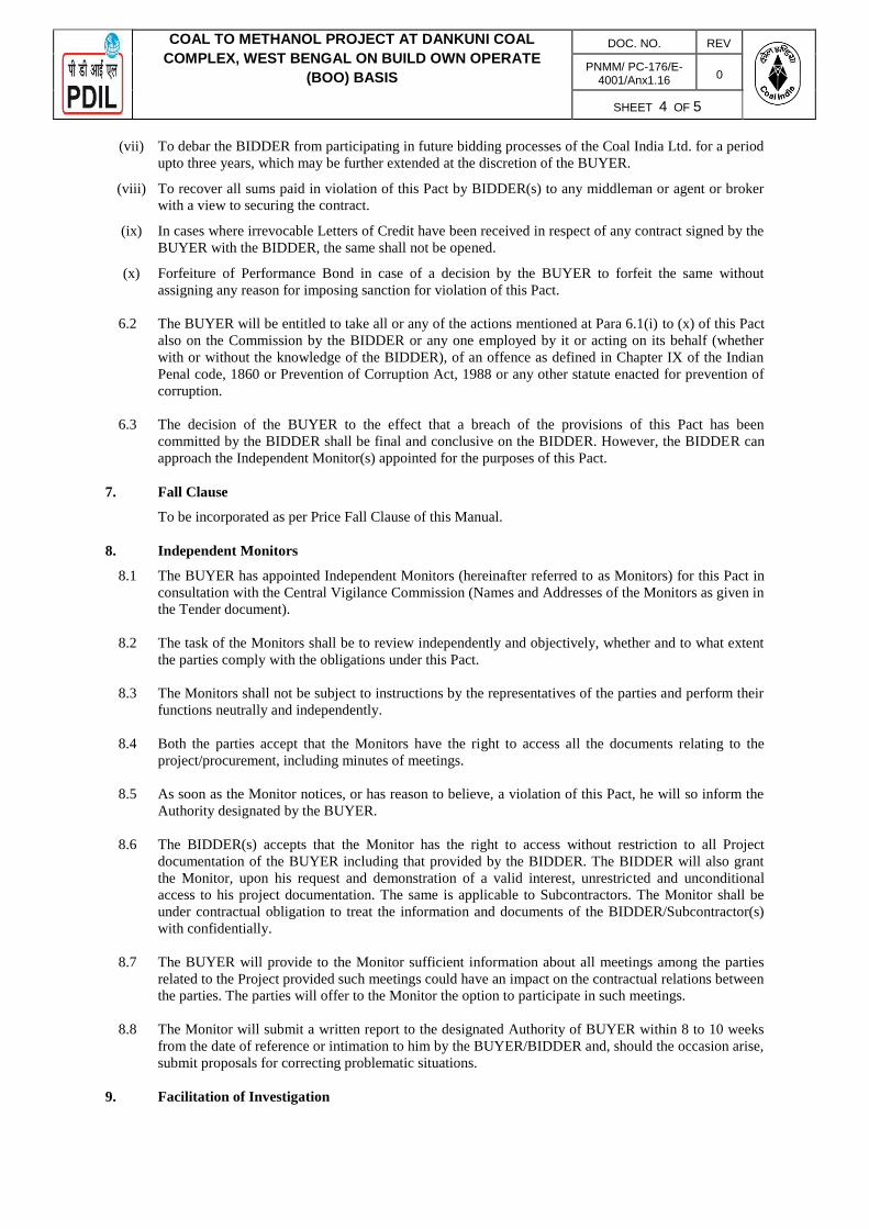
COAL TO METHANOL PROJECT AT DANKUNI COAL
COMPLEX, WEST BENGAL ON BUILD OWN OPERATE
(BOO) BASIS
DOC. NO. REV
PNMM/ PC-176/E-4001/Anx1.16
0
SHEET 4 OF 5
(vii) To debar the BIDDER from participating in future bidding processes of the Coal India Ltd. for a period
upto three years, which may be further extended at the discretion of the BUYER.
(viii) To recover all sums paid in violation of this Pact by BIDDER(s) to any middleman or agent or broker
with a view to securing the contract.
(ix) In cases where irrevocable Letters of Credit have been received in respect of any contract signed by the
BUYER with the BIDDER, the same shall not be opened.
(x) Forfeiture of Performance Bond in case of a decision by the BUYER to forfeit the same without
assigning any reason for imposing sanction for violation of this Pact.
6.2 The BUYER will be entitled to take all or any of the actions mentioned at Para 6.1(i) to (x) of this Pact
also on the Commission by the BIDDER or any one employed by it or acting on its behalf (whether
with or without the knowledge of the BIDDER), of an offence as defined in Chapter IX of the Indian
Penal code, 1860 or Prevention of Corruption Act, 1988 or any other statute enacted for prevention of
corruption.
6.3 The decision of the BUYER to the effect that a breach of the provisions of this Pact has been
committed by the BIDDER shall be final and conclusive on the BIDDER. However, the BIDDER can
approach the Independent Monitor(s) appointed for the purposes of this Pact.
7. Fall Clause
To be incorporated as per Price Fall Clause of this Manual.
8. Independent Monitors
8.1 The BUYER has appointed Independent Monitors (hereinafter referred to as Monitors) for this Pact in
consultation with the Central Vigilance Commission (Names and Addresses of the Monitors as given in
the Tender document).
8.2 The task of the Monitors shall be to review independently and objectively, whether and to what extent
the parties comply with the obligations under this Pact.
8.3 The Monitors shall not be subject to instructions by the representatives of the parties and perform their
functions neutrally and independently.
8.4 Both the parties accept that the Monitors have the right to access all the documents relating to the
project/procurement, including minutes of meetings.
8.5 As soon as the Monitor notices, or has reason to believe, a violation of this Pact, he will so inform the
Authority designated by the BUYER.
8.6 The BIDDER(s) accepts that the Monitor has the right to access without restriction to all Project
documentation of the BUYER including that provided by the BIDDER. The BIDDER will also grant
the Monitor, upon his request and demonstration of a valid interest, unrestricted and unconditional
access to his project documentation. The same is applicable to Subcontractors. The Monitor shall be
under contractual obligation to treat the information and documents of the BIDDER/Subcontractor(s)
with confidentially.
8.7 The BUYER will provide to the Monitor sufficient information about all meetings among the parties
related to the Project provided such meetings could have an impact on the contractual relations between
the parties. The parties will offer to the Monitor the option to participate in such meetings.
8.8 The Monitor will submit a written report to the designated Authority of BUYER within 8 to 10 weeks
from the date of reference or intimation to him by the BUYER/BIDDER and, should the occasion arise,
submit proposals for correcting problematic situations.
9. Facilitation of Investigation

COAL TO METHANOL PROJECT AT DANKUNI COAL
COMPLEX, WEST BENGAL ON BUILD OWN OPERATE
(BOO) BASIS
DOC. NO. REV
PNMM/ PC-176/E-4001/Anx1.16
0
SHEET 5 OF 5
In case of any allegation of violation of any provisions of this Pact or payment of commission, the
BUYER or its agencies shall be entitled to examine all the documents including the Books of Accounts
of the BIDDER and the BIDDER shall provide necessary information and documents in English and
shall extend all possible help for the purpose of such examination.
10. Law and Place of Jurisdiction
This Pact is subject to Indian Law. The place of performance and jurisdiction is the seat of the
BUYER.
11. Other Legal Actions.
The actions stipulated in this Integrity Pact are without prejudice to any other legal action that may
follow in accordance with the provisions of the extant law in force relating to any civil or criminal
proceedings.
12. Validity
12.1 The validity of this Integrity Pact shall be from date of signing the IP and extend till complete
execution of the contract to the satisfaction of both the BUYER and the BIDDER/Seller. Issues like
warranty/ guarantee shall be outside the purview of IEMs. In case, BIDDER is unsuccessful, this
Integrity Pact shall expire after six months from the date of the signing of the contract.
12.2 Should one or several provisions of this Pact turn out to be invalid, the remainder of this Pact shall
remain valid. In this case, the parties will strive to come to an agreement to their original intentions.
13. The parties hereby sign this Integrity Pact at………………………on…………..
For the BUYER For the BIDDER
Name of the Officer………. Name of the Officer……
Designation……… Designation…………………
Coal India Limited Name of the company…….
Witness:- Witness:-
1 .Name ………………… 1. Name …………………………
Designation……….. Designation………………..
Name of the company……. Name of the company…….
2. Name ………………. 2. Name………………………..
Designation…………… Designation………………..
Name of the company……. Name of the company…….
*In case of non-applicability of this clause, the bidder will mention “not applicable”.

COAL TO METHANOL PROJECT AT DANKUNI COAL COMPLEX, WEST BENGAL ON BUILD OWN OPERATE
(BOO) BASIS
DOC. NO. REV
PNMM/ PC-176/E-4001/Anx1.17
0
SHEET 1 OF 4
Annexure-1.17
PROFORMA OF "BANK GUARANTEE"
FOR "EARNEST MONEY / BID SECURITY" (To be stamped in accordance with the Stamp Act)
To,
M/s COAL INDIA LIMITED, Coal Bhawan, Action Area-1A, New Town, Kolkata - 700 156 (W.B.)
Bank Guarantee No.
Date of BG
BG Valid up to
Claim period up to (There should be three months gap between expiry date of BG & Claim period)
Stamp Sl. No. / e-Stamp Certificate No.
Dear Sir(s), In accordance with Letter Inviting Tender under your reference No __________________ M/s. ________________ having their Registered / Head Office at _____________ (hereinafter called the Tenderer), wish to participate in the said tender for ___________________________________________________________ As an irrevocable Bank Guarantee against Earnest Money for the amount of ______________ is required to be submitted by the Tenderer as a condition precedent for participation in the said tender which amount is liable to be forfeited on the happening of any contingencies mentioned in the Tender Document. We, the ____________________________________ Bank at _____________________________having our Head Office ________________________________________________________ (Local Address) guarantee and undertake to pay immediately on demand without any recourse to the tenderers by Coal India Limited (CIL), the amount ________________ ____________________ without any reservation, protest, demur and recourse. Any such demand made by CIL, shall be conclusive and binding on us irrespective of any dispute or difference raised by the Tenderer. This guarantee shall be irrevocable and shall remain valid up to ____________ [this date should be Nine (09) months beyond the validity of the bid].If any further extension of this guarantee is required, the same shall be extended to such required period on receiving instructions from M/s. ____________________________________________ whose behalf this guarantee is issued.

COAL TO METHANOL PROJECT AT DANKUNI COAL COMPLEX, WEST BENGAL ON BUILD OWN OPERATE
(BOO) BASIS
DOC. NO. REV
PNMM/ PC-176/E-4001/Anx1.17
0
SHEET 2 OF 4
In witness whereof the Bank, through its authorized officer, has set its hand and stamp on this ___________day of ____________ 20__ at ____________. Notwithstanding anything contained herein: a) The Bank’s liability under this Guarantee shall not exceed (currency in
figures)___________________ (currency in words only)___________________ b) This Guarantee shall remain in force upto ___________ (this expiry date of
BG should be Nine months beyond the validity of bid) and any extension(s) thereof; and
c) The Bank shall be released and discharged from all liability under this Guarantee unless a written claim or demand is issued to the Bank on or before the midnight of ………………….(indicate date of expiry of claim period which includes minimum three months from the expiry of this Bank Guarantee) and if extended, the date of expiry of the last extension of this Guarantee. If a claim has been received by us within the said date, all the rights of CIL under this Guarantee shall be valid and shall not cease until we have satisfied that claim.
WITNESS: (SIGNATURE) (SIGNATURE) (NAME) (NAME) Designation with Bank Stamp (OFFICIAL ADDRESS) Attorney as per
Power of Attorney No. ________ Date: ________________________ -------------------------------------------------------------------------------------------------------- INSTRUCTIONS FOR FURNISHING "BID SECURITY / EARNEST MONEY" BY "BANK GUARANTEE"
1. The Bank Guarantee by Bidders will be given on non-judicial stamp paper as
per "Stamp Duty" applicable. The non-judicial stamp paper should be in the name of the issuing Bank. In case of foreign Bank, the said Bank's Guarantee to be issued by its correspondent Bank in India on requisite non-judicial stamp paper.
2. The expiry date should be arrived at in accordance with "ITB: Clause-15.1". 3. The Bank Guarantee by bidders will be given from Bank as specified in "ITB". 4. A letter from the issuing Bank of the requisite Bank Guarantee confirming that
said Bank Guarantee / all future communication relating to the Bank Guarantee shall be forwarded to the Employer at its address as mentioned at "ITB".

COAL TO METHANOL PROJECT AT DANKUNI COAL COMPLEX, WEST BENGAL ON BUILD OWN OPERATE
(BOO) BASIS
DOC. NO. REV
PNMM/ PC-176/E-4001/Anx1.17
0
SHEET 3 OF 4
5. Bidders must indicate the full postal address of the Bank along with the Bank's
E-mail / Phone from where the Earnest Money Bond has been issued. 6. If a Bank Guarantee is issued by a commercial Bank, then a letter to
Employer confirming its net worth is more than Rs. 1,000,000,000.00 [Rupees One Hundred Crores] or equivalent along with documentary evidence.
.

COAL TO METHANOL PROJECT AT DANKUNI COAL COMPLEX, WEST BENGAL ON BUILD OWN OPERATE
(BOO) BASIS
DOC. NO. REV
PNMM/ PC-176/E-4001/Anx1.17
0
SHEET 4 OF 4
Annexure-1.17 (A)
MATTER TO BE MENTIONED IN COVERING LETTER TO BE SUBMITTED BY
VENDOR ALONG WITH BANK GUARANTEE (BG)
1. Bank Guarantee No.
2. Vendor Name
3. Nature of Bank Guarantee [Please Tick () whichever is applicable]
Contract Performance Security (CPS)
Earnest Money Deposit (EMD)
Advance
4. Purchase Order (PO) / Fax of Acceptance (FOA) / Detailed Letter of Acceptance (DLOA) No.
5. Details of Bank issuing Bank Guarantee (BG) (A) Name of Contact Person
(B) E-mail ID
(C) Address
(D) Phone No. / Mobile No.

COAL TO METHANOL PROJECT AT DANKUNI COAL COMPLEX, WEST BENGAL ON BUILD OWN OPERATE
(BOO) BASIS
DOC. NO. REV
PNMM/ PC-176/E-4001/Anx1.18
0
SHEET 1 OF 2
Annexure-1.18
Security Deposit Bank Guarantee Format
……….……..………………………… (name & address of the Purchaser ………………………………………… Company)
Re : Bank Guarantee in respect of Agreement dated ................ Day of …… 20 ……………between…. ……………………(Name of Purchaser Company) and………. (Name of Supplier Company)
Messers .................................. a Company / Firm having its office at No. ................................................... hereinafter called the Contractor has entered into an agreement dated .................... (hereinafter called ‘the said agreement’) with ……………………… (Name of the Purchaser Company) hereinafter called (‘the Company’) to supply……………. stores/materials amounting to Rs. …………on the terms and conditions contained in the said agreement.
It has been agreed that ................................... (......... percent) payment of the value of the stores/materials will be made to the Contractor in terms of the said agreement on the contractors furnishing to the company a bank guarantee for the sum of Rs.............................as security for due repayment of the said sum in terms of the said agreement, and also interest as therein provided.
The ...................... (Name of the Bank) having its Office at ............................... has a the request of the Contract or agreed to give the guarantee as herein after contained.
We ......................................... (Name of the Bank) (hereinafter called 'the Bank’) do hereby unconditionally agree with the Company that if the Contractor shall in any way fail to observe or perform the terms and condition o f the said agreement regarding repayment o f the said sum of Rs ……………………..or any of them including the term for payment of interest for delay in deliveries or shall commit any breach of its obligations there under, the Bank shall on demand and without any objection or demur pay to the Company the said sum of Rs ………. or such portion as shall then remain unpaid with interest without requiring the company to have recourse to any legal remedy that may be available to it to compel the Bank to pay the same, or calling on the company to compel such payment by the contractor.
Any such demand shall be conclusive as regards the liability of the Contractor to the company and as regards the amount payable by the Bank under this guarantee. The Bank shall not be entitled to withhold, payment on the ground that the contractor has disputed its liability to pay or has disputed the quantum of the amount or that any arbitration proceeding or legal proceeding is pending between the Company and the contractor regarding the claim.
We, the Bank- further agree that the guarantee shall come into force from the date hereof and shall remain in full force and effect till the period that will be taken for the performance of the said agreement which is likely to be the …. day of ….. but if the period of agreement is extended either pursuant to the provisions in the said agreement or by mutual agreement between the contractor and the Company the Bank shall renew the period of the guarantee failing which it shall pay to the Company the said sum of Rs……………. or such lesser amount out of the said sum of Rs……….. as may be due

COAL TO METHANOL PROJECT AT DANKUNI COAL COMPLEX, WEST BENGAL ON BUILD OWN OPERATE
(BOO) BASIS
DOC. NO. REV
PNMM/ PC-176/E-4001/Anx1.18
0
SHEET 2 OF 2
to the Company and as the Company may demand. This guarantee shall remain in force until the dues of the Company in respect of the said sum of Rs……………… and interest are fully satisfied and the company certifies that the agreement regarding re-payment of the said sum of Rs............. has been fully carried out by the contractor and discharges the guarantee,.
The Bank further agrees with the Company that the Company shall have the fullest liberty without the consent of the Bank and without affecting in any way the obligations hereunder to vary any of the terms and conditions of the said agreement or to extend the time for performance of the said agreement from time to time or to postpone for any time or from time to time any of the powers exercisable by the Company against the contractor and to forbear to enforce any of the terms and conditions relating to the said agreement and the Bank shall not be relieved from its liability by reason of such failure or extension being granted to the contractor or through any forbearance, act or omission on the part of the Company or any indulgence by the Company to the contractor or any other matter or thing whatsoever which under the law relating to sureties would butfor this provisions have the effect of relieving or discharging the Guarantor.
The Bank further agrees that in case this guarantee is required for a longer period and it is not extended by the Bank beyond the period specified above the Bank shall pay to the Company the said sum of Rs……… or such lesser sum as may then be due to the Company out of the said advance of Rs……… and as the Company may require. Notwithstanding anything herein contained the liability of the Bank under this guarantee is restricted to Rs…….. only. The guarantee shall remain in force till the ………. day of …………..and unless the guarantee is renewed or a claim is preferred against the Bank within 3 months from the said date all rights of the company under this guarantee shall cease and the Bank shall be released and discharged from all liability hereunder except as provided in the preceding clause.
The Bank has under its constitution power to give this guarantee and ..……... (Name of the person) who has signed it on behalf of the Bank has authority to do so.
The details of beneficiary bank for sending details of BG under SFMS Platform is furnished below
Name of the Bank: - ………..
Branch: - …………. IFSC: - ………….. A/c No: - …………
Customer ID : ……….
Dated this ……………. Day of ………………..20… Place ………………………………….. Signature of the authorized person For and on behalf of the Bank

COAL TO METHANOL PROJECT AT DANKUNI COAL COMPLEX, WEST BENGAL ON BUILD OWN OPERATE
(BOO) BASIS
DOC. NO. REV
PNMM/ PC-176/E-4001/Anx1.19
0
SHEET 1 OF 1
Annexure-1.19
LIST OF CIL APPROVED BANKS
The Performance Guarantee shall be in the form of a Bank Guarantee issued by a RBI scheduled bank in India in the prescribed format on a non-judicial stamp paper.
The PBG will be submitted through Structured Financial Management System (SFMS) as per following procedure:
a) The Issuing bank will receive application for BG along with the details of the bank of the beneficiary/ an Advising Bank for the Bank Guarantee
b) The issuing bank will issue the BG on SFMS Platform. The message will be sent to the Beneficiary’s bank/ Advising Bank through SFMS.
c) A hard copy of the Bank Guarantee marked as “COPY ONLY” may be handed over to the applicant for submission to the Purchaser.
d) The Beneficiary’s bank / Advising Bank receives the SFMS and print the BG on stamp paper with required value and deliver to the Beneficiaries and claim for reimbursement of the cost incurred from issuing bank.

COAL TO METHANOL PROJECT AT DANKUNI
COAL COMPLEX, WEST BENGAL ON BUILD OWN OPERATE (BOO) BASIS
PNMM/PC-176/E-4001/Annx-1.20 0
DOC. NO. REV.
SHEET 1 OF 5
All rights reserved
DRAFT FOR CONDITIONS OF AGREEMENT
CONDITIONS OF AGREEMENT
This Contract Agreement (hereinafter referred to as the “Contract Agreement”) is, made and entered into on the _______________ day of ___________2020 between: 1. Coal India Limited, a company incorporated in India under the provisions of the Companies
Act, 1956 and having its registered office at Coal Bhawan, Premises No. 04-MAR, Plot-AF-III, Action Area-1a, New Town, Rajarhat, Kolkata-700156 (hereinafter referred to as the "Owner", which expression shall, unless repugnant to the context or meaning thereof, include its successors and assigns), of One Part1 ;
AND 2. [●], a company incorporated in India under the provisions of the Companies Act, 1956/ 2013
and having its registered office at [●], (hereinafter referred to as the "BOO Operator", which expression shall, unless repugnant to the context or meaning thereof; include its successors, administrators, executors and permitted assigns) of the Other Part.
WI T N E S S E T H:
WHEREAS A. Owner has decided to diversify into a new “Coal to Chemical” business domain by
converting the high calorific value, low ash thermal coal into synthesis gas (CO+H2) and downstream chemicals and accordingly, intends to set up a Coal to Methanol Complex on Build Own Operate (BOO) basis. In pursuit of implementing this new strategy, the premises of the existing Dankuni Coal Complex (DCC) have been identified as the geo- strategic location for setting up a Coal to Methanol Complex on Build Own Operate basis (BOO) by using the good quality Indian coal from Raniganj coalfields.
B. In order to meet the requirement of Methanol, Owner issued Tender No.--------------------
---- for supply of Methanol at Dankuni Coal Complex (DCC), West Bengal (India) ON BUILD-OWN-OPERATE (BOO) Basis (hereinafter referred to as the “Tender”) for the Construction, Commissioning and thereafter, for Operating and Maintaining a new Methanol Plant referred to as “Production Plant” and which is more specifically defined in the Tender) in a designated plot ), within the premises of Dankuni Coal Comple (DCC).
B During the course of tendering process, ---------- its bid and on acceptance-----------
awarded Letter of Award No.------------dated ------------------------ and subsequent Detailed letter of Acceptance No. dated to
C The BOO Operator agrees to Build, Own, Operate and Maintain the "Production Plants"
with all brand new equipment, items, accessories and auxiliaries, designed and capable of steadily operating, by making its own investment, for the production of Methanol as Product to meet Owner’s requirements to be set up on the land allocated to by Owner under lease for use from which ------------- will supply Methanol to Owner.

COAL TO METHANOL PROJECT AT DANKUNI
COAL COMPLEX, WEST BENGAL ON BUILD OWN OPERATE (BOO) BASIS
PNMM/PC-176/E-4001/Annx-1.20 0
DOC. NO. REV.
SHEET 2 OF 5
All rights reserved
D The BOO Operator is having requisite experience and competence in the business, inter-alia
of, production and supply of Methanol and intends to produce and supply Methanol of specified parameters on continuous, reliable and long term basis by building, owning, operating and maintaining the Methanol Plant (hereinafter referred to as Production Plant) located inside the Dankuni Coal Complex of Owner.
E The BOO Operator has presently satisfied itself to the Project site conditions and has
acquainted itself in general with all local conditions and all its responsibilities for compliance to applicable laws and regulations and has obtained all other information on its own both as to risk, contingencies & other circumstances which may influence or affect the work and other requisites for proper installation, operation and maintenance of the Production Plant after due inspection of site and surrounding and scrutiny of other related factors.
NOW, THEREFORE, in consideration of the foregoing and the mutual promises contained herein, Owner and ----------------- intending to be legally bound, hereby agree as follows:
ARTICLE 1
CONTRACT DOCUMENT
1.1 The Contract Documents shall comprise thefollowing:
i. Contract Agreement ii. Land Lease Agreement iii. The Detailed Letter of Acceptance (DLOA) including Statement of Agreed Variations, if
any, and accepted Price-Schedule iv. The Notification of Award/Letter of Award. v. Amendments, if any, issued to the Bidding Documents. vi. Original Bidding Documents (including the Conditions to Contract) issued with its enclosures. vii. Integrity Pact (IP) signed between the Owner and the Bidder/BOO Operator.
ARTICLE 2
JURISDICTION & GOVERNING LAW
2.1.1 Notwithstanding any other court or courts, having jurisdiction to decide the question(s) forming the subject matter of the reference if the same had been the subject matter of a suit, any and all actions proceeding arising out or relative to the contract or any award arising there from, shall lie only in the Court of competent civil jurisdiction in this behalf at Kolkata (where this contract has been signed on behalf of Owner and only the said Court(s) shall have jurisdiction to entertain and try any such action(s) and/ or proceeding(s) to the exclusion of all other Courts.
2.1.2 This Contract Agreement shall be governed in all aspects by the law of the Republic of
India, without application of the doctrine of Renvoi.

COAL TO METHANOL PROJECT AT DANKUNI
COAL COMPLEX, WEST BENGAL ON BUILD OWN OPERATE (BOO) BASIS
PNMM/PC-176/E-4001/Annx-1.20 0
DOC. NO. REV.
SHEET 3 OF 5
All rights reserved
ARTICLE 3
ENTIRE CONTRACT
3.1 The Contract Documents mentioned in Article-1 hereof embody the entire agreement between the parties hereto, and the parties declare that in entering the Contract Documents they do not rely upon any previous representation, whether expressed or implied and whether written or oral, or any inducement, understanding or agreements of any kind not included within this Contract Agreement documents and all prior negotiations, representations, contracts and/or agreements and understandings are herebycancelled.
3.2 All additions, supplements, amendments or variations to this agreement shall be in writing
and shall be signed by the duly authorised representatives of Owner and BOO Operator.
ARTICLE 4
NOTICES
4.1 Subject to any provisions in the Contract Documents to the contrary, any notice, order or communication sought to be served by the BOO Operator on the Owner with reference to the Contract Agreement shall be deemed to have been sufficiently served uponthe Owner notwithstanding any enabling provisions under any law to the contrary, only if delivered by hand or by Courier to the Owner at the address mentioned in this Agreement.
4.2 Without prejudice to any other mode of service provided for in the Contract Documents or
otherwise available to the Owner, any notice order or other communication sought to be served by the Owner on the BOO Operator with reference to the Contract Agreement, shall be deemed to have been sufficiently served if delivered by hand or through Courier to the principal office of the BOO Operatorat ---------------------- (Lead Bidder in case of Consortium),or other address for service subsequently notified by -------to the Owner in this behalf in writing.
ARTICLE 5
WAIVER
5.1 No wavier by either Owner or BOO Operator of any default by the other in the performance of the Agreement (i) shall be effective unless recorded in a document duly executed by an authorised representative of such Party; (ii) shall operate or be constructed as a waiver or any other or further default whether of a similar or different character.
5.2 No failure or delay by Owner in enforcing any right or remedy of Ownerin terms of the
contract or any obligation or liability of the BOO Operator in terms thereof shall be deemed to be a waiver of such right, remedy, obligation, or liability, as the case may be, by Owner and notwithstanding such failure or delay, Owner shall be, entitled at any time to enforce such right, remedy, obligation or liability, as the case maybe.
5.3 No failure of delay by the BOO Operator in enforcing any right or remedy of the BOO
Operator in terms of the Agreement or any obligation or liability of Owner in terms thereof

COAL TO METHANOL PROJECT AT DANKUNI
COAL COMPLEX, WEST BENGAL ON BUILD OWN OPERATE (BOO) BASIS
PNMM/PC-176/E-4001/Annx-1.20 0
DOC. NO. REV.
SHEET 4 OF 5
All rights reserved
shall be deemed to be a waiver of such right, remedy, obligation, or liability, as the case may be, by the BOO Operator and notwithstanding such failure or delay, the BOO Operator shall be entitled at anytime to enforce such right, remedy, obligation or liability, as the case maybe.
5.4 The grant of additional time or order indulgence by one party to the other, or acceptance of
any variation in performance, shall not constitute awaiver.
ARTICLE 6
LANGUAGE OF CONTRACT AND COMMUNICATION
6.1 The language of the Contract Agreement shall be English and all communications, drawings, design, data, information, codes specifications and other document whatsoever supporting the bid or otherwise exchanged under the Contract Agreement shall be in English. In the event that any technical documentation is in any language other than English, the document should be translated and presented to the Owner in English and English document/ translated document shall be regarded as the only authenticdocument.
ARTICLE 7
GOVERNMENT OF INDIA NOT LIABLE
7.1 It is expressly understood and agreed by and between the BOO Operator and the Owner that the Owner is entering into this agreement solely on its own behalf and not on behalf of any other person or entity. In particular, it is expressly understood and agreed that the Government of India is not a party to this agreement and has no liabilities, obligations or rights there under. It is expressly understood and agreed that the Owner is an independent legal entity with power and authority to enter into contracts, solely in its behalf under the Applicable Laws, of India and general principles of contract law. The BOO Operator expressly agrees, acknowledges and understands that the Owner is not an agent, representative or delegate of the Government of India. It is further understood and agreed that the Government of India is not and shall not be liable for any acts, omissions, commissions, breaches or other wrongs arising out of the Contract Documents. Accordingly, BOO Operator hereby expressly waives, releases and foregoes any and all actions or claims, including cross claims, impleader claims or counter claims against the Government of India arising out of this Contract and covenants not to sue the Government of India on any matter, claim, cause of action or thing whatsoever arising out of or under thisContract Agreement.
ARTICLE 8
NON-ASSIGNABILITY
The contract and benefits and obligations thereof shall be strictly personal to the BOO Operator and Owner and shall not on any account be assignable or transferable tothird party by the BOO Operator or Owner without having obtained in writing the prior approval of Owner or BOO Operator.
ARTICLE 9

COAL TO METHANOL PROJECT AT DANKUNI
COAL COMPLEX, WEST BENGAL ON BUILD OWN OPERATE (BOO) BASIS
PNMM/PC-176/E-4001/Annx-1.20 0
DOC. NO. REV.
SHEET 5 OF 5
All rights reserved
NO LIABILITY ON DIRECTOR AND EMPLOYEE
No Director, employee, consultant or agent of the Owner or other person representing the Owner or acting on behalf of the Owner in or pursuant to the Contract Agreement or in the discharge of any obligation to the Owner under the Contract Documents or otherwise in relation to the Contract Agreement shall have any personal liabilitytothe or any Sub-Contractor,agent, representative, director or employeeofthe -------------------- or to any other person acting for oron behalf of the ----------- and the ----------- on its own behalf and on behalf of its Sub- Contactors, directors, employees, agents and representatives, hereby waives, and disclaims any and all right of action which it or they may have whether under tort or contract or otherwise against any director, employee, agent, consultant or representative of the Owner for act of omission or commission done or omitted to bedone.
ARTICLE 10
GENERAL
10.1 In this Contract Agreement, capitalized words and expressions used herein without having been defined, shall have the same meanings as are respectively assigned to them in the Conditions of Contract or the other Contract Documents, and they shall be deemed to form and be read and construed as part of this Contract Agreement.
IN WITNESS WHEREOF THE PARTIES hereto have executed this Contract Agreement in duplicate at the place, day and year first above written.
SIGNEDANDDELIVERED SIGNED AND DELIVERED For and onbehalf of For and on behalfof M/s-------------------- M/s-------------
BY BY
(THISDAYOF 2020)
IN THEPRESENCEOF: IN THE PRESENCEOF:
1. 1.
2. 2.
Person (s) authorised to sign.

All rights reserved
COAL TO METHANOL PROJECT AT DANKUNI COAL
COMPLEX, WEST BENGAL ON BUILD OWN OPERATE (BOO) BASIS
PNMM/PC176/ E-4001/Annx-
1.21
0
DOC. NO.
REV.
SHEET 1 OF 7
FORMAT OF LAND LEASE
LEASE DEED
(To be executed between CIL and BOO Operator)
THIS DEED OF Lease executed on this day of two thousand and between Coal India Limited, a
Government Company registered under the Indian Companies Act, 1956 and a, having its Registered
Office at 10, Netaji Subhas Road, Kolkata-700001, (hereinafter referred to as ‘CIL’ or ‘Lessor’ which
expression shall, unless it be repugnant to the context or meaning thereof, be deemed to mean and
include its successors and permitted assigns) on the one part, and
(Name of BOO Operator), a Body constituted under , (hereinafter referred
to as “” or ‘Lessee’ which expression shall, unless it be repugnant to the context of meaning thereof,
be deemed to mean and include its successors and permitted assigns) on the otherpart
WHEREAS
1. TheLessoristheabsoluteownerofthepieceoflandtotallymeasuring(SurveyNos.
Separately shown in the schedule)situated in Dankuni villageof
Taluka more particularly described in the schedule hereunder written hereafter
referred to as the Land to be leased out by the Lessor to theLessee.
2. In terms of an Agreement dated entered into between CIL and“ ”, CIL shall
provide on lease the presently required land based on the detailed engineering of the
plant/connected facilities being build, own and operate by“ ” subject to a
maximum of land admeasuring less than Acres, as is where is condition, near
At Dankuni.
3. In terms of the said Agreement, the Lessor has agreed to grant by way of lease to the Lessee in
respect of the said Land for a period of 25 years subject to the terms and conditions laid down
below w.e.f. .
NOW THIS DEED WITNESSETH that the Lessor does in consideration of the lease rent to be paid as
herein referred and other terms and conditions on the part of the Lessee to be observed, hereby grant to
the Lessee, a lease of ALL THAT piece of land containing by admeasurement

All rights reserved
COAL TO METHANOL PROJECT AT DANKUNI COAL
COMPLEX, WEST BENGAL ON BUILD OWN OPERATE (BOO) BASIS
PNMM/PC176/ E-4001/Annx-
1.21
0
DOC. NO.
REV.
SHEET 2 OF 7
less than Acres or thereabouts, situated at Dankuni more particularly described in the Schedule
hereunder written and for greater clarity delineated with the boundaries thereof on the Plan annexed (Plan
No. dated) hereto TO HOLD the same for the term of LESS THAN TWENTY FIVE (25) YEARS from
(hereinafter referred to as the “said term”) subject to the following conditions:-
1. The Lessor has agreed to provide the property described in the schedule hereunder on lease for a
period of 25 years with an option to renew the lease for a further period on mutual consent and on
executing a fresh deed to the Lessee on a nominal rent of Re. 1/- (Rupee ONE) per Acre per
Annum and the Lessor hereby grant and express permission to the Lessee to build, own and
operate plant for production Methanol and Sulphur (By- product) at their cost and expenditure in
the said property.
2. The Lessee shall pay to the Lessor during the said terms as yearly lease rent at a fixed rate of
Rs......../- (Rupees ..............) per Acre per Annum only alongwith applicable statutory levies
(hereinafter referred to as the “said lease rent”) for the entire term of less than Twenty Five (25)
years. The Lessee shall pay the Lessor the Lease rent on an yearly basis on or before March of
previous year.
3. The Lessee shall use the said land for construction of Plant premises to build, own and operate
and other structures on the property described in Schedule at their cost for the purpose as
provided in the said Agreement, unless otherwise agreed to by the Lessor in writing. The
construction shall be according to and in conformity with the plans which has already been
sanctioned by the appropriate authorities. The development and other protective measures for the
said land shall be on the Lessee’s account.
4. The Lessee shall have the liberty to use the said land for purposes connected with its trade or
business. The land shall be used by the BOO Operator/ Lessee for installation, commissioning and
operation of Coal to Methanol Plant.
5. The Lessee hereby agrees that the Lessor still holds the ownership of the said property and shall
have rights to access their other properties through the pathway which will be used by both parties.
Similarly, the Lessor shall use the pathways, approach roads only to access the Plant proposed to
be constructed and structures thereon freely without distance by the Lessor.
6. The Lessor shall not be responsible to the Lessee or any other person(s) for any loss or
damageorinjurytolifeorpropertyarisingdirectlyorindirectlyfromtheuseofthesaid
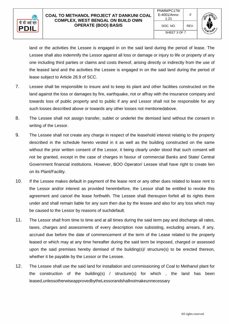
All rights reserved
COAL TO METHANOL PROJECT AT DANKUNI COAL
COMPLEX, WEST BENGAL ON BUILD OWN OPERATE (BOO) BASIS
PNMM/PC176/ E-4001/Annx-
1.21
0
DOC. NO.
REV.
SHEET 3 OF 7
land or the activities the Lessee is engaged in on the said land during the period of lease. The
Lessee shall also indemnify the Lessor against all loss or damage or injury to life or property of any
one including third parties or claims and costs thereof, arising directly or indirectly from the use of
the leased land and the activities the Lessee is engaged in on the said land during the period of
lease subject to Article 28.9 of SCC.
7. Lessee shall be responsible to insure and to keep its plant and other facilities constructed on the
land against the loss or damages by fire, earthquake, riot or affray with the insurance company and
towards loss of public property and to public if any and Lessor shall not be responsible for any
such losses described above or towards any other losses not mentionedabove.
8. The Lessee shall not assign transfer, sublet or underlet the demised land without the consent in
writing of the Lessor.
9. The Lessee shall not create any charge in respect of the leasehold interest relating to the property
described in the schedule hereto vested in it as well as the building constructed on the same
without the prior written consent of the Lessor, it being clearly under stood that such consent will
not be granted, except in the case of charges in favour of commercial Banks and State/ Central
Government financial institutions. However, BOO Operator/ Lessee shall have right to create lien
on its Plant/Facility.
10. If the Lessee makes default in payment of the lease rent or any other dues related to lease rent to
the Lessor and/or interest as provided hereinbefore, the Lessor shall be entitled to revoke this
agreement and cancel the lease forthwith. The Lessee shall thereupon forfeit all its rights there
under and shall remain liable for any sum then due by the lessee and also for any loss which may
be caused to the Lessor by reasons of suchdefault.
11. The Lessor shall from time to time and at all times during the said term pay and discharge all rates,
taxes, charges and assessments of every description now subsisting, excluding arrears, if any,
accrued due before the date of commencement of the term of the Lease related to the property
leased or which may at any time hereafter during the said term be imposed, charged or assessed
upon the said premises hereby demised of the building(s)/ structure(s) to be erected thereon,
whether it be payable by the Lessor or the Lessee.
12. The Lessee shall use the said land for installation and commissioning of Coal to Methanol plant for
the construction of the building(s) / structure(s) for which , the land has been
leased,unlessotherwiseapprovedbytheLessorandshallnotmakeunnecessary

COAL TO METHANOL PROJECT AT DANKUNI COAL
COMPLEX, WEST BENGAL ON BUILD OWN OPERATE (BOO) BASIS
PNMM/PC176/E-4001/Annx-
1.21 0
DOC. NO. REV.
SHEET 4 OF 7
All rights reserved
excavation or remove or appropriate any minerals, mineral substances of any description,
sand or clay, from the said land. Any such materials obtained from the site should be
placed or disposed of as directed by the Lessor or its authorized representative.
13. It is made clear that the Lessee should utilise the maximum permissible area of the land
leased for the construction of Plant as per the agreement and the Lessor reserves the right
to re-possess without any claim to compensation whatsoever, the whole or part of the
portion left un-utilised and use the same in any manner deemed expedient by the Lessor. In
case, there is any dispute regarding the extent of land that should be utilized for the
construction or the extent to be re-possessed, the decision of the Lessor shall be final and
binding.
14. The lessee shall erect or construct any building/ structures for installation and
commissioning of Coal to Methanol Plant. However, the Lessee shall not at any time
without the previous consent in writing of the Lessor erect or suffer to be erected on the
said land any building(s)/ structure(s) nor permit the same to be used for any purpose other
than that specified above. In case, Lessee fails to do so the lease shall be liable for
termination.
15. The Lessee shall at all times during the subsistence of the lease maintain the premises in
good sanitary condition and repair and keep the building(s)/ structure(s) erected and/or to
be erected on the said land in good and tenantable condition.
16. Hoarding or advertisement boards shall not be erected in the leased premises by the
Lessee without the written permission of the Lessor. However, BOO Operator can put its
sign board/ nameplate capacity of the facilty.
17. The Lessor hereby agrees that the Lessee observing all the aforesaid conditions, shall
peacefully hold and enjoy the said land during the said term without any interruption by the
Lessor or any one claiming under the Lessor, provided that upon any breach or non-
observance by the Lessee or by a person claiming through or under the Lessee of any of
the aforesaid covenants or conditions the Lessor may notwithstanding the waiver of any
previous cause or right of re-entry enter upon the said premises and re-possess it, as if this
lease had not been granted and thereupon this demise shall absolutely determine and the
Lessee shall be entitled within 3 (three) months from the date of such re-entry to
removeallbuildingandfixtureswhichatanytimeduringthecurrencyofthisleaseshallhave been
erected for affixed by the Lessee upon the said land without any claim to any compensation
whatsoever.

COAL TO METHANOL PROJECT AT DANKUNI COAL
COMPLEX, WEST BENGAL ON BUILD OWN OPERATE (BOO) BASIS
PNMM/PC176/E-4001/Annx-
1.21 0
DOC. NO. REV.
SHEET 5 OF 7
All rights reserved
18. It is also distinctly agreed that the Lessee shall deliver up the demised premises at the
expiration or sooner determination of tenancy restored to its former condition.
19. The Lessor shall be entitled to allow any public utility services such as electric posts, or
cables, water supply sewer lines, drains, sanitary lines or telegraph post or cables, to be
taken through the said land and the Lessee shall not be entitled to any compensation in
respect of the same including compensation, if any, relating to the space occupied by such
public utility services to be taken through the said land, only the minimum possible
hindrance shall be caused to other structures in the said land.
20. It is further agreed that if the Lessee does not remove the building and fixtures as allowed
above, or restore the demised premises to its original condition as required above within
the time prescribed in the said clauses, the Lessor shall have the right to remove the said
building and fixtures and restore the demised premises to its original condition and the cost
of such removal and restoration shall be realized by the Lessor by the sale of materials
recovered and the balance if any from the Lessee. In case, there is any amount left from
the sale price of the materials so removed, after realization of the cost of removal and
restoration preferred to herein, the same may be utilized by the Lessor for recovery of any
other amounts that may be due to the Lessor from the Lessee.
21. Notwithstanding anything contained hereinbefore, it is expressly agreed and understood
that the Lessor shall be entitled to terminate the lease at the risk and cost of the lessee in
the event of violation of any of the provisions hereof by the lessee which is not rectified with
in a period of 90 (ninety) days of receipt of a notice issued in this behalf by the Lessor.
22. The Lessor shall sign necessary papers and application forms for getting plan sanction or
for granting permission / rights for enabling the Lessee to build, own and operate the Plant.
23. The Lessee shall not use the property for construction of any structures not associated with
the construction of the Plant without prior consent of the Lessor.
24. The Lessor is absolutely seized and possessed or otherwise well and sufficiently entitled to
the demised property and is having full power and absolute authority to demand up to the
Lessee the demised property.
25. The Lease Deedshall be executed induplicate. The original shall be retained by
the Lessor and the duplicate by the Lessee.
26. The stamp duty and all other expenses in respect of this Lease Deed and duplicate thereof
shall be borne and paid by the Lessee.
27. In respect of the terms and conditions not specifically mentioned herein the Lessor and

COAL TO METHANOL PROJECT AT DANKUNI COAL
COMPLEX, WEST BENGAL ON BUILD OWN OPERATE (BOO) BASIS
PNMM/PC176/E-4001/Annx-
1.21 0
DOC. NO. REV.
SHEET 6 OF 7
All rights reserved
Lessee shall mutually decide and agree in writing.
SCHEDULE OF PROPERTY LEASED OUT TO THE LESSEE BY THE LESSOR
District :
Sub District :
Taluk :
Firka :
Panchayat :
Village :
Kara :
Tenure :
Survey
No.
Sub
Division
:
Extent in Ares :
In Cents :
DESCRIPTION
Allthatpiecesandparcelsoflandadmeasuringto cents (ares) madeup of
(ares) in Sy No. ()cents (----ares) in Sy.No. ()cents (ares) in Sy No.() owned by the Lessor with
the right of way through themetres wide pathway at the.
BOUNDARIES East :
Sough:
West:
North:

COAL TO METHANOL PROJECT AT DANKUNI COAL
COMPLEX, WEST BENGAL ON BUILD OWN OPERATE (BOO) BASIS
PNMM/PC176/E-4001/Annx-
1.21 0
DOC. NO. REV.
SHEET 7 OF 7
All rights reserved
IN WITNESS WHEREOF THE Lessor and the Lessee have their respective hands on the original
and a duplicate thereof the day and year first above writings in the presence of the following
witnesses :
Signed and delivered by within namedLessor
CIL BOO Operator
(Lessor) (Lessee)
Witness :
1. 1.
2. 2.

Page 1 of 4
COAL TO METHANOL PROJECT AT DANKUNI COAL COMPLEX, WEST BENGAL ON BUILD OWN OPERATE (BOO) BASIS
DOC. NO. REV
PNMM/ PC-176/E- 4001/Anx1.22
0
Format for Financial Details of Holding Company
(Details pertaining to Financial Criteria as per Clause No. 2.3 of PQC)
Since we do not satisfy the Financial Criteria stipulated at Clause No. 2.3 of PQC on our own, we give below the following details of our Holding Company interms of Note ii & iii of Clause 2.3 of PQC of ITB who meet the stipulated turnover requirements of INR…...USD and whose Net Worth as on the last day of the preceding financial years is at least equal to or more than the paid up share capital of the Holding Company.
1. Name and Address of the Holding Company: M/s…………………………... 2. Annual Turnover of the Holding Company with followingdetails:
ANNUAL TURNOVER OF LAST 3 FINANCIAL YEARS OF THE HOLDING COMPANY: Year Amount (Currency) Year 1 (FY 2019-20 or Calendar year 2019)
Year 2 (FY 2018-19 or Calendar year 2018) Year 3 (FY 2017-18 or Calendar year 2017) Average Annual Turnover of the Holding Company for the preceding three (3) Financial Years as on date of Techno- Commercial Bid Opening
We have enclosed Audited Balance sheet and Profit and Loss Account (financial statements) for the last Three (3) financial years
Yes*/No*
Note: Other income shall not be considered for arriving at annual turnover.
(*) Bidder to strike-off whichever is not applicable
NET WORTH DETAILS OF THE HOLDING COMPANY : Sl. No.
Description As on last day of the preceding financial year
1. Paid-up Share Capital 2. Net Worth of the Holding Company 3. %age of Net worth to Paid-up
Share Capital of the Holding Company
4. Documentary evidence like Annual Report/Audited Balance sheet and Profit and Loss Account (financial statements) for the last preceding financial year
5. A Letter of Undertaking from the Holding Company, supported by Board Resolution, pledging unconditional and irrevocable financial support for execution of the Contract Agreement by the Bidder in case of award is enclosed as per the format at Appendix- A & B to this Attachment. A Power of Attorney of the person signing on behalf of Holding Company shall also be enclosed.
Note: Net worth means the sum total of the paid up share capital and free reserves. Free reserve means all reserves credited out of the profits and share premium account but does not include reserves credited out of the revaluation of the assets, write back of depreciation provision and amalgamation. Further any debit balance of Profit andLoss

COAL TO METHANOL PROJECT AT DANKUNI COAL COMPLEX, WEST BENGAL ON BUILD OWN OPERATE
(BOO) BASIS
DOC. NO. REV
PNMM/ PC-176/E-4001/Anx1.22
0
SHEET 2 OF 4
Page 2 of 4
account and miscellaneous expenses to the extent not adjusted or written off, if any, shall be reduced from reserves and surplus. We further confirm that notwithstanding anything stated above, the Employer reserves the right to assess the capabilities and capacity of the Bidder/subsidiaries/group companies/Holding company to perform the contract, should the circumstances warrant such assessment in the overall interest of the Employer.
[Signature of Authorized Signatory]
Name: Designation:
Seal: Date: Place:

COAL TO METHANOL PROJECT AT DANKUNI COAL COMPLEX, WEST BENGAL ON BUILD OWN OPERATE
(BOO) BASIS
DOC. NO. REV
PNMM/ PC-176/E-4001/Anx1.22
0
SHEET 3 OF 4
Page 3 of 4
APPENDIX-A
PROFORMA OF CERTIFICATE FROM THE CEO/CFO OF THE HOLDING COMPANY IN ACCORDANCE WITH CLAUSE NO. …. OF PQC
(To be submitted by Bidder alongwith the Techno-Commercial Bid)
Ref. : Date:
To,
M/s COAL INDIA LIMITED, Coal Bhawan, Action Area-1A, New Town, Kolkata - 700 156 (W.B.) Ref: Tender no. …………………….. Dear Sir,
1) I, M/s ……………..…….. (CEO of the company / CFO of the company) declare that
M/s …………………............. (Name of the Holding Company) is the
Holding Company of M/s ……………………........ (Name of the Bidder)
2) I hereby confirm and undertake that the unaudited unconsolidated
financial statements (Balance sheet and Profit & Loss Account) submitted in
respect of the bidder as part of the Bid Reference No... ...dated... ... have been
considered for the purposes of the finalisation of Consolidated financial
statements of the Holding Company (Balance sheet and Profit & Loss
Account)as part of the Annual Reports.
3) I further, certify that the figures in the unaudited unconsolidated financial
statements (Balance sheet and Profit & Loss Account) are true and correct and
same have been duly reflected in the audited consolidated financial statements
and/or Annual Report of the Holding Company.
Yours faithfully, (Signature) (Name & Designation) (Name of the Holding Company) (Seal of Holding Company)

COAL TO METHANOL PROJECT AT DANKUNI COAL COMPLEX, WEST BENGAL ON BUILD OWN OPERATE
(BOO) BASIS
DOC. NO. REV
PNMM/ PC-176/E-4001/Anx1.22
0
SHEET 4 OF 4
Page 4 of 4
APPENDIX-B
PROFORMA OF LETTER OF UNDERTAKING (TO BE FURNISHED ON NON-JUDICIAL STAMP PAPER OF APPROPRIATE VALUE)
[To be executed by the Holding Company Supported by Board Resolution and submitted by the Bidder alongwith the Techno-Commercial Bid, in case financial support is being extended by the Holding Company to the Bidder for meeting the stipulated Financial Qualifying Requirement as per Clause No. 2.3 of PQC]
Ref. : Date:
To, M/s COAL INDIA LIMITED, Coal Bhawan, Action Area-1A, New Town, Kolkata - 700 156 (W.B.) Dear Sir,
1) We, M/s (Name of the Holding Company) declare that we are the Holding Company
of M/s. (Name of the Bidder) and have controlling interest therein therein. M/s……………………………………. (Name of the Bidder) proposes to submit the bid for the
package …………………………. (Name of the package) for TFL under bid reference no... ..dated ................... and have sought financial strength and support from us for meeting the stipulated Financial Qualifying Requirement as per Clause 2.3 of PQC.
2) We hereby undertake & pledge our unconditional & irrevocable financial support for the
execution of Contract Agreement for the said package to M/s. …………………………… (Name of the Bidder), in case they are awarded the contract for the said package, at the end of the bidding process. We further agree that this undertaking shall be without prejudice to the various liabilities that M/s (Name of Bidder) would be required to undertake in terms of the Contract Documents including the Performance Security as well as other obligations of the Bidder/Contractor.
3) This undertaking is irrevocable and unconditional, and shall remain in force till the successful execution and performance of the entire contract and/or till it is discharged by CIL.
4) We are herewith enclosing a copy of the Board Resolution in support of this
undertaking. Yours faithfully,
(Signature of Authorised Signatory) on behalf of the Holding Company) (Name & Designation) (Name of the Holding Company) (Seal of Holding Company)
Witness : (1) (2)

COAL TO METHANOL PROJECT AT DANKUNI COAL COMPLEX, WEST BENGAL ON BUILD OWN OPERATE
(BOO) BASIS
DOC. NO. REV
PNMM/ PC-176/E-4001/Anx1.23
0
SHEET 1 OF 5
Annexure-1.23
CLAUSE REGARDINGPROVISION FOR PROCUREMENT FROM A BIDDER WHICH SHARES A LAND BORDER WITH INDIA
1. Order (Public Procurement No. 1) dated 23.07.2020, Order (Public
Procurement No.2) dated 23.07.2020 and Order (Public Procurement No. 3) dated 24.07.2020, Department of Expenditure, Ministry of Finance, Govt. of India refers. The same are available at website https://doe.gov.in/procurement-policy-divisions.
2. Any bidder from a country which shares a land border with India will be
eligible to bid in this tender only if the bidder is registered with the Competent Authority. For details of competent authority refer to Annexure I of Order (Public Procurement No. 1) dated 23.07.2020.
Further the above will not apply to bidders from those countries (even if sharing a land border with India) to which the Government of India has extended lines of credit or in which the Government of India is engaged in development projects. Updated lists of countries to which lines of credit have been extended or in which development projects are undertaken are given in the website of the Ministry of External Affairs, Govt. of India
3. "Bidder" (including the term 'tenderer', 'consultant' 'vendor' or 'service
provider' in certain contexts) for purpose of this provision means any person or firm or company, including any member of a consortium or joint venture (that is an association of several persons, or firms or companies), every artificial juridical person not falling in any of the descriptions of bidders stated hereinbefore, including any agency, branch or office controlled by such person, participating in a procurement process.
4. "Bidder from a country which shares a land border with India" for the
purpose of this:
a) An entity incorporated, established or registered in such a country; or b) A subsidiary of an entity incorporated, established or registered in such a
country; or c) An entity substantially controlled through entities incorporated, established or
registered in such a country; or d) An entity whose beneficial owner is situated in such a country; or e) An Indian (or other) agent of such an entity; or f) A natural person who is a citizen of such a country; or g) A consortium or joint venture where any member of the consortium or joint
venture falls under any of the above

COAL TO METHANOL PROJECT AT DANKUNI COAL COMPLEX, WEST BENGAL ON BUILD OWN OPERATE
(BOO) BASIS
DOC. NO. REV
PNMM/ PC-176/E-4001/Anx1.23
0
SHEET 2 OF 5
5. "Beneficial owner" for the purpose of above (4) will be as under:
· i) In case of a company or Limited Liability Partnership, the beneficial owner is
the natural person(s), who, whether acting alone or together, or through one or more juridical person(s), has a controlling ownership interest or who exercises control through other means. Explanation-
a) "Controlling ownership interest" means ownership of, or entitlement to,
more than twenty-five per cent of shares or capital or profits of the company;
b) "Control" shall include the right to appoint the majority of the directors or to control the management or policy decisions, including by virtue of their shareholding or management rights or shareholders agreements or voting agreements;
ii) In case of a partnership firm, the beneficial owner is the natural person(s) who, whether acting alone or together, or through one or more juridical
person, has ownership of entitlement to more than fifteen percent of capital or profits of the partnership;
iii) In case of an unincorporated association or body of individuals, the
beneficial owner is the natural person(s), who, whether acting alone or together, or through one or more juridical person, has ownership of or entitlement to more than fifteen percent of the property or capital or profits of such association or body of individuals;
iv) Where no natural person is identified under (i) or (ii) or (iii) above, the
beneficial owner is the relevant natural person who holds the position of senior managing official;
v) In case of a trust; the identification of beneficial owner(s) shall include
identification of the author of the trust, the trustee, the beneficiaries with fifteen percent or more interest in the trust and any other natural person exercising ultimate effective control over the trust through a chain of control or ownership.
6. "Agent" for the purpose of this Order is a person employed to do any act for
another, or to represent another in dealings with third persons 7. SUBMISSION OF CERTIFICATE IN BIDS:
Bidder shall submit a certificate in this regard as Form-1.

COAL TO METHANOL PROJECT AT DANKUNI COAL COMPLEX, WEST BENGAL ON BUILD OWN OPERATE
(BOO) BASIS
DOC. NO. REV
PNMM/ PC-176/E-4001/Anx1.23
0
SHEET 3 OF 5
If such certificate given by a bidder whose bid is accepted is found to be false, this would be a ground for immediate rejection of the bid/termination and further action as per "Procedure for Action in case of Corrupt/Fraudulent/ Collusive I Coercive Practices" of tender document.
8. The registration, wherever applicable, should be valid at the time of submission of bids
and at the time of acceptance of bids. In respect of supply otherwise than by tender, registration should be valid at the time of placement of order. If the bidder was validly registered at the time of acceptance I placement of order, registration shall not be a relevant consideration during contract execution.
9. PROVISION TO BE IN WORKS CONTRACTS, INCLUDING TURNKEY
CONTRACTS:
The successful bidder shall not be allowed to sub-contract works to any contractor from a country which shares a land border with India unless such contractor is registered with the Competent Authority. The definition of "contractor from a country which shares a land border with India" shall be as in Para 4 herein above. A Certificate to this regard is to be submitted by bidder is placed at Form-II

COAL TO METHANOL PROJECT AT DANKUNI COAL COMPLEX, WEST BENGAL ON BUILD OWN OPERATE
(BOO) BASIS
DOC. NO. REV
PNMM/ PC-176/E-4001/Anx1.23
0
SHEET 4 OF 5
Form-I of Annexure-1.23
UNDERTAKING ON LETTERHEAD
To, M/s COAL INDIA LIMITED, _____________________ SUB: TENDER NO: Dear Sir We have read the clause regarding Provisions for Procurement from a Bidder which shares a land border with India, we certify that, bidder M/s (Name of Bidder) is:
(i) Not from such a country [ ]
(ii) If from such a country, has been registered [ ] with the Competent Authority. (Evidence of valid registration by the Competent Authority shall be attached) (Bidder is to tick appropriate option (√ or X) above).
We hereby certify that bidder M/s (Name of Bidder) fulfills all requirements in this regard and is eligible to be considered against the tender.
Place: [Signature of Authorized Signatory of Bidder]
Name:
Date: Designation: Seal:

COAL TO METHANOL PROJECT AT DANKUNI COAL COMPLEX, WEST BENGAL ON BUILD OWN OPERATE
(BOO) BASIS
DOC. NO. REV
PNMM/ PC-176/E-4001/Anx1.23
0
SHEET 5 OF 5
Form-II of Annexure-1.23
CERTIFICATE FOR TENDERS FOR WORKS INVOLVING POSSIBILITY OF SUB-CONTRACTING
To, M/s COAL INDIA LIMITED _____________________ SUB: TENDER NO: Dear Sir We have read the clause regarding Provisions for Procurement from a Bidder of a country which shares a land border with India and on sub-contracting to contractors from such countries; we certify that, bidder M/s ______________ (Name of Bidder) is:
(i) not from such a country [ ]
(ii) if from such a country, has been registered [ ] with the Competent Authority. (Evidence of valid registration by the Competent Authority shall be attached)
(Bidder is to tick appropriate option (√ or X) above). We further certify that bidder M/s _________________ (Name of Bidder) will not sub-contract any work to a contractor from such countries unless such contractor is registered with the Competent Authority. We hereby certify that bidder M/s _____________ (Name of Bidder) Fulfills all requirements in this regard and is eligible to be considered. Place: [Signature of Authorized Signatory of Bidder]
Name:
Date: Designation: Seal:

COA
COAL TO MOWN-O
AL TO METCOMPLEX
O
METHANOLOPERATE (B
THANOL PRX, WEST BE
OPERATE (B
CO
L (C2M) PROBOO) BASIS
(TEN
PROJE
PD
ROJECT ATENGAL ON
BOO) BASIS
OAL INDIA L
TENDE(PART-I
FOR SE
OJECT THRS AT DANKU
NDER NO.:
PREPARE
ECTS & DEV(A Govt. O
DIL BHAWANOIDA-20
T DANKUNI BUILD OW, CIL
LIMITED, KO
ER DOCUMEII, TECHNIC
ETTING-UP
ROUGH COAUNI COAL C
PNMM/PC-
ED & ISSUE
VELOPMEN
Of India Ente
AN, A-14, SE1301 U.P. (I
COAL WN PNM
OLKATA
ENT CAL)
OF
AL GASIFICCOMPLEX W
176/E-4001)
ED BY
NT INDIA LTerprise)
ECTOR-1, INDIA).
DOC. NO.
MM/ PC-176/E-4
SHEET 1 O
CATION ROWEST BENG
)
TD.
REV
4001
0
OF 1
UTE ON BUGAL, INDIA
24.09.
UILD-A
2020

COAL TO METHANOL PROJECT AT DANKUNI
COAL COMPLEX, WEST BENGAL ON BUILD OWN OPERATE (BOO) BASIS
MASTER INDEX
PNMM/PC176/E-4001 0
DOC. NO. REV.
SHEET 1 OF 1
SUBJECT : COAL TO METHANOL (C2M) PROJECT THROUGH COAL GASIFICATION ROUTE ON
BUILD-OWN-OPERATE (BOO) BASIS AT DANKUNI COAL COMPLEX WEST BENGAL, INDIA (NIT NO: P PNMM/PC176/E-4001 DATED 24.09.2020)
Volume-II, TECHNICAL
SECTION NO. DESCRIPTION
GENERAL
SECTION 1.1 PROJECT DESCRIPTION
SECTION 1.2 SCOPE OF WORK
SECTION 1.3 PROJECT EXECUTION PLAN
SECTION 1.4 DESIGN BASIS
SECTION 1.5 RAW MATERIAL AND UTILITY SPECIFICATION
SECTION 1.6 PROCESS DESIGN GUIDELINES
ENGINEERING SPECIFICATIONS
SECTION 1.7 PRESSURE VESSELS
SECTION 1.8 MACHINERY
SECTION 1.9 PIPING
SECTION 1.10 ELECTRICAL
SECTION 1.11 INSTRUMENTATION
SECTION 1.12 CIVIL
SECTION 1.13 MATERIAL HANDLING
TECHNICAL REQUIREMENTS/DATA
SECTION 1.14 SAFETY,HEALTH & ENVIRONMENT
SECTION 1.15 QUALITY ASSURANCE PLAN
SECTION 1.16 DRAWINGS & DOCUMENTS
SECTION 1.17 TECHNICAL INFORMATION
SECTION 1.18 SPARE PARTS

PROJECTS & DEVELOPMENT INDIA LTD.
PC176/E/4001/P-II/ SEC-1.1 0
Document No. Rev
Sheet 1 OF 7
0 24.09.2020 24.09.2020 Issued for Tender Purpose SK SKK MN REV REV DATE EFF DATE PURPOSE PREPD REVWD APPD
FORM NO: 02-0000-0021F1 REV4 All rights reserved
VOLUME - II: TECHNICAL
SECTION - 1.1
PROJECT DESCRIPTION PLANT: INTEGRATED COAL BASED METHANOL
PLANT, AT DANKUNI, KOLKATA (INDIA) PROJECT: COAL TO METHANOL (C2M) PROJECT
THROUGH COAL GASIFICATION ROUTE ON BUILD-OWN-OPERATE (BOO) BASIS AT DANKUNI COAL COMPLEX WEST BENGAL, INDIA

PROJECT DESCRIPTION COAL GASIFICATION BASED METHANOL PLANT ON
BUILD-OWN-OPERATE (BOO) BASIS OWNER: COAL INIDA LIMITED
PC176/E/4001/P-II/ SEC-1.1 0
Document No. Rev
Sheet 2 OF 7
FORM NO: 02-0000-0021F1 REV3 All rights reserved
CONTENTS
SL. NO. DESCRIPTION SHEET NUMBER
1.0 Introduction 3
2.0 Plot Area 3
LIST OF ATTACHMENT
SL. NO. DESCRIPTION NUMBER OF SHEETS
1.

PROJECT DESCRIPTION COAL GASIFICATION BASED METHANOL PLANT ON
BUILD-OWN-OPERATE (BOO) BASIS OWNER: COAL INIDA LIMITED
PC176/E/4001/P-II/ SEC-1.1 0
Document No. Rev
Sheet 3 OF 7
FORM NO: 02-0000-0021F1 REV3 All rights reserved
1.0 INTRODUCTION
Coal India Limited (CIL) as an organized state owned coal mining corporate came into being
in November 1975 with the government taking over private coal mines. With a modest
production of 79 Million Tonnes (Mt) at the year of its inception CIL today is the single largest
coal producer in the world. Operating through 82 mining areas CIL is an apex body with
seven wholly owned coal producing subsidiaries and one mine planning and Consultancy
Company spread over eight provincial states of India. CIL also fully owns a mining company
in Mozambique christened as 'Coal India Africana Limitada'. It has core competence across
the entire gamut of the coal business value chain. The business domain includes
exploration, planning and design of mines, coal mining operations, coal beneficiation and
marketing. CIL meets 42% of the nation’s primary energy demand and caters 84% of the
nation’s coal requirement.
M/s Coal India Limited has decided to build a world class Coal based Methanol Complex.
The Coal to Methanol complex is to be built at existing premises of Dankuni Coal
Complex at Dankuni West Bengal (India) and will consist of Coal Gasification Plant,
Methanol Plant, along with Offsite and Utility Plants. Coal India Limited, intend to invite
quotations from eligible contractors on BOO basis for building of Whole Complex for
production of Methanol. 1.1 Projects & Development India Ltd. (PDIL) has been retained by M/s Coal India Limited
as Technical Consultant for selection of a suitable BOO Operator for execution of the project
on a Build-Own-Operate basis with Single point responsibility. 1.2 BOO Operator is advised to visit and examine the site conditions and obtain for itself on its
own responsibility all information that may be necessary for preparing the bid and entering
into the Contract. Claims of any kind due to variation or ignorance of site conditions and
environmental conditions will not be eligible in any circumstances.
2.0 Plot Area: Coal to Methanol Complex shall be built in the earmarked area as given in the overall site
plan for Coal to Methanol Project. BOO Operator should ensure that the available area
should be used in the most optimum way. The plot may be required to be changed
considering utilization of occupied area of existing plant. The decision for which will be
intimated before bidding.
2.1 Plant Site:
A brief status of infrastructure at “Dankuni Coal Complex” Site is furnished below:
The proposed project will be located within the premises of existing premises of Dankuni
Coal Complex.

PROJECT DESCRIPTION COAL GASIFICATION BASED METHANOL PLANT ON
BUILD-OWN-OPERATE (BOO) BASIS OWNER: COAL INIDA LIMITED
PC176/E/4001/P-II/ SEC-1.1 0
Document No. Rev
Sheet 4 OF 7
FORM NO: 02-0000-0021F1 REV3 All rights reserved
Total land area of the site is 121 acre but 43 acre in 6 patches is available for proposed
Coal to Methanol plant. Plant site will be made ready after 12 months from award of
work.
The proposed project is situated by the side of Durgapur Expressway in the north and
Janai Road railway station of the grand chord in the south at Dankuni village of Hooghly
district of West Bengal. The project site, adjacent to the Kolkata –Durgapur Expressway,
at a distance of about 25 km by road from Kolkata. Kolkata Airport is the nearest Airport
to the proposed project site which is about 20 km.
Existing Township & other facilities: It is proposed that following facilities may be
handed over after refurbishment to BOO OPERATOR and BOO operator may utilize
them on chargeable basis which can mutually discussed between CIL and BOO
Operator at a later stage. Alternatively, BOO Operator may carry out refurbishment
themselves and shall be liable to pay nominal charges which can mutually discussed
between CIL and BOO Operator at a later stage.
Residential houses: DCC Township has about 344 quarters. Out of 344 quarters, A-type
quarters are 172 no, B-type are 90 nos., C-type are 72 nos. And D-type-10 Nos.
Including one no. G.M. Bungalow. Presently some quarters of various types (A/B/C/D)
are occupied by staff of DCC. Condition of these occupied quarters is better than the
unoccupied quarters. Required no. of unoccupied quarters of different types, which are in
better condition can be refurbished and converted to a good looking self contained
modern township.
Public Buildings and Other Facilities: The following public building and other facilities are
available but require proper refurbishing before any further use.
1. VIP Guest House
2. Officers Club Building
3. Community Centre
4. Two nos. High School
5. Apprentice Hostel
6. Health Centre
7. Overhead Tank & Water Supply System
8. Road, Drainage & Sewerage of Township
9. Small Shopping Complex
2.2 Process Technology: Coal Gasification The process for coal gasification shall be based on one of the Technologies, as mentioned in
Pre Qualification Criteria

PROJECT DESCRIPTION COAL GASIFICATION BASED METHANOL PLANT ON
BUILD-OWN-OPERATE (BOO) BASIS OWNER: COAL INIDA LIMITED
PC176/E/4001/P-II/ SEC-1.1 0
Document No. Rev
Sheet 5 OF 7
FORM NO: 02-0000-0021F1 REV3 All rights reserved
BOO Operator shall procure license & basic engineering package and assistance during
construction, commissioning & operation from selected technology providers for the
proposed plant.
Methanol Plant
Methanol Plant shall be based on one of the Technologies, as mentioned in Pre Qualification
Criteria
BOO Operator shall procure license & basic engineering package and assistance during
construction, commissioning & operation from the selected technology provider for the
proposed plant.
Process units: List of probable process units for the Methanol Complex along with their capacities: S.N. Process Unit Capacity Designer/ Licensor
1. Feed Coal Preparation based on ROM Coal supply at Battery Limit (B.L.)
BOO Operator to Fill Coal Gasification Licensor / BOO
Operator
2. Coal Gasification, Gas Cooling & Cleaning
BOO Operator to Fill Coal Gasification Licensor 3.
4.
Gas Purification, Air Separation Unit and Methanol Synthesis Gas Generation
BOO Operator to Fill
BOO Operator Based on Basic Engineering / Design from respective reputed system suppliers (Licensor) (with assistance of coal gasification licensor, if required). 5. Sulphur Recovery Unit BOO Operator to
Fill
6. Methanol Syn. Gas Compression and Methanol Synthesis & Purification Plant
2050 MTPD Basic Design Engineering from respective reputed system suppliers
7. Steam Generation Plant As per Requirement BOO Operator to finalize
8. Ash Handling BOO Operator to Fill
Licensor/ BOO Operator
9. Offsite & Utilities As per Requirement
BOO Operator to finalize
Coal Gasification Plant shall be capable of handling high ash in the range of about 18% to
30% in Raniganj Coal Field (Indian coal) (ROM).
2.3 Utility & Other Facilities: Major facilities are described as under: All utilities & offsite Facilities required for the Coal to
methanol project Complex shall be in the scope of BOO Operator.
2.3.1 Raw water Source & supply Raw water shall be supplied by the owner in water reservoir at plant site. Further treatment
of raw water as per requirement in treatment plant shall be in the scope of BOO Operator.
Construction water during construction period shall be provided by owner on chargeable
basis. Charges for construction water will be intimated before submission the bid.

PROJECT DESCRIPTION COAL GASIFICATION BASED METHANOL PLANT ON
BUILD-OWN-OPERATE (BOO) BASIS OWNER: COAL INIDA LIMITED
PC176/E/4001/P-II/ SEC-1.1 0
Document No. Rev
Sheet 6 OF 7
FORM NO: 02-0000-0021F1 REV3 All rights reserved
2.3.2 Demineralised water system
DMW Plant and Condensate polishing unit are in the BOO Operator’s scope. BOO Operator
shall arrange its own DM water requirement during construction, pre-commissioning &
Commissioning, if required. Condensate generated within B/L shall be treated in Condensate
Polishing Unit in complex for recycle and reuse.
2.3.3 Drinking and Service water system Treated water from the raw water treatment system is used as make-up to the drinking and
service water systems. The service water system takes treated raw water for supply to hose
stations, etc. by dedicated service water pumps and a distribution pipe network. Water for
gardening is also supplied from this system. BOO Operator shall arrange its own Drinking
water requirement during construction period.
2.3.4 Cooling water system Process water make-up shall be used for cooling tower. If any further treatment is required
for usage as cooling water, the same shall be in the scope of BOO Operator. BOO Operator
shall consider the total CW system (concrete cooling tower, pumps, fans, piping network,
chemical dosing and side stream filtration system etc.) required for Coal Gasification Plan,
downstream Gas processing units to make Methanol Synthesis Gas & Entire Methanol
Production unit including Methanol storage, Steam generation plant and any other
requirement.
2.3.5 Steam and Power generation Power: It is envisaged that entire power for BOO Operator B/L will be met from the grid
supply.
Construction Power required for whole complex shall be provided by owner on chargeable
basis. Charges for construction power will be intimated before submission the bid.
Power required for Plant start-up & operation for whole Complex shall be supplied by
Electricity grid at a single point in substation located at BOO Operator B/L.
Steam: H.P steam requirement for Process use as well as drives shall be generated in Coal
based Steam Generation Plant & same shall be in the scope of BOO Operator BOO
Operator to maximise the use of generated steam inside process plants BOO Operator is
required to optimize the use of steam & electric Power.
2.3.6 Plant and Instrument air system
Plant air and Instrument air will be generated by BOO Operator. Proper instrument air
storage and Plant air & Instrument air distribution network shall be envisaged for the
complex. Please refer Section-1.5 of Part-II Technical for plant and instrument air
specification.
2.3.7 Nitrogen & Oxygen system BOO Operator shall generate Nitrogen and Oxygen of desired specification to meet
requirement of Nitrogen and Oxygen in the Coal Gasification Plant. Proper Nitrogen and

PROJECT DESCRIPTION COAL GASIFICATION BASED METHANOL PLANT ON
BUILD-OWN-OPERATE (BOO) BASIS OWNER: COAL INIDA LIMITED
PC176/E/4001/P-II/ SEC-1.1 0
Document No. Rev
Sheet 7 OF 7
FORM NO: 02-0000-0021F1 REV3 All rights reserved
Oxygen storage and distribution network shall be envisaged for the Coal Gasification Plant.
In addition to this, provision for supplying of gaseous Nitrogen to other process plants along
with separate Liquid Nitrogen storage to be used as utility Nitrogen as per requirement shall
be under BOO Operator’s scope.
2.3.8 Sulphur Recovery Unit (SRU) & Sulphur Storage
Recovery of Sulphur from H2S generated in Acid Gas Removal Unit and transportation of
liquid Sulphur to storage area shall be in BOO Operator’s scope. BOO Operator shall
construct the sulphur storage area. Liquid Sulphur gets solidified during storing and same
shall be dispatched through trucks by owner.
2.3.9 Ash Handling System
BOO Operator shall construct the Slag/ Ash Handling System suitable for Slag, Slag-fines &
fly ash and recycling/ transfer to Ash pond/ Storage for disposal by Owner.
2.3.10 Solid Waste Disposal
BOO Operator shall provide the disposal procedure for hazardous solid waste generated in
their B/L. and shall also provide enabling infrastructure to dispose off the solid waste.
2.3.11 Effluent Treatment Plant
The effluent treatment system should be designed for a ZLD (Zero Liquid Discharge)
concept & under BOO Operator’s scope. Treatment system should be such that all liquid
discharge shall meet the state and central pollution Control board’s latest norms. Any
changes for up-gradation/ modification is under scope of BOO Operator.
2.3.12. Other facilities available in DCC. (BOO Operator may review for possible utilisation (if any)
and interact with Owner regarding any clarifications if required.)
Fire Stations including all fire fighting facilities
Administrative Building
Training Centre
Security Barack
Railway Line for transportation

PC176/E/4001/P-II/ SEC-1.2 0
PROJECTS & DEVELOPMENT INDIA LTD. DOC. NO. REV
SHEET 1 OF 5
0 24.09.2020 24.09.2020 Issued for Tender Purpose SK SKK MN
REV REV DATE EFF DATE PURPOSE PREPD REVWD APPD
PART - II: TECHNICAL
SECTION – 1.2
SCOPE OF WORK
PLANT: INTEGRATED COAL BASED METHANOL
PLANT, AT DANKUNI, KOLKATA (INDIA) PROJECT: COAL TO METHANOL (C2M) PROJECT
THROUGH COAL GASIFICATION ROUTE ON BUILD-OWN-OPERATE (BOO) BASIS AT DANKUNI COAL COMPLEX WEST BENGAL, INDIA

SCOPE OF WORK COAL GASIFICATION BASED METHANOL PLANT ON
BUILD-OWN-OPERATE (BOO) BASIS OWNER: COAL INIDA LIMITED
PC176/E/4001/P-II/ SEC-1.2 0
DOC. NO. REV. SHEET 2 OF 5
All rights reserved
CONTENTS
SL. NO. DESCRIPTION SHEET NUMBER
1.0 General 3
2.0 Other requirements 3
1.0 GENERAL

SCOPE OF WORK COAL GASIFICATION BASED METHANOL PLANT ON
BUILD-OWN-OPERATE (BOO) BASIS OWNER: COAL INIDA LIMITED
PC176/E/4001/P-II/ SEC-1.2 0
DOC. NO. REV. SHEET 3 OF 5
All rights reserved
The Scope of Work for BOO OPERATOR shall include installation of Coal Gasification
based Methanol plant including all offsite & Utilities at Dankuni Coal Complex owned by
Coal India Limited, as per the requirements and specifications mentioned in the technical
portion of the NIT. BOO OPERATOR shall install the facilities, own and operate the same
under the terminology and conditions commonly known as BUILD-OWN-OPERATE (BOO).
BOO OPERATOR shall take care of all men and material and infrastructural facilities so as
to operate and maintain the plant for uninterrupted supply of Methanol as defined in Design
basis.
Scope of work of the BOO Operator shall include supply of Process License from respective
licensors, Basic Design and Detailed Engineering, Procurement, Supply, Fabrication,
Inspection by Third Party Inspection Agency (TPI) as applicable, Expediting, Route survey
for Over Dimensional Consignments (ODCs), Insurance, Transportation of all equipment /
materials to work site, Storage, Construction of Temporary facilities, temporary work
construction and erection of all civil, mechanical, electrical and instrumentation works,
assembly and Installation, obtaining all necessary statutory approvals, painting, insulation,
fire proofing, Testing, Mechanical Completion, Pre-Commissioning, Commissioning,
Sustained Load Test Run, Performance Guarantee Test Run (PGTR) including Total Project
Management so as to complete the Coal Gasification Based Methanol Plant in all respect
and operate the plants and supply Methanol of specified quantity and quality to Coal India
Limited (CIL) as per technical requirements defined in the bid document and as per defined
in scope of work. The works shall be carried out as per the specifications, standards, codes
etc.
2.0 OTHER REQUIREMENTS:
2.1 Perform construction management and supervision of all equipments, material and works.
2.2 Provide and perform comprehensive quality assurance, quality control and inspection of all
equipments, materials works - both in manufacturing shop and at work site.
2.3 Provide all manpower, materials, consumables, construction equipment / machines, tools,
instruments, storage, fabrication, facility and all other services and inputs etc. necessary to
perform the work and complete the plant.
2.4 Comply with all Central, State & Local Govt. regulations, laws and requirements applicable
to the work and seek and obtain approval/ clearance/ renewal from such statutory bodies/
agencies, as required. CIL’s scope in this regard will be only to provide authorization in favor
of BOO OPERATOR for which necessary paper work will be done by BOO OPERATOR
subject to indemnity. Payment for any penalty is under scope of BOO Operator.
2.5 Provide necessary temporary construction facilities like construction water, fabrication,

SCOPE OF WORK COAL GASIFICATION BASED METHANOL PLANT ON
BUILD-OWN-OPERATE (BOO) BASIS OWNER: COAL INIDA LIMITED
PC176/E/4001/P-II/ SEC-1.2 0
DOC. NO. REV. SHEET 4 OF 5
All rights reserved
storage, illumination etc.
2.6 Comply with all safety practices for and during work.
2.7 Strictly comply with applicable codes and standards of Engineering, Fabrication, Inspection,
Construction etc.
2.8 Arrange services of Manufacturer's installation, commissioning Engineer(s) at Site during
Mechanical Completion, Pre-commissioning, Commissioning of all the major equipment and
systems.
2.9 Provide all the temporary connections, supplies required for testing, pre-commissioning
activities and also to provide all instrument metering systems required for measurements of
various parameters, testing during test runs.
2.10 Arrange spare parts for start up, pre-commissioning, commissioning, PGTR, operation of
plants. All such spares are to be available at site prior to commissioning/start up of the plant
including various test runs.
2.11 Perform testing, flushing, cleaning and pre-commissioning, start-up/commissioning including
guarantee performance runs of plant. Detail procedures in respect of these shall be
submitted by BOO OPERATOR for CIL/ PMC’s approval before commencement of such
work.
2.12 Submission of final As Built drawings and manufacturers, sub-vendor, vendor's
documents, data, unit books in requisite copies soft & hard, duly catalogued and bound
folders as per Final Document philosophy spelt out elsewhere in the Bid Document.
2.13 Project Management and planning, scheduling and monitoring/comprehensive reporting
services, periodic reviews, meeting notes with CIL/ PMC.
2.14 The scope of work as described above shall be supplementary to the scope of work
mentioned under various parts of Tender Document. In case of any contradiction between
the two, the stipulations mentioned under various disciplines shall be governing. In this
regard, CIL's interpretation shall be final and binding to BOO OPERATOR.
2.15 Transportation of all the materials supplied by CIL, if any from CIL’s store to BOO
OPERATOR's Store/ work site including loading/ unloading and transportation of all
materials including under BOO OPERATOR's Scope of Supply to work site.
2.16 Total painting including for special paints, colour coding, insulations, refractory, CS / SS
name plates etc.
2.17 Any other work not specifically mentioned above but required to complete the work in all
respects as per tender specifications, drawings and instruction of Engineer-in-Charge and
also to result in an fully operable and maintainable plant. As spelt out elsewhere in this
Tender, for all Civil Works, BOO OPERATOR’s scope shall include removal of existing
underground and / or rerouting above ground interferences as applicable. It is possible that
underground cables, foundations, other services may be located during Construction Phase.
The same shall be rerouted / protected by BOO OPERATOR using half cut pipes, and

SCOPE OF WORK COAL GASIFICATION BASED METHANOL PLANT ON
BUILD-OWN-OPERATE (BOO) BASIS OWNER: COAL INIDA LIMITED
PC176/E/4001/P-II/ SEC-1.2 0
DOC. NO. REV. SHEET 5 OF 5
All rights reserved
adequate care shall be taken of the same during Engineering & Construction phases. BOO
OPERATOR shall provide Metal Analyzer at Site for In-Situ Metallurgical Analysis of Metal,
during the Project Execution Stage. BOO OPERATOR shall comply with the requirements of
Positive Materials Identification, enclosed elsewhere in this Tender. PMI shall be carried out
by BOO OPERATOR for all pressure components of Mechanical (including Rotary, Static &
Package equipment, Piping Items & Instruments). For Metal gaskets & welding PMI shall be
carried out on Sample Basis.
2.18 BOO OPERATOR shall implement the requirements if any, of HAZOP, HAZAN, SIL Study
without any additional cost / time schedule implication to OWNER / PMC.
2.19 BOO OPERATOR shall adhere to Design Control exactly as per latest provisions of ISO
9001. BOO OPERATOR shall submit required records as evidence for review by CIL / PMC
as and when required, and shall carry out changes based on CIL / PMC review.

PC176/E/4001/P-II/ SEC-1.3 0
PROJECTS & DEVELOPMENT INDIA LTD. DOC. NO. REV.
SHEET 1 OF 8
VOLUME-II: TECHNICAL
SECTION – 1.3
PROJECT EXECUTION PLAN
PROJECT: COAL TO METHANOL (C2M) PROJECT
THROUGH COAL GASIFICATION ROUTE AT DANKUNI COAL COMPLEX WEST BENGAL, INDIA

PROJECT EXECUTION PLAN COAL GASIFICATION BASED METHANOL PLANT
COAL INIDA LIMITED ON BUILD-OWN-OPERATE
PC176/E/4001/P-II/ SEC-1.3 0
DOC. NO. REV.
SHEET 2 OF 8
All rights reserved
CONTENTS
SL. NO. DESCRIPTION SHEET NUMBER
1.0 Purpose 3
2.0 Communication and General Correspondence 3
3.0 Project Management & Execution 3
4.0 Project Planning, Scheduling & Monitoring System 5
5.0 Project Time Control Methodology 7

PROJECT EXECUTION PLAN COAL GASIFICATION BASED METHANOL PLANT
COAL INIDA LIMITED ON BUILD-OWN-OPERATE
PC176/E/4001/P-II/ SEC-1.3 0
DOC. NO. REV.
SHEET 3 OF 8
All rights reserved
1.0 PURPOSE: This procedure has been prepared with the objective of - Defining systematic and orderly administrative relationship amongst related parties
during the execution and the operation of the plant. - Progress reporting and review of progress of work.
2.0 COMMUNICATION AND GENERAL CORRESPONDENCE:
Project Manager of CIL is the sole contract for all activities of the project. Therefore all the correspondence between CIL and BOO OPERATOR shall be directly done with/ by Project Manager or by his authorized representative. The Name, Address, Telephone no, Fax, e-mail id shall be intimated during the kick off meeting.
3.0 PROJECT MANAGEMENT & EXECUTION:
3.1 Kick-Off Meeting:
Immediately after the award of job, a kick-off meeting will be held to finalise and establish the modalities and procedures to be adopted for execution of the contract based on the enquiry document, commitments made by BOO OPERATOR and subsequent agreements reached between CIL/PMC and BOO OPERATOR during negotiations. The kick-off meeting will be attended by key members of CIL/PMC and BOO OPERATOR. These will address the following details between CIL/PMC and BOO OPERATOR:
i) Execution Methodology/ Philosophy, in the line with project requirement. ii) Project execution schedule iii) Progress Reporting iv) Project Co-ordination Procedures. v) Organization Chart vi) Construction Site related issues.
3.2 Project Procedures and Methodology:
Detailed Technical Requirements along with the Detailed Scope of Work and overall proposed implementation schedule shall be prepared by BOO OPERATOR. These will form the basis for formulation of the overall Project schedule of the plant by BOO OPERATOR. BOO OPERATOR is required to organise his services in a systematic manner to ensure execution and completion of the unit as per the schedule. BOO OPERATOR is required to submit along with his bid the methodology/procedure proposed by him for this unit together with the organisational set up proposed and bio-data of Key-personnel.
In order to achieve uniformity in execution of various activities of the Methanol Plant, BOO OPERATOR shall develop Engineering Design Basis and Project Procedures/ Methodologies to be adopted by the executing agency. BOO OPERATOR is required to carry-out his supply of Know-How, Process Package, detailed engineering, procurement, tendering, construction supervision and management, planning scheduling, monitoring, reviewing, reporting, and Overall Project Management activities in accordance with the job specifications / procedures developed by BOO OPERATOR based on the methodologies / procedures. All activities to be performed/services to be rendered by BOO OPERATOR under this contract shall be monitored by CIL/PMC and will be subject to periodic reviews by the PMC. BOO OPERATOR shall facilitate such reviews/monitoring by CIL/ PMC.
3.2.1. BOO OPERATOR's service for engineering, procurement, tendering, construction,

PROJECT EXECUTION PLAN COAL GASIFICATION BASED METHANOL PLANT
COAL INIDA LIMITED ON BUILD-OWN-OPERATE
PC176/E/4001/P-II/ SEC-1.3 0
DOC. NO. REV.
SHEET 4 OF 8
All rights reserved
supervision and management, planning, scheduling, monitoring, reporting, and overall project management shall meet the requirements given in this section.
3.2.2. English language and Metric Units shall be used in all documents, drawings, reports,
correspondences etc. under this contract. 3.2.3 Critical drawings/documents prepared by BOO OPERATOR/Sub-bidders/Vendors shall be
submitted to CIL/PMC for review. Such review by CIL/PMC shall, however, not relieve BOO OPERATOR of his responsibilities.
3.2.4 For achieving the Project schedule it may be necessary in some cases to prepare the
drawings in stages and release it for construction so as to take up simultaneous execution of detail engineering and construction. Any revision involved for the above is included in the scope of work of BOO OPERATOR. Also any change required to meet the site conditions/statutory requirements shall have to be carried by BOO OPERATOR at no extra cost.
3.2.5 BOO OPERATOR is required to organise a Task Force of dedicated specialists from each
discipline under a Project Engineering Manager who will be assisted by Engineering Coordinator. An engineering schedule will be prepared and submitted to CIL/PMC for review. This schedule shall be used for all engineering activities. The engineering coordinator shall coordinate all design and engineering activities and interact with Purchase, Inspection, expediting, C&T, tendering, planning, construction and project groups. His responsibilities shall include.
3.3. Procurement: 3.3.1 The procurement services to be provided by BOO OPERATOR shall cover the purchasing, inspection, expediting, Custom clearance and transportation activities & transportation activities and demurrage charges if any. . 3.3.2 Purchase:
The Purchase activities will cover all equipments and materials required for completion of the Methanol plant.
3.3.3 Inspection and Expediting:
BOO OPERATOR is required to organise a proper inspection and expediting system so as to ensure timely delivery of all the items/equipment meeting the specified quality criteria. This function has to be carried out by appropriate deployment of qualified personnel who have wide experience in their respective fields. CIL/PMC will reserve the right to inspect items deemed necessary by them without any additional cost to BOO OPERATOR/Sub-bidder/vendor.
3.3.4 Customs Clearance and Transportation:
BOO OPERATOR is required to organise a custom clearance and transportation (C&T) system to ensure prompt clearance of imported equipments from customs and transportation of equipments/materials to project site from Ports/Vendors works.

PROJECT EXECUTION PLAN COAL GASIFICATION BASED METHANOL PLANT
COAL INIDA LIMITED ON BUILD-OWN-OPERATE
PC176/E/4001/P-II/ SEC-1.3 0
DOC. NO. REV.
SHEET 5 OF 8
All rights reserved
4.0 PROJECT PLANNING, SCHEDULING & MONITORING SYSTEM:
BOO OPERATOR is required to institute and maintain a proper planning; scheduling and monitoring system and employ professionally qualified and experienced planning Engineer(s) for the Project. The system shall have latest state-of-the-art technique; to this effect BOO OPERATOR shall implement this system through the Prima Vera Project Planner. The system developed should be capable to support and enforce proper control mechanism in the project. It should be based on hierarchical breakdown of works with elaborate level of detailing and control. The levels of controls should be such that it supports and foster controls at activity level, function level and management level with greater emphasis on target, scope and commitment at various stages of contract for accountability and action planning. Such multi-level/multi-tier system of planning, scheduling and monitoring, supports, effective information generation, assimilation, summarisation and reporting in proper and adequate manner. The system shall be predictive type and should constitute pre-warning mechanism to diagnose and anticipate the problem well in advance and provide preventive features/measures. It is required that work breakdown structure should consist of details of systems, work packages, functions, work items and activities from monitoring point of view at micro level and summarisation at higher levels. It is expected that the work breakdown structure coding system / methodology to be followed shall be informed / discussed with the successful BOO OPERATOR during the kick-off Meeting.
Following schedules documents/reports shall be prepared and submitted by BOO OPERATOR for CIL’s/PMC's review at various stages of the Project:
- List of critical drawings. - Breakdown of work packages to work items level. - Input requirements of each work item/activity. s - Schedule start and finish dates of all milestone/activities in line with overall schedule
of the project. - Overall system-wise, discipline-wise weightages for each item/activity. - 3 month front end schedule within a week of award.
In this kick-off meeting, it will be endeavored to reach complete understanding with BOO OPERATOR on activities, inputs and logic to establish Planning Documents for Monitoring. Venue of the Kick-off Meeting to be held between the successful BOO OPERATOR, PMC & CIL, shall be either at PMC’s Office or CIL’s Office preferably at Noida / Kolkata and the same would be informed subsequently.
4.1 Overall Project Schedule:
BOO OPERATOR shall submit within 30 days of Fax of Intent, the work breakdown structure showing Project work load i.e. preparation of Process Package, tenders, Material Requisitions, Construction Drawings equipments etc. alongwith a sufficiently detailed overall project schedule in the activity network form, clearly indicating the major milestones, inter relationship / interdependencies between various activities such as process, engineering, procurement tendering, manufacture / delivery, construction etc. together with a computer analysis of critical path and floats as well as quantum of work for major activities.
The schedule will be reviewed by CIL/PMC and the comments if any shall be incorporated in

PROJECT EXECUTION PLAN COAL GASIFICATION BASED METHANOL PLANT
COAL INIDA LIMITED ON BUILD-OWN-OPERATE
PC176/E/4001/P-II/ SEC-1.3 0
DOC. NO. REV.
SHEET 6 OF 8
All rights reserved
the network issued for implementation within 2 weeks from receipt of comments. The network thus finalised shall form part of the Contract and will become the basis for developing further detailed activity Network. This schedule shall not be revised without the prior permission from CIL/PMC during the entire period of contract. The changes made during revision of the contract shall be approved by CIL/PMC in writing.
4.2 Detailed Activity Network:
BOO OPERATOR should develop detailed activity networks for various systems/plant/ unit of the Project, based on approved overall project schedule within 2 months of fax of intent. Such networks would be computerised for further monitoring and reporting.
4.3 Progress Measurement Methodology
BOO OPERATOR is required to submit during the Kick off Meeting, the detail methodology of progress measurement of Engineering, Procurement, Manufacturing / Delivery, computation of total service/physical progress at the unit-wise level and on the overall basis. The progress basis shall be physical realisation of work such as in terms of deliverables and construction quantity/volume accomplished. The amalgamation of such output across the project to compute overall progress shall be suitably established with proper rational and norms and maintained throughout the project. CIL/PMC reserves the right to modify the methodology in part or in full.
4.4 Vendor Scheduling and Monitoring
BOO OPERATOR shall establish schedules for pre-ordering and post ordering for follow up. The vendor monitoring preferably should be on logical networks and commitments atleast on critical items in order to monitor them on regular basis for effective control. CIL/PMC may demand such follow up procedure and logical networks for the various critical equipment at any time during the course of order execution. The manufacturing schedule shall be established and agreed with the vendors and acceptance shall be brought to the notice of CIL/PMC in time.
4.5 Construction Network
BOO OPERATOR shall prepare and submit a detailed construction network with full consideration of logistics, construction studies and method for CIL/PMC. BOO OPERATOR shall describe the resources required and special construction equipments, Tools & Tackles to be mobilized. The network shall be developed subsequent of substantial progress of engineering and ordering with fairly known construction workload and quantities.
4.6 As indicated elsewhere, Project Schedules as above shall be developed/evolved using the
latest version of the Prima Vera Project Planner Software Package. 4.7 Progress Reporting:
BOO OPERATOR shall submit the following progress reports on a regular basis for CIL/PMC information/review.
4.7.1 Monthly Progress Report:
This report shall be submitted on a monthly basis within 7 calendar days from cutoff date, or as agreed upon, covering overall scenario of the project. The report shall include, but not limited, to the following:
- Executive summary - Summary of major events/activities.

PROJECT EXECUTION PLAN COAL GASIFICATION BASED METHANOL PLANT
COAL INIDA LIMITED ON BUILD-OWN-OPERATE
PC176/E/4001/P-II/ SEC-1.3 0
DOC. NO. REV.
SHEET 7 OF 8
All rights reserved
- Schedule v/s actual percentage progress and progress curves for detailed
Engineering, sub-ordering, Manufacturing/Delivery, Contracting, construction commissioning and overall. Areas of concern/problem/hold-ups, impact and recovery action plans/catch-up plan. Activities executed achievements during the months and targets for the following month. Analysis of critical activities and impact on overall completion. Chronological achievements of key events indicating schedules and actual occurrence date. Annexure giving status summary for drawings material requisitions, equipment and materials delivery, contracting & construction, Resource requirement & deployment status.
5.0 PROJECT TIME CONTROL METHODOLOGY: 5.1 The time for completion of the complete scope of work shall be strictly as per the time
schedule given in the tender document. 5.2 BOO OPERATOR shall furnish the following documents along with the bid. 5.2.1 An overall schedule in the form of Network, clearly indicating all important milestones in
design, engineering, fabrication, procurement construction, testing and commissioning for the plant commensurate with the overall time schedule.
5.2.2 Resource deployment schedule indicating mobilisation of all critical resources including
manpower and machinery for the smooth execution of the job at engineering offices, fabrication shops & construction site. The resource schedule shall also contain various construction aids envisaged to be deployed for execution.
5.2.3 Organization structure for effective project management and control, clearly indicating the
responsibility center as well as bio-data of the key personnel, who are permanent employees of BOO OPERATOR, shall be identified for the project.
5.3 Within 30 days of issue of Fax / letter of intent BOO OPERATOR shall finalize with CIL/PMC
the following as: 5.3.1 Overall Project Schedule:
Overall Project Schedule in line with the agreed milestone and detailed to adequate work breakdown structure level covering all phases of the work such as supply of Know-how, Process Package, design engineering, procurement manufacturing, shipment, tendering & field erection. This schedule shall also include the interface activities to be provided by CIL/PMC and the dates by which such facilities are needed. BOO OPERATOR shall get the scheduled submitted & reviewed by CIL/PMC and the agreed schedule shall form part of the Contract monitoring document based on which performance would be reported and evaluated. This document shall be signed by both the parties. CIL/PMC shall also review the weightage allotted to various activities and method of reporting to be adopted by BOO OPERATOR. During the progress of the contract if in the opinion of CIL/PMC, desired progress as physically/sequentially is not maintained, it would be obligatory on BOO OPERATOR to re-programme the work schedule in order to accommodate the backlog and/or provide work front to other agency, without any obligation to CIL / PMC.
5.3.2 BOO OPERATOR at any point of time of operating would be permitted to revise the accepted schedule/control documents with CIL/PMC without changing the contractual completion date, subject to prior approval by CIL/PMC in writing.

PROJECT EXECUTION PLAN COAL GASIFICATION BASED METHANOL PLANT
COAL INIDA LIMITED ON BUILD-OWN-OPERATE
PC176/E/4001/P-II/ SEC-1.3 0
DOC. NO. REV.
SHEET 8 OF 8
All rights reserved
5.3.3 The review of the performance of work would be made at different levels of management
and BOO OPERATOR is expected to ensure proper participation for effective reviewing and action plan.
5.3.4 BOO OPERATOR should ensure availability of professionally qualified planning Engineer
both at H.O and site deemed adequate by CIL/PMC. 5.3.5 BOO OPERATOR at his own cost should maintain a control room at site highlighting all the
features, schedule and achievements of the project. 5.3.6 Weighted percentage of each discipline/group of work shall be mutually agreed to between
BOO OPERATOR and CIL/PMC after the award of contract to facilitate compilation of progress.

PC176/E/4001/P-II/ SEC-1.4 0
PROJECTS & DEVELOPMENT INDIA LTD. DOC. NO. REV.
SHEET 1 OF 13
0 24.09.2020 24.09.2020 Issued for Tender Purpose SK SKK MN
REV REV DATE EFF DATE PURPOSE PREPD REVWD APPD
FORM NO: 02-0000-0021F1 REV2 All rights reserved
VOLUME - II: TECHNICAL
SECTION 1.4
DESIGN BASIS
PLANT: INTEGRATED COAL BASED METHANOL
PLANT, AT DANKUNI, KOLKATA (INDIA) PROJECT: COAL TO METHANOL (C2M) PROJECT
THROUGH COAL GASIFICATION ROUTE ON BUILD-OWN-OPERATE (BOO) BASIS AT DANKUNI COAL COMPLEX WEST BENGAL, INDIA
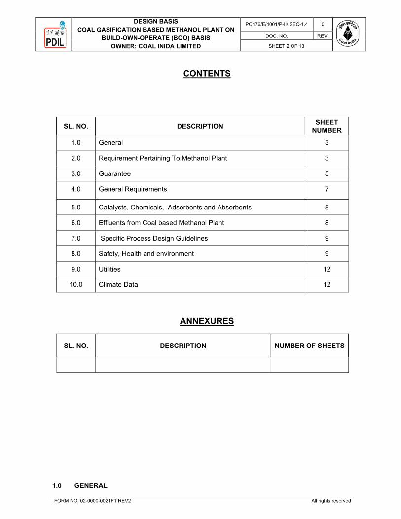
DESIGN BASISCOAL GASIFICATION BASED METHANOL PLANT ON
BUILD-OWN-OPERATE (BOO) BASIS OWNER: COAL INIDA LIMITED
PC176/E/4001/P-II/ SEC-1.4 0
DOC. NO. REV.
SHEET 2 OF 13
FORM NO: 02-0000-0021F1 REV2 All rights reserved
CONTENTS
SL. NO. DESCRIPTION SHEET
NUMBER
1.0 General 3
2.0 Requirement Pertaining To Methanol Plant 3
3.0 Guarantee 5
4.0 General Requirements 7
5.0 Catalysts, Chemicals, Adsorbents and Absorbents 8
6.0 Effluents from Coal based Methanol Plant 8
7.0 Specific Process Design Guidelines 9
8.0 Safety, Health and environment 9
9.0 Utilities 12
10.0 Climate Data 12
ANNEXURES
SL. NO. DESCRIPTION NUMBER OF SHEETS
1.0 GENERAL

DESIGN BASISCOAL GASIFICATION BASED METHANOL PLANT ON
BUILD-OWN-OPERATE (BOO) BASIS OWNER: COAL INIDA LIMITED
PC176/E/4001/P-II/ SEC-1.4 0
DOC. NO. REV.
SHEET 3 OF 13
FORM NO: 02-0000-0021F1 REV2 All rights reserved
This document (Design basis) indicates the requirements for design of Coal Gasification based Methanol Plant and all associated facilities such as Boiler, Raw water treatment Plant, DM Plant, Instrument Air Plant and ETP to be constructed by BOO Operator on BOO basis.
2.0 REQUIREMENT PERTAINING TO COAL GASIFICATION BASED METHANOL PLANT:
2.1 The Coal Gasification based Methanol Plant shall be designed to meet the following quantity
requirement of Methanol. However, BOO operator shall specify the supply quantities of other by-products. Methanol Plant (2050 MTPD): Continuous Normal requirement: 85.4 Mt/hr (100%) Maximum requirement: 94 Mt/hr (110%) Minimum requirement: 42.7 Mt/hr (50%) By- products Sulphur: Continuous Normal supply: --------- Kg/hr (To be specified by BOO operator) Minimum supply: --------- Kg/hr (To be specified by BOO operator)
Ash/ Slag/ Slag-fine: Continuous Normal supply: --------- Kg/hr (To be specified by BOO operator) Minimum supply: --------- Kg/hr (To be specified by BOO operator)
2.2 QUALITY SPECIFICATION
Product Methanol produced from the Methanol plant shall cater to the following minimum
specification:
Sl. No. Components Composition 1. Methanol, wt% (min.) / Grade 99.85 / AA 2. Water, wt% (max.) 0.1 3. Acetone & Aldehyds, wt% (max.) 0.003 4. Acetone, wt% (max.) 0.002 5. Acidity (as acetic acid), wt% (max.) 0.003
6. Appearance Free of opalescence, suspended matter, and sediment
7. Carbonizable impurities, colour.pt.co max. No. 30 of ASTM D1209 8. Colour, Pt-co maximum No.5 of ASTM D1209
9. Distillation ranges at 760mm Hg, max 10.0 0C (and shall include 64.6 0C
±0.1 0C 10. Ethanol, wt% (max.) 0.001 11. Non-volatile matter, mg per 100ml maxi. 10 12. Odor Characteristic. Non- residual 13. Permanganate time No discharge of colour in 50 min. 14. Specific gravity at 200/ 200C, maximum 0.7928 15. Alkalinity (as ammonal), wt% (max.) 0.003
16. Pressure @ B.L of Methanol Plant, kg/cm2a (Min.)
BOO Operator to decide
17. Temperature, °C (max.) 41 Max. By-product Sulphur (solid) produced from the plant shall cater to the following minimum
specification:

DESIGN BASISCOAL GASIFICATION BASED METHANOL PLANT ON
BUILD-OWN-OPERATE (BOO) BASIS OWNER: COAL INIDA LIMITED
PC176/E/4001/P-II/ SEC-1.4 0
DOC. NO. REV.
SHEET 4 OF 13
FORM NO: 02-0000-0021F1 REV2 All rights reserved
Parameter Unit Value Sulphur(S) Wt. %(min, dry) 99.9 Hydrogen Sulphide (H2S) Wt.ppm(max, dry) 10 Ash Wt.ppm (max) 200 Colour Bright Yellow Pressure Kg/Cm2abs Not Relevant Temperature OC Ambient Physical Appearance Solid lumps
By Product Fly Ash/slag (solid) / Slag-fine produced from the plant shall cater to the following
minimum specification:
Parameter Unit Value Fly-ash/ Slag/ Slag-fines Wt.%/ Wt. %/ Wt. % (To be specified by BOO Operator)Moisture (H2O) Wt.%/ Wt. %/ Wt. % (To be specified by BOO Operator)Carbon Content Wt.% Fly Ash: <5
Slag: <2 Slag fines: <30
Pressure Kg/cm2a Atmospheric Temperature OC <80 Physical appearance (To be specified by BOO Operator)
2.3 Feed stock:
Specification of ROM Coal fed to Coal Gasification Plant for production of Methanol
Synthesis Gas is as follows: Available coal analysis mentioned in the Clause no. 1.1 of
Section-1.5 (Raw Material & Utility Specification) Technical.
24% ash content in coal shall be the basis of design for Coal Gasification plant along with all
associated facilities to generate Methanol Syn. gas, Methanol Plant (2050 MTPD), Steam
Generation Plant and all associated offsite & utilities etc. Bidder shall also furnish the
Guaranteed specific coal consumption (in Metric Tonnes of coal per tonne of Methanol) at
different levels of ash content as per table given below:-
Sr. No.
Ash Content in Coal (%) Guaranteed specific coal consumption per tonne of Methanol* (MT)
1. 18.0 < Ash% < 20.0 2. 20.0 < Ash% < 22.0 3. 22.0 < Ash% < 24.0 4. 24.0 < Ash% < 26.0 5. 26.0 < Ash% < 28.0 6. 28.0 < Ash% < 30.0 7. 18.0 < Ash% < 20.0 *In case the ash content in the supplied coal is beyond the above range (i.e. beyond 18 < Ash% < 30), the guaranteed specific coal consumption on either side shall be derived mathematically through extrapolation at multiple of 2.0% intervals.
Required Raw Coal shall be supplied at the unloading hopper from BOBRN type wagon by the
owner.

DESIGN BASISCOAL GASIFICATION BASED METHANOL PLANT ON
BUILD-OWN-OPERATE (BOO) BASIS OWNER: COAL INIDA LIMITED
PC176/E/4001/P-II/ SEC-1.4 0
DOC. NO. REV.
SHEET 5 OF 13
FORM NO: 02-0000-0021F1 REV2 All rights reserved
To ensure continuous feed supply at a constant rate at coal gasification plant & Steam
Generation Plant through conveyor belts, proper facility shall be put up by BOO operator for
storage / transfer of coal from BOO Operator B.L. to gasification plant & Steam Generation
Plant.
Sulphur storage/ operation/ maintenance: Details of offsite storage facility for Sulphur that shall be provided by BOO operator:
Storage Capacity = Seven day’s production
Storage area = ------ m2 (To be specified by BOO operator)
Storage pressure = Atmospheric
Operated/maintained by = BOO Operator
Unloading facility from pipeline = by BOO operator at B.L. of OWNER.
Fly Ash/ Slag/ Slag-fine storage/ disposal: Details of offsite storage facility for Ash/ Slag/ Slag-fine shall be provided by BOO operator:
Storage Capacity = Fifteen day’s production
Storage area = -------- m2 (To be specified by BOO operator)
Storage pressure = Atmospheric
Operated/ maintained by = BOO Operator.
Disposal of Fly ash/ slag/ Slag Fine from inter-mediate storage located at BOO B.L. shall be the responsibility of BOO operator.
Methanol Storage & Loading Gantry
Methanol Storage Tanks of 2X 10000Mt capacities & Transfer Pump along with Methanol
loading gantry for Tank Truck and Rail wagon shall be in the scope of BOO Operator. Tank
Truck loading gantry shall be designed for loading of 10% of total Methanol production per
day. Rail wagon loading gantry shall be designed for loading of total methanol production per
day.
3.0 Guarantee BOO Operator shall guarantee performance of Coal Gasification based Methanol Plant as
specified in this Clause under the following heads.
1. Capacity mentioned in clause no. 2.1
2. Quality of the product mentioned in clause no. 2.2
3. Works cost
4. Noise Level
5. Gaseous Emission
6. Liquid Effluent

DESIGN BASISCOAL GASIFICATION BASED METHANOL PLANT ON
BUILD-OWN-OPERATE (BOO) BASIS OWNER: COAL INIDA LIMITED
PC176/E/4001/P-II/ SEC-1.4 0
DOC. NO. REV.
SHEET 6 OF 13
FORM NO: 02-0000-0021F1 REV2 All rights reserved
Failure to meet capacity of the plants, quality of the products, specific consumption of raw
material/ utilities, pollution levels and noise levels shall be breach of contract requiring
corrective action by BOO Operator irrespective of the cost involved.
For penalty clauses, please refer Part-1 Commercial Section.
BOO Operator shall guarantee overall consumption of ROM Coal (refer clause no. 2.3 of this
section), Fluxant, Power, make-up water for generating Methanol Grade-AA at 100% plant
capacity.
BOO Operator shall furnish all data and shall guarantee the Total Works Costs per day for
production of Methanol meeting the quality and conditions in the following manner.
Sl. No Raw Materials/ Utilities Consumption per day (Q)
Cost per day (Q*R) INR
1. ROM Coal, MT 2. Fluxant, MT 3. Make-up Water, M3 4. Power, KWh 5. Guaranteed Total Works Cost “A”/Day = ∑(Q x R) {Sl.No.1-4}
6. Production figures (per day): Methanol Grade-AA “N” (MTPD)
7. Guaranteed Specific Work Cost/ MT of Methanol Grade-AA (“S” = A/N)
Notes:
i) The guaranteed works cost shall include cost of materials and utilities required and power
consumption for building cooling/ heating, lighting, ventilations, air conditioning and
consequent costs of such materials which are in the usual operation of the plant
ii) For Bid submission purpose, BOO Operator shall furnish consumption and generation
figures of ROM Coal, Fluxant, Power, Make-up Water respectively whose actual works
cost shall be calculated on the basis of Unit Price mentioned in the above table
iii) For the purpose of calculating specific works cost of Methanol Grade-AA; ROM Coal,
Fluxant, Make up water and Power
iv) No meter tolerances are allowed
v) Steam venting is not allowed

DESIGN BASISCOAL GASIFICATION BASED METHANOL PLANT ON
BUILD-OWN-OPERATE (BOO) BASIS OWNER: COAL INIDA LIMITED
PC176/E/4001/P-II/ SEC-1.4 0
DOC. NO. REV.
SHEET 7 OF 13
FORM NO: 02-0000-0021F1 REV2 All rights reserved
4.0 GENERAL REQUIREMENTS: 4.1 Plant On-stream factor:
BOO OPERATOR may require from time to time to shutdown the production facilities of the
Production Plant for such period of time as may be necessary for BOO OPERATOR to make
ordinary repairs and for maintenance consistent with proper operation. However, such
planned shutdown (turn-around) shall be limited to about 35 (thirty five) days at a stretch
once in every year.
In addition, the Coal Based Methanol plant will be planned for shutdown to meet the
requirements of regulatory bodies (such as Indian Boiler Regulations) at intervals as
specified by those respective regulatory bodies. BOO OPERATOR will be allowed to
undertake such shutdown as per statutory requirements. BOO OPERATOR will make all
endeavours to utilise these shutdown on account of statutory requirements for other
maintenance of plant as may be necessary from time to time as well as for replacement of
catalyst.
4.2 Turn-Down ratio:
The Coal based Methanol Plant shall be designed to operate with turn-down ratios as given below:
Coal Gasification Plant: 50% of plant design capacity
Methanol Plant: 50% of plant design capacity
Ash / Slag: 50% of plant design capacity
4.3 Capacity Utilization
Name plate capacity of Methanol Complex is 2050 MTPD i.e. 100%. However, rated
capacity of Methanol complex shall be 110%.
4.4 Plant Availability:
Plant availability factor for all the Coal Based Methanol Plant should be 98.5% (min)
excluding the planned shutdowns.
4.5 Flare:
Flare system shall be in the BOO operator’s scope. All the flaring requirement for the Coal Based Methanol Plant shall be provided by the BOO operator within the battery limit to cater to the discharge of mitigated flare load from the unit. All hydrocarbon / combustible gases and vapours shall be relived to the flare through a knock out drum. Flare stake shall be in the scope of BOO Operator.
Quantity: Provision for mitigated HP flare load from Coal Based Methanol To be specified by

DESIGN BASISCOAL GASIFICATION BASED METHANOL PLANT ON
BUILD-OWN-OPERATE (BOO) BASIS OWNER: COAL INIDA LIMITED
PC176/E/4001/P-II/ SEC-1.4 0
DOC. NO. REV.
SHEET 8 OF 13
FORM NO: 02-0000-0021F1 REV2 All rights reserved
Plant BOO Operator Provision for mitigated LP flare load from Coal based Methanol Plant
To be specified by BOO Operator
4.6 Reliability:
In order to install a high degree of confidence and reliability of the offered plant, the
following shall be taken care of by BOO OPERATOR:
a) Providing adequate redundancy and standby requirements both for equipment
and control systems based on their experience of operating similar BOO plants. b) Maintaining adequate inventory of spare parts – BOO OPERATOR shall
maintain adequate inventory for the spare parts required for routine maintenance. c) 2 out of 3 voting logic to be considered for major plant trip logic functions. d) Providing catalyst volumes in the reactors with minimum catalyst life of 3
years, standby reactors to be considered wherever catalyst life is less than 3 years. 5.0 Catalysts, Chemicals, Adsorbents and Absorbents:
BOO OPERATOR to arrange/ consider all facilities for receiving, sorting, loading and
unloading Catalyst/ additive/ adsorbents/ chemicals & passivation facilities within ISBL of the
BOO facility as required in their scope. Consumables and chemicals required by BOO
Operator will not be supplied and same shall be sourced by BOO Operator directly.
6.0 Effluents from Coal Based Methanol plant
Basis of design of Coal based Methanol Plant shall be for Zero effluent discharge. All type of
effluent i.e. Process Waste Water, Boiler Blow Down water, Cooling water Blow-Down, oily
water etc. from all the units within Complex during Normal, start-up, Shut down and upset
conditions shall be routed to Effluent Treatment Plant through oily water sewer (OWS):-
Liquid Effluent Parameter from ETP Outlet
As per Central Pollution Control Board/ State Pollution Control Board norms for effluent
discharge.
Oily water
Parameter Unit Value Oil mg/lit (max) 10 Quantity M3/Hr (max) (To be specified by BOO operator) Frequency of discharge per year
(To be specified by BOO operator)
Duration of each discharge Hrs. (To be specified by BOO operator)
Boiler Blow-down Parameter Unit Value pH 9 – 11

DESIGN BASISCOAL GASIFICATION BASED METHANOL PLANT ON
BUILD-OWN-OPERATE (BOO) BASIS OWNER: COAL INIDA LIMITED
PC176/E/4001/P-II/ SEC-1.4 0
DOC. NO. REV.
SHEET 9 OF 13
FORM NO: 02-0000-0021F1 REV2 All rights reserved
Silica (as SiO2) ppm < 0.5 Conductivity μS/cm <50 Phosphate (PO4
3-) ppm 2 - 5 Quantity M3/Hr (max) (To be specified by BOO operator) Frequency of discharge per year
(To be specified by BOO operator)
Duration of each discharge Hrs. (To be specified by BOO operator)
Sour water Parameter Unit Value H2S Wt.% < 1 Quantity M3/Hr (max) (To be specified by BOO operator) Frequency of discharge per year
(To be specified by BOO operator)
Duration of each discharge Hrs. (To be specified by BOO operator)
BOO OPERATOR has to confirm compliance to above rates and specifications.
7.0 Specific Process Design Guidelines:
7.1 BOO Operator has to design the unit for maximum energy efficiency, meeting benchmark
numbers of international bench marking agencies. Process and equipment design should
incorporate features for maximizing energy efficiency.
7.2 Special safety requirements such as Methanol/H2S leak detectors and snuffing rings around
leak prone flanges, etc., shall be provided, wherever necessary.
7.3 Standards proposed by Central Pollution Control Board & State pollution Control Board of
India for emissions from the methanol plant to be followed w.r.t. BOO units and periodic
reports needs to be submitted to Coal India.
7.4 Design of units shall incorporate various safely features in line with international safety
standards and design practices.BOO Operator shall furnish brief write-up in the proposal
highlighting such safety features.
7.5 Flare relief from production plant shall be kept as minimum as possible. Flare mitigation
required to meet minimum flaring as per applicable API code shall be adopted.
8.0 SAFETY, HEALTH & ENVIRONMENT:
8.1 General
BOO OPERATOR & his employees shall –
1. Comply with the conditions of the EC (Environmental Clearance), NOC/ Consent to
Establish, Air & Water Consents, Hazardous Waste Authorization and the standards stipulated in the Gazette Notifications for the concerned industry.
2. Follow all the relevant rules & regulations like The Factories Act, The Environment
(Protection) Act etc. 3. Implement recommendations of EIA Report & Risk Analysis Report.

DESIGN BASISCOAL GASIFICATION BASED METHANOL PLANT ON
BUILD-OWN-OPERATE (BOO) BASIS OWNER: COAL INIDA LIMITED
PC176/E/4001/P-II/ SEC-1.4 0
DOC. NO. REV.
SHEET 10 OF 13
FORM NO: 02-0000-0021F1 REV2 All rights reserved
8.2 Safety
BOO OPERATOR & his employees shall –
1. Observe own safety rules & regulations in the Production plant and rules &
regulations of the refinery outside the Production plant.
2. Observe ‘No Smoking’ strictly in the BOO premises except the earmarked place (smoking booth). Any person who is found smoking or in the possession of match box or lighter or any other means of ignition in the Complex or in the Production plant shall be turned out of the Complex gate. Suitable action as decided by the OWNER’s management shall also be taken.
3. Maintain good standards of housekeeping.
4. Take all safety precautions and obtain permission from the Fire & Safety Department of the Complex before carrying out any hot job.
5. Deploy a qualified safety officer to monitor the safety performance.
6. Obtain permission from the Fire & Safety Department of the Complex before drawing water from the fire water network of the Complex.
7. Report all accidents to the Fire & Safety Department of the Complex and fulfill all legal formalities.
8. Enlist all chemicals on stock with their respective MSDS.
9. Be a part of the OWNER’s Emergency Response Team and shall participate in mock drills, rescue operations organized by the OWNER.
10. Take due insurance cover for affecting neighbour hood (damage, loss & injury to people, property & environment) due to any untoward incident.
8.3 Traffic Safety
BOO Operator & his employees shall –
1. Maintain the speed limit of 25 Km/hr inside the Complex premises.
2. Avoid traffic congestion and abide by the traffic rules by deploying trained and
licensed drivers.
8.4 Environment
BOO Operator & his employees shall –
1. Shall avoid wastage of drinking water, etc. (Utilities supplied free of cost by OWNER) 2. Transfer only neutralized effluent to the Effluent Treatment Plant as specified in cl.4.0
above 3. Install Hydrocarbon (HC) leak detectors at strategic locations in the plant area.

DESIGN BASISCOAL GASIFICATION BASED METHANOL PLANT ON
BUILD-OWN-OPERATE (BOO) BASIS OWNER: COAL INIDA LIMITED
PC176/E/4001/P-II/ SEC-1.4 0
DOC. NO. REV.
SHEET 11 OF 13
FORM NO: 02-0000-0021F1 REV2 All rights reserved
4. Install SO2, NOx, CO analyzers in all the stacks for computerized monitoring as stipulated in the EC. Stack heights shall be as per standard/ codes and stacks shall have proper sampling & monitoring facilities.
Stack Emission Limit SO2 100 mg/ Nm NOx 100 mg/ Nm3 Particulate Matter 10 mg/ Nm3 CO 100 mg/ Nm3 Methanol < 50 mg/Nm3 Sulphur < 20 PPMv Pressure Atmospheric
Carbon Mono-oxide emission limit shall be 650 PPMv (max) for Shift Conversion Section. Boo Operator to follow the latest norm of CPCB/ WBSPCB. State PCB or Central PCB norms whichever is more stringent shall be complied by BOO Operator
5. Monitor fugitive emission of Hydrocarbon (HC) / VOC & Benzene through Portable
Monitor at periodicity as per the latest Gazette Notification.
Limit of VOC & Benzene Concentration
VOC ppm Benzene ppm Pump/ Compressor 5000 2000
Valves/ Flanges 3000 1000 Other Components 3000 1000
6. Ground Level Concentration: The BOO Operator shall guarantee the ground level concentration in the atmospheric air
of within plant area and shall not exceed the limits given below:
TLV (for 8 hrs working)
Parameter Value
Carbon monoxide 2 ppm PM10 100 µg/m3 PM 2.5 60 µg/m3 SOx 80 µg/m3 NOx 80 µg/m3
TLV for 8 hours shall be as per latest OHSAS/ ACGIH
7. Noise Level:
BOO Operator shall guarantee the noise level within the ISBL Plant premises. Noise
nuisance from machinery is normally specified as sound pressure level which for standard
design shall not exceed, in work areas, 85dBA at 1m distance from each source.
However, Maximum allowable noise limit shall not exceed higher values of noise level
(115 dBa) as per OSHA standard during any upset conditions.
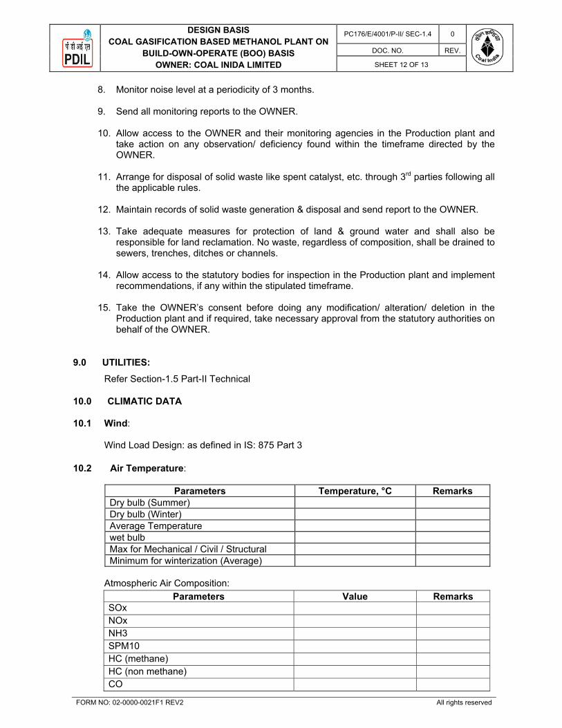
DESIGN BASISCOAL GASIFICATION BASED METHANOL PLANT ON
BUILD-OWN-OPERATE (BOO) BASIS OWNER: COAL INIDA LIMITED
PC176/E/4001/P-II/ SEC-1.4 0
DOC. NO. REV.
SHEET 12 OF 13
FORM NO: 02-0000-0021F1 REV2 All rights reserved
8. Monitor noise level at a periodicity of 3 months. 9. Send all monitoring reports to the OWNER.
10. Allow access to the OWNER and their monitoring agencies in the Production plant and
take action on any observation/ deficiency found within the timeframe directed by the OWNER.
11. Arrange for disposal of solid waste like spent catalyst, etc. through 3rd parties following all
the applicable rules. 12. Maintain records of solid waste generation & disposal and send report to the OWNER. 13. Take adequate measures for protection of land & ground water and shall also be
responsible for land reclamation. No waste, regardless of composition, shall be drained to sewers, trenches, ditches or channels.
14. Allow access to the statutory bodies for inspection in the Production plant and implement
recommendations, if any within the stipulated timeframe. 15. Take the OWNER’s consent before doing any modification/ alteration/ deletion in the
Production plant and if required, take necessary approval from the statutory authorities on behalf of the OWNER.
9.0 UTILITIES:
Refer Section-1.5 Part-II Technical 10.0 CLIMATIC DATA
10.1 Wind: Wind Load Design: as defined in IS: 875 Part 3
10.2 Air Temperature:
Parameters Temperature, °C Remarks Dry bulb (Summer) Dry bulb (Winter) Average Temperature wet bulb Max for Mechanical / Civil / Structural Minimum for winterization (Average)
Atmospheric Air Composition:
Parameters Value Remarks SOx
NOx
NH3
SPM10
HC (methane)
HC (non methane)
CO

DESIGN BASISCOAL GASIFICATION BASED METHANOL PLANT ON
BUILD-OWN-OPERATE (BOO) BASIS OWNER: COAL INIDA LIMITED
PC176/E/4001/P-II/ SEC-1.4 0
DOC. NO. REV.
SHEET 13 OF 13
FORM NO: 02-0000-0021F1 REV2 All rights reserved
VOC
NOTE: Bidder to take correction factors and worst atmospheric condition on above. 10.3 Relative Humidity:
Relative Humidity RH% Relative Humidity
10.4 Rainfall:
Rainfall Value Annual _____mm Design rainfall (per hour) _____mm
Note: - Civil philosophy is to be referred
10.5 Barometric Pressure:
Barometric Pressure Value Average _____mbar
10.6 Seismic Design Code:
Refer Section-1.12 (Design Philosophy – Civil & Structural Works) Part II-Technical. 10.7 Plant Elevation: The final plant elevation shall be established in consultation with owner / consultant based
on overall project requirement.

PROJECTS & DEVELOPMENT INDIA LTD.
PC176/E/4001/P-II/ SEC-1.5 0
Document No. Rev
Sheet 1 OF 8
0 24.09.2020 24.09.2020 Issued for Tender Purpose SK SKK MN
REV REV DATE EFF DATE PURPOSE PREPD REVWD APPD FORM NO: 02-0000-0021F1 REV4 All rights reserved
VOLUME II: TECHNICAL
SECTION – 1.5
RAW MATERIAL AND
UTILITY SPECIFICATIONS
PLANT: INTEGRATED COAL BASED METHANOL PLANT, AT DANKUNI, KOLKATA (INDIA)
PROJECT: COAL TO METHANOL (C2M) PROJECT
THROUGH COAL GASIFICATION ROUTE ON BUILD-OWN-OPERATE (BOO) BASIS AT DANKUNI COAL COMPLEX WEST BENGAL, INDIA

RAW MATERIAL, PRODUCT AND UTILITY SPECIFICATIONS
COAL GASIFICATION BASED METHANOL PLANT ON BUILD-OWN-OPERATE (BOO) BASIS
OWNER:COAL INIDA LIMITED
PC176/E/4001/P-II/ SEC-1.5 0
Document No. Rev
Sheet 2 OF 8
FORM NO: 02-0000-0021 F2 REV3 All rights reserved
CONTENTS
Section number Description Sheet Number
1.0 OWNER’S SCOPE 3
2.0 BOO OPERATOR’S SCOPE 3
LIST OF ATTACHMENT
Attachment number Description Number of Sheets
1. OWNER’S SCOPE

RAW MATERIAL, PRODUCT AND UTILITY SPECIFICATIONS
COAL GASIFICATION BASED METHANOL PLANT ON BUILD-OWN-OPERATE (BOO) BASIS
OWNER:COAL INIDA LIMITED
PC176/E/4001/P-II/ SEC-1.5 0
Document No. Rev
Sheet 3 OF 8
FORM NO: 02-0000-0021 F2 REV3 All rights reserved
Owner shall provide the followings Raw material and utilities on chargeable basis as mentioned in below clauses:-
1.1 RUN OF MINE (ROM) COAL
Specification of ROM Coal fed to Coal Gasification Plant for production of Methanol Synthesis Gas is as follows: Sr. No. % Ash % Moisture % Volatile Matter Gross cal. Value
1. 19.5 4.88 29.98 6010 2. 28.53 5.31 27.80 5097
Further, please refer clause no. 2.3 of Section-1.4 (Design Basis) Technical.
1.2 RAW WATER
Sr. No. Raw water supply at Plant B.L. 1. pH 6.8 2. Hardness (PPM) 200 3. Free Mineral Acid (PPM) --- 4. Chloride (PPM) 210 5. Iron as Fe (PPM) 5 6. TDS (PPM) 705
1.3 POWER
Power shall be provided from state grid. Further, Refer Section-1.10 Design Philosophy
Electrical.
2.0 BOO OPERATOR’S SCOPE
2.1 H.P Steam Operating Design
Pressure, kg/cm2g (Min/ Nor/ Max) * * Temperature, °C (Min/ Nor/ Max) * * Silica as SiO2, ppm < 0.02
pH 9-9.5
Conductivity, S/cm (at 25 deg.C) < 0.2
Total Iron (Fe) mg/kg <0.01
Na+K mg/kg <0.01
Copper mg/kg 0.003
* Above Figure shall be filled by BOO Operator
2.2 M.P Steam Operating Design
Pressure, kg/cm2g (Min/ Nor/ Max) * * Temperature, °C (Min/ Nor/ Max) * *

RAW MATERIAL, PRODUCT AND UTILITY SPECIFICATIONS
COAL GASIFICATION BASED METHANOL PLANT ON BUILD-OWN-OPERATE (BOO) BASIS
OWNER:COAL INIDA LIMITED
PC176/E/4001/P-II/ SEC-1.5 0
Document No. Rev
Sheet 4 OF 8
FORM NO: 02-0000-0021 F2 REV3 All rights reserved
*Above Figure shall be filled by Boo Operator
2.3 L.P Steam Operating Design
Pressure, kg/cm2g (Min/Nor/Max) * * Temperature, oC (Min/ Nor/ Max) * * *Above Figure shall be filled by Boo Operator
2.4 Cooling Water (Added with suitable chemicals)
Supply Header Pressure, kg/cm2g (Min/ Nor/ Max) BOO Operator to decide Return Header Pressure, kg/cm2g (Min/ Nor/ Max) BOO Operator to decide Mechanical Design Pressure, kg/cm2g 8.0 Supply Header Temperature, o C 33 Return Header Temperature, o C By BOO Operator Mechanical Design Temperature, o C 70 Design wet Bulb temperature , o C 29.0 T 10 °C max. Relative Humidity at Dankuni 100% (max.) COC 5 Drift losses and evaporation loss (% of circn.) By BOO Operator Analysis of Cooling Water By BOO Operator pH Conductivity, µ mho/cm Turbidity, NTU Total Alkanity as CaCO3, ppm P. Alkanity as CaCO3, ppm Total Hardness as CaCO3, ppm Ca Hardness as CaCO3, ppm Mg Hardness as CaCO3, ppm Chloride as Cl, ppm TDS, ppm Total iron as Fe, ppm Corrosion Rate, ppm Silica as SiO2, ppm Nitrate as NO3, ppm Sulphate as SO4, ppm SRB count Total Suspended solids (TSS) Manganese as Mn Free Chlorine, ppm Phosphate as PO4 (Orth), ppm

RAW MATERIAL, PRODUCT AND UTILITY SPECIFICATIONS
COAL GASIFICATION BASED METHANOL PLANT ON BUILD-OWN-OPERATE (BOO) BASIS
OWNER:COAL INIDA LIMITED
PC176/E/4001/P-II/ SEC-1.5 0
Document No. Rev
Sheet 5 OF 8
FORM NO: 02-0000-0021 F2 REV3 All rights reserved
Total Phosphate, ppm
2.5 Nitrogen Gas (Utility)
Pressure, kg/cm2g (Min/Nor/Design) 6.0/8.0/9.0 Temperature Ambient N2, Vol %, min 99.99% O2, Vol ppm < 10
2.6 Nitrogen Liquid (Utility) Nitrogen (N2) Vol. %, Min. 99.99% Oxygen (O2) Vol. ppm < 10 Pressure (Min/Nor/Max.) Kg/Cm2abs BOO Operator to specify Temperature OC BOO Operator to specify
2.7 Instrument Air Min. Nor. Max.
Pressure, kg/cm2 g 6.0 8.0 10.0 Supply Temperature, °C Ambient Ambient 50 Mech. Design Pressure, kg/cm2g 10.5 Mech. Design Temperature, °C 65 Dew point -40 o C at atm. pressure Quality Free of dust, water drops & oil Storage Capacity (10 to 6 Kg/Cm2g
depressurization) at each unit 15 minute
Storage Capacity (40 to 6 Kg/cm2g depressurization) at Instrument Air Plant
15 minute
2.8 Demineralised Water
Pressure @ B/L, kg/cm2g (Min/ Nor/ Max) 4.0/ 5.5/ 6.0 Temperature, °C (Normal) Ambient/ 40 (max) Mech. Design Pressure, kg/cm2g 10 Mech. Design Temperature, °C 70 pH 6.5-8.5 Total Hardness, ppm wt. Zero Total Dissolved Solids, ppm wt (max.) 0.1 Conductivity at 20 deg C, micro mho/cm (max.) <0.2 M Alkanity as CaCO3, ppm wt. Nil Chlorides, ppm wt. Nil Iron as Fe, ppm wt. (max.) 0.01 Copper , mg/l <0.003 Silica as SiO2, ppm wt. (max.) 0.02 Oil, ppm wt. Nil Sodium as Na, ppm wt. (max.) < 0.1

RAW MATERIAL, PRODUCT AND UTILITY SPECIFICATIONS
COAL GASIFICATION BASED METHANOL PLANT ON BUILD-OWN-OPERATE (BOO) BASIS
OWNER:COAL INIDA LIMITED
PC176/E/4001/P-II/ SEC-1.5 0
Document No. Rev
Sheet 6 OF 8
FORM NO: 02-0000-0021 F2 REV3 All rights reserved
2.9 Boiler Feed Water
Total Hardness as CaCO3, ppm Nil O2, ppm <0.005 Silica as SiO2, ppm < 0.02 pH (at 25 deg. C) 8.5-9.5 Conductivity, S/cm (at 250C before pH adjustment with NH3) < 0.3 Oil, ppm Nil Fe +Cu mg/lt. <0.01 Residual Hydrazine (as N2H4) Mg/l <0.05 Oxygen consumed in 4 hours, mg/l Nil
2.10 Boiler Blow Down (Boiler CBD)
pH 9.0-10.0 Silica as SiO2, ppm < 0.5 Conductivity, S/cm < 50 Phosphate, ppm 2-5
2.11 Service Water Colour < 5.0 Smell Agreeable pH 7.0-8.5 Taste & Odour Unobjectionable TDS, mg/l < 150 Turbidity, NTU < 1.0 Total Hardness, mg/l < 85 Chloride (as Cl), mg/l < 15 Sulphate (as SO4), mg/l < 60 Total Iron (Fe), mg/l < 0.01 Dissolved Silica, mg/l < 4 Supply Pressure, kg/cm2g (Min/ Nor/ Max) 4.0/6.0/8.0 Supply Temperature, deg C Ambient Mechanical Design Pressure, kg/cm2g 10.5 Mechanical Design Temperature, deg C 65 2.12 Process Water (after treatment) , BOO Operator to Fill pH Chlorides, mg/l Sulphates, mg/l Silica, mg/l Iron, mg/l

RAW MATERIAL, PRODUCT AND UTILITY SPECIFICATIONS
COAL GASIFICATION BASED METHANOL PLANT ON BUILD-OWN-OPERATE (BOO) BASIS
OWNER:COAL INIDA LIMITED
PC176/E/4001/P-II/ SEC-1.5 0
Document No. Rev
Sheet 7 OF 8
FORM NO: 02-0000-0021 F2 REV3 All rights reserved
Manganese, mg/l Total Suspended Solids, mg/l Total Dissolved Solids, mg/l Oil & Grease, mg/l Ammonia, mg/l Alkanity, mg/l as CaCO3 Calcium Hardness, mg/l as CaCO3 Total Hardness, mg/l as CaCO3 Supply Pressure, kg/cm2g (Min/ Nor/ Max) Supply Temperature, deg C Mechanical Design Pressure, kg/cm2g Mechanical Design Temperature, deg C 2.13 Drinking Water
Colour < 5.0 Smell Agreeable pH 7.0-7.5 Taste & Odour Unobjectionable TDS, mg/l < 150 Turbidity, NTU < 1.0 Total Hardness, mg/l < 85 Chloride (as Cl), mg/l < 15 Sulphate (as SO4), mg/l < 60 Total Iron (Fe), mg/l < 0.01 Dissolved Silica, mg/l < 4 Supply Pressure, kg/cm2g (Min/ Nor/ Max) 4/ 5.5/ 6.0 Supply Temperature, deg C Ambient Mechanical Design Pressure, kg/cm2g 10.0 Mechanical Design Temperature, deg C 65
Note: Drinking water of quality conforming to IS: 10500-1991 shall be provided by the Owner to Boo Operator at the Battery Limit.
2.14 Plant Air Moisture Saturated Oil Content Nil Supply Pressure, kg/cm2g (Min/ Nor/ Max) 4.0/7.0/8.0 Supply Temperature, deg C (Min/ Nor/ Max) 40/40/50 Mechanical Design Pressure, kg/cm2g 10.5 Mechanical Design Temperature, deg C 65 2.15 Fire Water

RAW MATERIAL, PRODUCT AND UTILITY SPECIFICATIONS
COAL GASIFICATION BASED METHANOL PLANT ON BUILD-OWN-OPERATE (BOO) BASIS
OWNER:COAL INIDA LIMITED
PC176/E/4001/P-II/ SEC-1.5 0
Document No. Rev
Sheet 8 OF 8
FORM NO: 02-0000-0021 F2 REV3 All rights reserved
Pressure kg/cm2g Min. 7 at farthest point (As per NFPA/ TAC)
Temp. deg C Ambient 2.16 LDO/ FO *
Quality IS-15770 latest revision for LDO IS-1593 latest revision for FO
Pressure kg/cm2g Atm. Temp. deg C Ambient
During start-up/ Shutdown, LDO/ FO shall be used. During normal operation, Fuel gas generated within Boo area shall be used.
2.17 FLUXANT
Purity in terms of CaCO3 To be filled by BOO Operator
Appearance (Solid Lumps) To be filled by BOO Operator
Fluxant (Lime) procurement and transportation will be in the scope of BOO Operator. Fluxant (Lime) handling, storage, conveying etc. shall be in the scope of BOO Operator’s scope.

PC176/E/4001/P-II/ SEC-1.6 0
PROJECTS & DEVELOPMENT INDIA DOC. NO. REV.
SHEET 1 OF 14
0 24.09.2020 24.09.2020 Issued for Tender Purpose SK SKK MN
REV REV DATE EFF DATE PURPOSE PREPD REVWD APPD
VOLUME-II: TECHNICAL
SECTION – 1.6
PROCESS DESIGN GUIDELINES
PLANT: INTEGRATED COAL BASED METHANOL PLANT, AT DANKUNI, KOLKATA (INDIA)
PROJECT: COAL TO METHANOL (C2M) PROJECT
THROUGH COAL GASIFICATION ROUTE ON BUILD-OWN-OPERATE (BOO) BASIS AT DANKUNI COAL COMPLEX WEST BENGAL, INDIA

PROCESS DESIGN GUIDELINES COAL GASIFICATION BASED METHANOL PLANT ON
BUILD-OWN-OPERATE (BOO) BASIS OWNER:COAL INIDA LIMITED
PC176/E/4001/P-II/ SEC-1.6 0
DOC. NO. REV.
SHEET 2 OF 14
All rights reserved
CONTENTS
SL. NO. DESCRIPTION SHEET NUMBER
1.0 Introduction 3
2.0 General Information 3
3.0 Equipment Design Information 4
4.0 Equipment Design Margin 12
5.0 Equipment Sparing 13
6.0 Control Valves 13
7.0 Plant Reliability 14
1.0 INTRODUCTION:

PROCESS DESIGN GUIDELINES COAL GASIFICATION BASED METHANOL PLANT ON
BUILD-OWN-OPERATE (BOO) BASIS OWNER:COAL INIDA LIMITED
PC176/E/4001/P-II/ SEC-1.6 0
DOC. NO. REV.
SHEET 3 OF 14
All rights reserved
The purpose of this document is to ensure consistency of approach to design of equipment
across the Dankuni Coal Complex, CIL. The requirements given below are for the purpose of
general guide line for BOO OPERATOR. However BOO OPERATOR may follow process
design guide lines as suggested by the process licensor. BOO OPERATOR shall indicate in
his bid the codes and standards which shall be followed for design of Coal Gasification
based Methanol plant.
2.0 GENERAL INFORMATION:
2.1 Equipment and machinery shall be provided so that the PLANTS can operate for minimum
two years without major overhaul or inspection. All design shall conform to the latest edition
of the applicable sections of ASME, ASTM, IEEE, NFC, TEMA, AISI, NEMA, AISC, ACI,
OSHA, UBE and other governing codes or standard practices. Any other equivalent and
acceptable Code of Standard practice may be adopted with the approval of the LICENSEE.
In addition, the following state/local Codes/laws shall supplement:
a) Pressure Vessels/ Formed ends ASME, Section VIII, DIV.I / Indian Standard IS 4049.
b) Boilers Indian Boiler Regulations Act c) Buildings & Structural Relevant Indian Standard (BIS) d) Electricity Indian Electricity Rules. e) Sanitary Relevant Indian Standard (BIS)
f) Safety a) Manual of Chief Inspector of Explosives, Govt. of India. b) Oil Industry Safety Directorate (OISD) norms
g) Water Pollution Relevant Indian Standard (BIS)
2.2 System of Measurements:
The system of measurement shall be Metric as follows:
Parameter Preferred Units Alternative Units Temperature °C Pressure - absolute kg/cm² abs Pressure - gauge kg/cm² g Flow (liquid) m³/hr kg/hr Flow (gas) Nm³/hr kg/hr Flow (steam) kg/hr Length, Level mm m Time hr sec, min Heat kcal Power kW Fouling resistance m² hr °C / kcal Pipe size / diameter mm (NB) Mass kg Liquid relative density sp gr T°C/15.6°C Liquid density kg/m3

PROCESS DESIGN GUIDELINES COAL GASIFICATION BASED METHANOL PLANT ON
BUILD-OWN-OPERATE (BOO) BASIS OWNER:COAL INIDA LIMITED
PC176/E/4001/P-II/ SEC-1.6 0
DOC. NO. REV.
SHEET 4 OF 14
All rights reserved
Vapor flowing density kg/m3 Furnace draft mm of WC Storage tank pressure mm of WC Vacuum mm of Hg, mm WC Standard vapor Nm3/hr at 0°C & 1.033
kg/cm2a
Standard liquid Sm3/hr at 15.6°C Thermal conductivity kcal/hr-m-°C Heat Transfer coefficient kcal/hr-m2-°C Enthalpy, Entropy kcal/kg
Heat rate 106kcal/hr or MM kcal/hr
Viscosity cP Kinematic Viscosity cSt Sound Pressure dB(A) Sound Power dB(A)
3.0 EQUIPMENT DESIGN INFORMATION: 3.1 Columns and Vessels:
Preferred diameters of columns, vessels and reactors shall be as. a) Corrosion allowance
SS Min.0.75 mm CS/LAS Min. 3.0 mm Cladding thickness Min. 3.0 mm
b) Man holes in Columns and Vessels
ID 900 mm and below: Flanged top cover if access required. ID above 900 mm: Preferred 24”, Minimum 20”
Columns: Man holes are to be provided above the top tray and below the bottom tray. The spacing of man holes in tray columns shall be every 6 m (approx). The minimum number of manholes for columns is three. Vessels: Minimum number of manholes is one. For vessels more than 6 m in length the minimum number is two. In case of small vessels, hand holes of 150 mm (6”) are to be provided.
c) Design pressure
i) Factors like pump shut-off conditions, pressure drops in recycle loop etc. should be considered for fixing design pressure. Pump shut-off shall be calculated at 1.25 x rated head + max. Suction pressure.
ii) When operating pressure is less than or equal to 100 kg/cm2, design pressure shall be equal to normal operating pressure plus 10% (min. 2.0 kg/cm2). When operating pressure is more than 100 kg/cm2, design pressure shall be equal to normal operating pressure plus 5% (min 10 kg/cm2).
iii) All steam handling / condensate vessels shall be designed for full vacuum
conditions also.

PROCESS DESIGN GUIDELINES COAL GASIFICATION BASED METHANOL PLANT ON
BUILD-OWN-OPERATE (BOO) BASIS OWNER:COAL INIDA LIMITED
PC176/E/4001/P-II/ SEC-1.6 0
DOC. NO. REV.
SHEET 5 OF 14
All rights reserved
iv) All vessels/ columns subject to internal pressure should be designed to withstand a minimum external pressure of 0.175 kg/cm2 abs.
v) Minimum design pressure for equipment connected with flare header should be 3.5 kg/cm
2g.
vi) Special consideration should be given (for vacuum design) to the design of vessel normally subject to internal pressure and connected to compressor suction or ejectors.
d) Design temperature
i) Design temperature for unfired pressure vessels and interconnecting piping will in general be equal to maximum anticipated operating temperature plus 30°C if vessel operates between zero to 400°C and 28°C if vessel operates above 400°C. If it operates below 0°C temperature, LICENSOR should follow his own philosophy.
ii) Conditions like steam-out (for handing out vessel to maintenance) will be considered while specifying design temperature.
iii) For vessels operating at ambient temperature, 65°C will be used for mechanical design.
Note: When different metal temperature can be predicted to occur for different zones
of a vessel during operation then different temperature should be indicated on the sketch and different temperature should be taken into account for designing the vessel.
e) The column internals can be trays or packing. Preferred type of trays shall be a valve
tray (stainless steel).
f) Hydraulic Residence time: Residence time is defined between low liquid level and high liquid level.
Service Residence time, minutes
Feed Surge Drum Drum diameter: < 1.2 m 30 Drum diameter: 1.2 to 1.8 m incl. 20
Drum diameter: > 1.8 m 15
Column Feed 15 minutes on flow control or 10 min on cascade level/flow control
Re-boiling by heater
-Calculated on net bottom product: 15 minutes on flow control or 8 min on cascade level/flow control for further processing or 2 min with discharge to storage. -Calculated on total feed heater: 2 minutes. Between LLL & TL (with LSLL installed at min. distance from LLL): 8min on the equivalent flow rate of the vapor generated in the fired heater.

PROCESS DESIGN GUIDELINES COAL GASIFICATION BASED METHANOL PLANT ON
BUILD-OWN-OPERATE (BOO) BASIS OWNER:COAL INIDA LIMITED
PC176/E/4001/P-II/ SEC-1.6 0
DOC. NO. REV.
SHEET 6 OF 14
All rights reserved
Reflux to Tower 5
Product to Storage 5
Product feeding another unit 15 minutes on flow control or 10 min on cascade level/flow control
Flow to Heat Exchanger 2
Flow to Sewer or Drain 1
In the case of pumps ensuring several services such as reflux and liquid distillate to storage, the residence time of the corresponding vessel will be whichever is greater from the above list.
In case hold-up must be provided for both product and reflux, the larger volume is used, not the sum of the two volumes. When the discharge rate is unimportant, a nominal hold-up time of approximately 2 minutes is provided.
The normal operating liquid level should be taken as the midpoint between the high and low levels. Level control should span between the high and low levels. Where high and low level trips are required, these should be located at a reasonable elevation above and below the high and low levels respectively, to allow operator intervention before a trip occurs.
Low liquid level shall be at least 200 mm above the bottom (for horizontal vessels) or bottom tangent line (for vertical vessels).
For water settling the above applies but this may need to be increased. Where there may be solids in the drum, which are not to be drawn off, the liquid outlet may be raised and the low liquid level shall be increased accordingly For horizontal vessels, the highest liquid level shall be at least either 300 mm or 20% of the drum diameter below the top, whichever is the greater.
Note: If a crinkled wire mesh pad is present then highest liquid level shall be at least 300 mm below the bottom of the pad.
For vertical vessels, if vapor flow is present the highest liquid level shall be at least 300mm below the bottom of the inlet arrangement. If little or no vapor is present, the highest liquid level shall be at least 300 mm or 15% of the drum diameter below the top tangent line, whichever is the greater. The minimum time between a HHLL alarm and trip and between a LLLL alarm and trip shall be no less than 2 minutes.
g) Tower Bottoms Surge Capacity & Hold-up Volume:
The liquid residence time (from the low to high levels) for the design of the bottom section of a column is as follows:
i. Bottoms as feed to a subsequent tower on level control are five (5) minutes. In general, level control will frequently prove satisfactory to the second of a series of towers.
ii. Bottoms as feed to a subsequent tower on flow control is ten (10) to twenty (20) minutes, when the column is acting as a feed surge drum to another unit. This surge capacity may be obtained by swaging to a larger diameter for the holdup section of the column, in some cases.
iii. Bottoms to a heat exchanger and/or tankage are two (2) minutes. This may be
reduced in the case of a crude or vacuum tower in order to prevent coking.

PROCESS DESIGN GUIDELINES COAL GASIFICATION BASED METHANOL PLANT ON
BUILD-OWN-OPERATE (BOO) BASIS OWNER:COAL INIDA LIMITED
PC176/E/4001/P-II/ SEC-1.6 0
DOC. NO. REV.
SHEET 7 OF 14
All rights reserved
iv. Feed to a fired coil re-boiler is the sum of five (5) minutes on the vaporized
portion and two (2) minutes on the bottoms product. It is normally desirable that the five (5) minutes on the vaporized portion be employed to establish the normal low level, with
v. the subsequent two (2) minutes on bottoms product used to establish the high
liquid level (normally 300 mm is the minimum allowed distance between these levels).
vi. For vacuum towers, a space corresponding to 30 seconds surge on total vacuum
bottoms plus quench rate is set between low and high liquid level at tower bottoms.
h) Knock-out Surge Capacity and Hold-up Volume:
For normal accumulation the following liquid hold up applies:
i) At low normal accumulation rate:
Liquid draw-off is usually manually controlled. Enough volume should be provided to ensure the frequency of emptying is less than once per shift (i.e. eight (8) hours) or preferably twenty four (24) hours. Generally a nominal height above the lower tangent line (say 200 mm) will be adequate.
ii) At higher normal accumulation rate:
Liquid draw-off is usually under level control. The distance between high and low level is usually made to suit a standard controller range, say 350 mm, (corresponding to controller connections and generally providing hold up time far in excess of the normal requirement of approximately two (2) minutes).
For a spill the following liquid hold up applies:
i) Frequently capacity is required for “spill from preceding unit”. Provide a volume equal to the entire production of the unit for ten (10) minutes between the ‘alarm’ level (see Note * below) and a point 300 mm above the normal high level.
Sometimes spill requirements govern the drum design. That is, an L/D ratio of approximately 3:1 results in a large drum diameter relative to the vapor load. Use of a critical wire mesh screen would then be uneconomic.
(Note: * level alarm provided if level rises 300 mm above ‘normal’ high level)
i) Minimum Auxiliary Nozzle Size:
The following list is a guide to the minimum auxiliary nozzle sizes to be used for process design sizing of nozzles (minimum mechanical nozzle size of 50 mm (2”) to be specified during vessel design).
Vessel Volume, m3 Vent Drain Pump out Steam out Blow down
1.5 1” 1” 1” 1” 2” 1.5 – 5.6 1” 1½ ” 1½” 1” 3” 5.6 – 17 2” 2” 2” 1” 3”

PROCESS DESIGN GUIDELINES COAL GASIFICATION BASED METHANOL PLANT ON
BUILD-OWN-OPERATE (BOO) BASIS OWNER:COAL INIDA LIMITED
PC176/E/4001/P-II/ SEC-1.6 0
DOC. NO. REV.
SHEET 8 OF 14
All rights reserved
17 – 70 2” 3” 3” 2” 4” 70 and over 2” 3” 3” 3” 4”
3.2 Fired Heaters
Fired heaters shall be designed for maximum efficiency. Air pre-heating is preferred to steam generation for heat recovery to improve furnace efficiency. Preferred order of levels for steam generation, if required to be included for energy optimization, would be HP/MP/LP. Heaters shall be provided for gas/ fuel oil firing. Each burner shall have a pilot gas burner. Atomizing steam shall be MP steam. Soot blowers shall be pneumatic, locally operated, retractable with auto-manual sequential control. Steam air de-coking facility shall be preferred if necessary.
3.3 Heat Exchangers/ Air Coolers/ Condensers/ Re-boilers: The following general guidelines will be followed: 3.3.1 Air-cooling shall be maximized for which the cut-off temperature of process streams shall be
55 deg C. However, when further trim-cooling by water is necessary, the cut-off temperature of process stream shall be 65 deg C. Dry bulb temperatures 35 deg C to be considered for Cooler sizing. However, to avoid small trim cooler or air cooler these guide lines can be relaxed.
3.3.2 Preferred straight tube length is 6000 mm. 3.3.3 Preferred size for Carbon Steel and low alloy (up to and including 5 Cr ½ Mo) tubes is 20 x
2 mm and 25 x 2.5 mm respectively. 3.3.4 Preferred size for brass and admiralty tubes is 20 x2 & 25 x2.5 mm respectively. 3.3.5 Preferred size for high alloy (above 5 Cr 1/2 Mo and Austenitic) tube is 20 & 25 x t to suit
design. 3.3.6 Preferred tube pitch is square pitch in fouling services. Maximum allowable bundle weight is
15 MT. Maximum allowable bundle diameter 1400mm. 3.3.7 For Shell and Tube Heat Exchangers:
a) Design fouling factor: Licensor will use following suggested fouling factors towards sizing of heat exchangers in the plant. Suggested fouling factor in the Process side is 0.0003 (m2 .hr °C/kcal) and in the Cooling water side is 0.0004 (m2 .hr °C/kcal).
b) Corrosion allowance: Unless otherwise specified corrosion allowance for all
exchangers should be as per TEMA standard. c) Design Pressure:
i) Maximum anticipated operating pressure plus 10 % or 2 kg/cm2, whichever is greater. The minimum design pressure is 3.5 kg/cm2g.
ii) Exchangers that are subject to pump shut off, in general, shall have design pressure equal to maximum shut off pressure.
iii) In case exchanger is operating under vacuum or in steam service, design should be for full vacuum.
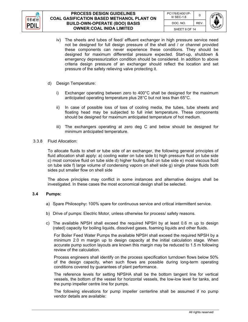
PROCESS DESIGN GUIDELINES COAL GASIFICATION BASED METHANOL PLANT ON
BUILD-OWN-OPERATE (BOO) BASIS OWNER:COAL INIDA LIMITED
PC176/E/4001/P-II/ SEC-1.6 0
DOC. NO. REV.
SHEET 9 OF 14
All rights reserved
iv) The sheets and tubes of feed/ effluent exchanger in high pressure service need not be designed for full design pressure of the shell and / or channel provided these components can never experience these conditions. They should be designed for maximum differential pressure expected. Start-up, shutdown & emergency depressurization condition should be considered. In addition to above criteria design pressure of an exchanger should reflect the location and set pressure of the safety relieving valve protecting it.
d) Design Temperature:
i) Exchanger operating between zero to 400°C shall be designed for the maximum anticipated operating temperature plus 28°C but not less than 65°C.
ii) In case of possible loss of loss of cooling media, the tubes, tube sheets and
floating head may be subjected to full inlet temperature. These components should be designed for maximum anticipated temperature of hot medium.
iii) The exchangers operating at zero deg C and below should be designed for
minimum anticipated temperature. 3.3.8 Fluid Allocation:
To allocate fluids to shell or tube side of an exchanger, the following general principles of fluid allocation shall apply: a) cooling water on tube side b) high pressure fluid on tube side c) most corrosive fluid on tube side d) higher fouling fluid on tube side e) most viscous fluid on tube side f) large volume of condensing vapors on shell side g) single phase fluids both sides put smaller flow on shell side
The above principles may conflict in some instances and alternative designs shall be investigated. In these cases the most economical design shall be selected.
3.4 Pumps:
a) Spare Philosophy: 100% spare for continuous service and critical intermittent service.
b) Drive of pumps: Electric Motor, unless otherwise for process/ safety reasons.
c) The available NPSH shall exceed the required NPSH by at least 0.6 m up to design (rated) capacity for boiling liquids, dissolved gases, foaming liquids and other fluids.
For Boiler Feed Water Pumps the available NPSH shall exceed the required NPSH by a minimum 2.0 m margin up to design capacity at the initial calculation stage. When accurate pump suction layouts are known this margin may be reduced to 1.5 m following review of the calculation.
Process engineers shall identify on the process specification turndown flows below 50% of the design capacity, when such flows are possible during long-term operating conditions covered by guarantees of plant performance.
The reference levels for setting NPSHA shall be the bottom tangent line for vertical vessels, the bottom of the vessel for horizontal vessels, the low-low level for tanks, and the pump impeller centre line for pumps.
The following elevations for pump impeller centerline shall be assumed if no pump vendor details are available:

PROCESS DESIGN GUIDELINES COAL GASIFICATION BASED METHANOL PLANT ON
BUILD-OWN-OPERATE (BOO) BASIS OWNER:COAL INIDA LIMITED
PC176/E/4001/P-II/ SEC-1.6 0
DOC. NO. REV.
SHEET 10 OF 14
All rights reserved
Pump Capacity, m3/h Centre Line Elevation, m
Up to 45 0.76 45 - 225 0.91
225 - 2270 1.07 2270 - 4540 1.37
3.5 Line Sizing: 3.5.1 Liquid Flow:
The guidelines shown in the following table should be used to size process piping for liquids. The guidelines cover most normal situations for systems within unit battery limits, but they may not be applicable for all cases. For critical services and long headers, the total pressure drop in the system must be checked to ensure the system meets the design pressure balance, whether or not individual process lines meet the pressure drop and velocity criteria given here. This standard may not apply to critical services, such as slurry lines or high pressure piping, for which reference should be made to additional standards.
SIZING LIQUID LINES ‘Recommended’ High Limits
∆P per 100 m, kg/cm² Velocity (4, 5) m/sec
Pump suction lines (1) - bubble point liquids - subcooled liquids (< DN 200) [< 8”] - subcooled liquids (≥ DN 200) [≥ 8”]
0.10 0.45 0.45
1.8 2.4 3.7
Pump discharge lines - CS - alloy / SS
0.90 0.90
6.1 7.6
Reboilers - trap out lines (3) - return lines
0.07 0.07
1.5 -
Liquid transfer lines (2) 0.35 3.7 Cooling water lines 0.35 3.7 Steam condensate lines (liquid) - 0.6 Notes (1) Pump suction line diameters should normally not be more than two standard line sizes larger than the pump suction nozzle. (2) Or as required by system pressure balance. (3) If the liquid velocity is too high, swaged up orifice meter runs may be required, hence it is recommended to restrict velocities in lines containing orifice meters within the following upper limits: - Line sizes ≤ 300 mm (12”) : 3.4 m/s max. - Lines sizes ≥ 350 mm (14”): 3.1 m/s max.
3.5.2 Pump Discharge Lines:

PROCESS DESIGN GUIDELINES COAL GASIFICATION BASED METHANOL PLANT ON
BUILD-OWN-OPERATE (BOO) BASIS OWNER:COAL INIDA LIMITED
PC176/E/4001/P-II/ SEC-1.6 0
DOC. NO. REV.
SHEET 11 OF 14
All rights reserved
Line sizing is a trade-off between piping installation costs and operating costs. Typical values for allowable pressure drops in pump discharge lines are given below for both carbon steel and alloy piping.
Pump Discharge Line Typical Pressure Drops:
Flow rate, m³/hr Carbon Steel Piping ∆P, kg/cm² per 100 m
Alloy Piping ∆P, kg/cm² per 100 m
0 - 60 0.6 – 2.0 1.4 –3.5 60 - 160 0.3 – 1.6 0.9 – 2.5
160 + 0.2 – 0.9 0.5 – 1.6 3.5.3 Vapour Flow:
The guidelines shown in the following table should be used to size vapor lines. The guidelines cover most normal situations for systems within unit battery limits, but they may not be applicable for all cases. For critical services and long headers, the total pressure drop in the system must be checked to ensure the system meets the design pressure balance, whether or not individual process lines meet the pressure drop and velocity criteria given here. For long vapor lines, such as flare headers or vacuum transfer lines, when the ∆P > 10% P, the compressible flow calculation procedure should be adopted.
SIZING VAPOUR LINES ‘Recommended’ High Limits
Operating Pressure Range ∆P per 100 m kg/cm² Velocity, m/s
HYDROCARBON LINES (< 100 m in length)
Vacuum: 0.07 kg/cm²a or less 0.014 120 / ρ0.5 Vacuum: ~ 0.50 kg/cm²a 0.035 120 / ρ0.5 0.0 – 3.5 kg/cm²g 0.12 120 / ρ0.5 3.5 – 10.5 kg/cm²g 0.35 120 / ρ0.5 10.5 – 35 kg/cm²g - 0.69 120 / ρ0.5 > 35 kg/cm²g 1.15 120 / ρ0.5
STEAM LINES (< 100 m in length)
Vacuum: 0.07 kg/cm²a or less 0.014 - Vacuum: ~ 0.50 kg/cm²a 0.046 - 0.0 – 3.5 kg/cm²g 0.12 - 3.5 – 10.5 kg/cm²g 0.35 - 10.5 – 35 kg/cm²g - 0.69 - > 35 kg/cm²g 1.15 -
4.0 EQUIPMENT DESIGN MARGIN:
The following values shall be incorporated into equipment design to allow for increased capacities.

PROCESS DESIGN GUIDELINES COAL GASIFICATION BASED METHANOL PLANT ON
BUILD-OWN-OPERATE (BOO) BASIS OWNER:COAL INIDA LIMITED
PC176/E/4001/P-II/ SEC-1.6 0
DOC. NO. REV.
SHEET 12 OF 14
All rights reserved
4.1 Columns:
Columns shall generally be sized according to vapor/liquid loads specified by the material balance. Over design on vapor and/or liquid loads must be agreed on a case to case basis, depending on the service and on whether foaming etc. may occur. The factors shall be specified on the equipment data sheets.
The following design criteria shall apply.
Trayed columns:
Columns with a diameter under 900 mm shall be designed to a maximum 70% of flooding rate
All other columns shall be designed to a maximum 80% of flooding rate
Packed columns:
Packed sections shall be designed to a maximum of 70% of flooding rate and shall be within the maximum pressure drop specified for the packing.
4.2 Pumps:
Unless otherwise stated, the sizing of pumps shall be in accordance with the material balance and the following overcapacity rates on flow rate:
Centrifugal Pumps Overcapacity, %
-Reflux & pumparound pumps 20
-Offsites product pumps Zero
-All other pumps 10
-Intermittent services Zero
Reciprocating Pumps
All 10
4.3 Heat Exchangers: Unless otherwise stated, heat exchangers shall be sized according to the heat and material balance and the following over capacity rates:
• 10% margin on flow, except for pump around services where a flow margin of 20% shall be used
• 10% margin on duty • 15% margin on re-boilers and condensers (duty and flow)
5.0 EQUIPMENT SPARING: 5.1 General:
Installation of standby spare equipment shall be included where justified for safety, reliability or economic reasons. All refinery units are scheduled for turnaround once every five years for planned maintenance. Running equipment requiring more frequent turnarounds shall justify a spare.
Whilst aiming to minimize standby equipment care should however be taken to ensure that unit operations are not rendered vulnerable to failure of relatively inexpensive equipment (e.g. lube oil and seal oil pumps for large turbo-compressor units).

PROCESS DESIGN GUIDELINES COAL GASIFICATION BASED METHANOL PLANT ON
BUILD-OWN-OPERATE (BOO) BASIS OWNER:COAL INIDA LIMITED
PC176/E/4001/P-II/ SEC-1.6 0
DOC. NO. REV.
SHEET 13 OF 14
All rights reserved
5.2 Heat Exchangers:
Heat exchangers with a high fouling potential must always be arranged in parallel trains, such that one train can be taken out of service for cleaning while the train in operation meets the plants minimum capacity.
5.3 Pumps:
All pumps with an immediate influence on the process must have a spare. However, consideration shall be given to the use of common installed stand-by pumps performing two duties.
Sparing of pumps with a delayed influence on the process (e.g. inhibitor feeding pumps) will be evaluated on an individual basis.
In general, both the main pump and the spare are to be motor driven. However, consideration is to be given to steam turbine drive for main and/or spare pumps where significant relief load reduction can be achieved.
Consideration is also to be given to having steam turbine drives and motor drives in critical services, such as BFW. For critical services such as firewater, the use of diesel drives on pumps shall be considered.
5.4 Compressors, Fans and Blowers:
Sparing of compressors will be as follows:- • Centrifugal compressors shall have a spare rotor in the warehouse. • Reciprocating compressors shall have a 100% spare For fired heaters fans: • ID fans shall have a 100% spare • FD fans shall have a 100% spare
6.0 CONTROL VALVES:
Control valves shall be sized for a normal flow at no more than 70 % of the capacity of the valve, with no less than 25 % of the total system friction drop or 10 % of the operating pressure to 70 kg/cm2, whichever is greater, allotted to the valve. Above 70 kg/cm2a lower percentage of the operating pressure may be used for valve differential pressure depending on process and control considerations for non flashing services.
(Note that a control valve having a pressure drop of 33 % of the total frictional loss, excluding the valve, is approximately equivalent to a valve with a pressure drop of 25 % of the total system friction drop)
In all cases the minimum pressure drop allowed for a control valve is 0.7 kg/cm² at design flow-rate.
Exceptional cases (e.g. gravity flow) where lower pressure drops are required should be evaluated on a case by case basis.
In summary:
i) At normal flow rate,
CV DP > 25% of Total Frictional Pressure Drop or,
CV DP > 33% of Frictional Pressure Drop, excluding CV DP.
ii) At normal flow rate,
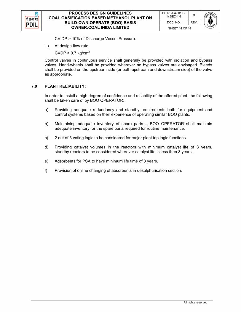
PROCESS DESIGN GUIDELINES COAL GASIFICATION BASED METHANOL PLANT ON
BUILD-OWN-OPERATE (BOO) BASIS OWNER:COAL INIDA LIMITED
PC176/E/4001/P-II/ SEC-1.6 0
DOC. NO. REV.
SHEET 14 OF 14
All rights reserved
CV DP > 10% of Discharge Vessel Pressure.
iii) At design flow rate,
CVDP > 0.7 kg/cm2
Control valves in continuous service shall generally be provided with isolation and bypass valves. Hand-wheels shall be provided wherever no bypass valves are envisaged. Bleeds shall be provided on the upstream side (or both upstream and downstream side) of the valve as appropriate.
7.0 PLANT RELIABILITY:
In order to install a high degree of confidence and reliability of the offered plant, the following shall be taken care of by BOO OPERATOR: a) Providing adequate redundancy and standby requirements both for equipment and
control systems based on their experience of operating similar BOO plants.
b) Maintaining adequate inventory of spare parts – BOO OPERATOR shall maintain adequate inventory for the spare parts required for routine maintenance.
c) 2 out of 3 voting logic to be considered for major plant trip logic functions. d) Providing catalyst volumes in the reactors with minimum catalyst life of 3 years,
standby reactors to be considered wherever catalyst life is less then 3 years.
e) Adsorbents for PSA to have minimum life time of 3 years. f) Provision of online changing of absorbents in desulphurisation section.

PROJECTS & DEVELOPMENT INDIA LTD
PC176/E/4001/P-II/ SEC-1.7 0
DOC. NO. REV
SHEET 1 OF 18
PART II: TECHNICAL
SECTION – 1.7
ENGINEERING SPECIFICATIONS FOR
PRESSURE VESSEL (STATIC EQUIPMENTS)
PROJECT: COAL TO METHANOL (C2M) PROJECT THROUGH COAL GASIFICATION ROUTE AT DANKUNI COAL COMPLEX WEST BENGAL, INDIA ON BUILD-OWN-OPERATE (BOO) BASIS

ENGINEERING SPECIFICATIONS -STATIC EQUIPMENTS
SUPPLY OF COAL TO METHANOL (C2M) PROJECT THROUGH COAL GASIFICATION ROUTE AT DANKUNI
COAL COMPLEX WEST BENGAL, INDIA ON BUILD-OWN-OPERATE (BOO) BASIS
PC176/E/4001/P-II/ SEC-1.7 0
DOC. NO REV
SHEET 2 OF 18
All rights reserved
CONTENTS
S.NO. DESCRIPTION PAGES 1.0 Referenced Publications 3
2.0 Design Philosophy/Criteria 5
3.0 Inspection & Testing 11
4.0 NDT Requirements 12
5.0 Documents, Data & Drawings 13
6.0 Spare Parts 13
Annexure --I Material Selection 15
Annexure --II General Points of Hydrogen Service 17

ENGINEERING SPECIFICATIONS -STATIC EQUIPMENTS
SUPPLY OF COAL TO METHANOL (C2M) PROJECT THROUGH COAL GASIFICATION ROUTE AT DANKUNI
COAL COMPLEX WEST BENGAL, INDIA ON BUILD-OWN-OPERATE (BOO) BASIS
PC176/E/4001/P-II/ SEC-1.7 0
DOC. NO REV
SHEET 3 OF 18
All rights reserved
1.0 REFERENCED PUBLICATIONS
a) The following codes and standards in their latest edition including latest addenda as on
the date of first issue of this design basis shall be followed unless otherwise specified in the requisition for the design, fabrication, inspection and testing of Vessels, Columns, Reactors, Spheres, Storage Tanks, Steel Silos, Bins, Hoppers, Steel Flare/Vents Stacks & heat exchangers:
ASME SEC. VIII DIV.1 Rules for construction of Unfired Pressure Vessels
ASME SEC. VIII DIV.2 For Pressure vessels and heat exchangers (Selectively for high pressure/high thickness)
ASME SEC. VIII DIV.2/PD 5500 For Storage Spheres/Bullets
ASME SEC.1 Rules for construction of power boilers,
IBR Indian Boiler Regulation Act 1950, Latest
Eddition.
ASME SEC. II A&B For material specification
ASME SEC II PART C Specification for welding rod, electrode & filler
metal
ASME SEC II PART D Properties
ASME SEC. IX For welding
ASME SEC V Non destructive examination
ASTM/IS For material specification
API 650/IS: 803 For Welded Steel Tanks for Oil Storage
API 620 For Design & Construction of Large, Welded, Low- pressure Storage Tank
API 625 Tank Systems For Refrigerated Liquefied Gas Storage API 661 For Air Cooled Exchanger IS 800 For Air Cooled Exchanger Structural Design

ENGINEERING SPECIFICATIONS -STATIC EQUIPMENTS
SUPPLY OF COAL TO METHANOL (C2M) PROJECT THROUGH COAL GASIFICATION ROUTE AT DANKUNI
COAL COMPLEX WEST BENGAL, INDIA ON BUILD-OWN-OPERATE (BOO) BASIS
PC176/E/4001/P-II/ SEC-1.7 0
DOC. NO REV
SHEET 4 OF 18
All rights reserved
API 2000 Venting Atmospheric & Low Pressure Storage Tanks. IS: 875/SITE DATA For wind load consideration
IS: 1893/SITE DATA For Seismic design consideration (IS: 1893 Part –IV Response Spectrum Method)
ASME B 16.5 For Pipe flanges & Flanged fittings
ASME B 16.47 For Large diameter Steel flanges
ASME B 16.20 For gaskets
ASME B 96.1 Welded Aluminum Alloy Storage Tanks
EJMA Standard of Expansion joint Manufacturing Association TEMA Class R For shell and tube Exchanger
OISD-STD 150 For Mounded Vessel
API 941 Steels for Hydrogen Service at Elevated
Temperature & Pressure
b) STATUTORY PROVISIONS:
National laws and statutory provisions such as Indian Boiler Regulation with any local by-laws for the state shall be complied with. Static and Mobile Pressure Vessel (SMPV) rules as applicable shall also be complied with.
c) PUBLICATIONS
NACE MR 0103 Materials Resistant to Sulfide Stress Cracking in Corrosive Petroleum Refining Environments.
NACE MR 0175 / ISO 15156 Petroleum and natural gas industries - Materials for use in H2S containing environments in oil and gas production.
NACE RP 0296 Guidelines for Detection, Repair and Mitigation of Cracking of Existing Petroleum Refinery Pressure Vessels in Wet H2S Environment.
NACE TM 0284 Evaluation of Pipeline and Pressure Vessel Steel
for Resistance to Hydrogen Induced Cracking.

ENGINEERING SPECIFICATIONS -STATIC EQUIPMENTS
SUPPLY OF COAL TO METHANOL (C2M) PROJECT THROUGH COAL GASIFICATION ROUTE AT DANKUNI
COAL COMPLEX WEST BENGAL, INDIA ON BUILD-OWN-OPERATE (BOO) BASIS
PC176/E/4001/P-II/ SEC-1.7 0
DOC. NO REV
SHEET 5 OF 18
All rights reserved
NACE TM 0177 Laboratory Testing of Metals for Resistance to Sulphide Stress Cracking in Hydrogen Sulphide Environment.
WRC Bulletin # 107 Local Stresses in Spherical & Cylindrical Shells due to External Loadings.
WRC Bulletin # 297 Local Stresses in Cylindrical Shells due to External Loadings on Nozzles.
2.0 DESIGN PHILOSOPHY / GENERAL CRITERIA
Equipment shall be designed in compliance with the latest design code requirements and applicable standards/ specifications. All design calculations shall be performed considering all applicable loads for erection, operating and hydro test conditions.
2.1 MINIMUM SHELL/HEAD THICKNESS
Vessel pressure components and supports shall have minimum thicknesses after forming not less than the requirements of the Code and this standard. The minimum nominal thickness before forming of carbon and alloy steel vessels shells, heads and support skirts shall not be less than the larger of the following:
1 Inside diameter in mm + 2540 + C.A. (mm) 1000 2 4.5MM + C.A 3. 10mm + clad thickness for clad vessels.
Nozzle necks shall not be less than ASME VIII Div. 1 Code minimum thickness (Para UG-45). Minimum thickness of vessel skirts shall be 6 mm. Internal non-pressure piping and fittings in vessels with up to 3mm C.A. shall have the following minimum nominal wall thickness unless otherwise shown on the data sheet.
Carbon Steel
Up to 100 mm NB Sch. 80 150 mm NB to 250 mm NB Sch. 40 (STD Wall) Over 250 mm NB STD Wall Alloy Steel or All sizes STD Wall Non-Ferrous.

ENGINEERING SPECIFICATIONS -STATIC EQUIPMENTS
SUPPLY OF COAL TO METHANOL (C2M) PROJECT THROUGH COAL GASIFICATION ROUTE AT DANKUNI
COAL COMPLEX WEST BENGAL, INDIA ON BUILD-OWN-OPERATE (BOO) BASIS
PC176/E/4001/P-II/ SEC-1.7 0
DOC. NO REV
SHEET 6 OF 18
All rights reserved
For higher C.A., thicknesses shall be suitably increased.
4) For shell & tube heat exchangers, minimum thickness shall be as per TEMA & Tube
sheet as per UHX of ASME SECTION VIII Div.1
5) For Air Cooled heat exchangers, minimum thickness shall be as per API 661, However minimum tube sheet thickness shall be 22mm (excluding corrosion allowance)
2.2 TEST PRESSURE a) Equipment shall be hydrostatically tested in the fabricator's shop as per design code. b) Equipment open to atmosphere shall be tested by filling with water to the top.
c) Unless otherwise specified in applicable design code allowable stress during hydro test
in tension shall not exceed 90% of yield point. d) Storage tanks shall be tested as per applicable code. 2.3 CORROSION ALLOWANCE:
Unless otherwise specified elsewhere, minimum corrosion allowance shall be considered as follows: - Carbon Steel equipment : 3.0 mm * - Low alloy steel equipment : 1.5 mm* (3 mm for shell & tube
exchangers) - Stainless steel equipment : NIL - Clad equipment : NIL (3 mm cladding minimum) - Lined equipment : 3.0 mm (plus lining) - CS Storage Tank bottom most shell : 3.0 mm course and bottom plate - CS Storage Tank shell : 1.5 mm
(other courses) - Storage tank Fixed roof/ : NIL
Floating Roof - CS Buried Vessels (External) : 1.5 mm - CS Spheres : 1.5 mm * Except for tubes
2.4 SUPPORTS: 2.4.1 All columns with diameter 1000 mm and more shall be self-supporting.

ENGINEERING SPECIFICATIONS -STATIC EQUIPMENTS
SUPPLY OF COAL TO METHANOL (C2M) PROJECT THROUGH COAL GASIFICATION ROUTE AT DANKUNI
COAL COMPLEX WEST BENGAL, INDIA ON BUILD-OWN-OPERATE (BOO) BASIS
PC176/E/4001/P-II/ SEC-1.7 0
DOC. NO REV
SHEET 7 OF 18
All rights reserved
2.4.2 All columns with diameter less than 1000 mm shall be supported by superimposed structure around the column covering the entire height. Guy wires are not permitted to be used for supporting any equipment.
2.4.3 In specific cases, columns having diameter less than 1000 mm and total L/D ratio not
exceeding 10 may be self-supported. 2.4.4 Storage spheres shall be supported on pipe legs with tie rod bracing and turnbuckles. 2.4.5 Buried vessels shall be suitably anchored to prevent the uplift due to under ground water.
Anchor bolts shall have corrosion allowance of 6 mm on diameter. Buried vessels shall be rested on concrete saddles with anchoring bracket at the centerline of the vessel.
2.4.6 All skirt supported columns/equipment with height 20 m and above (irrespective of weight)
and weight 50 MT and above (irrespective of height) are to be provided with tailing lug. 2.5 MANHOLES:
Vessels and columns with diameter greater than 900 mm and up to 1500 mm shall be provided with 500 NB manholes. However, if required, vessels and columns with diameter 1500 mm and above may be provided with 600 NB manholes.
2.6 FLANGES: 2.6.1 Nozzle flanges up to 600 NB shall be as per ASME B16.5 and above 600 NB shall be as
per ASME B 16.47 (SERIES 'B') except that for high pressure heat exchanger. 2.6.2 Unless otherwise specified, W.N. Flanges shall be used for all classes. 2.6.3 Unless otherwise specified, all girth flanges and intermediate body flanges shall be of
weld neck type only. 2.6.4 Flange rating shall be established based on design pressure, design temperature and
considering all external loads (moments and axial force). 2.7 PIPE DAVIT:
i) Vertical Vessel/Column having safety valve size 80 NB and above and or having internals, shall be provided with pipe davit.
ii) Exchangers shall be provided with davits for removal of flat channel cover and
shell covers only. 2.8 IMPORTANT CONSIDERATIONS:
- Vessels and columns shall be designed considering maximum operating liquid head in addition to design pressure.

ENGINEERING SPECIFICATIONS -STATIC EQUIPMENTS
SUPPLY OF COAL TO METHANOL (C2M) PROJECT THROUGH COAL GASIFICATION ROUTE AT DANKUNI
COAL COMPLEX WEST BENGAL, INDIA ON BUILD-OWN-OPERATE (BOO) BASIS
PC176/E/4001/P-II/ SEC-1.7 0
DOC. NO REV
SHEET 8 OF 18
All rights reserved
- All columns and vessels shall be capable of withstanding water full condition during system testing.
- In addition, all vertical vessels, columns and horizontal vessels shall be designed
so as to permit site testing of the equipment with water at the test pressure on the top of the equipment considering 33% of design wind load. The design shall be based on fully corroded condition.
- Vessels and columns shall be tested at shop hydrostatically at pressure
calculated as per applicable code in new and cold condition.
- Design of components not covered in IBR (Indian Boiler Regulations) shall be in accordance with ASME SEC VIII DIV I.
- All nozzle necks, all nozzle flanges and blind flanges shall be of weld deposit
construction for clad equipment. Loose liners are not permitted.
- All vertical equipment shall be provided with two lifting lugs. Lifting lugs shall be designed with impact factor of two.
2.9 SILENT REQUIREMENTS OF STATIC EQUIPMENTS 2.9.1 HEAT EXCHANGERS: 1. Tube Sheet type for
Floating head and U Tube heat exchanger: Non-extended for floating head and U tube exchangers. Extended for Stab in bundles only if
B' type stationary head of U tube Exchangers.
2. Testing accessories for
shell and tube Heat Exchanger: a. Testing rings shall be provided on all floating 'S' & 'T' head type exchangers.
b. Dummy shell shall be provided for
fixing test ring for exchangers such as kettle type or floating head without shell covers (TEMA 'AHT' or 'AKT') or stab in bundle where shell design pressure is higher than tube side pressure.
c. Test flanges shall be provided

ENGINEERING SPECIFICATIONS -STATIC EQUIPMENTS
SUPPLY OF COAL TO METHANOL (C2M) PROJECT THROUGH COAL GASIFICATION ROUTE AT DANKUNI
COAL COMPLEX WEST BENGAL, INDIA ON BUILD-OWN-OPERATE (BOO) BASIS
PC176/E/4001/P-II/ SEC-1.7 0
DOC. NO REV
SHEET 9 OF 18
All rights reserved
i) For exchangers with removable bundle and bonnet type channel.
ii) For exchanger with removable bundle and channel with flat cover if tube side pressure is greater than shell side pressure.
d. Minimum number of test rings/ test flanges/ dummy shells shall be at least one per set of three bundles.
e. For shell side interconnected and stacked exchangers the minimum number of test rings shall be equal to the number of exchangers in one stack.
f. For 'U' tube & removable bundle exchanger, number of test flanges shall be equal to number of exchangers in one stack.
2.9.2 Tall Columns
Mechanical design of self-supporting tall column and its anchorage block shall be carried out considering combination of various loads as below:
2.9.2.1 Loadings
The loadings to be considered in designing a self-supporting tall column/tower shall include: (i) Internal and or external design pressure specified on process data
sheets.
(ii) Self weight of column inclusive of piping, platforms, ladders, manholes, nozzles, trays, welded and removable attachments, insulation and operating liquid etc.
(iii) Other loadings as specified in UG-22 of ASME Code Sec. VIII Div.1,
wherever applicable. 2.9.2.2 Loading Condition
Analysis shall be carried out for following conditions:
(i) Erection Condition Column (uncorroded) erected on foundation, without insulation, platforms, trays etc. but with welded attachments plus full wind on column.

ENGINEERING SPECIFICATIONS -STATIC EQUIPMENTS
SUPPLY OF COAL TO METHANOL (C2M) PROJECT THROUGH COAL GASIFICATION ROUTE AT DANKUNI
COAL COMPLEX WEST BENGAL, INDIA ON BUILD-OWN-OPERATE (BOO) BASIS
PC176/E/4001/P-II/ SEC-1.7 0
DOC. NO REV
SHEET 10 OF 18
All rights reserved
(ii) Operating Condition Column (in corroded condition) under design pressure,
including welded items, trays, removable internals, piping, platforms, ladder, reboiler mounted on column, insulation and operating liquid etc. plus full wind on insulated column with all other projections open to wind, or earthquake forces.
(iii) Test Condition: Column (in corroded condition) under test pressure, filled with
water plus 33% of specified wind load on uninsulated column including all attachments shall be considered.
(iv) Earthquake And Wind Shall Be Considered Not Acting Concurrently.
2.9.2.3 Deflection of Column
Maximum allowable deflection at top of column shall be equal to height of the column divided by 200 up to a maximum of 300 mm.
(i) If the deflection of column exceeds the above allowable limit, the thickness of
skirt shall be increased as first trial up to a maximum value equal to the column thickness and this exercise shall be stopped if the deflection falls within allowable limit.
(ii) If the above step is inadequate, skirt shall be gradually flared to reduce the
deflection. Flaring of skirt shall be stopped if the deflection falls within limits or half angle of cone reaches maximum limit of 9.
(iii) If the above two steps prove inadequate in limiting the deflection within allowable
limits, the thickness of shell courses shall be increased one by one starting from bottom course above skirt and proceeding upwards till the deflection falls within allowable limits.
2.9.2.4 Stress Limits
The stresses due to pressure, weight, wind/seismic loads shall be combined using maximum principal stress theory for ASME Section VIII Div. I.
2.9.2.5 Skirt Support Base
Base supporting including base plate, anchor chairs, compression ring, foundation bolting etc. shall be designed based on over-turning moment (greater of seismic or wind). A minimum number of 8 foundation bolts shall be provided. Nos. of foundation bolts shall be in multiple of four.
2.9.2.7 Dynamic Analysis of Column/Tower
Dynamic analysis of each column shall be carried out for stability under transverse wind induced vibrations as per standard design practice.

ENGINEERING SPECIFICATIONS -STATIC EQUIPMENTS
SUPPLY OF COAL TO METHANOL (C2M) PROJECT THROUGH COAL GASIFICATION ROUTE AT DANKUNI
COAL COMPLEX WEST BENGAL, INDIA ON BUILD-OWN-OPERATE (BOO) BASIS
PC176/E/4001/P-II/ SEC-1.7 0
DOC. NO REV
SHEET 11 OF 18
All rights reserved
2.9.3 TOWERS
a) The design shall be done based on Process Licensor's Specifications.
b) Material selection shall strictly be as per Licensor's Specification.
c) Minimum thickness as per Licensor's Specification shall be adhered to.
e) FEM Analysis shall be done for all shell to head junction Y shaped skirt, welded/weld overlayed support rings and any other stressed point.
f) All internals shall have minimum thickness as given in Process Licensor's
Specification and shall be designed for loads defined by Process Licensor. 2.9.4 DOUBLE WALLED STORAGE TANKS 2.9.4.1 Type of Containment shall be selected from the following
a) Single Containment b) Double Containment (with or without outside-pressured concrete wall)
2.9.4.2. Metallurgy of inner and outer tanks shall be selected on the basis of containment and
service requirement. 2.9.4.3. Type of foundation shall be selected from the following:
a) Elevated pier type b) Electrically heated type.
3.0 INSPECTION & TESTING:
The following tests/procedures are mandatory to be witnessed / reviewed by Owner/ it’s authorized inspection agency.
i) Drawings & design calculations for critical equipments, other for
reference. ii) Welding procedure specifications approval. iii) Heat treatment procedure approval (if applicable). iv) Hydraulic test v) NDT tests reports e.g. RT, UT, MP / PT & hardness etc. including Leak
test, Ferrite check, Iron contaminated test, Inter-granular corrosion test etc.
vi) Material test certificates & Positive material identifications Vii) PWHT charts Viii) Production test coupons ix) WPS & PQR

ENGINEERING SPECIFICATIONS -STATIC EQUIPMENTS
SUPPLY OF COAL TO METHANOL (C2M) PROJECT THROUGH COAL GASIFICATION ROUTE AT DANKUNI
COAL COMPLEX WEST BENGAL, INDIA ON BUILD-OWN-OPERATE (BOO) BASIS
PC176/E/4001/P-II/ SEC-1.7 0
DOC. NO REV
SHEET 12 OF 18
All rights reserved
x) UT for Lack of bond in clad material. xi) Mock-up test for tube to tube sheet joint. xii) In-process inspection of tray / internal parts- Visual dimension, Shearing,
Punching & Bending. xiii) Vacuum test for Tank bottom plates. xiv) For Air cooled H.E, Inspection of tube sheet / plug sheet after machining
& pullout test on fin tubes.
3.1 The equipment shall be considered acceptable for dispatch only after final certification for acceptance is issued by concerned inspector.
3.2 Formed heads cold formed or hot formed below normalizing temperature shall be
subsequently normalized and weld seams if any shall be fully radio graphed after forming.
3.3 All nozzle reinforcing pads wherever applicable shall be tested pneumatically at 1.25
Kg/cm2g pressure with soap solution on attachment welds. Vent holes shall be plugged with non-hardening mastic to prevent ingress of water.
3.3 All completed equipment shall be tested hydraulically as per the requirements of
codes, standards & specifications in presence of the inspecting authority. Pneumatic test of completed equipment shall be carried out only when specially mentioned in the specification sheets. Duration of test shall be as per applicable codes & standards. Test medium/water shall be tested for the chlorine contents before filling the equipment.
3.4 The temperature of test water shall comply with requirement of Fabrication code. 3.5 Unless otherwise stated gaskets used during testing shall be same as specified for
operating conditions. After testing, gaskets used during testing shall be replaced by new gaskets.
4.0 NDT REQUIREMENTS: The following NDT requirements are mandatory in addition to codes, standards &
specification requirements.
A) UT examination:
i) All butt - as supplement to radiography (where radiography is not possible) ii) FPW of nozzle attachments as supplement to radiography iii) All forgings iv) All butt welds after hydro test
B) MP / PT Examination:
i) All edges of plates and opening in shell of CS and LAS/SS. ii) Root and final layer of all butt welds.

ENGINEERING SPECIFICATIONS -STATIC EQUIPMENTS
SUPPLY OF COAL TO METHANOL (C2M) PROJECT THROUGH COAL GASIFICATION ROUTE AT DANKUNI
COAL COMPLEX WEST BENGAL, INDIA ON BUILD-OWN-OPERATE (BOO) BASIS
PC176/E/4001/P-II/ SEC-1.7 0
DOC. NO REV
SHEET 13 OF 18
All rights reserved
iii) All weld surfaces after PWHT. iv) All forgings after machining. v) All fillet & butt weld after hydro testing.
vi) Knuckle surface of dished ends / toriconical sections, pipe bends and expansions bellow.
vii) All attachment welds.
C) Radiography:
i) All weld seams of formed head, if made in more than one segment shall be
full radiography after forming and heat treatment if any. ii) When spot radiography is specified, all T joints & minimum 10% of total
weld length excluding T joints shall be radiographed. iii) All nozzles fabricated from plates shall be 100% radiographed. iv) All butt welds irrespective of thickness (100% radiographed) before PWHT
and hydro test. 5.0 DOCUMENTS, DATA & DRAWINGS:
5.1 GENERAL
BOO OPERATOR shall develop detailed mechanical design & fabrication drawings pertaining to each type of Static Equipment as applicable.
BOO OPERATOR shall be responsible for the review & approval of all such design and fabrication drawings submitted by the Equipment manufacturer. Owner’s/PMC’s review/approval shall be limited to the mechanical design and vendor fabrication drawings for critical items. A list of such critical items shall be furnished by BOO OPERATOR along with bid.
5.2 DRAWINGS AND DOCUMENTS REQUIRED ALONG WITH BID
The Contractor shall furnish the following along with the bid:
(a) Technical Compliance Pro-forma, duly completed.
(b) List of deviations if any, to the applicable specifications.
(c) List of Critical items.
6.0 SPARE PARTS
a) MANDATORY SPARES : Guidelines for Mandatory spare requirement for all type of equipment shall be as per Section-10 of ITB. However BOO Operator may have their own Philosophy for procurement of mandatory spares & 2 years spares with in the
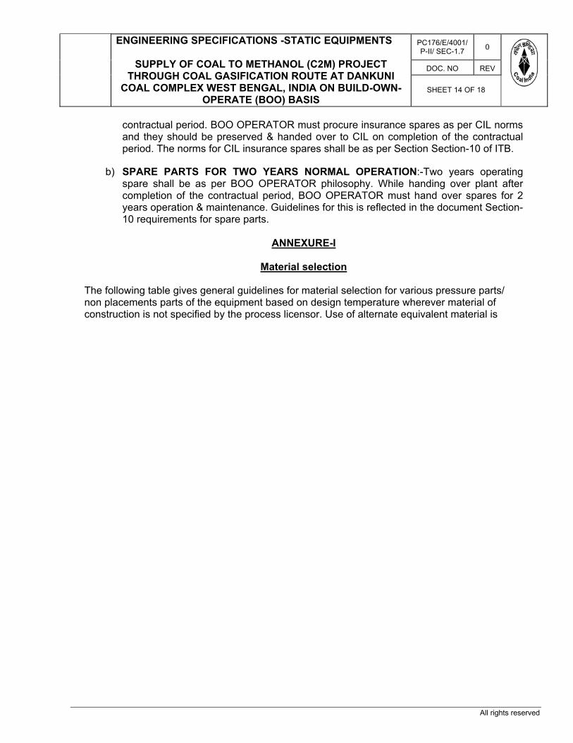
ENGINEERING SPECIFICATIONS -STATIC EQUIPMENTS
SUPPLY OF COAL TO METHANOL (C2M) PROJECT THROUGH COAL GASIFICATION ROUTE AT DANKUNI
COAL COMPLEX WEST BENGAL, INDIA ON BUILD-OWN-OPERATE (BOO) BASIS
PC176/E/4001/P-II/ SEC-1.7 0
DOC. NO REV
SHEET 14 OF 18
All rights reserved
contractual period. BOO OPERATOR must procure insurance spares as per CIL norms and they should be preserved & handed over to CIL on completion of the contractual period. The norms for CIL insurance spares shall be as per Section Section-10 of ITB.
b) SPARE PARTS FOR TWO YEARS NORMAL OPERATION:-Two years operating spare shall be as per BOO OPERATOR philosophy. While handing over plant after completion of the contractual period, BOO OPERATOR must hand over spares for 2 years operation & maintenance. Guidelines for this is reflected in the document Section-10 requirements for spare parts.
ANNEXURE-I
Material selection
The following table gives general guidelines for material selection for various pressure parts/ non placements parts of the equipment based on design temperature wherever material of construction is not specified by the process licensor. Use of alternate equivalent material is

ENGINEERING SPECIFICATIONS -STATIC EQUIPMENTS
SUPPLY OF COAL TO METHANOL (C2M) PROJECT THROUGH COAL GASIFICATION ROUTE AT DANKUNI
COAL COMPLEX WEST BENGAL, INDIA ON BUILD-OWN-OPERATE (BOO) BASIS
PC176/E/4001/P-II/ SEC-1.7 0
DOC. NO REV
SHEET 15 OF 18
All rights reserved
permitted with prior approval from CIL / PMC.
1. Plates are purchased to the requirement of the standard ASME SA-20, which requires
testing of individual plates for low temperature service. Carbon steel material is ordered to meet the impact requirements of supplement S5, of standard ASME SA 20; typical material specification is as follows. SA 516 Gr.60. Normalised, to meet impact requirements per supplement S5 of SA 20 at minus 50ºF.

ENGINEERING SPECIFICATIONS -STATIC EQUIPMENTS
SUPPLY OF COAL TO METHANOL (C2M) PROJECT THROUGH COAL GASIFICATION ROUTE AT DANKUNI
COAL COMPLEX WEST BENGAL, INDIA ON BUILD-OWN-OPERATE (BOO) BASIS
PC176/E/4001/P-II/ SEC-1.7 0
DOC. NO REV
SHEET 16 OF 18
All rights reserved
2. All permanent attachments welded directly to 9% nickel steel should be of the same material or of an austenitic stainless steel type, which cannot be hardened by heat treatment.
3. Check for impact testing requirement as per UCS-66, for coincident temperature and
part thickness. 4. Selection of stainless steel material shall be based on process recommendation /
process licensor. 5. This table is not applicable for atmospheric/low pressure storage tanks. Materials shall
be selected as per API 650/API 620 as applicable. 6. Materials for caustic service, sour service or sour service + HIC shall be selected based
on specific recommendation of process licensor. 7. Material for pressure vessels designed according to ASME Section VIII Division 2 shall
be given special consideration as per code. 8. All pipes shall be of seamless construction. 9. Non-ferrous material and super alloys are not covered above and shall be selected
based on specific recommendation. 10. Material for vessel / column skirt shall be the same material as of vessel /column shell
for the upper part with a minimum of 1000mm. 11. All tubes shall be of seamless construction. 12. SA 336 shall be used for Heat Exchanger non-standard SS/LAS forgings. 13. Internal bolting shall be selected on the basis of shell side material solid or clad as
follows: SHELL MATERIAL STUD NUTS Carbon steel & upto 1% Cr ASTM A 193 Gr B-7M ASTM A-194 Gr 2HM 5% Chrome A 193 Gr B5 A 194 Gr 3 13% Chrome A 193 Gr B6X A 194 Gr 6 Stainless Steel A 193 Gr* A 194 Gr* For low temperatures, min. quality of bolting material shall be as specified for external bolting and shall be improved if shell side materials are better. * Compatible / same grade of SS

ENGINEERING SPECIFICATIONS -STATIC EQUIPMENTS
SUPPLY OF COAL TO METHANOL (C2M) PROJECT THROUGH COAL GASIFICATION ROUTE AT DANKUNI
COAL COMPLEX WEST BENGAL, INDIA ON BUILD-OWN-OPERATE (BOO) BASIS
PC176/E/4001/P-II/ SEC-1.7 0
DOC. NO REV
SHEET 17 OF 18
All rights reserved
ANNEXURE –II
GENERAL POINTS FOR HYDROGEN SERVICE.
1) Hydrogen Service
a) Hydrogen partial pressure exceeding 50 psia (3.5 kg/cm2(a)}. b) More than 90 percent hydrogen at any pressure level.
2) Severe Cyclic Service
Cyclic Service as defined in ASME B31.3, Section 300.2. Cyclic service may be mechanical, thermal, or a combination of both.
3) The hydrogen partial pressure (design) does not exceed 50 psia {3.5 kg/cm2(a)}. 4) Details
Either an integrally reinforced nozzle or balanced integral reinforcement in both the nozzle neck and vessel is required for hydrogen service and is preferred for all services. Built-up construction using pipe or rolled plate with a flange and reinforcing pad is permissible for non-hydrogen service. Gussets are not permitted.
5) A) Plates and forgings over 2 inches (50mm) thick or used for pressure containment in Hydrogen service shall be Ultrasonically examined with 100% scanning in accordance with the following:
(i) Plates shall be examined before forming in accordance with ASME SA-435
including supplementary requirements S1.
(ii) Forgings shall be examined in accordance with ASME SA-388 and ASME Section VIII, Division 2, AM-203.2.
B) Examined by either liquid penetrant (PT) or magnetic particle (MT) in accordance with
the following: (i) The entire surface of all forgings after finish machining.
(ii) Formed plate surfaces to be welded, i.e., the weld level area, and a minimum of 2 inches (50 mm) of the neighbouring surfaces.
(iii) Formed plate surfaces where weld overlay will be applied. 6) Internal support rings shall be continuously welded to the shell on the top and
intermittently welded on the bottom. Internal lugs and brackets shall be continuously

ENGINEERING SPECIFICATIONS -STATIC EQUIPMENTS
SUPPLY OF COAL TO METHANOL (C2M) PROJECT THROUGH COAL GASIFICATION ROUTE AT DANKUNI
COAL COMPLEX WEST BENGAL, INDIA ON BUILD-OWN-OPERATE (BOO) BASIS
PC176/E/4001/P-II/ SEC-1.7 0
DOC. NO REV
SHEET 18 OF 18
All rights reserved
welded on the top and sides only. In hydrogen service all internal and external welds shall be full penetration, free of undercuts, through the support side of the joint.
7) In hydrogen services, all fillet welds (internal and external) to pressure containing
components shall be ground to a smooth and generous concave contour. 8) Covered welding electrodes (i.e. shielded metal are welding – SMAW) shall be of the
low hydrogen coating type and shall be in accordance with ASME Section II, Part C, SFA-5.5. Rod ovens, and other means as necessary, shall be used to ensure that the rods remain dry.
9) In hydrogen service, nozzles with tubular liners welded on both ends shall be vented
with a 1/8 inch NPS hole, drilled from the outside to the OD of the liner. The vent hole shall be tapped for future plugging with a materials adequate for the operating temperature but incapable of retaining the operating pressure.
10) When austenitic stainless steel weld deposit overlay is used in an elevated operating
temperature {over 700oF (370oC)} hydrogen service the fabricator shall demonstrate that their procedures and materials provide immunity to lining disbanding. Testing shall be representative of the actual operating conditions (e.g. hydrogen partial pressure, materials and material thicknesses, temperatures, and heating/cooling rates).
11) In addition to the requirements of ,when the hydrogen partial pressure exceeds 50 psia
{3.5 kg/cm2(a)}, the design temperature exceeds 600oF (315oC), and an austenitic stainless steel weld deposit overlay is used, the overlay shall be 100 percent ultrasonically examined for 4 lack of bond. The examination shall occur after the final post weld heat treatment and shall be from the outside. Examination shall be in accordance with ASME Section II, Part A, the SA-578. The acceptance level shall be S7. Indications of a lack of bond shall be recorded and re-examined from the inside. Indications of an unbonded are that exceed the acceptance criteria shall be repaired by weld deposit overlay and re-examined.
12) When the hydrogen partial pressure exceeds 50 psia {3.5 kg/cm2(a)}, the design
temperature exceeds 600oF (315oC), and an austenitic stainless steel cladding is used, clad surfaces shall be 100 percent ultrasonically examined for lack of bond. The examination shall occur from the outside after forming and before the final post weld heat treatment. The ultrasonic examination shall be in accordance with ASME Section II, part A, SA-578. The acceptance level shall be S7. Suspected unbonded areas shall be recorded and re-examined from the inside surface. Indications of unbonded areas that can not be encompassed within a 3-inch (75 mm) diameter circle shall be recorded, repaired by weld deposit and re-examined. All unbonded areas within 2 inches (50mm) of where attachments will be welded directly to the cladding shall also be repaired and re-examined. In addition, the lining shall be spot ultrasonically examined in accordance after final post weld heat treatment. The acceptance level shall be S6. Repaired areas and weld deposit overlay at weld seams shall be 100% liquid penetrant (PT) examined in accordance with ASTME 165. At attachments, the final PT shall be performed after final post weld heat treatment and pressure test.

PROJECTS & DEVLOPMENT INDIA LTD
PC176/E/4001/P-II/ SEC-1.8 0
DOC. NO. REV
SHEET 1 OF 18
0 24.09.2020 24.09.2020 ISSUED FOR TENDER YKG RRK RRK REV REV DATE EFF DATE PURPOSE PREPD REVWD APPD
FORM NO: 02-0000-0021F1 REV4 All rights reserved
PART-II, TECHNICAL
SECTION – 1.8
ENGINEERING SPECIFICATION – ROTATING EQUIPMENTS
PROJECT: COAL TO METHANOL (C2M) PROJECT
THROUGH COAL GASIFICATION ROUTE AT DANKUNI COAL COMPLEX WEST BENGAL, INDIA ON BUILD-OWN- OPERATE (BOO) BASIS
CONTENTS

COAL GASIFICATION BASED METHANOL PLANT
COAL INDIA LIMITED
DESIGN PHILOSOPHY – ROTATING EQUIPMENTS
PC176/E/4001/P-II/ SEC-1.8 0
DOC. NO REV
SHEET 2 OF 18
All Right Reserved
S.No. Description Sheet No. 1.0 REFERENCED PUBLICATIONS........................................................................ 3 2.0 DESIGN PHILOSOPHY........................................................................................ 6 2.1 SCOPE .......................................................................................................... 6 2.2 EQUIPMENT QUALIFICATION CRITERIA (EQC) ................... ......................... 6 2.3 ASSOCIATED ACCESSORIES AND AUXILIARY SYSTEMS ........................... 6 2.4 SEALING SYSTEM SELECTION CRITERIA .................................................... 7 2.5 COUPLINGS & COUPLING GUARDS ............................................................ 7 2.6 ALLOWABLE NOISE LEVEL ............................................................................ 8 2.7 EQUIPMENT STORAGE ................................................................................... 8 2.8 INSTALLATION CRITERIA ............................................................................... 8 2.9 MAINTENANCE FACILITIES ............................................................................ 9 2.10 HEAT EXCHANGERS ...................................................................................... 9 2.11 SAFETY ............................................................................................................ 9 3.0 SPECIAL REQUIREMENTS................................................................................... 10 3.1 CENTRIFUGAL COMPRESSORS ...................................................................... 10 3.2 RECIPROCATING COMPRESSORS ................................................................ 10 3.3 ROTARY TYPE POSITIVE DISPLACEMENT COMPRESSOR .......................... 11 3.4 LIQUID RING VACUUM PUMPS/COMPRESSORS ............................................ 12 3.5 DIAPHRAGM COMPRESSORS ......................................................................... 12 3.6 PACKAGED INTEGRALLY GEARED CENTRIFUGAL AIR COMPRESSOR ...... 13 3.7 ROOTS BLOWER ............................................................................................... 13 3.8 CENTRIFUGAL PUMPS ..................................................................................... 14 3.9 FANS CENTRIFUGAL/F.D./I.D. FANS ............................................................... 15 3.10 RECIPROCATING PUMPS ................................................................................ 16 3.11 POSITIVE DISPLACEMENT PUMP CONTROLLED VOLUME .......................... 16 3.12 CRYOGENIC PUMPS ........................................................................................ 17 3.13 SPECIAL PURPOSE GEAR UNITS ................................................................... 17 4.0 SPARES & SPECIAL TOOLS.............................................................................. 17 4.1 COMMISSIONING SPARE PARTS .................................................................... 17 4.2 SPECIAL TOOLS/TACKLES ............................................................................... 17 4.3 MANDATORY SPARES ....................................................................................... 17 4.4 SPARE PARTS FOR TWO YEARS NORMAL OPERATION ............................. 18
5.0 DRAWING & DOCUMENTS ………………………………………………………… 18
1.0 REFERENCED PUBLICATIONS

COAL GASIFICATION BASED METHANOL PLANT
COAL INDIA LIMITED
DESIGN PHILOSOPHY – ROTATING EQUIPMENTS
PC176/E/4001/P-II/ SEC-1.8 0
DOC. NO REV
SHEET 3 OF 18
All Right Reserved
The following codes are referred and applicable for the equipment as enlisted.
Table 1: Applicable/Referred Codes and Standards Sno. Description Standards / Codes Remarks
1 PUMPS:
1.1 Centrifugal Pumps (Special Purpose Process Service)
API Std. 610 (Latest edition.) (1)
1.2 Centrifugal Pumps (General Purpose Process Service)
(2)
1.3 Centrifugal Pumps (General Water Service) (3)
1.4 Centrifugal Pumps (Slurry & Liquor Service)
1.5 Positive Displacement Pumps (Reciprocating)
API Std. 674 (latest edition.)
1.6 Positive Displacement Pumps (Controlled Volume)
API Std. 675 (latest edition)
1.7 Positive Displacement Pumps (Rotary) API Std. 676 (latest edition)
1.8 Liquid Ring Vacuum Pumps API Std. 681 (latest edition)
1.9 Seal-less Pumps API Std. 685 (latest edition)
2 COMPRESSORS / FANS & BLOWERS
2.1 Centrifugal Compressors API Std. 617 (latest edition)
2.2 Axial Compressors API Std. 617 (latest edition)
2.3 Expander-Compressors API Std. 617 (latest edition)
2.4 Centrifugal Fans
2.5 Induced Draft / Forced Draft Fans API 673 (latest edition)
2.6 Packaged Integrally Geared Centrifugal Air Compressors
API Std. 672 (latest edition)
2.7 Reciprocating Compressors (Utility & Instrument Air Service)
2.8 Reciprocating Compressors (Process Service)
API Std. 618 (latest edition)
2.9 Positive Displacement Compressors (Rotary)
API Std. 619 (latest edition)

COAL GASIFICATION BASED METHANOL PLANT
COAL INDIA LIMITED
DESIGN PHILOSOPHY – ROTATING EQUIPMENTS
PC176/E/4001/P-II/ SEC-1.8 0
DOC. NO REV
SHEET 4 OF 18
All Right Reserved
2.10 Roots Blowers
3 MECHANICAL DRIVERS / GEAR BOXES
3.1 Diesel Engines
3.2 Gas Turbines API Std. 616 (latest edition)
3.3 Steam Turbines (General Purpose) API Std. 611 (latest edition) (4)
3.4 Steam Turbines (Special Purpose) API Std. 612 (latest edition) (5)
3.5 Special Purpose Gear Box API Std. 613 (latest edition) (6)
3.6 General Purpose Gear Box API Std. 677 (latest edition) (7)
3.7 Special Purpose Coupling API Std. 671 (latest edition) (8)
4 AUXILIARIES
4.1 Lubrication, shaft sealing and control-oil systems and auxiliaries
API Std. 614 (latest edition)
4.2 Shaft sealing for centrifugal & rotary pumps API Std. 682 (latest edition)
4.3 Vibration, Axial Position & Bearing Temp. Monitoring Systems
API Std. 670 (latest edition)
5 MISCELLANEOUS (For reference)
5.1 Steam Turbines PTC 6
5.2 Centrifugal compressor, Turbines and Exhausters
PTC 10
5.3 Large Industrial Fans PTC 11
5.4 Gas Turbines PTC 22
5.5 Gear units ANSI/AGMA
5.6 Bearings ABMA
5.7 Laboratory Methods of Testing Fans for Rating Purposes
AMCA
5.8 Mechanical Vibrations - Balancing quality requirements of rotating rigid rotors
ISO 1940 and Respective API standard
Remarks: (1) Centrifugal pumps for special purpose process service are classified as pumps
which are meant for process service (both for on-site & offsite) but excluding the

COAL GASIFICATION BASED METHANOL PLANT
COAL INDIA LIMITED
DESIGN PHILOSOPHY – ROTATING EQUIPMENTS
PC176/E/4001/P-II/ SEC-1.8 0
DOC. NO REV
SHEET 5 OF 18
All Right Reserved
pumps covered either under general- purpose process service or general water service.
(2) Centrifugal pumps for general purpose process service are classified as pumps for
applications where maximum pressure by all considerations does not exceed 16.0 kg/cm² g, pumping temperature remains within -29°C to 205°C, Specific gravity is not less than 0.7 at the specified operating conditions or when dual pressurized / un-pressurised mechanical seals are not required/specified. Typical areas of application are non-process services & utility services such as De-mineralised Water (DMW) plants, Raw Water Treatment Plants (RWTP), Effluent Treatment Plants (ETP), Blow down services etc.
(3) Centrifugal pumps for general water service are classified as pumps for
applications such as Large Capacity Cooling Water Pumps, Auxiliary Cooling Water Pumps & other centrifugal pumps handling clean & cold water.
(4) General-purpose steam turbines (conforming to API Std. 611) shall be used where
driven equipment is usually spared, or is in non-critical service and where the steam supply conditions will not exceed 48 bar,g inlet pressure or 400°C inlet temperature or both and where speed will not exceed 6000 rpm. General-purpose steam turbines may also be used, subject to market availability, for cases where the steam supply conditions will not exceed 60 bar,g inlet pressure and 475°C inlet temperature and where speed will not exceed 6000 rpm and where turbine rating will not exceed 1500 kW and where driven equipment is usually spared, or is in non-critical service.
(5) Special-purpose steam turbines (conforming to API Std. 612) shall be used where
driven equipment is not spared and/or is in critical service. (6) General-purpose gear units (conforming to API Std. 677) shall be used in equipment
trains that are usually spared, or are in non-critical service and up-to a maximum driver rating of 750 kW. All ID fan trains are to be considered as meant for non-critical service.
(7) Special-purpose gear units (conforming to API Std. 613) shall be used in equipment
trains that are usually not spared, or are in critical service. (8) Special-purpose couplings (conforming to API Std. 671) shall be used in equipment
trains, as specified in the Engineering specification. 2.0 DESIGN PHILOSOPHY 2.1 SCOPE

COAL GASIFICATION BASED METHANOL PLANT
COAL INDIA LIMITED
DESIGN PHILOSOPHY – ROTATING EQUIPMENTS
PC176/E/4001/P-II/ SEC-1.8 0
DOC. NO REV
SHEET 6 OF 18
All Right Reserved
This Specification covers the design criteria for the purpose of carrying out Engineering for Procurement of various rotating equipment required including requirements with regard to spare parts & special tools. This Engineering specification shall be applied for supply of COAL TO METHANOL (C2M) PROJECT THROUGH COAL GASIFICATION ROUTE AT DANKUNI COAL COMPLEX WEST BENGAL, INDIA.
Electrical items, Instrumentation & Controls, Piping, Pressure Vessels, Mechanical Equipment, Heat exchangers etc. associated with rotating equipment shall comply with the design requirements as given in the respective specifications forming part of the bid package / inquiry.
All technical specification used by PDIL/ BOO OPERATOR if in conflict with licensor’s specification, Licensor’s specification shall override.
2.2 EQUIPMENT QUALIFICATION CRITERIA (EQC)
All Rotating Equipment shall be field proven and shall have well experience record. The vendor for the complete unit shall be an established manufacturer of Rotating equipment and he shall also be the manufacturer of the proposed Rotating equipment having adequate engineering, manufacturing & testing facilities for the same.
The vendor shall have engineered, packaged, tested and supplied similar packages in
terms of type of Rotating equipment, driver, sealing system, inlet volumetric capacity & driver rating (kW) from the proposed plant.
The vendor besides satisfying the above requirements shall also be the packager of the
complete system proposed and shall have the single point responsibility for the entire package.
The equipment model offered shall be from regular manufacturing range of the manufacturer and shall meet the following minimum service and manufacturing experience requirements.
. 2.3 ASSOCIATED ACCESSORIES AND AUXILIARY SYSTEMS
2.3.1 BOO OPERATOR shall furnish all rotating equipment, drivers, auxiliary systems, instrumentation and control systems, all necessary electrical and safety devices as applicable or required for safe and reliable operation of the unit.
BOO OPERATOR in his scope of supply and work shall also include the hardware required over and above what is specified, for safe and satisfactory operation of the equipment package.
2.3.2 Motors, electrical/instrument components and electrical/instrument installations shall be suitable for the area classification specified by the BOO OPERATOR and shall meet the requirements as defined in the electrical/instrument specification attached with the relevant sections of the bid package /order.
2.4 SEALING SYSTEM SELECTION CRITERIA

COAL GASIFICATION BASED METHANOL PLANT
COAL INDIA LIMITED
DESIGN PHILOSOPHY – ROTATING EQUIPMENTS
PC176/E/4001/P-II/ SEC-1.8 0
DOC. NO REV
SHEET 7 OF 18
All Right Reserved
2.4.1 Centrifugal Pumps
2.4.1.1 All Pumps shall be provided with mechanical seals (except, clean cold water service) 2.4.2 Centrifugal Compressors 2.4.2.1 Centrifugal Compressors (for gas service) shall be provided with Dry Gas Seals except
for services (like Air, N2 etc.) where normally labyrinths shall be used for sealing. 2.4.2.2 Dry gas seal and sealing skid comprising of dry gas seal filters, valves and
instrumentation etc. shall be procured from Dry Gas seal supplier only. Seal gas/reference gas filters shall have stand by unit for cleaning/replacement during operation of compressor. Dry gas seal shall be bi-directional type and interchangeable between drive and non-drive end.
2.5 COUPLINGS & COUPLING GUARDS
2.5.1 Unless otherwise specified, Couplings shall be of metallic, non-lubricated, flexible element type (i.e. either diaphragm or discs) with spacer, for all equipment. All coupling models shall be selected for a minimum service factor of 1.5.
2.5.2 Couplings for the following equipment shall conform to API Standard 671:
- Centrifugal compressors (API Std. 617) - Special purpose Steam Turbines (API Std. 612) - Gas Turbines (API Std. 616) - Rotary Screw Compressors (API Std. 619) - Multi-stage (greater than two stages) centrifugal pumps with driver rating
greater than 160 kW.
2.5.3 Couplings as per manufacturer’s standard may be supplied for the following equipment:
- Reciprocating Compressors - Packaged Integrally Geared Centrifugal Air Compressors - Packaged Rotary Compressors (Screw type for Plant & Instrument Air Service)
2.5.4 Removable coupling guard shall be provided which shall be fabricated from non-
sparking material, and shall be open at the bottom to permit manual shaft rotation. The guard shall be sufficiently rigid to withstand deflections as a result of bodily contact of nominally 100 kgs. Centrifugal compressors and Gas Turbines coupling guards may have vendor standard features.
2.6 ALLOWABLE NOISE LEVEL
2.6.1 Equipment noise level (Driver + Driven equipment train + auxiliaries) shall not exceed 85 dBA when measured at One-meter distance from the equipment skid in any direction.
This requirement is not applicable for equipment for infrequent operation such as diesel

COAL GASIFICATION BASED METHANOL PLANT
COAL INDIA LIMITED
DESIGN PHILOSOPHY – ROTATING EQUIPMENTS
PC176/E/4001/P-II/ SEC-1.8 0
DOC. NO REV
SHEET 8 OF 18
All Right Reserved
engine driven fire water pump package. 2.6.2 Acoustic hoods shall not be used for any equipment excepting for DG sets (rating up-to
1000 kVA), gas turbines, rotary compressors & roots blowers. 2.7 EQUIPMENT STORAGE
All rotating equipment shall be packed for an outside storage period of at least 12 months.
2.8 INSTALLATION CRITERIA
2.8.1 Pumps
All pumps shall be suitable for outdoor installation. No equipment shelter is envisaged.
2.8.2 Compressors 2.8.2.1 All compressors shall be located under-roof with side walls partially open and shall be
suitable for outdoor installation. 2.8.2.2 Centrifugal compressors driven by steam turbine/electric motor: All centrifugal compressors driven by steam turbine/electric motor shall be installed on
Mezzanine floor with adequate working platform all around and drop out facility for maintenance. Other associated auxiliaries such as lube oil system, surface condenser, Condensate water pumps etc. shall be located on ground floor (i.e. on finished floor level). Alternative arrangement shall be subject to PMC/CIL approval.
2.8.2.3 Reciprocating multi-stage/multi-cylinder compressors:
Reciprocating compressors shall be so located that no trenches are required for volume/pulsation bottles. Large reciprocating multi-stage/multi-cylinder compressors can be installed on Mezzanine floor with its interstage piping/auxiliary equipment located on the ground floor. Skid mounted reciprocating compressors shall be located on finished floor level.
2.9 MAINTENANCE FACILITIES 2.9.1 General
Equipment layout shall incorporate adequate maintenance platforms, support

COAL GASIFICATION BASED METHANOL PLANT
COAL INDIA LIMITED
DESIGN PHILOSOPHY – ROTATING EQUIPMENTS
PC176/E/4001/P-II/ SEC-1.8 0
DOC. NO REV
SHEET 9 OF 18
All Right Reserved
structures, hand rails, operational access, material handling facilities for inspection and maintenance of equipment.
2.9.2 Compressors
2.9.2.1 Centrifugal Compressors
Adequately sized EOT crane with inching facility with 2 speeds (micro ¯o) shall be provided for maintenance of the centrifugal compressor. Electric motor driver if applicable shall be considered as a single component for maintenance.
2.9.2.2 Plant & Instrument Air Compressors
Adequately sized EOT crane with inching facility shall be provided for maintenance of the Compressor and its electric motor driver. Electric Motor Drivers shall be considered as a single component for maintenance.
2.9.2.3 Reciprocating Compressors
Adequately sized EOT crane with inching facility shall be provided for maintenance of the compressor and its driver. Electric motor driver shall be considered as a single component for maintenance except for the single bearing motors where the Motor Rotor and stator shall be considered as individual components.
2.10 HEAT EXCHANGERS
2.10.1 Lube Oil Coolers
2.10.1.1 Unless otherwise specified, Oil coolers shall be water-cooled shell and tube type with removable bundle as per TEMA 'C'.
2.10.1.2 In case of oil coolers, the oil-side operating pressure shall be higher than waterside
operating pressure except for cases where this is not feasible. 2.10.1.3 The material of construction shall be suitable for specified service. The tube material of
construction shall be admirality brass on tube side 2.11 SAFETY 2.11.1 Equipment design and engineering shall incorporate adequate safety features (as per
applicable specifications of respective equipment as well as Health, Safety and Environment Codes & Standards applicable for the subject project) to provide protection to operating personnel, equipment and environment.
2.11.2 Thermal relief valves shall be provided for components that may be blocked in by
isolation valves (including any cooling water return circuit piping of a cooler or a jacket). 2.11.3 All electrical components & installations, instruments shall be suitable for the electrical
area classification and grouping in which the equipment is installed.

COAL GASIFICATION BASED METHANOL PLANT
COAL INDIA LIMITED
DESIGN PHILOSOPHY – ROTATING EQUIPMENTS
PC176/E/4001/P-II/ SEC-1.8 0
DOC. NO REV
SHEET 10 OF 18
All Right Reserved
3.0 SPECIAL REQUIREMENTS All inspection/ testing/measurement/record shall be done as per respective
API/ASME&PTC. 3.1 CENTRIFUGAL COMPRESSORS 3.1.1 EQUIPMENT QUALIFICATION CRITERIA
Equipment qualification criteria as per clause 2.2 3.1.2 Inspection and Testing The following tests may be witnessed by BOO OPERATOR \authorized inspecting
agency:
- Hydrostatic test. - Helium Pressure test (For casing of compressors handling gas containing 30%
mole or higher of H2). - Impeller overspeed test. - Mechanical run test (For main and spare rotor)
During the test apart from other API requirements, the following data shall be recorded
- Vibration data in polar form and Tape recording of Vibration data. - Gas leak test (After post test inspection). - Post test inspection after mechanical run test. - Performance test as per PTC-10. - Sound level test (during mechanical run test) Complete unit test (including all
Auxiliaries) - Dry gas seal test. - Full load, Full pressure, Full speed test, if specified.
3.2 RECIPROCATING COMPRESSORS
3.2.1 EQUIPMENT QUALIFICATION CRITERIA Equipment qualification criteria as per clause 2.2 3.2. 2 INSPECTION AND TESTING 3.2. 2.1 Material certificate for Chemical and Physical properties of the following components
shall be provided: Cylinder liner, Piston, Piston rod, Crankshaft, Connecting rod, Cross head, Crankcase, Valves, Heat exchangers, Pressure vessels, Bolts (Connecting rod and Main Bearing).
3.2.2.2 a. Ultrasonic testing of the following -Crank shaft, connecting rod, Piston rod,

COAL GASIFICATION BASED METHANOL PLANT
COAL INDIA LIMITED
DESIGN PHILOSOPHY – ROTATING EQUIPMENTS
PC176/E/4001/P-II/ SEC-1.8 0
DOC. NO REV
SHEET 11 OF 18
All Right Reserved
Pressure vessels. b. Magnaflux testing/D.P.Testing of the following - Cross Head, Connecting
rod, Piston rod, Pressure vessels. c. 100% X-ray examination for all the welded joints for Pipes, Vessels and Heat
Exchangers handling process gas. d. Surface roughness and hardness check for the following - Cylinder bore/Liner
bore, Piston rod in packing area, Crankshaft journal and Crank pin. 3.2.2.3 The following test may be witnessed by BOO OPERATOR \authorized inspecting agency:
- Hydrostatic test (for all pressure containing parts and auxiliaries) - Leak proof test of Crankcase and Distance piece (24 hrs with Kerosene) - Helium pressure test (as applicable). - Checking of Cylinder clearance and rod run out. - Mechanical run test (for 4 hours) with job auxiliaries. - Stripping check and Internal inspection: Main Bearing Drive end side,
Connecting rod Big End Bearing (atleast 1 no.), Piston assembly (1 no.), Cylinder bore effective surface (all cylinder).
- Vibration level check (for record during mechanical run test). - Lube oil console, Cylinder cooling circuit console run test at Sub vendor works
(as applicable) - Functional test of control panel (By simulation at Sub Vendor works)
3.3 ROTARY TYPE POSITIVE DISPLACEMENT COMPRESSOR 3.3.1 EQUIPMENT QUALIFICATION CRITERIA Equipment qualification criteria as per clause 2.2 3.3.2 Driver Sizing The motor nameplate rating (with Service Factor =1) shall be at least 110% of the
maximum power required for any of the specified operating conditions. Equipment driven by Induction Motors shall be rated at the actual motor speed for the rated load condition.
3.3.3. INSPECTION & TESTING 3.3.3.1 The following tests shall be witnessed by BOO OPERATOR \authorized inspecting
agency:
- Hydrostatic Test - Mechanical Run Test - Mechanical Run Test for the spare rotor, if ordered along with the main
equipment - Performance Test - Dismantle-Reassembly Inspection - Sound level test
3.3.3.2 The vendor shall also furnish material certificates for major components.

COAL GASIFICATION BASED METHANOL PLANT
COAL INDIA LIMITED
DESIGN PHILOSOPHY – ROTATING EQUIPMENTS
PC176/E/4001/P-II/ SEC-1.8 0
DOC. NO REV
SHEET 12 OF 18
All Right Reserved
3.4 LIQUID RING VACUUM PUMPS/COMPRESSORS 3.4.1 EQUIPMENT QUALIFICATION CRITERIA
Equipment qualification criteria as per clause 2.2 3.4.2 DRIVER SIZING
The motor name plate rating (with service factor equal to one) shall be atleast 110% of the maximum power required (including gear and coupling losses) for any of the specified operating conditions.
Particular attention shall be given to starting conditions especially when the LRVP is required to start with the suction at the atmospheric pressure.
3.4.3 INSPECTION AND TESTING 3.4.3.1 The following tests shall be witnessed by BOO OPERATOR \authorized Inspecting
agency:
- Hydrostatic Test - Mechanical Run Test - Gas Leak test under - Performance Test - Sound level Test
3.4.3.2 The vendor shall also furnish material certificates for major components. 3.5 DIAPHRAGM COMPRESSORS 3.5.1 EQUIPMENT QUALIFICATION CRITERIA Equipment qualification criteria as per clause 2.2 3.5.2 Driver Sizing
For motor driven units, the maximum continuous rating (MCR), i.e. service equal to 1, shall be a minimum of 110% of the greatest power (including transmission losses) required under any of the specified compressor operating conditions or 5% higher than the power required at the relief valve setting pressure condition (including transmission losses) whichever is greater.
3.5.3 INSPECTION AND TESTING
The following tests shall be witnessed by BOO OPERATOR \authorized inspection agency:

COAL GASIFICATION BASED METHANOL PLANT
COAL INDIA LIMITED
DESIGN PHILOSOPHY – ROTATING EQUIPMENTS
PC176/E/4001/P-II/ SEC-1.8 0
DOC. NO REV
SHEET 13 OF 18
All Right Reserved
- Hydrostatic Test - Mechanical Run Test (4 hrs) - Helium Test if applicable - Noise Level Test - Functional test of control system and other auxiliaries as applicable.
3.6 PACKAGED INTEGRALLY GEARED CENTRIFUGAL AIR COMPRESSOR.
3.6.1 EQUIPMENT QUALIFICATION CRITERIA
Equipment qualification criteria as per clause 2.2 3.6.2 INSPECTION AND TESTING The following test shall be witnessed by BOO OPERATOR \authorized inspecting
agency:
- Hydrostatic Test (Pressure containing parts and auxiliaries). - Combined Mechanical and Performance test (for main and spare rotor as
applicable). - Check Bearings and Seals after test. - Functional tests of job lube oil system and job control panel at sub-vendor
works. - Noise level test. - Guide Vane Test (if applicable) - Gear contact pattern check.
3.7 POSITIVE DISPLACEMENT (ROOTS TYPE) BLOWER
3.7.1 EQUIPMENT QUALIFICATION CRITERIA
Equipment qualification criteria as per clause 2.2 3.7.2 INSPECTION AND TESTING 3.7.2.1 The following test shall be witnessed by BOO OPERATOR \authorized inspecting agency:
- Hydrostatic Test - Performance test of the blower at manufacturer’s works - Mechanical run test of the blower at manufacturer’s works -Noise level test
3.7.2.2 The vendor shall also furnish material certificates for major components.
3.8 CENTRIFUGAL PUMPS
3.8.1 EQUIPMENT QUALIFICATION CRITERIA
Equipment qualification criteria as per clause 2.2

COAL GASIFICATION BASED METHANOL PLANT
COAL INDIA LIMITED
DESIGN PHILOSOPHY – ROTATING EQUIPMENTS
PC176/E/4001/P-II/ SEC-1.8 0
DOC. NO REV
SHEET 14 OF 18
All Right Reserved
3.8.2 No centrifugal pump shall be selected where the difference of NPSH available and
NPSH required is less than and equal to 1. 3.8.3 Inspection and Testing (For Each Pump)
3.8.3.1 Material Certificates for the following are required
- Casing, Impeller & shaft.
3.8.3.2 The material inspection requirement for pressure containing parts shall be as per the following inspection category: Category A: This category is applicable for carbon steel & cast iron for services with process design pressure upto 40 bar and design temperature from 0 to 150°C.Application area in this category shall be for non API pump for water service only. Inspection requirement: As per vendor's standard Quality Assurance Plan. Category B: This category is applicable for services within the design pressure range of 0-70 bar and temperature range of -29°C to 300°C. Inspection requirement includes visual inspection and magnetic particle or liquid penetrant inspection of following components as a minimum:
- Nozzle weld - Butt welds on pressure containing components - Fillet welds on pressure containing components. - Shaft
Liquid penetrant inspection shall be performed only when specified magnetic particle inspection is not feasible.
Category C: This category is applicable for all hydrocarbon pumps and for services with process design pressure above 70 bar or process design temperature below -29°C and above 300°C. Inspection includes all the requirements of Category B together with radiographic or ultrasonic inspection of
- Nozzle weld - Butt welds on pressure containing components. Ultrasonic
inspection shall be carried out when radiography is not feasible.
3.8.3.3 Inspection shall also include dimensional check of pump, driver and auxiliaries (if any)

COAL GASIFICATION BASED METHANOL PLANT
COAL INDIA LIMITED
DESIGN PHILOSOPHY – ROTATING EQUIPMENTS
PC176/E/4001/P-II/ SEC-1.8 0
DOC. NO REV
SHEET 15 OF 18
All Right Reserved
duly mounted on the base plate, in accordance with certified general assembly drawing. This will include all main pump dimensions, base plate dimensions, location of foundation bolt holes, size/position/rating of flanges, coupling guard arrangement, verification of the required material certificates and their traceability to the respective components. In addition, following checks shall also be carried out:
- A measurement of the actual running clearances throughout the pump. - A check of the hardness of wear rings. - A check for good workmanship and finish throughout.
3.8.3.4 All tests, measurements & records shall be as per API 610 latest edition. The following
tests shall be witnessed by BOO OPERATOR \authorized inspecting agency:
- Hydrostatic (For all pressure containing parts including auxiliaries) - Performance - NPSH (In case difference between NPSHA and NPSHR is less than or
equal to 1.0m or when specified in the job specification) - Dismantling inspection and reassembly after the running test, which shall
include examination of mechanical seals, close clearance parts and measurement of running clearances. In case of multistage pumps having hydrodynamic bearings, the bearing shall be removed inspected and reassembled.
- Sound level test (During Performance Test). 3.9 FANS CENTRIFUGAL/F.D./I.D. FANS
3.9.1 EQUIPMENT QUALIFICATION CRITERIA
Equipment qualification criteria as per clause 2.2 3.9.2 Performance tolerance shall be as follows:
Capacity: - 0% Static Diff. Pressure: -0% Power: +0%
3.9.3 INSPECTION AND TESTING
3.9.3.1 Material test certificate shall be furnished for casing, impeller, shaft &shaft sleeve.
3.9.3.2 Following NDTs are required: -DP/MT for impeller welds.
- Ultrasonic/DP for shaft.
3.9.3.3 Following tests shall be witnessed by the BOO OPERATOR \authorized inspecting agency:
- No-load running test for 4hrs. - Vibration test at rated speed.

COAL GASIFICATION BASED METHANOL PLANT
COAL INDIA LIMITED
DESIGN PHILOSOPHY – ROTATING EQUIPMENTS
PC176/E/4001/P-II/ SEC-1.8 0
DOC. NO REV
SHEET 16 OF 18
All Right Reserved
- Performance test as per BS848/AMCA210/ASME PTC11 - Vibration test at minimum flow (turndown capacity) 3.10 RECIPROCATING PUMPS
3.10.1 EQUIPMENT QUALIFICATION CRITERIA
Equipment qualification criteria as per clause 2.2 3.10.2 Electric motor drivers shall have a rating as specified in API, however the motor rating
shall be adequate to start the pump at the specified maximum suction pressure.
3.10.3 INSPECTION AND TESTING The following tests shall be witnessed by BOO OPERATOR \authorized inspecting
agency:
- Hydrostatic test. - Performance test (including mechanical performance) for 4hours for pump
along with job accessories. - NPSH test when difference between NPSHA including allowances for
acceleration head & NPSHR is less than 2m. - Dismantling inspection of liquid end after performance test.
3.11 POSITIVE DISPLACEMENT PUMP CONTROLLED VOLUME
3.11.1 EQUIPMENT QUALIFICATION CRITERIA
Equipment qualification criteria as per clause 2.2 3.11.2 INSPECTION AND TESTING Following test shall be witnessed by BOO OPERATOR \authorized inspecting agency:
- Hydrostatic Test. - Performance Test. - Linearity and Repeatability. - Dismantling and Inspection after Test. - Diaphragm Rupture Detection (as applicable).
3.12 CRYOGENIC PUMPS
3.12.1 EQUIPMENT QUALIFICATION CRITERIA
Equipment qualification criteria as per clause 2.2

COAL GASIFICATION BASED METHANOL PLANT
COAL INDIA LIMITED
DESIGN PHILOSOPHY – ROTATING EQUIPMENTS
PC176/E/4001/P-II/ SEC-1.8 0
DOC. NO REV
SHEET 17 OF 18
All Right Reserved
3.12.2 The following tests shall be witnessed by BOO OPERATOR \authorized Inspecting
agency:
- Hydrostatic Test - Mechanical Run Test - Performance Test - Sound level Test - impact test
3.13 SPECIAL PURPOSE GEAR UNITS
3.13.1 In case of alternators gears shall be designed for short-circuit condition of the alternator.
3.13.2 Gears shall be of double helical or herringbone type.
3.13.3 INSPECTION AND TESTING 3.13.3.1 Following test shall be witnessed at lube oil system vendor's works by BOO
OPERATOR \authorized inspecting agency:
- Hardness verification. - Contact check - Journal run-out test. - Mechanical run test.
4.0 SPARES & SPECIAL TOOLS
4.1 COMMISSIONING SPARE PARTS Commissioning Spare Parts shall be procured along with the main equipment as per equipment manufacturer’s recommendations. The list of such recommended spares shall be obtained along with the offer. Any commissioning spare consumed over and above the recommended commissioning spares, during commissioning shall be supplied free of cost by the equipment vendor.
4.2 SPECIAL TOOLS/TACKLES Special Tools/Tackles shall be procured along with the main equipment as per equipment manufacturer’s recommendations. The list of such recommended special tools/tackles shall be obtained along with the offer.
4.3 MANDATORY SPARES Mandatory spares may be procured along with the main equipment. Spare rotors where supplied shall be boxed in a metal containers for vertical storage. Guidelines for Mandatory spare requirement for all type of equipment shall be as per SECTION 1.17, VOLUME II. However, BOO OPERATOR may have their own philosophy for procurement of mandatory & 2 year operation spare with in contractual period. BOO OPERATOR must procure insurance spares as per CIL’s norms and they should be preserved & handed over to CIL on completion of the contractual period. The norms for CIL insurance spares shall be as per SECTION 1.17, VOLUME II.

COAL GASIFICATION BASED METHANOL PLANT
COAL INDIA LIMITED
DESIGN PHILOSOPHY – ROTATING EQUIPMENTS
PC176/E/4001/P-II/ SEC-1.8 0
DOC. NO REV
SHEET 18 OF 18
All Right Reserved
4.4 SPARE PARTS FOR TWO YEARS NORMAL OPERATION As per rotating equipment manufacturer’s recommendations, a quotation for spare parts for two-years normal operation along with unit price shall be furnished with the proposal for customer to order the same separately. Customer shall indicate, in case these spares are required to be ordered along with the equipment or to be ordered separately. Two year operating spare shall be as per BOO OPERATOR philosophy. While handing over plant after completion of the contractual period BOO OPERATOR must hand over spares for 2 year operation & maintenance. Guidelines for this is reflected in the SECTION 1.17, VOLUME II requirements for spare parts.
5.0 DOCUMENTS, DATA & DRAWINGS
5.1 GENERAL
BOO OPERATOR shall develop detailed specifications for vendor data requirements pertaining to each type of Rotating Equipment as applicable.
BOO OPERATOR shall be responsible for the review & approval of all Vendor Data & Drawings submitted by the Equipment manufacturer. CIL/PMC’s review/approval shall be limited to the vendor drawings and datasheets for critical items. A list of such critical items shall be furnished by BOO OPERATOR along with bid.
5.2 DRAWINGS AND DOCUMENTS REQUIRED ALONG WITH BID: BOO OPERATOR shall furnish the following along with the bid:
(a) Technical Compliance Pro-forma duly completed.
(b) List of deviations if any, to the applicable specifications.
(c) List of critical items

PROJECTS & DEVELOPMENT INDIA LTD.
PC176/E/4001/P-II/ SEC. 1.9 0
DOCUMENT NO. REV
SHEET 1 OF 24
FORM NO: 02-0000-0021 F2 REV4 All rights reserved
PART II: TECHNICAL
SECTION – 1.9
ENGINEERING SPECIFICATION – PIPING
PROJECT: COAL TO METHANOL (C2M) PROJECT THROUGH COAL GASIFICATION ROUTE AT DANKUNI COAL COMPLEX WEST BENGAL, INDIA ON BUILD-OWN-OPERATE (BOO) BASIS
TABLE OF CONTENTS

COAL GASIFICATION BASED METHANOL PLANT
COAL INIDA LIMITED
ENGINEERING SPECIFICATION - PIPING
PC176/E/4001/P-II/ SEC. 1.9 0
DOCUMENT NO REV
SHEET 2 OF 24
FORM NO: 02-0000-0021 F2 REV3 All rights reserved
SECTION NUMBER
DESCRIPTION SHEET NUMBER
1.0 SCOPE 3
2.0 APPLICABLE CODES & STANDARDS 3
3.0 GENERAL DESIGN 4
4.0 DESIGN PHILOSOPHY 4
5.0 FLEXIBILITY ANALYSIS AND SUPPORTING 9
6.0 MATERIALS 11
7.0 PAINTING 15
8.0 WELDING 15
9.0 INSPECTION 15
LIST OF ATTACHMENTS
ANNEXURE
NUMBER DESCRIPTION SHEET
NUMBER
ANNEXURE-1 Table Of Basic Span 16
ANNEXURE-2 Accessibility For Valves & Instruments 18
ANNEXURE-3 Vertical And Horizontal Guides Spacing 19
ANNEXURE-4 Clearances 20
ANNEXURE-5 Special Requirements For Hydrogen Service 22
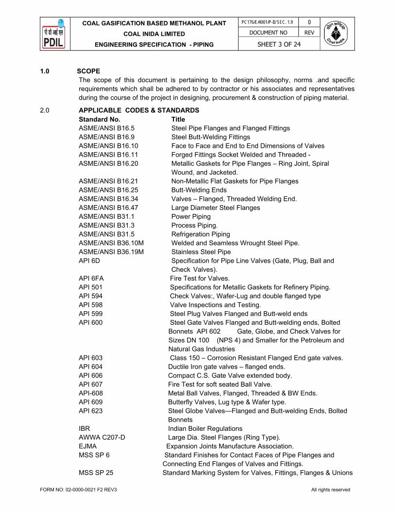
COAL GASIFICATION BASED METHANOL PLANT
COAL INIDA LIMITED
ENGINEERING SPECIFICATION - PIPING
PC176/E/4001/P-II/ SEC. 1.9 0
DOCUMENT NO REV
SHEET 3 OF 24
FORM NO: 02-0000-0021 F2 REV3 All rights reserved
1.0 SCOPE
The scope of this document is pertaining to the design philosophy, norms .and specific requirements which shall be adhered to by contractor or his associates and representatives during the course of the project in designing, procurement & construction of piping material.
2.0 APPLICABLE CODES & STANDARDS Standard No. Title ASME/ANSI B16.5 Steel Pipe Flanges and Flanged Fittings ASME/ANSI B16.9 Steel Butt-Welding Fittings ASME/ANSI B16.10 Face to Face and End to End Dimensions of Valves ASME/ANSI B16.11 Forged Fittings Socket Welded and Threaded - ASME/ANSI B16.20 Metallic Gaskets for Pipe Flanges – Ring Joint, Spiral Wound, and Jacketed. ASME/ANSI B16.21 Non-Metallic Flat Gaskets for Pipe Flanges ASME/ANSI B16.25 Butt-Welding Ends ASME/ANSI B16.34 Valves – Flanged, Threaded Welding End. ASME/ANSI B16.47 Large Diameter Steel Flanges ASME/ANSI B31.1 Power Piping ASME/ANSI B31.3 Process Piping. ASME/ANSI B31.5 Refrigeration Piping ASME/ANSI B36.10M Welded and Seamless Wrought Steel Pipe. ASME/ANSI B36.19M Stainless Steel Pipe API 6D Specification for Pipe Line Valves (Gate, Plug, Ball and Check Valves). API 6FA Fire Test for Valves. API 501 Specifications for Metallic Gaskets for Refinery Piping. API 594 Check Valves:, Wafer-Lug and double flanged type API 598 Valve Inspections and Testing. API 599 Steel Plug Valves Flanged and Butt-weld ends API 600 Steel Gate Valves Flanged and Butt-welding ends, Bolted Bonnets API 602 Gate, Globe, and Check Valves for Sizes DN 100 (NPS 4) and Smaller for the Petroleum and Natural Gas Industries API 603 Class 150 – Corrosion Resistant Flanged End gate valves. API 604 Ductile Iron gate valves – flanged ends. API 606 Compact C.S. Gate Valve extended body. API 607 Fire Test for soft seated Ball Valve. API-608 Metal Ball Valves, Flanged, Threaded & BW Ends. API 609 Butterfly Valves, Lug type & Wafer type.
API 623 Steel Globe Valves—Flanged and Butt-welding Ends, Bolted Bonnets
IBR Indian Boiler Regulations AWWA C207-D Large Dia. Steel Flanges (Ring Type). EJMA Expansion Joints Manufacture Association. MSS SP 6 Standard Finishes for Contact Faces of Pipe Flanges and Connecting End Flanges of Valves and Fittings. MSS SP 25 Standard Marking System for Valves, Fittings, Flanges & Unions

COAL GASIFICATION BASED METHANOL PLANT
COAL INIDA LIMITED
ENGINEERING SPECIFICATION - PIPING
PC176/E/4001/P-II/ SEC. 1.9 0
DOCUMENT NO REV
SHEET 4 OF 24
FORM NO: 02-0000-0021 F2 REV3 All rights reserved
MSS SP 43 Wrought Stainless Steel Butt-weld Fitting MSS SP 45 By-pass and Drain Connection. NACE MR0175-94 Sulphide Stress Cracking resistant Metallic Material EN 10204 Metallic Products - Types of Inspection documents ASTM D3035 Standard Specification for Polyethylene (PE) Plastic Pipe (DR-PR) Based on Controlled Outside Diameter ASTM D3261 Standard Specification for Butt Heat Fusion Polyethylene (PE) Plastic Fittings for Polyethylene (PE) Plastic Pipe and Tubing NBC National Building Code - 2016 NFPA National Fire Protection Association.
3.0 GENERAL DESIGN
3.1 Threaded pipe nipples between headers and vent, drain and instrument isolation valves shall be Schedule 160 for CS and Schedule 80S for SS in the size range ½” to 2” NPS.
3.2 Piping 2” NPS and above shall be butt-welded, 1½” NPS and below shall be socket welded.
3.3 Minimum clearances shall be as indicated in Annexure.
4.0 DESIGN PHILOSOPHY
4.1 Equipment Layout shall be finalized based on the following data :
a) Plot Plan of Proposed Plant b) P&I Ds c) Equipment Data Sheets d) Wind Direction e) Safety Distance as per statutory requirements. a) Economise piping. b) Construction ,Operation , Maintenance, Crane approaches Requirement
4.2 Plant Layout & Design guidelines The plant layout shall be based on ensuring adequate access, to allow construction,
inspection, maintenance and operation to be performed in a safe and efficient manner, to permit ready access of Cranes for removal of Equipment for inspection and servicing.
Flushing connections shall be provided on all lines containing flammable or toxic material, slurries, and materials which solidify when the line is dead. Sufficient Nitrogen purging points shall also be provided. Supply piping of fuel gas shall be arranged for equal flow distribution.
All utility and process piping shall be located above ground, and major lines shall be located in overhead pipe ways.
Piping to be sloped shall be indicated on the P&I D’s.
4.3 Pipe-Rack/T-Post/Small Portals
In general, equipment layout shall be prepared considering straight pipe rack, however other shapes like L / T / U / H / Z etc can also be considered based on area available. The width of the rack shall be 4M, 6M, 8M, 10M or 12M for single bay having four (4) tiers maximum. In general, the spacing between pipe rack portals (span) shall be taken as 8 M for main rack. However it can be decreased to 6 M depending on the size/number of the pumps to be housed below pipe rack. Intermediate Beams between two portals shall be provided to

COAL GASIFICATION BASED METHANOL PLANT
COAL INIDA LIMITED
ENGINEERING SPECIFICATION - PIPING
PC176/E/4001/P-II/ SEC. 1.9 0
DOCUMENT NO REV
SHEET 5 OF 24
FORM NO: 02-0000-0021 F2 REV3 All rights reserved
support smaller pipes <= 2". 20% extra space shall be provided on the pipe rack and portals on each tier for future expansion/modifications.
4.4 Pumps
Pump foundation height shall be 300 mm above H.P.P.
Gap between each pump foundation / and foundation of technical structure should be sufficient for easy removal of equipment after piping. All pumps not open to sky with motor rating >= 45 KW shall be provided with monorail. No monorail should normally be provided for pumps outside rack and sufficient space below rack shall be available for pump maintenance.
4.4.1 Access to Pumps
Clear access of 3.8M vertically and 4.5M horizontally shall be provided centrally under main pipe rack for small mobile equipment to service pumps, wherever these are put under pipe ways with prior specific approval. Pumps outside rack shall be approachable by small cranes etc. from under the pipe rack.
4.4.2 Access to lower items to grade (Lowering Area)
Clear access shall be provided at grade on the access side for lowering external and internal fittings from tall elevated equipment by providing pipe davits.
4.4.3 Layout & Access Requirements for Platforms ladders and Stairs
For providing platform ladder & staircase following guidelines shall be followed.
- Two means of access (i.e. two ladders or one ladder and one stair case) shall be provided at any elevated platform which serves three or more vessels & for B/L valves operating platform.
- Platforms, ladders and stairways shall be the minimum, consistent with access and safety requirements.
- Stairway for tanks to be provided on upstream of predominant wind direction.
i) Platform at elevated structure
a) Dual access (i.e. one staircase and one ladder) shall be provided at large elevated structure if any part of platform has more than 22.65M (75 ft) of travel.
ii) Platforms with stair access shall be provided for:
a) Location at which normal monitoring (once a day or more) is required or where samples are taken.
b) Locations where vessels or equipment items need operator attention "such as compressors, heaters, boilers etc.
iii) Platforms with ladder access shall be provided for:
a) Points which require occasional operating access including valves, spectacle blind and motor operated valves, heater stack sampling points.
b) Man ways above grade on equipment.
iv) Ladder location

COAL GASIFICATION BASED METHANOL PLANT
COAL INIDA LIMITED
ENGINEERING SPECIFICATION - PIPING
PC176/E/4001/P-II/ SEC. 1.9 0
DOCUMENT NO REV
SHEET 6 OF 24
FORM NO: 02-0000-0021 F2 REV3 All rights reserved
a) Wherever practicable, ladder shall be so arranged that users face equipment or platform rather than facing open space.
b) Landings shall be staggered. No ladder shall be more than 6 M in one flight.
4.5 Unit Piping
The following objective shall be ascertained during piping layout. - Proper access to all operating points including valves, and for all orifice tapping points
and instruments in particular. - Proper access to interrelated operating points for specific purpose and for maintenance.
4.6 Pipe Ways/Rack piping
4.6.1 Racks shall be designed to give the piping shortest possible run and to provide clear head rooms over main walkways, secondary walkways and platforms.
4.6.2 Predominantly process lines are to be kept at lower tier and, utility & hot process lines on upper tier.
4.6.3 Generally the top tier is to' be kept for Electrical (if not provided in underground trench as per electrical design basis) and Instrument cable trays. Cable tray laying to take care of necessary clearances for the fire proofing of structure.
4.6.4 Generally the hot lines and cold lines shall be kept apart in different groups on a tier. .
4.6.5 Generally the bigger size lines shall be kept nearer to the column.
4.6.6 Minimum spacing between adjacent lines shall be decided based on O.D of bigger size flange'(minimum rating 300# to be considered), O.D of the smaller pipe, individual insulation thickness and additional 25 mm clearance, preferably. Wherever even if flange is not appearing the minimum spacing shall be based on above basis only. '
4.6.7 Actual line spacing, especially at 'L' bend and loop locations, shall take care of thermal expansion / thermal contraction / non expansion of adjacent line.
4.6.8 Non expansion / thermal contraction may stop the free expansion of the adjacent line at "L' bend location.
4.6.9 Anchors shall be provided within unit on all hot lines leaving the unit.
4.6.10 Process lines crossing units (within units or from unit to main pipe way) are normally provided with a block valve, spectacle blind and drain valve which shall be accessible.
4.6.11 Provision of block valves, blinds etc. shall be as per Process Design Basis and P & IDs.
4.6.12 All small bore piping shall be have space for maintenance and operation and intermediate support between portals.
4.6.13 Minimum branch size for tapping including for instruments e.g PG/ PTI TE etc. shall be of 3" NPD and 150 mm height on internal cement lined pipes.
4.6.14 Aboveground lines shall be grouped to run on pipe racks or sleepers in so far as practicable.
4.6.15 Hot lines on pipe racks or sleepers shall be grouped and expansion loops shall be nested together. The number of expansion loops shall be kept to a minimum.
4.6.16 Piping handling corrosive fluids shall be run under piping handling non corrosive fluids, and shall not, where possible, be run overhead across walkways or normal passages for personnel.
COAL GASIFICATION BASED METHANOL PLANT
COAL INIDA LIMITED
ENGINEERING SPECIFICATION - PIPING
PC176/E/4001/P-II/ SEC. 1.9 0
DOCUMENT NO REV
SHEET 7 OF 24
FORM NO: 02-0000-0021 F2 REV3 All rights reserved
4.6.17 All process and utility piping will be located aboveground within the plant battery limit, except water mains.
4.6.18 All piping shall be arranged in horizontal banks, where possible, to facilitate supporting.
4.7 Pump Piping
4.7.1 Pump drives shall have clear access.
4.7.2 Pump suction piping shall be as short as possible and shall be arranged with particular care to avoid vapor pockets.
4.7.4 Pump discharge check valve if installed in vertical lines shall be fitted with a drain connection as close as possible downstream of the valve.
When a suction vessel operates under vacuum, the vent connection of the pump has to be permanently connected to vapour space of the suction vessel to allow possible filling of the pump with liquid before it is started.
4.7.5 Type of strainers for pump suction piping shall be as per pump manufacturer.
4.7.7 All small bore piping connected to pump shall have break up flanges for removal of pumps.
4.7.8 Piping shall be so arranged that forces and moments imposed on the pump nozzle do not exceed the allowable values as per API 610.
4.8 Steam and Condensate Systems Piping - Indian Boiler Regulations (IBR)
4.8.1 IBR system to comply IBR regulations as well as ASME B31.3. All design calculations towards the same must be approved by IBR authority.
4.8.2 Expansion loops are to be provided for thermal expansion
4.8.3 Condensate draining facility shall be provided.
4.8.4 Drip legs shall be provided with steam traps at low points in the system.
4.8.5 Steam Tracing & Steam Jacketing System shall be as per process requirements.
4.9 Supports and Anchors
4.9.1 Supports and/or anchors shall be provided close to changes in direction of lines, branch lines and, particularly, close to valves to prevent excessive sagging, vibration and strain.
4.9 2 Allowable spans between pipe supports shall be determined to keep the maximum deflection within 16 mm.
4.9 3 In cases where periodic maintenance requires removal of equipment, such as pumps and relief valves, and where lines must be dismantled for cleaning, piping shall be supported to minimize the necessity of temporary supports.
4.9.4 Spring-loaded hangers may be used on piping subject to thermal expansion or contraction. In cases where the movement is very large, or the limitation of reaction and
stress are very severe, constant support spring hangers shall be used.
4.9.5 Suction and discharge lines of rotating equipment shall be supported as close as possible to equipment nozzles, and shall be relieved of excessive strains by using proper pipe supports.
4.9.6 Supports shall not be directly welded to pipes. Where welding is unavoidable, supports having the same chemical composition as pipe shall be carefully welded.

COAL GASIFICATION BASED METHANOL PLANT
COAL INIDA LIMITED
ENGINEERING SPECIFICATION - PIPING
PC176/E/4001/P-II/ SEC. 1.9 0
DOCUMENT NO REV
SHEET 8 OF 24
FORM NO: 02-0000-0021 F2 REV3 All rights reserved
4.9.7 All piping shall be properly supported to minimize vibration.
4.9.8 Outlet piping of safety and relief valves shall be supported so that the inlet piping is capable of withstanding the reaction caused by operation of safety and relief valves. Furthermore, the supports shall be designed to minimize the stresses due to thermal expansion and the stresses in the valve body due to the weight of piping.
4.9.9 Expansion joints shall be guided and anchored to the extent necessary for their proper operation and alignment.
4.9.10 Anchors shall provide sufficient fixation to substantially transmit all load effects into the foundations.
4.9.11 Underground piping shall be given special anchoring consideration for differential settlement.
4,10 Utility Stations
Utility Stations shall have three connections [one for LP steam (SL), one for Plant Air (AP) and one for Service Water (WS)) each of 1" unless otherwise specified in P&ID, located adjacent to pipe-rack column & on elevated structures. The approach of utility station shall be considered 15M all around the station location. Number of utility stations shall be such that all equipments shall be approachable from at least one utility station.
4.11 Offsite & Yard Piping
In general, offsite piping (except tank ages area), electrical cable and instrumentation cable shall also be laid either on pipe rack or pipe sleepers.
Wherever piping is laid on pipe sleepers, it shall have hard surfacing below it keeping a gap of 300 mm from the bottom of the pipes. Hard surfacing should be completed before start of pipe laying. Width of hard surfacing shall be about 1.0 meter more than the piping corridor. This extra hard surfacing shall be for movement of operating personnel along the piping corridor.
4.12 Flare Piping
Flare header shall be sloped. Only horizontal loop shall be provided for thermal expansion.. Flare header shall be supported on shoe of height ranging from 100mm to 300mm.
4.13 Underground Piping
4.13.1 Underground piping shall be provided with wrapping & coating ( min. 4 mm thick), “Holiday Tested” before Hydro Test, break flange at + 500 MM from floor level connection to isolate underground pipe from above ground piping with rubber insulating gasket kit, with cathodic protection, Sand Bed (min. 150 mm) all around the pipe , laid at least 1.0 meter earth cushion in open ground and 1.5 meters earth cushion under the roads and crane movement areas with Hume Pipe Sleeves at road crossings & crane movement areas
4.13.2 Cooling water (> 16”NB), Sewage lines (oily and chemical), Fire water lines in Process areas large Potable Water Line, and / or lines as per process requirements, shall be underground.
4.13.3 Piping in Trenches shall be provided piping located below grade, requiring inspection & servicing or provided with protective heating, Drain lines requiring gravity flow , Suitable draining scheme , Sump for valves and trenches shall be provided.

COAL GASIFICATION BASED METHANOL PLANT
COAL INIDA LIMITED
ENGINEERING SPECIFICATION - PIPING
PC176/E/4001/P-II/ SEC. 1.9 0
DOCUMENT NO REV
SHEET 9 OF 24
FORM NO: 02-0000-0021 F2 REV3 All rights reserved
5.0 FLEXIBILITY ANALYSIS AND SUPPORTING
5.1 Pipe Supporting Criteria & General Guidelines.
Piping system shall be properly supported taking into account the following points:
1. Load of bare pipe + fluid + insulation (if any). 2. Load of bare pipe + water fill. 3. Load of valves and online equipment and instrument. 4. Thermal loads during operation. 5. Steam-out condition, if applicable. 6. Wind loads for piping at higher elevation, e.g. transfer lines, column over head lines,
flare headers, etc. 7. Forced vibration due to pulsating flow. 8. Vibration due to two phase flow. 9. Loads due to internal pressure. 10. Any external loads/concentrated loads and cold load of springs.
Pipe supporting shall preferably follow the minimum basic span as given in Annexure-1 except for flare line in off site on trestles in which case the maximum basic span shall be restricted to 18.0 meters, irrespective of line size.
For sizes not covered in Annexure-1, basic span shall be established based on project requirement. For piping on rack or sleeper, as a minimum, providing resting support on every grid of pipe rack / sleeper is mandatory. Depending on the pipe size, as a rule, guides shall be provided on straight run of pipes at intervals as specified in Annexure-3 unless specifically becomes non-viable due to flexibility problems.
Additional supports, guides, anchors, special supports like spring supports and sway braces shall be provided after detailed analysis of piping system to restrict the forces experienced on nozzles of critical items like pumps, compressors, turbines, exchangers, air fin coolers etc.
For lines which do not need any support otherwise but become unsupported by opening of flange, etc, during maintenance and thereby may transfer the total load on a small branch off, a permanent support shall be suitably provided which may be a spring support also. Bare pipes of size 14" and above on elevated structures shall be supported with pad or shoe. While bare pipes of size 6" and' above, on sleepers, corrosion pads shall be provided.
Pads shall be provided for insulated pipes before welding the shoes for sizes 8" & above.
Adequate stiffening shall be provided for the following:
a) Lines in above 600#,
b) Lines having two phase flow,
c) Lines having Pulsating flow such as discharge of reciprocating compressors & reciprocating pumps,
For pulsating flow lines detailed thermal and vibration analysis by analog study shall be done to decide location of anchor supports and guides etc. Pulsating flow lines shall be as identified by licensor/owner.
Wherever two phase flow in piping is expected, piping design shall be checked by dynamic analysis to prevent vibrations.

COAL GASIFICATION BASED METHANOL PLANT
COAL INIDA LIMITED
ENGINEERING SPECIFICATION - PIPING
PC176/E/4001/P-II/ SEC. 1.9 0
DOCUMENT NO REV
SHEET 10 OF 24
FORM NO: 02-0000-0021 F2 REV3 All rights reserved
Pipe support design shall be such that deflection in piping systems due to sustained loads shall not exceed 15mm, in any case, between two adjacent supports.
As far as possible long trunnion types of supports (more than 0.5 metre) are to be avoided. In case long trunnion support is unavoidable in straight length of pipe, trunnion height to be restricted to 0.5 M and balance height to be made up by providing extended structure.
In the heaters where steam air decoking provision is there, the main lines and decoking lines should be supported in a way so that either of the lines should not be in the hanging position while connected to other one. Same philosophy shall be adopted for similar type of switch over arrangement.
Piping passing through the technology structure or passing near the concrete column etc. should have adequate annular space to avoid restriction of line movement during thermal expansion. The gap should take care the thermal expansion along with insulation thickness.
High density PUF blocks shall be considered for cold piping supports. Use of wood blocks shall be avoided.
All pipes supports shall be so designed that there is no undue tension on equipment flanges. Flange joints should not move away from each other in case of unbolting of the joint.
5.2 Flexibility Analysis Criteria & General Guidelines
5.2.1 The directions of forces and moments shall be in accordance with Welding Research Council Bulletin 107 (WRC 107), with the exception that the radial force (P) shall be away from the vessel. All forces and moments shall be assumed to act simultaneously and apply at the nozzle/vessel interface.
5.2.2 Piping stress analysis and equipment nozzle loading analysis shall be in accordance with ASME B31.3 and the relevant API, ANSI/ISO and NEMA Codes.
5.2.3 API 610 Pumps
The allowable nozzle loads on centrifugal pumps shall meet the load criteria of API 610. Heavy duty base plate shall be specified where the pump design temperature is in excess of 150C.
ASME or Manufacturer’s Standard Pumps
The allowable nozzle loads on horizontal centrifugal pumps design to ASME B73.1 shall be specified by the manufacturer. For preliminary layout and analysis NEMA SM 23 criteria shall be used for individual nozzles.
Other Horizontal Centrifugal Pumps
The allowable nozzle loads shall meet the load criteria specified by the manufacturer.
Vertical Turbine, Can-Types Pumps
The combined bending and tensional thermal stress in the piping attached to the nozzle shall be limited to 25 percent of the allowable stress range shown in ASME B31.3. The combined stress due to dead load and other sustained loads shall be limited to 25 percent of the allowable hot stress.
5.2.4 For piping design purposes, differential settlement between items of major equipment on separate foundations shall be taken as 10 mm.

COAL GASIFICATION BASED METHANOL PLANT
COAL INIDA LIMITED
ENGINEERING SPECIFICATION - PIPING
PC176/E/4001/P-II/ SEC. 1.9 0
DOCUMENT NO REV
SHEET 11 OF 24
FORM NO: 02-0000-0021 F2 REV3 All rights reserved
5.2.5 Cold springing in piping shall not be permitted without written permission from the Owner. Cold springing of piping directly connected to rotating equipment is not permitted under any circumstances.
Piping shall be analyzed for expansion, contraction, differential settlement, relief, valve reaction and effects.
The design of piping systems shall take into account the different conditions expected during operation, start-up, shut-down, cold branch in case of standby pump, tracing, etc. Hydrocarbon lines shall be designed for steam-out conditions, if specified in line schedule. The use of expansion joints shall be considered only when space oar pressure drop
limitation does not permit pipe bends. Expansion joint of axial type shall be avoided.
Forces and moments due to weight, thermal loads and other imposed loads on the equipment nozzle must not exceed the allowed loads for the equipment.
Minimum analysis temperature shall be the design temperature of the line as per line list.
5.3 Personnel Protection
5.3.1 Eyewash and emergency safety showers shall be provided in areas where operating personnel are subject to hazardous sprays, emissions or spills.
5.3.2 Personnel protection insulation shall be provided on un-insulated lines and equipment operating above 70 deg C when they constitute a hazard to the operators during normal operation of the facility.
5.4 Mechanical Handling 5.4.1 Handling facilities such as davits and monorails shall be provided on vessels over 10m in
height where the weight of removable internal and/or external equipment is greater than 35 Kg.
6.0 MATERIALS
6.1 General
6.1.1 Basic material selection of particular line depending on its service, temperature and corrosivity shall be spelt out in process package. Material specification shall follow the requirements as per process parameters & Piping material specification of this document.
6.1.2 Only piping materials listed in ASME B31.3 shall be used for Category ‘M’ and Normal
Service piping. Unless otherwise specified in PMS, For Category ‘D’ utility piping, where scaling and impurities are to be avoided (such as, potable water and deluge water) hot dipped galvanised and threaded fittings may be used in sizes up to and including 4” NB. Galvanised piping shall not be used in environments containing acids or other corrosive commodities. In corrosive environments stainless steel piping material shall be used for such utility systems.
6.1.3 Austenitic Stainless Steel items shall be solution annealed & pickled.
6.1.4 Austenitic Stainless Steel items shall be with Inter granular Corrosion' (IGC) Test.

COAL GASIFICATION BASED METHANOL PLANT
COAL INIDA LIMITED
ENGINEERING SPECIFICATION - PIPING
PC176/E/4001/P-II/ SEC. 1.9 0
DOCUMENT NO REV
SHEET 12 OF 24
FORM NO: 02-0000-0021 F2 REV3 All rights reserved
6.1.5 In absence of specific requirement, Natural Rubber shall be used for lining in rubber lined piping items, wherever applicable. Unless otherwise specified, rubber lining shall be in accordance with IS4682 Part-I.
6.1.6 Unless otherwise specified, HDPE pipes & fittings shall be in accordance to ASTM D3035/ ASTM D3261/ASTM D3350 or equivalent.
6.1.7 Pipe thickness of FRP material , if any, shalll be according to vendor’s norms and standard calculations but not be lower than indicated in DIN 16965 Part 4. External FRP layer shall be protected against ultra-violet light. Anticorrosion Barrier of Polymer veil having minimum thickness 2.5 mm shall be provided for chemical resistance. Mechanical resistance to be sustained by FRP.
6.1.8 No cast iron items shall be used in any service.
6.2 Pipe
6.2.1 Unless specifically exempted, welded pipes shall be acceptable only with longitudinal weld made employing automatic welding. 100% radiography for all welds except for pipes for category D service.
6.2.2 Double seam 180˚ apart is allowed for sizes 36" and larger only.
6.2.3 Galvanized Pipes shall be only Hot Dip galv. to ASTM A53.
6.2.4 Hydrostatic tests shall be applied to each length of pipe and be in accordance with the requirements of ASTM A530/A530M, unless otherwise specified.
6.2.5 Check analysis shall be carried out as per ASTM-A-530 for pipes as per ASTM-A-312 and pipe size > 8” and thickness > Sch.120, Check analysis shall also be carried out as per supplementary requirement S1 of ASTM-A-312.
6.3 Fittings
6.3.1 Type of fittings shall be equivalent to pipe type. All fittings shall be seamless similar to pipe specification in construction unless otherwise specified.
6.3.2 BW fittings to match pipe thickness
6.3.3 Socket weld and screwed fittings shall be in accordance with ANSI B16.11 to the extent covered in the specification , otherwise as per MSS-SP.
6.3.4 All pipes employed for manufacturing of fittings shall be required to have undergone Hydro test to ASTM A530.
6.3.5 All welded fittings shall be 100% Radio-graphed on all welds.
6.4 Flanges
All flanges shall be of forged one piece material (seamless), and plate may not be substituted without written approval from the Purchaser.
6.5 Gaskets
Gaskets shall be as per piping material specification/ applicable standard.
6.6 Stud, Bolts, Nuts and Jack Screws

COAL GASIFICATION BASED METHANOL PLANT
COAL INIDA LIMITED
ENGINEERING SPECIFICATION - PIPING
PC176/E/4001/P-II/ SEC. 1.9 0
DOCUMENT NO REV
SHEET 13 OF 24
FORM NO: 02-0000-0021 F2 REV3 All rights reserved
6.6.1 All bolting shall be as per ASME/ANSI 818.2.1 for Studs, M/C Bolts and Jack screws, and ASME/ANSI B18.2.2 for nuts. Machine Bolts shall not be used in piping flange joint, except for lug type Butterfly Valves, having UNC Threads in lugs facilitating opening of flanges from both sides.
6.6.2 Screw threads of bolting shall be unified coarse threads in accordance with ANSI / ASME B1.1 having Class 2A for bolts and Class2B for nuts. Screw threads in sizel-1/8 and larger shall be 8 threads per inch.
6.7 Valves
6.7.1 General
All flanged valves (except forged) shall have flanges integral with the valve body. Valve Castings/Forgings purchased shall be from Local approved foundries/forging shop. Yoke material shall be at least equal to body material. Forgings are acceptable in place of Castings but not vice-versa. Valves in saline water (if applicable) service shall be with non ferrous trims and all wetted
parts other than trims shall be epoxy coated.
6.7.2 Ball/Plug/Butterfly/Check Valves
Use of soft seated ball/plug/butterfly valves shall be suitably selected based on temperatures handled.
Butterfly valves shall be suitable for throttling application.
Lug type Butterfly valves shall be with threaded lugs only.
High performance metal-seated Butterfly valves flanged/ lugged design to be used for
Hydrocarbon service. Soft seated Butterfly valves lugged design to be used for category ‘D’ fluid service for sizes 10” and above.
PN equivalent rating for Class150# valves shall be minimum PN16.
As an alternative to swing check valves, dual plate check valves can be used, if permitted by process requirements. Ball valves Fire safe type to be used for hydrocarbon services.
6.7.3 Non Destructive Testing of Valves
6.7.3.1 Radiography procedure, areas of casting to be radiographed, and the acceptance criteria shall be as per ASME/ANSI B16.34.
All valve castings shall be of radiographic quality.
The minimum requirement of radiography shall be as under:
Class Size Qty 150 Up to 24” 5% 150 26” & above 100% 300 Up to 16” 10% 300 18” & above 100%
600 & above All 100%

COAL GASIFICATION BASED METHANOL PLANT
COAL INIDA LIMITED
ENGINEERING SPECIFICATION - PIPING
PC176/E/4001/P-II/ SEC. 1.9 0
DOCUMENT NO REV
SHEET 14 OF 24
FORM NO: 02-0000-0021 F2 REV3 All rights reserved
6.7.3.2 The welds of body-to-bonnet and body-to-end flange shall be subjected to 100% NDT; both radiographic and magnetic or liquid penetrant examinations.
6.7.3.3 Beveled ends on each butt welding end valve shall be subjected 100% magnetic particle or liquid penetrant examination.
6.7.3.4 Each valve shall be pressure tested in accordance with API 598.
6.7.4 Criteria for Isolation Valves
Note: For S/D & at battery limit, it will be as per process requirements.
6.8 Traps
All the Traps shall be of compact assembly type with thermodynamic trap with In-built strainer, In-built piston valve for trap by-pass, trap vent, trap test, inlet isolation and outlet isolation valve. All traps shall be hydrostatically tested to twice the design pressure.
6.9 Hoses
All hoses shall be marked with service and working pressure at minimum two ends clearly. Hoses shall be resistant to ageing, abrasion and suitable for outdoor installations. Complete Hose assembly shall be tested at two times the design pressure. Steam hoses shall be subject to steam resistance test.
6.10 Expansion Joints(Metallic) The applicable codes are ASME B31.3 and EJMA (Expansion Joint Manufacturer's
Association).
Bellows shall be formed from solution annealed sheet conforming to the latest ASTM Spec. Any longitudinal weld shall be 100% radiographed. The finished longitudinal weld must be of the same thickness and same surface finish as the parent material.
Circumferential welds are not permitted. Bellows are to be hydraulically or expansion (punched) formed. Rolled formed bellows are not acceptable. Noticeable punch or die marks resulting from expansion operation are not acceptable.
The out of roundness shall be limited to ± 3mm. This is the max deviation between the max & min diameter. The actual circumference of the welding end shall be maintained to ± 3mm of the theoretical circumference.
Apart from the usual requirements, the vendor shall also furnish
a) Design calculations to justify stiffness and fatigue life. b) Axial, lateral stiffness, angular stiffness, effective pressure thrust area. c) Installation/maintenance manual. 6.11 Supports & Spring Assemblies
Installation Process Isolation
Drain/ Vent
Pressure Taping
Level Taping
Flow Element
Safety Valve
Control Valve
150 / 300# Single Single Single Single Single Single Single
600 # Single Double Double Single Double Single Single
Above 600# Double Double Double Double Double Double Single

COAL GASIFICATION BASED METHANOL PLANT
COAL INIDA LIMITED
ENGINEERING SPECIFICATION - PIPING
PC176/E/4001/P-II/ SEC. 1.9 0
DOCUMENT NO REV
SHEET 15 OF 24
FORM NO: 02-0000-0021 F2 REV3 All rights reserved
The Material, Design, Manufacture and Fabrication shall be generally as per MSS-SP-58/ MSS-SP-89 and/or BS 3974. Testing of springs shall be as per BS1726.
6.12 Non Destructive Examination 10% radiography of butt welds and 10%DP/ MP test of fillet welds shall be done for pipe
Classes in 150# & 300#. 100% radiography on butt weld joints and 100% DP/MP for fillet welds test shall be done for Pipe Classes in 600# & above.
7.0 PAINTING
Painting shall be as per attachment provided elsewhere in NIT.
8.0 WELDING
Welding shall be as per ASME BPV- Sec. IX
9.0 INSPECTION
9.1 Inspection authority means the Third Party Inspection Agencies (TPIA) approved by the Owner to carryout inspection of materials.
9.2 Quality Assurance plan (QAP) / Inspection Test Plan (ITP) shall be submitted by bidder for approval by Third Party Inspection Agency (TPIA).
9.3 Scope of Inspection by TPIA: Review of MTC (all batches). Visual check for surfaces, external appearance (10% random witness). Dimensional check (10% random witness). Positive Material Identification (PMI) for alloy steels (10% random witness). Hydrostatic test (10% random witness). Packing: Report review. Documentation (MTC, Inspection Release Note): 100% Review

COAL GASIFICATION BASED METHANOL PLANT
COAL INIDA LIMITED
ENGINEERING SPECIFICATION - PIPING
PC176/E/4001/P-II/ SEC. 1.9 0
DOCUMENT NO REV
SHEET 16 OF 24
FORM NO: 02-0000-0021 F2 REV3 All rights reserved
TABLE OF BASIC SPAN - ANNEXURE – 1
Pipe
Size
In.
SCH/Th
k
(in)
PIPE- VAPOR
INSULATION
PIPE- LIQUID
INSULATION
BARE PIPE
EMPTY
BARE PIPE
WATER FILLED Pipe size in.
BASIC SPAN (L)M BASIC SPAN (L)M
UPTO
1750 C
1760 C
TO
3150C
3160C
TO
4000C
UPTO
1750 C
1760 C
TO
3150C
3160C
TO
4000C
SPAN(L)
M
WEIGHT
KG/M
SPAN(L)
M
WEIGHT
KG/M
3/4" SCH 40 3.5 3.5 2.5 3.5 3.0 2.0 4.5 1.68 4.0 2.04 3/4"
1” SCH 40 4.5 4.0 3.0 4.5 3.5 3.0 5.0 2.52 4.5 '3.07 1"
1-
1/2" SCH 40 5.0 5.0 4.5 5.0 4.5 3.5 6.0 4.08 5.0 .5.4 1-1/2"
2" SCH 40 5.5 5.0 4.5 5.0 4.5 3.5 8.5 5.47 5.5 7.65 2"
2-
112" SCH 40 6.5 6.0 5.0 6.0 5.5 4.5 7.5 8.7 6.5 11.79 2-112"
3" SCH 40 7.5 6.5 5.5 6.5 6.0 5.0 8.0 11.35 6.5 16.15 3"
4" SCH 40 8.0 7.5 6.5 7.5 7.0 6.0 9.0 16.2 7.5 24.45 4"
6" SCH 40 10.0 9.5 8.5 9.0 8.0 7.5 10.5 28.3 9.0 46.7 6"
8" SCH 40 12.0 11.0 10.0 10.0 10.0 9.0 12.0 42.84 10.0 75.22 8"
10" SCH 40 13.5 13.0 12.0 11.5 10.5 10.5 14.0 60.74 11.5 111.9 10"
12" 3/8" w 14.5 13.5 13.0 12.0 11.5 11.0 15.0 74.40 12.0 147.5 12"
14" 318"w 15.0- 14.5 13.5 12.0 12.0 11.5 16.0 82.5 12.5 172.05 14"
16" 318"w 16.0 15.5 14.5 13.0 12.5 12.0 17.0 94.5 13.0 213.15 16"
18" 3/8" w 17.0 16.5 15.0 13..5 13.0 12.0 18.0 106.5 13.5 258.3 18"
20" 318" w 18.0 17.5 16.0 14.0 13.5 12.5 19.0 118.5 14.0 307.5 20"
24" 3/8"w 20.0 19.0 17.5 14.5 14.5 13.0 21.0 1425 15.0 418.2 24"
3/4" SCH 80 3.5 3.5 2.5 3.5 3.0 2.0 4..5 2.20 4.0 2.49 3/4"
1" SCH 80 4.5 4.0 3.0 4.5 3.5 3.0 5.0 3.25 4.5 3.72 1"
1-
112" SCH 80 5.0 5.0 4.5 5.0 4.5 4.0 6.0 5.45 5.0 6.60 1-112"
2" SCH 80 6.0 5.0 4.5 5.5 5.0 4.0 6.5 7.53 6.0 9.45 2"
2-
112" SCH 80 6.5 6.0 5.5 6.0 6.0 5.0 7.5 11.49 6.5 14.25 2-1/2"
3" SCH 80 7.5 6.5 6.0 6.5 6.5 6.0 8.0 15.37 7.0 19.66 3"
4" SCH 80 8.0 8.0 7.0 7.5 7.5 6.5 9.0 22.47 8.0 29.94 4"
6" SCH 80 10.5 10.0 9.0 9.5 9.0 8.5 10.5 42.90 9.5 59.85 6"
8" ½” w 12.0 11.5 10.5 10.5 10.0 10.0 12.0 65.10 11.0 94.8 8"
10" ½” w 13.5 13.0 12.0 11.5 11.5 10.5 14.0 82.20 12.0 130.69 10"
12" ½” w 14.5 13.5 ./, 3.0 12.5 12.0 11.5 15.0 98.13 13.0 168.64 12"
14" ½” w 15.0 14.5 13.5 13.0 12.5 12.0 16.0 108.15 13.5 194.4 14"
16" ½” w 16.0 15.5 15.0 13.5 13.0 13.0 17.0 124.2 14.0 240.0 16"
18" ½” w 17.5 17.0 .16.0 14.5 14.0 13.5 18.0 140.25 14.5 286.64 18"
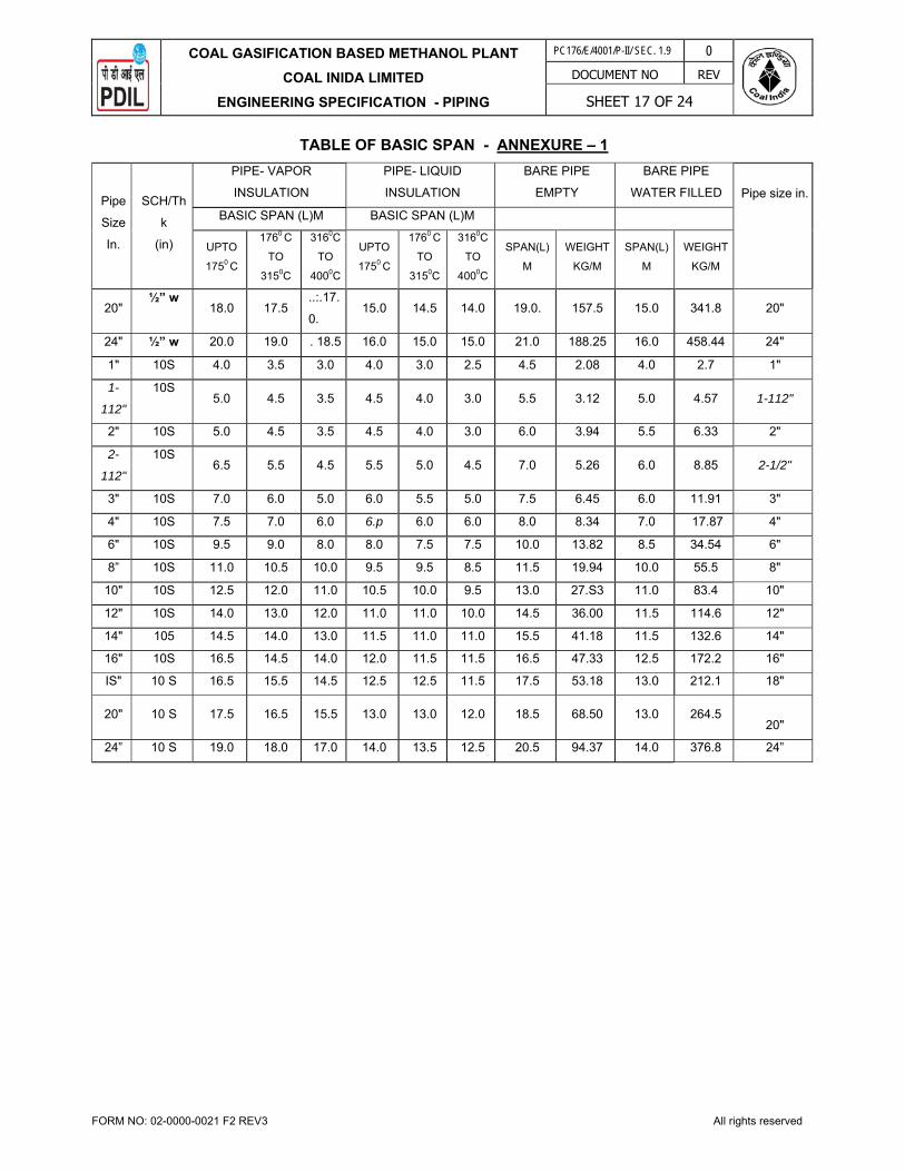
COAL GASIFICATION BASED METHANOL PLANT
COAL INIDA LIMITED
ENGINEERING SPECIFICATION - PIPING
PC176/E/4001/P-II/ SEC. 1.9 0
DOCUMENT NO REV
SHEET 17 OF 24
FORM NO: 02-0000-0021 F2 REV3 All rights reserved
TABLE OF BASIC SPAN - ANNEXURE – 1
Pipe
Size
In.
SCH/Th
k
(in)
PIPE- VAPOR
INSULATION
PIPE- LIQUID
INSULATION
BARE PIPE
EMPTY
BARE PIPE
WATER FILLED Pipe size in.
BASIC SPAN (L)M BASIC SPAN (L)M
UPTO
1750 C
1760 C
TO
3150C
3160C
TO
4000C
UPTO
1750 C
1760 C
TO
3150C
3160C
TO
4000C
SPAN(L)
M
WEIGHT
KG/M
SPAN(L)
M
WEIGHT
KG/M
20" ½” w
18.0 17.5 ..:.17.
0. 15.0 14.5 14.0 19.0. 157.5 15.0 341.8 20"
24" ½” w 20.0 19.0 . 18.5 16.0 15.0 15.0 21.0 188.25 16.0 458.44 24"
1" 10S 4.0 3.5 3.0 4.0 3.0 2.5 4.5 2.08 4.0 2.7 1"
1-
112"
10S 5.0 4.5 3.5 4.5 4.0 3.0 5.5 3.12 5.0 4.57 1-112"
2" 10S 5.0 4.5 3.5 4.5 4.0 3.0 6.0 3.94 5.5 6.33 2"
2-
112"
10S 6.5 5.5 4.5 5.5 5.0 4.5 7.0 5.26 6.0 8.85 2-1/2"
3" 10S 7.0 6.0 5.0 6.0 5.5 5.0 7.5 6.45 6.0 11.91 3"
4" 10S 7.5 7.0 6.0 6.p 6.0 6.0 8.0 8.34 7.0 17.87 4"
6" 10S 9.5 9.0 8.0 8.0 7.5 7.5 10.0 13.82 8.5 34.54 6"
8” 10S 11.0 10.5 10.0 9.5 9.5 8.5 11.5 19.94 10.0 55.5 8"
10" 10S 12.5 12.0 11.0 10.5 10.0 9.5 13.0 27.S3 11.0 83.4 10"
12" 10S 14.0 13.0 12.0 11.0 11.0 10.0 14.5 36.00 11.5 114.6 12"
14" 105 14.5 14.0 13.0 11.5 11.0 11.0 15.5 41.18 11.5 132.6 14"
16" 10S 16.5 14.5 14.0 12.0 11.5 11.5 16.5 47.33 12.5 172.2 16"
IS" 10 S 16.5 15.5 14.5 12.5 12.5 11.5 17.5 53.18 13.0 212.1 18"
20" 10 S 17.5 16.5 15.5 13.0 13.0 12.0 18.5 68.50 13.0 264.5
20"
24” 10 S 19.0 18.0 17.0 14.0 13.5 12.5 20.5 94.37 14.0 376.8 24”

COAL GASIFICATION BASED METHANOL PLANT
COAL INIDA LIMITED
ENGINEERING SPECIFICATION - PIPING
PC176/E/4001/P-II/ SEC. 1.9 0
DOCUMENT NO REV
SHEET 18 OF 24
FORM NO: 02-0000-0021 F2 REV3 All rights reserved
ACCESSIBILITY FOR VALVES AND INSTRUMENTS - ANNEXURE – 2
VALVES, INSTRUMENTS, EQUIPMENT TO BE OPERATED
CENTRELINE OF ITEM TO BE OPERATED, LOCATED LESS THAN 3.6m ABOVE GRADE, 2.75 m ABOVE FLOOR OR PLATFORM OR 1.8m ABOVE WING PLATFORM
CENTRELINE OF ITEM TO BE OPERATED, LOCATED MORE THAN 3.6m ABOVE GRADE, 2.75m ABOVE FLOOR OR PLATFORM OR 1.8m ABOVE WING PLATFORM
EXCHANGER HEADS NIL PLATFORM
OPER.VALVES 2" & SMALLER FIXED LADDER FIXED LADDER
OPER. VALVES 3" & ABOVE PLATFORM PLATFORM
MOTOR OPERATED VALVES PLATFORM PLATFORM
CONTROL VALVES PLATFORM PLATFORM
RELIEF VALVES 2" & SMALLER FIXED LADDER FIXED LADDER
RELIEF VALVES 3" & ABOVE PLATFORM PLATFORM
BLOCK VALVES 2" & SMALLER PORTABLE LADDER PLATFORM
BLOCK VALVES 3" & ABOVE PLATFORM (NOTE-1) PLATFORM (NOTE-1 )
BATTERY LIMIT VALVES PLATFORM PLATFORM
PRESSURE INSTRUMENT FIXED LADDER IF ABOVE 2.2m
HEIGHT
FIXED LADDER
TEMPERATURE INSTRUMENT FIXED LADDER IF ABOVE 2.2 M Ht FIXED LADDER
SAMPLE POINTS PLATFORM PLATFORM
GAUGE GLASSES FIXED LADDER FIXED LADDER
LEVEL CONTROLLERS PLATFORM PLATFORM
PROCESS BLINDS AND SPACERS
2" & SMALLER
PORTABLE LADDER I PLATFORM PLATFORM
PROCESS BLINDS AND
SPACERS 3" & ABOVE
PLATFORM PLATFORM
MANWAYS/MANHOLES PLATFORM PLATFORM
HANDHOLES/INSPECTION HOLES PLATFORM PLATFORM
NOZZLES (process} PLATFORM PLATFORM
VESSEL VENTS PORTABLE LADDER FIXED LADDER
LINE DRAINS & VENTS PORTABLE LADDER PORTABLE LADDER
ORIFICE FLANGES PLATFORM (NOTE-1) PLATFORM (NOTE-1)
NOTE -1:-BLOCK VALVES / ORIFICE FLANGES, IF LOCATED, WITH CENTRE LINES GREATER
THAN 2 METER FROM THE OPERATING FLOOR / OPERATING PLATFORM, SHALL BE PROVIDED WITH PORTABLE PLATFORM OR CHAIN FOR OPERATION.
NOTE -2 : PLATFORM SHALL BE PROVIDED FOR THE ORIFICE FLANGES ON PIPE RACK.

COAL GASIFICATION BASED METHANOL PLANT
COAL INIDA LIMITED
ENGINEERING SPECIFICATION - PIPING
PC176/E/4001/P-II/ SEC. 1.9 0
DOCUMENT NO REV
SHEET 19 OF 24
FORM NO: 02-0000-0021 F2 REV3 All rights reserved
MAXIMUM SPACING OF GUIDES FOR VERTICAL & HORIZONTAL PIPES - ANNEXURE-3
NOM PIPE SIZE
IN INCHES
VERTICALSPACING
METRES
HORIZONTAL SPACING
METRES
1 6.0 6.0
1 ½ 6.0 6.0
2 6.0 6.0
3 8.0 12.0
4 8.0 12.0
6 8.0 12.0
8 8.0 12.0
10 12.0 18.0
12 12.0 18.0
14 12.0 18.0
16 12.0 18.0
18 12.0 18.0
20 16.0 18.0
24 16.0 18.0
26 & ABOVE 16.0 18.0
NOTES:-
1. These spacings may be varied to suit column spacing of rack. The above spacing is for straight
runs of pipe & does not include guides which are used for control of thermal movements, as
decided by stress group.
2. The guide spacings given in the above table are indicative only.

COAL GASIFICATION BASED METHANOL PLANT
COAL INIDA LIMITED
ENGINEERING SPECIFICATION - PIPING
PC176/E/4001/P-II/ SEC. 1.9 0
DOCUMENT NO REV
SHEET 20 OF 24
FORM NO: 02-0000-0021 F2 REV3 All rights reserved
CLEARANCES - ANNEXURE – 4
Minimum clearances for piping, equipment, structures, platforms, and supports shall be in accordance with the following table:
Item Description
Roads Headroom for primary access roads wherever heavy duty crane movement is required. 9 M
Headroom for primary access roads 7.5 M
Width of primary access roads excluding shoulders. Refer Civil
Headroom for secondary roads 5 M
Width of secondary roads excluding shoulders. Refer Civil Clearance from edge of road shoulders to platforms, equipment, pipe associated with equipment, or similar features.
1.5 M**
Minimum Clearance beneath pipe rack 3.8 M. Minimum Road clearance shall be wherever heavy duty crane movement is required during construction and future maintenance.
9 M
Minimum Road clearance shall be for main roads. 7.5 M
Minimum Road clearance shall be for secondary roads. 5 M
T-Portal's width (max) 2.5 M
T-Portal's height (min) 3 M Maintenance Aisles at
Grade Horizontal clearances for equipment maintenance by hydraulic crane (12t capacity) 3 M
Vertical clearance for equipment maintenance by hydraulic crane (12t capacity) 3.6 M
Horizontal clearance for fork lift and similar equipment (2500 kgs capacity) 2.4 M
Vertical clearance for fork lift and similar equipment (2500 kgs capacity) 2.4 M
Horizontal clearances for equipment maintenance by portable manual equipment (A-frames, hand trucks, dollies or similar equipment)
1 M
Vertical clearances for equipment maintenance by portable manual equipment (A-frames, hand trucks, dollies or similar equipment)
2.4 M
Walkways Horizontal clearance (not necessarily in a straight line) 750 mm Headroom (except for hand wheels) 2.2 M Platforms Minimum width 1200 mm Headroom from stairwell treads. 2.2 M
Minimum clearance around any obstruction on the platform. 500 mm

COAL GASIFICATION BASED METHANOL PLANT
COAL INIDA LIMITED
ENGINEERING SPECIFICATION - PIPING
PC176/E/4001/P-II/ SEC. 1.9 0
DOCUMENT NO REV
SHEET 21 OF 24
FORM NO: 02-0000-0021 F2 REV3 All rights reserved
CLEARANCES - ANNEXURE – 4
Minimum clearances for piping, equipment, structures, platforms, and supports shall be in accordance with the following table:
Item Description
Platforms Headroom 2.2 M
Maximum vertical distance between platforms 6 M
Minimum toe clearance behind a ladder. 210 mm
Minimum handrail clearance. 100 mm
Equipment Minimum maintenance space required between flanges of exchangers or other equipment arranged in pairs.
500 mm
Minimum maintenance space required for structural members or pipe.
300 mm
Clearance from edge of road shoulder (the extreme projection)
1.5 M
Clearance (clear gap) between two adjacent pumps 900 mm
Fired Equipment Horizontal clearance from hydrocarbon equipment (shell to shell)
15 M
Exception: Reactors or equipment in alloy systems shall be located for the most economical piping arrangement.
Clearance from edge of road to heater shell. 3 M
Valve Hand wheels Clearance between the outside of the hand wheel and any obstruction.
25 mm*
Pipe (aboveground) Clearance between the outside diameter of the flange and the outside diameter of pipe insulation.
25 mm*
Clearance between the outside diameter of the pipe, flange or insulation and a structural member.
50 mm*
Clearance between the outside diameter of the flange and the outside diameter of bare pipe.
25 mm*
Minimum distance from underside of pipe to grade or platform.
300 mm
Control Valve Arrangement Centreline of control valve above grade or platform. 450 mm
Minimum centreline of control valve from face of column or wall.
600 mm
Where process conditions require steam or hydrocarbon vapours to be discharged to atmosphere at a safe location, the tail pipe shall terminate as below:
Distance above nearest operating platform. 3 M
Within radius of nearest operating platform. 7.5 M
** Verify conformance with local regulations. * With full consideration of thermal movements

COAL GASIFICATION BASED METHANOL PLANT
COAL INIDA LIMITED
ENGINEERING SPECIFICATION - PIPING
PC176/E/4001/P-II/ SEC. 1.9 0
DOCUMENT NO REV
SHEET 22 OF 24
FORM NO: 02-0000-0021 F2 REV3 All rights reserved
ANNEXURE – 5
1.0 Special Requirements For Hydrogen Service
These requirements are applicable in addition to the requirements specified for respective Piping Material.
1.1 Pipes, Flanges And Fittings
1.1 STAINLESS STEEL PIPES, FITTINGS AND FLANGES 1.1.1 All weld joints shall be 100% radiographed in accordance with paragraph UW-51 of ASME
Boiler and pressure vessel code, Section VII, Division 1. 1.1.2 All welds shall be post weld Heatreated (PWTH’D) at 1550-1650 Deg. F (843-899 Deg.C), 1
hour per inch of thickness, 1 hour minimum. 1.1.3 All pipes, flanges & fittings shall be solution annealed and pickled. 1.1.4 Weld deposits shall be checked for ferrite content. A ferrite number (FN) of not less than 3%
and not more than 10% is required to avoid sigma phase embrittlement during post weld heat treatment and high temperature service. FN may be determined by use of a ferrite scope or may be calculated using Schaeffer or Delong diagrams (The Delong Diagram should be used if “FCAW” welding is performed). Ferrite scope measurements must be made prior to post weld heat treatment to be meaningful.
1.2 Alloy Steel (Cr-Mo) Pipes, Fittings And Flanges 1.2.1 The alloy content of welds shall be verified by chemical analysis. Tests shall be conducted
when changes in weld wire and/or weld flux are made, or when a new set of electrode is used.
Maximum room temperature tensile strength of all pressure containing components and
welds shall be 100,000 PSI.
Serration on the flange face shall be concentric for hydrogen service. Spiral serration is not acceptable.
1.3 Method of Manufacture 1.3.1 All carbon steel pipes, forgings & fittings having wall thickness 9.53 mm (0.375”) and above
shall be normalized. Cold drawn pipes & fittings shall be normalized after the final cold draw pass for all thickness. The normalizing shall be a separate heating operation & not a part of the hot forming operation.
1.3.2 All alloy steel (Cr-Mo) pipes, forgings & fittings shall be normalized and tempered. The
normalizing and tempering shall be a separate heating operation and not a part of the hot forming operation. The maximum room temperature tensile strength shall be 100,000 psi.
1.4 Post Weld Heat Treatment All carbon steel pipes & fittings having wall thickness 19mm (0.75”) and above shall be post
weld heat-treated.
All alloy steel (Cr-Mo) pipes & fittings shall be post weld heat treated irrespective of type or thickness of weld.

COAL GASIFICATION BASED METHANOL PLANT
COAL INIDA LIMITED
ENGINEERING SPECIFICATION - PIPING
PC176/E/4001/P-II/ SEC. 1.9 0
DOCUMENT NO REV
SHEET 23 OF 24
FORM NO: 02-0000-0021 F2 REV3 All rights reserved
All stabilized grades of stainless steel shall be given a stabilizing heat treatment in addition to
solution heat treatment at 900ºC. 1.5 Impact Test 1.5.1 For Pipe and fittings of carbon steel of thickness over 19mm and alloy steel of all thickness,
Charpy-V notch impact testing shall be carried out in accordance with paragraph UG-84 of ASME Section VIII, Div-1 for weld metal and base metal from the thickest pipe, forging & fitting per heat of material and per heat treating batch. Impact test specimen shall be in complete heat treated condition and accordance with ASTM A370. Impact energies at 0ºC shall average greater than 27J (20 ft-lb) per set of three specimens, with a minimum of 19J (15 ft-lb).
1.5.2 If welding is used in manufacturing, impact test of Heat Affected Zone (HAZ) and weld metal shall also be carried out.
1.6 Hardness 1.6.1 For carbon steel pipes & fittings, hardness of weld and HAZ shall be 200 BHN (max.). 1.6.2 For alloy steel pipes & fittings, hardness of weld and HAZ shall be 225 BHN (max.). 1.7 Radiography
All welds, longitudinal & circumferential, shall be 100% radiographed in accordance with UW-51 of ASME Section VIII, Div-1 and ASME Section V. Radiography shall be performed after post weld heat treatment.
1.8 Ferrite No. Test For all austenitic stainless steels, the weld deposit shall be checked for ferrite content. A Ferrite No. (FN) not less than 3% and not more than 10% is required to avoid sigma phase embrittlement during heat treatment. FN shall be determined by Ferritescope prior to post weld heat treatment.
2.0 Valves 2.1 General 2.1.1 All valve castings shall be of radiographic quality. The requirement of radiography shall be as
under: 50% - Up to 24” size in 150# rating and 16” size in 300# rating. 100% - Beyond above range.
2.1.2 All cast valve flanges and bodies of rating 900# and greater shall be examined in accordance
with Appendix 7. ASME Section VIII, Div-1, regardless of casting quality factor. 2.1.3 A high pressure Helium leak test on valve body to be conducted on all valves (cast as well as
forged) of rating 900# and above. Test shall be conducted with Helium mass spectrometer (detector probe technique) in accordance with ASME Sec. V, subsection A, article 10, Appendix 5. Acceptance criteria shall be in accordance with ASME Sec. VIII, Div-1, Appendix 7.
2.2 Austenitic S. S. Valves 2.2.1 Casting and test bar shall be heat treated together. Casting shall be in the solution heat-
treated and pickled condition.

COAL GASIFICATION BASED METHANOL PLANT
COAL INIDA LIMITED
ENGINEERING SPECIFICATION - PIPING
PC176/E/4001/P-II/ SEC. 1.9 0
DOCUMENT NO REV
SHEET 24 OF 24
FORM NO: 02-0000-0021 F2 REV3 All rights reserved
2.2.2 Critical body and bonnet casting section typically defined in ANSI B-16.34 shall be radio
graphed and shall meet the requirement of ASTM E446 (up to 2” thick) category A, B & CA Level 2, category CB, CC & CD Level 3, category of D, B & F Level 0. For wall thickness 2” to 4.5” comparable plates of ASTM E186 shall be used. ASTM E94 & ASTM E142 shall be used for recommended practice & controlling quality of radiography as a guide. The entire surface of all casting shall be dye-penetrant inspected after pickling.
2.2.3 Repair welds shall be 10% radio graphed and evaluated in accordance with paragraph 334.5
of ASME B31.3 with a minimum casting quality factor of 0.95. Dye-penetration Test shall be as per ASTM E-165 Procedure B-2, Interpretation as per Appendix 8 of ASME VIII Div 1.
2.3 C. S. & A. S. Valves 2.3.1 Bend test and magnetic particle inspection of the entire surface of body and bonnet casting
shall be in accordance with ASTM A-217. Supplementary requirement S3 & S4, evaluation of magnetic particle inspection shall be in accordance with MSS-SP-53 except that no linear discontinuities shall be allowed.
2.3.2 The Brinell hardness of heat-treated casting shall not exceed 200 BHN for carbon steel & 225
for alloy steel. 2.3.3 Repair of defective casting shall be outlined in writing to the purchaser before commencing
repair. Repair method to be approved prior to welding. 2.3.4 Casting shall be preheated to a minimum of 400ºF prior to welding and all chromium-
molybdenum alloys shall be post weld heat treated after welding is complete. 2.3.5 Carbon steel and alloy steel shall be normalized and tempered. 2.3.6 Dye-penetrant test shall be in accordance with ASTM B165 Procedure B-2. Interpretation shall
as per Appendix-8 of ASME VIII Div. 1. 2.3.7 The tensile stress for A. S. shall be less than 100,000 psi. 2.3.8 For alloy steel valves Charpy-V notch impact testing to be done for valve body material as per
clause 1.3.1. 2.3.9 For radiography as per ANSI B-16.34 and acceptance criteria for valve casting refer clause
2.2.2. above.

PROJECTS & DEVELOPMENT INDIA LIMITED
PC176/E/4001/P-II/ SEC-1.10 0
Document No. Rev
Sheet 1 of 47
0 24.09.2020 25.08.2020 Issued for Tender RK SS SKB
REV REV DATE EFF DATE PURPOSE PREPD REVWD APPD FORM NO: 02-0000-0021F1 REV5 All rights reserved
PART - II: TECHNICAL
SECTION – 1.10
ENGINEERING SPECIFICATION - ELECTRICAL
PROJECT : COAL TO METHANOL (C2M) PROJECT
THROUGH COAL GASIFICATION ROUTE AT DANKUNI COAL COMPLEX WEST BENGAL, INDIA

COAL GASIFICATION BASED METHANOL PLANT ON BUILT-OWN-OPERATE (BOO) BASIS
COAL INDIA LIMITED
ENGINEERING SPECIFICATION – ELECTRICAL
PC176/E/4001/P-II/ SEC-1.10 0
Document No. Rev
Sheet 2 of 47
FORM NO: 02-0000-0021F3 REV5 All rights reserved
CONTENTS
SL. NO. DESCRIPTION
1.0 GENERAL
2.0 STATUTORY REQUIREMENT, CODES & STANDARDS
3.0 CONSTRUCTION POWER
4.0 ELECTRICAL SYSTEM DESCRIPTION & SCOPE
5.0 SYSTEM DESIGN PHILOSOPHY
6.0 AREA CLASSIFICATION
7.0 EQUIPMENT DESIGN PHILOSOPHY
8.0 SYSTEM LAYOUT
9.0 INSTALLATION
10.0 FIELD TESTING & COMMISSIONING

COAL GASIFICATION BASED METHANOL PLANT ON BUILT-OWN-OPERATE (BOO) BASIS
COAL INDIA LIMITED
ENGINEERING SPECIFICATION – ELECTRICAL
PC176/E/4001/P-II/ SEC-1.10 0
Document No. Rev
Sheet 3 of 47
FORM NO: 02-0000-0021F3 REV5 All rights reserved
1.0 GENERAL
This document defines broadly the scope & the specific interface requirement for developing detailed design and engineering for complete electrical facilities along with Fire Alarm, Plant Communicatin System, Public Address etc. required in Installation of Coal gasification based Methanol Plant. All data required in this regard shall be taken into consideration for acceptable, satisfactory, reliable, safe and trouble free operation of the system as per good engineering practices.
2.0 STATUTORY REQUIREMENTS, CODES & STANDARDS The design and the installation shall be in accordance with established codes, good engineering practices and shall conform to the statutory regulations applicable in the country. BOO OPERATOR shall be responsible for obtaining necessary approvals from the statutory authorities. e.g. Central Electricity Authority (CEA) / Electrical inspectorate, Chief Controller of explosives(CCE) as applicable before commissioning of electrical facilities. Liaison with CIL / PMC electrical engineers in charge / other contractors for implementing interfaces as required.
2.1 Latest version of main codes, standards and statutory regulations to be considered as minimum requirements are as given below :
OISD standards -Indian Standard Specification Indian Electricity act Indian Electricity rules Indian Standard Specification or equivalent IEC Standards Publications of IEEE The Indian Explosives Act. Indian Boiler Regulation Act Statutory requirement of Govt of West Bengal and Govt. of India. Guidelines, instructions, directions issued by Pollution control Boards of state as
well as central government. Guidelines, instructions, directions issued by Chief Controller of Explosives (CCoE), CPCB, CMRI, DGMS, CEA etc.
Guidelines of Tariff Advisory Committee Guidelines of Insurance Companies Association. National Electrical safety Code(NESC) Standards of Underwrites laboratory(UL) American Society for Testing Material (ASTM) American National Standards Institute (ANSI) Other International Standards The Factory act API Standards / IEEE NFPA Any other applicable Rules/Acts/Regulations. Requirements of other authorities concerned with the Project All statutory provisions of India / Govt of West Bengal

COAL GASIFICATION BASED METHANOL PLANT ON BUILT-OWN-OPERATE (BOO) BASIS
COAL INDIA LIMITED
ENGINEERING SPECIFICATION – ELECTRICAL
PC176/E/4001/P-II/ SEC-1.10 0
Document No. Rev
Sheet 4 of 47
FORM NO: 02-0000-0021F3 REV5 All rights reserved
2.2 Some of the bare minimum relevant Indian Standards / OISD Standards are as listed
below. However, system / equipment design shall be in line with latest edition of all applicable standards.
IS: 325,
IEC:60034 Three phase induction motors
IS: 335 New insulating oil for transformers and switchgears
IS: 722 AC electricity meters
IS: 732 Code of practice for electrical wiring installations system voltages not exceeding 650V
IS: 737 Specification for wrought aluminum and aluminum alloys, sheet and strip (for engineering purpose)
IS: 996, IEC:60034
Single phase AC motors
IS:1248 Direct acting analogue electrical measuring instruments and their accessories:
IS: 1367 Part-13
Hot dip galvanised coatings on threaded fasteners.
IS: 1646 Code of practice for fire safety of buildings and electrical installations
IS: 1913 General and safety requirements for Luminaries (Tubular fluorescent Lamp)
IS: 2071 Method of high voltage testing
IS: 2099 High voltage porcelain bushings
IEC:62305 Code of practice for the protection of buildings and allied structures against lightning
IS/IEC60079 Electrical apparatus for Explosive gas atmosphere
IS: 2544 Porcelain post Insulators for system with normal voltage greater than 1000 volts
IS: 2633 Methods of testing uniformity of coating on zinc coated articles
IS: 2705 Current Transformers
IS: 3034 Code of practice for fire safety of industrial buildings, electrical generating distributing stations.
IS: 3043 Code of practice for earthing
IS: 3156 Voltage Transformers
IS: 3177 IEC60034
Crane duty motors
IS: 3347 Dimensions for porcelain transformer bushings
IS: 3637 Gas operated relays
IS: 3639 Fittings and accessories for power transformers
IS: 3646 Interior illumination: Part I & Part II

COAL GASIFICATION BASED METHANOL PLANT ON BUILT-OWN-OPERATE (BOO) BASIS
COAL INDIA LIMITED
ENGINEERING SPECIFICATION – ELECTRICAL
PC176/E/4001/P-II/ SEC-1.10 0
Document No. Rev
Sheet 5 of 47
FORM NO: 02-0000-0021F3 REV5 All rights reserved
IS: 3716 Application guide for insulation co-ordination
IS: 4691 Degree of protection provided by enclosure for rotating electrical machinery
IS: 4722 DC motors
IS: 4759 Hot dip zinc coating on structural steel and allied products
IS: 5082 Specification for wrought Aluminum alloys bars, rods, tubes and sections for electrical purposes
IS: 5561 Electric power connectors
IS: 5571 Guide for selection of electrical equipment for hazardous areas
IS: 5572 Hazardous areas other than mines for electrical insulations area having flammable gases and vapours
IS: 5578 Guide for marking of insulated conductors (1st rev)
IS: 6362 Designation of methods of cooling of rotating electrical machines
IS: 6600 Guide for loading of oil immersed transformers
IS: 6665 Code of practice for Industrial lighting
IS: 7689 Guide for control of undesirable static electricity
IS: 8084 Interconnecting Bus bars for AC voltage above 1 KV upto and including 36 KV
IS: 9676 Reference ambient temperature for electrical equipment
IS: 10028 Code of practice for selection, installation and maintenance of transformers
IS: 10322-1 Specification for Luminaries,Part-1,General requirements
IS: 11353 Guide for uniform system of marking & identification of conductor & apparatus terminals
IS: 11448 Application Guide for AC electricity meters
IS: 12360 Voltage bands for electrical installations including preferred voltage and Frequency
IS: 12459 Code of practice for fire protection of cable runs
IS: 12615 Energy efficient motors
IS: 13234 Guide for short circuit calculations
IS: 13346 General requirements for electrical apparatus for explosive gas atmosphere.
IS: 13408 Code of practice for the selection, installation and maintenance of electrical apparatus for use in potentially explosive atmospheres
IS: 13947 Low voltage switchgear and control gear
IS: 60034-5 Degree of protection provided by Integral design of rotating electrical machines
IS: 60079-0 Explosive atmospheres, Equipment General Requirements
IS: 60079-1 Explosive gas atmospheres – Part-1 Equipment protection by Flame

COAL GASIFICATION BASED METHANOL PLANT ON BUILT-OWN-OPERATE (BOO) BASIS
COAL INDIA LIMITED
ENGINEERING SPECIFICATION – ELECTRICAL
PC176/E/4001/P-II/ SEC-1.10 0
Document No. Rev
Sheet 6 of 47
FORM NO: 02-0000-0021F3 REV5 All rights reserved
proof enclosures “d”.
IS: 60079-7 Equipment protection by increased safety “e”
SP: 30 National Electrical Codes (NEC) - BIS Publication
IEC 62271-203 Gas insulated metal enclosed switchgear for rated voltages of above 52 kV.
IS/IEC 62271 HV Switchboard.
IEC 60947 LV switchboard.
IEC 61439-1/2
LV switchboard (PCC/PMCC/MCC) for TOTAL TYPE TESTED (TTA). Type Test Certificates for short circuit withstand of 50kA for 1 sec. along with ACB mounted in the Switchboards shall apply.
IEC 61641 Switch Board with INTERNAL ARC CONTAINMENT test.
ANSI C-37:23 Metal enclosed bus
ANSI C-37:24 Effect of Solar radiation on metal enclosed bus.
IEC 60034 Rotating Electrical Machinery
IEC 61131 Programmable controllers
SP 30 National Electrical Code (NEC) - BIS Publication.
OISD 113 Classification of areas for electrical installation at hydrocarbon processing and handling facilities
OISD RP 147 Inspection and safe practices during electrical installations.
OISD RP 149 Design aspects for safety in Electrical system.
OISD 173 Fire prevention and protection system for electrical installation.
OISD GDN 180
Lightning protection.
2.3 Any other standard may be followed provided it is equivalent or more stringent than the
standards specified above. 3.0 CONSTRUCTION POWER
3.1 CIL, at its expense, shall provide temporary construction power to BOO OPEARATOR from the Existing DCC Plant Sub-station up to a total maximum load of 10MW at Single Point (33kV) within CIL Battery Limit on chargeable basis, subject to availability, as per prevailing rate of power. However, BOO OPERATOR, at its own cost, shall arrange alternative source of power to meet interruptions, if any in construction power supply provided by OWNER
3.2 BOO OPERATOR shall include adequately rated sub distribution boards, power supply cables, other associated material, trenches, overhead structures, road crossings etc. for feeding loads to carry out construction, fabrication activities, etc.
3.3 BOO OPERATOR shall provide adequate area lighting at site of construction, fabrication
yards, office, etc. by means of high flood light masts, flood lighting poles, etc. which are to be supplied and maintained by the BOO OPERATOR.

COAL GASIFICATION BASED METHANOL PLANT ON BUILT-OWN-OPERATE (BOO) BASIS
COAL INDIA LIMITED
ENGINEERING SPECIFICATION – ELECTRICAL
PC176/E/4001/P-II/ SEC-1.10 0
Document No. Rev
Sheet 7 of 47
FORM NO: 02-0000-0021F3 REV5 All rights reserved
4.0 ELECTRICAL SYSTEM DESCRIPTION & SCOPE
Normal Power supply shall be provided by CIL at 132 KV level from State Electricity Board. However, 132 kV Switchyard and further Distribution to 33kV / 6.6kV / 415V shall be in BOO Operator’s scope.
The Emergency power shall be arranged by the BOO OPERATOR through adequately rated
DG set at requisite voltage through suitably rated Switch board transformer. In addition to power required for safe shut down of plant the Emergency DG set shall also cater to the load of emergency lighting, Fire alarm & communication system, Critical load for process, UPS system, battery charger etc.
5.0 SYSTEM DESIGN PHILOSOPHY
5.1 The electrical installation shall be designed to provide:
Necessary amount of power
Flexibility
Service reliability
Ease of expansion
Ease of operation and maintenance & inter changeability of equipment
Safety of personnel The design of electrical installation shall ensure provision of a safe, efficient and reliable supply of electricity at all times including adverse system conditions. Safe conditions shall be ensured under all operating conditions including those associated with start up and shut down of plant as well as those arising out of failure of electrical equipment. The isolation of part of system of electrical equipment due to either maintenance or shut down shall not compromise safety aspects.
5.2 System shall be designed considering following aspects in general: -
To facilitate inspection, cleaning and maintenance with the care to safety in operation and personnel protection.
To minimize turnaround time.
To provide safety, reliability and flexibility of service.
Adequate provision for future extension and modification.
Maximum interchangeability of equipment.
Desired level of operator interface to achieve coordinated efficient and fail-safe operation, data logging and maintenance of the equipment.
To decide redundancy, stand by, spares and overload capacities to achieve desired reliability and flexibility requirement.
To get cost effective and techno commercially proven technology. Economic considerations shall cover capital and running costs and an assessment of the reliability of the system.
5.3 All the electrical consumers within the battery limit shall be identified and listed to have complete details of rating, efficiency, power factor, operating duty cycle (continuous, intermittent, standby), category of supply required (emergency, normal, critical) etc.
5.4 Required redundancy (based on specific process/operating needs) shall be built in substation which feeds power supply to process units/important facilities so that in case of tripping of one

COAL GASIFICATION BASED METHANOL PLANT ON BUILT-OWN-OPERATE (BOO) BASIS
COAL INDIA LIMITED
ENGINEERING SPECIFICATION – ELECTRICAL
PC176/E/4001/P-II/ SEC-1.10 0
Document No. Rev
Sheet 8 of 47
FORM NO: 02-0000-0021F3 REV5 All rights reserved
feeder, the unit may not be adversely affected and continuity in operation at full capacity is achieved.
5.5 While sizing the system necessary consideration shall be given to restrict the system voltage drop within permissible limits during starting of large rated motors. At the same time, the short circuit current shall be kept within limits keeping in view of the market availability of switchgears rating. For this purpose current limiting reactors/unit ratio transformers if required may be used.
5.6 Load Grouping
Electrical consumers shall be classified as 'normal / non-essential, emergency / essential or vital / critical loads as per the concepts defined below:
5.6.1 'Emergency' or 'essential' loads shall be identified on the criteria that, when failing in operation or when failing if called upon, will affect the continuity of operation, the quality or the quantity of product. For such loads, reliable source shall be ensured. Such feeders shall be grouped on a separate bus section in the respective Switchboards/ MCCs / PCCs.
5.6.2 Some of the loads which can be identified as emergency / essential load but not essentially limited to following: - Electrical loads required for continuous operation of process plants utility. - Electrical loads required for safe shut down of facilities in case of normal supply failure. - Emergency lighting & communication facilities. - Fire Detection and Alarm System. - AC & DC UPS / Battery charging equipment. - Control room AC equipment -Essential ventilation system for offices / Manned areas of
other buildings. - Motorised valves as per process requirement - PA & Paging system. - Barring gear - AC Emergency Lub Oil Pump - I.D. Fan Lub Oil Pump - F.D. Fan Lub Oil Pump - A.C. Seal Oil Pump - Compressors - Flame Scanner Cooling Air Fan - Any other load
5.6.3 Critical’ or 'vital' loads shall be identified on the criteria that, when failing in operation or when called upon, can cause an unsafe condition of the installation, jeopardize life or cause a major damage to the installation. For critical loads if any, UPS shall be provided to facilitate uninterrupted supply. The loads on UPS are AVR / PLC / DCS / Auxiliary supply for drives etc. Critical drives if any shall be provided with DC motors.
5.6.4 Some of the load which can be identified as critical / vital load but not essentially limited to following: - Loads providing control and protection to plant equipment. - Loads serving critical equipment for safety of plant, equipment and / or personnel
5.6.5 Non-essential service is a service, which is neither 'essential' nor 'vital'. Hence the non-essential load does not require any special measure such as standby feeder or standby source to safeguard the continuity of service.
5.7 SYSTEM VOLTAGES
Following factors shall be taken into account while selecting the voltage levels: - Short circuit level

COAL GASIFICATION BASED METHANOL PLANT ON BUILT-OWN-OPERATE (BOO) BASIS
COAL INDIA LIMITED
ENGINEERING SPECIFICATION – ELECTRICAL
PC176/E/4001/P-II/ SEC-1.10 0
Document No. Rev
Sheet 9 of 47
FORM NO: 02-0000-0021F3 REV5 All rights reserved
- Availability of the switchgear with suitable current rating and short circuit rating. - Existing available voltage levels in the refinery. - Utilisation voltages of various equipment - Provision of future extension. - Size and location of loads - Choice of voltage may also be affected by local regulations, standards as well as the voltage of existing installations - Overall economy for optimum voltage selection.
5.8 All the components of electrical system shall be designed to take into account following : - After Diversity Maximum demand (ADMD) after diversity under most severe operating and ambient conditions with an additional 10 % contingency - Intermittent service loads, if any. - 30 % spare for future addition.
5.9 PLANT UTILITY LEVELS 5.9.1 The various voltage levels for in plant power distribution shall be as follows:
A. Normal Power (State Grid Power
Grid power shall be available at 132KV. Necessary outdoor type switchyard shall be in BOO Operator’s scope. BOO Operator shall co-ordinate with WBSEDCL.
B. Emergency Power Voltage Variation ± 5%, 50Hz ± 3%, 3Ph, 3 W Voltage Level of DG shall be based upon actual voltage level of emergency loads. (DGs shall be in BOO Operator’s scope)
C. Distribution Equipment a) 6.6KV ± 10%, 50 Hz ± 5%, 3 Ph, 3 W with resistance earthed neutral
b) 415V±10%, 3 Ph, 4 W/240V ± 10%, 1 Ph, 2W, 50 Hz ± 5% solidly grounded neutral.
Combined variation in voltage & frequency
± 10%
Control Supply for: - 415V motors - Switch Gear Breaker controlled feeders: a. Closing, tripping & spring charging motor b. Auxiliary power
AC 240V ± 10%, 50 Hz ± 5%, 1Ph (For contactor controlled motors) DC 110V ± 5% (For breaker controlled motors) DC 110V ± 5%, 2 W AC 240V ± 10%, 50 Hz ± 5%, 1Ph, 2W
- Instrumentation and AC 115 V ± 10%, 50 Hz ± 3% 1Ph, 2W

COAL GASIFICATION BASED METHANOL PLANT ON BUILT-OWN-OPERATE (BOO) BASIS
COAL INDIA LIMITED
ENGINEERING SPECIFICATION – ELECTRICAL
PC176/E/4001/P-II/ SEC-1.10 0
Document No. Rev
Sheet 10 of 47
FORM NO: 02-0000-0021F3 REV5 All rights reserved
Automation, DCS & Auxiliaries
Voltage Ratings - Motors above 150 KW -Motors up to150 KW
6.6 KV, 3 Ph AC 415 V, 3 Ph AC
- Space heaters 240V, 1 Ph AC - Lighting 415V/240V AC - Panic Lights 110V DC/230V Ac from UPS - Power Sockets/Receptacle 415V, 3 Ph AC/240V, 1 Ph AC - Portable safety lamps & Tools
24V AC
.
5.9.2 VOLTAGE DROP
The maximum voltage drops in various sections of the electrical system shall be within the limits stated in the following table:
Sl.No. System Element Maximum Permissible Voltage Drop
a) Extra High/High voltage cables for general distribution
1 %
b) Bus duct / Cable between transformer secondary and Switchboards
0.5%
c) Cable between PMCC and MCC or auxiliary switchboard i) MCC / Auxiliary Switchboard near PMCC ii) MCC / Auxiliary Switchboard situated remote
from PMCC
0.5% Note-3b 2 to 2.5% Note-3a
d) Cables between HV Switchboard and HV Motor (during running)
3%
e) Cable between PMCC and motor (during running) 5%
f) Cable between MCC (situated near PMCC) and motors
5%
g) Cable between MCC (situated remote from PMCC) and motors
3%
h) Cable between Auxiliary Switchboard / MLDB and Lighting Panel / Power Panel
1 to 1.5% (Note-2)
i) Circuit between lighting panels and lighting points 4% (Note-2)
j) DC Supply Circuit (electrical Controls) 5% and/or as per instrumentation requirement
k) DCDB to Control Room 2% (Note-1)
l) UPS outgoing circuit 5% (Note-1)

COAL GASIFICATION BASED METHANOL PLANT ON BUILT-OWN-OPERATE (BOO) BASIS
COAL INDIA LIMITED
ENGINEERING SPECIFICATION – ELECTRICAL
PC176/E/4001/P-II/ SEC-1.10 0
Document No. Rev
Sheet 11 of 47
FORM NO: 02-0000-0021F3 REV5 All rights reserved
Note-1 Minimum voltage available across any instrument in the field / control room / satellite rack room shall be as per instrumentation design basis. Distribution system for instrumentation supplies shall be designed accordingly. In case of any conflict between electrical equipment specification sheet and instrumentation design basis report, the latter shall govern regarding instrumentation power supplies. Note-2 In case of difficulty in achieving specified voltage drops in cables up to lighting panel, 5% drop from Auxiliary Switchboard / MLDB up to lighting points may be permitted. Note-3 a) Higher voltage drop may be permitted between PMCC and remote mounted MCC / ASB; if
overall voltage drop up to motor (from PMCC) is limited within 5.5%. b) For large substations 1% drop may be permitted.
The maximum voltage drop at various buses during start-up of large motor and / or motor reacceleration conditions shall be within the limits stated below:-
Sl. No.
System Element Operating Condition Maximum Permissible Voltage Drop
a) At the bus bars of the worst affected Switchboard
Start-up of the large HV motor with other loads on the bus or reacceleration of a group of HV motors (Simultaneous start-up or group reacceleration of HV motors is not envisaged)
10%
b) At the bus bars of the worst affected LV Switchboard (PMCC / MCC)
Start-up of large LV motor with other loads on the bus, or reacceleration of a group of LV motors.
10%
c) Cables between HV Switchboard and motor
Motor start-up or reacceleration
5% (Note-a)
d) Cable between MV Switchboard (PMCC / MCC) and motor
Motor start-up or reacceleration
10% (Note-a)
Notes: a) Higher voltage drop in motor cables may be permitted, in case the conditions given in Note
b), c) and d) are complied. b) The voltage available at the motor terminals during start-up must be sufficient to ensure
positive starting or reacceleration of the motor (even with the motor fully loaded, if required), without causing any damage to the motor.
c) For medium voltage motors, the voltage available at the motor terminals must not be less than 80% of the rated value during start-up or reacceleration.
d) For high voltage motors, the voltage available at the motor terminals must not be less than 85% of the rated value during start-up or reacceleration.

COAL GASIFICATION BASED METHANOL PLANT ON BUILT-OWN-OPERATE (BOO) BASIS
COAL INDIA LIMITED
ENGINEERING SPECIFICATION – ELECTRICAL
PC176/E/4001/P-II/ SEC-1.10 0
Document No. Rev
Sheet 12 of 47
FORM NO: 02-0000-0021F3 REV5 All rights reserved
e) Soft Starter / VFD Starter shall be considered for starting large HV motors if essential / unavoidable as per system design requirement / equipment design limitation. For cases other than starting limitation, requirement of soft starter / VFD for any drive shall be confirmed by Process Department.
f) Unless otherwise specified as in clause e), all HV motors and MV motors shall be suitable for Direct on Line (DOL) starting.
5.9.3 Design Criteria for Cables / Bus Duct & Short Circuit Withstand Time
Sr.No. Design Criteria 132kV 33kV 6.6 kV 415 V 1. Loads beyond
1000A rating and located near the transformer
1-core cable
Bus Duct / 1-core cable
Bus Duct / 1-core cable
Bus Duct / 1-core cable
2. Loads located up to 200 M
1-core cable
Cable Cable Cable
3. Loads located 200 - 1000 M
1-core cable
1-core cable / 3-core cable
1-core cable / 3-core cable
1-core cable / 3.5-core cable
4. Loads located beyond 1 KM
Cable Cable Cable Cable
5. Recommended limiting size of multi-core cable (sq.mm) / Single Core (sqmm)
1C X 630 Sqmm.
3 Core x 300 / 1 Core x 630
3 Core x 400 / 1 Core x 630
3.5 Core x 300 / 1 Core x
630
6. Insulation voltage grade
132 kV Unearthed
33 kV Unearthed 6.6 kV Unearthed
1100 V Earthed
6. Type of cable insulation
XLPE XLPE XLPE Power: XLPE Control: XLPE
7. Power, Control & Earthing Cables
Armoured Armoured Armoured Armoured
For breaker control motor circuits the selection of size will be made ensuring that the cable shall withstand a short circuit fault directly for 0.2 sec. Suitable derating factors based on the site ambient conditions, method of laying and the no. of cables laid together shall also be applied. Short circuit withstand time (seconds) shall be as follows for Breaker controlled feeders.
Bus duct 1 Sec. Feeders to motors and transformer 0.25 sec Feeders from PCC/PMCC to MCC 0.6 sec 132kV feeder 3 Sec. Main 33 KV switchgear feeders 1 sec Main 6.6 KV primary distribution feeders 0.7 sec 6.6 KV cable from generator & transformer to switch board 1 sec Incomer from other switchboard 0.6 sec
5.10 Electrical System BOO Operator shall carry out following minimum Electrical System Studies using latest software preferably ETAP and the result of the same shall be furnished.
Load Flow Studies
Short Circuit Studies

COAL GASIFICATION BASED METHANOL PLANT ON BUILT-OWN-OPERATE (BOO) BASIS
COAL INDIA LIMITED
ENGINEERING SPECIFICATION – ELECTRICAL
PC176/E/4001/P-II/ SEC-1.10 0
Document No. Rev
Sheet 13 of 47
FORM NO: 02-0000-0021F3 REV5 All rights reserved
Transient Stability Studies
Motor Starting Studies
Relay Co-ordination and Relay settings.
Harmonic studies.
Arc Flashing. Electrical Equipment shall be designed as per worst operating conditions.
5.11 All the switchgears shall be designed for following Minimum fault level withstand capacity.
33 kV Switchgear. : 1800MVA for 3 Seconds 6.6 kV Switchgear – 500MVA for 3 Seconds. The fault level for 415V switchboards shall be 50KA for 1 sec.
5.12 Sizing of high voltage cables shall be based on short circuit withstand capacity in addition to the current capacity.
5.13 33 kV, 6.6 KV systems shall be non-effectively earthed through resistance. The earth fault current of 6.6 KV shall be limited to full load current of the transformer or 400 A, whichever is less. The neutral of 415V supply system shall be solidly earthed.
5.14 INSULATION SYSTEM Following factors shall be considered while designing the Insulation of Electrical system. - System voltage - System grounding
- Switching over voltages - Lightning surges - For HT motors (VCB controlled) surge arresters shall be provided.
For resistance grounded systems, the resistance value shall be chosen to limit the earth fault current to a value recommended by motor manufacturer for insulation protection and sufficient for selective and reliable operation of earth fault protection system. The value of limited earth fault current shall generally not exceed 50 % of transformer or generator full load current.
5.15 AUTO CHANGE OVER SCHEMES The normal operation of the 33 kV, 6.6 kV Switchgears, Power & Motor Control Centre
(PMCC) and Motor Control Centre (MCC) shall be as under: i. Bus-coupler shall be provided between all the sources. Incomer and Bus-coupler breaker
rating shall be same for all the switchboards. Each incoming feeder shall independently feed the loads on respective buses with full rated bus tie breaker open and the load on each bus balanced. In order to ensure maximum degree of reliability and continuity, automatic transfer from one incoming feeder to other shall be possible through auto/manual closing of bus tie breaker in case of sustained loss of power on any bus section.
ii. The bus tie breaker shall be provided with auto/manual selection. The bus tie breaker shall be independent in manual mode. In auto selection mode, the bus tie breaker is electrically interlocked with incoming circuit breakers, so that it cannot be closed unless one of the incoming breakers is open.
iii. When one of the incoming feeder trips, the bus tie breaker is closed automatically based on the philosophy described below and the total load is transferred to other healthy incoming

COAL GASIFICATION BASED METHANOL PLANT ON BUILT-OWN-OPERATE (BOO) BASIS
COAL INDIA LIMITED
ENGINEERING SPECIFICATION – ELECTRICAL
PC176/E/4001/P-II/ SEC-1.10 0
Document No. Rev
Sheet 14 of 47
FORM NO: 02-0000-0021F3 REV5 All rights reserved
feeder which is capable of carrying the entire load. Sufficient switchgear capacity is to be provided.
iv. Motors requiring reacceleration as per process requirement shall be provided with starter suiatable for reacceleration.
v. Auto Change Over scheme shall be provided for incomer feeders and bus coupler feeder of 33 kV switchboard, 6.6kV Switchboards and 415V Switchboards. Under normal operating conditions, incomer-1 and incomer-2 breakers shall be closed and bus coupler breaker shall remain open with ‘Local-Remote-Off’ switch in ‘Remote’ position. The bus coupler breaker shall close automatically under the following conditions being fulfilled:
Either of the incoming breaker trips due to under voltage (70% or below). Voltage on the healthy bus is more than 80% for the set period. Residual voltage on the bus with no power supply comes down to 30% or below.
Required nos. of bus PT, line PT and under voltage relays shall be provided to achieve the desired automatic changeover. vi. Auto transfer shall take place only on sustained loss of power on either of bus sections. Auto
transfer shall be blocked in case of fault on either of bus sections or no power on both incomers.
vii. Paralleling of two incoming feeders is not foreseen. However, facility for momentary paralleling shall be provided for intentional changeover without interruption of supply with synchro check relay in Bus Coupler panel. There shall also be provision of selective tripping of one feeder out of three feeders (two incoming feeders and one Bus Coupler).
5.16 PROTECTION AND METERING SCHEMES 5.16.1 Selection and co ordination of Protection and metering system shall be such as to ensure : - Selective and sensitive and reliable protection of equipment against damage due to
internal or external faults or atmosphere discharge. - Isolation of fault in the shortest possible time. Simplicity of the scheme with maximum protection at minimum cost. - Uninterrupted operation of healthy system. - Personnel & plant safety. 5.16.2 Important plant feeders in particular, which are connected to power generation bus, shall be
provided with differential protection. The CT arrangement / locations provided for differential protection shall be such that overlapping zones are formed for differential protections provided for HT feeders, incomers, bus couplers, tie feeders etc so that the protection zone gets extended up to the last breaker / zone for which differential protection is provided. Restricted earth fault protection shall be provided for transformer secondary.
5.16.3 Protective relays shall be of latest version, numerical / communicable type with non-volatile
memory, comprehensive unit providing protection, metering, control as per IEC 61850 compatible to communicate with MMI and ECS. 100% redundancy shall be provided for communication. Relays shall support features like remote relay parameterization, disturbance recorder etc. It shall be possible to set / operate
the relay from the front facia. A separate convention type lock out relay shall be provided with hand reset facility.
Numerical relay shall indicate MWH, MVAR, MVA, V, A, Hz, PF. It shall have future provision for connecting with substation HMI. Separate multifunction meter with communication (for centralized energy monitoring) shall be used and shall not be part of protective device. Relays shall support features like remote relay parameterization, disturbance recorder etc. It shall be possible to set/operate the relay from the front facia. Lock out relay shall be conventional type with hand reset facility.
5.16.4 Special protection for any feeder such as differential, restricted earth fault, directional distance
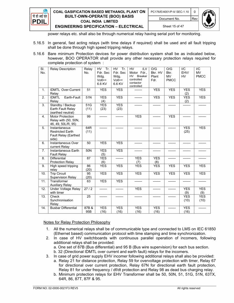
COAL GASIFICATION BASED METHANOL PLANT ON BUILT-OWN-OPERATE (BOO) BASIS
COAL INDIA LIMITED
ENGINEERING SPECIFICATION – ELECTRICAL
PC176/E/4001/P-II/ SEC-1.10 0
Document No. Rev
Sheet 15 of 47
FORM NO: 02-0000-0021F3 REV5 All rights reserved
power relays etc. shall also be through numerical relay having serial port for monitoring. 5.16.5 In general, fast acting relays (with time delays if required) shall be used and all fault tripping
shall be done through high speed tripping relays. 5.16.6 Bare minimum Protection devices for power distribution system shall be as indicated below,
however, BOO OPERATOR shall provide any other necessary protection relays required for complete protection of system :
Sl.No.
Relay Description Relay No.
HV Tr. Fdr. Sec Wdg. Volt=> 6.6 KV
HV Tr. Fdr. Sec Wdg. Volt=< 6.6 KV
HV /LV Motor Fdr., HV Breaker controlled contactor controlled
O/G Bkr. HV Plant Fdr.
O/G Bkr. MV PMCC
I/C EHV/ HV
I/C MV PMCC
1. IDMTL Over-Current Relay
51 YES YES ------- YES YES YES (2)
YES
2. IDMTL Earth-Fault Relay
51N YES (4)
YES ------- YES YES YES (2)
YES
3. Standby / Backup Earth Fault Relay (earthed neutral)
51G (11)
YES (23)
YES (23)
------- ------- ------- ------- -------
4. Motor Protection Relay with (50, 50N, 46, 49, 50L/R, 95)
99
------- ------- YES
------- YES
------- -------
5. Instantaneous Restricted Earth Fault Relay (Earthed side)
64R (11)
------- ------- ------- ------- ------- YES (25)
YES
6. Instantaneous Over current Relay
50 YES YES ------- ------- ------- ------- -------
7. Instantaneous Earth Fault Relay
50N YES (5)
YES ------- ------- ------- ------- -------
8. Differential Protection Relay
87 YES (6)
------- YES (7)
YES (8)
------- ------- -------
9. High speed tripping relay
86 (20)
YES YES YES YES YES YES YES
10. Trip Circuit Supervision Relay
95 (20)
YES YES YES YES YES YES YES
11. Transformer Auxiliary Relay
63 YES YES ------- ------- ------- ------- -------
12. Under Voltage Relay with timer
27 / 2 ------- ------- YES ------- ------- YES (9)
YES (9)
13. Check Synchronisation Relay
25 ------- ------- ------- ------- ------- YES (10)
YES (10)
14. Busbar Differential 87B & 95B
YES (16)
YES (16)
YES (16)
YES (16)
------- YES (16)
-------
Notes for Relay Protection Philosophy
1. All the numerical relays shall be of communicable type and connected to LMS on IEC 61850 (Ethernet based) communication protocol with time stamping and time synchronization.
2. In case of HV switchboards with continuous parallel operation of incomers, following additional relays shall be provided: a. One set of 87B (Bus differential) and 95 B (Bus wire supervision) for each bus section. b. 32 (Directional IDMTL over current and earth fault) relays for the incomers.
3. In case of grid power supply EHV incomer following additional relays shall also be provided: a. Relay 21 for distance protection, Relay 59 for overvoltage protection with timer, Relay 67
for directional over current protection, Relay 67N for directional earth fault protection, Relay 81 for under frequency / df/dt protection and Relay 98 as dead bus charging relay.
b. Minimum protection relays for EHV Transformer shall be 50, 50N, 51, 51G, 51N, 63TX, 64R, 86, 87T, 87F & 95.

COAL GASIFICATION BASED METHANOL PLANT ON BUILT-OWN-OPERATE (BOO) BASIS
COAL INDIA LIMITED
ENGINEERING SPECIFICATION – ELECTRICAL
PC176/E/4001/P-II/ SEC-1.10 0
Document No. Rev
Sheet 16 of 47
FORM NO: 02-0000-0021F3 REV5 All rights reserved
4. Instantaneous earth fault (50N) shall be provided only for transformer with delta primary. 5. Directional IDMTL earth fault (67N) shall be provided for transformer with star primary. 6. For transformers rated 5 MVA and above. 7. For motors rated 1500 kW and above, excluding VFD fed motors. 8. For critical/long feeders and plant feeders connected to main power generation and
distribution bus. A plant feeder implies outgoing feeders from one switchboard to another switchboard of same voltage level.
9. Wherever auto-transfer feature is provided. 10. For switchgears where continuous or momentary paralleling of Incomers is envisaged,
check synchronizing relay shall be provided. 11. 51G and 64R relays for input transformer of VFD system shall be decided by VFD
Manufacturer. 12. The bus tie feeders in HV switchboards shall be provided with 51, 51N, 86 and 95 relays. 13. HV capacitor bank feeders shall be provided with 51, 51N, 59 (over voltage), 60 (Neutral
displacement), 86 and 95 relays. 14. The following feeders shall be provided with timers for delayed tripping on bus under voltage
while the under voltage relay shall be common for the bus a. HV and MV capacitor feeders. b. HV and MV breaker controlled motor feeders. c. Contactor controlled motor feeders with DC control supply. Numerical relays where ever provided for motor and capacitor feeders shall use in built under voltage relay and timer for delayed tripping on bus under voltage.
15. One no. DC supply supervision relay (80) shall be provided for each incoming DC supply to the switchboard.
16. One set of bus differential relays (87B) and bus wire supervision relay (95 B) for each bus section shall be provided for HV switchboards connected directly to generation buses.
17. In case of numerical relays, all relays shall be comprehensive units including all protection, metering and control.
18. Under voltage and over voltage function along with associated timer shall be part of the numerical relays.
19. Auto changeover scheme control & logic between Incomers and bus coupler shall be built in the numerical relay.
20. Tripping relays (86) & Trip Circuit supervision relay (95) shall be separate relay. There shall be two nos. high speed tripping relay for motor feeder. One for electrical fault and one for process fault. Electrical fault relay shall be hand reset type and process falut relay shall be self reset.
21. 2 Nos. of 86 relays shall be considered for HV and MV breaker fed motors for ease of differentiating between process & electric trip. Process trip relay shall be electromechanical, self reset type.
22. Breaker control switch shall be hardwired type. 23. Stand by earth fault relay 51G shall be provided in the incomer of switchboard fed from
transformers where transformer & switchboard both are located remotely from HV substation as well as in same HV substation.
24. For transformers located remotely away from HV Substation, a local power isolating device in the form of breaker panel without any protection relay shall be provided before transformer. A local emergency stop push button shall also be provided in transformer bay for tripping remote breaker.
25. Restricted earth fault relay 64R shall be provided for transformer rating >= 1 MVA in the incomer of switchboard fed from transformers having secondary winding star connected. This shall trip the HV side breaker.
26. 6.6kV DG set shall be provided with protection but not limited to 51V,51G,40,46,86,95,80,64R etc. for generator rated above 500KVA and Generator rated less than 500KVA shall have 51V,51G,40,46,86,95,80 unless otherwise agreed with the owner.

COAL GASIFICATION BASED METHANOL PLANT ON BUILT-OWN-OPERATE (BOO) BASIS
COAL INDIA LIMITED
ENGINEERING SPECIFICATION – ELECTRICAL
PC176/E/4001/P-II/ SEC-1.10 0
Document No. Rev
Sheet 17 of 47
FORM NO: 02-0000-0021F3 REV5 All rights reserved
27. Relay 87 and 64R shall be separate numerical relay. Hence shall not be part of main comprehensive numerical relay. CT for 87 and 64R can be clubbed, as two core of single CT.
28. Accuracy class of the current transformers shall be - Class PS for differential and special requirements. - Class 1.0 / 0.2 S for metering purpose. - Class 5P20 for protection purpose All the CTs shall have rated burden of minimum 15 VA and secondary rated current of 1 A.
29. Accuracy class of the potential / voltage transformers shall be - Class 5P for protection purpose. - Class 1.0 for metering purpose. All the PTs shall have secondary voltage 110 V or 110 V / sqrt.3 and rated burden of minimum 50 VA per phase for both metering and protection core.
30. All the incoming, outgoing and tie breaker feeders of any HV & MV Switchboard shall be provided with numerical relays only with communication facility as protection devices. Releases shall not be acceptable in any case. The relays for outdoor 66 kV EHV switchyard shall also be of numerical type with communication facility.
31. Numerical relays in all HV motor feeders shall be suitable for RTD / BTD inputs. 32. Each bus section shall be provided with separate under voltage relays.
33. Multifunction meter shall be provided to keep a record of power consumption and supervision of all concerned parameters like current, voltage, power, frequency, power factor etc. as specified. All the metering instruments shall be flush mounted.
34. All metering shall be a part of comprehensive relay, if accuracy for metering in LAN can be obtained within 1.0%. If not, separate digital meters or comprehensive metering unit shall be provided in various feeders. These meters shall also be communicable type with open protocol, suitable to communicate with LMS system.
35. The protection of generator and generator isolation transformer shall be effected thru’ redundant (2 x 100%) numerical Relays.
36. Motors shall also be provided with Unbalanced (-Ve) Sequence Protection Relay (46), as required.
37. Numerical under voltage relays (27) with time delay relay including VT fuse failure relay shall be provided for Bus VTs.
38. Reverse power protection relay shall be provided in all incomer feeders of 33 kV Switchgear.
39. No Meters, transducers or measuring equipments to be installed in the Protection CT circuit.
5.17 Metering instruments shall be provided to keep record of power consumption and supervision of all concerned parameters like current, voltage, power (Active, Apparent and Reactive), frequency, power factor, Energy (Active & Reactive) etc. All the instruments shall be flush mounted. All meters shall be digital multifunctional meters with communication port for Load management at remote location. Additionally digital type ammeter, voltmeter and Hour Meter shall be provided separately for various feeders as indicated below :
The metering devices in EHV control & relay panel, HV and MV switchboards shall be as below:
- Type of metering: Analogue/As part of the Numerical relay (Figure inside bracket refers to note below) (YES - Applicable)
Sl. Feeder type A V Hz PF MW MWH HM MVAR MVAH MVA
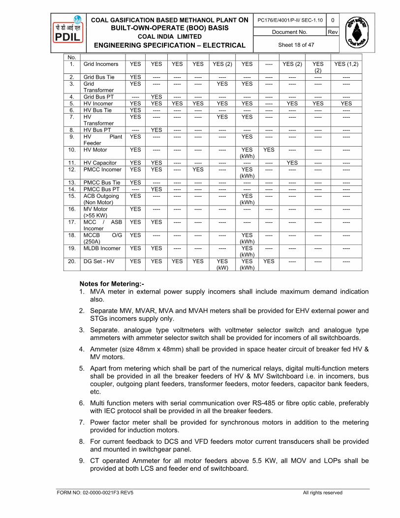
COAL GASIFICATION BASED METHANOL PLANT ON BUILT-OWN-OPERATE (BOO) BASIS
COAL INDIA LIMITED
ENGINEERING SPECIFICATION – ELECTRICAL
PC176/E/4001/P-II/ SEC-1.10 0
Document No. Rev
Sheet 18 of 47
FORM NO: 02-0000-0021F3 REV5 All rights reserved
No. 1. Grid Incomers YES YES YES YES YES (2) YES ---- YES (2) YES
(2) YES (1,2)
2. Grid Bus Tie YES ---- ---- ---- ---- ---- ---- ---- ---- ---- 3. Grid
Transformer YES ---- ---- ---- YES YES ---- ---- ---- ----
4. Grid Bus PT ---- YES ---- ---- ---- ---- ---- ---- ---- ---- 5. HV Incomer YES YES YES YES YES YES ---- YES YES YES 6. HV Bus Tie YES ---- ---- ---- ---- ---- ---- ---- ---- ---- 7. HV
Transformer YES ---- ---- ---- YES YES ---- ---- ---- ----
8. HV Bus PT ---- YES ---- ---- ---- ---- ---- ---- ---- ---- 9. HV Plant
Feeder YES ---- ---- ---- ---- YES ---- ---- ---- ----
10. HV Motor YES ---- ---- ---- ---- YES (kWh)
YES ---- ---- ----
11. HV Capacitor YES YES ---- ---- ---- ---- ---- YES ---- ---- 12. PMCC Incomer YES YES ---- YES ---- YES
(kWh) ---- ---- ---- ----
13. PMCC Bus Tie YES ---- ---- ---- ---- ---- ---- ---- ---- ---- 14. PMCC Bus PT ---- YES ---- ---- ---- ---- ---- ---- ---- ---- 15. ACB Outgoing
(Non Motor) YES ---- ---- ---- ---- YES
(kWh) ---- ---- ---- ----
16. MV Motor (>55 KW)
YES ---- ---- ---- ---- ---- ---- ---- ---- ----
17. MCC / ASB Incomer
YES YES ---- ---- ---- ---- ---- ---- ---- ----
18. MCCB O/G (250A)
YES ---- ---- ---- ---- YES (kWh)
---- ---- ---- ----
19. MLDB Incomer YES YES ---- ---- ---- YES (kWh)
---- ---- ---- ----
20. DG Set - HV YES YES YES YES YES (kW)
YES (kWh)
YES ---- ---- ----
Notes for Metering:-
1. MVA meter in external power supply incomers shall include maximum demand indication also.
2. Separate MW, MVAR, MVA and MVAH meters shall be provided for EHV external power and STGs incomers supply only.
3. Separate. analogue type voltmeters with voltmeter selector switch and analogue type ammeters with ammeter selector switch shall be provided for incomers of all switchboards.
4. Ammeter (size 48mm x 48mm) shall be provided in space heater circuit of breaker fed HV & MV motors.
5. Apart from metering which shall be part of the numerical relays, digital multi-function meters shall be provided in all the breaker feeders of HV & MV Switchboard i.e. in incomers, bus coupler, outgoing plant feeders, transformer feeders, motor feeders, capacitor bank feeders, etc.
6. Multi function meters with serial communication over RS-485 or fibre optic cable, preferably with IEC protocol shall be provided in all the breaker feeders.
7. Power factor meter shall be provided for synchronous motors in addition to the metering provided for induction motors.
8. For current feedback to DCS and VFD feeders motor current transducers shall be provided and mounted in switchgear panel.
9. CT operated Ammeter for all motor feeders above 5.5 KW, all MOV and LOPs shall be provided at both LCS and feeder end of switchboard.
COAL GASIFICATION BASED METHANOL PLANT ON BUILT-OWN-OPERATE (BOO) BASIS
COAL INDIA LIMITED
ENGINEERING SPECIFICATION – ELECTRICAL
PC176/E/4001/P-II/ SEC-1.10 0
Document No. Rev
Sheet 19 of 47
FORM NO: 02-0000-0021F3 REV5 All rights reserved
10. All ammeters for LV motors shall be connected through CT. Only HV motors shall have 3 ammeters or ammeter selector switch or Voltmeter and Voltmeter Selector Switch.
11. Hour run meter shall be provided in all breaker controlled motor feeder.
5.18 CONTROL AND MONITORING
The following provision shall be made for control and monitoring of following electrical equipments.
- Transformers
TNC switch in primary & secondary side of switchgear.
Emergency trip from secondary side for tripping primary side of transformer.
VCB with all required protection to be considered in all the 33kV, 6.6kV switchboards. .
Lockable ‘OFF’ push button in transformer room to trip sending end switchgear.
Indication lamp for ‘ON’ ‘OFF’ ‘Auto-trip, ‘Non-trip’ and ‘Trip Circuit Healthy’.
Ammeter and voltmeter on both primary and secondary side.
Load break switch with Earthing Switch on transformer primary side (only where primary side circuit breaker is not located in the same sub-station).
Annunciator for each feeder of switchboard
- Motors Controlled Through Circuit Breakers
OFF- ON switch with Ammeter on LCS
- OFF-AUTO/MAN-L/R-ON switch with Ammeter on DCS.
Ammeter in LCS and in switchgear.
Current monitoring at DCS, where required from process point of view.
Indication Lamps in switchgear for ‘ON’, ‘OFF’, ‘Auto-trip’ and ‘Trip Circuit Healthy’, ‘Ready for Service’, ‘Test’, ‘Service’, ‘Space Heater ON’.
Emergency trip in switchgear.
Winding and bearing temperatures of motors shall be available at DCS in control room.
Process interlock in CCR, where required.
Indication lamp for ‘ON’, ‘OFF’ and ‘TRIP’ in remote (DCS/PLC etc.)
Motor space heater & Panel board space heater Ammeter in switchgear, where required
Motors controlled through Circuit breakers should also be provided with ammeter, KVAh, KWH and running hour counter.
Annunciator for each feeders switchboard
- Medium Voltage Motors Controlled Through Contactors
OFF- ON switch on LCS
Ammeter in LCS for motors of 1.5 KW and above or as required from process point of view.
- OFF-AUTO/MAN-L/R-ON switch on DCS.
Current monitoring in DCS, where required from process point of view.
Emergency Trip in PCC/MCC.
Process interlock in CCR, where required shall be wired through separate auxillary relay..
COAL GASIFICATION BASED METHANOL PLANT ON BUILT-OWN-OPERATE (BOO) BASIS
COAL INDIA LIMITED
ENGINEERING SPECIFICATION – ELECTRICAL
PC176/E/4001/P-II/ SEC-1.10 0
Document No. Rev
Sheet 20 of 47
FORM NO: 02-0000-0021F3 REV5 All rights reserved
Indication lamp for ‘ON’, ‘OFF’ and ‘Fault’ in switchgear.
Indication lamp for ‘ON’, OFF’ and ‘TRIP’ in remote (DCS/PLC etc.)
Motor space heater & Panel board space heater shall be provided with Ammeter & LED in Switchgear.
5.19 DC POWER SUPPLY
5.19.1 110 V DC system shall be provided for control of circuit breaker feeders and panic lighting. It shall be obtained from Ni-Cd batteries to be located in respective Substation in a separate room. Separate dedicated Battery, Battery Charger and DC Distribution Board shall be provided in each substation.
5.19.2 The battery shall be provided with SCR controlled automatic rectifier-cum battery chargers and shall consist of load-cum-float-cum-boost charger and stand by unit for the same and one common battery bank of 100% capacity having backup time of 2 hours.
5.19.3 Each rectifier-cum- battery charger shall have independent power supply to be fed from the emergency source.
5.19.4 Each Substation requiring 110V DC shall have 2 sources with auto changeover facility in case of failure of 1 source, Redundant battery chargers with separate battery banks shall have to be provided.
5.19.5 DC Battery Charger, AC UPS and HVAC for control room shall be fed from emergency switchboard.
5.19.6 Battery end cell voltage shall 1.1V. Aging factor shall considered 120% and spare capacity shall have 125%.
5.19.7 For Temperature derating factor shall be based upon Minimum Ambient Temperature i.e. 50 C. 5.20 EMERGENCY POWER SUPPLY
The emergency power supply system shall be designed to feed the following types of loads as required: - Electrical loads essential for safe shut down - Emergency lighting - Fire alarm / communication system - DC supply system - UPS system - Loads critical for process, plant and personnel safety.
5.21 SUB-STATION
5.21.1 Substations shall be located at a safe distance from the process areas, hazardous areas and dusty areas, near the load centres.
5.21.2 Substations shall be two storeys building with ground floor mainly used as a cable gallery with minimum height of 3 meters.
5.21.3 The switch room shall have vitrous glazed tiles flooring. 5.21.4 Staircases shall be paved with anti skid tiles. 5.21.5 All door and windows shall have anodized aluminium frame and provided with toughened glass. 5.21.6 Arrangement shall be provided for lifting heavy equipment to be brought into substation.

COAL GASIFICATION BASED METHANOL PLANT ON BUILT-OWN-OPERATE (BOO) BASIS
COAL INDIA LIMITED
ENGINEERING SPECIFICATION – ELECTRICAL
PC176/E/4001/P-II/ SEC-1.10 0
Document No. Rev
Sheet 21 of 47
FORM NO: 02-0000-0021F3 REV5 All rights reserved
5.21.7 Switchgears and MCCs etc. shall be located on the first floor of the building. 5.21.8 Cables shall penetrate walls and floor via fire resistant barriers rated for 1 hour fire capacity. 5.21.9 The batteries shall be located in a suitable room provided with exhaust fan for the vapours
released by the batteries. Battery room shall have Acid / Alkali resistance Tiles for floor and wall up to 2.0 M.
5.21.10 Oil immersed transformers shall be located outdoor and under shed. The transformers shall be separated from each other by a fireproof wall. All the building walls surrounding transformers shall also be fireproof walls. The transformer basements shall be provided with oil collecting system. The transformer yard shall be fenced.
5.21.11 Dry type transformers shall be housed in a separate room in an enclosure. 5.21.12 The substation shall be provided with rubber mats in front of switch boards, safety signs, exist
signs and danger signs etc. to satisfy local regulations and statutory requirements. 5.21.13 The layout of equipment shall be such that it shall have adequate space for installation,
operation, maintenance and future expansion 5.21.14 In all substations HV Sw gear equipment shall be segregated from LV switchgear equipment as
per IE rules. 5.21.15 The clearance of equipment from the walls / other equipment shall be adequate to ensure
safety of working personnel and shall be as per IE rules. 5.21.16 Sufficient nos. of entrances (Min. 2) shall be provided for each floor. 5.21.17 Epoxy flooring shall be done to reduce the heat load and improve the aesthetic look. 5.21.18 The Sub-Station shall house all the Electrical Power, Control and Monitoring equipment except
those required for operation in the field. The equipment shall broadly include the following depending on the requirement :
Step up / Step down Transformers, Special type Transformer etc. each located in separate Bay/room outside the substation.
High Voltage Switch Boards Power Control Centres Power & Motor control centres Emergency Power & Motor control centres Motor Control Centres Auxiliary Service Panel Boards Lighting Transformer (Indoor / Outdoor as per requirement) Main Light Distribution Board Lighting Distribution Boards Lighting Sub-Distribution Boards Battery Sets Rectifier-Cum-Battery Charger DC Distribution Boards Rectifier-inverter Sets UPS System alongwith UPS distribution board. Neutral Earthling Resistors (Indoor / Outdoor as per requirement) Input / Output Panels VFD System / Soft Starter Any other equipment required
5.21.19 All static devices such as Rectifier-Cum-Battery Chargers, Static Inverter Sets, Programmable
Logic Controller, Variable Speed Drive Panels etc., shall be housed in air conditioned room.

COAL GASIFICATION BASED METHANOL PLANT ON BUILT-OWN-OPERATE (BOO) BASIS
COAL INDIA LIMITED
ENGINEERING SPECIFICATION – ELECTRICAL
PC176/E/4001/P-II/ SEC-1.10 0
Document No. Rev
Sheet 22 of 47
FORM NO: 02-0000-0021F3 REV5 All rights reserved
However, complete switch room shall be air pressurised type. All equipments shall be suitable for operation under specified ambient condition even on failure of air conditioning system.
5.21.20 Substations shall be provided with smoke detectors and fire alarm system.
6.0 AREA CLASSIFICATION
6.1 Following factors shall be considered for proper selection of electrical equipment for use in hazardous areas :
- Area classification (Zone 0 / Zone1 / Zone2)
- Gas classification (Gr. II A / IIB / IIC) – Characteristic of the gas / vapour involved
- Temperature classification (T1 to T6) - Environmental conditions – selected electrical equipment shall be protected against corrosive
and solvent agencies, water ingress, dusty, chemically polluted atmosphere as determined by the environmental conditions.
6.2 All electrical equipment installed in classified areas shall be selected as per IS 5571, OISD 113 and other relevant standards. For Zone 2 areas as a minimum Ex (e) type of equipment shall be used. However, Ex (e) type of equipment shall not be used for Zone – 1 area.
6.3 Pressurised type of motors Ex(p) may be considered in case flameproof motors in required kW
rating and gas gr. are not available. All pressurised motors shall be complete with flameproof pressurisation panel, control valves, flow meter, pressure switch etc. DC power
supply shall be considered for the pressurisation panel of the pressurised motors. Pressurisation system shall have parallel filter and draining arrangement prior to purging. Necessary interlock shall be provided such that on failure of pressurisation system, electrical equipment will be switched off with audiovisual alarm.
6.4 Selection of equipment for hazardous areas shall be as follows :
Area Classified
Type of protection Symbol
Zone 0 - No electrical equipment to be installed.
Zone 1 - Flameproof enclosure ‘ d ‘ - Intrinsic safety category ‘ I ‘
- Pressurised ‘ p ‘ - Other electrical apparatus specifically designed for
Zone 1 ‘ s ‘
Zone 2 - Increased safety ‘ e ‘
6.5 Increased safety apparatus located outdoor shall be provided with minimum IPW55 protection
as per IS 4691. 6.6 All electrical equipment for hazardous areas shall be certified by testing authorities like CMRI,
PTB, BASEEFA, UL / FM for the service and the area of installation and shall be approved by CCE. All indigenous flameproof equipment Ex (d) shall be under BIS license.
6.7 As additional safety features, the following requirements for electrical equipment shall be
followed: 6.7.1 All electric motors for agitators, mixers, LPG Pumps and metering pumps handling flammable
material shall be flameproof type irrespective of the area being classified as Zone-2 or Zone-1.

COAL GASIFICATION BASED METHANOL PLANT ON BUILT-OWN-OPERATE (BOO) BASIS
COAL INDIA LIMITED
ENGINEERING SPECIFICATION – ELECTRICAL
PC176/E/4001/P-II/ SEC-1.10 0
Document No. Rev
Sheet 23 of 47
FORM NO: 02-0000-0021F3 REV5 All rights reserved
6.7.2 All electric motors for vertical oil sump pumps shall be flameproof type Ex-d. 6.7.3 Irrespective of the area classification (whether Zone-1 or Zone-2) all motors and lighting
fixtures within the storage areas, pump house associated with storage areas and within the loading / unloading gantries shall be flameproof type.
6.7.4 Even though fired heaters in process units are not considered for area classification, all
electrical equipment associated with fired heaters in process units shall, as a minimum be suitable for installation in Zone-2 area.
6.7.5 All electrical equipment installed for an analyser room shall be flameproof type suitable for gas
group-IIA, IIB, IIC irrespective of the area being classified as Zone-1 or Zone-2. 6.7.6 All equipment inside the process units shall be suitable for Zone-2 Ex (e) temperature class T3
irrespective of area being safe. 6.7.7 Process units having different types of gas groups like IIA / IIB/ IIC or different area
classification like Zone-1 or Zone-2 or safe shall have electrical equipment to meet all gas groups / area classification to facilitate installation and minimum spare inventory and uniformity.
7.0 EQUIPMENT DESIGN PHILOSOPHY
Brief specification of the equipment has been mentioned. Equipment design shall be in line with latest edition of all applicable Indian / International standards.
7.1 General Constructional Features
7.1.1 The equipment shall be suitable for tropical climate conditions and corrosive and saline atmosphere. All electrical equipment accessories and wiring shall have fungus protection involving special treatment of insulation and metal against fungus, insects and corrosion. Fine mesh screen of corrosion resistant material shall be furnish on all ventilating openings to prevent entry of insects.
7.1.2 The equipment to be installed in indoor plant area shall be enclosed in dust, damp and vermin
proof enclosure equivalent to IP 54 as per relevant Indian Standards/IEC. 7.1.3 The equipment excluding motors to be installed in outdoor plant area shall have IP 65 enclosure.
Motors of Coal Conveyor, Coal Handling Section, Ash Handling Section shall have IP 65 enclosure. Motors of other sections of plant shall have IP 55 enclosure.
7.1.4 4 mm FRP (fire retardant and UV stabilized) canopies shall be provided for all outdoor equipments like motors, starters, LCS, SDBs, sw. sockets etc. PA stations shall have acoustic hood.
7.1.5 The switch boards, to be installed inside the building shall have enclosure IP 4X for HV switchgear, for LV switchgear degree of protection shall be IP 52 up to 1600A rating and IP-4X above 1600A rating. Equipment requiring ventilation opening such as battery charger/UPS etc. located in air conditioning room may have IP 43 enclosure however, opening for the ventilation shall be covered with fine wire mesh.
7.1.6 Creepage distance shall be 31mm/kV (for highest system voltage) for all equipment.
7.2 D.G. SET :
7.2.1 In order to meet the emergency power requirement for critical loads and also for safe shut down of plant. There shall be One no. of DG set each rated for full emergency power requirement, in

COAL GASIFICATION BASED METHANOL PLANT ON BUILT-OWN-OPERATE (BOO) BASIS
COAL INDIA LIMITED
ENGINEERING SPECIFICATION – ELECTRICAL
PC176/E/4001/P-II/ SEC-1.10 0
Document No. Rev
Sheet 24 of 47
FORM NO: 02-0000-0021F3 REV5 All rights reserved
the event of the failure of normal power one DG set will supply the total emergency power requirement ,other DG set shall be stand by.
7.2.2 DG Sets, Diesel tanks and associated switchgears shall be located at centralized place away and at a minimum safe distance from substations and hazardous areas as per relevant IS/IEC of hazardous area classification. Emergency power from DG Set shall cater to:- (a) Loads of emergency shut down (b) Essential loads of the package (c) Loads of emergency and aviation lighting (d) UPS Loads (e) Battery Charger & DCDB Loads
7.2.3 The DG Sets control shall have PLC/microprocessor based latest state of art technology. Brushless excitation system shall be used in generator.
7.2.4 The engine shall of high speed increase the efficiency of DG set, a system of air preheating (turbo charger etc.) shall be employed.
7.2.5 The starting of engine shall be air charging type. Battery start engines are not acceptable. 7.2.6 DG set shall have all its auxiliaries installed and controlled from same place. The control of DG
set shall be based on 110 V DC which shall be supplied from the DC panel. 7.2.7 The auto starting time (i.e. the time between actuation of loss of power in case of failure of main
power to the time of loading of total emergency load) shall be in accordance with the requirement of process. The maximum starting and synchronising time of Sets shall be 30 seconds even after 3rd attempt and shall be able to take full load within lower of two i.e process and 45 seconds. The DG power shall be made available within such a period that none of the plant unit is affected due to failure of normal power.
7.2.8 The auxiliary power supply board to feed the auxiliaries of DG set shall have dual power supply:- one from the normal power supply source of plant and other from the DG set itself. There shall be a provision of auto changeover in the incoming supply of auxiliary power supply board of DG set. The Emergency power distribution board shall be kept in a separate room near to engine room of DG set. The outgoing feeders for 400 A and below in Emergency power distribution board shall have Switch Fuse unit. The incomer and larger rated feeders shall be provided with Air Circuit Breaker. A comprehensive electrical protection system shall be provided to protect the generator as well as individual feeder. The incomer shall have a kwh meter along with ammeter, voltmeter etc.
7.2.9 There shall be a separate control panel to control the auxiliaries and comprehensive alarm and fault indication system shall be provided to indicate the status of auxiliaries as well as Diesel Generator set.
7.2.10 The quick start auto-mains failure DG set of adequate rating shall be battery/compressed air started and radiator cooled type suitable for supplying emergency load.
7.2.11 DG set shall be supplied with day oil storage tank (12 Hr. capacity at full load continuous operation ), bulk oil storage tank ,associated piping ,valves, accessories, earthing of all equipments, all power and control cables as required.
7.2.12 Emmission from DG set shall met the requirement of Local Pollution norms. 7.2.13 DG set / DG Building shall be provided with suitable acoustic enclosure to restrict the noise level
to 85db at 1Mtr.
7.3 TRANSFORMERS

COAL GASIFICATION BASED METHANOL PLANT ON BUILT-OWN-OPERATE (BOO) BASIS
COAL INDIA LIMITED
ENGINEERING SPECIFICATION – ELECTRICAL
PC176/E/4001/P-II/ SEC-1.10 0
Document No. Rev
Sheet 25 of 47
FORM NO: 02-0000-0021F3 REV5 All rights reserved
7.3.1 The transformers except lighting transformers shall be ONAN / ONAF, 3 phase, oil immersed, double wound type suitable for outdoor installation. Lighting transformers shall be dry type.
7.3.2 Transformer sizing shall be such as to take care of minimum 8 hour maximum demand, starting of highest rated induction motor with other load in running condition and minimum 25% spare capacity for future requirement.
7.3.3 The ONAN rating of ONAN/ONAF type power transformers shall be equal to or higher than maximum demand. ONAF rating shall be equal to or higher than 125% of ONAN rating.
7.3.4 In general, rating and % impedance of each transformer shall be selected to limit the short circuit current to values within the current rating and rupturing capacity of switchgear available and also to ensure the voltage drop within permissible limit. The transformer impedances shall be as per Indian standards unless otherwise required.
7.3.5 Power transformers shall be of low losses type. Usually no load & load losses shall be optimised for operation around 40 – 50 % of their ONAN rating.
7.3.6 Grid Transformers shall be equipped with ‘ON’ load tap changer (OLTC) and RTCC Panel . For on load tap changer, provision shall be made for Auto – Manual and Local – Remote electrical operation of the tap changer.
7.3.7 Routine test on all transformer and heat run test on one transformer of each rating shall be performed.
7.4 Neutral Earthing Resistor (NER)
7.4.1 The NER shall be provided to earth the neutral of 33kV, 6.6 KV systems. Neutral of 415V supply system shall be solidly earthed.
7.4.2 Neutral earthing resistor shall be outdoor type made of AISI 304/406 punched stainless steel grid element. . The earth fault current of 33kV & 6.6 KV shall be limited to full load current of transformer or 400 A, whichever is less.
7.4.3 Neutral earthing resistor shall be designed to carry continuously 20% of the rated short time current.
7.5 HT SWITCHGEAR
7.5.1 All switchgears and associated equipment shall be rated for the rating of motor being fed from it under any circuit configuration.
7.5.2 There shall be three positions for Breaker/Contactor trolley: - Service, Test and Isolate. In service position, the power connections shall be made; but in test and isolate mode, the power connection of bus bars shall be automatically removed.
ACB feeder for PCC, PMCC & MCC shall be single front for ease of operation & maintenance. Non-ACB feeders for motors or power may be double front type. Breaker duty cycle shall be O-0.3sec-CO-3min-CO. Separate CT shall be provided for differential and REF protection. LV circuit breaker shall be 4 Pole type except for outgoing motor feeders which shall be 3 Pole type.
7.5.3 Suitable shutter arrangement shall be provided to protect the person from accidental contact with live bus in trolley chamber.
7.5.4 The degree of protection shall be IP 4X for HV switchboards and IP 52 for LV Switchboard up to 1600A rating and IP-4X for LV switchboards above 1600A rating.
7.5.5 All HV, MV & LV Switchboards shall be LOTO compliance.

COAL GASIFICATION BASED METHANOL PLANT ON BUILT-OWN-OPERATE (BOO) BASIS
COAL INDIA LIMITED
ENGINEERING SPECIFICATION – ELECTRICAL
PC176/E/4001/P-II/ SEC-1.10 0
Document No. Rev
Sheet 26 of 47
FORM NO: 02-0000-0021F3 REV5 All rights reserved
7.5.6 33kV & 6.6 kV Switchboard shall conforms to IS/IEC 62271-200, IAC-A FLR-50KA/40KA 1 Sec, PM, LSC 2B which means that the switchgear panels shall be four side internal arc tested, shall have metal partitions and shall confirm to loss of service continuity. LV switchboard shall conform to IEC 60947.
7.5.7 LV switchboard (EPMCC/PMCC/MCC) shall be TOTAL TYPE TESTED (TTA) design as per IEC 61439-1/2. Type Test Certificates for short circuit withstand of 50kA for 1 sec along with ACB mounted in the Switchboards shall be provided.
7.5.8 LV switchboard (EPMCC/PMCC/MCC) shall comply with Internal Arc Containment test as per IEC 61641.
7.5.9 The minimum thickness of sheet steel used in HV and LV switchgear including charger, UPS, ASPB etc. shall be as under:-
a) Base Channel minimum 3.0 mm b) Load Bearing Members minimum 2.0 mm c) Doors and covers minimum 1.6 mm
7.5.10 A bottom channel of not less than 100 mm shall be provided. 7.5.11 Minimum 25 % spare feeders or one no. of each rating and type on each side of the bus section
whichever is more shall be provided. 7.5.12 In case of HT vacuum circuit breaker, adequate provision shall be made for motor switching to
limit the over voltage to 2.2 per unit of rated peak line to earth voltage. Required surge arrestors may be provided for this purpose.
7.5.13 The rating of Circuit breakers /contactors used in Motor feeder shall be at least 125% of the maximum continuous motor rating.
7.5.14 Electrical running loads shall be uniformly distributed on each bus and it shall be ensured that running and standby loads are fed from two different bus sections.
7.5.15 One panel of highest breaker rating shall be subjected to type test. This test can be exempted only in case of extension of existing panels.
7.5.16 Switchgears shall be supplied with necessary earthing trollies / earthing rods / breaker lifting
trollies. 7.5.17 For tie feeders, receiving end circuit breaker shall have ON / OFF control and indicating lamps
for sending end circuit breaker with selective closing of sending end breaker. 7.5.18 Antipumping relay used,If any, shall be considered as part of Breaker mechanism. 7.5.19 LT Switchgears shall have rating atleast equal to maximum demand under any circuit
configuration and provision for 30 % future requirement 7.5.20 Internal physical separation / segregation of LT Switchboards shall be 3 B for Non-ACB feeders
and 4 B for ACB feeders. 7.5.21 Separate feeders shall be provided in the switchboard for each load / motor. However, max. 2
nos. welding receptacles may be looped from single feeder. 7.5.22 All ACBs shall be electrically operated- EDO type only. All ACBs shall be without any internal
releases. The required protections shall be wired by means of external numerical relays. 7.5.23 Service breaking capacities (Ics) for all breakers and MCCBs shall be equal to or higher than the
maximum fault level at the point of installation. 7.5.24 For feeders rated above 630A, ACBs shall be provided and that below and including 630A,
MCCB shall be provided.

COAL GASIFICATION BASED METHANOL PLANT ON BUILT-OWN-OPERATE (BOO) BASIS
COAL INDIA LIMITED
ENGINEERING SPECIFICATION – ELECTRICAL
PC176/E/4001/P-II/ SEC-1.10 0
Document No. Rev
Sheet 27 of 47
FORM NO: 02-0000-0021F3 REV5 All rights reserved
7.5.25 All the switchgear components shall be designed to withstand maximum expected fault level for a minimum time of 1 second.
7.5.26 All motor feeders shall be provided with IEC type 2 co-ordinations. Motors rated above 55 kW & upto 160 kW shall be controlled through ACB & motor protection relay and shall be fed from PCC. All motors feeders rated above 22 kW & upto 55 kW shall be controlled through switch fuse unit, contactor, overload relay with CBCT, ELR for earth fault protection & shall be fed from MCC. All motors feeders rated upto & including 22 kW shall be controlled through switch fuse unit, contactor & overload relay. All loads upto 22 KW rating shall be provided with ELCBs. All motor feeders rated above 5.5 kW shall be provided with CT for remote metering.
7.5.27 The maximum rating of incomers / bus couplers of motor control centres / auxiliary switchboards
/ power distribution boards / lighting distribution boards shall be preferably limited to 800A. The incoming / tie feeders shall be with heavy-duty type load break switches / ACB suitable for key interlocks.
7.5.28 Motor Control Centres with breaker incomer and breaker buscoupler shall be provided with synchro check relay for momentary paralleling during auto transfer. Switching off shall be manually.
7.5.29 Electrical running loads shall be uniformly distributed on each bus and it shall be ensured that running and standby loads are fed from two different bus sections.
7.5.30 All the MCCB feeders shall be provided with ammeter. All emergency / critical drives, irrespective of their ratings shall be provided with ammeters.
7.6 MAN MACHINE INTERFACE (MMI)
7.6.1 MMI shall include CPU, Keyboard, Monitor, Mouse, Printer etc.Four number Man Machine Interfaces shall be provided in the substation, two number laptop for engineering workstation and two number PC for operator’s workstation. System Configuration shall be latest proven model and upgradable. Power supply for Substation MMI shall be obtained from emergency / critical source available in the substation / nearby substation / control room.
7.6.2 MMI shall allow minimum of the following functions - Feeder status monitoring - Data Logging - Relay parameterisation - Event recording - Annunciation - View of historical data and trends - Preparation of maintenance schedule.
7.6.3 Data concentrator for system relays shall be such as to get faster and effective communication for control, monitoring and supervising the electrical system. Suitable switching hardware shall be provided for selection of required data concentrator with click of a mouse from MMI.
7.6.4 User-friendly windows based software shall be provided for interactive display of substation data in multi-window feature.Software shall have the capability to display substation single line diagrams, display for electrical system parameters, reports, alarm annunciation, daily and monthly data logging, continuously polling, relay programming, relay monitoring, data logging, relay supervision, tripping features, fault disturbance record of each relay, graphic representation and trending of data etc. The display shall have electrical system overview and detailed information about its sub system. All softwares shall be written for operating on a common operating system platform plant wide and shall be able to communicate with existing ECS.A

COAL GASIFICATION BASED METHANOL PLANT ON BUILT-OWN-OPERATE (BOO) BASIS
COAL INDIA LIMITED
ENGINEERING SPECIFICATION – ELECTRICAL
PC176/E/4001/P-II/ SEC-1.10 0
Document No. Rev
Sheet 28 of 47
FORM NO: 02-0000-0021F3 REV5 All rights reserved
change of operating platform for MMI, CPU during detail engineering shall not have any commercial implications. Audio / Visual Alarm annunciation shall be provided along with hooter.
7.6.5 MMI system shall have two distinctive passwords one for viewing of data metering etc. and
second for authorisation for change in relay setting etc. 7.6.6 All numerical relays shall communicate to its data concentrator serially on dual redundant RS
485, mod bus / proprietary protocol. All relays shall be as per IEC 61850. Data concentrator shall have dual redundant architecture including internal bus and processor for the reliability of data communication. Scan time of Relay LAN shall be less than one second. Data not available on relay LAN shall be acquired through hardwired connections to MMI / ELMS-RTU.
7.6.7 Data concentrator shall be interfaced with RTU of integrator’s system on dual redundant RS485, mod bus protocol. In case relays are communicating serially to data concentrator on proprietary protocol, suitable protocol converter shall be supplied as a part of supply of data concentrator. Signals, data as required for MMI / ELMS system serially and through hard wiring as designed elsewhere shall be wired upto RTU panel.
7.6.8 The system shall be complied with standard IEC 60073 -Basic and safety principles for man-machine interface, marking and identification
7.6.9 Each relay / MMI system shall be time synchronised.
7.7 MOTORS
7.7.1 In general, three phase squirrel cage induction motors designed for direct on line starting shall be used. Motors shall be totally enclosed fan cooled suitable for outdoor application.
7.7.2 The type of enclosure for motors (i.e. indoor /outdoor, industrial / increased safety/ flameproof)
shall be adequate for the application and area in which it is to be used. 7.7.3 The rating of LV and HV motors shall be selected from the sizes as recommended in relevant
Indian Standard/IEC. 7.7.4 The margin between the installed power and absorbed power shall be as recommended by the
driven machine supplier but shall not be less than the following:- Motor Rating Margin above Driven M/C Absorbed Power
Less than 22 KW 25% 22 KW to 55 KW 15% 75 KW and above 10%
7.7.5 Voltage Ratings: Voltage rating for the motors of different ratings shall be as below:
Upto 160 KW: 415 V, 3-phase, 50 Hz AC Above 160 KW: 6.6 KV, 3-phase, 50 Hz AC
All motors shall be designed for 3-Phase supply only. 7.7.6 The mechanical parameters such as duty, mounting type, shaft extension, direction of rotation,
starting torque requirements etc. shall be adequate for the application. Sleeve or anti friction type bearings shall be used. Vertical motors shall have thrust bearings suitable for the load imposed by the driven machinery. Motors with sleeve bearings may require proximity probes to measure shaft vibration adjacent and relative to the bearings. Generally, all motors, except for application such as crane, hoist, turbine / engine starting, shall be designed for continuous duty with rated load.
7.7.7 All HT motors shall be provided with 6 nos. duplicate RTDs temperature detectors for winding :

COAL GASIFICATION BASED METHANOL PLANT ON BUILT-OWN-OPERATE (BOO) BASIS
COAL INDIA LIMITED
ENGINEERING SPECIFICATION – ELECTRICAL
PC176/E/4001/P-II/ SEC-1.10 0
Document No. Rev
Sheet 29 of 47
FORM NO: 02-0000-0021F3 REV5 All rights reserved
i. temperature detection and 2 nos. for bearing temperature detection. Dual dial type temperature
ii. indicator without contacts for bearing also shall be provided for all HT motors. All LT motor including & above 75 KW shall be provided with PTC thermistors.
7.7.8 The terminal box of HT motor shall be designed to withstand the specified short circuit current for 0.25 second without damage. A separate neutral terminal box shall be provided for making star connection and it shall be adequately sized to accommodate the current transformers for differential protection.
7.7.9 For critical synchronous motors, excitation panels shall have reliable power supply either from dedicated three phases or single phase UPS or any other reliable source as feasible.
7.7.10 All the motors shall have class ‘ F ’ insulation with temperature rise limited to class ‘ B ’ 7.7.11 Motors shall be capable for 20 % over speed without danger of mechanical failure.
Limiting Conditions for Motor start up (e.g. starting current limitation or method of starting): -
7.7.12 Starting current of motors rated upto 75 kW shall be limited to 700% (inclusive of +ve tolerance) of normal current.
7.7.13 Starting current of motor rated more than 75 KW and upto 150 kW shall be limited to 600%
(inclusive of +ve tolerance) of normal current. 7.7.14 Any assisted type of starting method (e.g. soft starter, Auto transformer etc.) for HT / LT motors
may be considered for regulation / voltage drop within limits, ensuring proper acceleration of the driven equipment .
7.7.15 Re-acceleration for identified critical motors shall be provided to cover brief interruption up to 5 seconds in normal power supply. Insulation for these motors shall be designed for 140 % of rated insulation level to take care of any over voltages that might result during changeover.
7.7.16 Outdoor motors shall be provided with canopy. 7.7.17 Motors of rating above 30 kW shall be provided with space heater. Ammeter shall be provided
on the panel for the space heater circuit. 7.7.18 Motors shall be rated for starting at 80 % voltage at motor terminals. 7.7.19 Winding temperature and bearing temperature alarm and trip shall be provided for all HT motors.
Minimum 10% additional RTD points shall be provided.
7.8 HT CAPACITOR BANK
7.8.1 HT Capacitor bank shall be connected on bus to improve the power factor of the system. 7.8.2 HT Capacitor shall comprise appropriate nos. of basic single phase units (minimum 4 nos. basic
units in parallel per phase) which shall be connected in star formation. 7.8.3 Capacitor banks shall be with necessary discharge resistors to reduce the terminal voltage of
each unit to a value equal to or less than 50 V in 5 minutes. 7.8.4 Necessary rack assembly for housing Capacitor units with necessary post insulators, Discharge
resistors, series reactors, etc. shall be provided for outdoor assembly. For indoor assembly, necessary panel to accommodate the basic capacitor units, interconnecting busbars, insulators, discharge resistors, series reactors, switching units, metering, protection units etc. The panel shall have minimum IP 55 protection and shall be constructed with sheet steel of minimum thickness 2.0 min.
7.8.5 Necessary series reactor shall be provided to limit in rush current and suppress harmonics.

COAL GASIFICATION BASED METHANOL PLANT ON BUILT-OWN-OPERATE (BOO) BASIS
COAL INDIA LIMITED
ENGINEERING SPECIFICATION – ELECTRICAL
PC176/E/4001/P-II/ SEC-1.10 0
Document No. Rev
Sheet 30 of 47
FORM NO: 02-0000-0021F3 REV5 All rights reserved
7.8.6 Capacitor dielectric medium shall be MPP or mixed dielectric. Impregnant in the capacitors shall be non – toxic.
7.8.7 Necessary protections include IDMTL over current with high set element for protection against short circuit, Instantaneous earth fault, under voltage, over voltage, built in fuse for each element, neutral unbalance voltage and current.
7.8.8 The capacitor bank feeders shall generally be tripped on bus under voltage / over voltage conditions. Necessary interlock / timer shall be provided for blocking re switching operation to take care of capacitor residual voltage.
7.8.9 The continuous current rating of fuses and switching devices for capacitors shall be 30 % higher than the normal full load current.
7.9 BUS-DUCT
7.9.1 LT bus ducts shall be phase segregated. 7.9.2 Bus bars shall be of electrolytic grade aluminium / copper. 7.9.3 It shall be suitably supported at regular intervals and both busbars and supports shall be
adequately sized and clamped to withstand rated short circuit current without permanent deformation.
7.9.4 The bus insulators shall be nonhygroscopic, non-inflammable material. Earth bus shall run
along the full length of bus duct without any break. 7.9.5 Outdoor bus duct shall be weatherproof to IP-55 and shall be provided with canopy, silica gel
breather. 7.9.6 Busduct shall be supplied with busbar flexible links for connection at both the ends and
expansion joints for every 3m of busduct and busduct support materials. 7.9.7 Openings with cover at suitable locations shall be provided on busduct for accessing the bus
bars for maintenance.
7.10 BATTERIES
7.10.1 While sizing the batteries, temperature correction, ageing factor and maintenance factor shall be considered.
7.10.2 Batteries shall be complete with batteries and battery racks. 7.10.3 Float type of level indicators shall be provided for each cell in the battery bank. 7.10.4 Batteries shall be adequate to meet the requirements as per duty cycle, type of load and min.
20 % spare capacity for future requirement. 7.10.5 Batteries back-up time shall be 60minutes. 7.10.6 Isolator shall be provided for battery bank isolation near battery.
7.10.7 All Ni-Cd battries are of suitable construction to suit the application. 7.11 BATTERY CHARGER
7.11.1 The Rectifier-Cum-Battery Charger shall be fully automatic using silicon controlled rectifier and shall consist of units as described below:- i) Main Float cum Load charger: To supply continuous load and keep the battery in healthy
state. ii) Standby Float cum Load charger: To supply continuous load & keep the battery in healthy
state in case any abnormality in Main charger.

COAL GASIFICATION BASED METHANOL PLANT ON BUILT-OWN-OPERATE (BOO) BASIS
COAL INDIA LIMITED
ENGINEERING SPECIFICATION – ELECTRICAL
PC176/E/4001/P-II/ SEC-1.10 0
Document No. Rev
Sheet 31 of 47
FORM NO: 02-0000-0021F3 REV5 All rights reserved
iii) Boost charger: To charge the battery set initially and recharge (after meeting emergency or sudden application of heavy loads.)
7.11.2 Battery Charger shall have at least 30% extra capacity for future load requirement. Battery Charger shall have 110 V DC system.
7.11.3 Separate Rectifier-Cum-Battery Charger with DC Distribution Board and Battery Bank shall be provided for each Substation.
7.11.4 Each substation shall be provided with redundant battery charger with 2x100% battery banks and connected to each Charger.
7.11.5 DCDBs of all substations shall be interconnected with each other in such a way that in the event of failure of battery bank of any substation, the DC power requirement of that substation shall be met by the remaining healthy battery banks of other substations.
7.11.6 The battery and charger combinations shall be such as to ensure continuity of D.C. supply at load terminals without even momentary interruption.
7.11.7 AC Ammeter and AC Voltmeter on Charger Input; DC Ammeter, DC Voltmeter for charger output/ battery voltage and on demand type Battery Charge / Discharge Ammeter shall be provided.
7.12 UNINTERRUPTED POWER SUPPLY (UPS).
7.12.1 The UPS shall have duty and ratings of feeders adequate for the application and shall be suitable for indoor use. UPS system shall be sized to take care of the crest factor of the load current.
7.12.2 The UPS System shall have IGBT type with touch screen LCD display and shall be backed up by nickel cadmium (Ni-Cd) battery rated for 2 hour at rated capacity of the UPS. Battery (100% Capacity) shall be separate for each Inverter.
7.12.3 The UPS shall have REDUNDANT SCHEME WITH INDIVIDUAL BYPASS and 100% Battery Bank for each UPS. Under normal operating conditions, one Inverter Unit alongwith Bypass shall cater 100% load, while other Inverter Unit alongwith Bypass shall be in HOT Standby Mode.
7.12.4 On failure of one of the inverters, the faulty inverter shall get automatically disconnected from the load and healthy inverter shall supply 100% load. In the event of second inverter also developing a fault, a no-break load transfer to bypass supply (by second inverter) shall take place through static switch. In the event of bypass supply of second inverter also developing a fault, a no-break load transfer to bypass supply (by first inverter) shall take place through static switch.
7.12.5 All four sections, i.e. Rectifier-I, Rectifier-II, Bypass – I and Bypass - II shall be fed through four separate feeders of emergency bus of PMCC.
7.12.6 Fused disconnect switch shall be provided for each outgoing feeder of the UPS and the fuse shall be of fast clearing type. The fuse rating shall be selected to achieve co-ordination to protect the UPS during short circuit. The rating of the largest branch circuit shall not exceed 25% of the system rating.
7.12.7 The UPS rating shall be adequately sized considering 25% spare capacity for future load. 7.12.8 25% spare outgoing feeders for future use shall be provided in each ACDB for each rating and
type of feeder. 7.12.9 AC distribution boards (Dual ACDB), fed from parallel redundant UPS shall be used for
instrumentation power distribution system for the improved reliability of instrumentation system. Redundant outgoing feeders shall be provided in ACDB.
7.12.10 The distribution shall be designed such that the failure of a single sub circuit does not cause an unacceptable loss of control or loss of data display to the plant operator.

COAL GASIFICATION BASED METHANOL PLANT ON BUILT-OWN-OPERATE (BOO) BASIS
COAL INDIA LIMITED
ENGINEERING SPECIFICATION – ELECTRICAL
PC176/E/4001/P-II/ SEC-1.10 0
Document No. Rev
Sheet 32 of 47
FORM NO: 02-0000-0021F3 REV5 All rights reserved
7.13 LIGHTING, POWER & DC DISTRIBUTION BOARDS
7.13.1 No. of LPs, PPs & DCDB shall be provided for complete lighting & power distribution adequate for the plant.
7.13.2 Lighting distribution boards fed through 415/ 415 V lighting transformers with off circuit taps +10 % in steps of 2.5 % shall be planned for feeding the lighting system of the package units.
7.13.3 Each lighting transformers shall be sized to feed the entire plant normal lighting load with 30 % as a minimum spare capacity.
7.13.4 Lighting distribution board shall have two incomers and one buscoupler. One Incomer shall be fed from PCC and other bus section of PCC.
7.13.5 Normally both the incomers shall be ‘ON’ with bus coupler in open condition. In case of any
problem to any of the incomer, tripping of the affected incomer followed by closing of bus coupler shall be done manually. Under voltage relay contacts of both the bus sections wired in parallel shall be used to switch on the DC lighting circuits. Where second incomer is from emergency PCC, Normal running condition normal incomer and bus coupler shall be in closed condition. During the fault on normal incomer, Bus coupler shall open and emergency incomer shall be switched ‘ON’.
7.13.6 No. of LPs shall be considered based on location / area served and total loading. 7.13.7 Plant lighting circuits shall be fed from dedicated lighting distribution boards installed in a safe
area. For LPs, incomer shall be provided with switch fuse unit / MCB and outgoings shall be with MCBs for control and protection of lighting circuits. ELCB shall be provided in each LDB outgoing circuits to lighting panels.
7.13.8 Plant lighting circuits shall be single phase (P & N) rated 240 V AC. Each circuit shall be rated
to 16A but not loaded more than 8 A. A minimum of 25% of MCBs of each board shall be left as spares. Normally about 8-10 fittings shall be wired in each circuit.
7.13.9 Plant lighting distribution board shall include 25% spare outgoing circuits 7.13.10 Adjacent lighting fittings shall not be fed from the same circuit. 7.13.11 Plant lighting circuits (excluding level gauge lighting) for open to sky areas shall be designed
for auto/manual switching through timer. In addition, it shall be possible to switch ON/ OFF entire lighting from ECS and local switchboard.
7.13.12 Lighting control scheme shall also be designed to trip the entire lighting system in case of air
raid warning. Tripping signal for the lighting system shall be wired from the nearest existing substation.
7.13.13 Auxiliary relays as required for remote switching ON / OFF of lighting system shall be included
in lighting distribution board.
7.13.14 Main Lighting distribution board shall feed Lighting Sub Distribution board having 63A TPN RCBO as incomer and 16Amp as SPN MCB as outgoing. The incomer ELCB shall have rating of 300 mA. Six, Nine or Twelve way Lighting Sub Distribution board shall be used having 30 % as spare outgoing MCB feeder.
7.14 LOCAL CONTROL STATIONS (LCS)
7.14.1. The local control stations shall be of aluminium alloy (LM6) construction. 7.14.2. The type and number of switchgear components such as push buttons, selector switches,
ammeters, lamps etc. shall be based on the functional requirements of the control scheme and

COAL GASIFICATION BASED METHANOL PLANT ON BUILT-OWN-OPERATE (BOO) BASIS
COAL INDIA LIMITED
ENGINEERING SPECIFICATION – ELECTRICAL
PC176/E/4001/P-II/ SEC-1.10 0
Document No. Rev
Sheet 33 of 47
FORM NO: 02-0000-0021F3 REV5 All rights reserved
the type of equipment. 7.14.3. Control stations shall be provided for each motor in the field. 7.14.4. Enclosure of the control station shall be suitable for site conditions such as weather proof, dust
proof, flame proof, corrosion resistant etc. All outdoor control stations shall be with canopy. 7.14.5. Stop push button shall be of stay put type, however it can be of momentary type in case of
drives such as lube oil pump etc which are critical. 7.14.6. Two numbers of stop push buttons shall be provided for the motors, which are installed at
elevated platforms, such as cooling tower fan etc. One of the push buttons shall be installed at ground level and the other near the motor.
7.14.7. Local control station shall be provided with ammeter for motors rated above 5.5 kW. LCS for all emergency / critical drives shall be provided with ammeters.
7.14.8. Weatherproof, break glass type emergency push button station shall be provided near transformers to trip the transformer feeder in case of emergency. Emergency trip push button shall also be provided for motors above 1000 kW rating if required.
7.15 Industrial Goods Lifts
7.15.1 Lifts shall have automatic centre opening doors, SS cabin with aluminium chequered plate flooring cabin and steel belts (rope), closed loop VFD, A low – inertia gear less machine with a permanent magnet (PM) synchronous motor, battery-operated rescue system with electronic speed monitoring, machine on the rails to transfer loads down to the pit.
7.15.2 Automatic Rescue Device shall be capable of moving the lift to the nearest landing on main power failure.
7.15.3 Lift Machine room shall be located at ground floor. 7.15.4 Following Control & Indication shall be provided on all landings and ground floor:
- Digital Car position indicator for each lift on top as well as on side wall - Audio alarm & direction indicator for each lift - Common up/down call buttons - Fireman switch - Braille marking on all buttons
7.15.5 Following Control & Indication shall be provided in car: - Braille marking on all buttons inside the car - Voice announcement system with all necessary equipments. - Appropriate positioning of Car Operating Panel - Floor selector button - Emergency stop and alarm button - Combined digital position and direction indicator. - Wiring for telephone and telephone instruments (intercom) in lift car, machine room and ground floor, lift lobby - Lighting, emergency alarm and fan to be provided with emergency supply through inverter having at least half an hour battery backup. - Car Operating Panel (COP) should be on the front panel as approved by the owner.
7.16 Variable Speed Drives (VSD/VFD)
7.16.1 Microprocessor based variable speed drive shall be communicable type and shall be able to communicate with LMS/DCS. It shall be possible to set speed from process DCS for optimum performance through 4-20 mA signal. Speed/current/status feedback to DCS shall be provided. Drive will run at preset speed in the event of loss of signal from DCS.
7.16.2 System shall be highly reliable, efficient and shall provide high power factor, low harmonic distortion, low noise level etc.
7.16.3 System shall be provided with complete by pass circuit to ensure the power supply reliability in case of VSD/VFD failure.

COAL GASIFICATION BASED METHANOL PLANT ON BUILT-OWN-OPERATE (BOO) BASIS
COAL INDIA LIMITED
ENGINEERING SPECIFICATION – ELECTRICAL
PC176/E/4001/P-II/ SEC-1.10 0
Document No. Rev
Sheet 34 of 47
FORM NO: 02-0000-0021F3 REV5 All rights reserved
7.16.4 The system shall be suitable for load characteristics, continuous speed control. Drive shall be able to accelerate the load over the full speed range (0 – 100 %) with incoming line voltage regulation of 10%.
7.16.5 The system shall be designed for 150% over current withstand for 1 minute. The system shall be equipped with an automatic restart facility which will restart the system in case of voltage dip over 20% or power interruptions less than 4 seconds and recovery of voltage to 95% with a facility to block the automatic restart.
7.16.6 The system shall be suitably designed with due care for long length of cables, output filters, chokes, motor insulation, cable voltage grades etc.
7.17 CABLES (HT / LT) 7.17.1 Cables shall be sized considering the following factors.
- Maximum continuous load current - Voltage drop - System voltage
- Laying conditions - (Derating due to ambient air temperature, ground temperature, grouping and proximity
of cables with each other, thermal resistivity of soil etc. shall be taken into account).
- Short circuit withstand criteria for HT cables
7.17.2 All power, control, data, signal cables shall be FRLS PVC outer sheath. 7.17.3 All LV power cables shall be with stranded aluminium/copper conductor with XLPE insulation,
PVC inner sheathed FRLS type , armoured, PVC outer sheathed FRLS type and construction as per IS: 7098 (Part 1). Power cables with conductor size upto and including 16 sq. mm shall be with copper conductor, conductor size 35 sq. mm and above shall be aluminium conductor. Single core LV Power cable shall be of aluminium conductor. The construction of same shall be as per above
7.17.4 All control cables shall be with 2.5 sq. mm, stranded copper conductor with XLPE insulation, PVC inner sheathed FRLS type, armoured, PVC outer sheathed FRLS type and construction as per IS: 7098 (Part 1). Control cables shall be twisted pair or shielded wherever electro-magnetic/electrostatic interference is anticipated.
7.17.5 All control cables shall have 20 % spare cores. All cores shall be identified with numerical core numbers printed on core instead of colours.
7.17.6 All HT power cables shall be made of stranded aluminium or copper conductor with dry cured XLPE insulation, PVC sheathed armoured, conductor screen, insulation screen and construction as per IS 7098.
7.17.7 All cables shall be armoured and shall have extruded inner and outer sheath 7.17.8 Cables connected in parallel shall be of the same type, cross section and terminations. 7.17.9 All power and control cables shall be in continuous lengths (except for very long feeders)
without any joints. The cables used for lighting and wires in conduits shall have appropriate junction boxes with adequately sized terminals. Cable joints in hazardous areas shall not be permitted.
7.17.10 In case of difficulty in connecting the cables to instrument or relay terminals, minimum cross section may be reduced to 1.5 sq.mm Cu. For lighting inside the building, minimum 1.5 sq.mm Cu conductor, PVC insulated wire shall be used in conduit system (for circuit and point wiring), with proper colour coding.
7.17.11 All LT power cables shall be 3 core / 3 1/2 core / 4 core with stranded aluminium / copper conductor with PVC insulation and construction as per IS 1554. For all LPs / PPs incoming power supply cable shall be 4 core of required cross section.
COAL GASIFICATION BASED METHANOL PLANT ON BUILT-OWN-OPERATE (BOO) BASIS
COAL INDIA LIMITED
ENGINEERING SPECIFICATION – ELECTRICAL
PC176/E/4001/P-II/ SEC-1.10 0
Document No. Rev
Sheet 35 of 47
FORM NO: 02-0000-0021F3 REV5 All rights reserved
7.17.12 HT cables shall be unearthed grade. 7.17.13 Size of Aluminium conductor cable shall be limited to 3.5C x 300 sq. mm in LT, 3C x 400 sq.
mm in HT and 1c x 1000 sq. mm in LT/HT.
7.18 CABLE TRAYS
7.18.1 Cable trays shall be run in either cable trenches / on overhead cable rack or along the pipe rack to suit the site conditions.
7.18.2 Separate cable trays shall be selected for:-
- HT cables - LT power cable - LT control cable - Instrumentation cables/communication cable - Cable trays shall be sized considering single layer of cables.
7.18.3 The trays shall not show deflection / bend / deformation after laying of cables. 7.18.4 All cable trays and accessories shall be prefabricated, G.I. ladder type. For tray system design,
in addition to self-load and wind forces, following guidelines for design shall be considered. - Support span : 2000 mm - Cable load for - 150 mm wide cable tray : 30 kg/m - 300 mm wide cable tray : 60 kg/m - 600 mm wide cable tray : 90 kg/m - 750 mm wide cable tray : 120 kg/m
7.18.5 In addition to this, 70 kg concentrated load at centre span shall be considered. All structural steel design shall be as per Indian Standards and shall be suitable / designed to withstand fire for a minimum period of 30 minutes.
7.18.6 Bends, tees, reducers, crosses, droppers etc. shall have the required bending radii as recommended by the manufacturer with 10% allowance for various cable sizes with a minimum of 300 mm.
7.19 LIGHTING EQUIPMENT
7.19.1 LED type lighting shall be provided. The average illumination levels in the various sections of the plants shall be as indicated in Annexure-I. All the plants and area lighting shall be energy efficient.
7.19.2 LED type lighting shall be provided for all areas. LED shall conform to the following types and standards:-

COAL GASIFICATION BASED METHANOL PLANT ON BUILT-OWN-OPERATE (BOO) BASIS
COAL INDIA LIMITED
ENGINEERING SPECIFICATION – ELECTRICAL
PC176/E/4001/P-II/ SEC-1.10 0
Document No. Rev
Sheet 36 of 47
FORM NO: 02-0000-0021F3 REV5 All rights reserved
Maintenance factor for indoor lighting shall be considered as 0.7 and for Outdoor lighting 0.6. The colour rendering index shall not be less than 90%. The LED lights shall work satisfactorily at the design temperature of 50 Degree Celsius. All the LED fittings shall be selected in accordance with Hazardous Area Classification. The life assessment of LEDs shall include control gears/ driver as well.
7.19.3 The specified illumination level shall be maintained after considering maintenance factor 0.5 for Coal Dust Area , 0.6 for plant & outdoor areas (other than Coal Dust Area) & 0.7 for indoor areas and utilisation factor as per manufacturer catalogues for size of room & type of fixture.
7.19.4 Voltage drop at the fixture from the MLDB bus shall not exceed 3%. 7.19.5 Aviation lights shall be provided on tall structures and all isolated structures. . Aviation
Lighting shall be in accordance with International Civil Aviation Organization (ICAO) Publication Annexure 14 and to Indian Standards, together with the approval of local aviation authority.
LED type Low Intensity Aviation Obstruction Light suitable for 240V, 50 Hz supply. It shall be covered under Indian patent act (Govt of India) No. 188995. Degree of protection shall be IP-65. The illumination intensity of aviation lights and mounting height shall be considered based on vicinity of civilian air terminal within 1 KM radius. Aviation lights at each location shall be fed from two separate and distinct DBs (one fed from normal bus and another fed from emergency bus of MLDB). Incase aviation lights are not switched ON for any reason, whatsoever, a signal shall be sent to control room which will sound buzzer and also result in flashing of red light. On acknowledgement, buzzer shall stop but flasher will continue unless aviation lights are turned ON. The fixtures shall have body of corrosion resistant aluminium alloy casting and shall be suitable for outdoor use and mounting on 40 mm NB G.I. pipe. Necessary electrical threading shall be tapped in the fixture for mounting.
7.19.6 Plant lighting circuits shall be single phase (Phase & Neutral) rated 240 V AC. Each circuit shall be rated to 16A but not loaded more than 8A. A minimum of 25% of MCBs of each board shall be left as spares. The load on one lighting sub-circuit of lighting sub-distribution board and junction box shall be limited to 1000W approx.
7.19.7 LED Tube Lighting Fixtures (inside Substations)
Product Type Safety Standard Performance Standard
Self ballasted LED lamps for general lighting services > 50 V
IEC 62560 Latest Edition IEC 62612 / PAS Publicly available specification
Control gear for LED modules IEC 61347-2-13 Latest Edition
IEC 62384 Latest Edition
LED modules for general lighting
IEC 62031 Latest Edition IEC / PAS 62717 Latest Edition
LED luminaries IEC 60598-1 Latest Edition
IEC / PAS 62722-2-1 Latest Edition Luminaries performance – Part 2-1: particular requirements for LED
LEDs and LED modules IEC TS 62504 Terms and Definitions for LEDs and LED modules in general lighting.

COAL GASIFICATION BASED METHANOL PLANT ON BUILT-OWN-OPERATE (BOO) BASIS
COAL INDIA LIMITED
ENGINEERING SPECIFICATION – ELECTRICAL
PC176/E/4001/P-II/ SEC-1.10 0
Document No. Rev
Sheet 37 of 47
FORM NO: 02-0000-0021F3 REV5 All rights reserved
a) High quality LED fluorescent tube twin batten type complete with 2 X 20W tube eco friendly, no UV radiation as per the specification tabulated below:
Sl. No. Parameter Technical Specification
1. Degree of Protection IP-20 2. Lumen output per Lamp ≥ 2000 3. CCT 6500K 4. Luminous efficacy ≥ 100 lm/watt 5. CRI >80 6. Life ≥ 40000 burning hours 7. PF >0.95 8. THD <10%
7.19.8 Street Lighting And Security Lighting 7.19.9 63A TPN outlet from outdoor lighting bus of main lighting board shall be taken direct to the
TPN junction box to be mounted on pole through cable and looped from pole to pole. 7.19.10 Hot dip GI octagonal poles of suitable mounting height shall be used for street light. However,
for plant lighting (platforms/ structures/ access ways/ walk ways/ pump house/ pump bay etc.), steel tubular poles of suitable mounting height shall be used
7.19.11 Hot dip galvanized octagonal high mast lighting shall be used for yard and general area lighting. LED type fittings may be used.
7.19.12 LED Street Lighting Fixtures a) LED Street Light Fitting with cool white light in Pressure Die Cast Aluminium Housing
with UV Stabilized Poly Carbonate Cover with in-built power unit of 3500 lumen suitable for 240V, 50 Hz, System shall be used.
b) Lighting fixture shall have 50000 hrs. Life Time, CRI>75, IP-65. 7.20 JUNCTION BOXES 7.20.1 The Junction boxes/Telephone Tag boxes shall be MS with epoxy paint for safe areas or die
cast aluminium alloy construction with IP 55 degree of protection suitable for installation in classified areas, hazardous areas. It shall be suitable for terminating or looping armoured signal/power cables. JBs shall be provided with earthing stud. It shall be suitable for wall/column/structure/ceiling mounting.
7.20.2 Junction boxes installed in classified hazardous area shall be explosion proof or increased safety type depending on area classification.
7.21 CONVENIENCE / WELDING RECEPTACLES 7.21.1 Enclosure of the convenient receptacle shall be suitable for site conditions such as weather
proof, dust proof, flame proof, corrosion resistant etc. Necessary interlocks and earthing facilities shall be provided as per safety requirements. These receptacles shall be provided at selected locations in the plant.
7.21.2 Welding receptacles shall be provided at suitable locations to make sure the receptacle is accessible from any point of the process area with a trailing cable of 30 meters length. The welding receptacle shall be rated for 63A, 415V, 3 phase and shall have a scraping earth.
7.21.3 63A, 415V, 3 phase receptacle (with scraping earth) shall be provided at suitable location near major equipment like compressors, blowers etc to provide power for portable equipment.
7.21.4 15A, 240V, single phase, three pin sockets shall be provided at suitable locations to make sure that the receptacle is accessible from any manholes of the equipment, near static/rotary equipment with a trailing cable of 15 meters length. However for hazardous areas 240/24V transformer shall be provided with socket to supply 24V to the portable equipment.

COAL GASIFICATION BASED METHANOL PLANT ON BUILT-OWN-OPERATE (BOO) BASIS
COAL INDIA LIMITED
ENGINEERING SPECIFICATION – ELECTRICAL
PC176/E/4001/P-II/ SEC-1.10 0
Document No. Rev
Sheet 38 of 47
FORM NO: 02-0000-0021F3 REV5 All rights reserved
7.21.5 Bulk Power Point near Heat exchange area for Hydro blast purpose for use during plant running condition / shutdown.
7.21.6 Outdoor receptacles shall be provided with canopies.
7.22 PUBLIC ADDRESS (PA) SYSTEM / PAGING SYSTEM 7.22.1 Public Address system suitable to provide reliable and quick source of communication among
operating personnel shall be provided. The system shall be microprocessor based with modular construction for ease of expansion capabilities and capacity. The system shall have speakers, calling points etc. suitable to area of classification for that location. Substation shall be connected with the PA System. PA system shall be located in respective control room. 1 Nos. Master Call Station shall be considered and to be install at each control room.
7.22.2 Stand alone systems shall be provided for different process units, substations etc. which shall be suitable for interfacing with Fire alarm system, EPABX system, Radio Paging system etc.
7.22.3 Paging speakers provided in areas having ambient noise levels shall produce a paging sound level at least 10 db above the anticipated ambient noise level. Where it is not possible to achieve the sound level of above 10 dB above the ambient, rotating beacons shall be installed such a way that that the operator is alerted in the area. The typical area where the provision of rotating beacons are envisaged as compressor house, generator house etc. Acoustic hoods shall be provided for call stations located in high noise areas.
7.22.4 Separate UPS with batteries shall be provided for each exchange. 7.22.5 The design of the system shall be such as to provide two channel communication i.e. Page &
Party in each zone. Page & Party system shall comprise of one channel for paging & one channel for party talk.
7.22.6 Close talk mode shall be provided for conversation between two or more stations through close talk channel. Speeches from any hand set shall be heard over all the speakers. The system shall have the following facility:- i) Alert tone facility ii) Paging facility iii) Private conversation facility iv) Loud speaker mute facility iv) Emergency tone facility.
7.22.7 In the Party mode, conversation shall not be heard over the loud speaker but it shall be carried out on the handsets. This mode shall be used for actual conversation, exchange of information etc.
7.22.8 It shall be possible to make a paging call by lifting the handset, off the hook switch & pressing the “press to page” switch. The paging message shall get transmitted over all the loud speakers when the paging person speaks in the microphone of the handset. While paging, it shall automatically mute the loud speaker near the paging handset to eliminate the acoustic feedback.
7.22.9 It shall be possible to communicate between two field stations without the interference of the MCS / operator. Also it shall be possible to have direct communication with the MCS.
7.22.10 A facility to monitor the health of the system including field stations / speaker shall be provided in the system.
7.22.11 The equipment shall be sturdy, impact resistant, dust & damp proof generally conforming to minimum IP-55 degree of protection. For classified hazardous areas flameproof equipment

COAL GASIFICATION BASED METHANOL PLANT ON BUILT-OWN-OPERATE (BOO) BASIS
COAL INDIA LIMITED
ENGINEERING SPECIFICATION – ELECTRICAL
PC176/E/4001/P-II/ SEC-1.10 0
Document No. Rev
Sheet 39 of 47
FORM NO: 02-0000-0021F3 REV5 All rights reserved
shall be provided duly certified by recognised certifying authority for the area of installation. The equipment for outdoor shall be weatherproof type conforming to IP 55 degree of protection & shall be provided with canopy. All equipment & accessories shall be given tropical protection against fungus, insects & corrosion. Equipment shall be made tamper proof by use of non standard screws, which can be opened only by means of special keys supplied by the manufacturer. Solid state components shall be used throughout & assembled in plug-in type modules.
7.22.12 Paging system shall have battery backup for 8 hours in case of power failure.
7.23 FIRE ALARM SYSTEM 7.23.1 BOO Operator shall provide the Fire Detection and Alarm System which shall be an
independent system comprising of individual break glass type manual call points, automatic sensors e.g. smoke and heat detectors, main panel, repeater panel, hooter, battery, battery charger and any other hardware.
7.23.2 The system shall be designed to provide audio-visual indication at the main panel to be located in sub-station and repeater panels shall be provided in fire station.
7.23.3 The manual call points shall be provided at strategic locations with access along all exit routes and roads.
7.23.4 Electrical sirens shall be provided to cover entire Coal to Methanol plant . Hooters and exit lights shall be provided at required locations in the buildings.
7.23.5 Panel design and component selection shall be done for future extension upto 10% of specified zones or one zone, whichever is maximum in each panel. The design of common facility and hardware shall be provided for required future extension of zones.
7.23.6 The fire detection system shall be interfaced with fire suppression system. 7.23.7 Fire Alarm system shall be microprocessor based, intelligent, analogue addressable type. 7.23.8 System shall be stand alone for entire plant area consisting of individual process units, utility
areas, substation, control rooms etc. System shall be designed to provide necessary audio visual signals at the main control panel with mimic panel and repeater control panel. The system shall be hooked up with main fire control panel located at fire station control room.
7.23.9 However system shall be suitable for integration with CCTV, PA, EPABX, Gas Detection system, Fire suppression system and HTAC system.
7.23.10 System shall be comprising of individual break glass type manual call points, detectors main panel, repeater panel, hooter, siren, battery, battery charger and other hardware.
7.23.11 Battery and charger shall be provided for each panel separately, rated for complete fire alarm system operation for failure of power supply for at least 48 hours. FRLS armoured cables shall be used for the system.
7.23.12 Detectors & Manual call points shall be connected in separate loop.
7.24 COAL HANDLING AND ASH DISPOSAL HANDLING SYSTEM
7.24.1 The Electrical system shall be suitable for the full capacity of coal conveying and ash disposal system.
7.24.2 Suitable switchgears, motors, cabling etc, for these systems shall be as described in the Electrical design philosophy under these headings.
7.24.3 Conveyor Control Panel (PLC based). 7.24.4 The conveyor control panel (CCP) is required to perform the various control operation to obtain
the material flow in the desired patterns. Vendor to develop control schematic diagram, trip/interlock logics and furnish the same for the safe & proper operation of all conveyor motors..

COAL GASIFICATION BASED METHANOL PLANT ON BUILT-OWN-OPERATE (BOO) BASIS
COAL INDIA LIMITED
ENGINEERING SPECIFICATION – ELECTRICAL
PC176/E/4001/P-II/ SEC-1.10 0
Document No. Rev
Sheet 40 of 47
FORM NO: 02-0000-0021F3 REV5 All rights reserved
7.24.5 Emergency Safety Devices Following emergency safety device shall be provided at the provided at the specified intervals to trip the conveyor under abnormal operating conditions:-
i. Pull cord switch ii. Belt sway switch iii. Zero speed switch iv. Emergency stop push button v. Gravity take up switch vi. Chute choking device vii. Bunker level indicating device
In addition status of all safety switches on CCP also to be also provided.
8.0 SYSTEM LAYOUTS
8.1 CABLE LAYOUTS / ROUTING.
8.1.1 Cabling system for various areas shall be generally as under.
- For process equipment RCC trenches with removable RCC covers shall be used. - Lighting, fire alarm, communication cables shall be laid directly buried in road berms.
The communication and fire alarm cables shall be laid in road berm opposite to the berm where street lighting cables are laid.
8.1.2 Cable trenches shall be sized depending upon the no. and voltage grade of cables used for different applications. Trenches in hazardous areas shall be filled up with sand. At road crossing, cables shall be laid through culverts / hume pipes / pre-cast RCC duct banks etc. Concrete lined trenches shall have suitable drainage arrangement to avoid water collection or these trenches shall be connected to nearest storm water drain. Concrete lined cable trenches shall be sealed against ingress of liquid and gases.
8.1.3 The top of cable trenches before entering the substation, shall be maximum 1m above the ground level and also all cutouts shall be properly sealed by a sealing compound. Pipes laid for mechanical protection shall be sealed at both the ends.
8.1.4 All entry and exit openings for cables crossing in substation, control room etc. shall be provided with fire barrier and it shall have minimum three hours rating.
8.1.5 Fire proofing / painting for all power cables on 3 meter length of cable at motor end and load end in the field and panel end in the substation shall be provided. Fire barriers shall also be provided below the opening of all HT and HT switchboard in all substations.
8.1.6 The offered painting and fire barriers shall be tested at site and comply to the requirement defined in the BS:476 (part – 20) Method of determination of fire resistance of element of construction and IS:12458 Fire resistance test of fire barriers and UL:1479 Fire test of through penetration fire barriers. Fire protection for cables shall be provided as per IS 12459 : code of practice for fire protection of cables.
8.1.7 For directly buried under ground cables, route markers shall be provided at every 30m interval all along the cable routes, at cable joints and where direction of cable trench changes. Cable joint pits shall be sand filled.
8.1.8 Whenever cables will be required to run above ground, these shall be run in a single layer form in covered G.I. cable trays. Separate cable trays shall be provided for HT power, LT
power, control and communication cables. Necessary tees and bends shall be provided to have neat and easily accessible routing.
8.1.9 Above ground cables shall be well supported on cable trays and shall be suitably protected

COAL GASIFICATION BASED METHANOL PLANT ON BUILT-OWN-OPERATE (BOO) BASIS
COAL INDIA LIMITED
ENGINEERING SPECIFICATION – ELECTRICAL
PC176/E/4001/P-II/ SEC-1.10 0
Document No. Rev
Sheet 41 of 47
FORM NO: 02-0000-0021F3 REV5 All rights reserved
against mechanical damage. Routing shall be decided to avoid interference with hot surfaces or places subject to undue fire risk. Cable trays shall be covered whenever they are running below pipes.
8.1.10 Cable trays, racks and trenches shall be sized to allow for 30% future cables. Cable installations shall provide minimum cable bending radii as recommended by cable manufacturer. Separate trays shall be provided for HT / LT power, control & plant communication cables. Separate cables shall be provided for AC and DC signal / control circuits.
8.1.11 Wherever pipe rack / pipe sleepers are not available for laying of above ground cable trays, cable tray support shall be sized to ensure lowest tray level to be min. 2.7m above grade.
8.1.12 Cables running between cable tray and the equipment shall run through rigid GI conduits. Necessary supports shall be provided for the same. Cables shall be protected by conduit up to a length of at least 300 mm above the floor level.
8.1.13 Plant cables shall run in either of the two directions formed by main axis, avoiding as much as possible crossings with instrument cable trenches and pipelines and preferably away from restricted areas.
8.1.14 Underground cable routes shall be designed to avoid close pipe crossings and adjacent runs with underground pipelines. A distance of at least 30 cm between cable and pipe shall be maintained. Cables shall preferably cross underneath buried pipelines.
8.1.15 Parallel / Duplicate feeder cables shall be laid separately as far as possible.
8.2 CATHODIC PROTECTION SYSTEM
8.2.1 Entire underground pipe work including those laid in concrete trench and filled with sand, the steel structures (within battery limit), tank bottom etc. shall be provided with cathodic protection in their battery limit. The scope shall include, site surveying to collect required information, design, supply, installation, commissioning, maintenance, monitoring and performance guarantee of impressed current cathodic protection system as per relevant Indian/IEC/BS/NACE Standards and codes of practices. BOO Operator shall have to design and engineering of complete CP system for their battery limit. The design life of CP System shall be 30 years. Following shall be excluded from Cathodic Protection system. ‐ Underground Pipes with SS material / GRP Material, ‐ Above Ground reinforcements bars of reinforced concrete, ‐ Reinforcements bars of reinforced concrete foundations. ‐ Reinforcement bars in concrete piles.
8.2.2 Shed shall be provided for all Cathodic Protection equipment installed in the field. . 8.2.3 Solid State Polarization Cell shall have short time fault current withstand capacity:- 5 kA/ 5000 A
@ 30 Cycles and Lightening Surge Current rating : 50000 A Crest for 8 to 20 μ seconds with DC Blocking voltage range of - 3.0 V to + 1.0 V.
8.2.4 Surge over voltage diverter shall be provided across each monolithic isolation joint.
8.3 EARTHING AND LIGHTNING PROTECTION
8.3.1 Earthing 8.3.1.1 Complete earthing installation shall be done as per IS: 3043, IEEE-80, IE Rules and IEC
recommendations. The earthing system shall be designed to: (a) Provide a permanent & continuous path from equipment and conductor enclosures to
earth from circuits for flow of fault current. (b) Provide sufficient current carrying capacity to conduct safely any current liable to be
imposed on it.
COAL GASIFICATION BASED METHANOL PLANT ON BUILT-OWN-OPERATE (BOO) BASIS
COAL INDIA LIMITED
ENGINEERING SPECIFICATION – ELECTRICAL
PC176/E/4001/P-II/ SEC-1.10 0
Document No. Rev
Sheet 42 of 47
FORM NO: 02-0000-0021F3 REV5 All rights reserved
(c) Provide sufficient low resistance to earth to limit the potential between metalwork and earth within safe limits.
(d) Provide equal distribution of potential and minimum potential difference for safety of personnel.
(e) Ensure sufficient current in case of fault to facilitate the operation of relays, over current devices, fuses etc. provided in the circuit.
8.3.1.2 Common underground earthing grid shall be provided covering switchyard, sub-stations and plants which is further connected to overall Earthing Grid. The overall earth resistance (dry) shall be limited to 1 ohm.
8.3.1.3 Earthing rings shall be provided around sub-stations and plants which in turn shall be connected to the common earthing grid. Minimum size of main grid shall be 75mm×12mm. Anti-corrosive bituminous paint shall be provided at each joint of earth flat after necessary finishing and priming treatment .
8.3.1.4 Earthing grid/ring shall comprise of buried GI earth strips and GI pipes/electrodes. 8.3.1.5 Separate earth electrodes shall be provided for system neutral earthing. For equipment
earthing, minimum two numbers of electrodes shall be provided around each plant/section. However, all these earth electrodes shall be interconnected.
8.3.1.6 Inter-connecting pits having an earth bus in an enclosed brick chamber without earth electrode shall be provided in the common underground earthing grid for convenience of taking earth conductors inside the plants.
8.3.1.7 As far as possible, the reinforcement rods inside concrete column shall be connected to the earthing grid/ring to reduce the overall earth resistance.
8.3.1.8 Individual electrical equipment shall be earthed by GI strip/GI wire/Cu/Al cable. Earth buses shall be provided in plants for earthing groups of electrical/non-electrical equipment to earthing grid/rings.
8.3.1.9 Size of earthing grid/ring and earth conductors of equipment for generating station and sub-stations shall be as per relevant standards. The fault current magnitude shall be decided based on system fault level. The time duration shall be taken as 1 second for voltage level above 66 kV and 3 seconds for voltage upto 66 kV as per IS -3043.
8.3.1.10 All equipment rated above 250 V shall have two external earth connections and those rated up to 250 V shall have one external earth connection. However, for lighting fixtures, earthing shall be done through 3rd core of the cable in safe as well as in hazardous area.
8.3.1.11 Flameproof equipment, in addition, shall have one internal earth connection. This means that 4 core cables to be used for all the flameproof equipments and 3.5 core cables to be used for all flameproof motors located at hazardous area.
8.3.1.12 All steel structures, tanks, vessels, pipes, pipe joints, valves etc. shall be earthed against static charge accumulation by 50x6 mm GI strip. The no. of earth connections shall be as follows:
Equipment having diameter Hazardous area Non hazardous area 30 M 2 2 More than 30 M 3 2
8.3.1.13 Wherever process equipments are mounted on steel structures, the structures shall be earthed instead of earthing the individual equipment.
8.3.1.14 The pipe structures shall be earthed at not more than 25M apart. 8.3.1.15 For all equipment in hazardous area, in addition to external earthing one internal earthing
shall be provided.

COAL GASIFICATION BASED METHANOL PLANT ON BUILT-OWN-OPERATE (BOO) BASIS
COAL INDIA LIMITED
ENGINEERING SPECIFICATION – ELECTRICAL
PC176/E/4001/P-II/ SEC-1.10 0
Document No. Rev
Sheet 43 of 47
FORM NO: 02-0000-0021F3 REV5 All rights reserved
8.3.1.16 Minimum sizes of earth conductors to be used shall be as given below.
Sl.No. Equipment GI conductor size Al conductor Size
1. HV/LV switch board, transformers, HV motors 50mm×8mm 150 sq. mm
2. Motors rated 75 KW and above 50mm×6mm 150 sq. mm
3. Motors rated 30 KW to less than 75 KW and vessel earthing 35mm×6mm 95 sq. mm
4. Motors rated 5.5 KW to less than 30 KW 25mm×6mm 25 sq. mm
5. Motors less than 5.5 KW 8 SWG 6 sq. mm
6. All minor equipment rated 250V & above. 10 SWG 6 sq. mm
7. Earth Grid 75mm x 12 mm. -
However, vendor to calculate the actual size:- All GI conductors shall meet the galvanizing requirement as per IS.
8.3.1.17 The main ground grid shall be buried in earth at a minimum depth of 1000 mm below finished grade level unless stated otherwise
8.3.2 Lightning Protection 8.3.2.1 All structure ,buildings like substation ,control room etc. shall be protected against lightning
strokes by suitable lightning protection system to be designed and installed as per IS/IEC-62305. 8.3.2.2 The number of down conductors shall be minimum two. All the lightning protection earth pits
shall be inter connected and same shall be connected with power system earth pits .The resistance at the earth pit shall not be more than 5 ohms .
8.3.2.3 Bare metallic structures shall not have any air termination rods at the top. The earth connections shall be welded to the bottom of structure at 300 mm above floor level. However, tall metallic columns with insulation at top shall be provided with air termination rods. Separate earth electrodes shall be provided for each down conductor of lightning protection. However, these shall be inter-connected with the other electrodes in main grid.
8.3.2.4 Air Terminal The vertical air terminal rods shall be installed at the roof of buildings (including power house main building), at the top of chimney and cooling towers to protect these objects from lightning strokes. The vertical air terminal except for chimney shall be made of 20 mm dia galvanized steel rod. The projected length of the rod shall be as required to protect the object (on which the rod is fixed) from lightning stroke. The air terminal rods provided at the top of chimney/stack for lightning protection shall be 20 mm dia lead coated solid copper rod. The air terminal rod shall be properly fixed on the top of the building/structure to withstand very high wind pressure. In case the air terminal rod is embedded at the top of roof of building: the portion embedded inside the concrete shall not touch the reinforcement bars and shall be duly insulated from them. All the vertical air terminal rods shall be electrically connected together by means of horizontal conductors of size 50 x 6 mm galvanized steel flats. The shielding angle for one vertical air termination shall be 45 degrees. For more than one rod, shielding angle between the rods shall be taken as 60 degrees.
COAL GASIFICATION BASED METHANOL PLANT ON BUILT-OWN-OPERATE (BOO) BASIS
COAL INDIA LIMITED
ENGINEERING SPECIFICATION – ELECTRICAL
PC176/E/4001/P-II/ SEC-1.10 0
Document No. Rev
Sheet 44 of 47
FORM NO: 02-0000-0021F3 REV5 All rights reserved
Horizontal air termination (i.e. G.S. Flat conductor) shall be so laid that no part of the rood will be more than nine (9) metres from the nearest roof conductor.
8.3.2.5 Shielding Masts
The shielding mast for lightning protection shall be installed at the top of steel columns cap plates of power house main building. The shielding mast shall be made of galvanized steel pipe and the height of the same shall be decided considering the zones to be protected. Each shielding mast shall be connected to grounding grid by a down conductor 50 x 6 mm. Galvanized steel flat run along the building column. In addition all power house building columns joints shall be electrically bonded.
8.3.2.6 Down Conductors The down conductors shall be 50 x 6 mm galvanized steel flats. The connection between each down conductor and earth electrode shall be made via test link located at approximately 1500 mm above ground level.
8.4 LIGHTING LAYOUTS 8.4.1 The lighting layouts shall be designed to meet the illumination levels recommenced in IS 3046. 8.4.2 Average illuminations levels as specified below shall be achieved while designing the lighting
system.

COAL GASIFICATION BASED METHANOL PLANT ON BUILT-OWN-OPERATE (BOO) BASIS
COAL INDIA LIMITED
ENGINEERING SPECIFICATION – ELECTRICAL
PC176/E/4001/P-II/ SEC-1.10 0
Document No. Rev
Sheet 45 of 47
FORM NO: 02-0000-0021F3 REV5 All rights reserved
8.4.3 Lighting design shall conform to relevant International Codes & Standards, IES Hand Book and
shall take into consideration the requirements from point of view of safety and ease in operation and maintenance. A maintenance factor of 0.8 shall be assumed for lighting illumination level calculation for normal areas. However, for dusty areas, maintenance factor as per relevant codes and standards shall be considered.
8.4.4 Generally plant lighting shall be classified as under: Normal lighting Emergency lighting Critical lighting
8.4.5 Normal & emergency lighting system shall be on 415 / 240 V system, where critical lighting shall be on 110 V DC.
Sl. No. AREA LUX
1.0 ROADS 1.1 Plant roads 20 1.2 Security roads 20 2.0 YARD 2.1 Marshalling yard 20 2.2 Loading/unloading areas 50 2.3 Open areas 20 3.0 PLANT 3.1 Operating platforms 100 3.2 Non-operating platform/ general process areas & walk ways 50 3.3 Compressor house 150 3.4 Turbine Hall 200 3.5 Pump house/Pump bay 250 3.6 Top of cooling towers 60 3.7 3.8 3.9 3.10 3.11 3.12 3.13
Boiler gallery Area near large rotating equipment/plant Air Conditioning Plant Room Elevator machine Room Power House Coal conveyor floor Conveyors, junction/transfer towers ESP hopper area, platforms and ESP top
100 200 200 200 100 100 100
4.0 SUB-STATION 4.1 Switch room - Front of panel 250 - Back of panel 150 - Battery room 150 4.2 Transformer room, cable room. 70 4.3 Outdoor/transformer bay 70 5.0 CONTROL ROOMS 5.1 Front of panel 500 5.2 Back of panel 200 6.0 OFFICES 300 7.0 STORES, BATH ROOM 100 8.0 STAIR CASES 8.1 Safe areas 100 8.2 Hazardous areas 100 9.0 PANIC LIGHTING -

COAL GASIFICATION BASED METHANOL PLANT ON BUILT-OWN-OPERATE (BOO) BASIS
COAL INDIA LIMITED
ENGINEERING SPECIFICATION – ELECTRICAL
PC176/E/4001/P-II/ SEC-1.10 0
Document No. Rev
Sheet 46 of 47
FORM NO: 02-0000-0021F3 REV5 All rights reserved
8.4.6 Sufficient lighting shall be provided so as to enable plant operators to move safely within the accessible areas of plant and to perform routine operations.
8.4.7 Lighting requirements provided during the failure of power supply for normal lighting shall be broadly,
- To facilitate carrying out of specified operations, for safe shutdown of the plant. - To gain access and permit ready identification of fire fighting facilities. - Escape route for safe evacuation of operating personnel. Recommended areas for critical lighting : - Fire station - Fire water pump house - First aid centre - Emergency escape route. - Operator cabin, plant area, pump house - Any other specific areas requiring critical lighting .
Recommended areas for AC emergency lighting :
- Fire stations - Staircases - Platforms with ladder changing directions - Strategic locations in process, utility areas where specific safety operations are to be
carried out, such as Areas near heat exchangers, condensers, Barring gears of turbine. - Areas around drives fed by emergency supply. - Some portions of roads interconnecting substation and process plant. Any other specific areas requiring emergency lighting.
8.4.8 Generally 25 % of normal lighting load shall be considered for AC emergency load. 8.4.9 Wiring for lighting and convenience outlets in outdoor areas shall be carried out with copper
conductor, PVC insulated, armoured cables run along the column/platforms and structures on GI perforated trays of required width. The armoured cable shall enter lighting fixture / JB through double compression gland for safe area and through flameproof glands for Ex(d) and Ex(e) equipment. Where required, suitable mechanical protection shall be provided for lighting fixtures (e.g. wire guard).
8.4.10 The lighting installations shall be designed to obviate stroboscopic effect. 8.4.11 Lamp fittings in structures shall be so located that maintenance and lamp changing can be
effected without use of ladder or scaffolding. 8.4.12 The lighting fittings shall be situated in such a way that reflection on instruments / VDU etc. in
control rooms and sub-stations is avoided. 8.4.13 All lighting fittings shall be wired using armoured PVC cable of suitable no. of cores and 8.4.14 size. Necessary type and no. of junction boxes shall be provided for branch connections. 8.4.15 DC critical lighting shall employ incandescent lamps. 8.4.16 Adequate no. of ceiling fan points shall be provided in offices, rooms allocated for operating and
maintenance personnel etc. 8.4.17 Pole isolation devices shall be used for controlling fixtures in hazardous areas to isolate phase
as well neutral.
9.0 INSTALLATION
Installation of all electrical equipment shall be carried out with high standard of workmanship,

COAL GASIFICATION BASED METHANOL PLANT ON BUILT-OWN-OPERATE (BOO) BASIS
COAL INDIA LIMITED
ENGINEERING SPECIFICATION – ELECTRICAL
PC176/E/4001/P-II/ SEC-1.10 0
Document No. Rev
Sheet 47 of 47
FORM NO: 02-0000-0021F3 REV5 All rights reserved
neat routing/layouts, and clearances/access as per recommendations by the manufacturer. After installation the system equipment shall be tested for pre-commissioning test as
recommended by the manufacturers & established practises. Further, commissioning tests shall be conducted to prove agreed performance within specified tolerance, temperature rise,noise and vibration.
10.0 FIELD TESTING AND COMMISSIONING
Field tests as per the procedures approved by CIL shall be performed on the electrical equipment before being put into service. Acceptance of the complete electrical installation shall be contingent upon inspection and test results. Field tests shall include but not be limited to the following:
10.1 A visual inspection at both ends of a cable/conduit run, and all intermediate joints to ensure that terminal chambers and other enclosures are clean, joints tight and sound, wiring correctly dressed and labelled and no obvious faults are present.
10.2 After visual inspection, all the covers shall be replaced and cover screw (and gaskets, if any) checked to be present and tight.
10.3 ELECTRICAL TESTS SHALL INCLUDE : 10.3.1 An insulation test for each winding and circuit with a separate test for each core of power circuit 10.3.2 Continuity test for all power circuits and windings. 10.3.3 Earth continuity test for all circuits. 10.3.4 An earth resistance measurement for each group of electrodes, and the earthing system as a
whole. 10.3.5 Lighting installation shall be tested for correct illumination levels with the fittings installed.
Fittings shall be operated only with their designed size of a lamp or tube. 10.3.6 All protective relays and meters shall be tested and calibrated. All relays must be checked
settings. 10.3.7 After the above tests and inspection are completed. Control circuit shall be tested for correct
operation under all operating combinations and proved correct before applying power to main circuits.
10.3.8 Main circuits shall be checked for correct phasing and rotation. 10.3.9 All motors except those having sealed prefabricated ball bearings shall be checked for proper
lubrication prior to energisation and shall be tested for correct rotation. 10.3.10 A close visual inspection of all electrical equipment in hazardous area shall be made to ensure
that the equipment is both suitable and correctly installed. 10.3.11 Capacity test shall be carried out on UPS / batteries / battery charger after installation at site. 10.3.12 After completion of tests BOO OPERATOR shall prepare a joint test report for each test carried
out on each equipment and shall get signed by PMC/ CIL’s representative. A copy of such test reports shall form a part of completion report.
PC176//E/4001/P-II/ SEC-1.11 0
PROJECTS & DEVELOPMENT INDIA LTD DOC. NO. REV
SHEET 1 OF 7
VOLUME-II : TECHNICAL
SECTION 1.11
ENGINEERING SPECIFICATION-INSTRUMENTATION
PROJECT: SUPPLY OF METHANOL (C2M) TO M/S COAL
INDIA LTD AT DANKUNI COAL COMPLEX WEST BENGAL, INDIA ON BUILD-OWN-OPERATE (BOO) BASIS

ENGINEERING SPECIFICATION-INSTRUMENTATION
SUPPLY OF METHANOL (C2M) TO M/S COAL INDIA LTD AT DANKUNI COAL COMPLEX WEST BENGAL,
INDIA ON BUILD-OWN-OPERATE (BOO) BASIS
PC176//E/4001/P-II/ SEC-1.11
0
DOC. NO. REV
SHEET 2 OF 7
All rights reserved
Scope of Instrumentation job for BOO OPERATOR for supply of Methanol (C2M) To M/s Coal India Ltd at Dankuni Coal Complex West Bengal, India on BUILD-OWN-OPERATE (BOO) Basis 1. Standards to be followed for instrumentation jobs:
1. API RP 520 Parts I & II Design and Installation of Pressure Relieving Systems in Refineries
2. API Std 526 Flanged Steel Safety Relief Valves
3. API Std 527 Commercial Seat Tightness of Safety Relief Valves with metal-to-metal seats
4. API RP 551 Process Measurement Instrumentation
5. API RP 552 Transmission Systems
6. API RP 553 Refinery Control Valves
7. API RP554
Process Instrumentation & Control
8. API RP 555 Process Analysers
9. API RP 557
Guide to Advance Control Systems
10. ANSI B1.20.1 Pipe Threads, General Purpose
11. ASME B16.5
Pipe Flanges and Flange Fittings (for steel,
12. ASME B16.10
Face-to-Face and End-to-End Dimensions of Valves
13. ANSI/ASME B16.36 Orifice Flanges
14. ASME B16.47
Large Diameter Steel Flanges (NPS 26 thru NPE 60)
15. ANSI B40.1/ASME
Gauges and Pressure Indicating Dial Type Elastic Element
16. ASME Boiler and Pressure Vessel Code: Part 1 . Power Boilers
17. ASME Boiler and Pressure Vessel Code: Part VIII Unfired Pressure Vessels
18. BS 3463
Observation and Gauge Glasses for Pressure Vessels

ENGINEERING SPECIFICATION-INSTRUMENTATION
SUPPLY OF METHANOL (C2M) TO M/S COAL INDIA LTD AT DANKUNI COAL COMPLEX WEST BENGAL,
INDIA ON BUILD-OWN-OPERATE (BOO) BASIS
PC176//E/4001/P-II/ SEC-1.11
0
DOC. NO. REV
SHEET 3 OF 7
All rights reserved
19. IEC 60529
Degrees of Protection provided by enclosures
20. IEC 60534.1
Control valve terminology and general considerations
21.
IEC 60534.2.1
Flow capacity - Sizing equations for fluid flow under installed conditions
22. IEC 60534.2.3 Flow capacity - Test procedures
23. IEC 60534.2.4
Flow Capacity - Inherent flow characteristics and rangeability
24.
IEC 60534,2.5
Flow capacity - Sizing equations for fluid flow through multistage control valves with interstage recovery
25.
IEC 60534.3.1
Face-to-face dimensions for flanged, two-way, globe-type, straight pattern and centre- to-face dimensions for flanged, two-way, Globe-type, angle pattern control valves
26.
IEC 60534.3.2
Face-to-face dimensions for rotary control valves except butterfly valves
27. IEC 60534.8.3
Industrial Process Control Valves- Aerodynamic Noise Prediction
28.
IEC 60534.8.4
Industrial Process Control Valves – Prediction of Noise Generated by Hydrodynamic Flow
29. IEC 60751
Industrial Platinum Resistance Thermometer Sensors
30.
IEC 60079
Code of Practice for the Selection, Installation and Maintenance of Electrical Apparatus for use in Potentially Explosive Atmospheres
31. IEC 60584 Thermocouples
32. IEC 61000.4.1
Testing and Measurement techniques- Overview
33. IEC 61000.4.3 Testing and Measurement
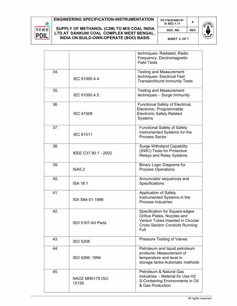
ENGINEERING SPECIFICATION-INSTRUMENTATION
SUPPLY OF METHANOL (C2M) TO M/S COAL INDIA LTD AT DANKUNI COAL COMPLEX WEST BENGAL,
INDIA ON BUILD-OWN-OPERATE (BOO) BASIS
PC176//E/4001/P-II/ SEC-1.11
0
DOC. NO. REV
SHEET 4 OF 7
All rights reserved
techniques- Radiated, Radio Frequency, Electromagnetic Field Tests
34.
IEC 61000.4.4
Testing and Measurement techniques- Electrical Fast Transient/burst Immunity Tests
35. IEC 61000.4.5
Testing and Measurement techniques – Surge Immunity
36.
IEC 61508
Functional Safety of Electrical, Electronic, Programmable Electronic Safety Related Systems
37.
IEC 61511
Functional Safety of Safety Instrumented Systems for the Process Sector
38.
IEEE C37.90.1 - 2002
Surge Withstand Capability (SWC) Tests for Protective Relays and Relay Systems
39. ISA5.2
Binary Logic Diagrams for Process Operations
40. ISA 18.1
Annunciator sequences and Specifications
41.
ISA S84-01-1996
Application of Safety Instrumented Systems in the Process Industries
42.
ISO 5167-AII Parts
Specification for Square-edges Orifice Plates, Nozzles and Venturi Tubes Inserted in Circular Cross Section Conduits Running Full
43. ISO 5208 Pressure Testing of Valves
44.
ISO 4266: 1994
Petroleum and liquid petroleum products- Measurement of temperature and level in storage tanks-Automatic methods
45.
NACE MR0175 ISO 15156
Petroleum & Natural Gas Industries – Material for Use H2 S-Containing Environments in Oil & Gas Production

ENGINEERING SPECIFICATION-INSTRUMENTATION
SUPPLY OF METHANOL (C2M) TO M/S COAL INDIA LTD AT DANKUNI COAL COMPLEX WEST BENGAL,
INDIA ON BUILD-OWN-OPERATE (BOO) BASIS
PC176//E/4001/P-II/ SEC-1.11
0
DOC. NO. REV
SHEET 5 OF 7
All rights reserved
The latest published issue or amendment at the time of contract placement shall apply unless otherwise stated
PUBLICATIONS
AUTHOR TITLE
R.W.Miller Flow Measurement Engineering Handbook.
Fieldbus Foundation AG-181 Foundation Fieldbus System Engineering Guidelines,
2. Statutory requirements to be followed
All instrumentation shall be subject to SIL Assessment. The implementation of SIL requirements shall be in accordance with IEC 61508 & 61511.
Not withstanding the hazard classification assigned to the area in which an instrument is
located, which is generally Zone 2 for hazardous areas subject to flammable gas 1 vapours, all instruments, except the drive section of motorised valves, shall be:
Certified, as a minimum, EEx'ib', suitable for Zone 1, with the Gas Group determine by the process area classification in which the instrument is located. Certified EEx'ia' in locations specified as Zone 0. The certification listed above, shall be provided by the Chief Controller of Explosives (CCOE), Nagpur, India, and an Internationally recognised authority,
The drive section of motorised valves shall be certified EEx'd', suitable for Zone 1, with the
Gas Group determine by the process area classification in which the instrument, for hazardous areas subject to flammable gas I vapours, or EEx'tD' for hazardous areas subject to flammable dust I fibres. These certifications shall be provided by the Chief Controller of Explosives (CCOE), Nagpur, India, and an internationally recognised authority.
Electromagnetic Compatibility Requirements
All equipment shall meet the technical requirements as defined in the following specifications:
IEC 61000 Sections 4.1 thru 4.5 - Electromagnetic Compatibility.
IEC 61326 section 1 - Electrical Equipment Measurement, Control Laboratory use – EMC requirements
IEEE C37.90.1 - 2002 -Surge Withstand Capability (SWC) Tests for Protective Relays and Relay Systems
Other requirements as per OISD & IBR standards

ENGINEERING SPECIFICATION-INSTRUMENTATION
SUPPLY OF METHANOL (C2M) TO M/S COAL INDIA LTD AT DANKUNI COAL COMPLEX WEST BENGAL,
INDIA ON BUILD-OWN-OPERATE (BOO) BASIS
PC176//E/4001/P-II/ SEC-1.11
0
DOC. NO. REV
SHEET 6 OF 7
All rights reserved
3. Design requirements for flow instruments:
The reference conditions for standardised flows shall be Liquids - 15 Deg C and 760mm HG Gas/Vapuors- 0 Deg C and 760mm Hg
4. All instrumentation requirement as per the NOC of Pollution control board and
Environmental Clearance accorded by the MOE & F 5. Interfacing jobs
Interfacing of control system for BOO units with Main project control system for critical data exchange for monitoring only. Necessary hardware for interfacing to be provided by BOO vendor in their control room.
Interfacing of Fire Detection and Alarm system & Gas detection system with main project
system for availability of data in Fire & safety control room. Necessary hardware for interfacing of Fire Detection and Alarm System & Gas Detection system shall be provided by BOO OPERATOR in their Control Room.
6. Custody transfer metering system:
For. Liquid/Gas Custody transfer, international standard like AGA5, AGA 7, AGA 8, AGA9, AGA 11 to be followed based on experience of similar application and concept.
BOO OPERATOR shall provide all the metering for all the interfaces given with relevant flowmeters and accuracies as specified elsewhere in the tender document.
BOO OPERATOR shall match all the material of construction at the battery limit.
7. Control room:
BOO OPERATOR shall be responsible for construction of SRR-810 for installation of System/ marshalling cabinets and all other control system related equipment under their scope of work. BOO OPERATOR shall install all the relevant hardware required for integration of BOO units with Main project control system.
BOO OPERATOR shall utilize the space inside SRR 810 for installing consoles for operation and control of units under their scope of work
8. Metering Equipment:
Following Instruments to be used for various measurements for Coal to Methanol Plant.
Sl. No. Measurement of Measurement through Accuracy 1 Power Energy Meter Class 0.2S *

ENGINEERING SPECIFICATION-INSTRUMENTATION
SUPPLY OF METHANOL (C2M) TO M/S COAL INDIA LTD AT DANKUNI COAL COMPLEX WEST BENGAL,
INDIA ON BUILD-OWN-OPERATE (BOO) BASIS
PC176//E/4001/P-II/ SEC-1.11
0
DOC. NO. REV
SHEET 7 OF 7
All rights reserved
2 Raw Water/Construction Water
Magnetic Flow Meter 0.5 %
3 Treated Effluent Orifice Plate 0.5 % 4 Coal
a. Through Wagon b. Unloading Ground
Hopper
a1. In-motion weighbridge
a2.Static rail weighbridge
b. Belt Weigher
a1. +/-0.5% for Wagon, +/-0.2% for rake
a2. +/-0.02% to 0.05%
b.+/-0.25 %
5 Methanol a. Flow b. Analytic
measurement of impurities in methanol
a. Coriolis Mass Flowmeter
b. GC
a. 0.05 %
b. 1%
*However same shall be in line with WBSEDCL.

PROJECTS & DEVELOPMENT INDIA LTD
PC176/E/4002/P-II/ SECTION 1.12 0
DOCUMENT NO. REV
Sheet 1 of 18
0 24.09.2020 24.09.2020 ISSUED FOR TENDER SK SS UPT REV REV DATE EFF DATE PURPOSE PREPD REVWD APPD
FORM NO: 02-0000-0021F1 REV4 All rights reserved
PART II: TECHNICAL
SECTION –1.12
CIVIL & STRUCTURAL WORKS
PROJECT: COAL TO METHANOL (C2M) PROJECT
THROUGH COAL GASIFICATION ROUTE AT DANKUNI COAL COMPLEX WEST BENGAL, (INDIA) ON BUILD-OWN-OPERATE (BOO) BASIS

SCOPE OF WORK
COAL TO METHANOL PROJECT THROUGH COAL GASIFICATION ROUTE, DANKUNI COAL COMPLEX,
WEST BENGAL
PC176/E/4002/P-II/ SECTION 1.12
0
Document No. Rev.
SHEET 2 OF 18
FORM NO: 02-0000-0021F2 REV3 All rights reserved
INDEX
Sl. No. DESCRIPTION
General Description
1.0 DETAILED SCOPE OF WORK
1.1 Soil Investigation
1.2 Topographical / Contour Survey
1.3 Site Data
1.4 Grading
1.5 Disposal of Surplus Earth
1.6 Site Cleaning
1.7 Roads
1.8 Surface Drainage
1.9 Contaminated Rain Water Sewer (CRWS) System and oily water sewer system (OWS)
1.10 Sewage Disposal Scheme
1.11 Paving
1.12 Structures, Buildings etc.
1.13 Fire Proofing
1.14 Surface Finishing
1.15 Acid / Alkali Proof Lining
1.16 Anti-termite Treatment / Damp Proof Course / Water Proofing
1.17 Miscellaneous
1.18 Engineering and Construction
1.19 Sizing of Various Facilities
1.20 Rules and Regulations
2.0 DETAILED ENGINEERING
2.1 General
2.2 References Documents

SCOPE OF WORK
COAL TO METHANOL PROJECT THROUGH COAL GASIFICATION ROUTE, DANKUNI COAL COMPLEX,
WEST BENGAL
PC176/E/4002/P-II/ SECTION 1.12
0
Document No. Rev.
SHEET 3 OF 18
FORM NO: 02-0000-0021F2 REV3 All rights reserved
2.3 Design Specification- Wind
2.4 Design Calculation & drawings
3.0 CONSTRUCTION
3.1 General
4.0 Special considerations for storage Tanks
5.0 APPENDIX-A : Certificate of Safety ,Serviceability & Maintenance
ATTACHMENTS
1. Topographical Survey Report
2. Geotechnical Report

SCOPE OF WORK
COAL TO METHANOL PROJECT THROUGH COAL GASIFICATION ROUTE, DANKUNI COAL COMPLEX,
WEST BENGAL
PC176/E/4002/P-II/ SECTION 1.12
0
Document No. Rev.
SHEET 4 OF 18
FORM NO: 02-0000-0021F2 REV3 All rights reserved
GENERAL DESCRIPTION OF SCOPE
This section of the Tender Documents deals mainly with the Scope and Technical
Specifications needed for the Detail design, preparation of detailed Drawings and getting
the design/ drawings approved by Owner/Consultant, execution and construction of
complete Civil, Structural and other Allied Works on BOO basis.
The scope of Civil Structural and Architectural Works under this Contract shall include
carrying out surveying, geotechnical investigation, Grading & Leveling, Detailed Design,
Drawings, Supply, Procurement of all materials, Construction, Demolitions, Supervision of
all relevant Civil and Structural Works including providing all labour, supervision, material,
scaffolding, construction equipment, tools, tackles and plants, supplies, transportation, all
incidental items though not indicated or specified but reasonably implied or necessary for
successful completion of the project.
Scope of the CONTRACTOR shall include but not limited to the following:-
a) Topographical survey and geotechnical investigation.
b) Engineering related to site leveling & preparation.
c) Specific soil Investigation, if required for specific design.
d) Preparation of concept notes for design, engineering & construction.
e) Structural Analysis and design calculations as per specifications and as per referred
codes. for all Civil works including but not limited to pile, pile-cap, foundation, plinth
beam, RC superstructure, steel super structure, RC underground structures and
water retaining structures, trenches, drains, pits etc.
f) Architectural design and drawings including details for doors, windows, partitions,
false floor, false ceiling, toilet, finishes etc.
g) General Arrangement and detail design drawings for pile, pile-cap, foundations,
plinth beams etc, based on the soil investigation carried out by the bidder for the
proposed site.

SCOPE OF WORK
COAL TO METHANOL PROJECT THROUGH COAL GASIFICATION ROUTE, DANKUNI COAL COMPLEX,
WEST BENGAL
PC176/E/4002/P-II/ SECTION 1.12
0
Document No. Rev.
SHEET 5 OF 18
FORM NO: 02-0000-0021F2 REV3 All rights reserved
h) General Arrangement and structural drawings at grade level showing foundations,
extent of paving, trenches, drains, pits etc.
i) General Arrangement and detail design drawings for superstructure (RCC and
structural steel) at all levels.
j) RCC drawings showing all necessary details for all foundations and structures.
k) Structural steel detail drawings for all steel structures.
l) General Arrangement and detail drawings for access roads, storm water drains,
effluent drains, cable trenches, sewerage, manholes, pits, sumps with all necessary
details.
m) Effluent Treatment Plant (having zero liquid discharge) and Sewage treatment plant
within battery limit.
n) Bar Bending Schedules for all RCC works.
o) Fabrication drawings with all details for steel structures.
p) Coordination with OWNER / PMC for various activities including approvals of design
basis, concept note, drawings, material samples, laboratory test results etc.
q) Procurement of all items necessary for completion of scope of work.
r) Construction of all units / structures, items of work included in scope of work.
s) Preparation of as built drawings & final documentation.
t) Obtaining Statutory Approvals.
u) Adherence to Quality Assurance Plan
1. DETAILED SCOPE OF WORK
1.0 SCOPE 1.1 SOIL INVESTIGATION 1.1.1 Soil Investigation Report v) The Geo- Technical Investigation for Dankuni Complex is attached with the NIT and
may be viewed by the bidders, for guidance purpose only.
1.1.2 BOO OPERATOR shall design and construct all foundations as per requirements.

SCOPE OF WORK
COAL TO METHANOL PROJECT THROUGH COAL GASIFICATION ROUTE, DANKUNI COAL COMPLEX,
WEST BENGAL
PC176/E/4002/P-II/ SECTION 1.12
0
Document No. Rev.
SHEET 6 OF 18
FORM NO: 02-0000-0021F2 REV3 All rights reserved
1.2 TOPOGRAPHICAL / CONTOUR SURVEY
Required Topographical / Contour survey shall be done by BOO OPERATOR for micro grading & layout purpose. The plant battery limit co-ordinates shall be as per enclosed plot plan (plant). Survey drawing of the Refinery area is attached with the NIT & can be viewed by the bidder, if desired.
1.3 SITE DATA: 1.3.1 Site Conditions
At bidding stage the contractor shall visit the site for studying the site condition & existing structures. Final plant elevation has been decided based on existing elevation of plant in consultation with the client.
1.3.2 Road Levels
BOO OPERATOR shall carryout contour survey of roads adjacent to the unit and also roadways around the unit as defined in plot plan drawing.
1.3.3 Meteorological Data:
For metrological data refer topographical survery report.
1.3.4 Wind Loads Basic wind speed for structural design shall be taken as per BIS Codes.
1.3.5 Earthquake Loads Earthquake loads for Dankuni Complex shall be considered as per BIS Codes.
1.3.6 Design Rainfall intensity shall be as mentioned in the attached topographical report. 1.3.7 Portable water shall be made available at one point location on free/chargeable
basis. Further distribution shall be in the scope of BOO OPERATOR. 1.3.8 Transfer of benchmark

SCOPE OF WORK
COAL TO METHANOL PROJECT THROUGH COAL GASIFICATION ROUTE, DANKUNI COAL COMPLEX,
WEST BENGAL
PC176/E/4002/P-II/ SECTION 1.12
0
Document No. Rev.
SHEET 7 OF 18
FORM NO: 02-0000-0021F2 REV3 All rights reserved
The reference benchmark is available inside the premises. This reference benchmark will be shown to BOO OPERATOR during execution. Same shall be used to transfer the levels to new benchmark near or inside the unit.
1.4 Grading The land shall be handed to the BOO contractor on ‘As is where As’ basis. BOO operator to develop the site as per requirement.
1.5 Disposal of surplus earth BOO OPERATOR shall dispose-off all surplus and unserviceable earth (if any), at his own cost with the consent of Owner / Consultant .The location of disposal area of surplus earth / sand shall be provided by Owner. However, location of disposal area of unserviceable earth, sand, rubbish/debris shall be decided by BOO OPERATOR and the required necessary approvals from the local bodies shall be BOO OPERATOR‘s responsibility.
1.6 Site cleaning During construction and on completion of construction (inclusive all internal and external finishes), cleaning all the debris, waste materials scattered in and around the site and disposal of the same shall be in the scope of BOO OPERATOR with the consent of the OWNER.
1.7 Roads BOO OPERATOR shall be responsible for complete planning and construction of the roads for access to all buildings and units of the plant including necessary approach road from peripheral main roads to the site area from at least two sides. The recommended width of the roads including berms shall be as follows:- Main Road Access Roads Tank/In-unit Areas Minimum width (m) 12 7.5 7.5
1.8 Surface Drainage BOO OPERATOR shall ensure proper drainage of all parts of the Methanol Plant under reference. BOO OPERATOR shall provide proper drainage system for all roads mentioned in the above clause 1.7. Storm Water Drains shall be connected to

SCOPE OF WORK
COAL TO METHANOL PROJECT THROUGH COAL GASIFICATION ROUTE, DANKUNI COAL COMPLEX,
WEST BENGAL
PC176/E/4002/P-II/ SECTION 1.12
0
Document No. Rev.
SHEET 8 OF 18
FORM NO: 02-0000-0021F2 REV3 All rights reserved
the main drainage system by providing suitable tie-in points in consultation with Owner / Consultant.
1.9 Contaminated Rain Water System and Oily Water Sewer (OWS) System BOO OPERATOR shall provide proper underground drainage system for contaminated rain-water and OWS. These shall be connected to Main CRWS & OWS networks at suitable tie-in points to be decided in consultation with Owner / Consultant during detailed engineering.
1.10 Sewage Disposal Scheme BOO OPERATOR shall provide proper underground sewage disposal. This shall be connected to Main sewerage system at suitable tie-in points to be decided in consultation with Owner / Consultant during detailed engineering.
1.11 Paving BOO OPERATOR shall provide RCC pavement for the complete area of the unit as job specific requirement. For the purpose of paving BOO OPERATOR’s scope is not limited only up to Battery Limit, but shall extend up to the adjacent roads around the unit.
1.12 Structures buildings etc.
BOO OPERATOR’s scope shall include are technological structures steel & R.C.C. structures, pipe rack, buildings, equipment foundations, pits, cable trench, sheds, etc. as required for the complete execution and commissioning of the plants.
1.13 Fire Proofing BOO OPERATOR shall design, supply and apply fire proofing to steel structures wherever required as per OISD – STD – 164 standards, published by ‘Oil Industry Safety Directorate, Government of India, Ministry of Petroleum & Natural Gas / Tariff Advisory Committee (TAC) rules and regulations and other Codes / requirements as applicable.
1.14 Surface Finishing BOO OPERATOR shall be responsible for complete planning and detailing of all surfaces finishes viz. painting, flooring etc.

SCOPE OF WORK
COAL TO METHANOL PROJECT THROUGH COAL GASIFICATION ROUTE, DANKUNI COAL COMPLEX,
WEST BENGAL
PC176/E/4002/P-II/ SECTION 1.12
0
Document No. Rev.
SHEET 9 OF 18
FORM NO: 02-0000-0021F2 REV3 All rights reserved
1.15 Acid / Alkali Proof Lining
BOO OPERATOR shall be responsible for surface treatment of floors, exposed portion of foundations, pits and basins against acid / alkali as per process requirement.
1.16 Anti-termite Treatment / Damp proof course / Water proofing BOO OPERATOR shall provide anti-termite treatment, damp proof course and water proofing as per requirement.
1.17 Miscellaneous 1.17.1 Boundary wall / Fencing /Gate / Security Room shall be provided by the bidder as
per the prevailing refinery norms/plant requirements. 1.17.2 The scope shall include local platforms, pipe sleepers, local foundations, local
supports, etc. as per requirement. 1.18 Engineering and construction
Preparation of detailed design, drawings, supply and construction of all civil, structural, architectural, plumbing and building works shall be in the scope of BOO OPERATOR’s work.
1.19 Sizing of various facilities
Sizing, nos., location etc. of various facilities viz. buildings, pipe rack, structures, equipments, etc. shall be in the scope of the bidder.
1.20 Rules and regulations
All the facilities shall conform to all Local Rules and Regulations, Factory Inspector, Rules, TAC rules, OISD norms, etc. whichever is more stringent. Getting the approval of the various documents through the various authorities, including all statutory approvals shall be in BOO OPERATOR’s scope, at no extra cost to OWNER.

SCOPE OF WORK
COAL TO METHANOL PROJECT THROUGH COAL GASIFICATION ROUTE, DANKUNI COAL COMPLEX,
WEST BENGAL
PC176/E/4002/P-II/ SECTION 1.12
0
Document No. Rev.
SHEET 10 OF 18
FORM NO: 02-0000-0021F2 REV3 All rights reserved
2.0 DETAILED ENGINEERING 2.1 General 2.1.1 BOO OPERATOR shall carryout Analysis and Design of the structures required and
prepare all the required Architectural, Civil and Structural drawings needed for correct and accurate construction based on scope and requirements as indicated in the NIT, elsewhere as per Internationally accepted standards and engineering practices, all safety rules pertaining to Refinery, OISD Norms, BIS Codes, International Codes, wherever applicable and Design Specifications given in the Tender.
2.1.2 It shall be the responsibility of BOO OPERATOR, to accommodate all the functional
requirements such as access, cutouts, clearances, interference etc. while designing / detailing of various structures / facilities.
2.2 REFERENCES & DOCUMENTS 2.2.1 Codes and Standards
The latest edition or revision of the following Codes and Standards relative to building design, specification and construction work at the time of contract award, shall form part of this specification. These shall include but not limited to: National Building Code
Technical Sections – Specifically: Part 4 - Fire and Life Safety Part 5 - Building Materials Part 6 - Structural Design Part 7 - Constructional Practices and Safety Part 8 - Building Services Part 9 - Plumbing Services Part 10 - Landscaping, Signs and Outdoor Structures. Bureau of Indian Standards (IS) Oil Industry Safety Directorate Standards (OISD)

SCOPE OF WORK
COAL TO METHANOL PROJECT THROUGH COAL GASIFICATION ROUTE, DANKUNI COAL COMPLEX,
WEST BENGAL
PC176/E/4002/P-II/ SECTION 1.12
0
Document No. Rev.
SHEET 11 OF 18
FORM NO: 02-0000-0021F2 REV3 All rights reserved
British Standards Institution (BSI) IEE Regulations for Electrical Installations Steel Structure Painting Council State Government Factory Acts Local Municipality, Government Authorities and Bye Laws Bye Laws of Town and Country Planning Organization Building Bye Laws Tariff Advisory Committee Guidelines & Recommendations (TAC) Bureau of P/A Guidelines ISO 1999 Acoustics – Assessment of Occupational Noise Exposure for
Hearing Conversation Purposes. 2.2.2 Indian Authorities Codes and Standards
Title
Factories Act; (As specific to Dankuni)
Indian Petroleum Rules;
Liquid effluent discharge, as per Minimal National Standards for liquid effluent and air emissions conforming to Pollution Control Board Standards;
Civil Aviation Rules;
Indian Boiler Regulations;
Indian Electricity Rules,;
Requirement of Chief Controller of Explosives;
Static & Mobile Pressure Vessels (SMPV) rules of the Chief Controller of Explosives
Requirement of Town & Country Planning Department;
Requirements of other authorities concerned with the Project as follows:
Indian Weights and Measures Bhaba Atomic Research Centre
2.2.3 REFERENCE STANDARDS & PUBLICATIONS:
SL. NO. CODES 1. Codes of practice for plain & reinforced concrete IS:456

SCOPE OF WORK
COAL TO METHANOL PROJECT THROUGH COAL GASIFICATION ROUTE, DANKUNI COAL COMPLEX,
WEST BENGAL
PC176/E/4002/P-II/ SECTION 1.12
0
Document No. Rev.
SHEET 12 OF 18
FORM NO: 02-0000-0021F2 REV3 All rights reserved
2. Code of practice for general construction in steel IS:800 3. Code of practice for use of cold formed light gauge
steel structural members in general building construction
IS:801
4. Code of practice for use of structural steel in overhead transmission line towers
IS:802
5. Code of practice for use of steel tubes in general building construction
IS:806
6. Covered electrodes for manual metal arc welding of carbon and carbon manganese steel
IS:814
7. Code of practice for use of metal arc welding for general construction
IS:816
8. Code of practice for design loads IS:875 9. Code of practice for construction of stone masonry IS:1597 10. Fillers for expansion joints IS:1838 11. Criteria for earthquake resistant design of structures IS:1893 12. Code of practice for structural use of unreinforced
masonry IS:1905
13. Recommended practice for hot dipped galvanizing on iron and steel
IS:2629
14. Methods for testing uniformity of coating of zinc coated articles
IS:2633
15. Code of practice for design & construction of raft foundations
IS:2950
16. Code of practice for design & construction of machine foundations
IS:2974
17. Code of practice for concrete structures for storage of liquids
IS:3370
18. Code of practice for design and construction of foundation for transmission line towers and poles
IS:4091
19. Code of practice for earthquake resistant design and construction of buildings
IS:4326
20. Criteria for blast resistant design of structures for explosions above ground
IS:4991
21. Criteria for design of RCC chimneys IS:4998 22. Code of practice for anti-termite measures in buildings IS:6313 23. Code of practice for design & construction of steel IS:6533

SCOPE OF WORK
COAL TO METHANOL PROJECT THROUGH COAL GASIFICATION ROUTE, DANKUNI COAL COMPLEX,
WEST BENGAL
PC176/E/4002/P-II/ SECTION 1.12
0
Document No. Rev.
SHEET 13 OF 18
FORM NO: 02-0000-0021F2 REV3 All rights reserved
chimney 24. Method for determination of mass of zinc coating IS:6745 25. Chlorpyrifos emulsifiable concentrates IS:8944 26. Recommendations for metal arc welding of carbon
and carbon manganese steel IS:9595
27. Two parts polysulphide based sealants IS:12118 28. Code of practice for ductile detailing of reinforced
concrete structures subjected to seismic forces 13920
29. Control Room Safety (a publication of Oil Industry Safety Directorate)
OISD-STD-163
30. Fire Proofing in Oil and Gas Industry (a publication of Oil Industry Safety Directorate)
OISD-STD-164
31. Code of practice for Design and construction of Pile foundations
IS:2911
32. Code of practice for structural safety of buildings -Shallow foundations
IS:1904
33. Code of practice for determination of bearing capacity of shallow foundations
IS:6403
34. Code of practice for calculation of settlements of foundations
IS:8009 (Pt I, II)
35. Determination of dynamic properties of soil IS:5249 36. Fire Protection System for Electrical Installations OISD-STD-173 37. National Building Code (other relevant clauses)
NOTE:
The above list is suggestive and nor exhaustive. Apart from these basic codes any other related codes shall also be followed wherever required.
2.3 DESIGN SPECIFICATION - WIND 2.3.1 SCOPE
Design wind load for process structure & equipment shall be established from IS:875 Part III

SCOPE OF WORK
COAL TO METHANOL PROJECT THROUGH COAL GASIFICATION ROUTE, DANKUNI COAL COMPLEX,
WEST BENGAL
PC176/E/4002/P-II/ SECTION 1.12
0
Document No. Rev.
SHEET 14 OF 18
FORM NO: 02-0000-0021F2 REV3 All rights reserved
This standard specifies the minimum design requirements for wind loadings to be imposed on buildings, equipment, vessels, structures and their foundations.
Design loads shall be in accordance with the Refinery norms & the latest revisions of relevant Indian Codes and Standards.
2.3.2 INDIAN CODES AND STANDARDS
IS 6533 Codes of practice for design and construction of steel chimney
Part 1 Mechanical Aspect Part 2 Structural Aspect IS 875
Codes of practice for design loads (Other than Earthquake) for Buildings & Structures.
Part 1 Dead Loads – Unit weights of building materials and stored materials
Part 2 Imposed Loads Part 3 Wind Loads Part 4 Snow Loads Part 5 Special Loads & Load combinations IS 802 Overhead Transmission Line Towers Part 1 Code of Practice for loading and Permissible
stresses. IS 1893 Criteria for Earthquake Resistant Design of
Structures. Part 1 General Provisions and Buildings Part 4 Industrial Structures including Stack like structuresIS 4326 Code of practice for Earthquake resistant design
and construction of Buildings IS 13920 Code of practice for Ductile detailing of reinforced
concrete structures subjected to seismic forces NBC National Building code of India 2005 Part 6 Structural Design
2.3.3 OTHER STANDARDS AND CODES
In situation where sufficient information / guidance are not found available in Indian Codes and Standards, the following Standards and Codes of Practice

SCOPE OF WORK
COAL TO METHANOL PROJECT THROUGH COAL GASIFICATION ROUTE, DANKUNI COAL COMPLEX,
WEST BENGAL
PC176/E/4002/P-II/ SECTION 1.12
0
Document No. Rev.
SHEET 15 OF 18
FORM NO: 02-0000-0021F2 REV3 All rights reserved
shall apply. The revision current at the time of Contract Placement shall be used.
2.3.4 BRITISH STANDARDS
BS 4076 Specification for Steel Chimneys BS 6399 Loadings for Buildings Part 1 Codes of practice for Dead and Imposed Loads Part 3 Code for Practice for Imposed Roof Loads BS 6399-2 Loadings for Buildings : Code of Practice for Wind
Loads BS 8100 Lattice Towers and Masts Part 1 Code of Practice for Loading Part 2 Guide to the background and use of Part 1 BS CP 3 Code of Basic Data for the Design of Buildings Ch. V, Part
2 Wind Loads
BS DD 133 Code of Practice for Strength Assessment of Members of Lattice Towers and masts
BS EN 1991-1-4 Euro code 1
Action on Structures, General Actions – Wind Actions, Annex E. Vortex Shedding and aero elastic instabilities.
2.3.5 STANDARDS
American Uniform Building Code NZS 4230 Code of Practice for Structural Design and
Design Loadings for Buildings Vol. 1 Code of Practice Vol. 2 Commentary

SCOPE OF WORK
COAL TO METHANOL PROJECT THROUGH COAL GASIFICATION ROUTE, DANKUNI COAL COMPLEX,
WEST BENGAL
PC176/E/4002/P-II/ SECTION 1.12
0
Document No. Rev.
SHEET 16 OF 18
FORM NO: 02-0000-0021F2 REV3 All rights reserved
2.3.6 TECHNICAL LITERATURE
CICIND Model Codes for Stacks AC I Standards Engineering Specification Design Units. Wind Engineering, London ESDU
International Cook N.J. The designers guide to wind loading of building structures. Part
2: Static structures. London: Butterworth Scientific, 1985 Wiliford, M.R., and Allsop, A.C. Design guide for wind loads on unclad
framed building structures construction (Supplement 3 to the designer's guide to wind loading of building structures). Gartson: Building Research Establishment, 1990
Blackmore P. Wind loads on unclad structures. BRE Special digest SD5 BRE Press
ASCE - Wind Loads and Anchor Bolt Design for Petrochemical Facilities 2.3.7 CONFLICT IN STANDARDS
Where conflict exists between specification and Standards, the stringent of the two shall be followed.
2.4. DESIGN CALCULATION & DRAWINGS 2.4.1 BOO OPERATOR shall submit a List of Documents, & Drawings, which shall be
prepared for this project in line with the overall Project Schedule given in the document.
2.4.2 Analysis and design of structures shall be done on latest version of STAAD-PRO
SOFTWARE. For other miscellaneous works Excel and Word shall be used. 2.4.3 Before taking up any construction activity, AFC drawings of all the important
buildings, technological structures & Equipments shall be submitted to the Owner / Consultant for information.
2.4.4 After the mechanical completion of the plants “As built drawings” pertaining to Civil,
Structural and Allied works for the complete Methanol plant, shall be submitted to the Owner, for their records, bearing certificate for structural soundness, strength & serviceability, as per attached Performa in Appendix A.

SCOPE OF WORK
COAL TO METHANOL PROJECT THROUGH COAL GASIFICATION ROUTE, DANKUNI COAL COMPLEX,
WEST BENGAL
PC176/E/4002/P-II/ SECTION 1.12
0
Document No. Rev.
SHEET 17 OF 18
FORM NO: 02-0000-0021F2 REV3 All rights reserved
3.0 CONSTRUCTION 3.1 General 3.1.2 Construction of all civil and structural works including all material, labour,
supervision, tools and tackles etc. shall be carried out by BOO OPERATOR. 3.1.3 Materials of construction, construction method etc. shall be such, so as to protect
the structures and foundations against the harmful effect of chemical, fumes etc. present in the plant, its vicinity, in ground and / or subsoil water.
3.1.4 Construction water & power shall be made available to BOO OPERATOR on
free/chargeable basis. 4.00 SPECIAL CONSIDERATIONS FOR STORAGE TANKS Seismic design of storage tanks shall be carried out as per the provisions of API
650 Appendix-E, API 620 Appendix-L, as applicable. For doubled walled tanks inner and outer tanks have to be checked separately and the outer tank has also to be checked for possible inner tank failure.
The value of Z and I (refer API 650 Appendix-E, API 620 Appendix-L) shall be taken as unity.
The values of CI shall be taken as the site-specific seismic spectral ordinate of 2% damping curve corresponding to the calculated time period of the tank.
The value of C2 shall be taken as the site-specific seismic spectral ordinate for 0.5% damping curve corresponding to the natural period of sloshing. The spectral acceleration values for periods greater than 3.0 seconds may be considered same as that per 3.0 seconds.

SCOPE OF WORK
COAL TO METHANOL PROJECT THROUGH COAL GASIFICATION ROUTE, DANKUNI COAL COMPLEX,
WEST BENGAL
PC176/E/4002/P-II/ SECTION 1.12
0
Document No. Rev.
SHEET 18 OF 18
FORM NO: 02-0000-0021F2 REV3 All rights reserved
5.00 APPENDIX - A
Certificate of Safety, Serviceability and Maintenance
1. It is certified that the Design & Construction of all the Structural Steel & RCC Structures
of the proposed COAL TO METHANOL PROJECT THROUGH COAL GASIFICATION ROUTE, DANKUNI COAL COMPLEX, have been checked for Structural soundness & serviceability requirements as per the relevant codal / safety provisions.
2. The functional viability of sewage system, storm water drainage, drainage systems for
OWS, CRWS & CBD, road / paths, culverts, water supply schemes have been checked for design and optimization as per the relevant BIS codes.
3. BOO OPERATOR M/s …........................... shall be responsible for proper maintenance of all the Structural Steel & RCC Structures and ensure proper functioning of all the systems /schemes/ services, once completed, for the period mentioned in the contract.
(Signature & Seal of Authorised signatory) Dated: For & Behalf Of BOO OPERATOR


Report on Geotechnical Investigation Work
for Proposed Coal to Methanol Project
at Dankuni Coal Complex, Dankuni (WB)
Principal Client Coal India Limited
Client Projects & Development India Limited
PDIL Bhawan, A-14, Sector-1, Noida – 201 301 Distt: Gautam Budh Nagar, (UP), India
Geotechnical Consultant Centre forAdvanced Engineering.
59/2, Bangur Avenue, Block-C, Kolkata-700 055 PH. No. : 033-2574 2130, email: [email protected]
JOB NO: 1638 PROJECT: SOIL_PDIL_DANKUNI COAL COMPLEX 1 of 280

Report on Geotechnical Investigation Work
for Proposed Coal to Methanol Project
at Dankuni Coal Complex, Dankuni (WB)
Principal Client: Coal India Limited Client: Projects & Development India Limited
A. Introduction: It has been proposed by Coal India Limited, to construct Coal to Methanol Project at Dankuni
Coal Complex, Dankuni (WB). A detailed geotechnical investigation was needed for this
purpose and Coal India Limited has appointed M/s Project & Development India Limited
(PDIL), PDIL Bhawan, A-14, Sector-1, Noida – 201 301, Gautam Budh Nagar, UP for
consultancy, Design & Engineering and site supervision services. M/s PDIL has entrusted
M/s Centre for Advanced Engineering of 59/2, Bangur Avenue, Block-C, Kolkata – 700055,
possessing their own ISO/IEC 17025:2017 accredited laboratory by NABL as Geotechnical
Consultant for carrying out Geotechnical Investigation and to provide recommendation for
foundation system.
Location:
The proposed site is located at Dankuni Coal Complex, West Bengal.
B Scope of Investigation: B1. Field Investigation:
Scope of field investigation work was indicated by Projects & Development India Limited vide
P.O. No. : 11/PNMM/P/4804/2019-20/4030000304, Dated: 20.09.2019. It consists of
sinking of fourteen (14) boreholes, two (2) Plate Load Test, two (2) Cyclic Plate Load Test,
eleven (11) Electrical Resistivity Test and three (3) Static Cone Penetration Test.
B2. Laboratory Test:
Scope of laboratory test consists of determination of Natural Moisture Content, Bulk & Dry
Density, Specific Gravity & Void Ratio, Liquid Limit & Plastic Limit, Grain Size Analysis (Sieve
& Hydrometer), Unconfined Compression Test, Direct Shear Test, Triaxial Shear Test – (UU,
JOB NO: 1638 PROJECT: SOIL_PDIL_DANKUNI COAL COMPLEX 2 of 280
CU,CD), Consolidation Test, Swelling Pressure Test, Shrinkage Limit Test, Modified Proctor
Density Test, Chemical Test on Soil Sample and Chemical Test on Water Sample.
B3. Recommendation of Foundation System:
Scope of work consists of analysis of soil characteristics based on result obtained from field
exploration and laboratory test, recommendation of suitable foundation system.
C. Description of Subsoil: The location of boreholes is shown in the enclosed sketch no: PC176-0000-0201. The bore-
log indicates the sub-soil condition as encountered during field investigation considering
laboratory test results on disturbed and undisturbed soil samples as well as soil samples
obtained from split spoon of the Standard Penetration Test (SPT) apparatus. The SPT values
(N Values) are indicated in the corresponding bore-log.
Sub- soil profile of the site
The entire area is divided into 13 zones as follows:-
1. Zone 1 – Air Separation Unit. (BH-8 & ERT-8)
2. Zone 2 – CMD & Gassifier Unit. (BH-4, BH-9, BH-11, CPLT-1, ERT-7, ERT-9 & SCPT-3)
3. Zone 3 – Gas Cleaning & Purification. (BH-7, CPLT-2, ERT-6 & SCPT-2)
4. Zone 4 – Methanol Synthesis. (BH-10 & ERT-4)
5. Zone 5 – Cooling Tower. (ERT-5)
6. Zone 6 – Boiler Unit. (BH-2, BH-3, SCPT-1, ERT-2)
7. Zone 7 – DM Plant & Storage. (BH-6, PLT-1 & ERT-3)
8. Zone 8 – Coal Storage Area including Crusher. (BH-1 & ERT-1)
9. Zone 9 – Methanol Storage Tank. (BH-5)
10. Zone 10 – ETP. (BH-13 & ERT-11)
11. Zone 11 – Work Shop. (PLT-2)
12. Zone 12 – Ware House. (BH-14)
13. Zone 13 – Canteen. (BH-12 & ERT-10)
D. Field Investigation: D1. Boring:
The exploratory boreholes were sunk using shell and auger/wash boring method. Casing was
used up to a depth of 3.000 metres to protect the sides of boreholes against collapse. The
JOB NO: 1638 PROJECT: SOIL_PDIL_DANKUNI COAL COMPLEX 3 of 280

boring was conducted as per the guidelines and provisions of IS: 1892. Standard Penetration
Test was conducted in the boreholes at all the strata encountered. Undisturbed soil samples
were collected from the boreholes. Disturbed samples were collected from the split spoon
sampler at all the test depths and test location of Standard Penetration Test and from
different typical strata.
The termination depth of the borehole and depth of water table as observed in the boreholes
are indicated below:
Table 1 Bore Hole
No.
Termination Depth
below EGL (Mtr)
Depth of Water Table Below EGL (Mtr.)
Explored during the period October to December 2019.
BH-1 35.000 2.100
BH-2 35.000 2.340
BH-3 35.000 2.250
BH-4 35.000 5.140
BH-5 35.000 2.150
BH-6 35.000 0.200
BH-7 30.000 3.150
BH-8 39.000 6.280
BH-9 39.000 6.450
BH-10 35.000 0.850
BH-11 30.000 2.340
BH-12 35.000 0.840
BH-13 35.000 1.000
BH-14 30.000 2.450
D.2. Sampling:
D.2.1 Undisturbed Sampling:
The collection of undisturbed soil sample was done, wherever possible depending on
existing soil strata, as per the guidelines of IS: 1892 – Code of Practice for site Investigation
for Foundation. The sampling system used was an assembly of sampling tube of 100 mm
diameter and 450 mm long, connected with a jarring link. The specification of the tube is as
per the provision of IS: 2132, Code of practice for thin walled sampling of soils.
JOB NO: 1638 PROJECT: SOIL_PDIL_DANKUNI COAL COMPLEX 4 of 280

After the samples are collected within the tubes, the tubes are taken out of the borehole. Both
the ends of the tube were properly sealed with wax, properly labeled depth-wise and
borehole-wise, capped and thus made ready for onward transmission for testing the soil
samples in the laboratory.
D.2.2 Disturbed Sampling:
Disturbed samples were collected from cutting shoe and split spoon of the SPT sampler.
These samples were collected in polythene bags, properly labeled depth-wise and borehole-
wise and were used in the preparation of bore log as well as for general identification &
classification purpose of soil as per IS: 1498. The same were then packed and sent to the
laboratory for further test.
D3. Standard Penetration Test:
Standard Penetration Test was conducted as per the guidelines and provisions of IS: 2131-
Method for standard penetration test for soil, in the borehole at regular intervals or at
change of strata with the SPT sampler. In this test, the sampler was driven by falling a weight
of 63.5 Kg hammer through a height of 750 mm. The sampler was driven through a depth of
450mm. The number of blows for every 150mm. of penetration was recorded. The first 150
mm. was taken as seating drive, the number of blows for subsequent 300 mm. is the SPT N-
value. The observed N–values are indicated in the corresponding bore log.
D4. Recording of Ground Water Table:
The field exploration was carried out during the month of October and December 2019.
The recorded ground water table is indicated in Table 1 of the report.
E. Laboratory Testing: Laboratory tests were conducted on the soil samples collected from the boreholes. The tests
were conducted as per provisions and guidelines of Bureau of Indian Standard laid down in
their different codes and as per requirements of the client.
All disturbed and undisturbed samples were opened up in the laboratory for further
identification & classification of soil samples. Various tests were conducted for ascertaining
the following engineering and physical properties of the sub-soil:
Natural Moisture Content
JOB NO: 1638 PROJECT: SOIL_PDIL_DANKUNI COAL COMPLEX 5 of 280

Bulk & Dry Density
Specific Gravity & Void Ratio.
Liquid Limit & Plastic Limit.
Grain Size Analysis (Sieve & Hydrometer)
Unconfined Compressive Strength.
Direct Shear Test
Tri-axial Shear Strength (UU, CU & CD.)
Consolidation Properties.
Swelling Pressure. Shrinkage Limit.
Modified Proctor Density Test.
Chemical Test on Soil Sample.
Chemical Test of Water Sample.
F. Discussion and Recommendation:- F1. Foundation system:
In general the top soil is heterogeneous fill with coal dust, sand, silt, clay, brickbats, stone
chips etc, thus this layer is not suitable for resting shallow foundation. However, shallow
foundation of light to medium pressure intensity is proposed to rest in this layer by sand
replacement and the same is recommended in Table – 3. At the location of Zone-2 CMD &
Gassifier Unit the shallow foundation is not suggested with sand replacement technique
since the thickness of heterogeneous fill is about 5.00Mtr.
F2. Ground Development:
In case any special requirement arises, ground improvement may be resorted to depending
on the proposed type of structure/ loading on ground. For foundation imparting medium
pressure on the sub-soil, sand replacement has been proposed. Sand replacement may be
adopted for subsoil having recorded N-value range of 0 to 4. For this, foundation is proposed
at a depth of 1.50Mtr below EGL, and soil underneath the foundation is proposed to be
replaced by sand for a thickness of 1.50Mtr below the foundation. The sand shall be
JOB NO: 1638 PROJECT: SOIL_PDIL_DANKUNI COAL COMPLEX 6 of 280

compacted for minimum relative density of 85%. The bearing capacities of improved soil
thus obtain is indicated below:
Table-3
Footing Size (m) Estimated Settlement (mm) Allowable Bearing Capacity (t/m2)
Square
2.00 X 2.00 31.71 12.25
2.50 X 2.50 52.42 10.24
3.00 X 3.00 77.24 9.00
Rectangular
3.00 X 2.00 38.45 10.50
3.75 X 2.50 65.76 8.96
4.50 X 3.00 90.24 8.00
Strip
1.50 43.56 6.00
2.00 68.73 5.25
2.50 99.21 4.80
F3. Pile Foundation:
Bored Cast-in-situ Pile foundations have been recommended for structures with
heavy load on foundations. Recommended pile capacities have been indicated
for different zones in their corresponding chapters.
Chemical tests were performed on a few soil samples and water samples for
determining the pH value, Sulphate & Chloride content. It is seen that the values
are on a safe side and so no precaution will be required for foundation concrete.
Either Ordinary Portland cement or Portland slag cement or Portland Pozzolana
cement can be used for the purpose.
JOB NO: 1638 PROJECT: SOIL_PDIL_DANKUNI COAL COMPLEX 7 of 280

BH-4
BH-8 ER
T-8
BH-9
BH-11
CPL
T-1
SCPT
-3ER
T-7
ERT-9
BH-7
ERT-6
SCPT
-2CPL
T-2
ERT-10
BH-10
ERT-4
BH-5
ERT-1
BH-1
BH-12
BH-14
PLT-2
BH-13
ERT-11
ERT-5
ERT-3
ERT-2
BH-2
SCPT
-1BH
-3
BH-6
PLT-1
JOB NO: 1638 PROJECT: SOIL_PDIL_DANKUNI COAL COMPLEX 8 of 280

ZONE-1
AIR SEPARATION
UNIT
JOB NO: 1638 PROJECT: SOIL_PDIL_DANKUNI COAL COMPLEX 9 of 280

One (1) borehole was sunk in this area, viz borehole marked BH-8. From the general sub soil profile it has been observed that the top soil is heterogeneous fill with coal dust etc followed by first layer of soft brownish grey silty clay/ clayey silt. The second layer is soft dark grey silty clay/ clayey silt. The third layer is medium to stiff mottled brownish/ bluish grey silty clay/ clayey silt and the fourth layer as encountered up to the explored depth is very stiff to hard mottled brownish/ bluish grey silty clay/ clayey silt.
Discussion and Recommendation:
Based on the sub-soil condition, pile foundation has been recommended for foundation system of medium to heavily loaded structures. Pile capacities in compression, pull-out and horizontal shear for different diameter of pile are indicated in the Table-2A (Zone-1). It is further recommended to carry out initial pile load test for load under compression, pull-out and horizontal shear, in order to confirm the recommended pile capacities and to take corrective measures, if required.
Table-2A (Zone-1). Recommended Pile Capacity
Sl.N
o
Pile
Dia
, D
Tota
l Len
gth
of P
ile, L
Cut
-off
Leve
l
Rec
omm
ende
d Pi
le
Cap
acity
in C
ompr
essi
on
Rec
omm
ende
d Pi
le
Cap
acity
in P
ull-O
ut
Rec
omm
ende
d Pi
le
Cap
acity
in H
oriz
onta
l Sh
ear
Mtr Mtr. Mtr. T T T
1 0.400 30.000 2.000 50 46 2.49
2 0.500 30.000 2.000 64 57 2.72
3 0.550 30.000 2.000 72 63 2.82
4 0.600 30.000 2.000 79 69 2.92
5 0.750 30.000 2.000 103 86 3.19
6 1.000 30.000 2.000 144 115 3.59
JOB NO: 1638 PROJECT: SOIL_PDIL_DANKUNI COAL COMPLEX 10 of 280

DS - Disturbed SampleSCPT-Static Cone Penetration DCPT - Dynamic Cone Penetration
SPT - Standard Penetration Test VST- Vane Shear TestUDS - Undisturbed
Test. Sample Test.
WS - Water Sample
RCS - Rock Core Sample
Centre for Advanced Engineering
N-V A L U E
20 RCSDSDCPTDepth of Drilling
Type of Drilling
D E S C R I P T I O N
VST SCPT
SYMBOL DEPTH
Co-ord: Type of Boring
Depth of Boring
Project:
FIELDTESTE.G.L.: 34.576
SPT39.000 M.Shell & Auger
BORE LOG SHEET
SAMPLESNOS.Unit:
UDS18 8NOS.
WSSAMPLES
6.25 M.Water Struck At :
6.20 M.S A M P L E
DEPTH
Standing Water Table :
NO.
Bore Hole No.:
Soil - 1638
Commenced on : Bore Hole Dia. :
Completed on :
Job No.:
NOS.150 MM.
BH-8 (Sheet-1)
22.11.201924.11.2019
01DS1 0.50 M
N = 9 1.50-1.95MDS3SPT1
1.50-1.95M
N = 2 7.50-7.95MDS7SPT5
7.50-7.95M
N = 2 10.50-10.95MDS9SPT7
10.50-10.95MUDS2 11.00-11.45M
N = 13 3.00-3.45MDS4SPT2
3.00-3.45M
N = 2 5.50-5.95MDS6SPT4
5.50-5.95M
UDS1 8.00-8.45M
N = 2 9.00-9.45MDS8SPT6
9.00-9.45M
UDS3 14.00-14.45MN = 7 14.50-14.95M
DS11SPT9
14.50-14.95M
N = 2 12.50-12.95MDS10SPT8
12.50-12.95M
N = 9 16.50-16.95MDS12SPT10
16.50-16.95M
N = 9 18.50-18.95MDS13SPT11
18.50-18.95M
UDS4 17.00-17.45M
SOIL_PDIL_DANKUNI_AIR SEPARATION UNIT
02
03
04
05
06
07
08
09
10
11
12
13
14
15
16
17
18
19
DS2 1.00 M
N = 12 4.50-4.95MDS5SPT3
4.50-4.95M
Filled up with coal dust, clayey silt,cinder, stone chips, moorum etc.
Soft brownish grey silty clay/clayey silt with traces of rustybrown spots.
Soft dark grey silty clay/ clayey siltwith peat and organic matter.
Medium to stiff mottled brownish/bluish grey silty clay/ clayey siltwith traces of silt stone.
Contd.........
JOB NO: 1638 PROJECT: SOIL_PDIL_DANKUNI COAL COMPLEX 11 of 280

6.25 M.6.20 M.
150 MM.
BH-8 (Sheet-1)
22.11.201924.11.2019
DS - Disturbed SampleSCPT-Static Cone Penetration DCPT - Dynamic Cone Penetration
SPT - Standard Penetration Test VST- Vane Shear TestUDS - Undisturbed
Test. Sample Test.
WS - Water Sample
RCS - Rock Core Sample
Centre for Advanced Engineering
N-V A L U E
20 RCSDSDCPTDepth of Drilling
Type of Drilling
D E S C R I P T I O N
VST SCPT
SYMBOL DEPTH
Co-ord: Type of Boring
Depth of Boring
Project:
FIELDTESTE.G.L.: 34.576
SPT39.000 M.Shell & Auger
BORE LOG SHEET
SAMPLESNOS.Unit:
UDS18 8NOS.
WSSAMPLES
6.25 M.Water Struck At :
6.20 M.S A M P L E
DEPTH
Standing Water Table :
NO.
Bore Hole No.:
Soil - 1638
Commenced on : Bore Hole Dia. :
Completed on :
Job No.:
NOS.150 MM.
22.11.201924.11.2019
Termination Depth 39.000 Mtr.
SOIL_PDIL_DANKUNI_AIR SEPARATION UNIT
21
22
23
24
25
26
27
28
29
30
31
32
33
34
35
36
37
38
39
UDS5 20.00-20.45MN = 12 20.50-20.95M
DS14SPT12
20.50-20.95M
UDS6 23.00-23.45MN = 14 23.50-23.95M
DS15SPT13
23.50-23.95M
UDS7 26.00-26.45M
UDS8 29.00-29.45M
N = 25 26.50-26.95MDS16SPT14
26.50-26.95M
N = 27 29.50-29.95MDS17SPT15
29.50-29.95M
BH-8 (Sheet-2)
N = 30 32.50-32.95MDS18SPT16
32.50-32.95M
N = 34 35.50-35.95MDS19SPT17
35.50-35.95M
N = 41 38.55-39.00MDS20SPT18
38.55-39.00M
Medium to stiff mottled brownish/bluish grey silty clay/ clayey siltwith traces of silt stone.
Very stiff to hard mottledbrownish/ bluish grey silty clay/clayey silt with traces of silt stone.
JOB NO: 1638 PROJECT: SOIL_PDIL_DANKUNI COAL COMPLEX 12 of 280

Sub-Soil Profile through BH-8 02
26.00M.
12.00M.
18.00M.
20.00M.
22.00M.
14.00M.
16.00M.
6.00M.
10.00M.
8.00M.
2.00M.
4.00M.
Sketch No.-SK/PDIL/ AIR SEPARATION UNIT 1638 1 of 13
Termination depth 39.000 M.
BH-8
RL=34.576
28.00M.
30.00M.
32.00M.
34.00M.
36.00M.
38.00M.
40.00M.
5.50M
9.00M
26.50M
14.50M
Layer-I
Layer-II
Layer-III
Layer-IV
Filled up with coal dust, clayey silt, cinder, stone chips, moorum etc.
Soft brownish grey silty clay/ clayey silt with traces of rustybrown spots.
Soft dark grey silty clay/ clayey silt with peat and organic matter.
Medium to stiff mottled brownish/ bluish grey silty clay/ clayey siltwith traces of silt stone.
Very stiff to hard mottled brownish/ bluish grey silty clay/ clayeysilt with traces of silt stone.
JOB NO: 1638 PROJECT: SOIL_PDIL_DANKUNI COAL COMPLEX 13 of 280

LL PL SL Type of Test
Cohesion in
kg/sqcm
Friction angle in degree
Gravel (> 4.75 mm) %
Sand (0.075 - 4.75 mm)
Silt (0.002 - 0.075 mm)
Clay (< 0.002 mm)
Meter % % % γb m G γd qu UU/UC/DS C φ % % % %
8 5.50 DN 2 48 21 11.6 2.67 9.85 0 9 66 25
0.00-0.10 0.0343
0.10-0.20 0.0383
0.20-0.40 0.0452
0.40-0.80 0.0261
0.80-1.60 0.0184
1.60-3.20 0.0149
8 10.50 DN 2 58 22 16.5 2.58 13.4 0 11 69 20
0.00-0.10 0.0334
0.10-0.20 0.0392
0.20-0.40 0.0463
0.40-0.80 0.0277
0.80-1.60 0.0191
1.60-3.20 0.0167
8 16.50 DN 9 49 20 10.8 2.67 14.4 2 12 59 27
0.00-0.10 0.0328
0.10-0.20 0.0357
0.20-0.40 0.0409
0.40-0.80 0.0238
0.80-1.60 0.0172
1.60-3.20 0.0138
8 20.50 DN 12 50 18 13.4 2.68 15.3 1 12 56 31
8 26.50 DN 25 53 20 14.1 2.67 20.2 1 10 60 29
8 32.50 DN 30 50 20 13.8 2.66 18.3 3 14 57 26
8 8.00
0.21
0.06
0
11
UU
CUUD
Bore Hole No.
Sample Type - UD/D/
DN
SPT VALUE
(N)
Atterberg LimitsUnconfined
Test in Kg/sqcm
Pressure (Kg/sqcm
)
Dry Density
in gm/cc
Project: Geotechnical Investigation Work for Proposed Coal to Methanol Project at Dankuni Coal Complex, Dankuni (WB)
Swell Pressure
(Kg/sqcm)
Specific Gravity Free Swell
Index(%)
Bulk Density
in gm/cc
Shear Test Grading
Layer No.
50 20
SUMMARY OF LABORATORY TEST RESULTSTable-3
Depth Water
Content in %Description of layer
Co-eff. of volume
compressibility in sqcm/kg
0.38
CD 0 17
12.3 1.81 33.64 2.66 1.35 280 10.5 0 10 62
Very stiff to hard mottled brownish/ bluish grey
silty clay/ clayey silt with traces of silt stone.
IV
0.468 11.00 UD
Soft brownish grey silty clay/ clayey silt with
traces of rusty brown spots.
I
Soft dark grey silty clay/ clayey silt with peat and
organic matter.II
Medium to stiff mottled brownish/ bluish grey
silty clay/ clayey silt with traces of silt stone.
III
55 21
0
15.7 1.80 37.49 2.61 1.31
31.19
0 9
UU
31.09 11
0
0 61 30CU 0.04 12
CD 18
UU 0.24
12.78
8 17.00 UD 51 21 12.6 1.86
0
0 16.62.66 1.42 58 28CU 0.11 19
CD 0 26
0.56
JOB NO: 1638 PROJECT: SOIL_PDIL_DANKUNI COAL COMPLEX 14 of 280

Centre for Advanced Engineering
Pile Model Scale :- N.T.S.
Existing Ground Level.
γ = 1.75 T/M3
c = 0φ = 28°
I
II
3.50
MIII
γ = 1.81 T/M3
c = 2.10 T/M2φ = 0
Filled up with coal dust, clayey silt,cinder, stone chips, moorum etc.
γ = 1.86 T/M3
c = 5.60 T/M2φ = 0
Pile
Cut
-Off
Leve
l = 2
.00M
03Sketch No.-SK/PDIL/ AIR SEPARATION UNIT 1638
5.50
M5.
50M
γ = 1.80 T/M3
c = 2.40 T/M2φ = 0
12.0
0M
IV
Soft brownish grey silty clay/clayey silt with traces of rustybrown spots.
Soft dark grey silty clay/ clayeysilt with peat and organic matter.
Medium to stiff mottled brownish/bluish grey silty clay/ clayey silt withtraces of silt stone.
Very stiff to hard mottled brownish/bluish grey silty clay/ clayey silt withtraces of silt stone. γ = 1.90 T/M3
c = 10.50 T/M2φ = 0
JOB NO: 1638 PROJECT: SOIL_PDIL_DANKUNI COAL COMPLEX 15 of 280

Ultimate skin friction capacity
Layer No: Fill
Soil Description :
Sl.N
o
Pile
Dia
, D
Tota
l Len
gth
of P
ile, L
Dep
th o
f lay
er to
p, fr
om E
GL
Dep
th o
f lay
er b
otto
m, f
rom
EG
L
Wat
er ta
ble
φφ
adop
ted
=(φ
-3)o co
nsid
erin
g lo
osen
ing
effe
ct
NC
Nq Nγ
Uni
t wei
ght,
γ
Effe
ctiv
e un
it w
eigh
t, γ'
k- V
alue
, as
per n
ote
3 IS
291
1 pa
rt 1/
Sec
2-19
79Li
miti
ng L
/D fo
r cal
cn. O
f max
m.
Effe
ctiv
e ov
erbu
rden
pre
ss. A
t pi
le ti
p
P Di a
t lay
er to
p
δ =
φ
Uni
t fric
tion,
f s =
K*P
di*ta
n δ -
at
laye
r top
, max
imum
= 1
0T/M
2
P Di a
t lay
er b
otto
m
Uni
t fric
tion,
f s =
K*P
di*ta
n δ -
at
laye
r bot
tom
, max
imum
= 1
0T/M
2
Aver
age
unit
frict
ion,
ado
pted
for
shaf
t fric
tion
capa
city
.
A Si
Shaf
t fric
tion,
F
Mtr
Mtr.
Mtr
Mtr.
Mtr.
Deg
ree
Deg
ree
T/M
3
T/M
3
T/M
2
Rad
ian
T/M
2
T/M
2
T/M
2
T/M
2
M2 T
1 0.400 30.000 2.000 5.500 1.000 28 25 20.72 10.66 10.88 1.75 0.75 1.3 15 1.5 0.44 0.909 4.125 2.501 1.705 4.398 -7.4992 0.500 30.000 2.000 5.500 1.000 28 25 20.72 10.66 10.88 1.75 0.75 1.3 15 1.5 0.44 0.909 4.125 2.501 1.705 5.498 -9.3733 0.550 30.000 2.000 5.500 1.000 28 25 20.72 10.66 10.88 1.75 0.75 1.3 15 1.5 0.44 0.909 4.125 2.501 1.705 6.048 -10.3114 0.600 30.000 2.000 5.500 1.000 28 25 20.72 10.66 10.88 1.75 0.75 1.3 15 1.5 0.44 0.909 4.125 2.501 1.705 6.597 -11.2485 0.750 30.000 2.000 5.500 1.000 28 25 20.72 10.66 10.88 1.75 0.75 1.3 15 1.5 0.44 0.909 4.125 2.501 1.705 8.247 -14.0606 1.000 30.000 2.000 5.500 1.000 28 25 20.72 10.66 10.88 1.75 0.75 1.3 15 1.5 0.44 0.909 4.125 2.501 1.705 10.996 -18.747
Project: Geotechnical Investigation Work for Proposed Coal to Methanol Project at Dankuni Coal Complex, Dankuni (WB)
Filled up with coal dust, clayey silt, cinder, stone chips, moorum etc.
Location: Air Separation unit, Dankuni Coal Complex, West Bengal
JOB NO: 1638 PROJECT: SOIL_PDIL_DANKUNI COAL COMPLEX 16 of 280

Ultimate skin friction capacity
Location: Air Separation unit, Dankuni Coal Complex, West Bengal
Layer No: 1Soil Description Soft brownish grey silty clay/ clayey silt with traces of rusty brown spots.
Sl.N
o
Pile
Dia
, D
Tota
l Len
gth
of P
ile, L
Dep
th o
f lay
er to
p fro
m E
GL
Dep
th o
f lay
er b
otto
m fr
om E
GL
Red
uctio
n fa
ctor
, α (N
ote1
IS
2911
( Par
t1/S
ec2)
Aver
age
Coh
esio
n al
ong
the
leng
th
of th
e pi
le in
this
laye
r, C
Surfa
ce a
rea
of th
e pi
le s
haft
in th
is
laye
r, A s
Ulti
mat
e Sk
in fr
ictio
n ca
paci
ty o
f th
e sh
aft i
n th
is la
yer,
Qsu
=
α*C
*AS
Mtr Mtr. Mtr Mtr. T/M2 M2
1 0.400 30.000 5.500 9.000 1 2.1 4.398 9.2362 0.500 30.000 5.500 9.000 1 2.1 5.498 11.5453 0.550 30.000 5.500 9.000 1 2.1 6.048 12.7004 0.600 30.000 5.500 9.000 1 2.1 6.597 13.8545 0.750 30.000 5.500 9.000 1 2.1 8.247 17.3186 1.000 30.000 5.500 9.000 1 2.1 10.996 23.091
Project: Geotechnical Investigation Work for Proposed Coal to Methanol Project at Dankuni Coal Complex, Dankuni (WB)
JOB NO: 1638 PROJECT: SOIL_PDIL_DANKUNI COAL COMPLEX 17 of 280

Ultimate skin friction capacity
Location: Air Separation unit, Dankuni Coal Complex, West Bengal
Layer No: 2Soil Description Soft dark grey silty clay/ clayey silt with peat and organic matter.
Sl.N
o
Pile
Dia
, D
Tota
l Len
gth
of P
ile, L
Dep
th o
f lay
er to
p fro
m E
GL
Dep
th o
f lay
er b
otto
m fr
om E
GL
Red
uctio
n fa
ctor
, α (N
ote1
IS
2911
( Par
t1/S
ec2)
Aver
age
Coh
esio
n al
ong
the
leng
th
of th
e pi
le in
this
laye
r, C
Surfa
ce a
rea
of th
e pi
le s
haft
in th
is
laye
r, A s
Ulti
mat
e Sk
in fr
ictio
n ca
paci
ty o
f th
e sh
aft i
n th
is la
yer,
Qsu
=
α*C
*AS
Mtr Mtr. Mtr Mtr. T/M2 M2
1 0.400 30.000 9.000 14.500 1 2.4 6.912 16.5882 0.500 30.000 9.000 14.500 1 2.4 8.639 20.7353 0.550 30.000 9.000 14.500 1 2.4 9.503 22.8084 0.600 30.000 9.000 14.500 1 2.4 10.367 24.8815 0.750 30.000 9.000 14.500 1 2.4 12.959 31.1026 1.000 30.000 9.000 14.500 1 2.4 17.279 41.469
Project: Geotechnical Investigation Work for Proposed Coal to Methanol Project at Dankuni Coal Complex, Dankuni (WB)
JOB NO: 1638 PROJECT: SOIL_PDIL_DANKUNI COAL COMPLEX 18 of 280

Ultimate skin friction capacity
Location: Air Separation unit, Dankuni Coal Complex, West Bengal
Layer No: 3Soil Description Medium to stiff mottled brownish/ bluish grey silty clay/ clayey silt.
Sl.N
o
Pile
Dia
, D
Tota
l Len
gth
of P
ile, L
Dep
th o
f lay
er to
p fro
m E
GL
Dep
th o
f lay
er b
otto
m fr
om E
GL
Red
uctio
n fa
ctor
, α (N
ote1
IS
2911
( Par
t1/S
ec2)
Aver
age
Coh
esio
n al
ong
the
leng
th
of th
e pi
le in
this
laye
r, C
Surfa
ce a
rea
of th
e pi
le s
haft
in th
is
laye
r, A s
Ulti
mat
e Sk
in fr
ictio
n ca
paci
ty o
f th
e sh
aft i
n th
is la
yer,
Qsu
=
α*C
*AS
Mtr Mtr. Mtr Mtr. T/M2 M2
1 0.400 30.000 14.500 26.500 0.9 5.6 15.080 76.0012 0.500 30.000 14.500 26.500 0.9 5.6 18.850 95.0023 0.550 30.000 14.500 26.500 0.9 5.6 20.735 104.5024 0.600 30.000 14.500 26.500 0.9 5.6 22.619 114.0025 0.750 30.000 14.500 26.500 0.9 5.6 28.274 142.5036 1.000 30.000 14.500 26.500 0.9 5.6 37.699 190.004
Project: Geotechnical Investigation Work for Proposed Coal to Methanol Project at Dankuni Coal Complex, Dankuni (WB)
JOB NO: 1638 PROJECT: SOIL_PDIL_DANKUNI COAL COMPLEX 19 of 280

Ultimate skin friction capacity
Location: Air Separation unit, Dankuni Coal Complex, West Bengal
Layer No: 4Soil Description Very stiff to hard mottled brownish/ bluish grey silty clay/ clayey silt.
Sl.N
o
Pile
Dia
, D
Tota
l Len
gth
of P
ile, L
Dep
th o
f lay
er to
p fro
m E
GL
Dep
th o
f lay
er b
otto
m fr
om E
GL
Red
uctio
n fa
ctor
, α (N
ote1
IS
2911
( Par
t1/S
ec2)
Aver
age
Coh
esio
n al
ong
the
leng
th
of th
e pi
le in
this
laye
r, C
Surfa
ce a
rea
of th
e pi
le s
haft
in th
is
laye
r, A s
Ulti
mat
e Sk
in fr
ictio
n ca
paci
ty o
f th
e sh
aft i
n th
is la
yer,
Qsu
=
α*C
*AS
Mtr Mtr. Mtr Mtr. T/M2 M2
1 0.400 30.000 26.500 30.000 0.45 10.5 4.398 20.7822 0.500 30.000 26.500 30.000 0.45 10.5 5.498 25.9773 0.550 30.000 26.500 30.000 0.45 10.5 6.048 28.5754 0.600 30.000 26.500 30.000 0.45 10.5 6.597 31.1725 0.750 30.000 26.500 30.000 0.45 10.5 8.247 38.9666 1.000 30.000 26.500 30.000 0.45 10.5 10.996 51.954
Project: Geotechnical Investigation Work for Proposed Coal to Methanol Project at Dankuni Coal Complex, Dankuni (WB)
JOB NO: 1638 PROJECT: SOIL_PDIL_DANKUNI COAL COMPLEX 20 of 280
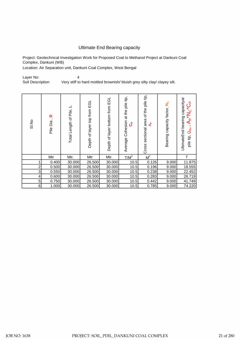
Ultimate End Bearing capacity
Location: Air Separation unit, Dankuni Coal Complex, West Bengal
Layer No: 4Soil Description Very stiff to hard mottled brownish/ bluish grey silty clay/ clayey silt.
Sl.N
o
Pile
Dia
, D
Tota
l Len
gth
of P
ile, L
Dep
th o
f lay
er to
p fro
m E
GL
Dep
th o
f lay
er b
otto
m fr
om E
GL
Aver
age
Coh
esio
n at
the
pile
tip,
C
P
Cro
ss s
ectio
nal a
rea
of th
e pi
le ti
p,
A P
Bear
ing
capa
city
fact
or, N
C
Ulti
mat
eEnd
bea
ring
capa
city
at
pile
tip,
QB u
= A
P*N
C*C
P
Mtr Mtr. Mtr Mtr. T/M2 M2 T1 0.400 30.000 26.500 30.000 10.5 0.126 9.000 11.8752 0.500 30.000 26.500 30.000 10.5 0.196 9.000 18.5553 0.550 30.000 26.500 30.000 10.5 0.238 9.000 22.4524 0.600 30.000 26.500 30.000 10.5 0.283 9.000 26.7195 0.750 30.000 26.500 30.000 10.5 0.442 9.000 41.7496 1.000 30.000 26.500 30.000 10.5 0.785 9.000 74.220
Project: Geotechnical Investigation Work for Proposed Coal to Methanol Project at Dankuni Coal Complex, Dankuni (WB)
JOB NO: 1638 PROJECT: SOIL_PDIL_DANKUNI COAL COMPLEX 21 of 280

Sample Calculation:-= 0.21 Kg/cm2
= 20.601 Kn/M2
= 30.00 Mtr.= 2.00 Mtr.= 0.400 Mtr.= 25 N/MM2
= 25000 MN/M2
= 0.00126 M4
= 31.5 KN/M6
= 1.153 MN/M3
T (Stiffness Factor) = 1.938 Mtr. [Where T = (EI/nh)1/5]
= 28.00 Mtr.
Hence, As per Table-5 pile is a LONG ELASTIC PILE Since Le>= 4T
= 0.000 Mtr.
= 2.200
= 4.264 Mtr.
Therefore, Lf = 4.264 Mtr.L1 = 0.000 Mtr.
For Fixed Head Pile, deflection at the pile head,
= 0.005 Mtr. (Adopt)
= 24.39 Kn
= 2.49 T
Horizontal Shear Capacity of Pile
Reference : Code of Practice for Design and Construction of Pile Foundation - IS 2911 (Part1/Sec2)
C Value
L (Length of Pile)Cut-off Level of PileDia of Pile (D)fckE=Econc=Young's modulas
I (Moment of inertia of the pile cross-section)
Neglecting the effect of steel we get EI
nh = Modulas of Subgrade Reaction (if top of the soil is clay) (Table3)
Le (Embeddment Length of the Pile)
Where L1 = free head of Pile above ground
And for fixed head file Lf/T (as per IS Code)
Where Lf is the length of fixicity below cut-off level of pile =
Y =H(e+zf)3/12EILateral Load = H
Horizontal Shear Capacity = Hdesign
JOB NO: 1638 PROJECT: SOIL_PDIL_DANKUNI COAL COMPLEX 22 of 280

Recommended Pile Capacity
Location: Air Separation unit, Dankuni Coal Complex, West Bengal
Sl.N
o
Pile
Dia
, D
Tota
l Len
gth
of P
ile, L
Fill
Skin
fric
tion
from
laye
r 1
Skin
fric
tion
from
laye
r 2
Skin
fric
tion
from
laye
r 3
Skin
fric
tion
from
laye
r 4
End
Bear
ing
Tota
l
F.O
.S
Allo
wab
le P
ile C
apac
ity
Rec
omm
emde
d Pi
le
Cap
acity
in
Com
pres
sion
Rec
omm
emde
d Pi
le
Cap
acity
in P
ull-O
ut
Rec
omm
emde
d Pi
le
Cap
acity
in H
oriz
onta
l Sh
ear
Mtr Mtr. T T T T T T T T T T T T1 0.400 30.000 -7.499 9.236 16.588 76.001 20.782 11.875 126.983 2.5 50.793 50 46 2.492 0.500 30.000 -9.373 11.545 20.735 95.002 25.977 18.555 162.440 2.5 64.976 64 57 2.723 0.550 30.000 -10.311 12.700 22.808 104.502 28.575 22.452 180.725 2.5 72.290 72 63 2.824 0.600 30.000 -11.248 13.854 24.881 114.002 31.172 26.719 199.382 2.5 79.753 79 69 2.925 0.750 30.000 -14.060 17.318 31.102 142.503 38.966 41.749 257.577 2.5 103.031 103 86 3.196 1.000 30.000 -18.747 23.091 41.469 190.004 51.954 74.220 361.991 2.5 144.796 144 115 3.59
Project: Geotechnical Investigation Work for Proposed Coal to Methanol Project at Dankuni Coal Complex, Dankuni (WB)
JOB NO: 1638 PROJECT: SOIL_PDIL_DANKUNI COAL COMPLEX 23 of 280

ZONE-2
CMD & GASSIFIER
JOB NO: 1638 PROJECT: SOIL_PDIL_DANKUNI COAL COMPLEX 24 of 280

Total three (3) boreholes were sunk in this area, viz borehole marked BH-4, BH-9 and BH-2. From the general sub soil profile it has been observed that the top soil is heterogeneous fill with coal dust, clayey silt etc followed by first layer of soft to medium brownish grey silty clay/ clayey silt. The second layer is soft to medium bluish grey silty clay/ clayey silt. The third layer is stiff mottled brownish/ bluish grey silty clay/ clayey silt. The fourth layer is very stiff to hard mottled brownish/ bluish grey silty clay/ clayey silt and the fifth layer as encountered up to the explored depth is dense brownish grey silty sand.
In addition the following field tests have been carried out at this zone and results are being indicated in this chapter.
1. Cyclic Plate Load Test: One (1) cyclic plate load test has been carried out at this zone marked as CPLT-1.
2. Static Cone Penetration Test: One (1) static cone penetration test has been carried out at this zone marked as SCPT-3.
3. Electrical Resistivity Test: Two (2) electrical resistivity tests have been carried out at this zone marked as ERT-7 and ERT-9.
Discussion and Recommendation:
Based on the subsoil condition pile foundation has been recommended for foundation system of medium to heavily loaded structures. Pile capacities in compression, pull-out and horizontal shear for different diameter of pile are indicated in the Table-2A (Zone-2). It is further recommended to carry out initial pile load test for load under compression, pull-out and horizontal shear, in order to confirm the recommended pile capacities and to take corrective measures, if required.
JOB NO: 1638 PROJECT: SOIL_PDIL_DANKUNI COAL COMPLEX 25 of 280
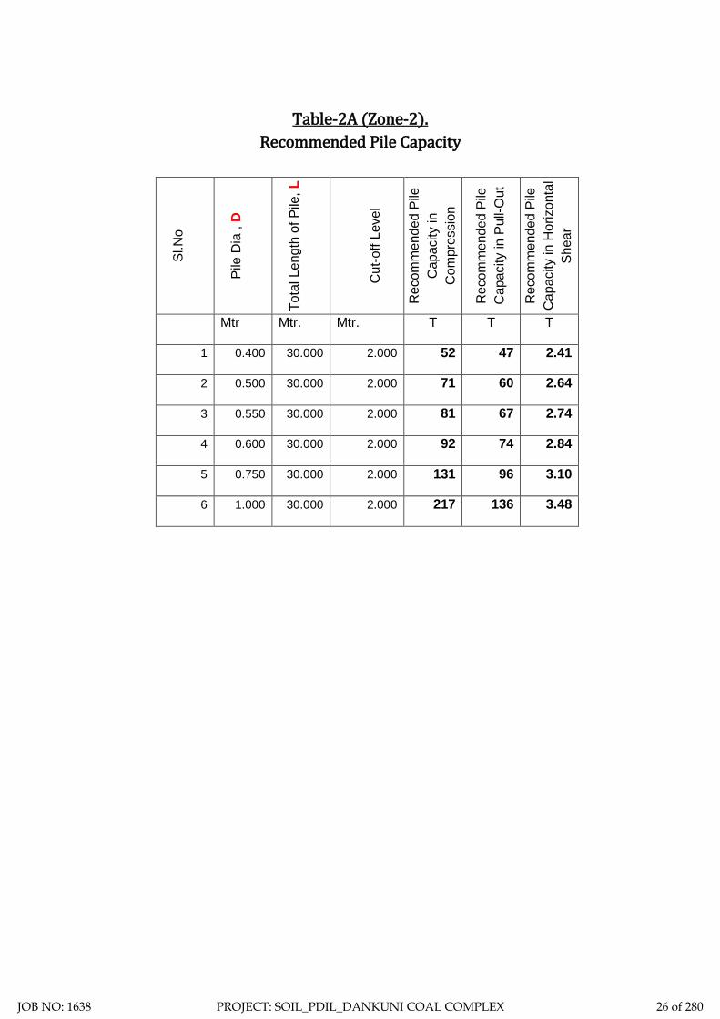
Table-2A (Zone-2).
Recommended Pile Capacity
Sl.N
o
Pile
Dia
, D
Tota
l Len
gth
of P
ile, L
Cut
-off
Leve
l
Rec
omm
ende
d Pi
le
Cap
acity
in
Com
pres
sion
Rec
omm
ende
d Pi
le
Cap
acity
in P
ull-O
ut
Rec
omm
ende
d Pi
le
Cap
acity
in H
oriz
onta
l Sh
ear
Mtr Mtr. Mtr. T T T
1 0.400 30.000 2.000 52 47 2.41
2 0.500 30.000 2.000 71 60 2.64
3 0.550 30.000 2.000 81 67 2.74
4 0.600 30.000 2.000 92 74 2.84
5 0.750 30.000 2.000 131 96 3.10
6 1.000 30.000 2.000 217 136 3.48
JOB NO: 1638 PROJECT: SOIL_PDIL_DANKUNI COAL COMPLEX 26 of 280

DS - Disturbed SampleSCPT-Static Cone Penetration DCPT - Dynamic Cone Penetration
SPT - Standard Penetration Test VST- Vane Shear TestUDS - Undisturbed
Test. Sample Test.
WS - Water Sample
RCS - Rock Core Sample
Centre for Advanced Engineering
N-V A L U E
19 RCSDSDCPTDepth of Drilling
Type of Drilling
D E S C R I P T I O N
VST SCPT
SYMBOL DEPTH
Co-ord: Type of Boring
Depth of Boring
Project:
FIELDTESTE.G.L.: 37.709
SPT35.000 M.Shell & Auger
BORE LOG SHEET
SAMPLESNOS.Unit:
UDS17 9NOS.
WSSAMPLES
5.20 M.Water Struck At :
5.14 M.S A M P L E
DEPTH
Standing Water Table :
NO.
Bore Hole No.:
Soil - 1638
Commenced on : Bore Hole Dia. :
Completed on :
Job No.:
NOS.150 MM.
BH-4 (Sheet-1)
14.11.201918.11.2019
01DS1 0.50 M
N = 2 1.50-1.95MDS3SPT1
1.50-1.95M
N = 6 7.50-7.95MDS7SPT5
7.50-7.95M
N = 4 10.50-10.95MDS9SPT7
10.50-10.95MUDS3 11.00-11.45M
N = 3 3.00-3.45MDS4SPT2
3.00-3.45M
N = 5 6.00-6.45MDS6SPT4
6.00-6.45M
UDS2 8.00-8.45M
N = 4 9.00-9.45MDS8SPT6
9.00-9.45M
UDS4 14.00-14.45MN = 14 14.50-14.95M
DS11SPT9
14.50-14.95M
UDS1 5.00-5.45M
N = 9 12.50-12.95MDS10SPT8
12.50-12.95M
N = 15 16.50-16.95MDS12SPT10
16.50-16.95M
N = 18 18.50-18.95MDS13SPT11
18.50-18.95M
UDS5 17.00-17.45M
SOIL_PDIL_DANKUNI_CMD & GASSIFIER UNIT
02
03
04
05
06
07
08
09
10
11
12
13
14
15
16
17
18
19
DS2 1.00 M
N = 4 4.50-4.95MDS5SPT3
4.50-4.95M
Filled up with coal dust, stonechips etc.
Medium brownish grey silty clay/clayey silt with traces of sand andrusty brown spots.
Medium dark grey silty clay/clayey silt with peat.
Medium to stiff mottled brownish/bluish grey silty clay/ clayey siltwith traces of concretion.
Stiff mottled brownish/ bluish greysilty clay/ clayey silt with traces ofconcretion.
Contd.........
Very stiff to hard mottledbrownish/ bluish grey silty clay/clayey silt with traces ofconcretion.
JOB NO: 1638 PROJECT: SOIL_PDIL_DANKUNI COAL COMPLEX 27 of 280

5.20 M.5.14 M.
150 MM.
BH-4 (Sheet-1)
14.11.201918.11.2019
DS - Disturbed SampleSCPT-Static Cone Penetration DCPT - Dynamic Cone Penetration
SPT - Standard Penetration Test VST- Vane Shear TestUDS - Undisturbed
Test. Sample Test.
WS - Water Sample
RCS - Rock Core Sample
Centre for Advanced Engineering
N-V A L U E
19 RCSDSDCPTDepth of Drilling
Type of Drilling
D E S C R I P T I O N
VST SCPT
SYMBOL DEPTH
Co-ord: Type of Boring
Depth of Boring
Project:
FIELDTESTE.G.L.: 37.709
SPT35.000 M.Shell & Auger
BORE LOG SHEET
SAMPLESNOS.Unit:
UDS17 9NOS.
WSSAMPLES
5.20 M.Water Struck At :
5.14 M.S A M P L E
DEPTH
Standing Water Table :
NO.
Bore Hole No.:
Soil - 1638
Commenced on : Bore Hole Dia. :
Completed on :
Job No.:
NOS.150 MM.
14.11.201918.11.2019
Termination Depth 35.000 Mtr.
SOIL_PDIL_DANKUNI_CMD & GASSIFIER UNIT
21
22
23
24
25
26
27
28
29
30
31
32
33
34
35
36
37
38
39
UDS6 20.00-20.45MN = 19 20.50-20.95M
DS14SPT12
20.50-20.95M
UDS7 23.00-23.45MN = 21 23.50-23.95M
DS15SPT13
23.50-23.95M
UDS8 26.00-26.45M
UDS9 29.00-29.45M
N = 24 26.50-26.95MDS16SPT14
26.50-26.95M
N = 27 29.50-29.95MDS17SPT15
29.50-29.95M
N = 30 32.50-32.95MDS18SPT16
32.50-32.95M
N = 36 34.55-35.00MDS19SPT17
34.55-35.00M
Very stiff to hard mottled brownish/bluish grey silty clay/ clayey siltwith traces of concretion.
BH-4 (Sheet-2)
JOB NO: 1638 PROJECT: SOIL_PDIL_DANKUNI COAL COMPLEX 28 of 280

DS - Disturbed SampleSCPT-Static Cone Penetration DCPT - Dynamic Cone Penetration
SPT - Standard Penetration Test VST- Vane Shear TestUDS - Undisturbed
Test. Sample Test.
WS - Water Sample
RCS - Rock Core Sample
Centre for Advanced Engineering
N-V A L U E
20 RCSDSDCPTDepth of Drilling
Type of Drilling
D E S C R I P T I O N
VST SCPT
SYMBOL DEPTH
Co-ord: Type of Boring
Depth of Boring
Project:
FIELDTESTE.G.L.: 35.378
SPT39.000 M.Shell & Auger
BORE LOG SHEET
SAMPLESNOS.Unit:
UDS18 9NOS.
WSSAMPLES
6.50 M.Water Struck At :
6.45 M.S A M P L E
DEPTH
Standing Water Table :
NO.
Bore Hole No.:
Soil - 1638
Commenced on : Bore Hole Dia. :
Completed on :
Job No.:
NOS.150 MM.
BH-9 (Sheet-1)
19.11.201922.11.2019
01DS1 0.50 M
N = 10 1.50-1.95MDS3SPT1
1.50-1.95M
N = 2 7.50-7.95MDS7SPT5
7.50-7.95M
N = 4 10.50-10.95MDS9SPT7
10.50-10.95MUDS3 11.00-11.45M
N = 11 3.00-3.45MDS4SPT2
3.00-3.45M
N = 4 6.00-6.45MDS6SPT4
6.00-6.45M
UDS2 8.00-8.45M
N = 3 9.00-9.45MDS8SPT6
9.00-9.45M
UDS4 14.00-14.45MN = 8 14.50-14.95M
DS11SPT9
14.50-14.95M
UDS1 5.00-5.45M
N = 5 12.50-12.95MDS10SPT8
12.50-12.95M
N = 12 16.50-16.95MDS12SPT10
16.50-16.95M
N = 13 18.50-18.95MDS13SPT11
18.50-18.95M
UDS5 17.00-17.45M
SOIL_PDIL_DANKUNI_CMD & GASSIFIER UNIT
02
03
04
05
06
07
08
09
10
11
12
13
14
15
16
17
18
19
DS2 1.00 M
N = 25 4.50-4.95MDS5SPT3
4.50-4.95M
Filled up with coal dust, stonechips etc.
Soft to medium brownish grey siltyclay/ clayey silt.
Soft to medium bluish grey siltyclay/ clayey silt with traces ofcalcareous nodules.
Stiff mottled brownish/ bluish greysilty clay/ clayey silt with traces ofsand, concretion and silt stone.
Contd.........
JOB NO: 1638 PROJECT: SOIL_PDIL_DANKUNI COAL COMPLEX 29 of 280

6.50 M.6.45 M.
150 MM.
BH-9 (Sheet-1)
19.11.201922.11.2019
DS - Disturbed SampleSCPT-Static Cone Penetration DCPT - Dynamic Cone Penetration
SPT - Standard Penetration Test VST- Vane Shear TestUDS - Undisturbed
Test. Sample Test.
WS - Water Sample
RCS - Rock Core Sample
Centre for Advanced Engineering
N-V A L U E
20 RCSDSDCPTDepth of Drilling
Type of Drilling
D E S C R I P T I O N
VST SCPT
SYMBOL DEPTH
Co-ord: Type of Boring
Depth of Boring
Project:
FIELDTESTE.G.L.: 35.378
SPT39.000 M.Shell & Auger
BORE LOG SHEET
SAMPLESNOS.Unit:
UDS18 9NOS.
WSSAMPLES
6.50 M.Water Struck At :
6.45 M.S A M P L E
DEPTH
Standing Water Table :
NO.
Bore Hole No.:
Soil - 1638
Commenced on : Bore Hole Dia. :
Completed on :
Job No.:
NOS.150 MM.
19.11.201922.11.2019
Termination Depth 39.000 Mtr.
SOIL_PDIL_DANKUNI_CMD & GASSIFIER UNIT
21
22
23
24
25
26
27
28
29
30
31
32
33
34
35
36
37
38
39
UDS6 20.00-20.45MN = 15 20.50-20.95M
DS14SPT12
20.50-20.95M
UDS7 23.00-23.45MN = 15 23.50-23.95M
DS15SPT13
23.50-23.95M
UDS8 26.00-26.45M
UDS9 29.00-29.45M
N = 36 26.50-26.95MDS16SPT14
26.50-26.95M
N = 30 29.50-29.95MDS17SPT15
29.50-29.95M
N = 32 32.50-32.95MDS18SPT16
32.50-32.95M
N = 30 35.50-35.95MDS19SPT17
35.50-35.95M
BH-9 (Sheet-2)
N = 37 38.55-39.00MDS20SPT18
38.55-39.00M
Stiff mottled brownish/ bluish greysilty clay/ clayey silt with traces ofsand, concretion and silt stone.
Very stiff to hard mottledbrownish/ bluish grey silty clay/clayey silt with traces of sand,concretion and silt stone.
Dense brownish grey silty sandwith clay binders and sand stone.
JOB NO: 1638 PROJECT: SOIL_PDIL_DANKUNI COAL COMPLEX 30 of 280

DS - Disturbed SampleSCPT-Static Cone Penetration DCPT - Dynamic Cone Penetration
SPT - Standard Penetration Test VST- Vane Shear TestUDS - Undisturbed
Test. Sample Test.
WS - Water Sample
RCS - Rock Core Sample
Centre for Advanced Engineering
N-V A L U E
17 RCSDSDCPTDepth of Drilling
Type of Drilling
D E S C R I P T I O N
VST SCPT
SYMBOL DEPTH
Co-ord: Type of Boring
Depth of Boring
Project:
FIELDTESTE.G.L.: 35.469
SPT30.000 M.Shell & Auger
BORE LOG SHEET
SAMPLESNOS.Unit:
UDS15 10NOS.
WSSAMPLES
2.40 M.Water Struck At :
2.34 M.S A M P L E
DEPTH
Standing Water Table :
NO.
Bore Hole No.:
Soil - 1638
Commenced on : Bore Hole Dia. :
Completed on :
Job No.:
NOS.150 MM.
BH-11 (Sheet-1)
25.11.201926.11.2019
01DS1 0.50 M
N = 2 1.50-1.95MDS3SPT1
1.50-1.95M
N = 3 7.50-7.95MDS7SPT5
7.50-7.95M
N = 4 10.50-10.95MDS9SPT7
10.50-10.95MUDS4 11.00-11.45M
N = 3 3.00-3.45MDS4SPT2
3.00-3.45M
N = 4 6.00-6.45MDS6SPT4
6.00-6.45M
UDS3 8.00-8.45M
N = 4 9.00-9.45MDS8SPT6
9.00-9.45M
UDS5 14.00-14.45MN = 25 14.50-14.95M
DS11SPT9
14.50-14.95M
UDS2 5.00-5.45M
N = 5 12.50-12.95MDS10SPT8
12.50-12.95M
N = 9 16.50-16.95MDS12SPT10
16.50-16.95M
N = 10 18.50-18.95MDS13SPT11
18.50-18.95M
UDS6 17.00-17.45M
SOIL_PDIL_DANKUNI_CMD & GASSIFIER UNIT
02
03
04
05
06
07
08
09
10
11
12
13
14
15
16
17
18
19
DS2 1.00 M
N = 2 4.50-4.95MDS5SPT3
4.50-4.95M
Filled up with coal dust, clayey silt,cinder, stone chips, morrum etc.
Soft to medium brownish grey siltyclay/ clayey silt with traces of seashell, sand and silt stone.
Soft to medium bluish grey siltyclay/ clayey silt with traces ofcalcareous nodules.
Stiff mottled brownish/ bluish greysilty clay/ clayey silt with traces ofconcretion.
Contd.........
UDS1 2.00-2.45M
JOB NO: 1638 PROJECT: SOIL_PDIL_DANKUNI COAL COMPLEX 31 of 280

2.40 M.2.34 M.
150 MM.
BH-11 (Sheet-1)
25.11.201926.11.2019
DS - Disturbed SampleSCPT-Static Cone Penetration DCPT - Dynamic Cone Penetration
SPT - Standard Penetration Test VST- Vane Shear TestUDS - Undisturbed
Test. Sample Test.
WS - Water Sample
RCS - Rock Core Sample
Centre for Advanced Engineering
N-V A L U E
17 RCSDSDCPTDepth of Drilling
Type of Drilling
D E S C R I P T I O N
VST SCPT
SYMBOL DEPTH
Co-ord: Type of Boring
Depth of Boring
Project:
FIELDTESTE.G.L.: 35.469
SPT30.000 M.Shell & Auger
BORE LOG SHEET
SAMPLESNOS.Unit:
UDS15 10NOS.
WSSAMPLES
2.40 M.Water Struck At :
2.34 M.S A M P L E
DEPTH
Standing Water Table :
NO.
Bore Hole No.:
Soil - 1638
Commenced on : Bore Hole Dia. :
Completed on :
Job No.:
NOS.150 MM.
25.11.201926.11.2019
Termination Depth 30.000 Mtr.
SOIL_PDIL_DANKUNI_CMD & GASSIFIER UNIT
21
22
23
24
25
26
27
28
29
30
31
32
33
34
35
36
37
38
39
UDS7 20.00-20.45MN = 17 20.50-20.95M
DS14SPT12
20.50-20.95M
UDS8 23.00-23.45MN = 25 23.50-23.95M
DS15SPT13
23.50-23.95M
UDS9 26.00-26.45M
UDS10 29.00-29.45M
N = 26 26.50-26.95MDS16SPT14
26.50-26.95M
N = 29 29.55-30.00MDS17SPT15
29.55-30.00M
Very stiff mottled brownish/ bluishgrey silty clay/ clayey silt withtraces of concretion.
BH-11 (Sheet-2)
Stiff mottled brownish/ bluish greysilty clay/ clayey silt with traces ofconcretion.
JOB NO: 1638 PROJECT: SOIL_PDIL_DANKUNI COAL COMPLEX 32 of 280

Sub-Soil Profile through BH-4, BH-9 & BH-11 02
26.00M.
12.00M.
18.00M.
20.00M.
22.00M.
14.00M.
16.00M.
6.00M.
10.00M.
8.00M.
2.00M.
4.00M.
Sketch No.-SK/PDIL/ CMD & GASSIFIER UNIT 1638 2 of 13
Termination depth 39.000 M.
BH-9
Termination depth35.000 M.
BH-4
RL=37.709
Termination depth 30.000 M.
BH-11
28.00M.
30.00M.
32.00M.
34.00M.
36.00M.
38.00M.
40.00M.
4.50M 5.00M
1.50M
7.50M
9.00M
7.50M
9.00M
14.50M
18.50M
26.00M
20.50M
32.50M
14.50M 14.50M
Medium dark grey siltyclay/ clayey silt with peat.
Soft to medium bluish grey silty clay/ clayey siltwith traces of calcareous nodules.
Stiff mottled brownish/ bluish grey silty clay/ clayey siltwith traces of sand, concretion and silt stone.
Very stiff to hard mottled brownish/ bluish grey silty clay/clayey silt with traces of sand, concretion and silt stone.
Dense brownish grey silty sand with clay binders andsand stone.
Filled up with coal dust, clayey silt,cinder, stone chips, morrum etc.
Soft to medium brownish grey silty clay/ clayey siltwith traces of sea shell, sand and silt stone.
Layer-I
Layer-II
Layer-III
Layer-IV
Layer-V
RL=35.378 RL=35.469
JOB NO: 1638 PROJECT: SOIL_PDIL_DANKUNI COAL COMPLEX 33 of 280

LL PL SL Type of Test
Cohesion in
kg/sqcm
Friction angle in degree
Gravel (> 4.75 mm) %
Sand (0.075 - 4.75 mm)
Silt (0.002 - 0.075 mm)
Clay (< 0.002 mm)
Meter % % % γb m G γd quUU/CU/CD
/DS C φ % % % %
4 4.50 DN 4 43 19 11.6 2.67 14.6 0 11 67 22
0.00-0.10 0.0167
0.10-0.20 0.0219
0.20-0.40 0.0448
0.40-0.80 0.0563
0.80-1.60 0.0443
1.60-3.20 0.0239
II 4 7.50 DN 6 59 23 14.7 2.56 14.8 0 7 71 22
4 10.50 DN 4 65 22 13.2 2.67 18.4 0 6 55 39
0.00-0.10 0.0073
0.10-0.20 0.0142
0.20-0.40 0.0254
0.40-0.80 0.0349
0.80-1.60 0.0298
1.60-3.20 0.0213
4 14.50 DN 14 49 21 13.8 2.71 0 0 9 64 27
0.00-0.10 0.0061
0.10-0.20 0.0131
0.20-0.40 0.0234
0.40-0.80 0.0331
0.80-1.60 0.0272
1.60-3.20 0.0183
0.00-0.10 0.0058
0.10-0.20 0.0128
0.20-0.40 0.0228
0.40-0.80 0.0324
0.80-1.60 0.0249
1.60-3.20 0.0159
4 23.50 DN 21 47 20 13.3 2.66 4.6 0 14 61 25
4 29.50 DN 27 54 22 15.1 2.68 8.37 0 11 59 30
0 30
Very stiff to hard mottled brownish/ bluish grey
silty clay/ clayey silt with traces of concretion.
V
8.69CU 0.17 22
CD
0 12 61 272.14
UU 1.09 0
012.2 1.92 25.31 2.67 1.53
0 28
Stiff mottled brownish/ bluish grey silty clay/
clayey silt with traces of concretion.
IV
4 20.00 UD 48 19
0 0 11 63 261.21
UU 0.63 0
0CU 0.12 15
CD
14.2 1.88 28.64 2.68 1.464 17.00 UD 48 20
8 57 35CU 0.09 15
CD 0 20
0.33 0
0 16.3 02.66 1.42 0.61
UU
58 21 13.1 1.85 30.66
Medium brownish grey silty clay/ clayey silt with traces of sand and rusty
brown spots.
I
Medium dark grey silty clay/ clayey silt with
peat.
4 11.00 UD
Medium to stiff mottled brownish/ bluish grey
silty clay/ clayey silt with traces of concretion.
III
17
4
UU
0CU
CD
12
0
1.84 35.4 0 9 66 250.41
0.22 0
20.40.092.66 1.365.00 UD 47 20 12.2
SUMMARY OF LABORATORY TEST RESULTSTable-3
Depth Water
Content in %Description of layer
Co-eff. of volume
compressibility in sqcm/kg
Project: Geotechnical Investigation Work for Proposed Coal to Methanol Project at Dankuni Coal Complex, Dankuni (WB)
Swell Pressure
(Kg/sqcm)
Specific Gravity Free Swell
Index(%)
Bulk Density
in gm/cc
Shear Test Grading
Layer No.Bore Hole No.
Sample Type - UD/D/
DN
SPT VALUE
(N)
Atterberg LimitsUnconfined
Test in Kg/sqcm
Pressure (Kg/sqcm
)
Dry Density
in gm/cc
JOB NO: 1638 PROJECT: SOIL_PDIL_DANKUNI COAL COMPLEX 34 of 280

LL PL SL Type of Test
Cohesion in
kg/sqcm
Friction angle in degree
Gravel (> 4.75 mm) %
Sand (0.075 - 4.75 mm)
Silt (0.002 - 0.075 mm)
Clay (< 0.002 mm)
Meter % % % γb m G γd quUU/CU/CD
/DS C φ % % % %
Depth Water
Content in %Description of layer
Co-eff. of volume
compressibility in sqcm/kg
Swell Pressure
(Kg/sqcm)
Specific Gravity Free Swell
Index(%)
Bulk Density
in gm/cc
Shear Test Grading
Layer No.Bore Hole No.
Sample Type - UD/D/
DN
SPT VALUE
(N)
Atterberg LimitsUnconfined
Test in Kg/sqcm
Pressure (Kg/sqcm
)
Dry Density
in gm/cc
0.00-0.10 0.0101
0.10-0.20 0.0169
0.20-0.40 0.0403
0.40-0.80 0.0348
0.80-1.60 0.0272
1.60-3.20 0.0191
9 6.00 DN 4 50 22 15.4 2.67 0 0 6 52 42
9 10.50 DN 4 55 20 14.2 2.66 10.47 0 8 60 32
0.00-0.10 0.0132
0.10-0.20 0.0177
0.20-0.40 0.0298
0.40-0.80 0.0238
0.80-1.60 0.0189
1.60-3.20 0.0131
9 12.50 DN 5 39 18 12.7 2.67 7.92 0 10 72 18
9 16.50 DN 12 52 24 16.2 2.69 0 0 7 73 20
0.00-0.10 0.0065
0.10-0.20 0.0139
0.20-0.40 0.0293
0.40-0.80 0.0243
0.80-1.60 0.0199
1.60-3.20 0.0148
9 20.50 DN 15 66 25 16.3 2.66 9.69 0 5 58 37
0.00-0.10 0.0059
0.10-0.20 0.0131
0.20-0.40 0.0268
0.40-0.80 0.0241
0.80-1.60 0.0184
1.60-3.20 0.0127
9 29.50 DN 30 53 22 16.1 2.66 0 0 9 62 29
9 32.50 DN 32 1.80 2.66 DS 0.08 34 0 35 64 1 0
9 35.50 DN 30 1.79 2.66 DS 0.05 32 0 0 98 2 0V
Dense brownish grey silty sand with clay
binders and sand stone.
380 0 0 7 550.45
CD 0 16
14.2 1.80 33.18 2.66 1.3548 199 5.00
0.24
0.07
0
12
UU
CUUD
9 11.00 UD 44 20 13.8 1.86 31.66 2.68 1.41 0.58
UU 0.31 0
0CU 0.12 14
CD
8.63 0 6 72 22
0 20
9 17.00 UD 57 23 15.8 1.91 27.66 2.68 1.50 1.28
UU 0.66 0
0 4.97 0 8 61 31CU 0.14 22
CD 0 28
2.67 1.569 26.50 UD 48 21 242.12
UU 1.09 0
0CU 0.21 26IV
5.67 0 11 65
CD
14.6 1.94 24.73
0 31
Soft to medium brownish grey silty clay/ clayey silt.I
Soft to medium bluish grey silty clay/ clayey silt with traces of calcareous
nodules.
II
Stiff mottled brownish/ bluish grey silty clay/
clayey silt with traces of sand, concretion and silt
stone.
III
Very stiff to hard mottled brownish/ bluish grey
silty clay/ clayey silt with traces of sand,
concretion and silt stone.
NP
NP
JOB NO: 1638 PROJECT: SOIL_PDIL_DANKUNI COAL COMPLEX 35 of 280

LL PL SL Type of Test
Cohesion in
kg/sqcm
Friction angle in degree
Gravel (> 4.75 mm) %
Sand (0.075 - 4.75 mm)
Silt (0.002 - 0.075 mm)
Clay (< 0.002 mm)
Meter % % % γb m G γd quUU/CU/CD
/DS C φ % % % %
Depth Water
Content in %Description of layer
Co-eff. of volume
compressibility in sqcm/kg
Swell Pressure
(Kg/sqcm)
Specific Gravity Free Swell
Index(%)
Bulk Density
in gm/cc
Shear Test Grading
Layer No.Bore Hole No.
Sample Type - UD/D/
DN
SPT VALUE
(N)
Atterberg LimitsUnconfined
Test in Kg/sqcm
Pressure (Kg/sqcm
)
Dry Density
in gm/cc
11 1.50 DN 2 50 21 14.6 2.69 15 0 8 54 38
0.00-0.10 0.0251
0.10-0.20 0.0329
0.20-0.40 0.0438
0.40-0.80 0.0366
0.80-1.60 0.0259
1.60-3.20 0.0191
11 6.00 DN 4 47 23 16.5 2.65 14.6 0 7 69 24
0.00-0.10 0.0249
0.10-0.20 0.0321
0.20-0.40 0.0429
0.40-0.80 0.0351
0.80-1.60 0.0249
1.60-3.20 0.0179
11 9.00 DN 4 50 24 17.2 2.66 0 0 8 67 25
11 12.50 DN 5 55 22 15.7 2.66 0 0 6 63 31
0.00-0.10 0.0165
0.10-0.20 0.0259
0.20-0.40 0.0409
0.40-0.80 0.0349
0.80-1.60 0.0281
1.60-3.20 0.0176
11 18.50 DN 10 54 24 16.9 2.66 0 0 10 63 27
11 26.50 DN 26 45 18 12.7 2.68 0 0 15 59 26
11 29.55 DN 29 46 19 11.9 2.67 0 0 13 62 25
62 28CU 0.11 15
CD 0 20
0.28
16.8 1.83
0
0 02.67 1.4011 8.00 UD 52 23
68 26CU 0.07 14
CD 17
UU 0.20
13.7
31.17
0 6
UU
00.54 10
0
02.00 UD 49 20
0
13.4 1.80 36.62 2.67
28.64 2.67
1.32
Soft to medium brownish grey silty clay/ clayey silt with traces of sea shell,
sand and silt stone.
I
Soft to medium bluish grey silty clay/ clayey silt with traces of calcareous
nodules.
II
11
11 17.00 UD 49 19
UU 0.62
0 27
13.7
0.38
1.87 0Stiff mottled brownish/ bluish grey silty clay/
clayey silt with traces of concretion.
III0 81.45 1.20
Very stiff mottled brownish/ bluish grey
silty clay/ clayey silt with traces of concretion.
IV
63 29CU 0.13 20
CD
0
0
JOB NO: 1638 PROJECT: SOIL_PDIL_DANKUNI COAL COMPLEX 36 of 280

SAMPLE CALCULATION
FOR PILE
FOUNDATION
JOB NO: 1638 PROJECT: SOIL_PDIL_DANKUNI COAL COMPLEX 37 of 280

Centre for Advanced Engineering
Pile Model Scale :- N.T.S.
Existing Ground Level.
γ = 1.75 T/M3
c = 0φ = 28°
I
II
Soft to medium brownish grey siltyclay/ clayey silt with traces of seashell, sand and silt stone.
Soft to medium bluish grey siltyclay/ clayey silt with traces ofcalcareous nodules.
4.00
M
IIIStiff mottled brownish/ bluish greysilty clay/ clayey silt with traces ofsand, concretion and silt stone.
γ = 1.80 T/M3
c = 2.00 T/M2φ = 0
Filled up with coal dust, clayey silt,cinder, stone chips, morrum etc.
γ = 1.85 T/M3
c = 3.30 T/M2φ = 0
Pile
Cut
-Off
Leve
l = 2
.00M
03Sketch No.-SK/PDIL/ CMD & GASSIFIER UNIT 1638
5.00
M5.
50M
γ = 1.83 T/M3
c = 2.80 T/M2φ = 0
11.5
0M6.
50M
IVVery stiff to hard mottled brownish/bluish grey silty clay/ clayey silt withtraces of sand, concretion and silt stone.
VDense brownish grey silty sand withclay binders and sand stone.
γ = 1.88 T/M3
c = 6.30 T/M2φ = 0
γ = 1.80 T/M3
c = 0φ = 34°
JOB NO: 1638 PROJECT: SOIL_PDIL_DANKUNI COAL COMPLEX 38 of 280

Ultimate skin friction capacity
Layer No: Fill
Soil Description :
Sl.N
o
Pile
Dia
, D
Tota
l Len
gth
of P
ile, L
Dep
th o
f lay
er to
p, fr
om E
GL
Dep
th o
f lay
er b
otto
m, f
rom
EG
L
Wat
er ta
ble
φφ
adop
ted
=(φ
-3)o co
nsid
erin
g lo
osen
ing
effe
ct
NC
Nq Nγ
Uni
t wei
ght,
γ
Effe
ctiv
e un
it w
eigh
t, γ'
k- V
alue
, as
per n
ote
3 IS
291
1 pa
rt 1/
Sec
2-19
79Li
miti
ng L
/D fo
r cal
cn. O
f max
m.
Effe
ctiv
e ov
erbu
rden
pre
ss. A
t pi
le ti
p
P Di a
t lay
er to
p
δ =
φ
Uni
t fric
tion,
f s =
K*P
di*ta
n δ -
at
laye
r top
, max
imum
= 1
0T/M
2
P Di a
t lay
er b
otto
m
Uni
t fric
tion,
f s =
K*P
di*ta
n δ -
at
laye
r bot
tom
, max
imum
= 1
0T/M
2
Aver
age
unit
frict
ion,
ado
pted
for
shaf
t fric
tion
capa
city
.
A Si
Shaf
t fric
tion,
F
Mtr
Mtr.
Mtr
Mtr.
Mtr.
Deg
ree
Deg
ree
T/M
3
T/M
3
T/M
2
Rad
ian
T/M
2
T/M
2
T/M
2
T/M
2
M2 T
1 0.400 35.000 2.000 5.000 1.000 28 25 20.72 10.66 10.88 1.75 0.75 1.3 15 1.5 0.44 0.909 3.75 2.273 1.591 3.770 -5.9992 0.500 35.000 2.000 5.000 1.000 28 25 20.72 10.66 10.88 1.75 0.75 1.3 15 1.5 0.44 0.909 3.75 2.273 1.591 4.712 -7.4993 0.550 35.000 2.000 5.000 1.000 28 25 20.72 10.66 10.88 1.75 0.75 1.3 15 1.5 0.44 0.909 3.75 2.273 1.591 5.184 -8.2494 0.600 35.000 2.000 5.000 1.000 28 25 20.72 10.66 10.88 1.75 0.75 1.3 15 1.5 0.44 0.909 3.75 2.273 1.591 5.655 -8.9985 0.750 35.000 2.000 5.000 1.000 28 25 20.72 10.66 10.88 1.75 0.75 1.3 15 1.5 0.44 0.909 3.75 2.273 1.591 7.069 -11.2486 1.000 35.000 2.000 5.000 1.000 28 25 20.72 10.66 10.88 1.75 0.75 1.3 15 1.5 0.44 0.909 3.75 2.273 1.591 9.425 -14.997
Project: Geotechnical Investigation Work for Proposed Coal to Methanol Project at Dankuni Coal Complex, Dankuni (WB)
Filled up with coal dust, clayey silt, cinder, stone chips, morrum etc.
Location: CMD & Gassifier unit, Dankuni Coal Complex, West Bengal
JOB NO: 1638 PROJECT: SOIL_PDIL_DANKUNI COAL COMPLEX 39 of 280

Ultimate skin friction capacity
Location: CMD & Gassifier unit, Dankuni Coal Complex, West Bengal
Layer No: 1Soil Description
Sl.N
o
Pile
Dia
, D
Tota
l Len
gth
of P
ile, L
Dep
th o
f lay
er to
p fro
m E
GL
Dep
th o
f lay
er b
otto
m fr
om E
GL
Red
uctio
n fa
ctor
, α (N
ote1
IS 2
911
( Par
t1/S
ec2)
Aver
age
Coh
esio
n al
ong
the
leng
th
of th
e pi
le in
this
laye
r, C
Surfa
ce a
rea
of th
e pi
le s
haft
in th
is
laye
r, A s
Ulti
mat
e Sk
in fr
ictio
n ca
paci
ty o
f th
e sh
aft i
n th
is la
yer,
Qsu
=
α*C
*AS
Mtr Mtr. Mtr Mtr. T/M2 M2
1 0.400 35.000 5.000 9.000 1 2 5.027 10.0532 0.500 35.000 5.000 9.000 1 2 6.283 12.5663 0.550 35.000 5.000 9.000 1 2 6.912 13.8234 0.600 35.000 5.000 9.000 1 2 7.540 15.0805 0.750 35.000 5.000 9.000 1 2 9.425 18.8506 1.000 35.000 5.000 9.000 1 2 12.566 25.133
Project: Geotechnical Investigation Work for Proposed Coal to Methanol Project at Dankuni Coal Complex, Dankuni (WB)
Soft to medium brownish grey silty clay/ clayey silt with traces of sea shell, sand and silt stone.
JOB NO: 1638 PROJECT: SOIL_PDIL_DANKUNI COAL COMPLEX 40 of 280

Ultimate skin friction capacity
Location: CMD & Gassifier unit, Dankuni Coal Complex, West Bengal
Layer No: 2Soil Description
Sl.N
o
Pile
Dia
, D
Tota
l Len
gth
of P
ile, L
Dep
th o
f lay
er to
p fro
m E
GL
Dep
th o
f lay
er b
otto
m fr
om E
GL
Red
uctio
n fa
ctor
, α (N
ote1
IS
2911
( Par
t1/S
ec2)
Aver
age
Coh
esio
n al
ong
the
leng
th
of th
e pi
le in
this
laye
r, C
Surfa
ce a
rea
of th
e pi
le s
haft
in th
is
laye
r, A s
Ulti
mat
e Sk
in fr
ictio
n ca
paci
ty o
f th
e sh
aft i
n th
is la
yer,
Qsu
=
α*C
*AS
Mtr Mtr. Mtr Mtr. T/M2 M2
1 0.400 35.000 9.000 14.500 1 2.8 6.912 19.3522 0.500 35.000 9.000 14.500 1 2.8 8.639 24.1903 0.550 35.000 9.000 14.500 1 2.8 9.503 26.6094 0.600 35.000 9.000 14.500 1 2.8 10.367 29.0285 0.750 35.000 9.000 14.500 1 2.8 12.959 36.2856 1.000 35.000 9.000 14.500 1 2.8 17.279 48.381
Project: Geotechnical Investigation Work for Proposed Coal to Methanol Project at Dankuni Coal Complex, Dankuni (WB)
Soft to medium bluish grey silty clay/ clayey silt with traces of calcareous nodules.
JOB NO: 1638 PROJECT: SOIL_PDIL_DANKUNI COAL COMPLEX 41 of 280

Ultimate skin friction capacity
Location: CMD & Gassifier unit, Dankuni Coal Complex, West Bengal
Layer No: 3Soil Description
Sl.N
o
Pile
Dia
, D
Tota
l Len
gth
of P
ile, L
Dep
th o
f lay
er to
p fro
m E
GL
Dep
th o
f lay
er b
otto
m fr
om E
GL
Red
uctio
n fa
ctor
, α (N
ote1
IS
2911
( Par
t1/S
ec2)
Aver
age
Coh
esio
n al
ong
the
leng
th
of th
e pi
le in
this
laye
r, C
Surfa
ce a
rea
of th
e pi
le s
haft
in th
is
laye
r, A s
Ulti
mat
e Sk
in fr
ictio
n ca
paci
ty o
f th
e sh
aft i
n th
is la
yer,
Qsu
=
α*C
*AS
Mtr Mtr. Mtr Mtr. T/M2 M2
1 0.400 35.000 14.500 26.000 1 3.3 14.451 47.6892 0.500 35.000 14.500 26.000 1 3.3 18.064 59.6123 0.550 35.000 14.500 26.000 1 3.3 19.871 65.5734 0.600 35.000 14.500 26.000 1 3.3 21.677 71.5345 0.750 35.000 14.500 26.000 1 3.3 27.096 89.4186 1.000 35.000 14.500 26.000 1 3.3 36.128 119.223
Project: Geotechnical Investigation Work for Proposed Coal to Methanol Project at Dankuni Coal Complex, Dankuni (WB)
Stiff mottled brownish/ bluish grey silty clay/ clayey silt with traces of sand, concretion and silt stone.
JOB NO: 1638 PROJECT: SOIL_PDIL_DANKUNI COAL COMPLEX 42 of 280

Ultimate skin friction capacity
Location: CMD & Gassifier unit, Dankuni Coal Complex, West Bengal
Layer No: 4Soil Description
Sl.N
o
Pile
Dia
, D
Tota
l Len
gth
of P
ile, L
Dep
th o
f lay
er to
p fro
m E
GL
Dep
th o
f lay
er b
otto
m fr
om E
GL
Red
uctio
n fa
ctor
, α (N
ote1
IS
2911
( Par
t1/S
ec2)
Aver
age
Coh
esio
n al
ong
the
leng
th
of th
e pi
le in
this
laye
r, C
Surfa
ce a
rea
of th
e pi
le s
haft
in th
is
laye
r, A s
Ulti
mat
e Sk
in fr
ictio
n ca
paci
ty o
f th
e sh
aft i
n th
is la
yer,
Qsu
=
α*C
*AS
Mtr Mtr. Mtr Mtr. T/M2 M2
1 0.400 35.000 26.000 32.500 0.7 6.3 8.168 36.0222 0.500 35.000 26.000 32.500 0.7 6.3 10.210 45.0273 0.550 35.000 26.000 32.500 0.7 6.3 11.231 49.5304 0.600 35.000 26.000 32.500 0.7 6.3 12.252 54.0325 0.750 35.000 26.000 32.500 0.7 6.3 15.315 67.5406 1.000 35.000 26.000 32.500 0.7 6.3 20.420 90.054
Project: Geotechnical Investigation Work for Proposed Coal to Methanol Project at Dankuni Coal Complex, Dankuni (WB)
Very stiff to hard mottled brownish/ bluish grey silty clay/ clayey silt with traces of sand, concretion and silt stone.
JOB NO: 1638 PROJECT: SOIL_PDIL_DANKUNI COAL COMPLEX 43 of 280

Ultimate skin friction capacity
Layer No: 5
Soil Description :
Sl.N
o
Pile
Dia
, D
Tota
l Len
gth
of P
ile, L
Dep
th o
f lay
er to
p, fr
om E
GL
Dep
th o
f lay
er b
otto
m, f
rom
EG
L
Wat
er ta
ble
φφ
adop
ted
=(φ
-3)o co
nsid
erin
g lo
osen
ing
effe
ct
NC
Nq Nγ
Uni
t wei
ght,
γ
Effe
ctiv
e un
it w
eigh
t, γ'
k- V
alue
, as
per n
ote
3 IS
291
1 pa
rt 1/
Sec
2-19
79Li
miti
ng L
/D fo
r cal
cn. O
f max
m.
Effe
ctiv
e ov
erbu
rden
pre
ss. A
t pi
le ti
p
P Di a
t lay
er to
p
δ =
φ
Uni
t fric
tion,
f s =
K*P
di*ta
n δ -
at
laye
r top
, max
imum
= 1
0T/M
2
P Di a
t lay
er b
otto
m
Uni
t fric
tion,
f s =
K*P
di*ta
n δ -
at
laye
r bot
tom
, max
imum
= 1
0T/M
2
Aver
age
unit
frict
ion,
ado
pted
for
shaf
t fric
tion
capa
city
.
A Si
Shaf
t fric
tion,
F
Mtr
Mtr.
Mtr
Mtr.
Mtr.
Deg
ree
Deg
ree
T/M
3
T/M
3
T/M
2
Rad
ian
T/M
2
T/M
2
T/M
2
T/M
2
M2 T
1 0.400 35.000 32.500 35.000 1.000 34 31 32.67 20.63 25.99 1.80 0.8 1.3 15 4.8 0.54 3.749 4.8 3.749 3.749 3.142 11.7792 0.500 35.000 32.500 35.000 1.000 34 31 32.67 20.63 25.99 1.80 0.8 1.3 15 6 0.54 4.687 6 4.687 4.687 3.927 18.4053 0.550 35.000 32.500 35.000 1.000 34 31 32.67 20.63 25.99 1.80 0.8 1.3 15 6.6 0.54 5.155 6.6 5.155 5.155 4.320 22.2704 0.600 35.000 32.500 35.000 1.000 34 31 32.67 20.63 25.99 1.80 0.8 1.3 15 7.2 0.54 5.624 7.2 5.624 5.624 4.712 26.5035 0.750 35.000 32.500 35.000 1.000 34 31 32.67 20.63 25.99 1.80 0.8 1.3 15 9 0.54 7.030 9 7.030 7.030 5.890 41.4116 1.000 35.000 32.500 35.000 1.000 34 31 32.67 20.63 25.99 1.80 0.8 1.3 15 12 0.54 9.373 12 9.373 9.373 7.854 73.619
Project: Geotechnical Investigation Work for Proposed Coal to Methanol Project at Dankuni Coal Complex, Dankuni (WB)
Location: CMD & Gassifier unit, Dankuni Coal Complex, West Bengal
Dense brownish grey silty sand with clay binders and sand stone.
JOB NO: 1638 PROJECT: SOIL_PDIL_DANKUNI COAL COMPLEX 44 of 280

Location: CMD & Gassifier unit, Dankuni Coal Complex, West Bengal
Layer No: 5
Sl.N
o
Pile
Dia
, D
Tota
l Len
gth
of P
ile, L
Dep
th o
f lay
er to
p, fr
om E
GL
Dep
th o
f lay
er b
otto
m, f
rom
EG
L
Wat
er ta
ble
φ
φ ad
opte
d =(
φ -3
)o cons
ider
ing
loos
enin
g ef
fect
NC
Nq Nγ
Uni
t wei
ght, γ
Effe
ctiv
e un
it w
eigh
t, γ'
Lim
iting
L/D
for c
alcn
. Of m
axm
. Ef
fect
ive
over
burd
en p
ress
. At
pile
tip
P Di a
t pile
tip
A P
End
Bear
ing
Mtr Mtr. Mtr Mtr. Mtr.
Deg
ree
Degree T/M3 T/M3 M2 T
1 0.400 35.000 32.500 35.000 0.000 34 31 32.67 20.63 25.99 1.8 0.8 15 4.8 0.126 12.9672 0.500 35.000 32.500 35.000 0.000 34 31 32.67 20.63 25.99 1.8 0.8 15 6 0.196 25.3263 0.550 35.000 32.500 35.000 0.000 34 31 32.67 20.63 25.99 1.8 0.8 15 6.6 0.238 33.7094 0.600 35.000 32.500 35.000 0.000 34 31 32.67 20.63 25.99 1.8 0.8 15 7.2 0.283 43.7635 0.750 35.000 32.500 35.000 0.000 34 31 32.67 20.63 25.99 1.8 0.8 15 9 0.442 85.4756 1.000 35.000 32.500 35.000 0.000 34 31 32.67 20.63 25.99 1.8 0.8 15 12 0.785 202.607
Ultimate end bearing capacity
Project: Geotechnical Investigation Work for Proposed Coal to Methanol Project at Dankuni Coal Complex, Dankuni (WB)
Soil Description : Dense brownish grey silty sand with clay binders and sand stone.
JOB NO: 1638 PROJECT: SOIL_PDIL_DANKUNI COAL COMPLEX 45 of 280

Sample Calculation:-= 0.2 Kg/cm2
= 19.62 Kn/M2
= 35.00 Mtr.= 2.00 Mtr.= 0.400 Mtr.= 25 N/MM2
= 25000 MN/M2
= 0.00126 M4
= 31.5 KN/M6
= 1.097 MN/M3
T (Stiffness Factor) = 1.957 Mtr. [Where T = (EI/nh)1/5]
= 33.00 Mtr.
Hence, As per Table-5 pile is a LONG ELASTIC PILE Since Le>= 4T
= 0.000 Mtr.
= 2.200
= 4.305 Mtr.
Therefore, Lf = 4.305 Mtr.L1 = 0.000 Mtr.
For Fixed Head Pile, deflection at the pile head,
= 0.005 Mtr. (Adopt)
= 23.68 Kn
= 2.41 T
Horizontal Shear Capacity of Pile
Reference : Code of Practice for Design and Construction of Pile Foundation - IS 2911 (Part1/Sec2)
C Value
L (Length of Pile)Cut-off Level of PileDia of Pile (D)fckE=Econc=Young's modulas
I (Moment of inertia of the pile cross-section)
Neglecting the effect of steel we get EI
nh = Modulas of Subgrade Reaction (if top of the soil is clay) (Table3)
Le (Embeddment Length of the Pile)
Where L1 = free head of Pile above ground
And for fixed head file Lf/T (as per IS Code)
Where Lf is the length of fixicity below cut-off level of pile =
Y =H(e+zf)3/12EILateral Load = H
Horizontal Shear Capacity = Hdesign
JOB NO: 1638 PROJECT: SOIL_PDIL_DANKUNI COAL COMPLEX 46 of 280

Recommended Pile Capacity
Location: CMD & Gassifier unit, Dankuni Coal Complex, West Bengal
Sl.N
o
Pile
Dia
, D
Tota
l Len
gth
of P
ile, L
Fill
Ski n
fric
tion
from
laye
r 1
Skin
fric
tion
from
laye
r 2
Skin
fric
tion
from
laye
r 3
Skin
fric
tion
from
laye
r 4
Skin
fric
tion
from
laye
r 5
End
Bear
ing
Tota
l
F.O
.S
Allo
wab
le P
ile C
apac
ity
Rec
omm
emde
d Pi
le
Cap
acity
in
Com
pres
sion
Rec
omm
emde
d Pi
le
Cap
acity
in P
ull-O
ut
Rec
omm
emde
d Pi
le
Cap
acity
in H
oriz
onta
l Sh
ear
Mtr Mtr. T T T T T T T T T T T T T1 0.400 30.000 -5.999 10.053 19.352 47.689 36.022 11.779 12.967 131.863 2.5 52.745 52 47 2.412 0.500 30.000 -7.499 12.566 24.190 59.612 45.027 18.405 25.326 177.627 2.5 71.051 71 60 2.643 0.550 30.000 -8.249 13.823 26.609 65.573 49.530 22.270 33.709 203.265 2.5 81.306 81 67 2.744 0.600 30.000 -8.998 15.080 29.028 71.534 54.032 26.503 43.763 230.942 2.5 92.377 92 74 2.845 0.750 30.000 -11.248 18.850 36.285 89.418 67.540 41.411 85.475 327.730 2.5 131.092 131 96 3.106 1.000 30.000 -14.997 25.133 48.381 119.223 90.054 73.619 202.607 544.019 2.5 217.607 217 136 3.48
Project: Geotechnical Investigation Work for Proposed Coal to Methanol Project at Dankuni Coal Complex, Dankuni (WB)
JOB NO: 1638 PROJECT: SOIL_PDIL_DANKUNI COAL COMPLEX 47 of 280

CYCLIC PLATE LOAD TEST
JOB NO: 1638 PROJECT: SOIL_PDIL_DANKUNI COAL COMPLEX 48 of 280

Client : Projects & Development India LimitedLocation : Beside the existing road way bridge.Test Number : CPLT-1Plate Size : 60 X 60 = 3600 SqcmPit Size : 3.00M X 3.00M X 2.50MGround Water Table : Not EncounteredL.C. of Dial Guage : 0.01 mmJack Ram Dia : 10.5 cmJack Ram Area : 86.59 Sqcm
DIAL-1 DIAL-2 DIAL-1 DIAL-2
12-12-2019 10:30:00 0 2500 2500 0.00 0.00 0.0010:30:00 0.42 2500 2500 0.00 0.00 0.0010:31:00 2454 2457 0.46 0.43 0.4510:32:15 2391 2399 1.09 1.01 1.0510:34:00 2357 2364 1.43 1.36 1.4010:36:15 2329 2337 1.71 1.63 1.6710:39:00 2315 2322 1.85 1.78 1.8210:46:00 2307 2310 1.93 1.90 1.9210:55:00 2304 2306 1.96 1.94 1.9511:30:00 2303 2300 1.97 2.00 1.9911:30:00 0 2303 2300 1.97 2.00 1.9912:30:00 2368 2381 1.32 1.19 1.2612:30:00 0.83 2368 2381 1.32 1.19 1.2612:31:00 2251 2247 2.49 2.53 2.5112:32:15 2183 2178 3.17 3.22 3.2012:34:00 2084 2092 4.16 4.08 4.1212:36:15 2011 2030 4.89 4.70 4.8012:39:00 1937 1943 5.63 5.57 5.6012:46:00 1914 1924 5.86 5.76 5.8112:55:00 1903 1914 5.97 5.86 5.9213:30:00 1899 1908 6.01 5.92 5.9713:30:00 0 1899 1908 6.01 5.92 5.9714:30:00 1979 2026 5.21 4.74 4.9814:30:00 1.25 1979 2026 5.21 4.74 4.9814:31:00 1892 1910 6.08 5.90 5.9914:32:15 1811 1830 6.89 6.70 6.8014:34:00 1768 1772 7.32 7.28 7.3014:36:15 1706 1713 7.94 7.87 7.9114:39:00 1676 1683 8.24 8.17 8.2114:46:00 1632 1642 8.68 8.58 8.6314:55:00 1611 1596 8.89 9.04 8.97
0
4500
0
3000
CYCLIC PLATE LOAD TEST SITE DATA SHEET
DIAL GUAGE READING (mm)
SETTLEMENT (mm)DATE TIME (Hrs)
PRESSURE IN Kg/Sqcm
LOAD IN (KG)MEAN
SETTLEMENT (mm)
REMARKS
0.001500
JOB NO: 1638 PROJECT: SOIL_PDIL_DANKUNI COAL COMPLEX 49 of 280

DIAL-1 DIAL-2 DIAL-1 DIAL-2
15:30:00 1607 1588 8.93 9.12 9.0315:30:00 0 1607 1588 8.93 9.12 9.0316:30:00 1733 1699 7.67 8.01 7.8416:30:00 1.67 1733 1699 7.67 8.01 7.8416:31:00 1673 1633 8.27 8.67 8.4716:32:15 1608 1588 8.92 9.12 9.0216:34:00 1557 1539 9.43 9.61 9.5216:36:15 1481 1469 10.19 10.31 10.2516:39:00 1403 1353 10.97 11.47 11.2216:46:00 1308 1269 11.92 12.31 12.1216:55:00 1237 1247 12.63 12.53 12.5817:30:00 1229 1238 12.71 12.62 12.6717:30:00 0 1229 1238 12.71 12.62 12.6718:30:00 1326 1319 11.74 11.81 11.7818:30:00 2.08 1326 1319 11.74 11.81 11.7818:31:00 1288 1282 12.12 12.18 12.1518:32:15 1207 1203 12.93 12.97 12.9518:34:00 1137 1129 13.63 13.71 13.6718:36:15 1088 1079 14.12 14.21 14.1718:39:00 1027 1022 14.73 14.78 14.7618:46:00 951 959 15.49 15.41 15.4518:55:00 831 824 16.69 16.76 16.7319:30:00 824 819 16.76 16.81 16.7919:30:00 0 824 819 16.76 16.81 16.7920:30:00 951 963 15.49 15.37 15.4320:30:00 2.50 951 963 15.49 15.37 15.4320:31:00 783 791 17.17 17.09 17.1320:32:15 689 696 18.11 18.04 18.0820:34:00 602 613 18.98 18.87 18.9320:36:15 509 522 19.91 19.78 19.8520:39:00 403 411 20.97 20.89 20.9320:46:00 221 224 22.79 22.76 22.7820:55:00 114 106 23.86 23.94 23.9021:30:00 45 53 24.55 24.47 24.5121:30:00 0.00 45 53 24.55 24.47 24.5122:30:00 206 219 22.94 22.81 22.88
0
9000
0
6000
DATE TIME (Hrs) LOAD IN (KG)
7500
0
0
PRESSURE IN Kg/Sqcm
DIAL GUAGE READING (mm)
SETTLEMENT (mm) MEAN SETTLEMENT
(mm)REMARKS
JOB NO: 1638 PROJECT: SOIL_PDIL_DANKUNI COAL COMPLEX 50 of 280

Load Vs Settlement Curve for CPLT-2
0
5
10
15
20
25
30
0 5 10 15 20 25 30
Sett
lem
ent i
n M
M
Load in T/Sq.M
JOB NO: 1638 PROJECT: SOIL_PDIL_DANKUNI COAL COMPLEX 51 of 280
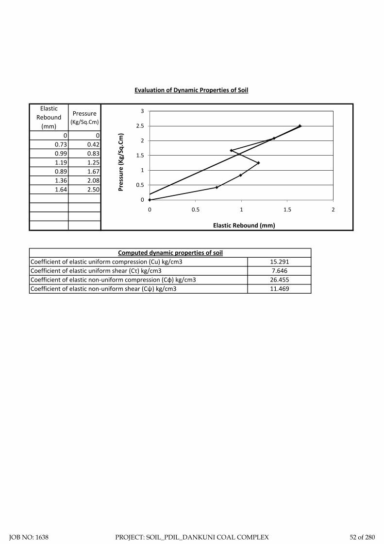
Elastic Rebound
(mm)
Pressure (Kg/Sq.Cm)
0 0 x y0.73 0.42 0 0.20.99 0.83 1.65 2.51.19 1.250.89 1.671.36 2.081.64 2.50
Evaluation of Dynamic Properties of Soil
Pres
sure
(Kg/
Sq.C
m)
Elastic Rebound (mm)
Computed dynamic properties of soilCoefficient of elastic uniform compression (Cu) kg/cm3 15.291Coefficient of elastic uniform shear (Cτ) kg/cm3 7.646Coefficient of elastic non-uniform compression (Cφ) kg/cm3 26.455Coefficient of elastic non-uniform shear (Cψ) kg/cm3 11.469
0
0.5
1
1.5
2
2.5
3
0 0.5 1 1.5 2
JOB NO: 1638 PROJECT: SOIL_PDIL_DANKUNI COAL COMPLEX 52 of 280

STATIC CONE
PENETRATION TEST
JOB NO: 1638 PROJECT: SOIL_PDIL_DANKUNI COAL COMPLEX 53 of 280
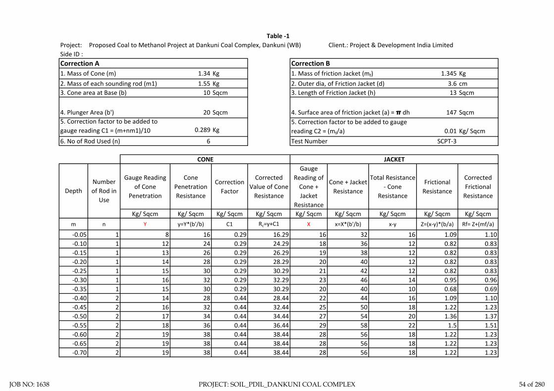
Project: Proposed Coal to Methanol Project at Dankuni Coal Complex, Dankuni (WB) Client.: Project & Development India LimitedSide ID :
1. Mass of Cone (m) 1.34 Kg 1.345 Kg2. Mass of each sounding rod (m1) 1.55 Kg 3.6 cm3. Cone area at Base (b) 10 Sqcm 13 Sqcm
4. Plunger Area (b') 20 Sqcm 147 Sqcm
0.289 Kg 0.01 Kg/ Sqcm6. No of Rod Used (n) 6 SCPT-3
Gauge Reading of Cone
Penetration
Cone Penetration Resistance
Correction Factor
Corrected Value of Cone
Resistance
Gauge Reading of
Cone + Jacket
Resistance
Cone + Jacket Resistance
Total Resistance - Cone
Resistance
Frictional Resistance
Corrected Frictional
Resistance
Kg/ Sqcm Kg/ Sqcm Kg/ Sqcm Kg/ Sqcm Kg/ Sqcm Kg/ Sqcm Kg/ Sqcm Kg/ Sqcm Kg/ Sqcmm n Y y=Y*(b'/b) C1 Rc=y+C1 X x=X*(b'/b) x-y Z=(x-y)*(b/a) Rf= Z+(mf/a)
-0.05 1 8 16 0.29 16.29 16 32 16 1.09 1.10-0.10 1 12 24 0.29 24.29 18 36 12 0.82 0.83-0.15 1 13 26 0.29 26.29 19 38 12 0.82 0.83-0.20 1 14 28 0.29 28.29 20 40 12 0.82 0.83-0.25 1 15 30 0.29 30.29 21 42 12 0.82 0.83-0.30 1 16 32 0.29 32.29 23 46 14 0.95 0.96-0.35 1 15 30 0.29 30.29 20 40 10 0.68 0.69-0.40 2 14 28 0.44 28.44 22 44 16 1.09 1.10-0.45 2 16 32 0.44 32.44 25 50 18 1.22 1.23-0.50 2 17 34 0.44 34.44 27 54 20 1.36 1.37-0.55 2 18 36 0.44 36.44 29 58 22 1.5 1.51-0.60 2 19 38 0.44 38.44 28 56 18 1.22 1.23-0.65 2 19 38 0.44 38.44 28 56 18 1.22 1.23-0.70 2 19 38 0.44 38.44 28 56 18 1.22 1.23
CONE JACKET
Correction A
Number of Rod in
UseDepth
Test Number
1. Mass of friction Jacket (mf)2. Outer dia, of Friction Jacket (d)
Table -1
3. Length of Friction Jacket (h)
4. Surface area of friction jacket (a) = π dh5. Correction factor to be added to gaugereading C2 = (mf/a)
Correction B
5. Correction factor to be added togauge reading C1 = (m+nm1)/10
JOB NO: 1638 PROJECT: SOIL_PDIL_DANKUNI COAL COMPLEX 54 of 280

Gauge Reading of Cone
Penetration
Cone Penetration Resistance
Correction Factor
Corrected Value of Cone
Resistance
Gauge Reading of
Cone + Jacket
Resistance
Cone + Jacket Resistance
Total Resistance - Cone
Resistance
Frictional Resistance
Corrected Frictional
Resistance
Kg/ Sqcm Kg/ Sqcm Kg/ Sqcm Kg/ Sqcm Kg/ Sqcm Kg/ Sqcm Kg/ Sqcm Kg/ Sqcm Kg/ Sqcmm n Y y=Y*(b'/b) C1 Rc=y+C1 X x=X*(b'/b) x-y Z=(x-y)*(b/a) Rf= Z+(mf/a)
Number of Rod in
UseDepth
-0.75 2 20 40 0.44 40.44 29 58 18 1.22 1.23-0.80 2 21 42 0.44 42.44 30 60 18 1.22 1.23-0.85 2 22 44 0.44 44.44 31 62 18 1.22 1.23-0.90 2 22 44 0.44 44.44 31 62 18 1.22 1.23-0.95 2 23 46 0.44 46.44 33 66 20 1.36 1.37-1.00 2 24 48 0.44 48.44 34 68 20 1.36 1.37-1.05 2 25 50 0.44 50.44 36 72 22 1.5 1.51-1.10 2 26 52 0.44 52.44 38 76 24 1.63 1.64-1.15 2 27 54 0.44 54.44 39 78 24 1.63 1.64-1.20 2 28 56 0.44 56.44 39 78 22 1.5 1.51-1.25 2 28 56 0.44 56.44 39 78 22 1.5 1.51-1.30 2 28 56 0.44 56.44 40 80 24 1.63 1.64-1.35 3 29 58 0.6 58.6 40 80 22 1.5 1.51-1.40 3 29 58 0.6 58.6 43 86 28 1.9 1.91-1.45 3 31 62 0.6 62.6 45 90 28 1.9 1.91-1.50 3 32 64 0.6 64.6 46 92 28 1.9 1.91-1.55 3 35 70 0.6 70.6 48 96 26 1.77 1.78-1.60 3 37 74 0.6 74.6 48 96 22 1.5 1.51-1.65 3 38 76 0.6 76.6 49 98 22 1.5 1.51-1.70 3 40 80 0.6 80.6 52 104 24 1.63 1.64-1.75 3 42 84 0.6 84.6 51 102 18 1.22 1.23-1.80 3 41 82 0.6 82.6 51 102 20 1.36 1.37-1.85 3 43 86 0.6 86.6 53 106 20 1.36 1.37-1.90 3 44 88 0.6 88.6 52 104 16 1.09 1.1-1.95 3 44 88 0.6 88.6 54 108 20 1.36 1.37-2.00 3 45 90 0.6 90.6 56 112 22 1.5 1.51-2.05 3 45 90 0.6 90.6 56 112 22 1.5 1.51-2.10 3 45 90 0.6 90.6 56 112 22 1.5 1.51-2.15 3 46 92 0.6 92.6 58 116 24 1.63 1.64
JOB NO: 1638 PROJECT: SOIL_PDIL_DANKUNI COAL COMPLEX 55 of 280

Gauge Reading of Cone
Penetration
Cone Penetration Resistance
Correction Factor
Corrected Value of Cone
Resistance
Gauge Reading of
Cone + Jacket
Resistance
Cone + Jacket Resistance
Total Resistance - Cone
Resistance
Frictional Resistance
Corrected Frictional
Resistance
Kg/ Sqcm Kg/ Sqcm Kg/ Sqcm Kg/ Sqcm Kg/ Sqcm Kg/ Sqcm Kg/ Sqcm Kg/ Sqcm Kg/ Sqcmm n Y y=Y*(b'/b) C1 Rc=y+C1 X x=X*(b'/b) x-y Z=(x-y)*(b/a) Rf= Z+(mf/a)
Number of Rod in
UseDepth
-2.20 3 46 92 0.6 92.6 58 116 24 1.63 1.64-2.25 3 47 94 0.6 94.6 59 118 24 1.63 1.64-2.30 4 50 100 0.75 100.75 61 122 22 1.5 1.51-2.35 4 50 100 0.75 100.75 61 122 22 1.5 1.51-2.40 4 50 100 0.75 100.75 61 122 22 1.5 1.51-2.45 4 51 102 0.75 102.75 62 124 22 1.5 1.51-2.50 4 51 102 0.75 102.75 62 124 22 1.5 1.51-2.55 4 52 104 0.75 104.75 62 124 20 1.36 1.37-2.60 4 52 104 0.75 104.75 64 128 24 1.63 1.64-2.65 4 53 106 0.75 106.75 65 130 24 1.63 1.64-2.70 4 54 108 0.75 108.75 64 128 20 1.36 1.37-2.75 4 54 108 0.75 108.75 64 128 20 1.36 1.37-2.80 4 55 110 0.75 110.75 66 132 22 1.5 1.51-2.85 4 56 112 0.75 112.75 67 134 22 1.5 1.51-2.90 4 57 114 0.75 114.75 68 136 22 1.5 1.51-2.95 4 57 114 0.75 114.75 68 136 22 1.5 1.51-3.00 4 57 114 0.75 114.75 68 136 22 1.5 1.51-3.05 4 57 114 0.75 114.75 68 136 22 1.5 1.51-3.10 4 55 110 0.75 110.75 67 134 24 1.63 1.64-3.15 4 55 110 0.75 110.75 67 134 24 1.63 1.64-3.20 4 55 110 0.75 110.75 67 134 24 1.63 1.64-3.25 4 55 110 0.75 110.75 67 134 24 1.63 1.64-3.30 5 56 112 0.91 112.91 69 138 26 1.77 1.78-3.35 5 57 114 0.91 114.91 70 140 26 1.77 1.78-3.40 5 58 116 0.91 116.91 71 142 26 1.77 1.78-3.45 5 59 118 0.91 118.91 72 144 26 1.77 1.78-3.50 5 60 120 0.91 120.91 71 142 22 1.5 1.51-3.55 5 62 124 0.91 124.91 74 148 24 1.63 1.64-3.60 5 63 126 0.91 126.91 72 144 18 1.22 1.23
JOB NO: 1638 PROJECT: SOIL_PDIL_DANKUNI COAL COMPLEX 56 of 280

Gauge Reading of Cone
Penetration
Cone Penetration Resistance
Correction Factor
Corrected Value of Cone
Resistance
Gauge Reading of
Cone + Jacket
Resistance
Cone + Jacket Resistance
Total Resistance - Cone
Resistance
Frictional Resistance
Corrected Frictional
Resistance
Kg/ Sqcm Kg/ Sqcm Kg/ Sqcm Kg/ Sqcm Kg/ Sqcm Kg/ Sqcm Kg/ Sqcm Kg/ Sqcm Kg/ Sqcmm n Y y=Y*(b'/b) C1 Rc=y+C1 X x=X*(b'/b) x-y Z=(x-y)*(b/a) Rf= Z+(mf/a)
Number of Rod in
UseDepth
-3.65 5 63 126 0.91 126.91 74 148 22 1.5 1.51-3.70 5 61 122 0.91 122.91 70 140 18 1.22 1.23-3.75 5 61 122 0.91 122.91 70 140 18 1.22 1.23-3.80 5 61 122 0.91 122.91 72 144 22 1.5 1.51-3.85 5 60 120 0.91 120.91 67 134 14 0.95 0.96
JOB NO: 1638 PROJECT: SOIL_PDIL_DANKUNI COAL COMPLEX 57 of 280

DepthCone
Resistance-0.05 16.29
-0.1 24.29-0.15 26.29
-0.2 28.29-0.25 30.29
-0.3 32.29-0.35 30.29
-0.4 28.44-0.45 32.44
-0.5 34.44-0.55 36.44
-0.6 38.44-0.65 38.44
-0.7 38.44-0.75 40.44
-0.8 42.44-0.85 44.44
-0.9 44.44-0.95 46.44
-1 48.44-1.05 50.44
-1.1 52.44-1.15 54.44
-1.2 56.44-1.25 56.44
-1.3 56.44-1.35 58.6
-1.4 58.6-1.45 62.6
-1.5 64.6
0
20
40
60
80
100
120
140
-4.5 -4 -3.5 -3 -2.5 -2 -1.5 -1 -0.5 0
Corr
ecte
d Va
lue
of C
one
Resi
stan
ce
Depth (m)
JOB NO: 1638 PROJECT: SOIL_PDIL_DANKUNI COAL COMPLEX 58 of 280

DepthFrictional
Resistance-0.05 1.10
-0.1 0.83-0.15 0.83
-0.2 0.83-0.25 0.83
-0.3 0.96-0.35 0.69
-0.4 1.10-0.45 1.23
-0.5 1.37-0.55 1.51
-0.6 1.23-0.65 1.23
-0.7 1.23-0.75 1.23
-0.8 1.23-0.85 1.23
-0.9 1.23-0.95 1.37
-1 1.37-1.05 1.51
-1.1 1.64-1.15 1.64
-1.2 1.51-1.25 1.51
0.00
0.50
1.00
1.50
2.00
2.50
-4.5 -4 -3.5 -3 -2.5 -2 -1.5 -1 -0.5 0
Corr
ecte
d Fr
ictio
nal R
esis
tanc
e
Depth
JOB NO: 1638 PROJECT: SOIL_PDIL_DANKUNI COAL COMPLEX 59 of 280

ELECTRICAL
RESISTIVITY TEST
JOB NO: 1638 PROJECT: SOIL_PDIL_DANKUNI COAL COMPLEX 60 of 280

: Geotechnical Investigation Work for Proposed Coal to Methanol Project at Dankuni Coal Complex, Dankuni (WB): Dankuni Coal Complex, Dankuni, WB: Project & Development India Limited: 12-12-2019: Metravi ERT-1501, SL. No.: 10109809
1 1.0 34 34 33 34 34 33 33 34 213.63 213.63 207.35 213.63 213.63 207.35 207.35 213.63 2 2.0 33 33 34 33 33 34 34 33 414.69 414.69 427.26 414.69 414.69 427.26 427.26 414.69 3 5.0 34 34 33 34 34 33 33 34 1,068.14 1,068.14 1,036.73 1,068.14 1,068.14 1,036.73 1,036.73 1,068.14 4 10.05 15.06 20.0
South South-West West North-West
Apparent Resistivity "ρ" (Ω-m")
Table ERT - 7
Sl. No. North North-East East East-South
Measured Resistance "R" (Ω)
North North-East
East East-South
South South-West
West North-West
Instrument
Space Not AvailableSpace Not Available
Electrode Spacing 's'
m
ProjectLocation of siteClient Test Date
Space Not Available
JOB NO: 1638 PROJECT: SOIL_PDIL_DANKUNI COAL COMPLEX 61 of 280

: Geotechnical Investigation Work for Proposed Coal to Methanol Project at Dankuni Coal Complex, Dankuni (WB): Dankuni Coal Complex, Dankuni, WB: Project & Development India Limited: 09-12-2019: Metravi ERT-1501, SL. No.: 10109809
1 1.0 50 49 49 49 49 49 49 50 314.16 307.88 307.88 307.88 307.88 307.88 307.88 314.16 2 2.0 51 51 51 51 51 51 51 51 640.88 640.88 640.88 640.88 640.88 640.88 640.88 640.88 3 5.0 52 52 52 52 52 52 52 52 1,633.63 1,633.63 1,633.63 1,633.63 1,633.63 1,633.63 1,633.63 1,633.63 4 10.0 53 53 53 53 53 53 53 53 3,330.09 3,330.09 3,330.09 3,330.09 3,330.09 3,330.09 3,330.09 3,330.09 5 15.06 20.0
Instrument
Table ERT - 9ProjectLocation of siteClient Test Date
Sl. No.
Electrode Spacing 's'
m
Measured Resistance "R" (Ω) Apparent Resistivity "ρ" (Ω-m")
North North-East
East East-South
South South-West
Space Not Available
South South-West West North-West
Space Not Available
West North-West
North North-East East East-South
JOB NO: 1638 PROJECT: SOIL_PDIL_DANKUNI COAL COMPLEX 62 of 280

Location - ERT-7
Electrode Spacing - 1.00MR = 33.49 ohm, Resistivity = 210.32 Ohm-m
Location - ERT-7
Electrode Spacing - 2.00MR = 33.22 ohm, Resistivity = 417.24 Ohm-m
Location - ERT-7
Electrode Spacing - 5.00MR = 33.49 ohm, Resistivity = 1051.57 Ohm-m
JOB NO: 1638 PROJECT: SOIL_PDIL_DANKUNI COAL COMPLEX 63 of 280

Electrode Spacing - 1.00MR = 49.05 ohm, Resistivity = 308.03 Ohm-m
Location - ERT-9
Electrode Spacing - 2.00MR = 51.00 ohm, Resistivity = 640.88 Ohm-m
Location - ERT-9
Electrode Spacing - 5.00MR = 52.00 ohm, Resistivity = 1633.63 Ohm-m
Location - ERT-9
Electrode Spacing - 10.00MR = 52.89 ohm, Resistivity = 3321.49 Ohm-m
Location - ERT-9
JOB NO: 1638 PROJECT: SOIL_PDIL_DANKUNI COAL COMPLEX 64 of 280

ZONE-3
GAS CLEANING &
PURIFICATION
JOB NO: 1638 PROJECT: SOIL_PDIL_DANKUNI COAL COMPLEX 65 of 280

Total one (1) borehole was sunk in this area, viz borehole marked BH-7. From the general sub soil profile it has been observed that the top soil is heterogeneous fill with coal dust, clayey silt etc followed by first layer of soft brownish grey silty clay/ clayey silt. The second layer is medium to stiff mottled brownish/ bluish grey silty clay/ clayey silt and the third layer as encountered up to the explored depth is very stiff to hard mottled brownish/ bluish grey silty clay/ clayey silt.
In addition the following field tests have been carried out at this zone and results are being indicated in this chapter.
1. Cyclic Plate Load Test: One (1) cyclic plate load test has been carried out at this zone marked as CPLT-2.
2. Static Cone Penetration Test: One (1) static cone penetration test has been carried out at this zone marked as SCPT-2.
3. Electrical Resistivity Test: One (1) electrical resistivity tests has been carried out at this zone marked as ERT-6.
Discussion and Recommendation:
Based on the subsoil condition pile foundation has been recommended for foundation system of medium to heavily loaded structures. Pile capacities in compression, pull-out and horizontal shear for different diameter of pile are indicated in the Table-2A (Zone-3). It is further recommended to carry out initial pile load test for load under compression, pull-out and horizontal shear, in order to confirm the recommended pile capacities and to take corrective measures, if required.
JOB NO: 1638 PROJECT: SOIL_PDIL_DANKUNI COAL COMPLEX 66 of 280

Table-2A (Zone-3). Recommended Pile Capacity
Sl.N
o
Pile
Dia
, D
Tota
l Len
gth
of P
ile, L
Cut
-off
Leve
l
Rec
omm
ende
d Pi
le
Cap
acity
in C
ompr
essi
on
Rec
omm
ende
d Pi
le
Cap
acity
in P
ull-O
ut
Rec
omm
ende
d Pi
le
Cap
acity
in H
oriz
onta
l Sh
ear
Mtr Mtr. Mtr. T T T
1 0.400 28.000 2.000 44 39 2.73
2 0.500 28.000 2.000 56 49 2.99
3 0.550 28.000 2.000 63 54 3.10
4 0.600 28.000 2.000 69 58 3.21
5 0.750 28.000 2.000 90 73 3.51
6 1.000 28.000 2.000 128 98 3.94
JOB NO: 1638 PROJECT: SOIL_PDIL_DANKUNI COAL COMPLEX 67 of 280

DS - Disturbed SampleSCPT-Static Cone Penetration DCPT - Dynamic Cone Penetration
SPT - Standard Penetration Test VST- Vane Shear TestUDS - Undisturbed
Test. Sample Test.
WS - Water Sample
RCS - Rock Core Sample
Centre for Advanced Engineering
N-V A L U E
17 RCSDSDCPTDepth of Drilling
Type of Drilling
D E S C R I P T I O N
VST SCPT
SYMBOL DEPTH
Co-ord: Type of Boring
Depth of Boring
Project:
FIELDTESTE.G.L.: 35.707
SPT30.000 M.Shell & Auger
BORE LOG SHEET
SAMPLESNOS.Unit:
UDS15 10NOS.
WSSAMPLES
3.20 M.Water Struck At :
3.15 M.S A M P L E
DEPTH
Standing Water Table :
NO.
Bore Hole No.:
Soil - 1638
Commenced on : Bore Hole Dia. :
Completed on :
Job No.:
NOS.150 MM.
BH-7 (Sheet-1)
27.11.201929.11.2019
01DS1 0.50 M
N = 3 1.50-1.95MDS3SPT1
1.50-1.95M
N = 2 7.50-7.95MDS7SPT5
7.50-7.95M
N = 4 10.50-10.95MDS9SPT7
10.50-10.95MUDS4 11.00-11.45M
N = 2 3.00-3.45MDS4SPT2
3.00-3.45M
N = 3 6.00-6.45MDS6SPT4
6.00-6.45M
UDS3 8.00-8.45M
N = 3 9.00-9.45MDS8SPT6
9.00-9.45M
UDS5 14.00-14.45MN = 7 14.50-14.95M
DS11SPT9
14.50-14.95M
N = 7 12.50-12.95MDS10SPT8
12.50-12.95M
N = 7 16.50-16.95MDS12SPT10
16.50-16.95M
N = 8 18.50-18.95MDS13SPT11
18.50-18.95M
UDS6 17.00-17.45M
SOIL_PDIL_DANKUNI_GAS CLEANING AND PURIFICATION
02
03
04
05
06
07
08
09
10
11
12
13
14
15
16
17
18
19
DS2 1.00 M
N = 2 4.50-4.95MDS5SPT3
4.50-4.95M
Filled up with coal dust, clayey silt,stone chips etc.
Soft brownish grey silty clay/clayey silt with traces of sand.
Medium to stiff mottled brownish/bluish grey silty clay/ clayey siltwith concretion.
Contd.........
UDS2 5.00-5.45M
UDS1 2.00-2.45M
JOB NO: 1638 PROJECT: SOIL_PDIL_DANKUNI COAL COMPLEX 68 of 280

3.20 M.3.15 M.
150 MM.
BH-7 (Sheet-1)
27.11.201929.11.2019
DS - Disturbed SampleSCPT-Static Cone Penetration DCPT - Dynamic Cone Penetration
SPT - Standard Penetration Test VST- Vane Shear TestUDS - Undisturbed
Test. Sample Test.
WS - Water Sample
RCS - Rock Core Sample
Centre for Advanced Engineering
N-V A L U E
17 RCSDSDCPTDepth of Drilling
Type of Drilling
D E S C R I P T I O N
VST SCPT
SYMBOL DEPTH
Co-ord: Type of Boring
Depth of Boring
Project:
FIELDTESTE.G.L.: 35.707
SPT30.000 M.Shell & Auger
BORE LOG SHEET
SAMPLESNOS.Unit:
UDS15 10NOS.
WSSAMPLES
3.20 M.Water Struck At :
3.15 M.S A M P L E
DEPTH
Standing Water Table :
NO.
Bore Hole No.:
Soil - 1638
Commenced on : Bore Hole Dia. :
Completed on :
Job No.:
NOS.150 MM.
27.11.201929.11.2019
Termination Depth 30.000 Mtr.
SOIL_PDIL_DANKUNI_GAS CLEANING AND PURIFICATION
21
22
23
24
25
26
27
28
29
30
31
32
33
34
35
36
37
38
39
UDS7 20.00-20.45MN = 9 20.50-20.95M
DS14SPT12
20.50-20.95M
UDS8 23.00-23.45MN = 23 23.50-23.95M
DS15SPT13
23.50-23.95M
UDS9 26.00-26.45M
UDS10 29.00-29.45M
N = 29 26.50-26.95MDS16SPT14
26.50-26.95M
N = 33 29.55-30.00MDS17SPT15
29.55-30.00M
BH-7 (Sheet-2)
Medium to stiff mottled brownish/bluish grey silty clay/ clayey siltwith concretion.
Very stiff to hard mottledbrownish/ bluish grey silty clay/clayey silt with concretion.
JOB NO: 1638 PROJECT: SOIL_PDIL_DANKUNI COAL COMPLEX 69 of 280

Sub-Soil Profile through BH-7 02
26.00M.
12.00M.
18.00M.
20.00M.
22.00M.
14.00M.
16.00M.
6.00M.
10.00M.
8.00M.
2.00M.
4.00M.
Sketch No.-SK/PDIL/ GAS CLEANING AND PURIFICATION 1638 3 of 13
Termination depth 30.000 M.
BH-7
RL=35.707
28.00M.
30.00M.
32.00M.
1.50M
10.50M
23.50M
Layer-I
Layer-II
Layer-III
Filled up with coal dust, clayey silt, stone chips etc.
Soft brownish grey silty clay/ clayey silt with traces of sand.
Medium to stiff mottled brownish/ bluish grey silty clay/ clayeysilt with concretion.
Very stiff to hard mottled brownish/ bluish grey silty clay/ clayey siltwith concretion.
JOB NO: 1638 PROJECT: SOIL_PDIL_DANKUNI COAL COMPLEX 70 of 280

LL PL SL Type of Test
Cohesion in
kg/sqcm
Friction angle in degree
Gravel (> 4.75 mm) %
Sand (0.075 - 4.75 mm)
Silt (0.002 - 0.075 mm)
Clay (< 0.002 mm)
Meter % % % γb m G γd quUU/CU/CD
/DS C φ % % % %
7 3.00 DN 2 52 20 13.4 2.66 8.29 0 9 61 30
0.00-0.10 0.0238
0.10-0.20 0.0289
0.20-0.40 0.0463
0.40-0.80 0.0388
0.80-1.60 0.0299
1.60-3.20 0.0193
7 7.50 DN 2 56 23 14.6 2.67 7.69 0 6 63 31
0.00-0.10 0.0251
0.10-0.20 0.0296
0.20-0.40 0.0457
0.40-0.80 0.0379
0.80-1.60 0.0284
1.60-3.20 0.0173
7 10.50 DN 4 49 21 14.2 2.68 18.93 0 9 66 25
7 14.50 DN 7 47 20 13.3 2.67 25.69 0 12 60 28
7 20.50 DN 9 50 19 12.9 2.66 14.68 0 11 59 30
0.00-0.10 0.0128
0.10-0.20 0.0198
0.20-0.40 0.0338
0.40-0.80 0.0218
0.80-1.60 0.0165
1.60-3.20 0.0119
7 26.50 DN 29 52 21 14.6 2.67 0 0 8 63 29
III62 28CU 0.22 22
CD 0 30
1.88
0
023.38Very stiff to hard mottled brownish/ bluish grey
silty clay/ clayey silt with concretion.
2.68 1.527 26.00 UD 50 13.120
67 26CU 0.11 13
CD 20
UU 0.30
0 7
UU
02.10 10
15.83
1.08
48 20
0
13.2 1.86 28.99 2.66 1.44
Soft brownish grey silty clay/ clayey silt with
traces of sand.I
Medium to stiff mottled brownish/ bluish grey
silty clay/ clayey silt with concretion.
II
0
0.577 11.00 UD
266.64 0 10 640.45
CD 0 18
15.1 1.82 31.15 2.67 1.3949 21
SUMMARY OF LABORATORY TEST RESULTSTable-3
Depth Water
Content in %Description of layer
Co-eff. of volume
compressibility in sqcm/kg
Project: Geotechnical Investigation Work for Proposed Coal to Methanol Project at Dankuni Coal Complex, Dankuni (WB)
Swell Pressure
(Kg/sqcm)
Specific Gravity Free Swell
Index(%)
Bulk Density in gm/cc
Shear Test Grading
Layer No.Bore Hole No.
Sample Type - UD/D/
DN
SPT VALUE
(N)
Atterberg LimitsUnconfined
Test in Kg/sqcm
Pressure (Kg/sqcm
)
Dry Density
in gm/cc
7 5.00
0.24
0.08
0
11
UU
CUUD
JOB NO: 1638 PROJECT: SOIL_PDIL_DANKUNI COAL COMPLEX 71 of 280

SAMPLE CALCULATION
FOR PILE
FOUNDATION
JOB NO: 1638 PROJECT: SOIL_PDIL_DANKUNI COAL COMPLEX 72 of 280

Centre for Advanced Engineering
Pile Model Scale :- N.T.S.
Existing Ground Level.
γ = 1.82 T/M3
c = 2.40 T/M2φ = 0I
II
III
γ = 1.86 T/M3
c = 3.00 T/M2φ = 0
Pile
Cut
-Off
Leve
l = 2
.00M
03Sketch No.-SK/PDIL/ GAS CLEANING AND PURIFICATION 1638
1.50
M9.
00M
γ = 1.88 T/M3
c = 10.80 T/M2φ = 0
13.0
0M
Filled up with coal dust, clayey silt,stone chips etc.
Soft brownish grey silty clay/ clayey siltwith traces of sand.
Medium to stiff mottled brownish/ bluishgrey silty clay/ clayey silt withconcretion.
Very stiff to hard mottled brownish/bluish grey silty clay/ clayey silt withconcretion.
JOB NO: 1638 PROJECT: SOIL_PDIL_DANKUNI COAL COMPLEX 73 of 280

Ultimate skin friction capacity
Location: Gas Cleaning & Purification unit, Dankuni Coal Complex, West Bengal
Layer No: 1Soil Description Soft brownish grey silty clay/ clayey silt with traces of sand.
Sl.N
o
Pile
Dia
, D
Tota
l Len
gth
of P
ile, L
Dep
th o
f lay
er to
p fro
m E
GL
Dep
th o
f lay
er b
otto
m fr
om E
GL
Red
uctio
n fa
ctor
, α (N
ote1
IS
2911
( Par
t1/S
ec2)
Aver
age
Coh
esio
n al
ong
the
leng
th
of th
e pi
le in
this
laye
r, C
Surfa
ce a
rea
of th
e pi
le s
haft
in th
is
laye
r, A s
Ulti
mat
e Sk
in fr
ictio
n ca
paci
ty o
f th
e sh
aft i
n th
is la
yer,
Qsu
=
α*C
*AS
Mtr Mtr. Mtr Mtr. T/M2 M2
1 0.400 28.000 2.000 10.500 1 2.4 10.681 25.6352 0.500 28.000 2.000 10.500 1 2.4 13.352 32.0443 0.550 28.000 2.000 10.500 1 2.4 14.687 35.2494 0.600 28.000 2.000 10.500 1 2.4 16.022 38.4535 0.750 28.000 2.000 10.500 1 2.4 20.028 48.0666 1.000 28.000 2.000 10.500 1 2.4 26.704 64.088
Project: Geotechnical Investigation Work for Proposed Coal to Methanol Project at Dankuni Coal Complex, Dankuni (WB)
JOB NO: 1638 PROJECT: SOIL_PDIL_DANKUNI COAL COMPLEX 74 of 280

Ultimate skin friction capacity
Location: Gas Cleaning & Purification unit, Dankuni Coal Complex, West Bengal
Layer No: 2Soil Description
Sl.N
o
Pile
Dia
, D
Tota
l Len
gth
of P
ile, L
Dep
th o
f lay
er to
p fro
m E
GL
Dep
th o
f lay
er b
otto
m fr
om E
GL
Red
uctio
n fa
ctor
, α (N
ote1
IS
2911
( Par
t1/S
ec2)
Aver
age
Coh
esio
n al
ong
the
leng
th
of th
e pi
le in
this
laye
r, C
Surfa
ce a
rea
of th
e pi
le s
haft
in th
is
laye
r, A s
Ulti
mat
e Sk
in fr
ictio
n ca
paci
ty o
f th
e sh
aft i
n th
is la
yer,
Qsu
=
α*C
*AS
Mtr Mtr. Mtr Mtr. T/M2 M2
1 0.400 28.000 10.500 23.300 1 3.0 16.085 48.2552 0.500 28.000 10.500 23.300 1 3.0 20.106 60.3193 0.550 28.000 10.500 23.300 1 3.0 22.117 66.3504 0.600 28.000 10.500 23.300 1 3.0 24.127 72.3825 0.750 28.000 10.500 23.300 1 3.0 30.159 90.4786 1.000 28.000 10.500 23.300 1 3.0 40.212 120.637
Project: Geotechnical Investigation Work for Proposed Coal to Methanol Project at Dankuni Coal Complex, Dankuni (WB)
Medium to stiff mottled brownish/ bluish grey silty clay/ clayey silt with concretion.
JOB NO: 1638 PROJECT: SOIL_PDIL_DANKUNI COAL COMPLEX 75 of 280

Ultimate skin friction capacity
Location: Gas Cleaning & Purification unit, Dankuni Coal Complex, West Bengal
Layer No: 3Soil Description
Sl.N
o
Pile
Dia
, D
Tota
l Len
gth
of P
ile, L
Dep
th o
f lay
er to
p fro
m E
GL
Dep
th o
f lay
er b
otto
m fr
om E
GL
Red
uctio
n fa
ctor
, α (N
ote1
IS
2911
( Par
t1/S
ec2)
Aver
age
Coh
esio
n al
ong
the
leng
th
of th
e pi
le in
this
laye
r, C
Surfa
ce a
rea
of th
e pi
le s
haft
in th
is
laye
r, A s
Ulti
mat
e Sk
in fr
ictio
n ca
paci
ty o
f th
e sh
aft i
n th
is la
yer,
Qsu
=
α*C
*AS
Mtr Mtr. Mtr Mtr. T/M2 M2
1 0.400 28.000 23.500 28.000 0.4 10.8 5.655 24.4292 0.500 28.000 23.500 28.000 0.4 10.8 7.069 30.5363 0.550 28.000 23.500 28.000 0.4 10.8 7.775 33.5904 0.600 28.000 23.500 28.000 0.4 10.8 8.482 36.6445 0.750 28.000 23.500 28.000 0.4 10.8 10.603 45.8046 1.000 28.000 23.500 28.000 0.4 10.8 14.137 61.073
Project: Geotechnical Investigation Work for Proposed Coal to Methanol Project at Dankuni Coal Complex, Dankuni (WB)
Very stiff to hard mottled brownish/ bluish grey silty clay/ clayey silt with concretion.
JOB NO: 1638 PROJECT: SOIL_PDIL_DANKUNI COAL COMPLEX 76 of 280

Ultimate End Bearing capacity
Location: Gas Cleaning & Purification unit, Dankuni Coal Complex, West Bengal
Layer No: 4Soil Description
Sl.N
o
Pile
Dia
, D
Tota
l Len
gth
of P
ile, L
Dep
th o
f lay
er to
p fro
m E
GL
Dep
th o
f lay
er b
otto
m fr
om E
GL
Aver
age
Coh
esio
n at
the
pile
tip,
C
P
Cro
ss s
ectio
nal a
rea
of th
e pi
le ti
p,
A P
Bear
ing
capa
city
fact
or, N
C
Ulti
mat
eEnd
bea
ring
capa
city
at
pile
tip,
QB u
= A
P*N
C*C
P
Mtr Mtr. Mtr Mtr. T/M2 M2 T1 0.400 28.000 23.500 28.000 10.8 0.126 9.000 12.2152 0.500 28.000 23.500 28.000 10.8 0.196 9.000 19.0853 0.550 28.000 23.500 28.000 10.8 0.238 9.000 23.0934 0.600 28.000 23.500 28.000 10.8 0.283 9.000 27.4835 0.750 28.000 23.500 28.000 10.8 0.442 9.000 42.9426 1.000 28.000 23.500 28.000 10.8 0.785 9.000 76.341
Project: Geotechnical Investigation Work for Proposed Coal to Methanol Project at Dankuni Coal Complex, Dankuni (WB)
Very stiff to hard mottled brownish/ bluish grey silty clay/ clayey silt with concretion.
JOB NO: 1638 PROJECT: SOIL_PDIL_DANKUNI COAL COMPLEX 77 of 280

Sample Calculation:-= 0.24 Kg/cm2
= 23.544 Kn/M2
= 28.00 Mtr.= 2.00 Mtr.= 0.400 Mtr.= 25 N/MM2
= 25000 MN/M2
= 0.00126 M4
= 31.5 KN/M6
= 1.350 MN/M3
T (Stiffness Factor) = 1.878 Mtr. [Where T = (EI/nh)1/5]
= 26.00 Mtr.
Hence, As per Table-5 pile is a LONG ELASTIC PILE Since Le>= 4T
= 0.000 Mtr.
= 2.200
= 4.132 Mtr.
Therefore, Lf = 4.132 Mtr.L1 = 0.000 Mtr.
For Fixed Head Pile, deflection at the pile head,
= 0.005 Mtr. (Adopt)
= 26.80 Kn
= 2.73 T
Horizontal Shear Capacity of Pile
Reference : Code of Practice for Design and Construction of Pile Foundation - IS 2911 (Part1/Sec2)
C Value
L (Length of Pile)Cut-off Level of PileDia of Pile (D)fckE=Econc=Young's modulas
I (Moment of inertia of the pile cross-section)
Neglecting the effect of steel we get EI
nh = Modulas of Subgrade Reaction (if top of the soil is clay) (Table3)
Le (Embeddment Length of the Pile)
Where L1 = free head of Pile above ground
And for fixed head file Lf/T (as per IS Code)
Where Lf is the length of fixicity below cut-off level of pile =
Y =H(e+zf)3/12EILateral Load = H
Horizontal Shear Capacity = Hdesign
JOB NO: 1638 PROJECT: SOIL_PDIL_DANKUNI COAL COMPLEX 78 of 280

Recommended Pile Capacity
Location: Gas Cleaning & Purification unit, Dankuni Coal Complex, West Bengal
Sl.N
o
Pile
Dia
, D
Tota
l Len
gth
of P
ile, L
Skin
fric
tion
from
laye
r 1
Skin
fric
tion
from
laye
r 2
Skin
fric
tion
from
laye
r 3
End
Bear
ing
Tota
l
F.O
.S
Allo
wab
le P
ile C
apac
ity
Rec
omm
emde
d Pi
le
Cap
acity
in
Com
pres
sion
Rec
omm
emde
d Pi
le
Cap
acity
in P
ull-O
ut
Rec
omm
emde
d Pi
le
Cap
acity
in H
oriz
onta
l Sh
ear
Mtr Mtr. T T T T T T T T T T1 0.400 28.000 25.635 48.255 24.429 12.215 110.534 2.5 44.214 44 39 2.732 0.500 28.000 32.044 60.319 30.536 19.085 141.984 2.5 56.794 56 49 2.993 0.550 28.000 35.249 66.350 33.590 23.093 158.282 2.5 63.313 63 54 3.104 0.600 28.000 38.453 72.382 36.644 27.483 174.962 2.5 69.985 69 58 3.215 0.750 28.000 48.066 90.478 45.804 42.942 227.290 2.5 90.916 90 73 3.516 1.000 28.000 64.088 120.637 61.073 76.341 322.139 2.5 128.856 128 98 3.94
Project: Geotechnical Investigation Work for Proposed Coal to Methanol Project at Dankuni Coal Complex, Dankuni (WB)
JOB NO: 1638 PROJECT: SOIL_PDIL_DANKUNI COAL COMPLEX 79 of 280

CYCLIC PLATE LOAD TEST
JOB NO: 1638 PROJECT: SOIL_PDIL_DANKUNI COAL COMPLEX 80 of 280

Client : Projects & Development India LimitedLocation : In front of Ex. Mechanical BuildingTest Number : CPLT-2Plate Size : 60 X 60 = 3600 SqcmPit Size : 3.00M X 3.00M X 2.50MGround Water Table : Not EncounteredL.C. of Dial Guage : 0.01 mmJack Ram Dia : 10.5 cmJack Ram Area : 86.59 Sqcm
DIAL-1 DIAL-2 DIAL-1 DIAL-2
28-11-2019 10:45:00 0 2500 2500 0.00 0.00 0.0010:45:00 0.42 2500 2500 0.00 0.00 0.0010:46:00 2439 2477 0.61 0.23 0.4210:47:15 2417 2456 0.83 0.44 0.6410:49:00 2391 2438 1.09 0.62 0.8610:51:15 2375 2407 1.25 0.93 1.0910:54:00 2331 2390 1.69 1.10 1.4011:01:00 2322 2368 1.78 1.32 1.5511:10:00 2312 2326 1.88 1.74 1.8111:46:00 2302 2316 1.98 1.84 1.9111:46:00 0 2302 2316 1.98 1.84 1.9112:46:00 2490 2445 0.10 0.55 0.3312:46:00 0.83 2490 2445 0.10 0.55 0.3312:47:00 2110 2120 3.90 3.80 3.8512:48:15 2100 2111 4.00 3.89 3.9512:50:00 2090 2102 4.10 3.98 4.0412:52:15 2082 2088 4.18 4.12 4.1512:55:00 2079 2080 4.21 4.20 4.2113:02:00 2030 2010 4.70 4.90 4.8013:11:00 1990 2003 5.10 4.97 5.0413:46:00 1940 1986 5.60 5.14 5.3713:46:00 0 1940 1986 5.60 5.14 5.3714:46:00 2136 2033 3.64 4.67 4.1614:46:00 1.25 2136 2033 3.64 4.67 4.1614:47:00 1570 1645 9.30 8.55 8.9314:48:15 1552 1532 9.48 9.68 9.5814:50:00 1441 1420 10.59 10.80 10.7014:52:15 1318 1394 11.82 11.06 11.4414:55:00 1200 1279 13.00 12.21 12.6115:02:00 1116 1195 13.84 13.05 13.4515:11:00 1045 1107 14.55 13.93 14.2415:46:00 1012 1095 14.88 14.05 14.4715:46:00 0 1012 1095 14.88 14.05 14.47
0
4500
0
3000
0.001500
MEAN SETTLEMENT
(mm)REMARKS
CYCLIC PLATE LOAD TEST SITE DATA SHEET
DIAL GUAGE READING (mm)
SETTLEMENT (mm)DATE TIME (Hrs)
PRESSURE IN Kg/Sqcm
LOAD IN (KG)
0
JOB NO: 1638 PROJECT: SOIL_PDIL_DANKUNI COAL COMPLEX 81 of 280

DIAL-1 DIAL-2 DIAL-1 DIAL-2
16:46:00 1327 1357 11.73 11.43 11.5816:46:00 1.67 1327 1357 11.73 11.43 11.5816:47:00 158 232 23.42 22.68 23.0516:48:15 130 214 23.70 22.86 23.2816:50:00 115 201 23.85 22.99 23.4216:52:15 112 198 23.88 23.02 23.4516:55:00 112 198 23.88 23.02 23.4517:02:00 112 198 23.88 23.02 23.4517:11:00 110 196 23.90 23.04 23.4717:46:00 108 193 23.92 23.07 23.5017:46:00 0 108 193 23.92 23.07 23.5018:46:00 421 462 20.79 20.38 20.5918:46:00 2.08 421 462 20.79 20.38 20.5918:47:00 0 0 25.00 25.00 25.0018:48:15 0 0 25.00 25.00 25.0018:50:00 0 0 25.00 25.00 25.0018:52:15 0 0 25.00 25.00 25.0018:55:00 0 0 25.00 25.00 25.0019:02:00 0 0 25.00 25.00 25.0019:11:00 0 0 25.00 25.00 25.0019:46:00 0 0 25.00 25.00 25.0019:46:00 0 0 0 25.00 25.00 25.0020:46:00 0 0 25.00 25.00 25.00
Load Vs Settlement Curve for CPLT-2
0
7500
0
6000
DIAL GUAGE READING (mm)
SETTLEMENT (mm) MEAN SETTLEMENT
(mm)REMARKSDATE TIME (Hrs) LOAD IN (KG)
PRESSURE IN Kg/Sqcm
0
5
10
15
20
25
30
0 5 10 15 20 25
Sett
lem
ent i
n M
M
Load in T/Sq.M
JOB NO: 1638 PROJECT: SOIL_PDIL_DANKUNI COAL COMPLEX 82 of 280

Elastic Rebound
(mm)
Pressure (Kg/Sq.Cm)
0 0 x y1.59 0.42 0 01.22 0.83 2.91 1.672.89 1.252.91 1.67
Evaluation of Dynamic Properties of Soil
Pres
sure
(Kg/
Sq.C
m)
Elastic Rebound (mm)
Computed dynamic properties of soilCoefficient of elastic uniform compression (Cu) kg/cm3 5.739Coefficient of elastic uniform shear (Cτ) kg/cm3 2.87Coefficient of elastic non-uniform compression (Cφ) kg/cm3 9.93Coefficient of elastic non-uniform shear (Cψ) kg/cm3 4.305
0
0.2
0.4
0.6
0.8
1
1.2
1.4
1.6
1.8
0 0.5 1 1.5 2 2.5 3 3.5
JOB NO: 1638 PROJECT: SOIL_PDIL_DANKUNI COAL COMPLEX 83 of 280

STATIC CONE
PENETRATION TEST
JOB NO: 1638 PROJECT: SOIL_PDIL_DANKUNI COAL COMPLEX 84 of 280

Project: Proposed Coal to Methanol Project at Dankuni Coal Complex, Dankuni (WB) Client.: Project & Development India LimitedSide ID :
1. Mass of Cone (m) 1.34 Kg 1.345 Kg2. Mass of each sounding rod (m1) 1.55 Kg 3.6 cm3. Cone area at Base (b) 10 Sqcm 13 Sqcm
4. Plunger Area (b') 20 Sqcm 147 Sqcm
0.289 Kg 0.01 Kg/ Sqcm6. No of Rod Used (n) 6 SCPT-2
Gauge Reading of Cone
Penetration
Cone Penetration Resistance
Correction Factor
Corrected Value of Cone
Resistance
Gauge Reading of
Cone + Jacket
Resistance
Cone + Jacket Resistance
Total Resistance - Cone
Resistance
Frictional Resistance
Corrected Frictional
Resistance
Kg/ Sqcm Kg/ Sqcm Kg/ Sqcm Kg/ Sqcm Kg/ Sqcm Kg/ Sqcm Kg/ Sqcm Kg/ Sqcm Kg/ Sqcmm n Y y=Y*(b'/b) C1 Rc=y+C1 X x=X*(b'/b) x-y Z=(x-y)*(b/a) Rf= Z+(mf/a)
-0.05 1 4 8 0.29 8.29 9 18 10 0.68 0.69-0.10 1 9 18 0.29 18.29 14 28 10 0.68 0.69-0.15 1 13 26 0.29 26.29 20 40 14 0.95 0.96-0.20 1 18 36 0.29 36.29 25 50 14 0.95 0.96-0.25 1 22 44 0.29 44.29 30 60 16 1.09 1.10-0.30 1 28 56 0.29 56.29 35 70 14 0.95 0.96-0.35 1 35 70 0.29 70.29 44 88 18 1.22 1.23-0.40 2 38 76 0.44 76.44 45 90 14 0.95 0.96-0.45 2 12 24 0.44 24.44 20 40 16 1.09 1.10-0.50 2 12 24 0.44 24.44 20 40 16 1.09 1.10-0.55 2 11 22 0.44 22.44 19 38 16 1.09 1.10-0.60 2 12 24 0.44 24.44 19 38 14 0.95 0.96-0.65 2 14 28 0.44 28.44 21 42 14 0.95 0.96-0.70 2 14 28 0.44 28.44 20 40 12 0.82 0.83
Table -1
3. Length of Friction Jacket (h)
4. Surface area of friction jacket (a) = π dh5. Correction factor to be added to gauge reading C2 = (mf/a)
Correction B
5. Correction factor to be added to gauge reading C1 = (m+nm1)/10
CONE JACKET
Correction A
Number of Rod in
UseDepth
Test Number
1. Mass of friction Jacket (mf)2. Outer dia, of Friction Jacket (d)
JOB NO: 1638 PROJECT: SOIL_PDIL_DANKUNI COAL COMPLEX 85 of 280

Gauge Reading of Cone
Penetration
Cone Penetration Resistance
Correction Factor
Corrected Value of Cone
Resistance
Gauge Reading of
Cone + Jacket
Resistance
Cone + Jacket Resistance
Total Resistance - Cone
Resistance
Frictional Resistance
Corrected Frictional
Resistance
Kg/ Sqcm Kg/ Sqcm Kg/ Sqcm Kg/ Sqcm Kg/ Sqcm Kg/ Sqcm Kg/ Sqcm Kg/ Sqcm Kg/ Sqcmm n Y y=Y*(b'/b) C1 Rc=y+C1 X x=X*(b'/b) x-y Z=(x-y)*(b/a) Rf= Z+(mf/a)
Number of Rod in
UseDepth
-0.75 2 11 22 0.44 22.44 17 34 12 0.82 0.83-0.80 2 12 24 0.44 24.44 16 32 8 0.54 0.55-0.85 2 15 30 0.44 30.44 19 38 8 0.54 0.55-0.90 2 14 28 0.44 28.44 20 40 12 0.82 0.83-0.95 2 16 32 0.44 32.44 21 42 10 0.68 0.69-1.00 2 17 34 0.44 34.44 22 44 10 0.68 0.69-1.05 2 17 34 0.44 34.44 22 44 10 0.68 0.69-1.10 2 18 36 0.44 36.44 23 46 10 0.68 0.69-1.15 2 17 34 0.44 34.44 21 42 8 0.54 0.55-1.20 2 15 30 0.44 30.44 20 40 10 0.68 0.69-1.25 2 14 28 0.44 28.44 20 40 12 0.82 0.83-1.30 2 19 38 0.44 38.44 27 54 16 1.09 1.10-1.35 3 18 36 0.6 36.6 25 50 14 0.95 0.96-1.40 3 19 38 0.6 38.6 26 52 14 0.95 0.96-1.45 3 20 40 0.6 40.6 27 54 14 0.95 0.96-1.50 3 21 42 0.6 42.6 29 58 16 1.09 1.10-1.55 3 22 44 0.6 44.6 30 60 16 1.09 1.10-1.60 3 23 46 0.6 46.6 32 64 18 1.22 1.23-1.65 3 24 48 0.6 48.6 33 66 18 1.22 1.23-1.70 3 26 52 0.6 52.6 35 70 18 1.22 1.23-1.75 3 26 52 0.6 52.6 35 70 18 1.22 1.23-1.80 3 25 50 0.6 50.6 37 74 24 1.63 1.64-1.85 3 28 56 0.6 56.6 36 72 16 1.09 1.1-1.90 3 29 58 0.6 58.6 40 80 22 1.5 1.51-1.95 3 29 58 0.6 58.6 40 80 22 1.5 1.51-2.00 3 30 60 0.6 60.6 39 78 18 1.22 1.23-2.05 3 30 60 0.6 60.6 40 80 20 1.36 1.37-2.10 3 28 56 0.6 56.6 38 76 20 1.36 1.37-2.15 3 27 54 0.6 54.6 38 76 22 1.5 1.51
JOB NO: 1638 PROJECT: SOIL_PDIL_DANKUNI COAL COMPLEX 86 of 280

Gauge Reading of Cone
Penetration
Cone Penetration Resistance
Correction Factor
Corrected Value of Cone
Resistance
Gauge Reading of
Cone + Jacket
Resistance
Cone + Jacket Resistance
Total Resistance - Cone
Resistance
Frictional Resistance
Corrected Frictional
Resistance
Kg/ Sqcm Kg/ Sqcm Kg/ Sqcm Kg/ Sqcm Kg/ Sqcm Kg/ Sqcm Kg/ Sqcm Kg/ Sqcm Kg/ Sqcmm n Y y=Y*(b'/b) C1 Rc=y+C1 X x=X*(b'/b) x-y Z=(x-y)*(b/a) Rf= Z+(mf/a)
Number of Rod in
UseDepth
-2.20 3 27 54 0.6 54.6 38 76 22 1.5 1.51-2.25 3 27 54 0.6 54.6 38 76 22 1.5 1.51-2.30 4 32 64 0.75 64.75 44 88 24 1.63 1.64-2.35 4 33 66 0.75 66.75 44 88 22 1.5 1.51-2.40 4 34 68 0.75 68.75 44 88 20 1.36 1.37-2.45 4 34 68 0.75 68.75 46 92 24 1.63 1.64-2.50 4 34 68 0.75 68.75 46 92 24 1.63 1.64-2.55 4 34 68 0.75 68.75 46 92 24 1.63 1.64-2.60 4 34 68 0.75 68.75 46 92 24 1.63 1.64-2.65 4 37 74 0.75 74.75 49 98 24 1.63 1.64-2.70 4 38 76 0.75 76.75 50 100 24 1.63 1.64-2.75 4 37 74 0.75 74.75 50 100 26 1.77 1.78-2.80 4 38 76 0.75 76.75 50 100 24 1.63 1.64-2.85 4 39 78 0.75 78.75 52 104 26 1.77 1.78-2.90 4 42 84 0.75 84.75 53 106 22 1.5 1.51-2.95 4 41 82 0.75 82.75 53 106 24 1.63 1.64-3.00 4 42 84 0.75 84.75 53 106 22 1.5 1.51-3.05 4 42 84 0.75 84.75 54 108 24 1.63 1.64-3.10 4 43 86 0.75 86.75 55 110 24 1.63 1.64-3.15 4 45 90 0.75 90.75 56 112 22 1.5 1.51-3.20 4 44 88 0.75 88.75 56 112 24 1.63 1.64-3.25 4 45 90 0.75 90.75 56 112 22 1.5 1.51-3.30 5 41 82 0.91 82.91 53 106 24 1.63 1.64-3.35 5 46 92 0.91 92.91 58 116 24 1.63 1.64-3.40 5 46 92 0.91 92.91 58 116 24 1.63 1.64-3.45 5 47 94 0.91 94.91 57 114 20 1.36 1.37-3.50 5 47 94 0.91 94.91 58 116 22 1.5 1.51-3.55 5 45 90 0.91 90.91 56 112 22 1.5 1.51-3.60 5 44 88 0.91 88.91 54 108 20 1.36 1.37
JOB NO: 1638 PROJECT: SOIL_PDIL_DANKUNI COAL COMPLEX 87 of 280

Gauge Reading of Cone
Penetration
Cone Penetration Resistance
Correction Factor
Corrected Value of Cone
Resistance
Gauge Reading of
Cone + Jacket
Resistance
Cone + Jacket Resistance
Total Resistance - Cone
Resistance
Frictional Resistance
Corrected Frictional
Resistance
Kg/ Sqcm Kg/ Sqcm Kg/ Sqcm Kg/ Sqcm Kg/ Sqcm Kg/ Sqcm Kg/ Sqcm Kg/ Sqcm Kg/ Sqcmm n Y y=Y*(b'/b) C1 Rc=y+C1 X x=X*(b'/b) x-y Z=(x-y)*(b/a) Rf= Z+(mf/a)
Number of Rod in
UseDepth
-3.65 5 45 90 0.91 90.91 57 114 24 1.63 1.64-3.70 5 46 92 0.91 92.91 57 114 22 1.5 1.51-3.75 5 46 92 0.91 92.91 57 114 22 1.5 1.51-3.80 5 49 98 0.91 98.91 60 120 22 1.5 1.51-3.85 5 49 98 0.91 98.91 60 120 22 1.5 1.51-3.90 5 49 98 0.91 98.91 60 120 22 1.5 1.51-3.95 5 48 96 0.91 96.91 59 118 22 1.5 1.51-4.00 5 48 96 0.91 96.91 60 120 24 1.63 1.64-4.05 5 50 100 0.91 100.91 62 124 24 1.63 1.64-4.10 5 52 104 0.91 104.91 64 128 24 1.63 1.64-4.15 5 55 110 0.91 110.91 67 134 24 1.63 1.64-4.20 5 56 112 0.91 112.91 70 140 28 1.9 1.91-4.25 5 60 120 0.91 120.91 71 142 22 1.5 1.51-4.30 6 61 122 1.06 123.06 72 144 22 1.5 1.51-4.35 6 60 120 1.06 121.06 70 140 20 1.36 1.37-4.40 6 63 126 1.06 127.06 75 150 24 1.63 1.64-4.45 6 64 128 1.06 129.06 72 144 16 1.09 1.1-4.50 6 60 120 1.06 121.06 69 138 18 1.22 1.23
JOB NO: 1638 PROJECT: SOIL_PDIL_DANKUNI COAL COMPLEX 88 of 280

DepthCone
Resistance-0.05 8.29
-0.1 18.29-0.15 26.29
-0.2 36.29-0.25 44.29
-0.3 56.29-0.35 70.29
-0.4 76.44-0.45 24.44
-0.5 24.44-0.55 22.44
-0.6 24.44-0.65 28.44
-0.7 28.44-0.75 22.44
-0.8 24.44-0.85 30.44
-0.9 28.44-0.95 32.44
-1 34.44-1.05 34.44
-1.1 36.44-1.15 34.44
-1.2 30.44-1.25 28.44
-1.3 38.44-1.35 36.6
-1.4 38.6-1.45 40.6
-1.5 42.6
0
20
40
60
80
100
120
140
-5 -4.5 -4 -3.5 -3 -2.5 -2 -1.5 -1 -0.5 0
Corr
ecte
d Va
lue
of C
one
Resi
stan
ce
Depth (m)
JOB NO: 1638 PROJECT: SOIL_PDIL_DANKUNI COAL COMPLEX 89 of 280

DepthFrictional
Resistance-0.05 0.69
-0.1 0.69-0.15 0.96
-0.2 0.96-0.25 1.10
-0.3 0.96-0.35 1.23
-0.4 0.96-0.45 1.10
-0.5 1.10-0.55 1.10
-0.6 0.96-0.65 0.96
-0.7 0.83-0.75 0.83
-0.8 0.55-0.85 0.55
-0.9 0.83-0.95 0.69
-1 0.69-1.05 0.69
-1.1 0.69-1.15 0.55
-1.2 0.69-1.25 0.83
0.00
0.50
1.00
1.50
2.00
2.50
-5 -4.5 -4 -3.5 -3 -2.5 -2 -1.5 -1 -0.5 0
Corr
ecte
d Fr
ictio
nal R
esis
tanc
e
Depth
JOB NO: 1638 PROJECT: SOIL_PDIL_DANKUNI COAL COMPLEX 90 of 280

ELECTRICAL
RESISTIVITY TEST
JOB NO: 1638 PROJECT: SOIL_PDIL_DANKUNI COAL COMPLEX 91 of 280

: Geotechnical Investigation Work for Proposed Coal to Methanol Project at Dankuni Coal Complex, Dankuni (WB): Dankuni Coal Complex, Dankuni, WB: Project & Development India Limited: 21-12-2019: Metravi ERT-1501, SL. No.: 10109809
1 1.0 31 31 37 29 34 40 33 29 194.78 194.78 232.48 182.21 213.63 251.33 207.35 182.21 2 2.0 35 38 33 40 39 43 31 36 439.82 477.52 414.69 502.65 490.09 540.35 389.56 452.39 3 5.0 48 41 44 47 52 49 50 46 1,507.96 1,288.05 1,382.30 1,476.55 1,633.63 1,539.38 1,570.80 1,445.13 4 10.0 53 50 43 49 51 46 48 42 3,330.09 3,141.59 2,701.77 3,078.76 3,204.42 2,890.27 3,015.93 2,638.94 5 15.06 20.0 Space Not Available
South South-West West North-West
Space Not Available
West North-West
North North-East East East-SouthSl. No.
Electrode Spacing 's'
m
Measured Resistance "R" (Ω) Apparent Resistivity "ρ" (Ω-m")
North North-East
East East-South
South South-West
Instrument
Table ERT - 6ProjectLocation of siteClient Test Date
JOB NO: 1638 PROJECT: SOIL_PDIL_DANKUNI COAL COMPLEX 92 of 280

Electrode Spacing - 1.00MR = 32.89 ohm, Resistivity = 206.55 Ohm-m
Location - ERT-6
Electrode Spacing - 2.00MR = 36.82 ohm, Resistivity = 462.46 Ohm-m
Location - ERT-6
Electrode Spacing - 5.00MR = 46.90 ohm, Resistivity = 1472.66 Ohm-m
Location - ERT-6
Electrode Spacing - 10.00MR = 47.45 ohm, Resistivity = 2979.86 Ohm-m
Location - ERT-6
JOB NO: 1638 PROJECT: SOIL_PDIL_DANKUNI COAL COMPLEX 93 of 280

ZONE-4
METHANOL
SYNTHESIS
JOB NO: 1638 PROJECT: SOIL_PDIL_DANKUNI COAL COMPLEX 94 of 280

Total one (1) borehole was sunk in this area, viz borehole marked BH-10. From the general sub soil profile it has been observed that the top soil is heterogeneous fill with fly ash etc followed by first layer of soft light grey silty clay/ clayey silt. The second layer is soft dark grey silty clay/ clayey silt. The third layer is soft bluish grey silty clay/ clayey silt. The fourth layer is medium to stiff mottled brownish/ bluish grey silty clay/ clayey silt. The fifth layer is medium to dense brownish grey silty sand and the sixth layer as encountered up to the explored depth is hard brownish grey silty clay/ clayey silt.
In addition the following field test has been carried out at this zone and results are being indicated in this chapter.
1. Electrical Resistivity Test: One (1) electrical resistivity tests has been carried out at this zone marked as ERT-4.
Discussion and Recommendation:
Based on the subsoil condition pile foundation has been recommended for foundation system of medium to heavily loaded structures. Pile capacities in compression, pull-out and horizontal shear for different diameter of pile are indicated in the Table-2A (Zone-4). It is further recommended to carry out initial pile load test for load under compression, pull-out and horizontal shear, in order to confirm the recommended pile capacities and to take corrective measures, if required.
JOB NO: 1638 PROJECT: SOIL_PDIL_DANKUNI COAL COMPLEX 95 of 280

Table-2A (Zone-4). Recommended Pile Capacity
Sl.N
o
Pile
Dia
, D
Tota
l Len
gth
of P
ile, L
Cut
-off
Leve
l
Rec
omm
ende
d Pi
le
Cap
acity
in C
ompr
essi
on
Rec
omm
ende
d Pi
le
Cap
acity
in P
ull-O
ut
Rec
omm
ende
d Pi
le
Cap
acity
in H
oriz
onta
l Sh
ear
Mtr Mtr. Mtr. T T T
1 0.400 27.000 2.000 48 43 2.14
2 0.500 27.000 2.000 65 56 2.34
3 0.550 27.000 2.000 74 62 2.43
4 0.600 27.000 2.000 84 69 2.52
5 0.750 27.000 2.000 120 90 2.75
6 1.000 27.000 2.000 201 129 3.09
JOB NO: 1638 PROJECT: SOIL_PDIL_DANKUNI COAL COMPLEX 96 of 280

DS - Disturbed SampleSCPT-Static Cone Penetration DCPT - Dynamic Cone Penetration
SPT - Standard Penetration Test VST- Vane Shear TestUDS - Undisturbed
Test. Sample Test.
WS - Water Sample
RCS - Rock Core Sample
Centre for Advanced Engineering
N-V A L U E
19 RCSDSDCPTDepth of Drilling
Type of Drilling
D E S C R I P T I O N
VST SCPT
SYMBOL DEPTH
Co-ord: Type of Boring
Depth of Boring
Project:
FIELDTESTE.G.L.: 35.744
SPT35.000 M.Shell & Auger
BORE LOG SHEET
SAMPLESNOS.Unit:
UDS17 10NOS.
WSSAMPLES
1.00 M.Water Struck At :
0.85 M.S A M P L E
DEPTH
Standing Water Table :
NO.
Bore Hole No.:
Soil - 1638
Commenced on : Bore Hole Dia. :
Completed on :
Job No.:
NOS.150 MM.
BH-10 (Sheet-1)
16.10.201919.10.2019
01DS1 0.50 M
N = 2 1.50-1.95MDS3SPT1
1.50-1.95M
N = 2 7.50-7.95MDS7SPT5
7.50-7.95M
N = 3 10.50-10.95MDS9SPT7
10.50-10.95MUDS4 11.00-11.45M
N = 3 3.00-3.45MDS4SPT2
3.00-3.45M
N = 2 6.00-6.45MDS6SPT4
6.00-6.45M
UDS3 8.00-8.45M
N = 2 9.00-9.45MDS8SPT6
9.00-9.45M
UDS5 14.00-14.45MN = 10 14.50-14.95M
DS11SPT9
14.50-14.95M
UDS2 5.00-5.45M
N = 5 12.50-12.95MDS10SPT8
12.50-12.95M
N = 16 16.50-16.95MDS12SPT10
16.50-16.95M
N = 10 18.50-18.95MDS13SPT11
18.50-18.95M
UDS6 17.00-17.45M
SOIL_PDIL_DANKUNI_METHANOL SYSTHESIS
02
03
04
05
06
07
08
09
10
11
12
13
14
15
16
17
18
19
DS2 1.00 M
N = 2 4.50-4.95MDS5SPT3
4.50-4.95M
Filled up with Fly Ash.
Soft light grey silty clay/ clayey siltwith traces of kankar.
Soft bluish grey silty clay/ clayeysilt with traces of calcareousnodules.
Medium to stiff mottled brownish/bluish grey silty clay/ clayey siltwith traces of concretion.
Contd.........
UDS1 2.00-2.45M
Soft dark grey silty clay/ clayey siltwith peat.
JOB NO: 1638 PROJECT: SOIL_PDIL_DANKUNI COAL COMPLEX 97 of 280

1.00 M.0.85 M.
150 MM.
BH-10 (Sheet-1)
16.10.201919.10.2019
DS - Disturbed SampleSCPT-Static Cone Penetration DCPT - Dynamic Cone Penetration
SPT - Standard Penetration Test VST- Vane Shear TestUDS - Undisturbed
Test. Sample Test.
WS - Water Sample
RCS - Rock Core Sample
Centre for Advanced Engineering
N-V A L U E
19 RCSDSDCPTDepth of Drilling
Type of Drilling
D E S C R I P T I O N
VST SCPT
SYMBOL DEPTH
Co-ord: Type of Boring
Depth of Boring
Project:
FIELDTESTE.G.L.: 35.744
SPT35.000 M.Shell & Auger
BORE LOG SHEET
SAMPLESNOS.Unit:
UDS17 10NOS.
WSSAMPLES
1.00 M.Water Struck At :
0.85 M.S A M P L E
DEPTH
Standing Water Table :
NO.
Bore Hole No.:
Soil - 1638
Commenced on : Bore Hole Dia. :
Completed on :
Job No.:
NOS.150 MM.
16.10.201919.10.2019
Termination Depth 35.000 Mtr.
SOIL_PDIL_DANKUNI_METHANOL SYSTHESIS
21
22
23
24
25
26
27
28
29
30
31
32
33
34
35
36
37
38
39
UDS7 20.00-20.45MN = 14 20.50-20.95M
DS14SPT12
20.50-20.95M
UDS8 23.00-23.45MN = 29 23.50-23.95M
DS15SPT13
23.50-23.95M
UDS9 26.00-26.45M
UDS10 29.00-29.45M
N = 43 26.50-26.95MDS16SPT14
26.50-26.95M
N = 45 29.50-29.95MDS17SPT15
29.50-29.95M
N = 49 32.50-32.95MDS18SPT16
32.50-32.95M
N = 50 34.55-35.00MDS19SPT17
34.55-35.00M
BH-10 (Sheet-2)
Medium to stiff mottled brownish/bluish grey silty clay/ clayey siltwith traces of concretion.
Medium to dense brownish greysilty sand with traces of claybinders.
Hard brownish grey silty clay/clayey silt.
JOB NO: 1638 PROJECT: SOIL_PDIL_DANKUNI COAL COMPLEX 98 of 280

Sub-Soil Profile through BH-10
02
24.00M.
12.00M.
18.00M.
20.00M.
22.00M.
14.00M.
16.00M.
6.00M.
10.00M.
8.00M.
2.00M.
4.00M.
Sketch No.-SK/PDIL/ METHANOL SYSTHESIS 1638 4 of 13
Termination depth 35.000 M.
BH-10
RL-35.744
26.00M.
28.00M.
30.00M.
32.00M.
34.00M.
36.00M.
38.00M.
1.00MLayer-I
Layer-II
Layer-III
Layer-IV
Layer-V
4.50M
7.50M
10.50M
23.50M
32.50MLayer-VI
Filled up with Fly Ash.
Soft light grey silty clay/ clayey silt with traces of kankar.
Soft bluish grey silty clay/ clayey silt with traces of calcareous nodules.
Medium to stiff mottled brownish/ bluish grey silty clay/ clayey silt withtraces of concretion.
Soft dark grey silty clay/ clayey silt with peat.
Medium to dense brownish grey silty sand with traces of clay binders.
Hard brownish grey silty clay/ clayey silt.
JOB NO: 1638 PROJECT: SOIL_PDIL_DANKUNI COAL COMPLEX 99 of 280

LL PL SL Type of Test
Cohesion in
kg/sqcm
Friction angle in degree
Gravel (> 4.75 mm) %
Sand (0.075 - 4.75 mm)
Silt (0.002 - 0.075 mm)
Clay (< 0.002 mm)
Meter % % % γb m G γd quUU/CU/CD
/DS C φ % % % %
0.00-0.10 0.0331
0.10-0.20 0.0370
0.20-0.40 0.0440
0.40-0.80 0.0246
0.80-1.60 0.0170
1.60-3.20 0.0145
10 3.00 DN 3 55 19 12.3 2.69 18.00 0 8 44 48
0.00-0.10 0.0342
0.10-0.20 0.0378
0.20-0.40 0.0451
0.40-0.80 0.0256
0.80-1.60 0.0181
1.60-3.20 0.0152
10 7.50 DN 2 56 19 11.8 2.66 15.2 0 7 58 35
0.00-0.10 0.0334
0.10-0.20 0.0369
0.20-0.40 0.0443
0.40-0.80 0.0267
0.80-1.60 0.0194
1.60-3.20 0.0169
10 10.50 DN 3 57 18 12.6 2.67 16.6 13 11 39 37
0.00-0.10 0.0235
0.10-0.20 0.0292
0.20-0.40 0.0385
0.40-0.80 0.0257
0.80-1.60 0.0188
1.60-3.20 0.0132
10 18.50 DN 10 50 21 14.4 2.62 10.1 12 16 46 26
10 23.50 DN 29 33 18 10.8 1.78 2.65 DS 0.11 32 0 0 59 27 14
10 29.50 DN 45 30 17 11.2 1.80 2.66 DS 0.09 33 0 0 66 24 10
VI 10 32.50 DN 49 51 20 13.3 2.69 6.27 0 9 67 24
0 14
ISoft light grey silty clay/ clayey silt with traces of
kankar.
21.00CU 0.06 10
CD
0 10 60 300.30
UU 0.16 0
014.2 1.77 40 2.68 1.2610 2.00 UD 54 21
62 30CU 0.07 13
CD 17
UU 0.23
0 814.4
12.2
13.5 1.80 35.66 2.67 1.33
0
00.4110 8.00 53 21
0
UD
290 11.00 0 8 630.29
CD 0 12
16.3 1.78 43.6 2.62 1.2454 22
SUMMARY OF LABORATORY TEST RESULTSTable-3
Depth Water
Content in %Description of layer
Co-eff. of volume
compressibility in sqcm/kg
Project: Geotechnical Investigation Work for Proposed Coal to Methanol Project at Dankuni Coal Complex, Dankuni (WB)
Swell Pressure
(Kg/sqcm)
Specific Gravity Free Swell
Index(%)
Bulk Density in gm/cc
Shear Test Grading
Layer No.Bore Hole No.
Sample Type - UD/D/
DN
SPT VALUE
(N)
Atterberg LimitsUnconfined
Test in Kg/sqcm Pressure
(Kg/sqcm)
Dry Density
in gm/cc
10 5.00
0.17
0.04
0
9
UU
CUUD
10 14.00 UD 53 20 13.8 1.87 28.27 2.68 1.46 1.14
UU 0.59 0
0 16 15 38 31CU 0.13 17
CD 0 22
Medium to dense brownish grey silty sand
with traces of clay binders.
V
Hard brownish grey silty clay/ clayey silt.
Soft dark grey silty clay/ clayey silt with peat.II
Soft bluish grey silty clay/ clayey silt with traces of
calcareous nodules.III
Medium to stiff mottled brownish/ bluish grey
silty clay/ clayey silt with traces of concretion.
IV
JOB NO: 1638 PROJECT: SOIL_PDIL_DANKUNI COAL COMPLEX 100 of 280

SAMPLE CALCULATION
FOR PILE
FOUNDATION
JOB NO: 1638 PROJECT: SOIL_PDIL_DANKUNI COAL COMPLEX 101 of 280

Centre for Advanced Engineering
Pile Model Scale :- N.T.S.
Existing Ground Level.
γ = 1.77 T/M3
c = 1.60 T/M2φ = 0
I
II
3.50
M
III
γ = 1.78 T/M3
c = 1.70 T/M2φ = 0
γ = 1.87 T/M3
c = 5.90 T/M2φ = 0°
Pile
Cut
-Off
Leve
l = 2
.00M
03Sketch No.-SK/PDIL/ METHANOL SYSTHESIS 1638
1.00
M
γ = 1.80 T/M3
c = 2.30 T/M2φ = 0°
13.5
0M9.
00M
IV
V
γ = 1.80 T/M3
c = 0φ = 33°
3.00
M3.
00M
VI
Filled up with Fly Ash.
Soft light grey silty clay/ clayey siltwith traces of kankar.
Soft bluish grey silty clay/ clayey siltwith traces of calcareous nodules.
Medium to stiff mottled brownish/ bluishgrey silty clay/ clayey silt with traces ofconcretion.
Soft dark grey silty clay/ clayeysilt with peat.
Medium to dense brownish grey siltysand with traces of clay binders.
Hard brownish grey silty clay/clayey silt.
JOB NO: 1638 PROJECT: SOIL_PDIL_DANKUNI COAL COMPLEX 102 of 280

Ultimate skin friction capacity
Location: Methanol Systhesis unit, Dankuni Coal Complex, West Bengal
Layer No: 1Soil Description
Sl.N
o
Pile
Dia
, D
Tota
l Len
gth
of P
ile, L
Dep
th o
f lay
er to
p fro
m E
GL
Dep
th o
f lay
er b
otto
m fr
om E
GL
Red
uctio
n fa
ctor
, α (N
ote1
IS 2
911
( Par
t1/S
ec2)
Aver
age
Coh
esio
n al
ong
the
leng
th
of th
e pi
le in
this
laye
r, C
Surfa
ce a
rea
of th
e pi
le s
haft
in th
is
laye
r, A s
Ulti
mat
e Sk
in fr
ictio
n ca
paci
ty o
f th
e sh
aft i
n th
is la
yer,
Qsu
=
α*C
*AS
Mtr Mtr. Mtr Mtr. T/M2 M2
1 0.400 27.000 2.000 4.500 1 1.6 3.142 5.0272 0.500 27.000 2.000 4.500 1 1.6 3.927 6.2833 0.550 27.000 2.000 4.500 1 1.6 4.320 6.9124 0.600 27.000 2.000 4.500 1 1.6 4.712 7.5405 0.750 27.000 2.000 4.500 1 1.6 5.890 9.4256 1.000 27.000 2.000 4.500 1 1.6 7.854 12.566
Project: Geotechnical Investigation Work for Proposed Coal to Methanol Project at Dankuni Coal Complex, Dankuni (WB)
Soft light grey silty clay/ clayey silt with traces of kankar.
JOB NO: 1638 PROJECT: SOIL_PDIL_DANKUNI COAL COMPLEX 103 of 280

Ultimate skin friction capacity
Location: Methanol Systhesis unit, Dankuni Coal Complex, West Bengal
Layer No: 2Soil Description
Sl.N
o
Pile
Dia
, D
Tota
l Len
gth
of P
ile, L
Dep
th o
f lay
er to
p fro
m E
GL
Dep
th o
f lay
er b
otto
m fr
om E
GL
Red
uctio
n fa
ctor
, α (N
ote1
IS
2911
( Par
t1/S
ec2)
Aver
age
Coh
esio
n al
ong
the
leng
th
of th
e pi
le in
this
laye
r, C
Surfa
ce a
rea
of th
e pi
le s
haft
in th
is
laye
r, A s
Ulti
mat
e Sk
in fr
ictio
n ca
paci
ty o
f th
e sh
aft i
n th
is la
yer,
Qsu
=
α*C
*AS
Mtr Mtr. Mtr Mtr. T/M2 M2
1 0.400 27.000 4.500 7.500 1 1.7 3.770 6.4092 0.500 27.000 4.500 7.500 1 1.7 4.712 8.0113 0.550 27.000 4.500 7.500 1 1.7 5.184 8.8124 0.600 27.000 4.500 7.500 1 1.7 5.655 9.6135 0.750 27.000 4.500 7.500 1 1.7 7.069 12.0176 1.000 27.000 4.500 7.500 1 1.7 9.425 16.022
Project: Geotechnical Investigation Work for Proposed Coal to Methanol Project at Dankuni Coal Complex, Dankuni (WB)
Soft dark grey silty clay/ clayey silt with peat.
JOB NO: 1638 PROJECT: SOIL_PDIL_DANKUNI COAL COMPLEX 104 of 280

Ultimate skin friction capacity
Location: Methanol Systhesis unit, Dankuni Coal Complex, West Bengal
Layer No: 3Soil Description
Sl.N
o
Pile
Dia
, D
Tota
l Len
gth
of P
ile, L
Dep
th o
f lay
er to
p fro
m E
GL
Dep
th o
f lay
er b
otto
m fr
om E
GL
Red
uctio
n fa
ctor
, α (N
ote1
IS
2911
( Par
t1/S
ec2)
Aver
age
Coh
esio
n al
ong
the
leng
th
of th
e pi
le in
this
laye
r, C
Surfa
ce a
rea
of th
e pi
le s
haft
in th
is
laye
r, A s
Ulti
mat
e Sk
in fr
ictio
n ca
paci
ty o
f th
e sh
aft i
n th
is la
yer,
Qsu
=
α*C
*AS
Mtr Mtr. Mtr Mtr. T/M2 M2
1 0.400 27.000 7.500 10.500 1 2.3 3.770 8.6712 0.500 27.000 7.500 10.500 1 2.3 4.712 10.8383 0.550 27.000 7.500 10.500 1 2.3 5.184 11.9224 0.600 27.000 7.500 10.500 1 2.3 5.655 13.0065 0.750 27.000 7.500 10.500 1 2.3 7.069 16.2586 1.000 27.000 7.500 10.500 1 2.3 9.425 21.677
Project: Geotechnical Investigation Work for Proposed Coal to Methanol Project at Dankuni Coal Complex, Dankuni (WB)
Soft bluish grey silty clay/ clayey silt with traces of calcareous nodules.
JOB NO: 1638 PROJECT: SOIL_PDIL_DANKUNI COAL COMPLEX 105 of 280

Ultimate skin friction capacity
Location: Methanol Systhesis unit, Dankuni Coal Complex, West Bengal
Layer No: 4Soil Description
Sl.N
o
Pile
Dia
, D
Tota
l Len
gth
of P
ile, L
Dep
th o
f lay
er to
p fro
m E
GL
Dep
th o
f lay
er b
otto
m fr
om E
GL
Red
uctio
n fa
ctor
, α (N
ote1
IS
2911
( Par
t1/S
ec2)
Aver
age
Coh
esio
n al
ong
the
leng
th
of th
e pi
le in
this
laye
r, C
Surfa
ce a
rea
of th
e pi
le s
haft
in th
is
laye
r, A s
Ulti
mat
e Sk
in fr
ictio
n ca
paci
ty o
f th
e sh
aft i
n th
is la
yer,
Qsu
=
α*C
*AS
Mtr Mtr. Mtr Mtr. T/M2 M2
1 0.400 27.000 10.500 24.000 0.75 5.9 16.965 75.0682 0.500 27.000 10.500 24.000 0.75 5.9 21.206 93.8353 0.550 27.000 10.500 24.000 0.75 5.9 23.326 103.2194 0.600 27.000 10.500 24.000 0.75 5.9 25.447 112.6035 0.750 27.000 10.500 24.000 0.75 5.9 31.809 140.7536 1.000 27.000 10.500 24.000 0.75 5.9 42.412 187.671
Project: Geotechnical Investigation Work for Proposed Coal to Methanol Project at Dankuni Coal Complex, Dankuni (WB)
Medium to stiff mottled brownish/ bluish grey silty clay/ clayey silt with traces of concretion.
JOB NO: 1638 PROJECT: SOIL_PDIL_DANKUNI COAL COMPLEX 106 of 280

Ultimate skin friction capacity
Layer No: 5
Soil Description :
Sl.N
o
Pile
Dia
, D
Tota
l Len
gth
of P
ile, L
Dep
th o
f lay
er to
p, fr
om E
GL
Dep
th o
f lay
er b
otto
m, f
rom
EG
L
Wat
er ta
ble
φφ
adop
ted
=(φ
-3)o co
nsid
erin
g lo
osen
ing
effe
ct
NC
Nq Nγ
Uni
t wei
ght,
γ
Effe
ctiv
e un
it w
eigh
t, γ'
k- V
alue
, as
per n
ote
3 IS
291
1 pa
rt 1/
Sec
2-19
79Li
miti
ng L
/D fo
r cal
cn. O
f max
m.
Effe
ctiv
e ov
erbu
rden
pre
ss. A
t pi
le ti
p
P Di a
t lay
er to
p
δ =
φ
Uni
t fric
tion,
f s =
K*P
di*ta
n δ -
at
laye
r top
, max
imum
= 1
0T/M
2
P Di a
t lay
er b
otto
m
Uni
t fric
tion,
f s =
K*P
di*ta
n δ -
at
laye
r bot
tom
, max
imum
= 1
0T/M
2
Aver
age
unit
frict
ion,
ado
pted
for
shaf
t fric
tion
capa
city
.
A Si
Shaf
t fric
tion,
F
Mtr
Mtr.
Mtr
Mtr.
Mtr.
Deg
ree
Deg
ree
T/M
3
T/M
3
T/M
2
Rad
ian
T/M
2
T/M
2
T/M
2
T/M
2
M2 T
1 0.400 27.000 24.000 27.000 1.000 33 30 30.14 18.40 22.40 1.80 0.8 1.3 15 4.8 0.52 3.603 4.8 3.603 3.603 3.770 13.5822 0.500 27.000 24.000 27.000 1.000 33 30 30.14 18.40 22.40 1.80 0.8 1.3 15 6 0.52 4.503 6 4.503 4.503 4.712 21.2213 0.550 27.000 24.000 27.000 1.000 33 30 30.14 18.40 22.40 1.80 0.8 1.3 15 6.6 0.52 4.954 6.6 4.954 4.954 5.184 25.6784 0.600 27.000 24.000 27.000 1.000 33 30 30.14 18.40 22.40 1.80 0.8 1.3 15 7.2 0.52 5.404 7.2 5.404 5.404 5.655 30.5595 0.750 27.000 24.000 27.000 1.000 33 30 30.14 18.40 22.40 1.80 0.8 1.3 15 9 0.52 6.755 9 6.755 6.755 7.069 47.7486 1.000 27.000 24.000 27.000 1.000 33 30 30.14 18.40 22.40 1.80 0.8 1.3 15 12 0.52 9.007 12 9.007 9.007 9.425 84.886
Project: Geotechnical Investigation Work for Proposed Coal to Methanol Project at Dankuni Coal Complex, Dankuni (WB)
Location: Methanol Systhesis unit, Dankuni Coal Complex, West Bengal
Medium to dense brownish grey silty sand with traces of clay binders.
JOB NO: 1638 PROJECT: SOIL_PDIL_DANKUNI COAL COMPLEX 107 of 280

Location: Methanol Systhesis unit, Dankuni Coal Complex, West Bengal
Layer No: 5
Sl.N
o
Pile
Dia
, D
Tota
l Len
gth
of P
ile, L
Dep
th o
f lay
er to
p, fr
om E
GL
Dep
th o
f lay
er b
otto
m, f
rom
EG
L
Wat
er ta
ble
φ
φ ad
opte
d =(
φ -3
)o cons
ider
ing
loos
enin
g ef
fect
NC
Nq Nγ
Uni
t wei
ght, γ
Effe
ctiv
e un
it w
eigh
t, γ'
Lim
iting
L/D
for c
alcn
. Of m
axm
. Ef
fect
ive
over
burd
en p
ress
. At
pile
tip
P Di a
t pile
tip
A P
End
Bear
ing
Mtr Mtr. Mtr Mtr. Mtr.
Deg
ree
Degree T/M3 T/M3 M2 T
1 0.400 27.000 24.000 27.000 0.000 33 30 30.14 18.40 22.40 1.8 0.8 15 4.8 0.126 11.5502 0.500 27.000 24.000 27.000 0.000 33 30 30.14 18.40 22.40 1.8 0.8 15 6 0.196 22.5583 0.550 27.000 24.000 27.000 0.000 33 30 30.14 18.40 22.40 1.8 0.8 15 6.6 0.238 30.0254 0.600 27.000 24.000 27.000 0.000 33 30 30.14 18.40 22.40 1.8 0.8 15 7.2 0.283 38.9805 0.750 27.000 24.000 27.000 0.000 33 30 30.14 18.40 22.40 1.8 0.8 15 9 0.442 76.1336 1.000 27.000 24.000 27.000 0.000 33 30 30.14 18.40 22.40 1.8 0.8 15 12 0.785 180.464
Ultimate end bearing capacity
Project: Geotechnical Investigation Work for Proposed Coal to Methanol Project at Dankuni Coal Complex, Dankuni (WB)
Soil Description : Medium to dense brownish grey silty sand with traces of clay binders.
JOB NO: 1638 PROJECT: SOIL_PDIL_DANKUNI COAL COMPLEX 108 of 280
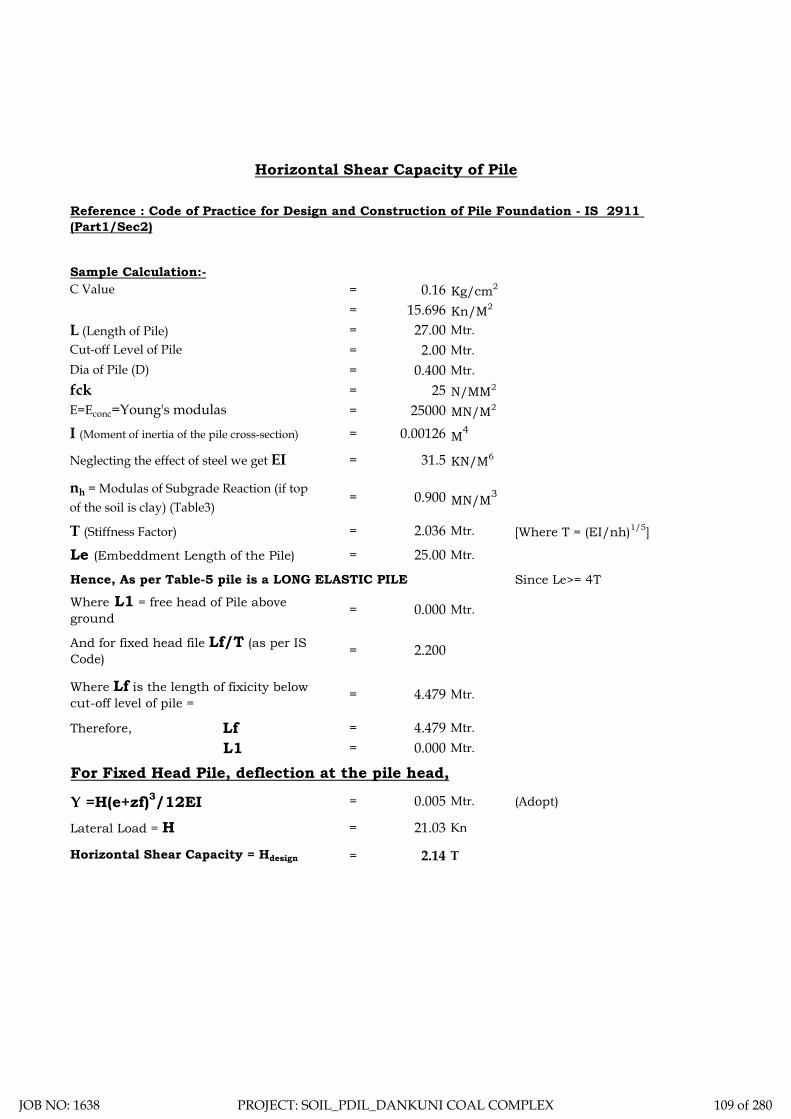
Sample Calculation:-= 0.16 Kg/cm2
= 15.696 Kn/M2
= 27.00 Mtr.= 2.00 Mtr.= 0.400 Mtr.= 25 N/MM2
= 25000 MN/M2
= 0.00126 M4
= 31.5 KN/M6
= 0.900 MN/M3
T (Stiffness Factor) = 2.036 Mtr. [Where T = (EI/nh)1/5]
= 25.00 Mtr.
Hence, As per Table-5 pile is a LONG ELASTIC PILE Since Le>= 4T
= 0.000 Mtr.
= 2.200
= 4.479 Mtr.
Therefore, Lf = 4.479 Mtr.L1 = 0.000 Mtr.
For Fixed Head Pile, deflection at the pile head,
= 0.005 Mtr. (Adopt)
= 21.03 Kn
= 2.14 T
Horizontal Shear Capacity of Pile
Reference : Code of Practice for Design and Construction of Pile Foundation - IS 2911 (Part1/Sec2)
C Value
L (Length of Pile)Cut-off Level of PileDia of Pile (D)fckE=Econc=Young's modulas
I (Moment of inertia of the pile cross-section)
Neglecting the effect of steel we get EI
nh = Modulas of Subgrade Reaction (if top of the soil is clay) (Table3)
Le (Embeddment Length of the Pile)
Where L1 = free head of Pile above ground
And for fixed head file Lf/T (as per IS Code)
Where Lf is the length of fixicity below cut-off level of pile =
Y =H(e+zf)3/12EILateral Load = H
Horizontal Shear Capacity = Hdesign
JOB NO: 1638 PROJECT: SOIL_PDIL_DANKUNI COAL COMPLEX 109 of 280
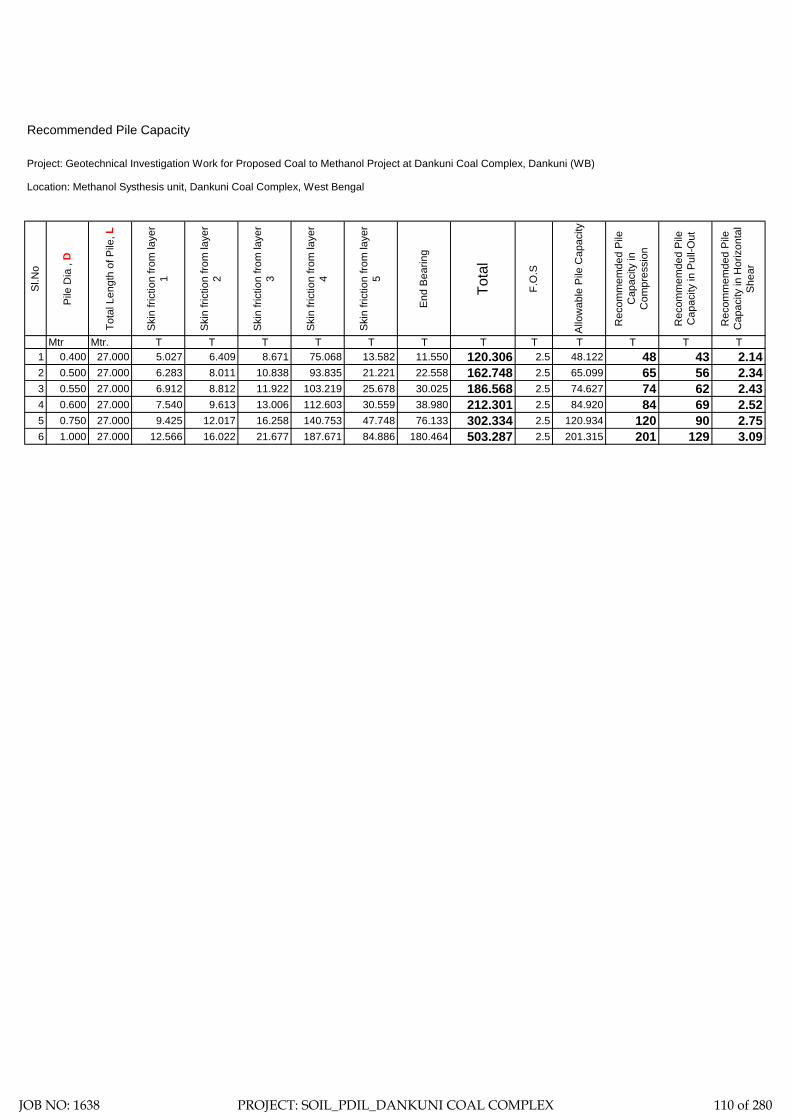
Recommended Pile Capacity
Location: Methanol Systhesis unit, Dankuni Coal Complex, West Bengal
Sl.N
o
Pile
Dia
, D
Tota
l Len
gth
of P
ile, L
Skin
fric
tion
from
laye
r 1
Skin
fric
tion
from
laye
r 2
Skin
fric
tion
from
laye
r 3
Skin
fric
tion
from
laye
r 4
Skin
fric
tion
from
laye
r 5
End
Bear
ing
Tota
l
F.O
.S
Allo
wab
le P
ile C
apac
ity
Rec
omm
emde
d Pi
le
Cap
acity
in
Com
pres
sion
Rec
omm
emde
d Pi
le
Cap
acity
in P
ull-O
ut
Rec
omm
emde
d Pi
le
Cap
acity
in H
oriz
onta
l Sh
ear
Mtr Mtr. T T T T T T T T T T T T1 0.400 27.000 5.027 6.409 8.671 75.068 13.582 11.550 120.306 2.5 48.122 48 43 2.142 0.500 27.000 6.283 8.011 10.838 93.835 21.221 22.558 162.748 2.5 65.099 65 56 2.343 0.550 27.000 6.912 8.812 11.922 103.219 25.678 30.025 186.568 2.5 74.627 74 62 2.434 0.600 27.000 7.540 9.613 13.006 112.603 30.559 38.980 212.301 2.5 84.920 84 69 2.525 0.750 27.000 9.425 12.017 16.258 140.753 47.748 76.133 302.334 2.5 120.934 120 90 2.756 1.000 27.000 12.566 16.022 21.677 187.671 84.886 180.464 503.287 2.5 201.315 201 129 3.09
Project: Geotechnical Investigation Work for Proposed Coal to Methanol Project at Dankuni Coal Complex, Dankuni (WB)
JOB NO: 1638 PROJECT: SOIL_PDIL_DANKUNI COAL COMPLEX 110 of 280

ELECTRICAL
RESISTIVITY TEST
JOB NO: 1638 PROJECT: SOIL_PDIL_DANKUNI COAL COMPLEX 111 of 280
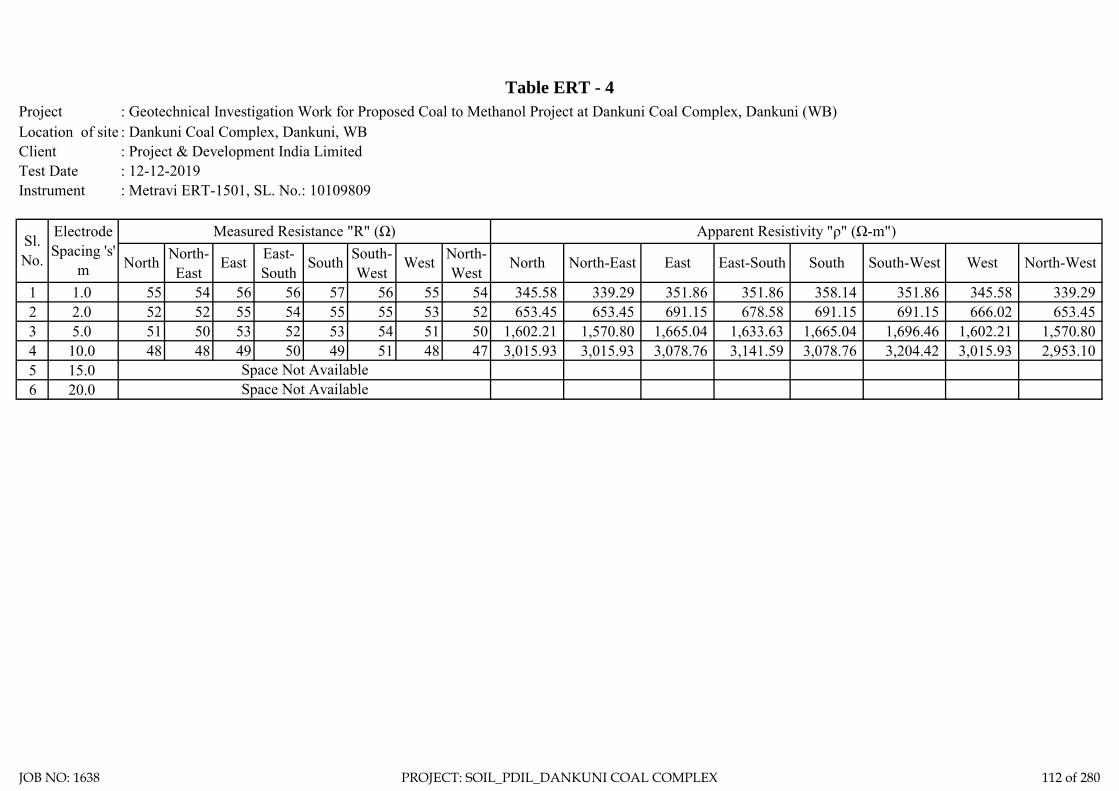
: Geotechnical Investigation Work for Proposed Coal to Methanol Project at Dankuni Coal Complex, Dankuni (WB): Dankuni Coal Complex, Dankuni, WB: Project & Development India Limited: 12-12-2019: Metravi ERT-1501, SL. No.: 10109809
1 1.0 55 54 56 56 57 56 55 54 345.58 339.29 351.86 351.86 358.14 351.86 345.58 339.29 2 2.0 52 52 55 54 55 55 53 52 653.45 653.45 691.15 678.58 691.15 691.15 666.02 653.45 3 5.0 51 50 53 52 53 54 51 50 1,602.21 1,570.80 1,665.04 1,633.63 1,665.04 1,696.46 1,602.21 1,570.80 4 10.0 48 48 49 50 49 51 48 47 3,015.93 3,015.93 3,078.76 3,141.59 3,078.76 3,204.42 3,015.93 2,953.10 5 15.06 20.0
Instrument
Table ERT - 4ProjectLocation of siteClient Test Date
Sl. No.
Electrode Spacing 's'
m
Measured Resistance "R" (Ω) Apparent Resistivity "ρ" (Ω-m")
North North-East
East East-South
South South-West
Space Not Available
South South-West West North-West
Space Not Available
West North-West
North North-East East East-South
JOB NO: 1638 PROJECT: SOIL_PDIL_DANKUNI COAL COMPLEX 112 of 280

Electrode Spacing - 1.00MR = 55.14 ohm, Resistivity = 346.28 Ohm-m
Location - ERT-4 Location - ERT-4
Location - ERT-4 Location - ERT-4
Electrode Spacing - 2.00MR = 53.29 ohm, Resistivity = 669.32 Ohm-m
Electrode Spacing - 5.00MR = 51.55 ohm, Resistivity = 1618.67 Ohm-m
Electrode Spacing - 10.00MR = 48.56 ohm, Resistivity = 3049.57 Ohm-m
JOB NO: 1638 PROJECT: SOIL_PDIL_DANKUNI COAL COMPLEX 113 of 280

ZONE-5
COOLING TOWER
JOB NO: 1638 PROJECT: SOIL_PDIL_DANKUNI COAL COMPLEX 114 of 280

: Geotechnical Investigation Work for Proposed Coal to Methanol Project at Dankuni Coal Complex, Dankuni (WB): Dankuni Coal Complex, Dankuni, WB: Project & Development India Limited: 21-12-2019: Metravi ERT-1501, SL. No.: 10109809
1 1.0 22 18 30 25 29 31 28 26 138.23 113.10 188.50 157.08 182.21 194.78 175.93 163.36 2 2.0 25 21 27 31 36 35 37 36 314.16 263.89 339.29 389.56 452.39 439.82 464.96 452.39 3 5.0 33 31 42 32 38 40 46 50 1,036.73 973.89 1,319.47 1,005.31 1,193.81 1,256.64 1,445.13 1,570.80 4 10.0 45 55 50 53 52 53 47 47 2,827.43 3,455.75 3,141.59 3,330.09 3,267.26 3,330.09 2,953.10 2,953.10 5 15.06 20.0 Space Not Available
South South-West West North-West
Space Not Available
West North-West
North North-East East East-SouthSl. No.
Electrode Spacing 's'
m
Measured Resistance "R" (Ω) Apparent Resistivity "ρ" (Ω-m")
North North-East
East East-South
South South-West
Instrument
Table ERT - 5ProjectLocation of siteClient Test Date
JOB NO: 1638 PROJECT: SOIL_PDIL_DANKUNI COAL COMPLEX 115 of 280

Electrode Spacing - 1.00MR = 26.07 ohm, Resistivity = 163.72 Ohm-m
Location - ERT-5 Location - ERT-5
Location - ERT-5 Location - ERT-5
Electrode Spacing - 2.00MR = 31.23 ohm, Resistivity = 392.25 Ohm-m
Electrode Spacing - 5.00MR = 38.93 ohm, Resistivity = 1222.40 Ohm-m
Electrode Spacing - 10.00MR = 50.09 ohm, Resistivity = 3145.65 Ohm-m
JOB NO: 1638 PROJECT: SOIL_PDIL_DANKUNI COAL COMPLEX 116 of 280

ZONE-6
BOILER UNIT
JOB NO: 1638 PROJECT: SOIL_PDIL_DANKUNI COAL COMPLEX 117 of 280

Total two (2) boreholes were sunk in this area, viz borehole marked BH-2 and BH-3. From the general sub soil profile it has been observed that the top soil is heterogeneous fill with coal dust, clayey silt etc followed by first layer of soft light/ dark grey silty clay/ clayey silt. The second layer is soft to medium bluish grey silty clay/ clayey silt. The third layer consists of stiff light/ yellowish grey silty clay/ clayey silt and the fourth layer as encountered up to the explored depth is very stiff to hard brownish grey silty clay/ clayey silt.
In addition the following field tests have been carried out at this zone and results are being indicated in this chapter.
1. Static Cone Penetration Test: One (1) static cone penetration test has been carried out at this zone marked as SCPT-1.
2. Electrical Resistivity Test: One (1) electrical resistivity tests has been carried out at this zone marked as ERT-2.
Discussion and Recommendation:
Based on the subsoil condition pile foundation has been recommended for foundation system of medium to heavily loaded structures. Pile capacities in compression, pull-out and horizontal shear for different diameter of pile are indicated in the Table-2A (Zone-6). It is further recommended to carry out initial pile load test for load under compression, pull-out and horizontal shear, in order to confirm the recommended pile capacities and to take corrective measures, if required.
JOB NO: 1638 PROJECT: SOIL_PDIL_DANKUNI COAL COMPLEX 118 of 280

Table-2A (Zone-6). Recommended Pile Capacity
Sl.N
o
Pile
Dia
, D
Tota
l Len
gth
of P
ile, L
Cut
-off
Leve
l
Rec
omm
ende
d Pi
le
Cap
acity
in C
ompr
essi
on
Rec
omm
ende
d Pi
le
Cap
acity
in P
ull-O
ut
Rec
omm
ende
d Pi
le
Cap
acity
in H
oriz
onta
l Sh
ear
Mtr Mtr. Mtr. T T T
1 0.400 28.000 2.000 54 49 2.52
2 0.500 28.000 2.000 69 62 2.76
3 0.550 28.000 2.000 77 68 2.86
4 0.600 28.000 2.000 85 74 2.96
5 0.750 28.000 2.000 110 93 3.24
6 1.000 28.000 2.000 154 124 3.64
JOB NO: 1638 PROJECT: SOIL_PDIL_DANKUNI COAL COMPLEX 119 of 280

DS - Disturbed SampleSCPT-Static Cone Penetration DCPT - Dynamic Cone Penetration
SPT - Standard Penetration Test VST- Vane Shear TestUDS - Undisturbed
Test. Sample Test.
WS - Water Sample
RCS - Rock Core Sample
Centre for Advanced Engineering
N-V A L U E
19 RCSDSDCPTDepth of Drilling
Type of Drilling
D E S C R I P T I O N
VST SCPT
SYMBOL DEPTH
Co-ord: Type of Boring
Depth of Boring
Project:
FIELDTESTE.G.L.: 35.782
SPT35.000 M.Shell & Auger
BORE LOG SHEET
SAMPLESNOS.Unit:
UDS17 10NOS.
WSSAMPLES
2.40 M.Water Struck At :
2.34 M.S A M P L E
DEPTH
Standing Water Table :
NO.
Bore Hole No.:
Soil - 1638
Commenced on : Bore Hole Dia. :
Completed on :
Job No.:
NOS.150 MM.
BH-2 (Sheet-1)
03.11.201905.11.2019
01DS1 0.50 M
N = 3 1.50-1.95MDS3SPT1
1.50-1.95M
N = 3 7.50-7.95MDS7SPT5
7.50-7.95M
N = 3 10.50-10.95MDS9SPT7
10.50-10.95MUDS4 11.00-11.45M
N = 4 3.00-3.45MDS4SPT2
3.00-3.45M
N = 2 6.00-6.45MDS6SPT4
6.00-6.45M
UDS3 8.00-8.45M
N = 3 9.00-9.45MDS8SPT6
9.00-9.45M
UDS5 14.00-14.45MN = 20 14.50-14.95M
DS11SPT9
14.50-14.95M
UDS2 5.00-5.45M
N = 7 12.50-12.95MDS10SPT8
12.50-12.95M
N = 20 16.50-16.95MDS12SPT10
16.50-16.95M
N = 27 18.50-18.95MDS13SPT11
18.50-18.95M
UDS6 17.00-17.45M
SOIL_PDIL_DANKUNI_BOILER UNIT
02
03
04
05
06
07
08
09
10
11
12
13
14
15
16
17
18
19
DS2 1.00 M
N = 3 4.50-4.95MDS5SPT3
4.50-4.95M
Filled up with coal, brickbats, sandetc.Soft light grey silty clay/ clayey siltwith traces of sand.
Soft to medium bluish grey siltyclay/ clayey silt with traces of sand.
Contd.........
UDS1 2.00-2.45M
Medium light grey fine silty sandwith mica.
JOB NO: 1638 PROJECT: SOIL_PDIL_DANKUNI COAL COMPLEX 120 of 280

2.40 M.2.34 M.
150 MM.
BH-2 (Sheet-1)
03.11.201905.11.2019
DS - Disturbed SampleSCPT-Static Cone Penetration DCPT - Dynamic Cone Penetration
SPT - Standard Penetration Test VST- Vane Shear TestUDS - Undisturbed
Test. Sample Test.
WS - Water Sample
RCS - Rock Core Sample
Centre for Advanced Engineering
N-V A L U E
19 RCSDSDCPTDepth of Drilling
Type of Drilling
D E S C R I P T I O N
VST SCPT
SYMBOL DEPTH
Co-ord: Type of Boring
Depth of Boring
Project:
FIELDTESTE.G.L.: 35.782
SPT35.000 M.Shell & Auger
BORE LOG SHEET
SAMPLESNOS.Unit:
UDS17 10NOS.
WSSAMPLES
2.40 M.Water Struck At :
2.34 M.S A M P L E
DEPTH
Standing Water Table :
NO.
Bore Hole No.:
Soil - 1638
Commenced on : Bore Hole Dia. :
Completed on :
Job No.:
NOS.150 MM.
03.11.201905.11.2019
Termination Depth 35.000 Mtr.
SOIL_PDIL_DANKUNI_BOILER UNIT
21
22
23
24
25
26
27
28
29
30
31
32
33
34
35
36
37
38
39
UDS7 20.00-20.45MN = 17 20.50-20.95M
DS14SPT12
20.50-20.95M
UDS8 23.00-23.45MN = 13 23.50-23.95M
DS15SPT13
23.50-23.95M
UDS9 26.00-26.45M
UDS10 29.00-29.45M
N = 33 26.50-26.95MDS16SPT14
26.50-26.95M
N = 36 29.50-29.95MDS17SPT15
29.50-29.95M
N = 36 32.50-32.95MDS18SPT16
32.50-32.95M
N = 42 34.55-35.00MDS19SPT17
34.55-35.00M
BH-2 (Sheet-2)
Very stiff to hard brownish greysandy clay. With traces of silt stoneand sand stone. A rusty brown spotin the deposit.
JOB NO: 1638 PROJECT: SOIL_PDIL_DANKUNI COAL COMPLEX 121 of 280

DS - Disturbed SampleSCPT-Static Cone Penetration DCPT - Dynamic Cone Penetration
SPT - Standard Penetration Test VST- Vane Shear TestUDS - Undisturbed
Test. Sample Test.
WS - Water Sample
RCS - Rock Core Sample
Centre for Advanced Engineering
N-V A L U E
19 RCSDSDCPTDepth of Drilling
Type of Drilling
D E S C R I P T I O N
VST SCPT
SYMBOL DEPTH
Co-ord: Type of Boring
Depth of Boring
Project:
FIELDTESTE.G.L.: 35.673
SPT35.000 M.Shell & Auger
BORE LOG SHEET
SAMPLESNOS.Unit:
UDS17 10NOS.
WSSAMPLES
2.40 M.Water Struck At :
2.34 M.S A M P L E
DEPTH
Standing Water Table :
NO.
Bore Hole No.:
Soil - 1638
Commenced on : Bore Hole Dia. :
Completed on :
Job No.:
NOS.150 MM.
BH-3 (Sheet-1)
03.11.201905.11.2019
01DS1 0.50 M
N = 2 1.50-1.95MDS3SPT1
1.50-1.95M
N = 5 7.50-7.95MDS7SPT5
7.50-7.95M
N = 6 10.50-10.95MDS9SPT7
10.50-10.95MUDS4 11.00-11.45M
N = 2 3.00-3.45MDS4SPT2
3.00-3.45M
N = 4 6.00-6.45MDS6SPT4
6.00-6.45M
UDS3 8.00-8.45M
N = 6 9.00-9.45MDS8SPT6
9.00-9.45M
UDS5 14.00-14.45MN = 9 14.50-14.95M
DS11SPT9
14.50-14.95M
UDS2 5.00-5.45M
N = 7 12.50-12.95MDS10SPT8
12.50-12.95M
N = 12 16.50-16.95MDS12SPT10
16.50-16.95M
N = 15 18.50-18.95MDS13SPT11
18.50-18.95M
UDS6 17.00-17.45M
SOIL_PDIL_DANKUNI_BOILER UNIT
02
03
04
05
06
07
08
09
10
11
12
13
14
15
16
17
18
19
DS2 1.00 M
N = 3 4.50-4.95MDS5SPT3
4.50-4.95M
Filled up with coal, brickbats, sandetc.
Soft light/ dark grey silty clay/clayey silt with traces ofconcretion.
Contd.........
UDS1 2.00-2.45M
stiff light/ yellowish grey silty clay/clayey silt mixed with fine sandand tracess of kankar, silt stones.
Medium bluish grey silty clay/clayey silt with traces of calcareousnodules.
JOB NO: 1638 PROJECT: SOIL_PDIL_DANKUNI COAL COMPLEX 122 of 280

2.40 M.2.34 M.
150 MM.
BH-3 (Sheet-1)
03.11.201905.11.2019
DS - Disturbed SampleSCPT-Static Cone Penetration DCPT - Dynamic Cone Penetration
SPT - Standard Penetration Test VST- Vane Shear TestUDS - Undisturbed
Test. Sample Test.
WS - Water Sample
RCS - Rock Core Sample
Centre for Advanced Engineering
N-V A L U E
19 RCSDSDCPTDepth of Drilling
Type of Drilling
D E S C R I P T I O N
VST SCPT
SYMBOL DEPTH
Co-ord: Type of Boring
Depth of Boring
Project:
FIELDTESTE.G.L.: 35.673
SPT35.000 M.Shell & Auger
BORE LOG SHEET
SAMPLESNOS.Unit:
UDS17 10NOS.
WSSAMPLES
2.40 M.Water Struck At :
2.34 M.S A M P L E
DEPTH
Standing Water Table :
NO.
Bore Hole No.:
Soil - 1638
Commenced on : Bore Hole Dia. :
Completed on :
Job No.:
NOS.150 MM.
03.11.201905.11.2019
Termination Depth 35.000 Mtr.
SOIL_PDIL_DANKUNI_BOILER UNIT
21
22
23
24
25
26
27
28
29
30
31
32
33
34
35
36
37
38
39
UDS7 20.00-20.45MN = 15 20.50-20.95M
DS14SPT12
20.50-20.95M
UDS8 23.00-23.45MN = 28 23.50-23.95M
DS15SPT13
23.50-23.95M
UDS9 26.00-26.45M
UDS10 29.00-29.45M
N = 28 26.50-26.95MDS16SPT14
26.50-26.95M
N = 29 29.50-29.95MDS17SPT15
29.50-29.95M
N = 37 32.50-32.95MDS18SPT16
32.50-32.95M
N = 45 34.55-35.00MDS19SPT17
34.55-35.00M
BH-3 (Sheet-2)
stiff light/ yellowish grey silty clay/clayey silt mixed with fine sandand tracess of kankar, silt stones.
Very stiff to hard brownish greysilty clay/ clayey silt with tracessof concretion and gravels.
JOB NO: 1638 PROJECT: SOIL_PDIL_DANKUNI COAL COMPLEX 123 of 280

Sub-Soil Profile through BH-2 & BH-3
02
24.00M.
12.00M.
18.00M.
20.00M.
22.00M.
14.00M.
16.00M.
6.00M.
10.00M.
8.00M.
2.00M.
4.00M.
Sketch No.-SK/PDIL/ BOILER UNIT 1638 6 of 13
Termination depth 35.000 M.
BH-2
RL=35.782
26.00M.
28.00M.
30.00M.
32.00M.
34.00M.
36.00M.
38.00M.
1.00M
Layer-I
Layer-II
Layer-III
Layer-IV
9.00M
14.50M
Termination depth 35.000 M.
BH-3
1.50M
7.50M
14.50M
20.00M
23.50M
Soft to medium bluish grey silty clay/ clayey silt with traces of sandand calcareous nodules.
Medium light grey fine silty sandwith mica.
Filled up with coal, brickbats, sand etc.
Soft light/ dark grey silty clay/ clayey silt with traces of concretion.
stiff light/ yellowish grey silty clay/clayey silt mixed with fine sandand tracess of kankar, silt stones.
Very stiff to hard brownish grey silty clay/ clayey silt/sandy clay with tracess of concretion and gravels.
RL=35.673
JOB NO: 1638 PROJECT: SOIL_PDIL_DANKUNI COAL COMPLEX 124 of 280

LL PL SL Type of Test
Cohesion in
kg/sqcm
Friction angle in degree
Gravel (> 4.75 mm) %
Sand (0.075 - 4.75 mm)
Silt (0.002 - 0.075 mm)
Clay (< 0.002 mm)
Meter % % % γb m G γd quUU/CU/CD
/DS C φ % % % %
2 1.50 DN 3 56 24 11.08 2.67 0.00 0 9 61 30
0.00-0.10 0.0239
0.10-0.20 0.0299
0.20-0.40 0.0421
0.40-0.80 0.0336
0.80-1.60 0.0257
1.60-3.20 0.0168
2 4.50 DN 3 50 20 11.83 2.68 3.6 0 12 76 12
2 7.50 DN 3 51 21 12.9 2.67 5.4 0 8 57 35
2 9.00 DN 3 62 19 11.3 2.68 4.8 0 7 53 40
0.00-0.10 0.0231
0.10-0.20 0.0286
0.20-0.40 0.0418
0.40-0.80 0.0325
0.80-1.60 0.0251
1.60-3.20 0.0157
2 12.50 DN 7 49 20 10.7 2.65 4.6 0 11 63 26
III 2 18.50 DN 27 2.66 DS 0.04 32 0 0 99 1 0
2 20.50 DN 17 45 18 10.6 2.67 21.3 3 15 56 26
0.00-0.10 0.0114
0.10-0.20 0.0168
0.20-0.40 0.0289
0.40-0.80 0.0376
0.80-1.60 0.0243
1.60-3.20 0.0117
2 26.50 DN 33 50 19 11.2 2.68 24.6 21 26 32 21
2 32.50 DN 36 49 19 12.06 2.66 22.5 0 25 51 24
2 34.55 DN 42 47 20 11.8 2.63 27 0 30 37 33
2 2.00 UD 52
0
13
UU
CU
Sample Type - UD/D/
DN
SPT VALUE
(N)
Atterberg LimitsUnconfined
Test in Kg/sqcm
Pressure (Kg/sqcm
)
Dry Density
in gm/cc
Project: Geotechnical Investigation Work for Proposed Coal to Methanol Project at Dankuni Coal Complex, Dankuni (WB)
Swell Pressure
(Kg/sqcm)
Specific Gravity Free Swell
Index(%)
Bulk Density in gm/cc
Shear Test Grading
Layer No.Bore Hole No.
21
SUMMARY OF LABORATORY TEST RESULTSTable-3
Depth Water
Content in %Description of layer
Co-eff. of volume
compressibility in sqcm/kg
0.51
CD 0 18
12.17 1.80 37.63 2.66 1.31
0.26
0.09 280 2.54 0 7 65
NP
IV
Soft light grey silty clay/ clayey silt with traces of
sand.I
Soft to medium bluish grey silty clay/ clayey silt
with traces of sand.II
Medium light grey fine silty sand with mica.
Very stiff to hard brownish grey sandy
clay. With traces of silt stone and sand stone. A rusty brown spot in the
deposit.
2 11.00 UD 53 20
CD
11.6 1.83 29.66 2.66 1.41 60 310.72
UU 0.38 0
0CU 0.13
0 22
3.2 0 918
2 23.00 UD 48 20 11.05 1.88 24.74 2.67 1.51 2.09
UU 1.06 0
0CU 0.15 22
CD
18.4 14 18 42 26
0 28
JOB NO: 1638 PROJECT: SOIL_PDIL_DANKUNI COAL COMPLEX 125 of 280

LL PL SL Type of Test
Cohesion in
kg/sqcm
Friction angle in degree
Gravel (> 4.75 mm) %
Sand (0.075 - 4.75 mm)
Silt (0.002 - 0.075 mm)
Clay (< 0.002 mm)
Meter % % % γb m G γd quUU/CU/CD
/DS C φ % % % %
Sample Type - UD/D/
DN
SPT VALUE
(N)
Atterberg LimitsUnconfined
Test in Kg/sqcm
Pressure (Kg/sqcm
)
Dry Density
in gm/cc
Swell Pressure
(Kg/sqcm)
Specific Gravity Free Swell
Index(%)
Bulk Density in gm/cc
Shear Test Grading
Layer No.Bore Hole No.
Depth Water
Content in %Description of layer
Co-eff. of volume
compressibility in sqcm/kg
3 1.50 DN 2 57 22 13.3 2.67 0 0 9 59 32
3 3.00 DN 2 62 25 14.39 2.67 1.8 0 12 54 34
3 4.50 DN 3 54 21 13.8 2.69 0 0 19 61 20
0.00-0.10 0.0234
0.10-0.20 0.0282
0.20-0.40 0.0434
0.40-0.80 0.0351
0.80-1.60 0.0276
1.60-3.20 0.0191
3 9.00 DN 6 57 18 11.9 2.67 10.2 0 8 55 37
0.00-0.10 0.0217
0.10-0.20 0.0269
0.20-0.40 0.0418
0.40-0.80 0.0343
0.80-1.60 0.0257
1.60-3.20 0.0182
3 14.50 DN 9 44 21 13.4 2.67 0 0 14 64 22
0.00-0.10 0.0194
0.10-0.20 0.0259
0.20-0.40 0.0383
0.40-0.80 0.0217
0.80-1.60 0.0174
1.60-3.20 0.0137
3 23.50 DN 28 44 19 11.4 2.68 21.4 7 12 51 30
0.00-0.10 0.0086
0.10-0.20 0.0161
0.20-0.40 0.0268
0.40-0.80 0.0231
0.80-1.60 0.0184
1.60-3.20 0.0149
3 29.50 DN 29 41 17 11.8 2.68 25 7 12 59 22
3 34.55 DN 45 45 19 10.6 2.69 13.7 8 8 47 37
0
0
UU 1.09 0
1.49
CU 0.17 2212.03 1.92
1.08
stiff light/ yellowish grey silty clay/ clayey silt mixed with fine sand
and tracess of kankar, silt stones.
III
0.56
Very stiff to hard brownish grey silty clay/ clayey silt with tracess
of concretion and gravels.
IV
3 17.00 UD 0 0 18
Soft light/ dark grey silty clay/ clayey silt with traces of concretion.
I
Medium bluish grey silty clay/ clayey silt with traces of calcareous
nodules.
II12.07 551.85 27.79 2.68
3 7.50 UD 41 18 12.1 1.81 30 2.65 1.39 0.40
UU 0.21 0
0 6.88 0 15 59 26CU 0.10 15
CD 0 19
3 11.00 UD 55 19 0 111.45 0.69
UU 0.36
34CU 0.11 16
CD 0 21
0
0 13.4
47 20 12.8 1.87 25.48 2.66 57 25CU 0.14 18
CD 0 26
UU 0
3 26.00 UD 48 18 6 60 3024.15 2.67 1.55 2.15
CD 0 29
23.2 4
JOB NO: 1638 PROJECT: SOIL_PDIL_DANKUNI COAL COMPLEX 126 of 280

SAMPLE CALCULATION
FOR PILE
FOUNDATION
JOB NO: 1638 PROJECT: SOIL_PDIL_DANKUNI COAL COMPLEX 127 of 280
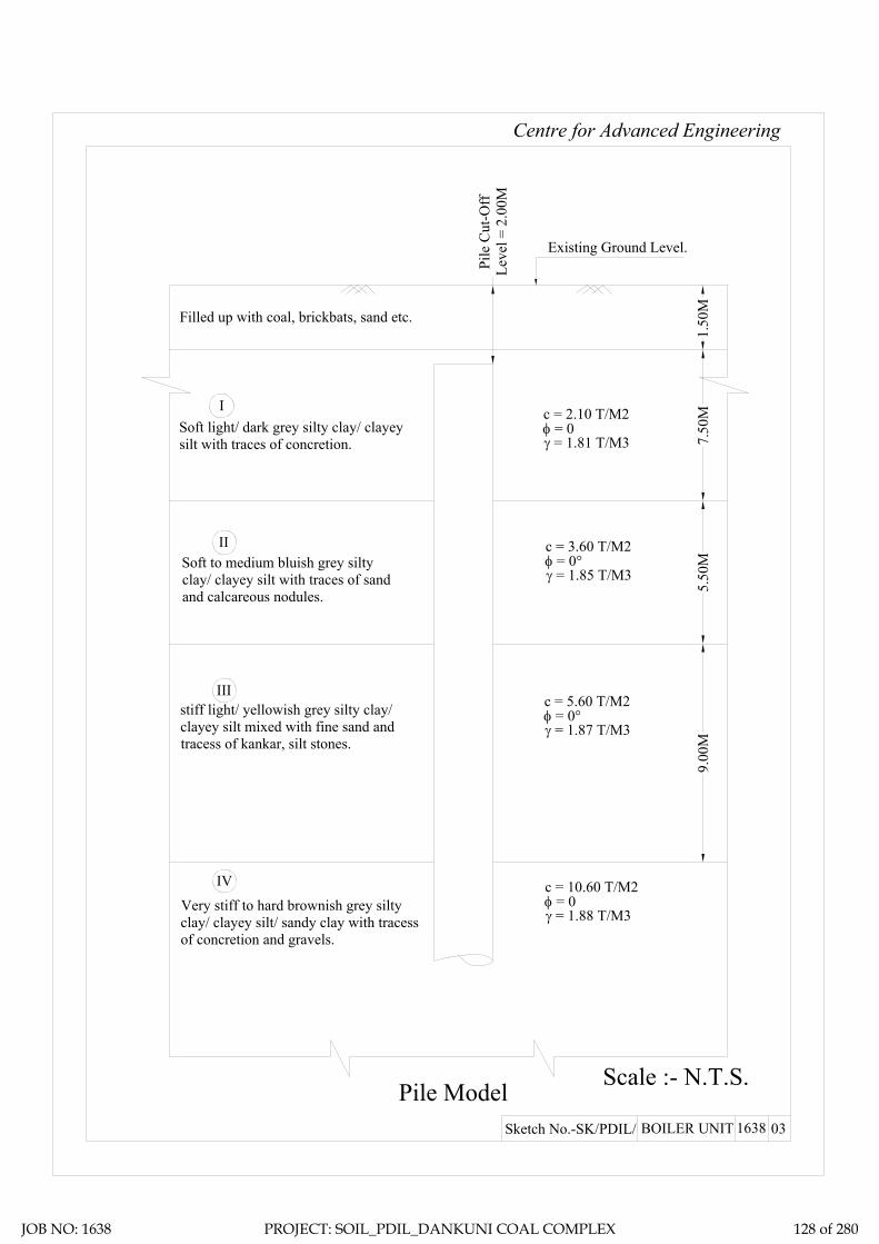
Centre for Advanced Engineering
Pile Model Scale :- N.T.S.
Existing Ground Level.
γ = 1.81 T/M3
c = 2.10 T/M2φ = 0
I
II
7.50
MIII
γ = 1.85 T/M3
c = 3.60 T/M2φ = 0°
γ = 1.88 T/M3
c = 10.60 T/M2φ = 0
Pile
Cut
-Off
Leve
l = 2
.00M
03Sketch No.-SK/PDIL/ BOILER UNIT 1638
1.50
M
γ = 1.87 T/M3
c = 5.60 T/M2φ = 0°
IV
5.50
M9.
00M
Filled up with coal, brickbats, sand etc.
Soft light/ dark grey silty clay/ clayeysilt with traces of concretion.
stiff light/ yellowish grey silty clay/clayey silt mixed with fine sand andtracess of kankar, silt stones.
Very stiff to hard brownish grey siltyclay/ clayey silt/ sandy clay with tracessof concretion and gravels.
Soft to medium bluish grey siltyclay/ clayey silt with traces of sandand calcareous nodules.
JOB NO: 1638 PROJECT: SOIL_PDIL_DANKUNI COAL COMPLEX 128 of 280

Ultimate skin friction capacity
Location: Boiler unit, Dankuni Coal Complex, West Bengal
Layer No: 1Soil Description Soft light/ dark grey silty clay/ clayey silt with traces of concretion.
Sl.N
o
Pile
Dia
, D
Tota
l Len
gth
of P
ile, L
Dep
th o
f lay
er to
p fro
m E
GL
Dep
th o
f lay
er b
otto
m fr
om E
GL
Red
uctio
n fa
ctor
, α (N
ote1
IS
2911
( Par
t1/S
ec2)
Aver
age
Coh
esio
n al
ong
the
leng
th
of th
e pi
le in
this
laye
r, C
Surfa
ce a
rea
of th
e pi
le s
haft
in th
is
laye
r, A s
Ulti
mat
e Sk
in fr
ictio
n ca
paci
ty o
f th
e sh
aft i
n th
is la
yer,
Qsu
=
α*C
*AS
Mtr Mtr. Mtr Mtr. T/M2 M2
1 0.400 28.000 2.000 9.000 1 2.1 8.796 18.4732 0.500 28.000 2.000 9.000 1 2.1 10.996 23.0913 0.550 28.000 2.000 9.000 1 2.1 12.095 25.4004 0.600 28.000 2.000 9.000 1 2.1 13.195 27.7095 0.750 28.000 2.000 9.000 1 2.1 16.493 34.6366 1.000 28.000 2.000 9.000 1 2.1 21.991 46.181
Project: Geotechnical Investigation Work for Proposed Coal to Methanol Project at Dankuni Coal Complex, Dankuni (WB)
JOB NO: 1638 PROJECT: SOIL_PDIL_DANKUNI COAL COMPLEX 129 of 280

Ultimate skin friction capacity
Location: Boiler unit, Dankuni Coal Complex, West Bengal
Layer No: 2Soil Description
Sl.N
o
Pile
Dia
, D
Tota
l Len
gth
of P
ile, L
Dep
th o
f lay
er to
p fro
m E
GL
Dep
th o
f lay
er b
otto
m fr
om E
GL
Red
uctio
n fa
ctor
, α (N
ote1
IS
2911
( Par
t1/S
ec2)
Aver
age
Coh
esio
n al
ong
the
leng
th
of th
e pi
le in
this
laye
r, C
Surfa
ce a
rea
of th
e pi
le s
haft
in th
is
laye
r, A s
Ulti
mat
e Sk
in fr
ictio
n ca
paci
ty o
f th
e sh
aft i
n th
is la
yer,
Qsu
=
α*C
*AS
Mtr Mtr. Mtr Mtr. T/M2 M2
1 0.400 28.000 9.000 14.500 1 3.6 6.912 24.8812 0.500 28.000 9.000 14.500 1 3.6 8.639 31.1023 0.550 28.000 9.000 14.500 1 3.6 9.503 34.2124 0.600 28.000 9.000 14.500 1 3.6 10.367 37.3225 0.750 28.000 9.000 14.500 1 3.6 12.959 46.6536 1.000 28.000 9.000 14.500 1 3.6 17.279 62.204
Project: Geotechnical Investigation Work for Proposed Coal to Methanol Project at Dankuni Coal Complex, Dankuni (WB)
Soft to medium bluish grey silty clay/ clayey silt with traces of sand and calcareous nodules.
JOB NO: 1638 PROJECT: SOIL_PDIL_DANKUNI COAL COMPLEX 130 of 280

Ultimate skin friction capacity
Location: Boiler unit, Dankuni Coal Complex, West Bengal
Layer No: 3Soil Description
Sl.N
o
Pile
Dia
, D
Tota
l Len
gth
of P
ile, L
Dep
th o
f lay
er to
p fro
m E
GL
Dep
th o
f lay
er b
otto
m fr
om E
GL
Red
uctio
n fa
ctor
, α (N
ote1
IS
2911
( Par
t1/S
ec2)
Aver
age
Coh
esio
n al
ong
the
leng
th
of th
e pi
le in
this
laye
r, C
Surfa
ce a
rea
of th
e pi
le s
haft
in th
is
laye
r, A s
Ulti
mat
e Sk
in fr
ictio
n ca
paci
ty o
f th
e sh
aft i
n th
is la
yer,
Qsu
=
α*C
*AS
Mtr Mtr. Mtr Mtr. T/M2 M2
1 0.400 28.000 14.500 23.500 0.9 5.6 11.310 57.0012 0.500 28.000 14.500 23.500 0.9 5.6 14.137 71.2513 0.550 28.000 14.500 23.500 0.9 5.6 15.551 78.3764 0.600 28.000 14.500 23.500 0.9 5.6 16.965 85.5025 0.750 28.000 14.500 23.500 0.9 5.6 21.206 106.8776 1.000 28.000 14.500 23.500 0.9 5.6 28.274 142.503
Project: Geotechnical Investigation Work for Proposed Coal to Methanol Project at Dankuni Coal Complex, Dankuni (WB)
Stiff light/ yellowish grey silty clay/ clayey silt mixed with fine sand and tracess of kankar, silt stones.
JOB NO: 1638 PROJECT: SOIL_PDIL_DANKUNI COAL COMPLEX 131 of 280

Ultimate skin friction capacity
Location: Boiler unit, Dankuni Coal Complex, West Bengal
Layer No: 4Soil Description
Sl.N
o
Pile
Dia
, D
Tota
l Len
gth
of P
ile, L
Dep
th o
f lay
er to
p fro
m E
GL
Dep
th o
f lay
er b
otto
m fr
om E
GL
Red
uctio
n fa
ctor
, α (N
ote1
IS
2911
( Par
t1/S
ec2)
Aver
age
Coh
esio
n al
ong
the
leng
th
of th
e pi
le in
this
laye
r, C
Surfa
ce a
rea
of th
e pi
le s
haft
in th
is
laye
r, A s
Ulti
mat
e Sk
in fr
ictio
n ca
paci
ty o
f th
e sh
aft i
n th
is la
yer,
Qsu
=
α*C
*AS
Mtr Mtr. Mtr Mtr. T/M2 M2
1 0.400 28.000 23.500 28.000 0.4 10.6 5.655 23.9772 0.500 28.000 23.500 28.000 0.4 10.6 7.069 29.9713 0.550 28.000 23.500 28.000 0.4 10.6 7.775 32.9684 0.600 28.000 23.500 28.000 0.4 10.6 8.482 35.9655 0.750 28.000 23.500 28.000 0.4 10.6 10.603 44.9566 1.000 28.000 23.500 28.000 0.4 10.6 14.137 59.942
Project: Geotechnical Investigation Work for Proposed Coal to Methanol Project at Dankuni Coal Complex, Dankuni (WB)
Very stiff to hard brownish grey silty clay/ clayey silt/ sandy clay with tracess of concretion and gravels.
JOB NO: 1638 PROJECT: SOIL_PDIL_DANKUNI COAL COMPLEX 132 of 280

Ultimate End Bearing capacity
Location: Boiler unit, Dankuni Coal Complex, West Bengal
Layer No: 4Soil Description
Sl.N
o
Pile
Dia
, D
Tota
l Len
gth
of P
ile, L
Dep
th o
f lay
er to
p fro
m E
GL
Dep
th o
f lay
er b
otto
m fr
om E
GL
Aver
age
Coh
esio
n at
the
pile
tip,
C
P
Cro
ss s
ectio
nal a
rea
of th
e pi
le ti
p,
A P
Bear
ing
capa
city
fact
or, N
C
Ulti
mat
eEnd
bea
ring
capa
city
at
pile
tip,
QB u
= A
P*N
C*C
P
Mtr Mtr. Mtr Mtr. T/M2 M2 T1 0.400 28.000 23.500 28.000 10.6 0.126 9.000 11.9882 0.500 28.000 23.500 28.000 10.6 0.196 9.000 18.7323 0.550 28.000 23.500 28.000 10.6 0.238 9.000 22.6654 0.600 28.000 23.500 28.000 10.6 0.283 9.000 26.9745 0.750 28.000 23.500 28.000 10.6 0.442 9.000 42.1466 1.000 28.000 23.500 28.000 10.6 0.785 9.000 74.927
Project: Geotechnical Investigation Work for Proposed Coal to Methanol Project at Dankuni Coal Complex, Dankuni (WB)
Very stiff to hard brownish grey silty clay/ clayey silt/ sandy clay with tracess of concretion and gravels.
JOB NO: 1638 PROJECT: SOIL_PDIL_DANKUNI COAL COMPLEX 133 of 280

Sample Calculation:-= 0.21 Kg/cm2
= 20.601 Kn/M2
= 28.00 Mtr.= 2.00 Mtr.= 0.400 Mtr.= 25 N/MM2
= 25000 MN/M2
= 0.00126 M4
= 31.5 KN/M6
= 1.181 MN/M3
T (Stiffness Factor) = 1.928 Mtr. [Where T = (EI/nh)1/5]
= 26.00 Mtr.
Hence, As per Table-5 pile is a LONG ELASTIC PILE Since Le>= 4T
= 0.000 Mtr.
= 2.200
= 4.242 Mtr.
Therefore, Lf = 4.242 Mtr.L1 = 0.000 Mtr.
For Fixed Head Pile, deflection at the pile head,
= 0.005 Mtr. (Adopt)
= 24.77 Kn
= 2.52 T
Where L1 = free head of Pile above ground
And for fixed head file Lf/T (as per IS Code)
Where Lf is the length of fixicity below cut-off level of pile =
Y =H(e+zf)3/12EILateral Load = H
Horizontal Shear Capacity = Hdesign
fckE=Econc=Young's modulas
I (Moment of inertia of the pile cross-section)
Neglecting the effect of steel we get EI
nh = Modulas of Subgrade Reaction (if top of the soil is clay) (Table3)
Le (Embeddment Length of the Pile)
Horizontal Shear Capacity of Pile
Reference : Code of Practice for Design and Construction of Pile Foundation - IS 2911 (Part1/Sec2)
C Value
L (Length of Pile)Cut-off Level of PileDia of Pile (D)
JOB NO: 1638 PROJECT: SOIL_PDIL_DANKUNI COAL COMPLEX 134 of 280

Recommended Pile Capacity
Location: Boiler unit, Dankuni Coal Complex, West Bengal
Sl.N
o
Pile
Dia
, D
Tota
l Len
gth
of P
ile, L
Skin
fric
tion
from
laye
r 1
Skin
fric
tion
from
laye
r 2
Skin
fric
tion
from
laye
r 3
Skin
fric
tion
from
laye
r 4
End
Bear
ing
Tota
l
F.O
.S
Allo
wab
le P
ile C
apac
ity
Rec
omm
emde
d Pi
le
Cap
acity
in
Com
pres
sion
Rec
omm
emde
d Pi
le
Cap
acity
in P
ull-O
ut
Rec
omm
emde
d Pi
le
Cap
acity
in H
oriz
onta
l Sh
ear
Mtr Mtr. T T T T T T T T T T T1 0.400 28.000 18.473 24.881 57.001 23.977 11.988 136.320 2.5 54.528 54 49 2.522 0.500 28.000 23.091 31.102 71.251 29.971 18.732 174.146 2.5 69.659 69 62 2.763 0.550 28.000 25.400 34.212 78.376 32.968 22.665 193.621 2.5 77.449 77 68 2.864 0.600 28.000 27.709 37.322 85.502 35.965 26.974 213.471 2.5 85.388 85 74 2.965 0.750 28.000 34.636 46.653 106.877 44.956 42.146 275.268 2.5 110.107 110 93 3.246 1.000 28.000 46.181 62.204 142.503 59.942 74.927 385.756 2.5 154.302 154 124 3.64
Project: Geotechnical Investigation Work for Proposed Coal to Methanol Project at Dankuni Coal Complex, Dankuni (WB)
JOB NO: 1638 PROJECT: SOIL_PDIL_DANKUNI COAL COMPLEX 135 of 280

STATIC CONE
PENETRATION TEST
JOB NO: 1638 PROJECT: SOIL_PDIL_DANKUNI COAL COMPLEX 136 of 280

Project: Proposed Coal to Methanol Project at Dankuni Coal Complex, Dankuni (WB) Client.: Project & Development India LimitedSide ID :
1. Mass of Cone (m) 1.34 Kg 1.345 Kg2. Mass of each sounding rod (m1) 1.55 Kg 3.6 cm3. Cone area at Base (b) 10 Sqcm 13 Sqcm
4. Plunger Area (b') 20 Sqcm 147 Sqcm
0.289 Kg 0.01 Kg/ Sqcm6. No of Rod Used (n) 5 SCPT-1
Gauge Reading of Cone
Penetration
Cone Penetration Resistance
Correction Factor
Corrected Value of Cone
Resistance
Gauge Reading of
Cone + Jacket
Resistance
Cone + Jacket Resistance
Total Resistance - Cone
Resistance
Frictional Resistance
Corrected Frictional
Resistance
Kg/ Sqcm Kg/ Sqcm Kg/ Sqcm Kg/ Sqcm Kg/ Sqcm Kg/ Sqcm Kg/ Sqcm Kg/ Sqcm Kg/ Sqcmm n Y y=Y*(b'/b) C1 Rc=y+C1 X x=X*(b'/b) x-y Z=(x-y)*(b/a) Rf= Z+(mf/a)
-0.05 1 7 14 0.29 14.29 16 32 18 1.22 1.23-0.10 1 9 18 0.29 18.29 18 36 18 1.22 1.23-0.15 1 11 22 0.29 22.29 20 40 18 1.22 1.23-0.20 1 12 24 0.29 24.29 21 42 18 1.22 1.23-0.25 1 13 26 0.29 26.29 23 46 20 1.36 1.37-0.30 1 14 28 0.29 28.29 20 40 12 0.82 0.83-0.35 1 15 30 0.29 30.29 22 44 14 0.95 0.96-0.40 2 16 32 0.44 32.44 25 50 18 1.22 1.23-0.45 2 18 36 0.44 36.44 27 54 18 1.22 1.23-0.50 2 20 40 0.44 40.44 29 58 18 1.22 1.23-0.55 2 21 42 0.44 42.44 28 56 14 0.95 0.96-0.60 2 21 42 0.44 42.44 28 56 14 0.95 0.96-0.65 2 21 42 0.44 42.44 28 56 14 0.95 0.96-0.70 2 22 44 0.44 44.44 29 58 14 0.95 0.96
CONE JACKET
Correction A
Number of Rod in
UseDepth
Test Number
1. Mass of friction Jacket (mf)2. Outer dia, of Friction Jacket (d)
Table -1
3. Length of Friction Jacket (h)
4. Surface area of friction jacket (a) = π dh5. Correction factor to be added to gauge reading C2 = (mf/a)
Correction B
5. Correction factor to be added to gauge reading C1 = (m+nm1)/10
JOB NO: 1638 PROJECT: SOIL_PDIL_DANKUNI COAL COMPLEX 137 of 280

Gauge Reading of Cone
Penetration
Cone Penetration Resistance
Correction Factor
Corrected Value of Cone
Resistance
Gauge Reading of
Cone + Jacket
Resistance
Cone + Jacket Resistance
Total Resistance - Cone
Resistance
Frictional Resistance
Corrected Frictional
Resistance
Kg/ Sqcm Kg/ Sqcm Kg/ Sqcm Kg/ Sqcm Kg/ Sqcm Kg/ Sqcm Kg/ Sqcm Kg/ Sqcm Kg/ Sqcmm n Y y=Y*(b'/b) C1 Rc=y+C1 X x=X*(b'/b) x-y Z=(x-y)*(b/a) Rf= Z+(mf/a)
Number of Rod in
UseDepth
-0.75 2 23 46 0.44 46.44 30 60 14 0.95 0.96-0.80 2 24 48 0.44 48.44 31 62 14 0.95 0.96-0.85 2 25 50 0.44 50.44 31 62 12 0.82 0.83-0.90 2 27 54 0.44 54.44 33 66 12 0.82 0.83-0.95 2 28 56 0.44 56.44 34 68 12 0.82 0.83-1.00 2 29 58 0.44 58.44 36 72 14 0.95 0.96-1.05 2 29 58 0.44 58.44 38 76 18 1.22 1.23-1.10 2 30 60 0.44 60.44 39 78 18 1.22 1.23-1.15 2 30 60 0.44 60.44 39 78 18 1.22 1.23-1.20 2 30 60 0.44 60.44 39 78 18 1.22 1.23-1.25 2 31 62 0.44 62.44 40 80 18 1.22 1.23-1.30 2 31 62 0.44 62.44 40 80 18 1.22 1.23-1.35 3 32 64 0.6 64.6 43 86 22 1.5 1.51-1.40 3 33 66 0.6 66.6 45 90 24 1.63 1.64-1.45 3 34 68 0.6 68.6 46 92 24 1.63 1.64-1.50 3 36 72 0.6 72.6 48 96 24 1.63 1.64-1.55 3 36 72 0.6 72.6 48 96 24 1.63 1.64-1.60 3 37 74 0.6 74.6 49 98 24 1.63 1.64-1.65 3 41 82 0.6 82.6 52 104 22 1.5 1.51-1.70 3 41 82 0.6 82.6 51 102 20 1.36 1.37-1.75 3 42 84 0.6 84.6 51 102 18 1.22 1.23-1.80 3 42 84 0.6 84.6 53 106 22 1.5 1.51-1.85 3 43 86 0.6 86.6 52 104 18 1.22 1.23-1.90 3 41 82 0.6 82.6 54 108 26 1.77 1.78-1.95 3 42 84 0.6 84.6 56 112 28 1.9 1.91-2.00 3 41 82 0.6 82.6 56 112 30 2.04 2.05-2.05 3 41 82 0.6 82.6 56 112 30 2.04 2.05-2.10 3 42 84 0.6 84.6 58 116 32 2.18 2.19-2.15 3 42 84 0.6 84.6 58 116 32 2.18 2.19
JOB NO: 1638 PROJECT: SOIL_PDIL_DANKUNI COAL COMPLEX 138 of 280
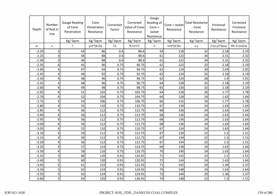
Gauge Reading of Cone
Penetration
Cone Penetration Resistance
Correction Factor
Corrected Value of Cone
Resistance
Gauge Reading of
Cone + Jacket
Resistance
Cone + Jacket Resistance
Total Resistance - Cone
Resistance
Frictional Resistance
Corrected Frictional
Resistance
Kg/ Sqcm Kg/ Sqcm Kg/ Sqcm Kg/ Sqcm Kg/ Sqcm Kg/ Sqcm Kg/ Sqcm Kg/ Sqcm Kg/ Sqcmm n Y y=Y*(b'/b) C1 Rc=y+C1 X x=X*(b'/b) x-y Z=(x-y)*(b/a) Rf= Z+(mf/a)
Number of Rod in
UseDepth
-2.20 3 43 86 0.6 86.6 59 118 32 2.18 2.19-2.25 3 44 88 0.6 88.6 61 122 34 2.31 2.32-2.30 3 44 88 0.6 88.6 61 122 34 2.31 2.32-2.35 4 45 90 0.75 90.75 61 122 32 2.18 2.19-2.40 4 47 94 0.75 94.75 62 124 30 2.04 2.05-2.45 4 46 92 0.75 92.75 62 124 32 2.18 2.19-2.50 4 48 96 0.75 96.75 62 124 28 1.9 1.91-2.55 4 48 96 0.75 96.75 64 128 32 2.18 2.19-2.60 4 49 98 0.75 98.75 65 130 32 2.18 2.19-2.65 4 51 102 0.75 102.75 64 128 26 1.77 1.78-2.70 4 52 104 0.75 104.75 64 128 24 1.63 1.64-2.75 4 53 106 0.75 106.75 66 132 26 1.77 1.78-2.80 4 55 110 0.75 110.75 67 134 24 1.63 1.64-2.85 4 56 112 0.75 112.75 68 136 24 1.63 1.64-2.90 4 56 112 0.75 112.75 68 136 24 1.63 1.64-2.95 4 56 112 0.75 112.75 68 136 24 1.63 1.64-3.00 4 56 112 0.75 112.75 68 136 24 1.63 1.64-3.05 4 55 110 0.75 110.75 67 134 24 1.63 1.64-3.10 4 56 112 0.75 112.75 67 134 22 1.5 1.51-3.15 4 56 112 0.75 112.75 67 134 22 1.5 1.51-3.20 4 56 112 0.75 112.75 67 134 22 1.5 1.51-3.25 4 57 114 0.75 114.75 69 138 24 1.63 1.64-3.30 4 58 116 0.75 116.75 70 140 24 1.63 1.64-3.35 5 60 120 0.91 120.91 71 142 22 1.5 1.51-3.40 5 60 120 0.91 120.91 72 144 24 1.63 1.64-3.45 5 61 122 0.91 122.91 71 142 20 1.36 1.37-3.50 5 62 124 0.91 124.91 74 148 24 1.63 1.64-3.55 5 62 124 0.91 124.91 72 144 20 1.36 1.37-3.60 5 63 126 0.91 126.91 74 148 22 1.5 1.51
JOB NO: 1638 PROJECT: SOIL_PDIL_DANKUNI COAL COMPLEX 139 of 280

Gauge Reading of Cone
Penetration
Cone Penetration Resistance
Correction Factor
Corrected Value of Cone
Resistance
Gauge Reading of
Cone + Jacket
Resistance
Cone + Jacket Resistance
Total Resistance - Cone
Resistance
Frictional Resistance
Corrected Frictional
Resistance
Kg/ Sqcm Kg/ Sqcm Kg/ Sqcm Kg/ Sqcm Kg/ Sqcm Kg/ Sqcm Kg/ Sqcm Kg/ Sqcm Kg/ Sqcmm n Y y=Y*(b'/b) C1 Rc=y+C1 X x=X*(b'/b) x-y Z=(x-y)*(b/a) Rf= Z+(mf/a)
Number of Rod in
UseDepth
-3.65 5 64 128 0.91 128.91 70 140 12 0.82 0.83-3.70 5 64 128 0.91 128.91 70 140 12 0.82 0.83-3.75 5 64 128 0.91 128.91 72 144 16 1.09 1.10
JOB NO: 1638 PROJECT: SOIL_PDIL_DANKUNI COAL COMPLEX 140 of 280

DepthCone
Resistance-0.05 14.29
-0.1 18.29-0.15 22.29
-0.2 24.29-0.25 26.29
-0.3 28.29-0.35 30.29
-0.4 32.44-0.45 36.44
-0.5 40.44-0.55 42.44
-0.6 42.44-0.65 42.44
-0.7 44.44-0.75 46.44
-0.8 48.44-0.85 50.44
-0.9 54.44-0.95 56.44
-1 58.44-1.05 58.44
-1.1 60.44-1.15 60.44
-1.2 60.44-1.25 62.44
-1.3 62.44-1.35 64.6
-1.4 66.6-1.45 68.6
-1.5 72.6
0
20
40
60
80
100
120
140
-4 -3.5 -3 -2.5 -2 -1.5 -1 -0.5 0
Corr
ecte
d Va
lue
of C
one
Resi
stan
ce
Depth (m)
JOB NO: 1638 PROJECT: SOIL_PDIL_DANKUNI COAL COMPLEX 141 of 280

DepthFrictional
Resistance-0.05 1.23
-0.1 1.23-0.15 1.23
-0.2 1.23-0.25 1.37
-0.3 0.83-0.35 0.96
-0.4 1.23-0.45 1.23
-0.5 1.23-0.55 0.96
-0.6 0.96-0.65 0.96
-0.7 0.96-0.75 0.96
-0.8 0.96-0.85 0.83
-0.9 0.83-0.95 0.83
-1 0.96-1.05 1.23
-1.1 1.23-1.15 1.23
-1.2 1.23-1.25 1.23
0.00
0.50
1.00
1.50
2.00
2.50
-4 -3.5 -3 -2.5 -2 -1.5 -1 -0.5 0
Corr
ecte
d Fr
ictio
nal R
esis
tanc
e
Depth
JOB NO: 1638 PROJECT: SOIL_PDIL_DANKUNI COAL COMPLEX 142 of 280

ELECTRICAL
RESISTIVITY TEST
JOB NO: 1638 PROJECT: SOIL_PDIL_DANKUNI COAL COMPLEX 143 of 280

: Geotechnical Investigation Work for Proposed Coal to Methanol Project at Dankuni Coal Complex, Dankuni (WB): Dankuni Coal Complex, Dankuni, WB: Project & Development India Limited: 12-12-2019: Metravi ERT-1501, SL. No.: 10109809
1 1.0 41 41 41 41 41 41 41 41 257.61 257.61 257.61 257.61 257.61 257.61 257.61 257.61 2 2.0 42 42 42 42 42 42 42 42 527.79 527.79 527.79 527.79 527.79 527.79 527.79 527.79 3 5.0 43 43 43 43 43 43 41 43 1,350.88 1,350.88 1,350.88 1,350.88 1,350.88 1,350.88 1,288.05 1,350.88 4 10.0 44 44 44 44 44 44 43 44 2,764.60 2,764.60 2,764.60 2,764.60 2,764.60 2,764.60 2,701.77 2,764.60 5 15.0 45 45 45 45 44 45 44 45 4,241.15 4,241.15 4,241.15 4,241.15 4,146.90 4,241.15 4,146.90 4,241.15 6 20.0
Instrument
Table ERT - 2ProjectLocation of siteClient Test Date
Sl. No.
Electrode Spacing 's'
m
Measured Resistance "R" (Ω) Apparent Resistivity "ρ" (Ω-m")
North North-East
East East-South
South South-West
Space Not Available
South South-West West North-WestWest North-West
North North-East East East-South
JOB NO: 1638 PROJECT: SOIL_PDIL_DANKUNI COAL COMPLEX 144 of 280

Electrode Spacing - 1.00MR = 41.00 ohm, Resistivity = 257.61 Ohm-m
Location - ERT-2 Location - ERT-2
Location - ERT-2 Location - ERT-2
Electrode Spacing - 2.00MR = 42.00 ohm, Resistivity = 527.79 Ohm-m
Electrode Spacing - 5.00MR = 42.54 ohm, Resistivity = 1335.76 Ohm-m
Electrode Spacing - 10.00MR = 43.67 ohm, Resistivity = 2742.48 Ohm-m
Location - ERT-2
Electrode Spacing - 15.00MR = 44.58 ohm, Resistivity = 4199.44 Ohm-m
JOB NO: 1638 PROJECT: SOIL_PDIL_DANKUNI COAL COMPLEX 145 of 280

ZONE-7
DM PLANT &
STORAGE
JOB NO: 1638 PROJECT: SOIL_PDIL_DANKUNI COAL COMPLEX 146 of 280

Total one (1) borehole was sunk in this area, viz borehole marked BH-6. From the general sub soil profile it has been observed that the top soil is heterogeneous fill with clayey silt, fly ash etc. followed by first layer of soft light/ bluish grey silty clay/ clayey silt. The second layer is medium to stiff light/ bluish grey silty clay/ clayey silt. The third layer consists of medium light yellowish grey silty sand. The fourth layer is very stiff to hard mottled bluish/ brownish grey silty clay/ clayey silt and the fifth layer as encountered up to the explored depth is hard brownish grey silty clay/ clayey silt.
In addition the following field tests have been carried out at this zone and results are being indicated in this chapter.
1. Plate Load Test: One (1) plate load test has been carried out at this zone marked as PLT-1.
2. Electrical Resistivity Test: One (1) electrical resistivity tests has been carried out at this zone marked as ERT-3.
Discussion and Recommendation:
Based on the subsoil condition pile foundation has been recommended for foundation system of medium to heavily loaded structures. Pile capacities in compression, pull-out and horizontal shear for different diameter of pile are indicated in the Table-2A (Zone-7). It is further recommended to carry out initial pile load test for load under compression, pull-out and horizontal shear, in order to confirm the recommended pile capacities and to take corrective measures, if required.
JOB NO: 1638 PROJECT: SOIL_PDIL_DANKUNI COAL COMPLEX 147 of 280

Table-2A (Zone-7).
Recommended Pile Capacity
Sl.N
o
Pile
Dia
, D
Tota
l Len
gth
of P
ile, L
Cut
-off
Leve
l
Rec
omm
ende
d Pi
le
Cap
acity
in C
ompr
essi
on
Rec
omm
ende
d Pi
le
Cap
acity
in P
ull-O
ut
Rec
omm
ende
d Pi
le
Cap
acity
in H
oriz
onta
l Sh
ear
Mtr Mtr. Mtr. T T T
1 0.400 32.000 2.000 61 56 2.38
2 0.500 32.000 2.000 80 72 2.60
3 0.550 32.000 2.000 90 81 2.69
4 0.600 32.000 2.000 101 90 2.79
5 0.750 32.000 2.000 134 117 3.05
6 1.000 32.000 2.000 197 166 3.42
JOB NO: 1638 PROJECT: SOIL_PDIL_DANKUNI COAL COMPLEX 148 of 280

DS - Disturbed SampleSCPT-Static Cone Penetration DCPT - Dynamic Cone Penetration
SPT - Standard Penetration Test VST- Vane Shear TestUDS - Undisturbed
Test. Sample Test.
WS - Water Sample
RCS - Rock Core Sample
Centre for Advanced Engineering
N-V A L U E
19 RCSDSDCPTDepth of Drilling
Type of Drilling
D E S C R I P T I O N
VST SCPT
SYMBOL DEPTH
Co-ord: Type of Boring
Depth of Boring
Project:
FIELDTESTE.G.L.: 35.508
SPT35.000 M.Shell & Auger
BORE LOG SHEET
SAMPLESNOS.Unit:
UDS17 10NOS.
WSSAMPLES
0.30 M.Water Struck At :
0.20 M.S A M P L E
DEPTH
Standing Water Table :
NO.
Bore Hole No.:
Soil - 1638
Commenced on : Bore Hole Dia. :
Completed on :
Job No.:
NOS.150 MM.
BH-6 (Sheet-1)
20.10.201923.10.2019
01DS1 0.50 M
N = 2 1.50-1.95MDS3SPT1
1.50-1.95M
N = 5 7.50-7.95MDS7SPT5
7.50-7.95M
N = 8 10.50-10.95MDS9SPT7
10.50-10.95MUDS4 11.00-11.45M
N = 2 3.00-3.45MDS4SPT2
3.00-3.45M
N = 4 6.00-6.45MDS6SPT4
6.00-6.45M
UDS3 8.00-8.45M
N = 7 9.00-9.45MDS8SPT6
9.00-9.45M
UDS5 14.00-14.45MN = 29 14.50-14.95M
DS11SPT9
14.50-14.95M
UDS2 5.00-5.45M
N = 8 12.50-12.95MDS10SPT8
12.50-12.95M
N = 32 16.50-16.95MDS12SPT10
16.50-16.95M
N = 16 18.50-18.95MDS13SPT11
18.50-18.95M
UDS6 17.00-17.45M
SOIL_PDIL_DANKUNI_DM PLANT AND STORAGE
02
03
04
05
06
07
08
09
10
11
12
13
14
15
16
17
18
19
DS2 1.00 M
N = 4 4.50-4.95MDS5SPT3
4.50-4.95M
Filled up with silty clay/ clayey silt,fly ash, sand, stone cheaps etc.
Soft light/ bluish grey silty clay/clayey silt with traces of sand.
Medium light yellowish grey siltysand with traces of mica.
Contd.....
UDS1 2.00-2.45M
Very stiff to hard mottled bluish/brownish grey silty clay/ clayey siltmixed with kankar.
Medium to stiff light/ bluish greysilty clay/ clayey silt with traces ofsand.
JOB NO: 1638 PROJECT: SOIL_PDIL_DANKUNI COAL COMPLEX 149 of 280

0.30 M.0.20 M.
150 MM.
BH-6 (Sheet-1)
20.10.201923.10.2019
DS - Disturbed SampleSCPT-Static Cone Penetration DCPT - Dynamic Cone Penetration
SPT - Standard Penetration Test VST- Vane Shear TestUDS - Undisturbed
Test. Sample Test.
WS - Water Sample
RCS - Rock Core Sample
Centre for Advanced Engineering
N-V A L U E
19 RCSDSDCPTDepth of Drilling
Type of Drilling
D E S C R I P T I O N
VST SCPT
SYMBOL DEPTH
Co-ord: Type of Boring
Depth of Boring
Project:
FIELDTESTE.G.L.: 35.508
SPT35.000 M.Shell & Auger
BORE LOG SHEET
SAMPLESNOS.Unit:
UDS17 10NOS.
WSSAMPLES
0.30 M.Water Struck At :
0.20 M.S A M P L E
DEPTH
Standing Water Table :
NO.
Bore Hole No.:
Soil - 1638
Commenced on : Bore Hole Dia. :
Completed on :
Job No.:
NOS.150 MM.
20.10.201923.10.2019
Termination Depth 35.000 Mtr.
SOIL_PDIL_DANKUNI_DM PLANT AND STORAGE
21
22
23
24
25
26
27
28
29
30
31
32
33
34
35
36
37
38
39
UDS7 20.00-20.45MN = 15 20.50-20.95M
DS14SPT12
20.50-20.95M
UDS8 23.00-23.45MN = 27 23.50-23.95M
DS15SPT13
23.50-23.95M
UDS9 26.00-26.45M
UDS10 29.00-29.45M
N = 34 26.50-26.95MDS16SPT14
26.50-26.95M
N = 37 29.50-29.95MDS17SPT15
29.50-29.95M
N = 43 32.50-32.95MDS18SPT16
32.50-32.95M
N = 44 34.55-35.00MDS19SPT17
34.55-35.00M
BH-6 (Sheet-2)
Very stiff to hard mottled bluish/brownish grey silty clay/ clayey siltmixed with kankar.
Hard brownish grey silty clay/clayey silt with fine sand.
JOB NO: 1638 PROJECT: SOIL_PDIL_DANKUNI COAL COMPLEX 150 of 280

Sub-Soil Profile through BH-6
02
24.00M.
12.00M.
18.00M.
20.00M.
22.00M.
14.00M.
16.00M.
6.00M.
10.00M.
8.00M.
2.00M.
4.00M.
Sketch No.-SK/PDIL/ DM PLANT AND STORAGE 1638 7 of 13
Termination depth 35.000 M.
BH-6
RL=35.508
26.00M.
28.00M.
30.00M.
32.00M.
34.00M.
36.00M.
38.00M.
1.50MLayer-I
Layer-II
Layer-III
Layer-IV
Layer-V
9.00M
14.50M
18.50M
29.00M
Filled up with silty clay/ clayey silt, fly ash, sand, stone cheaps etc.
Soft light/ bluish grey silty clay/ clayey silt with traces of sand.
Medium light yellowish grey silty sand with traces of mica.
Very stiff to hard mottled bluish/ brownish grey silty clay/ clayey silt mixed with kankar.
Medium to stiff light/ bluish grey silty clay/ clayey silt with traces of sand.
Hard brownish grey silty clay/ clayey silt with fine sand.
JOB NO: 1638 PROJECT: SOIL_PDIL_DANKUNI COAL COMPLEX 151 of 280
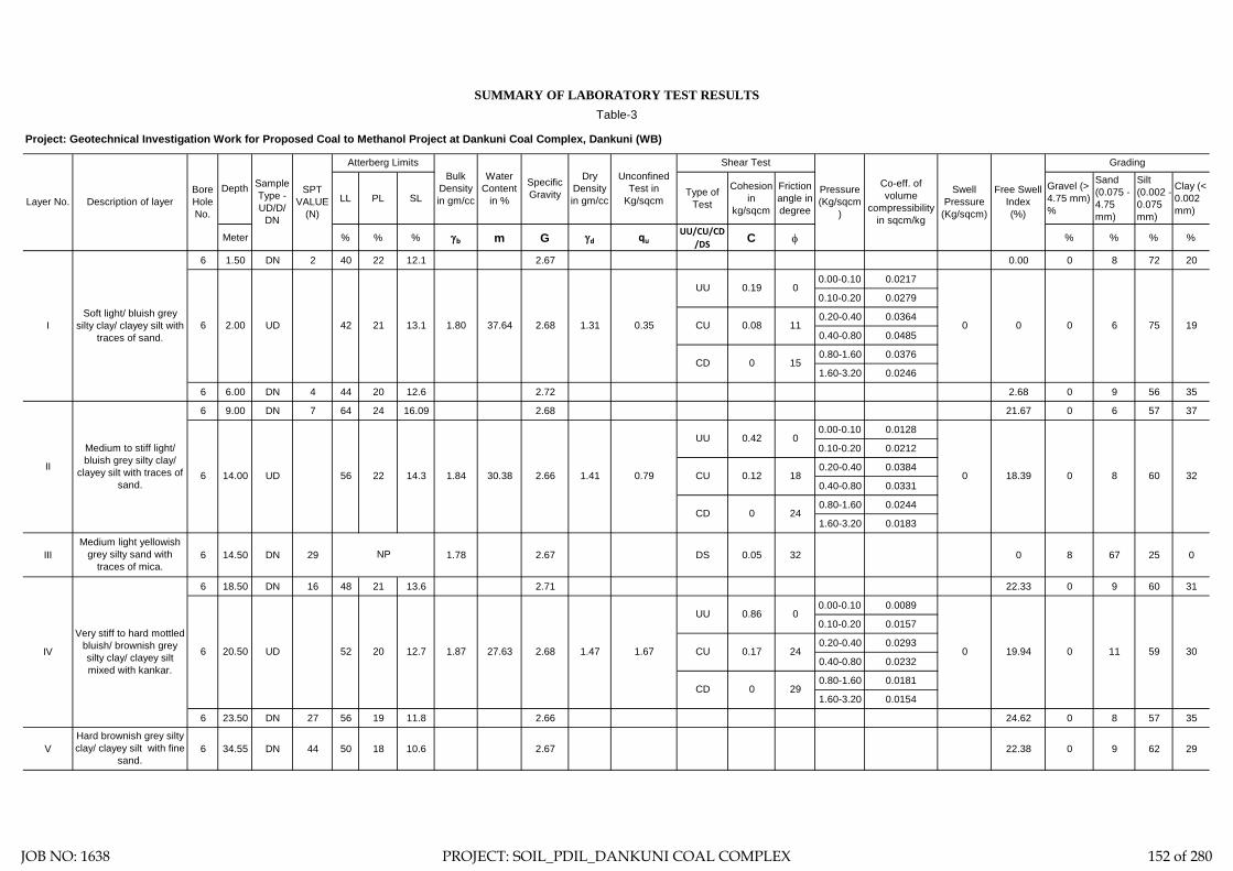
LL PL SL Type of Test
Cohesion in
kg/sqcm
Friction angle in degree
Gravel (> 4.75 mm) %
Sand (0.075 - 4.75 mm)
Silt (0.002 - 0.075 mm)
Clay (< 0.002 mm)
Meter % % % γb m G γd quUU/CU/CD
/DS C φ % % % %
6 1.50 DN 2 40 22 12.1 2.67 0.00 0 8 72 20
0.00-0.10 0.0217
0.10-0.20 0.0279
0.20-0.40 0.0364
0.40-0.80 0.0485
0.80-1.60 0.0376
1.60-3.20 0.0246
6 6.00 DN 4 44 20 12.6 2.72 2.68 0 9 56 35
6 9.00 DN 7 64 24 16.09 2.68 21.67 0 6 57 37
0.00-0.10 0.0128
0.10-0.20 0.0212
0.20-0.40 0.0384
0.40-0.80 0.0331
0.80-1.60 0.0244
1.60-3.20 0.0183
III 6 14.50 DN 29 1.78 2.67 DS 0.05 32 0 8 67 25 0
6 18.50 DN 16 48 21 13.6 2.71 22.33 0 9 60 31
0.00-0.10 0.0089
0.10-0.20 0.0157
0.20-0.40 0.0293
0.40-0.80 0.0232
0.80-1.60 0.0181
1.60-3.20 0.0154
6 23.50 DN 27 56 19 11.8 2.66 24.62 0 8 57 35
V 6 34.55 DN 44 50 18 10.6 2.67 22.38 0 9 62 29
Soft light/ bluish grey silty clay/ clayey silt with
traces of sand.I
Medium to stiff light/ bluish grey silty clay/
clayey silt with traces of sand.
II
Medium light yellowish grey silty sand with
traces of mica.
Very stiff to hard mottled bluish/ brownish grey silty clay/ clayey silt mixed with kankar.
IV 0 11
29
Hard brownish grey silty clay/ clayey silt with fine
sand.
NP
6 1.67
UU 0.86
CD 0
6 2.00 UD
6 14.00
0.08
0
11
UU
CU
20.50 UD 52 1.47
Grading
Layer No.Bore Hole No.
Sample Type - UD/D/
DN
SPT VALUE
(N)
Atterberg LimitsUnconfined
Test in Kg/sqcm
Pressure (Kg/sqcm
)
Dry Density in gm/cc
Swell Pressure
(Kg/sqcm)
Specific Gravity Free Swell
Index(%)
Bulk Density in gm/cc
Shear Test
42 21
SUMMARY OF LABORATORY TEST RESULTSTable-3
Depth Water
Content in %Description of layer
Co-eff. of volume
compressibility in sqcm/kg
Project: Geotechnical Investigation Work for Proposed Coal to Methanol Project at Dankuni Coal Complex, Dankuni (WB)
CD 0 15
13.1 1.80 37.64 2.68 1.31
0.19
1.41
190 0 0 6 750.35
CUUD 56 22
CD
14.3 1.84 30.38 2.66 0 60 320.79
UU 0.42 0
0.17 24
0.12
0 24
18.390
0
0 19.94 59 30
818
20 12.7 1.87 27.63 2.68 CU
JOB NO: 1638 PROJECT: SOIL_PDIL_DANKUNI COAL COMPLEX 152 of 280

SAMPLE CALCULATION
FOR PILE
FOUNDATION
JOB NO: 1638 PROJECT: SOIL_PDIL_DANKUNI COAL COMPLEX 153 of 280

Centre for Advanced Engineering
Pile Model Scale :- N.T.S.
Existing Ground Level.
γ = 1.80 T/M3
c = 1.90 T/M2φ = 0
I
II
7.50
M
III
γ = 1.84 T/M3
c = 4.20 T/M2φ = 0°
γ = 1.87 T/M3
c = 8.60 T/M2φ = 0°
Pile
Cut
-Off
Leve
l = 2
.00M
03Sketch No.-SK/PDIL/ DM PLANT AND STORAGE 1638
1.50
M
γ = 1.78 T/M3
c = 0φ = 32°
10.5
0MIV
V
γ = 1.92 T/M3
c = 11.0 T/M2φ = 0°
5.50
M4.
00M
Filled up with silty clay/ clayey silt, flyash, sand, stone cheaps etc.
Soft light/ bluish grey silty clay/ clayeysilt with traces of sand.
Medium light yellowish grey silty sandwith traces of mica.
Very stiff to hard mottled bluish/brownish grey silty clay/ clayey siltmixed with kankar.
Medium to stiff light/ bluish grey siltyclay/ clayey silt with traces of sand.
Hard brownish grey silty clay/ clayeysilt with fine sand.
JOB NO: 1638 PROJECT: SOIL_PDIL_DANKUNI COAL COMPLEX 154 of 280

Ultimate skin friction capacity
Location: DM Plant & Storage unit, Dankuni Coal Complex, West Bengal
Layer No: 1Soil Description Soft light/ bluish grey silty clay/ clayey silt with traces of sand.
Sl.N
o
Pile
Dia
, D
Tota
l Len
gth
of P
ile, L
Dep
th o
f lay
er to
p fro
m E
GL
Dep
th o
f lay
er b
otto
m fr
om E
GL
Red
uctio
n fa
ctor
, α (N
ote1
IS
2911
( Par
t1/S
ec2)
Aver
age
Coh
esio
n al
ong
the
leng
th
of th
e pi
le in
this
laye
r, C
Surfa
ce a
rea
of th
e pi
le s
haft
in th
is
laye
r, A s
Ulti
mat
e Sk
in fr
ictio
n ca
paci
ty o
f th
e sh
aft i
n th
is la
yer,
Qsu
=
α*C
*AS
Mtr Mtr. Mtr Mtr. T/M2 M2
1 0.400 32.000 2.000 9.000 1 1.9 8.796 16.7132 0.500 32.000 2.000 9.000 1 1.9 10.996 20.8923 0.550 32.000 2.000 9.000 1 1.9 12.095 22.9814 0.600 32.000 2.000 9.000 1 1.9 13.195 25.0705 0.750 32.000 2.000 9.000 1 1.9 16.493 31.3376 1.000 32.000 2.000 9.000 1 1.9 21.991 41.783
Project: Geotechnical Investigation Work for Proposed Coal to Methanol Project at Dankuni Coal Complex, Dankuni (WB)
JOB NO: 1638 PROJECT: SOIL_PDIL_DANKUNI COAL COMPLEX 155 of 280

Ultimate skin friction capacity
Location: DM Plant & Storage unit, Dankuni Coal Complex, West Bengal
Layer No: 2Soil Description Medium to stiff light/ bluish grey silty clay/ clayey silt with traces of sand.
Sl.N
o
Pile
Dia
, D
Tota
l Len
gth
of P
ile, L
Dep
th o
f lay
er to
p fro
m E
GL
Dep
th o
f lay
er b
otto
m fr
om E
GL
Red
uctio
n fa
ctor
, α (N
ote1
IS
2911
( Par
t1/S
ec2)
Aver
age
Coh
esio
n al
ong
the
leng
th
of th
e pi
le in
this
laye
r, C
Surfa
ce a
rea
of th
e pi
le s
haft
in th
is
laye
r, A s
Ulti
mat
e Sk
in fr
ictio
n ca
paci
ty o
f th
e sh
aft i
n th
is la
yer,
Qsu
=
α*C
*AS
Mtr Mtr. Mtr Mtr. T/M2 M2
1 0.400 32.000 9.000 14.500 1 4.2 6.912 29.0282 0.500 32.000 9.000 14.500 1 4.2 8.639 36.2853 0.550 32.000 9.000 14.500 1 4.2 9.503 39.9144 0.600 32.000 9.000 14.500 1 4.2 10.367 43.5425 0.750 32.000 9.000 14.500 1 4.2 12.959 54.4286 1.000 32.000 9.000 14.500 1 4.2 17.279 72.571
Project: Geotechnical Investigation Work for Proposed Coal to Methanol Project at Dankuni Coal Complex, Dankuni (WB)
JOB NO: 1638 PROJECT: SOIL_PDIL_DANKUNI COAL COMPLEX 156 of 280

Ultimate skin friction capacity
Layer No: 3
Soil Description :
Sl.N
o
Pile
Dia
, D
Tota
l Len
gth
of P
ile, L
Dep
th o
f lay
er to
p, fr
om E
GL
Dep
th o
f lay
er b
otto
m, f
rom
EG
L
Wat
er ta
ble
φφ
adop
ted
=(φ
-3)o co
nsid
erin
g lo
osen
ing
effe
ct
NC
Nq Nγ
Uni
t wei
ght,
γ
Effe
ctiv
e un
it w
eigh
t, γ'
k- V
alue
, as
per n
ote
3 IS
291
1 pa
rt 1/
Sec
2-19
79Li
miti
ng L
/D fo
r cal
cn. O
f max
m.
Effe
ctiv
e ov
erbu
rden
pre
ss. A
t pi
le ti
p
P Di a
t lay
er to
p
δ =
φ
Uni
t fric
tion,
f s =
K*P
di*ta
n δ -
at
laye
r top
, max
imum
= 1
0T/M
2
P Di a
t lay
er b
otto
m
Uni
t fric
tion,
f s =
K*P
di*ta
n δ -
at
laye
r bot
tom
, max
imum
= 1
0T/M
2
Aver
age
unit
frict
ion,
ado
pted
for
shaf
t fric
tion
capa
city
.
A Si
Shaf
t fric
tion,
F
Mtr
Mtr.
Mtr
Mtr.
Mtr.
Deg
ree
Deg
ree
T/M
3
T/M
3
T/M
2
Rad
ian
T/M
2
T/M
2
T/M
2
T/M
2
M2 T
1 0.400 32.000 14.500 18.500 1.000 32 29 27.86 16.44 19.34 1.78 0.78 1.3 15 4.68 0.51 3.372 4.68 3.372 3.372 5.027 16.9522 0.500 32.000 14.500 18.500 1.000 32 29 27.86 16.44 19.34 1.78 0.78 1.3 15 5.85 0.51 4.216 5.85 4.216 4.216 6.283 26.4873 0.550 32.000 14.500 18.500 1.000 32 29 27.86 16.44 19.34 1.78 0.78 1.3 15 6.435 0.51 4.637 6.435 4.637 4.637 6.912 32.0494 0.600 32.000 14.500 18.500 1.000 32 29 27.86 16.44 19.34 1.78 0.78 1.3 15 7.02 0.51 5.059 7.02 5.059 5.059 7.540 38.1415 0.750 32.000 14.500 18.500 1.000 32 29 27.86 16.44 19.34 1.78 0.78 1.3 15 8.775 0.51 6.323 8.775 6.323 6.323 9.425 59.5966 1.000 32.000 14.500 18.500 1.000 32 29 27.86 16.44 19.34 1.78 0.78 1.3 15 11.31 0.51 8.150 11.7 8.431 8.291 12.566 104.182
Project: Geotechnical Investigation Work for Proposed Coal to Methanol Project at Dankuni Coal Complex, Dankuni (WB)
Medium light yellowish grey silty sand with traces of mica.
Location: DM Plant & Storage unit, Dankuni Coal Complex, West Bengal
JOB NO: 1638 PROJECT: SOIL_PDIL_DANKUNI COAL COMPLEX 157 of 280

Ultimate skin friction capacity
Location: DM Plant & Storage unit, Dankuni Coal Complex, West Bengal
Layer No: 4Soil Description
Sl.N
o
Pile
Dia
, D
Tota
l Len
gth
of P
ile, L
Dep
th o
f lay
er to
p fro
m E
GL
Dep
th o
f lay
er b
otto
m fr
om E
GL
Red
uctio
n fa
ctor
, α (N
ote1
IS
2911
( Par
t1/S
ec2)
Aver
age
Coh
esio
n al
ong
the
leng
th
of th
e pi
le in
this
laye
r, C
Surfa
ce a
rea
of th
e pi
le s
haft
in th
is
laye
r, A s
Ulti
mat
e Sk
in fr
ictio
n ca
paci
ty o
f th
e sh
aft i
n th
is la
yer,
Qsu
=
α*C
*AS
Mtr Mtr. Mtr Mtr. T/M2 M2
1 0.400 32.000 18.500 29.000 0.55 8.6 13.195 62.4112 0.500 32.000 18.500 29.000 0.55 8.6 16.493 78.0143 0.550 32.000 18.500 29.000 0.55 8.6 18.143 85.8154 0.600 32.000 18.500 29.000 0.55 8.6 19.792 93.6165 0.750 32.000 18.500 29.000 0.55 8.6 24.740 117.0206 1.000 32.000 18.500 29.000 0.55 8.6 32.987 156.027
Project: Geotechnical Investigation Work for Proposed Coal to Methanol Project at Dankuni Coal Complex, Dankuni (WB)
Very stiff to hard mottled bluish/ brownish grey silty clay/ clayey silt mixed with kankar.
JOB NO: 1638 PROJECT: SOIL_PDIL_DANKUNI COAL COMPLEX 158 of 280

Ultimate skin friction capacity
Location: DM Plant & Storage unit, Dankuni Coal Complex, West Bengal
Layer No: 5Soil Description Hard brownish grey silty clay/ clayey silt with fine sand.
Sl.N
o
Pile
Dia
, D
Tota
l Len
gth
of P
ile, L
Dep
th o
f lay
er to
p fro
m E
GL
Dep
th o
f lay
er b
otto
m fr
om E
GL
Red
uctio
n fa
ctor
, α (N
ote1
IS
2911
( Par
t1/S
ec2)
Aver
age
Coh
esio
n al
ong
the
leng
th
of th
e pi
le in
this
laye
r, C
Surfa
ce a
rea
of th
e pi
le s
haft
in th
is
laye
r, A s
Ulti
mat
e Sk
in fr
ictio
n ca
paci
ty o
f th
e sh
aft i
n th
is la
yer,
Qsu
=
α*C
*AS
Mtr Mtr. Mtr Mtr. T/M2 M2
1 0.400 32.000 29.000 32.000 0.4 11.0 3.770 16.5882 0.500 32.000 29.000 32.000 0.4 11.0 4.712 20.7353 0.550 32.000 29.000 32.000 0.4 11.0 5.184 22.8084 0.600 32.000 29.000 32.000 0.4 11.0 5.655 24.8815 0.750 32.000 29.000 32.000 0.4 11.0 7.069 31.1026 1.000 32.000 29.000 32.000 0.4 11.0 9.425 41.469
Project: Geotechnical Investigation Work for Proposed Coal to Methanol Project at Dankuni Coal Complex, Dankuni (WB)
JOB NO: 1638 PROJECT: SOIL_PDIL_DANKUNI COAL COMPLEX 159 of 280

Ultimate End Bearing capacity
Location: DM Plant & Storage unit, Dankuni Coal Complex, West Bengal
Layer No: 5Soil Description Hard brownish grey silty clay/ clayey silt with fine sand.
Sl.N
o
Pile
Dia
, D
Tota
l Len
gth
of P
ile, L
Dep
th o
f lay
er to
p fro
m E
GL
Dep
th o
f lay
er b
otto
m fr
om E
GL
Aver
age
Coh
esio
n at
the
pile
tip,
C
P
Cro
ss s
ectio
nal a
rea
of th
e pi
le ti
p,
A P
Bear
ing
capa
city
fact
or, N
C
Ulti
mat
eEnd
bea
ring
capa
city
at
pile
tip,
QB u
= A
P*N
C*C
P
Mtr Mtr. Mtr Mtr. T/M2 M2 T1 0.400 32.000 29.000 32.000 11.0 0.126 9.000 12.4412 0.500 32.000 29.000 32.000 11.0 0.196 9.000 19.4393 0.550 32.000 29.000 32.000 11.0 0.238 9.000 23.5214 0.600 32.000 29.000 32.000 11.0 0.283 9.000 27.9925 0.750 32.000 29.000 32.000 11.0 0.442 9.000 43.7376 1.000 32.000 29.000 32.000 11.0 0.785 9.000 77.754
Project: Geotechnical Investigation Work for Proposed Coal to Methanol Project at Dankuni Coal Complex, Dankuni (WB)
JOB NO: 1638 PROJECT: SOIL_PDIL_DANKUNI COAL COMPLEX 160 of 280

Sample Calculation:-= 0.19 Kg/cm2
= 18.639 Kn/M2
= 32.00 Mtr.= 2.00 Mtr.= 0.400 Mtr.= 25 N/MM2
= 25000 MN/M2
= 0.00126 M4
= 31.5 KN/M6
= 1.069 MN/M3
T (Stiffness Factor) = 1.967 Mtr. [Where T = (EI/nh)1/5]
= 30.00 Mtr.
Hence, As per Table-5 pile is a LONG ELASTIC PILE Since Le>= 4T
= 0.000 Mtr.
= 2.200
= 4.327 Mtr.
Therefore, Lf = 4.327 Mtr.L1 = 0.000 Mtr.
For Fixed Head Pile, deflection at the pile head,
= 0.005 Mtr. (Adopt)
= 23.32 Kn
= 2.38 T
Where L1 = free head of Pile above ground
And for fixed head file Lf/T (as per IS Code)
Where Lf is the length of fixicity below cut-off level of pile =
Y =H(e+zf)3/12EILateral Load = H
Horizontal Shear Capacity = Hdesign
fckE=Econc=Young's modulas
I (Moment of inertia of the pile cross-section)
Neglecting the effect of steel we get EI
nh = Modulas of Subgrade Reaction (if top of the soil is clay) (Table3)
Le (Embeddment Length of the Pile)
Horizontal Shear Capacity of Pile
Reference : Code of Practice for Design and Construction of Pile Foundation - IS 2911 (Part1/Sec2)
C Value
L (Length of Pile)Cut-off Level of PileDia of Pile (D)
JOB NO: 1638 PROJECT: SOIL_PDIL_DANKUNI COAL COMPLEX 161 of 280

Recommended Pile Capacity
Location: DM Plant & Storage unit, Dankuni Coal Complex, West Bengal
Sl.N
o
Pile
Dia
, D
Tota
l Len
gth
of P
ile, L
Skin
fric
tion
from
laye
r 1
Skin
fric
tion
from
laye
r 2
Skin
fric
tion
from
laye
r 3
Skin
fric
tion
from
laye
r 4
Skin
fric
tion
from
laye
r 5
End
Bear
ing
Tota
l
F.O
.S
Allo
wab
le P
ile C
apac
ity
Rec
omm
emde
d Pi
le
Cap
acity
in
Com
pres
sion
Rec
omm
emde
d Pi
le
Cap
acity
in P
ull-O
ut
Rec
omm
emde
d Pi
le
Cap
acity
in H
oriz
onta
l Sh
ear
Mtr Mtr. T T T T T T T T T T T T1 0.400 32.000 16.713 29.028 16.952 62.411 16.588 12.441 154.132 2.5 61.653 61 56 2.382 0.500 32.000 20.892 36.285 26.487 78.014 20.735 19.439 201.851 2.5 80.740 80 72 2.603 0.550 32.000 22.981 39.914 32.049 85.815 22.808 23.521 227.087 2.5 90.835 90 81 2.694 0.600 32.000 25.070 43.542 38.141 93.616 24.881 27.992 253.243 2.5 101.297 101 90 2.795 0.750 32.000 31.337 54.428 59.596 117.020 31.102 43.737 337.220 2.5 134.888 134 117 3.056 1.000 32.000 41.783 72.571 104.182 156.027 41.469 77.754 493.786 2.5 197.515 197 166 3.42
Project: Geotechnical Investigation Work for Proposed Coal to Methanol Project at Dankuni Coal Complex, Dankuni (WB)
JOB NO: 1638 PROJECT: SOIL_PDIL_DANKUNI COAL COMPLEX 162 of 280

PLATE LOAD TEST
JOB NO: 1638 PROJECT: SOIL_PDIL_DANKUNI COAL COMPLEX 163 of 280

Calculation for Modulas of Subgrade Reaction (K) for PLT-1
From Load-Settlement curve of PLT-1, Pressure corresponding to settlement of 1.25mm is 0.28 Kg/Cm2.
Pressure/ Settlement.= 0.28/0.125 Kg/Cm3= 2.24 Kg/Cm3
Calculation for Modulas of Elasticity (Es) for PLT-1.
Modulas of Elasticity has been calculated for initial load of 4.20 T/M2 and corresponding settlement of 0.186 cm.
Es =
= {0.36*(1-0.32)*75*0.82}/0.121= 101.1 Kg/Cm2
Where, Modulas of Elasticity.0.42 Kg/Cm2
0.360 Cm0.80.2 Cm
(Kg/Cm3) (Kg/Cm2)
PLT-1 2 2.24 Kg/Cm3 101.1 Kg/Cm2
Test No.Depth of
Test
Modulas of Subgrade Reaction, K
Modulas of Elasticity, Es
(M)
µ = Poisson's Ratio = B = Least dimension of the plate =
Iw = Influence Factor =S = Settlement =
Modulas of Subgrade Reaction and Modulas of Elasticity, obtain from Plate Load Test.
q = Pressure =
Modulas of Subgrade Reaction and Modulas of Elasticity have been calculated for Plate Load Test as follows.
Hence, K =
{q*(1-µ2)*B*Iw} / S
Es =
JOB NO: 1638 PROJECT: SOIL_PDIL_DANKUNI COAL COMPLEX 164 of 280
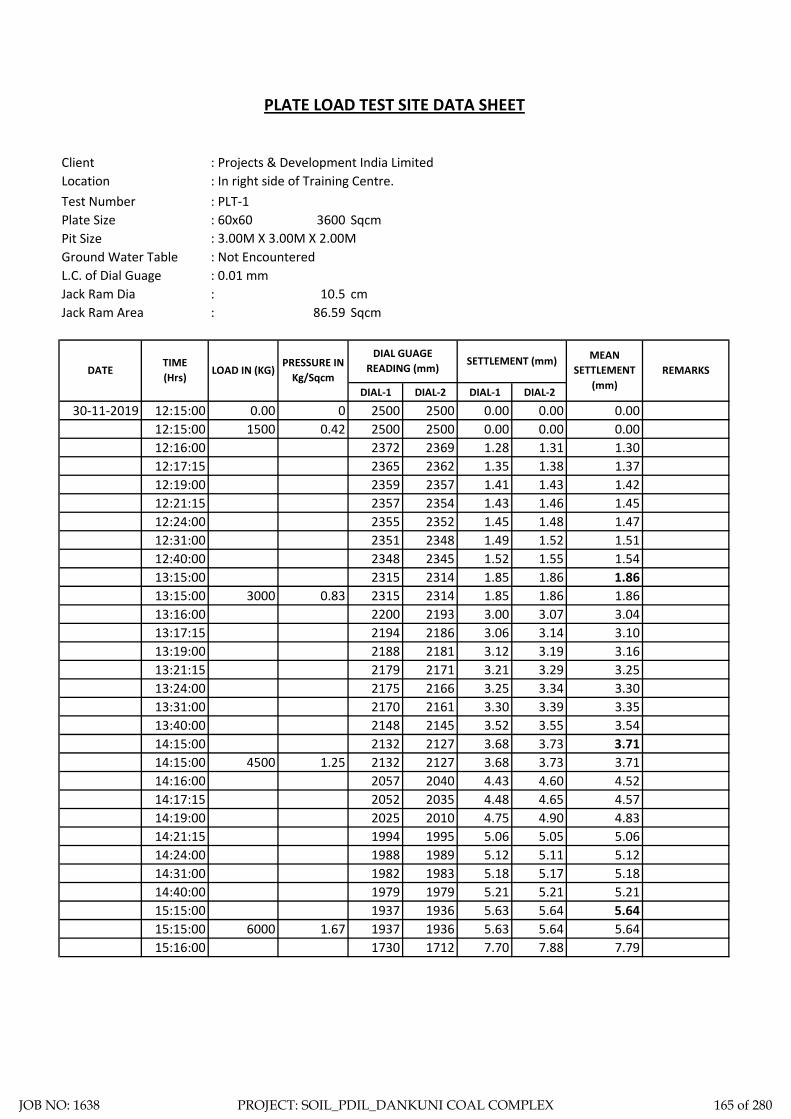
Client : Projects & Development India LimitedLocation : In right side of Training Centre.Test Number : PLT-1Plate Size : 60x60 3600 SqcmPit Size : 3.00M X 3.00M X 2.00MGround Water Table : Not EncounteredL.C. of Dial Guage : 0.01 mmJack Ram Dia : 10.5 cmJack Ram Area : 86.59 Sqcm
DIAL-1 DIAL-2 DIAL-1 DIAL-2
30-11-2019 12:15:00 0 2500 2500 0.00 0.00 0.0012:15:00 0.42 2500 2500 0.00 0.00 0.0012:16:00 2372 2369 1.28 1.31 1.3012:17:15 2365 2362 1.35 1.38 1.3712:19:00 2359 2357 1.41 1.43 1.4212:21:15 2357 2354 1.43 1.46 1.4512:24:00 2355 2352 1.45 1.48 1.4712:31:00 2351 2348 1.49 1.52 1.5112:40:00 2348 2345 1.52 1.55 1.5413:15:00 2315 2314 1.85 1.86 1.8613:15:00 0.83 2315 2314 1.85 1.86 1.8613:16:00 2200 2193 3.00 3.07 3.0413:17:15 2194 2186 3.06 3.14 3.1013:19:00 2188 2181 3.12 3.19 3.1613:21:15 2179 2171 3.21 3.29 3.2513:24:00 2175 2166 3.25 3.34 3.3013:31:00 2170 2161 3.30 3.39 3.3513:40:00 2148 2145 3.52 3.55 3.5414:15:00 2132 2127 3.68 3.73 3.7114:15:00 1.25 2132 2127 3.68 3.73 3.7114:16:00 2057 2040 4.43 4.60 4.5214:17:15 2052 2035 4.48 4.65 4.5714:19:00 2025 2010 4.75 4.90 4.8314:21:15 1994 1995 5.06 5.05 5.0614:24:00 1988 1989 5.12 5.11 5.1214:31:00 1982 1983 5.18 5.17 5.1814:40:00 1979 1979 5.21 5.21 5.2115:15:00 1937 1936 5.63 5.64 5.6415:15:00 1.67 1937 1936 5.63 5.64 5.6415:16:00 1730 1712 7.70 7.88 7.79
6000
4500
3000
0.001500
MEAN SETTLEMENT
(mm)REMARKS
PLATE LOAD TEST SITE DATA SHEET
DIAL GUAGE READING (mm)
SETTLEMENT (mm)DATE
TIME (Hrs)
PRESSURE IN Kg/Sqcm
LOAD IN (KG)
JOB NO: 1638 PROJECT: SOIL_PDIL_DANKUNI COAL COMPLEX 165 of 280

DIAL-1 DIAL-2 DIAL-1 DIAL-2
15:17:15 1725 1708 7.75 7.92 7.8415:19:00 1712 1696 7.88 8.04 7.9615:21:15 1098 1680 14.02 8.20 11.1115:24:00 1673 1651 8.27 8.49 8.3815:31:00 1659 1639 8.41 8.61 8.5115:40:00 1651 1631 8.49 8.69 8.5916:15:00 1638 1604 8.62 8.96 8.7916:15:00 2.08 1638 1604 8.62 8.96 8.7916:16:00 1365 1310 11.35 11.90 11.6316:17:15 1350 1300 11.50 12.00 11.7516:19:00 1341 1292 11.59 12.08 11.8416:21:15 1335 1286 11.65 12.14 11.9016:24:00 1314 1265 11.86 12.35 12.1116:31:00 1291 1244 12.09 12.56 12.3316:40:00 1266 1220 12.34 12.80 12.5717:15:00 1258 1210 12.42 12.90 12.6617:15:00 2.50 1258 1210 12.42 12.90 12.6617:16:00 1114 1131 13.86 13.69 13.7817:17:15 1009 1037 14.91 14.63 14.7717:19:00 906 936 15.94 15.64 15.7917:21:15 868 890 16.32 16.10 16.2117:24:00 827 850 16.73 16.50 16.6217:31:00 802 819 16.98 16.81 16.9017:40:00 798 803 17.02 16.97 17.0018:15:00 792 799 17.08 17.01 17.0518:15:00 2.92 792 799 17.08 17.01 17.0518:16:00 777 783 17.23 17.17 17.2018:17:15 658 604 18.42 18.96 18.6918:19:00 588 537 19.12 19.63 19.3818:21:15 507 489 19.93 20.11 20.0218:24:00 457 474 20.43 20.26 20.3518:31:00 420 450 20.80 20.50 20.6518:40:00 414 442 20.86 20.58 20.7219:15:00 410 438 20.90 20.62 20.7619:15:00 3.33 410 438 20.90 20.62 20.7619:16:00 318 392 21.82 21.08 21.4519:17:15 224 244 22.76 22.56 22.6619:19:00 107 116 23.93 23.84 23.8919:21:15 57 88 24.43 24.12 24.2819:24:00 30 54 24.70 24.46 24.5819:31:00 18 29 24.82 24.71 24.7719:40:00 0 12 25.00 24.88 24.9420:15:00 0 0 25.00 25.00 25.00
10500
PRESSURE IN Kg/Sqcm
DIAL GUAGE READING (mm)
SETTLEMENT (mm) MEAN SETTLEMENT
(mm)REMARKSDATE
TIME (Hrs)
LOAD IN (KG)
7500
9000
12000
JOB NO: 1638 PROJECT: SOIL_PDIL_DANKUNI COAL COMPLEX 166 of 280

Load Vs Settlement Curve for PLT-1
0.00
5.00
10.00
15.00
20.00
25.00
30.00
0.00 5.00 10.00 15.00 20.00 25.00 30.00 35.00
Sett
lem
ent i
n M
M
Load in T/Sq.M
13.90
Qu = 13.90 T/Sq.M
JOB NO: 1638 PROJECT: SOIL_PDIL_DANKUNI COAL COMPLEX 167 of 280

ELECTRICAL
RESISTIVITY TEST
JOB NO: 1638 PROJECT: SOIL_PDIL_DANKUNI COAL COMPLEX 168 of 280

: Geotechnical Investigation Work for Proposed Coal to Methanol Project at Dankuni Coal Complex, Dankuni (WB): Dankuni Coal Complex, Dankuni, WB: Project & Development India Limited: 21-12-2019: Metravi ERT-1501, SL. No.: 10109809
1 1.0 42 42 42 42 42 42 42 42 263.89 263.89 263.89 263.89 263.89 263.89 263.89 263.89 2 2.0 43 43 43 43 43 43 43 43 540.35 540.35 540.35 540.35 540.35 540.35 540.35 540.35 3 5.0 42 42 42 42 42 42 42 42 1,319.47 1,319.47 1,319.47 1,319.47 1,319.47 1,319.47 1,319.47 1,319.47 4 10.05 15.06 20.0 Space Not Available
South South-West West North-WestWest North-West
North North-East East East-South
Space Not AvailableSpace Not Available
Sl. No.
Electrode Spacing 's'
m
Measured Resistance "R" (Ω) Apparent Resistivity "ρ" (Ω-m")
North North-East
East East-South
South South-West
Instrument
Table ERT - 3ProjectLocation of siteClient Test Date
JOB NO: 1638 PROJECT: SOIL_PDIL_DANKUNI COAL COMPLEX 169 of 280

Electrode Spacing - 1.00MR = 42.00 ohm, Resistivity = 263.89 Ohm-m
Location - ERT-3 Location - ERT-3
Electrode Spacing - 2.00MR = 43.00 ohm, Resistivity = 540.35 Ohm-m
Location - ERT-3
Electrode Spacing - 5.00MR = 42.00 ohm, Resistivity = 1319.47 Ohm-m
JOB NO: 1638 PROJECT: SOIL_PDIL_DANKUNI COAL COMPLEX 170 of 280

ZONE-8
COAL STORAGE
AREA INCLUDING
CRUSHER
JOB NO: 1638 PROJECT: SOIL_PDIL_DANKUNI COAL COMPLEX 171 of 280

Total one (1) borehole was sunk in this area, viz borehole marked BH-1. From the general sub soil profile it has been observed that the top soil is heterogeneous fill with coal dust etc. followed by first layer of soft brownish grey silty clay/ clayey silt. The second layer is medium to stiff bluish grey silty clay/ clayey silt. The third layer consists of stiff to very stiff mottled bluish/ brownish grey silty clay/ clayey silt. The fourth layer is hard mottled bluish/ brownish grey silty clay/ clayey silt and the fifth layer as encountered up to the explored depth is dense brownish grey silty sand.
In addition the following field tests have been carried out at this zone and results are being indicated in this chapter.
1. Electrical Resistivity Test: One (1) electrical resistivity tests has been carried out at this zone marked as ERT-1.
Discussion and Recommendation:
Based on the subsoil condition pile foundation has been recommended for foundation system of medium to heavily loaded structures. Pile capacities in compression, pull-out and horizontal shear for different diameter of pile are indicated in the Table-2A (Zone-8). It is further recommended to carry out initial pile load test for load under compression, pull-out and horizontal shear, in order to confirm the recommended pile capacities and to take corrective measures, if required.
JOB NO: 1638 PROJECT: SOIL_PDIL_DANKUNI COAL COMPLEX 172 of 280

Table-2A (Zone-8). Recommended Pile Capacity
Sl.N
o
Pile
Dia
, D
Tota
l Len
gth
of P
ile, L
Cut
-off
Leve
l
Rec
omm
ende
d Pi
le
Cap
acity
in C
ompr
essi
on
Rec
omm
ende
d Pi
le
Cap
acity
in P
ull-O
ut
Rec
omm
ende
d Pi
le
Cap
acity
in H
oriz
onta
l Sh
ear
Mtr Mtr. Mtr. T T T
1 0.400 34.000 2.000 71 65 2.73
2 0.500 34.000 2.000 93 83 2.99
3 0.550 34.000 2.000 105 92 3.10
4 0.600 34.000 2.000 118 100 3.21
5 0.750 34.000 2.000 162 128 3.51
6 1.000 34.000 2.000 256 175 3.94
JOB NO: 1638 PROJECT: SOIL_PDIL_DANKUNI COAL COMPLEX 173 of 280
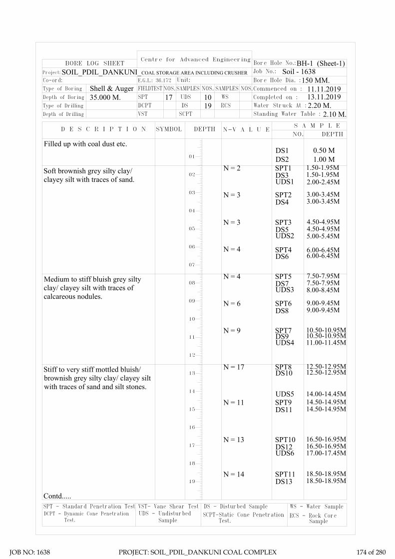
DS - Disturbed SampleSCPT-Static Cone Penetration DCPT - Dynamic Cone Penetration
SPT - Standard Penetration Test VST- Vane Shear TestUDS - Undisturbed
Test. Sample Test.
WS - Water Sample
RCS - Rock Core Sample
Centre for Advanced Engineering
N-V A L U E
19 RCSDSDCPTDepth of Drilling
Type of Drilling
D E S C R I P T I O N
VST SCPT
SYMBOL DEPTH
Co-ord: Type of Boring
Depth of Boring
Project:
FIELDTESTE.G.L.: 36.172
SPT35.000 M.Shell & Auger
BORE LOG SHEET
SAMPLESNOS.Unit:
UDS17 10NOS.
WSSAMPLES
2.20 M.Water Struck At :
2.10 M.S A M P L E
DEPTH
Standing Water Table :
NO.
Bore Hole No.:
Soil - 1638
Commenced on : Bore Hole Dia. :
Completed on :
Job No.:
NOS.150 MM.
BH-1 (Sheet-1)
11.11.201913.11.2019
01DS1 0.50 M
N = 2 1.50-1.95MDS3SPT1
1.50-1.95M
N = 4 7.50-7.95MDS7SPT5
7.50-7.95M
N = 9 10.50-10.95MDS9SPT7
10.50-10.95MUDS4 11.00-11.45M
N = 3 3.00-3.45MDS4SPT2
3.00-3.45M
N = 4 6.00-6.45MDS6SPT4
6.00-6.45M
UDS3 8.00-8.45M
N = 6 9.00-9.45MDS8SPT6
9.00-9.45M
UDS5 14.00-14.45MN = 11 14.50-14.95M
DS11SPT9
14.50-14.95M
UDS2 5.00-5.45M
N = 17 12.50-12.95MDS10SPT8
12.50-12.95M
N = 13 16.50-16.95MDS12SPT10
16.50-16.95M
N = 14 18.50-18.95MDS13SPT11
18.50-18.95M
UDS6 17.00-17.45M
SOIL_PDIL_DANKUNI_COAL STORAGE AREA INCLUDING CRUSHER
02
03
04
05
06
07
08
09
10
11
12
13
14
15
16
17
18
19
DS2 1.00 M
N = 3 4.50-4.95MDS5SPT3
4.50-4.95M
Filled up with coal dust etc.
Soft brownish grey silty clay/clayey silt with traces of sand.
Contd.....
UDS1 2.00-2.45M
Medium to stiff bluish grey siltyclay/ clayey silt with traces ofcalcareous nodules.
Stiff to very stiff mottled bluish/brownish grey silty clay/ clayey siltwith traces of sand and silt stones.
JOB NO: 1638 PROJECT: SOIL_PDIL_DANKUNI COAL COMPLEX 174 of 280

2.20 M.2.10 M.
150 MM.
BH-1 (Sheet-1)
11.11.201913.11.2019
DS - Disturbed SampleSCPT-Static Cone Penetration DCPT - Dynamic Cone Penetration
SPT - Standard Penetration Test VST- Vane Shear TestUDS - Undisturbed
Test. Sample Test.
WS - Water Sample
RCS - Rock Core Sample
Centre for Advanced Engineering
N-V A L U E
19 RCSDSDCPTDepth of Drilling
Type of Drilling
D E S C R I P T I O N
VST SCPT
SYMBOL DEPTH
Co-ord: Type of Boring
Depth of Boring
Project:
FIELDTESTE.G.L.: 36.172
SPT35.000 M.Shell & Auger
BORE LOG SHEET
SAMPLESNOS.Unit:
UDS17 10NOS.
WSSAMPLES
2.20 M.Water Struck At :
2.10 M.S A M P L E
DEPTH
Standing Water Table :
NO.
Bore Hole No.:
Soil - 1638
Commenced on : Bore Hole Dia. :
Completed on :
Job No.:
NOS.150 MM.
11.11.201913.11.2019
Termination Depth 35.000 Mtr.
21
22
23
24
25
26
27
28
29
30
31
32
33
34
35
36
37
38
39
UDS7 20.00-20.45MN = 14 20.50-20.95M
DS14SPT12
20.50-20.95M
UDS8 23.00-23.45MN = 15 23.50-23.95M
DS15SPT13
23.50-23.95M
UDS9 26.00-26.45M
UDS10 29.00-29.45M
N = 16 26.50-26.95MDS16SPT14
26.50-26.95M
N = 42 29.50-29.95MDS17SPT15
29.50-29.95M
N = 48 32.50-32.95MDS18SPT16
32.50-32.95M
N = 47 34.55-35.00MDS19SPT17
34.55-35.00M
BH-1 (Sheet-2)
Dense brownish grey silty sand.
SOIL_PDIL_DANKUNI_COAL STORAGE AREA INCLUDING CRUSHER
Stiff to very stiff mottled bluish/brownish grey silty clay/ clayey siltwith traces of sand and silt stones.
Hard mottled bluish/ brownish greysilty clay/ clayey silt with traces ofsand and silt stones.
JOB NO: 1638 PROJECT: SOIL_PDIL_DANKUNI COAL COMPLEX 175 of 280
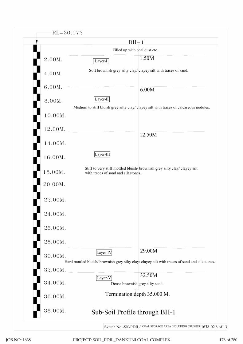
Sub-Soil Profile through BH-1
02
24.00M.
12.00M.
18.00M.
20.00M.
22.00M.
14.00M.
16.00M.
6.00M.
10.00M.
8.00M.
2.00M.
4.00M.
Sketch No.-SK/PDIL/ COAL STORAGE AREA INCLUDING CRUSHER 1638 8 of 13
Termination depth 35.000 M.
BH-1
RL=36.172
26.00M.
28.00M.
30.00M.
32.00M.
34.00M.
36.00M.
38.00M.
1.50MLayer-I
Layer-II
Layer-III
Layer-IV
Layer-V
6.00M
12.50M
29.00M
32.50M
Filled up with coal dust etc.
Soft brownish grey silty clay/ clayey silt with traces of sand.
Medium to stiff bluish grey silty clay/ clayey silt with traces of calcareous nodules.
Stiff to very stiff mottled bluish/ brownish grey silty clay/ clayey siltwith traces of sand and silt stones.
Dense brownish grey silty sand.
Hard mottled bluish/ brownish grey silty clay/ clayey silt with traces of sand and silt stones.
JOB NO: 1638 PROJECT: SOIL_PDIL_DANKUNI COAL COMPLEX 176 of 280

LL PL SL Type of Test
Cohesion in
kg/sqcm
Friction angle in degree
Gravel (> 4.75 mm) %
Sand (0.075 - 4.75 mm)
Silt (0.002 - 0.075 mm)
Clay (< 0.002 mm)
Meter % % % γb m G γd quUU/CU/CD
/DS C φ % % % %
1 1.50 DN 2 55 24 14 8.90 0 8 63 29
0.00-0.10 0.0154
0.10-0.20 0.0229
0.20-0.40 0.0364
0.40-0.80 0.0289
0.80-1.60 0.0248
1.60-3.20 0.0173
1 7.50 DN 4 61 19 12.2 2.71 36 0 6 54 40
1 10.50 DN 9 52 21 13.4 2.68 15 5 9 58 28
0.00-0.10 0.0137
0.10-0.20 0.0209
0.20-0.40 0.0357
0.40-0.80 0.0277
0.80-1.60 0.0239
1.60-3.20 0.0164
1 12.50 DN 17 56 19 11.2 2.61 10.4 0 7 58 35
1 16.50 DN 13 51 21 13.3 2.67 11.3 0 9 61 30
0.00-0.10 0.0127
0.10-0.20 0.0203
0.20-0.40 0.0349
0.40-0.80 0.0268
0.80-1.60 0.0231
1.60-3.20 0.0154
1 20.50 DN 14 63 22 13.6 2.67 8.70 0 10 52 38
1 26.50 DN 16 45 19 10.4 2.66 8.30 0 16 60 24
V 1 32.50 DN 48 1.80 2.65 DS 0 34 0.00 0 98 2 0
I
II
Medium to stiff bluish grey silty clay/ clayey silt
with traces of calcareous nodules.
Stiff to very stiff mottled bluish/ brownish grey
silty clay/ clayey silt with traces of sand and silt
stones.
III
Dense brownish grey silty sand.
0.15 23 61 31
NP
Soft brownish grey silty clay/ clayey silt with
traces of sand.
20 13 1.90 27.28 2.66 CU
0 25
14.4 2 1019 57 310.72
UU 0.38 0
0CU 0.1353 20
CD
13.8 1.86 29.27 2.67 1.44
300 12.6 0 9 610.46
CD 0 18
13.5 1.82 33.62 2.67 1.3652 22
SUMMARY OF LABORATORY TEST RESULTSTable-3
Depth Water
Content in %Description of layer
Co-eff. of volume
compressibility in sqcm/kg
Project: Geotechnical Investigation Work for Proposed Coal to Methanol Project at Dankuni Coal Complex, Dankuni (WB)
Swell Pressure
(Kg/sqcm)
Specific Gravity Free Swell
Index(%)
Bulk Density in gm/cc
Shear Test Grading
Layer No.Bore Hole No.
Sample Type - UD/D/
DN
SPT VALUE
(N)
Atterberg LimitsUnconfined
Test in Kg/sqcm
Pressure (Kg/sqcm
)
Dry Density
in gm/cc
0.24
0.08
0
12
UU
CU1 5.00 UD
1 11.00 UD
8
30
1.49 1.18
UU 0.62
CD 0
1
0
0 9.5 017.00 UD 53
JOB NO: 1638 PROJECT: SOIL_PDIL_DANKUNI COAL COMPLEX 177 of 280

SAMPLE CALCULATION
FOR PILE
FOUNDATION
JOB NO: 1638 PROJECT: SOIL_PDIL_DANKUNI COAL COMPLEX 178 of 280

Centre for Advanced Engineering
Pile Model Scale :- N.T.S.
Existing Ground Level.
γ = 1.82 T/M3
c = 2.40 T/M2φ = 0
I
II
6.00
M
III
γ = 1.86 T/M3
c = 3.80 T/M2φ = 0
γ = 1.92 T/M3
c = 10.50 T/M2φ = 0
Pile
Cut
-Off
Leve
l = 2
.00M
1.50
Mγ = 1.90 T/M3
c = 6.20 T/M2φ = 0
16.5
0M
IV
Vγ = 1.80 T/M3
c = 0φ = 34°
5.00
M3.
50M
Filled up with coal dust etc.
Soft brownish grey silty clay/ clayeysilt with traces of sand.
Medium to stiff bluish grey silty clay/clayey silt with traces of calcareousnodules.
Stiff to very stiff mottled bluish/brownish grey silty clay/ clayey siltwith traces of sand and silt stones.
Dense brownish grey silty sand.
Hard mottled bluish/ brownish grey siltyclay/ clayey silt with traces of sand andsilt stones.
03Sketch No.-SK/PDIL/ COAL STORAGE AREA INCLUDING CRUSHER 1638
JOB NO: 1638 PROJECT: SOIL_PDIL_DANKUNI COAL COMPLEX 179 of 280
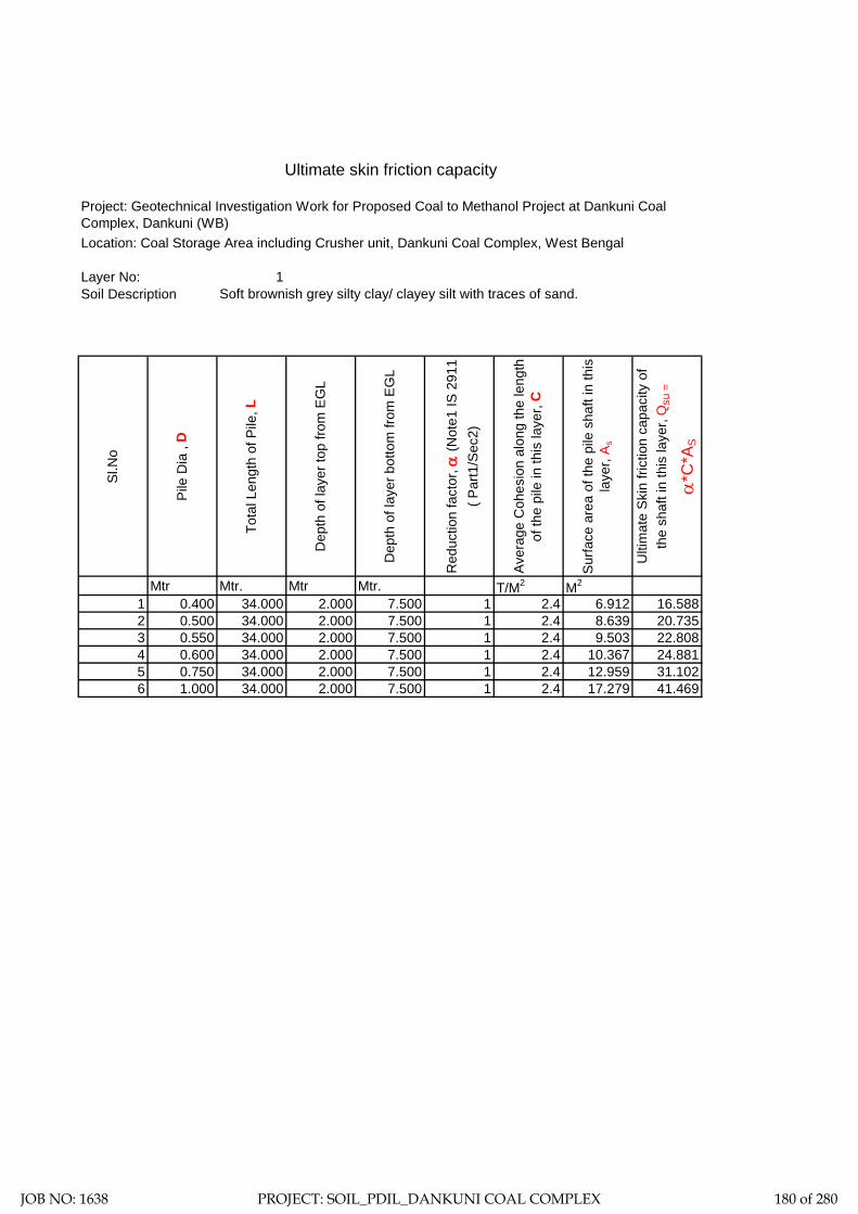
Ultimate skin friction capacity
Location: Coal Storage Area including Crusher unit, Dankuni Coal Complex, West Bengal
Layer No: 1Soil Description
Sl.N
o
Pile
Dia
, D
Tota
l Len
gth
of P
ile, L
Dep
th o
f lay
er to
p fro
m E
GL
Dep
th o
f lay
er b
otto
m fr
om E
GL
Red
uctio
n fa
ctor
, α (N
ote1
IS 2
911
( Par
t1/S
ec2)
Aver
age
Coh
esio
n al
ong
the
leng
th
of th
e pi
le in
this
laye
r, C
Surfa
ce a
rea
of th
e pi
le s
haft
in th
is
laye
r, A s
Ulti
mat
e Sk
in fr
ictio
n ca
paci
ty o
f th
e sh
aft i
n th
is la
yer,
Qsu
=
α*C
*AS
Mtr Mtr. Mtr Mtr. T/M2 M2
1 0.400 34.000 2.000 7.500 1 2.4 6.912 16.5882 0.500 34.000 2.000 7.500 1 2.4 8.639 20.7353 0.550 34.000 2.000 7.500 1 2.4 9.503 22.8084 0.600 34.000 2.000 7.500 1 2.4 10.367 24.8815 0.750 34.000 2.000 7.500 1 2.4 12.959 31.1026 1.000 34.000 2.000 7.500 1 2.4 17.279 41.469
Project: Geotechnical Investigation Work for Proposed Coal to Methanol Project at Dankuni Coal Complex, Dankuni (WB)
Soft brownish grey silty clay/ clayey silt with traces of sand.
JOB NO: 1638 PROJECT: SOIL_PDIL_DANKUNI COAL COMPLEX 180 of 280

Ultimate skin friction capacity
Location: Coal Storage Area including Crusher unit, Dankuni Coal Complex, West Bengal
Layer No: 2Soil Description
Sl.N
o
Pile
Dia
, D
Tota
l Len
gth
of P
ile, L
Dep
th o
f lay
er to
p fro
m E
GL
Dep
th o
f lay
er b
otto
m fr
om E
GL
Red
uctio
n fa
ctor
, α (N
ote1
IS
2911
( Par
t1/S
ec2)
Aver
age
Coh
esio
n al
ong
the
leng
th
of th
e pi
le in
this
laye
r, C
Surfa
ce a
rea
of th
e pi
le s
haft
in th
is
laye
r, A s
Ulti
mat
e Sk
in fr
ictio
n ca
paci
ty o
f th
e sh
aft i
n th
is la
yer,
Qsu
=
α*C
*AS
Mtr Mtr. Mtr Mtr. T/M2 M2
1 0.400 34.000 7.500 12.500 1 3.8 6.283 23.8762 0.500 34.000 7.500 12.500 1 3.8 7.854 29.8453 0.550 34.000 7.500 12.500 1 3.8 8.639 32.8304 0.600 34.000 7.500 12.500 1 3.8 9.425 35.8145 0.750 34.000 7.500 12.500 1 3.8 11.781 44.7686 1.000 34.000 7.500 12.500 1 3.8 15.708 59.690
Project: Geotechnical Investigation Work for Proposed Coal to Methanol Project at Dankuni Coal Complex, Dankuni (WB)
Medium to stiff bluish grey silty clay/ clayey silt with traces of calcareous nodules.
JOB NO: 1638 PROJECT: SOIL_PDIL_DANKUNI COAL COMPLEX 181 of 280
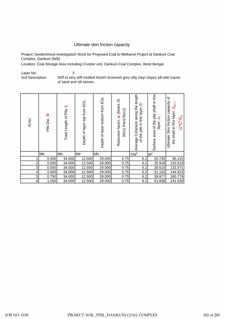
Ultimate skin friction capacity
Location: Coal Storage Area including Crusher unit, Dankuni Coal Complex, West Bengal
Layer No: 3Soil Description
Sl.N
o
Pile
Dia
, D
Tota
l Len
gth
of P
ile, L
Dep
th o
f lay
er to
p fro
m E
GL
Dep
th o
f lay
er b
otto
m fr
om E
GL
Red
uctio
n fa
ctor
, α (N
ote1
IS
2911
( Par
t1/S
ec2)
Aver
age
Coh
esio
n al
ong
the
leng
th
of th
e pi
le in
this
laye
r, C
Surfa
ce a
rea
of th
e pi
le s
haft
in th
is
laye
r, A s
Ulti
mat
e Sk
in fr
ictio
n ca
paci
ty o
f th
e sh
aft i
n th
is la
yer,
Qsu
=
α*C
*AS
Mtr Mtr. Mtr Mtr. T/M2 M2
1 0.400 34.000 12.500 29.000 0.75 6.2 20.735 96.4152 0.500 34.000 12.500 29.000 0.75 6.2 25.918 120.5193 0.550 34.000 12.500 29.000 0.75 6.2 28.510 132.5714 0.600 34.000 12.500 29.000 0.75 6.2 31.102 144.6235 0.750 34.000 12.500 29.000 0.75 6.2 38.877 180.7796 1.000 34.000 12.500 29.000 0.75 6.2 51.836 241.039
Project: Geotechnical Investigation Work for Proposed Coal to Methanol Project at Dankuni Coal Complex, Dankuni (WB)
Stiff to very stiff mottled bluish/ brownish grey silty clay/ clayey silt with traces of sand and silt stones.
JOB NO: 1638 PROJECT: SOIL_PDIL_DANKUNI COAL COMPLEX 182 of 280

Ultimate skin friction capacity
Location: Coal Storage Area including Crusher unit, Dankuni Coal Complex, West Bengal
Layer No: 4Soil Description
Sl.N
o
Pile
Dia
, D
Tota
l Len
gth
of P
ile, L
Dep
th o
f lay
er to
p fro
m E
GL
Dep
th o
f lay
er b
otto
m fr
om E
GL
Red
uctio
n fa
ctor
, α (N
ote1
IS
2911
( Par
t1/S
ec2)
Aver
age
Coh
esio
n al
ong
the
leng
th
of th
e pi
le in
this
laye
r, C
Surfa
ce a
rea
of th
e pi
le s
haft
in th
is
laye
r, A s
Ulti
mat
e Sk
in fr
ictio
n ca
paci
ty o
f th
e sh
aft i
n th
is la
yer,
Qsu
=
α*C
*AS
Mtr Mtr. Mtr Mtr. T/M2 M2
1 0.400 34.000 29.000 32.500 0.45 10.5 4.398 20.7822 0.500 34.000 29.000 32.500 0.45 10.5 5.498 25.9773 0.550 34.000 29.000 32.500 0.45 10.5 6.048 28.5754 0.600 34.000 29.000 32.500 0.45 10.5 6.597 31.1725 0.750 34.000 29.000 32.500 0.45 10.5 8.247 38.9666 1.000 34.000 29.000 32.500 0.45 10.5 10.996 51.954
Project: Geotechnical Investigation Work for Proposed Coal to Methanol Project at Dankuni Coal Complex, Dankuni (WB)
Hard mottled bluish/ brownish grey silty clay/ clayey silt with traces of sand and silt stones.
JOB NO: 1638 PROJECT: SOIL_PDIL_DANKUNI COAL COMPLEX 183 of 280

Ultimate skin friction capacity
Layer No: 5
Soil Description :
Sl.N
o
Pile
Dia
, D
Tota
l Len
gth
of P
ile, L
Dep
th o
f lay
er to
p, fr
om E
GL
Dep
th o
f lay
er b
otto
m, f
rom
EG
L
Wat
er ta
ble
φφ
adop
ted
=(φ
-3)o co
nsid
erin
g lo
osen
ing
effe
ct
NC
Nq Nγ
Uni
t wei
ght,
γ
Effe
ctiv
e un
it w
eigh
t, γ'
k- V
alue
, as
per n
ote
3 IS
291
1 pa
rt 1/
Sec
2-19
79Li
miti
ng L
/D fo
r cal
cn. O
f max
m.
Effe
ctiv
e ov
erbu
rden
pre
ss. A
t pi
le ti
p
P Di a
t lay
er to
p
δ =
φ
Uni
t fric
tion,
f s =
K*P
di*ta
n δ -
at
laye
r top
, max
imum
= 1
0T/M
2
P Di a
t lay
er b
otto
m
Uni
t fric
tion,
f s =
K*P
di*ta
n δ -
at
laye
r bot
tom
, max
imum
= 1
0T/M
2
Aver
age
unit
frict
ion,
ado
pted
for
shaf
t fric
tion
capa
city
.
A Si
Shaf
t fric
tion,
F
Mtr
Mtr.
Mtr
Mtr.
Mtr.
Deg
ree
Deg
ree
T/M
3
T/M
3
T/M
2
Rad
ian
T/M
2
T/M
2
T/M
2
T/M
2
M2 T
1 0.400 34.000 32.500 34.000 1.000 34 31 32.67 20.63 25.99 1.80 0.8 1.3 15 4.8 0.54 3.749 4.8 3.749 3.749 1.885 7.0672 0.500 34.000 32.500 34.000 1.000 34 31 32.67 20.63 25.99 1.80 0.8 1.3 15 6 0.54 4.687 6 4.687 4.687 2.356 11.0433 0.550 34.000 32.500 34.000 1.000 34 31 32.67 20.63 25.99 1.80 0.8 1.3 15 6.6 0.54 5.155 6.6 5.155 5.155 2.592 13.3624 0.600 34.000 32.500 34.000 1.000 34 31 32.67 20.63 25.99 1.80 0.8 1.3 15 7.2 0.54 5.624 7.2 5.624 5.624 2.827 15.9025 0.750 34.000 32.500 34.000 1.000 34 31 32.67 20.63 25.99 1.80 0.8 1.3 15 9 0.54 7.030 9 7.030 7.030 3.534 24.8466 1.000 34.000 32.500 34.000 1.000 34 31 32.67 20.63 25.99 1.80 0.8 1.3 15 12 0.54 9.373 12 9.373 9.373 4.712 44.171
Project: Geotechnical Investigation Work for Proposed Coal to Methanol Project at Dankuni Coal Complex, Dankuni (WB)
Location: Coal Storage Area including Crusher unit, Dankuni Coal Complex, West Bengal
Dense brownish grey silty sand.
JOB NO: 1638 PROJECT: SOIL_PDIL_DANKUNI COAL COMPLEX 184 of 280

Location: Coal Storage Area including Crusher unit, Dankuni Coal Complex, West Bengal
Layer No: 5
Sl.N
o
Pile
Dia
, D
Tota
l Len
gth
of P
ile, L
Dep
th o
f lay
er to
p, fr
om E
GL
Dep
th o
f lay
er b
otto
m, f
rom
EG
L
Wat
er ta
ble
φ
φ ad
opte
d =(
φ -3
)o cons
ider
ing
loos
enin
g ef
fect
NC
Nq Nγ
Uni
t wei
ght, γ
Effe
ctiv
e un
it w
eigh
t, γ'
Lim
iting
L/D
for c
alcn
. Of m
axm
. Ef
fect
ive
over
burd
en p
ress
. At
pile
tip
P Di a
t pile
tip
A P
End
Bear
ing
Mtr Mtr. Mtr Mtr. Mtr.
Deg
ree
Degree T/M3 T/M3 M2 T
1 0.400 34.000 32.500 34.000 0.000 34 31 32.67 20.63 25.99 1.8 0.8 15 4.8 0.126 12.9672 0.500 34.000 32.500 34.000 0.000 34 31 32.67 20.63 25.99 1.8 0.8 15 6 0.196 25.3263 0.550 34.000 32.500 34.000 0.000 34 31 32.67 20.63 25.99 1.8 0.8 15 6.6 0.238 33.7094 0.600 34.000 32.500 34.000 0.000 34 31 32.67 20.63 25.99 1.8 0.8 15 7.2 0.283 43.7635 0.750 34.000 32.500 34.000 0.000 34 31 32.67 20.63 25.99 1.8 0.8 15 9 0.442 85.4756 1.000 34.000 32.500 34.000 0.000 34 31 32.67 20.63 25.99 1.8 0.8 15 12 0.785 202.607
Ultimate end bearing capacity
Project: Geotechnical Investigation Work for Proposed Coal to Methanol Project at Dankuni Coal Complex, Dankuni (WB)
Soil Description : Dense brownish grey silty sand.
JOB NO: 1638 PROJECT: SOIL_PDIL_DANKUNI COAL COMPLEX 185 of 280

Sample Calculation:-= 0.24 Kg/cm2
= 23.544 Kn/M2
= 34.00 Mtr.= 2.00 Mtr.= 0.400 Mtr.= 25 N/MM2
= 25000 MN/M2
= 0.00126 M4
= 31.5 KN/M6
= 1.350 MN/M3
T (Stiffness Factor) = 1.878 Mtr. [Where T = (EI/nh)1/5]
= 32.00 Mtr.
Hence, As per Table-5 pile is a LONG ELASTIC PILE Since Le>= 4T
= 0.000 Mtr.
= 2.200
= 4.132 Mtr.
Therefore, Lf = 4.132 Mtr.L1 = 0.000 Mtr.
For Fixed Head Pile, deflection at the pile head,
= 0.005 Mtr. (Adopt)
= 26.80 Kn
= 2.73 T
Horizontal Shear Capacity of Pile
Reference : Code of Practice for Design and Construction of Pile Foundation - IS 2911 (Part1/Sec2)
C Value
L (Length of Pile)Cut-off Level of PileDia of Pile (D)fckE=Econc=Young's modulas
I (Moment of inertia of the pile cross-section)
Neglecting the effect of steel we get EI
nh = Modulas of Subgrade Reaction (if top of the soil is clay) (Table3)
Le (Embeddment Length of the Pile)
Where L1 = free head of Pile above ground
And for fixed head file Lf/T (as per IS Code)
Where Lf is the length of fixicity below cut-off level of pile =
Y =H(e+zf)3/12EILateral Load = H
Horizontal Shear Capacity = Hdesign
JOB NO: 1638 PROJECT: SOIL_PDIL_DANKUNI COAL COMPLEX 186 of 280

Recommended Pile Capacity
Location: Coal Storage Area including Crusher unit, Dankuni Coal Complex, West Bengal
Sl.N
o
Pile
Dia
, D
Tota
l Len
gth
of P
ile, L
Skin
fric
tion
from
laye
r 1
Skin
fric
tion
from
laye
r 2
Skin
fric
tion
from
laye
r 3
Skin
fric
tion
from
laye
r 4
Skin
fric
tion
from
laye
r 5
End
Bear
ing
Tota
l
F.O
.S
Allo
wab
le P
ile C
apac
ity
Rec
omm
emde
d Pi
le
Cap
acity
in
Com
pres
sion
Rec
omm
emde
d Pi
le
Cap
acity
in P
ull-O
ut
Rec
omm
emde
d Pi
le
Cap
acity
in H
oriz
onta
l Sh
ear
Mtr Mtr. T T T T T T T T T T T T1 0.400 34.000 16.588 23.876 96.415 20.782 7.067 12.967 177.695 2.5 71.078 71 65 2.732 0.500 34.000 20.735 29.845 120.519 25.977 11.043 25.326 233.445 2.5 93.378 93 83 2.993 0.550 34.000 22.808 32.830 132.571 28.575 13.362 33.709 263.854 2.5 105.542 105 92 3.104 0.600 34.000 24.881 35.814 144.623 31.172 15.902 43.763 296.156 2.5 118.462 118 100 3.215 0.750 34.000 31.102 44.768 180.779 38.966 24.846 85.475 405.935 2.5 162.374 162 128 3.516 1.000 34.000 41.469 59.690 241.039 51.954 44.171 202.607 640.930 2.5 256.372 256 175 3.94
Project: Geotechnical Investigation Work for Proposed Coal to Methanol Project at Dankuni Coal Complex, Dankuni (WB)
JOB NO: 1638 PROJECT: SOIL_PDIL_DANKUNI COAL COMPLEX 187 of 280

ELECTRICAL
RESISTIVITY TEST
JOB NO: 1638 PROJECT: SOIL_PDIL_DANKUNI COAL COMPLEX 188 of 280
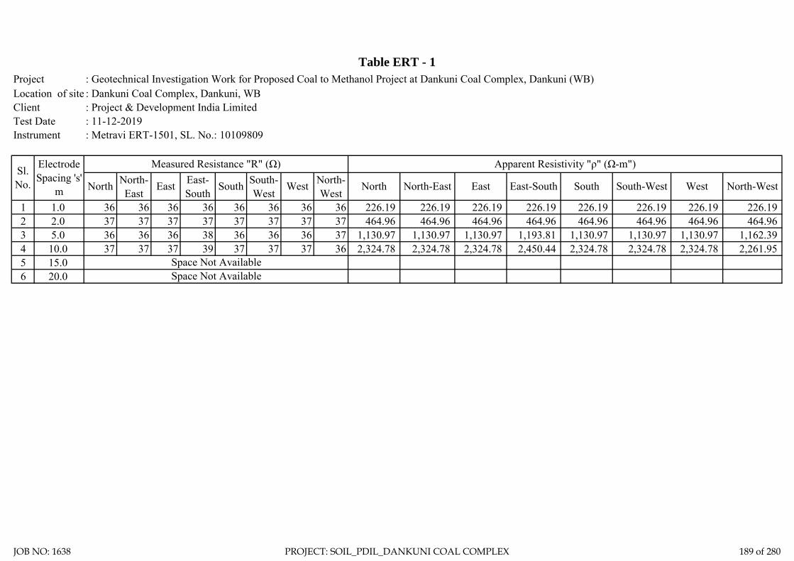
: Geotechnical Investigation Work for Proposed Coal to Methanol Project at Dankuni Coal Complex, Dankuni (WB): Dankuni Coal Complex, Dankuni, WB: Project & Development India Limited: 11-12-2019: Metravi ERT-1501, SL. No.: 10109809
1 1.0 36 36 36 36 36 36 36 36 226.19 226.19 226.19 226.19 226.19 226.19 226.19 226.19 2 2.0 37 37 37 37 37 37 37 37 464.96 464.96 464.96 464.96 464.96 464.96 464.96 464.96 3 5.0 36 36 36 38 36 36 36 37 1,130.97 1,130.97 1,130.97 1,193.81 1,130.97 1,130.97 1,130.97 1,162.39 4 10.0 37 37 37 39 37 37 37 36 2,324.78 2,324.78 2,324.78 2,450.44 2,324.78 2,324.78 2,324.78 2,261.95 5 15.06 20.0
Instrument
Table ERT - 1ProjectLocation of siteClient Test Date
Sl. No.
Electrode Spacing 's'
m
Measured Resistance "R" (Ω) Apparent Resistivity "ρ" (Ω-m")
North North-East
East East-South
South South-West
Space Not Available
South South-West West North-WestWest North-West
North North-East East East-South
Space Not Available
JOB NO: 1638 PROJECT: SOIL_PDIL_DANKUNI COAL COMPLEX 189 of 280

Electrode Spacing - 1.00MR = 36.00 ohm, Resistivity = 226.19 Ohm-m
Location - ERT-1 Location - ERT-1
Electrode Spacing - 2.00MR = 37.00 ohm, Resistivity = 464.96 Ohm-m
Location - ERT-1
Electrode Spacing - 5.00MR = 36.22 ohm, Resistivity = 1137.31 Ohm-m
Location - ERT-1
Electrode Spacing - 10.00MR = 36.96 ohm, Resistivity = 2321.09 Ohm-m
JOB NO: 1638 PROJECT: SOIL_PDIL_DANKUNI COAL COMPLEX 190 of 280

ZONE-9
METHANOL STORAGE
TANK
JOB NO: 1638 PROJECT: SOIL_PDIL_DANKUNI COAL COMPLEX 191 of 280

Total one (1) borehole was sunk in this area, viz borehole marked BH-5. From the general sub soil profile it has been observed that the top soil is heterogeneous fill with coal dust, clayey silt etc. followed by first layer of soft to medium brownish/ bluish grey silty clay/ clayey silt. The second layer is stiff mottled bluish/ brownish grey silty clay/ clayey silt. The third layer consists of soft to medium mottled bluish/ brownish grey silty clay/ clayey silt. The fourth layer is stiff brownish grey silty clay/ clayey silt and the fifth layer as encountered up to the explored depth is hard brownish grey silty clay/ clayey silt.
Discussion and Recommendation:
Based on the subsoil condition pile foundation has been recommended for foundation system of medium to heavily loaded structures. Pile capacities in compression, pull-out and horizontal shear for different diameter of pile are indicated in the Table-2A (Zone-9). It is further recommended to carry out initial pile load test for load under compression, pull-out and horizontal shear, in order to confirm the recommended pile capacities and to take corrective measures, if required.
Table-2A (Zone-9).
Recommended Pile Capacity
Sl.N
o
Pile
Dia
, D
Tota
l Len
gth
of P
ile, L
Cut
-off
Leve
l
Rec
omm
ende
d Pi
le
Cap
acity
in C
ompr
essi
on
Rec
omm
ende
d Pi
le
Cap
acity
in P
ull-O
ut
Rec
omm
ende
d Pi
le
Cap
acity
in H
oriz
onta
l Sh
ear
Mtr Mtr. Mtr. T T T
1 0.400 30.000 2.000 56 52 3.06
2 0.500 30.000 2.000 72 65 3.35
3 0.550 30.000 2.000 80 72 3.48
4 0.600 30.000 2.000 88 78 3.60
5 0.750 30.000 2.000 114 98 3.93
6 1.000 30.000 2.000 159 131 4.41
JOB NO: 1638 PROJECT: SOIL_PDIL_DANKUNI COAL COMPLEX 192 of 280
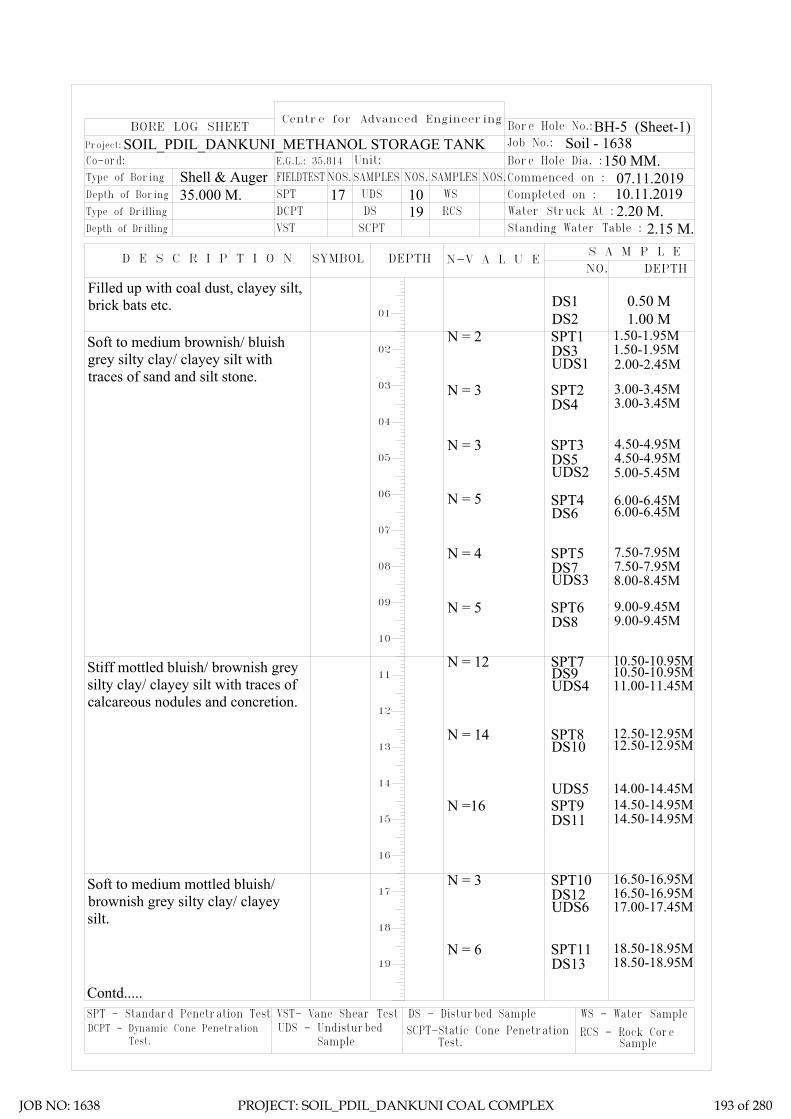
DS - Disturbed SampleSCPT-Static Cone Penetration DCPT - Dynamic Cone Penetration
SPT - Standard Penetration Test VST- Vane Shear TestUDS - Undisturbed
Test. Sample Test.
WS - Water Sample
RCS - Rock Core Sample
Centre for Advanced Engineering
N-V A L U E
19 RCSDSDCPTDepth of Drilling
Type of Drilling
D E S C R I P T I O N
VST SCPT
SYMBOL DEPTH
Co-ord: Type of Boring
Depth of Boring
Project:
FIELDTESTE.G.L.: 35.814
SPT35.000 M.Shell & Auger
BORE LOG SHEET
SAMPLESNOS.Unit:
UDS17 10NOS.
WSSAMPLES
2.20 M.Water Struck At :
2.15 M.S A M P L E
DEPTH
Standing Water Table :
NO.
Bore Hole No.:
Soil - 1638
Commenced on : Bore Hole Dia. :
Completed on :
Job No.:
NOS.150 MM.
BH-5 (Sheet-1)
07.11.201910.11.2019
01DS1 0.50 M
N = 2 1.50-1.95MDS3SPT1
1.50-1.95M
N = 4 7.50-7.95MDS7SPT5
7.50-7.95M
N = 12 10.50-10.95MDS9SPT7
10.50-10.95MUDS4 11.00-11.45M
N = 3 3.00-3.45MDS4SPT2
3.00-3.45M
N = 5 6.00-6.45MDS6SPT4
6.00-6.45M
UDS3 8.00-8.45M
N = 5 9.00-9.45MDS8SPT6
9.00-9.45M
UDS5 14.00-14.45MN =16 14.50-14.95M
DS11SPT9
14.50-14.95M
UDS2 5.00-5.45M
N = 14 12.50-12.95MDS10SPT8
12.50-12.95M
N = 3 16.50-16.95MDS12SPT10
16.50-16.95M
N = 6 18.50-18.95MDS13SPT11
18.50-18.95M
UDS6 17.00-17.45M
SOIL_PDIL_DANKUNI_METHANOL STORAGE TANK
02
03
04
05
06
07
08
09
10
11
12
13
14
15
16
17
18
19
DS2 1.00 M
N = 3 4.50-4.95MDS5SPT3
4.50-4.95M
Filled up with coal dust, clayey silt,brick bats etc.
Soft to medium brownish/ bluishgrey silty clay/ clayey silt withtraces of sand and silt stone.
Contd.....
UDS1 2.00-2.45M
Stiff mottled bluish/ brownish greysilty clay/ clayey silt with traces ofcalcareous nodules and concretion.
Soft to medium mottled bluish/brownish grey silty clay/ clayeysilt.
JOB NO: 1638 PROJECT: SOIL_PDIL_DANKUNI COAL COMPLEX 193 of 280

2.20 M.2.15 M.
150 MM.
BH-5 (Sheet-1)
07.11.201910.11.2019
DS - Disturbed SampleSCPT-Static Cone Penetration DCPT - Dynamic Cone Penetration
SPT - Standard Penetration Test VST- Vane Shear TestUDS - Undisturbed
Test. Sample Test.
WS - Water Sample
RCS - Rock Core Sample
Centre for Advanced Engineering
N-V A L U E
19 RCSDSDCPTDepth of Drilling
Type of Drilling
D E S C R I P T I O N
VST SCPT
SYMBOL DEPTH
Co-ord: Type of Boring
Depth of Boring
Project:
FIELDTESTE.G.L.: 35.814
SPT35.000 M.Shell & Auger
BORE LOG SHEET
SAMPLESNOS.Unit:
UDS17 10NOS.
WSSAMPLES
2.20 M.Water Struck At :
2.15 M.S A M P L E
DEPTH
Standing Water Table :
NO.
Bore Hole No.:
Soil - 1638
Commenced on : Bore Hole Dia. :
Completed on :
Job No.:
NOS.150 MM.
07.11.201910.11.2019
Termination Depth 35.000 Mtr.
21
22
23
24
25
26
27
28
29
30
31
32
33
34
35
36
37
38
39
UDS7 20.00-20.45MN = 12 20.50-20.95M
DS14SPT12
20.50-20.95M
UDS8 23.00-23.45MN = 33 23.50-23.95M
DS15SPT13
23.50-23.95M
UDS9 26.00-26.45M
UDS10 29.00-29.45M
N = 34 26.50-26.95MDS16SPT14
26.50-26.95M
N = 34 29.50-29.95MDS17SPT15
29.50-29.95M
N = 39 32.50-32.95MDS18SPT16
32.50-32.95M
N = 44 34.55-35.00MDS19SPT17
34.55-35.00M
BH-5 (Sheet-2)SOIL_PDIL_DANKUNI_METHANOL STORAGE TANK
Stiff brownish grey silty clay/clayey silt with traces of iron oxideand sand.
Hard brownish grey silty clay/clayey silt with traces of iron oxideand sand.
JOB NO: 1638 PROJECT: SOIL_PDIL_DANKUNI COAL COMPLEX 194 of 280

Sub-Soil Profile through BH-5
02
24.00M.
12.00M.
18.00M.
20.00M.
22.00M.
14.00M.
16.00M.
6.00M.
10.00M.
8.00M.
2.00M.
4.00M.
Sketch No.-SK/PDIL/ METHANOL STORAGE TANK 1638 9 of 13
Termination depth 35.000 M.
BH-5
RL=35.814
26.00M.
28.00M.
30.00M.
32.00M.
34.00M.
36.00M.
38.00M.
1.50MLayer-I
Layer-II
Layer-III
Layer-IV
Layer-V
10.50M
16.50M
20.00M
23.50M
Filled up with coal dust, clayey silt, brick bats etc.
Soft to medium brownish/ bluish grey silty clay/ clayey silt with traces of sand and silt stone.
Stiff mottled bluish/ brownish grey silty clay/ clayey silt with tracesof calcareous nodules and concretion.
Soft to medium mottled bluish/ brownish grey silty clay/ clayey silt.
Stiff brownish grey silty clay/ clayey silt with traces of iron oxide and sand.
Hard brownish grey silty clay/ clayey silt with traces of iron oxide and sand.
JOB NO: 1638 PROJECT: SOIL_PDIL_DANKUNI COAL COMPLEX 195 of 280

LL PL SL Type of Test
Cohesion in
kg/sqcm
Friction angle in degree
Gravel (> 4.75 mm) %
Sand (0.075 - 4.75 mm)
Silt (0.002 - 0.075 mm)
Clay (< 0.002 mm)
Meter % % % γb m G γd quUU/CU/CD
/DS C φ % % % %
5 3.00 DN 3 45 22 13.4 2.66 2.30 0 9 70 21
0.00-0.10 0.0183
0.10-0.20 0.0262
0.20-0.40 0.0439
0.40-0.80 0.0347
0.80-1.60 0.0264
1.60-3.20 0.0197
5 6.00 DN 5 52 21 12.2 2.67 7.6 0 8 63 29
5 9.00 DN 5 55 23 14.1 2.72 5.4 0 6 58 36
0.00-0.10 0.0172
0.10-0.20 0.0254
0.20-0.40 0.0428
0.40-0.80 0.0339
0.80-1.60 0.0254
1.60-3.20 0.0186
5 10.50 DN 12 44 18 10.1 2.70 9.75 0 7 69 24
5 14.50 DN 16 45 19 11.1 2.68 0 0 8 61 31
0.00-0.10 0.0166
0.10-0.20 0.0247
0.20-0.40 0.0417
0.40-0.80 0.0324
0.80-1.60 0.0246
1.60-3.20 0.0173
5 18.50 DN 6 53 19 13 2.66 14.70 0 99 1 0
5 23.50 DN 33 48 20 12.7 2.66 12.40 2 8 64 26
5 29.50 DN 34 45 18 11.4 2.67 8.70 6 12 58 24
5 34.55 DN 44 46 19 11.9 2.66 2.84 12 17 48 23
Soft to medium brownish/ bluish grey
silty clay/ clayey silt with traces of sand and silt
stone.
I
Stiff mottled bluish/ brownish grey silty clay/ clayey silt with traces of calcareous nodules and
concretion.
II
Soft to medium mottled bluish/ brownish grey silty clay/ clayey silt.
III0 10
21
V
5
Hard brownish grey silty clay/ clayey silt with
traces of iron oxide and sand.
0.6
UU 0.32
CD 0
5 5.00 UD
5 11.00
0.11
0
16
UU
CU
17.00 UD 51 1.51
Grading
Layer No.Bore Hole No.
Sample Type - UD/D/
DN
SPT VALUE
(N)
Atterberg LimitsUnconfined
Test in Kg/sqcm
Pressure (Kg/sqcm
)
Dry Density
in gm/cc
Swell Pressure
(Kg/sqcm)
Specific Gravity Free Swell
Index(%)
Bulk Density in gm/cc
Shear Test
49 20
SUMMARY OF LABORATORY TEST RESULTSTable-3
Depth Water
Content in %Description of layer
Co-eff. of volume
compressibility in sqcm/kg
Project: Geotechnical Investigation Work for Proposed Coal to Methanol Project at Dankuni Coal Complex, Dankuni (WB)
CD 0 20
11.9 1.85 30.44 2.66 1.42
0.29
1.50
270 4.8 0 7 660.55
CUUD 47 19
CD
10.4 1.88 25.66 2.67 0 69 260.75
UU 0.39 0
0.10 17
0.09
0 22
12.40
0
0 18.6 60 30
518
20 12.7 1.89 24.77 2.68 CU
JOB NO: 1638 PROJECT: SOIL_PDIL_DANKUNI COAL COMPLEX 196 of 280

SAMPLE CALCULATION
FOR PILE
FOUNDATION
JOB NO: 1638 PROJECT: SOIL_PDIL_DANKUNI COAL COMPLEX 197 of 280

Centre for Advanced Engineering
Pile Model Scale :- N.T.S.
Existing Ground Level.
γ = 1.85 T/M3
c = 2.90 T/M2φ = 0
I
II
9.00
M
III
γ = 1.88 T/M3
c = 3.90 T/M2φ = 0
γ = 1.90 T/M3
c = 6.0 T/M2φ = 0
Pile
Cut
-Off
Leve
l = 2
.00M
03Sketch No.-SK/PDIL/ METHANOL STORAGE TANK 1638
1.50
M
γ = 1.89 T/M3
c = 3.20 T/M2φ = 0
3.50
M
IV
Vγ = 1.90 T/M3
c = 10.0 T/M2φ = 0
6.00
M3.
50M
Filled up with coal dust, clayey silt,brick bats etc.
Soft to medium brownish/ bluish greysilty clay/ clayey silt with traces of sandand silt stone.
Stiff mottled bluish/ brownish greysilty clay/ clayey silt with traces ofcalcareous nodules and concretion.
Soft to medium mottled bluish/brownish grey silty clay/ clayey silt.
Stiff brownish grey silty clay/ clayeysilt with traces of iron oxide and sand.
Hard brownish grey silty clay/ clayeysilt with traces of iron oxide and sand.
JOB NO: 1638 PROJECT: SOIL_PDIL_DANKUNI COAL COMPLEX 198 of 280

Ultimate skin friction capacity
Location: Methanol Storage Tank unit, Dankuni Coal Complex, West Bengal
Layer No: 1Soil Description
Sl.N
o
Pile
Dia
, D
Tota
l Len
gth
of P
ile, L
Dep
th o
f lay
er to
p fro
m E
GL
Dep
th o
f lay
er b
otto
m fr
om E
GL
Red
uctio
n fa
ctor
, α (N
ote1
IS
2911
( Par
t1/S
ec2)
Aver
age
Coh
esio
n al
ong
the
leng
th
of th
e pi
le in
this
laye
r, C
Surfa
ce a
rea
of th
e pi
le s
haft
in th
is
laye
r, A s
Ulti
mat
e Sk
in fr
ictio
n ca
paci
ty o
f th
e sh
aft i
n th
is la
yer,
Qsu
=
α*C
*AS
Mtr Mtr. Mtr Mtr. T/M2 M2
1 0.400 30.000 2.000 10.500 1 2.9 10.681 30.9762 0.500 30.000 2.000 10.500 1 2.9 13.352 38.7203 0.550 30.000 2.000 10.500 1 2.9 14.687 42.5924 0.600 30.000 2.000 10.500 1 2.9 16.022 46.4645 0.750 30.000 2.000 10.500 1 2.9 20.028 58.0806 1.000 30.000 2.000 10.500 1 2.9 26.704 77.440
Project: Geotechnical Investigation Work for Proposed Coal to Methanol Project at Dankuni Coal Complex, Dankuni (WB)
Soft to medium brownish/ bluish grey silty clay/ clayey silt with traces of sand and silt stone.
JOB NO: 1638 PROJECT: SOIL_PDIL_DANKUNI COAL COMPLEX 199 of 280

Ultimate skin friction capacity
Location: Methanol Storage Tank unit, Dankuni Coal Complex, West Bengal
Layer No: 2Soil Description
Sl.N
o
Pile
Dia
, D
Tota
l Len
gth
of P
ile, L
Dep
th o
f lay
er to
p fro
m E
GL
Dep
th o
f lay
er b
otto
m fr
om E
GL
Red
uctio
n fa
ctor
, α (N
ote1
IS
2911
( Par
t1/S
ec2)
Aver
age
Coh
esio
n al
ong
the
leng
th
of th
e pi
le in
this
laye
r, C
Surfa
ce a
rea
of th
e pi
le s
haft
in th
is
laye
r, A s
Ulti
mat
e Sk
in fr
ictio
n ca
paci
ty o
f th
e sh
aft i
n th
is la
yer,
Qsu
=
α*C
*AS
Mtr Mtr. Mtr Mtr. T/M2 M2
1 0.400 30.000 10.500 16.500 1 3.9 7.540 29.4052 0.500 30.000 10.500 16.500 1 3.9 9.425 36.7573 0.550 30.000 10.500 16.500 1 3.9 10.367 40.4324 0.600 30.000 10.500 16.500 1 3.9 11.310 44.1085 0.750 30.000 10.500 16.500 1 3.9 14.137 55.1356 1.000 30.000 10.500 16.500 1 3.9 18.850 73.513
Project: Geotechnical Investigation Work for Proposed Coal to Methanol Project at Dankuni Coal Complex, Dankuni (WB)
Stiff mottled bluish/ brownish grey silty clay/ clayey silt with traces of calcareous nodules and concretion.
JOB NO: 1638 PROJECT: SOIL_PDIL_DANKUNI COAL COMPLEX 200 of 280
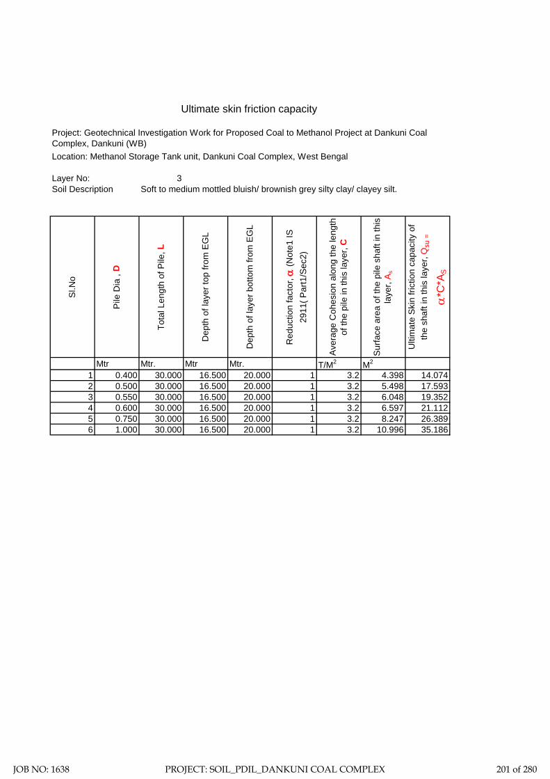
Ultimate skin friction capacity
Location: Methanol Storage Tank unit, Dankuni Coal Complex, West Bengal
Layer No: 3Soil Description Soft to medium mottled bluish/ brownish grey silty clay/ clayey silt.
Sl.N
o
Pile
Dia
, D
Tota
l Len
gth
of P
ile, L
Dep
th o
f lay
er to
p fro
m E
GL
Dep
th o
f lay
er b
otto
m fr
om E
GL
Red
uctio
n fa
ctor
, α (N
ote1
IS
2911
( Par
t1/S
ec2)
Aver
age
Coh
esio
n al
ong
the
leng
th
of th
e pi
le in
this
laye
r, C
Surfa
ce a
rea
of th
e pi
le s
haft
in th
is
laye
r, A s
Ulti
mat
e Sk
in fr
ictio
n ca
paci
ty o
f th
e sh
aft i
n th
is la
yer,
Qsu
=
α*C
*AS
Mtr Mtr. Mtr Mtr. T/M2 M2
1 0.400 30.000 16.500 20.000 1 3.2 4.398 14.0742 0.500 30.000 16.500 20.000 1 3.2 5.498 17.5933 0.550 30.000 16.500 20.000 1 3.2 6.048 19.3524 0.600 30.000 16.500 20.000 1 3.2 6.597 21.1125 0.750 30.000 16.500 20.000 1 3.2 8.247 26.3896 1.000 30.000 16.500 20.000 1 3.2 10.996 35.186
Project: Geotechnical Investigation Work for Proposed Coal to Methanol Project at Dankuni Coal Complex, Dankuni (WB)
JOB NO: 1638 PROJECT: SOIL_PDIL_DANKUNI COAL COMPLEX 201 of 280

Ultimate skin friction capacity
Location: Methanol Storage Tank unit, Dankuni Coal Complex, West Bengal
Layer No: 4Soil Description
Sl.N
o
Pile
Dia
, D
Tota
l Len
gth
of P
ile, L
Dep
th o
f lay
er to
p fro
m E
GL
Dep
th o
f lay
er b
otto
m fr
om E
GL
Red
uctio
n fa
ctor
, α (N
ote1
IS
2911
( Par
t1/S
ec2)
Aver
age
Coh
esio
n al
ong
the
leng
th
of th
e pi
le in
this
laye
r, C
Surfa
ce a
rea
of th
e pi
le s
haft
in th
is
laye
r, A s
Ulti
mat
e Sk
in fr
ictio
n ca
paci
ty o
f th
e sh
aft i
n th
is la
yer,
Qsu
=
α*C
*AS
Mtr Mtr. Mtr Mtr. T/M2 M2
1 0.400 30.000 20.000 23.500 0.75 6.0 4.398 19.7922 0.500 30.000 20.000 23.500 0.75 6.0 5.498 24.7403 0.550 30.000 20.000 23.500 0.75 6.0 6.048 27.2144 0.600 30.000 20.000 23.500 0.75 6.0 6.597 29.6885 0.750 30.000 20.000 23.500 0.75 6.0 8.247 37.1106 1.000 30.000 20.000 23.500 0.75 6.0 10.996 49.480
Project: Geotechnical Investigation Work for Proposed Coal to Methanol Project at Dankuni Coal Complex, Dankuni (WB)
Stiff brownish grey silty clay/ clayey silt with traces of iron oxide and sand.
JOB NO: 1638 PROJECT: SOIL_PDIL_DANKUNI COAL COMPLEX 202 of 280

Ultimate skin friction capacity
Location: Methanol Storage Tank unit, Dankuni Coal Complex, West Bengal
Layer No: 5Soil Description Hard brownish grey silty clay/ clayey silt with traces of iron oxide and sand.
Sl.N
o
Pile
Dia
, D
Tota
l Len
gth
of P
ile, L
Dep
th o
f lay
er to
p fro
m E
GL
Dep
th o
f lay
er b
otto
m fr
om E
GL
Red
uctio
n fa
ctor
, α (N
ote1
IS
2911
( Par
t1/S
ec2)
Aver
age
Coh
esio
n al
ong
the
leng
th
of th
e pi
le in
this
laye
r, C
Surfa
ce a
rea
of th
e pi
le s
haft
in th
is
laye
r, A s
Ulti
mat
e Sk
in fr
ictio
n ca
paci
ty o
f th
e sh
aft i
n th
is la
yer,
Qsu
=
α*C
*AS
Mtr Mtr. Mtr Mtr. T/M2 M2
1 0.400 30.000 23.500 30.000 0.45 10.0 8.168 36.7572 0.500 30.000 23.500 30.000 0.45 10.0 10.210 45.9463 0.550 30.000 23.500 30.000 0.45 10.0 11.231 50.5404 0.600 30.000 23.500 30.000 0.45 10.0 12.252 55.1355 0.750 30.000 23.500 30.000 0.45 10.0 15.315 68.9196 1.000 30.000 23.500 30.000 0.45 10.0 20.420 91.892
Project: Geotechnical Investigation Work for Proposed Coal to Methanol Project at Dankuni Coal Complex, Dankuni (WB)
JOB NO: 1638 PROJECT: SOIL_PDIL_DANKUNI COAL COMPLEX 203 of 280

Ultimate End Bearing capacity
Location: Methanol Storage Tank unit, Dankuni Coal Complex, West Bengal
Layer No: 5Soil Description Hard brownish grey silty clay/ clayey silt with traces of iron oxide and sand.
Sl.N
o
Pile
Dia
, D
Tota
l Len
gth
of P
ile, L
Dep
th o
f lay
er to
p fro
m E
GL
Dep
th o
f lay
er b
otto
m fr
om E
GL
Aver
age
Coh
esio
n at
the
pile
tip,
C
P
Cro
ss s
ectio
nal a
rea
of th
e pi
le ti
p,
A P
Bear
ing
capa
city
fact
or, N
C
Ulti
mat
eEnd
bea
ring
capa
city
at
pile
tip,
QB u
= A
P*N
C*C
P
Mtr Mtr. Mtr Mtr. T/M2 M2 T1 0.400 30.000 23.500 30.000 10.0 0.126 9.000 11.3102 0.500 30.000 23.500 30.000 10.0 0.196 9.000 17.6713 0.550 30.000 23.500 30.000 10.0 0.238 9.000 21.3824 0.600 30.000 23.500 30.000 10.0 0.283 9.000 25.4475 0.750 30.000 23.500 30.000 10.0 0.442 9.000 39.7616 1.000 30.000 23.500 30.000 10.0 0.785 9.000 70.686
Project: Geotechnical Investigation Work for Proposed Coal to Methanol Project at Dankuni Coal Complex, Dankuni (WB)
JOB NO: 1638 PROJECT: SOIL_PDIL_DANKUNI COAL COMPLEX 204 of 280

Sample Calculation:-= 0.29 Kg/cm2
= 28.449 Kn/M2
= 30.00 Mtr.= 2.00 Mtr.= 0.400 Mtr.= 25 N/MM2
= 25000 MN/M2
= 0.00126 M4
= 31.5 KN/M6
= 1.631 MN/M3
T (Stiffness Factor) = 1.808 Mtr. [Where T = (EI/nh)1/5]
= 28.00 Mtr.
Hence, As per Table-5 pile is a LONG ELASTIC PILE Since Le>= 4T
= 0.000 Mtr.
= 2.200
= 3.978 Mtr.
Therefore, Lf = 3.978 Mtr.L1 = 0.000 Mtr.
For Fixed Head Pile, deflection at the pile head,
= 0.005 Mtr. (Adopt)
= 30.03 Kn
= 3.06 T
Where L1 = free head of Pile above ground
And for fixed head file Lf/T (as per IS Code)
Where Lf is the length of fixicity below cut-off level of pile =
Y =H(e+zf)3/12EILateral Load = H
Horizontal Shear Capacity = Hdesign
fckE=Econc=Young's modulas
I (Moment of inertia of the pile cross-section)
Neglecting the effect of steel we get EI
nh = Modulas of Subgrade Reaction (if top of the soil is clay) (Table3)
Le (Embeddment Length of the Pile)
Horizontal Shear Capacity of Pile
Reference : Code of Practice for Design and Construction of Pile Foundation - IS 2911 (Part1/Sec2)
C Value
L (Length of Pile)Cut-off Level of PileDia of Pile (D)
JOB NO: 1638 PROJECT: SOIL_PDIL_DANKUNI COAL COMPLEX 205 of 280

Recommended Pile Capacity
Location: Methanol Storage Tank unit, Dankuni Coal Complex, West Bengal
Sl.N
o
Pile
Dia
, D
Tota
l Len
gth
of P
ile, L
Skin
fric
tion
from
laye
r 1
Skin
fric
tion
from
laye
r 2
Skin
fric
tion
from
laye
r 3
Skin
fric
tion
from
laye
r 4
Skin
fric
tion
from
laye
r 5
End
Bear
ing
Tota
l
F.O
.S
Allo
wab
le P
ile C
apac
ity
Rec
omm
emde
d Pi
le
Cap
acity
in
Com
pres
sion
Rec
omm
emde
d Pi
le
Cap
acity
in P
ull-O
ut
Rec
omm
emde
d Pi
le
Cap
acity
in H
oriz
onta
l Sh
ear
Mtr Mtr. T T T T T T T T T T T T1 0.400 30.000 30.976 29.405 14.074 19.792 36.757 11.310 142.314 2.5 56.926 56 52 3.062 0.500 30.000 38.720 36.757 17.593 24.740 45.946 17.671 181.427 2.5 72.571 72 65 3.353 0.550 30.000 42.592 40.432 19.352 27.214 50.540 21.382 201.514 2.5 80.605 80 72 3.484 0.600 30.000 46.464 44.108 21.112 29.688 55.135 25.447 221.954 2.5 88.781 88 78 3.605 0.750 30.000 58.080 55.135 26.389 37.110 68.919 39.761 285.394 2.5 114.158 114 98 3.936 1.000 30.000 77.440 73.513 35.186 49.480 91.892 70.686 398.197 2.5 159.279 159 131 4.41
Project: Geotechnical Investigation Work for Proposed Coal to Methanol Project at Dankuni Coal Complex, Dankuni (WB)
JOB NO: 1638 PROJECT: SOIL_PDIL_DANKUNI COAL COMPLEX 206 of 280
ZONE-10
ETP
JOB NO: 1638 PROJECT: SOIL_PDIL_DANKUNI COAL COMPLEX 207 of 280

Total one (1) borehole was sunk in this area, viz borehole marked BH-13. From the general sub soil profile it has been observed that the top soil is heterogeneous fill with sand, silt, clay, stone cheeps etc. followed by first layer of soft to medium bluish/ dark grey silty clay/ clayey silt. The second layer is stiff to very stiff mottled bluish/ brownish grey silty clay/ clayey silt and the third layer as encountered up to the explored depth is medium to dense yellowish grey silty sand.
In addition the following field tests have been carried out at this zone and results are being indicated in this chapter.
1. Electrical Resistivity Test: One (1) electrical resistivity tests has been carried out at this zone marked as ERT-11.
Discussion and Recommendation:
Based on the subsoil condition pile foundation has been recommended for foundation system of medium to heavily loaded structures. Pile capacities in compression, pull-out and horizontal shear for different diameter of pile are indicated in the Table-2A (Zone-10). It is further recommended to carry out initial pile load test for load under compression, pull-out and horizontal shear, in order to confirm the recommended pile capacities and to take corrective measures, if required.
JOB NO: 1638 PROJECT: SOIL_PDIL_DANKUNI COAL COMPLEX 208 of 280

Table-2A (Zone-10).
Recommended Pile Capacity
Sl.N
o
Pile
Dia
, D
Tota
l Len
gth
of P
ile, L
Cut
-off
Leve
l
Rec
omm
ende
d Pi
le
Cap
acity
in C
ompr
essi
on
Rec
omm
ende
d Pi
le
Cap
acity
in P
ull-O
ut
Rec
omm
ende
d Pi
le
Cap
acity
in H
oriz
onta
l Sh
ear
Mtr Mtr. Mtr. T T T
1 0.400 30.000 2.000 56 51 2.52
2 0.500 30.000 2.000 75 65 2.76
3 0.550 30.000 2.000 87 73 2.86
4 0.600 30.000 2.000 98 81 2.96
5 0.750 30.000 2.000 140 106 3.24
6 1.000 30.000 2.000 232 152 3.64
JOB NO: 1638 PROJECT: SOIL_PDIL_DANKUNI COAL COMPLEX 209 of 280

DS - Disturbed SampleSCPT-Static Cone Penetration DCPT - Dynamic Cone Penetration
SPT - Standard Penetration Test VST- Vane Shear TestUDS - Undisturbed
Test. Sample Test.
WS - Water Sample
RCS - Rock Core Sample
Centre for Advanced Engineering
N-V A L U E
19 RCSDSDCPTDepth of Drilling
Type of Drilling
D E S C R I P T I O N
VST SCPT
SYMBOL DEPTH
Co-ord: Type of Boring
Depth of Boring
Project:
FIELDTESTE.G.L.: 35.807
SPT35.000 M.Shell & Auger
BORE LOG SHEET
SAMPLESNOS.Unit:
UDS17 10NOS.
WSSAMPLES
1.10 M.Water Struck At :
1.00 M.S A M P L E
DEPTH
Standing Water Table :
NO.
Bore Hole No.:
Soil - 1638
Commenced on : Bore Hole Dia. :
Completed on :
Job No.:
NOS.150 MM.
BH-13 (Sheet-1)
13.10.201916.10.2019
01DS1 0.50 M
N = 2 1.50-1.95MDS3SPT1
1.50-1.95M
N = 5 7.50-7.95MDS7SPT5
7.50-7.95M
N = 5 10.50-10.95MDS9SPT7
10.50-10.95MUDS4 11.00-11.45M
N = 2 3.00-3.45MDS4SPT2
3.00-3.45M
N = 3 6.00-6.45MDS6SPT4
6.00-6.45M
UDS3 8.00-8.45M
N = 7 9.00-9.45MDS8SPT6
9.00-9.45M
UDS5 14.00-14.45MN =13 14.50-14.95M
DS11SPT9
14.50-14.95M
UDS2 5.00-5.45M
N = 13 12.50-12.95MDS10SPT8
12.50-12.95M
N = 10 16.50-16.95MDS12SPT10
16.50-16.95M
N = 12 18.50-18.95MDS13SPT11
18.50-18.95M
UDS6 17.00-17.45M
SOIL_PDIL_DANKUNI_ETP
02
03
04
05
06
07
08
09
10
11
12
13
14
15
16
17
18
19
DS2 1.00 M
N = 2 4.50-4.95MDS5SPT3
4.50-4.95M
Filled up with sand, silt, clay, stonecheaps etc.
Soft to medium bluish/ dark greysilty clay/ clayey silt with traces ofvegetative organic matter.Calcareous nodules foundoccasionally.
Contd.....
UDS1 2.00-2.45M
Stiff to very stiff mottled bluish/brownish grey silty clay/ clayey siltwith traces of kankar.
JOB NO: 1638 PROJECT: SOIL_PDIL_DANKUNI COAL COMPLEX 210 of 280

1.10 M.1.00 M.
150 MM.
BH-13 (Sheet-1)
13.10.201916.10.2019
DS - Disturbed SampleSCPT-Static Cone Penetration DCPT - Dynamic Cone Penetration
SPT - Standard Penetration Test VST- Vane Shear TestUDS - Undisturbed
Test. Sample Test.
WS - Water Sample
RCS - Rock Core Sample
Centre for Advanced Engineering
N-V A L U E
19 RCSDSDCPTDepth of Drilling
Type of Drilling
D E S C R I P T I O N
VST SCPT
SYMBOL DEPTH
Co-ord: Type of Boring
Depth of Boring
Project:
FIELDTESTE.G.L.: 35.807
SPT35.000 M.Shell & Auger
BORE LOG SHEET
SAMPLESNOS.Unit:
UDS17 10NOS.
WSSAMPLES
1.10 M.Water Struck At :
1.00 M.S A M P L E
DEPTH
Standing Water Table :
NO.
Bore Hole No.:
Soil - 1638
Commenced on : Bore Hole Dia. :
Completed on :
Job No.:
NOS.150 MM.
13.10.201916.10.2019
Termination Depth 35.000 Mtr.
21
22
23
24
25
26
27
28
29
30
31
32
33
34
35
36
37
38
39
UDS7 20.00-20.45MN = 14 20.50-20.95M
DS14SPT12
20.50-20.95M
UDS8 23.00-23.45MN = 23 23.50-23.95M
DS15SPT13
23.50-23.95M
UDS9 26.00-26.45M
UDS10 29.00-29.45M
N = 29 26.50-26.95MDS16SPT14
26.50-26.95M
N = 34 29.50-29.95MDS17SPT15
29.50-29.95M
N = 39 32.50-32.95MDS18SPT16
32.50-32.95M
N = 49 34.55-35.00MDS19SPT17
34.55-35.00M
BH-13 (Sheet-2)SOIL_PDIL_DANKUNI_ETP
Medium to dense yellowish greysilty sand. Sand grains are fine andmicaceous.
Stiff to very stiff mottled bluish/brownish grey silty clay/ clayey siltwith traces of kankar.
JOB NO: 1638 PROJECT: SOIL_PDIL_DANKUNI COAL COMPLEX 211 of 280

Sub-Soil Profile through BH-13
02
24.00M.
12.00M.
18.00M.
20.00M.
22.00M.
14.00M.
16.00M.
6.00M.
10.00M.
8.00M.
2.00M.
4.00M.
Sketch No.-SK/PDIL/ ETP 1638 10 of 13
Termination depth 35.000 M.
BH-13
RL=35.807
26.00M.
28.00M.
30.00M.
32.00M.
34.00M.
36.00M.
38.00M.
1.50M
Layer-I
Layer-II
Layer-III
12.50M
26.50M
Filled up with sand, silt, clay, stone cheaps etc.
Soft to medium bluish/ dark grey silty clay/ clayey silt with traces ofvegetative organic matter. Calcareous nodules found occasionally.
Stiff to very stiff mottled bluish/ brownish grey silty clay/ clayeysilt with traces of kankar.
Medium to dense yellowish grey silty sand. Sand grains are fine and micaceous.
JOB NO: 1638 PROJECT: SOIL_PDIL_DANKUNI COAL COMPLEX 212 of 280

LL PL SL Type of Test
Cohesion in
kg/sqcm
Friction angle in degree
Gravel (> 4.75 mm) %
Sand (0.075 - 4.75 mm)
Silt (0.002 - 0.075 mm)
Clay (< 0.002 mm)
Meter % % % γb m G γd quUU/CU/CD
/DS C φ % % % %
13 1.50 DN 2 59 23 14 2.71 6.90 0 11 56 33
0.00-0.10 0.0075
0.10-0.20 0.0131
0.20-0.40 0.0261
0.40-0.80 0.0359
0.80-1.60 0.0304
1.60-3.20 0.0222
13 4.50 DN 2 49 19 12.7 2.71 0 0 6 72 22
13 6.00 DN 3 57 22 16.3 2.69 4.35 0 8 60 32
13 7.50 DN 5 64 22 15.8 2.68 0 0 5 56 39
13 10.50 DN 5 56 22 15.4 2.69 0 0 9 53 38
13 12.50 DN 13 48 21 14.3 2.69 2.58 0 7 69 24
0.00-0.10 0.0068
0.10-0.20 0.0127
0.20-0.40 0.0254
0.40-0.80 0.0353
0.80-1.60 0.0284
1.60-3.20 0.0189
13 16.50 DN 10 43 20 10.7 2.65 0 0 33 47 20
13 20.50 DN 14 45 17 9.79 2.66 0 0 28 46 26
13 23.50 DN 23 36 16 8.75 2.66 0 0 39 37 24
III 13 29.50 DN 34 1.79 2.65 DS 0.03 34 0 0 99 1 0NP
13 3.00 UD
13 14.00
0.21
0.07
0
14
UU
CU
Sample Type - UD/D/
DN
SPT VALUE
(N)
Atterberg LimitsUnconfined
Test in Kg/sqcm
Pressure (Kg/sqcm
)
Dry Density
in gm/cc
Project: Geotechnical Investigation Work for Proposed Coal to Methanol Project at Dankuni Coal Complex, Dankuni (WB)
Swell Pressure
(Kg/sqcm)
Specific Gravity Free Swell
Index(%)
Bulk Density in gm/cc
Shear Test Grading
Layer No.Bore Hole No.
65 24
SUMMARY OF LABORATORY TEST RESULTSTable-3
Depth Water
Content in %Description of layer
Co-eff. of volume
compressibility in sqcm/kg
0.4
CD 0 18
15 1.81 34 2.72 1.35
30.7 2.66 1.42
260 24 0 13 61
0
0CUUD 47 20
CD
12.3 1.85 3.3 0 64 261.01
UU 0.53
Soft to medium bluish/ dark grey silty clay/
clayey silt with traces of vegetative organic matter. Calcareous
nodules found occasionally.
I
Stiff to very stiff mottled bluish/ brownish grey
silty clay/ clayey silt with traces of kankar.
II
Medium to dense yellowish grey silty sand. Sand grains are fine and
micaceous.
10180.13
0 26
JOB NO: 1638 PROJECT: SOIL_PDIL_DANKUNI COAL COMPLEX 213 of 280

SAMPLE CALCULATION
FOR PILE
FOUNDATION
JOB NO: 1638 PROJECT: SOIL_PDIL_DANKUNI COAL COMPLEX 214 of 280

Centre for Advanced Engineering
Pile Model Scale :- N.T.S.
Existing Ground Level.
γ = 1.81 T/M3
c = 2.10 T/M2φ = 0
I
II
11.0
0M
III
γ = 1.85 T/M3
c = 5.30 T/M2φ = 0
Pile
Cut
-Off
Leve
l = 2
.00M
03Sketch No.-SK/PDIL/ ETP 1638
1.50
M
γ = 1.79 T/M3
c = 0φ = 34°
14.0
0M
Filled up with sand, silt, clay, stonecheaps etc.
Soft to medium bluish/ dark grey siltyclay/ clayey silt with traces of vegetativeorganic matter. Calcareous nodules foundoccasionally.
Stiff to very stiff mottled bluish/brownish grey silty clay/ clayey siltwith traces of kankar.
Medium to dense yellowish grey siltysand. Sand grains are fine andmicaceous.
JOB NO: 1638 PROJECT: SOIL_PDIL_DANKUNI COAL COMPLEX 215 of 280

Ultimate skin friction capacity
Location: ETP unit, Dankuni Coal Complex, West Bengal
Layer No: 1Soil Description
Sl.N
o
Pile
Dia
, D
Tota
l Len
gth
of P
ile, L
Dep
th o
f lay
er to
p fro
m E
GL
Dep
th o
f lay
er b
otto
m fr
om E
GL
Red
uctio
n fa
ctor
, α (N
ote1
IS 2
911
( Par
t1/S
ec2)
Aver
age
Coh
esio
n al
ong
the
leng
th
of th
e pi
le in
this
laye
r, C
Surfa
ce a
rea
of th
e pi
le s
haft
in th
is
laye
r, A s
Ulti
mat
e Sk
in fr
ictio
n ca
paci
ty o
f th
e sh
aft i
n th
is la
yer,
Qsu
=
α*C
*AS
Mtr Mtr. Mtr Mtr. T/M2 M2
1 0.400 30.000 2.000 12.500 1 2.1 13.195 27.7092 0.500 30.000 2.000 12.500 1 2.1 16.493 34.6363 0.550 30.000 2.000 12.500 1 2.1 18.143 38.1004 0.600 30.000 2.000 12.500 1 2.1 19.792 41.5635 0.750 30.000 2.000 12.500 1 2.1 24.740 51.9546 1.000 30.000 2.000 12.500 1 2.1 32.987 69.272
Project: Geotechnical Investigation Work for Proposed Coal to Methanol Project at Dankuni Coal Complex, Dankuni (WB)
Soft to medium bluish/ dark grey silty clay/ clayey silt with traces of vegetative organic matter. Calcareous nodules found occasionally.
JOB NO: 1638 PROJECT: SOIL_PDIL_DANKUNI COAL COMPLEX 216 of 280

Ultimate skin friction capacity
Location: ETP unit, Dankuni Coal Complex, West Bengal
Layer No: 2Soil Description
Sl.N
o
Pile
Dia
, D
Tota
l Len
gth
of P
ile, L
Dep
th o
f lay
er to
p fro
m E
GL
Dep
th o
f lay
er b
otto
m fr
om E
GL
Red
uctio
n fa
ctor
, α (N
ote1
IS
2911
( Par
t1/S
ec2)
Aver
age
Coh
esio
n al
ong
the
leng
th
of th
e pi
le in
this
laye
r, C
Surfa
ce a
rea
of th
e pi
le s
haft
in th
is
laye
r, A s
Ulti
mat
e Sk
in fr
ictio
n ca
paci
ty o
f th
e sh
aft i
n th
is la
yer,
Qsu
=
α*C
*AS
Mtr Mtr. Mtr Mtr. T/M2 M2
1 0.400 30.000 12.500 26.500 0.9 5.3 17.593 83.9182 0.500 30.000 12.500 26.500 0.9 5.3 21.991 104.8983 0.550 30.000 12.500 26.500 0.9 5.3 24.190 115.3884 0.600 30.000 12.500 26.500 0.9 5.3 26.389 125.8775 0.750 30.000 12.500 26.500 0.9 5.3 32.987 157.3476 1.000 30.000 12.500 26.500 0.9 5.3 43.982 209.796
Project: Geotechnical Investigation Work for Proposed Coal to Methanol Project at Dankuni Coal Complex, Dankuni (WB)
Stiff to very stiff mottled bluish/ brownish grey silty clay/ clayey silt with traces of kankar.
JOB NO: 1638 PROJECT: SOIL_PDIL_DANKUNI COAL COMPLEX 217 of 280

Ultimate skin friction capacity
Layer No: 3
Soil Description :
Sl.N
o
Pile
Dia
, D
Tota
l Len
gth
of P
ile, L
Dep
th o
f lay
er to
p, fr
om E
GL
Dep
th o
f lay
er b
otto
m, f
rom
EG
L
Wat
er ta
ble
φφ
adop
ted
=(φ
-3)o co
nsid
erin
g lo
osen
ing
effe
ct
NC
Nq Nγ
Uni
t wei
ght,
γ
Effe
ctiv
e un
it w
eigh
t, γ'
k- V
alue
, as
per n
ote
3 IS
291
1 pa
rt 1/
Sec
2-19
79Li
miti
ng L
/D fo
r cal
cn. O
f max
m.
Effe
ctiv
e ov
erbu
rden
pre
ss. A
t pi
le ti
p
P Di a
t lay
er to
p
δ =
φ
Uni
t fric
tion,
f s =
K*P
di*ta
n δ -
at
laye
r top
, max
imum
= 1
0T/M
2
P Di a
t lay
er b
otto
m
Uni
t fric
tion,
f s =
K*P
di*ta
n δ -
at
laye
r bot
tom
, max
imum
= 1
0T/M
2
Aver
age
unit
frict
ion,
ado
pted
for
shaf
t fric
tion
capa
city
.
A Si
Shaf
t fric
tion,
F
Mtr
Mtr.
Mtr
Mtr.
Mtr.
Deg
ree
Deg
ree
T/M
3
T/M
3
T/M
2
Rad
ian
T/M
2
T/M
2
T/M
2
T/M
2
M2 T
1 0.400 30.000 26.500 30.000 1.000 34 31 32.67 20.63 25.99 1.79 0.79 1.3 15 4.74 0.54 3.703 4.74 3.703 3.703 4.398 16.2842 0.500 30.000 26.500 30.000 1.000 34 31 32.67 20.63 25.99 1.79 0.79 1.3 15 5.925 0.54 4.628 5.925 4.628 4.628 5.498 25.4443 0.550 30.000 26.500 30.000 1.000 34 31 32.67 20.63 25.99 1.79 0.79 1.3 15 6.518 0.54 5.091 6.518 5.091 5.091 6.048 30.7884 0.600 30.000 26.500 30.000 1.000 34 31 32.67 20.63 25.99 1.79 0.79 1.3 15 7.11 0.54 5.554 7.11 5.554 5.554 6.597 36.6405 0.750 30.000 26.500 30.000 1.000 34 31 32.67 20.63 25.99 1.79 0.79 1.3 15 8.888 0.54 6.942 8.888 6.942 6.942 8.247 57.2506 1.000 30.000 26.500 30.000 1.000 34 31 32.67 20.63 25.99 1.79 0.79 1.3 15 11.85 0.54 9.256 11.85 9.256 9.256 10.996 101.778
Project: Geotechnical Investigation Work for Proposed Coal to Methanol Project at Dankuni Coal Complex, Dankuni (WB)
Location: ETP unit, Dankuni Coal Complex, West Bengal
Medium to dense yellowish grey silty sand. Sand grains are fine and micaceous.
JOB NO: 1638 PROJECT: SOIL_PDIL_DANKUNI COAL COMPLEX 218 of 280

Location: ETP unit, Dankuni Coal Complex, West Bengal
Layer No: 3
Sl.N
o
Pile
Dia
, D
Tota
l Len
gth
of P
ile, L
Dep
th o
f lay
er to
p, fr
om E
GL
Dep
th o
f lay
er b
otto
m, f
rom
EG
L
Wat
er ta
ble
φ
φ ad
opte
d =(
φ -3
)o cons
ider
ing
loos
enin
g ef
fect
NC
Nq Nγ
Uni
t wei
ght, γ
Effe
ctiv
e un
it w
eigh
t, γ'
Lim
iting
L/D
for c
alcn
. Of m
axm
. Ef
fect
ive
over
burd
en p
ress
. At
pile
tip
P Di a
t pile
tip
A P
End
Bear
ing
Mtr Mtr. Mtr Mtr. Mtr.
Deg
ree
Degree T/M3 T/M3 M2 T
1 0.400 30.000 26.500 30.000 0.000 34 31 32.67 20.63 25.99 1.79 0.79 15 4.74 0.126 12.8052 0.500 30.000 26.500 30.000 0.000 34 31 32.67 20.63 25.99 1.79 0.79 15 5.925 0.196 25.0093 0.550 30.000 26.500 30.000 0.000 34 31 32.67 20.63 25.99 1.79 0.79 15 6.5175 0.238 33.2874 0.600 30.000 26.500 30.000 0.000 34 31 32.67 20.63 25.99 1.79 0.79 15 7.11 0.283 43.2165 0.750 30.000 26.500 30.000 0.000 34 31 32.67 20.63 25.99 1.79 0.79 15 8.8875 0.442 84.4066 1.000 30.000 26.500 30.000 0.000 34 31 32.67 20.63 25.99 1.79 0.79 15 11.85 0.785 200.074
Ultimate end bearing capacity
Project: Geotechnical Investigation Work for Proposed Coal to Methanol Project at Dankuni Coal Complex, Dankuni (WB)
Soil Description : Medium to dense yellowish grey silty sand. Sand grains are fine and micaceous.
JOB NO: 1638 PROJECT: SOIL_PDIL_DANKUNI COAL COMPLEX 219 of 280

Sample Calculation:-= 0.21 Kg/cm2
= 20.601 Kn/M2
= 30.00 Mtr.= 2.00 Mtr.= 0.400 Mtr.= 25 N/MM2
= 25000 MN/M2
= 0.00126 M4
= 31.5 KN/M6
= 1.181 MN/M3
T (Stiffness Factor) = 1.928 Mtr. [Where T = (EI/nh)1/5]
= 28.00 Mtr.
Hence, As per Table-5 pile is a LONG ELASTIC PILE Since Le>= 4T
= 0.000 Mtr.
= 2.200
= 4.242 Mtr.
Therefore, Lf = 4.242 Mtr.L1 = 0.000 Mtr.
For Fixed Head Pile, deflection at the pile head,
= 0.005 Mtr. (Adopt)
= 24.77 Kn
= 2.52 T
Where L1 = free head of Pile above ground
And for fixed head file Lf/T (as per IS Code)
Where Lf is the length of fixicity below cut-off level of pile =
Y =H(e+zf)3/12EILateral Load = H
Horizontal Shear Capacity = Hdesign
fckE=Econc=Young's modulas
I (Moment of inertia of the pile cross-section)
Neglecting the effect of steel we get EI
nh = Modulas of Subgrade Reaction (if top of the soil is clay) (Table3)
Le (Embeddment Length of the Pile)
Horizontal Shear Capacity of Pile
Reference : Code of Practice for Design and Construction of Pile Foundation - IS 2911 (Part1/Sec2)
C Value
L (Length of Pile)Cut-off Level of PileDia of Pile (D)
JOB NO: 1638 PROJECT: SOIL_PDIL_DANKUNI COAL COMPLEX 220 of 280

Recommended Pile Capacity
Location: ETP unit, Dankuni Coal Complex, West Bengal
Sl.N
o
Pile
Dia
, D
Tota
l Len
gth
of P
ile, L
Skin
fric
tion
from
laye
r 1
Skin
fric
tion
from
laye
r 2
Skin
fric
tion
from
laye
r 3
End
Bear
ing
Tota
l
F.O
.S
Allo
wab
le P
ile C
apac
ity
Rec
omm
emde
d Pi
le
Cap
acity
in
Com
pres
sion
Rec
omm
emde
d Pi
le
Cap
acity
in P
ull-O
ut
Rec
omm
emde
d Pi
le
Cap
acity
in H
oriz
onta
l Sh
ear
Mtr Mtr. T T T T T T T T T T1 0.400 30.000 27.709 83.918 16.284 12.805 140.716 2.5 56.287 56 51 2.522 0.500 30.000 34.636 104.898 25.444 25.009 189.988 2.5 75.995 75 65 2.763 0.550 30.000 38.100 115.388 30.788 33.287 217.562 2.5 87.025 87 73 2.864 0.600 30.000 41.563 125.877 36.640 43.216 247.297 2.5 98.919 98 81 2.965 0.750 30.000 51.954 157.347 57.250 84.406 350.957 2.5 140.383 140 106 3.246 1.000 30.000 69.272 209.796 101.778 200.074 580.920 2.5 232.368 232 152 3.64
Project: Geotechnical Investigation Work for Proposed Coal to Methanol Project at Dankuni Coal Complex, Dankuni (WB)
JOB NO: 1638 PROJECT: SOIL_PDIL_DANKUNI COAL COMPLEX 221 of 280

ELECTRICAL
RESISTIVITY TEST
JOB NO: 1638 PROJECT: SOIL_PDIL_DANKUNI COAL COMPLEX 222 of 280

: Geotechnical Investigation Work for Proposed Coal to Methanol Project at Dankuni Coal Complex, Dankuni (WB): Dankuni Coal Complex, Dankuni, WB: Project & Development India Limited: 21-12-2019: Metravi ERT-1501, SL. No.: 10109809
1 1.0 49 49 48 49 49 48 49 49 307.88 307.88 301.59 307.88 307.88 301.59 307.88 307.88 2 2.0 50 50 49 50 50 49 50 50 628.32 628.32 615.75 628.32 628.32 615.75 628.32 628.32 3 5.0 51 51 51 51 51 51 51 51 1,602.21 1,602.21 1,602.21 1,602.21 1,602.21 1,602.21 1,602.21 1,602.21 4 10.0 52 52 52 52 52 52 52 52 3,267.26 3,267.26 3,267.26 3,267.26 3,267.26 3,267.26 3,267.26 3,267.26 5 15.0 53 53 52 53 53 52 53 53 4,995.13 4,995.13 4,900.88 4,995.13 4,995.13 4,900.88 4,995.13 4,995.13 6 20.0 Space Not Available
South South-West West North-WestWest North-West
North North-East East East-SouthSl. No.
Electrode Spacing 's'
m
Measured Resistance "R" (Ω) Apparent Resistivity "ρ" (Ω-m")
North North-East
East East-South
South South-West
Instrument
Table ERT - 11ProjectLocation of siteClient Test Date
JOB NO: 1638 PROJECT: SOIL_PDIL_DANKUNI COAL COMPLEX 223 of 280

Electrode Spacing - 1.00MR = 48.54 ohm, Resistivity = 304.83 Ohm-m
Location - ERT-11 Location - ERT-11
Electrode Spacing - 2.00MR = 49.53 ohm, Resistivity = 622.10 Ohm-m
Location - ERT-11
Electrode Spacing - 5.00MR = 51.00 ohm, Resistivity = 1602.21 Ohm-m
Location - ERT-11
Electrode Spacing - 10.00MR = 52.00 ohm, Resistivity = 3267.26 Ohm-m
Location - ERT-11
Electrode Spacing - 15.00MR = 52.52 ohm, Resistivity = 4947.38 Ohm-m
JOB NO: 1638 PROJECT: SOIL_PDIL_DANKUNI COAL COMPLEX 224 of 280

ZONE-11
WORK SHOP
JOB NO: 1638 PROJECT: SOIL_PDIL_DANKUNI COAL COMPLEX 225 of 280

Calculation for Modulas of Subgrade Reaction (K) for PLT-2
From Load-Settlement curve of PLT-2, Pressure corresponding to settlement of 1.25mm is 0.79 Kg/Cm2.
Pressure/ Settlement.= 0.79/0.125 Kg/Cm3= 6.32 Kg/Cm3
Calculation for Modulas of Elasticity (Es) for PLT-2.
Modulas of Elasticity has been calculated for initial load of 4.20 T/M2 and corresponding settlement of 0.061 cm.
Es =
= {0.36*(1-0.32)*75*0.82}/0.121= 308.27 Kg/Cm2
Where, Modulas of Elasticity.0.42 Kg/Cm2
0.360 Cm
0.820.06 Cm
q = Pressure =
Modulas of Subgrade Reaction and Modulas of Elasticity have been calculated for Plate Load Test as follows.
Hence, K =
{q*(1-µ2)*B*Iw} / S
Es =
µ = Poisson's Ratio = B = Least dimension of the plate =
Iw = Influence Factor =S = Settlement =
Modulas of Subgrade Reaction and Modulas of Elasticity, obtain from Plate Load Test.
(Kg/Cm3) (Kg/Cm2)
PLT-2 2 6.32 Kg/Cm3 308.27 Kg/Cm2
Test No.Depth of
Test
Modulas of Subgrade Reaction, K
Modulas of Elasticity, Es
(M)
JOB NO: 1638 PROJECT: SOIL_PDIL_DANKUNI COAL COMPLEX 226 of 280

Client : Projects & Development India LimitedLocation : Near Ex. Sales & Marketing Office.Test Number : PLT-2Plate Size : 60x60 3600 SqcmPit Size : 3.00M X 3.00M X 2.00MGround Water Table : Not EncounteredL.C. of Dial Guage : 0.01 mmJack Ram Dia : 10.5 cmJack Ram Area : 86.59 Sqcm
DIAL-1 DIAL-2 DIAL-1 DIAL-2
03-12-2019 10:50:00 0 2500 2500 0.00 0.00 0.0010:50:00 0.42 2500 2500 0.00 0.00 0.0010:51:00 2444 2459 0.56 0.41 0.4910:52:15 2440 2456 0.60 0.44 0.5210:54:00 2439 2455 0.61 0.45 0.5310:56:15 2438 2453 0.62 0.47 0.5510:59:00 2437 2452 0.63 0.48 0.5611:06:00 2436 2449 0.64 0.51 0.5811:15:00 2435 2447 0.65 0.53 0.5911:50:00 2433 2445 0.67 0.55 0.6111:50:00 0.83 2433 2445 0.67 0.55 0.6111:51:00 2374 2390 1.26 1.10 1.1811:52:15 2371 2388 1.29 1.12 1.2111:54:00 2367 2386 1.33 1.14 1.2411:56:15 2366 2384 1.34 1.16 1.2511:59:00 2364 2381 1.36 1.19 1.2812:06:00 2363 2377 1.37 1.23 1.3012:15:00 2362 2375 1.38 1.25 1.3212:50:00 2361 2374 1.39 1.26 1.3312:50:00 1.25 2361 2374 1.39 1.26 1.3312:51:00 2345 2326 1.55 1.74 1.6512:52:15 2336 2293 1.64 2.07 1.8612:54:00 2330 2286 1.70 2.14 1.9212:56:15 2322 2280 1.78 2.20 1.9912:59:00 2310 2274 1.90 2.26 2.0813:06:00 2295 2267 2.05 2.33 2.1913:15:00 2290 2260 2.10 2.40 2.2513:50:00 2288 2257 2.12 2.43 2.2813:50:00 1.67 2288 2257 2.12 2.43 2.2813:51:00 2112 2133 3.88 3.67 3.78
6000
4500
3000
0.001500
MEAN SETTLEMENT
(mm)REMARKS
PLATE LOAD TEST SITE DATA SHEET
DIAL GUAGE READING (mm)
SETTLEMENT (mm)DATE TIME (Hrs)
PRESSURE IN Kg/Sqcm
LOAD IN (KG)
JOB NO: 1638 PROJECT: SOIL_PDIL_DANKUNI COAL COMPLEX 227 of 280

DIAL-1 DIAL-2 DIAL-1 DIAL-2
13:52:15 2105 2124 3.95 3.76 3.8613:54:00 2099 2116 4.01 3.84 3.9313:56:15 2092 2109 4.08 3.91 4.0013:59:00 2082 2103 4.18 3.97 4.0814:06:00 2075 2088 4.25 4.12 4.1914:15:00 2066 2078 4.34 4.22 4.2814:50:00 2051 2062 4.49 4.38 4.4414:50:00 2.08 2051 2062 4.49 4.38 4.4414:51:00 1985 1965 5.15 5.35 5.2514:52:15 1960 1940 5.40 5.60 5.5014:54:00 1933 1909 5.67 5.91 5.7914:56:15 1922 1898 5.78 6.02 5.9014:59:00 1890 1866 6.10 6.34 6.2215:06:00 1821 1792 6.79 7.08 6.9415:15:00 1780 1761 7.20 7.39 7.3015:50:00 1742 1736 7.58 7.64 7.6115:50:00 2.50 1742 1736 7.58 7.64 7.6115:51:00 1600 1604 9.00 8.96 8.9815:52:15 1580 1585 9.20 9.15 9.1815:54:00 1531 1539 9.69 9.61 9.6515:56:15 1464 1474 10.36 10.26 10.3115:59:00 1415 1404 10.85 10.96 10.9116:06:00 1374 1368 11.26 11.32 11.2916:15:00 1331 1334 11.69 11.66 11.6816:50:00 1260 1290 12.40 12.10 12.2516:50:00 2.92 1260 1290 12.40 12.10 12.2516:51:00 997 1064 15.03 14.36 14.7016:52:15 853 869 16.47 16.31 16.3916:54:00 792 804 17.08 16.96 17.0216:56:15 757 768 17.43 17.32 17.3816:59:00 727 724 17.73 17.76 17.7517:06:00 708 702 17.92 17.98 17.9517:15:00 700 690 18.00 18.10 18.0517:50:00 696 683 18.04 18.17 18.1117:50:00 3.33 696 683 18.04 18.17 18.1117:51:00 296 327 22.04 21.73 21.8917:52:15 181 192 23.19 23.08 23.1417:54:00 106 113 23.94 23.87 23.9117:56:15 69 71 24.31 24.29 24.3017:59:00 47 41 24.53 24.59 24.5618:06:00 30 25 24.70 24.75 24.7318:15:00 12 9 24.88 24.91 24.9018:50:00 0 0 25.00 25.00 25.00
12000
10500
PRESSURE IN Kg/Sqcm
DIAL GUAGE READING (mm)
SETTLEMENT (mm) MEAN SETTLEMENT
(mm)REMARKSDATE TIME (Hrs) LOAD IN (KG)
7500
9000
JOB NO: 1638 PROJECT: SOIL_PDIL_DANKUNI COAL COMPLEX 228 of 280

Load Vs Settlement Curve for PLT-2
0.00
5.00
10.00
15.00
20.00
25.00
30.00
0.00 5.00 10.00 15.00 20.00 25.00 30.00 35.00
Sett
lem
ent i
n M
M
Load in T/Sq.M
16.25
Qu = 16.25 T/Sq.M
JOB NO: 1638 PROJECT: SOIL_PDIL_DANKUNI COAL COMPLEX 229 of 280

ZONE-12
WARE HOUSE
JOB NO: 1638 PROJECT: SOIL_PDIL_DANKUNI COAL COMPLEX 230 of 280

Total one (1) borehole was sunk in this area, viz borehole marked BH-14. From the general sub soil profile it has been observed that the top soil is heterogeneous fill with sand, silt, clay, stone cheeps etc. followed by first layer of soft light brownish grey silty clay/ clayey silt and the second layer as encountered up to the explored depth is stiff to very stiff bluish/ brownish grey silty clay/ clayey silt.
Discussion and Recommendation:
Based on the subsoil condition pile foundation has been recommended for foundation system of medium to heavily loaded structures. Pile capacities in compression, pull-out and horizontal shear for different diameter of pile are indicated in the Table-2A (Zone-12). It is further recommended to carry out initial pile load test for load under compression, pull-out and horizontal shear, in order to confirm the recommended pile capacities and to take corrective measures, if required.
Table-2A (Zone-12).
Recommended Pile Capacity
Sl.N
o
Pile
Dia
, D
Tota
l Len
gth
of P
ile, L
Cut
-off
Leve
l
Rec
omm
ende
d Pi
le
Cap
acity
in C
ompr
essi
on
Rec
omm
ende
d Pi
le
Cap
acity
in P
ull-O
ut
Rec
omm
ende
d Pi
le
Cap
acity
in H
oriz
onta
l Sh
ear
Mtr Mtr. Mtr. T T T
1 0.400 28.000 2.000 50 47 2.60
2 0.500 28.000 2.000 64 59 2.83
3 0.550 28.000 2.000 71 65 2.94
4 0.600 28.000 2.000 78 71 3.05
5 0.750 28.000 2.000 100 89 3.33
6 1.000 28.000 2.000 138 119 3.74
JOB NO: 1638 PROJECT: SOIL_PDIL_DANKUNI COAL COMPLEX 231 of 280

DS - Disturbed SampleSCPT-Static Cone Penetration DCPT - Dynamic Cone Penetration
SPT - Standard Penetration Test VST- Vane Shear TestUDS - Undisturbed
Test. Sample Test.
WS - Water Sample
RCS - Rock Core Sample
Centre for Advanced Engineering
N-V A L U E
17 RCSDSDCPTDepth of Drilling
Type of Drilling
D E S C R I P T I O N
VST SCPT
SYMBOL DEPTH
Co-ord: Type of Boring
Depth of Boring
Project:
FIELDTESTE.G.L.: 34.650
SPT30.000 M.Shell & Auger
BORE LOG SHEET
SAMPLESNOS.Unit:
UDS15 10NOS.
WSSAMPLES
1.10 M.Water Struck At :
1.00 M.S A M P L E
DEPTH
Standing Water Table :
NO.
Bore Hole No.:
Soil - 1638
Commenced on : Bore Hole Dia. :
Completed on :
Job No.:
NOS.150 MM.
BH-14 (Sheet-1)
13.10.201916.10.2019
01DS1 0.50 M
N = 4 1.50-1.95MDS3SPT1
1.50-1.95M
N = 2 7.50-7.95MDS7SPT5
7.50-7.95M
N = 12 10.50-10.95MDS9SPT7
10.50-10.95MUDS4 11.00-11.45M
N = 3 3.00-3.45MDS4SPT2
3.00-3.45M
N = 2 6.00-6.45MDS6SPT4
6.00-6.45M
UDS3 8.00-8.45M
N = 2 9.00-9.45MDS8SPT6
9.00-9.45M
UDS5 14.00-14.45MN =15 14.50-14.95M
DS11SPT9
14.50-14.95M
UDS2 5.00-5.45M
N = 12 12.50-12.95MDS10SPT8
12.50-12.95M
N = 13 16.50-16.95MDS12SPT10
16.50-16.95M
N = 10 18.50-18.95MDS13SPT11
18.50-18.95M
UDS6 17.00-17.45M
SOIL_PDIL_DANKUNI_WARE HOUSE
02
03
04
05
06
07
08
09
10
11
12
13
14
15
16
17
18
19
DS2 1.00 M
N = 2 4.50-4.95MDS5SPT3
4.50-4.95M
Filled up with sand, silt, clay, stonecheaps etc.Soft light brownish grey silty clay/clayey silt.
Contd.....
UDS1 2.00-2.45M
Stiff to very stiff bluish/ brownishgrey silty clay/ clayey silt withtraces of silt stone.
JOB NO: 1638 PROJECT: SOIL_PDIL_DANKUNI COAL COMPLEX 232 of 280
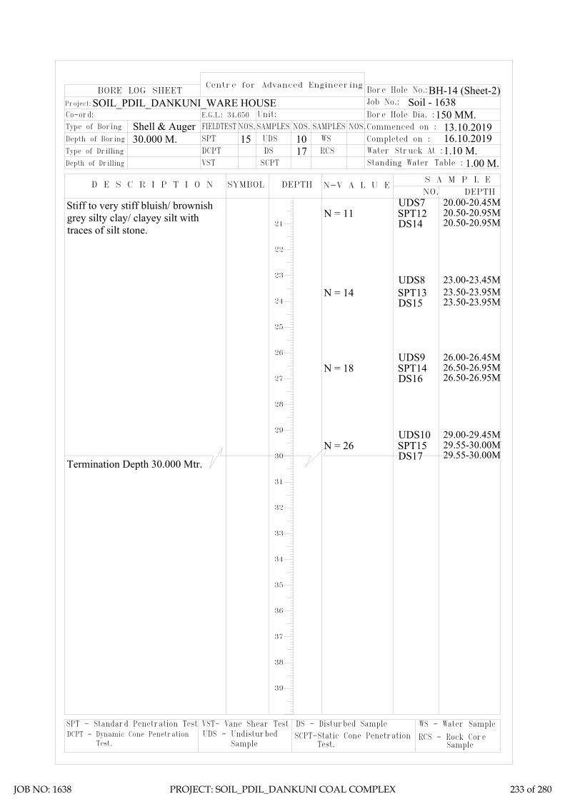
1.10 M.1.00 M.
150 MM.
BH-14 (Sheet-1)
13.10.201916.10.2019
DS - Disturbed SampleSCPT-Static Cone Penetration DCPT - Dynamic Cone Penetration
SPT - Standard Penetration Test VST- Vane Shear TestUDS - Undisturbed
Test. Sample Test.
WS - Water Sample
RCS - Rock Core Sample
Centre for Advanced Engineering
N-V A L U E
17 RCSDSDCPTDepth of Drilling
Type of Drilling
D E S C R I P T I O N
VST SCPT
SYMBOL DEPTH
Co-ord: Type of Boring
Depth of Boring
Project:
FIELDTESTE.G.L.: 34.650
SPT30.000 M.Shell & Auger
BORE LOG SHEET
SAMPLESNOS.Unit:
UDS15 10NOS.
WSSAMPLES
1.10 M.Water Struck At :
1.00 M.S A M P L E
DEPTH
Standing Water Table :
NO.
Bore Hole No.:
Soil - 1638
Commenced on : Bore Hole Dia. :
Completed on :
Job No.:
NOS.150 MM.
13.10.201916.10.2019
Termination Depth 30.000 Mtr.
21
22
23
24
25
26
27
28
29
30
31
32
33
34
35
36
37
38
39
UDS7 20.00-20.45MN = 11 20.50-20.95M
DS14SPT12
20.50-20.95M
UDS8 23.00-23.45MN = 14 23.50-23.95M
DS15SPT13
23.50-23.95M
UDS9 26.00-26.45M
UDS10 29.00-29.45M
N = 18 26.50-26.95MDS16SPT14
26.50-26.95M
N = 26 29.55-30.00MDS17SPT15
29.55-30.00M
BH-14 (Sheet-2)SOIL_PDIL_DANKUNI_WARE HOUSE
Stiff to very stiff bluish/ brownishgrey silty clay/ clayey silt withtraces of silt stone.
JOB NO: 1638 PROJECT: SOIL_PDIL_DANKUNI COAL COMPLEX 233 of 280

Sub-Soil Profile through BH-14
02
24.00M.
12.00M.
18.00M.
20.00M.
22.00M.
14.00M.
16.00M.
6.00M.
10.00M.
8.00M.
2.00M.
4.00M.
Sketch No.-SK/PDIL/ WARE HOUSE 1638 12 of 13
Termination depth 30.000 M.
BH-14
RL=34.650
26.00M.
28.00M.
30.00M.
32.00M.
34.00M.
36.00M.
38.00M.
1.00M
Layer-I
Layer-II
10.50M
Filled up with sand, silt, clay, stone cheaps etc.
Soft light brownish grey silty clay/ clayey silt.
Stiff to very stiff bluish/ brownish grey silty clay/ clayey silt with traces of silt stone.
JOB NO: 1638 PROJECT: SOIL_PDIL_DANKUNI COAL COMPLEX 234 of 280

LL PL SL Type of Test
Cohesion in
kg/sqcm
Friction angle in degree
Gravel (> 4.75 mm) %
Sand (0.075 - 4.75 mm)
Silt (0.002 - 0.075 mm)
Clay (< 0.002 mm)
Meter % % % γb m G γd quUU/CU/CD
/DS C φ % % % %
14 1.50 DN 4 51 20 12.5 2.67 10.00 0 9 62 29
0.00-0.10 0.0187
0.10-0.20 0.0251
0.20-0.40 0.0389
0.40-0.80 0.0326
0.80-1.60 0.0252
1.60-3.20 0.0188
14 7.50 DN 2 50 21 13.2 2.66 9.4 0 5 73 22
0.00-0.10 0.0154
0.10-0.20 0.0217
0.20-0.40 0.0358
0.40-0.80 0.0295
0.80-1.60 0.0243
1.60-3.20 0.0151
14 14.50 DN 15 56 20 12 2.67 3.57 3 11 54 32
14 29.55 DN 26 43 19 11 2.65 0 4 18 57 21
Soft light brownish grey silty clay/ clayey silt.I 14 2.00 UD
14 11.00
0.22
0.07
0
12
UU
CU49
Sample Type - UD/D/
DN
SPT VALUE
(N)
Atterberg LimitsUnconfined
Test in Kg/sqcm
Pressure (Kg/sqcm
)
Dry Density in gm/cc
Project: Geotechnical Investigation Work for Proposed Coal to Methanol Project at Dankuni Coal Complex, Dankuni (WB)
Swell Pressure
(Kg/sqcm)
Specific Gravity Free Swell
Index(%)
Bulk Density in gm/cc
Shear Test Grading
Layer No.Bore Hole No.
19
SUMMARY OF LABORATORY TEST RESULTSTable-3
Depth Water
Content in %Description of layer
Co-eff. of volume
compressibility in sqcm/kg
0.4
CD 0 16
11.7 1.81 33.28 2.66 1.36 280 8.6 0 7 65
UD 49 20
CD
13.6 1.83 25.8 2.67 1.45 65 261.28
UU 0.67 0
0CUStiff to very stiff bluish/ brownish grey silty clay/ clayey silt with traces of
silt stone.
II
8160.13
0 27
6.82 1
JOB NO: 1638 PROJECT: SOIL_PDIL_DANKUNI COAL COMPLEX 235 of 280

SAMPLE CALCULATION
FOR PILE
FOUNDATION
JOB NO: 1638 PROJECT: SOIL_PDIL_DANKUNI COAL COMPLEX 236 of 280
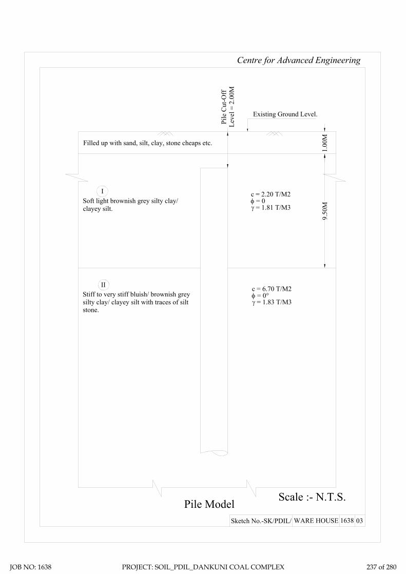
Centre for Advanced Engineering
Pile Model Scale :- N.T.S.
Existing Ground Level.
γ = 1.81 T/M3
c = 2.20 T/M2φ = 0
I
II
9.50
M
γ = 1.83 T/M3
c = 6.70 T/M2φ = 0°
Pile
Cut
-Off
Leve
l = 2
.00M
03Sketch No.-SK/PDIL/ WARE HOUSE 1638
1.00
M
Filled up with sand, silt, clay, stone cheaps etc.
Soft light brownish grey silty clay/clayey silt.
Stiff to very stiff bluish/ brownish greysilty clay/ clayey silt with traces of siltstone.
JOB NO: 1638 PROJECT: SOIL_PDIL_DANKUNI COAL COMPLEX 237 of 280

Ultimate skin friction capacity
Location: Ware House, Dankuni Coal Complex, West Bengal
Layer No: 1Soil Description
Sl.N
o
Pile
Dia
, D
Tota
l Len
gth
of P
ile, L
Dep
th o
f lay
er to
p fro
m E
GL
Dep
th o
f lay
er b
otto
m fr
om E
GL
Red
uctio
n fa
ctor
, α (N
ote1
IS
2911
( Par
t1/S
ec2)
Aver
age
Coh
esio
n al
ong
the
leng
th
of th
e pi
le in
this
laye
r, C
Surfa
ce a
rea
of th
e pi
le s
haft
in th
is
laye
r, A s
Ulti
mat
e Sk
in fr
ictio
n ca
paci
ty o
f th
e sh
aft i
n th
is la
yer,
Qsu
=
α*C
*AS
Mtr Mtr. Mtr Mtr. T/M2 M2
1 0.400 28.000 2.000 10.500 1 2.2 10.681 23.4992 0.500 28.000 2.000 10.500 1 2.2 13.352 29.3743 0.550 28.000 2.000 10.500 1 2.2 14.687 32.3114 0.600 28.000 2.000 10.500 1 2.2 16.022 35.2495 0.750 28.000 2.000 10.500 1 2.2 20.028 44.0616 1.000 28.000 2.000 10.500 1 2.2 26.704 58.748
Project: Geotechnical Investigation Work for Proposed Coal to Methanol Project at Dankuni Coal Complex, Dankuni (WB)
Soft light brownish grey silty clay/ clayey silt.
JOB NO: 1638 PROJECT: SOIL_PDIL_DANKUNI COAL COMPLEX 238 of 280

Ultimate skin friction capacity
Location: Ware House, Dankuni Coal Complex, West Bengal
Layer No: 2Soil Description
Sl.N
o
Pile
Dia
, D
Tota
l Len
gth
of P
ile, L
Dep
th o
f lay
er to
p fro
m E
GL
Dep
th o
f lay
er b
otto
m fr
om E
GL
Red
uctio
n fa
ctor
, α (N
ote1
IS
2911
( Par
t1/S
ec2)
Aver
age
Coh
esio
n al
ong
the
leng
th
of th
e pi
le in
this
laye
r, C
Surfa
ce a
rea
of th
e pi
le s
haft
in th
is
laye
r, A s
Ulti
mat
e Sk
in fr
ictio
n ca
paci
ty o
f th
e sh
aft i
n th
is la
yer,
Qsu
=
α*C
*AS
Mtr Mtr. Mtr Mtr. T/M2 M2
1 0.400 28.000 10.500 28.000 0.65 6.7 21.991 95.7712 0.500 28.000 10.500 28.000 0.65 6.7 27.489 119.7143 0.550 28.000 10.500 28.000 0.65 6.7 30.238 131.6864 0.600 28.000 10.500 28.000 0.65 6.7 32.987 143.6575 0.750 28.000 10.500 28.000 0.65 6.7 41.233 179.5716 1.000 28.000 10.500 28.000 0.65 6.7 54.978 239.429
Project: Geotechnical Investigation Work for Proposed Coal to Methanol Project at Dankuni Coal Complex, Dankuni (WB)
Stiff to very stiff bluish/ brownish grey silty clay/ clayey silt with traces of silt stone.
JOB NO: 1638 PROJECT: SOIL_PDIL_DANKUNI COAL COMPLEX 239 of 280

Ultimate End Bearing capacity
Location: Ware House, Dankuni Coal Complex, West Bengal
Layer No: 2Soil Description
Sl.N
o
Pile
Dia
, D
Tota
l Len
gth
of P
ile, L
Dep
th o
f lay
er to
p fro
m E
GL
Dep
th o
f lay
er b
otto
m fr
om E
GL
Aver
age
Coh
esio
n at
the
pile
tip,
C
P
Cro
ss s
ectio
nal a
rea
of th
e pi
le ti
p,
A P
Bear
ing
capa
city
fact
or, N
C
Ulti
mat
eEnd
bea
ring
capa
city
at
pile
tip,
QB u
= A
P*N
C*C
P
Mtr Mtr. Mtr Mtr. T/M2 M2 T1 0.400 28.000 10.500 28.000 6.7 0.126 9.000 7.5782 0.500 28.000 10.500 28.000 6.7 0.196 9.000 11.8403 0.550 28.000 10.500 28.000 6.7 0.238 9.000 14.3264 0.600 28.000 10.500 28.000 6.7 0.283 9.000 17.0495 0.750 28.000 10.500 28.000 6.7 0.442 9.000 26.6406 1.000 28.000 10.500 28.000 6.7 0.785 9.000 47.360
Project: Geotechnical Investigation Work for Proposed Coal to Methanol Project at Dankuni Coal Complex, Dankuni (WB)
Stiff to very stiff bluish/ brownish grey silty clay/ clayey silt with traces of silt stone.
JOB NO: 1638 PROJECT: SOIL_PDIL_DANKUNI COAL COMPLEX 240 of 280

Sample Calculation:-= 0.22 Kg/cm2
= 21.582 Kn/M2
= 28.00 Mtr.= 2.00 Mtr.= 0.400 Mtr.= 25 N/MM2
= 25000 MN/M2
= 0.00126 M4
= 31.5 KN/M6
= 1.238 MN/M3
T (Stiffness Factor) = 1.91 Mtr. [Where T = (EI/nh)1/5]
= 26.00 Mtr.
Hence, As per Table-5 pile is a LONG ELASTIC PILE Since Le>= 4T
= 0.000 Mtr.
= 2.200
= 4.202 Mtr.
Therefore, Lf = 4.202 Mtr.L1 = 0.000 Mtr.
For Fixed Head Pile, deflection at the pile head,
= 0.005 Mtr. (Adopt)
= 25.47 Kn
= 2.60 T
Horizontal Shear Capacity of Pile
Reference : Code of Practice for Design and Construction of Pile Foundation - IS 2911 (Part1/Sec2)
C Value
L (Length of Pile)Cut-off Level of PileDia of Pile (D)fckE=Econc=Young's modulas
I (Moment of inertia of the pile cross-section)
Neglecting the effect of steel we get EI
nh = Modulas of Subgrade Reaction (if top of the soil is clay) (Table3)
Le (Embeddment Length of the Pile)
Where L1 = free head of Pile above ground
And for fixed head file Lf/T (as per IS Code)
Where Lf is the length of fixicity below cut-off level of pile =
Y =H(e+zf)3/12EILateral Load = H
Horizontal Shear Capacity = Hdesign
JOB NO: 1638 PROJECT: SOIL_PDIL_DANKUNI COAL COMPLEX 241 of 280

Recommended Pile Capacity
Location: Ware House, Dankuni Coal Complex, West Bengal
Sl.N
o
Pile
Dia
, D
Tota
l Len
gth
of P
ile, L
Skin
fric
tion
from
laye
r 1
Skin
fric
tion
from
laye
r 2
End
Bear
ing
Tota
l
F.O
.S
Allo
wab
le P
ile C
apac
ity
Rec
omm
emde
d Pi
le
Cap
acity
in
Com
pres
sion
Rec
omm
emde
d Pi
le
Cap
acity
in P
ull-O
ut
Rec
omm
emde
d Pi
le
Cap
acity
in H
oriz
onta
l Sh
ear
Mtr Mtr. T T T T T T T T T1 0.400 28.000 23.499 95.771 7.578 126.848 2.5 50.739 50 47 2.602 0.500 28.000 29.374 119.714 11.840 160.928 2.5 64.371 64 59 2.833 0.550 28.000 32.311 131.686 14.326 178.323 2.5 71.329 71 65 2.944 0.600 28.000 35.249 143.657 17.049 195.955 2.5 78.382 78 71 3.055 0.750 28.000 44.061 179.571 26.640 250.272 2.5 100.109 100 89 3.336 1.000 28.000 58.748 239.429 47.360 345.536 2.5 138.214 138 119 3.74
Project: Geotechnical Investigation Work for Proposed Coal to Methanol Project at Dankuni Coal Complex, Dankuni (WB)
JOB NO: 1638 PROJECT: SOIL_PDIL_DANKUNI COAL COMPLEX 242 of 280

ZONE-13
CANTEEN
JOB NO: 1638 PROJECT: SOIL_PDIL_DANKUNI COAL COMPLEX 243 of 280

Total one (1) borehole was sunk in this area, viz borehole marked BH-12. From the general sub soil profile it has been observed that the top soil is heterogeneous fill with clay, brickbats, pebbles etc. followed by first layer of soft dark grey silty clay/ clayey silt. The second layer is soft bluish grey silty clay/ clayey silt. The third layer consists of stiff to very stiff mottled bluish/ brownish grey silty clay/ clayey silt and the forth layer as encountered up to the explored depth is dense to very dense brownish grey silty sand.
In addition the following field tests have been carried out at this zone and results are being indicated in this chapter.
1. Electrical Resistivity Test: One (1) electrical resistivity tests has been carried out at this zone marked as ERT-10.
Discussion and Recommendation:
Based on the subsoil condition pile foundation has been recommended for foundation system of medium to heavily loaded structures. Pile capacities in compression, pull-out and horizontal shear for different diameter of pile are indicated in the Table-2A (Zone-13). It is further recommended to carry out initial pile load test for load under compression, pull-out and horizontal shear, in order to confirm the recommended pile capacities and to take corrective measures, if required.
JOB NO: 1638 PROJECT: SOIL_PDIL_DANKUNI COAL COMPLEX 244 of 280

Table-2A (Zone-13). Recommended Pile Capacity
Sl.N
o
Pile
Dia
, D
Tota
l Len
gth
of P
ile, L
Cut
-off
Leve
l
Rec
omm
ende
d Pi
le
Cap
acity
in C
ompr
essi
on
Rec
omm
ende
d Pi
le
Cap
acity
in P
ull-O
ut
Rec
omm
ende
d Pi
le
Cap
acity
in H
oriz
onta
l Sh
ear
Mtr Mtr. Mtr. T T T
1 0.400 28.000 2.000 54 49 2.73
2 0.500 28.000 2.000 72 62 2.99
3 0.550 28.000 2.000 82 69 3.10
4 0.600 28.000 2.000 93 76 3.21
5 0.750 28.000 2.000 130 97 3.51
6 1.000 28.000 2.000 213 134 3.94
JOB NO: 1638 PROJECT: SOIL_PDIL_DANKUNI COAL COMPLEX 245 of 280

DS - Disturbed SampleSCPT-Static Cone Penetration DCPT - Dynamic Cone Penetration
SPT - Standard Penetration Test VST- Vane Shear TestUDS - Undisturbed
Test. Sample Test.
WS - Water Sample
RCS - Rock Core Sample
Centre for Advanced Engineering
N-V A L U E
19 RCSDSDCPTDepth of Drilling
Type of Drilling
D E S C R I P T I O N
VST SCPT
SYMBOL DEPTH
Co-ord: Type of Boring
Depth of Boring
Project:
FIELDTESTE.G.L.: 35.289
SPT35.000 M.Shell & Auger
BORE LOG SHEET
SAMPLESNOS.Unit:
UDS17 10NOS.
WSSAMPLES
0.50 M.Water Struck At :
0.34 M.S A M P L E
DEPTH
Standing Water Table :
NO.
Bore Hole No.:
Soil - 1638
Commenced on : Bore Hole Dia. :
Completed on :
Job No.:
NOS.150 MM.
BH-12 (Sheet-1)
01.10.201904.10.2019
01DS1 0.50 M
N = 2 1.50-1.95MDS3SPT1
1.50-1.95M
N = 3 7.50-7.95MDS7SPT5
7.50-7.95M
N = 10 10.50-10.95MDS9SPT7
10.50-10.95MUDS4 11.00-11.45M
N = 2 3.00-3.45MDS4SPT2
3.00-3.45M
N = 3 6.00-6.45MDS6SPT4
6.00-6.45M
UDS3 8.00-8.45M
N = 3 9.00-9.45MDS8SPT6
9.00-9.45M
UDS5 14.00-14.45MN =18 14.50-14.95M
DS11SPT9
14.50-14.95M
UDS2 5.00-5.45M
N = 8 12.50-12.95MDS10SPT8
12.50-12.95M
N = 19 16.50-16.95MDS12SPT10
16.50-16.95M
N = 12 18.50-18.95MDS13SPT11
18.50-18.95M
UDS6 17.00-17.45M
SOIL_PDIL_DANKUNI_CANTEEN
02
03
04
05
06
07
08
09
10
11
12
13
14
15
16
17
18
19
DS2 1.00 M
N = 2 4.50-4.95MDS5SPT3
4.50-4.95M
Filled up with silty clay, brickbats,pebbles etc.Soft dark grey silty clay/ clayey siltwith traces of vegetative organicmatter.
Contd.....
UDS1 2.00-2.45M
Stiff to very stiff mottled bluish/brownish grey silty clay/ clayey siltwith traces of fine sand.
Soft bluish grey silty clay/ clayeysilt with traces of calcareousnodules.
JOB NO: 1638 PROJECT: SOIL_PDIL_DANKUNI COAL COMPLEX 246 of 280

0.50 M.0.34 M.
150 MM.
BH-12 (Sheet-1)
01.10.201904.10.2019
DS - Disturbed SampleSCPT-Static Cone Penetration DCPT - Dynamic Cone Penetration
SPT - Standard Penetration Test VST- Vane Shear TestUDS - Undisturbed
Test. Sample Test.
WS - Water Sample
RCS - Rock Core Sample
Centre for Advanced Engineering
N-V A L U E
19 RCSDSDCPTDepth of Drilling
Type of Drilling
D E S C R I P T I O N
VST SCPT
SYMBOL DEPTH
Co-ord: Type of Boring
Depth of Boring
Project:
FIELDTESTE.G.L.: 35.289
SPT35.000 M.Shell & Auger
BORE LOG SHEET
SAMPLESNOS.Unit:
UDS17 10NOS.
WSSAMPLES
0.50 M.Water Struck At :
0.34 M.S A M P L E
DEPTH
Standing Water Table :
NO.
Bore Hole No.:
Soil - 1638
Commenced on : Bore Hole Dia. :
Completed on :
Job No.:
NOS.150 MM.
01.10.201904.10.2019
Termination Depth 35.000 Mtr.
21
22
23
24
25
26
27
28
29
30
31
32
33
34
35
36
37
38
39
UDS7 20.00-20.45MN = 17 20.50-20.95M
DS14SPT12
20.50-20.95M
UDS8 23.00-23.45MN = 24 23.50-23.95M
DS15SPT13
23.50-23.95M
UDS9 26.00-26.45M
UDS10 29.00-29.45M
N = 56 26.50-26.95MDS16SPT14
26.50-26.95M
N = 66 29.50-29.95MDS17SPT15
29.50-29.95M
BH-12 (Sheet-2)SOIL_PDIL_DANKUNI_CANTEEN
N = 43 32.00-32.45MDS18SPT16
32.00-32.45M
N = 49 34.55-35.00MDS19SPT17
34.55-35.00M
Stiff to very stiff mottled bluish/brownish grey silty clay/ clayey siltwith traces of fine sand.
Dense to very dense brownish greysilty sand.
JOB NO: 1638 PROJECT: SOIL_PDIL_DANKUNI COAL COMPLEX 247 of 280

Sub-Soil Profile through BH-12
02
24.00M.
12.00M.
18.00M.
20.00M.
22.00M.
14.00M.
16.00M.
6.00M.
10.00M.
8.00M.
2.00M.
4.00M.
Sketch No.-SK/PDIL/ CANTEEN 1638 13 of 13
Termination depth 30.000 M.
BH-12
RL=35.289
26.00M.
28.00M.
30.00M.
32.00M.
34.00M.
36.00M.
38.00M.
1.00MLayer-I
Layer-II
10.50M
6.00M
26.50M
Layer-III
Layer-IV
Filled up with silty clay, brickbats, pebbles etc.
Soft dark grey silty clay/ clayey silt with traces of vegetativeorganic matter.
Stiff to very stiff mottled bluish/ brownish grey silty clay/ clayeysilt with traces of fine sand.
Soft bluish grey silty clay/ clayey silt with traces of calcareous nodules.
Dense to very dense brownish grey silty sand.
JOB NO: 1638 PROJECT: SOIL_PDIL_DANKUNI COAL COMPLEX 248 of 280

LL PL SL Type of Test
Cohesion in
kg/sqcm
Friction angle in degree
Gravel (> 4.75 mm) %
Sand (0.075 - 4.75 mm)
Silt (0.002 - 0.075 mm)
Clay (< 0.002 mm)
Meter % % % γb m G γd quUU/CU/CD
/DS C φ % % % %
12 1.50 DN 2 2.59 14.24 0 9 69 22
0.00-0.10 0.0327
0.10-0.20 0.0221
0.20-0.40 0.0965
0.40-0.80 0.0676
0.80-1.60 0.0471
1.60-3.20 0.0312
12 4.50 DN 2 51 20 11.6 2.68 15.38 0 8 62 30
12 6.00 DN 3 55 20 13.8 2.68 12.64 0 9 67 24
0.00-0.10 0.0284
0.10-0.20 0.0363
0.20-0.40 0.0489
0.40-0.80 0.0417
0.80-1.60 0.0311
1.60-3.20 0.0251
12 9.00 DN 3 63 19 13.2 2.69 11.48 1 8 50 41
0.00-0.10 0.0177
0.10-0.20 0.0251
0.20-0.40 0.0381
0.40-0.80 0.0298
0.80-1.60 0.0242
1.60-3.20 0.0161
12 12.50 DN 8 50 19 11.8 2.70 18.83 0 10 69 21
12 14.50 DN 18 51 18 10.6 2.66 14.29 0 11 62 27
12 18.50 DN 12 46 21 13.5 2.68 15.64 0 10 70 20
12 23.50 DN 24 43 20 12.8 2.67 13.22 0 13 66 21
12 26.50 DN 56 1.80 2.65 DS 0.00 36 0 0 97 3 0
12 32.00 DN 43 1.78 2.65 DS 0.01 34 0 0 99 1 0
NP
NP
Soft dark grey silty clay/ clayey silt with traces of
vegetative organic matter.
I 12 2.00 UD
12 8.00
0.24
0.09
0
13
UU
CU58
Sample Type - UD/D/
DN
SPT VALUE
(N)
Atterberg LimitsUnconfined
Test in Kg/sqcm
Dry Density in gm/cc
Project: Geotechnical Investigation Work for Proposed Coal to Methanol Project at Dankuni Coal Complex, Dankuni (WB)
Swell Pressure
(Kg/sqcm)
Specific Gravity Free Swell
Index(%)
Bulk Density in gm/cc
Shear Test Grading
Layer No.Bore Hole No.
20
SUMMARY OF LABORATORY TEST RESULTSTable-3
Depth Water
Content in %Description of layer
Co-eff. of volume
compressibility in sqcm/kg
0.45
17
12.5 1.83 39.64 2.68 1.31
Pressure (Kg/sqcm
)
1.28
290 21.33 0 8 63
CD 0
CUUD 57 21
CD
14.1 1.82 41.64 2.67 2 54 340.41
UU 0.22 0
0 10110.07
0 16
12 11.00 UD
16.69
UU
48 20 12.4 1.86 30.33
0
0 13.38 02.66 1.43 0.99 13 61 26CU 0.16 22
CD 0 26
0.51
Stiff to very stiff mottles bluish/ brownish grey
silty clay/ clayey silt with traces of fine sand.
III
IV Dense to very dense brownish grey silty sand.
Soft bluish grey silty clay/ clayey silt with traces of calcareous
nodules.
II
JOB NO: 1638 PROJECT: SOIL_PDIL_DANKUNI COAL COMPLEX 249 of 280

SAMPLE CALCULATION
FOR PILE
FOUNDATION
JOB NO: 1638 PROJECT: SOIL_PDIL_DANKUNI COAL COMPLEX 250 of 280

Centre for Advanced Engineering
Pile Model Scale :- N.T.S.
Existing Ground Level.
γ = 1.83 T/M3
c = 2.40 T/M2φ = 0
I
II
5.00
M
γ = 1.82 T/M3
c = 2.20 T/M2φ = 0
Pile
Cut
-Off
Leve
l = 2
.00M
03Sketch No.-SK/PDIL/ CANTEEN 1638
1.00
M
Filled up with silty clay, brickbats, pebbles etc.
Soft dark grey silty clay/ clayey siltwith traces of vegetative organicmatter.
Soft bluish grey silty clay/ clayey siltwith traces of calcareous nodules. 4.
50M
16.0
0MIII
γ = 1.86 T/M3
c = 5.10 T/M2φ = 0Stiff to very stiff mottled bluish/
brownish grey silty clay/ clayey siltwith traces of fine sand.
IV
γ = 1.78 T/M3
c = 0φ = 34°Dense to very dense brownish grey
silty sand.
JOB NO: 1638 PROJECT: SOIL_PDIL_DANKUNI COAL COMPLEX 251 of 280

Ultimate skin friction capacity
Location: Canteen, Dankuni Coal Complex, West Bengal
Layer No: 1Soil Description
Sl.N
o
Pile
Dia
, D
Tota
l Len
gth
of P
ile, L
Dep
th o
f lay
er to
p fro
m E
GL
Dep
th o
f lay
er b
otto
m fr
om E
GL
Red
uctio
n fa
ctor
, α (N
ote1
IS 2
911
( Par
t1/S
ec2)
Aver
age
Coh
esio
n al
ong
the
leng
th
of th
e pi
le in
this
laye
r, C
Surfa
ce a
rea
of th
e pi
le s
haft
in th
is
laye
r, A s
Ulti
mat
e Sk
in fr
ictio
n ca
paci
ty o
f th
e sh
aft i
n th
is la
yer,
Qsu
=
α*C
*AS
Mtr Mtr. Mtr Mtr. T/M2 M2
1 0.400 28.000 2.000 6.000 1 2.4 5.027 12.0642 0.500 28.000 2.000 6.000 1 2.4 6.283 15.0803 0.550 28.000 2.000 6.000 1 2.4 6.912 16.5884 0.600 28.000 2.000 6.000 1 2.4 7.540 18.0965 0.750 28.000 2.000 6.000 1 2.4 9.425 22.6196 1.000 28.000 2.000 6.000 1 2.4 12.566 30.159
Project: Geotechnical Investigation Work for Proposed Coal to Methanol Project at Dankuni Coal Complex, Dankuni (WB)
Soft dark grey silty clay/ clayey silt with traces of vegetative organic matter.
JOB NO: 1638 PROJECT: SOIL_PDIL_DANKUNI COAL COMPLEX 252 of 280

Ultimate skin friction capacity
Location: Canteen, Dankuni Coal Complex, West Bengal
Layer No: 2Soil Description
Sl.N
o
Pile
Dia
, D
Tota
l Len
gth
of P
ile, L
Dep
th o
f lay
er to
p fro
m E
GL
Dep
th o
f lay
er b
otto
m fr
om E
GL
Red
uctio
n fa
ctor
, α (N
ote1
IS
2911
( Par
t1/S
ec2)
Aver
age
Coh
esio
n al
ong
the
leng
th
of th
e pi
le in
this
laye
r, C
Surfa
ce a
rea
of th
e pi
le s
haft
in th
is
laye
r, A s
Ulti
mat
e Sk
in fr
ictio
n ca
paci
ty o
f th
e sh
aft i
n th
is la
yer,
Qsu
=
α*C
*AS
Mtr Mtr. Mtr Mtr. T/M2 M2
1 0.400 28.000 6.000 10.500 1 2.2 5.655 12.4412 0.500 28.000 6.000 10.500 1 2.2 7.069 15.5513 0.550 28.000 6.000 10.500 1 2.2 7.775 17.1064 0.600 28.000 6.000 10.500 1 2.2 8.482 18.6615 0.750 28.000 6.000 10.500 1 2.2 10.603 23.3266 1.000 28.000 6.000 10.500 1 2.2 14.137 31.102
Project: Geotechnical Investigation Work for Proposed Coal to Methanol Project at Dankuni Coal Complex, Dankuni (WB)
Soft bluish grey silty clay/ clayey silt with traces of calcareous nodules.
JOB NO: 1638 PROJECT: SOIL_PDIL_DANKUNI COAL COMPLEX 253 of 280

Ultimate skin friction capacity
Location: Canteen, Dankuni Coal Complex, West Bengal
Layer No: 2Soil Description
Sl.N
o
Pile
Dia
, D
Tota
l Len
gth
of P
ile, L
Dep
th o
f lay
er to
p fro
m E
GL
Dep
th o
f lay
er b
otto
m fr
om E
GL
Red
uctio
n fa
ctor
, α (N
ote1
IS
2911
( Par
t1/S
ec2)
Aver
age
Coh
esio
n al
ong
the
leng
th
of th
e pi
le in
this
laye
r, C
Surfa
ce a
rea
of th
e pi
le s
haft
in th
is
laye
r, A s
Ulti
mat
e Sk
in fr
ictio
n ca
paci
ty o
f th
e sh
aft i
n th
is la
yer,
Qsu
=
α*C
*AS
Mtr Mtr. Mtr Mtr. T/M2 M2
1 0.400 28.000 10.500 26.500 0.9 5.1 20.106 92.2872 0.500 28.000 10.500 26.500 0.9 5.1 25.133 115.3593 0.550 28.000 10.500 26.500 0.9 5.1 27.646 126.8954 0.600 28.000 10.500 26.500 0.9 5.1 30.159 138.4315 0.750 28.000 10.500 26.500 0.9 5.1 37.699 173.0396 1.000 28.000 10.500 26.500 0.9 5.1 50.265 230.719
Project: Geotechnical Investigation Work for Proposed Coal to Methanol Project at Dankuni Coal Complex, Dankuni (WB)
Stiff to very stiff mottles bluish/ brownish grey silty clay/ clayey silt with traces of fine sand.
JOB NO: 1638 PROJECT: SOIL_PDIL_DANKUNI COAL COMPLEX 254 of 280

Ultimate skin friction capacity
Layer No: 4
Soil Description :
Sl.N
o
Pile
Dia
, D
Tota
l Len
gth
of P
ile, L
Dep
th o
f lay
er to
p, fr
om E
GL
Dep
th o
f lay
er b
otto
m, f
rom
EG
L
Wat
er ta
ble
φφ
adop
ted
=(φ
-3)o co
nsid
erin
g lo
osen
ing
effe
ct
NC
Nq Nγ
Uni
t wei
ght,
γ
Effe
ctiv
e un
it w
eigh
t, γ'
k- V
alue
, as
per n
ote
3 IS
291
1 pa
rt 1/
Sec
2-19
79Li
miti
ng L
/D fo
r cal
cn. O
f max
m.
Effe
ctiv
e ov
erbu
rden
pre
ss. A
t pi
le ti
p
P Di a
t lay
er to
p
δ =
φ
Uni
t fric
tion,
f s =
K*P
di*ta
n δ -
at
laye
r top
, max
imum
= 1
0T/M
2
P Di a
t lay
er b
otto
m
Uni
t fric
tion,
f s =
K*P
di*ta
n δ -
at
laye
r bot
tom
, max
imum
= 1
0T/M
2
Aver
age
unit
frict
ion,
ado
pted
for
shaf
t fric
tion
capa
city
.
A Si
Shaf
t fric
tion,
F
Mtr
Mtr.
Mtr
Mtr.
Mtr.
Deg
ree
Deg
ree
T/M
3
T/M
3
T/M
2
Rad
ian
T/M
2
T/M
2
T/M
2
T/M
2
M2 T
1 0.400 28.000 26.500 28.000 1.000 34 31 32.67 20.63 25.99 1.78 0.78 1.3 15 4.68 0.54 3.656 4.68 3.656 3.656 1.885 6.8912 0.500 28.000 26.500 28.000 1.000 34 31 32.67 20.63 25.99 1.78 0.78 1.3 15 5.85 0.54 4.570 5.85 4.570 4.570 2.356 10.7673 0.550 28.000 26.500 28.000 1.000 34 31 32.67 20.63 25.99 1.78 0.78 1.3 15 6.435 0.54 5.026 6.435 5.026 5.026 2.592 13.0284 0.600 28.000 26.500 28.000 1.000 34 31 32.67 20.63 25.99 1.78 0.78 1.3 15 7.02 0.54 5.483 7.02 5.483 5.483 2.827 15.5045 0.750 28.000 26.500 28.000 1.000 34 31 32.67 20.63 25.99 1.78 0.78 1.3 15 8.775 0.54 6.854 8.775 6.854 6.854 3.534 24.2256 1.000 28.000 26.500 28.000 1.000 34 31 32.67 20.63 25.99 1.78 0.78 1.3 15 11.7 0.54 9.139 11.7 9.139 9.139 4.712 43.067
Project: Geotechnical Investigation Work for Proposed Coal to Methanol Project at Dankuni Coal Complex, Dankuni (WB)
Location: Canteen, Dankuni Coal Complex, West Bengal
Dense to very dense brownish grey silty sand.
JOB NO: 1638 PROJECT: SOIL_PDIL_DANKUNI COAL COMPLEX 255 of 280

Location: Canteen, Dankuni Coal Complex, West Bengal
Layer No: 4
Sl.N
o
Pile
Dia
, D
Tota
l Len
gth
of P
ile, L
Dep
th o
f lay
er to
p, fr
om E
GL
Dep
th o
f lay
er b
otto
m, f
rom
EG
L
Wat
er ta
ble
φ
φ ad
opte
d =(
φ -3
)o cons
ider
ing
loos
enin
g ef
fect
NC
Nq Nγ
Uni
t wei
ght, γ
Effe
ctiv
e un
it w
eigh
t, γ'
Lim
iting
L/D
for c
alcn
. Of m
axm
. Ef
fect
ive
over
burd
en p
ress
. At
pile
tip
P Di a
t pile
tip
A P
End
Bear
ing
Mtr Mtr. Mtr Mtr. Mtr.
Deg
ree
Degree T/M3 T/M3 M2 T
1 0.400 28.000 26.500 28.000 0.000 34 31 32.67 20.63 25.99 1.78 0.78 15 4.68 0.126 12.6432 0.500 28.000 26.500 28.000 0.000 34 31 32.67 20.63 25.99 1.78 0.78 15 5.85 0.196 24.6933 0.550 28.000 26.500 28.000 0.000 34 31 32.67 20.63 25.99 1.78 0.78 15 6.435 0.238 32.8664 0.600 28.000 26.500 28.000 0.000 34 31 32.67 20.63 25.99 1.78 0.78 15 7.02 0.283 42.6695 0.750 28.000 26.500 28.000 0.000 34 31 32.67 20.63 25.99 1.78 0.78 15 8.775 0.442 83.3386 1.000 28.000 26.500 28.000 0.000 34 31 32.67 20.63 25.99 1.78 0.78 15 11.7 0.785 197.542
Ultimate end bearing capacity
Project: Geotechnical Investigation Work for Proposed Coal to Methanol Project at Dankuni Coal Complex, Dankuni (WB)
Soil Description : Dense to very dense brownish grey silty sand.
JOB NO: 1638 PROJECT: SOIL_PDIL_DANKUNI COAL COMPLEX 256 of 280

Sample Calculation:-= 0.24 Kg/cm2
= 23.544 Kn/M2
= 28.00 Mtr.= 2.00 Mtr.= 0.400 Mtr.= 25 N/MM2
= 25000 MN/M2
= 0.00126 M4
= 31.5 KN/M6
= 1.350 MN/M3
T (Stiffness Factor) = 1.878 Mtr. [Where T = (EI/nh)1/5]
= 26.00 Mtr.
Hence, As per Table-5 pile is a LONG ELASTIC PILE Since Le>= 4T
= 0.000 Mtr.
= 2.200
= 4.132 Mtr.
Therefore, Lf = 4.132 Mtr.L1 = 0.000 Mtr.
For Fixed Head Pile, deflection at the pile head,
= 0.005 Mtr. (Adopt)
= 26.80 Kn
= 2.73 T
Horizontal Shear Capacity of Pile
Reference : Code of Practice for Design and Construction of Pile Foundation - IS 2911 (Part1/Sec2)
C Value
L (Length of Pile)Cut-off Level of PileDia of Pile (D)fckE=Econc=Young's modulas
I (Moment of inertia of the pile cross-section)
Neglecting the effect of steel we get EI
nh = Modulas of Subgrade Reaction (if top of the soil is clay) (Table3)
Le (Embeddment Length of the Pile)
Where L1 = free head of Pile above ground
And for fixed head file Lf/T (as per IS Code)
Where Lf is the length of fixicity below cut-off level of pile =
Y =H(e+zf)3/12EILateral Load = H
Horizontal Shear Capacity = Hdesign
JOB NO: 1638 PROJECT: SOIL_PDIL_DANKUNI COAL COMPLEX 257 of 280

Recommended Pile Capacity
Location: Canteen, Dankuni Coal Complex, West Bengal
Sl.N
o
Pile
Dia
, D
Tota
l Len
gth
of P
ile, L
Skin
fric
tion
from
laye
r 1
Skin
fric
tion
from
laye
r 2
Skin
fric
tion
from
laye
r 3
Skin
fric
tion
from
laye
r 4
End
Bear
ing
Tota
l
F.O
.S
Allo
wab
le P
ile C
apac
ity
Rec
omm
emde
d Pi
le
Cap
acity
in
Com
pres
sion
Rec
omm
emde
d Pi
le
Cap
acity
in P
ull-O
ut
Rec
omm
emde
d Pi
le
Cap
acity
in H
oriz
onta
l Sh
ear
Mtr Mtr. T T T T T T T T T T T1 0.400 28.000 12.064 12.441 92.287 6.891 12.643 136.325 2.5 54.530 54 49 2.732 0.500 28.000 15.080 15.551 115.359 10.767 24.693 181.449 2.5 72.580 72 62 2.993 0.550 28.000 16.588 17.106 126.895 13.028 32.866 206.483 2.5 82.593 82 69 3.104 0.600 28.000 18.096 18.661 138.431 15.504 42.669 233.361 2.5 93.344 93 76 3.215 0.750 28.000 22.619 23.326 173.039 24.225 83.338 326.548 2.5 130.619 130 97 3.516 1.000 28.000 30.159 31.102 230.719 43.067 197.542 532.588 2.5 213.035 213 134 3.94
Project: Geotechnical Investigation Work for Proposed Coal to Methanol Project at Dankuni Coal Complex, Dankuni (WB)
JOB NO: 1638 PROJECT: SOIL_PDIL_DANKUNI COAL COMPLEX 258 of 280

ELECTRICAL
RESISTIVITY TEST
JOB NO: 1638 PROJECT: SOIL_PDIL_DANKUNI COAL COMPLEX 259 of 280

: Geotechnical Investigation Work for Proposed Coal to Methanol Project at Dankuni Coal Complex, Dankuni (WB): Dankuni Coal Complex, Dankuni, WB: Project & Development India Limited: 12-12-2019: Metravi ERT-1501, SL. No.: 10109809
1 1.0 47 47 47 47 47 46 47 47 295.31 295.31 295.31 295.31 295.31 289.03 295.31 295.31 2 2.0 48 48 48 48 48 47 48 48 603.19 603.19 603.19 603.19 603.19 590.62 603.19 603.19 3 5.0 49 49 49 49 49 48 49 49 1,539.38 1,539.38 1,539.38 1,539.38 1,539.38 1,507.96 1,539.38 1,539.38 4 10.0 51 50 50 50 51 49 51 50 3,204.42 3,141.59 3,141.59 3,141.59 3,204.42 3,078.76 3,204.42 3,141.59 5 15.0 51 51 51 51 51 51 51 51 4,806.64 4,806.64 4,806.64 4,806.64 4,806.64 4,806.64 4,806.64 4,806.64 6 20.0
Instrument
Table ERT - 10ProjectLocation of siteClient Test Date
Sl. No.
Electrode Spacing 's'
m
Measured Resistance "R" (Ω) Apparent Resistivity "ρ" (Ω-m")
North North-East
East East-South
South South-West
Space Not Available
South South-West West North-WestWest North-West
North North-East East East-South
JOB NO: 1638 PROJECT: SOIL_PDIL_DANKUNI COAL COMPLEX 260 of 280

Electrode Spacing - 1.00MR = 46.66 ohm, Resistivity = 293.02 Ohm-m
Location - ERT-10 Location - ERT-10
Electrode Spacing - 2.00MR = 47.67 ohm, Resistivity = 598.74 Ohm-m
Location - ERT-10
Electrode Spacing - 5.00MR = 48.66 ohm, Resistivity = 1527.92 Ohm-m
Location - ERT-10
Electrode Spacing - 10.00MR = 50.04 ohm, Resistivity = 3142.51 Ohm-m
Location - ERT-10
Electrode Spacing - 15.00MR = 51.00 ohm, Resistivity = 4806.64 Ohm-m
JOB NO: 1638 PROJECT: SOIL_PDIL_DANKUNI COAL COMPLEX 261 of 280

SAMPLE CALCULATION FOR SHALLOW
FOUNDATION ON NATURAL SOIL
JOB NO: 1638 PROJECT: SOIL_PDIL_DANKUNI COAL COMPLEX 262 of 280

Foundation Model on Natural SoilScale :- N.T.S.
Existing Ground Level.
I
1.00
M
III
γ = 1.77 T/M3
c = 1.60 T/M2φ = 0
3.00
M
V
mv = 0.00440 M2/TE = 1500 T/M2µ = 0.3
Soft light grey silty clay/clayey silt.
Soft bluish grey silty clay/ clayey silt.
Medium to dense brownish grey siltysand.
04Sketch No.-SK/PDIL DANKUNI 1638
VIHard brownish grey silty clay/ clayey silt.
Dep
th o
f Fdn
1 of 2
Filled Up.
3.50
M
II
Soft dark grey silty clay/clayey silt.
3.00
M
IV
Medium to stiff mottled brownish/ bluishgrey silty clay/ clayey silt.
13.5
0M9.
00M
γ = 1.78 T/M3
c = 1.70 T/M2φ = 0
mv = 0.00451 M2/TE = 1500 T/M2µ = 0.3
γ = 1.80 T/M3
c = 2.30 T/M2φ = 0
mv = 0.00267 M2/TE = 1500 T/M2µ = 0.3
γ = 1.87 T/M3
c = 5.90 T/M2φ = 0
mv = 0.00188 M2/TE = 2000 T/M2µ = 0.3
γ = 1.80 T/M3
c = 0φ = 33°
E = 2500 T/M2µ = 0.3
JOB NO: 1638 PROJECT: SOIL_PDIL_DANKUNI COAL COMPLEX 263 of 280

Sub-soil Srtatification & Properties considered in foundation model
Depth Value
Meter MeterStrata1 1.00 #DIV/0!
Strata 2 3.50 1.5 2 3
Strata 3 3.00 4.5 2 2
Strata4 3.00 7.5 2 2
Strata513.50 10.5 3 2
Strata6 9.00 23.5 29 16
Strata7 2.00 32.5 49 22Strata8
Depth of water Table from EGL = 0.850 Meter
LABORATORY RESULTSCohesion in
T/sqmFriction angle
in degreeBulk
Density in T/cum
Co-eff. of volume
compressibility in sqm/T
C φ γ mv
Strata1 1E-30Strata 2 1.6 0 1.77 0.0044
Strata 3 1.7 0 1.78 0.00451
Strata4 2.3 0 1.8 0.00267
Strata5 5.9 0 1.87 0.00188
Strata6 0 33 1.8 1E-24Strata7 1E-24Strata8
DESIGN PARAMETERS
C φ Depth of Water Table from EGL* γ mv E µT/sqm Degrees meter T/Cum Sqm/T T/sqm
1.6 0 0 1.77 0.00440 1500 0.3* For design purpose, Ground Water Table has been considered as at EGL due to seasonal variation in GWT
CHECK FOR TYPE OF SHEAR FAILUREDesign value of φ, in degrees = 0
Friction Angle<=28degrees, Local Shear Failure
As per IS 6403-1981, cl. No. 5.1.2, the Ultimate Net Safe Bearing Capacity (Net q(ult))1 For General Shear Failure, q(ult) = cNcscdcic + q(Nq-1)sqdqiq+0.5γBNγsγdγiγW'
2 For Local Shear Failure, q(ult) = c'N'cscdcic + q(N'q-1)sqdqiq+0.5γBN'γsγdγiγW'
3 For Intermediate Shear Failure, q(ult) = Value in between the General & Local Shear Failure
Layer Thickness
Soft dark grey silty clay/ clayey silt with peat.
Soft dark grey silty clay/ clayey silt with peat.
Soft bluish grey silty clay/ clayey silt with traces of calcareous nodules.
Hard brownish grey silty clay/ clayey silt.Not explored
SUMMARY OF FIELD/LABORATORY DATA AND CONSIDERED DESIGN PARAMETERS
Soft bluish grey silty clay/ clayey silt with traces of calcareous nodules.Medium to stiff mottled brownish/ bluish grey silty clay/ clayey silt with traces of concretion.Medium to dense brownish grey silty sand with traces of clay binders.
Field N ObservedDescription of layer
Filledup
Soft light grey silty clay/ clayey silt with traces of kankar.
Corrected N Value
Description of layer
Medium to stiff mottled brownish/ bluish grey silty clay/ clayey silt with traces of concretion.Medium to dense brownish grey silty sand with traces of cla bindersHard brownish grey silty clay/ clayey silt.NA
FilledupSoft light grey silty clay/ clayey silt with traces of kankar.
JOB NO: 1638 PROJECT: SOIL_PDIL_DANKUNI COAL COMPLEX 264 of 280

L B Df C C' φ φ' γ
Wat
er T
able
C
orre
ctio
n Fa
ctor
Fact
or o
f saf
ety
NET
SA
FE
BEA
RIN
G
CA
PAC
ITY
Meter Meter Meter Degree T/sqm T/sqm Deg. Deg. T/cum Nc Nq Nγ sc sq sγ dc dq dγ ic iq iγ W' F Qnet safe in T/sqm
2.00 2.00 1.50 0 1.6 1.60 0 0.00 1.77 5.14 1.00 0.00 1.30 1.20 0.80 1.15 1.00 1.00 1 1 1 0.5 2.5 4.92.50 2.50 1.50 0 1.6 1.60 0 0.00 1.77 5.14 1.00 0.00 1.30 1.20 0.80 1.12 1.00 1.00 1 1 1 0.5 2.5 4.73.00 3.00 1.50 0 1.6 1.60 0 0.00 1.77 5.14 1.00 0.00 1.30 1.20 0.80 1.10 1.00 1.00 1 1 1 0.5 2.5 4.72.00 2.00 1.75 0 1.6 1.60 0 0.00 1.77 5.14 1.00 0.00 1.30 1.20 0.80 1.18 1.00 1.00 1 1 1 0.5 2.5 5.02.50 2.50 1.75 0 1.6 1.60 0 0.00 1.77 5.14 1.00 0.00 1.30 1.20 0.80 1.14 1.00 1.00 1 1 1 0.5 2.5 4.83.00 3.00 1.75 0 1.6 1.60 0 0.00 1.77 5.14 1.00 0.00 1.30 1.20 0.80 1.12 1.00 1.00 1 1 1 0.5 2.5 4.72.00 2.00 2.00 0 1.6 1.60 0 0.00 1.77 5.14 1.00 0.00 1.30 1.20 0.80 1.20 1.00 1.00 1 1 1 0.5 2.5 5.12.50 2.50 2.00 0 1.6 1.60 0 0.00 1.77 5.14 1.00 0.00 1.30 1.20 0.80 1.16 1.00 1.00 1 1 1 0.5 2.5 4.93.00 3.00 2.00 0 1.6 1.60 0 0.00 1.77 5.14 1.00 0.00 1.30 1.20 0.80 1.13 1.00 1.00 1 1 1 0.5 2.5 4.83.00 2.00 1.50 0 1.6 1.60 0 0.00 1.77 5.14 1.00 0.00 1.13 1.13 0.73 1.15 1.00 1.00 1 1 1 0.5 2.5 4.23.75 2.50 1.50 0 1.6 1.60 0 0.00 1.77 5.14 1.00 0.00 1.13 1.13 0.73 1.12 1.00 1.00 1 1 1 0.5 2.5 4.14.50 3.00 1.50 0 1.6 1.60 0 0.00 1.77 5.14 1.00 0.00 1.13 1.13 0.73 1.10 1.00 1.00 1 1 1 0.5 2.5 4.13.00 2.00 1.75 0 1.6 1.60 0 0.00 1.77 5.14 1.00 0.00 1.13 1.13 0.73 1.18 1.00 1.00 1 1 1 0.5 2.5 4.33.75 2.50 1.75 0 1.6 1.60 0 0.00 1.77 5.14 1.00 0.00 1.13 1.13 0.73 1.14 1.00 1.00 1 1 1 0.5 2.5 4.24.50 3.00 1.75 0 1.6 1.60 0 0.00 1.77 5.14 1.00 0.00 1.13 1.13 0.73 1.12 1.00 1.00 1 1 1 0.5 2.5 4.13.00 2.00 2.00 0 1.6 1.60 0 0.00 1.77 5.14 1.00 0.00 1.13 1.13 0.73 1.20 1.00 1.00 1 1 1 0.5 2.5 4.43.75 2.50 2.00 0 1.6 1.60 0 0.00 1.77 5.14 1.00 0.00 1.13 1.13 0.73 1.16 1.00 1.00 1 1 1 0.5 2.5 4.34.50 3.00 2.00 0 1.6 1.60 0 0.00 1.77 5.14 1.00 0.00 1.13 1.13 0.73 1.13 1.00 1.00 1 1 1 0.5 2.5 4.222.5 1.50 1.50 0 1.6 1.60 0 0.00 1.77 5.14 1.00 0.00 1.00 1.00 1.00 1.20 1.00 1.00 1 1 1 0.5 2.5 3.930 2.00 1.50 0 1.6 1.60 0 0.00 1.77 5.14 1.00 0.00 1.00 1.00 1.00 1.15 1.00 1.00 1 1 1 0.5 2.5 3.7
37.5 2.50 1.50 0 1.6 1.60 0 0.00 1.77 5.14 1.00 0.00 1.00 1.00 1.00 1.12 1.00 1.00 1 1 1 0.5 2.5 3.622.5 1.50 1.75 0 1.6 1.60 0 0.00 1.77 5.14 1.00 0.00 1.00 1.00 1.00 1.23 1.00 1.00 1 1 1 0.5 2.5 4.030 2.00 1.75 0 1.6 1.60 0 0.00 1.77 5.14 1.00 0.00 1.00 1.00 1.00 1.18 1.00 1.00 1 1 1 0.5 2.5 3.8
37.5 2.50 1.75 0 1.6 1.60 0 0.00 1.77 5.14 1.00 0.00 1.00 1.00 1.00 1.14 1.00 1.00 1 1 1 0.5 2.5 3.722.5 1.50 2.00 0 1.6 1.60 0 0.00 1.77 5.14 1.00 0.00 1.00 1.00 1.00 1.27 1.00 1.00 1 1 1 0.5 2.5 4.130 2.00 2.00 0 1.6 1.60 0 0.00 1.77 5.14 1.00 0.00 1.00 1.00 1.00 1.20 1.00 1.00 1 1 1 0.5 2.5 3.9
37.5 2.50 2.00 0 1.6 1.60 0 0.00 1.77 5.14 1.00 0.00 1.00 1.00 1.00 1.16 1.00 1.00 1 1 1 0.5 2.5 3.8
CALCULATION OF NET SAFE BEARING CAPACITY FROM SHEAR CRITERIA
INCL
INAT
ION
FACT
ORS
FOOTING DIMENSIONS
Load
incli
natio
n w.
r.t.
Verti
cal (
α)
SOIL PARAMETERS
ISO
LATE
D S
QU
ARE
FOO
TIN
GS
ISO
LATE
D R
ECTA
NG
ULA
R
FOO
TIN
GS
CO
NTI
NU
OU
S ST
RIP
FO
OTI
NG
S
BEAR
ING
CAPA
CITY
FA
CTOR
S
SHAP
E FA
CTOR
S
DEPT
H FA
CTOR
S
JOB NO: 1638 PROJECT: SOIL_PDIL_DANKUNI COAL COMPLEX 265 of 280

L B Df
Foun
datio
n pr
esur
e,
p
Pois
son'
s R
atio
µYo
ungs
M
odul
us,
E
Cvo
effic
ient
of
cons
olid
atio
n,
m
v
pres
sure
in
crem
ent,
∆
p
Laye
r thi
ckne
ss
H
Influ
ence
Fac
tor
I
Elas
tic
settl
emen
t
Si
= p
B{(
1-µ2 )/E
}IC
onso
lidat
ion
Settl
emen
t Sc=
m
v∆pH
tota
l set
tlem
ent,
S t
= S i
+ S
c
Dep
th F
acto
r
Dfa
ct
Rig
idity
fact
or
Rfa
ct
tota
l cor
rect
ed
settl
emen
t,
S t(c
orre
ct)=
St *
D
Fact
*Rfa
ct
Meter Meter Meter T/m2 T/M2 m2/T T/m2 Meter mm mm mm mm2.00 2.00 1.50 4.9 0.3 1500 0.004 1.23 4.00 0.95 5.65 21.56 27.21 0.794 0.8 17.282.50 2.50 1.50 4.7 0.3 1500 0.004 1.18 5.00 0.95 6.77 25.85 32.62 0.835 0.8 21.793.00 3.00 1.50 4.7 0.3 1500 0.004 1.18 6.00 0.95 8.13 31.02 39.15 0.863 0.8 27.012.00 2.00 1.75 5.0 0.3 1500 0.004 1.25 4.00 0.95 5.76 22.00 27.76 0.759 0.8 16.872.50 2.50 1.75 4.8 0.3 1500 0.004 1.20 5.00 0.95 6.92 26.40 33.32 0.808 0.8 21.523.00 3.00 1.75 4.7 0.3 1500 0.004 1.18 6.00 0.95 8.13 31.02 39.15 0.84 0.8 26.292.00 2.00 2.00 5.1 0.3 1500 0.004 1.28 4.00 0.95 5.88 22.44 28.32 0.725 0.8 16.422.50 2.50 2.00 4.9 0.3 1500 0.004 1.23 5.00 0.95 7.06 26.95 34.01 0.78 0.8 21.223.00 3.00 2.00 4.8 0.3 1500 0.004 1.20 6.00 0.95 8.30 31.68 39.98 0.817 0.8 26.123.00 2.00 1.50 4.2 0.3 1500 0.004 1.26 4.00 1.2 6.12 22.18 28.29 0.832 0.8 18.823.75 2.50 1.50 4.1 0.3 1500 0.004 1.23 5.00 1.2 7.46 27.06 34.52 0.865 0.8 23.904.50 3.00 1.50 4.1 0.3 1500 0.004 1.23 6.00 1.2 8.95 32.47 41.43 0.888 0.8 29.423.00 2.00 1.75 4.3 0.3 1500 0.004 1.29 4.00 1.2 6.26 22.70 28.96 0.804 0.8 18.623.75 2.50 1.75 4.2 0.3 1500 0.004 1.26 5.00 1.2 7.64 27.72 35.36 0.843 0.8 23.844.50 3.00 1.75 4.1 0.3 1500 0.004 1.23 6.00 1.2 8.95 32.47 41.43 0.869 0.8 28.803.00 2.00 2.00 4.4 0.3 1500 0.004 1.32 4.00 1.2 6.41 23.23 29.64 0.775 0.8 18.393.75 2.50 2.00 4.3 0.3 1500 0.004 1.29 5.00 1.2 7.83 28.38 36.21 0.82 0.8 23.764.50 3.00 2.00 4.2 0.3 1500 0.004 1.26 6.00 1.2 9.17 33.26 42.44 0.85 0.8 28.87
22.50 1.50 1.50 3.9 0.3 1500 0.004 1.83 3.00 2.289 8.13 24.13 32.26 0.929 0.8 23.9730.00 2.00 1.50 3.7 0.3 1500 0.004 1.73 4.00 2.289 10.28 30.53 40.80 0.947 0.8 30.9037.50 2.50 1.50 3.6 0.3 1500 0.004 1.69 5.00 2.289 12.50 37.13 49.63 0.957 0.8 38.0122.50 1.50 1.75 4.0 0.3 1500 0.004 1.88 3.00 2.289 8.33 24.75 33.08 0.917 0.8 24.2730.00 2.00 1.75 3.8 0.3 1500 0.004 1.78 4.00 2.289 10.56 31.35 41.91 0.938 0.8 31.4437.50 2.50 1.75 3.7 0.3 1500 0.004 1.73 5.00 2.289 12.85 38.16 51.00 0.95 0.8 38.7822.50 1.50 2.00 4.1 0.3 1500 0.004 1.92 3.00 2.289 8.54 25.37 33.91 0.905 0.8 24.5630.00 2.00 2.00 3.9 0.3 1500 0.004 1.83 4.00 2.289 10.83 32.18 43.01 0.929 0.8 31.9637.50 2.50 2.00 3.8 0.3 1500 0.004 1.78 5.00 2.289 13.19 39.19 52.38 0.943 0.8 39.53
CALCULATION OF FOUNDATION SETTLEMENT
FOOTING DIMENSIONS
ISO
LATE
D S
QU
ARE
FOO
TIN
GS
ISO
LATE
D R
ECTA
NG
ULA
R
FOO
TIN
GS
CO
NTI
NU
OU
S ST
RIP
FO
OTI
NG
S
JOB NO: 1638 PROJECT: SOIL_PDIL_DANKUNI COAL COMPLEX 266 of 280

FOU
ND
ATI
ON
TYP
E
L B DfN
ET S
AFE
BEA
RIN
G
CA
PAC
ITY
tota
l cor
rect
ed
settl
emen
t,
S tco
rrec
t
For a
llow
able
se
ttlem
ent 2
5 m
m
For a
llow
able
se
ttlem
ent 4
0 m
m
For a
llow
able
se
ttlem
ent 7
5 m
m
Meter Meter Meter Qnet safe in T/sqm mm T/Sqm T/Sqm T/Sqm
2.00 2.00 1.50 4.9 17.28 4 4 42.50 2.50 1.50 4.7 21.79 4 4 43.00 3.00 1.50 4.7 27.01 4 4 42.00 2.00 1.75 5.0 16.87 5 5 52.50 2.50 1.75 4.8 21.52 4 4 43.00 3.00 1.75 4.7 26.29 4 4 42.00 2.00 2.00 5.1 16.42 5 5 52.50 2.50 2.00 4.9 21.22 4 4 43.00 3.00 2.00 4.8 26.12 4 4 43.00 2.00 1.50 4.2 18.82 4 4 43.75 2.50 1.50 4.1 23.90 4 4 44.50 3.00 1.50 4.1 29.42 3 4 43.00 2.00 1.75 4.3 18.62 4 4 43.75 2.50 1.75 4.2 23.84 4 4 44.50 3.00 1.75 4.1 28.80 3 4 43.00 2.00 2.00 4.4 18.39 4 4 43.75 2.50 2.00 4.3 23.76 4 4 44.50 3.00 2.00 4.2 28.87 3 4 422.5 1.50 1.50 3.9 23.97 3 3 330 2.00 1.50 3.7 30.90 2 3 3
37.5 2.50 1.50 3.6 38.01 2 3 322.5 1.50 1.75 4.0 24.27 4 4 430 2.00 1.75 3.8 31.44 3 3 3
37.5 2.50 1.75 3.7 38.78 2 3 322.5 1.50 2.00 4.1 24.56 4 4 430 2.00 2.00 3.9 31.96 3 3 3
37.5 2.50 2.00 3.8 39.53 2 3 3CO
NTI
NU
OU
S ST
RIP
FO
OTI
NG
S
FOOTING DIMENSIONS
ISO
LATE
D S
QU
ARE
FOO
TIN
GS
ISO
LATE
D R
ECTA
NG
ULA
R
FOO
TIN
GS
ALLOWABLE BEARING CAPACITY
ALLOWABLE BEARING CAPACITY FROM SHEAR AND SETTLEMENT CRITERIA
JOB NO: 1638 PROJECT: SOIL_PDIL_DANKUNI COAL COMPLEX 267 of 280

SAMPLE CALCULATION
FOR SHALLOW
FOUNDATION ON
IMPROVED SOIL BY
SAND REPLACEMENT
JOB NO: 1638 PROJECT: SOIL_PDIL_DANKUNI COAL COMPLEX 268 of 280

Foundation Model on Improved SoilScale :- N.T.S.
Existing Ground Level.
Dep
th o
f Fdn
04Sketch No.-SK/PDIL DANKUNI 1638 2 of 2
I
1.00
M
III
γ = 1.77 T/M3
c = 1.60 T/M2φ = 0
3.00
M
V
mv = 0.00440 M2/TE = 1500 T/M2µ = 0.3
Soft light grey silty clay/clayey silt.
Soft bluish grey silty clay/ clayey silt.
Medium to dense brownish grey siltysand.
VIHard brownish grey silty clay/ clayey silt.
Filled Up.
3.50
M
II
Soft dark grey silty clay/clayey silt.
3.00
M
IV
Medium to stiff mottled brownish/ bluishgrey silty clay/ clayey silt.
13.5
0M9.
00M
γ = 1.78 T/M3
c = 1.70 T/M2φ = 0
mv = 0.00451 M2/TE = 1500 T/M2µ = 0.3
γ = 1.80 T/M3
c = 2.30 T/M2φ = 0
mv = 0.00267 M2/TE = 1500 T/M2µ = 0.3
γ = 1.87 T/M3
c = 5.90 T/M2φ = 0
mv = 0.00188 M2/TE = 2000 T/M2µ = 0.3
γ = 1.80 T/M3
c = 0φ = 33°
E = 2500 T/M2µ = 0.3
Compacted Sand Fill
1.50
M1.
50M
JOB NO: 1638 PROJECT: SOIL_PDIL_DANKUNI COAL COMPLEX 269 of 280

COMPUTATION OF BEARING CAPACITY WITH SAND BACK FILLSquare Footing
2.00 x 2.00 2.50 x 2.50 3.00 x 3.002.00 2.50 3.00
1.50 1.50 1.50
0.00 0.00 0.0033 33 33
29.82 29.82 29.821.80 1.80 1.80
1.20 1.20 1.200.00 0.00 0.00
Bearing Capacity Factor29.71 29.71 29.7118.03 18.03 18.0321.81 21.81 21.81
Shape Factor1.30 1.30 1.301.20 1.20 1.200.80 0.80 0.80
Depth Factor1.26 1.21 1.17
1.13 1.10 1.09
1.13 1.10 1.09
Inclination1.00 1.00 1.00
1.00 1.00 1.00
1.00 1.00 1.00
0.50 0.50 0.50
0.00 0.00 0.00
27.69 27.06 26.64
17.74 21.66 25.59
45.43 48.72 52.23
2.50 2.50 2.50
18.17 19.49 20.89
0.5Bγ Nγ sγdγiγW'
N.U.B.C
F.O.S
N.S.B.C
q(Nq-1)Sqdqiq
ScSqSγ
dc
dq
dγ
iciqiγ
W'
0.67cNcScdcic
Nγ
Size (m x m)B (m)Df (m)
C (T/M2)φ (degree)φ' (degree)γ (T/M3)q (T/M2)α (Degree)
NcNq
JOB NO: 1638 PROJECT: SOIL_PDIL_DANKUNI COAL COMPLEX 270 of 280

Retengular Footing
2.00 x 3.00 2.50 x 3.75 3.00 x 4.503.00 3.75 4.502.00 2.50 3.00
1.50 1.50 1.50
0.00 0.00 0.0033 33 33
29.82 29.82 29.821.80 1.80 1.80
1.20 1.20 1.200.00 0.00 0.00
Bearing Capacity Factor29.71 29.71 29.7118.03 18.03 18.0321.81 21.81 21.81
Shape Factor1.13 1.13 1.131.13 1.13 1.130.73 0.73 0.73
Depth Factor1.26 1.21 1.17
1.13 1.10 1.09
1.13 1.10 1.09
Inclination1.00 1.00 1.00
1.00 1.00 1.00
1.00 1.00 1.00
0.50 0.50 0.50
0.00 0.00 0.00
26.16 25.56 25.16
16.26 19.86 23.46
42.42 45.41 48.612.50 2.50 2.50
16.97 18.17 19.45F.O.SN.S.B.C
L (m)
iγ
W'
0.67cNcScdcicq(Nq-1)Sqdqiq0.5Bγ Nγ sγdγiγW'N.U.B.C
Sγ
dc
dq
dγ
iciq
α (Degree)
NcNqNγ
ScSq
q (T/M2)
Size (m x m)
B (m)Df (m)
C (T/M2)φ (degree)φ' (degree)γ (T/M3)
JOB NO: 1638 PROJECT: SOIL_PDIL_DANKUNI COAL COMPLEX 271 of 280

Strip Footing
1.50 2.00 2.501.50 2.00 2.50
1.50 1.50 1.50
0.00 0.00 0.0033 33 33
29.82 29.82 29.821.80 1.80 1.80
1.20 1.20 1.200.00 0.00 0.00
Bearing Capacity Factor29.71 29.71 29.7118.03 18.03 18.0321.81 21.81 21.81
Shape Factor1.00 1.00 1.001.00 1.00 1.001.00 1.00 1.00
Depth Factor1.35 1.26 1.21
1.17 1.13 1.10
1.17 1.13 1.10
Inclination1.00 1.00 1.00
1.00 1.00 1.00
1.00 1.00 1.00
0.50 0.50 0.50
0.00 0.00 0.00
23.96 23.08 22.55
17.26 22.17 27.08
41.22 45.25 49.632.50 2.50 2.50
16.49 18.10 19.85F.O.SN.S.B.C
iγ
W'
0.67cNcScdcicq(Nq-1)Sqdqiq0.5Bγ Nγ sγdγiγW'N.U.B.C
iq
α (Degree)
NcNqNγ
ScSqSγ
dc
dq
dγ
ic
Df (m)
C (T/M2)φ (degree)φ' (degree)γ (T/M3)q (T/M2)
Size (m x m)B (m)
JOB NO: 1638 PROJECT: SOIL_PDIL_DANKUNI COAL COMPLEX 272 of 280

E.G.L
1.50M
1.50
M1.
50M
δP at the centre of the compressible layer = P x B/(B+Z1)= 18.10 x 2/(2+2.25) T/M2= 8.52 T/M2
δP = 8.52 T/M2Mv = 0.00440 M2/T
So, S = Mv x δP x H = 0.00440 x 8.52 x 1.50 x 1000 = 56.23mm
Corrected Settlement = (56.23+29.68) x 0.80 = 68.73mm < 75mmBearing Capacity of 2.00M wide strip = 18.10 T/M2
Similary Settlement of 2.50M wide strip = 99.21mm > 75mmHence, Bearing Capacity of 2.50M wide strip for 75mm settlement = 15.00 T/M2
Z1 (d
epth
)
Settlement Calculation for Strip Footing
1.00
M
Layer-I
Layer-II
Layer-I
δP at the centre of the compressible layer = P x B/(B+Z2)= 18.10 x 2/(2+3.50) T/M2= 6.58 T/M2
Layer-II
Z2 (d
epth
)
δP = 6.58 T/M2
Mv = 0.00451 M2/T
Layer-ISo, S = Mv x δP x H = 0.00451 x 6.58 x 1.00 x 1000 = 29.68mm
Layer-II
P = 18.10 T/M2
B = 2.00 M
SAND FILL
JOB NO: 1638 PROJECT: SOIL_PDIL_DANKUNI COAL COMPLEX 273 of 280

B L Df
(i) (ii) (iii) (iv) (v) (vi) (vii) (viii) (ix) (x) (xi)
2.00 2.00 1.50 1.50 18.17 31.71 5.93 4.00 4.00 12.25
2.50 2.50 1.50 1.50 19.49 52.42 7.61 4.00 4.00 10.24
3.00 3.00 1.50 1.50 20.89 77.24 9.28 4.00 4.00 9.00
2.00 3.00 1.50 1.50 16.97 38.45 6.46 4.00 4.00 10.50
2.50 3.75 1.50 1.50 18.17 65.76 8.11 4.00 4.00 8.96
3.00 4.50 1.50 1.50 19.45 90.24 9.72 4.00 4.00 8.00
1.50 1.50 1.50 16.49 43.56 8.24 3.00 3.00 6.00
2.00 1.50 1.50 18.10 68.73 10.34 3.00 3.00 5.25
2.50 1.50 1.50 19.85 99.21 12.41 3.00 3.00 4.80
TYPE
OF
FOO
TIN
GS
ISO
LATE
D
SQU
ARE
FOO
TIN
GS
ISO
LATE
D
REC
TAN
GU
LAR
FO
OTI
NG
S
CO
NTI
NU
OU
S ST
RIP
FO
OTI
NG
S
Bearing Capacity of Soil after Ground Improvement with Compacted Sand Fill
ADO
PTED
PR
ESSU
RE
AT T
OP
OF
VER
GIN
E SO
IL (t
/m2)
(LO
WER
OF
THE
VALU
ES O
F vi
i & v
iii )
DES
IGN
SBC
OF
FOU
ND
ATIO
N O
N T
OP
OF
SAN
D F
ILL
(t/m
2)
SIZE
OF
FOU
ND
ATIO
N (m
)
THIC
KNES
S O
F C
OM
PAC
TED
SAN
D
FILL
BEL
OW
FO
UN
DAT
ION
(m)
SAFE
BEA
RIN
G C
APAC
ITY
OF
CO
MPA
CTE
D S
AND
FIL
L AT
FO
UN
DAT
ION
DEP
TH (m
)
ESTI
MAT
ED S
ETTL
EMEN
T (m
m)
PRES
SUR
E O
N V
ERG
INE
SOIL
AT
A LE
VEL
BELO
W C
OM
PAC
TED
SAN
D F
ILL
(t/m
2)
ALLO
WAB
LE B
EAR
ING
CAP
ACIT
Y O
F VE
RG
INE
SOIL
(t/m
2)
JOB NO: 1638 PROJECT: SOIL_PDIL_DANKUNI COAL COMPLEX 274 of 280

CHEMICAL TEST ON SOIL AND WATER
SAMPLE
JOB NO: 1638 PROJECT: SOIL_PDIL_DANKUNI COAL COMPLEX 275 of 280

pH Value 6.9
Sulphite Content as SO3 Absent
Chloride Content as CI 0.032%
pH Value 7.0
Sulphite Content as SO3 Absent
Chloride Content as CI 0.031%
pH Value 6.7
Sulphite Content as SO3 Absent
Chloride Content as CI 0.033%
pH Value 6.8
Sulphite Content as SO3 Absent
Chloride Content as CI 0.035%
pH Value 6.9
Sulphite Content as SO3 Absent
Chloride Content as CI 0.038%
pH Value 6.8
Sulphite Content as SO3 Absent
Chloride Content as CI 0.034%
pH Value 6.9
Sulphite Content as SO3 Absent
Chloride Content as CI 0.037%
pH Value 6.7
Sulphite Content as SO3 Absent
Chloride Content as CI 0.034%
pH Value 6.7
Sulphite Content as SO3 Absent
Chloride Content as CI 0.036%
pH Value 6.9
Sulphite Content as SO3 Absent
Chloride Content as CI 0.037%
BH-1Depth: 1.50-1.95M
Soft brownish grey silty clay/ clayey silt with traces of sand.
Chemical Test on Soil Samples
Type of Chemical Test ResultLocation Description of Soil
PROJECT: Geotechnical Investigation Work for Proposed Coal to Methanol Project at Dankuni Coal Complex, Dankuni (WB)
BH-1Depth: 3.00-3.45M
Soft brownish grey silty clay/ clayey silt with traces of sand.
BH-5 Depth: 1.50-1.95M
Soft to medium brownish/ bluish grey silty clay/ clayey silt with traces of sand and silt
stone.
BH-5Depth: 3.00-3.45M
Soft to medium brownish/ bluish grey silty clay/ clayey silt with traces of sand and silt
stone.
BH-3Depth: 3.00-3.45M
Soft light/ dark grey silty clay/ clayey silt with traces of concretion.
BH-4Depth: 4.50-4.95M
Medium brownish grey silty clay/ clayey silt with traces of sand and rusty brown
spots.
BH-4Depth: 6.00-6.45M
Medium brownish grey silty clay/ clayey silt with traces of sand and rusty brown
spots.
BH-2Depth: 1.50-1.95M
Soft light grey silty clay/ clayey silt with traces of sand.
BH-2Depth: 3.00-3.45M
Soft light grey silty clay/ clayey silt with traces of sand.
BH-3Depth: 1.50-1.95M
Soft light/ dark grey silty clay/ clayey silt with traces of concretion.
JOB NO: 1638 PROJECT: SOIL_PDIL_DANKUNI COAL COMPLEX 276 of 280

Type of Chemical Test ResultLocation Description of Soil
pH Value 7.0
Sulphite Content as SO3 Absent
Chloride Content as CI 0.038%
pH Value 7.0
Sulphite Content as SO3 Absent
Chloride Content as CI 0.038%
pH Value 6.9
Sulphite Content as SO3 Absent
Chloride Content as CI 0.037%
pH Value 7.0
Sulphite Content as SO3 Absent
Chloride Content as CI 0.038%
pH Value 6.9
Sulphite Content as SO3 Absent
Chloride Content as CI 0.037%
pH Value 7.0
Sulphite Content as SO3 Absent
Chloride Content as CI 0.037%
pH Value 6.9
Sulphite Content as SO3 Absent
Chloride Content as CI 0.036%
pH Value 6.8
Sulphite Content as SO3 Absent
Chloride Content as CI 0.037%
pH Value 6.8
Sulphite Content as SO3 Absent
Chloride Content as CI 0.038%
pH Value 7.0
Sulphite Content as SO3 Absent
Chloride Content as CI 0.037%
pH Value 6.9
Sulphite Content as SO3 Absent
Chloride Content as CI 0.038%
pH Value 6.7
Sulphite Content as SO3 Absent
Chloride Content as CI 0.037%
BH-11Depth: 1.50-1.95M
Soft to medium brownish grey silty clay/ clayey silt with traces of sea shell, sand
and silt stone.
BH-11Depth: 3.00-3.45M
Soft to medium brownish grey silty clay/ clayey silt with traces of sea shell, sand
and silt stone.
BH-9 Depth: 7.50-7.95M
Soft to medium brownish grey silty clay/ clayey silt.
BH-10Depth: 1.50-1.95M
Soft light grey silty clay/ clayey silt with traces of kankar.
BH-10Depth: 3.00-3.45M
Soft light grey silty clay/ clayey silt with traces of kankar.
BH-8Depth: 5.50-5.95M
Soft brownish grey silty clay/ clayey silt with traces of rusty brown spots.
BH-8Depth: 8.00-8.45M
Soft brownish grey silty clay/ clayey silt with traces of rusty brown spots.
BH-9Depth: 6.00-6.45M
Soft to medium brownish grey silty clay/ clayey silt.
BH-6Depth: 3.00-3.45M
Soft light/ bluish grey silty clay/ clayey silt with traces of sand.
BH-7Depth: 1.50-1.95M
Soft brownish grey silty clay/ clayey silt with traces of sand.
BH-7Depth: 3.00-3.45M
Soft brownish grey silty clay/ clayey silt with traces of sand.
BH-6Depth: 1.50-1.95M
Soft light/ bluish grey silty clay/ clayey silt with traces of sand.
JOB NO: 1638 PROJECT: SOIL_PDIL_DANKUNI COAL COMPLEX 277 of 280

Type of Chemical Test ResultLocation Description of Soil
pH Value 6.9
Sulphite Content as SO3 Absent
Chloride Content as CI 0.037%
pH Value 6.7
Sulphite Content as SO3 Absent
Chloride Content as CI 0.038%
pH Value 7.0
Sulphite Content as SO3 Absent
Chloride Content as CI 0.034%
pH Value 6.9
Sulphite Content as SO3 Absent
Chloride Content as CI 0.038%
pH Value 6.8
Sulphite Content as SO3 Absent
Chloride Content as CI 0.033%
pH Value 7.0
Sulphite Content as SO3 Absent
Chloride Content as CI 0.035%
pH Value 6.9
Sulphite Content as SO3 Absent
Chloride Content as CI 0.038%
BH-12Depth: 1.50-1.95M
Soft dark grey silty clay/ clayey silt with traces of vegetative organic matter.
BH-12Depth: 3.00-3.45M
Soft dark grey silty clay/ clayey silt with traces of vegetative organic matter.
BH-11Depth: 4.50-4.95M
Soft to medium brownish grey silty clay/ clayey silt with traces of sea shell, sand
and silt stone.
BH-13Depth: 1.50-1.95M
BH-13Depth: 3.00-3.45M
Soft to medium bluish/ dark grey silty clay/ clayey silt with traces of vegetative
organic matter. Calcareous nodules found occasionally.
Soft to medium bluish/ dark grey silty clay/ clayey silt with traces of vegetative
organic matter. Calcareous nodules found occasionally.
BH-13Depth: 1.50-1.95M
BH-13Depth: 3.00-3.45M
Soft light brownish grey silty clay/ clayey silt.
Soft light brownish grey silty clay/ clayey silt.
JOB NO: 1638 PROJECT: SOIL_PDIL_DANKUNI COAL COMPLEX 278 of 280

Location Description Result
7.1
12.8
17.5
7.4
13.217.57.4
13.817.77.4
13.517.66.9
12.9
17.4
7
13.117.37.2
13.517.37.6
13.317.57.6
13.3
17.4
7.5
13.417.47.4
13.217.7
BH-5Water Collected from
Borehole Marked BH-5
Water Collected from Borehole Marked BH-4
pH valueSulphate SO3
Sulphate SO3
Chloride as Cl
Chloride as Cl
Water Collected from Borehole Marked BH-2
Water Collected from Borehole Marked BH-1
Chloride as Cl
Sulphate SO3
Chloride as Cl
Chemical Test on Water Samples
Type of Chemical Test
Sulphate SO3
BH-3Water Collected from
Borehole Marked BH-3
pH value
BH-2
BH-1
PROJECT: Geotechnical Investigation Work for Proposed Coal to Methanol Project at Dankuni Coal Complex, Dankuni (WB)
pH value
BH-7Water Collected from
Borehole Marked BH-7
pH valueSulphate SO3
Chloride as Cl
pH value
BH-6Water Collected from
Borehole Marked BH-6
pH value
Sulphate SO3
BH-9Water Collected from
Borehole Marked BH-9
pH value
Sulphate SO3
Chloride as Cl
Chloride as Cl
pH value
Sulphate SO3
Chloride as Cl
BH-4
BH-11Water Collected from
Borehole Marked BH-11
pH valueSulphate SO3
Chloride as Cl
BH-8Water Collected from
Borehole Marked BH-8
pH valueSulphate SO3
Chloride as Cl
BH-10Water Collected from
Borehole Marked BH-10
pH value
Sulphate SO3
Chloride as Cl
JOB NO: 1638 PROJECT: SOIL_PDIL_DANKUNI COAL COMPLEX 279 of 280

Location Description ResultType of Chemical Test7.8
13.117.17.3
13.5
17.6
7.2
13.4
17.6
BH-13Water Collected from
Borehole Marked BH-13
pH value
Sulphate SO3
Chloride as Cl
BH-12Water Collected from
Borehole Marked BH-12
pH valueSulphate SO3
Chloride as Cl
BH-14Water Collected from
Borehole Marked BH-14
pH value
Sulphate SO3
Chloride as Cl
JOB NO: 1638 PROJECT: SOIL_PDIL_DANKUNI COAL COMPLEX 280 of 280

0
REV
P
24.09.20
REV DATE
PLANT:
PROJEC
PROJECT
24.09.20
EFF DATE
COAL/
IA
CT: SPRW(
TS & DEV
P
ENGIN
/FLUXA
INTEGRAT DAN
SUPPLY PROJECROUTE WESTB(BOO) B
VELOPME
Issued fo
PURP
PART II:
SECT
NEERING
NT AND
RATED CNKUNI, K
OF CTTHRO
AT ENGALI
BASIS.
ENT INDIA
or Tender
OSE
: TECHN
TION –1.
G SPECIFOR
D ASH HA
COAL BKOLKAT
COAL OUGH
DANKINDIA O
A LTD
PII
NICAL
.13
IFICATIO
ANDLIN
BASED MTA (INDIA
TO MCOAL
KUNI ON BU
PC176/E/4001/PI/SECTION– 1.13
Document No.
SHEET 1 OF
NSINGH PREPD
ONS
NG SYST
METHANA)
METHANL GACOAL ILD-OW
-3 0
Rev
F 14
NSINGH REVWD
TEM
NOL PL
NOL (ASIFICA
COMPWN-OPER
NSINGH APPD
LANT,
C2M) ATION PLEX RATE

E
SC
FORM NO 02 0
CONTENT
S.NO
1.0
2.0
3.0
4.0
5.0
6.0
7.0
ENGINEERIN
UPPLY OF CCOAL GASIF
WEST BEN
0000 0021F3 REV
TS
SCOPE
CODES
RAW M
TECHN
DUST E
ASH HA
ACCES
NG SPECIFIC
HAN
COAL TO MEFICATION RONGAL, INDIA
V2
E
S AND STAN
ATERIAL HA
ICAL SPEC
EXTRACTIO
ANDLING SY
S TO MACH
CATIONS -CO
NDLING SYST
ETHANOL (C2OUTE AT DA
ON BUILD-O
D
NDARD
ANDLING S
CIFICATION
ON SYSTEM
YSTEM
HINERY
OAL/FLUXAN
TEM
2M) PROJECNKUNI COA
OWN-OPERA
DESCRIPTIO
SYSTEM
NT AND ASH
CT THROUGHL COMPLEX
ATE (BOO)
ON
H X
PC176/E/4II/SECTION
Documen
SHEET
001/P-N-1.13 0
nt No. Rev.
T 2 OF 14
All
i ht d

2
E
SC
FORM NO 02 0
1.0 SCO
ThiGason
i) ReqTipcon
ii) RawbeltrawCM
iii) BlePre
iv) Conshalice
IV) BOma
2.0 CODESThebassafeconaccacc
Con
Co
Fla
Co
Co
Co
Tro
Us
ENGINEERIN
UPPLY OF CCOAL GASIF
WEST BEN
0000 0021F3 REV
OPE
s documentsification baBuild-Own-O
quired Raw pler / BOBR
nveying etc. w material rt conveyor.
w material aMD system o
ended Coal essurisation
nveying Ashall be carriedensor.
OO operator y follow mat
S AND STAe design, mased Methanoety codes infirm to theeptable staepted.
nveyor Syste
onveyor Belt
at Belt/Slat C
onveyor Pulle
onveyor Idler
onveyor safe
oughed Bel
se & Selectio
NG SPECIFIC
HAN
COAL TO MEFICATION RONGAL, INDIA
V2
t lays downased MethanOperate (BO
Coal shall RN type wag
will be in threceived by In storage ynd transferrr transfer as
milling, dand Feeding
h / slag prodd out with th
shall adherterial specific
ANDARDS anufacture, iol Plant shaln the localit
e latest editandards/code
em
ting
Conveyors
eys
rs
ety
t Conveyors
on of Bucket
CATIONS -CO
NDLING SYST
ETHANOL (C2OUTE AT DA
ON BUILD-O
n for scopenol Plant of MOO) basis.
be suppliedon. For fluxa
he scope of BBOO Opera
yard stackered to crush
s recommend
rying and g” system or
duced from ghe help of co
re to these scation as rec
inspection all comply wity where thtion of the es, which e
s
t Elevator
OAL/FLUXAN
TEM
2M) PROJECNKUNI COA
OWN-OPERA
of Coal/FluM/s Coal Ind
d by the Owant, the procBOO Operatator shall ber cum reclaimer house foded by licen
feeding to r as recomm
gasifier to ovonveyors/du
specificationcommended
and testing oth all the cue equipmenfollowing s
ensure equa
“Conveyo(CEMA) o
IS : 1891
IS : 8597
IS : 8531
IS : 8598
IS : 7155
IS : 4776
IS : 7167
NT AND ASH
CT THROUGHL COMPLEX
ATE (BOO)
uxant and Adia Limited
wner at the curement, trator. e transferredmer shall ber crushing asor.
burners omended by pr
verhead bunmpers etc o
ns for engined by Process
of Coal and Aurrently applnt is to be standards &al or highe
r Equipmenor IS : 11592
latest edition
latest edition
latest edition
latest edition
latest edition
latest edition
latest edition
H X
PC176/E/4II/SECTION
Documen
SHEET
Ash Handlin for Coal ba
unloading hansportation
d to storage e used to staand then tra
of the gasifrocess licen
nkers or ashor as recomm
eering. Hows Licensor.
Ash Handlinlicable statuinstalled. Th
& codes. Oer performan
t Manufactu2 latest editio
n or equivale
n or equivale
n or equivale
n or equivale
n or equivale
n or equivale
n or equivale
001/P-N-1.13 0
nt No. Rev.
T 3 OF 14
All
ng System ased methan
hopper from n, handling, s
yard with sack and rec
ansfer to bun
fier via thesor.
/slag disposmended by
wever BOO o
ng System fues, regulatiohe equipme
Other internance, shall a
urer’s Assocon
ent / ISO
ent / ISO
ent / ISO
ent / ISO
ent / ISO
ent / ISO
ent / ISO
i ht d
of Coal nol Plant
Wagon storage,
series of laim the nkers of
e “Coal
sal pond process
operator
for Coal ons and
ent shall ationally also be
ciation”
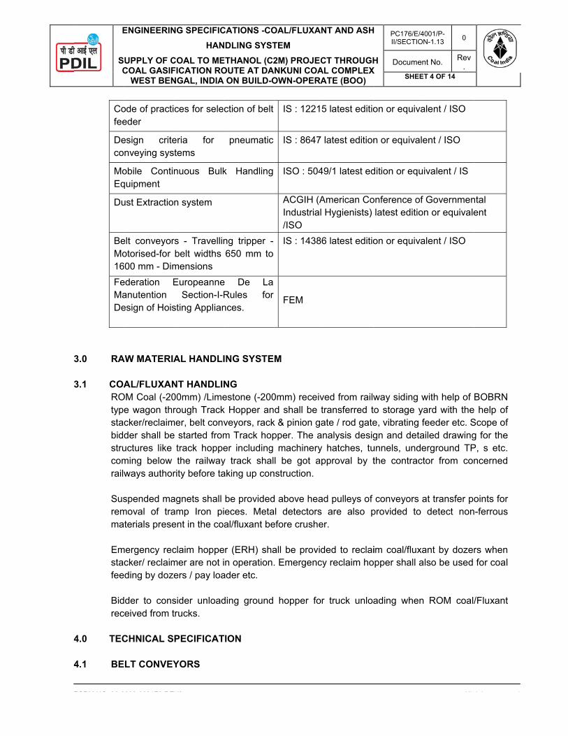
3
3
4 4
E
SC
FORM NO 02 0
Cofee
Deco
MoEq
Du
BeMo16FeMaDe
3.0 RA
3.1 COAROtypestacbiddstrucomrailw Susremma Emstacfee Bidrec
4.0 TEC
4.1 BE
ENGINEERIN
UPPLY OF CCOAL GASIF
WEST BEN
0000 0021F3 REV
ode of practieder
esign critenveying sys
obile Continquipment
ust Extractio
elt conveyorotorised-for 00 mm - Dim
ederation Eanutention esign of Hois
AW MATERIA
AL/FLUXANOM Coal (-20
e wagon thrcker/reclaimder shall beuctures like ming below ways author
spended mamoval of traterials prese
mergency reccker/ reclaimding by doze
der to consceived from t
CHNICAL S
LT CONVEY
NG SPECIFIC
HAN
COAL TO MEFICATION RONGAL, INDIA
V2
ces for sele
eria for tems
nuous Bulk
n system
rs - Travellinbelt widths
mensions Europeanne
Section-I-Rsting Applian
AL HANDLI
NT HANDLIN00mm) /Limerough Track
mer, belt conve started from
track hoppethe railway
rity before ta
agnets shall amp Iron pient in the coa
claim hoppemer are not iers / pay loa
sider unloadtrucks.
PECIFICAT
YORS
CATIONS -CO
NDLING SYST
ETHANOL (C2OUTE AT DA
ON BUILD-O
ction of belt
pneumatic
k Handling
ng tripper -650 mm to
e De La Rules for nces.
ING SYSTE
NG estone (-200k Hopper anveyors, rackm Track hoper including y track shalaking up con
be providedeces. Metaal/fluxant be
er (ERH) shan operation.
ader etc.
ding ground
TION
OAL/FLUXAN
TEM
2M) PROJECNKUNI COA
OWN-OPERA
IS : 12215
IS : 8647
ISO : 5049
ACGIH (AIndustrial /ISO IS : 14386
FEM
M
0mm) receivd shall be t
k & pinion gapper. The an
machinery l be got ap
nstruction.
d above headal detectors efore crushe
all be provid. Emergency
hopper for
NT AND ASH
CT THROUGHL COMPLEX
ATE (BOO)
5 latest editio
latest edition
9/1 latest ed
American CoHygienists)
6 latest editio
ved from railwransferred to
ate / rod gatenalysis desighatches, tu
pproval by t
d pulleys of are also p
r.
ded to reclaiy reclaim ho
r truck unloa
H X
PC176/E/4II/SECTION
Documen
SHEET
on or equiva
n or equivale
dition or equ
onference of latest editio
on or equiva
way siding wo storage yae, vibrating fgn and detaunnels, undethe contract
conveyors aprovided to
im coal/fluxapper shall a
ading when
001/P-N-1.13 0
nt No. Rev.
T 4 OF 14
All
alent / ISO
ent / ISO
ivalent / IS
Governmenn or equivale
alent / ISO
with help of ard with thefeeder etc. Sailed drawingerground TPtor from con
at transfer podetect non
ant by dozerlso be used
ROM coal/
i ht d
ntal ent
BOBRN e help of Scope of g for the P, s etc. ncerned
oints for n-ferrous
rs when for coal
/Fluxant
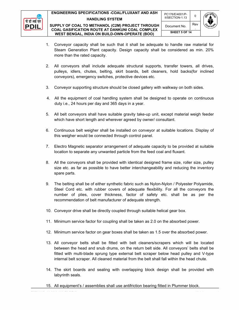
E
SC
FORM NO 02 0
1.
2.
3.
4.
5.
6.
7.
8.
9.
10. 11. 12. 13.
14.
15.
ENGINEERIN
UPPLY OF CCOAL GASIF
WEST BEN
0000 0021F3 REV
Conveyor Steam Gemore than
All conveypulleys, idconveyors)
Conveyor s
All the equduty i.e., 24
All belt conwhich have
Continuousthis weighe
Electro Malocation to
All the consize etc. aspare parts
The beltingSteel Cordnumber orecommen
Conveyor d
Minimum s
Minimum s
All conveybetween thfitted with internal be
The skirt labyrinth se
All equipme
NG SPECIFIC
HAN
COAL TO MEFICATION RONGAL, INDIA
V2
capacity shneration Plathe rated ca
yors shall indlers, chutes), emergency
supporting s
uipment of c4 hours per
nveyors shae short lengt
s belt weigher would be
agnetic sepaseparate an
veyors shals far as poss.
g shall be of d etc. with of plies, codation of be
drive shall b
service facto
service facto
yor belts shhe head andmulti-blade lt scraper. A
boards andeals.
ent’s / assem
CATIONS -CO
NDLING SYST
ETHANOL (C2OUTE AT DA
ON BUILD-O
all be such ant capacityapacity.
nclude adeqs, belting, y switches,
structure sho
coal handlinday and 365
all have suitath and where
her shall be connected t
arator arrangny unwanted
l be providessible to hav
either synthrubber cove
over thicknlt manufactu
e directly co
r for couplin
r on gear bo
hall be fitted snub drum
sprung typeAll cleaned m
d sealing w
mblies shall
OAL/FLUXAN
TEM
2M) PROJECNKUNI COA
OWN-OPERA
that it shay. Design ca
quate structskirt boardsprotective de
ould be close
g system sh5 days in a y
able gravity ever agreed
installed onhrough cont
gement of add particle from
ed with identve better int
hetic fabric sers of adeqess, factor urer of adequ
oupled throug
g shall be ta
oxes shall be
d with belt ms, on the ree external b
material from
ith overlapp
use antifrict
NT AND ASH
CT THROUGHL COMPLEX
ATE (BOO)
ll be adequapacity sha
ural suppors, belt cleaevices etc.
ed gallery wi
hall be desigyear.
take-up unitby owner/ c
n conveyor atrol panel.
dequate capm the feed c
tical designeerchangeab
such as Nyloquate flexibir of safetyuate strengt
gh suitable h
aken as 2.0 o
e taken as 1
cleaners/sceturn belt sidbelt scraper the belt sha
ping block d
tion bearing
H X
PC176/E/4II/SECTION
Documen
SHEET
ate to handll be consid
rts, transfer aners, hold
ith walkway
gned to ope
t, except maconsultant.
at suitable lo
pacity to be coal and flux
ed frame sizbility and red
on-Nylon / Plity. For all
y etc. shalh.
helical gear
on the abso
.5 over the a
crapers whide. All convebelow head
all fall within
design shal
fitted in Plum
001/P-N-1.13 0
nt No. Rev.
T 5 OF 14
All
dle raw matdered as m
towers, allbacks(for
on both side
erate on con
aterial weigh
ocations. Di
provided at xant.
e, roller sizeducing the in
olyester Polthe convey
l be as p
box.
rbed power.
absorbed po
ich will be eyors’ belts d pulley andthe head ch
l be provid
mmer block.i ht d
erial for in. 20%
drives, inclined
es.
ntinuous
h feeder
splay of
suitable
e, pulley nventory
yamide, yors the per the
ower.
located shall be
d V-type hute.
ed with

E
SC
FORM NO 02 0
16.
17.
18.
19.
20.
21.
22.
23. 24.
25.
26.
27.
ENGINEERIN
UPPLY OF CCOAL GASIF
WEST BEN
0000 0021F3 REV
All discharminimum 1
In Belt conm length (m
In Double swalkway 75
Self-aligninmaximum 3
Return idlerubber lagg
Impact idleImpact idle
All pulleys with 12 mmthickness N
All diverter
For safety switches likshall be pro
Suitable hoconveyor boperationainstantaneopersonnel. The holdba
All Conveychequeredsame shall
All over gprovided abe designepipelines.
NG SPECIFIC
HAN
COAL TO MEFICATION RONGAL, INDIA
V2
rge Chutes 12 mm).
veyor systemmin.) at rece
stream conv50mm.
ng training id30m for retu
er shall be wged type.
ers (minimumers shall be o
shall be lagm thicknessNeoprene.
r & gate shal
of conveyoke zero speeovision of au
ld back devbeing stoppl delays shously engagIt shall be r
ack devices
yor galleries plates. The be provided
round convt 100 m inteed to accom
CATIONS -CO
NDLING SYST
ETHANOL (C2OUTE AT DA
ON BUILD-O
shall be lin
m, Deck plaeiving end an
veyors centr
dler spacing urn side.
with rubber ri
m 5 nos.) shof rubber lag
gged in hers Neoprene
ll be electrica
ors and peed switch, beudible warnin
vices for preped in loadeall be provige without released instshall be inte
shall be proere shall be d at the midd
veyors are ervals (no crmmodate ca
OAL/FLUXAN
TEM
2M) PROJECNKUNI COA
OWN-OPERA
ed with mat
te shall be pnd 2 m lengt
ral walk way
to be consid
ings or rubb
all be providgged type.
ring-bone paand Tail &
ally or pneum
rsonnel, all elt sway swing (Hooter)
eventing runed conditionided to giveshock and tantly when
egral with ge
ovided with done dust ho
dle of walkw
provided wiross over forable & pipe
NT AND ASH
CT THROUGHL COMPLEX
ATE (BOO)
terial Tiscra
provided minth (min.) at d
width shall
dered as ma
ber lined. Ve
ded at loadin
attern. HeadSnub pulley
matically op
conveyors itch and pullof starting o
nning back ons due to pe positive pbe capable‘power’ resu
earbox.
dust sweepinopper for ea
way near tres
ith covered r conveyors es including
H X
PC176/E/4II/SECTION
Documen
SHEET
al /Sailhard(A
nimum thickndischarge en
be minimum
aximum 15m
rtical guide
ng points at s
d/Drive pulleys shall be l
erated.
shall be pr cord. In add
of conveyor.
of the convepower failurerotection. T
e of protectiumes or the
ng chutes coach walkwaystle location.
galleries. Cless than 10 fire water,
001/P-N-1.13 0
nt No. Rev.
T 6 OF 14
All
Adequate th
ness 3.15mmnd.
m 1100mm a
m for carrying
rollers shall
spacing of 3
eys shall belagged with
rovided withdition to thes
eyor belt in e or during he hold bacing equipme ‘delay’ is re
overed with y of gallery
Crossover s00 m). Galle Dust Supp
i ht d
hickness
m with 4
and side
g side &
also be
300 mm.
e lagged 12 mm
h safety se there
case of normal
ck shall ent and emoved.
removal and the
shall be ery shall pression
4
4
E
SC
FORM NO 02 0
28.
29.
30.
31.
32.
33.
4.2 HOTheto Iminflow
4.3 FEE1.
2.
3.
ENGINEERIN
UPPLY OF CCOAL GASIF
WEST BEN
0000 0021F3 REV
Walkway sof the cenusing pipe not be con
Bidder to battery limi
The inclininclination conveyor spossible, tshall be de
Wherever below the s
Minimum 3crosses the
For over gprovided a
PPERS
e hoppers shS : 2062 oimum 12 m
w of material EDERS The design duty conditimotors withflow. The dewith less ma The feeder extremely lowithin one m
The width oThe length othe feeder is
NG SPECIFIC
HAN
COAL TO MEFICATION RONGAL, INDIA
V2
shall be of chtral and sidof ‘medium
nected to co
consider reit to bunkers
ation of coof conveyo
shall be horihe inclinatio
esigned with
the conveyostructure.
3.15 mm thie road / build
ground convt the ground
hall be fabricor equivalenm) from ins.
of the feedons and giv
h vibration cesign shall baintenance.
shall be ableow noise levmeter radius
of the deck of the deck ss stopped or
CATIONS -CO
NDLING SYST
ETHANOL (C2OUTE AT DA
ON BUILD-O
hequered plae walkway
m’ class as ponveyor supp
edundancy /s for boilers f
onveyors insrs above thzontal at the
on at the feezero leakag
or crosses th
ck seal plateding / any ot
veyors take-ud level.
cated from Ct / ISO andide not only
der shall be ven uninterrucontrol and vbe such tha
e to start at vel. With th of the unit.
and height oshall be suitr not in work
OAL/FLUXAN
TEM
2M) PROJECNKUNI COA
OWN-OPERA
ate construcshall be pro
per IS: 1239porting string
/ stand-by ffeeding.
side the tune ground lee feed point ed point shage of coal.
he road, a m
e shall be pther facilities
up shall not
Carbon steel d to lined wy on bottom
sturdy and upted flow ofvariable cont it consume
full load quice empty tra
of skirts shaable for arre
king conditio
NT AND ASH
CT THROUGHL COMPLEX
ATE (BOO)
ction with anovided with
9having 32mger.
for belt con
nnel shall bvel shall beas far as poll be limited
minimum clea
provided at as.
t be provide
plates (minwith Tiscral portion but
robust in cf material. T
ntrol mechanes less powe
ckly, stop smay the noise
all be sufficieesting the flon.
H X
PC176/E/4II/SECTION
Documen
SHEET
nti skid arranpipe hand
mm nominal
nveying syst
be limited te as per CEossible. In cato 6 degree
arance of 8
all locations
d in the pits
. 10 mm thic/Sailhard (Aalso on vert
construction The unit shanism for coner per ton o
moothly and level shall
ent to suit thow from hopp
001/P-N-1.13 0
nt No. Rev.
T 7 OF 14
All
ngement. Borail with kesize. Handr
tem (1W+1
to 10 degreMA / IS115ase the same. Conveyor
M shall be p
wherever co
s. Sand pit s
ckness.) conAdequate thtical portion
to withstandll have unbantrolling the of material h
shall operatbe less tha
he duty conper efficientl
i ht d
oth sides rb plate rail shall
S) from
ee. The 92. The
me is not r system
provided
onveyor
shall be
nforming hickness
for free
d worst alanced rate of
andled,
te at an an 85db
nditions. ly when

4
4
E
SC
FORM NO 02 0
4. T
5.
4.4 BU
1. T
o
2. Tca
3. D
4. Bd
5. Er
6. Hc
7. A
c
4.5 VIB 1. T
tr
2. T
sa
3. V
v 4. S
w
5. P
ENGINEERIN
UPPLY OF CCOAL GASIF
WEST BEN
0000 0021F3 REV
The deck ansuitably stiff
Adequate cshall be con
CKET ELEV
The bucket eoperating co
Top cover shcomplete drappropriate l
Dust proof la
Bucket chaidesignated ty
Elevator sharotating back
Hoods & safcomponents
Adequate cacapacity sha
BRATING SC
The solid dehickness m
rigidly fixed w
The vibratingsprings madacceptable.
Vibrator beavibrating equ
Suitable seawork to avoid
Proper arran
NG SPECIFIC
HAN
COAL TO MEFICATION RONGAL, INDIA
V2
nd skirts shafened to avo
capacity feednsidered as m
VATORS
elevator shanditions and
hall be in pierive assembocation.
abyrinth meta
n shall be ype/ numbe
all be providkwards.
fety guard s. All safety s
apacity buckll be conside
CREENS
eck section inimum 12 with main fra
g screeningde of alloy
arings shall uipment. The
ling arranged dust nuisa
ngement to
CATIONS -CO
NDLING SYST
ETHANOL (C2OUTE AT DA
ON BUILD-O
all be providoid bending.
der shall bemin. 20% m
all be designd the various
eces for easybly. The ho
allic seal for
of heavy dr shall be sp
ded with Hea
shall be provswitches sha
ket elevatorered as min.
shall be pmm). The p
ame along th
feeders shsteel. No
be grease e bearings s
ement shall bnce in the su
avoid dust
OAL/FLUXAN
TEM
2M) PROJECNKUNI COA
OWN-OPERA
ded with abra
e selected bore than the
ned for conts component
y to disasseousing shall
the drive &
duty and thpecified in th
avy duty po
vided for theall be provide
r shall be se. 20% more
provided witperforated dhe length of
hall be mourubber/synt
lubricated, hall be sized
be providedurrounding a
t ingress in
NT AND ASH
CT THROUGHL COMPLEX
ATE (BOO)
asion resista
by bidder ate rated capac
tinuous dutyts shall conf
mble for thebe provide
return shaft
he chain spe bid.
ositive holdb
e coupling aed.
elected by than the rate
th replaceabdeck shall bgrizzly deck
nted on thethetic mate
double sphd for minimu
between tharea.
nto lubricant
H X
PC176/E/4II/SECTION
Documen
SHEET
ant liners. T
t all locationcity.
y at full loadform to relev
e maintenanced with insp
shall be pro
pecification
back in orde
and any othe
bidder at aed capacity.
ble Tiscral /be wear resik.
e floor with rial for the
herical rolleum 8,000 hou
he vibrating s
t of eccentr
001/P-N-1.13 0
nt No. Rev.
T 8 OF 14
All
he through
ns. Design c
as specifievant codes.
ce and inspepection ope
ovided.
with manuf
r to prevent
er exposed
ll locations.
/Sailhard(Adistant and s
the help of support s
er type suitaurs of opera
structure an
ric shafts si ht d
shall be
capacity
d under
ection of ening at
factures
t it from
rotating
Design
dequate shall be
f helical hall be
able for tion.
d chute
shall be

4
4
E
SC
FORM NO 02 0
p
6. Nv
4.6 CR
1. C
c 2. T
m 3. U 4. T
do
5. T
t 6. T
a 7. T
ndlib
8. M
Fain
9. C
G
4.7 VER 1. V
2. D
v
ENGINEERIN
UPPLY OF CCOAL GASIF
WEST BEN
0000 0021F3 REV
provided.
Necessary avibrator asse
RUSHER AN
Crusher shacomplete wit
The crusherminimum of a
Uniform crus
The crusher damp sticky on the crush
Temperaturerip the crush
The entire inabrasion res
The Plummenumbers of hdevice and loifting of top bottom surfa
Maximum acFor these puarrangementnspection.
Crusher shaGERB spring
RTICAL ROL
Vertical Rolle
Design capavertical roller
NG SPECIFIC
HAN
COAL TO MEFICATION RONGAL, INDIA
V2
arrangemenembly.
ND VIBRATIO
ll be provideth accessorie
r design shattrition.
shing impact
shall be cacoal having ing element
e sensing deher in case te
nside surfacistant steel l
er block shahigh tensile ocating arrapart of the pce all aroun
ccessibility surposes, thet. Hydraulica
ll be mountegs and damp
LLER MILL
er mills shall
acity shall br mill shall be
CATIONS -CO
NDLING SYST
ETHANOL (C2OUTE AT DA
ON BUILD-O
ts shall be
ON MONITO
ed for sizinges and subs
ould be su
t shall be ass
apable of demaximum mshall develo
evices shall emperature
ce of crusheiners.
all be of ‘Spsteel bolt stngement. In
plummer blocd having ma
shall be prove doors shaally operate
ed on indeppers.
l be supplied
be consideree used for g
OAL/FLUXAN
TEM
2M) PROJECNKUNI COA
OWN-OPERA
provided f
ORING SYS
g the input csystems.
ch that the
sured.
elivering themoisture conop.
be installed goes beyon
er coming in
lit Type’ destuds of adeq
n addition, thck. The samaximum cont
vided for rouall be of hined top cove
pendent foun
d complete w
ed as min. rinding, dryi
NT AND ASH
CT THROUGHL COMPLEX
ATE (BOO)
for maintain
TEM(VMS)
coal and flux
crushing a
normal ratentent. No clo
on both beand limit.
n contact wi
sign and shquate size che jacking scme shall be otact on the fo
utine inspecnge connectr of crusher
ndation with
with accesso
10% more ng, separatio
H X
PC176/E/4II/SECTION
Documen
SHEET
ning / repla
xant. Crushe
action is ac
ed output evgging or bui
arings of eac
ith coal sha
all be fixed complete witcrew shall beof solid baseoundation p
ction and reption with effrs shall be
vibration da
ories and sub
than the raon and trans
001/P-N-1.13 0
nt No. Rev.
T 9 OF 14
All
acing the co
er shall be s
ccompanied
ven when hilding up of m
ch of the cru
all be provid
with minimuth adequate e provided f
e with flat malate.
placement oective dust provided fo
ampring dev
bsystems.
ated capacisportation.
i ht d
omplete
supplied
by the
handling material
usher to
ed with
um four locking
for easy achined
of parts. sealing
or quick
vice like
ity. The

4
4
4
E
SC
FORM NO 02 0
3. Vdmm
4. R
p 5. B 6. H 7. T 8. M
4.8 TRA
1.
2.
3.
4.
5.
4.9 BUN
1.
2.
3.
4.10 FLA
ENGINEERIN
UPPLY OF CCOAL GASIF
WEST BEN
0000 0021F3 REV
Vertical rolledistribution omass of singmaximum fle
Roller swingprovided or o
Bevel Planet
High efficien
There shall b
Mill feed sha
ANSFER CH
Chutes tranthat materiaas possible.
All the chuteand lined w
Inspection h
Speed of thalmost the s
The angle oflow of mate
NKERS
The bunkerplates (min.with Tiscralbottom coni
Bunkers shaetc. The ang
Feeding to b
AP GATES
NG SPECIFIC
HAN
COAL TO MEFICATION RONGAL, INDIA
V2
r mill shall hof load on thgle moving pexibility to va
g-out deviceother facilitie
tary gearbox
cy dynamic
be no metall
all be sealed
HUTES
nsferring Coaal fall height.
es shall be ith material T
holes / windo
he material same as tha
of chutes shaerial.
s shall be of. 10 mm thil /Sailhard (cal portion b
all be providgle of conica
bunkers sha
CATIONS -CO
NDLING SYST
ETHANOL (C2OUTE AT DA
ON BUILD-O
have followinhe table, copart, variableary grinding p
e for quick aes shall be u
x with full lub
classifier sh
ic contact be
d through rot
al from one t is minimum
provided witTiscral /Sailh
ow with cove
falling on ct of the conv
all be 550 as
f round shapckness) con(Adequate tbut also on v
ded with loadal portion of
all be automa
OAL/FLUXAN
TEM
2M) PROJECNKUNI COA
OWN-OPERA
ng features mparative lee speed milpressure.
and easy chsed for quic
brication and
hall be used.
etween the g
tary air lock
conveyor tom and the ch
th IS: 2062 hard(Adequa
ers shall be
conveyor beveyor.
s far as poss
pe/rectangulnforming to thickness mvertical portio
d cells, vibrabunkers sha
atic with the
NT AND ASH
CT THROUGHL COMPLEX
ATE (BOO)
like better uess dynamicl drives and
hanging of k and easy m
d gear system
grinding rolle
o another shhange in dir
material of cate thicknes
provided at
elt in the dir
sible but in n
lar shape anIS : 2062 o
minimum 12 on for free fl
ators/pokingall be kept as
help of serie
H X
PC176/E/4II/SECTION
Documen
SHEET
tilisation of gc forces on d “hydraulic
grinding comaintenance
m shall be u
ers and grind
hall be desigrection is ac
constructionss minimum
all convenie
rection of be
no case less
nd fabricatedr equivalentmm) from
ow of mater
hole, radars 55° with th
es of convey
001/P-N-1.13 0
nt No. Rev.
T 10 OF 14
All
grinding aretable due toloading syst
mponents se.
sed.
ding tracks.
gned in suchhieved as s
n of 8 mm th12 mm).
ent locations
elt travel sh
s than 500 fo
d from Carbt / ISO and inside not
rial.
r type level ihe horizontal
yors system
i ht d
a, even o lesser tem” for
shall be
h a way moothly
hickness
.
ould be
r proper
on steel to lined only on
ndicator l.
.

4
4
E
SC
FORM NO 02 0
1. Tac
2. T
og
3. T
inc
4. P
waLr
4.11 RA 1. R
r
2. Ses
3. P
me
4.12 BE
1.
2.
ENGINEERIN
UPPLY OF CCOAL GASIF
WEST BEN
0000 0021F3 REV
The motor oand shall beconstruction
The motor raoperation of gate travel sh
The actuatonternal to thcapable of ad
Provision forwheel. The dapplied by a Limit switch frequired to o
ACK & PINIO
Rotary actuarequired. The
Suitable maneasy operatisuitable rolle
Provision formade. Limit seffort require
LT SCALE
Belt weigh specified lopanel etc. Tfor continuo
Each belt wweighing idlfloating typeprecision stload cells shof rated belt
NG SPECIFIC
HAN
COAL TO MEFICATION RONGAL, INDIA
V2
perated 2 poe complete wand suitable
ating for thethe flap ga
hall be 60 de
rs shall be he drive unitdjustments t
r alternative diameter of single operafor safety of
operation the
ON GATES /
ator operatee gate shall
nually operaon and mai
ers with bear
r alternative switch for sa
ed to operate
scale for mocations. SysThe weigh scous automati
weigh scale slers. It shall e (without ptrain gauge hall have 10t scale capa
CATIONS -CO
NDLING SYST
ETHANOL (C2OUTE AT DA
ON BUILD-O
osition flap gwith electrice for trouble
e actuator sates against eg. The mot
capable oft and shall to vary the to
manual opehand wheelator. Howevf person opee flap gate sh
/ ROD GATE
d rack and be mounted
ted rod gatentenance. Trings sealed
manual opeafety of perse the rack an
measuremenstem shall bcale shall beic weighing,
shall comprihave unitizepivot pointstype shall b
00% overloadcity.
OAL/FLUXAN
TEM
2M) PROJECNKUNI COA
OWN-OPERA
gates shall bcally operate
free operati
shall be so sthe moving
tor shall be c
f preventingbe completeotal length o
eration shall shall be se
ver, minimumerating the hhall not exce
E
pinion gatesd such that c
es shall be pThe rack and
for life and d
eration of moson operatinnd pinion ga
t of coal flobe completee automatic metering an
se of a belt ed construct). Minimum
be applied ind protection
NT AND ASH
CT THROUGHL COMPLEX
ATE (BOO)
be provided ed actuatorson.
selected as g weight of ccompletely d
g any over ely dust-pro
of travel of th
l also be maelected consm diameter oand wheel s
eed 25 kg.
s shall be pcoal load doe
provided oved pinion gatdust proof s
otorized rackg the hand wte shall not e
ow rate ande with flow and electro
nd printing of
weigh scaleion for ease
4 nos. hern tension to and shall be
H X
PC176/E/4II/SECTION
Documen
SHEET
in transfer c. The gates
to provide coal and/or dust proof.
travel. Thesoof. The limihe gates.
ade using dsidering conof hand wheeshall be prov
provided at ves not act ve
er rack and pte shall be ghall be prov
k and pinionwheel shall bexceed 25 k
d quantity srate indicato
onic type. It sf coal flow.
e platform w of installatiormetically ssupport the
e structurally
001/P-N-1.13 0
nt No. Rev.
T 11 OF 14
All
chutes as sps shall be of
sufficient thflap gate. T
se shall be t switches s
de-clutch abvenient forcel shall be 5vided. Manu
various locatertically on g
pinion gates guided propeided.
gates shall be provided
kg.
hall be provor, totaliser,should be d
with minimumon and shallealed load
e weigh bridy safe upto t
i ht d
pecified f robust
hrust for The flap
placed shall be
le hand ce to be 00 mm. al effort
tions as gate.
for their erly and
also be .Manual
vided at control esigned
m 4 nos. be fully cells of ge. The to 250%

4
4
E
SC
FORM NO 02 0
3.
4.
5.
4.13 INL
InlindiscThetramSepmov
4.14 TRAARR
1.
2.
3.
4.
5.
ENGINEERIN
UPPLY OF CCOAL GASIF
WEST BEN
0000 0021F3 REV
Belt scale smemory. It sbelt scale sy
The electropower ampagainst dus
The flow ratdisplay scal
LINE MAGNE
ne Magneticcharge of trae sets shall bmp-iron boxeparator shallving coal ove
AVELLING RANGEMEN
Rail mounteto overhead
Mobile Tripfurnished aapproach/melectrical inbunker, loca
The Mobile supports, wand bend pThe rating osame or opdrive axles starting poin
Supply of adshall be incconcave cur
The travelli
NG SPECIFIC
HAN
COAL TO MEFICATION RONGAL, INDIA
V2
hall be electshall be provystem. Fully
onic systemsplifiers and t and moistu
te indicator se with reset
ETIC SEPA
c Separatorsamp magnetbe completees and all el be provideer Conveyor
TRIPPER NT
ed movable d bunkers of
ppers on bund erected
maintenance cluding macation of whic
tripper conwalkways, rai
ulleys compof tripper travpposite direc
shall be prnt of the tripp
dequate lencluded. Suirve of belt ov
ng trippers
CATIONS -CO
NDLING SYST
ETHANOL (C2OUTE AT DA
ON BUILD-O
tronic microvided with s
y automatic z
s offered byprinted circ
ure.
shall have mfacility.
RATOR / SU
s shall be ptic pieces froe in all respeelectrical aned for pickinr as specified
UNIT /
travelling TrBoilers.
unker convecomplete wplatforms
chine mountch shall be d
veyors shalils, belt scra
plete with shvel motor sh
ction to belt rovided for per to avoid
gth of rails ttable belt hver tripper.
shall be pro
OAL/FLUXAN
TEM
2M) PROJECNKUNI COA
OWN-OPERA
processor belf-diagnost
zero and spa
y the Contracuits etc. Th
minimum 4 d
USPENDED
provided for om coal beinects with drivncillaries likeng up trampd.
SHUTTLE
ripper / shut
eyors along with rails, inwith ladderted local conecided durin
ll be motor apper with adaft bearings
hall be adequdirection untripper travefolding of be
to cover the hold down g
ovided with
NT AND ASH
CT THROUGHL COMPLEX
ATE (BOO)
ased with itsic features fan calibration
actor shall he printed c
igits. The flo
D MAGNET
continuousng dischargeves, magnete control pap magnetic
CONVEYO
ttle conveyo
with belt sncluding necs and handntrol panel &ng detail eng
driven type.djustable rub
s, chutes, stouate to move
nder fully loael. Arrangemelt.
runway lengguide pulley
fail safe A.
H X
PC176/E/4II/SECTION
Documen
SHEET
s program stfor trouble shn facility sha
include all circuits sha
ow totalizer s
s and automed from convts, inline beltnels etc. Supieces burie
OR & BU
r shall be pr
sealing arracessary supd railings, t& control pagineering.
. It shall conbber strip, ruops, limit swe the tripperaded conditiment shall b
gth for the my shall be
C. thruster
001/P-N-1.13 0
nt No. Rev.
T 12 OF 14
All
tored in nonhooting of thall be provide
signal condall be encap
should have
matic extractveyors as spts, hoppers, uspended Med under co
UNKER SE
rovided to fe
angement shpporting strutrailing cabl
anel on one
nsist of struubber lagged
witches, brakr smoothly eons. Minimu
be provided
motor driven provided ov
operated bri ht d
n-volatile he entire ed.
ditioning, psulated
e 8 digits
tion and pecified. chutes,
Magnetic oal from
EALING
eed coal
hall be ctures, les, all end of
ctures, d head
kes etc. either in um two
at the
tripper ver the
rake of

4
4
4
4
4
E
SC
FORM NO 02 0
6.
7.
8.
9.
10.
4.15 UNI
4.15.1 Uni
shaandbooeleccab
4.15.2 Theas deg120
4.15.3 Staalsonotin tbe for
4.15.4 Staent
ENGINEERIN
UPPLY OF CCOAL GASIF
WEST BEN
0000 0021F3 REV
totally enclothruster opeshall also be
Monorail & along the tri
Suitable dusbe providedbe providedhead pulley
The tripper mounted on
Suitable accboth sides scrossover pthrough the
Suitable raitrack.
IDIRECTION
idirectional tall be providd reclaimingom conveyoctrical powe
bles etc.
e design avespecified el
gree celcius 0% of the ac
acker/Reclaimo be able tot operating. Ahe control caprovided fokeeping the
acker-cum-retire coal stoc
NG SPECIFIC
HAN
COAL TO MEFICATION RONGAL, INDIA
V2
osed type werated rail ce provided.
electric hoisipper travel l
st cover shad at open sidd. Spring loa
for cleaning
shall run onn supporting
cess platformshall be provplatform shasame.
l cleaners s
NAL TRAVE
travelling staded as specg complete wor, boom h
er distribution
erage capaclsewhere foof the drive
ctual power r
mer shall beo withstand mA suitable aabin. Electror holding th stacker-rec
eclaimer shackyard. The
CATIONS -CO
NDLING SYST
ETHANOL (C2OUTE AT DA
ON BUILD-O
which shall lamps along
st shall be prlength to fac
all be providede to prevenaded scraperg the carryin
n rails with dstructure of
m of chequevided for accall be provid
hall be prov
ELLING STA
acker cum rcified. Stackwith adequa
hoist, reclain system, m
cities shall nr both stack
e motor to berequirement
e capable of maximum winemometer o-hydraulic te stacker-cu
claimer in fixe
all operate owheel load
OAL/FLUXAN
TEM
2M) PROJECNKUNI COA
OWN-OPERA
engage as g with manu
rovided for lcilitate maint
ed over trippt dust nuisar type belt cg side of the
double flangef respective c
ered plate wcess/maintended with trip
vided on lea
ACKER CUM
reclaimer opker-cum-Recate length omer bucketotorised cab
not be less thking & reclae provided oat motor ou
operating aind velocity shall be pro
thruster operum-reclaimeed stable po
on rail trackof stacker-re
NT AND ASH
CT THROUGHL COMPLEX
ATE (BOO)
soon as triual Rail clam
ifting conveytenance of tr
per head pulnce. Suitabl
cleaner shalle belt.
ed wheels. conveyors.
with ladders, nance of equpper so tha
ding and tra
M RECLAIM
perating in cclaimers shaof rail track,t wheel, coble reeling d
han 110% oaiming. The on each sidetput shaft.
t high wind vas indicated
ovided whichrated rail claer. Suitable osition when
k running foreclaimer sha
H X
PC176/E/4II/SECTION
Documen
SHEET
pper travel mps on both
yor drum to ripper shall b
lley. Serratee dust tight be provided
Rails for trip
hand railinguipment on tt operator c
ailing edge o
MER
conjunction all be capab and its fou
ontrol panelrum, adequa
of rated (guacontinuous
e of the yard
velocities upd in Project Sh shall indicaamp and maarrangementhe weathe
r adequate all not excee
001/P-N-1.13 0
nt No. Rev.
T 13 OF 14
All
motor stopsside of the
floors. Monobe provided.
d rubber seaaccess doord below the
pper travel s
g and walkwtripper. In adcan cross th
of tripper for
with yard cble of both sundation, cal, operatorsate length o
aranteed) camotor ratin
d conveyor
pto 65 km/hrSynopsis, wate the wind nual rail clam
nt shall be pr is stormy.
length to coed 27.0 tonn
i ht d
s. A.C. tripper
orail all
al shall rs shall tripper
shall be
ways on ddition, he belt
r either
onveyor stacking antilever s cabin, f trailing
apacities ng at 50 shall be
r. It shall hen it is velocity
mp shall provided
over the nes. The

E
SC
FORM NO 02 0
ratishaoth
5.0 DU
Dustype TheCoa Thefugietc. Dusbuilreco
6.0 ASH
Conshalice
7.0 ACC
1.
2.
3.
NOitem
ENGINEERIN
UPPLY OF CCOAL GASIF
WEST BEN
0000 0021F3 REV
o of boom leall be maintaerwise. Suit
ST EXTRAC
st control sye to suit at th
e Contractoral/Fluxant sc
e dust contrtive dust em Dust contro
st control sydings more ognized hyg
H HANDLIN
nveying Ashall be carriedensor.
CESS TO MA
Special atteoperation / m
Gravity takemaintenanc
Provision sgearboxes, Towers withof the heavi
OTE: - Bidms of Coa
NG SPECIFIC
HAN
COAL TO MEFICATION RONGAL, INDIA
V2
ength (as spained at 0.7 able numbe
CTION SYS
ystem shall he applicatio
r shall requicreening, cru
rol system tmissions fromol is achieve
ystem which than accep
ienic Standa
NG SYSTEM
h / slag prodd out with th
ACHINERY
ention shall maintenance
e-up of conce.
shall be maconveyor p
h the help ofest part to b
dder to strl Gasificat
CATIONS -CO
NDLING SYST
ETHANOL (C2OUTE AT DA
ON BUILD-O
pecified) to tm above ther of rail scra
TEM
be of dry / on point.
ire providingushing, coal/
o be furnishm dust gened by dust su
shall not alptable limits ards/Codes.
M
duced from ghe help of co
be given ine and cleani
veyor shall
ade for liftinpulleys, idlerf electric hoibe lifted.
rictly folloion Plant.
OAL/FLUXAN
TEM
2M) PROJECNKUNI COA
OWN-OPERA
the rail tracke ground levppers shall
wet / extrac
g suitable d/Fluxantcrus
hed under tration points
uppression/e
llow a dust as per the
gasifier to ovonveyors/du
providing ang purpose.
be provided
ng out andrs parts andst. Capacity
ow license
NT AND ASH
CT THROUGHL COMPLEX
ATE (BOO)
k gauge shalel, i.e., coal be provided
ction type an
ust control shing and fee
this specifics such as traextraction sy
concentratioapproved g
verhead bunmpers etc o
adequate ac.
d with the p
replacing d other heavy of the hoist
er’s specif
H X
PC176/E/4II/SECTION
Documen
SHEET
ll not exceedpile base le.
nd as well a
system at seding system
ation is reqansfer points
ystem.
on in the amguidelines or
nkers or ashor as recomm
ccess to all
platform and
equipment’svy machinert would be b
fication fo
001/P-N-1.13 0
nt No. Rev.
T 14 OF 14
All
d 5. Top of rvel unless s
as dust supp
suitable locam etc.
quired for cos, feeders, c
mbient air insr any interna
/slag disposmended by
machinery
d access lad
s such as ry in each Tbased on the
r the men
i ht d
rail level specified
pression
ation for
ontrol of crushers
side the ationally
sal pond process
for safe
dder for
motors, Transfer e weight
ntioned

PC176/E/4001/P-II/ SEC-1.114 0
PROJECTS & DEVELOPMENT INDIA LTD. DOC. NO. REV.
SHEET 1 OF 15
VOLUME-II: TECHNICAL
SECTION – 1.14
SAFETY, HEALTH AND ENVIRONMENT
PROJECT: COAL TO METHANOL (C2M) PROJECT THROUGH COAL GASIFICATION ROUTE AT DANKUNI COAL COMPLEX WEST BENGAL, INDIA ON BUILD-OWN-OPERATE (BOO) BASIS

SAFETY, HEALTH AND ENVIRONMENT SUPPLY OF COAL TO METHANOL (C2M) PROJECT
THROUGH COAL GASIFICATION ROUTE AT DANKUNI COAL COMPLEX WEST BENGAL, INDIA ON BUILD-OWN-
OPERATE (BOO) BASIS
PC176/E/4001/P-II/ SEC-1.14 0
DOC. NO. REV.
SHEET 2 OF 15
All rights reserved
CONTENTS
SL. NO. DESCRIPTION SHEET NUMBER
1.0 Fire And Security Regulations 3
2.0 Safety Regulations 4
3.0 Penalties In Case Of Non-Compliance To Safety Rules And
Regulations: 13
4.0 Compensation In Case Of Accidents 13
5.0 Emergency Response Plan 14
6.0 Environmental Management System 15

SAFETY, HEALTH AND ENVIRONMENT SUPPLY OF COAL TO METHANOL (C2M) PROJECT
THROUGH COAL GASIFICATION ROUTE AT DANKUNI COAL COMPLEX WEST BENGAL, INDIA ON BUILD-OWN-
OPERATE (BOO) BASIS
PC176/E/4001/P-II/ SEC-1.14 0
DOC. NO. REV.
SHEET 3 OF 15
All rights reserved
BOO OPERATOR shall abide by all Safety, Health and Environment rules applicable for CIL Complex during construction and subsequent operation of the Methanol plants. BOO OPERATOR shall also ensure compliance to all Safety, Health and Environment rules including (but not limited to) following points.
1.0 FIRE AND SECURITY REGULATIONS:
1.1 No Smoking:
1.1.1 BOO OPERATOR shall instruct his personnel/ employees NOT TO SMOKE except at the
prescribed smoking booths as provided by the CIL. BOO OPERATOR shall be responsible for all defaults of his workers in this regard.
1.1.2 Carrying of matchboxes, lighters or any other means of ignition is strictly prohibited inside
the Dankuni premises. 1.1.3 Any BOO OPERATOR’s employee who is found smoking or in the possession of match box
or lighter or any other means of ignition in a prohibited area will be turned out from the premises of the Dankuni. Suitable action as decided by the management will also be taken.
1.2 Dankuni Area: 1.2.1 BOO OPERATOR and his employee shall observe all fire & safety regulations of the
Dankuni and shall so organize his work as not to interfere with the running of the Dankuni in any manner whatsoever. BOO OPERATOR shall ensure that their staff/ workmen carry with them valid passes for proper identification inside the battery area.
1.2.2 The complete job is to be carried out within the unit of CIL Dankuni Coal complex. BOO
OPERATOR shall take all necessary safety precautions and obtain required certificates/ fire permits / safety/ work permits etc. from the competent authority before carrying out any hot works during the execution of the entire works covered by this tender. Safety barricade wherever necessary are to be put up at his own cost.
1.2.3 BOO OPERATOR’s employees shall abide by the Fire & Safety rules and regulations of the
Dankuni. 1.2.4 BOO OPERATOR shall make his own arrangements of Gate Pass with photo for his
employees as prescribed and instructed by the Security dept. i.e. CISF, CIL at his own cost, each gate pass has to be endorsed by the Security Officer of the Dankuni before the pass be used by any employee. In case of termination of the service of any of his employee during the contractual period, BOO OPERATOR shall have to surrender the Gate Pass issued to the employees to the Security Dept. At the end of the project all the gate passes endorsed by the Security Dept. for use of BOO OPERATOR’s employees shall have to be returned.
1.2.5 For any damage done by BOO OPERATOR’s employees to the existing facilities of the
Dankuni, BOO OPERATOR shall be solely responsible to make good as per the instruction of the Engineer-in-Charge or full satisfaction of the Dankuni belt for his workman at his own cost.
1.2.6 For any hazardous/ overhead work BOO OPERATOR has to arrange necessary safety belt
for his workman at his own cost.

SAFETY, HEALTH AND ENVIRONMENT SUPPLY OF COAL TO METHANOL (C2M) PROJECT
THROUGH COAL GASIFICATION ROUTE AT DANKUNI COAL COMPLEX WEST BENGAL, INDIA ON BUILD-OWN-
OPERATE (BOO) BASIS
PC176/E/4001/P-II/ SEC-1.14 0
DOC. NO. REV.
SHEET 4 OF 15
All rights reserved
2.0 SAFETY REGULATIONS: The following is a list of Rules and Regulations which must be observed by BOO OPERATOR working in the Dankuni.
2.1 Safety:
2.1.1 BOO OPERATOR shall ensure that all labourers/ supervisor engaged by him will carry Card/ Photo Pass displayed on their person during working hours at the work place in/ outside Dankuni for their easy identification.
2.1.2 BOO OPERATOR shall ensure that their supervisors must undergo Fire & Safety Training &
subsequent Test at Fire Station before starting the job. BOO OPERATOR must disclose to CISF the name of supervisors and arrange safety training at GR Fire Station, before obtaining a gate pass. CISF will issue the gate pass meant for supervisor, only after getting the confirmation from Fire & Safety. It is the duty of supervisor to train his work force in Fire & Safety on regular basis. The violation of this will be viewed seriously.
2.1.3 BOO OPERATOR shall ensure that their workmen/ supervisors shall not move to other
places other than their work premises without proper permission/ authorization. 2.1.4 BOO OPERATOR shall ensure verification of antecedents of the labourers/ supervisors from
Polices / Sarpanch/ other officials before they are engaged by him. No person having adverse antecedent shall be employed by BOO OPERATOR. BOO OPERATOR shall be held responsible for all the acts carried out by his workmen.
2.1.5 BOO OPERATOR shall ensure that the workmen working with him are given do’s and don’ts
for strict adherence. 2.1.6 BOO OPERATOR/ his workmen/ supervisor shall fully adhere to the security instructions
issued by Management from time to time. 2.1.7 Persons below the age of 18 (Eighteen) will not be employed in any part of the Dankuni. 2.1.8. The weekly safety report should be submitted in the prescribed format without fail. 2.2 Work Permit: 2.2.1 Any work carried out within the Dankuni must be covered by a work permit issued by the
concerned department or area-in-charge. In addition, a clearance must be obtained from the concerned department’s officer or supervisor prior to commencement of any job. A fire permit is required for all the hot jobs.
2.2.2. Any work involving open flames and spark such as welding, gas cutting, soldering, grinding,
concrete breaking, use of hurricane lamps and internal combustion driven vehicles/equipment.
2.2.3. Sand blasting, trucks, Jeeps, Cranes, Lifts, Cars or any kind of vehicle/equipment driven by
an internal combustion engine or by batteries. 2.2.4. Use of gasoline, diesel or electrical power engines or tools. 2.2.5. Entry of vehicles inside battery limits of process area, within tank dykes and adjacent to
pump houses / API separator and loading gantries. 2.2.6. Open fire such as burning of wood, coal etc. is strictly prohibited inside the Battery area.

SAFETY, HEALTH AND ENVIRONMENT SUPPLY OF COAL TO METHANOL (C2M) PROJECT
THROUGH COAL GASIFICATION ROUTE AT DANKUNI COAL COMPLEX WEST BENGAL, INDIA ON BUILD-OWN-
OPERATE (BOO) BASIS
PC176/E/4001/P-II/ SEC-1.14 0
DOC. NO. REV.
SHEET 5 OF 15
All rights reserved
2.2.7. While carrying out the hot job, BOO OPERATOR and his workmen must ensure the
following safety measures and job should not be carried out without these:
Valid hot job permit. Availability of Tested and proper Fire Extinguisher at the work places. Provision of running fire water hose at the work place.
2.2.8. All Flammable / combustible materials should either be removed from the work place or
should be properly protected. 2.3 Safety Permits: 2.3.1 BOO OPERATOR must obtain the safety permit from the area Incharge of the concerned
department, prior to the starting of the job as stated below. 2.3.2. Entry of personnel into any process area of storage facilities that has been in service etc.
Entry into hazardous areas, Dosing area or any other area where chemicals and hazardous materials are either in use or kept as store.
2.4 Vessels Entry Permit: 2.4.1 BOO OPERATOR must obtain this permit prior to the start up of the job, column, vessels,
tanks or any enclosed area where the chemicals and hazardous materials is either used or stores into it. It is BOO OPERATOR’s duty to ensure daily that the above permits are obtained from the area-in-charge till the completion of the job. All precautionary points stipulated in the permit and instruction of the Area In charge/Engineer In charge must be strictly complied with.
2.4.2 BOO OPERATOR shall ensure the following at the time of entry into the vessels:
Standby persons Provision of exhaust fan Use of breathing apparatus
2.5 Excavation: 2.5.1 All the areas where the existing grading is disturbed in the course of work by BOO
OPERATOR shall be made good by him to the full satisfaction of the Engineer-in-Charge. 2.5.2. This job must be executed only after obtaining a valid excavation permit for the particular
area where the excavation is required to be done. The permit shall be considered valid only when it is signed by the authorized person of CIL in addition to other signatories like F&S officer, Civil Engineer, the electrical section and supervising Engineer-in-Charge of the particular area where the excavation is to be carried out.
2.5.3. The company reserves the right to cancel a permit without assigning any reasons. When
called upon to stop the work by any personnel of the company, BOO OPERATOR shall immediately cease to continue the work. Before re-commencement, a fresh permit must be obtained.
2.5.4. If any excavation job is being done at the depth, then following precaution needs to be taken
up.
BOO OPERATOR has to obtain the permit "Working at Depth" duly authorized by

SAFETY, HEALTH AND ENVIRONMENT SUPPLY OF COAL TO METHANOL (C2M) PROJECT
THROUGH COAL GASIFICATION ROUTE AT DANKUNI COAL COMPLEX WEST BENGAL, INDIA ON BUILD-OWN-
OPERATE (BOO) BASIS
PC176/E/4001/P-II/ SEC-1.14 0
DOC. NO. REV.
SHEET 6 OF 15
All rights reserved
competent authorities. Proper barricading shall be provided at all sides of the opening. Excavation shall be done with adequate slop instead of vertical to avoid collapse of
wall. Proper shoring / strutting shall be provided without fail. At least two no. of escape ladders shall be provided at two sides. Adequate illumination shall be provided as per site requirement. Minimum person shall be kept inside the pit. All idle workers should be removed from
there. Heavy machinery like crane etc. should not be used near the pit.
2.6 Working at Heights: 2.6.1 While working at height, more than 2 meters from floor level, following safety precautions
has to be followed.
BOO OPERATOR has to obtain the permit for working at height duly approved by competent authority.
Proper type of scaffolding / platform /ladder should be made to facilitate the job at height. Minimum 2 nos. of ladders should be provided at opposite sides.
Use of bamboo scaffolding is strictly prohibited inside the Battery area. Only steel
scaffolding shall be used for work inside the Dankuni. The steel scaffolding material and its erection shall be done as per relevant IS specification.
BOO OPERATOR shall ensure the use of safety belts by the person who is working at heights. Safety belt to be used should be of good quality (IS marked) and shall be hooked up with firm support.
Safety nets also to be used as per site conditions. Before starting the job, scaffolding shall be inspected by competent person and a
record of the same shall be kept at site. 2.7 Working with Electrical System: 2.7.1 BOO OPERATOR should have valid electrical license for working in the state of Orissa.
BOO OPERATOR shall furnish a copy of the same to Engineer-in-Charge before commencement of any work pertaining to Electrical System. In any case, no work shall be permitted to be executed at site without a valid Electrical License, and the decision of the Engineer-in-charge in this regard shall be final and binding and no claim / compensation whatsoever shall entertain on this account.
2.7.2 While working on electrical system, BOO OPERATOR and his workmen shall ensure that
the following safety measures are in place:
Proper & valid Electrical line clearance is obtained for the equipment.
The cables are properly insulated and are without any temporary joint.
All Flammable / combustible materials should either be removed from the work place or should be properly protected.

SAFETY, HEALTH AND ENVIRONMENT SUPPLY OF COAL TO METHANOL (C2M) PROJECT
THROUGH COAL GASIFICATION ROUTE AT DANKUNI COAL COMPLEX WEST BENGAL, INDIA ON BUILD-OWN-
OPERATE (BOO) BASIS
PC176/E/4001/P-II/ SEC-1.14 0
DOC. NO. REV.
SHEET 7 OF 15
All rights reserved
Suitable Earth leakage Circuit Breaker (ELCB) is provided for incoming and all outgoing feeders.
Proper earthing is provided to distribution board and other electrical equipments like
welding machines & grinding machines etc.
Pipe sleeves are provided for road crossings of temporary cables laid by BOO OPERATOR for his work.
The power connection should not be overloaded and suitable overload protection
should be provided.
The tools used by BOO OPERATOR personnel should be properly insulated and in good condition
The grinding machine & other power tools should have proper guard.
2.8 Electrical Apparatus: 2.8.1 BOO OPERATOR should ensure that the portable electrical equipment like grinding
machine, drilling machine etc. is in healthy condition. BOO OPERATOR should take all precautionary safety action, as providing of earth leakage circuit breakers for their portable electric machines. In lieu of the above, double insulated portable equipment may be used.
2.8.2 All portable electrical apparatus shall be regularly examined, tested and maintained to
ensure the apparatus and leads are in good order. 2.8.3 Ensure that all portable appliances are provided with 3 pin plug and socket connections and
that all the metallic parts of the apparatus are effectively earthed. All loose wiring such as flexible cables for portable lamps, tools and trailing cables and other portable and transportable apparatus shall be tested regularly at frequent intervals to ensure safety.
2.8.4 No dry battery or accumulator, type of electric hand lamp or torch which is not of flameproof
safety type shall be taken inside the Dankuni. 2.9 Use of Company Facilities: Under no condition shall any BOO OPERATOR personnel temper with or use any property
belonging to the Dankuni without obtaining prior sanction from the supervisor of area concerned.
2.10 Radiography: 2.10.1 The radiography agency employed by BOO OPERATOR shall be duly approved by BARC. 2.10.2 Specific approval from the Engineer-in-charge for the radiography agency shall be obtained
by BOO OPERATOR prior to any radiography work. 2.10.3 BOO OPERATOR shall ensure the following safety precautions for the work to be done by
the radiography agency. The radiography work shall be carried out under the supervision & guidelines of their
site in-charge duly approved by BARC. As far as possible, field radiography should be done only during night time when there

SAFETY, HEALTH AND ENVIRONMENT SUPPLY OF COAL TO METHANOL (C2M) PROJECT
THROUGH COAL GASIFICATION ROUTE AT DANKUNI COAL COMPLEX WEST BENGAL, INDIA ON BUILD-OWN-
OPERATE (BOO) BASIS
PC176/E/4001/P-II/ SEC-1.14 0
DOC. NO. REV.
SHEET 8 OF 15
All rights reserved
is little or no occupancy around.
Field radiography during day time may be permitted with due permission of EIC when the occupancy around is minimum i.e. during lunch interval or on holidays.
A suitable area around the radiography job should necessarily be cordoned off, so that
the radiation level outside the area does not exceed the permissible radiation level. The radiation level along the cordon should be monitored by suitable & calibrated survey meter.
Radiation warning symbol during day time & red warning light during the night to be
prominently displayed while carrying the radiography work.
The concerned radiographer shall remain physically present outside the cordoned area during exposure.
2.11 Temporary Structure/ Fixtures: 2.11.1 Before erecting temporary shelters like sheds or tents anywhere within the Dankuni
premises, written permission of the concerned authorities must be obtained. 2.11.2 Temporary fixtures like sheds, tents, etc. shall be erected in conformity with normal safety
standards. Thatched roof to such fixtures will not be permitted. 2.11.3 Temporary piping, hose connections and electrical wiring must be laid in such manner that
they do not cause tripping or hitting hazard. 2.11.4 Temporary sheds can be constructed only for the storing of the material / site office. It should
not be used for any other purpose. 2.11.5 Following information shall be clearly written on the shed.
Name of BOO OPERATOR Work Order No. Working under the Department Name of the Engineer-in-charge. Permit No. & it's validity period.
The shed shall be made of safe construction material and good aesthetic view. The shed shall be made strictly at the authorized location and size.
2.11.6 All windows shall be either of wire mesh or glass. 2.11.7 After completion of the job, shed must be demolished within 10 days and area must be
cleaned. 2.11.8 All precautions should be taken to ensure that any temporary electrical wiring used
within the Dankuni will not cause spark or shock. 2.12 Compressed Gas Cylinders: 2.12.1 Compressed gas cylinders should be used in upright position. They must be firmly located
on the ground or to a sturdy stand and the cylinder should be chained to prevent accidental fall.

SAFETY, HEALTH AND ENVIRONMENT SUPPLY OF COAL TO METHANOL (C2M) PROJECT
THROUGH COAL GASIFICATION ROUTE AT DANKUNI COAL COMPLEX WEST BENGAL, INDIA ON BUILD-OWN-
OPERATE (BOO) BASIS
PC176/E/4001/P-II/ SEC-1.14 0
DOC. NO. REV.
SHEET 9 OF 15
All rights reserved
2.12.2 Rolling or throwing of cylinders is strictly prohibited. Cylinders shall be handled carefully and transported through hand trolleys.
2.12.3 Cylinders shall be stacked properly. Empty cylinders shall be stacked separately and filled
cylinders separately. After completion of job, all cylinders must be removed. 2.13 House Keeping: 2.13.1 Good House keeping must be practiced by BOO OPERATOR personnel at all times while
within the plant. During and after completion of the work, they are to ensure that their work area is kept clean and tidy. Materials and equipment should be stored in a safe and orderly manner so that they will not block exits to roads, buildings, aisles, passage and approach to firefighting equipment such as fire hydrants, fire hose and fire extinguishers or area where emergency safety showers, electrical switch panels and switch rooms are located.
2.13.2 The work / construction sites are to be cleaned daily and all debris / scrap generated is to be kept at the designated place only every day by BOO OPERATOR as directed by the Engineer-In-charge. The scrap / debris so generated shall be disposed off to the designated places once a week as per the direction of Engineer-in-charge.
2.13.3 A job will not be considered completed until all surplus material, scrape and debris / rubbish
are removed from the job site.
2.13.4 In case BOO OPERATOR does not clear the area within 5 days of completion of work, the same shall be got done by CIL and recoveries shall be made from the bills of BOO OPERATOR at double the rate at which CIL has got it done.
2.13.5 Any failure by BOO OPERATOR in maintaining good house-keeping / clearing the site as above shall be recorded in the performance report of BOO OPERATOR.
2.13.6 At all work sites, BOO OPERATOR has to display a board containing following information:
Name of BOO OPERATOR Name of the work Work Order No. Job site warning instruction Emergency Telephone Number Do's and don'ts on safety and security Working under the Department CIL site in-charge name Permit No. & Validity period.
2.13.7 BOO OPERATOR has to maintain the following at job site:
First Aid Box with required medicines Safety Register Injury record Records of Weekly Staff safety meeting. Record for Safety briefing / Training at site by BOO OPERATOR.

SAFETY, HEALTH AND ENVIRONMENT SUPPLY OF COAL TO METHANOL (C2M) PROJECT
THROUGH COAL GASIFICATION ROUTE AT DANKUNI COAL COMPLEX WEST BENGAL, INDIA ON BUILD-OWN-
OPERATE (BOO) BASIS
PC176/E/4001/P-II/ SEC-1.14 0
DOC. NO. REV.
SHEET 10 OF 15
All rights reserved
2.14 Personal Protective Equipment: 2.14.1 For the safe conduct of any job, BOO OPERATOR has to arrange personnel protective
equipments for his personnel as per requirement. The equipment's shall be approved type, good condition and adequate numbers. Use of PPE such as helmets, safety shoes, safety belt., hearing aids, hand gloves, aprons, safety goggles, etc, is a must. CIL shall not provide any personal protective equipment. However, in certain cases, personal protective equipment maintained by the Dankuni will be made available for this purpose in which event such equipments shall be returned to the authorities in good condition.
2.14.2 BOO OPERATOR shall arrange all Non-Respiratory Type of Personal Protective Equipment (PPE) (e.g. Safety Goggles, Welding Helmets, Belts etc.) at their own cost and shall ensure use of these PPE by their workmen/ personnel during execution of the job as per Fire & Safety Rules and Regulations of the Dankuni and as directed by the Site Engineer-in-Charge. Fire & Safety Dept. may be contacted for any clarification on Safety Regulations.
2.14.3 Special precautions and personal protection shall be taken as per Dankuni Safety
Regulation during the following jobs:
(i) Handling of Hazardous Chemicals, gases and Materials etc. (e.g. TEL, Acids, Chlorine, Ammonia, Pyrophoric Iron etc.)
(ii) Working in presence of Suspended Solids (e.g. Catalyst, Refractory, Sand, Dust etc.)
(iii) Cleaning / Maintenance of equipments in Lead/ Sulphur/ Phenol rich Hydrocarbon service.
(iv) Cleaning/ handling of oily sludge.
(v) Welding/ Grinding/ Gas cutting jobs.
(vi) Radiography of Mechanical jobs.
2.15 Clothing & Personal Protection:
BOO OPERATOR Personnel shall not wear loose clothing while working around moving or rotating machinery and equipment, and must wear helmets and safety shoes while working in Dankuni area.
2.16 Unsafe Practices: Any unsafe practices in disregard of normal safe working practices by BOO OPERATOR personnel when pointed out by company personnel shall be immediately corrected.
2.17 Personal Conduct:
2.17.1 Working under influence of alcohol/ narcotics and entering Dankuni premises while in the
influence of alcohol/ narcotics is strictly forbidden. BOO OPERATOR should ensure compliance of above by him and all his workmen.
2.17.2 Horseplay:
(i) Fooling on the job, mock fighting within the Dankuni premises will not be tolerated.
(ii) Gambling within the Dankuni premises is strictly forbidden.
SAFETY, HEALTH AND ENVIRONMENT SUPPLY OF COAL TO METHANOL (C2M) PROJECT
THROUGH COAL GASIFICATION ROUTE AT DANKUNI COAL COMPLEX WEST BENGAL, INDIA ON BUILD-OWN-
OPERATE (BOO) BASIS
PC176/E/4001/P-II/ SEC-1.14 0
DOC. NO. REV.
SHEET 11 OF 15
All rights reserved
(iii) Entering the Dankuni while in possession of weapons such as knives etc. is
prohibited.
(iv) BOO OPERATOR personnel shall not pick up quarrel or get into arguments with Dankuni personnel or act in any manner, which is in violation of plant discipline. In case of any misunderstanding, such problems should be referred to appropriate Dankuni personnel.
2.18 Driving of Motor Vehicles: 2.18.1 BOO OPERATOR shall ensure that all State traffic rules and regulations are complied with
while motor vehicles are driven inside the Dankuni premises. In addition, the following points are also outlined for compliance:
(i) Speed Limit: Speed limit within the Dankuni is 25 kmph except around the process
area where the speed limit is 20 kmph. In any case, vehicle drivers should take cognizance or road, weather and vehicle condition and adjust their driving accordingly. All vehicles must be mechanically sound and have an efficient exhaust with approved spark / flame arrestor, silencer, horn, breakers and fuel cap.
(ii) Parking: Park vehicles only in approved area. Vehicles must be parked in such
manner that they will not move while unattended. As a general rule, vehicles should not be parked at road bends; in front of fire equipment sheds and firefighting equipment thereby blocking access to them.
(iii) No vehicles should enter into any operating area without valid fire permit followed by
a safety clearance from the area-in-charge (this includes process areas, tank farms and loading racks).
(iv) Vehicles driven inside the Dankuni premises should have effective brakes horns,
lights, mufflers, flame arrestors etc. (v) Vehicles shall carry only the number of passengers or weight of load it is authorized
to carry as per law. Loads carried in trucks shall be properly secured so that they will not accidentally fall off while vehicle is in motion.
(vi) Tractors and trucks should not be used for transporting personnel. (vii) Vehicle drivers shall always check overhead and side clearance while driving
vehicles. (viii) Any kind of repair work on BOO OPERATOR's vehicle is not allowed inside the
Battery area. (ix) BOO OPERATORs shall prominently display the name of their company on all the
vehicles including tractor trolleys, trucks, open jeeps, cranes which are allowed by the Engineer-in-charge to enter inside the Dankuni for carrying out the job. The display board shall be put on front and rear side of each of the vehicle.
(x) Hand cart, tractor-trolley etc should also bear the name of BOO OPERATOR clearly. (xi) Only open type of vehicles like jeep etc are allowed inside the Dankuni having fitted
with approved spark arrestor.

SAFETY, HEALTH AND ENVIRONMENT SUPPLY OF COAL TO METHANOL (C2M) PROJECT
THROUGH COAL GASIFICATION ROUTE AT DANKUNI COAL COMPLEX WEST BENGAL, INDIA ON BUILD-OWN-
OPERATE (BOO) BASIS
PC176/E/4001/P-II/ SEC-1.14 0
DOC. NO. REV.
SHEET 12 OF 15
All rights reserved
2.19 Use of Heavy Equipment: 2.19.1 If hoists, cranes, derrick, mixer machine, pumps etc. are used by BOO OPERATOR, the
following are to be ensured by BOO OPERATOR and his workmen:
Testing of crane for its capacity. Inspection & maintenance logs Crane operation logs Safety latch is provided on the hooks. The area is notified through display of Sign boards/ barricades Over head power cables is removed or kept at a safe distance. The exhaust of machines should have a proper flame arrester Carrying material by hydra inside Dankuni. No change of boom length beyond permissible limit.
2.20 Fire Protection Equipment: 2.20.1 The Dankuni will provide fire protection equipment wherever it is required. BOO OPERATOR
personnel who are working on such jobs will be instructed by the concerned department about the operation of such standby fire protection equipment. In the event of an accidental fire, it is expected of such personnel to make efforts to extinguish the fire with the standby equipment made available and BOO OPERATOR personnel should immediately get in touch with any the Dankuni personnel available or break the nearest fire alarm point glass. In all cases, accidental fires shall be reported to the supervisor of the area concerned.
2.20.2 A work permit must be obtained prior to BOO OPERATOR personnel drawing water from the Dankuni fire water loop.
2.20.3 All efforts should be made by BOO OPERATOR personnel to prevent occurrence of any
unwanted fire, Gasoline driven engines, trucks, tractors etc. shall not be filled with fuel while the motor is still running.
2.20.4 Gasoline, naphtha, benzene or toluene must not be used as a cleaning agency or solvent. 2.21 Report on Accidents:
2.21.1 All accidents such as personal injuries sustained by BOO OPERATOR personnel and
damages to vehicle and property, no matter how slight they are, shall be immediately reported to the engineer-in-charge / RSM & Fire & Safety in writing. It is the responsibility of BOO OPERATOR to fulfill all legal formalities.
2.21.2 Medical treatment for injured BOO OPERATOR personnel will be entirely the responsibility of BOO OPERATORs. However, if required, emergency first aid treatment may be given by Dankuni hospital.
2.21.3 Any questions or doubts on the safety regulations enumerated in this tender or the generally
accepted safety working practices may be clarified with the concerned department of safety section.
2.22 The following actions shall be taken by BOO OPERATOR and his employees/ workmen
about bombs, unattended baggages / objects lining in secluded places in the plant:

SAFETY, HEALTH AND ENVIRONMENT SUPPLY OF COAL TO METHANOL (C2M) PROJECT
THROUGH COAL GASIFICATION ROUTE AT DANKUNI COAL COMPLEX WEST BENGAL, INDIA ON BUILD-OWN-
OPERATE (BOO) BASIS
PC176/E/4001/P-II/ SEC-1.14 0
DOC. NO. REV.
SHEET 13 OF 15
All rights reserved
2.22.1 On noticing any bomb/ unattended baggage or object lying in the plant area, they should immediately inform the CISF control room.
2.22.2 They should not touch the object or try to open the baggage or fiddle with the wires or
battery if found attached to the object. 2.22.3 They should move away to a safety distance of approximate 100 m without creating any
panic. 2.22.4 In case of unattended baggage, they should help CISF personnel in identifying the claimant. 2.22.5 They should not move to the area unless clearance is given by security personnel. 2.23 Do’s and Don’ts – Safety:
Do’s and Don’ts in case of Bomb/ Unattended baggage’s lying in secluded places in the plant:
Do’s Do’s on noticing any bomb or CISF unattended baggage, inform control room by
quickest possible means. Move away from the bomb/ unattended baggage. Help security personnel in identifying unattended baggage. Move back to your place of work after clearance has been given.
Don’ts
Do not touch the bomb/ unattended baggage. Do not lift any attended baggage. Do not go very close to the object. Do not create panic. Do not fiddle with wires or battery if found attached with any object. Do not open any unattended baggage. Do not try to defuse any bomb of explosive material.
3.0 PENALTIES IN CASE OF NON-COMPLIANCE TO SAFETY RULES AND REGULATIONS:
3.1 BOO OPERATOR has to follow all Safety, Health and Environment rules ®ulations of the
Dankuni. In case of non-compliance of any of these rules and regulations by BOO OPERATOR or his employees, BOO OPERATOR shall be held responsible. If any violation or non-fulfillment of these Safety, Health and Environment rules and regulation is observed by Dankuni authorities during checking at any time, a penalty of Rs. 5000.00 (Rs. Five Thousand Only) shall be imposed on BOO OPERATOR for each occasion of non-compliance to these rules and regulations by him or his employees. The decision of Dankuni authorities shall be final and binding on to BOO OPERATOR in this regard. The amount of penalties so imposed shall be recovered from the next R.A. Bill of the work or any other dues payable to BOO OPERATOR by Dankuni.
4.0 COMPENSATION IN CASE OF ACCIDENTS:
In case of any accidents/injury of a BOO OPERATOR's workmen, BOO OPERATOR shall pay a suitable compensation (subjected to the minimum compensation as mentioned below) to the affected person / his family members in the presence of Engineer-in-charge and in

SAFETY, HEALTH AND ENVIRONMENT SUPPLY OF COAL TO METHANOL (C2M) PROJECT
THROUGH COAL GASIFICATION ROUTE AT DANKUNI COAL COMPLEX WEST BENGAL, INDIA ON BUILD-OWN-
OPERATE (BOO) BASIS
PC176/E/4001/P-II/ SEC-1.14 0
DOC. NO. REV.
SHEET 14 OF 15
All rights reserved
consultation with Chief Medical Officer of the Dankuni. The said compensation shall depend on the seriousness of injury, etc, and shall be in addition to the hospitalization /treatment charges and Group Insurance Amount payable to the effected person. The following are the minimum compensation shall be paid to the affected person / his family as stated above:
4.1 In case of fatal accidents: Rs. One Lakh within 5 days of accident. 4.2 In case of loss of both the limbs (hand/legs/eyes/ears): Rs.50,000/- (Rs. Fifty Thousand)
within 1 week. 4.3 In case of loss of one limb (hand / legs/eyes/ ears): Rs.25,000/- (Rs. Twenty Five Thousand)
within 1 week. 4.4 In case of any injury not specified above, Rs.1000/- (Rs. One Thousand) to Rs.5000/- (Rs.
Five Thousand) as directed by Engineer-in-charge within 1week 5.0 EMERGENCY RESPONSE PLAN: 5.1 BOO OPERATOR has to adhere and respond to the on-site emergency plan and co-ordinate
with the site main controller of Pardip Dankuni.
5.2 BOO OPERATOR personnel shall stop their work and proceed to a safe area in the event an emergency arises in the area where they are working like, in case of fire, oil spillage, power failure etc. Before re-commencement of the job they should obtain clearance of supervisor of area involved.
5.3 In view of the hazards associated with Hydrocarbon processing, on site emergency plan has
been prepared in the event of major accident occurring on site. The plan envisages handling emergency situation, which shall be communicated through siren, based on nature of emergency as mentioned below.
5.4 In case of major emergency, it is the responsibility of BOO OPERATOR to headcount his
personnel and take them out with the help of concerned CIL Co-ordinator. BOO OPERATOR must confirm the safe evacuation of his personnel to CIL Coordinator. In case of any missing person, it must be brought into the notice of CIL Dankuni authorities immediately.
TYPES OF COMMUNICATION, IN CASE OF EMERGENCY
TYPE OF EMERGENCY SIRENAir Raid Warning Siren for two minutes on a wailing note
or intermittent blasts each for 4 sec. duration followed by 4 sec. silence.
All clear or Raiders Passed Warning Continuous siren for 2 min. at steady pitch
Small fire No siren Major fire Wailing type siren: 3 min. for 30 sec.
with an interval of 15 sec. in between (Total Duration: 2 min.)
Disaster Same type of siren as in the case of major fire except that it will be sounded three times at an interval of two minutes.
All clear Straight siren for two minutes. Siren testing Straight siren for two minutes (daily at
SAFETY, HEALTH AND ENVIRONMENT SUPPLY OF COAL TO METHANOL (C2M) PROJECT
THROUGH COAL GASIFICATION ROUTE AT DANKUNI COAL COMPLEX WEST BENGAL, INDIA ON BUILD-OWN-
OPERATE (BOO) BASIS
PC176/E/4001/P-II/ SEC-1.14 0
DOC. NO. REV.
SHEET 15 OF 15
All rights reserved
0815 hrs). First Monday of every month, all sirens will be tested in all the modes.
5.5 Evacuation and Sheltering:
In case of emergency/major accident or disaster, Muster points shall be identified for assembling of people for head counting /transportation to a safe place. BOO OPERATOR site-in-charge shall co-ordinate with Site Main Controller for sheltering and evacuation and advise his workmen to rush to the identified locations of muster points.
6.0 ENVIRONMENTAL MANAGEMENT SYSTEM:
6.1 BOO OPERATOR shall inculcate environmental awareness among their workmen/personnel and strive for enhancement of systems and skills for minimizing the environmental impact out of their activities/ services.
6.2 BOO OPERATOR shall avoid wastage of water, compressed Air and Steam supplied to them from owner’s source of supply for execution of the job and closes the supply valves properly while not in a use.
6.3 BOO OPERATOR shall ensure that while carrying out Modification/ Repair/ Replacement
jobs of any equipment of pipeline, the spillage of Hydrocarbon Oily sludge etc. are cleaned and routed to nearby OWS, at regular interval as well as after completion of jobs. BOO OPERATOR must ensure that the spillage of hydro-carbon oily sludge etc. is not drained in Storm water channel or open channel.
6.4 Before attending any blinding/ de-blinding jobs, all tools, tackles and spares shall be kept
ready at site in order to minimize Hydrocarbon spillage. 6.5 BOO OPERATOR shall clear and level the job-site and remove all metallic and non-metallic
surplus materials, scrap and other waste materials generated out of his job, from time to time as well as after completion of job to a specific location as per Engineer-in-charge.
6.6 BOO OPERATOR shall ensure to avoid idle running of all electrical equipments e.g. welding
machines etc. used for execution of the job.
6.7 BOO OPERATOR’s vehicles, trucks, tractor, cranes and other portable equipments. Air Compressor, DG Set, Dewatering pumps etc. used inside Dankuni premises (where Hydrocarbon is used as fuel) for execution of the job must be mechanically sound and have an approved spark arrester and have exhaust complying pollution norms. Idle running of those vehicles and equipments shall be avoided.

PC176/E/4001/P-II/ SEC-1.15 0
PROJECTS & DEVELOPMENT INDIA LTD. DOC. NO. REV.
SHEET 1 OF 10
VOLUME-II: TECHNICAL
SECTION – 1.15
QUALITY ASSURANCE PLAN
PROJECT: COAL TO METHANOL (C2M) PROJECT THROUGH COAL GASIFICATION ROUTE AT DANKUNI COAL COMPLEX WEST BENGAL, INDIA ON BUILD-OWN-OPERATE (BOO) BASIS

QUALITY ASSURANCE PLAN COAL TO METHANOL (C2M) PROJECT THROUGH COAL
GASIFICATION ROUTE AT DANKUNI COAL COMPLEX WEST BENGAL, INDIA ON BUILD-OWN-OPERATE (BOO)
BASIS
PC176/E/4001/P-II/ SEC-1.15 0
DOC. NO. REV.
SHEET 2 OF 10
All rights reserved
CONTENTS
SL. NO. DESCRIPTION SHEET NUMBER
1.0 Quality Assurance/ Quality Control 3
2.0 Implementation 5
3.0 Construction Equipment 7
4.0 Construction Man Power 9
5.0 Quality Assurance System And Inspection Requirements For Bought Out Items & During Construction
9
1.0 QUALITY ASSURANCE/ QUALITY CONTROL:

QUALITY ASSURANCE PLAN COAL TO METHANOL (C2M) PROJECT THROUGH COAL
GASIFICATION ROUTE AT DANKUNI COAL COMPLEX WEST BENGAL, INDIA ON BUILD-OWN-OPERATE (BOO)
BASIS
PC176/E/4001/P-II/ SEC-1.15 0
DOC. NO. REV.
SHEET 3 OF 10
All rights reserved
All work/services to be performed by BOO OPERATOR under this contract shall be of specified/approved quality and BOO OPERATOR shall have a QUALITY ASSURANCE/QUALITY CONTROL (QA/QC) system during the performance of various activities such as engineering, procurement, tendering, construction etc. Review of the activities by CIL/PMC shall not however, dilute the responsibility of BOO OPERATOR for maintaining quality.
1.1 QA/QC Procedure:
BOO OPERATOR shall submit the QA/QC Procedure to be adopted for the engineering procurement and construction activities of the PLANT for review to CIL/PMC. The QA/QC procedure shall cover all activities to be performed by BOO OPERATOR/Contract/Vendors. Some of the important activities & procedures to be evolved are listed below:
a) General Document control:
- Coordination - Non-conformance report of sub-Bidders. - Output identification and traceability - QA system review
b) Residual Basic Engineering:
- Residual Basic Engineering & detail engineering performing, checking, review and approval.
- Drafting - performing, checking, review & approval. - Engineering for procurement.
c) Procurement / Inspection; Incoming material control Welding qualification and repair:
- Manufacturing/fabrication process control. - Applicable non-destructive examination. - Coating/lining. - Preservation. - Post-weld heat treatment wherever applicable Packaging and dispatch control - Transportation - Inspection/Test plans for all specific and mandatory tests (as per drawings and
codes) with clear indication of Witness, Verification and Hold points. d) Construction Pre-construction activities viz., incoming material all control receipt
control etc. Job construction, Welding qualification and repair Inspection/Test Plans for all specified and tests (as per drawing & codes).with clear indication of witness, Verification and Hold points.
BOO OPERATOR shall prepare Construction QA Plans for review of the PMC/CIL & the same shall cover as minimum the areas as under, and shall confirm their compliance to approved codes/standards/specifications, etc. Site preparation Tie-ins Buildings and structures Incorporation of all witness tests/hold points of the construction work Clean-up testing Instrumentation installation and construction. As a part of Construction & Quality Assurance BOO OPERATOR shall also comply with the following activities:
- Stage wise inspection of quality of work as per approved QA plan and contract
specifications.

QUALITY ASSURANCE PLAN COAL TO METHANOL (C2M) PROJECT THROUGH COAL
GASIFICATION ROUTE AT DANKUNI COAL COMPLEX WEST BENGAL, INDIA ON BUILD-OWN-OPERATE (BOO)
BASIS
PC176/E/4001/P-II/ SEC-1.15 0
DOC. NO. REV.
SHEET 4 OF 10
All rights reserved
- Develop welding procedures and welders qualification procedures for their work. - Ensure compliance of various statutory rules, regulations and safety measures and to
arrange and co-ordinate site inspection, testing etc. as required under local- statutory rules and regulations prevalent in India.
- Take all necessary precautions to protect construction work and material from
damage by climate, outside elements and construction activities.
- Ensure that materials used are in accordance with the drawings and Project specification.
- Review safety procedures prepared by BOO OPERATOR for compliance with
applicable codes, regulations and CIL requirements.
- Prepare schemes for heavy/critical equipment's erection/lifts/rigging before and submit the same for PMC review.
- Ensure alignment (hot/cold) of all critical rotary equipment/machinery and their up-
keep/ maintenance as per supplier’s recommendations. - Perform house-keeping activities which include maintaining sanitary facilities,
sweeping clean-up, removal of excess materials/temporary facilities, scaffolding, as necessary.
- Conduct periodic Quality/Technical Audits for ensuring quality and conformance with
the Contract.
- To take immediate appropriate corrective actions as & when such discrepancy arises to fulfill quality, safety obligations. i) All inspection and Test Plans are required to be submitted for finalization and approval' to PMC immediately after award of contract.
The QA/QC Procedure shall also include Quality Plans, mostly in tabular formats defining the specific quality practices and flow of every identifiable activity of a discipline. All disciplines concerned with the performance of work are to be covered. These quality Plans should indicate the following
1.2 For Design and Engineering:
Activity description Preparation, checking, review and approval requirements Code of conformance (applicable standard specification number) Applicable procedure number Q A. data/records produced.
1.2 For Procurement & Construction:
- Activity description Procedure number/Inspection and Test Plan number
Conformance Code Testing and Inspection Code. The QA/QC Procedure together with Quality Plans will be discussed during kick-off meeting and Hold, Witness and Verification points and PMC / CIL / Licensor review/audit requirements will be finalized between BOO OPERATOR and PMC / CIL.
2.0 IMPLEMENTATION: During the performance of the contract, BOO OPERATOR shall:

QUALITY ASSURANCE PLAN COAL TO METHANOL (C2M) PROJECT THROUGH COAL
GASIFICATION ROUTE AT DANKUNI COAL COMPLEX WEST BENGAL, INDIA ON BUILD-OWN-OPERATE (BOO)
BASIS
PC176/E/4001/P-II/ SEC-1.15 0
DOC. NO. REV.
SHEET 5 OF 10
All rights reserved
Implement approved Quality Assurance programme including but not limited to: 2.1 Performance of internal quality audits, preparation of audit reports and submission for review
of PMC. BOO OPERATOR shall evolve a comprehensive system of planned and documented audit to verify whether various performed activities comply with detailed procedures, specifications, guidelines etc. and to determine the effectiveness of QUALITY SYSTEM. Scope of such internal audits shall be furnished to PMC for review. Verification documents shall be generated during audit and submitted periodically to PMC for review. Throughout all stages of the scope of contract, BOO OPERATORs procedures, documents, activities, products & services and those of his sub-bidder's shall be subject to CIL/PMC Review / approval. Such surveillance and audit are optional and shall not relieve BOO OPERATOR of his contractual obligations and liabilities.
- Generation of Q. A. records (mostly inspection and test plans) as per Quality Plan
and submission for review by PMC/CIL. BOO OPERATOR shall submit all quality records (generated during activity execution) and audit results on well laid formats/performance for CIL/PMC- review. The rights of such review are reserved by CIL/PMC. CIL/PMC may review it in full, parts or selectively. However, complete correctness of the Q. A. records shall be the sole responsibility of BOO OPERATOR irrespective of its review by CIL/PMC.
2.2 Facilitate CIL/PMC in the quality audit at works.
2.3 Certify "QA Programme" documents of BOO OPERATORs and submit to CIL/PMC- for review.
2.4 Carry out audits/inspection at BOO OPERATORs works as per approved Q. A. programme
and submit the reports for review by CIL/PMC.
2.5 Get similar Q. A. System implemented at his Sub-Bidder’s works/office. Q .A. records from BOO OPERATOR shall be reviewed and certified for compliance by BOO OPERATOR before submitting to CIL/PMC for information.
2.6 Carry-out audits at BOO OPERATORs' office/works and submit the report to CIL/PMC for information.
2.7 Ensure that all personnel shall be assigned tasks commensurate with their qualification.
Specialized workmen shall be qualified and certified. 2.8 Handle non-conformance brought out by internal and external sources as follows:
- Non Conformance Handling (Internal sources): Non-conformance brought out by BOO OPERATOR's own review/audit shall be resolved by BOO OPERATOR himself. One level higher than those responsible to carry-out the activity shall resolve the non-conformance. Such resolution shall be in full knowledge of Departmental Manager. Corrective action shall be initiated at the earliest. Report of such resolution shall be submitted to CIL/PMC for information.
- Non Conformance Handling (External sources): Non-conformance brought out by CIL/PMC through any of the following shall be resolved by BOO OPERATOR. Such corrective actions shall be submitted to CIL/PMC for review. However, corrective action shall be initiated at the earliest.
- Technical Reviews - Q. A. Review & Surveillance

QUALITY ASSURANCE PLAN COAL TO METHANOL (C2M) PROJECT THROUGH COAL
GASIFICATION ROUTE AT DANKUNI COAL COMPLEX WEST BENGAL, INDIA ON BUILD-OWN-OPERATE (BOO)
BASIS
PC176/E/4001/P-II/ SEC-1.15 0
DOC. NO. REV.
SHEET 6 OF 10
All rights reserved
- Inspection - External Audit (CIL/PMC)
2.9 Glossary of Terms used in the Section:
i) Hold Point:
A Point designed by CIL/PMC/BOO OPERATOR in the approved Quality Plan submitted by BOO OPERATOR in the kick-off meeting which requires inspection/verification and acceptance by CIL/PMC before any further progressing is permitted. BOO OPERATOR shall not process the activity/ item beyond a hold point without written approval by CIL/PMC/BOO OPERATOR except where prior writer permission for further processing is available.
ii) Witness Point:
An activity designated by CIL/PMC/BOO OPERATOR which requires witnessing by CIL/PMC/Licensor as the activity is performed. After proper notification has been provided (notification modalities and period shall be finalized in kick-off meeting) BOO OPERATOR is not obliged to hold further processing if CIL/PMC/Licensor is not available to witness the activity or does not provide comments before the date notified. Basis of acceptance shall be as per relevant technical specification.
iii) Verification Point:
Point where CIL/PMC/Licensor Plans to audit, monitor or witness in-process activity. BOO OPERATOR is not obliged to provide any advance written notification of these points. Basis of acceptance shall be as per relevant technical specification.
iv) Quality Surveillance:
Monitoring or making observations to verify whether or not material/items or services conform to specified requirements. Surveillance activities may include audit, inspections, witness of testing, review of Quality documentation, personnel qualifications etc.
v) Q. A. Records Documents which demonstrate achievement of required quality and
verify effective operation of Quality System, viz.
- Inspection reports - Test data/Inspection - Test Plans - Qualification reports - Validation reports
- Audit report
- Material review reports
- Calibration data
vi) Quality Audit: A systematic examination of the acts and decisions by people with respect to quality in order to independently verify or evaluate and report degree of compliance to the operational requirement of the quality programme, or the specifications or contract requirements of the product or service.

QUALITY ASSURANCE PLAN COAL TO METHANOL (C2M) PROJECT THROUGH COAL
GASIFICATION ROUTE AT DANKUNI COAL COMPLEX WEST BENGAL, INDIA ON BUILD-OWN-OPERATE (BOO)
BASIS
PC176/E/4001/P-II/ SEC-1.15 0
DOC. NO. REV.
SHEET 7 OF 10
All rights reserved
3.0 CONSTRUCTION EQUIPMENT:
BOO OPERATOR is required to organize and mobilize the construction equipment and other tools tackles in a sequential manner to ensure that plant installation is carried out in a mechanized manner and its mechanical completion is achieved within targeted time schedule. BOO OPERATOR shall without prejudice to his responsibility to execute and complete the work strictly as per the specifications and other laid down procedures by mechanizing the construction activities to the maximum extent by deploying all necessary construction equipment/ machinery of adequate capacities and numbers. For this purpose, BOO OPERATOR shall deploy a Rigging team headed by a Rigging foreman reporting to Area Engineer responsible for equipment erection. Area Engineer should be well conversant with various erection techniques and shall be responsible for preparing erection schemes in accordance with the approved procedures and based on crane manuals suiting to plan layout. Area Engineer will have to foresee various other constructive activities in the surroundings while planning erection schedules including safety aspects of man and machinery also. BOO OPERATOR will prepare erection schedule based on the overall project schedule of the Plant in phased manner with erection schemes of various equipments, vessels and submit to CIL/PMC for approval, Monitoring and control of erection schedule and erection activities will be carried out as per the approved construction procedures. or efficient working and maintenance of construction aids, BOO OPERATOR shall establish and maintain crane Yard/workshop equipped with regular maintenance facility for various construction aids for carrying out routine field maintenance during performance for the contract. Temporary approach road, wherever required for the movement of the Crane and other vehicles for equipment erection and transportation of material shall be properly planned and be made by BOO OPERATOR for quick mobilization of the transportation system. The proper padding for the crane movement shall be done to avoid any delays of erection schedule. Weekly/fortnightly maintenances shall be planned in such a way that it should not hamper the erection schedule BOO OPERATOR shall ensure the timely augmentation of the Plant, equipment and machinery depend upon the exigencies of the requirement to meet the overall project schedule. During performances of the work, BOO OPERATOR to ensure to keep structures, materials or equipment is adequately braced by Guys, Struts or otherwise approved means which shall be supplied and installed by BOO OPERATORs as required till the erection works is satisfactorily completed. Such guys, shoring, bracing, strutting, planking supports etc. shall not interfere with the work of other agencies and shall not damage or cause distortion to other works executed by him or other agencies. BOO OPERATOR to submit the construction equipment schedule along with the bid. A specimen of the same is enclosed herewith.
Sl.No ACTIVITY DESCRIPTION DURATION IN MONTHS
1 2 3 4 5 6 7 8 9 10 11 12 13 14
A. TEMPORARY WORKS
1 SITE OFFICE & MOBILISATION
2 CONSTRUCTION POWER-DG SET
B CIVIL WORKS

QUALITY ASSURANCE PLAN COAL TO METHANOL (C2M) PROJECT THROUGH COAL
GASIFICATION ROUTE AT DANKUNI COAL COMPLEX WEST BENGAL, INDIA ON BUILD-OWN-OPERATE (BOO)
BASIS
PC176/E/4001/P-II/ SEC-1.15 0
DOC. NO. REV.
SHEET 8 OF 10
All rights reserved
1
2
3
C MECHNICAL EQUIPMENT
1
2
3
D PIPING
1
2
3
E ELECTRICAL/ INSTRUMENTATION
1
2
3
F INSULATION/ PAINTING
1
2
3
G MISC
1
2
3
Note: May be corrected suiting to job requirement.
4.0 CONSTRUCTION MAN POWER:
BOO OPERATOR is required to organize and mobilize construction staff in a sequential manner to ensure that Plant installation is carried out in accordance with the S curve defined

QUALITY ASSURANCE PLAN COAL TO METHANOL (C2M) PROJECT THROUGH COAL
GASIFICATION ROUTE AT DANKUNI COAL COMPLEX WEST BENGAL, INDIA ON BUILD-OWN-OPERATE (BOO)
BASIS
PC176/E/4001/P-II/ SEC-1.15 0
DOC. NO. REV.
SHEET 9 OF 10
All rights reserved
with other chapter of the Bid package. Mobilization of construction staff should be such that “S” curve based on the time schedule and progress achieved in the phased manner should match with the overall project time schedule. For this purpose, BOO OPERATOR shall clearly indicate in his construction methodology that work shall be done departmentally or by engaging such sub-bidder or the combination of both. BOO OPERATOR will prepare detailed methodology for the work to be carried out departmental as well as by Sub-Bidder clearly defining the scope and responsibility of main BOO OPERATOR and Sub-Bidder.
BOO OPERATOR proposes to engage Sub-Bidder for the erection of various activities, he must enter into an agreement of Memorandum of Understanding and same shall be furnished along with their credential with the bid. Sub-Bidder’s credential will be evaluated along with the offer. BOO OPERATOR shall not be permitted to change the Sub-Bidder after the award of work under any circumstances. Non-compliances of the above will be strictly dealt with relevant provision(s) of the contract. During the execution of works at site, if the principal BOO OPERATOR engages Sub-Bidders for execution of works at site as per approval obtained from CIL/PMC in line with contract provision(s)and in the event Sub-Bidder complains in writing to CIL with regard to the non-payment of their dues from the principal BOO OPERATOR for the works executed by them and site (excluding final payments and payments due after termination of Sub-Bidders' services by the main BOO OPERATOR), CIL reserves their right to make such payment to the Sub-Bidders based on approved measurement with due notice to the principal BOO OPERATOR. CIL shall release such payments to Sub-Bidder at the cost and risk of the main BOO OPERATOR in order to ensure smart execution of work at site. The above such payment made by CIL to the Sub-Bidder shall be adjusted in the running account bills or any other payment due to the concerned principal BOO OPERATOR. BOO OPERATOR to submit the construction manpower schedule as per the specimen enclosed. All Sub-Bidders will be managed by the main BOO OPERATOR construction staff who will perform the duties of construction management and will administer, co-ordinate, and inspect the work of the sub-Bidder and be responsible for the Quality. BOO OPERATOR will establish the pre-requisite for successful construction of sub-Bidder work. However, by deploying the sub-Bidder(s) as approved by CIL/PMC for any discipline does not absolve the principal BOO OPERATOR for his total responsibility under the subject contract. BOO OPERATOR to ensure that in case of Sub-contract failure to execute the works as per standards/specifications/drawings and negligence & disobedience in carrying out any order or instruction of CIL/PMC will be viewed very seriously & dealt with appropriately in accordance with provision(s) of the contract. BOO OPERATOR to submit the construction manpower schedule along with the bid.
5.0 QUALITY ASSURANCE SYSTEM AND INSPECTION REQUIREMENTS FOR BOUGHT OUT ITEMS & DURING CONSTRUCTION:
5.1 Quality Assurance System:
Contractors are required to follow a well-documented quality assurance and quality control system covering all phases of project viz. design/engineering, procurement, installation, testing and commissioning. TEIL typical specification "Specification for Turnkey BOO OPERATOR's Quality Assurance System" is attached with the bid package to provide necessary guidelines to contractors in this respect and contractor shall have to demonstrate that the project shall be executed by following an acceptable QA/QC system.
5.2 Inspection Co-ordination Methodology:
Contractors are required to develop their own resources for inspection of all bought-out items supported by third party inspection services for specific cases. A typical inspection co-ordination write-up defining PMC's involvement during inspection of various equipment is enclosed herewith.

QUALITY ASSURANCE PLAN COAL TO METHANOL (C2M) PROJECT THROUGH COAL
GASIFICATION ROUTE AT DANKUNI COAL COMPLEX WEST BENGAL, INDIA ON BUILD-OWN-OPERATE (BOO)
BASIS
PC176/E/4001/P-II/ SEC-1.15 0
DOC. NO. REV.
SHEET 10 OF 10
All rights reserved
5.3 Inspection Requirement during construction: Considering that the day to day supervision of construction activities is the responsibility of the turnkey contractor, CIL/PMC’s role during construction phase is for quality surveillance. Typical write-up on inspection requirements during construction phase is attached herewith. The contractor is required to follow and comply with the above requirements during the bidding and contract execution stage.
5.4 Specification for BOO OPERATOR's Quality Assurance System: 5.4.1 Introduction:
This specification establishes the Quality Assurance requirements to be met by BOO OPERATOR during execution of CONTRACTED SERVICES. In case of any conflict between the requirements of this specification and other documents such as technical specifications, contract conditions etc. the Contractor shall notify PMC/CIL of all such conflicts for final resolution.
5.4.2 Scope of Work by BOO OPERATOR:
Prior to the award of contract: The following documents shall be submitted along with the bid for evaluation:
5.4.3 Quality Policy, Quality Objective & Company Quality Manual (Apex Document) Project
Quality Plans (Tentative). After the award of contract: Within 4 weeks after the award of the Contract the Contractor shall participate in the pre-start meeting with PMC /CIL to finalize "Project Quality Plans" as regards to the following:
- Standard practices specified by the contractor. - Hold, Witness and Verification point. - PMC/ CIL’s review/ audit requirements.

PC176/E/4001/P-II/ SEC-1.16 0
PROJECTS & DEVELOPMENT INDIA LTD. DOC. NO. REV.
SHEET 1 OF 6
0 24.09.2020 24.09.2020 First Issue for Tender Purpose SK SKK MN
REV REV DATE EFF DATE PURPOSE PREPD REVWD APPD
VOLUME-II: TECHNICAL
SECTION – 1.16
DRAWINGS AND DOCUMENTS
PLANT: INTEGRATED COAL BASED METHANOL PLANT, AT DANKUNI, KOLKATA (INDIA)
PROJECT: COAL TO METHANOL (C2M) PROJECT
THROUGH COAL GASIFICATION ROUTE ON BUILD-OWN-OPERATE (BOO) BASIS AT DANKUNI COAL COMPLEX WEST BENGAL, INDIA

DRAWINGS AND DOCUMENTS COAL GASIFICATION BASED METHANOL PLANT ON
BUILD-OWN-OPERATE (BOO) BASIS OWNER:COAL INIDA LIMITED
PC176/E/4001/P-II/ SEC-1.16 0
DOC. NO. REV.
SHEET 2 OF 6
All rights reserved
CONTENTS
SL. NO. DESCRIPTION SHEET NUMBER
1.0 Drawings And Documents 3
2.0 Category Of Documents 4

DRAWINGS AND DOCUMENTS COAL GASIFICATION BASED METHANOL PLANT ON
BUILD-OWN-OPERATE (BOO) BASIS OWNER:COAL INIDA LIMITED
PC176/E/4001/P-II/ SEC-1.16 0
DOC. NO. REV.
SHEET 3 OF 6
All rights reserved
1.0 DRAWINGS AND DOCUMENTS
This chapter details out various drawings and documents to be generated at various stages during the course of execution of the Project by BOO OPERATOR for different project activities. Categorization of the documents / drawings for review / information / records of PMC and the review requirements of CIL/ PMC along with routing of the documents / drawings will be conveyed separately as a philosophy. Drawings and documents to be prepared by BOO OPERATOR under the contract is the key to the timely completion of the plant. BOO OPERATOR to ensure that all drawings and documents to be submitted by him to CIL and/or PMC shall be of professional quality and conforming to the contractual requirements. BOO OPERATOR also undertakes to institute a formal drawing control system which will be documented and submitted to CIL/PMC for review or approval. The drawings / documents are generated by BOO OPERATOR at various stages of the project covering different activities. The drawings / documents generated will be in the category of Approval/review/information. The drawings and documents required with bid and after order are given below. The categorisation for the Drawings/docs will be informed separately. However, this will in no way relieve BOO OPERATOR of responsibility to conform to drawings, standards, specification, codes and contractual requirements / obligations. BOO OPERATOR shall prepare the drawing numbering procedure and submit to CIL/PMC for review. Each Drawing submitted by BOO OPERATOR shall be clearly marked with the name of CIL, PMC with revision number & date. It should contain the minimum following details: 1. Size of Drawing. 2. Discipline of Engineering for which the drawing is issued. 3. Discipline wise segregation of numbering sequence. BOO OPERATOR to note that the number corresponds to Methanol plant and shall be prefixed to all related documents/deliverables which shall be indicated to successful BOO OPERATOR. For drafting of Drawings Computer aided design and drafting, AutoCAD shall be used. Further, standard, approved and well established P.C. based computer programmes/software packages, available in market shall only be used by BOO OPERATOR/his sub-bidders/vendors etc. BOO OPERATOR shall bring out the list of all such packages in the offer for each discipline for evaluation of bid. Every time a computer aided design is submitted for review/ approval to CIL/PMC, it shall accompany with input/output data on Compact disc (CD) along with the name of the software package and operable on any system along with the requisite No. of Hard Copies. For drawing, data sheet and all graphic works AUTOCAD release 14 and for all texts, MS Word Package 2013 or above shall only be used. Soft Copies of all calculations & Drawings shall be made available by BOO OPERATOR for PMC review/records. Line List, Data Sheet & spread sheets shall be provided in MS Excel & all text items shall be in MS Word. The review by the PMC/CIL shall not be construed by BOO OPERATOR, as limiting any of his responsibilities and liabilities for mistakes and deviations from the requirements, specified under these specifications and drawings. Each drawing submitted by BOO OPERATOR shall be clearly marked with the name of the OWNER, the unit designation, the specifications, title, the specification number and the

DRAWINGS AND DOCUMENTS COAL GASIFICATION BASED METHANOL PLANT ON
BUILD-OWN-OPERATE (BOO) BASIS OWNER:COAL INIDA LIMITED
PC176/E/4001/P-II/ SEC-1.16 0
DOC. NO. REV.
SHEET 4 OF 6
All rights reserved
name of the Project with revision No. and date. If standards catalogue pages are submitted the applicable items shall be indicated therein. All titles, noting,-markings and writings on the drawings shall be in English. All the dimensions should be in metric units. Upon receiving comments on Drawings and Documents by BOO OPERATOR, the subsequent submission should give compliance report, separately on each of the comments, document-wise. Comments given by PMC/CIL to be discussed and finalized within agreed schedule. The schedule of submission of the Drawings and Documents shall be in accordance with project plans only. The detailed list under different category, document-wise, shall be prepared by BOO OPERATOR for approval of CIL/PMC. This activity is to be completed within one month of Fax of Intent. Sequence of submission of drawing is essential for proper review of documents and timely completion of the project is to be adhered. In case sequence is not maintained, the documents submitted will not be reviewed by CIL/PMC and responsibility of timely execution of plant shall be to BOO OPERATOR's accounts.
2.0 CATEGORY OF DOCUMENTS:
Sl.No Category Action by CIL/PMC 1 Records/
Information BOO OPERATOR can continue to progress with the work. This drawings or documents will be retained with CIL/PMC for information only. CIL/PMC reserves the right to advise BOO OPERATOR of any comments at any time and BOO OPERATOR is liable to respond to satisfy that the work being done is in accordance with the contract; deviations, if any will be BOO OPERATOR’s risk and cost.
2.0 Review CIL/ PMC will review and advise BOO OPERATOR of any comments on BOO OPERATOR’s Drawings/ Documents within specified schedule (i.e, 2 weeks), from date of receipt in PMC office. The review period is defined as date of receipt of documents by PMC, to date of issue of comments by PMC. This review period shall be valid only if submission of drawings is done by BOO OPERATOR in accordance with approved drawings/ documents schedule as indicated in ITB. In case of any non-conformity to the above by BOO OPERATOR due to which the period of review extends beyond 2 weeks by PMC, Schedule delay, if any will have to be absorbed by BOO OPERATOR.
The documents falling under Review category will be returned with comments within specified time schedules subject to fulfilling other conditions enumerated. The information category document will be retained for information only but however CIL/PMC reserves the right to comment at any stage of the Project, but not later than two weeks of receipt.
2.1 As-Built Drawings:
BOO OPERATOR will furnish reproducible and electronic files of all the drawings under their scope to CIL / PMC, certified as “As-Built Issue” by Third Party Inspection Agency (TPIA) for Vendor Items coming under Third Party Inspection / BOO OPERATOR for all other drawings. Upon completion of identifiable units or components of the fabrication, construction and installation phase of the project BOO OPERATOR will complete all the related plans to the "as built' stage including all Vendor drawings and furnish CIL/PMC with the following:

DRAWINGS AND DOCUMENTS COAL GASIFICATION BASED METHANOL PLANT ON
BUILD-OWN-OPERATE (BOO) BASIS OWNER:COAL INIDA LIMITED
PC176/E/4001/P-II/ SEC-1.16 0
DOC. NO. REV.
SHEET 5 OF 6
All rights reserved
One complete set of all original tracings/ copies. a) One complete set of reduced size (A3-297x420 mm) reproducible copies of all drawings.
b) One set of floppies for all documents/drawings/data. c) All the as built drawings duly certified should be scanned and converted into electronic
files made on magnetic/discs/optical long storage. All other project documents such as operating and maintenance manuals, manufacturers' Catalogues etc. shall also be scanned on magnetic/optical discs for safe storage and retrievals by CIL when needed. 15 complete sets of full size prints of the drawings and 4 sets of reduced size prints.
d) 6 complete bound sets of Manufacturer's specifications . e) 6 complete sets in hard binders of the Manufacturers data book including certified prints
and data for all items including test reports. Data Books shall be complete with index as tag numbers associated with Manufacturer's data shown. Equipment data shall include as a minimum requirement the principal and description of operation, drawings and dimensions, spare parts lists and unpriced purchase orders and bill of material.
f) 6 bound copies each of the Spare Parts data books and the Lubricants inventory
Schedule. g) 6 complete sets of field records shall be signed by both BOO OPERATOR's and CIL's
Representative at the site. h) Original approvals and related drawings and documents from the statutory authority. i) Copies of correspondence with the statutory authorities.
Sl. No
Description With Bid
After Job Award Remarks For Review For
Information For Record
1 Process Flow diagram with heat & material balance, identifying all equipment
√ * √ √
*Without Material Balance
2 P & ID with interlock and logic diagram and write-up
√ √
3 Equipment Specification
√ * √ √
*Indicating Type, Broad dimensions, capacity, duty, MOC etc
4 A write-up explaining the configured plant and how various demands will be
√ √ √

DRAWINGS AND DOCUMENTS COAL GASIFICATION BASED METHANOL PLANT ON
BUILD-OWN-OPERATE (BOO) BASIS OWNER:COAL INIDA LIMITED
PC176/E/4001/P-II/ SEC-1.16 0
DOC. NO. REV.
SHEET 6 OF 6
All rights reserved
met by BOO OPERATOR
5 Data sheet for equipments √ √
6 Flare Load summary √ √ √
7 Confirmed utility (both normal and peak consumption figures)
√ √ √
8 Interface Engineering Data
√ √
9 Report on HAZOP study √ √
10 Instrument data sheets √ √
11 Control Philosophy √ √
12 Line Schedule √ √ 13 Tie-In List √ √ √
Note: BOO OPERATOR to note that all final drawings and documents including installation,
operation and Maintenance manuals for all disciplines, viz., Process, Mechanical, Electrical,
Instrumentation, General Civil, Structural, Architectural, Rotating, Static, Heat and Mass
Transfer, Environmental etc covering all equipment/ item for the entire plant shall be
furnished in triplicate in hard copy and also 3 sets of soft copies for CIL’s record, after the
commissioning of the plant or before. The above also includes all inspection and test
records, FATs, Performance Test Records, Material test Certificates, Characteristic curves,
Catalogues, Nomographs etc.

PROJECTS & DEVELOPMENT INDIA LTD.
PC176/E/4001/P-II/ SEC-1.17 0
Document No. Re
Sheet 1 OF 10
0 24.09.2020 24.09.2020 Issued for Tender Purpose SK SKK MN
REV REV DATE EFF DATE PURPOSE PREPD REVWD APPD FORM NO: 02-0000-0021F1 REV4 All rights reserved
VOLUME - II: TECHNICAL
SECTION – 1.17
INFORMATION REQUIRED IN THE TECHNICAL PROPOSAL
PLANT: INTEGRATED COAL BASED METHANOL
PLANT, AT DANKUNI, KOLKATA (INDIA) PROJECT: COAL TO METHANOL (C2M) PROJECT
THROUGH COAL GASIFICATION ROUTE BUILD-OWN-OPERATE (BOO) BASIS AT DANKUNI COAL COMPLEX WEST BENGAL, INDIA

INFORMATION REQUIRED IN THE TECHNICAL PROPOSAL
COAL GASIFICATION BASED METHANOL PLANT ON BUILD-OWN-OPERATE (BOO) BASIS
OWNER:COAL INIDA LIMITED
PC176/E/4001/P-II/ SEC-1.16 0
Document No. Rev
Sheet 2 OF 10
FORM NO: 02-0000-0021F2 REV3 All rights reserved
CONTENTS
SL. NO. DESCRIPTION SHEET NUMBER
1.0 Plant Data 3
2.0 Utility Consumption 6
3.0 Plant Start-Up Requirement 8
4.0 Catalyst Requirements 8
5.0 Effluents And Emissions 8
6.0 Flare Load Summary 9
7.0 List of Equipments 9
8.0 List of On-Line Analyzers 9
9.0 Flow Measuring Instruments At Plant B/L 9
10.0 Other Technical Information To Be Submitted Along With The Bid 9
LIST OF ATTACHMENT
Attachment Number Description Number of Sheets

INFORMATION REQUIRED IN THE TECHNICAL PROPOSAL
COAL GASIFICATION BASED METHANOL PLANT ON BUILD-OWN-OPERATE (BOO) BASIS
OWNER:COAL INIDA LIMITED
PC176/E/4001/P-II/ SEC-1.16 0
Document No. Rev
Sheet 3 OF 10
FORM NO: 02-0000-0021F2 REV3 All rights reserved
1.0 PLANT DATA: 1.1 COAL GASSIFICATION PLANT: 1.1.1 PRODUCT METHANOL SYN GAS:
Sl. No.
Description Units At 100% capacity
At 110 % capacity
At 50% capacity
i Capacity Nm3/hr of
Methanol Syn. Gas
ii Plant Turn-down ratio % iii Product Methanol Syn Gas
Hydrogen (H2) (66-67) Vol. %, (min.),
Carbon Monoxide (CO) (31-32)
Vol % (min)
Argon (Ar), (0.5-0.75) PPv(max) Mercury (Hg), (Nil) PPMv (max.) N2+Ar (<1.5) PPMv Pressure ____ (Min.) Kg/Cm2abs Temperature ___ (Max.) OC
Quantity of Methanol Syn. gas
Nm3/MT of Feed Coal
1.1.2 CARBON DI-OXIDE GAS:
Sl. No.
Description Units At 100% capacity
At 110 % capacity
At 50% capacity
i Capacity (Note:1) Nm3/hr of CO2 ii Plant Turn-down ratio % iii Carbon di-oxide Gas (Dry)
Carbon dioxide (CO2), Vol % (min). Other Components, Vol. % Pressure ___ (min.) Kg/Cm2abs
Temperature ___ (max.) °C
1.1.3 BY-PRODUCT SULPHUR:
Sl. No.
Description Value Units At 100% capacity
At 110% capacity
At 50 % capacity
i Capacity TPH of Sulphur (Solid)
ii Plant Turn-down ratio %
iii Sulphur (Solid) 99.9 Wt. %(min, dry)
Hydrogen Sulphide 10 Wt.ppm(max, dry)

INFORMATION REQUIRED IN THE TECHNICAL PROPOSAL
COAL GASIFICATION BASED METHANOL PLANT ON BUILD-OWN-OPERATE (BOO) BASIS
OWNER:COAL INIDA LIMITED
PC176/E/4001/P-II/ SEC-1.16 0
Document No. Rev
Sheet 4 OF 10
FORM NO: 02-0000-0021F2 REV3 All rights reserved
(H2S)
Ash 200 Wt.ppm (max)
Colour Bright Yellow -
Physical Appearance -
Pressure Not Relevant Kg/cm2a
Temperature Ambient OC
1.1.4 BY-PRODUCT FLYASH/ SLAG/SLAGFINES:
Sl. No.
Description Value Units At 100% capacity
At 110% capacity
At 50 % capacity
i Capacity (To be specified by BOO OPERATOR) TPH of Ash/ Slag
ii Flyash (To be specified by BOO OPERATOR) Wt. %
Moisture (H2O) (To be specified by BOO OPERATOR) Wt. %
Pressure Atmospheric Kg/Cm2abs
Temperature <80 OC
Physical appearance
(To be specified by BOO OPERATOR) Wt.%
iii Slag (To be specified by BOO OPERATOR)
Moisture (H2O) (To be specified by BOO OPERATOR) Wt.%
Pressure Atmospheric Kg/Cm2abs
Temperature <80 OC
Physical appearance
(To be specified by BOO OPERATOR) Wt. %
iv Slagfines (To be specified by BOO OPERATOR)
Moisture (H2O) (To be specified by BOO OPERATOR) Wt.%
Pressure Atmospheric Kg/Cm2abs
Temperature <80 OC
Physical appearance
(To be specified by BOO OPERATOR) Wt. %

INFORMATION REQUIRED IN THE TECHNICAL PROPOSAL
COAL GASIFICATION BASED METHANOL PLANT ON BUILD-OWN-OPERATE (BOO) BASIS
OWNER:COAL INIDA LIMITED
PC176/E/4001/P-II/ SEC-1.16 0
Document No. Rev
Sheet 5 OF 10
FORM NO: 02-0000-0021F2 REV3 All rights reserved
1.2 METHANOL PLANT: PRODUCT METHANOL (GRADE-AA): Sl. No.
Description Units At 100% capacity
At 110 % capacity
At 50% capacity
i Capacity MT/hr of Methanol
ii Plant Turn-down ratio % iii Product Methanol
Methanol (99.85 / AA) wt% (min.) Water, (0.1) wt% (max.) Acetone & Aldehyds, (0.003) wt% (max.) Acetone, (0.002) wt% (max.)
Acidity (as acetic acid), (0.003)
wt% (max.)
Appearance (Free of opalescence, suspended matter, and sediment)
-----
Carbonizable impurities, colour.pt.co max. (No. 30 of ASTM D1209)
Colour, Pt-co maximum (No.5 of ASTM D1209)
Distillation ranges at 760mm Hg, max (10.0 0C (and shall include 64.6 0C ±0.1 0C)
Ethanol, (0.001) wt% (max.)
Nonvolatile matter, (10) mg per 100ml maxi.
Odor (Characteristic. Non- residual)
Permanganate time (No discharge of colour in 50 min.)
Specific gravity at 200/ 200C, maximum (0.7928)
Alkalimity (as ammonal), (0.003)
wt% (max.)
Pressure @ B.L of Methanol Plant, (BOO Operator to decide)
kg/cm2a (Min.)
Temperature, (41 Max.) °C (max.)
Quantity of Methanol Syn. Gas ()
MT/MT of Feed Coal

INFORMATION REQUIRED IN THE TECHNICAL PROPOSAL
COAL GASIFICATION BASED METHANOL PLANT ON BUILD-OWN-OPERATE (BOO) BASIS
OWNER:COAL INIDA LIMITED
PC176/E/4001/P-II/ SEC-1.16 0
Document No. Rev
Sheet 6 OF 10
FORM NO: 02-0000-0021F2 REV3 All rights reserved
2.0 RAW MATERIAL & UTILITY CONSUMPTION:
Gasification Plant
Sl. No. Raw Material & Utility Units Plant Capacity
50% 100 % 110 %
1. Coal MT/hr
2. Fluxant MT/hr
3. DM Water M3/hr
4. Condensate (Steam/ Process) export M3/hr
5. Condensate (Turbine) export M3/hr
6. Net import of HP steam MT/hr
7. HP/MP/LP Steam Export MT/hr
8. Power Consumption KWhr
9. Cooling water circulation M3/hr 10. Cooling water Make-up M3/hr
11. Make-up water for Ash and slag(if any) M3/hr
12. Service water requirement M3/hr 13. Drinking Water M3/hr 14. Fire water M3/hr 15. Fuel gas Nm3/hr 16. Instrument Air Nm3/hr 17. Plant Air Nm3/hr
Methanol Plant
Sl. No. Raw Material & Utility Units Plant Capacity
50% 100 % 110 %
1. Methanol Syn. Gas MT/hr
2. DM Water M3/hr
3. Condensate (Steam/ Process) export M3/hr
4. Condensate (Turbine) export M3/hr
5. Net import of HP steam MT/hr
6. HP/MP/LP Steam Export MT/hr
7. Power Consumption KWhr
8. Cooling water circulation M3/hr 9. Cooling water Make-up M3/hr 10. Service water requirement M3/hr 11. Drinking Water M3/hr 12. Fire water M3/hr

INFORMATION REQUIRED IN THE TECHNICAL PROPOSAL
COAL GASIFICATION BASED METHANOL PLANT ON BUILD-OWN-OPERATE (BOO) BASIS
OWNER:COAL INIDA LIMITED
PC176/E/4001/P-II/ SEC-1.16 0
Document No. Rev
Sheet 7 OF 10
FORM NO: 02-0000-0021F2 REV3 All rights reserved
13. Fuel gas Nm3/hr 14. Instrument Air Nm3/hr 15. Plant Air Nm3/hr
Steam Generation Plant
Sl. No. Raw Material & Utility Units Plant Capacity
50% 100 % 110 %
1. Coal MT/hr
2. Fluxant MT/hr
3. DM Water M3/hr
4. Power Consumption (Internal) KWhr
5. Steam Consumption (Internal) MT/hr
6. Cooling water circulation (if any) M3/hr 7. Cooling water Make-up (if any) M3/hr 8. Service water requirement M3/hr 9. Drinking Water M3/hr 10. Fire water M3/hr 11. Instrument Air Nm3/hr 12. Plant Air Nm3/hr
Water Treatment Plant/ DMW Plant/ Condensate Polishing Unit
Sl. No. Raw Material & Utility Units Plant Capacity
50% 100 % 110 %
1. Raw Water M3/hr
2. Power Consumption (Raw water/ DMW/ CPU) KWhr
3. Cooling water Make-up M3/hr 4. Instrument Air Nm3/hr 5. Plant Air Nm3/hr
Effluent Treatment Plant
Sl. No. Raw Material & Utility Units Plant Capacity
50% 100 % 110 %
1. Effluent M3/hr
2. Power Consumption (Raw water/ DMW/ CPU) KWhr
3. LP Steam Mt/hr
4. Cooling water Make-up M3/hr 5. Instrument Air Nm3/hr 6. Plant Air Nm3/hr

INFORMATION REQUIRED IN THE TECHNICAL PROPOSAL
COAL GASIFICATION BASED METHANOL PLANT ON BUILD-OWN-OPERATE (BOO) BASIS
OWNER:COAL INIDA LIMITED
PC176/E/4001/P-II/ SEC-1.16 0
Document No. Rev
Sheet 8 OF 10
FORM NO: 02-0000-0021F2 REV3 All rights reserved
Instrument Air Plant
Sl. No. Raw Material & Utility Units Plant Capacity
50% 100 % 110 %
1. Power Consumption KWhr
2. Cooling water Make-up M3/hr
3.0 PLANT START UP REQUIREMENT:
Sl. No. Item (Bidder to specify) Units
1. Bidder to specify
2. Normal Item-wise quantity, quality at B.L.
3. Peak, including duration required for start-up
4. B/L Pressure
5. B/L Temperature
6. Minimum purity required
7. Minimum acceptable limit of 4.0 CATALYST REQUIREMENT :
Bidder to specify Item-wise information on catalysts used in their process as per pro-forma given below:
Type Supplier Loaded Volume Expected Life
m3 Years
5.0 EFFLUENTS AND EMISSIONS: 5.1 Liquid Effluents: a) Continuous b) Intermittent 5.2 Gaseous Emissions: a) Continuous b) Intermittent 6.0 FLARE LOAD SUMMARY:
a) HP Flare load

INFORMATION REQUIRED IN THE TECHNICAL PROPOSAL
COAL GASIFICATION BASED METHANOL PLANT ON BUILD-OWN-OPERATE (BOO) BASIS
OWNER:COAL INIDA LIMITED
PC176/E/4001/P-II/ SEC-1.16 0
Document No. Rev
Sheet 9 OF 10
FORM NO: 02-0000-0021F2 REV3 All rights reserved
b) LP Flare load
7.0 LIST OF EQUIPMENT 8.0 LIST OF ON-LINE ANALYZERS:
9.0 FLOW MEASURING INSTRUMENTS AT PLANT BATTERY LIMITS:
Description Recommended Flow
Meter Unit
Limits of Accuracy (Instrument Accuracy)
Methanol Syn Gas Suitable Nm3 / hr, Nm3/day Carbon di-oxide Suitable Nm3 / hr, Nm3/day
HP/MP/LP Steam Export
Orifice Plate/ Coriolis Flow meter Kg/hr, Tonnes /day +/- 0.5%
DM water/ Potable water/ Construction
water Orifice Plate m3/hr, m3/day +/- 0.5%
Circulating CW Magnetic Flow meter Spool Type m3/hr, m3/day +/- 0.5%
CW Make-up Magnetic Flow meter Spool Type m3/hr, m3/day +/- 0.5%
Instrument air/ Service air Orifice Plate Nm3/hr, Nm3/day +/- 0.5%
HP Flare Header Ultrasonic Flow-meter (Insertion Type)
Nm3/hr, Nm3/day Kg/hr, Tonnes/day +/- 2-5 %
LP Flare Header Ultrasonic Flow-meter (Insertion Type)
Nm3/hr, Nm3/day Kg/hr, Tonnes/day +/- 2-5 %
10.0 OTHER TECHNICAL INFORMATION TO BE SUBMITTED ALONG WITH THE BID:
In addition to the requirements indicated in the earlier paragraphs, the following technical
information in accordance with the offer is to be furnished (but not limited to) in the
Technical proposal:
10.1 Salient features and description of process along with flow diagram indicating operating
temperature and pressure conditions of all equipment used in the process.
a) Process Flow Diagram including Heat & Material Balance
b) Steam Balance Diagram
c) Water Balance Diagram
d) Process description indicating the functions of various sections.
e) Turndown capability and operating range.
f) System suggested for on-line product quality control.

INFORMATION REQUIRED IN THE TECHNICAL PROPOSAL
COAL GASIFICATION BASED METHANOL PLANT ON BUILD-OWN-OPERATE (BOO) BASIS
OWNER:COAL INIDA LIMITED
PC176/E/4001/P-II/ SEC-1.16 0
Document No. Rev
Sheet 10 OF 10
FORM NO: 02-0000-0021F2 REV3 All rights reserved
g) The details of effluent treatment facilities included in the battery limit and the quantities
of gaseous, liquid and solid wastes released from the plant along with their
specifications for normal operation and during regeneration, if any.
h) Utility summary including the requirements of start-up / shutdown of Coal Gasification
Plant, Methanol Plant, Offsite utilities
i) Flare load summary for various failure cases (cooling water, reflux, power, blocked out,
fire).
j) Plant battery limit tie point details.
10.2 Equipment Layout plan:
Equipment Layout plan showing location of various equipment based on relevant
appropriate norms

PC176/E/4001/P-II/ SEC-1.18 0
PROJECTS & DEVELOPMENT INDIA LTD. DOC. NO. REV.
SHEET 1 OF 2
0 24.09.2020 24.09.2020 First Issue for Tender Purpose SK SKK MN
REV REV DATE EFF DATE PURPOSE PREPD REVWD APPD
VOLUME-II: TECHNICAL
SECTION – 1.18
SPARE PARTS
PLANT: INTEGRATED COAL BASED METHANOL PLANT, AT DANKUNI, KOLKATA (INDIA)
PROJECT: COAL TO METHANOL (C2M) PROJECT
THROUGH COAL GASIFICATION ROUTE ON BUILD-OWN-OPERATE (BOO) BASIS AT DANKUNI COAL COMPLEX WEST BENGAL, INDIA

SPARE PARTS COAL GASIFICATION BASED METHANOL PLANT ON
BUILD-OWN-OPERATE (BOO) BASIS OWNER:COAL INIDA LIMITED
PC176/E/4001/P-II/ SEC-1.18 0
DOC. NO. REV.
SHEET 2 OF 2
All rights reserved
The list of spare parts to be supplied by BOO OPERATOR will be given during the technical
clarification meeting.
Copyright © 2022 FDOKUMEN