CO2 as a Working Fluid in Geothermal Power Plants: Comparison of Recent Studies and Future...
13
PROCEEDINGS, Thirty-Ninth Workshop on Geothermal Reservoir Engineering Stanford University, Stanford, California, February 24-26, 2014 SGP-TR-202 1 CO2 as a Working Fluid in Geothermal Power Plants: Comparison of Recent Studies and Future Recommendations Waqas Ahmed, Adil Javed [email protected] [email protected] Keywords: EGS, SCCO2, reservoir creation, negative saturation ABSTRACT Conventional geothermal power plants works on a water based system, using hot water in underground reservoirs to produce electricity. (Brown, 2000) suggested that the rate of geothermal energy production using super critical CO 2 as a heat extraction fluid would be about 60% that of water based system. The concept of using CO 2 as the fluid for hydro fracturing the reservoir (reservoir creation) and heat extraction can help in solving energy and global warming problems. This paper summarizes the different approaches for using CO 2 as a working fluid in extraction of heat and producing electricity from geothermal reservoirs and gives future recommendations. The concept of SCCO 2 -HDR suggested by Brown (2000) is a novel approach for increasing the efficiency of a hot dry rock production (also known as Enhanced Geothermal system EGS) and the sequestration of CO 2 in a deep reservoir. In the SCCO 2 -HDR concept supercritical CO 2 acts as a heat transport fluid, the heat contained in SCCO 2 is then transferred to the secondary fluid which drives an expansion turbine in a binary cycle to produce power. Working on the concept of (Brown, 2000), (Pruess, 2010) studied the operation of enhanced geothermal systems (EGS) with CO 2 . (Pruess, 2010) numerical analysis concludes that CO 2 would achieve a more favorable heat extraction rate than water and will also avoid unfavorable rock fluid interactions that can be encountered in water based system. As (Brown, 2000) and (Pruess, 2010) focused their studies on Enhanced Geothermal Systems (EGS) but the draw back in the EGS process is that it may induce seismicity when the critical fracture stresses of geological formation are exceeded during hydro fracturing, so (Randolph & Saar, 2011) instead of using hydro fracturing, used the existing reservoir with high permeability and porosity for his study, His approach is known as CO 2 -plume geothermal system (CPG). (Salimi & Wolf, 2012) came up with another concept of co-injecting CO 2 -water mixture in the porous reservoir and gave one possible numerical solution for this kind of problem. This concept uses the extended gas saturation to numerically overcome the problem of phase appearance and disappearance. In their work they analyzed the effect of reservoir characterization (permeability and porosity heterogeneity) on the heat extraction and CO 2 storage. (Buscheck, Chen, Sun, Hao, & Elliot, 2012) Introduced a hybrid two-stage energy recovery approach to sequestrate CO 2 and produce geothermal energy. The hybrid two stage approach is carried out in the two steps. In the first step brine as a heat extraction fluid can also provide pressure relief for CO 2 injection. The produced brine is used for fresh water production through desalination or is used as a working fluid for a neighboring reservoir. The second step begins when CO 2 reaches the production well, from this time the coproduced brine and CO 2 act as working fluids. Different studies done till now suggest that the CO 2 as a working fluid is feasible but still it has to be worked out that which configuration can make this process the most feasible and publicly acceptable. This is the time to apply this concept on research site and come up with more data set to encourage investors to commercialize this approach. Cost is the key factor in applying this approach, so more work can be done to find configurations which can be applied practically. 1. INTRODUCTION Global warming and energy shortage are the two most discussed problems after the industrial revolution (Brown, 2000). Green house gases are considered as the main reason for a rise in temperature of the earth. CO 2 is one of the important greenhouse gases that effect the change in the global climate. It can be reduced in large amounts relatively to other as it is mainly emitted by point sources (power plants and industrial units) (Bielinski, 2006). Sequestration of CO 2 in geological formations is considered as the primary approach for the reduction of the CO 2 in the environment (Randolph & Saar, 2011). However the biggest challenge in the application of this approach is the costs (Davison, 2007). Geothermal energy offers clean, consistent, reliable electric power with no need for grid-scale energy storage, unlike most renewable power alternatives (Randolph & Saar, 2011). Its resource base is too high which corresponds to 6000 times the current primary energy consumption in the US but it only contributes to 0.3% of the primary energy consumption of the US (MIT, 2006). Conventional geothermal power plants work as water based system, these plants have some short comings like low heat extraction, precipitation and dissolution of rock minerals, large power requirements for the circulation of water, scarcity of water in some regions (Pruess, 2010).
Transcript of CO2 as a Working Fluid in Geothermal Power Plants: Comparison of Recent Studies and Future...
PROCEEDINGS, Thirty-Ninth Workshop on Geothermal Reservoir Engineering
Stanford University, Stanford, California, February 24-26, 2014
SGP-TR-202
1
CO2 as a Working Fluid in Geothermal Power Plants: Comparison of Recent Studies and
Future Recommendations
Waqas Ahmed, Adil Javed
Keywords: EGS, SCCO2, reservoir creation, negative saturation
ABSTRACT
Conventional geothermal power plants works on a water based system, using hot water in underground reservoirs to produce electricity.
(Brown, 2000) suggested that the rate of geothermal energy production using super critical CO2 as a heat extraction fluid would be
about 60% that of water based system. The concept of using CO2 as the fluid for hydro fracturing the reservoir (reservoir creation) and
heat extraction can help in solving energy and global warming problems. This paper summarizes the different approaches for using CO2
as a working fluid in extraction of heat and producing electricity from geothermal reservoirs and gives future recommendations.
The concept of SCCO2-HDR suggested by Brown (2000) is a novel approach for increasing the efficiency of a hot dry rock production
(also known as Enhanced Geothermal system EGS) and the sequestration of CO2 in a deep reservoir. In the SCCO2-HDR concept
supercritical CO2 acts as a heat transport fluid, the heat contained in SCCO2 is then transferred to the secondary fluid which drives an
expansion turbine in a binary cycle to produce power.
Working on the concept of (Brown, 2000), (Pruess, 2010) studied the operation of enhanced geothermal systems (EGS) with CO2.
(Pruess, 2010) numerical analysis concludes that CO2 would achieve a more favorable heat extraction rate than water and will also
avoid unfavorable rock fluid interactions that can be encountered in water based system.
As (Brown, 2000) and (Pruess, 2010) focused their studies on Enhanced Geothermal Systems (EGS) but the draw back in the EGS
process is that it may induce seismicity when the critical fracture stresses of geological formation are exceeded during hydro fracturing,
so (Randolph & Saar, 2011) instead of using hydro fracturing, used the existing reservoir with high permeability and porosity for his
study, His approach is known as CO2-plume geothermal system (CPG).
(Salimi & Wolf, 2012) came up with another concept of co-injecting CO2-water mixture in the porous reservoir and gave one possible
numerical solution for this kind of problem. This concept uses the extended gas saturation to numerically overcome the problem of
phase appearance and disappearance. In their work they analyzed the effect of reservoir characterization (permeability and porosity
heterogeneity) on the heat extraction and CO2 storage.
(Buscheck, Chen, Sun, Hao, & Elliot, 2012) Introduced a hybrid two-stage energy recovery approach to sequestrate CO2 and produce
geothermal energy. The hybrid two stage approach is carried out in the two steps. In the first step brine as a heat extraction fluid can
also provide pressure relief for CO2 injection. The produced brine is used for fresh water production through desalination or is used as a
working fluid for a neighboring reservoir. The second step begins when CO2 reaches the production well, from this time the coproduced
brine and CO2 act as working fluids.
Different studies done till now suggest that the CO2 as a working fluid is feasible but still it has to be worked out that which
configuration can make this process the most feasible and publicly acceptable. This is the time to apply this concept on research site and
come up with more data set to encourage investors to commercialize this approach. Cost is the key factor in applying this approach, so
more work can be done to find configurations which can be applied practically.
1. INTRODUCTION
Global warming and energy shortage are the two most discussed problems after the industrial revolution (Brown, 2000). Green house
gases are considered as the main reason for a rise in temperature of the earth. CO2 is one of the important greenhouse gases that effect
the change in the global climate. It can be reduced in large amounts relatively to other as it is mainly emitted by point sources (power
plants and industrial units) (Bielinski, 2006). Sequestration of CO2 in geological formations is considered as the primary approach for
the reduction of the CO2 in the environment (Randolph & Saar, 2011). However the biggest challenge in the application of this approach
is the costs (Davison, 2007).
Geothermal energy offers clean, consistent, reliable electric power with no need for grid-scale energy storage, unlike most renewable
power alternatives (Randolph & Saar, 2011). Its resource base is too high which corresponds to 6000 times the current primary energy
consumption in the US but it only contributes to 0.3% of the primary energy consumption of the US (MIT, 2006). Conventional
geothermal power plants work as water based system, these plants have some short comings like low heat extraction, precipitation and
dissolution of rock minerals, large power requirements for the circulation of water, scarcity of water in some regions (Pruess, 2010).

Ahmed, Javed
2
CO2 capture and sequestration (CCS) in geological formations and geothermal energy both help in reducing the green house gas
emission and thereby help in controlling the climate change (Socolow & Pacala, 2006). Coupling CCS with geothermal energy
production can improve the economic viability of CCS (Randolph & Saar, 2011) with an advantage of favorable properties of super
critical CO2, as the large expandability of CO2 which increase the buoyancy forces and thereby reduce the power consumption of the
fluid circulation, the lower viscosity of CO2 which yields in larger flow velocities and it is less effective as a solvent for minerals which
would reduce scaling problem (Pruess, 2010).
Research aimed at developing a quantitative understanding of potential advantages and disadvantages of operating geothermal plants
with CO2 has begun only recently and this paper summarizes the up to date research on CO2 based geothermal system and focus on
finding out the answers of different questions such as,
What are different numerical setups for describing geothermal systems working with CO2 as a working fluid?
The performance of CO2 as a heat transmission fluid in fractured reservoirs for a range of temperature and pressure
conditions.
Effect of well spacing and arrangement on the pressure relief and CO2 plume migration.
What are the different approaches to make geothermal power plants economically viable?
What is future research possibilities based on the up to date research?
2. SUPERCRITICAL CO2 AS WORKING FLUID IN EGS SYSTEM
2.1 The SCCO2 -HDR concept
The proposed SCCO2-HDR concept uses supercritical CO2 as the heat transfer fluid and heat contained in the SSCO2 is then transferred
to the working fluid on the surface to run a turbine.
In this concept SSCO2 is used as a fracturing fluid for reservoir creation as well as the heat transfer fluid. Three well arrangements are
proposed which include two production wells and one injection well with an initial temperature gradient of 60 oC and a mean depth of 4
km (see Table 1) but further research done by (Pruess, 2007) and (Spycher & Pruess, 2010) considered different reservoir conditions.
2.2 Working of HDR (EGS) system
SSCO2-HDR concept works in two stages
Creation of an engineered HDR reservoir by using SSCO2 as a fracturing fluid.
Circulation of the SSCO2 as a heat extraction fluid.
Hot impermeable rock is fractured by injection SSCO2 at rates in the range of 20 to 40 kg s-1 (Brown, 2000). First the most favorable
joints intersecting the well bore are opened and as the pumping continues more joints will be opened and interconnect, forming a
multiple connected region of pressure dilated joints in the rock mass surrounding the packed off wellbore interval, thus creating the
fractured HDR reservoir. At first the pore water in the system will be removed from the central zone of the stimulated volume. During
this phase the produced fluid will be the single water phase and later followed by the two phase flow of CO2-water mixture (Pruess,
2007). Further with passage of time the produced fluid will be a CO2 single phase fluid.
Working on the concept of (Brown, 2000), (Fouillac & Czernichowski-Lauriol, 2004) indicated that there will be three zones during the
reservoir development.
Core zone ( single phase dry supercritical CO2)
Surrounding zone (Two Phase CO2-water mixture)
Outer zone (Single Phase water with some dissolved CO2)
After the creation of the reservoir the pure SSCO2 is circulated in the closed loop to extract heat and to sequestrate some amount of CO2
in the surrounding rock mass. At the reservoir condition mentioned in Table 1Table 2 there is a huge density difference (i.e 0.57 g/cm3)
between the hot fluids rising from production well to the cold fluid in the injection well creating a significant buoyant drive across the
reservoir.
2.3 Typical HDR reservoir conditions assumed for EGS
Reservoir Thickness 4 km Injection pressure 30 MPa
Mean geothermanl gradient 60 oC/km Injection temperature 40 oC
Reservoir rock temperature 260 oC Surface production back pressure 30 MPa
Mean reservoir porosity 0.9e-4 Surface production temperature 250 oC
Table 1 Typical HDR reservoir conditions for EGS
Ahmed, Javed
3
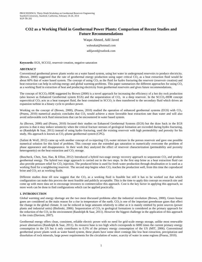
2.4 Model setup and numerical simulation
Different researchers have tried different model setups to analyze and compare the working of EGS system with CO2 as the working
fluid. The most common setup is five spot EGS injection production system with the consideration of two dimensional areal system for
reservoir. (Pruess, 2010) analyzed two different conditions, first all water system and second all CO2 system. (Spycher & Pruess, 2010)
analyzed for anhydrous CO2 injection into the water containing reservoir. In both studies simulation was performed with the TOUGH2
simulator with the ECO2N fluid property module. (Pruess, 2010) also analyzed the linear three well arrangement instead of typical five
well arrangement and compared them for the same thermodynamic conditions of the reservoir and for the same injected fluid.
Figure 1: Five spot well pattern (Pruess, 2007)
2.5 Conclusion
This section concludes findings from the research on CO2 as working fluid in EGS system.
Simulation done by (Pruess, 2007) concluded that initially the heat extraction rates are approximately 50 % larger with CO2 with
comparison to water. The difference becomes smaller with time, due to the more rapid thermal depletion when using CO2. Mass flow
rates in the CO2 system are larger than for water by factors ranging from 3.5 to almost 5. These results show that mass flow increases
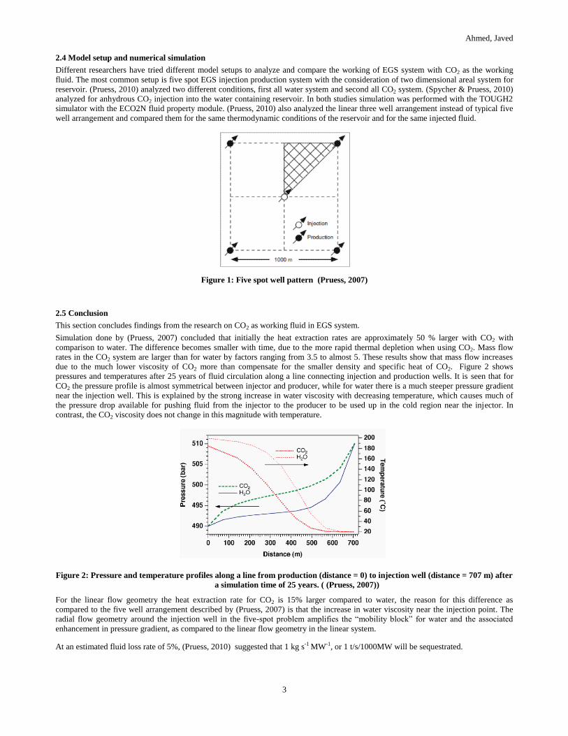
due to the much lower viscosity of CO2 more than compensate for the smaller density and specific heat of CO2. Figure 2 shows
pressures and temperatures after 25 years of fluid circulation along a line connecting injection and production wells. It is seen that for
CO2 the pressure profile is almost symmetrical between injector and producer, while for water there is a much steeper pressure gradient
near the injection well. This is explained by the strong increase in water viscosity with decreasing temperature, which causes much of
the pressure drop available for pushing fluid from the injector to the producer to be used up in the cold region near the injector. In
contrast, the CO2 viscosity does not change in this magnitude with temperature.
Figure 2: Pressure and temperature profiles along a line from production (distance = 0) to injection well (distance = 707 m) after
a simulation time of 25 years. ( (Pruess, 2007))
For the linear flow geometry the heat extraction rate for CO2 is 15% larger compared to water, the reason for this difference as
compared to the five well arrangement described by (Pruess, 2007) is that the increase in water viscosity near the injection point. The
radial flow geometry around the injection well in the five-spot problem amplifies the “mobility block” for water and the associated
enhancement in pressure gradient, as compared to the linear flow geometry in the linear system.
At an estimated fluid loss rate of 5%, (Pruess, 2010) suggested that 1 kg s-1 MW-1, or 1 t/s/1000MW will be sequestrated.

Ahmed, Javed
4
(Spycher & Pruess, 2010) studied the water plume break through after the injection of CO2, he concluded that the production of a free
aqueous phase from an EGS operated with CO2 will occur for only a limited time (a few years), he also found that the dissolved water
will persist in the CO2 production stream for decades.
3. THE CO2-PLUME GEOTHERMAL (CPG) APPROACH
3.1 The CO2-plume geothermal (CPG) concept
The research summarized in the previous section was related to the SSCO2 as a working fluid in the EGS, which includes the step of
reservoir creation (hydro fracturing). In this section a new concept introduced by (Randolph & Saar, 2011) is summarized, in which
SSCO2 is used as a working fluid in the high-permeability and high-porosity geologic reservoirs that are overlain by a low-permeability
cap rock. He differentiated this approach from EGS and referred it as CO2-plume geothermal (CPG) system.
In CPG system the CO2 is pumped in the naturally porous and permeable reservoir where it is heated via the underlying hot rock and
then circulated through the pipe system to generate the electricity. Some of the injected CO2 is leaked in the reservoir and stored
permanently.
3.2 Typical reservoir conditions assumed for CPG system
Reservoir Thickness 305 m Rock specific heat 1000 j/kg C
Well separation 707.1 m Thermal conductivity 2.1 W/mC
Permeability 5e-4 m2 Injected fluid temperature 20 C
Porosity 0.2 Down hole pressure 260 bar
Rock grain density 2650 kg m-2 Injection/production time 25 years
Table 2 Typical reservoir conditions for CPG
3.3 Model setup and numerical simulation
(Randolph & Saar, 2011) extended the research of (Pruess, 2007), he used the same model setup of a five well arrangement (see Figure
1). (Randolph & Saar, 2011) first simulated EGS system working with SSCO2 and then the porous media system working with SSCO2.
The porous medium in the domain considered was homogeneous with a permeability of 5x10⁻⁴ m2 and a porosity of 0.2. A two
dimensional horizontal plain domain was simulated. The equidistant grid with a discretization length of 70.71 m was considered. Top
and side boundaries were considered no fluid and heat flow while bottom was considered no fluid flow.
For the simulations he used the parameters given in Table 2 . Two reservoirs were considered in the simulation: one deep reservoir with
a depth of 4 km and a temperature of 150 oC, the second reservoir is shallow with a depth of 1km and a temperature of 100 oC . A value
of 5x10⁻⁴ m2 for the permeability was used for both reservoirs. Considering CO2 as the only fluid in the system and neglecting brine in
the formation (although it is important to consider it in the simulation) simulations were performed with the numerical simulator
TOUGH2 and the fluid property module ECO2N.
3.4 Conclusion
(Randolph & Saar, 2011) concluded that heat extraction rates decrease with time as the reservoir heat is depleted and the temperature at
the production wells decreases although the mass flow rates remain relatively constant with time. Heat extraction rates in the CPG
approach generally increase with formation temperature. Comparing his results with the Pruess2007 setup for EGS system, he found
that the heat extraction rate is higher in both cases (deep and shallow reservoir).
Based on the simulation of 25 years (Randolph & Saar, 2011) concluded that 7% of the CO2 will be permanently stored in the reservoir
(which is greater than the finding of the (Pruess, 2007) in EGS i.e 5%) which makes a total amount of CO2 sequestrated of 2x10⁷ tons
over the simulated 25-year life of the CPG power plant. Performing a cost analysis based on 100 $U.S.A (value per MW*hour) he
suggested that the CPG system could result in higher net revenue values due to fixed construction and low maintenance costs. His
results for the shallow reservoir (temperature = 150 oC, reservoir depth = 4 km) give a net revenue of 7.9 $ per ton CO2 sequestered
whereas the deep reservoir (temperature = 100 oC , reservoir depth = 4 km) has net revenue of 5.9 $U.S.A per ton CO2 sequestrated.
As this is a new concept further numerical simulations are required to investigate its feasibility. (Randolph & Saar, 2011) in his research
does not include in situ brine in the reservoir, so it has to be investigated how much time will be required until the reservoir is fully
occupied with SSCO2 and what will be done with the brine extracted from the production (can it be used directly or does it need to be
treated). The chemical and thermal behavior of the permeable reservoir formations for different regions in Europe still has to
investigated (the coming section gives a new approach in which the effect of different permeability is studied in order to test the
feasibility of this approach. His work is a bench mark to start investigating the possibilities of clean energy and CO2 sequestration in
permeable soil because it is much cheaper than EGS and there is no related to seismic activities.
Ahmed, Javed
5
4. "NEGATIVE SATURATION" (NEGSAT) SOLUTION APPROACH
4.1 The concept of "Negative saturation" (NegSat) solution approach
Injection of CO2 at a high rate can have negative effects like drying out of the reservoir and over pressurizing the aquifer, which can
lead to fracturing and therefore also to leakage (Salimi & Wolf, 2012) of CO2. (Salimi & Wolf, 2012) proposed to inject moderate
amounts of a mixture of CO2 combined with cooled production water into geothermal reservoirs. It has several advantages as to enhance
residual trapping, to reduce the mobility ratio, to enhance spreading, and also take advantage of single-phase dissolved CO2 injection
which avoids confining the CO2 to the upper part of the reservoir hence decreasing the leak risk via the cap rock.
As this concept involved the injection of CO2-water mixture so phase disappearance, appearance as well as the phase transition between
sub cooled and supercritical behavior is a problem in model formulation, so they formulated the NegSat solution approach for non-
isothermal compositional two-phase flow. This approach gives a uniform system of equations for the entire reservoir that could properly
deal with different phase states of the reservoir without changing the primary variables and thermodynamic-constraint conditions.
Formulating such a situation they assumed that for cold mixed CO2-water injection into a geothermal reservoir, two phases could
coexist at most (a CO2-rich phase and a water-rich phase), so they replaced the equation of single-phase region (i.e over saturated and
under saturated) with the equations for equivalent fictitious two phase regions with specific properties by defining equivalent specific
properties such as molar density, concentration, flux and saturation. Working on the following postulates they come up with equivalent
saturation as limiting parameter to control appearance and disappearance of the phase (Salimi & Wolf, 2012),
The single-phase molar density should be equal to the total molar density of the fictitious two phases.
The single-phase density must be calculated from an equation-of-state (EOS) program. It depends apart from the temperature
and pressure also on the overall composition of each component
The overall concentration of component "i" in the single-phase must be equal to that in the fictitious two phases
The single-phase flux must be equated to the total flux of the fictitious two phases
The energy conservation equation for the single-phase must be equivalent to that for the fictitious two phases
The saturation of the equivalent gas is called the extended gas saturation, given by
Where is extended gas saturation, is overall mole fraction, is mole fraction in gas phase and is mole fraction in liquid
phase. The possible phases which can be concluded base on the extended gas saturation is as follows,
If the extended gas saturation is between zero and one, it is the same as the actual gas saturation and there are two phases.
If the extended gas saturation is above one, we have a single gaseous phase and the actual gaseous saturation is one.
If the extended gas saturation is below zero, we have a single liquid phase and the actual gas saturation is zero.
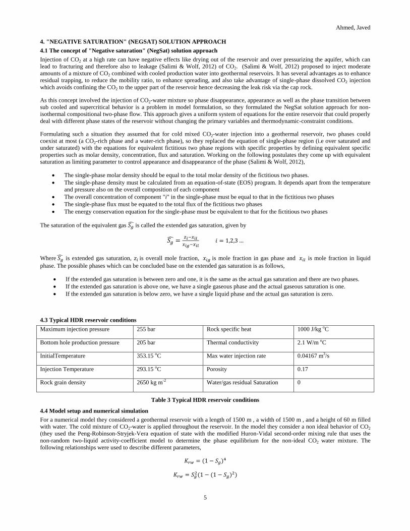
4.3 Typical HDR reservoir conditions
Maximum injection pressure 255 bar Rock specific heat 1000 J/kg oC
Bottom hole production pressure 205 bar Thermal conductivity 2.1 W/m oC
InitialTemperature 353.15 oC Max water injection rate 0.04167 m3/s
Injection Temperature 293.15 oC Porosity 0.17
Rock grain density 2650 kg m-2 Water/gas residual Saturation 0
Table 3 Typical HDR reservoir conditions
4.4 Model setup and numerical simulation
For a numerical model they considered a geothermal reservoir with a length of 1500 m , a width of 1500 m , and a height of 60 m filled
with water. The cold mixture of CO2-water is applied throughout the reservoir. In the model they consider a non ideal behavior of CO2
(they used the Peng-Robinson-Stryjek-Vera equation of state with the modified Huron-Vidal second-order mixing rule that uses the
non-random two-liquid activity-coefficient model to determine the phase equilibrium for the non-ideal CO2 water mixture. The
following relationships were used to describe different parameters,
Ahmed, Javed
6
√
⁄
⁄
⁄
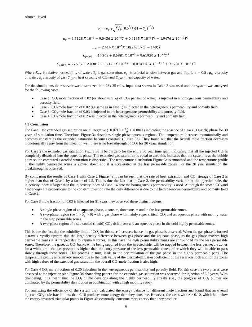
Where is relative permeability of water, is gas saturation, interfacial tension between gas and liquid, , viscosity
of water, viscosity of gas, heat capacity of CO2 and heat capacity of water.
For the simulations the reservoir was discretized into 23x 35 cells. Input data shown in Table 3 was used and the system was analyzed
for the following cases,
Case 1: CO2 mole fraction of 0.02 (or about 49.9 kg of CO2 per ton of water) is injected in a homogeneous permeability and
porosity field.
Case 2: CO2 mole fraction of 0.02 (i.e same as in case 1) is injected in the heterogeneous permeability and porosity field.
Case 3: CO2 mole fraction of 0.03 is injected in the heterogeneous permeability and porosity field.
Case 4: CO2 mole fraction of 0.2 was injected in the heterogeneous permeability and porosity field.
4.5 Conclusion
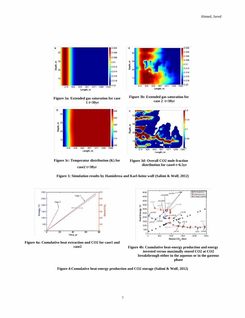
For Case 1 the extended gas saturation are all negative (−0.0213 < <−0.0011) indicating the absence of a gas (CO2-rich) phase for 30
years of simulation time. Therefore, Figure 3a describes single-phase aqueous regions. The temperature increases monotonically and
becomes constant as the extended saturation becomes constant (Figure 3b). They found out that the overall mole fraction decreases
monotonically away from the injection well there is no breakthrough of CO2 for 30 years simulation.
For Case 2 the extended gas saturation Figure 3b is below zero for the entire 30 year time span, indicating that all the injected CO2 is
completely dissolved into the aqueous phase. The extended gas saturation is equal to zero this indicates that the system is at the bubble
point so the computed extended saturation is dispersive. The temperature distribution Figure 3c is smoothed and the temperature profile
in the highly permeable zones is slowed down and it is accelerated in the less permeable zones. For the 30 year simulation the
breakthrough is observed.
By comparing the results of Case 1 with Case 2 Figure 4a it can be seen that the rate of heat extraction and CO2 storage of Case 2 is
higher than that of Case 1 by a factor of 2.5. This is due the fact that in Case 2, the permeability variation at the injection side, the
injectivity index is larger than the injectivity index of Case 1 where the homogeneous permeability is used. Although the stored CO2 and
heat energy are proportional to the constant injection rate the only difference is due to the heterogeneous permeability and porosity field
in Case 2.
For Case 3 mole fraction of 0.03 is injected for 51 years they observed three distinct regions,
A single-phase region of an aqueous phase, upstream, downstream and in the less permeable zones.
A two-phase region (i.e 1 > > 0) with a gas phase with mainly super critical CO2 and an aqueous phase with mainly water
in the high permeable zones.
A two-phase region of a sub cooled (liquid) CO2-rich phase and an aqueous phase in the cold highly permeable zones.
This is due the fact that the solubility limit of CO2 for this case increases, hence the gas phase is observed. When the gas phase is formed
it travels rapidly upward due the large density difference between gas phase and the aqueous phase, as the gas phase reaches high
permeable zones it is trapped due to capillary forces, In this case the high permeability zones are surrounded by the less permeable
zones, Therefore, the gaseous CO2 banks while being supplied from the injected side, will be trapped between the less permeable zones
for a while until the gas pressure is higher than the entry pressure of the less permeable zones, after which they will be able to pass
slowly through these zones. This process in turn, leads to the accumulation of the gas phase in the highly permeable parts. The
temperature profile is relatively smooth due to the high value of the thermal-diffusion coefficient of the reservoir rock and for the zones
with high values of the extended gas saturation the overall CO2 mole fraction is also high.
For Case 4 CO2 mole fractions of 0.20 injections in the heterogeneous permeability and porosity field. For this case the two phases were
observed at the injection side Figure 3d channeling pattern for the extended gas saturation was observed for injection of 6.5 years, With
channeling, it is meant that the CO2 plume develops along the highly permeability streaks (i.e., the progress of CO2 plumes are
dominated by the permeability distribution in combination with a high mobility ratio).
For analyzing the efficiency of the system they calculated the energy balance for different mole fraction and found that an overall
injected CO2 mole fraction less than 0.10 produces more energy than they consume. However, the cases with z > 0.10, which fall below
the energy-invested triangular points in Figure 4b eventually, consume more energy than they produce.
Ahmed, Javed
7
Figure 3a: Extended gas saturation for case
1 t=30yr
Figure 3b: Extended gas saturation for
case 2 t=30yr
Figure 3c: Temperatur distribution (K) for
case2 t=30yr
Figure 3d: Overall CO2 mole fraction
distribution for case4 t=6.5yr
Figure 3: Simulation results by Hamidreza and Karl-heinz wolf (Salimi & Wolf, 2012)
Figure 4a: Cumulative heat extraction and CO2 for case1 and
case2
Figure 4b: Cumulative heat-energy production and energy
invested versus maximally stored CO2 at CO2
breakthrough either in the aqueous or in the gaseous
phase
Figure 4:Cumulative heat-energy production and CO2 storage (Salimi & Wolf, 2012)

Ahmed, Javed
8
5. TWO STAGE INTEGRATED GEOTHERMAL-CCS APPROACH
(Buscheck, Chen, Sun, Hao, & Elliot, 2012) introduced a hybrid two-stage energy-recovery approach to sequestrate CO2 and produce
geothermal energy by integrating geothermal production with CO2 capture and sequestration (CCS) in saline, sedimentary formations.
During stage one of the hybrid approach, formation brine, this is extracted to provide pressure relief for CO2 injection as the working
fluid for energy recovery. During stage two, which begins as CO2 reaches the production wells, co produced brine and CO2 are the
working fluids. This section summarizes hybrid two-stage energy-recovery approach.
5.1 The concept of the hybrid two-stage energy-recovery approach
Introducing this approach Buscheck CO2 kept in mind the concept of Active CO2 Reservoir Management (ACRM) which combines
brine extraction and treatment and residual-brine re-injection with CO2 injection. He found that if the reservoir has sufficient trapping
characteristics, brine disposition options, reasonable formation temperature, proximity to CO2 emitters then Active CO2 Reservoir
Management can be applied to the separate formations with one formation being utilized for CO2 storage and a separate formation being
utilized for the purpose of brine re injection. He named this approach as Tandem-formation ACRM.
5.3 Typical HDR reservoir conditions
Maximum injection pressure 255 bar Rock specific heat 1000J/kgC
Bottom hole production pressure 205 bar Thermal conductivity 2.1 W/mC
InitialTemperature 353.15 C Max water injection rate 0.04167 m3/s
Injection Temperature 293.15 Porosity 0.17
Rock grain density 2650 kg/m2 Water/gas residual Saturation 0
Table 4 Typical HDR reservoir conditions for hybrid two-stage energy recovery approach
5.4 Model setup and numerical simulation
They used 3-D model with quarter symmetry to represent a 250-m-thick storage formation (reservoir) and Table 4 shows the assumed
condition used for simulation. The system was analyzed for 12, 16 and 5 well configuration. NUFT (Non isothermal Unsaturated-
saturated Flow and Transport) code was used to simulate multi-phase multi component heat and mass flow and reactive transport in
unsaturated and saturated porous media. Following different configurations were simulated
12 well configuration with 8 injectors ring at 10 km from center and 4 producer at 2 km from center.
16 well configuration with 8 injectors ring at 10 km from center and 8 producer at 3 km from center.
5 well configuration with areas of 1, 2, 4, 8, and 16 km2, with well spacing of 0.7071, 1.0, 1.4142, 2.0, and 2.8284 km,
respectively.
All configurations were simulated for heat flux of 50,75 and 100 MW/m2 for reservoir depth of 2500 km and 5000 km and
for 5 well configuration the flow rate of 280 kg s-1 and 120 kg s-1 for different reservoir thickness 125m and 250m respectively
were compared.
5.5 Conclusion
The aim of this study was to achieve pressure relief and delaying breakthrough time of CO2 to increase the life time of brine production
and maximize the CO2 storage (Buscheck, Chen, Sun, Hao, & Elliot, 2012), therefore various approaches was investigated as described
in the previous section. Following paragraphs summaries the result of different approaches.
First the 12 wells arrangement with 8 injection and 4 central production wells approach was simulated. The result shows that this type of
arrangement increases CO2 storage due to following reasons,
Producing from the center is an effective means of controlling the influence of buoyancy on CO2 plume migration.
Reduction in the pore space competition.
Reduction in the interface pressure with neighboring sub surface.
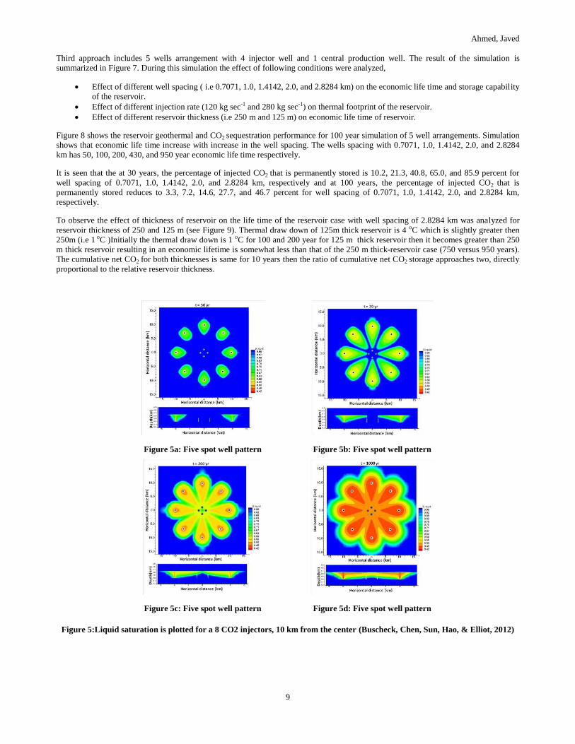
The simulation results are summarized in Figure 5 (which shows the liquid saturation for different simulation time). The break can be
observed for simulation of 70 year (see Figure 5b) and for 1000 year simulation the total fluid (brine plus CO2) production rate of 760
kg sec-1 is observed for injection of 760 kg sec-1 of CO2.
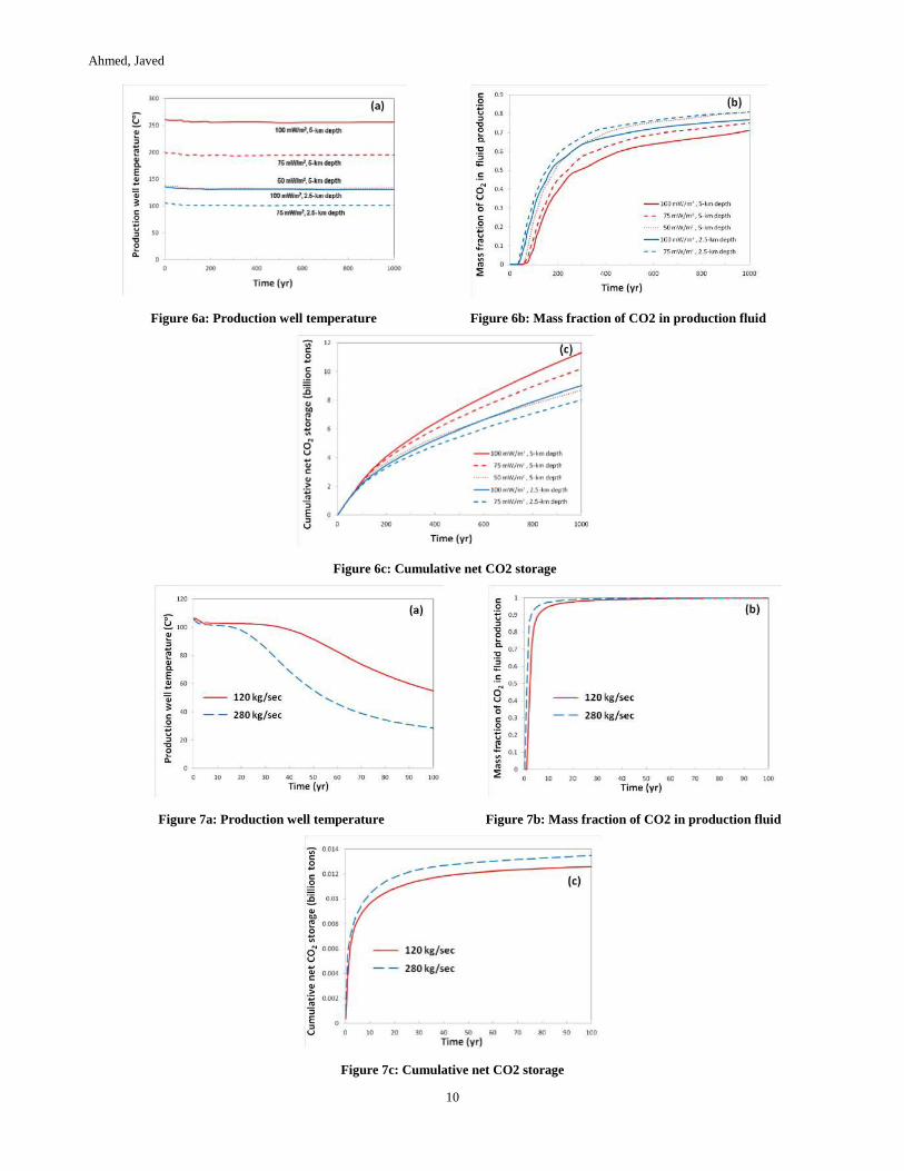
Second approach includes 16 wells arrangement with 8 injection and 8 production wells. The result of the simulation in summarized in
Figure 6. The result shows that there is decline in the temperature for about 30 years in the production well due to thermal mixing (see
Figure 6a) and it can also be seen from the Figure 6b that the cold CO2 is reaching production well between 30 to 100 years, hence the
small temperature decline during that time frame corresponds to the arrival of the slightly cooler CO2 plume. Figure 6c represents the
cumulative net CO2 storage, which shows that 720 million tons CO2 is stored for 30 year simulation before the break through of CO2 at
the production wells.
Ahmed, Javed
9
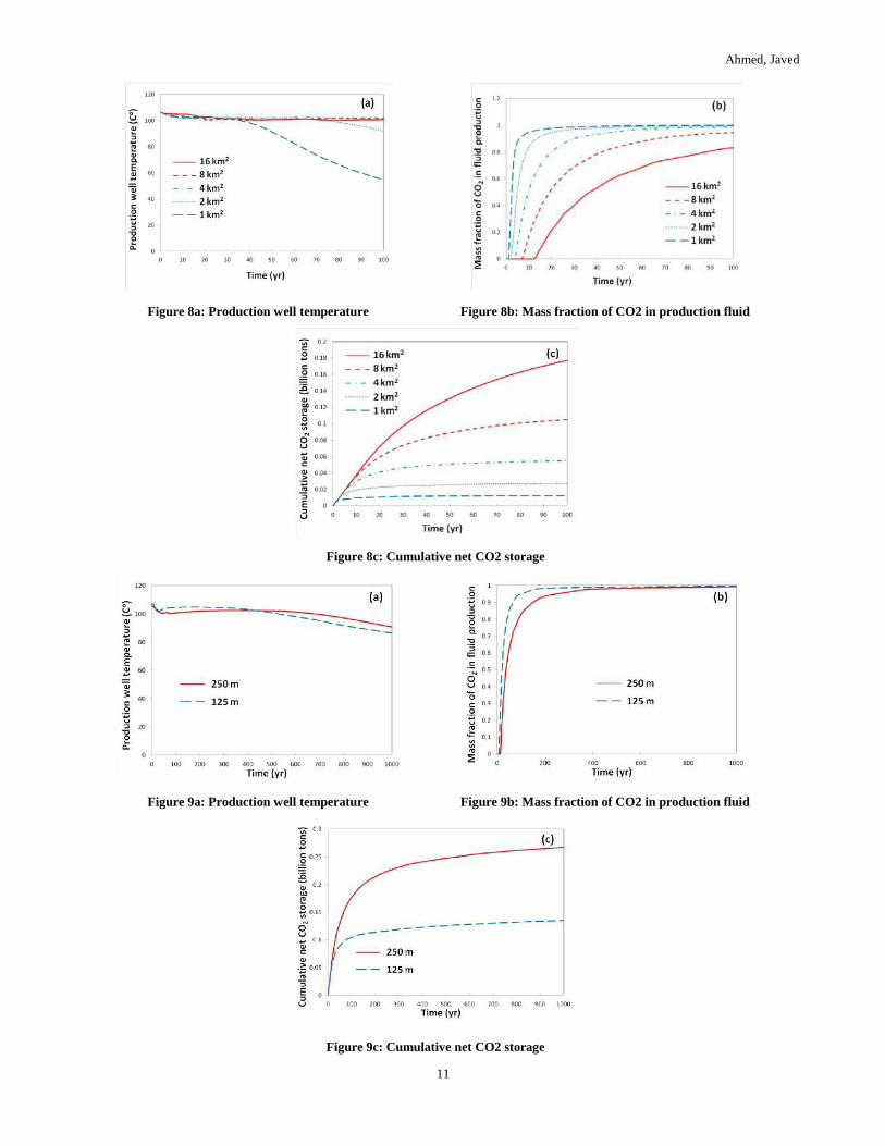
Third approach includes 5 wells arrangement with 4 injector well and 1 central production well. The result of the simulation is
summarized in Figure 7. During this simulation the effect of following conditions were analyzed,
Effect of different well spacing ( i.e 0.7071, 1.0, 1.4142, 2.0, and 2.8284 km) on the economic life time and storage capability
of the reservoir.
Effect of different injection rate (120 kg sec-1 and 280 kg sec-1) on thermal footprint of the reservoir.
Effect of different reservoir thickness (i.e 250 m and 125 m) on economic life time of reservoir.
Figure 8 shows the reservoir geothermal and CO2 sequestration performance for 100 year simulation of 5 well arrangements. Simulation
shows that economic life time increase with increase in the well spacing. The wells spacing with 0.7071, 1.0, 1.4142, 2.0, and 2.8284
km has 50, 100, 200, 430, and 950 year economic life time respectively.
It is seen that the at 30 years, the percentage of injected CO2 that is permanently stored is 10.2, 21.3, 40.8, 65.0, and 85.9 percent for
well spacing of 0.7071, 1.0, 1.4142, 2.0, and 2.8284 km, respectively and at 100 years, the percentage of injected CO2 that is
permanently stored reduces to 3.3, 7.2, 14.6, 27.7, and 46.7 percent for well spacing of 0.7071, 1.0, 1.4142, 2.0, and 2.8284 km,
respectively.
To observe the effect of thickness of reservoir on the life time of the reservoir case with well spacing of 2.8284 km was analyzed for
reservoir thickness of 250 and 125 m (see Figure 9). Thermal draw down of 125m thick reservoir is 4 oC which is slightly greater then
250m (i.e 1 oC )Initially the thermal draw down is 1 oC for 100 and 200 year for 125 m thick reservoir then it becomes greater than 250
m thick reservoir resulting in an economic lifetime is somewhat less than that of the 250 m thick-reservoir case (750 versus 950 years).
The cumulative net CO2 for both thicknesses is same for 10 years then the ratio of cumulative net CO2 storage approaches two, directly
proportional to the relative reservoir thickness.
Figure 5a: Five spot well pattern
Figure 5b: Five spot well pattern
Figure 5c: Five spot well pattern
Figure 5d: Five spot well pattern
Figure 5:Liquid saturation is plotted for a 8 CO2 injectors, 10 km from the center (Buscheck, Chen, Sun, Hao, & Elliot, 2012)
Ahmed, Javed
10
Figure 6a: Production well temperature
Figure 6b: Mass fraction of CO2 in production fluid
Figure 6c: Cumulative net CO2 storage
Figure 7a: Production well temperature
Figure 7b: Mass fraction of CO2 in production fluid
Figure 7c: Cumulative net CO2 storage
Ahmed, Javed
11
Figure 8a: Production well temperature
Figure 8b: Mass fraction of CO2 in production fluid
Figure 8c: Cumulative net CO2 storage
Figure 9a: Production well temperature
Figure 9b: Mass fraction of CO2 in production fluid
Figure 9c: Cumulative net CO2 storage

Ahmed, Javed
12
6. CONCLUSION AND FUTURE WORK
From the following literature review following points and future possibilities can be summarized,
SCCO2 as working fluid in EGS system is more favorable then water, with an anticipated thermal performance approximately
60% that of a water-based EGS system for equivalent operating conditions ( (Brown, 2000)).
In SSCO2-EGS system the rock-fluid interactions may also be more favorable for than with water, but little information is
available about chemical interactions on high temperatures between supercritical CO2 and rock minerals (so it has to be still
studied in detail. (Spycher & Pruess, 2010).
In SSCO2-EGS system there is a benefit of CO2 sequestration which makes it economically more feasible then water-EGS
system.
(Pruess, 2010) showed that the linear well arrangement has different heat extraction then typical 5 well arrangement, so more
studies can be done to see the effect of well arrangement on the heat extraction in SSCO2-EGS system.
SSCO2-EGS system has a problem of inducing the seismicity (during hydro fracturing process) so this process is less
acceptable publicly.
CPG system is more acceptable publicly because it does not produce seismicity.
CPG system can sequestrate more amount of CO2 then EGS system (i.e 2% more) and is more economically feasible due to
low construction and maintenance costs ( (Randolph & Saar, 2011)).
Study done by (Randolph & Saar, 2011) does not include in situ brine in the reservoir, so it has to be investigated how much
time will be required until the reservoir is fully occupied with SCCO2 and what will be done with the brine extracted from the
production.
The presence of water in the CO2 would have implications not only for the design of heat extraction systems, but would also
dictate the amount of reactivity of CO2 with the reservoir and engineered systems. For these reasons, future assessment of the
potential for CO2-EGS will need to focus not only on flow/recovery issues, but also on the reactivity of CO2 containing
various amounts of water (including dry CO2) with reservoir rocks and other relevant materials ( (Spycher & Pruess, 2010)).
Permeability and porosity heterogeneities in a geothermal aquifer significantly influence both heat extraction and CO2 storage.
Hence, reservoir characterization plays an important role in assessing the benefits of CO2 storage and energy extraction (
(Salimi & Wolf, 2012)).
Injecting CO2-water mixture help in large amount of heat extraction and CO2 storage because frequent occurrence of
evaporation and condensation substantially delays CO2 breakthrough and consequently leads to a larger amount of heat-energy
production and CO2 storage (Salimi & Wolf, 2012).
When injection CO2-water mixture there is a problem of phase appearance and disappearance so it has to be incorporated in
the numerical model (Salimi & Wolf, 2012).
The character of heterogeneity and the mobility ratio controls the displacement regime so to see the transition between
dispersive and channeling regime mobility ratio has to be monitored (Salimi & Wolf, 2012).
While injecting CO2-Water mixture the mole fraction of CO2 has to be monitored because larger CO2 mole fraction does not
ensures positive net energy balance. In the study done by Salimi (2012) for overall injected CO2 mole fractions smaller than
0.1, the net energy balance is positive, indicating that the process produces more energy than consumes. However, the net
energy balance becomes negative for overall injected CO2 mole fractions larger than 0.1.
(Salimi & Wolf, 2012) neglected the effect of heat gain and loss by the surrounding layers, so its effect on the net energy
balance can be studied for the future.
(Buscheck, Chen, Sun, Hao, & Elliot, 2012) showed that the well arrangement and distance of production well from injection
well effect the thermal foot print and CO2 storage so for future economically feasible arrangement of well can be studied.
(Buscheck, Chen, Sun, Hao, & Elliot, 2012) gave the concept of using the brine for drinking and purposes, so for future this
concept can be extended to find the feasible arrangement of using the in situ brine (Using it for pressure relief in the
neighboring reservoir or for drinking and agriculture purpose).
(Buscheck, Chen, Sun, Hao, & Elliot, 2012) considered homogeneous, permeable CO2 storage formation/geothermal
reservoir, so his study can be compared for heterogeneous reservoir condition.
Different subsurface has different condition so different reservoir can be simulated for finding out the feasible one.
For a realistic assessment it will be necessary to go beyond theoretical estimations and paper studies, and begin to design,
implement, and analyze practical tests in the laboratory and the field (Pruess, 2010).
7. CONCLUDING REMARKS
Different studies done till now suggest that the CO2 as working fluid is feasible but still it has to be worked out that which configuration
can make this process the most feasible and publicly acceptable. This is the time to apply this concept on different research site and
come up with more data set to encourage investors to commercialize this approach. Cost is the key factor in applying this approach, so
more work can be done to find configurations which can be applied practically.

Ahmed, Javed
13
REFERENCES
Bielinski, A. (2006). Numerical simulation of CO2 sequestration in geological formations. Inst. f{\"u}r Wasserbau.
Brown, D. (2000). A hot dry rock geothermal energy concept utilizing supercritical CO2 instead of water. Proceedings, (ss. 233-238).
Buscheck, T., Chen, M., Sun, Y., Hao, Y., & Elliot, T. (2012). Two-Stage, Integrated, Geothermal-CO2 Storage Reservoirs: An
Approach for Sustainable Energy Production, CO2-Sequestration Security, and Reduced Environmental Risk. Tech. rep.,
Lawrence Livermore National Laboratory (LLNL), Livermore, CA.
Davison, J. (2007). Performance and costs of power plants with capture and storage of CO< sub> 2</sub>. Energy, 32(7), 1163-1176.
Fouillac, C. B., & Czernichowski-Lauriol, I. (2004). Could Sequestration of CO2 be Combined with the Development of Enhanced
Geothermal Systems? Third Annual Conference on Carbon Capture and Sequestration.
MIT. (2006). The Future of Geothermal Energy. Tech. rep., Massachusetts Institute of Technology, Cambridge, MA.
Pruess, K. (2007). Enhanced Geothermal Systems (EGS) comparing water with CO2 as heat transmission fluids.
Pruess, K. (2010). Enhanced geothermal systems (EGS) with CO2 as heat transmission fluid--A scheme for combining recovery of
renewable energy with geologic storage of CO2.
Randolph, J., & Saar, M. (2011). Coupling carbon dioxide sequestration with geothermal energy capture in naturally permeable, porous
geologic formations: Implications for CO< sub> 2</sub> sequestration. Energy Procedia, 4, 2206-2213.
Salimi, H., & Wolf, K. (2012). Integration of heat-energy recovery and carbon sequestration. International Journal of Greenhouse Gas
Control, 6, 56-68.
Socolow, R., & Pacala, S. (2006). A plan to keep carbon in check. Scientific American, 295(3), 50-57.
Spycher, N., & Pruess, K. (2010). A Phase-Partitioning Model for CO 2--Brine Mixtures at Elevated Temperatures and Pressures:
Application to CO 2-Enhanced Geothermal Systems. Transport in porous media, 82(1), 173-196.
Vukalovich, M., & Altunin, V. (1968). Thermophysical properties of carbon dioxide. Wellingborough, Collets.