Callaway, Unit 1, 10CFR50.55a Request - Nuclear Regulatory ...
244
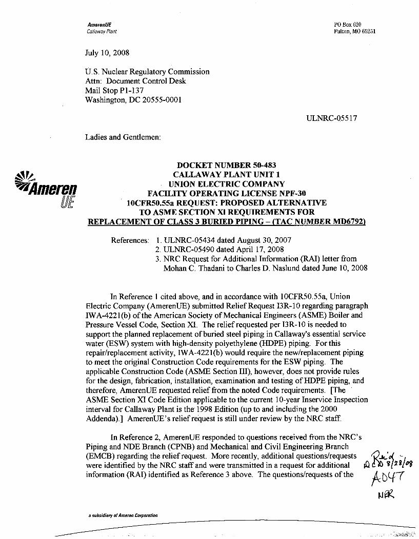
AmerenUE Callaway Plant PO Box 620 Fulton, MO 65251 July 10, 2008 U.S. Nuclear Regulatory Commission Attn: Document Control Desk Mail Stop P1-137 Washington, DC 20555-0001 ULNRC-05517 Ladies and Gentlemen: VIA merefn UE DOCKET NUMBER 50-483 CALLAWAY PLANT UNIT 1 UNION ELECTRIC COMPANY FACILITY OPERATING LICENSE NPF-30 10CFR50.55a REQUEST: PROPOSED ALTERNATIVE TO ASME SECTION X1 REQUIREMENTS FOR REPLACEMENT OF CLASS 3 BURIED PIPING - (TAC NUMBER MD6792) References: 1. ULNRC-05434 dated August 30, 2007 2. ULNRC-05490 dated April 17, 2008 3. NRC Request for Additional Information (RAI) letter from Mohan C. Thadani to Charles D. Naslund dated June 10, 2008 In Reference 1 cited above, and in accordance with 1OCFR50.55a, Union Electric Company (AmerenUE) submitted Relief Request 13R-10 regarding paragraph IWA-4221 (b) of the American Society of Mechanical Engineers (ASME) Boiler and Pressure Vessel Code, Section XI. The relief requested per 13R-10 is needed to support the planned replacement of buried steel piping in Callaway's essential service water (ESW) system with high-density polyethylene (HDPE) piping. For this repair/replacement activity, IWA-4221(b) would require the new/replacement piping to meet the original Construction Code requirements for the ESW piping. The applicable Construction Code (ASME Section III), however, does not provide rules for the design, fabrication, installation, examination and testing of HDPE piping, and therefore, AmerenUE requested relief from the noted Code requirements. [The ASME Section XI Code Edition applicable to the current 10-year Inservice Inspection interval for Callaway Plant is the- 1998 Edition (up to and including the 2000 Addenda).] AmerenUE's relief request is still under review by the NRC staff. In Reference 2, AmerenUE responded to questions received from the NRC's Piping and NDE Branch (CPNB) and Mechanical and Civil Engineering Branch (EMCB) regarding the relief request. More recently, additional questions/requests '•.io( ?i were identified by the NRC staff and were transmitted in a request for additional Q information (RAI) identified as Reference 3 above. The questions/requests of the P C(- a subsidiary of Ameren Corporation
-
Upload
khangminh22 -
Category
Documents
-
view
0 -
download
0
Transcript of Callaway, Unit 1, 10CFR50.55a Request - Nuclear Regulatory ...
AmerenUECallaway Plant
PO Box 620Fulton, MO 65251
July 10, 2008
U.S. Nuclear Regulatory CommissionAttn: Document Control DeskMail Stop P1-137Washington, DC 20555-0001
ULNRC-05517
Ladies and Gentlemen:
VIA merefnUE
DOCKET NUMBER 50-483CALLAWAY PLANT UNIT 1
UNION ELECTRIC COMPANYFACILITY OPERATING LICENSE NPF-30
10CFR50.55a REQUEST: PROPOSED ALTERNATIVETO ASME SECTION X1 REQUIREMENTS FOR
REPLACEMENT OF CLASS 3 BURIED PIPING - (TAC NUMBER MD6792)
References: 1. ULNRC-05434 dated August 30, 20072. ULNRC-05490 dated April 17, 20083. NRC Request for Additional Information (RAI) letter from
Mohan C. Thadani to Charles D. Naslund dated June 10, 2008
In Reference 1 cited above, and in accordance with 1OCFR50.55a, UnionElectric Company (AmerenUE) submitted Relief Request 13R-10 regarding paragraphIWA-4221 (b) of the American Society of Mechanical Engineers (ASME) Boiler andPressure Vessel Code, Section XI. The relief requested per 13R-10 is needed tosupport the planned replacement of buried steel piping in Callaway's essential servicewater (ESW) system with high-density polyethylene (HDPE) piping. For thisrepair/replacement activity, IWA-4221(b) would require the new/replacement pipingto meet the original Construction Code requirements for the ESW piping. Theapplicable Construction Code (ASME Section III), however, does not provide rulesfor the design, fabrication, installation, examination and testing of HDPE piping, andtherefore, AmerenUE requested relief from the noted Code requirements. [TheASME Section XI Code Edition applicable to the current 10-year Inservice Inspectioninterval for Callaway Plant is the- 1998 Edition (up to and including the 2000Addenda).] AmerenUE's relief request is still under review by the NRC staff.
In Reference 2, AmerenUE responded to questions received from the NRC'sPiping and NDE Branch (CPNB) and Mechanical and Civil Engineering Branch(EMCB) regarding the relief request. More recently, additional questions/requests '•.io( ?iwere identified by the NRC staff and were transmitted in a request for additional Qinformation (RAI) identified as Reference 3 above. The questions/requests of the P C(-
a subsidiary of Ameren Corporation
ULNRC-05517July 10, 2008Page 2
Reference 3 RAI letter were contained within five enclosures to the letter. Thequestions/requests contained in Enclosures 1 and 2, in particular, were provided fromthe NRC's Division of Component Integrity and Division of Engineering,respectively. AmerenUE is hereby providing its responses to thosequestions/requests. Responses for the questions/requests contained in Enclosures 3,4, and 5 of the Reference 3 RAI letter are being transmitted under a separate coverletter from AmerenUE, i.e., AmerenUE letter ULNRC-05520.
In response to the NRC's RAI letter, Enclosure 1 of this letter containsresponses to the questions/requests from the NRC's Division of Component Integrity,and Enclosure 2 provides responses to the questions/requests from the NRC'sDivision of Engineering. Supporting information for the responses is provided inadditional enclosures to this letter. Specifically, a letter from Dow ChemicalCompany (with its own attachments) is provided in Enclosure 3. Enclosure 4contains a calculation of the minimum wall thickness for the subject undergroundHDPE piping, i.e., Callaway Calculation 2007-13241. (The calculation is notfinalized but will be available for inspection after finalization.) Enclosure 6 providesinformation that supports the response to one of the RAI questions addressed inEnclosure 2. It provides a basis for use of a 0.56 design factor in the determination ofallowable stresses for the HDPE piping design. Enclosure 7 provides a summary ofthe commitments made within this submittal.
In addition, in developing the responses for the NRC's RAI, it was determinedthat the relief request document itself (as originally provided via Reference 1) mustbe revised. An updated and final version of the relief request, i.e., 1OCFR50.55aRequest Number 13R- 10, is therefore provided as Enclosure 5 to this letter. Therevised relief request has its own attachment, "Requirements for HDPE Piping forNuclear Service," which is included within Enclosure 5.
If you have any questions on this letter or its enclosures, please contact Mr.Scott Maglio at (573) 676-8719.
Very truly yours,
Keith A. MillsManager - Plant Engineering
ULNRC-05517July 10, 2008Page 3
GGY/MDB/TBE/nls
Enclosures: 1 - Responses to RAI Questions/Requests from NRCDivision of Component Integrity
2 - Responses to RAI Questions/Requests from NRCDivision of Engineering
3 - Letter from Dow Chemical Company (with attachments)4 - Callaway Calculation No. 2007-132415 - 1OCFR50.55a Request Number I3R-10 (with attachment)6 - Justification for Increase in Callaway's HDPE Design Factor7 - Summary of Regulatory Commitments
ULNRC-05517July 10, 2008Page 4
cc:
U.S. Nuclear Regulatory Commission (Original and 1 copy)Attn: Document Control DeskMail Stop P1-137Washington, DC 20555-0001
Mr. Elmo E. Collins, Jr.Regional AdministratorU.S. Nuclear Regulatory CommissionRegion IV611 Ryan Plaza Drive, Suite 400Arlington, TX 76011-4005
Senior Resident InspectorCallaway Resident OfficeU.S. Nuclear Regulatory Commission8201 NRC RoadSteedman, MO 65077
Mr. Mohan C. Thadani (2 copies)Licensing Project Manager, Callaway PlantOffice of Nuclear Reactor RegulationU. S. Nuclear Regulatory CommissionMail Stop O-8G14Washington, DC 20555-2738
ULNRC-05517July 10, 2008Page 5
Index and send hardcopy to QA File A160.0761
Hardcopy:Certrec Corporation4200 South Hulen, Suite 630Fort Worth, TX 76109(Certrec receives ALL attachments as long as they are non-safeguards and may be publiclydisclosed.)
Electronic distribution for the following can be made via Responses and ReportsULNRC Distribution:
A. C. Heflin w/oF. M. Diya w/oT. E. HerrmannL. H. Graessle w/oS. M. Maglio w/oT. B. ElwoodS. L. Gallagher w/oL. M. Belsky (NSRB)R. D. Myatt w/oC. R. Kieferw/oM. D. BrandesJ. E. O'SullivanG. G. Yates w/oMr. Ron Reynolds, Director (SEMA)Mr. Edward Gray, Senior REP Planner (SEMA)Mr. John Campbell, REP Planner (SEMA)Ms. Diane M. Hooper (WCNOC) w/oMr. Dennis Buschbaum (TXU) w/oMr. Scott Bauer (Palo Verde) w/oMr. Stan Ketelsen (PG&E) w/oMr. Scott Head (STP) w/oMr. John O'Neill (Pillsbury, Winthrop, Shaw, Pittman LLP)Mr. Floyd Gilzow (DNR)
Enclosure Ito ULNRC-05517
Enclosure 1
Responses to RAI Questions/Requests
from NRC Division of Component Integrity
OFFICE OF NUCLEAR REACTOR REGULATION
REQUEST FOR ADDITIONAL INFORMATION
RELATED TO ESSENTIAL SERVICE WATER
UNION ELECTRIC COMPANY
CALLAWAY PLANT
DOCKET NO. 50-483
The Division of Component Integrity staff has reviewed the licensee's response to theNuclear Regulatory Commission (NRC) staff s first round of request for additionalinformation (RAI). Based on that review, the NRC staff has a need for additionalinformation. Accordingly, a second round of RAIs was sent to the licensee via e-mail onJune 2, 2008, and is being formally documented here for response.
As stated above, the NRC staff requests a response to the following second round ofRAIs.
1. Title 10 of the Code of Federal Regulations (10 CFR) Appendix B, CriterionXVII, Quality Assurance Records, states, "Records shall be identifiable andretrievable." The Standard Fusion Procedure Specification (FSP) in QF-221implies that the supporting records exist in the Plastic Pipe Institute (PPI) reportTR-33/2001. The data used in TR-33/2001 is based on limited tests andequipment manufacturer recommendations. The information supplied inCallaway's request does not provide record traceability and record retrievabilitythat support the FSP qualification tests.
Question/Reqiuest:
Provide a discussion on the accessibility of records supporting the procedure,equipment, and personnel qualifications that will be used for installation andexamination of high density polyethylene (HDPE) pipe.
Response:
Background
Background information needs to be provided to answer this question. First, TR-33 waswritten to address 49 CFR 192.283 (Federal safety standards for transportation of naturaland other gas by pipeline):
-1-
Sec. 192.283 Plastic pipe:
(a) Heat fusion, solvent cement, and adhesive joints. Before anywritten procedure established under Sec. 192.273(b) is used for makingplastic pipe joints by a heat fusion, solvent cement, or adhesivemethod, the procedure must be qualified by subjecting specimen jointsmade according to the procedure to the following tests:
(1) The burst test requirements of--(i) In the case of thermoplastic pipe, paragraph 6.6 (Sustained
Pressure Test) or paragraph 6. 7 (Minimum Hydrostatic Burst Pressure(Quick Burst)) of ASTM D 2513...
(3) For procedures intended for nonlateral pipe connections,follow the tensile test requirements of ASTM D638, except that the testmay be conducted at ambient temperature and humidity. If the specimenelongates no less than 25 percent or failure initiates outside thejoint area, the procedure qualifies for use.
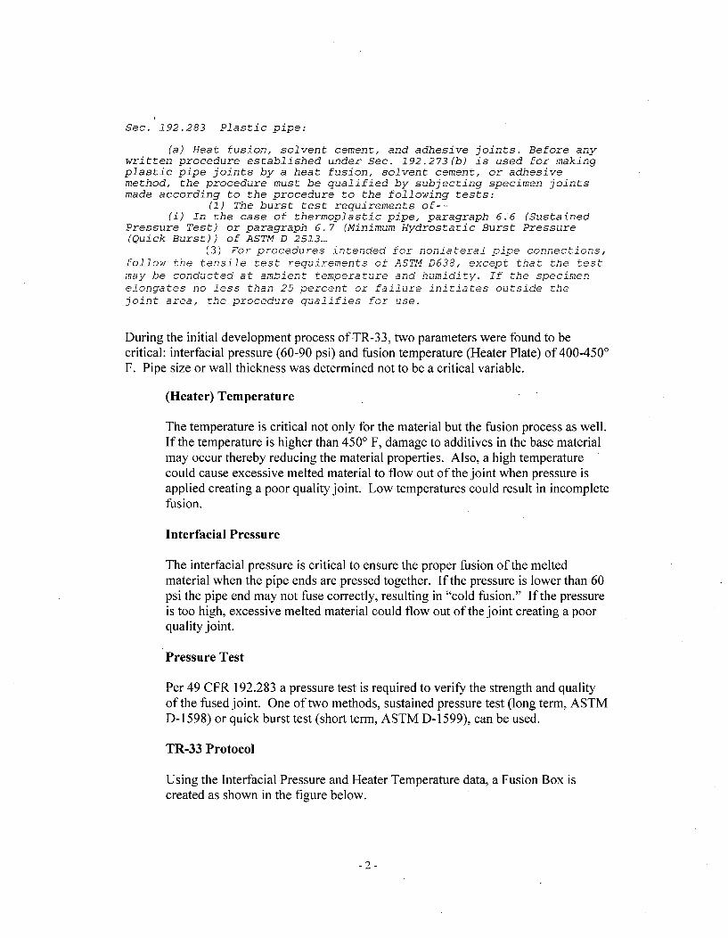
During the initial development process of TR-33, two parameters were found to becritical: interfacial pressure (60-90 psi) and fusion temperature (Heater Plate) of 400-450'F. Pipe size or wall thickness was determined not to be a critical variable.
(Heater) Temperature
The temperature is critical not only for the material but the fusion process as well.If the temperature is higher than 4500 F, damage to additives in the base materialmay occur thereby reducing the material properties. Also, a high temperaturecould cause excessive melted material to flow out of the joint when pressure isapplied creating a poor quality joint. Low temperatures could result in incompletefusion.
Interfacial Pressure
The interfacial pressure is critical to ensure the proper fusion of the meltedmaterial when the pipe ends are pressed together. If the pressure is lower than 60psi the pipe end may not fuse correctly, resulting in "cold fusion." If the pressureis too high, excessive melted material could flow out of the joint creating a poorquality joint.
Pressure Test
Per 49 CFR 192.283 a pressure test is required to verify the strength and qualityof the fused joint. One of two methods, sustained pressure test (long term, ASTMD-1598) or quick burst test (short term, ASTM D-1599), can be used.
TR-33 Protocol
Using the Interfacial Pressure and Heater Temperature data, a Fusion Box iscreated as shown in the figure below.
-2-
Test Poinla
450W
S 400
FUSION BOX
60 00PRESSURE
Any fused joints made using parameters within the "Fusion Box" will have a veryhigh probability of being a properly fused joint. Each corner of the "Fusion Box"is tested using a combination of tests: high speed impact testing, and quick bursttesting or sustained pressure testing. If there is a change in essential variables, anew procedure incorporating those variables will necessitate five test coupons(pipe fusion joints) at each of the extremes (20 total coupons)- three for highspeed impact testing and two for sustained pressure testing.
Applicability to Callaway
Although PE3408 was used for development ofTR-33/2001, Dow Chemical, theconstituent supplier for the piping provided for the Callaway ESW project, has providedCallaway with test results for the Dow PE4710 resin confirming acceptability for usewith the TR-33/2001 procedure. Information regarding this concern is included inEnclosure 3.
This information from Dow Chemical will be retained in permanent Callaway records.
In addition, and as a performance demonstration of the fusion process and equipmentbeyond TR33 and PPI requirements, AmerenUE will produce and perform testing on six(6) fusion joint test coupons of 36NPS DR 9.5 material and 4NPS DR 9 material on eachmodel of fusion machine expected to be used in production, as stated in the response toQuestion 2 below. All data from this performance demonstration will be retained inpermanent Callaway records.
Records are produced during qualification of fusion operators on production equipmentin accordance with Callaway's fusion qualification program requirements and areretained as permanent records. The instruments used on the production equipment are
-3-
calibrated under an approved program and the calibration records are also retained aspermanent records.
2. 10 CFR 50 Appendix B, Criterion III, Design Control, states, "Where a testprogram is used to verify the adequacy of a specific design feature in lieu of otherverifying or checking processes, it shall include suitable qualifications testing of aprototype unit under the most adverse design conditions." The two procedurequalification methods in Code Case N-755 must demonstrate that they are capableof making acceptable fused joints. The demonstrations must cover pipe sizes andessential variable extremes for the equipment (manufacturer model) that is beingused for fusing joints. The reference to PPI report TR-33/2001 does not providesufficient test data for equipment and procedure-specific qualifications for theessential variable extremes. The performance demonstration should userepresentative pipe material and pipe sizes (diameter and wall thickness), and theperformance demonstration should make sufficient repetitions of fused joints tostatistically evaluated equipment and fusion process reliability*
Question/Req uest:
Provide a discussion describing the performance demonstrations that will be usedfor equipment and procedure qualifications, and describe the testing that will beused to validate internal soundness supporting equipment and procedurequalifications. Provide the same discussion for each process (butt fusion, electro-fusion. etc,) if more than one process is used for fusing joints.
Response:
AmerenUE has elected to qualify all fusion operators on the standard TR33/2001procedure using the same size (36 NPS) and thickness (approximately 4 inches) of pipe,same model machines (McElroy and Ritmo), and at the same target values (pressure andtemperature) to be used during production. These qualification tests (similar to thosespecified in 49CFRI 92.285) simulated the actual production conditions to be employedand therefore serve as performance demonstrations for the process, as well as for theequipment and personnel. From each coupon, two specimens were cut, visuallyinspected, and hydraulically bend tested to exceed 20% strain at the fusion joint (one testspecimen for the interior surface and another for the exterior surface). (The yield point ofHDPE typically occurs at approximately 10% strain.) The surfaces of each specimenwere visually examined for any evidence of voids, discontinuities, or failure in the jointarea.
Sixteen (16) specimens were bend-tested (eight in the fabrication shop and eight in thefield), with one test failure. The operator with the one failure in the shop underwentadditional training and successfully passed on re-test. In addition, the machine wasinspected and adjusted to improve uniformity of heating, and six additional testspecimens (for a total of 22) were then produced on the machine - all of which
-4-
successfully passed the bend-tests. These tests - each pair of which simulates the singleperformance demonstration required by ASME Section IX (QW-5 10 & QW-302.1) toallow a manufacturer to use a Standard Welding Procedure Specification (QW- 100.1) -validate the internal soundness of large diameter heavy wall piping joints made bythermal butt fusion on actual production machines using the standard fusion proceduredescribed in TR33/2001.
As a performance demonstration at the request of the Regulator, AmerenUE will producesix (6) fusion joint test coupons of 36NPS DR 9.5 and six (6) fusion joint test specimensof 4NPS DR 9 material on each model of fusion machine carriage expected to be used inproduction for the respective size of piping as a performance demonstration. Three (3) ofthese fusions on each machine will target minimum temperature and interfacial pressureusing maximum heater removal times, and three (3) will target maximum temperatureand interfacial pressure using minimal heater removal times - to the extent feasibleconsidering production limits, machine capabilities and the limits of the AmerenUEFusion Procedure Specification.
A minimum of four (4) specimens will be cut from each fusion joint couponapproximately 90 degrees apart and tensile-tested to verify that the fusion joint is strongerthan the pipe. Testing will be performed by commercial plastics industry supplierswithout a 10 CFR 50 Appendix B quality program, but all testing will be overseen byAmerenUE representatives, and the test records will be retained in permanent Callawayrecords.
High-speed impact tensile testing for the 4NPS specimens will be performed inaccordance with QF-131. This testing will also be performed for the 36NPS specimens ifdetermined feasible and conclusive considering the need - due to tensile machinecapability - to test segmented specimens; otherwise, tensile testing for the 36 NPSspecimens will be performed with full-section specimens consistent with ASTMSpecification D638, "Standard Test Method for Tensile Properties of Plastic," inaccordance with the butt fusion procedure qualification requirements of 49CFR192.283for gas pipelines.
Only the butt thermal fusion process will be used on this project.
Question/Request:
2.(a) QF-223(a) provides one pipe diameter and wall thickness for equipment andprocedure qualification testing. The use of a one-size (diameter and wallthickness) pipe to represent all pipe sizes ignores the effect that pipe diameter andwall thickness have on fused joint integrity. The PPI TR-33/2001 report does notprovide information to support that a one-size pipe is representative of all pipesizes. Discuss the demonstration data that supports the representativeness of onepipe size for all pipe size combinations or that supports the range of pipe sizes
-5-
that will be used. Provide the criteria to be applied to demonstrate fused jointsoundness for the range of pipe sizes that will be used.
Response:
There are two options provided for a Fusion Procedure Specification (FPS): use of theStandard FPS based on TR-33, or development and qualification of a new FPS.
Standard FPS Option
The Standard FPS is based on TR-33, which was developed at the request of theUnited States Department of Transportation to promote greater uniformity in thejoining procedures utilized by gas utilities for the butt fusion of polyethyleneproducts. TR-33 has since become the standard industry practice for butt fusionof polyethylene. The conclusion of TR-33/2001, based on the testing of 2 NPSand 8 NPS samples, was that pressure range and temperature range were the onlyvariables essential for successful fusion of a broad range of medium and highdensity polyethylene piping materials.
TR-33/2006 subsequently expanded this testing to include 12 NPS, 14 NPS, 16NPS, and 22 NPS samples and concluded that the fusion pressure range andtemperature range established in TR-33/2001 are applicable to this expandedrange of sizes.
AmerenUE is using this option.
New FPS Option
Use of TR-33 is not mandatory, and every PE pipe producer and pipeline operatorretains the option of developing different procedures for its particular productsand pipelines. However, to develop a new FPS that deviates from the parametersof TR-33 would require 20 pipe coupons and 13 months of pressure testing.Since the standard procedure developed by TR-33 applies to a broad range ofsizes, there would little value added in requalifying for the AmerenUEapplication.
Callaway Plan
AmerenUE has utilized the Standard FPS for the qualification of all fusionmachine operators. As discussed above, this performance qualification/demonstration of the fusion machines and fusion operators also served todemonstrate satisfactory performance of the Standard FPS on 36 NPS DR 9.5piping.
Also, quick burst test data provided by Dow Chemical (included in Enclosure 3)confirms that joints produced with the TR-33/2001 procedure are stronger thanthe Dow PE4710 piping base material in sizes up to and including 22 NPS DR 9.
-6-
This burst test, coupled with the performance demonstration testing of six (6)fusion joint test coupons of 36NPS DR 9.5 material and 4NPS DR9 material oneach model of fusion machine expected to be used in production, exceeds therequirements of 49CFR192.283(a) for butt fusion procedure qualification, andwill confirm that the FPS used by AmerenUE is suitable for the sizes andthicknesses of piping that will be used.
QF-223(a) requires pipe coupons made from 8 IPS, DR 11. This size was chosenfor ease of manufacturing the high speed tensile specimens and to accommodatethe testing machine.
Question/Request:
2.(b) QF-104.1 (a) defines essential variables as conditions under which fusing must beperformed, and QF-222(a) lists essential variables for procedure and equipmentqualifications. The standard fusion procedure specification (QF-221) does notcontain all of the essential variables listed in (QF-222) for procedurequalification. Discuss the application of the essential variables listed in QF-222(a) that will be used in the equipment and procedure qualification.
Response:
The essential variables from QF-222 that were not included in QF-221 were (a) pipematerial and (d) fusion pressure. In the attached proposed alternative, QF-221(b) hasbeen corrected to include pipe material and QF-222 has been corrected to delete "fusionpressure" which is redundant to "butt fusion interfacial pressure range."
Question/Request:
2.(c) In the submittal, Paragraph 3041 provides criteria for minimum designtemperature which may inadvertently be applied to procedure qualifications. TheCode Case does not address the effects of lower temperatures on the effectivenessof the fusion process. In response to RAI question 1(b), the licensee stated thatthe minimum ambient temperature for joint fabrication is 50' F (degreesFahrenheit) and will apply an environmental enclosure as necessary fortemperature control. Since the fusion process is a temperature-dependent processand ambient temperature affects the heater removal to pipe fusion dwell time, theminimum ambient temperature is a variable. Provide the minimum ambienttemperature that was used during the performance demonstration for equipmentand procedure qualification.
Response:
The 6 NPS and 36 NPS performance qualification/demonstration testing at the fittingfabrication shop was performed indoors at ambient temperatures- approximately65-75' F. The 6 NPS and 36 NPS performance qualification! demonstration testingperformed at Callaway was performed in a shelter that was open to the atmosphere - with
-7-
temperatures ranging between 50 and 75' F. Fusing will not be performed in anenvironment below 50 'F.
Note that AmerenUE has placed this 50 'F lower limit for ambient temperature only as aconservative good practice; neither ASME nor the Plastics Pipe Industry (which oftenfuses HDPE using the standard procedure at temperatures below freezing) considerambient temperature to be an important variable for the fusion process.
3. The response to RAI question 3(a) did not address the question ofperformance-based VT (visual examination) personnel qualifications.Performance-based qualifications are in keeping with NUREG/BR-0303 andNRC's presentation, "NRC Perspective on NDE Performance Demonstration,"given July 24, 2006, at the EPRI Performance Demonstration Workshop,Myrtle Beach, SC. The VT examination of HDPE-fused joints is substantiallydifferent than VT examinations of metal pipe. Therefore, criteriasupplementing the current VT qualification are necessary to measure andverify personnel skill in VT examination of HDPE-fused joints.
Ouestion/Req uest:
Please supplement the response to RAI question 3(a) that includes criteria forperformance-based personnel qualifications.
Response:
All personnel performing Visual Examinations of HDPE pipe fusion joints must becertified VT-I examination personnel. In addition, they are required to receive the sametraining as required for the fusion machine operator. This involves a minimum of 24hours of training, covering the principles of the fusion process and the operation of thefusion equipment. Included is a two-part test addressing theoretical knowledge andmachine operation.
These requirements will be supplemented by additional evaluation involving examinationof physical samples of visually acceptable and unacceptable HDPE pipe fusion joints. Aminimum of five flaw samples will be used for the visual examination proceduredemonstration, and five for the personnel demonstration using the visual examinationprocedure.
Ouestion/Req uest:
3.(a) In response to RAI questions 3(b) pertaining to inside-surface VT examination,3(c) pertaining to voids at pipe ends, 3(d) pertaining to voids near the joint, and4.0 pertaining to in-process testing, the licensee proposed using ultrasonic testing(UT) examinations to verify internal soundness of each fused joint and theadjacent pipe material with the exception of fittings. Currently, there are no UT
-8-
performance-based criteria that are specific to an HDPE pipe. Provide theperformance demonstration criteria for detection of flaws (internal unsoundness),and provide an acceptance criterion statistically establishing detection reliability(an example is the ASME Code, Section XI, Appendix VIII).
Response:
As there are no existing performance-based criteria specific to HDPE piping, ademonstration will be performed to verify that the Time-of-Flight Diffraction (TOFD)procedure utilized will apply available technology for this technique. The demonstrationwill utilize specimen(s) containing ten flaws of varying shapes, dimensions and relativelocations, simulating flaws expected to occur in unacceptable joints.
As discussed in AmerenUE letter ULNRC-05490, the contractor performing the TOFDdoes not have a 10 CFR 50 Appendix B quality program, but the contractor's examinerswill be qualified in accordance with SNT-TC-I A or equivalent, and the inspectionrecords will be retained in permanent Callaway records.
AmerenUE is currently evaluating and refining acceptance criteria based on industrystandards (e.g. ASME B31 piping codes). The current acceptance criteria require thatany unbonded area in the joint, found as a result of the TOFD, is cause for rejection.
Question/Req uest:
3.(b) The response to RAI question 2(a) defined accessibility to the inside pipe surfaceas being within direct VT examination from an open pipe end or fitting end. Thedefinition is ignoring industry experience with remote control VT examinationequipment. Remote VT equipment is being used for diameters as small as steamgenerator tubes. Joints not conducive to UT examinations, such as fittings, willstill have to be VT examined from both the inside and outside surfaces. Providethe criteria for VT examinations performed from the inside surfaces regardless ofthe distance from the pipe end, or provide another means for ensuring internalsoundness for fused joints that can not be UT examined.
Response:
All joints that are not visually inspected on the interior beads will be examined usingTime-of-flight UT techniques.
4. The NRC staff has not found Code Case N-755 to be acceptable. Thereference of Code Case N-755 in the proposed alternative can not be approvedat this time. However, a proposed alternative for a site and application-specific request using the applicable parts and modifications provided in theRAI responses may be reviewable.
-9-
Question/Req uest:
Provide a revised proposed alternative that is specific to Callaway's essentialservice water system repair that does not reference Code Case N-755.
Response:
The revised proposed alternative, i.e., revised Relief Request 13R-10 and itsattachment, "Requirements for HDPE Piping for Nuclear Service," is provided inEnclosure 5.
- 10-
Enclosure 2to ULNRC-05517
Enclosure 2
Responses to RAI Questions/Requests
from NRC Division of Engineering
OFFICE OF NUCLEAR REACTOR REGULATION
REQUEST FOR ADDITIONAL INFORMATION
RELATED TO ESSENTIAL SERVICE WATER
UNION ELECTRIC COMPANY
CALLAWAY PLANT
DOCKET NO. 50-483
The NRC's Division of Engineering staff has reviewed the licensee's analysis provided inresponse to its request for additional information (RAI), and has determined thatadditional RAls are required based on its review. Please provide a response to thefollowing RAls to facilitate the continuation of the review by the NRC staff.
In its application dated August 30, 2007 (Agencywide Documents Access andManagement System (ADAMS) Accession No. ML072550488), Union ElectricCompany (AmerenUE) submitted Relief Request (RR) 13R- 10 for the replacement ofClass 3 buried steel piping in the safety-related essential service water (ESW) systemwith polyethylene (PE) piping at the Callaway Plant, Unit I (Callaway). AmerenUEstated that the construction code of record for buried Class 3 piping is the AmericanSociety of Mechanical Engineers (ASME) Boiler and Pressure Vessel Code, Section III,Division 1, subsection ND, 1974 Edition through Summer 1975 Addenda. As theconstruction code and later editions and addenda do not provide rules for the design,fabrication, installation, examination, and testing of piping constructed using PE material,AmerenUE requests the approval of RR 13R-10 for the use of PE piping. AmerenUEproposed to use the provisions of the ASME Code Case N-755 for the ESW pipingreplacement effort. Since the relief request did not contain detailed technicaldocumentation, the NRC staff requested detailed technical information that was capturedin six questions in its initial RAI on February 29, 2008. AmerenUE responded to theNRC RAls by ULNRC-05490 dated April 17, 2008 (ADAMS Accession No.ML081190648), which included three enclosures (Reference 1).
Based on our review of the information in Reference 1, the following additionalinformation is requested. Callaway is the first licensee that requested to utilize PE 4710material piping in a safety-related ASME Class 3 application, and is the first to usetemperatures higher than 100 'F (degrees Fahrenheit), pressures higher than 115 psig(pounds per square inch gauge), and diameters larger than 12.75 inches.
1. AmerenUE is requested to supplement the relief request to address specificaspects that prompted the NRC staff to not endorse ASME Code Case N-755.
-1-
NRC's review of the methodology utilized in the relief request is specific for theCallaway application only. The industry is engaged in an extensive ongoingtesting program to establish the full range of properties, fatigue data, stressintensification factors, long-term creep rupture data, and slow crack-growthcharacteristics for the specific grade of PE material (PE 4710) to be utilized in therequested Callaway application. The current test data that support a fatigue-allowable of 1100 pounds per square inch (psi) for PE 3408 material data is verylimited and does not meet the provisions in Section III of the ASME Code forestablishing fatigue, curves (Electric Power Research Institute (EPRI) Report1013549). More investigations are needed to confirm the short-duration (30 days)stress allowables, and applicable design factors. Furthermore, techniques toensure the structural integrity of fusion joints are still evolving. Finally, there iscurrently no domestic performance or operating experience history regarding PEpiping's use in nuclear safety-related applications.
Question/Req uest:
In light of these considerations and in conjunction with this request foralternative, AmerenUE should include whether it will formally commit to:
(a) Prior to submitting Callaway's fourth 10-year interval in-service inspection plan,Callaway will submit information obtained from the above referenced industrytesting program to the NRC. If the information supports operation using PE 4710for the remainder of plant life, this information will be submitted to the NRC forinformation only.
(b) If the information does not support operation using PE 4710 for the remainder ofplant life, this information will be submitted to the NRC as part of a subsequentrequest for alternative for the fourth 10-year interval.
Response:
AmerenUE will evaluate future investigations performed by the industry to confirm theshort-duration (30-day) stress allowables and applicable design factors applied atCallaway for the PE4710 piping. AmerenUE will also evaluate future evolution of thefusion technique to validate structural integrity of the installed fusion joints. The resultswill be submitted to the NRC prior to submittal of Callaway's fourth 10-year interval in-service inspection plan, and will include, if necessary, a fourth-interval alternativerequest.
2. In Enclosure 1 (page 18 of 20), Attachment 2, Design Paragraph 3016, and inEnclosure 3 (page 4 of 152), Section 4.2.2 of Reference 1, AmerenUE states thatthe Miner's Rule in accordance with ISO 13760 will be used to account foroperation for 30 days at (plant) post-accident conditions and normal operatingconditions for the balance of the 40-year design life. However, there was no suchevaluation included in Enclosure 3, Preliminary Stress Calculation 2007-16760.
-2-
Question/Reqiuest:
Provide the evaluation based on the Miner's Rule.
Response:
The use of Miner's Rule is documented in the design minimum wall thickness calculation,i.e., Callaway calculation No. 2007-13241. This calculation is provided in Enclosure 4.(Note: The calculation in Enclosure 4 is not finalized but will be available for inspectionafter finalization.)
3. In response to the staffs RAI question 6 (Enclosure 1, page 13 of 20, Reference1), you stated that any sections with flaws exceeding 10 percent of wall thicknessin 4-inch piping or flaws exceeding 7 percent of wall thickness in 36-inch pipingshall be cut out and replaced. The response further stated that flaws below theabove-stated limits will be left as-is or smoothly blended. Some degree ofconservatism needs to be maintained in order to account for the uncertainties inthe PE material properties. The ESW supply, return, and backwash lines, whenreplaced with PE material, will be subjected to relatively high temperatures (175'F) and/or pressures (for a 36-inch supply line, 95 'F/l190 psig; for a 36-inchreturn line, 175 'F/45 psig; and for a 4-inch backwash line, 95 'F/1 80 psig). Inthe minimum required wall thickness (tmin) calculations, the fabricated thickness(tactual) without accounting for the reduced wall thickness due to flaws wasutilized, and the margins left are practically insignificant as shown in Section8.1.1 of Enclosure 3, page 141 of 152 of Reference 1. (For a supply line, tmin =
3.82 inches versus tactual = 3.85 inches; for a backwash line, tmin = 0.46 inchesversus tactual = 0.5 inches.)
Question/Req uest:
3.(a) The NRC requests your reassessment of the minimum required wall thicknessaccounting for flaw depth in actual thickness. Please confirm that the remainingthickness (93 percent thickness (%t) for 36-inch pipes and 90 %t for 4-inch pipes inSection 7.1, Pressure Design of HDPE Pipes, of Enclosure 3, Reference 1) exceedsthe minimum required ASME Code thickness.
Response:
In response to the staffs concern, the following revised procedure for addressing damage topolyethylene piping under the scope of this project is provided:
(1) For 4-inch piping, any section with a flaw exceeding 10% of the wall thickness shallbe cut out and replaced.
(2) For 36-inch piping, any section with a flaw exceeding 7% of the wall thickness shallbe cut out and replaced.
-3-
(3) Wherever a flaw will result in a remaining wall thickness less than the required as-fabricated minimum wall thickness per ASTM F714, the affected section of pipingshall be cut out and replaced or the stresses in the affected section shall be re-evaluated and determined to be acceptable considering the remaining wall thickness.
(4) Any section of piping with a flaw not exceeding 5% of the wall thickness and notresulting in a remaining wall thickness less than the required as-fabricated minimumwall thickness per ASTM F714 may be left as-is.
(5) All other flaws shall be removed by blending as follows:
(a) The depression after flaw elimination is blended uniformly into the surroundingsurface with a maximum taper not to exceed 3:1 (ratio of width to height).
(b) After flaw elimination, the area will be examined by visual examination to ensurethat the flaw has been removed.
(c) If the elimination of the flaw reduces the thickness of the section below theminimum required design thickness, the section of piping containing the flawshall be cut out and replaced.
Question/Req uest:
3.(b) The NRC also requests you to confirm that the remaining wall thickness (93 %t for36-inch pipes and 90 %t for 4-inch pipes) was used, rather than the fabricated wallthickness, in all of the structural integrity calculations (Reference 1, Section 7.3, Soiland Surcharge Analysis; Section 7.5, Longitudinal Stress Analysis; Section 7.6,Thermal Expansion Stress Calculations; Section 7.7, Seismic Stress Calculations; andSection 7.8, Pipe Systems Finite Element Analysis) to establish the acceptability.
Response:
The final analysis will use the required as-fabricated minimum wall thickness per ASTMF714 in all structural integrity calculations. As stated in the response to RAI 3(a) above,wherever a flaw will result in a remaining wall thickness less than the required as-fabricatedminimum wall thickness per ASTM F714, the affected piping section shall be cut out andreplaced or the stresses in the affected section shall be reevaluated and determined to beacceptable considering the remaining wall thickness.
4. For Combined Seismic Induced Stresses [Seismic Wave Passage (equivalentthermal) and Building Seismic Anchor Motion], Enclosure 3, Reference 1: Section7.7.2 (page 64 of 152, Return Lines); Section 7.7.3 (pages 70 of 152 and 74 of152), the evaluations were based on a stress intensification factor, i = 1.0, for astraight pipe only. There is no sketch of the pipe layout provided to show thelocations of mitered elbows, flange connections, interfaces with steel pipe, andbuildings, and important joint numbers.
-4-
Question/Req uest:
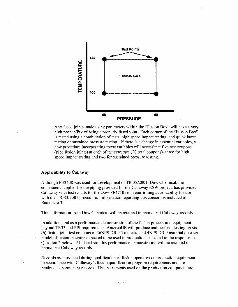
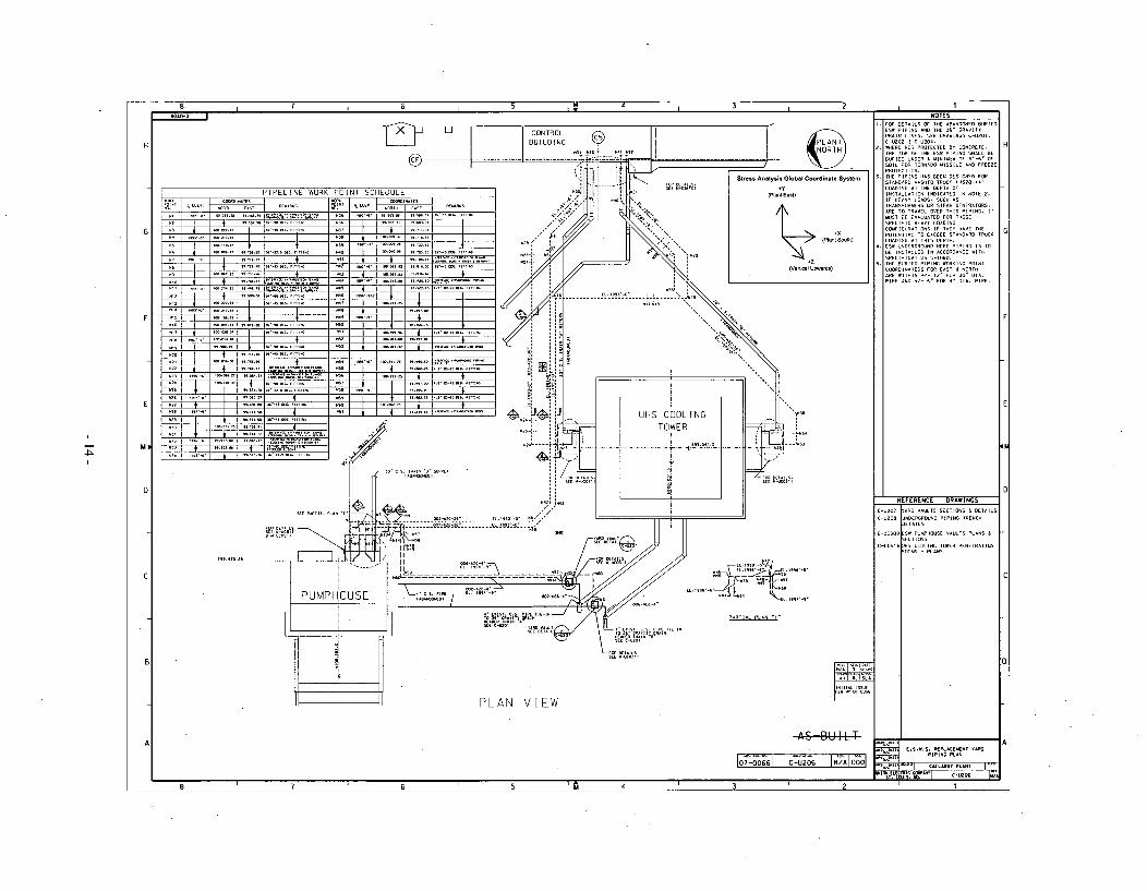
4.(a) Provide a simple schematic of piping layout showing at least the major details.Include orientation of N-S, E-W, and vertical directions along with Global X, Y,and Z coordinate axes.
Response:
A simple schematic of the piping layout (i.e., drawing C-U206) is provided on page 14 ofthis enclosure.
Question/Req uest:
4.(b) Include a stress evaluation at a miter-bend location with a stress intensificationfactor, i = 2.0.
Response:
Based on the results of the preliminary analysis, the locations of peak stress occurred inthe straight pipe sections, even when a stress intensification factor of i = 2.0 wasconsidered for mitered elbows. The final analysis will summarize the peak stress value instraight pipe and the peak stress in mitered elbows. A stress intensification factor ofi = 2.0 will be used for mitered elbow locations.
4.(c) In the stress evaluations, the resultant moment was computed using two momentcomponents (about vertical and transverse axes) only. Piping design rules specifythe use of all three moment components including torsional moment in resultantmoment computation. Please explain the rationale for your deviation.
Response:
The final analysis will compute resultant moments using all three moment components.This change is not expected to have a significant impact on the analysis results.
5. For Pipe Systems Finite Element Analyses, Enclosure 3, Reference 1, Section7.8.1 (pages 104 of 152 and 105 of 152, SAP2000 Output, Return Lines), theevaluations were based on a stress intensification factor, i = 2.0, for a criticalmiter-bend location.
Question/Request:
5.(a) Secondary or Thermal expansion stress evaluation should be based on range of allthermal modes or load cases. Based on page 75 of 152:
Load Case 1: Twater - Tground = 175-70 = +105 'F; and Load Case 2:
Twater - Tground = 32-55 = -23 'F and not +60 'F as was used in the evaluation.
-5-
Since Load Case 2 has a negative temperature difference, the moment rangebetween Load Case 1 and Load Case 2 will be higher than due to Load Case I orLoad Case 2 alone. Given that your evaluation does not account for thermalexpansion stress based on maximum range of moments, you are requested toexplain the rationale for your thermal analysis or provide a re-evaluationconsistent with maximum bounding thermal moment range. Typical piping stressanalysis programs compute moment ranges for load cases, apply the appropriatestress intensification, and automatically compute intensified stresses at every nodepoint in accordance with applicable ASME Section III Code edition. Are youdoing stress computations manually using moments from SAP2000, because theSAP2000 program version V7.40 utilized for PE piping analysis does not havethese features built-in?
Response:
If the alternative thermal expansion and contraction evaluation is performed in the finalanalysis, the range of moments for the expansion and contraction cases will be evaluatedinstead of evaluating the expansion and contraction cases individually.
For the fully constrained thermal expansion and contraction evaluations, the calculatedthermal stresses will be based on the temperature differential between the pipe operatingtemperature and the soil temperature. This approach is supported by EPRI document1013549, "Nondestructive Evaluation: Seismic Design Criteria for Polyethylene PipeReplacement Code Case," and EPRI document 1013549, "Design and Qualification of High-Density Polyethylene for ASME Safety Class 3 Piping Systems."
Stress computations are performed manually in Mathcad using the output from SAP2000because SAP2000 does not have built-in features for PE piping analysis.
Question/Req uest:
5.(b) In the stress evaluations, the resultant moment was computed using two momentcomponents (about vertical and transverse axes) only. NRC requests a re-evaluation using all three moment components including torsional moment inresultant moment computation (similar to item 4.(c) above of this RAI).
Response:
The final analysis will compute resultant moments using all three moment components.This change is not expected to have a significant impact on the analysis results.
6. For Pipe Systems Finite Element Analyses, Enclosure 3, Reference 1, Section7.8.2 (pages 139 of 152 and 140 of 152, SAP2000 Output, Backwash Lines), theevaluations were based on a stress intensification factor, i = 2.0, for a miter-bendlocation.
-6-
Question/Request:
6.(a) Secondary or Thermal expansion stress evaluation should be based on a range ofall thermal modes or load cases. Based on page 100 of 152, Load Case 1: Twater -Tground = 95-70 = +25 'F; Load Case 2: Twater - Tground = 32-55 = -23 'F andnot +20 'F as was used in the evaluation. Since Load Case 2 has a negativetemperature difference, the moment range between Load Case 1 and Load Case 2will be higher than due to Load Case I or Load Case 2 alone. An explanation forthis discrepancy is requested, or a re-evaluation of thermal expansion stress basedon maximum range of moments is required.
Response:
As stated in the response to RAI 5.(a), if the alternative thermal expansion and contractionevaluation is performed in the final analysis, the range of moments for the expansion andcontraction cases will be evaluated instead of evaluating the expansion and contraction casesindividually.
For the fully constrained thermal expansion and contraction evaluations, the calculatedthermal stresses will be based on the temperature differential between the pipe operatingtemperature and the soil temperature. This approach is supported by EPRI document1013549, "Nondestructive Evaluation: Seismic Design Criteria for Polyethylene PipeReplacement Code Case," and EPRI document 1013549, "Design and Qualification ofHigh-Density Polyethylene for ASME Safety Class 3 Piping Systems."
Question/Request:
6.(b) In the stress evaluations, the resultant moment was computed using two momentcomponents (about vertical & transverse axes) only. NRC requests a re-evaluation using all three moment components including torsional moment inresultant moment computation.
Response:
The final analysis will compute resultant moments using all three moment components.This change is not expected to have a significant impact on the analysis results.
7. For SAP2000 Input/Output, Enclosure 3, Reference 1 (page 10 of 24 ofAttachment 10.4; page 10 of 19 of Attachment 10.5; page 13 of 37 of Attachment10.6; and page 13 of 37 of Attachment 10.7), the value of 8.980E-05 kips percubic inch used for weight per unit volume for PE material under materialproperty data does not agree with the value of 0.959 grams per cubic centimeter(which corresponds to 3.465E-05 kips per cubic inch) given on page 7 of 152.
-7-
Question/Request:
Explain the discrepancy in the weight per unit volume for PE material andevaluate the impact, if any, on the results.
Response:
The weight per unit volume value input into SAP2000 for PE pipe is a value that isrepresentative of both the PE pipe and the water inside the pipe. The value is equivalentto the total weight of PE and water per unit length of pipe divided by the area of pipematerial. As shown on page 10 of 24 of Attachment 10.4 and page 10 of 19 ofAttachment 10.5, this value equates to 9.290E-05 kips per cubic inch for the 36" pipe. Asshown on page 13 of 37 of Attachment 10.6 and page 13 of 37 of Attachment 10.7, thisvalue equates to 8.980E-05 kips per cubic inch for the 4" pipe.
8. For Allowable Stress for Circumferential Compressive Stress in the sidewalls(Section 7.3, page 33 of 152 and Section 6.2.1, page 15 of 152), the NRC findsinappropriate the use of a constant allowable of 1000 psi (without any temperaturedependence) for compression of sidewalls in PE piping.
Question/Request:
A re-evaluation is required using an allowable stress corresponding to thetemperature to which the piping is subjected. For supply and backwash lines, itshould be 695 psi at 95 'F, and for return lines it should be 340 psi at 175 'F inlieu of a constant 1000 psi.
Response:
The final analysis will use temperature-dependent allowable stress values for evaluationof circumferential compressive stress in the sidewalls as requested. A review of thecalculated stresses in the preliminary analysis shows that the use of temperature-dependent allowable stress values in lieu of a constant allowable stress value of 1000 psiwill not change the conclusion that the calculated stresses are less than the allowablestresses.
9. For Flotation Analysis (Section 7.4, page 44 of 152), i.e., the weight of water(Ww) displaced by the pipe, the per-unit length (upward buoyant force) should bebased on the outside diameter of the pipe. The calculations in Section 7.4 werebased on the inside diameter of the pipe.
Question/Request:
Please re-evaluate the calculations based on outside diameter of supply, return,
-8-
and backwash lines.
Response:
The final analysis will perform flotation analysis based on the outside diameter of thepipe. This change is not expected to change the results of the flotation analysis.
10. For Longitudinal Stress Analysis (pages 46 of 152 through 52 of 152 in Sections7.5.1, 7.5.2, and 7.5.3, Reference 1), the evaluations were based on primary stressindices of B1 = 0.5 and B 2 = 1.0 for a straight pipe only. For mitered elbows witha diameter ratio of DR = 9, B1 = 0.69 and B 2 = 1.64; and with a diameter ratio ofDR = 9.35, B1 = 0.69 and B2 = 1.69.
Ouestion/Requ est:
10.(a) Include stress evaluation at a critical miter-bend location also with applicableprimary stress indices.
Response:
Based on the results of the preliminary analysis, the locations of peak longitudinal stressoccurred in the straight pipe sections, even when the mitered elbow primary stress indiceswere considered. The final analysis will summarize the peak longitudinal stress value instraight pipe and the peak longitudinal stress in mitered elbows. The mitered elbowprimary stress indices will be used for mitered elbow locations.
Question/Request:
I 0.(b) In the stress evaluations, the resultant moment was computed using two momentcomponents (about vertical and transverse axes) only. NRC requires a re-evaluation using all three moment components including torsional moment inresultant moment computation.
Response:
The final analysis will compute resultant moments using all three moment components.This change is not expected to have a significant impact on the analysis results.
11.
Ouestion/Req uest:
I L.(a) For Stress Allowable at 176 'F (Enclosure 3, Attachment 10.3, page 2 of 2,Reference 1), is 340 psi considered as the allowable with DF = 0.5 for 2.5 years ofcontinuous operation or for 30 days of continuous operation? Please provide
-9-
clarification. Also, note that DF > 0.5 which corresponds to a factor of safety ofless than 2 is not acceptable to the NRC.
Response:
As documented in the design minimum wall thickness calculation, which is included asEnclosure 4, the allowable stress value for 30 days of continuous operation at 175 'F isconservatively considered to be the same as the allowable stress value for 2.5 years ofcontinuous operation at 176 'F. Also note that as the ESW operating temperature isexpected to drop significantly within the first several days post-accident, the assumptionthat the peak post-accident operating temperature will occur continuously for 30 days isconservative.
With regard to the design factor, Ameren intends to utilize a design factor of 0.56 in lieuof 0.5. The justification for this approach is provided in Enclosure 6.
Question/Req uest:
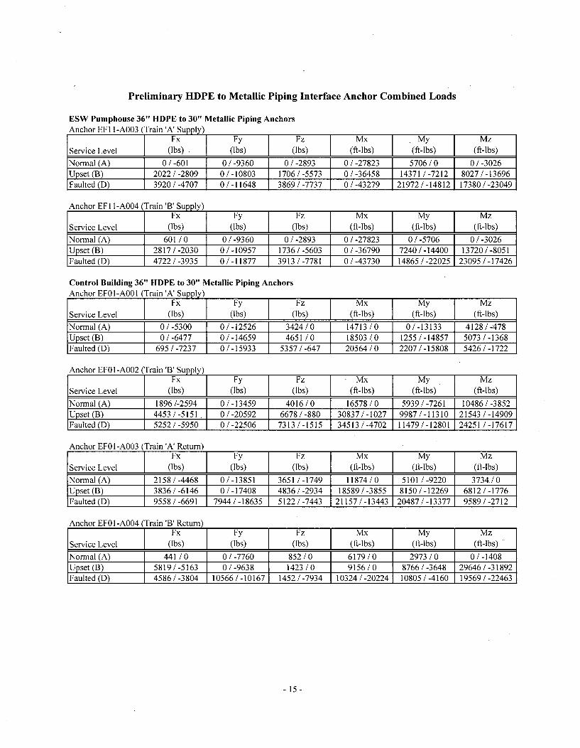
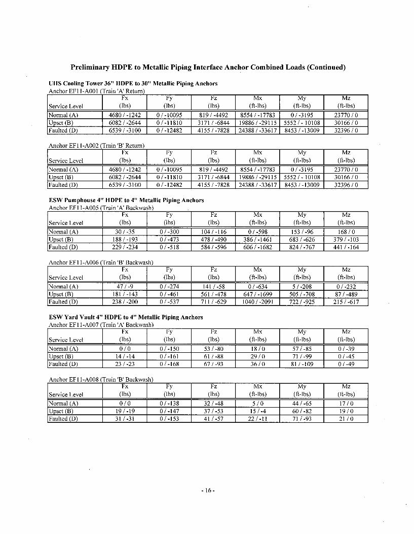
11.(b) Are the additional loads from the buried piping side included in the design ofinterface anchors at the control building, UHS Control Tower, ESW pump house,ESW Yard Vaults, and others, if any? Please provide a summary of anchor loads.
Response:
The anchors attach to the metallic piping, as close as practically possible to the flangedinterfaces between the HDPE piping and metallic piping. The combined anchor designloads are determined in the above ground piping analysis calculations using traditionalpiping stress analysis software. In order to obtain loads from the HDPE side of theanchors, the computer models used in the above ground piping analysis calculationsinclude the metallic piping on the HDPE side of the anchors up to the interface with theHDPE piping. The models also include a lumped mass at the end of the metallic pipingthat bounds the total weight of the HDPE transition flange, metallic flange and metallicback-up ring. The loads acting on the HDPE side and the loads acting on the metallicside of the anchor are calculated by the piping stress analysis software. A summary ofpreliminary combined anchor loads is provided on pages 15 and 16 of this enclosure.
Question/Request:
I .(c) For Ring Deflection Equation (page 15 of 152, Enclosure 3, Reference 1), clarifythat Q, i2max are non-dimensional ring deflections' that is, a ratio of ringdeflection to diameter and not ring deflection values. Since the units for verticalsoil pressure due to earth load (PE) and pressure due to surcharge load (PL)seismic anchor motion (SAM) are in psf (pounds per square foot) and the units forEpipe and E' are in psi, a 1/144 factor is required.
- 10-
Response:
Within the preliminary analysis, the calculated and allowable ring deflections as percentagesof the diameter are multiplied by the diameter to provide deflections in terms of inches. Thishas no impact on the results of the ring deflection evaluation. The preliminary evaluation isperformed using Mathcad software. Mathcad software automatically performs unitconversions. Therefore, the inclusion of the 1/144 factor is not required.
Question/Request:
I .(d) For Flotation (page 16 of 152, Enclosure 3, Reference 1), since the units for PEare in psf, and the units for D are in inches, a 1/12 factor for the term (PE.D) isrequired.
Response:
The preliminary evaluation is performed using Mathcad software. Mathcad softwareautomatically performs unit conversions. Therefore, the inclusion of the 1/12 factor is notrequired.
Question/Request:
1 .(e) Concerning Enclosure 2 of Reference 1, please provide clarification for the termsCRS and HBD (or HDB?).
Response:
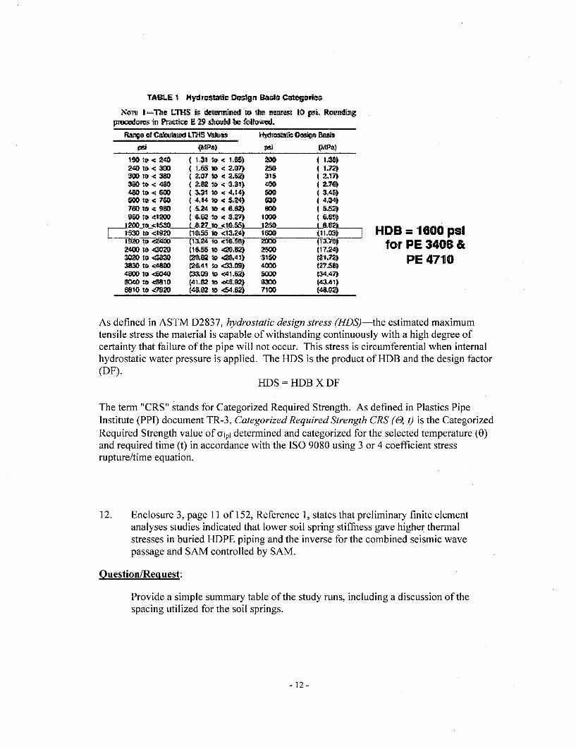
The term "HBD" in Enclosure 2 of Reference I is a typo. It should be "HDB" whichstands for Hydrostatic Design Basis. As defined in ASTM D-2837, hydrostatic designbasis (HDB) - one of a series of established stress values for a compound. It is obtainedby categorizing the long-term hydrostatic strength (LTHS) in accordance with Table 1.
-11-
TAB4.E $ HydroStafti DQO31n Dadt] Cutcg0904
o-m I -Te LTHS is dete'mrcld to The neamrt 10 psi. Roundimgpmoedures in Prutice E 29 should be followed.
"age at C&tulamod LTHS Vbhuos " stc Osign Basis
- {(WA) 06_ 1 (MPa190 p -C 240 ( l.$3 V., <c 1,.0)1 X0 I I.2.10 0,<30 ( 1.65 l o2.07 250 I I.7230 lo <c 380 2,07 to < :,2) 315 4 117)3W G10 -C480 C 2.82t6 < 3,31 400 12-76114,0 *1 6W (.31•to < 4,$4) 9O0 3.45)~Goo1* 70 C4,I4 * < 5,24) WD0 4.34)7M0 l <O ' T5,24 so.2} < 6). 5.52)
• 200Je150._ L&___:827 L 1 0i55•__J250 L~a.___No ~120, -4= 6w1O 0 < 134, M, 0 411.D
Z44J0 10 4 DO (1,&5 10 40'M2 2500 1l17.24)4320 1o 4W0D C.=82 10 ,<4C40 315 (13-M3=3 ib -0480 C2&.41 %a 4300'W 4wo 127-U)4800 10 SM4 P&~09 10 <4~1AZ~ 500D (34,47)G"040 <Solo1 (41.02 to -o4&92) a" ~ M441)68101.0t e92 (4.9 2 ito 64;W 710D 4a
HDB = 1600 psifor PE 3408 &
PE 4710,
As defined in ASTM D2837, hydrostatic design stress (HDS)-the estimated maximumtensile stress the material is capable of withstanding continuously with a high degree ofcertainty that failure of the pipe will not occur. This stress is circumferential when internalhydrostatic water pressure is applied. The HDS is the product of HDB and the design factor(DF).
HDS = HDB X DF
The term "CRS" stands for Categorized Required Strength. As defined in Plastics PipeInstitute (PPI) document TR-3, Categorized Required Strength CRS (0, t) is the CategorizedRequired Strength value of Olpl determined and categorized for the selected temperature (0)and required time (t) in accordance with the ISO 9080 using 3 or 4 coefficient stressrupture/time equation.
12. Enclosure 3, page 11 of 152, Reference 1, states that preliminary finite elementanalyses studies indicated that lower soil spring stiffness gave higher thermalstresses in buried HDPE piping and the inverse for the combined seismic wavepassage and SAM controlled by SAM.
Question/Request:
Provide a simple summary table of the study runs, including a discussion of thespacing utilized for the soil springs.
-12-
Response:
As discussed in EPRI document 1013549, "Design and Qualification of High-DensityPolyethylene for ASME Safety Class 3 Piping Systems," most of the movements inburied piping are absorbed with a short distance (i.e. the influence length) of changes indirection. EPRI document 1013549 recommends that springs be spaced at distance oftwo pipe diameters (2D) within the influence length and at a distance of IOD beyond theinfluence length. Within the SAP2000 analysis model, springs near mitered elbows werespaced at a distance of approximately ID. All other springs (i.e. between large spans)were spaced at a distance between approximately 3D and approximately 5D As thegreater the number of modeled springs, the more accurately the results will reflect thebehavior of the buried pipe under the load conditions. This spacing is conservative whencompared to the EPRI recommendations.
Summary tables of the study runs are provided on pages 17 and 18 of this enclosure.
- 13-
8 , 7 , 6 i 5 ,4 I 2 1I
BUILDING (
------- -- -Stress Asalysis Global Coodiate System
PIPELINE WORK POINT SCHEDULE Ea")
.. ... ,• ... ... ._S-, _h.0 .. L .. 2 ,,
aa aaa.5 asaa;a SIRS """
.3, .... a..... as-5 a, Ia, as I, 1/ 1 am•/ -.. •,, • f
i•7-1!'" .....IA -a -- - -,4; -aa,,
-P-1
---------------------- -
I PARTIAL PLoS¶ I
PLAN V IEW
FOR DETA ILS OF TIE ABANDONE0 BURIED055 PIPING AN5 THE 00" 0RAVIT3
EA"INL LOSES,0 aEE A INor a -•O.1C -B02 & C-U204.1 1R111 NOT PTETE 03 I CONCRETE.THE TOP OF THE E 3 PIP..N SILt BE...... UNDER A INWJOF4'-6" BE
SOIL FOR TORN.ADO 2]ILE AND FREEZE
PROTECTION.
THE NHAS BEEN DESIGNED IllSTAN.aRD AA...TO 'NC _HS0-4
L ..... AT THE OEPIH OF
INSTALLATION 0 N] CATIO I1 NOTE ILIF HEAVY LOADS. SUCH AS
TCANSF ORMERS OR STrAI PGENERORSBA 0. TRAVEL 0VEB THI PIPING, T,•ST BE EVALUATED Ill THOSE
SPLECIFI HEAVY LOLODS.CONFIGURAT IONS I F THEY HAVE THE
POTENTIAL TON E3C EE0 0TA NDARP TOOCLOA"IN AT T .. DET. plý . ST11. UNDERGR ..NU HOPE PPN ST
HE I NSTALLED I" ACCORDANCE WTSPECIFICATION .-1080.5.TIE BURIED PIPING WOý1]NG POINTC,1R1IN1T11 FBR 'AS & NRTHARE .ITIN +/- .. FOR I0 OA.
PIPE AND /- 6" FOR I- D[A. PIPE.
REFERENCE DRAWINGS
G-UZO? YARD VAULTS SECTIONS 4 DETAILS
C U 08 UNDERGROUND PIPING TRENCHDETAILS
C-UC309 ESW PUNPHOUSE VAULTS PLANS &SECTIONS
C-uc5%EUHS COO ING TOIER PENETRATION'GOOS - PLANS
H
0
F
E
3
C
B B
AAS-BI•LT
F077-00-661f C0-20N/00,wo 03OT0 PIPING PLA-N
A
6 - 7 - 6 N 'U 4 , 38 7 6 5 '1•1 ,4 ' 3 I
Preliminary HDPE to Metallic Piping Interface Anchor Combined Loads
ESW Pumphouse 36" HDPE to 30" Metallic Piping AnchorsAnchor EFI l-A003 (Train 'A' Supply)
Fx Fy Fz Mx My MzService Level (ls.bs) (Ibs) (f(Ibs) (ft--bs) My (ft-lbs)
Normal (A) 0/-601 0/-9360 0/-2893 0 / -27823 5706/0 0/-3026Upset (B) 2022/-2809 0/-10803 1706/-5573 0/-36458 14371 /-7212 8027/-13696Faulted (D) 3920/-4707 0/-11648 3869/-7737 0/-43279 21972/-14812 17380/-23049
Anchor EFI l-A004 (Train 'B' Supply)Fx Fy Fz Mx My Mz
Service Level (l-bs) (Ibs) (Ibs) (ft-lbs) (ft-lbs) (ft-lbs)
Normal (A) 601 /0 0/-9360 0/-2893 0/-27823 0/-5706 0/-3026Upset (B) 2817/-2030 0/-10957 1736/-5603 0/-36790 7240/-14400 13720/-8051Faulted (D) 4722/-3935 0/-11877 3913/-7781 0/-43730 14865/-22025 23095/-17426
Control Building 36" HDPE to 30" Metallic Piping AnchorsAnchor EFO1-AOO1 (Train 'A' Supply)
Fx Fy Fz Mx My MzService Level ((Ibs) (Ibs) ( (ft-lbs) ________ (ft-lbs)
Normal (A) 0/-5300 0/-12526 3424/0 14713/0 0/-13133 4128/-478Upset (B) 0/-6477 0/-14659 4651 /0 18503 1 0 1255/-14857 5073/-1368Faulted (D) 695/-7237 0/-15933 5357/-647 20564/0 2207/-15808 5426/-1722
Anchor EFOI-A002 (Train '3' Supply)FxFy Fz Mx MyMz
Service Level (7bs) (Ibs) (Ibs) (ft-lbs) (ft-lbs) (ft-lbs)
Normal (A) 1896/-2594 0/-13459 4016/0 16578/0 5939/-7261 10486/-3852Upset (B) 4453/-5151. 0/-20592 6678/-880 30837/-1027 9987/-11310 21543/-14909Faulted (D) 5252/-5950 0/-22506 7313/-1515 34513/-4702 11479/-12801 24251/-17617
Anchor EFOI-A003 (Train 'A' Return)Fx Fy Fz Mx My Mz
Service Level (Ibs) (lbs) (Ibs) (ft-lbs) (ft-lbs) (ft-lbs)
Normal (A) 2158/-4468 0/-13851 3651/-1749 11874/0 5101/-9220 3734/0Upset (B) 3836/-6146 0/-17408 4836/-2934 18589/-3855 8150/-12269 6812/-1776Faulted (D) 9558/-6691 7944/-18635 5122/-7443 21157/-13443 20487/-13377 9589/-2712
Anchor EFOI-A004 (Train 'B' Return)Fx Fy Fz NIX My Mz
Service Level (Ibs) (Ibs) (lbs) (ft-lbs) (ft-lbs) (ft-lbs)
Normal (A) 441/0 0/-7760 852/0 6179/0 2973/0 0/-1408Upset (B) 5819/-5163 0/-9638 1423/0 9156/0 8766/-3648 29646/-31892Faulted (D) 4586/-3804 10566/-10167 1452/-7934 10324/-20224 10805 /-4160 19569/-22463
- 15-
Preliminary HDPE to Metallic Piping Interface Anchor Combined Loads (Continued)
UHS Cooling Tower 36" HDPE to 30" Metallic Piping AnchorsAnchor EF I1 -AOO 1 (Train 'A' Return)
Fx Fy Fz
Service Level (lbs) (lbs) (lbs
Normal (A) 4680/-1242 0/-10095 819/-4Upset (B) 6082/-2644 0/-11810 3171/-(Faulted (D) 6539/-3100 0/-12482 4155/-2
49258447828
I Mx j(ft-lbs)
8554/-1778319886/-2911524388 /-33617
My(ft-lbs)
0/-31955552/- 101088453 /-13009
I
Mz(ft-lbs)
23770 /030166 /032396 /0
Anchor EF I1 -A002 (Train 'B' Return)Fx
Service Level (lbs)
Normal (A) 4680 / -1242Upset (B) 6082 / -2644Faulted (D) 6539/-3100
I
Fy(lbs)
0/-100950/-118100/-12482
I
I
Fz
(lbs)
819/-44923171/-68444155/-7828
Mx(ft-lbs)
8554/-1778319886 /-2911524388/-33617
My(ft-lbs)
0 /-31955552 /- 101088453 /-13009
I
Mz(ft-lbs)
23770 /030166 /032396 /0
ESW Pumphouse 4" HDPE to 4" Metallic Piping AnchorsAnchor EF1 I-AO05 (Train 'A' Backwash)
Fx Fy Fz Mx My Mz
Service Level (lbs) (lbs) (lbs) (ft-lbs) (ft-lbs) (ft-lbs)
Normal (A) 30/-35 0/-300 104/-116 0/-598 153/-96 168/0Upset (B) 188/-193 0/-473 478/-490 386/-1461 683/-626 379/-103Faulted (D) 229/-234 0/-518 584/-596 606/-1682 824/-767 441/-164
Anchor EFI 1-A006 (Train 'B' Backwash)Fx Fy Fz Mx My Mz
Service Level (lbs) (lbs) (lbbs) (fs-(bs) J My[s) (ft-lbs)
Normal (A) 47/-9 0/-274 141/-58 0/-634 5/-208 0/-232Upset (B) 181/-143 0/-461 561 /-478 647/-1699 505/-708 87/-489Faulted (D) 238/-200 0/-537 711/-629 1040/-2091 722/-925 215/-617
ESW Yard Vault 4" HDPE to 4" Metallic Piping AnchorsAnchor EFI I-A007 (Train 'A' Backwash)
Fx Fy Fz Mx My Mz
Service Level (lbs) (lbs) (lbs) (ft-lbs) (ft-lbs) (ft-lbs)
Normal (A) 0/0 0/-150 53/-80 18/0 57/-85 0/-39Upset (B) 14/-14 0/-161 61/-88 29/0 71 /-99 0/-45Faulted (D) 23/-23 0/-168 67/-93 36/0 81/-109 0/-49
Anchor EF1 I-A008 (Train 'B' Backwash)Fx Fy Fz Mx My Mz
Service Level (lbs) (lbs) (lbs) (ft-lbs) (ft-lbs) (ft-lbs)
Normal (A) 0/0 0/-138 32/-48 5/0 44/-65 17/0Upset (B) 19/-19 0/-147 37/-53 15/-4 60/-82 19/0Faulted (D) 31/-31 0/-153 41/-57 22/-11 71/-93 21/0
-16-
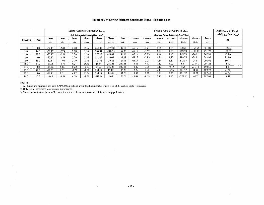
Summary of Spring Stiffness Sensitivity Runs - Seismic Case
Seismic Analysis Output @ 0. 5Kavg Seismic Analysis Output @ 2Kavg ABS(odouble @ 2Kag) -
(Half the Average Soil Sprang Stiffness Values) (Double the Average Soil Spring Sliffness Values) ABS(othaf @ 0. 5Kavg)
FRAME LOC Fa half Fbhalf Fc.half Ma.half Mb.half Uhalf qhalf Faduble Fb~double Fc.double MUadouble Mb.double Mc80oble t3double Al
(kip) (kip) (kip) (ip-in) (kip-in) (kip-in) (psi) (kip) (kip) (kip) (kip-in) (kip-in) (kip-in) (psi)
1.0 0.0 -32.17 -2.88 2.70 2.16 248.42 -159.48 187.00 -65.19 -3.21 4.84 1.87 340.21 -163.95 301.03 114.031.0 14.5 -32.17 -2.74 2.70 2.16 209.34 -118.75 167.74 -65.19 -3.07 4.84 1.87 269.98 -118.39 271.77 104.031.0 29.0 -32.17 -2.59 2.70 2.16 170.25 -80.09 149.19 -65.19 -2.93 4.84 1.87 199.75 -74.91 242.99 93.802.0 0.0 -32.17 -2.59 2.70 2.16 170.25 -80.09 149.19 -65.19 -2.93 4.84 1.87 199.75 -74.91 242.99 93.802.0 18.0 -32.17 -1.94 2.70 2.16 121.73 -39.25 127.91 -65.19 -2.28 4.84 1.87 112.57 -28.07 208.62 80.7138.0 57.3 -11.98 -4.75 0.24 14.49 16.54 249.26 207.56 -13.51 -4.13 0.12 6.92 6.87 235.48 201.24 -6.3239.0 0.0 -11.82 5.12 0.22 -2.00 21.94 249.26 207.16 -12.47 6.65 0.10 -0.47 9.75 235.48 198.55 -8.6126.0 72.0 -10.61 0.51 -3.72 -4.07 234.17 19.12 193.29 -12.79 0.62 -4.01 -3.36 221.57 14.57 189.77 -3.52
27.0 0.0 -10.13 0.51 4.87 10.64 234.17 16.40 192.06 -11.88 0.62 6.21 7.93 221.57 12.68 187.42 -4.6414.0 43.0 -9.48 -0.54 4.59 -3.09 -218.94 2.68 179.06 -11.44 -0.58 5.73 1.42 -223.10 6.17 187.09 8.03
NOTES:1) All forces and moments are from SAP2000 output and are in local coordinates where a=axial, b=vertical and c=transverse.2) Only ten highest stress locations are summarized.3) Stress intensification factor of 2.0 used for mitered elbow locations and 1.0 for straight pipe locations.
-17-
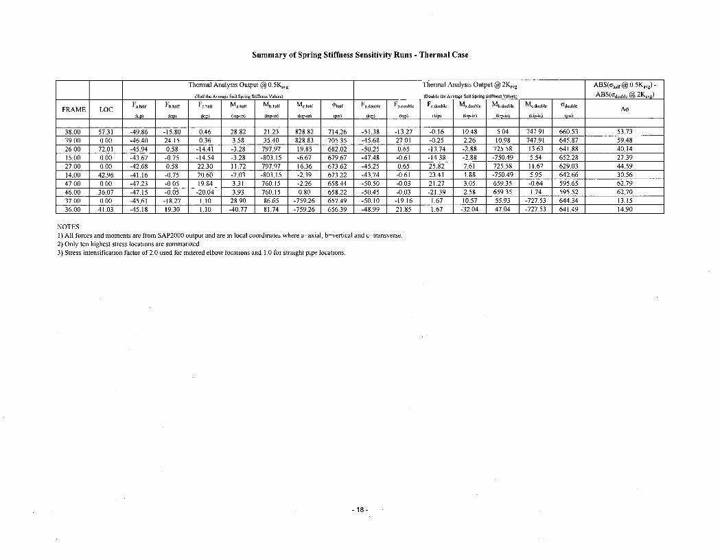
Summary of Spring Stiffness Sensitivity Runs - Thermal Case
Thermal Analysis Output @ 0.5K,,g Thermal Analysis Output @ 2Kn., ABS(ohalf @ 0.5Kavg) -
(Half the Aerage Soil Spring Stiffness Values) (Double Ithe Aerage Soil Spring Stiffness Values) ABS(Od-oube @ 2
Kv,)
FRAME LOC Fa half Fb half Fe.half Matha)f Mb.Sial Me.half t h)alf Fa double Fb.double Fe.doubl Ma.double Mb.doubl¢ Me~doubl I double A(kip) (kip) (kip) (kip-in) (kip-in) (kip-n) (psi) (kip) (kip) (kip) (kip-in) (kip-in) (kip-in) (psi)
38.00 57.31 -49.86 -15.80 0.46 28.82 21.23 828.82 714.26 -51.38 -13.27 -0.16 10.48 5.04 747.91 660.53 53.7339.00 0.00 -46.40 24.15 0.36 3.58 35.40 828.83 705.35 -45.68 27.01 -0.25 2.26 10.98 747.91 645.87 59.4826.00 72.01 -45.94 0.58 -14.41 -3.28 797.97 19.85 682.02 -50.25 0.65 -13.74 -2.88 725.58 13.63 641.88 40.1415.00 0.00 -43.67 -0.75 -14.54 -3.28 -803.15 -6.67 679.67 -47.48 -0.61 -14.38 -2.88 -750.49 5.54 652.28 27.3927.00 0.00 -42.68 0.58 22.30 11.72 797.97 16.36 673.62 -45.25 0.65 25.82 7.61 725.58 11.67 629.03 44.5914.00 42.96 -41.16 -0.75 20.60 -7.03 -803.15 -2.39 673.22 -43.74 -0.61 23.41 1.88 -750.49 5.95 642.66 30.5647.00 0.00 -47.23 -0.05 19.84 3.31 760.15 -2.26 658.44 -50.50 -0.03 21.27 3.05 659.35 -0.64 595.65 62.7946.00 36.07 -47.15 -0.05 -20.04 3.93 760.15 0.80 658.22 -50.45 -0.03 -21.39 2.58 659.35 1.74 595.52 62.70
37.00 0.00 -45.61 -18.27 1.10 28.90 86.65 -759.26 657.49 -50.10 -19.16 1.67 10.57 55.93 -727.53 644.34 13.1536.00 41.03 -45.18 19.30 1.10 -40.77 81.74 -759.26 656.39 -48.99 21.85 1.67 -32.04 47.04 -727.53 641.49 14.90
NOTES:1) All forces and moments are from SAP2000 output and are in local coordinates where a=axial, b-=vertical and c-transverse.2) Only ten highest stress locations are summarized.3) Stress intensification factor of 2.0 used for mitered elbow locations and 1.0 for straight pipe locations.
-18-
Enclosure 3To ULNRC-05517
Enclosure 3
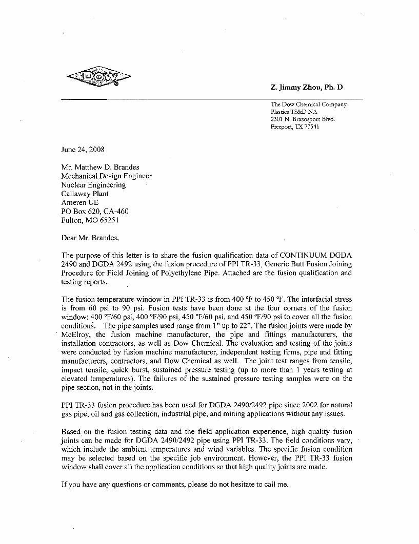
Letter from Dow Chemical Company (with attachments)
Z. Jimmy Zhou, Ph. D
The Dow Chemical CompanyPlastics TS&D NA2301 N. Brazosport Blvd.
Freeport, TX 77541
June 24, 2008
Mr. Matthew D. BrandesMechanical Design EngineerNuclear EngineeringCallaway PlantAmeren UEPO Box 620, CA-460Fulton, MO 65251
Dear Mr. Brandes,
The purpose of this letter is to share the fusion qualification data of CONTINUUM DGDA2490 and DGDA 2492 using the fusion procedure of PPI TR-33, Generic Butt Fusion JoiningProcedure for Field Joining of Polyethylene Pipe. Attached are the fusion qualification andtesting reports.
The fusion temperature window in PPI TR-33 is from 400 'F to 450 'F. The interfacial stressis from 60 psi to 90 psi. Fusion tests have been done at the four comers of the fusionwindow: 400 'F/60 psi, 400 'F/90 psi, 450 'F/60 psi, and 450 'F/90 psi to cover all the fusionconditions. The pipe samples used range from 1" up to 22". The fusion joints were made byMcElroy, the fusion machine manufacturer, the pipe and fittings manufacturers, theinstallation contractors, as well as Dow Chemical. The evaluation and testing of the jointswere conducted by fusion machine manufacturer, independent testing firms, pipe and fittingmanufacturers, contractors, and Dow Chemical as well. The joint test ranges from tensile,impact tensile, quick burst, sustained pressure testing (up to more than 1 years testing atelevated temperatures). The failures of the sustained pressure testing samples were on thepipe section, not in the joints.
PPI TR-33 fusion procedure has been used for DGDA 2490/2492 pipe since 2002 for naturalgas pipe, oil and gas collection, industrial pipe, and mining applications without any issues.
Based on the fusion testing data and the field application experience, high quality fusionjoints can be made for DGDA 2490/2492 pipe using PPI TR-33. The field conditions vary,which include the ambient temperatures and wind variables. The specific fusion conditionmay be selected based on the specific job environment. However, the PPI TR-33 fusionwindow shall cover all the application conditions so that high quality joints are made.
If you have any questions or comments, please do not hesitate to call me.
Yours very truly,
Z. Jimmy Zhou
Z. Jimmy ZhouSr. Development Specialist(979) 238-7410 (office)(281) 467-8659 (cell)[email protected]
Attachment:
1. CONTINUUM DGDA 2490 Gas Pipe Qualification2. McElroy Fusion Qualification Report3. 8" Pipe Fusion Testing Report4. "New Products, New Horizons: HDPE Resins for Natural Gas Piping"
CC: Lonnie J. Corley, Construction Supervisor, Ameren UE
Attachment 1 - Dow letter to Ameren dtd 6-24-08Page 1 of 59
TECHNICAL REPORT
ContinuumTBimodal Polyethylene Resins fl000 0 1[0111
CONTINUUM* DGDA-2490 BK 100
For
Natural Gas Pipe and Fittings
Compliance with
ASTM D2513-04 "Standard Specification for the Thermoplastic Gas Pressure Pipe,Tubing and Fittings"
PPI TR-33 "Generic Butt Fusion Joining Procedure for Polyethylene Gas Pipe"
PPI TR-41 "Generic Saddle Fusion Joining Procedure for Polyethylene Gas Pipe",
And
Department of Transportation (DOT) CFR49, Part 192
Attachment 1 - Dow letter to Ameren dtd 6-24-08Page 2 of 59
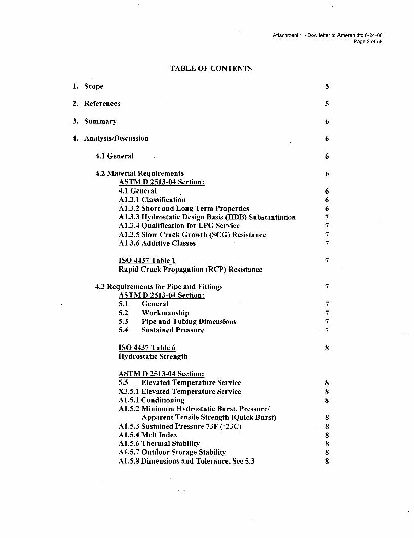
TABLE OF CONTENTS
1. Scope 5
2. References 5
3. Summary 6
4. Analysis/Discussion 6
4.1 General 6
4.2 Material Requirements 6ASTM D 2513-04 Section:4.1 General 6A1.3.1 Classification 6A1.3.2 Short and Long Term Properties 6A1.3.3 Hydrostatic Design Basis (HDB) Substantiation 7A1.3.4 Qualification for LPG Service 7A1.3.5 Slow Crack Growth (SCG) Resistance 7A1.3.6 Additive Classes 7
ISO 4437 Table 1 7Rapid Crack Propagation (RCP) Resistance
4.3 Requirements for Pipe and Fittings 7ASTM D 2513-04 Section:5.1 General 75.2 Workmanship 75.3 Pipe and Tubing Dimensions 75.4 Sustained Pressure 7
ISO 4437 Table 6 8Hydrostatic Strength
ASTM D 2513-04 Section:5.5 Elevated Temperature Service 8X3.5.1 Elevated Temperature Service 8A1.5.1 Conditioning 8A1.5.2 Minimum Hydrostatic Burst, Pressure/
Apparent Tensile Strength (Quick Burst) 8A1.5.3 Sustained Pressure 73F (123C) 8A1.5.4 Melt Index 8A1.5.6 Thermal Stability 8A1.5.7 Outdoor Storage Stability 8A1.5.8 Dimensions and Tolerance, See 5.3 8
Attachment 1 - Dow letter to Ameren dtd 6-24-08Page 3 of 59
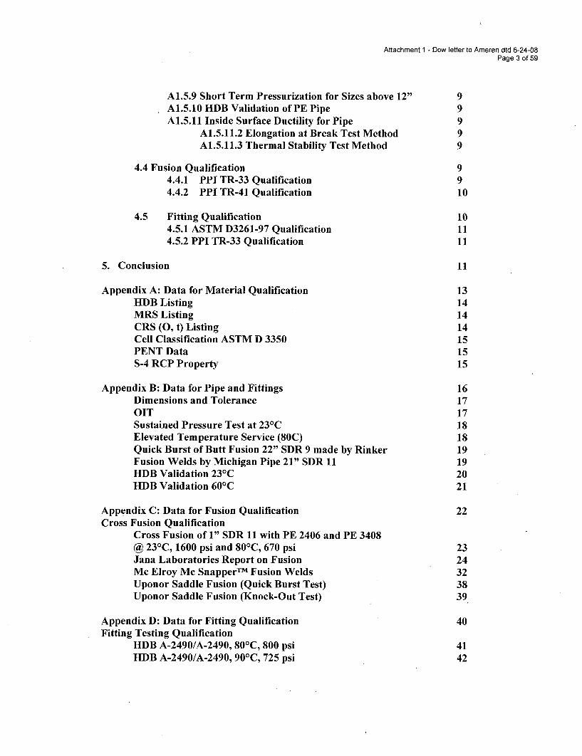
A1.5.9 Short Term Pressurization for Sizes above 12" 9A1.5.10 HDB Validation of PE Pipe 9A1.5.11 Inside Surface Ductility for Pipe 9
A1.5.11.2 Elongation at Break Test Method 9A1.5.11.3 Thermal Stability Test Method 9
4.4 Fusion Qualification 94.4.1 PPI TR-33 Qualification 94.4.2 PPI TR-41 Qualification 10
4.5 Fitting Qualification 104.5.1 ASTM D3261-97 Qualification 114.5.2 PPI TR-33 Qualification 11
5. Conclusion 11
Appendix A: Data for Material Qualification 13HDB Listing 14MRS Listing 14CRS (0, t) Listing 14Cell Classification ASTM D 3350 15PENT Data 15S-4 RCP Property 15
Appendix B: Data for Pipe and Fittings 16Dimensions and Tolerance 17OIT 17Sustained Pressure Test at 231C 18Elevated Temperature Service (80C) 18Quick Burst of Butt Fusion 22" SDR 9 made by Rinker 19Fusion Welds by Michigan Pipe 21" SDR 11 19HDB Validation 231C 20HDB Validation 601C 21
Appendix C: Data for Fusion Qualification 22Cross Fusion Qualification
Cross Fusion of 1" SDR 11 with PE 2406 and PE 3408@ 231C, 1600 psi and 80'C, 670 psi 23Jana Laboratories Report on Fusion 24Mc Elroy Mc Snapper TM Fusion Welds 32Uponor Saddle Fusion (Quick Burst Test) 38Uponor Saddle Fusion (Knock-Out Test) 39
Appendix D: Data for Fitting Qualification 40Fitting Testing Qualification
HDB A-2490/A-2490, 801C, 800 psi 41HDB A-2490/A-2490, 901C, 725 psi 42
Attachment 1 - Dow letter to Ameren dtd 6-24-08Page 4 of 59
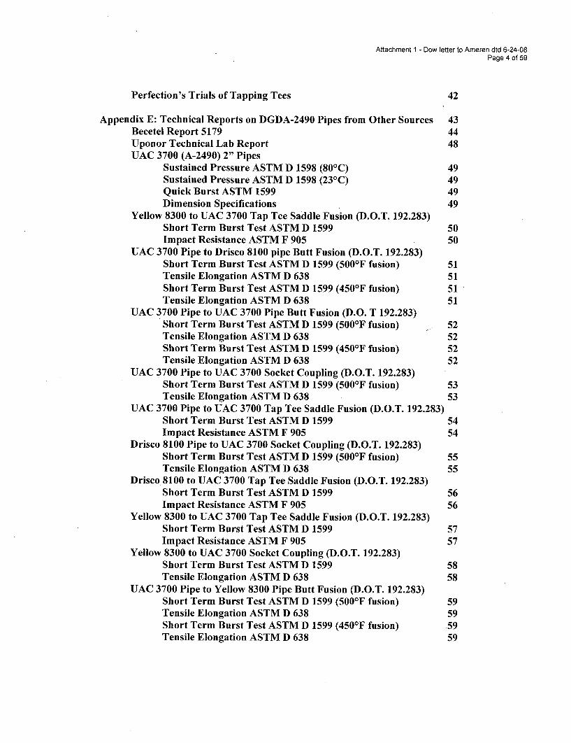
Perfection's Trials of Tapping Tees 42
Appendix E: Technical Reports on DGDA-2490 Pipes from Other Sources 43Becetel Report 5179 44Uponor Technical Lab Report 48UAC 3700 (A-2490) 2" Pipes
Sustained Pressure ASTM D 1598 (80 0 C) 49Sustained Pressure ASTM D 1598 (231C) 49Quick Burst ASTM 1599 49Dimension Specifications 49
Yellow 8300 to UAC 3700 Tap Tee Saddle Fusion (D.O.T. 192.283)Short Term Burst Test ASTM D 1599 50Impact Resistance ASTM F 905 50
UAC 3700 Pipe to Drisco 8100 pipe Butt Fusion (D.O.T. 192.283)Short Term Burst Test ASTM D 1599 (500°F fusion) 51Tensile Elongation ASTM D 638 51Short Term Burst Test ASTM D 1599 (450'F fusion) 51Tensile Elongation ASTM D 638 51
UAC 3700 Pipe to UAC 3700 Pipe Butt Fusion (D.O. T 192.283)Short Term Burst Test ASTM D 1599 (500°F fusion) 52Tensile Elongation ASTM D 638 52Short Term Burst Test ASTM D 1599 (450'F fusion) 52Tensile Elongation ASTM D 638 52
UAC 3700 Pipe to UAC 3700 Socket Coupling (D.O.T. 192.283)Short Term Burst Test ASTM D 1599 (500'F fusion) 53Tensile Elongation ASTM D 638 53
UAC 3700 Pipe to UAC 3700 Tap Tee Saddle Fusion (D.O.T. 192.283)Short Term Burst Test ASTM D 1599 54Impact Resistance ASTM F 905 54
Drisco 8100 Pipe to UAC 3700 Socket Coupling (D.O.T. 192.283)Short Term Burst Test ASTM D 1599 (5001F fusion) 55Tensile Elongation ASTM D 638 55
Drisco 8100 to UAC 3700 Tap Tee Saddle Fusion (D.O.T. 192.283)Short Term Burst Test ASTM D 1599 56Impact Resistance ASTM F 905 56
Yellow 8300 to UAC 3700 Tap Tee Saddle Fusion (D.O.T. 192.283)Short Term Burst Test ASTM D 1599 57Impact Resistance ASTM F 905 57
Yellow 8300 to UAC 3700 Socket Coupling (D.O.T. 192.283)Short Term Burst Test ASTM D 1599 58Tensile Elongation ASTM D 638 58
UAC 3700 Pipe to Yellow 8300 Pipe Butt Fusion (D.O.T. 192.283)Short Term Burst Test ASTM D 1599 (500'F fusion) 59Tensile Elongation ASTM D 638 59Short Term Burst Test ASTM D 1599 (450'F fusion) 59Tensile Elongation ASTM D 638 59
Attachment 1 - Dow letter to Ameren dtd 6-24-08Page 5 of 59
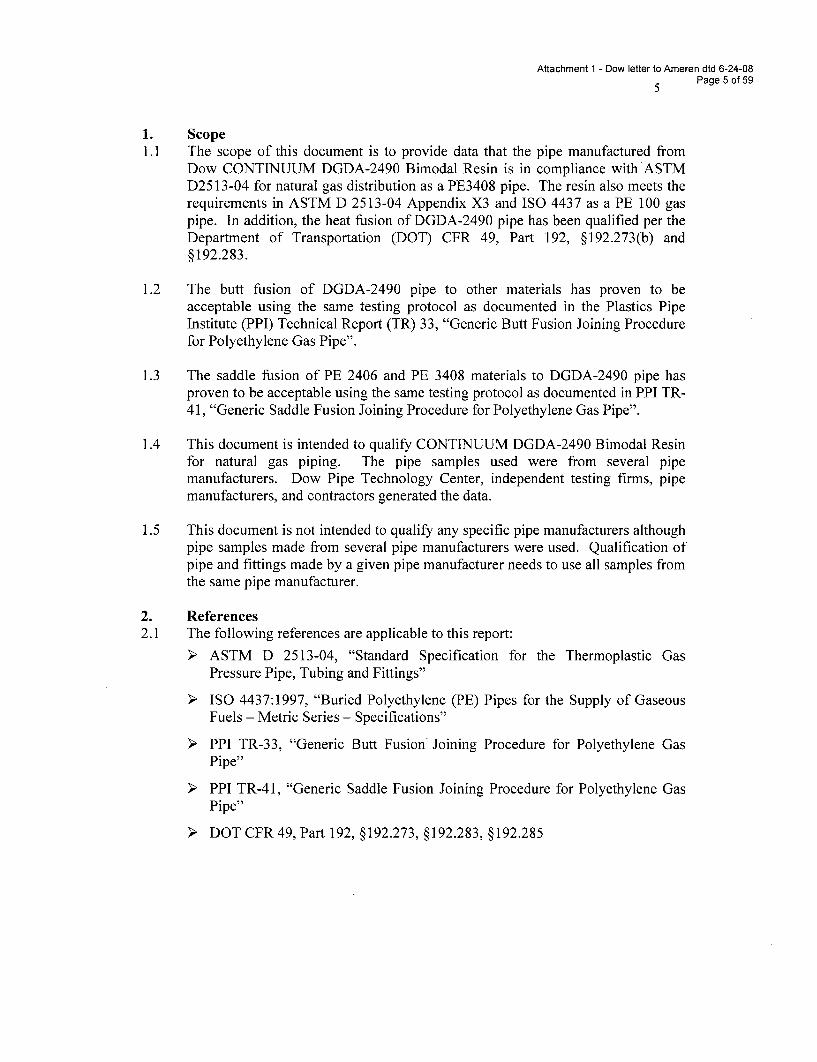
1. Scope1.1 The scope of this document is to provide data that the pipe manufactured from
Dow CONTINUUM DGDA-2490 Bimodal Resin is in compliance with ASTMD2513-04 for natural gas distribution as a PE3408 pipe. The resin also meets therequirements in ASTM D 2513-04 Appendix X3 and ISO 4437 as a PE 100 gaspipe. In addition, the heat fusion of DGDA-2490 pipe has been qualified per theDepartment of Transportation (DOT) CFR 49, Part 192, §192.273(b) and§192.283.
1.2 The butt fusion of DGDA-2490 pipe to other materials has proven to beacceptable using the same testing protocol as documented in the Plastics PipeInstitute (PPI) Technical Report (TR) 33, "Generic Butt Fusion Joining Procedurefor Polyethylene Gas Pipe".
1.3 The saddle fusion of PE 2406 and PE 3408 materials to DGDA-2490 pipe hasproven to be acceptable using the same testing protocol as documented in PPI TR-41, "Generic Saddle Fusion Joining Procedure for Polyethylene Gas Pipe".
1.4 This document is intended to qualify CONTINUUM DGDA-2490 Bimodal Resinfor natural gas piping. The pipe samples used were from several pipemanufacturers. Dow Pipe Technology Center, independent testing firms, pipemanufacturers, and contractors generated the data.
1.5 This document is not intended to qualify any specific pipe manufacturers althoughpipe samples made from several pipe manufacturers were used. Qualification ofpipe and fittings made by a given pipe manufacturer needs to use all samples fromthe same pipe manufacturer.
2. References2.1 The following references are applicable to this report:
ASTM D 2513-04, "Standard Specification for the Thermoplastic GasPressure Pipe, Tubing and Fittings"
ISO 4437:1997, "Buried Polyethylene (PE) Pipes for the Supply of GaseousFuels - Metric Series - Specifications"
PPI TR-33, "Generic Butt Fusion Joining Procedure for Polyethylene GasPipe"
PPI TR-41, "Generic Saddle Fusion Joining Procedure for Polyethylene GasPipe"
DOT CFR 49, Part 192, §192.273, §192.283, §192.285
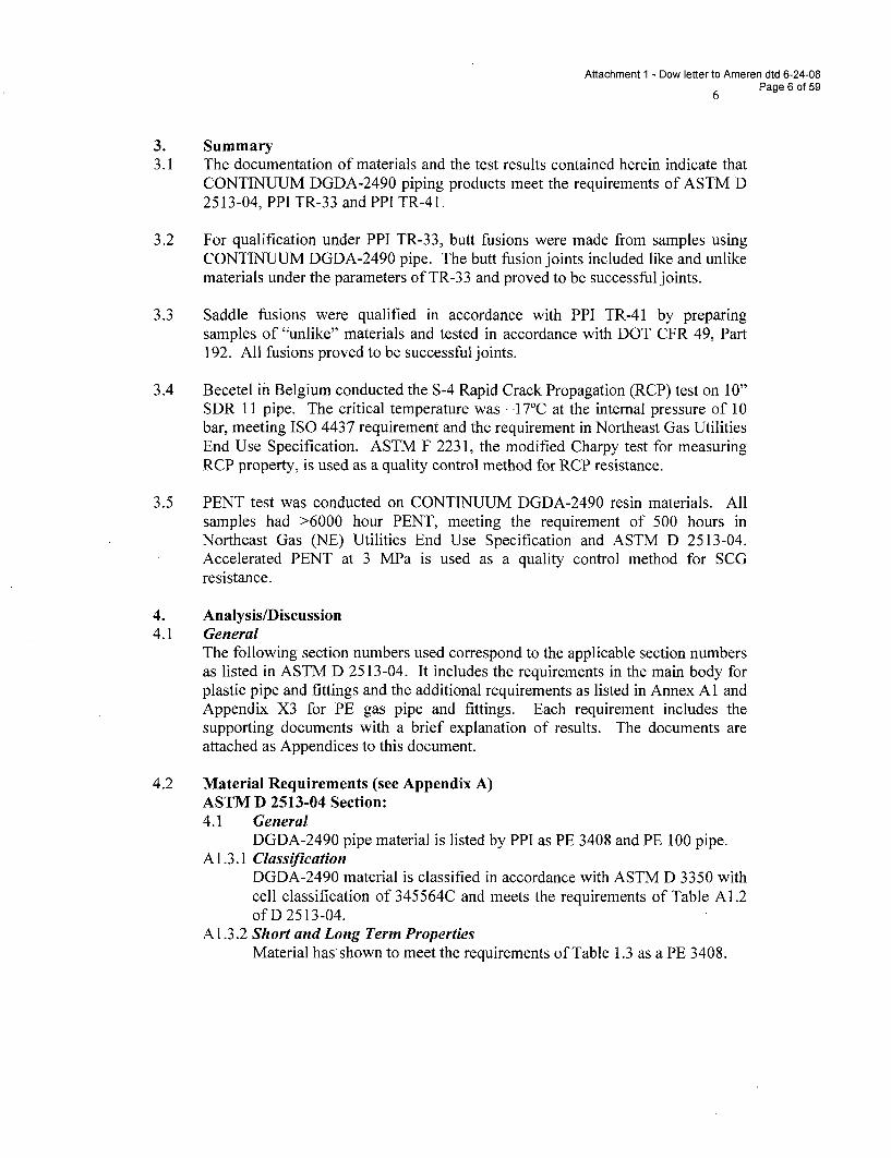
Attachment 1 - Dow letter to Ameren dtd 6-24-08
6 Page 6 of 59
3. Summary3.1 The documentation of materials and the test results contained herein indicate that
CONTINUUM DGDA-2490 piping products meet the requirements of ASTM D2513-04, PPI TR-33 and PPI TR-41.
3.2 For qualification under PPI TR-33, butt fusions were made from samples usingCONTINUUM DGDA-2490 pipe. The butt fusion joints included like and unlikematerials under the parameters of TR-33 and proved to be successful joints.
3.3 Saddle fusions were qualified in accordance with PPI TR-41 by preparingsamples of "unlike" materials and tested in accordance with DOT CFR 49, Part192. All fusions proved to be successful joints.
3.4 Becetel in Belgium conducted the S-4 Rapid Crack Propagation (RCP) test on 10"SDR 11 pipe. The critical temperature was -1 7C at the internal pressure of 10bar, meeting ISO 4437 requirement and the requirement in Northeast Gas UtilitiesEnd Use Specification. ASTM F 2231, the modified Charpy test for measuringRCP property, is used as a quality control method for RCP resistance.
3.5 PENT test was conducted on CONTINUUM DGDA-2490 resin materials. Allsamples had >6000 hour PENT, meeting the requirement of 500 hours inNortheast Gas (NE) Utilities End Use Specification and ASTM D 2513-04.Accelerated PENT at 3 MPa is used as a quality control method for SCGresistance.
4. Analysis/Discussion4.1 General
The following section numbers used correspond to the applicable section numbersas listed in ASTM D 2513-04. It includes the requirements in the main body forplastic pipe and fittings and the additional requirements as listed in Annex Al andAppendix X3 for PE gas pipe and fittings. Each requirement includes thesupporting documents with a brief explanation of results. The documents areattached as Appendices to this document.
4.2 Material Requirements (see Appendix A)ASTM D 2513-04 Section:4.1 General
DGDA-2490 pipe material is listed by PPI as PE 3408 and PE 100 pipe.A 1.3.1 Classification
DGDA-2490 material is classified in accordance with ASTM D 3350 withcell classification of 345564C and meets the requirements of Table A1.2of D 2513-04.
A1.3.2 Short and Long Term PropertiesMaterial has shown to meet the requirements of Table 1.3 as a PE 3408.
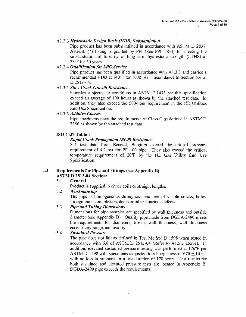
Attachment 1 - Dow letter to Ameren dtd 6-24-08Page 7 of 59
A 1.3.3 Hydrostatic Design Basis (HDB) SubstantiationPipe product has been substantiated in accordance with ASTM D 2837.Asterisk (*) listing is granted by PPI (See PPI TR-4) for meeting thesubstantiation of linearity of long term hydrostatic strength (LTHS) at730F for 50 years.
A 1.3.4 Qualification for LPG ServicePipe product has been qualified in accordance with A1.3.3 and carries arecommended HDB at 140'F for 1000 psi in accordance to Section 5.6 ofD 2513-04.
A 1.3.5 Slow Crack Growth ResistanceSamples subjected to conditions in ASTM F 1473 per this specificationexceed an average of 100 hours as shown by the attached test data. Inaddition, they also exceed the 500-hour requirement in the NE UtilitiesEnd Use Specification.
A 1.3.6 Additive ClassesPipe specimens meet the requirements of Class C as defined in ASTM D3350 as shown by the attached test data.
ISO 4437 Table 1Rapid Crack Propagation (RCP) ResistanceS-4 test data from Becetel, Belgium exceed the critical pressurerequirement of 4.2 bar for PE 100 pipe. They also exceed the criticaltemperature requirement of 20°F by the NE Gas Utility End UseSpecification.
4.3 Requirements for Pipe and Fittings (see Appendix B)ASTM D 2513-04 Section:5.1 General
Product is supplied in either coils or straight lengths.5.2 Workmanship
The pipe is homogeneous throughout and free of visible cracks, holes,foreign inclusion, blisters, dents or other injurious defects.
5.3 Pipe and Tubing DimensionsDimensions for pipe samples are specified by wall thickness and outsidediameter (see Appendix B). Quality pipe made from DGDA-2490 meetsthe requirements for diameters, toe-in, wall thickness, wall thicknesseccentricity range, and ovality.
5.4 Sustained PressureThe pipe does not fail as defined in Test Method D 1598 when tested inaccordance with 6.6 of ASTM D 2513-04 (Refer to A1.5.3 above). Inaddition, elevated sustained pressure testing was performed at 176°F perASTM D 1598 with specimens subjected to a hoop stress of 670 + 10 psiwith no loss in pressure for a test duration of 170 hours. Test results forboth sustained and elevated pressure tests are located in Appendix B.DGDA-2490 pipe exceeds the requirements.
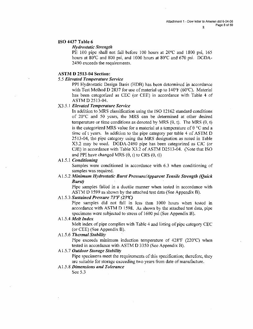
Attachment 1 - Dow letter to Ameren dtd 6-24-08
8 Page 8 of 59
ISO 4437 Table 6Hydrostatic StrengthPE 100 pipe shall not fail before 100 hours at 20 0C and 1800 psi, 165hours at 800C and 800 psi, and 1000 hours at 80'C and 670 psi. DGDA-2490 exceeds the requirements.
ASTM D 2513-04 Section:5.5 Elevated Temperature Service
PPI Hydrostatic Design Basis (HDB) has been determined in accordancewith Test Method D 2837 for use of material up to 140°F (60'C). Materialhas been categorized as CEC (or CEE) in accordance with Table 4 ofASTM D 2513-04.
X3.5.1 Elevated Temperature ServiceIn addition to MRS classification using the ISO 12162 standard conditionsof 20'C and 50 years, the MRS can be determined at other desiredtemperature or time conditions as denoted by MRS (0, t). The MRS (0, t)is the categorized MRS value for a material at a temperature of 0 'C and atime of t years. In addition to the pipe category per table 4 of ASTM D2513-04, the pipe category using the MRS designation as noted in TableX3.2 may be used. DGDA-2490 pipe has been categorized as CJC (orCJE) in accordance with Table X3.2 of ASTM D2513-04. (Note that ISOand PPI have changed MRS (0, t) to CRS (0, t))
A1.5.1 ConditioningSamples were conditioned in accordance with 6.3 when conditioning ofsamples was required.
Al .5.2 Minimum Hydrostatic Burst Pressure/Apparent Tensile Strength (QuickBurst)Pipe samples failed in a ductile manner when tested in accordance withASTM D 1599 as shown by the attached test data (See Appendix B).
A1.5.3 Sustained Pressure 73OF (230C)Pipe samples did not fail in less than 1000 hours when tested inaccordance with ASTM D 1598. As shown by the attached test data, pipespecimens were subjected to stress of 1600 psi (See Appendix B).
Al.5.4 Melt IndexMelt index of pipe complies with Table 4 and listing of pipe category CEC(or CEE) (See Appendix B).
A1.5.6 Thermal StabilityPipe exceeds minimum induction temperature of 428°F (220'C) whentested in accordance with ASTM D 3350 (See Appendix B).
A1.5.7 Outdoor Storage StabilityPipe specimens meet the requirements of this specification; therefore, theyare suitable for storage exceeding two years from date of manufacture.
A 1.5.8 Dimensions and ToleranceSee 5.3
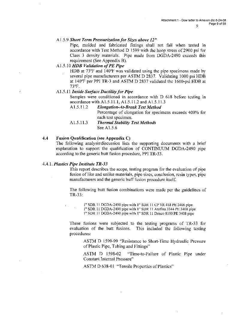
Attachment 1 - Dow letter to Ameren dtd 6-24-08Page 9 of 59
A 1.5.9 Short Term Pressurization for Sizes above 12"Pipe, molded and fabricated fittings shall not fail when tested inaccordance with Test Method D 1599 with the hoop stress of 2900 psi forClass 3 density materials. Pipe made from DGDA-2490 exceeds thisrequirement (See Appendix B).
A1.5.10 HDB Validation of PE PipeHDB at 73°F and 140'F was validated using the pipe specimens made byseveral pipe manufacturers per ASTM D 2837. Validating 1000 psi HDBat 140°F per PPI TR-3 and ASTM D 2837 validated the 1600-psi HDB at73 0F.
A 1.5.11 Inside Surface Ductility for PipeSamples were conditioned in accordance with D 618 before testing inaccordance with A1.5.11.1, A1.5.11.2 and A1.5.11.3A 1.5.11.2 Elongation-At-Break Test Method
Percentage of elongation for specimens exceeds 400% foreach test specimen.
A 1.5.11.3 Thermal Stability Test MethodsSee A1.5.6
4.4 Fusion Qualification (see Appendix C)The following analysis/discussion lists the supporting documents with a briefexplanation to support the qualification of CONTINUUM DGDA-2490 pipeaccording to the generic butt fusion procedure, PPI TR-33.
4.4.1. Plastics Pipe Institute TR-33This report describes the scope, testing program for the evaluation of pipefusion of like and unlike materials, pipe sizes, conclusion, resin types, pipemanufacturers and the generic buff fusion procedure itself.
The following butt fusion combinations were made per the guidelines ofTR-33:
1" SDR 11 DGDA-2490 pipe with 1" SDR 11 CP TR 418 PE 2406 pipe1" SDR 11 DGDA-2490 pipe with 1" SDR 11 Atofina 3344 PE 3408 pipe1" SDR 11 DGDA-2490 pipe with 1" SDR 11 Drisco 8100 PE 3408 pipe
These fusions were subjected to the testing programs of TR-33 forevaluation of the butt fusions. This included the following testingprocedures:
ASTM D 1599-99 "Resistance to Short-Time Hydraulic Pressureof Plastic Pipe, Tubing and Fittings"
ASTM D 1598-02 "Time-to-Failure of Plastic Pipe underConstant Internal Pressure"
ASTM D 638-01 "Tensile Properties of Plastics"
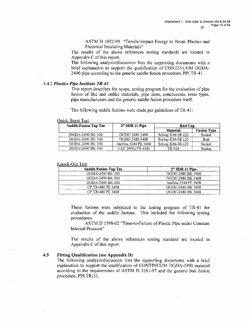
Attachment 1 - Dow letter to Ameren dtd 6-24-08
Page 10 of 59
ASTM D 1822-99 "Tensile-Impact Energy to Break Plastics andElectrical Insulating Materials"
The results of the above references testing standards are located inAppendix C of this report.The following analysis/discussion lists the supporting documents with abrief explanation to support the qualification of CONTINUUM DGDA-2490 pipe according to the generic saddle fusion procedure, PPI TR-41.
4.4.2 Plastics Pipe Institute TR-41This report describes the scope, testing program for the evaluation of pipefusion of like and unlike materials, pipe sizes, conclusions, resin types,pipe manufacturers and the generic saddle fusion procedure itself.
The following saddle fusions were made per guidelines ofTR-41:
Quick Burst TestSaddle Fusion Tap Tee 2" SDR 11 Pipe End Cap
_._Material Fusion TypeDGDA-2490 BK 100 DGDC-2480 3408 Solvay K44-08-123 SocketDGDA-2490 BK 100 DGDC-2480 3408 Solvay K44-08-123 ButtDGDA-2490 BK 100 Atofina 3344 PE 3408 Solvay K44-08-123 SocketDGDA-2490 BK 100 UAC 2000 (TR-418) TR-418 Socket
Knock-Out TestSaddle Fusion Tap Tee 2" SDR 11 Pipe
DGDA-2490 BK 100 DGDC-2480 BK 3408DGDA-2490 BK 100 DGDC-2480 BK 3408DGDA-2490 BK 100 Atofina 3344 PE 3408CP TR-480 PE 3408 DGDC-2480 BK 3408CP TR-480 PE 3408 DGDC-2480 BK 3408
These *fusions were subjected to the testing program of TR-41 forevaluation of the saddle fusions. This included the following testingprocedures:
ASTM D 1598-02 "Time-to-Failure of Plastic Pipe under ConstantInternal Pressure"
The results of the above references testing standard are located inAppendix Cof this report.
4.5 Fitting Qualification (see Appendix D)The following analysis/discussion lists the supporting documents with a briefexplanation to support the qualification of CONTINUUM DGDA-2490 materialaccording to the requirements of ASTM D 3261-97 and the generic butt fusion.procedure, PPI TR-33.
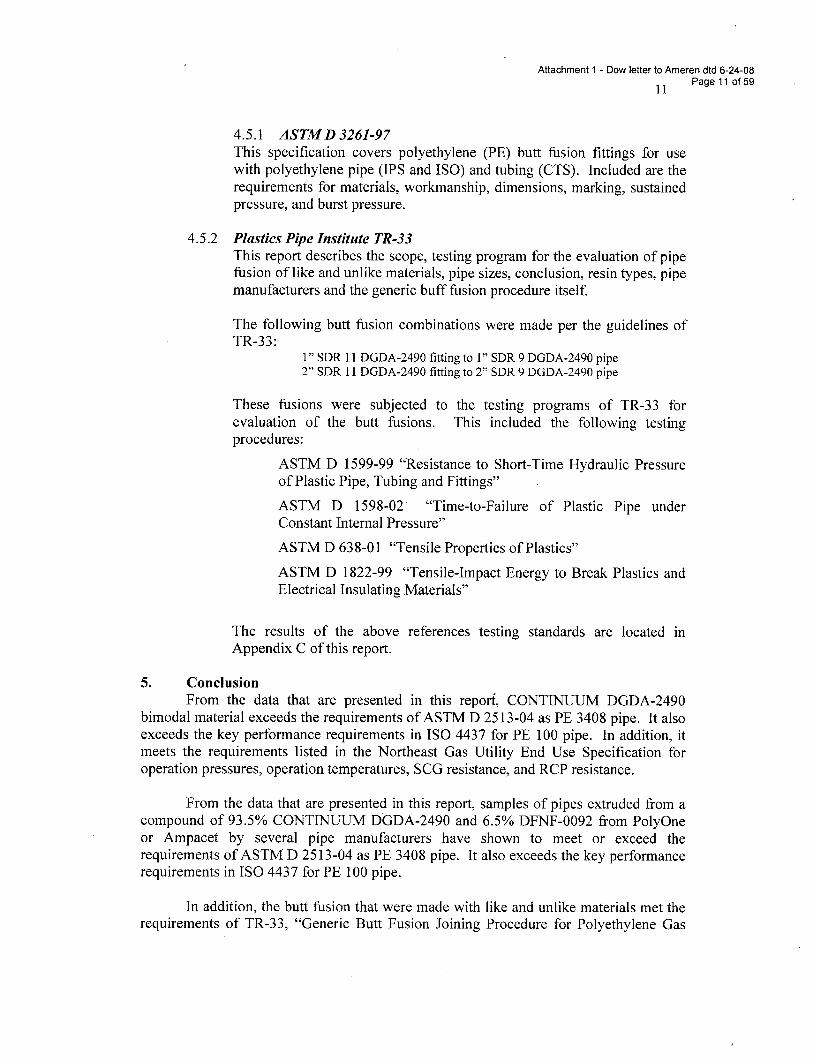
Attachment 1 - Dow letter to Ameren dtd 6-24-08Page 11 of 59
4.5.1 ASTMD3261-97This specification covers polyethylene (PE) butt fusion fittings for usewith polyethylene pipe (IPS and ISO) and tubing (CTS). Included are therequirements for materials, workmanship, dimensions, marking, sustainedpressure, and burst pressure.
4.5.2 Plastics Pipe Institute TR-33This report describes the scope, testing program for the evaluation of pipefusion of like and unlike materials, pipe sizes, conclusion, resin types, pipemanufacturers and the generic buff fusion procedure itself.
The following butt fusion combinations were made per the guidelines ofTR-33:
1" SDR 11 DGDA-2490 fitting to 1" SDR 9 DGDA-2490 pipe2" SDR 11 DGDA-2490 fitting to 2" SDR 9 DGDA-2490 pipe
These fusions were subjected to the testing programs of TR-33 forevaluation of the butt fusions. This included the following testingprocedures:
ASTM D 1599-99 "Resistance to Short-Time Hydraulic Pressure
of Plastic Pipe, Tubing and Fittings"
ASTM D 1598-02 "Time-to-Failure of Plastic Pipe underConstant Internal Pressure"
ASTM D 638-01 "Tensile Properties of Plastics"
ASTM D 1822-99 "Tensile-Impact Energy to Break Plastics andElectrical Insulating Materials"
The results of the above references testing standards are located inAppendix C of this report.
5. ConclusionFrom the data that are presented in this reporf, CONTINUUM DGDA-2490
bimodal material exceeds the requirements of ASTM D 2513-04 as PE 3408 pipe. It alsoexceeds the key performance requirements in ISO 4437 for PE 100 pipe. In addition, itmeets the requirements listed in the Northeast Gas Utility End Use Specification foroperation pressures, operation temperatures, SCG resistance, and RCP resistance.
From the data that are presented in this report, samples of pipes extruded from acompound of 93.5% CONTINUUM DGDA-2490 and 6.5% DFNF-0092 from PolyOneor Ampacet by several pipe manufacturers have shown to meet or exceed therequirements of ASTM D 2513-04 as PE 3408 pipe. It also exceeds the key performancerequirements in ISO 4437 for PE 100 pipe.
In addition, the butt fusion that were made with like and unlike materials met therequirements of TR-33, "Generic Butt Fusion Joining Procedure for Polyethylene Gas
Attachment 1 - Dow letter to Ameren dtd 6-24-08
12 Page 12 of 59
Pipe." Saddle fusions also proved to be acceptable per requirements of DOT, CFR 49,Part 192, §192.283 and met the requirement of PPI TRY41, "Generic Saddle FusionJoining Procedure for Polyethylene Gas Pipe."
From the data that are presented in this report, samples of fittings made, by CentralPlastics, Rahn Plastics and Perfection from black CONTINUUM DGDA-2490 material(93.5% DGDA-2490 NT resin and 6.5% DFNF-0092 black masterbatch) met therequirements of ASTM D 3261, "Butt Heat Fusion Polyethylene (PE) Plastic Fittings forPolyethylene (PE) Plastic Pipe and Tubing" and PPI TR-33, "Generic Butt FusionJoining Procedure for Polyethylene Gas Pipe".
Natural gas pipe and fittings manufactured from this material shall have a PPIdependent listing supported by The Dow Chemical Company and granted by PPI. It shallbe marked in accordance with ASTM D 2513-04 Section 7.1 and A1.6.1. The pipe shallbe identified by a trade name of the pipe manufacturer that is listed by PPI.
Attachment 1 - Dow letter to Ameren dtd 6-24-08
13 Page 13 of 59
APPENDIX A
DATA FOR MATERIAL QUALIFICATION
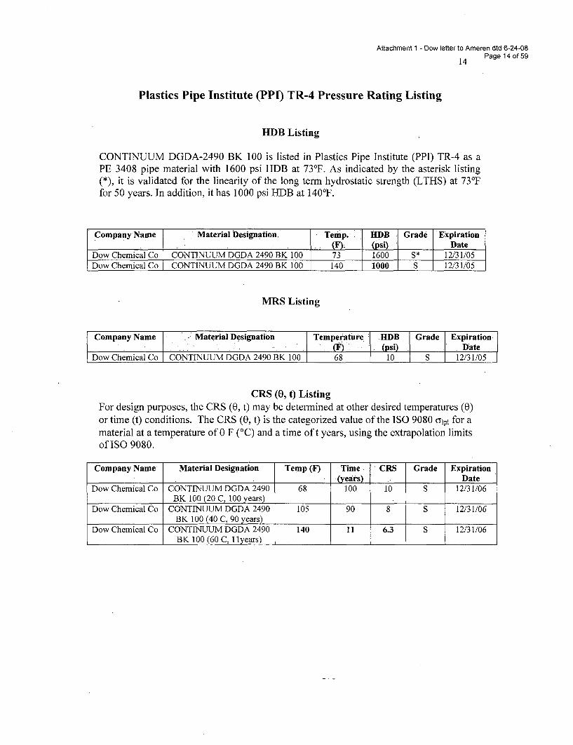
Attachment 1 - Dow letter to Ameren dtd 6-24-08
14 Page 14 of 59
Plastics Pipe Institute (PPI) TR-4 Pressure Rating Listing
HDB Listing
CONTINUUM DGDA-2490 BK 100 is listed in Plastics Pipe Institute (PPI) TR-4 as aPE 3408 pipe material with 1600 psi HDB at 73°F. As indicated by the asterisk listing(*), it is validated for the linearity of the long term hydrostatic strength (LTHS) at 73°Ffor 50 years. In addition, it has 1000 psi HDB at 140'F.
Company Name Material Designation, Temp. j 111DB Grade Expiration(F)- (psi) Date
Dow Chemical Co CONTINUUM DGDA 2490 BK 100 73 1600 S* 12/31/05Dow Chemical Co CONTINUUM DGDA 2490 BK 100 140 1000 S 12/31/05
MRS Listing
Company Name Material Designation Temperature HDB Grade Expiration(F) (psi) - Date
Dow Chemical Co CONTINUUM DGDA 2490 BK 100 68 10 S 12/31/05
CRS (0, t) ListingFor design purposes, the CRS (0, t) may be determined at other desired temperatures (0)or time (t) conditions. The CRS (0, t) is the categorized value of the ISO 9080 O7pl for amaterial at a temperature of 0 F (°C) and a time oft years, using the extrapolation limitsof ISO 9080.
Company Name- Material Designation Temp (F) Time. CRS Grade Expiration(years) . _ Date
Dow Chemical Co CONTINUUM DGDA 2490 68 100 10 S 12/31/06BK 100 (20 C, 100 years)
Dow Chemical Co CONTINUUM DGDA 2490 105 90 8 S 12/31/06BK 100 (40 C, 90 years) II
Dow Chemical Co CONTINUUM DGDA 2490 140 11 6.3 S 12/31/06BK 100 (60 C, Ilyears)
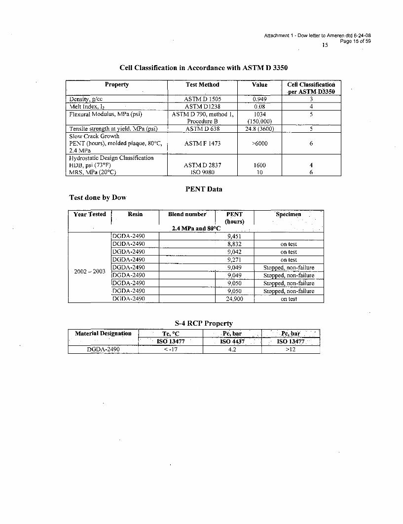
Attachment 1 - Dow letter to Ameren dtd 6-24-08
15 Page 15 of 59
Cell Classification in Accordance with ASTM D 3350
Property Test Method Value Cell Classification-per ASTM.3350
Density, g/cc ASTM D 1505 0.949 3Melt Index, 12 ASTM D1238 0.08 4Flexural Modulus, MPa (psi) ASTM D 790, method 1, 1034 5
Procedure B (150,000)Tensile strength at yield, MPa (psi) ASTM D 638 24.8 (3600) 5Slow Crack GrowthPENT (hours), molded plaque, 80'C, ASTM F 1473 >6000 62.4 MPaHydrostatic Design ClassificationHDB, psi (73°F) ASTM D 2837 1600 4MRS, MPa (20'C) ISO 9080 10 6
PENT DataTest done by Dow
Year Tested Resin Blend number PENT Specimen(hours)
2.4 MPa and 80 0CDGDA-2490 9,451DGDA-2490 8,832 on testDGDA-2490 9,042 on testDGDA-2490 9,271 on testDGDA-2490 9,049 Stopped, non-failureDGDA-2490 9,049 Stopped, non-failure
DGDA-2490 9,050 Stopped, non-failureDGDA-2490 9,050 Stopped, non-failureDGDA-2490 24,900 on test
S-4 RCP Property
Material Designation Tc, *C Pc, bar Pc, bar
ISO 13477 IS0443" ISO 13477DGDA-2490 < -17 4.2 > 12
Attachment 1 - Dow letter to Ameren dtd 6-24-08
16 Page 16 of 59
APPENDIX B
DATA FOR PIPE AND FITTINGS
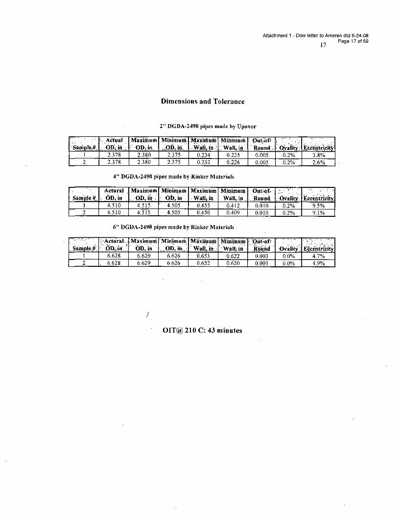
Attachment 1 - Dow letter to Ameren dtd 6-24-08
17 Page 17 of 59
Dimensions and Tolerance
2" DGDA-2490 pipes made by Uponor
Actual Maximum Minimum Ma xiium .Minimuuil Outof- ,"Saiple.# 'OD, in [ OD ,in .01j, in.: Wall; in,. - .in-, 'Round -i'Q aity: E -itrify
1 2.378 2.380 2.375 0.234 0.225 0.005 0.2% 3.8%2 2.378 2.380 2.375 0.232 0.226 0.005 0.2% 2.6%
4" DGDA-2490 pipes made by Rinker Materials
2)ActuraJ Maximum Minimum Maximum Minimum OUt-of-dSampe# . OD, in OD,. in 1OD, in Wallin Wall, in '.Round .. Q.valit*. ,Eccienf•rly
1 4.510 4.515 4.505 0.455 0.412 0.010 0.2% 9.5%2 4.510 4.515 4.505 0.450 0.409 0.010 0.2% 9.1%
6" DGDA-2490 pipes made by Rinker Materials-Actural J MaXimun Mifimumim 'Miximuinm MinimUm 'Oiit~ofz . .] .
Sample . 0D1'. ODD:i . in 'D ini.-i Wall, in : w in :Rond vOlity§ Ecnhicit3
1 6.628 6.629 6.626 0.653 0.622 0.003 0.0% 4.7%2 6.628 6.629 6.626 0.652 0.620 0.003 0.0% 4.9%
OIT@ 210 C: 43 minutes
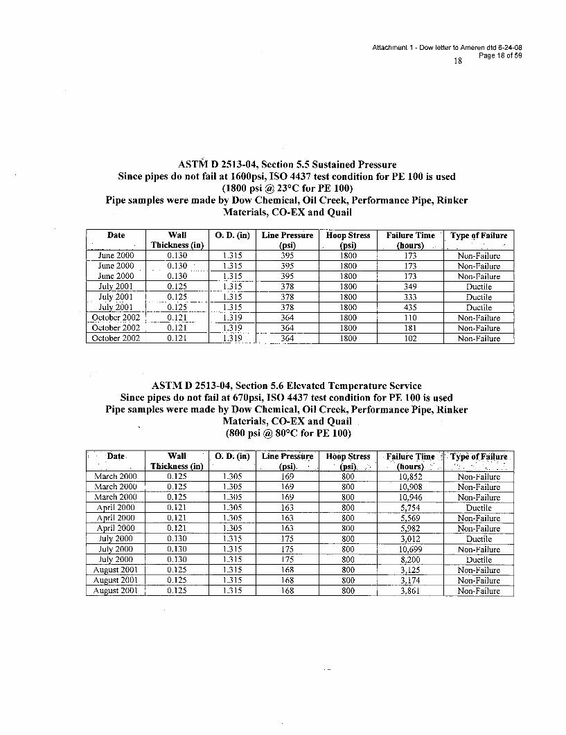
Attachment 1 - Dow letter to Ameren dtd 6-24-08
18 Page 18 of 59
ASTM D 2513-04, Section 5.5 Sustained PressureSince pipes do not fail at 1600psi, ISO 4437 test condition for PE 100 is used
(1800 psi @ 23 0C for PE 100)Pipe samples were made by Dow Chemical, Oil Creek, Performance Pipe, Rinker
Materials, CO-EX and Quail
Date Wall 0. D. (in) Line Pressure Hoop Stress Failure Time Type of FailureThickness (in) (psi) (psi) (hours)
June 2000 0.130 1.315 395 1800 173 Non-FailureJune 2000 0.130 1.315 395 1800 173 Non-FailureJune 2000 0.130 1.315 395 1800 173 Non-FailureJuly 2001 0.125 1.315 378 1800 349 DuctileJuly 2001 0.125 1.315 378 1800 333 DuctileJuly 2001 0.125 1.315 378 1800 435 Ductile
October 2002 0.121 1.319 364 1800 110 Non-FailureOctober 2002 0.121 1.319 364 1800 181 Non-FailureOctober 2002 0.121 1.319 364 1800 102 Non-Failure
ASTM D 2513-04, Section 5.6 Elevated Temperature ServiceSince pipes do not fail at 670psi, ISO 4437 test condition for PE 100 is used
Pipe samples were made by Dow Chemical, Oil Creek, Performance Pipe, RinkerMaterials, CO-EX and Quail(800 psi @ 801C for PE 100)
Date Wall 0. D. (in) Line Pressure Hoop Stress Failure Time ':Type of FailureThickness(in) , (psi). (psi). (hours). "
March 2000 0.125 1.305 169 800 10,852 Non-FailureMarch 2000 0.125 1.305 169 800 10,908 Non-FailureMarch 2000 0.125 1.305 169 800 10,946 Non-FailureApril 2000 0.121 1.305 163 800 5,754 DuctileApril 2000 0.121 1.305 163 800 5,569 Non-FailureApril 2000 0.121 1.305 163 800 5,982 Non-FailureJuly 2000 0.130 1.315 175 800 3,012 DuctileJuly 2000 0.130 1.315 175 800 10,699 Non-FailureJuly 2000 0.130 1.315 175 800 8,200 Ductile
August 2001 0.125 1.315 168 800 3,125 Non-FailureAugust 2001 0.125 1.315 168 800 3,174 Non-FailureAugust 2001 0.125 1.315 168 800 3,861 Non-Failure
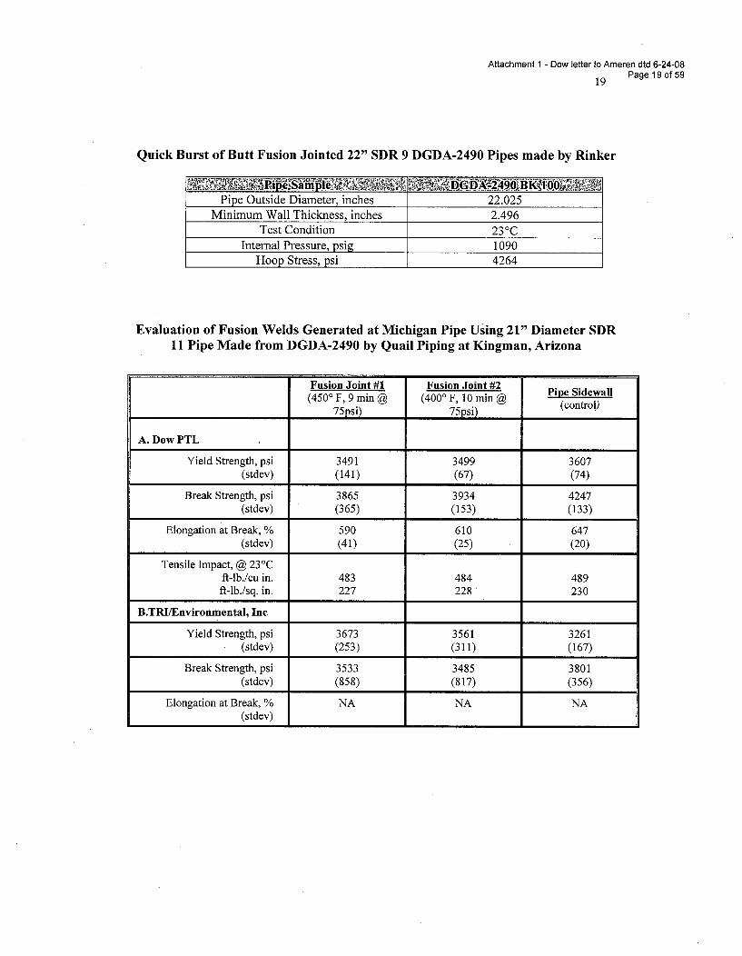
Attachment 1 - Dow letter to Ameren dtd 6-24-08
19 Page 19 of 59
Quick Burst of Butt Fusion Jointed 22" SDR 9 DGDA-2490 Pipes made by Rinker
Pipe Outside Diameter, inches 22.025Minimum Wall Thickness, inches 2.496
Test Condition 23 0CInternal Pressure, psig 1090
Hoop Stress, psi 4264
Evaluation of Fusion Welds Generated at Michigan Pipe Using 21" Diameter SDR11 Pipe Made from DGDA-2490 by Quail Piping at Kingman, Arizona
Fusion Joint #1 Fusion Joint #2 Pipe Sidewall(450° F, 9 min @ (4000 F, 10 min @ (control)
75psi) 75psi) (control)
A. Dow PTL
Yield Strength, psi 3491 3499 3607(stdev) (141) (67) (74)
Break Strength, psi 3865 3934 4247(stdev) (365) (153) (133)
Elongation at Break, % 590 610 647(stdev) (41) (25) (20)
Tensile Impact, @ 23°Cft-lb./cu in. 483 484 489ft-lb./sq. in. 227 228 230
B.TRI/Environmental, Inc
Yield Strength, psi 3673 3561 3261(stdev) (253) (311) (167)
Break Strength, psi 3533 3485 3801(stdev) (858) (817) (356)
Elongation at Break, % NA NA NA(stdev)
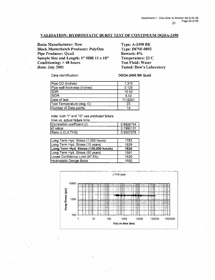
Attachment 1 - Dow letter to Ameren dtd 6-24-08
20 Page 20 of 59
VALIDATION: HYDROSTATIC BURST TEST OF CONTINUUM DGDA-2490
Resin Manufacturer: DowBlack Masterbatch Producer: PolyOnePipe Producer: QuailSample Size and Length: 1" SDR 11 x 18"Conditioning: > 48 hoursDate: July 2001
Data Identification:
Type: A-2490 BKType: DFNF-0092Rework: 0%Temperature: 23 CTest Fluid: WaterTested: Dow's Laboratory
DGDA-2490 BK Quail
Pipe OD (inches): 1.315Pipe wall thickness (inches): 0.125SDR: 10.52SIDR: 8.52Date of test: 7/1/2001Test Temperature (deg. C): 23Number of Data points: 15
note: both "r" and "r2" use predicted failuretime vs. actual failure time.Correlation coefficient (r): 0.8938754r2 value: 0.7990131Ratio (LCL/LTHS) 0.9357276
Long Term Hyd. Stress (1,000 hours) 1783Long Term Hyd. Stress (10 years) 1639Long Term Hyd. Stress (100,000 hours) 1635Long Term Hyd. Stress (50 years) 1591Lower Confidence Limit (97.5%) 1530Hydrostatic Design Basis 1600
LTHS data
1000
CO00
100 Lim1 10 100 1000 10000 100000 1000000
Failure time (hrs)
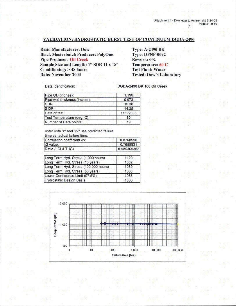
Attachment I - Dow letter to Ameren dtd 6-24-08
21 Page 21 of 59
VALIDATION: HYDROSTATIC BURST TEST OF CONTINUUM DGDA-2490
Resin Manufacturer: DowBlack Masterbatch Producer: PolyOnePipe Producer: Oil CreekSample Size and Length: 1" SDR 11 x 18"Conditioning: > 48 hoursDate: November 2003
Type: A-2490 BKType: DFNF-0092Rework: 0%Temperature: 60 CTest Fluid: WaterTested: Dow's Laboratory
Data Identification: DGDA-2490 BK 100 Oil Creek
Pipe OD (inches): 1.196Pipe wall thickness (inches): 0.073SDR: 16.38SIDR: 14.38Date of test: 11/3/2003Test Temperature (deg. C): 60Number of Data points: 19
note: both "r" and "r2" use predicted failuretime vs. actual failure time.Correlation coefficient (r): 0.8768598r2 value: 0.7688831Ratio (LCL/LTHS) 0.985369382
Long Term Hyd. Stress (1,000 hours) 1120Long Term Hyd. Stress (10 years) 1082Long Term Hyd. Stress (100,000 hours) 1080Long Term Hyd. Stress (50 years) 1068Lower Confidence Limit (97.5%) 1065Hydrostatic Design Basis 1000
10,000
! 1,000
0.00
100
10 100 1,000 10,000 100,000
Failure time (hrs)
Attachment 1 - Dow letter to Ameren dtd 6-24-08
22 Page 22 of 59
APPENDIX C
DATA FOR FUSION QUALIFICATION
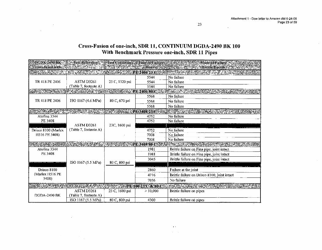
Attachment 1 - Dow letter to Ameren dtd 6-24-08Page 23 of 59
23
Cross-Fusion of one-inch, SDR 11, CONTINUUM DGDA-2490 BK 100With Benchmark Pressure one-inch, SDR 11 Pipes
,~ ~ W~tfei~ne s tii~~ai~~. YMod oofFai fl
-t W6 rec' on Win -- V1F1 -
5544 No failureTR 418 PE 2406 ASTM D3261 23 C, 1320 psi 5544 No failure
(Table 7, footnote A) 5544 No failure
5568. No failureTR 418 PE 2406 ISO 1167 (4.6 MPa) 80 C, 670 psi 5568 No failure
5568 No failure
Atofina 3344 4752 No failurePE 3408 4752 No failure
ASTM D3261 23C, 1600 psiDrisco 8100 (Marlex (Table 7, footnote A) 4752 No failure
H516 PE 3408) 7008 No failure7008 No failure
Atofina 3344 1981 Brittle failure on Fina pipe, joint intactPE 3408 1981 Brittle failure on Fina pipe, joint intact
3045 Brittle failure on Fina pipe, joint intactISO 1167 (5.5 MPa) 80 C, 800 psi _______________________
Drisco 8100 2860 Failure at the joint(Marlex H516 PE 4716 Brittle failure on Drisco 8100, joint intact
3408) 7056 No failure
ASTM D3261 23 C, 1600 psi > 10,000 Brittle failure on pipesDGDA-2490 BK (Table 7, footnote A)
_ _ ISO 1167 (5.5 MPa) 80 C, 800 psi 4300 Brittle failure on pipes
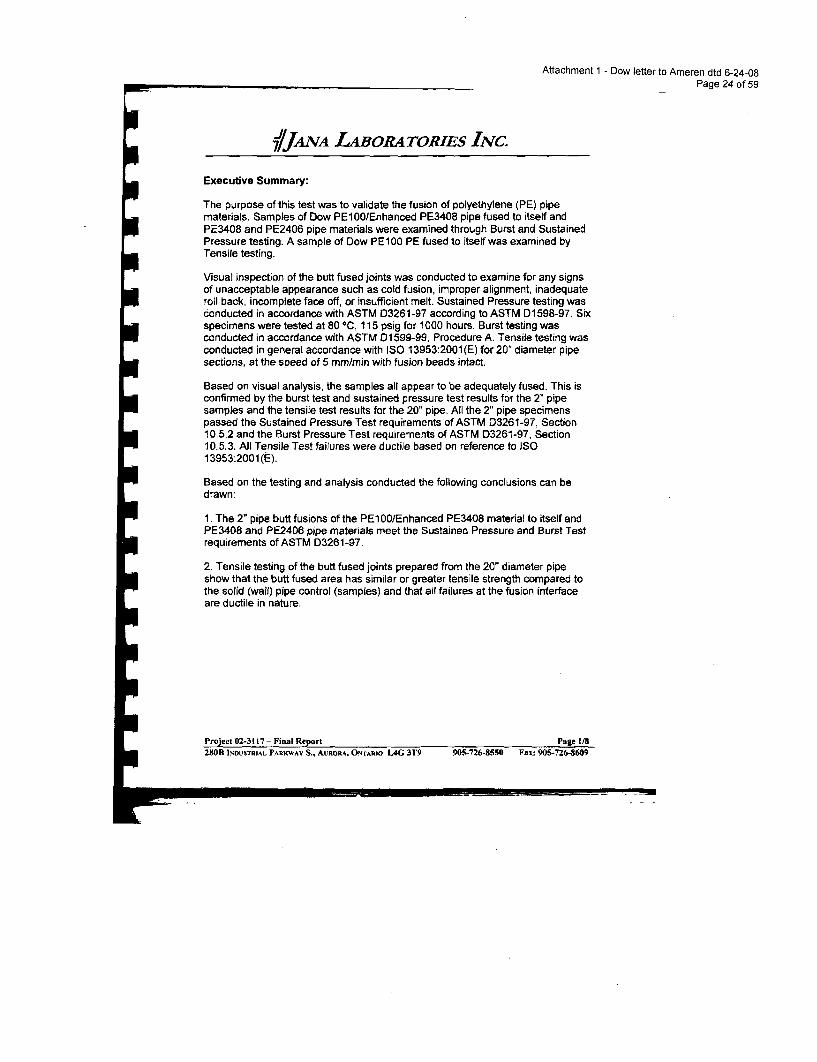
Attachment 1 - Dow letter to Ameren dtd 6-24-08Page 24 of 59
7JAoNA LABORATORIEs INc.
Executive Summary:
The purpose of this test was to validate the fusion of polyethylene (PE) pipematerials. Samples of Dow PEIOO/Enhanced PE3408 pipe fused to itself andPE3408 and PE2406 pipe materials were examined through Burst and SustainedPressure testing. A sample of Dow PE100 PE fused to itself was examined byUTensile testing.
Visual inspection of the butt fused joints was conducted to examine for any signsof unacceptable appearance such as cold fusion, improper alignment, inadequateroll back, incomplete face off, or insufficient melt. Sustained Pressure testing wasconducted in accordance with ASTM D3261-97 according to ASTM D1 598-97. Sixspecimens were tested at 80 nC, 115 psig for 1000 hours. Burst testing wasconducted in accordance with ASTM 01599-99, Procedure A. Tensile testing wasconducted in general accordance with ISO 13953:2001(E) for 20" diameter pipesections, at the speed of 5 mm/min with fusien beads intact.
Based on visual analysis, the samples all appear to be adequately fused. This isconfirmed by the burst test and sustained pressure test results for the 2" pipesamples and the tensile test results for the 20" pipe. All the 2" pipe specimenspassed the Sustained Pressure Test requirements of ASTM D3261-97, Section10.5.2 and the Burst Pressure Test requirements of ASTM D3261-97, Section10.5.3. All Tensile Test failures were ductile based on reference to ISO13953:2001(E).
UBased on the testing and analysis conducted the following conclusions can bedrawn:
U 1. The 2" pipe butt fusions of the PE100/Enhanced PE3408 material to itself andPE3408 and PE2406 pipe materials meet the Sustained Pressure and Burst Testrequirements of ASTM D3261-97.
2. Tensile testing of the butt fused joints prepared from the 20" diameter pipeshow that the butt fused area has similar or greater tensile strength compared tothe solid (wall) pipe control (samples) and that all failures at the fusion interfaceare ductile in nature.
i
Project 02-3117- Final Report Page 1/8m 280B INDUSTRIAL PARKWAY S., AURORA, ONTARMO L4G 3Y9 905-726-8550 Fax: 905-726-8609
RL
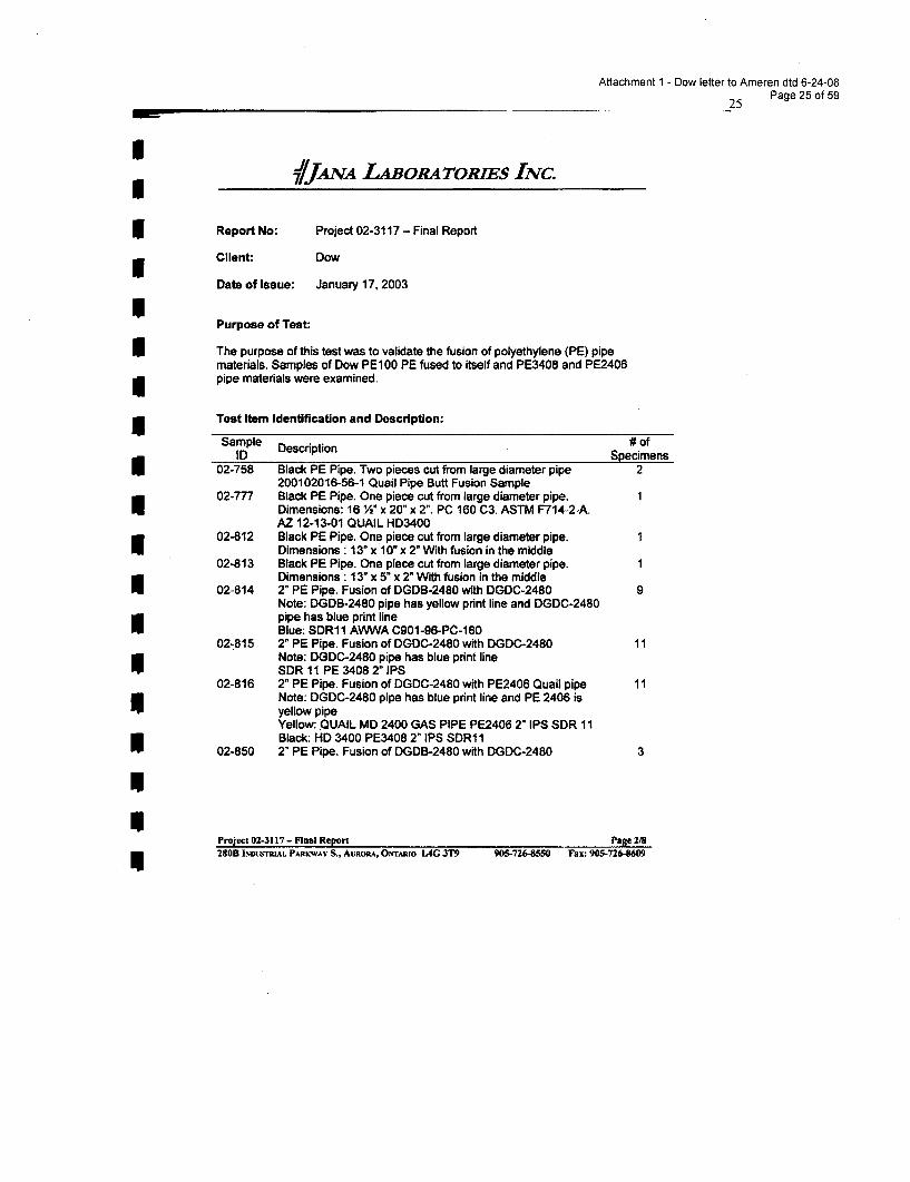
Attachment 1 - Dow letter to Ameren dtd 6-24-08
__25 Page 25 of 59
S V71JANA L4BORA TORIES INC.
5 Report No: Project 02-3117 - Final Report
s Client, Dow
Date of Issue: January 17, 2003
IPurpose of Test:
I The purpose of this test was to validate the fusion of polyethylene (PE) pipematerials. Samples of Dow PE100 PE fused to itself and PE3408 and PE2406pipe materials were examined.
Test Item Identification and Description:
Sample Description # ofID Specimens
02-758 Black PE Pipe. Two pieces cut from large diameter pipe 2200102016-56-1 Quail Pipe Butt Fusion Sample
02-777 Black PE Pipe. One piece cut from large diameter pipe. 1Dimensions: 16 M" x 20" x 2". PC 160 C3. ASTM F714-2-A.AZ 12-13-01 QUAIL HD3400
02-812 Black PE Pipe. One piece cut from large diameter pipe. 1Dimensions : 13" x 10" x 2" With fusion in the middle
02-813 Black PE Pipe. One piece cut from large diameter pipe. 1Dimensions : 13" x 5" x 2" With fusion in the middle
02-814 2" PE Pipe. Fusion of DGDB-2480 with DGDC-2480 9Note: DGDB-2480 pipe has yellow print line and DGDC-2480pipe has blue print lineBlue: SDR1 1 AWWA C901-96-PC-160
02-815 2" PE Pipe. Fusion of DGDC-2480 with DGDC-2480 11Note: DGDC-2480 pipe has blue print lineSDR 11 PE 3408 2" IPS
02-816 2" PE Pipe. Fusion of DGDC-2480 with PE2406 Quail pipe 11Note: DGDC-2480 pipe has blue print line and PE 2406 isyellow pipeYellow:. QUAIL MD 2400 GAS PIPE PE2406 2" IPS SDR 11Black: HD 3400 PE3408 2" IPS SDR1 I
02-850 2" PE Pipe. Fusion of DGDB-2480 with DGDC-2480 3
Project 02-3117- Final Report Page 2/8280B INDUSTRIAL PARacWAV S., AURORA, ONTARIO L4G 3T9 905-726-8550 Fax: 905-726-609
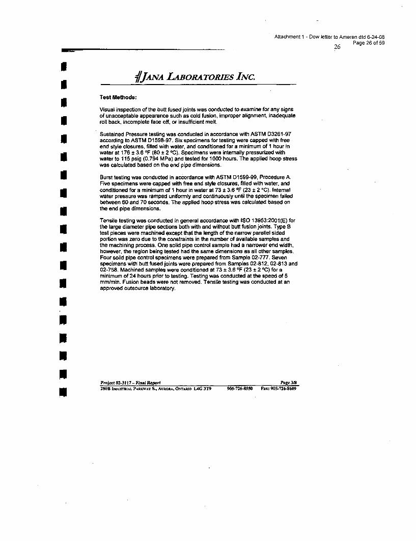
Attachment 1 - Dow letter to Ameren dtd 6-24-08
_26 Page 26 of 59
j/JANA LABORA TOMEs INC.
Test Methods:
Visual inspection of the butt fused joints was conducted to examine for any signsof unacceptable appearance such as cold fusion, improper alignment, inadequateIroll back, incomplete face off, or insufficient melt.
Sustained Pressure testing was conducted in accordance with ASTM D3261-97according to ASTM D1598-97. Six specimens for testing were capped with freeend style closures, filled with water, and conditioned for a minimum of I hour inwater at 176 ± 3.6 OF (80 ± 2 0C). Specimens were intemally pressurized withwater to 115 psig (0.794 MPa) and tested for 1000 hours. The applied hoop stresswas calculated based on the end pipe dimensions.
I Burst testing was conducted in accordance with ASTM D 599-99, Procedure A.Five specimens were capped with free end style closures, filled with water, andconditioned for a minimum of 1 hour in water at 73 ± 3.6 OF (23 ± 2 °C). Internalwater pressure was ramped uniformly and continuously until the specimen failedbetween 60 and 70 seconds. The applied hoop stress was calculated based onthe end pipe dimensions.
Tensile testing was conducted in general accordance with ISO 13953:2001 (E) forthe large diameter pipe sections both with and without butt fusion joints. Type Btest pieces were machined except that the length of the narrow parallel sidedportion was zero due to the constraints in the number of available samples andthe machining process. One solid pipe control sample had a narrower end width,however, the region being tested had the same dimensions as all other samples.Four solid pipe control specimens were prepared from Sample 02-777. Sevenspecimens with butt fused joints were prepared from Samples 02-812, 02-813 and02-758. Machined samples were conditioned at 73 ± 3.6 OF (23 + 2 0C) for aminimum of 24 hours prior to testing. Testing was conducted at the speed of 5mm/min. Fusion beads were not removed. Tensile testing was conducted at anapproved outsource laboratory.
III!N
Project 02-3117 - Final Report Page 3182M0B INDUSTMIAL PARKWAV S, AURoRA, ONTARtO LAG 3T9 905-726-8550 Fax: 905-726-8609
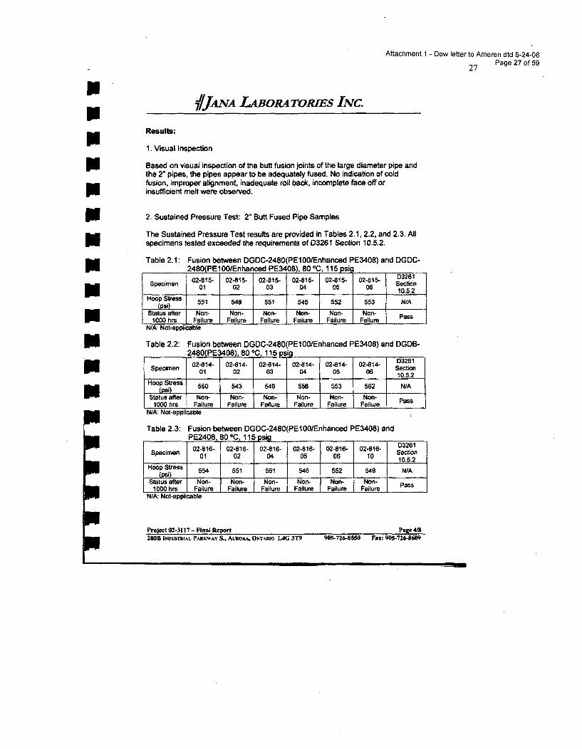
InIII!NIN!iiNINiInNININeNi
Attachment 1 - Dow letter to Ameren dtd 6-24-08
27 Page 27 of 59
7/JANA LABORATORIES INC.
Results:
1. Visual Inspection
Based on visual inspection of the butt fusion joints of the large diameter pipe andthe 2" pipes, the pipes appear to be adequately fused. No indication of coldfusion, improper alignment, inadequate roll back, incomplete face off orinsufficient melt were observed.
2. Sustained Pressure Test: 2" Butt Fused Pipe Samples
The Sustained Pressure Test results are provided in Tables 2.1, 2.2, and 2.3. Allspecimens tested exceeded the requirements of D3261 Section 10.5.2.
Table 2.1: Fusion between DGDC-2480(PE1OO/Enhanced PE3408) and DGDC-2480(PE1OO1Enhanced PE3408), 80 °C, 115 psi_
Specimen 02-815- 02-815- 02-815- 02-815- 02-815- 02-815- Sec328101 02 03 04 05 06 Sectio
1___ ________ ___ ___ ___ 10.5.2Hoop Stress 551 548 551 545 552 553 NIA
(psi)Status after Non- Non- Non- Non- Non- Non- Pass1000 hrs Failure Failure Failure Failure Failure Failure
N/Ak Not-applicable
Table 2.2: Fusion between DGDC-2480(PElOOEnhanced PE3408) and DGDB-2480(PE3408), 8000, 115 psi _
Specimen 02-8414- 02-814- 02-814- 02-814- 02-814- 02814 D3261
Spcmn 01 02 03 04 05 068 eto10.5.2
Hoop Stress 550 543 549 556 553 562 N/A(psi)Status after Non- Non- Non- Non- Non- Non. Pass
1000 hrs Failure Failure Failure Failure Failure FailureN/A: Not-applicable.
Table 2.3: Fusion between DGDC-2480(PE100I/Enhanced PE3408) andPE2406, 80 oC, ll5 g
02-816- 02-816- 02-816- 02-816- 02-816- 02-816- D3261Specimen 01 02 04 05 06 10 Section
10.5.2Hoop Stress 554 551 551 546 552 549 WA
(psi)Status after Non- Non- Non- Non- Non- Non-
1000 hrs Failure Failure Failure I Failure Failure Failure PassN/A: Not-applicable
Project 02-3117 - Final Report Page 4/8280B INDUSTRIAL PARK.-WAV S., AuRoRA, Otr4rnAo LAG 3T9 905-726-8550 Fax: 905-726-8609
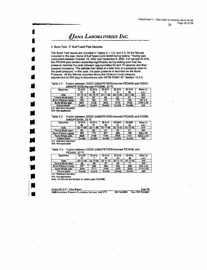
Attachment 1 - Dow letter to Ameren dtd 6-24-08
28 Page 28 of 59
IIIIIUSN
NN
I/JANA LABORAToRIES INC.
3. Burst Test: 2" Butt Fused Pipe Samples
The Burst Test results are provided in Tables 3.1, 3.2, and 3.3. All the failuresoccurred in the pipe. None of butt fused joints failed during testing. Testing wasconducted between October 18, 2002 and December 9, 2002. For sample 02-816,the PE2406 pipe section expanded significantly during testing such that thepressure reached the peak between approximately 60 and 70 seconds and thenstopped increasing. The sample then failed at a later time at a pressure close tothe peak pressure. In this case, the peak pressure is recorded as the BurstPressure. All the failures occurred above the minimum burst pressurerequirement of 500 psig in accordance with ASTM D3261-97, Section 10.5.3.
Table 3.1: Fusion between DGDC-2480(PE100/Enhanced PE3408) and DGDC-2480(PE10o/Enhanced PE3408), 23 TC
Specimen 02-815- 02-815- 02-815- 02-815- 02-815- Mean (±07 08 11 10 09 s.d.)
Date 02-10-18 02-10-18 02-11-06 02-11-06 02-11-06 N/ATime to Burst (seac) 66 64 69 63 ' 61 N/A
Burst Pressure (psig) 795 780 797 776 789 787 ± 9Burst Stress (psi) 3807 3729 3832 3718 3759 3769 ± 49
Failure Mode Ductile Ductile Ductile , Ductile . Ductile N/As.d.: Standard deviationN/A: Not-applicable
Table 3.2: Fusion between DGDC-2480(PE100/Enhanced PE3408) and DGDB-2480(PE3408), 23 OC
Specimen 02-814- 02-814- 02-814- 02-850- 02-850- Mean (+08 07 09 01 02 s.d.)
Date 02-11-06 02-11-06 02-11-06 02-12-09 02-12-09 N/ATime to Burst (sc) 65 62 67 63 61 N/A
Burst Pressure (psig) 800 773 877 989 789 842 1 82- Burst Stress (psi) 3826 3769 4193 4505 3721 4003 ± 337
Failure Mode Ductile Ductile Ductile Ductile Ductile N/As.d.: Standard deviationN/A: Not-applicable
Table 3.3: Fusion between DGDC-2480(PE100/Enhanced PE3408) andPE2406, 23 OC
Specimen 02-816- 02-816- 02-816- 02-816- 02-816- Mean (t07 11 09 03 08 s.d.)
Date 02-11-06 02-11-06 02-11-12 02-11-12 02-12-09 N/ATime to Burst Cj!-ec, 82 69 . ..8.7 85 71 NIA
Burst Pressure (psig) 637 656 664 654 698 662 122Burst Stress (psi) 3054 3111 3162 3032 3235 3119 183
Failure Mode Ductile Ductile Ductile Ductile Ductile . N/As.d.: Standard deviationNIA: Not-applicableNote: All failures are located on yellow pipe (PE2406)
Project 02-3117 - Final Report Page SIB280B INDUSTRIAL PARKWAY S., AURORA, ONTARto 1AG 3T9 90.5-7268550 Fax: 905-726-8609
IN
0N01
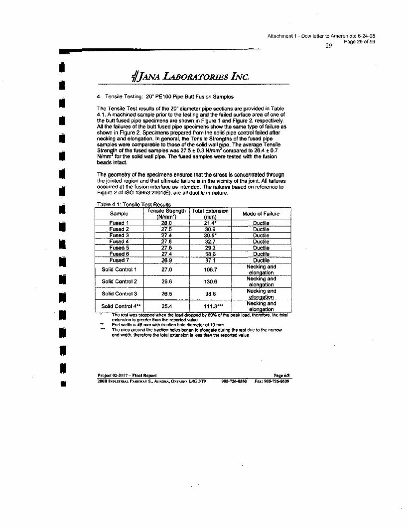
Attachment 1 - Dow letter to Ameren dtd 6-24-08
29 Page 29 of 59
IUIIIIIII
ImNNIUUIU
1/JAA LNABORATORJES INC.
4. Tensile Testing: 20" PE100 Pipe Butt Fusion Samples
The Tensile Test results of the 20" diameter pipe sections are provided in Table4.1. A machined sample prior to the testing and the failed surface area of one ofthe butt fused pipe specimens are shown in Figure 1 and Figure 2, respectively.All the failures of the butt fused pipe specimens show the same type of failure asshown in Figure 2. Specimens prepared from the solid pipe control failed afternecking and elongation. In general, the Tensile Strengths of the fused pipesamples were comparable to those of the solid wall pipe. The average TensileStrenqth of the fused samples was 27.5 ± 0.3 N/mm 2 compared to 26.4 ± 0.7N/mm for the solid wall pipe. The fused samples were tested with the fusionbeads intact.
The geometry of the specimens ensures that the stress is concentrated throughthe jointed region and that ultimate failure is in the vicinity of the joint. All failuresoccurred at the fusion interface as intended. The failures based on reference toFigure 2 of ISO 13953:2001(E), are all ductile in nature.
Table 4.1: Tensile Test ResultsTensile Strength Total ExtensionSample (N/mm 2 ) (mm) Mode of Failure
Fused 1 28.0 21.4* DuctileFused 2 27.5 30.9 DuctileFused 3 27.4 30.5* DuctileFused 4 27.6 32.7 DuctileFused 5 27.6 29.2 DuctileFused 6 27.4 58.6 DuctileFused 7 28.9 37.1 Ductile
Solid Control 1 27.0 106.7 Necking andelongation
Solid Control 2 26.6 130.6 Necking andelongation
Solid Control 3 26.5 98.8 Necking andelongation
Solid Control 4** 25.4 111.3" Necking andelongation
The test was stopped when the load dropped by 80% of the peak load. therefore, the totalextension Is greater than the reported valueEnd width is 45 mm with traction hole diameter of 19 mmThe area around the traction holes began to elongate during the test due to the narrowend width, therefore the total extension is less than the reported value
Project 02-3117 - Final Report Pape 6/828°IDSRM AKA S., UOA NAI 4 T 0-2-50 Fx 0-24280H INDUSTRIAL PARKWAV S., AvRORA. UNTAitio L4G 3T9 905-726-8SM Fax: 905-726-8609
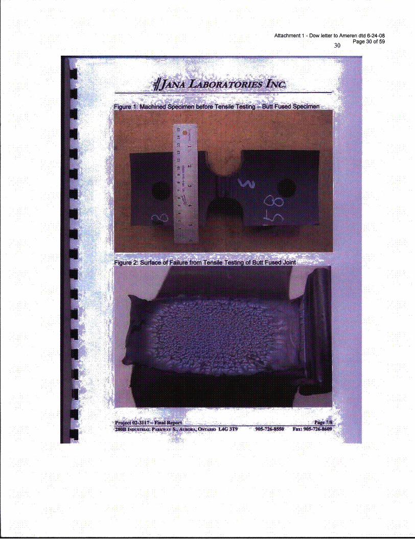
Attachment 1 - Dow letter to Ameren dtd 6-24-08
30 Page 30 of 59
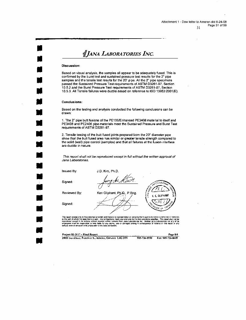
Attachment 1 - Dow letter to Ameren dtd 6-24-0831 Page 31 of 59
J/JANA LABoRA TOMEs INc.
Discussion:
Based on visual analysis, the samples all appear to be adequately fused. This isconfirmed by the burst test and sustained pressure test results for the 2" pipesamples and the tensile test results for the 20" pipe. All the 2" pipe specimenspassed the Sustained Pressure Test requirements of ASTM 03261-97, Section10.5.2 and the Burst Pressure Test requirements of ASTM D3261-97, Section10.5.3. All Tensile failures were ductile based on reference to ISO 13953:2001(E).
N Conclusions:
Based on the testing and analysis conducted the following conclusions can bedrawn:
1. The 2" pipe butt fusions of the PE1GO/Enhanced PE3408 material to itself andPE3408 and PE2406 pipe materials meet the Sustained Pressure and Burst Testrequirements of ASTM D3261-97.
N 2. Tensile testing of the butt fused joints prepared from the 20" diameter pipeshow that the butt fused area has similar or greater tensile strength compared tothe solid (wall) pipe control (samples) and that all failures at the fusion interfaceare ductile in nature.
NThis report shall not be reproduced except in full without the written approval ofJana Laboratories.NIssued By: J.D. Kim, Ph.D.
Signed: ' , o
Reviewed By: Ken Oliphant, P P.Eng.
IE.OLIPHANT
Signed: .t
This report relates only to the speomen provnidec and there is no representation on warranty that it applies to similar substances or naltenals
of the bulk of which the specirnm is a prlt Any comparisn osnl for tte test conditions swilled. This report shall not be
reproduced except in its entirety without express written consent from Ja-e Laboratories. Ic. Neither Jana Laboratoriea ton any Of itsetployees shal be responsible on held liabe for any daims, loss or damages arising in oonseaequnen of relanoe on this report or any
dcef.lt. entro t omrission in its preparation or the tests onducted.
Project 02-3117 - Final Report Page 8/8
280B INDUSTRAL PARKWAY S., AuRos., OwARo LAG 3T9 905-726-8550 Fax: 905-726-8609
Attachment 1 - Dow letter to Ameren dtd 6-24-08
32 Page 32 of 59
Evaluation and Comparison of Fusion Welds
by McElroy McSnapperTM High-Speed Tensile Impact Testing
Objective:
Evaluate and compare joint quality of butt-fused polyethylene pipes molded from Dow's DGDA-2490, Dow's DGDB-2480 and Uponor UAC 2000 in support of the Martin-Marietta DowPipeline Project.
Discussion:
In support of a proposed pipeline between Martin-Marietta and Dow facilities to deliver brinesolution, a modest study was undertaken to determine the quality and compatibility of fusion andcross-fusion joints made from sections of Dow DGDA-2490 (PE100), Dow DGDB-2480(PE3408) and Uponor UAC 2000 (PE2406) pipe. Eight-inch diameter, SDR 11 (0.73 inch wallthickness) pipe sections supplied by Quail Piping, Kingman, Arizona (HDPE) and McElroyManufacturing, Tulsa, Oklahoma (MDPE) were butt-fusion welded by McElroy technicalpersonnel. McElroy's expertise in the fusion of polyethylene pipes is widely recognized.. Twointerfacial pressures (60 psi and 90 psi) were used to represent a typical range of conditions forbutt-welding operations and pipe samples containing fusion welds made at these two differentpressures were collected for this study. Four specimens from each joint configuration werefabricated using a McElroy Coupon Cutter. In addition to these samples, coupons were cut frompipe sidewall to serve as controls for this study. The diagram on the last page provides apictorial representation of these coupons
Heat fusion joining process requires the uniform melting of two opposed (and aligned) surfaces,merging these melted surfaces under pressure and solidifying this merged surface under a givenpressure. Uniformity of melting and applied pressure(s) is tantamount to attaining an strong andacceptable fusion that will last the life of the pipe system. Generating a uniform melted surfaceis the first step in obtaining an acceptable weld. Several factors, such as starting with twosmooth parallel pipe surfaces, proper heating temperature, adequate contact time, and uniformpressure on the polymer surface during this melting stage are critical to achieving a uniformmelted surface. Polymer factors such as molecular weight, molecular weight distribution, andcomonomer content, can effect melting point and the ability of the melt to flow under pressureand temperature. When fusing pipe samples of equivalent polyethylene, the development of auniform melt surface and resultant interface (fusion) is straight forward and widely practiced art.The fusing of unlike polyethylenes can be a bit more involved and can require an adjustment tothe heating/melt portion of the fusion process. For this test, all materials were fused usingrecognized standard fusion practices.
Samples:
As indicated, examples of butt-fusion welds were collected at each pressure. The high-speed(McSnapperTM) tensile impact properties of these welds were compared to sections of wallwithout a weld present (controls). An important aspect of this testing is to evaluate the fusioncompatibility of pipe molded from Dow's new bi-modal HDPE product to itself and with pipeextruded from other existing polyethylene products. For test short examination, two other pipesamples were selected, a PE3408 pipe extruded from Dow's DGDB-2480 and a PE2406 pipeprovided by McElroy. The compatibility of Dow DGDA-2490 with other existing pipematerials, namely PE3408 and PE2406 is essential, since on occasion, it may be necessary for a
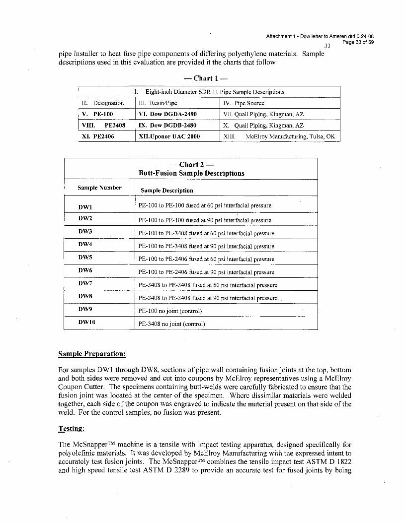
Attachment 1 - Dow letter to Ameren dtd 6-24-08Page 33 of 59
pipe installer to heat fuse pipe components of differing polyethylene materials. Sampledescriptions used in this evaluation are provided it the charts that follow
- Chart 1 -
I. Eight-inch Diameter SDR 11 Pipe Sample Descriptions
II. Designation Ill. Resin/Pipe IV. Pipe Source
V. PE-100 VI. Dow DGDA-2490 VII. Quail Piping, Kingman, AZ
VIII. PE3408 IX. Dow DGDB-2480 X. Quail Piping, Kingman, AZ
XI. PE2406 XII.Uponor UAC 2000 XIII. McElroy Manufacturing, Tulsa, OK
-Chart 2-Butt-Fusion Sample Descriptions
Sample Number Sample Description
DW1 PE-100 to PE-100 fused at 60 psi interfacial pressure
DW2 PE- 100 to PE- 100 fused at 90 psi interfacial pressure
DW3 PE-100 to PE-3408 fused at 60 psi interfacial pressure
DW4 PE- 100 to PE-3408 fused at 90 psi interfacial pressure
DW5 PE-I100 to PE-2406 fused at 60 psi interfacial pressure
DW6 PE-100 to PE-2406 fused at 90 psi interfacial pressure
DW7 PE-3408 to PE-3408 fused at 60 psi interfacial pressure
DW8 PE-3408 to PE-3408 fused at 90 psi interfacial pressure
DW9 PE-3400 no joint (control)
DW10 PE-3408 no joint (control)
Sample Preparation:
For samples DWI through DW8, sections of pipe wall containing fusion joints at the top, bottomand both sides were removed and cut into coupons by McElroy representatives using a McElroyCoupon Cutter. The specimens containing butt-welds were carefully fabricated to ensure that thefusion joint was located at the center of the specimen. Where dissimilar materials were weldedtogether, each side of the coupon was engraved to indicate the material present on that side of theweld. For the control samples, no fusion was present.
Testin$!:
The McSnapperTM machine is a tensile with impact testing apparatus, designed specifically forpolyolefinic materials. It was developed by McElroy Manufacturing with the expressed intent toaccurately test fusion joints. The McSnapperTM combines the tensile impact test ASTM D 1822and high speed tensile test ASTM D 2289 to provide an accurate test for fused joints by being
Attachment 1 - Dow letter to Ameren dtd 6-24-08Page 34 of 59
critical to the fusion, but allowing the pipe to fail if the joint is good. Using the ImpactResistance Test ASTM F 905 as a model, the McSnapperTM is capable of testing sidewallfusions. The machine can also be used in the development of new materials, quality assurancefor existing materials, or in fusion compatibility to determine lot uniformity, strength andfuseability of pipe and fittings. While the McSnapperTM test appears to have some usefulness asa quality control test for fusion joints, it only measures one set of "short term" propertycharacteristics of the fusions. As a follow-up to this study, we recognize that testing inaccordance with ASTM D-2837, "Standard Method for Obtaining Hydrostatic Design Basis forThermoplastic Pipe Materials" should be considered for long-term pressure performancevalidation of fusion joints.
Results:
All tested specimens were returned along with the data from the McElroy Manufacturing. Sincewe had the luxury of comparing failed test specimens with the data, we are able to report that nobrittle failures were observed in the returned strained coupon specimens. Additionally, all thefailures occurred in the pipe sidewall and none occurred at the actual fusion joints. The datafrom the testing is summarized in chart 3 and chart 4 that follow. In chart 4, the averaged dataalong with the standard deviation for each of the four individual test specimens run from eachfusion joint and control sample. Chart 4 at the end of this document provides all the datagenerated by McElroy on the pipe fusions and control specimens.
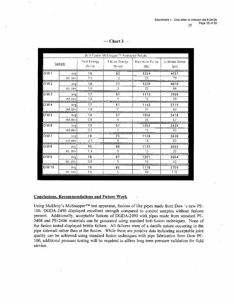
Attachment 1 - Dow letter to Ameren dtd 6-24-08Page 35 of 59
- Chart 3 -
Im Rijtt-Fijsi~n MnSn~nn~rTM Axi~ran~c1 R~siiIt~
SapeYield Energy TFailure Energy Maximum Force ]Ultimate StressSa pl { (ft-lbs) j (ft-lbs) (Ibs) J (psi)
DWl avg 19 83 1234 4031h std dev 1,5 12 21 l 79
DW2 avgi 18 77 T 1226 4010std dev 1.6 3 25 64
DW3 avg 17 67 1172 3908std dev 1.0 4 14 39
DW4 avg 17 61 1142 3775
std dev 160 11 31 93
DW5 E avg 14 57 1056 ] 3418std dev 0.6 5 25 67
DW6 -::avjg 13 57 1 1055 3459std dev 05 19 15 43
DW7 avg 19 75 1128 3636std dev 2.1 9 18 63
DW8 g avg 19 68 1135 3695L std dev 1.9 8 15 35
DW9 avg 18 87 1201 3964____ std dev 0.8 5 16 60
DW10 avg 19 85 1118 3701std dev 1,0 5 40 110
Conclusions, Recommendations and Future Work
Using McElroy's McSnapperTM test apparatus, fusions of like pipes made from Dow 's new PE-100, DGDA-2490 displayed excellent strength compared to control samples without fusionspresent. Additionally, acceptable fusions of DGDA-2490 with pipes made from standard PE-3408 and PE-2406 materials can be generated using standard butt-fusion techniques. None ofthe fusion tested displayed brittle failure. All failures were of a ductile nature occurring in thepipe sidewall rather than at the fusion. While these are positive data indicating acceptable jointquality can be achieved using standard fusion techniques with pipe fabrication from Dow PE-100, additional pressure testing will be required to affirm long term pressure validation for fieldservice.
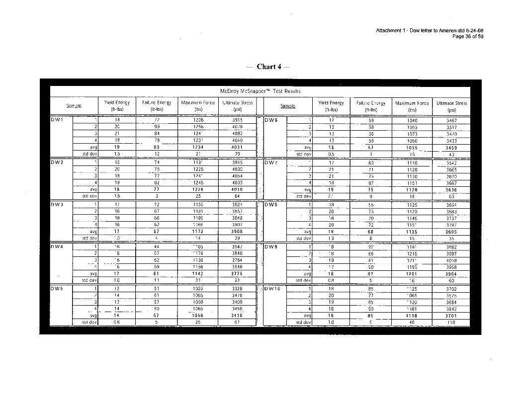
Attachment 1 - Dow letter to Ameren dtd 6-24-08Page 36 of 59
- Chart 4
McElroy McSnapperTM Test Results
Samole JYield Energy Falr nry Maximum Forte Ultimate Stress fYield Energy Failure Energy 1Maximum Force Ultimate Stress(ft-lbs (t-lbs) (Ibs) (psi) Sample (ft-lbs) (ft-lbs) (Ibs) (psi)
DW1 1 18 72 1206 3915 r-DW6 • "--'"-" 12 58 1040 34672 20 99 1256 4078 2 13 58 1055 3517
21 84 1241 4082 13 56 1075 3420
2 18 78 1231 4049 2 13 56 1050 3433
avg 19 83 1234 4031 avg 13 57 1055 3459
std dev 1.5 12 21 79 _std dev 0.5 1 15 43
DW2 1 16 74 1191 3915 ] DW7 1- 17 65 1110 35422 20 76 1226 4030 2 21 71 1120 36653 18 77 1241 4054 3 21 75 1130 36704 18 82 1246 4039 4 18 87 1151 3667
avg 18 77 1226 4010 1 _ 19 75 1128 3636std dev, 1.6 3 25 64 s "_1 _ 2.1 9 18 63
DW3 1 17 72 1156 3924 DW8 1 18 55 1125 36542 16 67 1181 3857 2 20 73 1120 36833 18 66 1186 3948 3 16 70 1145 3737
16 62 1166 3902 4 20 72 1151 3707avg 17 67 1172 3908 a 19 68 1135 3695
std dev 1.0 4 14 39 d__ 1 dev1 1,9 8 15 35
DW4 --W-1 16 44 1105 3647 =-DW9 -- 1_ 18 92 1181 3882
2 18 67 1176 3840 -2_ 18 86 1216 3997a 16 62 1130 3764 avg 19 81 1211 4018
4 16 69 1156 3848 4 17 90 1196 3958avd 17 61 1142 3- 1_7 E5____ 18 87 1201 3964
i std dev 1.0 11 31 9-3 std dev 0.8 5 16 60
IDW5 I 13 51 1025 3328 ",IDW10 I 18 86 1125 3702n 2 14 61 1085 3478
3 13 57 1050 34094 14 60 1065 3458
avg 14 57 1056 3418
2 20 77 1065 35753 19 85 1120 3684
4 18 90 1161 3842avg 19 85 1118 3701
std dev 0.6 5 25 67 std dev 1.0 5 40 110
-I- I
Attachment 1 - Dow letter to Ameren dtd 6-24-08Page 37 of 59
References:
Jim Perrault, P.E., McElroy Manufacturing, Inc. Testing Report PO#63518814, Dated4/24/2002
McElroy Manufacturing, Inc. Operator's Manual #S00106 Revised 3/99: "High SpeedTensile with Impact Testing System, McSnapperTM'"
Plastics Pipe Institute Technical Note, "General Guidelines for Butt, Saddle, and SocketFusion of Unlike Polyethylene Pipes and Fittings TN-13/2001"
Plastics Pipe Institute Technical Report, "Generic Butt Fusion Joining Procedure forPolyethylene Gas Pipe TR-33/2001"
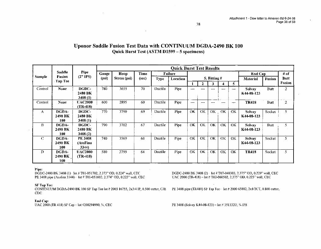
Attachment 1 - Dow letter to Ameren dtd 6-24-08
38 Page 38 of 59
Uponor Saddle Fusion Test Data with CONTINUUM DGDA-2490 BK 100Quick Burst Test (ASTM D1599 - 5 specimens)
Quick Burst Test ResultsSaddle Pipe Gauge Hoop Time Failure End Cap # of
Sample Fusion (2" IPS) (psi) Stress (psi) (sec) Type Location S. Fitting # Material Fusion ButtTap Tee 1 2 3 4 5 Fusion
Control None DGDC- 780 3655 70 Ductile Pipe - --- -------- ---- --- Solvay Butt 22480 BK K44-08-1233408 (1)
Control None UAC2000 600 2895 60 Ductile Pipe - --- -------- ---- --- TR418 Butt 2(TR-418) I I I
A DGDA- DGDC- 770 3790 69 Ductile Pipe OK OK OK OK OK Solvay Socket 52490 BK 2480 BK K44-08-123
100 3408 (1)B DGDA- DGDC- 790 3702 67 Ductile Pipe OK OK OK OK OK Solvay Butt 5
2490 BK 2480 BK K44-08-123100 3408 (2)
C DGDA- PE 3408 740 3569 60 Ductile Pipe OK OK OK OK OK Solvay Socket 52490 BK (AtoFina K44-08-123
100 3344)D DGDA- UAC2000 580 2799 64 Ductile Pipe OK OK OK OK OK TR418 Socket 5
2490 BK (TR-418)100
Pipe:DGDC-2480 BK 3408 (1)- lot # T01-051702, 2.373" OD, 0.224" wall, CECPE 3408 pipe (Atofina 3344) - lot # T01-051602, 2.374" OD, 0.223" wall, CEC
SF Tap Tee:CONTINUUM DGDA-2490 BK 100 SF Tap Tee lot # 2003 16755, 2x3/4 IP, 0.500 cutter, CJECDC
DGDC-2480 BK 3408 (2) - lot # T07-040303, 2.375" 013, 0.229" wall, CECUAC 2000 (TR-418) - lot # T02-060502, 2.375" OD, 0.223" wall, CEC
PE 3408 pipe (TR480) SF Tap Tee - lot # 2000 65882, 2xl/2CT, 0.800 cutter,
End Cap:UAC 2000 (TR 418) SF Cap - lot #200294990, /4, CEC PE 3408 (Solvay K44-08-123)- lot # 351332U, 3/4 IPS
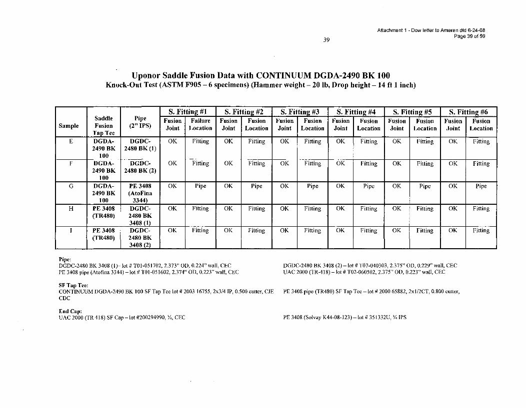
Attachment 1 - Dow letter to Ameren dtd 6-24-08Page 39 of 59
39
Uponor Saddle Fusion Data with CONTINUUM DGDA-2490 BK 100Knock-Out Test (ASTM F905 - 6 specimens) (Hammer weight - 20 1b, Drop height - 14 ft 1 inch)
S. Fitting #1 S. Fitting #2 S. Fitting #3 S. Fitting #4 S. Fitting #5 S. Fitting #6Saddle Pipe Fusion Failure Fusion Fusion Fusion Fusion Fusion Fusion Fusion Fusion Fusion Fusion
Sample Fusion (2" IPS) Joint Location Joint Location Joint Location Joint Location Joint Location Joint LocationTap Tee
E DGDA- DGDC- OK Fitting OK Fitting OK Fitting OK Fitting OK Fitting OK Fitting2490 BK 2480 BK (1)
100F DGDA- DGDC- OK Fitting OK Fitting OK Fitting OK Fitting OK Fitting OK Fitting
2490 BK 2480 BK (2)100
G DGDA- PE 3408 OK Pipe OK Pipe OK Pipe OK Pipe OK Pipe OK Pipe2490 BK (AtoFina
100 3344)
H PE 3408 DGDC- OK Fitting OK Fitting OK Fitting OK Fitting OK Fitting OK Fitting(TR480) 2480 BK
3408 (1)I PE 3408 DGDC- OK Fitting OK Fitting OK Fitting OK Fitting OK Fitting OK Fitting
(TR480) 2480 BK1 3408B(2) 1 1 1 1 2 1 0 w C
Pipe:DGDC-2480 BK 3408 (1)- lot # T01-051702, 2.373" OD, 0.224" wall, CECPE 3408 pipe (Atofina 3344) - lot # T01-051602, 2.374" OD, 0.223" wall, CEC
SF Tap Tee:CONTINUUM DGDA-2490 BK 100 SF Tap Tee lot # 2003 16755, 2x3/4 IP, 0.500 cutter, CJECDC
DGDC-2480 BK 3408 (2) - lot # T07-040303, 2.375" OD, 0.229" wall, CECUAC 2000 (TR-418)- lot # T02-060502, 2.375" OD, 0.223" wall, CEC
PE 3408 pipe (TR480) SF Tap Tee - lot # 2000 65882, 2xl/2CT, 0.800 cutter,
End Cap:UAC 2000 (TR 418) SF Cap - lot #200294990, 3, CEC PE 3408 (Solvay K44-08-123) - lot # 351332U, 3¾ IPS
Attachment 1 - Dow letter to Ameren dtd 6-24-08Page 40 of 5940
APPENDIX D
DATA FOR FITTING QUALIFICATION
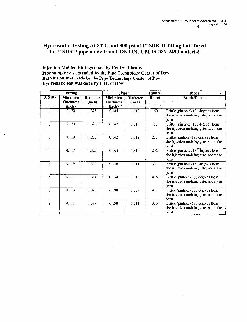
Attachment 1 - Dow letter to Ameren dtd 6-24-08
41 Page 41 of 59
Hydrostatic Testing At 80 0C and 800 psi of 1" SDR 11 fitting butt-fusedto 1" SDR 9 pipe made from CONTINUUM DGDA-2490 material
Injection-Molded Fittings made by Central PlasticsPipe sample was extruded by the Pipe Technology Center of DowButt-fusion was made by the Pipe Technology Center of DowHydrostatic test was done by PTC of Dow
Fitting Pi e., Failure ModeA-2490 Minimum Diameter Minimum Diameter Hours Brittle/Ductile
Thickness (inch). Thicknless (inch),(inch) (inch):' -
0.120 1.328 0.144 1.312 160 Brittle (pin hole) 180 degrees fromthe injection molding gate, not at thejoint
2 0.120 1.327 0.147 .1.315 187 Brittle (pin hole) 180 degrees fromthe injection molding gate, not at thejoint
3 0.119 1.230 0.142 1.312 283 Brittle (pinhole) 180 degrees fromthe injection molding gate, not at thejoint
4 0.117 1.325 0.144 1.310 206 Brittle (pin hole) 180 degrees fromthe injection molding gate, not at thejoint
5 0.119 1.320 0.146 1.311 321 Brittle (pin hole) 180 degrees fromthe injection molding gate, not at thejoint
6 0.111 1.314 0.134 1.310 438 Brittle (pinhole) 180 degrees fromthe injection molding gate, not at thejoint
7 0.113 1.325 0.138 1.309 421 Brittle (pinhole) 180 degrees fromthe injection molding gate, not at thejoint
9 0.111 1.324 0.138 1.311 330 Brittle (pinhole) 180 degrees fromthe injection molding gate, not at thejoint
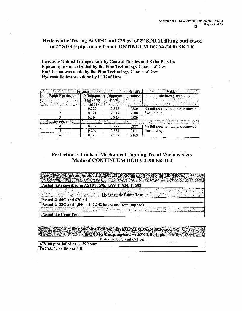
Attachment 1 - Dow letter to Ameren dtd 6-24-08
42 Page 42 of 59
Hydrostatic Testing At 900 C and 725 psi of 2" SDR It fitting butt-fusedto 2" SDR 9 pipe made from CONTINUUM DGDA-2490 BK 100
Injection-Molded Fittings made by Central Plastics and Rahn PlasticsPipe sample was extruded by the Pipe Technology Center of DowButt-fusion was made by the Pipe Technology Center of DowHydrostatic test was done by PTC of Dow
K•" ....... i.... s Mitianiu .... Hoursi-r4 'Di i B&tle ileTh~ickhessý (Indi:
1 0.225 2.385 2580 No failures. All samples removed2 0.221 2.385 2580 from testing3 0.216 2.385 2580
4 0.229 2.375 2387 No failures. All samples removed5 0.229 2.375 2111 from testing6 0.228 2.375 2169
Perfection's Trials of Mechanical Tapping Tee of Various SizesMade of CONTINUUM DGDA-2490 BK 100
Passed tests specified in ASTM 1598, 1599, F1924, F1588
Passed @ 80C and 670 psiPassed @ 23C and 1,000 psi (1,242 hours and test stopped)
Passed the Cone Test
Attachment 1 - Dow letter to Ameren dtd 6-24-08Page 43 of 59
APPENDIX E
TECHNICAL REPORTS ON DGDA-2490 PIPES
FROM
OTHER SOURCES
Attachment 1 - Dow letter to Ameren dtd 6-24-08Page 44 of 59
B E C E T E LBELGIAN RESEARCH CENTRE FOR PIPES AND FITTINGS
REPORT No. 5179
Demanded by
At the expense of
Concerning
DOW CHEMICAL
Attn. Mr. J. ZHOU
PO&E TS&D, Rml 10/B98
171 River Road
PISCATAWAY, NJ 08854
U.S.A.
idem
Determination of the resistance to rapid crack propagation of
10" PE pipes (S4 test method), product DGDA-2490 BK 100.
Your order by e-mail dd. 26/06/2001.
BEC 3616 and SR010333.doc
no.20010511
27 September 2001
4 pages
Our reference
Our invoice no.
Date of the report
This report contains
General remark
The results mentioned in this report are exclusively related to the product as definedhereinafter and this document may, in no case, be considered as an approval of this product.To warrant that the results would be representative of the product, as it is delivered or applied,conformity of the specimens to the product should be assured.The specimens are at your disposal during two months after the date of the report.This report may not be reproduced, except completely, without the prior written permission ofthe research centre BECETEL.
SR010333.doc - 1/4BECETEL VZW / ASeL
GONTRODE HEIRWEG 130 - B-9090 MELLETEL -+32 (0)9 272 50"70 - FAX +32 (0)9 272 50 72
BTW/TVA/VAT: BE 406 633 106 - FORTIS BANK GENT 290-0083433-34 - KB GENT 447"0039971-29
Attachment 1 - Dow letter to Ameren dtd 6-24-08Page 45 of 59
DETERMINATION OF THE RESISTANCE TO RAPID CRACK
PROPAGATION OF 10" PE PIPES(S4 TEST METHOD). PRODUCT DGDA-2490 BK 100
I Received material
10 PE pipes 10", delivered to Becetel on 20 July 2001.Product name: DGDA-2490 BK 100Marking: PLEXCO EHWW 10" IPS DI I PE3408 ASTM F714 C3 U-401 A002
06/25/01Colour: blackLength: 2,0 mPipe dimensions: diameter 273 mm, wall thickness 25 mm
The pipes are extruded and delivered to Becetel by Plexco Inc. (USA).
2 Test proeram
The tests on the PE pipes are executed in accordance with ISO 13477 "Thermoplastics pipesfor the conveyance of fluids - Determination of the resistance to Rapid Crack Propagation(RCP) - Small-Scale Steady-State Test (S4 test)"
The critical pressure at a temperature of 0 'C is determined, followed by a measurement ofcritcal temperature at a pressure of 10 bar.The critical pressure is determined again, but at that temperature where crack propagationoccurs at 10 bar pressure.
3 Principle
The Small-Scale Steady State (S4) test is developed to determine the critical pressure ofplastics pipes, i.e. the minimum internal pressure which results in a propagation of the brittlefracture over the entire length of the test piece.The S4 test simulates a steady state propagation of the rapid crack by an artificial limitation ofdecompression of the pipe during the crack propagation. The decompression ahead of thepropagating crack is retarded by internal baffles and by an external containment cage, whichrestricts flaring of the pipe at the edges of the fracture.Hence the stress at the crack tip does not decrease and the propagation of the crack issustained.The fast-running axial crack is initiated by driving a knife in the pipe wall. near one end. at aconsiderable speed (15 ± 5 m/s).Tests are executed at different internal pressures in order to determine the transition fromcrack arrest to crack propagation over the entire length of the specimen. This transitiondefines the critical pressure of the pipe material, p,,.,
SRO10333+doc - 2/4BECETEL VZ / ASBL
GONTRODE HEIRWEG 130 - 8.9090 MELLETEL, +32 (0)9 272 50"70 - FAX +32 (0)9 272 50 72
BTW/TVA/VAT: BE 406 633 106 - FORTIS BANK GENT 290-0083433-34 - KBC GENT 447,0039971-29E-MAIL: infoiSbecefel.be - WESSITE: www.beCete1.b8
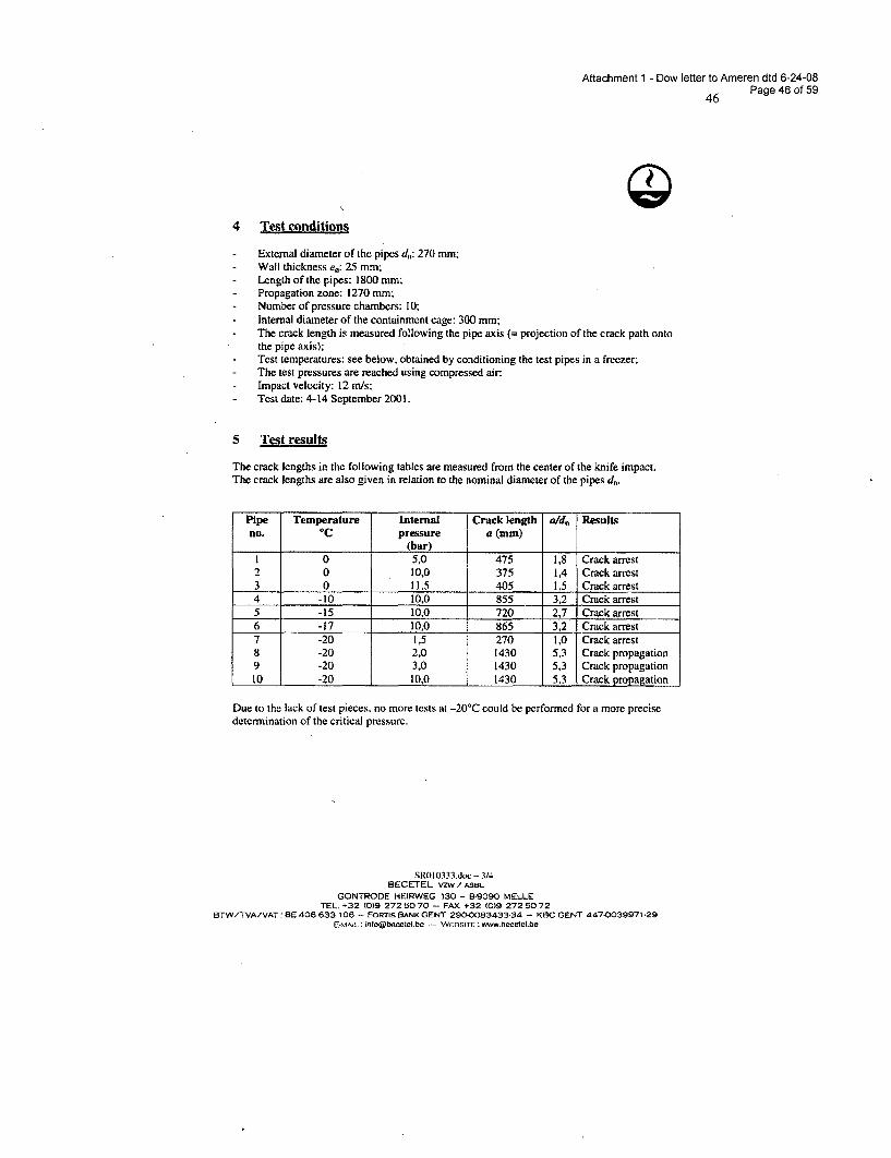
Attachment 1 - Dow letter to Ameren dtd 6-24-08
46 Page 46 of 59
4 Test conditions
External diameter of the pipes dc: 270 mm,Wall thickness e.: 25 mm;Length of the pipes: 1800 mm:Propagation zone: 1270 mm:Number of pressure chambers: 10;Internal diameter of the containment cage: 300 mm;The crack length is measured following the pipe axis (= projection of the crack path ontothe pipe axis);Test temperatures: see below, obtained by conditioning the test pipes in a freezer;The test pressures are reached using compressed air;Impact velocity: 12 m/s:
- Test date: 4-14 September 2001.
5 Test results
The crack lengths in the following tables are measured from the center of the knife impact.The crack lengths are also given in relation to the nominal diameter of the pipes d,.
Pipe Temperature Internal Crack length aid, Result,no. °C pressure a (mm)
(bar)1 0 5,0 475 1,8 Crack arrest2 0 10,0 375 1,4 Crack arrest3 0 11,5 405 1,5 Crack arrest4 -10 10.0 855 3.2 Crack arrest5 -15 10,0 720 2,7 Crack arrest6 -17 10,0 865 3,2 Crack arrest7 -20 1,5 270 1,0 Crack arrest8 -20 2,0 1430 5.3 Crack propagation9 -20 3,0 1430 5,3 Crack propagation10 -20 10,0 1430 5,3 Crack propagation
Due to the lack of test pieces, no more tests at -20*C could be performed for a more precisedetermination of the critical pressure.
SRO 10333.doc - 3/4BECETEL V7W/ ASBL
GONTRODE HEIRWEG 130 - B-9090 MELLETEL' +32 (0)9 272 5070 - FAX +32 (0)9 272 5072
BTW/TVA/VAT: BE 406 633 106 - FORMnS BANK GENT 290-0083433-34 - KBC GENT 447-0039971-29intoc@beteelbe -- WEBSITE: www.becelel.be
Attachment 1 - Dow letter to Ameren dtd 6-24-08Page 47 of 59
Q;
6 Discussion of results
The S4 tests on the 10" PE pipes, product DGDA-2490 BK 100 at a temperature of 0 °C.result in a critical pressure PC.S4 of higher than 11,5 bar.The critical temperature T,%4 at 10 bar air pressure is determined at -17C. The criticalpressure Pc.s4 at -20°C is determined at 1.5 bar.
Melle, 27 September 2001.
ir. J. VIENNEStaff Member
Prof. it. P(General ri
SR010333.doc - 4/4BECETEL vZw/ ASHL
GONTRODE HEIRWEG 130 - E-9090 MELLETEL. +32 (0)9 272 5070 - FAX +32 (0)9 272 5072
BTW/TVA/VAT: BE 406 633 106 - FORTIS BANK GENT 2900083433-34 - KBC GENT 447"0039971"29E.-MAIL :[email protected] .- WE3rrE :www.beceteV.be
Attachment I - Dow letter to Ameren dtd 6-24-08
48 Page 48 of 59
uponorTECHNICAL LAB REPORT
Uponor Aldyl Company4501 West 4 9 th Street
Tulsa, OK 74107-7315Tel. (918) 446-4471Fax (918) 446-9369
Plant Contact: Larry Shelton - Phone 918-445-5643Job Number: 090301 Lot Number: Pipe - T01081303 / Ftgs. -200316754 & 200316755.
Background: Uponor produced UAC 3700 ULTRA-STRIPE pipe and UAC 3700 molded fittings fromDow A 2490 PE 100 resin. The pipe and fittings were joined to each other and other PE3408 pipe products. The heat fusion joints were qualified per DOT 192.283requirements.
Product Description: Uponor UAC 3700 2 X V" butt outlet tap tees, UAC 3700 couplings, and UAC3700 pipe produced from Dow DGDA 2490 PE 100 / PE 3408 resin.
Scope: Testing was performed to qualify the extrusion process of UAC 3700 pipe from DowDGDA 2490 PE 100/PE 3408 resin and to qualify the heat fusion joints between UponorUAC 3700 pipe and fittings to other PE3408 pipe products.
Preparation: Test Conditions: 230 C & 800 CTest Procedures: Per ASTM F 905, ASTM D 638, ASTM D 1598, & ASTM D 1599.ASTM D 1599: 15 specimens were tested, with ductile failure occurring in the pipe wall.ASTM F 905 18 specimens were tested, with all failures occurring in the pipe wall.ASTM D 638: 36 specimens were elongated > 25% with no joint failures.ASTM D 1598 12 specimens were squeezed per D 2513, A1.5.5, then tested > 1000 hrs with no failures.Conclusion: All specimens met or exceeded the listed procedure requirements, thereby meeting
the qualification requirements per ASTM D 2513 & DOT 192.283. See attacheddata.
Note: "We certify that all portions of each test performed were under continuous, directsupervision of this laboratory."
Bob Creason Larry Shelton
Bob Creason Larry SheltonLab Operator Lab Supervisor
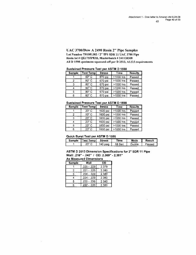
Attachment 1 - Dow letter to Ameren dtd 6-24-08Page 49 of 59
UAC 3700/Dow A 2490 Resin 2" Pipe SamplesLot Number T01081303 / 2" IPS SDR 11 UAC 3700 PipeResin lot # QE1755P83B, Masterbatch # 241120308All D 1598 specimens squeezed-off per D 2513, A1.5.5 requirements
Sustained Pressure Test per ASTM D 1598Sample Test Temp Stress Time Results
1 800 C 670 psi >1000 hrs Passed2 80' C 670 psi >1000 hrs Passed3 80' C 670 psi >1000 hrs Passed4 80' C 670 psi >1000 hrs Passed5 80' C 670 psi >1000 hrs Passed6 800 C 670 psi >1000 hrs Passed
Sustained Pressure Test per ASTM D 1598Sample Test Temp Stress Time Results
1 23' C 1600 psi >1000 hrs Passed2 230 C 1600 psi >1000 hrs Passed3 23° C 1600 psi >1000 hrs Passed4 23° C 1600 psi >1000 hrs Passed5 230 C 1600 psi >1000 hrs Passed6 23°C 1600 psi >1000 hrs Passed
Quick Burst Test per ASTM D 1599Sample Test Temp Stress Time Mode Result
1 230 C 740 psig 68 Sec Ductile Passed
ASTM D 2513 Dimension Specifications for 2" SDR 11 PipeWall: .216" -. 242" / OD: 2.369" - 2.381"As Measured Dimensions
Sample Wall OD1 .225- .2291 2.379
2 .221 - .2251 2.3803 .224- .229 2.3804 .224- .229 2.3805 .222- .226 2.3806 .222 - .226 2.380
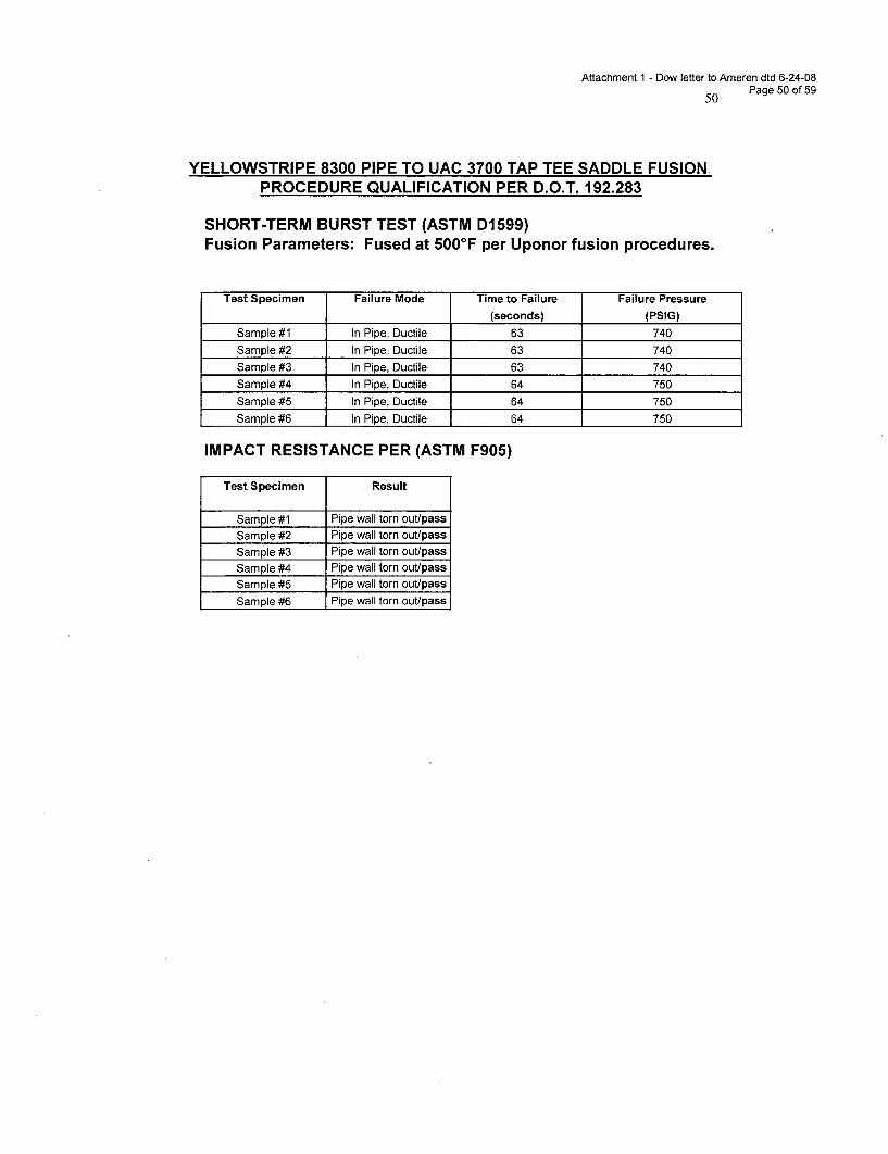
Attachment 1 - Dow letter to Ameren dtd 6-24-08
50 Page 50 of 59
YELLOWSTRIPE 8300 PIPE TO UAC 3700 TAP TEE SADDLE FUSION.PROCEDURE QUALIFICATION PER D.O.T. 192.283
SHORT-TERM BURST TEST (ASTM D1 599)Fusion Parameters: Fused at 500°F per Uponor fusion procedures.
Test Specimen Failure Mode Time to Failure Failure Pressure
(seconds) (PSIG)
Sample #1 In Pipe, Ductile 63 740
Sample #2 In Pipe, Ductile 63 740
Sample #3 In Pipe, Ductile 63 740
Sample #4 In Pipe, Ductile 64 750
Sample #5 In Pipe, Ductile 64 750
Sample #6 In Pipe, Ductile 64 750
IMPACT RESISTANCE PER (ASTM F905)
Test Specimen Result
Sample #1 Pipe wall torn out/pass
Sample #2 Pipe wall torn out/pass
Sample #3 Pipe wall torn out/pass
Sample #4 Pipe wall torn out/pass
Sample #5 Pipe wall torn out/pass
Sample #6 Pipe wall torn out/pass
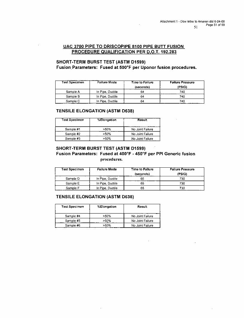
Attachment 1 - Dow letter to Ameren dtd 6-24-08
51 Page 51 of 59
UAC 3700 PIPE TO DRISCOPIPE 8100 PIPE BUTT FUSIONPROCEDURE QUALIFICATION PER D.O.T. 192.283
SHORT-TERM BURST TEST (ASTM D1599)Fusion Parameters: Fused at 500°F per Uponor fusion procedures.
Test Specimen Failure Mode Time to Failure Failure Pressure
(seconds) (PSIG)
Sample A In Pipe, Ductile 64 740
Sample B In Pipe, Ductile 64 740
Sample C In Pipe, Ductile 64 740
TENSILE ELONGATION (ASTM D638)
Test Specimen %Elongation Result
Sample #1 >50% No Joint Failure
Sample #2 >50% No Joint Failure
Sample #3 >50% No Joint Failure
SHORT-TERM BURST TEST (ASTM D1599)Fusion Parameters: Fused at 400°F - 450°F per PPI Generic fusion
procedures.
Test Specimen Failure Mode Time to Failure Failure Pressure
(seconds) (PSIG)
Sample D In Pipe, Ductile 65 730
Sample E In Pipe, Ductile 65 730
Sample F In Pipe, Ductile 65 730
TENSILE ELONGATION (ASTM D638)
Test Specimen %Elongation Result
Sample #4 >50% No Joint Failure
Sample #5 >50% No Joint Failure
Sample #6 >50% No Joint Failure
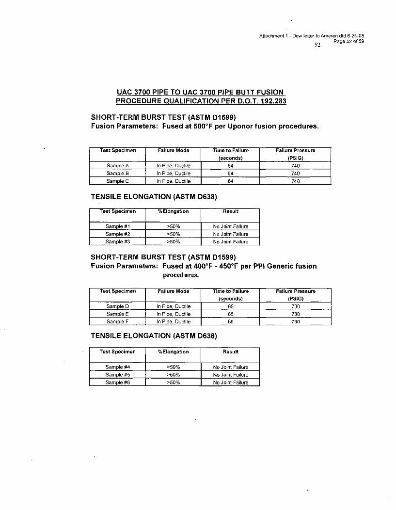
Attachment I - Dow letter to Ameren dtd 6-24-08
52 Page 52 of 59
UAC 3700 PIPE TO UAC 3700 PIPE BUTT FUSIONPROCEDURE QUALIFICATION PER D.O.T. 192.283
SHORT-TERM BURST TEST (ASTM D1599)Fusion Parameters: Fused at 500°F per Uponor fusion procedures.
Test Specimen Failure Mode Time to Failure Failure Pressure
(seconds) (PSIG)
Sample A In Pipe, Ductile 64 740
Sample B In Pipe, Ductile 64 740
Sample C In Pipe, Ductile 64 740
TENSILE ELONGATION (ASTM D638)
Test Specimen %Elongation Result
Sample #1 >50% No Joint Failure
Sample #2 >50% No Joint Failure
Sample #3 >50% No Joint Failure
SHORT-TERM BURST TEST (ASTM D1599)Fusion Parameters: Fused at 400°F - 450°F per PPI Generic fusion
procedures.
Test Specimen Failure Mode Time to Failure Failure Pressure
(seconds) (PSIG)
Sample D In Pipe, Ductile 65 730
Sample E In Pipe, Ductile 65 730
Sample F In Pipe, Ductile 65 730
TENSILE ELONGATION (ASTM D638)
Test Specimen %Elongation Result
Sample #4 >50% No Joint Failure
Sample #5 >50% No Joint Failure
Sample #6 >50% No Joint Failure
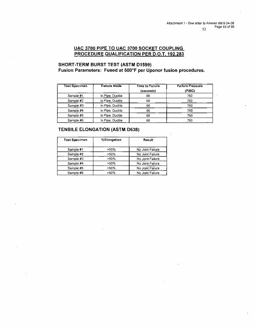
Attachment 1 - Dow letter to Ameren dtd 6-24-08Page 53 of 59
UAC 3700 PIPE TO UAC 3700 SOCKET COUPLINGPROCEDURE QUALIFICATION PER D.O.T. 192.283
SHORT-TERM BURST TEST (ASTM D1599)Fusion Parameters: Fused at 500°F per Uponor fusion procedures.
Test Specimen Failure Mode Time to Failure Failure Pressure
(seconds) (PSIG)
Sample #1 In Pipe, Ductile 66 760
Sample #2 In Pipe, Ductile 66 760
Sample #3 In Pipe, Ductile 66 760
Sample #4 In Pipe, Ductile 66 760
Sample #5 In Pipe, Ductile 66 760
Sample #6 In Pipe, Ductile 66 760
TENSILE ELONGATION (ASTM D638)
Test Specimen %Elongation Result
Sample #1 >50% No Joint FailureSample #2 >50% No Joint Failure
Sample #3 >50% No Joint FailureSample #4 >50% No Joint Failure
Sample #5 >50% No Joint Failure
Sample #6 >50% No Joint Failure
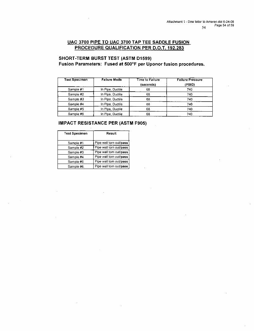
Attachment 1 - Dow letter to Ameren dtd 6-24-08Page 54 of 59
UAC 3700 PIPE TO UAC 3700 TAP TEE SADDLE FUSIONPROCEDURE QUALIFICATION PER D.O.T. 192.283
SHORT-TERM BURST TEST (ASTM D1599)Fusion Parameters: Fused at 500°F per Uponor fusion procedures.
Test Specimen Failure Mode Time to Failure Failure Pressure
(seconds) (PSIG)
Sample #1 In Pipe, Ductile 68 740
Sample #2 In Pipe, Ductile 68 740
Sample #3 In Pipe, Ductile 68 740Sample #4 In-Pipe, Ductile 68 740
Sample #5 In Pipe, Ductile 68 740
Sample #6 In Pipe, Ductile 68 740
IMPACT RESISTANCE PER (ASTM F905)
Test Specimen Result
Sample #1 Pipe wall torn out/passSample #2 Pipe wall torn out/passSample #3 Pipe wall torn out/pass
Sample #4 Pipe wall torn out/pass
Sample #5 Pipe wall torn out/pass
Sample #6. Pipe wall torn out/pass
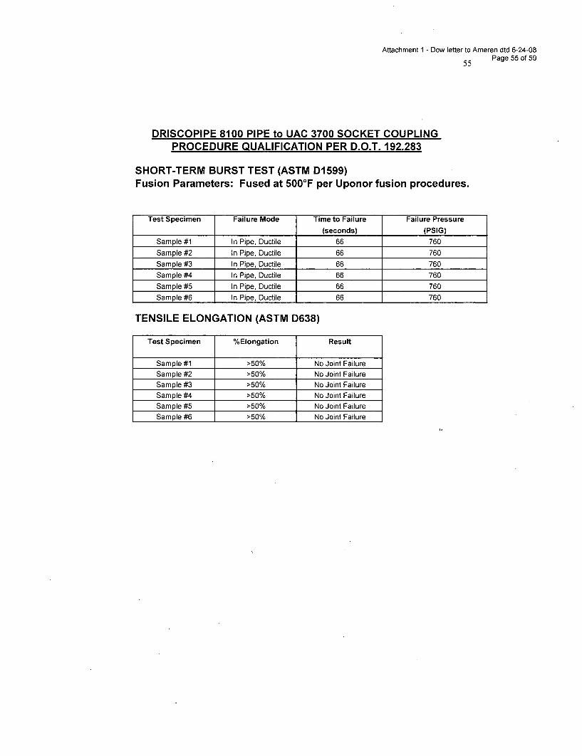
Attachment 1 - Dow letter to Ameren dtd 6-24-08Page 55 of 59
DRISCOPIPE 8100 PIPE to UAC 3700 SOCKET COUPLINGPROCEDURE QUALIFICATION PER D.O.T. 192.283
SHORT-TERM BURST TEST (ASTM D1599)Fusion Parameters: Fused at 500°F per Uponor fusion procedures.
Test Specimen Failure Mode Time to Failure Failure Pressure
(seconds) (PSIG)
Sample #1 In Pipe, Ductile 66 760
Sample #2 In Pipe, Ductile 66 760
Sample #3 In Pipe, Ductile 66 760
Sample #4 In Pipe, Ductile 66 760
Sample #5 In Pipe, Ductile 66 760
Sample #6 In Pipe, Ductile 66 760
TENSILE ELONGATION (ASTM D638)
Test Specimen %Elongation Result
Sample #1 >50% No Joint FailureSample #2 >50% No Joint Failure
Sample #3 >50% No Joint FailureSample #4 >50% No Joint Failure
Sample #5 >50% No Joint Failure
Sample #6 >50% No Joint Failure
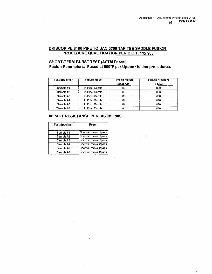
Attachment 1 - Dow letter to Ameren dtd 6-24-08
56 Page 56 of 59
DRISCOPIPE 8100 PIPE TO UAC 3700 TAP TEE SADDLE FUSIONPROCEDURE QUALIFICATION PER D.O.T. 192.283
SHORT-TERM BURST TEST (ASTM DI 599)Fusion Parameters: Fused at 500°F per Uponor fusion procedures.
Test Specimen Failure Mode Time to Failure Failure Pressure
(seconds) (PSIG)
Sample #1 In Pipe, Ductile 63 800
Sample #2 In Pipe, Ductile 63 800
Sample #3 In Pipe, Ductile 63 800
Sample #4 In Pipe, Ductile 64 810
Sample #5 In Pipe, Ductile 64 810
Sample #6 In Pipe, Ductile 64 810
IMPACT RESISTANCE PER (ASTM F905)
Test Specimen Result
Sample #1 Pipe wall torn out/pass
Sample #2 Pipe wall torn out/passSample #3 Pipe wall torn out/pass
Sample #4 Pipe wall torn out/pass
Sample #5 Pipe wall torn out/pass
Sample #6 Pipe wall torn out/pass
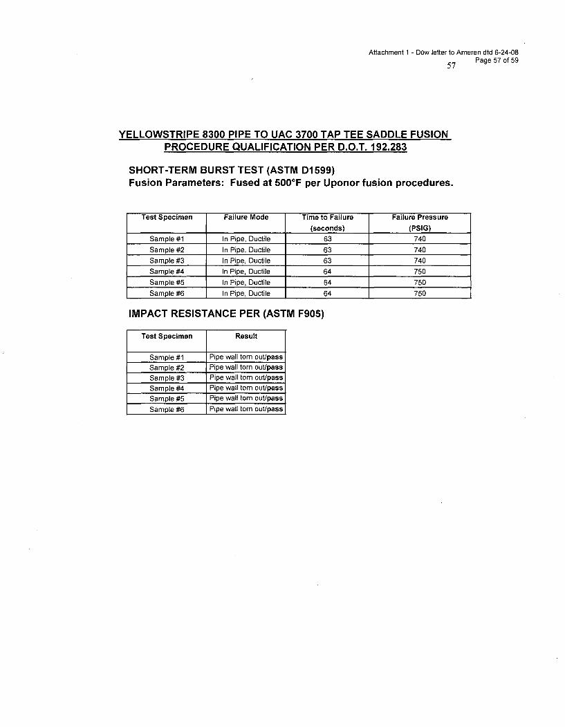
Attachment 1 - Dow letter to Ameren dtd 6-24-08Page 57 of 59
YELLOWSTRIPE 8300 PIPE TO UAC 3700 TAP TEE SADDLE FUSIONPROCEDURE QUALIFICATION PER D.O.T. 192.283
SHORT-TERM BURST TEST (ASTM D1599)Fusion Parameters: Fused at 500°F per Uponor fusion procedures.
Test Specimen Failure Mode Time to Failure Failure Pressure
(seconds) (PSIG)
Sample #1 In Pipe, Ductile 63 740
Sample #2 In Pipe, Ductile 63 740
Sample #3 In Pipe, Ductile 63 740
Sample #4 In Pipe, Ductile 64 750
Sample #5 In Pipe, Ductile 64 750
Sample #6 In Pipe, Ductile 64 750
IMPACT RESISTANCE PER (ASTM F905)
Test Specimen Result
Sample #1 Pipe wall torn out/pass
Sample #2 Pipe wall torn out/pass
Sample #3 Pipe wall torn out/passSample #4 Pipe wall torn out/pass
Sample #5 Pipe wall torn out/pass
Sample #6 Pipe wall torn out/pass
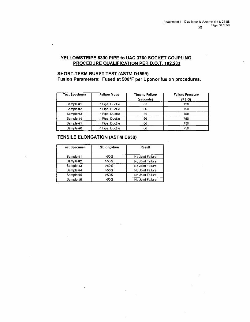
Attachment 1 - Dow letter to Ameren dtd 6-24-08Page 58 of 59
YELLOWSTRIPE 8300 PIPE to UAC 3700 SOCKET COUPLINGPROCEDURE QUALIFICATION PER D.O.T. 192.283
SHORT-TERM BURST TEST (ASTM D1599)Fusion Parameters: Fused at 5000 F per Uponor fusion procedures.
Test Specimen Failure Mode Time to Failure Failure Pressure
(seconds) (PSIG)Sample #1 In Pipe, Ductile 66 750
Sample #2 In Pipe, Ductile 66 750
Sample #3 In Pipe, Ductile 66 750
Sample #4 In Pipe, Ductile 66 750
Sample #5 In Pipe, Ductile 66 750
Sample #6 In Pipe, Ductile 66 750
TENSILE ELONGATION (ASTM D638)
Test Specimen %Elongation Result
Sample #1 >50% No Joint FailureSample #2 >50% No Joint Failure
Sample #3 >50% No Joint FailureSample #4 >50% No Joint FailureSample #5 >50% No Joint FailureSample #6 >50% No Joint Failure
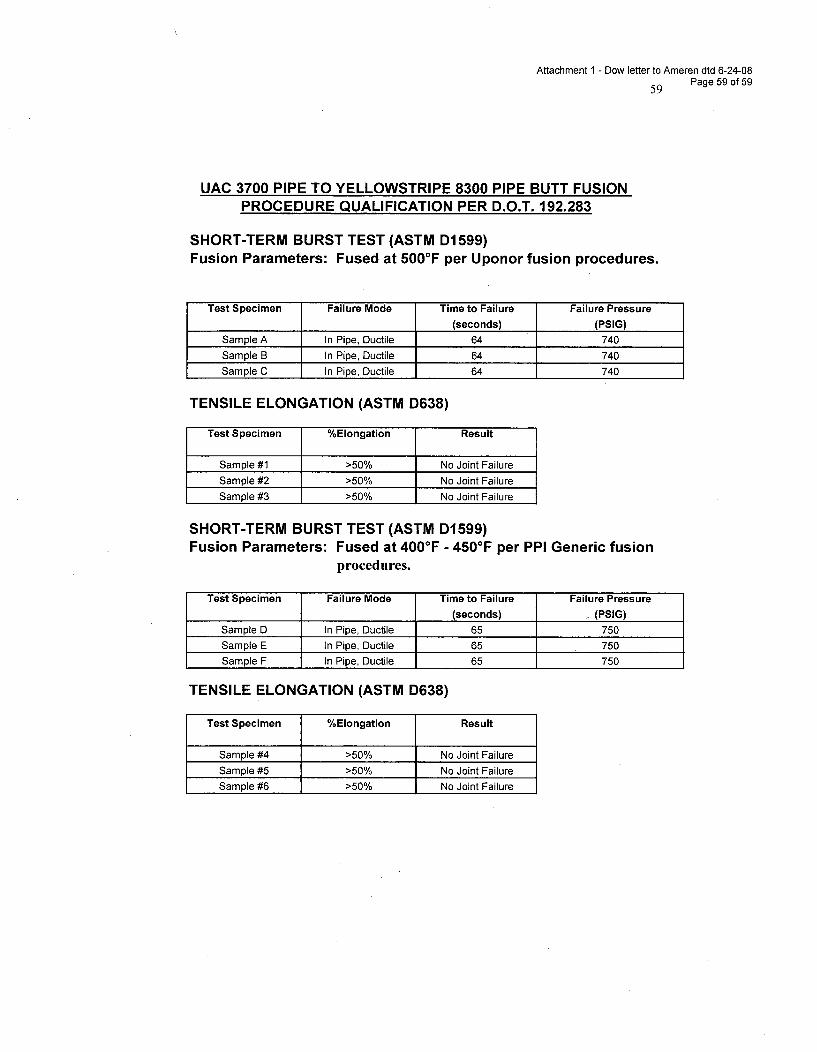
Attachment 1 - Dow letter to Ameren dtd 6-24-0859 Page 59 of 59
UAC 3700 PIPE TO YELLOWSTRIPE 8300 PIPE BUTT FUSIONPROCEDURE QUALIFICATION PER D.O.T. 192.283
SHORT-TERM BURST TEST (ASTM DI 599)Fusion Parameters: Fused at 500°F per Uponor fusion procedures.
Test Specimen Failure Mode Time to Failure Failure Pressure
(seconds) (PSIG)
Sample A In Pipe, Ductile 64 740
Sample B In Pipe, Ductile 64 740
Sample C In Pipe, Ductile 64 740
TENSILE ELONGATION (ASTM D638)
Test Specimen %Elongation Result
Sample #1 >50% No Joint Failure
Sample #2 >50% No Joint Failure
Sample #3 >50% No Joint Failure
SHORT-TERM BURST TEST (ASTM D1599)Fusion Parameters: Fused at 400°F - 450'F per PPI Generic fusion
procedures.
Test Specimen Failure Mode Time to Failure Failure Pressure
(seconds) (PSIG)Sample D In Pipe, Ductile 65 750
Sample E In Pipe, Ductile 65 750
Sample F In Pipe, Ductile 65 750
TENSILE ELONGATION (ASTM D638)
Test Specimen %Elongation Result
Sample #4 >50% No Joint Failure
Sample #5 >50% No Joint Failure
Sample #6 >50% No Joint Failure
Attachment 2 - Dow letter to Ameren dtd 6-24-08Page 1 of 6
Evaluation and Comparison of Fusion Weldsby McElroy McSnapperT High-Speed Tensile Impact Testing
Objective:Evaluate and compare joint quality of butt-fused polyethylene pipesmolded from Dow's DGDA-2490, Dow's DGDB-2480 and Uponor UAC 2000 insupport of the Martin-Marietta Dow Pipeline Project.
Discussion:In support of a proposed pipeline between Martin-Marietta and Dowfacilities to deliver brine solution, a modest study was undertaken todetermine the quality and compatibility of fusion and cross-fusionjoints made from sections of Dow DGDA-2490 (PEI00), Dow DGDB-2480(PE3408) and Uponor UAC 2000 (PE2406) pipe. Eight-inch diameter, SDR11 (0.73 inch wall thickness) pipe sections supplied by Quail Piping,Kingman, Arizona (HDPE) and McElroy Manufacturing, Tulsa, Oklahoma(MDPE) were butt-fusion welded by McElroy technical personnel.McElroy's expertise in the fusion of polyethylene pipes is widelyrecognized. Two interfacial pressures (60 psi and 90 psi) were usedto represent a typical range of conditions for butt-welding operationsand pipe samples containing fusion welds made at these two differentpressures were collected for this study. Four specimens from eachjoint configuration were fabricated using a McElroy Coupon Cutter. Inaddition to these samples, coupons were cut from pipe sidewall toserve as controls for this study. The diagram on the last pageprovides a pictorial representation of these coupons
Heat fusion joining process requires the uniform melting of twoopposed (and aligned) surfaces, merging these melted surfaces underpressure and solidifying this merged surface under a given pressure.Uniformity of melting and applied pressure(s) is tantamount toattaining an strong and acceptable fusion that will last the life ofthe pipe system. Generating a uniform melted surface is the firststep in obtaining an acceptable weld. Several factors, such asstarting with two smooth parallel pipe surfaces, proper heatingtemperature, adequate contact time, and uniform pressure on thepolymer surface during this melting stage are critical to achieving auniform melted surface. Polymer factors such as molecular weight,molecular weight distribution, and comonomer content, can effectmelting point and the ability of the melt to flow under pressure andtemperature. When fusing pipe samples of equivalent polyethylene, thedevelopment of a uniform melt surface and resultant interface (fusion)is straight forward and widely practiced art. The fusing of unlikepolyethylenes can be a bit more involved and can require an adjustmentto the heating/melt portion of the fusion process. For this test, allmaterials were fused using recognized standard fusion practices.
Samples:As indicated, examples of butt-fusion welds were collected at eachpressure. The high-speed (McSnapperT
M) tensile impact properties ofthese welds were compared to sections of wall without a weld present(controls). An important aspect of this testing is to evaluate thefusion compatibility of pipe molded from Dow's new bi-modal HDPEproduct to itself and with pipe extruded from other existingN :\ESW Buried Pipe\Relief RequestRAIs3rd round of RA [s\RAI attachments\Dow letter\U LN RC-05517 Dow Chemical 6-24-08 letter Attachment 2 - NRC 6-10-08 RAt Enclosure I Questions I and 2(a) - Mcelroy Mcsnapper Testing 8-13-02.docDavid W. Kababik / April 24, 2002
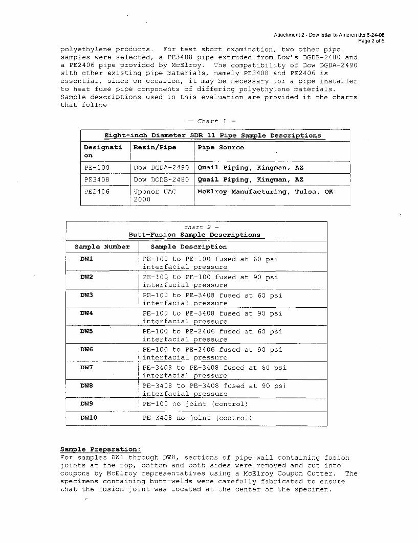
Attachment 2 - Dow letter to Ameren dtd 6-24-08Page 2 of6
polyethylene products. For test short examination, two other pipesamples were selected, a PE3408 pipe extruded from Dow's DGDB-2480 anda PE2406 pipe provided by McElroy. The compatibility of Dow DGDA-2490with other existing pipe materials, namely PE3408 and PE2406 isessential, since on occasion, it may be necessary for a pipe installerto heat fuse pipe components of differing polyethylene materials.Sample descriptions used in this evaluation are provided it the chartsthat follow
- Chart 1 -
Eight-inch Diameter SDR 11 Pipe Sample Descriptions
Designati Resin/Pipe Pipe Sourceon
PE-100 Dow DGDA-2490 Quail Piping, Kingman, AZ
PE3408 Dow DGDB-2480 Quail Piping, Kingman, AZ
PE2406 Uponor UAC McElroy Manufacturing, Tulsa, OK2000
- chart 2 -
Butt-Fusion Sample Descriptions
Sample Number Sample Description
DWI PE-100 to PE-100 fused at 60 psiinterfacial pressure
DW2 PE-100 to PE-100 fused at 90 psiinterfacial pressure
DW3 PE-100 to PE-3408 fused at 60 psiinterfacial pressure
DW4 PE-100 to PE-3408 fused at 90 psiinterfacial pressure
DW5 PE-100 to PE-2406 fused at 60 psiinterfacial pressure
DW6 PE-100 to PE-2406 fused at 90 psiinterfacial pressure
DW7 PE-3408 to PE-3408 fused at 60 psiinterfacial pressure
DW8 PE-3408 to PE-3408 fused at 90 psiinterfacial pressure
DW9 PE-100 no joint (control)
DW10 PE-3408 no joint (control)
Sample Preparation:For samples DWI through DW8, sections of pipe wall containing fusionjoints at the top, bottom and both sides were removed and cut intocoupons by McElroy representatives using a McElroy Coupon Cutter. Thespecimens containing butt-welds were carefully fabricated to ensurethat the fusion joint was located at the center of the specimen.
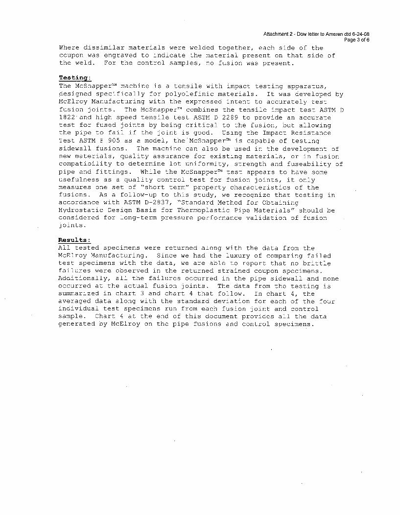
Attachment 2 - Dow letter to Ameren dtd 6-24-08Page 3 of 6
Where dissimilar materials were welded together, each side of thecoupon was engraved to indicate the material present on that side ofthe weld. For the control samples, no fusion was present.
Testing:The McSnapperTM machine is a tensile with impact testing apparatus,designed specifically for polyolefinic materials. It was developed byMcElroy Manufacturing with the expressed intent to accurately testfusion joints. The McSnapper TM combines the tensile impact test ASTM D1822 and high speed tensile test ASTM D 2289 to provide an accuratetest for fused joints by being critical to the fusion, but allowingthe pipe to fail if the joint is good. Using the Impact ResistanceTest ASTM F 905 as a model, the McSnapper TM is capable of testingsidewall fusions. The machine can also be used in the development ofnew materials, quality assurance for existing materials, or in fusioncompatibility to determine lot uniformity, strength and fuseability ofpipe and fittings. While the McSnapper TM test appears to have someusefulness as a quality control test for fusion joints, it onlymeasures one set of "short term" property characteristics of thefusions. As a follow-up to this study, we recognize that testing inaccordance with ASTM D-2837, "Standard Method for ObtainingHydrostatic Design Basis for Thermoplastic Pipe Materials" should beconsidered for long-term pressure performance validation of fusionjoints.
Results:All tested specimens were returned along with the data from theMcElroy Manufacturing. Since we had the luxury of comparing failedtest specimens with the data, we are able to report that no brittlefailures were observed in the returned strained coupon specimens.Additionally, all the failures occurred in the pipe sidewall and noneoccurred at the actual fusion joints. The data from the testing issummarized in chart 3 and chart 4 that follow. In chart 4, theaveraged data along with the standard deviation for each of the fourindividual test specimens run from each fusion joint and controlsample. Chart 4 at the end of this document provides all the datagenerated by McElroy on the pipe fusions and control specimens.
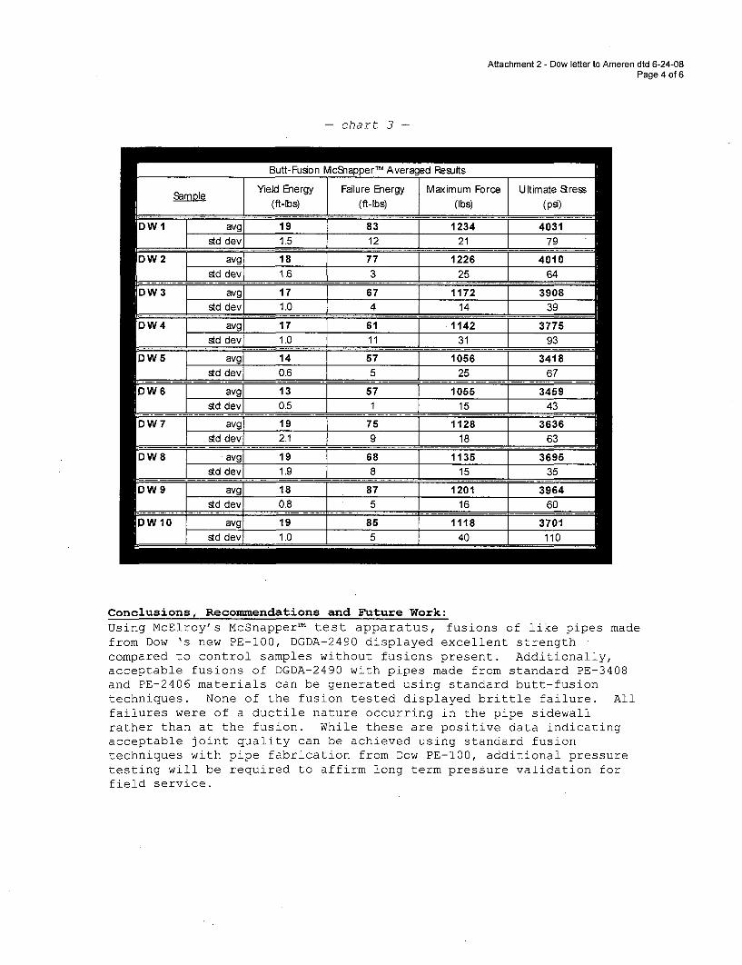
Attachment 2 - Dow letter to Ameren dtd 6-24-08Page 4 of 6
- chart 3 -
Butt-Fusion McSnapper TM Averaged Results
Sample Yield Energy Failure Energy Maximum Force Ultimate Stress______ _ __ ___ [ (ft-lbs) j (ft-Ibs) j (Ibs) (psi)______
DW { avg 19 83 1234 4031std dev 1.5 12 21 79
DW2 avg 18 77 1226 4010I std dev 1 1.6 3 25 64
DW3 avg 17 67 1172 3908std devI 1.0 4 __14 39
DW4 avg 17 61 1142 3std devI 1.0 11 31 93
DW5 avg 14 57 1056 3418std dev 0.6 5 25 67
DW6 avg 13 57 1055 -F 3459std dev [L 0.5 1 15 43
DW7 avg 19 75 1128 3636std dev_ 2.1_1 9 1 18 63
DW avg 19 68 E 1135 [ 3695std dev 1.9 8 15 35_m
DW9 avg 18 87 1201 3964std dev 0.8 5 16 60
DWio avg 19 85 1118 3701std dev 1.0 5 40 110
Conclusions Reconmmendations and Future Work:
Using McElroy's McSnapper TM test apparatus, fusions of like pipes madefrom Dow 's new PE-100, DGDA-2490 displayed excellent strengthcompared to control samples without fusions present. Additionally,acceptable fusions of DGDA-2490 with pipes made from standard PE-3408and PE-2406 materials can be generated using standard butt-fusiontechniques. None of the fusion tested displayed brittle failure. Allfailures were of a ductile nature occurring in the pipe sidewallrather than at the fusion. While these are positive data indicatingacceptable joint quality can be achieved using standard fusiontechniques with pipe fabrication from Dow PE-100, additional pressuretesting will be required to affirm long term pressure validation forfield service.
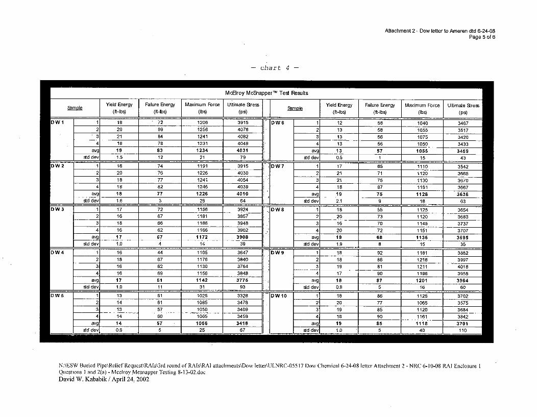
Attachment 2 - Dow letter to Ameren dtd 6-24-08Page 5 of 6
- chart 4
Mclroy McSnapper TM Test Results
Sam ole Yield Energy Falure Energy Maimum Force Ultimate Sress Sam Yield Energy Failure Energy Maximum Force Ultimate SresSape(ft-Ibs (ft-lbs) (Ibs) (psi) Sape(ft-lbs) (ft-lbs (Ibs) (psi)
owl 1 18 72 1206 3915 IDW6 1 12 58 1040 34672 20 99 1256 4078 - 2 13 58 1055 3517
'3 21 84 1241 4082 3 13 56 1075 3420
4 18 78 1231 4049 4 13 56 1050 3433avg 19 83 1234 4031 avg 13 57 1055 3459
td dev 1.5 12 21 1 79 std dev 0.5 1 15 43
DW2 1 16 74 1191 3915 DW7 1 17 65 1110 35422 20 76 1226 4030 2 21 71 1120 3665
18 82_246403 4_81 7_1 151 36618 77 1241 4054 3 21 75 1130 3670
4 18 82 1246 4039 4 18 87 1151 3667avg 18 77 1226 4010 avg 19 75 1128 3636
std dev 1.6 3 25 64 A std dev, 2.1 9 18 63
DW3 1 17 72 4 1156 3924 -DW8 1 18 55 1125 3654
2 16 67 1181 3857 2 20 73 1120 36833 18 66 1186 3948 3 16 70 1145 37374 16 62 1166 3902 4 20 72 1151 3707
avg 17 67 1172 3908 avg 19 68 _ 1135 3695std dev 1.0 4 14 39 std dev 1.9 8 15 35
DW4 1 16 44 1105 3647 DW9 1 18 92 1181 38822 18 67 1176 3840 2 18 86 1216 3997
3 16 62 1130 3764L 3 19 81 1211 40184 16 69 1156 3848 4 17 90 1196 3958
avg 17 61 1142 3775 avg 18 87 1201 3964st dev, 1.0 11 31 93 std dev, 0.8 5 16 60
IDWS 1 13 51 1025 3328 DW10 1 18 86 1125 37022 14 61 1085 3478
3 13 57 1050 34094 14 60 1065 3458
avg 14 57 1056 3418
2 20 77 1065
3 19 85 1120 36844 18 90 1161 3842
avg 19 85 1118 3701std dev 0.6 5 25 67 std dev 1.0 5 40 110
I
N:\ESW Buried Pipe\Relief Request\RAIs\3rd round of RAIs\RAI attachments\Dow letter\ULNRC-05517 Dow Chemical 6-24-08 letter Attachment 2 - NRC 6-I 0-08 RAI Enclosure IQuestions I and 2(a) - Mcelroy Mcsnapper Testing 8-13-02.docDavid W. Kababik / April 24, 2002
Attachment 2 - Dow letter to Ameren dtd 6-24-08Page 6 of 6
References:
Jim Perrault, P.E., McElroy Manufacturing, Inc. Testing ReportPO#63518814, Dated 4/24/2002
McElroy Manufacturing, Inc. Operator's Manual #S00106 Revised3/99: "High Speed Tensile with Impact Testing System,McSnapperý"
Plastics Pipe Institute Technical-Note, "General Guidelines forButt, Saddle, and Socket Fusion of Unlike Polyethylene Pipes andFittings TN-13/2001"
Plastics Pipe Institute Technical Report, "Generic Butt FusionJoining Procedure for Polyethylene Gas Pipe TR-33/2001"
N:\ESW Buried Pipe\Relief Request\RAIs\3rd round of RAIs\RA1 attachments\Dow letter\ULNRC-05517 DowChemical 6-24-08 letter Attachment 2 - NRC 6-10-08 RAI Enclosure I Questions I and 2(a) - Mcelroy McsnapperTesting 8-13-02.docDavid W. Kababik / April 24, 2002
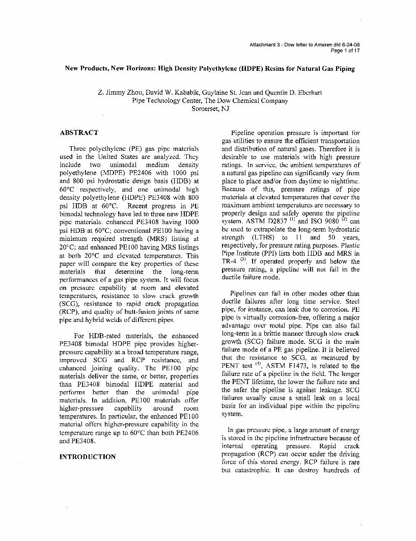
Attachment 3 - Dow letter to Ameren dtd 6-24-08Page 1 of 17
New Products, New Horizons: High Density Polyethylene (HDPE) Resins for Natural Gas Piping
Z. Jimmy Zhou, David W. Kababik, Guylaine St. Jean and Quentin D. EberhartPipe Technology Center, The Dow Chemical Company
Somerset, NJ
ABSTRACT
Three polyethylene (PE) gas pipe materialsused in the United States are analyzed. Theyinclude two unimodal medium densitypolyethylene (MDPE) PE2406 with 1000 psiand 800 psi hydrostatic design basis (HDB) at60'C respectively, and one unimodal highdensity polyethylene (HDPE) PE3408 with 800psi HDB at 60'C. Recent progress in PEbimodal technology have led to three new HDPEpipe materials: enhanced PE3408 having 1000psi HDB at 60'C; conventional PE100 having aminimum required strength (MRS) listing at20'C; and enhanced PE100 having MRS listingsat both 20'C and elevated temperatures. Thispaper will compare the key properties of thesematerials that determine the long-termperformances of a gas pipe system. It will focuson pressure capability at room and elevatedtemperatures, resistance to slow crack growth(SCG), resistance to rapid crack propagation(RCP), and quality of butt-fusion joints of samepipe and hybrid welds of different pipes.
For HDB-rated materials, the enhancedPE3408 bimodal HDPE pipe provides higher-pressure capability at a broad temperature range,improved SCG and RCP resistance, andenhanced joining quality. The PE100 pipematerials deliver the same, or better, propertiesthan PE3408 bimodal HDPE material andperforms better than the unimodal pipematerials. In addition, PEIOO materials offerhigher-pressure capability around roomtemperatures. In particular, the enhanced PE100material offers higher-pressure capability in thetemperature range up to 60'C than both PE2406and PE3408.
INTRODUCTION
Pipeline operation pressure is important forgas utilities to ensure the efficient transportationand distribution of natural gases. Therefore it isdesirable to use materials with high pressureratings. In service, the ambient temperatures ofa natural gas pipeline can significantly vary fromplace to place and/or from daytime to nighttime.Because of this, pressure ratings of pipematerials at elevated temperatures that cover themaximum ambient temperatures are necessary toproperly design and safely operate the pipelinesystem. ASTM D2837 (1) and ISO 9080 (2) canbe used to extrapolate the long-term hydrostaticstrength (LTHS) to 11 and 50 years,respectively, for pressure rating purposes. PlasticPipe Institute (PPI) lists both HDB and MRS inTR-4 (3). If operated properly and below thepressure rating, a pipeline will not fail in theductile failure mode.
Pipelines can fail in other modes other thanductile failures after long time service. Steelpipe, for instance, can leak due to corrosion. PEpipe is virtually corrosion-free, offering a majoradvantage over metal pipe. Pipe can also faillong-term in a brittle manner through slow crackgrowth (SCG) failure mode. SCG is the mainfailure mode of a PE gas pipeline. It is believedthat the resistance to SCG, as measured byPENT test (4), ASTM F1473, is related to thefailure rate of a pipeline in the field. The longerthe PENT lifetime, the lower the failure rate andthe safer the pipeline is against leakage. SCGfailures usually cause a small leak on a localbasis for an individual pipe within the pipelinesystem.
In gas pressure pipe, a large amount of energyis stored in the pipeline infrastructure because ofinternal operating pressure. Rapid crackpropagation (RCP) can occur under the drivingforce of this stored energy. RCP failure is rarebut catastrophic. It can destroy hundreds of
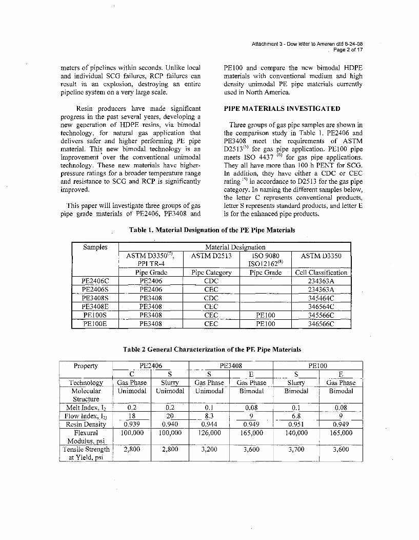
meters of pipelines within seconds. Unlike localand individual SCG failures, RCP failures canresult in an explosion, destroying an entirepipeline system on a very large scale.
Resin producers have made significantprogress in the past several years, developing anew generation of HDPE resins, via bimodaltechnology, for natural gas application thatdelivers safer and higher performing PE pipematerial. This new bimodal technology is animprovement over the conventional unimodaltechnology. These new materials have higher-pressure ratings for a broader temperature rangeand resistance to SCG and RCP is significantlyimproved.
This paper will investigate three groups of gaspipe grade materials of PE2406, PE3408 and
Attachment 3 - Dow letter to Ameren dtd 6-24-08Page 2 of 17
PE100 and compare the new bimodal HDPEmaterials with conventional medium and highdensity unimodal PE pipe materials currentlyused in North America.
PIPE MATERIALS INVESTIGATED
Three groups of gas pipe samples are shown inthe comparison study in Table 1. PE2406 andPE3408 meet the requirements of ASTMD2513( 51 for gas pipe application. PE100 pipemeets ISO 4437 (6) for gas pipe applications.They all have more than 100 h PENT for SCG.In addition, they have either a CDC or CECrating (5) in accordance to D25 13 for the gas pipecategory. In naming the different samples below,the letter C represents conventional products,letter S represents standard products, and letter Eis for the enhanced pipe products.
Table 1. Material Designation of the PE Pipe Materials
Samples Material DesignationASTM D3350( 71, ASTM D2513 ISO 9080 ASTM D3350
PPI TR-4 ISO12162(8)
Pipe Grade Pipe Category Pipe Grade Cell ClassificationPE2406C PE2406 CDC 234363APE2406S PE2406 CEC 234363APE3408S PE3408 CDC 345464CPE3408E PE3408 CEC 346564CPE1OOS PE3408 CEC PE1O0 345566CPE1OOE PE3408 CEC PE100 346566C
Table 2 General Characterization of the PE Pipe Materials
Property PE2406 PE3408 PE1O0C S S E S E
Technology Gas Phase Slurry Gas Phase Gas Phase Slurry Gas PhaseMolecular Unimodal Unimodal Unimodal Bimodal Bimodal BimodalStructure
Melt Index, 12 0.2 0.2 0.1 0.08 0.1 0.08Flow Index, 121 18 20 8.3 9 6.8 9Resin Density 0.939 0.940 0.944 0.949 0.951 0.949
Flexural 100,000 100,000 126,000 165,000 140,000 165,000Modulus, psi
Tensile Strength 2,800 2,800 3,200 3,600 3,700 3,600at Yield, psi
Attachment 3 - Dow letter to Ameren dtd 6-24-08Page 3 of 17
The general characterization of the pipematerials is illustrated in Table 2. PE3408E,PE100S and PE100E are bimodal HDPEmaterials. MDPE PE2406C and S and HDPEPE3408S are unimodal materials. The short-termproperties of the two PE2406 resin materials arevery close. Bimodal HDPEs have a higherdensity and display higher flexural modulus andtensile strengths over conventional HDPE.
PRESSURE CAPABILITY
When designing a natural gas pipeline, utilitycompanies expect them to operate safely for 50years. It is well known that the strength ofplastics is dependent on time and temperature. Itis not realistic to test the pipe materials for 50years in the real world. A good scientific methodis needed to extrapolate the 50-year performancebased on relatively short term testing data.ASTM D2837 and ISO 9080 have been used formany years to pressure-rate the plastic materialsbased on hydrostatic test data with a minimumtesting time of 10,000 and 9,000 hours,respectively. HDB-rated and MRS-ratedmaterials have been successfully used in thefield for several decades in North America andthe rest of the world (mainly in Europe),respectively.
HDB-Rated Materials
ASTM D2837 first extrapolates LTHS to100,000 h (11 years) using 18 hydrostatic datapoints generated at 23 °C. It assumes the linearityof the regression curve using the equation of astraight line.
where A, B and C are constants, S is the stress inpsi, T is the temperature in 'K, and t is thefailure time in hours. The LTHS is thencategorized into HDB and listed in PPI TR-4.
PE2406 and PE3408 can be used for gas pipein accordance to ASTM D2513. However, notall PE2406 and PE3408 rated materials arequalified for gas pipe applications. D2513 hasadditional requirements that include: a minimum630 psi HDB at 60'C; and HDB at 23°C issubstantiated by showing that the extrapolationof the stress regression curve is linear to the438,000 h intercept (LTHS at 50 years).
Table 3 lists the HDB of six pipe materials at23°C and 60'C. They meet the pressure ratingrequirements for natural gas distribution inNorth America in accordance to ASTM D2513.Note that PE2406S has 1250 psi HDB at 23°Cbut 1000 psi HDB at 60'C. PE3408S is listed for1600 psi HDB at 23°C but 800 psi HDB at60'C. PE2406S offers a higher pressure ratingthan PE3408S at 60'C.
However, bimodal technology has improvedlong-term performance in new HDPE resins. Itis important to note that PE3408E outperformsPE2406S at all temperature range up to 60'C.Thus, the bimodal PE3408E delivers a betterlong-term performance than PE2406S at ahigher operation pressure and for a broadertemperature range, based on HDB listing.
MRS-rated Materials
ISO 9080 extrapolates LTHS to 50 years(438,000 h) based on multi-temperature data.The regression curves can be non-linear usingthe four-parameter equations.
logt =a+bhlogS (1)
where a and b are constants, S is the failurestress in psi and t is the failure time in hours.The extrapolation is validated by elevatedtemperature data using the rate-process method,the three-parameter equation,
logt = C1 + - 2 +C 3 logc+ 4
T T(3)
logt = A + B clogsT T
(2)
where Ci is a parameter, cy is stress in MPa, T istemperature in 'K, and t is failure time in h. Theextrapolation and validation is completed byusing the same four-parameter equation (3). Itrequires data at minimum of two temperatures
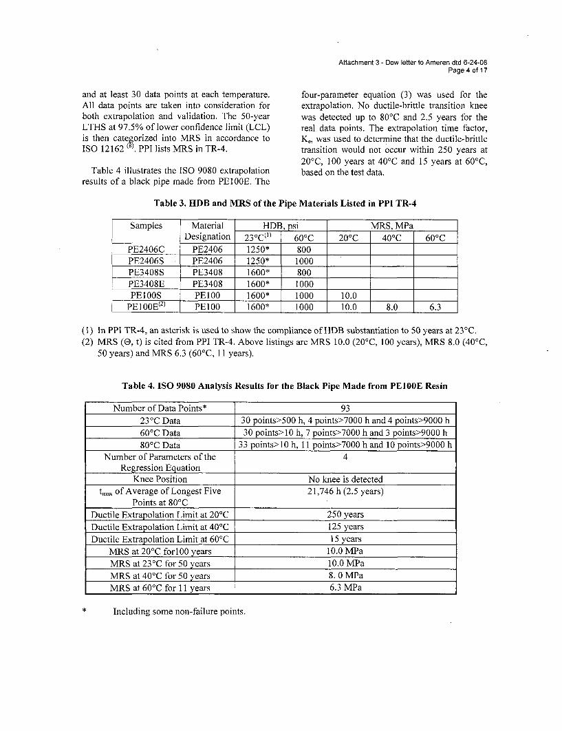
Attachment 3 - Dow letter to Ameren dtd 6-24-08Page 4 of 17
and at least 30 data points at each temperature.All data points are taken into consideration forboth extrapolation and validation. The 50-yearLTHS at 97.5% of lower confidence limit (LCL)is then categorized into MRS in accordance toISO 12162 (8. PPI lists MRS in TR-4.
Table 4 illustrates the ISO 9080 extrapolationresults of a black pipe made from PEIOOE. The
four-parameter equation (3) was used for theextrapolation. No ductile-brittle transition kneewas detected up to 80'C and 2.5 years for thereal data points. The extrapolation time factor,K,, was used to determine that the ductile-brittletransition would not occur within 250 years at200 C, 100 years at 40'C and 15 years at 60'C,based on the test data.
Table 3. HDB and MRS of the Pipe Materials Listed in PPI TR-4
Samples Material HDB, psi MRS, MPaDesignation 23oC(I) 60 0C 20oC 40 0C 600 C
PE2406C PE2406 1250* 800PE2406S PE2406 1250* 1000PE3408S PE3408 1600* 800PE3408E PE3408 1600* 1000PEIOOS PE100 1600* 1000 10.0
PE100E(2) PE1O0 1600* 1000 10.0 8.0 6.3
In PPI TR-4, an asterisk is used to show the compliance of HDB substantiation to 50 years at 23°C.MRS (0, t) is cited from PPI TR-4. Above listings are MRS 10.0 (20'C, 100 years), MRS 8.0 (40 0 C,50 years) and.MRS 6.3 (60'C, 11 years).
Table 4. ISO 9080 Analysis Results for the Black Pipe Made from PE100E Resin
(1)(2)
Number of Data Points* 93
23 0C Data 30 points>500 h, 4 points>7000 h and 4 points>9000 h60'C Data 30 points>10 h, 7 points>7000 h and 3 points>9000 h80 0C Data 33 points>10 h, 11 points>7000 h and 10 points>9000 h
Number of Parameters of the 4Regression Equation
Knee Position No knee is detectedtmax of Average of Longest Five 21,746 h (2.5 years)
Points at 80'CDuctile Extrapolation Limit at 20'C 250 yearsDuctile Extrapolation Limit at 40'C 125 yearsDuctile Extrapolation Limit at 60'C 15 years
MRS at 20'C forlOO years 10.0 MPaMRS at 23°C for 50 years 10.0 MPaMRS at 40'C for 50 years 8. 0 MPaMRS at 60'C for 11 years 6.3 MPa
Including some non-failure points.
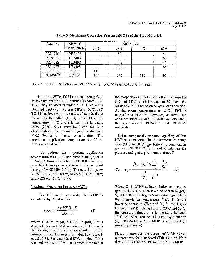
Attachment 3 - Dow letter to Ameren dtd 6-24-08Page 5 of 17
Table 5. Maximum Operation Pressure (MOP) of the Pipe Materials
Samples Material MOP, psigDesignation 20 0C 23oC 40 0C 60 0C
PE2406C PE 2406 80 51PE2406S PE2406 80 64PE3408S PE3408 102 51PE3408E PE3408 102 64PE1OOS PE 100 145
PE100E(l) PE 100 145 145 116 91
(1) MOP is for 20'C/100 years, 23'C/50 years, 400 C/50 years and 60'C/11 years.
To date, ASTM D2513 has not recognizedMRS-rated materials. A parallel standard, ISO4437, may be used provided a DOT waiver isobtained. ISO 4437 requires MRS at 20 0C. ISOTC 138 has been working on a draft standard thatrecognizes the MRS (0, t), where E is thetemperature in 'C and t is the time in years.MRS (20'C, 50y) must be listed for pipeclassification. The end-use engineers shall useMRS (0, t) for design consideration. Themaximum application temperature should bebelow or equal to 0.
To address the important applicationtemperature issue, PPI has listed MRS (0, t) inTR-4. As shown in Table 3, PEI OOE has threenew MRS listings in addition to the standardlisting of MRS (20'C, 50y). The new listings areMRS 10.0 (20°C, 100 y), MRS 8.0 (40'C, 50 y)and MRS 6.3 (60'C, 11 y).
Maximum Operation Pressure (MOP)
the temperatures of 23°C and 60'C. Because theHDB at 23°C is substantiated to 50 years, theMOP at 23'C is based on 50-year extrapolation.At the room temperature of 23°C, PE3408outperforms PE2406. However, at 60'C, theenhanced PE2406S and PE3408E are better thanthe conventional PE2406C and PE3408Smaterials.
Let us compare the pressure capability of fourHDB-rated materials in the temperature rangefrom 23°C to 60'C. The following equation, asgiven in PPI TN-18 (9), is used to calculate thepressure rating at a given temperature, T.
(SL -SH)X 1 1
ST = SL 1 T (5)
TL T,
Where ST is LTHS at interpolation temperature(psi), SL is LTHS at the lower temperature (psi),SH is LTHS at the higher temperature (psi), TT isthe interpolation temperature (°K), TL is thelower temperature (°K) and TH is the highertemperature (°K). Using HDB at 23°C and 600 C,the pressure ratings at a temperature between23°C and 60'C can be calculated by Equation(4). The corresponding MOP is calculated byusing Equation (4).
Figure 1 provides the curves of MOP versustemperatures for a standard SDR 11 pipe. Notethat: (1) PE2406S and PE3408E offer an MOP
For HDB-rated materials, the MOP iscalculated by Equation (4)
MOP = 2xHDBxFDR-1
(4)
where HDB is in psi, MOP is in psig, F is adesign factor and the dimension ratio DR equalsthe average outside diameter divided by theminimum wall thickness. For natural gas pipe, Fequals 0.32. For a standard SDR 11 pipe, Table5 calculates MOP of the HDB-rated materials at
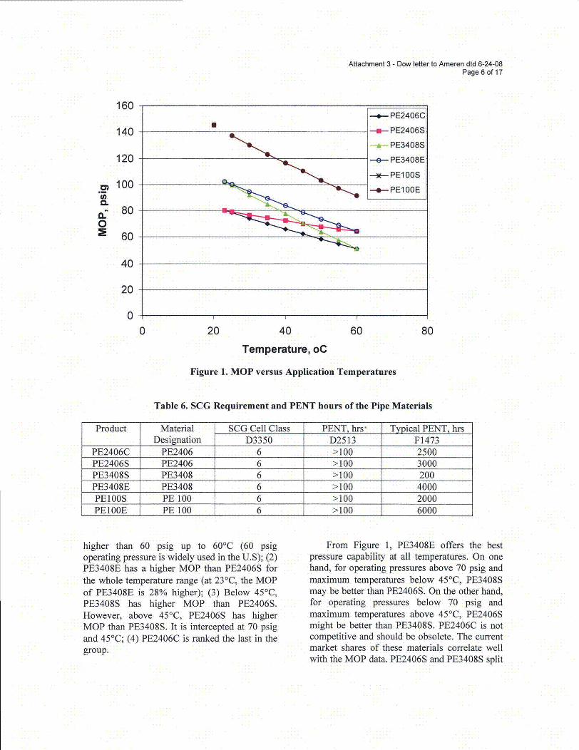
Attachment 3 - Dow letter to Ameren dtd 6-24-08Page 6 of 17
160
140
120
100
80
600
40
20
00 20 40 60 80
Temperature, oC
Figure 1. MOP versus Application Temperatures
Table 6. SCG Requirement and PENT hours of the Pipe Materials
Product Material SCG Cell Class PENT, hrs" Typical PENT, hrsDesignation D3350 D2513 F1473
PE2406C PE2406 6 >100 2500PE2406S PE2406 6 >100 3000PE3408S PE3408 6 >100 200PE3408E PE3408 6 >100 4000PEIOOS PE 100 6 >100 2000PEIOOE PE 100 6 >100 6000
higher than 60 psig up to 60'C (60 psigoperating pressure is widely used in the U.S); (2)PE3408E has a higher MOP than PE2406S forthe whole temperature range (at 23°C, the MOPof PE3408E is 28% higher); (3) Below 45°C,PE3408S has higher MOP than PE2406S.However, above 45°C, PE2406S has higherMOP than PE3408S. It is intercepted at 70 psigand 45°C; (4) PE2406C is ranked the last in thegroup.
From Figure 1, PE3408E offers the bestpressure capability at all temperatures. On onehand, for operating pressures above 70 psig andmaximum temperatures below 45°C, PE3408Smay be better than PE2406S. On the other hand,for operating pressures below 70 psig andmaximum temperatures above 45°C, PE2406Smight be better than PE3408S. PE2406C is notcompetitive and should be obsolete. The currentmarket shares of these materials correlate wellwith the MOP data. PE2406S and PE3408S split
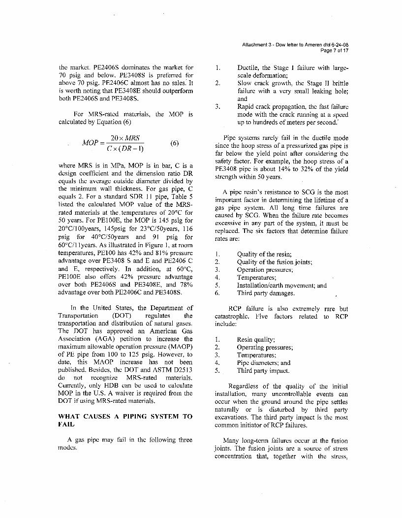
Attachment 3 - Dow letter to Ameren dtd 6-24-08Page 7 of 17
the market. PE2406S dominates the market for70 psig and below. PE3408S is preferred forabove 70 psig. PE2406C almost has no sales. Itis worth noting that PE3408E should outperformboth PE2406S and PE3408S.
For MRS-rated materials, the MOP iscalculated by Equation (6)
MOP=20 x MRSCx(DR-1)
(6)
1. Ductile, the Stage I failure with large-scale deformation;
2. Slow crack growth, the Stage II brittlefailure with a very small leaking hole;and
3. Rapid crack propagation, the fast failuremode with the crack running at a speedup to hundreds of meters per second.*
Pipe systems rarely fail in the ductile modesince the hoop stress of a pressurized gas pipe isfar below the yield point after considering thesafety factor. For example, the hoop stress of aPE3408 pipe is about 14% to 32% of the yieldstrength within 50 years.
A pipe resin's resistance to SCG is the mostimportant factor in determining the lifetime of agas pipe system. All long time failures arecaused by SCG. When the failure rate becomesexcessive in any part of the system, it must bereplaced. The six factors that determine failurerates are:
where MRS is in MPa, MOP is in bar, C is adesign coefficient and the dimension ratio DRequals the average outside diameter divided bythe minimum wall thickness. For gas pipe, Cequals 2. For a standard SDR 11 pipe, Table 5listed the calculated MOP value of the MRS-rated materials at the temperatures of 20'C for50 years. For PEIOOE, the MOP is 145 psig for20'C/100years, 145psig for 23°C/50years, 116psig for 40°C/50years and 91 psig for60°C/1 lyears. As illustrated in Figure 1, at roomtemperatures, PE100 has 42% and 81% pressureadvantage over PE3408 S and E and PE2406 Cand E, respectively. In addition, at 60'C,PE100E also offers 42% pressure advantageover both PE2406S and PE3408E, and 78%advantage over both PE2406C and PE3408S.
In the United States, the Department ofTransportation (DOT) regulates thetransportation and distribution of natural gases.The DOT has approved an American GasAssociation (AGA) petition to increase themaximum allowable operation pressure (MAOP)of PE pipe from 100 to 125 psig. However, todate, this MAOP increase has not beenpublished. Besides, the DOT and ASTM D2513do not recognize MRS-rated materials.Currently, only HDB can be used to calculateMOP in the U.S. A waiver is required from theDOT if using MRS-rated materials.
WHAT CAUSES A PIPING SYSTEM TOFAIL
A gas pipe may fail in the following threemodes.
1.2.
4.5.6.
Quality of the resin;Quality of the fusion joints;Operation pressures;Temperatures;Installation/earth movement; andThird party damages.
RCP failure is also extremely rare butcatastrophic. Five factors related to RCPinclude:
1.2.
4.5.
Resin quality;Operating pressures;Temperatures;Pipe diameters; andThird party impact.
Regardless of the quality of the initialinstallation, many uncontrollable events canoccur when the ground around the pipe settlesnaturally or is disturbed by third partyexcavations. The third party impact is the mostcommon initiator of RCP failures.
Many long-term failures occur at the fusionjoints. The fusion joints are a source of stressconcentration that, together with the stress,
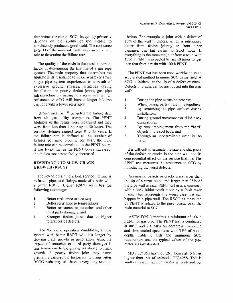
Attachment 3 - Dow letter to Ameren dtd 6-24-08Page 8 of 17
determines the rate of SCG. Its quality primarilydepends on the ability of the welder toconsistently produce a good weld. The resistanceto SCG of the material itself plays an importantrole to determine the failure rate.
The quality of the resin is the most importantfactor in determining the lifetime of a gas pipesystem. The resin property that determines thelifetime is its resistance to SCG. Whatever abusea gas pipe system experiences as a result ofexcessive ground stresses, scratches duringinstallation, or poorly fusion joints, gas pipeinfrastructure consisting of a resin with a highresistance to SCG will have a longer lifetimethan one with a lower resistance.
Brown and Lu (12) collected the failure datafrom six gas utility companies. The PENTlifetimes of the resins were measured and theywere from less than 1 hour up to 50 hours. Theservice lifetimes ranged from 8 to 25 years. Ifthe failure rate is defined as the number offailures per mile pipeline per year, the fieldfailure rate can be correlated to the PENT hours.It was found that as the PENT hours increased,the failure rate dramatically decreased.
RESISTANCE TO SLOW CRACKGROWTH (RSCG)
The key to obtaining a long service lifetime isto install pipes and fittings made of a resin witha better RSCG. Higher RSCG resin has thefollowing advantages.
1. Better resistance to stresses;2. Better resistance to temperatures;3. Better resistance to scratches and other
third party damages; and4. Stronger fusion joints due to higher
tolerances of defects.
For the same operation conditions, a pipesystem with better RSCG will last longer byslowing crack growth or penetration. Also, theimpact of scratches or third party damages isless severe due to the greater resistance to crackgrowth. A poorly fusion joint may causepremature failures but fusion joints using betterRSCG resin may still have a very long residual
lifetime. For example, a joint with a defect of10% of the wall thickness, which is introducedeither from fusion joining or from otherdamages, can fail earlier in SCG mode. Ifeverything is the same the joint from a resin with4000 h PENT is expected to last 40 times longerthan that from a resin with 100 h PENT.
The PENT test has been used worldwide as anaccelerated method to mimic SCG in the field. ASCG is initiated at the tip of a defect or crack.Defects or cracks can be introduced into the pipewall:
1. During the pipe extrusion process;2. When joining parts of the pipe together;3. By scratching the pipe surfaces during
installation;4. During ground movement or third party
excavations;5. By rock impingement from the "hard"
objects in the soil beds; and6. Through an uncontrollable event in the
field;
It is difficult to estimate the size and sharpnessof the defects or cracks in the pipe wall and itsconsequential effect on the service lifetime. ThePENT test measures the resistance to SCG byintroducing the worst defects.
Assume no defects or cracks are sharper thanthe tip of a razor blade and larger than 35% ofthe pipe wall in size. PENT test uses a specimenwith a 35% initial notch made by a fresh razorblade. This represents the worst case that canhappen in a pipe wall. The RSCG as measuredby PENT is related to the pure resistance of theresin material to SCG.
ASTM D2513 requires a minimum of 100 hPENT for gas pipe. The PENT test is conductedat 80'C and 2.4 MPa on compression-moldedand slow-cooled specimens with 35% of notchdepth. Table 6 lists the minimum SCGrequirement and the typical values of the pipematerials investigated.
MD PE2406S has the PENT hours at 15 timeshigher than that of unimodal PE3408S. This isanother reason why PE2406S is preferred for
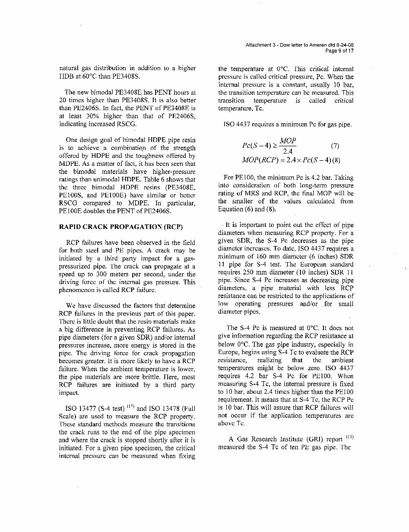
Attachment 3 - Dow letter to Ameren dtd 6-24-08Page 9 of 17
natural gas distribution in addition to a higherHDB at 60 'C than PE3408S.
The new bimodal PE3408E has PENT hours at20 times higher than PE3408S. It is also betterthan PE2406S. In fact, the PENT of PE3408E isat least 30% higher than that of PE2406S,indicating increased RSCG.
One design goal of bimodal HDPE pipe resinis to achieve a combinatioIn of the strengthoffered by HDPE and the toughness offered byMDPE. As a matter of fact, it has been seen thatthe bimodal materials have higher-pressureratings than unimodal HDPE. Table 6 shows thatthe three bimodal HDPE resins (PE3408E,PE1OOS, and PE1O0E) have similar or betterRSCG compared to MDPE. In particular,PEI OOE doubles the PENT of PE2406S.
RAPID CRACK PROPAGATION (RCP)
RCP failures have been observed in the fieldfor both steel and PE pipes. A crack may beinitiated by a third party impact for a gas-pressurized pipe. The crack can propagate at aspeed up to 300 meters per second, under thedriving force of the internal gas pressure. Thisphenomenon is called RCP failure.
We have discussed the factors that determineRCP failures in the previous part of this paper.There is little doubt that the resin materials makea big difference in preventing RCP failures. Aspipe diameters (for a given SDR) and/or internalpressures increase, more energy is stored in thepipe. The driving force for crack propagationbecomes greater. It is more likely to have a RCPfailure. When the ambient temperature is lower,the pipe materials are more brittle. Here, mostRCP failures are initiated by a third partyimpact.
ISO 13477 (S-4 test) (13) and ISO 13478 (FullScale) are used to measure the RCP property.These standard methods measure the transitionsthe crack runs to the end of the pipe specimenand where the crack is stopped shortly after it isinitiated. For a given pipe specimen, the criticalinternal pressure can be measured when fixing
the temperature at 0°C. This critical internalpressure is called critical pressure, Pc. When theinternal pressure is a constant, usually 10 bar,the transition temperature can be measured. Thistransition temperature is called criticaltemperature, Tc.
ISO 4437 requires a minimum Pc for gas pipe.
MOPPc(S - 4) >_ 24(
2.4 (7)
MOP(RCP) = 2.4 x Pc(S - 4) (8)
For PE100, the minimum Pc is 4.2 bar. Takinginto consideration of both long-term pressurerating of MRS and RCP, the final MOP will bethe smaller of the values calculated fromEquation (6) and (8).
It is important to point out the effect of pipediameters when measuring RCP property. For agiven SDR, the S-4 Pc decreases as the pipediameter increases. To date, ISO 4437 requires aminimum of 160 mm diameter (6 inches) SDR11 pipe for S-4 test. The European standardrequires 250 mm diameter (10 inches) SDR 11pipe. Since S-4 Pc increases as decreasing pipediameters, a pipe material with less RCPresistance can be restricted to the applications oflow operating pressures and/or for smalldiameter pipes.
The S-4 Pc is measured at 0°C. It does notgive information regarding the RCP resistance atbelow 0°C. The gas pipe industry, especially inEurope, begins using S-4 Tc to evaluate the RCPresistance, realizing that the ambienttemperatures might be below zero. ISO 4437requires 4.2 bar S-4 Pc for PE100. Whenmeasuring S-4 Tc, the internal pressure is fixedto 10 bar, about 2.4 times higher than the PE100requirement. It means that at S-4 Tc, the RCP Pcis 10 bar. This will assure that RCP failures willnot occur if the application temperatures areabove Tc.
A Gas Research Institute (GRI) report (11)
measured the S-4 Tc of ten PE gas pipe. The
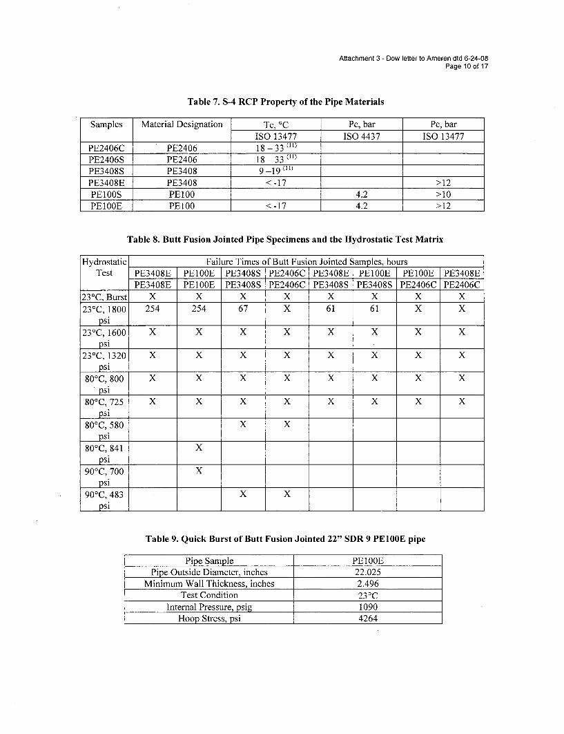
Attachment 3 - Dow letter to Ameren dtd 6-24-08Page 10 of 17
Table 7. S-4 RCP Property of the Pipe Materials
Samples Material Designation Tc, 'C Pc, bar Pc, barISO 13477 IS04437 ISO 13477
PE2406C PE2406 18-33 (11)
PE2406S PE2406 18--33 (l)
PE3408S PE3408 9-19(11)PE3408E PE3408 < -17 >12PE1OOS PE100 4.2 >10PE100E PEOO < -17 4.2 >12
Table 8. Butt Fusion Jointed Pipe Specimens and the Hydrostatic Test Matrix
Hydrostatic Failure Times of Butt Fusion Jointed Samples, hoursTest PE3408E PElOOE PE3408S PE2406C PE3408E PE100E PE100E PE3408E
PE3408E PElOOE PE3408S PE2406C PE3408S PE3408S PE2406C PE2406C23 0C, Burst X X X X X X X X23°C, 1800 254 254 67 X 61 61 X X
psi23-C,1600 X X X X X X X X
psi23°C, 1320 X X X X X X X X
psi80°C,800 X X X X X X X X
psi80°C,725 X X X X X X X X
psi80°C, 580 X X
psi80°C, 841 X
psi90°C, 700 X
psi90°C, 483 X X
psi
Table 9. Quick Burst of Butt Fusion Jointed 22" SDR 9 PE100E pipe
Pipe Sample PE1OOEPipe Outside Diameter, inches 22.025
Minimum Wall Thickness, inches 2.496Test Condition 23 0 C
Internal Pressure, psig 1090Hoop Stress, psi 4264
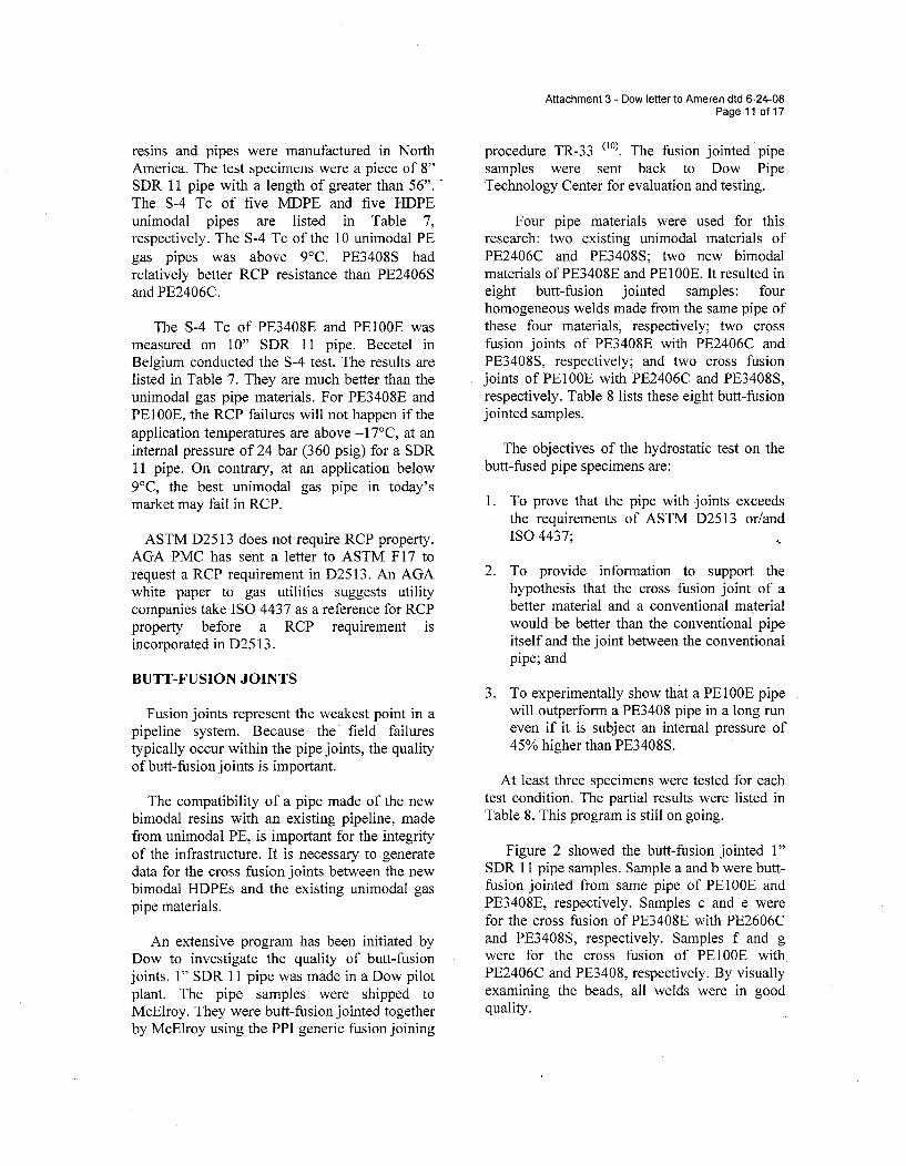
Attachment 3 - Dow letter to Ameren dtd 6-24-08Page 11 of 17
resins and pipes were manufactured in NorthAmerica. The test specimens were a piece of 8"SDR 11 pipe with a length of greater than 56".The S-4 Tc of five MDPE and five HDPEunimodal pipes are listed in Table 7,respectively. The S-4 Tc of the 10 unimodal PEgas pipes was above 9°C. PE3408S hadrelatively better RCP resistance than PE2406Sand PE2406C.
The S-4 Tc of PE3408E and PEOOE wasmeasured on 10" SDR 11 pipe. Becetel inBelgium conducted the S-4 test. The results arelisted in Table 7. They are much better than theunimodal gas pipe materials. For PE3408E andPE100E, the RCP failures will not happen if theapplication temperatures are above -17C, at aninternal pressure of 24 bar (360 psig) for a SDR11 pipe. On contrary, at an application below9°C, the best unimodal gas pipe in today'smarket may fail in RCP.
ASTM D25 13 does not require RCP property.AGA PMC has sent a letter to ASTM F17 torequest a RCP requirement in D2513. An AGAwhite paper to gas utilities suggests utilitycompanies take ISO 4437 as a reference for RCPproperty before a RCP requirement isincorporated in D25 13.
BUTT-FUSION JOINTS
Fusion joints represent the weakest point in apipeline system. Because the' field failurestypically occur within the pipe joints, the qualityof butt-fusion joints is important.
The compatibility of a pipe made of the newbimodal resins with an existing pipeline, madefrom unimodal PE, is important for the integrityof the infrastructure. It is necessary to generatedata for the cross fusion joints between the newbimodal HDPEs and the existing unimodal gaspipe materials.
An extensive program has been initiated byDow to investigate the quality of butt-fusionjoints. 1" SDR 11 pipe was made in a Dow pilotplant. The pipe samples were shipped toMcElroy. They were butt-fusion jointed togetherby McElroy using the PPI generic fusion joining
procedure TR-33 (10). The fusion jointed pipesamples were sent back to Dow PipeTechnology Center for evaluation and testing.
Four pipe materials were used for thisresearch: two existing unimodal materials ofPE2406C and PE3408S; two new bimodalmaterials of PE3408E and PE1OOE. It resulted ineight butt-fusion jointed samples: fourhomogeneous welds made from the same pipe ofthese four materials, respectively; two crossfusion joints of PE3408E with PE2406C andPE3408S, respectively; and two cross fusionjoints of PElO0E with PE2406C and PE3408S,respectively. Table 8 lists these eight butt-fusionjointed samples.
The objectives of the hydrostatic test on thebutt-fused pipe specimens are:
1. To prove that the pipe with joints exceedsthe requirements of ASTM D2513 or/andISO 4437;
2. To provide information to support thehypothesis that the cross fusion joint of abetter material and a conventional materialwould be better than the conventional pipeitself and the joint between the conventionalpipe; and
3. To experimentally show that a PEIOOE pipewill outperform a PE3408 pipe in a long runeven if it is subject an internal pressure of45% higher than PE3408S.
At least three specimens were tested for eachtest condition. The partial results were listed inTable 8. This program is still on going.
Figure 2 showed the butt-fusion jointed 1"SDR 11 pipe samples. Sample a and b were butt-fusion jointed from same pipe of PE1OOE andPE3408E, respectively. Samples c and e werefor the cross fusion of PE3408E with PE2606Cand PE3408S, respectively. Samples f and gwere for the cross fusion of PE1OOE withPE2406C and PE3408, respectively. By visuallyexamining the beads, all welds were in goodquality.

Attachment 3 - Dow letter to Ameren dtd 6-24-08Page 12 of 17
0
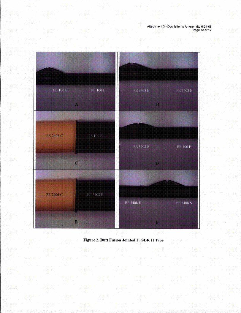
Attachment 3 - Dow letter to Ameren dtd 6-24-08Page 13 of 17
III ION, I IOX I
III ,, III j()1) I
N I PIS I III " 108
Figure 2. Butt Fusion Jointed 1" SDR 11 Pipe
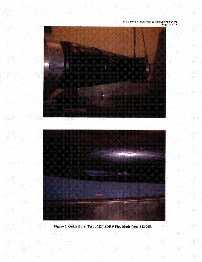
Attachment 3 - Dow letter to Ameren dtd 6-24-08Page 14 of 17
Figure 3, Quick Burst Test of 22" SDR 9 Pipe Made from PE100E.
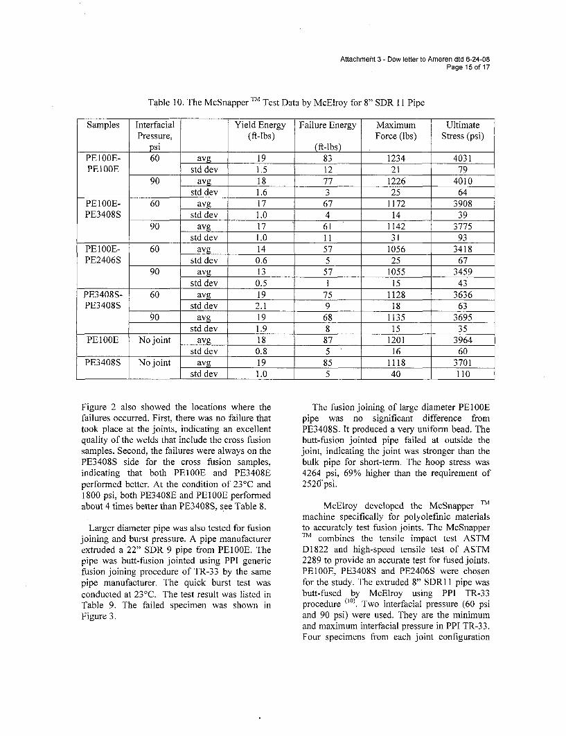
Attachment 3 - Dow letter to Ameren dtd 6-24-08Page 15 of 17
Table 10. The McSnapper TM Test Data by McElroy for 8" SDR 11 Pipe
Samples Interfacial Yield Energy Failure Energy Maximum UltimatePressure, (ft-lbs) Force (lbs) Stress (psi)
psi (ft-lbsPElOOE- 60 avg 19 83 1234 4031PEIOOE std dev 1.5 12 21 79
90 avg 18 77 1226 4010std dev 1.6 3 25 64
PE1OOE- 60 avg 17 67 1172 3908PE3408S std dev 1.0 4 14 39
90 avg 17 61 1142 3775std dev 1.0 11 31 93
PE1OOE- 60 avg 14 57 1056 3418PE2406S std dev 0.6 5 25 67
90 avg 13 57 1055 3459std dev 0.5 1 15 43
PE3408S- 60 avg 19 75 1128 3636PE3408S std dev 2.1 9 18 63
90 avg 19 68 1135 3695std dev 1.9 8 15 35
PE100E No joint avg 18 87 1201 3964std dev 0.8 5 16 60
PE3408S No joint avg 19 85 1118 3701std dev 1.0 5 40 110
Figure 2 also showed the locations where thefailures occurred. First, there was no failure thattook place at the joints, indicating an excellentquality of the welds that include the cross fusionsamples. Second, the failures were always on thePE3408S side for the cross fusion samples,indicating that both PEIOOE and PE3408Eperformed better. At the condition of 23°C and1800 psi, both PE3408E and PE1OOE performedabout 4 times better than PE3408S, see Table 8.
Larger diameter pipe was also tested for fusionjoining and burst pressure. A pipe manufacturerextruded a 22" SDR 9 pipe from PE100E. Thepipe was butt-fusion jointed using PPI genericfusion joining procedure of TR-33 by the samepipe manufacturer. The quick burst test wasconducted at 2' C. The test result was listed inTable 9. The failed specimen was shown inFigure 3.
The fusion joining of large diameter PE1OOEpipe was no significant difference fromPE3408S. It produced a very uniform bead. Thebutt-fusion jointed pipe failed at outside thejoint, indicating the joint was stronger than thebulk pipe for short-term. The hoop stress was4264 psi, 69% higher than the requirement of2520"psi.
McElroy developed the McSnapper TM
machine specifically for polyolefinic materialsto accurately test fusion joints. The McSnapperTM combines the tensile impact test ASTMD1822 and high-speed tensile test of ASTM2289 to provide an accurate test for fused joints.PEIOOE, PE3408S and PE2406S were chosenfor the study. The extruded 8" SDR1 1 pipe wasbutt-fused by McElroy using PPI TR-33procedure (10). Two interfacial pressure (60 psiand 90 psi) were used. They are the minimumand maximum interfacial pressure in PPI TR-33.Four specimens from each joint configuration
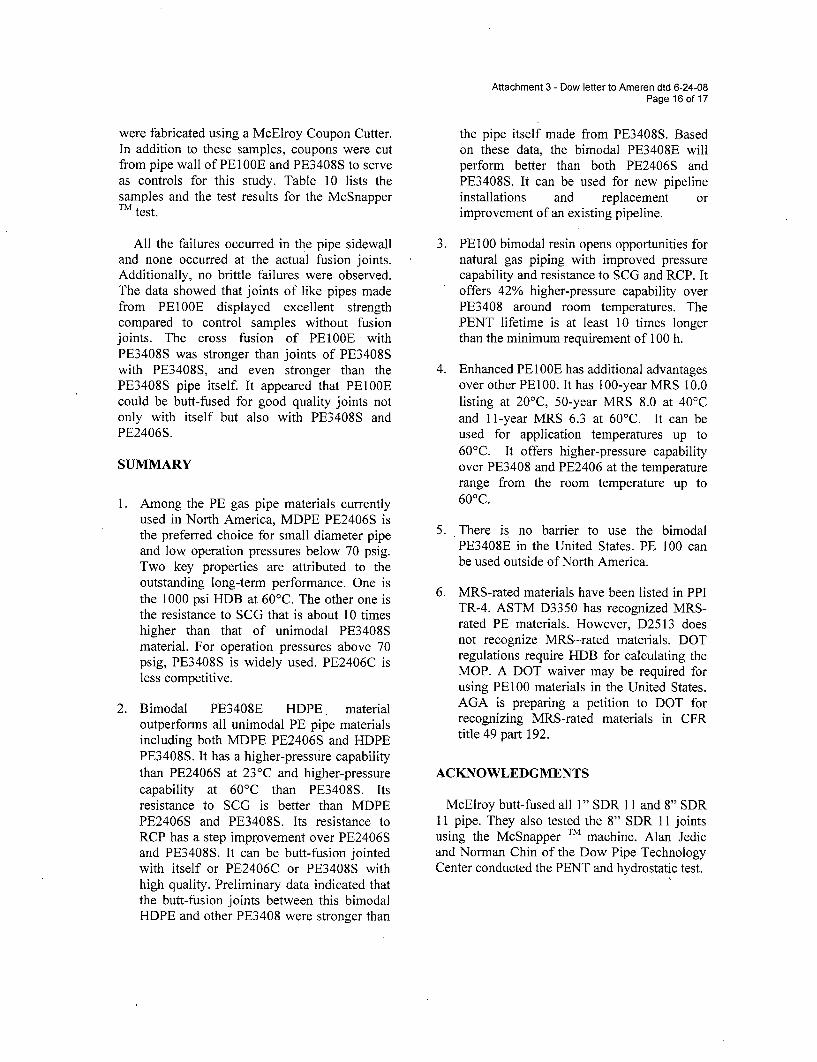
Attachment 3 - Dow letter to Ameren dtd 6-24-08Page 16 of 17
were fabricated using a McElroy Coupon Cutter.In addition to these samples, coupons were cutfrom pipe wall of PEIOOE and PE3408S to serveas controls for this study. Table 10 lists thesamples and the test results for the McSnapperTM test.
All the failures occurred in the pipe sidewalland none occurred at the actual fusion joints.Additionally, no brittle failures were observed.The data showed that joints of like pipes madefrom PE100E displayed excellent strengthcompared to control samples without fusionjoints. The cross fusion of PE1OOE withPE3408S was stronger than joints of PE3408Swith PE3408S, and even stronger than thePE3408S pipe itself. It appeared that PElOOEcould be butt-fused for good quality joints notonly with itself but also with PE3408S andPE2406S.
SUMMARY
1. Among the PE gas pipe materials currentlyused in North America, MDPE PE2406S isthe preferred choice for small diameter pipeand low operation pressures below 70 psig.Two key properties are attributed to theoutstanding long-term performance. One isthe 1000 psi HDB at 60'C. The other one isthe resistance to SCG that is about 10 timeshigher than that of unimodal PE3408Smaterial. For operation pressures above 70psig, PE3408S is widely used. PE2406C isless competitive.
2. Bimodal PE3408E HDPE materialoutperforms all unimodal PE pipe materialsincluding both MDPE PE2406S and HDPEPE3408S. It has a higher-pressure capabilitythan PE2406S at 23°C and higher-pressurecapability at 60'C than PE3408S. Itsresistance to SCG is better than MDPEPE2406S and PE3408S. Its resistance toRCP has a step improvement over PE2406Sand PE3408S. It can be butt-fusion jointedwith itself or PE2406C or PE3408S withhigh quality. Preliminary data indicated thatthe butt-fusion joints between this bimodalHDPE and other PE3408 were stronger than
the pipe itself made from PE3408S. Basedon these data, the bimodal PE3408E willperform better than both PE2406S andPE3408S. It can be used for new pipelineinstallations and replacement orimprovement of an existing pipeline.
3. PE100 bimodal resin opens opportunities fornatural gas piping with improved pressurecapability and resistance to SCG and RCP. Itoffers 42% higher-pressure capability overPE3408 around room temperatures. ThePENT lifetime is at least 10 times longerthan the minimum requirement of 100 h.
4. Enhanced PE100E has additional advantagesover other PE100. It has 100-year MRS 10.0listing at 20°C, 50-year MRS 8.0 at 40'Cand 11-year MRS 6.3 at 60'C. It can beused for application temperatures up to60'C. It offers higher-pressure capabilityover PE3408 and PE2406 at the temperaturerange from the room temperature up to60 0 C.
5. There is no barrier to use the bimodalPE3408E in the United States. PE 100 canbe used outside of North America.
6. MRS-rated materials have been listed in PPITR-4. ASTM D3350 has recognized MRS-rated PE materials. However, D2513 doesnot recognize MRS-rated materials. DOTregulations require HDB for calculating theMOP. A DOT waiver may be required forusing PE100 materials in the United States.AGA is preparing a petition to DOT forrecognizing MRS-rated materials in CFRtitle 49 part 192.
ACKNOWLEDGMENTS
McElroy butt-fused all 1" SDR 11 and 8" SDR11 pipe. They also tested the 8" SDR 11 jointsusing the McSnapper TM machine. Alan Jedicand Norman Chin of the Dow Pipe TechnologyCenter conducted the PENT and hydrostatic test.
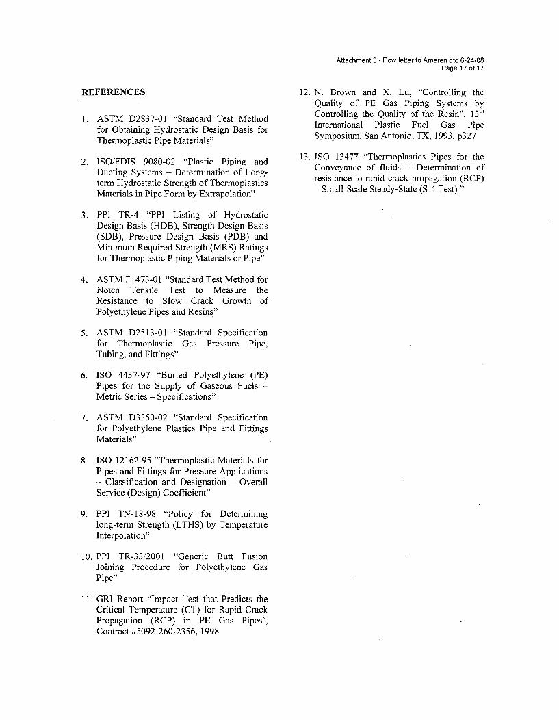
Attachment 3 - Dow letter to Ameren dtd 6-24-08Page 17 of 17
REFERENCES
1. ASTM D2837-01 "Standard Test Methodfor Obtaining Hydrostatic Design Basis forThermoplastic Pipe Materials"
2. ISO/FDIS 9080-02 "Plastic Piping andDucting Systems - Determination of Long-term Hydrostatic Strength of ThermoplasticsMaterials in Pipe Form by Extrapolation"
3. PPI TR-4 "PPI Listing of HydrostaticDesign Basis (HDB), Strength Design Basis(SDB), Pressure Design Basis (PDB) andMinimum Required Strength (MRS) Ratingsfor Thermoplastic Piping Materials or Pipe"
4. ASTM F1473-01 "Standard Test Method forNotch Tensile Test to Measure theResistance to Slow Crack Growth ofPolyethylene Pipes and Resins"
5. ASTM D2513-01 "Standard Specificationfor Thermoplastic Gas Pressure Pipe,Tubing, and Fittings"
6. ISO 4437-97 "Buried Polyethylene (PE)Pipes for the Supply of Gaseous Fuels -Metric Series - Specifications"
7. ASTM D3350-02 "Standard Specificationfor Polyethylene Plastics Pipe and FittingsMaterials"
8. ISO 12162-95 "Thermoplastic Materials forPipes and Fittings for Pressure Applications- Classification and Designation - OverallService (Design) Coefficient"
9. PPI TN-18-98 "Policy for Determininglong-term Strength (LTHS) by TemperatureInterpolation"
10. PPI TR-33/2001 "Generic Butt FusionJoining Procedure for Polyethylene GasPipe"
11. GRI Report "Impact Test that Predicts theCritical Temperature (CT) for Rapid CrackPropagation (RCP) in PE Gas Pipes',Contract #5092-260-2356, 1998
12. N. Brown and X. Lu, "Controlling theQuality of PE Gas Piping Systems byControlling the Quality of the Resin", 13th
International Plastic Fuel Gas PipeSymposium, San Antonio, TX, 1993, p3 2 7
13. ISO 13477 "Thermoplastics Pipes for theConveyance of fluids - Determination ofresistance to rapid crack propagation (RCP)- Small-Scale Steady-State (S-4 Test) "
Attachment 4- Dow letter to Ameren dtd 6-2408Page of 27
L
I
New Products, New Horizons: HighDensity Polyethylene (HDPE) Resins
for Natural Gas Piping
Z. Jimmy Zhou, David W. Kababik, Guylaine St. Jean and Quentin D. Eberhart
Pipe Technology Center, The Dow Chemical Company
17th International Plastic Fuel Gas Pipe Symposium
October 22, 2002, San Francisco
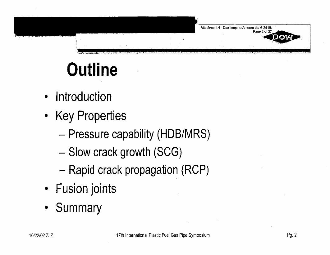
Attachment 4 - Dow letter to Ameren dtd 6-24-08Page 2 of 27
Outline* Introduction
# Key Properties- Pressure capability (HDB/MRS)
- Slow crack growth (SCG)- Rapid crack propagation (RCP)
* Fusion joints
* Summary
10/22/02 ZJZ 17th International Plastic Fuel Gas Pipe Symposium Pg. 2
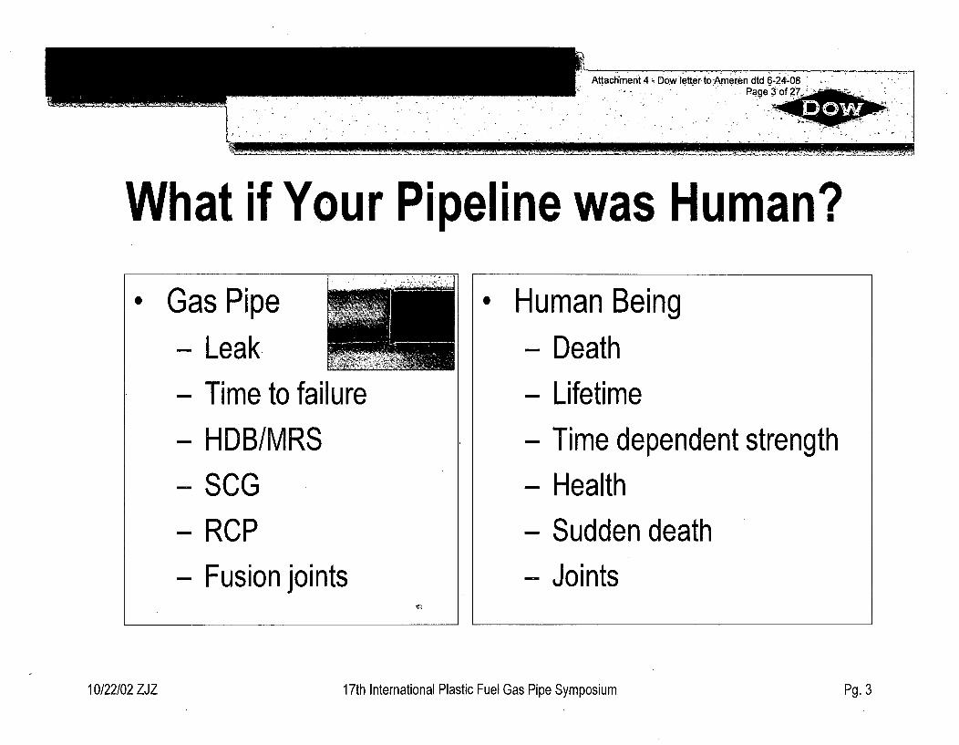
Attachment 4 - Dow letter toAmeren dtd 6-24-08. ,ofPage 3 2
I
What if Your Pipeline was Human?I
* Human Being- Death
- Lifetime
- Time dependent strength
- Health
- Sudden death
- Joints
10/22/02 ZJZ 17th International Plastic Fuel Gas Pipe Symposium Pg. 3
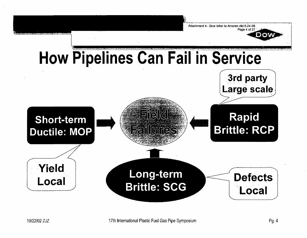
Attachment 4- Dow letter to Ameren dtd 6ý24-08Page 4of 27
IL
How Pipelines Can Fail in ServiceSLar,,,ge scale.J
YieldLocal
I *MRapid
Brittle: RCP
Log-er e . D efects'Lý IocalLocal
10/22/02 ZJZ 17th International Plastic Fuel Gas Pipe Symposium Pg. 4
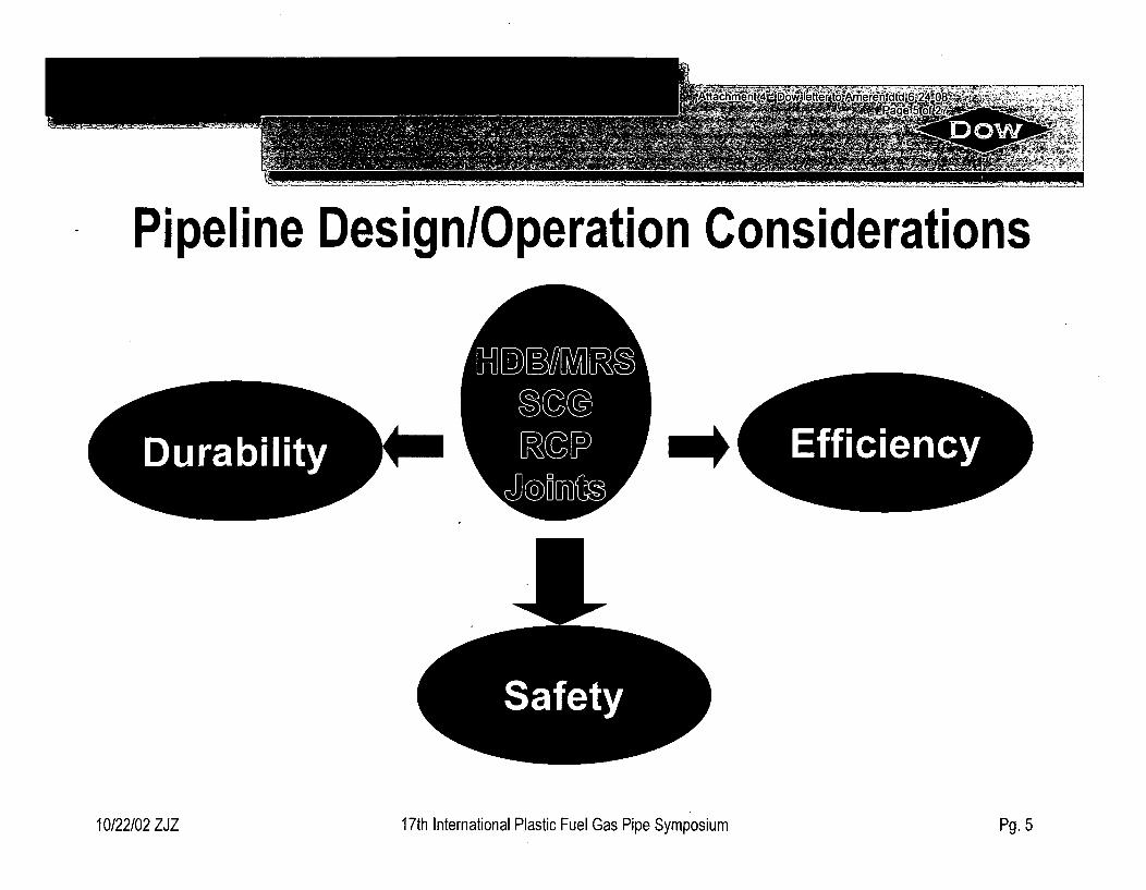
Pipeline Design/Operation Considerations
[Durability
IMIMMRý9ýcgRUP
J@U01MM* :Effiiciency::
p.
17th International Plastic Fuel Gas Pipe Symposium10/22/02 ZJZ Pg. 5
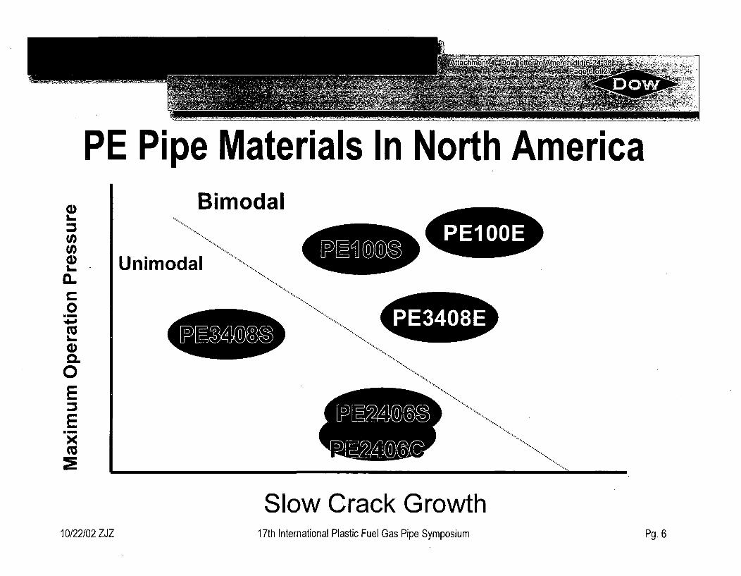
PE Pipe Materials In North AmericaBimodal
a)a.
0~
L.0-E
x
Unimc)dal
MIE M SI
L PE3408ii.ý
240.°
Mmwmmbý
Slow Crack Growth17th International Plastic Fuel Gas Pipe Symposium10/22/02 ZJZ Pg. 6
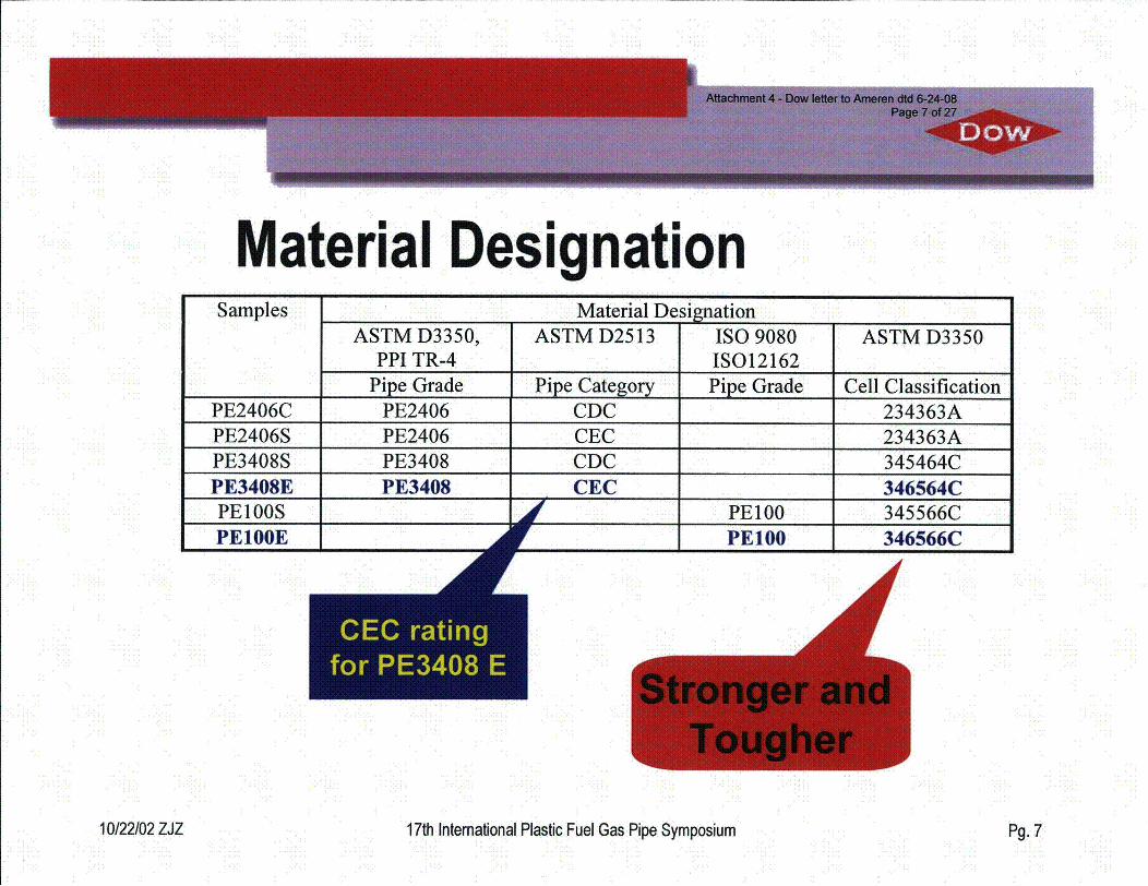
Dow
Material DesignationSamples Material Designation
ASTM D3350, ASTM D2513 ISO 9080 ASTM D3350PPI TR-4 IS012162
Pipe Grade Pipe Category Pipe Grade Cell ClassificationPE2406C PE2406 CDC 234363APE2406S PE2406 CEC 234363APE3408S PE3408 CDC 345464CPE3408EPE1OOS
PE3408 CEC 346564C
PE100E
-s atnfo0 E30
PE100 345566C1*
1*
PE100 346566C
10/22/02 ZJZ 17th International Plastic Fuel Gas Pipe Symposium Pg. 7
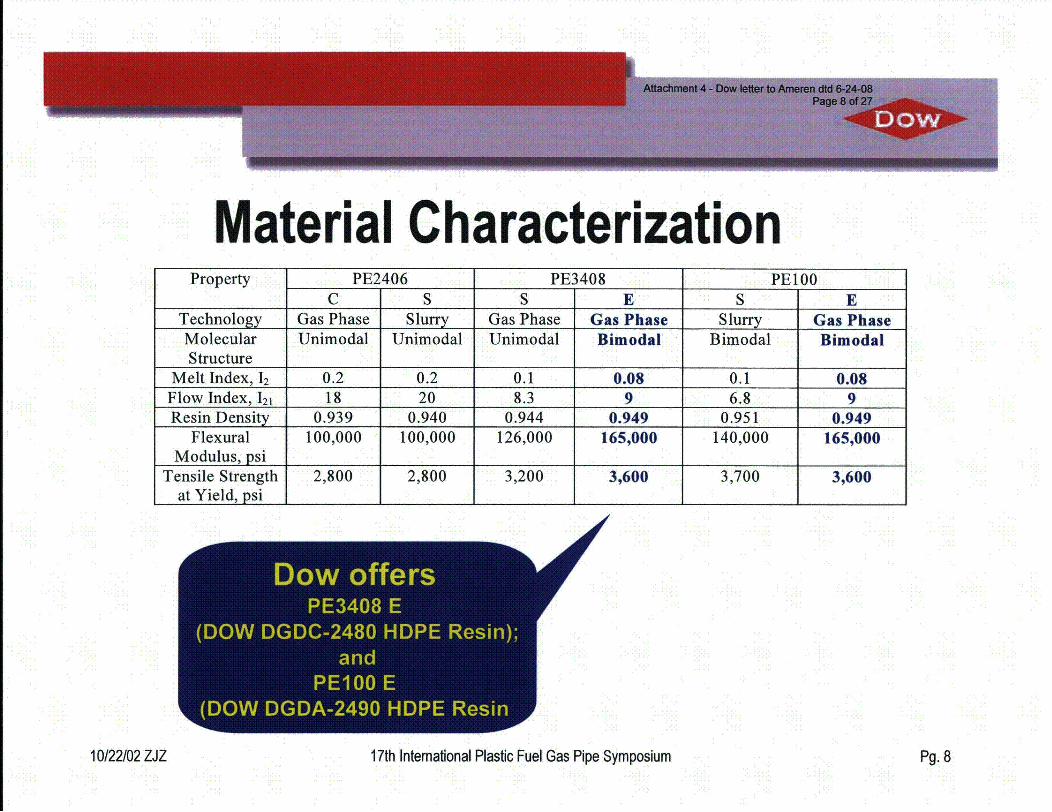
Material CharacterizationProperty PE2406 PE3408 PE100
C S S E S ETechnology Gas Phase Slurry Gas Phase Gas Phase Slurry Gas PhaseMolecular Unimodal Unimodal Unimodal Bimodal Bimodal BimodalStructure
Melt Index, 12 0.2 0.2 0.1 0.08 0.1 0.08Flow Index, 121 18 20 8.3 9 6.8 9Resin Density 0.939 0.940 0.944 0.949 0.951 0.949
Flexural 100,000 100,000 126,000 165,000 140,000 165,000Modulus, psi
Tensile Strength 2,800 2,800 3,200 3,600 3,700 3,600at Yield, psi
r owofer
10/22/02 ZJZ 17th Intemational Plastic Fuel Gas Pipe Symposium Pg. 8
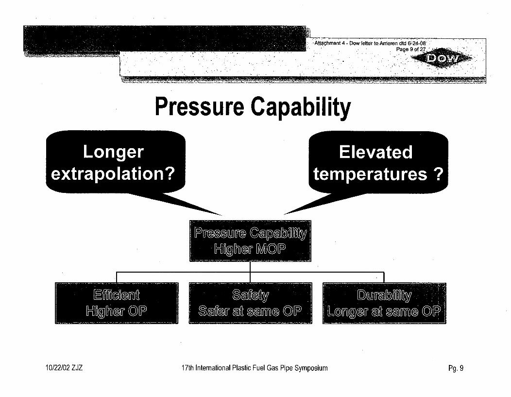
MAttachment 4- Dow lefterltoAmeren dtd 6-24-08 "1Page9W f27
"I•
Pressure Capability7 Longer
extrapolation?Elevated
temperatures ?
E5IrdsM
I .1
10/22/02 ZJZ 17th International Plastic Fuel Gas Pipe Symposium Pg. 9
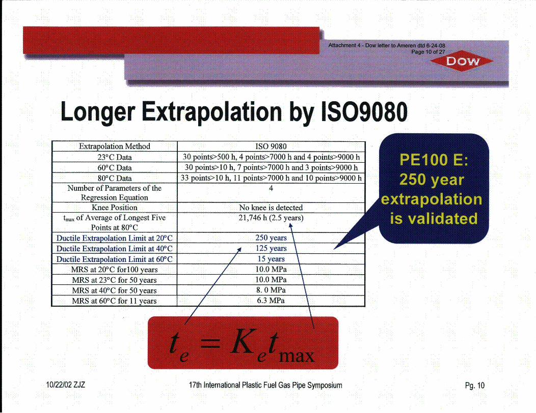
Longer Extrapolation by IS09080Extrapolation Method ISO 9080
23°C Data 30 points>500 h, 4 points>7000 h and 4 points>9000 h60 0C Data 30 points>10 h, 7 points>7000 h and 3 points>9000 h800C Data 33 points>10 h, 11 points>7000 h and 10 points>9000 h
Number of Parameters of the 4Regression Equation
Knee Position No knee is detectedt,,. of Average of Longest Five 21,746 h (2.5 years)
Points at 80*CDuctile Extrapolation Limit at 20*C 250 yearsDuctile Extrapolation Limit at 40'C 125 yearsDuctile Extrapolation Limit at 60'C 15 years
MRS at 20'C forl100 years 10.0 MPaMRS at 231C for 50 years 10.0 MPaMRS at 401C for 50 years 8.0 MPaMRS at 601C for 11 years 6.3 MPa
/
10/22/02 ZJZ 17th Intemational Plastic Fuel Gas Pipe Symposium Pg. 10
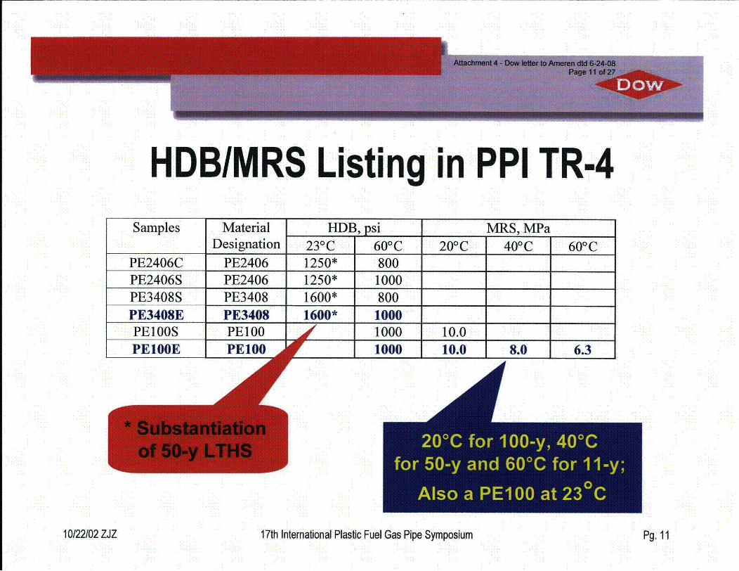
HDB/MRS Listing in PPI TR-4Samples Material HDB, psi MRS, MPa
Designation 230C 600 C 200C 400C 600CPE2406C PE2406 1250* 800PE2406S PE2406 1250* 1000PE3408S PE3408 1600* 800PE3408E PE3408 1600* 1000PElOOS PE100 19
_ _ 1000 10.0 1 11000 10.0 1 8.0 1 6.3
V
20'C for 1 00-y, 40'Cfor 50-y and 60'C for 11 -yI
Also a PE100 at 230C
10/22/02 ZJZ 17th International Plastic Fuel Gas Pipe Symposium Pg. 11
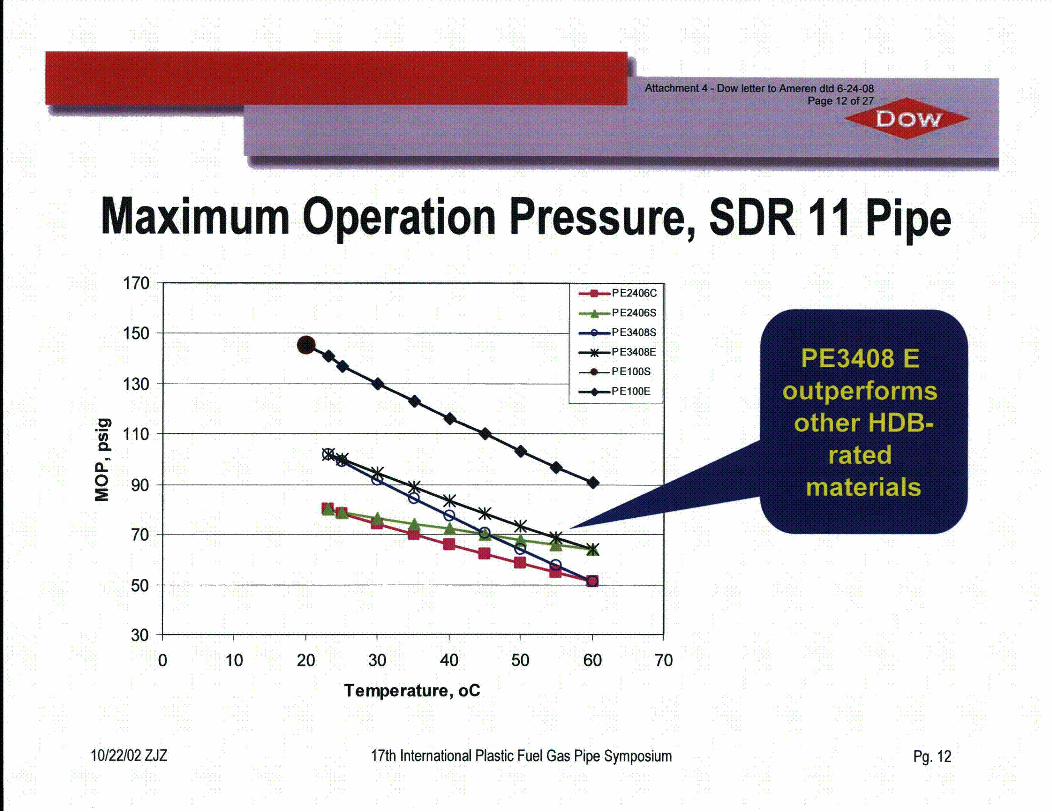
Maximum Operation Pressure, SDR 11 Pipe170
150
130
110
90
C)
0.02
- P E2406C
-A- P E2406S
-0-PE3408S
,---PE3408E
-- *. P ElOOSPE3408 E
outperformsother HDB-
ratedmaterials
70
50
30 -4
10 20 30 40 50 600 70
Temperature, oC
10/22/02 ZJZ 17th International Plastic Fuel Gas Pipe Symposium Pg. 12
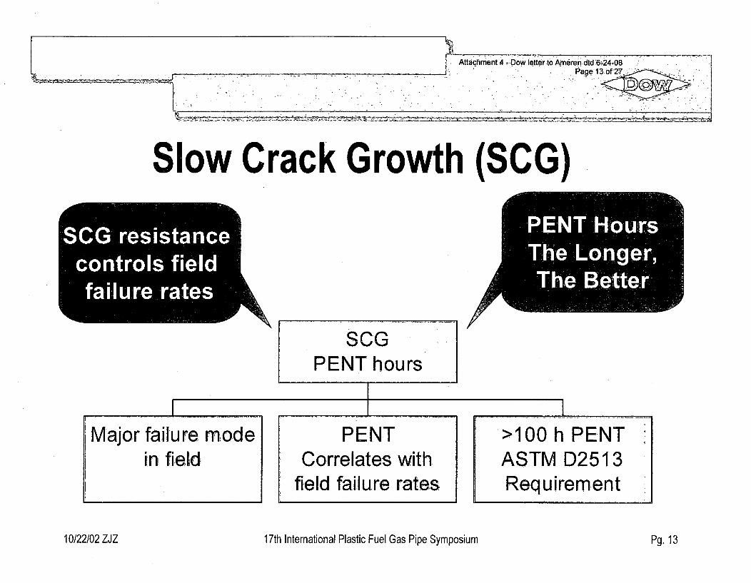
L r,Attachment 4 =DBw I etterto Ameren dtd '&24-08
- -
Slow Crack Growth (SCG)
7SCG" resistancecontrols fieldfailure rates
PENT HoUrsThe Longer,The Be" tter A'
SCGPENT hours
Major failure modein field
PENTCorrelates with
field failure rates
>100 h PENTASTM D2513Requirement
10/22/02 ZJZ 17th International Plastic Fuel Gas Pipe Symposium Pg. 13
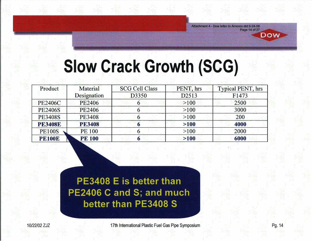
Slow Crack Growth (SCG)Product Material SCG Cell Class PENT, hrs Typical PENT, hrs
Designation D3350 D2513 F1473PE2406C PE2406 6 >100 2500PE2406S PE2406 6 >100 3000PE3408S PE3408 6 >100 200PE3408E PE3408 6 >100 4000DU IAA40 DU 1AA >,AA AA1- Jl_• Jl. VU 0 i.IL J. IVVJ1 V3 - I VJ •V)'J
I I 4
PE100E 6000
10/22/02 ZJZ 17th International Plastic Fuel Gas Pipe Symposium Pg. 14
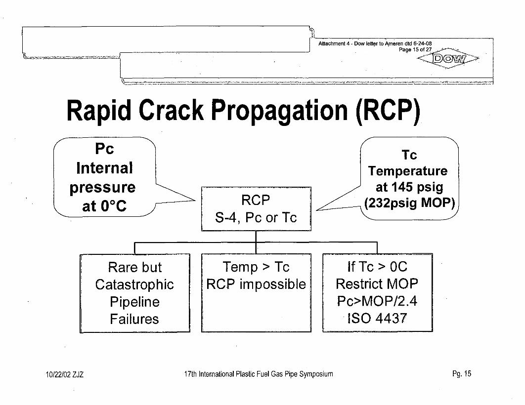
Attachment 4 - Dow letter to Ameren dtd 6-24-08Page 15 of27
Rapid Crack Propagation (RCP)~PC
Internal
pressureat 0°C
I TcTemperature
at 145 psig(232psig MOP)RCP
S-4, Pc or TcI
I - ---I-Rare but
CatastrophicPipelineFailures
Temp > TcRCP impossible
If Tc > OCRestrict MOPPc>MOP/2.4
ISO 4437
10/22/02 ZJZ 17th International Plastic Fuel Gas Pipe Symposium Pg. 15
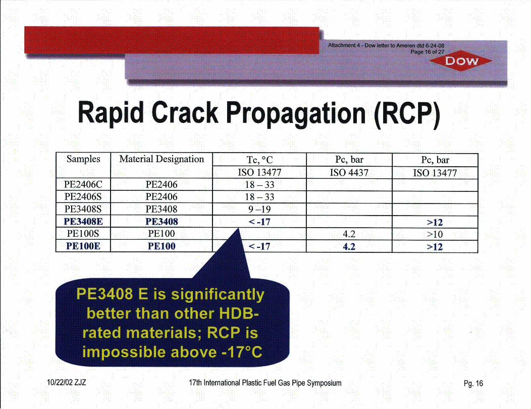
Rapid Crack Propagation (RCP)Samples Material Designation Tc, 0C Pc, bar Pc, bar
ISO 13477 ISO 4437 ISO 13477PE2406C PE2406 18-33PE2406S PE2406 18-33PE3408S PE3408 9-19PE3408E PE3408 < -17 >12
4.2 >104.2 >12
S
10/22/02 ZJZ 17th Intemational Plastic Fuel Gas Pipe Symposium Pg. 16
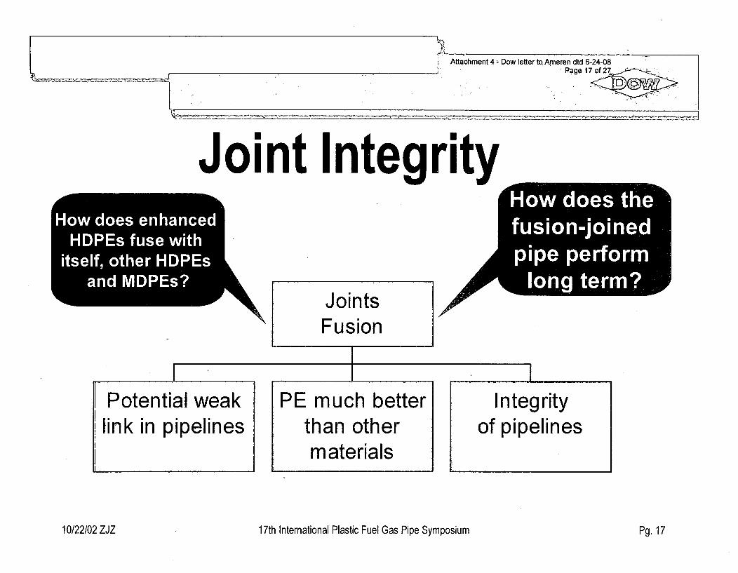
I Attachment 4 - Dow letter to.Ameren dtd 6-24-08Page 17 of 27• -
7
Joint Integrityw
7Hwde ehneHDI fue it
itef ote DS
-ndID.s
Ho oste
fsionjone
JointsFusion
A
f
II I
Potential weaklink in pipelines
PE much betterthan othermaterials
I . . . . . . . . . .
Integrityof pipelines
10/22/02 ZJZ 17th International Plastic Fuel Gas Pipe Symposium Pg. 17
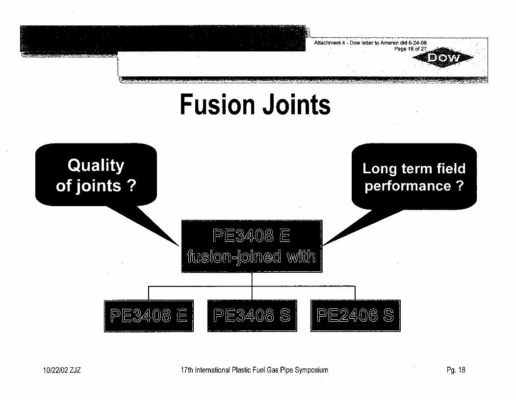
Attachment 4 - Dow letter to Ameren dtd 6-24 08Page 18 of 27
Fusion Joints
Qualityof joints ?
"ILong term fieldperformance ?
I I I
10/22/02 ZJZ 17th International Plastic Fuel Gas Pipe Symposium Pg. 18
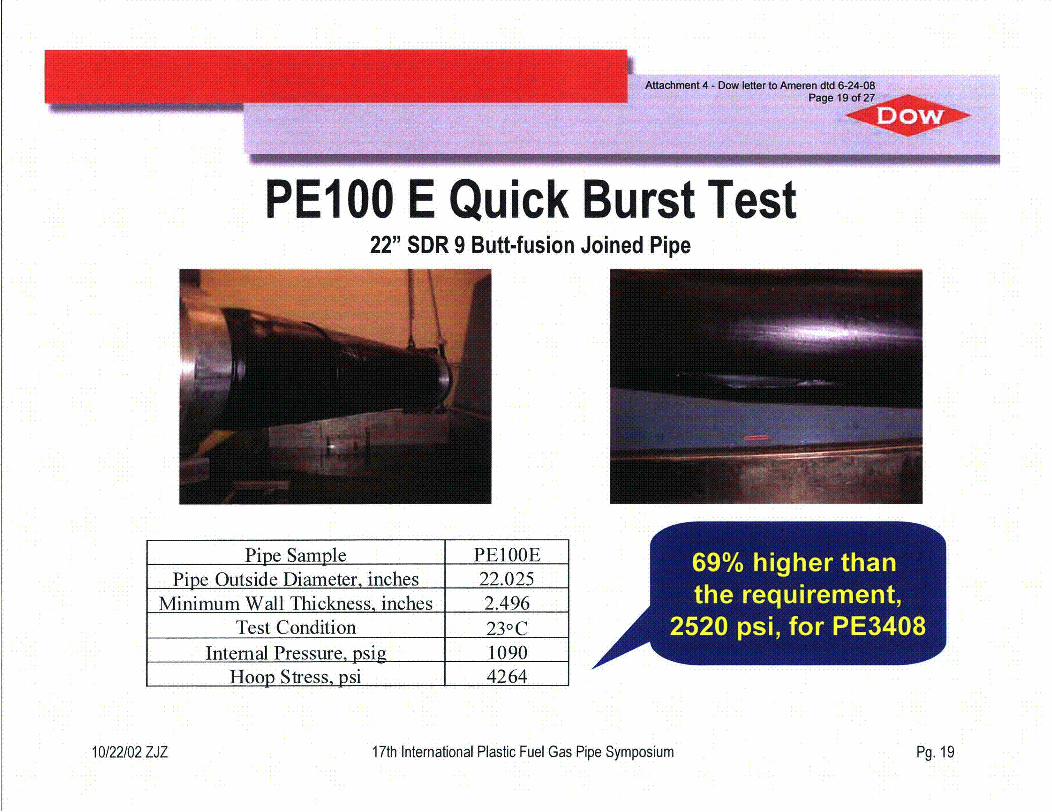
PEI00 E Quick Burst Test22" SDR 9 Butt-fusion Joined Pipe
Pipe Sample PE1OOEPipe Outside Diameter, inches 22.025
Minimum Wall Thickness, inches 2.496Test Condition 230C
Internal Pressure, psig 1090Hoop Stress, psi 4264
69% higher thanthe requirement,
2520 psi, for PE3408--.4A
10/22/02 ZJZ 17th International Plastic Fuel Gas Pipe Symposium Pg. 19
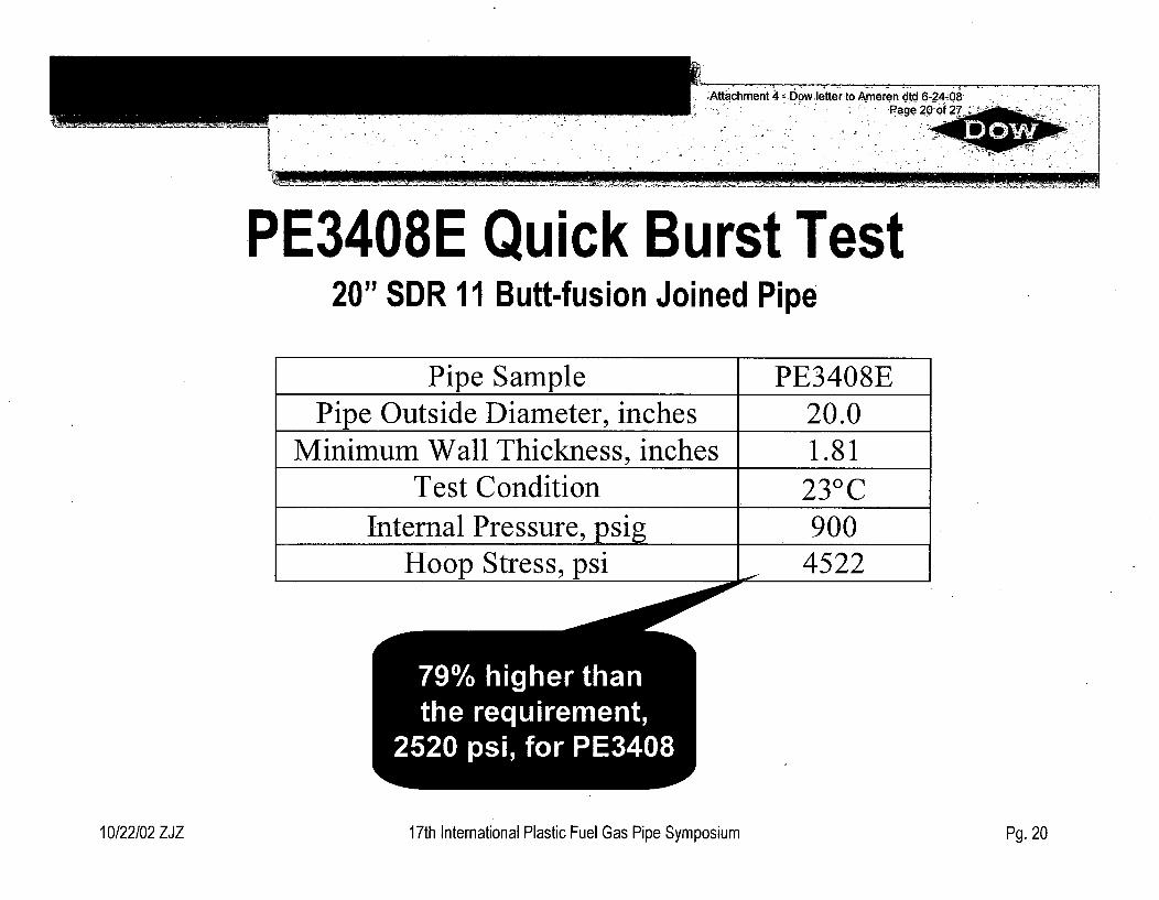
;Att chment 4 Dowetter to Ameren dtd 6-24-08.Page 20of 27__
•Z
I62OW!2za
PE3408E Quick Burst Test20" SDR 11 Butt-fusion Joined Pipe
Pipe Sample PE3408EPipe Outside Diameter, inches 20.0
Minimum Wall Thickness, inches 1.81Test Condition 23 0C
Internal Pressure, psig 900Hoop Stress, psi 4522
79% higher thanthe requirement,
2520 psi, for PE34 8L
W_
10/22/02 ZJZ 17th International Plastic Fuel Gas Pipe Symposium Pg. 20
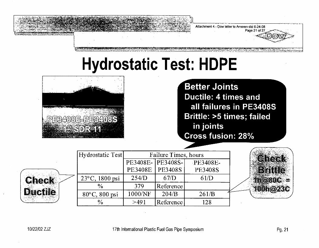
Attachment 4.- Dow letter to Ameren dtd 6-24-08
Hydrostatic Test: HDPEett,uct7 B etter Joint sDDuctile: 4 times andall failures in PE3408S
Brittle: >5 times; failedin joints
ross fusion: 28%C
7CC,6',eackekOu''Ictillb'i,
Hydrostatic Test Failure Times, hoursPE3408E- PE3408S- PE3408E-PE3408E PE3408S PE3408S
23 0 C, 1800 psi 254/D 67/D 61/D% 379 Reference
800C psi 1000/NF 204/B. 261/B% >491 Reference 128
Th"(00)=
~I0 )h @&R 3)C
10/22/02 ZJZ 17th International Plastic Fuel Gas Pipe Symposium Pg. 21
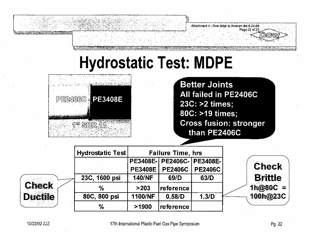
L Afahet4 -Dow lette-rto Atnereh dtd 6-124MO} ttchen - Pagek?2o 27
Hydrostatic Test: MDPE
Hydrostatic Test Failure Time, hrs
C, h kýhielc k-Dructil'e--',
PE3408E- PE2406C- PE3408E-PE3408E PE2406C PE2406C
23C, 1600 psi 140/NF 69/D 63/D
% >203 reference80C, 800 psi 1100/NF 0.58/D 1.3/D
% >1900 reference,
Check| rit,,tle
10/22/02 ZJZ 17th International Plastic Fuel Gas Pipe Symposium Pg. 22
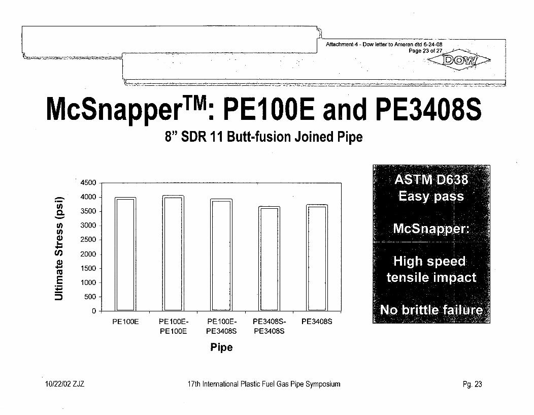
11l-Attachment.4 - Dow letter to Ameren dtd 6-24-08
J Page 23 of 2 - ...
McSnapperTMU
U PEIOOE and PE3408S8" SDR 11 Butt-fusion Joined Pipe
4500
U,
0.U)U)()C,)
E
4000-
3500 -
3000 -
2500 -
2000 -
1500 -
1000 -
500
0 LI. __________ LZ _____ ~J ___________ LZ ______ LI. __________ U: ______ L.L.........................LJ _____
PE100E PE1O0E- PE1O0E- PE3408S-PE100E PE3408S PE3408S
PE3408S
Pipe
10/22/02 ZJZ 17th International Plastic Fuel Gas Pipe Symposium Pg. 23
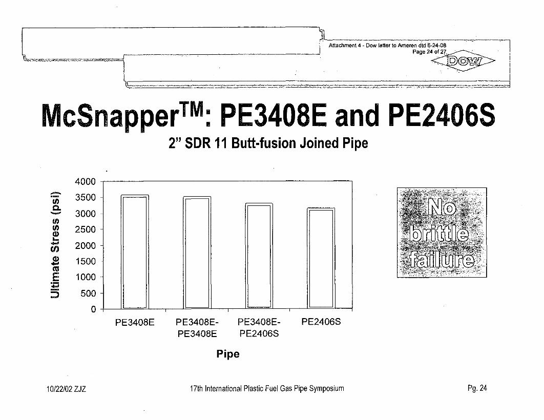
McSnap U]
U] PE3408E and PE2406S2" SDR 11 Butt-fusion Joined Pipe
4000
U)
E)
5)
3500-
3000
2500
2000
1500
1000
500
0 .4. j~ _______________ -~ __________ _______
PE3408E PE3408E-PE3408E
PE3408E-PE2406S
PE2406S
Pipe
10/22/02 ZJZ 17th International Plastic Fuel Gas Pipe Symposium Pg. 24
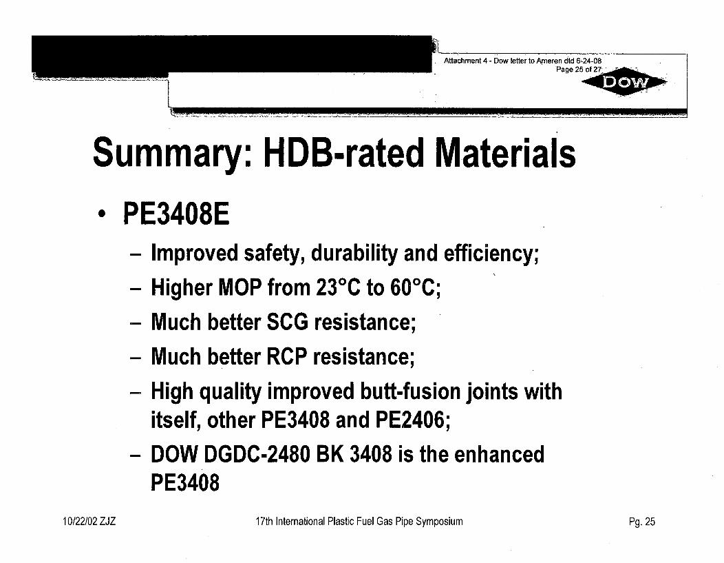
____ Attachment 4- Dow letter to Ameren dtd 6-24-08______________Page 25 of 27
Summary: HDB-rated M-aterialsPE3408E- Improved safety, durability and efficiency;
- Higher MOP from 230C to 60'C;
- Much better SCG resistance;
- Much better RCP resistance;
- High quality improved butt-fusion joints withitself, other PE3408 and PE2406;
- DOW DGDC-2480 BK 3408 is the enhancedPE3408
10/22/02 ZJZ 17th International Plastic Fuel Gas Pipe Symposium Pg. 25
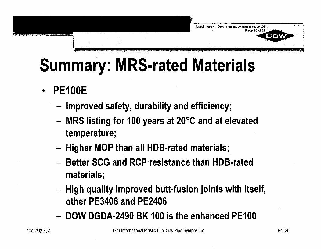
Attachment 4 - Dow letter to Ameren dtd 6-24-08Page 26 of 27
Summary: MRS-rated Materials* PE100E
- Improved safety, durability and efficiency;
- MRS listing for 100 years at 20°C and at elevatedtemperature;
- Higher MOP than all HDB-rated materials;- Better SCG and RCP resistance than HDB-rated
materials;
- High quality improved butt-fusion joints with itself,other PE3408 and PE2406
- DOW DGDA-2490 BK 100 is the enhanced PEI0010/22/02 ZJZ 17th International Plastic Fuel Gas Pipe Symposium Pg. 26
Attachment 4 - Dow letter to Ameren dtd 6-24-08Page of 27
Thank You for Your Attention
i Questions?
10/22/02 ZJZ 17th International Plastic Fuel Gas Pipe Symposium Pg. 27
Enclosure 4to ULNRC-05517
Enclosure 4
Callaway Calculation No. 2007-13241
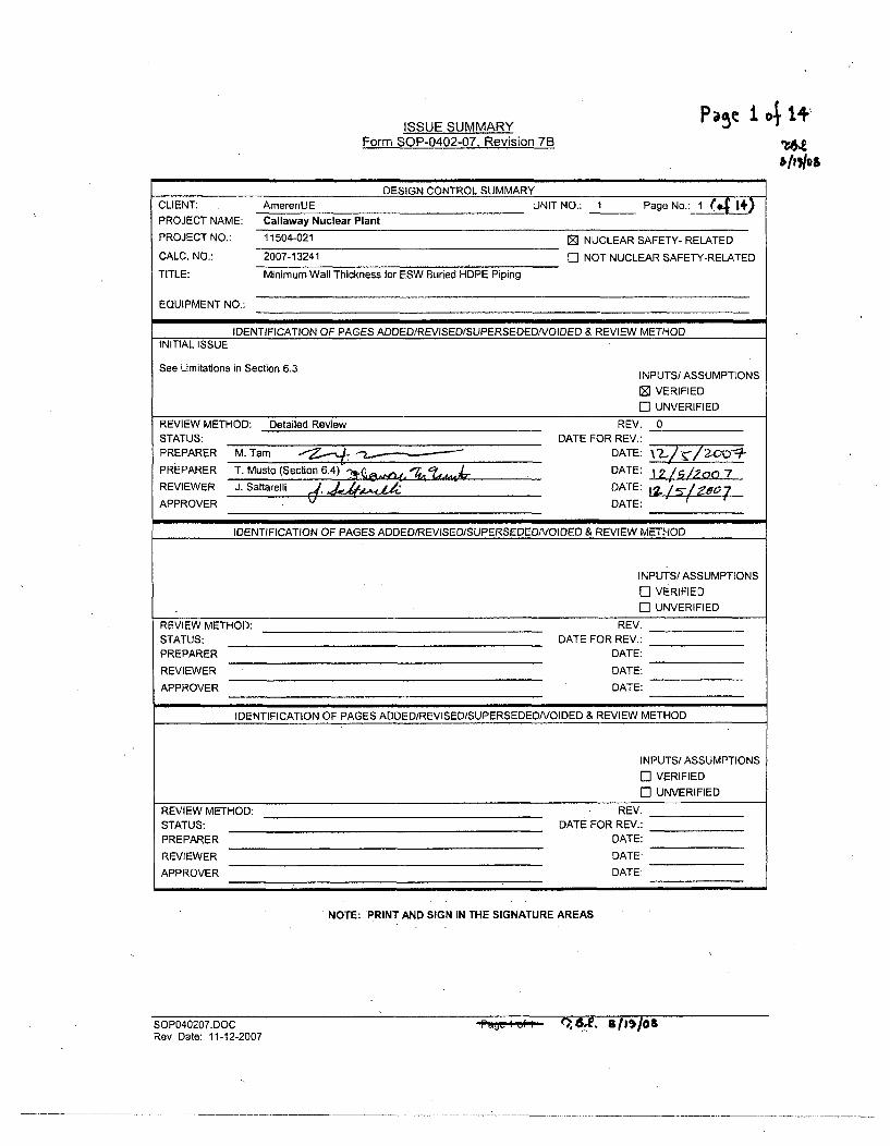
ISSUE SUMMARY PN 14 1+
Form SOP-0402-07, Revision 7B TU11,7los
DESIGN CONTROL SUMMARY
CLIENT: AmerenUE UNIT NO.: 1 Page No.: 1 (4 i*)PROJECT NAME: Callaway Nuclear Plant
PROJECT NO.: 11504-021 [ NUCLEAR SAFETY- RELATED
CALC. NO.: 2007-13241 El NOT NUCLEAR SAFETY-RELATED
TITLE: Minimum Wall Thickness for ESW Buried HDPE Piping
EQUIPMENT NO.:
IDENTIFICATION OF PAGES ADDED/REVISED/SUPERSEDEDNOIDED & REVIEW METHODINITIAL ISSUE
See Limitations in Section 6.3 INPUTS/ ASSUMPTIONS
[] VERIFIED
El UNVERIFIED
REVIEW METHOD: Detailed Review REV. 0
STATUS: DATE FOR REV.:
PREPARER M. Tam • .. - DATE: X OL
PREPARER T. Musto (Section 6.4) t ,, DATE:
REVIEWER J. Saltarelli d, a'4A.•.- DATE:7
APPROVER V DATE:
IDENTIFICATION OF PAGES ADDED/REVISED/SUPERSEDEDNOIDED & REVIEW METHOD
INPUTS/ ASSUMPTIONS
El VERIFIED
El UNVERIFIED
REVIEW METHOD: REV.
STATUS: DATE FOR REV.:
PREPARER DATE:
REVIEWER DATE:
APPROVER DATE:
IDENTIFICATION OF PAGES ADDED/REVISED/SUPERSEDEDNOIDED & REVIEW METHOD
INPUTS/ ASSUMPTIONS
ED VERIFIED
El UNVERIFIED
REVIEW METHOD: REV.
STATUS: DATE FOR REV.:
PREPARER DATE:
REVIEWER DATE:
APPROVER DATE:
NOTE: PRINT AND SIGN IN THE SIGNATURE AREAS
SOP040207.DOCRev. Date: 11-12-2007
ft'.4ofi,- Qlv. 811$/08
Calculation 2007-13241Revision 0
Page 2 of 14
TABLE OF CONTENTS
1.0 PURPOSE AND SCOPE ................................................................................. 3
2.0 DESIGN INPUTS .............................................................................................. 4
3.0 ASSUM PTIO NS ................................................................................................ 6
4.0 M ETHODOLOGY AND ACCEPTANCE CRITERIA ........................................... 7
5.0 CALCULATIONS ............................................................................................ 10
6 .0 R E S U L T S ..................................................................... ....................................... 1 2
7.0 REFERENCES ................................................................................................. 14
8.0 ATTACHM ENTS .............................................................................................. 14
Calculation 2007-13241Revision 0
Page 3 of 14
1.0 PURPOSE AND SCOPE
The purpose of this calculation is to determine the minimum required wall thickness forthe Callaway Nuclear Plant ESW buried High Density Polyethylene (HDPE) supply,return, and strainer backwash straight piping that is to replace the currently existingburied carbon steel piping under modification number MP 07-0066 [Ref. 7.2.1]. Thiscalculation does not apply to fittings and components.
Specifically, this calculation applies to the following line numbers:
EF-002-HBC-4" - ESW Train 'A' Strainer Backwash LineEF-003-HBC-30" - ESW Train 'A' Supply from ESW PumphouseEF-006-HBC-4" - ESW Train 'B' Strainer Backwash LineEF-007-HBC-30" - ESW Train 'B' Supply from ESW PumphouseEF-083-HBC-30" - ESW Train 'A' Return to UHS Cooling TowerEF-140-HBC-30" - ESW Train 'B' Return to UHS Cooling Tower
Note: As a result of the replacements performed under modification number MP 07-0066 [Ref. 7.2.1], the material designation code (HBC) as defined by MS-02 [Ref. 7.2.7]will change for the replaced sections of the above lines.
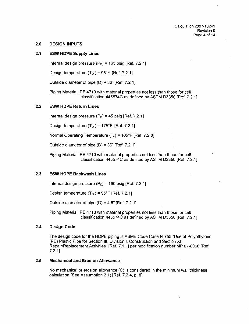
Calculation 2007-13241Revision 0
Page 4 of 14
2.0 DESIGN INPUTS
2.1 ESW HDPE Supply Lines
Internal design pressure (PD) = 165 psig [Ref. 7.2.1]
Design temperature (TD) = 95°F [Ref. 7.2.1]
Outside diameter of pipe (D) = 36" [Ref. 7.2.1]
Piping Material: PE 4710 with material properties not less than those for cellclassification 445574C as defined by ASTM D3350 [Ref. 7.2.1]
2.2 ESW HDPE Return Lines
Internal design pressure (Po) = 45 psig [Ref. 7.2.1]
Design temperature (Tc) = 175°F [Ref. 7.2.1]
Normal Operating Temperature (T,) = 105'F [Ref. 7.2.8]
Outside diameter of pipe (D) = 36" [Ref. 7.2.1]
Piping Material: PE 4710 with material properties not less than those for cellclassification 445574C as defined by ASTM D3350 [Ref. 7.2.1]
2.3 ESW HDPE Backwash Lines
Internal design pressure (PD) = 160 psig [Ref. 7.2.1]
Design temperature (TD) = 95°F [Ref. 7.2.1]
Outside diameter of pipe (D) = 4.5" [Ref. 7.2.1]
Piping Material: PE 4710 with material properties not less than those for cellclassification 445574C as defined by ASTM D3350 [Ref. 7.2.1]
2.4 Design Code
The design code for the HDPE piping is ASME Code Case N-755 '.'Use of Polyethylene(PE) Plastic Pipe for Section III, Division I, Construction and Section XlRepair/Replacement Activities" [Ref. 7.1.1] per modification number MP 07-0066 [Ref.7.2.1].
2.5 Mechanical and Erosion Allowance
No mechanical or erosion allowance (C) is considered in the minimum wall thicknesscalculation (See Assumption 3.1) [Ref. 7.2.4, p. 8].
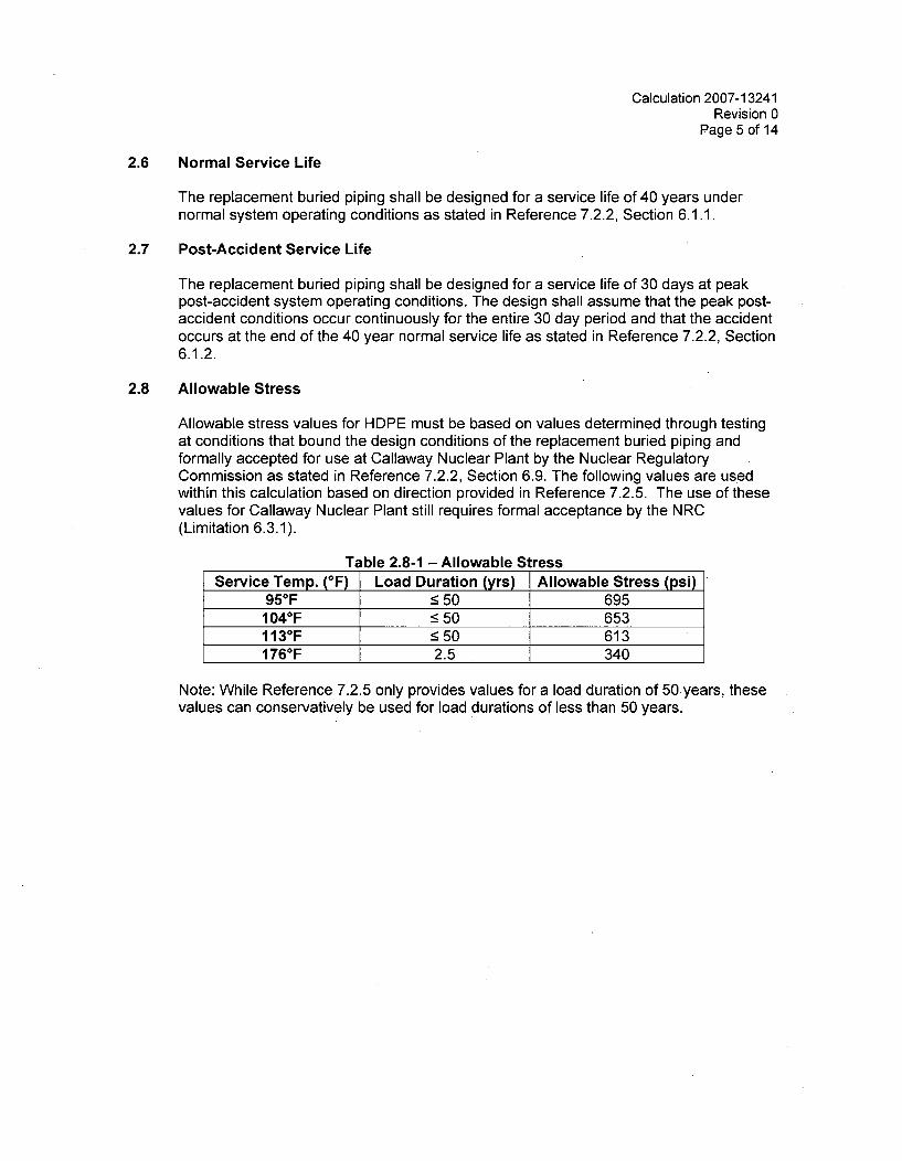
Calculation 2007-13241Revision 0
Page 5 of 14
2.6 Normal Service Life
The replacement buried piping shall be designed for a service life of 40 years undernormal system operating conditions as stated in Reference 7.2.2, Section 6.1.1.
2.7 Post-Accident Service Life
The replacement buried piping shall be designed for a service life of 30 days at peakpost-accident system operating conditions. The design shall assume that the peak post-accident conditions occur continuously for the entire 30 day period and that the accidentoccurs at the end of the 40 year normal service life as stated in Reference 7.2.2, Section6.1.2.
2.8 Allowable Stress
Allowable stress values for HDPE must be based on values determined through testingat conditions that bound the design conditions of the replacement buried piping andformally accepted for use at Callaway Nuclear Plant by the Nuclear RegulatoryCommission as stated in Reference 7.2.2, Section 6.9. The following values are usedwithin this calculation based on direction provided in Reference 7.2.5. The use of thesevalues for Callaway Nuclear Plant still requires formal acceptance by the NRC(Limitation 6.3.1).
Table 2.8-1 - Allowable StressService Temp. (OF) Load Duration (yrs) Allowable Stress (psi)
95°F -50 6951040F <50 653113 0F _50 6131760F 2.5 340
Note: While Reference 7.2.5 only provides values for a load duration of 50 years, thesevalues can conservatively be used for load durations of less than 50 years.
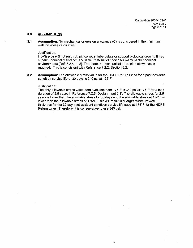
Calculation 2007-13241Revision 0
Page 6 of 14
3.0 ASSUMPTIONS
3.1 Assumption: No mechanical or erosion allowance (C) is considered in the minimumwall thickness calculation.
Justification:HDPE pipe will not rust, rot, pit, corrode, tuberculate or support biological growth. It hassuperb chemical resistance and is the material of choice for many harsh chemicalenvironments [Ref. 7.2.4, p. 8]. Therefore, no mechanical or erosion allowance isrequired. This is consistent with Reference 7.2.2, Section 6.2.
3.2 Assumption: The allowable stress value for the HDPE Return Lines for a post-accidentcondition service life of 30 days is 340 psi at 175°F.
Justification:The only allowable stress value data available near 175 0F is 340 psi at 176°F for a loadduration of 2.5 years in Reference 7.2.5 [Design Input 2.8]. The allowable stress for 2.5years is lower than the allowable stress for 30 days and the allowable stress at 176°F islower than the allowable stress at 175 0F. This will result in a larger minimum wallthickness for the 30 day post-accident condition service life case at 175 0F for the HDPEReturn Lines. Therefore, it is conservative to use 340 psi.

Calculation 2007-13241Revision 0
Page 7 of 14
4.0 METHODOLOGY AND ACCEPTANCE CRITERIA
4.1 Methodology
4.2 Allowable Stress for HDPE Return Lines
Since the allowable stress value at a design temperature of 175°F for the HDPE ReturnLines has only been provided for a maximum load duration of 2.5 years in Reference7.2.5, an allowable stress value is calculated for the Normal Operating Condition case asdefined by Miner's Rule using the methodology in Sections 4.2.1 and 4.2.2 and 340 psifor the 30 day Post-Accident Condition case (See Assumption 3.2). A minimum wallthickness will be calculated for both the Normal Operating Condition and the 30 dayPost-Accident Condition and the larger of the two shall be conservatively used for theHDPE Return Lines.
4.2.1 Miner's Rule to Calculate Load Duration
Miner's Rule takes into consideration the damages done to the pipe under differentoperating conditions to calculate the cumulative maximum permissible time of use underall varying conditions of the pipe. For the HDPE return lines, Normal OperatingConditions and Post-Accident Operating Conditions are considered. The cumulativemaximum permissible time of use is the design service life of 40 years.
To calculate the allowable stress value for Normal Operating Conditions, Miner's Rulefor plastic pipe [Ref. 7.2.6] is used to find the load duration for the pipe under normaloperating conditions that will ensure a cumulative maximum permissible time of use of40 years when considering the 30 day load duration at Post-Accident OperatingConditions. This load duration can then be used to interpolate a correspondingallowable stress value using the values in Reference 7.2.5 at the normal operatingtemperature of 105°F. The allowable stress value for a load duration of < 50 years at105°F is provided in Reference 7.2.5 [Design Input 2.8]. The following variables are usedby Miner's Rule:
T, = normal operating temperature (OF)Tmax = maximum operating temperature (post-accident temperature) (°F)Ai = percent of total service life of pipe under condition "i" (i=1, 2, 3, etc.) (%)tI = lifetime of pipe if placed under condition "i" (yrs)tmax = lifetime of pipe if placed under maximum operating temperature Tmax (yrs)to = lifetime of pipe if placed under normal operating temperature T. (yrs)tx = maximum permissible time of use under all varying conditions (yrs)TYD = total yearly damage (%)
The percent of total service life of the pipe under each condition "i" is calculated for i=1,2, 3, etc.
Ai = Time Under Condition "i" (yrs)Total Service Life of Pipe (yrs)
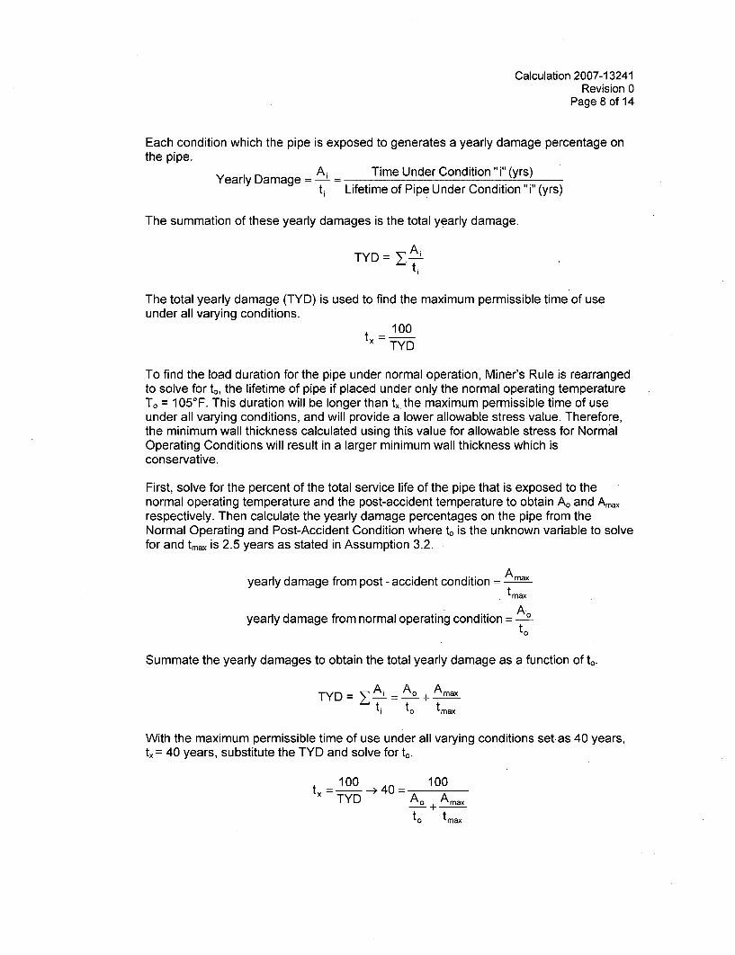
Calculation 2007-13241Revision 0
Page 8 of 14
Each condition which the pipe is exposed to generates a yearly damage percentage onthe pipe.
Yearly Damage = Ai Time Under Condition "i" (yrs)tj Lifetime of Pipe Under Condition "i" (yrs)
The summation of these yearly damages is the total yearly damage.
TYD = YAiti
The total yearly damage (TYD) is used to find the maximum permissible time of useunder all varying conditions.
= 100TYD
To find the load duration for the pipe under normal operation, Miner's Rule is rearrangedto solve for to, the lifetime of pipe if placed under only the normal operating temperatureTo = 105 0F. This duration will be longer than tx, the maximum permissible time of useunder all varying conditions, and will provide a lower allowable stress value. Therefore,the minimum wall thickness calculated using this value for allowable stress for NormalOperating Conditions will result in a larger minimum wall thickness which isconservative.
First, solve for the percent of the total service life of the pipe that is exposed to thenormal operating temperature and the post-accident temperature to obtain Ao and Amaxrespectively. Then calculate the yearly damage percentages on the pipe from theNormal Operating and Post-Accident Condition where to is the unknown variable to solvefor and tmax is 2.5 years as stated in Assumption 3.2.
yearly damage from post - accident condition = Amaxt max
yearly damage from normal operating condition = A.to
Summate the yearly damages to obtain the total yearly damage as a function of to.
TYD= YAi A. + Amaxtj to tmax
With the maximum permissible time of use under all varying conditions set. as 40 years,tx = 40 years, substitute the TYD and solve for to.
100 100tx_- -*40=-TYD A. Amax
+to tmax
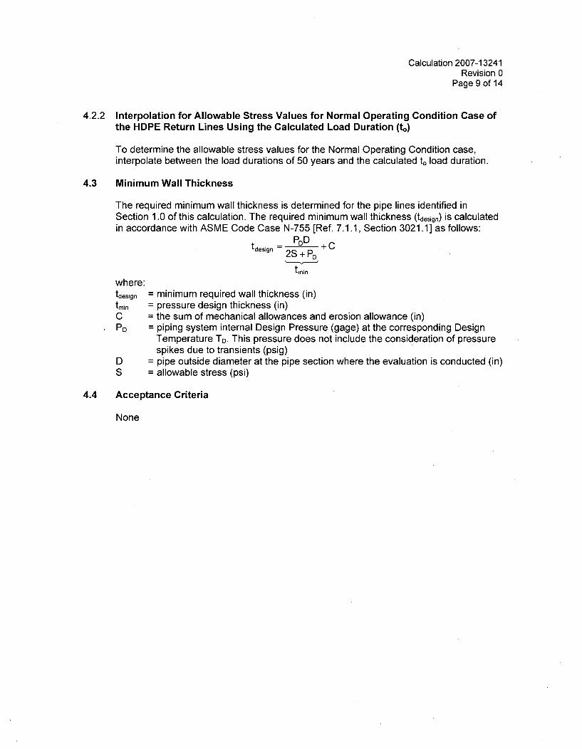
Calculation 2007-13241Revision 0
Page 9 of 14
4.2.2 Interpolation for Allowable Stress Values for Normal Operating Condition Case ofthe HDPE Return Lines Using the Calculated Load Duration (to)
To determine the allowable stress values for the Normal Operating Condition case,interpolate between the load durations of 50 years and the calculated to load duration.
4.3 Minimum Wall Thickness
The required minimum wall thickness is determined for the pipe lines identified inSection 1.0 of this calculation. The required minimum wall thickness (tdesign) is calculatedin accordance with ASME Code Case N-755 [Ref. 7.1.1, Section 3021.1] as follows:
tdesign -2S + CD
tmin
where:tdesign = minimum required wall thickness (in)tmin = pressure design thickness (in)C = the sum of mechanical allowances and erosion allowance (in)PD = piping system internal Design Pressure (gage) at the corresponding Design
Temperature TD. This pressure does not include the consideration of pressurespikes due to transients (psig)
D = pipe outside diameter at the pipe section where the evaluation is conducted (in)S = allowable stress (psi)
4.4 Acceptance Criteria
None
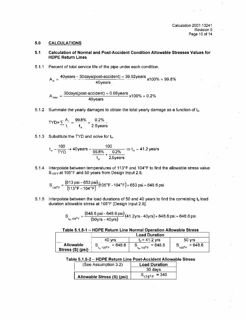
Calculation 2007-13241Revision 0
Page 10 of 14
5.0 CALCULATIONS
5.1 Calculation of Normal and Post-Accident Condition Allowable Stresses Values forHDPE Return Lines
5.1.1 Percent of total service life of the pipe under each condition.
Ao = 40years - 30days(post-accident) = 39.92years x1 00% = 99.8%40years
A max = 30days(post-accident) = 0.08years x1 00% = 0.2%40years
5.1.2 Summate the yearly damages to obtain the total yearly damage as a function of to.
TYD= A 99.8% + 0.2%
tj to 2.5years
5.1.3 Substitute the TYD and solve for to.
100 100_______tx TYD -> 40years = 100 0% to = 41.2years
TY 9.8% 0.2% 0
to 2.5years
5.1.4 Interpolate between temperatures of 113°F and 104 0 F to find the allowable stress valueS105oFat 1050F and 50 years from Design Input 2.8.
(613 psi-653 psi) 0 0 s68
1050F (113 0F- 104F-p
5.1.5 Interpolate between the load durations of 50 and 40 years to find the correlating to loadduration allowable stress at 105 0F [Design Input 2.8].
St. 0 ° (648.6 psi -648.6 Psi) (4 1. 2yrs - 40yrs) + 648.6 psi = 648.6 psi
Table 5.1.5-1 - HDPE Return Line Normal Operation Allowable StressLoad Duration
40 yrs to = 41.2 yrs; 50 yrsAllowable S = 648.6 S5 = 648.6 S1OF = 648.6
Stress (S) (psi) tx'1°5°F t°,105°F 1
Table 5.1.5-2 - HDPE Return Line Post-Accident Allowable Stress(See Assumption 3.2) Load Duration
30 days
Allowable Stress (S) (psi) S175°F = 340
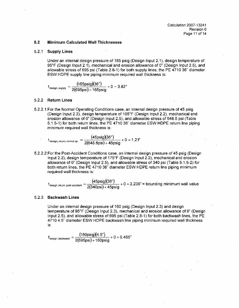
Calculation 2007-13241Revision 0
Page 11 of 14
5.2 Minimum Calculated Wall Thicknesses
5.2.1 Supply Lines
Under an internal design pressure of 165 psig (Design Input 2.1), design temperature of950F (Design Input 2.1), mechanical and erosion allowance of 0" (Design Input 2.5), andallowable stress of 695 psi (Table 2.8-1) for both supply lines, the PE 4710 36" diameterESW HDPE supply line piping minimum required wall thickness is:
tdesign, supply (165psigX36") + 0 = 3.82"
2(695psi) + 165psig
5.2.2 Return Lines
5.2.2.1 For the Normal Operating Conditions case, an internal design pressure of 45 psig(Design Input 2.2), design temperature of 105°F (Design Input 2.2), mechanical anderosion allowance of 0" (Design Input 2.5), and allowable stress of 648.6 psi (Table5.1.5-1) for both return lines, the PE 4710 36" diameter ESW HDPE return line pipingminimum required wall thickness is:
tdesign, r n n(45psig)36") + 0 = 1.21",return, normal op. 2(648.6psi) + 45psig
5.2.2.2 For the Post-Accident Conditions case, an internal design pressure of 45 psig (DesignInput 2.2), design temperature of 175 0F (Design Input 2.2), mechanical and erosionallowance of 0" (Design Input 2.5), and allowable stress of 340 psi (Table 5.1.5-2) forboth return lines, the PE 4710 36" diameter ESW HDPE return line piping minimumrequired wall thickness is:
t (45psig)(36") + 0 = 2.235"= bounding minimum wall value
tdesign, return, post-accident - 2(340psi) + 45psig
5.2.3 Backwash Lines
Under an internal design pressure of 160 psig (Design Input 2.3) and designtemperature of 95°F (Design Input 2.3), mechanical and erosion allowance of 0" (DesignInput 2.5), and allowable stress of 695 psi (Table 2.8-1) for both backwash lines, the PE4710 4.5" diameter ESW HDPE backwash line piping minimum required wall thicknessis:
tdesign backwash (1 60psig)(4.5") + 0 = 0.465"backwash 2(695psi) + 160psig
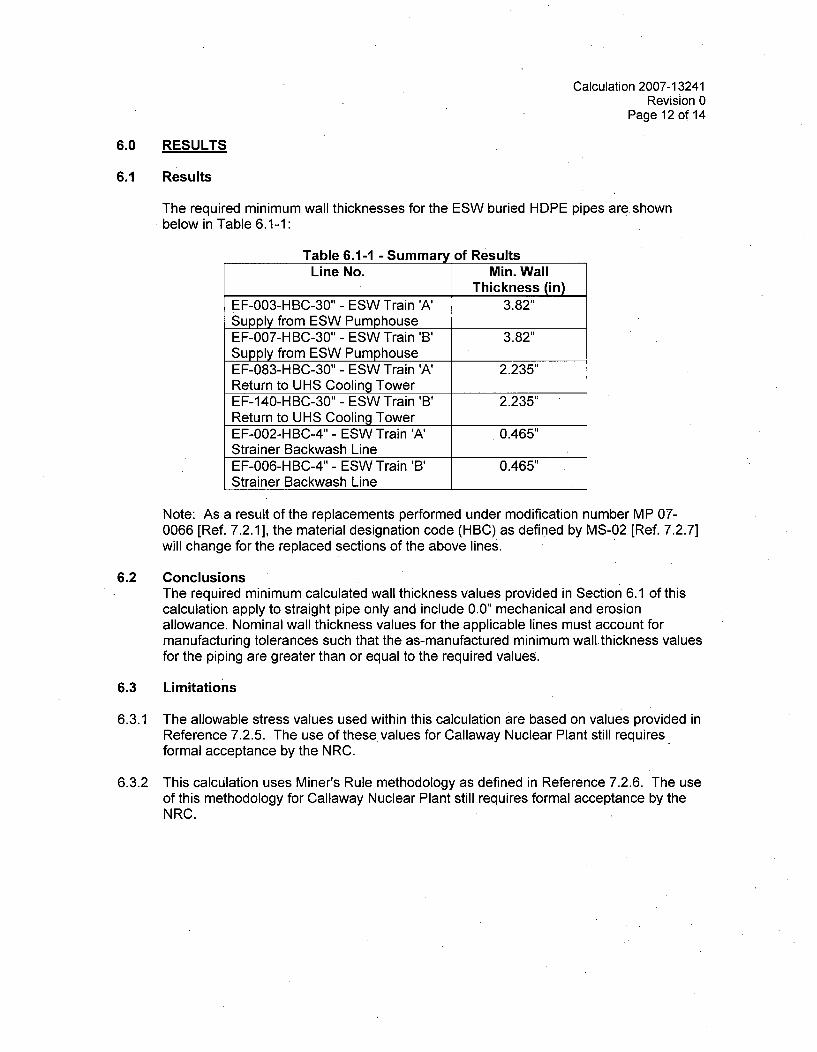
Calculation 2007-13241Revision 0
Page 12 of 14
6.0 RESULTS
6.1 Results
The required minimum wall thicknesses for the ESW buried HDPEbelow in Table 6.1-1:
pipes are shown
Table 6.1-1 - Summary of ResultsLine No. Min. Wall
Thickness (in)EF-003-HBC-30" - ESW Train 'A' 3.82"Supply from ESW PumphouseEF-007-HBC-30" - ESW Train 'B' 3.82"Supply from ESW PumphouseEF-083-HBC-30" - ESW Train 'A' 2.235"Return to UHS Cooling TowerEF-140-HBC-30" - ESW Train 'B' 2.235"Return to UHS Cooling TowerEF-002-HBC-4" - ESW Train 'A' 0.465"Strainer Backwash LineEF-006-HBC-4" - ESW Train 'B' 0.465"Strainer Backwash Line
Note: As a result of the replacements performed under modification number MP 07-0066 [Ref. 7.2.1], the material designation code (HBC) as defined by MS-02 [Ref. 7.2.7]will change for the replaced sections of the above lines.
6.2 ConclusionsThe required minimum calculated wall thickness values provided in Section 6.1 of thiscalculation apply to straight pipe only and include 0.0" mechanical and erosionallowance. Nominal wall thickness values for the applicable lines must account formanufacturing tolerances such that the as-manufactured minimum wallthickness valuesfor the piping are greater than or equal to the required values.
6.3 Limitations
6.3.1 The allowable stress values used within this calculation are based on values provided inReference 7.2.5. The use of these values for Callaway Nuclear Plant still requiresformal acceptance by the NRC.
6.3.2 This calculation uses Miner's Rule methodology as defined in Reference 7.2.6. The useof this methodology for.Callaway Nuclear Plant still requires formal acceptance by theNRC.
Calculation 2007-13241Revision 0
Page 13 of 14
6.4 Impact Assessment
The following sections identify the documents reviewed for impact by this calculation andsummarize the results of the impact assessments. Impacts as a result of the pipingreplacement being performed under MP 07-0066 are identified and evaluated as part ofMP 07-0066.
6.4.1 FSAR / Site Addendum
The following sections of the standard plant FSAR and site addendum were reviewed forimpact by this calculation:
3.9(B) (SP): Minimum wall thickness is not discussed in the FSAR for the design of non-NSSS piping. (NOT IMPACTED)
9.2 (SP and SA): This calculation does not change the design basis functions of theESW system, design conditions of the ESW piping or design heat loads acting on theESW system. (NOT IMPACTED)
6.4.2 Technical Specifications / Technical Specification Bases
The following sections of the technical specifications and technical specification baseswere reviewed for impact by this calculation:
3.7.8 / B 3.7.8: This calculation does not change any surveillance requirements for theESW system. None of the bases for the surveillance requirements are impacted. (NOTIMPACTED)
6.4.3 Other Documents
MS-02: A new material designation must be added to MS-02 for HDPE. This materialdesignation must ensure that the nominal wall thickness values of installed HDPE pipingwill provide actual minimum wall thickness values greater than or equal to the requiredminimum wall thickness values determined in this calculation. (IMPACTED)
6.4.4 Design and Operating Margins
This calculation determines required minimum wall thickness for the subject replacementESW piping. The nominal wall thickness of the installed piping, and hence the marginbetween the as-manufactured minimum wall thickness and the required minimum wallthickness, will be identified by MP 07-0066.
Calculation 2007-13241Revision 0
Page 14 of 14
7.0 REFERENCES
7.1 Codes
7.1.1 ASME Code Case N-755, "Use of Polyethylene (PE) Plastic Pipe for Section III, Division1, Construction and Section XI Repair/Replacement Activities", as approved by theBoard on Nuclear Codes and Standards on 03/22/2007 (Prior to incorporation of ASMEEditor changes made in PDF Release)
7.2 Miscellaneous
7.2.1 Callaway Nuclear Plant Modification No. MP 07-0066, "Replace Buried ESW Piping withHDPE Material"
7.2.2 Callaway Nuclear Plant Design Specification No. M-2017, Rev.0, "Design Specificationfor Replacement ASME Section III Buried Essential Service Water System Piping"
7.2.3 S&L Calculation 2007-11380, Rev. 1, "Determination of Peak ESW Buried Piping
Operating Conditions"
7.2.4 The Plastics Pipe Institute, Inc. "Handbook of Polyethylene Pipe", First Edition
7.2.5 Letter NEMM 07-0038 from Matt Brandes (AmerenUE) to Mr. Musto (Sargent & Lundy,LLC) dated 11/30/2007, "Design Inputs for Development of MP 07-0066, ESW BuriedPiping Replacement" (See Limitation 6.3.1)
7.2.6 The International Organization for Standardization, ISO 13760:1998(E), "Plastics Pipesfor the Conveyance of Fluids Under Pressure - Miner's Rule - Calculation Method forCumulative Damage" (See Limitation 6.3.2)
7.2.7 Callaway Nuclear Plant Drawing MS-02, Rev. 83,-"Piping Class Sheets"
7.2.8 Callaway Nuclear Plant Document MS-01, Rev. 96, "Piping Class Summary"
8.0 ATTACHMENTS
1. Letter NEMM 07-0038 from Matt Brandes (AmerenUE)to Mr. Musto (Sargent & Lundy, LLC) dated 11/30/2007,"Design Inputs for Development of MP 07-0066, ESWBuried Piping Replacement" 3 Pages
2. AmerenUE Owner's Review Comments Later
Calculation 2007-13241Revision 0
Attachment 1Page 1 of 3
Attachment 1
Letter NEMM 07-0038 from Matt Brandes (AmerenUE) to Mr. Musto (Sargent & Lundy, LLC)dated 11/30/2007, "Design Inputs for Development of MP 07-0066, ESW Buried Piping
Replacement"
Calculation 2007-13241Revision 0
Attachment 1Page 2 of 3
AmerenUE PO Box 620Callaway Plant Fulton, MO 65251
NEMM 07-0038November 30, 2007
Mr. Thomas M. MustoSenior AssociateSargent & Lundy, LLC55 East Monroe St.Chicago, IL 60603
Subject: Design Inputs for Development of MP 07-0066, ESW Buried Piping Replacement
Reference: 1. MP 07-0066, "Replace Buried ESW Piping with HDPE Material"
, i~ ereg Dear Mr. Musto"IEi Sargent and Lundy (S&L) have requested that Ameren UE provide the following information as design
UFE inputs for development of Reference 1. The design inputs that are requested are:
1. Stress allowables for the high density polyethylene (HDPE) piping at temperatures abovethose currently provided in ASME Code Case N-755.
2. Elastic modulus values for the HDPE piping at temperatures above those currently provided inASME Code Case N-755.
The information requested is being transmitted in the attachments to this letter.
For item 1, the stress allowables for HDPE provided by this transmittal are equivalent to the tablescurrently being added to the planned revision of Code Case N-755 (i.e. Revision 1), which is underreview of ASME. During the ASME code committee meeting in November 2007, the issue of designfactor was discussed. Although the ASME may yet approve a design factor greater than 0.5, for thescope of MP 07-0066, a design factor of 0.5 should be used.
For item 2, the elastic modulus to be used is table 3031-3 in ASME Code Case N-755, "Use ofPolyethylene (PE) Plastic Pipe for Section III, Division 1, Construction and Section XIRepair/Replacement Activities", as approved by BPV Standards Committee 02/02/2007". This table isequivalent to Table 3210-3 in the current Code Case N-755 Rev. 0. Based on discussion with FrankSchaaf and Bill Adams (WL Plastics), the use of the elastic modulus values at 140°F for temperatureshigher than those currently provided in ASME Code Case N-755 (i.e. >140°F) is conservative forthermal expansion and contraction stress calculations. For ring deflection and buckling due to externalpressure, a minimum elastic modulus of 2 ksi for temperatures less than or equal to 176°F can be usedfor the PE 4710 material. Industry testing is currently being performed to determine actual values.However, based on linear extrapolation of the data in Code Case N-755, the actual value is expectedto be higher. Therefore, the use of a value of 2 ksi is expected to be conservative.
Sincerely,
Matt Brandes
Attachment
cc: S. L. AbelJ. E. O'SullivanA160.2001
a subsidiary of Amoren Corporation
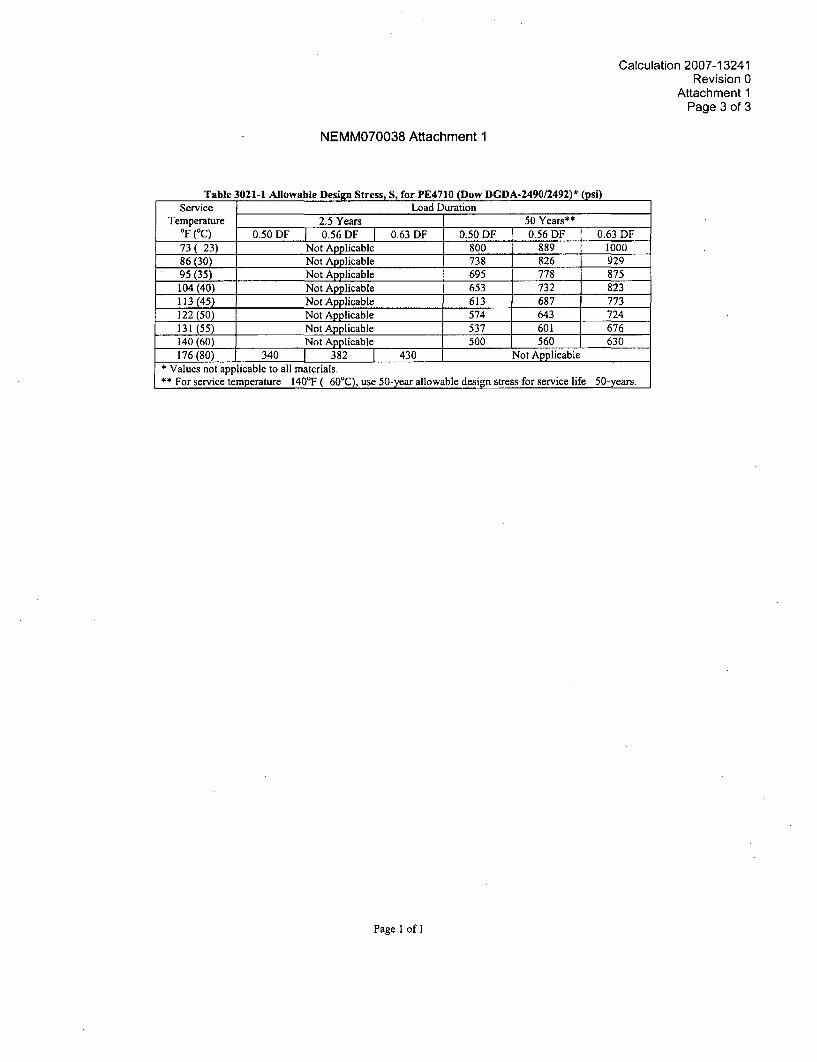
Calculation 2007-13241Revision 0
Attachment 1Page 3 of 3
NEMM070038 Attachment 1
Table 3021-1 Allowable Design Stress, S, for PE4710 (Dow DGDA-2490/2492)* (psi)Service Load Duration
Temperature 2.5 Years 50 Years**OF (0C) 0.50 DF 1 0.56 DF 0.63 DF 0.50 DF 0.56 DF 0.63 DF73( 23) Not Applicable 800 889 100086 (30) Not Applicable 738 826 92995 (35) Not Applicable 695 778 875104 (40) Not Applicable 653 732 823113 (45) Not Applicable 613 687 773122(50) Not Applicable 574 643 724131 (55) Not Applicable 537 601 676140 (60) Not Applicable 500 560 630176 (80) 340 T 382 430 Not Applicable
* Values not applicable to all materials.** For service temperature 140'F ( 60'C), use 50-year allowable design stress for service life 50-years.
Page 1 of 1
Calculation 2007-13241Revision 0
Attachment 2Page 1
Attachment 2
AmerenUE Owner's Review Comments
Enclosure 5To ULNRC-05517
Enclosure 5
AmerenUE
Callaway Nuclear Plant
10 CFR 50.55a Request Number I3R-10
Proposed Alternative to ASME Section XI Requirements for Replacement of Class 3 BuriedPiping in Accordance with 10 CFR 50.55a(a)(3)(i)
(Includes attachment, "Requirements for HDPE Pipingfor Nuclear Service," dated July 10, 2008)
AmerenUE10 CFR 50.55a Request Number 13R-10
Page 1 of 3
10 CFR 50.55a Request Number 13R-10
1.ASME Code Component(s) Affected
ASME Class 3 buried Essential Service Water (ESW) System piping.
2. Applicable Code Edition and Addenda
ASME Boiler and Pressure Vessel Code, Section XI, Division 1, 1998 Editionthrough 2000 Addenda.
3. Applicable Code Requirement
ASME Section XI, IWA-4221 (b) requires that "an item to be used for repair / replacementactivities shall meet the Construction Code specified in accordance with (1), (2), or (3) [of IWA-4221 (b)]", and ASME Section XI, IWA-4221 (b)(1) requires that "when replacing an existingitem, the new item shall meet the Construction Code to which the original item was constructed."
4. Reason for Request
A modification has been proposed for Callaway in which the underground steel piping of theESW system would be replaced with piping made from high-density polyethylene (HDPE).
The Construction Code of record for buried ASME Class 3 ESW piping is ASME Boiler andPressure Vessel Code, Section III, Division 1, Subsection ND, 1974 Edition, through Summer1975 Addenda. This Construction Code and later editions and addenda of this ConstructionCode do not provide rules for the materials, design, fabrication, installation, examination andtesting of piping constructed with polyethylene material.
Therefore, this request is being submitted to allow the replacement of buried steel piping in theCallaway ESW system with polyethylene piping. The replacement will be in accordance withthe attached document, "Requirements for HDPE Piping for Nuclear Service," dated July 10,2008.
5. Proposed Alternative and Basis for Use
The attached document, "Requirements for HDPE Piping for Nuclear Service," dated July 10,2008 provides the requirements for material, design, fabrication, installation, examination andtesting of high density polyethylene piping, and reflects an acceptable level of quality and safetyfor repair / replacement activities for ASME Section III, Division 1 Class 3 buried piping.
1
AmerenUE10 CFR 50.55a Request Number 13R-10
Page 2 of 3
The Callaway ESW system was originally designed with unlined carbon steel piping. Plantspecific and industry operating experience has shown that carbon steel piping is susceptible tofouling, corrosion, and microbiologically induced corrosion (MIC) for raw water applications.
The use of corrosion resistant steel piping provides added resistance to these problems, but doesnot eliminate susceptibility. Alternatively, the use of internal linings or coatings in carbon steelpiping provides resistance to these problems. However, degradation of and/or damage to thelinings and coatings can cause exposure of the carbon steel piping to the raw water, resulting inpiping degradation. Additionally, the linings and coatings can pose a potential foreign materialconcern if they are released from the piping wall as a result of the degradation or damage.
Polyethylene piping pipe will not rust, rot, pit, corrode, tuberculate, or support biological growth.The use of polyethylene piping in raw water applications will thus ensure long term reliabilityfrom a structural integrity and flow standpoint. Callaway has recently installed approximately600 linear feet of 36-inch diameter buried polyethylene piping in a non-safety related blowdownapplication and has not experienced any significant problems. On a larger scale, Duke PowerCompany has installed 20,000 linear feet of polyethylene piping at Catawba Nuclear Station innon-safety related raw water applications. Since the installations began in 1998, Duke PowerCompany has reported that the material has had an excellent service history and has notexperienced fouling or corrosion.
The use of polyethylene piping in accordance with this Relief Request will result in improvedsystem performance and enhanced system reliability, and will provide an acceptable level ofquality and safety.
6. Duration of Proposed Alternative
The use of the proposed alternative is requested for the third ten-year inserviceinspection interval for Callaway.
The Callaway third ten-year inservice inspection interval is currently scheduled toend on December 18, 2014.
2
AmerenUE10 CFR 50.55a Request Number 13R-10
Page 3 of 3
7. References
"Requirements for HDPE Piping for Nuclear Service," dated July 10, 2008 (attached)
TR33/2001, "Generic Butt Fusion Joining Procedure for Polyethylene Gas Pipe"
The Plastics Pipe Institute, Inc. "Handbook of Polyethylene Pipe"
3
Requirements for HDPE Piping for Nuclear Service
AmerenUE Callaway Plant
July 10, 2008
-1000 GENERAL REQUIREMENTS-1100 SCOPE
(a) This document contains rules for the construction of Class 3 high density polyethylene(HDPE) pressure piping and fittings. Use of these materials is permitted only for buriedEmergency Service Water Systems that are classified as ASME Section III Class 3. The designpressures and temperatures of the various lines to be replaced will be 161 psig at 95'F, 160 psigat 95 'F, or 45 psig at 175 'F, as applicable to the specific line.
(b) Terms relating to polyethylene as used in this document are defined in Supplement 1.
-1200 QUALIFICATION OF SUPPLIERS
Qualification(a) The PE material shall be procured from a qualified supplier as follows;
(1) AmerenUE shall be responsible for surveying, qualification, and auditing of theNonmetallic Material Manufacturer and the Nonmetallic Material Constituent Supplierbased on the survey and audit results of the Nonmetallic Material Manufacturer.Alternately, AmerenUE shall audit and qualify the Nonmetallic Material Manufacturerfor surveying/auditing the Nonmetallic Material Constituent Supplier as permitted byASME Section III NCA-3125 and NCA-3820.
(a) The survey and audit of the Nonmetallic Material Manufacturer will establishthe following;
1. verification process of constituent material chemistry, and
2. Quality System Program conforms to NCA- 3900.
(b) When survey and audit of the Nonmetallic Material Constituent Supplier isrequired, the survey and audit shall evaluate the Quality System Program and theimplementation of ASTM D-3350, Standard Specification for PolyethylenePlastics Pipe and Fittings Materials.
(c) Satisfactory completion of the survey and audit will allow the NonmetallicMaterial Manufacturer to supply material to AmerenUE for a period of threeyears. After the three year period an audit shall be performed to assure continuedprogram maintenance.
1
(b) AmerenUE shall perform any of the functions required by their respective QualityAssurance Program which are not performed by the Nonmetallic Material Manufacturer.AmerenUE may elect to perform any other Quality Program functions, which would normally bethe responsibility of the Nonmetallic Material Manufacturer. These functions shall be clearlydefined in the AmerenUE Quality Assurance Program.
c) AmerenUE shall make all necessary provisions so that the Authorized Inspection Agency canmake the inspections necessary to comply with this document.
-1210 PE Procurement Chain
(a) When the Quality System surveys/audits required by -1200 have been completed,AmerenUE shall establish a qualified HDPE supply chain.
(1) The Nonmetallic Material Constituent Supplier is the organization whichmanufactures and certifies the base HDPE material pellets.
(2) The Nonmetallic Material Manufacturer is the organization which manufactures, andcertifies HDPE material in compliance with requirements of this document. He shallperform or shall supervise and directly control one or more of the operations which affectthe HDPE material properties capable to meet the requirements of the basic materialspecification, and shall verify the satisfactory completion of all other requirementsperformed by other organizations prior to his certification.
(3) The Nonmetallic Material Supplier is an organization which supplies products of theNonmetallic Material Manufacturer but does not perform any operations which affect theHDPE materials properties required by the basic material specification.
(4) Certification to the requirements of ASME Code Case N-755 will be consideredequivalent to certification to this document.
(b) All pressure retaining HDPE material used in construction of components shall be suppliedwith a certified certificate of analyses for batch (CCAB) or product quality certification (PQC).These documents shall include all the results of analysis and production tests performed on theHDPE material.
(1) Nonmetallic Material Constituent Supplier - Certified Certificate of Analysis forBatch or Product Quality Certification shall include HDPE material identification,physical property test results, and melt index temperature when required by AmerenUEwhen the approved Nonmetallic Material Manufacturer program relies on audits andcertification.
(2) Nonmetallic Material Manufacturer - Certified Analysis for Batch or Product QualityCertification shall include HDPE material identification, physical property test results
2
(includes all in-situ and final tests), melt index temperature, mechanical property testresults, and shall certify that the product was made from virgin pellets (no scrap orregrind material). The product form shall be permanently marked.
-2000 MATERIALS-2100 GENERAL REQUIREMENTS FOR MATERIALS-2110 Scope
(a) All HDPE material and components shall be procured using the requirements of thisdocument and the following additional requirements.
(1) HDPE material shall be selected from approved ASTM standards listed inSupplement 2, and shall have material properties not less than those for cell classification445574C per ASTM D 3350-05 (PE 4710). The material may contain a color stripe withcell classification 445574E. (There is no physical difference between C and E other thancolor.)
(2) Only HDPE pipe, mitered elbows, and flanges of nominal size 4 NPS (DR9) and 36NPS (DR9.5) using Carbon Black pigment shall be used.
(3) All HDPE product forms (pipe, mitered elbows, and flanges) shall conform to theASTM Standards identified in Supplement 2, as applicable.
(b) HDPE material shall be marked in accordance with the marking requirements of the ASTMspecified for the material, as applicable. If required the HDPE material shall be marked foridentification purposes using a metallic paint marker or stenciling marker.
(c) All metallic materials and components shall be procured using the requirements of ASMESection III, Subsection ND.
-2200 ADDITIONAL PRODUCT FORM REQUIREMENTS
-2210 Mitered Elbows
The elbow fabricator shall be covered under the AmerenUE Quality Assurance Program.AmerenUE shall provide the services of an Authorized Nuclear Inspector. AmerenUE shallensure the following requirements are met.
(a) All HDPE pipe material used shall comply with -2110(a)
(b) The configuration of the mitered elbow shall meet the requirements of -3022.4
(c) All fabrication processes used in the fabrication of the mitered elbow shall meet therequirements of -4000 and Supplement 9.
3
(d) Mitered elbows shall have the fused joints inspected and accepted in accordance with -5000.
(e) A code data report shall be used for this product form (Supplement 4). Multiple assembliesmay be included on a single form.
-2220 Transition Flange
(a) The pressure rating of the transition flange shall be equal to or greater than the attachedstraight pipe.
(b) The material cell classification shall be not less than 445574C per ASTM D 3350-05 (PE4710)
-2300 EXAMINATION AND REPAIR OF MATERIAL
-2310 Receipt Examination
(a) All HDPE material external surfaces shall be. given a visual examination prior toinstallation. Any indentation or flaw more than 10% of the minimum wall thickness for 4 NPSpiping, and more than 7% for 36 NPS piping, regardless of wall thickness, shall beunacceptable. Additionally, for any flaw that will result in a remaining wall thickness less thanthe required as-fabricated minimum wall thickness per ASTM F714 shall be unacceptableunless evaluated and determined to be acceptable considering the remaining wall thickness.Lesser flaws shall be evaluated in accordance with -2320.
(b) Personnel performing the examination shall be qualified in accordance with -5000 of thisdocument.
-2320 Repair of Material
(a) For all piping, any section with a flaw not exceeding 5% of the wall thickness and notresulting in a remaining wall thickness less than the required as-fabricated minimum wallthickness per ASTM F714 may be left as is.
(b) For all other flaws, the damaged section of pipe shall either be physically removed, or shallbe repaired as follows:
(1) The depression after flaw elimination is blended uniformly into the surroundingsurface with a maximum taper not to exceed 3:1 (width to height).
(2) After flaw elimination the area will be inspected by visual examination to ensure thatthe flaw has been removed.
(3) If elimination of the flaw reduces the thickness of the section below the minimumrequired design thickness, the section of piping containing the flaw shall be cut out and replaced.
(c) For flanges the following requirements shall be met;
4
(1) if the damaged area is in the flange section the entire flange shall be replaced, and
(2) if the damaged area is in the pipe section the section shall be removed or repaired asrequired by (a) and (b), above.
-3000 DESIGN-3001 Scope
The design rules of this Section are limited to buried, high density polyethylene piping systemsconstructed of straight pipe, one, three and five-joint mitered elbows not exceeding 22-1/2degrees per miter, fusion joints, and flanged connections.
-3010 Nomenclature
A = cross-section area of pipe at the pipe section where the evaluation is. conducted, in 2
Bd = trench width, ftB' = burial factorc = the sum of mechanical allowances and erosion allowance, inD = pipe outside diameter at the pipe section where the evaluation is conducted, inDavg = average pipe diameter in accordance with ASTM F-714DR = dimension ratio of pipe = mean diameter divided by the minimum fabricated wallthickness = Davg / t fab min
Epipe = modulus of elasticity of pipe, psi, Table 3031-3E' = modulus of soil reaction, psi (Data is site specific)E'N = modulus of soil reaction of native soil around trench, psi (Data is site specific)Fa = axial force due to the specified Design, Service Level A, B, C, or D applied mechanicalloads, lbFac = axial force range due thermal expansion and/or the restraint of free end displacement, lbFaD = axial force due to the non repeated anchor motion, lbFaE = axial force range due to the combined effects of seismic wave passage, seismic soilmovement, and building seismic anchor motion effects, lbFb = upward force per unit length, lb/ftFs = soil support factor, Table 3031-2fo = ovality correction factor, Table 3033.2-1H = height of ground cover, ftHgw = height of water table above pipe, ftK = bedding factor = 0.1L = deflection lag factor, 1.25 to 1.50, or 1.0 if using the soil prism pressurei = stress intensification factor, Table 3042-1M = resultant moment due to the specified Design, Service Level A, B, C, or D appliedmechanical loads, in-lbMc = resultant moment range due thermal expansion and/or the restraint of free enddisplacement, in-lbMD = resultant moment due to the non repeated anchor motion, in-lbME = resultant moment range due to the combined effects of seismic wave passage, seismic soilmovement, and building seismic anchor motion effects, in-lb
5
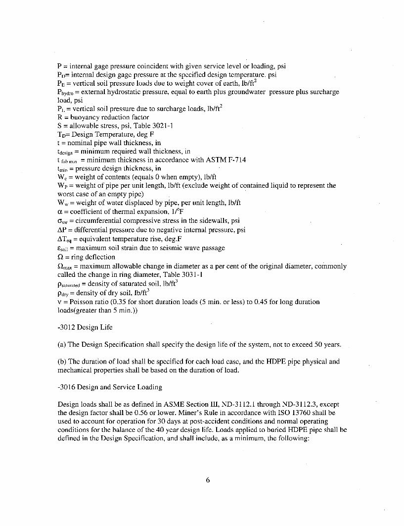
P = internal gage pressure coincident with given service level or loading, psiPD= internal design gage pressure at the specified design temperature. psiPE = vertical soil pressure loads due to weight cover of earth, lb/ft2
Phydro = external hydrostatic pressure, equal to earth plus groundwater pressure plus surchargeload, psiPL = vertical soil pressure due to surcharge loads, lb/ft2
R = buoyancy reduction factorS = allowable stress, psi, Table 3021-1TD= Design Temperature, deg Ft = nominal pipe wall thickness, intdesign = minimum required wall thickness, int fab min = minimum thickness in accordance with ASTM F-714tmin = pressure design thickness, inWc = weight of contents (equals 0 when empty), lb/ftWp = weight of pipe per unit length, lb/ft (exclude weight of contained liquid to represent theworst case of an empty pipe)Ww = weight of water displaced by pipe, per unit length, lb/ft
= coefficient of thermal expansion, 1f/Fw= circumferential compressive stress in the sidewalls, psi
AP = differential pressure due to negative internal pressure, psiATeq = equivalent temperature rise, deg.FEsoi1 = maximum soil strain due to seismic wave passagen = ring deflection
92,ma = maximum allowable change in diameter as a per cent of the original diameter, commonlycalled the change in ring diameter, Table 3031-1Psaturated = density of saturated soil, lb/ft3
Pdry = density of dry soil, lb/ft3
v = Poisson ratio (0.35 for short duration loads (5 min. or less) to 0.45 for long durationloads(greater than 5 min.))
-3012 Design Life
(a) The Design Specification shall specify the design life of the system, not to exceed 50 years.
(b) The duration of load shall be specified for each load case, and the HDPE pipe physical andmechanical properties shall be based on the duration of load.
-3016 Design and Service Loading
Design loads shall be as defined in ASME Section III, ND-3112.1 through ND-3112.3, exceptthe design factor shall be 0.56 or lower. Miner's Rule in accordance with ISO 13760 shall beused to account for operation for 30 days at post-accident conditions and normal operatingconditions for the balance of the 40 year design life. Loads applied to buried HDPE pipe shall bedefined in the Design Specification, and shall include, as a minimum, the following:
6
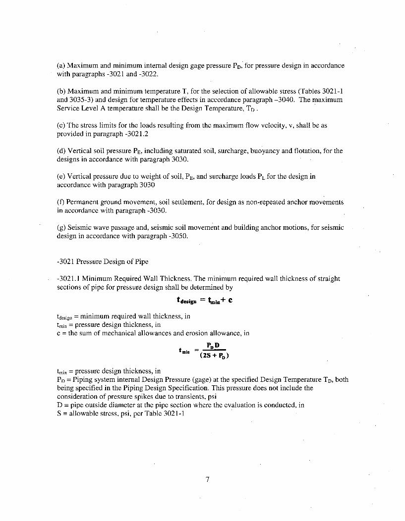
(a) Maximum and minimum internal design gage pressure PD, for pressure design in accordancewith paragraphs -3021 and -3022.
(b) Maximum and minimum temperature T, for the selection of allowable stress (Tables 3021-1and 3035-3) and design for temperature effects in accordance paragraph -3040. The maximumService Level A temperature shall be the Design Temperature, TD.
(c) The stress limits for the loads resulting from the maximum flow velocity, v, shall be asprovided in paragraph -3021.2
(d) Vertical soil pressure PE, including saturated soil, surcharge, buoyancy and flotation, for thedesigns in accordance with paragraph 3030.
(e) Vertical pressure due to weight of soil, PE, and surcharge loads PL for the design inaccordance with paragraph 3030
(f) Permanent ground movement, soil settlement, for design as non-repeated anchor movementsin accordance with paragraph -3030.
(g) Seismic wave passage and, seismic soil movement and building anchor motions, for seismicdesign in accordance with paragraph -3050.
-3021 Pressure Design of Pipe
-3021.1 Minimum Required Wall Thickness. The minimum required wall thickness of straightsections of pipe for pressure design shall be determined by
tdesign = tmin+ C
tdesign = minimum required wall thickness, intmin = pressure design thickness, inc = the sum of mechanical allowances and erosion allowance, in
tmin =-- P__ D-(2S + PD)
tmin = pressure design thickness, inPD = Piping system internal Design Pressure (gage) at the specified Design Temperature TD, bothbeing specified in the Piping Design Specification. This pressure does not include theconsideration of pressure spikes due to transients, psiD = pipe outside diameter at the pipe section where the evaluation is conducted, inS = allowable stress, psi, per Table 3021-1
7
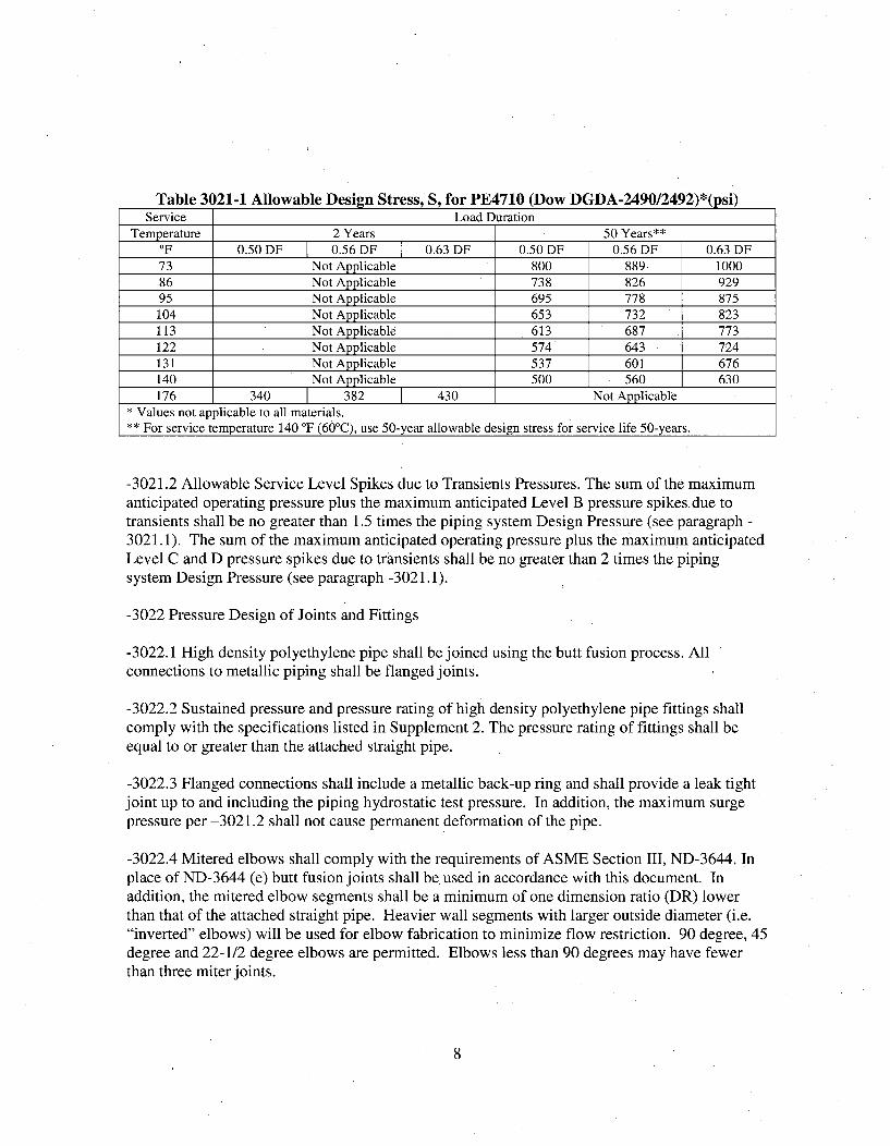
Table 3021-1 Allowable Design Stress, S, for PE4710 (Dow DGDA-2490/2492)*(psi)Service Load Duration
Temperature 2 Years 50 Years**OF 0.50 DF 0.56 DF 0.63 DF 0.50 DF 0.56 DF 0.63 DF73 Not Applicable 800 889 100086 Not Applicable 738 826 92995 Not Applicable 695 778 875104 Not Applicable 653 732 823113 Not Applicable 613 687 773122 Not Applicable 574 643 724131 Not Applicable 537 601 676140 Not Applicable 500 560 630176 340 382 430 Not Applicable
* Values not applicable to all materials.** For service temperature 140 TF (60°C), use 50-year allowable design stress for service life 50-years.
-3021.2 Allowable Service Level Spikes due to Transients Pressures. The sum of the maximumanticipated operating pressure plus the maximum anticipated Level B pressure spikes due totransients shall be no greater than 1.5 times the piping system. Design Pressure (see paragraph -3021.1). The sum of the maximum anticipated operating pressure plus the maximum anticipatedLevel C and D pressure spikes due to transients shall be no greater than 2 times the pipingsystem Design Pressure (see paragraph -3021.1).
-3022 Pressure Design of Joints and Fittings
-3022.1 High density polyethylene pipe shall be joined using the butt fusion process. Allconnections to metallic piping shall be flanged joints.
-3022.2 Sustained pressure and pressure rating of high density polyethylene pipe fittings shallcomply with the specifications listed in Supplement 2. The pressure rating of fittings shall beequal to or greater than the attached straight pipe.
-3022.3 Flanged connections shall include a metallic back-up ring and shall provide a leak tightjoint up to and including the piping hydrostatic test pressure. In addition, the maximum surgepressure per -3021.2 shall not cause permanent deformation of the pipe.
-3022.4 Mitered elbows shall comply with the requirements of ASME Section III, ND-3644. Inplace of ND-3644 (e) butt fusion joints shall be' used in accordance with this document. Inaddition, the mitered elbow segments shall be a minimum of one dimension ratio (DR) lowerthan that of the attached straight pipe. Heavier wall segments with larger outside diameter (i.e."inverted" elbows) will be used for elbow fabrication to minimize flow restriction. 90 degree, 45degree and 22-1/2 degree elbows are permitted. Elbows less than 90 degrees may have fewerthan three miter joints.
8
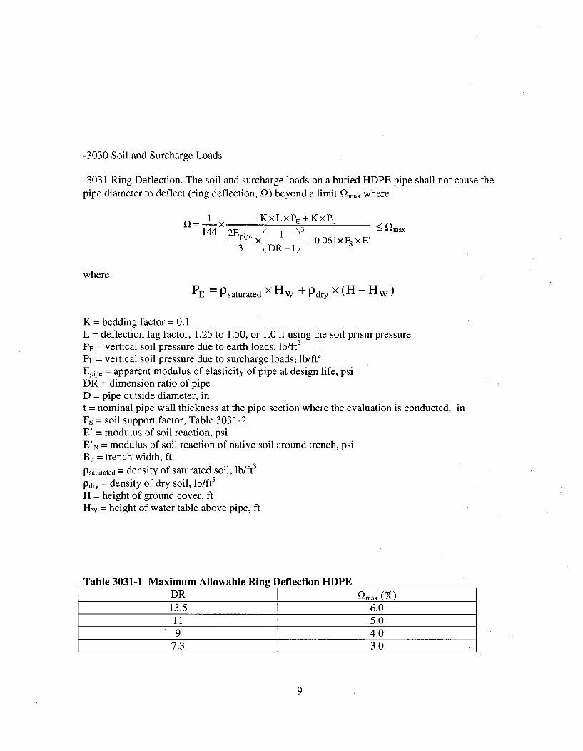
-3030 Soil and Surcharge Loads
-3031 Ring Deflection. The soil and surcharge loads on a buried HDPE pipe shall not cause thepipe diameter to deflect (ring deflection, n) beyond a limit K•max where
1 KxLxPE +KxPL144 2Epipe x 3 +0.061xFs xE'
3 •.DR-l
where
PE = Psaturated X HW + Pdry x (H- Hw)
K = bedding factor = 0.1L = deflection lag factor, 1.25 to 1.50, or 1.0 if using the soil prism pressurePE = vertical soil pressure due to earth loads, lb/ft2
PL = vertical soil pressure due to surcharge loads, lb/ft2
Epipe = apparent modulus of elasticity of pipe at design life, psiDR = dimension ratio of pipeD = pipe outside diameter, int = nominal pipe wall thickness at the pipe section where the evaluation is conducted, inFs = soil support factor, Table 3031-2E' = modulus of soil reaction, psiE'N = modulus of soil reaction of native soil around trench, psiBd = trench width, ft
P saturated = density of saturated soil, lb/ft3
Pdry = density of dry soil, lb/ft3
H = height of ground cover, ftHw = height of water table above pipe, ft
Table 3031-1 Maximum Allowable Ring Deflection HDPEDR 2 max (%)13.5 6.011 5.09 4.0
7.3 3.0
9
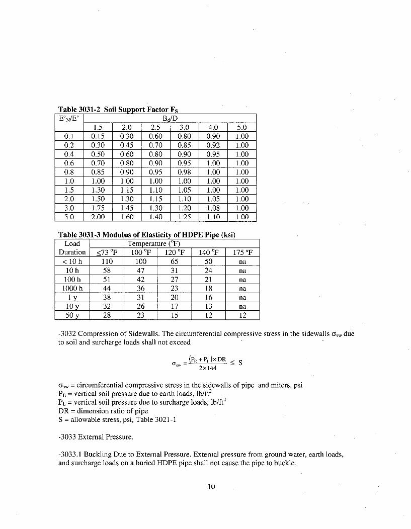
Table 3031-2 Soil Support Factor FsE'N/E' BdID
1.5 2.0 2.5 3.0 4.0 5.00.1 0.15 0.30 0.60 0.80 0.90 1.000.2 0.30 0.45 0.70 0.85 0.92 1.000.4 0.50 0.60 0.80 0.90 0.95 1.000.6 0.70 0.80 0.90 0.95 1.00 1.000.8 0.85 0.90 0.95 0.98 1.00 1.001.0 1.00 1.00 1.00 1.00 1.00 1.001.5 1.30 1.15 1.10 1.05 1.00 1.002.0 1.50 1.30 1.15 1.10 1.05 1.003.0 1.75 1.45 1.30 1.20 1.08 1.005.0 2.00 1.60 1.40 1.25 1.10 1.00
Table 3031-3 Modulus of Elasticity of HDPE Pipe (ksi)Load Temperature (°F)
Duration <73 OF 100 OF 120 °F 140 OF 175 OF< 10 h 110 100 65 50 na10h 58 47 31 24 na
100 h 51 42 27 21 na1000 h 44 36 23 18 na
I y 38 31 20 16 na10y 32 26 17 13 na50 y 28 23 15 12 12
-3032 Compression of Sidewalls. The circumferential compressive stress in the sidewalls osw dueto soil and surcharge loads shall not exceed
(PE+PL)XDR < S2x144
a~w = circumferential compressive stress in the sidewalls of pipe and miters, psiPE = vertical soil pressure due to earth loads, lb/ft2
PL = vertical soil pressure due to surcharge loads, lb/ft2
DR = dimension ratio of pipeS = allowable stress, psi, Table 3021-1
-3033 External Pressure.
-3033.1 Buckling Due to External Pressure. External pressure from ground water, earth loads,and surcharge loads on a buried HDPE pipe shall not cause the pipe to buckle.
10
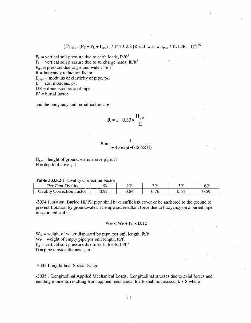
[ Phydro = (PE + PL + Pgw) ] / 144•< 2.8 [R x B' x E' x Epipe / 12 (DR - 1)311/2
PE = vertical soil pressure due to earth loads, lb/ft2
PL = vertical soil pressure due to surcharge loads, lb/ft2
Pgw = pressure due to ground water, lb/ft2
R = buoyancy reduction factorEpipe = modulus of elasticity of pipe, psiE' = soil modulus, psiDR = dimension ratio of pipeB' = burial factor
and the buoyancy and burial factors are
HgR = 1-0.33x gw
H
11 + 4xexp(-0.065x H)
Hgw = height of ground water above pipe, ftH = depth of cover, ft
Table 3033.2-1 Ovality Correction FactorPer Cent-Ovality 1% 2% 3% 5% 6%
Ovality Correction Factor 0.91 0.84 0.76 0.64 0.59
-3034 Flotation. Buried HDPE pipe shall have sufficient cover or be anchored to the ground toprevent flotation by groundwater. The upward resultant force due to buoyancy on a buried pipein saturated soil is
WW < Wp + PE x D/12
Ww = weight of water displaced by pipe, per unit length, lb/ftWp = weight of empty pipe per unit length, lb/ftPE = vertical soil pressure due to earth loads, lb/ft2
D = pipe outside diameter, in
-3035 Longitudinal Stress Design
-3035.1 Longitudinal Applied Mechanical Loads, Longitudinal stresses due to axial forces andbending moments resulting from applied mechanical loads shall not exceed k x S where
11
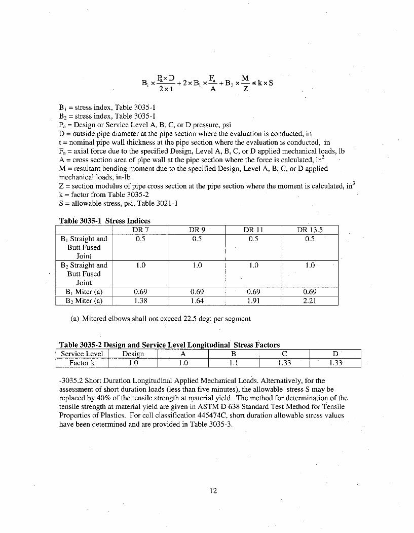
PaxD Fa MBx , +2xB1 x x 3B2 x--___kxS2xt A Z
B, = stress index, Table 3035-1B 2 = stress index, Table 3035-1Pa = Design or Service Level A, B, C, or D pressure, psiD = outside pipe diameter at the pipe section where the evaluation is conducted, int = nominal pipe wall thickness at the pipe section where the evaluation is conducted, inFa = axial force due to the specified Design, Level A, B, C, or D applied mechanical loads, lb
2A = cross section area of pipe wall at the pipe section where the force is calculated, inM = resultant bending moment due to the specified Design, Level A, B, C, or D appliedmechanical loads, in-lbZ = section modulus of pipe cross section at the pipe section where the moment is calculated, in3
k= factor from Table 3035-2S = allowable stress, psi, Table 3021-1
Table 3035-1 Stress IndicesDR 7 DR 9 DR 11 DR 13.5
B, Straight and 0.5 0.5 0.5 0.5Butt Fused
JointB2 Straight and 1.0 1.0 1.0 1.0
Butt FusedJoint
B 1 Miter (a) 0.69 0.69 0.69 0.69B2 Miter (a) 1.38 1.64 1.91 2.21
(a) Mitered elbows shall not exceed 22.5 deg. per segment
Table 3035-2 Design and Service Level Longitudinal Stress FactorsService Level Design A B C D
Factor k 1.0 1.0 1.1 1.33 1.33
-3035.2 Short Duration Longitudinal Applied Mechanical Loads. Alternatively, for theassessment of short duration loads (less than five minutes), the allowable stress S may bereplaced by 40% of the tensile strength at material yield. The method for determination of thetensile strength at material yield are given in ASTM D 638 Standard Test Method for TensileProperties of Plastics. For cell classification 445474C, short duration allowable stress valueshave been determined and are provided in Table 3035-3.
12
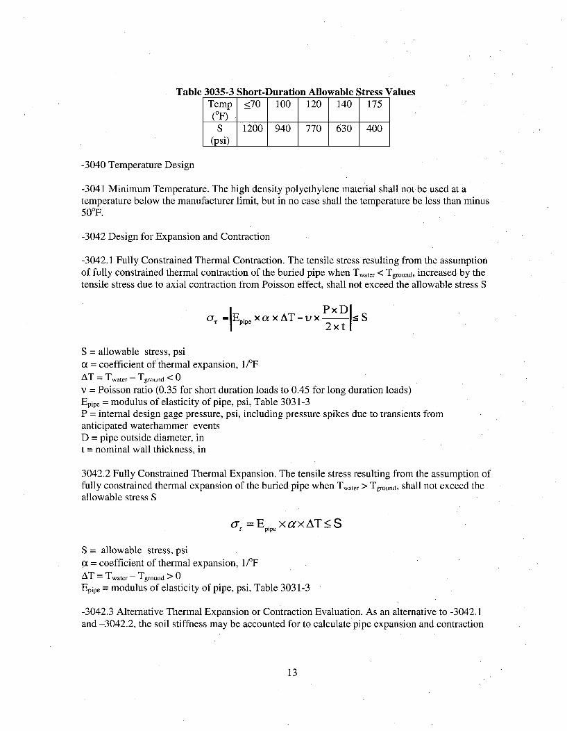
Table 3035-3 Short-Duration Allowable Stress ValuesTemp <70 100 120 140 175
(OF)S 1200 940 770 630 400
(psi)
-3040 Temperature Design
-3041 Minimum Temperature. The high density polyethylene material shall not be used at atemperature below the manufacturer limit, but in no case shall the temperature be less than minus50 0F.
-3042 Design for Expansion and Contraction
-3042.1 Fully Constrained Thermal Contraction. The tensile stress resulting from the assumptionof fully constrained thermal contraction of the buried pipe when Twater < Tground, increased by thetensile stress due to axial contraction from Poisson effect, shall not exceed the allowable stress S
OyT -hpipe xa x AT-v x1 5S
S = allowable stress, psi(x = coefficient of ,thermal expansion, 1f/FAT = Twater - Tground < 0
v = Poisson ratio (0.35 for short duration loads to 0.45 for long duration loads)Epipe = modulus of elasticity of pipe, psi, Table 3031-3P = internal design gage pressure, psi, including pressure spikes due to transients fromanticipated waterhammer eventsD = pipe outside diameter, int = nominal wall thickness, in
3042.2 Fully Constrained Thermal Expansion. The tensile stress resulting from the assumption offully constrained thermal expansion of the buried pipe when Twater > Tground, shall not exceed theallowable stress S
orz = Ep xaxAT•<S
S = allowable stress, psiq = coefficient of thermal expansion, 1/FAT = Twater - Tground > 0
Epipe = modulus of elasticity of pipe, psi, Table 3031-3
-3042.3 Alternative Thermal Expansion or Contraction Evaluation. As an alternative to -3042.1and -3042.2, the soil stiffness may be accounted for to calculate pipe expansion and contraction
13
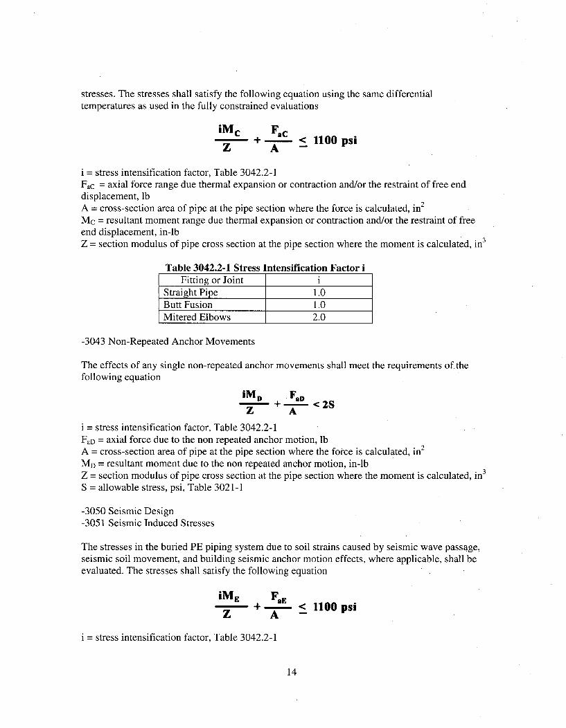
stresses. The stresses shall satisfy the following equation using the same differentialtemperatures as used in the fully constrained evaluations
iMc Fac+A < 1lOOpsiZ A -
i = stress intensification factor, Table 3042.2-1Fac = axial force range due thermal expansion or contraction and/or the restraint of free enddisplacement, lbA = cross-section area of pipe at the pipe section where the force is calculated, in 2
Mc = resultant moment range due thermal expansion or contraction and/or the restraint of freeend displacement, in-lbZ = section modulus of pipe cross section at the pipe section where the moment is calculated, in 3
Table 3042.2-1 Stress Intensification Factor iFitting or Joint i
Straight Pipe 1.0Butt Fusion 1.0Mitered Elbows 2.0
-3043 Non-Repeated Anchor Movements
The effects of any single non-repeated anchor movements shall meet the requirements of. thefollowing equation
iMD FOD+ -< 2S
Z A
i = stress intensification factor, Table 3042.2-1FaD = axial force due to the non repeated anchor motion, lbA = cross-section area of pipe at the pipe section where the force is calculated, in2
MD = resultant moment due to the non repeated anchor motion, in-lbZ = section modulus of pipe cross section at the pipe section where the moment is calculated, in 3
S = allowable stress, psi, Table 3021-1
-3050 Seismic Design-3051 Seismic Induced Stresses
The stresses in the buried PE piping system due to soil strains caused by seismic wave passage,seismic soil movement, and building seismic anchor motion effects, where applicable, shall beevaluated. The stresses shall satisfy the following equation
iME FaE+ - < l00 psi
Z A -
1 = stress intensification factor, Table 3042.2-1
14
FaE = axial force range due to the combined effects of seismic wave passage, seismic soilmovement, and building seismic anchor motion effects, lbA = cross-section area of pipe at the pipe section where the force is calculated, in 2
ME = resultant moment range due to the combined effects of seismic wave passage, seismic soilmovement, and building seismic anchor motion effects, in-lbZ = section modulus of pipe cross section at the pipe section where the moment is calculated, in3
S = allowable stress, psi, Table 3021-1
Seismic wave passage, seismic soil movement, and building seismic anchor motions shall becombined by square root sum of the squares or by algebraic sum.
Supplement 3 provides a non-mandatory method for the analysis of seismic wave passage,seismic soil movement, and building seismic anchor motion effects,
-3060 Design for Future Internal Access
Removable spools will be installed that would provide future access to the ID surfaces ineach replacement line should suitable remote examination equipment be developed.
-4000 FABRICATION AND INSTALLATION-4100 GENERAL REQUIREMENTS-4110 Scope
This Article provides the requirements for the installation of PE piping and fittings. Methods ofinstallation shall be by thermal fusion and flanged fittings. Use of threaded or adhesive jointswith HDPE material is not permitted. All metallic interface components will be installedfollowing the requirements of ASME Section III, Subsection ND.
-4120 Examinations
Examination activities that are not referenced for examination by specific Code paragraphs, andare performed solely to verify compliance with requirements of -4000, may be performed by thepersons who perform or supervise the work. These visual examinations are not required to beperformed by personnel and procedures qualified to -5100 and -5500, respectively, unless sospecified.
-4130 REPAIR OF MATERIAL
HDPE material originally accepted on delivery in which defects exceeding the limits of -2300are known or discovered during the process of fabrication or installation is unacceptable. TheHDPE material may be used provided the defective area can be physically removed from thematerial or repaired in accordance with -2300.
15
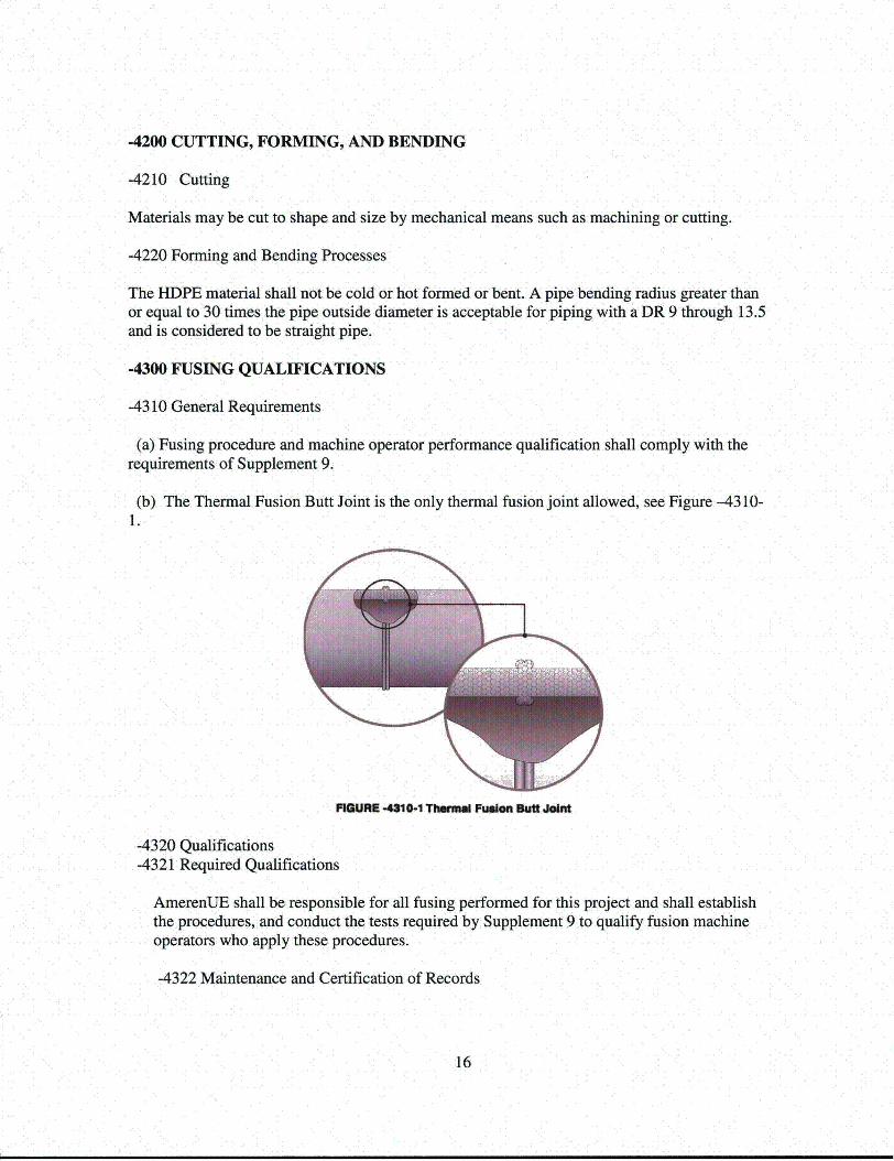
-4200 CUTTING, FORMING, AND BENDING
-4210 Cutting
Materials may be cut to shape and size by mechanical means such as machining or cutting.
-4220 Forming and Bending Processes
The HDPE material shall not be cold or hot formed or bent. A pipe bending radius greater thanor equal to 30 times the pipe outside diameter is acceptable for piping with a DR 9 through 13.5and is considered to be straight pipe.
-4300 FUSING QUALIFICATIONS
-4310 General Requirements
(a) Fusing procedure and machine operator performance qualification shall comply with therequirements of Supplement 9.
(b) The Thermal Fusion Butt Joint is the only thermal fusion joint allowed, see Figure -4310-1.
PWIWJ -431 -1 Tmmi Fusion Buttf Join
-4320 Qualifications-4321 Required Qualifications
AmerenUE shall be responsible for all fusing performed for this project and shall establishthe procedures, and conduct the tests required by Supplement 9 to qualify fusion machineoperators who apply these procedures.
-4322 Maintenance and Certification of Records
16
AmerenUE shall maintain records of qualified fusing procedures and the fusion machineoperators qualified by them, showing the date and results of tests and the identification markassigned to each fusing operator. These records shall be reviewed, verified, and signed byan authorized individual and they shall be accessible to the Authorized Nuclear Inspector.
-4323 Fusing Prior to Qualification
Fusing Procedure Specification (FPS) shall be qualified as required by Supplement 9 priorto their use. Only fusing operators who are qualified in accordance with -4320 andSupplement 9 shall be used.
-4324 Transferring Qualifications
The FPS qualifications and performance qualification tests for fusion machine operatorsshall not be transferred to another organization.
-4330 Requirements for Fusing Procedure Qualification Tests
-433 1Conformance to Supplement 9 Requirements
All fusing procedure qualification tests shall be in accordance with the requirements ofSupplement 9 as supplemented or modified by the requirements of this document.
-4332 Preparations of Test Coupons and Specimens
Removal of test coupons from the fusion test coupons and the dimensions of specimensmade from them shall conform to the requirements of Supplement 9.
-4340 Performance Demonstration
-4341 AmerenUE will produce six (6) fusion joint test coupons of 36NPS DR 9.5 and six(6) fusion joint test specimens of 4NPS DR 9 material on each model of fusion machinecarriage expected to be used in production for the respective size of piping as a performancedemonstration. Three (3) of these fusions on each machine will target minimumtemperature and interfacial pressure using maximum heater removal times, and three (3) willtarget maximum temperature and interfacial pressure using minimal heater removal times -to the extent feasible considering production limits, machine capabilities and the limits ofthe AmerenUE Fusion Procedure Specification.
-4342 A minimum of four (4) specimens will be cut from each fusion joint couponapproximately 90 degrees apart and tensile-tested to verify that the fusion joint is strongerthan the pipe. Testing will be performed by commercial plastics industry suppliers withouta 10 CFR 50 Appendix B quality program, but all testing will be overseen by AmerenUErepresentatives, and the test records will be retained in permanent Callaway records.
17
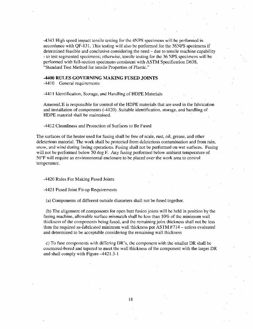
-4343 High speed impact tensile testing for the 4NPS specimens will be performed inaccordance with QF- 131. This testing will also be performed for the 36NPS specimens. ifdetermined feasible and conclusive considering the need - due to tensile machine capability- to test segmented specimens; otherwise, tensile testing for the 36 NPS specimens will beperformed with full-section specimens consistent with ASTM Specification D638,"Standard Test Method for tensile Properties of Plastic."
-4400 RULES GOVERNING MAKING FUSED JOINTS
-4410 General requirements
-4411 Identification, Storage, and Handling of HDPE Materials
AmerenUE is responsible for control of the HDPE materials that are used in the fabricationand installation of components (-4120). Suitable identification, storage, and handling ofHDPE material shall be maintained.
-4412 Cleanliness and Protection of Surfaces to Be Fused
The surfaces of the heater used for fusing shall be free of scale, rust, oil, grease, and otherdeleterious material. The work shall be protected from deleterious contamination and from rain,snow, and wind during fusing operations. Fusing shall not be performed on wet surfaces. Fusingwill not be performed below 50 deg F. Any fusing performed below ambient temperature of50'F will require an environmental enclosure to be placed over the work area to controltemperature.
-4420 Rules For Making Fused Joints
-4421 Fused Joint Fit-up Requirements
(a) Components of different outside diameters shall not be fused.together.
(b) The alignment of components for open butt fusion joints will be held in position by thefusing machine, allowable surface mismatch shall be less than 10% of the minimum wallthickness of the components being fused, and the remaining joint thickness shall not be less
• than the required as-fabricated minimum wall thickness per ASTM F714 - unless evaluatedand determined to be acceptable considering the remaining wall thickness
c) To fuse components with differing DR' s, the component with the smaller DR shall becountered-bored and tapered to meet the wall thickness of the component with the larger DRand shall comply with Figure -4421.3-1
18
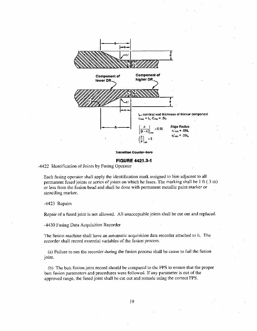
I a
~~I-- I
Component of Component oflower DR higher DR
t, = nominal wall thickness of thinner componenttc,,m C.• .t
=0.55 Edge Radius-,----- --- b --- ---, = .55 ri'M- = .0%1
r2.i. = .05t.
Transition Counter-bore
FIGURE 4421.3-1-4422 Identification of Joints by Fusing Operator
Each fusing operator shall apply the identification mark assigned to him adjacent to allpermanent fused joints or series of joints on which he fuses. The marking shall be 1 ft (.3 m)or less from the fusion bead and shall be done with permanent metallic paint marker orstenciling marker.
-4423 Repairs
Repair of a fused joint is not allowed. All unacceptable joints shall be cut out and replaced.
-4430 Fusing Data Acquisition Recorder
The fusion machine shall have an automatic acquisition data recorder attached to it. Therecorder shall record essential variables of the fusion process.
(a) Failure to run the recorder during the fusion process shall be cause to fail the fusionjoint.
(b) The butt fusion joint record should be compared to the FPS to ensure that the properbutt fusion parameters and procedures were followed. If any parameter is out of theapproved range, the fused joint shall be cut out and remade using the correct FPS.
19
-4500 ASSEMBLY AND ERECTION-4510 General
Any distortion of piping to bring it into alignment for joint assembly which introduces apermanent strain in the piping or associated piping components is prohibited.
-4520 Flanged Joints using HDPE material
(a) Flanged connections are only permitted for the joining of high density polyethylenepipe to metallic pipe or piping components. The flange connection shall be constructedusing a high density polyethylene flange adapter having a DR ratio equal to or less than thatof the attached HDPE pipe and shall be joined by fusion to the attached high densitypolyethylene piping.
(b) The high density polyethylene flange adapter shall be connected to the metal flangeusing a metallic backing ring, The backing ring shall have a pressure rating equal to orgreater than the metal flange.
(c) Following acceptable visual examination, the external fusion beads may be removed inorder to accommodate installation of the metallic backing ring.
(d) Before bolting up, flange faces shall be aligned to the design plane within 1/16 in./ftmeasured across any diameter; flange bolt holes shall be aligned within 1/8 in. maximumoffset. Damage to a gasket, if used, or seating surface on the HDPE flange which wouldprevent proper sealing shall be replaced per -2320(c).
(e) The flange shall be joined using bolts of a size and strength that conforms to therequirements of ASME B 16.5 or B16.47 as applicable. Bolts or studs should extendcompletely through their nuts. Any which fail to do so are considered acceptably engaged ifthe lack of complete engagement is not more than one thread. Flat washers shall be usedunder bolt heads and nuts
(f) In assembling flanged joints, the gasket, or high density polyethylene flange face if agasket is not used, shall be uniformly compressed to the proper design loading. Special careshall be used in assembling flanged joints in which the flanges have widely differingmechanical properties. The required HDPE flange joint seating stress and bolt torque will bedetermined in accordance with the guidance provided in PPI document Technical Note TN-38, "Bolt Torque for Polyethylene Flanged Joints." If used, gasket material shall be selectedto be consistent and compatible with the service requirements of the piping system. No morethan one gasket shall be used between contact faces in assembling a flanged joint. SeeFigure -4520-1 for a typical flange configuration
20
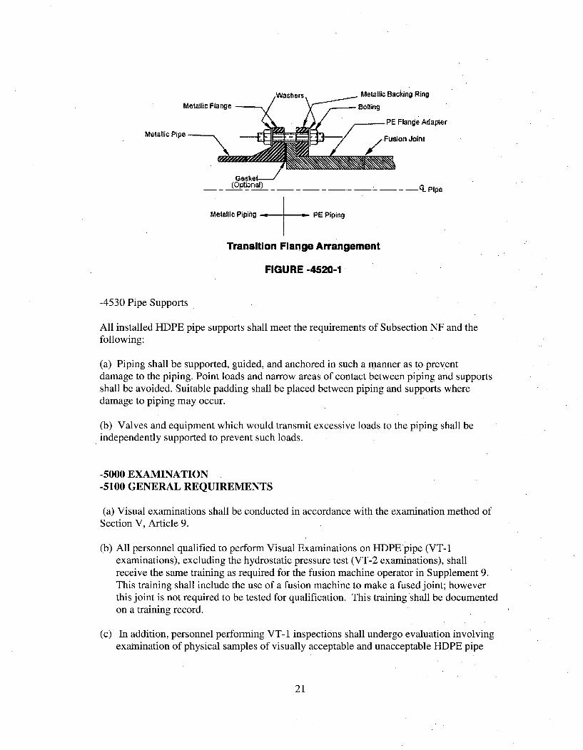
Washers Metallic Backing Ring
Metallic Flange B
PE Flange AdapterMetallic Pipe Fso on
Gasket
(Optional) -C- L Pipe
Metallic Piping PE Piping
Transition Flange Arrangement
FIGURE -4520-1
-4530 Pipe Supports
All installed HDPE pipe supports shall meet the requirements of Subsection NF and thefollowing:
(a) Piping shall be supported, guided, and anchored in such a manner as to preventdamage to the piping. Point loads and narrow areas of contact between piping and supportsshall be avoided. Suitable padding shall be placed between piping and supports wheredamage to piping may occur.
(b) Valves and equipment which would transmit excessive loads to the piping shall beindependently supported to prevent such loads.
-5000 EXAMINATION-5100 GENERAL REQUIREMENTS
(a) Visual examinations shall be conducted in accordance with the examination method ofSection V, Article 9.
(b) All personnel qualified to perform Visual Examinations on HDPE pipe (VT-Iexaminations), excluding the hydrostatic pressure test (VT-2 examinations), shallreceive the same training as required for the fusion machine operator in Supplement 9.This training shall include the use of a fusion machine to make a fused joint; howeverthis joint is not required to be tested for qualification. This training shall be documentedon a training record.
(c) In addition, personnel performing VT-1 inspections shall undergo evaluation involvingexamination of physical samples of visually acceptable and unacceptable HDPE pipe
21
fusion joints. A minimum of five flaw samples will be used for the visual examinationprocedure demonstration, and five for the personnel demonstration using the visualexamination procedure
-5110 Procedures
Examination Procedures. All examinations shall be executed in accordance with detailedwritten procedures which have been proven by actual demonstration, to the satisfaction ofthe Authorized Nuclear Inspector. Written procedures, records of demonstration ofprocedure capability, and personnel qualification shall be made available to the AuthorizedNuclear Inspector on request.
-5120 Time of Examination of Completed Fused Joints
Visual examination of all fused joints shall be conducted;
(a) upon the completion of cooling period;(b) after the review required by paragraph -4430 has been reviewed and accepted; and(c) shall be completed before piping becomes inaccessible for inspection.
-5200 REQUIRED EXAMINATIONS
-5210 Visual Examinations are required on the following material and components.
(a) During receipt inspection of the external surface for indentations.
(b) Fusion joints after the fusion process includes, review and verification of fusion datafor the joint, and external surfaces. Joints that are not examined in accordance with -5220 shall be visually inspected on the interior of the joint, including the interior beadsof mitered joints.
(c) All pipe fusion joints during the hydrostatic test.
-5220 Time-of-Flight Diffraction (TOFD) ExaminationTo provide added assurance of joint integrity, AmerenUE will perform ultrasonic Time-of-Flight Diffraction (TOFD) examination of all completed fusion joints, with theexception of portions of joints where the geometry prohibits effective examination (i.e.intrados and extrados areas of mitered fitting joints).
(a) This is a non-standard non-Code examination, and the contractor providing theservice will not have a 1OCFR50 Appendix B program. AmerenUE personnel willoversee the examinations.
(b) A demonstration will be performed to verify that the Time-of-Flight Diffraction(TOFD) procedure utilized will apply available technology for this technique. Thedemonstration will utilize specimen(s) containing ten flaws of varying shapes,
22
dimensions and relative locations, simulating flaws expected to occur in unacceptablejoints.
(c) Personnel performing TOFD examinations will be qualified in accordance withSNT-TC-lA or equivalent.
(d) Acceptance criteria will be evaluated and refined by AmerenUE, and will bebased on industry standards (e.g. B31 piping codes). The current acceptance criteriarequire that any unbonded area in the joint, found as a result of the TOFD, is cause forrejection.
(e) All TOFD joint examination records shall be retained as permanent records.
-5300 ACCEPTANCE STANDARDS
-5310 General Requirements
Unacceptable joints shall be removed. Repair of unacceptable joints is not permitted.
-5320 Visual Examination Acceptance Criteria of external surfaces
-5321 Thermal fusion butt joints shall meet the following:
(a) Joints shall exhibit proper fusion bead configuration, see Supplement 5.
(b) There shall be no evidence of cracks or incomplete fusion.
Except for mitered joints, joints shall not be visually angled or off-set. The ovality offset shallbe less than 10% of the minimum wall thickness of the fused components provided theremaining joint thickness is not be less than the required as-fabricated minimum wall thicknessper ASTM F714 - unless evaluated and determined to be acceptable considering the remainingwall thickness.
(c) The cleavage between fusion beads shall not extend to or below the outside diameterpipe surface (see Figure -5321-1).
(d) For mitered joints, the beads may flare out instead of roll back to the pipe surface,and/or may exhibit multiple beads or heavy beads with no cleavage. In either case,there must be evidence of melt flow around the complete interior and exteriorcircumference of the joint. Refer to Supplement 5.
23
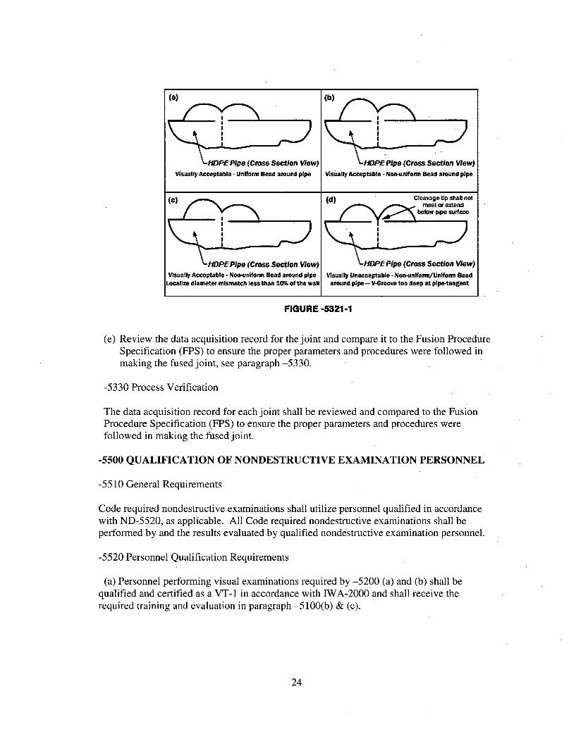
(a) (b)
IOPE Pipe (Cross Section Wow) HOPE Pipe (Cross Section Wow)Visually Acceptable -Uniform Bead around pipe Visually Acceptable - Nco-un"Worm Bead around pipe
(c) •(d)Cleavage tUp Shall notmeet or extend
Woow p~ipo surface
HDPE Pipe (Cross Section Wow) HDPE Pipe (Cross Section Wow)Visually Acceptable - Non-en[fonm Bead around pipe Visually Unacceptable - Noo-uniform/Uniform Bead
Localize diameter mismatch less than 10% of the wall around pipe - V-0roove too deep at pipe-tangent
FIGURE -5321-1
(e) Review the data acquisition record for the joint and compare it to the Fusion ProcedureSpecification (FPS) to ensure the proper parameters and procedures were followed inmaking the fused joint, see paragraph -5330.
-5330 Process Verification
The data acquisition record for each joint shall be reviewed and compared to the FusionProcedure Specification (FPS) to ensure the proper parameters and procedures werefollowed in making the fused joint.
-5500 QUALIFICATION OF NONDESTRUCTIVE EXAMINATION PERSONNEL
-5510 General Requirements
Code required nondestructive examinations shall utilize personnel qualified in accordancewith ND-5520, as applicable. All Code required nondestructive examinations shall beperformed by and the results evaluated by qualified nondestructive examination personnel.
-5520 Personnel Qualification Requirements
(a) Personnel performing visual examinations required by -5200 (a) and (b) shall bequalified and certified as a VT- 1 in accordance with IWA-2000 and shall receive therequired training and evaluation in paragraph -5100(b) & (c).
24
(b) Personnel performing visual examinations required by -5200(c) shall be qualified andcertified as a VT-2 in accordance with IWA-2000 and receive four hours of training in PEpiping and joining practices. This training shall be documented on a training record.
-6000 TESTING-6100 GENERAL REQUIREMENTS
(a) Prior to initial operation, the installed system shall be hydrostatically tested in thepresence of the Authorized Nuclear Inspector.
(b) All joints, including fused joints shall be left exposed for examination during the test.For long sections of piping the hydrostatic testing may be accomplished by testing in smallsub-sections of the longer section. Upon a satisfactory test of each small section the pipingmay be buried. This process shall be documented in the AmerenUE Quality AssuranceProgram or Repair/Replacement Program and found acceptable to the Authorized NuclearInspector.
(c) The pressure in the test section shall be gradually (minimum rate of 5 psig/min not toexceed a maximum rate of 20 psig/min) increased to the specified test pressure and held for4 hours. Make up water may be added to maintain test pressure during this time to allow forinitial expansion. Following the 4 hour initial pressurization period, the test pressure shall bereduced by 10 psig and the system monitored for anther 1 hour. Make up water may nolonger be added to maintain pressure. Each joint shall be examined. If no visual leakage isobserved and the pressure remains within 5% of the test pressure for the 1 hour, the pipesection under test is considered acceptable.
(d) The temperature of the piping under test will be maintained within the temperaturelimits of the system design.
(e) The total test time including initial pressurization, initial expansion, and time at testpressure, must not exceed 8 hours. If the pressure test is not completed the test sectionshall be de-pressurized. The test section shall not be, re-pressurized for at least 8 hours.
(f) A pneumatic test is not permitted.
-6200 Hydrostatic Test Requirements
(a) Instrumentation for the hydrostatic test shall be in accordance with IWA-5260.
(b) The minimum test pressure shall be 1.5 times the Design Pressure of the HDPE pipingsystem plus 10 psi.
(c) Personnel qualified in accordance -5520(b) shall conduct the examination.
25
-8000 NAMEPLATES, STAMPING AND REPORTS-8100 GENERAL REQUIREMENTS-8110 Scope
The requirements for nameplates, stamping and reports shall be in accordance withAmerenUE's ASME Section XI Repair/Replacement Program with the following exception:
(a) Other than thermal indentation line printing during manufacture, no indentationstamping is allowed on the high density polyethylene pipe surface, all marking shall beperformed with a metallic paint marker or stenciling marker.
(b) Form NM(PE)-2 (Supplement 2) shall be used for batch produced products produced byfusion (i.e. shop fabricated fittings). Multiple fittings may be included on oneData ReportForm.
26
SUPPLEMENT 1
GLOSSARY
1. Butt Fusion Cycle - Pressure/Time diagram for a defined fusion temperature, representing thebutt fusion operation.
2. Certified Certificate of Analysis for Batch (CCAB) - a document attesting that material is inaccordance with specified requirements, including batch analysis of all chemical analysis, test,and examinations.
3. control specimen - The specimen from the base material tested to determine the tensilestrength for the purpose of determining an acceptable tensile strength.
4. Cool time under Pressure - In the fusion process, the theoretical fusion pressure plus dragpressure is applied between the pipe ends. This pressure must be maintained until the fusion jointis cool to the touch.
5. coupon - a fusion assembly for procedure or performance qualification testing. The couponmay be any product from sheet plate, pipe, or tube material.
6. Data Acquisition Record - A detailed record of the times and pressures used in the fusionprocess along with the heater surface temperature , employee information, fusion machineinformation, pipe information, date and time for a permanent record of each joint made.
7. Drag Pressure - The pressure required by the fusion machine to overcome the drag resistanceand frictional resistance and keep the carriage moving at its slowest speed.
8. Drag Resistance - Frictional resistance due to the weight of the length of pipe fixed in themovable clamp at the point at which movement of the moveable clamp is initiated (peak drag) orthe friction occurring during movement (dynamic drag)
9. Frictional Resistance in the Butt Fusion Machine - Force necessary to overcome friction inthe whole mechanism of the butt fusion machine.
10. Fusion Machine Operator - Person trained to carry out fusion joining between polyethylene(PE) pipes and/or fittings based on the Fusion Procedure Specification (FPS).
11. Fusion Operator Certificate - Approval certificate issued by the examiner/assessor stating theknowledge and the skill of the fusion operator to produce fusion joints following a given fusionprocedure.
12. Fusion Procedure - A document providing in detail the required variables for the butt fusionprocess to assure repeatability in the butt fusion procedure (FPS).
27
13. Heater Bead-up Size - In the heating cycle, the pipe is brought against the heater and theforce is dropped to the soak cycle. During this cycle, a bead of polyethylene is formed betweenthe pipe end and the heater surface on both sides. When the bead-up size reaches the sizeestablished in the FPS, it is time to open the carriage and remove the heater.
14. Heater Surface Temperature - The temperature, in degrees F, of the surface of the coatedheater is critical to the butt fusion process. It is usually expressed as a range (example: 400 - 4500F) and the common practice is to set the average surface temperature at the mid-range (example:4250 F).
15. hydrostatic design basis (HDB) - one of a series of established stress values for a compound.
16. hydrostatic design stress (HDS) - the estimated maximum tensile stress the material iscapable of withstanding continuously with a high degree of certainty that failure of the pipe willnot occur. This stress is circumferential when internal hydrostatic water pressure is applied.
17. Interfacial Pressure - The amount of force in pounds (lbs) per square inch of pipe arearequired to calculate the fusion machine gauge pressure. The interfacial pressure is multiplied bythe pipe area in square inches to determine the amount of fusion force (lbs) required to fuse thepipe. This force is divided by the total effective piston area of the hydraulic fusion machine todetermine the theoretical gauge pressure to set on the fusion machine. The Drag pressure must beadded to this pressure to determine the actual gauge pressure required for fusion. The interfacialpressure usually has a range (example: 60-90 psi) and the common practice is to use the mid-range (example: 75 psi) when making these calculations.
18. long-term hydrostatic pressure - strength (LTHS) - the estimated tensile stress in the wall ofthe pipe in the circumferential orientation that when applied continuously will cause failure ofthe pipe at 100,000 hours.
19. Modulus of Soil Reaction, E' - The soil reaction modulus is a proportionality constant thatrepresents the embedment soil's resistance to ring deflection of pipe due to earth pressure. E' hasbeen determined empirically from field deflection measurements by substituting site parameters(i.e. depth of cover, soil weight) into Spangler's evaluation and "back calculating" F'.
20. HDPE - (high density polyethylene) A polyolefin composed of polymers of ethylene. It isnormally a translucent, tough, waxy solid which is unaffected by water and by a large range ofchemicals. This is one of three general classifications based on material density; low-density,medium-density, and high-density.
21. product quality certification (PQC) - a document attesting that material is in accordancewith specified requirements, including batch analysis of all chemical analysis, test, andexaminations.
22. stiffness factor - the measurement of a pipe's ability to resist deflection as determined inaccordance with ASTM D 2412.
28
23. test joint - work pieces joined by fusing to qualify fusing procedures, or fusing operators
24. thermoplastic resin - a resin material which does not react or polymerize and which flowswith the application of heat and solidifies when cooled. A material which can be reformed.
29
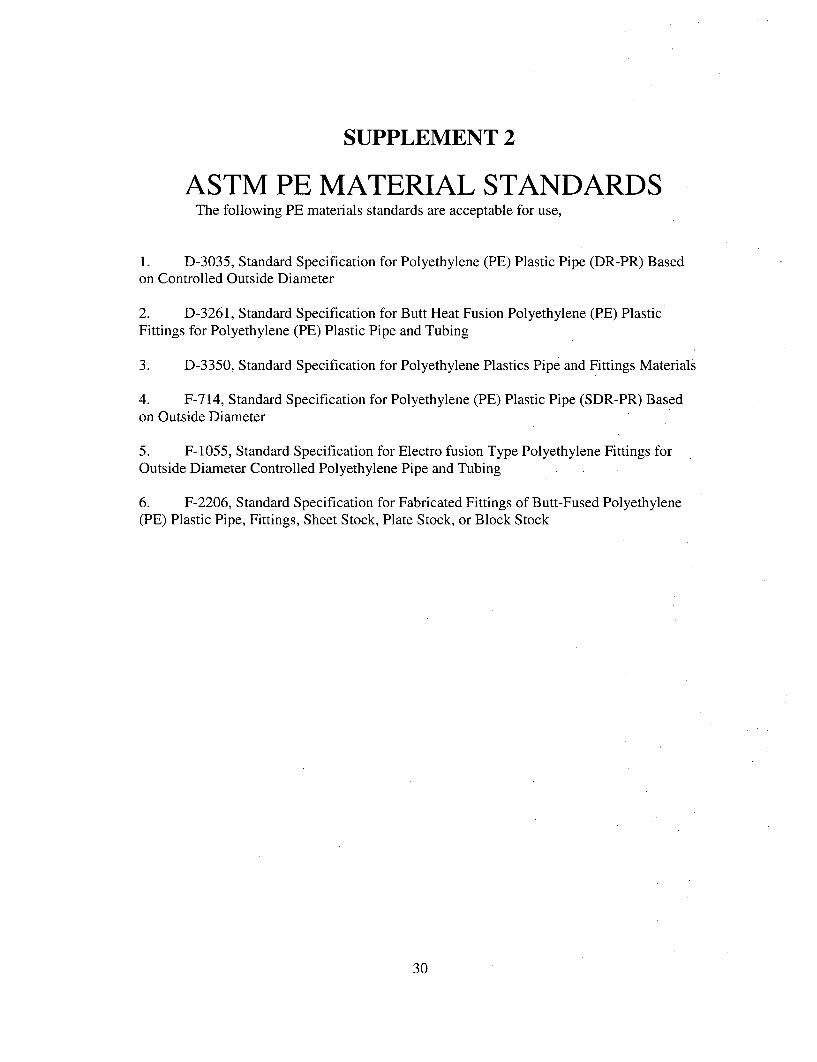
SUPPLEMENT 2
ASTM PE MATERIAL STANDARDSThe following PE materials standards are acceptable for use,
1. D-3035, Standard Specification for Polyethylene (PE) Plastic Pipe (DR-PR) Basedon Controlled Outside Diameter
2. D-3261, Standard Specification for Butt Heat Fusion Polyethylene (PE) PlasticFittings for Polyethylene (PE) Plastic Pipe and Tubing
3. D-3350, Standard Specification for Polyethylene Plastics Pipe and Fittings Materials
4. F-714, Standard Specification for Polyethylene (PE) Plastic Pipe (SDR-PR) Basedon Outside Diameter
5. F-1055, Standard Specification for Electro fusion Type Polyethylene Fittings forOutside Diameter Controlled Polyethylene Pipe and Tubing
6. F-2206, Standard Specification for Fabricated Fittings of Butt-Fused Polyethylene(PE) Plastic Pipe, Fittings, Sheet Stock, Plate Stock, or Block Stock
30
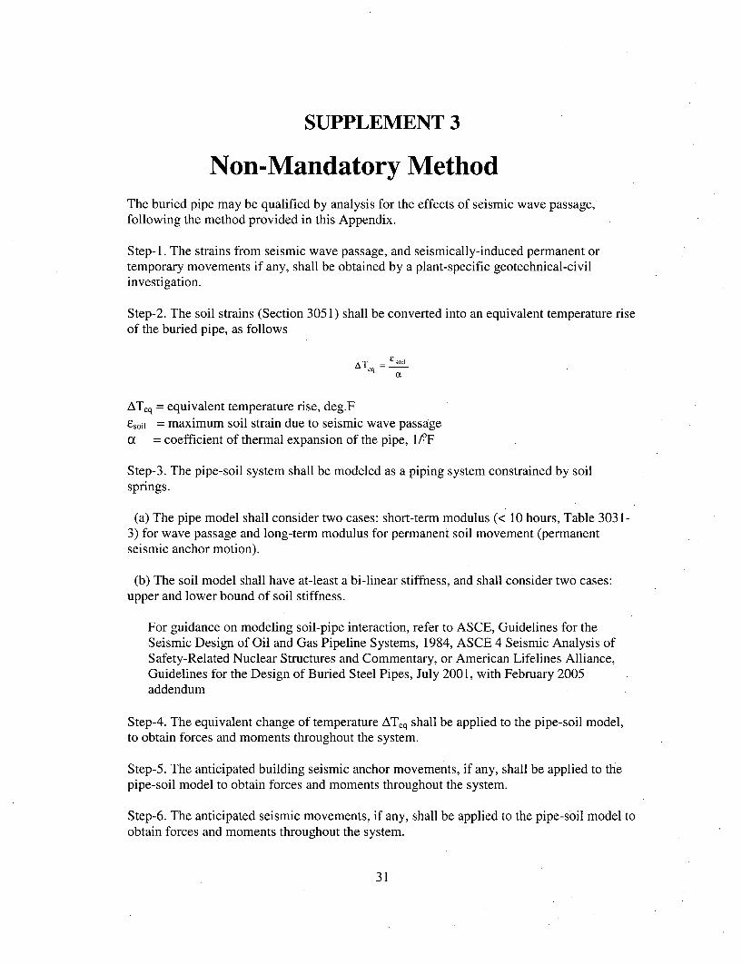
SUPPLEMENT 3
Non-Mandatory MethodThe buried pipe may be qualified by analysis for the effects of seismic wave passage,following the method provided in this Appendix.
Step-1. The strains from seismic wave passage, and seismically-induced permanent ortemporary movements if any, shall be obtained by a plant-specific geotechnical-civilinvestigation.
Step-2. The soil strains (Section 3051) shall be converted into an equivalent temperature riseof the buried pipe, as follows
ATq E soil
ATeq = equivalent temperature rise, deg.Fesoil = maximum soil strain due to seismic wave passagea = coefficient of thermal expansion of the pipe, 1fF
Step-3. The pipe-soil system shall be modeled as a piping system constrained by soilsprings.
(a) The pipe model shall consider two cases: short-term modulus (< 10 hours, Table 303 1-3) for wave passage and long-term modulus for permanent soil movement (permanentseismic anchor motion).
(b) The soil model shall have at-least a bi-linear stiffness, and shall consider two cases:upper and lower bound of soil stiffness.
For guidance on modeling soil-pipe interaction, refer to ASCE, Guidelines for theSeismic Design of Oil and Gas Pipeline Systems, 1984, ASCE 4 Seismic Analysis ofSafety-Related Nuclear Structures and Commentary, or American Lifelines Alliance,Guidelines for the Design of Buried Steel Pipes, July 2001, with February 2005addendum
Step-4. The equivalent change of temperature ATeq shall be applied to the pipe-soil model,to obtain forces and moments throughout the system.
Step-5. The anticipated building seismic anchor movements, if any, shall be applied to thepipe-soil model to obtain forces and moments throughout the system.
Step-6. The anticipated seismic movements, if any, shall be applied to the pipe-soil model toobtain forces and moments throughout the system.
31
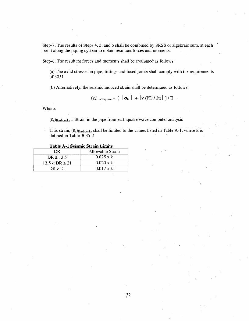
Step-7. The results of Steps 4, 5, and 6 shall be combined by SRSS or algebraic sum, at eachpoint along the piping system to obtain resultant forces and moments.
Step-8. The resultant forces and moments shall be evaluated as follows:
(a) The axial stresses in pipe, fittings and fused joints shall comply with the requirementsof 3051.
(b) Alternatively, the seismic induced strain shall be determined as follows:
(Fa)Earthquake G[ E + Iv (PD / 2t)I ]/E
Where:
(Fa)Earthquake- = Strain in the pipe from earthquake wave computer analysis
This strain, (Sa)Earthquake shall be limited to the values listed in Table A-i, where k isdefined in Table 3035-2
Table A-1 Seismic Strain LimitsDR Allowable Strain
DR _• 13.5 0.025 x k13.5 < DR _• 21 0.020 x k
DR > 21 0.017 xk
32
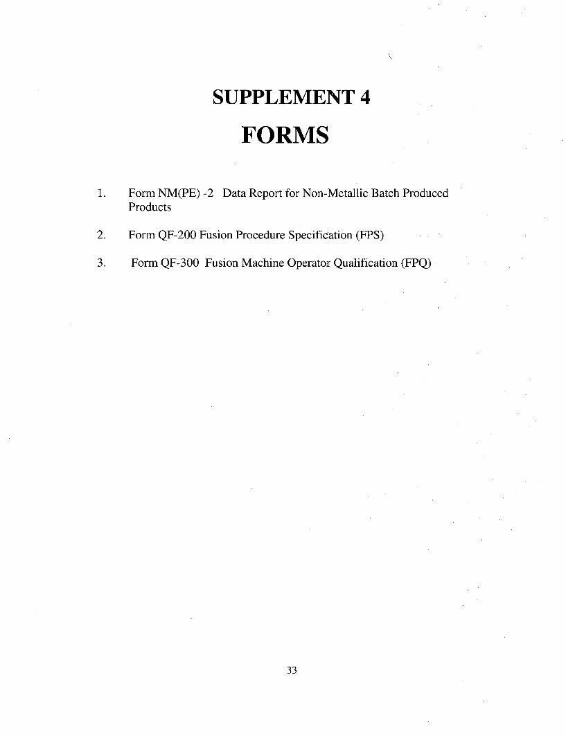
SUPPLEMENT 4
FORMS
1. Form NM(PE) -2 Data Report for Non-Metallic Batch Produced
Products
2. Form QF-200 Fusion Procedure Specification (FPS)
3. Form QF-300 Fusion Machine Operator Qualification (FPQ)
33
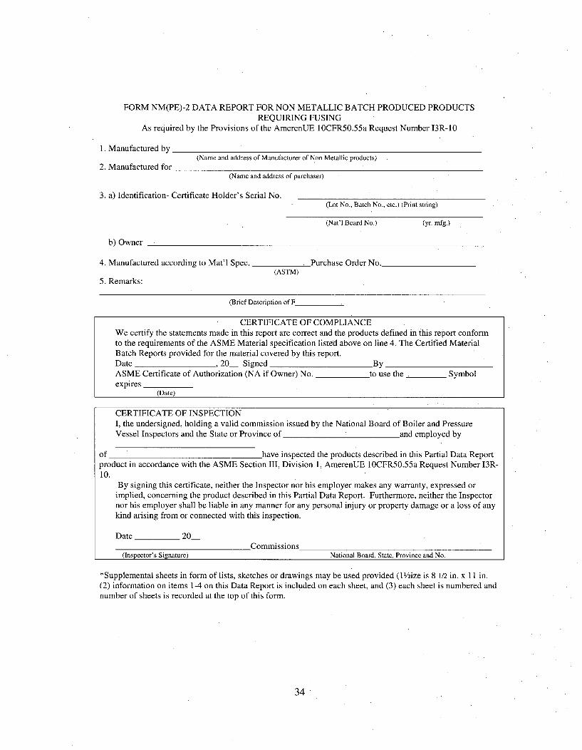
FORM NM(PE)-2 DATA REPORT FOR NON METALLIC BATCH PRODUCED PRODUCTSREQUIRING FUSING
As required by the Provisions of the AmerenUE 1OCFR50.55a Request Number 13R-10
1. Manufactured by
2. Manufactured for(Name and address of Manufacturer of Non Metallic products)
(Name and address of purchaser)
3. a) Identification- Certificate Holder's Serial No.(Lot No., Batch No., etc.) (Print string)
(Nat'l Board No.) (yr. mfg.)
b) Owner
4. Manufactured according to Mat'l Spec.
5. Remarks:
Purchase Order No.(ASTM)
(Brief Description of F
CERTIFICATE OF COMPLIANCEWe certify the statements made in this report are correct and the products defined in this report conformto the requirements of the ASME Material specification listed above on line 4. The Certified MaterialBatch Reports provided for the material covered by this report.Date , 20 Signed ByASME Certificate of Authorization (NA if Owner) No. to use the Symbolexpires
(Date)
CERTIFICATE OF INSPECTIONI, the undersigned, holding a valid commission issued by the National Board of Boiler and PressureVessel Inspectors and the State or Province of __and employed by
of have inspected the products described in this Partial Data Reportproduct in accordance with the ASME Section III, Division 1, AmerenUE I OCFR50.55a Request Number 13R-10.
By signing this certificate, neither the Inspector nor his employer makes any warranty, expressed orimplied, concerning the product described in this Partial Data Report. Furthermore, neither the Inspectornor his employer shall be liable in any manner for any personal injury or property damage or a loss of anykind arising from or connected with this inspection.
Date 20_________________________________________vU1l11a1la________________________________________________
(Inspector's Signature) National Board, State, Province and No.
*Supplemental sheets in form of lists, sketches or drawings may be used provided (l/ize is 8 1/2 in. x 11 in.(2) information on items 1-4 on this Data Report is included on each sheet, and (3) each sheet is numbered andnumber of sheets is recorded at the top of this form.
34
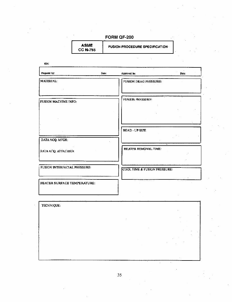
FORM QF-200
ASME FUSION PROCEDURE SPECIFICATIONCC N-755I
Ppftpmd by: Dam: ARp1Oed bY
FUSION MACHINE INFO:
FUSION DRAG PRESSURE:
FJSION I**IJK.,I, R:
DATAACQ. MFGR:
LJATA ACQ. A`flACHlpf):
FUSION INTERFACIAL PRESSURE:
[ COOL TIME &, FUSION PRESSURE-
HEATER SURFACE TEMPERATURE:
TECHNIQUE:
35
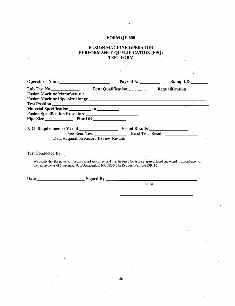
FORM QF-300
FUSION MACHINE OPERATORPERFORMANCE QUALIFICATION (FPQ)
TEST FORM
Operator's Name Payroll No. Stamp I.D.
Lab Test No. Test: Qualific,Fusion Machine ManufacturerFusion Machine Pipe Size RangeTest PositionMaterial Specification toFusion Specification ProcedurePipe Size Pipe DR
ition Requalification
NDE Requirements: Visual Visual ResultsFree Bend Test Bend Tests Results
Data Acquisition Record Review Results
Test Conducted By
We certify that the statements in this record are correct and that the fused joints are prepared, fused and tested in accordance withthe requirements of Supplement 9, of AmerenUE 1OCFR50.55a Request Number 13R-10.
Date Signed ByTitle
36
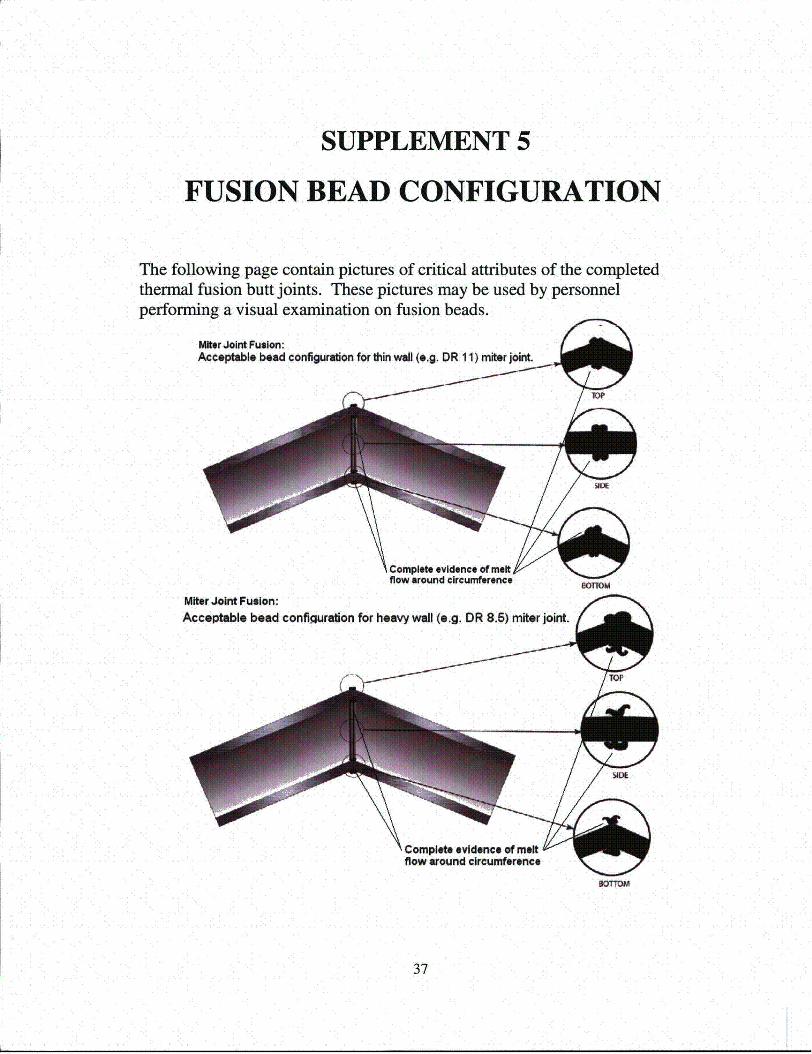
SUPPLEMENT 5
FUSION BEAD CONFIGURATION
The following page contain pictures of critical attributes of the completedthermal fusion butt joints. These pictures may be used by personnelperforming a visual examination on fusion beads.
Miter Joint Fusion:Acceptable bead configuration for thin wall (e.g. DR 11) miter joint.
Complete evidence of meltflow around circumference
Miter Joint Fusion:Acceptable bead configuration for heavy wall (e.g. DR 8.5) miter joint.
f - fr~
Complete evidence of mertflow around circumference
37
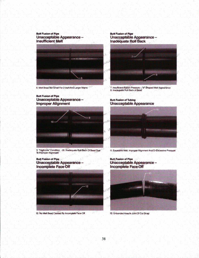
SsfltFuson of Pip*Ur "1,111"1 pmeImca-
SuU Fusion of PI"e
I Pr0p o wM
SuU tslon of =Yw, Mok be"
win ppinOfcS
ý"Prwcwm10.
5uFbim iof",:,
lt~k Met 944Coýd y kVc9.O ( S OýAmelnJcikt Of CtA SWp
38
SUPPLEMENT 9
HIGH DENSITY POLYETHYLENEPIPE FUSING
1. Article I -- Fusion General Requirements
1. Article II -- Fusion Procedure Qualifications
2. Article III -- Fusion Performance Qualification
3. Appendixes
Non-mandatory Appendix A -- Fusion Machine OperatorQualification Training
39
ARTICLE IFUSION GENERAL REQUIREMENTS
QF- 100 GENERAL
This Supplement relates to the qualification of fusion machine operators and the proceduresthat they employ in fusing high density polyethylene (HDPE) piping. Due to the majordifferences between metallic welding and plastic fusing, the Fusion Procedure Specification(FPS) and the Procedure Qualification Record (PQR) have been combined for thissupplement.
QF-10i Scope
The requirements in this supplement apply to the preparation of the Fusion ProcedureSpecification (FPS), and the qualification of fusion machine operators for thermal buttfusion joining.
QF- 102 Terms and Definitions
Some of the more common terms relating to fusion are defined in Supplement 1, and ASTMF412 Standard Terminology Relating to Plastic Piping Systems,
QF-103 Responsibility
QF-103.1 Fusion. AmerenUE is responsible for all fusing done for the project and shallconduct the tests required in this Supplement to qualify procedures (Article II), and theperformance of fusion machine operators who use these procedures (Article III).
QF-103.2 Records. Records of the results obtained in the fusing procedure and fusionmachine operator performance qualifications shall be maintained. These records shall becertified by AmerenUE and shall be accessible to the Authorized Nuclear Inspector.
QF-104 Documents
QF-104.1 A FPS is a written document that provides direction to the fusion machineoperator for making fused joints in accordance with the requirements of this Supplement.
(a) The FPS specifies the conditions under which the fusing must be performed. Theseconditions include the HDPE materials that are permitted. Such conditions are referred to inthis Supplement as fusing "essential variables." The FPS shall address these essentialvariables.
(b) When required, qualification of a FPS is intended to determine that the fused jointproposed for construction is capable of providing the required properties for its intended
40
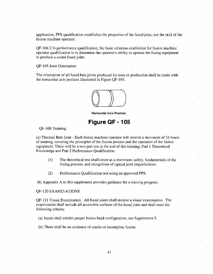
application. FPS qualification establishes the properties of the fused joint, not the skill of thefusion machine operator.
QF-104.2 In performance qualification, the basic criterion established for fusion machineoperator qualification is to determine the operator's ability to operate the fusing equipmentto produce a sound fused joint.
QF-105 Joint Orientation
The orientation of all fused butt joints produced for tests or production shall be made withthe horizontal axis position illustrated in Figure QF-105.
0Horizontal Axis Position
Figure QF - 105QF- 106 Training
(a) Thermal Butt Joint - Each fusion machine operator will receive a minimum of 24 hoursof training, covering the principles of the fusion process and the operation of the fusionequipment. There will be a two part test at the end of this training; Part 1 TheoreticalKnowledge and Part 2 Performance Qualification.
(1) The theoretical test shall cover as a minimum; safety, fundamentals of thefusing process, and recognition of typical joint imperfections.
(2) Performance Qualification test using an approved FPS.
(b) Appendix A to this supplement provides guidance for a training program.
QF- 120 EXAMINATIONS
QF-121 Visual Examination. All fused joints shall receive a visual examination. Theexamination shall include all accessible surfaces of the fused joint and shall meet thefollowing criteria;
(a) Joints shall exhibit proper fusion bead configuration, see Supplement 5.
(b) There shall be no evidence of cracks or incomplete fusion.
41,
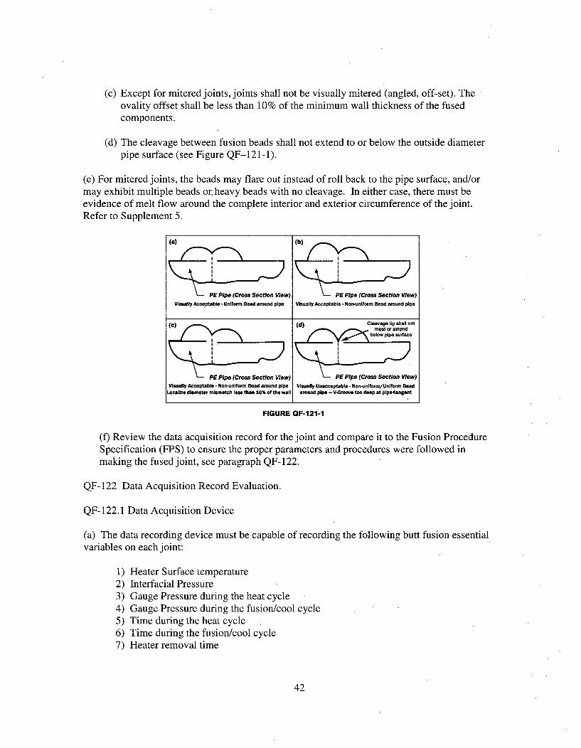
(c) Except for mitered joints, joints shall not be visually mitered (angled, off-set). Theovality offset shall be less than 10% of the minimum wall thickness of the fusedcomponents.
(d) The cleavage between fusion beads shall not extend to or below the outside diameterpipe surface (see Figure QF-121-1).
(e) For mitered joints, the beads may flare out instead of roll back to the pipe surface, and/ormay exhibit multiple beads or. heavy beads with no cleavage. In either case, there must beevidence of melt flow around the complete interior and exterior circumference of the joint.Refer to Supplement 5.
(a) (b)
PE Pipe (Cross Section View) PE Pipe (Cross Section View)Visually Acceptable. Uniform Bead around pipe Visually Acceptable. Non-unIform Bead around pipe
() (d) Cleavage tip shall not(C ( meet or extend
below pipe surface
PEPipe (Cross Section View) PE Pipe (Cross Section View)Visually Acceptable • Non-unlform Bead around pipe Visually Unacceptable - Non-uniform/Uniform Bead
Localize diameter mismatch lese than 10% of the wall around pipe - V4-rove too deep at plpe4angent
FIGURE QF-121-1
(f) Review the data acquisition record for the joint and compare it to the Fusion ProcedureSpecification (FPS) to ensure the proper parameters and procedures were followed inmaking the fused joint, see paragraph QF-122.
QF-122 Data Acquisition Record Evaluation.
QF-122.1 Data Acquisition Device
(a) The data recording device must be capable of recording the following butt fusion essentialvariables on each joint:
1)2)3)4)5)6)7)
Heater Surface temperatureInterfacial PressureGauge Pressure during the heat cycleGauge Pressure during the fusion/cool cycleTime during the heat cycleTime during the fusion/cool cycleHeater removal time
42
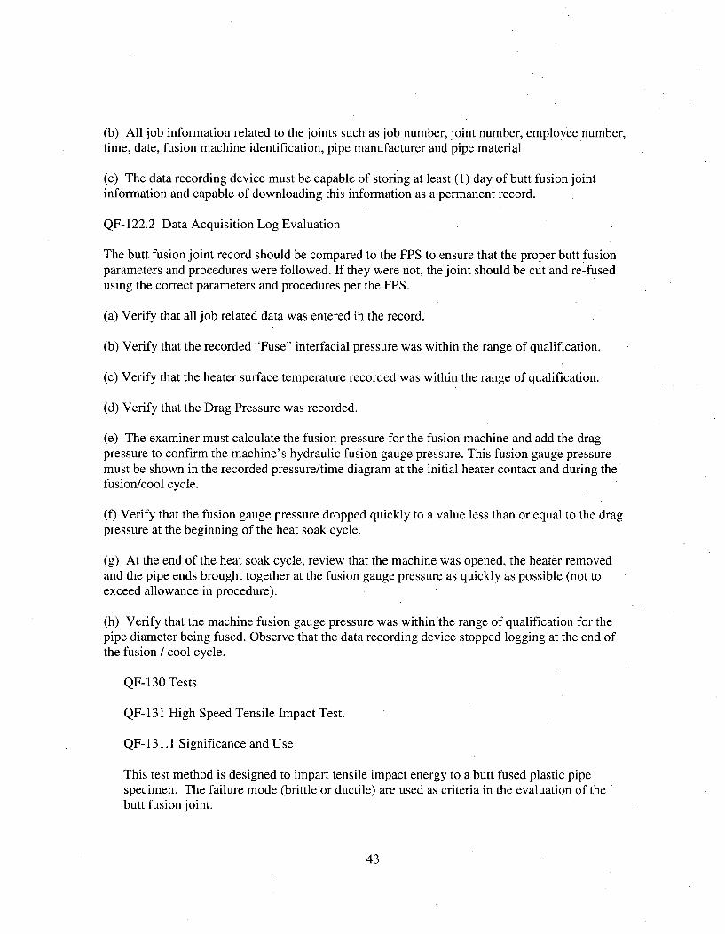
(b) All job information related to the joints such as job number, joint number, employee number,time, date, fusion machine identification, pipe manufacturer and pipe material
(c) The data recording device must be capable of storing at least (1) day of butt fusion jointinformation and capable of downloading this information as a permanent record.
QF-122.2 Data Acquisition Log Evaluation
The butt fusion joint record should be compared to the FPS to ensure that the proper butt fusionparameters and procedures were followed. If they were not, the joint should be cut and re-fusedusing the correct parameters and procedures per the FPS.
(a) Verify that all job related data was entered in the record.
(b) Verify that the recorded "Fuse" interfacial pressure was within the range of qualification.
(c) Verify that the heater surface temperature recorded was within the range of qualification.
(d) Verify that the Drag Pressure was recorded.
(e) The examiner must calculate the fusion pressure for the fusion machine and add the dragpressure to confirm the machine's hydraulic fusion gauge pressure. This fusion gauge pressuremust be shown in the recorded pressure/time diagram at the initial heater contact and during thefusion/cool cycle.
(f) Verify that the fusion gauge pressure dropped quickly to a value less than or equal to the dragpressure at the beginning of the heat soak cycle.
(g) At the end of the heat soak cycle, review that the machine was opened, the heater removedand the pipe ends brought together at the fusion gauge pressure as quickly as possible (not toexceed allowance in procedure).
(h) Verify that the machine fusion gauge pressure was within the range of qualification for thepipe diameter being fused. Observe that the data recording device stopped logging at the end ofthe fusion / cool cycle.
QF-130 Tests
QF- 131 High Speed Tensile Impact Test.
QF- 131.1 Significance and Use
This test method is designed to impart tensile impact energy to a butt fused plastic pipespecimen. The failure mode (brittle or ductile) are used as criteria in the evaluation of thebutt fusion joint.
43
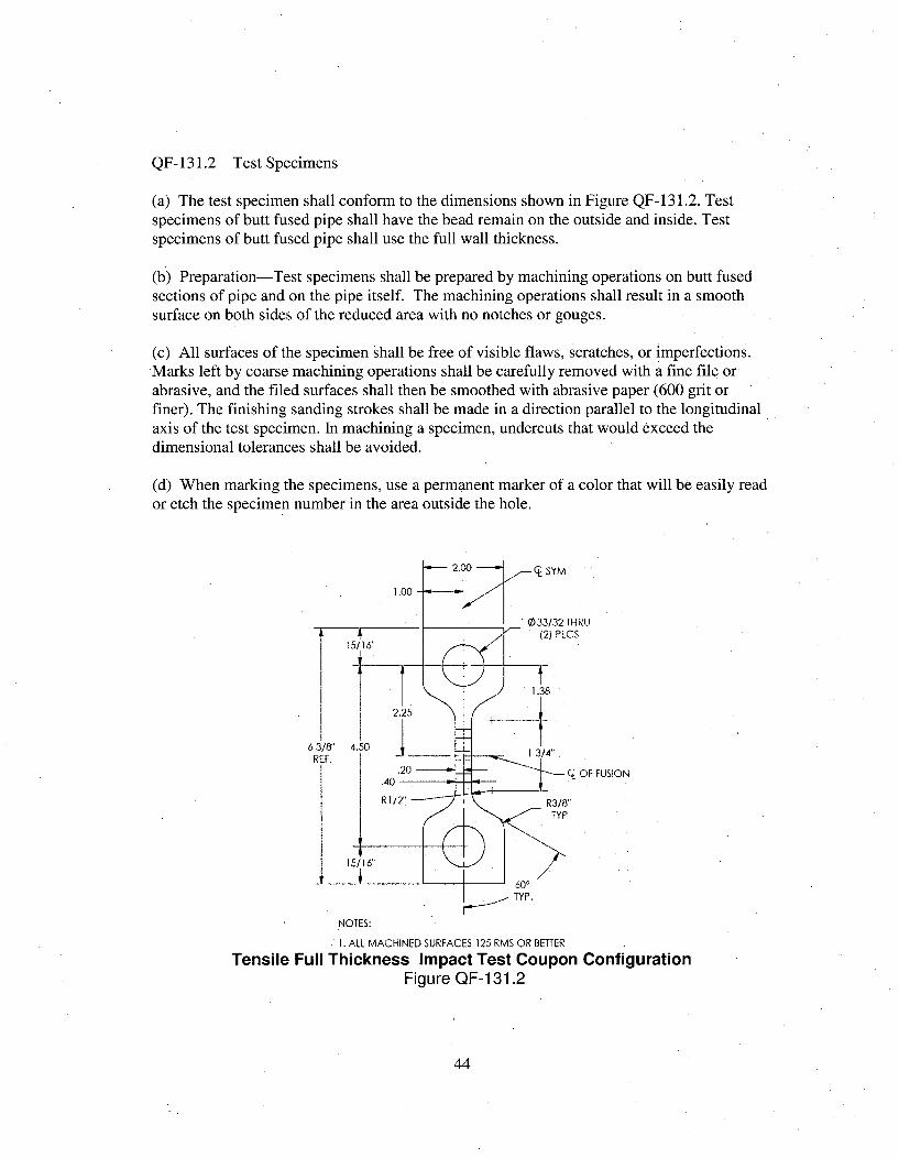
QF-131.2 Test Specimens
(a) The test specimen shall conform to the dimensions shown in Figure QF-131.2. Testspecimens of butt fused pipe shall have the bead remain on the outside and inside. Testspecimens of butt fused pipe shall use the full wall thickness.
(b) Preparation-Test specimens shall be prepared by machining operations on butt fusedsections of pipe and on the pipe itself. The machining operations shall result in a smoothsurface on both sides of the reduced area with no notches or gouges.
(c) All surfaces of the specimen shall be free of visible flaws, scratches, or imperfections.Marks left by coarse machining operations shall be carefully removed with a fine file orabrasive, and the filed surfaces shall then be smoothed with abrasive paper (600 grit orfiner). The finishing sanding strokes shall be made in a direction parallel to the longitudinalaxis of the test specimen. In machining a specimen, undercuts that would exceed thedimensional tolerances shall be avoided.
(d) When marking the specimens, use a permanent marker of a color that will be easily reador etch the specimen number in the area outside the hole.
62RI
- OF FUSION
15/ 16" \ __L 600
TYP.
NOTES:
1. ALL MACHINED SURFACES 125 RMS OR BETTER
Tensile Full Thickness Impact Test Coupon ConfigurationFigure QF-131.2
44
QF- 131.3 Number of Test Specimens
Test at least four specimens from butt fused pipe sections 900 apart for pipe sizes 4" andlarger. Test two specimens from butt fused pipe sections 180' apart for pipe sizes 2" to 4".
QF-131.4 Speed of Testing The speed of testing shall be in accordance with Table QF-131.4
Wall Thickness Testing Speed
<1.25 in. (32mm) 6 in./s (152 mm/s)
>1.25 in. (32 mm) 4 in./S (102 mnn/s)
Testing Speed Tolerance: +5 in,/s to -1 in./s (+12.7 mm/s to -25.4 mrnds)
TABLE QF-131.4
QF- 131.5 Conditioning
(a) Conditioning-Condition the test specimens at 73.4 ± 4°F [23 ± 2°C] for not less than 1hour prior to test.
(b) Test Conditions-Conduct the tests at 73.4 ± 4°F [23 ± 2'C] unless otherwise specifiedby contract or the relevant ASTM material specification.
QF-131.6 Test Procedure
(a) Set up the machine and set the speed of testing to the proper rate as required in QF-131.4
(b) Pin each specimen in the clevis tooling of the testing machine. This will align the longaxis of the specimen and the tooling with the direction of pull of the machine.
(c) Determine the mode of failure and note in the report.
QF-131.7 Acceptance Criteria
Failure mode shall be ductile. Reference Figure QF-130.7.
45
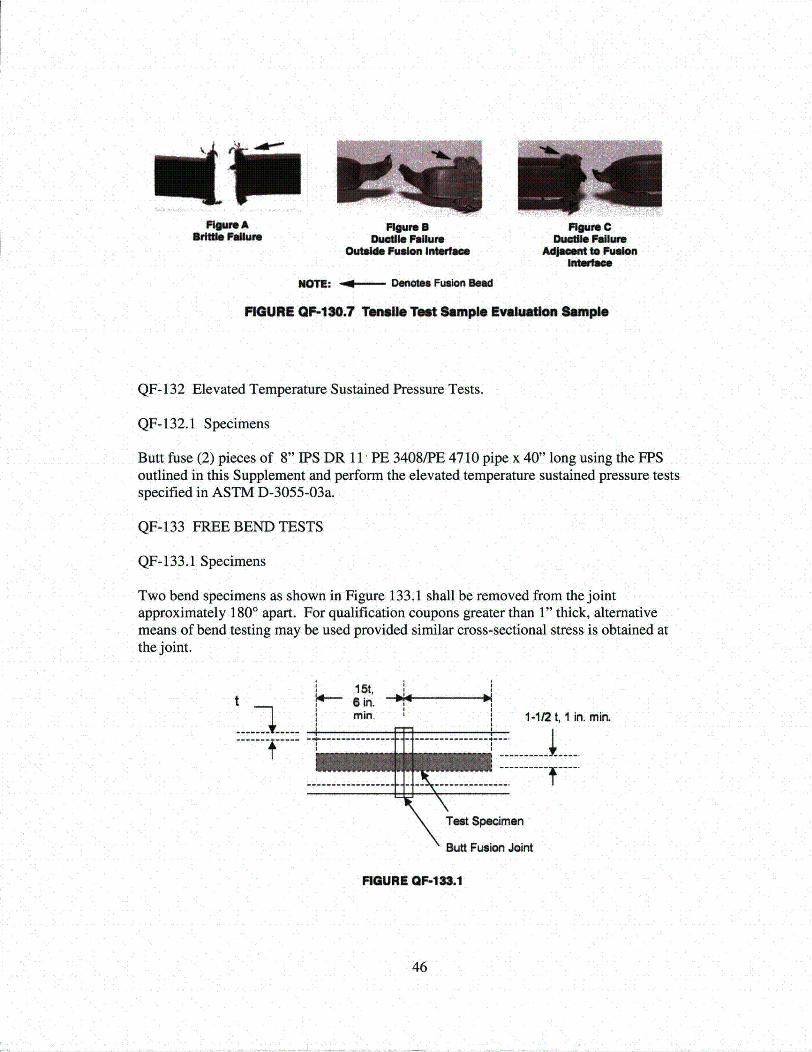
RDMteABrims P61umr
Fiwre S no"r CDue"is Pollute Dudle Foiurs
OUtsde Fusion Intore A4s to FusonI - I I
NOTE: o Denotes Fusion Used
FIGURE GF-130.7 Tensft Tedt Slmple Evalkutlo Sample
QF-132 Elevated Temperature Sustained Pressure Tests.
QF-132.1 Specimens
Butt fuse (2) pieces of 8" IPS DR 11 PE 3408/PE 4710 pipe x 40" long using the FPSoutlined in this Supplement and perform the elevated temperature sustained pressure testsspecified in ASTM D-3055-03a.
QF-133 FREE BEND TESTS
QF-133.1 Specimens
Two bend specimens as shown in Figure 133.1 shall be removed from the jointapproximately 1800 apart. For qualification coupons greater than 1" thick, alternativemeans of bend testing may be used provided similar cross-sectional stress is obtained atthe joint.
15t,t 6 iGin.
Sin. 1-1t2 t, 1 in. min
-------------- -------------- -----I ---- - - - - - -
BMt Fusojn Joint
FIGURE OF-1S3.1
46
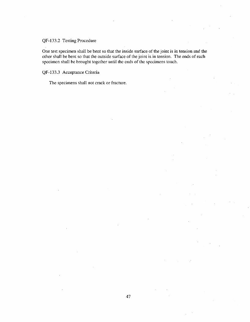
QF-133.2 Testing Procedure
One test specimen shall be bent so that the inside surface of the joint is in tension and theother shall be bent so that the outside surface of the joint is in tension. The ends of eachspecimen shall be brought together until the ends of the specimens touch.
QF-133.3 Acceptance Criteria
The specimens shall not crack or fracture.
47
ARTICLE II
FUSION PROCEDUREQUALIFICATIONS
QF-200 GENERAL
QF-201 Written Fusion Procedure Specifications shall be prepared as follows:
(a) Fusion Procedure Specification (FPS). A FPS is a written qualified fusingprocedure prepared to provide direction for making production fused. The FPS shallbe used to provide direction to the fusion machine.
(b) Contents of the FPS. The completed FPS shall describe all of the essentialvariables for each fusion process used in the FPS. These essential variables are listedand defined in QF-220. Any other information may be included in the FPS that maybe helpful in making a fused joint.
(c) Changes in essential variables require requalification of the FPS
(d) Format of the FPS. The information required to be in the FPS may be in anyformat, written or tabular, as long as every essential variables outlined in QF-220 isincluded or referenced. Form QF-200 has been provided as a guide for the FPS.This Form includes the required data for the fusing, it is only a guide and is locatedin Supplement 4.
(e) Availability of the FPS. A FPS used for production fusing shall be available forreference and review by the Authorized Nuclear Inspector at the fabrication orinstallation site.
QF-210 Responsibility
(a) The parameters applicable to fusing that are performed in construction of fusionjoints shall be listed in a document known as a Fusion Procedure Specification(FPS).
(b) The FPS shall be qualified by the fusing of test coupons, testing of specimenscut from the test coupons; and recording fusing data and test results in the FPS. Thefusion machine operators used to produce the fused joints to be tested forqualification of procedures shall be under the full supervision and control of
48
AmerenUE during the production of these test fused joints. .The fused joints to betested for qualification of procedures shall be fused either by direct employees or byindividuals engaged by contract for their services as fusion machine operators underthe full supervision and control of AmerenUE. It is not permissible to have thesupervision and control of fusing of the test fused joints performed by anotherorganization. It is permissible, however to subcontract any or all of the work ofpreparation of test material for fusing and subsequent work on preparation of testspecimens from the completed fused joint, performance of nondestructiveexamination, and mechanical tests, provided AmerenUE accepts the responsibility'for any such work.
(c) AmerenUE has responsible operational control of the production of all fusionjoints to be made for this project.
(d) AmerenUE shall certify each Fusion Procedure Specification.
QF-220 FUSION PROCEDURE SPECIFICATION (FPS)
QF-221 STANDARD FUSION PROCEDURE SPECIFICATION
(a) The Standard Fusion Procedure Specification is based on standard industrypractice and testing as reported in the Plastics Pipe Institute (PPI), report TR-33/2001,
(a) (b) When the FPS is limited to the following parameters, qualification testing isnot required. If there are to be deviation from the conditions listed below,procedure qualification testing in paragraph QF-223 shall be performed.
(1) The pipe material is PE3408 or PE4710
(2) Position is limited to horizontal, ±45'.
(3) The pipe ends shall be faced to establish clean, parallel mating surfacesthat for non-mitered joints are perpendicular to the pipe centerline on eachpipe end. When the ends are brought together, there shall be no visible gap.
(4) The external surfaces of the pipe are aligned to within 10% of the pipewall thickness.
(5) The drag pressure shall be measured and recorded. The fusion pressureshall be calculated so that an interfacial pressure of 60 to 90 psi is applied tothe pipe ends.
(6) The heater plate surface temperature shall be 400 to 450'F measured at 4locations approximately 900 apart on both sides of the heater plate.
49
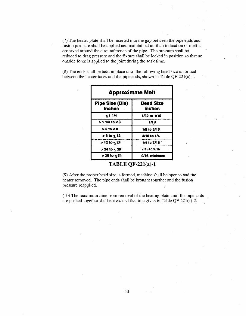
(7) The heater plate shall be inserted into the gap between the pipe ends andfusion pressure shall be applied and maintained until an indication of melt isobserved around the circumference of the pipe. The pressure shall bereduced to drag pressure and the fixture shall be locked in position so that nooutside force is applied to the joint during the soak time.
(8) The ends shall be held in place until the following bead size is formedbetween the heater faces and the pipe ends, shown in Table QF-221(a)-1.
Approximate Melt
Pipe Size (Dia) Bead Sizeinches Inches-c 1 1/4 1/32 to 1/16
> 1 114 to< 3 1/16
* 3 to < 8 liBto 3/16
* 8 to <_12 3116 to 1/4
11 12 to < 24 1/4 to 7/16"
> 24 to <36 7/16 to 9f16
S>36 to < 54 9/16 minimum
TABLE QF-221(a)-I
(9) After the proper bead size is formed, machine shall be opened and theheater removed. The pipe ends shall be brought together and the fusionpressure reapplied.
(10) The maximum time from removal of the heating plate until the pipe endsare pushed together shall not exceed the time given in Table QF-221(a)-2.
50
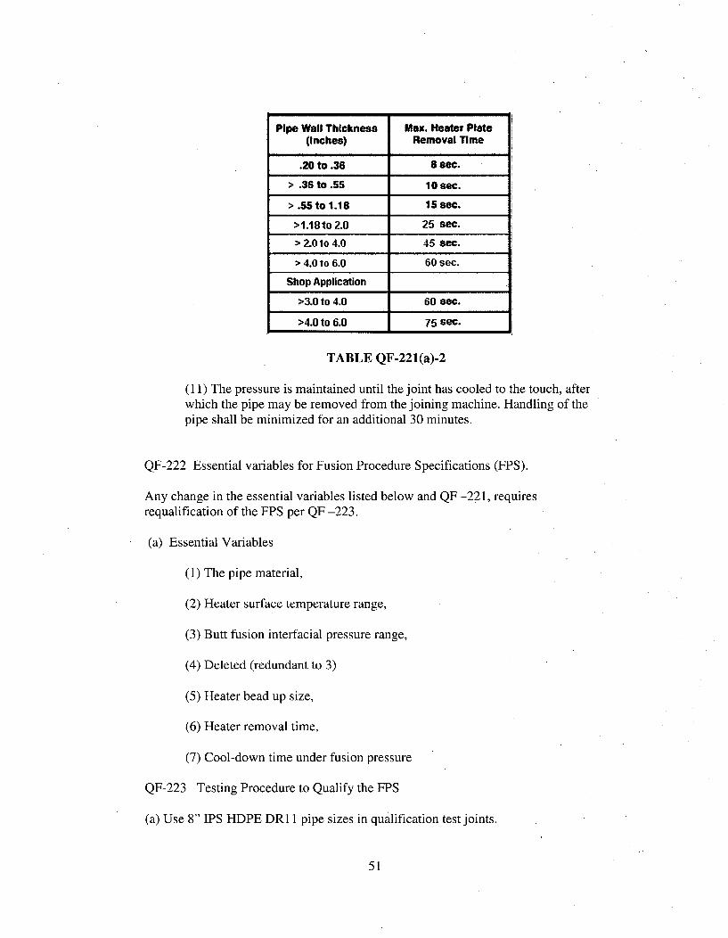
Pipe Wall Thickness Max. Heater Plate(inches) Removal Time
.20 to .36 8 sec.
> .36 to .55 10 sec.
> .55 to 1.18 15 sec.
>1.18to 2.0 25 sec.
> 2.0 to 4.0 45 sec.
> 4.0 to 6.0 60 sec.
Shop Application
>3.0 to 4.0 60 sec.
>4.0 to 6.0 75 sec.
TABLE QF-221(a)-2
(11) The pressure is maintained until the joint has cooled to the touch, afterwhich the pipe may be removed from the joining machine. Handling of thepipe shall be minimized for an additional 30 minutes.
QF-222 Essential variables for Fusion Procedure Specifications (FPS).
Any change in the essential variables listed below and QF -221, requiresrequalification of the FPS per QF -223.
(a) Essential Variables
(1) The pipe material,
(2) Heater surface temperature range,
(3) Butt fusion interfacial pressure range,
(4) Deleted (redundant to 3)
(5) Heater bead up size,
(6) Heater removal time,
(7) Cool-down time under fusion pressure
QF-223 Testing Procedure to Qualify the FPS
(a) Use 8" IPS HDPE DR 11 pipe sizes in qualification test joints.
51

(b) Make the following butt fusion joints using the following combinations of heatertemperature ranges and interfacial pressure ranges and the FPS:
(1) High heater surface temperature and high interfacial pressure, (5) joints(2) High heater surface temperature and low interfacial pressure, (5) joints(3) Low heater surface temperature and high interfacial pressure, (5) joints(4) Low heater surface temperature and low interfacial pressure, (5) joints
(c) Evaluate (3) joints of each combination using the High Speed Tensile ImpactTests per QF-131. All joints must fail in a ductile mode.
(d) Evaluate (2) joints of each combination using the Sustained Pressure Testing perQF-132. All joints must pass this test.
QF-230 Mechanical Tests.QF-231 General Requirements
(a) The type and number of test specimens that shall be tested to qualify a butt FPSare given in QF-223, and shall be removed in a manner similar to that shown in QF-130. If any test specimen required by QF-223 fails to meet the applicable acceptancecriteria, the test coupon shall be considered as failed.
(b) When it can be determined that the cause of failure is not related to fusingparameters, another test couponmay be fused using identical fusing parameters.
(c) Alternatively, if adequate material of the original test coupon exists, additionaltest specimens may be. removed as close as practicable to the original specimenlocation to replace the failed test specimens.
(d) When it has been determined that the test failure was caused by an essentialvariable, a new test coupon may be fused with appropriate changes to the variable(s)that was determined to cause the test failure.
(e) When it is determined that the test failure was caused by one or more fusingconditions other than essential variables, a new set of test coupons may be fusedwith the appropriate changes to the fusing conditions that were determined to causethe test failure. If the new test passes, the fusing conditions that were determined tocause the previous test failure shall be addressed by the manufacturer to ensure thatthe required properties are achieved in the production fused joint.
QF-232 Preparation of Test Coupon
The base materials shall consist of pipe. The dimensions of the test coupon shall besufficient to provide the required test specimens.
52
ARTICLE III
FUSION PERFORMANCEQUALIFICATION
QF-300 GENERAL
QF-300.1 This Article lists the essential variables that apply to fusion machineoperator performance qualifications.
The fusion machine operator qualification is limited by the essential variables.
QF-300.2
(a) The basic premises of responsibility in regard to fusion are contained withinQF-103 and QF-301.2. AmerenUE shall be responsible for conducting tests toqualify the performance of fusion machine operators in accordance with qualifiedFusion Procedure Specifications, which are employed in the construction of fusedjoints built in accordance with this Supplement. This responsibility cannot bedelegated to another organization.
(b) The fusion machine operators used to produce such fused joints shall be testedunder the full supervision and control of AmerenUE during the production of thesetest fused joints. It is not permissible to have the fusing performed by anotherorganization. It is permissible, however, to subcontract any or all of the work ofpreparation of test materials for fusing and subsequent work on the preparation oftest specimens from the completed fused joints, performance of nondestructiveexamination and mechanical tests, provided AmerenUE accepts full responsibilityfor any such work.
(c) AmerenUE is the organization which has responsible operational control of theproduction of the fused joints to be made in accordance with this Supplement.
QF-301 Tests
QF-301.1 Intent of Tests. The performance qualification tests are intended todetermine the ability of fusion machine operators to make sound fused joints.
QF-301.2 Qualification Tests. AmerenUE shall qualify each fusion machine operatorfor the fusing process to be used in production. The performance qualification testshall be fused in accordance with a qualified Fusion Procedure Specifications (FPS).Changes beyond which requalification is required are given in QF-322. Allowable
53
visual and mechanical examination requirements are described in QF-303. Retestsand renewal of qualification are given in QF-320.
The fusion machine operator who prepares the FPS qualification test couponsmeeting the requirements of QF-200 is also qualified within the limits of theperformance qualifications, listed in QF-303 for fusion machine operators.
The performance test may be terminated at any stage of the testing procedure,whenever it becomes apparent to the supervisor conducting the tests that the fusionmachine operator does not have the required skill to produce satisfactory results.
QF-301.3 Identification of Fusion machine operators. Each qualified fusion machineoperator shall be assigned an identifying number, letter, or symbol which shall beused to identify the work of that fusion machine operator.
QF-301.4 Record of Tests. The record of Fusion machine operator PerformanceQualification (FPQ) tests shall include the essential variables, the type of test andtest results, and the ranges qualified in accordance with Form QF-300 for eachfusion machine operator.
QF-302 Type of Test Required
QF-302.1 Mechanical Tests. All mechanical tests shall meet the requirementsprescribed in QF- 133.
QF-302.2 Test Coupons in Pipe. For test coupons made on pipe in the horizontal axisposition of Figure QF- 105. The coupons shall be removed from the test piece inaccordance with Figure QF-133.1.
QF-302.3 Visual Examination. For pipe coupons all surfaces shall be examinedvisually per QF-121 before cutting of bend specimens. Pipe coupons shall bevisually examined per QF-121 over the entire circumference, inside and outside.
QF-303 Fusion machine operators
Each fusion machine operator who fuses under the rules of this Supplement shallhave passed the mechanical and visual examinations prescribed in QF-302.1 and QF-302.3 respectively.
QF-303.1 Examination. Fused joints made in test coupons for performancequalification shall be examined by mechanical and visual examinations (QF-302. 1,QF-302.3).
54
QF-310 QUALIFICATION TEST COUPONS
QF-3 10.1 Test Coupons. The test coupons shall be pipe. Qualifications for pipe areaccomplished by fusing one pipe assembly in the horizontal axis position (figure QF-105). The minimum pipe size shall be IPS 6.
QF-320 RETESTS AND RENEWAL OF QUALIFICATION
QF-321 Retests
A fusion machine operator who fails one or more of the tests prescribed in QF-303,as applicable, may be retested under the following conditions.
QF-321.1 Immediate Retest Using Visual Examination. When the qualificationcoupon has failed the visual examination of QF-302.3, retesting shall be by visualexamination before conducting the mechanical testing.
When an immediate retest is made, the fusion machine operator shall make twoconsecutive test coupons all of which shall pass the visual examination requirements.
The examiner may select one of the successful test coupons from each set of retestcoupons which pass the visual examination for conducting the mechanical testing.
QF-321.2 Immediate Retest Using Mechanical Testing.
When the qualification coupon has failed the mechanical testing of QF-302.1, theretesting shall be mechanical testing.
When an immediate retest is made, the fusion machine operator shall make twoconsecutive test coupons which shall pass the test requirements.
QF-321.4 Further Training. When the fusion machine operator has had furthertraining or practice, a new test shall be made.
QF-322 Expiration and Renewal of Qualification
QF-322.1 Expiration of Qualification. The performance qualification of a fusionmachine operator shall be affected when one of the following conditions occurs:
(a) When he has not performed thermal butt fusion during a period of 6 months ormore, his qualification shall expire.
(b) When there is a specific reason to question his ability to make fused joints thatmeet the specification, the qualifications that support the fusing he is doing shall berevoked.
55
QF-322.2 Renewal of Qualification
(a) Renewal of qualification expired under QF-322.1 (a) may be made by fusing asingle test coupon and by testing of that coupon as required by QF-301. A successfultest renews the fusion machine operator previous qualifications for the process forwhich he was previously qualified.
(b) Fusion machine operators whose qualifications have been revoked under QF-322.1 (b) above shall requalify. Qualification shall utilize a test coupon appropriate tothe planned production work. The coupon shall be fused and tested as required byQF-301 and QF-302. Successful test restores the qualification.
QF-330 FUSION ESSENTIAL VARIABLES FOR FUSION MACHINEOPERATORS
QF-331 General
A fusion machine operator shall be requalified whenever a change is made, in one ormore of the essential variables listed.
(a) A change in pipe diameter from one range to another;(1) Less than IPS 8,(2) IPS 8 to IPS 24. and(3) IPS over 24
(b) A change in name of the manufacturer of equipment
(c) The axis of the pipe is limited beyond the horizontal position ±450.
Qualification in any position other than horizontal qualifies the orientationtested ± 20'.
QF-340 Testing
(a) Test joints shall be 6" IPS minimum. A data acquisition device shall be attached to thefusion machine and the data concerning the joint entered. The data acquisition device shallbe used to record data required by QF-122.
(b) The supervisor conducting the test shall observe making of the butt fusion joint and noteif the fusion procedure (FPS) was followed.
(c) The completed joint shall be visually examined and meet the acceptance criteria ofQF-121.
(d) After the joint is complete, the data acquisition record shall be reviewed by theassessor and compared to the FPS to ensure the proper procedures were followed.
56
(e) Bend test specimens shall be removed, tested and meet the acceptance criteria inaccordance with QF- 133.
57
Non-MandatoryAppendix A
ToSupplement 9
Fusion Machine OperatorQualification Training
A-1000 SCOPE
(a) The major portion of the quality of HDPE piping systems is determined by theskills of the fusion machine operators. When installing polyethylene (PE) piping, thequality of the fusion joints is essential for the piping system.
(b) It is important that the fusion machine operators are trained and competent in thefusion technology employed in constructing HDPE piping systems. Continuedcompetence of the fusion operator is covered by periodic re-training and re-assessment.
(c) This document gives guidance for the training, assessment and approval of fusionoperators in order to establish and maintain competency in construction of highdensity polyethylene piping systems for pressure applications. The fusion joiningtechnique covered by this Appendix is butt fusion. This article covers both thetheoretical and practical knowledge necessary to ensure high quality fusion joints.
A- 1100 REFERENCES
(a) Plastics Pipe Institute (PPI) Technical Report TR-33/2001 "Generic Butt FusionJoining Procedure for Field Joining of Polyethylene Pipe
(b) American Society of Testing and Materials (ASTM) D 2657-03 "StandardPractice for Heat Fusion Joining of Polyolefin Pipe and Fittings"
(c) ISO TR 19480/2005 "Thermoplastics pipes and fittings for the supply of gaseousfuels or water - Guidance for training and assessment of fusion operators"
A-2000 TRAINING
A-2100 Training Course
(a) A trainee fusion operator for HDPE systems should follow a training course inorder to obtain a fusion operator certificate for HDPE pipes. The course should coverall aspects of the butt fusion process including safety, machine evaluation and
58
maintenance, machine operation, FPS guidelines, pressure and temperature setting,data log device operation and set-up, in-ditch fusion techniques, visual examinationguidance, and data log record evaluation. The minimum course duration is 24 hours.
(b) The course will be delivered by a competent qualified trainer with a minimum of3 years of experience in the butt fusion processes and who has mastered thetechniques involved.
(c) The trainer should have a range of fusion machines representative of theequipment encountered on worksites for installing pipes, in order for the traineefusion operator to become acquainted with the fusion equipment commonly used.The trainee fusion operator may be trained on one of these fusion machines or on amachine from his own company if accepted by the training center. The fusionequipment must comply with the fusion machine manufacturer's specificationsand/or ISO 12176-1 "Plastics pipes and fittings - Equipment for fusion jointingpolyethylene systems - Part 1: Butt fusion "
A-2200 Operator Assessment
The trainee fusion operator who has followed a training course as described aboveshould then pass a theoretical and practical assessment in order to be qualified as afusion operator for PE systems. The assessor should not be the trainer but shouldhave the same assessment qualifications as the trainer shown above.
A-2300 Training Curriculum
(a) The training course should comprise of any combination of fusion packagesbased on the requirements of utility or pipeline operators. These packages may begiven as individual modules or combined to suit requirements. The course shallinclude safety training related to the fusion process and equipment.
(b) All consumables and tools necessary for the training package should beavailable during the training session. The pipes and fittings to be used shall conformto the ASTM product forms permitted by this Supplement.
(c) The lessons should be designed so that the trainee fusion operator learns tomaster the fusion technique and attains a good working knowledge of the pipingsystem materials and practical problems encountered when fusing pipe in the field.The fusion operator should receive a written manual covering all the elements dealtwith in the training.
(d) The theoretical course should deal with general information in connection withraw materials, pipes and fittings, and also with theoretical knowledge aboutpreparation, tools, and devices, joining components, different materials, differentdiameter ratios and correct and incorrect parameters. The safety course shouldinclude information concerning the fusion process, such as protective clothing,
59
general safety, regulations for electrical equipment, handling heater plates, etc. Areasof study should include but not be limited to the following:
(1) Butt fusion joining* Principles of fusion* Straight/coiled pipes, service lines, main lines, etc.* Components: pipes, flange adapters saddle fittings, other fittings* Butt fusion equipment: manual, semi-automatic and automaticmachines.• Joint preparation: Cleaning, rounding, alignment, facing, etc* Butt fusion cycle: pressure, time and temperature relationships,diagram.* Failure modes: understanding and avoiding possible errors* Test methods: visual examination, high speed tensile-impact test,bending test, hydrostatic test, data log recording / evaluation, etc.
(2) The trainee fusion operator should be familiar with the butt fusion joiningtechnique and procedure (FPS) by making a sufficient number of butt fusionjoints. In some cases, the fusion technique may vary slightly according todiameter, material or other factors. In such cases, the trainee fusion operatorshould also be made familiar with the various techniques.
(3) The trainee should start by making a butt joint between two pipes, andshould then learn to make butt fusion joints with pipes and fittings such astees, reducers, etc.
(4) The trainee should learn how to detect and avoid typical fusion defects.
(5) The trainee should learn how to assess the quality of a butt fusion joint bydoing a visual examination of the butt fusion joint and comparing it to thevisual guidelines published in the pipe manufacturer's heat fusion joiningprocedure booklet. The trainee should also compare the data log record to theFPS to ensure the proper parameters and procedures were followed in thebutt fusion process.
A-3000 ASSESSMENT AND TESTING
(a) Training program should end with a theoretical and practical examination (testpiece).
(b) The content of the theoretical examination shall consist of not less than (20)multiple choice questions about the butt fusion process, fusion machine operation,pipe, quality examination, safety, etc. within a set period of time. A score of 80% orbetter is considered passing on this examination. Questions to be included but notlimited to are:
60
How do you calculate the fusion machine gauge pressure?What is the proper heater surface temperature range from the FPS?What is the proper butt fusion interfacial pressure range from the FPS?How do you calculate the drag pressure?How do you know when to remove the heater in the heating cycle?How long do you leave the pipe ends together under pressure in the coolingcycle?What is the difference between IPS pipe and DIPS pipe?How do I determine the hydraulic fusion machines total effective pistonarea?How is the total effective piston area of the fusion machine used to determinethe fusion machines gauge pressure for a specific pipe?How do you adjust the machine to improve the alignment of the pipe afterfacing?How much material should be removed from the pipe ends in the facingoperation?How do you determine if the fusion machine conforms to the equipmentmanufacturer's specifications?How do you align the pipe in the butt fusion machine?Can you butt fuse pipe in a ditch?What is interfacial pressure?
(c) The practical examination will require the trainee fusion operator tomake afusion joint with a hydraulic butt fusion machine with a minimum pipe size of 6"IPS DRI 1. A data acquisition device must be attached to the fusion machine and thedata concerning the joint entered. The data log device shall be used to record thejoint made by the trainee. The assessor shall observe the butt fusion joint and note ifthe proper procedure (FPS) was followed. After thejoint is complete, the data logrecord shall be reviewed by the assessor and compared to the FPS to ensure theproper procedures was followed. The assessor will then conduct a visualexamination of the joint to make sure it satisfies the pipe manufacturers recommendvisual guidance criteria per QF- 121 of this Supplement.
(d) If a data log device is not available, the assessor will manually record the buttfusion parameters used in the butt fusion process. This should be compared with theFPS to ensure they agree.
(e) Trainee fusion operators who pass the theoretical and practical examinationwould receive a fusion operator certificate bearing the logo of the assessment centerawarding the approval. The fusion operator certificate should state the technique ortechniques and fusion machines for which the operator is qualified.
A-4000 REASSESSMENT
61

If the trainee fails one of the examinations, he should retake it after a period not shorterthan one week. If the trainee fails the examination for the second time, the trainee shouldrepeat the training course before taking the test again.
62
Enclosure 6
To ULNRC-05517
Enclosure 6
Justification for Increase in Callaway's HDPE Design Factor
Justification for Increase in Callaway's HDPE Design Factor
A Design Factor (DF) of 0.5 has historically been used in the determination of allowable
stress for pipe design utilizing PE 3408 piping material. For the PE 4710 High Density
Polyethylene (HDPE) piping material to be installed in Callaway's Essential Service
Water (ESW) system, AmerenUE intends to use a Plastics Pipe Institute (PPI) DF of 0.56
(i.e. a safety factor of 1.8) to provide sufficient design margin.
The bases for increasing the DF from 0.5 to 0.56 in the replacement Callaway ESW
HDPE piping are as follows:
1) The PPI DF is not determined using the same method as the ASME DF. The
allowable stress determined using a PPI DF of 0.56 will actually result in a DF
greater than 3.5 (the ASME DF for ASME Section III, Class 3 piping) using the
ASME method.
2) PE 4710 material will be used in the replacement Callaway ESW HDPE piping
rather than PE 3408. It has been accepted by PPI that PE 4710 has superior
properties when compared to other PE materials and that it is therefore
appropriate to use a higher PPI DF in the design of PE 4710 piping systems.
Additionally, as discussed below, the primary failure mechanism for HDPE
piping is slow crack growth. The PE 4710 material selected for use at Callaway
significantly exceeds the requirements for slow crack growth resistance with a
PENT (Pennsylvania Notch Test - ASTM F 1473) of greater than 10,000 hours as
compared to the requirement to exceed 500 hours.
3) The replacement Callaway ESW HDPE piping and fittings are all being
manufactured from the same PE 4710 material. The purpose of the design factor
in the ASME Code is to account for the unknowns in the design and construction
process. One such unknown is variation in materials. By manufacturing all of the
HDPE piping and fitting from the same material and at the same facilities, the
material variability is reduced.
These bases are discussed below in further detail.
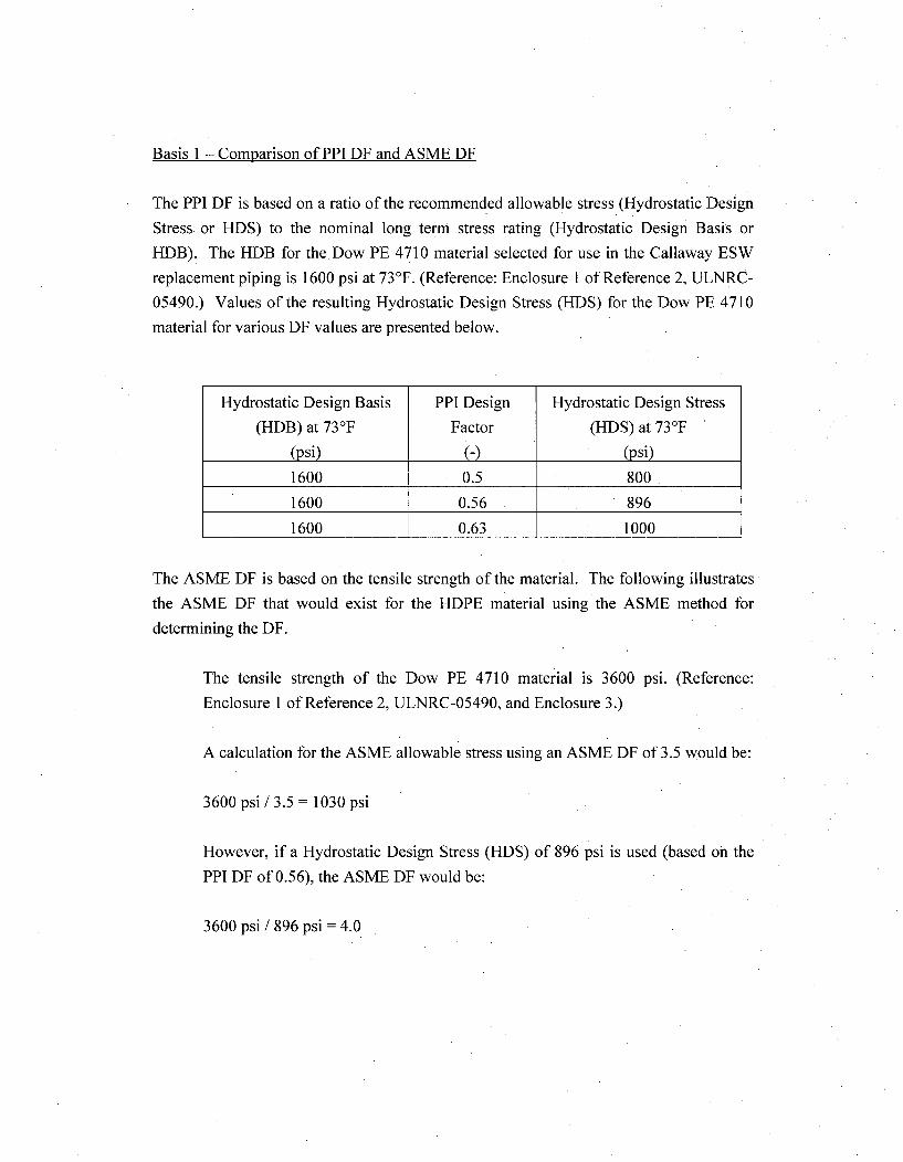
Basis 1 - Comparison of PPI DF and ASME DF
The PPI DF is based on a ratio of the recommended allowable stress (Hydrostatic Design
Stress or HDS) to the nominal long term stress rating (Hydrostatic Design Basis or
HDB). The HDB for the Dow PE 4710 material selected for use in the Callaway ESW
replacement piping is 1600 psi at 73'F. (Reference: Enclosure 1 of Reference 2, ULNRC-
05490.) Values of the resulting Hydrostatic Design Stress (HDS) for the Dow PE 4710
material for various DF values are presented below.
Hydrostatic Design Basis PPI Design Hydrostatic Design Stress
(HDB) at 73-F Factor (HDS) at 73-F
(psi) (psi)
1600 0.5 800
1600 0.56 896
1600 0.63 1000
The ASME DF is based on the tensile strength of the material. The following illustrates
the ASME DF that would exist for the HDPE material using the ASME method for
determining the DF.
The tensile strength of the Dow PE 4710 material is 3600 psi. (Reference:
Enclosure I of Reference 2, ULNRC-05490, and Enclosure 3.)
A calculation for the ASME allowable stress using an ASME DF of 3.5 would be:
3600 psi / 3.5 = 1030 psi
However, if a Hydrostatic Design Stress (HDS) of 896 psi is used (based on the
PPI DF of 0.56), the ASME DF would be:
3600 psi / 896 psi = 4.0
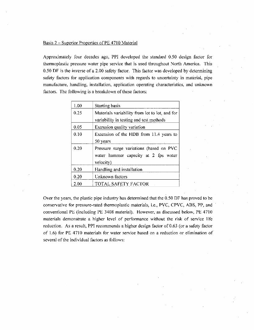
Basis 2 - Superior Properties of PE 4710 Material
Approximately four decades ago, PPI developed the standard 0.50 design factor for
thermoplastic pressure water pipe service that is used throughout North America. This
0.50 DF is the inverse of a 2.00 safety factor. This factor was developed by determining
safety factors for application components with regards to uncertainty in material, pipe
manufacture, handling, installation, application operating characteristics, and unknown
factors. The following is a breakdown of these factors:
1.00 Starting basis
0.25 Materials variability from lot to lot, and for
variability in testing and test methods
0.05 Extrusion quality variation
0.10 Extension of the HDB from 11.4 years to
50 years
0.20 Pressure surge variations (based on PVC
water hammer capacity at 2 fps water
velocity)
0.20 Handling and installation
0.20 Unknown factors
2.00 TOTAL SAFETY FACTOR
Over the years, the plastic pipe industry has determined that the 0.50 DF has proved to be
conservative for pressure-rated thermoplastic materials, i.e., PVC, CPVC, ABS, PP, and
conventional PE (including PE 3408 material). However, as discussed below, PE 4710
materials demonstrate a higher level of performance without the risk of service life
reduction. As a result, PPI recommends a higher design factor of 0.63 (or a safety factor
of 1.6) for PE 4710 materials for water service based on a reduction or elimination of
several of the individual factors as follows:
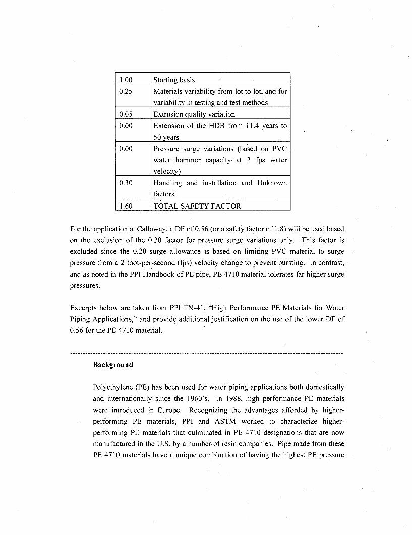
1.00 Starting basis
0.25 Materials variability from lot to lot, and for
variability in testing and test methods
0.05 Extrusion quality variation
0.00 Extension of the HDB from 11.4 years to
50 years
0.00 Pressure surge variations (based on PVC
water hammer capacity. at 2 fps water
velocity)
0.30 Handling and installation and Unknown
factors
1.60 TOTAL SAFETY FACTOR
For the application at Callaway, a DF of 0.56 (or a safety factor of 1.8) will be used based
on the exclusion of the 0.20 factor for pressure surge variations only. This factor is
excluded since the 0.20 surge allowance is based on limiting PVC material to surge
pressure from a 2 foot-per-second (fps) velocity change to prevent bursting. In contrast,
and as noted in the PPI Handbook of PE pipe, PE 4710 material tolerates far higher surge
pressures.
Excerpts below are taken from PPI TN-41, "High Performance PE Materials for Water
Piping Applications," and provide additional justification on the use of the lower DF of
0.56 for the PE 4710 material.
Background
Polyethylene (PE) has been used for water piping applications both domestically
and internationally since the 1960's. In 1988, high performance PE materials
were introduced in Europe. Recognizing the advantages afforded by higher-
performing PE materials, PPI and ASTM worked to characterize higher-
performing PE materials that culminated in PE 4710 designations that are now
manufactured in the U.S. by a number of resin companies. Pipe made from these
PE 4710 materials have a unique combination of having the highest PE pressure
rating (PR), outstanding resistance to slow crack growth (SCG), and increased
resistance to rapid crack propagation (RCP). These are the three key engineering
properties for evaluating a plastic piping material, and these high performance PE
materials exhibit outstanding performance in all three areas.
Although these high performance PE materials may be relatively new in North
America, they have over 20 years of very successful history worldwide for water
piping applications.
The Plastics Pipe Institute (PPI) identified that the best way to take advantage of
these high performance PE materials in North America was to incorporate them
into the ASTM and AWWA standards by applying higher material specifications
that result in an increased hydrostatic design stress compared to conventional PE
materials. Changes to support a higher HDS for water piping have been
accomplished through revising PPI TR-3 and existing ASTM PE resin and pipe
standards. The higher HDS for pressure rating can be a deciding factor whether a
water company uses PE pipe or metal pipe. The premise for this increased HDS
is that higher performing PE materials must demonstrate superior performance
characteristics such that PE pipe would provide a safer, cost effective alternative
piping system.
III. ASTM Pressure Rating Method
The ASTM pressure rating method utilizes pipe samples tested at a constant
temperature with the log stress vs. log time regression line extrapolated to
100,000 hours. This extrapolated value is the long-term hydrostatic strength
(LTHS) of the material, and the categorized value of the LTHS is called the
Hydrostatic Design Basis (HDB) in accordance with ASTM standard test method
D 2837. This HDB is reduced to a maximum working stress by a design factor
(DF) to establish the Hydrostatic Design Stress (HDS). The HDS is the product
of the HDB and the design factor for water:
HDS HDB x DF (for water)
HDB and HDS values for various thermoplastic materials used for piping
applications are published in PPI TR-4 which is available on the PPI website
www.plasticpipe.org. These PPI listings of HDB and HDS values are classified
in accordance with the material's standard pipe material designation code. In this
designation system, the plastic pipe material is identified by its standard
abbreviated terminology in accordance with ASTM D 1600, "Standard
Terminology Relating to Abbreviations, Acronyms, and Codes for Terms
Relating to Plastics," followed by a four or five digit number. The first two or
three digits, as the case may be, code the material's ASTM classification (short-
term properties) in accordance with the appropriate ASTM standard specification
for that material. The last two digits of this number represent the PPI
recommended HDS for water at 73YF (23°C) divided by 100. Examples of pipe
material designation codes for PE materials are as follows:
* PE 3408 is a polyethylene (the PE abbreviation is in accordance with ASTM
D 1600) with a density cell class of 3 and a slow crack growth (SCG) cell
class of 4 (in accordance with ASTM D 3350). It has an 800 psi maximum
recommended HDS (based on a design factor of 0.5) for water at 730F (23°C).
* PE 4710 is a polyethylene (the PE abbreviation is in accordance with ASTM
D 1600) with a density cell class of 4 and a slow, crack growth (SCG) cell
class of 7 (in accordance with ASTM D 3350). It has a 1000-psi maximum
recommended HDS (based on a design factor of 0.63) for water at 73°F
(23°C).
IV. PPI Program
A coordinated industry effort was undertaken to revise PPI documents and
ASTMIAWWA/CSA standards to recognize the improved performance properties
of these high-performance PE materials. These newly defined performance
properties enabled expanded classification of PE materials, and justified the use of
a higher hydrostatic design stress for water piping applications. Several changes
to PPI documents and ASTM standards were required to accomplish this. These
included changes in the pipe material designation code:
* Base resin density - 1st digit in the code
* Slow crack growth (SCG) - 2nd digit in the code
" Hydrostatic design stress (HDS) - 3rd and 4th digits in the code
a) Base Resin Density
PE 3408 materials used for water pipe applications have a base resin density
about 0.944 g/cc, which is a D 3350 density cell class 3 - this is the first digit in
the pipe material designation code PE 3408. Most high-performance PE 4710
materials have a base resin density around 0.950 g/cc. In order to differentiate the
high performance HDPE materials from traditional HDPE materials, the density
cell class of ASTM D 3350 was split to create a new density class 4 for the new
high performance PE materials:
* Previous cell class 3 > 0.941 - 0.955 g/cc
" New cell class 3 > 0.941 - 0.947 g/cc
" New cell class 4 > 0.947 - 0.955 g/cc
Most high-performance HDPE materials will have a density cell class 4 based on
their base resin density around 0.950 g/cc.
b) Slow Crack Growth (SCG)
Slow crack growth is the dominant field failure mode for PE pipes. Simply put, it
is a crack that can develop in PE pipe and grows slowly through the pipe wall.
Poor backfill, excessive surface damage, rock impingement, excessively tight
bend radiuses, improper backfill and other field conditions could cause localized
stress concentrations resulting in slow crack growth in polyethylene pipes. The
resistance to slow crack growth is a valuable property for PE pipes.
The PENT (Pennsylvania Notch Test - ASTM F 1473) measures relative
resistance to slow crack growth using a laboratory test method. A specimen is cut
from a compression molded plaque. It is precisely notched and then exposed to a
constant tensile stress at a temperature of 176°F (80'C). The time to failure is
recorded and this failure time is related to actual service life in the field. The
PENT test has proven to be a very good indicator of SCG in PE pipes.
A published paper in the Plastic Pipe VIII conference provided data which
correlated laboratory PENT values to field pipe performance. Based upon this
data, a laboratory PENT value of 10 to 20 hours, should correlate to a field life of
at least 100 years with very few failures. PPI determined that a requirement of at
least 500 hours PENT slow crack growth resistance would provide assurance that
high performance PE pipes will be highly unlikely to fail in the field in the slow
crack growth mode.
The current PE 3408 requirement for PENT (ASTM F 1473) performance in
ASTM water pipe standards is 10 hours, which is a D 3350 SCG (slow crack
growth) cell class 4 - this is the second digit in the pipe material designation code
PE 3408. ASTM D 3350 was revised to add a new SCG cell class 7 for 500 hours
to recognize the elevated SCG resistance of the high-performance PE materials.
* Current cell class 4 at least 10 hours
* Current cell class 6 at least 100 hours
* New cell class 7 at least 500 hours
With this change, the traditional HDPE materials will have a SCG cell class 4 or
6, where high performance PE materials will qualify for the new SCG cell class 7.
c) Hydrostatic Design Stress
The hydrostatic design stress (HDS) for PE 3408 materials is 800 psi for water at
73°F (23 0C), which are the third and fourth digits in the pipe material designation
code PE 3408. High-performance PE materials that meet the increased
performance requirements indicated below qualify to be listed in PPI document
TR-4 with a 1000 psi HDS for water at 73°F (23°C) if the PE material meets high-
performance criteria as published in PPI TR-3. (Reference: Section F.7 of
"Requirements For Polyethylene (PE) Materials To Qualify For A Higher Design
Factor.")
1) PENT value over 500 hours
2) 23°C stress regression line substantiated to 50 years
3) LCLiLTHS ratio over 90%
High-performance PE 4710 materials that meet the additional high performance
have a 1000 psi HDS (based on a design factor of 0.63), where the "10" is derived
by dividing the 1000 psi HDS by 100.
As discussed above, PPI document TR-3 section F.7, "Requirements For Polyethylene
(PE) Materials To Qualify For A Higher Design Factor," states that in order for a material
to qualify for a recommended PPI design factor of 0.63, the HDPE material must meet
three requirements. The Dow PE 4710 selected for use in the Callaway ESW
replacement piping meets all three of these requirements as demonstrated below:
1) Minimum slow crack growth performance by ASTM F 1473 of 500 hours as required
by ASTM D 3350 (i.e. PENT of at least 500 hours).
The Dow PE 4710 material significantly exceeds this requirement for
resistance to slow crack growth (i.e., PENT greater than 10,000 hours) as
shown in Enclosure 1 in ULNRC-05490 (Ref. 2).
2) 50 year substantiation according to Part F.5 of TR-3.
* The Dow PE 4710 material met this requirement as shown in Enclosure 3.
3) LCL/LTHS ratio of at least 90% as per ASTM D 2837 -Where LCL is Lower
Confidence Limit - The lowest value of the LTHS, based on a statistical analysis of
the regression data that can be expected at 100,000 hours.
* The Dow PE 4710 material met this requirement (i.e. LCL/LTHS greater than
93%) as shown on Enclosure 3.
Basis 3 - Reduction in Material Variability
The purpose of the design factor in ASME Code is to account for the unknowns in the
design and construction process. If the number and/or extent of the unknowns can be
reduced, the design factor can be reduced without a reduction in safety.
In the typical design and construction of a piping system, the design is performed
assuming minimum material performance requirements as defined by the Code.
Furthermore, there is no limit to the number of different suppliers that can supply piping
or fittings to be used in the same system. This results in an inherent amount of variability
in the material properties. The design factor accounts for such variations.
The replacement Callaway ESW HDPE pipe and fitting are all being manufactured from
Dow PE 4710 material. Furthermore, all piping is being manufactured in one facility
from the same batch lot of resin material, and all fittings are being manufactured in one
facility from the same batch lot of resin material. These facilities, and processes were
assessed and witnessed by Ameren to assure all identified critical characteristics for the
products being supplied were acceptably controlled.
These actions implemented by AmerenUE for this project significantly reduce the extent
of the unknowns associated with material variability. Although the accounting for the
material variability is not removed from the design factor for PPI or Callaway, the
reduction in material variability at Callaway provides additional confidence that an
increase in the design factor would not constitute a reduction in safety.
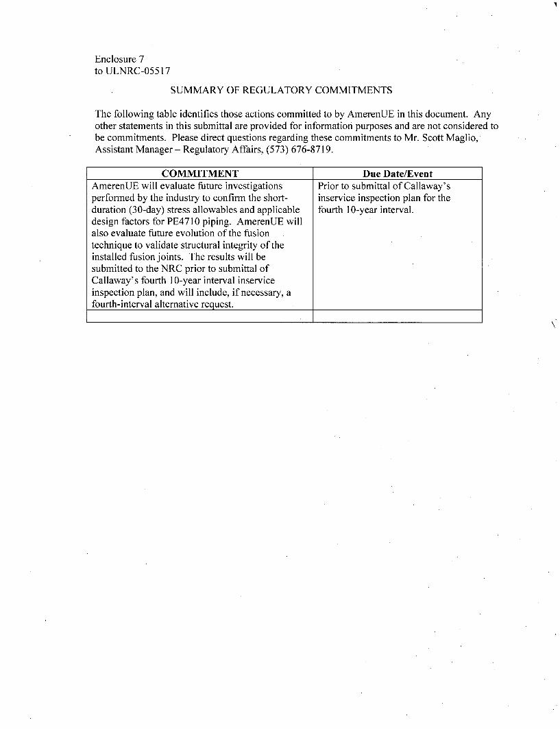
Enclosure 7to ULNRC-05517
SUMMARY OF REGULATORY COMMITMENTS
The following table identifies those actions committed to by AmerenUE in this document. Anyother statements in this submittal are provided for information purposes and are not considered tobe commitments. Please direct questions regarding these commitments to Mr. Scott Maglio,Assistant Manager - Regulatory Affairs, (573) 676-8719.
COMMITMENT I Due Date/EventAmerenUE will evaluate future investigationsperformed by the industry to confirm the short-duration (30-day) stress allowables and applicabledesign factors for PE4710 piping. AmerenUE willalso evaluate future evolution of the fusiontechnique to validate structural integrity of theinstalled fusion joints. The results will besubmitted to the NRC prior to submittal ofCallaway's fourth 10-year interval inserviceinspection plan, and will include, if necessary, afourth-interval alternative request.
Prior to submittal of Callaway'sinservice inspection plan for thefourth 10-year interval.