ASCET V6.2 AUTOSAR User's Guide - ETAS
169
ASCET V6.2 AUTOSAR User’s Guide
-
Upload
khangminh22 -
Category
Documents
-
view
1 -
download
0
Transcript of ASCET V6.2 AUTOSAR User's Guide - ETAS

ASCET V6.2
AUTOSAR User’s Guide

2
Copyright
The data in this document may not be altered or amended without special notification
from ETAS GmbH. ETAS GmbH undertakes no further obligation in relation to this docu-ment. The software described in it can only be used if the customer is in possession of a
general license agreement or single license. Using and copying is only allowed in concur-
rence with the specifications stipulated in the contract.
Under no circumstances may any part of this document be copied, reproduced, transmit-
ted, stored in a retrieval system or translated into another language without the express
written permission of ETAS GmbH.
© Copyright 2013 ETAS GmbH, Stuttgart
The names and designations used in this document are trademarks or brands belonging to the respective owners.
Document EC010201 V6.2 R01 EN – 05.2013

ETAS Contents
ASCET V6.2 AUTOSAR User’s Guide 3
Contents
1 Introduction .......................................................................................................................... 13
1.1 Safety Advice ................................................................................................................. 13 1.1.1 Correct Use ........................................................................................................ 13 1.1.2 Labeling of Safety Instructions ............................................................................. 13 1.1.3 Demands on the Technical State of the Product .................................................... 13
1.2 System Information ........................................................................................................ 14 1.3 User Information ............................................................................................................ 14
1.3.1 User Profile ......................................................................................................... 14 1.3.2 Document Structure ............................................................................................ 14 1.3.3 How to use this Manual ....................................................................................... 15 1.3.4 Related Documents ............................................................................................. 16
1.4 Definitions and Abbreviations .......................................................................................... 16
2 AUTOSAR Overview ............................................................................................................... 18
2.1 AUTOSAR Basic Approach ............................................................................................... 18 2.2 What is an AUTOSAR Authoring Tool? ............................................................................. 19 2.3 What is a Runtime Environment? .................................................................................... 20 2.4 What is a Behavior Modeling Tool? .................................................................................. 21
3 Developing Software Components in ASCET ............................................................................ 22
3.1 Configuring ASCET ......................................................................................................... 22 3.1.1 Configuring the Creation of AUTOSAR Components ............................................... 22 3.1.2 Code Generation Settings for AUTOSAR ................................................................ 22 3.1.3 Settings for the AUTOSAR XML Output ................................................................. 25 3.1.4 Code Generation ................................................................................................. 26
3.2 Approaches for Creating Software Components ................................................................ 28 3.2.1 Top-Down Approach ........................................................................................... 28 3.2.2 Bottom-Up Approach ........................................................................................... 30
3.3 Working with the RTE Generator ..................................................................................... 30 3.3.1 Contract Phase ................................................................................................... 31 3.3.2 RTE Phase .......................................................................................................... 31
4 Data Types (AUTOSAR R3.1.5 or Lower) ................................................................................. 33
4.1 BSW Types .................................................................................................................... 33 4.2 Primitive Data Types ...................................................................................................... 33 4.3 Primitive Data Types With Semantics ............................................................................... 36
4.3.1 Std_ReturnType .............................................................................................. 39 4.4 Complex Types .............................................................................................................. 39
4.4.1 Record Types ...................................................................................................... 39 4.4.2 Array Types ........................................................................................................ 43
5 Data Types (AUTOSAR R4.0.*) ............................................................................................... 45
5.1 Application Data Types ................................................................................................... 45 5.2 Implementation Data Types ............................................................................................ 45 5.3 Type Mappings............................................................................................................... 45 5.4 Platform Types ............................................................................................................... 46 5.5 Base Types .................................................................................................................... 47
ETAS Contents
ASCET V6.2 AUTOSAR User’s Guide 4
5.6 Examples ....................................................................................................................... 47 5.6.1 Primitive Data Type ............................................................................................. 47 5.6.2 Enumeration Type (Primitive Data Type with Semantics) ....................................... 50 5.6.3 Record Type (Complex Types) ............................................................................. 52 5.6.4 Array Type (Complex Types) ................................................................................ 58
6 Interfaces ............................................................................................................................. 62
6.1 Sender-Receiver ............................................................................................................. 62 6.1.1 Data Element Prototypes ..................................................................................... 64
6.2 Mode Switch .................................................................................................................. 67 6.3 Client-Server .................................................................................................................. 70
6.3.1 Operations .......................................................................................................... 71 6.4 Calibration ..................................................................................................................... 78
6.4.1 Calibration Parameters ........................................................................................ 79 6.5 NVData (AUTOSAR R4.0.* only) ...................................................................................... 83
6.5.1 Variable Data Prototypes ..................................................................................... 84
7 Software Component Types ................................................................................................... 86
7.1 Ports ............................................................................................................................. 87 7.1.1 Provided Ports .................................................................................................... 87 7.1.2 Required Ports .................................................................................................... 92
8 Internal Behavior ................................................................................................................ 100
8.1 Events ......................................................................................................................... 101 8.1.1 Timing Events ................................................................................................... 102 8.1.2 Operation-Invoked Events ................................................................................. 103 8.1.3 Mode-Switch Events .......................................................................................... 105
8.2 Runnable Entities ......................................................................................................... 107 8.3 Responding to Timing Events ........................................................................................ 109 8.4 Sending to a Port ......................................................................................................... 110
8.4.1 Explicit Communication ..................................................................................... 110 8.4.2 Implicit Communication ..................................................................................... 112
8.5 Receiving from a Port ................................................................................................... 114 8.5.1 Explicit Data Read Access .................................................................................. 115 8.5.2 Implicit Data Read Access.................................................................................. 117
8.6 Responding to a Server Request on a Port ..................................................................... 119 8.6.1 Concurrent Invocation of Servers ....................................................................... 121
8.7 Making a Client Request on a Port ................................................................................. 123 8.8 Interrunnable Variables ................................................................................................ 125
8.8.1 Read and Write Access ...................................................................................... 127 8.9 Exclusive Areas ............................................................................................................ 129
8.9.1 New in ASCET V6.2 ........................................................................................... 129 8.9.2 Configuration .................................................................................................... 129 8.9.3 Usage............................................................................................................... 131
9 Modes ................................................................................................................................ 134
9.1 Defining Modes ............................................................................................................ 134 9.2 Mode Communication ................................................................................................... 135 9.3 Using Modes ................................................................................................................ 136
9.3.1 Software Component Initialization and Finalization .............................................. 137 9.3.2 Triggering a Runnable Entity on a Mode-Switch .................................................. 137 9.3.3 Disabling Modes ................................................................................................ 139
10 Implementing Software Components .................................................................................... 142
10.1 Basic Concepts ............................................................................................................. 142 10.1.1 Namespace ....................................................................................................... 142 10.1.2 Runnable Naming Convention ............................................................................ 142 10.1.3 API Naming Convention ..................................................................................... 142 10.1.4 API Parameter Passing Mechanisms ................................................................... 143

ETAS Contents
ASCET V6.2 AUTOSAR User’s Guide 5
10.2 Application Source Code ............................................................................................... 143 10.2.1 Application Header Files .................................................................................... 143 10.2.2 Entry Point Signature for Runnable Entities ......................................................... 144
10.3 Sender-Receiver Communication ................................................................................... 145 10.3.1 Sending to a Port .............................................................................................. 146 10.3.2 Receiving from a Port ........................................................................................ 149
10.4 Client-Server Communication ........................................................................................ 152 10.4.1 Implementing a Server Operation ...................................................................... 153 10.4.2 Making a Client Request on a Port ...................................................................... 154
10.5 Accessing Calibration Parameters .................................................................................. 155 10.6 Accessing ASCET Messages ........................................................................................... 159 10.7 Concurrency Control with Exclusive Areas ...................................................................... 163
10.7.1 Sequences of a Runnable Assigned to an Exclusive Area...................................... 163
11 ETAS Contact Addresses ...................................................................................................... 165

ETAS Figures
ASCET V6.2 AUTOSAR User’s Guide 6
Figures Figure 1: AUTOSAR software component (SWC) communications are represented by a virtual
function bus (VFB) implemented through the use of the runtime environment (RTE) and basic
software. .....................................................................................................................................19
Figure 2: Enable creation of AUTOSAR components ......................................................................22
Figure 3: Project settings for AUTOSAR projects ...........................................................................23
Figure 4: MISRA compliant casting for AUTOSAR projects .............................................................24
Figure 5: OS Configuration settings for an AUTOSAR R4.0.* project ..............................................25
Figure 6: Select item Swc in the project ARProject ........................................................................27
Figure 7: ASCET generated code for the project ARProject (*.arxml, *.c and *.h files). .........28
Figure 8: Using UUIDs to identify components on import ..............................................................30
Figure 9: Default implementation of model types ..........................................................................34
Figure 10: Implementation of the signed discrete element sdisc as sint8 ..................................35
Figure 11: Example of an enumeration in ASCET ..........................................................................37
Figure 12: Record with elements A and B ....................................................................................40
Figure 13: Implementation of the unsigned discrete element A as uint16 ....................................41
Figure 14: Implementation Impl of Record with elements A and B .............................................42
Figure 15: Record type Record_Impl32 ....................................................................................43
Figure 16: AUTOSAR R4.0.* abstraction levels for describing data types ........................................45
Figure 17: Data element Speed for the sender-receiver interface SRInterface...........................64
Figure 18: Implementation Impl of the sender-receiver interface SRInterface with data
element Speed ............................................................................................................................65
Figure 19: Mode declaration group OnOffMode ...........................................................................67
Figure 20: Selection of the mode group OnOffMode ....................................................................69
Figure 21: Mode-switch interface ModeInterface......................................................................69
Figure 22: Arguments of the operation MaximumValue ...............................................................72
Figure 23: Operation MaximumValue for the client-server interface CSInterface.......................72
Figure 24: Implementation of the operation MaximumValue ........................................................73
Figure 25: Return type for the operation Notification .............................................................76
Figure 26: Implementation Impl of the calibration interface CalInterface ................................80
Figure 27: NVData element Speed_NV of the NVData interface NVData_Interface with
implementation Impl ...................................................................................................................84
Figure 28: Selection of the item SRInterface ...........................................................................87
Figure 29: Provided port Sender of type SRInterface ..............................................................88
Figure 31: Provided port Server of type CSInterface ..............................................................91
ETAS Figures
ASCET V6.2 AUTOSAR User’s Guide 7
Figure 32: Pport Server in the "Outline" tab of the software component Swc ...............................92
Figure 33: Required port Receiver of type SRInterface .........................................................93
Figure 35: Required port Client of type CSInterface .............................................................95
Figure 37: Rport Client in the drawing area of the software component editor ............................96
Figure 38: Rport Calibration in the drawing area of the software component editor ..................97
Figure 39: Rport NVData in the drawing area of the software component editor ............................98
Figure 40: Definition of the timing event Cyclic_10ms ............................................................. 103
Figure 41: Operation-Invoked event for the server operations MaximumVal and
Notification ......................................................................................................................... 104
Figure 42: Modeling ModeEvent on entry with mode on of the application mode OnOffMode .... 105
Figure 44: Setting the symbol RteRunnable_Swc_RunnableEntity for the runnable
RunnableEntity ..................................................................................................................... 108
Figure 45: The event Cyclic_10ms is assigned to RunnableEntity ....................................... 110
Figure 46: Sending a value 120 to a sender port with explicit communication .............................. 111
Figure 47: Changing the access type of the RTE Access operator to implicit ................................. 113
Figure 48: Writing a value 120 to a sender port with implicit communication................................ 113
Figure 49: Receiving the value Speed from the Rport Receiver with explicit communication ...... 115
Figure 50: Changing the access type to implicit in the RTE Access operator ................................. 117
Figure 51: Receiving the value Speed from the Rport Receiver with implicit communication ..... 118
Figure 52: Setting Can be Invoked Concurrently for the runnable Server_MaximumValue ... 122
Figure 53: Request on Rport Client to compute MaximumValue(A,B) and store it in C ........... 123
Figure 54: Interrunnable variables used by two runnable entities ................................................ 127
Figure 55: Use of the exclusive area SwcExclusiveArea in RunnableEntity ........................ 132
Figure 56: Mode declaration group OnOffMode ......................................................................... 135
Figure 60: ModeEvent is assigned to ModeRunnable ............................................................... 138
Figure 61: Mode off disabled in ModeEvent ............................................................................ 139
Figure 62: Setting explicit communication with status. ................................................................ 147
Figure 63: Sending a value 120 to a sender port using explicit communication with status ............ 147
Figure 64: Implementation of the operation Server_MaximumValue in the diagram
Server_CSInterface ............................................................................................................. 153
Figure 65: Parameter localLog defined as imported ................................................................ 156
Figure 67: Accessing ClassWithParam in the software component ........................................... 157
Figure 68: Mapping an imported parameter and a calibration parameter ...................................... 158
Figure 69: Completed parameter mapping ................................................................................. 159
Figure 70: Block diagram of process process ........................................................................... 161
Figure 71: Mapping messages and interrunnable variables .......................................................... 162
Figure 72: Mapping messages and data elements ....................................................................... 162

ETAS Code Listings
ASCET V6.2 AUTOSAR User’s Guide 8
Code Listings Listing 1: ARXML code – primitive data type (AUTOSAR R3.1.2) ....................................................36
Listing 2: ARXML code – enumeration data type (AUTOSAR R3.1.2) ..............................................37
Listing 3: ARXML code – compu-method for an enumeration (AUTOSAR R3.1.2) ............................38
Listing 4: ARXML code – record type (AUTOSAR R3.1.2) ...............................................................42
Listing 5: ARXML code – array type (AUTOSAR R3.1.2) .................................................................44
Listing 6: ARXML code - mapping application data types and mode type to implementation data
types (AUTOSAR R4.0.2) ..............................................................................................................46
Listing 7: ARXML code – primitive application data type SInt8 (AUTOSAR R4.0.2) ........................48
Listing 8: ARXML code – mapping of SInt8 application data type and implementation data type
(AUTOSAR R4.0.2) .......................................................................................................................48
Listing 9: ARXML code – platform data type sint8 (AUTOSAR R4.0.2) .........................................49
Listing 10: ARXML code – base type sint8 (AUTOSAR R4.0.2) ....................................................50
Listing 11: ARXML code – application data type Enumeration (AUTOSAR R4.0.2) ........................51
Listing 12: ARXML code – mapping of Enumeration application data type and implementation
data type (AUTOSAR R4.0.2) ........................................................................................................51
Listing 13: ARXML code – implementation data type Enumeration (AUTOSAR R4.0.2) .................52
Listing 14: ARXML code – application data type Record_Impl (AUTOSAR R4.0.2) ........................53
Listing 15: ARXML code – mapping of Record_Impl application data type and implementation
data type (AUTOSAR R4.0.2) ........................................................................................................54
Listing 16: ARXML code – implementation data type Record_Impl (AUTOSAR R4.0.2) .................55
Listing 17: ARXML code – platform data type Boolean (AUTOSAR R4.0.2) ...................................56
Listing 18: ARXML code – platform data type uint16 (AUTOSAR R4.0.2) .....................................57
Listing 19: ARXML code – base types boolean and uint16 (AUTOSAR R4.0.2) ...........................58
Listing 20: ARXML code – application data type UInt8_16 of category ARRAY
(AUTOSAR R4.0.2) .......................................................................................................................59
Listing 21: ARXML code – mapping of UInt8_16 application data type and implementation data
type (AUTOSAR R4.0.2) ................................................................................................................60
Listing 22: ARXML code – implementation data type Record_Impl (AUTOSAR R4.0.2) .................60
Listing 23: ARXML code – platform data type uint8 (AUTOSAR R4.0.2) .......................................61
Listing 24: ARXML code – base type uint8 (AUTOSAR R4.0.2) ....................................................61
Listing 25: ARXML code – sender-receiver interface definition (AUTOSAR R3.1.2) ..........................63
Listing 26: ARXML code – sender-receiver interface definition (AUTOSAR R4.0.*) ..........................63
Listing 27: ARXML code - declaration of data elements within sender-receiver interface
(AUTOSAR R3.1.2) .......................................................................................................................65

ETAS Code Listings
ASCET V6.2 AUTOSAR User’s Guide 9
Listing 28: ARXML code - declaration of data elements within sender-receiver interface
(AUTOSAR R4.0.2) .......................................................................................................................66
Listing 29: ARXML code for a mode declaration group (AUTOSAR R3.1.2) .....................................68
Listing 30: ARXML code for a mode declaration group (AUTOSAR R4.0.2) .....................................68
Listing 31: ARXML code - declaration of mode group within sender-receiver interface (AUTOSAR
R3.1.2) ........................................................................................................................................70
Listing 32: ARXML code – declaration of mode group within mode-switch interface
(AUTOSAR R4.0.2) .......................................................................................................................70
Listing 33: ARXML code - client-server interface structure (all AUTOSAR versions) .........................71
Listing 34: ARXML code – operation in a client-server interface (AUTOSAR R3.1.2) ........................74
Listing 35: ARXML code – operation in a client-server interface (AUTOSAR R4.0.2) ........................74
Listing 36: ARXML code - operation with possible application errors (AUTOSAR R3.1.2) ..................77
Listing 37: ARXML code - operation with possible application errors (AUTOSAR R4.0.2) ..................78
Listing 38: ARXML code - calibration interface structure (AUTOSAR R3.1.2) ...................................79
Listing 39: ARXML code - calibration interface structure (AUTOSAR R4.0.2) ...................................79
Listing 40: ARXML code - declaration of calibration elements within a calibration interface
definition (AUTOSAR R3.1.2) .........................................................................................................81
Listing 41: ARXML code - declaration of calibration elements within a calibration interface
definition (AUTOSAR R4.0.2) .........................................................................................................82
Listing 42: ARXML code - calibration interface structure (AUTOSAR R4.0.2) ...................................83
Listing 43: ARXML code - declaration of NVData elements within NVData interface
(AUTOSAR R4.0.2) .......................................................................................................................85
Listing 44: ARXML code – definition of application software component type (AUTOSAR R3.1.2) .....86
Listing 45: ARXML code – definition of application software component type (AUTOSAR R4.0.2) .....86
Listing 46: ARXML code – port definition structure (all AUTOSAR versions) ....................................87
Listing 47: ARXML code – provided port Sender definition (AUTOSAR R3.1.2) ..............................89
Listing 48: ARXML code – provided port Sender definition (AUTOSAR R4.0.2) ..............................90
Listing 49: ARXML code – provided port Server definition (all AUTOSAR versions) .......................92
Listing 50: ARXML code – required port Receiver definition (AUTOSAR R3.1.2)...........................94
Listing 51: ARXML code – required port Receiver definition (AUTOSAR R4.0.2)...........................94
Listing 52: ARXML code – required port Client definition (all AUTOSAR versions) ........................96
Listing 53: ARXML code – required port Calibration definition (AUTOSAR R3.1.2).....................97
Listing 54: ARXML code – required port Calibration definition (AUTOSAR R4.0.2).....................97
Listing 55: ARXML code – required port NVData definition (AUTOSAR R4.0.2)...............................99
Listing 56: ARXML code – internal behavior description for Swc (AUTOSAR R3.1.2)...................... 100
Listing 57: ARXML code – internal behavior description for Swc (AUTOSAR R4.0.2)...................... 101
Listing 58: ARXML code – structure for event specification (AUTOSAR R3.1.2) ............................. 102
Listing 59: ARXML code – structure for event specification (AUTOSAR R4.0.2) ............................. 102
Listing 60: ARXML code – definition of a timing event (all AUTOSAR versions) ............................. 103
Listing 61: ARXML code – definition of an Operation-Invoked event (AUTOSAR R3.1.2) ................ 104
Listing 62: ARXML code – definition of an Operation-Invoked event (AUTOSAR R4.0.2) ................ 105
Listing 63: ARXML code – definition of a Mode-Switch event (AUTOSAR R3.1.2) .......................... 106
Listing 64: ARXML code – definition of a Mode-Switch event (AUTOSAR R4.0.2) .......................... 106
Listing 67: ARXML code – runnable entity definition (AUTOSAR R3.1.2) ....................................... 107
Listing 68: ARXML code – runnable entity definition (AUTOSAR R4.0.2) ....................................... 107
ETAS Code Listings
ASCET V6.2 AUTOSAR User’s Guide 10
Listing 69: ARXML code – runnable entity definition with user-defined <SYMBOL>
(AUTOSAR R3.1.2) ..................................................................................................................... 108
Listing 70: ARXML code – runnable entity definition with user-defined <SYMBOL>
(AUTOSAR R4.0.2) ..................................................................................................................... 109
Listing 71: ARXML code – runnable entity with explicit send (AUTOSAR R3.1.2) ........................... 111
Listing 72: ARXML code – runnable entity with explicit send (AUTOSAR R4.0.2) ........................... 112
Listing 73: ARXML code – runnable entity with implicit send (AUTOSAR R3.1.2) ........................... 114
Listing 74: ARXML code – runnable entity with implicit send (AUTOSAR R4.0.2) ........................... 114
Listing 75: ARXML code – runnable entity with explicit receive (AUTOSAR R3.1.2) ....................... 116
Listing 76: ARXML code – runnable entity with explicit receive (AUTOSAR R4.0.2) ....................... 116
Listing 77: ARXML code – runnable entity with implicit receive (AUTOSAR R3.1.2) ....................... 118
Listing 78: ARXML code – runnable entity with implicit receive (AUTOSAR R4.0.2) ....................... 119
Listing 79: ARXML code – internal behavior responding to a server request (AUTOSAR R3.1.2) .... 120
Listing 80: ARXML code – internal behavior responding to a server request (AUTOSAR R4.0.2) .... 121
Listing 81: ARXML code – server runnable with concurrent invocation (AUTOSAR R3.1.2) ............ 122
Listing 82: ARXML code – server runnable with concurrent invocation (AUTOSAR R4.0.2) ............ 122
Listing 83: ARXML code – runnable entity with client request (AUTOSAR R3.1.2) ......................... 124
Listing 84: ARXML code – runnable entity with client request (AUTOSAR R4.0.2) ......................... 124
Listing 85: ARXML code – explicit and implicit interrunnable variables (AUTOSAR R3.1.2) ............. 126
Listing 86: ARXML code – explicit interrunnable variable (AUTOSAR R4.0.2) ................................ 126
Listing 87: ARXML code – implicit interrunnable variable (AUTOSAR R4.0.2) ................................ 127
Listing 88: ARXML code – runnable entities with read and write access to interrunnable
variables (AUTOSAR R3.1.2) ....................................................................................................... 128
Listing 89: ARXML code – runnable entity with read and write access to interrunnable variables
(AUTOSAR R4.0.2) ..................................................................................................................... 129
Listing 90: ARXML code – exclusive area definition (AUTOSAR R3.1.2) ........................................ 130
Listing 91: ARXML code – exclusive area definition (AUTOSAR R4.0.2) ........................................ 130
Listing 92: ARXML code – runnable entity with reference to exclusive area (AUTOSAR R3.1.2) ..... 132
Listing 93: ARXML code – runnable entity with reference to exclusive area (AUTOSAR R4.0.2) ..... 133
Listing 94: ARXML code – mode declaration group (AUTOSAR R3.1.2) ........................................ 134
Listing 95: ARXML code – mode declaration group (AUTOSAR R4.0.2) ........................................ 134
Listing 96: ARXML code – definition of a Mode-Switch event with disabled mode
(AUTOSAR R3.1.2) ..................................................................................................................... 140
Listing 97: ARXML code – definition of a Mode-Switch event with disabled mode
(AUTOSAR R4.0.2) ..................................................................................................................... 141
Listing 98: C code – include application header file .................................................................... 143
Listing 99: C code – entry point for runnable entity .................................................................... 144
Listing 100: C code – server runnable entity .............................................................................. 145
Listing 101: C code – explicit send (example of section 8.4.1, Explicit Communication) ................ 146
Listing 102: C code – explicit send with status ........................................................................... 148
Listing 103: C code – implicit send (example of section 8.4.2, Implicit Communication) ............... 149
Listing 104: C code – explicit receive (example of section 8.5.1, Explicit Data Read Access;
AUTOSAR R3.1.2) ....................................................................................................................... 150
Listing 105: C code – explicit receive (example of section 8.5.1, Explicit Data Read Access;
AUTOSAR R4.0.2) ....................................................................................................................... 150
Listing 106: C code – explicit receive with status (AUTOSAR R3.1.2) ........................................... 151

ETAS Code Listings
ASCET V6.2 AUTOSAR User’s Guide 11
Listing 107: C code – explicit receive with status (AUTOSAR R4.0.2) ........................................... 151
Listing 108: C code - implicit receive (example of section 8.4.2, Implicit Communication) ............. 152
Listing 109: C code – server runnable ....................................................................................... 154
Listing 110: C code – client request .......................................................................................... 155
Listing 111: C code – class with mapped parameters ................................................................. 159
Listing 112: C code – module with mapped messages ................................................................ 163
Listing 113: C code – enter/exit exclusive area .......................................................................... 164
Listing 114: C code – exclusive area example ............................................................................ 164

ETAS Tables
ASCET V6.2 AUTOSAR User’s Guide 12
Tables Table 1: Categories for the configuration of generated ARXML code. The content of the categories
depends on the selected AUTOSAR version. ...................................................................................26
Table 2: AUTOSAR error codes ....................................................................................................39
Table 3: Message types and compatible AUTOSAR types ............................................................. 160

ETAS Introduction
ASCET V6.2 AUTOSAR User’s Guide 13
1 Introduction
This document describes the use of AUTOSAR features in ASCET V6.2.
1.1 Safety Advice
Please adhere to the Product Liability Disclaimer (ETAS Safety Advice) and to the following
safety instructions to avoid injury to yourself and others as well as damage to the device.
1.1.1 Correct Use
ETAS GmbH cannot be made liable for damage which is caused by incorrect use and not
adhering to the safety instructions.
1.1.2 Labeling of Safety Instructions
The safety instructions contained in this manual are shown with the standard danger symbol
shown below:
The following safety instructions are used. They provide extremely important information.
Read this information carefully.
WARNING!
Indicates a possible medium-risk danger which could lead to serious or even fatal injuries if not avoided.
CAUTION!
Indicates a low-risk danger which could result in minor or less serious injury or damage if not avoided.
NOTICE
Indicates behavior which could result in damage to property.
1.1.3 Demands on the Technical State of the Product
The following special requirements are made to ensure safe operation:
Take all information on environmental conditions into consideration before setup and operation (see the documentation of your computer, hardware, etc.).

ETAS Introduction
ASCET V6.2 AUTOSAR User’s Guide 14
WARNING!
Wrongly initialized NVRAM variables can lead to unpredictable behavior of a vehicle or a test bench, and thus to safety-critical situations.
ASCET projects that use the NVRAM possibilities of AUTOSAR expect a user-defined initialization that checks whether all NV variables are valid for the current project, both individually and in combination with other NV variables. If this is not the case, all NV variables have to be initialized with their (reasonable) default values.
Due to the NVRAM saving concept, this is absolutely necessary when projects are used in environments where any harm to people and equipment can happen when unsuitable initialization values are used (e.g. in-vehicle-use or at test benches).
Further safety advice is given in the ASCET V6.2 safety manual (ASCET Safety
Manual.pdf) available on your installation disk, in the ETASManuals\ASCET V6.2
folder on your computer or in the download center of the ETAS web site.
1.2 System Information
The ASCET product family consists of a number of products that provide interfaces to
simulation processors, third-party software packages and for remote access to ASCET. See
the "ASCET Getting Started" manual for more details.
The following products are required to use the AUTOSAR features of the current ASCET
version:
ASCET-MD
ASCET-SE
RTA-RTE (not part of the ASCET product family, see http://www.etas.com/en/products/rta_rte.php for further information)
1.3 User Information
1.3.1 User Profile
This manual addresses qualified personnel working in the fields of automobile control unit
development and calibration. Specialized knowledge in the areas of measurement and control unit technology is required, as well as knowledge of ASCET and (at least) basic
knowledge of AUTOSAR.
Any user who is not familiar with ASCET should read the "ASCET Getting Started" manual before reading the AUTOSAR User's Guide.
Any user who is not familiar with AUTOSAR should learn the relevant concepts before using
the AUTOSAR features of ASCET.
1.3.2 Document Structure
The ASCET AUTOSAR User’s Guide contains the following chapters:
"Introduction" (this chapter)
This chapter contains general information, user and system information.
"AUTOSAR Overview"
This chapter contains a brief introduction to AUTOSAR.
ETAS Introduction
ASCET V6.2 AUTOSAR User’s Guide 15
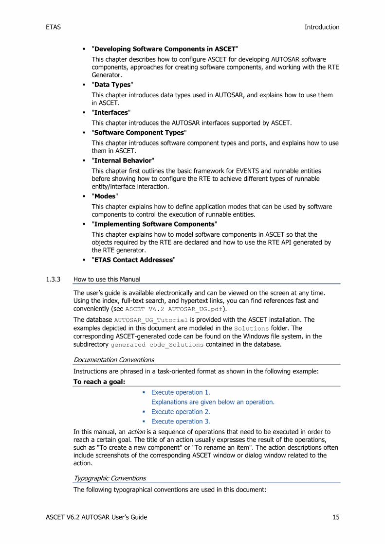
"Developing Software Components in ASCET"
This chapter describes how to configure ASCET for developing AUTOSAR software components, approaches for creating software components, and working with the RTE
Generator.
"Data Types"
This chapter introduces data types used in AUTOSAR, and explains how to use them
in ASCET.
"Interfaces"
This chapter introduces the AUTOSAR interfaces supported by ASCET.
"Software Component Types"
This chapter introduces software component types and ports, and explains how to use
them in ASCET.
"Internal Behavior"
This chapter first outlines the basic framework for EVENTS and runnable entities before showing how to configure the RTE to achieve different types of runnable
entity/interface interaction.
"Modes"
This chapter explains how to define application modes that can be used by software
components to control the execution of runnable entities.
"Implementing Software Components"
This chapter explains how to model software components in ASCET so that the
objects required by the RTE are declared and how to use the RTE API generated by
the RTE generator.
"ETAS Contact Addresses"
1.3.3 How to use this Manual
The user’s guide is available electronically and can be viewed on the screen at any time. Using the index, full-text search, and hypertext links, you can find references fast and
conveniently (see ASCET V6.2 AUTOSAR_UG.pdf).
The database AUTOSAR_UG_Tutorial is provided with the ASCET installation. The
examples depicted in this document are modeled in the Solutions folder. The
corresponding ASCET-generated code can be found on the Windows file system, in the
subdirectory generated code_Solutions contained in the database.
Documentation Conventions
Instructions are phrased in a task-oriented format as shown in the following example:
To reach a goal:
Execute operation 1.
Explanations are given below an operation.
Execute operation 2.
Execute operation 3.
In this manual, an action is a sequence of operations that need to be executed in order to
reach a certain goal. The title of an action usually expresses the result of the operations,
such as "To create a new component" or "To rename an item". The action descriptions often include screenshots of the corresponding ASCET window or dialog window related to the
action.
Typographic Conventions
The following typographical conventions are used in this document:
ETAS Introduction
ASCET V6.2 AUTOSAR User’s Guide 16
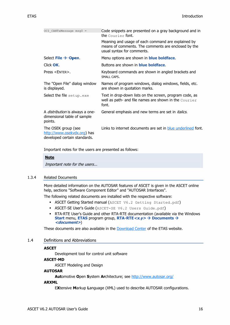
OCI_CANTxMessage msg0 = Code snippets are presented on a gray background and in
the Courier font.
Meaning and usage of each command are explained by means of comments. The comments are enclosed by the
usual syntax for comments.
Select File . Menu options are shown in blue boldface.
Click OK. Buttons are shown in blue boldface.
Press <ENTER>. Keyboard commands are shown in angled brackets and
SMALL CAPS.
The "Open File" dialog window
is displayed.
Names of program windows, dialog windows, fields, etc.
are shown in quotation marks.
Select the file setup.exe Text in drop-down lists on the screen, program code, as
well as path- and file names are shown in the Courier
font.
A distribution is always a one-
dimensional table of sample points.
General emphasis and new terms are set in italics.
The OSEK group (see http://www.osekvdx.org) has
developed certain standards.
Links to internet documents are set in blue underlined font.
Important notes for the users are presented as follows:
Note
Important note for the users...
1.3.4 Related Documents
More detailed information on the AUTOSAR features of ASCET is given in the ASCET online help, sections "Software Component Editor" and "AUTOSAR Interfaces".
The following related documents are installed with the respective software:
ASCET Getting Started manual (ASCET V6.2 Getting Started.pdf)
ASCET-SE User's Guide (ASCET-SE V6.2 Users Guide.pdf)
RTA-RTE User's Guide and other RTA-RTE documentation (available via the Windows Start menu, ETAS program group, RTA-RTE<x.y> Documents <document>)
These documents are also available in the Download Center of the ETAS website.
1.4 Definitions and Abbreviations
ASCET
Development tool for control unit software
ASCET-MD
ASCET Modeling and Design
AUTOSAR
Automotive Open System Architecture; see http://www.autosar.org/
ARXML
EXtensive Markup Language (XML) used to describe AUTOSAR configurations.

ETAS Introduction
ASCET V6.2 AUTOSAR User’s Guide 17
BSW
Basic software; provides communications, I/O, and other functionality that all software components are likely to require.
CPU
Central processing unit
ECU
Embedded Control Unit
ERCOSEK
ETAS real-time operating system, OSEK-compliant
OS
Operating system
OSEK
Working group "open systems for electronics in automobiles" (German: Arbeitskreis Offene Systeme für die Elektronik im Kraftfahrzeug)
RE
Runnable entity; a piece of code in an SWC that is triggered by the RTE at runtime. It corresponds largely to the processes known in ASCET.
RTA-OSEK
ETAS real-time operating system; implements the AUTOSAR-OS V1.0 (SC-1) and OSEK/VDX OS V2.2.3 standards and is fully MISRA compliant.
RTA-OS
ETAS real-time operating system; implements the AUTOSAR R3.0 OS and OSEK/VDX OS V2.2.3 standards and is fully MISRA compliant.
RTA-RTE
AUTOSAR runtime environment by ETAS
RTE
AUTOSAR runtime environment; provides the interface between software components, basic software, and operating systems.
SWC
AUTOSAR software component; the smallest non-dividable software unit in AUTOSAR.
UUID
Universally Unique Identifier
VFB
Virtual Function Bus

ETAS AUTOSAR Overview
ASCET V6.2 AUTOSAR User’s Guide 18
2 AUTOSAR Overview
Today, special effort is needed when integrating software components from different
suppliers in a vehicle project comprising networks, electronic control units (ECUs), and dissimilar software architectures. While clearly limiting the reusability of automotive
embedded software in different projects, this effort also calls for extra work in order to
provide the required fully functional, tested, and qualified software.
By standardizing, inter alia, basic system functions and functional interfaces, the AUTOSAR
partnership aims to simplify the joint development of software for automotive electronics,
reduce its costs and time-to-market, enhance its quality, and provides mechanisms required for the design of safety relevant systems.
To reach these goals, AUTOSAR defines an architecture for automotive embedded software.
It provides for the easy reuse, exchange, scaling, and integration of those ECU-independent software components that implement the functions of the respective application.
The next sections briefly describe the AUTOSAR process for the development of application
software components. For more detailed information the reader can refer to the AUTOSAR documents at the AUTOSAR website: http://www.autosar.org/.
2.1 AUTOSAR Basic Approach
Application software is the name given in AUTOSAR to vehicle functions. Each application is decomposed into one or more software components (SWCs), which are designed to be both
CPU- and location-neutral. An AUTOSAR application software component can be mapped to any available ECU during system configuration.
The abstraction of the SWC environment is called the virtual function bus (VFB). In each real
AUTOSAR ECU, the VFB is mapped by a specific, ECU-dependent implementation of the platform software. The AUTOSAR platform software is split into two major areas of
functionality: the runtime environment (RTE) and the basic software (BSW).
The BSW provides communications, I/O, and other functionality that all software
components are likely to require, e.g., diagnostics and error reporting, or non-volatile memory management.
Application SWCs have no direct access to the BSW. This means that components cannot,
for example, directly access operating system or communication services. The runtime environment provides the interface between software components, BSW modules, and
operating systems (OS). Concerning the interconnection of SWCs, the RTE acts like a telephone switchboard. This is similarly true of components that reside either on single ECUs
or networked ECUs interconnected by vehicle buses.
In AUTOSAR, the OS calls the runnable entities of the SWCs through the RTE. RTE and OS are the key modules of the basic software with respect to controlling application software
execution.
ETAS has been supplying the auto industry with automotive operating systems for more
than a decade: ERCOSEK and RTA-OSEK. The RTA-RTE AUTOSAR Runtime Environment and RTA-OS AUTOSAR Operating System extend the RTA product portfolio with support for the
key AUTOSAR software modules. Based on their AUTOSAR interfaces, basic software modules from third-party suppliers can be seamlessly integrated with RTA-RTE and RTA-
OSEK.
ETAS AUTOSAR Overview
ASCET V6.2 AUTOSAR User’s Guide 19
ECU
descriptions
System
constraint
description
Tool support deployment of SW
components
Mapping
ECU I
AUTOSAR
SWC 1
AUTOSAR
SWC 2
RTE
Basic Software
ECU II
AUTOSAR
SWC 3
RTE
Basic Software
...
Gateway
ECU III
AUTOSAR
SWC n
RTE
Basic Software
Virtual Function Bus
AUTOSAR
SWC 1
SWC
description
AUTOSAR
SWC 2
SWC
description
AUTOSAR
SWC 3
SWC
description
AUTOSAR
SWC n
SWC
description
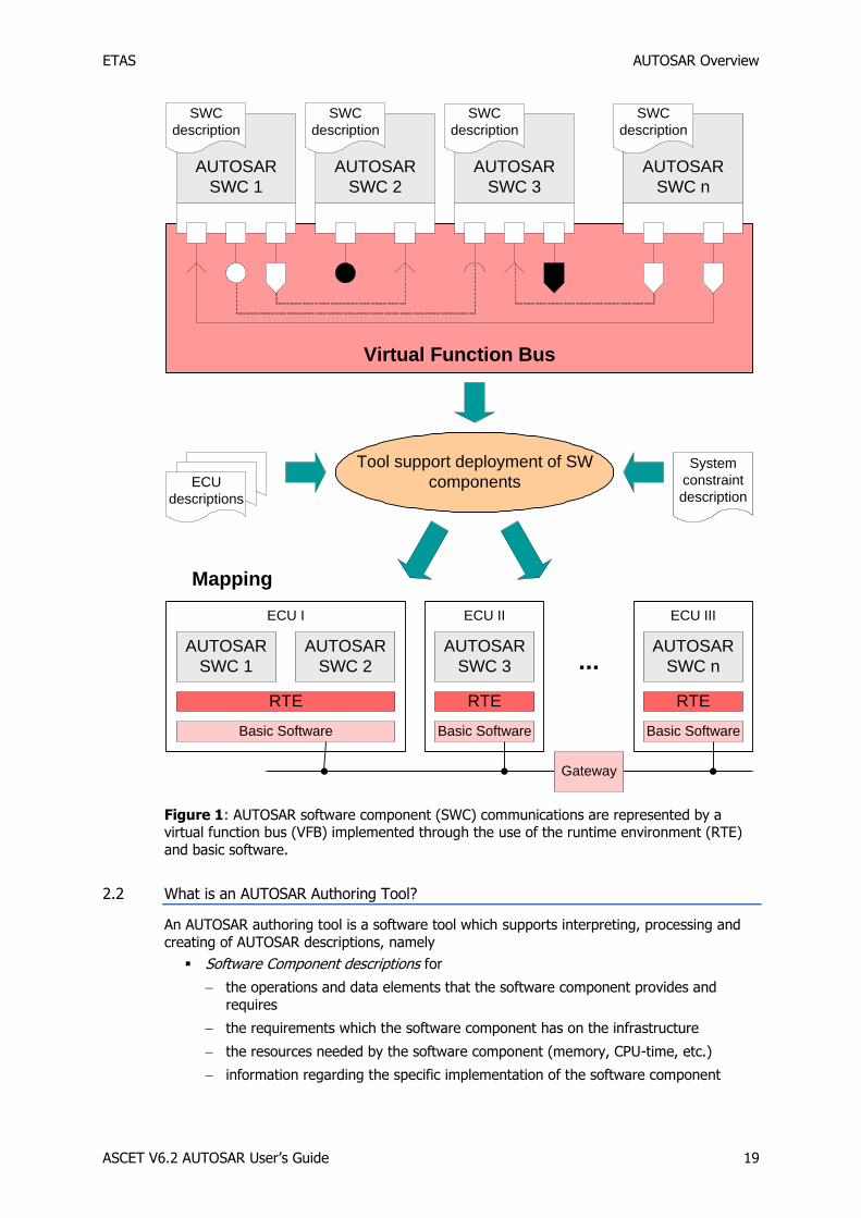
Figure 1: AUTOSAR software component (SWC) communications are represented by a virtual function bus (VFB) implemented through the use of the runtime environment (RTE)
and basic software.
2.2 What is an AUTOSAR Authoring Tool?
An AUTOSAR authoring tool is a software tool which supports interpreting, processing and
creating of AUTOSAR descriptions, namely
Software Component descriptions for
the operations and data elements that the software component provides and
requires
the requirements which the software component has on the infrastructure
the resources needed by the software component (memory, CPU-time, etc.)
information regarding the specific implementation of the software component
ETAS AUTOSAR Overview
ASCET V6.2 AUTOSAR User’s Guide 20
System constraint descriptions for all system information and the information that must be agreed between different ECUs.
ECU descriptions for the resources and configuration of the single ECUs.
AUTOSAR SWCs are generic application-level components that are designed to be
independent of both CPU and location in the vehicle network. An SWC can be mapped to
any available ECU during system configuration, subject to constraints imposed by the system designer. An AUTOSAR software component is therefore the atomic unit of distribution in an
AUTOSAR system; it must be mapped completely onto one ECU.
Before an SWC can be created, its component type (SWC type) must be defined. The SWC type identifies fixed characteristics of an SWC, i.e. port names, how ports are typed by
interfaces, how the SWC behaves, etc. The SWC type is named, and the name must be
unique within the system. Thus, an SWC consists of
a complete formal SWC description that indicates how the infrastructure of the component must be configured,
an SWC implementation that contains the functionality (in the form of C code).
To allow an SWC to be used, it needs to be instantiated at configuration time. The
distinction between type and instance is analogous to types and variables in conventional programming languages. You define an application-wide unique type name (SWC type), and
declare one uniquely named variable of that type (one or more SWC instance).
In the VFB model, software components interact through ports which are typed by interfaces. The interface controls what can be communicated, as well as the semantics of
communication. The port provides the SWC access to the interface. The combination of port
and port interface is named AUTOSAR interface.
A runnable entity is a piece of code in an SWC that is triggered by the RTE (see section 2.3,
What is a Runtime Environment?, on page 20) at runtime.
A software component comprises one or more runnable entities the RTE can access at
runtime. Runnable entities are triggered, among others, by the following events:
Timing events represent some periodic scheduling event, e.g. a periodic timer tick. The runnable entity provides the entry point for regular execution.
Events triggered by the reception of data at an Rport (DataReceive events).
AUTOSAR runnable entities can be sorted in several categories. ASCET supports runnable
entities of category 1.
In order to be executed, runnable entities must be assigned to the tasks of an AUTOSAR operating system.
AUTOSAR elements reference each other in a standardized XML file format, the so-called
ARXML format. The ARXML format can slightly differ depending on the AUTOSAR release version. AUTOSAR authoring tools are required to be able to interpret, create or modify
ARXML descriptions.
Note
The ARXML examples provided in this user guide are generated using the AUTOSAR release version 3.1.2.
2.3 What is a Runtime Environment?
The VFB provides the abstraction that allows components to be reusable. The runtime environment (RTE) provides the mechanisms required to make the VFB abstraction work at
runtime. The RTE is, therefore, in the simplest case, an implementation of the VFB. However, the RTE must provide the necessary interfacing and infrastructure to allow
software components to
1. be implemented without reference to an ECU (the VFB model); and

ETAS AUTOSAR Overview
ASCET V6.2 AUTOSAR User’s Guide 21
2. be integrated with the ECU and the wider vehicle network once this is known (the Systems Integration model) without changing the application software itself.
More specifically, the RTE must
Provide a communication infrastructure for software components.
This includes both communication between software components on the same ECU
(intra-ECU) and communication between software components on different ECUs (inter-ECU).
Arrange for real-time scheduling of software components.
This typically means that the runnable entities of the SWCs are mapped, according to
time constraints specified at design time, onto tasks provided by an operating system.
Application software components have no direct access to the basic software below the abstraction implemented by the RTE. This means that components cannot, for example,
directly access operating system or communication services. So, the RTE must present an
abstraction over such services. It is essential that this abstraction remains unchanged, irrespective of the software components’ location. All interaction between software
components therefore happens through standardized RTE interface calls.
In addition, the RTE is used for the specific realization of a previously specified architecture consisting of SWCs on one or more ECUs. To make the RTE implementation efficient, the
RTE implementation required for the architecture is determined at build time for each ECU. The standardized RTE interfaces are automatically implemented by an RTE generation tool
that makes sure that the interface behaves in the correct way for the specified component
interaction and the specified component allocation.
For example, if two software components reside on the same ECU, they can use internal ECU communication, but if one is moved to a different ECU, communication now needs to
occur across the vehicle network.
From the application software component perspective, the generated RTE therefore encapsulates the differences in the basic software of the various ECUs by:
Presenting a consistent interface to the software components so they can be reused—they can be designed and written once but used multiple times.
Binding that interface onto the underlying AUTOSAR basic software implemented in the VFB design abstraction.
2.4 What is a Behavior Modeling Tool?
An AUTOSAR Behavior Modeling Tool is a software tool which allows defining and implementing the functional behavior of AUTOSAR-compliant vehicle functions using a
behavior modeling language.
A behavior modeling language is a notation primarily used to capture a functional behavior specification or design of a function or system. Usually, a functional behavior modeling
language has a graphical notation and is regarded to be executable, i.e. its semantics is
sufficiently precise to execute functional behavior models by means of a simulation engine. Furthermore, the precision in its semantics then allows the transformation of the functional
model into a source code in a programming language like C.
When ASCET is used as a behavioral modeling tool, the internal behavior of the application software components is specified by means of the block diagram editor. The internal
behavior can consist of variables, parameters, class instances and modules. AUTOSAR runnable entities can be seamlessly implemented by means of sequences of methods calls
and processes.
Existing ASCET models can be easily adapted to AUTOSAR because many AUTOSAR
concepts can be mapped to interface specifications in ASCET in a similar form. On the whole, it suffices to rework the interface of the respective application to make an existing
software module AUTOSAR-compliant. In terms of time, the expenditure of reworking an existing application is relatively minor.
ETAS Developing Software Components in ASCET
ASCET V6.2 AUTOSAR User’s Guide 22
3 Developing Software Components in ASCET
3.1 Configuring ASCET
This section briefly describes how to configure ASCET for developing AUTOSAR software components. For a more detailed description on how to work with ASCET, please refer to the
"ASCET Getting Started" manual and the ASCET online help.
3.1.1 Configuring the Creation of AUTOSAR Components
ASCET offers the possibility to configure user profiles. In the context of AUTOSAR, ASCET
provides a configuration option for the creation of AUTOSAR components.
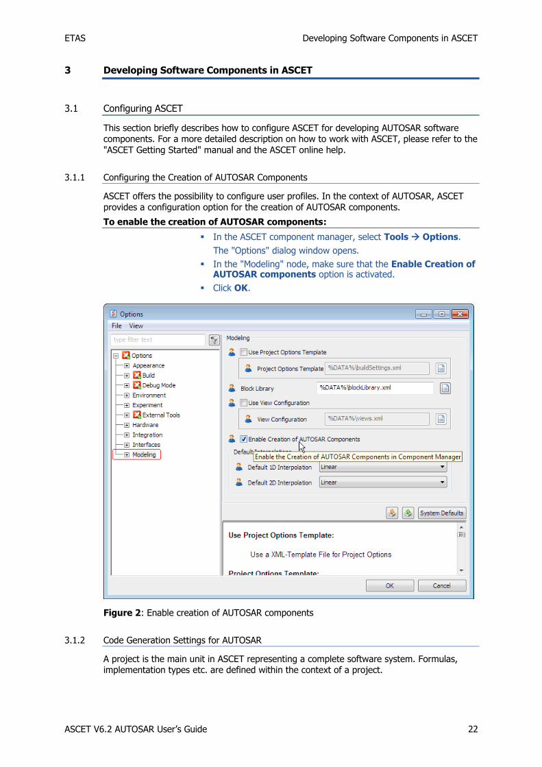
To enable the creation of AUTOSAR components:
In the ASCET component manager, select Tools Options.
The "Options" dialog window opens.
In the "Modeling" node, make sure that the Enable Creation of AUTOSAR components option is activated.
Click OK.
Figure 2: Enable creation of AUTOSAR components
3.1.2 Code Generation Settings for AUTOSAR
A project is the main unit in ASCET representing a complete software system. Formulas, implementation types etc. are defined within the context of a project.
ETAS Developing Software Components in ASCET
ASCET V6.2 AUTOSAR User’s Guide 23
To create a project:
In the component manager, select Insert Project or click on the Insert Project button to add a new project.
Name the project ARProject.
Select Edit Open Component or double-click the project.
The project editor opens.
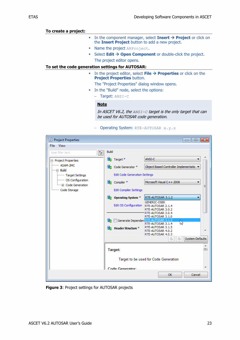
To set the code generation settings for AUTOSAR:
In the project editor, select File Properties or click on the Project Properties button.
The "Project Properties" dialog window opens.
In the "Build" node, select the options:
Target: ANSI-C
Note
In ASCET V6.2, the ANSI-C target is the only target that can be used for AUTOSAR code generation.
Operating System: RTE-AUTOSAR x.y.z
Figure 3: Project settings for AUTOSAR projects
ETAS Developing Software Components in ASCET
ASCET V6.2 AUTOSAR User’s Guide 24
Note
ASCET V6.2 supports the AUTOSAR releases 2.1.4, 3.0.2, 3.0.4, 3.1.0, 3.1.2, 3.1.4, 3.1.5, 4.0.2 and 4.0.3.
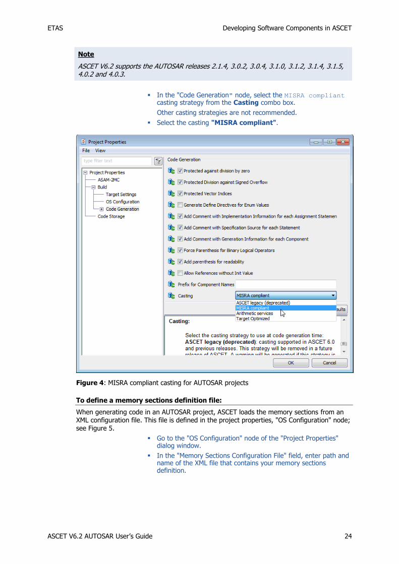
In the "Code Generation" node, select the MISRA compliant casting strategy from the Casting combo box.
Other casting strategies are not recommended.
Select the casting "MISRA compliant".
Figure 4: MISRA compliant casting for AUTOSAR projects
To define a memory sections definition file:
When generating code in an AUTOSAR project, ASCET loads the memory sections from an XML configuration file. This file is defined in the project properties, "OS Configuration" node;
see Figure 5.
Go to the "OS Configuration" node of the "Project Properties" dialog window.
In the "Memory Sections Configuration File" field, enter path and name of the XML file that contains your memory sections definition.

ETAS Developing Software Components in ASCET
ASCET V6.2 AUTOSAR User’s Guide 25
Figure 5: OS Configuration settings for an AUTOSAR R4.0.* project
ASCET provides two sample files, memorySections_Autosar.xml (AUTOSAR R3.1.5 or
lower) and memorySections_Autosar4.xml (AUTOSAR R4.0.*). The suitable
memorySelecions_*.xml file for the selected RTE-AUTOSAR * operating system (see
section 3.1.2, Code Generation Settings for AUTOSAR, on page 22) is preselected.
3.1.3 Settings for the AUTOSAR XML Output
The "Project Properties" window offers a possibility to configure the AUTOSAR XML output,
i.e. to set package names or short names, to specify output files, etc.
To configure the AUTOSAR XML (ARXML) output:
In the "Project Properties" dialog window, go to the "OS Configuration" node.
In the "AUTOSAR XML Configuration File" field, enter or select the configuration file.
By default, each AUTOSAR Rx.y version uses a separate configuration file. It is recommended that you do not change this behavior because different AUTOSAR versions allow different ARXML settings.
Click on the Edit button to open the "ARXML Configuration Settings" dialog window.
This window provides a set of options to configure the AUTOSAR XML generation. The options are grouped in several categories; see Table 1.

ETAS Developing Software Components in ASCET
ASCET V6.2 AUTOSAR User’s Guide 26
Category Content
Package Templates Each package template allows the specification of an ARXML
package name following the scheme:
/<Root-Package>/<Sub-Package>/.../<Short-
Name>
Specific template parameters can be used.
Short Name Templates Each short name template allows the specification of an
ARXML short name.
Specific template parameters can be used.
Filename Templates Each filename template allows the specification of a filename
where the associated package will be generated into.
Specific template parameters can be used.
Miscellaneous Each miscellaneous option represents an additional option -
which might be a template - somehow relevant for the ARXML generation.
Table 1: Categories for the configuration of generated ARXML code. The content of the
categories depends on the selected AUTOSAR version.
Adjust the options in the different categories according to your needs.
The descriptions in the "ARXML Configuration Settings" dialog window contain detailed information on each option.
Click OK to confirm the settings and close the "ARXML Configuration Settings" dialog window.
Note
The changes in the "ARXML Configuration Settings" window are kept even if you leave the "Project Properties" window with Cancel.
3.1.4 Code Generation
An AUTOSAR project shall contain an AUTOSAR software component and requires the project settings described in the previous section. When generating code for the project,
ASCET creates the AUTOSAR XML description files (*.arxml files) and the corresponding
C code. The generated C code uses the AUTOSAR API macros which are implemented in the
RTE.
To create an AUTOSAR software component:
In the component manager, select Insert AUTOSAR Software Component.
Name the software component Swc.
To insert an AUTOSAR software component in a project:
Open the project ARProject in the project editor.
In the project editor, select Insert Component.
The "Select Item…" window opens.
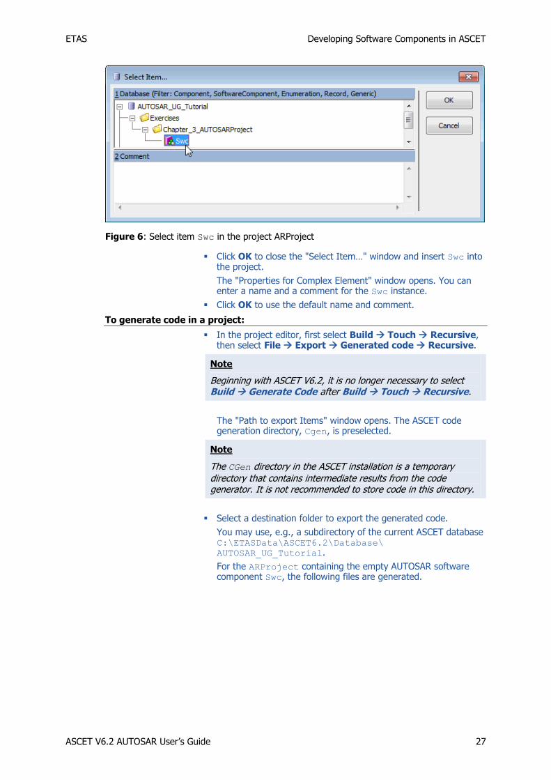
In the "1 Database” or "1 Workspace” field of the "Select Item…" window, select the component Swc.
ETAS Developing Software Components in ASCET
ASCET V6.2 AUTOSAR User’s Guide 27
Figure 6: Select item Swc in the project ARProject
Click OK to close the "Select Item…" window and insert Swc into the project.
The "Properties for Complex Element" window opens. You can enter a name and a comment for the Swc instance.
Click OK to use the default name and comment.
To generate code in a project:
In the project editor, first select Build Touch Recursive, then select File Export Generated code Recursive.
Note
Beginning with ASCET V6.2, it is no longer necessary to select Build Generate Code after Build Touch Recursive.
The "Path to export Items" window opens. The ASCET code generation directory, Cgen, is preselected.
Note
The CGen directory in the ASCET installation is a temporary directory that contains intermediate results from the code generator. It is not recommended to store code in this directory.
Select a destination folder to export the generated code.
You may use, e.g., a subdirectory of the current ASCET database C:\ETASData\ASCET6.2\Database\
AUTOSAR_UG_Tutorial.
For the ARProject containing the empty AUTOSAR software component Swc, the following files are generated.

ETAS Developing Software Components in ASCET
ASCET V6.2 AUTOSAR User’s Guide 28
Figure 7: ASCET generated code for the project ARProject (*.arxml, *.c and *.h files).
3.2 Approaches for Creating Software Components
The development of AUTOSAR software components in ASCET can be done using two approaches: the top-down approach and the bottom-up approach.
In the top-down approach, the software architecture is described in an authoring tool. In
this case, ASCET is used as a behavior modeling tool for the implementation of the software components.
In the bottom-up approach, ASCET is not only used as a behavior modeling tool, but as an
authoring tool for the description of the AUTOSAR software components as well.
3.2.1 Top-Down Approach
In the top-down approach, the creation of an AUTOSAR software component is done in two
steps:
1. In the first step, the interface of the component is defined. The interface is specified
in an authoring tool and exchanged via ARXML. The ARXML files are then given to a
component API generator which transforms the interface description into a header file. As a rule, the component API generator is the contract phase part of an RTE
generator (see section 3.3.1, Contract Phase, on page 31).
2. In a second step, the ARXML files are imported in ASCET and the application software component developer provides the internal behavior in terms of C files respecting and
using the interfaces as defined in the header file. Now the *.h and the *.c files of
the software components are defined and can be compiled.
In the top-down approach, a key feature is the ARXML importer, which is described in the
next subsections.
The ARXML Importer
The ARXML description of a software component can be imported into ASCET with the
"AUTOSAR to ASCET Importer". This tool transforms the ARXML file(s) containing all necessary information to describe a software component (i.e. AUTOSAR types, interfaces,
software component type) into the proprietary ASCET XML format, the AMD format. Afterwards, ASCET imports the AMD files into the currently open database or workspace.
ETAS Developing Software Components in ASCET
ASCET V6.2 AUTOSAR User’s Guide 29
The AUTOSAR to ASCET Importer is started from the component manager, with the Tools AUTOSAR to ASCET Converter menu option. See the AUTOSAR to ASCET Importer
User’s Guide for details.
In addition, ARXML file(s) can be imported using the standard import menu option.
To import an ARXML in ASCET
In the component manager, select File Import.
The "Select Import File" dialog opens.
Select the ARXML file(s) to be imported and click OK.
ASCET imports the selected files in the currently open database or workspace.
Using the Attribute UUID in the ARXML Import
UUIDs (Universally Unique Identifiers) are optional fields in the ARXML specification, and
most authoring tools support them. ASCET also supports UUIDs in the AMD format, and this enables ASCET to be easily integrated in AUTOSAR toolchains. At present, the ASCET-
generated ARXML provides a UUID for those elements that were imported with this attribute; otherwise, the attribute is empty.
UUIDs are mainly used for the identification of existing elements in the ASCET database or
workspace when importing ARXML files. The use of the UUID attribute needs to be explicitly
enabled.
To use UUIDs for identification:
In the component manager, select Tools Options.
The ASCET options dialog window opens.
Go to the "Interfaces\Import" node.
Enable the option "Use UUIDs for Identification".
Click OK to close the ASCET options window and accept the setting.
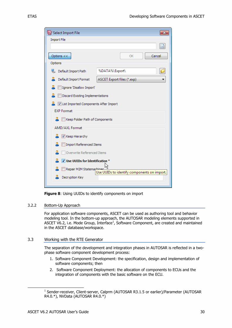
The Use UUIDs for Identification option is also available in the "Select Import File" window, see Figure 8.
ETAS Developing Software Components in ASCET
ASCET V6.2 AUTOSAR User’s Guide 30
Figure 8: Using UUIDs to identify components on import
3.2.2 Bottom-Up Approach
For application software components, ASCET can be used as authoring tool and behavior
modeling tool. In the bottom-up approach, the AUTOSAR modeling elements supported in ASCET V6.2, i.e. Mode Group, Interface1, Software Component, are created and maintained
in the ASCET database/workspace.
3.3 Working with the RTE Generator
The separation of the development and integration phases in AUTOSAR is reflected in a two-phase software component development process:
1. Software Component Development: the specification, design and implementation of
software components; then
2. Software Component Deployment: the allocation of components to ECUs and the integration of components with the basic software on the ECU.
1 Sender-receiver, Client-server, Calprm (AUTOSAR R3.1.5 or earlier)/Parameter (AUTOSAR R4.0.*), NVData (AUTOSAR R4.0.*)

ETAS Developing Software Components in ASCET
ASCET V6.2 AUTOSAR User’s Guide 31
The two phases of operation allow for initial software component configurations to be made and integrated onto the VFB (through some auxiliary design and development process) and
then the RTE interface to be generated so that the software components can be
implemented before the prototypes are defined and their particular allocations onto an ECU are known.
The phased development process means that some time can pass between the development
of a component type and the allocation of its component prototypes to an ECU. Indeed, a component may be developed once and re-used multiple times over many generations of
vehicles. Furthermore, the component may be supplied to an integrator in binary form only, but must be integrated to an ECU with other components that have not yet been written.
The RTE generator supports the phased process by allowing the interface to the RTE to be
generated in advance of full knowledge of component prototype/ECU allocation. Given a
software component description, the RTE generator has sufficient information to generate the interface definition files necessary for engineers to start developing software
components. The interface defines the contract between the RTE and the component – what that component must provide if future integration work is to happen easily. This is known as
contract phase.
When the system is integrated, and the mapping of software components to ECUs is known, the RTE itself can be generated. However, we now know how many instances of a software
component exist, where runnable entities are executing, which communication is local to an
ECU and which must be routed across the network, etc. The RTE generator can use this information to re-generate the interface definition files to include optimizations based on this
additional context. This is known as RTE phase.
The following sections discuss the Contract and RTE phases in more detail.
3.3.1 Contract Phase
In the contract phase, the RTE generator produces header files to be used in the components under implementation. The header files define the contract between the
component and the system as a whole and are suitable for both binary-code and source-
code components. When running in the contract phase, the RTE generator only needs access to the software component description file(s). It is not necessary to have any
information about system deployment.
The definitions in the ARXML file are used to define the APIs, and therefore only valid runnable entities can be declared without an error occurring when the component is
compiled.
3.3.2 RTE Phase
Prior to using an RTE generator in RTE phase, a significant amount of system engineering is
needed. The AUTOSAR development process assumes that there are a number of inputs to the system engineering process:
Software component descriptions that define the software components, their ports, internal behavior and implementation characteristic and the interfaces provided and required by the ports assuming their connection to the Virtual Function Bus. These are the same descriptions as used in contract phase.
ECU resource descriptions that define the ECU hardware characteristics (e.g. communication ports)
A System constraint description that defines aspects of the system (e.g. communication protocols)
To build an AUTOSAR system (i.e. a set of software components mapped to ECUs that
communicate over a network) it is necessary to define:
ECU configuration descriptions that define which software components are mapped to which ECUs, the resources available on the ECU etc.
ETAS Developing Software Components in ASCET
ASCET V6.2 AUTOSAR User’s Guide 32
A System configuration description that defines things like the network topology, how inter-ECU communication is mapped to the physical network etc.
An ECU Configuration that defines the mapping between elements; for example the mapping of runnable entities to AUTOSAR Operating System tasks and the mapping of AUTOSAR signals to AUTOSAR COM signals.
Once you have configured your AUTOSAR system with an allocation of component prototypes to ECU instances, the RTE generator is used in RTE Generation phase to create
the following items:
1. the implementation of the RTE itself
2. optimized component header files that exploit mapping knowledge provided by your configuration
3. operating system tasks that package your runnable entities
4. (optional) an operating system configuration file for the RTE generated objects and
required behavior
5. (optional) a communication stack configuration file for inter-ECU communication configuration
In the RTE phase, the RTE generates optimized application header files suitable for
compiling source code components and, optionally, XML configuration files for the communication stack and operating system. When running the RTE phase, the RTE
generator needs access to all system deployment information.
The RTE is generated as one or more C modules. Each module must be compiled according
to the dependency information output by the RTE. The module Rte.c contains the core
generated RTE.

ETAS Data Types (AUTOSAR R3.1.5 or Lower)
ASCET V6.2 AUTOSAR User’s Guide 33
4 Data Types (AUTOSAR R3.1.5 or Lower)
The communication over interfaces is typed so, before an interface can be defined, it is
necessary to define the types of data that can be used.
ASCET supports both primitive types and complex types, i.e. those composed from values of primitive types.
Definitions of AUTOSAR primitive and complex data types are created by ASCET based on
data implementation information. The ASCET data implementation is then mapped by the AUTOSAR RTE into BSW types.
4.1 BSW Types
For AUTOSAR R3.1.5 or lower, the AUTOSAR RTE supports the following BSW data types:
sint8 – 8 bit signed integer.
uint8 – 8-bit unsigned integer.
sint16 – 16-bit signed integer.
uint16 – 16-bit unsigned integer.
sint32 – 32-bit signed integer.
uint32 – 32-bit unsigned integer.
float32 – single precision floating point.
float64 – double precision floating point.
uint8_least – at least 8-bit unsigned integer.
uint16_least – at least 16-bit unsigned integer.
uint32_least – at least 32-bit unsigned integer.
sint8_least – at least 7-bit signed integer (plus sign bit).
sint16_least – at least 15-bit signed integer (plus sign bit).
sint32_least – at least 31-bit signed integer (plus sign bit).
boolean – for use with TRUE/FALSE.
The BSW types, plus definitions for TRUE and FALSE, are defined in the RTA-RTE
installation, in the AUTOSAR header file Platform_Types.h.
4.2 Primitive Data Types
The ASCET type system consists of model types and implementation types. Model types are abstract generic types which can be realized in one or more implementation types.
The basic model types for scalar elements are:
Logic
Signed Discrete
Unsigned Discrete
Continuous
All scalar elements in ASCET are implemented using one of the following data types:
sint8
sint16
sint32
uint8
uint16
uint32

ETAS Data Types (AUTOSAR R3.1.5 or Lower)
ASCET V6.2 AUTOSAR User’s Guide 34
Additionally, the model type "cont" can be implemented as
real64
real32
and the model type "log" as
bool
To configure the default implementation of model types:
In the component manager, select Tools Options.
The "Options" dialog window opens.
Open the "Modeling\Implementation\default Implementation Types" node.
Configure the default implementation types, for instance, as shown below.
Figure 9: Default implementation of model types
Click OK.
The implementation of a model element can always be individually configured. In what
follows, we illustrate how to implement a variable sdisc as an 8 bit signed integer.
To implement a model type sdisc as a sint8:
In the component manager, select the project ARProject and select Edit Open Component.
The project editor opens.
In the project editor, double-click the software component Swc.
The software component editor opens.
Use the Signed Discrete Variable button to create an sdisc variable.
The dialog "Properties for Scalar Element: sdisc" opens.
Name the signed discrete variable sdisc and close the properties editor with OK.
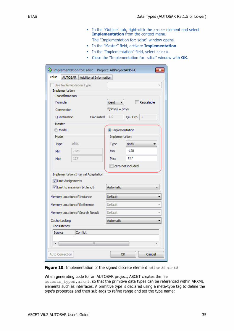
ETAS Data Types (AUTOSAR R3.1.5 or Lower)
ASCET V6.2 AUTOSAR User’s Guide 35
In the "Outline" tab, right-click the sdisc element and select Implementation from the context menu.
The "Implementation for: sdisc" window opens.
In the "Master” field, activate Implementation.
In the "Implementation” field, select sint8.
Close the "Implementation for: sdisc" window with OK.
Figure 10: Implementation of the signed discrete element sdisc as sint8
When generating code for an AUTOSAR project, ASCET creates the file
autosar_types.arxml, so that the primitive data types can be referenced within ARXML
elements such as interfaces. A primitive type is declared using a meta-type tag to define the type's properties and then sub-tags to refine range and set the type name:

ETAS Data Types (AUTOSAR R3.1.5 or Lower)
ASCET V6.2 AUTOSAR User’s Guide 36
Listing 1: ARXML code – primitive data type (AUTOSAR R3.1.2)
The short-name of a data type must be a valid C identifier.
The types file autosar_types.arxml is an input for the RTE generator. The type
definition for the user-defined primitive type is then included in the generated file
Rte_Type.h. The implementation of the primitive types created by RTE references the
BSW data types is defined for a particular micro-controller target by the AUTOSAR header
file Platform_Types.h.
4.3 Primitive Data Types With Semantics
An additional data type in ASCET is Enumerations.
An enumeration in ASCET corresponds to an integer type with semantics. The semantic is
given by a compu-method with category "Text Table". A compu-method is a conversion
formula from bit-pattern to a physical value and vice versa.
To create an enumeration
In the component manager, select Insert Enumeration or click on the Enumeration button.
Name the enumeration Enumeration.
Select the enumeration and switch to the "Contents” pane.
For the value 0, select Enumeration Rename and set the label red.
Select Enumeration Add Enumeration Append or press the <INSERT> key to create a new enumerator with the value 1. Set the label to yellow.
Create another enumerator with value 2 and label green.

ETAS Data Types (AUTOSAR R3.1.5 or Lower)
ASCET V6.2 AUTOSAR User’s Guide 37
Figure 11: Example of an enumeration in ASCET
The definition of the data type and the compu-method in configuration language can be
found in the AUTOSAR package ASCET_types. The package ASCET_types contains
software component specific types and is stored in the types file of the software component,
i.e. the generated file Swc_Types.arxml.
Listing 2: ARXML code – enumeration data type (AUTOSAR R3.1.2)
The description of the compu-method is attached below:

ETAS Data Types (AUTOSAR R3.1.5 or Lower)
ASCET V6.2 AUTOSAR User’s Guide 38
Listing 3: ARXML code – compu-method for an enumeration (AUTOSAR R3.1.2)

ETAS Data Types (AUTOSAR R3.1.5 or Lower)
ASCET V6.2 AUTOSAR User’s Guide 39
4.3.1 Std_ReturnType
The AUTOSAR standard defines "status" and "error" values returned by RTE API functions.
The following values are defined in the Std_ReturnType type:
Error Code Available in AUTOSAR Release
R4.0.* R3.* R2.*
RTE_E_COM_STOPPED X X
RTE_E_COMMS_ERROR X
RTE_E_INVALID X X X
RTE_E_LIMIT X X X
RTE_E_LOST_DATA X X X
RTE_E_MAXAGE_EXCEEDED X X X
RTE_E_NO_DATA X X X
RTE_E_OK X X X
RTE_E_TIMEOUT X X X
RTE_E_TRANSMIT_ACK X X X
Table 2: AUTOSAR error codes
ASCET provides the Std_ReturnType type as a built-in enumeration. The error codes are
reserved words in ASCET and cannot be used in other enumerations.
Furthermore, E_OK is also reserved in ASCET, which denotes that a server runnable returns
no application error. The user shall specify – or import – the possible values of the application error in a standard enumeration.
4.4 Complex Types
4.4.1 Record Types
Record types allow new complex types to be created. A record type creates a data structure
consisting of one or more named members.
To create a record in ASCET:
In the component manager, select Insert Record or click on the Record button.
Name the record Record.
Select Edit Open Component or double-click the record.
The record editor opens.
Use the Unsigned Discrete Variable button to create a udisc variable.
The dialog "Properties for Scalar Element: udisc" opens.
Name the unsigned discrete variable A.
Use the Logic Variable button to create a log variable named B.

ETAS Data Types (AUTOSAR R3.1.5 or Lower)
ASCET V6.2 AUTOSAR User’s Guide 40
Figure 12: Record with elements A and B
To create an implementation of a record:
In the record editor, switch from the "Elements" tab to the "Implementation" tab.
In the "Implementation" tab, double-click the element A.
The "Implementation for: A" window opens.
In the "Master" field, activate Implementation.
In the "Implementation" field, select uint16.
Right-click in the "Max" field and select Default Value from the context menu.
Close the "Implementation for: A" window with OK.

ETAS Data Types (AUTOSAR R3.1.5 or Lower)
ASCET V6.2 AUTOSAR User’s Guide 41
Figure 13: Implementation of the unsigned discrete element A as uint16
For the logic variable B, select the implementation type bool.
The "Implementation" tab of the record editor looks like the figure below.
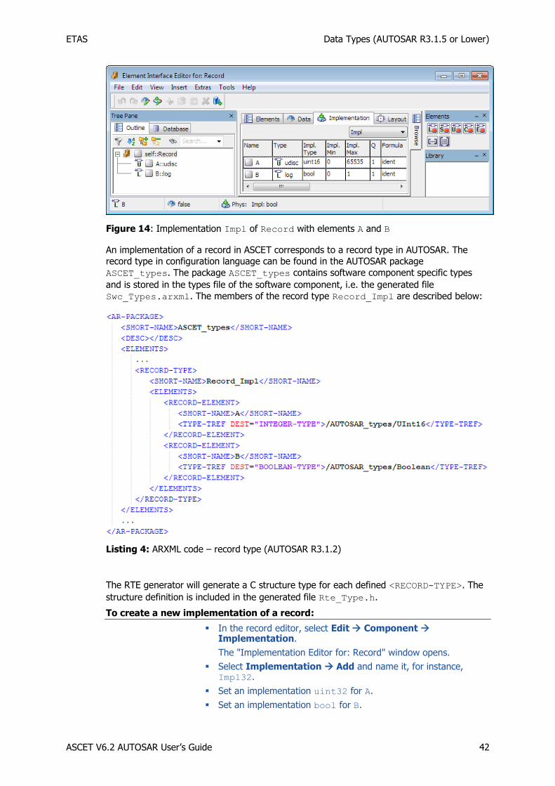
ETAS Data Types (AUTOSAR R3.1.5 or Lower)
ASCET V6.2 AUTOSAR User’s Guide 42
Figure 14: Implementation Impl of Record with elements A and B
An implementation of a record in ASCET corresponds to a record type in AUTOSAR. The
record type in configuration language can be found in the AUTOSAR package
ASCET_types. The package ASCET_types contains software component specific types
and is stored in the types file of the software component, i.e. the generated file
Swc_Types.arxml. The members of the record type Record_Impl are described below:
Listing 4: ARXML code – record type (AUTOSAR R3.1.2)
The RTE generator will generate a C structure type for each defined <RECORD-TYPE>. The
structure definition is included in the generated file Rte_Type.h.
To create a new implementation of a record:
In the record editor, select Edit Component Implementation.
The "Implementation Editor for: Record" window opens.
Select Implementation Add and name it, for instance, Impl32.
Set an implementation uint32 for A.
Set an implementation bool for B.
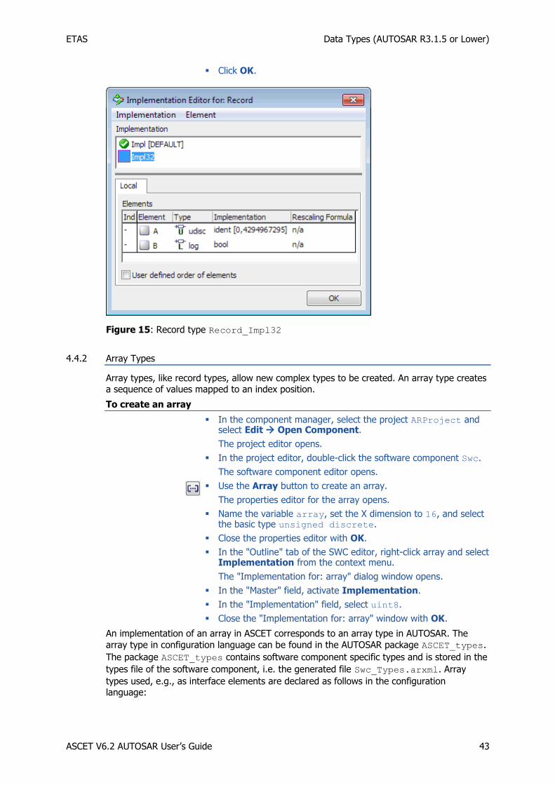
ETAS Data Types (AUTOSAR R3.1.5 or Lower)
ASCET V6.2 AUTOSAR User’s Guide 43
Click OK.
Figure 15: Record type Record_Impl32
4.4.2 Array Types
Array types, like record types, allow new complex types to be created. An array type creates a sequence of values mapped to an index position.
To create an array
In the component manager, select the project ARProject and select Edit Open Component.
The project editor opens.
In the project editor, double-click the software component Swc.
The software component editor opens.
Use the Array button to create an array.
The properties editor for the array opens.
Name the variable array, set the X dimension to 16, and select the basic type unsigned discrete.
Close the properties editor with OK.
In the "Outline" tab of the SWC editor, right-click array and select Implementation from the context menu.
The "Implementation for: array" dialog window opens.
In the "Master" field, activate Implementation.
In the "Implementation" field, select uint8.
Close the "Implementation for: array" window with OK.
An implementation of an array in ASCET corresponds to an array type in AUTOSAR. The
array type in configuration language can be found in the AUTOSAR package ASCET_types.
The package ASCET_types contains software component specific types and is stored in the
types file of the software component, i.e. the generated file Swc_Types.arxml. Array
types used, e.g., as interface elements are declared as follows in the configuration language:

ETAS Data Types (AUTOSAR R3.1.5 or Lower)
ASCET V6.2 AUTOSAR User’s Guide 44
Listing 5: ARXML code – array type (AUTOSAR R3.1.2)
The RTE generator will generate a C array type for each defined <ARRAY-TYPE>. Array
types must be therefore declared according to the same semantics as the C array. The array
type definition is included in the generated file Rte_Type.h.
Note
The implementation of arrays in application software components shall be consistent with their declaration in the generated RTE. It is first specified how to declare an array typed element at C code level in AUTOSAR R3.1.2. For more information, refer to the AUTOSAR_SWS_RTE.pdf manual of your AUTOSAR release, chapter 5.2.6.5, for more information.
The C code generation of arrays in ASCET is configurable in the file codegen.ini by means of the option ARArrayBaseTypePassing.
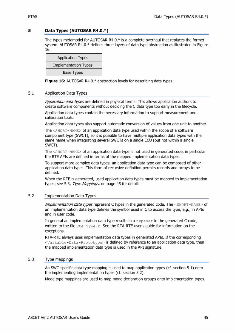
ETAS Data Types (AUTOSAR R4.0.*)
ASCET V6.2 AUTOSAR User’s Guide 45
5 Data Types (AUTOSAR R4.0.*)
The types metamodel for AUTOSAR R4.0.* is a complete overhaul that replaces the former
system. AUTOSAR R4.0.* defines three layers of data type abstraction as illustrated in Figure 16.
Application Types
Implementation Types
Base Types
Figure 16: AUTOSAR R4.0.* abstraction levels for describing data types
5.1 Application Data Types
Application data types are defined in physical terms. This allows application authors to
create software components without deciding the C data type too early in the lifecycle.
Application data types contain the necessary information to support measurement and calibration tools.
Application data types also support automatic conversion of values from one unit to another.
The <SHORT-NAME> of an application data type used within the scope of a software
component type (SWCT), so it is possible to have multiple application data types with the same name when integrating several SWCTs on a single ECU (but not within a single
SWCT).
The <SHORT-NAME> of an application data type is not used in generated code, in particular
the RTE APIs are defined in terms of the mapped implementation data types.
To support more complex data types, an application data type can be composed of other
application data types. This form of recursive definition permits records and arrays to be defined.
When the RTE is generated, used application data types must be mapped to implementation
types; see 5.3, Type Mappings, on page 45 for details.
5.2 Implementation Data Types
Implementation data types represent C types in the generated code. The <SHORT-NAME> of
an implementation data type defines the symbol used in C to access the type, e.g., in APIs
and in user code.
In general an implementation data type results in a typedef in the generated C code,
written to the file Rte_Type.h. See the RTA-RTE user's guide for information on the
exceptions.
RTA-RTE always uses implementation data types in generated APIs. If the corresponding
<Variable-Data-Prototype> is defined by reference to an application data type, then
the mapped implementation data type is used in the API signature.
5.3 Type Mappings
An SWC-specific data type mapping is used to map application types (cf. section 5.1) onto the implementing implementation types (cf. section 5.2).
Mode type mappings are used to map mode declaration groups onto implementation types.

ETAS Data Types (AUTOSAR R4.0.*)
ASCET V6.2 AUTOSAR User’s Guide 46
Note
RTA-RTE requires a data type mapping for each application type and a mode type mapping for each used mode declaration group in order to be able to generate the RTE.
In ASCET, these mappings are provided in the Swc_mappings.arxml file.
The data type mapping for a SWC is held within a <DATA-TYPE-MAPPING-SET> element:
Listing 6: ARXML code - mapping application data types and mode type to implementation
data types (AUTOSAR R4.0.2)
A data type mapping contains one or more data type maps. Each map references a single application data type and a single implementation data type; see Listing 8, Listing 12, Listing
15 or Listing 21 for ARXML examples.
For more information on data type and mode mapping, refer to the RTA-RTE user's guide.
5.4 Platform Types
AUTOSAR specifies a set of platform types for use in C code. These are implementation data
types whose purpose is to provide a set of types with the same semantics across different target hardware. RTA-RTE uses platform types when it needs to create types for internal
variables.
Unlike most implementation data types, the platform types are also defined in C language in
the file PlatformTypes.h.
Beginning with R4.0.2, AUTOSAR also specifies the correct definitions and package name of
the platform types.
The platform types defined in AUTOSAR Specification of Platform Types and in the standard
header file Platform_Types.h are:

ETAS Data Types (AUTOSAR R4.0.*)
ASCET V6.2 AUTOSAR User’s Guide 47
sint8 – 8-bit signed integer
uint8 – 8-bit unsigned integer
sint16 – 16-bit signed integer
uint16 – 16-bit unsigned integer
sint32 – 32-bit signed integer
uint32 – 32-bit unsigned integer
float32 – single precision floating point
float64 – double precision floating point
uint8_least – at least 8-bit unsigned integer
uint16_least – at least 16-bit unsigned integer
uint32_least – at least 32-bit unsigned integer
sint8_least – at least 7-bit signed integer (plus sign bit)
sint16_least – at least 15-bit signed integer (plus sign bit)
sint32_least – at least 31-bit signed integer (plus sign bit)
boolean – for use with TRUE/FALSE.
5.5 Base Types
Finally, base types describe the hardware-specific aspects of the data type, e.g., size and
encoding. They form the basis on which the implementation data types are built. A base type can be referenced by several implementation data types (see 5.2, Implementation Data Types, on page 45).
A base type’s <SHORT-NAME> never appears in the generated code; it is only used as a
reference target within the model. Only implementation data types are present in the
generated code.
5.6 Examples
This section shows examples for application data types, implementation data types, platform types, and base types. The models used in chapter 4, Data Types (AUTOSAR R3.1.5 or Lower), on page 33, are used here, too.
5.6.1 Primitive Data Type
When generating code for an AUTOSAR R4.0.* project, ASCET creates the files
Swc_appltypes.arxml and Swc_impltypes.arxml, and copies the files
AUTOSAR_MOD_PlatformTypes.arxml and
AUTOSAR_MOD_PlatformBaseTypes_TC1796.arxml to the code generation directory.
The following primitive application data type is defined in Swc_appltypes.arxml for the
variable sdisc with sint8 implementation from section 4.2, Primitive Data Types, on page
33:

ETAS Data Types (AUTOSAR R4.0.*)
ASCET V6.2 AUTOSAR User’s Guide 48
Listing 7: ARXML code – primitive application data type SInt8 (AUTOSAR R4.0.2)
In the file Swc_mappings.arxml, the application data type is mapped to an
implementation data type:
Listing 8: ARXML code – mapping of SInt8 application data type and implementation data
type (AUTOSAR R4.0.2)

ETAS Data Types (AUTOSAR R4.0.*)
ASCET V6.2 AUTOSAR User’s Guide 49
The referenced implementation data type is a platform type, i.e. it does not appear in the
Swc_impltypes.arxml file. In the AUTOSAR_MOD_PlatformTypes.arxml file, the
referenced implementation data type looks as follows:
Listing 9: ARXML code – platform data type sint8 (AUTOSAR R4.0.2)
The referenced base type is provided in the
AUTOSAR_MOD_PlatformBaseTypes_TC1796.arxml file:

ETAS Data Types (AUTOSAR R4.0.*)
ASCET V6.2 AUTOSAR User’s Guide 50
Listing 10: ARXML code – base type sint8 (AUTOSAR R4.0.2)
5.6.2 Enumeration Type (Primitive Data Type with Semantics)
The following application data type is defined in Swc_appltypes.arxml for the
enumeration Enumeration from section 4.3, Primitive Data Types With Semantics, on page
36:
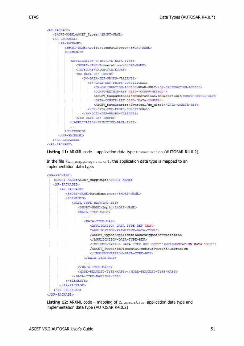
ETAS Data Types (AUTOSAR R4.0.*)
ASCET V6.2 AUTOSAR User’s Guide 51
Listing 11: ARXML code – application data type Enumeration (AUTOSAR R4.0.2)
In the file Swc_mappings.arxml, the application data type is mapped to an
implementation data type:
Listing 12: ARXML code – mapping of Enumeration application data type and
implementation data type (AUTOSAR R4.0.2)

ETAS Data Types (AUTOSAR R4.0.*)
ASCET V6.2 AUTOSAR User’s Guide 52
The referenced implementation data type is not a platform type, i.e. it appears in the
Swc_impltypes.arxml file.
Listing 13: ARXML code – implementation data type Enumeration (AUTOSAR R4.0.2)
The implementation data type references the sint8 platform type; see Listing 9 on page
49.
The sint8 platform type references the sint8 base type; see Listing 10 on page 50.
5.6.3 Record Type (Complex Types)
The following application data type is defined in Swc_appltypes.arxml for the record
Record from section 4.4.1, Record Types, on page 39:

ETAS Data Types (AUTOSAR R4.0.*)
ASCET V6.2 AUTOSAR User’s Guide 53
Listing 14: ARXML code – application data type Record_Impl (AUTOSAR R4.0.2)
In the file Swc_mappings.arxml, the application data type Record_Impl is mapped to
an implementation data type:
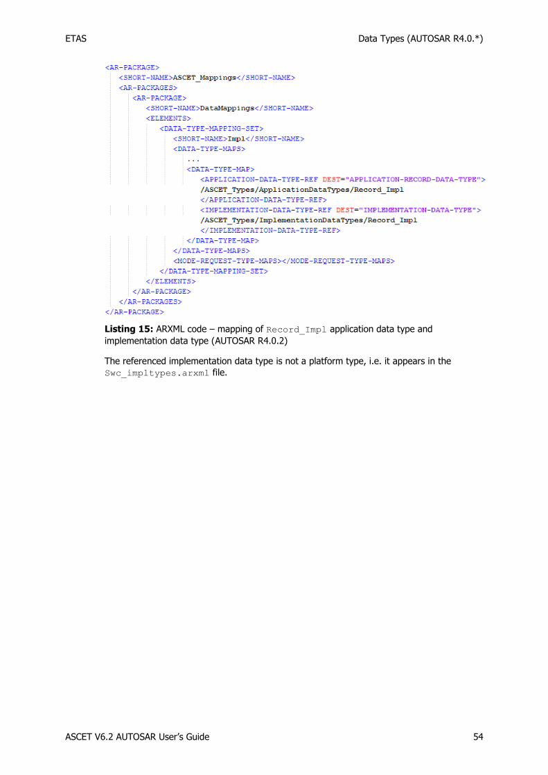
ETAS Data Types (AUTOSAR R4.0.*)
ASCET V6.2 AUTOSAR User’s Guide 54
Listing 15: ARXML code – mapping of Record_Impl application data type and
implementation data type (AUTOSAR R4.0.2)
The referenced implementation data type is not a platform type, i.e. it appears in the
Swc_impltypes.arxml file.

ETAS Data Types (AUTOSAR R4.0.*)
ASCET V6.2 AUTOSAR User’s Guide 55
Listing 16: ARXML code – implementation data type Record_Impl (AUTOSAR R4.0.2)
The implementation data type Record_impl references two platform types, one for each
record element. In the AUTOSAR_MOD_PlatformTypes.arxml file, the referenced
implementation data types look as follows:

ETAS Data Types (AUTOSAR R4.0.*)
ASCET V6.2 AUTOSAR User’s Guide 56
Listing 17: ARXML code – platform data type Boolean (AUTOSAR R4.0.2)

ETAS Data Types (AUTOSAR R4.0.*)
ASCET V6.2 AUTOSAR User’s Guide 57
Listing 18: ARXML code – platform data type uint16 (AUTOSAR R4.0.2)
The base types boolean and uint16, referenced in Listing 17 and Listing 18, are provided
in the AUTOSAR_MOD_PlatformBaseTypes_TC1796.arxml file:

ETAS Data Types (AUTOSAR R4.0.*)
ASCET V6.2 AUTOSAR User’s Guide 58
Listing 19: ARXML code – base types boolean and uint16 (AUTOSAR R4.0.2)
5.6.4 Array Type (Complex Types)
The following application data type is defined in Swc_appltypes.arxml for the array
array from section 4.4.2, Array Types, on page 43:

ETAS Data Types (AUTOSAR R4.0.*)
ASCET V6.2 AUTOSAR User’s Guide 59
Listing 20: ARXML code – application data type UInt8_16 of category ARRAY (AUTOSAR
R4.0.2)
In the Swc_mappings.arxml file, the application data type is mapped to an
implementation data type:

ETAS Data Types (AUTOSAR R4.0.*)
ASCET V6.2 AUTOSAR User’s Guide 60
Listing 21: ARXML code – mapping of UInt8_16 application data type and implementation
data type (AUTOSAR R4.0.2)
The referenced implementation data type is not a platform type, i.e. it appears in the
Swc_impltypes.arxml file.
Listing 22: ARXML code – implementation data type Record_Impl (AUTOSAR R4.0.2)
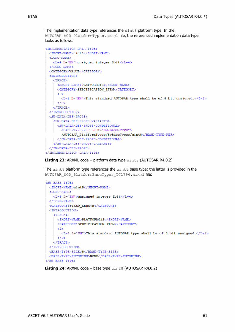
ETAS Data Types (AUTOSAR R4.0.*)
ASCET V6.2 AUTOSAR User’s Guide 61
The implementation data type references the uint8 platform type. In the
AUTOSAR_MOD_PlatformTypes.arxml file, the referenced implementation data type
looks as follows:
Listing 23: ARXML code – platform data type uint8 (AUTOSAR R4.0.2)
The uint8 platform type references the uint8 base type; the latter is provided in the
AUTOSAR_MOD_PlatformBaseTypes_TC1796.arxml file:
Listing 24: ARXML code – base type uint8 (AUTOSAR R4.0.2)
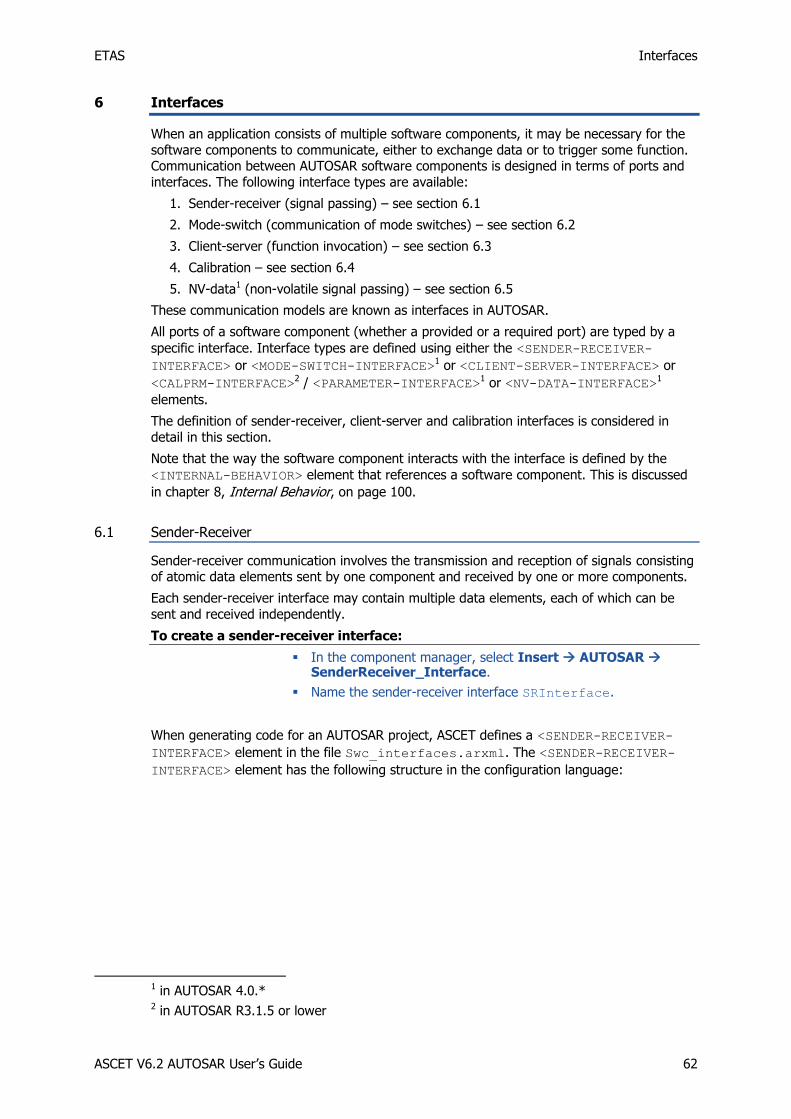
ETAS Interfaces
ASCET V6.2 AUTOSAR User’s Guide 62
6 Interfaces
When an application consists of multiple software components, it may be necessary for the
software components to communicate, either to exchange data or to trigger some function. Communication between AUTOSAR software components is designed in terms of ports and
interfaces. The following interface types are available:
1. Sender-receiver (signal passing) – see section 6.1
2. Mode-switch (communication of mode switches) – see section 6.2
3. Client-server (function invocation) – see section 6.3
4. Calibration – see section 6.4
5. NV-data1 (non-volatile signal passing) – see section 6.5
These communication models are known as interfaces in AUTOSAR.
All ports of a software component (whether a provided or a required port) are typed by a
specific interface. Interface types are defined using either the <SENDER-RECEIVER-
INTERFACE> or <MODE-SWITCH-INTERFACE>1 or <CLIENT-SERVER-INTERFACE> or
<CALPRM-INTERFACE>2 / <PARAMETER-INTERFACE>1 or <NV-DATA-INTERFACE>1
elements.
The definition of sender-receiver, client-server and calibration interfaces is considered in
detail in this section.
Note that the way the software component interacts with the interface is defined by the
<INTERNAL-BEHAVIOR> element that references a software component. This is discussed
in chapter 8, Internal Behavior, on page 100.
6.1 Sender-Receiver
Sender-receiver communication involves the transmission and reception of signals consisting of atomic data elements sent by one component and received by one or more components.
Each sender-receiver interface may contain multiple data elements, each of which can be
sent and received independently.
To create a sender-receiver interface:
In the component manager, select Insert AUTOSAR SenderReceiver_Interface.
Name the sender-receiver interface SRInterface.
When generating code for an AUTOSAR project, ASCET defines a <SENDER-RECEIVER-
INTERFACE> element in the file Swc_interfaces.arxml. The <SENDER-RECEIVER-
INTERFACE> element has the following structure in the configuration language:
1 in AUTOSAR 4.0.* 2 in AUTOSAR R3.1.5 or lower

ETAS Interfaces
ASCET V6.2 AUTOSAR User’s Guide 63
Listing 25: ARXML code – sender-receiver interface definition (AUTOSAR R3.1.2)
Listing 26: ARXML code – sender-receiver interface definition (AUTOSAR R4.0.*)
The name of the sender-receiver interface definition is given by the <SHORT-NAME>. The
name is used within other elements that need to reference the interface type, for example a
software component may specify that it uses sender-receiver interface SRInterface.
The short-name of a sender-receiver interface should be a valid C identifier.

ETAS Interfaces
ASCET V6.2 AUTOSAR User’s Guide 64
A sender-receiver interface can be used to communicate data (using data element
prototypes within the <DATA-ELEMENTS> element) or modes (see section 6.2, Mode , on
page 67 for more details).
Note
In AUTOSAR R3.1.5 or lower, a sender-receiver interface can contain zero or more data elements and/or zero or more mode groups. However, it is good practice to separate interfaces used for data transfer and interfaces used for mode management.
In AUTOSAR R4.0.*, a sender-receiver interface must contain either data elements or a single mode group. If a sender-receiver interface contains both kinds of elements, an error is issued during code generation.
6.1.1 Data Element Prototypes
Each sender-receiver interface can specify zero or more data elements that constitute the
AUTOSAR signals communicated over the interface. Each data item defines a prototype of a
specific type and can be a primitive data type, a RECORD or an ARRAY type. See chapter 4,
Data Types, on page 33 for details of defining data types.
To create a data element in ASCET:
In the component manager, double-click on SRInterface.
The "Sender Receiver Interface Editor for: SRInterface" editor opens.
Use the Signed Discrete Variable button to create an sdisc variable.
The "Properties for Scalar Element: sdisc" dialog window opens.
Name the signed discrete variable Speed.
Figure 17: Data element Speed for the sender-receiver interface SRInterface
To create an implementation of a data element:
In the "Sender Receiver Interface Editor for: SRInterface" editor, go to the Implementation tab.
In the Implementation tab, double-click the Speed element.
The "Implementation for: Speed" window opens.
In the "Master" field, activate Implementation.
In the "Implementation" field, select sint16.
Right-click in the "Min" and "Max" fields and select Default Value from the context menu.
Close the "Implementation for: sdisc" window with OK.

ETAS Interfaces
ASCET V6.2 AUTOSAR User’s Guide 65
The Implementation tab of the "Sender Receiver Interface Editor for: SRInterface" editor shall look like the figure below.
Figure 18: Implementation Impl of the sender-receiver interface SRInterface with data
element Speed
An implementation of a sender-receiver interface in ASCET corresponds to a sender-receiver interface in AUTOSAR. The sender-receiver interface in configuration language is generated
by ASCET in the file Swc_interfaces.arxml.
In AUTOSAR R3.1.5 or lower, the declaration of data elements within a sender-receiver interface definition has the following structure:
Listing 27: ARXML code - declaration of data elements within sender-receiver interface (AUTOSAR R3.1.2)
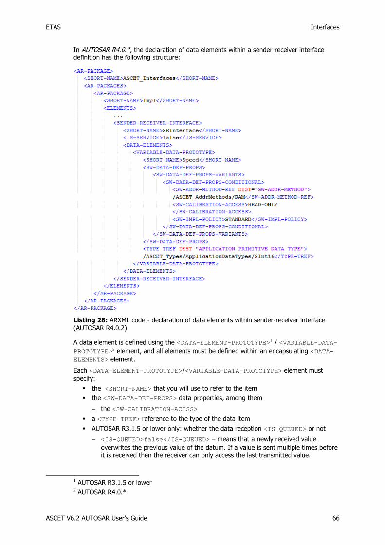
ETAS Interfaces
ASCET V6.2 AUTOSAR User’s Guide 66
In AUTOSAR R4.0.*, the declaration of data elements within a sender-receiver interface definition has the following structure:
Listing 28: ARXML code - declaration of data elements within sender-receiver interface (AUTOSAR R4.0.2)
A data element is defined using the <DATA-ELEMENT-PROTOTYPE>1 / <VARIABLE-DATA-
PROTOTYPE>2 element, and all elements must be defined within an encapsulating <DATA-
ELEMENTS> element.
Each <DATA-ELEMENT-PROTOTYPE>/<VARIABLE-DATA-PROTOTYPE> element must
specify:
the <SHORT-NAME> that you will use to refer to the item
the <SW-DATA-DEF-PROPS> data properties, among them
the <SW-CALIBRATION-ACESS>
a <TYPE-TREF> reference to the type of the data item
AUTOSAR R3.1.5 or lower only: whether the data reception <IS-QUEUED> or not
<IS-QUEUED>false</IS-QUEUED> – means that a newly received value
overwrites the previous value of the datum. If a value is sent multiple times before
it is received then the receiver can only access the last transmitted value.
1 AUTOSAR R3.1.5 or lower 2 AUTOSAR R4.0.*

ETAS Interfaces
ASCET V6.2 AUTOSAR User’s Guide 67
<IS-QUEUED>true</IS-QUEUED> – means that the sender-receiver interface
queues arrivals of the datum on the receiver side.
Note
Queued communication can currently not be modeled in ASCET V6.2. It is possible, however, to use queued communication by means of ASCET C code components.
6.2 Mode Switch
An AUTOSAR system can be configured to operate in one or more application modes. A mode-switch interface can specify zero or more mode groups that define application modes.
In ASCET, mode-switch interfaces are realized as sender-receiver interface components that
contain mode groups.
In AUTOSAR R3.1.5 or lower, a sender-receiver interface that contains a mode group can also contain data elements. However, it is strongly recommended to add either data
elements or mode groups to a single sender-receiver interface.
Beginning with AUTOSAR R4.0, a sender-receiver interface that contains a mode group must not contain data elements, and vice versa. Mixing both kinds of elements leads to a code
generation error.
To create a mode group:
In the component manager, select Insert AUTOSAR Mode Group.
Name the mode group OnOffMode.
In the "1 Database" or "1 Workspace" pane, select OnOffMode and go to the "3 Contents" pane.
Select Mode Rename to rename the label mode as off.
Select Mode Add Mode As Last to create a new mode on.
Figure 19: Mode declaration group OnOffMode

ETAS Interfaces
ASCET V6.2 AUTOSAR User’s Guide 68
In AUTOSAR R3.1.5 or lower, ASCET declares the <MODE-DECLARATION-GROUP> in the
autosar_types.arxml file, AUTOSAR package ASCET_types.
Listing 29: ARXML code for a mode declaration group (AUTOSAR R3.1.2)
In AUTOSAR R4.0.*, ASCET declares the <MODE-DECLARATION-GROUP> in the <swc
name>_appltypes.arxml file, AUTOSAR package ASCET_types, sub-package
ApplicationDataTypes.
Listing 30: ARXML code for a mode declaration group (AUTOSAR R4.0.2)

ETAS Interfaces
ASCET V6.2 AUTOSAR User’s Guide 69
To create a mode-switch interface:
Note
AUTOSAR R3.1.5 or lower allows more than one mode group per interface.
AUTOSAR R4.0.* allows only one mode group per interface.
In the component manager, select Insert AUTOSAR SenderReceiver Interface.
Name the sender-receiver interface ModeInterface.
Double-click on ModeInterface.
The "Sender Receiver Interface Editor for: ModeInterface" editor opens.
Select Insert Component.
The "Select Item" window opens.
Figure 20: Selection of the mode group OnOffMode
In the "1 Database" or "1 Workspace" field of the "Select Item" window, select the mode group OnOffMode.
Click OK to close the "Select Item" window and insert OnOffMode into ModeInterface.
The "Properties for Element: OnOffMode" window opens. You can enter a name and a comment for the OnOffMode instance.
Click OK to use the default name and comment.
Figure 21: Mode-switch interface ModeInterface

ETAS Interfaces
ASCET V6.2 AUTOSAR User’s Guide 70
In AUTOSAR R3.1.5 or lower, the declaration of mode groups within a mode-switch interface (i.e. a sender-receiver interface that contains a mode group) definition has the following
structure:
Listing 31: ARXML code - declaration of mode group within sender-receiver interface
(AUTOSAR R3.1.2)
In AUTOSAR R4.0.*, the declaration of the mode group within a mode-switch interface definition has the following structure:
Listing 32: ARXML code – declaration of mode group within mode-switch interface (AUTOSAR R4.0.2)
In AUTOSAR R3.1.5 or lower, a mode group is defined using the <MODE-DECLARATION-
GROUP-PROTOTYPE> element, and all elements must be defined within an encapsulating
<MODE-GROUPS> element.
In AUTOSAR R4.0.*, a mode group is defined using the <MODE-GROUP> element.
Each <MODE-DECLARATION-GROUP-PROTOTYPE> / <MODE-GROUP> element must specify:
the <SHORT-NAME> that you will use to refer to the item
the <TYPE-TREF> reference to mode declaration group
The use of mode declaration prototypes within sender-receiver interfaces is considered in
detail in chapter 9, Modes, on page 134.
6.3 Client-Server
Client-server communication involves a component invoking a defined "server" function in another component, which may or may not return a reply. Each client-server interface can
contain multiple operations, each of which can be invoked separately.
To create a client-server interface:
In the component manager, select Insert AUTOSAR ClientServer_Interface.
Name the client-server interface CSInterface.
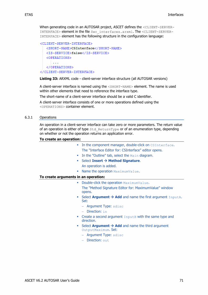
ETAS Interfaces
ASCET V6.2 AUTOSAR User’s Guide 71
When generating code in an AUTOSAR project, ASCET defines the <CLIENT-SERVER-
INTERFACE> element in the file Swc_interfaces.arxml. The <CLIENT-SERVER-
INTERFACE> element has the following structure in the configuration language:
Listing 33: ARXML code - client-server interface structure (all AUTOSAR versions)
A client-server interface is named using the <SHORT-NAME> element. The name is used
within other elements that need to reference the interface type.
The short-name of a client-server interface should be a valid C identifier.
A client-server interface consists of one or more operations defined using the
<OPERATIONS> container element.
6.3.1 Operations
An operation in a client-server interface can take zero or more parameters. The return value
of an operation is either of type Std_ReturnType or of an enumeration type, depending
on whether or not the operation returns an application error.
To create an operation:
In the component manager, double-click on CSInterface.
The "Interface Editor for: CSInterface" editor opens.
In the "Outline" tab, select the Main diagram.
Select Insert Method Signature.
An operation is added.
Name the operation MaximumValue.
To create arguments in an operation:
Double-click the operation MaximumValue.
The "Method Signature Editor for: MaximumValue" window opens.
Select Argument Add and name the first argument InputA. Set:
Argument Type: sdisc
Direction: in
Create a second argument InputB with the same type and direction.
Select Argument Add and name the third argument OutputMaximum. Set:
Argument Type: sdisc
Direction: out

ETAS Interfaces
ASCET V6.2 AUTOSAR User’s Guide 72
Figure 22: Arguments of the operation MaximumValue
Click OK.
ASCET represents the client-server interface CSInterface with operation MaximumValue and arguments InputA, InputB and OutputMaximum as follows.
Figure 23: Operation MaximumValue for the client-server interface CSInterface
To create an implementation of an operation:
In the "Interface Editor for: CSInterface" editor, go to the "Implementation" tab.
In the "Implementation" tab, double-click the InputA element.
The "Implementation for: InputA" window opens.

ETAS Interfaces
ASCET V6.2 AUTOSAR User’s Guide 73
In the "Master" field, activate Implementation.
In the "Implementation" field, select sint16.
Right-click in the "Min" and "Max" fields and select Default Value from the context menu.
Close the "Implementation for: InputA" window with OK.
Repeat the implementation procedure for the arguments InputB and OutputMaximum.
Figure 24: Implementation of the operation MaximumValue
An implementation of a client-server interface in ASCET corresponds to a client-server
interface in AUTOSAR. The client-server interface in configuration language is generated by
ASCET in the Swc_interfaces.arxml file. The <OPERATIONS> element encapsulates
one or more <OPERATION-PROTOTYPE>1 / <CLIENT-SERVER-OPERATION>2 elements,
each of which defines a single operation in the client-server interface.
1 AUTOSAR R3.1.5 or lower 2 AUTOSAR R4.0.*

ETAS Interfaces
ASCET V6.2 AUTOSAR User’s Guide 74
Listing 34: ARXML code – operation in a client-server interface (AUTOSAR R3.1.2)
Listing 35: ARXML code – operation in a client-server interface (AUTOSAR R4.0.2)

ETAS Interfaces
ASCET V6.2 AUTOSAR User’s Guide 75
Each operation is named using the <SHORT-NAME> element. The name specified here will
form part of the name used by the RTE to refer to the operation in your code.
The <ARGUMENTS> element encapsulates one or more <ARGUMENT-PROTOTYPE>1 /
<ARGUMENT-DATA-PROTOTYPE>2 elements that define each argument (parameter) of the
operation.
Each <ARGUMENT-PROTOTYPE>/<ARGUMENT-DATA-PROTOTYPE> definition must define:
the <SHORT-NAME> of the parameter
a <TYPE-TREF> reference to the type of the parameter. The referenced type must correspond to a defined type – see chapter 4, Data Types, on page 33
the <DIRECTION> of the parameter as "IN" (read only), "OUT" (write only) or "INOUT" (readable and writable by the component)
If nothing else is specified, operations in client-server interfaces return the RTE standard
return type Std_ReturnType. It is also possible to return an application error. This is done
by selecting a previously defined ASCET enumeration that contains all possible errors.
To create an enumeration with the possible errors in an application error:
In the component manager, select Insert Enumeration or click on the Enumeration button.
Name the enumeration ApplicationError.
Select the enumeration and switch to the "Contents" pane.
In the "Contents" pane, select the enumerator.
Select Enumeration Rename and set the label to E_NOT_OK.
Double-click on the value 0.
Set the value to a number in the range 2..63.
Note
The value range for application errors is [2..63]. If the ASCET enumeration for the application errors contains a value less than 2 or larger than 63, an error is issued during code generation.
To assign an application error to the return value of an operation:
In the component manager, choose the client-server interface CSInterface and select Edit Open Component or double-click on CSInterface.
The "Interface Editor for: CSInterface" editor opens.
Create another operation (see page 71) and name it Notification.
1 AUTOSAR R3.1.5 or lower 2 AUTOSAR R4.0.*

ETAS Interfaces
ASCET V6.2 AUTOSAR User’s Guide 76
Double-clik the operation Notification. The "Method Signature Editor for: Notification" window opens.
Go to the "Return" tab and open the "Return Type" combo box.
Figure 25: Return type for the operation Notification
Select <enumeration>.
The "Choose a enumeration type…" window opens.
Select the enumeration ApplicationError.
Click OK to close the "Choose a enumeration type…" window.
Click OK to close the "Method Signature Editor for: Notification" window.

ETAS Interfaces
ASCET V6.2 AUTOSAR User’s Guide 77
The operation Notification and the possible application errors in configuration language
are generated by ASCET in the Swc_interfaces.arxml file:
Listing 36: ARXML code - operation with possible application errors (AUTOSAR R3.1.2)

ETAS Interfaces
ASCET V6.2 AUTOSAR User’s Guide 78
Listing 37: ARXML code - operation with possible application errors (AUTOSAR R4.0.2)
Note
Application errors are coded in the least significant 6 bits of Std_ReturnType. The
value range for application errors is [2..63]. If the ASCET enumeration for the application errors contains a value less than 2 or larger than 63, an error is issued during code generation.
6.4 Calibration
Calibration interfaces are used for communication with Calibration components. Calibration
components are a kind of software component, which uniquely consist of calibration information (parameters and characteristics).
Each calibration interface can contain multiple calibration parameters. A port of a software
component that requires an AUTOSAR calibration interface can independently access any of the parameters defined in the interface by making an RTE API to the required port.
Calibration components provide the calibration interface and thus provide implementations of the calibration parameters.
To create a calibration interface:
In the component manager, select Insert AUTOSAR Calibration Interface.
Name the calibration interface CalInterface.

ETAS Interfaces
ASCET V6.2 AUTOSAR User’s Guide 79
When generating code for an AUTOSAR project, ASCET defines a <CALPRM-INTERFACE>1 /
<PARAMETER-INTERFACE>2 element in the file Swc_interfaces.arxml. The <CALPRM-
INTERFACE>/<PARAMETER-INTERFACE> element has the following structure in the
configuration language:
Listing 38: ARXML code - calibration interface structure (AUTOSAR R3.1.2)
Listing 39: ARXML code - calibration interface structure (AUTOSAR R4.0.2)
A calibration interface is named using the <SHORT-NAME> element. The name is used within
other elements that need to reference the interface type.
The short-name of a calibration interface should be a valid C identifier.
A calibration interface consists of one or more calibration elements defined using the
<CALPRM-ELEMENTS>1 / <PARAMETER-DATA-PROTOTYPE>2 container element.
6.4.1 Calibration Parameters
To create a calibration parameter:
In the component manager, double-click on CalInterface.
The "Calibration Interface Editor for: CalInterface" editor opens.
Use the Logic Parameter button to create a logic parameter.
The dialog "Properties for Scalar Element: log" window opens.
Name the parameter CalParam1.
Create another logic parameter and name it CalParam2.
"Use the Unsigned Discrete Parameter" button to create an unsigned discrete parameter.
1 AUTOSAR R3.1.5 or lower 2 AUTOSAR R4.0.*

ETAS Interfaces
ASCET V6.2 AUTOSAR User’s Guide 80
The "Properties for Scalar Element: udisc" window opens.
Name the parameter CalParam3.
To create an implementation of a calibration parameter:
In the "Calibration Interface Editor for: CalInterface" editor, go to the "Implementation" tab.
In the "Implementation" tab, double-click the CalParam3 element.
The "Implementation for: CalParam3" dialog opens.
In the "Master" area, activate Model.
In the "Model" area, enter the value 24 in the "Max" field.
Click OK.
The Implementation tab of the "Calibration Interface Editor for: CalInterface" editor shall look like the figure below.
Figure 26: Implementation Impl of the calibration interface CalInterface
An implementation of a calibration interface in ASCET corresponds to a calibration interface
in AUTOSAR. The calibration interface in configuration language is generated by ASCET in
the Swc_interfaces.arxml file. The declaration of calibration elements within a
calibration interface definition has the following structure:

ETAS Interfaces
ASCET V6.2 AUTOSAR User’s Guide 81
Listing 40: ARXML code - declaration of calibration elements within a calibration interface
definition (AUTOSAR R3.1.2)
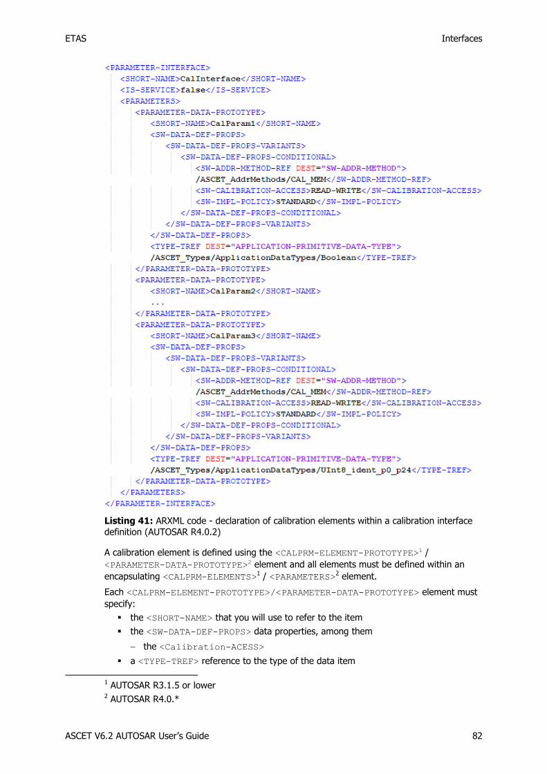
ETAS Interfaces
ASCET V6.2 AUTOSAR User’s Guide 82
Listing 41: ARXML code - declaration of calibration elements within a calibration interface
definition (AUTOSAR R4.0.2)
A calibration element is defined using the <CALPRM-ELEMENT-PROTOTYPE>1 /
<PARAMETER-DATA-PROTOTYPE>2 element and all elements must be defined within an
encapsulating <CALPRM-ELEMENTS>1 / <PARAMETERS>2 element.
Each <CALPRM-ELEMENT-PROTOTYPE>/<PARAMETER-DATA-PROTOTYPE> element must
specify:
the <SHORT-NAME> that you will use to refer to the item
the <SW-DATA-DEF-PROPS> data properties, among them
the <Calibration-ACESS>
a <TYPE-TREF> reference to the type of the data item
1 AUTOSAR R3.1.5 or lower 2 AUTOSAR R4.0.*

ETAS Interfaces
ASCET V6.2 AUTOSAR User’s Guide 83
6.5 NVData (AUTOSAR R4.0.* only)
AUTOSAR R4.0 introduced the <NV-DATA-INTERFACE> element, which defines an
interface used by an Nv-block software component type (see …).
Note
NVData interfaces cannot be used in ASCET projects that use AUTOSAR R3.1.5 or lower. If you try, an error message is issued during code generation.
Each NVData interface may contain multiple NVData elements, which can be sent and
received independently.
To create an NVData interface:
Create a project named R4_project (page 23) and set the code generation settings for AUTOSAR R4.0.2 (page 23).
Create a software component named SWC (page 26) and insert it into R4_project (page 26).
Open R4_project, then open SWC.
In the component manager, select Insert AUTOSAR NVData Interface.
Name the NVData interface NVData_Interface.
Insert NVData_Interface into SWC.
When generating code for an AUTOSAR project, ASCET defines an <NVDATA-INTERFACE>
element in the file Swc_interfaces.arxml. The <NVDATA-INTERFACE> element has
the following structure in the configuration language:
Listing 42: ARXML code - calibration interface structure (AUTOSAR R4.0.2)
The name of the NVData interface definition is given by the <SHORT-NAME> element. The
name is used within other elements that need to reference the interface type, for example a
software component may specify that it uses NVData interface NVData_interface.
The short-name of an NVData interface should be a valid C identifier.
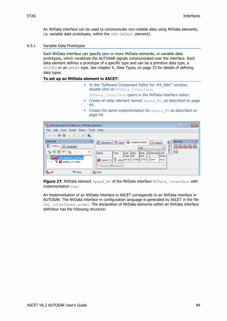
ETAS Interfaces
ASCET V6.2 AUTOSAR User’s Guide 84
An NVData interface can be used to communicate non-volatile data using NVData elements,
i.e. variable data prototypes, within the <NV-DATAS> element).
6.5.1 Variable Data Prototypes
Each NVData interface can specify zero or more NVData elements, or variable data
prototypes, which constitute the AUTOSAR signals communicated over the interface. Each
data element defines a prototype of a specific type and can be a primitive data type, a
RECORD or an ARRAY type. See chapter 4, Data Types, on page 33 for details of defining
data types.
To set up an NVData element in ASCET:
In the "Software Component Editor for: R4_SWC" window, double-click on NVData_Interface.
NVData_Interface opens in the NVData interface editor.
Create an sdisc element named Speed_NV, as described on page 64.
Create the same implementation for Speed_NV as described on page 64.
Figure 27: NVData element Speed_NV of the NVData interface NVData_Interface with
implementation Impl
An implementation of an NVData interface in ASCET corresponds to an NVData interface in
AUTOSAR. The NVData interface in configuration language is generated by ASCET in the file
Swc_interfaces.arxml. The declaration of NVData elements within an NVData interface
definition has the following structure:
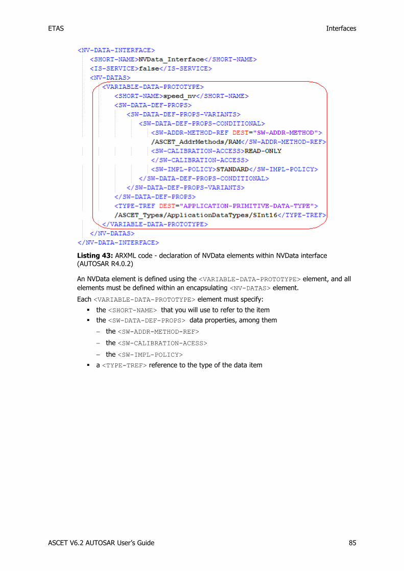
ETAS Interfaces
ASCET V6.2 AUTOSAR User’s Guide 85
Listing 43: ARXML code - declaration of NVData elements within NVData interface (AUTOSAR R4.0.2)
An NVData element is defined using the <VARIABLE-DATA-PROTOTYPE> element, and all
elements must be defined within an encapsulating <NV-DATAS> element.
Each <VARIABLE-DATA-PROTOTYPE> element must specify:
the <SHORT-NAME> that you will use to refer to the item
the <SW-DATA-DEF-PROPS> data properties, among them
the <SW-ADDR-METHOD-REF>
the <SW-CALIBRATION-ACESS>
the <SW-IMPL-POLICY>
a <TYPE-TREF> reference to the type of the data item

ETAS Software Component Types
ASCET V6.2 AUTOSAR User’s Guide 86
7 Software Component Types
A software component is the atomic software unit of application in AUTOSAR. Software
components interact through ports, which are typed interfaces. The interfaces control what can be communicated and the semantics of the communication.
To create an AUTOSAR software component:
In the component manager, select Insert AUTOSAR Software Component.
Name the software component Swc.
Follow the steps described in section 3.1.2, Code Generation Settings for AUTOSAR, on page 22 to create an AUTOSAR project ARProject and set the AUTOSAR code generation settings.
Insert the software component Swc in the project, as described on page 26.
To open a software component in an AUTOSAR project:
In the component manager, double-click the ARProject project.
The project editor window opens.
In the "Outline" tab of the project editor, double-click the Swc software component.
The software component editor window opens.
Each software component must have its component type declared in the RTE generator's
configuration. The component type makes the component available for composition into a
larger software system. An application software component type is defined using the
<APPLICATION-SOFTWARE-COMPONENT-TYPE> element in the <swc name>.arxml file.
Listing 44: ARXML code – definition of application software component type (AUTOSAR R3.1.2)
Listing 45: ARXML code – definition of application software component type (AUTOSAR
R4.0.2)
The software component type must be named using the <SHORT-NAME> element. The
name must be system-wide unique; it is used within other elements to reference the
software component type.
The short-name of a software-component should be a valid C identifier.

ETAS Software Component Types
ASCET V6.2 AUTOSAR User’s Guide 87
7.1 Ports
Ports provide the software component access to the interface. There are two classes of
ports: provided ports (Pports) and required ports (Rports).
The ports of a software component are defined within the <PORTS> element.
Listing 46: ARXML code – port definition structure (all AUTOSAR versions)
Within the <PORTS> element, the <P-PORT-PROTOTYPE> and the <R-PORT-PROTOTYPE>
elements are used to define provided and required ports respectively. When two components communicate then typically both provided and required ports reference the
same interface definition. This guarantees that they are compatible.
7.1.1 Provided Ports A
Pports are used by a software component to provide data or services to other software
components. Provided ports implement senders and servers.
To create a sender port:
In the "Software Component Editor for: Swc", select Insert Component.
The "Select item…" window opens.
In the "1 Database" or "1 Workspace" field of the "Select Item" window, select the interface SRInterface and click OK.
Figure 28: Selection of the item SRInterface
The "Properties for complex element: SRInterface" window open.
Name the Port Sender, activate Provided in the "Internal Access" area and click OK.

ETAS Software Component Types
ASCET V6.2 AUTOSAR User’s Guide 88
Figure 29: Provided port Sender of type SRInterface
Drag the element Sender::SRInterface from the "Outline" tab and drop it on the drawing area of the software component editor.
The Pport Sender with element Speed appears in the drawing area as follows.
Figure 30: Pport Sender in the drawing area of the software component editor

ETAS Software Component Types
ASCET V6.2 AUTOSAR User’s Guide 89
A provided port within a software component type definition is named using the <SHORT-
NAME> element. The name is used within other elements to reference the software
component type. The short-name of a provided port must be a valid C identifier.
Each provided port definition must specify the interface type over which it will communicate
with other ports. This is done in the <swc name>.arxml file, using the <PROVIDED-
INTERFACE-TREF> element. This <PROVIDED-INTERFACE-TREF> element must identify
the required interface.
Listing 47: ARXML code – provided port Sender definition (AUTOSAR R3.1.2)
In addition, AUTOSAR R4.0.* requires the <PROVIDED-COM-SPECS> element that contains
details about individual data elements, e.g.,
<DATA-ELEMENT-REF> - which identifies the data element,
<INIT-VALUE> - which specifies the initial value of the data element,
and others.

ETAS Software Component Types
ASCET V6.2 AUTOSAR User’s Guide 90
Listing 48: ARXML code – provided port Sender definition (AUTOSAR R4.0.2)
To create a server port:
In the "Software Component Editor for: Swc", select Insert Component.
The "Select item…" window opens.
In the "1 Database" or "1 Workspace" field of the "Select Item" window, select the interface CSInterface and click OK.
The "Properties for complex element: CSInterface" opens.
Name the Port "Server", activate Provided in the "Internal Access" area and click OK.

ETAS Software Component Types
ASCET V6.2 AUTOSAR User’s Guide 91
Figure 31: Provided port Server of type CSInterface
Then, ASCET creates the following items:
a server node named Server::CSInterface under the folder "Realized Interfaces",
a diagram Server_CSInterface, and
a server runnable for each operation in the client-server interface CSInterface. In the screenshot below, ASCET creates the runnables Server_MaximumValue and Server_Notification.

ETAS Software Component Types
ASCET V6.2 AUTOSAR User’s Guide 92
Figure 32: Pport Server in the "Outline" tab of the software component Swc
The entry function of the server runnable has a return type of void or Std_ReturnType,
depending on whether or not the server returns an application error.
The provided port must specify the interface type over which it will communicate with other
ports using the <PROVIDED-INTERFACE-TREF>. This <PROVIDED-INTERFACE-TREF>
element must identify the required interface.
Listing 49: ARXML code – provided port Server definition (all AUTOSAR versions)
Furthermore, ASCET provides additional information to the internal behavior of the software
component Swc. On the one hand, one operation-invoked event is created for each
operation in the server port. On the other hand, a runnable entity is created for each
operation in the server port. Refer to chapter 8, Internal Behavior, on page 100 for more detailed information.
Note
A client-server interface might be edited once a server is inserted in a software component. In this case, the user must update the server interface in the software component using the menu option Build Update Interfaces.
7.1.2 Required Ports
Rports are used by a software component to require data or services from other software
components. Required ports implement receivers and clients.
The definition of a required port is identical to that of a provided port, with the exception
that the <R-PORT-PROTOTYPE> element is used.

ETAS Software Component Types
ASCET V6.2 AUTOSAR User’s Guide 93
To create a receiver port:
In the "Software Component Editor for: Swc", select Insert Component.
The "Select item…" window opens.
In the "1 Database" or "1 Workspace" field of the "Select Item" window, select the interface SRInterface and click OK.
The "Properties for complex element: SRInterface" window opens.
Name the Port Receiver, activate "Required" in the "Internal Access" area and click OK.
Figure 33: Required port Receiver of type SRInterface
Drag the element Receiver::SRInterface from the "Outline" tab and drop it on the drawing area of the software component editor.
The Rport Receiver with element Speed appears in the drawing area as follows.

ETAS Software Component Types
ASCET V6.2 AUTOSAR User’s Guide 94
Figure 34: Rport Receiver in the drawing area of the software component editor
A required port within a software component type definition is named using the <SHORT-
NAME> element. The name is used within other elements to reference the software
component type. The short-name of a required port must be a valid C identifier.
The required port definition must reference an interface definition defined using the
<REQUIRED-INTERFACE-TREF> element:
Listing 50: ARXML code – required port Receiver definition (AUTOSAR R3.1.2)
In addition, AUTOSAR R4.0.* requires the <REQUIRED-COM-SPECS> element that contains
details about individual data elements, e.g.,
<DATA-ELEMENT-REF> - which identifies the data element,
<INIT-VALUE> - which specifies the initial value of the data element,
and others.
Listing 51: ARXML code – required port Receiver definition (AUTOSAR R4.0.2)

ETAS Software Component Types
ASCET V6.2 AUTOSAR User’s Guide 95
To create a client port:
In the "Software Component Editor for: Swc", select Insert Component.
The "Select item…" window opens.
In the "1 Database" or "1 Workspace" field of the "Select Item" window, select the interface CSInterface and click OK.
The "Properties for complex element: CSInterface" open.
Name the Port "Client", activate "Required" in the "Internal Access” area and click OK.
Figure 35: Required port Client of type CSInterface
Drag the element Client::CSInterface from the "Outline” tab and drop it on the drawing area of the software component editor.
If necessary, activate flexible layout for the interface CSInterface:
Go to the component manager.

ETAS Software Component Types
ASCET V6.2 AUTOSAR User’s Guide 96
In the "1 Database" or "1 Workspace" pane, right-click CSInterface and select Flexible Class Layout Activate from the context menu.
In the "Change Flexible Class Layout State" window, select CSInterface and click OK.
In the drawing area, right-click the Client port and select Ports Methods from the context menu.
The "Port Editor<CSInterface>" window opens.
Deactivate the method Notification and click OK.
Figure 36: Port editor window to select/deselect methods
Resize the Client block and reposition the pins.
The Rport Client with operation MaximumValue appears as follows (or similar) in the drawing area.
Figure 37: Rport Client in the drawing area of the software component editor
The required port definition must reference an interface definition defined using the
<REQUIRED-INTERFACE-TREF> element:
Listing 52: ARXML code – required port Client definition (all AUTOSAR versions)
To create a calibration port:
In the "Software Component Editor for: Swc", select Insert Component.
The "Select item…" window opens.
In the "1 Database" or "1 Workspace" field of the "Select Item" window, select the interface CalInterface and click OK.
The "Properties for complex element: CalInterface" window opens.

ETAS Software Component Types
ASCET V6.2 AUTOSAR User’s Guide 97
Name the Port Calibration and click OK.
The "Internal Access" is set to Required; it cannot be changed.
Drag the element Calibration::CalInterface from the "Outline" tab and drop it on the drawing area of the software component editor.
The Rport Receiver with elements CalParam1, CalParam2 and CalParam3 appears in the drawing area as follows.
Figure 38: Rport Calibration in the drawing area of the software component editor
The required port definition must reference an interface definition defined using the
<REQUIRED-INTERFACE-TREF> element:
Listing 53: ARXML code – required port Calibration definition (AUTOSAR R3.1.2)
In addition, AUTOSAR R4.0.* requires the <REQUIRED-COM-SPECS> element that contains
one <PARAMETER-REQUIRE-COM-SPEC> element for each parameter interface with details
about the respective parameter, e.g.,
<PARAMETER-REF> - which identifies the parameter,
<INIT-VALUE> - which specifies the initial value of the parameter,
and others.
Listing 54: ARXML code – required port Calibration definition (AUTOSAR R4.0.2)

ETAS Software Component Types
ASCET V6.2 AUTOSAR User’s Guide 98
To create an NVData port:
Note
NVData interfaces and ports are only available in AUTOSAR R4.0.*.
In the "Software Component Editor for: Swc", select Insert Component.
The "Select item…" window opens.
In the "1 Database" or "1 Workspace" field of the "Select Item" window, select the interface NVData_Interface and click OK.
The "Properties for complex element: NVData_Interface" window opens.
Name the Port NVData and click OK.
The "Internal Access" is set to Required; it cannot be changed.
Drag the element NVData::NVData_Interface from the "Outline" tab and drop it on the drawing area of the software component editor.
The Rport NVData with element Speed_NV appears in the drawing area as follows.
Figure 39: Rport NVData in the drawing area of the software component editor
AUTOSAR R4.0.* requires the <REQUIRED-COM-SPECS> element that contains one <NV-
REQUIRE-COM-SPEC> element for each NVData element with details about the respective
NVData element, e.g.,
<VARIABLE-REF> - which identifies the NVData element,
<INIT-VALUE> - which specifies the initial value of the NVData element,
and others.

ETAS Software Component Types
ASCET V6.2 AUTOSAR User’s Guide 99
Listing 55: ARXML code – required port NVData definition (AUTOSAR R4.0.2)

ETAS Internal Behavior
ASCET V6.2 AUTOSAR User’s Guide 100
8 Internal Behavior
The internal behavior of a software component defines how the code that implements the
component interacts with the ports. In this chapter you will see how to configure the internal behavior.
Internal behavior elements are used to define how the software component will interact with
the RTE at runtime. The internal behavior of a software component specifies:
The runnable entities that belong to the software component and how they interact (if at all) with the ports of the software component.
The events that cause runnable entities to be activated at runtime.
The interrunnable variables used for communication between the runnables of a software component.
The exclusive areas that exist so runnable entities can execute all or part of their code in mutual exclusion from other runnable entities.
Each internal behavior description is applicable to a single software component and therefore must reference the software component type to which it applies. In AUTOSAR
R3.1.5 or lower, the reference is established using the <COMPONENT-REF> element. In
AUTOSAR R4.0.*, the reference is established using the <DATA-TYPE-MAPPING-REF>
element.
Listing 56: ARXML code – internal behavior description for Swc (AUTOSAR R3.1.2)

ETAS Internal Behavior
ASCET V6.2 AUTOSAR User’s Guide 101
Listing 57: ARXML code – internal behavior description for Swc (AUTOSAR R4.0.2)
An internal behavior must be named using the <SHORT-NAME> element. The name is used
within other elements to reference the behavior. ASCET automatically names the internal
behavior of a software component with a prefix b followed by the name of the software
component.
The short-name of an internal behavior does not need to be a valid C identifier (but it must pass the syntactic checks enforced by the XML Schema).
The following sections first outline the basic framework for events and runnable entities
before showing how to configure the RTE to achieve different types of runnable entity/interface interaction.
8.1 Events
Events control how runnable entities are triggered by the generated RTE at runtime. ASCET V6.2 supports the following events:
TIMING-EVENT – activates a runnable entity periodically. The <TIMING-EVENT> allows you to execute a runnable entity to poll an Rport to check if data has been received, periodically call a server (i.e. be a client), periodically send data on a Pport or simply to execute some internal software component functionality. Runnable entities that are activated in response to a timing event are said to be time-triggered.
OPERATION-INVOKED-EVENT – activates a runnable entity to handle a server call for an operation on a provided port characterized by a client-server interface.
MODE-SWITCH-EVENT – activates a runnable entity on either entry to, or exit from an application mode.
The structure for specifying events is similar to the structure shown in Listing 58 and Listing
59. The actual sequence of events is determined by the event names.

ETAS Internal Behavior
ASCET V6.2 AUTOSAR User’s Guide 102
Listing 58: ARXML code – structure for event specification (AUTOSAR R3.1.2)
Listing 59: ARXML code – structure for event specification (AUTOSAR R4.0.2)
An event can be used to activate a runnable entity when the event occurs. An event
references the runnable entity that is to be activated when the event occurs.
8.1.1 Timing Events
A <TIMING-EVENT> is used to indicate that a runnable entity will be activated periodically
by the Operating System. The RTE generator will use this information to generate an
appropriate schedule table that must be ticked from application code.
To create a timing event:
In the "Software Component Editor for: Swc", go to the "Event Specification" tab.
Select Event Add Event and name the event Cyclic_10ms.
In the "Event Kind" combo box, select Timing.
In the "Period" field, enter a period of 0.01 seconds.
The timing event Cyclic_10ms appears in the "Event Specification" tab as follows.

ETAS Internal Behavior
ASCET V6.2 AUTOSAR User’s Guide 103
Figure 40: Definition of the timing event Cyclic_10ms
Note that ASCET enables the user to specify the modes in which this timing event shall be
activated. For the use of application modes refer to chapter 9, Modes, on page 134.
When the timing event is mapped to a runnable entity (see section 8.2, Runnable Entities, on page 107), then ASCET generates the <TIMING-EVENT> element in the configuration
language:
Listing 60: ARXML code – definition of a timing event (all AUTOSAR versions)
A timing event must be named using the <SHORT-NAME> element. The name is used within
other elements to reference the timing event. The short-name of a timing event does not
need to be a valid C identifier.
The <START-ON-EVENT-REF DEST="RUNNABLE-ENTITY"> element defines the runnable
entity that is to be activated when the event occurs. The <PERIOD> element specifies the
time raster in seconds to be used by the RTE generator.
8.1.2 Operation-Invoked Events
Operation-Invoked events are automatically inserted in an ASCET software component when you create a server port (see section 7.1.1, Provided Ports, on page 87 for how to create a
server port).
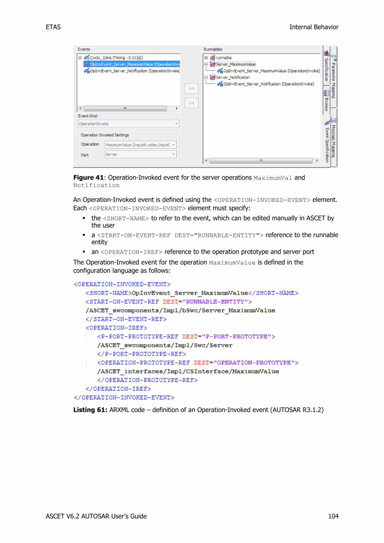
ETAS Internal Behavior
ASCET V6.2 AUTOSAR User’s Guide 104
Figure 41: Operation-Invoked event for the server operations MaximumVal and Notification
An Operation-Invoked event is defined using the <OPERATION-INVOKED-EVENT> element.
Each <OPERATION-INVOKED-EVENT> element must specify:
the <SHORT-NAME> to refer to the event, which can be edited manually in ASCET by the user
a <START-ON-EVENT-REF DEST="RUNNABLE-ENTITY"> reference to the runnable entity
an <OPERATION-IREF> reference to the operation prototype and server port
The Operation-Invoked event for the operation MaximumValue is defined in the
configuration language as follows:
Listing 61: ARXML code – definition of an Operation-Invoked event (AUTOSAR R3.1.2)

ETAS Internal Behavior
ASCET V6.2 AUTOSAR User’s Guide 105
Listing 62: ARXML code – definition of an Operation-Invoked event (AUTOSAR R4.0.2)
8.1.3 Mode-Switch Events
Mode-switch events activate a runnable entity on entry to, or exit from an application mode.
To create a mode-switch event:
In the "Software Component Editor for: Swc", go to the Event Specification tab.
Select Event Add Event and name the event ModeEvent.
In the "Event Kind" combo box, select ModeSwitch.
Set the following mode switch settings:
Activation: entry
Assigned Mode: on::OnOffMode
Figure 42: Modeling ModeEvent on entry with mode on of the application mode OnOffMode
When the mode-switch event is mapped to a runnable entity (see section 1.1, Responding to Timing Events, on page 109), then ASCET generates the <MODE-SWITCH-EVENT>1 / <SWC-
MODE-SWITCH-EVENT>2 element in the configuration language:
1 AUTOSAR R3.1.5 or lower 2 AUTOSAR R4.0.*

ETAS Internal Behavior
ASCET V6.2 AUTOSAR User’s Guide 106
Listing 63: ARXML code – definition of a Mode-Switch event (AUTOSAR R3.1.2)
Listing 64: ARXML code – definition of a Mode-Switch event (AUTOSAR R4.0.2)
In the "Events" field, all modes in the assigned mode group are shown below the Mode-
Switch event. They can be enabled/disabled individually. If at least one mode is deactivated
(see Figure 61 on page 139), the <MODE-DEPENDENCY>1 / <DISABLED-MODE-IREFS>2
element is added to the configuration language, with one <DEPENDENT-ON-MODE-IREF>1 /
<DISABLED-MODE-IREF>2 element for each deactivated mode.
1 AUTOSAR R3.1.5 or lower 2 AUTOSAR R4.0.*
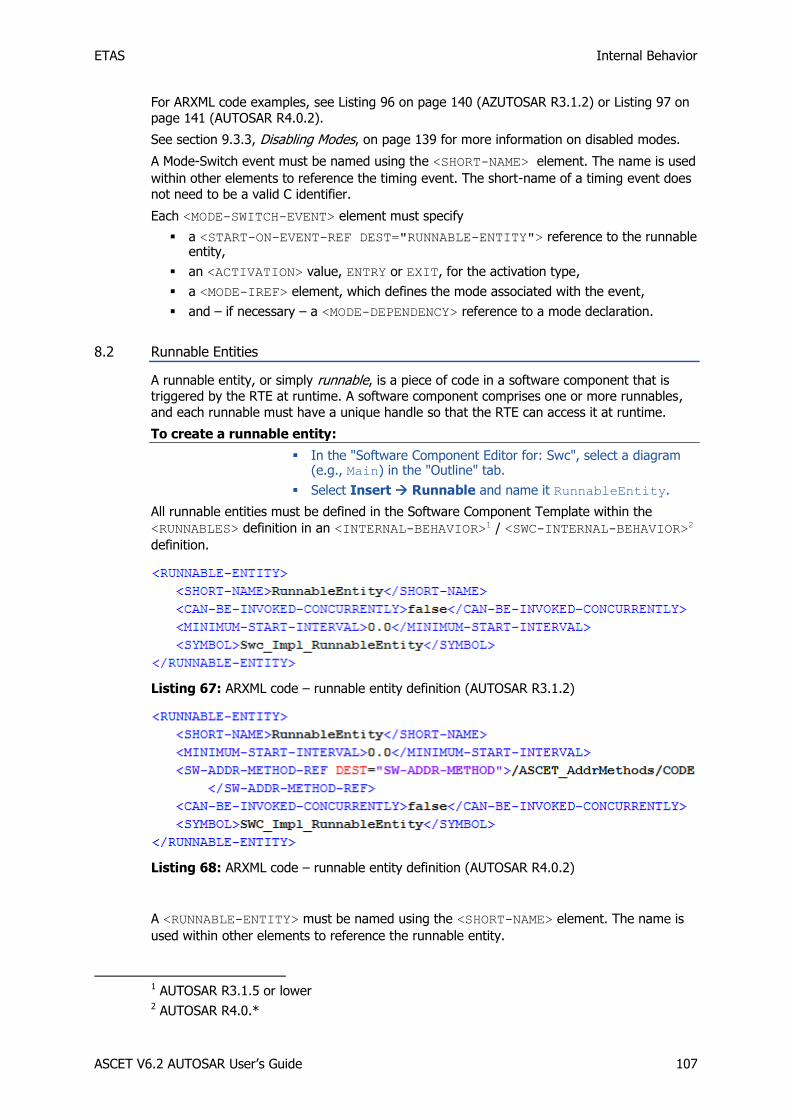
ETAS Internal Behavior
ASCET V6.2 AUTOSAR User’s Guide 107
For ARXML code examples, see Listing 96 on page 140 (AZUTOSAR R3.1.2) or Listing 97 on page 141 (AUTOSAR R4.0.2).
See section 9.3.3, Disabling Modes, on page 139 for more information on disabled modes.
A Mode-Switch event must be named using the <SHORT-NAME> element. The name is used
within other elements to reference the timing event. The short-name of a timing event does not need to be a valid C identifier.
Each <MODE-SWITCH-EVENT> element must specify
a <START-ON-EVENT-REF DEST="RUNNABLE-ENTITY"> reference to the runnable entity,
an <ACTIVATION> value, ENTRY or EXIT, for the activation type,
a <MODE-IREF> element, which defines the mode associated with the event,
and – if necessary – a <MODE-DEPENDENCY> reference to a mode declaration.
8.2 Runnable Entities
A runnable entity, or simply runnable, is a piece of code in a software component that is triggered by the RTE at runtime. A software component comprises one or more runnables,
and each runnable must have a unique handle so that the RTE can access it at runtime.
To create a runnable entity:
In the "Software Component Editor for: Swc", select a diagram (e.g., Main) in the "Outline" tab.
Select Insert Runnable and name it RunnableEntity.
All runnable entities must be defined in the Software Component Template within the
<RUNNABLES> definition in an <INTERNAL-BEHAVIOR>1 / <SWC-INTERNAL-BEHAVIOR>2
definition.
Listing 67: ARXML code – runnable entity definition (AUTOSAR R3.1.2)
Listing 68: ARXML code – runnable entity definition (AUTOSAR R4.0.2)
A <RUNNABLE-ENTITY> must be named using the <SHORT-NAME> element. The name is
used within other elements to reference the runnable entity.
1 AUTOSAR R3.1.5 or lower 2 AUTOSAR R4.0.*

ETAS Internal Behavior
ASCET V6.2 AUTOSAR User’s Guide 108
The <SHORT-NAME> denotes the name of the runnable entity in the XML namespace, but it
does not tell the RTE what the associated function body you will provide in your code is
called. This information is provided by the <SYMBOL> declaration that links the runnable
entity to the C function name you will use in your implementation. The <SYMBOL> name
must be a valid C identifier.
In AUTOSAR R4.0.*, the <SW-ADDR-METHOD-REF> element is used to determine the
memory class for the generated code.
The symbol of a runnable entity is optional information in ASCET. If not defined, ASCET takes the name of the function in the ASCET-generated code that implements the runnable
entity. In the example, ASCET generates the C function SWC_IMPL_RunnableEntity. If
the symbol is defined, then ASCET generates C code for the runnable entity according to the
given symbol.
To set the C identifier for a runnable:
In the "Outline" tab of the software component editor, select the runnable RunnableEntity and select Edit Implementation.
The window "Implementation for: RunnableEntity" opens.
Enter the symbol RteRunnable_Swc_RunnableEntity.
Click OK.
Figure 44: Setting the symbol RteRunnable_Swc_RunnableEntity for the runnable RunnableEntity
With that, ASCET will generate C code for the implemented runnable and name it
RteRunnable_Swc_RunnableEntity (see file Swc.c in this example):
The <RUNNABLE-ENTITY> description is generated accordingly:
Listing 69: ARXML code – runnable entity definition with user-defined <SYMBOL>
(AUTOSAR R3.1.2)

ETAS Internal Behavior
ASCET V6.2 AUTOSAR User’s Guide 109
Listing 70: ARXML code – runnable entity definition with user-defined <SYMBOL>
(AUTOSAR R4.0.2)
This declaration is sufficient if your runnable entity does not need to interact with the
software component's ports. However, if a runnable entity needs to communicate through ports, then you need to specify additional information that allows the RTE generator to
generate APIs to allow interaction to take place, for example:
1. What data items the runnable entity can send.
2. What data items the runnable entity can receive.
3. Which servers the runnable entity calls and how it expects the result to be returned.
You can use the same runnable entity to receive data on one port and send data on another port, or to receive data on a port and then call a server port to process the received data.
For example, you may create a runnable entity that reads an integer value from an Rport, multiplies it by two and sends it out on a Pport.
A runnable entity that is not invoked by an Operation-Invoked event can also specify a
minimum start interval to control the rate at which activations occur. A minimum start interval will delay the activation of a runnable to prevent that the runnable is started more
than once within the interval.
Note
When using minimum start intervals, the user shall check how the runnable activation is implemented by the RTE generator in use.
8.3 Responding to Timing Events
A runnable entity is executed periodically at runtime when the runnable entity is associated
with a timing event. Timing events specify how often the runnable entities should execute.
The <TIMING-EVENT> element specifies the <PERIOD> of occurrence in seconds and must
reference a runnable entity defined in the component's internal behavior using a <START-
ON-EVENT-REF> element. A period of zero is illegal.
The following example shows how to configure the RTE to activate a runnable entity every 10 milliseconds.
To assign a timing event to a runnable:
Go to the "Event Specification" tab of the "Software Component Editor for: Swc".
In the "Events" field, select the event Cyclic_10ms.
In the "Runnables" field, select the runnable RunnableEntity.
Select Event Assign Event or click the >> button.

ETAS Internal Behavior
ASCET V6.2 AUTOSAR User’s Guide 110
Figure 45: The event Cyclic_10ms is assigned to RunnableEntity
In the <TIMING-EVENT> element, the <START-ON-EVENT-REF DEST="RUNNABLE-
ENTITY"> element defines the runnable entity that is to be activated when the event
occurs. The <PERIOD> element specifies the time raster to be used by the RTE generator.
A timing event must be named using the <SHORT-NAME> element. The name is used within
other elements to reference the timing event. The short-name of a timing event does not need to be a valid C identifier.
See also Listing 60: ARXML code – definition of a timing event (all AUTOSAR versions), on
page 103.
8.4 Sending to a Port
If your software component provides a sender-receiver interface, you must define at least
one runnable entity that sends data over the interface.
The runnable can send data in two ways:
Explicitly, in which case the RTE generates an explicit API call that may be optimized to a macro. The sent datum may be either queued or unqueued.
Implicitly, in which case the RTE generates an implicit API call that will be optimized to a macro. The sent datum must not be queued.
For senders, it does not matter how the runnable entity is triggered, so any event can be used to activate the runnable entity.
8.4.1 Explicit Communication
To send to a port with explicit communication:
Add a Pport Sender to Swc, as described in section To create a sender port on page 87.
Drag the Pport Sender from the "Outline" tab and drop it in the drawing area of the software component editor.
Use the RTE Access button to create an RTE Access operator and place it in the drawing area.
Connect the output of the RTE Access operator with the data element Speed of the Sender port.
In the "Outline" tab, select the runnable RunnableEntity, then double-click on the sequence call of Speed.

ETAS Internal Behavior
ASCET V6.2 AUTOSAR User’s Guide 111
ASCET automatically assigns a sequence number for the sending of the data element Speed within the runnable RunnableEntity, i.e. the sequence 5.
Insert a literal with value 120 and connect the literal to the input of the RTE Access operator.
Now you are able to generate code (see To generate code in a project on page 27)..
Figure 46: Sending a value 120 to a sender port with explicit communication
Runnable entities sending data with explicit communication must define a <DATA-SEND-
POINTS> element that specifies the data items that will be sent for a given interface.
In AUTOSAR R3.1.5 or lower, a sent data item is described in a <DATA-SEND-POINT>
element. Each <DATA-SEND-POINT> element must specify the following properties:
the <SHORT-NAME> that you will use to refer to the item (the short-name does not need to be a valid C identifier)
the <DATA-ELEMENT-IREF> element that contains
a <P-PORT-PROTOTYPE-REF> reference to the Pport
a <DATA-ELEMENT-PROTOTYPE-REF> reference to the sent element
Listing 71: ARXML code – runnable entity with explicit send (AUTOSAR R3.1.2)
In AUTOSAR R4.0.*, a sent data item is described in a <VARIABLE-ACCESS> element. Each
<VARIABLE-ACCESS> element must specify the following properties:
the <SHORT-NAME> that you will use to refer to the item (the short-name does not need to be a valid C identifier)

ETAS Internal Behavior
ASCET V6.2 AUTOSAR User’s Guide 112
the <ACCESSED-VARIABLE> element that includes the <AUTOSAR-VARIABLE-IREF> element that contains
a <P-PORT-PROTOTYPE-REF> reference to the Pport
a <TARGET-DATA-PROTOTYPE-REF> reference to the sent element
Listing 72: ARXML code – runnable entity with explicit send (AUTOSAR R4.0.2)
For senders, it does not matter how the runnable entity is triggered, so any event can be used to activate the runnable entity.
For the ASCET-generated code, refer to section 10.3.1, Sending to a Port, on page 146.
8.4.2 Implicit Communication
Runnable entities can also communicate using implicit data read/write access. Such
configuration is guaranteed to be implemented as a simple macro that accesses global storage defined in the RTE rather than through a C function call.
There are two possibilities to model implicit communication in ASCET:
1. Changing the RTE access from explicit to implicit.
2. Modeling the implicit communication without using the RTE access operator.
To change the RTE access to implicit:
In the drawing area, right-click the RTE access operator from the example of section 8.4.1 and select Access Implicit from the context menu as shown in Figure 47.
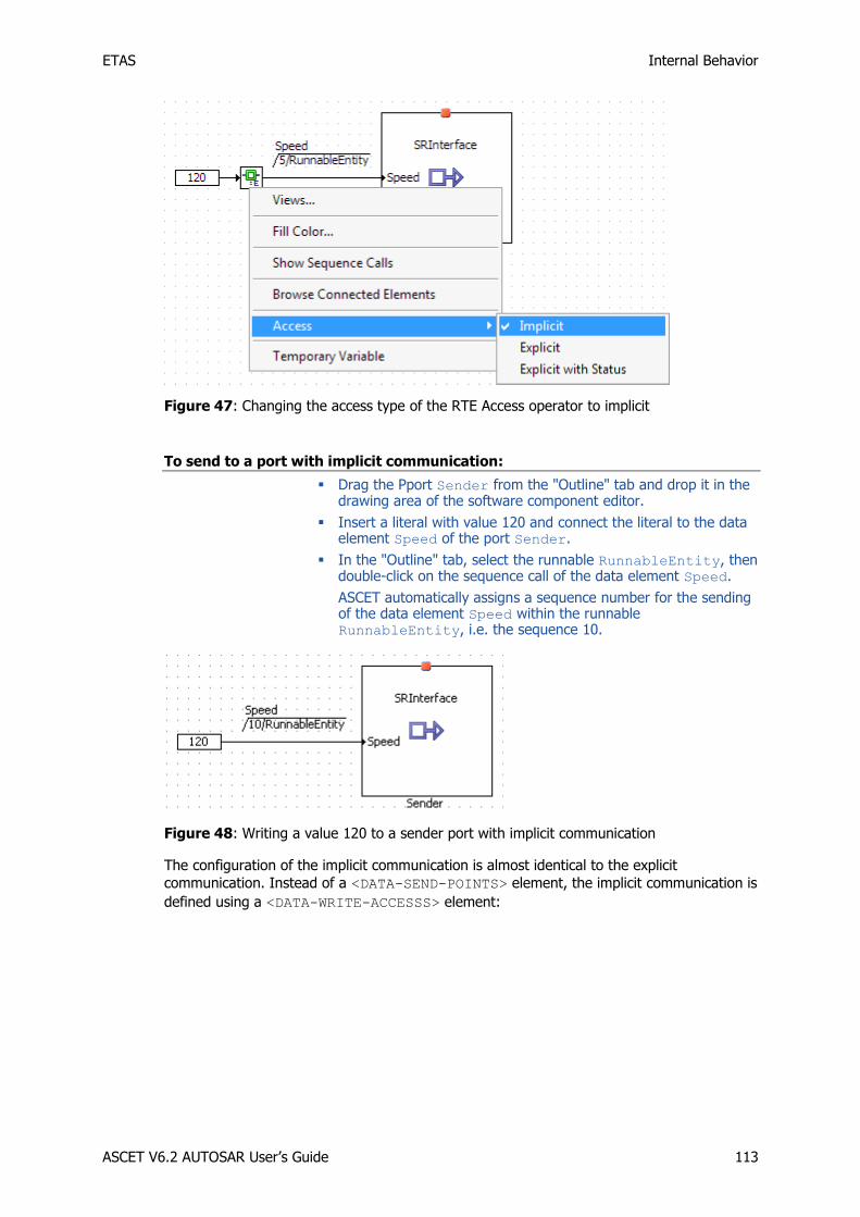
ETAS Internal Behavior
ASCET V6.2 AUTOSAR User’s Guide 113
Figure 47: Changing the access type of the RTE Access operator to implicit
To send to a port with implicit communication:
Drag the Pport Sender from the "Outline" tab and drop it in the drawing area of the software component editor.
Insert a literal with value 120 and connect the literal to the data element Speed of the port Sender.
In the "Outline" tab, select the runnable RunnableEntity, then double-click on the sequence call of the data element Speed.
ASCET automatically assigns a sequence number for the sending of the data element Speed within the runnable RunnableEntity, i.e. the sequence 10.
Figure 48: Writing a value 120 to a sender port with implicit communication
The configuration of the implicit communication is almost identical to the explicit
communication. Instead of a <DATA-SEND-POINTS> element, the implicit communication is
defined using a <DATA-WRITE-ACCESSS> element:

ETAS Internal Behavior
ASCET V6.2 AUTOSAR User’s Guide 114
Listing 73: ARXML code – runnable entity with implicit send (AUTOSAR R3.1.2)
Listing 74: ARXML code – runnable entity with implicit send (AUTOSAR R4.0.2)
For the ASCET-generated code, refer to section 10.3.1, Sending to a Port, on page 146.
8.5 Receiving from a Port
Similarly, if your software component requires a sender-receiver interface then you must define at least one runnable entity that receives data over the interface. Data can be
received in the following ways:
Implicit data read access – your runnable is activated by some event, e.g. a timing event, and makes an RTE API call to read data

ETAS Internal Behavior
ASCET V6.2 AUTOSAR User’s Guide 115
Explicit Data read access – your runnable entity is activated by an event and makes an RTE API call to read/receive the data. The receiver uses a non-blocking API to poll for the data.
8.5.1 Explicit Data Read Access
To receive from a port with explicit communication:
Add an Rport Receiver to SWC, as described in section To create a receiver on page 93.
Drag the Rport Receiver from the "Outline" tab and drop it in the drawing area of the software component editor.
Use the RTE Access button to create an RTE Access operator and place it in the drawing area.
Connect the data element Speed of the Receiver port to the input of the RTE Access operator.
Insert a signed discrete variable and name it SpeedSwc.
Implement the variable SpeedSwc as a sint16 with implementation range [-32768, 32767].
In the "Outline" tab, select the runnable RunnableEntity, then double-click on the empty sequence call of the variable SpeedSwc.
ASCET automaticallys assign a sequence number to SpeedSwc within the runnable RunnableEntity, e.g., the sequence 10.
Figure 49: Receiving the value Speed from the Rport Receiver with explicit
communication
Runnables that are required to receive data with explicit "data read access" must define a
<DATA-RECEIVE-POINTS>1 / <DATA-RECEIVE-POINT-BY-VALUES>2 element that
specifies the received data items.
In AUTOSAR R3.1.5 or lower, a received data item is described in a <DATA- RECEIVE-
POINT> element. Each <DATA- RECEIVE-POINT> element must specify the following
properties:
the <SHORT-NAME> that you will use to refer to the item (the short-name does not need to be a valid C identifier)
the <DATA-ELEMENT-IREF> element that contains
a <P-PORT-PROTOTYPE-REF> reference to the Rport
a <DATA-ELEMENT-PROTOTYPE-REF> reference to the sent element
1 AUTOSAR R3.1.5 or lower 2 AUTOSAR R4.0.*

ETAS Internal Behavior
ASCET V6.2 AUTOSAR User’s Guide 116
Listing 75: ARXML code – runnable entity with explicit receive (AUTOSAR R3.1.2)
In AUTOSAR RR4.0.*, a received data item is described in a <VARIABLE-ACCESS>
element. Each <VARIABLE-ACCESS> element must specify the following properties:
the <SHORT-NAME> that you will use to refer to the item (the short-name does not need to be a valid C identifier)
the <ACCESSED-VARIABLE> element that includes the <AUTOSAR-VARIABLE-IREF> element that contains
a <P-PORT-PROTOTYPE-REF> reference to the Rport
a <TARGET-DATA-PROTOTYPE-REF> reference to the received element
Listing 76: ARXML code – runnable entity with explicit receive (AUTOSAR R4.0.2)
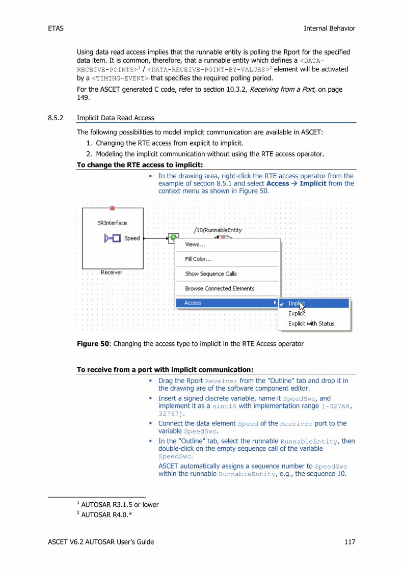
ETAS Internal Behavior
ASCET V6.2 AUTOSAR User’s Guide 117
Using data read access implies that the runnable entity is polling the Rport for the specified
data item. It is common, therefore, that a runnable entity which defines a <DATA-
RECEIVE-POINTS>1 / <DATA-RECEIVE-POINT-BY-VALUES>2 element will be activated
by a <TIMING-EVENT> that specifies the required polling period.
For the ASCET generated C code, refer to section 10.3.2, Receiving from a Port, on page
149.
8.5.2 Implicit Data Read Access
The following possibilities to model implicit communication are available in ASCET:
1. Changing the RTE access from explicit to implicit.
2. Modeling the implicit communication without using the RTE access operator.
To change the RTE access to implicit:
In the drawing area, right-click the RTE access operator from the example of section 8.5.1 and select Access Implicit from the context menu as shown in Figure 50.
Figure 50: Changing the access type to implicit in the RTE Access operator
To receive from a port with implicit communication:
Drag the Rport Receiver from the "Outline" tab and drop it in the drawing are of the software component editor.
Insert a signed discrete variable, name it SpeedSwc, and implement it as a sint16 with implementation range [-32768, 32767].
Connect the data element Speed of the Receiver port to the variable SpeedSwc.
In the "Outline" tab, select the runnable RunnableEntity, then double-click on the empty sequence call of the variable SpeedSwc.
ASCET automatically assigns a sequence number to SpeedSwc within the runnable RunnableEntity, e.g., the sequence 10.
1 AUTOSAR R3.1.5 or lower 2 AUTOSAR R4.0.*

ETAS Internal Behavior
ASCET V6.2 AUTOSAR User’s Guide 118
Figure 51: Receiving the value Speed from the Rport Receiver with implicit
communication
Likewise, runnables that are required to receive data with implicit data read access must
define a <DATA-READ-ACCESSS> element that specifies the data items they will receive.
Listing 77: ARXML code – runnable entity with implicit receive (AUTOSAR R3.1.2)

ETAS Internal Behavior
ASCET V6.2 AUTOSAR User’s Guide 119
Listing 78: ARXML code – runnable entity with implicit receive (AUTOSAR R4.0.2)
A single received data item is described by a <DATA-READ-ACCESS>1 / <VARIABLE-
ACCESS>2 element. A <DATA-READ-ACCESS>/<VARIABLE-ACCESS> element must be
named using the <SHORT-NAME> element. The name is used within other elements to
reference the data read access. The short-name does not need to be a valid C identifier.
For the ASCET-generated code, refer to section 10.3.2, Receiving from a Port, on page 149.
8.6 Responding to a Server Request on a Port
In software components that provide a client-server interface, ASCET defines one runnable entity for each operation in the interface. These runnable entities are the servers for the
client-server Pports on the software component.
The runnable entity to be regarded by the RTE as a server must be tied to an
<OPERATION-INVOKED-EVENT>. This RTE event allows the RTE to call the runnable entity
at runtime in response to client requests. The <OPERATION-INVOKED-EVENT> must
specify what operation request on the server interface will result in the runnable entity being
activated.
The following example shows how ASCET configures the runnable Server_MaximumValue
to be executed when the operation called MaximumValue is called on the Pport Server of
interface type CSInterface. See also
1. section 6.3, Client-Server, on page 70 for the creation of the client interface
CSInterface,
2. section 7.1.1, Provided Ports, on page 87 for the creation of the Pport Server, and
1 AUTOSAR R3.2.5 or lower 2 AUTOSAR R4.0.*

ETAS Internal Behavior
ASCET V6.2 AUTOSAR User’s Guide 120
3. section 8.1.2, Operation-Invoked Events, on page 103 for a detailed description of Operation-Invoked events.
Listing 79: ARXML code – internal behavior responding to a server request (AUTOSAR
R3.1.2)

ETAS Internal Behavior
ASCET V6.2 AUTOSAR User’s Guide 121
Listing 80: ARXML code – internal behavior responding to a server request (AUTOSAR R4.0.2)
An <OPERATION-INVOKED-EVENT> must be named using the <SHORT-NAME> element.
The name is used within other elements to reference the event. The short-name does not need to be a valid C identifier.
8.6.1 Concurrent Invocation of Servers
When a runnable acting as a server is written to be invoked concurrently, then the RTE can
optimize invocation by clients on the same ECU to a direct function call. This means that no
queuing is required (or possible) and therefore multiple invocations of the server can occur concurrently.
The RTE generator needs to know which runnable entities can be called in this way.
To enable concurrent invocation of a server:
In the "Outline" tab of the software component editor, double-click the server runnable Server_MaximumValue.

ETAS Internal Behavior
ASCET V6.2 AUTOSAR User’s Guide 122
The server runnable Server_MaximumValue was automatically inserted by ASCET when the Pport Server was created in section 7.1.1, Provided Ports, on page 87.
The dialog "Runnable Signature Editor for: Server_MaximumValue" opens.
Select the "Settings" tab.
Activate the Can be Invoked Concurrently option.
Figure 52: Setting Can be Invoked Concurrently for the runnable Server_MaximumValue
Close the runnable signature editor with OK.
Concurrent invocation is defined within the server's runnable entity definition as follows:
Listing 81: ARXML code – server runnable with concurrent invocation (AUTOSAR R3.1.2)
Listing 82: ARXML code – server runnable with concurrent invocation (AUTOSAR R4.0.2)
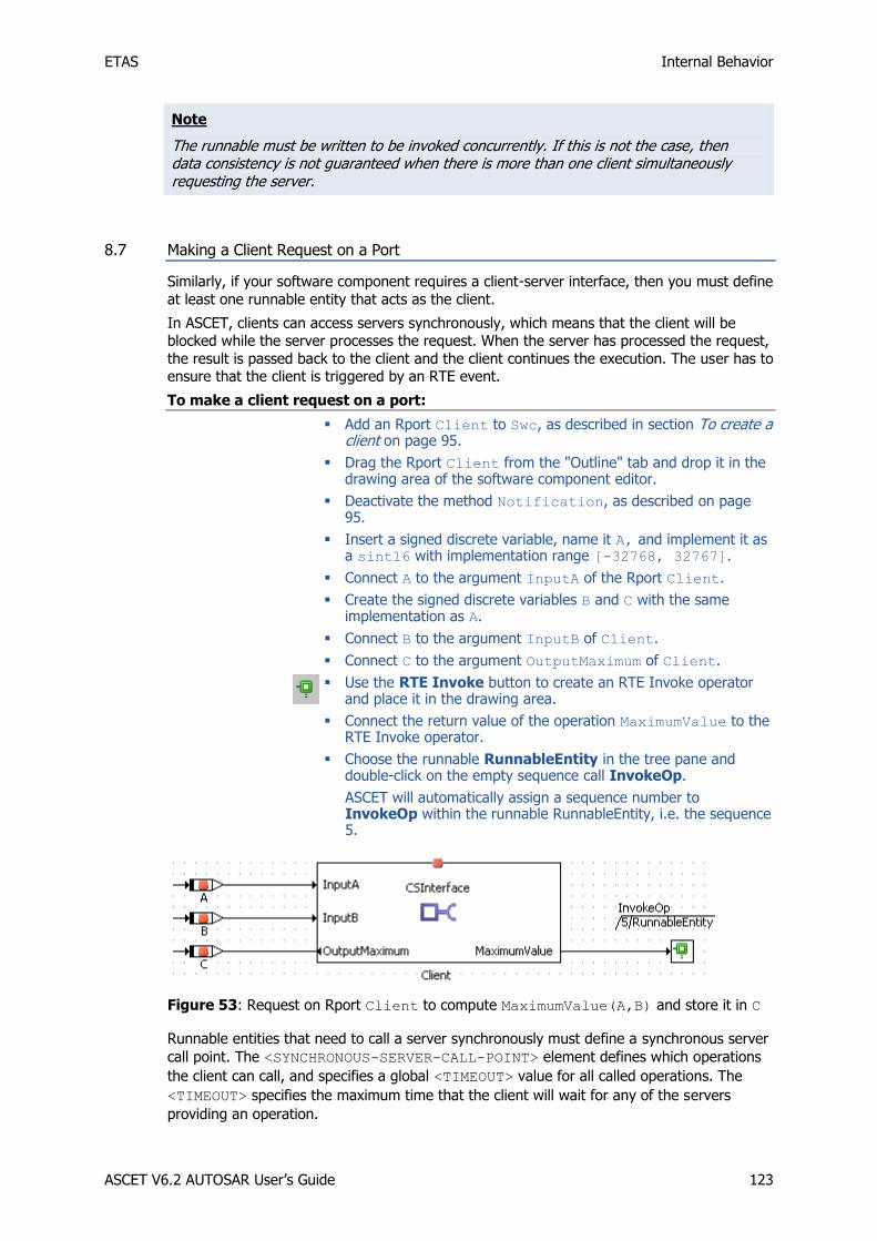
ETAS Internal Behavior
ASCET V6.2 AUTOSAR User’s Guide 123
Note
The runnable must be written to be invoked concurrently. If this is not the case, then data consistency is not guaranteed when there is more than one client simultaneously requesting the server.
8.7 Making a Client Request on a Port
Similarly, if your software component requires a client-server interface, then you must define
at least one runnable entity that acts as the client.
In ASCET, clients can access servers synchronously, which means that the client will be blocked while the server processes the request. When the server has processed the request,
the result is passed back to the client and the client continues the execution. The user has to ensure that the client is triggered by an RTE event.
To make a client request on a port:
Add an Rport Client to Swc, as described in section To create a client on page 95.
Drag the Rport Client from the "Outline" tab and drop it in the drawing area of the software component editor.
Deactivate the method Notification, as described on page 95.
Insert a signed discrete variable, name it A, and implement it as a sint16 with implementation range [-32768, 32767].
Connect A to the argument InputA of the Rport Client.
Create the signed discrete variables B and C with the same implementation as A.
Connect B to the argument InputB of Client.
Connect C to the argument OutputMaximum of Client.
Use the RTE Invoke button to create an RTE Invoke operator and place it in the drawing area.
Connect the return value of the operation MaximumValue to the RTE Invoke operator.
Choose the runnable RunnableEntity in the tree pane and double-click on the empty sequence call InvokeOp.
ASCET will automatically assign a sequence number to InvokeOp within the runnable RunnableEntity, i.e. the sequence 5.
Figure 53: Request on Rport Client to compute MaximumValue(A,B) and store it in C
Runnable entities that need to call a server synchronously must define a synchronous server
call point. The <SYNCHRONOUS-SERVER-CALL-POINT> element defines which operations
the client can call, and specifies a global <TIMEOUT> value for all called operations. The
<TIMEOUT> specifies the maximum time that the client will wait for any of the servers
providing an operation.
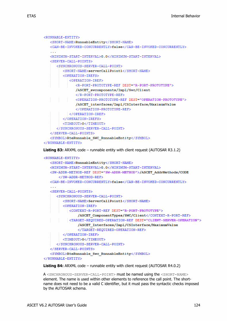
ETAS Internal Behavior
ASCET V6.2 AUTOSAR User’s Guide 124
Listing 83: ARXML code – runnable entity with client request (AUTOSAR R3.1.2)
Listing 84: ARXML code – runnable entity with client request (AUTOSAR R4.0.2)
A <SNCHRONOUS-SERVER-CALL-POINT> must be named using the <SHORT-NAME>
element. The name is used within other elements to reference the call point. The short-
name does not need to be a valid C identifier, but it must pass the syntactic checks imposed by the AUTOSAR schema.

ETAS Internal Behavior
ASCET V6.2 AUTOSAR User’s Guide 125
Note
The global <TIMEOUT> value for all the called operations is always set to 0 in ASCET.
For the ASCET-generated C code, refer to section 10.4.2, Making a Client Request on a Port, on page 154.
The same runnable entity can be used as a server on one interface and client on another interface. For example, you may create a runnable entity that handles a server request for
sorting on a Pport and uses an auxiliary operation on an Rport.
8.8 Interrunnable Variables
In non-AUTOSAR projects, ASCET messages can be used for inter-process communication.
These messages are not available in AUTOSAR software component. Instead, interrunnable variables are used for communication between different runnable entities.
Communication via interrunnable variables is equivalent in semantics to implicit/explicit
sender-receiver communication (see also section 6.1, Sender-Receiver, on page 62), but within the scope of the software component instance.
To specify interrunnable variables:
In the software component editor, use the Interrunnable Variable button to add an interrunnable variable.
The "Properties for Scalar Element: interrunnable" dialog window opens.
Name the interrunnable variable IRV_explicit.
Set the "Internal Access" to Explicit.
Select a "Basic Type", e.g. Unsigned Discrete.
Close the properties editor with OK.
Create a second interrunnable variable IRV_implicit with Implicit internal access.
Implement both interrunnable variables as sint8 (see Figure 10).
In AUTOSAR R3.1.5 or lower, an interrunnable variable is specified in an <INTER-
RUNNABLE-VARIABLE> element. The <COMMUNICATION-APPROACH> element determines
whether the variable uses implicit or explicit access.

ETAS Internal Behavior
ASCET V6.2 AUTOSAR User’s Guide 126
Listing 85: ARXML code – explicit and implicit interrunnable variables (AUTOSAR R3.1.2)
In AUTOSAR R4.0.*, an interrunnable variable is described in a <VARIABLE-DATA-
PROTOTYPE> element. Explicit and implicit interrunnable variables are stored in different
elements of the <SWC-INTERNAL-BEHAVIOR>, i.e. <EXPLICIT-INTER-RUNNABLE-
VARIABLES> (see Listing 86) and <IMPLICIT-INTER-RUNNABLE-VARIABLES> (see
Listing 87).
Listing 86: ARXML code – explicit interrunnable variable (AUTOSAR R4.0.2)
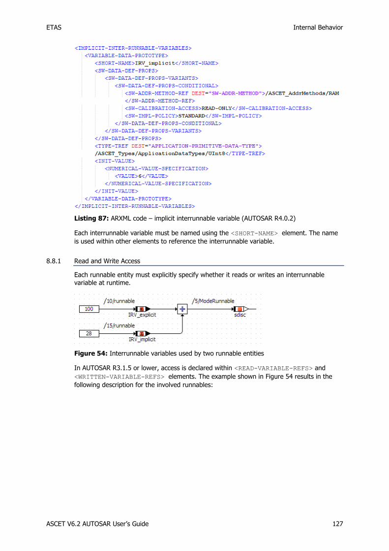
ETAS Internal Behavior
ASCET V6.2 AUTOSAR User’s Guide 127
Listing 87: ARXML code – implicit interrunnable variable (AUTOSAR R4.0.2)
Each interrunnable variable must be named using the <SHORT-NAME> element. The name
is used within other elements to reference the interrunnable variable.
8.8.1 Read and Write Access
Each runnable entity must explicitly specify whether it reads or writes an interrunnable
variable at runtime.
Figure 54: Interrunnable variables used by two runnable entities
In AUTOSAR R3.1.5 or lower, access is declared within <READ-VARIABLE-REFS> and
<WRITTEN-VARIABLE-REFS> elements. The example shown in Figure 54 results in the
following description for the involved runnables:

ETAS Internal Behavior
ASCET V6.2 AUTOSAR User’s Guide 128
Listing 88: ARXML code – runnable entities with read and write access to interrunnable
variables (AUTOSAR R3.1.2)
In AUTOSAR R4.0.*, access is declared within <READ-LOCAL-VARIABLES> and
<WRITTEN-LOCAL-VARIABLES> elements. The example shown in Figure 54 results in the
following description for the runnable runnable:

ETAS Internal Behavior
ASCET V6.2 AUTOSAR User’s Guide 129
Listing 89: ARXML code – runnable entity with read and write access to interrunnable variables (AUTOSAR R4.0.2)
8.9 Exclusive Areas
Software components that need to provide mutual exclusion over data shared by two (or
more) of their runnable entities do so by configuring exclusive areas.
The RTE generator uses exclusive area configuration to create operating system
configuration files and to optimize exclusive areas. For example, if the only components that access a region are mapped to the same task then the entire region can be elided.
Exclusive areas are defined in the XML configuration and are associated with the runnable
entities that use them.
8.9.1 New in ASCET V6.2
In previous ASCET versions, exclusive areas were used to protect read/write access to
messages in an SWC. An exclusive area named ASCET_exclusive_area was created
automatically.
With ASCET V6.2, messages in an SWC are no longer permitted, and messages in included ASCET modules must be mapped to AUTOSAR elements. With that, an exclusive area for
protected message access is no longer required, and ASCET_exclusive_area is no longer
available.
8.9.2 Configuration
Exclusive areas are created by means of ASCET resources.

ETAS Internal Behavior
ASCET V6.2 AUTOSAR User’s Guide 130
To create an exclusive area:
In the software component editor, use the Resource button to create a resource, and place it in the drawing area.
In the "Outline" tab, right-click the resource , select Rename from the context menu and rename the resource to SwcExclusiveArea.
When the newly created exclusive area SwcExclusiveArea is used in the software
component (see section 8.9.3), then the <INTERNAL-BEHAVIOR>1 / <SWC-INTERNAL-
BEHAVIOR>2 declaration names the <EXCLUSIVE-AREAS> it uses:
Listing 90: ARXML code – exclusive area definition (AUTOSAR R3.1.2)
Listing 91: ARXML code – exclusive area definition (AUTOSAR R4.0.2)
1 AUTOSAR R3.1.5 or lower 2 AUTOSAR R4.0.*

ETAS Internal Behavior
ASCET V6.2 AUTOSAR User’s Guide 131
Note that this means that the scope of any exclusive areas that you define is the software component instance. It is not possible to define exclusive areas that cross software
component boundaries. Data that is shared between multiple software-component instances,
which can potentially be accessed concurrently, should be encapsulated in its own component and then normal sender-receiver or client-server communication used to access
the data.
Each exclusive area defined within an internal behavior definition must be named using the
<SHORT-NAME> element. The name is used within other elements to reference the software
component type and to form the "handle" by which the exclusive area is accessed at run-time. The short-name of an exclusive area should be a valid C identifier.
Additionally, the RTE can be informed how to implement the exclusive area with an
ExclusiveAreaImplementation element within the ECU description.
Note
If the definition of the ExclusiveAreaImplementation for an exclusive area is omitted, then the RTE defaults to "OS resource" implementation strategy.
A different exclusive area implementation method can be set for each exclusive area and
SWC instance.
Note
The InterruptBlocking method will cause all OS interrupts to be blocked in the worst case for the longest execution time of the protected critical section.
8.9.3 Usage
Each runnable in the <INTERNAL-BEHAVIOR>1 / <SWC-INTERNAL-BEHAVIOR>2 section
can declare if it uses one of the named exclusive areas and how it uses the area at runtime.
ASCET defines exclusive areas with explicit access. The <RUNNABLE-ENTITY-CAN-ENTER-
EXCLUSIVE-AREA> element determines that the exclusive area is accessed using an explicit
API. The area's name forms part of the generated API (explicit access is similar to a
standard resource in OSEK OS).
In ASCET V6.2 or later, exclusive areas can only be accessed by assigning sequences of a runnable entity in a user-defined exclusive area.
Note
Beginning with ASCET V6.2, messages and the automatically generated exclusive area ASCET_exclusive_area are no longer available in software components.
To assign sequences of a runnable in an exclusive area:
Edit the sequence call reserve of the SwcExclusiveArea and provide the sequence number 8 in the method RunnableEntity.
1 AUTOSAR R3.1.5 or lower 2 AUTOSAR R4.0.*

ETAS Internal Behavior
ASCET V6.2 AUTOSAR User’s Guide 132
Edit the sequence call release of the SwcExclusiveArea and provide the sequence number 22 in the method RunnableEntity.
Figure 55: Use of the exclusive area SwcExclusiveArea in RunnableEntity
In the definition of the <RUNNABLE-ENTITY> element, the reference to the
SwcExclusiveArea will be generated as shown in Listing 92 and Listing 93.
Listing 92: ARXML code – runnable entity with reference to exclusive area (AUTOSAR R3.1.2)
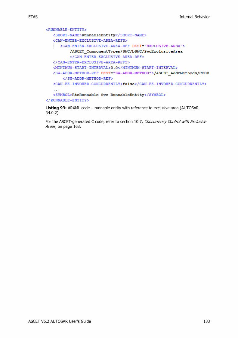
ETAS Internal Behavior
ASCET V6.2 AUTOSAR User’s Guide 133
Listing 93: ARXML code – runnable entity with reference to exclusive area (AUTOSAR R4.0.2)
For the ASCET-generated C code, refer to section 10.7, Concurrency Control with Exclusive Areas, on page 163.
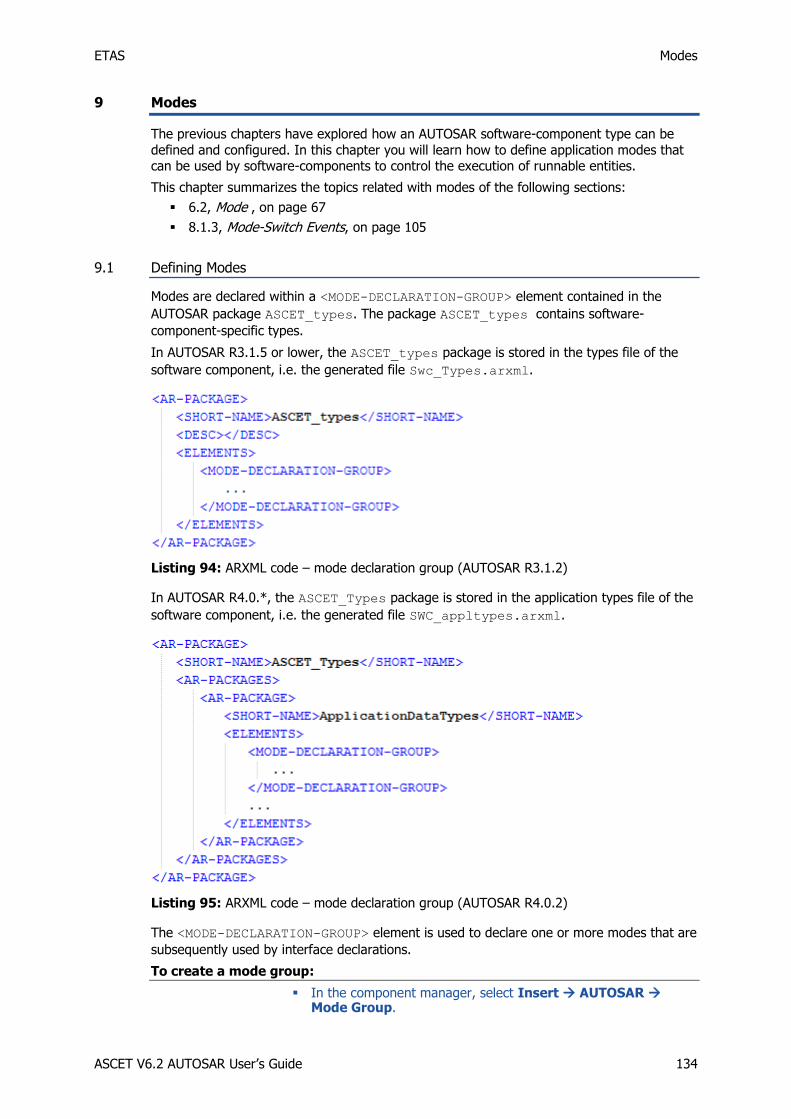
ETAS Modes
ASCET V6.2 AUTOSAR User’s Guide 134
9 Modes
The previous chapters have explored how an AUTOSAR software-component type can be
defined and configured. In this chapter you will learn how to define application modes that can be used by software-components to control the execution of runnable entities.
This chapter summarizes the topics related with modes of the following sections:
6.2, Mode , on page 67
8.1.3, Mode-Switch Events, on page 105
9.1 Defining Modes
Modes are declared within a <MODE-DECLARATION-GROUP> element contained in the
AUTOSAR package ASCET_types. The package ASCET_types contains software-
component-specific types.
In AUTOSAR R3.1.5 or lower, the ASCET_types package is stored in the types file of the
software component, i.e. the generated file Swc_Types.arxml.
Listing 94: ARXML code – mode declaration group (AUTOSAR R3.1.2)
In AUTOSAR R4.0.*, the ASCET_Types package is stored in the application types file of the
software component, i.e. the generated file SWC_appltypes.arxml.
Listing 95: ARXML code – mode declaration group (AUTOSAR R4.0.2)
The <MODE-DECLARATION-GROUP> element is used to declare one or more modes that are
subsequently used by interface declarations.
To create a mode group:
In the component manager, select Insert AUTOSAR Mode Group.

ETAS Modes
ASCET V6.2 AUTOSAR User’s Guide 135
Name the mode group OnOffMode.
Create two modes, off and on, as described on page 67.
Figure 56: Mode declaration group OnOffMode
Note
A mode declaration group resembles an ASCET enumeration. In contrast to enumerations, the representing value cannot be set explicitly.
ASCET declares the <MODE-DECLARATION-GROUP> in the AUTOSAR package
ASCET_types. See Listing 29 on page 68 for an AUTOSAR R3.1.2 ARXML example and
Listing 30 on page 68 for an AUTOSAR R4.0.2 ARXML example.
One mode within a <MODE-DECLARATION-GROUP> element is marked as the group's initial
mode through the <INITIAL-MODE-REF>. Mode-Switch events that are attached to the
ENTRY of an initial mode are triggered by the RTE when this is started using Rte_Start.
A <MODE-DECLARATION-GROUP> can be used (referenced) by multiple mode-switch
interfaces and therefore inherently used by multiple software-components.
9.2 Mode Communication
Modes are communicated over a mode-switch interface (see section 6.2, Mode , on page 67).
In ASCET, mode-switch interfaces are realized as sender-receiver interface components that
contain mode groups.
In AUTOSAR R3.1.5 or lower, each mode-switch interface can specify zero or more mode declaration group prototypes that define the AUTOSAR modes communicated over the
interface.

ETAS Modes
ASCET V6.2 AUTOSAR User’s Guide 136
In AUTOSAR R4.0.*, each mode-switch interface must specify one mode declaration group prototype.
Each mode declaration group prototype defines a prototype of a specific mode declaration
group.
To create a mode group interface:
In the component manager, select Insert AUTOSAR SenderReceiver Interface.
Name the sender-receiver interface ModeInterface.
Double-click on ModeInterface.
The "Sender Receiver Interface Editor for: ModeInterface" editor opens.
Select Insert Component.
The "Select Item …" window opens.
In the "1 Database" or "1 Workspace" field of the "Select Item" window, select the mode group OnOffMode (see also Figure 20 on page 69).
Click OK to close the "Select Item" window and insert OnOffMode into ModeInterface.
The "Properties for Element: OnOffMode" window opens.
Click OK to use the default name and comment.
The mode group interface ModeInterface now looks as shown in Figure 21 on page 69.
The declaration of mode declaration group prototypes within a mode-switch interface
definition has the structure shown in Listing 31 on page 70 (AUTOSAR R3.1.5 or lower) or Listing 32 on page 70 (AUTOSAR R4.0.*).
In AUTOSAR R3.1.5 or lower, a mode group is defined using the <MODE-DECLARATION-
GROUP-PROTOTYPE> element and all elements must be defined within an encapsulating
<MODE-GROUPS> element.
In AUTOSAR R4.0.*, a mode group is defined using the <MODE-GROUP> element.
Each <MODE-DECLARATION-GROUP-PROTOTYPE>/<MODE-GROUP> must specify:
the <SHORT-NAME> that you will use to refer to the item
the <TYPE-TREF> reference to mode declaration group
In AUTOSAR R3.1.5 or lower, a sender-receiver interface component can specify both
<DATA-ELEMENTS> and <MODE-GROUPS> in the same declaration. However, it is strongly
recommended that you add either data elements or mode groups to a single interface.
In AUTOSAR R4.0.*, a sender-receiver interface component that contains a mode group
must not contain data elements, and vice versa. Mixing both kinds of elements leads to a code generation error.
9.3 Using Modes
A software component can be a mode user activated in response to a mode switch. In this section you learn how to use modes in a software component.
To insert a mode group interface in a software component:
Create and set up a project as shown in section 3.1.2, Code Generation Settings for AUTOSAR, on page 22.
Insert a software component Swc in the project, as described in To insert an AUTOSAR software component in a project on page 26.

ETAS Modes
ASCET V6.2 AUTOSAR User’s Guide 137
In the "Outline" tab of the project editor, double-click Swc to open the software component editor.
In the software component editor, select Insert Component.
The "Select item…" window opens.
In the "1 Database" or "1 Workspace" field of the "Select Item" window, select the interface ModeInterface and click OK.
The "Properties for complex element: ModeInterface" opens.
Click OK to accept the default settings.
9.3.1 Software Component Initialization and Finalization
AUTOSAR modes can be used to execute code when the RTE is started, e.g. to initialize
internal data structures, etc. Similarly, when a system is shut down your software
component may need to store data, log operational details, etc.
Each mode declaration group describes an initial mode – to activate a runnable when the
system is started created by a <MODE-SWITCH-EVENT>1 / <SWC-MODE-SWITCH-EVENT>2
for entry to the initial mode.
To create a mode-switch event:
In the "Software Component Editor for: Swc", go to the "Event Specification" tab.
Select Event Add Event and name the event ModeEvent.
In the "Event Kind" combo box, select ModeSwitch.
Set the following mode switch settings (see also Figure 42 on page 105):
Activation: entry
Assigned Mode: On::OnOffMode
A runnable entity within a software component can be started when the RTE is started by
declaring a <MODE-SWITCH-EVENT> / <SWC-MODE-SWITCH-EVENT> for entry to an initial
mode.
9.3.2 Triggering a Runnable Entity on a Mode-Switch
A runnable entity can be activated on either entry or exit from a mode using a Mode-Switch
event configured, like all other events, in the <INTERNAL-BEHAVIOR>1 / <SWC-
INTERNAL-BEHAVIOR>2 element of a software component.
To create a runnable entity:
In the "Software Component Editor for: Swc", select a diagram (e.g., Main) in the "Outline" tab.
Select Insert Runnable and name it ModeRunnable.
For details on runnable entities, refer to section 8.2, Runnable Entities, on page 107.
If RunnableEntity is defined for entry, the runnable entity must be of Category 1. This
means that it must not make any (blocking) RTE calls nor access other application
components.
Similarly, when a system is defined for exit, your software component may need to store
data, log termination etc. The principle is the same as initialization, except that finalization is simply a transition to a new mode that is simply associated with shutdown.
1 AUTOSAR R3.1.5 or lower 2 AUTOSAR R4.0.*

ETAS Modes
ASCET V6.2 AUTOSAR User’s Guide 138
To add a Mode-Switch event to a runnable:
Go to the "Event Specification" tab of the "Software Component Editor for: Swc".
In the "Events" field, select the event ModeEvent.
In the "Runnables" field, select the runnable ModeRunnable.
Select Event Assign Event or click the >> button.
Figure 60: ModeEvent is assigned to ModeRunnable
When the Mode-Switch event is mapped to a runnable entity, then ASCET generates the
<MODE-SWITCH-EVENT>1 / <SWC-MODE-SWITCH-EVENT>2 element in the configuration
language as shown in Listing 63 on page 106 (AUTOSAR R3.1.2) or Listing 64 on page 106 (AUTOSAR R4.0.2).
A <MODE-SWITCH-EVENT>/<SWC-MODE-SWITCH-EVENT> element defines the following
things:
1. The <START-ON-EVENT-REF> element defines the runnable entity to be activated.
The reference must be to a runnable entity within the same software component type.
2. The <ACTIVATION> element defines whether the runnable entity is triggered on
entry to, or exit from, the mode. ASCET supports the text ENTRY or EXIT. A Mode-
Switch event can apply either to entry to a mode or exit from a mode, but not to
both. If runnable activation is required for entry and exit, then two Mode-Switch
events must be defined.
3. The <MODE-IREF> element defines the mode associated with the Mode-Switch event.
The <MODE-IREF> element must contain three references (the port prototype, the
mode declaration group prototype and the mode declaration group that types the
declaration group prototype).
One mode within a <MODE-DECLARATION-GROUP> element is marked as the group's initial
mode. Any Mode-Switch events that are attached to the entry of an initial mode within any
group are triggered by the RTE when this is started using Rte_Start.
1 AUTOSAR R3.1.5 or lower 2 AUTOSAR R4.0.*
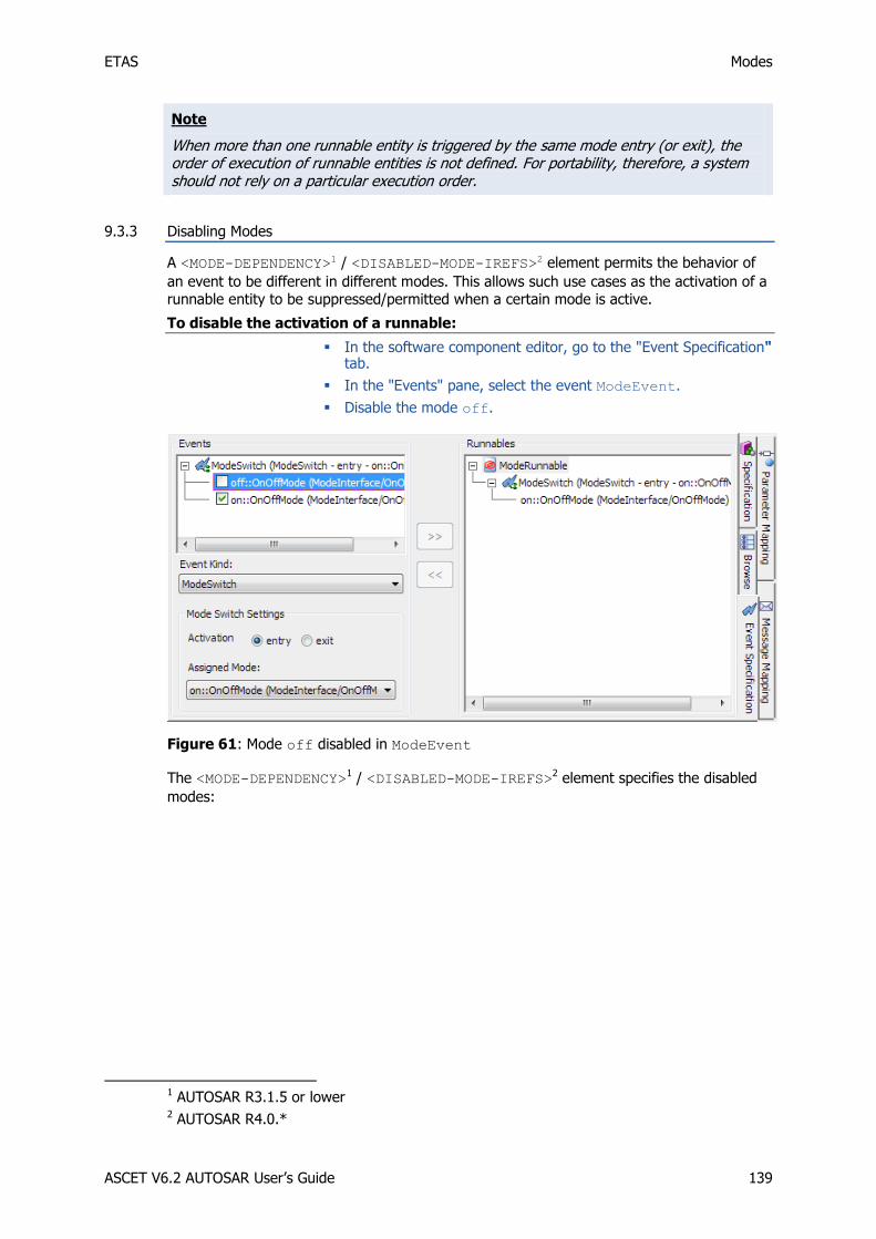
ETAS Modes
ASCET V6.2 AUTOSAR User’s Guide 139
Note
When more than one runnable entity is triggered by the same mode entry (or exit), the order of execution of runnable entities is not defined. For portability, therefore, a system should not rely on a particular execution order.
9.3.3 Disabling Modes
A <MODE-DEPENDENCY>1 / <DISABLED-MODE-IREFS>2 element permits the behavior of
an event to be different in different modes. This allows such use cases as the activation of a runnable entity to be suppressed/permitted when a certain mode is active.
To disable the activation of a runnable:
In the software component editor, go to the "Event Specification" tab.
In the "Events" pane, select the event ModeEvent.
Disable the mode off.
Figure 61: Mode off disabled in ModeEvent
The <MODE-DEPENDENCY>1 / <DISABLED-MODE-IREFS>2 element specifies the disabled
modes:
1 AUTOSAR R3.1.5 or lower 2 AUTOSAR R4.0.*

ETAS Modes
ASCET V6.2 AUTOSAR User’s Guide 140
Listing 96: ARXML code – definition of a Mode-Switch event with disabled mode (AUTOSAR
R3.1.2)

ETAS Modes
ASCET V6.2 AUTOSAR User’s Guide 141
Listing 97: ARXML code – definition of a Mode-Switch event with disabled mode (AUTOSAR
R4.0.2)
When the mode specified within the <MODE-DEPENDENCY>1 / <DISABLED-MODE-IREFS>2
element is active, the RTE will not activate the runnable (the activation is discarded).
For more information about the implementation of mode instances, please refer to the RTA-RTE User Guide.
1 AUTOSAR R3.1.5 or lower 2 AUTOSAR R4.0.*

ETAS Implementing Software Components
ASCET V6.2 AUTOSAR User’s Guide 142
10 Implementing Software Components
This section shows how to model software components in ASCET so that the objects
required by the RTE are declared, and how to use the RTE API generated by the RTE generator.
10.1 Basic Concepts
10.1.1 Namespace
All RTE symbols (e.g. function names, global variables etc.) that are visible in the global
namespace use either the prefix Rte_ or the prefix RTE_.
Note
You must not create symbols that use either the prefix Rte_ or the prefix RTE_ to remove the possibility of namespace clashes.
10.1.2 Runnable Naming Convention
The RTE generator generates code that activates your runnable entities. To do this, the
RTE's internal mechanisms need to be able to access your code through defined interfaces.
Each of the named runnable entities defined in your runnable entity <SYMBOL> declarations
must be implemented. Failure to define all runnable entities will be detected at compile time
when your application is linked to form the ECU's executable image. The linker error message will reference the missing runnable entity entry point.
Runnable entities are executed by RTE-generated code when required. The function
providing an entry point for a runnable entity should not be invoked directly by an application software component.
10.1.3 API Naming Convention
The RTE API calls are generated for each software component using names derived from the RTE generator's input. The RTE API provides a consistent interface to each software
component but allows the RTE generator to provide different implementations of the API functionality.
Each API call name is formed from:
The prefix Rte_
The call functionality (read, write etc.)
Either
The port name and data item name (sender-receiver) or operation name (client-
server) through which the call operates
or
The name of the object (e.g. exclusive area) upon which the call operates
Thus RTE API calls involving communication through ports have the format:
Rte_StatusType Rte_<API call name>_<port>_<dataitem/operation>
Whereas other RTE APIs have the format:
Rte_StatusType Rte_<API call name>_<object name>

ETAS Implementing Software Components
ASCET V6.2 AUTOSAR User’s Guide 143
10.1.4 API Parameter Passing Mechanisms
The RTE API calls may have one or more parameters. The API parameters (if any) fall into
one of three classes:
"In" Parameters – All "in" parameters that are AUTOSAR primitive data types (with the exception of a string) are passed by value. Strings and other "in" parameters that are of a complex data type (i.e. a record or an array) are passed by reference.
Note that while AUTOSAR defines a string as a primitive data type, its inherent size
makes it inefficient to pass by value and is therefore treated the same as a complex data type.
"In" parameters are strictly read-only.
"Out" Parameters – All "out" parameters are passed to RTE API functions by reference. This is required to ensure that the API functions can modify the parameter.
"Out" parameters are strictly write-only.
"In/Out" Parameters – All "in/out" parameters are passed to the RTE API functions by reference except for an asynchronous client-server call when primitive data types (other than strings) are passed by value to Rte_Call and by reference to Rte_Result.
"In/out" parameters can be read and written by the API function being called.
Note
ASCET configures the identifiers of the API parameters in the XML configuration file specified in the project properties (see To define a memory sections definition file on page 24). The standard configuration of the AUTOSAR memory sections is provided in the exemplary files memorySections_Autosar.xml and
memorySections_Autosar4.xml.
When generating code in an AUTOSAR project, ASCET loads the memory sections defined in the specified XML file. Changes in the *.xml file will only be taken into account if the user performs Build Touch Recursive before the code generation is started.
10.2 Application Source Code
ASCET is a C code generator and the RTE also generates C code. ASCET V6.2 supports, at
present, single-instance software components.
10.2.1 Application Header Files
Each software component generated in ASCET includes the relevant application header file created during RTE configuration.
Listing 98: C code – include application header file
The RTE API is specific to each software component type and therefore it must be included only in the component's application header file for each source code file that defines a
component (whether completely or partially).
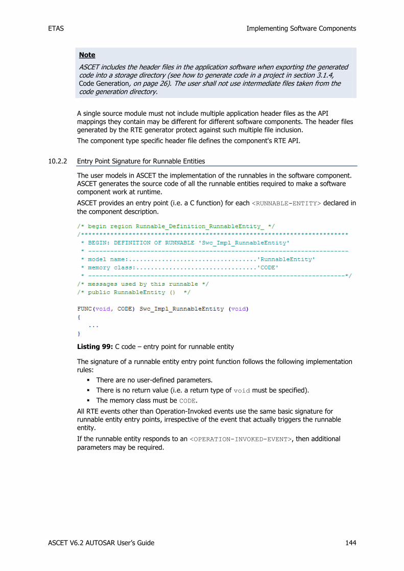
ETAS Implementing Software Components
ASCET V6.2 AUTOSAR User’s Guide 144
Note
ASCET includes the header files in the application software when exporting the generated code into a storage directory (see how to generate code in a project in section 3.1.4, Code Generation, on page 26). The user shall not use intermediate files taken from the code generation directory.
A single source module must not include multiple application header files as the API
mappings they contain may be different for different software components. The header files
generated by the RTE generator protect against such multiple file inclusion.
The component type specific header file defines the component's RTE API.
10.2.2 Entry Point Signature for Runnable Entities
The user models in ASCET the implementation of the runnables in the software component. ASCET generates the source code of all the runnable entities required to make a software
component work at runtime.
ASCET provides an entry point (i.e. a C function) for each <RUNNABLE-ENTITY> declared in
the component description.
Listing 99: C code – entry point for runnable entity
The signature of a runnable entity entry point function follows the following implementation
rules:
There are no user-defined parameters.
There is no return value (i.e. a return type of void must be specified).
The memory class must be CODE.
All RTE events other than Operation-Invoked events use the same basic signature for runnable entity entry points, irrespective of the event that actually triggers the runnable
entity.
If the runnable entity responds to an <OPERATION-INVOKED-EVENT>, then additional
parameters may be required.

ETAS Implementing Software Components
ASCET V6.2 AUTOSAR User’s Guide 145
Listing 100: C code – server runnable entity
The signature of a runnable entity entry point function invoked as a result of an Operation-
Invoked event follows the following implementation rules:
There is a return value when a server specifies application errors, in which case Std_ReturnType is used.
Formal parameters are the operations IN, IN/OUT and OUT parameters. These parameters are passed by value or reference depending on the type.
The memory class must be CODE.
10.3 Sender-Receiver Communication
The RTE API calls for handling non-queued sender-receiver communication differ for the
type of data access.
Non-queued communication with explicit access
Send with Rte_Write
Receive with Rte_Read
Receive with Rte_Dread (AUTOSAR R4.0.*)
Non-queued communication with explicit access can be optionally implemented with
status.
Non-queued communication with implicit access
Send with Rte_IWrite
Receive with Rte_IRead
The implicit API uses a locally cached copy of data to preserve consistency over a
calling runnable entity invocation. Data is read into a global cache before the runnable entity starts executing and is written from the global cache after the runnable entity
terminates. Data writes are done once, no matter how many times it is written.
The RTE guarantees cached data does not change during execution of the runnable entity.

ETAS Implementing Software Components
ASCET V6.2 AUTOSAR User’s Guide 146
The implicit API should be used when you need to guarantee that every access to a datum in a runnable entity will provide the same result irrespective of how many
times it is accessed during an invocation of the runnable entity.
The following sections show how to use these sections in your application.
10.3.1 Sending to a Port
Sending to a Port with Explicit Communication
Components communicate data to other components using the Rte_Write call. The call is
defined per port and interfaces data item for each component and therefore has the
following signature:
Rte_StatusType Rte_Write_<Port>_<DataItem>(DataItemType Data)
For the example of section 8.4.1, Explicit Communication,
ASCET generates the following C code:
Listing 101: C code – explicit send (example of section 8.4.1, Explicit Communication)
Sending to a Port with Explicit Communication with Status
Explicit access can be optionally implemented with status.
To set explicit communication with status
Open the ARProject project and Swc software component from the example in section 8.4.1, Explicit Communication, on page 110.
In the drawing area of the software component editor, right-click the RTE access operator and select Access Explicit with Status from the context menu (see Figure 62).

ETAS Implementing Software Components
ASCET V6.2 AUTOSAR User’s Guide 147
Figure 62: Setting explicit communication with status.
Use the RTE Status button to create an RTE Status operator and place it in the drawing area.
Use one of the * Literal buttons to create a literal, and place the literal in the drawing area.
Edit the literal (see the online help for details) and enter one of the status/error values listed in section Std_ReturnType, on page 39.
This example uses RTE_E_NO_DATA.
Add a logic variable named, e.g., noData.
Covert the variable's sequence call into a connector (see the online help for details).
Add an Equal operator.
Connect literal, RTE status block, operator and variable as shown in Figure 63.
Connect the pin below the RTE Status block with the connector of the variable noError.
Figure 63: Sending a value 120 to a sender port using explicit communication with status
For the example, ASCET generates the following C code:

ETAS Implementing Software Components
ASCET V6.2 AUTOSAR User’s Guide 148
Listing 102: C code – explicit send with status
Sending to a Port with Implicit Communication
The implicit API includes a reference to the runnable entity that is declared as accessing the data in the API name. Care should be taken when writing a runnable entity to invoke the
correct API. The Rte_IWrite API reads data:
Rte_StatusType Rte_IWrite_<runnable>_<port>_<data>( DataItemType
Data)
The cache is updated before the runnable entity starts. Rte_IWrite writes data to a
cached copy and changes are only made visible after the runnable entity terminates
irrespective of the number of times the data is written.
For the example of section 8.4.2, Implicit Communication,
ASCET generates the following C code:

ETAS Implementing Software Components
ASCET V6.2 AUTOSAR User’s Guide 149
Listing 103: C code – implicit send (example of section 8.4.2, Implicit Communication)
10.3.2 Receiving from a Port
Receiving from a Port with Explicit Communication
Components receive communicated data items from other components using the Rte_Read
call. The call is defined per port and interfaces data item for each component and therefore
has the following signature:
AUTOSAR R3.1.5 or lower
Rte_StatusType Rte_Read_<Port>_<DataItem>(DataItemType* Data)
AUTOSAR R4.0.*
Rte_StatusType Rte_DRead_<Port>_<DataItem>()
For the example of section 8.5.1, Explicit Data Read Access,
ASCET generates the following C code:

ETAS Implementing Software Components
ASCET V6.2 AUTOSAR User’s Guide 150
Listing 104: C code – explicit receive (example of section 8.5.1, Explicit Data Read Access; AUTOSAR R3.1.2)
Listing 105: C code – explicit receive (example of section 8.5.1, Explicit Data Read Access; AUTOSAR R4.0.2)
Receiving from a Port with Explicit Communication with Status
Explicit access can be optionally implemented with status. To set explicit communication
with status, see the example in section 10.3.1, Sending to a Port, subsection Sending to a Port with Explicit Communication with Status, on page 146.
When setting explicit communication with status to the example of the previous section,
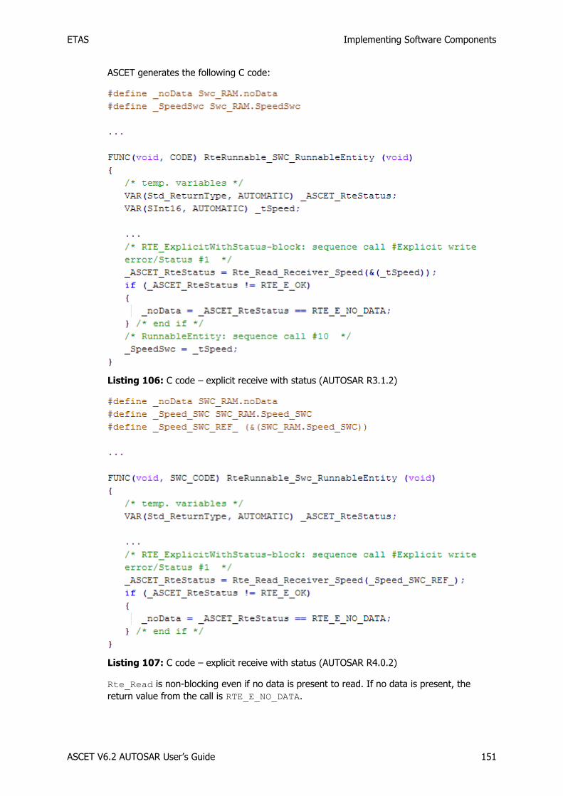
ETAS Implementing Software Components
ASCET V6.2 AUTOSAR User’s Guide 151
ASCET generates the following C code:
Listing 106: C code – explicit receive with status (AUTOSAR R3.1.2)
Listing 107: C code – explicit receive with status (AUTOSAR R4.0.2)
Rte_Read is non-blocking even if no data is present to read. If no data is present, the
return value from the call is RTE_E_NO_DATA.
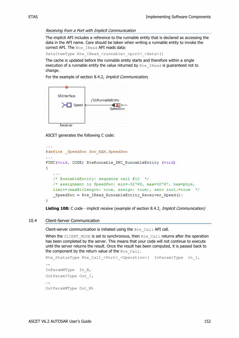
ETAS Implementing Software Components
ASCET V6.2 AUTOSAR User’s Guide 152
Receiving from a Port with Implicit Communication
The implicit API includes a reference to the runnable entity that is declared as accessing the
data in the API name. Care should be taken when writing a runnable entity to invoke the
correct API. The Rte_IRead API reads data:
DataItemType Rte_IRead_<runnable>_<port>_<data>()
The cache is updated before the runnable entity starts and therefore within a single
execution of a runnable entity the value returned by Rte_IRead is guaranteed not to
change.
For the example of section 8.4.2, Implicit Communication,
ASCET generates the following C code:
Listing 108: C code - implicit receive (example of section 8.4.2, Implicit Communication)
10.4 Client-Server Communication
Client-server communication is initiated using the Rte_Call API call.
When the CLIENT_MODE is set to synchronous, then Rte_Call returns after the operation
has been completed by the server. This means that your code will not continue to execute until the server returns the result. Once the result has been computed, it is passed back to
the component by the return value of the Rte_Call.
Rte_StatusType Rte_Call_<Port>_<Operation>( InParam1Type In_1,
…,
InParamNType In_N,
OutParam1Type Out_1,
…,
OutParamMType Out_M)
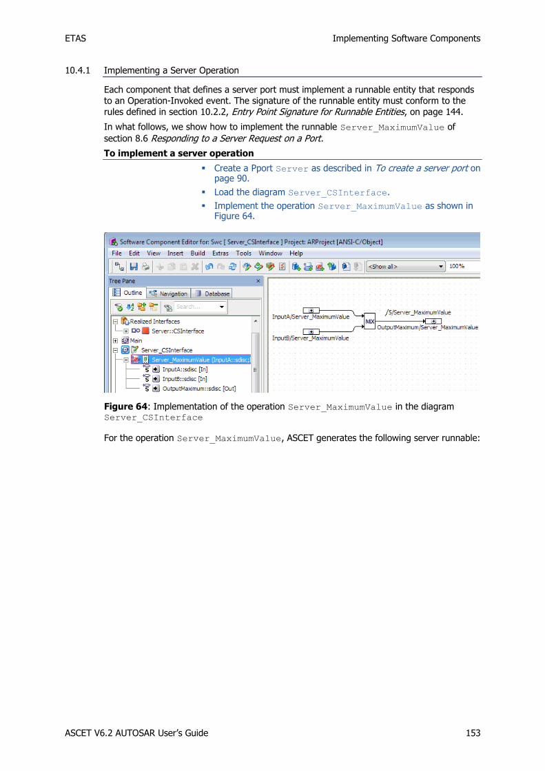
ETAS Implementing Software Components
ASCET V6.2 AUTOSAR User’s Guide 153
10.4.1 Implementing a Server Operation
Each component that defines a server port must implement a runnable entity that responds
to an Operation-Invoked event. The signature of the runnable entity must conform to the
rules defined in section 10.2.2, Entry Point Signature for Runnable Entities, on page 144.
In what follows, we show how to implement the runnable Server_MaximumValue of
section 8.6 Responding to a Server Request on a Port.
To implement a server operation
Create a Pport Server as described in To create a server port on page 90.
Load the diagram Server_CSInterface.
Implement the operation Server_MaximumValue as shown in Figure 64.
Figure 64: Implementation of the operation Server_MaximumValue in the diagram Server_CSInterface
For the operation Server_MaximumValue, ASCET generates the following server runnable:

ETAS Implementing Software Components
ASCET V6.2 AUTOSAR User’s Guide 154
Listing 109: C code – server runnable
Servers may be invoked from multiple sources, for example, through a request from a client received via the communication service or directly via intra-task communication. Unless
marked as concurrently executable within the runnable’s configuration, the RTE will serialize access to the server, queuing requests on a first-in/first-out basis.
10.4.2 Making a Client Request on a Port
A runnable entity will be invoked by the RTE each time a request is made for an operation on the server’s port.
For the example of section 8.7, Making a Client Request on a Port, on page 123,
ASCET generates the following C code:

ETAS Implementing Software Components
ASCET V6.2 AUTOSAR User’s Guide 155
Listing 110: C code – client request
10.5 Accessing Calibration Parameters
If a software component declares calibration parameters, then each characteristic is
accessed at runtime using the API call:
CalprmElementType Rte_Calprm_<Port>_<CalprmElement>()
The call returns either the calibration data (primitive types) or a pointer to the data (complex types).
Calibration data in a function is modeled by means of ASCET parameters. In an application
software component, the calibration data can be mapped to the calibration parameters of an AUTOSAR calibration component using the parameter mapping table.
To create a function with parameters:
In the ASCET component manager, select Insert Class Block diagram in order to create an ASCET class.
Name the class ClassWithParam.
Open ClassWithParam in the block diagram editor.
Use the Logic Parameter button to create a logic parameter.
The dialog "Properties for Scalar Element: log" opens.
Name the parameter localLog and change the scope to Imported.

ETAS Implementing Software Components
ASCET V6.2 AUTOSAR User’s Guide 156
Figure 65: Parameter localLog defined as imported
Add an unsigned discrete parameter with name localUdisc and scope Imported.
Model the following method:

ETAS Implementing Software Components
ASCET V6.2 AUTOSAR User’s Guide 157
Figure 66: Block diagram of method calc
To map internal parameters of a function to AUTOSAR calibration parameters:
Create a project as described on page 23.
Insert Swc into the new project as described on page 26.
Insert the calibration interface CalInterface created in section 6.4, Calibration, on page 78 into the software component Swc.
Insert the class ClassWithParam into the software component Swc.
Insert the variables inValue1, inValue2, outValue1 and outValue2 as shown in the block diagram below.
Figure 67: Accessing ClassWithParam in the software component

ETAS Implementing Software Components
ASCET V6.2 AUTOSAR User’s Guide 158
Create a runnable Runnable_Entity and provide a sequence to the method calc within this runnable.
Go to the "Parameter Mapping" tab in the software component editor.
The left column of the table lists all imported parameters in modules and classes of the software component.
The right column of the table contains a drop-down list for each imported parameter. Each list provides the calibration parameters in the software component matching, in type, the imported parameters.
For the parameter localLog, select the calibration parameter calParam1.
Figure 68: Mapping an imported parameter and a calibration parameter
For the parameter localUdisc, select the calibration parameter calParam3.
With that, parameter mapping is complete.
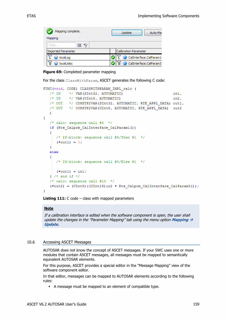
ETAS Implementing Software Components
ASCET V6.2 AUTOSAR User’s Guide 159
Figure 69: Completed parameter mapping
For the class ClassWithParam, ASCET generates the following C code:
Listing 111: C code – class with mapped parameters
Note
If a calibration interface is edited when the software component is open, the user shall update the changes in the "Parameter Mapping" tab using the menu option Mapping Update.
10.6 Accessing ASCET Messages
AUTOSAR does not know the concept of ASCET messages. If your SWC uses one or more
modules that contain ASCET messages, all messages must be mapped to semantically equivalent AUTOSAR elements.
For this purpose, ASCET provides a special editor in the "Message Mapping" view of the
software component editor.
In that editor, messages can be mapped to AUTOSAR elements according to the following rules:
A message must be mapped to an element of compatible type.

ETAS Implementing Software Components
ASCET V6.2 AUTOSAR User’s Guide 160
Message type AUTOSAR element type
Continuous (cont) cont / sdisc / udisc
Signed Discrete (sdisc) cont / sdisc / udisc
Unsigned Discrete (udisc) cont / sdisc / udisc
Logic (log) log
Enumeration (enum) Enumeration of the same type
Table 3: Message types and compatible AUTOSAR types
A pure send message can only be mapped to an element of a sender-receiver interface used as Pport, since the message value is not used within the SWC and thus provided to be used by another SWC.
A pure send message is a send message that appears in only one module of the
software component, i.e. it is not received by another module.
A pure receive message can only be mapped to an element of a sender-receiver interface used as Rport, since the message value is not given within the SWC and must therefore be given by another SWC.
A pure receive message is a receive message that is not used as send message within
the SWC.
All other messages, i.e. SendReceive messages and messages specified as send message in one module and as receive message in another module, can be mapped to an interrunnable variable or to an element of a sender-receiver interface used as Pport.
To ease reuse of ASCET modules in SWC, it is possible to export mappings from one SWC and import them into another SWC. See the ASCET online help for details.
To create a module with messages:
In the ASCET component manager, select Insert Module Block diagram in order to create an ASCET module.
Name the module ModuleWithMsg.
Open ModuleWithMsg in the block diagram editor.
Use the SendReceive Message button to create a receive message.
The dialog "Properties for Scalar Element: message" opens.
Name the message SendRecMsg1 and change the basic type to Signed Discrete.
Click OK to close the properties editor.
Add a second SendReceive message with name SendRecMsg2 and basic type Signed Discrete.
Add a send message with name SendMsg and basic type Logic.
Implement SendRecMsg1 and SendRecMsg2 as sint8 (see Figure 10).
Implement SendMsg as bool.
Model the following process:

ETAS Implementing Software Components
ASCET V6.2 AUTOSAR User’s Guide 161
Figure 70: Block diagram of process process
To map ASCET messages to AUTOSAR elements:
Create (cf. page 23) and set up (cf. page 23) a project ARProject.
Create a software component Swc (cf. page 26) with a runnable entity and three interrunnable variables (cf. page 125):
name IRV_sdisc1 IRV_sdisc2 IRV_log
basic type Signed Discrete Logic
Impl. type sint8 bool
Internal access implicit explicit implicit
Create a sender-receiver interface SRinterface (cf. page 62) with two sdisc data elements, implemented as sint8, and one log element, implemented as bool.
Add the module ModuleWithMsg to Swc.
Use SRinterface to create a sender port in the SCW (cf. page 87).
Add Swc to ARProject.
In the "Outline" tab of the project editor, double-click Swc to open the component in the project context.
In the software component editor, go to the "Message Mapping" tab and the "Internal Access" sub-tab.
The left column of the table lists all messages that can be mapped to interrunnable variables.
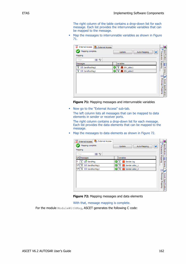
ETAS Implementing Software Components
ASCET V6.2 AUTOSAR User’s Guide 162
The right column of the table contains a drop-down list for each message. Each list provides the interrunnable variables that can be mapped to the message.
Map the messages to interrunnable variables as shown in Figure 71.
Figure 71: Mapping messages and interrunnable variables
Now go to the "External Access" sub-tab.
The left column lists all messages that can be mapped to data elements in sender or receiver ports.
The right column contains a drop-down list for each message. Each list provides the data elements that can be mapped to the message.
Map the messages to data elements as shown in Figure 72.
Figure 72: Mapping messages and data elements
With that, message mapping is complete.
For the module ModuleWithMsg, ASCET generates the following C code:

ETAS Implementing Software Components
ASCET V6.2 AUTOSAR User’s Guide 163
Listing 112: C code – module with mapped messages
10.7 Concurrency Control with Exclusive Areas
Where a component has multiple runnable entities that require concurrent write access to
the same prototype state, then the Rte_Enter and Rte_Exit API calls must be used to
ensure that data consistency is maintained.
A component includes multiple runnable entities each of which can be active simultaneously. The potential exists for concurrent access to private global data (e.g. elements in the data
memory sections) and/or non-reentrant functions.
Operating system concurrency control mechanisms are hidden from components. However the RTE API implements explicit access to exclusive areas by exposing an appropriate OS
mechanism to components:
Rte_Enter_<exclusive area name> enters an exclusive area.
Rte_Exit_<exclusive area name> exits an exclusive area.
Where components declare exclusive areas, the generated RTE API for the component includes these API calls to allow you to control concurrent access to shared data.
10.7.1 Sequences of a Runnable Assigned to an Exclusive Area
A component can use the Rte_Enter and Rte_Exit API calls for any exclusive area ID
you define at configuration time.
For example, for the exclusive are SwcExclusiveArea of section 8.9, Exclusive Areas, on
page 129, the following C calls are used:

ETAS Implementing Software Components
ASCET V6.2 AUTOSAR User’s Guide 164
Listing 113: C code – enter/exit exclusive area
For the example of section 8.9.3 on page 131,
ASCET generates the following C code:
Listing 114: C code – exclusive area example
Note
The scope of an exclusive area is the software component prototype and not the software component type or system wide. Therefore, exclusive areas only provide concurrency control within a software component. Wider scope can be achieved using an AUTOSAR component to broker access to shared data.

ETAS ETAS Contact Addresses
ASCET V6.2 AUTOSAR User’s Guide 165
11 ETAS Contact Addresses
ETAS HQ
ETAS GmbH
Borsigstraße 14 Phone: +49 711 89661-0
70469 Stuttgart Fax: +49 711 89661-106
Germany WWW: www.etas.com/
ETAS Subsidiaries and Technical Support
For details of your local sales office as well as your local technical support team and product hotlines, take a look at the ETAS website:
ETAS subsidiaries WWW: www.etas.com/en/contact.php
ETAS technical support WWW: www.etas.com/en/hotlines.php
ETAS Index
ASCET V6.2 AUTOSAR User’s Guide 166
Index
A
access macros
Rte_Calprm, 155
Rte_DRead, 149 Rte_Enter, 163
Rte_Exit, 163 Rte_IRead, 152
Rte_IWrite, 148
Rte_Read, 149 Rte_Write, 146
application data type, 45 application error, 75
assign to operation return value, 75 create, 75
array, 43, 58
create, 43 ARXML file
configure, 25 ARXML importer, 28
ASCET
assign runnable sequences to exclusive area, 131
AUTOSAR code generation settings, 23 change RTE access, 112
create application error, 75 create calibration interface, 78
create client-server interface, 70
create enumeration, 36 create exclusive area, 130
create mode group, 67 create mode-switch interface, 69
create NVData interface, 83
create operation, 71 create record, 39
create runnable entity, 107 create sender-receiver interface, 62
create software component, 26, 86
develop SWC, 32 enable AUTOSAR component creation, 22
generate code, 27 implementation of data element, 64
import ARXML file, 29 model software components, 142–64
parameter mapping, 157
specify operation, 153
authoring tool, 19 AUTOSAR
authoring tool, 19 basic approach, 18
behavior modeling tool, 21 calibration interface, 78
client-server interface, 70
code generation, 26 code generation settings, 22
configure ARXML output, 25 data types (R3.1.5), 33–44
exclusive area, 129, 163
interfaces, 62–85 interrunnable variable, 125
memory sections definition, 24 mode, 141
mode group, 67 operation, 71
Overview, 18–21
runnable entity, 20, 107 runtime environment, 18, 20
software component, 18 software component types, 86–99
virtual function bus, 18
AUTOSAR component create calibration interface, 78
create client-server interface, 70 create NVData interface, 83
create sender-receiver interface, 62 create software component, 86
enable creation, 22
AUTOSAR interface, 20 AUTOSAR R4
NVData interface, 83 provided port definition, 89
required port definition, 94
Rte_DRead, 149
B
base type, 47
basic approach, 18
behavior modeling tool, 21 bottom-up approach, 30
BSW types, 33
ETAS Index
ASCET V6.2 AUTOSAR User’s Guide 167
C
calibration interface, 78 create, 78
implementation, 80 parameter, 79
calibration parameter, 79
access, 155 create, 79
implementation, 80 map to ASCET parameter, 157
client request, 123
client request on port, 123 client-server communication, 152
client request, 154 client-server interface, 70
application error, 75
create, 70 implementation, 73
operation, 71, 153 code generation, 26
code generation settings, 23 complex types, 39, 52
array, 43, 58
record, 39, 52 concurrent invocation of server, 121
enable, 121
D
data element create, 64
implementation, 64, 84 data types (R3.1.5), 33–44
array, 43
BSW types, 33 complex, 39, 43
default implementation, 34 enumeration, 36
primitive, 33 primitive ~ with semantics, 36
record, 39
data types (R4.0.*) application data type, 45
array, 58 base type, 47
complex, 52, 58
enumeration, 50 implementation data type, 45
platform type, 46 primitive, 47
primitive ~ with semantics, 50
data types (R4.0.5) record, 52
default implementation, 34 developing SWC, 32
E
enumeration, 36, 50 create, 36
create application error, 75 event, 101
mode-switch ~, 105
operation-invoked ~, 103 timing ~, 102
exclusive area, 129, 163 assign sequences of runnable, 131, 163
create, 130
use, 131 explicit communication, 110
read access, 115 receive from port, 115
send to port, 110
explicit data read access, 115
I
implementation
calibration parameter, 80
data element, 64 default, 34
of record, 40, 42 operation, 72
sdisc as sint8, 34 implementation data type, 45
platform type, 46
implicit communication, 112 read access, 117
receive from port, 117 send to port, 113
implicit data read access, 117
interfaces, 62–85 calibration, 78
client-server, 70 NVData, 83
sender-receiver, 62 internal behavior, 100–133
client request on port, 123
event, 101 exclusive area, 129
explicit communication, 110, 115 implicit communication, 112, 117
interrunnable variable, 125
receive from port, 114 respond to server request on port, 119
response to timing event, 109 runnable entity, 107
send to port, 110
interrunnable variable, 125
M
memory sections
definition, 24
memorySections_Autosar.xml, 25

ETAS Index
ASCET V6.2 AUTOSAR User’s Guide 168
memorySections_Autosar4.xml, 25
mode, 141
create mode group, 134 define, 134
disable, 139 trigger runnable on mode-switch event, 137
use, 136
mode communication, 135 create mode group interface, 136
mode group, 67 create, 67, 134
R3.1.5 or lower, 67
R4.0.*, 67 mode group interface
create, 136 insert in SWC, 136
mode-switch interface create, 69
mode-switch event, 105
add to runnable, 138 create, 105, 137
trigger runnable, 137 mode-switch interface, 67
R4.0.*, 67
N
NVData interface, 83
NVdata element
create, 84 NVData interface
create, 83 create data element, 84
implementation, 84 implementation of data element, 84
variable data prototypes, 84
O
operation, 71, 153 assign application error to return value, 75
create, 71
create argument, 71 implementation, 72
specify in ASCET, 153 operation-invoked event, 103
Overview, 18–21
authoring tool, 19 behavior modeling tool, 21
runtime environment, 20
P
platform type, 46 port, 87
client request, 154 client request on ~, 123
create calibration port, 96
create client port, 95
create NVData port, 98
create receiver port, 93 create sender port, 87
create server port, 90 make client request, 123
provided, 87
receive from ~, 114 required, 92
respond to server request on ~, 119 send to ~, 110
PPort. see provided port
primitive data types, 33, 47 with semantics, 36, 50
project configure ARXML output, 25
insert software component, 26 provided port, 87
create sender port, 87
create server port, 90
R
receive from port, 114, 149
explicit communication, 115, 149
explicit communication + status, 150 implicit communication, 117, 152
record, 39, 52 create, 39
required port, 92
create calibration port, 96 create client port, 95
create NVData port, 98 create receiver port, 93
respond to server request on port, 119 RPort. see required port
RTE API
client-server communication, 152 naming convention, 142
parameter passing mechanism, 143 sender-receiver communication, 145
RTE generator, 30
contract phase, 31 RTE phase, 31
Rte_Call, 152 Rte_Calprm, 155
Rte_DRead, 149
Rte_Enter, 163 Rte_Exit, 163
Rte_IRead, 152 Rte_IWrite, 148
Rte_Read, 149 Rte_Write, 146 runnable. See runnable entity
runnable entity, 20, 107
access interrunnable variable, 127
add mode-switch event, 138 assign sequences in exclusive area, 131,
163

ETAS Index
ASCET V6.2 AUTOSAR User’s Guide 169
assign timing event, 109
category, 20
create, 107, 137 disable activation, 139
entry point, 144 naming convention, 142
response to timing event, 109
set C identifier, 108 trigger on mode-switch event, 137
runtime environment, 18, 20
S
sample database, 15 send to port, 110, 146
explicit communication, 110, 146 explicit communication + status, 146
implicit communication, 113, 148
Sender-Receiver interface, 62
sender-receiver communication, 145 receive, 149
send, 146 sender-receiver interface
create, 62
create data element, 64 create mode group interface, 69
data element prototypes, 64 implementation, 65
mode communication, 135
mode group, 67 server
concurrent invocation, 121 software component, 18
~ types, 86–99 component type, 86
create, 26, 86
create calibration port, 96 create client port, 95
create NVData port, 98 create receiver port, 93
create sender port, 87
create server port, 90 event, 101
implement, 142–64 insert in project, 26
insert mode group interface, 136
internal behavior, 100–133
open, 86 port, 87
soncurrent invocation of server, 121 software component development, 22–32
bottom-up approach, 30
RTE generator, 30 top-down approach, 28
software component modeling, 142–64 access calibration parameters, 155
application header files, 143
application source code, 143 basic concepts, 142
client request, 154 client-server communication, 152
entry point for runnable, 144 exclusive area, 163
receive with explicit communication, 149
receive with explicit communication + status, 150
receive with implicit communication, 152 send with explicit communication, 146
send with explicit communication + status,
146 send with implicit communication, 148
sender-receiver communication, 145 server operation, 153
software component types, 86–99 Std_ReturnType, 39
T
timing event, 102
assign to runnable, 109 create, 102
response to ~, 109
top-down approach, 28
U
UUID, 29
V
virtual function bus, 18