ERB-24 User's Guide
33
ERB-24 User’s Guide A GREATER MEASURE OF CONFIDENCE
-
Upload
khangminh22 -
Category
Documents
-
view
1 -
download
0
Transcript of ERB-24 User's Guide

ERB-24User’s Guide
A G R E A T E R M E A S U R E O F C O N F I D E N C E

WARRANTY
Hardware
Keithley Instruments, Inc. warrants that, for a period of one (1) year from the date of shipment (3 years for Models 2000, 2001, 2002, 2010 and 2700), the Keithley Hardware product will be free from defects in materials or workmanship. This warranty will be honored provided the defect has not been caused by use of the Keithley Hardware not in accordance with the instructions for the product. This warranty shall be null and void upon: (1) any modification of Keithley Hardware that is made by other than Keithley and not approved in writing by Keithley or (2) operation of the Keithley Hardware outside of the environmental specifications therefore.
Upon receiving notification of a defect in the Keithley Hardware during the warranty period, Keithley will, at its option, either repair or replace such Keithley Hardware. During the first ninety days of the warranty period, Keithley will, at its option, supply the necessary on site labor to return the product to the condition prior to the notification of a defect. Failure to notify Keithley of a defect during the warranty shall relieve Keithley of its obligations and liabilities under this warranty.
Other Hardware
The portion of the product that is not manufactured by Keithley (Other Hardware) shall not be covered by this warranty, and Keithley shall have no duty of obligation to enforce any manufacturers' warranties on behalf of the customer. On those other manufacturers’ products that Keithley purchases for resale, Keithley shall have no duty of obligation to enforce any manufacturers’ warranties on behalf of the customer.
Software
Keithley warrants that for a period of one (1) year from date of shipment, the Keithley produced portion of the software or firmware (Keithley Software) will conform in all material respects with the published specifications provided such Keithley Software is used on the product for which it is intended and otherwise in accordance with the instructions therefore. Keithley does not warrant that operation of the Keithley Software will be uninterrupted or error-free and/or that the Keithley Software will be adequate for the customer's intended application and/or use. This warranty shall be null and void upon any modification of the Keithley Software that is made by other than Keithley and not approved in writing by Keithley.
If Keithley receives notification of a Keithley Software nonconformity that is covered by this warranty during the warranty period, Keithley will review the conditions described in such notice. Such notice must state the published specification(s) to which the Keithley Software fails to conform and the manner in which the Keithley Software fails to conform to such published specification(s) with sufficient specificity to permit Keithley to correct such nonconformity. If Keithley deter-mines that the Keithley Software does not conform with the published specifications, Keithley will, at its option, provide either the programming services necessary to correct such nonconformity or develop a program change to bypass such nonconformity in the Keithley Software. Failure to notify Keithley of a nonconformity during the warranty shall relieve Keithley of its obligations and liabilities under this warranty.
Other Software
OEM software that is not produced by Keithley (Other Software) shall not be covered by this warranty, and Keithley shall have no duty or obligation to enforce any OEM's warranties on behalf of the customer.
Other Items
Keithley warrants the following items for 90 days from the date of shipment: probes, cables, rechargeable batteries, diskettes, and documentation.
Items not Covered under Warranty
This warranty does not apply to fuses, non-rechargeable batteries, damage from battery leakage, or problems arising from normal wear or failure to follow instructions.
Limitation of Warranty
This warranty does not apply to defects resulting from product modification made by Purchaser without Keithley's express written consent, or by misuse of any product or part.

Disclaimer of Warranties
EXCEPT FOR THE EXPRESS WARRANTIES ABOVE KEITHLEY DISCLAIMS ALL OTHER WARRANTIES, EXPRESS OR IMPLIED, INCLUDING WITHOUT LIMITATION, ALL IMPLIED WARRANTIES OF MERCHANT-ABILITY AND FITNESS FOR A PARTICULAR PURPOSE. KEITHLEY DISCLAIMS ALL WARRANTIES WITH RESPECT TO THE OTHER HARDWARE AND OTHER SOFTWARE.
Limitation of Liability
KEITHLEY INSTRUMENTS SHALL IN NO EVENT, REGARDLESS OF CAUSE, ASSUME RESPONSIBILITY FOR OR BE LIABLE FOR: (1) ECONOMICAL, INCIDENTAL, CONSEQUENTIAL, INDIRECT, SPECIAL, PUNITIVE OR EXEMPLARY DAMAGES, WHETHER CLAIMED UNDER CONTRACT, TORT OR ANY OTHER LEGAL THEORY, (2) LOSS OF OR DAMAGE TO THE CUSTOMER'S DATA OR PROGRAMMING, OR (3) PENALTIES OR PENALTY CLAUSES OF ANY DESCRIPTION OR INDEMNIFICATION OF THE CUSTOMER OR OTHERS FOR COSTS, DAM-AGES, OR EXPENSES RELATED TO THE GOODS OR SERVICES PROVIDED UNDER THIS WARRANTY.
Keithley Instruments, Inc.
28775 Aurora Road • Cleveland, Ohio 44139 • 440-248-0400 • Fax: 440-248-6168
1-888-KEITHLEY (534-8453) • www.keithley.com
Sales Offices: BELGIUM: Bergensesteenweg 709 • B-1600 Sint-Pieters-Leeuw • 02-363 00 40 • Fax: 02/363 00 64 CHINA: Yuan Chen Xin Building, Room 705 • 12 Yumin Road, Dewai, Madian • Beijing 100029 • 8610-6202-2886 • Fax: 8610-6202-2892FINLAND: Tietäjäntie 2 • 02130 Espoo • Phone: 09-54 75 08 10 • Fax: 09-25 10 51 00FRANCE: 3, allée des Garays • 91127 Palaiseau Cédex • 01-64 53 20 20 • Fax: 01-60 11 77 26GERMANY: Landsberger Strasse 65 • 82110 Germering • 089/84 93 07-40 • Fax: 089/84 93 07-34GREAT BRITAIN: Unit 2 Commerce Park, Brunel Road • Theale • Berkshire RG7 4AB • 0118 929 7500 • Fax: 0118 929 7519INDIA: Flat 2B, Willocrissa • 14, Rest House Crescent • Bangalore 560 001 • 91-80-509-1320/21 • Fax: 91-80-509-1322ITALY: Viale San Gimignano, 38 • 20146 Milano • 02-48 39 16 01 • Fax: 02-48 30 22 74JAPAN: New Pier Takeshiba North Tower 13F • 11-1, Kaigan 1-chome • Minato-ku, Tokyo 105-0022 • 81-3-5733-7555 • Fax: 81-3-5733-7556KOREA: 2FL., URI Building • 2-14 Yangjae-Dong • Seocho-Gu, Seoul 137-888 • 82-2-574-7778 • Fax: 82-2-574-7838NETHERLANDS: Postbus 559 • 4200 AN Gorinchem • 0183-635333 • Fax: 0183-630821SWEDEN: c/o Regus Business Centre • Frosundaviks Allé 15, 4tr • 169 70 Solna • 08-509 04 679 • Fax: 08-655 26 10SWITZERLAND: Kriesbachstrasse 4 • 8600 Dübendorf • 01-821 94 44 • Fax: 01-820 30 81TAIWAN: 1FL., 85 Po Ai Street • Hsinchu, Taiwan, R.O.C. • 886-3-572-9077• Fax: 886-3-572-9031
4/02

ERB-24User’s Guide
©1994, Keithley Instruments, Inc.All rights reserved.
Cleveland, Ohio, U.S.A.Third Printing, June 2002
Document Number: 63930 Rev. C
New Contact Information
Keithley Instruments, Inc.28775 Aurora Road
Cleveland, OH 44139
Technical Support: 1-888-KEITHLEYMonday – Friday 8:00 a.m. to 5:00 p.m (EST)
Fax: (440) 248-6168
Visit our website at http://www.keithley.com

Basic™ is a trademark of Dartmouth College.
IBM® is a registered trademark of International Business Machines Corporation.
PC, XT, and AT® are trademarks of International Business Machines Corporation.
Microsoft® is a registered trademark of Microsoft Corporation.
Turbo C® is a registered trademark of Borland International.
DriverLINX is a registered trademark of Scientific Software Tools, Inc.
All other brand and product names are trademarks or registered trademarks of theirrespective companies.
Information furnished by Keithley Instruments is believed to be accurate and reliable.However, Keithley Instruments assumes no responsibility for the use of such information norfor any infringements of patents or other rights of third parties that may result from itsuse. No license is granted by implication or otherwise under any patent rights of Keithley
Instruments.
WARNINGKeithley Instruments assumes no responsibility for damages consequent to
the use of this product. This product is not designed with components of a level ofreliability suitable for use in life support or critical applications.

Table of Contents
iii
Preface
1 OverviewFeatures . . . . . . . . . . . . . . . . . . . . . . . . . . . . . . . . . . . . . . . . . . . .1-1Applications . . . . . . . . . . . . . . . . . . . . . . . . . . . . . . . . . . . . . . . . .1-2Accessories. . . . . . . . . . . . . . . . . . . . . . . . . . . . . . . . . . . . . . . . . .1-2
2 Functional Description
3 SetupUnpacking the Board . . . . . . . . . . . . . . . . . . . . . . . . . . . . . . . . . .3-1Setting the AC Line Voltage . . . . . . . . . . . . . . . . . . . . . . . . . . . . .3-2
4 Cabling and WiringConnector Pin Assignments . . . . . . . . . . . . . . . . . . . . . . . . . . . . .4-1Attaching to a PIO-12, PIO-24, µCPIO-12, or µCPIO-24 . . . . . .4-4Attaching to the DAS-1600 or DAS-1200 Series . . . . . . . . . . . .4-5Attaching to a PIO-96 . . . . . . . . . . . . . . . . . . . . . . . . . . . . . . . . .4-6
5 ProgrammingPIO-12 Relay Signal Names . . . . . . . . . . . . . . . . . . . . . . . . . . . .5-1BASIC Example. . . . . . . . . . . . . . . . . . . . . . . . . . . . . . . . . . . . . .5-2
6 TroubleshootingProblem Isolation . . . . . . . . . . . . . . . . . . . . . . . . . . . . . . . . . . . . .6-1Technical Support. . . . . . . . . . . . . . . . . . . . . . . . . . . . . . . . . . . . .6-2
A Specifications
B Connector Pin Assignments37-Pin Connector . . . . . . . . . . . . . . . . . . . . . . . . . . . . . . . . . . . . B-150-Pin Connector . . . . . . . . . . . . . . . . . . . . . . . . . . . . . . . . . . . . B-2

iv
Index
List of FiguresFigure 2-1. ERB-24 Block Diagram. . . . . . . . . . . . . . . . . . . . .2-2Figure 2-2. Typical Relay Channel. . . . . . . . . . . . . . . . . . . . . .2-2Figure 3-1. ERB-24 Board Layout . . . . . . . . . . . . . . . . . . . . . .3-2Figure 4-1. Pin Assignments of the 37-Pin Connector (J14) . .4-2Figure 4-2. Pin Assignments of the 50-Pin Connector (J15) . .4-3Figure 4-3. Attaching to a PIO-12, PIO-24, µCPIO-12, or
µCPIO-24 Board . . . . . . . . . . . . . . . . . . . . . . . . . .4-4Figure 4-4. Attaching to a DAS-1600 or DAS-1200 Series
Board . . . . . . . . . . . . . . . . . . . . . . . . . . . . . . . . . . .4-5Figure 4-5. Attaching to a PIO-96 Board . . . . . . . . . . . . . . . . .4-6Figure B-1. Pin Assignments for the 37-Pin Connector (J14) B-1Figure B-2. Pin Assignments for the 50-Pin Connector (J15) B-2
List of TablesTable 5-1. PIO-12 Relay Signals. . . . . . . . . . . . . . . . . . . . . . .5-1Table 6-1. Troubleshooting Information . . . . . . . . . . . . . . . . .6-2Table A-1. ERB-24 Specifications. . . . . . . . . . . . . . . . . . . . . A-1

v
Preface
This manual describes how to cable, wire, program, and use ERB-24 relay output boards with digital I/O boards, such as the PIO-12.
This guide serves data acquisition system designers, engineers, technicians, programmers, scientists, and other users responsible for setting up, cabling, wiring, and writing programs that access the functionality of the ERB-24 board. This guide assumes that you are familiar with data acquisition and programming principles and with your particular application.
The ERB-24 User’s Guide is organized as follows:
● Chapter 1 briefly describes the features, applications, and accessories supported by the ERB-24.
● Chapter 2 describes the features of the ERB-24 in more detail and provides a block diagram of the board.
● Chapter 3 describes how to unpack and set up the ERB-24 board.
● Chapter 4 describes how to attach the ERB-24 to digital I/O boards.
● Chapter 5 provides an example of accessing the functionality of an ERB-24 board using a PIO-12 board and the BASIC programming language.
● Chapter 6 provides troubleshooting information and information on how to obtain technical support and repairs for the ERB-24.
● Appendix A lists the specifications for the ERB-24.
● Appendix B lists the connector pin assignments for the ERB-24.
An index completes this guide.

1-1
1Overview
The ERB-24 is a 24-channel relay output board. This chapter describes the features and typical applications of the ERB-24 and the accessories provided for the board.
Features
The ERB-24 is compatible with the PIO-12, PIO-24, PIO-96, µCPIO-12, and µCPIO-24 digital I/O boards. The ERB-24 is also compatible with the digital I/O section of the DAS-1600 Series and DAS-1200 Series boards.
The ERB-24 provides the following features:
● 24 double-pole, double-throw relays (dual form C)
● 3 A contact rating (120 Vrms)
● Built-in power supply
● Screw terminals that accept 12-22 AWG wire
● LEDs that indicate activated relays
● 37-pin connector
● 50-pin connector
1-2 Overview
Applications
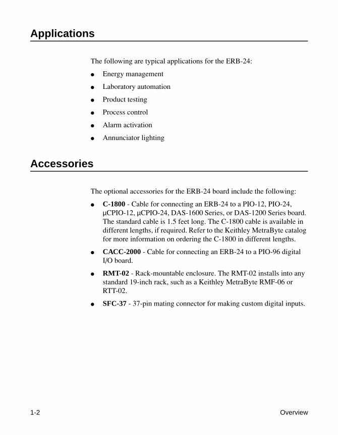
The following are typical applications for the ERB-24:
● Energy management
● Laboratory automation
● Product testing
● Process control
● Alarm activation
● Annunciator lighting
Accessories
The optional accessories for the ERB-24 board include the following:
● C-1800 - Cable for connecting an ERB-24 to a PIO-12, PIO-24, µCPIO-12, µCPIO-24, DAS-1600 Series, or DAS-1200 Series board. The standard cable is 1.5 feet long. The C-1800 cable is available in different lengths, if required. Refer to the Keithley MetraByte catalog for more information on ordering the C-1800 in different lengths.
● CACC-2000 - Cable for connecting an ERB-24 to a PIO-96 digital I/O board.
● RMT-02 - Rack-mountable enclosure. The RMT-02 installs into any standard 19-inch rack, such as a Keithley MetraByte RMF-06 or RTT-02.
● SFC-37 - 37-pin mating connector for making custom digital inputs.

2-1
2Functional Description
Each of the 24 relays on the ERB-24 board is supported by its own control line. The relay is an electromechanical, dual form C (double-pole, double-throw) module capable of switching loads under program control. The electromechanical relays offer zero-leakage output currents.
Each relay contains two normally open contacts and two normally closed contacts. Each contact can switch up to 3 A (resistive) at 120 Vrms.
The ERB-24 provides both a 37-pin and a 50-pin connector. The 37-pin connector is provided for connecting to a PIO-12, PIO-24, µCPIO-12, or µCPIO-24 digital I/O board or to the 37-pin auxiliary connector on a DAS-1600 Series or DAS-1200 Series board. The 50-pin connector is provided for connecting to a PIO-96 digital I/O board.
A 5 V signal applied to the corresponding relay control pin on the connector energizes the relay. Onboard transistor drivers allow control of the ERB-24 by any LSTTL- or NMOS/ CMOS-compatible digital output board.
The ERB-24 contains an annunciator LED for each relay for purposes of monitoring and troubleshooting. Each annunciator LED lights when its associated relay is energized.
The board also contains its own power supply. The power supply operates on 115/230 VAC and accepts 15% voltage fluctuations. Operating temperatures range from 0° to 60°C.
A block diagram of the ERB-24 board is shown in Figure 2-1. Figure 2-2 shows the circuitry for a single relay channel.

2-2 Functional Description
Figure 2-1. ERB-24 Block Diagram
Figure 2-2. Typical Relay Channel
24 DarlingtonTransistor Drivers
Relay 0
Relay 23
Relays0 to 23
.
.
.
.
.
.
For Relays0 to 23
.
.
PowerSupply
TTLSignals
FromDigitalI/OBoard
115/230 Vat 50/60 Hz Notes: NC = Normally Closed
NO = Normally Open C = Common
.
.
.
NC ANO AC ANC BNO BC B
NC ANO AC ANC BNO BC B
RELAY “X”
FROMDIGITAL I/O
BOARD
DIGCOM
2.7K
7.2K 3.0K
MOTOROLAULN2803/8
+24V
NO B NC B
COM B
NO A NC A
COM A
NO = NORMALLY OPENNC = NORMALLY CLOSED

3-1
3Setup
This chapter describes how to set up your ERB-24 board. If you encounter any problems with the board after setting it up, refer to Chapter 6 for troubleshooting information.
Unpacking the Board
Caution: A discharge of static electricity from your hands can seriously damage certain electrical components on any circuit board. It is recommended that you use wrist strap grounds when handling a board. If a wrist strap ground is not available, make sure that you discharge static electricity from yourself by touching a grounded conductor such as your computer chassis (your computer must be turned off).
Whenever you handle a board, hold it by the edges and avoid touching any board components.
Use the following procedure to unpack an ERB-24 board:
1. Remove the board from its anti-static wrapping material. You may wish to store the wrapping material for possible future use.
2. Inspect the board for signs of damage. If damage is apparent, arrange to return the board (see page 6-2).
3. Check the remaining contents of your package against the packing list to be sure your order is complete. Report any missing items, immediately.

4. Once you have determined that the board is acceptable, select the appropriate AC line voltage, as described in the next section.
Setting the AC Line Voltage
Caution:
Be sure to set the AC line voltage for the voltage you are using before connecting the ERB-24 to line power. The default setting is 115 V.
The 115/230 AC Line Voltage Selector is a 2-position slide switch located as shown in Figure 3-1. To change the line voltage setting, slide the switch to the appropriate setting (115 V or 230 V) marked on the switch.
Figure 3-1. ERB-24 Board Layout
Once you have set the AC line voltage, you can attach accessories and wire appli-cations to the ERB-24 board, as discussed in Chapter 4.
37-Pin ConnectorAC LineVoltageSelector
ACPowerInput
Screw Terminals
Screw Terminals
Transformer
J13
J14LEDS
J15, 50-Pin Connector Fuse
0 1 2 3 4 5 6 7 8 9 10 11
23 22 21 20 19 18 17 16 15 14 13 12
3-2 Setup

4-1
4Cabling and Wiring
Once you have set up the ERB-24, you can attach accessories and wire applications to the board. This chapter describes the pin assignments of the connectors on the ERB-24 and how to attach the ERB-24 to digital I/O boards.
Connector Pin Assignments
The ERB-24 board contains two connectors: a 37-pin, D-type, male connector (J14) and a 50-pin connector (J15), shown in Figure 3-1. The pin assignments of the 37-pin connector are shown in Figure 4-1; the pin assignments of the 50-pin connector are shown in Figure 4-2.

4-2 Cabling and Wiring
Figure 4-1. Pin Assignments of the 37-Pin Connector (J14)
N/C Pin 19N/C Pin 18N/C Pin 17N/C Pin 16N/C Pin 15N/C Pin 14N/C Pin 13N/C Pin 12DIG COM Pin 11Relay 16 Pin 10Relay 17 Pin 9Relay 18 Pin 8Relay 19 Pin 7Relay 20 Pin 6Relay 21 Pin 5Relay 22 Pin 4Relay 23 Pin 3N/C Pin 2N/C Pin 1
Pin 37 Relay 0Pin 36 Relay 1Pin 35 Relay 2Pin 34 Relay 3Pin 33 Relay 4Pin 32 Relay 5Pin 31 Relay 6Pin 30 Relay 7Pin 29 Relay 8Pin 28 Relay 9Pin 27 Relay 10 Pin 26 Relay 11 Pin 25 Relay 12 Pin 24 Relay 13 Pin 23 Relay 14 Pin 22 Relay 15 Pin 21 DIG COMPin 20 N/C

4-3
Figure 4-2. Pin Assignments of the 50-Pin Connector (J15)
Relay 7 Pin 1Relay 6 Pin 3Relay 5 Pin 5Relay 4 Pin 7Relay 3 Pin 9Relay 2 Pin 11Relay 1 Pin 13Relay 0 Pin 15Relay 15 Pin 17Relay 14 Pin 19Relay 13 Pin 21Relay 12 Pin 23Relay 11 Pin 25Relay 10 Pin 27Relay 9 Pin 29Relay 8 Pin 31Relay 23 Pin 33Relay 22 Pin 35Relay 21 Pin 37Relay 20 Pin 39Relay 19 Pin 41Relay 18 Pin 43Relay 17 Pin 45Relay 16 Pin 47N/C Pin 49
Pin 2 GndPin 4 GndPin 6 GndPin 8 GndPin 10 GndPin 12 GndPin 14 GndPin 16 GndPin 18 GndPin 20 GndPin 22 GndPin 24 GndPin 26 GndPin 28 GndPin 30 GndPin 32 GndPin 34 GndPin 36 GndPin 38 GndPin 40 GndPin 42 GndPin 44 GndPin 46 GndPin 48 GndPin 50 Gnd
4-4 Cabling and Wiring
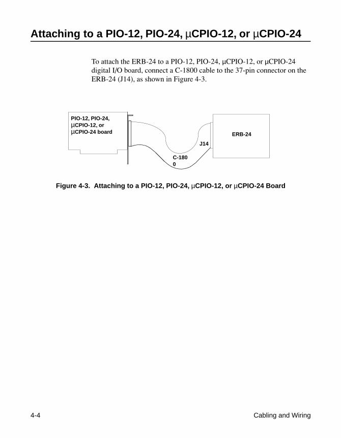
Attaching to a PIO-12, PIO-24, µCPIO-12, or µCPIO-24
To attach the ERB-24 to a PIO-12, PIO-24, µCPIO-12, or µCPIO-24 digital I/O board, connect a C-1800 cable to the 37-pin connector on the ERB-24 (J14), as shown in Figure 4-3.
Figure 4-3. Attaching to a PIO-12, PIO-24, µCPIO-12, or µCPIO-24 Board
ERB-24
PIO-12, PIO-24, µCPIO-12, or µCPIO-24 board
C-1800
J14

4-5
Attaching to the DAS-1600 or DAS-1200 Series
To attach the ERB-24 to a DAS-1600 or DAS-1200 Series board, first attach the DAS board end of the PIO cable that comes with the DAS-1600 and DAS-1200 Series boards to the PIO cable connector (J2) on the DAS board. Next, install the 37-pin D-type connector of the PIO cable in the connector panel next to the main I/O connector (J1) of the DAS-1600 or DAS-1200 Series board. Finally, attach connector J14 on the ERB-24 to the 37-pin D-type connector of the PIO cable with the C-1800 cable. Figure 4-4 illustrates these connections.
Figure 4-4. Attaching to a DAS-1600 or DAS-1200 Series Board
DAS-1600 or DAS-1200 Series board
C-1800 cable
J2
PIO cable ERB-24
J14

4-6 Cabling and Wiring
Attaching to a PIO-96
You can attach up to four ERB-24 boards to a PIO-96 digital I/O board. To attach an ERB-24 to a PIO-96, connect the CACC-2000 cable to the 50-pin connector (J15) on the ERB-24 board and to the 50-pin connector on the PIO-96, as shown in Figure 4-5.
Figure 4-5. Attaching to a PIO-96 Board
PIO-96 board
ERB-24ERB-24ERB-24
J1J2J3J4
ERB-24
CACC-2000Cable
J15J15
CACC-2000CableCACC-2000
CableCACC-2000Cable
J15J15

5-1
5Programming
This chapter provides an example of how to activate relays on the ERB-24 using a PIO-12 digital I/O board and BASIC as the programming language.
PIO-12 Relay Signal Names
Table 5-1 lists the PIO-12 signal names and the corresponding ERB-24 relays.
Table 5-1. PIO-12 Relay Signals
Relay Signal Relay Signal
0 PA0 12 PC4
1 PA1 13 PC5
2 PA2 14 PC6
3 PA3 15 PC7
4 PA4 16 PB0
5 PA5 17 PB1
6 PA6 18 PB2
7 PA7 19 PB3
8 PC0 20 PB4
9 PC1 21 PB5
10 PC2 22 PB6
11 PC3 23 PB7

5-2 Programming
BASIC Example
The following simple BASIC program activates relays on the ERB-24 used with a PIO-12 board:
10 OUT &H313, &H80 ’Sets all PIO-12 ports to outputs20 OUT &H310, 1 ’Activates relay 0 (Port A, Bit 0)30 OUT &H311, 16 ’Activates relay 20 (Port B, Bit 4)40 OUT &H312, 3 ’Activates relays 8 and 9 ’(Port C, Bits 0 and 1)

6-1
6Troubleshooting
If your ERB-24 board is not operating properly, use the information in this chapter to help you isolate the problem. If the problem appears serious enough to require technical support, refer to page 6-2 for information on how to contact an applications engineer.
Problem Isolation
If you encounter a problem with an ERB-24 board, use the troubleshooting information in Table 6-1 to try to isolate the problem. Table 6-1 lists general symptoms and possible solutions for problems with ERB-24 boards.

Table 6-1, Troubleshooting Information
If your board is not operating properly after using the information in Table 6-1, refer to the next section for information on how to contact an applications engineer.
Technical Support
Before returning any equipment for repair, call Keithley for technical support at:
1-888-KEITHLEY
Monday - Friday, 8:00 A.M. - 5:00 P.M., Eastern Time
Symptom Possible Cause Possible Solution
Board does not respond
The board is damaged. Contact the Keithley Applications Engineering Department; see page 6-2
Bad cable or cable not connected.
Check cable connections. Replace cable if defec-tive.
No A/C or power cord not plugged in.
Check power connections to board.
Intermittent operation
Vibrations or loose con-nections exist.
Cushion source of vibration and tighten connec-tions. Check cable.
The board is overheating. Check environmental and ambient temperature. See the documentation for your computer for specifications.
Electrical noise exists. Provide better shielding or reroute wiring.
Data appears to be invalid
An open connection exists.
Check wiring to screw terminal.
Outputs not indicating proper level.
Check that the circuit is complete (are both relay and connections used?).
You may need to apply pull-up resistors for the external source.
6-2 Troubleshooting

6-3
An applications engineer will help you diagnose and resolve your problem over the telephone. Please make sure that you have the following information available before you call:
ERB-24 Serial # _____________________Board Revision code _____________________
VAC line voltage _____________________
Digital I/O Board Type _____________________Serial # _____________________Base address _____________________Interrupt selection _____________________
Computer Manufacturer _____________________CPU type 8088, 286, 386, 486,
Pentium, ____________Clock speed (MHz) 8 12 20 25 33 ____Math coprocessor Yes NoAmount of RAM _____________________Video system CGA Hercules EGA VGABIOS type _____________________
Operating system DOS version _____________________Windows version 3.0 3.1 _____________Windows mode Standard Enhanced
Software package Name _____________________(if applicable) Version _____________________
Invoice/order # _____________________
Compiler Language _____________________(if applicable) Manufacturer _____________________
Version _____________________

If a telephone resolution is not possible, the application engineer will issue you a Return Material Authorization (RMA) number and ask you to return the equipment.Include the RMA number with any documentation regarding the equipment.
When returning equipment for repair, include the following information:
• Your name, address, and telephone number.
• The invoice or order number and date of equipment purchase.
• A description of the problem or its symptoms.
• The RMA number on the
outside
of the package.
Notes:
If you are submitting your equipment for repair under warranty, you must include the invoice number and date of purchase.
To enable Keithley Instruments, Inc., to respond as quickly as possible, you must include the RMA number on the outside of the package.
6-4 Troubleshooting

A-1
ASpecifications
Table A-1 lists the specifications for the ERB-24.
Table A-1. ERB-24 Specifications
Feature Attribute Specification
Relays Quantity and type 24 DPDT, dual form C
Contact material Gold overlay silver
Contact rating 3 A at 28 VDC, resistive3 A at 120 VAC, resistive1.6 A at 220 VAC
Operate time 20 ms maximum at rated voltage
Release time 10 ms maximum
Life expectancy Mechanical Electrical
107 operations/minute
105 operations/minute at rated load
Environmental Operating temperature rangeStorage temperature rangeHumidity
0° to 60°C−40° to +100°C0 to 90% noncondensing
Power Consumption
Input power 115 VAC ±15% (2 A fuse)230 VAC ±15% (1 A fuse)50/60 Hz, 14.5 VA maximum

A-2 Specifications
Physical Dimensions 16-inches long by 4.75-inches wide by 2-inches high
(40.6 cm long by 12.1 cm wide by 5.1 cm high)
Weight 2.2 lb (1 kg)
Screw terminal wire spacing 0.197 inches (5 mm)
Screw terminal wire sizes 12-22 AWG
Mounting screws for boards 4-40
Table A-1. ERB-24 Specifications (cont.)
Feature Attribute Specification

B-1
BConnector Pin Assignments
This appendix contains the pin assignments for the ERB-24 board connectors.
37-Pin Connector
Pin assignments for the 37-pin connector, J14, on the ERB-24 are shown in Figure B-1.
Figure B-1. Pin Assignments for the 37-Pin Connector (J14)
N/C Pin 19N/C Pin 18N/C Pin 17N/C Pin 16N/C Pin 15N/C Pin 14N/C Pin 13N/C Pin 12DIG COM Pin 11Relay 16 Pin 10Relay 17 Pin 9Relay 18 Pin 8Relay 19 Pin 7Relay 20 Pin 6Relay 21 Pin 5Relay 22 Pin 4Relay 23 Pin 3N/C Pin 2N/C Pin 1
Pin 37 Relay 0Pin 36 Relay 1Pin 35 Relay 2Pin 34 Relay 3Pin 33 Relay 4Pin 32 Relay 5Pin 31 Relay 6Pin 30 Relay 7Pin 29 Relay 8Pin 28 Relay 9Pin 27 Relay 10 Pin 26 Relay 11 Pin 25 Relay 12 Pin 24 Relay 13 Pin 23 Relay 14 Pin 22 Relay 15 Pin 21 DIG COMPin 20 N/C

B-2 Connector Pin Assignments
50-Pin Connector
Pin assignments for the 50-pin connector, J15, on the ERB-24 are shown in Figure B-2.
Figure B-2. Pin Assignments for the 50-Pin Connector (J15)
Pin 2 GndPin 4 GndPin 6 GndPin 8 GndPin 10 GndPin 12 GndPin 14 GndPin 16 GndPin 18 GndPin 20 GndPin 22 GndPin 24 GndPin 26 GndPin 28 GndPin 30 GndPin 32 GndPin 34 GndPin 36 GndPin 38 GndPin 40 GndPin 42 GndPin 44 GndPin 46 GndPin 48 GndPin 50 Gnd
Relay 7 Pin 1Relay 6 Pin 3Relay 5 Pin 5Relay 4 Pin 7Relay 3 Pin 9Relay 2 Pin 11Relay 1 Pin 13Relay 0 Pin 15Relay 15 Pin 17Relay 14 Pin 19Relay 13 Pin 21Relay 12 Pin 23Relay 11 Pin 25Relay 10 Pin 27Relay 9 Pin 29Relay 8 Pin 31Relay 23 Pin 33Relay 22 Pin 35Relay 21 Pin 37Relay 20 Pin 39Relay 19 Pin 41Relay 18 Pin 43Relay 17 Pin 45Relay 16 Pin 47N/C Pin 49

X-1
Index
Numerics37-pin connector 2-1
pin assignments 4-2, B-150-pin connector 2-1
pin assignments 4-3, B-2
AAC line voltage 3-2accessories 1-2
C-1800 1-2CACC-2000 1-2RMT-02 1-2SFC-37 1-2
applications 1-2Applications Engineering Department 6-2attaching
DAS-1200 Series 4-5DAS-1600 Series 4-5µCPIO-12 4-4µCPIO-24 4-4PIO-12 4-4PIO-24 4-4PIO-96 4-6
BBASIC example 5-2block diagram 2-2board layout 3-2
CC-1800 1-2, 4-4, 4-5cabling 4-1CACC-2000 1-2, 4-6connector pin assignments 4-1connectors 2-1contacts 1-1, 2-1
DDAS-1200 Series 1-1
attaching 4-5DAS-1600 Series 1-1
attaching 4-5
Eenergizing a relay 2-1example 5-2
Ffeatures 1-1functional description 2-1
Ggetting help 6-2
Iisolating problems 6-1

X-2 Index
JJ14 4-2J15 4-3
Llayout 3-2LED 1-1, 2-1line voltage 3-2
MµCPIO-12 1-1
attaching 4-4µCPIO-24 1-1
attaching 4-4
Ppin assignments 4-1
37-pin connector 4-2, B-150-pin connector 4-3, B-2
PIO cable 4-5PIO-12 1-1
attaching 4-4relay signal names 5-1
PIO-24 1-1attaching 4-4
PIO-96 1-1attaching 4-6
power supply 1-1, 2-1problem isolation 6-1programming 5-1
Rrelay channel 2-2relays 1-1returning equipment 6-4RMA number 6-4RMT-02 1-2
Sscrew terminals 1-1setting the AC line voltage 3-2setting up the ERB-24 3-1SFC-37 1-2specifications A-1
Ttechnical support 6-2transistor drivers 2-1troubleshooting 6-1
Uunpacking the board 3-1
Wwarranty repairs 6-4

Specifications are subject to change without notice.
All Keithley trademarks and trade names are the property of Keithley Instruments, Inc. All other trademarks andtrade names are the property of their respective companies.
Keithley Instruments, Inc. 28775 Aurora Road • Cleveland, Ohio 44139 • 440-248-0400 • Fax: 440-248-61681-888-KEITHLEY (534-8453) • www.keithley.com
Sales Offices: BELGIUM: Bergensesteenweg 709 • B-1600 Sint-Pieters-Leeuw • 02-363 00 40 • Fax: 02/363 00 64 CHINA: Yuan Chen Xin Building, Room 705 • 12 Yumin Road, Dewai, Madian • Beijing 100029 • 8610-6202-2886 • Fax: 8610-6202-2892FINLAND: Tietäjäntie 2 • 02130 Espoo • Phone: 09-54 75 08 10 • Fax: 09-25 10 51 00FRANCE: 3, allée des Garays • 91127 Palaiseau Cédex • 01-64 53 20 20 • Fax: 01-60 11 77 26GERMANY: Landsberger Strasse 65 • 82110 Germering • 089/84 93 07-40 • Fax: 089/84 93 07-34GREAT BRITAIN: Unit 2 Commerce Park, Brunel Road • Theale • Berkshire RG7 4AB • 0118 929 7500 • Fax: 0118 929 7519INDIA: Flat 2B, Willocrissa • 14, Rest House Crescent • Bangalore 560 001 • 91-80-509-1320/21 • Fax: 91-80-509-1322ITALY: Viale San Gimignano, 38 • 20146 Milano • 02-48 39 16 01 • Fax: 02-48 30 22 74JAPAN: New Pier Takeshiba North Tower 13F • 11-1, Kaigan 1-chome • Minato-ku, Tokyo 105-0022 • 81-3-5733-7555 • Fax: 81-3-5733-7556KOREA: 2FL., URI Building • 2-14 Yangjae-Dong • Seocho-Gu, Seoul 137-888 • 82-2-574-7778 • Fax: 82-2-574-7838NETHERLANDS: Postbus 559 • 4200 AN Gorinchem • 0183-635333 • Fax: 0183-630821SWEDEN: c/o Regus Business Centre • Frosundaviks Allé 15, 4tr • 169 70 Solna • 08-509 04 679 • Fax: 08-655 26 10SWITZERLAND: Kriesbachstrasse 4 • 8600 Dübendorf • 01-821 94 44 • Fax: 01-820 30 81TAIWAN: 1FL., 85 Po Ai Street • Hsinchu, Taiwan, R.O.C. • 886-3-572-9077• Fax: 886-3-572-9031
© Copyright 2001 Keithley Instruments, Inc.Printed in the U.S.A.
4/02