Document Image Enhancement Using Directional ... - CiteSeerX
1078 IEEE JOURNAL OF QUANTUM ELECTRONICS, VOL. 47, NO. 8, AUGUST 2011
All-Optical Directional Switching of BistableSemiconductor Ring Lasers
Julien Javaloyes, Member, IEEE, and Salvador Balle, Member, IEEE
Abstract— All-optical directional switching of bistable semi-conductor ring lasers is studied by numerical simulations of atraveling-wave model. We discuss how the reversal depends onthe bias current applied to the laser as well as on the energy,duration, and wavelength of the trigger pulses. For pulse dura-tions longer than the cavity roundtrip time, the reversal occurssmoothly with a transient that exhibits relaxation oscillations,otherwise, the transient is composed of large long-lived spikesthat reveal its multimode character. In the former case, theswitching speed can be defined like in electronics systems, butnot in the latter, which requires an operational definition ofthe maximum speed based on, e.g., bit-error rate measurements.Our model includes the light extraction sections present in realdevices, which allows us to discuss the experimental problemsposed by the differences existing between intracavity fields andoutput fields.
Index Terms— Bistability, optical injection, ring lasers, semi-conductor lasers, switching, traveling-wave model.
I. INTRODUCTION
THE development of photonic components has been his-torically governed by the search of higher transmission
speed in optical networks; however, recent surveys [1] indicatean increasing demand of devices that also allow for a higherlevel of integration as well as some capability to performbasic all-optical signal processing [2]. From this point of view,optical bistable devices are extremely appealing because theycan act as an all-optical Set-Reset Flip-Flop (SRFF), which isthe basic building block for implementing several elementalall-optical logic gates. Optical bistability has been observedin semiconductor lasers in a variety of cases. In particular, itis found in devices subject to optical injection (see [3] fora recent report) or in coupled, optically pumped microdisklasers [4]. Among all possibilities, Semiconductor Ring Lasers(SRLs) are electrically driven and they can intrinsically dis-play very robust bistability between (almost) unidirectional,counter-propagating lasing states [5]. In such a regime, thedirection of emission can be reversed by injecting an external
Manuscript received March 4, 2011; revised April 28, 2011; acceptedMay 1, 2011. Date of current version July 1, 2011. This work was supportedin part by the Engineering and Physical Sciences Research Council underProject EP/E065112/1 and the ALAS Project TEC2009-14581-C02-01.
J. Javaloyes is with the Departament de Fisica, Universitat de les IllesBaleares, Palma de Mallorca E-07122, Spain (e-mail: [email protected]).
S. Balle is with the Institut Mediterrani d’Estudis Avançats, ConsejoSuperior de Investigaciones Científicas-University of the Balearic Islands,Esporles E-07071, Spain (e-mail: [email protected]).
Color versions of one or more of the figures in this paper are availableonline at http://ieeexplore.ieee.org.
Digital Object Identifier 10.1109/JQE.2011.2152368
optical signal propagating in the direction opposite to theactive one [6], [7], allowing to implement elemental logic gates[8]. The compactness of SRLs and the possibility of integratingthem on silicon [9] allow to foresee real-world applicationsfor these systems. However, the application potential of SRLsstrongly depends on the robustness of the bistable regime andon three critical aspects: the switching speed, the pulse energyrequired for the switching, and the wavelength sensitivity.
Bistable, unidirectional lasing in ring lasers happens whenthe interaction between counter-propagating fields is domi-nated by their nonlinear competition for the gain [10]. Thisrequires a low linear backscattering —due to either side-wallroughness or to localized reflections in the cavity— of onefield into the other. SRLs have a cavity formed by a closedsingle-transverse mode waveguide with high quality side-walls that induce very little backscattering of the fields. Thisclosed waveguide is evanescently coupled to one or severalbus waveguides that allow for light injection or extraction[11]. The evanescent coupling introduces only tiny localizedreflections, and the total effective reflectivity is minimizedby tilting the bus waveguides with respect to the exit facetsand anti-reflection coating them. In these conditions, robustbistability among unidirectional lasing states is achieved forsufficiently large bias current [5], [12]
Several experimental reports confirm the potential of SRLsfor all-optical switching applications. M. Hill et al. [6] havemeasured rise times about 20 ps in micro-ring lasers of 16μmdiameter upon the injection of optical pulses with energiesof 5.5 fJ and 13 ps Full Width at Half Maximum (FWHM);however, the delay incurred between injection of the triggerpulse and the switching was not mentioned, and the power andwavelength dependences were not discussed. A. Trita et al. [7]have reported more complete results on these aspects for largerrings (equivalent diameters in the range 150-400μm) withpulses of 5 ps FWHM, achieving switching times of 20 ps anddelay times of 60 ps. More recently, L. Liu et al. [9] havereported switching times of 60 ps with pulse energies of 1.8 fJin micro-disk lasers of 7.5μm in diameter.
These impressive results clearly indicate the potential ofSRLs for ultra-fast all-optical logic, but a number of issuesstill remain to be clarified. In the first place, the mechanismsetting the ultimate switching speed has yet to be elucidated.In particular, it has been suggested that reducing the size ofthe SRL would induce an increase in switching speed [6];however, the time of flight of the photon within the resonatoris not the only relevant time scale present in a laser. Second,the possible interplay of the directional switching with other
0018–9197/$26.00 © 2011 IEEE
JAVALOYES AND BALLE: DIRECTIONAL SWITCHING OF BISTABLE SEMICONDUCTOR RING LASERS 1079
dynamical processes. Specifically, it has been shown that SRLsmay also exhibit wavelength multistability [13] and subtlemodal selection rules [14], [15] that could affect the reliabilityand speed of the switching process. In this sense, we remarkthat the results reported in [7], [9] for large SRLs clearly cor-respond to directional bistability, but those in [6] are found in amixed situation between directional and wavelength bistability.In addition, long-lived multimodal dynamics excited by thetrigger pulses can have a large impact on the maximal rate atwhich one can perform logical operations.
Improving our understanding of the switching behavior inSRL optical bistables is a must for assessing their applicability,as well as for providing specific design rules. This requiresa model more sophisticated than the usual single-mode rateequation model [5], which can be only used to study theswitching dynamics for slow optical pulses that are nearlyresonant with the injected optical pulses [16]. Multimode rate-equations [17], [18] could in principle account for shorterpulses and larger ranges of detuning. However, the difficultyfor computing the modal coupling coefficients —aggravatedwhen spatial effects exist— renders this approach unpracticalwhen many modes must be considered.
Travelling-Wave Models (TWMs) provide a natural way tostudy multimode dynamics including any possible longitudinalinhomogeneity of the optical field and of the active material(the so-called Spatial-Hole Burning effects). At the same time,external optical signals, if any, and the complex geometry ofSRLs are easily accounted for via the boundary conditions forthe fields. In this manuscript, we use the TWM presented in[15], [19], [20] to study the all-optical directional switchingcharacteristics of SRLs, including the case of short triggerpulses that may encompass many SRL modes. In this limit,we need a temporal description of the optical response of thesemiconductor that is valid for broadband optical fields, andwe use the convolution method recently developed in [19] forthe study of passive mode-locking dynamics [20].
The paper is organized as follows. In Section II, we brieflyrecall the basics of our TWM and its implementation forthe geometrical configuration of the SRL. In Section IIIwe analyze the parametric dependencies of the switchingdynamics for long and short trigger pulses. Finally, we presentour conclusions in Section IV.
II. MODELLING
We assume single-transverse mode waveguides, and we usethe TWM developed in [15] —which we summarize below—for determining the dynamics and spatial distribution of theslowly varying amplitudes [21] of the Clockwise and Counter-Clockwise fields, E±(z, t), of a quasi-monochromatic TE fieldof optical frequency ω0. Due to the counter-propagating waves,the total carrier density is expressed as
N(z, t) = N0(z, t) + N+2(z, t)e2iq0z + N−2(z, t)e−2iq0z,
where q0 = ngω0/c, N0(z, t) is the local average of the carrierdensity and N+2(z, t) = N∗−2(z, t) describes the amplitude ofthe carrier spatial modulation at half the optical wavelength(Spatial Hole Burning) imposed by the counter-propagating
waves. Since this modulation is substantially washed out byby carrier diffusion, we assume that N0 � |N±2|.
Scaling space and time to the ring length Lr and the thering round trip τr = ng Lr/c, respectively, our TWM reads(
∂
∂ t± ∂
∂z
)E± (z, t) = i
qw�ω0 Lr
2ε0ngcP± − αi
2E±, (1)
τ−1r
∂
∂ tN0 (z, t) = J − R (N0)
− i
h̄
(P+E�+ + P− E�− − c.c.
), (2)
τ−1r
∂
∂ tN±2 (z, t) = −
(R′ (N0) + 4Dq2
0
)N±2
− i
h̄
(P±E�∓ − E± P�∓
). (3)
Eq. (1) gives the evolution of the fields, while the othersdescribe the evolution of the components of the carrier density.In eq. (1), αi denotes the (scaled) internal losses, � is theoptical confinement factor for one QW, qw is the number ofQW, and ng the group refractive index. In eq. (2), J denotesthe injected current density and the carrier recombination readsR (N) = AN + B N2 + C N3 with A, B and C being the nonradiative, bi-molecular and Auger recombination coefficients,respectively. In eq. (3) the decay of the grating term is givenby the differential carrier recombination R′ = d R/d N plusthe contribution of diffusion, D being the ambipolar diffusioncoefficient.
Eqs. (1)–(3) are coupled through P±(z, t), which are theslowly-varying amplitudes of the active medium’s total polar-ization at (z, t). These are determined from the analyticalapproximation to the frequency- and carrier-dependent opticalsusceptibility of the QW active region developed in [22] bythe convolution method prescribed in [19]. This method allowsus to describe in time domain the spectral dispersion of thecarrier-induced gain and refractive index variations over widefrequency ranges. In this way, they read
P±(z, t) = ε0
∫ ∞
0dt ′
{χ[t ′, N0(z, t − t ′)]E±(z, t − t ′)
+ χN [t ′, N0(z, t − t ′)]N±2(z, t − t ′)E∓(z, t − t ′)}, (4)
with χN (t ′, N) ≡ ∂χ(t ′, N)/∂ N .The functional form of χ(t ′, N) can be found in [19], and
it depends on three main parameters: i) the gap frequency�g which defines the transition point – in frequency domain– from transparent to absorptive or amplifying behavior; ii)the intraband relaxation rate γ which sets the width of theindividual transitions; and iii) the maximal energy of theallowed transitions within the band, given by the parameter b.Finally, the carrier N determines how many of the individualtransitions are inverted. Assuming that |N±2| � N0 becauseof strong diffusion, we arrive to eq. (4), which evidences thatN±2 imposes a coupling between the forward and backwardpropagating waves. This coupling is the dominant source ofcross saturation between the forward and backward waves,and it is responsible for the transition from bidirectional tounidirectional emission when the bias current is increased.
Eqs. (1–4) have to be solved with the appropriate boundaryconditions, schematically depicted in Fig. 1 that connect a SRL

1080 IEEE JOURNAL OF QUANTUM ELECTRONICS, VOL. 47, NO. 8, AUGUST 2011
Le
Y(e)
Lw
Y(w)
(rw, t
w) (r
e, t
e)
Lr
E(w)+/−(0) E(w)
+/−(Lw)
E(r)+/−(L
r)
E(e)+/−(0)
E(r)+/−(0)
E(e)+/−(L
e)
δ
Fig. 1. Sketch of the SRL coupled cavities, with the coupler and the outputwaveguides used for the boundary conditions, see (5)–(10).
with the west and east buses of lengths Lw and Le, respec-tively. We assume a single, point-like, evanescent coupler withextraction efficiency δ2 for which the boundary conditionslinking the fields E (w)
± (resp. E (e)± ) in the west (resp. east)
bus and the ring fields E (r)± read
E (w)+ (0, t) = rw E (w)
− (0, t) + twY (w)(t), (5)
E (w)− (Lw, t) = ρE (e)
− (0, t) + iδE (r)− (0, t), (6)
E (e)+ (0, t) = ρE (w)
+ (Lr , t) + iδE (r)+ (Lr , t), (7)
E (e)− (Le, t) = re E (e)
+ (Le, t) + teY (e)(t), (8)
E (r)+ (0, t) = ρE (r)
+ (Lr , t) + iδE (w)+ (Lr , t), (9)
E (r)− (Lr , t) = ρE (r)
− (0, t) + iδE (e)− (0, t). (10)
For the sake of simplicity, we assume an ideal couplerand therefore ρ = (1 − δ2)1/2, and re,w (te,w) represent thereflectivity (transmitivity) of the west and east output facets.
This theoretical model has been numerically integrated overa spatial grid of Mc = 400 points in the ring and Mw,e = 150points in each output arm, which corresponds to a time steph = 40 fs. The parameter set for the material and the cavitiesare described in Table I. In addition, we simulate spontaneousemission noise with a Mersenne twister. These stochastic termsare added after each step to P±(z, t) at each mesh point. Weassume for the sake of simplicity that the noise amplitudeis both frequency and carrier density independent and itsvalue was chosen to reproduce the experimental side modesuppression ratio (SMSR) [7], [9].
In order to induce directional switching we will consider inthe following gaussian input pulses of the form
Y (w,e)(t) = √Ip exp
(−t2/(4σ 2) − i�t
), (11)
which corresponds to input pulses at the frequency �, pulseenergy E p = Ip
√2πσ 2 and pulse FWHM τp 2.355σ .
Since there can be salient differences upon pulse injection,between the response of the ring laser and the output of thebus waveguide, we will monitor the intravity fields beforethe extraction by the evanescent coupler, I+
in = |E (r)+ (Lr )|2
and I−in = |E (r)
− (0)|2 as well as within the bus waveguide,I+out = |E (e)
+ (0)|2 and I−out = |E (w)
− (Lw)|2.
TABLE I
TABLE OF PARAMETERS USED
Symbol Value Units Meaning
Waveguide Parameters
λ0 1.55 μm Emission wavelength
ng 3.6 - Effective group index
τc 16 ps Ring transit time
τw,e 6 ps Bus transit time
rw,e 2 × 10⁻² - Bus reflectivity
δ2 50% - Coupler extraction
αi 17 cm−1 Internal losses
Active Material Parameters
� 5 % - Optical confinement factor
qw 5 - Number of Quantum Well
g 424 cm−1 Saturated gain factor
b 10 - Empty band contribution
γ 6 × 10¹² s−1 Polarization decay rate
Nt 1 × 1018 cm−3 Transparency Carrier Density
D 12 cm2s−1 Ambipolar diffusion coefficient
A 1 × 10⁸ s−1 Non radiative recombination
B 7 × 10⁻¹⁰ cm3s−1 Spontaneous recombination
C 1 × 10⁻²⁹ cm6s−1 Auger recombination
Jt 8.1 × 108 cm−3s−1 Transparency current
20 70 120 170 2200
20
40
60
80
100
Bias current ( A.U. )
I± in
(A.U
.)
(a)
0
10
20
30
DSR
(dB
) (b)
20 70 120 170 2200
5
10
Bias current ( A.U.)
�ro
f (
GH
z) (c)
Fig. 2. (a) Directionally resolved L-I curve for the intracavity fields, (b) DSR,and (c) relaxation oscillation frequency as a function of the bias current.
III. RESULTS
In this section we present the results obtained with theTWM in different situations. Since we focus on the directionalswitching of SRLs, for the sake of simplicity we considertransparent bus waveguides.
A. Static Properties
The cavity length of the SRL is 1.37 mm, yielding a modalseparation of 1/τc = 62.5 GHz. We first consider the staticcharacteristics by focusing on the intracavity fields at theentrance of the output coupler.
In Fig. 2(a) we plot the directionally resolved L-I curve— with E− in solid blue and E+ in dotted red throughoutthe paper — while Fig. 2(b) and Fig. 2(c) show the direc-tional suppression ratio (DSR) —defined as |E−|2/|E+|2 —and the relaxation oscillation frequency (ROF) of the SRL,respectively.
For our parameters, the lasing threshold occurs at Jth = 20—which corresponds to 24 mA— and the emission is blue
JAVALOYES AND BALLE: DIRECTIONAL SWITCHING OF BISTABLE SEMICONDUCTOR RING LASERS 1081
0
100
I± in (
A.U
.)I± ou
t (A
.U.)
0 0.5 1 0
100
200
time (ns)0 0.5 1 time (ns)
0 0.5 1 time (ns)
0 0.5 1 time (ns)
0 0.5 1 time (ns)
Ip = 5 I
p = 6.9 I
p = 10 I
p = 100 I
p = 500
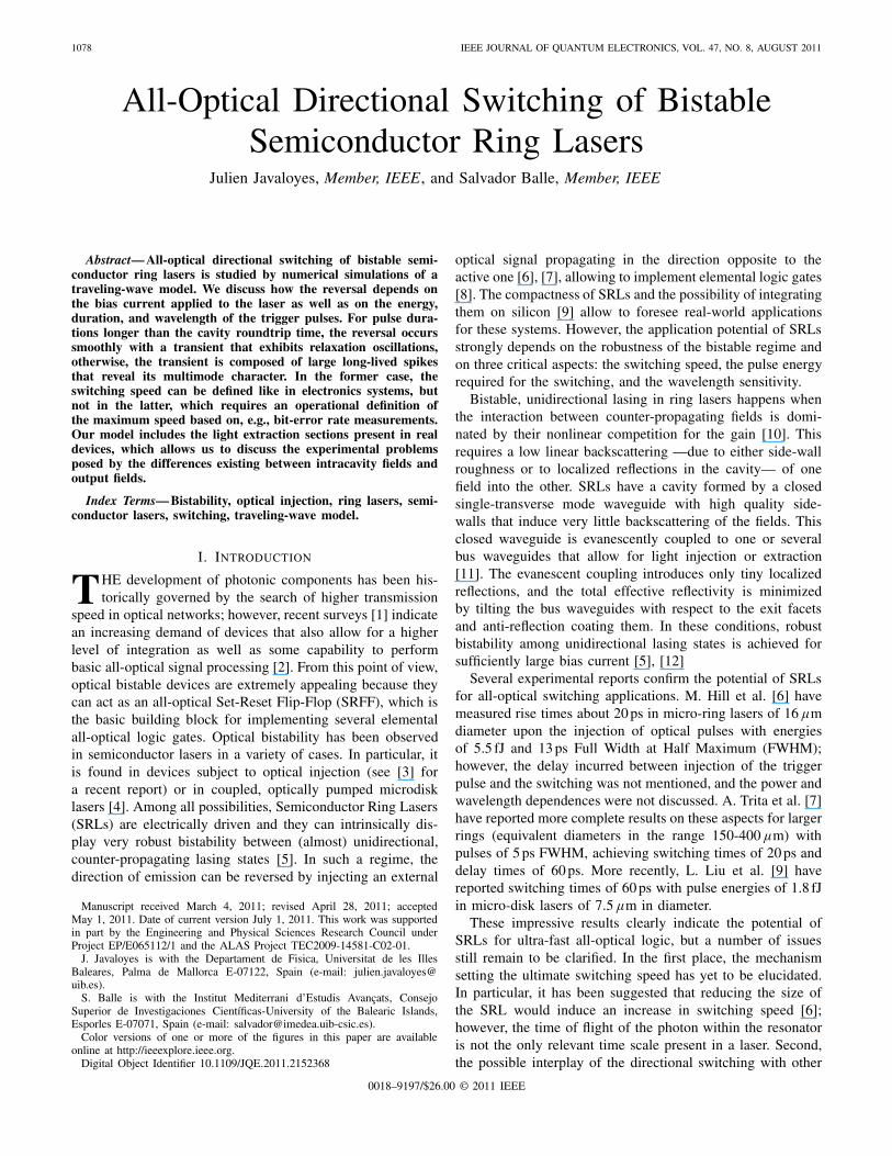
Fig. 3. Time trace of the intracavity fields (upper row) and the output fields(bottom row) to the application of optical trigger pulses of τp = 50 ps andpeak powers as denoted.
shifted by 345 GHz with respect to the band gap. Just abovethreshold the SRL emits bi-directionally, but as the currentis increased above a critical value the unidirectional regimeoccurs. This value (in our case, J = 2Jth) depends mainly onthe effective reflectivities in the cavity, i. e., on re,w and δ.The total intracavity power then goes into only one of thetwo lasing directions, and it increases almost linearly withcurrent, reaching a value of 90 (that corresponds to a realintracavity power of 9 mW and an extracted power of 4.5 mW)for J = 11Jth. We note that in our case no spontaneousdirectional and modal switchings occur as the SRL currentis increased. These have been explained by modal couplingin a rate-equation context [13] and by the thermal shift ofthe active material gain peak in a TWM [15], but this has notbeen included here for simplicity. In the unidirectional bistableregime — which lasts up to J = 13Jth , where the SRL startspulsing irregularly— the SRL emits on a single longitudinalmode with a SMSR larger than 20 dB and a DSR larger than10 dB, approaching 30 dB at high current. The ROF followsthe square-root dependence with power and reaches 11 GHzfor J = 11Jth . When the injected current is kept constant, theSRL remains for an indefinite time in its state, and it is thusa real optical memory with an infinite persistence time.
B. Switching Induced by Injection of Slow Pulses
When we inject into the SRL a slow pulse (i.e., a pulsewhose spectral width is smaller than the free spectral rangeof the SRL cavity) that travels in the direction opposite tothe active lasing field, the lasing direction might be reverseddepending on the energy and wavelength of the trigger pulses.We examine the influence of these parameters as well as thatof the working point of the laser on the switching.
1) Dependence on the Energy of the Trigger Pulses: First,we analyze the dependence of the switching time on the powerof the injected field. Hence we fix the SRL current to J =10Jth , and we consider a counter-propagating trigger pulseresonant with the SRL field. We take a pulse width τp = 50 psin order to ensure that the pulse does not excite other SRLmodes, and we consider that it takes 200 ps for the pulse toreach the entrance of the evanescent coupler. In order to givea physical order of magnitude, such a 50 ps pulse with a peakpower Ip = 100 corresponds to an energy of 530 fJ, notice
150
200
250
300
t 10,5
0,90
(ps
) rising direction falling direction
101 1020
50
100
150
Ip (A.U.)
|t 90 −
t 10 | (
ps)
101 102
Ip (A.U.)
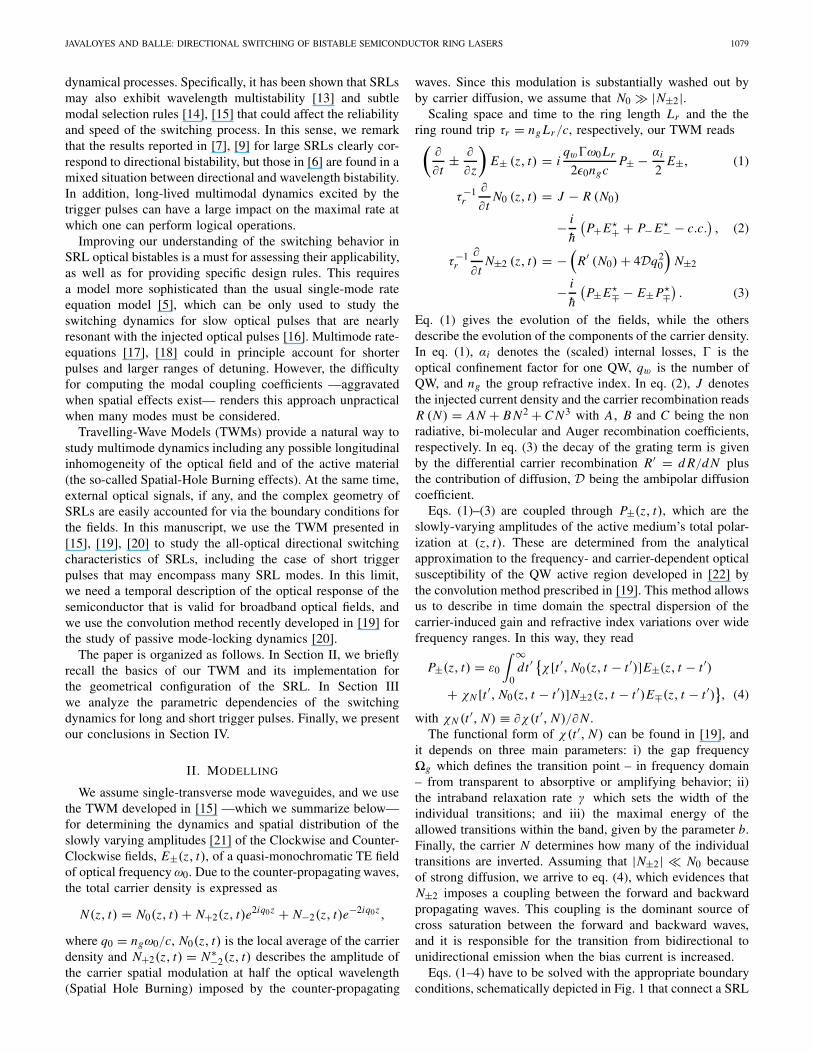
Fig. 4. Upper left and right panels: time required to reach 10% (blue), 50%(red), and 90% (green) of the steady-state power for the rising and the fallingdirections. Lower left and right panels: rise and fall time. The pulsewidth isτp = 50 ps, full and dashed lines correspond to J = 5Jth and J = 10Jth .
however that only a fraction enters the cavity. In addition,energies have to be compared with the typical energy emittedby the SRL per round trip, i.e. 144 fJ at J = 10Jth .
In Fig. 3 we show the effects of trigger pulses of differentenergies for both the intracavity fields (upper row) and thefields at the output facet (lower row). We observe that theSRL initially emits in the clockwise direction (red traces),but in response to the arrival of the injected pulse its powerdecreases at the same time that the power emitted in theopposite direction increases (blue traces). If the trigger pulsehas a high-enough energy (Ip = 100), the counter-propagatingwave switches on with an overshoot, hence short switchingtimes are obtained. If the injected power is reduced (Ip = 10),there is no transient overshoot in the power thus leadingto long switching times. The switching time diverges asone approaches the critical energy 36 fJ, corresponding toI c
p 6.9, which determines the minimum energy requiredfor performing a successful directional switching. For pulseswith Ip < I c
p the injection of the pulse leads only to a transientvariation of the emitted power, but the originally lasing stateis eventually recovered. It is worth mentioning that the finalpower level is determined by J only, and it does not depend onthe pulse energy; this latter parameter only determines whetheror not a directional switching occurs, hence the SRL acts asan optical thresholder, because it switches direction only whenan external optical signal of sufficient power is injected in thedirection opposite to the lasing one.
We note that, as shown in Fig. 4, the critical energydepends on the working point of the SRL: higher values ofJ correspond to higher values of the critical energy. Thereason is that for higher currents, the active medium is moreheavily saturated, hence the trigger pulse has to induce a largerperturbation in the carrier density in order to successfullytrigger a directional switching. Also, we note that for energiesabove the critical one, there is another characteristic energythat marks a change in trend in the timing curves. Belowit, pulses induce transient responses without overshoot, hencewith long 90% times. Above it, pulses induce transients withovershoot (compare the panels of Fig. 3 obtained with Ip = 10and Ip = 100). For even larger pulse energies, the leading edgeof the pulse is sufficient to trigger the reversal and the 10%,
1082 IEEE JOURNAL OF QUANTUM ELECTRONICS, VOL. 47, NO. 8, AUGUST 2011
0
100
200
300 I
± in (
A.U
.)I± ou
t (A
.U.)
δ2 = 30%
200 4000
100
200
300
time (ps)200 400
time (ps)200 400
time (ps)
δ2 = 50% δ2 = 70%
δ2 = 30%
δ2 = 30%
δ2 = 50% δ2 = 70%
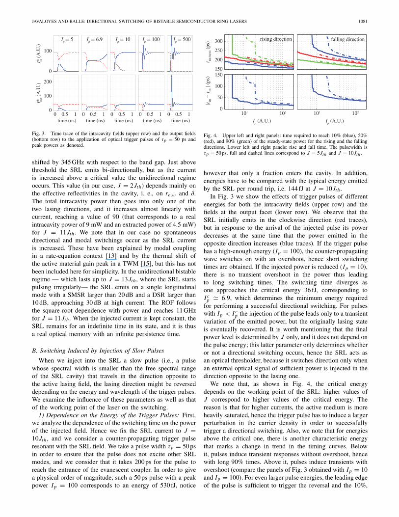
Fig. 5. Time trace of the intracavity fields (upper row) and the output fields(bottom row) to the application of optical trigger pulses of τp = 20 ps andpeak power Ip = 500 for different coupler efficiencies as denoted.
50% and 90% levels on the rising edge are attained before thecenter of the trigger pulse enters the cavity.
The above effects are clearly visible on both the intracavityfields and the output fields. However, we notice that thetime traces of the powers in each case are not the same,with noticeable differences on, e. g., the amount of overshootduring the switching transients. For the fields in the originallylasing direction, the time trace for the output field is justa scaled version of that for the intracavity field. Instead,the trace for the output field that is triggered by the pulseis remarkably different from its corresponding intracavityfield. These differences are due to the fact that the field atthe output port of the coupler is the superposition of thefraction of the intracavity field that is outcoupled with thefraction of the trigger pulse that passes undiverted through thecoupler.
The impact of the output coupler efficiency is exemplified inFig. 5, where we plot the switching transient in the intracavityfields (upper row) and output fields (bottom row) to an opticalpulse of τp = 20 ps and peak power Ip = 500, hence anenergy of 1 pJ, for different coupler efficiencies when operatingat the same current value. Notice that for the three values ofthe coupling efficiency, the lasing threshold is almost identicalas the total losses are dominated by internal losses. Therefore,the intracavity power is almost identical but a larger fractionof the input pulse enter the cavity for large coupling efficiency.Indeed, we observe that the switching of the intracavity fieldsproceeds on a slower way for δ2 = 30% as compared tothe other cases because of the lower fraction of the triggerpulse that is injected in the SRL cavity, which also leads tothe less pronounced transient relaxation oscillation. However,the amplitude of the transient relaxation oscillation of theoutput fields does not present a monotonous trend due tothe contribution of the optical trigger passing undiverted andwhich affects the leading edge of the response. In particular,for low efficiency couplers that let most of the trigger pulseto pass undiverted, the rise time during the switching is goingto be determined fundamentally by the trigger pulse. Such aneffect is specially evident in our case for δ2 = 50%, whichshows a double peaked structure corresponding to the passageof the undiverted part of the trigger pulse followed by theresponse of the SRL after one roundtrip. These doubled peaked
0
100
200
200 4000
100
200
time (ps)200 400time (ps)
200 400time (ps)
200 400time (ps)
200 400time (ps)
200 400time (ps)
I± in
(A
.U.)
I± out (
A.U
.)
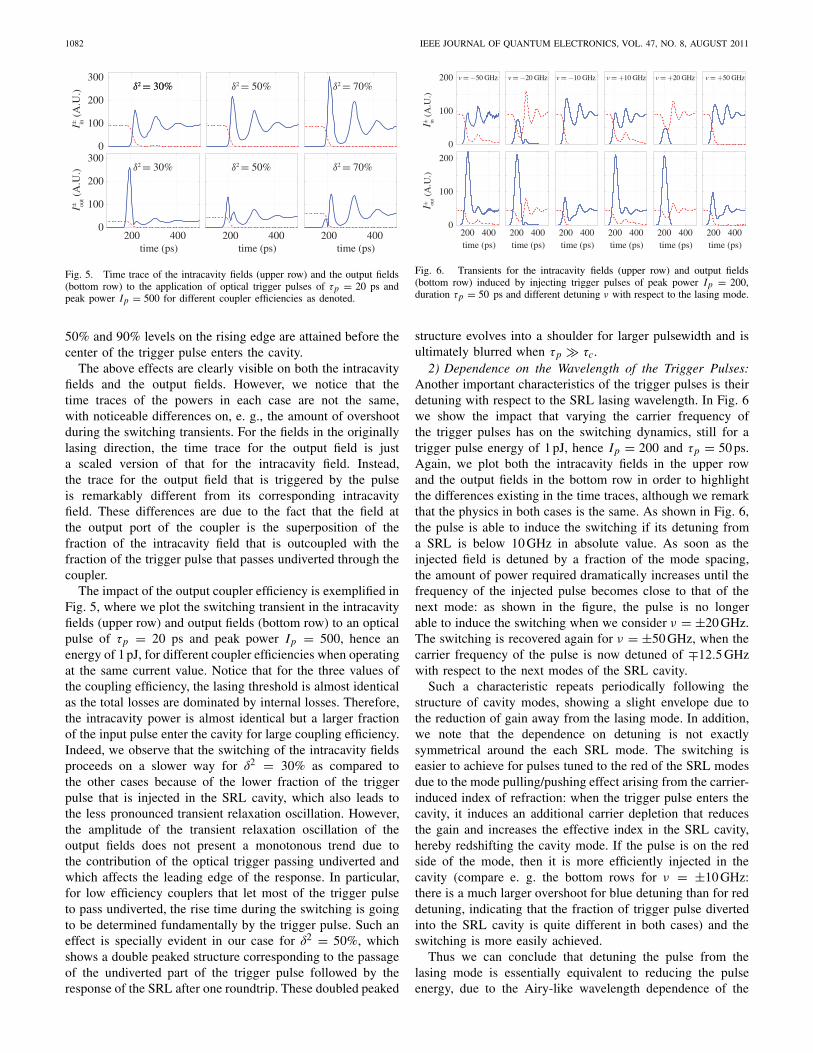
v = −50 GHz v = −20 GHz v = −10 GHz v = +10 GHz v = +20 GHz v = +50 GHz
Fig. 6. Transients for the intracavity fields (upper row) and output fields(bottom row) induced by injecting trigger pulses of peak power Ip = 200,duration τp = 50 ps and different detuning ν with respect to the lasing mode.
structure evolves into a shoulder for larger pulsewidth and isultimately blurred when τp � τc.
2) Dependence on the Wavelength of the Trigger Pulses:Another important characteristics of the trigger pulses is theirdetuning with respect to the SRL lasing wavelength. In Fig. 6we show the impact that varying the carrier frequency ofthe trigger pulses has on the switching dynamics, still for atrigger pulse energy of 1 pJ, hence Ip = 200 and τp = 50 ps.Again, we plot both the intracavity fields in the upper rowand the output fields in the bottom row in order to highlightthe differences existing in the time traces, although we remarkthat the physics in both cases is the same. As shown in Fig. 6,the pulse is able to induce the switching if its detuning froma SRL is below 10 GHz in absolute value. As soon as theinjected field is detuned by a fraction of the mode spacing,the amount of power required dramatically increases until thefrequency of the injected pulse becomes close to that of thenext mode: as shown in the figure, the pulse is no longerable to induce the switching when we consider ν = ±20 GHz.The switching is recovered again for ν = ±50 GHz, when thecarrier frequency of the pulse is now detuned of ∓12.5 GHzwith respect to the next modes of the SRL cavity.
Such a characteristic repeats periodically following thestructure of cavity modes, showing a slight envelope due tothe reduction of gain away from the lasing mode. In addition,we note that the dependence on detuning is not exactlysymmetrical around the each SRL mode. The switching iseasier to achieve for pulses tuned to the red of the SRL modesdue to the mode pulling/pushing effect arising from the carrier-induced index of refraction: when the trigger pulse enters thecavity, it induces an additional carrier depletion that reducesthe gain and increases the effective index in the SRL cavity,hereby redshifting the cavity mode. If the pulse is on the redside of the mode, then it is more efficiently injected in thecavity (compare e. g. the bottom rows for ν = ±10 GHz:there is a much larger overshoot for blue detuning than for reddetuning, indicating that the fraction of trigger pulse divertedinto the SRL cavity is quite different in both cases) and theswitching is more easily achieved.
Thus we can conclude that detuning the pulse from thelasing mode is essentially equivalent to reducing the pulseenergy, due to the Airy-like wavelength dependence of the
JAVALOYES AND BALLE: DIRECTIONAL SWITCHING OF BISTABLE SEMICONDUCTOR RING LASERS 1083
0
50
100
150
0 0.5 1 0
50
100
150
time (ns)0 0.5 1
time (ns)0 0.5 1
time (ns)0 0.5 1
time (ns)
I± in (
A.U
.)I± ou
t (A
.U.)
J = 10Jth
J = 7.5Jth
J = 5Jth
J = 2.5Jth
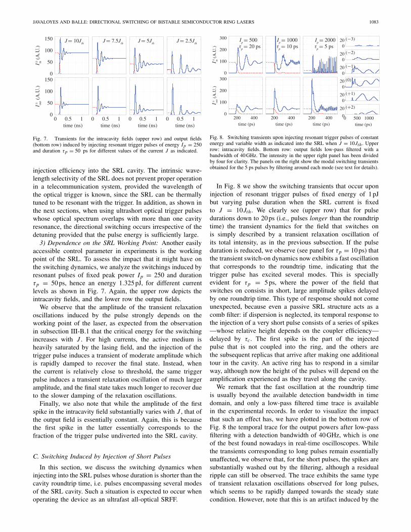
Fig. 7. Transients for the intracavity fields (upper row) and output fields(bottom row) induced by injecting resonant trigger pulses of energy Ip = 250and duration τp = 50 ps for different values of the current J as indicated.
injection efficiency into the SRL cavity. The intrinsic wave-length selectivity of the SRL does not prevent proper operationin a telecommunication system, provided the wavelength ofthe optical trigger is known, since the SRL can be thermallytuned to be resonant with the trigger. In addition, as shown inthe next sections, when using ultrashort optical trigger pulseswhose optical spectrum overlaps with more than one cavityresonance, the directional switching occurs irrespective of thedetuning provided that the pulse energy is sufficiently large.
3) Dependence on the SRL Working Point: Another easilyaccessible control parameter in experiments is the workingpoint of the SRL. To assess the impact that it might have onthe switching dynamics, we analyze the switchings induced byresonant pulses of fixed peak power Ip = 250 and durationτp = 50 ps, hence an energy 1.325 pJ, for different currentlevels as shown in Fig. 7. Again, the upper row depicts theintracavity fields, and the lower row the output fields.
We observe that the amplitude of the transient relaxationoscillations induced by the pulse strongly depends on theworking point of the laser, as expected from the observationin subsection III-B.1 that the critical energy for the switchingincreases with J . For high currents, the active medium isheavily saturated by the lasing field, and the injection of thetrigger pulse induces a transient of moderate amplitude whichis rapidly damped to recover the final state. Instead, whenthe current is relatively close to threshold, the same triggerpulse induces a transient relaxation oscillation of much largeramplitude, and the final state takes much longer to recover dueto the slower damping of the relaxation oscillations.
Finally, we also note that while the amplitude of the firstspike in the intracavity field substantially varies with J , that ofthe output field is essentially constant. Again, this is becausethe first spike in the latter essentially corresponds to thefraction of the trigger pulse undiverted into the SRL cavity.
C. Switching Induced by Injection of Short Pulses
In this section, we discuss the switching dynamics wheninjecting into the SRL pulses whose duration is shorter than thecavity roundtrip time, i.e. pulses encompassing several modesof the SRL cavity. Such a situation is expected to occur whenoperating the device as an ultrafast all-optical SRFF.
0
100
200
300
200 4000
100
200
300
time (ps)200 400
time (ps)200 400
time (ps)0 500 10000
20 (+2)
time (ps)
020 (+1)
020 (0)
020 (−1)
020 (−2)
020 (−3)
I± in
(A
.U.)
I± out (
A.U
.)
Ip = 500
τp = 20 ps
Ip = 1000
τp = 10 ps
Ip = 2000
τp = 5 ps
Fig. 8. Switching transients upon injecting resonant trigger pulses of constantenergy and variable width as indicated into the SRL when J = 10Jth . Upperrow: intracavity fields. Bottom row: output fields low-pass filtered with abandwidth of 40 GHz. The intensity in the upper right panel has been dividedby four for clarity. The panels on the right show the modal switching transientsobtained for the 5 ps pulses by filtering around each mode (see text for details).
In Fig. 8 we show the switching transients that occur uponinjection of resonant trigger pulses of fixed energy of 1 pJbut varying pulse duration when the SRL current is fixedto J = 10Jth . We clearly see (upper row) that for pulsedurations down to 20 ps (i.e., pulses longer than the roundtriptime) the transient dynamics for the field that switches onis simply described by a transient relaxation oscillation ofits total intensity, as in the previous subsection. If the pulseduration is reduced, we observe (see panel for τp = 10 ps) thatthe transient switch-on dynamics now exhibits a fast oscillationthat corresponds to the roundtrip time, indicating that thetrigger pulse has excited several modes. This is speciallyevident for τp = 5 ps, where the power of the field thatswitches on consists in short, large amplitude spikes delayedby one roundtrip time. This type of response should not comeunexpected, because even a passive SRL structure acts as acomb filter: if dispersion is neglected, its temporal response tothe injection of a very short pulse consists of a series of spikes—whose relative height depends on the coupler efficiency—delayed by τc. The first spike is the part of the injectedpulse that is not coupled into the ring, and the others arethe subsequent replicas that arrive after making one additionaltour in the cavity. An active ring has to respond in a similarway, although now the height of the pulses will depend on theamplification experienced as they travel along the cavity.
We remark that the fast oscillation at the roundtrip timeis usually beyond the available detection bandwidth in timedomain, and only a low-pass filtered time trace is availablein the experimental records. In order to visualize the impactthat such an effect has, we have plotted in the bottom row ofFig. 8 the temporal trace for the output powers after low-passfiltering with a detection bandwidth of 40 GHz, which is oneof the best found nowadays in real-time oscilloscopes. Whilethe transients corresponding to long pulses remain essentiallyunaffected, we observe that, for the short pulses, the spikes aresubstantially washed out by the filtering, although a residualripple can still be observed. The trace exhibits the same typeof transient relaxation oscillations observed for long pulses,which seems to be rapidly damped towards the steady statecondition. However, note that this is an artifact induced by the
1084 IEEE JOURNAL OF QUANTUM ELECTRONICS, VOL. 47, NO. 8, AUGUST 2011
100
120
140
160
180
200
220rising direction falling direction
0 20 40 60 800
50
Tp (ps) T
p (ps)
0 20 40 60 80
t 10,5
0,90
(ps
)|t 90
− t 10
| (ps
)
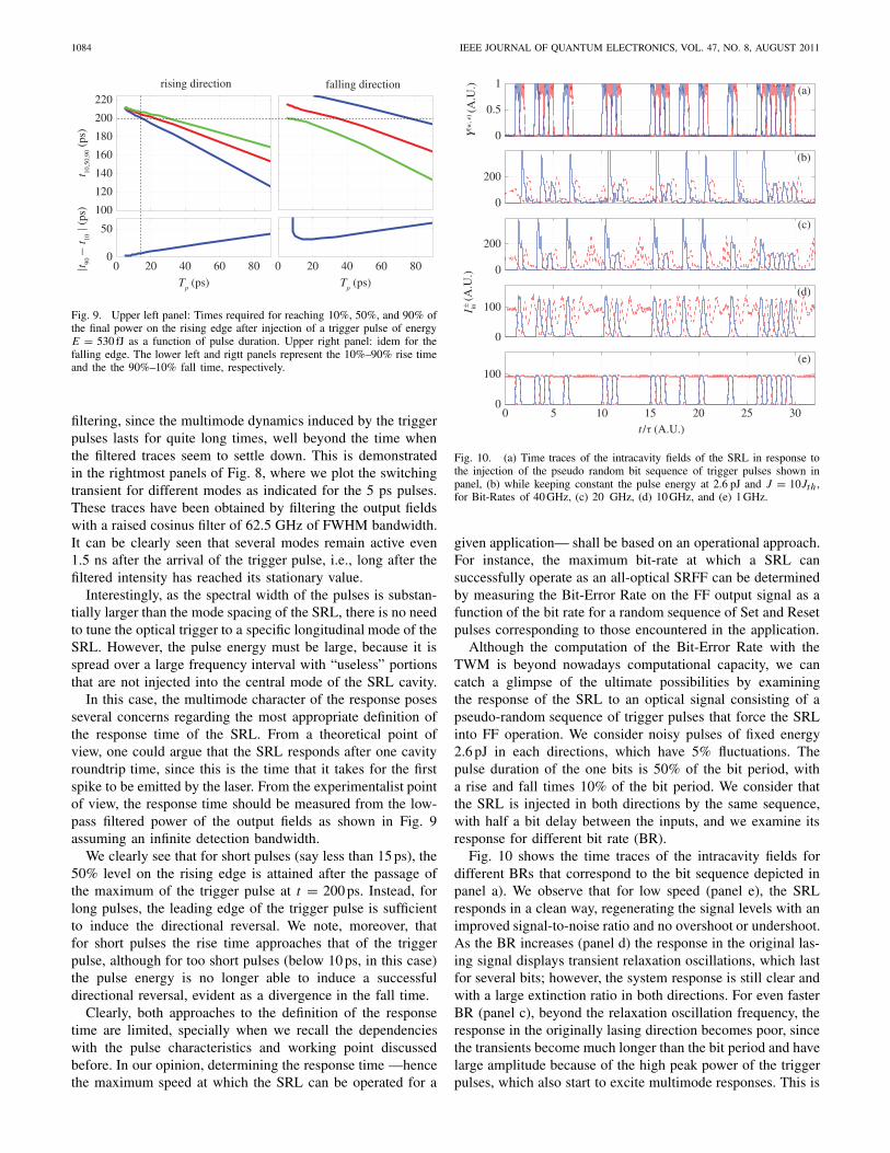
Fig. 9. Upper left panel: Times required for reaching 10%, 50%, and 90% ofthe final power on the rising edge after injection of a trigger pulse of energyE = 530 fJ as a function of pulse duration. Upper right panel: idem for thefalling edge. The lower left and rigtt panels represent the 10%–90% rise timeand the the 90%–10% fall time, respectively.
filtering, since the multimode dynamics induced by the triggerpulses lasts for quite long times, well beyond the time whenthe filtered traces seem to settle down. This is demonstratedin the rightmost panels of Fig. 8, where we plot the switchingtransient for different modes as indicated for the 5 ps pulses.These traces have been obtained by filtering the output fieldswith a raised cosinus filter of 62.5 GHz of FWHM bandwidth.It can be clearly seen that several modes remain active even1.5 ns after the arrival of the trigger pulse, i.e., long after thefiltered intensity has reached its stationary value.
Interestingly, as the spectral width of the pulses is substan-tially larger than the mode spacing of the SRL, there is no needto tune the optical trigger to a specific longitudinal mode of theSRL. However, the pulse energy must be large, because it isspread over a large frequency interval with “useless” portionsthat are not injected into the central mode of the SRL cavity.
In this case, the multimode character of the response posesseveral concerns regarding the most appropriate definition ofthe response time of the SRL. From a theoretical point ofview, one could argue that the SRL responds after one cavityroundtrip time, since this is the time that it takes for the firstspike to be emitted by the laser. From the experimentalist pointof view, the response time should be measured from the low-pass filtered power of the output fields as shown in Fig. 9assuming an infinite detection bandwidth.
We clearly see that for short pulses (say less than 15 ps), the50% level on the rising edge is attained after the passage ofthe maximum of the trigger pulse at t = 200 ps. Instead, forlong pulses, the leading edge of the trigger pulse is sufficientto induce the directional reversal. We note, moreover, thatfor short pulses the rise time approaches that of the triggerpulse, although for too short pulses (below 10 ps, in this case)the pulse energy is no longer able to induce a successfuldirectional reversal, evident as a divergence in the fall time.
Clearly, both approaches to the definition of the responsetime are limited, specially when we recall the dependencieswith the pulse characteristics and working point discussedbefore. In our opinion, determining the response time —hencethe maximum speed at which the SRL can be operated for a
0
0.5
1(a)
(b)
(c)
(d)
0 5 10 15 20 25 30
0
200
0
200
0
100
0
100(e)
t /τ (A.U.)
I± in (
A.U
.)Y
(w, e
) (A
.U.)
Fig. 10. (a) Time traces of the intracavity fields of the SRL in response tothe injection of the pseudo random bit sequence of trigger pulses shown inpanel, (b) while keeping constant the pulse energy at 2.6 pJ and J = 10Jth ,for Bit-Rates of 40 GHz, (c) 20 GHz, (d) 10 GHz, and (e) 1 GHz.
given application— shall be based on an operational approach.For instance, the maximum bit-rate at which a SRL cansuccessfully operate as an all-optical SRFF can be determinedby measuring the Bit-Error Rate on the FF output signal as afunction of the bit rate for a random sequence of Set and Resetpulses corresponding to those encountered in the application.
Although the computation of the Bit-Error Rate with theTWM is beyond nowadays computational capacity, we cancatch a glimpse of the ultimate possibilities by examiningthe response of the SRL to an optical signal consisting of apseudo-random sequence of trigger pulses that force the SRLinto FF operation. We consider noisy pulses of fixed energy2.6 pJ in each directions, which have 5% fluctuations. Thepulse duration of the one bits is 50% of the bit period, witha rise and fall times 10% of the bit period. We consider thatthe SRL is injected in both directions by the same sequence,with half a bit delay between the inputs, and we examine itsresponse for different bit rate (BR).
Fig. 10 shows the time traces of the intracavity fields fordifferent BRs that correspond to the bit sequence depicted inpanel a). We observe that for low speed (panel e), the SRLresponds in a clean way, regenerating the signal levels with animproved signal-to-noise ratio and no overshoot or undershoot.As the BR increases (panel d) the response in the original las-ing signal displays transient relaxation oscillations, which lastfor several bits; however, the system response is still clear andwith a large extinction ratio in both directions. For even fasterBR (panel c), beyond the relaxation oscillation frequency, theresponse in the originally lasing direction becomes poor, sincethe transients become much longer than the bit period and havelarge amplitude because of the high peak power of the triggerpulses, which also start to excite multimode responses. This is

JAVALOYES AND BALLE: DIRECTIONAL SWITCHING OF BISTABLE SEMICONDUCTOR RING LASERS 1085
even more pronounced at 40 Gb/s (panel b). Notice howeverthat the signal in the inverted direction is still quite clean, and itmight be useful for all-optical processing purposes dependingon the detection scheme used in each case. Therefore, the SRLcould be used as an all-optical FF even at high speeds.
Intuition suggests that improved performances could beobtained from smaller devices. However, increased bendinglosses induce a larger threshold current density and anincrease of power dissipation in a reduced volume. Thismay mitigate the improvement. Notice that such an analysisrequires the inclusion of the thermal dependence of thematerial parameters.
IV. CONCLUSION
We have analyzed the optically-induced directional switch-ing of bistable SRLs by numerical simulations of a TWM.The complex geometry of the device —that includes an opticalcoupler and output bus waveguides— and the optical triggerpulses are incorporated into the TWM through the boundaryconditions for the fields. In addition, the material response isgiven via a convolution kernel including both the dispersionof the gain and of the carrier-induced index of refraction.
We have discussed the experimental problems posed by thedifferences between intracavity fields and output fields, whichcan be traced back to the characteristics of the light extractionsection. We have shown that detecting the fields on the samebus waveguide used to inject the trigger pulses leads to anoutput signal that contains a significant contribution of thetrigger pulse on the rising edge. This problem is removed whendetecting the signal on the opposite waveguide, although inthis case the precise timing of the measured signal and thetrigger pulses becomes rather involved.
We have studied how the directional switching depends onthe bias current applied to the laser and on the energy, durationand wavelength of the trigger pulses. For pulse durationslonger than the cavity roundtrip time, the reversal occurssmoothly with a transient that exhibits relaxation oscillations;in this case, the switching speed can be defined from therise-time of the response like in electronic systems. However,pulses whose duration is shorter than the cavity roundtriptime induce switching transients composed of large, long-lived spikes revealing a strong multimode character. In thiscase, the switching speed cannot be defined by analogy toelectronic systems, but an operational definition based on e.g.Bit-Error Rate measurements is required in order to determinethe maximal bit rate at which the device can be operated.
ACKNOWLEDGMENT
The authors would like to acknowledge useful discussionswith A. Trita, G. Mezosi, M. Strain, M. Sorel, and G. Giuliani.
REFERENCES
[1] Merging Optics and Nanotechnologies. Honolulu, HI [Online]. Avail-able: http://www.ist-mona.org/home.asp
[2] A. Lattes, H. Haus, F. Leonberger, and E. Ippen, “An ultrafast all-opticalgate,” IEEE J. Quantum Electron., vol. 19, no. 11, pp. 1718–1723, Nov.1983.
[3] W. Coomans, S. Beri, G. V. Sande, L. Gelens, and J. Danckaert, “Opticalinjection in semiconductor ring lasers,” Phys. Rev. A, vol. 81, no. 3, pp.033802-1–033802-7, Mar. 2010.
[4] S. Ishii, A. Nakagawa, and T. Baba, “Modal characteristics and bista-bility in twin microdisk photonic molecule lasers,” IEEE J. Sel. TopicsQuantum Electron., vol. 12, no. 1, pp. 71–77, Jan.–Feb. 2006.
[5] M. Sorel, G. Giuliani, A. Scire, R. Miglierina, S. Donati, and P. J. R.Laybourn, “Operating regimes of GaAs-AlGaAs semiconductor ringlasers: Experiment and model,” IEEE J. Quantum Electron., vol. 39,no. 10, pp. 1187–1195, Oct. 2003.
[6] M. T. Hill, H. J. S. Dorren, T. de Vries, X. J. M. Leijtens, J. H. Besten,B. Smalbrugge, Y.-S. Oei, H. Binsma, G.-D. Khoe, and M. K. Smit,“A fast low-power optical memory based on coupled micro-ring lasers,”Nature, vol. 432, pp. 206–209, Nov. 2004.
[7] A. Trita, S. Furst, G. Mezosi, M. Sorel, M. J. L. Vidal, J. Yu, F. Bragheri,I. Cristiani, and G. Giuliani, “Time-domain response to ps optical pulsetrigger of an all-optical flip-flop based on semiconductor ring laser,”Proc. SPIE: Semicond. Lasers Laser Dyn. III, vol. 6997, no. 1, pp.699724-1–699724-6, 2008.
[8] B. Li, D. Lu, M. Memon, G. Mezosi, Z. Wang, M. Sorel, and S. Yu,“All-optical digital logic AND and XOR gates using four-wave-mixingin monolithically integrated semiconductor ring lasers,” Electron. Lett.,vol. 45, no. 13, pp. 698–700, Jun. 2009.
[9] L. Liu, R. Kumar, K. Huybrechts, T. Spuesens, G. Roelkens, E.-J. Geluk,T. de Vries, P. Regreny, D. Van Thourhout, R. Baets, and G. Morthier,“An ultrasmall, low-power, all-optical flip-flop memory on a siliconchip,” Nature Photon., vol. 4, pp. 182–187, Jan. 2010.
[10] M. Sargent, “Theory of a multimode quasiequilibrium semiconductorlaser,” Phys. Rev. A, vol. 48, no. 1, pp. 717–726, Jul. 1993.
[11] G. Mezosi, M. J. Strain, S. Furst, Z. Wang, S. Yu, and M. Sorel,“Unidirectional bistability in AlGaInAs microring and microdisk semi-conductor lasers,” IEEE Photon. Technol. Lett., vol. 21, no. 2, pp. 88–90,Jan. 2009.
[12] M. Sorel, P. J. R. Laybourn, G. Giuliani, and S. Donati, “Unidirectionalbistability in semiconductor waveguide ring lasers,” Appl. Phys. Lett.,vol. 80, no. 17, pp. 3051–3053, Apr. 2002.
[13] C. Born, G. Yuan, Z. Wang, M. Sorel, and S. Yu, “Lasing mode hys-teresis characteristics in semiconductor ring lasers,” IEEE J. QuantumElectron., vol. 44, no. 12, pp. 1171–1179, Dec. 2008.
[14] S. Fürst, A. Pérez-Serrano, A. Scirè, M. Sorel, and S. Balle, “Modalstructure, directional and wavelength jumps of integrated semiconductorring lasers: Experiment and theory,” Appl. Phys. Lett., vol. 93, no. 25,pp. 251109-1–251109-3, Dec. 2008.
[15] J. Javaloyes and S. Balle, “Emission directionality of semiconductorring lasers: A traveling-wave description,” IEEE J. Quantum Electron.,vol. 45, no. 5, pp. 431–438, May 2009.
[16] T. Pérez, A. Scirè, G. V. Sande, P. Colet, and C. R. Mirasso, “Bistabilityand all-optical switching in semiconductor ring lasers,” Opt. Exp.,vol. 15, no. 20, pp. 12941–12948, Oct. 2007.
[17] C. Born, M. Sorel, and S. Yu, “Linear and nonlinear mode interactions ina semiconductor ring laser,” IEEE J. Quantum Electron., vol. 41, no. 3,pp. 261–271, Mar. 2005.
[18] I. Stamataki, S. Mikroulis, A. Kapsalis, and D. Syvridis, “Investigationon the multimode dynamics of InGaAsP–InP microring lasers,” IEEE J.Quantum Electron., vol. 42, no. 12, pp. 1266–1273, Dec. 2006.
[19] J. Javaloyes and S. Balle, “Quasiequilibrium time-domain susceptibilityof semiconductor quantum wells,” Phys. Rev. A, vol. 81, no. 6, pp.062505-1–062505-10, Jun. 2010.
[20] J. Javaloyes and S. Balle, “Mode-locking in semiconductor Fabry–Pérotlasers,” IEEE J. Quantum Electron., vol. 46, no. 7, pp. 1023–1030, Jul.2010.
[21] L. Narducci and N. B. Abraham, Laser Physics and Laser Instabilities.Singapore: World Scientific, 1988.
[22] S. Balle, “Simple analytical approximations for the gain and refractiveindex spectra in quantum-well lasers,” Phys. Rev. A, vol. 57, no. 2, pp.1304–1312, Feb. 1998.
Julien Javaloyes (M’11) is with the Departament de Fisica, Universitat de lesIlles Balears, Palma de Mallorca, Spain. His current research interests includemodeling and nonlinear dynamics of semiconductor lasers.
Salvador Balle (M’81) is with the Institut Mediterrani d’Estudis Avançats,Esporles, Spain. His current research interests include modeling and thenonlinear optical dynamics of semiconductor lasers and amplifiers and theirpotential applications to information processing.
Copyright © 2022 FDOKUMEN