High Power Lasers in Manufacturing
79
High Power Lasers in Manufacturing by Professor Chris R. Chatwin University of Sussex http ://www.sussex.ac.uk/profiles/9815
-
Upload
khangminh22 -
Category
Documents
-
view
1 -
download
0
Transcript of High Power Lasers in Manufacturing

High Power Lasers in Manufacturing
by
Professor Chris R. Chatwin
University of Sussex
http://www.sussex.ac.uk/profiles/9815

2
Brief History and Evolution of Lasers
1917 - Albert Einstein developed the concept of
stimulated emission, which is the phenomenon
used in lasers
In 1954 the maser was the first device to use
stimulated emission (Townes & Schawlow).
Microwave amplification by stimulated emission of
radiation

3
Brief History of Lasers
In 1958 Townes & Schawlow
suggested that stimulated
emission could be used in
the infrared and optical
portions of the spectrum
The device was originally
termed the optical maser
This term was dropped in
favour of LASER. Standing
for Light Amplification by
Stimulated Emission of
Radiation
Charles Townes & Jim Gordon at Columbia University
in 1954 with their second working MASER

4
1st Laser - Ted Maiman 15th May 1960 - working
alone and against the wishes of his boss at Hughes Research Laboratories
Electrical Engineer

5
Maiman’s Ruby Laser - 694.3 nm
Synthetic pale pink ruby crystal Al2O3
containing about 0.05% by weight of Cr2O3
New York Times
8th July 1960,
Wrong Ruby Crystal
is shown here.
The journalist didn’t
like the actual stubby
crystal. This crystal
was used later

6
Bell Labs & the Laser
1960 Ali Javan, William Bennet,
Donald Herriot - HeNe Laser -
1st CW Laser - 1.15 m
1961 Boyle & Nelson - Continuously
operating Ruby Laser
1962 Kumar Patel (front), Faust, McFarlane,
Bennet (left to right) - 5 Noble gas lasers
and lasers using oxygen mixtures

7
Bell Labs & the Laser
1964 C. K. N. Patel - High Power
Carbon Dioxide Laser - 10.6m
1971 Izuo Hayashsi & Morton Panish - first
semiconductor laser that operated continuously
at room temperature
1964: First Nd:YAG laser 1.06m (uses neodymium doped
yttrium aluminium garnet crystals) by J. F. Geusic and R. G. Smith

8
Stimulated Emission
Atoms in Ground State
Flash lamp excites Cr+++
Spontaneous emmision
Stimulated emission
Stimulated emission
Laser output pulse

9
Coherence and Focusing
Spatially & temporally
incoherent:out-of-step
& various wavelengths
Spatially Coherent
Temporally coherent
single wavelength
Spatially & temporally
coherent- only 1% left
Laser Light
100% coherent

10
A Beam Focusing Lens and an Assist Gas Nozzle is
required for all but UV lasers
Gases: Oxygen, Nitrogen,
Argon, Helium etc.
http://www.youtube.com/watch?v=uuLAkC6jrP0 laser cutting

11
Dry Laser Etching Ablates Material by Bond
Breaking
Chrome on Quartz Mask Lambda Physik LPX 201i, 125W mean power,
2.5J/pulse,100 Hz prf, 10 to 50 ns pulse width

12
Evolution of Industrial Lasers
1990 201020001960 19801970
Industrial Application
Research
CW CO2
Excimer
Diode-pumped
Fibre
Pulsed CO2
Solid State

13
Laser Transverse Modes – cylindrical symmetry
In a laser with cylindrical
symmetry, the transverse mode
patterns are described by a
combination of a Gaussian
beam profile with a Laguerre
polynomial.
The modes are denoted TEMpl
where p and l are integers
labelling the radial and angular
mode orders, respectively.

14
Laser Transverse Modes – rectangular symmetry
In many lasers, the symmetry of the optical resonator is restricted by polarizing elements such as Brewster's angle windows. In these lasers, transverse modes with rectangular symmetry are formed.
These modes are designated TEMmn with m and n being the horizontal and vertical orders of the pattern.

15
Beam waste, Rayleigh Range & Depth of Focus
For a Gaussian beam propagating in free
space, the spot size w (z ) will be at a
minimum value w0 at one place along the
beam axis, known as the beam waist .
For a beam of wavelength λ at a distance z
along the beam from the beam waist, the
variation of the spot size is given by
where the origin of the z-axis is defined,
without loss of generality, to coincide with the
beam waist, and where
Is called the Rayleigh range
At a distance from the waist equal to
the Rayleigh range z0, the width w of
the beam is
The distance between these two points is called
the confocal parameter or depth of focus of the
beam:

16
Angular Spread of the Beam
The parameter w (z ) approaches a straight line for z >> z0 . The
angle between this straight line and the central axis of the beam is
called the divergence of the beam. It is given by
The total angular spread of the beam far from the waist is then given by Θ = 2θ
Because of this property, a Gaussian laser beam that is focused to a small
spot spreads out rapidly as it propagates away from that spot. To keep a
laser beam very well collimated, it must have a large diameter.

17
Power Output
The power P passing through a circle of radius r in the
transverse plane at position z is
Where:
is the total power transmitted by the beam
ω0 = M2 λ / π Θ

18
M2 Factor – Beam Quality Factor
The M2 factor, also called beam quality factor or beam propagation factor, is a common measure for the beam quality of a laser beam. According to ISO 11146, it is defined as the beam parameter product divided by λ/π, the latter being the beam parameter product for a diffraction-limited Gaussian beam with the same wavelength. In other words, the beam divergence is
θ = M2 λ/πω0 where w0 is the beam radius at the beam waist and λ the
wavelength. A laser beam is often said to be "M2 times diffraction-limited". A diffraction-limited beam has an M2
of 1, and is a Gaussian beam. Smaller values of M2 are physically not possible. A Hermite-Gaussian beam, related to a TEMnm resonator mode (→ higher-order modes), has an M2 factor of (2n + 1) in x direction, and (2m + 1) in y direction.

19
M2 Factor – Beam Quality Factor
The beam waist of a laser beam is the location along the
propagation direction where the beam radius has a
minimum. The waist radius is the beam radius at this
location.
The M2 factor of a laser beam limits the degree to which
the beam can be focused for a given beam divergence
angle, which is often limited by the numerical aperture of
the focusing lens.
Together with the optical power, the beam quality factor
determines the brightness (more precisely, the radiance)
of a laser beam.

20
High Power Fibre Lasers
The steady march of high-power single-mode
output from ytterbium-doped fiber lasers is continuing.

21
Fibre Laser Operation
Pump light from a diode-laser stack illuminates the outer core of a dual-core fiber
(focusing optics are not shown for simplicity).
The cladding confines the pump light in the outer core so it passes through
the inner core. One pump photon excites an ytterbium atom in the inner core,
which emits light that is confined in the inner core,
becoming part of the fiber-laser beam

22
Optical Arrangement
A high-power Yb-doped fiber laser is pumped from both ends.
Filters transmit the 975-nm pump light into the laser cavity
while serving as mirrors that reflect the 1.1-µm laser light.
This is a simplified version of the arrangement that generated
1.3 kW CW in experiments at Southampton.

23
Fibre lasers are available up to 50 kW in power
Optical microscope image of the core of a
Ytterbium doped fibrelaser showing the
individually inscribed grating periods of a grating
for operation at 1064 nm.
Courtesy: Graham D. Marshall et al
http://www.youtube.com/watch?v=LVpD5y7ngA4

24
High Power Materials Processing Lasers
Carbon Dioxide - up to 100kW more usually 2 to
7kW - 10.6m
Carbon Monoxide - not generally available, up to
5kW - 5 to 6m
Nd-YAG - up to 4.5kW - 1.06m
UV - Argon Ion 2W, HeCd, Tripled YAG 5W
Diode Lasers 2 kW
Fibre Lasers 2kW single mode 50kW multimode
>25% efficiency

25
High Power Micro-machining Lasers
Copper Vapour Lasers 511& 578 nm, 20-30 ns pulses,
2-20kHz, 50 to 500 kW peak power
Excimer - pulsed mean power 1kW – UV – 157nm,
193nm, 248nm,308nm, 351nm, 1000Hz, 1kW
Nd-YVO4 – 355nm Neodymium Vanadate 38ns
pulses, 10kHz, 6 W mean
Ti:Sapphire – 850nm , 250kHz, 100 fs pulses,
300kW,

26
8kW CO2 Laser
1. Laserbeam
2. Tangential blower
3. Gas flow direction
4. Heat exchanger
5. Rear mirror with real time power monitor
6. Fold mirror
7. HF-electrodes
8. Output mirror
9. Output window

27
3.5kW Diffusion Cooled CO2
Laser - CW or 5kHz pulsed
1. Laserbeam
2. Beam shaping unit
3. Output mirror
4. Cooling water
5. RF excitation
6. Cooling water
7. Rear mirror
8. RF excited discharge
9. Waveguiding electrodes
Courtesy of Rofin

28
Flash Lamp Pumped 2.7kW cw or Pulsed (500 Hz)
Nd-YAG Laser
1. Laser beam
2. Output mirror
3. Nd:YAG rod
4. Excitation lamps
5. Reflector
6. Rear mirror
7. Focusing unit
8. Fibre - 600 microns
9. In-coupling unit
10.Beam bending mirrors
Courtesy of Rofin
29
4.4 kW cw Diode Pumped Nd-YAG Laser
1. Nd:YAG rod
2. Laserbeam
3. Output coupler
4. Diode arrays
5. Collimating optic
6. High-refelectance mirror
7. Cooling
8. Electrical supply
9. 300 micron fibre
Courtesy of Rofin

30
Industrial Application Areas
Electronics
Semiconductor
Aerospace
Automotive
Medical Device
Metrology
Package Coding
General Manufacturing

31
Long Pulse Interaction

32
Nd: Glass Laser Interactions
Titanium Zirconia Dioxide

33
Nd: Glass Laser Interactions
TantalumSilicon Nitride

34
Streak Photographs of Laser Drilling with an
Nd:Glass Laser
35
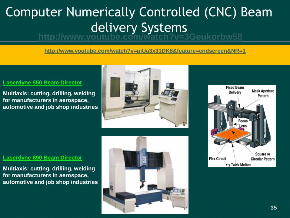
Computer Numerically Controlled (CNC) Beam
delivery Systems
Laserdyne 550 Beam Director
Multiaxis: cutting, drilling, welding
for manufacturers in aerospace,
automotive and job shop industries
Laserdyne 890 Beam Director
Multiaxis: cutting, drilling, welding
for manufacturers in aerospace,
automotive and job shop industries
http://www.youtube.com/watch?v=pjUa3x31DK8&feature=endscreen&NR=1
http://www.youtube.com/watch?v=3Geukorbw58

36
Small Batch Rapid Manufacture using LasersMFK 1 kW CO2 LaserAF8P - 8kW Carbon Dioxide Laser can run CW or Pulsed up to 3.3kHz
Weld Penetration
in 12 mm SS
Case Hardening of a Camshaft
AF8P- CO: 1 - 2.5kW Carbon Monoxide Laser
can run CW or Pulsed up to 3.3kHz

37
Rapid Programmable Manufacture Using Lasers

38
Pulsing CW Lasers
Pulsed lasers give a
sharper, hotter knife
Narrower focus
It gives greater process
control
High instantaneous power
allows processing of
highly reflective metals
like aluminium

39
Laser Cutting
25mm Armour Plate
Inert gas (N2) cut samples of 10 mm
stainless, 5 mm stainless, 6 mm aluminium

40
YAG laser trimming of pressings

41
Laser Cutting Nd-YAG & CO2
Laser cutting of sheet metal is now widely accepted, up to 20 mm thick
Laser cutting and scribing of ceramics, eg. alumina
Laser cutting of tubes
http://www.youtube.com/watch?v=UeGVbtrrHjE&feature=related tube cutting

42
Laser Cutting
In principle, both CO2 and Nd:YAG lasers are suitable for this application.
The decision for one or the other beam source is influenced by such factors as the geometry of the cut, the cycle time, the system technology and above all the material.
Cutting in two dimensions, which is the most common case, is the domain of the CO2 laser, because it yields the best cost-benefit ratio.
Typical cutting speeds in steel are, for example, in the region of approx. 8 meters per minute for 1 mm, 4.5 meters per minute for 3mm and 1.5 meters per minute for 8 mm thick material.
High reflectivity materials such as: Gold, Silver, Copper, Aluminium and Brass are possible with CO2 but better with Nd-YAG
http://www.youtube.com/watch?v=be4LrGn0lPg cut and bend
43
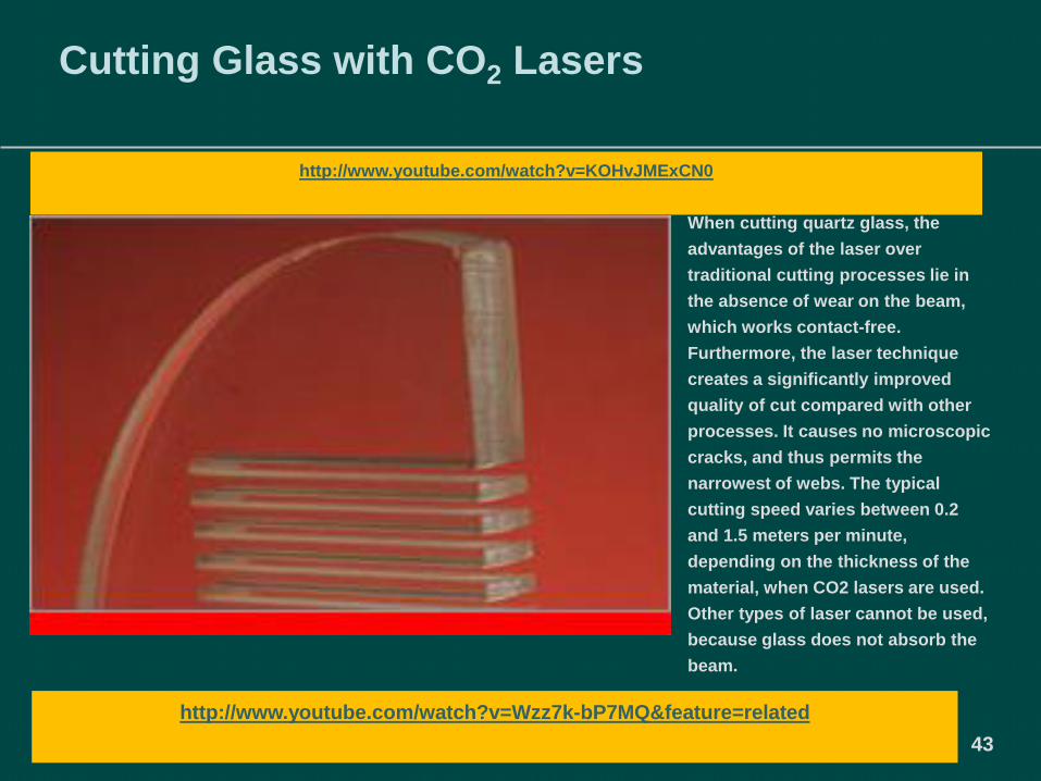
Cutting Glass with CO2 Lasers
When cutting quartz glass, the
advantages of the laser over
traditional cutting processes lie in
the absence of wear on the beam,
which works contact-free.
Furthermore, the laser technique
creates a significantly improved
quality of cut compared with other
processes. It causes no microscopic
cracks, and thus permits the
narrowest of webs. The typical
cutting speed varies between 0.2
and 1.5 meters per minute,
depending on the thickness of the
material, when CO2 lasers are used.
Other types of laser cannot be used,
because glass does not absorb the
beam.
http://www.youtube.com/watch?v=Wzz7k-bP7MQ&feature=related
http://www.youtube.com/watch?v=KOHvJMExCN0

44
Cutting Thermoplastics with CO2 Lasers
Thermoplastics can be cut by
comparatively low-power CO2 lasers
in the range of 100 to 300 Watts.
Depending on the setup of the
application, separation cuts or
polishing cuts (visually clean cut
edge) can be carried out. One
important area in which laser-cut
parts of this kind are used is in
illuminated advertising, in which
plastic sheet is often glued to the
material before or after cutting. The
cutting speeds depend to a great
extent on the desired quality of the
edges, but an example would be 2.5
meters per minute for separation
cutting in 4 mm material at 200
Watts.
http://www.youtube.com/watch?v=I_FmlorBGqg&feature=related
http://www.youtube.com/watch?v=7Jf8kk3Lq74

45
Nd-YAG Laser Drilling of Refractory metals
Jet-engine turbine blade
- Nimonic alloy
0.5 mm holes at 20 degrees to the surface
in a jet engine combustion chamber
http://www.youtube.com/watch?v=83OQTZZ4ML8

46
Nd-YAG Laser Welding
Laser Welded Tailored
Blank
Laser Welded Car DoorCar Body Welding

47
Laser Welding
Light weight sandwich
panel
5 axis CO2 laser welding of a
petrol tank
Arc assisted laser
welding

48
Nd-Yag Laser Welding has the edge over CO2
Airbag detonator
hermetically welded
Hermetically welded pacemaker
Fuel Injector Elements

49
Nd-Yag Laser Welding
Seam welding of relay cans. The
The low heat input prevents damage
to the adjacent glass to metal seals.
Shadow mask of TV tube welded
to its support structure.
Alignment is maintained to 5m
Ball bearing cage. A two fibre
system heats both sides of the
weld simultaneously
This diaphragm is only 0.04 mm
thick. The component is welded
at 15 mm/s without buckling
Welding silicon iron motor laminations
eases handling prior to winding.
Welding of battery
terminals

50
25W Pump Diode Modules - IPG
16 4/25/2007 IPG Photonics Confidential Information
https://www.youtube.com/watch
?v=ofEqFlqkiS0 fibre laser
ooperation

51
400W…700 W Ytterbium Fiber Blocks - IPG
17 4/25/2007 IPG Photonics Confidential Information

52
IPG Conception - IPG
++LDM# Active Fiber LDM#
LDM# LDM#
LDM# LDM#
LDM# LDM#
LDM# Fiber Block LDM#
LDM# LDM#
- -
All-Fiber Format Laser Module
• Compact integrated optical design
• In parallel combining by single emitter diodes
• Side pumping
• Robust mechanical construction
• Stable thermal characteristics
14 4/25/2007 IPG Photonics Confidential Information

53
kW-(multimode)-Fiber Lasers - IPG
YLR-10000: Block Diagram
MCU P=600W Beam
MCU P=600W CombinerUART
InterBus
Length 200 mEithernet
10 kWMCU P=600W
10 kW
MCU P=600W Optical Switch
43 kW
POWER SUPPLY
22 4/25/2007 IPG Photonics Confidential Information

54
Welding with Singlemode-Fiber Lasers - IPG
AluminiumCopper
Stainless steel
Fe-Cu-
Joint
BIAS
30 4/25/2007 IPG Photonics Confidential Information

55
Welding of Gear Box Parts
CO2-Laser Electron beam Fiber Laser
YLR4000-S-Low heat input Low distortion
-Reduced crack risk
32 4/25/2007 IPG Photonics Confidential Information
http://www.youtube.com/watch?NR=1&v=8B35zeYmeO4&feature=endscreen

56
Fiber Laser Remote Welding - IPG
Scannerfree Remote Processing Scanner Remote Processing
Source IWS
Source Highyag
Source Kuka
Working Distances
1000-1500 mm
Working Distances
~ 500 mm
33 4/25/2007 IPG Photonics Confidential Information
57
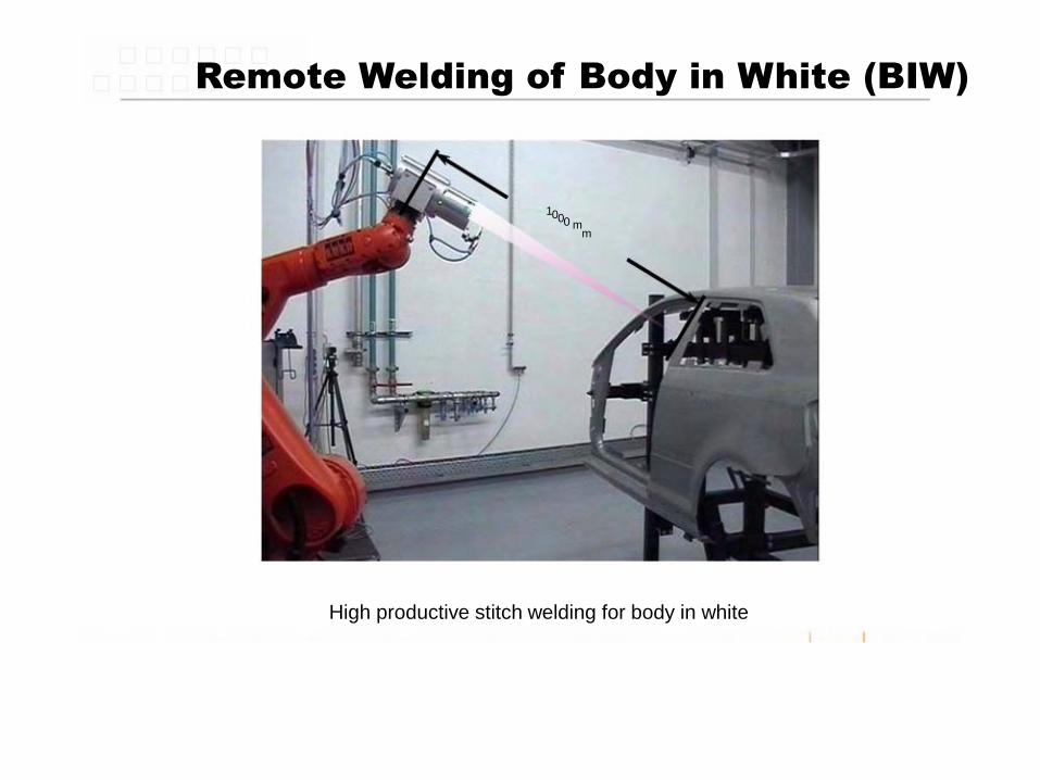
Remote Welding of Body in White (BIW)
1000 mm
High productive stitch welding for body in white
34 4/25/2007 IPG Photonics Confidential Information

58
Process Efficiency
IPG YLR 10000 (10 kW Fiber Laser) 15 kW CO2-Laser
X70, t = 12 mmX70, t = 12 mm
+ 32 %
PL = 13.5 kWPL = 10.2 kW+18 %
vw = 1,8 m/minvw = 2.2 m/min
+ 61 % E = 4,5 kJ/cmE = 2,8 kJ/cm
39 4/25/2007 IPG Photonics Confidential Information
59
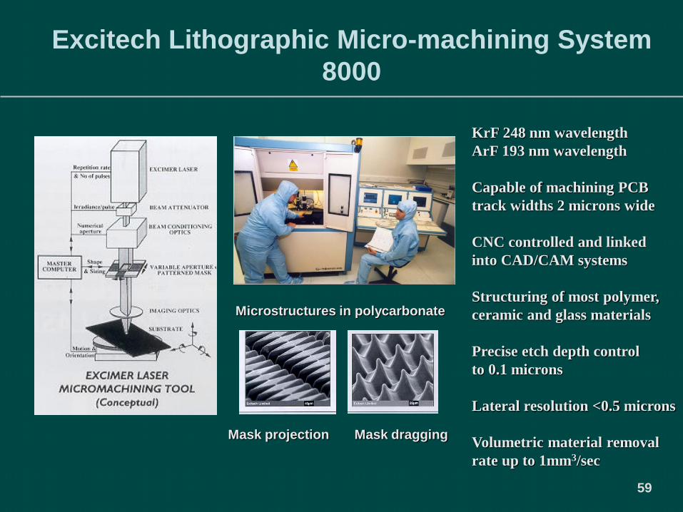
Excitech Lithographic Micro-machining System
8000
Mask projection Mask dragging
KrF 248 nm wavelength
ArF 193 nm wavelength
Capable of machining PCB
track widths 2 microns wide
CNC controlled and linked
into CAD/CAM systems
Structuring of most polymer,
ceramic and glass materials
Precise etch depth control
to 0.1 microns
Lateral resolution <0.5 microns
Volumetric material removal
rate up to 1mm3/sec
Microstructures in polycarbonate

60
Example of Fine Processing With Excimer
Lasers
Hair diameter: ~50 microns (2
thou)
Hole diameter: ~5 microns (0.2
thou)
Illustrative of the resolution that
can be achieved with a standard
excimer laser using the mask-
imaging technique and good
quality beam delivery optics.

61
PCB Drilling Printer Nozzles 720 dpi nozzle holes Micro-Fluidic Systems
Biomedical Devices Microstructuring Fibre Gratings Diamond Smoothing
DUV Lithography A-R Surface Tapered micro-via Sensors
Excimer Laser Micro-Machining - Exitech

62
Excimer Laser Micromachining
Gear 50 microns diameter
http://www.youtube.com/watch?v=fFpov-ZSujA
http://www.youtube.com/watch?v=GgR-
mH6X5VU&feature=related

63
Micro-engineering Application
With a length of 24 mm and a
weight of 0.4 grams the
helicopter takes off at 40,000
rpm.
With a diameter of only 1.9 millimeters
the electromagnetic motors can reach
an incredible revolution speed of nearly
500,000 rpm.
They are also used for scanners, drive
units in heart catheters and high-tech
display systems.
The integrated planetary gear system
converts low torque at high rotational
speed into high torque at correspondingly
lower rotational speed.

64
Silicon
Dicing
27 microns
27 microns
DD = 30 microns
DD = 30 microns
Nd-YAG laser pulsed
micron and nano
second pulses 532nm
or 355nm wavelength,
mean power 10 to
200watts

65
Water absorption coefficients
66
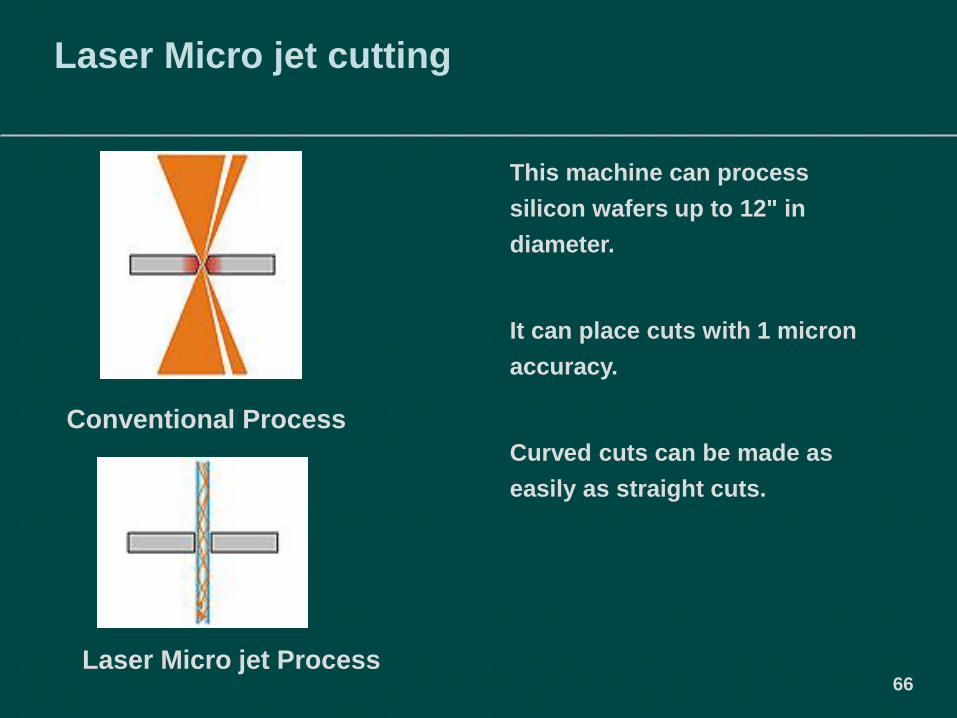
Laser Micro jet cutting
This machine can process
silicon wafers up to 12" in
diameter.
It can place cuts with 1 micron
accuracy.
Curved cuts can be made as
easily as straight cuts.
Laser Micro jet Process
Conventional Process

67
Photovoltaic (PV) Cell Edge Isolation
In this example a rounded
groove at the corner of the
solar cell, something that a
diamond saw cannot perform.
The groove shown is ~ 20 μm
deep, 40μm wide and was cut
at a speed of 250 mm/s, with
no post cutting cleaning
required.

68
Blind and Micro-via drilling
Multi Laser (CO2 /Nd: YAG)
Drills both copper and dielectric
High speed - up to 60,000
holes/minute
The pulsed frequency trippled
3Watt YAG (355nm) laser is used for
drilling metals
A wavelength tuned pulsed 80 Watt
CO2 (9.6 microns)laser is used for
removal of dielectric
High speed drilling of blind and microvias in all types of
multilayer printed circuit boards (PCB's), and multichip
modules (MCM's) for panel sizes up to 24" x 28".
69
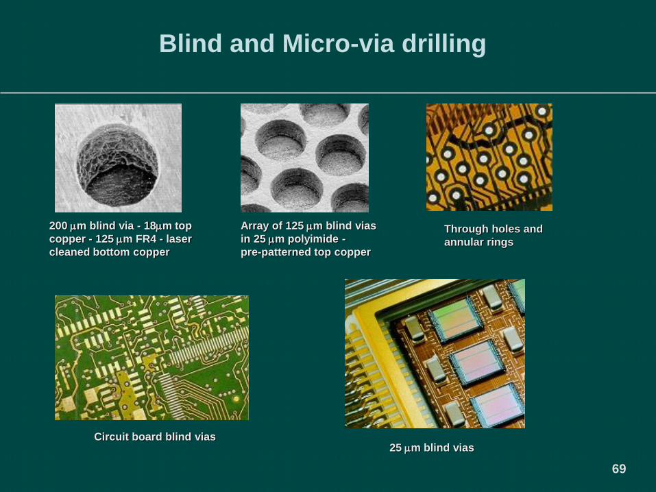
Blind and Micro-via drilling
200 m blind via - 18m top
copper - 125 m FR4 - laser
cleaned bottom copper
Array of 125 m blind vias
in 25 m polyimide -
pre-patterned top copper
Through holes and
annular rings
Circuit board blind vias25 m blind vias
70
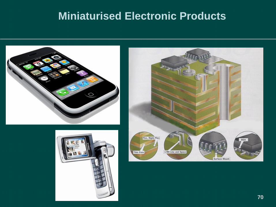
Miniaturised Electronic Products
71
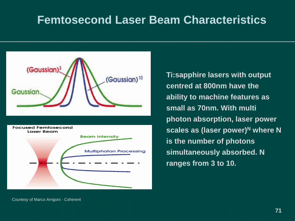
Femtosecond Laser Beam Characteristics
Ti:sapphire lasers with output
centred at 800nm have the
ability to machine features as
small as 70nm. With multi
photon absorption, laser power
scales as (laser power)N where N
is the number of photons
simultaneously absorbed. N
ranges from 3 to 10.
Courtesy of Marco Arrigoni - Coherent

72
Ultra Fast Pulse Interaction

73
Femtosecond Laser Machining Ti:sapphire -
Exitech
Aluminium
Silica Glass
Stainless Steel100 micron diameter hole
drilled in stainless steel
using a 355 nm
nanosecond pulse Nd:
vanadate laser
Lithium Tantalate
Ti:sapphire laser; λ0 = 800 nm, Δτ = 110 fs,
E =1mJ/pulse, Rep Rate=3–5kHz, M2 =1.2

74
Lab on a Chip

75
Precision Percussion Drilling of Stainless Steel -
Copper Vapour Laser – Oxford Lasers
Photograph shows a 22,000 hole array of 5μm
diameter holes. Material is stainless steel, 100 μm
Copper Vapour Laser , 511 & 578 nm, 10kHz, 20 to
30 ns pulses, 50 to 500 kW

76
Diameter –
laser exit
side
(μm)
Taper
(μm)
Thickness
(μm)
Exit Side
Diameter
Tolerance
(μm)
1.5 – 15 + (5 – 10) 10 – 100 +/- 1
15 – 500 + (5 – 10) 10 – 200 +/- 0.25 to +/-
1.5
40 – 500 +10 to 0 to -
10
200 – 1000 +/- 2 to +/- 4
CVL Hole Drilling Capability Table
Oxford Lasers

77
Nanosecond Pulse Ablation : Micro-Milling
Polyimide
355nm
Alumina
511nmTungsten
511nm
Diamond
511nm
Examples of optimized processes with nanosecond laser sources

78
Precision Holes in CVD Diamond – CVL
(Sample grids for Transmission Electron Microscopes)
Photograph: An array of precision drilled holes of 230μm
diameter on a 295μm pitch in 250 μm thick synthetic diamond.(Photograph courtesy of GEC-Marconi, Materials Technology Ltd,

The End