
manufacturing processes - overview
73
manufacturing processes - overview 2.810 T. Gutowski Page references are to Kalpakjian and Schmid 6th ed Part 1:mechanisms of geometry formation Part 2:performance (rate, quality, cost, energy)
-
Upload
khangminh22 -
Category
Documents
-
view
3 -
download
0
Transcript of manufacturing processes - overview
manufacturing processes - overview
2.810
T. Gutowski
Page references are to Kalpakjian and Schmid 6th ed
Part 1:mechanisms of geometry formationPart 2:performance (rate, quality, cost, energy)

Mechanisms of Geometry Formation
1. Subtractive
2. Additive
3. Continuous
4. Net shape
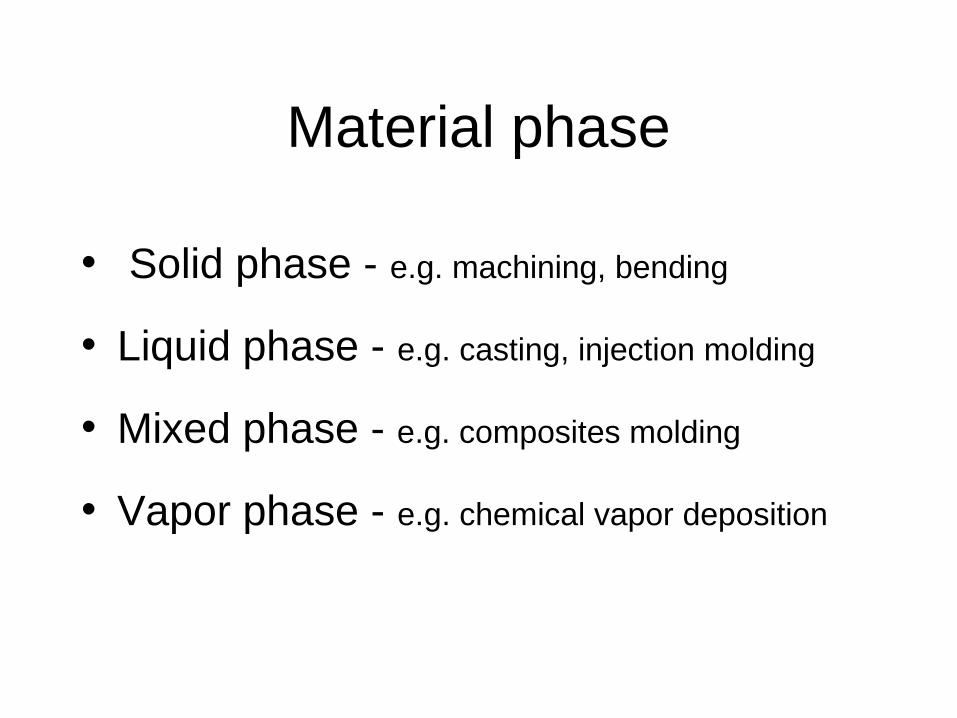
Material phase
• Solid phase - e.g. machining, bending
• Liquid phase - e.g. casting, injection molding
• Mixed phase - e.g. composites molding
• Vapor phase - e.g. chemical vapor deposition

1. Subtractive Processes
• Processes– Machining: Turning, milling, boring,
grinding– Non-traditional machining: EDM, chemical
milling, waterjet, etc.– Micro-electronics processes: Primarily
etching type processes using either masks or beam, chemical mechanical polishing…
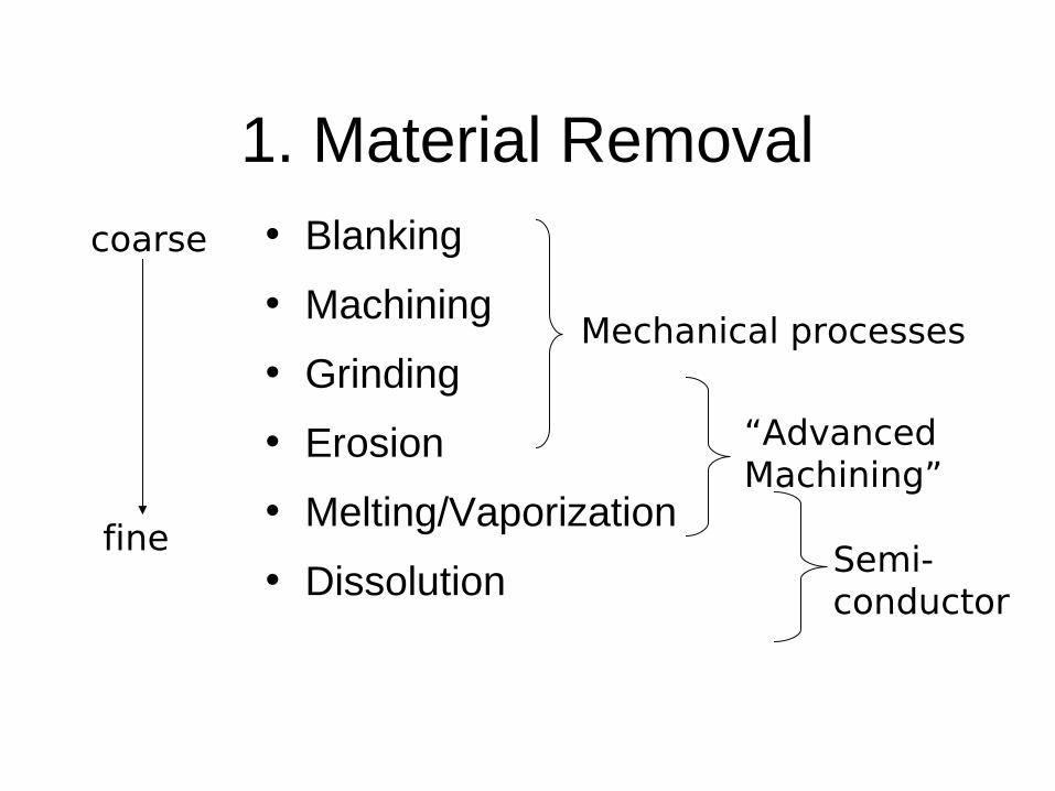
1. Material Removal• Blanking
• Machining
• Grinding
• Erosion
• Melting/Vaporization
• Dissolution
coarse
fine
Mechanical processes
“Advanced Machining”
Semi-conductor
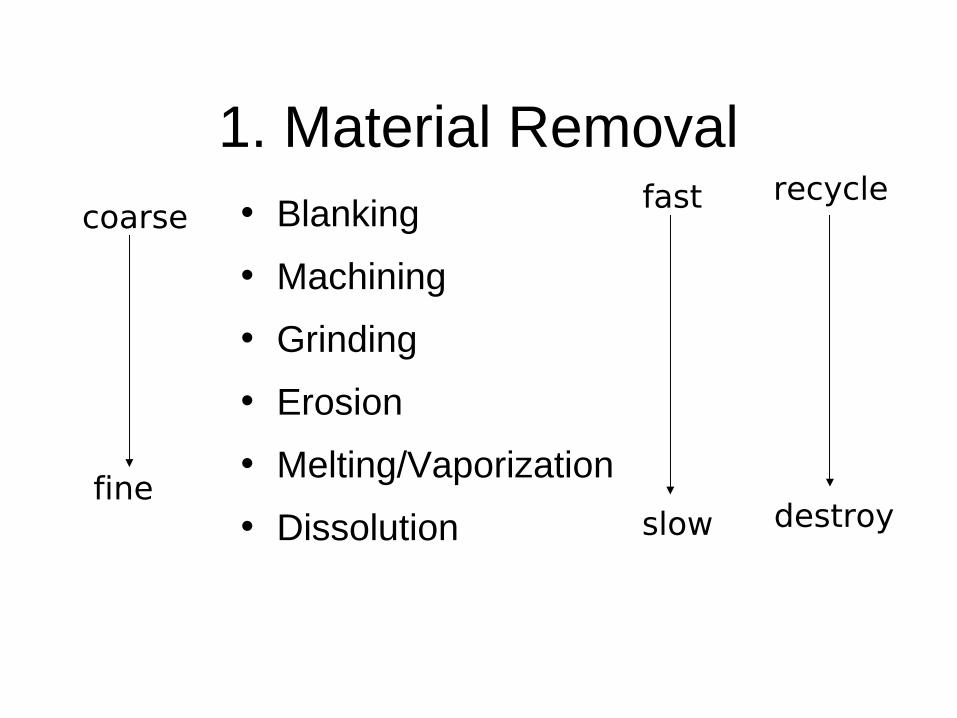
1. Material Removal• Blanking
• Machining
• Grinding
• Erosion
• Melting/Vaporization
• Dissolution
coarse
fine
fast
slow
recycle
destroy
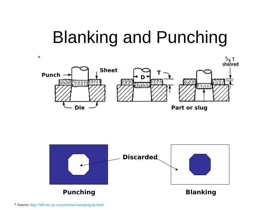
Blanking and Punching
Die
SheetPunch T
D
Part or slug
* Source: http://bdi-inc.qc.ca/processes/stamping/sp.html
*
Discarded
Punching Blanking

Machining
• Conventional Machining processes:– To first approx mat’l properties are
independent of process– Very flexible– Good dimensional control (possible)– Good surface finish (possible)
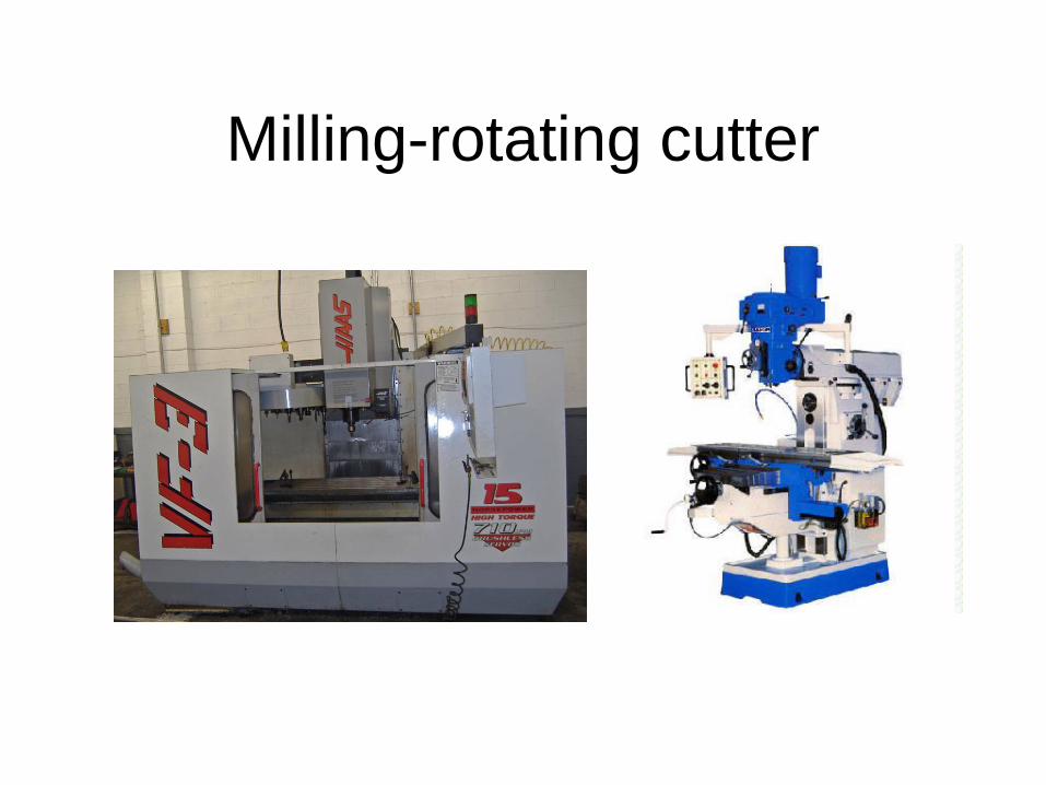
Milling-rotating cutter
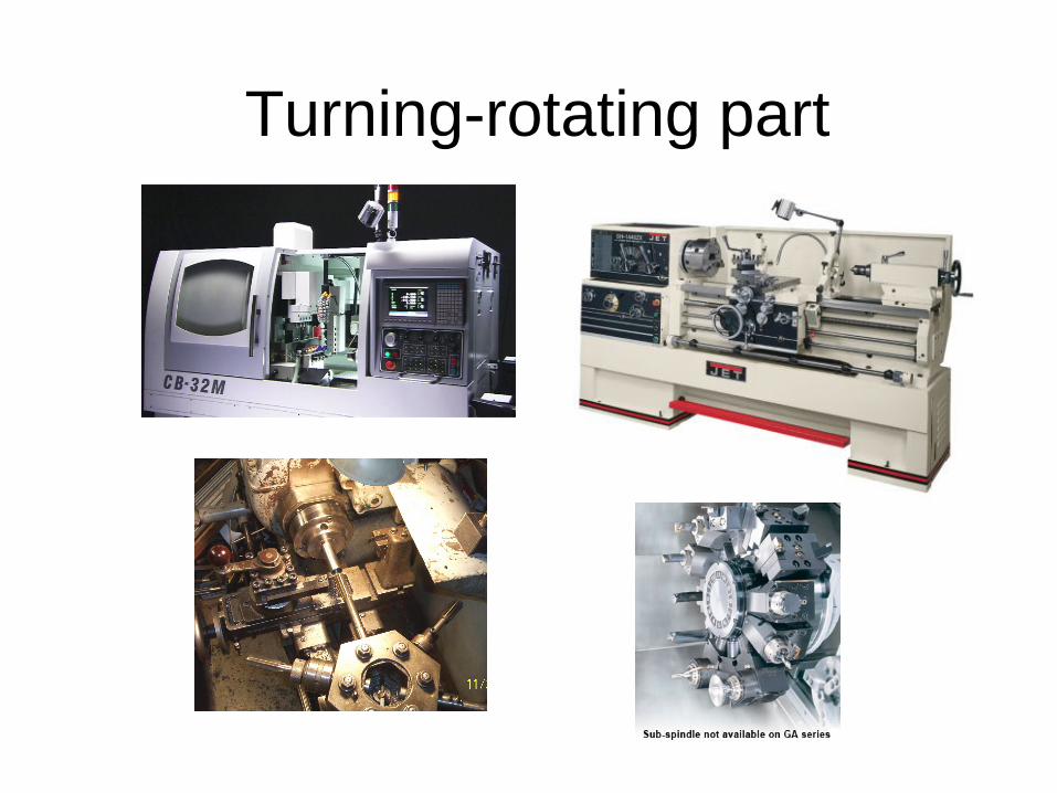
Turning-rotating part

grinding
Surface grinding Cylindrical grinding
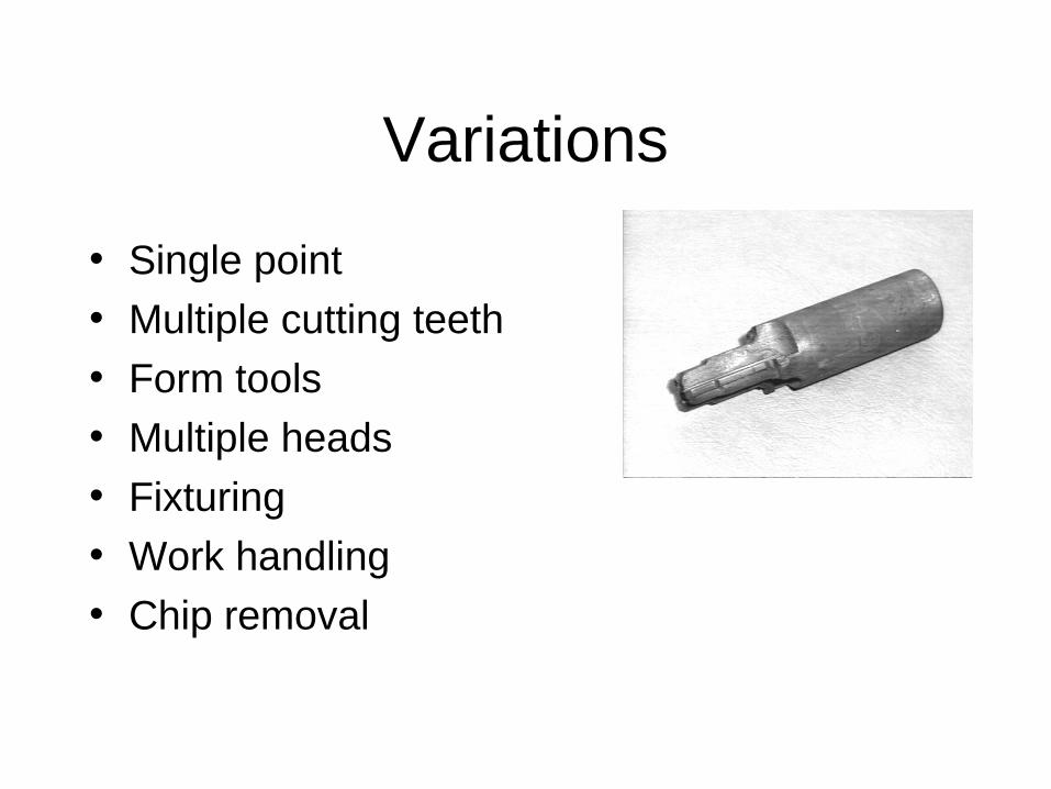
Variations
• Single point• Multiple cutting teeth• Form tools• Multiple heads• Fixturing• Work handling• Chip removal
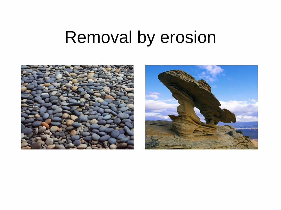
Removal by erosion
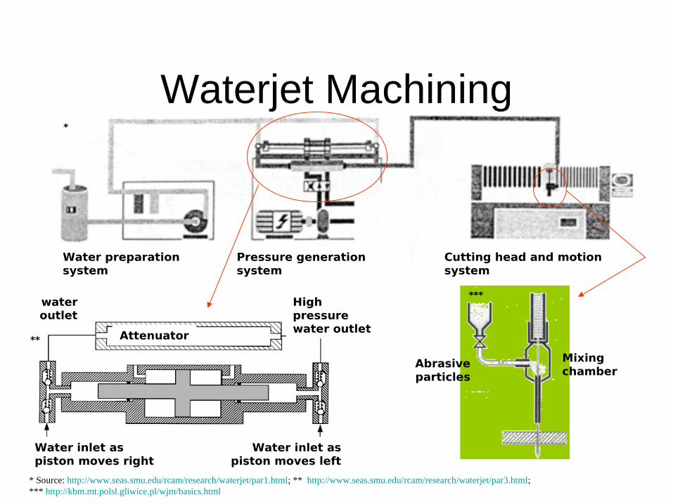
Water preparation system
Pressure generation system
Cutting head and motion system
*
Waterjet Machining
* Source: http://www.seas.smu.edu/rcam/research/waterjet/par1.html; ** http://www.seas.smu.edu/rcam/research/waterjet/par3.html; *** http://kbm.mt.polsl.gliwice.pl/wjm/basics.html
Water inlet as piston moves right
Water inlet as piston moves left
High pressure water outlet
Attenuator
water outlet
**
Abrasive particles
Mixing chamber
***

Waterjet Machining
Water preparation system
Pressure generation system
Cutting head and motion system
*
* Source: http://cybercut.berkeley.edu/mas2/html/processes/edm/index.html; ** http://www.omax.com/components_of_waterjet.html
**
http://www.youtube.com/watch?v=_FIsrYzyvlg

Gore Mt, New York
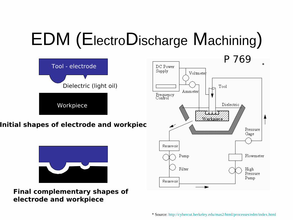
EDM (ElectroDischarge Machining)
Dielectric (light oil)
Workpiece
Tool - electrode
Initial shapes of electrode and workpiece
Final complementary shapes of electrode and workpiece
* Source: http://cybercut.berkeley.edu/mas2/html/processes/edm/index.html
*P 769
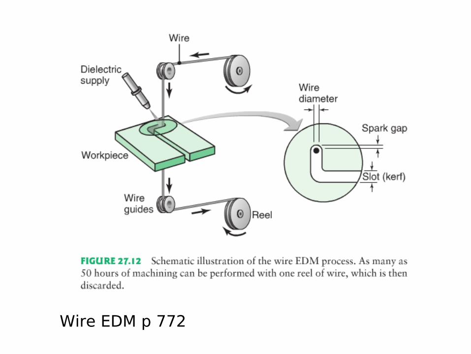
Wire EDM p 772
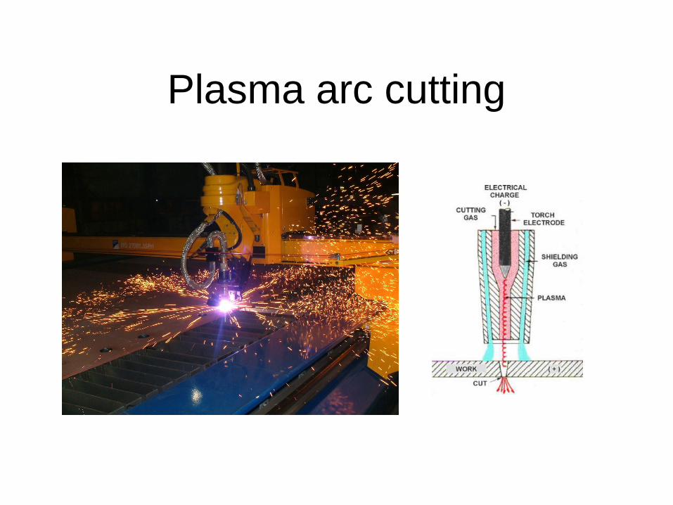
Plasma arc cutting
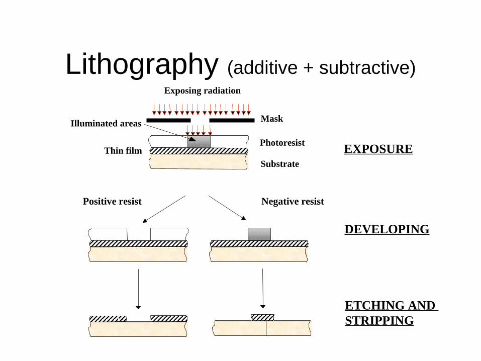
Lithography (additive + subtractive)Exposing radiation
DEVELOPING
ETCHING AND STRIPPING
Positive resist
Substrate
Thin filmPhotoresist
Illuminated areas
EXPOSURE
Negative resist
Mask
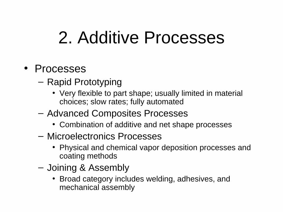
2. Additive Processes
• Processes– Rapid Prototyping
• Very flexible to part shape; usually limited in material choices; slow rates; fully automated
– Advanced Composites Processes• Combination of additive and net shape processes
– Microelectronics Processes• Physical and chemical vapor deposition processes and
coating methods
– Joining & Assembly• Broad category includes welding, adhesives, and
mechanical assembly

2. Additive Processes
Joiningmechanicaladhesivesmelt/solidification
AssemblyComposites layupCoating, platingVapor depositionSputteringIon implant
coarse
fine
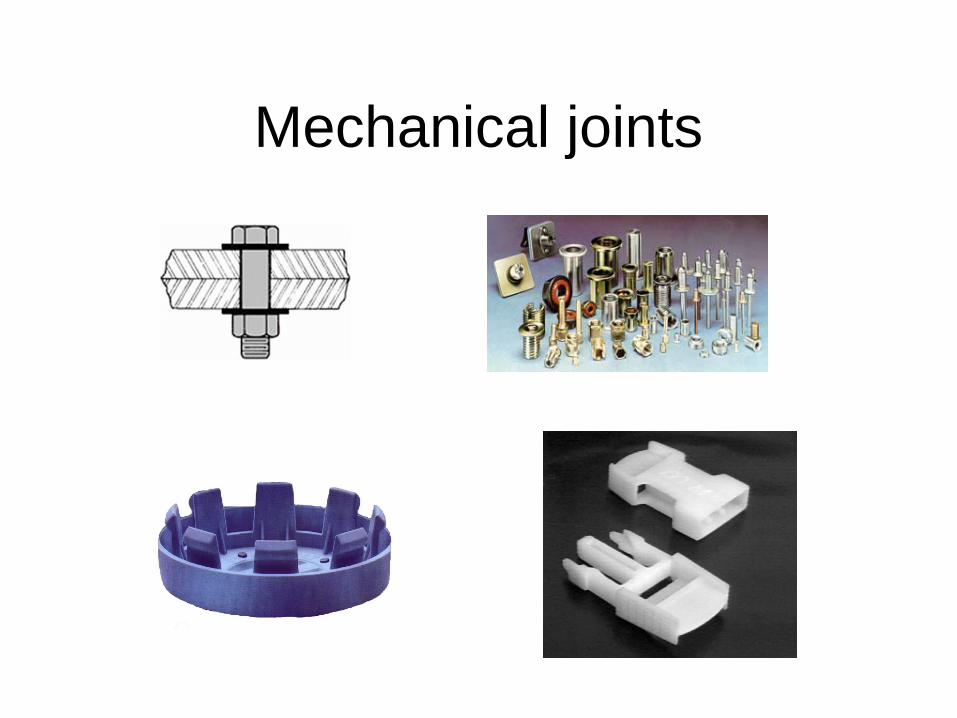
Mechanical joints
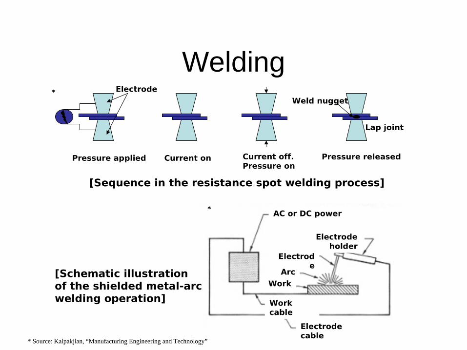
Welding
Pressure applied
Electrode
Current on Current off.Pressure on
Pressure released
Weld nugget
Lap joint
AC or DC power source
Electrode holder
Electrode
Arc
Work
Work cable
Electrode cable
[Sequence in the resistance spot welding process]
[Schematic illustration of the shielded metal-arcwelding operation]
*
*
* Source: Kalpakjian, “Manufacturing Engineering and Technology”

Brazing
http://www.youtube.com/watch?v=3UBd1HIXegM
Furnace brazing
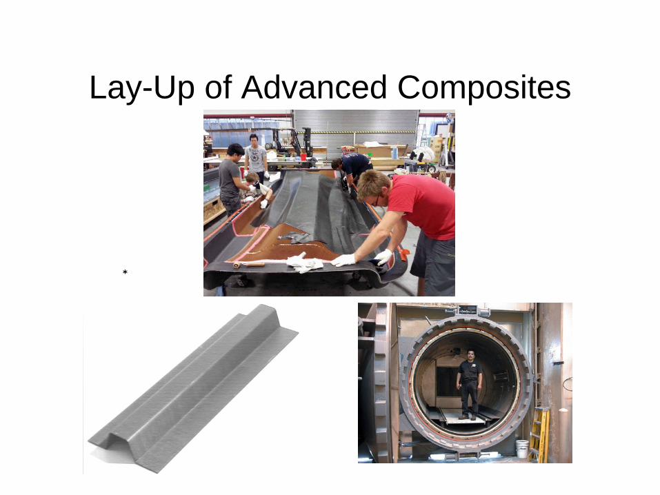
Lay-Up of Advanced Composites
**
* **

Automated tape layup
Ref Grimshaw, Grant, Luna Diaz
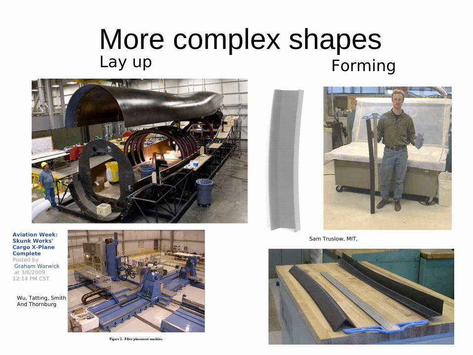
More complex shapesLay up Forming
Aviation Week:Skunk Works' Cargo X-Plane CompletePosted by Graham Warwick at 3/6/2009 12:14 PM CST
Wu, Tatting, SmithAnd Thornburg
Sam Truslow, MIT,
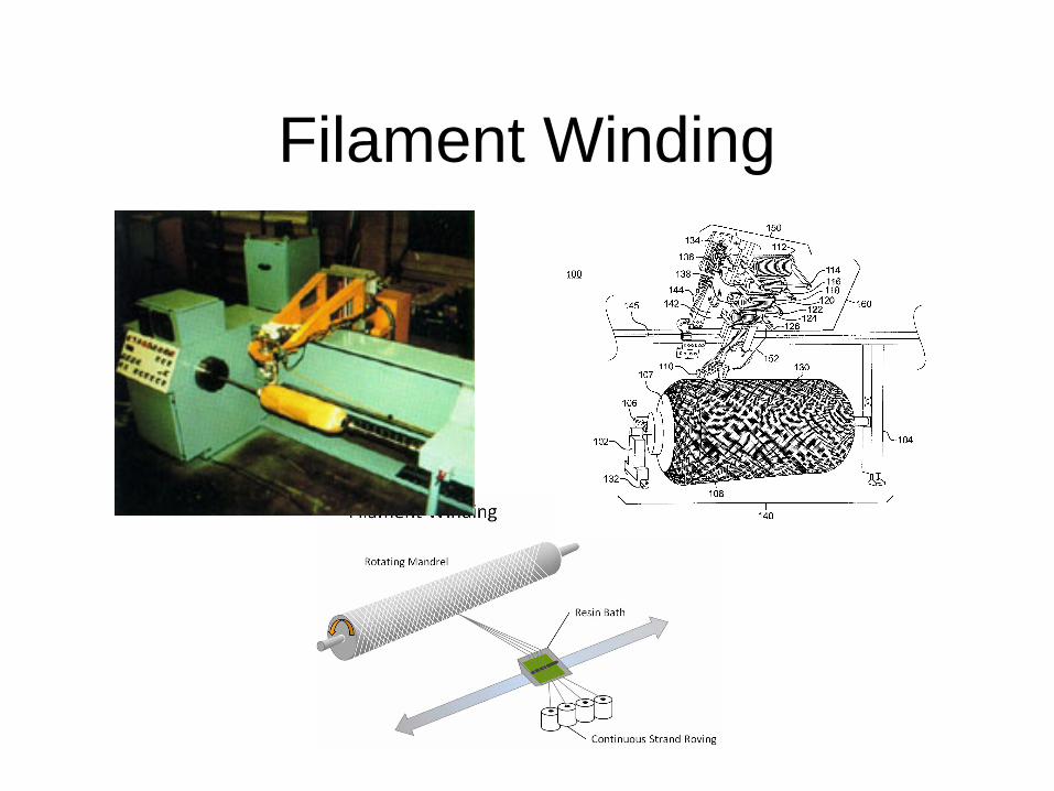
Filament Winding
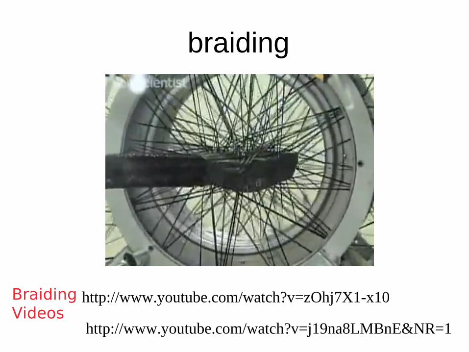
braiding
http://www.youtube.com/watch?v=j19na8LMBnE&NR=1
http://www.youtube.com/watch?v=zOhj7X1-x10BraidingVideos

•Hand lay-up•Spray-up•Vacuum molding
http://www.youtube.com/watch?v=YZAkf1E2Jcs
Vacuum mold videoJump to 4 min
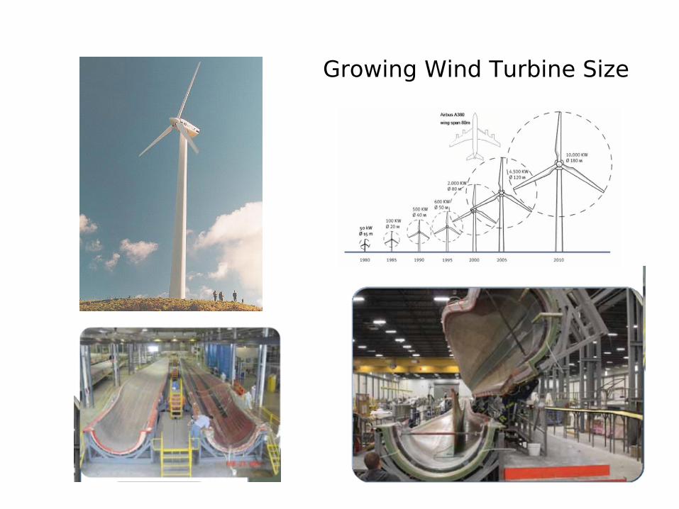
Growing Wind Turbine Size
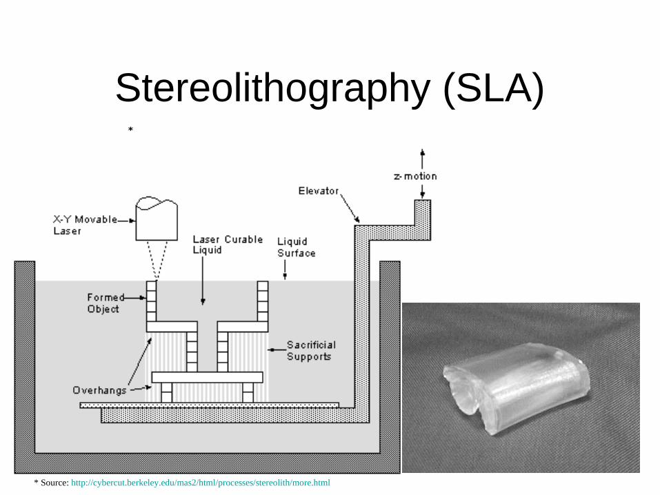
Stereolithography (SLA)
* Source: http://cybercut.berkeley.edu/mas2/html/processes/stereolith/more.html
*
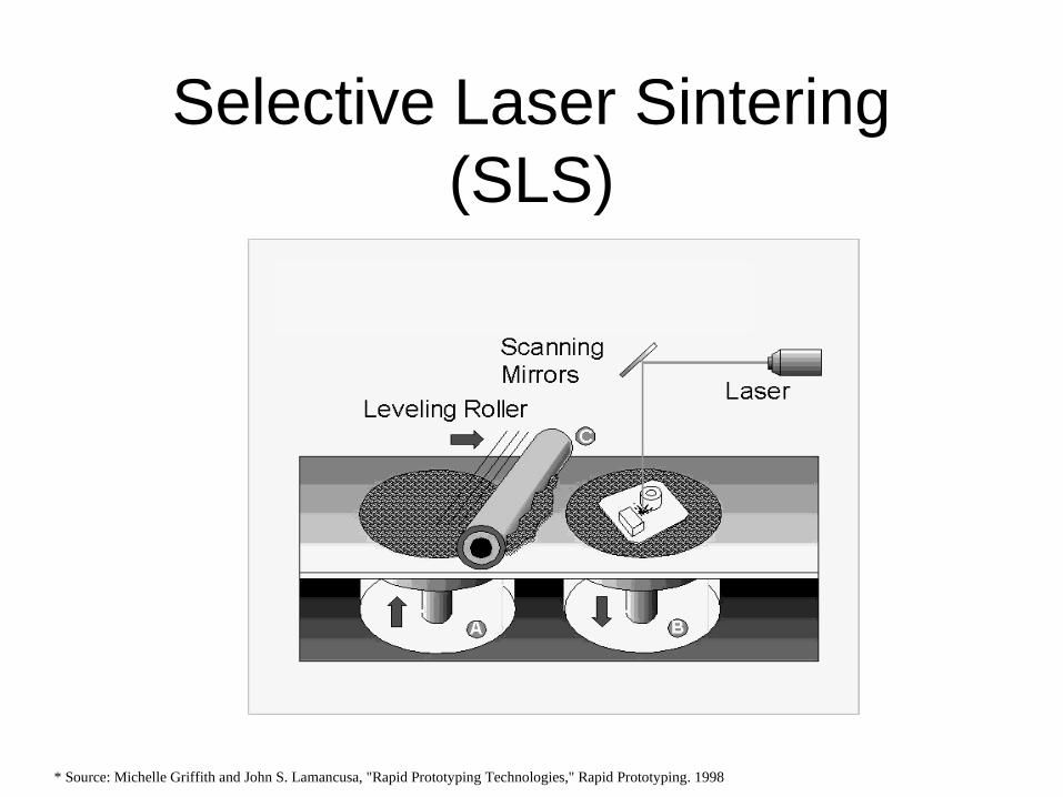
Selective Laser Sintering (SLS)
* Source: Michelle Griffith and John S. Lamancusa, "Rapid Prototyping Technologies," Rapid Prototyping. 1998

Selective Laser Sintering (SLS)
* Source: DTM Corporation (3D Systems)
http://web.mit.edu/2.810/www/lecture/sinter_movie.mov
http://www.youtube.com/watch?v=SVkUwqzjGJY
http://www.youtube.com/watch?v=gLxve3ZOmvc
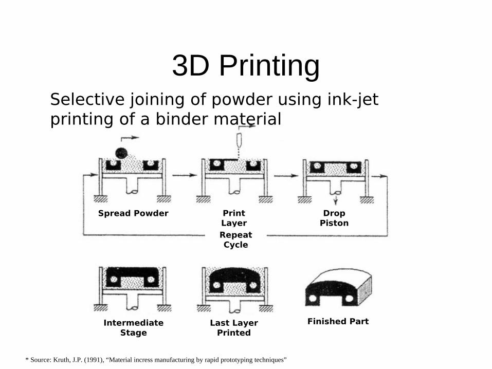
3D Printing
Spread Powder Print Layer
Drop Piston
Repeat Cycle
Intermediate Stage
Last Layer Printed
Finished Part
Selective joining of powder using ink-jet printing of a binder material
* Source: Kruth, J.P. (1991), “Material incress manufacturing by rapid prototyping techniques”
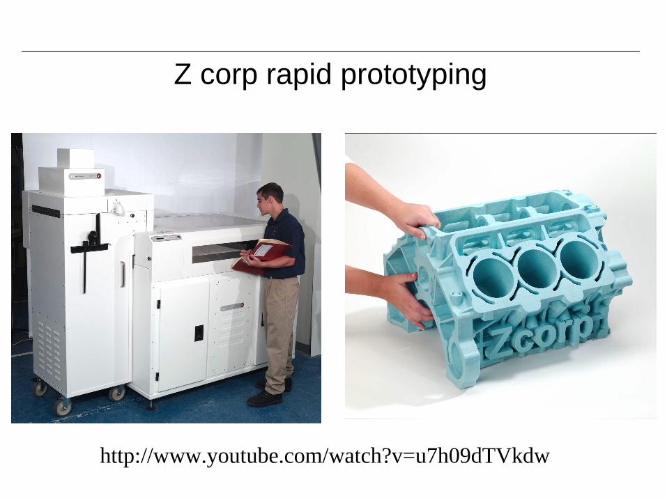
Z corp rapid prototyping
http://www.youtube.com/watch?v=u7h09dTVkdw
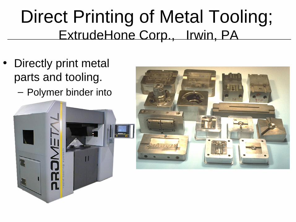
Direct Printing of Metal Tooling; ExtrudeHone Corp., Irwin, PA
• Directly print metal parts and tooling.– Polymer binder into
metal powder.
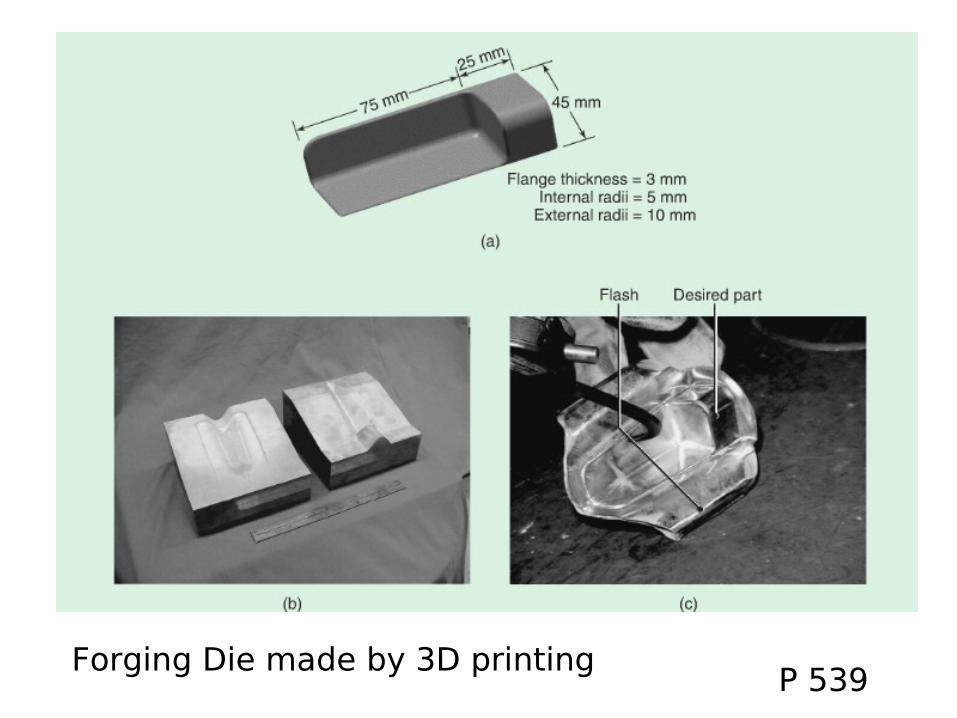
3 D Parts
P 539Forging Die made by 3D printing
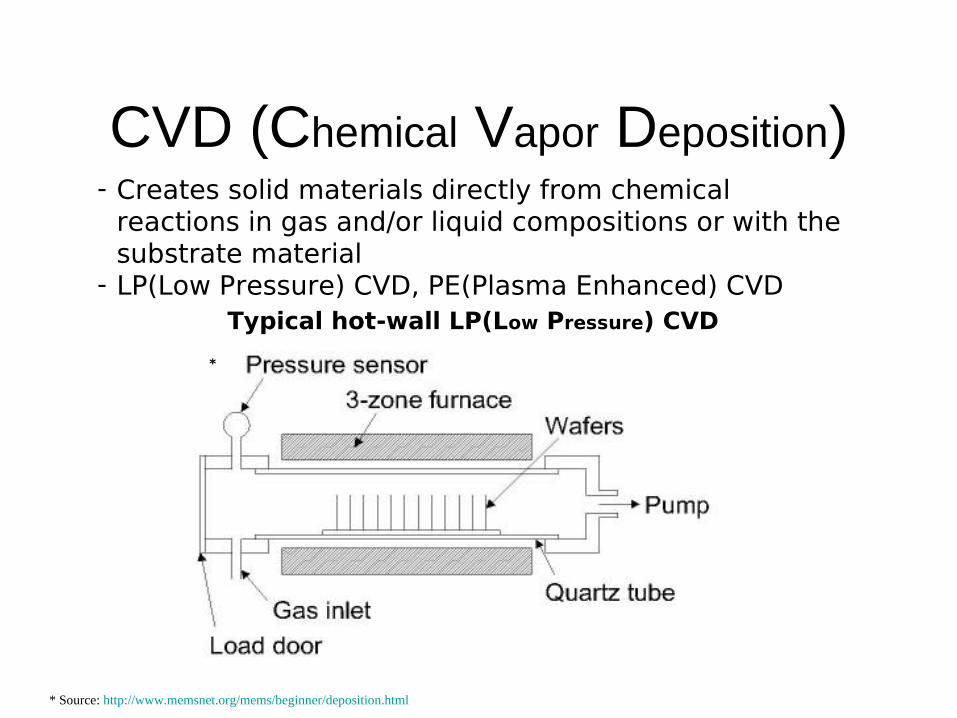
CVD (Chemical Vapor Deposition)
Typical hot-wall LP(Low Pressure) CVD
*
* Source: http://www.memsnet.org/mems/beginner/deposition.html
- Creates solid materials directly from chemical reactions in gas and/or liquid compositions or with the substrate material
- LP(Low Pressure) CVD, PE(Plasma Enhanced) CVD

Deposition of SiO2 fromSilane gas by PECVD
SiH4 + O2 → SiO2 + 2H2
2 HSiCl3 → Si + 2 HCl + SiCl4
Siemens CVDProcess for the Purification of Si
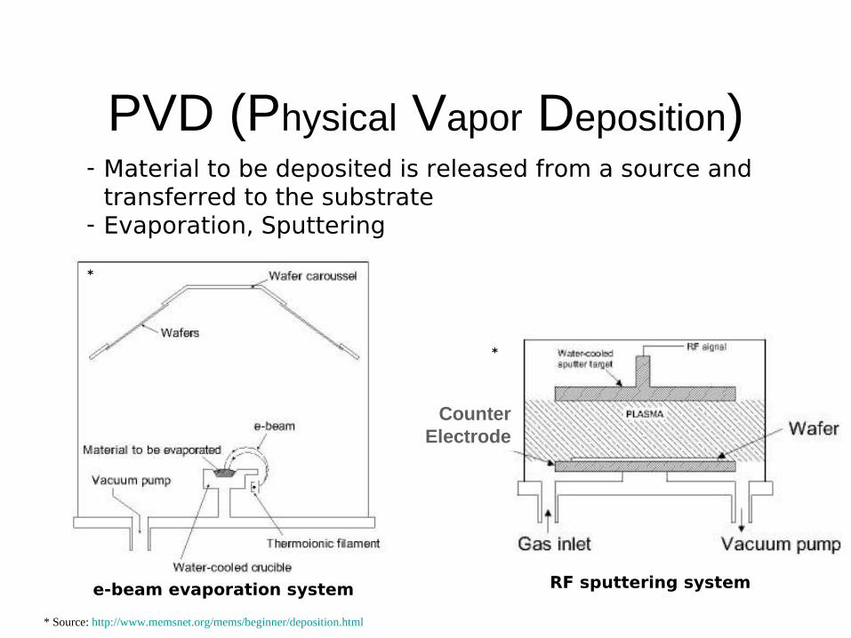
PVD (Physical Vapor Deposition)- Material to be deposited is released from a source and
transferred to the substrate- Evaporation, Sputtering
Counter Electrode
e-beam evaporation system RF sputtering system
* Source: http://www.memsnet.org/mems/beginner/deposition.html
*
*

Thin film PV cell - CIGS
Ascent CIGS Solar Cell
Photo-response mappingOf a CIGS cell
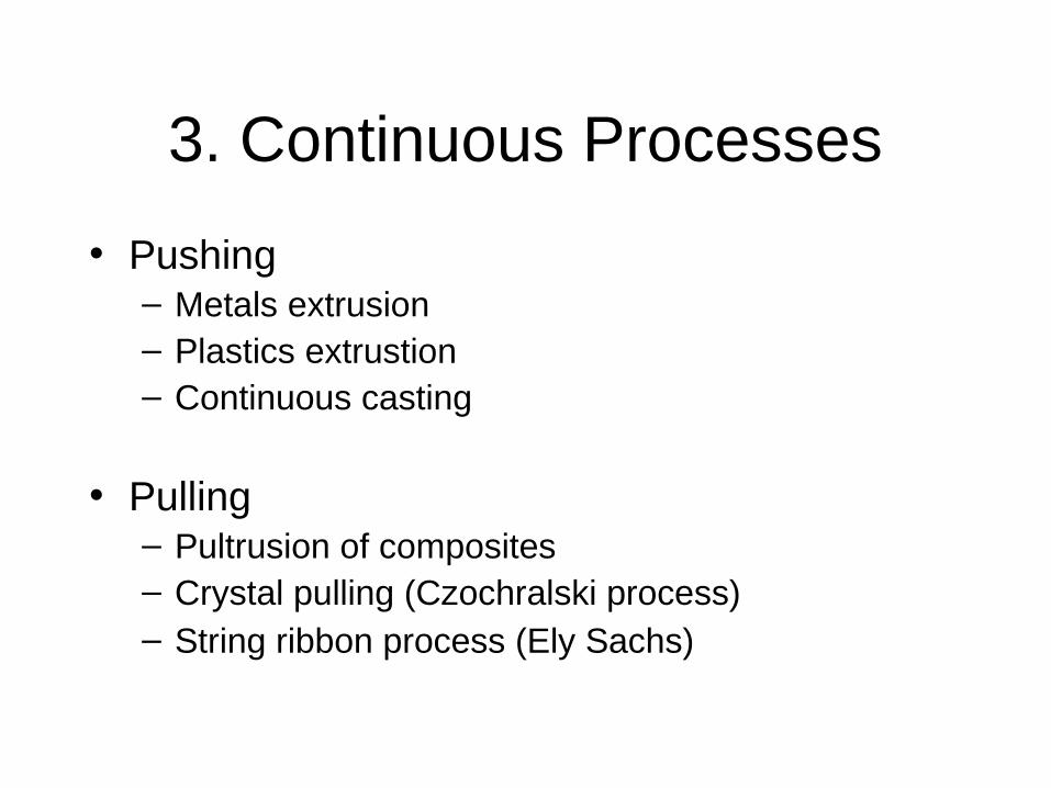
3. Continuous Processes
• Pushing– Metals extrusion– Plastics extrustion– Continuous casting
• Pulling– Pultrusion of composites– Crystal pulling (Czochralski process)– String ribbon process (Ely Sachs)
Pros and Cons
• + Low unit cost for large runs
• + Low unit cost for large runs
• + Low unit cost for large runs
• - constant cross section
• - constant cross section
• - constant cross section
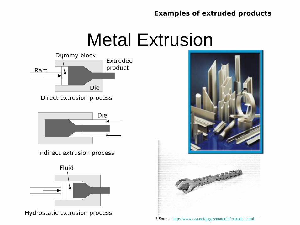
Metal ExtrusionExtrudedproduct
Die
Dummy block
Ram
Fluid
Direct extrusion process
Hydrostatic extrusion process
Die
Indirect extrusion process
Examples of extruded products
* Source: http://www.eaa.net/pages/material/extruded.html
*
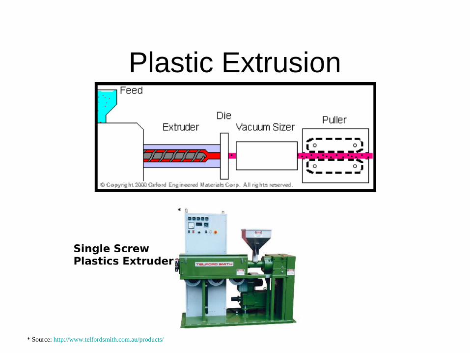
Plastic Extrusion
Single ScrewPlastics Extruder
*
* Source: http://www.telfordsmith.com.au/products/
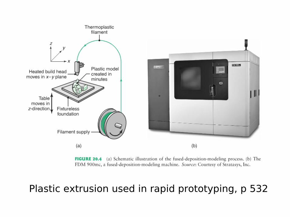
Plastic extrusion used in rapid prototyping, p 532
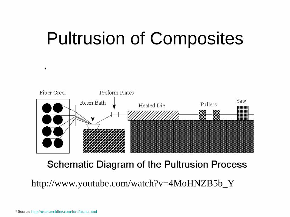
Pultrusion of Composites
*
* Source: http://users.techline.com/lord/manu.html
http://www.youtube.com/watch?v=4MoHNZB5b_Y
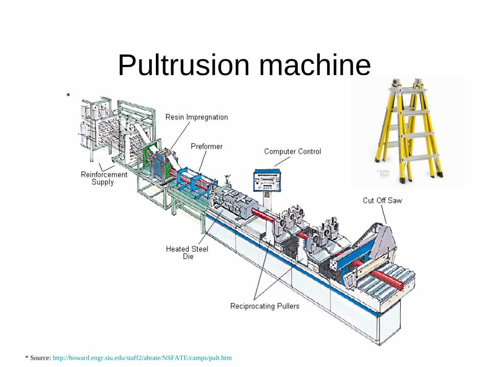
Pultrusion machine*
* Source: http://howard.engr.siu.edu/staff2/abrate/NSFATE/camps/pult.htm
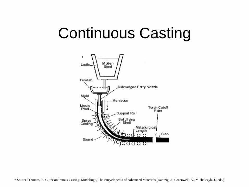
Continuous Casting*
* Source: Thomas, B. G., “Continuous Casting: Modeling”, The Encyclopedia of Advanced Materials (Dantzig, J., Greenwell, A., Michalczyk, J., eds.)
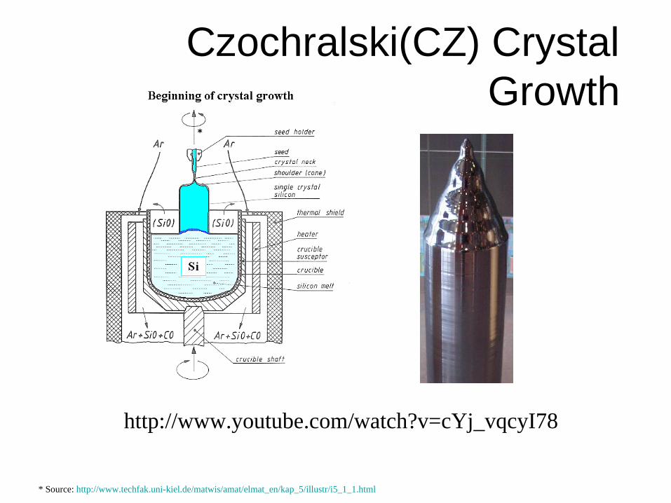
Czochralski(CZ) Crystal Growth
*
* Source: http://www.techfak.uni-kiel.de/matwis/amat/elmat_en/kap_5/illustr/i5_1_1.html
http://www.youtube.com/watch?v=cYj_vqcyI78
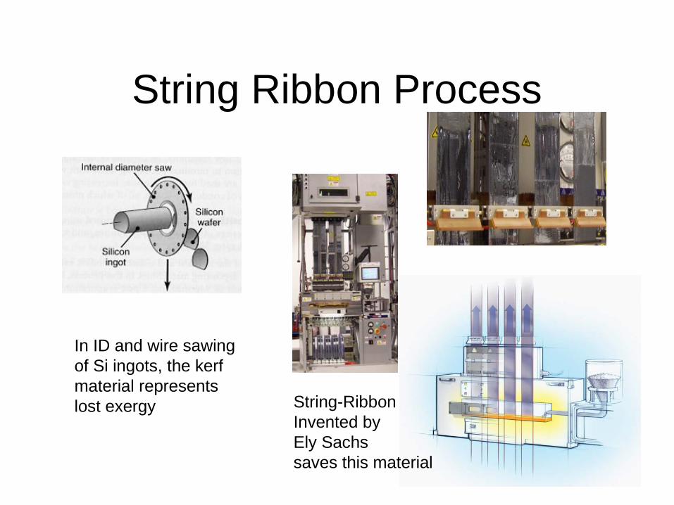
String Ribbon Process
In ID and wire sawingof Si ingots, the kerf material representslost exergy String-Ribbon
Invented byEly Sachssaves this material
4. Net Shape: Molding
• Types– Solids: Metal Forming, Powders, Others– Liquids: Casting, Injection Molding, Others– Mixtures: Infiltration, Viscoelastics, Others
• Characteristics– Hard tooling– Solid forming – very fast cycle time– Thermal processes – slower and depend upon
cooling rate– Dimensional control is not as good as machining
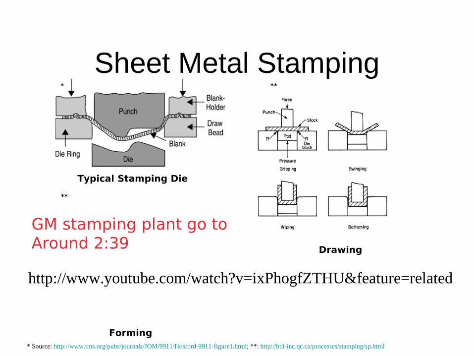
Sheet Metal Stamping
Typical Stamping Die
Forming
Drawing
* **
**
* Source: http://www.tms.org/pubs/journals/JOM/9911/Hosford-9911-figure1.html; **: http://bdi-inc.qc.ca/processes/stamping/sp.html
http://www.youtube.com/watch?v=ixPhogfZTHU&feature=related
GM stamping plant go toAround 2:39

Forging*
**
* Source: http://www.forging.org/facts/wwhy6.htm#fig3; **: Kalpakjian, “Manufacturing Engineering and Technology”; ***: http://www.johnsonforging.com
***
Open Die Forging
Closed Die Forging
No frictionFriction force
http://www.youtube.com/watch?v=PXVWiGqeltM
Video
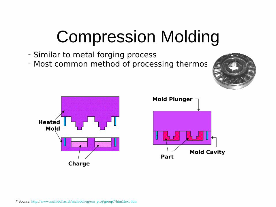
Compression Molding- Similar to metal forging process- Most common method of processing thermosets
Charge
HeatedMold
Mold Plunger
Mold CavityPart
* Source: http://www.mahidol.ac.th/mahidol/eg/em_proj/group7/htm1text.htm

Metal Casting
* Source: http://www.cepsales.com/Castings.htm ; ** http://www.eaa.net/pages/material/casting.html
Sand Casting Mold Die Casting machine
* **
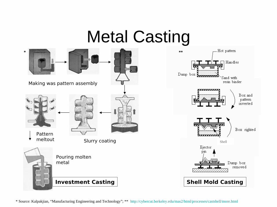
Metal Casting
Making was pattern assembly
Slurry coating
Pattern meltout
Pouring moltenmetal
Shell
Investment Casting Shell Mold Casting
* **
* Source: Kalpakjian, “Manufacturing Engineering and Technology”; ** http://cybercut.berkeley.edu/mas2/html/processes/castshell/more.html
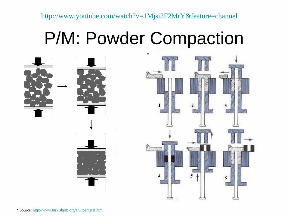
P/M: Powder Compaction*
* Source: http://www.turkishpm.org/en_tozmetal.htm
http://www.youtube.com/watch?v=1Mjsi2F2MrY&feature=channel

SinteringDensity
Strength
Ductility
Time
Ind
icate
d p
rop
ert
y,
com
pare
d t
o
solid
mate
rial,
%
100 %
0 %
Green compact Necks formed Pore size reduced Fully sintered
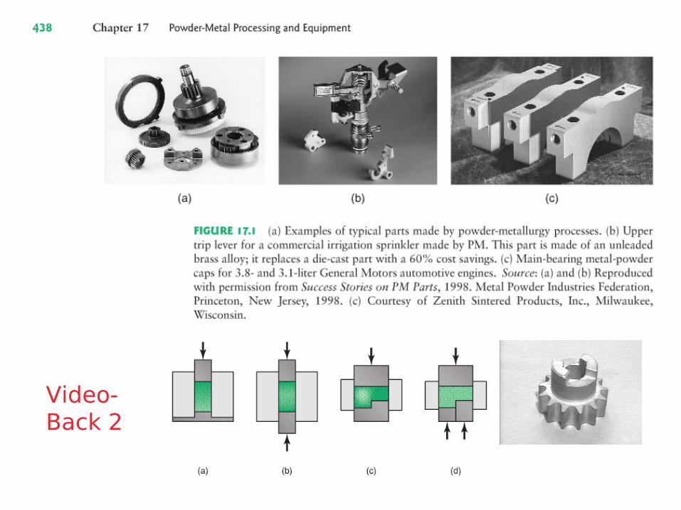
Video-Back 2
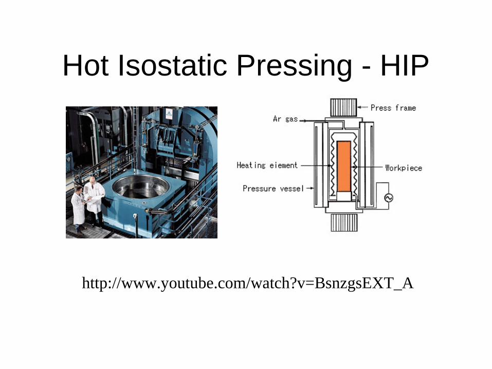
Hot Isostatic Pressing - HIP
http://www.youtube.com/watch?v=BsnzgsEXT_A
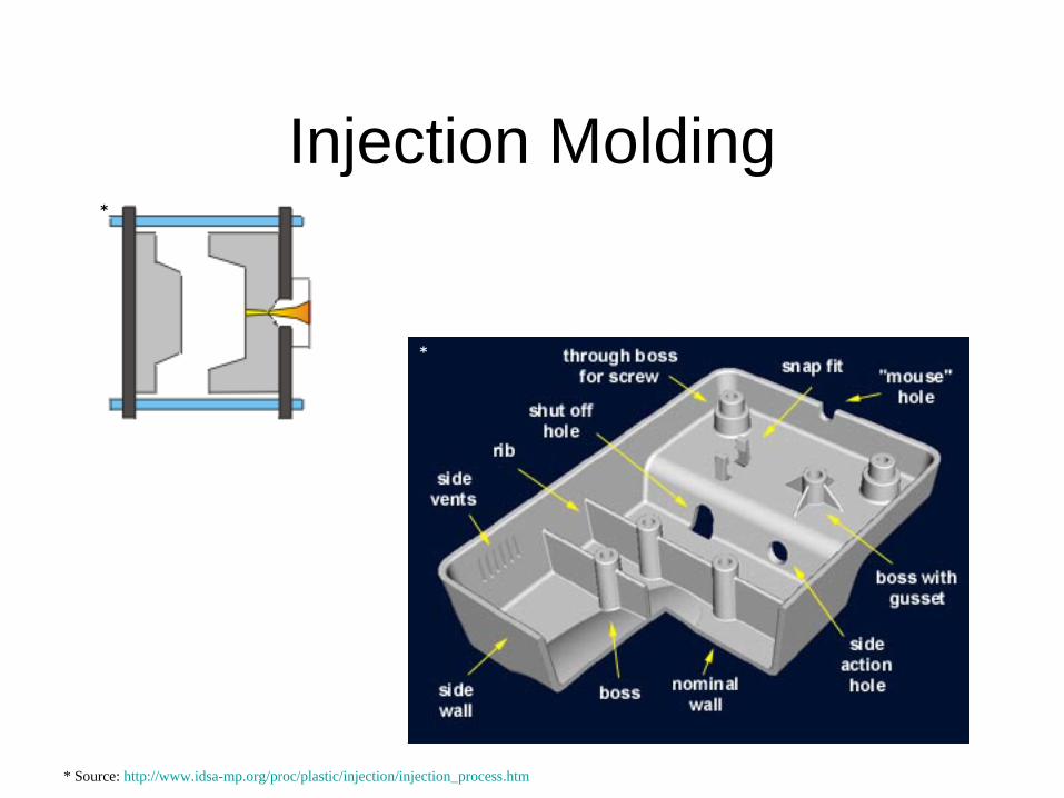
Injection Molding*
*
* Source: http://www.idsa-mp.org/proc/plastic/injection/injection_process.htm
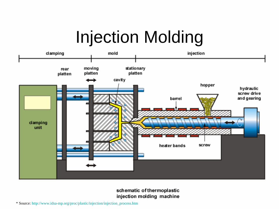
Injection Molding
* Source: http://www.idsa-mp.org/proc/plastic/injection/injection_process.htm
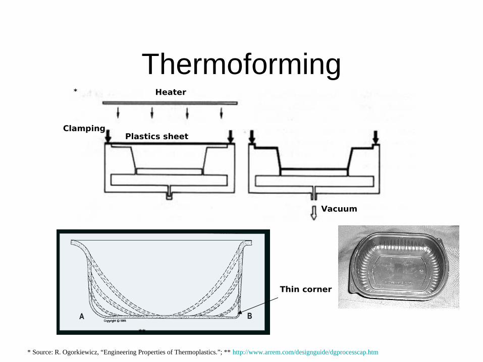
ThermoformingHeater
Plastics sheetClamping
Vacuum
*
**
* Source: R. Ogorkiewicz, “Engineering Properties of Thermoplastics.”; ** http://www.arrem.com/designguide/dgprocesscap.htm
Thin corner
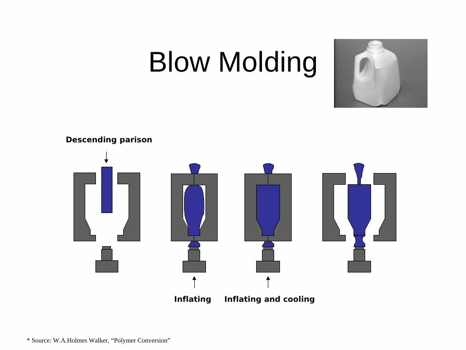
Blow Molding
Descending parison
Inflating Inflating and cooling
* Source: W.A.Holmes Walker, “Polymer Conversion”

Resin Transfer Molding (RTM)
* Source: http://howard.engr.siu.edu/staff2/abrate/rtm
Preform Tool Injection Cure Demold*
*
Summary
1. Subtractive = large forces
2. Additive = computer controlled
3. Continuous = constant X-section
4. Net shape = Molding
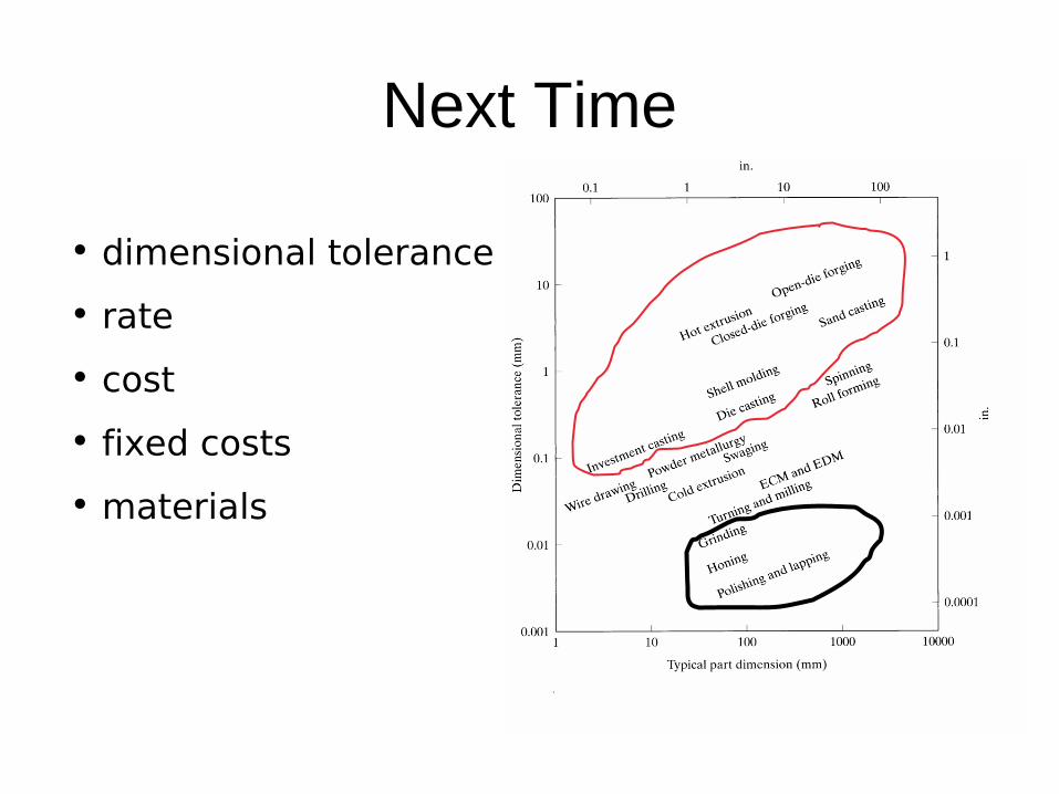
Next Time
• dimensional tolerance
• rate
• cost
• fixed costs
• materials
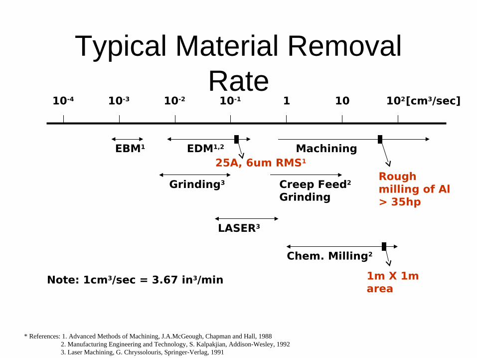
Typical Material Removal Rate
10-4 10-3 10-2 10-1 1 10 102
EBM1 EDM1,2
Grinding3
Machining
Creep Feed2
Grinding
LASER3
Chem. Milling2
[cm3/sec]
25A, 6um RMS1
Rough milling of Al > 35hp
1m X 1m area
Note: 1cm3/sec = 3.67 in3/min
* References: 1. Advanced Methods of Machining, J.A.McGeough, Chapman and Hall, 1988 2. Manufacturing Engineering and Technology, S. Kalpakjian, Addison-Wesley, 1992 3. Laser Machining, G. Chryssolouris, Springer-Verlag, 1991

Unit cost: C/N =F/N + V
QuickTime™ and a decompressor
are needed to see this picture.
Serial processes takelonger, larger variable costsSpecialty mat’l add to variablecosts
Parallel processes require tooling,larger fixed costs, but short cycle time