
Using Digital Signal Processor in Linear Switched Reluctance Actuator Driving and Control
Upload
independentCategory
view
1download
0
Ain Shams Engineering Journal (2014) xxx, xxx–xxx
Ain Shams University
Ain Shams Engineering Journal
www.elsevier.com/locate/asejwww.sciencedirect.com
ELECTRICAL ENGINEERING
Toward including the effect of manufacturing
processes in the pre-estimated losses of the
switched reluctance motor
* Corresponding author. Tel.: +20 2 01000921079.
E-mail address: [email protected] (E. El-Kharahi).
Peer review under responsibility of Ain Shams University.
Production and hosting by Elsevier
http://dx.doi.org/10.1016/j.asej.2014.09.005
2090-4479 � 2014 Production and hosting by Elsevier B.V. on behalf of Ain Shams University.
Please cite this article in press as: El-Kharahi E et al., Toward including the effect of manufacturing processes in the pre-estimated losses of the switched remotor, Ain Shams Eng J (2014), http://dx.doi.org/10.1016/j.asej.2014.09.005
Eyhab El-Kharahia,*, Maher El-Dessouki
a, Pia Lindh
b, J. Pyrhonen
b
a 1 El-Sarayat Street, Abdou Basha Square, Abbassia, 11517, Faculty of Engineering, Electrical Power & Machines Department,Ain Shams University, Cairo, Egyptb Department of Electrical Engineering in LUT Energy, Lappeenranta, Finland
Received 28 June 2014; revised 27 August 2014; accepted 9 September 2014
KEYWORDS
Iron losses;
Manufacturing effect;
Adaptive finite element;
Matlab/Simulink;
High non-linear machine;
Steinmetz formulas
Abstract The estimation of losses plays a key role in the process of building any electrical machine.
How to estimate those losses while designing any machine; by obtaining the characteristic of the
electrical steel from the catalogue and calculate the losses. However, this way is inaccurate since
the electrical steel performs several manufacturing processes during the process of building any
machine, which affects directly the magnetic property of the electrical steel and accordingly the
characteristic of the electrical steel will be affected. That means the B–H curve of the steel that
was obtained from the catalogue will be changed. Moreover, during loading and rotating the
machine, some important changes occur to the B–H characteristic of the electrical steel such as
the stress on the laminated iron. Accordingly, the pre-estimated losses are completely far from
the actual losses because they were estimated based on the data of the electrical steel obtained from
the catalogue. So in order to estimate the losses precisely significant factors of the manufacturing
processes must be included. The paper introduces the systematic estimation of the losses including
the effect of one of the manufacturing factors. Similarly, any other manufacturing factor can be
included in the pre-designed losses estimations.� 2014 Production and hosting by Elsevier B.V. on behalf of Ain Shams University.
1. Introduction
Theoretically, the foundation of any design of any electricalmachine, and how to calculate its losses estimation is based
on the characteristic of the unprocessed electrical steel that isobtained from the catalogue without including the effect ofmanufacturing processes [1]. The previous researches found
out that the process of including the effect of manufacturingprocesses on the steel through the pre-designed loss estimation
luctance

2 E. El-Kharahi et al.
was somehow difficult, and needs a thorough understanding,which complicate the process of loss estimation. That discour-aged the machine designers to include these effects in the
pre-estimated losses of the electrical machine [1]. For furtherclarification, the process of designing and building any electri-cal machines has different aspects such as magnetic circuit, the
electrical circuit, the thermal design, the mechanical design, theventilations, the isolation, the bearing, and the balancing ofelectrical and mechanical circuits. All those different aspects
are related to the design and the building of any electricalmachine. Moreover, the machine frequently needs a controlleror a sensor. Those factors are more than enough to complicatethe process of designing and building electrical machine.
However, the manufacturing processes have great impacts onthe unprocessed electrical steel and these impacts must beincluded in the design and pre-estimated losses of the electrical
machine [2].From this point of view, the paper addresses a simple
approach to include the manufacturing factors in the design
and pre-estimated losses. Since the manufacturing processesaffect the B–H characteristic of the electrical steel, whichmeans that if the effect of any manufacturing process on the
electrical steel is known through the experiences or previousmeasurements, then a mathematical formula can be concludedto the relation between the manufacturing process and the fluxdensity to create a new B–H curve of the electrical steel. In
other words, the B–H curve of the electrical steel, which isobtained from the catalogue, is now modified according to thismathematical formula, which link between the flux density and
the manufacturing factor. Now a new B–H curve can be usedin the pre-design process and in the loss estimation without themiscalculation in the previous steps [3].
This paper explains in detail the design and losses estima-tion process, using an example of an electrical machine withnon-linear characteristic and rotational transient operation.
This means that this electrical machine has no steady stateoperation, which means that it has high iron losses. The objec-tive of doing that was to illustrate in detail how the calculationof the iron losses is determined by including a manufacturing
factor by simple steps [4].
2. Understanding one of the manufacturing effects in the
electrical machine
The manufacturing process of the electrical steel sheet causesdistortion, residual stress, etc. in the electrical steel sheet.
The distortion and the residual stress of the electrical steelsheet used in the stator and the rotor are the causes of the ironloss increment, which also generates the degradation of the
magnetic properties of a magnetic circuit of the machine thatbuilt from punched electrical steel sheets [5].
Punching the iron sheets affects the material properties andcreates heterogeneous stress inside the sheets. The effect is
depending on the alloy composite, whereas the grain size inthe sheets seems to be the main influencing factor, especiallyfor operating ranges between 0.4 T and 1.5 T. The influenced
region in the sheet due to cutting and punching goes up to10 mm in distance from the cutting edge, where the permeabil-ity is significantly decreased. This reduction in permeability
increases the iron losses in the material. Specifically, for geo-metric parts smaller than 10 mm in width (small stator teeth
Please cite this article in press as: El-Kharahi E et al., Toward including the effect omotor, Ain Shams Eng J (2014), http://dx.doi.org/10.1016/j.asej.2014.09.005
for example), the punching process can have a significant influ-ence on the iron losses and therefore has to be considered inthe loss calculation. Further, the cutting and punching process
damages the thin insulation layer. This might lead to haveshort circuits between several sheet layers. In this paper, thepunching effect will be included in the pre-designed losses
estimation [5].
3. The proposed electrical machines for design and losses
estimation including one of the manufacturing factors
This paper will use the switched reluctance motor as an exam-ple for non-linear electrical machines that has a core exposed
and all its running time in non-sinusoidal excitation. Theswitched reluctance motor estimation losses will be illustratedin detail within this paper, using the punching effect as the
manufacturing process factor in the losses estimation process[6].
The losses in the switched reluctance motor (SRM) consistmainly of the stator copper losses and the core losses. The cop-
per losses are proportional to the square of the root meansquare of the current whereas the core losses are a functionof the excitation frequency and the flux density. The iron losses
in the SRM cannot be ignored as the SRM always operates intransient operation mode. During transient operations, thehigh switching frequency increases the iron loss to a significant
value compared with the value of copper loss [6].The process of concluding the SRM iron losses value is
complicated, because the frequency of the varying of the fluxreversals depends on the place and time. Therefore, the iron
losses are different for each part of the motor’s cross-sectionalarea. In addition, the iron losses depend on the flux density,whose waveform varies in different zones of the SRM. More-
over, the current waveforms are non-sinusoidal and theydepend on the operating conditions and the type of controller.These factors have significant impact on complicating the pro-
cess of the estimation of the core losses [7].The models for the iron losses estimation either can be
empirical or based on the solution of Maxwell’s equations.
The general idea for finding any formula to estimate the ironlosses in the SRM is based on separating the specific corelosses (W/kg) into three parts (hysteresis, eddy current andexcess losses) and to be calculated using the waveforms and
time derivatives of the local flux densities.The equation for estimating the iron losses [7]:
Piron losses ¼ Physteresis þ Peddy þ Panomalous ð1Þ
4. Design of the SRM in case of excitation by non-sinusoidal
excitation
The output torque of any electric machine can be calculated bythree different variables. The variables are the air gap flux den-
sity B, the machine volume V, and a constant C as follows:
T ¼ C � B � V ð2Þ
This method usually used in case of designing electricalmachines that have linear characteristics. However, thismethod cannot be used for designing any highly non-linear
characteristic electrical machines, because this methodfunction depends on the assumptions of ratios and many
f manufacturing processes in the pre-estimated losses of the switched reluctance

Figure 2 Initial mesh.
The effect of manufacturing in the design and losses estimation of the reluctance motor 3
approximations in the magnetic circuit and the winding config-urations. The switched reluctance motor SRM is a device withdouble rotational salient pole with single excitation that usu-
ally works fully saturated. The torque here resulted by theswitched reluctance motor’s rotor tendency to move to a posi-tion where the maximisation of inductance of the excited phase
winding occurs. Therefore, there is a need to have a power con-verter with solid-state to generate the right sequence of phasecommutation according to the position of the rotor. The
curves that represent flux linkage with consideration of currentand rotor position, W(h, i), are called magnetisation curves,and they are a key point for the SRM. Then due to the com-bined effects of saturation, saliency and hysteresis, these curves
found to be very difficult to determine with any degree of pre-cision using the relationships methods derived from SRMgeometry. Therefore, their accurate determination requires
adaptive finite element (FE) calculations [8].
5. Using the adaptive two dimensions finite element to design
12/8 SRM
Fig. 1 illustrates a schematic diagram of the proposed 12/8three phases SRM. The figure illustrates the machine magnetic
circuit layout in boundary conditions.Fig. 2 illustrates the initial finite element mesh of the
machine.
The first step in the finite element process is to generate aset of machine parts to define the geometry as shown inFig. 2. These objects are defined by co-ordinate pairs, takenin counter-clockwise order, defining successive vertices of
polygonal figure defining the component. In this case, thereare five parts: the stator, the air gap, the two conductors,and the rotor. Dividing the machine parts into those five
parts illustrates the layout of the machine in flat 2D layout,which means that the curved surfaces of the machines arerepresented as a series of straight lines; therefore, the use of
sufficient meeting points is necessary especially in the impor-tant air gap areas. From this definition of the machine part,emerge the initial mesh [9].
The geometry and the layout of the machine are knownfrom the design synthesis stage, and consequently, the infor-mation required defining the iron saturation curves, conductor
Figure 1 12/8 SRM with boundary conditions.
Please cite this article in press as: El-Kharahi E et al., Toward including the effect ofmotor, Ain Shams Eng J (2014), http://dx.doi.org/10.1016/j.asej.2014.09.005
positions, and boundary conditions. The task is merely to mapthis information onto the initial finite element mesh.
In the third step, the initial mesh is adapted for furtheraccuracy, Fig. 3.
Fig. 3 shows the mesh after adaptation in the motor asshown in Fig. 1 and it is clear that the meshes fit with all theparts especially the small parts that cannot be modelled
mathematically.
6. Electric circuit design, performance optimisation and losses
computation in 12/8 standard SRM
The second part of designing the conventional 12/8 SRM is todesign the electric circuit. The design of any electric circuit has
to include the following three factors (the determination of thebest number of the turns, the cross-sectional area of the con-ductor and the number of the coils). The following step afterthe design of this motor is the performance optimisation.
The performance optimisation is applied through two phases:The First phase, by selecting different values of the intervalsbetween switching on/off angles, and the second phase by
changing the switching on angles. The best values are the val-ues that lead to maximising the torque. This process may lead
Figure 3 Mesh after adaptation.
manufacturing processes in the pre-estimated losses of the switched reluctance
05
1015
20
0
20
40
600
0.5
1
1.5
CurrentPosition
Flu
x
Figure 5 Flux versus current and position.
50
4 E. El-Kharahi et al.
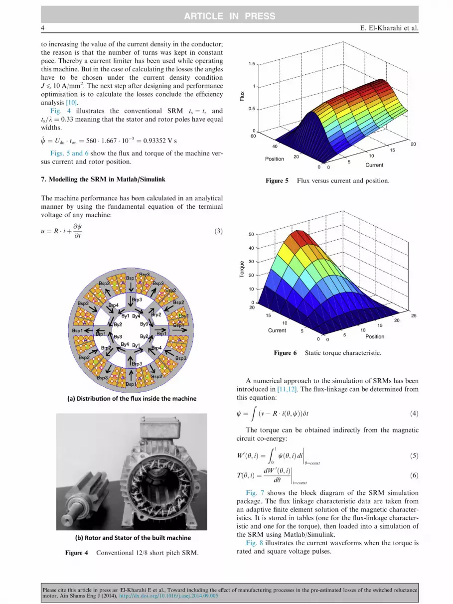
to increasing the value of the current density in the conductor;the reason is that the number of turns was kept in constantpace. Thereby a current limiter has been used while operating
this machine. But in the case of calculating the losses the angleshave to be chosen under the current density conditionJ 6 10 A/mm2. The next step after designing and performance
optimisation is to calculate the losses conclude the efficiencyanalysis [10].
Fig. 4 illustrates the conventional SRM ts ¼ tr and
ts=k ¼ 0:33 meaning that the stator and rotor poles have equalwidths.
w ¼ Udc � ton ¼ 560 � 1:667 � 10�3 ¼ 0:93352 V s
Figs. 5 and 6 show the flux and torque of the machine ver-sus current and rotor position.
7. Modelling the SRM in Matlab/Simulink
The machine performance has been calculated in an analytical
manner by using the fundamental equation of the terminalvoltage of any machine:
u ¼ R � iþ @w@t
ð3Þ
(a) Distribu�on of the flux inside the machine
(b) Rotor and Stator of the built machine
Figure 4 Conventional 12/8 short pitch SRM.
05
1015
2025
0
5
10
15
200
10
20
30
40
PositionCurrent
Tor
que
Figure 6 Static torque characteristic.
Please cite this article in press as: El-Kharahi E et al., Toward including the effect omotor, Ain Shams Eng J (2014), http://dx.doi.org/10.1016/j.asej.2014.09.005
A numerical approach to the simulation of SRMs has beenintroduced in [11,12]. The flux-linkage can be determined from
this equation:
w ¼Z
m� R � iðh;wÞð Þdt ð4Þ
The torque can be obtained indirectly from the magnetic
circuit co-energy:
W0ðh; iÞ ¼Z 1
0
wðh; iÞdi����h¼const
ð5Þ
Tðh; iÞ ¼ dW 0ðh; iÞdh
����i¼const
ð6Þ
Fig. 7 shows the block diagram of the SRM simulationpackage. The flux linkage characteristic data are taken froman adaptive finite element solution of the magnetic character-
istics. It is stored in tables (one for the flux-linkage character-istic and one for the torque), then loaded into a simulation ofthe SRM using Matlab/Simulink.
Fig. 8 illustrates the current waveforms when the torque israted and square voltage pulses.
f manufacturing processes in the pre-estimated losses of the switched reluctance

Figure 9 Total torque (20 Nm).
Figure 10 Voltage waveform.
Figure 11 Flux-linkage waveform versus position.
Figure 7 Block diagram of SRM simulation using Matlab/Toolbox.
Figure 8 Current wave form.
The effect of manufacturing in the design and losses estimation of the reluctance motor 5
Irms = 5.7 A (on/off angles: 0/15 mech. degrees)
Jrms
Irms
Area of one conductor¼ 5:7
0:5733ffi 10 A=mm2
Please cite this article in press as: El-Kharahi E et al., Toward including the effect ofmotor, Ain Shams Eng J (2014), http://dx.doi.org/10.1016/j.asej.2014.09.005
Fig. 9 illustrates total torque waveform when the machine isdriven by the simple voltage pulses that is illustrated in Fig. 10to produce the flux-linkage waveform versus position that isillustrated in Figs. 11 and 12.
manufacturing processes in the pre-estimated losses of the switched reluctance

Figure 14 Flux densities in stator yokes.
Figure 15 Flux densities in rotor Pole 1 and Pole 3.
Figure 12 Flux-linkage trajectory.
6 E. El-Kharahi et al.
7.1. The flux waveforms
In the SRM, the flux density waveforms are non-sinusoidal,and then we find that the waveforms change according towhich part of the magnetic circuit it occurs. The flux densitiesin the different parts of the SRM are deducted from the flux
density of the stator poles. Flux density waveforms of the sta-tor poles are more or less unipolar triangular pulses anddepend on three factors (the phase switch conducting period,
the diode conducting period and, of course, the type of con-trol). The flux densities of all stator phases have the samewaveform, albeit shifted by the delay angle. The different flux
waveforms in the stator yoke are obtained by summing the sta-tor pole flux waveforms in the different zones of the magneticcircuit. The flux polarity in the rotor reverses at every half arevolution, so the rotor poles flux waveforms are bipolar.
The rotor yoke flux waveform is obtained by subtracting therotor pole flux waveforms. Fig. 13 illustrates the flux densitiesin the three stator poles.
The flux densities in the stator yokes are calculated from theflux density in the stator poles illustrated in Fig. 14:
Bsy1 ¼ Bsp2 þ Bsp1 � Bsp3
Bsy2 ¼ Bsp1 � Bsp2 � Bsp3
Bsy3 ¼ Bsp1 þ Bsp3 � Bsp3
ð7Þ
Figure 13 Flux density in three stator poles.
Figure 16 Rotor yoke 1.
Please cite this article in press as: El-Kharahi E et al., Toward including the effect omotor, Ain Shams Eng J (2014), http://dx.doi.org/10.1016/j.asej.2014.09.005
Bsy1 ¼ Bnsy1
Bsy2 ¼ Bnsy2
Bsy3 ¼ Bnsy3
ð8Þ
From the distribution of the flux inside the machine whichis illustrated in Fig. 4(a) the flux can be determined in the dif-ferent parts of the rotor. Then dividing it by the area of each
zone, the flux densities can be determined and they are illus-trated in Figs. 15 and 16.
f manufacturing processes in the pre-estimated losses of the switched reluctance

Figure 17 Flowchart of core losses calculation process.
Figure 18 One stator tooth and two stator slots.
The effect of manufacturing in the design and losses estimation of the reluctance motor 7
8. Losses in the SRM
The flow chart in Fig. 17 summarises the steps in this paper to
estimate the losses in the SRM.
8.1. Predicting the iron losses using Steinmetz formula [13–15]
(a) Calculation of the hysteresis losses.
Pnh ¼ k
nh � f � bBa ð9Þ
where knh ¼ 2:01 � 10�2 a ¼ 1:84.
The Steinmetz constant a and knh are dependent on the lam-
ination material.
(b) The equation for calculating the eddy current losses in
the SRM.
Pne ¼kneffiffiffi2p� p
� �2 dB
dt
� �2
ð10Þ
Figure 19 Distribution of the losses in the different parts of the
SRM.
Pne ¼3:75 � 10�5ffiffiffi
2p� p
� �2 � dB
dt
� �2
(c) Calculation of the anomalous losses for the machine
performed by using the following formula.
Pna ¼kna8:76
dB
dt
��������1:5 ð11Þ
where kna ¼ 3:43 � 10�4.
Please cite this article in press as: El-Kharahi E et al., Toward including the effect ofmotor, Ain Shams Eng J (2014), http://dx.doi.org/10.1016/j.asej.2014.09.005
8.2. Calculation of the copper losses
Fig. 18 shows one stator tooth and four stator slots. There arefour coils per phase. Each coil fills two halves of two statorslots, as shown above:
The circumferential length of the section shown (y) fromthe end-winding turns is estimated as follows [29–32]:
1. The length is taken as average distance from the centre of
the windings of the coil on the right side of the tooth tothe centre of the windings of the coil on the left sideof the tooth.
2. Rst_inner is the inner radius of the stator, Lps is the statortooth height and t is the stator tooth width.
3. The mean circumferential distance for one end-winding
arc = (2p/12) Æ (Rst_inner + Lps/2). Subtracting the statortooth width from this value approximately gives the meancircumferential length between winding centres.
y ¼ ð2pðRst inner þ Lps=2Þ=12Þ � t
2þ t
� �¼ 0:0209 m
Total length of one turn ¼ 2 � 0:15þ 2 � ð1:5�0:01176Þþ 2 � 0:0209 ¼ 0:38 m
Copper loss for 3-phase
Ploss ¼ 3J2qVcu
¼ 3 � ð10 � 106Þ2 � 0:0178 � 10�6 � 300 � 0:37708 � 1:1466 � 10�6
¼ 692:64 W
manufacturing processes in the pre-estimated losses of the switched reluctance

Figure 20 Distribution of the different types of losses in the
SRM.
Table 1 Machine parameters for a 12/8 SRM.
Value
Speed (rpm) 1500
Frequency (Hz) 200
The number of conductors per phase 300
Copper fill factor 0.4
DC voltage (V) 560
Table 2 Volume, hysteresis loss and anomalous loss of the differen
Volume (m3) Hysteresis losses (W) Anoma
Stator poles 5.0 Æ 10�4 42 3.4
Stator yoke 4.0 Æ 10�4 35 7.8
Rotor poles 2.3 Æ 10�4 6 0.92
Rotor yoke 1.4 Æ 10�4 4 1.07
Total
Table 3 Bold (stator poles).
k 0.01 0.03 0.06 0.1
Bold 1.7085 1.7256 1.7515 1.7864
Table 4 Bold (stator yoke).
k 0.01 0.03 0.06 0.1
Bold 1.73 1.7479 1.774166 1.8095
Table 5 Bold (rotor poles).
k 0.01 0.03 0.06 0.1
Bold 0.89 0.899 0.91253 0.9307
Table 6 Bold (rotor yoke).
k 0.01 0.03 0.06 0.1
Bold 0.9246 0.93385 0.94787 0.9667
8 E. El-Kharahi et al.
Please cite this article in press as: El-Kharahi E et al., Toward including the effect omotor, Ain Shams Eng J (2014), http://dx.doi.org/10.1016/j.asej.2014.09.005
Fig. 19 illustrates the distribution of the losses in the differ-ent parts of the SRM as a percentage of total losses.
Fig. 20 illustrates the percentage of the copper losses,
anomalous losses, hysteresis losses and eddy current losses asa percentage of the total losses.
Total losses ¼ Copper Lossesþ Iron Losses ¼ 818:09 W
Input Power ¼ 3 � 560 � 5:7 ¼ 9576 W
Efficiency ¼ 100 � ½ð9576� 818:09=9576Þ� ¼ 91:456%
9. Including the manufacturing effect in the losses calculations
The mathematical formula in [5] is used to include the effect ofpunching the electrical steel in the losses estimation of the
SRM:
Bold ¼k
1� e�kBnew ð12Þ
where k in Eq. (4) is the manufacturing factor (see Tables 1
and 2).Tables 3–6 resulted from applying Eq. (12) to find the flux
density in different parts of the magnetic circuit:
t parts of the core of the 12/8 SRM.
lous losses (W) Eddy current losses (W) Iron losses (W)
5.4 50.8
17.3 60
1.05 7.9
1.7 6.7
125.6
0.13 0.17 0.2 0.5 1
1.81289 1.84859 1.87566 2.16 2.689
0.13 0.17 0.2 0.5 1
1.836 1.8725 1.899 2.1879 2.723
0.13 0.17 0.2 0.5 1
0.9445 96311 0.9772 1.12536 1.4
0.13 0.17 0.2 0.5 1
0.981 1 1.015 1.1689 1.455
f manufacturing processes in the pre-estimated losses of the switched reluctance

Figure 21 Flux density in different parts of the core of the SRM
before any iron manufacturing process versus manufacture factor.
Figure 22 Impact of the manufacturing factor on the hysteresis
losses.
Figure 23 Impact of the manufacturing factor on the anomalous
losses.
Figure 24 Impact of the manufacturing factor on the eddy
current losses.
Figure 25 Impact of the manufacturing factor on the different
types of the iron losses.
Figure 26 Distribution of the iron losses in different parts of the
core.
The effect of manufacturing in the design and losses estimation of the reluctance motor 9
Please cite this article in press as: El-Kharahi E et al., Toward including the effect of manufacturing processes in the pre-estimated losses of the switched reluctancemotor, Ain Shams Eng J (2014), http://dx.doi.org/10.1016/j.asej.2014.09.005

Figure 27 Impact of the manufacturing factor on the efficiency.
10 E. El-Kharahi et al.
Fig. 21 illustrates the flux density in the different parts ofthe core of the SRM before any manufacturing process versus
the manufacturing factor.Fig. 22 illustrates the impact of the manufacturing factor on
the hysteresis losses.Fig. 23 illustrates the impact of the manufacturing factor on
the anomalous losses.Fig. 24 illustrates the impact of the manufacturing factor on
the eddy current losses.
Fig. 25 illustrates the impact of the manufacturing factor onthe different types of the iron losses
Fig. 26 illustrates the distribution of the iron losses in dif-
ferent parts of the core.Fig. 27 illustrates the impact of the manufacturing factor on
the efficiency.Fig. 27 illustrates the efficiency decreases as the
manufacture factor increases because the iron losses increasedue to the impact of the manufacture effect on the electricalsteel.
10. Conclusion
The paper clarifies the misconception of the losses estimation
in any electrical machine, in case of the manufacturing effectsare not included in the loss estimation. Moreover, that lossestimation must be modified to include the manufacturing fac-
tors when it is based on the unprocessed electrical steel. Inaddition, the paper highlights two main factors regarding themanufacturing effect, first it has to be simplified to avoid the
complicating the design and building process the electricalmachine. Second, it has to be included in the iron losses esti-mation. The paper explains the iron losses estimation in non-linear electrical machine using the switched reluctance motor
(SRM) as an example. The paper started with a detailed expla-nation of the design of the magnetic circuit and the electricalcircuit and then obtaining the flux density waveforms in differ-
ent zones. The paper proceeds to present the estimation of thelosses using Steinmetz formula and the modifications of theflux density according to the manufacturing effect. Concluding
that the efficiency decreases as the manufacturing factorincreases.
Please cite this article in press as: El-Kharahi E et al., Toward including the effect omotor, Ain Shams Eng J (2014), http://dx.doi.org/10.1016/j.asej.2014.09.005
Appendix A
SRM Switched reluctance motor
12/8 12 poles in the stator and 8 poles in the rotor
Udc Converter DC supply voltage
ton Switching on time
Wn Co-energy
T Torque
t Time
h Rotor position
ts Stator tooth width
tr Rotor tooth width
I Current
Irms Root mean square value of the current
J Current density
Jrms Root mean square value of the current density
W Flux linkage
w Maximum flux density
U FluxbB Maximum flux density
Bsy Flux density in the stator yoke
Bsp Flux density in the stator pole
kr Rotor pole pitch = Rotor diameter/number
of rotor poles
q Resistivity of copper
Vcu The volume of the copper in the stator of the machine
Pt Is the specific loss (W/m3)
Piron losses Total iron losses
Physteresis Hysteresis losses
Peddy Eddy current losses
Panomalous Anomalous losses
Bsp Flux density in the stator pole
Bsy Flux density in the stator yoke
Brp Flux density in the rotor pole
Bry Flux density in the rotor yoke
Pcopper losses Copper losses
f m
anufacturingReferences
[1] Pichan Mohammad, Rastegar Hasan, Monfared Mohammad.
Two fuzzy-based direct power control strategies for doubly-fed
induction generators in wind energy conversion systems. Energy
2013;51:154–62.
[2] Popa Cezar, Pentiuc Radu. Analysis of a new induction thermal
converter for heating. Energy 2012;42(1):81–93.
[3] Sakthivel VP, Subramanian S. On-site efficiency evaluation of
three-phase induction motor based on particle swarm optimiza-
tion. Energy 2011;36(3):1713–20.
[4] Hasanuzzaman M, Rahim NA, Saidur R, Kazi SN. Energy
savings and emissions reductions for rewinding and replacement
of industrial motor. Energy 2011;36(1):233–40.
[5] Kedous-Lebouc A, Cornut B, Perrier JC, Manfe Ph, Chevalier Th.
Punching influence on magnetic properties of the stator teeth of an
inductionmotor. Elsevier JMagnMagnMater 2003;254–255:124–6.
[6] Asadullah Siddiqui Makhdoomzada. Theoretical investigations of
stator iron losses in a 15 MW induction motor equipped with
fractional conductor windings. Master of science thesis. Royal
Institute of Technology, Department of Electrical Machines and
Power Electronics, Stockholm, Sweden, XR-EE-EME-2011: 011;
June 2011.
processes in the pre-estimated losses of the switched reluctance

The effect of manufacturing in the design and losses estimation of the reluctance motor 11
[7] Krings A, Soulard J. Overview and comparison of iron loss
models for electrical machines. J Electr Eng 2010;10:162–9.
[8] Li Jieli, Abdallah T, Sullivan CR. Improved calculation of core
loss with non-sinusoidal waveforms. In: IAS annual meeting
conference records, vol. 4; 2001. p. 2203–10.
[9] Van den Bossche A, Valchev VC. Measurement and loss model of
ferrites with non-sinusoidal waveforms. In: 35th Annual IEEE
power electronics specialists conference, Aachen, Germany; 2004.
[10] Fiorillo F, Novikov A. An improved approach to power losses in
magnetic laminations under non-sinusoidal induction waveform.
IEEE Trans Magn 1988;24(1):621–30.
[11] Hrabovcova V, Rafajdus P, Licko M, Janousek L. Modelling of
the dynamic operation of the switched reluctance drive by
Simulink. In: SPEEDAM’98, Sorrento, Italy, 06, 3.–5; 1998. p.
P1-61–P1-66.
[12] Leicht J, Moses AJ, Zurek S. Hysteresis loss component under
non-sinusoidal flux waveforms. J Magn Magn Mater
2008;320:p608–10.
[13] Hernandez-Aramburo Carlos A, Green Tim C, Smith Alexander
C. Estimating rotational iron losses in an induction machine.
IEEE Trans Magn 2003;39(6).
[14] Grop H. Investigation of AC electrical machine stators with
fractional conductor windings. Licentiate thesis. Division of
Electrical Machines and Power Electronics, Royal Institute of
Technology, Stockholm, Sweden; 2010. ISBN:978-91-7415-
602-7.
[15] Grop H, Soulard J, Persson H. Theoretical investigation of
fractional conductor windings for AC-machines – definition, air-
gap m.m.f. and winding factors. In: Proceedings of the 2008
international conference on electrical machines, paper ID 1117.
Eyhab El-Kharashi: Received his PhD degree
in the electrical machines design from Uni-
versity of Newcastle upon Tyne, UK in 2003
and B.Sc. (first class honours) and M.Sc.
degrees in electrical Power and Machines
Engineering from Ain Shams University,
Cairo, Egypt, in 1994 and 1997 respectively.
Now he is an associate professor in the
Department of Electrical Power and
Machines, Faculty of Engineering, Ain Shams
University, Cairo, Egypt. His research inter-
ests include modelling, simulation, control of electromechanical drive
systems, electrical traction, neural network, power systems; theory,
analysis and design of novel electrical machines.
Please cite this article in press as: El-Kharahi E et al., Toward including the effect ofmotor, Ain Shams Eng J (2014), http://dx.doi.org/10.1016/j.asej.2014.09.005
Maher M. El-Dessouki, Received his Ph.D.
degree from Warsaw University of technology
in 1994 in dynamic study of power systems
considering electrical machines as dynamic
loads. Now he is an assistant professor in the
Department of Electrical Power and
Machines, Faculty of Engineering, Ain Shams
University, Cairo, Egypt. His research inter-
ests include modelling, simulation, control of
electrical machines, power systems dynamics,
power system stability, power system recon-
struction, design of novel electrical machines, new techniques in power
system distribution, use of the artificial intelligent in the control of
both the electrical machines and power systems. He supervised many
research projects. He teaches many courses of electrical machines and
power system inside and outside Egypt in different universities.
P. Lindh (previously Salminen) born in Hel-
sinki in 1969, received her M.Sc. degree in
energy technology in 1998 and her D.Sc.
degree in electrical engineering (Technology)
in 2004 from Lappeenranta University of
Technology (LUT), Lappeenranta, Finland.
She is currently serving as an associate
professor at the Department of Electrical
Engineering in LUT Energy, Lappeenranta,
where she is engaged in teaching and research
of electric motors and electric drives. Her
research work focuses on permanent magnet motors, especially con-
centrated winding machines.
Juha J. Pyrhonen (IEEE member) born in
1957 in Kuusankoski, Finland, received the
Doctor of Science (D.Sc.) degree from Lapp-
eenranta University of Technology (LUT),
Finland in 1991. He became Associate Pro-
fessor of Electrical Engineering at LUT in
1993 and Professor of Electrical Machines and
Drives in 1997. He is currently the Head of the
Department of Electrical Engineering in the
Institute of LUT Energy, where he is engaged
in research and development of electric motors
and electric drives. His current interests include different synchronous
machines and drives, induction motors and drives and solid-rotor
high-speed induction machines and drives.
manufacturing processes in the pre-estimated losses of the switched reluctance
Copyright © 2022 FDOKUMEN