Electrically Switched Cesium Ion Exchange - International ...
Upload
khangminh22Category
view
3download
0
HAL Id: hal-02466641https://hal.archives-ouvertes.fr/hal-02466641
Submitted on 26 Mar 2020
HAL is a multi-disciplinary open accessarchive for the deposit and dissemination of sci-entific research documents, whether they are pub-lished or not. The documents may come fromteaching and research institutions in France orabroad, or from public or private research centers.
L’archive ouverte pluridisciplinaire HAL, estdestinée au dépôt et à la diffusion de documentsscientifiques de niveau recherche, publiés ou non,émanant des établissements d’enseignement et derecherche français ou étrangers, des laboratoirespublics ou privés.
Active Diagnosis for Switched Systems Using MealyMachine Modeling
Jérémy van Gorp, Alessandro Giua, Michael Defoort, Mohamed Djemai
To cite this version:Jérémy van Gorp, Alessandro Giua, Michael Defoort, Mohamed Djemai. Active Diagnosis for SwitchedSystems Using Mealy Machine Modeling. Diagnosability, Security and Safety of Hybrid Dynamic andCyber-Physical Systems, Springer International Publishing, pp.147-173, 2018, 10.1007/978-3-319-74962-4_6. hal-02466641

Active diagnosis for switched systems usingMealy machine modeling
Jeremy Van Gorp, Alessandro Giua, Michael Defoort, Mohamed Djemaı
Abstract Generally, fault diagnosis schemes play an important role in ensuringthe safety of physical or engineering systems. The study of diagnosis problem forswitched systems is interesting and allows considering a more wide range of sys-tems. This chapter deals with the active diagnosis for a class of switched systemswhich may not satisfy the classical diagnosability conditions usually consideredin the Discrete-Event-Systems setting. In the first part, the modeling approach wepropose is introduced. We propose to use an abstract representation of a switchedsystem using a Mealy Machine where discrete faults may occur. An appropriatediagnoser is designed in order to reduce the uncertain state subset. In the secondpart, some diagnosability conditions are deduced. Based on the Mealy Machine, anew active diagnosis strategy is designed in order to ensure the fault detection andisolation for a class of switched systems. An algorithm combining the proposed di-agnoser and a testing procedure is introduced in order to solve the fault identificationproblem. A study on the cascade multicellular converter is carried out to detect andisolate faulty cells. Illustrative simulation results, on a two cells converter, show thedetails of the algorithm and experimental results, on a three cells converter, presentthe effectiveness, in real time, of the proposed scheme.
Jeremy Van GorpConservatoire National des Arts et Metiers (CNAM), CEDRIC - LAETITIA, 292, rue St-Martin,75141 Paris Cedex 03, e-mail: jeremy.van [email protected]
Alessandro GiuaAix Marseille Universite, CNRS, ENSAM, Universite de Toulon, LSIS UMR 7296, 13397,Marseille, France and DIEE, University of Cagliari, 09123 Cagliari, Italy e-mail: [email protected], e-mail: [email protected]
Michael DefoortUniv. Valenciennes, CNRS, UMR 8201 - LAMIH, F-59313 Valenciennes, France e-mail:[email protected]
Mohamed DjemaıUniv. Valenciennes, CNRS, UMR 8201 - LAMIH, F-59313 Valenciennes, France, e-mail:[email protected]
1

2 Jeremy Van Gorp, Alessandro Giua, Michael Defoort, Mohamed Djemaı
1 Introduction
Switched systems are systems involving both continuous and discrete dynamics.They can describe a wide range of physical and man-made systems (i.e., powerconverters, multi-tank systems, transmission systems, etc.). They have been widelystudied during the last decade (see for instance [15]). Most of the attention has beenfocused on stability and stabilization problems [2, 14, 15, 18]. In the power elec-tronic field, since the 1950s, power converters are used in traction systems, powersupplies, or numerical amplifiers. Among these systems, multicellular converters,which appeared at the beginning of the 1990s are based on the association in se-ries of elementary commutation cells. The multicellular converter is an interestingswitched system widely studied in the literature on control, observation and diag-nosis. Its structure enables the reduction of the losses due to the commutations ofpower semiconductors while allowing low cost components. A blocked cell or ablocked switch or the internal components ageing can lead to critical situations forthe system if the control law is not broken off or adapted (tolerant control).
Occurrence of faults can be extremely detrimental, not only to the equipment andsurroundings but also to the human operator if they are not detected and isolated intime. Moreover, usually, a fault tolerant controller [16, 23] cannot be applied if thefault is not isolated, i.e., if the exact nature of the fault that has occurred is notidentified. Fault detection and isolation (FDI) have been widely investigated usingvarious methods [8, 11, 12]. Observer-based FDI techniques rely on the estimationof outputs from measurements with the observer in order to detect the fault. Theobservability and observer design problems for hybrid systems have been studiedusing different approaches. The Z−observability concept was introduced in [13]to study the observability of some particular classes of hybrid systems. Using asimilar approach in [24], it is provided a generalization of observability concepts.Analytical redundancy, i.e., mathematical relationship between measured and esti-mated variables in order to detect possible faults, can be computed by the analysisof the parity space [9, 29] or using a Bond Graph [17] for instance. However, due tothe particular structure of the multicellular converter, the state components are onlypartially observable for every fixed configuration of the switches. Hybrid observershave been proposed for this system [7, 25, 26, 27] but they cannot be easily appliedin real-time to solve the fault observation problem.
Several contributions have also been presented in the discrete event systems(DES) framework. Necessary and sufficient conditions for diagnosability, in thecase of multiple failures, are developed both for automata [21] (I-diagnosability)and Petri nets [4, 5]. For DES, the diagnosability analysis and the online diagnosisare computed by a diagnoser where the available measurements are considered asinputs of the diagnoser. It leads to an estimated state which could be either “normal”or “faulty” or “uncertain” after the occurrence of every observable event.
The classical model used in DES diagnosis is finite state machine (FSM) anda system is seen as a spontaneous generator of events. However, in many physicalsystems, the system evolution is driven by the control input and the diagnosabilityconditions depend both on the system structure and on the control strategy. Hence,

Active diagnosis for switched systems using Mealy machine modeling 3
some studies proposed an active diagnosis, using a supervisor, to simultaneouslyensure the control and the diagnosability of the system. It is proposed, in [1], an al-gorithm that controls the system toward diagnosable states when a fault is detected.However, following this approach, the system may cross nondiagnosable regionsin order to isolate the fault. In [6, 20], a diagnoser was used to block controllableevents that drive the system into nondiagnosable regions. For the multicellular con-verter, the control law design, satisfying the stability conditions associated with thediagnosability, is complex. Indeed, the unobservable events, related to the system,define uncertain states in the diagnoser and the diagnosability conditions cannot besatisfied. In our approach, the algorithm of [1] is extended. The set of uncertainstates, associated to the diagnoser, is partitioned in order to distinguish uncertainstates, which may be explained by a fault but consistent with the evolution of thenominal model, from uncertain fault state where the occurrence of a fault has beendetected and a suitable control input can be applied to identify it.
In this chapter, an active diagnosis algorithm for switched systems is proposed.The introduced algorithm in [28] is extended and an experimental validation is de-veloped. Here, we assume that the only control input that drives the evolution of thesystem is represented by the switching function. This function specifies the activemode. Furthermore, discrete outputs are also available, as a result of each transitionbetween modes, in order to detect and isolate the fault. Under these assumptions, aMealy Machine (MM), i.e., an automaton with inputs and outputs, may be used torepresent the system. Indeed, if suitably selected, an input applied to the MM maybe used to steer the diagnoser out of the set of uncertain states, thus improving thedetection procedure. In this context, the diagnoser, presented in [20], is re-definedin order to introduce the uncertain states and the uncertain fault states. Some tran-sitions of the automaton, including those corresponding to faults, may occur in theabsence of a control input and may be unobservable.
In the nominal situation, the control input is selected by the controller accordingto a given specification and a diagnoser observes the evolution. Although the stateof the diagnoser may be uncertain, (i.e., a fault may have or may have not occurred),as long as the observed evolution can be explained by the nominal model, no alarmis generated by the diagnoser. Hence, such a system may be nondiagnosable in thesense of [21]. However, as soon as the diagnoser detects an abnormal behavior, i.e.,an evolution that cannot be explained without the occurrence of a fault, an alarm isgenerated and the control objective becomes to isolate the fault if necessary. A faultisolating sequence can be determined based on the well-known notion of homingsequences defined in testing theory [3].
The study of testing procedure for FSM has been first motivated as fundamen-tal research in computer science [3]. In [10], a fault diagnosis algorithm based ontesting was investigated. In [22] the testing theory was applied for diagnosis usingInput/Output automata. They consider state faults contrary to our approach where afault is modeled by an unobservable event on transitions and thus is more general.The problem of determining a synchronizing sequence for interpreted Petri nets, i.e.,an input sequence that drives the system to a known state is considered in [19]. Inthis paper, an adapted algorithm to compute the fault isolating sequences for MMs,

4 Jeremy Van Gorp, Alessandro Giua, Michael Defoort, Mohamed Djemaı
and a generic algorithm, for the active diagnosis, are presented. If a correspondingisolating sequence can be computed for each uncertain fault state of the diagnoser,using interconnection between a diagnoser and an online testing algorithm we areable to isolate every fault for switched systems.
The chapter is organized as follows. Section II deals with the problem formu-lation and introduces the system and diagnoser modeling. In Section III, a testingcondition is defined. An algorithm is presented in order to compute the fault isolat-ing sequences. An algorithm combining a MM diagnoser and a testing procedureis also proposed in order to solve the fault diagnosis problem. Simulation results,on the 2-cells converter, and experimentation results, on the 3-cells converter, arepresented in Section IV to highlight the efficiency of the proposed approach.
2 Problem statement and modeling
2.1 Preliminaries on DES diagnosis
Hereafter, some definitions from [20] and the diagnoser modeling are reformulatedto account for faulty uncertain states. The classical DES approach for diagnosis[20, 21], considers a system modeled by a deterministic finite automaton (DFA):
G = (X ,Σ ,δ ,x0) (1)
where X is the state set, Σ is the set of events, δ : X×Σ→X is the (partial) transitionfunction and x0 is the initial state of the system. The state x0 is assumed to be known.
The model G accounts for the normal and faulty behavior of the system, de-scribed by the prefix-closed language L(G) generated by G, i.e., a subset of Σ ∗
where Σ ∗ denotes the Kleene closure of Σ . The event set Σ is partitioned asΣ = Σo ∪Σuo where Σo represents the set of the observable events and Σuo the un-observable events. The fault event set is defined as Σ f ⊆ Σuo and may be partitionedinto m different fault classes Σ f = Σ f1 ∪Σ f2 ∪ . . .∪Σ fm .
Let us re-define ([20]) the projection operator P : Σ ∗→ Σ ∗o such that:
P(ε) = ε
P(σ) = σ i f σ ∈ ΣoP(σ) = ε i f σ ∈ Σuo
P(sσ) = P(s)P(σ) i f s ∈ Σ ∗, σ ∈ Σ
where ε is the empty word. Therefore, P simply erases the unobservable eventsfrom a trace. The inverse projection operator with codomain in L(G) is the relationP−1 : Σ ∗o → 2L(G) that associates to each word of observable events w the set oftraces that may have generated it, i.e., P−1(w) = s ∈ L(G) | P(s) = w. In thefollowing, we will denote by s ∈ Σ ∗ a trace of events generated by the DFA and

Active diagnosis for switched systems using Mealy machine modeling 5
by w = P(s) ∈ Σ ∗o an observed word, i.e., the observable projection of a generatedtrace.
The diagnosis problem for a DFA G consists in determining if, given an observedword w∈ Σ ∗o , a fault has occurred or not, i.e., if a transition labeled with a fault eventin Σ f ⊆ Σuo has been fired or not and find the fault class. This may be done using adiagnoser, i.e., a DFA on the alphabet of observable events.
Definition 1. Given a DFA G with set of events Σ = Σo∪Σuo and set of fault eventsΣ f = Σ f1 ∪Σ f2 ∪ . . .∪Σ fm . Let F = F1,F2, . . . ,Fm be the set of labels associatedto the fault classes. A diagnoser for the DFA defined by Eq. (1) is a DFA
Diag(G) = (Y,Σo,δy,y0)
such that
• Y ⊆ (X×N)∪ (X×2F ), i.e., each state of the diagnoser is a set of pairs
y = (x1,γ1),(x2,γ2), . . . ,(xk,γk),
where xi ∈ X and γi = N or γi ⊆F (with γi 6= /0), for i = 1,2, . . . ,k. Here N isinterpreted as meaning Normal (no fault has occurred), while Fi as meaning thata failure of class Fi has occurred.
• The initial state y0 of the diagnoser is defined to be (x0,N),(x1,γ1), . . . ,(xk,γk),i.e., from a known initial state x0, if there exist unobservable traces si, for i =1, . . . ,k, whose projections are ε , the initial state y0 also contains all pairs (xi,γi)such that xi ∈ X is reachable with an unobservable trace si and γi denotes the faultclasses that may have occurred in si or N if no fault has occurred in si.
• δy(y0,w) = yw if and only if
yw =
(x,N) | (∃s ∈ P−1(w)) δ (x0,s) = x∧ s∩Σ f = /0∪(x,γi) | (∃s ∈ P−1(w)) δ (x0,s) = x ∧ i ∈ 1,2, . . . ,m,s∩Σ fi 6= /0∧ γi = Fi,
i.e., the execution in Diag(G) of a word w yields a state yw containing:
- all pairs (x,N) where x can be reached in G executing a string in P−1(w) thatdoes not contain a fault event;
- all pairs (x,γi) where x can be reached in G executing a string in P−1(w) thatcontains, for each γi ⊆F , a fault event of class Σ fi .
For each state, y = (x1,γ1),(x2,γ2), . . .(xk,γk) of Diag(G), a diagnosis valueϕ(y) is associated such that:
• ϕ(y) = N (no fault state): if γi = N for all i = 1,2, . . . ,k,• ϕ(y) =U (uncertain state): if there exist i, j ∈ 1,2, . . . ,k such that γi = N and
γ j ⊆F ,• ϕ(y) = F (isolated fault state): if γi 6= N and γi = γ j for all i, j = 1,2, . . . ,k,

6 Jeremy Van Gorp, Alessandro Giua, Michael Defoort, Mohamed Djemaı
• ϕ(y) = UF (uncertain fault state): if γi 6= N for all i = 1,2, . . . ,k and there existi, j = 1,2, . . . ,k such that γi 6= γ j.
Thus, a diagnoser allows one to associate to each observed word w a diagnosis stateϕ(yw) where yw = δy(y0,w) is the state reached in Diag(G) by executing word wfrom the diagnoser initial state y0.
Remark 1. Following Definition 1, if the diagnosis value is ϕ(y) = UF , it meansthat the detection of the fault is ensured whereas its isolation is only possible whenϕ(y) = F . A fault is not diagnosable if there does no exist a corresponding state inthe diagnoser with ϕ(y) = F .
The objective of this chapter is to design an algorithm which solves the faultdiagnosis problem for a large class of switched systems.
2.2 Switched system modeling
In this chapter, the proposed approach can address the diagnosis problem of a classof switched systems which is generally represented by the following model:
x(t) = Aη(t)(x(t), f(t))O(t) = Cη(t)(x(t), f(t))
(2)
where x(t) is the continuous state, O(t) is the continuous output, f(t) is the faultvector and η(t) represents the switching function which is piecewise constant andη(t) : [0,∞)→ 1,2, . . . ,N. N denotes the known number of discrete modes orsubsystems. In general, function η(t) could depend on an external control inputand/or the state x(t) and/or the fault vector f(t). The measured variables are the out-put signal O(t) and eventually the continuous state x(t) if it is observable. Here, afault can be considered on the system parameters, actuators or sensors. The multi-ple fault occurrences are not considered. Hereafter, we assume that all continuousvariables of system (2) can be represented by sets of discrete variables.
In most of the existing studies on the diagnosis in the DES framework, the set ofevents is only based on one information from the system (input or output signal).The hybrid models allow representing the complex dynamics (continuous and dis-crete) of a system. It can appear that this class of systems needs a more accuratemethod for the diagnosis. In order to design a new approach of diagnosis using theformalism of DFA for the class of switched systems, it is interesting to consider thesystem as a MM. Using this particular modeling, the set of discrete events can beenriched with the combination of input and output signals. An event will be definedby a pair input/output. The idea is to highlight the equivalence between DFA andMM in order to deduce a MM diagnoser using the formalism of DFA previouslyredefined.
The switched systems can be modeled as MMs, where the input event corre-sponds to the active mode of the system and the output event to the sensor readings.

Active diagnosis for switched systems using Mealy machine modeling 7
Formally a Mealy Machine is a structure:
M = (X , I,O,ζ ,λ ,x0) (3)
where X is the set of discrete states, I and O are the set of input and output events,ζ : X× I→ X is the transition function, λ : X× I→O is the output function and x0is the initial state of the system.
Here, we consider that the set of input events can be partitioned as I = Ic ∪ Iuc.Events in Ic are controllable events, i.e., they denote controlled transitions that aretriggered by an external control input. Events in Iuc are uncontrollable events, i.e.,they denote autonomous transitions that may occur without being triggered by anexternal control input. The set of fault events I f = I f1 ∪ . . .∪ I fm is a subset of Iuc.Note that the transition function of a MM is total on the set of controllable inputevents, i.e., for all x ∈ X and for all i ∈ Ic, ζ (x, i) is defined. This means that acontrollable input may be applied regardless of the state of the machine. We alsoassume that the set of output events O may contain the special symbol /0 that denotestransitions whose occurrence does not generate as output a measurable event.
One can easily convert, for the purpose of diagnosis, a MM to an equivalent DFAwith the same state set and alphabet Σ = I×O. A transition of the MM ζ (x, i) =x with output function λ (x, i) = o can be represented in the DFA by a transitionδ (x,(i,o)) = x. The set of unobservable events of the DFA is Σuo = Iuc× /0, theset of fault events can be redefined as Σ f = I f × /0 and Σo = Σ \ Σuo. Oncea MM has been converted into an equivalent DFA, a diagnoser can be designed tosolve the diagnosis problem. Below, an example is given in order to highlight theequivalence between MM and DFA. The corresponding MM diagnoser is illustrated.
Example 1. Consider the MM M =(X , I,O,ζ ,λ ,x0) with X = 1,2,3, I = a,b,ε1,ε f , Ic = a,b, Iuc = ε1, I f = ε f , O = o1,o2,o3, /0, x0 = 1, transition andoutput function:
ζ a b ε1 ε f
1 3 22 1 2 13 2 3 1
λ a b ε1 ε f
1 o1 o22 o3 o2 /03 o2 o1 /0
Using the first line of the left table, one can see that, in the MM M, there existtransitions from the state 1 to states 2 and 3 using input events noted b and a withζ (1,a) = 3, ζ (1,b) = 2. Associated to the second table, the corresponding outputevent is represented with λ (1,a) = o1, λ (1,b) = o2. Using the proposed modeling,an equivalent DFA of this MM can be deduced. Couples (a,o1) and (b,o2) are twoevents of Σo in the new representation using the formalism of DFA.
The equivalent DFA is shown in Fig. 1(left) where the set of observable eventsis Σo = (a,o1), (a,o2), (a,o3), (b,o1), (b,o2), the set of unobservable events isΣuo = (ε1, /0),(ε f , /0) and the set of fault events is Σ f1 = (ε f , /0) (here we have asingle fault class). The diagnoser for this DFA is shown in Fig. 1(right), where eachstate y of Diag(G) is labelled with its corresponding diagnosis value ϕ(y) in squarebrackets.

8 Jeremy Van Gorp, Alessandro Giua, Michael Defoort, Mohamed Djemaı
Fig. 1 On the left, a DFA G. On the right, its diagnoser automaton Diag(G).
The objective of the following section is to design an algorithm in order to detectand isolate faults in spite of the presence of uncertain fault states (i.e., ϕ(y) = UF )in the diagnoser.
3 Active diagnosis
It is assumed that in normal conditions the control inputs of the MM (i.e., the switch-ing sequence of the system) are selected by a controller to satisfy a given objective.In parallel to the controller, a diagnoser is used to detect the evolution of the system.There is no interaction between the diagnoser and the controller when no fault hasbeen detected, i.e., while the diagnoser is in a state with diagnosis value N or U .In such a condition, in fact, the diagnoser behavior may be explained by a nominalevolution and no alarm is generated. However, when a fault has been detected (whenϕ(y) = UF or F), the control objective is suspended for safety reasons and a faultisolation procedure is applied. Here, the trade-off between the control objective andthe active diagnosis is not studied.
In particular, if the diagnoser is in a state F , the fault has been isolated becauseit is known exactly which fault classes have occurred. On the contrary, when thediagnoser is in one of the uncertain fault states UF , the control input sequence willbe selected on the basis of a testing procedure to design an active diagnoser [20] thatisolates the fault identifying the class of the fault that has occurred.
3.1 Testing condition
In this subsection, the active diagnosis procedure for the MM defined in Eq. (3) isdescribed. It consists in finding a control input sequence which isolates the fault.
In order to design the proposed algorithm, we need to define a function whichspecifies, for each state y ∈ Y of the diagnoser and for each control input sequence

Active diagnosis for switched systems using Mealy machine modeling 9
α ∈ Ic, the set of pairs (y′,β ) where y′ ∈ Y is the state of the diagnoser reached ifβ ∈ O has been observed.
Definition 2. Given the diagnoser (De f . 1) associated with the DFA equivalent tothe MM Eq. (3), we define the following function f : Y × I∗c → 2Y×O∗ as follows.For all y ∈ Y and all α ∈ I∗c :
f (y,α) = (y′,β ) | δy(y,σ) = y′,σ = (i1,o1)(i2,o2) . . .(ik,ok),α = i1i2 . . . ik, β = o1o2 . . .ok.
(4)
Proposition 1. The input sequence α ∈ I∗c isolates the faults from uncertain faultstate yu ∈ Y such that ϕ(yu) =UF if and only if
f (yu,α)⊆ (yi,βi) | ϕ(yi) = F. (5)
Proof: Obviously, condition (5) is a necessary condition for sequence α to isolatethe fault. Since the diagnoser is a deterministic automaton, (y′,β ),(y′′,β ) ∈ f (y,α)implies y′ = y′′, i.e., the state of the diagnoser, reached by applying a given controlinput sequence α , is perfectly known from the observed output sequence β . Thisensures that condition (5) is also sufficient.
From Proposition 1, an active diagnosability condition for the MM Eq. (3) canbe deduced.
Proposition 2. A switched system modeled by a MM Eq. (3) is actively diagnos-able, using the MM diagnoser (corresponding to Def. 1), if there is at least onecontrol input sequence which verifies Proposition 1 for each uncertain fault state ofits diagnoser.
Remark 2. The above Proposition 2 is slightly different from the active diagnos-ability definitions usually considered in the literature [1, 20]. In this study, a MMmodeling is used for the system and its diagnoser in order to highlight input/outputtransitions and to design an adapted algorithm which solves the active diagnosisproblem for the class of switched systems.
The proposed approach is inspired by the notion of homing sequence that is stud-ied in testing theory [3]. A homing sequence is an input sequence that brings a MM(with outputs) from an unknown state to a known state, i.e., after the input sequenceis applied by observing the output sequence, one can unambiguously determine thecurrent state of the MM (see [3] for further details). Indeed, our objective consistsin finding a control input sequence in the MM diagnoser which isolates the fault ordisambiguates the fault class by observing the output sequence.
For a system which satisfies Proposition 2, a sequence that isolates the fault canbe determined, using the following approach to compute all fault isolating sequencescorresponding to the set of uncertain fault states.

10 Jeremy Van Gorp, Alessandro Giua, Michael Defoort, Mohamed Djemaı
3.2 Algorithm
Before introducing our proposed algorithm, let us consider the following example.
Example 2. Consider the MM given in Fig. 2. There are three different fault classes,i.e., Σ f1 = F1, Σ f2 = F2 and Σ f3 = F3. X = 1,2,3,4,5,6,7, I = a,b,c,d,F1,F2,F3 with I f 1 = F1, I f 2 = F2 and I f 3 = F3, Iuc = I f , Ic = a,b,c,d, O =1,2, /0 and x0 = 1. The corresponding diagnoser contains 41 states and it is notdetailed here. Our approach consists in applying an algorithm which detects andisolates the fault that has occurred. On the following figures, we have chosen todecompose the diagnoser in steps in order to explain the algorithm. Figs. 3 and 4illustrate two parts of the diagnoser during its construction in order to achieve thefault detection and isolation. Fig. 3 presents the MM diagnoser o f detection inthe detection step. It has an unique nominal state (1 N,2 F1,3 F2,5 F3) since weassume that an uncertain state U in the MM diagnoser is not a faulty situation. Thisdiagnoser shows transitions which allow the fault diagnosis or only detection. It hasfour uncertain fault states UF and three isolated fault states F .
Considering the system in Fig. 2 with initial state 1, the sequence of observableevents (b, /0)(d,2), for instance, allows detecting a fault but not to isolate it. On thediagnoser (Fig. 3), this sequence leads to the uncertain fault state (6 F1,7 F2) withϕ(y) =UF . When a fault is detected, the nominal control objective is suspended forsafety reason.
The proposed approach is to compute a fault isolating sequence from the MMdiagnoser. Fig. 4 presents the MM active diagnoser when a sequence α ∈ I∗c , de-fined by k = 1 event, can be observed for the isolation step. It highlights the setof reachable states from the detection step after observation of ‖α‖ = k = 1 event,where ‖.‖ is the length of a string. Our off-line objective is to analyze this part ofthe diagnoser in order to find a fault isolating sequence for each uncertain fault stateof the MM diagnoser o f detection (Fig. 3). The idea is to increment k while noinput sequence α ∈ I∗c with ‖α‖ = k verifying Proposition 1 can be found for anuncertain fault state UF of the detection step.
Following this MM active diagnoser Fig. 4, all sequences of one event can betested from each uncertain fault state. Considering condition (5) on the diagnoser,the control input event b can be applied as a fault isolating sequence for the states(4 F1,7 F3) (blue state) and (6 F1,7 F2) (green state). Indeed, observing if thecorresponding output event is /0 or 1, we can isolate the fault F1 or F2 or F3. Theevent b is not a valid isolating sequence for the uncertain fault states (4 F2,6 F3)(magenta state) and (2 F1,3 F2,5 F3) (red state). This sequence does not verifyProposition 1 because it leads to uncertain fault states (4 F2,6 F3) or (2 F2,2 F3).The input event c can be taken as a fault isolating sequence for the state (4 F2,6 F3).If the corresponding output event is /0, we can isolate the fault F3 and if the outputevent is 1, then the fault F2 can be isolated. Following this strategy, the uncertainfault state (2 F1,3 F2,5 F3) requires ‖α‖ = 2. Hereafter, the corresponding diag-noser with k = 2 is not presented but from Fig. 4, we can propose the fault isolatingsequence bc whereas bb is not a valid isolating sequence.

Active diagnosis for switched systems using Mealy machine modeling 11
Fig. 2 Example of a MM with three fault classes.
Fig. 3 MM diagnoser for the detection step.
The proposed idea is to compute a minimal fault isolating sequence for each un-certain fault states (UF ) of the MM diagnoser in the detection step using the testingtheory and based on homing sequences.
Function HomingSequence can be applied off-line to compute all fault isolatingsequences.
Function HomingSequence(Diag(G))
1. Input: The diagnoser Diag(G) = (Y,Σo,δy,y0)

12 Jeremy Van Gorp, Alessandro Giua, Michael Defoort, Mohamed Djemaı
Fig. 4 MM active diagnoser for the isolation step, condition (5) is satisfied.
2. Create a set I ′ = /03. For all yui ∈ Y
3.1. If ϕ(yui) =UF and ∃σ ∈ Σo, ∃y ∈ Y with ϕ(y) = N or U s.t. δy(y,σ) = yui3.1.1. Let αui = ε (ε is the empty word)3.1.2. Let k=13.1.3. While αui = ε
• If ∃α ∈ I∗c s.t. ‖α‖= k and α verifies Proposition 1 for the state yuiαui← α
• Elsek← k+1
End ifEnd while
3.1.4. I ′ = I ′∪(yui,αyui)End if
End for4. Output: I ′ = (yu1,αyu1),(yu2,αyu2), . . . ,(yui,αyui), . . . → all pairs combining
an uncertain fault state yui with a minimal fault isolating sequence αyui .
For a system which satisfies Proposition 2, Function HomingSequence allowsfinding the set of minimal fault isolating sequences in order to isolate the fault asquickly as possible after its detection. Indeed, in Function HomingSequence, step

Active diagnosis for switched systems using Mealy machine modeling 13
3.1. verifies that there exists a transition between the uncertain fault state yui and astate y such that ϕ(y) = N or U . This function is designed in order to increment thesize k of the sequence when no sequence can be found for an uncertain fault stateyui. A set of pairs can be proposed in order to combine each uncertain fault state witha fault isolating sequence. If a fault is not diagnosable, this function could return anempty set and the variable k goes to infinity.
According to the example (Fig. 2), the Function HomingSequence can be appliedon the MM diagnoser (Fig. 3) in order to find all minimal fault isolating sequences.The following algorithm is an application of the proposed example. The function isillustrated just for 2 uncertain fault states (steps between lines 3.1.4 and 4 correspondto others uncertain fault states of the MM diagnoser, these are not detailed in thischapter in order to simplify notations). The computed output in line 4 is for alluncertain fault states.
Function HomingSequence(Diag(G)) applied on the MM diagnoser (Fig. 3)
1. Input: The diagnoser Diag(G) corresponding to the MM Fig. 22. Create a set I ′ = /03. For yui = (6 F1,7 F2) (or yui = (4 F1,7 F3))
3.1. ϕ(yui) = UF and ∃σ = (d,2) (or ∃σ = (c,2)), ∃y = (1 N,2 F1,3 F2,5 F3)with ϕ(y) =U such that δy(y,σ) = yui
3.1.1. Let αui = ε
3.1.2. Let k=13.1.3. While αui = ε
• ∃α = b such that ‖b‖ = 1 and b verifies Proposition 1 for the state(6 F1,7 F2) (or (4 F1,7 F3))
αui← bEnd while
3.1.4. I ′ = I ′∪((6 F1,7 F2),b) (or ∪((4 F1,7 F3),b))...
4. Output: I ′ = ((6 F1,7 F2),b),((4 F1,7 F3),b),((4 F2,6 F3),c),((2 F1,3 F2,5 F3),bc)
The proposed MM active diagnoser algorithm can be summarized by Algorithm 1.
Algorithm 1 Active Diagnoser
1. Compute I = HomingSequence(Diag(G))2. Loop
2.1. Nominal control of the system (defined according to the control objective)2.2. Follow the occurred events (i,o) in the MM active diagnoser

14 Jeremy Van Gorp, Alessandro Giua, Michael Defoort, Mohamed Djemaı
2.3. If a fault is detected (ϕ(y) =UF or F)2.3.1. Stop the control objective2.3.2. If ϕ(y) = F
• The fault is isolated using the MM diagnoser2.3.3. Else
• Apply the homing sequence αy corresponding to the pair (y,αy) ∈I• Follow the occurred events (i,o) in the MM diagnoser in order to reach
a final state y f ∈ Y such that ϕ(y f ) = F and the fault is isolatedEnd if
2.3.4. STOPEnd if
End loop
Following Algorithm 1, in the first step, all minimal fault isolating sequences arecomputed off-line using Function Homing Sequence for each uncertain fault state ofthe MM diagnoser computed for the detection step. In the second step, the nominalcontrol can be applied and the MM diagnoser follows the occurred events (i,o) (thediagnosis value ϕ(y) can be equal to N, U , UF or F). If a fault is detected, thecontrol objective is broken off. If the diagnosis value ϕ(y) = F , the fault class isisolated and the algorithm is ended. If the fault is only detected (i.e., ϕ(y) = UF ),then corresponding fault isolating sequence can be applied in order to achieve thediagnosis objective.
4 Application to the multicellular converter
In this section, the proposed diagnosis algorithm is applied to the multicellular con-verter. The details of the algorithm are presented with simulation results using a2 cells converter (4 modes). Experimental results on a 3 cells converter (8 modes)highlight the effectiveness of the proposed approach and show that the algorithmcan be generalized for this class of switched system and applied in real time.
4.1 Multicellular converter modeling
The multicellular converter is based on the combination of p elementary cells ofcommutation. The current flows from the source E toward the output through thedifferent switches. The converter shows, by its structure illustrated Fig. 5, a hybridbehavior due to the discrete variables, i.e., switches. Note that because of the pres-ence of (p−1) floating capacitors, there are also continuous variables, i.e., currentsand voltages.

Active diagnosis for switched systems using Mealy machine modeling 15
S1
Sj
S2Sp Sj
S1S2Sp
E
L
R
I Vc Vc Vc
Vs
p-1 j-1 1
Fig. 5 Multicellular converter associated to an inductive load.
The dynamics of the converter, with a load consisting in a resistance R and aninductance L, can be expressed by the following differential equations:
I = −RL I + E
L Sp−∑p−1j=1
Vc jL (S j+1−S j)
Vc j =Ic j(S j+1−S j), j = 1, . . . , p−1
(6)
where I is the load current, c j is the capacitance, Vc j is the voltage in the j−thcapacitor and E is the voltage of the source. Here, it is assumed that only the outputvoltage Vs can be measured:
Vs = ESp−p−1
∑j=1
Vc j(S j+1−S j) (7)
Each commutation cell is controlled by the binary signal S j ∈ 0,1. Signal S j =1 means that the upper switch of the j−th cell is “on” and the lower switch is “off”whereas S j = 0 means that the upper switch is “off” and the lower switch is “on”.
Remark 3. System defined by (6) and (7) is not observable in the classical sense.Indeed, if ∀ j ∈ 1, . . . , p, S j = 0 or S j = 1, then the internal voltages Vc j cannot beestimated.
It is important to highlight that in order to standardize the industrial production,the electrical switches constraints should be similar in each cell. This requirementimplies a unique voltage switch constraint of E
p . Thus, the discrete control laws,which determine the evolution of the control signals S j, ensure the simultaneousregulation of the load current and capacitor voltages such that:
Vc j ,re f = jEp, ∀ j ∈ 1, . . . , p (8)
A driver applies the control strategy on the switches of each cell (see Fig. 6(left)for the 2-cells converter). [S1, . . . ,Sp]
T ∈ 0,1p is a boolean vector describing theconfiguration or mode of the system.

16 Jeremy Van Gorp, Alessandro Giua, Michael Defoort, Mohamed Djemaı
Assuming that the control law is computed using a PWM module (Fig. 6(left)),the switching sequence, which depends on the desired load current, is known. Sincethe transient period is very short, one can only consider the steady state value foreach mode. Therefore, the hybrid control strategy is defined by 2p modes. It createsa stairs behavior of the output voltage, i.e., Vs ∈ 0, E
p ,2Ep , . . . ,E. In order to re-
duce the harmonic contents and the switching losses of semiconductors during thedifferent commutations, the control limits the variation of the output voltage to E
p .Indeed, the control operates one cell at once.
4.2 Active fault diagnosis for a 2-cells converter
Without loss of generality, we consider the case p = 2 in order to simplify notations.Anyway, the proposed approach can be easily applied for any p.
4.2.1 2-cells converter modeling
Fig. 6 depicts the topology of the 2-cells converter associated to an inductive loadand its corresponding MM for the nominal modes where, the control signals S1S2represent the input events and the discrete values, associated to Vs, are the outputset.
Fig. 6 Topology of a 2-cells converter with a PWM based control and the corresponding MM inits nominal behavior.

Active diagnosis for switched systems using Mealy machine modeling 17
The model of the 2-cells converter involves that the reference voltage of the ca-pacitor is such that Vc =
E2 and the output voltage is defined as Vs ∈ 0, E
2 ,E whenthe transient is ignored.
In this work, only faults which occur on a commutation cell are considered. Itis possible that a commutation cell is blocked due to a faulty driver. For the 2-cellsconverter, four faults can be defined. The fault event set is Σ f = f1 ∪ f2 ∪ f1 ∪ f2,where f j (resp. f j) indicates that the j-cell is blocked in S j = 1 (resp. S j = 0). Thefault states are denoted according to the corresponding nominal state. For instance,the fault state 2 f2 is the equivalent state of 2 in the presence of fault f2.
Fig. 7 MM modeling for the 2-cells converter considering ((S2,S1),Vs variation) as the observablequantity.
Fig. 7 shows the MM representation of the 2-cells converter. The output set isO = /0,0,1,2 and corresponds to Table 1. The output set represents the outputvoltage variations. The input set is I = ε f ,s1s2, s1s2,s1s2, s1s2 with Iuc = ε f .s j (resp. s j) indicates a control law S j = 1 (resp. S j = 0). Each transition edge islabeled with the values of the input and output. The system has unobservable faults,noted by pair (ε f , /0).
Remark 4. The MM of the converter (given in Fig. 7) contains observable faultsbased on physical considerations of the system between the input and output (linkedto the output value Vs). An expert can associate these faults with the differentfault classes. Observable faults represented by the events associated with their faultclasses are given in Table 2.

18 Jeremy Van Gorp, Alessandro Giua, Michael Defoort, Mohamed Djemaı
Table 1 Output voltage variations and the output set for the 2-cells converter.
O = /0,0,1,2 Vs variation/0 no variation0 E/2 to 01 0 or E to E/22 E/2 to E
Table 2 Observable faults associated with the fault classes.
Fault events Classes(s1s2,2) f1(s1 s2,2) f2(s1 s2,1) f1, f2(s1s2,1) f1, f2(s1s2,0) f2(s1 s2,0) f1
The MM modeling allows taking into account the change in sensor readings whena same control is applied. It improves the fault detection procedure.
4.2.2 Algorithm associated with the 2-cells converter
Fig. 8 shows the diagnoser corresponding to the 2-cells converter, modeled byits equivalent DFA and assuming that the control is broken off if a fault is de-tected. Each state of the diagnoser is a set of pairs (xi,γi) where xi ∈ X andγi ∈ N, f1, f1, f2, f2. It should be pointed out that it has two uncertain fault states,(2 f2,3 f1) and (2 f1,3 f2). Indeed, if the state of the system is, for instance 1 (or 4), afault event (s1s2,1) (or (s1s2,1)) enables to detect a fault but does not enable to iso-late it. Using the proposed diagnoser, the states 4 f1, 4 f2, 1 f1 and 1 f2 can be directlyisolated using the observations (s1s2,0), (s1s2,0), (s1s2,2) and (s1s2,2) (see Fig. 8).By a classical approach [20], from the state of the system 2 or 3, the observations(s1s2, /0) and (s1s2, /0) also lead to the fault diagnosis. Therefore, a fault can alwaysbe detected but may not directly be isolated.
Associated to the MM diagnoser, a fault isolating sequence can be computed, us-ing Function HomingSequence, to eliminate the uncertainty between states (2 f2,3 f1)and (2 f1,3 f2) (see Fig. 9). The input event (s1s2) ∈ I∗c satisfying condition (5) canbe a fault isolating sequence for the system (the input event (s1s2) ∈ I∗c can be alsoused).
Remark 5. The diagnoser given in Fig. 8 cannot isolate a fault if the initial statex0 is unknown. Here, it is considered that the initial conditions of the system areknown and the initial mode is without fault. The initial mode corresponds to themode without control (all S j = 0) (see Fig. 5) and will be defined with mode 1.

Active diagnosis for switched systems using Mealy machine modeling 19
Fig. 8 Part of the diagnoser associated to the 2-cells converter, considering that the control isbroken off if a fault can be detected.
Fig. 9 Homing sequences allowing faults isolation (i.e., (s1 s2) and (s1s2) with ‖α‖= 1).
4.2.3 Simulation results
In this section, some simulations are carried out to show the effectiveness of theproposed approach. Equations (6)-(7) are written using Matlab/Simulink, a PWMmodule controls the 2-cells converter and a Stateflow module is used to model theDFA. The parameters used in the simulation are as follows:
E = 60V, c = 400µF, R = 200Ω , L = 0.1H

20 Jeremy Van Gorp, Alessandro Giua, Michael Defoort, Mohamed Djemaı
Fig. 10(a) depicts the evolution of faults. In order to highlight the efficiency of thediagnoser, the simulation takes into account all kind of faults f1, f2, f1, f2. Fig.10(b) highlights the fault detection and Fig. 10(c) illustrates the fault diagnosis usingthe proposed strategy. Indeed, a reset of the system is realized between each fault.The state is re-initialized at x0 = [Vcre f , Ire f ]
t = [30,0.2]t and the mode is 1. Fig. 11shows the evolution of the mode of the DFA.
Fig. 10 Fault detection and isolation, using the proposed active diagnosis algorithm. (a) Faultevolution. (b) Fault detection using the proposed diagnoser. (c) Isolation using the diagnoser andthe homing sequences given in Figs. 8-9.
Fig. 11 Mode commutations (nominal and faulty).

Active diagnosis for switched systems using Mealy machine modeling 21
One can see, in Fig. 10, that the diagnoser, using the MM representation, fulfilsthe objective, i.e., the faulty modes are well detected and isolated. In Fig. 11, one cannote that faults f1 and f2 are identified using the proposed fault isolating sequence.Indeed, these faults generate an uncertain fault state in the diagnoser. Using thetesting theory, a sequence is applied, among the fault isolating sequences given inFig. 9, i.e., (s1s2) or (s1s2). This sequence depends on the uncertain state of thediagnoser. It enables to eliminate the uncertain states and isolate the correspondingfault.
4.3 Active fault diagnosis for a 3-cells converter
In order to highlight the performance of the proposed active diagnosis, we have alsoperformed some experimental validations.
4.3.1 Experimental setup
To demonstrate the effectiveness of the proposed strategy, experimental investiga-tions have been realized on a test bench which consists of a 3-cells converter. Theschematic view of the overall platform is shown in Fig. 12(a). The experimentalsetup (see Fig. 12(b)) is described as follows:
• The power block is composed of a 3-cells converter with three legs. The nomi-nal bench characteristics, obtained after identification, are: c1 = 40.10−6F, c2 =40.10−6F, E = 60V .
• The measurement part is composed of voltage sensors to measure the voltageacross the floating capacitors and a current transductor to measure the load cur-rent. A low pass filter has been added.
• The computer is equipped with Mathworks softwares and an interface Dspacecard DSP1103, based on a floating point DSP (TMS320C31) with ControlDesksoftware in order to visualize the state during the experiment. In order to ob-tain the best resolution, the minimum sampling period for the Dspace has beenchosen, i.e. Tech = 7.10−5s.
• The three control inputs, designed by the proposed scheme, are computed anddelivered by the interface Dspace card. An interface card allows to protect, byinsulation, the DSP of the power electronics.
• The load is composed of an inductance and a resistance: R = 200Ω , L = 1H.
4.3.2 3-cells converter modeling
Fig. 13 depicts the MM of the 3-cells converter associated to an inductive load forthe nominal modes.

22 Jeremy Van Gorp, Alessandro Giua, Michael Defoort, Mohamed Djemaı
a.
Dspace Card
Power Converter
Load
Interface Card
Measurement Part
b.
Fig. 12 Schematic view of the overall platform (a.). A photography of the experimental setup (b.).
Fig. 13 Nominal MM of the 3-cells converter (without faults).
The model of the 3-cells converter involves that the reference voltages of thecapacitors are such that Vc1re f =
E3 and Vc2re f =
2E3 . The output voltage is defined
as Vs ∈ 0, E3 ,
2E3 ,E (considering the system in the steady state). Similarly with
the model of the 2-cells converter, the fault event set may be defined with 6 faultclasses Σ f = f1 ∪ f2 ∪ f3 ∪ f1 ∪ f2 ∪ f3 (associated to each cells of the converter).The output set is O = /0,0,1,2,3 and corresponds to Table 3. The input set isI = ε f ,s1s2s3, s1s2s3,s1s2s3, s1s2s3,s1s2s3, s1s2s3,s1s2s3, s1s2s3. The initial condi-

Active diagnosis for switched systems using Mealy machine modeling 23
tions of the system are defined by x0 = [Vc1 ,Vc2 , I]T = [0,0,0]T and the initial mode
is 1.
Table 3 Output voltage variations and the output set for the 3-cells converter.
O = /0,0,1,2,3 Vs variation/0 no variation0 E/3 to 01 0 or 2E/3 to E/32 E/3 or E to 2E/33 2E/3 to E
Remark 6. If the fault f1 or f2 or f3 occurs, then Vs ∈ 0, E3 ,
2E3 . If the fault f1 or f2
or f3 occurs then Vs ∈ E3 ,
2E3 ,E. When a fault occurs (when a cell is blocked), the
system becomes similar to the 2-cells converter (4 modes).
Remark 7. This work considers the system in steady state. During the experimenta-tion, there is a transient period to fulfil the control objective xre f = [Vc1re f ,Vc2re f , Ire f ]
T
= [20,40,0,17]T . Therefore, after each reset, the system is re-initialized at x0 anda delay, corresponding to its transient time, is considered on the active diagnosisprocedure.
In this paper, the diagnoser, associated to the 3-cells converter, is not detailedin order to simplify notations. The diagnosis algorithm follows the same procedurethan the 2-cells converter. Some experimental results are carried out to show that theapproach can be generalized for this class of systems and applied in real time.
4.3.3 Experimental results
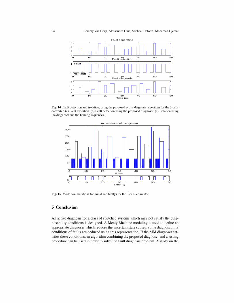
Fig. 14(a) depicts the evolution of faults. In order to highlight the efficiency ofthe approach in real time, the experimentation takes into account all kind of faults f1, f2, f3, f1, f2, f3. The faults are manually generated in order to interact with thecontrol. A reset of the system is realized between each fault (see Fig. 15(b)). Figs. 15and 16 show respectively the evolution of the actual mode of the DFA and the stateevolution of the converter. For each fault class, the diagnoser is initialized and thecontrol ensures the state regulation. In Fig. 16, the nominal working of the converterbetween each generated fault is illustrated. When a fault is detected, the control isbroken off and a fault isolating sequence can be applied in order to isolate it.
One can see, in Fig. 14, that the diagnoser, using the MM representation, fulfilsthe objective, i.e., the faulty modes are well detected and isolated. In Fig. 15, onecan note that faults are identified by the same approach as the 2-cells converter andusing the fault isolating sequences.
24 Jeremy Van Gorp, Alessandro Giua, Michael Defoort, Mohamed Djemaı
0 10 20 30 40 50 600
2
4
6
Fault generating
0 10 20 30 40 50 60
0
1
Fault detection
0 10 20 30 40 50 600
2
4
6
Fault diagnosis
Time (s)
Fault
No Fault
Fig. 14 Fault detection and isolation, using the proposed active diagnosis algorithm for the 3-cellsconverter. (a) Fault evolution. (b) Fault detection using the proposed diagnoser. (c) Isolation usingthe diagnoser and the homing sequences.
0 10 20 30 40 50 600
5
10
15
20
25
30
Active mode of the system
0 10 20 30 40 50 600
1
Reset
Time (s)
Fig. 15 Mode commutations (nominal and faulty) for the 3-cells converter.
5 Conclusion
An active diagnosis for a class of switched systems which may not satisfy the diag-nosability conditions is designed. A Mealy Machine modeling is used to define anappropriate diagnoser which reduces the uncertain state subset. Some diagnosabilityconditions of faults are deduced using this representation. If the MM diagnoser sat-isfies these conditions, an algorithm combining the proposed diagnoser and a testingprocedure can be used in order to solve the fault diagnosis problem. A study on the

Active diagnosis for switched systems using Mealy machine modeling 25
0 10 20 30 40 50 600
20
40
60
Internal voltage Vc1
Vc1
Vc1ref
0 10 20 30 40 50 600
20
40
60
Internal voltage Vc2
Vc2
Vc2ref
0 10 20 30 40 50 60
0
0.2
0.4Load current I
Time (s)
IIref
Fig. 16 Evolution of the state and the reference for the 3-cells converter.
cascade multicellular converter is carried out to detect and isolate faulty cells. Sim-ulation results, on the 2-cells converter, are detailed and highlight the effectivenessof the proposed algorithm. Experimental results, on the 3-cells converter, show thatthe approach can be generalized for this class of switched system and applied in realtime.
References
1. Bayoudh M. and Trave-Massuyes L. (2009), An Algorithm for Active Diagnosis of HybridSystems Casted in the DES Framework, 2nd IFAC Workshop on Dependable Control of Dis-crete Systems, pp. 329–334.
2. Branicky M. S. (1998), Multiple Lyapunov functions and other analysis tools for switchedand hybrid systems, IEEE Trans. Aut. Cont., 43(4):475–482.
3. Broy M., Jonsson B., Katoen J.-P. (2005), Leucker M. and Pretschner A. (Eds.), Model-BasedTesting of Reactive Systems, Lecture Notes in Computer Science, Vol. 3472, Springer.
4. Cabasino M.P., Giua A., Lafortune S. and Seatzu C. (2012), A New Approach for Diagnos-ability Analysis of Petri Nets Using Verifier Nets, IEEE Trans. Aut. Cont., 57(12):3104–3117.
5. Cabasino M.P., Giua A. and Seatzu C. (2013), Diagnosis using labeled Petri nets with silent orundistinguishable fault events, IEEE Trans. Syst. Man & Cybernetics, Part A, 43(2):345–355.
6. Daigle M. and Biswas G. (2009), Improving diagnosability of hybrid systems through activediagnosis, Safeprocess09, pp. 217–222.
7. Defoort M., Van Gorp J., Djemaı M. and Veluvolu K. (2012), Hybrid Observer for SwitchedLinear Systems with Unknown Inputs, IEEE Conf. Ind. Elect. and App., pp. 594–599.
8. Franck P.M. (1990), Fault diagnosis in dynamic systems using analytical and knowledge-based redundancy-a survey and some new results, Automatica, 26(3):459–474.
9. Gertler, J. (1997), Fault detection and isolation using parity relations, Cont. Eng. Pract.,5(5):653–661.

26 Jeremy Van Gorp, Alessandro Giua, Michael Defoort, Mohamed Djemaı
10. Guo Q., Hierons R. M., Harman M. and Derderian K. (2007), Heuristics for fault diagnosingwhen testing from finite state machines, The J. of Software Testing, Verification and Reliabil-ity, 17(1):41–57.
11. Hwang I., Kim S., Kim Y. and Seah C. E. (2010), A survey of fault detection, isolation, andreconfiguration methods, IEEE Trans. Cont. Syst. Tech., 18(3):636–653.
12. Isermann R. (2006), Fault diagnosis of technical process-applications, Springer, Heidelberg.13. Kang W., Barbot J.P. and Xu L. (2009), On the Observability of Nonlinear and Switched
Systems, Lecture Notes in Control and Information Sciences, Springer Berlin.14. Liberzon D. (2003), Switching in Systems and Control, Systems and Control: Foundations
and Applications, Birkhuser, Boston, MA.15. Lin H. and Antsaklis P.J. (2009), Stability and stabilizability of switched linear systems: A
survey of recent results, IEEE Trans. Aut. Cont., 54(2):308–322.16. Maharjan L., Yamagishi T., Akagi H. and Asakura J. (2010), Fault-Tolerant Operation of a
Battery-Energy-Storage System Based on a Multilevel Cascade PWM Converter With StarConfiguration, IEEE Trans. Power Elect., 25(9):2386–2396.
17. Medjaher K., Andrews J. (Eds.), Berenguer CH. (Eds.) and Jackson L. (Eds.) (2011), A bondgraph model-based fault detection and isolation, Maintenance Modelling and Applications.Chapter 6 : Fault Diagnostics. Det Norske Veritas (DNV), pp. 503–512.
18. Pettersson S. and Lennartson B. (2002), Hybrid System Stability and Robustness Verificationusing Linear Matrix Inequalities, Int. J. Control, 75(16/17):1335–1355.
19. Pocci M., Demongodin I., Giambiasi N. and Giua A. (2014), Testing experiments on synchro-nized Petri nets, IEEE Trans. Aut. Sc. and Eng., 11(1):125–138.
20. Sampath M., Lafortune S. and Teneketzis D. (1998), Active diagnosis of discrete-event sys-tems, IEEE Trans. Auto. Cont., 43(7):908–929.
21. Sampath M., Sengupta R., Lafortune S., Sinnamohideen K. and Teneketzis D.C. (1996), Fail-ure diagnosis using discrete-event models, IEEE Trans. Cont. Syst. Tech., 4(2):105–124.
22. Schmidt M. and Lunze J. (2013), Active Diagnosis of Deterministic I/O Automata, 4th IFACWorkshop on Dependable Cont. of Dis. Syst., 4(1), pp. 79–84.
23. Song W. and Huang A.Q. (2010), Fault-Tolerant Design and Control Strategy for CascadedH-Bridge Multilevel Converter-Based STATCOM, IEEE Trans. Ind. Elect., 57(8):2700–2708.
24. Tanwani A. and Liberzon D. (2010), Invertibility of switched nonlinear systems, Automatica,46(12):1962–1973.
25. Van Gorp J., Defoort M., Djemai M. and Manamanni N. (2012), Hybrid observer for themulticellular converter, Proceedings IFAC ADHS 12, pp. 259–264.
26. Van Gorp J., Defoort M., Djemai M. and Veluvolu K. (2015), Fault detection based on higher-order sliding mode observer for a class of switched linear systems, IET Cont. Th. Appl.,9(15):2249–2256.
27. Van Gorp J., Defoort M., Veluvolu K. and Djemai M. (2014), Hybrid sliding mode observerfor switched linear systems with unknown inputs, J. Franklin Inst., 351(7):3987–4008.
28. Van Gorp J., Giua A., Defoort M. and Djemai M. (2013), Active diagnosis for a class ofswitched systems, IEEE Conf. on Decis. Cont., pp. 5003–5008.
29. Yoon S., Kim S., Bae J., Kim Y. and Kim E. (2011), Experimental evaluation of fault diagnosisin a skew-configured UAV sensor system, Cont. Eng. Pract., 19(2):158–173.
View publication statsView publication stats
Copyright © 2022 FDOKUMEN