19RAC03 MANUFACTURING TECHNOLOGY
162
19RA C03 MANUFACTURING TECHNOLOGY
-
Upload
khangminh22 -
Category
Documents
-
view
1 -
download
0
Transcript of 19RAC03 MANUFACTURING TECHNOLOGY

19RAC03 MANUFACTURING TECHNOLOGY

CENTRE LATHE Lathe is one of the oldest important machine tools in
the metal working industry.
A lathe operates on the principle of a rotating work piece and a fixed cutting tool.
Its main function is to remove material from a work piece to produce the required shape and size.


Major parts of a centre lathe


• This is heavy rugged casting
made to support the working
parts of lathe and also guide
and align major parts of
lathe.
• On top section are machined
ways.
To resist the cutting force and
vibration

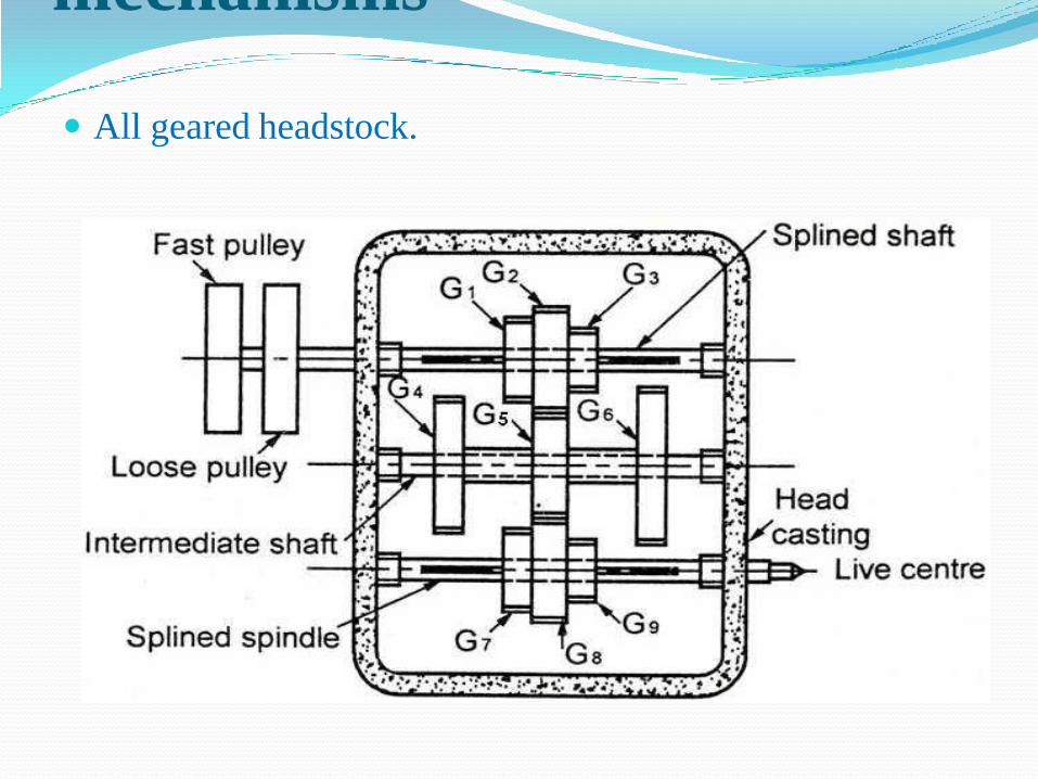
• The headstock houses
the main spindle,speed
change mechanism, and
change gears.
• The headstock is
required to be made as
robust as possible due to
the cutting forces
involved,which can distort
a lightly built housing.

• Contains number of different-size gears.
• Provides feed rod and lead-screw with various speeds for turning and thread-cutting operations
TOP VIEW

The arrangement which are employed in feed gear boxes to obtain multispindle speeds and different rates of feeds are:
I. Sliding Gear Mechanism
II. Sliding Clutch Mechanism
III. Gear Cone And Tumbler Gear Mechanism
IV. Sliding Key Mechanism
V. Combination of any two or more of the above
• Usually two or three levers must be moved to obtain the desired combination within a given range.

• Used to move cutting tool along lathe bed.
• Consists of three main parts-
i. Saddle
ii. Cross-slide
iii. Apron

• Mounted on top of saddle.• Provides manual or automatic cross movement for cutting tool.

• Fastened to saddle.
• Houses gears and
mechanism required to
move carriage or cross-
slide automatically.
• Locking-off lever inside
apron prevents engaging
split-nut lever and
automatic feed lever at
same time.
• Apron hand wheel
turned manually to move
carriage along lathe bed

• Upper and lower tailstock castings.
• Adjusted for taper or parallel turning by two screws set in base.
• Tailstock clamp locks tailstock in any position along bed of lathe.
• Tailstock spindle has internal taper to receive dead center.
• Provides support for right-hand end of work.

Specification of a lathe Length of bed
Max distance b/w dead and live centres
Type of bed i.e straight, semi gap, gap type
Height of centers from the bed
Swing over the bed
Swing over the cross slide
Width of the bed
Spindle bore
Spindle speed

Specification of a lathe H.P of main motor and rpm
No. of spindle speeds
Spindle nose diameter
Feeds
Floor space required


• This term ‘engine’ is associated with the lathe owing to the fact that early lathes were driven by steam engine. It is also called Engine lathe or centre lathe
• The most common form of lathe, motor driven and comes in large variety of sizes and shapes.

• A bench top model usually of low power used to make precision machine small work pieces.
• It is used for small w/p having a maximum swing of 250 mm at the face plate. Practically it consists of all the parts of engine lathe or speed lathe.

A tool room lathe having features similar to an engine lathe is much more accurately built and has a wide range of spindle speeds ranging from a very low to a quite high speed up to 2500 rpm.
This lathe is mainly used for precision work on a tools, dies, gauges, and in machining work where accuracy is needed.
This lathe machine is costlier than an engine lathe of the same size.

• A lathe in which the work piece is automatically fed and removed without use of an operator. It requires very less attention after the setup has been made and the machine loaded.

A highly automated lathe, where both cutting, loading, tool changing, and
part unloading are automatically controlled by computer coding.
E.g. CNC Lathe M/C.(Computer Numerical Control Machine)


Headstock driving
mechanisms Back geared headstock.
mechanisms
All geared headstock.

Feed mechanismsTumbler gear reversing mechanism.
Quick-change gearbox.
Tumbler gear quick-change gearbox.
Apron mechanism.

Tumbler gear reversing
mechanism.

Quick-change gearbox.

gearbox.

Apron mechanism.

Work holding devices Chucks
Centres
Face plate
Angle plate
Mandrels
Steady and follower rest

Magnetic chuck

Three jaw and Four jaw chuck


Types of centres Work held between centres


Angle plate and face plate
(a) Angle plate (b) Angle plate used along with face plate

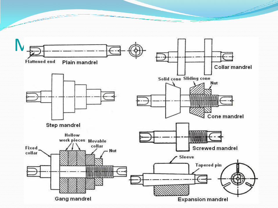
Mandrels

Steady rest and Follower rest

Various Lathe operations

Various Lathe operations
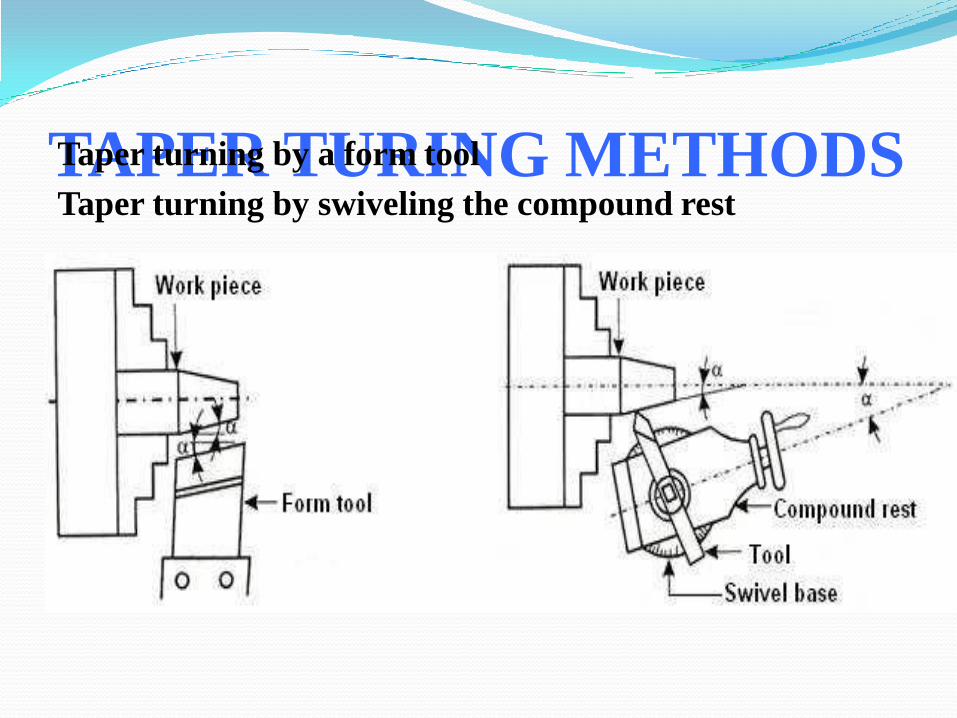
TAPER TURING METHODSTaper turning by a form tool
Taper turning by swiveling the compound rest

TAPER TURING METHODS Taper turning by offsetting the tailstock

TAPER TURING METHODS Taper turning by using taper turning attachment
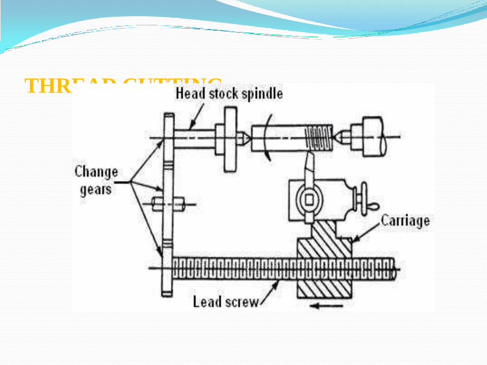
THREAD CUTTING
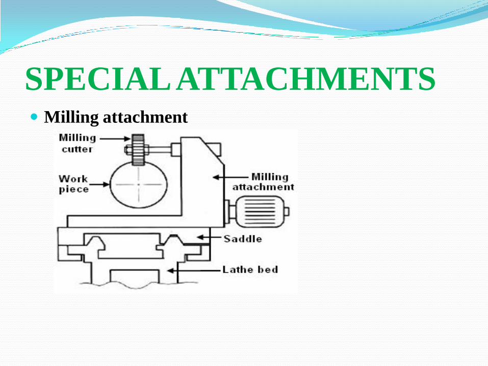
SPECIALATTACHMENTS Milling attachment

SPECIALATTACHMENTS Cylindrical grinding attachment

SPECIAL PURPOSE LATHES CAPSTAN LATHES

TURRET LATHES

Photographic view of a
hexagonal turret

Bar feeding mechanisms
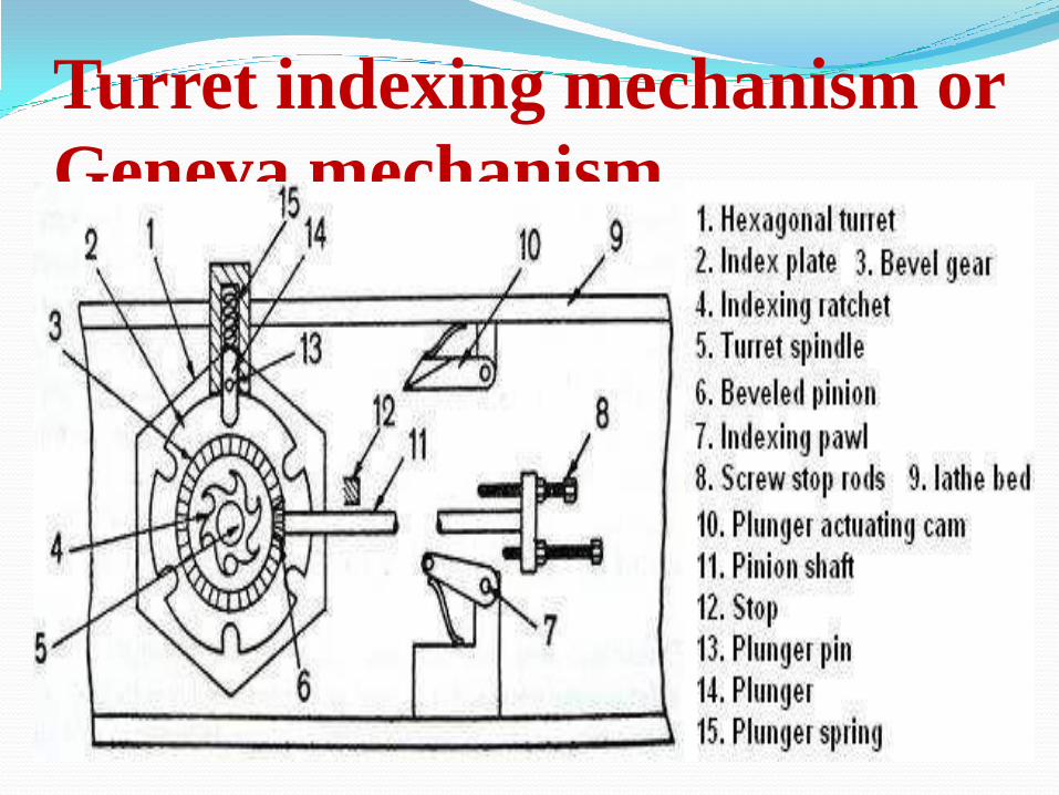
Turret indexing mechanism or
Geneva mechanism

Work holding devices used in
capstan and turret lathes
Air operated chuck

Collet chucks (a) Push out type (b)
draw back type (c) Dead length type

Tool holding devices used in
capstan and turret lathes Straight cutter holder
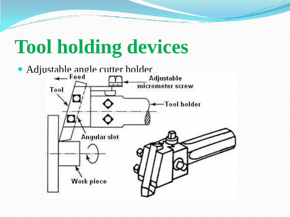
Tool holding devices Adjustable angle cutter holder

Tool holding devices Multiple cutter holder and Offset cutter holder

Tool holding devices Sliding tool holder and Knee tool holder

Automatic lathes These are machine tools in which the components are
machined automatically.
Single spindle automatic lathe
Swiss type automatic lathe or sliding head automatic lathe
Single spindle automatic screw cutting machine
Multiple spindle automatic lathes

Single spindle automatic lathe
Arrangement of tool slide
Simple parts produced on cutting off machine

SWISS TYPE AUTOMATIC SCREW MACHINE

SINGLE SPINDLE AUTOMATIC SCREW TYPE MACHINE

MULTI SPINDLE
AUTOMAT Parallel Action Multi Spindle Automat

Progressive Action Multi Spindle
Automat

SHAPER The main function of the shaper is to produce flat surfaces in
different planes.
ss

Types of quick return mechanisms are used in
the shaper
1) Crank and slotted mechanism
2) Whitworth quick return mechanism
3) Hydraulic shaper mechanism .


DRILLING Drilling is a cutting process that uses a drill bit to cut
a hole of circular cross-section in solid materials. Thedrill bit is usually a rotary cutting tool, oftenmultipoint. The bit is pressed against the work pieceand rotated at rates from hundreds to thousands ofrevolutions per minute.

Types of drilling machine The different types of drilling machine which are most commonly
used are:
Portable drilling machine.
Sensitive drilling machine (Bench mounting or table top and Floor
mounting).
Upright drilling machine (Pillar or Round column section and Box
column section).
Radial drilling machine (Plain, Semi-universal and Universal).
Gang drilling machine.
Multiple spindle drilling machine.
Deep hole drilling machine.
Turret type drilling machine
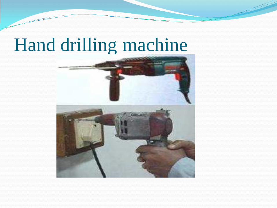
Hand drilling machine

Table top sensitive drilling
machine

Floor mounting sensitive
drilling machine

Box column section upright
drilling machine

Radial drilling machine

Deep hole drill

Gang drilling machine


Twist drill nomenclature

Different operations performed
in a drilling machine

BORING Boring is an operation of enlarging and locating
previously drilled holes with a single point cutting tool.

Table type horizontal boring
machine

Planer type horizontal boring
machine

Multiple head type horizontal
boring machine

Vertical boring machines
Double column vertical boring machine Turret boring machine

Jig borers or jig boring
machines

MILLING MACHINE This is a machine tool that removes material as the work is
fed against a rotating cutter.
The cutter rotates at a high speed and because of the
multiple cutting edges it removes material at a very fast
rate.
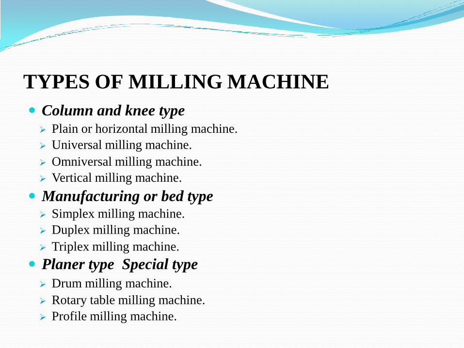
TYPES OF MILLING MACHINE
Column and knee type
Plain or horizontal milling machine.
Universal milling machine.
Omniversal milling machine.
Vertical milling machine.
Manufacturing or bed type Simplex milling machine.
Duplex milling machine.
Triplex milling machine.
Planer type Special type
Drum milling machine.
Rotary table milling machine.
Profile milling machine.

Plain or horizontal milling
machine

Vertical milling machine

Universal milling machine Omniversal milling machine
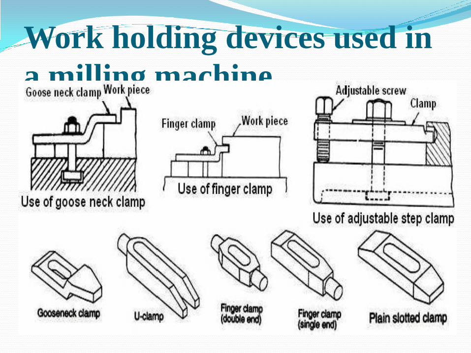
Work holding devices used in
a milling machine


Tool holding devices used in a
milling machine

MILLING CUTTERS1. Slab or plain milling cutters

Side milling cutters

Slitting saws or parting tools
Slitting saw End milling cutters Face milling cutter

T-slot milling cutter Involute gear milling cutter

Convex milling cutter Concave milling cutter Corner rounding milling cutter

Single angle milling cutter and Double angle milling cutter

MILLING OPERATIONS
Schematic view of the face milling operation

End milling


Parting by slitting saw Straddle milling

Form milling operations


Gear Generating Processes1.Gear Shaping
2.Gear Planning
3.Gear Hobbing

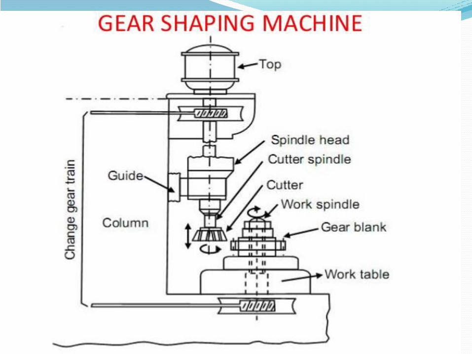

Gear Shaping


ABRASIVE PROCESSES: GRINDING
The cutting action of abrasive grits of disc type grinding
wheel similar to cutting action of teeth of the cutter
in slab milling.


Applications of grindingTo remove small amount of metal from work pieces and finish
then to close tolerances.
To obtain a better surface finish.
To machine hard surfaces that cannot be machined by high-
speed steels.
Grinding of tools and cutters and resharpening of the same.
Grinding of threads.
Stock removal (abrasive milling) finishing of flat as well as
cylindrical surface.

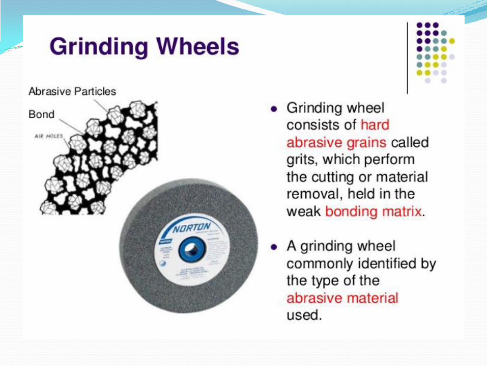
GRINDING WHEELS Grinding wheel consists of hard abrasive grains called
grits, which perform the cutting or material removal, held
in the weak bonding matrix.


Types of abrasives1.Natural abrasives - Emery (50 - 60 % crystalline Al2O3 + Iron
Oxide), Sandstone or Solid Quartz, Corundum (75 -
90 % crystalline Al2O3 + Iron Oxide) and Diamond.
2.Artificial abrasives - Aluminium Oxide (Al2O3), Silicon
Carbide (SiC), Artificial diamond, Boron Carbide
and Cubic Boron Nitride (CBN).
Bond It is an adhesive substance which holds the abrasive grains
together to form the grinding wheel.

Types of bonds - Bonds are classified into two types
1.Organic (Resinoid, Rubber, Shellac & Oxychloride )
2.Non – Organic (Metallic, Vitrified & Silicate)


1. Cylindrical grinding process.
2. Surface grinding process.
3. Centreless grinding process.
TYPES OF GRINDING PROCESS

Rough Grinding Machine
1.Bench Grinder

2.Portable Grinder

3.Abrasive Belt Grinding
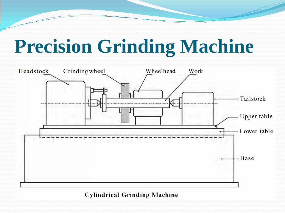
Precision Grinding Machine
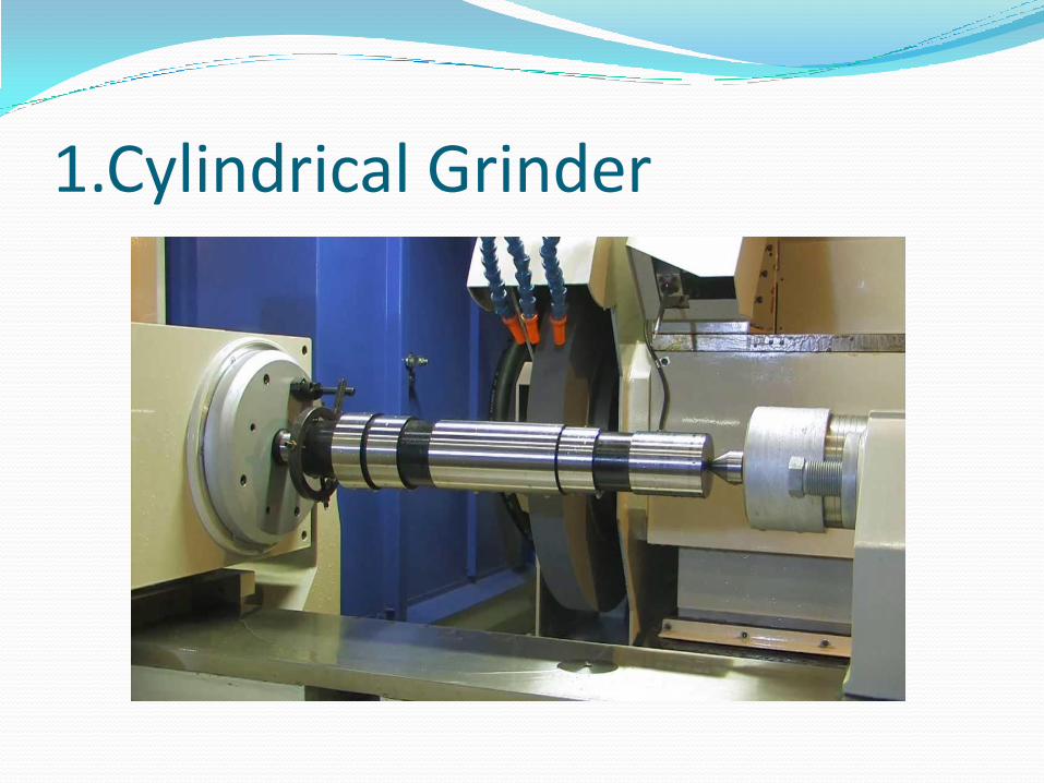
1.Cylindrical Grinder

Surface Grinders1. Horizontal Spindle Reciprocating Table surface
grinding machines

2. Horizontal Spindle Rotary Table surface grinding machines


Vertical Spindle Rotary Table surface grinding machines

Centreless Grinder

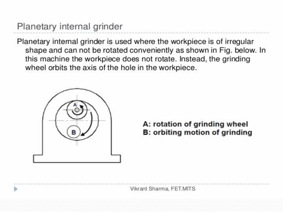
Internal Grinding Internal grinding is used to grind the internal diameter of the
work piece.
Tapered holes can be ground with the use of internal grinders
that can swivel on the horizontal.
Center less grinding is when the work piece is supported by a
blade instead of by centers or chucks.


BROACHING Broaching is a machining process for removal of a layer
of material of desired width and depth usually in one stroke
by a slender rod or bar type cutter having a series of cutting
edges with gradually increased protrusion.

Basic principle of broaching

Schematic views of finishing hole by broaching

Typical examples of shapes produced by internal broaching

Different types of broachesInternal broaching or external broaching.
Pull type or Push type.
Ordinary cut or Progressive type.
Solid, Sectional or Modular type.
Profile sharpened or form relieved type.

Internal broaching – tools

External broaching – making slot

PUSH BROACHING MACHINES
Push down type vertical surface broaching machine

Pull type horizontal internal broaching machine
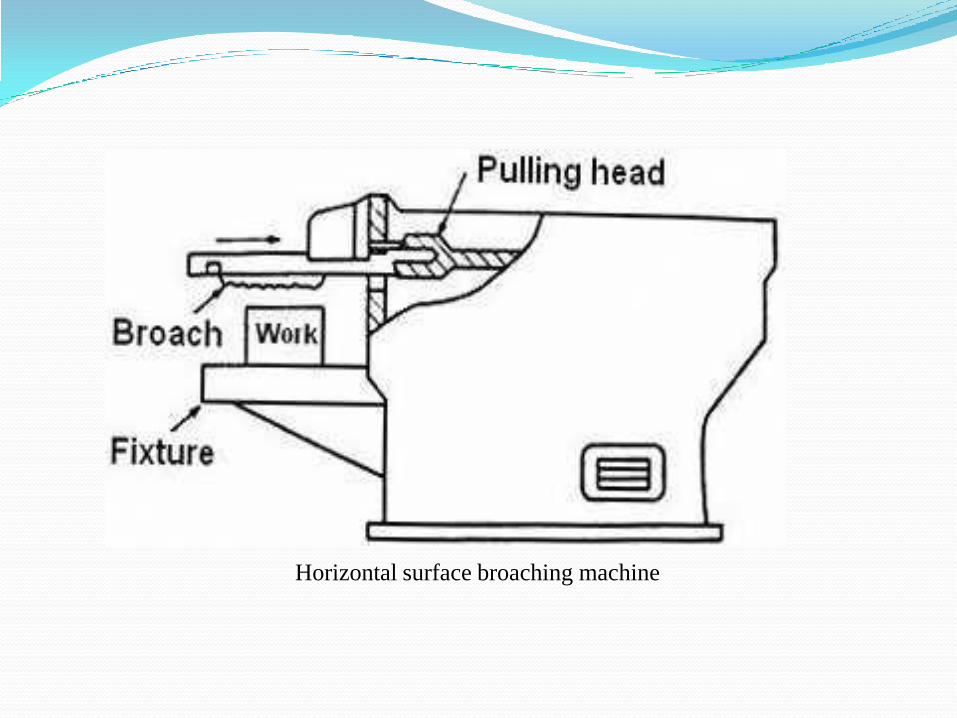
Horizontal surface broaching machine

Vertical surface broaching machine

CONTINUOUS BROACHING MACHINES
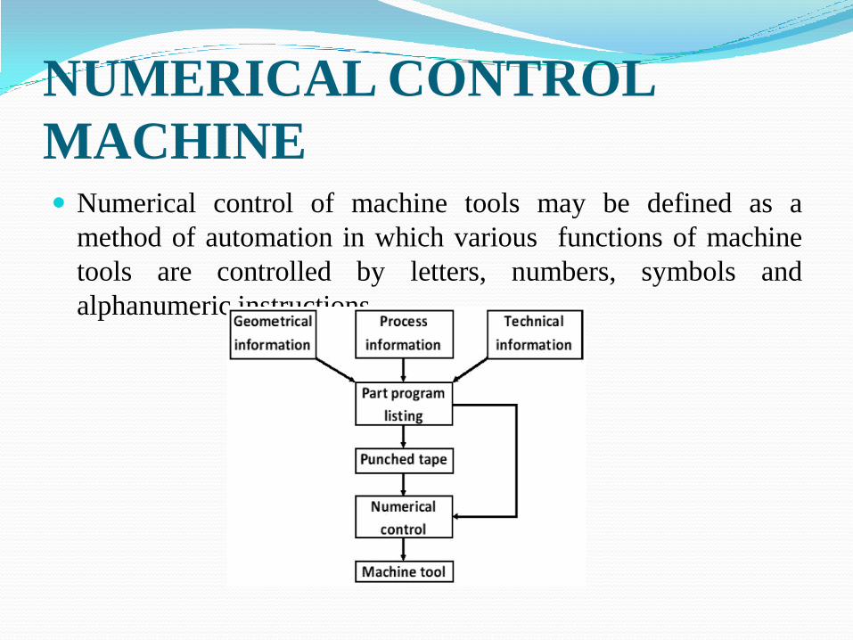
NUMERICAL CONTROL
MACHINE Numerical control of machine tools may be defined as a
method of automation in which various functions of machine
tools are controlled by letters, numbers, symbols and
alphanumeric instructions.

Types of NC systems
Machine controls are divided into three groups:
Traditional numerical control (NC).
Computer numerical control (CNC).
Distributed numerical control (DNC).


Controlled axes
NC system can be classified on the number of directions
of motion they are capable to control simultaneously on a
machine tool.
Identification of controlled axes for (a) lathe, (b) vertical spindle
milling machine and (c) horizontal spindle milling machine
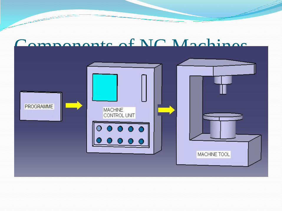
Components of NC Machines

Classification of NC Machines Based on NC System
The Three major types of NC systems are:
Point-to-point (PTP) system.
Contouring system.
Straight