Ahmet Refah Torun Advanced manufacturing technology for ...
130
Fakultät Maschinenwesen Institut für Textilmaschinen und Textile Hochleistungswerkstofftechnik Herausgeber: Chokri Cherif Ahmet Refah Torun Advanced manufacturing technology for 3D profiled woven preforms Dissertation
-
Upload
khangminh22 -
Category
Documents
-
view
0 -
download
0
Transcript of Ahmet Refah Torun Advanced manufacturing technology for ...

Fakultät Maschinenwesen Institut für Textilmaschinen und Textile Hochleistungswerkstofftechnik
Herausgeber: Chokri Cherif
Neue Fertigungstechnologie für 3D profilierte Preforms auf Webbasis
Textile 3D-Halbzeuge besitzen ein großes Potenzial zur Steigerung der mechanischen Eigenschaften von Verbundwerkstoffen sowie zur Reduzierung der für ihre Herstellung notwendigen Produktionsstufen und -kosten. Die Vielfalt der webtechnisch realisierba-ren Strukturen ist unendlich. Durch die Algorithmen der konventionellen Bindungsno-tation lässt sich die Vielfalt der möglichen Gewebestrukturen nur begrenzt ermitteln. Die im Rahmen der Dissertation neu entwickelte Bindungsnotation erlaubt die analy-tische Entwicklung von Gewebestrukturen. Technologische Lösungen zur reproduzier-baren Preformherstellung mit Hybridgarnen wurden erarbeitet. Die Faltenwebtechnik ist durch die Möglichkeit der vertikalen Verbindungen auf einem Trägergewebe für die Herstellung komplexer Profile geeignet. Die Faltenwebtechnologie wurde mittels einer elektronisch gesteuerten Gewebespeichereinheit sowie einem pneumatischen Kett-fadenrückzugssystem an einer Doppelgreifer-Webmaschine umgesetzt. Verschiedene spacer fabrics und 3D-Profile wurden entwickelt. Zur reproduzierbaren und schonen-den Halbzeugfertigung wurde ein linearer Abzug entwickelt und umgesetzt. Durch die in die Webanlage integrierten Schneid- und Ablagesysteme wurde ein hoher Automa-tisierungsgrad erreicht.
Advanced manufacturing technology for 3D profiled woven preforms
3D textile performs offer a high potential to increase mechanical properties of compo-sites and they can reduce the production steps and costs as well. The variety of woven structures is enormous. The algorithms based on the conventional weaving notation can only represent the possible woven structures in a limited way. Within the scope of this dissertation, a new weaving notation was developed in order to analyze the multilayer woven structures analytically. Technological solutions were developed in or-der to guarantee a reproducible preform production with commingled hybrid yarns. Terry weaving technique can be utilized to create vertical connections on carrier fabrics, which makes it suitable for the development of complex profiles. A double rapier weav-ing machine was modified with electronically controlled terry weaving and pneumatic warp yarn pull-back systems. Various spacer fabrics and 3D profiles were developed. A linear take-up system is developed to assure reproducible preform production with a minimum material damage. Integrated cutting and laying mechanisms on the take-up system provides a high level of automation.
Ah
met
Ref
ah T
oru
n -
Ad
van
ced
man
ufa
ctu
rin
g t
ech
no
log
y fo
r 3D
pro
file
d w
ove
n p
refo
rms
ISBN 978-3-86780-241-3
Ahmet Refah Torun
Advanced manufacturing technology for 3D profiled woven preforms
Dissertation

Advanced Manufacturing Technology for 3D Profiled Woven Preforms
Von der Fakultät Maschinenwesen
der
Technischen Universität Dresden
zur
Erlangung des akademischen Grades
Doktoringenieur (Dr.-Ing.)
angenommene Dissertation
M. Sc. Dipl.-Wirt. Ing. Ahmet Refah Torun
geb. am 26.10.1979 in Adana, Türkei
Tag der Einreichung: 29.04.2011
Tag der Verteidigung: 04.07.2011
Gutachter: Prof. Dr.-Ing. habil. Dipl.-Wirt. Ing. Chokri Cherif
Prof. Dr.-Ing. Frank Ficker


Acknowledgments
I owe my deepest gratitude to my supervisor, Prof. Dr.-Ing. habil. Dipl.-Wirt. Ing.
Chokri Cherif, whose encouragement, supervision and support from the very
beginning enabled this dissertation. I appreciate his vast knowledge and skills in
many areas. His insight, invaluable ideas and comments have had a significant
contribution to find my way both in research and in life.
I want to express my sincere gratitude to Prof. Dr.-Ing. Frank Ficker, for accepting to
referee this dissertation.
I am indebted to Prof. Dr.-Ing. habil. Hartmut Rödel for his friendly support during my
studies.
I am heartily thankful to Prof. Dr. Hiroyuki Hamada for his invaluable advices. He and
Dr. Asami Nakai have given me great motivation and support during my research
activities at the Kyoto Institute of Technology.
Meeting Prof. Dr. Ali Demir is one of the best things that happened to me. He is a
great role model as a scientist and human. In such a hard time when everyone was
gone away, he gave me encouragement to continue which have practically saved my
life. He had convinced me in 2002 to start doing research without being affected by
mental, cultural or geographical borders. In all those years, he provided me with
direction and became more of a mentor than a professor.
I would like to express my sincere appreciation to Dr.-Ing. Gerald Hoffmann. He was
officially research group leader but he was more like a father for me. Gerald has deep
knowledge and interest both in technical challenges and psychology. He provided
excellent guidance and still high amount of freedom to solve the problems, which was
the most valuable learning process.
It was a great chance to cooperate with Dr.-Ing Andreas Mühl. He is an excellent
researcher with a positive personality. I am very thankful for his advices and
encouragement.

I appreciate the cooperation and friendship of Adil Mountasir at TU Dresden and
Özgür Demircan at Kyoto Institute of Technology. I wish, together we will make
significant contributions to engineering research.
I am grateful to Müslüm Kaplan and Recep Türkay Kocaman for their friendship and
continuing help. My cousin Mehmet Berat Gök has always been beside me with his
support in various subjects.
I would like to thank sincerely Mr. Dominique Maes and Mr. Luc Coenegracht of the
company Van de Wiele for their continuous support and for their friendly approach.
I would like to express my sincere gratitude to German Research Foundation for the
financial support of the collaborative research activities SFB 639, in particular the
subprojects A3 and A4.
I am so much indebted to my parents Fatma Torun and Adil Torun. They do not really
accept verbal or written sentences as an expression of my gratitude. For them
research is the best way to serve humanity and to pray to God. They give me only
one way to thank them: I have to continue and improve my research, encourage and
support younger scientist. Promise, I will do my best!
To Kiyoko who can change nightmares into beautiful dreams…
Dresden, 29.04.2011 Ahmet Refah Torun

Table of Contents i
Table of Contents
Symbols and Abbreviations ........................................................................................ iii
Chapter 1 - Introduction .............................................................................................. 1
Chapter 2 - State of the Art and Aim ........................................................................... 3
2.1 Composite Structures .................................................................................... 3
2.1.1 Manufacturing Aspects ........................................................................... 5
2.1.2 Advantages of Fiber Reinforcements ...................................................... 6
2.1.3 Matrices .................................................................................................. 9
2.2 Textile Preforms .......................................................................................... 10
2.3 Spacer Fabrics ............................................................................................ 14
2.3.1 Conventional Spacer Fabrics ................................................................ 14
2.3.2 Spacer Fabrics with Fabric Cross-links ................................................. 16
2.4 Composite Stiffener Structures .................................................................... 19
2.5 Hybrid Yarns ................................................................................................ 20
2.6 Aim of the Thesis ......................................................................................... 22
Chapter 3 - Mathematical Treatment of 3D Woven Structures ................................. 24
3.1 Representation of Multi-layer Woven Fabrics .............................................. 25
3.2 Alternative Ways of Weave Representation ................................................ 27
3.3 Conclusion ................................................................................................... 38
Chapter 4 - Weaveability of Commingled Hybrid Yarns ............................................ 40
4.1 Experimental ............................................................................................... 42
4.1.1 Materials ............................................................................................... 42
4.1.2 Testing Procedure ................................................................................. 43
4.2 Results and Discussion ............................................................................... 44
4.2.1 Commingled Yarn Structure .................................................................. 44
4.2.2 Commingled Yarn Friction Properties ................................................... 47
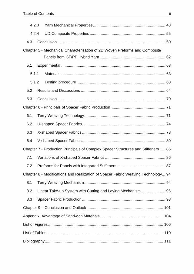
Table of Contents ii
4.2.3 Yarn Mechanical Properties .................................................................. 48
4.2.4 UD-Composite Properties ..................................................................... 55
4.3 Conclusion ................................................................................................... 60
Chapter 5 - Mechanical Characterization of 2D Woven Preforms and Composite
Panels from GF/PP Hybrid Yarn ............................................................ 62
5.1 Experimental ............................................................................................... 63
5.1.1 Materials ............................................................................................... 63
5.1.2 Testing procedure ................................................................................. 63
5.2 Results and Discussions ............................................................................. 64
5.3 Conclusion ................................................................................................... 70
Chapter 6 - Principals of Spacer Fabric Production .................................................. 71
6.1 Terry Weaving Technology .......................................................................... 71
6.2 U-shaped Spacer Fabrics ............................................................................ 74
6.3 X-shaped Spacer Fabrics ............................................................................ 78
6.4 V-shaped Spacer Fabrics ............................................................................ 80
Chapter 7 - Production Principals of Complex Spacer Structures and Stiffeners ..... 85
7.1 Variations of X-shaped Spacer Fabrics ....................................................... 86
7.2 Preforms for Panels with Integrated Stiffeners ............................................ 87
Chapter 8 - Modifications and Realization of Spacer Fabric Weaving Technology ... 94
8.1 Terry Weaving Mechanism .......................................................................... 94
8.2 Linear Take-up System with Cutting and Laying Mechanism ...................... 96
8.3 Spacer Fabric Production ............................................................................ 98
Chapter 9 – Conclusion and Outlook ...................................................................... 101
Appendix: Advantage of Sandwich Materials .......................................................... 104
List of Figures ......................................................................................................... 106
List of Tables .......................................................................................................... 110
Bibliography ............................................................................................................ 111

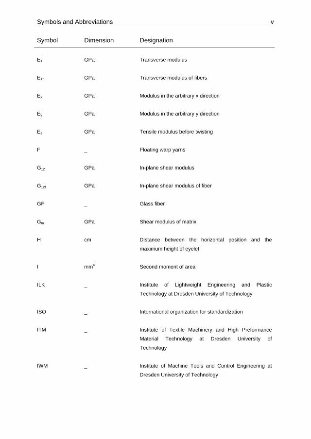
Symbols and Abbreviations iii
Symbols and Abbreviations
Symbol Dimension Designation
[Q]
GPa Stiffness matrix
[Q’] GPa Reduced stiffness matrix
{ε} _ Strain tensor
{σ} GPa Stress tensor
2D _ Two dimensional
3D
_ Three dimensional
A mm² Cross-sectional area of element
A1
mm² Interface area
A2 mm²
New interface area
ASTM _ American society for testing and materials
B _ Base fabrics
B.C.
_ Before Christ
c _ Number of lines
C _ Connection section of floating yarns to fabric
CAD _ Computer aided design
CAM _ Computer aided manufacturing
CCD _ Charge coupled device

Symbols and Abbreviations iv
Symbol Dimension Designation
D
mm Fiber diameter
d
mm Smaller fiber diameter
dav mm Average yarn diameter
DIN _ Deutsches Institut für Normung (German Institute for
Standardization)
Dr _ Damage factor of twist angle
E GPa Tensile modulus
e.g.
_ Exempli gratia (for example)
E1 GPa Tensile modulus of element 1
E2 GPa Tensile modulus of element 2
EL GPa Tensile modulus in fiber direction (longitudinal)
ELf GPa Tensile modulus of fiber (longitudinal)
Em GPa Tensile modulus of matrix
Em1 GPa Tensile modulus of matrix element 1
Em2 GPa Tensile modulus of matrix element 2
EN _ European standards
Er1 GPa Tensile modulus of reinforcement element 1
Er2 GPa Tensile modulus of reinforcement element 2
Ere GPa Tensile modulus reduced after twisting
Symbols and Abbreviations v
Symbol Dimension Designation
ET GPa Transverse modulus
ETf GPa Transverse modulus of fibers
Ex GPa Modulus in the arbitrary x direction
Ey GPa Modulus in the arbitrary y direction
Ez GPa Tensile modulus before twisting
F _ Floating warp yarns
G12 GPa In-plane shear modulus
G12f GPa In-plane shear modulus of fiber
GF _ Glass fiber
Gm GPa Shear modulus of matrix
H cm Distance between the horizontal position and the
maximum height of eyelet
I mm4 Second moment of area
ILK _ Institute of Lightweight Engineering and Plastic
Technology at Dresden University of Technology
ISO _ International organization for standardization
ITM _ Institute of Textile Machinery and High Preformance
Material Technology at Dresden University of
Technology
IWM _ Institute of Machine Tools and Control Engineering at
Dresden University of Technology

Symbols and Abbreviations vi
Symbol Dimension Designation
k N/mm Overall spring stiffness
k1 N/mm Spring stiffness of element 1
k2 N/mm Spring stiffness of element 2
L
mm Fiber length
L1 mm Length of element 1
L2 mm Length of element 2
Li _ Representative length of element I
M Nmm Moment
N _
Number of fibers
n _
Number of warp yarns
nnew _ New number of fibers
NC _ Number of cycles for warp yarns to pass through the
heddle frames
OD % Over-delivery
OPP _ Overall possibilities of patterns
PEEK _ Polyetheretherketon
PES _ Polyester
PET _ Polyethylenterephthalat
PP _ Polypropylene
Prepreg _ Preimpregnated fibers

Symbols and Abbreviations vii
Symbol Dimension Designation
r _ Number of columns
R _ Reed
RTM _ Resin transfer molding
S _ Stiffener fabric
Si m/min Input speed of feeding
SP _ Number of possible structures
So m/min Output speed of take-up
SW _ Number of woven structures
T _ Regular take-up motion
TD cm Travel distance of warp yarn in one machine revolution
tw Twist per meter Twist
TW _ Terry weaving take-up motion
UD _ Uni-directional
US _ Ultrasonic
v mm Deflection of the central line of a beam
Vf _ Volume fraction of reinforcing material
WD Yarn/cm Weft density
x mm Coordinate along the length of a beam
X cm Distance from fabric to horizontal position of eyelet

Symbols and Abbreviations viii
Symbol Dimension Designation
αod degree Equivalent angle of distortion of over-delivery
αod_i degree Equivalent angle of distortion of over-delivery, element I
αt degree Total twist angle
αtw degree Twist angle
ΔX cm Travelling distance through eyelet
η _ Correction factor for transverse modulus
η’ _ Correction factor for in-plane shear modulus
θ degree Angle of distortion
ν12 _ Poisson’s ratio
ν12f _ Poisson’s ratio of fibers
νm _ Poisson’s ratio of matrix
π _ The number Pi

Chapte
Chap
From a
advanc
advanc
advanc
enable
Howev
techno
In anci
and ce
the big
polyme
enginee
After 1
commo
helicop
equipm
potentia
er 1 - Introd
pter 1 - I
a historical
ced mater
cement of
cement of
the cons
er, the lim
logies [1].
ent times
ramics we
achievem
ers, comp
ering mate
Figu
950s, poly
on enginee
pters, spa
ment, sport
al applicat
duction
Introduc
l point of v
rials of th
f the mate
the human
struction o
its of mate
metals ha
re often us
ments into
posites an
erials [1].
ure 1: Schem
ymer comp
ering mater
ce-craft, s
ing goods
tions in su
ction
view past c
heir time
erials was
n societies
of very co
erials are s
d little imp
sed. Afterw
the mid of
nd ceram
matic of the
posites em
rials. Toda
satellites,
and civil e
uch as me
civilization
such as
s up to a
s. Intelligen
omplex str
till defining
portance w
wards, the
f 20th cent
ics regain
e evolution o
merged fro
y polymer
ships, su
engineering
edicine, mi
s were na
stone, bro
a high ex
nt enginee
ructures w
g the limits
whereas na
skills and
ury. Howe
ned their
of engineer
om being e
composite
ubmarines
g applicatio
cro electro
amed acco
onze and
xtent also
ering desig
with conve
of enginee
atural polym
constructio
ever in the
importan
ing materia
exotic nich
es are wide
, automob
ons [2]. Th
onics, nan
ording to th
iron age
determin
gn has evo
ntional ma
ering and f
mers, com
on with me
mid 20th c
nce as h
ls [1]
he applica
ely used in
biles, pro
here are st
o technolo
1
he most
es. The
ing the
olved to
aterials.
feasible
mposites
etals led
century,
igh-end
tions to
aircraft,
cessing
ill many
ogy etc.

Chapter 1 - Introduction 2
The expanding application areas of composites naturally require a multi-disciplinary
approach in research activities. Composite research had started as a branch of
material science and mechanical engineering. Recently it is not uncommon to see
collaborative research activities of scientist from mechanical, computer, electronics,
textile engineering with mathematicians, physicists, chemists and even medicine
doctors [3].
Modelling, mechanical characterization and design of materials are the three
dominating research fields in composites. It is crucial to understand and predict the
behaviour of composite materials through these studies in order to fully utilize its
advantageous properties, spread its use and ensure safety requirements. One pole is
the design of constituent materials which deals with the subjects such as interface
design, nano-composites or bio-degradability. Another pole is the modelling and
characterization of composite structures as well as process modelling. Although
textile technologies offer unexhausted potential for near-net-shape and stress-
compatible preforms, the intensity of publications in this intermediate field is
apparently minor compared with the above mentioned two poles. The general
preform structures are explained in textbooks [2] and particular structures are mainly
described in patents. There are also some institutions, which develop innovative
preforms but avoid both publications and patents as a protection policy.
There may be couple of reasons why intensive research efforts are not invested in
the fruitful field of preform development. First of all, still not many textile specialists
are working in composite research which leads to the illusion that all the possible
textile structures have already been developed. As a result, composite specialists
mostly take the textile reinforcement structures available in the market and try to
construct best components out of them, instead of actively demanding and designing
more suitable textile preforms. High necessary investments would inhibit the research
in preforms, for instance a weaving or a knitting machine is much more expensive
than a simulation workstation or an RTM device. Another reason would be that the
research in textile structures and preforms does not seem scientific enough, although
it requires multi-disciplinary thinking, creativity and pattern recognition.
This dissertation is a contribution to the multidisciplinary field of composites. Novel
woven preforms and necessary automated technology is developed, concerning the
reproducibility and cost-effectiveness.

Chapter 2 - State of the Art and Aim 3
Chapter 2 - State of the Art and Aim
Both textile and composites are ancient crafts of mankind. Straw (reinforcement) and
mug (matrix) was mixed in order to produce a light but dimensionally stable
construction material. Weaving and braiding techniques were known at least 3000
B.C. In the second half of 18th century textile technology started the industrial
revolution and various types of machines were developed for production with natural
fibers mainly cotton and wool. Since 1950s, use of synthetic fibers such as polyester,
polyamide, polypropylene, viscose etc. is significantly increasing. The existing textile
machinery is also compatible with the mentioned synthetic fiber types. However,
high-performance fibers of carbon, glass, aramide etc. necessitates proper
modifications on textile machinery. During production with high-performance fibers,
material waste should be minimized as well as the damage on the fibers.
This section demonstrates the state of the art structures and technologies in
composite and textile fields to set the stage. From state of the art and industrial
requirements, the importance of research direction in thermoplastic matrix
composites as well as 3D complex preforms will be clearly derived.
2.1 Composite Structures
In a broad sense, composite materials can be defined as a combination of at least
two materials to generate desirable properties. The final combination of materials
results in better properties than the input materials used alone. This definition does
not include for instance alloys or polymer blends which are material combinations in
atomic level. Also as opposed to alloys, each constituent material in a composite
retains its characteristic properties. In most of the cases, composites comprise a
bulky and a fibrous part, which are called matrix (e.g. unsaturated polyester) and
reinforcement (e.g. glass fiber) respectively. Matrices can be polymers, metals or
ceramics whereas polymer based matrices clearly dominates the applications. The
objective of matrix is to integrally bind the reinforcement together in order to
effectively transfer external loads on to the reinforcement as well as protect it from
environmental effects. The matrix gives a composite its shape, appearance, overall
durability, on the other hand reinforcement carries most of the loads. Reinforcements

Chapter 2 - State of the Art and Aim 4
can be in various forms such as chopped fibers, unidirectional filaments and textile
structures [4, 5]. Figure 2 and 3 demonstarete the high specific tensile strength and
modulus of composite materials in comparison with conventional materials such as
metals and wood. High specific strength and modulus can be regarded as the main
advantage of composite materials.
Figure 2: Specific tensile strength of common structural materials [6]
Figure 3: Specific tensile modulus of common structural materials [6]
Like in many fields, the development of advanced polymer composites has primarily
been driven by aerospace and military applications, where performance is the main
concern. With the time passing, most types of polymer composites became
commodity materials in daily life. This transition put more emphasis on the design

Chapter 2 - State of the Art and Aim 5
and cost aspects in order to gain acceptance in the market where they compete with
traditional materials such as wood, steel, concrete etc.
Figure 4 gives an overview of the composite use in aviation, in particular Airbus
airplanes. The tendency can clearly be seen that every new airplane has more
composite materials. There are still some technical tasks and challenges. For
instance it is difficult to join metallic parts with carbon reinforced composites and the
behavior of carbon (highly inductive) reinforced composite is still not known if a
thunder meets the airplane.
Figure 4: Tendency of composite use in aviation [7]
The practical attainment of the high strength and modulus of composites in the
reinforcement direction is complicated by less favorable factors, mainly low
transverse properties. To provide improved transverse properties, composites are
produced as laminates with varying angles of reinforcements. By this way, final
composite part gains some additional performance in transverse direction at the
expense of reduced properties in the unidirectional material [8].
2.1.1 Manufacturing Aspects
Continuous filament reinforcements, which offer the greatest potential for
performance, are used in filament winding and unidirectional composites. Chopped

Chapter 2 - State of the Art and Aim 6
fibers are usually used in molding compounds because of the ease in the formation
of complex shapes. Continuous strand rovings or multiple filament bundles are used
for economy of manufacturing thick sections. Mats (random or semi-oriented fibers of
varying lengths) are economical reinforcements in bulk and easy to form complex
shapes when performance is less important. Woven fabrics of various configurations
can be seen as a compromise between maximum performance of unidirectional
composites and ease of handling and formability of chopped fibers and mats [8].
Whether the fibers are discontinuous or continuous affects both the processability
and mechanical performance of the final composite structure. The reinforcements
can be very short fibers of 1-2 mm as used in injection molding. In this case the ease
of processibility is high whereas the contribution of short fibers to the mechanical
performance is low.
2.1.2 Advantages of Fiber Reinforcements
Theoretical modulus and strength values for materials can be calculated according to
the bond strength between their atoms. However, materials have actual strengths
which are several magnitudes lower than the theoretical ones. The reason for this
phenomenon is the impurities and flaws within the atomic structure. There are
dislocations, missing atoms as well as grain boundaries which reduce the strength
and modulus. Removal of these flaws increases the mechanical properties. Small
diameter of fibers reduces the chance of inherent flaw in the materials. Generally,
decreasing fiber diameter increases the fiber strength [4, 9].
Another important aspect is the transfer of loads onto the reinforcements through
matrix. This load transfer is realized with fiber-matrix interface regions. For the same
volume fraction of fibers in a composite, the fiber-matrix interface area is inversely
proportional to the fiber diameter. For a composite containing N fibers with diameter
D and fiber length L, the interface area is:
(1)
Chapter 2 - State of the Art and Aim 7
If the fiber diameter D is replaced with a smaller one d, the new number of fibers nnew
in the composite is calculated according to the following formula to keep the volume
fraction same.
(2)
This formula can be interpreted as; if the fiber diameter is halved, then the number of
fibers with reduced diameter should be 4 times as many to keep the volume fraction
same. The interface area for the new fiber diameter is:
(3)
By putting the expression of nnew into the formula of new area results in:
(4)
Then the ratio of fiber matrix interface areas according to the fiber diameters is
determined as:
(5)
According to this expression, interface area is inversely proportional to the fiber
diameter, which means if the fiber diameter is halved the interface region is doubled.
Fibers can be bent without breaking, which is an important requirement for
manufacturing. Bending stiffness decreases with a decrease in fiber diameter.

Chapter 2 - State of the Art and Aim 8
Bending stiffness is the resistance to bending moments and if a beam is bent by a
moment:
(6)
v: deflection of the central line
E: Tensile modulus of the beam material
M: Bending moment
I: second moment of area
x: coordinate along the length of the beam
In the formula above EI term is the bending stiffness. Second moment of area of a
cylindirical beam is:
64 (7)
Thus, the flexibility (inverse of bending stiffness) of a particular material is inversely
proportional to the fourth power of its diameter.
Four properties of fibers in a composite effect the final component properties directly
which are; length, orientation in the matrix, cross-sectional shape and material.
Use of fibers as load bearing structures is limited, with exception of ropes and cables.
Therefore fibers are used as reinforcements in matrices.

Chapter 2 - State of the Art and Aim 9
2.1.3 Matrices
Matrices are binding fibers together, protecting fibers from the environment and
distribute the load. Matrices usually have low mechanical properties compared to
fibers, however, they still significantly affect mechanical properties such as
transverse modulus and strength, shear modulus and strength, interlaminar shear
strength, thermal expansion coefficient and resistance as well as fatigue strength.
Polymer matrix composites are mostly used and they are classified into two main
groups.
2.1.3.1 Thermosetting matrices
Epoxy, unsaturated polyester and vinyl ester are the most common thermosetting
resins. These resins cover a broad range of properties. Thermosetting resins are
delivered in liquid form and after impregnation into the reinforcement, crosslinking of
the polymers occurs which leads to a three dimensional network of solid polymers.
Curing (crosslinking of polymers) can occur at room temperature, but higher
temperatures can be used to achieve optimum crosslinking as well as higher
production rates. Relatively high post-cure temperatures are applied in order to
minimize further curing and change of material properties during use. Thermosets are
brittle materials caused by the crosslinking of polymers. Type of thermoset resin
affects the properties significantly, e.g. epoxy resins are generally tougher than
unsaturated polyesters and mainly used for high performance composites [5].
2.1.3.2 Thermoplastic matrices
Unlike thermosetting resins, thermoplastics are not crosslinked. Therefore
mechanical properties are derived from structure of the long molecular chains.
Amorphous thermoplastics, which have no oriented crystalline blocks of polymers,
have high amount of molecular entanglements acting like a crosslink. Semi-
crystalline thermoplastics have a high degree of molecular order and alignment.
Molecular alignment of semi-crystalline thermoplastics contributes to the mechanical
properties. However, after consolidation, semi-crystalline matrices tend to shrink after
consolidation which can cause deformations and residual stresses on the final

Chapter 2 - State of the Art and Aim 10
composite component. Thermoplastics are ductile materials with high failure strains
and have good resistance to chemicals. PEEK (poly- ether- ether- ketone) is mostly
used in high performance composites. Another feature of thermoplastic resins is
creep; which means under constant load the strain tends to increase. From
processing point of view, thermoplastic melts have high viscosity because they are
already polymeric. High viscosity roughly means high resistance to flow, that makes
impregnation of thermoplastic resin into the reinforcement quite difficult. In order to
overcome this difficulty, flow distances of the polymers should be kept as short as
possible [5].
2.2 Textile Preforms
Textile structures are widely used in advanced applications such as aerospace,
automobile, machinery, marine and medical areas. Textile structures posses
outstanding physical thermal and favorable mechanical properties, in particular light
weight, high stiffness and strength, good fatigue resistance, excellent corrosion
resistance and dimensional stability [10]. Textile preforms, mainly woven fabrics, are
used as reinforcement materials in composites due to their low cost production and
easy handling. The design of yarn orientation in textile preforms becomes more and
more important in load-bearing complex shape composites
The type of constituent materials in the composite and their interface mainly
influences the properties of the final component, however, the fiber architecture also
plays a major role. Manufacturing technologies each with characteristic behavior for
textile preforms are:
- Weaving
- Warp knitting
- Weft knitting
- Braiding
- Stitching
Weaving is the most widely used manufacturing technique and accounts for the
majority of the 2D fabrics produced [11]. Conventional woven fabrics consist of two
yarn systems interlaced with each other with an angle of 90°. Horizontally integrated

Chapter 2 - State of the Art and Aim 11
yarns, along the width, are called weft or pick and the yarns running along the fabric
length vertically are called warp. Warp and weft yarns can be interlaced with each
other with almost unlimited ways. The way of warp and weft yarn interlacing is called
weave. The most basic woven structure is alternating warp and weft interlacing which
is known as plain weave.
There is actually no such 2D structure in reality, every structure exist in three
dimensions. The notation of textile preforms considers a structure 3D if the
reinforcement yarns have significant effect in all three dimensions. Due to the crimp
on the yarns, even plain woven fabrics may have varying properties in the third
dimension. A slack warp (low tension) woven with a high weft tension leads to the
structure in figure 5A, whereas a tight warp (high tension) woven with a low weft
tension looks like figure 5B. The rate of warp and weft crimps is adjusted through
their tensions. A decrease in tension increases the crimp which decreases the in-
plane contribution of yarn and increases the out-of-plane mechanical properties in z-
direction.
Figure 5: Structural change of plain woven fabrics due to warp (black) and weft (grey) tensions; slack warp (A) and tight warp (B)
A triaxial woven structure consists of three yarn systems; two warp yarn systems and
one weft yarn system which are interlacing with each other at 60° (see figure 6).
Triaxial woven fabrics have an open structure with higher shear resistance than
conventional 2D woven fabrics and almost isotropic in-plane behavior.
A B

Chapter 2 - State of the Art and Aim 12
Despite the use of 2D structure over a long period of time as reinforcements, there
are some drawbacks which limit the industrial use in composites. Laying-up of 2D
structures increase the manufacturing costs as well as reduce the precision of the
final components. Inferior mechanical properties are also caused by the lack of
reinforcement in the direction normal to the plane, mainly higher tendency of
delamination.
In a multilayer woven fabric structure, if the warp yarn (sometimes also called binding
yarn) moves along a column of weft yarns, its contribution in the z-direction becomes
more significant (figure 6). These kind of multilayer woven fabrics are often called as
3D woven fabrics and they offer higher resistance to delamination due to the
reinforcement in z-direction.
If the preforms do not have reinforcement fibers in the direction of thickness, damage
tolerance and impact resistance are significantly reduced. The trend to delamination
is drastically diminished in the case of reinforcement existence in the thickness
direction. However undulations, crimp and process damage may reduce mechanical
properties [12].
In a composite lamina, reinforcement fibers are oriented in an optimum fashion which
fully utilizes the stiffness of fibers. The stack of these structures creates laminates. In
this concept, very low transverse stiffness and strength may causes premature matrix
cracking. The use of 2D fabrics or [0°/90°] laminates reduces the problem in in-plane
transverse direction, however, the lack of reinforcement in the thickness direction still
exhibits low mechanical properties. In particular lack of perpendicular reinforcement
causes the slippage of layers and delamination under certain loading conditions.
3D textile structures assemble yarn system in such a way that both in-plane and
transverse yarns are integrated into the same structure. Although in the literature,
fabric structures with unit cells containing yarns in all three orthogonal directions are
considered mainly as 3D, profile weaving should also be considered as 3D.
In order to clarify the notation of 3D textiles, it is convenient to distinguish between
3D geometry of preform and 3D reinforcement structure.

Chapter 2 - State of the Art and Aim 13
- 3D geometry of preform is the global formation of the textile, independent of
the yarn structure in the unit cell. Spiral weaving or profile weaving are 3D
structures with possibly 2D or 3D yarn courses in unit cell.
- 3D reinforcement structure has at least three yarn system within the preform
structure which are orthogonal to each other, in other words there are yarns
oriented in x- y- and z-axis of the coordinate system
Figure 6 demonstrates the overview of existing textile reinforcements. The structures
in 1D and 2D are already developed. Research for roving yarns and 2D structures
are mainly based on the application of new materials and process optimization. 3D
linear element structures are also industrially produced, however, structural and
process developments are still necessary up to some extent. 3D plane elements are
the most complex types of reinforcements and there is a high level of research
necessity in this field, both in structure and process development.
Figure 6: Classification of reinforcements [10]
Spacer fabrics are mainly used as preforms for sandwich light weight composites.
Next section explains the state of the art spacer fabrics. There are significant
chances and challenges concerning the new spacer fabric structures and their
applications.

Chapter 2 - State of the Art and Aim 14
2.3 Spacer Fabrics
2.3.1 Conventional Spacer Fabrics
Spacer fabrics are special types of 3D fabrics which are characterized by two outer
fabric surfaces connected with pile yarns. Warp knitting, weft knitting and weaving
technologies are suitable for producing this kind of 3D structures.
2.3.1.1 Woven Spacer Fabrics
Woven spacer fabrics are produced with the so called face-to-face weaving
technique. Face-to-face weaving is mainly applied for producing velvet and carpets
with high productivity. Two surfaces of carrier woven layers are connected with pile
yarns and a cutting mechanism separates these two layers in the middle of pile yarns.
Two separate woven layers with cut piles are wound onto rollers through two take-up
systems. If the cutting system is omitted, woven spacer fabrics are produced with
connecting piles. Along the width of the spacer fabric, pile yarns have a right angle,
however, along the length pile yarns are binding the two layers with angle. After
consolidation, pile connections have an angle distortion and they have limited
capacity to withstand high pressure and shear stresses. Woven spacer fabrics (figure
7) are mainly used as reinforcements for tanks and car parts [13].
Figure 7: Woven spacer fabric [13]
2.3.1.2 Warp Knitted Spacer Fabrics
Double bed Raschel warp knitting machines are used for the production of warp
knitted spacer fabrics. Two layers of fabric layers are produced simultaneously and
between them pile yarns are inserted. Warp knitting technology has higher
productivity than weaving and weft knitting which is an important advantage for the

Chapter 2 - State of the Art and Aim 15
production of spacer fabrics. On the other hand there are limitations concerning the
pile height between two fabric layers. Unlike woven spacer fabrics, warp knitted
spacer fabrics have perpendicular pile connections along the length but inclined pile
connections along the width. Warp knitted spacer fabrics with biaxial reinforcement of
outer layers also exist with an open grid structure as concrete reinforcement. Warp
knitted spacer fabrics (figure 8) are mainly used as comfort and insulation materials
in car seats, running shoes, mattresses etc [14, 15].
Figure 8: Warp knitted spacer fabric [14]
2.3.1.3 Weft Knitted Spacer Fabrics
2.3.1.3.1 Circular Weft Knitted Spacer Fabrics
Circular weft knitted spacer fabrics are produced on a circular knitting machine with a
dial and a cylinder. At least three different yarn systems are necessary, two systems
for the outer fabric layers and one system of mostly monofilament yarn for the pile
connections [16]. Circular weft knitted spacer fabrics (figure 9) have limited chance to
insert reinforcement material and they are not used as preforms.
Figure 9: Circular weft knitted spacer fabric [17]

Chapter 2 - State of the Art and Aim 16
2.3.1.3.2 Flat Weft Knitted Spacer Fabrics
Spacer fabrics can also be produced with a V-bed flat knitting machine. A tubular
knitted fabric is connected with mainly monofilament pile connections. Pile yarns are
inserted with a zigzag movement between two fabric layers. Angle of connections
can be varied, which enables a construction with a localized adjustment of
compression stiffness. The distance between two needle beds is the cause of limited
dimensions [18].
Figure 10: Flat weft knitted spacer fabrics [19]
2.3.2 Spacer Fabrics with Fabric Cross-links
As shown in the preceding section, conventional spacer fabrics are produced with
two layers and connecting pile yarns. For flexural stiff thermoplastic composites,
spacer fabrics with fabric cross-links are necessary. The conventional pile connection
is not suitable for hot pressing of thermoplastic composites. Spacer fabrics with fabric
cross-links have been developed at the Institute of Textile Machinery and High
Performance Material Technology of Technische Universitaet Dresden. Flat knitting
and weaving technologies are suitable for the development of this kind of spacer
fabrics. These kinds of structures have the advantages of continuous reinforcement
along the connecting points of base fabrics and cross-links.
2.3.2.1 Weft Knitted Spacer Fabrics with Knitted Connections
Weft knitted spacer fabrics with knitted cross-links are produced with a V-bed flat
knitting machine. Loop transfer is used in order to knit 3 layers of knitted fabrics on
two needle beds [20-24]. Figure 11 depicts the production steps for V-shaped weft
knitted spacer fabrics.
Chapter 2 - State of the Art and Aim 17
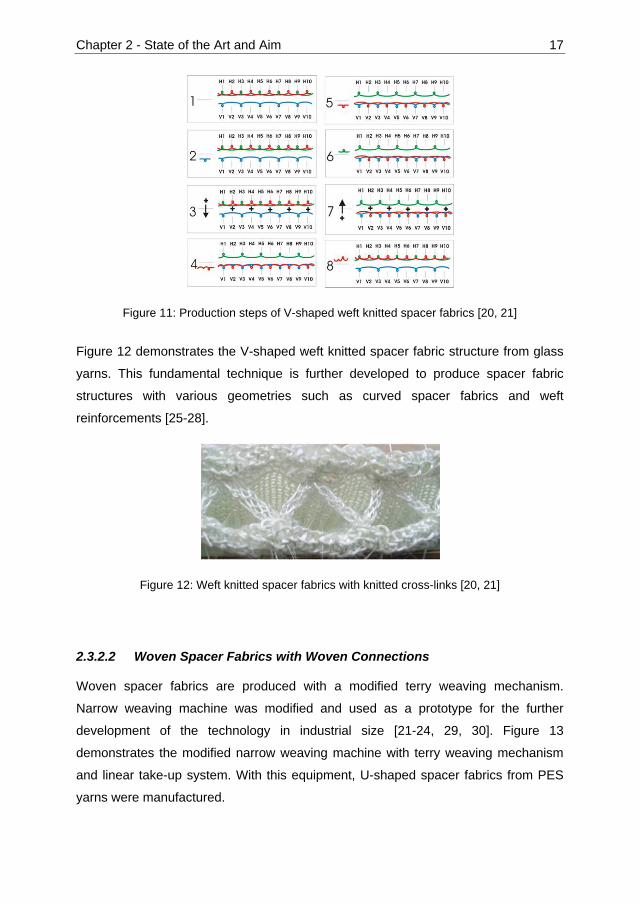
Figure 11: Production steps of V-shaped weft knitted spacer fabrics [20, 21]
Figure 12 demonstrates the V-shaped weft knitted spacer fabric structure from glass
yarns. This fundamental technique is further developed to produce spacer fabric
structures with various geometries such as curved spacer fabrics and weft
reinforcements [25-28].
Figure 12: Weft knitted spacer fabrics with knitted cross-links [20, 21]
2.3.2.2 Woven Spacer Fabrics with Woven Connections
Woven spacer fabrics are produced with a modified terry weaving mechanism.
Narrow weaving machine was modified and used as a prototype for the further
development of the technology in industrial size [21-24, 29, 30]. Figure 13
demonstrates the modified narrow weaving machine with terry weaving mechanism
and linear take-up system. With this equipment, U-shaped spacer fabrics from PES
yarns were manufactured.

Chapter 2 - State of the Art and Aim 18
Figure 13: Modified narrow weaving machine [21]
Figure 14 depicts the narrow woven U-shaped spacer fabrics prototypes from PES
yarns. The floating warp yarns on the left picture are pulled-back by using terry
weaving mechanism. The picture on the right is the final spacer fabric structure with
U-shaped cross-links.
Figure 14: U-shaped narrow woven spacer fabrics from PES yarns. Flat structure without pulling-back of floating yarns (left), final spacer fabric after pulling-back of floating yarns
(right) [21]
Needle narrow weaving machine has side needles to bind the inserted weft yarns.
During the activation of terry weaving mechanism, the side needles continue holding
the weft yarns as loops. When the fabric is moved back and forward, the weft yarn
loops must suddenly increase their size enormously. This applies very high stresses
on the side needles, and deforms the structure of the woven fabric. After finishing the
terry weaving movement, the needles are not able to continue their function because
of the very high loop dimensions and fabric deformation. Another point of concern is
the negative feeding of warp yarns from warp beams. As the warp beams of the

Chapter 2 - State of the Art and Aim 19
prototype narrow weaving machine are only driven by the warp tension and the
friction mechanism, the pull-back mechanism takes yarn length both from the
weaving side and from the warp beam side. This phenomenon avoids removal of the
required length of floating warp yarns and the crosslinks are not fully formed.
Therefore, further research is necessary for the following points:
- Development of a flexible technology and production methods for the industrial
size manufacturing of complex shaped preforms (such as V-, X-shaped,
variable crosslink etc.)
- Reproducible continuous preform production
- Application of technical yarns in complex preform weaving
- Increasing the mechanical performance and thickness of composite by non-
crimp 3D orthogonal structures
2.4 Composite Stiffener Structures
Large composite panels of naval and aerospace application are an important area
where out-of-plane reinforcement is necessitated. Low bending modulus of these
structures is a major constraint to overcome in the design of large composite parts,
therefore, various types of stiffeners are integrated. Stiffeners are either a stack of
laminates perpendicular to the panel or a chamber of laminates with or without foam
inside. The connection between the panel and stiffeners is mostly resin, in some
cases sewing yarns and resin connection is also applied. Many experimental studies
are conducted in order to determine the effects of connection type between stiffeners
and panels as well as resin type, fillet radii etc. The lack of reinforcement between
stiffeners and panels are recognized and explicitly mentioned as the main cause of
failure in the early studies [31]. Matrix connection clearly increases the risk of
delamination. Other connection techniques such as sewing increase the cost of
production as well as generate inhomogenity and damage the preform. Figures 15
and 16 demonstrate the state of the art production technique of stiffener structures
for aerospace applications. Both the panel and the stiffener parts consist of multiple
prepreg layers and the critical connection area between these two parts are
manufactured by only matrix connection.

Chapter 2 - State of the Art and Aim 20
Figure 15: Examples of I-beam and T-beam stiffener structures used in aerospace applications (above) and their internal structure of fabric plies (below) where different color
means separate layers [32]
Figure 16: Stiffener structures for aerospace applications (above) and schematic of stacked fabric layers (below) where different color means separate layers [32]
2.5 Hybrid Yarns
Fracture toughness and recycling are important advantages to use thermoplastic
matrices in composite manufacturing. However, high viscosity of thermoplastics

Chapter 2 - State of the Art and Aim 21
requires mixing of the reinforcement material and the matrix in the solid state. This
mixing process is realized through hybrid yarn production which reduces the flow
path of the resin during impregnation and consolidation. One application field of
hybrid yarns is car tires in which the two components are mixed in such a way to
create a required bimodular behavior [33]. Main application of hybrid yarns is to mix
the reinforcement component and the thermoplastic matrix component. Figure 17
demonstrates the possible ways of producing hybrid yarns.
Online hybrid yarn spinning delivers good mixture of matrix and reinforcement
components without significant process damage [34-36]. However, online spinning of
hybrid yarns is currently available in the market only for the GF/PP and GF/PET
material combinations [37]. Commingled yarns are produced with modified air jet
texturizing machines [38, 39]. Commingling is a flexible production process which
provides good mixture of components in the cross-section. Any material combination
can be processed, however, air nozzle damages the reinforcement material [40]. Also,
it is not possible to produce thick rovings with commingling process. In friction
spinning, reinforcement yarns are in the core of the yarn and the matrix is in short
fibre form and wound around the reinforcement [41, 42]. Reinforcement material is
covered and protected by the matrix. On the other hand, due to the poor mixture in
the cross-section, impregnation is not easily realized. Similar cross-sectional
structure is created by micro-braiding [43]. Like friction spinning, micro braiding also
protects the reinforcement during further processing. Impregnation does not always
reach until the core of the reinforcement if suitable process parameters are not
selected [44]. Twisting and covering are not preferred for hybrid yarn production to
mix thermoplastic matrix and reinforcement because of the poor mixture in the cross-
section.

Chapte
2.6 A
Weavin
perform
profiled
manua
automa
the dem
ultimate
cycles,
produc
matrix
woven
The aim
A
er 2 - State
Aim of th
ng techno
mance com
d woven p
l works.
ated techn
mands of t
e strain, in
as well
tion of hi
composite
fabrics can
m of the dis
Developm
Analysis a
hybrid yarn
Determina
reinforcem
e of the Art
Figure 17
he Thesi
logy is do
mposite ma
preforms a
By consid
ology for r
the curren
ncreased fr
as the gr
igh-perform
es are mai
n be used
ssertation
ent of a no
and solutio
ns
ation of th
ment and co
and Aim
7: Productio
s
ominating
aterials bo
are necess
dering rec
reproducib
t composit
racture tou
eat oppor
mance str
nly aimed
as reinforc
is as follow
ovel notatio
ons conce
e effects
omposites
on technique
the marke
oth with ex
sary to pro
cycling an
le product
te market.
ughness, h
rtunity they
ructural co
by using
cement for
wing:
on to analy
erning the
of weavin
es of hybrid
et of texti
xisting and
ovide repr
nd cost is
tion of com
Thermopl
higher impa
y offer for
omponents
commingle
r thermose
yze and cla
weaveab
ng and str
d yarn [24]
ile reinforc
d potential
roducibility
ssues, dev
mplex wove
lastic comp
act toleran
r rapid an
s. Therefo
ed yarns,
t matrices
assify 3D w
ility of GF
ructural pa
cements f
l applicatio
y by reduc
velopment
en preform
posites ha
nce, short m
nd low-cos
ore, therm
however,
as well.
woven struc
F/PP comm
arameters
22
for high
ons. 3D
cing the
t of an
ms fulfils
ave high
molding
st mass
oplastic
profiled
ctures
mingled
on the

Chapter 2 - State of the Art and Aim 23
Development of industrial size production principles for basic spacer fabric
structures with woven cross-links
Development of industrial size production techniques for complex spacer
fabrics and stiffeners
Development of technology, application of mechanical modifications and
industrial size manufacturing of preforms

Chapter 3 - Mathematical Treatment of 3D Woven Structures 24
Chapter 3 - Mathematical Treatment of 3D Woven
Structures
Creating surfaces with fibrous materials has been known by mankind since ancient
times and weaving is the oldest of these techniques. In conventional weaving, the
interlacing of warp and weft yarns creates the textile surface. There are almost
unlimited ways of interlacing these two yarn systems, which generates different
appearance, touch and mechanical properties. Three basic weave structures, that
are called plain weave, twill weave and satin weave, are utilized by weave designers
and engineers to derive further weaves. Thickness of conventional weaving is not
significant in comparison with its width and length, therefore they can be regarded as
2D weaving. A weave repeat (unit cell) of a 2D woven structure is represented by
black and white coloring of a rectangular block of squares. This general notation is
demonstrated in figure 18. Square blocks represent the crossing points of warp
(vertical black lines) and weft (horizontal white lines). A square is filled with black
color if warp yarn is on the top of weft yarn. A square is left white if weft yarn is on the
top of warp yarn, in that particular crossing point. The weave repeat is 2x2 which
means the smallest repeating weave unit consists of 2 warp and weft yarns. This
notation is sufficient for the conventional 2D woven structures.
Figure 18: Weave representation of a plain woven fabric (left) and actual positioning of warp (black color) and weft (white color) yarns (right)
In the literature, some research efforts have been reported to determine the possible
number and types of weaves for a given repeat size as well as what kind of patterns
of the notation in figure 18 brings a real woven structure. Gu and Greenwood have
shown that there is a large discrepancy between the number of weaves that can be
woven and the number that are theoretically exist [45]. They claimed that
computational analysis with algorithms is necessary to find the exact number of

Chapter 3 - Mathematical Treatment of 3D Woven Structures 25
weaves for a given repeat size. However theoretical analysis would give good
approximation to the minimum number of weaves. There are also algorithms
developed to check whether the weave represents a single fabric layer or two or
more separate fabric layers laying over one another [46, 47]. Dawson introduced an
algorithm to identify all families of weaves for a given repeat size. In this study,
weave representations are transformed into binary digits. “0” is used for a white
square and “1” is used for a black square within the notation of figure 18. Binary
numbers represents the weaves and an algorithm is used to subtract the number,
which do not generate a woven structure. It is claimed that the number of weave
families increases almost exponentially with repeat size, therefore any algorithm
would be practicable only over a range of small repeat size [48].
3.1 Representation of Multi-layer Woven Fabrics
Multi-layer woven fabrics have significant thickness compared with their length and
width, as well as yarn paths going in the z-direction (normal to the fabric plane).
Therefore multilayer woven fabrics are also regarded as 3D woven structures. Chen
and Potiyaraj have reported about parametric construction of two types of 3D woven
fabrics, namely orthogonal and angle-interlock, by using a CAD/CAM system [49].
The general notation for multilayer woven fabrics is the same as the notation for
conventional 2D woven structures. There are multiple plies within a multilayer fabric
which consists of weft yarns positioned onto each other and these weft yarn layers
are connected through warp yarns. Since the general notation includes only two
positions which are black and white areas, the weft yarn layers are drawn as if they
are positioned next to each other. Figure 19 demonstrates the weave of two separate
layers of plain woven fabrics. In the figure, columns represent the warp yarns and
horizontal lines represent the weft yarns. U1 and U2 are the first and second yarns of
the upper layer plain weave. L1 and L2 are the first and second yarns of the lower
layer plain weave.

Chapter 3 - Mathematical Treatment of 3D Woven Structures 26
Figure 19: Weave for double layers of separate plain woven fabrics
At the first look, the patterns of plain weave (as in figure 18) for the upper and lower
fabrics are not easily seen, although they are already included within the unit cell in
figure 19. The reason for this confusion is caused by the additional areas which have
to be included into the pattern. These additional areas are created by definition of
upper and lower layer fabrics, namely; warp yarns of upper layer should always be on
top of the weft yarns of lower layer, and warp yarns of lower layer should always be
under the weft yarns of upper layer. According to this definition, areas of all black and
all white should be included into the pattern respectively. Figure 20 depicts the 4
building blocks of the pattern shown in figure 19, which are two plain weave
structures for upper (figure 20A) and lower fabric (figure 20B), as well as the 2 areas
by definition of upper (figure 20C) and lower (figure 20D) layers. The pattern of figure
19 is constructed by the assembly of 4 patterns shown in figure 20. If demanded,
there are two ways to connect these two separate fabric layers. First one is adding
white squares into the area of figure 20C which means the warp yarns of the upper
layer will connect with the weft yarns of the lower layer. Second one is adding black
squares into the area of figure 20D. In this case warp yarns of lower layer will
connect with the weft yarns of upper layer.
Figure 20: Elements of weave for double layers of separate plain woven fabrics
U1 L1 U2 L2
U1
L1
U2
L2
U1
U1
U2
U2
L1
L1
L2
L2
U1
L1
U2
L2
L1
U1
L2
U2
A B C D
Chapter 3 - Mathematical Treatment of 3D Woven Structures 27
If 3D weaves are needed to be analyzed, above described notation is insufficient
because the information about the yarn course in the z-direction cannot be seen
easily. Flat demonstration of a 3D structure with black and white squares which can
be translated into binary code does not give enough insight to see the real 3D
structure. Therefore two new notations are suggested in the following.
3.2 Alternative Ways of Weave Representation
As mentioned before, the areas of black or white regions created by the definition
such as in figure 20C and 20D, makes it difficult to analyze a multilayer woven
structure. One alternative is to use matrix notation with numbers of suitable mode.
Since single layer fabric can be demonstrated by a binary data, such as black and
white squares or 1 and 0, for an n-layer fabric, the mode of numbers should be n+1.
In this case, the structure in figure 19 can be reformulated with a matrix of mode 3. It
is assumed that weft yarns of upper layer are already positioned over the weft yarns
of lower layer. In order to include the important z-direction, side-view of the structure
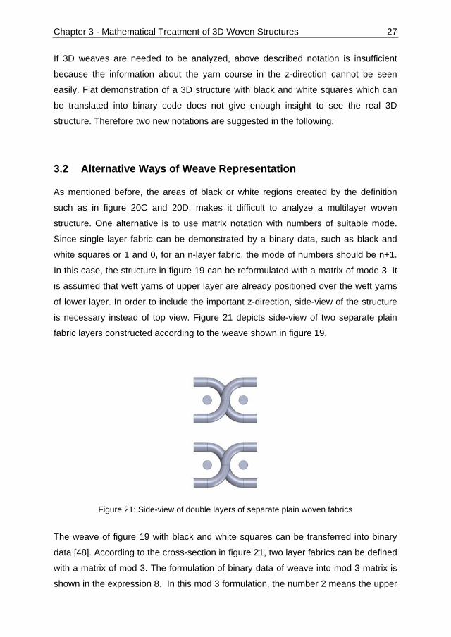
is necessary instead of top view. Figure 21 depicts side-view of two separate plain
fabric layers constructed according to the weave shown in figure 19.
Figure 21: Side-view of double layers of separate plain woven fabrics
The weave of figure 19 with black and white squares can be transferred into binary
data [48]. According to the cross-section in figure 21, two layer fabrics can be defined
with a matrix of mod 3. The formulation of binary data of weave into mod 3 matrix is
shown in the expression 8. In this mod 3 formulation, the number 2 means the upper

Chapter 3 - Mathematical Treatment of 3D Woven Structures 28
position for a warp yarn, the number 1 means the position between upper weft yarn
and lower weft yarn, and the number 0 means the lower position under all of the weft
yarns. This notation can be applied in the same way to woven fabrics consisting of
more than two layers.
11101000
10110010 21101201 (8)
Changing the mode of the matrix notation creates a more compact representation of
what is happening within the structure. However the top-view perspective is still not
suitable to gain the necessary insight. The side-view of a multilayer woven fabric
gives better idea about how the normal to the plane direction of the fabric is
constructed.
The simplest weave, so called plain woven fabric in figure 18, has a unit cell
representation with 2x2 squares. The available four squares can be either white or
black. Therefore the overall possibilities of pattern OPP within this size of squares
can be calculated as in the equation 9 where c is the number of lines (weft yarns) and
r is the number of columns (warp yarns). For the unit cell of 2x2, 16 possible
configurations exist. Within these 16 configurations, only two patterns define a real
woven structure, which are actually the same plain woven fabric (figure 22).
OPP c, r 2 . (9)
Figure 22: Two equivalent representations of plain woven fabrics
The selection of two possible plain weave structures is a simple matter when the
side-view is used instead of top-view. Figure 23 depicts the two possible structures
≡

Chapter 3 - Mathematical Treatment of 3D Woven Structures 29
for a 2x2 unit cell, one of which does not provide a woven structure because of
floating (figure 23 left) and the other is the plain woven fabric (figure 23 right). The
two equivalent representations of figure 22 exist in the cross-sectional view (figure 23
right). Here the sequence of the two warp yarns creates two equivalent patterns from
conventional top-view, however the sequence of warp yarns can be ignored
especially when the mechanical characteristics of the structure is mainly concerned.
Figure 23: Side-view of patterns with two warp yarns and two weft yarns. Floating of warp yarns without forming a woven structure (left), plain woven structure (right)
Underlying assumptions to utilize the cross-sectional views of figure 23 as a weaving
notation are:
- Weft yarns lay straight between warp yarns as solid cylinders. Crimp of weft
yarns in real woven structures is ignored in order to provide simplicity.
- For n-1 numbers of weft yarns lying onto each other, n warp yarns are
available. In figure 23, one layer of weft yarn is drawn and two warp yarns are
available.
- Weft yarns are fixed through crossing of warp yarns. Inside of one area
created by the crossing of warp yarns, only one weft yarn can exist. The
thickness of weft yarns and the possibility of more than one weft yarn within
the crossing of warp yarns are irrelevant for the analysis.
- Only two columns of weft yarns are considered.
- No warp yarn follows the same route.
- According to the 3rd assumption, all warp yarns start in successive positions,
in order to avoid double weft yarns within the same crossing area of warp
yarns.
Chapter 3 - Mathematical Treatment of 3D Woven Structures 30
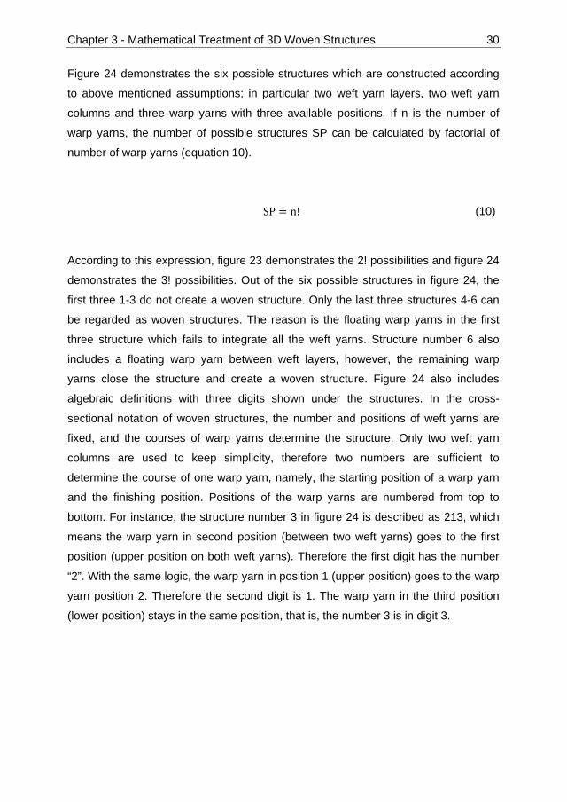
Figure 24 demonstrates the six possible structures which are constructed according
to above mentioned assumptions; in particular two weft yarn layers, two weft yarn
columns and three warp yarns with three available positions. If n is the number of
warp yarns, the number of possible structures SP can be calculated by factorial of
number of warp yarns (equation 10).
SP n! (10)
According to this expression, figure 23 demonstrates the 2! possibilities and figure 24
demonstrates the 3! possibilities. Out of the six possible structures in figure 24, the
first three 1-3 do not create a woven structure. Only the last three structures 4-6 can
be regarded as woven structures. The reason is the floating warp yarns in the first
three structure which fails to integrate all the weft yarns. Structure number 6 also
includes a floating warp yarn between weft layers, however, the remaining warp
yarns close the structure and create a woven structure. Figure 24 also includes
algebraic definitions with three digits shown under the structures. In the cross-
sectional notation of woven structures, the number and positions of weft yarns are
fixed, and the courses of warp yarns determine the structure. Only two weft yarn
columns are used to keep simplicity, therefore two numbers are sufficient to
determine the course of one warp yarn, namely, the starting position of a warp yarn
and the finishing position. Positions of the warp yarns are numbered from top to
bottom. For instance, the structure number 3 in figure 24 is described as 213, which
means the warp yarn in second position (between two weft yarns) goes to the first
position (upper position on both weft yarns). Therefore the first digit has the number
“2”. With the same logic, the warp yarn in position 1 (upper position) goes to the warp
yarn position 2. Therefore the second digit is 1. The warp yarn in the third position
(lower position) stays in the same position, that is, the number 3 is in digit 3.

Chapter 3 - Mathematical Treatment of 3D Woven Structures 31
Figure 24: Possible structures with 2 weft yarn layers, 2 weft yarn columns and 3 warp yarns
The number of woven structures SW with number of warp yarns n, within the possible
structures of n! can be calculated as in the equation 11.
SW 1
SW n! SW i! for n 2,3,4 … (11)
The logic of the equation 11 is based on the subtraction of structures with floating
warp yarns (in figure 24, structures 1 and 2) and the structures which create a
smaller number of weft layers (in figure 24, structure 3). The algebraic notation
shown in figure 24 is helpful to construct and appreciate the meaning of the equation
11. Let the woven structures with n=4 be the subject of the analysis. According to the
equation 11, the number of woven structures is calculated as shown in the
expression 12.
SW 4! SW 1! SW 2! SW 3! (12)
The total number of structures are given as 4!. Figure 25 depicts the individual blocks
of structures which do not represent a woven structure, thus they should be
1 2 3 4 5 6
123 132 213 312 231 321

Chapter 3 - Mathematical Treatment of 3D Woven Structures 32
subtracted from the total 4!. SW1 is defined as 1 in the equation 4, which means that
the uppermost warp yarn is floating. This structure is symbolized as the algebraic
expression with a 1 in the first digit. There are 3! structures which have a 1 in the first
digit. SW2 is the number of woven structures with two warp yarns. As shown in figure
23, SW2 is 1, and the algebraic notation starts with a “21” in the first two digits. The
remaining two digits are in total 2!. SW3 is the number of total woven structures with
3 warp yarns. Figure 24 shows that there are three possible woven structures with
structure numbers 4-6. These three structures have the algebraic notations “312”,
“231” and “321”. In all these three cases the last digit can only be “4”, which is 1!. All
the above mentioned possibilities, which generate a local woven structure and
therefore do not create a whole woven structure, are subtracted from n! as in the
equation 11.
Figure 25: Subtraction blocks to determine the woven structures with 4 warp yarns SW4
Table 1 depicts the development of possible structures SP and the woven structures
SW according to the number of weft yarn layers from one to six.
1 _ _ _
2 1 _ _
3 1 2 _
2 3 1 _
3 2 1 _
SW1
SW2
SW3
3!
2!
1!
1!
1!

Chapter 3 - Mathematical Treatment of 3D Woven Structures 33
warp yarns
(n)
weft yarn
layers (n-1)
weft yarn
columns
possible
structures
(SP=n!)
woven
structures
(SW)
2 1 2 2 1
3 2 2 6 3
4 3 2 24 13
5 4 2 120 71
6 5 2 720 461
7 6 2 5040 3447
Table 1: Development of possible structures SP and the woven structures SW according to the number of warp and weft yarns
After looking closely at the structures in figure 24, it can be figured out that not all the
3 woven structures are independent. In fact, structure number 5 can be regarded as
the symmetry of the structure number 4 both according to x-axis (horizontal) and y-
axis (vertical). The determined woven structures SW are further distributed into 5
groups due to the symmetry. The schematics as well as the definitions are given in
table 2. The starting woven structure is positioned on the upper left and called “main”.
Symmetries of x-, y-, and diagonal-directions are positioned accordingly.

Chapter 3 - Mathematical Treatment of 3D Woven Structures 34
Definition of symmetry group Schematic of symmetry group 1. x, y and diagonal symmetries are same as the main weave
Main { } y symmetry x symmetry { } diagonal symmetry
2. Diagonal symmetry is same as the main weave; x and y symmetries are same
3. x, y and diagonal symmetries are all different from the main weave
4. x symmetry is same as the main weave; y symmetry is same as diagonal symmetry
5. y symmetry is same as the main weave; x symmetry is same as diagonal symmetry
Table 2: Symmetry groups of woven structures

Chapter 3 - Mathematical Treatment of 3D Woven Structures 35
Figure 26 demonstrates the symmetries of the woven structure 51243 as an example.
This woven structure belongs to the symmetry group 3 which is explained in table 2.
It can be seen that all x-, y- and diagonal symmetries are different from the main
woven structure 51243.
Figure 26: Symmetries of the woven structure 51243
The symmetry groups can be identified with algebraic notation as well. Figure 27
shows the operations to determine the x and y symmetries of a given woven structure.
Operations I and II are applied to a given algebraic expression to find the x symmetry.
Operation I turns the sequence of the algebraic expression, which means 51243 is
rewritten from back to forward to get 34215. Operation II changes the numbers with
their symmetries according to the middle point of the number set. In figure 27, the
operation II changes 34215 to 32451, where the number set is {1, 2, 3, 4, 5} and the
middle point of the number set is the number “3”. Therefore, the first digit is 3 and it
remains. The second digit is 4 and it is changed to 2, because the symmetry of 4
according to the middle point 3 is 2. The operations III and IV change a given
y
51243
x
23541
32451 52134

Chapter 3 - Mathematical Treatment of 3D Woven Structures 36
algebraic expression to its y symmetry. First, the main algebraic expression 51243 is
written in open form, i.e. 5 1 means that the warp yarn goes from the position 5 in
the first weft yarn column to the position 1 in the second weft yarn column. After
writing the routes of all the warp yarns, the sequence is changed, namely 5 1
becomes 1 5. After operation III, the left hand side of the number columns is in
order from 1 to 5. Operation IV merely makes the right hand side of the number
columns in ascending order. The left hand side of the number columns read from top
to bottom gives the y symmetry as 23541.
Figure 27: Algebraic operations to determine the x symmetry (I & II) and y symmetry (III & IV) of a given woven structure
According to the operations shown in figure 27, distribution of woven structures to the
five symmetry groups are executed. The results up to n=5 is shown in table 3.
Symmetry groups 1, 2, 3, 4, and 5 define one, two, four, two and two woven
structures respectively. Thus, in table 3 under symmetry groups, the numbers of
woven structures are expanded as the multiplication of independent woven structures
51243 I
34215 II
32451
51243 III & IV
23541
5 1
1 2
2 3
4 4
3 5
III
1 5
2 1
3 2
4 4
5 3
IV
2 1
3 2
5 3
4 4
1 5
x symmetry of
y symmetry of

Chapter 3 - Mathematical Treatment of 3D Woven Structures 37
in brackets. For example, if the number of warp yarns (n) is taken as five, symmetry
group 2 has 20 woven structures which consist of 10 independent woven structures.
n (SW) Independent
woven
structures
symmetry
group 1
symmetry
group 2
symmetry
group 3
symmetry
group 4
symmetry
group 5
2 1 1 1 (1*1) 0 0 0 0
3 3 2 1 (1*1) 2 (1*2) 0 0 0
4 13 7 3 (3*1) 4 (2*2) 4 (1*4) 2 (1*2) 0
5 71 26 3 (3*1) 20 (10*2) 44 (11*4) 2 (1*2) 2 (1*2)
Table 3: Distribution of woven structure according to the symmetry groups
Although a 2-tuple data can be described by an algebraic expression as utilized
above, there are still limitations to gain insight. One dimension of the data is the digit
number which is not easily visible. Therefore, it is advantageous to draw the number
pairs in a Cartesian coordinate plane, which represent the starting and ending
positions of warp yarns. This transformation shows the equivalent representation of
woven fabric symmetry in analytical geometry. If the number of weft yarn columns is
increased from two to n, the data can still be presented in n-tuple space.
Figure 28 demonstrates the x-, y- and diagonal symmetries of the woven structure
51243 on coordinate axis, which was already shown in figure 26 with cross sectional
and algebraic notation. In this figure, the starting positions of warp yarns within the
first weft yarn column are given in the x-axis and the ending positions are given in the
y-axis. For instance, the point (1,2) means that the warp yarn is moving from the first
position in the first weft yarn column to the second position in the second yarn
column. From the representations in figure 28, it is obvious that;
• x-symmetry of the woven structure (32451) can be found by finding the
symmetries of all the points according to the middle point, which is (3,3) in the
given example
• y-symmetry of the woven structure (23541) is the symmetry of all the points
according to y=x line, and

Chapter 3 - Mathematical Treatment of 3D Woven Structures 38
• diagonal symmetry of the woven structure (52134) is the symmetry of all the
points according to the line with a gradient of -1 and includes the middle point.
Here the middle point is (3,3) and the line is y=6-x.
Figure 28: Representations of the symmetries of 51243 on Cartesian coordinate plane
3.3 Conclusion
Normal to the plane direction defines the multilayer woven structures, thus it is the
most important dimension. Therefore, this section starts analyzing multilayer woven
structures from their cross sectional views. An equation is derived to determine the
real woven structures for two weft yarn columns and any number of warp yarns.
Furthermore, symmetry groups within the real woven structures are identified.
Algebraic expressions and Cartesian coordinates are utilized to find the symmetries
of given woven structures. Independent woven structures, which are not symmetries
of each other, are important to determine the realizable mechanical properties. As
future work, the equations which describe the development of each of five symmetry
groups as well as the independent woven structures are necessary. Moreover, the

Chapter 3 - Mathematical Treatment of 3D Woven Structures 39
cases where the number of weft yarn columns is three or more should be analyzed
with multidimensional data. If the warp yarn lengths in the woven structure are
different, then also different feeding systems are necessary. It would be useful from
production point of view to group the woven structures according to the number of
different warp yarn lengths.

Chapter 4 - Weaveability of Commingled Hybrid Yarns 40
Chapter 4 - Weaveability of Commingled Hybrid Yarns
The viscosities of fully polymerized thermoplastics are around two to three orders of
magnitude higher than their thermoset counterparts [50]. In order to overcome the
difficulties of impregnation caused by high viscosity of thermoplastics, reinforcement
materials (e.g. carbon, glass) and thermoplastic polymer (e.g. PP, PEEK) are already
mixed in solid state. The aim of solid state mixing is to reduce the flow path of
polymers during impregnation. This mixture is processed into preforms mostly with
textile machinery. Thermoplastic polymers in the preform are melted under the
application of pressure and temperature (e.g. pultrusion, compression molding), and
consolidated [51-53].
Commingled yarns can be produced with a modified air-jet texturizing machine (figure
29). The most important modification is the type of air nozzle used. Commercial air
nozzles are available, which claim to reduce the damage on the reinforcement yarns
during processing and offer a better mixture in the cross-section. Especially for
commingled yarns, a good mixture in the cross-section is crucial, because the main
idea of commingling process is to reduce the flow paths of the viscous thermoplastic
resin. Another important modification for commingling process is the bobbin winding
device. Commingled yarns should be wound up with a constant yarn tension with
higher bending radii of machine elements to minimize the damage on the yarn.
Besides material mixing and high production rates, commingled yarns embody
structural elongation which enables a smoother processing with textile machinery.
During commingling process, reinforcement yarns are damaged by the applied air
pressure in the nozzle, which can be seen as a drawback. Another disadvantage of
commingled yarns was identified from processing point of view while executing trials
on high packing densities of 3D near-net shape woven preforms [21-24]. Harnesses
apply forces on the warp yarns in both normal and longitudinal direction during
weaving. These forces should be minimized by reducing the warp yarn tension
especially for the brittle reinforcement yarns. However, reduced warp yarn tension
with high packing density increases the probability of stuck yarns in the shed and
causes unclear shed opening. After commingling, yarns become more voluminous
and open. Depending on the structure, high packing density commingled yarns

Chapter 4 - Weaveability of Commingled Hybrid Yarns 41
showed higher production stops than conventional materials, which necessitates
improvement for the industrial production.
Over-delivery of input yarns is necessary for the formation of the commingled
structure [39]. This indicates the possibility of slightly twisting the commingled yarn to
create a more compact yarn structure without causing significant effect on the
composite properties. In the literature, contributions about the effects of twisting on
high performance yarns were reported however no study is available about the effect
of twisting on the commingled yarns and their composites. Within the scope of this
study, main aim is to determine whether twisting can be applied on commingled
yarns in order to improve the processing behavior on textile machinery. The effect of
twisting level both on the yarn and composite properties were analyzed to see how
the physical and mechanical properties were changed. A yarn model with serially
connected linear bar elements was introduced to consider the varying contribution of
bulky and knot areas in the commingled yarn structure. Over-delivery of the
constituent materials during commingled yarn production was modeled as an
equivalent angle distortion of a lamia. Both yarn-yarn and metal-yarn friction areas
occur during weaving. As the surface of the commingled yarn is altered through
twisting, its effects on the friction coefficients between yarn-yarn and yarn-metal were
analyzed.

Chapter 4 - Weaveability of Commingled Hybrid Yarns 42
Figure 29: Air-jet texturizing machine utilized for commingled yarn production (left) and detail view of the air nozzle (right)
4.1 Experimental
4.1.1 Materials
The GF/PP commingled yarns were produced with the commercial input materials of
300 tex glass (E 35, P-D Glasseiden GmbH, Germany) and 3 x 32 tex polypropylene
(Prolen H, CHEMOSVIT FIBROCHEM a.s., Slovakia) which resulted in a fiber
volume fraction of 52% in UD composites. Commingled yarns were produced with 4
bar air pressure in the nozzle and a winding speed of 100 m/min. In order to generate
the commingled structure, input cylinders deliver the glass and polypropylene yarns
with a higher speed than the output cylinder which is removing the final commingled
yarn out of the air-nozzle. This setting is called over-delivery and defined as the
percentage ratio of the speed difference to the output cylinder speed. Equation 13
shows the calculation of over-delivery OD, where Si is the input speed of feeding
cylinders and So is the output speed of take-up cylinders.
100 (13)

Chapter 4 - Weaveability of Commingled Hybrid Yarns 43
Over-delivery of glass yarns was kept at a value of 2% to avoid damage and
extensive loss of orientation. Over-delivery of polypropylene yarns was 8%, therefore
polypropylene filaments had higher entanglement than glass filaments and were
tending to be at the outer part in the cross-section.
Produced commingled yarns were twisted (DirecTwist, Agteks) with 0, 5, 10, 15, 20,
40 and 60 tpm (twist per meter) and compared with the reference yarn which was
commingled without any further process. 0 twist per meter in the trials actually means
winding to another bobbin by using the same twisting machine. Winding without twist
was done to isolate the effect of extra processing on the yarn properties. 5 to 20 tpm
were the main experiments of concern whereas 40 and 60 tpm experiments
demonstrated extreme values. Uni-directional (UD) composites were produced with
compression molding. Processing conditions for compression molding is shown in
figure 30.
Figure 30: Processing parameters for compression molding of UD-composite plates
4.1.2 Testing Procedure
Yarn profiles as well as yarn-yarn and yarn-metal friction coefficients were
determined by using dynamic tensile tester (LH-402 CTT-DTT Attachment, Lawson
Hemphill Inc. USA). A CCD camera was used to measure the yarn diameter values
with 3.25 micron precision when the yarn was moving at a speed of 100 m/min. Yarn-
metal and yarn-yarn friction coefficients were determined dynamically according to
0
10
20
30
40
50
60
70
020406080
100120140160180200220240
0 1 20 23 33 58
Pre
ssur
e [b
ar]
Tem
pera
ture
[°C
]
Time [min]
Temperature
Pressure

Chapter 4 - Weaveability of Commingled Hybrid Yarns 44
ASTM D-3108, and ASTM D-3412. Tensile tests for yarns were executed with 20
specimens according to the norm DIN EN ISO 2062, with a clamping length of 500
mm and testing speed of 25 mm/min (Z100, Zwick GmbH & Co. KG). Tensile tests of
UD-composites were executed according to DIN EN ISO 527-4. Upper and lower
clamping areas were 50 mm each, and the testing lengths of the specimens were
150 mm. 0° specimens had a width of 15 mm and 90° specimens had a width of
25mm. 12 specimens for 0° and 8 specimens for 90° were tested for each twisting
level and the reference. Testing speeds for both 0° and 90° were 2mm/min.
Confidence intervals with 95% were determined according to Student’s t-distribution.
4.2 Results and Discussion
4.2.1 Commingled Yarn Structure
Commingling process is based on the mixing of materials through an air nozzle. As in
the air jet texturizing process, commingling process creates a special yarn structure
with two different areas which are called as bulky and knot areas (figure 31).
Continuous air pressure through the nozzle creates distinctive areas; in bulky region
the materials are voluminous and open whereas in knot areas they are intermingled
together. Various process parameters such as nozzle type, air pressure, take-up
speed etc. affect the frequency and intermingling intensity of knot areas, however a
fully control on this phenomenon is not possible. In the case of commingled yarns, a
better mixture of reinforcement and matrix materials occurred in the knot area. Figure
31 demonstrates the cross-sectional observations from bulky and knot areas, dark
points are polypropylene and the light points are glass filaments.

Chapter 4 - Weaveability of Commingled Hybrid Yarns 45
Figure 31: Cross-sectional observations of bulky (A-A) and knot (B-B) areas of GF/PP commingled yarns
Profile scanning results demonstrated a progressive improvement of commingled
yarn evenness with increasing twist (figure 32). Bulky and sticky regions on
commingled yarns were the main cause of production stops during weaving. The
number of events, which is defined as ±50% variations in yarn diameter, was
decreased from 42 events/m to the interval of 30-35 events/m for all twisting ratios.
A-A B-B
A B
A B

Chapter 4 - Weaveability of Commingled Hybrid Yarns 46
Figure 32: Comparison of GF/PP commingled yarn profile, from top to bottom; reference commingled yarn, 10tpm, 20tpm, 40tpm, 60tpm
Mean values of yarn diameter (figure 33) were increased for 0 tpm and 5 tpm
samples, which was caused by the effect of the additional process step. After 10 tpm,
yarn diameter decreased gradually. The standard deviation of every sample was less
than the reference commingled yarn, thus more regular yarn structure was generated.
Small yarn diameters enable denser packing of material during weaving. 3rd degree
regression polynomial in figure 33 has a local minimum around 55 tpm. After 60 tpm
the diameter would not change significantly, however, the regression polynomial
increases. Therefore the regression polynomial can be used for interpolation between
the twisting values of 0 tpm and 60 tpm, but twisting values more than 60 tpm cannot
be estimated with extrapolation.
Reference
10 tpm
20 tpm
40 tpm
60 tpm

Chapter 4 - Weaveability of Commingled Hybrid Yarns 47
Figure 33: Effect of twisting on the diameter of GF/PP commingled yarns
4.2.2 Commingled Yarn Friction Properties
In the literature the increase of friction coefficient for both yarn-to-yarn and yarn-to-
metal with increasing twist values of multifilament yarns was reported [54]. Increasing
twisting levels decreases the cross-sectional area and increases the hardness. The
overall structure as well as the surface of commingled yarns are different than
multifilament yarns. Twisting increases the surface roughness of a conventional
multifilament yarn. On the other hand, commingled yarns already have a high surface
unevenness caused by the air-nozzle during production. Twisting increases the
surface evenness of a commingled yarn which generates a tendency of decrease in
coefficient of friction. Friction coefficient depends on the interaction of both touching
surfaces. In the case of yarn-metal experiments, polished surface of the metal part
suppressed the reduction tendency for the coefficient of friction. On the other hand,
yarn-yarn friction had a linear decrease with increasing twist levels (figure 34). Yarn-
metal friction coefficient increases with the increase of testing speed, so during
weaving weft yarns yield around 20 % higher friction coefficients than warp yarns.
y = 1E-06x3 - 8E-05x2 - 0,0006x + 0,5559R2 = 0,9985
0,4
0,45
0,5
0,55
0,6
0 5 10 15 20 25 30 35 40 45 50 55 60 65 70
Twist [revolution/m]
Yarn
dia
met
er [m
m]
commingled + twistedcommingled referenceconfidence interval 95%

Chapter 4 - Weaveability of Commingled Hybrid Yarns 48
Figure 34: Effect of twisting on yarn-yarn and yarn-metal friction of GF/PP commingled yarns
4.2.3 Yarn Mechanical Properties
Figure 35 demonstrates the two different regions of commingled structure, therefore,
the modulus of elasticity was modeled with two linear bar elements. This model aims
to represent the varying contribution of the bulky and knot regions of commingled
yarns on the tensile modulus. In the bulky region, voluminous structure is mainly
created by the matrix material (PP), while reinforcing material (GF) remains straight.
In the knot region, over-delivery of reinforcing material is consumed by the intensive
intermingling. The two elements in figure 35 represent the bulky area with straight
reinforcement and the knot area with intermingled reinforcement yarns. The boundary
of bulky and knot region cannot be always clearly defined. In addition, the intensity of
intermingling in knot regions varies too. Under tensile loading, actual commingled
yarns change their internal structure and yield a bi-modular behavior. In the following
model, bi-modular behavior and the transition regions are omitted to simplify the
analysis.
y = -0.0009x + 0.237R2 = 0.9931
y = -2E-06x2 - 4E-05x + 0,2006R2 = 0.9688
0,17
0,19
0,21
0,23
0,25
0,27
0 5 10 15 20 25 30 35 40 45 50 55 60 65 70
Twist [revolution/m]
Fric
tion
coef
ficie
nt [-
]
yarn-metal twistyarn-yarn twistyarn-metal referenceyarn-yarn-reference

Chapter 4 - Weaveability of Commingled Hybrid Yarns 49
Figure 35: Yarn structure and model for determining the E-modulus of commingled yarns
The overall E-modulus was determined by the stiffness equation of serial springs
(Equation 14)
1 1 1
(14)
After putting the stiffness values of k1 and k2 into Equation 2, with the same cross-
sectional areas A;
(15)
The assumption of same cross-sectional area is valid because the total area of the
constituent fibers in the cross-section is same everywhere.
Rewriting equation 15;
(16)
k1 = A1 * E1 / L1 k2 = A2 * E2 / L2
1 2 3
(1) (2)

Chapter 4 - Weaveability of Commingled Hybrid Yarns 50
In the literature a model was derived from laminate theory to determine the effect of
twist on the E-modulus of some technical yarns such as Kevlar®, Vectran® etc. [55].
The model is in very good agreement with experimental data. Twisted yarn samples
in those experiments should yield reduction of modulus which is caused by both the
structural change by twisting and the yarn damage throughout processing. However,
the damage on the yarns caused by twisting was not considered. Another previous
study predicted the relation between twisting angle and E-modulus of Nylon yarns
with Equation 17 [56]. This equation progressively overestimated the E-modulus of
technical yarns [55]. This slight overestimation compared with the experimental
results is more reasonable to isolate only the effect of twisting without considering the
yarn damage. Therefore, in this study Equation 17 was utilized to determine the
reduction in modulus of elasticity caused by twisting.
(17)
Over-delivery of input materials in commingling process is necessary in order to
create the knot areas, and most of the additional material length is integrated in these
areas because the bulky region can easily be stretched during further processing.
The twist angle equivalent of over-delivery ratio was calculated according to Equation
18, where αod is the twist angle equivalent caused by over-delivery and OD (%) is the
over-delivery of input material.
Over-delivery of the reinforcement material within commingled hybrid yarn can be
approximated as an angle distortion of a lamina. The input length of the
reinforcement material is the hypotenuse of a right triangle and the output length is
the adjacent side. Figure 36 demonstrates this approximation where OD is the over-
delivery as percentage and θ is the angle of distortion.

Chapter 4 - Weaveability of Commingled Hybrid Yarns 51
Figure 36: Equivalent angle distortion caused by over-delivery of reinforcing material
The inverse trigonometric function of cosine gives the equivalent of the distortion
angle as shown in the equation 18.
100100 (18)
According to the assumption that the over-delivered material is mainly consumed in
the knot areas, where the length is a ratio of overall yarn length, Equation 18 can be
rewritten as;
_ 100 ∑100 ∑ (19)
Equation 19 is the general expression of how to distribute the angle distortion
between n linear bar elements. The subscript i was used to distribute the overall
over-delivery on the commingled yarn to the identified number of different regions.
αod_i stands for the angular distortion of the particular region and Li is the
representative length of that region. The summation symbol with Lj stands for the
total representative length of the yarn. According to the model in figure 35 there are
two regions which represent the bulky and knot areas.
θ
100
100+OD

Chapter 4 - Weaveability of Commingled Hybrid Yarns 52
Twist angle αtw (degree) can be calculated according to the Equation 20, where dav
(mm) is the average yarn diameter and tw (tpm) is the twist value per meter.
1000 (20)
The total twist angle αt is determined through superposition of the nominal twisting
angle αtw and the twist angle equivalent of over-delivery αod as in Equation 21. After
putting Equation 21 into Equation 17, Equation 22 can be generated, which was used
to calculate the modulus of elasticity of one element in figure 35.
100 ∑100 ∑ 1000 (21)
_ 100 ∑100 ∑ 1000 (22)
With the introduction of damage factor to the Equation 16 and the rule of mixtures the
final equation for the determination of E-modulus becomes;
1 (23)
Where Er1 is E-modulus of reinforcement element 1 (bulky region), Er2 is E-modulus
of reinforcement element 2 (knot region), Em1 is E-modulus of matrix element 1 (bulky
region), Em2 is E-modulus of reinforcement element 2 (knot region). All E-moduli are
calculated with Equation 22. Dr is the damage factor which is a function of twist angle

Chapter 4 - Weaveability of Commingled Hybrid Yarns 53
αtw and multiplies only the reinforcement elements. Vf is the volume fraction of the
reinforcing material.
Some simplifications and assumptions were done for the calculations. Based on the
visual information, the length of the bulky region was approximately 9 times the
length of knot region which was reflected in the model with the length of elements.
The reduction of E-modulus through twisting was mainly caused by the damage on
the material because the orientation of the reinforcement material was not
significantly affected within the trials. Over-delivery of glass yarns were 2%, in the
calculations it is assumed that all this extra length is integrated into the knot area.
Over-delivery of polypropylene was 8%, in the calculations it was assumed that the
additional length was equally consumed in both bulky region and knot areas. An
interesting phenomenon was the increase of both breaking force and E-modulus of
commingled yarns after further processing. After twisting with 0° (only winding), yarn
samples had higher E-modulus and breaking force than the reference yarn (figure 37).
This is caused by the restructuring of the knot areas under tension, the yarn was
stretched and the orientation of the reinforcement material in knot areas was
increased. Figure 37 demonstrates the E-modulus and breaking force comparison of
twisted and reference GF/PP commingled yarns. 40 tpm sample had almost same E-
modulus and breaking force values as the reference sample. Reduction of E-modulus
started with 60 tpm sample however the breaking force was still same as the
reference yarn. These results indicate that the higher intermingling of filaments
through twisting increases the mechanical properties of commingled yarns. Damage
on glass fibers cannot be easily detected with yarn testing.

Chapter 4 - Weaveability of Commingled Hybrid Yarns 54
Figure 37: Effect of twisting on E-modulus and breaking force of GF/PP commingled yarns
By using Equations 22 and 23, theoretical E-modulus values were calculated for all
the samples. Calculated theoretical E-modulus values were divided into 4 regions
(figure 38) which were; measured E-modulus values during experiments as in figure
37, loss of E-modulus caused by over-delivery during commingling (Equation 19),
loss of E-modulus caused by twisting (Equation 20) and loss of E-modulus caused by
the commingled process damage (difference between the theoretical E-modulus and
the sum of the mentioned 3 regions). Although the y-axis presents the percentage of
the regions within theoretical E-modulus values, the nominal E-modulus values (GPa)
can be seen on the histograms. These results indicate that the commingling process
reduces the yarn stiffness almost 50%. The damage factor Dr of equation 23 was
taken as 1.0 in order to show the deviation from the theoretical modulus values. Dr
(around 0.5) can be used as an adjustment parameter to fit the experimental data. It
is an important question whether the E-modulus reduction of commingled yarns
affects the E-modulus of UD-composites in the same fashion.

Chapter 4 - Weaveability of Commingled Hybrid Yarns 55
Figure 38: Distribution of E-modulus parts; difference between theoretical and measured modulus values
4.2.4 UD-Composite Properties
The 0° and 90° E-modulus calculations were executed according to laminate theory
[4, 5]. Unlike the calculations for yarn E-modulus, UD-composite calculations were
based on the homogeneous distribution of the glass filament in the PP matrix. Off-
axis angle equivalent of over-delivery value for glass yarn was integrated to the
equation, thus the UD composites structures were assumed to have a slight angle
distortion.
Slab models deliver sufficient approximation to the elastic constants of a lamina.
Within this model, aligned long fiber composites were treated as if the two
constituents of matrix and reinforcement are bonded together. Relative thicknesses
of slabs were determined according to the volume fractions of fiber and matrix.
Interface regions as well as local stress concentrations were ignored. EL (E-modulus
fiber direction) is calculated according to equal strain assumption for both matrix and
fiber in longitudinal direction. The equation 24 is also called as “the rule of mixtures”
and delivers a very good approximation. Discrepancies may results from the different
17,3819,68 18,70 19,65 19,59 18,33 17,46 16,23
1,68
1,681,68
1,68 1,681,68
1,681,68
0,06 0,12 0,180,24
0,460,69
18,8016,50 17,42 16,41 16,41 17,61 18,27 19,26
0%
10%
20%
30%
40%
50%
60%
70%
80%
90%
100%
reference 0 5 10 15 20 40 60
Perc
enta
ge E
-mod
ulus
[%]
Commingled yarns twist [revolution/m]
total process damage
loss twist
loss over-delivery
measured modulus

Chapter 4 - Weaveability of Commingled Hybrid Yarns 56
poisson’s ratios of matrix and reinforcement, however, it can be theoretically proved
by the Eshelby model that the deviation is small under all conditions [57, 58].
1 (24)
Transverse modulus of a composite with unidirectional fibers can also be
approximated by a slab model which assumes an equal stress condition for matrix
and fibers. The stress field is complex under transverse loading and in the literature,
especially for thermoplastic matrices, underestimation of transverse modulus was
reported. The modified equation for the transverse modulus contains a correction
factor η [5, 59, 60]. If η is taken as 1, the equation becomes the usual expression
derived from an equal stress assumption for matrix and reinforcement. In order to fit
the experimental data, η was taken as 0.6 which compensates the above mentioned
underestimation of transverse modulus.
11 (25)
The expression for the in-plane shear modulus is analogous to the expression of
transverse modulus because it assumes equal shear stress on the matrix and fibers.
In order to avoid the underestimation, η’ parameter with 0.6 is applied in the
calculations.
11 (26)

Chapter 4 - Weaveability of Commingled Hybrid Yarns 57
Since the equal strain assumption is applicable to a UD lamina, the poisson’s ratio
can be determined by “the rule of mixtures”.
1 (27)
According to the above expression, 2% over-delivery of glass filaments was
equivalent to 11.36° off-axis angle distortion. The off-axis longitudinal and transverse
stiffness were calculated according to laminate theory. The relation between stress
and strain tensors in the principal material direction is given in Equations 28.
000 0
1
1
1
(28)
The transformation of the stresses from principal material direction to an arbitrary
coordinate system can be done with a modified reduced-stiffness matrix [Q’] as in
Equations 29, where m = cos θ and n = sin θ.

Chapter 4 - Weaveability of Commingled Hybrid Yarns 58
2 2
4
2
2 2
2
2 (29)
The modulus in the arbitrary x and y directions are defined as in Equations 30.
(30)
Stiffness value in longitudinal direction is found as 34.13 GPa which is
underestimating the experimental results. Experimental results of longitudinal E-
modulus in figure 39 show agreement with the nominal stiffness values according to
the rule of mixtures. This indicates that the angle distortion caused by the over-
delivery is disappeared during compression molding under tension. Modulus of
elasticity in 0° direction is not much affected from twisting. Statistically, only the
modulus of elasticity of the 60 tpm sample can be regarded as a reduction. On the
other hand, the effect of further processing can be easily seen from the tensile

Chapter 4 - Weaveability of Commingled Hybrid Yarns 59
strength reduction starting immediately with 0 tpm sample. All the samples had an
overall tendency of strength reduction, however, between 0 tpm and 60 tpm samples,
it cannot be concluded that higher twist reduces the strength more than lower twist.
Figure 39: Modulus of elasticity and tensile strength of UD composites from GF/PP commingled yarns in 0°
Lamina stiffness calculation in transverse direction, 3.98 GPa, is in good agreement
with overall experimental results (figure 40). It can be seen in figure 33 that the yarn
diameter is decreasing after 10 tpm. As the UD performs were prepared with the
same amount of material, increasing compactness of the reinforcement material
leads to greater resin rich areas. This reduces the E-modulus in transverse direction.
Transverse tensile strength shows a slight reduction tendency with increasing twist
level.
28
30
32
34
36
38
40
0 5 10 15 20 25 30 35 40 45 50 55 60 65 70
Twist [revolution/m]
Mod
ulus
of e
last
icity
[GPa
]
640
670
700
730
760
790
820
850
880
910
940
Tens
ile s
tren
gth
[MPa
]
E-modulus twistE-modulus referenceReference confidence interval 95%Tensile strength twist Tensile strength reference

Chapter 4 - Weaveability of Commingled Hybrid Yarns 60
Figure 40: Modulus of elasticity and tensile strength of UD composites from GF/PP commingled yarns in 90°
4.3 Conclusion
Effects of twisting on the mechanical properties of GF/PP commingled yarns are
analyzed. This study is initiated through the production stops caused by the open and
sticky commingled yarn structure during weaving of dense 3D woven preforms. A
decreasing tendency of the yarn friction coefficient is observed unlike the results of
other studies in the literature. The decrease is almost linear for yarn-yarn friction.
Twisting decreases the average yarn diameter and creates a more compact and
even structure. In commingled yarns, two distinctive areas can be recognized. These
areas have varying mixing quality and yarn consumption. Increase of both E-modulus
and tensile strength of commingled yarns are observed until 40tpm. A model is
presented to calculate the yarn distortion effects on the E-modulus for over-delivery
and twisting. Most of the E-modulus reduction can be explained with the damage on
the material and structure change. The differences between the theoretical and
calculated values were not observed in the UD-experiments. Longitudinal UD E-
modulus values lay close to the theoretical values. A statistically confident reduction
was observed after 40 tpm. However UD tensile strength values of twisted samples
2,9
3,1
3,3
3,5
3,7
3,9
4,1
4,3
0 5 10 15 20 25 30 35 40 45 50 55 60 65 70
Twist [revolution/m]
Mod
ulus
of e
last
icity
[GPa
]
17
19
21
23
25
27
29
31
Tens
ile s
tren
gth
[MPa
]
E-modulusE-modulus referenceReference confidence interval 95%Tensile strengthTensile strength reference

Chapter 4 - Weaveability of Commingled Hybrid Yarns 61
were around 10% less than the reference commingled yarn. E-module in transverse
direction starts decreasing with 20 tpm which correlates with the reduction in yarn
diameter. A slight decrease in transverse tensile strength was observed. Twist
application on commingled yarns creates more compact yarn structure which can
increase productivity in dense woven preform manufacturing. Up to 20 tpm twist
levels can be applied where a longitudinal strength reduction of about 10% can be
tolerated without any E-modulus reduction.

Chapter 5 - Mechanical Characterization 62
Chapter 5 - Mechanical Characterization of 2D Woven
Preforms and Composite Panels from GF/PP
Hybrid Yarn
Before starting with the target woven spacer fabrics, it is important to execute
experiments concerning the mechanical characteristics of 2D woven fabrics and their
composites. The aim of this section is to determine the process damage on the
reinforcement material as well as the effect of structural parameter in particular weft
density and number of plies.
Compression molding causes significant change of thickness during consolidation of
thermoplastic matrix preforms. If a constant weave is selected, increasing the weft
density results in higher weight per unit area as well as a higher thickness of the final
composite. On the other hand higher weft density changes the inner structure of the
woven fabric and processing conditions. A weaving machine with a dobby shed
opening mechanism has a limited number of heddle frames (mostly up to 24). The
weaving machine, which was used for the development of spacer fabrics, had 16
heddle frames. Spacer fabrics with woven cross-links have four different areas, two
for upper and lower layers and two for the cross-links. The production principle will be
explained in the following sections. These four areas have four heddle frames each
for the construction of weave. Figure 41 demonstrates the selected double layer X-
twill weave for the woven areas of spacer fabrics. Double layer woven fabric provides
sufficient thickness after compression molding, and the X-twill weave is homogenous
due to its both diagonal directions. Usual twill weaves have only one diagonal
direction which results in anisotropic in-plane mechanical properties.

Chapter 5 - Mechanical Characterization 63
L U L U L U L U
Figure 41: X-twill weave (left) L: lower weft yarn, U: upper weft yarn, and woven fabric (right)
5.1 Experimental
5.1.1 Materials
Woven fabrics with the above defined weave were produced with weft densities of 7,
8, 9 and 10 yarn/cm. Warp density was 20 yarn/cm for every sample. Commingled
hybrid yarns, which were defined in section 4, were used both as warp and weft
yarns. Compression molding technique was used with the same settings of section 4.
In order to increase the wall thickness of spacer fabrics, it is possible to lay flat woven
fabrics above and under the spacer fabrics, and they can be pressed together.
Therefore, within the design of experiments, 1, 2 and 3 layers of flat woven fabrics
were consolidated and tested.
5.1.2 Testing procedure
Tensile tests were executed according to DIN EN ISO 527-5. Upper and lower
clamping areas were 50 mm each, and the testing lengths of the specimens were
150 mm. Both weft and warp direction samples had the width of 25 mm. Testing
speed were 2 mm/min. 4 point bending tests were executed according to DIN EN ISO
14125. Sample length was 60 mm and sample width was 15 mm. Testing speed of
bending was 2 mm/min. Charpy impact test was executed according to ISO 179-2.
Confidence intervals with 95% were determined according to Student’s t-distribution.
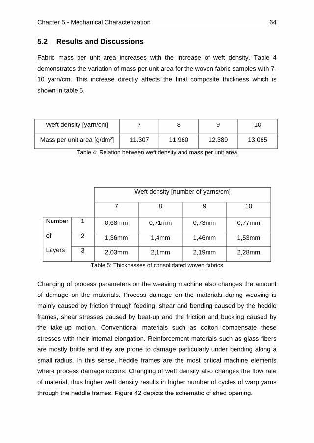
Chapter 5 - Mechanical Characterization 64
5.2 Results and Discussions
Fabric mass per unit area increases with the increase of weft density. Table 4
demonstrates the variation of mass per unit area for the woven fabric samples with 7-
10 yarn/cm. This increase directly affects the final composite thickness which is
shown in table 5.
Weft density [yarn/cm] 7 8 9 10
Mass per unit area [g/dm²] 11.307 11.960 12.389 13.065
Table 4: Relation between weft density and mass per unit area
Weft density [number of yarns/cm]
7 8 9 10
Number
of
Layers
1 0,68mm 0,71mm 0,73mm 0,77mm
2 1,36mm 1,4mm 1,46mm 1,53mm
3 2,03mm 2,1mm 2,19mm 2,28mm
Table 5: Thicknesses of consolidated woven fabrics
Changing of process parameters on the weaving machine also changes the amount
of damage on the materials. Process damage on the materials during weaving is
mainly caused by friction through feeding, shear and bending caused by the heddle
frames, shear stresses caused by beat-up and the friction and buckling caused by
the take-up motion. Conventional materials such as cotton compensate these
stresses with their internal elongation. Reinforcement materials such as glass fibers
are mostly brittle and they are prone to damage particularly under bending along a
small radius. In this sense, heddle frames are the most critical machine elements
where process damage occurs. Changing of weft density also changes the flow rate
of material, thus higher weft density results in higher number of cycles of warp yarns
through the heddle frames. Figure 42 depicts the schematic of shed opening.

Chapter 5 - Mechanical Characterization 65
Figure 42: Schematic of shed opening
The elongation of technical yarns is negligible, so the position change of eyelet from
point A to point B is compensated from the warp beam side. Any point on the warp
yarn must travel the distance ΔX through the eyelet of heddle frame. Weft density
determines the number of cycles, in which the warp yarn can pass through this
distance under buckling and shear stresses. ΔX can be calculated according to the
equation 31 where X is the distance between the woven fabric line and the horizontal
position of eyelet, and H is the distance between the horizontal position and the
maximum height of eyelet.
(31)
In every cycle of the weaving machine, warp yarns travel the distance TD which is
the inverse of weft density WD (equation 32).
(32)
In order to find the number of cycles NC for warp yarns to pass through the heddle
frames, the expression of ΔX is divided by the travel distance in one cycle TD which
gives:
(33)
B
A
O
ΔX
X
XH
Woven
Warp beam side

Chapter 5 - Mechanical Characterization 66
From equation 33, it can be seen that the number of cycles to pass through the
heddle frame is directly proportional to the weft density. Therefore it is expected to
have higher damage on the warp yarns processed with higher weft densities.
Figure 43 compares the breaking force of unprocessed reference GF/PP commingled
yarns and the processes steps after warp beam preparation and the woven fabric
manufacturing with different weft densities. As expected, the tendency of reduction in
breaking force can clearly be seen both on the weft and the warp yarns.
Figure 43: Change of yarn tensile strength after beaming and weaving
Woven fabric tensile test results are depicted in figure 44. The tendency of breaking
force reduction of fabrics in warp direction with increasing weft density is higher in
comparison with the tendency of individual yarns. The reason for this phenomenon is
that both warp yarn crimp and damage on the yarn increases with higher weft density.
In weft direction, breaking force increases with higher weft density simply due to the
increased number of yarns. Therefore the process damage cannot be seen directly
from the breaking force of the fabric.
0
10
20
30
40
50
60
70
80
Reference Warp beam 7 8 9 10
Bre
akin
g fo
rce
[N]
Weft density [number of yarns/cm]
WarpWeft

Chapter 5 - Mechanical Characterization 67
Figure 44: Tensile strength of woven fabrics with different weft densities
Compression molding causes extensive deformation of woven fabrics in the normal
direction. Depending on the process conditions and the fabric structure, the thickness
of the final composite is around 20% of the thickness of woven fabric. This
deformation in the normal direction results in the sinus form of warp yarns, which can
be seen in figure 45 for different weft densities. It can be clearly seen from the figure
that the increasing weft density also increases the lateral deformation. Thus the
period of sinus form in the sample with the weft density of 10 yarn/cm is shorter than
that of the sample with the weft density of 7 yarn/cm.
Figure 45: Composite surfaces with weft densities of 7 to 10 from left to right
0
1
2
3
4
5
6
7 8 9 10
Bre
akin
g fo
rce
[kN
]
Weft density [number of yarns/cm]
Warp
Weft
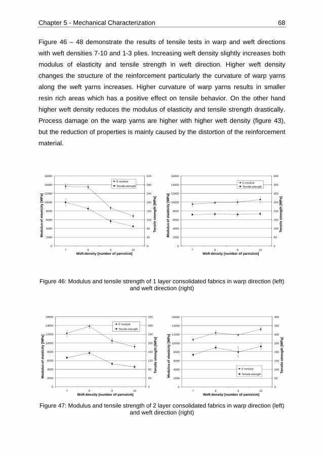
Chapter 5 - Mechanical Characterization 68
Figure 46 – 48 demonstrate the results of tensile tests in warp and weft directions
with weft densities 7-10 and 1-3 plies. Increasing weft density slightly increases both
modulus of elasticity and tensile strength in weft direction. Higher weft density
changes the structure of the reinforcement particularly the curvature of warp yarns
along the weft yarns increases. Higher curvature of warp yarns results in smaller
resin rich areas which has a positive effect on tensile behavior. On the other hand
higher weft density reduces the modulus of elasticity and tensile strength drastically.
Process damage on the warp yarns are higher with higher weft density (figure 43),
but the reduction of properties is mainly caused by the distortion of the reinforcement
material.
Figure 46: Modulus and tensile strength of 1 layer consolidated fabrics in warp direction (left) and weft direction (right)
Figure 47: Modulus and tensile strength of 2 layer consolidated fabrics in warp direction (left) and weft direction (right)
0
40
80
120
160
200
240
280
320
0
2000
4000
6000
8000
10000
12000
14000
16000
7 8 9 10
Tens
ile s
tren
gth
[MPa
]
Mod
ulus
of e
last
icity
[MPa
]
Weft density [number of yarns/cm]
E-module
Tensile strength
0
50
100
150
200
250
300
350
400
0
2000
4000
6000
8000
10000
12000
14000
16000
7 8 9 10
Tens
ile s
tren
gth
[MPa
]
Mod
ulus
of e
last
icity
[MPa
]
Weft density [number of yarns/cm]
E-moduleTensile strength
0
40
80
120
160
200
240
280
320
0
2000
4000
6000
8000
10000
12000
14000
16000
7 8 9 10
Tens
ile s
tren
gth
[MPa
]
Mod
ulus
of e
last
icity
[MPa
]
Weft density [number of yarns/cm]
E-module
Tensile strength
0
50
100
150
200
250
300
350
400
0
2000
4000
6000
8000
10000
12000
14000
16000
7 8 9 10
Tens
ile s
tren
gth
[MPa
]
Mod
ulus
of e
last
icity
[MPa
]
Weft density [number of yarns/cm]
E-module
Tensile strength

Chapter 5 - Mechanical Characterization 69
Figure 48: Modulus and tensile strength of 3 layer consolidated fabrics in warp direction (left) and weft direction (right)
Bending and impact tests were conducted with two and three layers consolidated
woven fabrics. One layer fabrics did not have the sufficient thickness. Flexural
strength increases with increasing weft density in the weft direction. However, flexural
strength reduces with increasing weft density in the warp direction (figure 49). Impact
strength is mostly affected by the thickness of the samples, therefore, increasing of
weft density and the number of plies increases the total impact energy (figure 50).
Figure 49: Flexural strength of 2 and 3 layer consolidated fabrics in warp and weft direction
0
40
80
120
160
200
240
280
320
0
2000
4000
6000
8000
10000
12000
14000
16000
7 8 9 10
Tens
ile s
tren
gth
[MPa
]
Mod
ulus
of e
last
icity
[MPa
]
Weft density [number of yarns/cm]
E-moduleTensile strength
0
50
100
150
200
250
300
350
400
0
2000
4000
6000
8000
10000
12000
14000
16000
7 8 9 10
Tens
ile s
tren
gth
[MPa
]
Mod
ulus
of e
last
icity
[MPa
]
Weft density [number of yarns/cm]
E-module
Tensile strength
0
50
100
150
200
250
300
7 8 9 10
Weft density [number of yarns/cm]
Flex
ural
str
engt
h [M
Pa]
Weft 2 layerWarp 2 layerWeft 3 layerwarp 3 layer

Chapter 5 - Mechanical Characterization 70
Figure 50: Impact strength of 2 and 3 layer consolidated fabrics in warp and weft direction
5.3 Conclusion
Woven fabrics with commingled yarns are subject to extensive deformation in the
out-of plane direction when manufactured by hot press molding. Higher weft density
increases the final composite thickness, however, it also increases the crimp of warp
yarns, thus reduces the in-plane mechanical properties. Increasing weft density
increased the damage both on weft and warp yarns. Single, double and triple layers
of separate woven fabrics were pressed and consolidated with four different weft
densities. In warp direction, significant decrease of modulus and strength was
observed mainly due to the increasing crimp of internal structure. In weft direction, a
slight increase of modulus and strength with increasing weft density was observed
which was caused by the compact reinforcement structure and the reduced resin rich
areas
According to these results, higher crimp which was caused by higher weft density
reduces the tensile properties significantly. Therefore, the yarn crimp should be
avoided inside the woven structure. It is advantageous for tensile properties to adjust
the component thickness by multiple layers of woven fabrics with lower weft density
instead of using fewer layers of woven fabrics with higher weft density.
0
0,5
1
1,5
2
2,5
3
3,5
4
4,5
5
7 8 9 10
Weft density [number of yarns per cm]
Ener
gy [J
]
weft 2 layerwarp 2 layerweft 3 layerwarp 3 layer

Chapter 6 - Principals of Spacer Fabric Production 71
Chapter 6 - Principals of Spacer Fabric Production
According to the mentioned frame under state of the art, development of woven
sandwich perform structures are necessary to extend the use of thermoplastic matrix
composites in demanding structural applications. As for every technology aiming a
wide spread application, cost is an important aspect which should be considered from
the very beginning of the development. Proper use of automation can both increase
the product quality as well as decrease the production costs significantly.
6.1 Terry Weaving Technology
Novel woven sandwich preforms should have two outer woven layers which are
connected also with woven layers. This is necessitated in order to use commingled
yarns in the structure and consolidate the thermoplastic matrix easily. Main difficulty
in producing such woven sandwich preforms is how to create woven structures of
crosslinks which lay normal to the fabric plane. The terry weaving technology, which
is used for terry towel production, proves suitable as the basis.
Figure 51 demonstrates the production principle of the terry weaving in four steps:
- Step I: Weaving starts with a regular base fabric “B” of any kind. In the figure
take-up direction “T” is shown with a solid arrow from right to the left near the
base fabric. Additional temporary take-up of terry weaving mechanism “TW” is
also shown with a dotted solid arrow. This mechanism is explained under step
III. Care should be taken that the “TW” and “T” act together and
simultaneously. Beat-up motion of the reed “R” is shown with a solid and a
transparent reed element.
- Step II: When the required position of the stiffener fabric “S” is reached, the
warp yarns of the base fabric “B” is divided into two groups. One of the warp
yarn groups continue to weave with the inserted weft yarns and create the
stiffener fabric “S”. The other warp yarn group however does not connect with
the weft yarns and create a yarn floating “F” under the stiffener fabric. An

Chapter 6 - Principals of Spacer Fabric Production 72
important aspect is that the stiffener layer is not necessarily always on the top.
The positions of stiffener “S” and floating “F” structures are interchangeable.
- Step III: After the double length of the required stiffener height is woven, the
floating yarns and the stiffener fabric are woven together as one layer over a
couple of connecting weft yarns “C”. In this moment the fabric is still flat and
the weaving machine necessitates two additional mechanisms to remove the
floating yarns out of the structure back to the warp beam direction. First
mechanism moves the fabric back to the shed, which is called terry weaving
mechanism. Terry weaving mechanism is an additional take-up device which
stores exactly the same length of the floating warp yarns “F” step by step.
After completing the stiffener “S” and the connection section “C”, the
additionally stored length is suddenly moved back to the shed. This sudden
motion is demonstrated with a longer dotted arrow “TW” from left to the right.
Second mechanism pulls back the now loose floating yarns and give them
again tension. Beat-up moves the connection section “C” to the base fabric “B”.
Stiffener fabric “S” pleats into itself and creates a double layer woven structure
normal to the base fabric plane. During this movement, heddle frames cross
each other and increase the tension of warp yarns as well as the friction
between the warp and weft yarns in the fabric, which keeps the closed
stiffener in its position. There is a critical level of friction between the warp
yarns and weft yarns of the connection section “C”. If the friction is too low, the
stiffener will be created however it will open up after the reed goes back to its
dwelling position. On the other hand if the friction is too high, the beat-up
motion of the reed will not be able to move the connection section “C” to the
base fabric “B”. This will also lead to an uncompleted closure of the stiffener,
which is characterized by a triangular stiffener and remaining floating yarns.
- Step IV: Base fabric production continues as in Step I. As the warp yarn
consumption of the stiffener part and the floating part are not the same, at
least two warp beams are necessary to feed the yarns of the stiffener and
floating parts.

Chapter 6 - Principals of Spacer Fabric Production 73
I
II
III
IV
Figure 51: Production principle of terry weaving from side view, B: base fabric, R: reed, S: stiffener fabric, F: floating warp yarns, C: connection between stiffener and floating yarns
The question arises what would be the limitations of structures which can be created
by this method. The height of the stiffener is first of all determined by the stroke of the
terry weaving mechanism and pull-back mechanisms. For the continuous production,
also the length between the fabric creation line and the dwelling position of reed
should be considered. This means after moving the still flat stiffener and the floating
into the shed as in the step III of figure 51, there should not be a jam and the fabric
should in maximum barely touch the reed. If a short production stop can be tolerated,
the defined structures can be produced on any weaving machine by turning the take-
up and warp beam backwards manually. In this case the fabric can be gradually
B
R
T
TW
T
TW
S FTW
T
C
T
TW
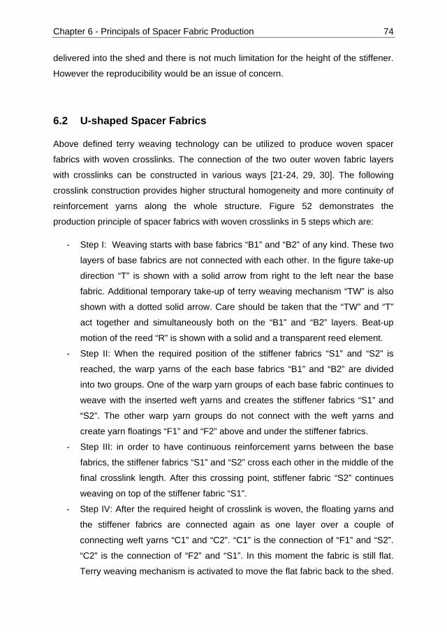
Chapter 6 - Principals of Spacer Fabric Production 74
delivered into the shed and there is not much limitation for the height of the stiffener.
However the reproducibility would be an issue of concern.
6.2 U-shaped Spacer Fabrics
Above defined terry weaving technology can be utilized to produce woven spacer
fabrics with woven crosslinks. The connection of the two outer woven fabric layers
with crosslinks can be constructed in various ways [21-24, 29, 30]. The following
crosslink construction provides higher structural homogeneity and more continuity of
reinforcement yarns along the whole structure. Figure 52 demonstrates the
production principle of spacer fabrics with woven crosslinks in 5 steps which are:
- Step I: Weaving starts with base fabrics “B1” and “B2” of any kind. These two
layers of base fabrics are not connected with each other. In the figure take-up
direction “T” is shown with a solid arrow from right to the left near the base
fabric. Additional temporary take-up of terry weaving mechanism “TW” is also
shown with a dotted solid arrow. Care should be taken that the “TW” and “T”
act together and simultaneously both on the “B1” and “B2” layers. Beat-up
motion of the reed “R” is shown with a solid and a transparent reed element.
- Step II: When the required position of the stiffener fabrics “S1” and “S2” is
reached, the warp yarns of the each base fabrics “B1” and “B2” are divided
into two groups. One of the warp yarn groups of each base fabric continues to
weave with the inserted weft yarns and creates the stiffener fabrics “S1” and
“S2”. The other warp yarn groups do not connect with the weft yarns and
create yarn floatings “F1” and “F2” above and under the stiffener fabrics.
- Step III: in order to have continuous reinforcement yarns between the base
fabrics, the stiffener fabrics “S1” and “S2” cross each other in the middle of the
final crosslink length. After this crossing point, stiffener fabric “S2” continues
weaving on top of the stiffener fabric “S1”.
- Step IV: After the required height of crosslink is woven, the floating yarns and
the stiffener fabrics are connected again as one layer over a couple of
connecting weft yarns “C1” and “C2”. “C1” is the connection of “F1” and “S2”.
“C2” is the connection of “F2” and “S1”. In this moment the fabric is still flat.
Terry weaving mechanism is activated to move the flat fabric back to the shed.

Chapter 6 - Principals of Spacer Fabric Production 75
This sudden motion is demonstrated with a longer dotted arrow “TW” from left
to the right. The pull-back mechanism removes the floating yarns “F1” and
“F2”. Beat-up moves the connection sections “C1” and “C2” to the base fabrics
“B1” and “B2”. Stiffener fabrics “S1” and “S2” are closed during beat-up and a
double layer woven crosslink is created between two woven base fabric layers
“B1” and “B2”. During this movement, heddle frames cross each other and
increase the tension of warp yarns as well as the friction between the warp
and weft yarns in the fabric, which keeps the closed stiffener in its position.
- Step V: Weaving continues as defined in the step I. Stiffness of the crosslink
between two base fabric layers is not enough to keep its vertical structure, so
it will be bent between two base fabric layers.
I
II
III
IV
B1
T
TW
F2 S2
T
TW
C1 TW
T
C2
S1
R B2
F1 T
TW

Chapter 6 - Principals of Spacer Fabric Production 76
V
Figure 52: Production principle of U-shaped spacer fabrics, B: base fabric, R: reed, S: stiffener fabric, F: floating warp yarns, C: connection between stiffener and floating yarns
Figure 53 demonstrates the detailed view of the crossing point of crosslinks. There
are no connections between the warp yarns coming from the top fabric and the warp
yarns coming from the bottom fabric. This kind of weave is advantageous to reduce
the joint effect at the crossing point.
Figure 53: Crosssectional view of the crosslink side change
Figure 54 depicts a weave model of U-shaped spacer fabrics with plain weave along
the base and stiffener parts. Different colors represent different yarn systems and it
can be obviously seen that the reinforcement is continuous along the structure.
T
TW
weft yarn
warp yarn weaving from
bottom to top warp yarn weaving from
top to bottom

Chapter 6 - Principals of Spacer Fabric Production 77
Figure 54: CAD model of a U-shaped spacer fabric
Connections of the crosslink and the base fabrics are critical points concerning the
local stresses. In order to round the edges in these connection areas, the weaving
structure should be further improved. According to the weaving principle defined in
figure 52, woven crosslinks can be produced however they would have sharp edges.
To avoid this potential problem, a “rounding weft yarn” is integrated into the very
beginning of the floating parts. This means that the floating parts “F1” and “F2” do not
begin directly floating after the separation point, but they start with a woven part
containing only one weft yarn. The effect of the rounding weft yarn is depicted in
figure 55.
Figure 55: Effect of rounding weft yarn
floating warp
base fabric
weft
warp
Rounding weft
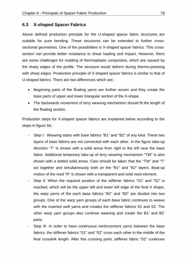
Chapter 6 - Principals of Spacer Fabric Production 78
6.3 X-shaped Spacer Fabrics
Above defined production principle for the U-shaped spacer fabric structures are
suitable for pure bending. These structures can be extended to further cross-
sectional geometries. One of the possibilities is X-shaped spacer fabrics. This cross-
section can provide better resistance to shear loading and impact. However, there
are some challenges for molding of thermoplastic composites, which are caused by
the sharp edges of the profile. The structure would deform during thermo-pressing
with sharp edges. Production principle of X-shaped spacer fabrics is similar to that of
U-shaped fabrics. There are two differences which are;
• Beginning parts of the floating yarns are further woven and they create the
base parts of upper and lower triangular section of the X-shape.
• The backwards movement of terry weaving mechanism should fit the length of
the floating section.
Production steps for X-shaped spacer fabrics are explained below according to the
steps in figure 56:
- Step I: Weaving starts with base fabrics “B1” and “B2” of any kind. These two
layers of base fabrics are not connected with each other. In the figure take-up
direction “T” is shown with a solid arrow from right to the left near the base
fabric. Additional temporary take-up of terry weaving mechanism “TW” is also
shown with a dotted solid arrow. Care should be taken that the “TW” and “T”
act together and simultaneously both on the “B1” and “B2” layers. Beat-up
motion of the reed “R” is shown with a transparent and solid reed element.
- Step II: When the required position of the stiffener fabrics “S1” and “S2” is
reached, which will be the upper left and lower left edge of the final X shape,
the warp yarns of the each base fabrics “B1” and “B2” are divided into two
groups. One of the warp yarn groups of each base fabric continues to weave
with the inserted weft yarns and creates the stiffener fabrics S1 and S2. The
other warp yarn groups also continue weaving and create the B1’ and B2’
parts.
- Step III: In order to have continuous reinforcement yarns between the base
fabrics, the stiffener fabrics “S1” and “S2” cross each other in the middle of the
final crosslink length. After this crossing point, stiffener fabric “S2” continues

Chapter 6 - Principals of Spacer Fabric Production 79
weaving on top of the stiffener fabric “S1”. After weaving of B1’ and B2’, their
warp yarns start floating without any connection with weft yarns as shown in
the figure with “F1” and “F2”. Depending on the required dimensions of B1’, B2’
and “S1”, “S2”, crossing of the “S1” and “S2” can take place before or after the
B1’ and B2’ parts start floating.
- Step IV: After the required dimension of crosslink is woven, the floating yarns
and the stiffener fabrics are connected again as one layer over a couple of
connecting weft yarns “C1” and “C2”. In this moment the fabric is still flat. “C1”
is the connection of “F1” and “S2”. “C2” is the connection of “F2” and “S1”.
Terry weaving mechanism is activated to move the flat fabric back to the shed.
This sudden motion is demonstrated with a longer dotted arrow “TW” from left
to the right. The pull-back mechanism removes the floating yarns “F1” and
“F2”. Beat-up moves the connection sections “C1” and “C2” to the base fabrics
B1’ and B2’. Stiffener fabrics “S1” and “S2” are closed during beat-up and an
X-shape woven crosslink is created between two woven base fabric layers “B1”
and “B2”. During this movement, heddle frames cross each other and increase
the tension of warp yarns as well as the friction between the warp and weft
yarns in the fabric, which keeps the closed stiffener in its position.
- Step V: Weaving continues as defined in the step I. Stiffness of the crosslink
between two base fabric layers is not enough to keep its vertical structure, so
it will be bent between two base fabric layers.
I
II
R B2
B1’ T
TW
B1 T
TW
S1
B2’ S2

Chapter 6 - Principals of Spacer Fabric Production 80
III
IV
V
Figure 56: Production principle of X-shaped spacer fabrics, B: base fabric, R: reed, S:
stiffener fabric, F: floating warp yarns, C: connection between stiffener and floating yarns
6.4 V-shaped Spacer Fabrics
Another basic possibility of cross-sectional profile is the V-shape. In this type, two
base layers are connected with upwards and downwards moving diagonal crosslinks
[29, 30]. This creates triangular crosslinks, which would be more stable under shear
loading compared with U-shaped profiles. However, V-shaped molding for
thermoplastic composites has same difficulties as X-shape, which are caused by the
sharp edges.
Production steps for V-shaped spacer fabrics are explained below, based on the
steps in figure 57:
- Step I: Weaving starts with base fabrics “B1”, “B2” and the stiffener fabric “S”
of any kind between base fabrics. These two layers of base fabrics are not
connected with each other. In the figure take-up direction “T” is shown with a
solid arrow from right to the left near the base fabric. Additional temporary
take-up of terry weaving mechanism “TW” is also shown with a dotted solid
arrow. Care should be taken that the “TW” and “T” act together and
T
TW F1
C1 TW
T
F2
C2
T
TW

Chapter 6 - Principals of Spacer Fabric Production 81
simultaneously both on the “B1” and “B2” layers. Beat-up motion of the reed
“R” is shown with a transparent and solid reed element.
- Step II: When the required position of the connection point between “B1” and
“S” is reached, the warp yarns of the base fabrics “B1” and “B2” start floating
without any weft insertion. After this point, only stiffener part continues
weaving with weft insertion.
- Step III: After the required dimension of crosslink is woven, the floating yarns
of “F1” are connected with the stiffener fabric “S” over couple of weft yarns. In
this moment the fabric is still flat. “C” is the connection of “F1” and “S”. To
keep the same length between upper and lower parts of the preform, lower
base fabric “B2” also weaves the same length of “C” before activation of terry
weaving. Afterwards terry weaving mechanism is activated to move the flat
fabric back to the shed. This sudden motion is demonstrated with a longer
dotted arrow “TW” from left to the right. The pull-back mechanism removes the
floating yarns “F1” and “F2”. Beat-up moves the connection section “C” and
the small part of “B2”. Stiffener fabric “S” is closed during beat-up and one side
of the final triangular profile is created between two woven base fabric layers
“B1” and “B2”. During this movement, heddle frames cross each other and
increase the tension of warp yarns as well as the friction between the warp
and weft yarns in the fabric, which keeps the closed stiffener in its position.
- Step IV: Weaving continues as defined in the step I. Stiffness of the crosslink
between two base fabric layers is not enough to keep its vertical structure, so
it will be bent between two base fabric layers. This time step II and III are
necessary to connect the stiffener layer “S” with the lower base fabric “B2”.

Chapter 6 - Principals of Spacer Fabric Production 82
I
II
III
IV
Figure 57: Production principle of V-shaped spacer fabrics, B: base fabric, R: reed, S: stiffener fabric, F: floating warp yarns, C: connection between stiffener and floating yarns
Sandwich composite materials with continuous reinforcement along the structure can
be produced with the above described principles. Three basic connection types of
crosslinks are called U-, V- and X-shape spacer fabrics. Schematic components with
these kinds of crosslinks are demonstrated in figure 58.
R B2
F1 T
TW
B1 T
TW
F2
T
TW
TW
T
C
S
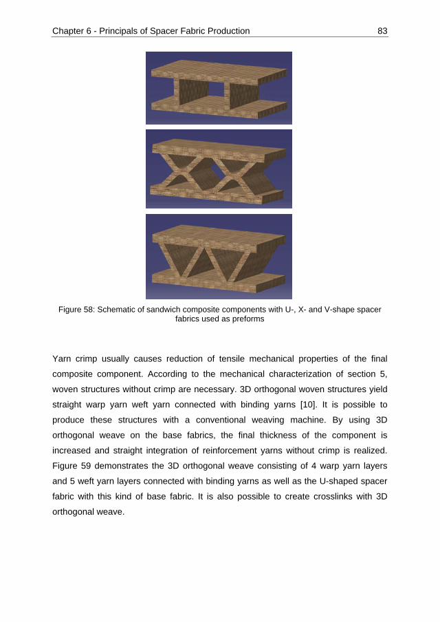
Chapter 6 - Principals of Spacer Fabric Production 83
Figure 58: Schematic of sandwich composite components with U-, X- and V-shape spacer
fabrics used as preforms
Yarn crimp usually causes reduction of tensile mechanical properties of the final
composite component. According to the mechanical characterization of section 5,
woven structures without crimp are necessary. 3D orthogonal woven structures yield
straight warp yarn weft yarn connected with binding yarns [10]. It is possible to
produce these structures with a conventional weaving machine. By using 3D
orthogonal weave on the base fabrics, the final thickness of the component is
increased and straight integration of reinforcement yarns without crimp is realized.
Figure 59 demonstrates the 3D orthogonal weave consisting of 4 warp yarn layers
and 5 weft yarn layers connected with binding yarns as well as the U-shaped spacer
fabric with this kind of base fabric. It is also possible to create crosslinks with 3D
orthogonal weave.

Chapter 6 - Principals of Spacer Fabric Production 84
Figure 59: CAD model of orthogonal 3D spacer fabrics (left) and the layer structure of orthogonal 3D woven fabric (right)

Chapter 7 - Production Principals of Complex Spacer Structures and Stiffeners 85
Chapter 7 - Production Principals of Complex Spacer
Structures and Stiffeners
In the preceding section, production principles of three fundamental woven
connection types (U, X, V) for spacer preforms are described. Another possibility is
the use of well-known 3D orthogonal weaves both in the base and stiffener parts.
The development of production technology for these basic spacer fabric types with
woven crosslinks leads to further implications as well. First of all, heights of the U-, X-
and V-shape crosslinks can be varied throughout the structure. Unlike the
descriptions above which start with a double or triple layer fabric in Step I, it is
possible to start weaving of spacer fabrics from a single layer. Gradually starting
single layer can be divided into two separate layers and the whole structure can be
woven with increasing and decreasing dimensions of crosslinks. By this method,
aerodynamic structures can be produced as shown in figure 60. Lengths of the two
base fabrics (upper and lower parts) should be symmetric along the middle axis.
Additional take-up devices are necessary to create asymmetric sandwich profiles.
Figure 60: Structures with variable heights of the U-, X- and V-shape crosslinks

Chapter 7 - Production Principals of Complex Spacer Structures and Stiffeners 86
7.1 Variations of X-shaped Spacer Fabrics
Crossing point of the stiffener parts within the preceding explanations of U- and X-
shaped spacer fabrics are exactly in the middle of the final length. Another possibility
is to create an asymmetrical crossing point for these structures. Asymmetrical
crossing point for U-shaped spacer fabrics would leave either remaining floating
yarns or generate a kind of pocket with the longer side of the crosslink. On the other
hand, asymmetrical crosslinks for X-shaped spacer fabrics offers the possibility of
immediately changing the height of spacer fabrics. Figure 61 demonstrates the
change of height by using asymmetric X-shaped crosslinks. According to triangle
inequality, the length of part A should be shorter than the sum of the parts B and C.
In the limiting condition; length of part A is equal to the sum of part B and C, the
triangle disappears and a rectangular chamber with a higher height can be produced,
which is also demonstrated in figure 61.
Figure 61: Spacer fabrics with asymmetric X-shaped crosslinks; gradual change of height (top) and immediate change of height (bottom)
Another variation of the X-shape spacer fabrics is shown in figure 62. After the
stiffener parts comes together at the crossing point to change their position, two
layers of stiffener fabrics can be woven as one layer for a while. This method enables
the production of double chamber crosslinks.
A
C B

Chapter 7 - Production Principals of Complex Spacer Structures and Stiffeners 87
Figure 62: Variation of X-shape spacer fabrics to produce double chamber crosslinks, before pull-back (left) and after pull-back (right)
7.2 Preforms for Panels with Integrated Stiffeners
In order to manufacture preforms with integrated stiffeners and structural continuity in
one step, terry weaving technique is utilized. Terry weaving is mostly used for
weaving of towels with pile yarns standing out-of-plane. Same technique can be used
to produce pleats in the normal direction to the main woven surface. Two additional
mechanisms are necessary for terry weaving which are temporary storage
mechanism and warp yarn pull-back mechanism. At the beginning point of stiffener,
warp yarns are divided into two systems, one of them continues weaving while the
second system floats without any connection to inserted weft yarns (figure 63 dotted
lines). The warp yarns, which are producing the stiffeners and the warp yarns for
floating should be fed from separate warp beams. After completing the required
stiffener dimensions, two separated warp yarn systems are connected along 2 or 3
weft insertions. Then, temporary storage mechanism moves the fabric immediately
backwards in the opposite direction of fabric production while yarn pull-back
mechanism removes the floating warp yarns back to the warp beam direction. Beat-
up with reed closes the structure and gives its final 3D shape. Increased friction after
beat-up and heddle frame crossing avoids the opening of the structure. This
technique can be applied continuously with conventional production speed of
weaving machines.

Chapter 7 - Production Principals of Complex Spacer Structures and Stiffeners 88
Figure 63: Weaving technique of symmetric and asymmetric stiffener structures; before and
after beat-up
The dotted lines in figure 63 represent the floating warp yarns which are pulled back
during continuous production. The position of the pulled-back warp yarns are
demonstrated with a black dot in the final 3D shape. These dots only show the
position of closing, in the actual final structure there is no discontinuity. Figure 64
demonstrates the basic symmetric and asymmetric stiffener structures which can be
produced with the same terry weaving system.
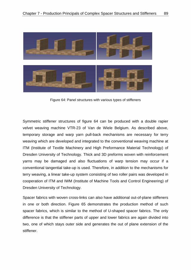
Chapter 7 - Production Principals of Complex Spacer Structures and Stiffeners 89
Figure 64: Panel structures with various types of stiffeners
Symmetric stiffener structures of figure 64 can be produced with a double rapier
velvet weaving machine VTR-23 of Van de Wiele Belgium. As described above,
temporary storage and warp yarn pull-back mechanisms are necessary for terry
weaving which are developed and integrated to the conventional weaving machine at
ITM (Institute of Textile Machinery and High Preformance Material Technology) of
Dresden University of Technology. Thick and 3D preforms woven with reinforcement
yarns may be damaged and also fluctuations of warp tension may occur if a
conventional tangential take-up is used. Therefore, in addition to the mechanisms for
terry weaving, a linear take-up system consisting of two roller pairs was developed in
cooperation of ITM and IWM (Institute of Machine Tools and Control Engineering) of
Dresden University of Technology.
Spacer fabrics with woven cross-links can also have additional out-of-plane stiffeners
in one or both direction. Figure 65 demonstrates the production method of such
spacer fabrics, which is similar to the method of U-shaped spacer fabrics. The only
difference is that the stiffener parts of upper and lower fabrics are again divided into
two, one of which stays outer side and generates the out of plane extension of the
stiffener.

Chapter 7 - Production Principals of Complex Spacer Structures and Stiffeners 90
Figure 65: Spacer fabrics with woven cross-links and integrated out of plane stiffeners
If on the weaving machine more than one warp yarn pull-back mechanism is utilized,
the stiffener structures can be branched, namely stiffeners can also be freely
positioned on other stiffeners as well as base fabric. Figure 66 demonstrates the
production steps of multiple stiffeners. Production steps for multiple stiffeners are:
- Step I: Weaving starts with a regular base fabric “B” of any kind. In the figure
take-up direction “T” is shown with a solid arrow from right to the left near the
base fabric. Additional temporary take-up of terry weaving mechanism “TW” is
also shown with a dotted solid arrow. Care should be taken that the “TW” and
“T” act together and simultaneously. Beat-up motion of the reed “R” is shown
with a transparent and solid reed element.
- Step II: When the required position of the stiffener fabric “S1” is reached, the
warp yarns of the base fabric “B” is divided into two groups. One of the warp
yarn groups continue to weave with the inserted weft yarns and create the
stiffener fabric “S1”. The other warp yarn group however does not connect with
the weft yarns and create a yarn floating “F1” under the stiffener fabric. An
important aspect is that the stiffener layer is not necessarily always on the top.
The positions of stiffener “S” and floating “F” structures are interchangeable.
- Step III: After reaching the position of the secondary stiffener, which will be on
top of the primary stiffener, the warp yarns of the primary stiffener layer “S1”
are again divided into two groups. One of these groups continues weaving to
create the secondary stiffener “S2”, and the other group of warp yarns starts
floating as “F2”.
Chapter 7 - Production Principals of Complex Spacer Structures and Stiffeners 91
- Step IV: When the required length of the secondary stiffener “S2” is completed,
the warp yarns of “S2” and the floating warp yarns of “F2” are connected over
a couple of weft yarns. This connecting area for the stiffener is shown as “C2”
in the figure. In this moment, the terry weaving mechanism moves the flat
fabric back to shed and the pull back mechanism controlling the warp yarns of
“F2” removes the remaining length of the yarns. Beat-up of the reed “R”
pushes the connecting point “C2” back to the beginning of “S2” and the
secondary stiffener “S2” is constructed.
- Step V: After completing the secondary stiffener “S2”, weaving process
continues in the same way as described in step II. In this step, weaving of the
stiffener part “S1” and the floating yarns “F1” still continue.
- Step VI: When the final length of stiffener “S1” is reached, the floating yarns
“F1” and the stiffener part “S1” are connected over a couple of weft yarns. This
connecting area is demonstrated with “C1”. The terry weaving mechanism
moves the flat fabric back to shed and the pull back mechanism controlling the
warp yarns of “F1” removes the remaining length of the yarns. Care should be
taken that only one terry weaving mechanism is sufficient to move the fabric
back to the shed. The warp yarn pull-back mechanisms of step IV and VI
should be different, because the yarn consumption of “F1” and “F2” are
different. Therefore warp yarns of “F1” and “F2” should be fed from different
warp beams. Beat-up of the reed “R” pushes the connecting point “C1” back to
the beginning of “S1” and the secondary stiffener “S1” is constructed.
- Step VII: Now there is one primary stiffener “S1” positioned on the base fabric
and one secondary stiffener “S2” positioned on the secondary stiffener “S1”.
Weaving continues with any woven structure of base fabric.
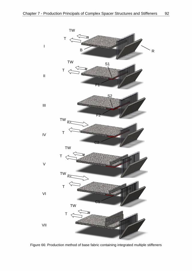
Chapter 7 - Production Principals of Complex Spacer Structures and Stiffeners 92
I
II
III
IV
V
VI
VII
Figure 66: Production method of base fabric containing integrated multiple stiffeners
R
S1 T
TW
F1
T
TW
TW
T
F2
B
T
TW
S2
C2
C1
TW
T
T
TW

Chapter 7 - Production Principals of Complex Spacer Structures and Stiffeners 93
Figure 66 deals with the simplest type of multiple stiffeners. This technique can be
applied to create many different cross-sections. It should be noted that the stiffeners
consist of two plied layers, therefore they can be flat as shown in figure 66, but they
can also be freely formed into any cross-section with the same circumference. Figure
67 depicts some of the possible multiple stiffener structures. In this figure, I and II are
actually the same structures where I uses flat stiffener layers and II demonstrates the
free forming of secondary stiffeners “S2” and “S3” into circles. Figure 67-III shows
three levels of stiffeners which necessitates three separate warp yarn pull-back
mechanism. Figure 67-IV demonstrates the possibility of symmetric structures with
two levels of stiffeners.
Figure 67: Examples of possible preforms with multiple stiffeners, B: base fabric, S1: primary stiffener, S2-S5: further stiffener layers
B
S2 S3
S1 B
S2 S3
S1
B
S2
S3
S1
B
S2 S3
S1
S4 S5
I II
III IV

Chapter 8 - Modifications and Realization of Spacer Fabric Weaving Technology 94
Chapter 8 - Modifications and Realization of Spacer Fabric
Weaving Technology
The explained concept of spacer weaving in the preceding section requires the
integration of a terry weaving mechanism as well as a warp thread pull back
mechanism for the weaving machine. Both additional mechanisms must be
synchronized. Figure 68 illustrates the conception of the technology with a modified
double rapier face-to-face weaving machine. Terry weaving mechanism works as a
temporary storage in the vertical direction. Warp thread pull-back mechanism is
responsible for the reverse movement of the floating yarns to close the woven
crosslinks between two outer layers. All the other elements defined in the figure are
standard elements of a conventional double rapier face-to-face weaving machine.
Figure 68: Technological concept of spacer fabric production with terry weaving [61]
8.1 Terry Weaving Mechanism
The terry weaving mechanism consists of two subsystems: The warp yarn pull-back
system and the fabric storage system. The warp yarn pull-back is carried out from the
back rest roller with an additional pneumatic drive (figure 69). There are two functions
integrated into the warp yarn pull-back system. One of them is the tensioning of the

Chapter 8 - Modifications and Realization of Spacer Fabric Weaving Technology 95
warp yarns by pulling the arm in the vertical direction. The second function is to
clamp the arm horizontally to keep the warp yarn tension and positions constant. The
second function is necessary because during the closing of the cross-links by beat-up,
the tension of warp yarns alone is not sufficient. Without clamping of the arm, floating
yarns move together with the reed and the cross-link is not fully created.
Figure 69: Warp yarn pull-back mechanism
Temporary fabric storage system is the main part of terry weaving mechanism and
acts in synchronization with the pull-back system (figure 70). Fabric storage system
has two stationary cylinders which are guiding the fabric out of the shed and one
driven cylinder which is temporarily storing a defined fabric length. In every revolution
of the machine, a defined length of fabric is stored through the upwards movement of
the red colored cylinder in Figure 70 left. After completing the required predetermined
length, the warp thread pull-back system puts extra tension on the warp yarns and
the fabric storage instantaneously moves the fabric into the shed (counter-take-up
direction). This technique closes the yarn floatings and continuously creates a woven
crosslink connection normal to the weaving direction without any manual work.

Chapte
Fig
8.2
A take-
fabric w
adjusta
force m
forces
force to
in figur
woven
-
g
d
- w
d
- d
Therefo
longitud
develop
er 8 - Modif
gure 70: Ter
Linear T
-up motion
with a de
able in ord
must be in
in the shed
o the wove
re 71. This
crosslinks
buckling o
glass fiber
decisively
warp tensi
differential
deformatio
next steps
ore the 3D
dinal direc
ped in coo
fications a
rry weaving
ake-up S
n is require
efined velo
der to gen
equilibrium
d-zone. Us
en fabrics.
s technolog
such as:
of outer lay
r damage b
degradatio
on variatio
l take-up v
on of flexib
of the pro
D spacer
ction. A s
operation o
nd Realiza
g mechanism
System w
ed for every
ocity out o
erate the
m with the
sually tang
The fabric
gy has som
yers and c
by using c
on of the m
ons and red
elocity of t
ble fabrics
ocess chain
fabrics sh
special tak
of ITM and
ation of Spa
m, CAD con
with Cutt
y weaving
of the we
required w
holdback t
gential take
cs are wou
me disadva
crosslinks
conventiona
mechanical
duction of
the inner a
s; a proble
n
ould be re
ke-up devi
d IWM at D
acer Fabric
ncept (left) a
ting and
process w
aving zon
weft densi
torque of w
e-up rolls t
und around
antages re
in the spa
al tangenti
properties
reproducib
nd the oute
em for the
emoved w
ce with h
Dresden Un
c Weaving
and applica
Laying M
which remo
e. The ve
ty. In add
warp beam
ransmit the
d the take-
egarding sp
acer; hereb
ial take-up
s of compo
bility cause
er layer
handling
with a linea
high level
niversity o
g Technolo
tion (right) [
Mechanis
oves the pr
elocity sho
dition, the
s and with
e velocity
up rolls as
pacer fabr
by exists a
p system a
osites
ed by the d
operations
ar take-up
of automa
f Technolo
ogy 96
[24]
sm
roduced
ould be
take-up
h friction
and the
s shown
rics with
a risk of
nd thus
different
s in the
p in the
ation is
ogy [61-

Chapter 8 - Modifications and Realization of Spacer Fabric Weaving Technology 97
63]. This device enables the transmission of take-up forces without buckling and
damage of the preform. Slack spacer preforms are quasi solidified with the insertion
of supporting bars. The linear take-up motion system is characterized by some
straight line arranged roll-pairs. Within every roll-pair one roll can be engaged to the
other roll with a defined contact force. In front of the linear take-up motion system a
gripper inserts supporting bars in the hollow space of the woven fabrics, a second
gripper takes out the bars from the fabrics at the back side of the take-up motion
system. Each roller has a servo direct drive. The first roll-pair behind the rapier
weaving machine is in closed-loop angle control and with adjustable transmission
ratio synchronous to the main shaft of the weaving machine. The transmission ratio is
a linear function of the desired weft density in spacer fabric. This results in defined
geometry of the woven fabric. The next pair is in closed-loop torque control. The
reference values for the torques are precalculated from the average take-up forces.
So, the take-up forces are equally partitioned between the roll-pairs.
Figure 71: Schematic of conventional and new linear take-up concepts (left) and application of linear take-up [61, 62]
Figure 72 depicts the cutting and laying mechanism integrated at the exit of the take-
up system. Necessary numbers of spacer fabric chambers are entered into the
controlling unit of the take-up. Numbers of chambers are counted by an inductive
counter which determines the final preform length. In the beginning and final
chamber of a preform part, supporting bars are not removed. The preform parts are
cut between the final chamber of the preceding preform part and the beginning
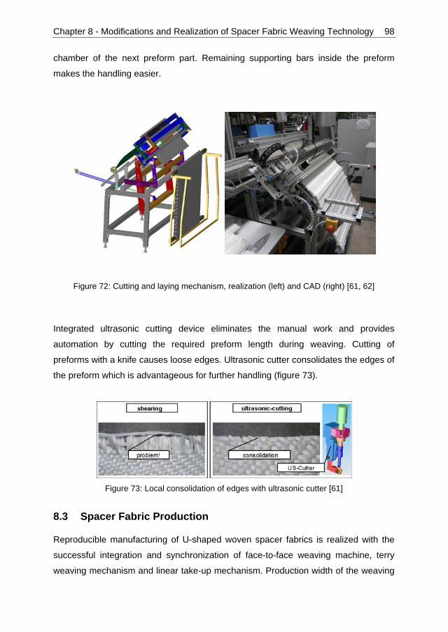
Chapter 8 - Modifications and Realization of Spacer Fabric Weaving Technology 98
chamber of the next preform part. Remaining supporting bars inside the preform
makes the handling easier.
Figure 72: Cutting and laying mechanism, realization (left) and CAD (right) [61, 62]
Integrated ultrasonic cutting device eliminates the manual work and provides
automation by cutting the required preform length during weaving. Cutting of
preforms with a knife causes loose edges. Ultrasonic cutter consolidates the edges of
the preform which is advantageous for further handling (figure 73).
Figure 73: Local consolidation of edges with ultrasonic cutter [61]
8.3 Spacer Fabric Production
Reproducible manufacturing of U-shaped woven spacer fabrics is realized with the
successful integration and synchronization of face-to-face weaving machine, terry
weaving mechanism and linear take-up mechanism. Production width of the weaving

Chapte
machin
weavin
enough
betwee
Figure 7
Figure
consoli
machin
spacer
mm x 2
Mecha
Figure
er 8 - Modif
ne is one m
g zone du
h to keep
en two oute
74: Spacer
75 depict
dated ther
ne (COLLI
preforms
230 mm wi
nics at Dre
e 75: U-shap
fications a
meter. Figu
uring prod
the distan
er layers.
fabric prod
ts the dev
rmoplastic
N P300 P
into sandw
ith 30 mm
esden Univ
ped spacer p
nd Realiza
ure 74 dem
uction of
ce therefo
uction: Dim
velopment
matrix san
PV, Dr. Co
wich comp
height. Sp
versity of T
fabric frompreform (mi
ation of Spa
monstrates
spacer fab
ore after th
mensions (le
steps of
ndwich co
ollin GmbH
posite part
pecial tools
Technology
concept toddle), comp
acer Fabric
s the dime
brics. Wov
he cross-lin
eft) and clos
spacer fa
mposite. L
H, German
s. Dimens
s are desig
y [64].
o sandwich cposite (right
c Weaving
ensions an
ven cross-
nk formatio
se view of w
abrics, from
Laboratory
ny) is use
ions of the
gned by the
composite; t)
g Technolo
d a close
-links are
on, they a
weaving zon
m CAD m
size hot-p
d for pres
e sample a
e Institute
CAD (left),
ogy 99
view of
not stiff
re plied
ne (right)
model to
pressing
ssing of
are 180
of Solid
woven

Chapter 8 - Modifications and Realization of Spacer Fabric Weaving Technology 100
A sandwich composite with higher dimension of 900 mm x 900 mm is pressed at the
Institute of Lightweight Engineering and Plastic Technology (ILK) at Dresden
University of Technology. Figure 76 demonstrates the produced composite
component. With the integration of hot-press station after the weaving process,
required dimensions of sandwich composite components can be produced with a
high level of automation.
Figure 76: Sandwich composite component from spacer fabrics

Chapter 9 - Conclusion and Outlook 101
Chapter 9 - Conclusion and Outlook
Achieving energy efficiency and reduction of CO2 emission belong to the main
challenges of governments and research institutions in the 21th century. Increased
use of renewable energy sources alone is not sufficient to achieve the ambitious
objectives of the governments. Simultaneously, novel production methods should be
developed which yield high automation level, minimum number of production steps
and high reproducibility.
In composite industries, simple shaped parts have been already produced with
automated systems. However, complex shaped composite structures are still being
produced with mostly manual work. Extra production steps for tailoring and
connecting these parts not only significantly increases the production costs, but also
the product quality and the energy efficiency is decreased.
Woven preforms are mainly used as the textile reinforcement for composite
structures. Therefore integrated 3D near-net-shape woven preforms are very
important to extend the use of composites and to reach energy efficiency both during
the production process and end use of the components.
Automated industrial size production of woven spacer fabrics with woven crosslinks
are realized within the scope of this dissertation. Analysis of the 3D woven structures
brings insights about the possible yarn interlacings and their effects on the
mechanical properties of the final component. Concerning the effect of yarn
interlacing, the expression which determines the possible woven structures for two
weft yarn blocks is derived. Further research is necessary to understand the pattern
of symmetry and multiple weft yarn blocks.
Commingled hybrid yarns are necessary to mix the reinforcement and thermoplastic
matrix materials in solid state, which enables the significant reduction of process
cycle time for consolidation. However, commingled process makes the input
materials voluminous which causes production problems with textile machinery.
Slightly twisting of commingled yarns enables compacter yarn structures with less
variation of diameter and less coefficient of friction. Therefore twisted commingled
hybrid yarns can be applied in the case of high density preform production, especially
if the open structure of commingled yarns cause production stops.

Chapter 9 - Conclusion and Outlook 102
Increasing of weft density also increases the crimp on the yarn. The tensile and
bending properties are significantly affected by the increase of yarn crimp. Impact
energy however increases with the increasing sample thickness and no direct relation
between yarn crimp and the impact energy is identified. In order to minimize the yarn
crimp, 3D orthogonal weave is used on the base fabrics.
Terry weaving mechanism is used to produce woven surfaces normal to the carrier
woven fabric. This technique is applied to develop the fundamental connection types
of U-, X-, and V-shaped spacer fabrics. Terry weaving technique can be applied to
produce complex preforms such as spacer fabrics with variable crosslink heights and
panels with integrated stiffeners. If the weaving machine has multiple warp yarn pull-
back mechanisms, it is possible to construct multiple layers of stiffeners. Stiffeners
are two layer plied fabrics which can be freely formed into required cross-section.
A conventional double rapier face-to-face weaving machine is modified in order to
realize the industrial scale production of complex preforms in various shape and
geometry of spacer fabrics. Modification of existing machinery is advantageous and
flexible for wide spread application of preform production. Terry weaving and warp
yarn pull-back mechanisms with their controlling units are developed which enables
the closing of floating yarns and creating woven structures normal to the carrier fabric.
Linear take-up system is necessary to remove a 3D structure out of the weaving zone
without causing deformation and tension differences on the preforms. A tailored
linear take-up system with supporting rollers is developed. Exit of the take-up system
includes cutting and laying mechanism which provides automated preparation and
delivery of required preforms into the molding station.
Within the scope of this dissertation, 9 layer 3D orthogonal fabrics are used in the
base fabric. As future work, machine setting should be changed to apply the non-
crimp structures also in the stiffener part. Curved spacer fabrics are necessary to fit
the contours of a composite component. Additional take-up system should be applied
to compensate the length difference of upper and lower base fabrics, which is caused
by the curvature. In order to understand and control the complex interactions of the
weaving machine and the applied modifications, it is necessary to simulate the yarn
tension behavior during the process.

Chapter 9 - Conclusion and Outlook 103
As mentioned in the section V-shaped spacer fabrics, it is a challenge to develop a
tool to press the sharp edge of a V-shape connection. On the other hand, the
connection part of the V-shape spacer fabric can be extended to create a trapezoid
cross-section. This type of spacer fabrics can be consolidated in compression
molding and they offer higher shear resistance compared to the U-shaped structured.
An edge component can also be created by omitting one of the base fabrics in a
spacer fabric chamber. The spacer fabric structure can be plied around the missing
base fabric and a perpendicular edge connection can be produced.
Weft yarn selection and jacquard shed opening system can be combined to realize
connections of inductive yarns within the spacer fabric structures. Copper or carbon
yarns can be integrated into the preform during weaving process. By this way, sensor
networks for structural health monitoring can be created without additional process
steps.

Appendix: Advantage of Sandwich Materials 104
Appendix: Advantage of Sandwich Materials
The cross-sections of many beams and frameworks are in the forms of I-, T- beams
or channel bars. These shapes afford better resistance to bending with a minimum
amount of material and weight. Lightweight construction has two dimensions, one of
which is using light materials in the overall structure, the other one is to have
optimized geometries tailored to the application and the stress fields. Figure A1
demonstrates two rectangular plates as reference to compare the advantage of
sandwich construction. Figure A1-i has the wall thickness of 2.552h which is selected
to compare a U-shaped sandwich material with two walls each of the thickness h and
a crosslink with a width of h and a height of 8h. Figure A1-ii has the thickness of
3.104h to compare a V-shaped sandwich material with two walls each of the
thickness h and a crosslink with a width of h and a height of 8h.
Figure A1: Cross-sections of panels; with 2.552 h thickness (i) and 3.104 h thickness (ii); Cross-sections of unit cells for composites from U-shaped and V-shaped spacer fabrics
3.104h 2.552h
b b
i ii
6h
h
h
8h
b=14.5h
U-shaped V-shaped
b=14.5h

Appendix: Advantage of Sandwich Materials 105
The equations 1 and 2 give the amount of the second moment of the area which can
be regarded as the resistance to bending.
1.385 (1)
2.492 (2)
Cross-section of unit cells for the composites from U-shaped and V-shaped spacer
fabrics are demonstrated in figure A1 with corresponding dimensions to compare with
the panels. X-shaped spacer fabrics have very similar values to V-shape therefore
they are not included into this analysis. I-profile in figure A1 is the unit cell of a
sandwich composite from U-shaped spacer fabrics. In order to fully define the
geometry of the V-shaped cross-section, the width b of is arbitrarily selected as 14.5h.
The second moment of area for the U-shape is calculated as:
632.333 (3)
The second moment of area for the V-shape is calculated as:
696.333 (4)
If the expression b for width is changed to 14.5h in the equations 1-4, it is possible to
compare the bending stiffness of U-shaped and V-shaped sandwich structures with
the rectangular panels which have the same amount of material respectively.
2.552h panel U-shape 3.104h panel V-shape
second moment of area
normalized with the panels
separately
1 31.487 1 19.271
Table A1: Comparison of sandwich and panel structures with same amount of material

List of Figures 106
List of Figures
Figure 1: Schematic of the evolution of engineering materials [1] .............................. 1
Figure 2: Specific tensile strength of common structural materials [6] ........................ 4
Figure 3: Specific tensile modulus of common structural materials [6] ....................... 4
Figure 4: Tendency of composite use in aviation [7] ................................................... 5
Figure 5: Structural change of plain woven fabrics due to warp (black) and
weft (grey) tensions; slack warp (A) and tight warp (B) .............................. 11
Figure 6: Classification of reinforcements [10] .......................................................... 13
Figure 7: Woven spacer fabric [13] ........................................................................... 14
Figure 8: Warp knitted spacer fabric [14] .................................................................. 15
Figure 9: Circular weft knitted spacer fabric [17] ....................................................... 15
Figure 10: Flat weft knitted spacer fabrics [19] ......................................................... 16
Figure 11: Production steps of V-shaped weft knitted spacer fabrics [20, 21] .......... 17
Figure 12: Weft knitted spacer fabrics with knitted cross-links [20, 21] ..................... 17
Figure 13: Modified narrow weaving machine [21] ................................................... 18
Figure 14: U-shaped narrow woven spacer fabrics from PES yarns. Flat structure
without pulling-back of floating yarns (left), final spacer fabric after
pulling-back of floating yarns (right) [21] .................................................. 18
Figure 15: Examples of I-beam and T-beam stiffener structures used in
aerospace applications (above) and their internal structure of
fabric plies (below) where different color means separate layers [32] ..... 20
Figure 16: Stiffener structures for aerospace applications (above) and
schematic of stacked fabric layers (below) where different color
means separate layers [32] ..................................................................... 20
Figure 17: Production techniques of hybrid yarn [24] ............................................... 22
Figure 18: Weave representation of a plain woven fabric (left) and actual
positioning of warp (black color) and weft (white color) yarns (right) ....... 24
Figure 19: Weave for double layers of separate plain woven fabrics ........................ 26
Figure 20: Elements of weave for double layers of separate plain woven fabrics ..... 26
Figure 21: Side-view of double layers of separate plain woven fabrics .................... 27
Figure 22: Two equivalent representations of plain woven fabrics ........................... 28

List of Figures 107
Figure 23: Side-view of patterns with two warp yarns and two weft yarns.
Floating of warp yarns without forming a woven structure (left),
plain woven structure (right) ................................................................... 29
Figure 24: Possible structures with 2 weft yarn layers, 2 weft yarn columns
and 3 warp yarns ..................................................................................... 31
Figure 25: Subtraction blocks to determine the woven structures with 4 warp
yarns SW4 ............................................................................................... 32
Figure 26: Symmetries of the woven structure 51243 .............................................. 35
Figure 27: Algebraic operations to determine the x symmetry (I & II) and
y symmetry (III & IV) of a given woven structure ...................................... 36
Figure 28: Representations of the symmetries of 51243 on Cartesian
coordinate plane ...................................................................................... 38
Figure 29: Air-jet texturizing machine utilized for commingled yarn
production (left) and detail view of the air nozzle (right) ........................... 42
Figure 30: Processing parameters for compression molding of
UD-composite plates ............................................................................... 43
Figure 31: Cross-sectional observations of bulky (A-A) and knot (B-B)
areas of GF/PP commingled yarns .......................................................... 45
Figure 32: Comparison of GF/PP commingled yarn profile, from top to bottom;
reference commingled yarn, 10tpm, 20tpm, 40tpm, 60tpm ...................... 46
Figure 33: Effect of twisting on the diameter of GF/PP commingled yarns ............... 47
Figure 34: Effect of twisting on yarn-yarn and yarn-metal friction of GF/PP
commingled yarns .................................................................................... 48
Figure 35: Yarn structure and model for determining the E-modulus of
commingled yarns .................................................................................... 49
Figure 36: Equivalent angle distortion caused by over-delivery of
reinforcing material .................................................................................. 51
Figure 37: Effect of twisting on E-modulus and breaking force of GF/PP
commingled yarns .................................................................................... 54
Figure 38: Distribution of E-modulus parts; difference between theoretical
and measured modulus values ................................................................ 55
Figure 39: Modulus of elasticity and tensile strength of UD composites from
GF/PP commingled yarns in 0° ................................................................ 59

List of Figures 108
Figure 40: Modulus of elasticity and tensile strength of UD composites
from GF/PP commingled yarns in 90° ...................................................... 60
Figure 41: X-twill weave (left) L: lower weft yarn, U: upper weft yarn,
and woven fabric (right) ........................................................................... 63
Figure 42: Schematic of shed opening ..................................................................... 65
Figure 43: Change of yarn tensile strength after beaming and weaving ................... 66
Figure 44: Tensile strength of woven fabrics with different weft densities ................ 67
Figure 45: Composite surfaces with weft densities of 7 to 10 from left to right ......... 67
Figure 46: Modulus and tensile strength of 1 layer consolidated fabrics
in warp direction (left) and weft direction (right) ....................................... 68
Figure 47: Modulus and tensile strength of 2 layer consolidated fabrics
in warp direction (left) and weft direction (right) ....................................... 68
Figure 48: Modulus and tensile strength of 3 layer consolidated fabrics
in warp direction (left) and weft direction (right) ....................................... 69
Figure 49: Flexural strength of 2 and 3 layer consolidated fabrics in warp
and weft direction ..................................................................................... 69
Figure 50: Impact strength of 2 and 3 layer consolidated fabrics in warp
and weft direction ..................................................................................... 70
Figure 51: Production principle of terry weaving from side view, B: base fabric,
R: reed, S: stiffener fabric, F: floating warp yarns, C: connection
between stiffener and floating yarns ........................................................ 73
Figure 52: Production principle of U-shaped spacer fabrics, B: base fabric,
R: reed, S: stiffener fabric, F: floating warp yarns, C: connection
between stiffener and floating yarns ........................................................ 76
Figure 53: Crosssectional view of the crosslink side change .................................... 76
Figure 54: CAD model of a U-shaped spacer fabric ................................................. 77
Figure 55: Effect of rounding weft yarn ..................................................................... 77
Figure 56: Production principle of X-shaped spacer fabrics, B: base fabric,
R: reed, S: stiffener fabric, F: floating warp yarns, C: connection
between stiffener and floating yarns ........................................................ 80
Figure 57: Production principle of V-shaped spacer fabrics, B: base fabric,
R: reed, S: stiffener fabric, F: floating warp yarns, C: connection
between stiffener and floating yarns ........................................................ 82

List of Figures 109
Figure 58: Schematic of sandwich composite components with U-, X- and
V-shape spacer fabrics used as preforms ............................................... 83
Figure 59: CAD model of orthogonal 3D spacer fabrics (left) and the layer
structure of orthogonal 3D woven fabric (right) ........................................ 84
Figure 60: Structures with variable heights of the U-, X- and V-shape crosslinks ..... 85
Figure 61: Spacer fabrics with asymmetric X-shaped crosslinks; gradual
change of height (top) and immediate change of height (bottom) ............ 86
Figure 62: Variation of X-shape spacer fabrics to produce double chamber
crosslinks, before pull-back (left) and after pull-back (right) ..................... 87
Figure 63: Weaving technique of symmetric and asymmetric stiffener structures;
before and after beat-up .......................................................................... 88
Figure 64: Panel structures with various types of stiffeners ...................................... 89
Figure 65: Spacer fabrics with woven cross-links and integrated out of
plane stiffeners ........................................................................................ 90
Figure 66: Production method of base fabric containing integrated
multiple stiffeners ..................................................................................... 92
Figure 67: Examples of possible preforms with multiple stiffeners,
B: base fabric, S1: primary stiffener, S2-S5: further stiffener layers ........ 93
Figure 68: Technological concept of spacer fabric production with
terry weaving [61] .................................................................................... 94
Figure 69: Warp yarn pull-back mechanism ............................................................. 95
Figure 70: Terry weaving mechanism, CAD concept (left) and
application (right) [24] .............................................................................. 96
Figure 71: Schematic of conventional and new linear take-up concepts
(left) and application of linear take-up [61, 62] ......................................... 97
Figure 72: Cutting and laying mechanism, realization (left) and
CAD (right) [61, 62] .................................................................................. 98
Figure 73: Local consolidation of edges with ultrasonic cutter [61] ........................... 98
Figure 74: Spacer fabric production: Dimensions (left) and close view
of weaving zone (right) ............................................................................ 99
Figure 75: U-shaped spacer fabric from concept to sandwich composite;
CAD (left), woven preform (middle), composite (right) ............................. 99
Figure 76: Sandwich composite component from spacer fabrics ............................ 100

List of Tables 110
List of Tables
Table 1: Development of possible structures S and the woven structures SW
according to the number of warp and weft yarns ........................................ 33
Table 2: Symmetry groups of woven structures ........................................................ 34
Table 3: Distribution of woven structure according to the symmetry groups ............. 37
Table 4: Relation between weft density and mass per unit area ............................... 64
Table 5: Thicknesses of consolidated woven fabrics ................................................ 64
Bibliography 111
Bibliography
[1] ASTRÖM, B.T.: Manufacturing of Polymer Composites. Nelson Thornes Ltd,
Cheltenham, 2002
[2] TONG, L. ; MOURITZ, A.P. ; BANNISTER, M.K.: 3D Fibre Reinforced Polymer
Composites. Elsevier Science Ltd, Oxford, 2002
[3] DFG: Collaborative Research Centre (SFB) 639: Textile-reinforced composite
components for function-integrating multi-material design in complex
lightweight applications. In: http://www.tu-dresden.de/mw/ilk/sfb639/,
06.11.2010
[4] KAW, A.K.: Mechanics of Composite Materials. Taylor & Francis, Boca Raton,
2006
[5] HULL, D. ; CLYNE, T. W.: An Introduction to Composite Materials. Cambridge
University Press, Cambridge, 1996
[6] http://www.azom.com/Details.asp?ArticleID=962, 12.08.2009
[7] HERMANN, A. ; EBERTH, U.: Textilien für die Flugzeugstruktur - Stand der
Technologie und Herausforderungen. In: 44. Internationale
Chemiefasertagung, Dornbirn, 21.-23.9.2005
[8] DOSTAL, J.A.: Engineered Materials Handbook Vol. 1 Composites. ASM
International, Metals Park, Ohio, 1987
[9] ASHBY, M. ; SHERCLIFF, H. ; CEBON, D.: Materials Engineering, Science,
Processing and Design. Butterworth-Heinemann, Oxford, 2007
[10] HU, J.: 3-D Fibrous Assemblies. Woodhead Publishing Ltd., Cambridge, 2008
[11] STOBBE, D. ; MOHAMED, M.: 3D Woven Composites: Cost and Performance
Viability in Commercial Applications. In: Proceedings of 48th International
SAMPE Symposium and Exhibition, Long Beach, CA, 11-15.05.2003
[12] MIRAVETE, A.: 3-D Textile Reinforcements in Composite Materials.
Woodhead Publishing Ltd., Cambridge, 1999

Bibliography 112
[13] http://www.parabeam.nl, 10.12.2010
[14] http://www.baltex.co.uk/technical_textiles.html, 10.12.2010
[15] MACHOVA, K.: Abstandstextilien als Kaminsystem für Sport- und Outdoor-
Bekleidung, Technische Universität Dresden, Dissertation, 2007
[16] ANAND, S.: Spacers – At the Technical Frontier. In: Knitting International.
110(1305), pp. 38-41, 2003
[17] http://www.mayercie.de/docs/586_Prospekt_e_Maerz_09.pdf, 22.11.2010
[18] ABOUNAIM, M.: Process development for the manufacturing of flat knitted
innovative 3D spacer fabrics for high performance composite applications.
Dresden, Technische Universität Dresden, Dissertation, 2011
[19] CHERIF, CH. ; DIESTEL, O. ; TRÜMPER, W. ; SACHSE, C.: IGF-
Forschungsvorhaben Nr. 15580 BR, Formgerechte 3D-Abstandsflachgestricke
für orthopädische Produkte, Institute of Textile Machinery and High
Performance Material Technology TU Dresden, 01.03.2008 – 30.06.2010
[20] ÜNAL, A. ; HOFFMANN, G. ; CHERIF, CH.: Development of weft knitted
spacer fabrics for composite materials. In: Melliand English Textilberichte 87-4,
pp. E49-E50, 2006
[21] TORUN, A.R. ; HOFFMANN, G. ; ÜNAL, A.; KLUG, P. ; CHERIF, CH. ;
BADAWI, S.: Technologische Lösungen zur Entwicklung von spacer fabrics
mit Flächenstrukturen als Abstandshalter - Technological solutions to the
development of spacer fabrics including fabric structures. In: CD-Rom und
Kurzreferateband. 8. Dresdner Textiltagung, Dresden, 21.06. - 22.06.2006., pp.
56-59
[22] CHERIF, CH. ; RÖDEL, H. ; DIESTEL, O. ; HOFFMANN, G. ; HERZBERG,
C. ; TORUN, A.R.: Development of innovative spacer preforms for function
integrated composite production. In: CD-Rom. 7th World Textile Conference
AUTEX 2007, Tampere (Finland), 26-28.06.2007
[23] TORUN, A.R. ; HANUSCH, J. ; DIESTEL, O. ; HOFFMANN, G. ; CHERIF,
CH.: Verstärkte, gewirkte Preforms und Abstandsgewirke sowie gewebte
Abstandsgewirke aus gemischten Hybridgarnen für verstärkte Kunststoffe /

Bibliography 113
Reinforced weft-knitted preforms and spacer fabrics as well as woven spacer
fabrics made of commingled hybrid yarns. In: 14. Techtextil Symposium,
Frankfurt, 12.-14.06.2007
[24] TORUN, A.R. ; HOFFMANN, G. ; ÜNAL, A. ; CHERIF, CH.: Spacer fabrics
from hybrid yarn with fabric structures as spacer. In: CD-Rom. ICCM16, Kyoto
(Japan), 8-13.07.2007
[25] ABOUNAIM, M.: Process development for the manufacturing of flat knitted
innovative 3D spacer fabrics for high performance composite applications.
Technische Universität Dresden, Dissertation, 2011
[26] ABOUNAIM, M. ; DIESTEL, O. ; HOFFMANN, G. ; CHERIF, CH.: High
performance thermoplastic composite from flat knitted multi-layer textile
preform using hybrid yarn. In: Composites Science and Technology 71(2011),
pp. 511-519
[27] ABOUNAIM, M. ; DIESTEL, O. ; HOFFMANN, G. ; CHERIF, CH.:
Thermoplastic composites from curvilinear 3D multi-layer spacer fabrics. In:
Journal of Reinforced Plastics and Composites 29(2010)24, pp. 3554-3565
[28] ABOUNAIM, M. ; HOFFMANN, G. ; DIESTEL, O. ; CHERIF, CH.:
Development of flat knitted spacer fabrics for composites using hybrid yarns
and investigation of two-dimensional mechanical properties. In: Textile
Research Journal 79(2009)07; pp. 596-610
[29] TORUN, A.R. ; BADAWI, S.S. ; HOFFMANN, G. ; KLUG, P. ; CHERIF, CH.:
Neue Band-Gewebe als spacer fabrics / New narrow woven spacer fabrics. In:
Band- und Flechtindustrie 43(2006)2, pp. 27-29
[30] BADAWI, S.S.: Development of the Weaving Machine and 3D Spacer Fabrics
Structures for Leightweight Composites Materials. Technische Universität
Dresden, Dissertation, 2007
[31] JUNHOU, P. ; SHENOI R.A.: Examination of key aspects defining the
performance charachteristics of out-of-plane joints in FRP marine structures.
In: Composites, PartA 1996, 27A, pp. 89-103

Bibliography 114
[32] Picture taken during the exhibition at ICCM 16 in Kyoto Japan. Courtesy of
Kado Corporation and Japan Aerospace Exploration Agency (JAXA)
[33] RAMPANA, B. ; TIRELLI, D. ; CHERIF, Ch. ; PAUL, Ch. ; TORUN, A.R. ;
DIESTEL, O. ; KUHLMANN, U.: Tire Having A Structural Element Reinforced
with a Hybrid Yarn – WO/2009/052844
[34] MÄDER, E. ; ROTHE, C. ; GAO, S.-L.: Commingled yarns of surface
nanostructured glass and polypropylene filaments for effective composite
properties. In: Journal of Materials Science 42 (2007) pp. 8062-8070
[35] MÄDER, E. ; ROTHE, C. ; BRÜNIG, H. ; LEOPOLD, T.: Online spinning of
commingled yarns - equipment and yarn modification by tailored fibre surfaces.
In: Key Engineering Materials 334-335 (2007) pp. 229-232
[36] MÄDER, E. ; ROTHE, C.: Tailoring of commingled yarns for effective
composite properties. In: Chemical Fibers International 56 (2006) pp. 298-300
[37] http://www.ocvreinforcements.com/solutions/Twintex.asp, 03.02.2011
[38] OFFERMANN, P. ; DIESTEL, O. ; CHOI, B.-D. ; CF-PEEK Commingled yarns
for textile reinforced light weight rotors – situation and development
perspectives. In: Chemical Fibers International – Frankfurt, 52 (2002), pp. 258
[39] CHOI, B.D.: Entwicklung von Commingling-Hybridgarnen für faserverstärkte
thermoplastische Verbundwerkstoffe. Technische Universität Dresden,
Dissertation, 2005
[40] TORUN, A.R. ; HOFFMANN, G. ; MOUNTASIR, A. ; CHERIF, CH.: Effect of
Twisting on Mechanical Properties of GF/PP Commingled Hybrid Yarns and
UD-Composites, In: Journal of Applied Polymer Science, 2011, in print
[41] LORD, P.R.; RUST, J.P.: Fibre Assembly in Friction Spinning. In: Journal of
the Textile Institute, No.4, 1982, pp. 465-478
[42] FEHRER, E.: Friction spinning: The State of the Art. In: Text. Month, Sept.,
1987, pp. 115-116
[43] SAKAGUCHI, M. ; NAKAI, A. ; HAMADA, H. ; TAKEDA, N.: The mechanical
properties of unidirectional thermoplastic composites manufactured by a

Bibliography 115
micro-braiding technique. In: Composites Science and Technology
Volume 60, Issue 5 (2000), pp. 717-722
[44] TORUN, A.R. ; TANAKA, Y. ; NAKAI, A.: Effect of CF wetting properties, PP
viscosity and production parameters on the impregnation quality of UD
compression molded composites from micro-braided yarns, In: Japan Material
Conference, Kyoto, 27.10.2010
[45] GU, P. ; GREENWOOD, K.: The scope for Fabric Engineering by means of the
Weave, In: Journal of the Textile Institute 77 (1986), pp. 88-103
[46] CLAPHAM, C.R.J.: When a Fabric Hangs Together, In: Bulletin of the London
Mathematical Society 12 (1980), pp. 161-164
[47] GRÜNBAUM, B. ; SHEPHARD, G.C.: Isonemal Fabrics. In: American
Mathematical Monthly. 95 (1988), pp. 5-30
[48] DAWSON, R. M.: Enumeration and Identification by Elimination of Weave
Families of Given Repeat Size. In: Textile Research Journal. 70(4) (2000), pp.
304-310
[49] CHEN, X. ; POTIYARAJ, P.: CAD/CAM of Orthogonal and Angle-Interlock
Woven Structures for Industrial Applications. In: Textile Research Journal.
69(9) (1999), pp. 648-655
[50] ADVANI, S.G. ; SÖZER, E.M.: Process Modeling in Composite Manufacturing.
Marcel Dekker, New York, 2003
[51] OFFERMANN, P. ; WULFHORST, B. ; MÄDER, E.: Hybridgarne für neuartige
Verbundwerkstoffe aus Thermoplasten. In: Technische Textilien/Technical
Textiles - Frankfurt, 38(1995)2, pp. 55-57
[52] BERNET, N. ; MICHAUD, V. ; BOURBAN, P.-E. ; MANSON, J.-A. E.:
Commingled yarn composites for rapid processing of complex shapes. In:
Composites, Part A 32, (2001), pp. 1613-1626
[53] BOURBAN, P.-E. ; BERNET, N. ; ZANETTO, J.-E. ; MANSON, J.-A. E.:
Material phenomena controlling rapid processing of thermoplastic composites
In: Composites, Part A 32, (2001), pp. 1045-1057

Bibliography 116
[54] SUBRAMANIAM, V. ; NATARAJAN, K. S.: Frictional Properties of Siro Spun
Yarns. In: Textile Research Journal (1990), 60 (4), pp. 234-239.
[55] RAO, Y. ; FARRIS, R.J.: A modeling and experimental study of the influence of
twist on the mechanical properties of high-performance fiber yarns. In: Journal
of Applied Polymer Science (2000), 77, pp. 1938-1949.
[56] HADLEY, D.W. ; PINNOCK, P.R. ; WARD, I.M.: Anisotropy in oriented fibres
from synthetic polymers. In: Journal of Material Science (1969), 4, pp. 152-165
[57] ESHELBY, J. D.: The determination of the elastic field of an ellipsoidal
inclusion and related problems. In: Proceedings of the Royal Society 1957,
A241, pp. 376-396
[58] ESHELBY, J. D.: The elastic field outside an ellipsoidal inclusion. In:
Proceedings of the Royal Society 1959, A252, pp. 561-569
[59] HYER, M.W.: Stress Analysis of Fiber-Reinforced Composite Materials.
MyGraw-Hill, 1998
[60] HALPIN, J.C. ; TSAI, S.W.: Air Force Materials Laboratory Technical Report
1967 , AFML-TR-67, pp. 423
[61] GROSSMANN, K. ; MÜHL, A.; LÖSER, M. ; CHERIF, CH. ; HOFFMANN, G. ;
TORUN, A.R.: New solutions for the manufacturing of spacer preforms for
thermoplastic textile-reinforced lightweight structures. In: Production
Engineering Research & Development, pp. 589-597
[62] MÜHL, A. ; GROSSMANN, K. ; OFFERMANN, P. ; LÖSER, M.: Neuartiges
Abzugs-, Schneid und Stapelsystem für das Weben von spacer fabrics, A new
take-up-motion, cutting and storing system for weaving of spacer fabrics. In:
CD-ROM 8. Dresdner Textiltagung, 21.-22.6.2006
[63] MÜHL, A. ; LÖSER, M. ; GROSSMANN, K. ; HOFFMANN, G. ; KLUG, P. ;
CHERIF, CH.: Abzugs-, Schneid- und Stapelsystem für das Weben von
Abstandsstrukturen. In: Melliand Textilberichte 87(2006)11/12, pp. 810-812
[64] LIN, S. ; MODLER, KH. ; HANKE, U.: The application of mechanisms in
producing textile-reinforced thermoplastic composite. In: Journal of Mechanical
Design & Research 24 (2008), Nr. 4, pp. 380

Fakultät Maschinenwesen Institut für Textilmaschinen und Textile Hochleistungswerkstofftechnik
Herausgeber: Chokri Cherif
Neue Fertigungstechnologie für 3D profilierte Preforms auf Webbasis
Textile 3D-Halbzeuge besitzen ein großes Potenzial zur Steigerung der mechanischen Eigenschaften von Verbundwerkstoffen sowie zur Reduzierung der für ihre Herstellung notwendigen Produktionsstufen und -kosten. Die Vielfalt der webtechnisch realisierba-ren Strukturen ist unendlich. Durch die Algorithmen der konventionellen Bindungsno-tation lässt sich die Vielfalt der möglichen Gewebestrukturen nur begrenzt ermitteln. Die im Rahmen der Dissertation neu entwickelte Bindungsnotation erlaubt die analy-tische Entwicklung von Gewebestrukturen. Technologische Lösungen zur reproduzier-baren Preformherstellung mit Hybridgarnen wurden erarbeitet. Die Faltenwebtechnik ist durch die Möglichkeit der vertikalen Verbindungen auf einem Trägergewebe für die Herstellung komplexer Profile geeignet. Die Faltenwebtechnologie wurde mittels einer elektronisch gesteuerten Gewebespeichereinheit sowie einem pneumatischen Kett-fadenrückzugssystem an einer Doppelgreifer-Webmaschine umgesetzt. Verschiedene spacer fabrics und 3D-Profile wurden entwickelt. Zur reproduzierbaren und schonen-den Halbzeugfertigung wurde ein linearer Abzug entwickelt und umgesetzt. Durch die in die Webanlage integrierten Schneid- und Ablagesysteme wurde ein hoher Automa-tisierungsgrad erreicht.
Advanced manufacturing technology for 3D profiled woven preforms
3D textile performs offer a high potential to increase mechanical properties of compo-sites and they can reduce the production steps and costs as well. The variety of woven structures is enormous. The algorithms based on the conventional weaving notation can only represent the possible woven structures in a limited way. Within the scope of this dissertation, a new weaving notation was developed in order to analyze the multilayer woven structures analytically. Technological solutions were developed in or-der to guarantee a reproducible preform production with commingled hybrid yarns. Terry weaving technique can be utilized to create vertical connections on carrier fabrics, which makes it suitable for the development of complex profiles. A double rapier weav-ing machine was modified with electronically controlled terry weaving and pneumatic warp yarn pull-back systems. Various spacer fabrics and 3D profiles were developed. A linear take-up system is developed to assure reproducible preform production with a minimum material damage. Integrated cutting and laying mechanisms on the take-up system provides a high level of automation.
Ah
met
Ref
ah T
oru
n -
Ad
van
ced
man
ufa
ctu
rin
g t
ech
no
log
y fo
r 3D
pro
file
d w
ove
n p
refo
rms
ISBN 978-3-86780-241-3
Ahmet Refah Torun
Advanced manufacturing technology for 3D profiled woven preforms
Dissertation