advanced manufacturing systems - Dayalbagh Educational ...
33
PRODUCT PROCESS & ORGANIZATION DATA Design for x CIM Control Robotics Advanced Manufacturing process CAD/ CAM Procoss Planning Simulations M N A O N I T U A F A R C E T N U E R G I N T G X E N I J S A M ADVANCED MANUFACTURING SYSTEMS International Journal of Volume 17, Issue 1, Year 2020 PUBLISHED BY INTERNATIONAL SOCIETY OF AGILE MANUFACTURING K. Hans Raj Puneet Mangla EXECUTIVE EDITORS
-
Upload
khangminh22 -
Category
Documents
-
view
2 -
download
0
Transcript of advanced manufacturing systems - Dayalbagh Educational ...

PRODUCTPROCESS
&ORGANIZATION
DATA
Design forx
CIM
Contr
ol
Rob
otics
Advanced
Manufacturing
process
CA
D/
CA
M
Pro
coss
Pla
nnin
g
Simulat
ions
M N AO NIT UA FAR CE TN UE RG INTGX
EN
IJ SAM
ADVANCED MANUFACTURING SYSTEMS
International Journalof
Volume 17, Issue 1, Year 2020
PUBLISHED BY INTERNATIONAL SOCIETY OF AGILE MANUFACTURING
K. Hans RajPuneet Mangla
EXECUTIVE EDITORS
International Journal of Advanced Manufacturing Systems
CHIEF EDITORK. HANS RAJ, PhD, FIE, FAeSI, FISPE
President, International Society for Agile Manufacturing (ISAM)Faculty of Engineering,
Dayalbagh Educational Institute, AGRA 282 005 INDIA, E-mail: [email protected]
CHIEF ASSOCIATE EDITOR SUBRAMANIAM GANESAN
Department of Computer Science and Engineering,Oakland University, Rochester, MI- 48309, USA
ASSOCIATE EDITORS
RICARDO GONCALVESSenior Researcher,Head of UNINOVA-GRISUNINOVA, Campus da FCT/UNL, Caparica, [email protected]
T. G. C. PRASAD Founder & CEO, msupply.com, Bengaluru, [email protected]
FELIX CHANProgramme Leader,Department of Industrial & Systems Engineering,The Hong Kong Polytechnic University, Hung Hom, Kowloon, Hong Kong [email protected]
S. K. SHARMADepartment of Mechanical EngineeringIndian Institute of Technology, BHUVaranasi 221005 [email protected]
FARROKH MISTREEProfessor, Systems Realization Laboratory,Woodruff School of Mechanical Engineering,Georgia Institute of Technology, Atlanta, Georgia 30332-0405 [email protected]
PEI-CHANN CHANGDean, College of Informatics,Department of Information Management, Yuan Ze University, 135 Yuan-Tung Road, Chung-Li , Taiwan 32003, R.O.C.
MANOJ KUMAR TIWARIDepartment of Industrial Engineering and Management,Indian Institute of Technology, Kharagpur-721302, INDIA
KALYAN GHOSHDepartment of Mathematics & Industrial Engineering ,École Polytechnique, University de Montréal, MontréalQuébec H3C3A7, [email protected]
HANS E ANDERSINHelsinki University Of Technology,POB 9210,02015 HUT, Finland [email protected]
FRIEDRICH B. PRINZDepartment of Mechanical Engineering,Stanford University , Stanford, California [email protected]
HUGH MCMANUSLean Academy, [email protected]
JERZY POKOJSKIInstitute of Material Design Fundamentals,Warsaw University of Technology,Narbutta 84 02-524 Warsaw [email protected]
JEAN-LOUP CHENOTARMINES-CEMEF, Mines ParisTech, B.P. 207, 06 904 Sophia Antipolis Cedex, [email protected]
SHUICHI FUKUDAProfessor and Chair, Tokyo Metropolitan Institute of Technology,6-6. Asahigaoka, Hino, Tokyo 191, [email protected]
UMA JAYARAMAssistant Professor,School of Mechanical and Material Engineering,Washington State University, Pullman, WA [email protected]
EDWARD S. KOLESARMoncrief Professor of Engineering, Texas Christian University,Department of Engineering, TCU Box 2986640,2800 South University Drive, Fort Worth, TX [email protected]
C. PATVARDHANProfessor and Dean DEDayalbagh Educational Institute, Dayalbagh, Agra 282005, [email protected]
PUNEET MANGLADepartment of Mechanical EngineeringHindustan College of Science & Technology,Farah, Mathura 281122 [email protected]
PAOLO GARELLOIntelligent Manufacturing Systems-European CommissionRue de Loi, 200-1049 Brussels, [email protected]
PARISA GHODOUSLIGIM University of Lyon I,Bat 710, 43, Bd. Du 11 nov 191869622, Villeurbanne Cedex,[email protected]
SHANKAR Z. THAWKARDepartment of Information Technology,Hindustan College of Science & Technology,Farah, Mathura 281122 [email protected]
RAJ KUMAR ROYSchool of Industrial & Manufacturing Science, Building 53Crafield, Bedford MK43 OAL, [email protected]
FAUSTO P GARCIA MARQUEZUniversity of Castilla-La Mancha, [email protected]
PAVEL G. IKONOMOVIndustrial and Manufacturing Engineering,Western Michigan University,E221 Park View Campus, Kalamazoo, [email protected]
IJAMS

INTERNATIONAL JOURNAL
OF
ADVANCE MANUFACTURING SYSTEMS
Volume 17, Issue 1, 2020
Foreword
It is a great honor and pleasure for us to put forth the Issue 1, Volume 17 of International Journal of
Advance Manufacturing Systems (IJAMS) in 2020. This issue presents three papers that were
reviewed and selected from the papers submitted to the journal. These papers deal with
development and implementation topics of high interest related to Agile Manufacturing. We are
committed to bringing out highest quality research papers in each issue.
We wish to express our sincere gratitude to all the authors whose papers have been selected to
appear in this issue. We will also make these papers available as soft copy in the journal’s new web
page being launched shortly. The soft copies will bring greater hit to the papers and in turn our
IJAMs journals impact factor will increase. We will also produce a limited number of hard copies of
the journal for individuals and libraries.
The journal quality can be improved by publishing more theoretical and application oriented papers.
We also look forward to papers relevant for Industry 4.0 and collaborative manufacturing using
advanced techniques and IOT. The editorial committee has decided to bring in a new section
entitled Innovation and Entrepreneurship in the journal. We request all the prospective authors to
send the papers for publication considerations to the chief-editor.
Dayalbagh Educational Institute was declared as one of the five cleanest Institutes of India, NAAC
A+ and IIC 5 Star rated institute. It is a great honor to bring this IJAMs journal from Dayalbagh
Educational Institute (DEI) campus, India.
As this volume is getting published at a time when the world’s economy is disrupted on account of
COVID-19 Pandemic, it is pertinent to write few lines on how innovative practices adopted at
Dayalbagh have helped the institute and community. In the COVID-19 pandemic era, Dayalbagh, in
its own inimitable way, has devised practical and economically viable solutions that have enabled
life to go on without lockdowns and disruptions of activities. It has adopted a multi-pronged
approach that includes adopting adequate social distancing and safety precautions, boosting
immunity through wholesome nourishment, physical exercise, Sahaj Yoga and exposure to sunlight,
adopting low cost hybrid sanitization schemes etc.
There have been no instances of COVID-19 affliction in Dayalbagh. Activities have been pursued
without a single day’s break. The Dayalbagh Educational Institute (Deemed to be University) has
completed the previous academic session in time and completed the admission process for the
current session successfully. This has been made possible through adoption of appropriate
technology for online, supervised and mobile technology solutions that are affordable and available
even in the remote and remotest locations of the country. Detailed treatises on the best practices
followed are given at:
https://www.dei.ac.in/dei/edei/files/COVID-19%20Best%20Practices%20DEI.pdf
Prof. Hans Raj Kondikonda
Chief Editor, IJAMS
DEI, Dayalbagh, Agra-282004,
INDIA

Volume 17 Issue 1 1 ©2020 IJAMS
HYBRID 3D METAL PRINTING
Pavel Ikonomov1 1Western Michigan University, Kalamazoo,USA
Abstract: The goal of this research is to design, build, and test a novel and unique Hybrid 3D metal printer technology system
employing both additive and subtractive processes in one unit. The system is capable of producing a high quality finished
components on one setup. The Hybrid 3D metal printer technology is an integration of control and physical systems of Gas Metal Arc
Welding (GMAW) unit used for material deposition and a Computer Numerically Controlled (CNC) Milling machine used for
material removal. This system provides a smaller footprint and a more cost-effective way to produce complex metal parts than other
competitive 3D metal printing technologies. Both 3D metal printing and machining are digitally controlled from a computer program
using a standard digital interface utilizing CNC programming. As a supplementary benefit, the proposed Hybrid 3D metal printer is
user-friendly; a user without additional experience than CNC machining can produce functional, high-quality products.
Keywords: Three dimensional printing, hybrid metal printing, additive manufacturing, CNC machining
1. Introduction
1.1. Background
The most common 3D (three dimensional)
printing technology (also known as Additive
Manufacturing) has been developed around
plastics and is still a relatively new technology.
While there are many options in 3D printing
plastics, metal 3D printing, with a few exceptions,
has been confined mainly to costly pieces of
equipment like one used in the airspace and jet
propulsion industries [1].
Presently there are two fundamental 3-D metal
technologies to build a part layer-upon-layer.
Laser sintering of metal powder and direct metal
deposition using laser/high energy beam to melt
powder on a metal substrate, to create a part layer-
by-layer. Parts made with either technique require
using of support material to fabricate complex
structures (overhang, bridges), secondary
operations (follow on machining to achieve part
tolerance and surface finishes), and additional
labor to make the final product. The high cost of
equipment and material, size limitations,
maintenance and operation cost, and the extra
added cost for secondary machining and finishing
operation limit’s their application to low volume,
high-cost parts used in industries like airspace [2,
3, 4]. These high-capital and operating costs of
present 3D metal printing technology prevent
many manufacturers from adopting it. There are
few hybrid 3D metal printing systems based on
CNC manufacturers like DMG MORI, ELB-
Schliff, Matsuura, Mazak, Mitsui Seiki, and
Okuma and several new ones such as Diversified
Machine Systems, Fabrisonic, and Optomec [4,
5].
Other companies such as Hybrid Manufacturing
Technologies (HMT) and 3D-Hybrid Solutions,
Inc. also provide add on solutions to CNC
machines. Most of the 3d metal printing systems
are based on laser sintering or direct metal
deposition to create a 3D printed part at first, and
then they are machined on the same or different
equipment. Only a few systems use GMAW (also
known as MIG- metal inert gas) welding for
deposition, similar to our process [3, 4, 5].
Essentially, both groups metal powder and hybrid
technologies completed the 3D printed parts first
and machined them after that. These technologies
pose several disadvantages with performance,
quality, and cost. The cost of the machine,
IJAMS

Pavel Ikonomov
Volume 17 Issue 1 2 ©2020 IJAMS
material, and maintenance is prohibitively high
(starting from several hundred thousand to
millions of dollars), and performance speed is
quite low. Both groups could not produce
complex overhang geometry without the support
structure and provide in-situ layer control of
building geometry, and surface finishes when
machining each layer. We believe our system has
several unique advantages in comparison with
other technologies. It is capable of producing
high-quality functional parts, with complex
geometries, tight tolerance, and superior finish on
the same machine while providing lower material
and operation costs.
1.2. Additive and subtractive
manufacturing
At present 3D printing, now called additive
manufacturing (AM), is one of the fastest-growing
manufacturing systems. The widespread became
the usage is simple. It is often called 3D printing,
implying that it is an extension of the 2D printing
in one more dimension to produce 3D objects.
Additive manufacturing is a type of so-called 3D
printing process when a material is added layer by
layer to build a 3D structure. We will explain this
general process to reveal the difference with the
proposed system described later. The explosive
increase of the 3D printer usage is based on the
fact that everybody, without any engineering
knowledge, can produce their object, at relatively
low cost, anytime at any place, and mostly at
home. Another factor for extensive usage is that
the AM type 3D printers and materials costs
became very affordable.
1.3. Proposed 3D Metal
Printing/Machining
Traditional AM has many limitations, such as
materials, mostly plastics, small working volume,
and low quality, which could not even get closer
to industrial quality products. Looking at the
advantages and limitations of AM and subtractive
manufacturing processes, we developed a new
method to take the best of both processes without
drawbacks. To distinguish our process from
traditional AM and subtractive manufacturing
(mostly metal cutting), we call our system Hybrid
3D metal printing that combines both methods.
Earlier research and knowledge are readily
available to 3D metal printing materials and
successfully applied in industry. There are many
examples of successful applications of 3D metal
printing like aircraft parts, Airbus titanium pylon
bracket [6], engine parts by Mercedes [7], and
WV [8], and Metal Jet fuel nozzles by GE [9].
Our hybrid 3D metal printer allows the building of
additive/subtractive machines based on existing
well-know and developed technologies GMAW
welding and CNC machining, to deliver finished,
ready to use parts, [10]. It can extend the existing
machine shops to 3D printing advantage while
still keeping its original operation capabilities.
2. Methodology
2.1. Feasibility study and testing of the 3D
metal printing/machining system
concept
Initially, we defined parameters for a 3D metal
printer with machining capability as an alternative
to the more expensive options currently available.
This machine can deposit and remove metal
material to create a work piece. This technology
follows the 3D design created using a 3D solid
modeling application, crates a program, and
uploads it to the 3D printer to produce functional
parts. The machine can withstand higher
temperatures needed to work with molted metals
while maintaining the desired accuracy in
machining. A set of specifications was created to
keep the project on track, and a set of benchmarks
tests were accomplished.
We had investigated suitable metal 3D printing
technology for metal deposition. We examined
several methods for 3D metal printing to deliver
material layer by layer. We found that one
common way to deposit build material is gas
metal arc welding (GMAW), commonly called
metal inert gas (MIG) welding. It provides a
sufficient method to build the material structure
but lacks a building precision. Initially, we

Hybrid 3D Metal Printing
Volume 17 Issue 1 3 ©2020 IJAMS
developed and built a simple prototype machine
using MIG welding and machining controlled by a
CNC machine. Although the testing process and
the prototype machine were not fully automated
completed, we successfully produce good quality
samples. This proof of the concept prototype
facilitated us to refine the concept to build a
system to function automatically.
2.2. Hybrid 3D metal welding/machining
process interleave method
The operation process of the 3D metal
printing/machining system is as follows. At the
initial stage of the process, a 3D CAD solid model
is used in CAM software to create the models of
the additive (metal deposition) and subtractive
(CNC machining) program.
Figure 1: 3D metal printing (left) and machining processes
The Hybrid 3D printing process start after the
program is loaded in the CNC system. At first, the
tool with the welding head is moved in the
position and deposits a thin layer of material on
the substrate plate, see Figure 1 (left). The
welding head movement is controlled by the CNC
machine, while the welding parameters are
controlled by the GMAW welder. After a layer is
completed, the welding head retracts, and the
cutting tool machined the layer sides following the
programmed CNC path, (Figure 1) (middle and
right). This process is repeated multiple times to
finish the production of a part.
During the initial testing stage, we discovered that
for some basic shapes, the 3D printer worked
great. Although, when producing complex shapes
with overhang, hollow parts, and bridges, the
molted metal tends to overflow, and the sound
quality could not be effortlessly achieved. We
went back to refine the concept and redesigned the
initial prototype to avoid these problems.

Pavel Ikonomov
Volume 17 Issue 1 4 ©2020 IJAMS
Figure2 (a, b, c): 5 axis hybrid 3D printing-MIG welding deposition and CNC machining of overhang structure
2.3. The new Hybrid 3D metal printing
system
A novel 3-D metal printing device and process
were developed and built at Western Michigan
University. This device combines GMAW
welding technology (also known as MIG) with
Computer Numerical Controlled (CNC)
Machining. We integrate additive welding
technology (the build-up of metal layers) with the
subtractive/machining capabilities of CNC
machines to create a unique ability for 3D
component fabrication, feature addition, and
repair for a wide variety of metals and metal
alloys. The machine’s synchronous 5 axes, linear
(3), and rotational (2) motions provide precise
control of both additive delivery and machining of
each layer from start to finish, see Figure2. The
attached retractable welding arm is guided by the
CNC controller to deposit metal precisely on a
predefined path for each layer; then, the CNC
machining tool removes excess material from the
deposited layer. This deposition welding
(additive) and machining processes (subtractive)
is repeated multiple times until the final part is
produced. Our hybrid system has the unique
feature that it can deposit material and machine it
in 5 axes, to create complex shapes, including
overhang, bridges, and holes without supporting
material (Figure 2). The milling passes are
capable of achieving high accuracy and surface
finish on any surface in any direction without any
additional setup or adjustment. Because the
deposition process utilizes standard welding wire,
the operating cost of our hybrid technology is
relatively low, without requirements for special
materials or training, resulting in a low cost per
part production.
2.4. Hybrid 3D Metal printing prototype
We are creating a hybrid additive, and subtractive
interleave process and build our first Hybrid 3D
metal printing prototype from scratch. All these
operations are performed on the same setup,
(Figure 3).
Figure 3: Hybrid 3D Metal printing prototype
GMAWWeldingheadmove -X, Y, Z
Metal
deposition
Metal substrate
X axis
Rotate aroundYaxis
Rotate around Z axis
Ret
ract
ble
Z axis
axis
(b)
Machined Paths
Z axis
Rotate Y axis around Y axis
X axis Rotate around Z axis
retr
acta
ble
Machine tool X, Y, Z move
Weldinghead (retractable)
(c) Machining Tool
Machined paths
Rotate AroundY-axis
Z Y
X
Rotate AroundZ-axis
(a)

Hybrid 3D Metal Printing
Volume 17 Issue 1 5 ©2020 IJAMS
The Hybrid 3D metal printing machine can
produce functional parts, without using any
support structure, in the one setup with high
tolerance, same as CNC machining, while reduced
manufacturing time and cost.
3. Results and Discussion
Our hybrid technology eliminates the additional
steps and costs of machining parts on separate
stations, e.g., machining immediately after each
layer of metal is deposited. It enables the
manufacture of 3D printed parts with complex
geometries (including overhangs and cavities)
without using support structures––required with
existing 3-D metal printing technologies.
We are creating a hybrid additive and subtractive
interleave process for our Hybrid 3D metal
printing technology using CAM software to create
the automation program. All these operations are
performed on the same setup and without using
any support structure.
3.1. 3D Metal printing problems and our
solution
There are several problems that other 3D metal
printing technology has, such as overhang/hollow
structures, low-quality surface finish, and
tolerance, etc. For example, existing 3D metal
printers design with an overhang structure greater
than 0.020 inch (0.5mm) requires additional
support to prevent damage to the part [11], (Figure
4).
Figure 4: Existing metal 3D printing problems-
overhang structures [11].
Our technology provides capabilities, in addition
to three linear motions, to rotate the table to any
angle to create effortless overhang structures
without support that are also precisely machined,
(Figure 5).
Figure 5: Hybrid technology allow 3D print and
machining without any overhang
Other problems for 3D printing are producing
complex overhand structures such as bridges - flat
down-facing surfaces supported by two or more
features with minimum unsupported -0.080
inch(2mm) and holes (Figure 6.) and channels not
exceed a diameter of 0.30 inch (8mm), [11].
Figure 6: Existing metal 3D printing -bridges and
complex structure [11]
Again our technology proved that we can build
not only simple overhang structures, like single
bridges or even multi-story bridges, (Figure 7).
Figure 7: Hybrid technology allows 3D print and
machining single or multi-store bridges

Pavel Ikonomov
Volume 17 Issue 1 6 ©2020 IJAMS
Furthermore, we can produce parts with intricate
geometry and inner surfaces normally unreachable
by any CNC machining tool, (Figures 8 and 9).
Figure 8: Hybrid 3D printing aluminum of spiral
surface machined inside/outside
Figure 9: Hybrid 3D design of toroidal surface
machined inside/outside
In general, existing 3D metal printing technology
produces inferior quality parts with relatively low
tolerances for metal 3D printing features +/- 0.020
inches (0.5mm); furthermore, the printed surface
finish is very low that made produced parts
impossible to assemble [12]. To make parts
functional, secondary machining, on separate
machines and setup, are required to remove
support structures and provide suitable tolerance
and surface finish.
Figure 10: Existing metal 3D printing quality
problems- removing support structure, tolerance,
surface finish [12,13].
Our Hybrid 3D metal printing technology
provides the same quality as CNC machining with
tolerances in range 0.001 to 0.0001 in and
superior finish, all on the same machine and setup
(Figure 11).
Figure 11: Hybrid 3D metal printing delivers same
quality as CNC machining process
3.2. Hybrid 3D metal printer result and
testing
We have created a hybrid additive and subtractive
process for our Hybrid 3D metal printing
technology using CAD/CAM software that can
produce:
• High quality finished parts:
• All additive/subtractive operations are
performed on the same setup with superior
CNC quality.
• Complex geometry without support material:
• Our technology allows the production of
finished machined parts with complex 3D
geometry on the same machine, without the
need for any support structure.
• Structures with isotropic properties in any
direction:
• Our machine can deposit and subtract metal in
any direction utilizing 3 linear axes and 2
rotational axes. We have produced samples by
adding metal, layer by layer, in specific
patterns: along the X-axis direction, across Y-
axis, at 45°angle, and vertical Z-axis (Figure
12) and have tested the mechanical and
microstructural properties using destructive
and non-destructive methods. The results
show almost identical isotropic mechanical
properties, metallurgical properties, and
superior surface finish in all directions [14].
• Testing process and optimization:

Hybrid 3D Metal Printing
Volume 17 Issue 1 7 ©2020 IJAMS
• We proved that our Hybrid 3D metal printing
technology could produce complex geometry
parts with precision dimensional accuracy,
meeting the design specifications.
Figure 12: Hybrid 3D printing layers’ directions:
along X axis, across Y axis, at angle 45°, and
vertical Z axis.
Furthermore, we have tested and evaluated that
the Hybrid process is capable of fabricating fully
dense metal parts, isotropic in all directions with
mechanical properties better than bar stock
material.
For example, the average yield (YTS) and
ultimate (UTS) tensile strength of 3D printed
tensile specimens is 395MPa and 500MPa, which
are better compared to standard AISI 1018
mild/low carbon steel (YTS 370MPa & 440MPa).
The Rockwell B (90-98) and Brinell hardness
(170-178) numbers are also better than AISI 1018
mild/low carbon steel (HRB 71 and Brinell 126),
for more details refer to results listed in our
publication [14].
Built parts for industry: We have made multiple
complex geometry parts with a superior surface
finish and tight tolerances. These sample parts are
3D printed and machined on the same setup. Most
of these parts were made for industrial customers
who successfully tested them inside their
equipment, (Figure 13).
Figure 13: Sample parts produced for industrial
customer.
We had proved that the Hybrid 3D metal printing
machine could produce functional parts in the
same setup with high tolerance, same as CNC
machining, while reduced manufacturing time and
cost. This hybrid concept can be effortlessly
incorporated as add on kit to new or convert
existing any CNC machine to a hybrid 3D metal
printer. It can produce metal parts without the
need for special training for the operator while
still retaining the original machining capabilities.
4. Conclusions
We completed and tested the functionality of the
Hybrid 3D metal printing/machining prototype
system. One of the best advantages of the
proposed technology its capability to produce high
quality finished functional parts in one setup. The
advantage of using the hybrid 3D printing process
and machining is that the quality of every layer is
controlled precisely, thus make it possible creating
of finished complex surfaces, isotropic in all
directions, with intricate internal and external
shapes. Such achievement cannot be
accomplished with traditional CNC machines or
3D printers. In contrast to the metal powder-
based technologies used by other 3D metal
printers, the material used in this technology,
GMAW welding wire, is broadly commercially
available produced in large quantities and doesn’t
need special requirements for storage and
operation. This Hybrid technology is significantly
Along-X axis
Along-Y axis
Angle-45°
Along-Z axis
Z
X
Y
X

Pavel Ikonomov
Volume 17 Issue 1 8 ©2020 IJAMS
lower in initial cost and cost to operate. It has a
small facility footprint as it constitutes nothing
more than an add-on accessory to a new or an
existing CNC machine.
References
1. Beth McKenna, 3-DPrinting in the
Aerospace Industry: How General Electric
and United Technologies Are Using This
Technology, retrieved on October 18, 2019,
http://www.fool.com/investing/general/2014/
02/28/3-d-printing-in-the-aerospace-industry-
how-general.aspx
2. Tomas Kellner, (2017), Mind Meld: How GE
and A 3D-Printing Visionary Joined Forces,
retrieved on October 18, 2019,
https://www.ge.com/reports/mind-meld-ge-
3d-printing-visionary-joined-forces/
3. Jessica Van Zeijderveld, State of 3D Printing
2018: The rise of metal 3D printing, DMLS,
retrieved October 18, 2019,
https://www.sculpteo.com/blog/2018/06/12/s
tate-of-3d-printing-2018-the-rise-of-metal-
3d-printing-dmls-and-finishes/
4. Wohlers Report, Wohlers Associates.
Wohlers Report 2018: 3D Printing and
Additive Manufacturing State of the
Industry, Annual Worldwide Progress
Report. (ISBN 978-0-9913332-3-3).
5. Anatol Locker, The metal 3D Printer Guide –
All about Metal 3D Printing retrieved on
October 18, 2019, https://all3dp.com/1/3d-
metal-3d-printer-metal-3d-printing/
6. First titanium 3D-printed part installed into
serial production aircraft, retrieved on
October 18, 2019,
https://www.airbus.com/newsroom/press-
releases/en/2017/09/first-titanium-3d-printed
-part-installed-into-serial-production-.html
7. Premiere at Mercedes-Benz Trucks: New
from the 3D printer: the first spare part for
trucks made of metal, retrieved on October
26, 2019,
https://media.daimler.com/marsMediaSite/en
/instance/ko/Premiere-at-Mercedes-Benz-
Trucks-New-from-the-3D-printer-the-first-
spare-part-for-trucks-made-of-
metal.xhtml?oid=23666435
8. Ready for mass production: Volkswagen
uses the latest 3D printing process for
production, retrieved on October 26, 2019,
https://www.volkswagenag.com/en/news/201
8/09/volkswagen_3d_printing.html
9. Tomas Kellner, (2017), Mind Meld: How GE
and A 3D-Printing Visionary Joined Forces,
retrieved on January 20, 2019,
https://www.ge.com/reports/mind-meld-ge-
3d-printing-visionary-joined-forces/
10. US Patent US20170144242A1 (2016), Jim
Mcqueen, Daniel Ziemer, Matt Ziemer, Jake
Ives, Pavel Ikonomov, 3D Metal Printing
Device and Process, retrieved from
https://patents.google.com/patent/US201701
44242A1
11. Jonathan Bissmeyer, Designing for the DMLS
Process, Proto Labs, retrieved on January 23,
2019,
https://www.slideshare.net/MecklerMedia/de
signing-for-the-dmls-process-oct2015
12. DMLS technology (n.d.), (Direct Metal Laser
Sintering), examples, retrieved on January
23, 2019, https://dmlstechnology.com/dmls-
examples
13. Larry Greenemeier, NASA Plans for 3-D
Printing Rocket Engine Parts Could Boost
Larger Manufacturing Trend, retrieved on
January 23, 2019,
https://www.scientificamerican.com/article/n
asa-3-d-printing-sls-rocket-engine
14. Swanand Pavanaskar, Pavel Ikonomov,
Prashant Gunai, David Mawma, Testing
Mechanical Properties of Hybrid 3D Metal

Hybrid 3D Metal Printing
Volume 17 Issue 1 9 ©2020 IJAMS
Printed Parts, RAPID 2019 conference,
Detroit, May 20 - 24 2019.
15. Vikram Srinivasan, Pavel Ikonomov, Avinash
Srinivas and Van Bawi Lal, Hybrid 3D Metal
Printing & Process Improvement, RAPID
2019conference, Detroit, May 20 - 24 2019.
Biography
Dr. Pavel Ikonomov is an
associate professor at Western
Michigan University,
Kalamazoo, Michigan, USA,
since 2003. He has a Ph. D.
degree in Precision
Engineering, System and Inf.
Engineering from Hokkaido
University, Sapporo, Japan. He has been an
assistant professor at the Technical University of
Varna, Bulgaria, visiting professor at Tokyo
Metropolitan Institute of Technology, UCLA, and
NIST, CTO of Virtual Reality Centere Yokohama,
Japan, and chief scientific officer of hybrid 3D
metal printingstartup 3DASH Technology, USA.
He has more than 160 referenced publications in
journals and conferences proceeding, nine books,
and three patents. He is chair of the 116 chapter of
SME-USA, and a member of JSPE, JSME,
ASME, SME, ASEE, AEE, and International
Society of Agile Manufacturing (ISAM). He is
also an associate editor of the International
Journal of Advanced Manufacturing Systems
(IJAMS). He has more than 35 years research
experience in the areas of CAD/CAM, Virtual
Reality simulation for industrial application, 3D
printing, precision machining, and robotics,
Immerse technologies, nanotechnology: virtual
assembly using force feedback for micro and
nanometer assembly control; tolerance modeling
and inspection with Coordinate Measuring
machine, free form surfaces design and CNC
machining, process planning, component
grouping, design of manufacturing systems,
project management, Concurrent Engineering,
client/server computing. Wireless Internet for
mobile industrial applications. Extensive
computer experience with a wide range of
CAD/CAM, Computer-Aided Process Planning
(CAPP), 3D data exchange, and system
development tools. He expertizes in AR/VR
simulations, Hybrid 3D metal printing, IoT and
digital manufacturing technologies, Industry 4.0,
and smart manufacturing.

Volume 17 Issue 1 10 ©2020 IJAMS
CHARACTERIZATION OF THE MECHANICAL
PROPERTIES OF PARTS PRODUCES WITH A HYBRID
3D METAL PRINTER
Pavel Ikonomov1, Andrew Wyman1, Sudarshan Rawale1 1Western Michigan University, Kalamazoo, Michigan, USA
Corresponding author: [email protected]
Abstract: 3D printing, also known as Additive manufacturing and rapid prototyping in the past, has been growing exponentially in
reset years. While plastic 3D printing is widely used, 3D metal printing has limited applications due to several factors. This
technology needs to be tested and compared with existing metal fabrication technology to make functional metal parts. We will
discuss testing the physical, mechanical, and metallurgical properties of the parts produced with the Hybrid 3D metal printer. Our
printer uses GMAW welding and CNC machining, two widely used methods in industry-developed to a novel hybrid system that can
produce a part in one setup. We did our testing following the regulation by ASTM and ISO 3D printing standards and NIST Additive
Manufacturing Benchmark Test Series (AM-Bench). We used standard methods to evaluate tensile and bending strength, hardness
test, micrograph with optical and microscale laser microscopes, surface rouges, CT X-ray scan, and laser and white light 3D
scanning. The result proved that our technology could produce parts with mechanical properties exceeding the standard wrought
metal products.
Keywords: Three dimensional printing, mechanical properties, hybrid metal printing, additive manufacturing, characterization
1. Introduction
Additive Manufacturing (AM), also called 3D
printing, has been primarily focused on
thermoplastic components but is rapidly growing
to include metal 3D parts. Powder bed fusion,
binder jetting, direct energy deposition, and
material extrusion are the most common
technologies employed for producing 3D metal
parts. Based on the 3D printing method, metal
parts are produces differ in their quality, size, cost,
and mechanical properties.
1.1 Metal 3D printing technology
MBF: One of the 3D printing technologies, metal
powder bed fusion (MBF), includes three
subtypes: direct metal laser sintering (DMLS),
selective laser melting (SLM), and electron beam
melting (EBM). SLS technology works by
spreading a thin layer of powder on a flat surface;
the power laser/beam melt it the desired path; the
process is repeated multiple times to complete the
part. Depends on the technique, SLS and DMLS
can create parts by implementing sintering or
melting. SLS is using one metal when DSLM
metal alloys. Sintering produces parts with
porosity and needs a heat treatment after the print
to melt and joint particle; therefore, they could not
reach the density and mechanical properties of the
solid metal. At present most of the SLS and
DMLS machines use melting. Instead of a laser,
EMB employs a high-power electronic beam that
makes them capable of printing with high-
temperature metal alloys [1].
MBF advantages pose advantages such as using
various metals and alloys, mechanical properties
matching wrought metal, and processing are the
same as regular metal parts. The disadvantages are
that parts need designed support structures and
build plates, require additional secondary
IJAMS

Characterization of the Mechanical Properties of Parts Produces with a Hybrid 3D Metal Printer
Volume 17 Issue 1 11 ©2020 IJAMS
operations to remove excess material, prints are
small sizes, and uses expensive machines,
operations, and metal powder [2].
MBT: Another 3D printing technology, Metal
Binder Jetting (MBT), uses an inkjet-based
process spraying binder onto the metal powder. It
is based on the technology developed at MIT in
’90 s, then called 3D printing [1]. MBT process
starts with spreading a thin layer of powder
(similar to SLS). Then, the inkjet head sprays
binder on the powder, and the process is repeated
to create a fragile part. To produce solid parts,
rebinding and sintering using a furnace are
required. This method has several advantages,
such as producing large parts, deliver very fact
printing, it is cheaper than PBF, does not need
support structures, and build plate.
DED: The third 3D printing technology, Direct
Energy Deposition (DED), has two sub-types laser
engineered net shaping (LENS) and direct metal
deposition (DMD). DED prints by melting, with
laser, electronic beam or arc, metal powder, or
wire on a metal build substrate. The way it works
is similar to welding [1]. The advantages of DED
are large sizes, efficient material usages, fast
printing, solid wrought like metal with good
mechanical properties, and most inexpensive
material (if a metal wire is used). Disadvantages
include low surface quality and details resolution,
which require machining, require support
material, and uses expensive machines and
operation [2].
MME: The fourth method is Metal Material
Extrusion (MME), which works similar to Fused
Deposition Modeling (FDM), producing parts
using plastic filament or rod with embedded metal
powder. Solid parts are produced by sintering the
printed parts in a furnace [3]. Advantages of this
technology are that produce the most inexpensive
3D printing parts, and it is easy to operate.
Disadvantages are high porosity and lower
mechanical properties, require debinding and
sintering, precision, and geometry restrictions
related to shrinkage during sintering [2, 3].
Current 3D metal printing methods present several
problems, including inconsistent material
structure, uses multiple specialized chambers, uses
systems expensive to purchase, install, operate,
and maintain. Furthermore, these methods require
additional support structures that need secondary
operations to remove excess material to meet
tolerance requirement and surface finish. These
challenges call for an innovative 3D metal
printing device that is simple, inexpensive, and
easy to operate.
1.2 Hybrid 3D Metal Printing Technology
A novel 3-D metal printing device and process
were developed and built at Western Michigan
University [4]. This device marries Gas Metal Arc
Welding (GMAW, also known as Metal Inert Gas
MIG) with Computer Numerical Controlled
(CNC) Machining. It integrates additive welding
technology (the build-up of metal layers) with the
subtractive/machining capabilities of CNC
machines. The CNC controller guides the welding
arm to precisely deposit metal on a predefined
path for each layer; then, the CNC machining tool
removes unwanted material after depositing each
additive layer. This deposition welding (additive)
and machining processes (subtractive) is repeated
multiple times until the part is produced. This
process of integrating additive with is subtractive
processes enables the fabrication of complex
geometries (e.g., overhangs, cavities) without
using support structures usually required by other
AM technologies.
The innovative hybrid 3D metal printing
technology fulfills the industry's needs for an
economical, zero-footprint solution for the rapid
fabrication of complex metal components. The
hybrid 3D metal printer technology can be
incorporated directly onto new or existing
standard CNC mills already a part of a machine
shop, with near-zero incremental footprint to the
facility, and utilizes standard commercial welding
wire as the raw material input.
Advantages of this approach to metallic Additive
Manufacturing include lower capital cost, smallest
footprint, lower operating cost, unlimited

Pavel Ikonomov, Andrew Wyman, Sudarshan Rawale
Volume 17 Issue 1 12
©2020 IJAMS
X-axis
Y-axis
45o
on XY plane
Z-axis
scalability, and inherently full density printed
components with final form and finish directly
from the machine without the need for secondary
operations. Commercial applications include
manufacturing plants, maintenance shops, and
isolated remote fabrication/repair facilities.
2. Methodology
2.1 Why extensive testing is needed
To make 3D printing the next stage in the new
technology, there is a need to prove that it can
meet the requirement regarding material quality.
The 3D metal printing poses new challenges
regarding the testing of the material structure of
the parts produced with our hybrid methods.
Casting, welding, and machining are well-
established processes with a clear path for testing
material structures and mechanical properties. The
hybrid 3D metal printing process and its products,
which can be considered as a combination of these
elements of three technologies, is completely new
and not well investigated. Due to the intensive
heating-cooling process during metal deposition,
tiny defects such as pores or cracks can appear in
the layers reducing the mechanical properties of
the part. For example, when layers are deposited
over each other as they cool, residual stress can
accumulate, creating cracks between some layers
and even wrapping the surfaces. Therefore, the 3D
metal printing process requires superior control to
avoid defect and changes within the internal
structures of the material and material properties
need to be tested thoroughly.
3D printing parts, depending on the process
parameters, can have anisotropic properties [5, 6].
For example, depending on the direction of the
deposition of material, most 3D printed produce
layers with isotropic properties in XY direction,
but the properties in the Z direction are lower.
These properties also depend on the delivery path
directions, layers width, and thickness. For
example, a structure may be different for the
material delivered on the X-axis direction, from
one delivered on a crossways pattern along Y-axis
(90o degree to X), from one delivered at 45o
degree, and significantly different on the vertical
Z-axis (Figure1.)
Figure 1: Deposition directions: along on X –axis, across
on Y-axis, on 45o, and on vertical Z-axis
Many governments and industry standards are in
progress of development to ensure that 3D metal
printer parts are testing to meet industrial
requirements. As discussed at ASTM and NIST, a
workshop May 4-5, 2016, there are metal additive
manufacturing (AM) products applications where
fatigue and fracture are critical [7]. NASA is well
known for its pioneer efforts in AM
implementation and usage while applying strict
standards requirements for any product used in the
space industry [7, 8].The draft NASA MSFN
standard lists “four fundamentals aspects for
process control of AM ”to achieve products with
reliable mechanical properties: Metallurgical
Process Control, Part Process Control Equipment
Process Control, and Build Vendor Process
Control.” According to these standards, the AM
produces unique material products from each AM
machine, so the process needs to be qualified
separately. Witness samples allow testing without
handling the actual part, to ensure the 3D metal

Characterization of the Mechanical Properties of Parts Produces with a Hybrid 3D Metal Printer
Volume 17 Issue 1 13 ©2020 IJAMS
printing process is accurate before moving
forward with the actual product. Witness
specimens provide direct evidence only for the
systemic health of the 3D printing processes
during the witnessed build [8].To meet the
requirement of the industry, AM and in particular
our hybrid metal 3D printing process, rigor
standard requirements need to meet when building
products.
2.2 Testing of 3D printed products
Samples produced with our hybrid 3D metal
printer need to be tested to meet requirements for
quality parts. Apart from the dimension and
tolerance requirement to be met by the production,
we decide to perform the following tests [9].
2.2.1 Destructive testing
Tensile testing: a tensile test measures the strength
of a 3D metal printed and machined sample locate
midway between the jaws of the testing machine.
The width thickness of the test specimen is
measured before testing. The tensile strength is
calculated by divide the load by the cross-section
area of the middle of the sample. b. The shearing
strength of transverse and longitudinal fillet welds
is determined by tensile stress on the test
specimens. The shearing strength of the weld in
pounds per linear inch is determined by dividing
the maximum load by the length of fillet weld that
ruptured [10,11].
Bend testing: It provides values for the modulus
of elasticity in bending, flexural stress, flexural
strain, and the flexural stress-strain response of
the material. It deforms the test material at the
midpoint forming a bend without fracture [10].
Hardness testing: Hardness is the resistance to
indentation, and it is determined by measuring the
permanent depth of the indentation. The
indentation hardness value is obtained by
measuring the depth or the area of the indentation
using a ball-shaped indenter for the Brinell
hardness test or cone for the Rockwell test.
Appropriate methods will be selected depending
on the welding materials and heat treatment [10].
Macro etching testing: The acid reacts with cracks
edges and accentuates the weld defects. Small
samples are polished and then etched. The cracks
are inspected visually and measured for lack of
fusion, porosity, cracks, and others. [10,11].
2.2.2 Nondestructive testing
Liquid penetrant testing: is also called dye
penetrant inspection. It is one of the most
commonly used crack detection methods for of
surface-breaking discontinuities. It can reveal
discontinuities problems or pores internal to the
weld. There are two methods, using the so-called
visible die or fluorescent dye. For the visible die, a
colored die is used with a white developer to
increase the contrast and make it visible under
regular light. Similarly, when the fluorescent dye
is applied, the developed is applied later to
increase penetration to the surface imperfections.
A black-light is then used to highlight the contrast
between the fluorescent material and the sample
reveals the defects [12, 13].
Magnetic particle testing: is used to detect cracks,
porosity, seams, inclusions, lack of fusion, surface
discontinuities, and shallow subsurface
discontinuities in ferromagnetic materials. When
applying a magnetic field to a part, it attracts the
magnetic particles to the crack or imperfection
places [10, 12].
CT X-Ray testing: is a radiographic test method
used to reveal the presence and nature of internal
defects in a weld, such as cracks, slag, blowholes,
and zones where proper fusion is lacking. Gamma
provides deeper penetration allowing thicker walls
to be inspected but is slower [12-13].
2.2.3 Metallurgical testing
Although the metallurgical tested will be
performed during the project, the information for
grain size, expected phases or carbide sizes, grain
boundary cleanliness, porosity, lack of
fusion/cracks were used to correlate these results
with the one investigated by this research.

Pavel Ikonomov, Andrew Wyman, Sudarshan Rawale
Volume 17 Issue 1 14 ©2020 IJAMS
Figure 2: Tensile testing X, Y, Z, 45 degrees and side directions of material delivery
3. Results and discussion
3.1 Destructive testing
We have optimized the 3D printing and CNC
machining during the technology development
and testing, so our final results show no cracks,
porosity, and imperfection on any samples. They
were produced with different directions of the 3D
printing welding delivery: along the X-axis, across
on Y axis, under 45 degrees, along the Z-axis
sideways, and vertical along the Z-axis. The
testing proved that our technology provides the
same mechanical properties (isotropy properties of
the material) in all directions.
Tensile testing: The test samples were prepared as
per ASTM E8/E8M-16a standards [14]. Sub-sized
specimens were used, with dimensions of
100x6x6 mm (LxWxH). Twenty-five samples we
created for each direction, X, Y, Z, 45o degree,
and vertical side, of materials delivery. The shield
gas ratios used were Argon30%/C0270%. After
each layer was delivered, the top was machined to
produce a smooth surface for the next layer. This
process assured the quality of the welding and the
constant height of the delivery pattern.
We tested more than 125 tensile samples using
disposition the specified above five different
directions of the welding material deposition.
According to the results, the average yield &
ultimate tensile strength for all directions of
deposition is 395 MPa and 500MPa, respectively
(Figure 2.)
According to ER70S-6 Gas Metal Arc Welding
(GMAW) wire technical specification sheet,
ultimate strength, and yield strength are 586 MPa
and 483 MPa, respectively [15. In addition to wire
material properties, we compared our 3D printed
test results with ASTM A36 Mild/Low Carbon
Steel [16], which has the yield and ultimate tensile
strength between 380 MPa and 505 MPa,
respectively. The result shows that our 3D printed
samples have the same or better tensile properties
when compared with GMAW welding wire MDS
specifications and higher than ASTM A36
Mild/Low Carbon Steel. The test also confirms
the isotropic mechanical properties of the parts
produced with this technology. There was not
much difference in the tensile properties when
metal was a deposit in a different direction.
Bend tests: It provides values for the modulus of
elasticity in bending, flexural stress, flexural
strain, and the flexural stress-strain response of

Characterization of the Mechanical Properties of Parts Produces with a Hybrid 3D Metal Printer
Volume 17 Issue 1 15 ©2020 IJAMS
samples directions
Figure 3: 3D surface finish and deviations in micrometers
the material. Our 3D printed samples have
identical or better bending properties when
compared with ASTM A36 Mild/Low Carbon
Steel.
Hardness testing: Our 3D printed samples
(Average Brinell 173, Hardeners Rockwell B
94.8, Hardeners Rockwell C 65, have identical or
better hardness properties compared with GMAW
welding wire MDS specifications and higher than
ASTM A36 Mild/Low Carbon Steel [10, 16, 17].
3.2 Nondestructive testing
Liquid penetrant testing: Liquid penetrant testing,
also called dye penetrant inspection, is one of the
most commonly used crack detection methods for
surface-breaking discontinuities [17, 18]. We
applied for liquid penetrant Cantesco D101-A dye

Pavel Ikonomov, Andrew Wyman, Sudarshan Rawale
Volume 17 Issue 1 16
©2020 IJAMS
penetrant developer, and Cantesco P301W-A
white visible dye penetrant. We found that the
common deposition approach, when welding
layers were deposit directly on the previous one,
the 3D metal printer may produce cracks or pores
between layers, mostly due to incomplete
overlapping of the weld bids or imperfect weld
penetration. Therefore, we designed the hybrid 3D
printing process that includes machining each
layer before deposing the new layer, and we did
not observe any cracks or pores.
3.3 Metallurgical testing
The metallurgical microstructure was performed
to check the grain boundary cleanliness, porosity,
and lack of fusion/cracks to check the quality of
our hybrid technology [19]. Samples we cut into
three planes XY, YZ, and XZ for printing X, Y, Z,
45o direction.
First, the microstructure testing was performed
using Nikon optical microscope with x400,
x1,000, and x1,500 magnifications, and no
porosity, cracks, and other imperfection were
found.
Also, Keynce MicroscopeVR-3000 with
resolution 1 µm was used to measure the3D
surface imperfection of the samples. Roughness,
flatness, form, contour deviations, and 3D analysis
functions, such as height differences, area,
volume, and roughness, were performed. Again
not pores and cracks were found on any sample.
The roughness from the 3D metal printing and
machining is the same as after a standard CNC
milling process. Depending on the cutting speed
and federate, the average measure Ra values were
0.57 µm (between 16 and 32 µin.), (Figure 3.)
CT X-ray scans: CT X-ray scans were performed
on several parts before delivering them to the user.
No imperfection such as crack, cavity, and
porosity was observed (Figure 4.)
Finally, a new digital Keynce Microscope VHX-
7000 series with magnification up to 6000 times
Figure 4: CT X-ray scans of parts #2 and #1 produced
for a company
and resolution of 0.5 microns was used to measure
3D printed surfaces.
No cracks, pores, cavity are observed on any
measured surface. The only visible imperfections
noticed were few microns elevated surface bumps
left from the tool marks after machining the
surface of the samples.
The overall testing results proved that the hybrid
technology we developed could produce
functional parts with isotropic mechanical
properties, superior internal/external structures,
and surface finish.
4. Conclusion
We have developed and tested the performance of
our novel Hybrid 3D metal printer system that can
produce quality parts in one setup. Testing was
performed following the requirements of existing
ASTM and ISO standards for 3D printing and the
NIST Additive Manufacturing Benchmark Test

Characterization of the Mechanical Properties of Parts Produces with a Hybrid 3D Metal Printer
Volume 17 Issue 1 17 ©2020 IJAMS
Series (AM-Bench). We optimized our process to
produce multiple samples in multiple delivery
directions (X, Y, Z, 45o) to teste the mechanical
and metallurgical properties. We evaluated
properties using tensile and bending strength,
hardness test, micrograph structures with optical
and microscale laser microscopes, surface
roughness, CT X-ray scanning, laser, and white
light 3D scanning. The result proved that our
technology could produce parts with superior
isotropic mechanical properties exceeding the
standard wrought metal products.
We have produced multiple parts for several
companies that are successfully using. The testing
and real applications' results prove that our hybrid
3D metal printing technology is ready for
industrial application.
Future work to be done includes optimizing of the
Hybrid 3D metal printing process, adding sensor
based closed-loop feedback capabilities, and
testing other all available GMAW wieldable
materials.
References
1. Wohlers Report 2018, Annual Worldwide
Progress Report, 2018.
2. Metal 3D Printing: An Overview of the Most
Common Types, retrieved on 06/12/2020,
https://3dprinting.com/metal/types-of-metal-
3d-printing/.
3. Timothy W. Simpson TIMOTHY W.
SIMPSON, Material Extrusion: Now with
Metal, retrieved on 06/12/2020,
https://www.additivemanufacturing.media/blog
/post/material-extrusion-now-with-metal
4. US Patent US20170144242A1 (2016), Jim
Mcqueen, Daniel Ziemer, Matt Ziemer, Jake
Ives, Pavel Ikonomov, 3D Metal Printing
Device and Process, retrieved from
https://patents.google.com/patent/US20170144
242A1
5. Chee Kai Chua, Chee How Wong, Wai Yee
Yeong, Standards, Quality Control, and
Measurement Sciences in 3D Printing and
Additive Manufacturing, ISBN: 978-0-12-
813489-4, 2017 Elsevier Ltd.
6. Additive Manufacturing Technology
Standards, retrieved on 06/14/2020,
https://www.astm.org/Standards/additive-
manufacturing-technology-standards.html
7. Aaron M. Forster, Materials Testing Standards
for Additive Manufacturing of Polymer
Materials: State of the Art and Standards
Applicability, retrieved on 06/15/2020,
https://www.nist.gov/publications/materials-
testing-standards-additive-manufacturing-
polymer-materials-state-art-and
8. Nikolas Hrabe, Nicholas Barbosa, Steve
Daniewicz, Nima Shamsaei, Findings from the
NIST/ASTM Workshop on Mechanical
Behavior of Additive Manufacturing
Components, May 4-5, 2016,
https://doi.org/10.6028/NIST.AMS.100-4
9. Matthews, Clifford (2001), ASME engineer's
data book, ASME Press, p. 211, ISBN978-0-
7918-0155-0.
10. Welding test, retrieved on January 9, 2018,
http://www.angelfire.com/my/welding/test.ht
ml
11. Esab, Introduction to destructive weld testing,
retrieved on January 9, 2019,
http://www.esabna.com/us/en/education/blog/
destructive-testing-of-welds.cfm
12. Lincoln Electric, Nondestructive Weld
Examination, retrieved on January 9, 2019,
http://www.lincolnelectric.com/en-
us/support/process-and-
theory/Pages/nondestructivie-weld-detail.aspx
13. Esab, Radiographic and Ultrasonic Testing of
Welds , retrieved on January 9, 2019,
http://www.esabna.com/us/en/education/blog/r
adiographic-and-ultrasonic-testing-of-
welds.cfm
14. ASTM, I. "ASTM E8/E8M-16a: Standard
Test Methods for Tension Testing of Metallic
Materials." West Conshohocken, PA, USA:
ASTM International (2016).

Pavel Ikonomov, Andrew Wyman, Sudarshan Rawale
Volume 17 Issue 1 18
©2020 IJAMS
15. Technical Specification Sheet ER70S-6
Carbon Steel Welding Wire, retrieved
on06/14/2020,
www.unibraze.com/DataSheets/Data70S-
6.pdf
16. ASTM A36 Mild/Low Carbon Steel,
https://www.azom.com/article.aspx?ArticleID
=6117.
17. Raj, Baldev, Jayakumar, T., Thavasimuthu, M.
(2002), Practical non-destructive testing (2nd
ed.), Woodhead Publishing, ISBN 978-1-
85573-600-9
18. Linkoln Electric, Nondestructive Weld
Examination, retrieved on 06/15/2020,
http://www.lincolnelectric.com/en-us/support/
process-and-theory/Pages/nondestructivie-
weld-detail.aspx
19. Moreno, Preto (2013), Welding Defects (1st
ed.), Aracne, ISBN 978-88-548-5854-1.
20. Image Dimension Measurement System IM-
7000 series, retrieved on 06/15/2020,
https://www.keyence.com/products/measure-
sys/image-measure/im-7000/models/
Biography
Dr. Pavel Ikonomov is an
associate professor at Western
Michigan University,
Kalamazoo, Michigan, USA,
since 2003. He has a Ph. D.
degree in Precision
Engineering, System and Inf.
Engineering from Hokkaido University, Sapporo,
Japan. He has been an assistant professor at the
Technical University of Varna, Bulgaria, visiting
professor at Tokyo Metropolitan Institute of
Technology, UCLA, and NIST, CTO of Virtual
Reality Centere Yokohama, Japan, and chief
scientific officer of hybrid 3D metal
printingstartup 3DASH Technology, USA. He has
more than 160 referenced publications in journals
and conferences proceeding, nine books, and three
patents. He is chair of the 116 chapter of SME-
USA, and a member of JSPE, JSME, ASME,
SME, ASEE, AEE, and International Society of
Agile Manufacturing (ISAM). He is also an
associate editor of the International Journal of
Advanced Manufacturing Systems (IJAMS). He
has more than 35 years research experience in the
areas of CAD/CAM, Virtual Reality simulation
for industrial application, 3D printing, precision
machining, and robotics, Immerse technologies,
nanotechnology: virtual assembly using force
feedback for micro and nanometer assembly
control; tolerance modeling and inspection with
Coordinate Measuring machine, free form
surfaces design and CNC machining, process
planning, component grouping, design of
manufacturing systems, project management,
Concurrent Engineering, client/server computing.
Wireless Internet for mobile industrial
applications. Extensive computer experience with
a wide range of CAD/CAM, Computer-Aided
Process Planning (CAPP), 3D data exchange, and
system development tools. He expertizes in
AR/VR simulations, Hybrid 3D metal printing,
IoT and digital manufacturing technologies,
Industry 4.0, and smart manufacturing.

Volume 17 Issue 1 19 ©2020 IJAMS
AGILE MANUFACTURING: AN IT PERSPECTIVE
Vipin Mittal1, Piyush Jain2, Subra Ganesan3, K. Hans Raj4 1Dayalbagh Educational Institute,Agra, INDIA
[email protected] 2Dayalbagh Educational Institute,Agra, INDIA
[email protected] 3Oakland University, Michigan Rochester, USA
[email protected] 4Dayalbagh Educational Institute, Agra, INDIA
Abstract: An organization’s success depends on how it responds against turbulent environment changes, demand fluctuations, hyper
competition by their rivals, technological advancement and respond readily for these changes to perform well and this is where the
term Agile originates. In this paper, we describe role of information technology/service sector in manufacturing industry’s agility and
how it has / is / will be continuously creating outstanding results. The agility of an enterprise/industry can be broken down into two
main criteria- (a) Sensing (b) Responding. We have discussed the following topics in this paper: 1. How was the manufacturing
industry before the introduction of IT; 2. How IT has managed to take the manufacturing industry to the next level and how IT has
provided many tools to enhance the capacity and efficiency of production, security, safety and quality in the industry and, 3.What are
the future technologies which will boost the industry performance even more. In the end we discuss, what are the challenges before
IT industry in implementation of new technologies and how those can be addressed to promote Agile Manufacturing.
Keywords: Agile Manufacturing, Information Technology, Manufacturing Industry, Automation
1. Introduction
The term Agile is generally used to refer
enterprises that can adapt and respond to the
turbulent environment changes and perform well
[1]. And information technology has proved itself
to be major contributor in this. Information
technology (IT) is the application of computers
and software to store, analyze, retrieve, transmit,
& manipulate data or information, generally in the
context of a business, industry or other enterprise.
Information Technology is considered a subset of
information and communications technology
(ICT) [2]. The use and availability of information
systems and technologies has grown almost to the
point where it has become a commodity like labor.
By 1991, U.S. companies spent more on
information technology than any other form of
investment; total spending on computers and
related services got doubled from approximately
$80 billion in 1984 to over $160 billion in 1998.
Information systems include many different
varieties of software platforms, frameworks,
management systems and databases naming some
of the few. These comprehend enterprise-wide
systems designed to manage all major functions of
the organization provided by companies such as
SAP, PeopleSoft, JD Edwards and so on to more
general purpose database products targeted
towards specific uses such as the products offered
by Oracle, Microsoft, and many others [3].
2. Manufacturing Industry before
Information Technology
In the initial stages of manufacturing when
computer was not present the data recording was
in log books so it was very difficult to search for a
particular entry and lot of effort to maintain those
IJAMS

Vipin Mittal, Piyush Jain, Subra Ganesan, K. Hans Raj
Volume 17 Issue 1 20 ©2020 IJAMS
hard files. If a machine gets down, the error
reporting was done by telegram and used to take
many days for service engineer to come and repair
it. Monitoring of inventory buildup and inventory
decline was very cumbersome before introduction
of barcode and RFID system as all the working
and monitoring processes were manual.
I. Impact of Information Technology on
Manufacturing
SAP was started in 1972 by five former IBM
employees with a vision to create standard
application software for real-time business
processing and it made real time monitoring very
easy with different access controls. Let’s take an
example, suppose you work with Amex and Amex
has various divisions, e.g. Risk Analysis,
Accounts Payables, Sales & Marketing, CRM, etc.
If there is an ERP (SAP), it will have the
necessary ‘specific’ screens to capture the
transactions happening in various departments and
the access is also restricted. i.e. A CRM person
does not have access to the Risk Analysis screen,
etc. And when your MD or MIS team wants to
review the performance at various levels, they
can. Simply pull out various reports of the
transactions happened in various functions.
Another tool is Computer systems use of barcode
to keep track of products as they are manufactured
and progress down the production line. Barcodes
are used to track the progress of products as they
are distributed to customers. As the product
progresses down the production line the barcode is
scanned repeatedly. NCR Corp. (which was then
called National Cash Register Co) made one of
the first UPC scanner in June 1974 and was
installed at Marsh's supermarket in Troy, Ohio.
On June 26, 1974, the first product with a bar
code was scanned at a check-out counter. It was a
10-pack of Wrigley's Juicy Fruit chewing gum [4].
Introduction of Computer Aided Design made the
designing process very comfortable
Now the design can be seen in three dimensions
virtually and any changes made and their effect
upon the whole design is visible to designer.
Similarly Computer Aided Manufacturing (CAM)
and Computer Aided Engineering (CAE) have
made the manufacturing much more flexible and
efficient. In the 1940s and 1950s, NC machines
built, based on existing tools that were modified
with motors that moved the controls to follow
points fed into the system on punched tape. These
early servomechanisms were rapidly augmented
with analog and digital computers, creating the
modern CNC machine tools that have
revolutionized machining processes. In an
enhanced version, if the available memory is
short, the program is stored in a separate computer
that has sufficient memory and is sent directly to
the machine. This enhanced method is termed as
Direct Numerical Control or Distributed
Numerical Control (DNC) [5]. One more example
at Thiokol, a major supplier for NASA’s Space
Shuttle Program, collaborative practices between
different workstations lead to a reduction of
product development and lead time by 50% [6].
A. Cloud Computing and Agile
Manufacturing
Cloud Computing is a technology of deploying a
network of servers with centralized data storage
and online access to computer services/resources.
The idea of cloud computing in manufacturing has
led to two categories of implementations [7].One
concerns deploying manufacturing software on the
Cloud and the other in which both material and
non-material facilities are unified into
manufacturing services in a way that permits full
sharing of resources and capabilities. This may be
the key enabling factor for agile manufacturing
where it is important that the organization be able
to respond quickly to customer requirements and
market situations [8, 26].In fact a paradigm of
Cloud Agile Manufacturing has been coined
recently to take advantage of the benefits of
Manufacturing Clouds [9].
In this work we would like to crystallize some of
the aspects of Cloud Agile Manufacturing relate to
aspects of efficient implementations through
model development and simulations. Another
concept that is attracting researchers is the cyber-
physical production systems (CPPS), a concept
that helps one realize agile cloud based cellular

Agile Manufacturing: An IT Perspective
Volume 17 Issue 1 21 ©2020 IJAMS
lean manufacturing by enabling communication
between humans, machines and products.
Intelligent manufacturing systems [10, 11, 12, 13]
wireless communication, sensor networks and
internet of things (IoT) made the development of
high resolution manufacturing systems possible
[14]. Finally Digital Factories [15, 16, 17] and
Cloud computing led to cloud services to
manufacturing.
B. 3D Printing/Rapid Prototyping
3D Printing/Rapid Prototyping is being assumed
as a next revolution in Manufacturing and
Industrial Engineering. In early 2014, Swedish
supercar manufacturer Koenigsegg announced the
One: 1 (Figure 1), a supercar that utilizes many
components that were 3D printed [18]. Urbee is
the name of the first car in the world car mounted
using the technology 3D printing (its bodywork
and car windows were "printed") [19]. In 2014,
Local Motors debuted Strati (Figure 2), a
functioning vehicle that was entirely 3D Printed
using ABS plastic and carbon fiber, except the
power train. In May 2015 Airbus announced that
its new Airbus A350 XWB included over 1000
components manufactured by 3D printing. In
2015, a Royal Air Force Euro fighter Typhoon
fighter jet flew with printed parts. The US Air
Force has started working with 3D printers & the
Israeli Air Force also purchased a 3D printer for
printing spare parts. In 2017, GE Aviation
revealed that it had used design for additive
manufacturing to create a helicopter engine with
16 parts instead of 900, with great potential
impact on reducing the complexity of supply
chains [20].
Figure 1:Koenigsegg One car, the first homologated
production car in the world
Figure2:Local Motors- Strati
C. Remote Support
Remote Support tool (like Team Viewer) for
remotely accessing the machines from a distant
location by the manufacturer enables the machine
to be remotely repaired and hence saving time,
reducing machine idle time and increases
enterprise’s performance which otherwise could
have adversely affected. Introduction of E-
commerce portals has opened new doors for
supply chain management, it is now easier to work
on JIT(Just in Time) manufacturing system
because of better management of Supply Chain by
E-commerce. Ecommerce giants like- Amazon,
Alibaba, Flipkart, Ebay, etc., has proved it and
making the changes continuously in the process.
Moreover software frameworks like-wordpress,
drupal, magenta etc., have enabled a single person
to start one’s own company with a very little
programming knowledge.
II. Emerging IT tools- Artificial
Intelligence, Machine Learning &
Internet of Things (IoT) all leading to
Automation
The Internet of Things (IoT) “connects people,
data, things & processes in big networks thus
creating vastamounts of information which, when
analyzed and used intelligently, could create new
efficiencies & innovations” [21]. The German
conglomerate Siemens has been using neural
networks to monitor its steel plants and improve
efficiencies for decades. It was claimed by the
company that this practical experience has given it
a boost in developing AI for manufacturing and

Vipin Mittal, Piyush Jain, Subra Ganesan, K. Hans Raj
Volume 17 Issue 1 22 ©2020 IJAMS
industrial applications. In addition, the company
claims to have invested around $10 billion in US
software companies (via acquisitions) over the
past decade. In March of 2016 Siemens launched
Mindsphere (in beta), which is a main competitor
to General Electric’s Predix product. Mindsphere
– that Siemens described as a smart cloud for
industry – it allows machine manufacturers to
monitor machine fleets for service purposes
throughout the world. At the end of 2016 it also
integrated IBM’s Watson Analytics into the tools
offered by their service.
General Electric takes a holistic approach of
tracking and processing everything in the
manufacturing process to find possible issues
before they emerge and to detect inefficiencies.
GE’s first “Brilliant Factory” was built in the
same year in Pune, India with a $200 million
investment. GE claims it improved equipment
effectiveness at this facility by 18 percent as it is
powered by Predix (Figure 3), their industrial
internet of things (IOT) platform.
IT giant TCS has built “The TCS Digital Store
TM” that contains more than 150 solutions,
including TCS Plant Operations for real time
analytics in a manufacturing plant, Environmental
Health and Safety Analytics for industrial
facilities, Plant Equipment Prognostic
Maintenance, and Engine Telematics for tracking
and logistics. More than 50 of these solutions are
built on GE’s IoT- Predix [22].
Japanese company-Fanuc, a leader in industrial
robotics, recently made a strong push for greater
connectivity and AI usage within their equipment.
In early 2016 it announced collaboration with
Cisco and Rockwell Automation to develop and
deploy FIELD (FANUC Intelligent Edge Link and
Drive). It is described as an industrial internet of
things platform for manufacturing. Just a few
months later Fanuc partnered with NVIDIA to use
their AI chips for their “the factories of the
future”. KUKA claims their LBR iiwa “is the
world’s first series-produced sensitive, and
therefore HRC-compatible, robot.” Its use of
intelligent control technology and high-
performance sensors means it can work right
beside a human without the risk of accidentally
crushing a person [23].
Another example of automation, the software tool
'OptiWo' can depict global production networks in
a holistic way and helps to optimize their
complete design and setup [24].
III. Challenges for IT in Implementation
of technology
A. Cloud Computing
Cloud Computing One of the thorniest issues is
who owns the data and how the provider is
supposed to keep it which is an important concern
in law enforcement and litigation-related requests,
notes "Forbes" magazine. And a Debate also
persists that whether companies are letting their IT
staff manage the data or are dealing with a cloud
vendor who is specially certified in security
protocols affecting the medium cyber security.
B. Cyber Security
One important concern is maintaining the security
of their clients because there are unknown bugs
and loopholes present in the system which no one
is aware of and when they are known by some
black hat person, it could be exploited and used in
malicious way. Recently a bug in Wi-Fi called
KRACK (Key Reinstallation Attack) is a serious
loophole and it has no solution and is an open
threat to the world. There are many cases of virus
and malware attacks like Ransom ware asking for
money to unlock the files. Open SSL encryption
was considered to be safe nut it got Heart bleed
vulnerability. So it is very difficult to maintain the
client’s privacy and data safe in this internet
connected world which is a great challenge for
these IT companies.
C. Big Data Management
Because today the world is dealing with a lot of
data and Internet of Things which generates a lot
of data and to process in real time is a big

Agile Manufacturing: An IT Perspective
Volume 17 Issue 1 23 ©2020 IJAMS
challenge. New technology like Hadoop has
solved this problem.
D. Skilled Labour and Talent Retention
Skilled Labor and Talent Retention It is difficult
for an industry to retain their top talents because
their rivals are ready to pay them more to get that
talent and also due to emergence of new
technologies every year, there is a huge demand
for skilled labor.
IV. Digital Twin and Industry 4.0
IT activity includes:
SaaS- Software as a Service - AI- Artificial
Intelligence (adoption for efficient
manufacturing).
IaaS- Infrastructure as a service - use of Cloud
and creation of real time Database, Data
Center/Cloud outsourcing and their security.
Covid-19 causes reorganization of IT services
for agile manufacturing, condition based
maintenance and quality monitoring. Mobile
application for Agile manufacturing control and
monitoring.
Respond to continuously changing situations
Remote working or Working from home for
agile manufacturing.
3. Conclusion
Information Technology has transformed the way,
the manufacturing used to work and is
continuously improving connectivity, data sharing
capabilities, supply chain management,
production activities monitoring in real time
intelligently. In future it will be possible to store
data in such a global cloud system where it can be
recalled fast and independently from any
geographic location. Though there are some
challenges for this industry in implementation for
their technologies but if dealt in an agile manner
those can be easily answered.
Figure 3:Predix, an IOT platform by General Electric

Vipin Mittal, Piyush Jain, Subra Ganesan, K. Hans Raj
Volume 17 Issue 1 24 ©2020 IJAMS
References
1. Eric Overby, Anandhi Bharadwaj, V.
Sambamurthy, “Enterprise agility and the
enabling role of information technology”,
European Journal of Information Systems
(2006) 15, 120–131 © 2006 Operational
Research Society Ltd.
2. Daintith, John, ed. (2009), "IT", A
Dictionary of Physics, Oxford University
Press, retrieved 1 August 2012.
3. Todd Dewett, Gareth R. Jones “The role of
information technology in the organization:
a review, model, and assessment”, Journal
of Management 27 (2001) 313–346.
4. https://www.barcode.ro/tutorials/barcodes/hi
story.html
5. https://en.wikipedia.org/wiki/Numerical_con
trol
6. Lu, S. C-Y.; ElMaraghy, W.; Schuh. G.;
Wilhelm, R. (2007) A Scientific Foundation
of Collaborative Engineering. In CIRP
Annals – Manufacturing Technology 56 (2),
pp. 605-634.
7. Zhang, L, YL Luo, F Tao, BH Li, YK Liu,
XS Zhang, H Guo, Y Cheng, AR Hu (2011),
Cloud manufacturing: a new manufacturing
paradigm, Enterprise Information Systems,
DOI:10.1080/17517575.2012.683812
8. Luis M. Sanchez and Rakesh Nagi (2001), A
review of agile manufacturing systems, Int.
J. Prod.Res., vol. 39, no. 16, pp. 3561-3600.
9. Thomas H Beach, Omer F Rana,
YacineRezgui and Manish Parashar (2013),
Cloud computing for the architecture,
engineering & construction sector:
requirements, prototype & experience,
Journal of Cloud Computing: Advances,
Systems and Applications, pp.2-8.
10. Hatvany J. (2013), The efficient use of
deficient information, CIRP Annals-
Manufacturing Technology; 32/1 , pp. 423-
425.
11. Hatvany J. (1985), Intelligence and
cooperation in heterarchic manufacturing
systems. Robotics and Computer-Integrated
Manufacturing; 2/2, pp. 101-104.
12. Monostori L. (1993), A step towards
intelligent manufacturing: Modelling and
monitoring of manufacturing through
artificial neural networks. CIRP Annals-
Manufacturing Technology; 42/1, pp. 485-
488.
13. Monostori L., Markus A., Van Brussel H.,
WestkamperE.( 1996), Machine learning
approaches to manufacturing. CIRP Annals-
Manufacturing Technology; 45/2, pp. 675-
712.
14. Schuh G., Gottschalk S., Hohne T. (2007),
High resolution production management.
CIRP Annals- Manufacturing Technology;
56/1, pp. 439-442.
15. MaropoulosPG.(2002), Digital Enterprise
Technology-Defining perspectives and
research priorities. Proc of the Ist CIRP
Seminar on Digital Enterprise Technology.
Durham, UK Part V, pp. 3-12
16. Kadar B., Lengyel A., Monostori L.,
Suginishi Y., Pfeiffer A., Nonaka Y.
(2010),Enhanced control of complex
production structures by tight coupling of
the digital and physical worlds. CIRP
Annals- Manufacturing Technology; 59/1,
pp. 437-440.

Agile Manufacturing: An IT Perspective
Volume 17 Issue 1 25 ©2020 IJAMS
17. Kadar B., Terkaj W., Sacco M. (2013),
Factory supporting interoperable modelling
and evaluation of production systems. CIRP
Annals- Manufacturing Technology, 52/1,
pp.443-446 .
18. "Koenigsegg One: 1 Comes With 3D
Printed Parts". Business Insider.
Retrieved 2014-05-14.
19. tecmundo.com.br/ Conheça o Urbee,
primeiro carro a ser fabricado com uma
impressora 3DJump up^ Eternity,
Max. "The Urbee 3D-Printed Car: Coast to
Coast on 10 Gallons?".
20. https://en.wikipedia.org/wiki/3D_printing
21. ASCE (2016) : “American Society of Civil
Engineers Ponders the Potential of the
Internet of Things”, Engineering News
Letter, January 20, 2016.
22. https://www.tcs.com/tcs-awarded-2016-
digital-innovator-of-year-by-ge-digital
23. https://www.techemergence.com/machine-
learning-in-manufacturing
24. Schuh, G.; Potente, T.; Kupke, D.;
Varandani, R. (2013) Innovative
Approaches for Global Production
Networks. In Robust Manufacturing
Control. Berlin: Springer, pp. 385-397.
25. https://www.researchgate.net/publication/25
0019137_Agile_Manufacturing_Enablers_a
nd_an_Implementation_Framewok"Agile
Manufacturing: Enablers and an
Implementation Framework" by Angappa
GunasekaranMay 1998, International
Journal of Production Research 36(5):1223-
1247, DOI: 10.1080/002075498193291
26. Mangla, P., Agarwal, A., & Pandey, P. M.
(2015). Factors Influencing the Information
Technology Adoption in Micro, Small and
Medium Enterprises (MSMEs): An
Empirical Study. International Journal of
Engineering Research and
Applications, 15(2), pp. 115-123.
Biography
Vipin Mittal is an M.Tech (Engineering
Systems) student in Dayalbagh Educational
Institute, Dayalbagh, Agra. He earned B.Tech in
Mechanical Engineering from GLA Institute of
Technology & Management, Mathura. He has
published a Research paper in “Applied
Mechanics & Materials Journal.” His interests
include computer programming, manufacturing,
optimization , Internal Combustion Engines etc.
Piyush Jain is an M.Tech (Engineering Systems)
student in Dayalbagh Educational Institute,
Dayalbagh, Agra. He earned B.Tech in
Mechanical Engineering from Hindustan College
of Science & Technology, Mathura. His interests
include manufacturing and design.
Prof. Subra Ganesan is a Professor in
Engineering, Oakland University with more than
30 years of experience in teaching, research and
industry. He is a consultant to Texas Instruments
Inc., 1988-89, 1991, Motorola Inc., 1989,
Compression Lab, California, 1988, Vickers, Inc.,
1990,Chrysler 1994-98, 2005, 2006, General
Motors: 1996-97. His research interests are Real
time Digital Signal Processor systems, Parallel
computerarchitecture, Sensor network and
applications, Cloud based Agile Manufacturing.
His recent Awards include: Jan 25 2015- Hind
Rattan award from NRI India, 2014- Best
professor of the year 2014 from Bangkok. ; 2014-
May—Fellow ISPE-International Society of
Productivity Enhancement; 2014- May—Best
Service Award ISPE.; 2012 December received
“Life Time Achievement award” for illustrious
career in teaching, research, and administration
and contribution to the fields of engineering,
conferred by ISAM, USA, 2012, Withrow Wilson
Distinguished Speaker SAE; Life Time
achievement award,for teaching, research and

Vipin Mittal, Piyush Jain, Subra Ganesan, K. Hans Raj
Volume 17 Issue 1 26 ©2020 IJAMS
contributions to engineering, ISAM, USA,
December 2012; Fellow ISPE 2014; 1999
Outstanding Teacher Award- ASEE- North
Central Section; Naim Kheir Teaching excellence
award Oakland University, 1999; Best Paper
award- First Prize- IEEE Electro Information
Technology conference, June2001. Best Paper
award IJAM 2014 journal, He published around
70 Journal papers, 12 books and 190 papers in
refereed conference proceedings.
Prof. K. Hans Raj is a Professor in Mechanical
Engineering Department with more than 31 years
of experience in teaching and research. He
teaches Finite Element Analysis, Artificial
Intelligence, Engineering Mechanics, Soft
Computing Techniques and Computer Aided
Design. His research interests include Intelligent
and Agile Manufacturing, Metal Forming Process
Modeling and Optimization, Soft Computing
Applications in Manufacturing and Evolutionary
Optimization. He was conferred more than 50
recognitions and awards by National and
International organizations including Lifetime
Achievement Award by ISPE and ISAM and
Vikram Award 2017 by System Society of
India(SSI) constituted in the memory of Late
Hon. Vikram Sarabhai. He has completed several
R&D projects (more than 17) and has provided
consultancy to a number of government agencies
including ADRDE and National/International
companies. He has wide recognition in various
universities around the world and has visited
more than 17 universities of International repute
including University of Maryland, USA,
University of North Carolina, USA, MIT, Boston,
Western Michigan University, RPI, Troy, USA.
As a visiting scientist he undertook collaborative
research work at University of Kiel, Germany,
CEMEF Laboratory, France. He has hosted
several National/International conferences and
has chaired several sessions in a number of
National/International conferences. Some of his
research contributions include Design of an
Aerostat Winching and Mooring System for
ADRDE (DRDO), Detailed Finite Element
Analysis of Air Inflatable Hemispherical Dome
for ADRDE, Detailed Finite Element Analysis of
Hot Extrusion of a Transmission Shaft, Hot
Closed Die Forging of a Piston and Hot Powder
Forming of a Gear, Application of Artificial
Neural Networks to the Modeling of Orthogonal
Cutting, Upsetting and Extrusion Processes,
Development of Group Technology Cell
Formation with Similarity Co-efficient, ART2,
Competitive Nets and Kohonen Map Neural
Network Paradigms, Application of the same to
Intelligent Manufacturing systems and Socio-
economic Systems, and Indigenous Development
of Friction Stir Welding Machine. He is an
eminent researcher and has authored more than
146 research papers, 5 technical reports/ books/
monographs and a patent. He is the Editor of
International Journal of Agile Manufacturing
(IJAM).
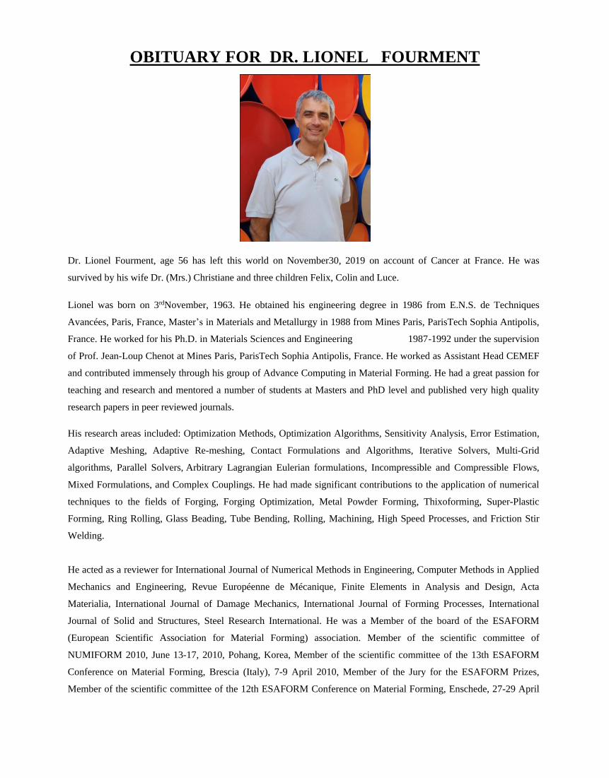
OBITUARY FOR DR. LIONEL FOURMENT
Dr. Lionel Fourment, age 56 has left this world on November30, 2019 on account of Cancer at France. He was
survived by his wife Dr. (Mrs.) Christiane and three children Felix, Colin and Luce.
Lionel was born on 3rdNovember, 1963. He obtained his engineering degree in 1986 from E.N.S. de Techniques
Avancées, Paris, France, Master’s in Materials and Metallurgy in 1988 from Mines Paris, ParisTech Sophia Antipolis,
France. He worked for his Ph.D. in Materials Sciences and Engineering 1987-1992 under the supervision
of Prof. Jean-Loup Chenot at Mines Paris, ParisTech Sophia Antipolis, France. He worked as Assistant Head CEMEF
and contributed immensely through his group of Advance Computing in Material Forming. He had a great passion for
teaching and research and mentored a number of students at Masters and PhD level and published very high quality
research papers in peer reviewed journals.
His research areas included: Optimization Methods, Optimization Algorithms, Sensitivity Analysis, Error Estimation,
Adaptive Meshing, Adaptive Re-meshing, Contact Formulations and Algorithms, Iterative Solvers, Multi-Grid
algorithms, Parallel Solvers, Arbitrary Lagrangian Eulerian formulations, Incompressible and Compressible Flows,
Mixed Formulations, and Complex Couplings. He had made significant contributions to the application of numerical
techniques to the fields of Forging, Forging Optimization, Metal Powder Forming, Thixoforming, Super-Plastic
Forming, Ring Rolling, Glass Beading, Tube Bending, Rolling, Machining, High Speed Processes, and Friction Stir
Welding.
He acted as a reviewer for International Journal of Numerical Methods in Engineering, Computer Methods in Applied
Mechanics and Engineering, Revue Européenne de Mécanique, Finite Elements in Analysis and Design, Acta
Materialia, International Journal of Damage Mechanics, International Journal of Forming Processes, International
Journal of Solid and Structures, Steel Research International. He was a Member of the board of the ESAFORM
(European Scientific Association for Material Forming) association. Member of the scientific committee of
NUMIFORM 2010, June 13-17, 2010, Pohang, Korea, Member of the scientific committee of the 13th ESAFORM
Conference on Material Forming, Brescia (Italy), 7-9 April 2010, Member of the Jury for the ESAFORM Prizes,
Member of the scientific committee of the 12th ESAFORM Conference on Material Forming, Enschede, 27-29 April

2009, Member of the Jury for the ESAFORM Prizes, Member of the scientific committee of the 11th ESAFORM
Conference on Material Forming, Lyon, 23-25 April 2008, Member of the scientific committee of the Journeé de
Mécanique des Structures organized by and at Faculté des Sciences et Techniques de Settat on 26 November 2008,
Member of the scientific committee of the ESAFORM association since June 2006. He was conferred with Fellow of
International Society of Agile Manufacturing (FISAM) during NUMIFORM 2016.
Dr. Lionel Fourment was greatly impressed by Most Revered Dr. M.B. Lal Sahab and Most Revered Prof. P.S.
Satsangi Sahab, the spiritual leaders of Radhasoami faith at Dayalbagh, Agra and visited Dayalbagh a number of
times. His last visit to Dayalbagh with his family was in the year 2018. He was the connecting link between the two
great institutions, CEMEF and Dayalbagh Educational Institute (DEI). He was a Buddhist by faith. Dr. Lionel
Fourment has kindly mentored the author along with Prof. J.L. Chenot for his doctoral dissertation. He was a great
family friend of the author. His research acumen, his kindness and compassion for all his family members, friends,
colleagues and students is extraordinary.
We at DEI, ISAM and ISPE join all his family members, relatives and friends and pray to the Merciful God to bless
his soul and bestow courage to his family to bear this great loss.
K. Hans Raj
Professor and Head Mechanical Engineering
Dayalbagh Educational Institute, Agra, India.
Chief Editor, IJAMS and Chairman, ISAM
IJAMS International Journal of Advanced Manufacturing Systems
Manuscripts should be submitted through e-mail as a MS word document to Prof. K. Hans Raj, Chief Editor, Faculty of Engineering, Dayalbagh Educational Institute, Dayalbagh, AGRA-282 110, INDIA, E-mail: [email protected] or Prof. Subramaniam Ganesan, Chief Associate Editor, Department of Computer Science and Engineering, Oakland University, Rochester, MI- 48309, USA, E-mail: [email protected].
All original journal articles are copyrighted in the name of the Publisher. All original articles accepted for publication must be accompanied by a signed copyright transfer agreement available from the journal editor. Previously copyrighted material may be published with the written permission of the copyright holder. Copies of any letters granting permission to reproduce illustrations, tables, or lengthy quoted passages should be included with the manuscript. Responsibility for the accuracy of the material in the manuscript, including appropriate references to related work, lies entirely with the authors. The Publisher will not put any limitation on the personal freedom of the author to use material contained in the paper in other work which may be published elsewhere, provided due acknowledgment is given.
3. Contact
1. Manuscript Submission:
This journal welcomes original papers that pertain to state of the art research and development, product development, novel applications, and tools in the areas related to advance manufacturing. The journal addresses the utilization of advance manufacturing system and includes the area of information modeling, distribution, planning and scheduling, and collaborative decision making, as well as the organization and management of advance manufacturing systems. AMS technologies that result in the faster productivity and better costumer value are emphasized. Major research area includes process characterization and matrices, enterprise modeling, multi enterprise integration, information sharing and collaboration, networked collection tools for multimedia conferences, distributed environments, corporate technical memories, AMS languages and tools, intelligent retrieval, virtual teams, architectures and emerging standards and practices, intelligent manufacturing systems, process modeling and simulation.
2. Copyright Permission:
The journal will publish only original, quality papers. Manuscripts are accepted for review with the understanding that (a) the same paper has not been published elsewhere, has not been submitted elsewhere for review, and will not be published elsewhere; (b) all persons listed as authors have given their approval for the submission; and (c) any person cited as a source of personal communication has approved such citation. Written authorization from cited sources may be required at the editor's discretion. Articles and other material published in IJAMS represent the opinions of the authors and should not be construed to reflect the opinions of the editors or the publisher.

FOREWORD
1. HYBRID 3D METAL PRINTING PAVEL IKONOMOV
2. CHARACTERIZATION OF THE MECHANICAL PROPERTIES OF PARTS PRODUCES WITH A HYBRID 3D METAL PRINTER
PAVEL IKONOMOV, ANDREW WYMAN, SUDARSHAN RAWALE
3. AGILE MANUFACTURING: AN IT PERSPECTIVE VIPIN MITTAL, PIYUSH JAIN, SUBRA GANESAN, K. HANS RAJ
ORBITUARY FOR DR. LIONEL FOURMENT
1
10
19
IJAMS International Journal of Advanced Manufacturing Systems
TABLE OF CONTENTS
ISSN No. 1536 2647