Spectral parameters of reference-cavity-stabilised lasers
8
Abstract. A semiconductor laser emitting at 972 nm is stabilised with respect to a vibrationally and thermally compensated reference Fabry º Perot resonator with the vertical axis. The supporting points lie in the horizontal symmetry plane of the resonator, the inŒuence of vibrations in the vertical direction being substantially suppressed in this case. This conØguration provides a low sensitivity of the laser emission frequency to vertical accelerations of the reference resonator. To reduce the inŒuence of temperature Œuctua- tions, the resonator is made of an ULE (ultra-low-expansion) glass and is kept at temperature at which the expansion coefØcient of this glass is close to zero. The laser linewidth is smaller than 0.5 Hz and the frequency drift is 0:1 Hz s 1 . The minimum of the Allan deviation achieved for 3 s is 2 10 15 . The laser was used to record the spectra of the 1S º 2S transition in atomic hydrogen. Keywords: semiconductor laser, frequency stabilisation, subhertz spectral width. 1. Introduction Lasers emitting very narrow lines are required for the development of optical atomic clocks and applications in ultrahigh-resolution spectroscopy. To provide the high stability and accuracy of an optical clock (better than 10 15 ), a laser source should have the linewidth of 1 Hz. During the past decade, a considerable progress has been achieved in the Øeld of laser frequency stabilisation. More and more attention is being paid to the frequency stabilisation of semiconductor lasers, which have a simple design, a broad tuning range, and are low-cost. However, semiconductor lasers have the excessive noise caused by the amplitude º phase coupling, which complicates their stabi- lisation [1]. Thus, the linewidth of a semiconductor laser can achieve hundreds of megahertz [2]. The narrowing of the emission line of a semiconductor laser is usually performed in two stages: Ørst by using the optical feedback from an external dispersion resonator, which allows the line narrowing to 1 kHz º 1 MHz [3 º 5], and then by using an electronic feedback loop by the transmission peak of an external stable resonator [6 º 8]. Although the electronic stabilisation of the laser frequency with respect to the transmission peak of an external reference resonator with the subhertz mutual instability was demonstrated already in 1988 [9] (the laser emission frequency virtually coincides with the frequency of a resonator mode when the feedback loop operated properly), the development of resonators providing the subhertz stability level took ten more years. Until recently such systems were extremely inconvenient and were used only in a limited number of laser experiments performed in the leading laboratories of the world. Our paper is devoted to the development of a compact reference resonator providing the subhertz linewidth of a 972-nm semiconductor laser. The fourth harmonic of this laser can be used to excite the two-photon 1S º 2S transition with the natural width of 1.3 Hz in a hydrogen atom. The laser can be also employed in a number of other experi- ments, in particular, for studying the spectra of the 1S º 2S transition in atomic tritium and antihydrogen [10]. To provide a narrow laser line, the distance between mirrors in the reference Fabry º Perot resonator should be extremely stable, which severely restricts the admissible levels of vibrations, temperature Œuctuations, and Œuctuations of the refractive index of a medium between the mirrors. Thus, to provide the linewidth 1 Hz of a laser stabilised with respect to the reference resonator of length 10 cm, Œuctuations of the optical length of the resonator should not exceed 10 15 m. The frequency stabilisation of a tunable laser at the subhertz level has been demonstrated for the Ørst time in 1998 [11]. A dye laser was stabilised with respect to the reference resonator with a horizontal axis. The vibration isolation was achieved by suspending an optical table with rubber strips to the laboratory room ceiling. This provides a low intrinsic vibrational frequency of the system and suppression of adverse vibrations; however, the large mass and size of the system exclude the possibility of its transport. An alternative approach is based on a new principle of mounting the reference resonator, which provides the A.N. Matveev, N.N. Kolachevsky P.N. Lebedev Physics Institute, Russian Academy of Sciences, Leninsky prosp. 53, 119991 Moscow, Russia; Moscow Institute of Physics and Technology (State University), Institutskii per. 9, 141700 Dolgoprudnyi, Moscow region, Russia; e-mail: [email protected], [email protected]; J. Alnis Max Planck Institute of Quantum Optics, Hans-Kopfermann-Str. 1, 85748 Garching, Germany; e-mail: [email protected]; T.W. H ansch Max Planck Institute of Quantum Optics, Hans-Kopfermann-Str. 1, 85748 Garching, Germany; Ludwig-Maximilians University, Geschwister-Scholl-Platz 1, 80539 Munuch; e-mail: [email protected] Received 29 January 2008; revision received 22 April 2008 Kvantovaya Elektronika 38 (10) 895 º 902 (2008) Translated by M.N. Sapozhnikov PACS numbers: 42.55.Px; 42.60.By; 42.62.Eh; 42.62.Fi LASERS DOI:10.1070/QE2008v038n10ABEH013806 Semiconductor laser with the subhertz linewidth A.N. Matveev, N.N. Kolachevsky, J. Alnis, T.W. H ansch 611/584 º MBº 22/xii-08 º SVERKA º 8 ÒÑ˛ÑÔ ˝ÑˇÒ. å 1 Quantum Electronics 38 (10) 895 º 902 (2008) ß2008 Kvantovaya Elektronika and Turpion Ltd
-
Upload
independent -
Category
Documents
-
view
5 -
download
0
Transcript of Spectral parameters of reference-cavity-stabilised lasers

Abstract. A semiconductor laser emitting at 972 nm isstabilised with respect to a vibrationally and thermallycompensated reference Fabry ëPerot resonator with thevertical axis. The supporting points lie in the horizontalsymmetry plane of the resonator, the inêuence of vibrations inthe vertical direction being substantially suppressed in thiscase. This conéguration provides a low sensitivity of the laseremission frequency to vertical accelerations of the referenceresonator. To reduce the inêuence of temperature êuctua-tions, the resonator is made of an ULE (ultra-low-expansion)glass and is kept at temperature at which the expansioncoefécient of this glass is close to zero. The laser linewidth issmaller than 0.5 Hz and the frequency drift is �0:1 Hz sÿ1.The minimum of the Allan deviation achieved for 3 s is2� 10ÿ15. The laser was used to record the spectra of the1S ë 2S transition in atomic hydrogen.
Keywords: semiconductor laser, frequency stabilisation, subhertzspectral width.
1. Introduction
Lasers emitting very narrow lines are required for thedevelopment of optical atomic clocks and applications inultrahigh-resolution spectroscopy. To provide the highstability and accuracy of an optical clock (better than1015), a laser source should have the linewidth of �1 Hz.During the past decade, a considerable progress has beenachieved in the éeld of laser frequency stabilisation. Moreand more attention is being paid to the frequencystabilisation of semiconductor lasers, which have a simpledesign, a broad tuning range, and are low-cost. However,
semiconductor lasers have the excessive noise caused by theamplitude ë phase coupling, which complicates their stabi-lisation [1]. Thus, the linewidth of a semiconductor lasercan achieve hundreds of megahertz [2]. The narrowing ofthe emission line of a semiconductor laser is usuallyperformed in two stages: érst by using the optical feedbackfrom an external dispersion resonator, which allows the linenarrowing to 1 kHz ë 1 MHz [3 ë 5], and then by using anelectronic feedback loop by the transmission peak of anexternal stable resonator [6 ë 8]. Although the electronicstabilisation of the laser frequency with respect to thetransmission peak of an external reference resonator withthe subhertz mutual instability was demonstrated already in1988 [9] (the laser emission frequency virtually coincideswith the frequency of a resonator mode when the feedbackloop operated properly), the development of resonatorsproviding the subhertz stability level took ten more years.Until recently such systems were extremely inconvenientand were used only in a limited number of laser experimentsperformed in the leading laboratories of the world.
Our paper is devoted to the development of a compactreference resonator providing the subhertz linewidth of a972-nm semiconductor laser. The fourth harmonic of thislaser can be used to excite the two-photon 1S ë 2S transitionwith the natural width of 1.3 Hz in a hydrogen atom. Thelaser can be also employed in a number of other experi-ments, in particular, for studying the spectra of the 1S ë 2Stransition in atomic tritium and antihydrogen [10]. Toprovide a narrow laser line, the distance between mirrorsin the reference Fabry ë Perot resonator should be extremelystable, which severely restricts the admissible levels ofvibrations, temperature êuctuations, and êuctuations ofthe refractive index of a medium between the mirrors.Thus, to provide the linewidth 1 Hz of a laser stabilisedwith respect to the reference resonator of length 10 cm,êuctuations of the optical length of the resonator should notexceed 10ÿ15 m.
The frequency stabilisation of a tunable laser at thesubhertz level has been demonstrated for the érst time in1998 [11]. A dye laser was stabilised with respect to thereference resonator with a horizontal axis. The vibrationisolation was achieved by suspending an optical table withrubber strips to the laboratory room ceiling. This provides alow intrinsic vibrational frequency of the system andsuppression of adverse vibrations; however, the largemass and size of the system exclude the possibility of itstransport.
An alternative approach is based on a new principle ofmounting the reference resonator, which provides the
A.N. Matveev, N.N. Kolachevsky P.N. Lebedev Physics Institute,Russian Academy of Sciences, Leninsky prosp. 53, 119991 Moscow,Russia; Moscow Institute of Physics and Technology (State University),Institutskii per. 9, 141700 Dolgoprudnyi, Moscow region, Russia;e-mail: [email protected], [email protected];J. Alnis Max Planck Institute of Quantum Optics,Hans-Kopfermann-Str. 1, 85748 Garching, Germany;e-mail: [email protected];T.W. H�ansch Max Planck Institute of Quantum Optics,Hans-Kopfermann-Str. 1, 85748 Garching, Germany;Ludwig-Maximilians University, Geschwister-Scholl-Platz 1, 80539Munuch; e-mail: [email protected]
Received 29 January 2008; revision received 22 April 2008Kvantovaya Elektronika 38 (10) 895 ë 902 (2008)Translated by M.N. Sapozhnikov
PACSnumbers:42.55.Px; 42.60.By; 42.62.Eh; 42.62.FiLASERS
DOI:10.1070/QE2008v038n10ABEH013806
Semiconductor laser with the subhertz linewidth
A.N. Matveev, N.N. Kolachevsky, J. Alnis, T.W. H�ansch
611/584 ëMBë 22/xii-08 ë SVERKA ë 8 ÒÑÎÑÔ ÍÑÏÒ. å 1Quantum Electronics 38 (10) 895 ë 902 (2008) ß2008 Kvantovaya Elektronika and Turpion Ltd

reduction of the assembly total mass down to 10 ë 20 kg. Inthe new conéguration, the supporting points of the Fabry ëPerot resonator with the vertical axis lie in its horizontalsymmetry plane. The vertical acceleration leads to almostsymmetric expansion and compression of the upper andlower halves of the resonator, so that the distance betweenresonator mirrors remains virtually invariable due to themutual compensation of expansion and compression [12].The resonator should be mounted on rigid posts éxing itsposition with respect to a stage. This provides the sup-pression of the Doppler effect inherent in systems in whichthe resonator is suspended with threads or spring-mounted.As a stage, a commercial system with the active suppressionof vibrations, manufactured, for example, by HalcyonicsInc., is used. In this case, the mechanical coupling of theresonator with the stage proves to be rather rigid. However,the high stability of the resonator itself and the system ofactive suppression of vibrations provide the sufécientsuppression of both vertical and horizontal accelerations,which is required for obtaining subhertz linewidths. Thehigh degree of stabilisation of resonators was also achievedby other research groups, which used resonators with thehorizontal axis and supporting points lying in the horizontalsymmetry plane [13].
To eliminate êuctuations of the refractive index, it isnecessary to accommodate the resonator in a vacuumchamber where pressure êuctuations should not exceed10ÿ8 mbar. This requirement can be easily fulélled byplacing the resonator into a vacuum chamber evacuatedwith an ion-getter pump. However, an important problem inthe development of highly stable resonators is temperatureêuctuations of their length l. At present the best materialused for manufacturing the body and mirrors of referenceresonators operating at room temperatures is the ULE (ultra-low-expansion) Corning glass [14]. A speciéc feature ofthis material is the presence of the so-called zero point atwhich the thermal expansion coefécient of the material iszero. The detuning Dv of the resonator frequency near thezero point depends quadratically on temperature:
Dv=v � Dl=l � 10ÿ9�Tÿ Tcr�2, (1)
where T is the resonator temperature and Tcr is thetemperature at the zero point.
To reduce the inêuence of temperature êuctuations, it isdesirable to stabilise the temperature of the Fabry ë Perotresonator near Tcr. In this case, the length instability will becaused by a slow recrystallisation of the ULE glass (thus, therelevant frequency for the resonator used in [15] was�65 mHz sÿ1). Our measurements showed that the temper-ature Tcr for our ULE glass sample was �10 8C, which isnoticeably lower than room temperature. The externalcooling of a vacuum chamber is a complicated technicalproblem because of the condensation of moisture on inputwindows, and for this reason most of the existing resonatorsoperate at temperatures considerably exceeding Tcr.
In this paper, we used two systems to stabilise 972-nmsemiconductor lasers. Both systems employed identicalFabry ë Perot resonators FP1 and FP2; however, theirtemperature stabilisation systems were substantially differ-ent. The FP1 resonator was equipped with a heating systemproviding the temperature stabilisation near 31 8C, which isconsiderably higher than Tcr. The temperature stabilisationsystem with heating, which will be described below, was
successfully used in previous experiments [8, 15]. Anothersystem, which was developed for the érst time, provided thecooling of the FP2 resonator down to the temperature Tcr
by using Peltier elements placed in vacuum. We describebelow the design of devices and present the parameters ofstabilised semiconductor lasers and the results of the studyof the spectrum of the 1S ë 2S transition in atomic hydrogen.
2. Experimental setup
Figure 1 shows the scheme of a vertical resonator used inour paper, which was manufactured by ATF Inc. [16]. Twomirrors are attached by optically contacting the resonatorbody of length 77.5 mm. The mirror substrates are alsomade of the ULE glass. The resonator body has the shapeof a `rugby ball' as approximation to the spherical shapeproviding the minimal excitation of vibrational modes. Thereêectance of mirrors was �99:999% at 972 nm. Themultilayer reêecting structure contained 38 SiO2 and Ta2O5
layers with a total thickness of �0:5 mm. One of the mirrorswas plane and the other had the radius of curvature of0.5 m. The resonator was mounted on three Teêon postsinserted into a ring made of Zerodur. The ring suppressesthe inêuence of temperature on the distance between theposts and prevents the appearance of radial forces fromposts on the resonator body. The posts had circularchannels reducing their rigidity in the horizontal directionand weakening the inêuence of horizontal vibrations.
2.1 Temperature stabilisation system of the FP1 resonator
Figure 2 shows the temperature stabilisation system of theFP1 resonator. The resonator is located inside a cylindricalvacuum chamber made of duralumin. Due to the high heat
g�Dg�t�
l=77.5
mm
ÿDl
�Dl
Figure 1. Scheme of the Fabry ë Perot resonator with the vertical axiséxed in the horizontal symmetry axis. In the case vertical acceleration g,the compression of the upper half of the resonator is compensated by theelongation of its lower half, and the total resonator length remainsconstant.
896 A.N. Matveev, N.N. Kolachevsky, J. Alnis, T.W. H�ansch
conduction, the aluminium chamber provides a moreuniform temperature distribution than stainless steelchambers. Duralumin was subjected to chemical processing(passivation), which allowed us to evacuate the chamberdown to 10ÿ7 mbar by using an ion-getter pump with acapacity of 3 L sÿ1. All the vacuum seals were provided byusing a indium wire.
The temperature of the vacuum chamber was stabilisedwith the help of a heater and an electronic proportionallyintegrating (PI) feedback circuit. The system stabilisestemperature at 30.5 8C only at the location site of atemperature sensor, not monitoring êuctuations and tem-perature gradients at the other sites of the surface. To reducethe inêuence of temperature gradients and suppress heatexchange with the environment, the second, external six-cannel stabilisation system is used. The vacuum chamber isplaced into a container made of heat conducting duraluminplates, each of them being independently heated andstabilised with the help of a fast relay two-position con-troller providing the temperature stability at the sensor siteno worse than 100 mK. The second stage produces theuniform thermal background with temperature 30 8Caround the vacuum chamber with minimal temperaturegradients and drifts. Both the vacuum chamber andduralumin container are covered with a thermal insulationlayer for passive suppression of temperature oscillations.The uniform distribution of the thermal power was providedby using thin-élm heating elements. The AD590 sensors(Analog Devices, USA) used in temperature control feed-back systems were preliminarily calibrated. The heatexchange time constant of the resonator was �3 h.
The temperature stabilisation system provides the tem-perature stability of the external surface of the vacuumchamber �1 mK during ten hours and �5 mK for a week,which was measured with an independent sensor. Theresidual temperature êuctuations are caused by êuctuationsof room temperature and the inêuence of these êuctuationson temperature controllers themselves. Thus, the temper-ature of the PI controller also was stabilised with anaccuracy of 0.1 K to prevent a drift caused by the inêuenceof temperature on the capacity of the capacitors (ten foil 22-mF capacitors), the resistance of the resistors, and the biasvoltage of semiconductor elements.
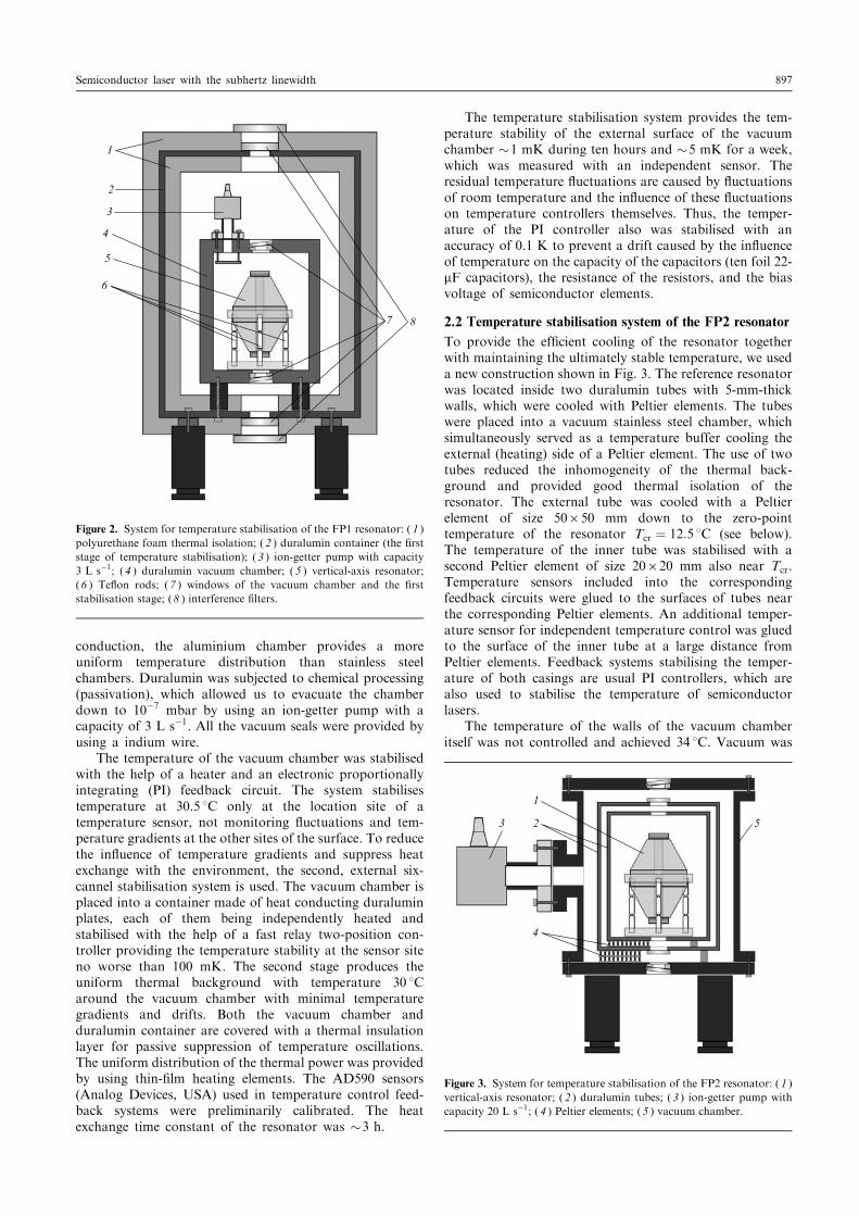
2.2 Temperature stabilisation system of the FP2 resonator
To provide the efécient cooling of the resonator togetherwith maintaining the ultimately stable temperature, we useda new construction shown in Fig. 3. The reference resonatorwas located inside two duralumin tubes with 5-mm-thickwalls, which were cooled with Peltier elements. The tubeswere placed into a vacuum stainless steel chamber, whichsimultaneously served as a temperature buffer cooling theexternal (heating) side of a Peltier element. The use of twotubes reduced the inhomogeneity of the thermal back-ground and provided good thermal isolation of theresonator. The external tube was cooled with a Peltierelement of size 50650 mm down to the zero-pointtemperature of the resonator Tcr � 12:5 8C (see below).The temperature of the inner tube was stabilised with asecond Peltier element of size 20620 mm also near Tcr.Temperature sensors included into the correspondingfeedback circuits were glued to the surfaces of tubes nearthe corresponding Peltier elements. An additional temper-ature sensor for independent temperature control was gluedto the surface of the inner tube at a large distance fromPeltier elements. Feedback systems stabilising the temper-ature of both casings are usual PI controllers, which arealso used to stabilise the temperature of semiconductorlasers.
The temperature of the walls of the vacuum chamberitself was not controlled and achieved 34 8C. Vacuum was
1
2
3
4
5
6
7 8
Figure 2. System for temperature stabilisation of the FP1 resonator: ( 1 )polyurethane foam thermal isolation; ( 2 ) duralumin container (the érststage of temperature stabilisation); ( 3 ) ion-getter pump with capacity3 L sÿ1; ( 4 ) duralumin vacuum chamber; ( 5 ) vertical-axis resonator;( 6 ) Teêon rods; ( 7 ) windows of the vacuum chamber and the érststabilisation stage; ( 8 ) interference élters.
3 2
1
4
5
Figure 3. System for temperature stabilisation of the FP2 resonator: ( 1 )vertical-axis resonator; ( 2 ) duralumin tubes; ( 3 ) ion-getter pump withcapacity 20 L sÿ1; ( 4 ) Peltier elements; ( 5 ) vacuum chamber.
Semiconductor laser with the subhertz linewidth 897

maintained by using an ion-getter pump with capacity20 L sÿ1. The measurements of temperature êuctuationsof the inner casing performed with the independent sensorshowed that the typical temperature instability was �15 mKduring several days, which is approximately three timesworse than the stability achieved for the FP1 resonator.Nevertheless, the long-term stability of the resonator fre-quency was improved approximately by two orders ofmagnitude due to approach to the zero point of theULE glass [see expression (1)]. During several érst weeksafter evacuation of the chamber, a few abrupt temperaturejumps amounting to several millikelvin were observed,which are probably caused by transient processes in Peltierelements.
2.3 Frequency stabilisation of a semiconductor laser withrespect to the Fabry ëPerot resonator frequency
Both vacuum chambers with resonators and temperaturestabilisation systems were mounted on two stages of size40640 cm providing the active suppression of vibrations.Due to the use of the vertical resonator, the size and weightof the system were considerably reduced compared to thesystem employed earlier for studying the hydrogen spec-trum [15]. The resonators were used to stabilise two almostidentical 972-nm diode lasers with external resonators in theLittrow mounting.
The optical scheme used to stabilise lasers is shown inFig. 4. Laser radiation is delivered through a single-modeébre to the stage with the reference resonator. The phaseand intensity noises introduced by the ébre were compen-
sated by using a standard active compensation system withan acousto-optic modulator [17]. The Gaussian mode at theébre output is matched with the resonator mode with thehelp of a lens ( f � 500 mm). The laser frequency is stabilisedby the frequency of a certain resonator mode by thePound ëDrever ëHall (PDH) method [14]. This methodof laser frequency stabilisation is based on the active lockingof the laser radiation phase to the phase of a wave in theresonator averaged due to the long lifetime of a photon inthe resonator [18]. In this case, the resonator operates as aêywheel, by éltering rapid phase êuctuations of inputradiation. Due to the active phase locking, a laser withthe natural linewidth of �1 MHz stabilised with respect tothe transmission peak of the resonator of width 7 kHz emitsa narrow line with the subhertz width.
A number of reasons leading to the zero-level shift in thePDH locking scheme considerably affect the laser frequencystability. One of the important undesirable factors is theamplitude modulation of the éeld accompanying the phasemodulation in the PDH locking scheme. This effect is verystrong if the phase modulation is provided by modulatingthe diode current. Because of this, we used a scheme inwhich modulation was performed by an external electro-optical modulator and the polarisation of light was chosento provide the minimal amplitude modulation. In addition,to reduce the drift of optical axes of crystals, the temper-ature of the electrooptical modulator was stabilised with anaccuracy of 0.1 K. The locking zero can be also shifted dueto interference effects, which were eliminated by placing anoptical isolator in front of the ébre.
9
8
5
4
671011
12
1 2
3
Locking unit
Figure 4. Scheme of the diode laser frequency stabilisation by the Pound ëDrever ëHall method: ( 1 ) external cavity diode laser; ( 2 ) tapered ampliéer;( 3 ) acousto-optic modulator; ( 4 ) active vibration suppression stage; ( 5 ) optical ébre; ( 6 ) reference resonator; ( 7 ) photodiode; ( 8 ) electroopticalmodulator operating in the phase modulation regime; ( 9 ) radiofrequency generator; ( 10 ) phase shifter; ( 11 ) balance mixer; ( 12 ) low-frequency élter;the optical ébre is equipped with a noise-compensation system, which, as matching optics, is not shown in the égure.
898 A.N. Matveev, N.N. Kolachevsky, J. Alnis, T.W. H�ansch

The laser frequency was controlled, as usual, by employ-ing two channels ë the fast channel (controlling the laserdiode current) and the slow channel (controlling the rotationof a diffraction grating with the help of a piezoelectricelement). The frequency curve of a proportionally integro-differential controller of the laser frequency provided a highampliécation (more than 60 dB) at low frequencies and thebandwidth of up to 10 MHz.
The optimal operation of the locking scheme wasachieved by coupling the radiation power �20 mW intothe resonator. The increase in the radiation power resultedin the noticeable inêuence of radiation intensity êuctuationson the resonator frequency, which was characterised by thevalue 5 Hz mWÿ1. The decrease in the radiation powerreduced the signal-to-noise ratio of photodetectors (siliconpin-photodiodes) and impaired the frequency stability.
3. Experimental results
3.1 Parameters of the FP1 and FP2 resonators
The énesse of the resonators determined from the radiationdecay time was 4:1� 105 and 4:0� 105 for the FP1 andFP2 resonators, respectively. The temperature at the zeropoint was determined from the dependence of the beatfrequency of two laser éelds on the temperature of one ofthe resonators (Fig. 5). For this purpose, the temperature ofone of the resonators was kept constant, while thetemperature of the other was varied, the temperature ofthe resonator under study being stabilised for �24 hours.After cessation of transient processes, the beat frequency ofthe light éelds was measured and the results wereapproximated by quadratic function (1). Its minimumcorresponded to the zero point of the resonator. Thetemperatures Tcr measured for the FP1 and FP2 resonatorswere 7� 2 8C and 12:5� 0:1 8C, respectively. These valuesare different most likely due to the inêuence of posts andresidual stresses in resonators.
A simple estimate shows that the cooling of theresonator down to the temperature Tcr considerably reducesits sensitivity to temperature êuctuations. By assuming thatthe temperature adjustment accuracy is 0.1 8C, we obtain thesensitivity of the FP1 resonator equal approximately to10 kHz mKÿ1, whereas the sensitivity of the FP2 resonatoris reduced to 50 Hz mKÿ1. Note that the contribution of the
temperature expansion of the multilayer coating of mirrorsfor the FP2 resonator is considerable and is equal to20 Hz mKÿ1. Rapid temperature êuctuations of the envi-ronment (heat exchange mainly occurs due to radiation)affect érst of all the relatively thin mirror substrates and themultilayer coating, which is followed by thermalisation withthe resonator body. This means that the real sensitivity ofthe resonator to rapid temperature êuctuations can con-siderably exceed the estimate even in the case of itsstabilisation near Tcr. This effect was observed in experi-ments. Thus, even when the zero point of the ULE glass isused, the resonator temperature should be stabilised withthe maximum possible accuracy.
3.2 Residual phase noise of a semiconductor laser
The study of the beat signal of light éelds from stabilisedlasers with the help of a spectrum analyser showed that,apart from a narrow spectral peak containing the main partof the signal, the high-frequency noise forming a pedestal ofwidth of several megahertz was also observed (Fig. 6). Thishigh-frequency noise appears due to the residual phasenoise of a semiconductor laser, which is not completelycompensated by the feedback. The optimisation of thefeedback parameters reduces the noise pedestal, but doesnot suppress it completely.
The measurements showed that when 20 mW of radia-tion power was coupled into the reference resonator(operating regime), the central peak corresponding to thecarrier frequency contained 99.0%� 0.1% of the totalpower. An increase in the power used for locking leadsto the increase in this value. Thus, for example, when200 mW of laser radiation power was coupled into theresonator, the power fraction at the carrier frequencyincreased up to 99.7%� 0.1%. However, such an operationregime is unfavourable from the point of view of the spectralwidth of the central peak (see above). The noise pedestalposes a serious problem in the spectroscopy of the 1S ë 2Stransition in the hydrogen atom because its excitationinvolves three two-photon processes. The frequency multi-plication leads to the increase in the phase noise, thedecrease in the power fraction at the carrier frequency,and reduces the transition excitation eféciency [19].
Beatsign
alfrequency� MH
z
5 10 15 20 25 30
Temperature�8C
FP2
FP1
Tcr � 7� 2 8C
Tcr � 12:5� 0:1 8C
0
20
40
60
80
100
120
140
Figure 5. Determination of the zero point of the FP1 and FP2 resonators(see text).
Spectral
power
density� dB
ÿ5 ÿ4 ÿ3 ÿ2 ÿ1 0 1 2 3 4 5
Frequency detuning�MHz
ÿ90
ÿ80
ÿ70
ÿ60
ÿ50
ÿ40
ÿ30
ÿ20
Figure 6. Spectrum of the beat signal of light éelds of two laser systemsat 972 nm. The noise pedestal is caused by the phase noise. Theresolution of the spectrum analyser is 20 kHz.
Semiconductor laser with the subhertz linewidth 899

3.3 Frequency drift in resonators and the Allan deviationThe beat signal of laser éelds was heterodyned in the regionnear 10 MHz and transmitted through a band-pass élter ofwidth 1 MHz. Figure 7a shows the frequency drift of thebeat signal during half an hour. The average frequency driftis several tens of millihertz per second (for the realisationpresented in Fig. 7a, this drift is 15 mHz sÿ1), whereas themaximum drift does not exceed 1 Hz sÿ1, remaining usuallywithin �100 mHz sÿ1 (the drift magnitude depends on theoperation reliability of a laboratory climate control system).Unfortunately, it is impossible in this case to determinewhich of the resonators makes the greater contribution tothe observed frequency drift. The FP1 resonator is betterisolated and slower responses to temperature variations inthe environment, but it is highly sensitive to temperatureêuctuations (10 kHz mKÿ1). The FP2 resonator is worseisolated from the environment because the vacuumchamber serves as a thermal radiator, however, it has aconsiderably lower temperature sensitivity (50 Hz mKÿ1).At present we plan to measure the absolute radiationfrequency of stabilised semiconductor lasers with respect tothe hydrogen maser frequency by using a femtosecondfrequency comb [20].
The Allan deviation corresponding to data in Fig. 7a ispresented in Fig. 7b. The deviation achieves the minimum(2� 10ÿ15) for the averaging time 3 s. This is only twice aslarge as the theoretical limit caused by the thermal noise ofthe resonator [21].
3.4 Spectral linewidth
The linewidth was measured by heterodyning the beatsignal in the 100-Hz region, which allowed us to study thecarrier spectrum by using a Fourier spectrum analyser. Therecording time of one data realisation was 4 s, whichcorresponds to the resolution of the spectrum analyserequal to 0.25 Hz. For twelve successively recordedrealisations, the spectral width of the peak varied from0.3 to 0.75 Hz, which gave 0.47� 0.14 Hz after averaging.Figure 8 presents the result of averaging of the obtained
lines after combining their centres (compensation of thelaser frequency drift). The spectral line proéle is wellapproximated by a Lorentzian.
The beat signal was also recorded by using a standarddigital oscilloscope. The typical oscillogram obtained afterthe éltration of high frequencies looks like a sinusoid with aslowly êuctuating frequency (Fig. 9). The heterodyning ofthe beat signal to the sound frequency region followed by itsmonitoring with a dynamic loudspeaker is convenient to usefor the adjustment of the system and determining the factorsaffecting the frequency stability of the laser system.
4. The 1S ë 2S transition spectrumof the hydrogen atom
By using a laser stabilised with respect to the FP1resonator, we recorded the 1S ë 2S transition spectra ofthe hydrogen atom. For this purpose, laser radiation was
Beatsign
alfrequency� Hz
Allan
deviation
0 500 1000 1500
5
10
15
20
25
15mHzsÿ1
100mHzsÿ
1
1 10 100
Thermal noise limit10ÿ15
10ÿ14
3� 10ÿ15
3� 10ÿ14
Time�s
aTime
�s
b
Figure 7. Drift of the beat signal frequency of light éelds of two laser systems (a) and the corresponding Allan deviation (b).
Power
spectral
density� V2
Hzÿ
1
Frequency detuning�Hz
ÿ10 ÿ8 ÿ6 ÿ4 ÿ2 0 2 4 6 8 10
0.5 Hz
0
0.2
0.4
0.6
0.8
Figure 8. Spectrum of the beat signal of two laser systems at 972 nmobtained with a Fourier spectrum analyser. The resolution of thespectrum analyser is 0.25 Hz.
900 A.N. Matveev, N.N. Kolachevsky, J. Alnis, T.W. H�ansch

ampliéed in a tapered ampliéer providing 650 mW ofoutput power and was directed to two successive stages forsecond harmonic generation [8]. The second stage generated� 5 mW of output power at 243 nm, which was requiredfor studying the two-photon spectra of atomic hydrogen.The spectra were recorded by tuning the laser frequencywith the help of the acousto-optic modulator operating inthe double-pass regime. Atomic hydrogen was excited in acold beam (the temperature of hydrogen atoms was 5 ë 7 K)inside a linear resonator, which increased the radiationpower density and provided Doppler-free excitation incounterpropagating beams. Hydrogen atoms in the 2S statewere detected with a photomultiplier which countedphotons at 121 nm appearing due to the decay of excitedhydrogen atoms to the ground state in a weak electric éeld.
Figure 10 shows the typical 1S ë 2S transition spectrum.The spectroscopic method used in the paper allows us to
obtain signals both from all the atoms of the total Maxwelldistribution and from groups of atoms with low velocities.The velocity selection is performed by the time-of-êightmethod and reduces the contributions of the time-of-êightbroadening and second-order Doppler effect [15]. By usingvertical reference resonators to stabilise a semiconductorlaser, we have managed to record considerably narrowerresonances compared to these obtained in [8]. The estimatesshow that the excitation eféciency did not exceed 50%,which is related to the residual noise of the semiconductorlaser. The spectral resolution of the setup was �4 kHz(calculated for l � 121 nm).
5. Conclusions
We have developed two independent laser setups based on972-nm semiconductor lasers stabilised with respect toreference Fabry ë Perot resonators with vertical axes. Thereference resonator design insensitive to vibrations providedthe laser linewidth smaller than 0.5 Hz. We have used a newmethod for cooling the reference resonator down to thetemperature corresponding to the zero point of the ULEglass, which considerably improved the stability of theresonator frequency at large time intervals. The frequencydrift of the laser systems was �0:1 Hz sÿ1. A small size ofthe resonator allowed us to achieve the high temperaturestability. The Allan deviation for the frequency beats of theéelds of stabilised laser systems achieves 2� 10ÿ15 for 3 s.The power fraction at the carrier frequency is 99%, whichallows the investigation of the 1S ë 2S transition spectrumof the hydrogen atom with the eféciency of �50%. It hasbeen shown that these laser systems can be used to excitethe narrow 1S ë 2S transition spectra with the resolution4 kHz (calculated for l � 121 nm). The laser system iscompact and can be easily transported to other laboratoriesfor performing experiments with exotic hydrogen-likesystems.
Acknowledgements. This work was partially supported bythe Russian Foundation for Basic Research (Grant No. 08-07-00127a), Grant MD-887.2008.2 of the President of theRussian Federation, the Foundation for Assistance to theRussian Science, and the Alexander Humboldt Foundation.
References1. Henry C. IEEE J. Quantum Electron., 18, 259 (1982).2. Bogatov A.P., Eliseev P.G., Sverdlov P.N. Kvantovaya Elektron.,
1, 2286 (1974) [ Sov. J. Quantum Electron., 4, 1275 (1974)].3. Belenov E.M., Velichansky V.L., Zibrov A.S., Nikitin V.V.,
Sautenkov V.A., Uskov A.V. Kvantovaya Elektron., 10, 1232(1983) [Sov. J. Quantum Electron., 13, 792 (1983)].
4. Akul'shin A.M., Basov N.G., Velichansky V.L., Zibrov A.S.,Zverkov M.V., Nikitin V.V., Okhotnikov O.G., Senkov N.V.,Sautenkov V.A., Tyurikov D.A., Yurkin E.K. KvantovayaElektron., 10, 1527 (1983) [Sov. J. Quantum Electron., 13, 1003(1983)].
5. Dahmani B., Hollberg L., Drullinger R. Opt. Lett., 12, 876(1987).
6. Stoehr H., Mensing F., Helmcke J., Sterr U. Opt. Lett., 31, 736(2006).
7. Ludlow A.D., Huang X., Notcutt M., Zanon-Willette T.,Foreman S.M., Boyd M.M., Blatt S., Ye J. Opt. Lett., 32, 641(2007).
8. Kolachevsky N., Alnis J., Bergeson S.D., H�ansch T.W.Phys. Rev. A, 73, 021801 (2006).
Voltag
e� VSignal
0 0.5 1.0 1.5 2.0
aTime
�s
0.5 Hz
5 6 7 8 9
Frequency�Hz
b
ÿ5
0
5
Figure 9. Beat signal of two laser systems at 972 nm recorded with adigital oscilloscope (a) and the spectrum obtained by the Fourier trans-form of this signal (b). The result is consistent with observationsobtained by using a Fourier spectrum analyser.
Countrate� sÿ1
ÿ50 ÿ40 ÿ30 ÿ20 ÿ10 0 10 20 30 40 50
Frequency detuning at 121 nm�kHz
0
1000
2000
3000
Figure 10. The 1S ë 2S transitions lines in atomic hydrogen obtained withthe help of the laser system with the FP1 resonator from all the atoms ofthe total Maxwell distribution (&) and from groups of atoms withvelocities smaller than 620 m sÿ1 (*) and smaller than 310 m sÿ1 (~).
Semiconductor laser with the subhertz linewidth 901

9. Salomon C., Hils D., Hall J.L. J. Opt. Soc. Am. B, 5, 1576(1988).
10. Gabrielse G., Bowden N.S., Oxley P., Speck A., Storry C.H.,Tan J.N., Wessels M., Grzonka D., Oelert W., Schepers G.,Sefzick T., Walz J., Pittner H., H�ansch T.W., Hessels E.A.Phys. Rev. Lett., 89, 213401 (2002).
11. Young B.C., Cruz F.C., Itano W.M., Bergquist J.C. Phys. Rev.Lett., 82, 3799 (1999).
12. Notcutt M., Ma L.-S., Ye J., Hall J.L. Opt. Lett., 30, 1815 (2005).13. Nazarova T., Riehle F., Sterr U. Appl. Phys. B, 83, 531 (2006).14. http://www.corning.com/specialtymaterials.15. Fischer M., Kolachevsky N., Zimmermann M., Holzwarth R.,
Udem Th., H�ansch T.W., Abgrall M., Gr�unert J., Maksimovic I.,Bize S., Marion H., Pereira Dos Santos F., Lemonde P.,Santarelli G., Laurent P., Clairon A., Salomon C., Haas M.,Jentschura U.D., Keitel C.H. Phys. Rev. Lett., 92, 230802 (2004).
16. http://www.atfilminc.com.17. Ma L.-S., Jungner P., Ye J., Hall J.L. Opt. Lett., 19, 1777 (1994).18. Drever R.W.P., Hall J.L., Kowalski F.V., Hough J., Ford G.M.,
Munley A.J., Ward H. Appl. Phys., 31, 97 (1983).19. Matveev A.N., Kolachevsky N.N., Alnis J., H�ansch T.W.
Kvantovaya Elektron., 38, 391 (2008) [Quantum Electron., 38,391 (2008)].
20. Reichert J., Holzwarth R., Udem Th., H�ansch T.W.Opt. Commun., 172, 59 (1999).
21. Notcutt M., Ma L.-S., Ludlow A.D., Foreman S.M., Ye J.,Hall J.L. Phys. Rev. A, 73, 031804 (2006).
902 A.N. Matveev, N.N. Kolachevsky, J. Alnis, T.W. H�ansch