
Airport Master Plan - ADOT
132
Airport Master Plan Airport Master Plan Airport Master Plan
-
Upload
khangminh22 -
Category
Documents
-
view
9 -
download
0
Transcript of Airport Master Plan - ADOT

Airport Master PlanAirport Master PlanAirport Master Plan

AIRPORT MASTER PLAN
for
GREENLEE COUNTY AIRPORT Greenlee County, Arizona
Prepared for
GREENLEE COUNTY
by
Coffman Associates, Inc.
April 2008
ALP Finalized August 2010
“The contents of this plan do not necessarily reflect the official views or policy of the FAA or ADOT Aeronautics. Acceptance of this document by the FAA and ADOT Aeronautics does not in any way constitute a commitment on the part of the United States or the State of Arizona to participate in any development depicted herein nor does it indicate that the proposed development is environmentally acceptable in accordance with the appropriate public laws.”

TABLE OF CONTENTS

GREENLEE COUNTY AIRPORT Greenlee County, Arizona
Airport Master Plan INTRODUCTION MASTER PLAN GOALS AND OBJECTIVES ................................................... ii Baseline Assumptions ............................................................................. iii MASTER PLAN ELEMENTS AND PROCESS ................................................ iii COORDINATION .............................................................................................. iv SUMMARY AND RECOMMENDATIONS ........................................................ v Chapter One INVENTORY AIRPORT SETTING ........................................................................................ 1-2 Previous Airport Development Grants ................................................. 1-2 Based Aircraft........................................................................................ 1-3 THE AIRPORT’S SYSTEM ROLE .................................................................. 1-3 AIRPORT FACILITIES ................................................................................... 1-4 Airside Facilities ................................................................................... 1-4 AREA AIRSPACE AND AIR TRAFFIC CONTROL ...................................... 1-7 Airspace Structure ................................................................................ 1-8 Special Use Airspace ............................................................................. 1-8 Airspace Control .................................................................................... 1-9 Navigational Aids .................................................................................. 1-9 Instrument Approach Procedures ...................................................... 1-10 Visual Flight Procedures .................................................................... 1-10 Area Airports ....................................................................................... 1-10

Chapter One (Continued) LANDSIDE FACILITIES .............................................................................. 1-10 Terminal .............................................................................................. 1-11 Apron and Aircraft Parking ................................................................ 1-11 Aircraft Hangar Facilities ................................................................... 1-11 Maintenance and Aircraft Rescue and Fire Fighting ........................ 1-11 Fueling Facilities ................................................................................. 1-11 Utilities ................................................................................................ 1-12 Security Fencing and Gates ................................................................ 1-12 ACCESS & CIRCULATION .......................................................................... 1-12 General Access to Greenlee County Airport – Surrounding Roads ............................................................. 1-12 SOCIOECONOMIC PROFILE ...................................................................... 1-12 Population ............................................................................................ 1-13 Employment ........................................................................................ 1-13 Per Capita Personal Income ............................................................... 1-14 CLIMATE ....................................................................................................... 1-15 LAND ZONING .............................................................................................. 1-16 Height and Hazard Zoning ................................................................. 1-16 SUMMARY ..................................................................................................... 1-16 DOCUMENT SOURCES ............................................................................... 1-16 Chapter Two AVIATION DEMAND FORECASTS NATIONAL AVIATION TRENDS .................................................................. 2-2 General Aviation ................................................................................... 2-2 FORECASTING APPROACH ......................................................................... 2-4 BASED AIRCRAFT ......................................................................................... 2-4 Registered Aircraft Forecasts ............................................................... 2-5 Based Aircraft Forecast ........................................................................ 2-6 Based Aircraft Fleet Mix ....................................................................... 2-8 AIRCRAFT OPERATIONS.............................................................................. 2-8 General Aviation Operations ................................................................ 2-8 Air Taxi Operations ............................................................................... 2-9 ANNUAL INSTRUMENT APPROACHES ................................................... 2-10 SUMMARY ..................................................................................................... 2-10

Chapter Three FACILITY REQUIREMENTS PEAKING CHARACTERISTICS .................................................................... 3-2 AIRFIELD REQUIREMENTS ........................................................................ 3-3 Airfield Capacity ................................................................................... 3-3 Runway Orientation .............................................................................. 3-4 Physical Planning Criteria ................................................................... 3-5 Dimensional Design Standards ............................................................ 3-6 Runway Length ..................................................................................... 3-8 Runway Width ....................................................................................... 3-9 Pavement Strength ............................................................................. 3-10 Taxiways .............................................................................................. 3-10 Navigational Aids and Instrument Approach Procedures ................ 3-10 Airfield Marking, Lighting, and Signage ........................................... 3-12 Weather Reporting .............................................................................. 3-13 LANDSIDE REQUIREMENTS ..................................................................... 3-14 Hangars ............................................................................................... 3-14 Fixed Base Operator (FBO) ................................................................ 3-15 Aircraft Parking Apron ....................................................................... 3-15 General Aviation Terminal Facilities ................................................. 3-15 Support Requirements ........................................................................ 3-15 SUMMARY ..................................................................................................... 3-17 Chapter Four DEVELOPMENT ALTERNATIVES REVIEW OF PREVIOUS MASTER PLAN .................................................... 4-2 DO-NOTHING ALTERNATIVE ..................................................................... 4-2 TRANSFER AVIATION SERVICES............................................................... 4-3 DEVELOPMENT OF A NEW AIRPORT ........................................................ 4-3 KEY PLANNING ISSUES .............................................................................. 4-4 Airfield Alternatives.............................................................................. 4-4 Landside Considerations....................................................................... 4-6 SUMMARY ....................................................................................................... 4-8 Chapter Five AIRPORT PLANS AIRFIELD PLAN ............................................................................................. 5-1 Airfield Design Standards .................................................................... 5-1 Airfield Development ............................................................................ 5-2

Chapter Five (Continued) LANDSIDE PLAN ........................................................................................... 5-5 Fixed Base Operator ............................................................................. 5-6 Aircraft Storage Hangars ...................................................................... 5-6 Revenue Generating Parcels ................................................................. 5-7 Airport Access/Perimeter Road ............................................................. 5-7 AIRPORT LAYOUT PLAN DRAWINGS ........................................................ 5-7 SUMMARY ....................................................................................................... 5-8 Chapter Six CAPITAL IMPROVEMENT PROGRAM AIRPORT DEVELOPMENT SCHEDULES AND COST SUMMARIES ...... 6-2 Short Term Improvements .................................................................... 6-3 Runway 18-36 Projects .......................................................................... 6-3 CAPITAL IMPROVEMENTS FUNDING ....................................................... 6-4 Federal Grants ...................................................................................... 6-4 State Aid to Airports ............................................................................. 6-5 Local Funding ........................................................................................ 6-7 PLAN IMPLEMENTATION ............................................................................ 6-9 EXHIBITS IA AIRFIELD DEVELOPMENT CONCEPT ............................. after page vi 1A LOCATION MAP ................................................................ after page 1-2 1B EXISTING FACILITIES ..................................................... after page 1-4 1C AIRSPACE CLASSIFICATION .......................................... after page 1-8 1D VICINITY AIRSPACE ........................................................ after page 1-8 2A U.S. ACTIVE GENERAL AVIATION AIRCRAFT FORECASTS ....................................................................... after page 2-4 2B REGISTERED & BASED AIRCRAFT ............................... after page 2-6 3A WINDROSE ......................................................................... after page 3-4 3B AIRFIELD REQUIREMENTS ......................................... after page 3-17 3C LANDSIDE FACILITY REQUIREMENTS ..................... after page 3-17 4A 2000 AIRPORT LAYOUT PLAN ........................................ after page 4-2 4B KEY PLANNING ISSUES .................................................. after page 4-4 4C AIRFIELD & LANDSIDE ALTERNATIVES ..................... after page 4-6 4D RUNWAY 18-36 ALTERNATIVE ...................................... after page 4-6
EXHIBITS (Continued) 5A AIRFIELD DEVELOPMENT CONCEPT .......................... after page 5-2 5B LANDSIDE IMPROVEMENTS .......................................... after page 5-6 DRAWING INDEX ...................................................................... after page 5-10 AIRPORT LAYOUT DRAWING ................................................. after page 5-10 EXHIBIT A ................................................................................... after page 5-10 6A CAPITAL IMPROVEMENT PROGRAM ........................... after page 6-4 6B SHORT TERM PROJECTS ................................................ after page 6-4 Appendix A GLOSSARY OF TERMS

INTRODUCTION

i
This update of the Greenlee County Airport (CFT) Master Plan has been undertaken to evaluate the airport’s capabilities and role, to review forecasts of future aviation demand, and to plan for the timely development of new or expanded facilities that may be required to meet that demand. The ultimate goal of the master plan is to provide systematic guidelines for the airport’s overall development, maintenance, and operation.
The master plan is intended to be a proactive document which identifies and then plans for future facility needs well in advance of the actual need for the facilities. This is done to ensure that Greenlee County, the Arizona Department of Transportation (ADOT), and the Federal Aviation Administration (FAA) can coordinate project approvals, design, financing, and construction to avoid
experiencing detrimental effects due to inadequate facilities.
An important result of the master plan is reserving sufficient areas for future facility needs. This protects development areas and ensures they will be readily available when required to meet future demand. The intended result is a development concept which outlines the proposed uses for all areas of airport property.
The preparation of this master plan is evidence that Greenlee County recognizes the importance of air transportation to their community and the associated challenges inherent in providing for its unique operating and improvement needs. The cost of maintaining an airport is an investment which yields impressive benefits to the community and the region. With a sound and realistic master plan, the
INTRODUCTIONINTRODUCTION

ii
Greenlee County Airport can maintain its role as an important link to the na-tional air transportation system for the community and maintain the ex-isting public and private investments in its facilities. MASTER PLAN GOALS AND OBJECTIVES The primary objective of the master plan is to provide the County and pub-lic officials with proper guidance for future development which will address aviation demands. The accomplish-ment of this objective requires the evaluation of the existing airport and determination of what actions should be taken to maintain an adequate, safe, and reliable airport facility in support of those long term goals. This master plan provides an outline of ne-cessary development and gives those responsible an advance notice of fu-ture airport funding needs so that ap-propriate steps can be taken to ensure that adequate funds are budgeted and planned. Specific goals for the airport are: To preserve and protect public and
private investments in existing airport facilities;
To enhance the safety of aircraft
operations; To be reflective of County and re-
gional goals, needs, and plans; To establish a schedule of devel-
opment priorities and a program to
meet the needs of the proposed im-provements in the master plan;
To develop a plan that is respon-
sive to air transportation demands; To develop an orderly plan for use
of the airport, and; To coordinate this master plan
with local, regional, state, and fed-eral agencies.
Specific objectives of this master plan designed to help in attaining these goals include: Examining the projected aviation
demand and identifying the facili-ties necessary to accommodate the demand;
Determining projected needs of
airport users for the next five years, by which to support airport development alternatives;
Evaluating the required airport de-
sign standards based on the identi-fied critical aircraft;
Identifying design standard defi-
ciencies and providing plausible so-lutions, improvements and/or cor-rective actions in order to meet current design standards;
Recommending improvements that
will enhance the airport’s safety and capacity to the maximum ex-tent possible;
Identifying potential property ac-
quisition if needed to accommodate future development plans;

iii
Establishing a development sche-dule and a program for proposed improvements;
Prioritizing the airport capital im-
provement program; and Preparing a new Airport Layout
Plan and Property Map (Exhibit A) in accordance with FAA and ADOT guidelines.
The Master Plan provides recommen-dations from which Greenlee County may take action to improve the airport and all associated services important to public needs, convenience, and eco-nomic growth. The plan benefits all residents of the area by providing a single, comprehensive plan which supports and balances the continued growth of aviation activity with the preservation of the surrounding envi-rons. BASELINE ASSUMPTIONS A study such as this typically requires several baseline assumptions that will be used throughout the analysis. The baseline assumptions for this study are as follows: Greenlee County Airport will re-
main as a general aviation airport through the planning period.
The general aviation industry will
continue to grow positively through the planning period as forecast by the FAA in its annual Aerospace Forecasts.
Civil aviation activity will continue to share the Arizona airspace with the military air installations and its training operations.
Both a federal program and state
program will be in place through the planning period to assist in funding future capital development needs.
MASTER PLAN ELEMENTS AND PROCESS The Greenlee County Airport Master Plan was prepared in a systematic fa-shion following FAA guidelines and industry-accepted principles and prac-tices. The master plan has six chap-ters that are intended to assist in the discovery of future facility needs and provide the supporting rationale for their implementation. Chapter One - Inventory summa-rizes the inventory efforts. The inven-tory efforts are focused on collecting and assembling relevant data pertain-ing to the airport and the area it serves. Information was collected on existing airport facilities and opera-tions. Local economic and demograph-ic data was collected to define the local growth trends. Planning studies which may have relevance to the mas-ter plan were also collected. Chapter Two - Forecasts examines the potential demand for aviation ac-tivity at the airport. This analysis re-
iv
views and updates the Greenlee Coun-ty Airport demand forecasts previous-ly prepared for Greenlee County in the 2002 Airport Master Plan. The fore-cast effort takes into account local so-cioeconomic information, as well as national air transportation trends to quantify the levels of aviation activity which can reasonably be expected to occur at Greenlee County Airport through the year 2012. The results of this effort are used to determine the types and sizes of facilities which will be required to meet the projected avia-tion demands on the airport through the planning period. Chapter Three - Facility Require-ments comprises the demand/capacity and facility requirements analyses. The intent of these analyses is to com-pare the existing facility capacities to forecast aviation demand and deter-mine where deficiencies in capacities (as well as excess capacities) may ex-ist. Where deficiencies are identified, the size and type of new facilities to accommodate the demand are identi-fied. The airfield analysis focuses on improvements needed to serve the type of aircraft expected to operate at the airport in the future, as well as navigational aids to increase the safe-ty and efficiency of operations. This element also examines general avia-tion facilities and support needs. Chapter Four - Alternatives con-siders a variety of solutions to accom-modate the projected facility needs. This element proposes various facility and site plan configurations which can meet the projected facility needs. An analysis is completed to identify the strengths and weaknesses of each
proposed development alternative, with the intention of determining a conceptual direction for development. Chapter Five – Recommended Master Plan Concept provides both a graphic and narrative description of the recommended plan for the use, de-velopment, and operation of the air-port. The master plan also supports the official Airport Layout Plan (ALP) and detailed property data. These drawings are used by the FAA in de-termining grant eligibility and fund-ing. Chapter Six - Financial Plan estab-lishes the capital needs program, which defines the schedules and costs for the recommended development projects. The plan then evaluates the potential funding sources to analyze financial strategies for successful im-plementation of the plan. Appendices – A Glossary of Terms appendix is included in the final Mas-ter Plan report. COORDINATION The Greenlee County Airport Master Plan is of interest to many within Greenlee County. This includes local citizens, community organizations, airport users, airport tenants, local and state planning agencies, and avia-tion organizations. As the airport is a strategic component of the state and national aviation systems, the Green-lee County Airport Master Plan is of importance to both state and federal agencies responsible for overseeing air transportation.

v
To assist in the review process, phase reports were prepared at the various milestones in the planning process. The phase report process allows for timely input and review during each step within the master plan to ensure that all master plan issues are fully addressed as the recommended pro-gram develops. SUMMARY AND RECOMMENDATIONS The proper planning of a facility of any type must consider the demand that may occur in the future. For Greenlee County Airport, this involved updating forecasts to identify potential future aviation demand. Because of the cyclical nature of the economy, it is virtually impossible to predict with certainty year-to-year fluctuations in
activity when looking five years into the future. Recognizing this reality, the Master Plan is keyed more toward a potential demand “horizon” level than future dates in time. This “planning horizon” was established as levels of activity that will call for consideration of the implementation of the next step in the Master Plan program. By developing the airport to meet the aviation de-mand levels instead of specific points in time, the airport will serve as a safe and efficient aviation facility, which will meet the operational demands of its users while being developed in a cost-efficient manner. This program allows airport management to adjust specific development in response to unanticipated needs or demand. The forecast planning horizon is summa-rized in Table A.
TABLE A Planning Horizon Activity Levels
Current
Short Term Planning Horizon
Based Aircraft Annual Operations
2 1,900
4 2,900
The Airport Layout Plan set has also been updated to act as a blueprint for everyday use by management, plan-ners, programmers, and designers. These plans were prepared on com-puter to help ensure their continued use as an everyday working tool for airport management. This Master Plan is an update of the previous Master Plan completed in 2002. Since the completion of that plan, an east partial-parallel taxiway was constructed, and an automated
weather observing system (AWOS) was installed west of the terminal parking lot. Exhibit IA depicts the updated plan. The airfield plan for Greenlee County Airport focuses on meeting FAA de-sign and safety standards, extending Runway 7-25 to a to an ultimate length of 5,250 feet, constructing a full-length parallel taxiway for Run-way 7-25, expanding the aircraft park-ing apron, land acquisitions for airside and landside expansion, construction


vi
of an airport perimeter service road, construction of exit taxiways, preser-vation of land for a potential Runway 18-36, and proposed sites for fixed base operator (FBO) and hangar de-velopment. Detailed costs were prepared for each development item included in the pro-gram. As shown in Table B, complete implementation of the short term plan will require a total financial commit-ment of approximately $15 million dol-lars over the long-term planning hori-zon. Over 96 percent of the recom-mended program funding could be
funded through state or federal grant-in-aid programs. The source for feder-al monies is through the Airport Im-provement Program (AIP) adminis-tered by the FAA and established to maintain the integrity of the air transportation system. Federal mo-nies could come from the Aviation Trust Fund, which is the depository for federal aviation taxes such as those from airline tickets, aviation fuel, aircraft registrations, and other aviation-related fees. Federal AIP funding of 95 percent can be received from the FAA for eligible projects.
TABLE B Development Funding Summary Greenlee County Airport
Total Costs
FAA Share
ADOT Share
Local Share
Total Short Term Program Costs $15,069,203 $11,656,199 $2,826,310 $586,694
The Arizona Department of Transpor-tation (ADOT) also provides a sepa-rate state funding mechanism which receives annual funding appropriation from collection of statewide aviation-related taxes. Eligible projects can re-ceive up to 90 percent funding from ADOT for non-federally funded projects, and one-half (2.5 percent) of the local share for projects receiving federal AIP funding. Table B depicts the breakdown of federal, state, and local funding for the implementation of the Master Plan.
With the airport master plan com-pleted, the most important challenge is implementation. The cost of devel-oping and maintaining aviation facili-ties is an investment which yields im-pressive benefits for the community. This plan and associated development program provides the tools airport management will require to meet the challenges of the future. By providing a safe and efficient facility, the Green-lee County Airport will continue to be a valuable asset to Greenlee County and the surrounding community.

Chapter One
INVENTORY

1-1
INVENTORYINVENTORY
Chapter One
•
•
•
•
The initial step in the preparation of the Airport Master Plan Update for Greenlee County Airport (CFT) is the collection of information pertaining to the airport and the area it serves. The information summarized in this chapter will be used in subsequent analyses in this study and includes:
Physical inventories and descriptions of the facilities and services currently provided at the airport, including the regional airspace, air traffic control, and aircraft operating procedures.
Background information pertaining to the Town of Clifton; the region, including descriptions of the regional climate; surface transportation systems; CFT’s role in the regional, state, and federal aviation systems; and
development that has taken place recently at the airport.
Population and other significant socioeconomic data which can provide an indication of future trends that could influence aviation activity at the airport.
A review of existing local and regional plans and studies to determine their potential influence on the development and implementation of the Airport Master Plan.
The information in this chapter was obtained from several sources, includ-ing on-site inspections, interviews with County staff and airport tenants, airport records, related studies, the Federal Aviation Administration (FAA), Arizona Department of Trans-

1-2
portation (ADOT) – Aeronautics Divi-sion, and a number of internet sites. A complete listing of the data sources is provided at the end of this chapter. AIRPORT SETTING Greenlee County Airport is located approximately eight miles southeast of the cities of Clifton and Morenci, Ari-zona at an elevation of 3,811 feet mean sea level (MSL). As shown on Exhibit 1A, Clifton and Morenci are located approximately 175 miles northeast of Tucson, and are located in Greenlee County. Greenlee County has a total area of 1,837 square miles and is located on the eastern border of Arizona abutting the New Mexico bor-der. Greenlee County contains two incorporated cities: Clifton and Dun-can. The county topography consists of desert terrains, river valleys, and high mountain ranges. The Town of Clifton is the county seat and is lo-cated in the central part of the county. Clifton and Morenci, an unincorpo-rated town, were both established as mining towns in the late 1800s. Greenlee County Airport started off as a dirt strip built by the United States Army in the late 1940s. The 4,977 foot long primary runway was paved in
1957. The existing airport site en-compasses approximately 457 acres of Greenlee County-owned property. The Greenlee County Airport is now owned and operated by Greenlee County. The County Public Works director is responsible for the management of the airport. PREVIOUS AIRPORT DEVELOPMENT GRANTS The Federal Aviation Administration (FAA) has provided funding assistance to Greenlee County Airport through the Airport Improvement Program (AIP). The AIP is funded through the Aviation Trust Fund, which was es-tablished in 1970 to provide funding for aviation capital investment pro-grams (aviation development, facilities and equipment, and research and de-velopment). The Trust Fund also fin-ances a portion of the operation of the FAA. It is funded by user fees, taxes on airline tickets, aviation fuel, and various aircraft parts. Table 1A summarizes FAA AIP grants for Fiscal Year (FY) 2003 through FY 2005. The FAA has pro-vided almost $1.4 million for airport construction and improvements at Greenlee County Airport.
TABLE 1A AIP Grants Offered to Greenlee County Airport
Fiscal Year
AIP Grant Number
Project Description
Total Grant Funds
2003 3-04-0009-005 Install Runway Visual Guidance Signs $396,000 2004 3-04-0009-006 Construct Parallel Taxiway Phase II $823,422 2005 3-04-0009-007 Rehabilitate Runway 7/25 $170,013
Total AIP Grant Funds $1,389,435 Source: ADOT

191
10
Tombstone
Saint David
Douglas
Bisbee
NORTH
NOT TO SCALE
MorenciMorenciMorenciCliftonClifton
BylasBylasBylas
PimaPimaPima
Willcox
ThatcherThatcherThatcher
SSSSSSSSSSSSSSSSSSSSSSSSSSSSSSSSSSSSSSSSS
Willcococooo
78
78
75
75
191
191
191
191
191
70
180
191
Brub
aker
Rd.
Guthrie
Guth
rie R
d.
Wards Canyon RdSk
yline
View
Rd.
Skyline View Rd.
San F
rancis
co Rive
r Rd.
Gilliard H
ot Sprin
gs Rd.
High Ta
nk Rd
.
Black Hills Back Country Bywy
Greenlee CountryClub
GREENLEECOUNTYAIRPORT
GREENLEECOUNTYAIRPORT
nnn 78
75
GREENLEECOUNTYAIRPORT
GREENLEECOUNTYAIRPORT
ARIZ
ONA
ARIZ
ONA
ARIZ
ONA
NEW
MEX
ICO
NEW
MEX
ICO
NEW
MEX
ICO
Will
191
Swift Trail JunctionSwift Trail JunctionSwift Trail Junction
Clifton
York
10
Exhibit 1ALOCATION MAP
06M
P20
-1A
-3/7
/07

1-3
Between 2001 and 2007, the Arizona Department of Transportation in-vested over $302,000 for the develop-ment of the Greenlee County Airport.
Table 1B summarizes those projects and their total expenditures over this six-year period.
TABLE 1B ADOT Grants Offered to Greenlee County Airport
Fiscal Year
ADOT Grant Number
Project Description
Total Grant Funds
2001 0139 Master Plan Update $3,436 2004 4F07 Install Runway Visual Guidance Signs $19,439 2005 5F41 Construct Parallel Taxiway Phase II $21,669 2005 5S70 Airport Master Drainage Study $81,998 2006 6F68 Rehabilitate Runway 7/25 $4,474 2006 6S23 Design Only: Apron Rehabilitation $72,000 2007 7S33 Design Only: Install Guidance Signs $31,500 2007 7S32 Limited Master Plan Update $67,500
Total State Grant Funds $302,016 Source: ADOT
BASED AIRCRAFT Table 1C summarizes historical based aircraft for Greenlee County Airport since 2000. As shown in the table, based aircraft levels have remained static over the past seven years at two based aircraft.
TABLE 1C Historical Based Aircraft Greenlee County Airport
Year
Based Aircraft
2000 2007
2 2
Source: 2006, Airport Records.
Based aircraft are also classified ac-cording to type. Aircraft type catego-ries include single engine piston, mul-ti-engine piston, turboprop, turbojet, and rotorcraft. The single engine pis-ton includes all fixed wing aircraft that have a single piston-powered en-gine. Both based aircraft are classi-
fied as single engine piston aircraft. The multi-engine piston category in-cludes all piston-powered fixed wing aircraft with more than one power-plant. The turboprop category in-cludes fixed wing turbine-powered air-craft with propellers. The jet category includes the remainder of fixed wing turbine-powered aircraft. Finally, the rotorcraft category includes all heli-copters. THE AIRPORT’S SYSTEM ROLE Airport planning exists on many le-vels: local, state, and national. Each level has a different emphasis and purpose. This Airport Master Plan is the primary local airport planning document. At the State level, Greenlee County Airport is included in the Arizona State Aviation System Plan (SASP).

1-4
The purpose of the SASP is to ensure that the State has an adequate and efficient system of airports to serve its aviation needs. The SASP defines the specific role of each airport in the State’s aviation system and establish-es funding needs. Through the State’s continuous aviation system planning process, the SASP is updated every five years. The most recent update to the SASP was in 2000, when the State Aviation Needs Study (SANS) was prepared. The SANS provides policy guidelines that promote and maintain a safe aviation system in the State, assess the State’s airports’ capital im-provement needs, and identify re-sources and strategies to implement the plan. Greenlee County Airport is one of 112 airports included in the 2000 SANS, which includes all air-ports and heliports in Arizona that are open to the public, including American Indian and recreational airports. The SANS classifies Greenlee County Air-port as a general aviation community airport. At the national level, the airport is in-cluded in the National Plan of Inte-grated Airport Systems (NPIAS). The NPIAS includes a total of 3,489 air-ports (both existing and proposed) which are important to national air transportation. Greenlee County Air-port is one of 59 airports in Arizona that are included in the NPIAS and one of 37 airports in Arizona classified as a General Aviation Airport. An airport must be included in the NPIAS to be eligible for federal funding.
AIRPORT FACILITIES Airport facilities can be functionally classified into two broad categories: airside and landside. The airside cat-egory includes those facilities directly associated with aircraft operations. The landside category includes those facilities necessary to provide a safe transition from surface to air trans-portation, and support aircraft servic-ing, storage, maintenance, and opera-tional safety. AIRSIDE FACILITIES Airside facilities include runways, tax-iways, lighting, and navigational aids. Airside facilities are depicted on Ex-hibit 1B. Table 1D summarizes air-side facility data. Runways Greenlee County Airport is served by a single asphalt runway, as shown on Exhibit 1B. Runway 7-25 is 4,977 feet long by 75 feet wide. Runway 7-25 is oriented in a northeast to southwest manner, and has a load bearing strength of 21,000 pounds single wheel loading (SWL). SWL refers to the design of certain aircraft landing gear which has a single wheel on each main landing gear strut. The runway gradient describes the average slope of a runway. The gradient is determined by dividing the runway’s high and low

0 400 800
SCALE IN FEET
NORTH
LEGEND
Property Line
STATE ROAD 78
STATE ROAD 78
PAPI-2PAPI-2
ROTATINGBEACON
ROTATINGBEACON
GARAGEGARAGEBASEBALL FIELDBASEBALL FIELD
ELECTRICALVAULT
ELECTRICALVAULT
TAXIWAY 1TAXIWAY 1
GAS LINE
GAS LINE
AIRPORT ACCESS ROADAIRPORT ACCESS ROAD
RUNWAY 7 -25 (4,979’ X 75’)
RUNWAY 7 -25 (4,979’ X 75’)1
1
2
2
3
3
4
4
5
5
6
6
7
77
12
12
9
9
8
8
10
10
11
11
State Road 78State Road 78 GateGate AWOSAWOS
Automobile ParkingAutomobile Parking TerminalTerminalTerminal HangarHangar HangarHangarApronApron
Water Supply SystemWater Supply SystemAccess GateAccess Gate Detention CenterDetention CenterLighted Windcone and Segmented CircleLighted Windcone and Segmented Circle PAPI-2PAPI-2
40’40’
40’40’
40’40’
75’75’
40’40’240’240’
75’75’
06M
P20
-1B
-3/1
9/07
Exhibit 1BEXISTING FACILITIES

1-5
points by its length. Runway 7-25 slopes downward to the southwest and
has an effective gradient of 1.5 per-cent.
TABLE 1D Airside Facility Data Runway 7-25 Length (ft.) Width (ft.) Surface Material
4,977 75
Asphalt Load Bearing Strength Single Wheel Loading
21,000 Lbs.
Approach Aids
Rwy 7 PAPI-2
Rwy 25 PAPI-2
Pavement Edge Lighting Medium Intensity Runway Lighting
Pavement Markings Basic Elevation 3,811 Feet Fixed Wing Aircraft Traffic Pattern Left Left Source: Airport/Facility Directory Southwest U.S. Edition; May 10, 2007 PAPI - Precision Approach Path Indicators
Pavement Condition The Federal Aviation Administration has mandated that any airport spon-sor receiving and/or requesting federal funds for pavement improvement projects must have implemented a pavement maintenance management program. Part of the pavement maintenance management program is to develop a Pavement Condition Index (PCI) rat-ing. The rating is based on the guide-lines contained in FAA Advisory Cir-cular 150/5380-6, Guidelines and Pro-cedures for Maintenance of Airport Pavements. The PCI procedure was developed to collect data that would provide engi-neers and managers with a numerical value indicating overall pavement conditions, and that would reflect both
pavement structural integrity and op-erational surface condition. A PCI survey is performed by measuring the amount and severity of certain dis-tresses (defects) observed within a pavement sample unit. A pavement inspection was conducted at Greenlee County Airport by the Arizona Department of Transportation on March 18th, 2006. At the time of this inspection, Runway 7-25 was found to have a PCI rating of 83 out of a possible 100. Taxiway 1 was found to have a PCI rating of 100 and was in excellent condition. The apron re-ceived a PCI rating of 33. Taxiways Runway 7-25 is served by a partial pa-rallel taxiway for the eastern half of the runway. The taxiway is located

1-6
250 feet north of the runway center-line. The taxiway has a width of 40 feet, and has three connecting tax-iways to the runway and apron area, including: an entrance/exit taxiway at the threshold of Runway 25, a by-pass taxiway at the Runway 25 end, and an exit taxiway to the east of the apron area. There is also an additional by-pass-taxiway turnaround at the end of Runway 7 and an exit/entrance tax-iway at the west end of the apron. Airfield Lighting & Signage Airfield lighting systems extend an airport’s usefulness into periods of darkness and/or poor visibility. A va-riety of lighting systems are installed at the airport for this purpose. They are categorized by function as follows: Identification Lighting: The loca-tion of the airport at night is univer-sally identified by a rotating beacon. A rotating beacon projects two beams of light, one white and one green, 180 degrees apart. Greenlee County Air-port’s rotating beacon is located on the north side of the runway adjacent to the terminal building. When low-visibility operations occur during the daytime, the airport beacon will be turned on to make the airport more visible. Pavement Edge Lighting: Pave-ment edge lighting utilizes light fix-tures placed near the edge of the pavement to define the lateral limits of the pavement. This lighting is es-sential for safe operations during night and/or times of low visibility, in order to maintain safe and efficient
access to and from the runway and aircraft parking areas. Runway 7-25 has a medium intensity runway light-ing (MIRL) system. The taxiway sys-tem is currently equipped with tax-iway delineators. Delineators are co-lored reflective markers resembling taxiway lighting. These reflective markers serve the same purpose as taxiway lights, but are illuminated by the landing lights of the aircraft. Obstruction Lighting: Objects which obstruct the Federal Aviation Regulation (FAR) Part 77 imaginary surfaces are marked with red lights. Obstructions marked at Greenlee County Airport include wind cones, navigational aids, and approach aid systems. Airfield Signs: Airfield identification signs assist pilots in identifying their location on the airfield and directing them to their desired location. The airport is not currently equipped with airfield signs. Visual Approach Lighting: Preci-sion approach path indicators (PAPI-2) are available for both runway ap-proach ends. The PAPIs provide ap-proach path guidance with a series of light units. The two-unit PAPI gives the pilot an indication of whether their approach is above, below, or on-path, through the pattern of red and white light visible from the light unit. Runway End Identification Light-ing: Runway end identifier lights (REILs) provide rapid and positive identification of the approach end of a runway. REILs are typically used on

1-7
runways with no other approach light-ing system. The REIL system consists of two synchronized flashing lights, located laterally on each side of the runway threshold facing the approach-ing aircraft. Runway 7-25 is not cur-rently equipped with REILs. Airport Markings Pavement markings aid in the move-ment of aircraft along airport surfaces and identify closed or hazardous areas on the airport. Basic runway mark-ings identify the runway centerline and designation. Runway 7-25 is equipped with basic runway markings. Taxiway and apron taxilane centerline markings are provided to assist air-craft using these airport surfaces. Centerline markings assist pilots in maintaining proper clearance from pavement edges and objects near the taxilane/taxiway edges. Aircraft hold positions are also marked on all tax-iway surfaces. Pavement markings identify aircraft parking positions. Weather Reporting A segmented circle and lighted wind cone are located north of the runway to the east of the terminal building. The segmented circle identifies the traffic pattern to pilots, and the wind cone indicates wind direction and ap-proximate speed. These facilities are sufficient and should be maintained in the future.
The airport is equipped with an auto-mated weather observation system (AWOS). The County is currently in the process of commissioning the AWOS. The AWOS provides auto-mated weather observations 24 hours per day. The system updates weather observations every minute, conti-nuously reporting significant weather changes as they occur. The AWOS re-ports cloud ceiling, visibility, tempera-ture, dew point, wind direction, wind speed, altimeter setting (barometric pressure), and density altitude (air-field elevation corrected for tempera-ture). The AWOS is sufficient and should be maintained through the planning period. AREA AIRSPACE AND AIR TRAFFIC CONTROL The Federal Aviation Administration (FAA) Act of 1958 established the FAA as the responsible agency for the con-trol and use of navigable airspace within the United States. The FAA has established the National Airspace System (NAS) to protect persons and property on the ground and to estab-lish a safe and efficient airspace envi-ronment for civil, commercial, and mil-itary aviation. The NAS covers the common network of U.S. airspace, in-cluding: air navigation facilities; air-ports and landing areas; aeronautical charts; associated rules, regulations, and procedures; technical information; and personnel and material. The sys-tem also includes components shared jointly with the military.
1-8
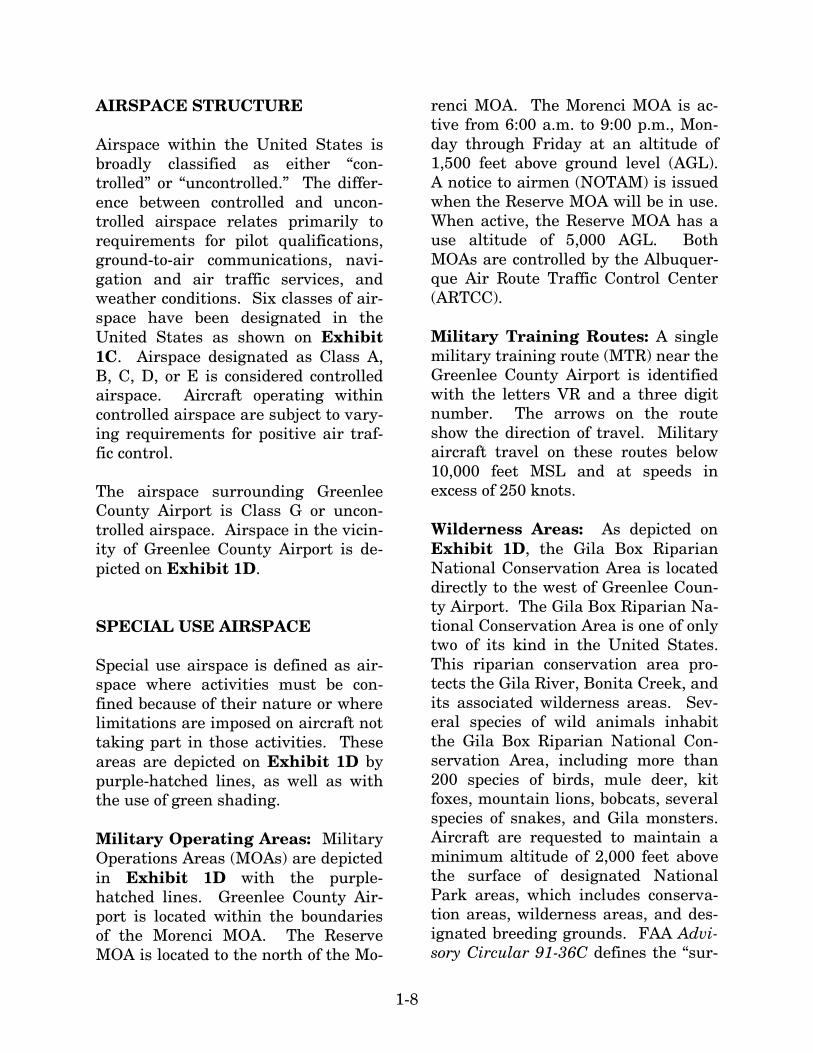
AIRSPACE STRUCTURE Airspace within the United States is broadly classified as either “con-trolled” or “uncontrolled.” The differ-ence between controlled and uncon-trolled airspace relates primarily to requirements for pilot qualifications, ground-to-air communications, navi-gation and air traffic services, and weather conditions. Six classes of air-space have been designated in the United States as shown on Exhibit 1C. Airspace designated as Class A, B, C, D, or E is considered controlled airspace. Aircraft operating within controlled airspace are subject to vary-ing requirements for positive air traf-fic control. The airspace surrounding Greenlee County Airport is Class G or uncon-trolled airspace. Airspace in the vicin-ity of Greenlee County Airport is de-picted on Exhibit 1D. SPECIAL USE AIRSPACE Special use airspace is defined as air-space where activities must be con-fined because of their nature or where limitations are imposed on aircraft not taking part in those activities. These areas are depicted on Exhibit 1D by purple-hatched lines, as well as with the use of green shading. Military Operating Areas: Military Operations Areas (MOAs) are depicted in Exhibit 1D with the purple-hatched lines. Greenlee County Air-port is located within the boundaries of the Morenci MOA. The Reserve MOA is located to the north of the Mo-
renci MOA. The Morenci MOA is ac-tive from 6:00 a.m. to 9:00 p.m., Mon-day through Friday at an altitude of 1,500 feet above ground level (AGL). A notice to airmen (NOTAM) is issued when the Reserve MOA will be in use. When active, the Reserve MOA has a use altitude of 5,000 AGL. Both MOAs are controlled by the Albuquer-que Air Route Traffic Control Center (ARTCC). Military Training Routes: A single military training route (MTR) near the Greenlee County Airport is identified with the letters VR and a three digit number. The arrows on the route show the direction of travel. Military aircraft travel on these routes below 10,000 feet MSL and at speeds in excess of 250 knots. Wilderness Areas: As depicted on Exhibit 1D, the Gila Box Riparian National Conservation Area is located directly to the west of Greenlee Coun-ty Airport. The Gila Box Riparian Na-tional Conservation Area is one of only two of its kind in the United States. This riparian conservation area pro-tects the Gila River, Bonita Creek, and its associated wilderness areas. Sev-eral species of wild animals inhabit the Gila Box Riparian National Con-servation Area, including more than 200 species of birds, mule deer, kit foxes, mountain lions, bobcats, several species of snakes, and Gila monsters. Aircraft are requested to maintain a minimum altitude of 2,000 feet above the surface of designated National Park areas, which includes conserva-tion areas, wilderness areas, and des-ignated breeding grounds. FAA Advi-sory Circular 91-36C defines the “sur-

- Above Ground Level
- Flight Level in Hundreds of Feet
- Mean Sea Level
AGLFL
MSL
CLASSIFICATION DEFINITION
CLASS A
CLASS B
CLASS C
CLASS D
CLASS E
CLASS G
Generally airspace above 18,000 feet MSL up to and including FL 600.
Generally multi-layered airspace from the surface up to 10,000 feet MSL surrounding the nation's busiest airports.
Generally airspace from the surface to 4,000 feet AGL surrounding towered airports with service by radar approach control.
Generally airspace from the surface to 2,500 feet AGL surrounding towered airports.
Generally controlled airspace that is not Class A, Class B, Class C, or Class D.
Generally uncontrolled airspace that is not Class A, Class B, Class C, Class D, or Class E.
Exhibit 1CAIRSPACE CLASSIFICATION
06M
P20
-1C
-3/5
/07
Source: "Airspace Reclassification and Charting Changes for VFR Products," National Oceanic and Atmospheric Administration,National Ocean Service. Chart adapted by Coffman Associates from AOPA Pilot, January 1993.
LEGEND
NOT TO SCALE
ss E.
MORENCI MOA
RESERVE MOA
SAFFORD REGIONALSAFFORD REGIONALSAFFORD REGIONAL
VR263 VR263
Source: Phoenix & Albuquerque Sectional Charts, US Department of Commerce, National Oceanic and Atmospheric Administration 02/15/07
Class E Airspace with floor700 ft. above surface
Class E Airspace with floor1200 ft. or greator above surfacethat abuts Class G Airspace
Military Operating Area
Military Training Routes
Wilderness Area
NORTHNORTHNORTH
NOT TO SCALENOT TO SCALE
Airport with other than hard-surfacedrunways
Airport with hard-surfaced runways1,500' to 8,069' in length
Airports with hard-surfaced runwaysgreater than 8,069' or some multiplerunways less than 8,069'
LEGEND
GREENLEE COUNTY AIRPORT
GREENLEE COUNTY AIRPORT
Blue RangeWildernessBlue RangeWildernessBlue RangeWilderness
Gila WildernessArea
Gila WildernessArea
Gila WildernessArea
Exhibit 1DVICINITY AIRSPACE
06M
P20
-1D
-3/7
/07
Gila Box RiparionNational Conservation Area
Gila Box RiparionNational Conservation Area
Gila Box RiparionNational Conservation Area
LELE

1-9
face” as the highest terrain within 2,000 feet laterally of the route of flight or the uppermost rim of a can-yon or valley. AIRSPACE CONTROL The FAA has established 21 ARTCCs throughout the continental United States to control aircraft operating under instrument flight rules (IFR) within controlled airspace and while enroute. An ARTCC assigns specific routes and altitudes along federal air-ways to maintain separation and or-derly traffic flow. The Albuquerque ARTCC controls IFR airspace enroute over Greenlee County Airport. The ARTCC delegates certain airspace to local terminal facilities which assume responsibility for the orderly flow of air traffic arriving and departing ma-jor terminals. NAVIGATIONAL AIDS Navigational aids are electronic devic-es that transmit radio frequencies, which pilots of properly equipped air-craft translate into point-to-point guidance and position information. The types of electronic navigational aids available for aircraft flying to or from Greenlee County Airport include the VOR, global positioning system (GPS), and Loran-C. The VOR provides azimuth readings to pilots of properly equipped aircraft by transmitting a radio signal at every
degree to provide 360 individual navi-gational courses. Frequently, distance measuring equipment (DME) is com-bined with a VOR facility to provide distance as well as direction informa-tion to the pilot. Military tactical air navigation aids (TACANs) and civil VORs are commonly combined to form a VORTAC. A VORTAC provides dis-tance and direction information to civ-il and military pilots. The San Simon VORTAC, located approximately 41 nautical miles south of the field, is the only VORTAC within close proximity to Greenlee County Airport. Loran-C is a ground-based enroute navigational aid which utilizes a sys-tem of transmitters located in various locations across the continental Unit-ed States. Loran-C allows pilots to navigate without using a specific facil-ity. With a properly equipped aircraft, pilots can navigate to any airport in the United States using Loran-C. GPS was initially developed by the United States Department of Defense for military navigation around the world. GPS differs from a VOR, in that pilots are not required to navi-gate using a specific facility. GPS uses satellites placed in orbit around the earth to transmit electronic radio signals, which pilots of properly equipped aircraft use to determine al-titude, speed, and other navigational information. With GPS, pilots can di-rectly navigate to any airport in the country and are not required to navi-gate using a specific navigation facili-ty.

1-10
INSTRUMENT APPROACH PROCEDURES Instrument approach procedures are a series of predetermined maneuvers established by the FAA, using elec-tronic navigational aids that assist pi-lots in locating and landing at an air-port, especially during instrument flight conditions. Greenlee County Airport currently does not have any published instrument approach proce-dures. VISUAL FLIGHT PROCEDURES All flights into and out of Greenlee County Airport are currently con-ducted under VFR. Under VFR flight, the pilot is responsible for collision avoidance. Typically, the pilot will make radio calls announcing the posi-tion of the aircraft relative to the air-port and the intentions of the pilot. The traffic pattern defines which side of the runway aircraft will operate. At Greenlee County Airport, Runway 7 and Runway 25 have an established left-hand traffic pattern. For these runways, aircraft make a left turn from base leg to final for landing. Therefore, aircraft operating to Run-way 7 remain north of the runway, and aircraft operating to Runway 25 remain south of the runway. The FAA has established that piston-powered aircraft operating in the traf-fic pattern fly at 1,000 feet above the ground (or 4,811 feet MSL) when on the downwind leg. The traffic pattern altitude is established so that aircraft
have a predictable descent profile on base leg to final approach for landing. AREA AIRPORTS A review of the single public-use air-port within the vicinity of Greenlee County Airport has been made to identify and distinguish the type of air service provided in the area surround-ing the airport. Information pertain-ing to this airport was obtained from FAA records. Safford Regional Airport is located approximately 22 miles west of Green-lee County Airport. Safford Regional Airport is owned and operated by the City of Safford and is open to public use. The airport has a dual asphalt runway system: Runway 12-30 with a length of 6,015 feet and Runway 8-26 with a length of 4,800 feet. The air-port does not have an operating ATCT. There are two published non-precision GPS instrument approaches into Saf-ford Regional Airport. The airport has 21 based aircraft and experiences ap-proximately 8,760 annual operations. A full range of general aviation servic-es are available at the airport. LANDSIDE FACILITIES Landside facilities are the facilities that support the aircraft and pi-lot/passenger handling functions. These facilities typically include a terminal building, aircraft sto-rage/maintenance hangars, aircraft parking aprons, and support facilities such as fuel storage, automobile park-

1-11
ing, roadway access, and aircraft res-cue and firefighting. The landside fa-cilities at Greenlee County Airport are identified on Exhibit 1B. TERMINAL The 800 square-foot terminal building at Greenlee County airport was built in 2000. The building consists of a pi-lot lounge, storage area, and two re-strooms. An adjacent parking lot pro-vides approximately 37 automobile parking spaces, including two handi-capped parking spaces. APRON AND AIRCRAFT PARKING The aircraft parking apron at Green-lee County Airport is located north of Runway 7-25. The 9,800 square yard apron provides adequate space for ap-proximately 25 aircraft tie-down spac-es. Currently, there are built-in hold-ers for tie-down ropes or chains; how-ever, no ropes or chains are present and the tie-down spaces are not clear-ly painted. The tie-down spaces are used mainly by transient aircraft as the two based aircraft are housed in hangar facilities. AIRCRAFT HANGAR FACILITIES Presently there are two privately owned enclosed portable aircraft sto-rage facilities encompassing approx-imately 1,075 square feet of the air-
craft parking apron. Both aircraft sto-rage facilities house one single engine aircraft. MAINTENANCE AND AIRCRAFT RESCUE AND FIRE FIGHTING Maintenance at Greenlee County Air-port is performed by County Public Works personnel. There are no dedi-cated maintenance facilities on the airport, which requires maintenance equipment to be brought in from an off-airport location. The County is currently in the process of developing a Public Works maintenance facility on the airport, which would include equipment for the maintenance of the airport. There are no aircraft rescue and fire fighting (ARFF) facilities located on the airport. Firefighting services are typically provided by the Morenci Fire Association and the Duncan Rural Fire Department, both of which have an approximate response time of 25 minutes. The Morenci Fire Associa-tion is owned by the Morenci mine. Both of these emergency response units are made up of volunteers. FUELING FACILITIES Aircraft fueling services are not avail-able at Greenlee County Airport. The nearest airport offering fueling facili-ties is Safford Regional Airport located approximately 22 nautical miles to the west of the airport.

1-12
UTILITIES Water and sanitary sewer services at the airport are provided onsite from water wells and septic tanks. Duncan Valley Electrical Cooperative provides electrical service to the airport. Air-field electrical power, including the runway and approach visual aid light-ing, is provided by an electrical vault located adjacent to the terminal build-ing. Phone service at Greenlee County Airport is provided by Copper Valley Telephone. SECURITY FENCING AND GATES The north side of the airport perimeter is secured by an eight foot chain link fence with three strands of barbed wire. The southern portion of the air-port perimeter is fenced with a four foot high fence with hog wire on the bottom to stop varmints and barbed wire on top. The fencing is in good condition. There is a single mechanical gate on the north side of the airport allowing access to the apron area and the air-side of the airport. There is a gate at the entrance of the airport just after the turn off of State Route 78. The County has also installed a 30 foot swing gate at the end of Runway 7 off of State Route 78 and a 30 foot slide gate in the northeast corner of the air-port for construction use.
ACCESS & CIRCULATION GENERAL ACCESS TO GREENLEE COUNTY AIRPORT – SURROUNDING ROADS The airport is located approximately one-half mile to the east of the inter-section of State Route 78 and U.S. Route 191. The airport is accessible via an access road which extends from State Route 78 to the airport terminal building. The two-lane road is con-structed of asphalt and is in good con-dition. SOCIOECONOMIC PROFILE The socioeconomic profile provides a general look at the socioeconomic ma-keup of the community that utilizes Greenlee County Airport. It also pro-vides an understanding of the dynam-ics for growth and the potential changes that may affect aviation de-mand. Aviation demand forecasts are often directly related to the population base, economic strength of the region, and the ability of the region to sustain a strong economic base over an ex-tended period of time. Current demo-graphic and economic information was collected from the Arizona Depart-ment of Economic Security, the 1980, 1990, and 2000 census reports, as well as several federal agencies.

1-13
POPULATION Population is a basic demographic element to consider when planning for future needs of the airport. The State of Arizona has been one of the fastest growing states in the country. Table 1E shows the total population growth since 1980 for the State of Arizona, Greenlee County, and the Town of Clifton. Arizona has grown at an an-nual average rate of 3.30 percent since
1980, increasing its population by more than 3.5 million. The popula-tions of the Town of Clifton and Greenlee County have been declining since 1980 at average annual rates of -2.05 percent and -1.22 percent respec-tively. Greenlee County is the smal-lest county in the State by population and is the only county in Arizona to experience a decrease in total popula-tion over the past 26 years.
TABLE 1E Historical Population Town of Clifton, Greenlee County, State of Arizona
Year
Town of Clifton
% Change
Greenlee County
% Change
State of Arizona
% Change
1980 4,256 N/A 11,428 N/A 2,714,013 N/A 1990 2,840 -33.27% 8,000 -30.00% 3,680,800 35.62% 2000 2,596 -8.59% 8,547 6.84% 5,130,632 39.39% 2001 2,595 -0.04% 8,590 0.50% 5,319,895 3.69% 2002 2,595 0.00% 8,605 0.17% 5,472,750 2.87% 2003 2,590 -0.19% 8,595 -0.12% 5,629,870 2.87% 2004 2,505 -3.28% 8,350 -2.85% 5,833,685 3.62% 2005 2,495 -0.40% 8,300 -0.60% 6,044,985 3.62% 2006 2,485 -0.40% 8,300 0.00% 6,305,210 3.62%
Average Annual
% Change -2.05% -1.22% 3.30% Source: Arizona Department of Economic Security
EMPLOYMENT Employment opportunities affect mi-gration to the area and population
growth. As shown in Table 1F, the Town of Clifton’s unemployment rate has been above state and national le-vels historically.

1-14
TABLE 1F Unemployment Rates (Not Seasonally Adjusted) Town of Clifton, Greenlee County, State of Arizona, The United States
Year Town of Clifton
Greenlee County
State of Arizona
The United States
1995 5.1% 6.7% 5.1% 5.6% 1996 6.0% 7.9% 5.5% 5.4% 1997 5.5% 7.2% 4.6% 4.9% 1998 6.1% 8.1% 4.1% 4.5% 1999 6.6% 8.7% 4.4% 4.2% 2000 6.3% 4.3% 4.0% 4.0% 2001 10.5% 7.2% 4.7% 4.7% 2002 11.4% 7.9% 6.2% 5.8% 2003 11.0% 7.6% 5.6% 6.0% 2004 8.5% 5.8% 5.1% 5.6% 2005 8.4% 5.7% 4.8% 4.9% 2006 6.8% 4.7% 3.9% 4.8%
Source: Arizona Department of Economic Security
Table 1G summarizes total employ-ment by sector for Greenlee County from 2000 to 2006. As shown in the table, Greenlee County recorded growth in only one sector (trade,
transportation, and utilities) during the period. Total employment expe-rienced an average annual reduction of 0.57 percent over the period, reduc-ing 150 total jobs since 2000.
TABLE 1G Employment By Sector (Non-Farm) Greenlee County
Sector 2000 2001 2002 2003 2004 2005 2006 Avg. Annual % Change Goods Producing 3,250 2,725 2,400 2,325 2,400 2,675 3,150 -0.52% Trade, Transporta-tion, and Utilities 75 300 275 250 250 275 275 24.18% Other Private Service-Providing 550 375 375 325 325 325 400 -5.17% Government 575 550 525 525 525 500 475 -3.13% Total 4,450 3,950 3,575 3,425 3,500 3,775 4,300 -0.57% Source: Arizona Department of Economic Security
PER CAPITA PERSONAL INCOME Per capita personal income (PCPI) for Greenlee County is summarized in Table 1H. PCPI is determined by di-viding total income by population. For PCPI to grow significantly, income
growth must outpace population growth. As shown in the table, PCPI has grown at an average annual rate of 0.98 percent in Greenlee County since 1990. The State of Arizona has experienced a greater increase in PCPI, at 1.45 percent annually over the same time period.

1-15
TABLE 1H Per Capita Personal Income (1996 $) Greenlee County and Arizona
Year Greenlee County Arizona 1990 1995 1996 1997 1998 1999 2000 2001 2002 2003 2004 2005 2006
$15,680 $17,735 $18,355 $18,621 $17,905 $17,189 $18,892 $17,926 $18,282 $19,112 $17,693 $18,049 $18,341
$19,762 $20,357 $20,823 $21,499 $22,628 $23,064 $24,004 $23,873 $23,814 $24,148 $24,298 $24,653 $24,866
Average Annual Growth Rate 1990-2006 0.98% 1.45%
Source: Woods & Poole Economics
CLIMATE Weather plays an important role in the operational capabilities of an air-port. Temperature is an important factor in determining runway length required for aircraft operations. The
percentage of time that visibility is impaired due to cloud coverage is a major factor in determining the use of instrument approach aids. Precipitation in Clifton is generally more plentiful in the late summer and early autumn months than at any oth-er time during the year. Approximate-ly 55 percent of the annual total preci-pitation occurs from July through Oc-tober. Precipitation is in the form of rain, as the average low rarely drops below freezing. The winter season is marked by mild temperatures with oc-casional light snow falls. Summer produces high temperatures and most of the precipitation. Fall and Spring are transitional in nature. April, May, and June average the least amount of precipitation during the year, with a combined 8.7 percent of the annual total. Table 1J summarizes typical temperature and precipitation data for the region.
TABLE 1J Temperature and Precipitation Data Clifton, Arizona Temperature (Fahrenheit)
Mean Maximum
Mean Minimum
Precipitation (inches)
January 59.7 32.7 1.01 February 65.8 37.1 1.00 March 72.4 42.4 0.82 April 80.9 49.0 0.40 May 89.7 57.4 0.33 June 99.2 66.8 0.42 July 100.2 71.4 2.15 August 97.7 70.3 2.42 September 93.2 65.0 1.63 October 82.9 53.9 1.12 November 69.3 40.7 0.76 December 59.8 33.4 1.19 Annual 80.9 51.7 13.25 Source: Western Regional Climate Center

1-16
LAND ZONING According to the Greenlee County Zon-ing map, the land on which the airport is situated is zoned as an overlay dis-trict. The land directly to the west of the airport is zoned as general busi-ness, and the majority of the remain-ing surrounding land is zoned as RU-36, which allows for one residential unit per 36 acres. HEIGHT AND HAZARD ZONING Height and hazard zoning establishes height limits for new construction near an airport and within the runway approaches. Height and hazard zon-ing ordinances are typically based on Federal Aviation Regulation (FAR) Part 77, which defines imaginary sur-faces surrounding the airport that are to remain free of obstructions for the purpose of safe air navigation. Green-lee County has adopted airport air-space district height restrictions for structures and objects of natural growth that lie within defined zones related to the airport safety areas. These zoning restrictions can be found in Article 15, Sections 1501-1506 of the Greenlee County Planning and Zoning Regulations dated March 8, 2007. SUMMARY The information discussed on the pre-vious pages provides a foundation upon which the remaining elements of the planning process will be con-structed. Information on current air-port facilities and utilization will serve as a basis, with additional analysis
and data collection, for the develop-ment of forecasts of aviation activity and facility requirement determina-tions. The inventory of existing condi-tions is the first step in the process of determining those factors which will meet projected aviation demand in the community and the region. DOCUMENT SOURCES A variety of sources were used during the inventory process. The following listing reflects a partial compilation of these sources. In addition, considera-ble information was provided directly to the consultant by the Greenlee County Airport. AirNAV Airport information, website: www.airnav.com Airport/Facility Directory Southwest U.S; May 10, 2007 Arizona Department of Economic Se-curity; 2007 Arizona Department of Transportation FAA 5010 Form, Airport Master Record, 2007 Greenlee County Planning and Zoning Regulations, March 8, 2007 Phoenix Sectional Chart, US Depart-ment of Commerce, National Oceanic and Atmospheric Administration, Feb-ruary 15, 2007 Western Regional Climate Center; 2007 Woods & Poole Economic and Demo-graphic Forecasts, 2006

Chapter Two
AVIATION DEMAND FORECASTS

2-1
AVIATION DEMANDFORECASTSAVIATION DEMANDFORECASTS
Chapter Two
Facility planning must begin with a definition of the demand that may reasonably be expected to occur at the facility over a specific period of time. The scope for this Airport Master Plan Update is exclusive to the short-term (five-year) development of the airport; therefore, forecasts of aviation activity indicators through the year 2012 will be prepared. These aviation activity indicators including forecasts of based aircraft, based aircraft fleet mix, and annual aircraft operations will serve as the basis for facility planning.
It is virtually impossible to predict, with certainty, year-to-year fluctuations of activity when looking into the future. Because aviation activity can be affected by many influences at the local, regional, and national levels, it is important to
remember that forecasts are to serve only as guidelines, and planning must remain flexible enough to respond to unforeseen facility needs.
The forecasts prepared in this chapter will establish a demand-based rather than time-based short-term planning horizon. As a result, the reasonable level of activity potential that is derived from this forecasting effort will be related to the planning horizon level rather than dates in time. This planning horizon will be established as a level of activity that will call for consideration of the implementation of proposed projects over the next five years.
The following forecast analysis exam-ines recent developments, historical information, and current aviation

2-2
trends to provide an updated set of aviation demand projections for Greenlee County Airport. The intent is to permit Greenlee County to make the planning adjustments necessary to ensure that the facility meets pro-jected demands in an efficient and cost-effective manner. NATIONAL AVIATION TRENDS Each year, the FAA updates and pub-lishes a national aviation forecast. In-cluded in this publication are forecasts for the large air carriers, region-al/commuter air carriers, general avia-tion, and FAA workload measures. The forecasts are prepared to meet budget and planning needs of the con-stituent units of the FAA and to pro-vide information that can be used by state and local authorities, the avia-tion industry, and the general public. The current edition when this chapter was prepared was FAA Aerospace Forecasts-Fiscal Years 2007-2020, pub-lished in March 2007. The forecasts use the economic performance of the United States as an indicator of future aviation industry growth. Similar economic analyses are applied to the outlook for aviation growth in interna-tional markets. In the seven years prior to the events of September 11, 2001, the U.S. civil aviation industry experienced unprec-edented growth in demand and profits . The impacts to the economy and avi-ation industry from the events of 9/11 were immediate and signifi-cant. The economic climate and aviation indus-
try, however, has been on the recov-ery. The Office of Management and Budget (OMB) expects the U.S. economy to continue to grow in terms of Gross Domestic Product (GDP) at an average annual rate of 3.0 percent over the next 13 years. This will positively in-fluence the aviation industry, leading to passenger, air cargo, and general aviation growth throughout the fore-cast period (assuming there will not be any new successful terrorist incidents against either the U.S. or world avia-tion). GENERAL AVIATION Following more than a decade of de-cline, the general aviation industry was revitalized with the passage of the General Aviation Revitalization Act in 1994, which limits the liability on gen-eral aviation aircraft to 18 years from the date of manufacture. This legisla-tion sparked an interest to renew the manufacturing of general aviation air-craft due to the reduction in product liability, as well as renewed optimism for the industry. The high cost of product liability insurance had been a major factor in the decision by many American aircraft manufacturers to slow or discontinue the production of general aviation aircraft. The sustained growth in the general aviation industry slowed considerably in 2001, negatively impacted by the events of September 11. Thousands of general aviation aircraft were grounded for weeks due to no-fly zone

2-3
restrictions imposed on operations of aircraft in security-sensitive areas. This, in addition to the economic re-cession that began in early 2001, had a negative impact on the general avia-tion industry. General aviation ship-ments by U.S. manufacturers declined for three straight years from 2001 through 2003. Stimulated by an expanding U.S. economy as well as accelerated depre-ciation allowances for operators of new aircraft, general aviation staged a rel-atively strong recovery with over ten percent growth in each of the last three years. Resilience being demonstrated in the piston aircraft market offers hope that the new aircraft models are attracting interest in the low-end market of gen-eral aviation. The introduction of new, light sport aircraft is expected to provide further stimulation in the coming years. Despite a slower growth rate in ship-ments over the past few years, new models of business jets are also stimu-lating interest for the high-end of the market. The FAA still expects the business segment to expand at a faster rate than personal/sport flying. Safety and security concerns, combined with increased processing time at commer-cial terminals, make business/ corpo-rate flying an attractive alternative. In addition, the bonus depreciation provision of the President’s economic stimulation package had begun to help business jet sales late in 2004. In 2006, there were an estimated 226,422 active general aviation air-craft in the United States. Exhibit
2A depicts the FAA forecast for active general aviation aircraft. The FAA projects an average annual increase of 1.4 percent through 2020, resulting in 274,914 active aircraft. Piston-powered aircraft are expected to grow at an average annual rate of 1.3 per-cent. This is driven primarily by a 5.7 percent annual increase in piston-powered rotorcraft, as single-engine fixed-wing piston aircraft are projected to increase at just 0.3 percent and multi-engine fixed-wing piston aircraft are projected to decrease at -0.2 per-cent annually. This is due, in part, to the attrition of approximately 1,500 older piston aircraft annually. In ad-dition, it is expected that the new, light sport aircraft and the relatively inexpensive microjets will dilute or weaken the replacement market for piston aircraft. Owners of ultralight aircraft could be-gin registering their aircraft as “light sport” aircraft in 2005. The FAA es-timates there will be a registration of 10,500 aircraft by 2015, and then grow to 13,200 aircraft by 2020. Turbine-powered aircraft (turboprop and jet) are expected to grow at an av-erage annual rate of 4.1 percent over the forecast period. Even more signif-icantly, the jet portion of this fleet is expected to double in size in 12 years, with an average annual growth rate of 6.0 percent. The total number of jets in the general aviation fleet is pro-jected to grow from 10,032 in 2006, to 22,797 by 2020. The Business Aviation Panel has sug-gested that the market for the new, very light jet (VLJ), or microjet air-craft, could add 500 more aircraft a

06M
P20
-2A
-3/7
/07
U.S. ACTIVE GENERAL AVIATION AIRCRAFT (in thousands)U.S. ACTIVE GENERAL AVIATION AIRCRAFT (in thousands)
2006(Est.)
2010
2015
2020
148.2
150.4
154.0
155.6
8.0
8.2
8.5
8.8
6.6
6.8
6.7
6.6
226.4
242.8
261.4
274.9
24.5
27.7
31.1
33.9
10.0
13.4
18.0
22.8
19.4
19.2
19.0
18.8
3.4
4.8
6.3
7.4
5.9
6.5
7.2
7.9
0.4
5.6
10.5
13.2
Year
FIXED WINGPISTON ROTORCRAFTTURBINE
SingleEngine Other
SportAircraft TotalExperimentalTurbojet
Multi-Engine Piston TurbineTurboprop
ACTUALACTUALACTUAL FORECASTFORECASTFORECAST
150
175
200
225
250
AIR
CR
AF
T (
in t
ho
usa
nd
s)
1980 1985 1990 1995 2000 2005
YEAR
2010
275
125
2015 2020
Exhibit 2AU.S. ACTIVE GENERAL AVIATION
AIRCRAFT FORECASTS
Source: FAA Aerospace Forecasts, Fiscal Years 2007-2020.
Notes: An active aircraft is one that has a current registration and was flown at least one hour during the calendar year.
U.S. ACTIVE GENERAL AVIATION AIRCRAFT FORECASTS
U.S. ACTIVE GENERAL AVIATION AIRCRAFT U.S. ACTIVE GENERAL AVIATION AIRCRAFT

2-4
year to the fleet by 2010. These twin-engine jets are expected to be priced between $1 million and $2 million, and are believed to have the potential to redefine business jet flying with the capability to support a true on-demand air taxi business service. The FAA forecast assumes that microjets will begin to enter the active fleet in 2007, with 350 new aircraft. After this year’s introduction, they are fore-cast to grow by 400 to 500 aircraft per year, contributing a total of 6,300 air-craft to the jet forecast by 2020. FORECASTING APPROACH The development of aviation forecasts proceeds through both analytical and judgmental processes. A series of ma-thematical relationships are tested to establish statistical logic and rationale for projected growth. However, the judgment of the forecast analyst, based upon professional experience, knowledge of the aviation industry, and their assessment of the local situ-ation, is important in the final deter-mination of the preferred forecast. However, it is important to use fore-casts which do not overestimate reve-nue-generating capabilities or unders-tate demand for facilities needed to meet public (user) needs. A wide range of factors are known to influence the aviation industry and can have significant impacts on the extent and nature of air service pro-vided in both the local and national markets. Technological advances in aviation have historically altered and will continue to change the growth
rates in aviation demand over time. The most obvious example is the im-pact of jet aircraft on the aviation in-dustry, which resulted in a growth rate that far exceeded expectations. Such changes are difficult, if not im-possible, to predict, and there is simp-ly no mathematical way to estimate their impacts. Using a broad spec-trum of local, regional and national socioeconomic and aviation informa-tion, and analyzing the most current aviation trends, forecasts are pre-sented in the following sections. To determine the types and sizes of facilities that should be planned to ac-commodate general aviation activity, certain elements of this activity must be forecast. Indicators of general avia-tion demand include: Based aircraft Based aircraft fleet mix General aviation operations Air taxi operations Annual instrument approaches The remainder of this chapter will ex-amine historical trends with regard to these areas of general aviation and project future demand for these seg-ments of general aviation activity at the airport. BASED AIRCRAFT The number of aircraft based at an airport is, to some degree, dependent upon the nature and magnitude of air-craft ownership in the local service area. Therefore, the process of devel-oping a projection of based aircraft for Greenlee County Airport begins with a
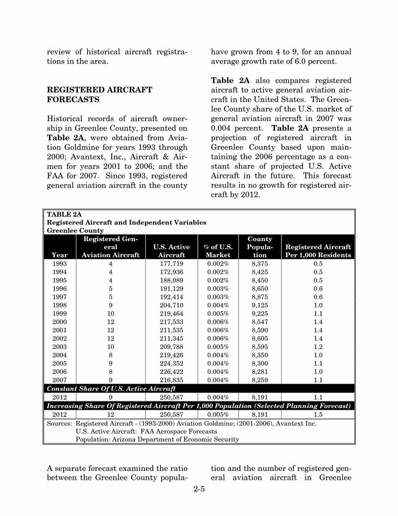
2-5
review of historical aircraft registra-tions in the area. REGISTERED AIRCRAFT FORECASTS Historical records of aircraft owner-ship in Greenlee County, presented on Table 2A, were obtained from Avia-tion Goldmine for years 1993 through 2000; Avantext, Inc., Aircraft & Air-men for years 2001 to 2006; and the FAA for 2007. Since 1993, registered general aviation aircraft in the county
have grown from 4 to 9, for an annual average growth rate of 6.0 percent. Table 2A also compares registered aircraft to active general aviation air-craft in the United States. The Green-lee County share of the U.S. market of general aviation aircraft in 2007 was 0.004 percent. Table 2A presents a projection of registered aircraft in Greenlee County based upon main-taining the 2006 percentage as a con-stant share of projected U.S. Active Aircraft in the future. This forecast results in no growth for registered air-craft by 2012.
TABLE 2A Registered Aircraft and Independent Variables Greenlee County
Year
Registered Gen-eral
Aviation Aircraft U.S. Active
Aircraft % of U.S. Market
County Popula-
tion Registered Aircraft Per 1,000 Residents
1993 4 177,719 0.002% 8,375 0.5 1994 4 172,936 0.002% 8,425 0.5 1995 4 188,089 0.002% 8,450 0.5 1996 5 191,129 0.003% 8,650 0.6 1997 5 192,414 0.003% 8,875 0.6 1998 9 204,710 0.004% 9,125 1.0 1999 10 219,464 0.005% 9,225 1.1 2000 12 217,533 0.006% 8,547 1.4 2001 12 211,535 0.006% 8,590 1.4 2002 12 211,345 0.006% 8,605 1.4 2003 10 209,788 0.005% 8,595 1.2 2004 8 219,426 0.004% 8,350 1.0 2005 9 224,352 0.004% 8,300 1.1 2006 8 226,422 0.004% 8,281 1.0 2007 9 216,835 0.004% 8,259 1.1
Constant Share Of U.S. Active Aircraft 2012 9 250,587 0.004% 8,191 1.1
Increasing Share Of Registered Aircraft Per 1,000 Population (Selected Planning Forecast) 2012 12 250,587 0.005% 8,191 1.5
Sources: Registered Aircraft - (1993-2000) Aviation Goldmine; (2001-2006), Avantext Inc. U.S. Active Aircraft: FAA Aerospace Forecasts Population: Arizona Department of Economic Security
A separate forecast examined the ratio between the Greenlee County popula-
tion and the number of registered gen-eral aviation aircraft in Greenlee

2-6
County. As shown in Table 2A, there were 0.5 registered aircraft per 1,000 residents in 1993. This ratio has since increased to 1.1 registered aircraft per 1,000 residents in 2007 as registered aircraft have grown while population has remained fairly static over the last 14 years. A projection of registered aircraft was developed assuming that registered aircraft per 1,000 residents will in-crease through the planning period to recapture ratio levels that were expe-rienced between 2000 and 2002. This projection results in registered aircraft growing to 12 by 2012, an average an-nual growth rate of 6.4 percent. The forecast of registered aircraft per capi-ta are presented in Table 2A. In recent years, registered aircraft in Greenlee County have grown at the same rate as U.S. Active Aircraft and slightly faster than the Greenlee County population. The selected planning forecast assumes slight growth over the next five years, par-tially attributable to an expected in-crease in sport aircraft registrations. This selected forecast provides a rea-sonable growth rate over the planning period with registered aircraft in Greenlee County growing to 12 air-craft by 2012. Exhibit 2B graphically depicts the selected forecast in com-parison with the other projections.
BASED AIRCRAFT FORECAST The number of based aircraft is the most basic indicator of general avia-tion demand at an airport. By first developing a forecast of based aircraft, the growth of other general aviation activities and demands can be pro-jected. According to the 2007 FAA Terminal Area Forecasts (TAF), there were two based aircraft at Greenlee County Airport in 1996. The number of based aircraft has remained static, with two based aircraft reported by the airport in 2007. Table 2B examines based aircraft as a percentage of aircraft ownership in Greenlee County. As shown in the ta-ble, the airport’s based aircraft were equivalent to 50.0 percent of aircraft registered in the County in 1995. The airport’s share has since decreased to 22.2 percent in 2007. This is the re-sult of a zero percent growth rate for based aircraft at Greenlee County Airport over the past 12 years. The airport’s based aircraft have averaged 31.9 percent of the total registered air-craft in the county over the same time period. A projection of based aircraft was de-veloped by maintaining Greenlee County Airport’s average market share in the county (31.9 percent). This would yield four based aircraft by 2012, with based aircraft growing at a rate of 13.9 percent annually.

Exhibit 2BREGISTERED & BASED
AIRCRAFT
06M
P20
-1D
-3/5
/07
44
2
0
6
8
1010
1212
1414
4
2
0
6
8
10
12
14
201220122007200720052005 20102010200020001995199519931993 201220072005 201020001995
9696969696969969696 979797797797977979797 98989898989898998989889 999999999999999999 01001010101001011 02020202020020202 0303030300030303 040404040400404 060606060666660660606
1993
0
1
2
3
4
5
0
1
2
3
4
5
2012201220072007200520052000200019951995 2012200720052000
Based Aircraft Average Share Projection(SELECTED FORECAST)
2000 AirportMaster Plan
FAA-TAF Arizona StateAviation NeedsStudy
1995
RE
GIS
TE
RE
D A
IRC
RA
FTR
EG
IST
ER
ED
AIR
CR
AFT
RE
GIS
TE
RE
D A
IRC
RA
FTB
AS
ED
AIR
CR
AFT
BA
SE
D A
IRC
RA
FTB
AS
ED
AIR
CR
AFT
Gre
enle
e C
oun
ty A
irp
ort
Gre
enle
e C
oun
ty A
irp
ort
Gre
enle
e C
oun
ty A
irp
ort
Gre
enle
e C
oun
ty
Gre
enle
e C
oun
ty
Gre
enle
e C
oun
ty
Registered GeneralAviation Aircraft
Constant Share ofU.S. Active Aircraft
HISTORIC
Increasing Share ofRegistered Aircraft(Selected Forecast)
9999989897979696 0404 0606030302020101
FORECASTS
HISTORIC FORECASTS

2-7
TABLE 2B Based Aircraft Projection Greenlee County Airport
Year
Greenlee County Registered
Aircraft Based Aircraft Greenlee County
Market Share 1995 4 2 50.0% 1996 5 2 40.0% 1997 5 2 40.0% 1998 9 2 22.2% 1999 10 3 30.0% 2000 12 3 25.0% 2001 12 3 25.0% 2002 12 3 25.0% 2003 10 3 30.0% 2004 8 3 37.5% 2005 9 3 33.3% 2006 8 2 25.0% 2007 9 2 22.2%
Average Share Projection (Selected Forecast) 2012 12 4 33.3%
2000 Airport Master Plan 2012 12 2 16.7% FAA-TAF
2012 12 3 25.0% Arizona State Aviation Needs Study
2012 12 4 33.3%
For comparative purposes, projections for the 2000 Greenlee County Airport Master Plan, the 2007 FAA-TAF, and the 2000 Arizona State Aviation Needs Study (SANS) have also been ex-amined. The SANS projection years did not match those used in this mas-ter plan; therefore, those figures were interpolated and extrapolated by Coffman Associates. The extrapolated projections indicated based aircraft growing to four by 2012 which matches the average share projection. The FAA-TAF projects based aircraft
at Greenlee County Airport growing to three by 2012. The 2000 Airport Mas-ter Plan projected based aircraft to remain static at two through the planning period. Table 2B and Exhibit 2B provide a summary of these general aviation based aircraft forecasts. This plan-ning forecast allows for two additional based aircraft by 2012. This growth, again, can be attributed to potential growth in sport aircraft operators.

2-8
BASED AIRCRAFT FLEET MIX The aircraft fleet mix expected to util-ize the airport is necessary to properly plan facilities that will best serve the level of activity and type of activities occurring at the airport. The existing based aircraft fleet mix is comprised of two single-engine piston aircraft. Based aircraft at Greenlee County Airport are projected to increase by only two aircraft by 2012. The two additional aircraft are most likely to be single engine fixed-wing aircraft as well. Therefore, the airport should plan for four single engine based air-craft by 2012. AIRCRAFT OPERATIONS Aircraft operations at airports are classified as either local or itinerant. A local operation is a take-off or land-ing performed by an aircraft that op-erates within site of the airport, or which executes simulated approaches or “touch-and-go” operations at the airport. Itinerant operations are those performed by aircraft with a specific origin or destination away from the airport. Generally, local operations are characterized by training opera-tions. Typically, itinerant operations increase with business and industrial use, since business aircraft are used primarily to carry people from one lo-cation to another. GENERAL AVIATION OPERATIONS Due to the absence of an airport traffic control tower, actual operational
counts are not available for Greenlee County Airport. The FAA 5010 Air-port Master Record for Greenlee County Airport estimates a total of 3,190 general aviation operations in 2006. For this study, an FAA-approved statistical methodology for estimating general aviation operations using local variables was utilized to update the operations count. This method, the Model for Estimating General Aviation Operations at Non-Towered Airports, was prepared for the FAA Statistics and Forecast Branch in July 2001. This report de-velops and presents a regression mod-el for estimating general aviation op-erations at non-towered airports. The model was derived using a combined data set for small towered and non-towered general aviation airports and incorporates a dummy variable to dis-tinguish the two airport types. In ad-dition, the report applies the model to estimate activity at 2,789 non-towered general aviation airports contained in the FAA Terminal Area Forecasts. The forecasts of annual operations at Greenlee County Airport were com-puted using the recommended equa-tion (#15) for non-towered airports. Independent vari-ables used in the equation include airport characteris-tics (i.e., number of based aircraft, number of flight schools), population totals, and geographic location. This equation yields an annual general avi-ation operations estimate of approx-imately 1,000 for 2006. Local and iti-nerant operation percentages for 2007 were taken from the FAA 5010 Airport Master Record estimates for 2006 (31% and 69%, respectively).

2-9
Based aircraft at Greenlee County Airport experienced approximately 500 operations in 2006. Maintaining a constant level of operations per based aircraft, based on the 2006 ratio (500), yields a projection of 2,000 annual general aviation operations by the year 2012. The 2007 FAA TAF fore-cast general aviation operations at Greenlee County Airport to reach 3,650 operations by 2012. The Arizo-na SANS projected general aviation
operations to reach 7,800 annual gen-eral aviation operations by 2012. This number most likely includes air taxi operations conducted by City Link for Phelps Dodge. All other projections do not include City Link operations, which are to be discussed in the Air Taxi Operations section below. The average ratio projection, constant ratio projection, FAA TAF, Arizona SANS, and the 2000 Airport Master Plan forecasts are presented in Table 2C.
TABLE 2C General Aviation Operations Forecast Greenlee County Airport
Year Total
Operations Local % Itinerant % Based
Aircraft Operations Per Based
2006 1,000 300 30.0% 700 70.0% 2 500 Constant Ratio Projection (PREFERRED PLANNING FORECAST) 2012 2,000 600 30.0% 1,400 70.0% 4 500
FAA TAF 2012 3,650 1,460 40.0% 2,190 60.0% 3 1,217
Arizona SANS 2012 7,800 N/A N/A N/A N/A 4 1,950
2000 Airport Master Plan 2012 2,791 1,890 67.7% 901 32.3% 2 1,276
The preferred planning forecast (con-stant ratio projection) maintains the current level of operations per based aircraft (approximately 500) through 2012. This projection was selected to represent the most reasonable activity level the airport can expect over the planning period. The preferred plan-ning forecast yields 2,000 annual gen-eral aviation operations by 2012. Lo-cal and itinerant operations were pro-jected to remain near the current per-centages at 30.0 and 70.0 percent, re-spectively.
AIR TAXI OPERATIONS Air taxi operations at Greenlee County Airport consist solely of operations conducted by City Link for the trans-portation needs of Phelps Dodge em-ployees. These operations generally originate from Phoenix Sky Harbor Airport or the Grant County Airport in Silver City, New Mexico. The aircraft used to conduct these operations in-clude the twin-piston engine Cessna 414, the twin-turboprop Cessna 425, and occasionally twin-turboprop air-

2-10
craft Beechcraft C90 King Air, and Beechcraft King Air 200. The own-er/operator of City Link estimated yearly operations at approximately 864. It is not anticipated that these operations will increase or decrease in the next five years; therefore, air taxi operations are projected to remain stable at approximately 900 per year through 2012. ANNUAL INSTRUMENT APPROACHES An instrument approach as defined by the FAA is “an approach to an airport with the intent to land an aircraft in accordance with an Instrument Flight Rules (IFR) flight plan, when visibility is less than three miles and/or when the ceiling is at or below the minimum initial approach altitude.” Due to the lack of an instrument approach at Greenlee County Airport, instrument approaches are not performed. With the addition of an instrument ap-proach into Greenlee County Airport, it can be expected that annual instru-ment approaches (AIAs) would repre-sent one percent of total itinerant op-erations. Applying this percentage to forecast itinerant operations yields 23 instrument approaches in 2012.
SUMMARY This chapter has outlined the various aviation demand levels anticipated over the planning period. In sum-mary, general aviation activity at Greenlee County Airport has shown slow growth. However, the airport still has growth potential for both based aircraft and general aviation operations due to the introduction of sport aircraft and a strong local eco-nomic base. Table 2F provides a summary of the aviation activity planning horizon for Greenlee County Airport. Activity for 2007 is included in the table as a base-line reference. TABLE 2F Forecasts Summary Greenlee County Airport 2007 2012 ANNUAL OPERATIONS Itinerant Operations General Aviation Air Taxi Local Operations General Aviation Total Operations
700 900
300 1,900
1,400
900
600 2,900
BASED AIRCRAFT Total Based Aircraft 2 4

Chapter Three
FACILITY REQUIREMENTS

3-1
FACILITYREQUIREMENTSFACILITYREQUIREMENTS
Chapter Three
To properly plan for the future of the Greenlee County Airport, it is necessary to translate forecast aviation demand into the specific types and quantities of facilities that can adequately serve this identified demand. This chapter uses the results of the forecasts conducted in Chapter Two, as well as established planning criteria to determine the airfield (i.e., runways, taxiways, navigational aids, marking and lighting) and landside (i.e., hangars, aircraft parking apron) facility requirements.
The objective of this effort is to identify, in general terms, the adequacy of the existing airport facilities, outline what new facilities may be needed, and when these may be needed to accommodate forecast demands. Having established these facility requirements, alternatives
for providing these facilities will be evaluated in Chapter Four to determine the most cost-effective and efficient means for implementation.
The cost-effective, efficient, and orderly development of an airport should rely more upon actual demand at an airport than on a time-based forecast figure. In order to develop a Master Plan that is demand-based rather than time-based, a short-term planning horizon milestone has been established for Greenlee County Airport that takes into consideration the reasonable range of aviation demand projections prepared in Chapter Two. It is important to consider that the actual activity at the airport may be higher or lower than projected activity levels. By planning according to an ac-

3-2
tivity milestone, the resultant plan can accommodate unexpected shifts or changes in the area’s aviation de-mand. The most important reason for utiliz-ing a milestone is that it allows the airport to develop facilities according to need generated by actual demand levels. The demand-based schedule
provides flexibility in development, as development schedules can be slowed or expedited according to actual de-mand at any given time over the plan-ning period. The resultant plan pro-vides airport officials with a financial-ly responsible and needs-based pro-gram. Table 3A presents the plan-ning horizon milestone for each activi-ty demand category.
TABLE 3A Planning Horizon Activity Levels
Current
Short Term Planning Horizon
Based Aircraft Annual Operations
2 1,900
4 2,900
PEAKING CHARACTERISTICS Most facility planning relates to levels of peak activity. The following plan-ning definitions apply to the peak pe-riods: Peak Month – The calendar month
when peak aircraft operations oc-cur.
Design Day – The average day in the peak month.
Busy Day – The busy day of a typi-cal week in the peak month.
Design Hour – The peak hour with-in the design day.
It is important to note that only the peak month is an absolute peak within a given year. All other peak periods will be exceeded at various times dur-
ing the year. However, they do represent reasonable planning stan-dards that can be applied without overbuilding or being too restrictive. Without an airport traffic control tower, adequate operational informa-tion is not available to directly deter-mine peak operational activity at the airport. Therefore, peak period fore-casts have been determined according to trends experienced at similar air-ports. Typically, the peak month for activity at general aviation airports approximates 10 to 15 percent of the airport’s annual operations. General aviation itinerant operations and total operations were estimated at 12 per-cent of total annual operations. The forecast of busy day operations was calculated as 1.40 times design day activity. Design hour operations were estimated at 25 percent of design day operations. Table 3B summarizes peak operations forecasts for the air-port.

3-3
TABLE 3B Peak Period Forecasts
Current
Short Term
Annual 1,900 2,900 Peak Month (12%) 228 348 Design Day 7 11 Busy Day 10 15 Design Hour (25%) 3 4
AIRFIELD REQUIREMENTS Airfield requirements include the need for those facilities related to the arriv-al and departure of aircraft. These fa-cilities are comprised of the following items: Runways Taxiways Navigational Aids Airfield Lighting and Marking The adequacy of existing airfield facil-ities at Greenlee County Airport is analyzed from a number of perspec-tives within each of these components, including (but not limited to): airfield capacity, runway length, runway pavement strength, Federal Aviation Administration (FAA) design stan-dards, airspace configuration, and air traffic control. AIRFIELD CAPACITY A demand/capacity analysis measures the capacity of the airfield facilities (i.e., runways and taxiways) in order to identify a plan for additional devel-opment needs. The capacity of the air-field is affected by several factors, in-cluding airfield layout, meteorological
conditions, aircraft mix, runway use, aircraft arrivals, aircraft touch-and-go activity, and exit taxiway locations. An airport's airfield capacity is ex-pressed in terms of its annual service volume (ASV). Annual service volume is a reasonable estimate of the maxi-mum level of aircraft operations that can be accommodated in a year. Pursuant to FAA guidelines detailed in the FAA Advisory Circular (AC) 150/5060-5, Airport Capacity and De-lay, the annual service volume of a single runway configuration normally does not exceed 230,000 operations at general aviation airports similar to Greenlee County Airport. Since the forecasts for the airport indicate that activity throughout the planning pe-riod will remain below 230,000 annual operations, the capacity of the existing airfield system will not be reached, and the airfield is expected to meet operational demands. Therefore, no additional runways are needed for ca-pacity reasons. This Airport Master Plan includes the planning for a potential future “pri-mary” Runway 18-36. This plan is carried over from previous Greenlee County Airport Master Plan. The mining company Phelp’s Dodge, has indicated an interest in constructing Runway 18-36 to allow them to oper-ate a Boeing 727-200 aircraft at the Greenlee County Airport. The Boeing 727-200 would dictate ARC C-III de-sign requirements. The inclusion of this runway in this study is to aid in local land use planning to ensure that appropriate land use measures are put into place to allow for this expansion in the future if it is needed. By plan-ning for the construction of this run-

3-4
way, the County can take appropriate measures to ensure that there are no hazards or obstacle penetrations to the 14 Code of Federal Regulations (CFR) Part 77 airspace in the future that could prevent the construction of the runway, and to allow for compatible land use to be planned in the potential runway approach/departure area. Separate justification for constructing the runway will be required outside this Master Plan at the time of im-plementation. RUNWAY ORIENTATION For the operational safety and effi-ciency of an airport, it is desirable for the primary runway of an airport's runway system to be oriented as close as possible to the direction of the pre-vailing wind. This reduces the impact of wind components perpendicular to the direction of travel of an aircraft that is landing or taking off (defined as a crosswind). FAA Advisory Circular 150/5300-13, Change 11, Airport Design, recom-mends that a crosswind runway should be made available when the primary runway orientation provides less than 95 percent wind coverage for any aircraft forecast to use the airport on a regular basis. The 95 percent wind coverage is computed on the ba-sis of the crosswind component not ex-ceeding 10.5 knots (12 mph) for ARC A-I and B-I; 13 knots (15 mph) for ARC A-II and B-II; 16 knots (18 mph) for ARC A-III, B-III, and C-I through D-II; and 20 knots (23 mph) for ARC C-III through D-IV.
Wind data specific to Greenlee County Airport is not currently available. In instances when wind data specific to the airport is not available, FAA AC 150/5300-13, Airport Design, provides for the wind analysis to be based in part on wind data from a nearby re-cording station. The closest recording station with available wind data is Safford Regional Airport. Exhibit 3A summarizes wind coverage for Green-lee County Airport using wind data from Safford, Arizona. As shown in the exhibit, the wind coverage for Runway 7-25 provides 94.6 percent coverage for 10.5 knot crosswinds, 97.5 percent coverage for 13 knot crosswinds, 99.2 percent coverage for 16 knot crosswinds, and 99.8 percent coverage for 20 knot crosswinds. Wind coverage for the potential Runway 18-36 is also shown on the exhibit. This analysis is limited by the fact that Safford Regional Airport is not exactly comparable to Greenlee Coun-ty Airport. Safford Regional Airport is located approximately 22 nautical miles west of Greenlee County Air-port. There are significant geographi-cal features between each facility, in-cluding high altitude terrain. This leads to significantly different wind patterns and climatological conditions at each airport. The primary runway at Safford Regional Airport is Runway 12-30, which is oriented in a north-west/southeast direction. The primary runway at Greenlee County Airport is Runway 7-25 which is oriented in an east-west direction. Safford Regional Airport is equipped with Runway 8-26 as well, although this runway is sec-ondary and shorter.
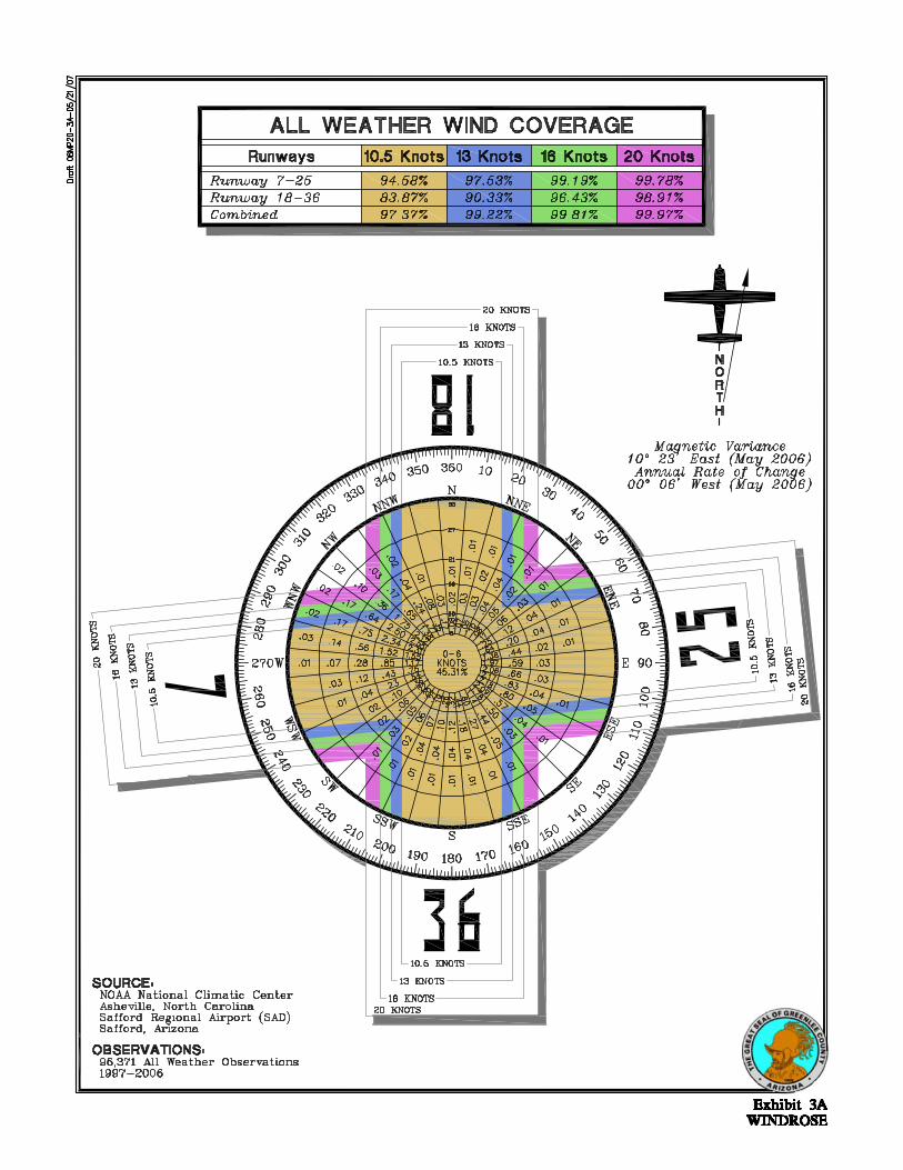

3-5
FAA AC 150/5300-13 recognizes that substituting wind data from another airport is only reliable when the ter-rain between the airports is similar. In situations when the terrain varies significantly, such as between Safford Regional Airport and Greenlee County Airport, the wind analysis is expected to have only marginal validity. Recognizing the limitations of the wind data available for this analysis, the wind coverage analysis shown on the exhibit should not be solely relied upon to make determinations of run-way orientation at Greenlee County Airport. The wind coverage analysis should be updated when 10 years of consecutive wind data specific to the airport can be collected using the AWOS at the airport. PHYSICAL PLANNING CRITERIA The selection of appropriate Federal Aviation Administration (FAA) design standards for the development and lo-cation of airport facilities is based primarily upon the characteristics of the aircraft which are currently using or are expected to use the airport. Planning for future aircraft use is of particular importance since design standards are used to plan separation distances between facilities. These standards must be determined now since the relocation of these facilities will likely be extremely expensive at a later date. The FAA has established a coding sys-tem to relate airport design criteria to the operational and physical characte-
ristics of aircraft expected to use the airport. This code, the airport refer-ence code (ARC), has two components. The first component, depicted by a let-ter, is the aircraft approach speed (op-erational characteristic); the second component, depicted by a Roman numeral, is the airplane design group and relates to aircraft wingspan (phys-ical characteristic). Generally, aircraft approach speed applies to runways and runway-related facilities, while aircraft wingspan primarily relates to separation criteria involving taxiways, taxilanes, and landside facilities. According to FAA Advisory Circular 150/5300-13, Airport Design, an air-craft’s approach category is based upon 1.3 times its stall speed in land-ing configuration at that aircraft’s maximum certificated weight. The five approach categories used in air-port planning are as follows: Category A: Speed less than 91 knots. Category B: Speed 91 knots or more, but less than 121 knots. Category C: Speed 121 knots or more, but less than 141 knots. Category D: Speed 141 knots or more, but less than 166 knots. Category E: Speed greater than 166 knots. The airplane design group (ADG) is based upon the aircraft’s wingspan. The six ADGs used in airport planning are as follows: Group I: Up to but not including 49 feet. Group II: 49 feet up to but not includ-ing 79 feet.
3-6
Group III: 79 feet up to but not in-cluding 118 feet. Group IV: 118 feet up to but not in-cluding 171 feet. Group V: 171 feet up to but not in-cluding 214 feet. Group VI: 214 feet or greater. The FAA advises designing airfield facilities to meet the requirements of the airport’s most demanding aircraft, or critical aircraft. An aircraft or group of aircraft within a particular Approach Category or ADG must con-duct more than 500 operations an-nually to be considered the critical de-sign aircraft. In order to determine facility requirements, an ARC should first be determined, and then appro-priate airport design criteria can be applied. This begins with a review of aircraft currently using the airport and those expected to use the airport through the planning period. Greenlee County Airport is currently used by a small variety of general avi-ation aircraft. The two based aircraft are single engine aircraft weighing less than 12,500 pounds, which fall within ARC A-I. The most demanding aircraft operating at the airport are those used by City Link for air taxi operations. These aircraft include the multi-engine turboprop aircraft Cess-na 414 and Cessna 425 Conquest which fall within ARC B-I. City Link also occasionally operates the multi-engine turboprop aircraft (Beechcraft King Air C90 and King Air 200) which fall within ARC B-II. City Link con-ducts approximately 900 annual oper-ations, of which 840 are by either the Cessna 414 or the Cessna 425.
The aviation demand forecasts pro-jected the mix of aircraft to use the airport to remain nearly the same as it is now through the short-term plan-ning period. However, the previous master plan established ARC B-II de-sign standards for the airport, and the airport maintains ARC B-II design standards currently. Therefore, even though all based aircraft are expected to fall within ARC A-I and City Link is expected to continue its operations us-ing ARC B-I and occasional ARC B-II aircraft, this Master Plan will main-tain the ARC B-II design standards through the short-term planning pe-riod. DIMENSIONAL DESIGN STANDARDS Runway dimensional design standards define the widths and clearances re-quired to optimize safe operations in the landing and takeoff area. These dimensional standards vary depending upon the ARC for the runway. Table 3C outlines key dimensional stan-dards for the airport reference codes most applicable to Greenlee County Airport, both now and in the short-term planning horizon. The runway should be planned to the standards of the critical ARC, which is currently B-II and forecast to remain B-II in the short-term. A cursory re-view of these design requirements at Greenlee County Airport indicates that these design requirements are fully met. A potential Runway 18-36 should be designed to meet at least C-III stan-dards.

3-7
TABLE 3C Airfield Design Standard Greenlee County Airport
Runway 7-25 Potential
Runway 18-36 Airport Reference
Code (ARC) Available (ft.) B-II (ft.) C-III (ft.) Runway Width 75 75 150 Runway Safety Area Width Length Beyond End
150 300
150 300
500
1,000 Runway Object Free Area Width Length Beyond End
500 300
500 300
800
1,000 Runway Centerline to: Holding Position Parallel Taxiway Parallel Runway
125 240 N/A
200 240 700
250 400 700
Taxiway Width 40 35 60 Taxiway Centerline to: Fixed or Moveable Object Parallel Taxilane
65.5 N/A
65.5 105
93
152 Taxilane Centerline to: Fixed or Moveable Object Parallel Taxilane
57.5 97
57.5 97
81
140 Runway Protection Zones - One Mile or Greater Visibility Inner Width Length Outer Width Not Lower than ¾-Mile Inner Width Length Outer Width Lower than ¾-Mile Inner Width Length Outer Width
500 1,000 700
N/A N/A N/A
N/A N/A N/A
500 1,000 700
1,000 1,700 1,510
1,000 2,500 1,750
500 1,700 1,010
1,000 1,700 1,510
1,000 2,500 1,750
Airfield Safety Standards The FAA has established several im-aginary surfaces to protect aircraft op-erational areas and keep them free from obstructions that could affect the safe operation of aircraft. These in-clude the object free area (OFA), ob-stacle free zone (OFZ), runway protec-tion zone (RPZ), and runway safety area (RSA).
The OFA is defined as “a two-dimensional ground area surrounding runways, taxiways, and taxilanes, which is clear of objects except for ob-jects whose location is fixed by func-tion.” The RSA is “a defined surface surrounding the runway prepared or suitable for reducing the risk of dam-age to airplanes in the event of an un-dershoot, overshoot, or excursion from the runway.” The OFZ is a “defined

3-8
volume of airspace centered above the runway centerline whose elevation is the same as the nearest point on the runway centerline and extends 200 feet beyond each runway end.” The RPZ is a two-dimensional trapezoidal-shaped surface located along the ex-tended runway centerline to protect people and property on the ground. The FAA expects these areas to be un-der the control of the airport and free from obstructions. Most of the Runway 7 RPZ is located within an avigation easement outside the existing airport property boun-dary. Due to its location, State Route 78 may need to be realigned to remove it from the Runway 7 RPZ and OFA. Once this project is undertaken, the land encompassed by the RPZ may need to be acquired by the airport. The analyses in Chapter Four will ad-dress the potential acquisition me-thods, which may include the fee sim-ple purchase of the property. RUNWAY LENGTH Runway length requirements are based upon five primary elements: airport elevation, the mean maximum daily temperature of the hottest month, runway gradient, critical air-craft type expected to use the runway, and the stage length of the longest non-stop trip destination.
Aircraft performance declines as ele-vation, temperature, and runway gra-dient factors increase. For calculating runway length requirements at Green-lee County Airport, elevation is 3,811 feet above mean sea level (MSL) and the mean maximum daily temperature of the hottest month is 100.2 degrees Fahrenheit. Runway end elevations vary by 75 feet. In examining runway length require-ments at the airport, the “primary” runway should be designed to accom-modate the most demanding aircraft currently serving the airport, as well as aircraft expected to serve the air-port in the future. Multi-engine tur-boprop aircraft will be the most de-manding aircraft for runway length determinations at the airport. These aircraft are most likely desiring to op-erate at maximum payload to carry both passengers and fuel to their des-tination. Using the specific data for Greenlee County Airport described above, run-way length requirements for the vari-ous classifications of aircraft that may operate at the airport were examined using the FAA Airport Design com-puter program, Version 4.2D, which groups general aviation aircraft into several categories, reflecting the per-centage of the fleet within each cate-gory and useful load (passengers and fuel) of the aircraft. Table 3D sum-marizes the FAA recommended run-way length for airport.

3-9
TABLE 3D Runway Length Requirements AIRPORT AND RUNWAY DATA Airport elevation ..................................................................................................................... 3,811 feet Mean daily maximum temperature of the hottest month ...................................................... 100.2° F Maximum difference in runway centerline elevation ................................................................ 75 feet RUNWAY LENGTHS RECOMMENDED FOR AIRPORT DESIGN Small airplanes with less than 10 passenger seats 75 percent of these small airplanes .................................................................................. 4,050 feet 95 percent of these small airplanes ................................................................................. 5,250 feet 100 percent of these small airplanes ................................................................................ 5,610 feet Reference: FAA’s airport design computer software utilizing Chapter Two of AC 150/5325-4A, Runway Length Requirements for Airport Design, no Changes included.
According to the table, the present runway length of 4,977 feet is ade-quate to accommodate 75 percent of these small airplanes. FAA Advisory Circular 150/5325-4B recommends that airports be designed to at least serve 95 percent of small airplanes. At the airport’s temperature and ele-vation, this would require a runway length of 5,250 feet. Thus, Runway 7-25 should be planned to be extended to 5,250 feet. An extension to Runway 7-25 is in-cluded in this Airport Master Plan for planning purposes only. This is to aid in local land use planning to ensure that appropriate land use measures are put into place to allow for this ex-tension in the future if it is needed. By planning for a 5,250-foot runway, the County can take appropriate measures to ensure that there are no hazards or obstacle penetrations to the 14 Code of Federal Regulations (CFR) Part 77 airspace in the future that could prevent the extension, and to allow for compatible land use to be planned in the extended runway ap-proach/de-parture area. Separate jus-tification for constructing the runway
extension will likely be required out-side this Airport Master Plan at the time of implementation. This justifi-cation will need to identify those spe-cific users that require a longer run-way to operate at the airport. This type of justification is generally built upon letters of support from specific users requiring the runway extension. Runway length requirements for air-craft used by Phelp’s Dodge would need to accommodate the runway ta-keoff distance of a Boeing 727 or like aircraft. The previous Airport Master Plan recommended a runway length of 8,700 feet for use by a Boeing 727-200. Re-examination of this runway length indicates that 8,700 feet would be an appropriate runway length to accom-modate a Boeing 727 aircraft. There-fore, the potential Runway 18-36 should be designed to 8,700 feet. RUNWAY WIDTH Runway width is primarily deter-mined by the planning ARC for the particular runway. FAA design stan-dards specify a minimum width of 75

3-10
feet for ARC B-II runways. Presently, Runway 7-25 has a width of 75 feet meeting the design standard. There-fore, additional pavement width will not be needed. Any future runway constructed to ac-commodate ARC C-III design standard requirements and aircraft with maxi-mum certificated takeoff weight great-er than 150,000 pounds, should be built to a width of 150 feet. This width will accommodate a Boeing 727 or like aircraft. PAVEMENT STRENGTH The most important feature of airfield pavement is its ability to withstand repeated use by aircraft of significant weight. The current strength rating on Runway 7-25 is 21,000 pounds sin-gle wheel loading (SWL). This current strength rating is adequate for the mix of aircraft currently using and ex-pected to use the airport in the short-term horizon on a regular basis. The potential Runway 18-36 should be designed to accommodate the weight of its design aircraft, the Boeing 727-200. The maximum takeoff weight of this aircraft is 209,500 pounds on dual wheels. Therefore, Runway 18-36 should be designed to 210,000 pounds DWL. TAXIWAYS Taxiways are constructed primarily to facilitate aircraft movements to and from the runway system. Some tax-iways are necessary simply to provide
access between the aprons and run-ways, whereas other taxiways become necessary as activity increases at an airport to provide safe and efficient use of the airfield. Design standards for separation be-tween the runways and parallel tax-iways are based upon the wingspan of the critical aircraft using the runway. Runway 7-25 is served by a 40-foot wide partial-length parallel taxiway on the north side of the runway serv-ing the Runway 25 end. Aircraft using Runway 7 must back-taxi on the run-way for takeoff. This causes the po-tential of runway incursions. Facility planning should include extending the partial-parallel taxiway to the Run-way 7 end for a full-length parallel taxiway to limit the possibility of run-way incursions. The type and frequency of runway en-trance/exit taxiways can affect the ef-ficiency and capacity of the runway system. Additional connecting tax-iways (at a minimum of 35 feet in width) should be considered to allow aircraft to exit the runway quicker af-ter landing. This can increase airfield capacity and safety, as the time an aircraft occupies the active runway is reduced. The number and location of these exit taxiways will be examined more closely in the alternatives analy-sis. NAVIGATIONAL AIDS AND INSTRUMENT APPROACH PROCEDURES Navigational aids are electronic devic-es that transmit radio frequencies

3-11
which properly equipped aircraft and pilots translate into point-to-point guidance and position information. The one type of electronic navigational aid available for aircraft flying to or from Greenlee County Airport is the global positioning system (GPS). This system is sufficient for navigation to and from the airport; therefore, no other navigational aids are needed at the airport. Instrument approach procedures con-sist of a series of predetermined ma-neuvers established by the FAA for navigation during inclement weather conditions. Currently, there are no established instrument approach pro-cedures for Greenlee County Airport. Therefore, during those times when visibility drops below three miles and/or cloud ceilings are below 1,000 feet MSL, the airport is essentially closed to arrivals. A GPS modernization effort is under-way by the FAA and focuses on aug-menting the GPS signal to satisfy re-quirements for accuracy, coverage, availability, and integrity. For civil aviation use, this includes the contin-ued development of the Wide Area Augmentation System (WAAS), which was initially launched in 2003. The WAAS uses a system of reference sta-tions to correct signals from the GPS satellites for improved navigation and approach capabilities. Where the non-WAAS GPS signal provides for enroute navigation and limited in-strument approach (lateral naviga-tion) capabilities, WAAS provides for approaches with both course and ver-tical navigation. This capability was historically only provided by an in-strument landing system (ILS), which
requires extensive on-airport facilities. The WAAS upgrades are expected to allow the development of approaches to most airports with cloud ceilings as low as 200 feet above the ground and visibilities restricted to one-half mile, after 2015. Nearly all new instrument approach procedures developed in the United States are being developed with GPS. GPS approaches are currently catego-rized as to whether they provide only lateral (course) guidance or a combi-nation of lateral and vertical (descent) guidance. An approach procedure with vertical guidance (APV) GPS ap-proach provides both course and des-cent guidance. A lateral navigation approach (LNAV) provides only course guidance. In the future, as WAAS is upgraded, precision approaches simi-lar in capability to the existing ILS will become available. These ap-proaches are currently categorized as the Global Navigation Satellite Sys-tem Landing System (GLS). A GLS approach may be able to provide for approaches with one-half-mile visibili-ty and 200-foot cloud ceilings. A GLS would be implemented in lieu of an ILS approach. Since both course guidance and des-cent information is desirable for an instrument approach to Greenlee County Airport and GPS does not re-quire the installation of costly naviga-tion equipment at the airport, an APV approach with one-mile visibility mi-nimums is appropriate to Runway 7-25. Based on the desire of Phelp’s Dodge to have maximum flexibility for future instrument operations, Runway 18

3-12
should be planned for a Category I ILS approach. With improved GPS mini-mums in the future, the cost for Cate-gory I equipment will be minimal. The key will be ensuring that the ap-proaches are maintained and the run-way meets the other standards neces-sary to provide for CAT I minimums. Runway 36 should be planned for an APV approach with one-mile visibility minimums. AIRFIELD MARKING, LIGHTING, AND SIGNAGE There are a number of lighting and pavement marking aids serving pilots using the Greenlee County Airport. These lighting and marking aids as-sist pilots in locating the airport dur-ing night or poor weather conditions, as well as assist in the ground move-ment of aircraft. The location of an airport at night is universally indicated by a rotating beacon. The rotating beacon at the airport is located north of the runway adjacent the terminal building. The rotating beacon is sufficient and should be maintained through the planning period. Runway 7-25 is equipped with me-dium intensity runway lighting (MIRL), which will be adequate through the planning period. The pa-rallel taxiway and apron are currently equipped with reflective taxiway deli-neators. Adding medium intensity taxiway lighting (MITL) to all tax-iways should be a short-term goal for Greenlee County. A MITL system at Greenlee County Airport would help pilots navigate the taxiways at night.
Any future expansion of the runway and taxiway system, including the construction of an additional runway, should incorporate MIRL and MITL systems. Airfield signage assists pilots in iden-tifying their location on the airport. Signs located at intersections of tax-iways provide crucial information to avoid conflicts between moving air-craft and potential runway incursions. Directional signage also instructs pi-lots as to the location of taxiways and apron areas. Currently, there is no directional signage in place at Green-lee County Airport. Lighted direction-al signage should be planned for Greenlee County Airport. In most instances, the landing phase of any flight must be conducted in vis-ual conditions. To provide pilots with visual guidance information during landings to the runway, electronic vis-ual approach aids are commonly pro-vided at airports. A two-light preci-sion approach path indicator (PAPI-2) is installed on the approach end of Runways 7 and 25. The PAPIs are appropriate for the mix of aircraft op-erating at the airport and should be maintained through the planning pe-riod. PAPI-4s should also be estab-lished on any future runway. Greenlee County Airport is equipped with pilot-controlled lighting (PCL). PCL allows pilots to control the inten-sity of the runway lighting using the radio transmitter in the aircraft. PCL also provides for more efficient use of airfield lighting energy. A PCL sys-tem turns the airfield lights off or to a lower intensity when not in use. Simi-

3-13
lar to changing the intensity of the lights, pilots can turn up the lights us-ing the radio transmitter in the air-craft. This system should be main-tained through the planning period. In order to facilitate the safe move-ment of aircraft about the field, air-ports use pavement markings, light-ing, and signage to direct pilots to their destinations. Runway markings are designed according to the type of instrument approach available on the runway. FAA Advisory Circular 150/5340-1H, Marking of Paved Areas on Airports, provides the guidance ne-cessary to design airport markings. Runway 7-25 is marked with ba-sic/visual markings. The runway is planned to have non-precision instru-ment approaches, therefore non-precision runway markings should be planned. Runway 18-36 is planned for a CAT I precision instrument approach. Preci-sion markings should be planned for this runway. Holdlines need to be marked on all taxiways connecting to the runway. At Greenlee County Airport, the hol-dlines are required to be placed 200 feet from the runway centerline. These markings assist in reducing runway incursions as aircraft must remain behind the holdline until tak-ing the active runway for departure. Any future runway designed to ARC C-III design standards with a preci-sion instrument approach would need hold-
lines to be placed 250 feet from the runway centerline. Taxiway and apron areas also require marking to assure that aircraft re-main on the pavement and clear of any objects located along the tax-iway/taxilane. Yellow centerline stripes are currently painted on all taxiway and apron surfaces at the air-port to provide assistance to pilots in taxiing along these surfaces at the airport. Besides routine maintenance, these markings will be sufficient through the planning period. WEATHER REPORTING The airport has a lighted wind cone and wind tee that provide pilots with information about wind conditions. A segmented circle provides traffic pat-tern information to pilots. These facil-ities are required when the airport is not served by a 24-hour ATCT. These facilities are sufficient and should be maintained in the future. The airport is equipped with an AWOS. The AWOS provides auto-mated weather observations every minute, continuously reporting signifi-cant weather changes as they occur. The AWOS reports cloud ceiling, visi-bility, temperature, dew point, wind direction, wind speed, altimeter set-ting (barometric pressure), and densi-ty altitude (airfield elevation corrected for temperature). The AWOS is suffi-cient and should be maintained through the planning period.

3-14
LANDSIDE REQUIREMENTS Landside facilities are those necessary for handling aircraft, passengers, and freight while on the ground. These facilities provide the essential inter-face between the air and ground transportation modes. The capacities of the various components of each area were examined in relation to projected demand to identify future landside fa-cility needs. For this analysis, the requirements for aircraft currently based and projected to be based on the airport will be con-sidered. The scope of the Master Plan is concentrated on the short-term ho-rizon; therefore, facilities that are immediately needed will be the focus of this section. HANGARS The demand for aircraft storage han-gars typically depends upon the num-ber and type of aircraft expected to be based at the airport. For planning purposes, hangar requirements are estimated based upon forecast opera-tional activity. However, hangar de-velopment should be based on actual demand trends and financial invest-ment conditions. Utilization of hangar space varies as a function of local climate, security, and owner preferences. The trend in gen-eral aviation aircraft, whether single or multi-engine, is in more sophisti-cated (and, consequently, more expen-sive) aircraft. Vintage aircraft owners and many recreational aircraft owners
prefer hangar space to protect their aircraft, which many times are con-structed with fabric wing and fuselage covers. Therefore, many aircraft own-ers prefer hangar space to outside tie-downs. Presently, both aircraft based at the airport are stored in detached hangar facilities. These two hangar facilities are currently the only han-gars on the airport. There is no waiting list for hangar space at Greenlee County; therefore, it is not recommended that the airport construct new hangar facilities until a demand has been established. Han-gars may be privately developed by aircraft owners wishing to base their aircraft at the airport, which would produce revenue for the airport in the form of a lease agreement for the land the hangar is built on. It was indi-cated in the forecast chapter that an additional two aircraft will base at Greenlee County Airport through the planning period. For the purposes of this study, it will be assumed that the potential aircraft owners will privately fund the construction of two additional detached conventional hangar facili-ties. Conventional hangar space needed over the planning period was deter-mined by providing 1,200 square feet for single engine aircraft. This results in a potential need of an additional 2,400 square feet of hangar space in the short-term planning horizon. The alternatives analysis will examine options available for hangar develop-ment at the airport and determine the best location for each hangar facility.

3-15
FIXED BASE OPERATOR (FBO) Greenlee County Airport is currently without a fixed base operator (FBO) and the associated services FBOs pro-vide (fuel, aircraft maintenance, flight planning equipment, pilot/passenger lobby, etc.). Requirements for a fixed base operator (FBO) hangar facility were estimated at 3,600 square feet. This should provide adequate hangar space to conduct maintenance opera-tions and other aircraft services for the level of activity that can be ex-pected at Greenlee County Airport. FBO hangars can also be cross-utilized for storage and aircraft maintenance. They are also sometimes used to store transient aircraft overnight. It should be noted that due to limited operations, current demand for FBO services is low. Over the short-term horizon, it is not anticipated that de-mand will rise to a level where FBO services could be adequately main-tained. However, potential locations for an FBO facility will be examined in the Alternatives section of this study for planning purposes. AIRCRAFT PARKING APRON The Greenlee County Airport parking apron should provide adequate air-craft parking space for transient air-craft. There are approximately 25 tie-downs available on the 9,800 square yard apron for both based and tran-sient aircraft at the airport. Although future based aircraft are assumed to be stored in enclosed hangars, a num-ber of transient aircraft will still tie down outside. Total apron area re-
quirements were determined by apply-ing a planning criterion of 700 square yards per transient aircraft parking position. Based upon the planning cri-teria above and assumed transient and based aircraft users, the existing apron areas should be sufficient through the planning period. GENERAL AVIATION TERMINAL FACILITIES General aviation terminal facilities have several functions separate from those of the airline terminal building. Space is required for waiting passen-gers, pilots’ lounge and flight plan-ning, management, storage, and vari-ous other needs. This space is not necessarily limited to a single, sepa-rate terminal building, but also in-cludes the space offered by fixed base operators for these functions and ser-vices. Presently, a small terminal building located north of the runway provides a conference room, storage area, and re-stroom services. Due to the limited amount of operations and itinerant passenger traffic, there is little de-mand at the airport currently for a terminal facility. Therefore, the exist-ing terminal building should ade-quately serve the short-term needs of the airport. SUPPORT REQUIREMENTS Various facilities that do not logically fall within classifications of airfield, terminal building, or general aviation facilities have been identified for in-

3-16
clusion in this Master Plan. Facility requirements have been identified for these remaining facilities: Perimeter Fencing Utilities Off-Airport Vehicular Access On-Airport Vehicular Access Perimeter Fencing The airport perimeter and apron areas are equipped with a mixture of barbed-wire and chain-link fencing. An automated access gate is located at the entrance of the airport off of State Road 78. Perimeter fencing is used at airports to primarily secure the aircraft opera-tions area. The physical barrier of pe-rimeter fencing provides the following functions: Gives notice of the legal boundary
of the outermost limits of a facility or security sensitive area.
Assists in controlling and screening
authorized entries into a secured area by deterring entry elsewhere along the boundary.
Supports surveillance, detection,
assessment, and other security functions by providing a zone for installing intrusion-detection equipment and closed-circuit tele-vision (CCTV).
Deters casual intruders from pene-
trating a secured area by present-ing a barrier that requires an overt action to enter.
Demonstrates the intent of an in-truder by their overt action of gain-ing entry.
Causes a delay to obtain access to a
facility, thereby increasing the pos-sibility of detection.
Creates a psychological deterrent. Optimizes the use of security per-
sonnel while enhancing the capa-bilities for detection and apprehen-sion of unauthorized individuals.
Demonstrates a corporate concern
for facility security. Provides a cost-effective method of
protecting facilities. In addition to these security en-hancements, perimeter fencing also limits inadvertent access to the air-craft operations area by wildlife. The airport perimeter fence should be maintained through the planning pe-riod. Utilities Electrical, water, sanitary sewer, and telephone services are available at the airport. It is not anticipated that over the short-term horizon, new landside facilities will be constructed that will require these utilities. However, if development should occur in the vicin-ity of existing landside facilities, there would be no deficiencies in providing any of these utility services.

3-17
Off-Airport Access Primary access to the airport is pro-vided from State Route 78. The air-port access road is an unmarked 25-foot wide road in good condition. Sev-eral areas in the terminal area are be-ing planned for aeronautical and non-aeronautical uses. For these areas of the airport to develop, a new entrance road alignment will need to be planned. New entrance road align-ments will be analyzed in the Alterna-tives Chapter. State Route 78 currently lies within the Runway 7 RPZ and the OFA. Current FAA regulations require these safety areas to be clear of ob-structions including roadways. Plans for the realignment of State Route 78 will be included in the Alternatives Chapter. On-Airport Access A manual access gate located to the west end of the apron allows vehicle
traffic to enter the airfield area. Ac-cess to this gate is restricted to airport personnel. The airport is not current-ly equipped with an airport perimeter road. It is recommended that an air-port perimeter road be considered in the short-term to provide vehicle access to all areas of the airport for maintenance, safety, and security purposes. SUMMARY The intent of this chapter has been to outline the facilities required to meet potential aviation demands projected for the airport through the short-term planning horizon. A summary of the airfield and general aviation facility requirements are presented on Exhi-bits 3B and 3C. The next step is to develop a direction for implementation that will best meet these projected needs. The remainder of the Airport Master Plan will be devoted to outlin-ing this direction, its schedule, and costs.
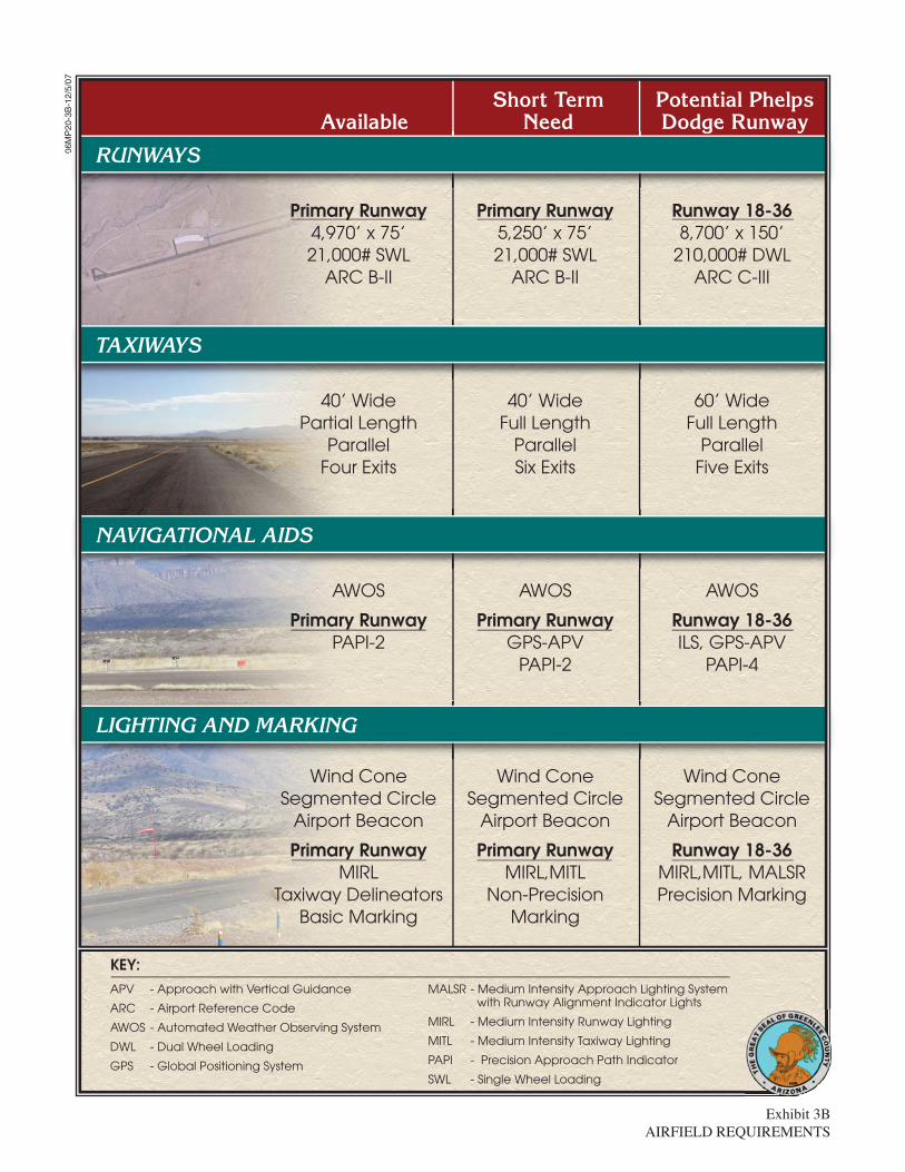
Exhibit 3BAIRFIELD REQUIREMENTS
06M
P20
-3B
-12/
5/07
AvailableShort Term
NeedPotential PhelpsDodge Runway
06M
P
g y
RUNWAYS
Primary Runway4,970’ x 75’21,000# SWL
ARC B-II
Primary Runway5,250’ x 75’21,000# SWL
ARC B-II
TAXIWAYS
40’ WidePartial Length
ParallelFour Exits
40’ WideFull Length
ParallelSix Exits
Runway 18-368,700’ x 150’
210,000# DWLARC C-III
60’ WideFull Length
ParallelFive Exits
NAVIGATIONAL AIDS
AWOS
Primary RunwayPAPI-2
AWOS
Primary RunwayGPS-APV
PAPI-2
AWOS
Runway 18-36ILS, GPS-APV
PAPI-4
LIGHTING AND MARKING
Wind ConeSegmented Circle
Airport Beacon
Primary RunwayMIRL
Taxiway DelineatorsBasic Marking
KEY:
Wind ConeSegmented Circle
Airport Beacon
Primary RunwayMIRL,MITL
Non-PrecisionMarking
Wind ConeSegmented Circle
Airport Beacon
Runway 18-36MIRL,MITL, MALSRPrecision Marking
APV - Approach with Vertical Guidance
ARC - Airport Reference Code
AWOS - Automated Weather Observing System
DWL - Dual Wheel Loading
GPS - Global Positioning System
MALSR - Medium Intensity Approach Lighting System with Runway Alignment Indicator Lights
MIRL - Medium Intensity Runway Lighting
MITL - Medium Intensity Taxiway Lighting
PAPI - Precision Approach Path Indicator
SWL - Single Wheel Loading

Exhibit 3CLANDSIDE FACILITY REQUIREMENTS
06M
P20
-3C
-5/2
2/07
Existing SpaceAvailable
Short TermNeed2007
Hangar Positions 2 2 4
Hangar Area Requirements Conventional (s.f.) 1,075 1,075 3,475 FBO (s.f.) 0 0 3,600Total Hangar Area (s.f.) 1,075 1,075 7,075
Existing SpaceAvailable
Short TermNeed2007
GA Apron Requirements Total Ramp Positions 25 9 14 Total Apron Area (s.y.) 9,800 6,300 9,800
Existing Short Term Need
Other Facilities Terminal Facility Terminal Facility

Chapter Four
DEVELOPMENT ALTERNATIVES

4-1
DEVELOPMENTALTERNATIVESDEVELOPMENTALTERNATIVES
Chapter Four
Prior to defining the development program for Greenlee County Airport, it is important to consider development potential and constraints at the airport. The purpose of this chapter is to consider the actual physi-cal facilities that are needed to accommo-date projected short-term demand and meet the program requirements as defined in Chapter Three, Facility Requirements.
In this chapter, a series of airport development scenarios are considered for the airport. In each of these scenarios, different physical facility layouts are presented for the purposes of evaluation. The ultimate goal is to develop the underlying rationale that supports the final master plan recommendations. Through this process, an evaluation of the highest and best uses of airport property
is made while considering local goals, physical constraints, and federal airport design standards, where appropriate.
Any development proposed by an Airport Master Plan Update evolves from an analysis of projected needs. Though the needs were determined by the best methodology available, it cannot be assumed that future events will not change these needs. The Airport Master Plan process attempts to develop a viable concept for meeting the needs caused by projected demands through the short-term planning period.
The alternatives have been developed to meet the overall program objectives for the airport in a balanced manner. Through coordination with Greenlee

4-2
County, the alternatives (or combina-tion thereof) will be refined and mod-ified as necessary to produce the rec-ommended development program. Therefore, the alternatives presented in this chapter can be considered a be-ginning point in the development of the recommended master plan devel-opment program, and input will be ne-cessary to define the resultant pro-gram. REVIEW OF PREVIOUS MASTER PLAN The previous master plan for Greenlee County Airport was completed in 2002. Recommendations presented in the 2002 Airport Master Plan included the westerly extension of Runway 7-25 to 5,280 feet along with the extension of the taxiway making it a full-length parallel taxiway, the installation of an AWOS-III, apron and taxiway light-ing, the installation of PAPI approach lights, as well as contingency plans for the construction of Runway 18-36. Exhibit 4A depicts the planning scheme as outlined in the 2002 Airport Master Plan and ALP. Projects that have been undertaken since the pre-vious master plan include the exten-sion of Taxiway 1 from the apron to the end of Runway 25, and the instal-lation of the AWOS-III and the PAPI approach lights. DO-NOTHING ALTERNATIVE The “do-nothing” alternative essential-ly considers keeping the airport in
its present condition and not providing for any type of improvement to the ex-isting facilities. The primary result of this alternative would be the inability of the airport to satisfy the projected aviation demands of the airport ser-vice area. Greenlee County has experienced mi-nimal economic growth over the past several years, and any growth pro-jected in the short-term horizon is mi-nimal. Most of the recommended im-provements proposed in this Airport Master Plan are meant to accommo-date existing users of the airport and to provide increased safety and securi-ty to all airport users. Improvements recommended in the previous chapter include improvements to the taxiway system, airfield lighting and signage, and the construction of additional landside facilities including hangars. Greenlee County Airport currently provides a much needed service for its primary user, City Link, who on a dai-ly basis transports Phelps Dodge em-ployees. Without regular maintenance and additional improvements, existing and potential users and business for Greenlee County Airport could be lost. To propose no further development at Greenlee County Airport would ad-versely affect the long term viability of the airport, resulting in negative eco-nomic effects on Greenlee County. Therefore, the “do-nothing” alternative is not considered as prudent or feasi-ble.


4-3
TRANSFER AVIATION SERVICES The alternative of shifting aviation services to another existing airport was also examined. The airport in closest proximity to Greenlee County Airport with like or better facilities is Safford Regional Airport, which is lo-cated approximately 22 miles to the west. Drive time to Safford Regional Airport from Clifton is approximately 50 minutes and approximately 60 mi-nutes from Morenci. This commute time would be considered unaccepta-ble by existing users of the Greenlee County Airport. While the forecast demand at Greenlee County Airport is low and would have very little impact on Safford Regional Airport, it would not be desirable to essentially close the existing airport. Much federal, state, and local financial investment has been made in the Greenlee County Airport since its original construction, and it is in the best interests of Green-lee County to continue to operate and maintain the airport facility. Also, other public airports are too far away to adequately serve the needs of the Clifton area general aviation users. DEVELOPMENT OF A NEW AIRPORT The alternative of developing an en-tirely new airport facility in the Clif-ton area to meet projected aviation demands was also considered. Simi-larly, this alternative was found to be unacceptable primarily due to econom-ic and environmental considera-
tions. Land acquisition, site prepara-tion, and the construction of an entire-ly new airport can be a very difficult and costly action. In addition, closing Greenlee County Airport would mean the loss of a substantial investment in a transportation facility that can still be utilized and readily expanded. In a situation where public funds are li-mited, the replacement of a functional and expandable airport facility would represent an unjustifiable loss of a significant public investment. From the social, political, and envi-ronmental standpoints, the commit-ment of a new large land area must also be considered. Furthermore, the development of a new airport similar to Greenlee County Airport would likely take a significant amount of time to become a reality. The poten-tial exists for significant environmen-tal impacts associated with disturbing a large land area when developing a new airport site. In addition, the loca-tion of the new site would likely be less convenient than Greenlee County Airport. Overall, transferring service to an ex-isting airport in the region or to an en-tirely new facility are unreasonable alternatives that should not be pur-sued further at this time. Greenlee County Airport is fully capable of ac-commodating its share of aviation de-mand in the area and should be devel-oped in response to those demands. The airport has the potential to con-tinue to develop as a quality general aviation facility that could greatly en-hance the economic development of Greenlee County and the Clifton area.

4-4
KEY PLANNING ISSUES A commitment to remain at the exist-ing site and develop facilities suffi-cient to meet the short range aviation demands entails the following: Provide sufficient airside and land-
side capacity to meet the short range planning horizon level de-mand of the area.
Develop the airport in accordance
with the currently established FAA design criteria.
Analyses in the earlier chapters of this master plan indicated that several improvements will be necessary to en-sure the airport’s capability to serve the needs of the Greenlee County re-gion over the next five years. The primary airfield focus will be on pro-viding a full-length parallel taxiway, providing adequate runway length for the airport’s short-term needs, ex-amining potential layouts for Runway 18-36, as well as preserving the viabil-ity of the facility. On the landside, primary issues focus on possible loca-tions for a fixed base operator (FBO), and other improvements that would be beneficial to overall County develop-ment. Exhibit 4B outlines key con-siderations for this alternative analy-sis. AIRFIELD ALTERNATIVES Airfield facilities are, by nature, the focal point of the airport complex. Be-cause of their primary role and the fact that they physically dominate air-port land use, airfield facility needs
are often the most critical factor in the determination of viable airport devel-opment alternatives. In particular, the runway system requires the great-est commitment of land area and often imparts the greatest influence of the identification and development of oth-er airport facilities. Furthermore, air-craft operations dictate the FAA de-sign criteria that must be considered when looking at airfield improve-ments. These criteria, depending upon the areas around the airport, can often have a significant impact on the viability of various alternatives de-signed to meet airfield needs. The airside considerations summa-rized in Exhibit 4B are the result of the analyses conducted previously in Chapter Two, Aviation Demand Fore-casts, and Chapter Three, Facility Re-quirements. These issues have been incorporated into a series of airfield development considerations. The fol-lowing describes in detail the specific requirements considered in the devel-opment of the airfield. Runway Length Runway 7-25 is presently 4,977 feet in length. FAA design standards rec-ommend a runway length of 5,250 feet to meet the need of 95 percent of all small (less than 10 passenger seats) general aviation aircraft. To meet this runway length recommendation, Runway 7-25 should be extended 273 feet. This extension would be most effective if constructed at the east end of Runway 7-25. An extension to the west is undesirable due to the location of State Route 78. State Route 78 cur-

Exhibit 4BKEY PLANNING ISSUES
06M
P20
-4B
-3/5
/07
LANDSIDE CONSIDERATIONSLocations for fixed base operator developmentLocations for aircraft storage hangar developmentLocations for revenue support developmentVehicle parking locationsRoad circulation
AIRSIDE CONSIDERATIONSExtend Runway 7-25 to 5,250 feetEstablish instrument approaches to each runway endutilizing GPS technologyTaxiway circulation and runway exitsProtection of runway approachesFuture land acquisition needsPreserve land for potential Runway 18-36

4-5
rently penetrates the Runway 7 RPZ and OFA. Because of this, the rea-lignment of State Route 78 will be ne-cessary. If any pavement construction at the west end of the runway were to occur, State Route 78 would need to be relocated further to the west, which would affect several existing washes. To preserve the washes a runway ex-tension to the east is more desirable. Currently, there is existing airport property available at the east end of the runway which is undeveloped and gradable and will allow for the 273-foot runway extension at far less cost. The Runway 7-25 layout alternative and the planned realignment of State Route 78 are shown on Exhibit 4C. As it was discussed in Chapter Three, Facility Requirements, there is poten-tial for Phelp’s Dodge to begin operat-ing a Boeing 727 aircraft at the Green-lee County Airport. The runway length required to accommodate an aircraft of this type would be 8,700 feet. The first extension possibilities considered extensions to the existing Runway 7-25 to accomplish an ulti-mate length of 8,700 feet. Extending Runway 7-25 to this length would prove to be quite costly as it would re-quire a large amount of land grading due to great differences in elevations off both runway ends. Ultimately, the Runway 18-36 alignment proposed in the previous Airport Master Plan was determined to be more economically feasible. The alternative depicting the construction of Runway 18-36 is de-picted on Exhibit 4D. It should be noted that the extension to Runway 7-25 and the potential Runway 18-36 are included in this
master plan for planning purposes on-ly. This is to aid in local land use planning to ensure that appropriate land use measures are put into place to allow for these airfield additions in the future if they are needed. By planning for these additions, the County can take appropriate measures to ensure that there are no hazards or obstacle penetrations to the 14 Code of Federal Regulations (CFR) Part 77 airspace in the future that could pre-vent the Runway 7-25 extension or the construction of Runway 18-36, and to allow for compatible land use to be planned in the potential runway ap-proach/departure areas. Separate jus-tification for constructing these air-field improvements will be required outside this master plan at the time of implementation. This justification will need to identify those specific us-ers that require a longer Runway 7-25 and the construction of Runway 18-36 to operate at the airport. This type of justification is generally built upon letters of support from the specific us-ers requiring the runway improve-ments. Full-Length Parallel And Exit Taxiways Runway 7-25 is currently served by a partial parallel taxiway which extends from the apron to the Runway 25 end. Aircraft departing from the Runway 7 end or those that are landing on Run-way 25 and miss the last exit taxiway for the apron are required to back-taxi on the runway. To advance airport safety and aircraft movement efficien-cy for all airport users, Taxiway 1 should be upgraded to a full-length

RelocatedState Route 78
RelocatedState Route 78
Runway 7-25Runway 7-25
Runway 7-25Runway 7-25
Taxiway 1Taxiway 1
Taxiway 1Taxiway 1
06M
P20
-4C
-3/1
9/07
Exhibit 4CAIRFIELD & LANDSIDE
ALTERNATIVES
Airport Service RoadAirport Service Road
Box HangarsBox HangarsFBOFBO
State Route 78
State Route 78
Runway 7-25 (4,977’ x 75’)
Runway 7-25 (4,977’ x 75’) Ultimate (5,250’ x 75’)
Ultimate (5,250’ x 75’)
LEGENDExisting Property LineUltimate Airport Propert LineUltimate Airport PavementUltimate Airport RoadObject Free Area (OFA)Runway Safety Area (RSA)Building/Pavementto be RemovedRunway Protection Zone (RPZ)Non-Aviation RelatedRevenue Support
NORTH
0 600 1200
SCALE IN FEET
0 200 400
SCALE IN FEET
Box HangarsBox HangarsFBOFBO
LANDSIDE ALTERNATIVE 2LANDSIDE ALTERNATIVE 1
AIRFIELD ALTERNATIVE
RPZ500’x1,000’x700’RPZ500’x1,000’x700’
RPZ500’x1,000’x700’
RPZ500’x1,000’x700’
273’ Extension273’ Extension


4-6
parallel taxiway. Upon completion of the 273-foot runway extension to the west, Taxiway 1 should also be ex-tended to meet the new Runway 25 end. Another planning goal is to construct additional exit taxiways from Runway 7-25, as well as the ultimate Runway 18-36, as shown on Exhibit 4C and Exhibit 4D. The additional exit tax-iways would allow aircraft to exit the runway quicker after landing, reduc-ing runway occupancy times. Airport Perimeter Service Road A vehicular perimeter service road should be provided to allow access to all areas of the airfield for mainten-ance, security, safety, and emergency purposes. This perimeter road should remain outside of the runway safety areas where possible and should be wide enough to allow access to emer-gency and maintenance vehicles. The airport service road layout depicted on Exhibit 4C shows how the road should be planned without the con-struction of Runway 18-36. Exhibit 4D shows the layout of the perimeter service road with Runway 18-36. Navigational Aids The airport will need to continue to adapt to changes in navigational sys-tems associated with aviation. One major ongoing change is the transfor-mation to the global positioning sys-tem (GPS) as the primary navigation system for the FAA. While the trans-
formation will take a longer period than originally scheduled and may not be exactly as originally envisioned, it is still in the plans. GPS remains a key consideration for improving ap-proach minimums at Greenlee County Airport. From a master planning standpoint, the objective will be to continue to plan for GPS implementa-tion, but to also ensure that other more traditional systems are still in the plan as backups wherever possi-ble. Land Acquisitions Other airside considerations included is the potential acquisition of other properties that may be strategic to the long range viability of the airport. This includes the acquisition of land that is encompassed by the runway protection zones (RPZ) and the land that would potentially be needed to construct the proposed Runway 18-36. These areas of land are identified on Exhibits 4C and 4D. LANDSIDE CONSIDERATIONS The primary planning considerations for this analysis are summarized on Exhibit 4B. The general aviation functions to be considered in the de-velopment program at Greenlee Coun-ty Airport include a fixed base opera-tor (FBO) facility, aircraft storage hangars, revenue support develop-ment, and automobile parking and access. The interrelationship of these functions is important to defining a short-range landside layout for gener-al aviation uses at the airport. Run-
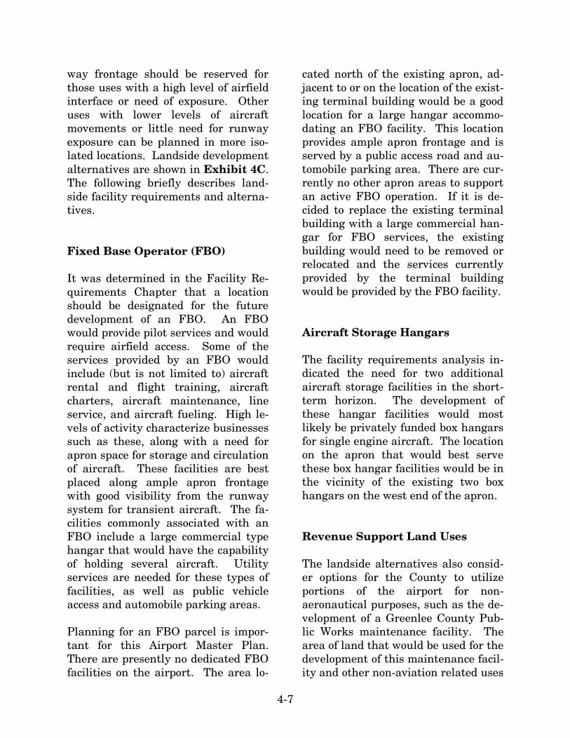
4-7
way frontage should be reserved for those uses with a high level of airfield interface or need of exposure. Other uses with lower levels of aircraft movements or little need for runway exposure can be planned in more iso-lated locations. Landside development alternatives are shown in Exhibit 4C. The following briefly describes land-side facility requirements and alterna-tives. Fixed Base Operator (FBO) It was determined in the Facility Re-quirements Chapter that a location should be designated for the future development of an FBO. An FBO would provide pilot services and would require airfield access. Some of the services provided by an FBO would include (but is not limited to) aircraft rental and flight training, aircraft charters, aircraft maintenance, line service, and aircraft fueling. High le-vels of activity characterize businesses such as these, along with a need for apron space for storage and circulation of aircraft. These facilities are best placed along ample apron frontage with good visibility from the runway system for transient aircraft. The fa-cilities commonly associated with an FBO include a large commercial type hangar that would have the capability of holding several aircraft. Utility services are needed for these types of facilities, as well as public vehicle access and automobile parking areas. Planning for an FBO parcel is impor-tant for this Airport Master Plan. There are presently no dedicated FBO facilities on the airport. The area lo-
cated north of the existing apron, ad-jacent to or on the location of the exist-ing terminal building would be a good location for a large hangar accommo-dating an FBO facility. This location provides ample apron frontage and is served by a public access road and au-tomobile parking area. There are cur-rently no other apron areas to support an active FBO operation. If it is de-cided to replace the existing terminal building with a large commercial han-gar for FBO services, the existing building would need to be removed or relocated and the services currently provided by the terminal building would be provided by the FBO facility. Aircraft Storage Hangars The facility requirements analysis in-dicated the need for two additional aircraft storage facilities in the short-term horizon. The development of these hangar facilities would most likely be privately funded box hangars for single engine aircraft. The location on the apron that would best serve these box hangar facilities would be in the vicinity of the existing two box hangars on the west end of the apron. Revenue Support Land Uses The landside alternatives also consid-er options for the County to utilize portions of the airport for non-aeronautical purposes, such as the de-velopment of a Greenlee County Pub-lic Works maintenance facility. The area of land that would be used for the development of this maintenance facil-ity and other non-aviation related uses

4-8
is located north of the terminal facility and encompasses approximately 18 acres. It should be noted that the County does not have approval to use airport property for non-aeronautical purposes at this time; however, the request for the land use change has been submitted to the FAA. To use airport land for non-aeronautical purposes requires specific approval from Congress. The Airport Master Plan does not gain approval for non-aeronautical uses, even if these uses are ultimately shown on the ALP. A separate request justify-ing the use of airport property for non-aeronautical uses will be required once the Airport Master Plan is com-plete. Federal law obligates an airport spon-sor to use all property shown on an ALP and/or Property Map for public airport purposes. A distinction is gen-erally not made between property ac-quired locally and property acquired with federal assistance. However, property acquired with federal assis-tance or transferred as surplus prop-erty from the federal government may have specific covenants or restrictions on its use different from property ac-quired locally. These obligations will require that the County formally request from Con-gress a release from the terms, condi-tions, reservations, and restrictions contained in any conveyance deeds and assurances in previous grant agreements. A release is required even if the airport desires to continue to own the land and only lease the land for development. The obligations relate to the use of the land just as
much as they do to the ownership of the land. Ultimately, the ability of the County to use airport property for non-aeronautical revenue production will rest upon a determination by Congress that portions of the airport property are no longer needed for airport-related or aeronautical uses. To prove that land is not needed for aeronauti-cal purposes, an assessment and de-termination of the area that will be required for aeronautical purposes will be required. An environmental determination will also be required. While FAA Order 1050.1E, Environmental Policies and Procedures, states that a release of an airport sponsor from federal obliga-tions is normally categorically ex-cluded and would not normally require an Environmental Assessment (EA), the issuance of a categorical exclusion is not automatic and the FAA must determine that no extraordinary cir-cumstances exist at the airport. Ex-traordinary circumstances would in-clude a significant environmental im-pact to any of the environmental re-sources governed by federal law. An Environmental Assessment may be required if there are extraordinary cir-cumstances. SUMMARY The process utilized in assessing the airfield and landside development al-ternatives involved consideration of short-term needs as well as future growth potential. Current airport de-sign standards were considered in

4-9
every scenario. Safety, both in the air and on the ground, was given high priority in the analyses. The recommended development con-cept for Greenlee County Airport must represent a means by which the air-port can grow in a balanced manner to accommodate short-term needs as well as the ability to grow efficiently beyond the short-term horizon.
Through further meetings and discus-sions with the County, a recommended concept will evolve. The plan will represent a means by which the air-port can continue to effectively serve general aviation needs within the overall operation and development of the airport. This will then be devel-oped into a plan for maintaining and improving Greenlee County Airport.

Chapter Five
AIRPORT PLANS

5-1
AIRPORT PLANSAIRPORT PLANS
Chapter Five
The planning process for the Greenlee County Airport Master Plan has included several analytic efforts in the previous chapters intended to project potential aviation demand, establish airside and landside facility needs, and evaluate options for improving the airport to meet those airside and landside facility needs. The process, thus far, has included the presentation of one draft phase report (representing the first four chapters of the Airport Master Plan) to Greenlee County. A plan for the use of Greenlee County Airport has evolved considering their input. The purpose of this chapter is to describe, in narrative and graphic form, the plan for the future use of Greenlee County Airport.
AIRFIELD PLAN
The airfield plan for Greenlee County Airport focuses on meeting Federal Aviation Administration (FAA) design and safety standards, extending Runway 7-25 to achieve an ultimate length of 5,250 feet, constructing a full-length parallel taxiway for Runway 7-25, constructing additional exit taxiways along Runway 7-25, and planning for a potential 8,700- foot runway to accommodate Phelps Dodge’s operational demands. Exhibit 5A graphically depicts the proposed airfield improvements. The following text sum- marizes the elements of the airfield plan.
AIRFIELD DESIGN STANDARDS
The FAA has established a variety of design criterion to define the physical
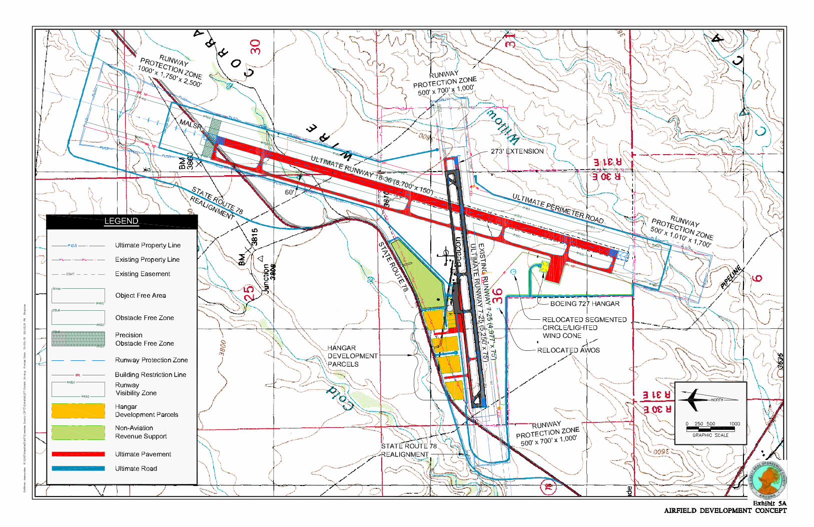

5-2
dimensions of runways and taxiways and the surrounding imaginary sur-faces that protect the safe operation of aircraft at the airport. FAA design standards also define the separation criteria for the placement of landside facilities. As discussed previously in Chapter Three, FAA design criteria are a function of the critical design aircraft’s (the most demanding aircraft or “family” of aircraft which will con-duct 500 or more operations [take-offs and landings] per year at the airport) wingspan and approach speed, and in some cases, the runway approach visi-bility minimums. The FAA has estab-lished the Airport Reference Code (ARC) to relate these factors to airfield design standards. Greenlee County Airport is currently used by a variety of general aviation aircraft, ranging from regular general aviation turboprop aircraft such as the Beechcraft King Air to general avia-tion recreational aircraft. Aircraft within ARC A-I to ARC B-II are the primary users of the airport. The air-field is presently designed to ARC B-II design standards, which meets the op-erational demands of the airport. These ARC B-II design standards should be maintained through the short-term horizon. This Airport Master Plan reflects the potential for larger aircraft to use the airport in the future as part of in-creased Phelps Dodge operational ac-tivity. Phelps Dodge has indicated that it may begin operating a Boeing 727-200 aircraft, which is in ARC C-III. Therefore, ARC C-III design stan-dards should be planned for a poten-tial Phelps Dodge runway.
Assigning ARC B-II/C-III to the ulti-mate design of airfield facilities at Greenlee County Airport provides for the full range of corporate aircraft, in-cluding the Raytheon Beechcraft King Air 300, Falcon 900, Cessna Citation III, as well as the Boeing 727-200. As the existing primary runway, Runway 7-25 and its associated tax-iway should continue to be planned and developed to ARC B-II standards. Table 5A summarizes the ARC B-II and ARC C-III airfield safety and fa-cility dimensions to be applied to Greenlee County Airport planning and design. AIRFIELD DEVELOPMENT The components of the planned air-field development are summarized be-low. Maintain Airport Reference
Code (ARC) B-II design stan-dards on Runway 7-25.
The majority of short-term operational aircraft at Greenlee County Airport is anticipated to remain within ARC A-I and B-II. To accommodate this opera-tional demand, Runway 7-25 will need to maintain ARC B-II airport design standards. As shown on Table 5A, all ARC B-II design standards are cur-rently met or exceeded. The extension of Runway 7-25
to 5,250 feet. The Master Plan Development Con-cept includes extending Runway 7-25 273 feet to the east from 4,977 feet to

5-3
5,250 feet. This extension requires the acquisition of approximately 3.4 acres of land to secure the runway safety area (RSA), object free area (OFA),
and runway protection zone (RPZ). This acquisition area is depicted on Exhibit 5A.
TABLE 5A Airfield Design Standards Greenlee County Airport
Runway 7-25 Potential
Runway 18-36 Airport Reference
Code (ARC) Available (ft.) B-II One-Mile Visibility (ft.)
C-III ½-Mile Visibility(ft.)
Runway Width 75 75 150 Runway Safety Area Width Length Beyond End
150 300
150 300
500
1,000 Runway Object Free Area Width Length Beyond End
500 300
500 300
800
1,000 Runway Centerline to: Holding Position Parallel Taxiway Parallel Runway
125 240 N/A
200 240 700
250 400 700
Taxiway Width 40 35 60 Taxiway Centerline to: Fixed or Moveable Object Parallel Taxilane
65.5 N/A
65.5 105
93
152 Taxilane Centerline to: Fixed or Moveable Object Parallel Taxilane
57.5
97
57.5
97
81
140 Runway Protection Zones - One mile or Greater Visibility Inner Width Length Outer Width ¾-Mile or Greater Visibility Inner Width Length Outer Width ½-Mile or Greater Visibility Inner Width Length Outer Width
500 1,000
700
N/A N/A N/A
N/A N/A N/A
500 1,000
700
1,000 1,700 1,510
1,000 2,500 1,750
500 1,700 1,010
1,000 1,700 1,510
1,000 2,500 1,750
The proposed extension to Runway 7-25 is included in this Airport Master Plan for planning purposes only. This is to aid in local land use planning to ensure that appropriate land use measures are put into place to allow for this extension in the future if it is needed. By planning for a runway ex-
tension, the County can take appro-priate measures to ensure that there are no hazards or obstacle penetra-tions to the 14 Code of Federal Regu-lations (CFR) Part 77 airspace in the future that could prevent the exten-sion, and to allow for compatible land use to be planned in the extended

5-4
runway approach/departure area. Separate justification for constructing the runway extension will likely be re-quired outside this Master Plan at the time of implementation. This justifi-cation will require letters of support from users detailing 500 annual oper-ations by the critical aircraft requiring the additional runway length. One-mile non-precision in-
strument approach to Runways 7 and 25.
The airfield plan reserves the poten-tial for the FAA to establish a one-mile visibility non-precision instrument approach to Runways 7 and 25. This is planned to involve the utilization of the Global Positioning System (GPS) approach procedure with vertical guidance (APV). A non-precision in-strument approach provides both des-cent and lateral guidance to the pilot. This GPS APV approach is planned for visibility minimums as low as one-mile. Improving the instrument ap-proach capability to Runway 7-25 will be at the sole discretion of the FAA. While instrument approaches are de-signed for use by pilots during incle-ment weather conditions, instrument approaches are commonly used during good visibility conditions by transient pilots to navigate to the airport. Construction of an 8,700-foot
Runway 18-36. The airfield plan includes planning for the construction of 8,700-foot long, 150-foot wide Runway 18-36 to meet operational demands of Phelps Dodge. It has been suggested by Phelps Dodge that they have potential to begin oper-
ating a Boeing 727-200 aircraft into the Greenlee County Airport in the short-term horizon. To meet the oper-ational demands of the ARC C-III Boe-ing 727-200, a new runway would need to be constructed. The FAA funds runway construction projects once the critical design aircraft, in this case the Boeing 727, conducts 500 or more annual itinerant operations. Unless this operational threshold is met, construction of Runway 18-36 would need to be funded by the Coun-ty or by private entities. Runway 18-36 should be designed to ARC C-III design standards that are shown in Table 5A. Runway 18 is planned for a ½-mile visibility preci-sion instrument landing system (ILS) approach with a medium intensity ap-proach lighting system with runway alignment indicator lighting (MALSR). This will allow the Greenlee County Airport to be accessible in almost all weather conditions. Runway 36 is planned for a one-mile visibility GPS APV non-precision instrument ap-proach. The pavement strength for the runway and the associated tax-iways should be planned up to the maximum potential takeoff weight of the Boeing 727, which is 210,000 pounds dual wheel loading (DWL). Precision approach path indicator lights (PAPI-4s) should be planned at both ends of the runway. Full-length parallel taxiway,
exit taxiways, and taxiway lighting.
Currently, Runway 7-25 has a partial-parallel taxiway serving the east side of the runway. This taxiway should be

5-5
planned to be extended to the west end of the runway, making it a full-length parallel taxiway. One addi-tional exit taxiway for Runway 7-25 is included in the plan to reduce runway occupancy time. This 90-degree exit taxiway is planned to be located 1,000 feet from the Runway 7 threshold. This exit taxiway will allow for 100 percent utilization of aircraft in cate-gory A, 98 percent of category B, and eight percent of category C. With the extension of the parallel taxiway and the addition of a new exit taxiway, it will be necessary to develop a new tax-iway designation system according to the FAA Advisory Circular 15/5340-18D Standards for Airport Sign Sys-tems. Since the airfield development plan includes two full-length parallel taxiways, the ultimate full-length pa-rallel taxiway for Runway 7-25 should be designated Taxiway A and the full-length parallel taxiway for Runway 18-36 should be designated Taxiway B. Associated exit taxiways for Tax-iway A should be designated “A1,” “A2,” “A3,” etc., starting with the wes-ternmost exit taxiway and ending at “A7” with the most easterly exit tax-iway. Associated exit taxiways for Taxiway B should be designated “B1,” “B2,” “B3,” etc., starting with the nor-thernmost exit taxiway and ending at “B6” with the southernmost taxiway. Taxiway A is currently equipped with taxiway delineators. Taxiway A, Tax-iway B, and each new exit taxiway should be planned to be equipped with medium intensity taxiway lights (MITL).
LANDSIDE PLAN Examples of landside facilities include aircraft storage hangars, terminal buildings, aircraft parking aprons, hangar and apron access taxilanes, and vehicle parking lots. The landside plan for Greenlee County Airport has been devised to efficiently accommo-date potential aviation demand and provide revenue enhancement possi-bilities by designating the use of cer-tain portions of airport property for aviation-related and non-aviation-related commercial uses. The development of landside facilities will be demand-based. In this man-ner, the facilities will only be con-structed if required by verifiable de-mand. For example, hangar facilities will only be constructed if new based aircraft owners desire enclosed air-craft storage. The landside plan is based on projected needs that can change over time. The landside plan is developed with flexibility in mind to ensure the orderly development of the airport should this demand material-ize. The landside plan provides for the de-velopment of aircraft storage facilities and parcels, a new terminal area access road, an airport perimeter ser-vice road, and airfield-access/non-airfield access revenue support devel-opment parcels. Landside improve-ments are shown in detail on Exhibit 5B.

06M
P20
-5B
-10/
5/10
Exhibit 5BLANDSIDE IMPROVEMENTS
Airport Service RoadAirport Service Road
State Route 78
State Route 78
LEG
END
Existing Property LineUltimate Airport Propert LineUltimate Airport PavementUltimate Airport RoadFuture Airport BuildingRunway Protection Zone (RPZ)
Runway Visibility Zone
Non-Aviation Related Revenue SupportHangar Development ParcelsExisting Easement
NORTH
FBOFBO
RelocatedState Route 78
RelocatedState Route 78
0 500 1000
SCALE IN FEET
HangarDevelopment ParcelsHangarDevelopment Parcels
RelocatedAWOS
RelocatedAWOS
Runw
ay 1
8-36
(8,7
00’ x
150
’)Ru
nway
18-
36 (8
,700
’ x 1
50’)Ultimate (5,250’ x 75’)
Ultimate (5,250’ x 75’)
Runway 7-25 (4,977’ x 75’)
Runway 7-25 (4,977’ x 75’)
Relocated Segmented Circle/Lighted Wind IndicatorRelocated Segmented Circle/Lighted Wind Indicator

5-6
FIXED BASE OPERATOR A new 4,800 square-foot hangar is planned to the east of the existing terminal building. As demand arises for an additional fixed base operator (FBO), this hangar may be utilized for this purpose. This location provides good visibility from the airside system for FBO activities such as aircraft maintenance and provides ample area for aircraft parking and movement and easy access from the proposed terminal access road. An automobile parking lot would be located adjacent to the hangar. Upon the construction of Runway 18-36, a clear line of site between the runways will need to be maintained. The imaginary surface formed to en-compass the area that will need to re-main unobstructed by permanent ob-jects is called the runway visibility zone (RVZ). The RVZ and the land that is encompassed by the RVZ are depicted on Exhibits 5A and 5B. As it can be seen on the exhibit, several existing structures, including the segmented circle and lighted wind in-dicator, and apron space lie within the RVZ. These structures will need to be removed or relocated and aircraft will no longer be able to park on the area of apron within the RVZ. A new terminal area access road is proposed to be constructed from State Route 78 to the existing terminal building and the adjacent proposed hangar facility. The alignment of this access road can be seen on Exhibits 5A and 5B. This access road align-ment would open up airport property
to aviation-related and non-aviation-related revenue support uses. AIRCRAFT STORAGE HANGARS Hangar development parcels are planned on the west side of the ter-minal parking lot as shown on Exhi-bit 5B. These hangar parcels should be reserved for private development of hangar facilities. The existing aircraft parking apron is planned to be ex-panded to the west to provide supple-mental apron space to four of the smaller parcels. Vehicular access to these parcels will be provided by an access road constructed from the pro-posed terminal area access road. Several larger hangar development parcels, ranging in size from 1.9 to 3.4 acres, are located north and west of the apron. These parcels should be available for larger conventional han-gar construction for businesses wish-ing to have airport access capabilities. These parcels will be accessible via planned access roads stemming from State Route 78 and the proposed ter-minal access road. The automated weather observation system (AWOS) currently located to the west of the terminal parking lot is planned to be relocated to the south side of Runway 7-25 to allow for this future hangar development. A 32,000 square-foot hangar facility is planned at the south end of Runway 18-36 to accommodate a Boeing 727-200 aircraft. An adjacent apron area is planned to provide parking and

5-7
movement area for this aircraft. These facilities will have vehicular access provided by a proposed access road stemming from the relocated State Route 78. These facilities are shown on Exhibit 5A. REVENUE-GENERATING PARCELS A 15-acre parcel located northeast of the terminal building is planned to be used for a Greenlee County public works maintenance facility. This non-aviation-related revenue support par-cel is depicted on Exhibit 5B with green shading. The new terminal access road and State Route 78 will encompass this parcel. The use of airport property for non-aviation purposes such as a County Public Works maintenance facility will need to be approved by Congress. The Airport Master Plan does not gain ap-proval for the non-aeronautical uses, even if these uses are ultimately shown on the ALP. A separate re-quest justifying the use of airport property for non-aeronautical uses will be required once the Airport Master Plan is complete. Approval for non-aviation uses will also require an envi-ronmental determination by the FAA. This approval process has already been initiated by the County. AIRPORT ACCESS/ PERIMETER ROAD State Route 78, which serves the Greenlee County Airport, currently lies within the Runway 7-25 object
free area (OFA) and the runway pro-tection zone (RPZ). Airport design standards require these safety areas to be free of obstructions, including roadways. Therefore, a proposed rea-lignment of State Route 78 is depicted on Exhibit 5A, which removes the road from these safety areas. Ulti-mately, to allow for the construction of the 8,700-foot Runway 18-36, State Route 78 will also need to be realigned northeast of the terminal area. This realignment is also depicted on Exhi-bit 5A. An airport perimeter service road is planned. This road would provide maintenance and emergency vehicles access around the airport perimeter without utilizing aircraft operational areas such as the runway and tax-iways. This increases safety by reduc-ing the potential for runway incur-sions. When new property is acquired in the future or when Runway 18-36 is constructed, the perimeter road will need to be realigned and expanded to ensure that the road remains clear of the runway safety areas and extends to all new areas of the airport. Exhi-bit 5A depicts the ultimate alignment for the airport perimeter service road. The perimeter service road ends in cul-de-sacs near the end of Runway 25. This is due to the extreme grade off the runway end which would make the construction of the perimeter ser-vice road in that area infeasible. AIRPORT LAYOUT PLAN DRAWINGS Per FAA and Arizona Department of Transportation (ADOT) requirements,
5-8
an official ALP has been developed for Greenlee County Airport. The ALP drawing set (Sheets 1 through 3) can be found at the end of this chapter. The ALP (Sheet 2 of 3) graphically presents the existing and ultimate airport layout. The ALP is used, in part by the FAA and ADOT, to deter-mine funding eligibility for future de-velopment projects. The ALP was prepared on a computer-aided drafting system for future ease of use. The computerized plan set provides detailed information of exist-ing and future facility layout on mul-tiple layers that permits the user to focus in on any section of the airport at a desirable scale. The plan can be used as base information for design and can be easily updated in the fu-ture to reflect new development and more detail concerning existing condi-tions as made available through de-sign surveys. An airport property map (Sheet 3 of 3) was also included with the ALP drawing. The Airport Property Map provides information on the acquisi-
tion and identification of all land tracts under the control of the airport. Both existing and future property holdings are identified on the “Exhibit A” Property Map. SUMMARY The Airport Master Plan for Greenlee County Airport has been developed in cooperation with Greenlee County. It is designed to assist the County in making decisions relative to the future use of Greenlee County Airport as it is maintained and developed to meet its role as defined in Chapter Two. Flexibility will be a key to the plan, since activity may not occur exactly as forecast. The Airport Master Plan provides the County with options to pursue in marketing the assets of the airport for community development. Following the general recommenda-tions of the plan, the airport can main-tain its viability and continue to pro-vide air transportation services to the region.


Chapter Six
CAPITAL IMPROVEMENT PROGRAM

6-1
CAPITAL IMPROVEMENTPROGRAMCAPITAL IMPROVEMENTPROGRAM
Chapter Six
The implementation of the Greenlee County Airport Airport Master Plan will require sound judgment on the part of airport management. Among the more important factors influencing decisions to carry out a recommendation is timing and airport activity. Both of these factors should be used as references in plan implementation.
Experience has indicated that major problems can materialize from the standard time-based format of traditional planning documents. The problems typically center on inflexibility and an inability to deal with unforeseen changes that may occur.
While it is necessary for scheduling and budgeting purposes to consider timing
of airport development, the actual need for facilities is established by airport activity. Proper planning implementa-tion suggests the use of airport activity levels, rather than time, as guidance for development.
This section of the Airport Master Plan is intended to become one of the primary references for decision-makers respon-sible for implementing this document's recommendations. Consequently, the narrative and graphic presentations must provide understanding of each recommended development item. This understanding will be critical in maintaining a realistic and cost-effective program that provides maximum benefit to the community.
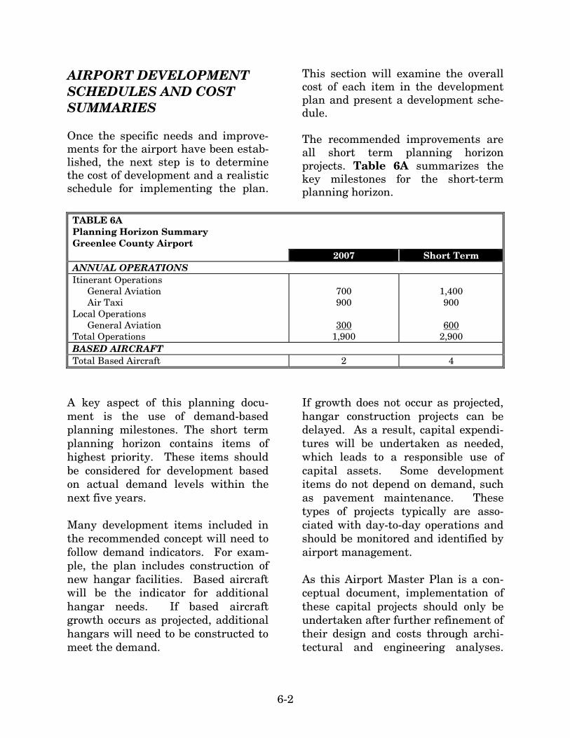
6-2
AIRPORT DEVELOPMENT SCHEDULES AND COST SUMMARIES Once the specific needs and improve-ments for the airport have been estab-lished, the next step is to determine the cost of development and a realistic schedule for implementing the plan.
This section will examine the overall cost of each item in the development plan and present a development sche-dule. The recommended improvements are all short term planning horizon projects. Table 6A summarizes the key milestones for the short-term planning horizon.
TABLE 6A Planning Horizon Summary Greenlee County Airport 2007 Short Term ANNUAL OPERATIONS Itinerant Operations General Aviation Air Taxi Local Operations General Aviation Total Operations
700 900
300
1,900
1,400 900
600
2,900 BASED AIRCRAFT Total Based Aircraft 2 4
A key aspect of this planning docu-ment is the use of demand-based planning milestones. The short term planning horizon contains items of highest priority. These items should be considered for development based on actual demand levels within the next five years. Many development items included in the recommended concept will need to follow demand indicators. For exam-ple, the plan includes construction of new hangar facilities. Based aircraft will be the indicator for additional hangar needs. If based aircraft growth occurs as projected, additional hangars will need to be constructed to meet the demand.
If growth does not occur as projected, hangar construction projects can be delayed. As a result, capital expendi-tures will be undertaken as needed, which leads to a responsible use of capital assets. Some development items do not depend on demand, such as pavement maintenance. These types of projects typically are asso-ciated with day-to-day operations and should be monitored and identified by airport management. As this Airport Master Plan is a con-ceptual document, implementation of these capital projects should only be undertaken after further refinement of their design and costs through archi-tectural and engineering analyses.

6-3
Moreover, some projects, such as the runway extension and the construc-tion of Runway 18-36, will require fur-ther study at the time of implementa-tion. The cost estimates presented in this chapter have been increased to allow for contingencies that may arise on the project (15 percent), sponsor ad-ministration (2 percent), engineering costs (8 percent), and construction management costs (12 percent). Capi-tal costs presented here should be viewed only as estimates subject to further refinement during design. Nevertheless, these estimates are con-sidered sufficiently accurate for plan-ning purposes. Cost estimates for each of the development projects listed in the capital improvement plan are listed in current (2008) dollars. Ex-hibit 6A presents the proposed short term capital improvement program for Greenlee County Airport.
SHORT TERM IMPROVEMENTS As indicated above, the short term planning horizon is concentrated first on the most immediate needs of the airfield and landside areas. Therefore, the program is presented year by year (2009-2013) to assist in capital im-provement. The primary focus of the short term planning horizon is to provide the air-port with essential facilities and the land that will be needed for short term projects. Some of the essential facili-ties and projects to be undertaken in-clude the extension of Runway 7-25, the design and construction of an air-port perimeter road, the construction
of a full-length parallel taxiway, the construction of a new airport access road, the installation of medium in-tensity taxiway lighting (MITL), and the acquisition of adjacent land for the protection of future airfield expansion projects. The short term projects that can be depicted are shown on Exhibit 6B. The total investment necessary for the short term CIP is approximately $15 million. Of this total, $11.7 million is eligible for FAA grant funding; $2.8 million is eligible for state funds, with the airport sponsor responsible for $586,700. RUNWAY 18-36 PROJECTS As it was discussed previously in Chapter Five, the potential exists for Phelps Dodge to privately fund the construction of a runway to accommo-date operations by a Boeing 727 air-craft. To meet the needs of Phelps Dodge and the ARC C-III design stan-dards, the runway is planned for a length of 8,700 feet and a width of 150 feet. Several additional projects would need to be undertaken to complete this project, including the acquisition of approximately 208 acres of land sur-rounding the airport, the realignment of State Route 78, the construction of a 60-foot wide, full-length parallel Tax-iway B, the installation of medium in-tensity runway lighting (MIRL), me-dium intensity taxiway lighting (MITL), precision approach path indi-cators (PAPI-4s), and runway end identifier lights (REILs). To meet po-tential demand of Phelps Dodge for the airport to be accessible in all

No. Project
1 Construct Full-Length Taxiway 1,337,068$ 1,270,215$ 33,427$ 33,427$ 2 Drainage Improvements 950,000$ 902,500$ 23,750$ 23,750$ 3 Fencing Improvements 500,000$ 475,000$ 12,500$ 12,500$ 4 Obstruction Removal 500,000$ 475,000$ 12,500$ 12,500$ 5 EA For Land Acquisition/Runway Extension 100,000$ 95,000$ 2,500$ 2,500$ 6 Apron Reconstruction 300,000$ -$ 270,000$ 30,000$ 7 Sign Installation 300,000$ -$ 270,000$ 30,000$ 8 Entrance Road & Parking Lot Design 175,000$ -$ 157,500$ 17,500$ 9 Utility Design 50,000$ 47,500$ 1,250$ 1,250$
4,212,068$ 3,265,215$ 783,427$ 163,427$
1 Utility Construction 150,000$ 142,500$ 3,750$ 3,750$ 2 Design Runway & Taxiway Extension 175,000$ -$ 157,500$ 17,500$ 3 Design Taxiway Lighting 75,000$ -$ 67,500$ 7,500$ 4 Extend Runway 7-25 273 Feet 1,296,900$ 1,232,055$ 32,423$ 32,423$ 5 Install Runway Lighting 100,000$ 95,000$ 2,500$ 2,500$ 6 Install Taxiway Lighting 507,760$ 482,372$ 12,694$ 12,694$ 7 Construct Entrance Road and Parking Lot 774,520$ -$ 697,068$ 77,452$ 8 Relocate State Route 78 - Southwest Portion 1,103,970$ 1,048,772$ 27,599$ 27,599$
4,183,150$ 3,000,699$ 1,001,034$ 181,418$
1 Install GPS Approach 650,000$ 617,500$ 16,250$ 16,250$ 2 Acquire 17.16 Acres - Runway 7 RPZ 591,000$ 561,450$ 14,775$ 14,775$ 3 Design Fire Protection Upgrades 150,000$ -$ 135,000$ 15,000$ 4 Design Runway Rehabilitation 75,000$ 71,250$ 1,875$ 1,875$ 5 Acquire 3.35 Acres - Runway 25 RPZ 131,500$ 124,925$ 3,288$ 3,288$
1,597,500$ 1,375,125$ 171,188$ 51,188$
1 Install REILS Runway 7-25 252,800$ 240,160$ 6,320$ 6,320$ 2 Rehabilitate Runway 600,000$ 570,000$ 15,000$ 15,000$ 3 Construct Fire Protection Upgrades 850,000$ -$ 765,000$ 85,000$
1,702,800$ 810,160$ 786,320$ 106,320$
1 Apron Expansion 868,005$ 824,605$ 21,700$ 21,700$ 2 Relocate AWOS 77,600$ 73,720$ 1,940$ 1,940$ 3 Construct Airport Perimeter Service Road 2,428,080$ 2,306,676$ 60,702$ 60,702$
3,373,685$ 3,205,001$ 84,342$ 84,342$ 15,069,203$ 11,656,199$ 2,826,310$ 586,694$
Local ShareTotal Cost
Federally
Eligible ADOT Eligible
2009
Subtotal 20092010
Subtotal 20102011
Subtotal 20112012
Subtotal 20122013
Subtotal 2013Total Short Term Planning Horizon
Exhibit 6ACAPITAL IMPROVEMENT PROGRAM
06M
P20
-6A
-1/1
6/08
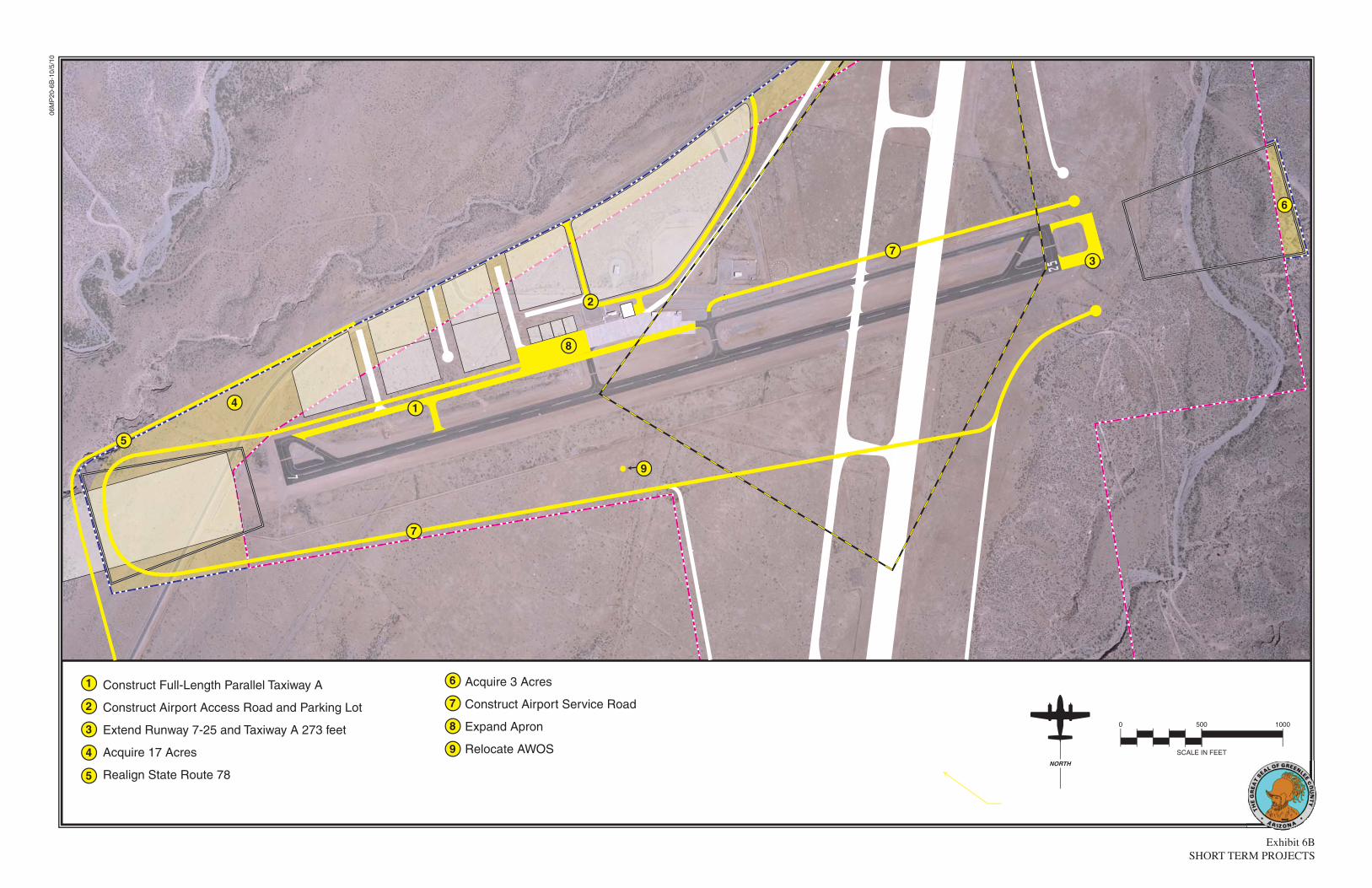
06M
P20
-6B
-10/
5/10
Exhibit 6BSHORT TERM PROJECTS
NORTH
0 500 1000
SCALE IN FEET
1
1
2
2
3
3
4
4
5
6
6
7
8
8
9
9
Construct Full-Length Parallel Taxiway A
Construct Airport Access Road and Parking Lot
Extend Runway 7-25 and Taxiway A 273 feet
Acquire 17 Acres
Realign State Route 78
Acquire 3 Acres
Construct Airport Service Road
Expand Apron
Relocate AWOS
5
7
7

6-4
weather conditions, an instrument landing system (ILS) is planned for ½-mile visibility instrument approaches to Runway 18. Should this ILS equipment be installed and become operational, a medium intensity ap-proach lighting system with a runway alignment indicator system (MALSR) would also need to be installed on the Runway 18 end. Landside facilities are planned to meet parking and storage needs of a Boeing 727 aircraft. A 15,000 square yard apron at the south end of Run-way 18-36 is planned to provide ade-quate parking and movement space for a Boeing 727 aircraft. An automo-
bile access road is planned to extend from State Route 78 to a hangar facili-ty (which is not included in the cost estimates) and the apron area for a Boeing 727. A total cost breakdown of each project associated with the construction of Runway 18-36 is presented in Table 6B. As it was with the previous project cost estimates, each project has been increased to allow for contingen-cies that may arise on the project (15 percent), sponsor administration (2 percent), engineering costs (8 percent), and construction management costs (12 percent). Each cost estimate is listed in current (2008) dollars.
TABLE 6B Runway 18-36 Project Program Costs (2008 $) Greenlee County Airport
No. Project Total Cost 1 Acquire 207.79 Acres $6,849,000 2 Relocate State Route 78 $1,929,808 3 Construct Runway 18-36 $8,449,995 4 Construct Taxiway B $5,456,540 5 Install MIRL $693,700 6 Install MITL $834,800 7 Install ILS Equipment $2,193,000 8 Install PAPI-4s $428,900 9 Install REILs Runway 36 $260,700
10 Install MALSR Runway 18 $738,000 11 Construct South Apron - 15,000 Square Yards $1,426,720 12 Construct South Apron Access Road $1,296,400
Total Project Cost $30,557,563
CAPITAL IMPROVEMENTS FUNDING Financing capital improvements at the airport will not rely exclusively upon the financial resources of Greenlee County. Capital improvement funding is available through various grants-in-aid programs at both the federal and
state level. The following discussion outlines the key sources for capital improvement funding. FEDERAL GRANTS The United States Congress has long recognized the need to develop and

6-5
maintain a system of aviation facilities across the nation for the purpose of national defense and promotion of in-terstate commerce. Various grants-in-aid programs to public airports have been established over the years for this purpose. The most recent legisla-tion is the Airport Improvement Pro-gram (AIP) of 1982. The AIP has been reauthorized several times, with the most recent legislation enacted in late 2003 and entitled the Vision 100 – Century of Aviation Reauthorization Act. Vision 100 expired in September of 2007. To date, Congress has yet to pass a reauthorization for 2008. It is not presently known when this reau-thorization bill will be passed by Con-gress. The source for AIP funds is the Avia-tion Trust Fund. The Aviation Trust Fund was established in 1970 to pro-vide funding for aviation capital in-vestment programs (aviation devel-opment, facilities and equipment, and research and development). The Trust Fund also finances the operation of the FAA. It is funded by user fees, taxes on airline tickets, aviation fuel, and various aircraft parts. Funds are distributed each year by the FAA from appropriations by Congress. A portion of the annual distribution is to prima-ry commercial service airports based upon enplanement levels. General aviation airports, however, also re-ceived entitlements under the last reauthorization. After all specific funding mechanisms are distributed; the remaining AIP funds are dis-bursed by the FAA, based upon the priority of the project for which they have requested federal assistance
through discretionary apportionments. A national priority system is used to evaluate and rank each airport project. Those projects with the high-est priority are given preference in funding. Under the AIP program, examples of eligible development projects include the airfield, aprons, and access roads. Passenger terminal building im-provements (such as bag claim and public waiting lobbies) may also be el-igible for FAA funding. Under Vision 100, automobile parking at small hub airports were also eligible. Improve-ments such as fueling facilities, utili-ties (with the exception of water supply for fire prevention), hangar buildings, airline ticketing, and airline operations areas are not typically eli-gible for AIP funds. Under Vision 100, Greenlee County Airport had been eligible for 95 per-cent funding assistance from AIP grants, as opposed to the previous AIR-21 level of 90 percent. While sim-ilar programs have been in place for over 50 years, it will be up to Congress to either extend or draft new legisla-tion authorizing and appropriating fu-ture federal funding. STATE AID TO AIRPORTS In support of the state airport system, the State of Arizona also participates in airport improvement projects. The source for State airport improvement funds is the Arizona Aviation Fund. Taxes levied by the State on aviation fuel, flight property, aircraft registra-tion tax, and registration fees (as well

6-6
as interest on these funds) are depo-sited in the Arizona Aviation Fund. The Transportation Board establishes the policies for distribution of these State funds. Under the State of Arizona grant pro-gram, an airport can receive funding for one-half (2.5 percent) of the local share of projects receiving federal AIP funding. The State also provides 90 percent funding for projects which are typically not eligible for federal AIP funding or have not received federal funding. State Airport Loan Program The Arizona Department of Transpor-tation - Aeronautics Division (ADOT) Airport Loan Program was established to enhance the utilization of State funds and provide a flexible funding mechanism to assist airports in fund-ing improvement projects. Eligible projects include runway, taxiway, and apron improvements; land acquisition; planning studies; and the preparation of plans and specifications for airport construction projects, as well as reve-nue-generating improvements such as hangars and fuel storage facilities. Projects which are not currently eligi-ble for the State Airport Loan Pro-gram are considered if the project would enhance the airport’s ability to be financially self-sufficient. There are two ways in which the loan funds can be used: Matching Funds, or Revenue Generating Projects. The Matching Funds are provided to meet the local matching fund requirement for securing federal airport improve-
ment grants or other federal or state grants. The Revenue Generating funds are provided for airport-related construction projects that are not eli-gible for funding under another pro-gram. Pavement Maintenance Program The airport system in Arizona is a multi-million dollar investment of public and private funds that must be protected and preserved. State avia-tion fund dollars are limited, and the State Transportation Board recognizes the need to protect and extend to the maximum amount the useful life of the airport system’s pavement. This program, the Airport Pavement Pre-servation Program (APPP), is estab-lished to assist in the preservation of the Arizona airport system infrastruc-ture. Greenlee County Airport parti-cipates in this program. Public Law 103-305 requires that air-ports requesting Federal AIP funding for pavement rehabilitation or recon-struction have an effective pavement maintenance management system. To this end, ADOT-Aeronautics has com-pleted and is maintaining an Airport Pavement Management System (APMS) which, coupled with monthly pavement evaluations by the airport sponsors, fulfills this requirement. The Arizona Airport Pavement Man-agement System uses the Army Corps of Engineers’ “Micropaver” program as a basis for generating a Five-Year Airport Pavement Preservation Pro-gram (APPP). The APMS consists of visual inspections of all airport pave-

6-7
ments. Evaluations are made of the types and severities observed and en-tered into a computer program data-base. Pavement Condition Index (PCI) values are determined through the visual assessment of pavement condition in accordance with the most recent FAA Advisory Circular 150/5380-6, and range from 0 (failed) to 100 (excellent). Every three years, a complete database update with new visual observations is conducted. In-dividual airport reports from the up-date are shared with all participating system airports. The Aeronautics Di-vision ensures that the APMS data-base is kept current, in compliance with FAA requirements. Every year, the Aeronautics Division, utilizing the APMS, will identify air-port pavement maintenance projects eligible for funding for the upcoming five years. These projects will appear in the State’s Five-Year Airport De-velopment Program. Once a project has been identified and approved for funding by the State Transportation Board, the airport sponsor may elect to accept a state grant for the project and not participate in the APPP, or the airport sponsor may sign an Inter-Government Agreement (IGA) with the Aeronautics Division to participate in the APPP. LOCAL FUNDING The balance of project costs, after con-sideration has been given to grants, must be funded through local re-sources. Assuming federal funding, this essentially equates to 2.5 percent of the project costs if all eligible FAA
and state funds are available. If only ADOT grants are available, the local share would be 10 percent of the project. According to Exhibit 6A, $586,700 in local funding will be needed in the short-term planning horizon. There are several alternatives for local finance options for future development at the airport, including airport reve-nues, direct funding from the City, is-suing bonds, and leasehold financing. These strategies could be used to fund the local matching share or complete the project if grant funding cannot be arranged. The capital improvement program has assumed that the Runway 18-36 project and its associated projects in addition to other landside facility de-velopment (conventional hangars, T-hangars, and public auto parking) would be completed privately. There are several municipal bonding options available to Greenlee County, including general obligation bonds, limited obligation bonds, and revenue bonds. General obligation bonds are a common form of municipal bond which is issued by voter approval and is se-cured by the full faith and credit of the County. County tax revenues are pledged to retire the debt. As instru-ments of credit, and because the com-munity secures the bonds, general ob-ligation bonds reduce the available debt level of the community. Due to the community pledge to secure and pay general obligation bonds, they are the most secure type of municipal bond and are generally issued at lower

6-8
interest rates and carry lower costs of issuance. The primary disadvantage of general obligation bonds is that they require voter approval and are subject to statutory debt limits. This requires that they be used for projects that have broad support among the voters, and that they are reserved for projects that have the highest public priorities. In contrast to general obligation bonds, limited obligation bonds (some-times referred to as Self-Liquidating Bonds) are secured by revenues from a local source. While neither general fund revenues nor the taxing power of the local community is pledged to pay the debt service, these sources may be required to retire the debt if pledged revenues are insufficient to make in-terest and principal payments on the bonds. These bonds still carry the full faith and credit pledge of the local community and, for the purpose of fi-nancial analysis, are considered as part of the debt burden of the local community. The overall debt burden of the local community is a factor in determining interest rates on munici-pal bonds. There are several types of revenue bonds, but in general, they are a form of municipal bond which is payable solely from the revenue derived from the operation of a facility that was constructed or acquired with the proceeds of the bonds. For example, a Lease Revenue Bond is secured with the income from a lease assigned to the repayment of the bonds. Revenue bonds have become a common form of financing airport improvements. Rev-enue bonds present the opportunity to provide those improvements without
direct burden to the taxpayer. Reve-nue bonds normally carry a higher in-terest rate because they lack the guarantees of general and limited ob-ligation bonds. Leasehold financing refers to a devel-oper or tenant financing improve-ments under a long term ground lease. The obvious advantage of such an ar-rangement is that it relieves the com-munity of all responsibility for raising the capital funds for improvements. However, the private development of facilities on a ground lease, particular-ly on property owned by a municipal agency, produces a unique set of prob-lems. In particular, it is more difficult to obtain private financing as only the improvements and the right to contin-ue the lease can be claimed in the event of a default. Ground leases normally provide for the reversion of improvements to the lessor at the end of the lease term, which reduces their potential value to a lender taking pos-session. Also, companies that want to own their property as a matter of fi-nancial policy may not locate where land is only available for lease. If Greenlee County should provide general aviation services in the future, this would ensure that the airport maximizes future revenue potential. Greenlee County Airport can accom-plish this by periodically reviewing aviation services rates and charges (i.e., fuel flowage fees, hangar and tie-down rental) at other regional airports to ensure that rates and charges at the airport are competitive and simi-lar to aviation services at other air-ports. Additionally, all new leases at the airport should have inflation clauses allowing for periodic rate in-

6-9
creases in-line with inflationary fac-tors. While it is desirable for the airport to directly pay for itself, the indirect and intangible benefits of the airport to the community’s economy and growth must be considered in implementing future capital improvements. PLAN IMPLEMENTATION The best means to begin implementa-tion of the recommendations in this Airport Master Plan is to first recog-nize that planning is a continuous process that does not end with comple-tion and approval of this document. Rather, the ability to continuously monitor the existing and forecast sta-tus of airport activity must be pro-vided and maintained. The issues upon which this Airport Master Plan is based will remain valid for a num-ber of years. The primary goal is for the airport to best serve the air trans-portation needs of the region, while continuing to be economically self-sufficient. The actual need for facilities is most appropriately established by airport activity levels rather than a specified date. For example, projections have been made as to when additional han-gars may be needed at the airport. In reality, however, the timeframe in which the development is needed may be substantially different. Actual de-mand may be slower to develop than
expected. On the other hand, high le-vels of demand may establish the need to accelerate the development. Al-though every effort has been made in this planning process to conservatively estimate when facility development may be needed, aviation demand will dictate when facility improvements need to be delayed or accelerated. The real value of a usable Airport Master Plan is in keeping the issues and objectives in the minds of the managers and decision-makers so that they are better able to recognize change and its effect. In addition to adjustments in aviation demand, deci-sions made as to when to undertake the improvements recommended in this Airport Master Plan will impact the period that the plan remains valid. The format used in this plan is in-tended to reduce the need for formal and costly updates by simply adjusting the timing. Updating can be done by the manager, thereby improving the plan’s effectiveness. In summary, the planning process re-quires that airport management con-sistently monitor the progress of the airport in terms of aircraft operations and based aircraft. Analysis of air-craft demand is critical to the timing and need for new airport facilities. The information obtained from conti-nually monitoring airport activity will provide the data necessary to deter-mine if the development schedule should be accelerated or decelerated.

Appendix A
GLOSSARY AND TERMS

Glossary of Terms
Airport ConsultantsA - 1
A
ABOVE GROUND LEVEL: The elevation of a point or surface above the ground.
ACCELERATE-STOP DISTANCE AVAILABLE (ASDA): See declared distances.
ADVISORY CIRCULAR: External publications issued by the FAA consisting of nonregulatory material providing for the recommendations relative to a policy, guidance and information relative to a specifi c aviation subject.
AIR CARRIER: An operator which: (1) performs at least fi ve round trips per week between two or more points and publishes fl ight schedules which specify the times, days of the week, and places between which such fl ights are performed; or (2) transports mail by air pursuant to a current contract with the U.S. Postal Service. Certifi ed in accordance with Federal Aviation Regulation (FAR) Parts 121 and 127.
AIRCRAFT: A transportation vehicle that is used or intended for use for fl ight.
AIRCRAFT APPROACH CATEGORY: A grouping of aircraft based on 1.3 times the stall speed in their landing confi guration at their maximum certifi cated landing weight. The categories are as follows:
• Category A: Speed less than 91 knots.• Category B: Speed 91 knots or more, but less than 121 knots.• Category C: Speed 121 knots or more, but less than 141 knots.• Category D: Speed 141 knots or more, but less than 166 knots.• Category E: Speed greater than 166 knots.
AIRCRAFT OPERATION: The landing, takeoff, or touch-and-go procedure by an aircraft on a runway at an airport.
AIRCRAFT OPERATIONS AREA (AOA): A restricted and secure area on the airport property designed to protect all aspects related to aircraft operations.
AIRCRAFT OWNERS AND PILOTS ASSOCIATION: A private organization serving
the interests and needs of general aviation pilots and aircraft owners.
AIRCRAFT RESCUE AND FIRE FIGHTING: A facility located at an airport that provides emergency vehicles, extinguishing agents, and personnel responsible for minimizing the impacts of an aircraft accident or incident.
AIRFIELD: The portion of an airport which contains the facilities necessary for the operation of aircraft.
AIRLINE HUB: An airport at which an airline concentrates a significant portion of its activity and which often has a significant amount of connecting traffic.
AIRPLANE DESIGN GROUP (ADG): A grouping of aircraft based upon wingspan. The groups are as follows:
• Group I: Up to but not including 49 feet. • Group II: 49 feet up to but not including 79 feet. • Group III: 79 feet up to but not including 118 feet. • Group IV: 118 feet up to but not including 171 feet. • Group V: 171 feet up to but not including 214 feet. • Group VI: 214 feet or greater.
AIRPORT AUTHORITY: A quasi-governmental public organization responsible for setting the policies governing the management and operation of an airport or system of airports under its jurisdiction.
AIRPORT BEACON: A navigational aid located at an airport which displays a rotating light beam to identify whether an airport is lighted.
AIRPORT CAPITAL IMPROVEMENT PLAN: The planning program used by the Federal Aviation Administration to identify, prioritize, and distribute funds for airport development and the needs of the National Airspace System to meet specifi ed national goals and objectives.
AIRPORT ELEVATION: The highest point on the runway system at an airport expressed in feet above mean sea level (MSL).
AIRPORT IMPROVEMENT PROGRAM: A program authorized by the Airport and Airway
APPENDIX A
Glossary of Terms
Airport ConsultantsA - 2
Improvement Act of 1982 that provides funding for airport planning and development.
AIRPORT LAYOUT DRAWING (ALD): The drawing of the airport showing the layout of existing and proposed airport facilities.
AIRPORT LAYOUT PLAN (ALP): A scaled drawing of the existing and planned land and facilities necessary for the operation and development of the airport.
AIRPORT LAYOUT PLAN DRAWING SET: A set of technical drawings depicting the current and future airport conditions. The individual sheets comprising the set can vary with the complexities of the airport, but the FAA-required drawings include the Airport Layout Plan (sometimes referred to as the Airport Layout Drawing (ALD), the Airport Airspace Drawing, and the Inner Portion of the Approach Surface Drawing, On-Airport Land Use Drawing, and Property Map.
AIRPORT MASTER PLAN: The planner’s concept of the long-term development of an airport.
AIRPORT MOVEMENT AREA SAFETY SYSTEM: A system that provides automated alerts and warnings of potential runway incursions or other hazardous aircraft movement events.
AIRPORT OBSTRUCTION CHART: A scaled drawing depicting the Federal Aviation Regulation (FAR) Part 77 surfaces, a representation of objects that penetrate these surfaces, runway, taxiway, and ramp areas, navigational aids, buildings, roads and other detail in the vicinity of an airport.
AIRPORT REFERENCE CODE (ARC): A coding system used to relate airport design criteria to the operational (Aircraft Approach Category) to the physical characteristics (Airplane Design Group) of the airplanes intended to operate at the airport.
AIRPORT REFERENCE POINT (ARP): The latitude and longitude of the approximate center of the airport.
AIRPORT SPONSOR: The entity that is legally responsible for the management and operation of an airport, including the fulfi llment of the requirements of laws and regulations related thereto.
AIRPORT SURFACE DETECTION EQUIPMENT: A radar system that provides air traffi c controllers with a visual representation of the movement of aircraft and other vehicles on the ground on the airfi eld at an airport.
AIRPORT SURVEILLANCE RADAR: The primary radar located at an airport or in an air traffi c control terminal area that receives a signal at an antenna and transmits the signal to air traffi c control display equipment defi ning the location of aircraft in the air. The signal provides only the azimuth and range of aircraft from the location of the antenna.
AIRPORT TRAFFIC CONTROL TOWER (ATCT): A central operations facility in the terminal air traffi c control system, consisting of a tower, including an associated instrument fl ight rule (IFR) room if radar equipped, using air/ground communications and/or radar, visual signaling and other devices to provide safe and expeditious movement of terminal air traffi c.
AIR ROUTE TRAFFIC CONTROL CENTER: A facility which provides en route air traffi c control service to aircraft operating on an IFR fl ight plan within controlled airspace over a large, multi-state region.
AIRSIDE: The portion of an airport that contains the facilities necessary for the operation of aircraft.
AIRSPACE: The volume of space above the surface of the ground that is provided for the operation of aircraft.
AIR TAXI: An air carrier certifi cated in accordance with FAR Part 121 and FAR Part 135 and authorized to provide, on demand, public transportation of persons and property by aircraft. Generally operates small aircraft “for hire” for specifi c trips.
AIR TRAFFIC CONTROL: A service operated by an appropriate organization for the purpose of providing for the safe, orderly, and expeditious fl ow of air traffi c.
AIR ROUTE TRAFFIC CONTROL CENTER (ARTCC): A facility established to provide air traffi c control service to aircraft operating on an IFR fl ight plan within controlled airspace and principally during the en route phase of fl ight.

Glossary of Terms
Airport ConsultantsA - 3
AIR TRAFFIC CONTROL SYSTEM COMMAND CENTER: A facility operated by the FAA which is responsible for the central fl ow control, the central altitude reservation system, the airport reservation position system, and the air traffi c service contingency command for the air traffi c control system.
AIR TRAFFIC HUB: A categorization of commercial service airports or group of commercial service airports in a metropolitan or urban area based upon the proportion of annual national enplanements existing at the airport or airports. The categories are large hub, medium hub, small hub, or non-hub. It forms the basis for the apportionment of entitlement funds.
AIR TRANSPORT ASSOCIATION OF AMERICA: An organization consisting of the principal U.S. airlines that represents the interests of the airline industry on major aviation issues before federal, state, and local government bodies. It promotes air transportation safety by coordinating industry and governmental safety programs and it serves as a focal point for industry efforts to standardize practices and enhance the effi ciency of the air transportation system.
ALERT AREA: See special-use airspace.
ALTITUDE: The vertical distance measured in feet above mean sea level.
ANNUAL INSTRUMENT APPROACH (AIA): An approach to an airport with the intent to land by an aircraft in accordance with an IFR fl ight plan when visibility is less than three miles and/or when the ceiling is at or below the minimum initial approach altitude.
APPROACH LIGHTING SYSTEM (ALS): An airport lighting facility which provides visual guidance to landing aircraft by radiating light beams by which the pilot aligns the aircraft with the extended centerline of the runway on his fi nal approach and landing.
APPROACH MINIMUMS: The altitude below which an aircraft may not descend while on an IFR approach unless the pilot has the runway in sight.
APPROACH SURFACE: An imaginary obstruction limiting surface defi ned in FAR Part 77 which is longitudinally centered on an extended runway
centerline and extends outward and upward from the primary surface at each end of a runway at a designated slope and distance based upon the type of available or planned approach by aircraft to a runway.
APRON: A specifi ed portion of the airfi eld used for passenger, cargo or freight loading and unloading, aircraft parking, and the refueling, maintenance and servicing of aircraft.
AREA NAVIGATION: The air navigation procedure that provides the capability to establish and maintain a fl ight path on an arbitrary course that remains within the coverage area of navigational sources being used.
AUTOMATED TERMINAL INFORMATION SERVICE (ATIS): The continuous broadcast of recorded non-control information at towered airports. Information typically includes wind speed, direction, and runway in use.
AUTOMATED SURFACE OBSERVATION SYSTEM (ASOS): A reporting system that provides frequent airport ground surface weather observation data through digitized voice broadcasts and printed reports.
AUTOMATED WEATHER OBSERVATION STATION (AWOS): Equipment used to automatically record weather conditions (i.e. cloud height, visibility, wind speed and direction, temperature, dew point, etc.)
AUTOMATIC DIRECTION FINDER (ADF): An aircraft radio navigation system which senses and indicates the direction to a non-directional radio beacon (NDB) ground transmitter.
AVIGATION EASEMENT: A contractual right or a property interest in land over which a right of unobstructed fl ight in the airspace is established.
AZIMUTH: Horizontal direction expressed as the angular distance between true north and the direction of a fi xed point (as the observer’s heading).
B
BASE LEG: A fl ight path at right angles to the landing runway off its approach end. The base leg normally extends from the downwind leg to the intersection of the extended runway centerline. See “traffi c pattern.”

Glossary of Terms
Airport ConsultantsA - 4
BASED AIRCRAFT: The general aviation aircraft that use a specifi c airport as a home base.
BEARING: The horizontal direction to or from any point, usually measured clockwise from true north or magnetic north.
BLAST FENCE: A barrier used to divert or dissipate jet blast or propeller wash.
BLAST PAD: A prepared surface adjacent to the end of a runway for the purpose of eliminating the erosion of the ground surface by the wind forces produced by airplanes at the initiation of takeoff operations.
BUILDING RESTRICTION LINE (BRL): A line which identifi es suitable building area locations on the airport.
C
CAPITAL IMPROVEMENT PLAN: The planning program used by the Federal Aviation Administration to identify, prioritize, and distribute Airport Improvement Program funds for airport development and the needs of the National Airspace System to meet specifi ed national goals and objectives.
CARGO SERVICE AIRPORT: An airport served by aircraft providing air transportation of property only, including mail, with an annual aggregate landed weight of at least 100,000,000 pounds.
CATEGORY I: An Instrument Landing System (ILS) that provides acceptable guidance information to an aircraft from the coverage limits of the ILS to the point at which the localizer course line intersects the glide path at a decision height of 100 feet above the horizontal plane containing the runway threshold.
CATEGORY II: An ILS that provides acceptable guidance information to an aircraft from the coverage limits of the ILS to the point at which the localizer course line intersects the glide path at a decision height of 50 feet above the horizontal plane containing the runway threshold.
CATEGORY III: An ILS that provides acceptable guidance information to a pilot from the coverage
limits of the ILS with no decision height specifi ed above the horizontal plane containing the runway threshold.
CEILING: The height above the ground surface to the location of the lowest layer of clouds which is reported as either broken or overcast.
CIRCLING APPROACH: A maneuver initiated by the pilot to align the aircraft with the runway for landing when fl ying a predetermined circling instrument approach under IFR.
CLASS A AIRSPACE: See Controlled Airspace.
CLASS B AIRSPACE: See Controlled Airspace.
CLASS C AIRSPACE: See Controlled Airspace.
CLASS D AIRSPACE: See Controlled Airspace.
CLASS E AIRSPACE: See Controlled Airspace.
CLASS G AIRSPACE: See Controlled Airspace.
CLEAR ZONE: See Runway Protection Zone.
COMMERCIAL SERVICE AIRPORT: A public airport providing scheduled passenger service that enplanes at least 2,500 annual passengers.

Glossary of Terms
Airport ConsultantsA - 5
COMMON TRAFFIC ADVISORY FREQUENCY: A radio frequency identifi ed in the appropriate aeronautical chart which is designated for the purpose of transmitting airport advisory information and procedures while operating to or from an uncontrolled airport.
COMPASS LOCATOR (LOM): A low power, low/medium frequency radio-beacon installed in conjunction with the instrument landing system at one or two of the marker sites.
CONICAL SURFACE: An imaginary obstruction- limiting surface defi ned in FAR Part 77 that extends from the edge of the horizontal surface outward and upward at a slope of 20 to 1 for a horizontal distance of 4,000 feet.
CONTROLLED AIRPORT: An airport that has an operating airport traffi c control tower.
CONTROLLED AIRSPACE: Airspace of defi ned dimensions within which air traffi c control services are provided to instrument fl ight rules (IFR) and visual fl ight rules (VFR) fl ights in accordance with the airspace classifi cation. Controlled airspace in the United States is designated as follows:
• CLASS A: Generally, the airspace from 18,000 feet mean sea level (MSL) up to but not including fl ight level FL600. All persons must operate their aircraft under IFR.
• CLASS B: Generally, the airspace
from the surface to 10,000 feet MSL sur-rounding the nation’s busiest airports. The confi guration of Class B airspace is unique to each airport, but typically consists of two or more layers of air space and is designed to contain all published in-strument approach procedures to the airport. An air traffi c control clearance is required for all air-craft to operate in the area.
• CLASS C: Generally, the airspace from the surface to 4,000 feet above the airport elevation (charted as MSL) surrounding those airports that have an operational control tower and radar approach
control and are served by a qualifying number of IFR operations or passenger enplanements. Although individually tailored for each airport, Class C airspace typically consists of a surface area with a fi ve nautical mile (nm) radius and an outer area with a 10 nautical mile radius that extends from 1,200 feet to 4,000 feet above the airport elevation. Two-way radio communication is required for all aircraft.
• CLASS D: Generally, that airspace from the surface to 2,500 feet above the air port elevation (charted as MSL) surrounding those airports that have an operational control tower. Class D airspace is individually tailored and confi gured to encompass published instrument approach procedure . Unless otherwise authorized, all persons must establish two-way
radio communication.
• CLASS E: Generally, controlled airspace that is not classifi ed as Class A, B, C, or D. Class E airspace extends upward from either the surface or a designated altitude to the overlying or adjacent controlled airspace. When designated as a surface area, the airspace will be confi gured to contain all instrument procedures. Class E airspace encompasses all Victor
Airways. Only aircraft following instrument fl ight rules are
required to establish two-way radio communication with air traffi c control.
• CLASS G: Generally, that airspace not classifi ed as Class A, B, C, D, or E. Class G airspace is uncontrolled for all aircraft. Class G airspace extends from the surface to the overlying Class E airspace.
CONTROLLED FIRING AREA: See special-use airspace.
CROSSWIND: A wind that is not parallel to a runway centerline or to the intended fl ight path of an aircraft.
CROSSWIND COMPONENT: The component of wind that is at a right angle to the runway centerline or the intended fl ight path of an aircraft.
CROSSWIND LEG: A fl ight path at right angles to the landing runway off its upwind end. See “traffi c pattern.”
1NM
3 NM
2 NM
Glossary of Terms
Airport ConsultantsA - 6
D
DECIBEL: A unit of noise representing a level relative to a reference of a sound pressure 20 micro newtons per square meter.
DECISION HEIGHT: The height above the end of the runway surface at which a decision must be made by a pilot during the ILS or Precision Approach Radar approach to either continue the approach or to execute a missed approach.
DECLARED DISTANCES: The distances declared available for the airplane’s takeoff runway, takeoff distance, accelerate-stop distance, and landing distance requirements. The distances are:
• TAKEOFF RUNWAY AVAILABLE (TORA): The runway length declared available and suitable for the ground run of an airplane taking off.
• TAKEOFF DISTANCE AVAILABLE (TODA): The TORA plus the length of any remaining runway and/or clear way beyond the far end of the TORA.
• ACCELERATE-STOP DISTANCE AVAILABLE (ASDA): The runway plus stopway
length declared available for the acceleration and deceleration of an aircraft aborting a takeoff.
• LANDING DISTANCE AVAILABLE (LDA): The runway length declared available and suitable for landing.
DEPARTMENT OF TRANSPORTATION: The cabinet level federal government organization consisting of modal operating agencies, such as the Federal Aviation Administration, which was established to promote the coordination of federal transportation programs and to act as a focal point for research and development efforts in transportation.
DISCRETIONARY FUNDS: Federal grant funds that may be appropriated to an airport based upon designation by the Secretary of Transportation or Congress to meet a specifi ed national priority such as enhancing capacity, safety, and security, or mitigating noise.
DISPLACED THRESHOLD: A threshold that is located at a point on the runway other than the designated beginning of the runway.
DISTANCE MEASURING EQUIPMENT (DME): Equipment (airborne and ground) used to measure, in nautical miles, the slant range distance of an aircraft from the DME navigational aid.
DNL: The 24-hour average sound level, in Aweighted decibels, obtained after the addition of ten decibels to sound levels for the periods between 10 p.m. and 7 a.m. as averaged over a span of one year. It is the FAA standard metric for determining the cumulative exposure of individuals to noise.
DOWNWIND LEG: A fl ight path parallel to the landing runway in the direction opposite to landing. The downwind leg normally extends between the crosswind leg and the base leg. Also see “traffi c pattern.”
E
EASEMENT: The legal right of one party to use a portion of the total rights in real estate owned by another party. This may include the right of passage over, on, or below the property; certain air rights above the property, including view rights; and the rights to any specifi ed form of development or activity, as well as any other legal rights in the property that may be specifi ed in the easement document.
ELEVATION: The vertical distance measured in feet above mean sea level.
ENPLANED PASSENGERS: The total number of revenue passengers boarding aircraft, including originating, stop-over, and transfer passengers, in scheduled and nonscheduled services.
ENPLANEMENT: The boarding of a passenger, cargo, freight, or mail on an aircraft at an airport.
ENTITLEMENT: Federal funds for which a commercial service airport may be eligible based upon its annual passenger enplanements.
ENVIRONMENTAL ASSESSMENT (EA): An environmental analysis performed pursuant to the National Environmental Policy Act to determine whether an action would signifi cantly affect the environment and thus require a more detailed environmental impact statement.
ENVIRONMENTAL AUDIT: An assessment of the current status of a party’s compliance with applicable

Glossary of Terms
Airport ConsultantsA - 7
environmental requirements of a party’s environmental compliance policies, practices, and controls.
ENVIRONMENTAL IMPACT STATEMENT (EIS): A document required of federal agencies by the National Environmental Policy Act for major projects are legislative proposals affecting the environment. It is a tool for decision-making describing the positive and negative effects of a proposed action and citing alternative actions.
ESSENTIAL AIR SERVICE: A federal program which guarantees air carrier service to selected small cities by providing subsidies as needed to prevent these cities from such service.
F
FEDERAL AVIATION REGULATIONS: The general and permanent rules established by the executive departments and agencies of the Federal Government for aviation, which are published in the Federal Register. These are the aviation subset of the Code of Federal Regulations.
FEDERAL INSPECTION SERVICES: The provision of customs and immigration services including passport inspection, inspection of baggage, the collection of duties on certain imported items, and the inspections for agricultural products, illegal drugs, or other restricted items.
FINAL APPROACH: A fl ight path in the direction of landing along the extended runway centerline. The fi nal approach normally extends from the base leg to the runway. See “traffi c pattern.”
FINAL APPROACH AND TAKEOFF AREA (FATO). A defi ned area over which the fi nal phase of the helicopter approach to a hover, or a landing is completed and from which the takeoff is initiated.
FINAL APPROACH FIX: The designated point at which the fi nal approach segment for an aircraft landing on a runway begins for a non-precision approach.
FINDING OF NO SIGNIFICANT IMPACT (FONSI): A public document prepared by a Federal agency that presents the rationale why a proposed action will not have a signifi cant effect on the environment and for which an environmental impact statement will not be prepared.
FIXED BASE OPERATOR (FBO): A provider of services to users of an airport. Such services include, but are not limited to, hangaring, fueling, fl ight training, repair, and maintenance.
FLIGHT LEVEL: A designation for altitude within controlled airspace.
FLIGHT SERVICE STATION: An operations facility in the national fl ight advisory system which utilizes data interchange facilities for the collection and dissemination of Notices to Airmen, weather, and administrative data and which provides pre-fl ight and in-fl ight advisory services to pilots through air and ground based communication facilities.
FRANGIBLE NAVAID: A navigational aid which retains its structural integrity and stiffness up to a designated maximum load, but on impact from a greater load, breaks, distorts, or yields in such a manner as to present the minimum hazard to aircraft.
G
GENERAL AVIATION: That portion of civil aviation which encompasses all facets of aviation except air carriers holding a certifi cate of convenience and necessity, and large aircraft commercial operators.
GENERAL AVIATION AIRPORT: An airport that provides air service to only general aviation.
GLIDESLOPE (GS): Provides vertical guidance for aircraft during approach and landing. The glideslope consists of the following:
1.Electronic components emitting signals which provide vertical guidance by reference to airborne instruments during instrument approaches such as ILS; or
2.Visual ground aids, such as VASI, which provide vertical guidance for VFR approach or for the visual portion of an instrument approach and landing.
GLOBAL POSITIONING SYSTEM (GPS): A system of 24 satellites used as reference points to enable navigators equipped with GPS receivers to determine their latitude, longitude, and altitude.
GROUND ACCESS: The transportation system on and around the airport that provides access to and

Glossary of Terms
Airport ConsultantsA - 8
from the airport by ground transportation vehicles for passengers, employees, cargo, freight, and airport services.
H
HELIPAD: A designated area for the takeoff, landing, and parking of helicopters.
HIGH INTENSITY RUNWAY LIGHTS: The highest classifi cation in terms of intensity or brightness for lights designated for use in delineating the sides of a runway.
HIGH-SPEED EXIT TAXIWAY: A long radius taxiway designed to expedite aircraft turning off the runway after landing (at speeds to 60 knots), thus reducing runway occupancy time.
HORIZONTAL SURFACE: An imaginary obstruction- limiting surface defi ned in FAR Part 77 that is specifi ed as a portion of a horizontal plane surrounding a runway located 150 feet above the established airport elevation. The specifi c horizontal dimensions of this surface are a function of the types of approaches existing or planned for the runway.
I
INITIAL APPROACH FIX: The designated point at which the initial approach segment begins for an instrument approach to a runway.
INSTRUMENT APPROACH PROCEDURE: A series of predetermined maneuvers for the orderly transfer of an aircraft under instrument fl ight conditions from the beginning of the initial approach to a landing, or to a point from which a landing may be made visually.
INSTRUMENT FLIGHT RULES (IFR): Procedures for the conduct of fl ight in weather conditions below Visual Flight Rules weather minimums. The term IFR is often also used to defi ne weather conditions and the type of fl ight plan under which an aircraft is operating.
INSTRUMENT LANDING SYSTEM (ILS): A precision instrument approach system which normally consists of the following electronic components and visual aids:
1. Localizer.2. Glide Slope.3. Outer Marker.4. Middle Marker.5. Approach Lights.
INSTRUMENT METEOROLOGICAL CONDITIONS: Meteorological conditions expressed in terms of specifi c visibility and ceiling conditions that are less than the minimums specifi ed for visual meteorological conditions.
ITINERANT OPERATIONS: Operations by aircraft that are not based at a specifi ed airport.
K
KNOTS: A unit of speed length used in navigation that is equivalent to the number of nautical miles traveled in one hour.
L
LANDSIDE: The portion of an airport that provides the facilities necessary for the processing of passengers, cargo, freight, and ground transportation vehicles.
LANDING DISTANCE AVAILABLE (LDA): See declared distances.
LARGE AIRPLANE: An airplane that has a maximum certifi ed takeoff weight in excess of 12,500 pounds.
LOCAL AREA AUGMENTATION SYSTEM: A differential GPS system that provides localized measurement correction signals to the basic GPS signals to improve navigational accuracy integrity, continuity, and availability.
LOCAL OPERATIONS: Aircraft operations performed by aircraft that are based at the airport and that operate in the local traffi c pattern or within sight of the airport, that are known to be departing for or arriving from fl ights in local practice areas within a prescribed distance from the airport, or that execute simulated instrument approaches at the airport.
LOCAL TRAFFIC: Aircraft operating in the traffi c pattern or within sight of the tower, or aircraft known to be departing or arriving from the local practice areas, or aircraft executing practice instrument

Glossary of Terms
Airport ConsultantsA - 9
approach procedures. Typically, this includes touch and-go training operations.
LOCALIZER: The component of an ILS which provides course guidance to the runway.
LOCALIZER TYPE DIRECTIONAL AID (LDA): A facility of comparable utility and accuracy to a localizer, but is not part of a complete ILS and is not aligned with the runway.
LONG RANGE NAVIGATION SYSTEM (LORAN): Long range navigation is an electronic navigational aid which determines aircraft position and speed by measuring the difference in the time of reception of synchronized pulse signals from two fi xed transmitters. Loran is used for en route navigation.
LOW INTENSITY RUNWAY LIGHTS: The lowest clas- sifi cation in terms of intensity or brightness for lights designated for use in delineating the sides of a runway.
M
MEDIUM INTENSITY RUNWAY LIGHTS: The middle classifi cation in terms of intensity or brightness for lights designated for use in delineating the sides of a runway.
MICROWAVE LANDING SYSTEM (MLS): An instrument approach and landing system that provides precision guidance in azimuth, elevation, and distance measurement.
MILITARY OPERATIONS: Aircraft operations that are performed in military aircraft.
MILITARY OPERATIONS AREA (MOA): See special-use airspace
MILITARY TRAINING ROUTE: An air route depicted on aeronautical charts for the conduct of military fl ight training at speeds above 250 knots.
MISSED APPROACH COURSE (MAC): The fl ight route to be followed if, after an instrument approach, a landing is not affected, and occurring normally:
1. When the aircraft has descended to the decision height and has not established visual contact; or
2. When directed by air traffi c control to pull up or to go around again.
MOVEMENT AREA: The runways, taxiways, and other areas of an airport which are utilized for taxiing/hover taxiing, air taxiing, takeoff, and landing of aircraft, exclusive of loading ramps and parking areas. At those airports with a tower, air traffi c control clearance is required for entry onto the movement area.
N
NATIONAL AIRSPACE SYSTEM: The network of air traffi c control facilities, air traffi c control areas, and navigational facilities through the U.S.
NATIONAL PLAN OF INTEGRATED AIRPORT SYSTEMS: The national airport system plan developed by the Secretary of Transportation on a biannual basis for the development of public use airports to meet national air transportation needs.
NATIONAL TRANSPORTATION SAFETY BOARD: A federal government organization established to investigate and determine the probable cause of transportation accidents, to recommend equipment and procedures to enhance transportation safety, and to review on appeal the suspension or revocation of any certifi cates or licenses issued by the Secretary of Transportation.
NAUTICAL MILE: A unit of length used in navigation which is equivalent to the distance spanned by one minute of arc in latitude, that is, 1,852 meters or 6,076 feet. It is equivalent to approximately 1.15 statute mile.
NAVAID: A term used to describe any electrical or visual air navigational aids, lights, signs, and associated supporting equipment (i.e. PAPI, VASI, ILS, etc.)
NAVIGATIONAL AID: A facility used as, available for use as, or designed for use as an aid to air navigation.
NOISE CONTOUR: A continuous line on a map of the airport vicinity connecting all points of the same noise exposure level.

Glossary of Terms
Airport ConsultantsA - 10
NON-DIRECTIONAL BEACON (NDB): A beacon transmitting nondirectional signals whereby the pilot of an aircraft equipped with direction fi nding equipment can determine his or her bearing to and from the radio beacon and home on, or track to, the station. When the radio beacon is installed in conjunction with the Instrument Landing System marker, it is normally called a Compass Locator.
NON-PRECISION APPROACH PROCEDURE: A standard instrument approach procedure in which no electronic glide slope is provided, such as VOR, TACAN, NDB, or LOC.
NOTICE TO AIRMEN: A notice containing information concerning the establishment, condition, or change in any component of or hazard in the National Airspace System, thetimely knowledge of which is considered essential to personnel concerned with fl ight operations.
O
OBJECT FREE AREA (OFA): An area on the ground centered on a runway, taxiway, or taxilane centerline provided to enhance the safety of aircraft operations by having the area free of objects, except for objects that need to be located in the OFA for air navigation or aircraft ground maneuvering purposes.
OBSTACLE FREE ZONE (OFZ): The airspace below 150 feet above the established airport elevation and along the runway and extended runway centerline that is required to be kept clear of all objects, except for frangible visual NAVAIDs that need to be located in the OFZ because of their function, in order to provide clearance for aircraft landing or taking off from the runway, and for missed approaches.
ONE-ENGINE INOPERABLE SURFACE: A surface emanating from the runway end at a slope ratio of 62.5:1. Air carrier airports are required to maintain a technical drawing of this surface depicting any object penetrations by January 1, 2010.
OPERATION: The take-off, landing, or touch-and-go procedure by an aircraft on a runway at an airport.
OUTER MARKER (OM): An ILS navigation facility in the terminal area navigation system located four to seven miles from the runway edge on the extended
centerline, indicating to the pilot that he/she is passing over the facility and can begin fi nal approach.
P
PILOT CONTROLLED LIGHTING: Runway lighting systems at an airport that are controlled by activating the microphone of a pilot on a specifi ed radio frequency.
PRECISION APPROACH: A standard instrument approach procedure which provides runway alignment and glide slope (descent) information. It is categorized as follows:
• CATEGORY I (CAT I): A precision approach which provides for approaches with a decision height of not less than 200 feet and visibility not less than 1/2 mile or Runway Visual Range (RVR) 2400 (RVR 1800) with operative touchdown zone and runway centerline lights.
• CATEGORY II (CAT II): A precision approach which provides for approaches with a decision height of not less than 100 feet and visibility not less than 1200 feet RVR.
• CATEGORY III (CAT III): A precision approach which provides for approaches with minima less than Category II.
PRECISION APPROACH PATH INDICATOR (PAPI): A lighting system providing visual approach slope guidance to aircraft during a landing approach. It is similar to a VASI but provides a sharper transition between the coloredindicator lights.
PRECISION APPROACH RADAR: A radar facility in the terminal air traffi c control system used to detect and display with a high degree of accuracy the direction, range, and elevation of an aircraft on the fi nal approach to a runway.
PRECISION OBJECT FREE AREA (POFA): An area centered on the extended runway centerline, beginning at the runway threshold and extending behind the runway threshold that is 200 feet long by 800 feet wide. The POFA is a clearing standard which requires the POFA to be kept clear of above ground objects protruding above the runway safety

Glossary of Terms
Airport ConsultantsA - 11
RNAV: Area navigation - airborne equipment which permits fl ights over determined tracks within prescribed accuracy tolerances without the need to overfl y ground-based navigation facilities. Used en route and for approaches to an airport.
RUNWAY: A defi ned rectangular area on an airport prepared for aircraft landing and takeoff. Runways are normally numbered in relation to their magnetic direction, rounded off to the nearest 10 degrees. For example, a runway with a magnetic heading of 180 would be designated Runway 18. The runway heading on the opposite end of the runway is 180 degrees from that runway end. For example, the opposite runway heading for Runway 18 would be Runway 36 (magnetic heading of 360). Aircraft can takeoff or land from either end of a runway, depending upon wind direction.
RUNWAY ALIGNMENT INDICATOR LIGHT: A series of high intensity sequentially fl ashing lights installed on the extended centerline of the runway usually in conjunction with an approach lighting system.
RUNWAY END IDENTIFIER LIGHTS (REIL): Two synchronized fl ashing lights, one on each side of the runway threshold, which provide rapid and positive identifi cation of the approach end of a particular runway.
RUNWAY GRADIENT: The average slope, measured in percent, between the two ends of a runway.
RUNWAY PROTECTION ZONE (RPZ): An area off the runway end to enhance the protection of people and property on the ground. The RPZ is trapezoidal in shape. Its dimensions are determined by the aircraft approach speed and runway approach type and minima.
RUNWAY SAFETY AREA (RSA): A defi ned surface surrounding the runway prepared or suitable for reducing the risk of damage to airplanes in the event of an undershoot, overshoot, or excursion from the runway.
RUNWAY VISIBILITY ZONE (RVZ): An area on the airport to be kept clear of permanent objects so that there is an unobstructed line of- site from any point fi ve feet above the runway centerline to
area edge elevation (except for frangible NAVAIDS). The POFA applies to all new authorized instrument approach procedures with less than 3/4 mile visibility.
PRIMARY AIRPORT: A commercial service airport that enplanes at least 10,000 annual passengers.
PRIMARY SURFACE: An imaginary obstruction limiting surface defi ned in FAR Part 77 that is specifi ed as a rectangular surface longitudinally centered about a runway. The specifi c dimensions of this surface are a function of the types of approaches existing or planned for the runway.
PROHIBITED AREA: See special-use airspace.
PVC: Poor visibility and ceiling. Used in determining Annual Service Volume. PVC conditions exist when the cloud ceiling is less than 500 feet and visibility is less than one mile.
R
RADIAL: A navigational signal generated by a Very High Frequency Omni-directional Range or VORTAC station that is measured as an azimuth from the station.
REGRESSION ANALYSIS: A statistical technique that seeks to identify and quantify the relationships between factors associated with a forecast.
REMOTE COMMUNICATIONS OUTLET (RCO): An unstaffed transmitter receiver/facility remotely controlled by air traffi c personnel. RCOs serve fl ight service stations (FSSs). RCOs were established to provide ground-to-ground communications between air traffi c control specialists and pilots at satellite airports for delivering en route clearances, issuing departure authorizations, and acknowledging instrument fl ight rules cancellations or departure/landing times.
REMOTE TRANSMITTER/RECEIVER (RTR): See remote communications outlet. RTRs serve ARTCCs.
RELIEVER AIRPORT: An airport to serve general aviation aircraft which might otherwise use a congested air-carrier served airport.
RESTRICTED AREA: See special-use airspace.

Glossary of Terms
Airport ConsultantsA - 12
any point fi ve feet above an intersecting runway centerline.
RUNWAY VISUAL RANGE (RVR): An instrumentally derived value, in feet, representing the horizontal distance a pilot can see down the runway from the runway end.
S
SCOPE: The document that identifi es and defi nes the tasks, emphasis, and level of effort associated with a project or study.
SEGMENTED CIRCLE: A system of visual indicators designed to provide traffi c pattern information at airports without operating control towers.
SHOULDER: An area adjacent to the edge of paved runways, taxiways, or aprons providing a transition between the pavement and the adjacent surface; support for aircraft running off the pavement; enhanced drainage; and blast protection. The shoulder does not necessarily need to be paved.
SLANT-RANGE DISTANCE: The straight line distance between an aircraft and a point on the ground.
SMALL AIRPLANE: An airplane that has a maximum certifi ed takeoff weight of up to 12,500 pounds.
SPECIAL-USE AIRSPACE: Airspace of defi ned dimensions identifi ed by a surface area wherein activities must be confi ned because of their nature and/or wherein limitations may be imposed upon aircraft operations that are not a part of those activities. Special-use airspace classifi cations include:
• ALERT AREA: Airspace which may contain a high volume of pilot training activities or an unusual type of aerial activity, neither of which is hazardous to aircraft.
• CONTROLLED FIRING AREA: Airspace wherein activities are conducted under conditions so controlled as to eliminate hazards to nonparticipating aircraft and to ensure the safety of persons or property on the ground.
• MILITARY OPERATIONS AREA (MOA): Designated airspace with defi ned vertical and
lateral dimensions established outside Class A airspace to separate/segregate certain military activities from instrument fl ight rule (IFR) traffi c and to identify for visual fl ight rule (VFR) traffi c where these activities are conducted.
• PROHIBITED AREA: Designated airspace within which the fl ight of aircraft is prohibited.
• RESTRICTED AREA: Airspace designated under Federal Aviation Regulation (FAR) 73, within which the fl ight of aircraft, while not wholly prohibited, is subject to restriction. Most restricted areas are designated joint use. When not in use by the using agency, IFR/VFR operations can be authorized by the controlling air traffi c control facility.
• WARNING AREA: Airspace which may contain hazards to nonparticipating aircraft.
STANDARD INSTRUMENT DEPARTURE (SID): A preplanned coded air traffi c control IFR departure routing, preprinted for pilot use in graphic and textual form only.
STANDARD INSTRUMENT DEPARTURE PROCEDURES: A published standard fl ight procedure to be utilized following takeoff to provide a transition between the airport and the terminal area or en route airspace.
STANDARD TERMINAL ARRIVAL ROUTE (STAR): A preplanned coded air traffi c control IFR arrival routing, preprinted for pilot use in graphic and textual or textual form only.
STOP-AND-GO: A procedure wherein an aircraft will land, make a complete stop on the runway, and then commence a takeoff from that point. A stop-and-go is recorded as two operations: one operation for the landing and one operation for the takeoff.
STOPWAY: An area beyond the end of a takeoff runway that is designed to support an aircraft during an aborted takeoff without causing structural damage to the aircraft. It is not to be used for takeoff, landing, or taxiing by aircraft.
STRAIGHT-IN LANDING/APPROACH: A landing made on a runway aligned within 30 degrees

Glossary of Terms
Airport ConsultantsA - 13
two operations: one operation for the landing and one operation for the takeoff.
TOUCHDOWN: The point at which a landing aircraft makes contact with the runway surface.
TOUCHDOWN AND LIFT-OFF AREA (TLOF): A load bearing, generally paved area, normally centered in the FATO, on which the helicopter lands or takes off.
TOUCHDOWN ZONE (TDZ): The fi rst 3,000 feet of the runway beginning at the threshold.
TOUCHDOWN ZONE ELEVATION (TDZE): The highest elevation in the touchdown zone.
TOUCHDOWN ZONE (TDZ) LIGHTING: Two rows of transverse light bars located symmetrically about the runway centerline normally at 100- foot intervals. The basic system extends 3,000 feet along the runway.
TRAFFIC PATTERN: The traffi c fl ow that is prescribed for aircraft landing at or taking off from an airport. The components of a typical traffi c pattern are the upwind leg, crosswind leg, downwind leg, base leg, and fi nal approach.
U
UNCONTROLLED AIRPORT: An airport without an air traffi c control tower at which the control of Visual Flight Rules traffi c is not exercised.
UNCONTROLLED AIRSPACE: Airspace within which aircraft are not subject to air traffi c control.
UNIVERSAL COMMUNICATION (UNICOM):A nongovernment communication facility which may provide airport information at certain airports. Locations and frequencies of UNICOM’s are shown on aeronautical charts and publications.
of the fi nal approach course following completion of an instrument approach.
T
TACTICAL AIR NAVIGATION (TACAN): An ultrahigh frequency electronic air navigation system which provides suitably-equipped aircraft a continuous indication of bearing and distance to the TACAN station.
TAKEOFF RUNWAY AVAILABLE (TORA): See declared distances.
TAKEOFF DISTANCE AVAILABLE (TODA): See declared distances.
TAXILANE: The portion of the aircraft parking area used for access between taxiways and aircraft parking positions.
TAXIWAY: A defi ned path established for the taxiing of aircraft from one part of an airport to another.
TAXIWAY SAFETY AREA (TSA): A defi ned surface alongside the taxiway prepared or suitable for reducing the risk of damage to an airplane unintentionally departing the taxiway.
TERMINAL INSTRUMENT PROCEDURES: Published fl ight procedures for conducting instrument approaches to runways under instrument meteorological conditions.
TERMINAL RADAR APPROACH CONTROL: An element of the air traffi c control system responsible for monitoring the en-route and terminal segment of air traffi c in the airspace surrounding airports with moderate to high levels of air traffi c.
TETRAHEDRON: A device used as a landing direction indicator. The small end of the tetrahedron points in the direction of landing.
THRESHOLD: The beginning of that portion of the runway available for landing. In some instances the landing threshold may be displaced.
TOUCH-AND-GO: An operation by an aircraft that lands and departs on a runway without stopping or exiting the runway. A touch-and go is recorded as

Glossary of Terms
Airport ConsultantsA - 14
UPWIND LEG: A fl ight path parallel to the landing runway in the direction of landing. See “traffi c pattern.”
V
VECTOR: A heading issued to an aircraft to provide navigational guidance by radar.
VERY HIGH FREQUENCY/ OMNIDIRECTIONAL RANGE (VOR): A ground-based electronic navigation aid transmitting very high frequency navigation signals, 360 degrees in azimuth, oriented from magnetic north. Used as the basis for navigation in the national airspace system. The VOR periodically identifi es itself by Morse Code and may have an additional voice identifi cation feature.
VERY HIGH FREQUENCY OMNI-DIRECTIONAL RANGE/ TACTICAL AIR NAVIGATION (VORTAC): A navigation aid providing VOR azimuth, TACAN azimuth, and TACAN distance-measuring equipment (DME) at one site.
VICTOR AIRWAY: A control area or portion thereof established in the form of a corridor, the centerline of which is defi ned by radio navigational aids.
VISUAL APPROACH: An approach wherein an aircraft on an IFR fl ight plan, operating in VFR conditions under the control of an air traffi c control facility and having an air traffi c control authorization, may proceed to the airport of destination in VFR conditions.
VISUAL APPROACH SLOPE INDICATOR (VASI): An airport lighting facility providing vertical visual approach slope guidance to aircraft during approach to landing by radiating a directional pattern of high intensity red and white focused light beams which indicate to the pilot that he is on path if he sees red/white, above path if white/white, and below path if red/red. Some airports serving large aircraft have three-bar VASI’s which provide two visual guide paths to the same runway.
VISUAL FLIGHT RULES (VFR): Rules that govern the procedures for conducting fl ight under visual conditions. The term VFR is also used in the United States to indicate weather conditions that are equal to or greater than minimum VFR requirements. In addition, it is used by pilots and controllers to indicate type of fl ight plan.
VISUAL METEOROLOGICAL CONDITIONS: Meteorological conditions expressed in terms of specifi c visibility and ceiling conditions which are equal to or greater than the threshold values for instrument meteorological conditions.
VOR: See “Very High Frequency Omnidirectional Range Station.”
VORTAC: See “Very High Frequency Omnidirectional Range Station/Tactical Air Navigation.”
W
WARNING AREA: See special-use airspace.
WIDE AREA AUGMENTATION SYSTEM: An enhancement of the Global Positioning System that includes integrity broadcasts, differential corrections, and additional ranging signals for the purpose of providing the accuracy, integrity, availability, and continuity required to support all phases of fl ight.

Airport ConsultantsA - 15
AC: advisory circular
ADF: automatic direction fi nder
ADG: airplane design group
AFSS: automated fl ight service station
AGL: above ground level
AIA: annual instrument approach
AIP: Airport Improvement Program
AIR-21: Wendell H. Ford Aviation Investment and Reform Act for the 21st Century
ALS: approach lighting system
ALSF-1: standard 2,400-foot high intensity approach lighting system with sequenced fl ashers (CAT I confi guration)
ALSF-2: standard 2,400-foot high intensity approach lighting system with sequenced fl ashers (CAT II confi guration)
AOA: Aircraft Operation Area
APV: instrument approach procedure with vertical guidance
ARC: airport reference code
ARFF: aircraft rescue and fi re fi ghting
ARP: airport reference point
ARTCC: air route traffi c control center
ASDA: accelerate-stop distance available
ASR: airport surveillance radar
ASOS: automated surface observation station
ATCT: airport traffi c control tower
ATIS: automated terminal information service
AVGAS: aviation gasoline - typically 100 low lead (100L)
AWOS: automated weather observation station
BRL: building restriction line
CFR: Code of Federal Regulation
CIP: capital improvement program
DME: distance measuring equipment
DNL: day-night noise level
DWL: runway weight bearing capacity of aircraft with dual-wheel type landing gear
DTWL: runway weight bearing capacity of aircraft with dual-tandem type landing gear
FAA: Federal Aviation Administration
FAR: Federal Aviation Regulation
FBO: fi xed base operator
FY: fi scal year
GPS: global positioning system
GS: glide slope
HIRL: high intensity runway edge lighting
IFR: instrument fl ight rules (FAR Part 91)
ILS: instrument landing system
IM: inner marker
LDA: localizer type directional aid
LDA: landing distance available
LIRL: low intensity runway edge lighting
LMM: compass locator at ILS outer marker
LORAN: long range navigation
MALS: midium intensity approach lighting system with indicator lights
Abbreviations

Abbreviations
Airport ConsultantsA - 16
MIRL: medium intensity runway edge lighting
MITL: medium intensity taxiway edge lighting
MLS: microwave landing system
MM: middle marker
MOA: military operations area
MSL: mean sea level
NAVAID: navigational aid
NDB: nondirectional radio beacon
NM: nautical mile (6,076.1 feet)
NPES: National Pollutant Discharge Elimination System
NPIAS: National Plan of Integrated Airport Systems
NPRM: notice of proposed rule making
ODALS: omnidirectional approach lighting system
OFA: object free area
OFZ: obstacle free zone
OM: outer marker
PAC: planning advisory committee
PAPI: precision approach path indicator
PFC: porous friction course
PFC: passenger facility charge
PCL: pilot-controlled lighting
PIW public information workshop
PLASI: pulsating visual approach slope indicator
POFA: precision object free area
PVASI: pulsating/steady visual approach slope indicator
PVC: poor visibility and ceiling
RCO: remote communications outlet
REIL: runway end identifi er lighting
RNAV: area navigation
RPZ: runway protection zone
RSA: runway safety area
RTR: remote transmitter/receiver
RVR: runway visibility range
RVZ: runway visibility zone
SALS: short approach lighting system
SASP: state aviation system plan
SEL: sound exposure level
SID: standard instrument departure
SM: statute mile (5,280 feet)
SRE: snow removal equipment
SSALF: simplifi ed short approach lighting system with runway alignment indicator lights
STAR: standard terminal arrival route
SWL: runway weight bearing capacity for aircraft with single-wheel tandem type landing gear
TACAN: tactical air navigational aid
TAF: Federal Aviation Administration (FAA) Terminal Area Forecast
TLOF: Touchdown and lift-off
TDZ: touchdown zone
TDZE: touchdown zone elevation
TODA: takeoff distance available
Abbreviations
Airport ConsultantsA - 17
TORA: takeoff runway available
TRACON: terminal radar approach control
VASI: visual approach slope indicator
VFR: visual fl ight rules (FAR Part 91)
VHF: very high frequency
VOR: very high frequency omni-directional range
VORTAC: VOR and TACAN collocated

KANSAS CITY(816) 524-3500
237 N.W. Blue ParkwaySuite 100
Lee's Summit, MO 64063
PHOENIX(602) 993-6999
4835 E. Cactus RoadSuite 235
Scottsdale, AZ 85254
Airport Consultants
www.coffmanassociates.com