Airport Engineering
24
Airport Engineering Geometric Design 1 Geometric Design Airport Components: A typical airport, there are terminal buildings and hangars; pavements for aircraft runways, taxiways, and aprons; roads, bridges, and tunnels for automobiles and walks for pedestrians; automobile parking areas; drainage structures; and underground storage tanks. Aircraft include airplanes, helicopters, and the anticipated tilt rotor aircraft. Airport engineers have the responsibility of determining the size and arrangement of these facilities for safe, efficient, low-cost functioning of an airport. Elements of an Airport; Runway:- Area for landing and takeoff operations. انمظبدخسمخ انبد نؼمه اعل طجان ( خ ػمهعل اطجان ن رك ػكض ارجبح انزب حثم ب انبح انززح مزغرجب ا يرح ثصمز مظز حظزخذو نذنك و ػذد اكجز مه انمذارجثكبفخ بدرجب ابطزخذام دظت ارجب يبح انز) . Taxiway:- Connection between apron and runway. دهمخصم انه ث انمذرجطبدخ فل ان. Apron:- Planes parking are next to the building s line in which loading takes place.
-
Upload
khangminh22 -
Category
Documents
-
view
8 -
download
0
Transcript of Airport Engineering

Airport Engineering Geometric Design
1
Geometric Design
Airport Components:
A typical airport, there are terminal buildings and hangars; pavements for aircraft
runways, taxiways, and aprons; roads, bridges, and tunnels for automobiles and walks
for pedestrians; automobile parking areas; drainage structures; and underground
storage tanks. Aircraft include airplanes, helicopters, and the anticipated tilt rotor
aircraft.
Airport engineers have the responsibility of determining the size and arrangement
of these facilities for safe, efficient, low-cost functioning of an airport.
Elements of an Airport;
Runway:- Area for landing and takeoff operations.
انزبح ان بثم حبانز ارجبح ػكض ركن انجط االلالع ػمهخ) انجط اللالعا نؼمهبد انالسمخ انمظبدخ
يارجب دظت الطزخذامب االرجببد ثكبفخ انمذارج مه اكجز ػذد نذنك وظزخذو حمظزمز ثصرح ياالرجب مزغزح
.(انزبح
Taxiway:- Connection between apron and runway.
.انلف طبدخ انمذرج ثه انصم دهمخ
Apron:- Planes parking are next to the building s line in which loading takes place.

Airport Engineering Geometric Design
2
.انجضبئغ نزذمم رظزخذو انمجبو خظ لزة انطبئزاد لف مظبدبد
Hangar: Building for storage of airplanes also maintenance ; hangars for repair and
servicing of longer planes will usually be built for a specific air line according to its
specification and most major repairs will be done at a planes home base.
.انطهخ نهزدالد انخذمبد رجش انزصهخ ا انصبوخ انطبئزاد نذفظ مجبو
Terminal Building Consists of an administration facility and passenger services
building. (Ticket offices, Rest rooms, waiting rooming).
1-Runway length:
As the first step, a basic length should be selected of a runway adequate to meet
the operation requirement of the airplanes for which the runway is intended.
انطل وظزخذو دش انمظزخذمخ ئزحانطب وػخ ػه اػزمبدا نهمذرج االطبط انطل اخزبر االن انخطح
:ي ادوب انجذل ف مجه كمب انمصىؼخ انشزكخ لجم مه رذذد انذ ذي انطبئزح ػمهبد الوجبس انالسو

Airport Engineering Geometric Design
3
Basic Runway:- LBRW
Is a runway length selected for aerodrome planning purposes which are required for
landing or takeoff under standards atmospheric conditions; (according to ICAO)
1) Sea level elevation.
2) Standard sea level temperature 59 F (15Co).
3) Zero percent of effective gradient.
طخبانم انظزف ط دظتانج االلالع نؼمهبد انالسو نهمطبر انزخطظ الغزاض زبرخانم انمذرج طل
االطبط انطل ذا رصذخ ان وذزبج نذنك مزفزح غز ركن انظزف يذ نفب انذممخ ف نكه .اػالي
LBRW انمذو انطزان مىظمخ لجم مه انمذذدح انمبطخ انظزف دظت.

Airport Engineering Geometric Design
4
Factors that influence required runway length:
1- Performance characteristics of aircraft using airport.
2- Landing & takeoff grass weight of the aircraft.
3- Elevation of the airport.
4- Air temp.
5- Runway gradient.
6- Humidity.
7- Wind.
8- Natural & condition of runway surface.
Correction to Basic Runway length due to;
1) Correction due to Elevation:
Standard lengths must increase by 7% per each 1000 ft of elevation above sea level.
وشذ انجذز ططخ مظز فق لذو ٠١١١ فكم انجذز ططخ مظز اطبص ػه مذظة االطبط انمذرج طل
%.٧ ثممذار
LRW= LBRW + LBRW*0.07*E
% )٧ وطزح انجذز ططخ مظز رذذ لذو٠١١١ منك ) انجذز ططخ ػه االوخفبض دبنخ ف انذبل كذنك

Airport Engineering Geometric Design
5
2) Correction due to Temperature:
Standard lengths must increase by 0.5 % for each 1 Fo which the mean temperature at
the site for the no hot month of the year.
Average of over expressed of years exceeds the standard temp. for that elevation.
Standard temperature site is obtained by reducing the standard sea level temp. of 59
Fo at the rate of 3.566 F
o per 1000 ft elevation.
.(مئ٠٩ ( فزوبذ ٩٥ انجذز ططخ ػه انمبطخ انذزارح درجخ .1
ػه انمبطخ انذزارح درجخ ظب انمطبر ػه ىشئ طف انذ انملغ ف انمبطخ انذزارح درجخ .2
. لذو ٠١١١ نكم فزوبذ 3.566 مى مطزدب انجذز ططخ
Ts=59-3.566 *E ( elevation greater than 1000 (above or down M.S.L))
Tm. ثبنظىخ شز ادز درجخ مؼذل نهملغ انمبطخ انذزارح درجخ ثه انفزق وجذ .3
ΔT=Tm-Ts
.انمؼذل وجذ ثبنظىخ شز ادز وأخذ
0.5 % بممذار سبدح وؼط )فزوبذ ٠ (ممذاري فزق نكم .4
LRW= LRW + LRW*ΔT*0.005
Co=5/9*( F
o -32)
3) Correction due to Effective Gradient:-
The effective runway gradient is found by dividing the max. different in elevation
by the total length of the runway, should be noted that the developed as the result of
experience with many different types on takeoff and landing .
\ مىطمخ اطئ مىظة – مىطمخ اػه مىظة % G = ( انمصذخ نهمذرج انمم وظجخ ممذار وجذ .1
.( نهمذرج انكه انطل
.%٠١ ممذارب ثبنطل سبدح وؼطب مم وظجخ % ٠ منك .2
LRW = LRW + LRW* G% * 0.2
زحبظان يذ رذذس انجط ا عااللال ف نهطبئزح انزجبطؤ انزؼجم ػمهخ ػه ؤصز ثبنمذرج انمم ممذار ان
رجىتفضم نذا fill كن مب ػىذ خصصب انذذل ػىذ ثبنمذرج جط دذس أدزمبنخ .انززاثخ االػمبل ثظجت
.انززاثخ االػمبل
Airport Engineering Geometric Design
6
Example:-
Pre limiting investigation indicates that aircraft to service a particular town will
require a truck line airport with runways 4100 ft long under standard conditions. The
airport site is located 2700 ft above M.S.L, the av. Temp. during the hottest month is
67 Fo and the effective gradient is 0.18 % . Find the required length of runways.
Solution:-
LBRW=4100ft
1) Correction due to Elevation:
LRW= LBRW + LBRW*0.07*E
=4100 +4100* (2700/1000)*0.07= 4875 ft.
2) Correction due to Temperature:
Ts=59- 3.566*( 2700/1000)= 49.4 Fo
ΔT=Tm-Ts = 67 - 49.4 = 17.6 Fo
LRW= LRW + LRW*ΔT*0.005
LRW= 4875 + 4875*17.6*0.005=5304 ft.
3) Correction due to Effective Gradient:
LRW = LRW + LRW* G% * 0.2
LRW= 5304 +5304* 0.18 * 0.2= 5495 ft . =5500 ft.
The selected length would normally be multiple of 100 ft
4) % of correction = (planned length-basic length) / basic length *100%
= 5500-4100/4100*100%
= 34% < 35% O.K

Airport Engineering Geometric Design
7
Field runway required based on the
1) Aircraft characterize.
2) Safety regulation.
-:انزبنخ انمىبطك ان وذزبج نهمذارج االمبن مزطهجبد رفز نغزض
Stop way;
An area beyond the runway not less in width than the width of the runway and
designed by the airport authorities for use in decelerating the aircraft during on
aborted takeoff to be considered as such the stop way must be capable of supporting
the aircraft without in during structural.
انمذرج مزكش امزذاد ػه رمغ انمذرج ػزض ػه ثبنؼزض الرمم امزذادي ػه رمغ نهمذرج مجبرح مظبدخ
ان جت االضطزار انجط ا االلالع اصىبء انطبئزح خنزج انمطبر طهطبد لجم مه رظزخذو انزجهظ وفض مه
شجكبد ػه ذزر بوبز ف نب اوشبئ رهف ا ظجت ان ثذن انطبئزح امبف ػه لبدرا انطبر كن
.انطبئزح المبف
Figure (1) Runway stop way

Airport Engineering Geometric Design
8
Clear way;
An area beyond the runway not less than 500 centrally located about the extended
center line of the runway and under control of the airport authorities.
ططزح رذذ ركن لذو ٩١١ ػه ػزضب مم ال امزذادي ػه رمغ نهمذرج مجبرح االرض مه مؼىخ مظبدخ
. انطبئزح مبف ال كبفخ غز Stop wayركن ػىذمب االضطزار انجط دبنخ ف رظزخذو انمطبر طهطبد
Figure (2) Runway clearway
Note:

Airport Engineering Geometric Design
9
2-Runway Width:
No
WR=TM+2C
Where;
TM= Outer main gear wheel span.
C= Clearance between the outer main gear wheel and the runway edge.
2-1-Runway Width Requirements:
The width of a runway is one of the elements that is affected by several geometrical
characteristics of aeroplanes:
The distance between the outside edges of the main gear wheels.
The distance between wing mounted engines and the longitudinal axis of an
airplane.
The wing span.
However, the required runway width is also affected by the operational elements:
The approach speed of the airplane

Airport Engineering Geometric Design
11
The prevailing meteorological conditions.
Lack of sufficient width will cause constraints on the operations. The minimum
runway width is therefore specified in Annex 14 by interrelating both of the code el-
ements, see Table (2)
Under normal conditions, the width of a runway should ensure that an airplane does
run off from the side of the runway during the take-off or landing, even after a critical
engine failure causing the aircraft to yaw towards the failed engine.
Table ( 2 ) Minimum runway width
Example : Baghdad International Airport ( WR=60 m)
The Runway typical cross-section is shown in the figure below:

Airport Engineering Geometric Design
11

Airport Engineering Geometric Design
12
2-3 Runway Shoulders:
Figure (3) Plane view of runway elements
Figure (4) Runway with runway shoulder

Airport Engineering Geometric Design
13
3-Taxiways:
3-1 Taxiway Width;

Airport Engineering Geometric Design
14
The taxiway width, WT is based on a formula:
WT = TM + 2C
where:
WT - taxiway width on the straight parts of the taxiway
TM - outer main gear span
C - clearance between the outer main gear wheel and the taxiway edge
The clearance value depends on the taxiway code letter.
Table (3) ICAO Recommended Practices-width of Taxiways

Airport Engineering Geometric Design
15
3.2 Taxiway System Design:
It is often difficult to design an optimum system of taxiways. The taxiway system
may have a decisive influence on the capacity of the runway system, and thereby
also the overall capacity of the aerodrome.
1- Runway and apron connected with short right angle taxiway:
In those aerodromes where the number of aircraft movements during the peak hour
traffic is relatively small, it is usually sufficient to provide only a short taxiway at
right angles to the runway to connect it to the apron. To cope with larger airplanes, it
is then usually necessary to provide additional pavement at the ends of the runway to
allow the aircraft to turn round. The runway occupancy time is then considerable.
2- System of a parallel taxiway with right angle connections:
If the number of movements during the peak hour traffic exceeds about 12, con-
sideration may have to be given to construction of a taxiway parallel to the runway,
and right angle connecting taxiways at the ends of the runway. In addition, in the
event of a longer runway, several right angle connecting taxiways may be construct-
ed, usually at one third or quarter of the runway length.
The system of a parallel taxiway with right angle connections may be sufficient
for up to 25 movements during the peak hour

Airport Engineering Geometric Design
16
3-System of a parallel taxiway with right angle connections and high-speed exit
taxiway:
To improve the capacity further, it is necessary to construct one or more rapid exit
(high-speed exit) taxiways, usually from the preferred direction of the main runway,
whose parameters and location need to correspond to the type of operation on the
given runway.

Airport Engineering Geometric Design
17
3-3 Taxiway Separation:
The minimum safe separation distance between the centre line of a taxiway and
the centre line of a runway is defined as a standard in Annex 14.
Figure (5) Parallel taxiways separation
The formula for the separation distance in this case is:
S = WS + C + Z
Where:
WS - Wing span
C - Clearance between the outer main gear wheel and the taxiway edge (maximum
allowable lateral deviation).
Z - Wing tip clearance.

Airport Engineering Geometric Design
18
Table (4) Taxiway minimum separation distances
4- Aprons:
4-1 Apron Requirements
Aprons are designed for parking airplanes and turning them around between
flights. They should permit the on and off loading of passengers, baggage and cargo,
and the technical servicing of airplanes including refueling.
4-2 Apron Concepts:
The geometric and maneuvering characteristics of airplanes make it practically im-
possible in most cases to locate all the stands required for peak traffic directly adja-
cent to the central processing part of the terminal building. It is therefore necessary to
generate other solutions.
Several basic concepts that have developed over time may be identified, depending
on the total size of the airport. Each concept has its advantages and disadvantages, so
the solution is often a compromise and a combination of the basic concepts discussed
below. Apron design must be consistent with the adjacent terminal. Apron and termi-

Airport Engineering Geometric Design
19
nal design is an iterative process where the optimum combination of apron and termi-
nal concepts are analyzed at the same time.
4.2.1 Simple Concept:
This concept is used normally at very small airports with a few movements of com-
mercial aircraft a day.
Figure (6) Simple concept
4.3.2 Linear Concept
At many airports the simple concept develops gradually to the linear concept. Indi-
vidual stands are located along the terminal building.
Figure (7) Linear concept
4.3.3 Open Concept:
In this concept, the stands are located on one or more rows in front of the building
Figure (8).

Airport Engineering Geometric Design
21
One of the rows may be close-in, but most will be a long way from the terminal.
The transport of passengers to the distant stands is provided by buses or mobile
lounges, with only a short walk for passengers.
Figure (8) Open concept
4.3.4 Pier Concept:
In many large airports, the introduction or extension of piers was the most conven-
ient way of providing a greater number of contact stands and to increase the capacity
of the airport while providing weather protection for the passengers.
Figure (9) Pier concept

Airport Engineering Geometric Design
21
4.3.5 Satellite Concept:
In this concept, each of the remote passenger loading satellites is connected with
the terminal building by underground tunnels or by overhead corridors, as in Figure
(10).
Figure (10) Satellite concept
4.3.6 Hybrid Concept:
At many airports combination of two or more above mentioned concepts is usual.
During the summer peak season it is quite common to park some, especially charter
aircraft, on the remote apron and transport passengers by busses or transporters to the
aircraft stands.

Airport Engineering Geometric Design
22
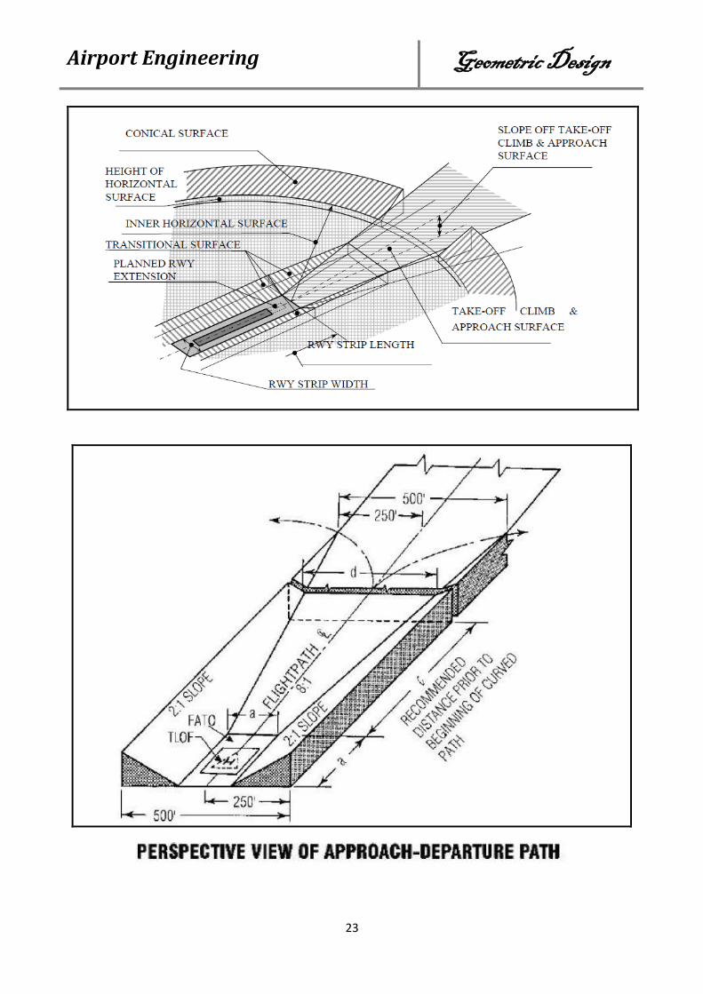
Obstruction Clearance Requirements
Aircraft landing to or taking off from a runway need an area free of obstructions to
safely operate. The Federal Aviation Administration (FAA) defines a series of
imaginary surfaces that define the maximum allowable height of any structures that
may be placed in the vicinity of an active runway.
1-Primary surface: The primary surface is a surface that is longitudinally centered on
the runway, extends 200 feet beyond the threshold in each direction in the case of
paved runways.
2-Approach surface: The approach surface is an inclined plane or combination of
planes of varying width running from the ends of the primary surface (40:1).
3-Horizontal surface: The horizontal surface is a horizontal plane 150 feet above the
established airport elevation. The plane dimensions of the horizontal surface are set
by arcs of specified dimensions from the end of the primary surfaces, which are con-
nected by tangents.
4-Transitional surface: Transitional surface is an inclined plane with slope of (7:1)
extending upward and outward from the primary and approach surfaces terminating
at the horizontal surface where these planes meet.
5-Conical surface: The conical surface is an inclined plane at a slope of (20:1) ex-
tending upward and outward from the periphery of the horizontal surface for a hori-
zontal distance of 4,000 feet.
Airport Engineering Geometric Design
23

Airport Engineering Geometric Design
24