
ashland municipal airport - airport master plan
265
ASHLAND MUNICIPAL AIRPORT AIRPORT MASTER PLAN CITY OF ASHLAND, OREGON JANUARY 2020
-
Upload
khangminh22 -
Category
Documents
-
view
4 -
download
0
Transcript of ashland municipal airport - airport master plan

ASHLAND MUNICIPAL AIRPORT
AIRPORT MASTER PLAN
CITY OF ASHLAND, OREGON JANUARY 2020

ACKNOWLEDGEMENTS
The following organizations and individuals contributed to this Master Plan. The study was funded by
the City of Ashland with grants from the Federal Aviation Administration ‐ Airport Improvement
Program (AIP) and Oregon Department of Aviation ‐ Critical Oregon Airport Relief (COAR) programs.
CITY OF ASHLAND STAFF
Scott Fleury, Deputy Public Works Director
Kaylea Kathol, Project Manager
Chance Metcalf, Project Manager
Shannon Burrus, Permit Technician
FEDERAL AVIATION ADMINISTRATION
Valerie Thorsen, Airport Planner
Jennifer Kandel, Airport Planner
Robert Tykoski, Airport Planner
Sandy Simmons, Airport Engineer
OREGON DEPARTMENT OF AVIATION
Jeff Caines, Airport Planner
Heather Peck, Planning and Programs Manager
PLANNING ADVISORY COMMITTEE
George Schoen
William Skillman
Daniel Palomino
H. Lincoln Zeve
Bernard Spera
David Wolske
William Butler
Susan Moen
Michael Morris
Bob Skinner
CENTURY WEST ENGINEERING
Matt Rogers, Project Manager
Mike Dane, Senior Airport Planner
David Miller, Senior Airport Planner
Samantha Peterson, Airport Planner
Mark Steele, AGIS/Airport Planner
Justin Strother, CAD/ALP
PRECISION APPROACH ENGINEERING
Josh Lekkerkerker
QUANTUM SPATIAL

ASHLAND MUNICIPAL AIRPORTAIRPORT MASTER PLAN
TABLE OF CONTENTS | JANUARY 2020 Century West Engineering
TABLE OF CONTENTS
Chapter 1 ‐ Introduction and Project Overview
Study Purpose ............................................................................................................................................................ 1‐1
Project Need .............................................................................................................................................................. 1‐1
Project Funding .......................................................................................................................................................... 1‐2
Airport Ownership ..................................................................................................................................................... 1‐2
History of the Airport and Development ................................................................................................................... 1‐3
Study Organization .................................................................................................................................................... 1‐3
Local Citizen Participation ......................................................................................................................................... 1‐4
Summary .................................................................................................................................................................... 1‐5
Chapter 2 ‐ Inventory of Existing Conditions
Airport Setting & Geography ..................................................................................................................................... 2‐1
Climate ....................................................................................................................................................................... 2‐3
Soils and Geology ....................................................................................................................................................... 2‐3
Airport Activity ........................................................................................................................................................... 2‐4
Airfield Facilities ........................................................................................................................................................ 2‐5
Runway .................................................................................................................................................................... 2‐11
Runway Wind Coverage ........................................................................................................................................... 2‐12
Taxiways and Taxilanes ............................................................................................................................................ 2‐13
Main Apron .............................................................................................................................................................. 2‐15
Airfield Pavement Condition ................................................................................................................................... 2‐15
Airport Lighting & Visual Navigational Aids ............................................................................................................. 2‐19
Landside Facilities .................................................................................................................................................... 2‐20
Airspace and Navigational Aids ............................................................................................................................... 2‐22
Instrument Procedures ............................................................................................................................................ 2‐23
Airport Support Facilities and Services .................................................................................................................... 2‐26
Vehicle Access and Parking ...................................................................................................................................... 2‐27
Public Protection ..................................................................................................................................................... 2‐27
Utilities ..................................................................................................................................................................... 2‐27
Population an dSocioeconomic Data ....................................................................................................................... 2‐31
Land Use Planning and Zoning ................................................................................................................................. 2‐31
Airport Environmental Inventory ............................................................................................................................ 2‐37
Chapter 3 ‐ Aviation Activity Forecasts
Overview and Purpose ............................................................................................................................................... 3‐1
Airport Service Area ................................................................................................................................................... 3‐3
Economic Conditions and Population ........................................................................................................................ 3‐6
National General Aviation Activity Trends ............................................................................................................... 3‐10
Overview of Recent Local Events ............................................................................................................................. 3‐14
Existing Aviation Activity Forecasts ......................................................................................................................... 3‐17
Updated Aviation Activity Forecasts ........................................................................................................................ 3‐21

ASHLAND MUNICIPAL AIRPORT
AIRPORT MASTER PLAN
TABLE OF CONTENTS | JANUARY 2020 Century West Engineering
Based Aircraft .......................................................................................................................................................... 3‐21
Based Aircraft Fleet Mix .......................................................................................................................................... 3‐23
Aircraft Operations .................................................................................................................................................. 3‐25
Local and Itinerant Operations ................................................................................................................................ 3‐30
Aircraft Operations Fleet Mix .................................................................................................................................. 3‐30
Critical Aircraft (FAA Planning Guidance) ................................................................................................................ 3‐31
Current and Future Critical Aircraft ......................................................................................................................... 3‐35
Operational Peaks .................................................................................................................................................... 3‐37
Military Activity ....................................................................................................................................................... 3‐38
Air Taxi Activity ........................................................................................................................................................ 3‐38
Forecast Summary ................................................................................................................................................... 3‐38
Fifty‐Year Forecast ................................................................................................................................................... 3‐39
Chapter 4 ‐ Airport Facility Requirements
Introduction .............................................................................................................................................................. 4‐1
Critical Aircraft and Airport Design Standards Discussion ......................................................................................... 4‐2
Demand/Capacity Analysis ........................................................................................................................................ 4‐5
Airport Facilities Analysis ........................................................................................................................................... 4‐5
Airfield Pavement Strength and Condition ............................................................................................................. 4‐11
Airside Facilities Requirements ............................................................................................................................... 4‐13
Landside Facilities Requirements ............................................................................................................................ 4‐27
Support Facilities Requirements .............................................................................................................................. 4‐29
Summary .................................................................................................................................................................. 4‐30
Chapter 5 ‐Airport Development Alternatives
Introduction ............................................................................................................................................................... 5‐1
Evaluation Process .................................................................................................................................................... 5‐2
Development Alternatives ......................................................................................................................................... 5‐3
No‐Action Alternative ................................................................................................................................................ 5‐4 Alternative 1 .............................................................................................................................................................. 5‐5
Alternative 2 ............................................................................................................................................................ 5‐11
Alternative 3 ............................................................................................................................................................ 5‐17
Alternative 3A .......................................................................................................................................................... 5‐23
Preferred Alternative (Figure 5‐5) ........................................................................................................................... 5‐29
Summary .................................................................................................................................................................. 5‐35
Chapter 6 ‐ Airport Layout Drawings
Introduction ............................................................................................................................................................... 6‐1
Chapter 7 – Airport Compatible Land Use Planning
Introduction ............................................................................................................................................................... 7‐1
Government Roles in Airport Land Use ..................................................................................................................... 7‐1
Comprehensive Planning ........................................................................................................................................... 7‐5
Airport Vicinity Zoning ............................................................................................................................................... 7‐7

ASHLAND MUNICIPAL AIRPORT
AIRPORT MASTER PLAN
TABLE OF CONTENTS | JANUARY 2020 Century West Engineering
Airport Base Zoning ................................................................................................................................................... 7‐8
Airport Overlay Zones ................................................................................................................................................ 7‐8
Land Use Summary and Recommendations .............................................................................................................. 7‐9
Chapter 8 – Capital Improvement and Implementation Plan
Overview and Purpose ............................................................................................................................................... 8‐1
Airport Development Schedule and Cost Estimates .................................................................................................. 8‐2
Capital Funding Sources & Programs ......................................................................................................................... 8‐9
Airport Rates and Fees ............................................................................................................................................ 8‐13
Cash Flow Analysis ................................................................................................................................................... 8‐14
Chapter 9 –Recycling and Solid Waste Management Plan
Introduction ............................................................................................................................................................... 9‐1
Local Recycling Management and Programs ............................................................................................................. 9‐2
Waste Audit ............................................................................................................................................................... 9‐5
Waste Disposal .......................................................................................................................................................... 9‐5
Recycling Feasibility ................................................................................................................................................... 9‐5
Plan to Minimize Solid Waste Generation ................................................................................................................. 9‐6
Operation and Maintenance Requirements .............................................................................................................. 9‐6
Waste Management Contracts .................................................................................................................................. 9‐6
Potential for Cost Savings or Revenue Generation.................................................................................................... 9‐6
Future Development and Recommendations ........................................................................................................... 9‐7
List of Tables
Table 2‐1: Based Aircraft And Operations ................................................................................................................. 2‐5
Table 2‐2: Airport Data ............................................................................................................................................ 2‐11
Table 2‐3: Runway Data ........................................................................................................................................... 2‐12
Table 2‐4: Runway Wind Coverage .......................................................................................................................... 2‐13
Table 2‐5: Summary Of Airfield Pavement Condition (2016 Inpsection) ................................................................. 2‐16
Table 2‐6: Ashland Visual Navigational Aids (Navaids) ............................................................................................ 2‐19
Table 2‐7: Airport Buildings ..................................................................................................................................... 2‐20
Table 2‐8: Nearby Ground Based Navigation Aids ................................................................................................... 2‐22
Table 2‐9: Aviation Fuel Tanks ................................................................................................................................. 2‐26
Table 2‐10: Airport Utilities And Service Providers ................................................................................................. 2‐28
Table 3‐1: Public Use Airports In Vicinity Of Ashland Municipal Airport ................................................................... 3‐4
Table 3‐2: Leading Employment Sectors In Jackson County (2016) .......................................................................... 3‐7
Table 3‐3: Leading Employment Sectors Wages In Jackson County (2016) ............................................................... 3‐7
Table 3‐4: Historic Population Data ........................................................................................................................... 3‐9
Table 3‐5: Population Forecasts .............................................................................................................................. 3‐10
Table 3‐6: FAA Long Range Forecast Assumptions (U.S. General Aviation) ............................................................ 3‐13
Table 3‐7: S03 ‐ Aircraft Fueling Activity .................................................................................................................. 3‐14
Table 3‐8: Instrument Activity (2012‐2016)............................................................................................................. 3‐15
Table 3‐9: Instrument Activity Detail – S03 (2017) .................................................................................................. 3‐15

ASHLAND MUNICIPAL AIRPORT
AIRPORT MASTER PLAN
TABLE OF CONTENTS | JANUARY 2020 Century West Engineering
Table 3‐10: 2017 Based Aircraft – S03 (Verified May 2018) .................................................................................... 3‐16
Table 3‐11: Existing Based Aircraft & GA Operations Forecasts ............................................................................. 3‐19
Table 3‐12: Based Aircraft Forecast Summary ........................................................................................................ 3‐23
Table 3‐13: Forecast Based Aircraft Fleet Mix ......................................................................................................... 3‐24
Table 3‐14: Updated GA Aircraft Operations Forecasts .......................................................................................... 3‐29
Table 3‐15: GA Aircraft Operations Fleet Mix .......................................................................................................... 3‐31
Table 3‐16: GA Aircraft & Design Categories ........................................................................................................... 3‐32
Table 3‐17: GA Forecast Activity Fleet Mix (By AAC + ADG) .................................................................................... 3‐35
Table 3‐18: Summary Of Critical Aircraft & ARC ...................................................................................................... 3‐36
Table 3‐19: Peak General Aviation Operations Forecast ......................................................................................... 3‐37
Table 3‐20: Forecast Summary ................................................................................................................................ 3‐39
Table 3‐21: 50‐Year Forecast .................................................................................................................................. 3‐39
Table 4‐1: Runway 12/30 Airport Design Standards Summary (Dimensions In Feet) ............................................... 4‐4
Table 4‐2: Wind Analysis .......................................................................................................................................... 4‐17
Table 4‐3: Apron and Hangar Facility Requirements Summary ............................................................................... 4‐25
Table 8‐1: 20‐Year Capital Improvement Program .................................................................................................... 8‐5
Table 8‐2: Airport Rates and Fees ............................................................................................................................ 8‐13
Table 8‐3: Operating Revenues and Expenses ......................................................................................................... 8‐15
Table 9‐1: Recyclable Items ....................................................................................................................................... 9‐5
List of Figures
Figure: 2‐1: Airport Location Map ............................................................................................................................. 2‐2
Figure: 2‐2: Existing Airfield Conditions ..................................................................................................................... 2‐7
Figure: 2‐3: Existing Airfield Conditions – Landside Area .......................................................................................... 2‐9
Figure: 2‐4: PCI Map ................................................................................................................................................ 2‐17
Figure: 2‐5: Airspace Classifications ........................................................................................................................ 2‐21
Figure: 2‐6: Area Airspace........................................................................................................................................ 2‐24
Figure: 2‐7: Traffic Patterns ..................................................................................................................................... 2‐25
Figure: 2‐8: Utilities Map ......................................................................................................................................... 2‐29
Figure: 2‐9: Ashland Zoning Map ............................................................................................................................. 2‐33
Figure: 2‐10: Land Use Jurisdiction .......................................................................................................................... 2‐35
Figure: 3‐1: Airport Service Area ............................................................................................................................... 3‐5
Figure: 3‐2: US Active General Aviation Fleet .......................................................................................................... 3‐11
Figure: 3‐3: Based Aircraft Forecasts ....................................................................................................................... 3‐23
Figure: 3‐4: Based Aircraft Fleet Mix (2017) ............................................................................................................ 3‐24
Figure: 3‐5: Forecast Based Aircraft Fleet Mix (2037) ............................................................................................. 3‐25
Figure: 3‐6: General Aviation Operations Forecast ................................................................................................. 3‐29
Figure: 3‐7: Airport Reference Codes (ARC) ............................................................................................................ 3‐33
Figure: 4‐1: Airside Facility Requirements Analysis ................................................................................................... 4‐7
Figure: 4‐2: Landside Facility Requirements Analysis ................................................................................................ 4‐9
Figure: 4‐3: Pavement Condidtion ........................................................................................................................... 4‐12
Figure: 4‐4: Land Use Jurisdiction ............................................................................................................................ 4‐16

ASHLAND MUNICIPAL AIRPORT
AIRPORT MASTER PLAN
TABLE OF CONTENTS | JANUARY 2020 Century West Engineering
Figure: 4‐5: Small Airplanes with Fewer than 10 Passenger Seats .......................................................................... 4‐18
Figure: 5‐1: Airport Development Alternatives – Alternative 1 ................................................................................. 5‐9
Figure: 5‐2: Airport Development Alternatives – Alternative 2 ............................................................................... 5‐15
Figure: 5‐3: Airport Development Alternatives – Alternative 3 ............................................................................... 5‐21
Figure: 5‐4: Airport Development Alternatives – Alternative 3A ............................................................................ 5‐27
Figure: 5‐5: Airport Development Alternatives – Preferred Alternative ................................................................. 5‐33
Figure 6‐1: Cover Sheet ............................................................................................................................................. 6‐5
Figure 6‐2: Airport Data Sheet ................................................................................................................................... 6‐7
Figure 6‐3: Airport Layout Plan .................................................................................................................................. 6‐9
Figure 6‐4: Terminal Area Plan ................................................................................................................................ 6‐11
Figure 6‐5: Airport Airspace Plan (FAR Part 77) ...................................................................................................... 6‐13
Figure 6‐6: Airport Airspace Plan (FAR Part 77) ....................................................................................................... 6‐15
Figure 6‐7: Airport Airspace Plan (FAR Part 77) Obstruction Tables ....................................................................... 6‐17
Figure 6‐8: Airport Airspace Plan (FAR Part 77) Obstruction Tables ....................................................................... 6‐19
Figure 6‐9: Airport Airspace Plan (FAR Part 77) Obstruction Tables ....................................................................... 6‐21
Figure 6‐10: Runway 12 RPZ and Inner Approach Plan and Profile ........................................................................ 6‐23
Figure 6‐11: Runway 30 RPZ and Inner Approach Plan and Profile ........................................................................ 6‐25
Figure 6‐12: On Airport Land Use Plan ................................................................................................................... 6‐27
Figure 6‐13: Off Airport Land Use Plan .................................................................................................................... 6‐29
Figure 6‐14: Exhibit “A” Airport Property Plan ........................................................................................................ 6‐31
Figure 7‐1: Exhibit “A” Airport Property Plan ............................................................................................................ 7‐6
Appendix
Appendix A – Environmental Technical Memorandum
Glossary of Aviation Terms
List of Abbreviations

This page intentionally left blank

Chapter 1
Introduction & Project Overview


CHAPTER 1 - INTRODUCTION AND PROJECT OVERVIEW | JANUARY 2020 | PAGE 1-1
ASHLAND MUNICIPAL AIRPORT AIRPORT MASTER PLAN
Century West Engineering
Chapter 1 – Introduction and Project Overview
The City of Ashland, in cooperation with the Federal Aviation Administration (FAA), is in the process of updating the Ashland Municipal
Airport (FAA airport identifier – S03) Airport Master Plan to address the airport’s needs for the next twenty years. The airport master
plan will provide specific guidance in making the improvements necessary to maintain a safe and efficient airport that is economically,
environmentally, and socially sustainable.
Study Purpose
The purpose of the Ashland Municipal Airport - Airport Master Plan is to define the current, short-term,
and long-term needs of the airport through a comprehensive evaluation of facilities, existing facilities, site
conditions, and current FAA airport planning and design standards. The study addresses elements of local
planning (land use, transportation, environmental, economic development, etc.) that have the potential to
affect the planning, development, and operation of the airport. This project updates the 2004 Airport
Layout Plan.1 Since the last airport layout plan was completed, the FAA has identified several areas of
emphasis for airports that affect airport planning; including land use compatibility in runway protection
zones (RPZ) and airfield design standards compliance.
Project Need
Ashland Municipal Airport is included in the federal airport system—the National Plan of Integrated
Airport Systems (NPIAS). Inclusion in the NPIAS is limited to public use airports that meet specific FAA
activity thresholds. The FAA requires all NPIAS airports to maintain current planning, with periodic
updates of their master plans and airport layout plans (ALP). These updates maintain current planning
1 Airport Layout Plan – Ashland Municipal Airport (Final Report, October 2005; Century West Engineering Inc., Aron Faegre & Associates, and Gazeley & Associates).

CHAPTER 1 - INTRODUCTION AND PROJECT OVERVIEW | JANUARY 2020 | PAGE 1-2
ASHLAND MUNICIPAL AIRPORT AIRPORT MASTER PLAN
Century West Engineering
consistent with applicable FAA technical standards, policies, and regulations that change over time, and
maintain overall funding eligibility with FAA.
There are currently 3,332 existing NPIAS facilities including airports, heliports, and seaplane bases.2 The
FAA recognizes that NPIAS airports are vital to serving the air transportation needs of the public and that
access to the nation’s air transportation system is not limited to commercial service airports. The majority
of NPIAS airports are designated “Primary” or “Non-primary.” The 382 Primary airports provide the
majority of commercial air service within the system. The 2,950 Non-primary airports include General
Aviation, Reliever, and Non-primary Commercial Service airports (airports that enplane 2,500 to 9,999
annual passengers). Ashland Municipal Airport is designated as a Non-primary General Aviation airport.
NPIAS airports may qualify for federal funding of eligible improvements through FAA programs such as
the Airport Improvement Program (AIP). The AIP is a dedicated fund administered by the FAA with the
specific purpose of maintaining and improving the nation’s public use airports. The AIP is funded
exclusively through general aviation and commercial aviation user fees. These funds are only available for
use on AIP eligible projects.
Project Funding
Funding for the airport master plan was provided through an FAA Airport Improvement Program (AIP)
grant (90%), ODA Critical Oregon Airport Relief (COAR) grant (8%), with local match (2%) provided by
the airport sponsor.
Airport Ownership
The City of Ashland is the owner of Ashland Municipal Airport. As the airport owner (sponsor) of record,
the City is responsible for conforming to all applicable FAA regulations, design standards, and grant
assurances.
2 2017-2021 NPIAS Report

CHAPTER 1 - INTRODUCTION AND PROJECT OVERVIEW | JANUARY 2020 | PAGE 1-3
ASHLAND MUNICIPAL AIRPORT AIRPORT MASTER PLAN
Century West Engineering
History of the Airport and Development3
1940s Local pilot Sumner Parker developed and leased an airstrip to the City of Ashland for use as a
public airport. The airstrip, which is the current airport site, is located approximately 3 miles from
downtown Ashland;
1963 The City established an airport committee and conducted a feasibility study to determine the best
location for an airport. The leased airstrip was determined to be the most feasible location. The
City then began negotiations to purchase the airstrip. This is the current airport site location;
1964 The FAA approved the airport site and the property was acquired by the City shortly after the
approval. Following acquisition by the City, the airport was renamed Ashland Municipal Airport
– Sumner Parker Field;
1983 Land acquisition for development, runway extension, construction and rehabilitation of the apron;
1984 Runway and taxiway extension project;
1994 Access road improvements, airport drainage improvements, installed VASIs, apron and taxiway
expansion, and airport master plan update;
2004 Installed taxiway lighting and rehabilitated runway lighting;
2007 Installed Super AWOS system and rehabilitated the parking lot;
2010 Rehabilitated runway and installed PAPIs; and
2014 Constructed taxiway to access hangar area.
Study Organization
Work completed during the airport master plan was documented in a series of technical memoranda
(presented as draft chapters). These chapters were prepared to document progress in the study, facilitate
the review of preliminary results, and obtain input throughout the master planning process. The draft
chapters were updated and incorporated into the draft and final airport master plan technical report at the
study’s conclusion.
The draft chapters and supporting documents were prepared over a period of approximately 18 months.
Each draft chapter was reviewed locally, by the FAA, and the Oregon Department of Aviation (ODA) for
consistency with federal and state regulations, policies, and standards.
3 2004 Ashland Municipal Airport Layout Plan, Century West Engineering Inc., Aron Faegre & Associates, and Gazeley & Associates.

CHAPTER 1 - INTRODUCTION AND PROJECT OVERVIEW | JANUARY 2020 | PAGE 1-4
ASHLAND MUNICIPAL AIRPORT AIRPORT MASTER PLAN
Century West Engineering
The 2017-2037, Ashland Municipal Airport -Airport Master Plan will include the following chapters:
Chapter 1 – Introduction and Project Overview
Chapter 2 – Inventory of Existing Conditions
Chapter 3 – Aviation Activity Forecasts
Chapter 4 – Airport Facility Requirements
Chapter 5 – Airport Development Alternatives
Chapter 6 – Airport Layout Drawings
Chapter 7 – Airport Compatible Land Use Planning
Chapter 8 – Capital Improvement and Implementation Plan
Chapter 9 –Recycling and Solid Waste Management Plan
Appendix – Environmental Technical Memorandum
Local Citizen Participation
The City of Ashland is committed to an inclusive, transparent planning process and made all project work
products available for public review. The public involvement element of the airport master plan provided
several ways for all interested individuals, organizations, or groups to participate in the project:
All draft work products were available for public review and comment. Links to the documents
were posted on the City’s webpage to allow for convenient access, review, and comment;
A series of public meetings were held during the project to facilitate public participation including;
o A local planning advisory committee (PAC) was formed by the City of Ashland to assist
the project team in reviewing draft technical working papers and to provide input into the
planning process. The composition of the PAC was intended to provide an effective blend
of community members, airport commission, and city and county planners.
Representatives from the FAA Seattle Airports District Office and ODA served as ex officio
members of the PAC. The PAC met periodically during the project, provided review and
comment on draft work products, discussed key project issues, and provided local
knowledge and expertise to the planning process. The PAC meetings were open to the
public.
o Periodic study sessions and briefings with City staff, project meetings, and open houses
were conducted, as required.

CHAPTER 1 - INTRODUCTION AND PROJECT OVERVIEW | JANUARY 2020 | PAGE 1-5
ASHLAND MUNICIPAL AIRPORT AIRPORT MASTER PLAN
Century West Engineering
Summary
The FAA-defined airport master planning process requires a sequential, systematic approach, which leads
to the selection of a preferred airport development option. The preferred development option was then
integrated into the ALP and Airport Capital Improvement Program (ACIP). To meet this goal, the airport
master plan:
Provided an updated assessment of existing facilities and activity;
Forecasted airport activity measures (design aircraft, based aircraft, aircraft operations, etc.) for the current 20-
year planning period;
Examined previous planning recommendations (2005 Airport Layout Plan) based on ability to meet current FAA
airport design standards and policies;
Determined current and future facility requirements for both demand-driven development and conformance with
FAA design standards;
Evaluated airside and landside facility improvement options in the form of development alternatives;
Provided consistency between airport planning and land use planning/zoning to promote maximum compatibility
between the airport and surrounding areas;
Prepared an updated Airport Layout Plan (ALP) drawing set to accurately reflect current conditions and master
plan facility recommendations; and
Develop an Airport Capital Improvement Program (ACIP) that prioritizes improvements and estimates project
development costs and funding eligibility for the 20-year planning period.
The preparation of this document may have been supported, in part, through the Airport Improvement Program financial assistance from the Federal
Aviation Administration as provided under Title 49, United States Code, section 47104. The contents do not necessarily reflect the official views or policy
of the FAA. Acceptance of this report by the FAA does not in any way constitute a commitment on the part of the United States to participate in any
development depicted therein nor does it indicate that the proposed development is environmentally acceptable with appropriate public laws.

This page intentionally left blank

Chapter 2
Inventory of Existing Conditions


CHAPTER 2 - INVENTORY OF EXISTING CONDITIONS | JANUARY 2020 | PAGE 2-1 Century West Engineering
ASHLAND MUNICIPAL AIRPORT AIRPORT MASTER PLAN
Chapter 2 – Inventory of Existing Conditions
The purpose of this chapter is to document the existing facilities and conditions at Ashland Municipal Airport (Airport Identifier Code: S03).
The inventory section of the Airport Master Plan summarizes existing conditions of the facilities at Ashland
Municipal Airport – Sumner Parker Field (S03). The inventory also summarizes other pertinent information
relating to the community, airport background, airport role, surrounding environment, various operational
parameters and other significant characteristics. The information in this chapter provides a baseline for
determining future facility needs at Ashland Municipal Airport. Information was obtained through site visits,
consultant research, review of existing documents, and airport management input.
Airport Setting & Geography
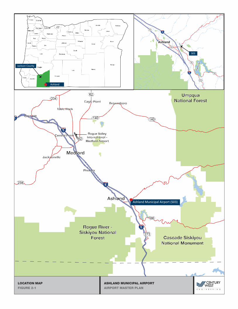
Ashland is an incorporated city located in Jackson County, in southwest Oregon. Ashland is located near
the south end of the Rogue Valley, adjacent to U.S. Interstate 5 (I-5), the primary north-south interstate
highway that extends from Washington to California. Ashland is approximately 13 miles south of Medford
and 21 miles north of the Oregon-California border on I-5.
Ashland Municipal Airport is located near the eastern corner of the Ashland city limits and urban growth
boundary (UGB), east of I-5. The airport is located at the base of mountainous terrain that forms the eastern
side of the valley. The airport is surrounded predominately by unincorporated Jackson County land, with the
City of Ashland urban area located to the west. A location and vicinity map is provided in Figure 2-1.
ASHLAND MUNICIPAL AIRPORT
AIRPORT MASTER PLAN
LOCATION MAP
FIGURE 2-1
Ashland Municipal Airport (S03)
Ashland66
Ashland
Jackson County66
66
273
Emig
rant
Lake
99
S03

CHAPTER 2 - INVENTORY OF EXISTING CONDITIONS | JANUARY 2020 | PAGE 2-3 Century West Engineering
ASHLAND MUNICIPAL AIRPORT AIRPORT MASTER PLAN
Climate
Ashland’s climate is directly affected by the mountainous terrain that forms each side of the Rogue Valley.
The local area has warm, dry summers and cool, moist winters, with moderate amounts of precipitation
and snowfall. Historic climatic data 1 for Ashland indicates the average maximum temperature is 86.9
degrees Fahrenheit (July) and the average minimum temperature is 29.7 degrees Fahrenheit (January).
Ashland averages 19.43 inches of precipitation and 6.9 inches of snowfall annually. Prevailing winds
generally follow the valley contours, which is similar to the alignment of Runway 12/30.
Soils and Geology
The airport site is composed of a combination of sandy loam and clay soils. A review of current soil survey
mapping2 identifies four soil types account for the majority of the airport:
31A - Central Point sandy loam (0 to 3 percent slopes) – The majority of the runway, south apron,
and main vehicle parking lot. Primary characteristics: stream terraces, sandy loam and gravely sandy
loam, depth to restrictive feature more than 80 inches, well drained, high capacity to transmit water,
depth to water table about 48 to 72 inches. About 40 percent of the airport area.
27B - Carney clay (1 to 5 percent slopes) – The majority of the lower and uphill landside
development area (Brim Hangar, T-Hangars, FBO). Primary characteristics: alluvial fans, clay and
weathered bedrock, depth to restrictive feature 20 to 40 inches (paralithic bedrock), moderately
well drained, very low to moderately low capacity to transmit water, depth to water table about
36 to 42 inches. About 28 percent of the airport area.
23A - Camas-Newberg-Evans complex (0 to 3 percent slopes) – Neil Creek and Emigrant Creek
drainages, portions of south runway safety area and runway end, portions of north section of
parallel taxiway and aircraft hold area. Primary characteristics: flood plains, gravely sandy loam
and extremely gravelly coarse sand, depth to restrictive feature 9 to 17 inches (to strongly
contrasting textural stratification), excessively drained, high capacity to transmit water, depth to
water table more than 80 inches. About 17 percent of the airport area.
127A - Medford silty clay loam (0 to 3 percent slopes) – Middle section of parallel taxiway,
segmented circle, north section of apron, and aircraft fuel area. Primary characteristics: alluvial
fans and stream terraces, silty lay loam and silty clay, depth to restrictive feature more than 80
inches, moderately well drained, moderately high capacity to transmit water, depth to water table
about 48 to 72 inches. About 12 percent of the airport area.
1 Western Regional Climatic Center, Observation Station 350304 (1948-2005) 2 Natural Resources Conservation Service, Web Soil Survey (11/16/17)

CHAPTER 2 - INVENTORY OF EXISTING CONDITIONS | JANUARY 2020 | PAGE 2-4 Century West Engineering
ASHLAND MUNICIPAL AIRPORT AIRPORT MASTER PLAN
Airport Activity
The primary measures of aviation activity at Ashland Municipal Airport include aircraft operations
(takeoffs and landings) and based aircraft. An aircraft operation is defined as either a takeoff or landing. A
“touch-and-go” is counted as two operations. Operations are categorized as local and itinerant.
According to the FAA, local operations are defined as operations performed by aircraft that:
Operate in the local traffic pattern or within sight of the airport, or Are known to be departing for, or arriving from, flight in local practice areas located within a 20-
mile radius of the airport, or Execute simulated instrument approaches or low passes at the airport.
Itinerant operations are all aircraft operations, other than local operations.
The FAA’s 5010-1 Airport Master Record is the official record kept by the FAA for public-use airport
activity and facility conditions. The 5010 based aircraft data are populated by periodic airport management
reporting through the FAA’s www.basedaircraft.com database. Aircraft operations at non-towered
airports are periodically estimated by FAA through reference to the FAA’s Terminal Area Forecast (TAF).
The most recent FAA Airport Master Record (5010) for Ashland Municipal Airport lists a total of 28 based
aircraft, including 23 single-engine, 1 multi-engine aircraft, and four ultra-lights.3 It is evident that the 5010
based aircraft total is not accurate based on the airport’s current hangar and aircraft tiedown occupancy,
and current tenants, including Brim Aviation, which bases helicopters and fixed wing aircraft at the
airport. An updated airport management based aircraft count is being developed and will be used in
preparing the updated forecasts of aviation activity. The 5010 lists 26,050 aircraft operations (estimate) for
the 12 months ending 3/17/15.
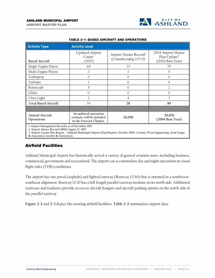
Table 2-1 summarizes the airport’s based aircraft and operations, as indicated on the current FAA 5010 form.
3 FAA 5010-1 Airport Master Record (8/17/2017)
CHAPTER 2 - INVENTORY OF EXISTING CONDITIONS | JANUARY 2020 | PAGE 2-5 Century West Engineering
ASHLAND MUNICIPAL AIRPORT AIRPORT MASTER PLAN
TABLE 2-1: BASED AIRCRAFT AND OPERATIONS
Activity Type Activity Level
Based Aircraft
Updated Airport Count1
(2017)
Airport Master Record2
(12 months ending 3/17/15)
2004 Airport Master Plan Update3
(2004 Base Year)
Single-Engine Piston 64 23 79
Multi-Engine Piston 2 1 5
Turboprop 0 0 0
Turbojet 1 0 0
Rotorcraft 5 0 2
Glider 0 0 0
Ultra-Light 2 4 3
Total Based Aircraft 74 28 89
Annual Aircraft Operations
An updated operations estimate will be included in the Forecast Chapter.
26,050 20,878
(2004 Base Year)
1. Airport Management Records, as of December 2017 2. Airport Master Record (5010) August 17, 2017 3. Airport Layout Plan Report – Ashland Municipal Airport (Final Report, October 2005., Century West Engineering, Aron Faegre & Associates, Gazeley & Associates)
Airfield Facilities
Ashland Municipal Airport has historically served a variety of general aviation users, including business,
commercial, government and recreational. The airport can accommodate day and night operations in visual
flight rules (VFR) conditions.
The airport has one paved (asphalt) and lighted runway (Runway 12/30) that is oriented in a northwest-
southeast alignment. Runway 12/30 has a full-length parallel taxiway/taxilane on its north side. Additional
taxiways and taxilanes provide access to aircraft hangars and aircraft parking aprons on the north side of
the parallel taxiway.
Figure 2-2 and 2-3 depict the existing airfield facilities. Table 2-2 summarizes airport data.

This page intentionally left blank

BUILDING/FACILITY KEY
1 SEGMENTED CIRCLE
0 150 300
SCALE OF FEETSCALE: 1"=150'
EXISTING CONDITIONS AIRFIELD (FIG 2-2)
DEAD INDIAN MEMORIAL RD
DEAD INDIAN MEMORIAL RD
ashland municipal airport
E MAIN STE MAIN ST
MAJESTIC LN
MAJESTIC LN
EMIG
RANT C
REEK
EMIG
RANT C
REEK
NEIL CREEKNEIL CREEK
PAPIPAPI
RUNWAY 12/30RUNWAY 12/30 3,603' X 75'3,603' X 75'
PAPIPAPI
1
2 SUPER AWOS
3 TIEDOWN APRON
5 EQUIPMENT STORAGE
LEGEND
PROPERTY BOUNDARY
VEHICLE GATEAIRPORT FENCE
X X
PED. GATE
5
PARALLEL TAXIWAYPARALLEL TAXIWAY
23
4 3
X
X
X
X
X
X
X
X
X
X
X
X
X
X
X
190' DISPLACEDTHRESHOLD190' DISPLACEDTHRESHOLD
REILREIL
X
AIRPORTBEACONAIRPORTBEACON
PARALLEL TAXILANEPARALLEL TAXILANE
7
6
6
4 AIRCRAFT FUEL
6 HANGARS
7 FBO
ASHLAND MUNICIPAL AIRPORTAIRPORT MASTER PLAN
EXISTING AIRFIELD CONDITIONSFIGURE 2-2


X
X
X
X
X
X
X
X
X
X
X
X
X
X
X
X
X
X
X
X
X
X
X
X
X
X
X
X
X
X
X
X
X
XX X
X
RUNWAY 12/30RUNWAY 12/30 3,603' X 75'3,603' X 75'0 60 120
SCALE OF FEETSCALE: 1"=60'
EXISTING CONDITIONS LANDSIDE AREA (FIG 2-3)ashland municipal airport
DEAD INDIAN MEMORIAL RD
DEAD INDIAN MEMORIAL RD
1
4
5
2
PAPIPAPI
LEGEND
PROPERTY BOUNDARY
VEHICLE GATEAIRPORT FENCE
X X
PED. GATE
BUILDING (CITY OWNED)BUILDING (TENANT OWNED)
2
FACILITY KEY
1 AIRCRAFT WASH PAD
23
AIRCRAFT APRON
5
FIXED BASE OPERATOR
VEHICLE PARKING
6
BUILDING KEY
T-HANGAR
437
433
431
411
413
415
417
419
421
439
429425
403
423
395
399 405 407 409
6 BEACON
399 HANGAR
395
405FIXED BASE OPERATOR (FBO)
407HANGAR
409HANGAR
411HANGAR
413HANGAR
415HANGAR
417HANGAR
419
HANGAR
421HANGAR
HANGAR
423 ELECTRICAL BUILDING
425 FBO HANGAR
429 BRIM HANGAR & OFFICE
403
431 T-HANGAR
433 T-HANGAR/HANGAR
437 T-HANGAR
439 BRIM HANGAR
3
4 FUELING AREA
7 TEMPORARY EQUIPMENTSTORAGE & VEHICLEPARKING
7
PARALLEL TAXIWAYPARALLEL TAXIWAYPARALLEL TAXILANEPARALLEL TAXILANE
REILREIL
190' DISPLACEDTHRESHOLD190' DISPLACEDTHRESHOLD
ASHLAND MUNICIPAL AIRPORTAIRPORT MASTER PLAN
EXISTING AIRFIELD CONDITIONS - LANDSIDE AREAFIGURE 2-3


CHAPTER 2 - INVENTORY OF EXISTING CONDITIONS | JANUARY 2020 | PAGE 2-11 Century West Engineering
ASHLAND MUNICIPAL AIRPORT AIRPORT MASTER PLAN
TABLE 2-2: AIRPORT DATA
Airport Name/Designation Ashland Municipal Airport (S03)
Airport Owner City of Ashland
Date Established 1940s
Airport Category National Plan of Integrated Airport Systems (NPIAS): Non-primary Local Service, General Aviation Airport Oregon Aviation Plan (2007): Category III – Regional General Aviation Airports FAA Airport Reference Code: B-I Small (as depicted on 2004 ALP)
Airport Acreage 94 Acres (1989 Exhibit A)
Airport Reference Point (ARP) Coordinates
N 42° 11’ 25.02” W 122° 39’ 33.26”
Airport Elevation 1,884.8 feet MSL (surveyed)
Airport Traffic Pattern Configuration/Altitude
Left Traffic: Runway 12 & 30 Traffic Pattern Altitude: 2,899.8 feet MSL (1,015 feet AGL)
Airport Communication Common Traffic Advisory Frequency (CTAF) 122.8 MHz
Airport Weather SuperAWOS – Pilot Controlled Automated Unicom 122.8 MHz
Runway
Runway 12/30 is 3,603 feet long and 75 feet wide with an asphalt surface. The runway has a 190-foot
displaced threshold at the Runway 30 end to improve obstruction clearance (road, trees, and structures).
The runway pavement has a published weight bearing capacity of 15,000 pounds for aircraft with single-
wheel landing gear configurations.4 The runway has an effective gradient of 1.1 percent with a high point
at the Runway 30 end. The runway pavement is in good condition. The most recent crack filling project
was completed in 2014, and last rehabilitation project (3” asphalt overlay, reconstructed sections of
pavement, an installation of underdrains) was completed in 2011.
The runway has visual instrument (VIS) markings on both ends. The runway markings (white paint) include
runway designation numbers and centerline stripe. The Runway 30 displaced threshold markings include
one centerline arrow, three arrowheads, and a threshold bar. Yellow taxiway lead-in/lead-off lines are painted
on all the entrance/exit taxiways. The runway markings meet FAA standards for configuration, color, and
approach type. The markings were observed to be in generally good condition during a recent site visit.
Runway 12/30 is lighted and equipped with visual guidance indicators at both ends. There are no runway
or taxiway hold position signs, runway distance remaining signs, or taxiway location signs on the airport.
The runway is served by a full-length east parallel taxiway with six 90-degree exit taxiway connections.
4 FAA 5010-1 Airport Master Record (8/17/2017);
CHAPTER 2 - INVENTORY OF EXISTING CONDITIONS | JANUARY 2020 | PAGE 2-12 Century West Engineering
ASHLAND MUNICIPAL AIRPORT AIRPORT MASTER PLAN
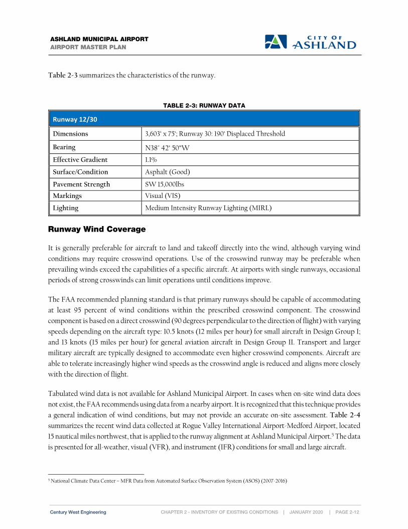
Table 2-3 summarizes the characteristics of the runway.
TABLE 2-3: RUNWAY DATA
Runway 12/30
Dimensions 3,603’ x 75’; Runway 30: 190’ Displaced Threshold
Bearing N38° 42’ 50”W
Effective Gradient 1.1%
Surface/Condition Asphalt (Good)
Pavement Strength SW 15,000lbs
Markings Visual (VIS)
Lighting Medium Intensity Runway Lighting (MIRL)
Runway Wind Coverage
It is generally preferable for aircraft to land and takeoff directly into the wind, although varying wind
conditions may require crosswind operations. Use of the crosswind runway may be preferable when
prevailing winds exceed the capabilities of a specific aircraft. At airports with single runways, occasional
periods of strong crosswinds can limit operations until conditions improve.
The FAA recommended planning standard is that primary runways should be capable of accommodating
at least 95 percent of wind conditions within the prescribed crosswind component. The crosswind
component is based on a direct crosswind (90 degrees perpendicular to the direction of flight) with varying
speeds depending on the aircraft type: 10.5 knots (12 miles per hour) for small aircraft in Design Group I;
and 13 knots (15 miles per hour) for general aviation aircraft in Design Group II. Transport and larger
military aircraft are typically designed to accommodate even higher crosswind components. Aircraft are
able to tolerate increasingly higher wind speeds as the crosswind angle is reduced and aligns more closely
with the direction of flight.
Tabulated wind data is not available for Ashland Municipal Airport. In cases when on-site wind data does
not exist, the FAA recommends using data from a nearby airport. It is recognized that this technique provides
a general indication of wind conditions, but may not provide an accurate on-site assessment. Table 2-4
summarizes the recent wind data collected at Rogue Valley International Airport-Medford Airport, located
15 nautical miles northwest, that is applied to the runway alignment at Ashland Municipal Airport.5 The data
is presented for all-weather, visual (VFR), and instrument (IFR) conditions for small and large aircraft.
5 National Climate Data Center – MFR Data from Automated Surface Observation System (ASOS) (2007-2016)

CHAPTER 2 - INVENTORY OF EXISTING CONDITIONS | JANUARY 2020 | PAGE 2-13 Century West Engineering
ASHLAND MUNICIPAL AIRPORT AIRPORT MASTER PLAN
The data indicates prevailing winds predominately follow a northwest-southeasterly pattern, which
is generally aligned with the runway. As noted earlier, the general alignment of the runway and valley
in Ashland is similar, which suggests reasonably good wind coverage and terrain avoidance during
takeoff and landing. Available data indicates that Runway 12/30 has adequate wind coverage (≥95%)
to meet FAA standards for airports with one runway.
TABLE 2-4: RUNWAY WIND COVERAGE
Weather Conditions Wind Speed Runway 12/30
All WX 12 MPH (10.5 Knots) 99.4% 15 MPH (13 Knots) 99.73%
VFR 12 MPH (10.5 Knots) 96.11% 15 MPH (13 Knots) 97.78%
IFR 12 MPH (10.5 Knots) 99.82% 15 MPH (13 Knots) 99.82%
Runway 12/30 Source: NOAA National Climatic Center Data for MFR Period: 2007-2016 with a total of 132,083 (All WX), 94,613 (VFR), and 20,511 (IFR) observations.
Taxiways and Taxilanes
Taxiways are a crucial airport element because they expedite the safe and efficient flow of traffic to and
from the runway and can reduce the amount of time aircraft are on the runway. Taxiways also provide an
important link between airside and landside facilities. Taxilanes provide access within aircraft apron areas
and hangar developments.
The taxiway system at Ashland Municipal Airport is depicted on Figure 2-2, presented earlier in this
chapter. Runway 12/30 has a full-length east parallel taxiway/taxilane with six 90-degree exit taxiways.
The parallel taxilane is located on the outer section of the main apron (south end). For identification
purposes, the parallel taxiway is designated “Taxiway A” and the exit taxiways are designated A1-A6, with
A1 located at the Runway 30 end.
The airport taxiways are equipped with edge reflectors. Taxiway markings include (yellow) centerline and
runway hold position lines on exit taxiways, which are in good to fair condition. The aircraft hold lines are
located 125 feet from runway centerline, which coincides with the outer edge of the runway obstacle free
zone (OFZ).

CHAPTER 2 - INVENTORY OF EXISTING CONDITIONS | JANUARY 2020 | PAGE 2-14 Century West Engineering
ASHLAND MUNICIPAL AIRPORT AIRPORT MASTER PLAN
RUNWAY 12/30 PARALLEL TAXIWAY/TAXILANE
Taxiway A is full-length parallel taxiway/taxilane for Runway 12/30. Taxiway A is 30 feet wide and
constructed of asphalt. It has six exit taxiway connectors to Runway 12/30. Taxiway A provides access to
all landside areas on the east side of Runway 12/30. An aircraft hold area is located adjacent to the Runway
12 end and Taxiway A6. A compass rose is painted on the north aircraft hold area.
The parallel taxiway has a runway centerline separation of 162.5 feet. The parallel taxilane has a runway
centerline separation of 150 feet. The taxiway/taxilane centerline shift is located adjacent to Taxiway A3.
A dashed yellow line is painted along the inside edge of the parallel taxilane to distinguish the taxilane and
apron areas.
EXIT TAXIWAYS (RUNWAY 12/30)
The runway has six 90-degree exit taxiways. The exit taxiways are 30 feet wide and constructed of asphalt.
The runway exit taxiways include:
Taxiway A1 - located at the Runway 30 end (at south end of runway - displaced threshold);
Taxiway A2 - located at the Runway 30 displaced threshold;
Taxiway A3 - located approximately 775 feet from the Runway 30 end;
Taxiway A4- located approximately mid-runway;
Taxiway A5 - located approximately 660 feet from Runway 12 end; and
Taxiway A6 -located at the Runway 12 end.
TAXILANES
The aircraft parking aprons and hangar areas at Ashland Municipal Airport are served by taxilanes that
connect to Taxiway A. The main apron has eleven east-west taxilanes with direct connections to Taxiway
A. The apron taxilanes access adjacent aircraft tiedowns, hangars, and the fueling area. An east-west
taxilane extending from the north section of the main apron accesses three T-hangars and two
conventional hangars located east of the FBO and airport access road.

CHAPTER 2 - INVENTORY OF EXISTING CONDITIONS | JANUARY 2020 | PAGE 2-15 Century West Engineering
ASHLAND MUNICIPAL AIRPORT AIRPORT MASTER PLAN
Main Apron
The main apron at Ashland Municipal Airport supports aircraft parking, FBO operations, aircraft fueling, the
aircraft wash rack, and provides access to adjacent tenant hangars. The main apron is located on the east side
of the runway near the Runway 30 end and is approximately 1,500 feet long and 150 to 200 feet wide (varies).
The main apron directly abuts approximately 1,200 feet of the south parallel taxilane and has two taxilane
connections to the adjacent parallel taxiway (north end of apron). One of the north taxilane connections
provides access through the apron to aircraft storage hangars that cannot be directly accessed from the main
apron. The apron is constructed of asphalt and the pavement is in fair or satisfactory condition.
Airfield Pavement Condition
The Oregon Department of Aviation (ODA) manages the Pavement Evaluation/Maintenance Management
Program (commonly referred to as the “PMP”), a program of pavement evaluation and maintenance for
Oregon’s general aviation airports. The PMP conducts on-site inspections on 3- to 4-year intervals. The
PMP inspections assign a pavement condition index (PCI) for each pavement section using a scale of 0-
100 (new pavement) based on a variety of visual assessment factors, pavement type, age, etc. The PCI is
intended provide a general indication of pavement condition, where “0” is the worst (failed) and 100 is the
best (good).
The airfield pavements at Ashland Municipal Airport reflect numerous projects dating back to
approximately 1967. The entire runway received an asphalt overlay in 2011. Portions of the runway base
and subbase were reconstructed during that project. The parallel taxiway, taxilane, and aprons are among
the older pavements requiring rehabilitation. Based on the historical work detail contained in the PMP,
the pavement thickness on the runway ranges from 3 to 5 inches; the parallel taxiway varies between 2 to
4 inches; and the aprons range from 3 to 4.5 inches.
The most recent PMP airfield pavement inspection for Ashland Municipal Airport was conducted in 2016. This
inspection reflects recent airfield pavement maintenance or rehabilitation work, including a 2014 runway and
parallel taxiway crack seal project and a 2011 runway rehabilitation project (3-inch asphalt overlay). The results
from the 2016 on-site inspection are summarized in Table 2-5 and depicted in Figure 2-4.

CHAPTER 2 - INVENTORY OF EXISTING CONDITIONS | JANUARY 2020 | PAGE 2-16 Century West Engineering
ASHLAND MUNICIPAL AIRPORT AIRPORT MASTER PLAN
TABLE 2-5: SUMMARY OF AIRFIELD PAVEMENT CONDITION (2016 INSPECTION)
Section Date Work 2016 PCI Condition
Runway 12/30
R12AS (Sections 1-4) 2014 2011
Crack Seal 3” AC
94/96/94/93 Excellent
Taxiway A
TAAS (Sections 1-5) 2014 2003
Crack Seal Slurry Seal
75/72/71/80/75 Fair
Exit Taxiways (Taxiways A1-A6)
TA1AS (Sections 1-2) 2011 Crack Seal 1.25” AC
96/83 Excellent/Good
TA2AS (Sections 1-2) 2011 1.25” AC 91/56 Excellent/Fair
TA3AS (Sections 1-3) 2011 1.25” to 3” AC 83/90/14 Good/Poor
TA4AS (Sections 1-3) 2011 1.25” AC 88/98/75 Excellent/Fair
TA5AS (Sections 1-3) 2011 1.25” AC 91/100/72 Excellent/Fair
TA6AS (Sections 1-2) 2011 3” AC 92/70 Excellent/Fair
Main Apron
A01AS-01 2014 Crack Seal 75 Fair
A01AS-02 2014 Crack Seal & Patching 70 Fair
A01AS-03 2014 Crack Seal & Patching 69 Fair
A01AS-04 2014 Crack Seal & Patching 60 Fair
Source: Oregon Department of Aviation, Pavement Evaluation/Maintenance Management Program 2016, Ashland Municipal Airport

ASHLAND MUNICIPAL AIRPORTAIRPORT MASTER PLAN
PCI MAPFIGURE 2-4


CHAPTER 2 - INVENTORY OF EXISTING CONDITIONS | JANUARY 2020 | PAGE 2-19 Century West Engineering
ASHLAND MUNICIPAL AIRPORT AIRPORT MASTER PLAN
Airport Lighting & Visual Navigational Aids
Table 2-6 summarizes airport lighting and visual aids at Ashland Municipal Airport.
TABLE 2-6: ASHLAND VISUAL NAVIGATIONAL AIDS (NAVAIDS)
General
UNICOM/Common Traffic Advisory (CTAF) - 122.8 MHz
Rotating Beacon (clear & green; Photocell Activated)
(1) Lighted Wind Cone (Photocell Activated); (2) Unlighted Wind Cones
SuperAWOS™ - 122.8 MHz
Lighting/Visual NAVAIDs Runway 12/30
MIRL Yes - Pilot Controlled – CTAF
REIL RWY 30 - Pilot Controlled – CTAF
PAPI 2-light - Operate Continuously
Rwy 12 (P2L: 3.75 degree glide path) Rwy 30 (P2R: 4.00 degree glide path)
AIRPORT LIGHTING
Runway 12/30 is equipped with medium intensity runway edge lighting (MIRL) that includes edge
fixtures and threshold lighting at both runway ends, and on the Runway 30 displaced threshold. Runway
30 is equipped with runway end identifier lights (REIL), which consist of two high intensity strobes that
flash at a fixed interval when activated. The REIL is installed adjacent to the Runway 30 displaced
threshold.
Both runway ends are equipped with visual guidance indicators (VGI) that project an unobstructed
approach path to the runway threshold. The VGIs are two-bar precision approach slope indicators (PAPI).
The PAPIs were installed in 2011 as part of a runway rehabilitation project and are located between the
runway and parallel taxiway/taxilane.
The MIRL and REIL are controlled through a pilot controlled lighting (PCL) system, which is activated
via the common traffic advisory frequency (CTAF) 122.8 MHz. The PAPIs operate continuously.
A white-green rotating beacon is located east of the runway adjacent to the FBO building. The beacon
operates on a photocell switch between dusk and dawn and during other low-light conditions.
The airport has one lighted wind cone located in the segmented circle on the east side of the runway, near
midfield. The wind cone lighting is activated by a photocell switch. Two unlighted wind cones are installed
near the runway ends, on the east side.

CHAPTER 2 - INVENTORY OF EXISTING CONDITIONS | JANUARY 2020 | PAGE 2-20 Century West Engineering
ASHLAND MUNICIPAL AIRPORT AIRPORT MASTER PLAN
AIRPORT WEATHER OBSERVATION
Ashland Municipal Airport has an on-site Super Automated Weather Observation System
(SuperAWOS™) that provides 24-hour weather information. The SuperAWOS is located on the east side
of the runway in the segmented circle. The SuperAWOS provides altimeter setting and visibility. The
SuperAWOS is operated on an Automatic Unicom using frequency 122.8 MHz.
Landside Facilities
Ashland accommodates a variety of landside facilities on the east side of Runway 12/30 including aircraft
storage and mixed-use hangars, the FBO building, aircraft fueling, aircraft parking, and the aircraft wash
rack. Figure 2-2 and 2-3, presented earlier in this chapter depicts the existing airport buildings. Table 2-
7 summarizes existing aviation use buildings located at the airport.
TABLE 2-7: AIRPORT BUILDINGS
Building # as identified
on Figure 2‐3 Building Type Building Ownership
395 T-hangar Private
399 Hangar Private*
403 FBO Building City
405 Hangar Private
407 Hangar Private*
409 Hangar Private*
411 Hangar Private*
413 Hangar Private*
415 Hangar Private*
417 Hangar Private*
419 Hangar Private*
421 Hangar Private*
423 Electrical Building City
425 FBO Hangar City
429 Commercial Hangar Private
439 Commercial Hangar Private
431 T-hangar (open door) City
433 T-hangar/1 Commercial Hangar Unit City
437 T-hangar City
Note: *Reversionary became property of the city at the end of the initial lease term.

ASHLAND MUNICIPAL AIRPORT
AIRPORT MASTER PLAN
AIRSPACE CLASSIFICATIONS
FIGURE 2-5
COMMUNICATION REQUIREMENTS AND WEATHER MINIMUMSClass A Class B Class C Class D Class E Class G
Airspace Class Definition
Generally airspace above 18,000 feet MSL up to and including FL 600.
Generally multi-layered airspace from the surface up to 10,000 feet MSL surrounding the nation’s busiest airports
Generally airspace from the surface to 4,000 feet AGL surrounding towered airports with service by radar approach control
Generally airspace from the surface to 2,500 feet AGL surrounding towered airports
Generally controlled airspace that is not Class A, Class B, Class C, or Class D
Generally uncontrolled airspace that is not Class A, Class B, Class C, Class D, or Class E
Minimum Pilot Qualifications Instrument Rating Student* Student* Student* Student* Student*
Entry RequirementsIFR: ATC Clearance VFR: Operations Prohibited
ATC Clearance
IFR: ATC Clearance VFR: Two-Way Communication w/ ATC
IFR: ATC Clearance VFR: Two-Way Communication w/ ATC
IFR: ATC Clearance VFR: None
None
VFR VisibilityBelow 10,000 msl** N/A 3 Statute Miles 3 Statute Miles 3 Statute Miles 3 Statute Miles
Day: 1 Statute MileNight: 3 Statute Miles
VFR Cloud ClearanceBelow 10,000 msl*** N/A Clear of Clouds
500 Below1,000 Above2,000 Horizontal
500 Below1,000 Above2,000 Horizontal
500 Below1,000 Above2,000 Horizontal
500 Below1,000 Above2,000 Horizontal***
VFR Visibility 10,000 msl and Above** N/A 3 Statute Miles 3 Statute Miles 3 Statute Miles 5 Statute Miles 5 Statute Miles
VFR Cloud Clearance 10,000 msl and Above N/A Clear of Clouds
500 Below1,000 Above2,000 Horizontal
500 Below1,000 Above2,000 Horizontal
1,000 Below1,000 Above1 Statute Mile Horizontal
1,000 Below1,000 Above1 Statute Mile Horizontal
*Prior to operating within Class B, C or D airspace (or Class E airspace with an operating control tower), student, sport, and recreational pilots must meet the applicable FAR Part 61 training and endorsement requirements. Solo student, sport, and recreational pilot operations are prohibited at those airports listed in FAR Part 91, appendix D, section 4.
**Student pilot operations require at least 3 statute miles visibility during the day and 5 statute miles visibility at night.***Class G VFR cloud clearance at 1,200 agl and below (day); clear of clouds.
18,000 msl14,500 msl
700 agl1,200 agl
Class E
Class B
Class A
Class CClass D
Clas
s G
Class G
FL600

CHAPTER 2 - INVENTORY OF EXISTING CONDITIONS | JANUARY 2020 | PAGE 2-22 Century West Engineering
ASHLAND MUNICIPAL AIRPORT AIRPORT MASTER PLAN
Airspace and Navigational Aids
AIRSPACE CLASSIFICATIONS
The FAA classifies airspace within the United States as “controlled” or “uncontrolled” with altitudes
extending from the surface upward to 60,000 feet above mean sea level (MSL). Controlled airspace
classifications include Class A, B, C, D, and E. Class G airspace is uncontrolled.
Aircraft operating within controlled airspace are subject to varying levels of positive air traffic control that
are unique to each airspace classification. Requirements to operate within controlled airspace vary, with
the most stringent requirements associated with very large commercial service airports in high traffic areas.
Uncontrolled airspace is typically found in remote areas or is limited to a 700 or 1,200-foot AGL layer above
the surface and below controlled airspace.
Figure 2-5 illustrates and describes the characteristics of FAA airspace classifications.
NAVIGATIONAL AIDS
A Navigational Aid (NAVAID) is defined by the FAA as “any facility used in the aid of air navigation, including
landing areas, lights, any apparatus or equipment for disseminating weather information, for signaling, for radio direction-
finding, or for radio or other electronic communication, and any other structure or mechanism having similar purpose and
controlling flight in the air or the landing or takeoff of aircraft.”
Visual NAVAIDs located at Ashland Municipal Airport are described in a previous section of this chapter.
There are no electronic NAVAIDs located on-site or in the immediate vicinity of Ashland Municipal
Airport. The nearest electronic NAVAIDs in the area include the Medford NDB, located 15.5 NM
northwest; the Rogue Valley VORTAC located 20.7 NM northwest; and the Montague NDB (Yreka)
located 28.9 NM south-southeast. Table 2-7 summarizes electronic navigational aids in the vicinity of
Ashland Municipal Airport.
TABLE 2-8: NEARBY GROUND BASED NAVIGATION AIDS
Type Name/Identifier Frequency Distance Radial
NDB Medford/MEF 356 kHz 15.5 NM 125°
VORTAC Rogue Valley/OED 113.6 MHz 20.7 NM 128°
NDB Montague/MOG 404 kHz 28.9 NM 329°

CHAPTER 2 - INVENTORY OF EXISTING CONDITIONS | JANUARY 2020 | PAGE 2-23 Century West Engineering
ASHLAND MUNICIPAL AIRPORT AIRPORT MASTER PLAN
LOCAL AREA AIRSPACE STRUCTURE
Figure 2-6 depicts nearby airports, notable obstructions, special airspace designations, and instrument
flight rules (IFR) routes in the vicinity of Ashland Municipal Airport, as identified on current FAA
aeronautical charts.6
The nearest Low Altitude Enroute Instrument (Victor) Airway in the vicinity of Ashland Municipal
Airport is V287, which passes north-south, approximately 2 nautical miles west of the airport (the Klama
reporting point). The section of V287 north of Klama has a Minimum Enroute Altitude (MEA) of 8,000
feet above mean sea level (MSL) between Ashland and Medford. V287 south of Klama has a MEA of 12,000
feet MSL and a Minimum Obstruction Clearance Altitude (MOCA) of 9,800 feet MSL.
The instrument airways are designed to provide defined paths (fixed courses and minimum altitudes) for
enroute aircraft that are clear of terrain and other potential hazards for aircraft operating without the
benefit of visual contact. Aircraft transition between enroute and terminal airspace through the use of
defined instrument approach and departure procedures.
Ashland is located in an area of Class G airspace that begins at the surface and extends upward to 700 feet
MSL where it then becomes Class E airspace. An area of Class E that extends from the surface upward is
located approximately 1.5 nautical miles west of Ashland Municipal Airport. These sections of Class E
airspace are associated with Rogue Valley International – Medford Airport. Radio communication is not
required for VFR operations in Class E airspace, although pilots are encouraged to use the common traffic
advisory frequency (CTAF) when operating at the airport. Aircraft are required to obtain an ATC clearance
prior to operating in Class E airspace during IFR conditions.
Instrument Procedures
There are no published instrument approach procedures at Ashland.
VFR TRAFFIC PATTERN
Runway 12 and 30 have standard left traffic patterns with a pattern altitude of 2,899.8 feet above mean sea level (MSL), which is approximately 1,015 feet above ground level (AGL). The runway traffic patterns at Ashland are depicted in Figure 2-7.
6 Klamath Falls Sectional Chart and the IFR Enroute Low Altitude Chart (L-1/L-2)

ASHLAND MUNICIPAL AIRPORT
AIRPORT MASTER PLAN
AREA AIRSPACE
FIGURE 2-6
LEGENDAirports with other than hard-surface runways Class D Airspace
Airports with hard-surfaced runways 1,500 ft. to 8,069 ft. Class E Airspace with floor 700’ above surface
VOR/ VORTAC Military Operations Area (MOA)
Compass Rose (VOR/DME or VORTAC) Prohibited, Restricted, Warning, and Alert Areas
VOR or RNAV Airways Airports with hard-surfaced runways greater than 8,069 ft. or some multiple runways less than 8,069 ftClass E Airspace (surface)
ASHLAND PARKER (S03)
SISKIYOU COUNTY (SIY)
GRANTS PASS (3S8)
ROGUE VALLEY INTERNATIONAL - MEDFORD(MRR)
PROSPECT STATE (64S)
PINEHURST STATE (24S)
MONTAGUE YREKA ROHRER (10S)
HAPPY CAMP (36S)

DRAFT
AIRPORT TRAFFIC PATTERN (FIG 2-7)ASHLAND MUNICIPAL AIRPORT
RUNWAY 12RUNWAY 12
RUNWAY 30RUNWAY 30
N
5INTERSTATE
FIXED WING
RUNWAY 12 - LEFT TRAFFICRUNWAY 30 - LEFT TRAFFIC
LARGE AIRPLANE PATTERNSMALL AIRPLANE PATTERN
TPA = 1015' AGL
5INTERSTATE
ASHLAND MUNICIPAL AIRPORT
AIRPORT MASTER PLAN
TRAFFIC PATTERNS
FIGURE 2-7

CHAPTER 2 - INVENTORY OF EXISTING CONDITIONS | JANUARY 2020 | PAGE 2-26 Century West Engineering
ASHLAND MUNICIPAL AIRPORT AIRPORT MASTER PLAN
Airport Support Facilities and Services
AIRCRAFT FUEL
The City of Ashland owns two aboveground double-wall aviation fuel tanks. These tanks provide storage for
100 low lead (100LL) aviation gasoline (AVGAS) and Jet-A (jet fuel). The tanks are equipped with a
dispensing system which provides 24-hour credit card self-service access. The FBO manages the fueling
operations, fuel purchases, and fuel sales. An airport tenant (Brim Aviation) owns and operates three mobile
fuel storage tanks for 100LL and Jet-A. Table 2-8 summarizes the aviation fuel storage tanks at the airport.
TABLE 2-9: AVIATION FUEL TANKS
Fuel TypeTank Capacity
(Gallons)Location
Tank
Ownership
100LL 12,000 Fuel Apron City
Jet-A 10,000 Fuel Apron City
Jet-A 6,000 Brim Aviation Private
Jet-A 4,000 Brim Aviation Private
Jet-A 3,800 Brim Aviation Private
Note: Brim Aviation purchases 100LL through the FBO.
FIXED BASE OPERATOR (FBO)
Ashland Municipal Airport has one FBO (Skinner Aviation) who leases the FBO building, apron, and fuel
facilities from the City of Ashland. The FBO provides aircraft fuel, tiedowns, aircraft maintenance services,
restrooms, and flight planning facilities. The FBO owner, Robert Skinner, also provides on-site airport
management services to the City of Ashland.
PUBLIC RESTROOMS
Public restrooms are located in the FBO building. Several airport tenants also have restroom facilities in
their hangars.
FENCING
Portions of the airport’s property line is fenced with 6-foot chain link fencing. The section of fencing that
extends along the east property line abutting Dead Indian Memorial Highway also has 3-strand barbed
wire along the top. Additional chain link fencing is located along the airport entrance access road to the
FBO building and vehicle parking area. Other portions of the airport property line have wire field fencing.

CHAPTER 2 - INVENTORY OF EXISTING CONDITIONS | JANUARY 2020 | PAGE 2-27 Century West Engineering
ASHLAND MUNICIPAL AIRPORT AIRPORT MASTER PLAN
Two vehicle swing gates are located adjacent to access roads serving adjacent hangar areas. Pedestrian
gates are located along the fence between the vehicle parking lot and the FBO building, and the main apron.
There are no electronic or combination lock controls on the existing gates.
Vehicle Access and Parking
Vehicle access to Ashland Municipal Airport is provided by Ashland Street/Green Springs Highway 66
(OR-66) and Dead Indian Memorial Road, with two paved airport access road connections. U.S. Interstate
5 (I-5) Exit 14 (north and south) connects to Ashland Street. The main airport entrance road provides
access to the FBO building, terminal area, public vehicle parking lot, and hangars. The second airport
access road is located approximately 700 feet north of the main airport entrance and provides access to
landside facilities and two adjacent residences (easements).
Public Protection
POLICE
The City of Ashland provides public safety protection for the airport. The City Police Department is
located in downtown Ashland, approximately 3.3 miles northeast of the airport.
FIRE AND RESCUE
City of Ashland Fire District provides airport fire protection to the airport and has two fire stations located
around the city. The nearest fire station is Fire Station 2 located 2.4 miles west of the airport on Ashland
Street (OR-66). Fire Station 1 is located 3.8 miles west of the airport on Siskiyou Blvd (OR-99).
Utilities
Several utility providers serve the developed areas at Ashland Municipal Airport. The airport has water,
sewer, electrical, natural gas, and telephone service. Refuse and recycling services are provided at the
airport by Recology Ashland Sanitary Service. Table 2-9 summarizes the current utilities and service
providers at Ashland. Figure 2-8 depicts the utility service on, and in the vicinity of the airport.
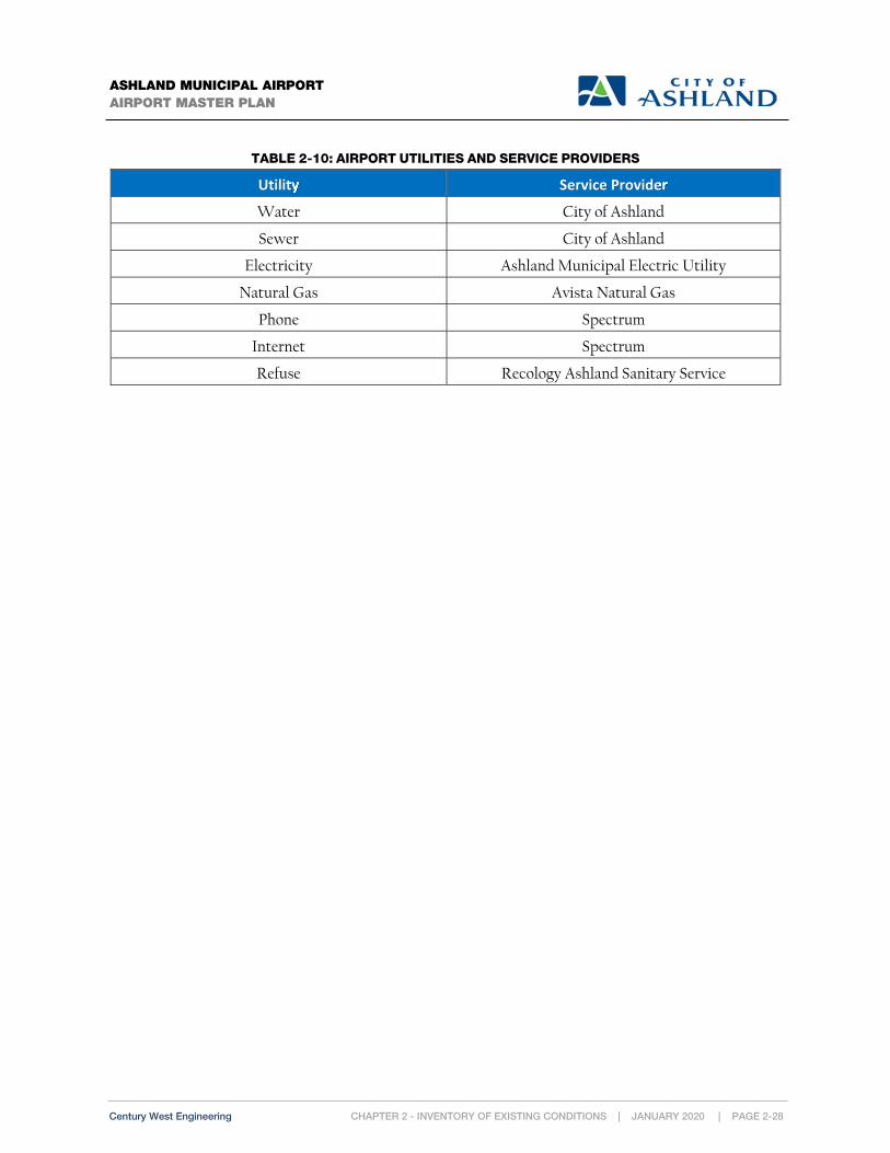
CHAPTER 2 - INVENTORY OF EXISTING CONDITIONS | JANUARY 2020 | PAGE 2-28 Century West Engineering
ASHLAND MUNICIPAL AIRPORT AIRPORT MASTER PLAN
TABLE 2-10: AIRPORT UTILITIES AND SERVICE PROVIDERS
Utility Service Provider
Water City of Ashland
Sewer City of Ashland
Electricity Ashland Municipal Electric Utility
Natural Gas Avista Natural Gas
Phone Spectrum
Internet Spectrum
Refuse Recology Ashland Sanitary Service

ASHLAND MUNICIPAL AIRPORTAIRPORT MASTER PLAN
UTILITY MAPFIGURE 2-8
0 150 300
SCALE OF FEETSCALE: 1"=150'
EXISTING UTILITIES (FIG 2-8)
DEAD INDIAN MEMORIAL RD
DEAD INDIAN MEMORIAL RD
ashland municipal airport
N
E MAIN STE MAIN ST
EMIG
RANT C
REEK
EMIG
RANT C
REEK
NEIL CREEKNEIL CREEK
RUNWAY 12/30RUNWAY 12/30 3,603' X 75'3,603' X 75'
LEGEND
AIRPORT PROPERTYBOUNDARYPOWER
WATERSEWERHYDRANT
STORM


CHAPTER 2 - INVENTORY OF EXISTING CONDITIONS | JANUARY 2020 | PAGE 2-31 Century West Engineering
ASHLAND MUNICIPAL AIRPORT AIRPORT MASTER PLAN
Population and Socioeconomic Data
Preliminary July, 1, 2017 population estimates prepared by Portland State University (PSU) indicate that
Jackson County population is 216,900, up 1.5 percent from 2016. PSU estimates City of Ashland population
is 20,700, up 0.4 percent from 2016. Jackson County includes 11 incorporated cities and 34 unincorporated
communities. The county seat is Medford.
The top employment sectors for Jackson County include Health Care, Retail and Manufacturing, and
Government.7 The top employment sectors in Ashland are Health Care & Social Assistance, Leisure &
Hospitality, and Retail Trade.8
Additional population and economic data will be presented in the updated Aviation Activity Forecasts
chapter to support the analysis.
Land Use Planning and Zoning
The City of Ashland has land use jurisdiction for the airport; however, some of the runway protection areas
and the Part 77 surfaces extend beyond city limits and the Ashland urban growth boundary into
unincorporated Jackson County. The City of Ashland Part 18 Land Use Code establishes the zoning
guidelines for airport land. The airport is zoned Employment District (E-I).9 The Employment District is
“designed to provide for a variety of uses such as office, retail, or manufacturing in an aesthetic environment and having a
minimal impact on surrounding uses.” The airport has been zoned E-I since prior to the 2001 Airport Layout Plan
Report, but has no specific references to airport activities found in the description.
Both the City of Ashland and Jackson County have created Airport Overlay Zoning to protect Ashland
Municipal Airport. The City of Ashland Airport Overlay (A)10 protects the FAR Part 77 surfaces for the
runway and provides regulations and controls on buildings or development within the zone. Jackson
County has established an Airport Approach (AA) and Airport Concern (AC) overlay for airports and
heliports in the county. It establishes protective zones and height limitations to protect the FAR Part 77
surfaces of the runway.
A detailed description of current zoning, airport overlay zoning, and land use will be presented in the
Airport Land Use (Chapter 8). Figure 2-9 depicts the current zoning for the City of Ashland. Figure 2-10
illustrates local land use jurisdictions with responsibilities to protect the FAR Part 77 airspace associated
with Runway 12/30 at Ashland Municipal Airport.
7 Jackson County Economy (http://jacksoncountyor.org/County/About-Us). 8 Ashland Economic Opportunities Analysis (April 2007) ECONorthwest 9 City of Ashland - Part 18 Land Use Code (Employment District) 10 City of Ashland - Part 18 Land Use Code (Section 18.3.7 Airport Overlay)

This page intentionally left blank

ASHLAND MUNICIPAL AIRPORTAIRPORT MASTER PLAN
ASHLAND ZONING MAPFIGURE 2-9
N Mountain Zone(see inset)
Croman Mill Zone(see inset)
N MAIN
ST
OAK
ST
GR
AN
ITE S
T
SISKIYOU BL
A ST
ASHLAND ST
SCEN
IC D
R
GLE
NV
IEW
DR
BEA
CH
ST
IOWA ST
TER
RA
CE
ST
CLAY ST
DITCH RD
WA
LKE
R A
V
WIMER ST
LITHIA WY
W NEVADA ST
OAK KNO
LL DR
FAIT
H A
V
E HERSEY ST
WIG
HTM
AN
ST
PAR
K S
T
HOLLY ST
E MAIN ST
PRIM
ST
MIS
TLETO
E R
D
HIL
LVIE
W D
R
IND
IAN
A S
T
TOLM
AN
CR
EE
K R
D
B ST
BES
WIC
K W
Y
WA
LNU
T S
T
GA
RFI
ELD
ST
ALTA
AV
PINE
CRES
T TR
VAN NESS AVGRANDVIEW DR
STRAWBERRY LN
LIB
ER
TY S
T
MAPLE ST
TER
RA
AV
FIFT
H S
T
GR
ES
HA
M S
T
OTIS ST
RO
CA
ST
W HERSEY ST
N L
AU
RE
L S
T
MO
RTO
N S
T
ORANGE AV
DIANE ST
W FORK ST
IVY LN
SHERIDAN ST
CLINTON ST
EUCLID AV
CH
ES
TNU
T ST
HOMES AV
NO
RM
AL
AV
THIR
D S
T
ALID
A S
T
BRID
GE
ST
FOX S
T
WE
STW
OO
D S
T
WOODLAND DR
CRESTVIEW DR
HIGHW
AY 66
JAQ
UE
LYN
ST
CHURCH ST
GRANT ST
RID
GE
RD
MO
RS
E A
V
BENSON W
Y
AVE
RY
ST
TAY
LOR
ST
AIRPORT RDABBOTT AV
LIN
DA
AV
FOR
DY
CE
ST
TAKELMA WY
PEACHEY RD
HA
RM
ON
Y L
N
BELL
VIE
W A
V
WAT
ER S
T
THO
RN
TON
WY
LIN
CO
LN S
T
NUTLEY ST
GA
RD
EN
WY
S M
OU
NTA
IN A
V
UNION S
T
GLE
ND
ALE
AV
LIT
WY
LEO
NA
RD
ST
EIG
HTH
ST
ANN
ST
GU
THR
IE S
T
ELK
AD
ER
ST
RAY
LN
PIN
E ST
VISTA ST
E NEVADA ST
ALMO
ND ST
CA
LIFO
RN
IA S
T
HIG
H S
T
OXFORD ST
ME
AD
E S
T
BUSH ST
WEBSTER ST
SEVE
NTH
ST
CLARK AVFRA
NC
ES
LNGLE
NW
OO
D D
R
LEE ST
WINDSOR ST
TUDOR ST
GR
EE
NM
EA
DO
WS
WY
LOR
I LN
SIXT
H S
T
FAIR OAKS AV
CLO
VE
R L
N
FOU
RTH
ST
PALM
AV
CREEK DR
HA
RR
ISO
N S
T
ROSS LN
PALM
ER
RD
N F
IRS
T S
T
MA
RY
JAN
E A
V
CA
RO
L S
T
MOHAWK ST
PARKSID
E DR
HIL
LCR
ES
T S
T
OHIO ST
KENT ST
MANZANITA ST
GLE
ND
OW
ER
ST
ORCHARD ST
PLA
ZA A
V
SCHOFIELD ST
C ST
ASHLAND MINE RD
TUCKER ST
PARKER ST
NEZLA ST
EMMA ST NOVA DR
HENRY ST
N W
IGH
TMA
N S
T
CLEAR CREEK DR
LILAC CR
KIRK LN
CAMBRIDGE ST
N S
ECO
ND
ST
DR
AG
ER
ST
ALN
UTT
ST
NOB HILL ST
S LAUREL ST
IDA
HO
ST
OREGON ST
WR
IGH
TS C
RE
EK
DR
SKY
CR
ES
T DR
SHER
MA
N S
T
LON
G W
Y
WELLER
LN
PHEL
PS
ST
CAT
ALI
NA
DR
CO
UR
TNE
Y S
T
NURSERY ST
MADRONE ST
DE
WE
Y S
T
HARGADINE ST
ASHLAND LOOP RD
RANCH RD
WILEY ST
FOREST ST
MORADA LN
RO
GU
E P
L
HU
NTE
R C
T
STA
RFL
OW
ER
LN
WIL
LOW
ST
GLENN ST
WA
SH
ING
TON
ST
MC
CA
LL D
R
DO
G P
AR
K R
DGRIZZLY DR
BRO
OK
S L
N
JOY AV
LUPINE DR
CENTRAL AV
ROSE LN
VOR
IS A
V
LYN
N S
T
EME
RIC
K S
T
ALMEDA DR
BARBARA ST
VAN
SA
NT
ST
ALLISON ST
SEENA LN
PRACHT ST
WATERLINE RD
JESSICA LN
KEA
RN
EY
ST
STA
DIU
M S
T
RUSSELL ST
HERBERT ST
RO
CK
ST
ORCHID ST
BLAINE ST
DRAGONFLY LN
COOLIDGE ST
BRISCOE PL
NEPENTHE RD
YORK ST
BEACH AV
ELMS ST
LOGAN DR
ALTAMONT ST
JEFF
ER
SO
N A
V
SUN
NY
VIE
W S
T
PIE
DM
ON
T D
R
SYLV
IA S
T
FREMONT ST
PAR
AD
ISE
LN
QUINCY ST
FOR
K S
T
ALDER LN
PEARL ST
TIM
BERL
INE
TR
LIS
A LN
EVAN LN
AUD
RY
CR
YMC
A W
Y
SUN
RIS
E S
T
CLAY CREEK WY
SKYLARK PL
SUTT
ON PL
MIC
HE
LLE
AV
WINE ST
PATTERSON ST
MAE ST
NYLA LN
WIL
LIA
MS
ON
WY
CY
PRES
S P
OIN
T LP
HOPE ST
S PIO
NEER ST
ROMEO DR
N PI
ONE
ER S
T
SHER
WO
OD
AV
DO
VE
R A
V
HEMLO
CK LN
DOLLARHIDE WY
PENNSYLVANIA AV
JEN
NIF
ER S
T
CED
AR W
Y
FERN ST
DO
GW
OO
D W
Y
PLAZA
DO
CTO
R'S
ALL
EY
HOXIE'S ALLEY
CA
MP
US
WY
MEADOW DR
LAKOTA WY
SPR
ING
WY
OLD MILL WY
BLA
CK
OA
K W
Y
NIN
TH S
T A
LLE
Y
WILL DODGE WY
PROSPECT ST
BAUM ST
GREENBRIAR PL
TAMARACK PL
WO
LFA
RD
'S A
LLE
Y
OVE
RLO
OK
DR
MA
PLE
WY
LUNA VISTA ST
VILL
AG
E P
AR
K D
R
CH
ER
RY
LN
AUBURN ST
ST ANDREWS CR
WEISSENBACK WY
FIELDER ST
APPLEGATE WY
CU
B C
R
SHAMROCK LN
E JEFFERSON AV
STA
RLI
TE P
L
TESSA LN
ON
EID
A C
R
ELIZ
ABE
TH A
V
MERRILL ST
STONERIDGE AV
WEST ST
VERDA ST
ALASKA ST
FRIENDSHIP ST
ENDERS ALLEY
SKID
MO
RE S
T
MICKELSON WY
THIMBLEBERRY LN
OAK HILL CR
TUDOR CR
PLACER RUN
QUIET LN
WILDWOOD WY
MOUNTAIN VIEW DR
BENJAMIN CT
VILLAGE GREEN DR
CHAPMAN LN
GO
LDE
N S
PIK
E W
Y
LARKIN LN
FAIRWAY CT
CLARENCE LN
IVY LN
SCEN
IC D
R
HIGH ST
ALLISON ST
C ST
VISTA ST
WA
LKE
R A
V
THIR
D S
T
HARM
ONY LN
FAIR OAKS AV
OREGON ST
PRIM
ST
ASHLAND ST
CLA
RK
AV
S LAUREL ST
WA
LKE
R A
V
WAT
ER S
T
CA
MB
RID
GE
ST
WIMER ST
WIL
LOW
ST
MO
RTO
N S
T
C ST
TOLM
AN
CR
EE
K R
D
IOWA ST
S M
OU
NTA
IN A
V
FOREST ST
ELK
AD
ER
ST
PRACHT ST
B ST
HIGH ST
IOWA ST
FOU
RTH
ST
LIND
A AV
LIT WY
CLA
Y S
T
CLAY ST
N PI
ONE
ER S
T
PAR
K S
T
LIB
ER
TY S
T
ASHLAND ST
C ST
MAE ST
HIL
LCR
ES
T S
T
LORI
LN
N LA
UREL
ST
B ST
QUINCY ST
FIFT
H S
T
HIGH ST
LIB
ER
TY S
T
C ST
TAYLO
R S
T
MO
RTO
N S
T
C ST
BLACK OAK WY
WILEY ST
HA
RR
ISO
N S
T
SHER
MA
N S
T
N MAIN ST
TOLM
AN
CR
EE
K R
D
N S
ECO
ND
ST
STA
DIU
M S
T
S M
OU
NTA
IN A
V
BRISCOE PL
SUN
NY
VIE
W S
T
NO
RM
AL
AV
RAY
LN
B ST
B ST
E NEVADA ST
HIGH ST
LIT
WY
MO
RTO
N S
T
NUTLEY ST
SIXT
H S
T
ME
AD
E S
T
MORADA LN
MO
RTO
N S
T
ROSS LN
HIGHW
AY 66
PINE
ST
IDA
HO
ST
E MAIN ST
This is to certify that this is the Official Zoning Map referred to in Section 18.12.030 of Title 18.12 of the Ashland Municipal Code. Adopted as Ordinance No. 2951
Signed: Mayor __________________________________________ Date ____________________
City Recorder _____________________________________ Date ____________________
Mapping is schematic only and bears no warranty of accuracy.All features, structures, facilities, easement or roadway locationsshould be independently field verified for existence and/or location.
R-1-3.5
R-1-5
R-1-7.5
R-2
R-3
RR-.5
RR-1
SO
WR
WR-20
City Limits
Urban Growth Boundary
Airport Overlay
Freeway Overlay
Residential Overlay
P-overlay
Taxlots
MISTLETO
E RD
TOLM
AN C
REE
K R
D
SISKIYOU BL
JAQ
UEL
YN
ST
BEN
SONW
Y
DIANE ST
BE
LLV
IEW
AV
OAKKN
OLL
DR
TAKELMA WY
NOVA DR
CLOVERLN
GRIZZLY DR
BARBARA ST
SPR
ING
CREE
KDR
W
ASHINGTON ST
JEFF
ER
SON
AV
CLAY CREEK WY
SP
RIN
GW
Y
OLD MILL WY
BLAC
K OAK WY
CU
BC
R
E JEFFERSON AV
EAGLE CR EEK
LN
CHAPMAN LN
TAKE
L MA
WY
TOLM
AN C
REE
K R
D
BLACK OAK WY
LegendCM-CI
CM-MU
CM-NC
CM-OE
CM-OS
N M
OU
NTA
IN A
V
E NEV ADA ST
FAIR OAKS AV
PLU
M R
IDG
E D
R
PATT
ON
LN
KEST
REL
PA
RKW
A Y
CAM
ELO
TD
R
OVE
RLO
OK
DR
NEPENTHE RD
STONERIDGE AV
MEADO
WLARK W
Y
MOUNTAI N MEADOWS DR
JULI
AN C
T
STONY POINT
FAIR OA KSCT
SOU THALL
EY
COBBLESTONE CT
STO
NER
IDGEAV
FAIR OAKS AV
PATT
ON
LN
E NEVADA ST
LegendNM-C
NM-G
NM-MF
NM-R 15
NM-R 17.5
North Mountain Zoning Overlay Detail
Croman Mill Zoning Overlay Detail
Zoning MapC-1
C-1-D
E-1
HC
M-1
NM
R-1-10
CM
0 10.5 Miles
0 0.50.25 Miles
0 0.250.125 Miles


ASHLAND MUNICIPAL AIRPORTAIRPORT MASTER PLAN
LAND USE JURISDICTIONFIGURE 2-10
0 150 300
SCALE OF FEETSCALE: 1"=150'
LAND USE JURISDICTIONS (FAR PART 77 COVERAGE) (FIG 2-10)ashland municipal airport
LEGEND
CITY OF ASHLAND
JACKSON COUNTY
PROPERTY BOUNDARY
CITY BOUNDARY
20:1APPROACHSURFACE
RWY 12 RWY 30
20:1APPROACHSURFACE


CHAPTER 2 - INVENTORY OF EXISTING CONDITIONS | JANUARY 2020 | PAGE 2-37 Century West Engineering
ASHLAND MUNICIPAL AIRPORT AIRPORT MASTER PLAN
Airport Environmental Inventory
INTRODUCTION
An environmental review was conducted as a component of the master plan to identify physical or environmental conditions of record, which may affect the recommended improvements at Ashland Municipal Airport. This review included land use, water resources (wetlands, stormwater), species of concern, federal lands, and essential fish habitat.
The scope of work for this element is limited to compiling, reviewing, and briefly summarizing information of record from applicable local, federal, and state sources for the airport site and its environs. The environmental memorandum is included in Appendix A and is briefly summarized below.
PROTECTED SPECIES AND HABITAT
The U.S. Fish and Wildlife (USFWS) and the National Marine Fisheries Service websites were queried to determine any species or critical habitat that is protected under the Endangered Species Act could occur in the vicinity of the airport. The gray wolf (endangered), the northern spotted owl (threatened) and the gentner’s fritillary (endangered) have potential to occur within or near the airport.
WETLANDS
Wetlands are under the jurisdiction of both Oregon Department of State Lands (DSL) and the US Army
Corps of Engineers (Corps) and are protected under the State of Oregon Removal Fill Law and Section
404 of the Clean Water Act.
A wetland inventory was conducted for the City of Ashland and adopted by DSL in 2005. The LWI indicates
that one potential wetland could occur on the northeast corner of airport property, on the east side of
Emigrant Creek. The LWI also identified Emigrant Creek and Neil Creek as occurring on airport property.
FLOODPLAINS
The airport is located within the floodplains of both Emigrant Creek and Neil Creek. The development standards for floodplains are regulated under Chapter 18.3.10.080 of the Ashland Municipal code. According to the City’s Flood Insurance Rate Map (FIRM), there is approximately seven percent of airport property is located in flood zone AE, the regulatory floodway of Emigrant Creek, which is an area determined by base flood elevations to have a one percent annual chance of flooding. In addition, a small portion of the airport’s western boundary is within the FEMA floodplain of Neil Creek.

This page intentionally left blank

Chapter 3
Aviation Activity Forecasts


CHAPTER 3 - AVIATION ACTIVITY FORECASTS | JANUARY 2020 | PAGE 3-1
ASHLAND MUNICIPAL AIRPORT AIRPORT MASTER PLAN
Century West Engineering
Chapter 3 – Aviation Activity Forecasts
The overall goal of aviation activity forecasting is to provide reasonable projections of future activity that can be translated into specific
airport facility needs anticipated during the next twenty years and beyond.
Overview and Purpose
This chapter provides updated aviation activity forecasts for Ashland Municipal Airport (S03) for the
twenty-year master plan horizon (2017-2037). The most recent Federal Aviation Administration (FAA)
approved aviation activity forecasts for Ashland Municipal Airport were developed in the 2004 Airport
Layout Plan Report.
The forecasts presented in this chapter are consistent with current and historic role as a community/regional
general aviation airport. Ashland Municipal Airport is capable of accommodating a full range of general
aviation activity, including business class turboprops, small business jets and helicopters. This level of
capability expands the airport’s role beyond the local community and accommodates users throughout the
region, which is acknowledged in the 2007 Oregon Aviation Plan (OAP).
Ashland Municipal Airport is designated a Category III - Regional General Aviation airport in OAP 2007.
The definition for Category III airports is: “These airports support most twin and single-engine aircraft and may
accommodate occasional business jets. These airports support a regional transportation need.”
The forecasts of activity are unconstrained and assume the City of Ashland will be able to make the facility
improvements necessary to accommodate the anticipated demand unless specifically noted. The City of
Ashland will consider if any unconstrained demand will not or cannot be reasonably met through the
evaluation of airport development alternatives later in the master plan.

CHAPTER 3 - AVIATION ACTIVITY FORECASTS | JANUARY 2020 | PAGE 3-2
ASHLAND MUNICIPAL AIRPORT AIRPORT MASTER PLAN
Century West Engineering
FAA FORECASTING PROCESS
The FAA provides aviation activity forecasting guidance for airport master planning projects. FAA
Advisory Circular (AC) 150/5070-6B, Airport Master Plans, outlines seven standard steps involved in the
forecast process:
1) Identify Aviation Activity Measures: The level and type of aviation activities likely to impact
facility needs. For general aviation, this typically includes based aircraft and operations.
2) Previous Airport Forecasts: May include the FAA Terminal Area Forecast (TAF), state or
regional system plans, and previous master plans.
3) Gather Data: Determine what data are required to prepare the forecasts, identify data sources, and
collect historical and forecast data.
4) Select Forecast Methods: There are several appropriate methodologies and techniques available,
including regression analysis, trend analysis, market share or ratio analysis, exponential
smoothing, econometric modeling, comparison with other airports, survey techniques, cohort
analysis, choice and distribution models, range projections, and professional judgment.
5) Apply Forecast Methods and Evaluate Results: Prepare the actual forecasts and evaluate for
reasonableness.
6) Summarize and Document Results: Provide supporting text and tables as necessary.
7) Compare Forecast Results with FAA’s TAF: Follow guidance in FAA Order 5090.3C, Field
Formulation of the National Plan of Integrated Airport Systems. In part, the Order indicates that
forecasts should not vary significantly (more than 10 percent) from the TAF. When there is a
greater than 10 percent variance, supporting documentation should be supplied to the FAA. The
aviation demand forecasts are then submitted to the FAA for their approval.
KEY ACTIVITY ELEMENTS
As noted above, general aviation airport activity forecasting focuses on two key activity segments: based
aircraft and aircraft operations (takeoffs & landings). Detailed breakdowns of these activity segments
include:
Aircraft fleet mix;
Peak activity;
Distribution of local and itinerant operations; and
Determination of the critical aircraft (also referred to as the design aircraft).
The critical aircraft represents the most demanding aircraft type or family of aircraft that uses an airport
on a regular basis (a minimum of 500 annual takeoffs & landings). The critical aircraft is used to establish
a variety of FAA design categories, which then establish design standards for airfield facilities. FAA airport
design standard groupings reflect the physical requirements of specific aircraft types and sizes. Design

CHAPTER 3 - AVIATION ACTIVITY FORECASTS | JANUARY 2020 | PAGE 3-3
ASHLAND MUNICIPAL AIRPORT AIRPORT MASTER PLAN
Century West Engineering
items, such as runway length evaluations, are determined by the requirements of current/future critical
aircraft. The activity forecasts also support the evaluation of several demand-based facility requirements
including runway and taxiway capacity, aircraft parking, and hangar capacity.
Airport Service Area
An airport service area refers to the geographic area surrounding an airport that has the greatest influence
on its activity. The population and economic conditions, and the number and type of airports within a
service area can directly influence individual airport activity. For general aviation airports, a 30- or 60-
minute surface travel time is often used to approximate the boundaries of its service area.
A significant portion of general aviation airport activity is normally generated by aircraft that are owned
and operated by individuals, businesses, or government agencies located within its service area. Other
activity is generated by transient aircraft that chose to operate at the airport, instead of a nearby competing
airport. Transient aircraft activity includes both enroute and origin-destination travel. In many cases, the
airport itself is the destination, when the purpose of flight is to access FBO and related services, fuel, an
airport restaurant, or specific flight training needs.
Convenience, choice, and cost are three primary considerations that every airport user weighs when
making their consumer choice. Surface travel time to or from an airport is a primary measure of
convenience, although facility capabilities, available services, and user costs may outweigh convenience for
many users.
Table 3-1 lists the public use airports within a 35 nautical mile (air miles) radius of Ashland Municipal
Airport, which incorporates the majority of the defined service area for the airport. Figure 3-1 illustrates
the approximate service area boundaries for Ashland Municipal Airport.
Service areas for commercial airports often extend well beyond a one-hour drive time due to the relatively
small number of airports with scheduled airline service. Ashland Municipal Airport is located within the
service areas (approximately a two-hour drive time) defined for two commercial airports: Rogue Valley
International Medford Airport (approximately 30 minute drive time) and Crater Lake Klamath Regional
Airport (approximately 1.5-hour drive time).

CHAPTER 3 - AVIATION ACTIVITY FORECASTS | JANUARY 2020 | PAGE 3-4
ASHLAND MUNICIPAL AIRPORT AIRPORT MASTER PLAN
Century West Engineering
TABLE 3-1: PUBLIC USE AIRPORTS IN VICINITY OF ASHLAND MUNICIPAL AIRPORT (WITHIN 35 NAUTICAL MILES)
Airport Location Runway Length(s) (Feet)
Surface Lighted Runway
Fuel Available
Rogue Valley International-Medford Airport (MFR)
15NM NW 8,800 Asphalt HIRL 100LL Jet-A
Pinehurst State (24S) 13NM SE 2,800 Asphalt N/A N/A
Siskiyou County Airport (SIY) 26 NM S 7,490 Asphalt MIRL 100LL Jet-A
Montague-Yreka Rohrer Field (105) 28 NM S 3,360 Asphalt MIRL 100LL
Butte Valley Airport (A32) 35 NM SE 4,000 Asphalt N/A N/A

ASHLAND MUNICIPAL AIRPORT
AIRPORT MASTER PLAN
AIRPORT SERVICE AREA
FIGURE 3-1
Approximate 60 minute surface travel time to/from Ashland Municipal Airport Public use airports in service area.
Approximate 30 minute surface travel time to/from Ashland Municipal Airport Public use airports in vicinity (outside service area)
Ashland Municipal Airport (S03)
Grants PassAirport (3S8)
Rogue Valley International-Medford Airport (MFR)
Pinehurst State Airport (24S)
Prospect State Airport (64S)
Siskiyou County (SIY)
Montague-Yreka Rohrer (10S)
Happy Camp Airport (36S)

CHAPTER 3 - AVIATION ACTIVITY FORECASTS | JANUARY 2020 | PAGE 3-6
ASHLAND MUNICIPAL AIRPORT AIRPORT MASTER PLAN
Century West Engineering
Economic Conditions and Population
Historically, downturns in general aviation activity often occur during periods of weak economic
conditions while growth typically coincides with favorable economic conditions. The recent economic
recession and the slow recovery that followed, has constrained general aviation activity locally, statewide,
and throughout the national airport system. However, the FAA’s national long-term aviation forecasts1
reflect overall strength in both the U.S. and regional economies. This forecast economic strength is
expected to sustain modest growth in aviation activity over the long-term.
AREA ECONOMY
The economy for the City of Ashland has both local and regional components. The City actively pursues and
promotes local economic development activities while supporting broader regional initiatives. In 2007, the
City of Ashland supported Jackson County’s expansion of commercial and industrially zoned properties
in the Jackson County Enterprise Zone. The Ashland City Council adopted the city’s current Economic
Development Strategy in 2011 and is now engaged in implementation. The purpose of the strategy
addressed four elements including diversifying the economic base of the community; supporting growth
in businesses that provide local and regional products; increasing family-wage jobs in the community; and
leveraging Ashland’s tourism and repeat visitor strengths. Several key economic sectors were identified:
Southern Oregon University;
Oregon Shakespeare Festival;
Lodging, restaurants and specialty retail;
Value added specialty manufacturing; and
Specialty food and beverage innovation.
The economic strategy recommended focused efforts to build on current successes, while also addressing
several economic challenges or weaknesses. Examples include seasonality of tourism, high housing costs,
land supply required to support industrial employment, distance to major economic markets, and an older
age demographic.
The City of Ashland conducted a buildable lands inventory in 2011 to quantify land development
opportunities and constraints within the city limits and urban growth boundary (UGB). Ashland
Municipal Airport is included in the inventory with 9 developable parcels listed; no net buildable acreage
within the airport is listed, instead referring to the airport specific site planning (“Per Airport Master
Plan”). Although the airport represents a small percentage of developable lands in the Ashland UGB, it
provides an inventory of developable land that is capable of supporting targeted airport-compatible
1 FAA Aerospace Forecast (Fiscal Years 2016-2036)

CHAPTER 3 - AVIATION ACTIVITY FORECASTS | JANUARY 2020 | PAGE 3-7
ASHLAND MUNICIPAL AIRPORT AIRPORT MASTER PLAN
Century West Engineering
commercial or light industrial uses. These activities may generate aviation activity or complement the
common range of aeronautical activities.
The economy of Jackson County has a diverse group of sectors including trade, transportation, and utilities;
education and health services; government; leisure and hospitality; and manufacturing. The nearby Medford
metropolitan area supports a wide range of consumer services and employment opportunities that results in a
strong economic connection with Ashland.
EMPLOYMENT
Oregon Employment Department data indicates total employment for Jackson County in 2016 was 87,110
employees. In 2016 the average income among all industry segments in Jackson County was $40,323
compared to Oregon’s statewide average of $49,467. The leading employment sectors and average annual
wages for Jackson County are summarized in Table 3-2 and Table 3-3.
TABLE 3-2: LEADING EMPLOYMENT SECTORS IN JACKSON COUNTY (2016)
JACKSON COUNTY
Sector Total Employment by Sector % of Total Employment
1. Trade, Transportation, and Utilities 20,900 24%
2. Education and Health Services 15,280 17.5%
3. Government 12,880 14.8%
4. Leisure and Hospitality 10,520 12.1%
5. Manufacturing 7,610 8.7%
All other industries 19,920 22.9%
Total Employment 87,110 100%
Source: State of Oregon Employment Department, Jackson County 2016
TABLE 3-3: LEADING EMPLOYMENT SECTORS WAGES IN JACKSON COUNTY (2016)
Sector Jackson County
Annual Average Wage Oregon
Annual Average Wage
1. Trade, Transportation, and Utilities $35,676 $41,405
2. Education and Health Services $50,644 $49,269
3. Government $47,992 $52,766
4. Leisure and Hospitality $18,711 $20,165
5. Manufacturing $46,390 $67,493
Source: State of Oregon Employment Department, Jackson County and State of Oregon 2016

CHAPTER 3 - AVIATION ACTIVITY FORECASTS | JANUARY 2020 | PAGE 3-8
ASHLAND MUNICIPAL AIRPORT AIRPORT MASTER PLAN
Century West Engineering
POPULATION
The population within an airport’s service area, in broad terms, affects the type and scale of aviation
facilities and services that can be supported. Changes in population often reflect broader economic
conditions that may also affect airport activity. The airport service area for Ashland Municipal Airport
extends beyond the City of Ashland and Jackson County along the Interstate 5 corridor and includes portions
of Klamath County in Oregon and Siskiyou County in California. However, for the purpose of forecasting
aviation activity, an evaluation of local city and Jackson County population trends will provide a reasonable
indication of activity.
Historic Population
Certified estimates of population for Oregon counties and incorporated cities are developed annually by
the Population Research Center at Portland State University (PRC-PSU). The annual PRC-PSU estimates,
coupled with U.S. Census conducted every ten years, provide an indication of local area population trends
over an extended period.2 The 2017 PRC-PSU certified population estimate for the City of Ashland was
20,700 and the estimate for Jackson County was 216,900.
The City of Ashland’s population has increased slightly since the 2000 Census. Annual population growth
over the last 25 years has been modest, averaging just below 0.5 percent, compared to statewide average
growth that is typically just above 1 percent per year. Jackson County grew at a rate nearly double that of
the City of Ashland, averaging just above 1 percent since 2000. Recent historic population data and average
growth rates for the City of Ashland, Jackson County, and Oregon are summarized in Table 3-4.
2 Portland State University Population Research Center (July 1, 2017); Estimates 1990, 2000, 2010 U.S. Census

CHAPTER 3 - AVIATION ACTIVITY FORECASTS | JANUARY 2020 | PAGE 3-9
ASHLAND MUNICIPAL AIRPORT AIRPORT MASTER PLAN
Century West Engineering
TABLE 3-4: HISTORIC POPULATION DATA
Year Jackson County
City of Ashland (Incorporated Area)
City Share (%) of Jackson County
Oregon
19901 146,389 16,252 11.1% 2,842,321
20001 181,269 19,610 10.8% 3,421,399
20101 203,206 20,078 9.9% 3,831,074
20172 216,900 20,700 9.5% 4,141,100
Average Annual Rates (AAR) of Growth (%)
Year Jackson County
City of Ashland (Incorporated Area)
Oregon
1990-2000 2000-2010 2000-2017 2010-2017
2.16% 1.14% 1.06% 0.94%
1.90% 0.24% 0.32% 0.44%
1.87% 1.14% 1.13% 1.11%
Sources: 1. U.S. Census Data (April 1) 2. Portland State University, Certified Population Estimate (July 1, 2017)
POPULATION FORECASTS
Population Research Center – Portland State University
The Oregon legislature recently assigned development of coordinated population forecasts for Oregon
counties and cities to the Population Research Center at Portland State University (PRC-PSU). Previously,
long-term population forecasts were prepared by the Oregon Office of Economic Analysis (OEA) to support
local and statewide planning. The current PRC forecast for Jackson County was published in June 2015.3
The current PRC forecast provides a fifty-year projection (2065), with one intermediate projection (2035).
The 2035 projection approximates the end of the current airport master plan planning period (2017-2037)
and provides relevant information about future population expectations for the City of Ashland Urban
Growth Boundary (UGB) and Jackson County. The PRC forecast projects modest, sustained population
growth for the Ashland UGB and more rapid growth for Jackson County through 2065. The PRC forecasts
indicate that Ashland’s share of Jackson County population will decrease slightly during this period, while
still experiencing growth. The PRC population forecasts are summarized below and in Table 3-5.
3 Coordinated Population Forecast 2015 through 2065 Jackson County Urban Growth Boundaries (UGB), and Area of outside UGBs. Population
Research Center Portland State University, June 2015.

CHAPTER 3 - AVIATION ACTIVITY FORECASTS | JANUARY 2020 | PAGE 3-10
ASHLAND MUNICIPAL AIRPORT AIRPORT MASTER PLAN
Century West Engineering
City of Ashland
Ashland’s population is projected to increase from 20,905 in 2015 to 24,138 in 2065. The forecast reflects a
15 percent increase in population over the next fifty years, with an average annual growth rate of
approximately 0.3 percent. Slightly higher annual growth (0.5% AAR) is anticipated through the first
thirty years (between 2015 and 2035), followed by slower growth (0.1%) over the latter twenty years.
Jackson County
Jackson County’s population is projected to increase from 211,275 in 2015 to 306,858 in 2065. The forecast
reflects a 45 percent increase in population over the next fifty years, with an average annual growth rate of
approximately 0.75 percent. As with the Ashland forecast, a slightly higher annual growth (1.0% AAR) is
anticipated between 2015 and 2035, followed by slower growth (0.6% AAR) over the latter twenty years.
TABLE 3-5: POPULATION FORECASTS
Year Jackson County City of Ashland (UGB) City Share (%) of County
2015 211,275 20,905 9.9%
2035 255,840 23,183 9.1%
2065 306,858 24,138 7.9%
Annual Average Growth Rate (AAR %)
2015-2065 0.75% 0.3% --
2015-2035 1.0% 0.5% --
2035-2065 0.6% 0.1% --
National General Aviation Activity Trends
The early years of the 21st Century have presented numerous challenges for general aviation (GA). On a
national level, most measures of GA activity declined sharply during “The Great Recession” and have only
modestly improved in recent years.
As depicted in Figure 3-2, the active U.S. GA fleet has fluctuated within a slight overall decline since 2001.
This trend coincides with other GA industry trends including annual aviation fuel consumption, hours
flown, IFR enroute air traffic, operations at towered airports, active pilots, etc.

CHAPTER 3 - AVIATION ACTIVITY FORECASTS | JANUARY 2020 | PAGE 3-11
ASHLAND MUNICIPAL AIRPORT AIRPORT MASTER PLAN
Century West Engineering
FIGURE 3-2: US ACTIVE GENERAL AVIATION FLEET
The FAA performs an annual assessment of U.S. civil aviation through its FAA Aerospace Forecast.4 The
twenty-year forecasts are updated annually by evaluating recent events and established trends affecting a
wide range of commercial and general aviation segments. Broad economic conditions and current forecasts
are examined in order to provide reasonable expectations for aviation within the broader U.S. and global
economy. The FAA forecasts examine in detail several key aviation industry indicators including fuel
prices, production and supply; aircraft manufacturing trends; aircraft ownership trends; fleet and pilot
attrition; flight training trends; advances in fuel, engine, avionics, and airspace technology (ADS-B
NextGen, etc.); and on-demand air travel. This array of factors is reflected in the FAA’s overall assessment
of future U.S. aviation activity.
The FAA currently predicts that the active GA aircraft fleet will grow at an average annual rate of
approximately 0.1 percent between 2016 and 2037. Although the FAA maintains a modestly favorable long-
term outlook for general aviation, many of the activity segments associated with piston engine aircraft and
AVGAS consumption are not projected to return to “pre-recession” levels within the 20-year forecast. It
should be noted however, that the FAA forecasts do include some bright spots for specific activity
segments that are relevant to Ashland Municipal Airport. Key takeaways from the FAA 2017-2037
Aerospace Forecast Highlights are summarized below:
4 FAA Aerospace Forecast Fiscal Years 2017-2037.

CHAPTER 3 - AVIATION ACTIVITY FORECASTS | JANUARY 2020 | PAGE 3-12
ASHLAND MUNICIPAL AIRPORT AIRPORT MASTER PLAN
Century West Engineering
Positive
Turbine aircraft (turboprop, turbojet, helicopter) fleet and hours flown will grow;
Sport and Experimental aircraft fleet and hours flown will grow;
Piston Rotorcraft fleet and hours flown will grow;
Jet fuel consumption will grow;
Student, Sport, Airline Transport, Rotorcraft, and Instrument rated pilots will grow;
GA enroute IFR air traffic will grow; and
GA Operations at towered airports will grow.
Negative
Fixed wing Piston aircraft fleet and hours flown will shrink;
AVGAS consumption will shrink; and
The number of Private and Commercial pilots will shrink.
Neutral
Overall GA fleet will grow by less than 2% over the next 20 years.
The FAA’s annual growth assumptions for individual general aviation activity segments are summarized
in Table 3-6.

CHAPTER 3 - AVIATION ACTIVITY FORECASTS | JANUARY 2020 | PAGE 3-13
ASHLAND MUNICIPAL AIRPORT AIRPORT MASTER PLAN
Century West Engineering
TABLE 3-6: FAA LONG RANGE FORECAST ASSUMPTIONS (U.S. GENERAL AVIATION)
Activity Component Forecast Annual Average Growth Rate (2016‐2037)
Aircraft in U.S. Fleet
Single Engine Piston Aircraft in U.S. Fleet -0.9%
Multi-Engine Piston Aircraft in U.S. Fleet -0.5%
Turboprop Aircraft in U.S. Fleet 1.4%
Turbojet Aircraft in U.S. Fleet 2.3%
Experimental Aircraft in U.S. Fleet 1.0%
Sport Aircraft in U.S. Fleet 4.1%
Piston Helicopters in U.S. Fleet 1.3%
Turbine Helicopters in U.S. Fleet 1.8%
Active GA Fleet (# of Aircraft) 0.1%
Active Pilots in U.S.
Private Pilots -0.7%
Commercial Pilots -0.6%
Airline Transport Pilots 0.5%
Instrument Rated Pilots 0.3%
Sport Pilots 4.1%
Student Pilots (Indicator of flight training activity) 0.4%
Active GA Pilots (All Ratings) 0.1%
Hours Flown in U.S.
Piston AC -0.8%
Turbine AC 2.5%
Experimental AC 2.0%
Sport AC 4.6%
Total GA Fleet Hours 0.9%
Fuel Consumption in U.S.
AVGAS (Gallons consumed - GA only) -0.4%
Jet Fuel (Gallons consumed – GA only) 1.9%
Source: FAA Long Range Aerospace Forecasts (FY 2016-2037)
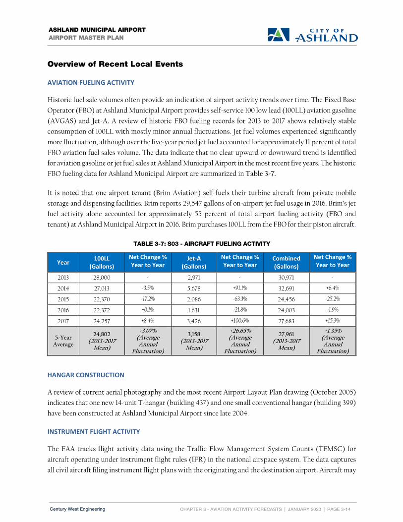
CHAPTER 3 - AVIATION ACTIVITY FORECASTS | JANUARY 2020 | PAGE 3-14
ASHLAND MUNICIPAL AIRPORT AIRPORT MASTER PLAN
Century West Engineering
Overview of Recent Local Events
AVIATION FUELING ACTIVITY
Historic fuel sale volumes often provide an indication of airport activity trends over time. The Fixed Base
Operator (FBO) at Ashland Municipal Airport provides self-service 100 low lead (100LL) aviation gasoline
(AVGAS) and Jet-A. A review of historic FBO fueling records for 2013 to 2017 shows relatively stable
consumption of 100LL with mostly minor annual fluctuations. Jet fuel volumes experienced significantly
more fluctuation, although over the five-year period jet fuel accounted for approximately 11 percent of total
FBO aviation fuel sales volume. The data indicate that no clear upward or downward trend is identified
for aviation gasoline or jet fuel sales at Ashland Municipal Airport in the most recent five years. The historic
FBO fueling data for Ashland Municipal Airport are summarized in Table 3-7.
It is noted that one airport tenant (Brim Aviation) self-fuels their turbine aircraft from private mobile
storage and dispensing facilities. Brim reports 29,547 gallons of on-airport jet fuel usage in 2016. Brim’s jet
fuel activity alone accounted for approximately 55 percent of total airport fueling activity (FBO and
tenant) at Ashland Municipal Airport in 2016. Brim purchases 100LL from the FBO for their piston aircraft.
TABLE 3-7: S03 - AIRCRAFT FUELING ACTIVITY
Year 100LL
(Gallons)
Net Change % Year to Year
Jet‐A (Gallons)
Net Change % Year to Year
Combined (Gallons)
Net Change % Year to Year
2013 28,000 - 2,971 - 30,971 -
2014 27,013 -3.5% 5,678 +91.1% 32,691 +6.4%
2015 22,370 -17.2% 2,086 -63.3% 24,456 -25.2%
2016 22,372 +0.1% 1,631 -21.8% 24,003 -1.9%
2017 24,257 +8.4% 3,426 +100.6% 27,683 +15.3%
5-Year Average
24,802 (2013-2017
Mean)
-3.07% (Average Annual
Fluctuation)
3,158 (2013-2017
Mean)
+26.65% (Average Annual
Fluctuation)
27,961 (2013-2017
Mean)
+1.35% (Average Annual
Fluctuation)
HANGAR CONSTRUCTION
A review of current aerial photography and the most recent Airport Layout Plan drawing (October 2005)
indicates that one new 14-unit T-hangar (building 437) and one small conventional hangar (building 399)
have been constructed at Ashland Municipal Airport since late 2004.
INSTRUMENT FLIGHT ACTIVITY
The FAA tracks flight activity data using the Traffic Flow Management System Counts (TFMSC) for
aircraft operating under instrument flight rules (IFR) in the national airspace system. The data captures
all civil aircraft filing instrument flight plans with the originating and the destination airport. Aircraft may

CHAPTER 3 - AVIATION ACTIVITY FORECASTS | JANUARY 2020 | PAGE 3-15
ASHLAND MUNICIPAL AIRPORT AIRPORT MASTER PLAN
Century West Engineering
cancel IFR flight plans enroute, so not every flight plan actually results in an instrument operation. As
noted in the Inventory chapter, Ashland Municipal Airport does not have a published instrument approach
procedure, which limits its instrument activity.
Instrument flight plan data for Ashland Municipal Airport was obtained and analyzed for 2012-2016 to
assist in evaluating overall air traffic. The 2012-2016 data are summarized in Table 3-8 by Airport Reference
Code (ARC). 2017 activity is summarized by ARC and aircraft type in Table 3-9. The mix of air traffic
includes single-engine and multi-engine piston aircraft, business jets and turboprops. A portion of the
turboprop activity was attributed to air cargo/express aircraft diverted from Medford.
TABLE 3-8: INSTRUMENT ACTIVITY (2012-2016)
ARC 2012 2013 2014 2015 2016
A-I 231 351 406 304 213 A-II 30 19 8 12 8 B-I 29 98 96 68 76 B-II 14 26 75 98 76 C-I 0 0 0 0 0 C-II 0 0 0 0 0 D-I 0 0 0 0 0 D-II 0 0 0 0 0 HELI 0 0 0 0 0 UNKNOWN 0 0 0 0 0 304 494 585 482 373 Source: FAA TFMSC Data (normalized)
TABLE 3-9: INSTRUMENT ACTIVITY DETAIL – S03 (2017)
Aircraft Type ARC 2017
Single Engine Piston A-I 280
Multi-Engine Piston B-I 32
Single Engine Turboprop A-II 22
Multi-Engine Turboprop B-I /B-II 34
Business Jet B-I / B-II 40
Helicopter -- 4
Total Aircraft Operations Related to Instrument Flight Plans 412

CHAPTER 3 - AVIATION ACTIVITY FORECASTS | JANUARY 2020 | PAGE 3-16
ASHLAND MUNICIPAL AIRPORT AIRPORT MASTER PLAN
Century West Engineering
BASED AIRCRAFT FLEET (REVISED DATA)
The updated aviation activity forecasts for Ashland Municipal Airport presented in the draft chapter
(March 2018) used a fall 2017 airport management count of 74 based aircraft. Several discrepancies were
subsequently identified between the airport estimate and the FAA based aircraft database
(www.basedaircraft.com). Additional review of the airport’s based aircraft records was conducted to
physically verify actual aircraft on the field and to ensure that the FAA database accurately reflected all
verifiable aircraft. The review identified a total of 60 qualified aircraft located at the airport in May 2018:
59 active powered aircraft
1 active glider not previously included in the FAA database
A total of 15 aircraft were eliminated from the recent based aircraft count:
9 inactive powered aircraft located at the airport (without active FAA registration)
6 powered aircraft previously counted could not be accounted for.
The FAA requires aircraft to have current registration to be included an airport’s based aircraft count.
According to airport management, the inactive aircraft at the airport include several with one owner (now
decreased) that are in the process of being sold. Several other aircraft are undergoing major repair or
restoration. Some of these aircraft are expected to return to service early in the planning period and will
be reflected in the initial 5-year forecast of based aircraft (2022).
Table 3-10 summarizes the May 2018 verified count of based aircraft at Ashland Municipal Airport. The
current mix of aircraft is predominantly single-engine piston and helicopters. The airport also has one light
piston twin, one business jet, and one glider.
TABLE 3-10: 2017 BASED AIRCRAFT – S03 (VERIFIED MAY 2018)
Aircraft Type 2017
Single Engine Piston 53
Multi-Engine Piston 1
Turboprop 0
Business Jet 1
Helicopter 4
Glider 1
Total Based Aircraft 60
Source: Airport management & FAA verified count (5/2018) as entered into FAA www.basedaircraft.com database.

CHAPTER 3 - AVIATION ACTIVITY FORECASTS | JANUARY 2020 | PAGE 3-17
ASHLAND MUNICIPAL AIRPORT AIRPORT MASTER PLAN
Century West Engineering
A 2004 aerial photo (Figure 2-2) in the 2005 Airport Layout Plan Report depicts existing buildings and
parked aircraft in the terminal area. Approximately 46 “hangar units” in 16 separate structures are
identified in the figure. A total of 24 aircraft are identified parked on the aircraft apron. Although some
variations in counts would be expected, the combination of hangar units and observed parked aircraft is
more than 20 percent below the 2004 estimate of 89 based aircraft for the airport. As noted earlier, the
recent verification of based aircraft at the airport indicates that some overestimating may have occurred,
perhaps extending back many years. It is difficult to verify whether the annual updates of based aircraft on
the FAA’s Airport Master Record (Form 5010-1) submitted by the airport to FAA, consistently captured
actual activity or were often pushed forward without change. As noted earlier, the FAA TAF relies on data
provided by airport sponsors through 5010 updates.
Since the accuracy of the 2004 estimate of 89 based aircraft cannot be verified, it does not provide a reliable
baseline to measure recent trends at Ashland Municipal Airport. The current based aircraft count of 60
suggests a decline in activity, however, this cannot be definitively quantified with available data. The
absence of reliable data eliminates the ability to assess local trends beyond recent fuel sales and hangar
construction activity.
Moving forward, the required annual update/verification of the airport’s based aircraft count by the City
for 5010 and FAA database (www.basedaircraft.com) updates, will improve accuracy of based aircraft
counts over previous estimating methods. More accurate 5010 data will also improve the accuracy of the
FAA TAF.
Existing Aviation Activity Forecasts
Updating aviation activity forecasts for the master plan requires an updated assessment of current
conditions and a review of existing aviation activity forecasts. Several existing forecasts relevant to
Ashland Municipal Airport are available for review, including the 2005 Airport Layout Plan Report, the
2007 Oregon Aviation Plan (OAP), and the 2018 FAA Terminal Area Forecast (TAF). Table 3-11
summarizes the based aircraft and operations forecasts currently available for Ashland Municipal Airport.
It is important to note that all of the forecasts generated for Ashland Municipal Airport in the 2004-2005
time period (2004 TAF, 2007 OAP and 2005 ALP Report) shared common based aircraft data that
originated with airport estimates of activity as reported through 5010 Airport Master Record form updates.
The updates were subsequently used in the TAF, which was then cited as a primary data source in the
other forecasts. As noted earlier, reported 5010 based aircraft totals appear to have been inadvertently
overestimated during this period, which subsequently skewed the TAF and the other dependent forecasts
upward.
As with based aircraft data, the FAA indicates that the TAF relies on aircraft operations data supplied by
airport sponsors for non-towered airports. However, it is recognized that an airport sponsor’s ability to

CHAPTER 3 - AVIATION ACTIVITY FORECASTS | JANUARY 2020 | PAGE 3-18
ASHLAND MUNICIPAL AIRPORT AIRPORT MASTER PLAN
Century West Engineering
accurately estimate aircraft operations is very limited (at a non-towered airport). With few exceptions,
aircraft takeoffs and landings operations are estimates only, and the associated forecasts are heavily
dependent on the accuracy of the estimates, which can vary widely. The resulting limitations should be
considered when evaluating forecasts that are dependent on non-statistical estimates. Acoustical activity
counts performed at airport during the stated period provided statistically-valid estimates of annual
aircraft operations that were periodically reflected in the TAF. This program has been discontinued and is
currently unavailable to airport sponsors as a method of accurately estimating activity.
The 2018 TAF update now reflects the recently-verified based aircraft count and applies a modest growth
rate to provide a reasonable long-term based aircraft forecast. However, there is no indication that the TAF
historical (2007 to 2016) or forecast (2017 to 2045) aircraft operations data were adjusted to reflect the
impacts of the recent economic recession (see below). Despite this, the small range of aircraft operations
involved suggests that the current TAF is adequate for comparison with the updated aircraft operations
forecasts.
Aviation activity forecasts prepared prior to “The Great Recession,” that began in Q4 of 2007, became
largely obsolete due to the effects of the severe economic downturn. General aviation airports routinely
saw sustained, double-digit declines in annual activity during the recession that was characterized by
closed businesses, reduced fuel sales, loss of based aircraft, increased hangar vacancy rates, lower aircraft
utilization, and a dearth of new hangar construction. In general, the recovery of airport activity segments
has been slower than their preceding declines. None of these conditions were anticipated in forecasts
prepared prior to the recession, and as a result, tend to overestimate activity compared to actual events.
With these limitations in mind, the 2007 OAP and 2005 ALP based aircraft forecasts are presented for
reference only since they do not support reliable analysis. The OAP and ALP aircraft operations forecasts
were comparable to the 2004 TAF, which reflected the pre-recession activity verified through the
acoustical counts.

CHAPTER 3 - AVIATION ACTIVITY FORECASTS | JANUARY 2020 | PAGE 3-19
ASHLAND MUNICIPAL AIRPORT AIRPORT MASTER PLAN
Century West Engineering
TABLE 3-11: EXISTING BASED AIRCRAFT & GA OPERATIONS FORECASTS
ASHLAND MUNICIPAL AIRPORT – AIRPORT LAYOUT PLAN REPORT (2005)
Assessment: The forecasts of aviation activity are skewed by earlier based aircraft estimates and pre-recession assumptions
about future growth. The based aircraft forecast is currently running approximately 90 percent above the most recent airport
management count and is no longer considered valid.
The Airport Layout Plan Report provides airport activity forecasts for a 2004-2024 planning period. The
forecasts include based aircraft, based aircraft fleet mix, annual aircraft operations, activity peaking, and
local/itinerant traffic distributions. The analysis of critical aircraft was developed in the facility
requirements element of the master plan, using overall numbers contained in the forecast.
Based Aircraft
As indicated above, this forecast is no longer valid. The based aircraft forecast projected an increase
from 89 to 125 at Ashland Municipal Airport between 2004 and 2024, which translates into an annual
average growth rate of 1.71 percent over the twenty-year period. The forecasts for 2014 and 2019 (109 and
117) are well above the fall 2017 based aircraft count of 74.
Forecast 2017 2022 2027 2032 2037 AAR
2018 FAA Terminal Area Forecast (TAF) Operations
26,357 27,887 29,431 31,050 32,757 1.10%1
2018 FAA Terminal Area Forecast (TAF) Based Aircraft
59 65 70 75 80 1.54%1
Operations Per Based Aircraft (OPBA) 447 429 420 414 410 -
2007 Oregon Aviation Plan Annual Operations
24,5844 25,9434 27,3765 - - 1.24%2
2007 Oregon Aviation Plan Based Aircraft 1054 1114 1185 - - 1.27%2
Operations Per Based Aircraft (OPBA) 234 234 232 - - -
2005 Airport Layout Plan Report Annual Operations
26,7304 28,6074 30,5635 - - 1.72%3
2005 Airport Layout Plan Report Based Aircraft
1144 1234 1315 - - 1.71%3
Operations Per Based Aircraft (OPBA) 235 233 233 - - -
1. AAR: annual average rate of growth (2016-2037) 2. AAR: annual average rate of growth (2005-2025) 3. AAR: annual average rate of growth (2004-2024) 4. Interpolation of original forecast to fit current forecast year 5. Extrapolation of original forecast to fit current forecast year

CHAPTER 3 - AVIATION ACTIVITY FORECASTS | JANUARY 2020 | PAGE 3-20
ASHLAND MUNICIPAL AIRPORT AIRPORT MASTER PLAN
Century West Engineering
Annual Aircraft Operations
As indicated above, this forecast is no longer valid. The annual aircraft operations forecast for Ashland
Municipal Airport began with a base year (2004) estimate of 20,878 annual operations and projected an
increase to 29,375 in 2024, which translates into an annual average growth rate of 1.72 percent over the
twenty-year period. The annual aircraft operations forecast reflected a fixed operations to based aircraft
(OPBA) ratio of 235.
FAA TERMINAL AREA FORECAST (2018‐2038)
Assessment: The January 2018 FAA TAF has been updated to reflect the currently-verified based aircraft count provided by
airport management. The TAF based aircraft forecast provides a reasonable estimate of long term activity for comparison
with other updated forecasts. The accuracy of the aircraft operations numbers contained in the TAF cannot be determined,
however the TAF provides a reasonable estimate of long term activity for comparison with other updated forecasts.
The FAA Terminal Area Forecast (TAF) for Ashland Municipal Airport was reviewed as one of the estimates
of activity currently available for the airport. The current TAF base year is 2016, with projections extending
through the planning horizon defined for the current airport master plan referenced in this analysis.
Based Aircraft
The TAF for Ashland Municipal Airport projects an increase from 58 (2016) to 80 based aircraft in 2037
(the end of current master planning period). This forecast translates into an annual average growth rate of
1.54 percent over the 21-year period (2016-2037).
Annual Aircraft Operations
The TAF for Ashland Municipal Airport projects an increase in annual aircraft operations from a base
estimate of 26,050 in 2016 to 32,757 in 2037. This forecast translates into an annual average growth rate of 1.1
percent over the period.
For reference, the TAF 2017 forecast (26,357 annual operations) corresponds to an operation to based
aircraft ratio (OPBA) of 447, when paired with the 2017 TAF based aircraft forecast of 59.
OREGON AVIATION PLAN (2007)
Assessment: The OAP forecasts of aviation activity are skewed by earlier based aircraft estimates and pre-recession
assumptions about future growth. The based aircraft forecast is currently running approximately 75 percent above the most
recent airport management count and is no longer considered valid.
The OAP provides aviation activity forecasts for a 2005-2025 planning period. Forecasts were developed for
general aviation activity (based aircraft and annual aircraft operations) individual airports and statewide.

CHAPTER 3 - AVIATION ACTIVITY FORECASTS | JANUARY 2020 | PAGE 3-21
ASHLAND MUNICIPAL AIRPORT AIRPORT MASTER PLAN
Century West Engineering
Based Aircraft
As indicated above, this forecast is no longer valid. The OAP based aircraft forecast projected an increase
from 89 to 115 at Ashland Municipal Airport between 2005 and 2025, which translates into an annual
average growth rate of 1.29 percent over the twenty-year period.
Annual Aircraft Operations
As indicated above, this forecast is no longer valid. The OAP forecast of annual aircraft operations at
Ashland Municipal Airport projected an increase from 20,954 to 26,793 between 2005 and 2025, which
reflects an average annual rate of 1.24 percent over the twenty-year period.
Updated Aviation Activity Forecasts
As noted earlier, the initial aviation activity forecasts developed with the original based aircraft data are
obsolete. Revised forecasts were developed using the updated based aircraft information and also reflecting
FAA review comments.
Based Aircraft
Four new based aircraft forecasts were originally developed for comparison with the existing forecasts
described earlier. The issues related to the changes in the based aircraft count have been described earlier.
In addition, the FAA provided input on the methodology used in the forecasts.
Three of the forecasts were based on Ashland Municipal Airport’s market share within the FAA’s seven
state Northwest-Mountain Region,5 utilizing the FAA’s current long-term based aircraft forecast for the
region.6 During its review, the FAA indicated that the absence of direct data (airport vs. region) over an
extended period does not support variable market share assessments.
The fourth forecast applied the Oregon Aviation Plan (OAP) 2005-2025 forecast growth rate assigned to
Ashland Municipal Airport to the updated (2017) based aircraft count for Ashland Municipal Airport.
During its review, the FAA indicated that the original 2007 OAP forecast were too old to provide a reliable
basis for forecasting airport activity. By extension, developing updated forecasts that use the OAP growth
rate assumptions would not be valid.
Based on FAA input, the four forecasts have been dropped from consideration and a new projection was
developed to reflect the FAA’s forecast growth for the seven state Northwest-Mountain Region contained
in the Terminal Area Forecast.7 The absence of reliable historic airport-specific data make trend analyses
5 ANM – FAA Northwest Mountain Region (WA, OR, ID, MT, WY, UT, CO)
6 Terminal Area Forecast Summary Fiscal Years 2016-2045 7 Terminal Area Forecast Summary Fiscal Years 2016-2045

CHAPTER 3 - AVIATION ACTIVITY FORECASTS | JANUARY 2020 | PAGE 3-22
ASHLAND MUNICIPAL AIRPORT AIRPORT MASTER PLAN
Century West Engineering
difficult. However, there are no site conditions or other local or regional factors to suggest that future
growth at Ashland Municipal Airport will deviate significantly from FAA-defined growth for the region.
The updated based aircraft forecast and the previous existing forecasts are summarized in Table 3-12 and
depicted on Figure 3-3.
A review of historic local and regional population and based aircraft activity at Ashland Municipal Airport did not identify any statistical correlations that supported using population as the basis for estimating
future based aircraft activity at Ashland Municipal Airport. As a result, no population-based projections
of airport demand were developed. Despite the absence of a statistical correlation and a measurable cause
and effect, it is important to emphasize that population growth is generally recognized as one of many
factors needed to contribute to growth in airport activity.
FAA NORTHWEST‐MOUNTAIN REGION (ANM) LONG TERM GROWTH RATE
The FAA projects the based aircraft fleet in the Northwest-Mountain Region to grow at an average annual
rate of 0.93 percent between 2015 and 2045. This rate exceeds the growth rate projected for five of the nine
FAA regions and it is well above the annual projected growth for the nation (0.63 percent). The overall
takeaway is that although the forecast rate of growth is modest, the region is expected to be among the
strongest in the nation for general aviation based aircraft fleet growth over the next thirty years.
The twenty-year projection is based on the current count of 60 based aircraft and includes a one-time
increase of 4 based aircraft in the first forecast year (2022) from the group of 9 inactive aircraft currently
at the airport. As noted earlier, it is assumed that several of the inactive aircraft will return to active status
in next year and remain on the airport. The adjustment is combined with the annual growth rate of 0.93
percent for the 2022 forecast. Beyond 2022, based aircraft are projected to grow at an average annual rate
of 0.93 percent. The projection results in an increase from 60 to 77 based aircraft (+17) by 2037, which
represents an average annual growth rate of 1.26 percent.
Summary (Recommended Based Aircraft Forecast)
The FAA Northwest-Mountain Region Growth Rate forecast is recommended as the preferred based
aircraft forecast for use in the airport master plan. This projection assumes that Ashland Municipal Airport
will be able sustain growth in its based aircraft fleet that is in line with the FAA’s anticipated growth in
the Northwest-Mountain region. The selected forecast results in a net increase of 17 based aircraft over the
twenty-year planning period (2017-2037), which reflects an average annual growth of 1.26 percent. The
recommended based aircraft forecast is summarized in Table 3-12 and depicted on Figure 3-3.

CHAPTER 3 - AVIATION ACTIVITY FORECASTS | JANUARY 2020 | PAGE 3-23
ASHLAND MUNICIPAL AIRPORT AIRPORT MASTER PLAN
Century West Engineering
TABLE 3-12: BASED AIRCRAFT FORECAST SUMMARY
FIGURE 3-3: BASED AIRCRAFT FORECASTS
The primary purpose of the based aircraft forecast is to define future related facility needs, particularly
aircraft storage (aircraft parking and hangar space). The use of development reserves is recommended for
defining activity-dependent facility needs that may exceed forecast activity. An aircraft storage
development reserve equal to 100 percent of the projected net increase in based aircraft (+17) is
recommended for planning landside facilities in the planning period.
Based Aircraft Fleet Mix
The airport’s current mix of based aircraft consists of single-engine and multi-engine piston aircraft, multi-
engine turbine aircraft, and helicopters. Table 3-13 summarizes the forecast based aircraft fleet mix for the
planning period. Figures 3-4 and 3-5 depict the current (2017) and long-term (2037) distribution of based
Projection 2017 2022 2027 2032 2037 AAR
2005 ALP Forecast 2007 OAP Forecast (Unadjusted) 2017 FAA Terminal Area Forecast (TAF) ANM 20-Year Growth Rate (Recommended)
114 105 59 60
123 111 65 67
131 118 70 70
- -
75 74
- -
80 77
1.71%1 1.29%2
1.54%31.26%4
Selected Forecast 60 67 70 74 77 1.26%4
1. AAR: annual average rate of growth (2004-2024) 2. AAR: annual average rate of growth (2005-2025) 3. AAR: annual average rate of growth (2016-2037) 4. AAR: annual average rate of growth (2017-2037)

CHAPTER 3 - AVIATION ACTIVITY FORECASTS | JANUARY 2020 | PAGE 3-24
ASHLAND MUNICIPAL AIRPORT AIRPORT MASTER PLAN
Century West Engineering
aircraft by type. The based aircraft fleet mix during the planning period is expected to become slightly
more diverse to include light sport aircraft, additional turbine aircraft, and helicopters.
TABLE 3-13: FORECAST BASED AIRCRAFT FLEET MIX
Aircraft Type 2017 2022 2027 2032 2037
Single Engine Piston 53 58 60 62 63
Multi-Engine Piston 1 2 2 2 2
Turboprop 0 0 2 3 3
Business Jet 1 1 1 1 2
Helicopter 4 5 5 5 6
Glider 1 1 1 1 1
Total Based Aircraft 60 67 71 74 77
FIGURE 3-4: BASED AIRCRAFT FLEET MIX (2017)
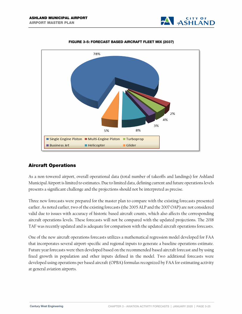
CHAPTER 3 - AVIATION ACTIVITY FORECASTS | JANUARY 2020 | PAGE 3-25
ASHLAND MUNICIPAL AIRPORT AIRPORT MASTER PLAN
Century West Engineering
FIGURE 3-5: FORECAST BASED AIRCRAFT FLEET MIX (2037)
Aircraft Operations
As a non-towered airport, overall operational data (total number of takeoffs and landings) for Ashland
Municipal Airport is limited to estimates. Due to limited data, defining current and future operations levels
presents a significant challenge and the projections should not be interpreted as precise.
Three new forecasts were prepared for the master plan to compare with the existing forecasts presented
earlier. As noted earlier, two of the existing forecasts (the 2005 ALP and the 2007 OAP) are not considered
valid due to issues with accuracy of historic based aircraft counts, which also affects the corresponding
aircraft operations levels. These forecasts will not be compared with the updated projections. The 2018
TAF was recently updated and is adequate for comparison with the updated aircraft operations forecasts.
One of the new aircraft operations forecasts utilizes a mathematical regression model developed for FAA
that incorporates several airport-specific and regional inputs to generate a baseline operations estimate.
Future year forecasts were then developed based on the recommended based aircraft forecast and by using
fixed growth in population and other inputs defined in the model. Two additional forecasts were
developed using operations per based aircraft (OPBA) formulas recognized by FAA for estimating activity
at general aviation airports.

CHAPTER 3 - AVIATION ACTIVITY FORECASTS | JANUARY 2020 | PAGE 3-26
ASHLAND MUNICIPAL AIRPORT AIRPORT MASTER PLAN
Century West Engineering
The preliminary aircraft operations forecasts included one projection that utilized historic activity ratios
captured through aircraft activity counts conducted at the airport over a 22-year period between 1983 and
2001. The FAA in its review, concluded that the on-airport counts were not relevant due to their age. The
projection also became obsolete with the changes to the based aircraft forecasts noted earlier. This forecast
has been discarded rather than updated based on the FAA opinion of relevancy.
The updated aircraft operations forecasts and the 2018 FAA TAF are summarized in Table 3-14 and
depicted on Figure 3-6.
2018 FORECAST – FAA REGRESSION MODEL FOR ESTIMATING AIRCRAFT OPERATIONS AT NON‐
TOWERED AIRPORTS
This forecast uses a statistical regression model approved by the FAA to estimate operations at non-
towered airports. The report, entitled Model for Estimating General Aviation Operations at Non-Towered
Airports Using Towered and Non-Towered Airport Data (GRA, Inc., 2001) presents the methodology and
formula for the model. Several independent variables are used in the model, including airport
characteristics, demographics, and geographic features. The model was created by using a combined data
set for small towered and non-towered general aviation airports with the addition of a dummy variable to
distinguish the two airport types. The following variables are included in the model:
Based Aircraft (at the subject airport);
Percent of aircraft based at the airport among general aviation airports within 100 miles;
Number of FAR Part 141 flight training schools at the airport;
Population within 100 miles; and
Ratio of population within 25 miles and 100 miles.
The model is designed to consider a variety of elements that directly and indirectly affect airport activity.
This forecast uses the current year analysis of the model to estimate annual aircraft operations. The
accompanying forecast of operations is developed from the based aircraft forecast and reflects several key
assumptions: 1 percent annual population growth; no changes in the number of FAR Part 141 flight schools
at the airport; and no change in the number of airports located in the 100 mile radius surrounding the airport.
The worksheet for the regression analysis is provided on the following page.
The regression model developed for Ashland Municipal Airport produced 17,400 aircraft operations for
2017. The associated forecast increases annual aircraft operations to 21,300 by 2037, which reflects an
average annual growth rate of 1.02 percent between 2017 and 2037.

CHAPTER 3 - AVIATION ACTIVITY FORECASTS | JANUARY 2020 | PAGE 3-27
ASHLAND MUNICIPAL AIRPORT AIRPORT MASTER PLAN
Century West Engineering
Ashland Municipal Airport – Aircraft Operations Estimate Prepared by Century West Engineering 7/5/18 GA Operations Regression Equation 15, Data for Non-Towered GA Airports8
775 241 0.14 2 31,478 % 100 5,777 0.001 100 3,736 12,12125100
Independent Variable Definitions
BA = Total based aircraft at an airport BA2 = Total based aircraft at an airport squared %in100mi = Percentage of based aircraft among based aircraft at GA airports within 100 miles VITFSnum = Number of FAR 141 pilot schools on airport Pop100 = Population within 100 miles WACAORAK = 1 if airport is in Washington, California, Oregon, or Alaska; otherwise, 0. Pop25/Pop100 = Ratio of population within 25 miles to population within 100 miles
Independent Variable Values
BA = 60 BA2 = 3,600 %in100mi = 60/854 = 0.070258 VITFSnum = 0 Pop100 = 578,128 WACAORAK = 1 Pop25/Pop100 = 170,895/578,128 = 0.295601
Total Estimated Annual Operations at Ashland (2017)
775 241 60 0.14 3,600 31,478 0.070258 5,777 0 0.001 578,128 3,736 1 12,121 0.295601 775 14,460 504 2,212 0 578 3,736 1 3,583
,
Future Year Estimates
Assumptions:
Based aircraft forecast o 2022 = 67 o 2027 = 70 o 2032 = 74 o 2037 = 77
%in100mi is constant throughout future year projections (0.086651) No future flight schools (VITFSnum = 0 for all years) Average population growth = 1.0% for Pop100 and Pop25 variables
Year Estimated Operations (Rounded)
2022 19,000
2027 19,700
2032 20,600
2037 21,300
8 Model for Estimating General Aviation Operations at Non-Towered Airports Using Towered and Non-Towered Airport Data, GRA, Inc., 2001.
Accessed December 20, 2017.
https://www.faa.gov/data_research/aviation_data_statistics/general_aviation/media/GAModel3F.doc

CHAPTER 3 - AVIATION ACTIVITY FORECASTS | JANUARY 2020 | PAGE 3-28
ASHLAND MUNICIPAL AIRPORT AIRPORT MASTER PLAN
Century West Engineering
2018 FORECAST – FAA NPIAS FORMULA
FAA Order 5090.3C. Field Formulation of the National Plan of Integrated Airport Systems, suggests a
forecast methodology for non-towered airports that relies on a general formula for estimating operations
by utilizing an activity ratio that is applied to current and forecast based aircraft. The Order 5090.3C
identifies a typical range of 250 to 450 operations per based aircraft (OPBA) for different types of general
aviation airports. The FAA recognizes that these ratios approximate activity, and that individual airports
may vary.
The projection (NPIAS 1) uses a fixed OPBA of 350, which is applied to the updated based aircraft forecast
presented earlier. The OPBA is within the FAA’s range for general aviation airports with moderate levels
of itinerant traffic. This assumption is consistent with Ashland Municipal Airport’s ability to attract
business aviation and general aviation activity within the region and the Airport’s functional role (Category III
- Regional General Aviation) defined in the current Oregon Aviation Plan (OAP).
The formula establishes base year (2017) activity at 21,000 annual operations (60 BAC x 350 OPBA) and
projects general aviation operations to increase to 26,974 by 2037, which reflects an average annual growth rate
of 1.26 percent.
Summary (Aircraft Operations Forecast)
The recommended forecast of aircraft operations for Ashland Municipal Airport is the FAA Regression
Model. This forecast projects average annual growth in aircraft operations of 1.03 percent.
The absence of reliable historic based aircraft counts at the airport makes the use of conventional
operations per based aircraft (OPBA) ratios to estimate annual operations unreliable. Both the current FAA
TAF and the OPBA-derived projections cannot be readily verified without an actual aircraft activity count.
However, it is noted that any level of activity within the range of forecasts presented in Table 3-14 will
have a nominal effect on defining future airport facility needs based on the recommended forecast.

CHAPTER 3 - AVIATION ACTIVITY FORECASTS | JANUARY 2020 | PAGE 3-29
ASHLAND MUNICIPAL AIRPORT AIRPORT MASTER PLAN
Century West Engineering
TABLE 3-14: UPDATED GA AIRCRAFT OPERATIONS FORECASTS
Projection 2017 2022 2027 2032 2037
2018 FAA Terminal Area Forecast (1.10% AAR 2016-2037)
26,357 27,887 29,431 31,050 32,757
NPIAS Formula (OPBA 350) (1.26% AAR 2017-2037)
21,000 23,559 24,550 25,805 26,974
FAA Non-Towered Equation2 (1.02% AAR 2017-2037)
17,400 19,000 19,700 20,600 21,300
Selected Forecast – FAA Non-Tower
Equation
(1.02% AAR 2017-2037)
17,400 19,000 19,700 20,600 21,300
1 FAA Field Formulation for NPIAS, 2 Model for Estimating General Aviation Operations at Non-Towered Airports (FAA 2001) AAR: Average Annual Rate (Growth)
FIGURE 3-6: GENERAL AVIATION OPERATIONS FORECAST

CHAPTER 3 - AVIATION ACTIVITY FORECASTS | JANUARY 2020 | PAGE 3-30
ASHLAND MUNICIPAL AIRPORT AIRPORT MASTER PLAN
Century West Engineering
Local and Itinerant Operations
General aviation (GA) operations consist of aircraft takeoffs and landings conducted by GA aircraft. All
aircraft operations are classified as local or itinerant. Local operations are conducted in the vicinity of an
airport and include flights that begin and end at the airport. These include aerial applicators, flight
training, touch and go operations, and other flights that do not involve a landing at another airport.
Itinerant operations include flights between airports, including cross-country flights. Itinerant operations
reflect specific travel between multiple points, often associated with business and personal travel.
The aircraft operations data presented in the current FAA TAF for Ashland Municipal Airport reflects a
17/839 percent split between local and itinerant aircraft operations. This operational distribution was
similar to the 15/85 percent split reflected in the 2005 Airport Layout Plan forecasts. It is recommended
that the TAF’s 17/83 percent - local/itinerant air traffic distribution be applied to forecast aircraft operations
during the current planning period. The local and itinerant distribution for each forecast year is
summarized in the forecast summary (Table 3-20), located at the end of the chapter.
Aircraft Operations Fleet Mix
Single engine piston aircraft (including light sport and experimental) currently account for nearly 90
percent of airport operations, followed by helicopters, multi-engine piston, single-engine and multi-engine
turboprops, and business jets. It is expected that the mix of air traffic at Ashland Municipal Airport will
shift slightly during the twenty-year planning period to include more turbine aircraft (turboprops, jets,
and helicopters) based on current trends in aircraft manufacturing and the composition of airport users.
The growing popularity of single-engine turboprops for personal and business use is also expected to affect
the operational fleet mix at Ashland Municipal Airport. Piston helicopter activity is also expected to
increase for both transportation and flight training purposes. The aircraft operations fleet mix forecast is
summarized in Table 3-15.
9 Airport Master Record - Itinerant operations include General Aviation and Air Taxi for 12 months ending 03/17/2015.

CHAPTER 3 - AVIATION ACTIVITY FORECASTS | JANUARY 2020 | PAGE 3-31
ASHLAND MUNICIPAL AIRPORT AIRPORT MASTER PLAN
Century West Engineering
TABLE 3-15: GA AIRCRAFT OPERATIONS FLEET MIX
Aircraft Type 2017 % 2022 % 2027 % 2032 % 2037 %
Single Engine Piston* 14,775 85 16,040 84 16,360 83 16,930 82 17,100 80
Multi Engine Piston 400 2 450 2 500 2 520 2 550 2
Turboprop 155 <1 220 1 320 <2 400 <2 460 2
Jet 70 <1 90 <1 120 <1 150 <1 190 <1
Helicopter 2,000 11 2,200 12 2,400 12 2,600 13 3,000 14
Total Operations 17,400 100 19,000 100 19,700 100 20,600 100 21,300 100
*Includes Sport and LSA Note: Percentages may not sum due to independent rounding
Critical Aircraft (FAA Planning Guidance)
As noted earlier, the selection of design standards for airfield facilities is based upon the characteristics of
the aircraft that are expected to use the airport. This aircraft or aircraft type is designated as the “critical
aircraft.” The FAA provides the following definitions:
“The critical aircraft is the most demanding aircraft type, or grouping of aircraft with similar characteristics, that make
regular use of the airport. Regular use is 500 annual operations, including both itinerant and local operations, but excluding
touch-and-go operations. An operation is either a takeoff or landing.” 10
The FAA group aircraft into five categories (A-E) based upon their approach speeds. Aircraft Approach
Categories A and B include small propeller aircraft, many small or medium business jet aircraft, and some
larger aircraft with approach speeds of less than 121 knots (nautical miles per hour). Categories C, D, and
E consist of the remaining business jets as well as larger jet and propeller aircraft generally associated with
commercial and military use with approach speeds of 121 knots or more. The FAA also establishes six
airplane design groups (I-VI), based on the wingspan and tail height of the aircraft. The categories range
from Airplane Design Group (ADG) I, for aircraft with wingspans of less than 49 feet, to ADG VI for the
largest commercial and military aircraft. A list of typical general aviation and business aviation aircraft and
their respective design categories is presented in Table 3-16.
10 FAA Advisory Circular (AC) 150/5000-17 Critical Aircraft and Regular Use Determination

CHAPTER 3 - AVIATION ACTIVITY FORECASTS | JANUARY 2020 | PAGE 3-32
ASHLAND MUNICIPAL AIRPORT AIRPORT MASTER PLAN
Century West Engineering
TABLE 3-16: GA AIRCRAFT & DESIGN CATEGORIES
Aircraft Aircraft Approach
Category Airplane Design
Group Maximum Gross
Takeoff Weight (lbs)
Cessna 182 (Skylane) A I 3,100
Cirrus Design SR22 A I 3,400
Beechcraft Bonanza A36 A I 3,650
Socata/Daher TBM 700-930 A I 6,579-7,394
Beechcraft Baron 58 B I 5,500
Cessna 340 B I 5,990
Cessna Citation Mustang B I 8,645
Embraer Phenom 100 B I 10,472
Cessna Citation CJ1+ B I 10,700
Beech King Air A100 B I 11,800
Beechcraft 400A/Premier I B I 16,100
Piper Malibu (PA-46) A II 4,340
Cessna Caravan 675 A II 8,000
Pilatus PC-12 A II 10,450
Cessna Citation CJ2+ B II 12,500
Cessna Citation II B II 13,300
Cessna Citation CJ3 B II 13,870
Beech King Air 350 B II 15,000
Cessna Citation CJ4 B II 16,950
Embraer Phenom 300 B II 17,968
Cessna Citation XLS+ B II 20,200
Dassault Falcon 20/200 B II 28,660
Bombardier Learjet 55 C I 21,500
Beechcraft Hawker 800XP C II 28,000
Gulfstream 150 C II 26,100
Cessna Citation X C II 36,100
Bombardier Challenger 300 C II 37,500
Gulfstream III C II 69,700
Learjet 35A/36A D I 18,300
Gulfstream G450 D II 73,900
Bombardier Global Express 5000 C III 92,750
Source: AC 150/5300-13, as amended; aircraft manufacturer data.
The combination of airplane design group and aircraft approach speed for the critical aircraft creates the
Airport Reference Code (ARC), which is used to define applicable airfield design standards. Figure 3-7
illustrates representative aircraft in various design groups based on ARC.

ASHLAND MUNICIPAL AIRPORTAIRPORT MASTER PLAN
AIRPORT REFERENCE CODES (ARC)FIGURE 3.7
A-I B-I A-II, B-II B-II A-III, B-III12,500 lbs. or less (small) 12,500 lbs. or less (small) 12,500 lbs. or less (small) Greater than 12,500 lbs. Greater than 12,500 lbs.
Beech Baron 55 Beech Baron 58 Super King Air 200 Super King Air 300, 350 DHC Dash 7, Dash 8Beech Bonanza Beech King Air 100 Pilatus PC-12 Beech 1900 Q-200, Q-300
Cessna 182 Cessna 402 DHC Twin Otter Cessna Citation Excel DC-3Piper Archer Cessna 421 Cessna Caravan Falcon 20, 50 Convair 580Piper Seneca Piper Navajo King Air C90 Falcon 200, 900 Fairchild F-27
Piper Cheyenne Citation II, Bravo XLS+ ATR 72Cessna Citation I Citation CJ3 ATP
C-I, D-I C-II, D-II C-III, D-III C-IV, D-IV D-VLear 25, 35, 55, 60 Gulfstream II, III, IV Boeing Business Jet B-757 B - 747 Series
Israeli Westwind Canadair 600 Gulfstream 650 B-767 B - 777HS 125-700 Canadair Regional Jet B 737-300 Series DC - 8-70
Lockheed JetStar MD-80, DC-9 DC - 10Citation X Q-400 MD - 11
Citation Sovereign A319, A320 L 1011Hawker 800 XP Gulfstream V
Global Express
BEND OFFICE1020 SW EMKAY DRIVE # 100BEND, OR 97702541.322.8962541.382.2423 (FAX)WWW.CENTURYWEST.COM
AIRPORT REFERENCE CODES (ARC)


CHAPTER 3 - AVIATION ACTIVITY FORECASTS | JANUARY 2020 | PAGE 3-35
ASHLAND MUNICIPAL AIRPORT AIRPORT MASTER PLAN
Century West Engineering
Current and Future Critical Aircraft
The identification of the existing and future critical aircraft for the airport is required to define the
appropriate design standards for various airport facilities. Table 3-17 summarizes the selected operations
forecast at Ashland Municipal Airport by aircraft type; aircraft approach speed (AAC), and airplane design
group (ADG).
TABLE 3-17: GA FORECAST ACTIVITY FLEET MIX (BY AAC + ADG)
Aircraft Type (Representative)
AAC + ADG
Historic Forecast
2017 2022 2027 2032 2037
Cessna 172 A-I 14,775 16,040 16,360 16,930 17,100
TBM 900 A-I 50 80 120 150 180
Beechcraft Baron 58 B-I 400 450 500 520 550
Piper Cheyenne II (PA-31T) B-I 45 60 80 90 100
Cessna Citation CJ1 B-I 20 30 50 70 100
Pilatus PC-12/Cessna Caravan A-II 60 80 120 160 180
Cessna 550 - Citation Bravo B-II 50 60 70 80 90
Bombardier Learjet 60 C-I 0 0 0 0 0
Gulfstream G150 C-II 0 0 0 0 0
Total Operations
(Fixed Wing) 15,400 16,800 17,300 18,000 18,300
Helicopter 2,000 2,200 2,400 2,600 3,000
TOTAL – GA OPERATIONS 17,400 19,000 19,700 20,600 21,300
Subtotals by AAC
(FW + Heli)
A 16,885 18,400 19,000 19,840 20,460
B 515 600 700 760 840
C 0 0 0 0 0
D 0 0 0 0 0
Subtotals by ADG
(FW only)
I 15,290 16,660 17,110 17,760 18,030
II 110 140 190 240 270
Source: Aircraft operations by segment estimated based on available information including: based aircraft fleet, transient aircraft activity, FAA TFMSC data, fuel data, and FBO interviews.
Ashland Municipal Airport accommodates a wide range of ADG I and II transient multi-engine piston and
turbine aircraft in addition to local aircraft activity. One multi-engine piston aircraft and one medium
business jet (Cessna Citation II/Bravo) are currently based at the airport.
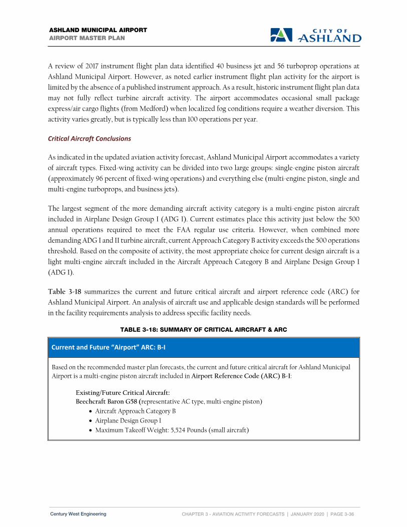
CHAPTER 3 - AVIATION ACTIVITY FORECASTS | JANUARY 2020 | PAGE 3-36
ASHLAND MUNICIPAL AIRPORT AIRPORT MASTER PLAN
Century West Engineering
A review of 2017 instrument flight plan data identified 40 business jet and 56 turboprop operations at
Ashland Municipal Airport. However, as noted earlier instrument flight plan activity for the airport is
limited by the absence of a published instrument approach. As a result, historic instrument flight plan data
may not fully reflect turbine aircraft activity. The airport accommodates occasional small package
express/air cargo flights (from Medford) when localized fog conditions require a weather diversion. This
activity varies greatly, but is typically less than 100 operations per year.
Critical Aircraft Conclusions
As indicated in the updated aviation activity forecast, Ashland Municipal Airport accommodates a variety
of aircraft types. Fixed-wing activity can be divided into two large groups: single-engine piston aircraft
(approximately 96 percent of fixed-wing operations) and everything else (multi-engine piston, single and
multi-engine turboprops, and business jets).
The largest segment of the more demanding aircraft activity category is a multi-engine piston aircraft
included in Airplane Design Group I (ADG I). Current estimates place this activity just below the 500
annual operations required to meet the FAA regular use criteria. However, when combined more
demanding ADG I and II turbine aircraft, current Approach Category B activity exceeds the 500 operations
threshold. Based on the composite of activity, the most appropriate choice for current design aircraft is a
light multi-engine aircraft included in the Aircraft Approach Category B and Airplane Design Group I
(ADG I).
Table 3-18 summarizes the current and future critical aircraft and airport reference code (ARC) for
Ashland Municipal Airport. An analysis of aircraft use and applicable design standards will be performed
in the facility requirements analysis to address specific facility needs.
TABLE 3-18: SUMMARY OF CRITICAL AIRCRAFT & ARC
Current and Future “Airport” ARC: B‐I
Based on the recommended master plan forecasts, the current and future critical aircraft for Ashland Municipal Airport is a multi-engine piston aircraft included in Airport Reference Code (ARC) B-I:
Existing/Future Critical Aircraft:
Beechcraft Baron G58 (representative AC type, multi-engine piston)
Aircraft Approach Category B
Airplane Design Group I
Maximum Takeoff Weight: 5,524 Pounds (small aircraft)

CHAPTER 3 - AVIATION ACTIVITY FORECASTS | JANUARY 2020 | PAGE 3-37
ASHLAND MUNICIPAL AIRPORT AIRPORT MASTER PLAN
Century West Engineering
Operational Peaks
Activity peaking is evaluated to identify potential capacity related issues that may need to be addressed
through facility improvements or operational changes.
The Peak Month represents the month of the year with the greatest number of aircraft operations (takeoffs
and landings). The peak month for most general aviation airports occurs during the summer when weather
conditions and daylight are optimal. The peak month at Ashland Municipal Airport is estimated to account
for approximately 11 percent of annual aircraft operations. This level of peaking is consistent with other
airports with similar levels of flight training and transient activity.
Peak Day operations are defined by the average day in the peak month (Design Day) and the busy day in
the typical week during peak month (busy day). The Design Day is calculated by dividing peak month
operations by 30. For planning purposes, the Busy Day is often estimated to be 25 percent higher than the
average day in the peak month (Design Day x 1.25), unless the airport routinely experiences significant
seasonal or daily surges in traffic.
The peak activity period in the Design Day is the Design Hour. For planning purposes, the Design Hour
operations are estimated to account for 20 percent of Design Day operations (Design Day x 0.20).
The operational peaks for each forecast year are summarized in Table 3-19. This level of peaking is
consistent with the mix of airport traffic and is expected to remain relatively unchanged during the
planning period. These measures of activity are considered when calculating runway/taxiway capacity and
transient aircraft parking requirements. No significant runway or taxiway capacity issues have been
identified based on current or forecast activity levels.
TABLE 3-19: PEAK GENERAL AVIATION OPERATIONS FORECAST
Activity 2017 2022 2027 2032 2037
Annual Operations (GA) 17,400 19,000 19,700 20,600 21,300
Peak Month Operations (11%) 1,914 2,090 2,167 2,266 2,343
Design Day Operations (average day in peak month) 64 70 72 76 78
Busy Day Operations (assumed 125% of design day)
80 87 90 94 98
Design Hour Operations (assumed 20% of design day)
13 14 15 15 16

CHAPTER 3 - AVIATION ACTIVITY FORECASTS | JANUARY 2020 | PAGE 3-38
ASHLAND MUNICIPAL AIRPORT AIRPORT MASTER PLAN
Century West Engineering
Military Activity
The FAA Terminal Area Forecast (TAF) lists no military flight activity at Ashland Municipal Airport.
However, occasional military use with helicopters or small fixed-wing aircraft in support of emergency
response, search and rescue, and training activities would be consistent with activity (Oregon Army
National Guard, etc.) experienced at other Oregon general aviation airports. Military flight activity at the
airport is limited by available airfield capabilities and is assumed at 100 annual operations during the
planning period.
Air Taxi Activity
Air taxi activity includes for-hire charter flights and some scheduled commercial air carriers operating
under FAR Part 135. Ashland Municipal Airport accommodates a limited number air cargo/express flight
diversions from Medford due to localized weather conditions. These aircraft are operated by a FedEx or
UPS contract carrier under FAR Part 135. Additional charter flight activity at Ashland Municipal Airport
would also be conducted under Part 135.
The FAA Terminal Area Forecast (TAF) estimates current air taxi activity at Ashland Municipal Airport
at 1,500 annual operations. A static 1,500 air taxi operations projection is maintained through the end of
the TAF forecast period (2045). For master planning purposes, this level of activity will be assumed in the
recommended aircraft operations forecast.
Forecast Summary
The summary of based aircraft and annual aircraft operations forecasts is provided in Table 3-20. The
forecast for based aircraft and aircraft operations projects modest sustained growth in activity at Ashland
Municipal Airport through the twenty-year planning period that is consistent with the FAA’s long-term
expectations for general aviation. Based aircraft are forecast to increase at an average annual rate of 1.26
percent between 2017 and 2037. Annual aircraft operations are forecast to increase at an average annual
rate of 1.03 percent during the same period.

CHAPTER 3 - AVIATION ACTIVITY FORECASTS | JANUARY 2020 | PAGE 3-39
ASHLAND MUNICIPAL AIRPORT AIRPORT MASTER PLAN
Century West Engineering
TABLE 3-20: FORECAST SUMMARY
Activity 2017 2022 2027 2032 2037
Itinerant Operations
General Aviation 12,925 14,253 14,834 15,581 16,162
Air Taxi/Commercial 1,500 1,500 1,500 1,500 1,500
Military 100 100 100 100 100
Total Itinerant Operations 14,525 15,853 16,434 17,181 17,762
Local Operations 2,975 3,247 3,366 3,519 3,638
Total Local & Itinerant Operations 17,500 19,100 19,800 20,700 21,400
Based Aircraft 60 67 70 74 77
Operations Per Based Aircraft (GA) 290 284 281 282 277
Fifty-Year Forecast
Fifty-year demand forecasts were prepared as required in the FAA-approved master plan scope of work by
extrapolating the average annual growth rates (AAGR) for the recommended 20-year based aircraft and
aircraft operations forecasts. The purpose of the 50-year projection is to provide an estimate of demand
that can be used to approximate long-term aviation use land requirements for the airport. Table 3-21
summarizes the 50-year forecast including the intermediate 30- and 40-year based aircraft and aircraft
operations
TABLE 3-21: 50-YEAR FORECAST
Activity 2017 2037 2047 2057 2067
Annual Operations 17,500 21,400 23,709 26,268 29,102
Based Aircraft 60 77 85 93 102

U.S. Departmentof TransportationFederal AviationAdministration
Northwest Mountain RegionSeattle Airports District Office1601 Lind Avenue S.W., Suite 250Renton, Washington 98057-3356
August 31, 2018
Mr. Scott FleuryEngineering Service ManagerCity of Ashland 20 E Main StreetAshland, OR 97520
Dear Mr. Fleury:
Forecast Approval Ashland Municipal Airport – Sumner Parker Field, Ashland, OR
AIP- 3-41-0002-011-2017
I have reviewed the Forecasts of the Master Plan Update submitted by Century West for Ashland Municipal Airport – Sumner Parker Field. The forecasts of based aircraft and aircraft operations, respectively, are hereby approved and accepted for Federal Aviation Administration (FAA) purposes.
If you have any questions about this forecast approval, please call me at (206) 231-4139.
Sincerely,
Valerie ThorsenAirport Planner, Oregon
cc:David Miller, Century West
Valerie Renee Thorsen
Digitally signed by Valerie Renee Thorsen Date: 2018.08.31 11:14:29 -07'00'

Chapter 4
Airport Facility Requirements


CHAPTER 4 – FACILITY REQUIREMENTS | JANUARY 2020 | PAGE 4-1
ASHLAND MUNICIPAL AIRPORT AIRPORT MASTER PLAN
Century West Engineering
Chapter 4 – Airport Facility Requirements
The evaluation of airport facility requirements is intended to determine the facility needs for Ashland Municipal Airport (S03) for the
current twenty-year planning period based on updated aviation activity forecasts and conformance to established airport design criteria.
Introduction
The evaluation of airport facility requirements combines the results of the inventory and forecasts
contained in Chapters Two and Three, and established planning criteria to determine the future facility
needs for the Airport during the current twenty-year planning period. Airside facilities include the
airspace around the Airport, runways, taxiways, navigational aids and lighting systems. Landside facilities
include hangars, terminal, and fixed base operator (FBO) facilities, aircraft parking apron(s), and surface
access and automobile parking. Support Facilities such as aircraft fueling, security/perimeter fencing, and
utilities are also examined. All airfield items are evaluated based on established FAA standards and
community derived goals for the Airport.
The facility requirements evaluation identifies the adequacy or inadequacy of existing facilities and
identifies what new facilities may be needed during the planning period based on forecast demand or
conformance to FAA standards. The evaluation of demand-driven elements will reflect in gross numbers,
new facility needs such as runway length requirements, hangar space, and aircraft parking positions based
on forecast demand and the needs of the type of aircraft being accommodated. Items such as lighting,
navigational aids, and approach capabilities are evaluated based on overall airport activity and facility
classification. Potential options for accommodating current and future facility needs will be evaluated in
the Airport Development Alternatives (Chapter Five).

CHAPTER 4 – FACILITY REQUIREMENTS | JANUARY 2020 | PAGE 4-2
ASHLAND MUNICIPAL AIRPORT AIRPORT MASTER PLAN
Century West Engineering
Critical Aircraft and Airport Design Standards Discussion
Based on the current and projected level of activity described in
Chapter Three, Aviation Activity Forecasts, the existing and future
critical aircraft is determined. The critical aircraft establishes existing
and future airport planning & design standards that will guide future
planning, design, and development of the Airport.
CRITICAL AIRCRAFT AND AIRPORT REFERENCE CODE
The recommended existing and future critical aircraft is the
Raytheon/Beechcraft Baron 58 (Be58). The design aircraft is intended
to represent the most demanding aircraft using the airport on a regular
basis and establishes the Airport Reference Code (ARC) of B-I (small),
which is an airport designation that signifies the airport’s highest
Runway Design Code (RDC), minus the third (visibility) component
of the RDC. For more information see FAA Advisory Circular 150/5000-
17 Critical Aircraft and Regular Use Determination and applicable
airport planning & design standards summarized in greater detail
below.
RUNWAY DESIGN CODE (RDC)
The Runway Design Code (RDC) is comprised of the selected Aircraft
Approach Category (AAC), the Airplane Design Group (ADG), and the
approach visibility minimums of a specific runway end. For airports
with more than one runway, each runway will have its own RDC. The RDC provides the information
needed to determine specific runway design standards. The approach visibility minimums refer to the
visibility minimums expressed by runway visual range (RVR) values in feet. The existing and planned
RDC for Runway 12/30 is B-I-VIS. For more detailed information on determining RDC see FAA Advisory
Circular 150/5300-13A Airport Design.
APPROACH AND DEPARTURE REFERENCE CODE
The Approach and Departure Reference Codes (APRC and DPRC respectively) represent the current
operational capabilities of each specific runway end and adjacent taxiways. The approach reference code
uses the physical characteristics of the design aircraft (approach speed and wingspan/tail height) and the
approach visibility minimums (expressed in RVR values) and runway to taxiway separation on the airfield
to define specific standards. The existing and planned APRC for Runway 12/30 is B-I(S)-VIS.
The departure reference code uses only the physical characteristics of the design aircraft and runway to
taxiway separation. The existing and planned DPRC for Runway 12/30 is B-I(S). For more detailed
information on determining APRC and DPRC see FAA Advisory Circular 150/5300-13A Airport Design.
BEECHCRAFT BARON 58 (BE58)
3 VIEW DRAWING

CHAPTER 4 – FACILITY REQUIREMENTS | JANUARY 2020 | PAGE 4-3
ASHLAND MUNICIPAL AIRPORT AIRPORT MASTER PLAN
Century West Engineering
TAXIWAY DESIGN GROUP
Taxiway Design Group (TDG) is based on the dimensions of the aircraft landing gear including distance
from the cockpit to the main gear (CMG) and main gear width (MGW). These dimensions affect an
aircraft’s ability to safely maneuver around the airport taxiways and dictate pavement fillet design.
Taxiways and taxilanes can be constructed to different TDGs based on the expected use of that
taxiway/taxilane by the design aircraft. The major taxiways at the Airport accommodate primarily
ADG I aircraft, which is best represented by TDG 1.

CHAPTER 4 – FACILITY REQUIREMENTS | JANUARY 2020 | PAGE 4-4
ASHLAND MUNICIPAL AIRPORT AIRPORT MASTER PLAN
Century West Engineering
FAA DESIGN STANDARDS
FAA Advisory Circular 150/5300-13A Airport Design
serves as the primary reference in establishing the
geometry of airfield facilities. A comparison of existing
condition dimensions and future design standards for the
runway is summarized in Table 4-1.
TABLE 4‐1: RUNWAY 12/30 AIRPORT DESIGN STANDARDS SUMMARY (DIMENSIONS IN FEET)
FAA STANDARD RUNWAY 12/30
EXISTING CONDITIONS
RUNWAY 12/30 ARC A/B‐I (SMALL) NOT LOWER THAN 1‐MILE OR VISUAL EXISTING/FUTURE
STANDARD
RUNWAY 12/30 ARC A/B‐I (SMALL) NOT LOWER THAN
3/4‐MILE COMPARISON STANDARD1
Runway Length 3,603 See Runway Length Analysis Discussion (Page 15)
Runway Width 75 60 60
Runway Shoulder Width6 10 10 10
Runway Safety Area Width Beyond RWY End Prior to Landing Threshold
120 240 240
120 240 240
120 240 240
Runway Obstacle Free Zone Width Beyond RWY End Prior to Landing Threshold
250 200 200
250 200 200
250 200 200
Object Free Area Width Beyond RWY End Prior to Landing Threshold
250 240 240
250 240 240
250 240 240
Runway Protection Zone Length
RWY 12: 1,000 RWY 30: 1,000
RWY 12: 1,000 RWY 30: 1,000
RWY 12: 1,700 RWY 30: 1,700
Runway Protection Zone Inner Width
RWY 12: 250 RWY 30: 250
RWY 12: 250 RWY 30: 250
RWY 12: 1000 RWY 30: 1000
Runway Protection Zone Outer Width
RWY 12: 450 RWY 30: 450
RWY 12: 450 RWY 30: 450
RWY 12: 1,500 RWY 30: 1,500
Runway Centerline to: Parallel Taxiway/Taxilane CL Aircraft Parking Area 32’ Building Restriction Line (BRL)
163/1512
2003
3504
150 125
350
150 125
4745
Notes:
1. Not lower than ¾ mile B-I (small) standards depicted for the purpose of comparison. 2. Runway centerline to parallel Taxiway A centerline separation varies. 3. Distance between Runway 12/30 centerline and closest apron tiedowns. 4. A 350-foot BRL for 32-foot structures was depicted on the 2005 ALP. 5. A 474-foot BRL for 32-foot structures is required due to wider primary surface. 6. Turf, aggregate-turf, soil cement, lime or bituminous stabilized soil as measured outwards from the runway edge are recommended adjacent to ADG I runways.
FAA DESIGN STANDARDS
Specific design standards and conditions applicable to Ashland Municipal Airport facilities are presented in the following sections of this chapter within the sidebar “FAA Design Standards” text box. For additional information reference appropriate sections within AC 150/5300‐13A.

CHAPTER 4 – FACILITY REQUIREMENTS | JANUARY 2020 | PAGE 4-5
ASHLAND MUNICIPAL AIRPORT AIRPORT MASTER PLAN
Century West Engineering
Demand/Capacity Analysis
Annual service volume (ASV) is a measure of estimated airport capacity and delay used for long-term
planning. ASV, as defined in FAA Advisory Circular (AC) 150/5060-5, Airport Capacity and Delay,
provides a reasonable estimate of an airport’s operational capacity.
For long-term planning purposes, the FAA estimates ASV capacity for a single runway with no air carrier
traffic is approximately 230,000 operations; hourly capacity is estimated to be 98 operations during visual
flight rules (VFR) conditions and 59 operations during instrument flight rules (IFR) conditions. Although
these estimates assume optimal conditions (air traffic control, radar, etc.), they provide a reasonable basis
for approximating existing and future capacity:
Existing Capacity: 23,964 Annual Operations / 230,000 ASV = 10% (demand/capacity ratio)
Future Capacity: 28,869 Annual Operations / 230,000 ASV = 12% (demand/capacity ratio)
Based on these ratios, the average delay per aircraft would be expected to remain below one minute
through the planning period and no capacity enhancements are anticipated during the planning
period.
Airport Facilities Analysis
Based on the updated inventory of facilities presented in Chapter Two, existing airfield facilities were
evaluated for their conformance with applicable FAA standards. Additionally, any other Airport facility
issues and/or opportunities that may have been identified or need to be addressed during the planning
process are also depicted and discussed further within the Facility Requirements chapter.
Figure 4-1 depicts the airside facilities analysis.
Figure 4-2 depicts the landside facilities analysis.

This page intentionally left blank

ASHLAND MUNICIPAL AIRPORTAIRPORT MASTER PLAN
AIRSIDE FACILITY REQUIREMENTS ANALYSISFIGURE 4-1
0 200 400
SCALE OF FEETSCALE: 1"=200'
AIRPORT FACILITY ANALYAIS (FIG 4-1)ashland municipal airport
1
2
3
4
CONFORMANCE ITEMS
RWY 12 RPZ; PROPERTY CONTROL
RWY 30 RPZ; ROAD
PROPERTY BOUNDARY
LEGEND
OFA/OFZ(E)
RUNWAY 12EL. 1845.1'
RUNWAY PROTECTION ZONE250' X 450' X 1000'> 1-MILE APPROACH VISIBILITYMINIMUMS B-I (SMALL)
DEAD INDIAN MEMORIAL RD
DEAD INDIAN MEMORIAL RD
E MAIN STE MAIN ST
MAJESTIC LN
MAJESTIC LN
EMIG
RANT C
REEK
EMIG
RANT C
REEK
NEIL CREEKNEIL CREEK
PARALLEL TAXIWAYPARALLEL TAXIWAY
RSA(E)
OFA/OFZ(E)
RSA(E)
OFA/OFZ(E)
RSA(E)
OFA/OFZ(E)
RSA(E)
RUNWAY 30EL. 1884.8'
190' DISP.THRESHOLDEL. 1883.0'
RUNWAY 12/30RUNWAY 12/30 3,603' X 75'3,603' X 75'250'
120'
DEPARTURE RWY PROTECTION ZONE250' X 450' X 1000'> 1-MILE APPROACH VISIBILITYMINIMUMS B-I (SMALL)
1
RWY 30 RPZ; PROPERTY CONTROL/BUILDINGS
2
4
RWY 12 RPZ; DRIVEWAY
3
163'
ARRIVAL RWY PROTECTION ZONE250' X 450' X 1000'> 1-MILE APPROACH VISIBILITYMINIMUMS B-I (SMALL)
5
6
DISPLACED THRESHOLD
5
DIRECT ENTRY
NO PERIMETER FENCING
NON-AVIATIONDEVELOPMENTNON-AVIATIONDEVELOPMENT
AVIATIONDEVELOPMENTAVIATIONDEVELOPMENT
NON-AVIATIONDEVELOPMENTNON-AVIATIONDEVELOPMENT
7
7
7 ROFA ROFZ; TREE/BRUSH INTRUSIONS
8 NON STANDARD RUNWAY WIDTH / EXCEEDS STANDARDS
8
6.7 AC.
2 AC.
3.4 AC.
1.8 AC.
0.9 AC.
XX
XX
X
X
X
XX
XX
X
X
X
XX6
XX
X
X
EXISTING FENCINGXX


ASHLAND MUNICIPAL AIRPORTAIRPORT MASTER PLAN
LANDSIDE FACILITY REQUIREMENTS ANALYSISFIGURE 4-2
X
0 60 120
SCALE OF FEETSCALE: 1"=60'
AIRPORT FACILITY ANALYSIS (FIG 4-2)ashland municipal airport
RUNWAY 12/30RUNWAY 12/30 3,603' X 75'3,603' X 75'
DEAD INDIAN MEMORIAL RD
DEAD INDIAN MEMORIAL RD
PARALLEL TAXIWAYPARALLEL TAXIWAY
1
2
3
4
5
CONFORMANCE ITEMSPROPERTY BOUNDARY
LEGEND
TAXIWAY / TAXILANE OBJECT FREEAREA (TOFA)
ADG-I TAXILANE OFA; TREES/BRUSH
ADG-I TAXILANE WIDTH; >25'
79'
79'
79'
79'
79'
79'
79'
79'
79'
60'
89' 89'
79'79' 79' 79' 79' 79' 79' 79'
55'
79'
151'
1
1
ADG-I TAXILANE OFA; SMALL AIRPLANE TIEDOWNS
2 22
ADG-I TAXIWAY OFA; FUEL CLEAR AREA
3
ADG-I TAXILANE OFA; PARKED VEHICLES
4
ADG-I TAXILANE OFA; HANGAR SEPARATION
5
5
20'
20'
25'
6
7
7
20'
7
89'
OFA/OFZ(E)
RSA(E)
OFA/OFZ(E)
RSA(E)
79'55'
52'
HANGAR WITHIN TOFA
DIRECT ENTRY
7
6 6 6
AVIATIONDEVELOPMENT
AVIATIONDEVELOPMENT
46'(TYP)
40'26' 23'
APRON FOCUS AREA
POTENTIAL REDESIGN BOUNDARY
TAXIWAY / TAXILANE
AIRCRAFT PARKING AREA
AIRCRAFT PARKING / TAXIWAYBUFFER
AIRCRAFT TIEDOWN / TAXIWAYCENTERLINE
79' 79'
41'20'
79'
41'45'
NON-AVIATIONDEVELOPMENTNON-AVIATIONDEVELOPMENT
AVIATIONDEVELOPMENT
AVIATIONDEVELOPMENT
XX
XX
XX
XX
XX
XX
XX
XX
X
X
X
X
X
X
X
X
XXXXXXX
XX
XX
XX
XX
XX
XX
X
X
X
X
X
X
X
X
XXX
EXISTING FENCINGXX


CHAPTER 4 – FACILITY REQUIREMENTS | JANUARY 2020 | PAGE 4-11
ASHLAND MUNICIPAL AIRPORT AIRPORT MASTER PLAN
Century West Engineering
Airfield Pavement Strength and Condition
Airfield pavements are considered to be the single most important asset on the Airport. Monitoring and
planning for future improvements to the strength and condition of airfield pavements is critical to
satisfying existing and future aeronautical demand.
AIRFIELD PAVEMENT STRENGTH
The published runway pavement strength rating is 15,000 pounds for aircraft equipped with single-wheel
landing gear, which is sufficient to accommodate all A/B-I (small) aircraft. Ideally, taxiway and apron
pavements designed to accommodate all aircraft operating at an airport should have the same weight
bearing strength as the runway. However, pavements used by small aircraft (Hangar taxilanes, tiedown,
aprons, and runways) are normally designed to accommodate aircraft weighing 12,500 pounds or less with
single-wheel landing gear configurations. It is recommended that pavement strength ratings of 12,500
lbs be maintained during the planning period.
AIRFIELD PAVEMENT CONDITION
An updated Pavement Evaluation/Maintenance Management Program inspection, performed by Oregon
Department of Aviation, was conducted in 2016. A graphical depiction of pavement condition in 2016 along
with predicted conditions for 2021 and 2026 (assuming no future pavement maintenance) is presented
within 4-3 on the following page. A summary of pavement conditions on the Airfield provided in the 2016
pavement condition report states:
“Section PCIs (Pavement Condition Index) at Ashland Municipal Airport range from a low of 14 (a PCR (Pavement
Condition Rating) of “Serious”) to a high of 100 (a PCR of “Good”). The area-weighted average PCI for all airport
pavements is 77, corresponding to an overall PCR of “Satisfactory”.
The primary distresses observed during the inspection were: longitudinal and transverse cracking, patching,
weathering, alligator cracking, depressions, block cracking and raveling.”

CHAPTER 4 – FACILITY REQUIREMENTS | JANUARY 2020 | PAGE 4-12
ASHLAND MUNICIPAL AIRPORT AIRPORT MASTER PLAN
Century West Engineering
FIGURE 4‐3: PAVEMENT CONDITION
It is expected that apron, taxiway, and taxilane pavements on the airfield will require rehabilitation or
reconstruction during the current planning period. A prioritized list of pavement rehabilitation or
reconstruction projects will be provided in the updated capital improvement program. It is recommended
that ongoing maintenance, including vegetation removal, crack filling, and sealcoats be conducted
on a regular basis and consistent with ODA PMP to maximize the longevity of asphalt airfield
pavements through the planning period.

CHAPTER 4 – FACILITY REQUIREMENTS | JANUARY 2020 | PAGE 4-13
ASHLAND MUNICIPAL AIRPORT AIRPORT MASTER PLAN
Century West Engineering
Airside Facilities Requirements
Airside facilities include the airspace around the Airport, runways, taxiways/taxilanes, apron/aircraft
parking areas, navigational aids, signage, and lighting systems.
FAR PART 77 AIRSPACE AND OFF‐AIRPORT LAND USE COMPATIBILITY
U.S. airport airspace is defined by Federal Aviation Regulations (FAR) Part 77.25 – Objects Affecting
Navigable Airspace. FAR Part 77 defines airport imaginary surfaces that are established to protect the
airspace immediately surrounding a runway. The airspace surfaces and ground areas surrounding a runway
should be free of obstructions (i.e., structures, parked aircraft, trees, etc.) to the maximum extent possible
to provide a safe aircraft operating environment.

CHAPTER 4 – FACILITY REQUIREMENTS | JANUARY 2020 | PAGE 4-14
ASHLAND MUNICIPAL AIRPORT AIRPORT MASTER PLAN
Century West Engineering
Approach Surface
The Approach Surface extends outward and upward from each end of the primary surface, along the
extended runway centerline. The dimensions and slope of the approach surfaces are determined by the
type of aircraft intended to use the runway and the most demanding approach planned for the runway.
In the late 1960s avigation easements for the inner portion of the 20:1 Visual Approach Surface beginning
200 feet from the runway end to the outer extents of the RPZ on both runway ends were acquired to ensure
obstructions were not allowed to penetrate the approach surface within the defined area. In April 2018 the
City of Ashland trimmed numerous trees that were identified as obstruction within the avigation easement
area contained within the Runway 30 20:1 Approach Surface.
Utilizing the 2018 AGIS obstruction data and additional information from the April 2018 City of
Ashland obstruction clearing project, it is recommended the obstacle disposition tables developed in
coordination with the ALP drawing set be utilized for future obstacle removal projects to be
identified in the Capital Improvement Plan (CIP) (Chapter 8).
Primary Surface
The Primary Surface is a rectangular plane longitudinally centered on the runway (at centerline elevation)
extending 200 feet beyond each runway end. The width of the primary surface depends on runway
category, approach capability, and approach visibility minimums. The primary surface should be free of
any penetrations, except items with locations fixed-by-function (i.e., PAPI, runway or taxiway edge lights,
etc.). The outer ends of the primary surface connect to the inner portion of the runway approach surfaces.
Three primary surface penetrations were identified in 2018 AGIS data that include NAVAIDs,
terrain, and a tree. Utilizing the 2018 AGIS obstruction data, it is recommended the obstacle
disposition tables developed in coordination with the ALP drawing set be utilized for future obstacle
removal projects as required.
Transitional Surface
The Transitional Surface is located along the lateral edges of the primary surface and is represented by a
plane rising perpendicularly to the runway centerline at a slope of 7 to 1. The transitional surface extends
outward and upward to an elevation 150 feet above the airport elevation. The outer edges of the transitional
surface connect with the horizontal surface. The transitional surface should be free of obstructions (i.e.,
parked aircraft, structures, trees, terrain, etc.).
12 transitional surface penetrations were identified in 2018 AGIS data that includes NAVAIDs,
antennas, buildings, fences, terrain, tanks, poles, bushes, and trees. Utilizing the 2018 AGIS
obstruction data, it is recommended the obstacle disposition tables developed in coordination with
the ALP drawing set be utilized for future obstacle removal projects as required.

CHAPTER 4 – FACILITY REQUIREMENTS | JANUARY 2020 | PAGE 4-15
ASHLAND MUNICIPAL AIRPORT AIRPORT MASTER PLAN
Century West Engineering
Horizontal Surface
The Horizontal Surface is a flat plane located 150 feet above the airport elevation. The horizontal surface
boundaries are defined by the radii (10,000 feet for larger than utility instrument runways and 5,000 feet
for utility runways) constructed from each runway end. The outer edges of the radii for each runway are
connected with tangent lines, which taken together define the horizontal surface.
Numerous horizontal surface obstructions were identified in the 2018 AGIS data due to topography
within the Rogue Valley. Obstructions generally include terrain, trees, and other man-made
obstacles. Utilizing the 2018 AGIS obstruction data, it is recommended the obstacle disposition
tables developed in coordination with the ALP drawing set be utilized for future obstacle removal
projects as required.
Conical Surface
The Conical Surface is an outer band of airspace that encircles the horizontal surface. The conical surface
begins at the outer edge of the horizontal surface and extends outward 4,000 feet and upward at a slope of
20:1.
Numerous conical surface obstructions were identified in the 2018 AGIS data due to topography
within the Rogue Valley. Obstructions generally include terrain, trees, and other man-made
obstacles. Utilizing the 2018 AGIS obstruction data, it is recommended the obstacle disposition
tables developed in coordination with the ALP drawing set be utilized for future obstacle removal
projects as required.
Off‐Airport Land Use
The City of Ashland has land use jurisdiction for the airport; however, some of the runway protection areas
and the Part 77 surfaces extend beyond city limits and the Ashland urban growth boundary into
unincorporated Jackson County. Both the City of Ashland and Jackson County have created Airport
Overlay Zoning to protect Ashland Municipal Airport and address any off-airport land use compatibility
issues that may potentially exist. Figure 4-4 on the following page illustrates local land use jurisdictions
with responsibilities to protect the FAR Part 77 airspace associated with the existing Runway 12/30 at
Ashland Municipal Airport. Additionally, in the late 1960s avigation easements for both runway ends were
acquired by the City to address off Airport obstructions.
It is recommended the City of Ashland, in coordination with Jackson County, continue to work to
develop a mitigation plan to remove FAR Part 77 surface obstructions and continue to ensure land
use compatibility. Additionally, upon selection of a preferred alternative it is recommended the City
and County update the Airport Overlay Zoning as required to address any potential shifts due to
relocation of runway ends or other upgrades that may require an update of the Part 77 surfaces.

CHAPTER 4 – FACILITY REQUIREMENTS | JANUARY 2020 | PAGE 4-16
ASHLAND MUNICIPAL AIRPORT AIRPORT MASTER PLAN
Century West Engineering
FIGURE 4‐4: LAND USE JURISDICTION

CHAPTER 4 – FACILITY REQUIREMENTS | JANUARY 2020 | PAGE 4-17
ASHLAND MUNICIPAL AIRPORT AIRPORT MASTER PLAN
Century West Engineering
RUNWAY 12/30
The Runway 12/30 facility requirements were analyzed relative to runway orientation, runway length and
width, and FAA design standards.
Runway Orientation and Crosswind Coverage
The preferred orientation of runways is a function of wind velocity and direction, combined with the
ability of aircraft to operate under given conditions. FAA has defined the maximum allowable crosswind
for small aircraft as 10.5 knots and 13 knots for larger general aviation aircraft.
The FAA recommends that primary runways accommodate at least 95 percent of local crosswind
conditions. When this level of coverage is not provided, the FAA recommends consideration of a crosswind
runway. An updated evaluation of wind data (All Weather, VFR, and IFR) utilizing closest available wind
data from the Medford Airport was conducted and indicates that Runway 12/30 accommodates greater
than 95 percent of all weather wind conditions for both small and larger general aviation aircraft. The
current tabulated wind data from Medford is summarized below in Table 4-2.
TABLE 4‐2: WIND ANALYSIS
Runway 12/30
All Weather
10.5 KNOTS 99.42%
13 KNOTS 99.74%
VFR
10.5 KNOTS 99.35%
13 KNOTS 99.71%
IFR
10.5 KNOTS 99.92%
13 KNOTS 99.95% Runway 12/30 Bearing = 141.0 Degrees True Wind Data Source: National Climate Data Center (2007-2016 KMFR ASOS data)

CHAPTER 4 – FACILITY REQUIREMENTS | JANUARY 2020 | PAGE 4-18
ASHLAND MUNICIPAL AIRPORT AIRPORT MASTER PLAN
Century West Engineering
Runway Length
Runway length requirements are based primarily on airport elevation, mean maximum temperature of the hottest month, runway gradient, and the critical aircraft type expected to use the runway.
For general aviation airports the FAA recommends using a “family of design aircraft” approach to defining runway length requirements. FAA Advisory Circular (AC) 150/5325-4B, Runway Length Requirements for Airport Design provides the length analysis requirements for “small airplanes with fewer than 10 seats” that make up “95 percent of the fleet” for airports that are intended to serve medium size population communities with a diversity of usage and a greater potential for increased aviation activities.
Based on local conditions, this segment of activity requires a runway length of 3,700 at the Ashland Municipal Airport. The City of Ashland has committed to not extending the runway beyond its existing length. The City would prefer to maintain the existing
runway length of 3,603’ or meet FAA recommended length to
accommodate existing aircraft without encouraging new larger
aircraft to come to the Airport.
FIGURE 4‐5: SMALL AIRPLANES WITH FEWER THAN 10 PASSENGER SEATS
FAA DESIGN STANDARDS
Runway Safety Area (RSA) Standards: ADG I standard is 120’ wide or 60’ each side of runway centerline and 240’ beyond runway ends. Additional gradient standards apply.
Condition: The RSA for Runway 12/30 appears to meet FAA dimensional, object clearing, and grading standards.
Runway Object Free Area (OFA) Standards: ADG I standard is 250’ wide or 125’ each side of runway centerline and 240’ beyond runway ends. Additional gradient standards apply.
Condition: The OFA for Runway 30 end appears to meet FAA dimensional, object clearing, and grading standards. The OFA for Runway 12 end does not meet standards due to trees, creeks, and a private drive within a small corner of the OFA.
Runway Obstacle Free Zone (OFZ) Standards: ADG I standard is 250’ wide or 125’ each side of runway centerline and 200’ beyond runway ends.
Condition: The OFZ for Runway 12/30 appears to meet FAA dimensional and obstacle clearing standards.

CHAPTER 4 – FACILITY REQUIREMENTS | JANUARY 2020 | PAGE 4-19
ASHLAND MUNICIPAL AIRPORT AIRPORT MASTER PLAN
Century West Engineering
Displaced Threshold
The Ashland Municipal Airport currently has a
190’ displaced threshold on the Runway 30 end
to provide additional clearance for landing
aircraft over existing obstacles located off of
Airport property. While the FAA provides
guidance to establish displaced thresholds, it
should not be interpreted as an endorsement by
the FAA – Seattle ADO of the option to displace
or maintain a displaced runway threshold.
Therefore, for the displaced threshold to remain,
as part of this master plan the FAA will require
an evaluation that reveals displacement is still
the best alternative. It is recommended an
alternatives evaluation that addresses the existing displaced threshold and FAA policy to maximize
utilization and retention of existing paved areas on the Airport be conducted in the following
development alternatives analysis chapter to determine a preferred solution.
Runway Protection Zones (RPZ)
In October 2012, the FAA released interim guidance
regarding RPZs and incompatible land uses, with a
particular focus on roads. This guidance directs airport
sponsors to evaluate any planned changes to existing RPZs
that introduce or increase the presence of roads in RPZs.
Existing roads within RPZs are also to be evaluated during
master planning to determine if feasible alternatives exist
for realignment of a road outside RPZs or for changes to
the RPZs themselves. The FAA Seattle Airports District
Office has subsequently indicated that the primary focus of
this policy is related to proposed changes to RPZs—as the
result of a change to a runway end/RPZ location, approach
visibility minimums, or the built items located in an RPZ. Any proposed changes in the length or
configuration of the runway/runway displaced threshold that changes the location of existing RPZs
evaluated in this study are subject to review by FAA headquarters in Washington D.C. It is recommended
existing RPZ conditions and potential alternatives for each runway end be considered in
coordination with the displaced threshold alternatives analysis.
FAA DESIGN STANDARDS
Runway Protection Zone (RPZ) Standards: ADG I/Visual RPZs comprise 8.035 acres. RPZs should be owned by the Airport or under control by easement and should be clear of incompatible land uses such as roads and buildings.
Condition: Both Runway 12 and 30 RPZs extend beyond Airport property and have roads, buildings, and/or private drives within their boundaries. No easements for incompatible land uses currently exists.
See Figure 4‐1 for legend and full runway length.

CHAPTER 4 – FACILITY REQUIREMENTS | JANUARY 2020 | PAGE 4-20
ASHLAND MUNICIPAL AIRPORT AIRPORT MASTER PLAN
Century West Engineering
Runway Width/Shoulders
Runway 12/30 is 75 feet wide, which exceeds the
dimensional standard for ARC A/B-I (small) with current
approach visibility minimums (Visual). Existing 10 foot
turf shoulders meet standards.
As part of a future runway reconstruction project,
anticipated to be completed in 15 to 20 years, a
cost/benefit analysis will need to be completed to justify
maintaining the existing nonstandard pavement width at
nonstandard 75 feet. If it is determined that the excess
width is not justified, the runway width will need to be
reduced to FAA standards or the reconstruction of the excess 15’ feet of pavement, which will not be
eligible for FAA funding, could be funded entirely by the City of Ashland. Narrowing the runway to 60 feet
would require relocation of edge lighting, signage, grading, shoulders, taxiway connectors, and drainage
systems. It is recommended that the existing runway width of 75’ be maintained throughout the
useful life of the pavement. The future runway width must be depicted at 60 feet on the ALP to
comply with FAA standards.
Runway Object Free Area (OFA)
As mentioned in the design standards discussion sidebar on Page 15, the Runway 12 end OFA is not clear
of above ground objects. There are currently trees and bushes associated with the riparian area of Neil
Creek and Emgrant Creek that may need to be removed. Additionally, the private drive outside of Airport
property overlaps with the OFA by only several feet. It is recommended existing OFA conditions and
potential alternatives for each runway end be considered in coordination with the displaced
threshold, RPZ, and runway end alternatives analysis.
FAA DESIGN STANDARDS
Runway Width/Shoulders Standards: ADG I standard runway width for runways with visual or not lower than 1 mile visibility is 60’ with 10’ shoulders.
Condition: Existing Runway 12/30 width is 75’ which exceeds standards by 15’. The excess 15’ of runway would not be eligible for future FAA funding for runway reconstruction. 10’ turf shoulders exist and meet standards.

CHAPTER 4 – FACILITY REQUIREMENTS | JANUARY 2020 | PAGE 4-21
ASHLAND MUNICIPAL AIRPORT AIRPORT MASTER PLAN
Century West Engineering
TAXIWAY/TAXILANE NETWORK
The taxiway/taxilane facility requirements were
analyzed relative to existing hangar siting, apron and
aircraft parking requirements, runway access, and FAA
design standards.
Taxiways
The full-length parallel taxiway, holding bay, and
appurtenant connecter and entry/exit taxiways on the
east side of the runway generally meets standards.
However, when analyzed as part of an airport system
several deficiencies were identified. Specifically, the wide
expanse of pavement connecting the ramp to the parallel
taxiway providing direct access from the apron to the
runway is not recommended and should be mitigated to
better define the apron, taxiway, and runway so a pilot
can more easily distinguish between airfield features. It
is recommended an alternatives evaluation focused on
the parallel taxiway, apron/aircraft parking, and
runway entry/exit taxiways be conducted in the
following development alternatives analysis chapter
to identify a preferred solution.
FAA DESIGN STANDARDS
Runway – Parallel Taxiway/Taxilane Separation Standards: ADG I standard is 150’ separation between runway to parallel taxiway for visual runways.
Condition: Runway to parallel taxiway separation ranges from 163’ to 151’ feet.
Taxiway Safety Area (TSA) Standards: ADG I standard is 49’ wide or 24.5’ each side of taxiway centerline for the entire length of the taxiway. Additional gradient standards apply.
Condition: The existing TSAs on the Airport appear to meet FAA dimensional and grading standards.
Taxiway Object Free Area (TOFA) Standards: TOFA for ADG I standards is 89’ wide or 44.5’ each side of taxiway centerline.
Condition: The existing parallel Taxiway “A” appears to meet FAA dimensional criteria. The relationship to adjacent aircraft parking area dimensions and wide expanse of pavement requires additional analysis.
See Figure 4‐2 for legend and full runway length.

CHAPTER 4 – FACILITY REQUIREMENTS | JANUARY 2020 | PAGE 4-22
ASHLAND MUNICIPAL AIRPORT AIRPORT MASTER PLAN
Century West Engineering
Taxilanes
Taxilane OFAs in several locations on the ramp and
hangar development area are narrower than current
standards due to evolving enforcement of FAA standards.
It is anticipated these taxilane conditions in the hangar
development areas, where they exist, will remain and a
modification to standards will need to be pursued as a
short-term solution. Beyond the planning period,
buildings will need to be reconfigured at the end of their
useful life.
On the apron where parked aircraft sometimes obstruct the taxilane OFAs, consideration will need to be
given to address the conditions in coordination with apron/aircraft parking requirements discussed in the
following section.
It is recommended a modification to standards for hangar/TOFA obstructions be pursued and an
alternatives evaluation focused on apron/aircraft parking and TOFA/tiedown obstructions be
conducted in the following development alternatives analysis chapter to identify a preferred solution
for the apron area.
FAA DESIGN STANDARDS
Taxilane Object Free Area Standards: Taxilane OFA for ADG I standards is 79’ wide or 39.5’ each side of taxilane centerline.
Condition: TOFA penetrations exist on the aircraft parking apron and in the hangar development area in several instances.
See Figure 4‐2 for full legend.

CHAPTER 4 – FACILITY REQUIREMENTS | JANUARY 2020 | PAGE 4-23
ASHLAND MUNICIPAL AIRPORT AIRPORT MASTER PLAN
Century West Engineering
AIRCRAFT PARKING APRON
The aircraft parking apron facility requirements were
analyzed relative to existing FAA apron and aircraft
parking requirements analysis provided in FAA Advisory
Circular 150/5300-13A Airport Design and facility needs
depicted in Table 4-3: Apron and Hangar Facility
Requirements.
Based and Itinerant Aircraft Parking
The size of aircraft parking areas and tie down layouts are
considered non-standard due to their juxtaposition with
taxilane OFAs. This non-standard condition (depicted in
Figure 4-2) on the apron will require a redesign of the
aircraft parking spots to remove parked aircraft from
taxilane and address taxilane OFA obstructions.
To quantify the based and transient aircraft parking
needs/requirements depicted in Table 4-3, the based
aircraft forecasts and average day of the peak month
Aviation Activity Forecasts were used to determine the
parking spots necessary to satisfy existing and future
demand.
Historically the number of based aircraft parked on the apron fulltime has ranged from 40 to 20 percent,
but more recently it is estimated that 10 percent of based aircraft are parked on the apron full-time. For
planning purposes, it is estimated that 10 percent of the based aircraft would be parked on the apron full-
time. Using this ratio, it is estimated the Airport will need to provide apron parking for approximately 8
based aircraft at the end of the 20-year planning period.
Transient aircraft parking needs were developed from the average peak day forecast data presented in
Chapter 3 – Aviation Activity Forecasts. Transient aircraft parking requirements are estimated to be 50%
of the itinerant operations of the average peak day of the peak month. Using this formula, it is estimated
the Airport will need to provide parking for approximately 27 itinerant aircraft at the end of the 20-year
planning period.
It is recommended an alternatives evaluation focused on providing apron/aircraft parking for
approximately 36 aircraft, in coordination with taxiways, taxilanes, and runway entry/exit taxiways
be conducted in the following development alternatives analysis chapter to identify a preferred
layout.
FAA DESIGN STANDARDS
Aircraft Parking Area Standards: Runway centerline to aircraft parking area standards for ADG I is 125’
Condition: All aircraft parking areas are beyond the standard parking separation requirement.
Parking area for 10 Beech Baron 58 tie‐down positions.

CHAPTER 4 – FACILITY REQUIREMENTS | JANUARY 2020 | PAGE 4-24
ASHLAND MUNICIPAL AIRPORT AIRPORT MASTER PLAN
Century West Engineering
Business Aircraft Parking
The standard parking area layout dimensions for ADG I
aircraft provided in FAA Advisory Circular 150/5300-13A
Airport Design would accommodate the existing design
aircraft, the Airport’s smaller fleet, as well as the occasional
business aircraft. The conceptual parking area dimensions
required to provide adequate parking clearances for larger
business aircraft is depicted in the parking figure to the
right. It is recommended aircraft parking areas be
designed to ADG I standards and accommodate the
occasional business aircraft that may utilize the Airport.
Helicopter Parking
Utility helicopter operator Brim Aviation has five helicopters currently based at the Airport. It is typically
recommended by the FAA that Airport sponsors plan to separate fixed wing aircraft and helicopter
operations when and where possible. For the Ashland Municipal Airport the separation in operations
currently exists more or less. However, there is no designated area for helicopter operations and Brim
Aviation helicopters have operated within the context of the largely fixed wing aircraft population. If
future expansion continues north and east in to the developable areas as expected, in the future Brim
Aviation would be surrounded by fixed wing operations, which may conflict. It is recommended
consideration be given to providing a designated helicopter parking/operations area during the
development of apron layout alternatives.
Parking area for 10 Beech Baron 58 tie‐down positions marked for larger aircraft.

CHAPTER 4 – FACILITY REQUIREMENTS | JANUARY 2020 | PAGE 4-25
ASHLAND MUNICIPAL AIRPORT AIRPORT MASTER PLAN
Century West Engineering
TABLE 4‐3: APRON AND HANGAR FACILITY REQUIREMENTS SUMMARY
Based Aircraft Forecast 60 67 71 74 77
Aircraft Parking Apron - Existing Aircraft Parking Type/Capacity
Existing Apron Areas1 29,623 sy
Small & Large Aircraft Parking 72 Tiedowns6
Transient Helicopter Parking 2 0
Projected Needs (Gross Demand) 3
Locally Based Tiedowns (@ 300 SY each)
6 spaces / 1,800 sy
7 spaces / 2,100 sy
7 spaces / 2,100 sy
7 spaces / 2,100 sy
8 spaces / 2,400 sy
Small Airplane Itinerant Tiedowns (@ 360 SY each)
20 spaces / 7,200 sy
20 spaces / 7,200 sy
21 spaces / 7,560 sy
21 spaces / 7,560 sy
23 spaces / 8,280 sy
Business Aircraft Parking Positions (@ 625 SY each)
1 space / 625 sy
1 space / 625 sy
1 space / 625 sy
1 space / 625 sy
2 spaces / 1,250 sy
Small Helicopter Parking Positions (@ 380 SY each)
2 spaces / 760 sy
2 spaces / 760 sy
3 spaces / 1,140 sy
3 spaces / 1,140 sy
3 spaces / 1,140 sy
Total Apron Needs 29 spaces / 10,385 sy
30 spaces / 10,685 sy
32 spaces / 11,425 sy
32 spaces / 11,425 sy
36 spaces / 13,070 sy
Aircraft Hangars (Existing Facilities)
Existing Hangar Units/Aircraft Storage Capacity 18 Units4
Projected Needs (Net Increase in Demand) 5
(New) T-Hangar Space Demand (@ 1,500 SF per space) (Cumulative twenty-year projected demand: 8 Units / 15,000 SF)
2 Units / 3,000 sf
5 Units / 7,500 sf
7 Units / 10,500 sf
8 Units / 12,000 sf
1. Apron pavement area as defined in ODA Pavement Management Plan database.
2. No designated helicopter parking spaces; helicopter parking is accommodated within the existing apron.
3. Apron parking demand levels identified for each forecast year represents estimated gross demand.
4. 18 hangars including four T-hangars (42 spaces or 56,525 SF); 12 small/medium conventional hangars (26,500 SF); and two large commercial hangars consisting of approximately 18,500 SF, which provides storage capacity for approximately 72 aircraft.
5. Aircraft hangar demand levels identified for each forecast year represent forecast cumulative demand; assumed 90% of new based aircraft will be stored in hangars.
6. 72 marked tiedowns; however, apron/tiedown reconfiguration is required to meet TOFA standards between tiedown rows and to provide standard aircraft parking. It is assumed a 50% reduction in tiedowns could occur.
ITEM BASE YEAR (2017)
2022 2027 2032 2037

CHAPTER 4 – FACILITY REQUIREMENTS | JANUARY 2020 | PAGE 4-26
ASHLAND MUNICIPAL AIRPORT AIRPORT MASTER PLAN
Century West Engineering
AIRFIELD INSTRUMENTATION, SIGNAGE, LIGHTING, AND MARKINGS
Runway Lighting
The runway lighting systems associated with Runway 12/30 and described in Chapter 2 – Inventory are in
good condition. Lighting systems are typically replaced every twenty years, although some systems remain
reliable, serviceable, and fully functional for a considerably longer period. For planning purposes, the useful
life of airfield lighting systems is twenty years and replacement projects for the systems will be included
in the twenty-year capital improvement program, as appropriate. It is recommended runway lighting be
maintained and updated accordingly depending on runway alternatives discussed in subsequent
chapters. Runway lighting would need to be relocated as required at the time of runway narrowing
rehabilitation or reconstruction.
Runway Markings
The runway markings at the Airport as noted in the Inventory Chapter are consistent with FAA standards
for color (white), configuration, and approach type and are considered to be in good condition. It is
recommended runway markings be maintained consistent with the ODA Pavement Maintenance
Program.
Taxiway Markings
The taxiway markings at the Airport are consistent with FAA standards for color (yellow) and
configuration and are considered to be in good condition. It is recommended taxiway markings be
maintained consistent with the ODA Pavement Maintenance Program.
Airfield Signage
There are no runway or taxiway hold position signs, runway distance remaining signs, or taxiway location
signs on the airport. It is recommended lighted airfield signage be installed in conjunction with a
future runway lighting project, or unlighted signage be installed when practical.
Airfield Lighting
The airfield lighting systems (airport beacon, wind cones, taxiway edge reflectors, etc.) meet standards for
location, type, and color. The taxiways at the Airport are equipped with blue retroreflective edge markers.
It is recommended existing airfield lighting systems be maintained and the City consider installation
of Medium Intensity Taxiway Lights (MITL) if pilot visibility at night needs to be enhanced.

CHAPTER 4 – FACILITY REQUIREMENTS | JANUARY 2020 | PAGE 4-27
ASHLAND MUNICIPAL AIRPORT AIRPORT MASTER PLAN
Century West Engineering
Landside Facilities Requirements
Landside facilities include hangars, terminal, and fixed base operator (FBO) facilities, aircraft parking
apron(s), and surface access and automobile parking.
AIRCRAFT HANGARS
The Airport has 18 hangars including four T-hangars (42 spaces or 56,525 SF); 12 small/medium
conventional hangars (26,500 SF); and two large commercial hangars consisting of approximately 18,500
SF, which provides storage capacity for approximately 72 aircraft. As previously noted, for planning
purposes it is assumed that approximately 90% of the Airport’s based aircraft will be stored in hangars.
As noted in the updated aviation activity forecasts, the number of based aircraft at the Airport is projected
to increase by 17 aircraft during the twenty-year planning period. Demand for new hangar space (aircraft
storage only) is estimated to be 8 spaces totaling approximately 12,000 square feet over the 20-year
planning period based on a projected 90 percent hangar utilization. A planning standard of 1,500 square
feet per based aircraft stored in hangars is used to project gross space requirements. The projected hangar
storage requirements are presented in Table 4-3.
It is recommended adequate space for future T-Hangars and conventional hangar space to satisfy
future demand be identified and depicted during the landside development alternatives process.
FBO/CORPORATE/TERMINAL AREA
In addition to aircraft storage, additional demand for business related and commercial hangar needs are
anticipated. Specialized aviation service businesses such as flight training, engine & airframe repair,
avionics, interior, and paint shops need locations where aircraft can access their facilities. Aviation service
businesses rely on both locally based aircraft and customers from outside the local area. While there is no
specific formula to predict demand for general aviation service businesses, reserving space for additional
commercial hangars with access to taxiways is recommended.
It is recommended adequate space for future business and commercial hangar space to satisfy
potential future demand be identified and depicted during the landside development alternatives
process.
SURFACE ACCESS AND VEHICLE PARKING
Vehicle access to Ashland Municipal Airport is provided by Ashland Street/Green Springs Highway 66
(OR-66) and Dead Indian Memorial Road, with two paved airport access road connections. U.S. Interstate
5 (I-5) Exit 14 (north and south) connects to Ashland Street. The main airport entrance road provides
access to the FBO building, terminal area, public vehicle parking lot, and hangars. The second airport
access road is located approximately 700 feet north of the main airport entrance and provides access to

CHAPTER 4 – FACILITY REQUIREMENTS | JANUARY 2020 | PAGE 4-28
ASHLAND MUNICIPAL AIRPORT AIRPORT MASTER PLAN
Century West Engineering
landside facilities and two adjacent residences (easements). It is recommended existing automobile
access and parking facilities be maintained.
ON‐AIRPORT LAND USE
On-airport land use needs consist primarily of airfield facilities such as runways, aprons,
taxiways/taxilanes, hangars, aircraft storage, and other typical aviation services. There are several areas on
the Airport that are not accessible to aircraft due to topography and access roads/easements serving
adjacent properties that may be well suited for non-aviation type development. The majority of the space
available for future development is well suited for aviation type development and is expected to satisfy
demand for a 50-year planning period. It is recommended existing Airport owned vacant land parcels
be identified and confirmed for aviation or non-aviation land uses during the alternatives process.
See Figure 4‐1 for full legend.

CHAPTER 4 – FACILITY REQUIREMENTS | JANUARY 2020 | PAGE 4-29
ASHLAND MUNICIPAL AIRPORT AIRPORT MASTER PLAN
Century West Engineering
Support Facilities Requirements
Support Facilities such as aircraft fueling, security/perimeter fencing, and utilities were also examined.
FUEL FACILITIES
As described in Chapter 2 – Inventory and Existing Conditions, the City of Ashland owns two above
ground fuel tanks that are managed and operated by the FBO and Brim Aviation owns and operates three
mobile fuel storage tanks. The planned redesign of the apron aircraft parking layout and associated
taxiways and taxilanes may require some changes to the existing aircraft fueling facilities dependent on
the final siting of aircraft parking areas and taxiway and taxilane OFAs. It is recommended that, during
the alternatives evaluation of the apron/tiedown/aircraft parking area, the location of existing fueling
facilities be considered with a strong preference to maintain the existing location.
UTILITIES
The existing airport utilities as discussed in the Inventory Chapter appear to be adequate to support future
development in the east landside development area of the airport. It is recommended the existing
utilities be maintained and extended as required to accommodate new development throughout the
planning period.
SECURITY/PERIMETER FENCING
Fencing currently exists along the majority of the southern Airport boundary along Dead Indian Memorial
Road. The remaining perimeter of the Airport is unfenced. Preliminary project planning to construct a full-
length perimeter fence along the remaining portions of Airport property occurred but the project was
postponed due to siting constraints and environmental concerns. While it is not an FAA requirement for
GA airports to have perimeter fencing, it is highly recommended. When constructed, the FAA generally
requires perimeter fencing encompass all airport property. However, due to environmental constraints
associated with regulated riparian setbacks for Neil Creek, Runway OFA limitations, and adjacent
property access requirements stakeholders were not able to come to an agreement on the final alignment
of the previously proposed fence line project. It is recommended the need for a full-length perimeter
fence, as well as any siting limitations and alternative options available be considered during the
alternatives process.

CHAPTER 4 – FACILITY REQUIREMENTS | JANUARY 2020 | PAGE 4-30
ASHLAND MUNICIPAL AIRPORT AIRPORT MASTER PLAN
Century West Engineering
Summary
The projected twenty-year facility needs for the Airport are low to moderate and will consist primarily of
facility improvements to satisfy FAA design standards and maintaining existing pavements as an ongoing
facility need. The updated forecasts of aviation activity anticipate modest growth in activity that will
resulting in similarly moderate airside and landside facility demands beyond existing capabilities. The
existing airfield facilities can accommodate the forecasted increase in activity, with targeted facility
improvements. For the most part, the need for new or expanded facilities, such as aircraft hangars, will be
market driven. The non-conforming items noted within this chapter can be addressed systematically
during the current planning period to improve overall safety for all users.
Chapter 5
Airport Development Alternatives


CHAPTER 5 – AIRPORT DEVELOPMENT ALTERNATIVES | JANUARY 2020 | PAGE 5-1
ASHLAND MUNICIPAL AIRPORT AIRPORT MASTER PLAN
Century West Engineering
Chapter 5 – Airport Development Alternatives
The evaluation of future development options represents a critical step in the airport master planning process. The primary goal is to define
a path for future development that provides an efficient use of resources and is capable of accommodating the forecast demand and facility
needs defined in the master plan.
Introduction
As noted in the facility requirements evaluation, current and long-term planning for Ashland Municipal
Airport is based on maintaining and improving the airport’s ability to serve a range of general aviation and
business aviation type aircraft. The airport facilities accommodate a wide variety of aircraft types including
conventional fixed-wing and rotary-wing aircraft. This unique mix of aircraft activity requires facility
improvements capable of accommodating demand while maintaining air safety for all users.
The alternatives depicted in this chapter address current and future facility demands and FAA airport
design requirements discussed in Chapter 4 – Facility Requirements. All proposed facility improvements
depicted within each alternative are evaluated against five broad categories that include operational
performance, fiscal factors, environmental factors, planning tenets, and FAA design standards.
The FAA recommends that airport master plans be developed in an “unconstrained” manner when initially
defining future demand and related facility improvements, rather than establishing pre-defined limits that
drive the planning process. The evaluation of development alternatives for Ashland Municipal Airport will
be unconstrained, consistent with FAA guidance, forecast demand, and the defined facility requirements.

CHAPTER 5 – AIRPORT DEVELOPMENT ALTERNATIVES | JANUARY 2020 | PAGE 5-2
ASHLAND MUNICIPAL AIRPORT AIRPORT MASTER PLAN
Century West Engineering
Evaluation Process
Developing effective alternatives for evaluation represents the first step in a multi-step process that leads
to the selection of a preferred alternative. It is important to note that the current FAA-approved airport
layout plan (ALP) identifies future improvements recommended in the last master planning process.
The alternatives are created to respond to defined facility needs, with the goal identifying general
preferences for both individual items and the overall concepts being presented. The process will allow the
widest range of ideas to be considered and the most effective facility development concept to be defined.
The evaluation process utilized in this study is based on guidance provided in AC 150/5070-6B Airport
Master Planning. Evaluation criteria categories selected to support the evaluation of development
alternatives include:
Operational Performance (Capacity, Capability, and Efficiency) – Includes criteria that
evaluate how well the airport functions as a system and is able to satisfy future activity levels, meet
functional objectives such as accommodating the design aircraft, and provide for the most efficient
taxiway system or aircraft parking layout.
Fiscal Factors (Cost Estimates, Fiscal Constraints, etc.) - Includes cursory fiscal analysis
through the preparation of rough order magnitude cost estimates and identifies any fiscal
constraints to implementation that may exist.
Environmental Factors (NEPA Categories) – Includes a cursory analysis/identification of
potential environmental effects as defined in FAA order 1050.1 Environmental Impacts Policies and
Procedures and FAA Order 5050.4 FAA Airports Guidance for complying with NEPA.
Planning Tenets (Land Use, Growth, Local Vision, Political Feasibility, etc.) – Includes an
analysis of best planning practices such as highest and best use of land, land-use compatibility,
political feasibility, and more.
FAA Design Standards (FAA Advisory Circulars and Requirements) – Includes an analysis of
existing FAA design standards and various requirements or areas of focus currently identified by
staff at the Seattle ADO.
By analyzing the development alternatives against the evaluation criteria presented above, and
subsequently discussed with local stakeholders and interested Airport users, an iterative process of
identifying and selecting elements of a preferred alternative will emerge that can best accommodate all
required facility improvements. Based on the preferences of the airport sponsor, the Consultant will
consolidate these elements into a draft preferred alternative that can be refined further as the City proceeds

CHAPTER 5 – AIRPORT DEVELOPMENT ALTERNATIVES | JANUARY 2020 | PAGE 5-3
ASHLAND MUNICIPAL AIRPORT AIRPORT MASTER PLAN
Century West Engineering
through the process of finalizing the remaining elements of the airport master plan. Throughout this
process, public input and coordination with the Planning Advisory Committee (PAC), FAA, and ODA will
also help to shape the preferred alternative.
Once the preferred alternative is selected by the City of Ashland, a detailed capital improvement program
will be created that identifies and prioritizes specific projects to be implemented. The elements of the
preferred alternative will be integrated into the updated ALP drawings that will guide future
improvements at the airport.
Development Alternatives
The development alternatives are intended to facilitate a discussion about the most effective way to meet
the facility needs of the airport. The facility needs identified in the previous chapter and depicted
accordingly within each development alternative include a variety of airside (runway-taxiway) and
landside needs (aircraft parking, hangars, fueling, terminal, FBO facilities, fencing, etc.). Items such as
lighting improvements, minor roadway extensions and pavement maintenance do not typically require an
alternatives analysis and will be incorporated into the preferred development alternative and the ALP. The
development alternatives have been organized accordingly:
No-Action Alternative
Alternative 1
Alternative 2
Alternative 3
Alternative 3A
Preferred Alternative
The development alternatives are described below with graphic depictions (Figures 5-1 through 5-4)
provided to illustrate the key elements of each proposed alternative.
It is important to note that the eventual preferred alternative selected by the City may come from one of
the alternatives, a combination or hybrid of the alternatives, or a new concept that evolves through the
evaluation and discussion of the alternatives. As noted earlier, the City of Ashland also has the option of
limiting future facility improvements based on financial considerations or development limitations.

CHAPTER 5 – AIRPORT DEVELOPMENT ALTERNATIVES | JANUARY 2020 | PAGE 5-4
ASHLAND MUNICIPAL AIRPORT AIRPORT MASTER PLAN
Century West Engineering
No-Action Alternative
In addition to proactive options that are designed to respond to defined future facility needs, a “no-action”
option also exists, in which the City of Ashland may choose to maintain existing facilities and capabilities
without investing in facility upgrades or expansion to address future demand. The existing airfield
configuration would remain unchanged from its present configuration and the airport would essentially
be operated in a “maintenance-only” mode.
The primary result of this alternative would be the inability of the airport to accommodate aviation demand
beyond current facility capabilities. Future aviation activity would eventually be constrained by the
capacity, safety, and operational limits of the existing airport facilities. In addition, the absence of new
facility development effectively limits the airport sponsor’s ability to increase airport revenues and operate
the airport on a financially sustainable basis over the long term.
The no-action alternative establishes a baseline from which the action alternatives can be developed and
compared. The purpose and need for the action alternatives are defined by the findings of the forecasts and
facilities requirements analyses. The factors associated with both current and future aircraft activity
(potential for congestion, safety, etc.) are the underlying rationale for making facility improvements.
Market factors (demand) effectively determine the level and pace of private investment (hangar
construction, business relocation to the airport, etc.) at an airport. Public investment in facilities is driven
by safety, capacity, and the ability to operate an airport on a financially sustainable basis.
Based on the factors noted above, the no-action alternative is inconsistent with the management and
development policies established by the City of Ashland and its long-established commitment to provide
a safe and efficient air transportation facility to serve the surrounding areas that is socially,
environmentally, and economically sustainable.

CHAPTER 5 – AIRPORT DEVELOPMENT ALTERNATIVES | JANUARY 2020 | PAGE 5-5
ASHLAND MUNICIPAL AIRPORT AIRPORT MASTER PLAN
Century West Engineering
Alternative 1
Alternative 1 (Figure 5-1) addresses FAA design standard issues and Airport facility requirements by
removing the displaced threshold pavement on Runway 30 end and constructing a 190’ extension on the
Runway 12 end to maintain the runway length at 3,603’; redesigning the apron/aircraft parking layout;
developing additional hangar and apron space to satisfy aircraft storage needs for the 20-year planning
period; and by addressing other secondary facilities including fencing and fuel tanks within the context of
the primary Airport facility improvements.
Before any landside alternatives were introduced or discussed, the conceptual runway shift was analyzed
and discussed with the PAC at a meeting in August 2018. The first step to analyzing the feasibility of the
potential runway shift and removal of the displaced threshold was to identify any approach surface
obstructions that may result. Utilizing the 2018 AGIS data provided by the City of Ashland, the obstacles
identified in the survey were depicted against existing and future approach surfaces. The most notable
issues created from the runway shift to the north is the introduction of new tree obstructions located in
the cemetery to the north of the Airport. The new obstructions introduced were not considered to be severe
enough to prevent additional consideration of the runway shift as a potential alternative to address facility
requirements. The following figure presented to the PAC in the August meeting depicts existing and future
20:1 Visual Approach surfaces and surveyed obstructions.

CHAPTER 5 – AIRPORT DEVELOPMENT ALTERNATIVES | JANUARY 2020 | PAGE 5-6
ASHLAND MUNICIPAL AIRPORT AIRPORT MASTER PLAN
Century West Engineering
After the runway shift to address the displaced threshold was tested for preliminary feasibility, the
remaining elements of the alternative were developed and evaluated within the context of the Airport as a
system. As previously mentioned, the evaluation criteria selected to assess each alternative include
operational performance, fiscal factors, environmental factors, planning tenets, and FAA design standards.
OPERATIONAL PERFORMANCE
Operationally, Alternative 1 adequately addresses and/or maintains many of the facilities and needs
identified within the facility requirements chapter. Most notably, this alternative maintains the locally
preferred existing runway length of 3,603’ but does not satisfy the FAA recommended runway length of
3,700’. Alternative 1 provides adequate space for future development of hangars and aircraft storage during
the planning period in addition to providing for non-aviation type development where appropriate. The
hangar layout depicted in Alternative 1 may be modified to depict larger 100’x75’ hangars (similar to
Alternative 2) in which case the number of tiedown spots would be reduced. The apron/aircraft parking
tie-down redesign and proposed hangar layout of 50’x50’ hangars fronting the apron results in
approximately 37 tie-down spots on existing apron pavement and 56 tie-down spots with planned apron
expansion exceeding facility requirements over the planning period. If the larger 100’ x 75’ hangars were
constructed at the apron frontage and ADG Group I TLOFA was applied, the total number of tiedown
spots would be reduced to 51.This alternative also includes the relocation of the existing fuel tanks
(existing pump location remains) from the apron to an area behind the FBO identified by Skinner Aviation
as the preferred location. Relocating the fuel tanks and constructing the requisite piping to this location
behind the existing FBO may present future access issues due to fuel tank set back requirements.
FISCAL FACTORS
Alternative 1 is the second most expensive alternative with an estimated rough order magnitude cost of
$9.3 million. The bulk of the costs in this alternative stem from the creek diversion and culvert and requisite
environmental process that is expected to be very costly due to the fact that Emigrant and Neil Creek are
known habitat for salmon species. Another considerable cost associated with this alternative is the land
acquisition of farm land/orchard currently in production.
ENVIRONMENTAL FACTORS
Environmentally, Alternative 1 presents several challenges due to the proposed runway shift and requisite
construction of culverts and creek diversions in Emigrant Creek and Neil Creek, which are understood to
be sensitive salmon habitat and home to other potential threatened and endangered species. The
relocation/diversion of the small portion of Neil Creek and culvert for Emigrant Creek will likely require
an Environmental Impact Statement (EIS) and significant environmental coordination before any major
design/construction can begin. The fencing option depicted in this alternative is sensitive to local riparian
setback regulations and only proposes constructing future fencing where it does not interfere with local
CHAPTER 5 – AIRPORT DEVELOPMENT ALTERNATIVES | JANUARY 2020 | PAGE 5-7
ASHLAND MUNICIPAL AIRPORT AIRPORT MASTER PLAN
Century West Engineering
environmental features. A wildlife hazard assessment will likely be required before any fencing options
described can be constructed. Additionally, relocation of the fuel tanks will require additional
environmental permitting and analysis per State and federal requirements.
PLANNING TENETS
The planning principles evaluated and highlighted in Alternative 1 presents several opportunities and
challenges for the community. The partial perimeter fencing depicted in coordination with the natural
barriers of the adjacent creeks and vegetation is expected to provide adequate security for the airfield and
also to be in compliance with local riparian setback ordinance prohibiting fencing within certain
proximity to adjacent creeks. The 6.05 acres of non-aviation development depicted on the alternative
provides for the highest and best use of land that is considered to be inaccessible to airside facilities. The
relocated runway and Runway 12 RPZ requires 7.6 acres minimum of private farmland currently in
production. While an agricultural leaseback is an option, the acquisition will still likely require a
Department of Land Conservation & Development DLCD Goal Exception and is inconsistent with local
planning goals expressed early in the planning process not to extend/relocate the runway to the North.
The depicted runway relocation also requires the closure and relocation of a private driveway that would
protrude through the future RPZ, OFA, and RSA. Additionally, relocating the runway to the north
introduces new approach surface obstructions such as trees in the cemetery. Overall, the elements depicted
in Alternative 1 satisfy growth/facility requirements for the planning period, but the political feasibility is
questionable.
FAA DESIGN STANDARDS
Alternative 1 addresses several design standard issues identified and discussed in the facility requirements
analysis. Relocating the Runway 30 RPZ minimizes incompatible land uses within Runway 30 RPZ but
introduces new incompatible land uses within Runway 12 RPZ (Road/Driveway). The alternative removes
the Runway 30 displaced threshold and also depicts the removal of all non-standard direct entry
connections and wide expanses of pavement on the apron directly between the runway/taxiway and apron
area. The diversion of Neil Creek and culvert for Emigrant Creek addresses Runway OFA issues but comes
with significant cost and environmental impacts. Additionally, Alternative 1 addresses the existing issues
with aircraft parking/tiedowns and taxilane OFAs which have been redesigned to meet applicable
standards

This page intentionally left blank

ASHLAND MUNICIPAL AIRPORTAIRPORT MASTER PLAN
AIRPORT DEVELOPMENT ALTERNATIVES - ALTERNATIVE 1FIGURE 5-1
RUNWAY 12-30 PLAN VIEW
ashland municipal airport
· REMOVES DISPLACED THRESHOLD RWY 30 END· RUNWAY 12 EXTENSION OF 190' TO MAINTAIN 3603' RUNWAY LENGTH
· EXISTING RUNWAY LENGTH = 3,603'· FUTURE RUNWAY LENGTH (190' EXTENSION) = 3,603'
AIRSIDE DEVELOPMENT ALTERNATIVE 1
NEIL CREEKDIVERSION
LAND ACQUISITION(7.6 ACRES)
EMIGRANT CREEKCULVERT
RELOCATEDWINDSOCK
AVIATIONHANGARS
NON-AVIATIONDEVELOPMENT(1.15 AC.)
NON-AVIATIONDEVELOPMENT
RELOCATEDFUEL TANKS
NEIL CREEKDIVERSION
LAND ACQUISITION(7.6 ACRES)
EMIGRANT CREEKCULVERT
AVIATIONHANGARS
NON-AVIATIONDEVELOPMENT(1.15 AC.)
NON-AVIATIONDEVELOPMENT
RELOCATEDFUEL TANKS
RELOCATEDWINDSOCK
EXISTING FUEL PUMPAND MARKING TO REMAINEXISTING FUEL PUMPAND MARKING TO REMAIN
REDESIGNEDAPRON LAYOUTREDESIGNEDAPRON LAYOUT
EXISTINGFENCINGEXISTINGFENCING
3.4 AC.3.4 AC.
1.5 AC.1.5 AC.
ROAD RE-ALIGNMENTROAD RE-ALIGNMENT
FUTURE 3,603' X 75'FUTURE 3,603' X 75'
FUTURERELOCATEDDRIVEWAY
FUTURERELOCATEDDRIVEWAY
PRIVATE DRIVEWAYTO BE CLOSED ANDRELOCATED
PRIVATE DRIVEWAYTO BE CLOSED ANDRELOCATED
190' EXTENSION190' EXTENSION 190' REMOVED190' REMOVEDADG I TOFAADG I TOFA
LEGEND
FUTURE AIRFIELD PAVEMENT
NON-AVIATION DEVELOPMENT
XXPROPERTY BOUNDARY
EXISTING FENCING
FUTURE AVIATION HANGAR
FUTURE FENCING
FUTURE WILDLIFE FENCE
FUTURE VEHICLE PARKING
PAVEMENT REMOVAL
LAND ACQUISITION
FUTURE RELOCATED DRIVEWAY
FUTURE RUNWAY EXTENSION


CHAPTER 5 – AIRPORT DEVELOPMENT ALTERNATIVES | JANUARY 2020 | PAGE 5-11
ASHLAND MUNICIPAL AIRPORT AIRPORT MASTER PLAN
Century West Engineering
Alternative 2
Alternative 2 (Figure 5-2) addresses FAA design standard issues and Airport facility requirements by
shifting and shortening the runway to address Runway 30 RPZ issues; minimizing future Runway 12
obstructions resulting in 3,522’ final runway length; redesigning the apron/aircraft parking layout;
developing additional hangar and apron space to satisfy aircraft storage needs for the 20-year planning
period; and by addressing other secondary facilities including fencing, fuel tanks, and FBO siting and
visibility within the context of the primary Airport facility improvements.
The conceptual runway shift depicted in Alternative 2 was analyzed and discussed with the PAC at a
meeting in August 2018. The intent of analyzing the feasibility of the potential runway shift and removal
of the displaced threshold was to identify any approach surface obstructions that may result. 2018 AGIS
data obstacles were depicted against existing and future approach surfaces. The most notable issues
created from the runway shift to the north is the introduction of new tree obstructions located in the
cemetery to the north of the Airport. The placement of the proposed Runway 12 end was selected based
on preventing any man-made obstructions that may protrude through the proposed future 20:1 Visual
Approach Surface. While new tree obstructions were introduced, they were not considered to be severe
enough to prevent additional consideration of the runway shift as a potential alternative to address facility
requirements. The following figure presented to the PAC in the August meeting depicts existing and future
20:1 Visual Approach surfaces and surveyed obstructions.

CHAPTER 5 – AIRPORT DEVELOPMENT ALTERNATIVES | JANUARY 2020 | PAGE 5-12
ASHLAND MUNICIPAL AIRPORT AIRPORT MASTER PLAN
Century West Engineering
After the runway shift to address the displaced threshold and other non-standard runway conditions was
tested for preliminary feasibility, the remaining elements of the alternative were developed and evaluated
within the context of the Airport as a system. As previously mentioned, the evaluation criteria selected to
assess each alternative include operational performance, fiscal factors, environmental factors, planning
tenets, and FAA design standards.
OPERATIONAL PERFORMANCE
The operational performance evaluation of Alternative 2 suggests that many of the airfield facility
requirements are satisfied by Alternative 2, but several issues still remain. The reduction in runway length
by 81' to 3,522' does not satisfy the FAA recommended length of 3,700'. The redesign of the apron/tiedowns
results in 35 spots on the existing apron and 39 with future apron expansion, which provides the fewest
number of tiedown spots throughout the planning period, but still satisfies facility requirements. The
number of available tie down spots on the future apron expansion has been reduced significantly on this
alternative due to an assumption that the FAA may require ADG Group II TLOFAs adjacent to future
hangars directly fronting the ramp that are able to accommodate Group II aircraft. No FAA standard or
requirement for a Group II TLOFA is known to exist and the aviation activity forecasts and facility
requirements analysis clearly identified ADG Group I as the design aircraft. Hangars and aircraft storage
expansion depicted in Alternative 2 exceeds facility requirements expected during the planning period.
The relocation of fuel tanks/pumps to the northern end of the future ramp in coordination with a future
second FBO option addresses siting and ramp flow/visibility concerns of the existing tanks but presents
timing and coordination issues with the relocation. The second FBO option was introduced to increase
competition on the Airport concurrent with an optimal siting solution for relocated fuel tanks.
FISCAL FACTORS
Alternative 2 is the most expensive alternative with an estimated rough order magnitude cost of
approximately $11.3 million. The bulk of the costs in this alternative stem from the runway extension, creek
diversion, creek culvert, and requisite environmental process that is expected to be very costly due to the
fact that Emigrant and Neil Creek are known habitat for salmon species. Another considerable cost
associated with this alternative is the considerable land acquisition of farm land/orchard currently in
production.
ENVIRONMENTAL FACTORS
Environmental factors evaluated within Alternative 2 identified several challenges that will require
additional consideration. Numerous negative environmental impacts from the fencing option that
generally follows Airport perimeter were identified as the option conflicts with local riparian setback
ordinance. Furthermore, a Wildlife Hazard Assessment would likely be required for the proposed fencing
option. Similar to Alternative 1, the proposed runway shift and requisite construction of culverts and creek

CHAPTER 5 – AIRPORT DEVELOPMENT ALTERNATIVES | JANUARY 2020 | PAGE 5-13
ASHLAND MUNICIPAL AIRPORT AIRPORT MASTER PLAN
Century West Engineering
diversions in Emigrant Creek and Neil Creek, which are understood to be sensitive salmon habitat and
home to other potential threatened and endangered species, presents numerous environmental challenges.
The relocation/diversion of the small portion of Neil Creek and culvert for Emigrant Creek will likely
require an Environmental Impact Statement (EIS) and significant environmental coordination before any
major design/construction can begin. Additionally, relocation of the fuel tanks will require additional
environmental permitting and analysis per State and federal requirements.
PLANNING TENETS
The planning principles evaluated in Alternative 2 presents several opportunities and challenges
associated with this alternative. Most notably, the full-length perimeter fencing proposed is inconsistent
with local riparian setbacks and presents numerous challenges. The 6.05 acres of non-aviation
development depicted on the alternative provides for the highest and best use of land that is considered to
be inaccessible to airside facilities due to topographical constraints and an access road easement to off-
airport property. While the mitigation of incompatible land-uses within the Runway 30 RPZ, the
relocated runway and Runway 12 RPZ requires land acquisition of 13.5 acres of private farmland currently
in production. An agricultural leaseback is not an option in Alternative 2 due to the scale of the runway
extension. The acquisition will require a DLCD Goal Exception and is inconsistent with local planning
goals expressed early in the planning process not to extend/relocate the runway to the North. Similar to
Alternative 1, the depicted runway relocation also requires the closure and relocation of a private driveway.
Additionally, relocating the runway to the north introduces new approach surface obstructions such as
trees in the cemetery as well as new Runway 12 RPZ incompatibilities such as roads and the cemetery.
Overall, the elements depicted in Alternative 2 satisfy growth/facility requirements for the planning
period, but the political feasibility is very questionable.
FAA DESIGN STANDARDS
Alternative 2 addresses several design standard issues identified and discussed in the facility requirements
analysis. Relocating Runway 30 end completely mitigates incompatible land uses within Runway 30 RPZ
but introduces new incompatible land uses within Runway 12 RPZ (Road/Driveway). The alternative
removes the Runway 30 displaced threshold and also depicts the removal of all non-standard direct entry
connections and wide expanses of pavement on the apron directly between the runway/taxiway and apron
area. The diversion of Neil Creek and culvert for Emigrant Creek addresses Runway OFA issues but comes
with significant cost and environmental impacts. Additionally, Alternative 2 addresses the existing issues
with aircraft parking/tiedowns and taxilane OFAs which have been redesigned to meet applicable
standards.

This page intentionally left blank

ASHLAND MUNICIPAL AIRPORTAIRPORT MASTER PLAN
AIRPORT DEVELOPMENT ALTERNATIVES - ALTERNATIVE 2FIGURE 5-2
ashland municipal airport
· RUNWAY 30 RPZ MOVED WITHIN AIRPORT PROPERTY· RUNWAY 12 RPZ PUSHED DOWN AS FAR AS POSSIBLE
· EXISTING RUNWAY LENGTH = 3,603'· FUTURE RUNWAY LENGTH (578' EXTENSION) = 3,522'
RUNWAY 12-30 PLAN VIEW
AIRSIDE DEVELOPMENT ALTERNATIVE 2
LAND ACQUISITION(13.5 ACRES)LAND ACQUISITION(13.5 ACRES)
RELOCATEDWINDSOCKRELOCATEDWINDSOCK
NON-AVIATIONDEVELOPMENTNON-AVIATIONDEVELOPMENT
AVIATIONHANGARSAVIATIONHANGARS
EMIGRANT CREEKCULVERTEMIGRANT CREEKCULVERT
REDESIGNEDAPRON LAYOUTREDESIGNEDAPRON LAYOUT
EXISTINGFENCINGEXISTINGFENCING
FUTURE 3,522' X 75'FUTURE 3,522' X 75'
FUTURERELOCATEDDRIVEWAY
FUTURERELOCATEDDRIVEWAY
PRIVATE DRIVEWAYTO BE CLOSED ANDRELOCATED
PRIVATE DRIVEWAYTO BE CLOSED ANDRELOCATED
NON-AVIATIONDEVELOPMENT(1.15 AC.)
NON-AVIATIONDEVELOPMENT(1.15 AC.)
3.4 AC.3.4 AC.
578' EXTENSION578' EXTENSION
ACQUIRERPZ EASEMENTS(4.5 ACRES)
ACQUIRERPZ EASEMENTS(4.5 ACRES)
NEIL CREEKDIVERSIONNEIL CREEKDIVERSION
ROAD RE-ALIGNMENTROAD RE-ALIGNMENT
659' REMOVED659' REMOVED
1.5 AC.1.5 AC.
RELOCATEDFUEL ISLANDRELOCATEDFUEL ISLAND
FBOFBO ADG II TOFAADG II TOFA
LEGEND
FUTURE AIRFIELD PAVEMENT
NON-AVIATION DEVELOPMENT
XXPROPERTY BOUNDARY
EXISTING FENCING
FUTURE AVIATION HANGAR
FUTURE FENCING
FUTURE WILDLIFE FENCE
FUTURE VEHICLE PARKING
PAVEMENT REMOVAL
LAND ACQUISITION
FUTURE RELOCATED DRIVEWAY
FUTURE RUNWAY EXTENSION


CHAPTER 5 – AIRPORT DEVELOPMENT ALTERNATIVES | JANUARY 2020 | PAGE 5-17
ASHLAND MUNICIPAL AIRPORT AIRPORT MASTER PLAN
Century West Engineering
Alternative 3
Alternative 3 (Figure 5-3) addresses FAA design standard issues and Airport facility requirements by
removing the Runway 30 displaced threshold and relocating the runway end 40’ to a location that
minimizes obstructions to the Runway 30 20:1 Visual Approach Surface. The alternative also includes
addressing several future Runway 30 obstructions with obstruction lighting; including a 137’ extension on
the Runway 12 end to satisfy FAA recommended length; redesigning the apron/aircraft parking layout;
developing additional hangar and apron space to satisfy aircraft storage needs for the 20-year planning
period; and by addressing other secondary facilities including fencing and fuel tanks within the larger
context of the primary Airport facility improvements.
After the initial presentation of preliminary runway alternatives to the FAA prior to the PAC meeting in
August 2018, the FAA expressed interest in evaluating another runway alternative that maximized the use
of existing runway pavements through the use of obstruction lighting for man-made obstacles on the
Runway 30 end in coordination with future tree clearing projects. The 2018 AGIS data obstacles identified
in the survey were depicted against existing and future approach surfaces that were best able to minimize
the obstructions and maximize the existing runway pavement. The resultant 40’ Runway 30 shift to the
north removes Dead Indian Memorial Road (includes 15’ vehicle) as an obstruction and with the
installation of obstruction lighting on the remaining man-made obstacles, Alternative 3 was developed for
additional consideration by the PAC.

CHAPTER 5 – AIRPORT DEVELOPMENT ALTERNATIVES | JANUARY 2020 | PAGE 5-18
ASHLAND MUNICIPAL AIRPORT AIRPORT MASTER PLAN
Century West Engineering
In addition to the focused analysis of Runway 30 end siting and relevant obstructions, the extension of
Runway 12 by 137’, based on PAC recommendations at the August 2018 meeting, was also considered to
satisfy FAA runway length recommendations of 3,700’. The intent was to meet FAA recommended runway
length and minimize the introduction of new tree obstructions located in the cemetery to the north of the
Airport. While new tree obstructions were introduced on the Runway 12 end, they were not considered
to be severe enough to prevent additional consideration of the runway shift as a potential alternative to
address airside facility requirements. The following figure depicts existing and future 20:1 Visual Approach
surfaces and surveyed obstructions for Alternative 3.
After the runway shift to address the displaced threshold and other non-standard runway conditions was
tested for preliminary feasibility, the remaining elements of the alternative were developed and evaluated
within the context of the Airport as a system. As previously mentioned, the evaluation criteria selected to
assess each alternative include operational performance, fiscal factors, environmental factors, planning
tenets, and FAA design standards.
OPERATIONAL PERFORMANCE
The operational performance evaluation of Alternative 3 verifies that many of the airfield facility
requirements are satisfied by Alternative 3. The final runway length of 3,700' satisfies the FAA
recommended length requirements. Hangars and aircraft storage expansion depicted in Alternative 3
exceeds facility requirements and demand expected during the planning period, but no longer provides the

CHAPTER 5 – AIRPORT DEVELOPMENT ALTERNATIVES | JANUARY 2020 | PAGE 5-19
ASHLAND MUNICIPAL AIRPORT AIRPORT MASTER PLAN
Century West Engineering
option for larger corporate style hangars fronting the apron area. In this alternative, the larger hangars have
been traded for additional apron space and tiedowns. The redesign of the apron/tiedowns results in 42
tiedown spots on the existing apron and 81 with future apron expansion, which exceeds the parking
requirements calculated in the facility requirements, but is consistent with local knowledge that suggests
the existing 72 tiedown spots are all necessary. The relocation of fuel tanks/pumps to the existing apron
edge provides additional aircraft parking/apron space and removes any visibility issues that exist but does
reduce the space available for vehicle parking.
FISCAL FACTORS
Alternative 3 is the third most expensive alternative with an estimated rough order magnitude cost of
approximately $7.9 million. The bulk of the costs in this alternative originate from the proposed runway
extension, creek diversion, creek culvert, and requisite environmental process that is expected to be very
costly due to the fact that Emigrant and Neil Creek are known critical habitat for salmon species.
ENVIRONMENTAL FACTORS
Environmentally, Alternative 3 – similar to the previous alternatives - presents several challenges due to
the proposed runway shift and requisite construction of a culvert extension for Emigrant Creek, which is
understood to be sensitive salmon habitat and home to other potential threatened and endangered species.
The tree removal - and revegetation for sensitive salmon habitat - to address OFA obstructions over a small
portion of Neil Creek and Emigrant Creek will likely require an Environmental Assessment (EA) and
significant environmental coordination before any major design/construction can begin. NOAA National
Marine Fisheries Service will require consultation to determine impacts on salmon habitat in the area of
the tree removal/revegetation OFA project. It is also likely that any removal of trees would have to be
completed outside of nesting season. The fencing option depicted in this alternative is sensitive to local
riparian setback regulations and only proposes constructing future fencing where it does not interfere with
local environmental features. A wildlife hazard assessment will likely be required before any fencing
options described can be constructed. Additionally, relocation of the fuel tanks will require additional
environmental permitting and analysis per State and federal requirements.
PLANNING TENETS
The planning principles evaluated and highlighted in Alternative 3 presents several opportunities and
challenges for the community. The partial perimeter fencing depicted in coordination with the natural
barriers of the adjacent creeks and vegetation is expected to provide adequate security for the airfield and
also to be in compliance with local riparian setback ordinance prohibiting fencing within certain
proximity to adjacent creeks. The 6.05 acres of non-aviation development depicted on the alternative
provides for the highest and best use of land that is considered to be inaccessible to airside facilities. The
relocated runway Runway 12 end requires .5 acres minimum of private farmland currently in production
CHAPTER 5 – AIRPORT DEVELOPMENT ALTERNATIVES | JANUARY 2020 | PAGE 5-20
ASHLAND MUNICIPAL AIRPORT AIRPORT MASTER PLAN
Century West Engineering
for the OFA and RSA. Also, there will need to be an extension of the existing RPZ easement to
accommodate the proposed runway extension. While an agricultural leaseback is an option within the
RPZ, the acquisition will still likely require a DLCD Goal Exception and is inconsistent with local
planning goals expressed early in the planning process not to extend/relocate the runway to the North.
The depicted runway relocation also requires the closure and relocation of a private driveway that would
protrude through the future RPZ, OFA, and RSA. Additionally, relocating the runway to the north
introduces new approach surface obstructions such as trees in the cemetery. Overall, the elements depicted
in Alternative 3 satisfy growth/facility requirements for the planning period, but the political feasibility is
questionable.
FAA DESIGN STANDARDS
Alternative 3 addresses several design standard issues identified and discussed in the facility requirements
analysis. Relocating the Runway 30 RPZ minimizes incompatible land uses within Runway 30 RPZ but
introduces new incompatible land uses within Runway 12 RPZ (Road/Driveway). The alternative removes
the Runway 30 displaced threshold and also depicts the removal of all non-standard direct entry
connections and wide expanses of pavement on the apron directly between the runway/taxiway and apron
area. The diversion of Neil Creek and culvert for Emigrant Creek addresses Runway OFA issues but comes
with significant cost and environmental impacts. Additionally, Alternative 3 addresses the existing issues
with aircraft parking/tiedowns and taxilane OFAs which have been redesigned to meet applicable
standards.

ASHLAND MUNICIPAL AIRPORTAIRPORT MASTER PLAN
AIRPORT DEVELOPMENT ALTERNATIVES - ALTERNATIVE 3FIGURE 5-3
RUNWAY 12-30 PLAN VIEW
ashland municipal airport AIRSIDE DEVELOPMENT ALTERNATIVE 3
· REMOVES 40' OF RUNWAY PAVEMENT ON 30 END· RUNWAY 12 EXTENSION OF 137' TO OBTAIN 3700' RUNWAY LENGTH
· EXISTING RUNWAY LENGTH = 3,603'· FUTURE RUNWAY LENGTH (137' EXTENSION) = 3,700'
FUTURERELOCATEDDRIVEWAY
FUTURERELOCATEDDRIVEWAY
PRIVATE DRIVEWAYTO BE CLOSED ANDRELOCATED
PRIVATE DRIVEWAYTO BE CLOSED ANDRELOCATED
NON-AVIATIONDEVELOPMENTNON-AVIATIONDEVELOPMENT
AVIATIONHANGARSAVIATIONHANGARS
REDESIGNEDAPRON LAYOUTREDESIGNEDAPRON LAYOUT
ACQUIRERPZ EASEMENTACQUIRERPZ EASEMENT
LAND ACQUISITION(0.5 ACRES)LAND ACQUISITION(0.5 ACRES)
EXISTINGFENCINGEXISTINGFENCING
FUTURE 3,700' X 75'FUTURE 3,700' X 75'
NON-AVIATIONDEVELOPMENT(1.15 AC.)
NON-AVIATIONDEVELOPMENT(1.15 AC.)
3.4 AC.3.4 AC.
137' EXTENSION137' EXTENSION
ROAD RE-ALIGNMENTROAD RE-ALIGNMENT
40' REMOVED40' REMOVED
1.5 AC.1.5 AC.
RELOCATEDWINDSOCKRELOCATEDWINDSOCK
4' TALL DOUBLEWILDLIFE FENCE4' TALL DOUBLEWILDLIFE FENCE
NEIL CREEKNEIL CREEKOFA TREE/OBSTRUCTIONREMOVAL AND REVEGETATIONOFA TREE/OBSTRUCTIONREMOVAL AND REVEGETATION
ULTIMATE TAXIWAYEXTENSION WILL REQUIREEMIGRANT CREEK CULVERTEXTENSION
ULTIMATE TAXIWAYEXTENSION WILL REQUIREEMIGRANT CREEK CULVERTEXTENSION
LEGEND
FUTURE AIRFIELD PAVEMENT
NON-AVIATION DEVELOPMENT
XXPROPERTY BOUNDARY
EXISTING FENCING
FUTURE AVIATION HANGAR
FUTURE FENCING
FUTURE WILDLIFE FENCE
FUTURE VEHICLE PARKING
PAVEMENT REMOVAL
LAND ACQUISITION
FUTURE RELOCATED DRIVEWAY
FUTURE RUNWAY EXTENSION


CHAPTER 5 – AIRPORT DEVELOPMENT ALTERNATIVES | JANUARY 2020 | PAGE 5-23
ASHLAND MUNICIPAL AIRPORT AIRPORT MASTER PLAN
Century West Engineering
Alternative 3A
Alternative 3A (Figure 5-4) addresses FAA design standard issues and Airport facility requirements by
removing the Runway 30 displaced threshold and relocating the runway end 40’ to a location that
minimizes obstructions to the Runway 30 20:1 Visual Approach Surface. However, this alternative does
not include the extension on the Runway 12 end depicted in Alternative 3 which is consistent with local
planning goals not to extend the runway to the north. Alternative 3A depicts redesigning the apron/aircraft
parking layout; developing additional hangar and apron space to satisfy aircraft storage needs for the 20-
year planning period; and addressing other secondary facilities requirements including fencing and fuel
tanks within the larger context of the primary Airport facility improvements.
The runway solutions depicted in Alternative 3A are similar to the improvements proposed in Alternative
3. The primary difference is the exclusion of any additional runway length on the Runway 12 end.
Therefore, no profile obstruction analysis is depicted or discussed for the Runway 12 end within
Alternative 3A. For a discussion of the Runway 30 20:1 Approach Surface and obstruction analysis depicted
below, see the Alternative 3 discussion on Page 13.
After the runway shift to address the displaced threshold and other non-standard runway conditions was
tested for preliminary feasibility, the remaining elements of the alternative were developed and evaluated
within the context of the Airport as a system. As previously mentioned, the evaluation criteria selected to
assess each alternative include operational performance, fiscal factors, environmental factors, planning
tenets, and FAA design standards.

CHAPTER 5 – AIRPORT DEVELOPMENT ALTERNATIVES | JANUARY 2020 | PAGE 5-24
ASHLAND MUNICIPAL AIRPORT AIRPORT MASTER PLAN
Century West Engineering
OPERATIONAL PERFORMANCE
The operational performance evaluation of Alternative 3A identifies that many of the airfield facility
requirements are addressed, but several issues still remain. The reduction in runway length by 40' to 3,563'
does not satisfy the FAA recommended length of 3,700'. Hangars and aircraft storage expansion depicted
in Alternative 3A exceeds facility requirements expected during the planning period. The redesign of the
apron/tiedowns results in 37 spots on the existing apron and 55 with future apron expansion. This
alternative does not implement a TLOFA fronting the future corporate hangars on the ramp and maintains
the existing dead-end taxilane/tiedown layout consistent throughout the ramp. The space between
hangars and tiedown areas is 50’ and is expected to be the minimum space necessary to provide adequate
space for repositioning aircraft. The fuel tanks/pumps remain in the existing location on the ramp.
FISCAL FACTORS
Alternative 3A is the least expensive alternative with an estimated rough order magnitude cost of
approximately $3 million. The bulk of the costs in this alternative originate from the depicted fencing
upgrades, apron redesign, and apron expansion.
ENVIRONMENTAL FACTORS
Environmental factors evaluated within Alternative 3A presents solutions with the lowest impact on the
environment, however, several projects will still require additional environmental analysis per FAA
requirements. Most notably, environmental impacts from the proposed fencing alignment, that is generally
outside of local riparian setbacks (but within Runway OFA in some instances), will require additional
environmental analysis including a Wildlife Hazard Assessment. Modifications to fence type and height
may be required to identify preferred fence line for PART 77, OFA, and other obstructions.
PLANNING TENETS
The planning principles evaluated in Alternative 3A depicts several challenges and opportunities
associated with this alternative. Most notably, the fencing proposed is inconsistent with local riparian
setbacks in some locations. The 6.05 acres of non-aviation development depicted on the alternative
provides for the highest and best use of land that is considered to be inaccessible to airside facilities.
Runway 12 is planned to remain in its existing location which is consistent with local planning goals not
to extend the runway north. Overall, the elements depicted in Alternative 3A satisfy growth/facility
requirements for the planning period and is the most politically feasible alternative.

CHAPTER 5 – AIRPORT DEVELOPMENT ALTERNATIVES | JANUARY 2020 | PAGE 5-25
ASHLAND MUNICIPAL AIRPORT AIRPORT MASTER PLAN
Century West Engineering
FAA DESIGN STANDARDS
Alternative 3A addresses several design standard issues identified and discussed in the facility
requirements analysis. Relocating the Runway 30 end RPZ minimizes incompatible land uses within
Runway 30 RPZ and addresses several approach surface obstructions. The alternative removes the
Runway 30 displaced threshold and also depicts the removal of all non-standard direct entry connections
and wide expanses of pavement on the apron directly between the runway/taxiway and apron area. The
primary difference noted on Alternative 3A is that the diversion of Neil Creek and culvert for Emigrant
Creek to address existing Runway OFA issues is not addressed. It is expected that a Modification to
Standards will need to be pursued if this alternative is selected and future planning/environmental would
need to address the non-standard condition. Additionally, Alternative 3A addresses the existing issues
with aircraft parking/tiedowns and taxilane OFAs which have been redesigned to meet applicable
standards. Future fence line option depicted may require unique solutions to avoid creating new
obstructions to PART 77 surfaces and the runway OFA.

This page intentionally left blank

ASHLAND MUNICIPAL AIRPORTAIRPORT MASTER PLAN
AIRPORT DEVELOPMENT ALTERNATIVES - ALTERNATIVE 3AFIGURE 5-4
RUNWAY 12-30 PLAN VIEW0 200' 400'
SCALE OF FEETSCALE: 1"=200'
AIRSIDE DEVELOPMENT ALTERNATIVE 3A
AVIATIONHANGARS
NON-AVIATIONDEVELOPMENT(1.15 AC.)
NON-AVIATIONDEVELOPMENT
AVIATIONHANGARS
NON-AVIATIONDEVELOPMENT(1.15 AC.)
NON-AVIATIONDEVELOPMENT
3.4 AC.3.4 AC.
FUTURE 3,563' X 75'FUTURE 3,563' X 75'
ashland municipal airport
· REMOVES 40' OF RUNWAY PAVEMENT ON 30 END· NO CHANGE ON RUNWAY 12 END
· EXISTING RUNWAY LENGTH = 3,603'· FUTURE RUNWAY LENGTH = 3,563'
REDESIGNEDAPRON LAYOUTREDESIGNEDAPRON LAYOUT
EXISTINGFENCINGEXISTINGFENCING
ROAD RE-ALIGNMENTROAD RE-ALIGNMENT
1.5 AC.1.5 AC.
RELOCATEDWINDSOCKRELOCATEDWINDSOCK
40' REMOVED40' REMOVED
LEGEND
FUTURE AIRFIELD PAVEMENT
NON-AVIATION DEVELOPMENT
XXPROPERTY BOUNDARY
EXISTING FENCING
FUTURE AVIATION HANGAR
FUTURE FENCING
FUTURE WILDLIFE FENCE
FUTURE VEHICLE PARKING
PAVEMENT REMOVAL
LAND ACQUISITION
FUTURE RELOCATED DRIVEWAY
FUTURE RUNWAY EXTENSION


CHAPTER 5 – AIRPORT DEVELOPMENT ALTERNATIVES | JANUARY 2020 | PAGE 5-29
ASHLAND MUNICIPAL AIRPORT AIRPORT MASTER PLAN
Century West Engineering
Preferred Alternative (Figure 5-5)
At the November 13, 2018 PAC Meeting, the PAC discussed each of the alternatives and the individual
elements of each alternative in detail. The PAC discussed the challenges and opportunities associated with
each alternative and ultimately identified a preferred alternative that depicts elements from each of the
alternatives but most closely resembles Alternative 3. After additional ongoing discussion with the FAA,
the preferred alternative was edited to address concerns raised by the FAA which included the OFA
obstructions and non-standard runway width.
The PAC selected the airside options depicted in Alternative 3 that include removing the Runway 30
displaced threshold and relocating the runway end 40’ to a location that minimizes obstructions to the
Runway 30 20:1 Visual Approach Surface. This option also requires obstruction lighting on several close-
in obstructions. The PAC also elected to include a 137’ extension on the Runway 12 end to satisfy FAA
recommended length, which will require the relocation of an off-airport private drive, a minimum of .5
acres of land acquisition for RSA and OFA. The FAA preferred solution to address OFA obstructions
associated with Neil Creek and Emigrant Creek was to show removal and revegetation and/or similar
solutions to be identified during an extensive environmental assessment and design process that will
finalize a preferred solution. The PAC also identified the minimalist fencing alignment option depicted in
Alternative 3 as the preferred alternative for future fencing at the Airport. The FAA demanded the width
of the runway depicted should meet the 60’ standard. However, it is understood that maintaining the 75’
width will be reevaluated when a major runway project is begun. This issue will be noted on the ALP
drawing set for clarification.
The PAC selected a modified version of the landside development layout depicted in Alternative 3. The
PAC directed the planning team to depict a modified version of Alternative 3 with a focus on airport
facilities designed to accommodate Airplane Design Group (ADG) or “Group I” standards. The PAC
preferred alternative landside options include Group I airfield facilities consistent with aviation activity
forecasts and facility requirements combined with larger corporate style hangars intended to
accommodate multiple Group I aircraft and related businesses. This decision was directed to be in
coordination with what they believe to be adequate tie-down parking (approximately 70 spaces) at the
expense of reducing the number of T-hangars within existing City owned developable ground.
There was additional discussion amongst the PAC on the preferred location of fuel tanks and fuel pump
facilities. The existing site and those presented in the alternatives were considered to be less than ideal due
to the loss of aircraft parking/tie downs and/or future hangar space in addition to the existing locations
obstructing views of the runway from existing FBO. It was mentioned in the PAC meeting that there had
been an aircraft that veered off of the runway and the existing fuel tanks obstructed visibility to the FBO
so staff in the FBO was not aware of the incident until bystanders called the office. Therefore, the PAC
elected to relocate fuel tanks to a developable site directly south of the existing auto parking lot. Similar

CHAPTER 5 – AIRPORT DEVELOPMENT ALTERNATIVES | JANUARY 2020 | PAGE 5-30
ASHLAND MUNICIPAL AIRPORT AIRPORT MASTER PLAN
Century West Engineering
to the previous alternatives, the preferred alternative was evaluated against the following criteria:
operational performance, fiscal factors, environmental factors, planning tenets, and FAA design standards.
OPERATIONAL PERFORMANCE
The final runway length of 3,700' satisfies the FAA recommended length requirements. Hangars and
aircraft storage expansion depicted exceeds facility requirements and demand expected during the
planning period. The preferred alternative also depicted the PAC preferred option for larger corporate
style hangars fronting the apron area. In the preferred alternative, the number of T-hangars have been
reduced for a combination of larger corporate style hangars and additional apron space and tiedowns.
The redesign of the apron/tiedowns results in 2 aircraft staging areas in front of the existing FBO and 43
tiedown spots on the existing apron space and 73 with future apron expansion, which slightly exceeds
the parking requirements calculated in the facility requirements, but is consistent with local knowledge
that suggests the existing 72 tiedown spots are necessary for peak days. The site selected for fuel tank
relocation provides additional future tie-down space and will not interfere with future hangar
development. Another item added to the preferred alternative was designated auto parking outside of
existing aircraft operations areas.
FISCAL FACTORS
The preferred alternative results in an estimated rough order magnitude cost of approximately $8-10
million or more depending on timing and project phasing, inflation, and other variables to be considered
as required. However, it is clear the majority of the costs required to implement the preferred alternative
originate from the proposed runway extension/relocation, creek diversion, creek culvert, and requisite
environmental process that is expected to be very costly due to the fact that Emigrant and Neil Creek are
known critical habitat for salmon species. This project is expected to be an AIP eligible project and funded
up to 90% by federal funds.
ENVIRONMENTAL FACTORS
The preferred alternative presents several challenges due to the proposed runway shift and requisite
construction of a culvert extension for Emigrant Creek, which is understood to be sensitive salmon
habitat and home to other potential threatened and endangered species. The tree removal - and
revegetation for sensitive salmon habitat - to address OFA obstructions over a small portion of Neil
Creek and Emigrant Creek will likely require an Environmental Assessment (EA) and significant
environmental coordination before any major design/construction can begin. NOAA National Marine
Fisheries Service will require consultation to determine impacts on salmon habitat in the area of the tree
removal/revegetation OFA project. It is also likely that any removal of trees would have to be completed
outside of nesting season. The fencing option depicted in this alternative is sensitive to local riparian
setback regulations and only proposes constructing future fencing where it does not interfere with local

CHAPTER 5 – AIRPORT DEVELOPMENT ALTERNATIVES | JANUARY 2020 | PAGE 5-31
ASHLAND MUNICIPAL AIRPORT AIRPORT MASTER PLAN
Century West Engineering
environmental features. A wildlife hazard assessment will likely be required before any fencing options
described can be constructed.
PLANNING TENETS
The planning principles evaluated and highlighted in the preferred alternative presents several
opportunities and challenges for the community. The partial perimeter fencing depicted in coordination
with the natural barriers of the adjacent creeks and vegetation is expected to provide adequate security for
the airfield and also to be in compliance with local riparian setback ordinance prohibiting fencing within
certain proximity to adjacent creeks. The 5.81 acres of non-aviation development depicted on the
alternative provides for the highest and best use of land that is considered to be inaccessible to airside
facilities. The inclusion of designated auto parking (upwards of 100 spots identified) will satisfy local
parking requirements for new hangar construction. The relocated runway Runway 12 end requires .5 acres
minimum of private farmland currently in production for the OFA and RSA. While an agricultural
leaseback is an option within the RPZ, the acquisition will still likely require a DLCD Goal Exception and
is generally inconsistent with local planning goals expressed early in the planning process not to
extend/relocate the runway to the North. The depicted runway relocation also requires the closure and
relocation of a private driveway that would protrude through the future RPZ, OFA, and RSA. Additionally,
relocating the runway to the north introduces new approach surface obstructions such as trees in the
cemetery. Overall, the elements depicted in preferred alternative satisfy growth/facility requirements for
the planning period, but the political feasibility may be questionable.
FAA DESIGN STANDARDS
The preferred alternative addresses several design standard issues identified and discussed in the facility
requirements analysis. Relocating the Runway 30 RPZ minimizes incompatible land uses within Runway
30 RPZ but introduces new incompatible land uses within Runway 12 RPZ (Road/Driveway). The
alternative removes the Runway 30 displaced threshold and also depicts the removal of all non-standard
direct entry connections and wide expanses of pavement on the apron directly between the
runway/taxiway and apron area. The diversion of Neil Creek and culvert for Emigrant Creek addresses
Runway OFA issues but comes with significant cost and environmental impacts. Additionally, the
preferred alternative addresses any existing issues with aircraft parking/tiedowns and taxilane OFAs
which have been redesigned to meet applicable ADG-I design standards.
The hangar/TOFA issues identified in the facility requirements are identified with a notation indicating
that the existing hangars will remain until the end of their useful life, at which time any new
construction will be developed to meet taxilane OFA obstruction clearance standards.

This page intentionally left blank

ASHLAND MUNICIPAL AIRPORTAIRPORT MASTER PLAN
AIRPORT DEVELOPMENT ALTERNATIVES - PREFERRED ALTERNATIVEFIGURE 5-5
RUNWAY 12-30 PLAN VIEW0 200' 400'
SCALE OF FEETSCALE: 1"=200'
AIRSIDE DEVELOPMENT PREFERRED ALTERNATIVE
AVIATIONHANGARS
NON-AVIATIONDEVELOPMENT(0.91 AC.)
NON-AVIATIONDEVELOPMENT
AVIATIONHANGARS
NON-AVIATIONDEVELOPMENT(0.91 AC.)
NON-AVIATIONDEVELOPMENT
3.4 AC.3.4 AC.
FUTURE 3,700' X 60'FUTURE 3,700' X 60'
ashland municipal airport
· REMOVES 40' OF RUNWAY PAVEMENT ON 30 END· RUNWAY 12 EXTENSION OF 137' TO OBTAIN 3700' RUNWAY LENGTH
· EXISTING RUNWAY LENGTH = 3,603'· FUTURE RUNWAY LENGTH (137' EXTENSION) = 3,700'
REDESIGNEDAPRON LAYOUTREDESIGNEDAPRON LAYOUT
EXISTINGFENCINGEXISTINGFENCING
ROAD RE-ALIGNMENTROAD RE-ALIGNMENT
1.5 AC.1.5 AC.
RELOCATEDWINDSOCKRELOCATEDWINDSOCK
40' REMOVED40' REMOVED
FUTURERELOCATEDDRIVEWAY
FUTURERELOCATEDDRIVEWAY
PRIVATE DRIVEWAYTO BE CLOSED ANDRELOCATED
PRIVATE DRIVEWAYTO BE CLOSED ANDRELOCATED
ACQUIRERPZ EASEMENTACQUIRERPZ EASEMENT
LAND ACQUISITION(0.5 ACRES)LAND ACQUISITION(0.5 ACRES)
4' TALL DOUBLEWILDLIFE FENCE4' TALL DOUBLEWILDLIFE FENCE
HANGARS TO REMAIN, ANYNEW CONSTRUCTION WILLBE BUILT TO CONFORM TOFAA DESIGN STANDARDS
HANGARS TO REMAIN, ANYNEW CONSTRUCTION WILLBE BUILT TO CONFORM TOFAA DESIGN STANDARDS
RELOCATED FUEL TANKRELOCATED FUEL TANK
HANGARS DESIGNED TO ACCOMMODATEMULTIPLE GROUP I AIRCRAFTHANGARS DESIGNED TO ACCOMMODATEMULTIPLE GROUP I AIRCRAFT
137' EXTENSION137' EXTENSION
NEIL CREEKNEIL CREEKOFA TREE/OBSTRUCTIONREMOVAL AND REVEGETATIONOFA TREE/OBSTRUCTIONREMOVAL AND REVEGETATION
ULTIMATE TAXIWAYEXTENSION WILL REQUIREEMIGRANT CREEK CULVERTEXTENSION
ULTIMATE TAXIWAYEXTENSION WILL REQUIREEMIGRANT CREEK CULVERTEXTENSION
LEGEND
FUTURE AIRFIELD PAVEMENT
NON-AVIATION DEVELOPMENT
XXPROPERTY BOUNDARY
EXISTING FENCING
FUTURE AVIATION HANGAR
FUTURE FENCING
FUTURE WILDLIFE FENCE
FUTURE VEHICLE PARKING
PAVEMENT REMOVAL
LAND ACQUISITION
FUTURE RELOCATED DRIVEWAY
FUTURE RUNWAY EXTENSION


CHAPTER 5 – AIRPORT DEVELOPMENT ALTERNATIVES | JANUARY 2020 | PAGE 5-35
ASHLAND MUNICIPAL AIRPORT AIRPORT MASTER PLAN
Century West Engineering
Summary
Of the four alternatives presented and discussed over the course of numerous meetings with stakeholders,
PAC members, the FAA, and the planning team, the PAC identified a preferred alternative that included
elements from each of the alternatives as well as several specific requests that were identified by the PAC.
Similar to the development alternative, the facility improvements depicted on the preferred alternative
were evaluated against the five evaluation criteria categories that include operational performance, fiscal
factors, environmental factors, planning tenets, and FAA design standards. The preferred alternative was
submitted to the FAA in late 2018 for final approval to begin the process of developing capital improvement
planning, ALP drawing set, and the remaining implementation elements as required in the master planning
process.

This page intentionally left blank

Chapter 6
Airport Layout Drawings

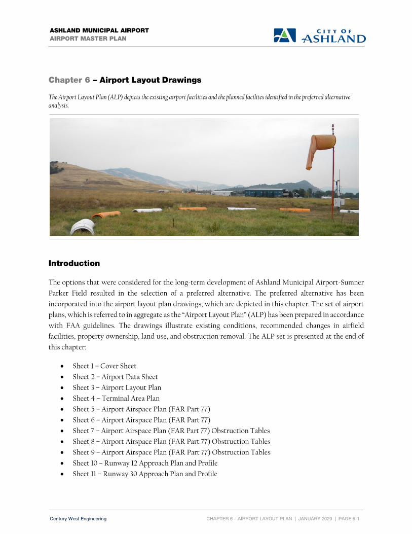
CHAPTER 6 – AIRPORT LAYOUT PLAN | JANUARY 2020 | PAGE 6-1
ASHLAND MUNICIPAL AIRPORT AIRPORT MASTER PLAN
Century West Engineering
Chapter 6 – Airport Layout Drawings
The Airport Layout Plan (ALP) depicts the existing airport facilities and the planned facilites identified in the preferred alternative analysis.
Introduction
The options that were considered for the long-term development of Ashland Municipal Airport-Sumner
Parker Field resulted in the selection of a preferred alternative. The preferred alternative has been
incorporated into the airport layout plan drawings, which are depicted in this chapter. The set of airport
plans, which is referred to in aggregate as the “Airport Layout Plan” (ALP) has been prepared in accordance
with FAA guidelines. The drawings illustrate existing conditions, recommended changes in airfield
facilities, property ownership, land use, and obstruction removal. The ALP set is presented at the end of
this chapter:
Sheet 1 – Cover Sheet
Sheet 2 – Airport Data Sheet
Sheet 3 – Airport Layout Plan
Sheet 4 – Terminal Area Plan
Sheet 5 – Airport Airspace Plan (FAR Part 77)
Sheet 6 – Airport Airspace Plan (FAR Part 77)
Sheet 7 – Airport Airspace Plan (FAR Part 77) Obstruction Tables
Sheet 8 – Airport Airspace Plan (FAR Part 77) Obstruction Tables
Sheet 9 – Airport Airspace Plan (FAR Part 77) Obstruction Tables
Sheet 10 – Runway 12 Approach Plan and Profile
Sheet 11 – Runway 30 Approach Plan and Profile

CHAPTER 6 – AIRPORT LAYOUT PLAN | JANUARY 2020 | PAGE 6-2
ASHLAND MUNICIPAL AIRPORT AIRPORT MASTER PLAN
Century West Engineering
Sheet 12 – On Airport Land Use Plan
Sheet 13 – Off Airport Land Use Plan
Sheet 14 – Exhibit “A” Airport Property Plan
The airport layout plan drawings provide detailed information for existing and future facilities. The future
improvements depicted in the drawing set are consistent with the airport master plan’s updated twenty-
year capital improvement program contained in Chapter 8. The ALP drawing set will be submitted along
with the draft final airport master plan report to Federal Aviation Administration (FAA) for review and
approval. The drawings will be reviewed by the FAA Airports District Office (ADO) with additional
review coordinated with other FAA offices (Flight Procedures, Flight Standards, etc.). Once approved, the
final ALP drawing set will be signed by the City of Ashland and the FAA Seattle Airports District Office
(ADO). As individual projects are completed, minor “as-built” updates to the ALP drawing may be
completed (with FAA coordination) without updating the airport master plan. A complete update of the
full ALP drawing set will be conducted as part of the next master plan update.
The airport layout plan drawings are prepared using AutoCAD® computer-aided drafting software, which
allows for easier updating and revision. The drawing files may also be imported into geographic information
systems (GIS) software to support land use planning, airport overlay zone mapping, etc.
A brief summary of the individual drawings is provided below:
Airport Data Sheet
The Airport Data Sheet drawing contains detailed runway and taxiway dimensions, FAA dimensional
standards, wind roses, and other data that is reflected on the sheets in the drawing set.
Airport Layout Plan
The Airport Layout Plan (ALP) drawing graphically depicts existing and future airfield facilities. Future
facilities are color-coded to distinguish them from existing facilities. Future facilities are represented in
the airport master plan’s twenty-year capital improvement program (CIP) as individual projects or project
groupings.
Terminal Area Plan
The Terminal Area Plan provides additional detail for existing and new facilities in the landside areas. The
Terminal Area Plan focuses on the main apron area, fuel facilities, Fixed Base Operator, and hangar areas.
FAR Part 77 Airport Airspace Plan
The FAR Part 77 Airspace drawings depict the protected airspace defined for Runway 12/30 in Federal Air
Regulation (FAR) Part 77, Objects Affecting Navigable Airspace. The airspace plan drawings depict the five

CHAPTER 6 – AIRPORT LAYOUT PLAN | JANUARY 2020 | PAGE 6-3
ASHLAND MUNICIPAL AIRPORT AIRPORT MASTER PLAN
Century West Engineering
“imaginary surfaces” defined in FAR Part 77.25 including the primary, transitional, approach, horizontal,
and conical surfaces, previously described in the Facility Requirements Chapter. FAR Part 77 surfaces
should be free of built or terrain obstructions to the greatest extent possible. Objects that penetrate FAR
FAR Part 77 surfaces may require action to mark or remove depending on their severity, location, and the
feasibility of the action. The drawings are supplemented by tables detailing the obstacles with
recommended dispositions. Obstacles presented on the Airspace Plan were provided by the AGIS survey
data. Only obstacles identified by the AGIS data are presented on these sheets.
The physical characteristics of the FAR Part 77 surfaces are defined by the size of aircraft using the runway
and the approach capabilities of the runway.
Runway 12/30 Approach Surfaces: Extends 5,000 feet from the end of the runway primary surface.
Both runway ends have an approach surface slope of 20:1, which represents the horizontal distance
required for each increment of vertical rise.
Runway 12/30 Primary Surface: Based on the visual approach standards for utility runways, the
primary surface is 250 feet wide extending 200 feet beyond each end of the runway. The primary
surface is a flat plane of airspace centered on the runway with the same elevation as the nearest point
on the runway centerline.
Transitional Surface: The runway transitional surfaces extend outward and upward from the outer
edges of the primary surface. The transitional surfaces have a slope of 7:1 and extend to an elevation 150
feet above airfield elevation and connect to the runway horizontal surface.
Horizontal Surface: The horizontal surface is drawn from 5,000-foot radii that extend from both ends
of the primary surface to form an oval. The horizontal surface is a flat plane of airspace with an elevation
150 feet above airport elevation.
Conical Surface: The conical surface extends from the outer edge of the horizontal surface at a slope
of 20:1 for 4,000 feet.
The FAR Part 77 Airport Airspace Plan is shown in two drawings. The first drawing presents the obstacles
in the conical, horizontal, and transitional surfaces. Due to the number and density of obstacles in the
horizontal and conical surfaces displaying each penetrating obstacle is not feasible. Instead, a 1,000’ square
grid was overlaid on the surfaces and the highest penetrating obstacle was identified and noted for each
grid cell. For the transitional surface, all penetrating obstacles and those within 10’ of the surface are
identified and called out.
The second drawing presents the runway, approaches and approach obstacles. Where scale allows,
individual obstacles are identified. Due to scale requirements, obstacles in the RPZ and Inner Approaches

CHAPTER 6 – AIRPORT LAYOUT PLAN | JANUARY 2020 | PAGE 6-4
ASHLAND MUNICIPAL AIRPORT AIRPORT MASTER PLAN
Century West Engineering
are not individually identified. Instead, they are detailed on the following Runway RPZ and Inner
Approach Plan and Profile drawings.
Obstacles identified in these drawings are listed in the obstruction tables that follow.
Runway RPZ and Inner Approach Plan and Profile Drawings
The Inner Approach Surface and Runway Protection Zone (RPZ) drawing depict detailed plan and profile
views of the approach surfaces. The drawings provide additional detail in identify obstructions, terrain
and other physical features within the approach surfaces. The drawings include obstruction data tables
for items depicted on the drawing, using the same numbering identifiers from the overall FAR Part 77
Airspace Plan. Only obstacles present in the AGIS data are presented on this sheet.
Airport Land Use Plans
The Airport Land Use Plan drawings depict, in two separate sheets, the existing land use designations for
the airport and surrounding areas. The On-Airport Land Use drawing details the major use classifications
of the Airport property. The Off-Airport Land Use drawings depicts the land use classifications of the
property beyond Airport property that are impacted by the Part 77 Surfaces and associated airspace overlay
zoning districts. Land use classifications were derived from city and county comprehensive plans and
zoning districts. The City of Ashland has land use jurisdiction for Ashland Municipal Airport – Sumner
Parker Field and surrounding properties to the west. The remaining land surrounding the airport and that
under the FAR Part 77 surfaces extends into Jackson County. The Airport Land Use Plan drawing also
includes the existing and future traffic patterns.
Exhibit “A” – Airport Property Plan
The Airport Property Plan drawing provides depicts all property owned or controlled by the City included
in the airport. The drawing notes the form of ownership or control (fee simple, easement, etc.) and the date
of acquisition per FAA guidelines. Though a thorough public records search was completed, some details
were not avialble. A formal property title search may be required to complete the missing data.


Chapter 7
Airport Compatible Land Use Planning


CHAPTER 7 – AIRPORT COMPATIBLE LAND USE PLANNING | JANUARY 2020 | PAGE 7-1
ASHLAND MUNICIPAL AIRPORT AIRPORT MASTER PLAN
Century West Engineering
Chapter 7 – Airport Compatible Land Use Planning
An evaluation of both on-airport and off-airport land uses in the vicinity of the airport to address the potential development
of a broad range of land uses that are compatible with airport operations and support the region’s economic development
strategy.
Insert picture
Introduction
This chapter describes land use associated with the Ashland Municipal Airport and its surroundings,
describes federal regulations established to protect airports and airspace, and summarizes state statutes
and rules that guide land use planning and airport protection. The intent of this chapter is to summarize
all existing land use controls affecting the Airport, identify any potential land use or zoning
incompatibilities, and if applicable, provide recommendations for improving land use compatibility.
Government Roles in Airport Land Use
FEDERAL
The Federal Aviation Administration (FAA) does not have authority to regulate off airport land use,
including the construction of built items. Land use regulation is a local responsibility and FAA has a
technical advisory role based on its interest in protecting the airspace associated with an airport as part of
the national airspace system. The FAA does have a role in regulating on-airport land use through approval
of the Airport Layout Plan (ALP) and airport sponsor compliance with the FAA Airport Improvement
Program (AIP) grant assurances. These assurances include measures to maintain airport land use
compatibility and protect the aeronautical function of airports.
The FAA’s current guidance on regulating non-aeronautical land uses on federally obligated airports is
addressed in the FAA Reauthorization Act of 2018 (Title I—Authorizations, Subtitle C—Airport

CHAPTER 7 – AIRPORT COMPATIBLE LAND USE PLANNING | JANUARY 2020 | PAGE 7-2
ASHLAND MUNICIPAL AIRPORT AIRPORT MASTER PLAN
Century West Engineering
Improvement Program Modifications, Sec. 163), which narrows the FAA’s direct or indirect regulation of
non-aeronautical property transactions (including leases) and limits the requirement for ALP amendments
depicting non-aeronautical developments that may in turn, trigger environmental review. The intent of the
law is to ensure the aeronautical functions of an airport are adequately preserved, but to enable airport
sponsors to responsibly pursue non-aeronautical development that benefits the operation of the airport.
Under 14 Code of Federal Regulations (CFR), Part 77, the FAA has the authority to review proposed
construction through its Form 7460-1 Notice of Proposed Construction or Alteration process. The FAA
review addresses compatibility both on and off airport based on the potential for creating a “hazard to air
navigation” associated with obstructions/penetrations in defined airspace. FAA airspace reviews include
FAR Part 77 surfaces; Terminal Instrument Procedures (TERPS) surfaces, visual runway traffic patterns,
and visual navigation aid (e.g., VASI, PAPI, etc.) protected airspace. When a proposed structure penetrates
navigable airspace, the FAA will issue a letter objecting to the proposed action (determination of presumed
hazard to air navigation) for the consideration of local authorities. When proposed actions do not present
a hazard to air navigation, a “no objection” finding is issued. It is important to note that this analysis is
based on an obstruction evaluation and is not intended to address land use compatibility in terms of noise
exposure or proximity to an airport or runway.
The FAA recommends local jurisdictions include the following language in their development codes to
recognize and protect airports from incompatible development: “Nothing in this chapter shall diminish
the responsibility of project proponents to submit a Notice of Proposed Construction or Alteration to the
Federal Aviation Administration if required, in accordance with FAR Part 77, Objects Affecting
Navigable Airspace.”
FAR Part 150, Airport Noise Compatibility Planning provides guidance for land use compatibility
around airports. The Airport Noise and Capacity Act of 1990 (ANCA), defines the federal policy on the
regulation of airport noise (operating curfews, aircraft restrictions, etc.), with the intent of standardizing
noise controls throughout the national system.
STATE
The State of Oregon has created statutes and rules that provide standards and guidelines for local
governments to use in order to create zoning ordinances to encourage compatible land uses around
airports. The State of Oregon’s laws and statutes are provided by the Airport Planning Rule, which is
located in Oregon Administrative Rules (OAR), contained in Chapter 660, Department of Land
Conservation and Development; Division 12, Transportation Planning and Division 13, Airport
Planning to address airport protection and function. Local governments shall follow State rules as
described in OAR 660 for planning and managing public-use airports. Division 12 states that local

CHAPTER 7 – AIRPORT COMPATIBLE LAND USE PLANNING | JANUARY 2020 | PAGE 7-3
ASHLAND MUNICIPAL AIRPORT AIRPORT MASTER PLAN
Century West Engineering
governments shall participate and develop a Transportation System Plan with “measures to protect public
use airports by controlling land uses within airport noise corridors and imaginary surfaces, and by limiting
physical hazards to air navigation.”
Division 13, Airport Planning states, “the policy of the State of Oregon is to encourage and support the
continued operation and vitality of Oregon’s airports.” It includes “rules that are intended to promote a
convenient and economic system of airports in the State and for land use planning to reduce risks to aircraft
operations and nearby land uses.” A summary of these requirements is provided below:
660-013-0030 Preparation and Coordination of Aviation Plans states “A city or county with
planning authority for one or more airports, or areas within safety zones or compatibility zones
described in this division, shall adopt comprehensive plan and land use regulations for airports
consistent with the requirements of this division and ORS 836.600 through 836.630.”
660-013-0040 Aviation Facility Planning Requirements provides a list of planning requirements
including a map showing the location of the airport boundary, a map or description of existing and
planned facilities, a projection of future aeronautical needs, etc.
660-013-0070 Local Government Safety Zones for Imaginary Surfaces specifies that “local
governments shall adopt an Airport Safety Overlay Zone to promote aviation safety by prohibiting
structures, trees and other objects of natural growth from penetrating airport imaginary surfaces.”
660-13-0080 Local Government Land Use Compatibility Requirements for Public Use
Airports provides a list of requirements including prohibiting new residential development and
public assembly uses within the Runway Protection Zone (RPZ) and limits establishment of uses
within the noise impact boundary.
660-013-0100 Airport Uses at Non-Towered Airports requires local governments to adopt land
use regulations that authorize a range of defined airport uses within the airport boundary of non-
towered airports.
660-013-0140 Safe Harbors defines “safe harbor” requirements that may be used by local
governments including existing comprehensive plans, land use regulations, Airport Master Plans,
and Airport Layout Plans.
660-013-155 Planning Requirements for Small Airports specifies that airports are to be subject
to the planning and zoning requirements within ORS 836.

CHAPTER 7 – AIRPORT COMPATIBLE LAND USE PLANNING | JANUARY 2020 | PAGE 7-4
ASHLAND MUNICIPAL AIRPORT AIRPORT MASTER PLAN
Century West Engineering
Division 13 implements Oregon Revised Statutes (ORS) 836.600 through 836.630, which promotes land
use planning to reduce unnecessary risk to aircraft operations. Several key statutes important in land use
planning are summarized below:
836.608 Airport operation as matter of state concern (local planning documents to recognize
airport location, limitations on use, and expansion of facility) - requires local governments to
recognize airport locations within planning documents. It also prohibits limitations on use and
includes a process by which airports can add new land uses on their property.
836.610 Local government land use plans and regulations to accommodate airport zones and
uses including funding and rules - requires local governments to amend their land use regulations
and comprehensive plans in accordance to 836.616 and 836.619.
836.616 Rules for airport uses and activities - identifies types of permitted land uses and
activities on airport property and requires local government to meet standards for safe land uses
near airports.
836.623 Local compatibility and safety requirements more stringent than state requirements
(criteria, water impoundments, report to federal agency, and application to certain activities)
- allows local governments to adopt land use compatibility and safety requirements that are more
stringent than the minimum required by Land Conservation and Development Commission rules.
It provides rules which limit the size of water impoundments near airports in an effort to reduce
wildlife attractants.
LOCAL
In Oregon, protecting airports from incompatible land uses and establishing compatible land uses around
airports is the responsibility of local governments through comprehensive planning and local zoning
authority. As with other local land use regulations, the requirements are unrelated to property ownership,
and are not limited to jurisdiction where the airport is physically located.
The City of Ashland has land use jurisdiction for Ashland Municipal Airport and for all lands located in
the city limits. Ashland Municipal Airport is located within the Ashland city limits, approximately three
miles southeast of downtown Ashland.
Jackson County has land use jurisdiction for all other lands in the vicinity of the Airport, including the
areas of the Ashland Urban Growth Boundary (UGB) located outside the city limits and for all
unincorporated areas outside the UGB.
The City and County have adopted policies and goals within comprehensive planning elements and
established airport overlay and base zoning language to ensure their off- and on-airport land uses are

CHAPTER 7 – AIRPORT COMPATIBLE LAND USE PLANNING | JANUARY 2020 | PAGE 7-5
ASHLAND MUNICIPAL AIRPORT AIRPORT MASTER PLAN
Century West Engineering
compatible with the Airport for long-term growth. However, City and County comprehensive plans as
well as zoning ordinances may require updating to be more consistent with modern airport planning
terminology, growth and expansion at the Airport, and consistency with the Oregon rules and statutes
noted above. Further analysis of the specific local comprehensive plan documents and local zoning
ordinances is examined in more detail below.
Comprehensive Planning
JACKSON COUNTY
The Jackson County Comprehensive Plan is the official long-range land use policy document for Jackson
County. The plan sets forth general land use planning policies and allocates land uses into resource,
residential, commercial and industrial categories. The following is a summary of those sections of the
Jackson County Comprehensive Plan related to the Ashland Municipal Airport.
Environmental Quality Element
The County utilizes an Airport Approach overlay zone and very low density residential zoning
surrounding the facility to ensure land use compatibility for not only safety and airspace obstruction
concerns, but also as a mechanism to regulate land uses and densities regarding noise. The County will
continue to work with airport authorities, affected agencies, concerned citizens, and the cities of Ashland
and Medford on any matters affecting noise emanating from these aviation facilities and their flight
operation activities. Methodologies for dealing with airport-related noise, such as zoning, land acquisition,
and sound-proofing of structures are discussed in these airport master plans.
Public Facilities and Services Element
The City operates an activated sludge plant which discharges effluent into Bear Creek. The Ashland City
Airport is served by holding tanks and septic systems, but, as of February 1994, connection to the city
sewer is planned when funding is available.
Construction for sanitary sewer to the Airport was completed in 1999.
Transportation System Plan (TSP) Element
In addition to a general summary of aviation facilities within Jackson County, the TSP identifies a handful
of Aviation System Policies specific to public use airports in Jackson County like the Ashland Municipal
Airport.

CHAPTER 7 – AIRPORT COMPATIBLE LAND USE PLANNING | JANUARY 2020 | PAGE 7-6
ASHLAND MUNICIPAL AIRPORT AIRPORT MASTER PLAN
Century West Engineering
4.2.5-A The County’s first aviation planning priority is the preservation and protection of existing
commercial and general aviation facilities and uses for all public use airports.
4.2.5-B The County will plan for and support the expansion and enhancement of commercial and general
aviation facilities and uses for all public use airports as planning deficiencies are identified.
4.2.5-D The County will support multi-modal transportation improvement and service enhancements to
improve access to the air system facilities, including the Medford International Airport.
General Implementation Element
The County Comprehensive Plan identifies several implementation techniques that may be utilized for
areas within the “airport flight path zones” beyond the more traditional methods of implementation such
as zoning, ordinances and review, and building codes. Some of the techniques identified include outright
purchase, advance acquisition, purchase and leaseback, eminent domain, scenic & conservation easements,
and covenants deed restrictions.
CITY OF ASHLAND
The City of Ashland Comprehensive Plan is the guiding document for all development within the City. The
Plan incorporates specific elements related to development including: citizen participation, environmental
resources, population projections and growth, housing, economy, aesthetic resources, public services,
transportation, energy and urbanization. The following is a summary of those sections of the
Comprehensive Plan related to the Ashland Municipal Airport.
Introduction and Definitions
PUBLIC SCHOOLS AND FACILITIES (2.04.14) These are areas needed for existing or future public uses,
such as schools, treatment plants, airport, and so forth. These areas should be programmed into the City
or school system budgets and purchased prior to projected development. In cases of possible combined
uses (e.g., school parks), a joint acquisition should be encouraged.
Environmental Resources
GOAL To make a continuing effort to reduce noise levels, and insure that new development is developed
in a way to minimize noise impacts.
56) Insure that residential development is kept away from the maximum noise area around the Ashland
Airport, and that new residential development near the Airport is aware of the potential for noise, and
waives the right to file nuisance suits in the future

CHAPTER 7 – AIRPORT COMPATIBLE LAND USE PLANNING | JANUARY 2020 | PAGE 7-7
ASHLAND MUNICIPAL AIRPORT AIRPORT MASTER PLAN
Century West Engineering
Transportation Element
10.26 Commercial Freight and Passenger Transportation Goals and Policies
GOALS (10.26.01) To provide efficient and effective movement of goods, services and passengers by air,
rail, water, pipeline, and highway freight transportation while maintaining the high quality of life of
Ashland.
POLICIES 1) Review development within the Airport Overlay Zone to ensure compatibility with the
Ashland Municipal Airport.
Urbanization
12.08 Description of the Urban Growth Boundary – “…across the freeway, the urban growth boundary
continues along East Main until it comes to the Cityʼs Municipal Airport and two areas reserved for
expansion of the Municipal Airport. However, there are no plans for any residential development in this
area.”
Airport Vicinity Zoning
JACKSON COUNTY
Jackson County has land use jurisdiction for most of the lands in the vicinity of the Airport, including the
areas of the Ashland Urban Growth Boundary (UGB) located outside the city limits and all unincorporated
areas outside the UGB. The County land and respective zoning surrounding the Airport is typically
Exclusive Farm Use (EFU) and Rural Residential 5 (RR5) which is generally compatible with airport
operations.
CITY OF ASHLAND
The City of Ashland zoning districts in the vicinity of the Airport provide a reasonable level of
compatibility with airport operations. Aside from the roads located partially within the Runway
Protection Zone (RPZs), there are no known areas of incompatible land use or significant aircraft noise
exposure in the vicinity of Ashland Municipal Airport. The relocation and/or minimizing the impacts of
the existing RPZ incompatibilities is recommended in the master plan. Control of the RPZ through
purchase where practical is also recommended.

CHAPTER 7 – AIRPORT COMPATIBLE LAND USE PLANNING | JANUARY 2020 | PAGE 7-8
ASHLAND MUNICIPAL AIRPORT AIRPORT MASTER PLAN
Century West Engineering
Airport Base Zoning
CITY OF ASHLAND
Ashland Municipal Airport is located within the Ashland city limits which provides jurisdiction and
regulations for all on-airport development through AMC Title 18 Land Use. As depicted in Figure 2-9 in
Chapter 2 of this Airport Master Plan, Ashland Municipal Airport is zoned (Employment) E-1 in Part
18.2 – Zoning Regulations, which does not provide clear guidance on typical aviation related uses such as
hangar development, taxiways, runways, etc. within airport property. The code as currently written
directs any Airport specific inquiries to Chapter 18.3.7 Airport Overlay, which provides for the
“protection of properties that lie within close proximity to the Ashland Airport where aircraft are likely
to be flying at relatively low elevations.”
It is recommended the City of Ashland adopt a base zone specific to the Airport comparable to
either the “Appendix G – Model Public Use Airport Zone” from the ODA Airport Land Use
Compatibility Guidebook, or an overlay comparable to the Jackson County “Airport Boundary
Overlay” in Chapter 7.3.2 of the Jackson County Land Use Ordinance, or implement a master plan
based method for permitting on airport land uses similar to what is currently done within the City
of Ashland for the SOU (Southern Oregon University District) and HC (Health Care Services
District) zones.
Airport Overlay Zoning
JACKSON COUNTY
Section 7.3.1 of the Jackson County Land Use Ordinance provides Airport Approach (AA) and Airport
Concern (AC) overlays intended to reduce risks to aircraft operations and land uses within close
proximity to the Airport as defined by FAR Part 77 surfaces. This section of the Jackson County
ordinance references a 1976 Approach and Clear Zone Plan for the Ashland Municipal Airport.
It is recommended the City of Ashland work with Jackson County to update the reference of the
1976 Approach and Clear Zone Plan within Section 7.3.1 to read as the “adopted Ashland Airport
Master Plan’s “Airspace Plan” on file with the City of Ashland.”
CITY OF ASHLAND
The City of Ashland Airport Overlay Zone provided in Chapter 18.3.7 is intended to prevent the
establishment of airspace obstructions in the areas around the Airport to comply with “FAR Part 77 Safe,
Efficient Use, and Preservation of the Navigable Airspace” through the establishment of airspace surfaces
associated with the Airport and runway environment.

CHAPTER 7 – AIRPORT COMPATIBLE LAND USE PLANNING | JANUARY 2020 | PAGE 7-9
ASHLAND MUNICIPAL AIRPORT AIRPORT MASTER PLAN
Century West Engineering
Section 18.3.7.020 indicates “this chapter applies to properties located in the Airport Overlay (A) on the
Zoning map (Figure 2-9 of this Airport Master Plan Report). In addition to the provisions of this
ordinance, the requirements of section 18.3.7.030 Airport Overlay Regulations apply within the Airport
Overlay.”
It is recommended the City of Ashland adopt an airport overlay zone specific to the Airport Part 77
Surfaces comparable to the “Appendix E – Model Public Use Airport Safety and Compatibility
Overlay Zone” from the ODA Airport Land Use Compatibility Guidebook, or an overlay
comparable to the Jackson County “Airport Approach and Airport Concern Overlays” in Chapter
7.3.1 of the Jackson County Land Use Ordinance, or another more specific approach that best suits
the City of Ashland while still being consistent with State land use laws and FAR Part 77
requirements and federal grant assurances.
Land Use Summary and Recommendations
To remain in compliance with State of Oregon land use laws (OAR 660) it is recommended the City of
Ashland work with Jackson County to update the outdated County Comprehensive Plan language to
prepare for the changes planned within this updated Airport Master Plan for the Ashland Municipal
Airport. Additionally, the City will need to take appropriate steps to adopt the Airport Master Plan in to
the City of Ashland Comprehensive Plan. As a final step, it is recommended the City of Ashland update the
base zone and overlay zone for consistency with the Master Plan and City of Ashland Comprehensive Plan.

This page intentionally left blank

Chapter 8
Capital Improvement andImplementation Plan


ASHLAND MUNICIPAL AIRPORT AIRPORT MASTER PLAN
CHAPTER 8 – CAPITAL IMPROVEMENT AND IMPLEMENTATION PLAN | JANUARY 2020 | PAGE 8-1 Century West Engineering
Chapter 8 – Capital Improvement and Implementation Plan
The Capital Improvement and Implementation Plan details the specific projects, costs, available funding sources, and an implementation schedule needed to realize the preferred alternative.
Overview and Purpose
The purpose of this chapter is to present the projects identified in the twenty-year Capital Improvement
Program (CIP) that have been developed and assembled based on the analyses conducted in the Facility
Requirements and Development Alternatives evaluations (Chapters 4 and 5). The CIP projects are
summarized in Table 8-1 later in the chapter. The CIP is organized into short, intermediate, and long-term
planning periods that reflect both project prioritization and financial capabilities. Several factors were
considered in determining project prioritization, including safety, forecast demand, the need to
maintain/replace existing airfield facilities, and financial capabilities of both the city and FAA to support
the development program based on existing funding mechanisms.
The Master Plan preferred alternative includes both airside elements and landside elements. Minor
pavement maintenance items such as vegetation removal and crack filling are not included in the CIP, but
will need to be undertaken by the City on an annual or semi-annual basis.
A brief environmental review was prepared and is presented in Chapter 2 – Inventory of Existing
Conditions. The review provides an overview of areas of potential concern associated with proposed
development. In addition, all federally funded projects will require some level of project-specific
environmental study, as determined by FAA.
Individual projects for the first five years of the planning period are listed in order of priority by year.
Projects for the intermediate and long-term phases of the planning period (years 6-20) are listed in order

ASHLAND MUNICIPAL AIRPORT AIRPORT MASTER PLAN
CHAPTER 8 – CAPITAL IMPROVEMENT AND IMPLEMENTATION PLAN | JANUARY 2020 | PAGE 8-2 Century West Engineering
of priority but have not been assigned a year. Each project’s eligibility for FAA funding is noted, based on
current federal legislation and funding formulas. Specific project details are depicted on the updated
Airport Layout Plan and Terminal Area Plan drawings contained in Chapter 6.
A primary source of potential funding identified in this plan is the FAA’s Airport Improvement Program
(AIP). Funds from this program are derived from the Aviation Trust Fund, which is the depository for all
federal aviation taxes collected on such items as airline tickets, aviation fuel, lubricants, tires, aircraft
registrations, and other aviation related fees. These funds are distributed by FAA under appropriations set
by Congress for all airports in the United States included in the federal airport system (National Plan of
Integrated Airport Systems – NPIAS).
However, as noted in Table 8-1, the projected twenty-year total for FAA eligible projects in the CIP
significantly exceeds current FAA funding levels through the non-primary entitlement program, which is
$150,000 annually. While other types of FAA funding may be available for some projects, it is reasonable
to assume not all eligible projects are likely to be funded despite establishing FAA funding eligibility. The
City must maximize the use of available FAA and other outside funding sources as it manages its CIP. In
some cases, the limited availability of outside funds may require deferring some projects, or increasing
funding with additional local, state, or private funding.
Airport Development Schedule and Cost Estimates
Cost estimates for each individual project were developed in 2019 dollars based on typical construction
costs associated with the specific type of project. The project costs listed in the CIP represent order-of-
magnitude estimates that approximate design, engineering, environmental, other related costs, and
contingencies. The estimates are intended only for preliminary planning and programming purposes.
Specific project analysis and detailed engineering design will be required prior to project implementation
to provide more refined and detailed estimates of the development costs.
These cost estimates can continue to assist management through adjustments to the 2019-dollar amounts
to account for subsequent inflation as the plan is carried out in future years. This can be accomplished by
converting the appropriate change in the United States Consumer Price Index (USCPI) to a multiplier
using the following formula:

ASHLAND MUNICIPAL AIRPORT AIRPORT MASTER PLAN
CHAPTER 8 – CAPITAL IMPROVEMENT AND IMPLEMENTATION PLAN | JANUARY 2020 | PAGE 8-3 Century West Engineering
X --------- = Y
I
Where: X = USCPI in any given future year
Y = Change Ratio I = Current Index (USCPI)1
USCPI-U
267.370
(1982-1984 = 100)
March 2019
Multiplying the change ratio (Y) times any 2019-based cost estimate presented in this study will yield the
adjusted dollar amounts appropriate in any future year evaluation. Several different CPI-based indices are
available for use and any applicable index may be substituted by the city in its financial management
program.
The following sections outline the recommended development program and funding assumptions. The
scheduling has been prepared according to the facility requirements determined through the master plan
evaluation. The projected staging of development projects is based on anticipated needs and investment
priorities. Actual activity levels may vary from projected levels; therefore, the staging of development in
this section should be viewed as a general guide. When activity does vary from projected levels,
implementation of development projects should occur when demand warrants, rather than according to
the estimated staging presented in this chapter. In addition to major projects, the airport will continue to
require regular facility maintenance such as pavement maintenance, vegetation control, sweeping, lighting
repair, and fuel system maintenance.
The following summary describes the key projects.
Short-Term Projects
The short-term program contains highest priority work items including safety related improvements.
These items will need to be incorporated into the State Capital Improvement Program (SCIP) managed by
the FAA Seattle Airport District Office and the Oregon Department of Aviation (ODA). To assist with this
process, the short-term projects are scheduled in specific calendar years for the first five years of the
planning period (2019-2023).
1 U.S. Consumer Price Index for All Urban Consumers (USCPI-U)

ASHLAND MUNICIPAL AIRPORT AIRPORT MASTER PLAN
CHAPTER 8 – CAPITAL IMPROVEMENT AND IMPLEMENTATION PLAN | JANUARY 2020 | PAGE 8-4 Century West Engineering
The primary focus for short-term development is to address the pavement conditions on the airfield.
Specific short-term projects are listed below.
SHORT‐TERM PROJECTS (YEARS 2019‐2023):
• Pavement Management Plan (PMP) Maintenance Work
• Rehabilitate Taxiway: Phase I - Design
• Rehabilitate Taxiway: Phase II - Construction
• Pavement Management Plan (PMP) Maintenance
Intermediate & Long-Term Projects
Several intermediate - or long-term projects are considered to be current needs. However, it was necessary
to shift some projects to subsequent planning periods based on the limited funding resources available.
Individual projects may be completed sooner in the event additional funding can be obtained.
INTERMEDIATE‐TERM PROJECTS (YEARS 2024‐2028):
• Environmental Assessment – Fencing/Road Realignment/Apron Expansion/Threshold
• Fencing Project and Road Realignment
• Pavement Management Plan (PMP) Maintenance
• OFA Obstruction Removal
• Displaced Threshold Removal and Runway Seal Coat
• Apron Redesign and Expansion/Fuel Tank Relocation
LONG‐TERM PROJECTS (YEARS 2029‐2038):
• Airport Master Plan Update
• Pavement Management Plan (PMP) Maintenance
• Construction of Hangar Taxilanes
• Environmental Assessment – Runway Extension
• Pavement Management Plan (PMP) Maintenance
• Runway Extension: Phase I – Design
• Runway Extension/Displace Threshold Removal: Phase II - Runway Extension (Construction of
Runway/Taxiway, culvert, land acquisition, private drive relocation, etc)

ASHLAND MUNICIPAL AIRPORT AIRPORT MASTER PLAN
CHAPTER 8 – CAPITAL IMPROVEMENT AND IMPLEMENTATION PLAN | JANUARY 2020 | PAGE 8-5 Century West Engineering
TABLE 8‐1: 20‐YEAR CAPITAL IMPROVEMENT PROGRAM
Current NPE $ Accumulation: $299,249
ASHLAND MUNICIPAL AIRPORT20-YEAR CAPITAL IMPROVEMENT PROGRAMPrepared by Century West Engineering
Project Project Category Project CostFAA GA
EntitlementOther FAA ** Local Costs ***
2019 No Projects $0 $0 $0 $0 FY 2019 NPE + Accum. $449,249NPE Used $0
Subtotal - Year 1 $0 $0 $0 $0 NPE Remaining $449,249
2020 PMP* Rehabilitation $20,000 $18,000 $0 $2,000 FY 2020 NPE + Accum. $599,249NPE Used $18,000
Subtotal - Year 2 $20,000 $18,000 $0 $2,000 NPE Remaining $581,249
2021 Rehabilitate Taxiway: Phase I - Design Design $263,000 $236,700 $0 $26,300 FY 2021 NPE + Accum. $731,249NPE Used $236,700
Subtotal - Year 3 $263,000 $236,700 $0 $26,300 NPE Remaining $494,549
2022 Rehabilitate Taxiway: Phase II - Construction Construction $2,598,000 $644,549 $1,693,651 $259,800 FY 2022 NPE + Accum. $644,549NPE Used $644,549
Subtotal - Year 4 $2,598,000 $644,549 $1,693,651 $259,800 NPE Remaining $0
2023 PMP* Rehabilitation $20,000 $18,000 $0 $2,000 FY 2023 NPE +Accum. $150,000NPE Used $18,000
Subtotal - Year 5 $20,000 $18,000 $0 $2,000 NPE Remaining $132,0005-YEAR TOTAL: $2,901,000 $917,249 $1,693,651 $290,100
* Participation in ODA PMP/PEP program is assumed. Actual project costs and local cost share to be determined.
** Other FAA Funding Total listed for reference only based on general project eligibility; FAA funding levels are expected to be below projected needs.
*** Local (City) costs at 10% (City may apply for a ODA grant for a portion of matching funds)
Note: Contingencies for project engineering, and construction services are included in lump sum project costs. Environmental contingencies are not included.
Short-Term
20-CAPITAL IMPROVEMENT PROGRAM


ASHLAND MUNICIPAL AIRPORT AIRPORT MASTER PLAN
CHAPTER 8 – CAPITAL IMPROVEMENT AND IMPLEMENTATION PLAN | JANUARY 2020 | PAGE 8-7 Century West Engineering
TABLE 8‐1: 20‐YEAR CAPITAL IMPROVEMENT PROGRAM (CONT.)
Project Project Category Total CostFAA GA
EntitlementFAA Eligible ** Local Costs***
Non-Primary Entitlements Accumulation Total (5-Years) $750,000EA (OFA Obstruction Removal/Fencing/Road Realignment/Apron Environmental $350,000 $315,000 $35,000Fencing Project and Road Realignment Design/Construction $700,000 $630,000 $70,000PMP* Planning $20,000 $18,000 $2,000OFA Obstruction Removal Design/Construction $180,000 $162,000 $18,000Displaced Threshold Removal and Runway Seal Coat Design/Construction $1,080,000 $972,000 $108,000Apron Redesign and Expansion/Fuel Tank Relocation Design/Construction $6,840,000 $6,156,000 $684,000
Subtotal - Year 6-10 10-YEAR TOTAL: $9,170,000 $750,000 $8,253,000 $917,000
Project Project Category Total CoastFAA GA
EntitlementFAA Eligible ** Local Costs***
Non-Primary Entitlements Accumulation Total (10-Years) $1,500,000Airport Master Plan Update Planning $400,000 $360,000 $40,000PMP* Planning $20,000 $18,000 $2,000Hangar Taxilanes Design/Construction $2,240,000 $2,016,000 $224,000Environmental Assessment (Runway Extension) Planning $500,000 $450,000 $50,000PMP* Planning $20,000 $18,000 $2,000Phase I - Runway Extension Design $420,000 $378,000 $42,000
Phase II - Runway Extension (Construction of Runway/Taxiway, culvert, land acquisition, private drive relocation, etc)
Construction $6,320,000 $5,688,000 $632,000
Subtotal Year 11-20 10-YEAR TOTAL: $9,920,000 $1,500,000 $8,928,000 $992,000
* Participation in ODA PMP/PEP program is assumed. Actual project costs and local cost share to be determined.
** Other FAA Funding Total listed for reference only based on general project eligibility; FAA funding levels are expected to be below projected needs.
*** Local (City) costs at 10% (City may apply for a ODA grant for a portion of matching funds)
Note: Contingencies for project engineering, and construction services are included in lump sum project costs. Environmental contingencies are not included.
2024-2028
Long-Term
2029-2038
20-CAPITAL IMPROVEMENT PROGRAM
Intermediate-Term


ASHLAND MUNICIPAL AIRPORT AIRPORT MASTER PLAN
CHAPTER 8 – CAPITAL IMPROVEMENT AND IMPLEMENTATION PLAN | JANUARY 2020 | PAGE 8-9 Century West Engineering
Capital Funding Sources & Programs
Federal Grants
Federal funding is provided through the Federal Airport Improvement Program (AIP). The Airport
Improvement Program is the latest evolution of a funding program originally authorized by Congress in
1946 as the Federal Aid to Airports Program (FAAP). The AIP provides Entitlement funds for commercial
service and cargo airports based on the number of annual enplaned passengers and amount of air cargo
handled. Other appropriations of AIP funds go to states, general aviation airports, reliever airports, and
other commercial service airports, as well as for noise compatibility planning. Any remaining AIP funds at
the national level are designated as Discretionary funds and may be used by the FAA to fund eligible
projects. Discretionary funds are typically used to enhance airport capacity, safety, and/or security and are
often directed to specific national priorities such as the recent program to improve Runway Safety Areas.
These annual entitlement funds can only be used for eligible capital improvement projects and may not be
used to support airport operation and maintenance costs.
AIP funding programs include:
AIP Entitlement Grants: The FAA Reauthorization Act of 2018 was signed into law in October of
2018, extending the authorization for Federal Aviation Administration (FAA) programs, including
the AIP program, and related revenue authorities through 2023. Ashland Municipal Airport is
classified in the current NPIAS as a Local General Aviation Airport. FAA Order 5100.38D, Airport
Improvement Handbook, adjusts the percentage of Federal shares for allowable project costs for
certain states. In the Order, Table 4-8 “Federal Shares by Airport Classification in Public Land
States” stipulates that the Federal match in the State of Oregon is 90-percent for Non-primary
General Aviation airports.
AIP Discretionary Grants: The FAA also provides Discretionary grants to airports for projects that
have a high Federal priority and enhance safety, security, or capacity. These grants are over and
above Entitlement funding. Discretionary grant amounts can vary significantly compared to
Entitlements and are awarded at the FAA’s sole discretion. Discretionary grant applications are
evaluated based on need, the FAA’s project priority ranking system, and the FAA’s assessment of
a project’s significance within the national airport and airway system.
FAA Facilities and Equipment Funds. Additional funds are available under the FAA Facilities and
Equipment Program. Money is available in the FAA Facilities and Equipment (F&E) program to
purchase navigation aids and air safety-related technical equipment, including Airport Traffic
Control Towers (ATCTs) for use at commercial service airports in the National Airport System.
Each F&E project is evaluated independently using a cost-benefit analysis to determine funding

ASHLAND MUNICIPAL AIRPORT AIRPORT MASTER PLAN
CHAPTER 8 – CAPITAL IMPROVEMENT AND IMPLEMENTATION PLAN | JANUARY 2020 | PAGE 8-10 Century West Engineering
eligibility and priority ranking. Qualified projects are funded in total (i.e., 100 percent) by the FAA,
while remaining projects would likely be eligible for funding through the AIP or PFC programs. In
addition, an airport can apply for NAVAID maintenance funding through the F&E program for
those facilities not funded through the F&E program
FAA funding is limited to projects that have a clearly defined need and are identified through preparation
of an FAA approved Airport Layout Plan (ALP). Periodic updates of the ALP are required when new or
unanticipated project needs or opportunities exist that require use of FAA funds and to reflect the status
of completed projects. The FAA will generally not participate in projects involving vehicle parking,
utilities, building renovations, or projects associated with non-aviation development.
Projects such as hangar construction or fuel systems are eligible for funding, although the FAA considers
this category of project to be considered a much lower priority than other airfield needs.
State of Oregon
No specific level of Oregon Department of Aviation (ODA) funding has been assumed in the CIP presented
in Table 8-1. It is recommended that the city maximize use of any ODA or other State funding available in
the planning period.
PAVEMENT MAINTENANCE PROGRAM
The Pavement Management Program (PMP) programs airfield pavement maintenance funds on
established multi-year cycles. The PMP is funded by a portion of the fuel tax revenues. Forty-five percent
of the original fuel taxes collected ($0.01/gallon on Jet-A and $0.09/gallon on AVGAS) are used to fund the
PMP. (It should be noted that the remainder of the revenues collected from the original $0.01/gallon Jet-A
and $0.09/gallon AVGAS fuel taxes equaling 55 percent are used to fund the operation of Oregon’s 28 state
owned airports and ODA administrative costs.) This program is intended to preserve and maintain existing
airfield pavements in order to maximize their useful lives and the economic value of the pavement. Several
short-term pavement maintenance projects are identified in the most recent PMP as noted earlier. The
program funds pavement maintenance and associated improvements (crack filling, repair, sealcoats, etc.),
including some items that have not traditionally been eligible for FAA funding.
Funding for the PMP is generated through collection of aviation fuel taxes. ODA manages the PMP through
an annual consultant services contract and work is programmed on a three-year regional rotation. The
program includes a regular schedule of inspections and subsequent field work. Benefits from the PMP
include:
Economy of scale in bidding contracts;
Federal/State/Local partnerships that maximize airport improvement funds; and

ASHLAND MUNICIPAL AIRPORT AIRPORT MASTER PLAN
CHAPTER 8 – CAPITAL IMPROVEMENT AND IMPLEMENTATION PLAN | JANUARY 2020 | PAGE 8-11 Century West Engineering
PMP is not a grant program and local match is on a sliding scale (50% - 5% required).
The PMP includes the following features:
Review prior year’s Pavement Condition Index (PCI) reports;
Only consider PCIs below 70;
Apply budget;
Limit work to patching, crack sealing, fog sealing, slurry sealing;
Add allowance for markings; and
Program to include approximately 20 airports per year, depending on funding levels.
FINANCIAL AID TO MUNICIPALITIES (FAM) GRANTS
ODA’s Financial Aid to Municipalities (FAM) grant program has been suspended in recent years due to a
lack of funding. House Bill 2075 (discussed later in this chapter) established a new source of funding
revenue for aviation programs within the state. This bill resulted in the creation of three new programs
that have essentially replaced FAM Grants. In order to facilitate these new programs, the rules used to
administer funds under FAM have been amended to incorporate the language of House Bill 2075 and serve
as the funding mechanism for these new programs.
CONNECT OREGON GRANTS
The Oregon Legislature authorized funding for air, marine, rail, and transit infrastructure, known as
ConnectOregon in 2005. This program is intended to improve commerce, reduce delay, and enhance safety
for the state’s multi-modal transportation system.
Lottery-based bonds, sold by the Oregon Department of Administrative Services are used to fund the
program. The funds are deposited into Oregon’s Multimodal Transportation Fund and administered by the
Oregon Department of Transportation Local Government Section. ConnectOregon funds cannot be used
for projects eligible for Oregon’s Highway Fund, thereby providing less competition for aviation projects
seeking ConnectOregon funding.
In 2014, after the fifth installment of funding, the Legislature had provided $382 million to the program.
Connect Oregon grants fund up to 80-percent of project costs with a 20-percent sponsor match and loans
up to 100-percent of project costs.

ASHLAND MUNICIPAL AIRPORT AIRPORT MASTER PLAN
CHAPTER 8 – CAPITAL IMPROVEMENT AND IMPLEMENTATION PLAN | JANUARY 2020 | PAGE 8-12 Century West Engineering
HOUSE BILL 2075
House Bill 2075 (HR 2075) increased the tax on aircraft fuels, providing new revenues for the State
Aviation Account. HR 2075 increased the fuel tax on both Jet-A and AVGAS by $0.02/gallon resulting in a
new tax on Jet-A of $0.03 per gallon and AVGAS of $0.11 per gallon. The additional $0.02/gallon in revenues
on Jet-A and AVGAS generated by HR 2075will be distributed to fund a variety of aviation needs through
ODA’s new Aviation System Action Program (ASAP) fund.
ASAP allocates and distributes the additional $0.02/gallon revenues generated by HR 2075 among three
new programs: COAR - Critical Oregon Airport Relief Program; ROAR – Rural Oregon Aviation Relief
Program; and SOAR – State Owned Airports Reserve Program. The specific programs are outlined below.
COAR - Fifty percent of the revenues from the $0.02/gallon fuel tax increase will be distributed as follows:
(A) To assist airports in Oregon with match requirements for Federal Aviation Administration (FAA)
Airport Improvement Program grants;
(B) To make grants for emergency preparedness and infrastructure projects, in accordance with the
Oregon Resilience Plan, including seismic studies, emergency generators, etc.;
(C) To make grants for:
1. Services critical or essential to aviation including, but not limited to, fuel, sewer, water and
weather equipment.
2. Aviation-related business development including, but not limited to, hangars, parking for
business aircraft and related facilities.
3. Airport development for local economic benefit including, but not limited to, signs and
marketing.
ROAR – Twenty-five percent of the revenues from the $0.02/gallon fuel tax increase will be distributed to
assist commercial air service to rural Oregon.
SOAR – Twenty-five percent of the revenues from the $0.02/gallon fuel tax increase will be distributed to
state owned airports for:
(A) Safety improvements recommended by the Oregon State Aviation Board and local community
airports;
(B) Infrastructure projects at public use airports.
STATE CAPITAL IMPROVEMENT PROGRAM (SCIP)
The FAA’s Seattle Airport District Office (ADO) is working with state aviation agencies in Oregon and
Washington to develop a coordinated “State” Capital Improvement Program, known as the SCIP. The SCIP
is intended to become the primary tool used by FAA, state aviation agencies, and local airport sponsors to
prioritize funding. The program has reached full implementation with current and near-term future

ASHLAND MUNICIPAL AIRPORT AIRPORT MASTER PLAN
CHAPTER 8 – CAPITAL IMPROVEMENT AND IMPLEMENTATION PLAN | JANUARY 2020 | PAGE 8-13 Century West Engineering
funding decisions prioritized through evaluation formulas. Airport sponsors are asked to provide annual
updates to their short-term project lists in order to maintain a current system of defined project needs. The
short-term priorities identified in the master plan CIP will be imported into the SCIP and will be subject
to additional prioritization for funding in competitive statewide evaluations.
Local Funding
The locally funded (city/tenant) portion of the CIP for the twenty-year planning period is estimated to be
approximately $1,950,100 as currently defined. Hangar and building construction and maintenance costs
have not been included in the CIP, since no FAA funding is assumed.
A portion of local matching funds are generated through airport revenues, including fuel sales, land leases,
and hangar rentals. Airport sponsors occasionally fund infrastructure and revenue-generating
development, including hangars and buildings, either through an inter fund loan or the issuance of long-
term debt (revenue or general obligation bonds).
Airport Rates and Fees
The primary aviation use rates and fees at Ashland Municipal Airport are summarized in Table 8-2. A
review of existing rates and fees indicates that the airport’s fee structure is generally comparable with other
similarly sized Oregon airports. Rates at individual general aviation airports vary based primarily on
market conditions. For example, hangar rental rates in the Portland metro area or in the Bend-Redmond
area are typically higher than at airports in other parts of the state. An airport’s ability to effectively raise
rates must consider local and regional market conditions and the potential for nearby competitive airports
to attract tenants through more economical rates. The rates and fees structure should be subject to regular
review and adjustment to reflect inflation, market conditions and specific facility improvements.
TABLE 8‐2: AIRPORT RATES AND FEES
Ground Lease Rate per square foot: $0.15
Fuel Flowage Fee (Jet-A) per gallon: $0.07
Fuel Flowage Fee (100LL) per gallon: $0.07
Landing Fee (Large GA) per 1,000lbs MGLW: No Charge
Hangar Lease Rate per square foot: $0.25

ASHLAND MUNICIPAL AIRPORT AIRPORT MASTER PLAN
CHAPTER 8 – CAPITAL IMPROVEMENT AND IMPLEMENTATION PLAN | JANUARY 2020 | PAGE 8-14 Century West Engineering
Cash Flow Analysis
A projection of airport operating revenues and expenses for the twenty-year planning period is presented
in Table 8-3, based on data provided by the City and the noted assumptions on future events. According
to data provided by the City for the time period of 2007-2017, the airport regularly operates with a small
surplus (based on operating revenues and expenses only), with the exception of the 2010 and 2014 fiscal
years which were impacted by airfield construction projects. The general operating position of the airport
is expected to remain at this level through the planning period. Basic business decisions will need to be
made regarding the financial feasibility of renovating individual city-owned buildings. These decisions
should be made based on market conditions, expected return on investment, and any intangible benefits
provided to the community that would result from the project.
The airport has two primary revenue categories: airport leases including ground leases, hangar leases, and
tiedown leases, and fuel sales. Both of these revenue streams are managed by the FBO in exchange for 25%
of the revenue. Financial records provided by the City do not distinguish between the individual revenue
and expenditure sources.
For the purposes of projecting future revenues, it is assumed that revenues will increase at an average rate
of 3.5 percent annually, through the twenty-year planning period. This rate assumes both an increase in
revenue-producing activities on the airport (new leases, fuel sales, etc.) and periodic increases in current
rates and fees to account for inflation and market conditions.
For the purposes of projecting future expenses, it is assumed that expenses will increase at an average rate
of 3 percent annually, through the twenty-year planning period. Additional maintenance expenses are
anticipated as the airfield continues to expand physically. The actual timing of facility expansion will
depend on market demand and availability of funding for the new facilities identified in the twenty-year
CIP. The costs of maintaining the airfield can be reasonably expected to increase incrementally as the
facility expands.
Ongoing capital improvement expenditures will include local match for state and federal grants and the
full or partial cost of projects not eligible for FAA or state funding.
Revenue Assumptions:
A. All revenues will increase at 3.5% per year (inflation factor)
Expense Assumptions:
A. All operating expenses assumed to increase at 3% per year (inflation factor).
B. No increase in airport staffing assumed.

ASHLAND MUNICIPAL AIRPORT AIRPORT MASTER PLAN
CHAPTER 8 – CAPITAL IMPROVEMENT AND IMPLEMENTATION PLAN | JANUARY 2020 | PAGE 8-15 Century West Engineering
TABLE 8‐3: OPERATING REVENUES AND EXPENSES
Ashland Municipal Airport Projected Finances FY Revenue Expenditure Balance
2007 $118,961.36 $118,496.23 $465.13
2008 $289,060.39 $257,508.32 $31,552.07
2009 $400,375.59 $386,816.22 $13,559.37
2010 $118,362.79 $186,615.83 ($68,253.04)
2011 $126,054.06 $98,130.71 $27,923.35
2012 $112,861.72 $89,270.57 $23,591.15
2013 $144,061.68 $111,075.48 $32,986.20
2014 $135,185.06 $171,393.73 ($36,208.67)
2015 $139,960.76 $102,933.12 $37,027.64
2016 $126,195.46 $104,806.21 $21,389.25
2017 $147,719.18 $113,398.33 $34,320.85
2018* $152,889.35 $116,800.28 $36,089.07
2019* $158,240.48 $120,304.29 $37,936.19
2020* $163,778.90 $123,913.42 $39,865.48
2021* $169,511.16 $127,630.82 $41,880.34
2022* $175,444.05 $131,459.74 $43,984.30
2023* $181,584.59 $135,403.54 $46,181.05
2024* $187,940.05 $139,465.64 $48,474.41
2025* $194,517.95 $143,649.61 $50,868.34
2026* $201,326.08 $147,959.10 $53,366.98
2027* $208,372.49 $152,397.87 $55,974.62
2028* $215,665.53 $156,969.81 $58,695.72
2029* $223,213.82 $161,678.90 $61,534.92
2030* $231,026.31 $166,529.27 $64,497.04
2031* $239,112.23 $171,525.15 $67,587.08
2032* $247,481.16 $176,670.90 $70,810.25
2033* $256,143.00 $181,971.03 $74,171.97
2034* $265,108.00 $187,430.16 $77,677.84
2035* $274,386.78 $193,053.07 $81,333.71
2036* $283,990.32 $198,844.66 $85,145.66
2037* $293,929.98 $204,810.00 $89,119.98
2038* $304,217.53 $210,954.30 $93,263.23
* Forecasted Estimate

This page intentionally left blank

Chapter 9
Recycling and Solid WasteManagement Plan


ASHLAND MUNICIPAL AIRPORT AIRPORT MASTER PLAN
CHAPTER 9 – RECYCLING AND SOLID WASTE MANAGEMENT PLAN | JANUARY 2020 | PAGE 9-1 Century West Engineering
Chapter 9 – Recycling and Solid Waste Management Plan
Introduction
The Recycling and Solid Waste Management Plan discusses the solid waste generated at Ashland
Municipal Airport, their recycling practice, and any opportunities for reducing waste at the airport.
On September 30, 2014, the Federal Aviation Administration (FAA) established guidance on preparing
airport recycling and solid waste management plans as an element of an airport master plan update. This
guidance was in response to Section 133 of the FAA Modernization and Reform Act (FMRA) of 20121 that
established the requirement for all airport master plan updates to include a recycling plan that
addresses the following:
Local Recycling Management and Programs;
Waste Audit;
Recycling Feasibility;
Plan to Minimize Solid Waste Generation;
Operational and Maintenance Requirements;
Waste Management Contracts;
1 49 United States Code, §§ 132 and 133.

ASHLAND MUNICIPAL AIRPORT AIRPORT MASTER PLAN
CHAPTER 9 – RECYCLING AND SOLID WASTE MANAGEMENT PLAN | JANUARY 2020 | PAGE 9-2 Century West Engineering
Potential for Cost Savings or Revenue Generation; and
Future Development and Recommendations.
The types of waste generated at general aviation airports include:
Construction and Demolition Waste – Solid waste produced during the excavation, clearing,
demolition, construction, and or renovation of airport pavements, buildings, roads, or utilities.
Yard Waste – Yard waste includes grass clippings, weeds, trees, shrubs, and other debris generated
during landscape maintenance.
Hazardous Wastes – Hazardous wastes are identified in regulation 40 CFR 261.31-33, which are
typically corrosive, ignitable, toxic, or reactive. This type of waste requires specific handling,
treatment, and disposal.
Universal Hazardous Waste – The Environmental Protection Agency (EPA) provide less stringent
regulations for universal wastes as defined in 40 CFR Part 273, Universal Waste Rule.
To assist airports in developing their recycling program, the FAA has created the Recycling, Reuse, and Waste Reduction at Airports: A Synthesis Document. The FAA provides guidance to airports in
two key focus areas:
Programs to encourage recycling, reduction and reuse of materials; and
Programs to encourage airports to reduce their energy consumption.
Local Recycling Management and Programs
STATE OF OREGON
In 1983, the Recycling Opportunity Act was the first law in the U.S. to require that people statewide
be provided with an opportunity to recycle. This statute established solid waste management
policies for waste prevention, reuse and recycling. In order to conserve energy and natural resources
the statute uses a solid waste management hierarchy:
Reduce the amount of waste generated;
Reuse materials for their original intended use;
Recycle what can’t be reused;
Compost what can be reused or recycled;
Recover energy from what cannot be reused, recycled, or composted; and
Dispose of residual materials safely.

ASHLAND MUNICIPAL AIRPORT AIRPORT MASTER PLAN
CHAPTER 9 – RECYCLING AND SOLID WASTE MANAGEMENT PLAN | JANUARY 2020 | PAGE 9-3 Century West Engineering
The Recycling Opportunity Act also required that:
Wasteshed counties, except for the City of Milton-Freewater and the greater Portland tri-
county area known as the Metro wasteshed, to have recycling depots; and
Cities with populations over 4,000 to provide monthly curbside recycling collection service
to all garbage service customers.
The 1991 Oregon Recycling Act (Senate Bill 66) strengthened the states recycling requirements and
created a recovery goal of 50 percent by year 2000. This statute also established a household
hazardous waste program; required recycled content in glass containers, directories and newsprint
publications; established requirements for recycling rigid plastic containers to promote market
development; and required the Department of Environmental Quality to calculate annual recovery
rates and develop a solid waste management plan. In 2005, House Bill 3744 established a new
wasteshed goal and extended Oregon’s statewide recovery goals of 45 percent in 2005 and 50 percent
in 2009.
In 2011, DEQ convened a workgroup to help develop a long-term vision and framework for responsible
materials management in Oregon. The Oregon Environmental Quality Commission adopted the
resulting Materials Management in Oregon: 2050 Vision and Framework for Action (2050 Vision).
The 2050 Vision is also Oregon’s State Integrated Resource and Solid Waste Management Plan and
guides statewide policy for managing materials throughout their entire life cycles, including recovery,
reduction, reuse, and recycling.
In June 2015, the Oregon Legislature passed Senate Bill (SB 263), to enable DEQ, local
governments, and Oregonians to make progress under the 2050 Vision. Among other things,
SB 263:
Raised statewide recovery rates;
Set statewide material-specific recovery rates for food waste, plastic waste, and carpet
waste;
Made wastesheds’ self-determined recovery goals voluntary to give local governments
more flexibility;
Increased to thirteen the number of recycling program elements available to local
governments;
Amended the expanded education and promotion program element to include a
contamination reduction education aspect;
Increased minimum numbers of recycling program elements required for certain cities
based on their population sizes and distances from Portland;

ASHLAND MUNICIPAL AIRPORT AIRPORT MASTER PLAN
CHAPTER 9 – RECYCLING AND SOLID WASTE MANAGEMENT PLAN | JANUARY 2020 | PAGE 9-4 Century West Engineering
Added seven waste prevention education and reuse program elements, requiring
minimums ranging from three to five elements depending on cities’ populations or
location within Metro;
Allows a local government using a DEQ-approved alternative program the flexibility of
meeting either the lesser of its recovery goal or recovery levels comparable to similar
communities;
Expands statewide the opportunity to recycle to residential and commercial tenants of
multi-tenant properties with collection service; and
Permits DEQ to develop outcome-based recovery goals to measure recovery using
methods besides materials’ weight, such as energy savings.
Under the current legislation, the State’s mandatory rate of material recovery from the general
solid waste stream is 52% for 2020 and rises to 55% for 2025 and subsequent years. The law also
sets mandatory material-specific recovery rates for: food waste (25% by 2020); plastic waste
(25% by 2020); and carpet waste (25% by 2025).
CITY OF ASHLAND
The City of Ashland utilizes the Jackson County Solid Waste Management Plan. The city partners
with the Jackson County Recycling and Recology Ashland to provide waste reduction, recycling, and
composting services to the community. The City’s Conservation Division administers the Earth
Advantage residential new construction program within Ashland. This program certifies new homes
who have met strict standards in five categories including: energy, health, water, materials, and land,
which includes waste reduction and recycling through the construction process.
The City of Ashland has established a demolition ordinance that includes recycling and reuse
planning and implementation for any demolition project. The city verifies that the demolition
complies with the debris diversion and recycling plan that was submitted with the permit
application.
JACKSON COUNTY
Jackson County Ordinance Chapter 1864 governs the Solid Waste Franchising and Nuisance
Abatement within the county. Additionally, County Administration assists the Jackson County
Board of Commissioners in planning, administering, and implementing the Jackson County
Wasteshed Recover Plan.
The Jackson County Recycling Partnership, LLC is a consortium of local governments and waste
haulers that were formed to address the county-wide solid waste issues. Their mission is to “promote
education about the benefits of recycling, waste prevention, hazardous waste reduction, and
composting throughout Jackson County.”

ASHLAND MUNICIPAL AIRPORT AIRPORT MASTER PLAN
CHAPTER 9 – RECYCLING AND SOLID WASTE MANAGEMENT PLAN | JANUARY 2020 | PAGE 9-5 Century West Engineering
Waste Audit
Ashland Municipal Airport creates a limited amount of waste is generated on site due to the size of
the airport. Specific sources of on-site waste include:
Fixed base operator (FBO) building generates paper waste, plastic bottles, aluminum cans
and other typical office trash. As part of the FBO operations, they can produce used oil and
aircraft parts such as tires, filters, etc.
Private hangars and buildings can create a variety of waste, depending on the function of the
building. Hangars typically produce anything from typical household trash to used oil and
aircraft parts.
Waste Disposal
No state or federal requirements apply to the waste that is generated on the airport. Each individual
tenant is responsible for disposal of their own waste and any hazardous materials. Recology
Ashland provides trash removal for the airport and tenants. There are both waste and recycling
dumpsters located on airport property for use.
CONSTRUCTION WASTE
Construction waste at Ashland may include waste generated from excavation, construction,
demolition, renovation, or maintenance of airport facilities and structures. It is the responsibility
of the contractor for each specific project on airport.
Recycling Feasibility
Table 9-1 includes the recyclable materials list for Valley View Transfer Station.
TABLE: 9-1: RECYCLABLE ITEMS
Valley View Transfer Station
Cardboard Air Conditioners
Newspaper Tires & Rims
Aluminum Cans Oil
Glass Furniture
Vehicle Batteries Home Appliances
Plastic Toilets
Yard Waste Light Bulbs
Concrete & Rock Propane Tanks

ASHLAND MUNICIPAL AIRPORT AIRPORT MASTER PLAN
CHAPTER 9 – RECYCLING AND SOLID WASTE MANAGEMENT PLAN | JANUARY 2020 | PAGE 9-6 Century West Engineering
Plan to Minimize Solid Waste Generation
METHODS TO REDUCE SOLID WASTE
There are limited opportunities to reduce solid waste generation at the airport, since little waste
is produced. However, the airport should still establish a goal to reduce the amount of solid waste
generated. While the airport is not responsible for waste generated by airport tenants,
informational brochures on recycling opportunities could be distributed to all the airport tenants
to encourage them to recycle their waste.
Operational and Maintenance Requirements
Operational and maintenance requirements at the airport are minimal. The City of Ashland is
responsible for mowing the airfield. When the airfield is mowed, the clippings are left in place,
which is a standard practice for airports. Additional maintenance would include items such as weed
management in pavement cracks and changing of airfield light bulbs. The airport does not use
chemical deicing for airfield pavements during winter months.
Waste Management Contracts
Hangar leases provided by the City were reviewed for information regarding waste and recycling. No
hauling or landfill contracts are available.
The hangar leases dictate that “Lessee shall provide proper containers for trash and garbage and shall
keep the premises free and clear of weeds, rubbish, debris, and litter at all times.” Although
tenants are responsible for their own waste from the hangar, no mention for the opportunity for
recycling is included in the lease.
To promote additional recycling opportunities, language could be added to the hangar lease that
encourages the tenant to use the Transfer Station and to be conscientious of any waste generated in
their hangar.
Potential for Cost Savings or Revenue Generation
The potential for cost savings is limited since individual tenants are responsible for costs associated
with solid waste disposal and recycling.
Revenue generation is also limited due to the small amount of waste generated. Any potential for
additional revenue would accrue to the individual tenants since they contract with the waste
disposal and recycling provider.

ASHLAND MUNICIPAL AIRPORT AIRPORT MASTER PLAN
CHAPTER 9 – RECYCLING AND SOLID WASTE MANAGEMENT PLAN | JANUARY 2020 | PAGE 9-7 Century West Engineering
Future Development and Recommendations
FUTURE DEVELOPMENT
Future development projects at the airport include tenant improvements, landside and airside
facility development, and rehabilitation projects. The demolition and waste associated with each of
these projects would be the responsibility of the contractor performing the work. It is assumed that
the demolition waste would be taken to the transfer station or landfill.
RECOMMENDATIONS
Immediate
An immediate recommendation would be for the City to create an Airport Solid Waste and Recycling
Plan, utilizing guidance from FAA in the Airport Recycling, Reuse, and Waste Reduction at Airports: A Synthesis Document.
It is recommended to continue the existing practice of leaving airfield clippings. This practice saves
money on disposal fees while preserving the aesthetics of the infield area and providing needed
nutrients to the turf.
Short‐Term
A short-term recommendation would be to add a statement into hangar leases advising tenants of the
recycling options available through Recology Ashland and to encourage tenants to recycle and
minimize waste. Additionally, informational brochures on recycling opportunities could be
distributed to all of the hangar tenants to encourage them to recycle their waste.
Ongoing
An ongoing recommendation would be to reevaluate the airport’s solid waste plan, especially after
development has occurred. Any increase in hangars and additional businesses at the airport may
increase the amount of waste generated.
Modifications to Specifications
Language in construction contract documents could be added that encourages contractors to recycle
waste at the Recology Ashland and to minimize waste caused by construction activities as much
as practical.

This page intentionally left blank

Appendix A


2863 NW Crossing Drive
Suite 100
Bend, OR 97701
541.241.8441 phone
541.241.2869 fax
www.esassoc.com
memorandum
date October 20, 2017
to Samantha Peterson, Century West Engineering
cc Project File D160938.00
from Susan Cunningham and Luke Johnson
subject Ashland Municipal Airport – Master Plan Update Draft Environmental Screening
The City of Ashland is in the process of updating the Ashland Airport Master Plan. The Master Plan will provide the City with a plan to address the development needs at the airport for a 20-year planning horizon and develop a realistic program for implementation within known funding constraints. Century West Engineering has been retained by the City to develop the Master Plan. ESA is be a subconsultant to Century West for the following elements that will be included in the Master Plan:
Air Quality Biotic Resources Federally-listed Endangered and Threatened Species Floodplains Land use Section 4(f) Stormwater and Water Quality Wetlands and Waters of the US
ESA gathered and utilizing existing maps of the airport environs and environmental documents to document existing conditions. An on-site field verification of site conditions was not conducted. This summary is intended to reference any known or potential environmental conditions or issues that could be affected by proposed airport development that have been identified in recent environmental efforts conducted on or in the vicinity of the Airport.
AIR QUALITY
at the Airport will need to comply with the updated PM10 attainment and maintenance plans. Under the 1990 Clean Air Act Amendments, the Rogue Valley (Jackson County, Ashland, Phoenix, Talent, Medford, Jacksonville, Central Point, White City, and Eagle Point) became a nonattainment area for particulate matter (PM10). These communities shared a common airshed, known as the Medford-Ashland Air Quality Maintenance Area (AQMA). During the 1980s, particulate pollution in the AQMA reached some of the highest levels in the

Ashland Municipal Airport – Master Plan Update Draft Environmental Screening
2
nation and violated the federal air quality health standards also known as National Ambient Air Quality Standard. This violation meant two things:
1. DEQ needed to write a plan to bring the Medford-Ashland AQMA back into compliance with the standard; and
2. Added restrictions would be placed on Rogue Valley communities to limit new and expanding industries and significant transportation projects would need to be reviewed to determine their compliance with the plan.
The plan and rules addressing industry and residential woodstove curtailment were prepared by DEQ in 1991. The Environmental Quality Commission (EQC) adopted the plan and rules shortly thereafter. All emission reduction measures adopted by the EQC were successfully implemented and air quality monitoring in the AQMA demonstrated that the PM10 standards were met in 1992. The Medford-Ashland AQMA currently meets the PM10 standards and EPA’s tougher new standards for fine particulate (PM2.5).
On December 10, 2004, the EQC approved an updated PM10 attainment and maintenance plans. This plan continues all of the PM10 strategies from the 1991 attainment plan and continues the strictest requirements for managing emissions growth from future new and expanding major industry under the New Source Review program. EPA approved the plans in 2005. Future development
BIOTIC RESOURCES
Habitat at the Ashland Airport consists mostly of mowed herbaceous species that is regularly mowed. Emigrant Creek flows west on the northeastern property boundary and Neil Creek flows north along the western property boundary. Both creeks support steelhead (StreamNet 2017) and are confined within steep side slopes and have a narrow riparian fringe of Himalayan blackberry, white alder, black cottonwood, Oregon ash, Pacific willow, and black hawthrone (SWCA 205).
Migratory birds include species that nest in the United States and Canada during the summer and migrate south to warmer regions of the United States, Mexico, Central and South America, and the Caribbean for the winter. The Migratory Bird Treaty Act (MBTA) protects migratory birds and most resident birds within the United States. With a few exceptions, all bird species that are native to the United States are protected by the MBTA. Under the MBTA, it is illegal to pursue; hunt; take; capture; kill; attempt to take, capture, or kill; possess; offer for sale; and export, import, or transport birds, their parts (e.g., feathers), and active nests (and the eggs or young within). Unlike the federal Endangered Species Act, the MBTA does not include harassment or destruction of habitat in its list of prohibitions or within its definition of take. Also, unlike the Bald and Golden Eagle Protection Act, the MBTA does not include disturbance within its definition of take. Using this definition, the MBTA prohibition that is germane to the Airport and any construction, operation, or maintenance activities is the killing of an individual or egg (through destruction of an active nest).
The U.S. Fish and Wildlife’s (USFWS) Information for Planning and Conservation (IPaC) tool was used to identify MBTA protected species that may be present in the project area. The IPaC Tool identified four birds covered under the MBTA that may breed in the vicinity of the Airport. The birds identified, breeding timing, and the potential for suitable breeding habitat on the Airport are listed in a table below. To avoid impacts to migratory birds, development activities need to avoid destruction of an active nest, therefore it is recommended

Ashland Municipal Airport – Master Plan Update Draft Environmental Screening
3
that clearing and grading activities start before the breeding window of March 15 or after September 1. Birds are likely to avoid building nests in active construction sites. Additionally, once the breeding habitat is removed, there will be no take on migratory birds for the operation and maintenance of the facility.
Table 1. MBTA species that may breed in the vicinity of the Airport
MBTA Species Potential Breeding Habitat On Airport
Breeding Season In Ashland, OR Area
Allen's hummingbird (Selasphorus sasin)
The riparian fringe of both Emigrant and Neil Creeks provide potential breeding habitat for these species.
Feb 1 to Jul 15
Great blue heron (Ardea herodias)
Mar 15 to Aug 15
Olive‐sided flycatcher (Contopus cooperi)
May 20 to Aug 31
Rufous hummingbird (Selasphorus rufus)
Apr 15 to Jul 15
FEDERAL-LISTED ENDANGERED AND THREATENED SPECIES
The UFWS and the National Marine Fisheries Service websites were queried to determine what species and critical habitat protected under the Endangered Species Act could occur in the vicinity of the Airport. The agencies indicated the following species could occur in the vicinity of the airport:
Gray wolf – Endangered (project is outside designated critical habitat)
Northern spotted owl – Threatened (project is outside designated critical habitat)
Gentner’s fritillary (Fritillaria gentneri) – Endangered
The potential presence of listed species within the project area was further evaluated by reviewing data from the Oregon Biodiversity Information Center (ORBIC, 2017).
Gray wolf – it is highly unlikely that gray wolf would occur at the Airport given that the Airport is within Ashland’s urban growth boundary. Generally, gray wolfs are not found in areas with high human density/activity and a lack of ungulate prey. Additionally, and there are no documented sightings of gray wolves within a mile radius of the Airport.
Northern spotted owl – it is highly unlikely that northern spotted owls would occur at the Airport give that the Airport is within Ashland’s urban growth boundary and there is not suitable habitat. Northern spotted owls are found in old growth forests. There is not suitable habitat on or near the Airport to support northern spotted owls. Additionally, and there are no documented sightings of northern spotted owls within a mile radius of the Airport.
Gentner’s fritillary – it is highly unlikely that Gentner’s fritillary occurs at the Airport. Gentner's fritillary typically grows in or on the edge of open woodlands at elevations from 306 to 1,544 meters (1,004 to 5,064 feet) with Oregon white oak and Pacific madrone as the most common overstory plants. Gentner's fritillary can also grow in open chaparral/grassland habitat, which is often found within or adjacent to the mixed hardwood forest type, but always where some wind or sun protection is provided by other shrubs. It does not grow on very dry sites. Flowering typically occurs from April to June. Gentner's fritillary is known only from scattered localities in southwest Oregon, along the Rogue and Illinois River drainages in Josephine and Jackson counties. It is highly

Ashland Municipal Airport – Master Plan Update Draft Environmental Screening
4
localized in a 48 kilometers (30 miles) radius around Jacksonville, Oregon, on land managed by the Bureau of Land Management, Forest Service, Oregon Department of Transportation, Southern Oregon University, City of Jacksonville, and private landowners.
FLOODPLAINS
The Airport is located within the floodplains of both Neil Creek and Emigrant Creek. Development Standards for floodplains are regulated under Chapter 18.3.10.080 of the Ashland Municipal Code. Flood zones are geographic areas that the Federal Emergency Management Agency (FEMA) has defined according to varying levels of flood risk. These zones are depicted on the City’s Flood Insurance Rate Map (FIRM), which was last updated in 2017. Approximately seven percent of the Airport property is within the flood zone AE, the regulatory floodway, of Emigrant Creek, which is an area determined by base flood elevations to have a one percent annual chance of flooding. This Emigrant Creek floodplain includes the north and northeastern Airport property. A small portion of the Airport’s western boundary is with thin the FEMA floodplain of Neil Creek, which was reduced as result of the FIRM update in 2017. This area is designated as flood zone A, which is an area that is determined to have a percent annual chance of flooding, however, no base flood elevations have been completed to support this finding.
These floodplain maps will be used by the City and Jackson County officials for floodplain management and permitting purposes related to any future development at the Airport.
LAND USE
The Airport is zone Employment (E-1) and has an Airport Overlay. The Airport Overlay is intended to be applied to properties that lie within close proximity to the Ashland Airport where aircraft are likely to be flying at relatively low elevations. Further, the zone is intended to prevent the establishment of airspace obstructions in such areas through height restrictions and other land use controls. Application of the overlay zone does not alter the requirements of the parent zone except as specifically provided herein.
Emigrant Creek and Neil Creek flow through and adjacent to Ashland Airport property. Both creeks are classified by the City of Ashland as “Locally Significant Streams”, and their riparian corridors are protected as Goal 5 resources under Ashland’s Municipal Code Chapter 18.3.11 – Water Resources Protection Zones. City code establishes Stream Bank Protection Zones that include these streams plus a riparian buffer extending 50 feet from the streams’ top-of-bank. The location of the existing airport perimeter fence is not consistent with the City water resources protection requirements (fence is within 50-foot riparian setback), and fences can interfere with the stream and riparian functions and processes those code requirements are intended to protect (e.g., hydrologic functions, wildlife habitat/movement, etc.). Chapter 18.1.11.050.B.3 does allow for certain types of fences to be installed in the upland half of the riparian buffer furthest away from the stream, as long as they conform to the requirements of subsection 18.3.11.080.K.
SECTION 4(F)
There are no properties protected under Section 4(f) (as defined by FAA Order 1050.1F) in or near the Airport. This includes publicly owned parks, recreation areas, and wildlife or waterfowl refuges of national, state or local significance or land from a historic site of national, state or local significance.

Ashland Municipal Airport – Master Plan Update Draft Environmental Screening
5
STORMWATER AND WATER QUALITY
The Airport is permitted by the DEQ for a 1200-Z Industrial Stormwater General Permit (application # 954985) under the National Pollutant Discharge Elimination System (NPDES), Section 402 of the Clean Water Act. Any noncompliance with the requirements of this permit constitutes a violation of the Clean Water Act. As a requirement of this permit, a Stormwater Pollution Control Plan (SWPCP) must be kept current and revised as necessary to reflect applicable changes to the site. The Airport is responsible for monitoring the applicable statewide benchmark pollutants identified in the permit (Table 2) four times per year or, if applicable, the Airport must monitor for the Impairment Pollutants identified in the permit assignment letter.
The 1200-Z permit requires that the Airport not contribute to a violation of instream water quality for the two stream adjacent to the Airport property, Neil Creek to the south and west and Emigrant Creek to the north and east. These two creeks are tributaries to Bear Creek, which has a TMDL that was approved by the EPA in 2007. DEQ presumes that compliance with the terms and conditions of the 1200-Z permit complies with the TMDL; however, it is possible that the Bear Creek TMDL establishes wasteload allocation for industrial stormwater discharges. These wasteload allocations and additional requirements for industrial stormwater discharges would have been identified in the permit assignment letter. Finally, for airports with more than 1,000 annual non-propeller aircraft departures that discharge stormwater from airfield pavement deicing activities, there shall be no discharge of airfield pavement deicers containing urea. To comply with this limitation, the Airport must do one of the following: (1) certify annually on the annual report that the Airport does not use pavement deicers containing urea; or (2) meet the effluent limitation specified in the 1200-Z permit.
Table 2. Permit 1200-Z regional water quality benchmarks1
1 does not include Impairment Pollutant wasteloads potentially listed in the Bear Creek TMDL
In the event of future development, the Ashland Airport would need to apply for a 1200-C Construction Stormwater General Permit under the NPDES. Under Ashland’s Municipal Code Chapter 18.4.6.080, the Airport would need to apply for development permit from the City and the subsequent surface water management plan must be approved by the City Engineer.
WETLANDS AND WATERS OF THE U.S./OREGON
Wetlands are under the jurisdiction of both Oregon Department of State Lands (DSL) and the US Army Corps of Engineers (Corps) and are protected under the State of Oregon Removal Fill Law and Section 404 of the Clean Water Act. Both agencies use the Corps of Engineers Wetland Delineation Manual (Experimental Laboratory 1987) and the Arid West Wetland Delineation Supplement Manual (Corps of Engineers 2008) for determining what a wetland is and the extent of a wetland. An area is determined to be a wetland if it has a dominance of hydrophytic vegetation (plants that grow in wet conditions), hydric soils, and positive wetland hydrology.
Parameter Units Regional WQ Benchmark
Total Copper mg/L 0.020
Total Lead mg/L 0.015
Total Zinc mg/L 0.090
pH SU 5.5 – 9.0
TSS mg/L 100
Total Oil & Grease mg/L 10
E. coli counts/100 ml 406*
BOD5 mg/L N/A
Total Phosphorus mg/L N/A

Ashland Municipal Airport – Master Plan Update Draft Environmental Screening
6
The Natural Resource Conservation Service maps the majority of the Airport as having Adkins fine sandy loam. This soil services is not listed as a hydric soil.
A Local Wetlands Inventory was conducted for the City of Ashland and was adopted by DSL in 2005. The LWI indicates that one potential wetland could occur on the northeast corner of Airport property, on the east side of Emigrant Creek. The LWI also identified Emigrant Creek and Neil Creek as occurring on Airport property. No other wetlands or bodies were indicated to occur on Airport property.

Glossary of Terms


GLOSSARY OF AVIATION TERMS
The following glossary of aviation terms was compiled from a variety of aviation industry sources.
Above Ground Level (AGL) – As measured above the ground; used to identify heights of built items (towers, etc.) on aeronautical charts in terms of absolute height above the ground.
Accelerate Stop Distance Available (ASDA) – The length of the takeoff run available plus the length of a stopway, when available.
Agricultural Aviation – The use of fixed-wing or rotor-wing aircraft in the aerial application of agricultural products (i.e., fertilizers, pesticides, etc.).
Air Cargo - All commercial air express and air freight with the exception of airmail and parcel post.
Air Carrier/Airline - All regularly scheduled airline activity performed by airlines certificated in accordance with Federal Aviation Regulations (FAR Part 121).
Air Taxi - Operations of aircraft "for hire" for specific trips, commonly referred to an aircraft available for charter (FAR Part 135).
Aircraft Approach Category - Grouping of aircraft based on the speed they are traveling when configured for landing (typically 1.3 times the aircraft stall speed in landing configuration). As a rule of thumb, slower approach speeds mean smaller airport dimensions and faster approach speeds require larger dimensions. The aircraft approach categories are:
Category A - Speed less than 91 knots; Category B - Speed 91 knots or more but less than 121 knots Category C - Speed 121 knots or more but less than 141 knots Category D - Speed 141 knots or more but less than 166 knots Category E - Speed 166 knots or more
Aircraft Holding Area – An area typically located adjacent to a taxiway and runway end designed to accommodate aircraft prior to departure (for pre–takeoff engine checks, instrument flight plan clearances, etc.). Per FAA design standards, aircraft holding areas should be located outside the runway safety area (RSA) and obstacle free zone (OFZ) and aircraft located in the holding area should not interfere with normal taxiway use (taxiway object free area). Sometimes referred to as holding bays or “elephant ear.” Smaller areas (aircraft turnarounds) are used to facilitate aircraft movement on runways
without exit taxiways or where back-taxiing is required.
Aircraft Operation - A landing or takeoff is one operation. An aircraft that takes off and then lands creates two aircraft operations.
Aircraft Owners and Pilots Association (AOPA) – A general aviation organization.
Aircraft Parking Line (APL) – A setback depicted on an ALP or other drawings that defines the minimum separation between aircraft parking areas and an adjacent runway or taxiway. The APL dimension reflects runway and taxiway clearances (object free area, etc.) and FAR Part 77 airspace surface clearance (transitional surface penetrations) for parked aircraft. Typically the tail height of the parked aircraft is used to determine adequate clearance for the transitional surface.
Airplane Design Group - A grouping of airplanes based on wingspan and tail height. As with Approach Category, the wider the wingspan, the bigger the aircraft is, the more room it takes up for operating on an airport. The Airplane Design Groups are:
Group I: Up to but not including 49 feet or tail height up to but not including 20 feet.
Group II: 49 feet up to but not including 79 feet or tail height from 20 up to but not including 30 feet.
Group III: 79 feet up to but not including 118 feet or tail height from 30 up to but not including 45 feet.
Group IV: 118 feet up to but not including 171 feet or tail height from 45 up to but not including 60 feet.
Group V: 171 feet up to but not including 214 feet or tail height from 60 up to but not including 66 feet.
Group VI: 214 feet up to but not including 262 feet or tail height from 66 up to but not including 80 feet.
Airport - A landing area regularly used by aircraft for receiving or discharging passengers or cargo, including heliports and seaplane bases.
Airport Beacon (also Rotating Beacon) – A visual navigational aid that displays alternating green and white flashes for a lighted land airport and white for an unlighted land airport.
GLOSSARY OF AVIATION TERMS 1

GLOSSARY OF AVIATION TERMS
Airports District Office (ADO) - The "local" office of the FAA that coordinates planning and construction projects. The Seattle ADO is responsible for airports located in Washington, Oregon, and Idaho.
Airport Improvement Program (AIP) - The funding program administered by the Federal Aviation Administration (FAA) with user fees which are dedicated to improvement of the national airport system. This program currently provides 95% of funding for eligible airport improvement projects. The local sponsor of the project (i.e., airport owner) provides the remaining 5% known as the "match."
Airport Layout Plan (ALP) - The FAA approved drawing which shows the existing and anticipated layout of an airport for the next 20 years. An ALP is prepared using FAA design standards. Future development projects must be consistent with the ALP to be eligible for FAA funding. ALP drawings are typically updated every 7 to 10 years to reflect significant changes, or as needed.
Airport Reference Code (ARC) - An FAA airport coding system that is defined based on the critical or design aircraft for an airport or individual runway. The ARC is an alpha-numeric code based on aircraft approach speed and airplane wingspan (see definitions in glossary). The ARC is used to determine the appropriate design standards for runways, taxiways, and other associated facilities. An airport designed to accommodate a Piper Cub (an A-I aircraft) requires less room than an airport designed to accommodate a Boeing 747 (a D-V aircraft).
Airport Reference Point (ARP) – The approximate mid-point of an airfield that is designated as the official airport location.
Aircraft Rescue and Fire Fighting (ARFF) - On airport emergency response required for certificated commercial service airports (see FAR Part 139).
Airside – The portion of an airport that includes aircraft movement areas (runways, taxiways, etc.).
Airspace - The area above the ground in which aircraft travel. It is divided into enroute and terminal airspace, with corridors, routes, and restricted zones established for the control and safety of air traffic.
Alternate Airport – An airport that is available for landing when the intended airport becomes unavailable. Required for instrument flight planning in the event that weather conditions at destination airport fall below approach minimums (cloud ceiling or visibility).
Annual Service Volume (ASV) - An estimate of how many aircraft operations an airport can handle based upon the number, type and configuration of runways, aircraft mix (large vs. small, etc.), instrumentation, and weather conditions with a “reasonable” amount of delay. ASV is a primary planning standard used to determine when a runway (or an airport) is nearing its capacity, and may require new runways or taxiways. As operations levels approach ASV, the amount of delay per operation increases; once ASV is exceeded, “excessive” delay generally exists.
Approach End of Runway - The end of the runway used for landing. Pilots generally land into the wind and choose a runway end that best aligns with the wind.
Approach Light System (ALS) – Configurations of lights positioned symmetrically beyond the runway threshold and the extended runway centerline. The ALS visually augments the electronic navigational aids for the runway.
Approach Reference Code (APRC) - The APRC is composed of three components: AAC, ADG, and visibility minimums. Visibility minimums are expressed as Runway Visual Range (RVR) values in feet of 1600, 2400, 4000, and 5000 (nominally corresponding to lower than 1/2 mile, lower than 3/4 mile but not lower than 1/2 mile, not lower than 3/4 mile, and not lower than one mile, respectively).
Approach Surface (Also FAR Part 77 Approach) - An imaginary (invisible) surface that rises and extends from the ends of a runway to provide an unobstructed path for aircraft to land or take off. The size and slope of the approach surface vary depending upon the size of aircraft that are accommodated and the approach capabilities (visual or instrument).
Apron - An area on an airport designated for the parking, loading, fueling, or servicing of aircraft (also referred to as tarmac and ramp).
Aqueous Film Forming Foam (AFFF) – A primary fire-fighting agent that is used to create a blanket that smothers flame or prevents ignition (fuel spills, etc.). AFFF is also used to foam runways during emergency landings.
Asphalt or Asphaltic Concrete (AC) – Flexible oil-based pavement used for airfield facilities (runways, taxiways, aircraft parking apron, etc.); also commonly used for road construction.
GLOSSARY OF AVIATION TERMS 2

GLOSSARY OF AVIATION TERMS
Automated Surface Observation System (ASOS) and Automated Weather Observation System (AWOS) – Automated observation systems providing continuous on-site weather data, designed to support aviation activities and weather forecasting.
AVGAS – Highly refined gasoline used in airplanes with piston engines. The current grade of AVGAS available is 100 Octane Low Lead (100LL).
Avigation Easement - A grant of property interest (airspace) over land to ensure unobstructed flight. Typically acquired by airport owners to protect the integrity of runway approaches. Restrictions typically include maximum height limitations for natural (trees, etc.) or built items, but may also address permitted land uses by the owner of the underlying land that are compatible with airport operations.
Back-Taxiing – The practice of aircraft taxiing on a runway before takeoff or after landing, normally, in the opposite direction of the runway’s traffic pattern. Back-taxiing is generally required on runways without taxiway access to both runway ends.
Based Aircraft - Aircraft permanently stationed at an airport usually through some form of agreement with the airport owner. Used as a measure of activity at an airport.
Capacity - A measure of the maximum number of aircraft operations that can be accommodated on the runways of an airport in an hour.
Ceiling – The height above the ground or water to base of the lowest cloud layers covering more than 50 percent of the sky.
Charter - Operations of aircraft "for hire" for specific trips, commonly referred to an aircraft available for charter.
Circle to Land or Circling Approach – An instrument approach procedure that allows pilots to “circle” the airfield to land on any authorized runway once visual contact with the runway environment is established and maintained throughout the procedure.
Commercial Service Airport - An airport designed and constructed to serve scheduled or unscheduled commercial airlines. Commercial service airports are certified under FAR Part 139.
Common Traffic Advisory Frequency (CTAF) – A frequency used by pilots to communicate and obtain airport advisories at an uncontrolled airport.
Complimentary Fire Extinguishing Agent – Fire extinguishing agents that provide rapid fire suppression, which may be used in conjunction with principal agents (e.g., foam). Examples include sodium-based and potassium-based dry chemicals, Halocarbons, and Carbon dioxide. Also recommended for electrical and metal fires where water-based foams are not used. Complimentary agents are paired with principal agents based on their compatibility of use.
Conical Surface - One of the "FAR Part 77 "Imaginary" Surfaces. The conical surface extends outward and upward from the edge of the horizontal surface at a slope of 20:1 to a horizontal distance of 4,000 feet.
Controlling Obstruction – The highest obstruction relative to a defined plane of airspace (i.e., approach surface, etc.).
Critical Aircraft - Aircraft which controls one or more design items based on wingspan, approach speed and/or maximum certificated take-off weight. The same aircraft may not be critical to all design items (i.e., runway length, pavement strength, etc.). Also referred to as “design aircraft.”
Crosswind - Wind direction that is not parallel to the runway or the path of an aircraft.
Crosswind Runway – An additional runway (secondary, tertiary, etc.) that provides wind coverage not adequately provided by the primary runway. Crosswind runways are generally eligible for FAA funding when a primary runway accommodates less than 95 percent of documented wind conditions (see wind rose).
Decision Height (DH) – For precision instrument approaches, the height (typically in feet or meters above runway end touchdown zone elevation) at which a decision to land or execute a missed approach must be made by the pilot.
Declared Distances – The distances the airport owner declares available for airplane operations (e.g., takeoff run, takeoff distance, accelerate-stop distance, and landing distance). In cases where runways meet all FAA design criteria without modification, declared distances equal the total runway length. In cases where any declared distances are less than full runway length, the dimension should be published in the FAA Airport/Facility Directory (A/FD).
Departure Reference Code (DPRC) – The DPRC represents aircraft that can take off from a runway while any aircraft are present on adjacent taxiways, under particular meteorological conditions with no special operational procedures necessary.
GLOSSARY OF AVIATION TERMS 3

GLOSSARY OF AVIATION TERMS
Departure Surface – A surface that extends upward from the departure end of an instrument runway that should be free of any obstacle penetrations. For instrument runways other than air carrier, the slope is 40:1, extending 10,200 feet from the runway end. Air carrier runways have a similar surface designed for one-engine inoperative conditions with a slope of 62.5: 1.
Design Aircraft - Aircraft which controls one or more design items based on wingspan, approach speed and/or maximum certificated takeoff weight. The same aircraft may not represent the design aircraft for all design items (i.e., runway length, pavement strength, etc.). Also referred to as “critical aircraft.”
Displaced Threshold – A landing threshold located at a point other than on the runway end, usually provided to mitigate close-in obstructions to runway approaches for landing aircraft. The area between the runway end and the displaced threshold accommodates aircraft taxi and takeoff, but not landing.
Distance Measuring Equipment (DME) – Equipment that provides electronic distance information to enroute or approaching aircraft from a land-based transponder that sends and receives pulses of fixed duration and separation. The ground stations are typically co-located with VORs, but they can also be co-located with an ILS.
Distance Remaining Signs – Airfield signs that indicate to pilots the amount of useable runway remaining in 1,000-foot increments. The signs are located along the side of the runway, visible for each direction of runway operation.
DNL - Day-night sound levels, a mathematical method of measuring noise exposure based on cumulative, rather than single event impacts. Night time operations (10pm to 7AM) are assessed a noise penalty to reflect the increased noise sensitivity that exists during normal hours of rest. Previously referred to as Ldn.
Easement – An agreement that provides use or access of land or airspace (see avigation easement) in exchange for compensation.
Enplanements - Domestic, territorial, and international revenue passengers who board an aircraft in the states in scheduled and non-scheduled service of aircraft in intrastate, interstate, and foreign commerce and includes in-transit passengers (passengers on board international flights that transit an airport in the US for non-traffic purposes).
Entitlements - Distribution of Airport Improvement Plan (AIP) funds by FAA from the Airport & Airways Trust Fund to commercial service airport sponsors based on passenger enplanements or cargo volumes and smaller fixed amounts for general aviation airports (Non-Primary Entitlements).
Experimental Aircraft – See homebuilt aircraft.
Federal Aviation Administration (FAA) - The FAA is the branch of the U.S. Department of Transportation that is responsible for the development of airports and air navigation systems.
FAR Part 77 - Federal Air Regulations (FAR) which establish standards for determining obstructions in navigable airspace and defines imaginary (airspace) surfaces for airports and heliports that are designed to prevent hazards to air navigation. FAR Part 77 surfaces include approach, primary, transitional, horizontal, and conical surfaces. The dimensions of surfaces can vary with the runway classification (large or small airplanes) and approach type of each runway end (visual, non-precision instrument, precision instrument). The slope of an approach surface also varies by approach type and runway classification. FAR Part 77 also applies to helicopter landing areas.
FAR Part 139 - Federal Aviation Regulations which establish standards for airports with scheduled passenger commercial air service. Airports accommodating scheduled passenger service with aircraft more than 9 passenger seats must be certified as a “Part 139” airport. Airports that are not certified under Part 139 may accommodate scheduled commercial passenger service with aircraft having 9 passenger seats or less.
Final Approach Fix (FAF) – The fix (location) from which the final instrument approach to an airport is executed; also identifies beginning of final approach segment.
Final Approach Point (FAP) – For non-precision instrument approaches, the point at which an aircraft is established inbound for the approach and where the final descent may begin.
Fixed Base Operator (FBO) - An individual or company located at an airport providing aviation services. Sometimes further defined as a "full service" FBO or a limited service. Full service FBOs typically provide a broad range of services (flight instruction, aircraft rental, charter, fueling, repair, etc.) where a limited service FBO provides only one or two services (such as fueling, flight instruction or repair).
Fixed Wing - A plane with one or more "fixed wings," as opposed to a helicopter that utilizes a rotary wing.
GLOSSARY OF AVIATION TERMS 4

GLOSSARY OF AVIATION TERMS
Flexible Pavement – Typically constructed with an asphalt surface course and one or more layers of base and subbase courses that rest on a subgrade layer.
Flight Service Station (FSS) – FAA or contracted service for pilots to contact (on the ground or in the air) to get weather and airport information. Flight plans are also filed with the FSS.
General Aviation (GA) - All civil (non-military) aviation operations other than scheduled air services and non-scheduled air transport operations for hire.
Glide Slope (GS) – For precision instrument approaches, such as an instrument landing system (ILS), the component that provides electronic vertical guidance to aircraft.
Global Positioning System (GPS) - GPS is a system of navigating which uses multiple satellites to establish the location and altitude of an aircraft with a high degree of accuracy. GPS supports both enroute flight and instrument approach procedures.
Helicopter Landing Pad (Helipad) – A designated landing area for rotor wing aircraft. Requires protected FAR Part 77 imaginary surfaces, as defined for heliports (FAR Part 77.29).
Helicopter Parking Area – A designated area for rotor wing aircraft parking that is typically accessed via hover-taxi or ground taxiing from a designated landing area (e.g., helipad or runway-taxiway system). If not used as a designated landing area, helicopter parking pads do not require dedicated FAR Part 77 imaginary surfaces.
Heliport – A designated helicopter landing facility (as defined by FAR Part 77).
Height Above Airport (HAA) – The height of the published minimum descent altitude (MDA) above the published airport elevation. This is normally published in conjunction with circling minimums.
High Intensity Runway Lights (HIRL) - High intensity (i.e., very bright) lights are used on instrument runways to help pilots to see the runway when visibility is poor.
High Speed (Taxiway) Exit – An acute-angled exit taxiway extending from a runway to an adjacent parallel taxiway which allows landing aircraft to exit the runway at a higher rate of speed than is possible with standard (90-degree) exit taxiways.
Hold Line (Aircraft Hold Line) – Pavement markings located on taxiways that connect to runways, indicating where aircraft should stop before entering runway environment. At controlled
airports, air traffic control clearance is required to proceed beyond a hold line. At uncontrolled airports, pilots are responsible for ensuring that a runway is clear prior to accessing for takeoff.
Hold/Holding Procedure – A defined maneuver in controlled airspace that allows aircraft to circle above a fixed point (often over a navigational aid or GPS waypoint) and altitude while awaiting further clearance from air traffic control.
Home Built Aircraft - An aircraft built by an amateur from a kit or specific design (not an FAA certified factory built aircraft). The aircraft built under the supervision of an FAA-licensed mechanic and are certified by FAA as “Experimental.”
Horizontal Surface - One of the FAR Part 77 Imaginary (invisible) Surfaces. The horizontal surface is an imaginary flat surface 150 feet above the established airport elevation (typically the highest point on the airfield). Its perimeter is constructed by swinging arcs (circles) from each runway end and connecting the arcs with straight lines. The oval-shaped horizontal surface connects to other Part 77 surfaces extending upward from the runway and also beyond its perimeter.
Initial Approach Point/Fix (IAP/IAF) – For instrument approaches, a designated point where an aircraft may begin the approach procedure.
Instrument Approach Procedure (IAP) – A series of defined maneuvers designed to enable the safe transition between enroute instrument flight and landing under instrument flight conditions at a particular airport or heliport. IAPs define specific requirements for aircraft altitude, course, and missed approach procedures. See precision or non-precision instrument approach.
Instrument Flight Rules (IFR) - IFR refers to the set of rules pilots must follow when they are flying in bad weather. Pilots are required to follow these rules when operating in controlled airspace with visibility (ability to see in front of themselves) of less than three miles and/or ceiling (a layer of clouds) lower than 1,000 feet.
Instrument Landing System (ILS) - An ILS is an electronic navigational aid system that guides aircraft for a landing in bad weather. Classified as a precision instrument approach, it is designed to provide a precise approach path for course alignment and vertical descent of aircraft. Generally consists of a localizer, glide slope, outer marker, and middle marker. ILS runways are generally equipped with an approach lighting system (ALS) to maximize approach capabilities. A Category I ILS allows aircraft to descend as low as 200 feet above runway elevation with ½ mile visibility.
GLOSSARY OF AVIATION TERMS 5

GLOSSARY OF AVIATION TERMS
Instrument Meteorological Conditions (IMC) - Meteorological conditions expressed in terms of visibility, distance from clouds, and ceiling less than minima specified for visual meteorological conditions.
Instrument Runway - A runway equipped with electronic navigational aids that accommodate straight-in precision or non-precision instrument approaches.
Itinerant Operation - All aircraft operations at an airport other than local, i.e., flights that come in from another airport.
Jet Fuel – Highly refined grade of kerosene used by turbine engine aircraft. Jet-A is currently the common commercial grade of jet fuel.
Knot (Nautical Mile) – one nautical mile = 1.152 statute miles.
Landing Area - That part of the movement area intended for the landing and takeoff of aircraft.
Landing Distance Available (LDA) – The length of runway which is available and suitable for the ground run of an airplane landing.
Landside – The portion of an airport that includes aircraft parking areas, fueling, hangars, airport terminal area facilities, vehicle parking and other associated facilities.
Larger than Utility Runway – As defined under FAR Part 77, a runway designed and constructed to serve large planes (aircraft with maximum takeoff weights greater than 12,500 pounds).
Ldn – Noise measurement metric (see DNL).
Left Traffic – A term used to describe which side of a runway the airport traffic pattern is located. Left traffic indicates that the runway will be to the pilot’s left when in the traffic pattern. Left traffic is standard unless otherwise noted in facility directories at a particular airport.
Large Aircraft - An aircraft with a maximum takeoff weight more than 12,500 lbs.
Light Sport Aircraft (LSA) – A basic aircraft certified by FAA that can be flown by pilots with limited flight training (Sport Pilot certificates), but also provide lower cost access to basic aircraft for all pilot levels. LSA design limits include maximum a gross takeoff weight of 1,320 pounds (land planes) and a maximum of two seats.
Local Area Augmentation System (LAAS) – GPS-based instrument approach that utilizes ground-based systems to augment satellite coverage to provide vertical (glideslope) and horizontal (course) guidance.
Local Operation - Aircraft operation in the traffic pattern or within sight of the tower, or aircraft known to be departing or arriving from flight in local practice areas, or aircraft executing practice instrument approaches at the airport.
Localizer – The component of an instrument landing system (ILS) that provides electronic lateral (course) guidance to aircraft. Also used to support non-precision localizer approaches.
LORAN C - A navigation system using land based radio signals, which indicates position and ground speed, but not elevation. (See GPS)
Localizer Performance with Vertical Guidance (LPV) – Satellite navigation (SATNAV) based GPS approaches providing “near category I” precision approach capabilities with course and vertical guidance. LPV approaches are expected to eventually replace traditional step- down, VOR and NDB procedures by providing a constant, ILS glideslope-like descent path. LPV approaches use high-accuracy WAAS signals, which allow narrower glideslope and approach centerline obstacle clearance areas.
Magnetic Declination – Also called magnetic variation, is the angle between magnetic north and true north. Declination is considered positive east of true north and negative when west. Magnetic declination changes over time and with location. Runway end numbers, which reflect the magnetic heading/alignment (within 5 degrees +/-) occasionally require change due to declination.
MALSR - Medium-intensity Approach Lighting System with Runway alignment indicator lights. An approach lighting system (ALS) which provides visual guidance to landing aircraft.
Medevac - Fixed wing or rotor-wing aircraft used to transport critical medical patients. These aircraft are equipped to provide life support during transport.
Medium Intensity Runway Lights (MIRL) - Runway edge lights which are not as intense as HIRLs (high intensity runway lights). Typical at medium and smaller airports which do not have sophisticated instrument landing systems.
GLOSSARY OF AVIATION TERMS 6

GLOSSARY OF AVIATION TERMS
Microwave Landing System (MLS) - An instrument landing system operating in the microwave spectrum, which provides lateral and vertical guidance to aircraft with compatible equipment. Originally developed as the “next-generation” replacement for the ILS, the FAA discontinued the MLS program in favor of GPS-based systems.
Minimum Descent Altitude (MDA) – The lowest altitude in a non-precision instrument approach that an aircraft may descend without establishing visual contact with the runway or airport environment.
Minimums - Weather condition requirements established for a particular operation or type of operation.
Missed Approach Procedure – A prescribed maneuver conducted by a pilot when an instrument approach cannot be completed to a landing. Usually requires aircraft to climb from the airport environment to a specific holding location where another approach can be executed or the aircraft can divert to another airport.
Missed Approach Point (MAP) – The defined location in a non-precision instrument approach where the procedure must be terminated if the pilot has not visually established the runway or airport environment.
Movement Area - The runways, taxiways and other areas of the airport used for taxiing, takeoff and landing of aircraft, i.e., for aircraft movement.
MSL - Elevation above Mean Sea Level.
National Plan of Integrated Airport Systems (NPIAS). The NPIAS is the federal airport classification system that includes public use airports that meet specific eligibility and activity criteria. A “NPIAS designation” is required for an airport to be eligible to receive FAA funding for airport projects.
Navigational Aid (Navaid) - Any visual or electronic device that helps a pilot navigate. Can be for use to land at an airport or for traveling from point A to point B.
Noise Contours – Continuous lines of equal noise level usually drawn around a noise source, such as runway, highway or railway. The lines are generally plotted in 5-decibel increments, with higher noise levels located nearer the noise source, and lesser exposure levels extending away from the source.
Non-directional Beacon (NDB) - Non-Directional Beacon which transmits a signal on which a pilot may "home" using equipment installed in the aircraft.
Non-Precision Instrument (NPI) Approach - A non-precision instrument approach provides horizontal (course) guidance to pilots for landing. NPI approaches often involve a series of “step down” sequences where aircraft descend in increments (based on terrain clearance), rather than following a continuous glide path. The pilot is responsible for maintaining altitude control between approach segments since no "vertical" guidance is provided.
Obstacle Clearance Surface (OCS) – As defined by FAA, an approach surface that is used in conjunction with alternative threshold siting/clearing criteria to mitigate obstructions within runway approach surfaces. Dimensions, slope and placement depend on runway type and approach capabilities. Also known as Obstacle Clearance Approach (OCA).
Obstruction - An object (tree, house, road, phone pole, etc.) that penetrates an imaginary surface described in FAR Part 77.
Obstruction Chart (OC) - A chart that depicts surveyed obstructions that penetrate an FAR Part 77 imaginary surface surrounding an airport. OC charts are developed by the National Ocean Service (NOS) based on a comprehensive survey that provides detailed location (latitude/longitude coordinates) and elevation data in addition to critical airfield data.
Parallel Taxiway – A taxiway that is aligned parallel to a runway, with connecting taxiways to allow efficient movement of aircraft between the runway and taxiway. The parallel taxiway effectively separates taxiing aircraft from arriving and departing aircraft located on the runway. Used to increase runway capacity and improve safety.
Passenger Facility Charge (PFC) – A user fee charged by commercial service airports for enplaning passengers. Airports must apply to the FAA and meet certain requirements in order to impose a PFC.
Pavement Condition Index (PCI) – A scale of 0-100 that is used to rate airfield pavements ranging from failed to excellent based on visual inspection. Future PCIs can be predicted based on pavement type, age, condition and use as part of a pavement maintenance program.
Pavement Strength or Weight Bearing Capacity – The design limits of airfield pavement expressed in maximum aircraft weight for specific and landing gear configurations (i.e., single wheel, dual wheel, etc.) Small general aviation airport pavements are typically designed to accommodate aircraft weighing up to 12,500 pounds with a single-wheel landing gear.
GLOSSARY OF AVIATION TERMS 7

GLOSSARY OF AVIATION TERMS
Portland Cement Concrete (PCC) – Rigid pavement used for airfield facilities (runways, taxiways, aircraft parking, helipads, etc.).
Precision Approach Path Indicator (PAPI) - A system of lights located by the approach end of a runway that provides visual approach slope guidance to aircraft during approach to landing. The lights typically show green if a pilot is on the correct flight path, and turn red of a pilot is too low.
Precision Instrument Runway (PIR) - A runway equipped with a "precision" instrument approach (descent and course guidance), which allows aircraft to land in bad weather.
Precision Instrument Approach – An instrument approach that provides electronic lateral (course) and vertical (descent) guidance to a runway end. A non-precision instrument approach typically provides only course guidance and the pilot is responsible for managing defined altitude assignments at designated points within the approach.
Primary Runway - That runway which provides the best wind coverage, etc., and receives the most usage at the airport.
Primary Surface - One of the FAR Part 77 Imaginary Surfaces, the primary surface is centered on top of the runway and extends 200 feet beyond each end. The width is from 250' to 1,000' wide depending upon the type of airplanes using the runway.
Principal Fire Extinguishing Agent – Fire extinguishing agents that provide permanent control of fire through a fire-smothering foam blanket. Examples include protein foam, aqueous film forming foam and fluoroprotein foam.
Procedure Turn (PT) - A maneuver in which a turn is made away from a designated track followed by a turn in an opposite direction to permit an aircraft to intercept the track in the opposite direction (usually inbound).
Area Navigation (RNAV) - is a method of instrument flight navigation that allows an aircraft to choose a course within a network of navigation beacons rather than navigating directly to and from the beacons. Originally developed in the 1960, RNAV elements are now being integrated into GPS-based navigation.
Relocated Threshold – A runway threshold (takeoff and landing point) that is located at a point other than the (original) runway end. Usually provided to mitigate nonstandard runway safety area (RSA) dimensions beyond a runway end. When a runway threshold is relocated, the published length of the runway is reduced and the pavement between the relocated threshold and to the original end of the
runway is not available for aircraft takeoff or landing. This pavement is typically marked as taxiway, marked as unusable, or is removed.
Required Navigation Performance (RNP) – A type of performance-based navigation system that that allows an aircraft to fly a specific path between two 3-dimensionally defined points in space. RNPapproaches require on-board performancemonitoring and alerting. RNP also refers to the levelof performance required for a specific procedure ora specific block of airspace. For example, an RNP of.3 means the aircraft navigation system must beable to calculate its position to within a circle with aradius of 3 tenths of a nautical mile. RNPapproaches have been designed with RNP valuesdown to .1, which allow aircraft to follow precise 3dimensional curved flight paths through congestedairspace, around noise sensitive areas, or throughdifficult terrain.
Rigid Pavement – Typically constructed of Portland cement concrete (PCC), consisting of a slab placed on a prepared layer of imported materials.
Rotorcraft - A helicopter.
Runway – A defined area intended to accommodate aircraft takeoff and landing. Runways may be paved (asphalt or concrete) or unpaved (gravel, turf, dirt, etc.), depending on use. Water runways are defined takeoff and landing areas for use by seaplanes.
Runway Bearing – The angle of a runway centerline expressed in degrees (east or west) relative to true north.
Runway Design Code (RDC) – The RDC is comprised of the AAC, ADG, and approach visibility minimums of a particular runway. The RDC provides the information needed to determine applicable design standards. The AAC is based on aircraft approach speed. The ADG is based on either the aircraft wingspan or tail height; (whichever is most restrictive) of the largest aircraft expected to operate on the runway and taxiways adjacent to the runway. The approach visibility minimums represent RVR values in feet of 1,200, 1,600, 2,400, 4,000, and 5,000 (corresponding to lower than 1/4 mile, lower than 1/2 mile but not lower than 1/4 mile, lower than 3/4 mile but not lower than 1/2 mile, lower than 1 mile but not lower than 3/4 mile, and not lower than 1 mile, respectively).
Runway Designation Numbers – Numbers painted on the ends of a runway indicating runway orientation (in degrees) relative to magnetic north. “20” = 200 degrees magnetic, which means that the final approach for Runway 20 is approximately 200 degrees (+/- 5 degrees).
GLOSSARY OF AVIATION TERMS 8

GLOSSARY OF AVIATION TERMS
Runway End Identifier Lights (REILs) - Two high-intensity sequenced strobe lights that help pilots identify a runway end during landing in darkness or poor visibility.
Runway Object Free Area (OFA) – A defined area surrounding a runway that should be free of any obstructions that could in interfere with aircraft operations. The dimensions for the OFA increase for runways accommodating larger or faster aircraft.
Runway Protection Zone (RPZ) – A trapezoid-shaped area located beyond the end of a runway that is intended to be clear of people or built items. The geometry of the RPZ often coincides with the inner portion of the runway approach surface. However, unlike the approach surface, the RPZ is a defined area on the ground that does not have a vertical slope component for obstruction clearance. The size of the RPZ increases as runway approach capabilities or aircraft approach speeds increase. Previously defined as “clear zone.”
Runway Safety Area (RSA) – A symmetrical ground area extending along the sides and beyond the ends of a runway that is intended to accommodate inadvertent aircraft passage without causing damage. The dimensions for the RSA increase for runways accommodating larger or faster aircraft. FAA standards include surface condition (compaction, etc.) and absence of obstructions. Any items that must be located within an RSA because of their function (runway lights, airfield signage, wind cones, etc.) must be frangible (breakable) to avoid significant aircraft damage.
Segmented Circle - A system of visual indicators designed to show a pilot in the air the direction of the traffic pattern at that airport.
Small Aircraft - An aircraft that weighs 12,500 lbs. or less.
Straight-In Approach – An instrument approach that directs aircraft to a specific runway end.
Statute Mile – 5,280 feet (a nautical mile = 6,080 feet).
Stop and Go – An aircraft operation where the aircraft lands and comes to a full stop on the runway before takeoff is initiated.
T-Hangar – A rectangular aircraft storage hangarwith several interlocking "T" units that minimizes -building per storage unit. Usually two-sided witheither bi-fold or sliding doors.
Takeoff Distance Available (TODA) – the length of the takeoff run available plus the length of clearway, if available.
Takeoff Run Available (TORA) – the length of runway available and suitable for the ground run of aircraft when taking off.
Taxilane – A defined path used by aircraft to move within aircraft parking apron, hangar areas and other landside facilities.
Taxiway – A defined path used by aircraft to move from one point to another on an airport.
Threshold – The beginning of that portion of a runway that is useable for landing.
Taxiway Design Group (TDG) – The TDG is based on the undercarriage dimensions of the aircraft. TDG is used to determine taxiway/taxilane width and fillet standards, and in some instances, runway to taxiway and taxiway/taxilane separation requirements.
Threshold Lights – Components of runway edge lighting system located at the ends of runways and at displaced thresholds. Threshold lights typically have split lenses (green/red) that identify the beginning and ends of usable runway.
Through-the-Fence – Term used to describe how off-airport aviation users (private airparks, hangars, etc.) access an airport “through-the-fence,” rather than having facilities located on airport property.
Tiedown - A place where an aircraft is parked and "tied down." Surface can be grass, gravel or paved. Tiedown anchors may be permanently installed or temporary.
Touch and Go – An aircraft operation involving a landing followed by a takeoff without the aircraft coming to a full stop or exiting the runway.
Traffic Pattern - The flow of traffic that is prescribed for aircraft landing and taking off from an airport. Traffic patterns are typically rectangular in shape, with upwind, crosswind, base and downwind legs and a final approach surrounding a runway.
Traffic Pattern Altitude - The established altitude for a runway traffic pattern, typically 800 to 1,000 feet above ground level (AGL).
Transitional Surfaces - One of the FAR Part 77 Imaginary Surfaces, the transitional surface extend outward and upward at right angles to the runway centerline and the extended runway centerline at a slope of 7:1 from the sides of the primary surface and from the sides of the approach surfaces.
Universal Communications (UNICOM) is an air-ground communication facility operated by a private agency to provide advisory service at uncontrolled airports.
GLOSSARY OF AVIATION TERMS 9

GLOSSARY OF AVIATION TERMS
Utility Runway – As defined under FAR Part 77, a runway designed and constructed to serve small planes (aircraft with maximum takeoff weights of 12,500 pounds or less).
Vertical Navigation (VNAV) – Vertical navigation descent data or descent path, typically associated with published GPS instrument approaches. The use of any VNAV approach technique requires operator approval, certified VNAV-capable avionics, and flight crew training.
VOR - Very High Frequency Omnidirectional Range – A ground based electronic navigational aid thattransmits radials in all directions in the VHFfrequency spectrum. The VOR provides azimuthguidance to aircraft by reception of radio signals.
VORTAC – VOR collocated with ultra-high frequency tactical air navigation (TACAN).
Visual Approach Slope Indicator (VASI) - A system of lights located by the approach end of a runway which provides visual approach slope guidance to aircraft during approach to landing. The lights typically show some combination of green and white if a pilot is on the correct flight path, and turn red of a pilot is too low.
Visual Flight Rules (VFR) - Rules that govern the procedures to conducting flight under visual conditions. The term is also used in the US to indicate weather conditions that are equal to or greater than minimum VFR requirements. In addition, it is used by pilots and controllers to indicate type of flight plan.
Visual Guidance Indicator (VGI) – Equipment designed to provide visual guidance for pilots for landing through the use of different color light beams. Visual Approach Slope Indicators (VASI) and Precision Approach Path Indicators (PAPI) defined above are examples.
Waypoint – A specified geographical location used to define an area navigation route or the flight path of an aircraft employing area navigation.
Wide Area Augmentation System (WAAS) – GPS-based instrument approach that can provide both vertical (glideslope) and horizontal (course) guidance. WAAS-GPS approaches are able to provide approach minimums nearly comparable to a Category I Instrument Landing System (ILS).
Wind Rose - A diagram that depicts observed wind data direction and speed on a 360-degree compass rose. Existing or planned proposed runway alignments are overlain to determine wind coverage levels based on the crosswind limits of the design aircraft.
Wind Cone – A device located near landing areas used by pilots to verify wind direction and velocity. Usually manufactured with brightly colored fabric and may be lighted for nighttime visibility. Also referred to as “wind sock.”
GLOSSARY OF AVIATION TERMS 10

LIST OF ABBREVIATIONS
LIST OF ABBREVIATIONS 1
AC – Advisory Circular AC – Asphaltic Concrete ACM – Airport Certification Manual ADG – Airplane Design Group ADO – Airport District Office AGL – Above Ground Level AIP – Airport Improvement Program ALP – Airport Layout Plan ALS – Approach Lighting System AOA – Airport Operations Area APL – Aircraft Parking Line APRC – Approach Reference Code ARC – Airport Reference Code ARFF – Aircraft Rescue and Fire Fighting ARP - Airport Reference Point ASDA – Accelerate-Stop Distance Available ASV – Annual Service Volume ATC –Air Traffic Control ATCT – Airport Traffic Control Tower ASOS – Automated Surface Observation System AWOS – Automated Weather Observation System BRL – Building Restriction Line CFR – Code of Federal Regulations CTAF – Common Traffic Advisory Frequency DPRC – Departure Reference Code DME – Distance Measuring Equipment FAA – Federal Aviation Administration FAR – Federal Air Regulation FBO – Fixed Base Operator GIS – Geographic Information System GS – Glide Slope GPS – Global Positioning System HIRL – High Intensity Runway Lighting IFR – Instrument Flight Rules ILS – Instrument Landing System IMC – Instrument Meteorological Conditions LDA – Landing Distance Available LDA - Localizer Directional Aid LIRL – Low Intensity Runway Lighting LOC – Localizer
MALSR – Medium Intensity Approach Lighting System (MALS) with Runway Alignment Indicator Lights (RAIL) MIRL – Medium Intensity Runway Lighting MITL - Medium Intensity Taxiway Lighting MTOW – Maximum Takeoff Weight NAVAID – Navigation Aid NDB – Non-Directional Beacon NEPA – National Environmental Policy Act NGS – National Geodetic Survey NPIAS – National Plan of Integrated Airport Systems OCS – Obstacle Clearance Surface ODALS – Omnidirectional Airport Lighting System OFA – Object Free Area OFZ – Obstacle Free Zone PAPI – Precision Approach Path Indicator PCC – Portland Cement Concrete PCI – Pavement Condition Index PCN – Pavement Condition Number POFZ – Precision Obstacle Free Zone RAIL – Runway Alignment Indicator Lights RDC – Runway Design Code REIL – Runway End Identifier Lights RNAV – Area Navigation ROFA – Runway Object Free Area ROFZ – Runway Obstacle Free Zone RPZ – Runway Protection Zone RSA – Runway Safety Area RVR – Runway Visual Range RVZ – Runway Visibility Zone TDG – Taxiway Deign Group TSA- Taxiway Safety Area TSA – Transportation Security Administration TODA – Takeoff Distance Available TOFA – Taxiway/Taxilane Object Free Area TORA – Takeoff Run Available TSS – Threshold Siting Surface TVOR – Terminal Very High Frequency Omni- directional Range UAS – Unmanned Aircraft Systems UGA – Urban Growth Area UGB – Urban Growth Boundary

LIST OF ABBREVIATIONS
LIST OF ABBREVIATIONS 2
UHF – Ultra-High Frequency USDA – United States Department of Agriculture USGS – U. S. Geological Survey UNICOM – Universal Communications VASI – Visual Approach Slope Indicator VFR – Visual Flight Rules VGI - Visual Guidance Indicators VOR – Very High Frequency Omni-Directional Range

OREGON
BEND | 541.322.8962
PORTLAND | 503.419.2130
WASHINGTON
SPOKANE | 509.838.3810
ELLENSBURG | 509.933.2477
FEDERAL WAY | 253.939.6275
BOTHELL | 425.286.6602
IDAHO
COEUR d’ALENE | 208.758.0620
SANDPOINT | 208.946.4380
WWW.CENTURYWEST.COM