Airport design - RIT Scholar Works
83
Rochester Institute of Technology Rochester Institute of Technology RIT Scholar Works RIT Scholar Works Theses 1999 Airport design Airport design Long-Wen Chen Follow this and additional works at: https://scholarworks.rit.edu/theses Recommended Citation Recommended Citation Chen, Long-Wen, "Airport design" (1999). Thesis. Rochester Institute of Technology. Accessed from This Thesis is brought to you for free and open access by RIT Scholar Works. It has been accepted for inclusion in Theses by an authorized administrator of RIT Scholar Works. For more information, please contact [email protected].
-
Upload
khangminh22 -
Category
Documents
-
view
0 -
download
0
Transcript of Airport design - RIT Scholar Works
Rochester Institute of Technology Rochester Institute of Technology
RIT Scholar Works RIT Scholar Works
Theses
1999
Airport design Airport design
Long-Wen Chen
Follow this and additional works at: https://scholarworks.rit.edu/theses
Recommended Citation Recommended Citation Chen, Long-Wen, "Airport design" (1999). Thesis. Rochester Institute of Technology. Accessed from
This Thesis is brought to you for free and open access by RIT Scholar Works. It has been accepted for inclusion in Theses by an authorized administrator of RIT Scholar Works. For more information, please contact [email protected].
Rochester Institute ofTechnology
A Thesis submitted to the Faculty of
The College of ImagingArts and Sciences
in candidacy for the degree of
Master ofFine Arts
AirportDesign
by
Long-Wen Chen
1999
Approvals
Chief Advisor: Charles F. Lewis
Date ~--.3 -- ~9
Associate Advisor: Nancy Chwiecko
Date -z, 3·7')
Associate Advisor: Doug C1eminshaw
Chairperson: Charles F. Lewis _
I, Long-Wen Chen, would like to be contacted a request for production is made, I can bereached at the following address:8F, No.351, Chang Chun RoadTaipei, [email protected]
Signature _
Date 2_-_~_...._~_g _
CONTENTS
ACKNOWLEDGEMENTS i
LIST OF TABLES ii
LIST OF ILLUSTRATIONS iii
LIST OF ABBREVIATIONS vi
GLOSSARY vii
PREFACE ix
PROPOSAL x
CHAPTER
I. INTRODUCTION 1
II. BACKGROUND INFORMATION 3
What is an Airport ? 3
Airport Land Planning 4
Airport Land Needs 4
Airport System Planning 4
A Data Base for Airport System Planning 5
Traffic Data 5
Demand Characteristics 5
Airport Data 5
Supply Data 7
Socioeconomic Data 7
Physical Elements of theMasterplan 7
Standards of Space Requirements 8
Elements to be Considered in Design ofAir Freight Terminals 9
1. Market Demand Forecast 9
2. Forecast ofAircraft Fleet and Flight Activity 9
3. Main Capacity Constrained Elements ofDesign 10
4. Cargo Handling Concept Choice 10
5. Site Selection Factors 10
6. Architecture Decisions 10
7. Other Areas to be Included 10
8. General Design Considerations 12
Airport Master Planning 12
Airport Layout Basic Factors and Types 13
III. DESIGN DEVELOPMENT 19
Concept Development and Evaluation 19
IV. DESIGN EVOLUTION 22
A. The Original Concept 22
B. Concept Evolution 26
C. Final Concept 26
1. Apron Ceiling Structure 26
2. Vertical Separation 32
3. Central (Departure/Check-In) Building 32
4. Air Traffic Control Building (Navigation Tower) 35
5. Satellite (Arrival/Pick-Up) Building 39
Airport Prototype 42
V. DESIGN RESULTS 45
VI. CONCLUSION 62
BIBLIOGRAPHY 64
ACKNOWLEDGEMENTS
I would like to take this opportunity to thank my advisors, Charles F. Lewis,
Douglas Cleminshaw and Nancy Chwiecko, who have always helped me and have given
me ideas. Furthermore, during the developing periods before the thesis exhibition,
Professor Craig McArt gave me many ideas for building a model and performing my
work. I highly appreciate all the help they have given me. Their concerns about the many
problems involved in acquiring land for new airports or for the expansion of existing ones
have encouraged me to conduct this study as a means of presenting more explicitly the
difficulties of airport planning in metropolitan areas.
The growing need for resource planning for air transport is reflected in the
updated thinking in the latest publications in this area by the International Civil Aviation
Organization (ICAO) and the Federal Aviation Administration (FAA), as well as some
non-governmental organizations such as the International Air Transport Association
(LATA). Airport Association Council International (AACI) and Institute of Air Transport
(ITA).
Naturally, any errors of omission and/or commission are mine alone.
LONG-WEN CHEN
Rochester, NY
January 1999
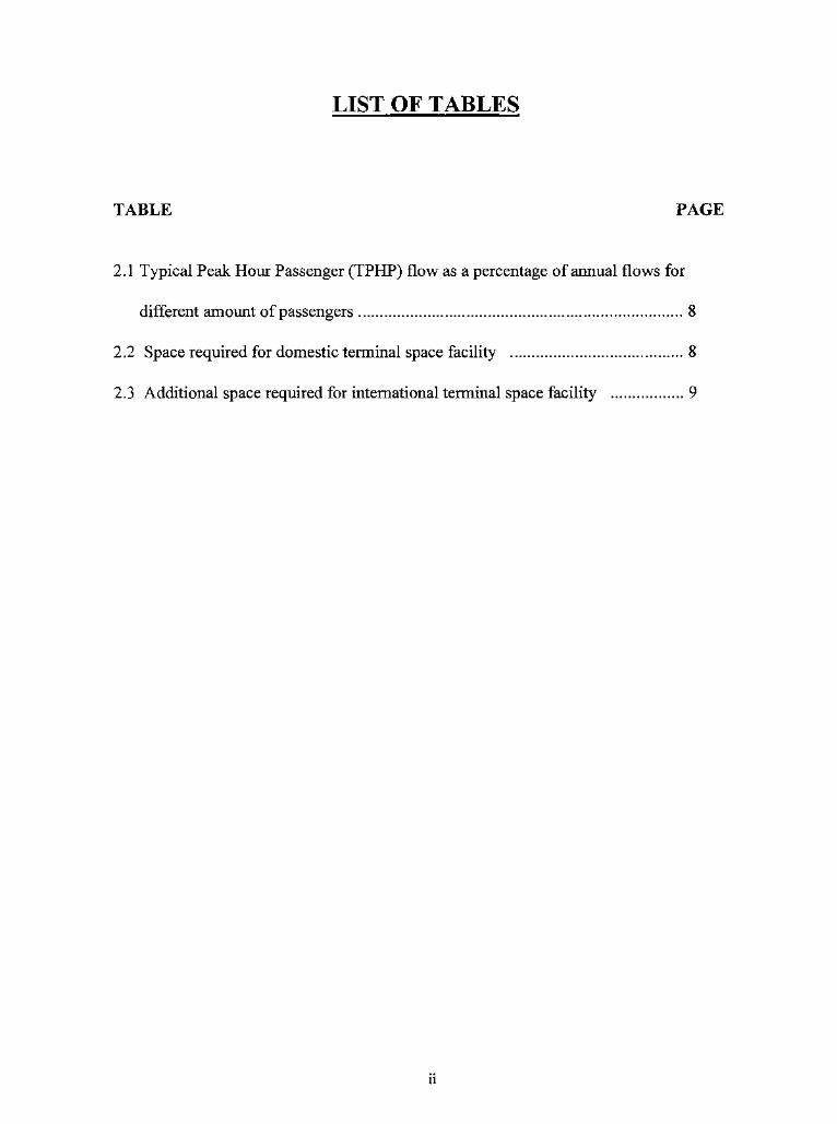
LIST OF TABLES
TABLE PAGE
2.1 Typical Peak Hour Passenger (TPHP) flow as a percentage of annual flows for
different amount ofpassengers 8
2.2 Space required for domestic terminal space facility 8
2 . 3 Additional space required for international terminal space facility 9
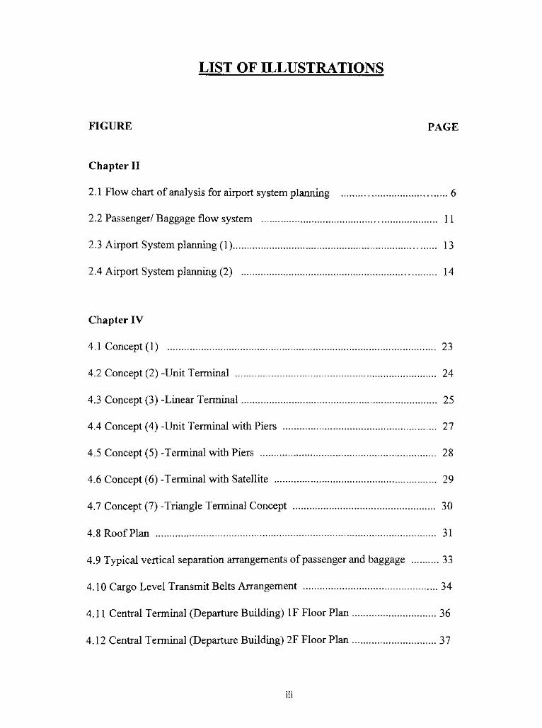
LIST OF ILLUSTRATIONS
FIGURE PAGE
Chapter II
2.1 Flow chart of analysis for airport system planning 6
2.2 Passenger/ Baggage flow system 11
2.3 Airport System planning (1) 13
2.4 Airport System planning (2) 14
Chapter IV
4.1 Concept (1) 23
4.2 Concept (2) -Unit Terminal 24
4.3 Concept (3) -Linear Terminal 25
4.4 Concept (4) -Unit Terminal with Piers 27
4.5 Concept (5) -Terminal with Piers 28
4.6 Concept (6) -Terminal with Satellite 29
4.7 Concept (7) -Triangle Terminal Concept 30
4.8 RoofPlan 31
4.9 Typical vertical separation arrangements ofpassenger and baggage 33
4.10 Cargo Level Transmit Belts Arrangement 34
4.11 Central Terminal (Departure Building) IF Floor Plan 36
4.12 Central Terminal (Departure Building) 2F Floor Plan 37
Ul
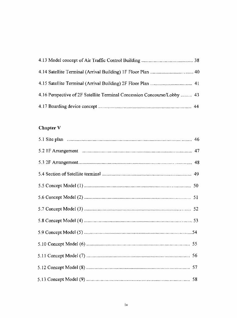
4.13 Model concept ofAir Traffic Control Building 38
4.14 Satellite Terminal (Arrival Building) IF Floor Plan 40
4.15 Satellite Terminal (Arrival Building) 2F Floor Plan 41
4.16 Perspective of2F Satellite Terminal Concession Concourse/Lobby 43
4.17 Boarding device concept 44
Chapter V
5.1 Site plan 46
5.2 IF Arrangement 47
5.3 2F Arrangement 48
5.4 Section of Satellite terminal 49
5.5 Concept Model (1) 50
5.6 ConceptModel (2) 51
5.7 Concept Model (3) 52
5.8 Concept Model (4) 53
5.9 Concept Model (5) 54
5.10 ConceptModel (6) 55
5.11 Concept Model (7) 56
5.12 ConceptModel (8) 57
5.13 ConceptModel (9) 58
IV
5.14 Concept Model (10) 59
5.15 ConceptModel (11) 60
5.16 ConceptModel (12) 61

Missing Page
GLOSSARY
Airport
An area of land (including buildings, runways and control towers) for the arrival or departure of aircraft
Airport Roads
Network of public and private roads providing access to airport buildings and areas
Airside
Area under government or airport control providing access to aircraft, and prohibited to non-traveling
public
Apron
Paved area on airside where aircraft are parked
Arriving passengerA passenger arriving at terminal by air
Baggage
The personal property of a passenger
Carousel
Rotating baggage-claim device
Concessions
Passenger amenities provided by retail, food services etc
Concourse
Open space or hall in passenger terminal, used for circulation or waiting
Departing passenger
A passenger departing from a terminal by air
DeplaningTo disembark from an airplane
Domestic flight
Flight within a single country not involving government control
Dwell time
Time that a passenger spends in a terminal
EnplaningTo board an airplane
vu
Gate
Point of passenger access to aircraft
Gate lounge
Waiting area adjacent to gate
Inbound Baggage
Inward bound baggage collecting area
International Flight
A flight between two or more countries, and subject to government controls
Landside
Area of airport terminal to which non-traveling public has access.
Moving Passenger ConveyorA transportation system for moving large numbers of people travelling distances too great on foot
Outbound Baggage
Outward bound baggage
Pier
A protruding extension to a terminal building giving access to aircraft gate
Satellite BuildingBuilding surrounded by aircraft gate positions, normally separate from terminal building
ScreeningSecurity checking by personal or electronic means of passengers, baggage, freight, and airport supplies
Terminal BuildingA building between landside and airside where passenger and baggage processing takes place
Transit Lounge
Area set aside for passenger who has arrived by plane but is not terminating his travel there
Visitor
Non-passenger and non-employee using terminal building
vm
PREFACE
"Airport and hospital design are the two most complicated designprojects."
according to Charles F. Lewis, my chief advisor and Chairman of the Department of
Industrial and Interior Design at Rochester Institute of Technology. When he told me that
at first, I did not believe what he said. I just thought that there must be some way to
improve the design of existing airports. Also, it was the first idea I had for my graduate
thesis project. I started doing research and found that it was much more difficult and
complicated than I had thought because of the many details, which not only an interior
designer, but also an architect, needs to consider, as well as the professional knowledge
required. It was also a big challenge for me as an interior designer to understand more
about architecture. Seeking that challenge, I chose Airport Design as the subject for my
thesis.
IX
PROPOSAL
The purpose of this thesis is to improve the design of airport terminals to provide
a more convenient environment for passengers and airport staff.
I intend to enhance the comfort, convenience, and experience of air travel and
shorten the time required from arrival to check-in to boarding.
CHAPTER I
INTRODUCTION
A look at the early airports, aircraft factories, and airliners themselves, reveals that
their design vocabulary reflecteddesigners'
efforts to encounter society's feelings of
ambivalence and insecurity toward this new mode of transportation. This design proposes
a new generation terminal which does not exist today.
The objectives of this thesis are to:
1 . Create and design a totally new terminal which can be used on any kind of airport
site in the future. Most current airports are designed and restricted to the area,
location, and terrain of the airport land itself. Thus, to create and design a new
terminal, free from any restriction listed above, is the priority of this study.
2. Design the terminal to be easily expanded in the future when necessary. An
existing airport might alter its design and original structure as necessary in the
future. The goal of this thesis study is to retain the existing terminal building.
3. Shorten the time and improve the process for passengers from check-in to
boarding without undermining the airport, aircraft and airline security.
4. Create a more humanistic, more convenient and more thoughtful environment for
passengers. Frequently, those passengers who are reboarding from large to small
aircraft, or from international to domestic flights, need to face unfavorable
weather conditions because there is no enclosed access between aircraft and
terminal. If the weather condition is unsatisfactory such as windy, raining,
snowing, or hot, passengers have no choice but to bear it without any protection.
5. The most important part of this thesis study, airport design, is to create a new
generation of airport terminal building. Passengers will experience the same
humanistic, convenient, and thoughtful environment to access the aircraft,
regardless of size or location.
CHAPTER II
BACKGROUND INFORMATION
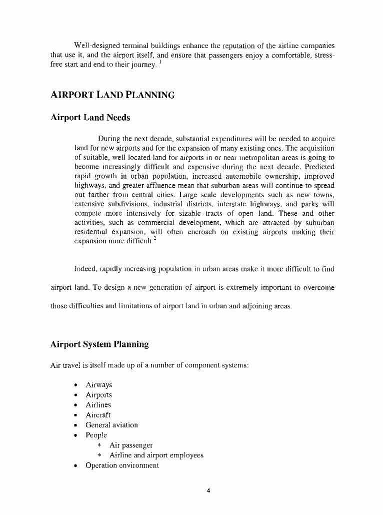
WHAT IS AN AIRPORT?
Airports are large, complex and generally highly profitable industrial enterprises.
They are part of a nation's essential transportation infrastructure, which, besides
providing thousands of jobs at the airport itself, supports a much broader audience in
social and economic terms. It has been estimated that for every job at the airport, an
additional one is created in the region. As large industrial complexes, airports consist
primarily of:
runways and taxiing areas
air traffic control buildings
aircraft maintenance buildings
passenger terminals and car parks
freight warehouses
For the architect, the passenger terminal is the main airport building and an opportunity
for architectural expression. Organizationally, the terminal building is the key element
within the airport estate. It is, however, just part of an integrated system, which involves a
complex interaction between airline companies, airport authorities and the traveler. The
reputation of an airport is, however, determined by the quality of its terminal buildings,
not just as architectural imagery but in terms of customer needs.
Well-designed terminal buildings enhance the reputation of the airline companies
that use it, and the airport itself, and ensure that passengers enjoy a comfortable,stress-
free start and end to their journey.l
AIRPORT LAND PLANNING
Airport Land Needs
During the next decade, substantial expenditures will be needed to acquire
land for new airports and for the expansion ofmany existing ones. The acquisition
of suitable, well located land for airports in or near metropolitan areas is going to
become increasingly difficult and expensive during the next decade. Predicted
rapid growth in urban population, increased automobile ownership, improved
highways, and greater affluence mean that suburban areas will continue to spread
out farther from central cities. Large scale developments such as new towns,
extensive subdivisions, industrial districts, interstate highways, and parks will
compete more intensively for sizable tracts of open land. These and other
activities, such as commercial development, which are attracted by suburban
residential expansion, will often encroach on existing airports making their
expansion moredifficult."
Indeed, rapidly increasing population in urban areas make it more difficult to find
airport land. To design a new generation of airport is extremely important to overcome
those difficulties and limitations of airport land in urban and adjoining areas.
Airport System Planning
Air travel is itselfmade up of a number of component systems:
Airways
Airports
Airlines
Aircraft
General aviation
People
* Air passenger
* Airline and airport employees
Operation environment
"Airport system planning, however, frequently has to be carried out as part of the
exercise ofmaster planning at one or more airports within the system!V?
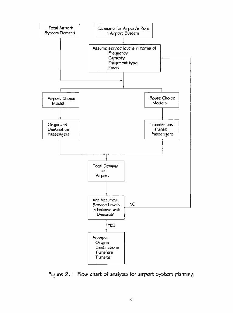
A Data Base For Airport System Planning
The following is a comprehensive data base recommended by A. Kanafani :
Figure 2.1 indicates the method of predicting an individual airport's share of total system
traffic.
Traffic Data
Route and city-pair specific data, including origin/destination flows
Airport specific traffic data
Traffic by other modes especially in short-haul situations
The traffic data should be obtained on an annual basis, as well as on a monthly
and daily basis. The data should cover both passengers, cargo tonnages, and aircraft
operations. For the calibration of demand forecasting models, it is necessary to obtain
traffic data for at least seven years.
Demand Characteristics
Origin destination demand
Trip purpose distributions for passenger demand
Commodity classifications for cargo demands
General aviation activity demand
Airport Data
Financial results, operation costs, and revenues
Facility inventories
Capacity
Temporal traffic patterns, including hourly distributions
General aviation-based aircraft and fixed-base operators
Total Airport
System Demand
Scenario for Airport's Role
in Airport System
Assume service level's in terms of:
Frequency
CapacityEquipment type
Pares
Airport Choice
Model
Route Choice
Models
Origin and
Destination
Passengers
Transfer and
Transit
Passengers
Total Demand
at
Airport
Are Assumed
Service Levels
in Balance with
Demand?
NO
YES
Accept:
Origins
Destinations
Transfers
Transits
Figure 2. 1 Plow chart of analysis for airport system planning
Airlines served
Access traffic conditions and facility inventories
Safety records
Weather conditions
Traffic operating patterns, including delay characteristics
Supply Data
City pair available capacity
Schedules and fares for passengers and cargo
Load factors prevailing
Airline operating cost data
Socioeconomic Data
Economic studies for regions and economic plans, if available
Population and demographic characteristics and forecasts, if available
Income characteristics and consumption patterns
Foreign and tourism trade patterns
Resource costs, including labor, fuel, and other inputs to aviation systems.
Prevailing land use patterns, both locally andregionally3
Physical Elements Of The Masterplan
Masterplanning an airport is a team effort, but the architect or engineer is
normally responsible for the physical disposition of the parts. It involves three principle
elements:
1 . Runways and taxiways
2. Hangers and service aprons
3. Terminals
and several secondary ones:
Roads and car parks
Security enclosure
Air traffic control tower
Airport railway station and light rail system
Hotels, conference facilities etc.
Freightwarehouses6
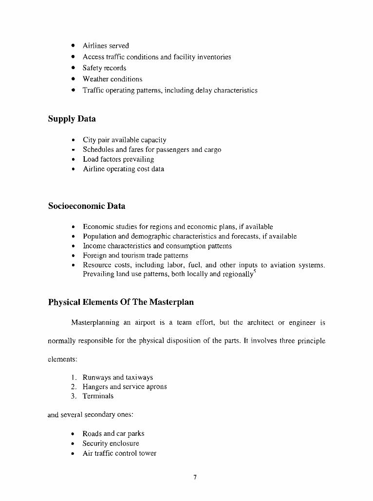
Standards of Space Requirements
The FAA and other bodies have set down guidelines for relationships with TPHP (Table
2.1). LATA also published a set of space design standards based on the level of the service
concept (Table 2.2 & 2.3)7
.
Table 2.1
Total annual passengers TPHP as a Percentage of Annual Flows
30 million and over
20,000,000 to 29,999,999
10,000,000 to 19,999,999
1,000,000 to 9,999,999
500,000 to 999,999
100,000 to 499,999
under 100,000
0.035
0.040
0.045
0.050
0.080
0.130
0.200
Table 2.2 SPACE REQUIREMENTS (Domestic)
Domestic Terminal Space Facility Space Required per 100 TPHP
(1000 ft2)
Total 24.2
(100 m-)
Ticket lobby 1.0 0.95
Airline operational 4.8 4.57
Baggage claim 1.0 0.95
Waiting rooms 1.8 1.70
Eating facilities 1.6 1.52
Kitchen and storage 1.6 1.52
Other concessions 0.5 0.48
Toilets 0.3 0.28
Circulation, mechanical, and maintenance, walls 11.6 11.05
23.02
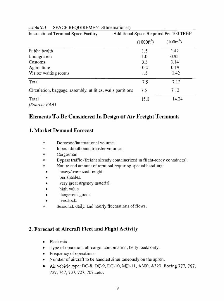
Table 2.3 SPACE REQUIREMENTS(International)
International Terminal Space Facility Additional Space Required Per 100 TPHP
(1000ft2) (100m2)
Public health
Immigration
Customs
Agriculture
Visitor waiting rooms
1.5 1.42
1.0 0.95
3.3 3.14
0.2 0.19
1.5 1.42
Total 7.5
Circulation, baggage, assembly, utilities, walls partitions 7.5
7.12
7.12
Total
(Source: FAA)
15.0 14.24
Elements To Be Considered In Design ofAir Freight Terminals
1.Market Demand Forecast
Domestic/international volumes
Inbound/outbound transfer volumes
Cargo/mail
Bypass traffic (freight already containerized in flight-ready containers).
Nature and amount of terminal requiring special handling:
heavy/oversized freight.
perishables.
very great urgency material.
high value
dangerous goods
livestock.
Seasonal, daily, and hourly fluctuations of flows.
2. Forecast ofAircraft Fleet and Flight Activity
Fleet mix.
Type of operation: all-cargo, combination, belly loads only.
Frequency of operations.
Number of aircraft to be handled simultaneously on the apron.
Air vehicle type: DC-8, DC-9, DC-10, MD-1 1, A300, A320, Boeing 777, 767,
757, 747, 737, 727, 707. ..etc.
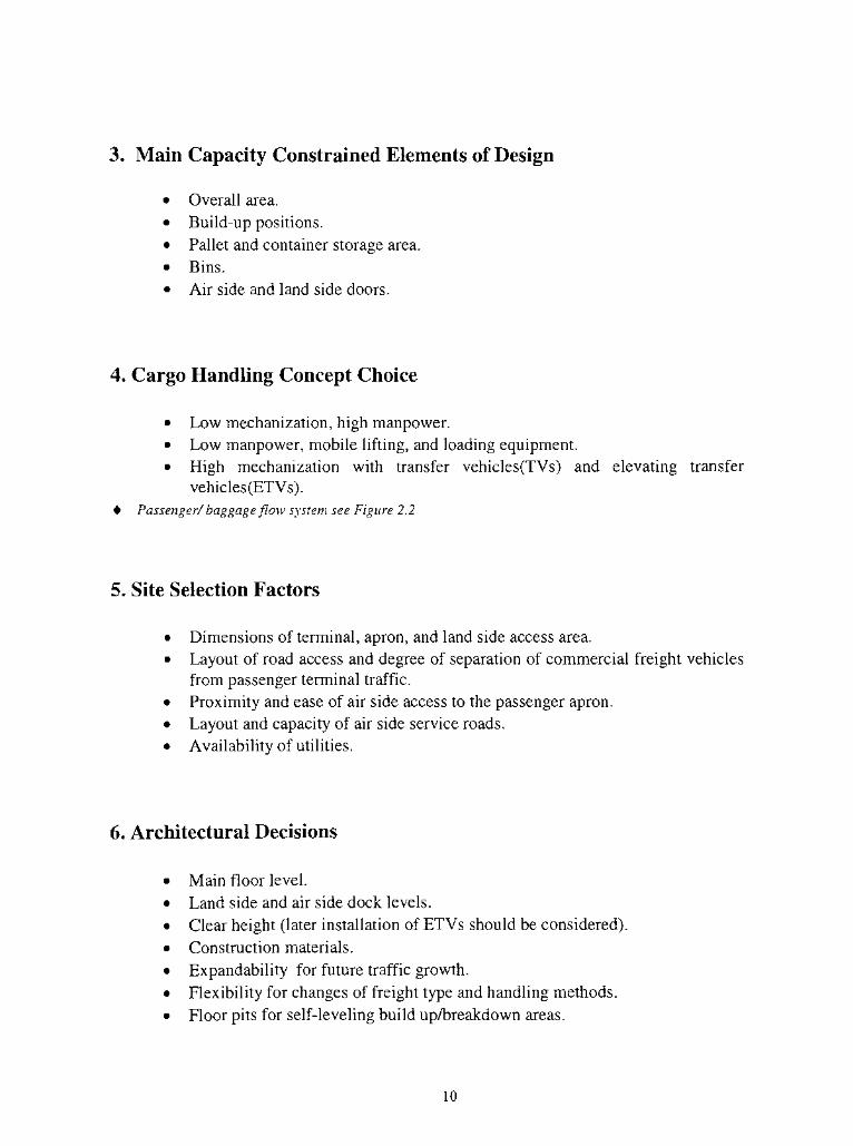
3. Main Capacity Constrained Elements ofDesign
Overall area.
Build-up positions.
Pallet and container storage area.
Bins.
Air side and land side doors.
4. Cargo Handling Concept Choice
Low mechanization, high manpower.
Low manpower, mobile lifting, and loading equipment.
High mechanization with transfer vehicles(TVs) and elevating transfer
vehicles(ETVs).
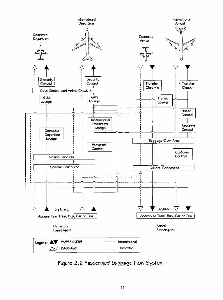
? Passenger/baggage flow system see Figure 2.2
5. Site Selection Factors
Dimensions of terminal, apron, and land side access area.
Layout of road access and degree of separation of commercial freight vehicles
from passenger terminal traffic.
Proximity and ease of air side access to the passenger apron.
Layout and capacity of air side service roads.
Availability of utilities.
6. Architectural Decisions
Main floor level.
Land side and air side dock levels.
Clear height (later installation of ETVs should be considered).
Construction materials.
Expandability for future traffic growth.
Flexibility for changes of freight type and handling methods.
Floor pits for self-leveling build up/breakdown areas.
10
Domestic
Departure
A A
International
Departure
u
International
Arrival
Domestic
Arrival
T
u
A 4
SecurityControl
V
SecurityControl
Gate Control and Airline Check-In
Gate
Lounge
A-
Gate
Lounge
.A rL_
Domestic
Departure
Lounge
International
Departure
Lounge
Passport
Control
Airlines Check-In
General Concourse
_A-
A
A <lv_
Enplaning A
i
i
i
i
i
i
i
V
Transfer
Check-In
_A_
I
Transfer
Check-In
Transit LALounge
Health
Control
Passport
Control
Baggage Claim Area
Customs
Control
General Concourse
io^-
i
I
\7 i Deplaning
--i
i
_A_
I
I
I
I
\7
Access from Train, Bus, Car or Taxi Access to Train, Bus, Car or Taxi
Departure
Passengers
Arrival
Passengers
Legend:_W
PASSENGERS
/_J BAGGAGE
International
Domestic
Figure 2.2 Passenger/ Baggage How System
n
7. Other Areas to be Included
In all cases, the dimensions of the space allotted, as well as of the doors, must be suitable
for the function of the area.
Maintenance and Support Facilities: For the maintenance and repair of ULDs
and their handling devices. Space will include facilities for washing and welding,
compressor and vehicle hoist.
Customs: Inspection area, offices, toilets, secure storage area.
Livestock: Storage areas, cages, feeding, watering, and cleaning facilities.
Environmental control.
Dangerous goods: Facilities dependent on nature ofgoods; secure storage.
Cold Room: Areas for high value and fragile cargo, human remains, and
radioactive material.
8. General Design Considerations
Security: Ease of general access into the freight terminal area, location of space
for security personnel, use of closed circuit TV.
Health and Safety: Design to observe local and national industrial health and
safety laws that govern workers and working conditions. Noise levels, operatingprocedures predicted by design, and surface finishes.
Insurance: Sprinkler system, smoke detectors, fire rating ofbuilding materials.
Suitability of Building Materials: Material used must reflect the handlingmethods within the terminal. Potential damage should be minimized and its repair
o
should be easy.
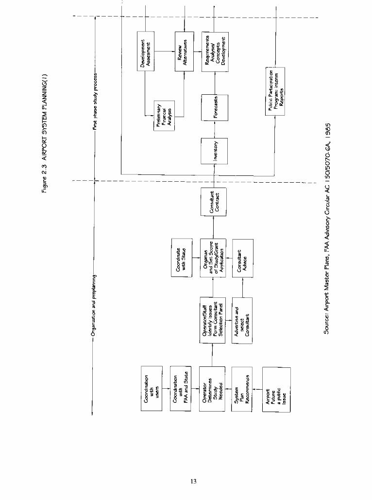
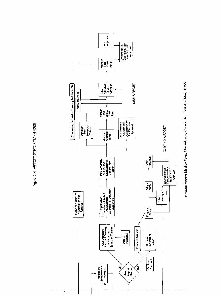
AirportMaster Planning
The FAA specifies a number of elements which are generally to be included in anymaster
planning exercise (Figure 2.3 & 2.4):
1 . Organization and preplanning
2. Inventory of existing conditions and issues
3. Aviation demand forecasts
4. Requirements analysis and concept development
5. Airport site selection
6. Environmental procedures and analysis
7. Simulation airport plans
12
U c
E o
Si. EO m if
5
e"??e
z
2
Z
D_
UJ
in
o
8z
CO
c\i
u
3
u_
re n in
15e .. m
Et
0- n o
5
C 4-1
5 g
as
2.3-^ IT)
Os
ilf|
IX fto-am
a.
a
O
|8
<_>
it in S
u c F *
O^iLin
.= I"
Ssi*
Ss2
e s
in
<
6NOIT)
in
u
oin
>
2
0_
o
<uuE-
3
oin
in
Od
E
6S5
?
a-J>
13
co
<5
D_
IU
Iino
k<
CM
S>
a c
6 in Si^D
lflu
3 E
IS-.So j=
- fln E to- n o
IIIpi:
T"
a, O-
SCE2
g o
j) a. e o
i jj^m
^ s -a
$1*
Si2,o
. i
am b-e
<->, D a-
O
= E InOUT! cji c a
a cs
IS
g c < O
o
<
O
<
oz
2
"5. tfi
.3c
-30- 31
in
cr>
<
o
Oin
c5in
1
om
5
5
&
0a.
o
8. Airport plans
9. Plan implementation
Airport Layout Basic Factors And Types
A. The layout of an airport is determined by five basic factors:
1. The direction of prevailing winds (the major runway[s] being oriented to the
prevailing wind with a back-up runway on a cross-wind alignment)
2. The size and number of terminal buildings
3. The ground transport system, especially the position of major access roads and
railways
4. Mandatory clearance dimensions between aircraft and buildings
5. Topography and geology
B. Typical of the data that need to be gathered are:
1. Passenger statistics (international or domestic, scheduled or non-scheduled,
arriving/departing or transit, weekly, daily or hourly flows)
2. Cargo statistics (similar breakdown as for passenger flows)
3. Aircraft (types, international or domestic, passenger or cargo, peakmovements)
4. Visitors (meeters and greeters, airport visitors as non-travelling tourists, shoppers,
business users)
15
C. For the passenger terminal, operational capacity is dependent upon the
performance of the following key elements:
1 . Landside access
2. Baggage handling
3. Passenger check-in capacity
4. Immigration control capacity
5. Security check capacity
6. Boarding gate capacity
D. Airport types
1 . International airports serving over 20 million passengers a year
2. National airports serving between 2 and 20 million passengers a year
3. Regional airports serving up to 2 million passengers a year
E. Other factors relevant to typological classification include:
1 . The split between domestic and international movements
2. The role of the airport as an international center for aviation or as a distribution hub
3. The scale ofnon-airport facilities, such as other transportation modes, hotels, business
and conference centers.
F. The life of assets at airports
1 . Runways, taxiways and aprons: 1 00 years
16
2. Terminal buildings, pier and satellite structures: 50 years
3. Tunnels, bridges and subways: 50 years
4. Terminal fixtures and fittings: 20 years
5. Transit systems: 20-50 years
6. Plant and equipment(runway lighting and building plant): 5-20 years
7. Motor vehicles: 4-8 years
8. Retail units, bars and restaurants: 3-5 years
9. Office equipment: 5-10years.10
It is obvious that the impact of an airport extends far beyond its physical
boundaries. Two types ofmasterplan are commonly met: that which structures the airport
estate only (but with a statement of wider impacts), and that which structures both the
airport and neighbor areas into a coordinated development proposal. The latter is
increasingly adopted as airport developers, working usually with neighboring landowners
and civic authorities, recognize that coordinating neighborhood land uses with airport
expansion is mutually beneficial.
The physical and environmental planning of an airport and its surrounding land
should seek to ease community conflict (from problems such as noise and traffic
congestion) and realize the possibilities of development alongside the airport. The growth
in service, such as air cargo, has led to an expansion of warehousing facilities near to
airports. Therefore, airport expansion should recognize that much growth occurs outside
the perimeter fence, and that both need to be structured in time and space to ensure that
infrastructure demands (water, drainage, transport) and environmental impacts are
foreseen and accommodated.
17
Sources and References:
1. The Modern Terminal, Brian Edwards, NewApproaches to AirportArchitecture, 1998
2. Airport Land Needs, Warren H. Deem & John S. Reed, AuthorD. Little Inc., 1967
3. Airport Engineering,3rd
Edition, Norman Ashford & Paul H. Wright, AWiley-Interscience Publication, 1991
4. A Framework for Aviation SystemsPlanning,"
Kanafani, A., Course Notes for Airport Planning and Design
Short Course, Institute for Transportation Studies, Berkeley, California, 1988
5. Airport Engineering,3rd
Edition, Norman Ashford & PaulH. Wright, AWiley-Interscience Publication, 1991
6. The Modern Terminal, Brian Edwards, New Approaches To Airport Architecture, 1998
7. Airport Engineering,3rd
Edition, Norman Ashford & Paul H. Wright, AWiley-Interscience Publication, 1991
8. Airport Engineering,3rd
Edition,Norman Ashford & Paul H. Wright,AWiley-Interscience Publication, 1991
9. Airport, Aircraft and Airline Security, Kenneth C. Moore, SecurityWorld Publishing Co., Inc., 1976
10. TheModern Terminal, Brian Edwards, New Approaches ToAirportArchitecture, 1998
18
CHAPTER III
DESIGN DEVELOPMENT
Concept Development And Evaluation
My research into the concept of airport design has focused on combining four
main scales of air transport international, continental, regional and commuter into one
terminal building as the program for my thesis.
While the intercontinental and continental markets are met by jet aircraft, the
lower end of the regional scale and commuter markets are increasingly served by
turboprops. The new generation of turboprops offers distinct advantages over jet aircraft:
they are less noisy, can operate at lower altitudes, have reduced emissions, and have
shorter take-off and landing needs. Commuter jets and larger jets now have greater need
to be on the closest apron for passengers to easily transfer. The main problem here is
access from the terminal building to the plane; the usual pattern of elevated telescope
gates will not suffice. Demarcation for commuter flights is normally directly over the
apron alongside the terminal or by busing to locations further afield. In unsatisfactory
weather conditions, passengers do not have any protection and need to face adverse
weather without choice. Where large numbers of commuter passengers regularly use a
terminal, there needs to be provision for direct and easy access to the apron area from the
19
departure lounge. Forpassengers'
convenience, larger jets and smaller commuters could
be combined on the same apron.
My research has targeted terminal design. The design of a terminal depends on the
nature of the air traffic to be handled at an airport. The design concept chosen is a
function of a number of factors, including the size and nature of traffic demand, the
number of participating airlines, the traffic split between international, domestic,
scheduled, and charter flights, the available physical site, the principal access modes, and
the type of financing.
I researched several existing terminal building types to see if they are efficient.
And the result is "No!"; they could be improved. The research developed step by step and
the final concept was made with regard to several advantages. The advantages of the
terminal type I have selected to concentrate on are:
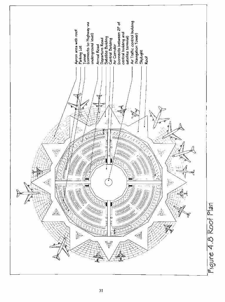
1 . A Round-shaped terminal building has maximum apron space.
2. The skylight roof of the apron area meets the minimum space requirement.
3. The roof of the apron area has a strong structure.
4. Passengers have the shortest distance for transferring between airlines.
5. Star-shaped terminal building with "angled-nosein"
aircraft parking has the
shortest corridor access from terminal to aircraft.
6. All air side service roadways could be easily added or modified underground.
7. Center navigation tower has the best view of all taxiways and runways.
8. Center navigation tower has minimum limitation of airport land.
9. Underground cargo level uses roadways separate frompassengers'
cars,
providing better safety, convenience and attractiveness.
20

10. Additional round-shaped terminal buildings could be built easily later within a
limited amount of airport land.
21
CHAPTER IV
DESIGN EVOLUTION
After I decided to explore airport design as my thesis project, I began collecting
and evaluating materials, and established the design goal to meet not onlypassengers'
but
also airportstaffs'
needs and expectations, and the functional requirements of an airport.
That criteria helped me develop preliminary concepts which meet my design
goals. I developed concepts and possible solutions through sketches and diagrams, and
evaluated them based on the design criteria. I reported my progress to faculty weekly as
my development evolved.
A. The Original Concept
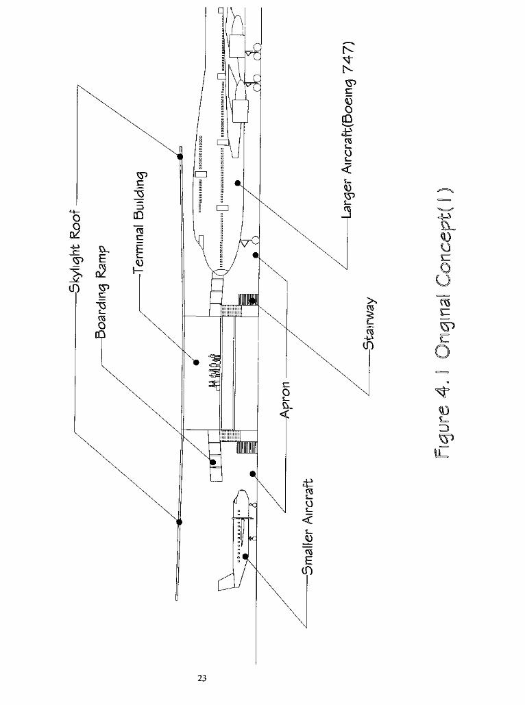
The first concept I had was to build a roof above the aprona paved area where
airplanes are parked (Figure 4.1). The advantage of this concept is to provide passengers
enclosed access to small aircraft. Thus, passengers who are boarding small aircraft have a
service route to the aircraft without exposure to unfavorable weather conditions. Then, I
started to develop and evaluate variations of aprons which are used in most existing
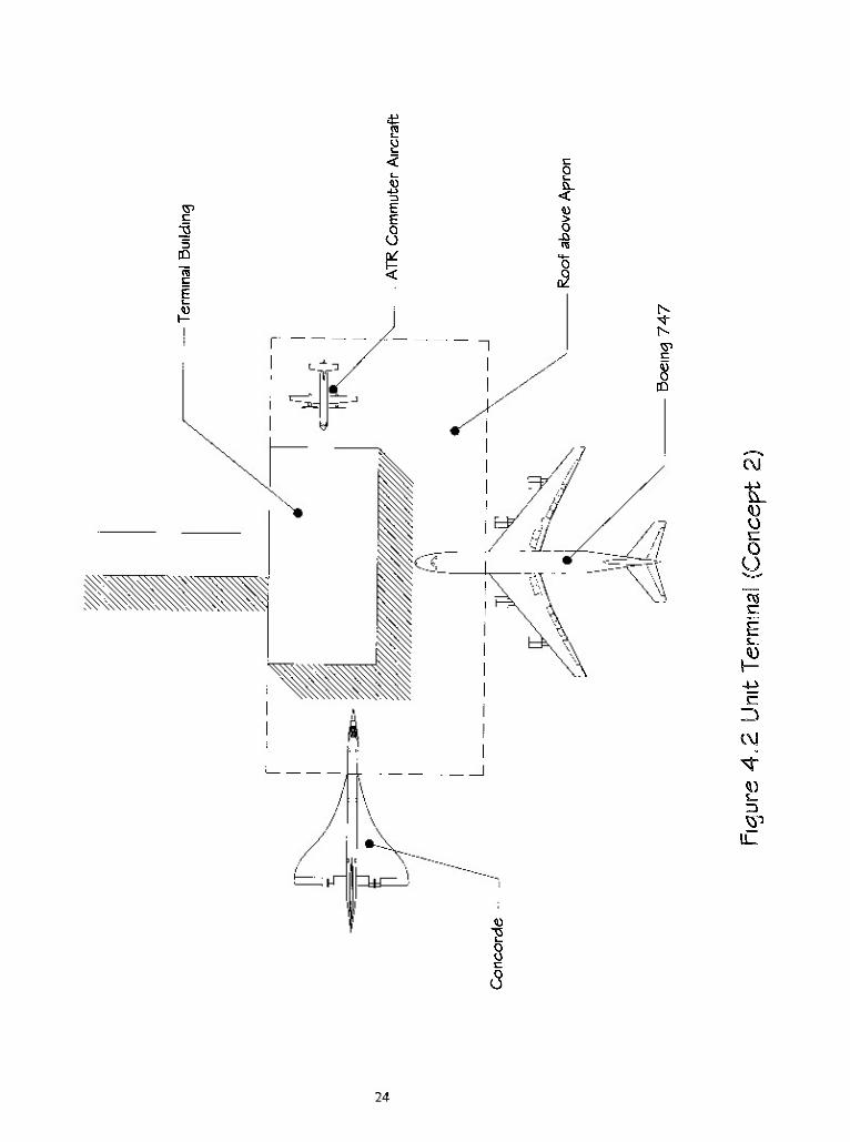
airport terminals. As follows:
1 . Unit Terminals (Figure 4.2)
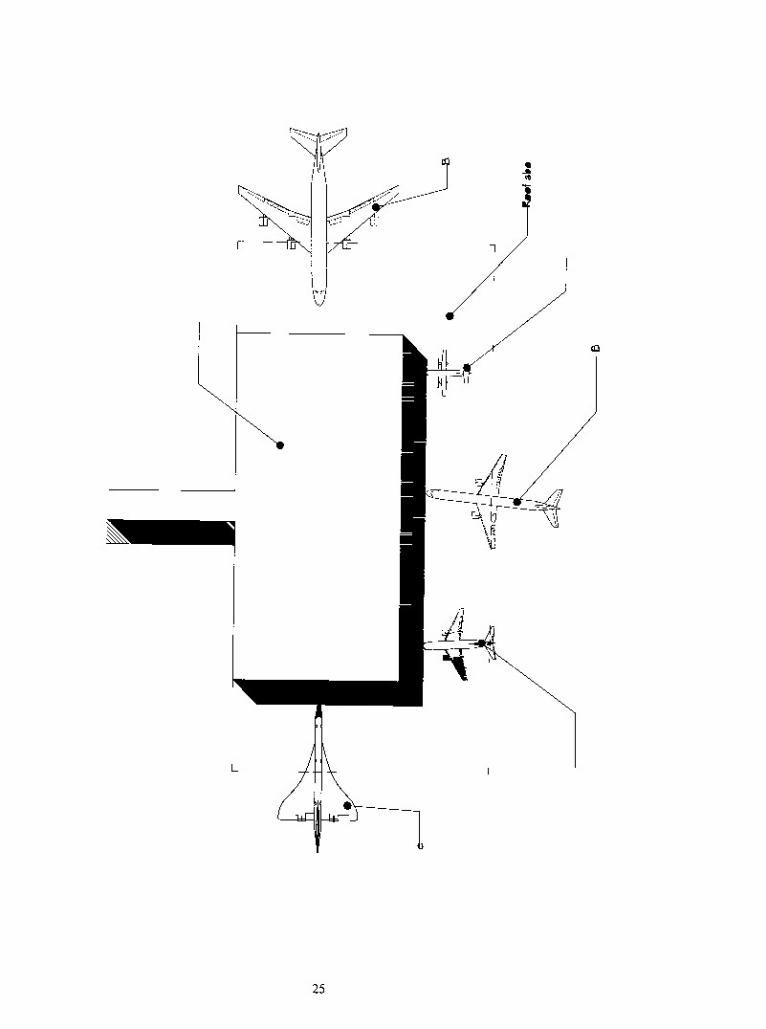
2. Linear Terminals (Figure 4.3)
22
23
CM
<UOc
O
U
r.
r=
E
c\j
24
CO
Oc
O
u
eg
r-
s_
E=j
CO
25
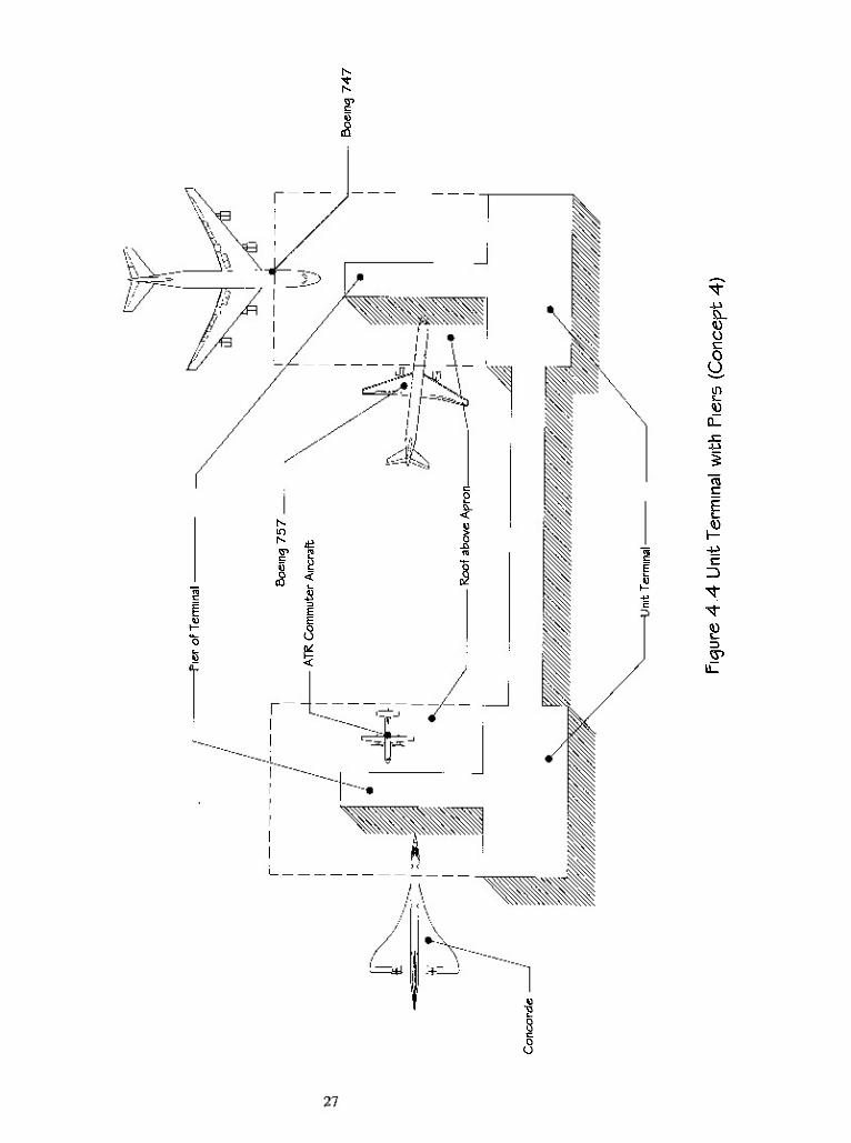
3. Unit Terminals With Piers (Figure 4.4)
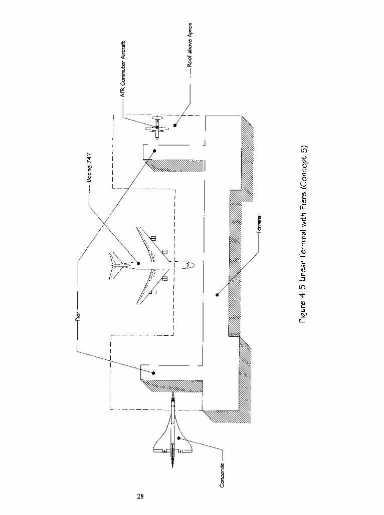
4. Terminal With Piers (Figure 4.5)
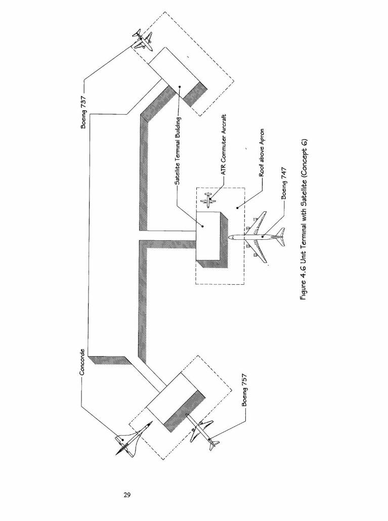
5. Terminal With Satellites (Figure 4.6)
B. Concept Evolution
After evaluating the five typical terminal types listed above, I found that most of
them require greater square footage of roof area, which is less efficient and more difficult
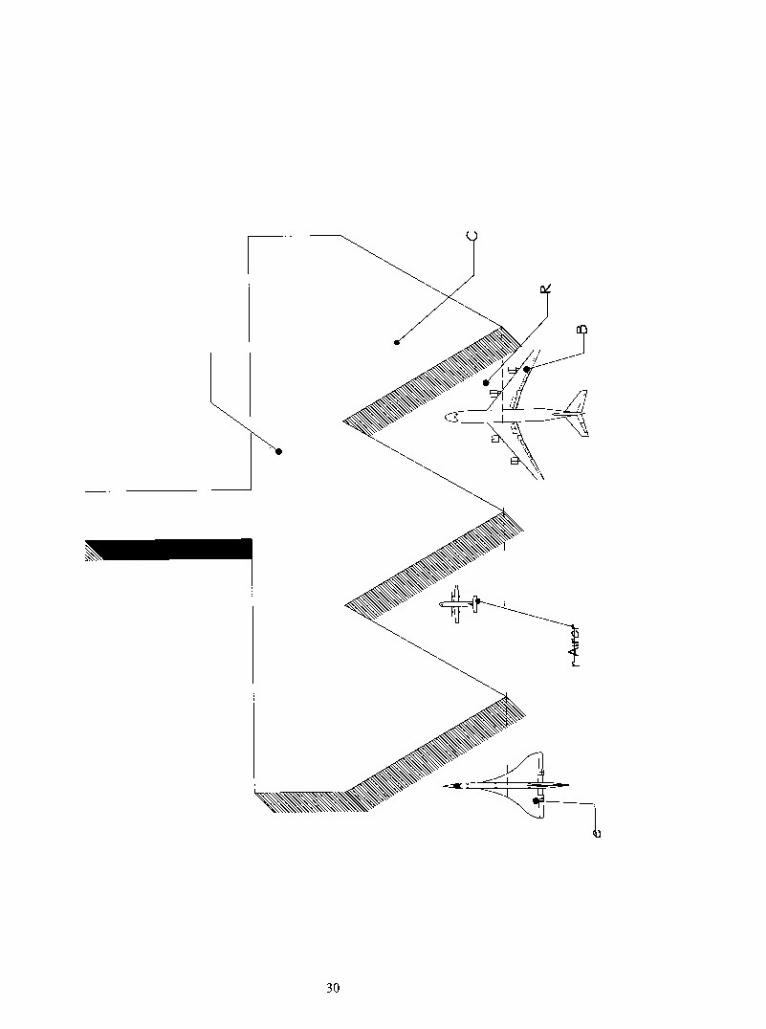
to construct. Then I thought of creating a triangular apron space (Figure 4.7) to both
minimize the roof area, and strengthen the structure.
C. Final Concept
After experimenting with several variations, triangle-square, triangle-linear,
triangle-round, etc., I selected the triangle-round apron type as the most successful
solution (Figure 4.8).
1. Apron Roof Structure
The apron serves two functions: it is an area for parking airplanes and for
performing servicing and minor maintenance work. The dimensions of the apron are
determined by the first function. The facilities supplied on the apron and their locations
are set by the servicing function. The principle services to be supplied are:
Aircraft Fueling ;
Electrical Supply ;
Aircraft Grounding ;
Apron Roadways.
26
&_<DO
O
U
in
Q_
"toc
Es_
27
in
k_
<0U
O
u
ini_
<0
TO
03\-
s_
TO
E
in
<o
28
8.
u
o
u
<u
15
to
m
5
"to
E
IP
29
4->
&_
o
o
u
Es_
<ur-
^>
I
IS
<0s_
u_
30
2
to
s . w ^
to
>
3=
JQ S--
cu
<0
aTO
IL.
CM
.a
3 2^
iB " 5 J .8
-=-ri^2oiUTO-fi
<Dinu<>y.oS<=-ir)
u o+= jj +>
Q_
ft
IL
31
"The Sun is the best lightingsource"
says I.M.Pei, a famous American architect.
Indeed, a bright, sunlit environment is very welcoming. Thus, I chose a pyramid structure
to support glass for the apron roof. This efficient structure had been used in ancient Egypt
long ago. To accommodate parking configurations I determined that15,000m2
(161,450
ft"), large enough for the Boeing 747-400, would be required. The Boeing 747-400 is the
largest, currently used commercial aircraft in the world.
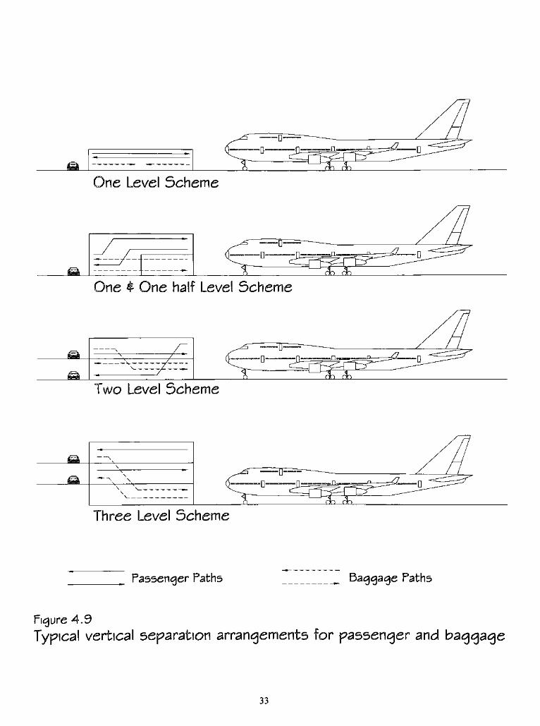
2. Vertical Separation
There are four typical arrangements for vertical separation of passengers and
baggage (Figure 4.9). I chose "one and one halflevels"
as my solution due to its simple
circulation and operation system. It separates departures and arrivals without complex
intersection routes. Also it provides an excellent circulation and operation system giving
passengers and visitors easy access to the airport without confusion.
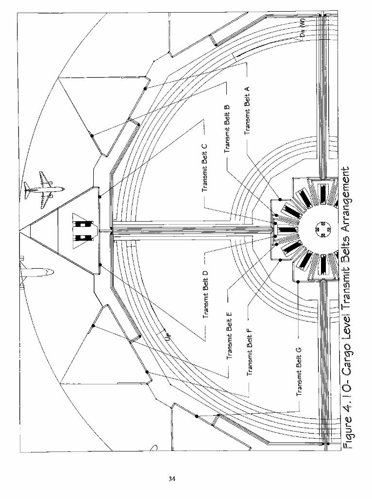
3. Central (Departure/Check-In) Building
Having selected the "One and One HalfLevel"
scheme, I developed a new
concept which, to my knowledge, has never been used in an existing airport. The concept
places a center building as the check-in/departure building, and several satellite buildings
as arrival/pick-up buildings. In addition, there is a freight level between the second floor
and the first floor, which is only six-foot high. Passengers can check luggage at the
center/departure building on the first floor, and then go to a coffee shop, restaurant or
duty-free shop unencumbered by heavy baggage. Cargo transits on its specific route and
level to the particular satellite terminal where the passenger will board (Figure 4.10).
32
One Level Scheme
One half Level Scheme
Two Level Scheme
Three Level Scheme
Passenger Paths Baggage Paths
Figure 4.9
Typical vertical separation arrangements for passenger and baggage
33
34
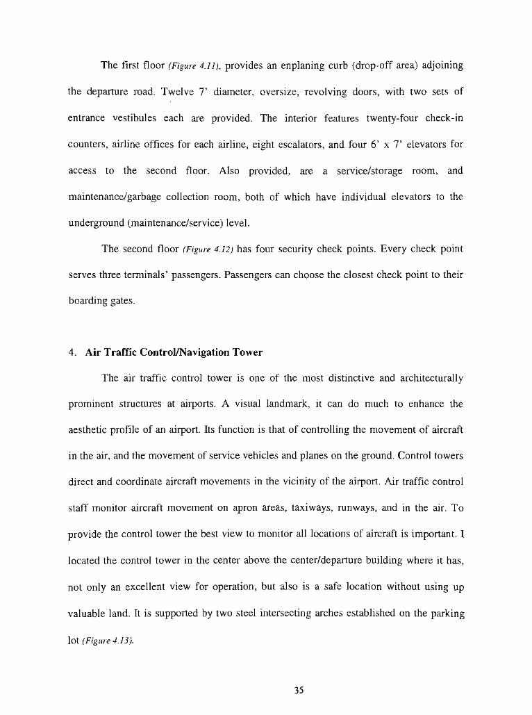
The first floor (Figure 4.11), provides an enplaning curb (drop-off area) adjoining
the departure road. Twelve7'
diameter, oversize, revolving doors, with two sets of
entrance vestibules each are provided. The interior features twenty-four check-in
counters, airline offices for each airline, eight escalators, and four6'
x7'
elevators for
access to the second floor. Also provided, are a service/storage room, and
maintenance/garbage collection room, both of which have individual elevators to the
underground (maintenance/service) level.
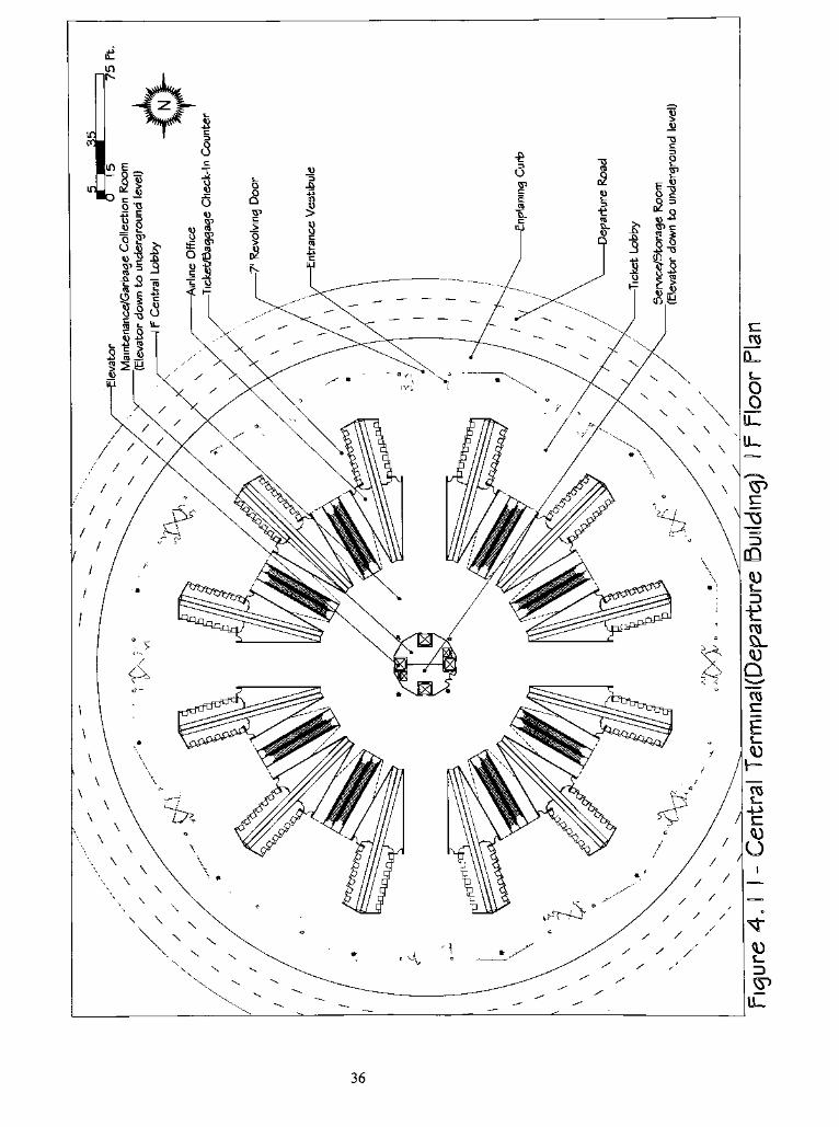
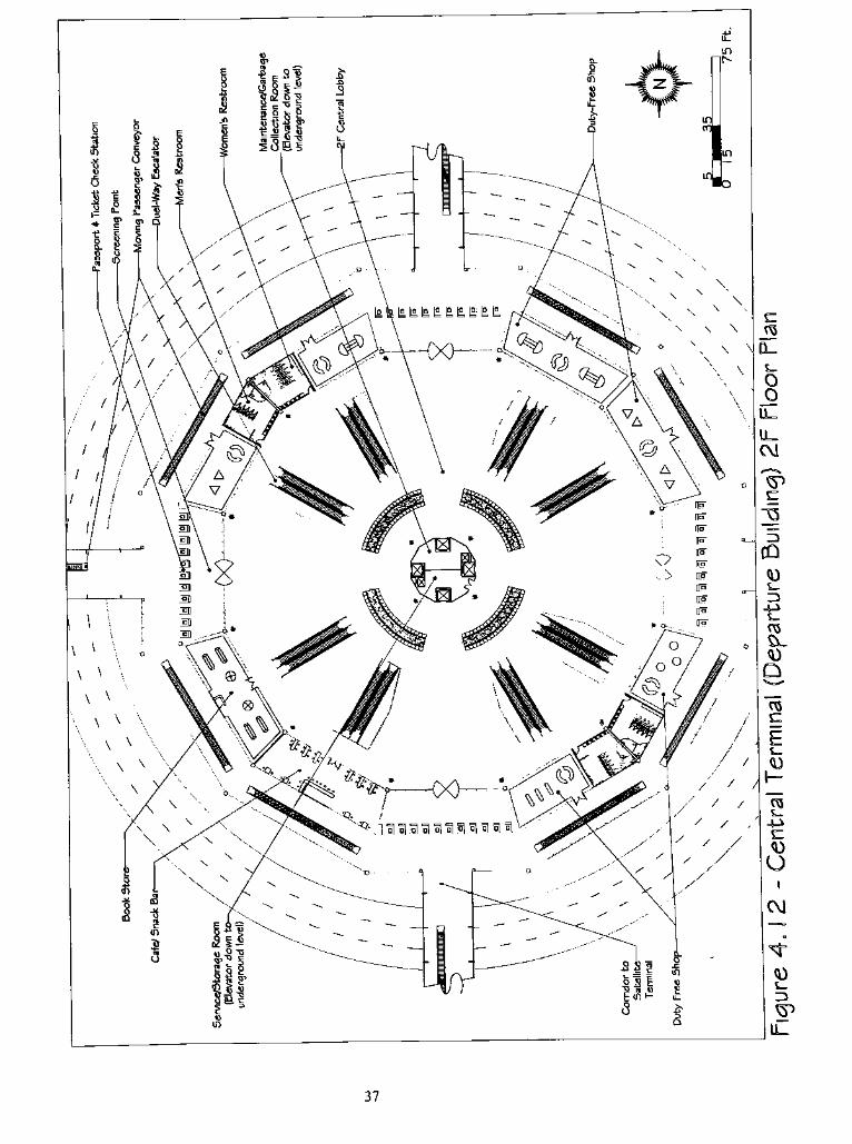
The second floor (Figure 4.12) has four security check points. Every check point
serves threeterminals'
passengers. Passengers can choose the closest check point to their
boarding gates.
4. Air Traffic Control/Navigation Tower
The air traffic control tower is one of the most distinctive and architecturally
prominent structures at airports. A visual landmark, it can do much to enhance the
aesthetic profile of an airport. Its function is that of controlling the movement of aircraft
in the air, and the movement of service vehicles and planes on the ground. Control towers
direct and coordinate aircraft movements in the vicinity of the airport. Air traffic control
staff monitor aircraft movement on apron areas, taxiways, runways, and in the air. To
provide the control tower the best view to monitor all locations of aircraft is important. I
located the control tower in the center above the center/departure building where it has,
not only an excellent view for operation, but also is a safe location without using up
valuable land. It is supported by two steel intersecting arches established on the parking
lot (Figure 4.13).
35
36
37
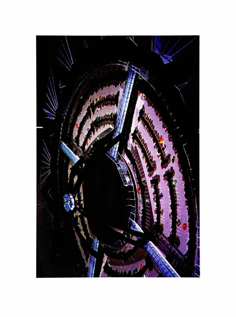
5. Satellite (Arrival/Pick-Up) Building
While considering the apron configuration, I evaluated airplane parking
requirements as well. After studying them, I understood that having a 30,60
or45
parking angle will assistwith the better function of the airline.
720(Exterior Angle ofPolygon)/
60(Angle per apron)
= 12 (Number ofApron)
Through experimentation, I finally decided to provide twelve satellite terminals;
each with two adjoining aprons, for a total of twenty four in the airport prototype. With a
seven-hundred-forty foot radius, round building, each apron has a minimum 75,000 ft to
a maximum 170,000 ft area. It exceeds the standard suggested requirement for the
Boeing 747-400, the newest, wide-bodied, four-engine jet aircraft.
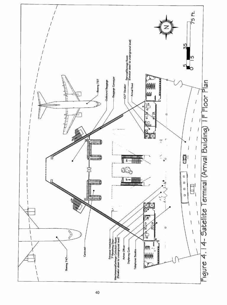
The first floor (Figure 4.14), features a passenger pick-up area along side the arrival
road, two seven-foot diameter oversize, revolving doors, and four sets of entrance
vestibules. I provided women's and men's restrooms, telephone booths, two 112ft2
airline offices, a 30 ft service/storage room, and a 30 ft maintenance/garbage collection
room, four6'
x7'
elevators, escalators, stairways, baggage claims and outbound baggage
areas.
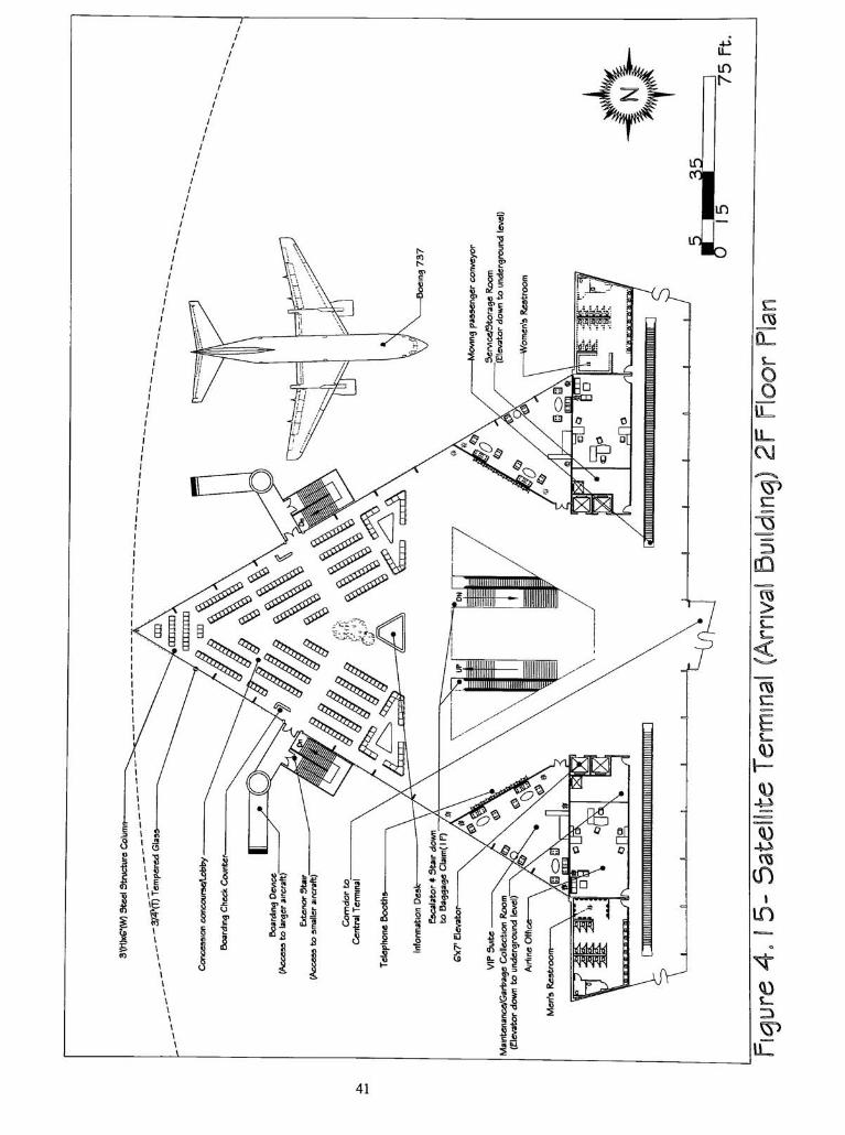
The second floor (Figure 4.15), provides passenger seating, telephone booths,
airline offices, women's and men's restrooms, a maintenance/garbage collection room,
and a service/storage room. The seating area provides seating for 322 people, an
39
40
41
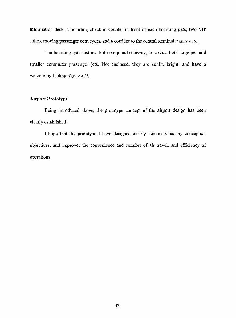
information desk, a boarding check-in counter in front of each boarding gate, two VIP
suites, moving passenger conveyors, and a corridor to the central terminal (Figure 4.16).
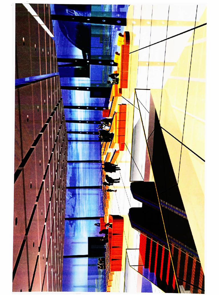
The boarding gate features both ramp and stairway, to service both large jets and
smaller commuter passenger jets. Not enclosed, they are sunlit, bright, and have a
welcoming feeling (Figure 4.17).
Airport Prototype
Being introduced above, the prototype concept of the airport design has been
clearly established.
I hope that the prototype I have designed clearly demonstrates my conceptual
objectives, and improves the convenience and comfort of air travel, and efficiency of
operations.
42
44
CHAPTER V
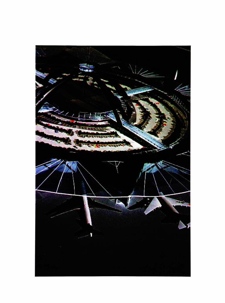
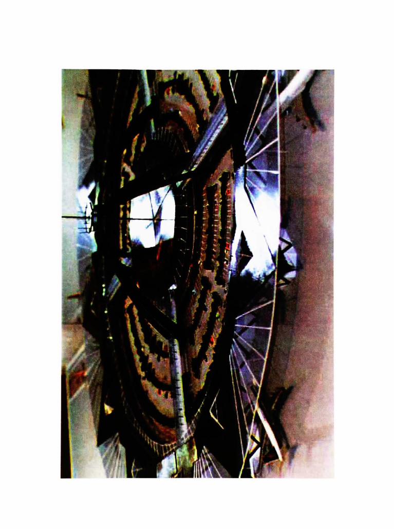
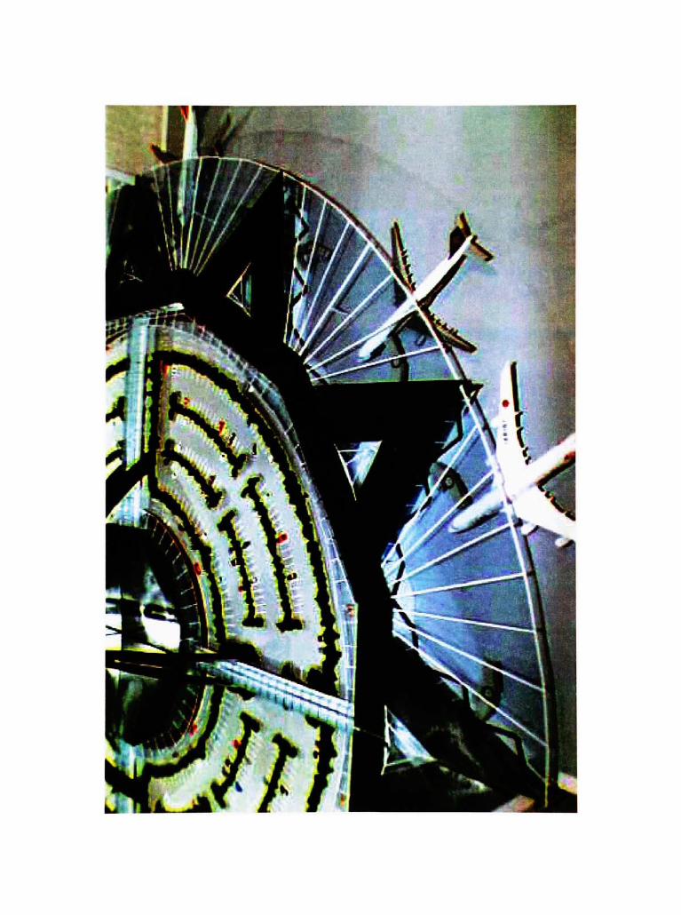
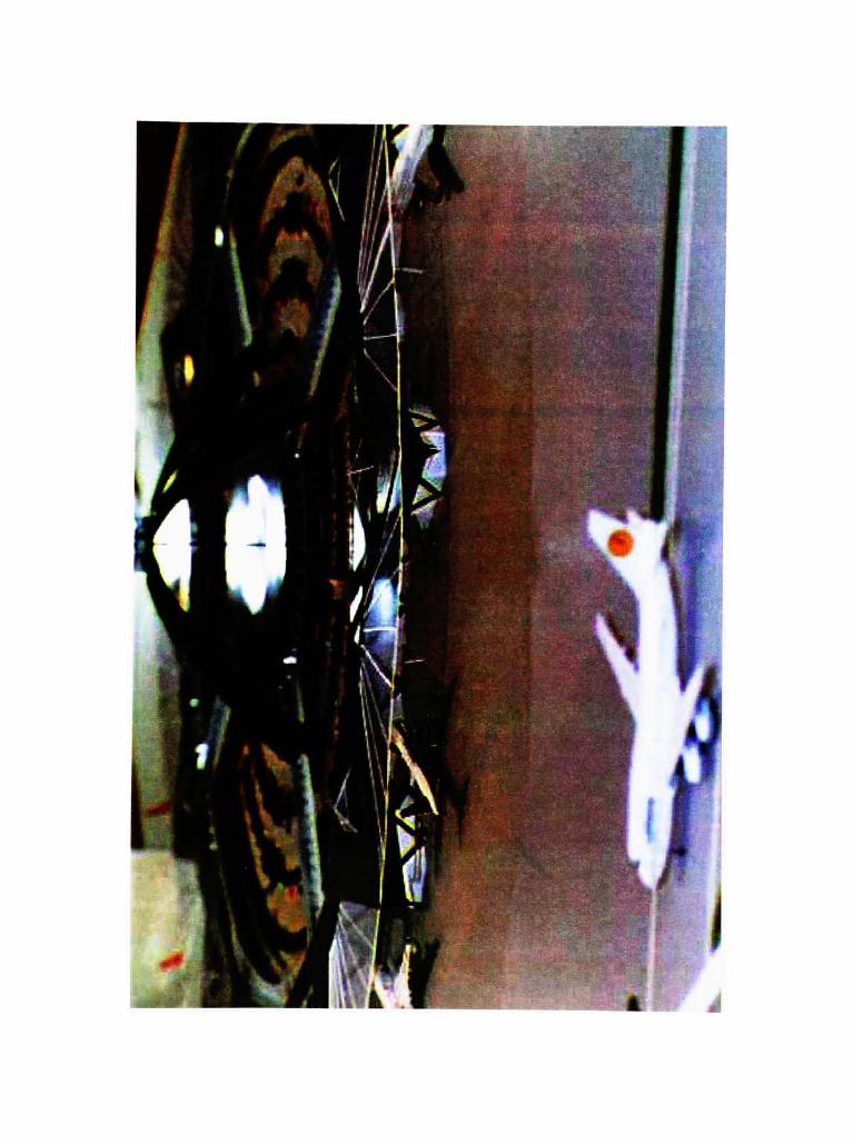
DESIGN RESULT
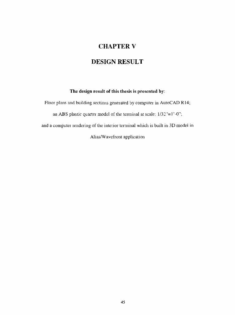
The design result of this thesis is presented by:
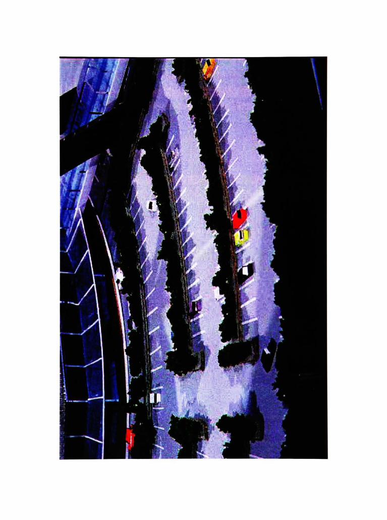
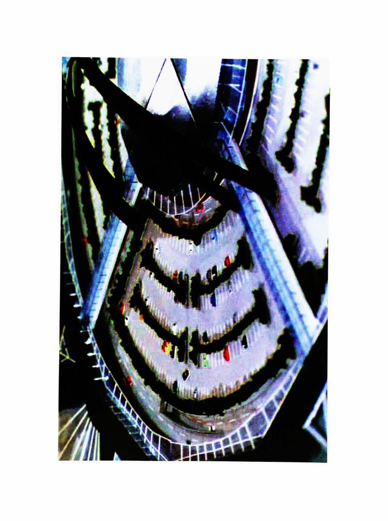
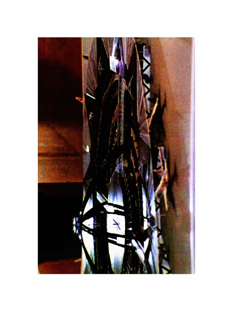
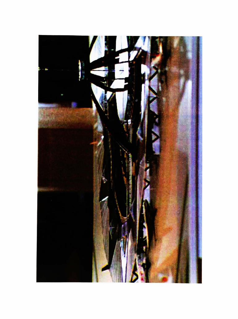
Floor plans and building sections generated by computer in AutoCAD R14;
an ABS plastic quarter model of the terminal at scale: 1/32"= 1 '-0";
and a computer rendering of the interior terminal which is built in 3D model in
Alias/Wavefront application
45
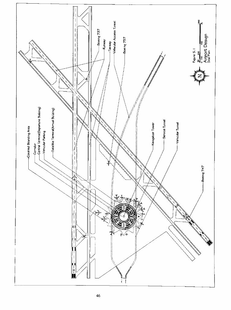
46
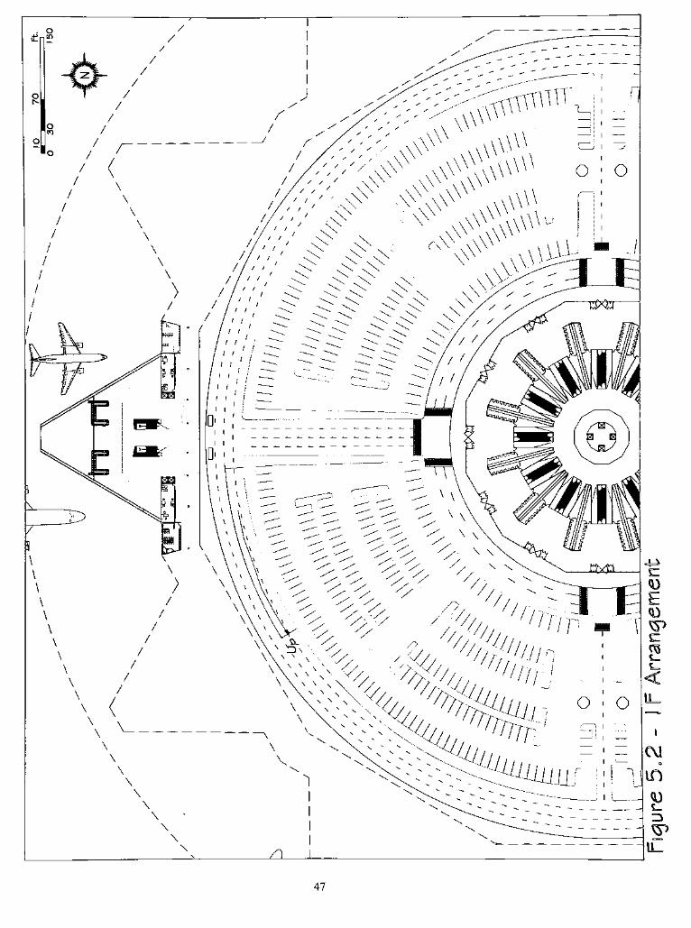
47
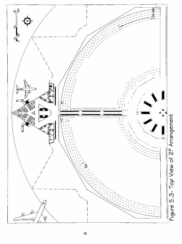
48
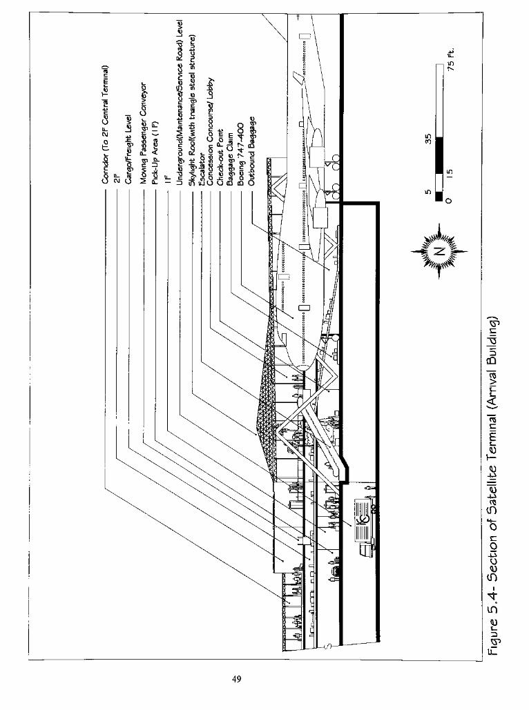
in
in
CO
Iin
49

CHAPTER VI
CONCLUSION
Although it is impossible to predict the future of air travel, even over the next few
years, several things appear to be fairly certain. One is that air travel will continue to
grow rather quickly for the foreseeable future. A large number of people have learned to
use the airplane just as they used trains in an earlier era or they use the automobile or bus
today. Commuting by airplane has become common.
The goal of this thesis was to improve the current design of the airport terminal to
better serve passengers. In the final result, shown in Chapter IV, the round-shaped
terminal represents a Twenty-first Century terminal design for the near future. The future
terminal will be quite different from that experienced at most airports today. The modern
airport, and certainly the airport of the21st
century, is a huge, complex and noisy facility.
It is a focus for a wide diversity of human activity-from travel to leisure, from shopping
to health clubs, from plane-spotting to conferences, and from family reunions to church
outings. The airport is as a new type of city in the twenty-first century.
62

I hope to see this multifunctional, convenient, safe, and comfortable prototype
introduced to the public soon.
63
BIBLIOGRAPHY
Aerodrome Design Manual Part 2, Taxiways, Aprons andHolding Bays,2nd
Edition,
Montreal: International Civil Aviation Organization, 1983.
Airport Design Standards- Site Requirements for Terminal Navigational Facilities, AC
150/5300-2D, Washington D.C.: FAA, 1980(Including Changes).
AirportMaster Plans, FAA Advisory Circular AC 150/5070-6A, 1985.
Airport PlanningManual Part 1,Master Planning,2nd
Edition, Montreal: International
Civil Aviation Organization, 1987.
Airspace Utilization Consideration in the Proposed Construction, Alteration,
Aviation and Deactivation ofAirports, 70-2D, Washington, D.C.: FAA, 1970.
Airport System Capacity, Special Report 226, Washington D.C.: Transportation
Research Board, 1990.
Ashford, N., Level of Service Design Concept for Airport Passenger Terminals: An
European View, Transportation Planning and Technology, Vol. 12, No. I, 1987.
Ashford, N. L, Planning and Designing for Air Cargo Under Condition of
Technological and Market Change, Avmark Conference Proceedings, The Air Cargo
Industry and Its Aircraft, Capri, May 1990.
Ashford, N., Predicting thePassengers'
Choice of Airport, Airport Forum, March
1989.
Ashford, N. L, Problems in Long Term Air Transport Forecasting, Journal of
Advanced Transportation, Vol. 19-2, August, 1985.
Ashford, Norman J. & Wright, Paul H., Airport Engineering,3rd
Edition, A Wiley-
Interscience Publication, 1991.
Avmark, Bennet D., Meeting Air Cargo Demands, Conference Proceedings, The Air
Cargo Industry and Its Aircraft, Capri, May 1990.
Boeing Commercial Airplanes, CurrentMarket Outlook, 1989.
64
Caves, R. E., Airport System Planning- A U.K. Study, Transportation Planning And
Technology, 1980.
Cowan, Henry J. & Smith, Peter R, Environmental Systems, Van Nostrand Reinhold
Company, 1983.
De Chiara, Joseph, Panero, Julius and Zelnik, Martin, Time Saver Standards for
Interior Design and Space Planning, McGraw Hill Inc., 1991.
Deem, Warren H. & Reed, John S., Airport Land Needs, , Author D. Little Inc., 1967.
Department of Transportation, Planning the Metropolitan Airport System, Federal
AviationAdministration, AC 150/5070-5, Washington D.C.: U.S., May 1970.
Department of Transportation, Planning the State Aviation System, Federal Aviation
Administration, AC 150/5050-3B, Washington D.C.: U.S. January 1989.
Doganis, R. And A. Graham, Airport Management, London: Polytechnic of Central
London, 1988.
Douglas, McDonnell, Outlook for Commercial Aircraft, 1988-2002. Long Beach 1988.
Edition, FAIA, The American Institute ofArchitects, 1994.
Edwards, Brian, The Modern Terminal, New Approaches toAirportArchitecture, 1998.
FAA, Airport Design, Y 1 150/53000-13-Yo, Washington D.C.,FAA, 1989.
Federal Aviation Administration, FAA Aviation Forecast, Fiscal Years 1989-2000,
Washington D.C., ,1989.
Federal Aviation Administration, Runway Length Requirements for Airport Design,
Ac 150/5325-4A, Washington D.C., January 1990.
Francis D.K. Ching with Cassandra Adams, Building Construction Illustrated,2nd
Edition, ,Van Nostrand Reinhold, 1991.
Future Development of The U.S. Airport Network, Washington D.C.: Transportation
Research Board, 1988.
65
Hoke, John Ray JR., Architectural Graphic Standards, an Abridgment of The8th
Edition, FAIA, The American Institute ofArchitects, 1994.
Horonjeff, R. and Mckelvey, Francis X., Planning and Design ofAirports,3rd
Edition,
New York: McGraw-Hill, 1983.
Jacobson, I. D., Demand Modeling of Passenger Air Travel, NASA Report Cr-157469,
1970.
Kanafani, A., A Framework for Aviation Systems Planning, Course Notes for Aviation
Planning and Design Short Course, Institute for Transportation Studies, Berkeley,
California, 1998.
Moore, Kenneth C, Airport, Aircraft and Airline Security, SecurityWorld Publishing
Co., Inc., 1976.
Mumayiz, S. and Ashford, N, Methodology for Planning and Operations
Management of Airport Terminal Facilities, Transportation Research Record 1094,
Washington D.C.: Transportation Research Board, 1987.
National Fire Protection Association. NFPA 403, 412, and 424.
Neufville, De Richard, Airport System Planning, The MIT Press, Cambridge,
Massachusetts, 1976.
Noise Control and Compatibility Planning for Airports, AC 150/5020/1, Washington,
D.C.: Federal Aviation Agency, August 1983.
Office of the Federal Register, U.S. GovernmentManual, 1990-1991., General Services
Administration, Washington DC: Government Printing, 1991.
Reznikoff, S.C., Interior Graphic and Design Standards, Whitney Library of Design,
1986.
Smith, Fran Kellogg & Bertolone, Fred J., Bringing Interiors to Light, The Principles
andPractices ofLightingDesign, Whitney Library OfDesign, 1986.
Transportation In America, Transportation Policy Associates: Washington DC, May1989.
United States Standards For Terminal Instrument ProceduresfTERPS), Order 8260-
3B, Washington, D.C.: FAA, 1991.
66
U.S. Department Of Transportation, National Plan of Integrated Airport
System(NPIAS) 1986-1995, Washington D.C.: Federal Aviation Administration,
November 1987.
Whitelaw, J., (Ed.), Airports Of The21st
Century, Thomas Telford Publications,
London, 1995.
World Air Traffic Forecast, Seattle: Boeing, 1990.
Wright, Ian Allan, A. J.World Airports, London, 1991.
Zukowsky, John. Building For Air Travel, ,Architecture And Design For Commercial
Aviation, The Art Institute ofChicago, 1996.
67