Slot waveguide-based splitters for broadband terahertz radiation
Upload
independentCategory
view
0download
0
Progress In Electromagnetics Research, PIER 81, 167–182, 2008
A HYBRID MULTIMODE CONTOUR INTEGRALMETHOD FOR ANALYSIS OF THE H-PLANEWAVEGUIDE DISCONTINUITIES
A. Banai
School of Electrical EngineeringSharif University of TechnologyTehran, Iran
A. Hashemi
Faculty of EngineeringIslamic Azad UniversityScience & Research Campus, Tehran, Iran
Abstract—A hybrid method is introduced for analysis of the H-planewaveguide discontinuities. It combines multimode contour integraland mode matching techniques. The process is based on dividing thecircuit structure into key building blocks and finding the multimodescattering matrix of each block individually. The multimode scatteringmatrix of the whole structure can be found by cascading these blocks.Also contour integral method is developed for analysis of multi-mediacircuits. Therefore, it is possible to analyze H-plane waveguide filterswith dielectric resonators using this method. The accuracy and runtime of the purposed method is compared with those reported inliteratures and/or Ansoft HFSS software.
1. INTRODUCTION
H-plane rectangular waveguide circuits consist of inductive obstaclesand discontinuities are the key elements of many microwave circuitsand devices. The correct analysis and design of these circuits is ofgreat importance for many applications such as satellite and wirelesscommunication systems [1–4].
There are three main categories of methods for the analysis of themicrowave circuits:

168 Banai and Hashemi
• analytical or modal methods;• numerical methods;• hybrid methods.
The analytical methods can give good solutions with reasonableCPU time for only waveguide problems with regular shapes. Thenumerical methods are capable of analyzing any waveguide problemwith arbitrary shape, but need a lot of CPU time and memory. The aimof hybrid methods is the combination of the main advantages of othertechniques. They combine the efficiency and accuracy of analyticalmethods and the flexibility of numerical methods. Compared withnumerical methods, hybrid methods are more accurate and reduce theCPU time and the storage requirements.
A great number of hybrid techniques have been reported over thelast years, with an increasing degree of flexibility [5–11].
This article presents a hybrid method based on multimode contourintegral and mode matching techniques. It is capable of analyzing theH-plane discontinuities in a rectangular waveguide. The process isbased on segmentation and dividing the structure into key buildingblocks. We use the multimode contour integral method to analyze theblocks including irregular shape inductive discontinuities or dielectricdiscontinuities. In opposite to traditional contour integral method,which considers only the effect of dominant mode (TE10) on waveports, multimode contour integral considers the effect of higher ordermodes (TEn0) excited by discontinuities on these ports. The modematching technique will be used to analyze the blocks which can beeasily treated by modal expansion. Finally, the multimode scatteringmatrix of the whole structure can be found by cascading the blocks.Therefore, the new method is suitable for analysis of a wide range ofwaveguide problems.
In the following sections, in Section 2 we describe the basis ofcontour integral method and develop it to include the effect of higherorder modes and analysis of multi-media problems. In Section 3, wedescribe the purposed hybrid method. Section 4 provides the simulatedresults and finally, Section 5 concludes the paper.
2. BASIS OF CONTOUR INTEGRAL METHOD
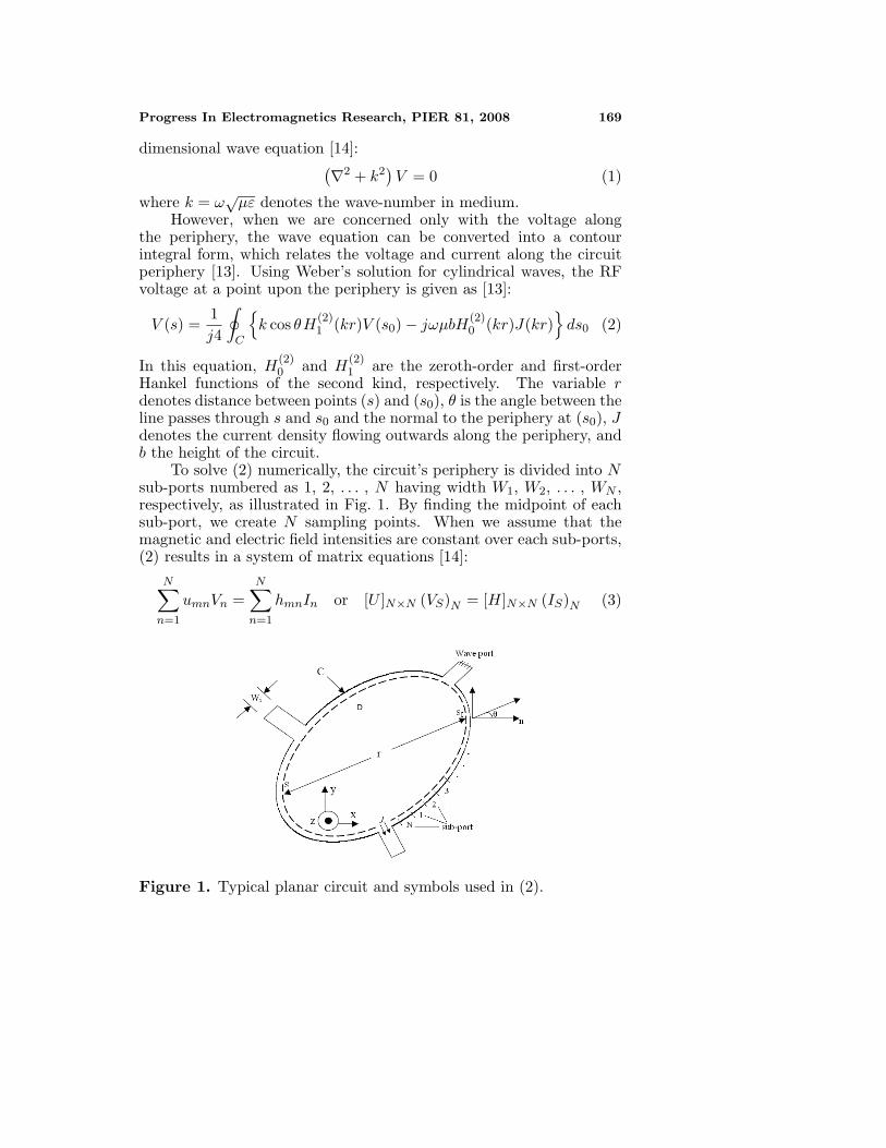
The contour integral (CI) method is one of the planar circuit analysismethods [12–15]. Consider an arbitrary shaped planar circuit havingcoupling (or wave) ports, such as shown in Fig. 1. From the Maxwell’sequation, it is found that the RF voltage in region D satisfies the two-
Progress In Electromagnetics Research, PIER 81, 2008 169
dimensional wave equation [14]:(∇2 + k2
)V = 0 (1)
where k = ω√µε denotes the wave-number in medium.
However, when we are concerned only with the voltage alongthe periphery, the wave equation can be converted into a contourintegral form, which relates the voltage and current along the circuitperiphery [13]. Using Weber’s solution for cylindrical waves, the RFvoltage at a point upon the periphery is given as [13]:
V (s) =1j4
∮C
{k cos θH(2)
1 (kr)V (s0) − jωµbH(2)0 (kr)J(kr)
}ds0 (2)
In this equation, H(2)0 and H
(2)1 are the zeroth-order and first-order
Hankel functions of the second kind, respectively. The variable rdenotes distance between points (s) and (s0), θ is the angle between theline passes through s and s0 and the normal to the periphery at (s0), Jdenotes the current density flowing outwards along the periphery, andb the height of the circuit.
To solve (2) numerically, the circuit’s periphery is divided into Nsub-ports numbered as 1, 2, . . . , N having width W1, W2, . . . , WN ,respectively, as illustrated in Fig. 1. By finding the midpoint of eachsub-port, we create N sampling points. When we assume that themagnetic and electric field intensities are constant over each sub-ports,(2) results in a system of matrix equations [14]:
N∑n=1
umnVn =N∑
n=1
hmnIn or [U ]N×N (VS)N = [H]N×N (IS)N (3)
Figure 1. Typical planar circuit and symbols used in (2).
170 Banai and Hashemi
where
umn =δmn − k
j2
∫Wn
cos θH(2)1 (kr)ds, δmn
{1; (m = n)0; (m �= n)
hmn =
ωµb
41Wn
∫Wn
H(2)0 (kr)ds; (m �= n)
ωµb
4
[1 − j2
π
(lnkWm
4− 1 + γ
)]; (m = n)
(4)
γ = 0.5772 . . . is Euler’s constant, and In = −2JWn represents thetotal current flowing into the n-th port on both the upper and lowersurfaces of the circuit plate.
Solving (3), the RF voltage on each sampling point is obtained as:
(VS) = [U ]−1 [H] (IS) (5)
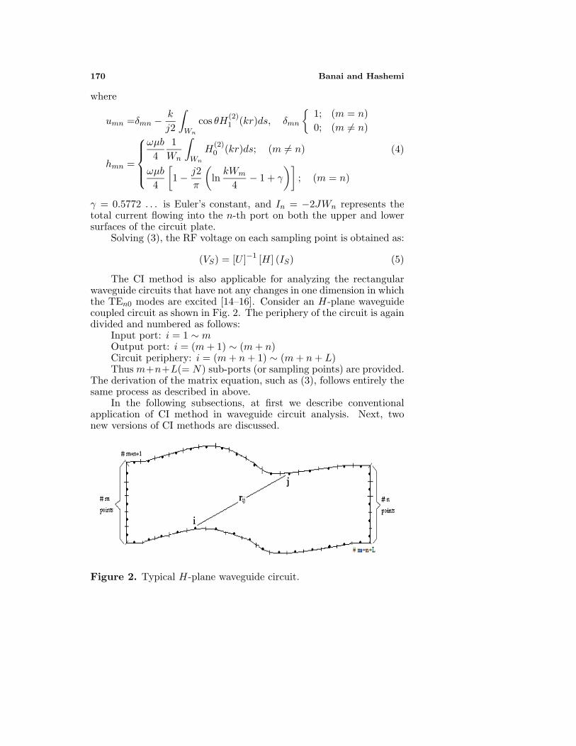
The CI method is also applicable for analyzing the rectangularwaveguide circuits that have not any changes in one dimension in whichthe TEn0 modes are excited [14–16]. Consider an H-plane waveguidecoupled circuit as shown in Fig. 2. The periphery of the circuit is againdivided and numbered as follows:
Input port: i = 1 ∼ mOutput port: i = (m+ 1) ∼ (m+ n)Circuit periphery: i = (m+ n+ 1) ∼ (m+ n+ L)Thus m+n+L(= N) sub-ports (or sampling points) are provided.
The derivation of the matrix equation, such as (3), follows entirely thesame process as described in above.
In the following subsections, at first we describe conventionalapplication of CI method in waveguide circuit analysis. Next, twonew versions of CI methods are discussed.
Figure 2. Typical H-plane waveguide circuit.
Progress In Electromagnetics Research, PIER 81, 2008 171
2.1. Single-mode CI Method
In conventional applications of the CI method to solve waveguideproblems, we interest to deal with the characteristics of only dominantpropagating mode (TE10) on reference planes. Thus, the straightwaveguide sections with appropriate length (almost λ/2) are addedin both sides of reference planes [14–16]. It is caused the effectof non-propagating higher order modes (TEn0), which excited bydiscontinuities, can be neglected on these reference planes. Thus, itcan be named single mode CI method.
Applying the short circuit condition of peripheral sub-ports forthe admittance matrix of N sub-ports, [YT ] = [H]−1[U ], results in theadmittance matrix of wave ports named [Y ]. Finally, the scatteringmatrix of wave ports can be found as:
[S] = (Y0 [E] + [Y ])−1 (Y0 [E] − [Y ]) (6)
where [E] represents the identity matrix and Y0 is the waveguideadmittance in TE10 mode and calculated as [14–18]:
1Y0
= Z0 = 120πb
a
1√1 − (λ/2a)2
=b
aZTE10 (7)
In this equation, “a” and “b” are the width and height of waveguidecross section, respectively. λ is the wavelength in free space and ZTE10
is the wave impedance of TE10 mode.
2.2. Multimode CI Method
In single mode CI method, the presence of straight waveguide sectionson both sides of the reference planes increase the size of the circuitand, therefore, the number of sub-ports on the boundary which alllead to higher computational costs. Also, it is not reasonable to ignorethe effect of higher order modes since distances between the existingdiscontinuities and wave ports are small. In this case, for having moreaccurate results, it is necessary to evaluate the generalized scatteringmatrix (GSM) of the circuit because the complex power flow into theevanescent modes on either side of the discontinuity is considerable.
For all the above reasons, the multimode CI method is introduced.This method, at first, was introduced by Okoshi [14], but up to ourknowledge, it has not been yet applied to waveguide circuit analysis.In multimode CI method we consider that at each reference plane (M-1) higher order TE modes (TE20, TE30, . . . , TEM0) exist in additionto the fundamental TE10 mode.
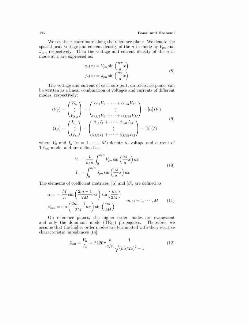
172 Banai and Hashemi
We set the x coordinate along the reference plane. We denote thespatial peak voltage and current density of the n-th mode by Vpn andJpn, respectively. Then the voltage and current density of the n-thmode at x are expressed as:
vn(x) = Vpn sin(nπax)
jn(x) = Jpn sin(nπax) (8)
The voltage and current of each sub-port, on reference plane, canbe written as a linear combination of voltages and currents of differentmodes, respectively:
(VS) =
VS1
...VSM
=
α11V1 + · · · + α1MVM...
αM1V1 + · · · + αMMVM
= [α] (V )
(IS) =
IS1
...ISM
=
β11I1 + · · · + β1MIM...
βM1I1 + · · · + βMMIM
= [β] (I)
(9)
where Vn and In (n = 1, . . . , M) denote to voltage and current ofTEn0 mode, and are defined as:
Vn =1a/n
∫ a/n
0Vpn sin
(nπax)dx
In =∫ a/n
0Jpn sin
(nπax)dx
(10)
The elements of coefficient matrices, [α] and [β], are defined as:
αmn =M
nsin
(2m− 1
2Mnπ
)sin
( nπ
2M
)
βmn = sin(
2m− 12M
nπ
)sin
( nπ
2M
) m,n = 1, · · · ,M (11)
On reference planes, the higher order modes are evanescentand only the dominant mode (TE10) propagates. Therefore, weassume that the higher order modes are terminated with their reactivecharacteristic impedances [14]:
Zn0 =Vn
In= j 120π
b
a/n
1√(nλ/2a)2 − 1
(12)
Progress In Electromagnetics Research, PIER 81, 2008 173
Similar reasoning of the single-mode CI method leads to the GSMof the circuit, including the effect of higher order modes.
2.3. Analysis of Multi-media Problems
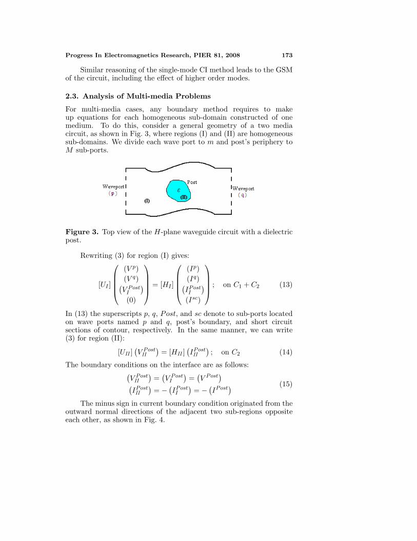
For multi-media cases, any boundary method requires to makeup equations for each homogeneous sub-domain constructed of onemedium. To do this, consider a general geometry of a two mediacircuit, as shown in Fig. 3, where regions (I) and (II) are homogeneoussub-domains. We divide each wave port to m and post’s periphery toM sub-ports.
Figure 3. Top view of the H-plane waveguide circuit with a dielectricpost.
Rewriting (3) for region (I) gives:
[UI ]
(V p)(V q)(V Post
I
)(0)
= [HI ]
(Ip)(Iq)(IPostI
)(Isc)
; on C1 + C2 (13)
In (13) the superscripts p, q, Post, and sc denote to sub-ports locatedon wave ports named p and q, post’s boundary, and short circuitsections of contour, respectively. In the same manner, we can write(3) for region (II):
[UII ](V Post
II
)= [HII ]
(IPostII
); on C2 (14)
The boundary conditions on the interface are as follows:(V Post
II
)=
(V Post
I
)=
(V Post
)(IPostII
)= −
(IPostI
)= −
(IPost
) (15)
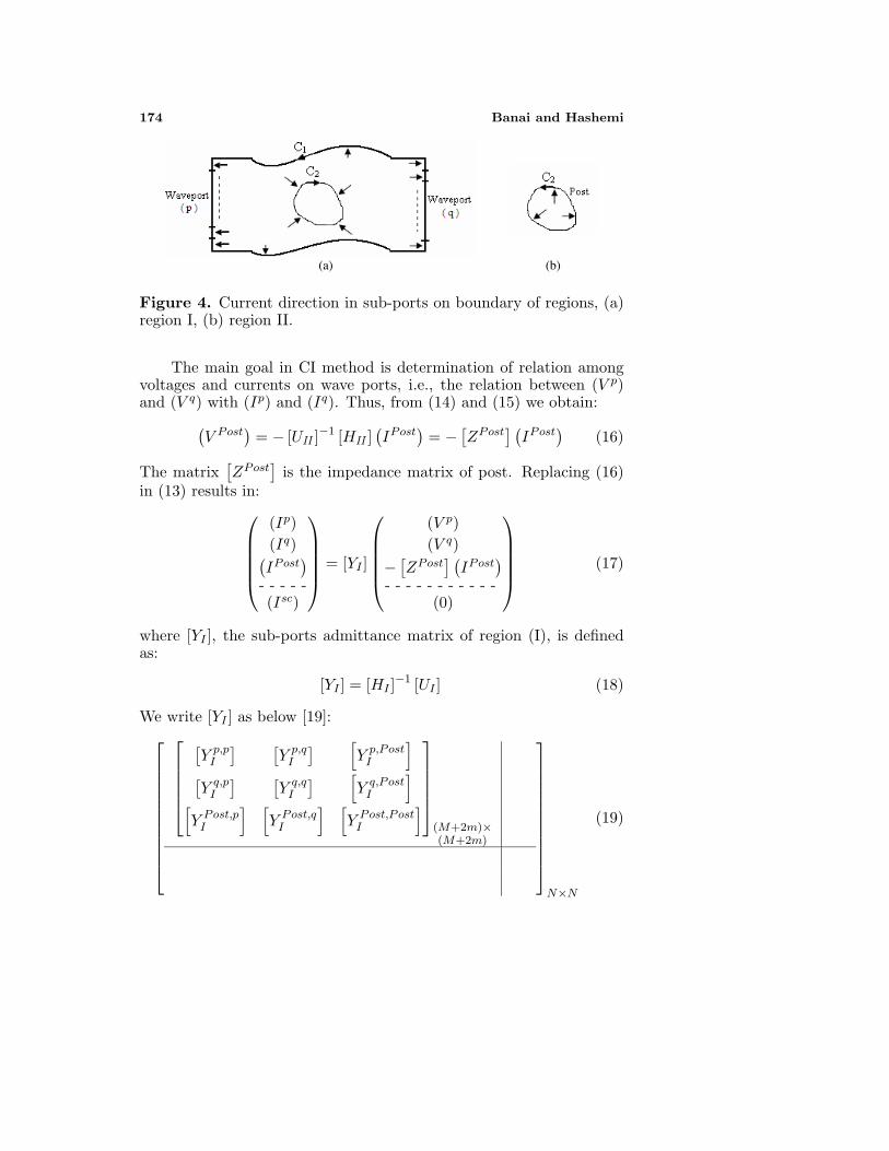
The minus sign in current boundary condition originated from theoutward normal directions of the adjacent two sub-regions oppositeeach other, as shown in Fig. 4.
174 Banai and Hashemi
(a) (b)
Figure 4. Current direction in sub-ports on boundary of regions, (a)region I, (b) region II.
The main goal in CI method is determination of relation amongvoltages and currents on wave ports, i.e., the relation between (V p)and (V q) with (Ip) and (Iq). Thus, from (14) and (15) we obtain:
(V Post
)= − [UII ]
−1 [HII ](IPost
)= −
[ZPost
] (IPost
)(16)
The matrix[ZPost
]is the impedance matrix of post. Replacing (16)
in (13) results in:
(Ip)(Iq)(IPost
)- - - - -(Isc)
= [YI ]
(V p)(V q)
−[ZPost
] (IPost
)- - - - - - - - - - -
(0)
(17)
where [YI ], the sub-ports admittance matrix of region (I), is definedas:
[YI ] = [HI ]−1 [UI ] (18)
We write [YI ] as below [19]:
[Y p,p
I
] [Y p,q
I
] [Y p,Post
I
][Y q,p
I
] [Y q,q
I
] [Y q,Post
I
][Y Post,p
I
] [Y Post,q
I
] [Y Post,Post
I
]
(M+2m)×(M+2m)
N×N
(19)
Progress In Electromagnetics Research, PIER 81, 2008 175
The sizes of sub-matrices of [YI ] depend on the number of sub-ports on wave ports and around the post. Finally, by using thesesub-matrices we find the final relations among currents and voltagesas below:
(Ip) ={[Y p,p
I
]−[Cp][A]
[Y Post,p
I
]}(V p)
+{[Y p,q
I
]−[Cp][A]
[Y Post,q
I
]}(V q)
(Iq) ={[Y q,p
I
]−[Cq][A]
[Y Post,p
I
]}(V p)
+{[Y q,q
I
]−[Cq][A]
[Y Post,q
I
]}(V q)
(20)
In this equation, the coefficient matrices are defined as below:
[Cp] =[Y p,Post
I
] [ZPost
]; [Cq] =
[Y q,Post
I
] [ZPost
][A] =
{[E] +
[CPost
]}−1
[E] = unit matrix;[CPost
]=
[Y Post,Post
I
] [ZPost
] (21)
By using (13), it is easy to find other characteristics of circuit such asscattering matrix or impedance matrix [14–18].
3. OUR PURPOSED HYBRID METHOD
Consider a waveguide circuit containing some arbitrary shape H-planediscontinuities. Specially, if these discontinuities are due to dielectricposts or slabs, the use of CI method for analysis of whole structureneeds too many sub-ports. This leads to increment of the size ofmatrices in CI method and finally, raise the computational costs. Also,this matrices enlargement, increase the possibility of singularity inthem. It can cause to reduce the accuracy of results.
To solve this type of circuits, hybrid methods are suggested. Inthis section, a new hybrid method is introduced. It combines contourintegral and mode matching techniques. The main goal in our purposedhybrid method is determination of the multimode scattering matrix ofthe circuit.
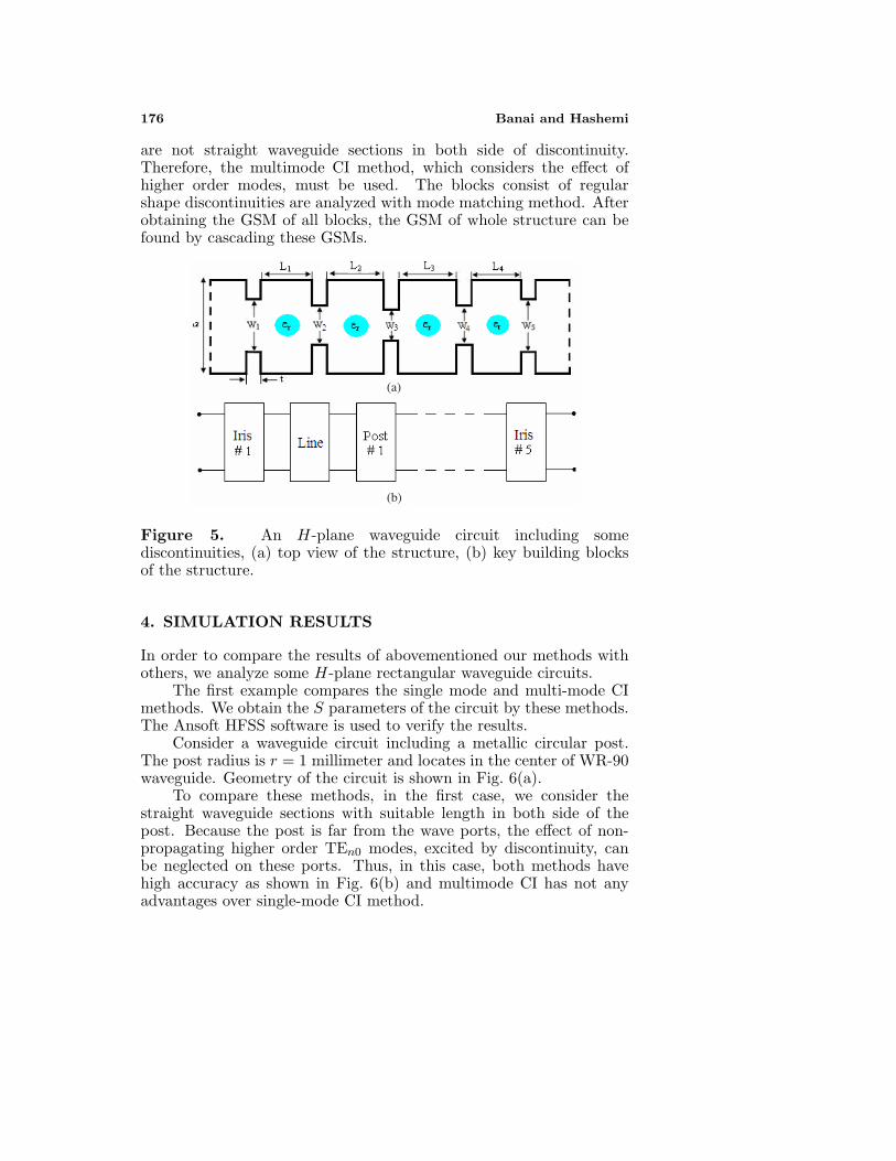
To introduce the purposed method, consider Fig. 5(a) that showsan H-plane waveguide circuit including some discontinuities. Wedivide the circuit into key building blocks, as shown in Fig. 5(b).Some of these blocks contain irregular shape discontinuities. Theseblocks are analyzed with contour integral method. It is obviousthat the single-mode CI method is not applicable because there
176 Banai and Hashemi
are not straight waveguide sections in both side of discontinuity.Therefore, the multimode CI method, which considers the effect ofhigher order modes, must be used. The blocks consist of regularshape discontinuities are analyzed with mode matching method. Afterobtaining the GSM of all blocks, the GSM of whole structure can befound by cascading these GSMs.
(a)
(b)
Figure 5. An H-plane waveguide circuit including somediscontinuities, (a) top view of the structure, (b) key building blocksof the structure.
4. SIMULATION RESULTS
In order to compare the results of abovementioned our methods withothers, we analyze some H-plane rectangular waveguide circuits.
The first example compares the single mode and multi-mode CImethods. We obtain the S parameters of the circuit by these methods.The Ansoft HFSS software is used to verify the results.
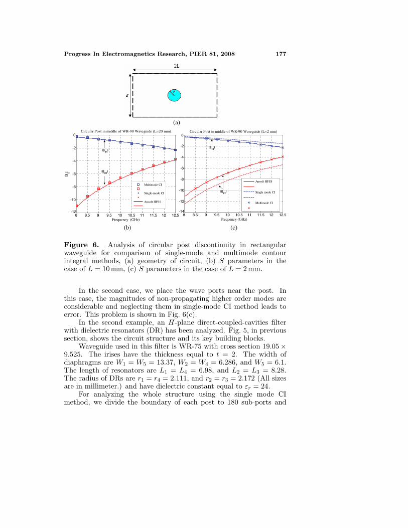
Consider a waveguide circuit including a metallic circular post.The post radius is r = 1 millimeter and locates in the center of WR-90waveguide. Geometry of the circuit is shown in Fig. 6(a).
To compare these methods, in the first case, we consider thestraight waveguide sections with suitable length in both side of thepost. Because the post is far from the wave ports, the effect of non-propagating higher order TEn0 modes, excited by discontinuity, canbe neglected on these ports. Thus, in this case, both methods havehigh accuracy as shown in Fig. 6(b) and multimode CI has not anyadvantages over single-mode CI method.
Progress In Electromagnetics Research, PIER 81, 2008 177
(a)
8 8.5 9 9.5 10 10.5 11 11.5 12 12.5-12
-10
-8
-6
-4
-2
0
Frequency (GHz)
Circular Post in middle of WR-90 Waveguide (L=20 mm)
|Sij|
|S11|
|S21|
Multimode CI
Single-mode CI
Ansoft HFSS
8 8.5 9 9.5 10 10.5 11 11.5 12 12.5-14
-12
-10
-8
-6
-4
-2
0
Frequency (GHz)
Circular Post in middle of WR-90 Waveguide (L=2 mm)
|S11|
|S21|
Ansoft HFSS
Single mode CI
Multimode CI
(b) (c)
Figure 6. Analysis of circular post discontinuity in rectangularwaveguide for comparison of single-mode and multimode contourintegral methods, (a) geometry of circuit, (b) S parameters in thecase of L = 10 mm, (c) S parameters in the case of L = 2 mm.
In the second case, we place the wave ports near the post. Inthis case, the magnitudes of non-propagating higher order modes areconsiderable and neglecting them in single-mode CI method leads toerror. This problem is shown in Fig. 6(c).
In the second example, an H-plane direct-coupled-cavities filterwith dielectric resonators (DR) has been analyzed. Fig. 5, in previoussection, shows the circuit structure and its key building blocks.
Waveguide used in this filter is WR-75 with cross section 19.05 ×9.525. The irises have the thickness equal to t = 2. The width ofdiaphragms are W1 = W5 = 13.37, W2 = W4 = 6.286, and W5 = 6.1.The length of resonators are L1 = L4 = 6.98, and L2 = L3 = 8.28.The radius of DRs are r1 = r4 = 2.111, and r2 = r3 = 2.172 (All sizesare in millimeter.) and have dielectric constant equal to εr = 24.
For analyzing the whole structure using the single mode CImethod, we divide the boundary of each post to 180 sub-ports and
178 Banai and Hashemi
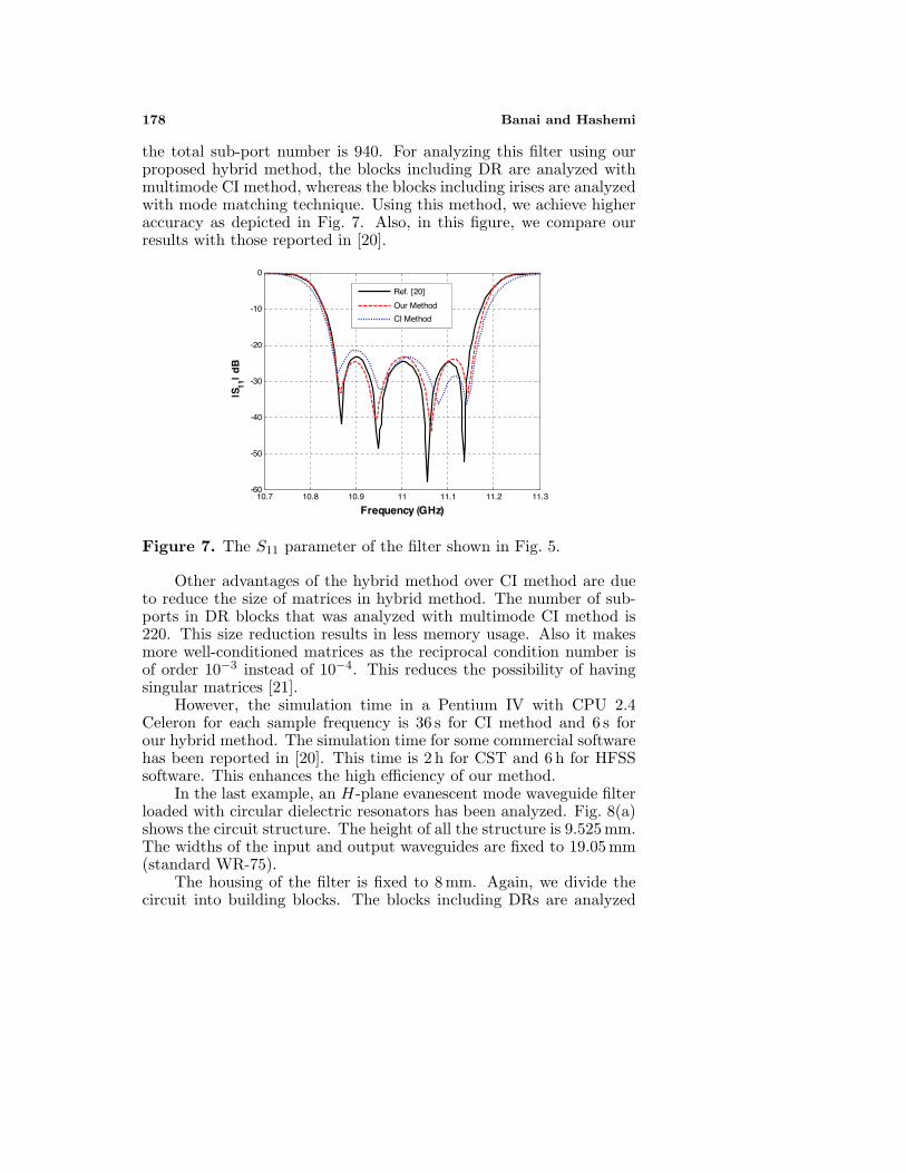
the total sub-port number is 940. For analyzing this filter using ourproposed hybrid method, the blocks including DR are analyzed withmultimode CI method, whereas the blocks including irises are analyzedwith mode matching technique. Using this method, we achieve higheraccuracy as depicted in Fig. 7. Also, in this figure, we compare ourresults with those reported in [20].
10.7 10.8 10.9 11 11.1 11.2 11.3-60
-50
-40
-30
-20
-10
0
Frequency (GHz)
|S11
| d
B
Ref. [20]
Our Method
CI Method
Figure 7. The S11 parameter of the filter shown in Fig. 5.
Other advantages of the hybrid method over CI method are dueto reduce the size of matrices in hybrid method. The number of sub-ports in DR blocks that was analyzed with multimode CI method is220. This size reduction results in less memory usage. Also it makesmore well-conditioned matrices as the reciprocal condition number isof order 10−3 instead of 10−4. This reduces the possibility of havingsingular matrices [21].
However, the simulation time in a Pentium IV with CPU 2.4Celeron for each sample frequency is 36 s for CI method and 6 s forour hybrid method. The simulation time for some commercial softwarehas been reported in [20]. This time is 2 h for CST and 6 h for HFSSsoftware. This enhances the high efficiency of our method.
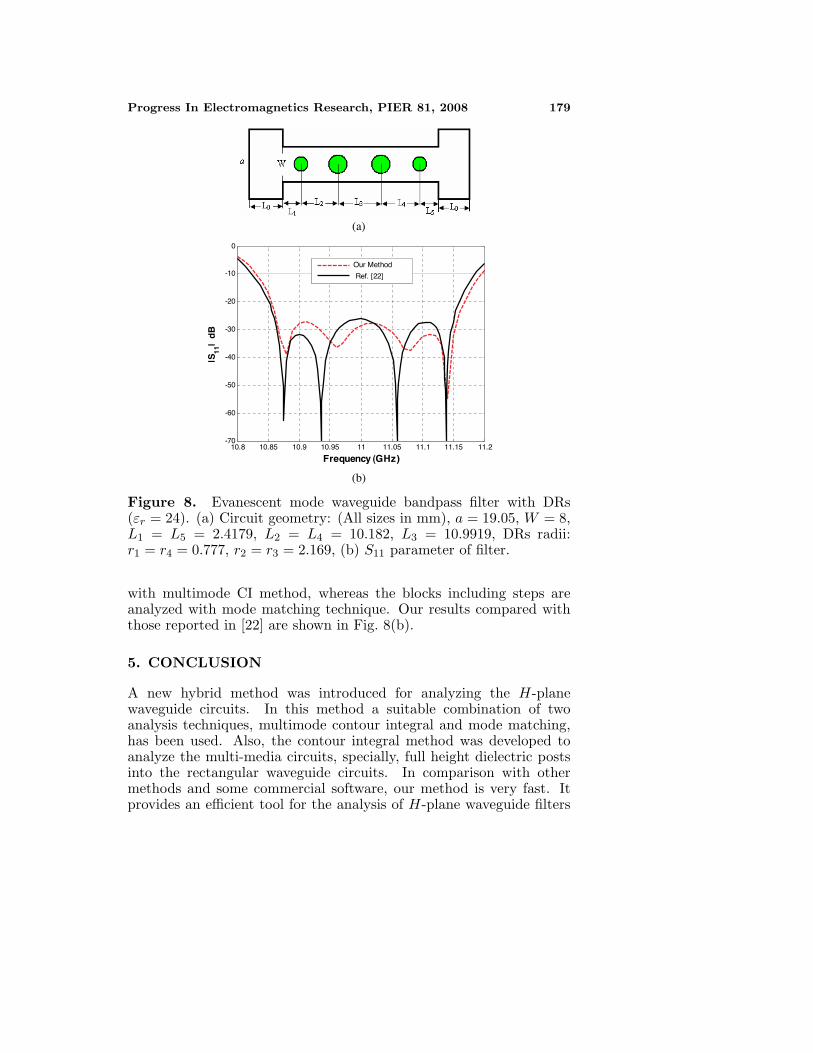
In the last example, an H-plane evanescent mode waveguide filterloaded with circular dielectric resonators has been analyzed. Fig. 8(a)shows the circuit structure. The height of all the structure is 9.525 mm.The widths of the input and output waveguides are fixed to 19.05 mm(standard WR-75).
The housing of the filter is fixed to 8 mm. Again, we divide thecircuit into building blocks. The blocks including DRs are analyzed
Progress In Electromagnetics Research, PIER 81, 2008 179
(a)
(b)
10.8 10.85 10.9 10.95 11 11.05 11.1 11.15 11.2-70
-60
-50
-40
-30
-20
-10
0
Frequency (GHz )
|S11
| d
B
Our Method
Ref. [22]
Figure 8. Evanescent mode waveguide bandpass filter with DRs(εr = 24). (a) Circuit geometry: (All sizes in mm), a = 19.05, W = 8,L1 = L5 = 2.4179, L2 = L4 = 10.182, L3 = 10.9919, DRs radii:r1 = r4 = 0.777, r2 = r3 = 2.169, (b) S11 parameter of filter.
with multimode CI method, whereas the blocks including steps areanalyzed with mode matching technique. Our results compared withthose reported in [22] are shown in Fig. 8(b).
5. CONCLUSION
A new hybrid method was introduced for analyzing the H-planewaveguide circuits. In this method a suitable combination of twoanalysis techniques, multimode contour integral and mode matching,has been used. Also, the contour integral method was developed toanalyze the multi-media circuits, specially, full height dielectric postsinto the rectangular waveguide circuits. In comparison with othermethods and some commercial software, our method is very fast. Itprovides an efficient tool for the analysis of H-plane waveguide filters
180 Banai and Hashemi
with dielectric resonators in reasonable CPU time. Also, the sizesof matrices produced in the hybrid method are smaller than themin CI method. It makes more well-conditioned matrices and reducesthe possibility of singularity in matrices. The accuracy of the hybridmethod was validated by comparison of results with those reported inliteratures.
ACKNOWLEDGMENT
The authors wish to acknowledge the assistance and support of theIslamic Azad university- Majlesi branch.
REFERENCES
1. Jia, H., K. Yoshtomi, and K. Yasumoto, “Rigorous analysis ofrectangular waveguide junctions by Fourier transform technique,”Progress In Electromagnetics Research, PIER 20, 263–282, 1998.
2. Jia, H., K. Yoshtomi, and K. Yasumoto, “Rigorous analysis ofE-/H-plane junctions in rectangular waveguides using Fouriertransform technique,” Progress In Electromagnetics Research,PIER 21, 273–292, 1999.
3. El Sabbagh, M. and K. Zaki, “Modeling of rectangularwaveguide junctions containing cylindrical posts,” Progress InElectromagnetics Research, PIER 33, 299–331, 2001.
4. Lilonga-Boyenga, D., C. N. Mabika, and G. Okoumou-Moko, “Rigorous analysis of uniaxial discontinuities microwavecomponents using a new multimodal variational formulation,”Progress In Electromagnetics Research B, Vol. 2, 61–71, 2008.
5. Steban, H., S. Cogollos, V. E. Boria, A. San Blas, andM. Ferrando, “A new hybrid mode-matching/numerical methodfor the analysis of arbitrarily shaped inductive obstaclesand discontinuities in rectangular waveguides,” IEEE Trans.Microwave Theory Tech., Vol. 50, No. 4, 1219–1224, April 2002.
6. Morro, J. V., P. S. Pacheco, H. E. Gonzalez, V. E. Boria,C. Bachiller, M. Taroncher, S. Cogollos, and B. Gimeno,“Fast automated design of waveguide filters using aggressivespace mapping with a new segmentation strategy and a hybridoptimization algorithm,” IEEE Trans. Microwave Theory Tech.,Vol. 53, No. 4, 1130–1142, April 2005.
7. Xiang, Z. and Y. Lu, “An effective hybrid method forelectromagnetic scattering from inhomogeneous objects,” ProgressIn Electromagnetics Research, PIER 17, 305–321, 1997.
Progress In Electromagnetics Research, PIER 81, 2008 181
8. Wu, K. L., G. Y. Delisle, D. G. Fang, and M. Lecours, “Coupledfinite element and boundary element methods in electromagneticscattering,” Progress In Electromagnetics Research, PIER 02, 113–132, 1990.
9. Nie, X.-C., Y.-B. Gan, N. Yuan, C.-F. Wang, and L.-W. Li,“An efficient hybrid method for analysis of slot arrays enclosedby a large radome,” Journal of Electromagnetic Waves andApplications, Vol. 20, No. 2, 249–264, 2006.
10. Fikioris, J. G. and A. N. Magoulas, “Scattering from axisymmetricscatterers: A hybrid method of solving Maus’s equation,” ProgressIn Electromagnetics Research, PIER 25, 131–165, 2000.
11. Liu, H.-X., H. Zhai, L. Li, and C.-H. Liang, “A progressivenumerical method combined with MoM for a fast analysis oflarge waveguide slot antenna array,” Progress In ElectromagneticsResearch, PIER 20, No. 2, 183–192, 2006.
12. Mittal, A., K. K. Gupta, G. P. Srivastava, P. K. Singhal,R. D. Gupta, and P. C. Sharma, “Contour integral analysis ofplanar components,” J. Microwaves and Optoelectronics, Vol. 3,No. 3, 58–72, Dec. 2003.
13. Okoshi, T. and T. Miyoshi, “The planar circuit — An approach tomicrowave integrated circuitry,” IEEE Trans. Microwave TheoryTech., Vol. 20, No. 4, 245–252, Apr. 1972.
14. Okoshi, T., Planar Circuits for Microwaves and Lightwaves,Springer-Verlag, 1985.
15. Itoh, T., Ed., Numerical Techniques for Microwave andMillimeter-Wave Passive Structures, Wiley, 1989.
16. Okoshi, T. and S. Kitazawa, “Computer analysis of short-boundary planar circuits,” IEEE Trans. Microwave Theory Tech.,Vol. 23, No. 3, 299–306, March 1975.
17. Hashemi, A. and A. Banai, “Analysis of H-plane waveguidediscontinuities using hybrid multimode contour integral and modematching techniques,” 2007 SBMO/IEEE MTT-S (IMOC2007),840–843, 2007.
18. Hiraoka, T. and J. P. Hsu, “Equivalent network for H-planerectangular waveguide circuits and its practical application foranalysis of circuit performance and field behavior,” Int. J. RFand Microwave CAE, Vol. 14, No. 3, 210–226, Wiley Interscience,April 2004.
19. Hashemi, A. and A. Banai, “Analysis of waveguide filters withdielectric resonators using multimode contour integral method,”2007 IEEE MTT-S (APMC2007), 2083–2086, 2007.
182 Banai and Hashemi
20. Bachiller, C., H. Esteban, V. E. Boria, J. V. Morro, L. J. Rogla,M. Taroncher, and A. Belenguer, “Efficient CAD tool of direct-coupled-cavities filters with dielectric resonators,” 2005 IEEE AP-S, Vol. 1B, 578–581, 2007.
21. Qiu, Z.-J., X.-Y. Hou, X. Li, and J.-D. Xu, “On the conditionnumber of matrices from various hybrid vector FEM-BEMformulations for 3-D scattering,” Journal of ElectromagneticWaves and Applications, Vol. 20, No. 13, 1797–1806, 2006.
22. Bachiller, C., H. Esteban, V. E. Boria, J. V. Morro, M. Taroncher,and B. Gimeno, “CAD of evanescent mode waveguide filters withcircular dielectric resonators,” 2006 IEEE AP-S, 1567–1570, 2006.
Copyright © 2022 FDOKUMEN