A general treatment of crack tip contour integrals
16
International Journal of Fracture 35:295-310 (1987) © Martinus Nijhoff Publishers, Dordrecht Printed in the Netherlands 295 A general treatment of crack tip contour integrals B. MORAN and C.F. SHIH Division of Engineering, Brown University, Providence, RI 02912, USA Received 12 January 1987; accepted 19 May 1987 Abstract. Given a general balance statement we derive an expression for the associated crack tip flux integral. The conditions under which the integral is physically meaningful and yields a non-trivial result are outlined. To illus- trate the approach a number of well known integrals in use in fracture mechanics are derived. It is demonstrated that complementary analogues to these integrals can be derived in a similar fashion and a result indicating the equality of dual integrals under quite general conditions is presented. We discuss the domain integral method as an alternative means of representing crack tip integrals and we show that the method may be interpreted as a par- ticular form of Signorini's theorem of stress means. A discussion of some associated integral identities is presented. 1. Introduction In this paper we present a perspective on crack tip integrals from the point of view that these integrals can be simply derived from appropriate balance laws. The approach has its origin in a crack tip integral expression for the elastodynamic energy release rate proposed by Atkinson and Eshelby [1] and independently derived from the field equations by Kostrov and Nikitin [2] and Freund [3]. It has since been recognized that the result is also valid for general material response [4, 5]. We build upon the approach taken by Nakamura et al. [5] to obtain some general results. We begin with a general balance statement and derive an expression for the associated crack tip flux integral in Section 2. Then we examine the conditions under which this integral is physically significant (namely path-independent in the crack tip region) and yields a non-trivial result. In Section 3, the general result is specialized to particular balance laws and a number of crack tip integrals currently used in fracture analysis are derived. No a priori restrictions on material response and crack tip motion are required in the derivations. To illustrate the approach, the fundamental crack tip energy flux and energy release rate integrals are derived in this manner for both total and mechanical energy balance statements. We then derive a general dissipation integral from a variational form of momentum balance and show that it reduces to the C(t) integral (e.g., Bassani and McClintock [6]) for power law creeping solids. Also crack tip integrals for conduction/diffusion problems are discussed. In Section 4, we illustrate that the complementary counterparts of the above mentioned crack tip integrals can be derived using the same approach. For nonlinear elastic response, Bui [7] has shown that the energy and complementary energy release rates are equal. We establish in a direct manner that Bui's observation is valid for quite general material response and for all dual crack tip integrals under discussion. The implication is that no new information can be extracted from complementary integrals which is not already provided by their counterparts. However, in certain circumstances, the pair of integrals, referred to as dual integrals, may be employed to obtain a bound for the crack tip parameter.
-
Upload
independent -
Category
Documents
-
view
3 -
download
0
Transcript of A general treatment of crack tip contour integrals
International Journal of Fracture 35:295-310 (1987) © Martinus Nijhoff Publishers, Dordrecht Printed in the Netherlands 295
A general treatment of crack tip contour integrals
B. MORAN and C.F. SHIH Division of Engineering, Brown University, Providence, RI 02912, USA
Received 12 January 1987; accepted 19 May 1987
Abstract. Given a general balance statement we derive an expression for the associated crack tip flux integral. The conditions under which the integral is physically meaningful and yields a non-trivial result are outlined. To illus- trate the approach a number of well known integrals in use in fracture mechanics are derived. It is demonstrated that complementary analogues to these integrals can be derived in a similar fashion and a result indicating the equality of dual integrals under quite general conditions is presented. We discuss the domain integral method as an alternative means of representing crack tip integrals and we show that the method may be interpreted as a par- ticular form of Signorini's theorem of stress means. A discussion of some associated integral identities is presented.
1. Introduction
In this paper we present a perspective on crack tip integrals from the point of view that these integrals can be simply derived from appropriate balance laws. The approach has its origin in a crack tip integral expression for the elastodynamic energy release rate proposed by Atkinson and Eshelby [1] and independently derived from the field equations by Kostrov and Nikitin [2] and Freund [3]. It has since been recognized that the result is also valid for general material response [4, 5]. We build upon the approach taken by Nakamura et al. [5] to obtain some general results.
We begin with a general balance statement and derive an expression for the associated crack tip flux integral in Section 2. Then we examine the conditions under which this integral is physically significant (namely path-independent in the crack tip region) and yields a non-trivial result. In Section 3, the general result is specialized to particular balance laws and a number of crack tip integrals currently used in fracture analysis are derived. No a priori restrictions on material response and crack tip motion are required in the derivations. To illustrate the approach, the fundamental crack tip energy flux and energy release rate integrals are derived in this manner for both total and mechanical energy balance statements. We then derive a general dissipation integral from a variational form of momentum balance and show that it reduces to the C(t) integral (e.g., Bassani and McClintock [6]) for power law creeping solids. Also crack tip integrals for conduction/diffusion problems are discussed.
In Section 4, we illustrate that the complementary counterparts of the above mentioned crack tip integrals can be derived using the same approach. For nonlinear elastic response, Bui [7] has shown that the energy and complementary energy release rates are equal. We establish in a direct manner that Bui's observation is valid for quite general material response and for all dual crack tip integrals under discussion. The implication is that no new information can be extracted from complementary integrals which is not already provided by their counterparts. However, in certain circumstances, the pair of integrals, referred to as dual integrals, may be employed to obtain a bound for the crack tip parameter.

296 B. Moran and C.F. Shih
In Section 5, we show that Signorini's theorem of stress means may be used in conjunction with a general momentum/flux tensor to yield integral identities from which a number of useful results may be extracted. The numerical evaluation of crack tip contour integrals poses a fundamental problem. The limiting contour (shrunk onto the crack tip) cannot be defined due to the finite spatial discretization. In addition it is precisely near the crack tip that the field quantities are least accurate. Domain integral methods have been introduced to circumvent this difficulty. We show that the domain integral representation of crack tip integrals is a particular application of the general result based on Signorini's theorem and some associated integral identities are discussed.
2. Balance l a w - c r a c k tip integral
We consider a general balance statement and derive an expression for the associated crack tip flux integral. The development closely follows that of Nakamura et al. [5] who derived an expression for the crack tip energy flux, valid for arbitrary material response and crack tip motion. In the following section we will extract a number of useful integrals from the general result. The general balance statement is written as
+j,j = (2.1)
A comma ( , ) denotes a partial derivative with respect to a spatial coordinate and a superposed dot (") denotes the material time derivative. We will see later that appropriate choice of the field quantities @ and ~ leads to some useful results in fracture mechanics. Integrating the expression (2.1) over an arbitrary volume V and applying the divergence and transport theorems yields*
d fev @mj dS = ~ f v ~ dV - ;~v Ovjrn~ dS, (2.2)
where rnj is the outward unit normal to the surface ~3 V and vi is the instantaneous velocity of ~3 V. We now specialize this result to the case of crack propagation and, for purposes of clarity, focus our attention on the planar crack problem.
Consider a two-dimensional body with an extending crack oriented along the x 1 axis of a rectangular Cartesian coordinate system (see Fig. 1). The cracked body lies in the Xl-X 2 plane with the crack plane given by x2 = 0. The crack extends in its own plane along the x~ axis with instantaneous speed v. We isolate the vanishing small crack tip region with a Small contour F which is fixed in size and orientation with respect to the crack tip and is translating with the crack tip at speed v. At a given instant, the area bounded by the fixed material curve Co and the translating curve F is denoted by A(t) and is free of singularities. If ~b2 does not vanish on the crack faces the contour Co is taken to include the crack faces.
* We have assumed that the fields are sufficiently smooth so that the divergence and transport theorems may be applied. In particular the fields must be free of shock-like discontinuities which can develop in wave and dynamic crack propagation problems.

Crack tip contour integrals
m j
Co
297
Fig. 1. Crack tip convent ions . D o m a i n A is enclosed by F, C+, C , and C 0. Uni t no rma l mj = nJ on c + , c and C O , a n d m / = - n / o n F .
The expression (2.2) thus becomes
d /c 4)jn/dC - dt fA 0 dA -- fr (4)/ + Ov6v)mj dr . (2.3)
It is noted that the only non-vanishing velocity on the boundary of A(t) of consequence in (2.3) is v~ = v on F. Often 0 will be a physically significant quantity such as energy. The term on the left-hand side of (2.3) is then the rate at which energy is being input into the body; the first term on the right hand side is the rate of increase of internal energy and consequently the last term is the instantaneous rate at which energy is being lost from the body due to flux through F. We denote this quantity as F and write, for nj = - r n / o n F,
F(F) = fr (4)J + OvSv)nJ dF. (2.4)
There are two contributions to this flux integral. The first term represents the usual contribu- tion from the flux vector 4)j and if F were a material curve this would be the only contribu- tion. The second term represents the contribution due to the flux of the material across F. The limiting value of F(F)/v as the contour F is shrunk onto the crack tip, is defined by and will be loosely referred to as the crack extension force. The precise interpretation will be made in the context of the actual application. (One subsequent identification of ~ will be the energy release rate.) For this concept to have physical significance, the limiting value, ~, must be independent of the actual shape of F in the limit F ~ 0. In other words, the value of ~ must be path-independent in the limit F ---, 0 (i.e., in the crack tip region). We now consider conditions under which ~ is non-vanishing and path independent in the limiting sense described.
2.1. Conditions for local path-independence
Consider the closed path formed by two crack tip contours F 1 and F2 and the crack face segments which connect the ends of the two contours. We assume, for simplicity, that 4)2 = 0

298 B. Moran and C.F. Shih
on the crack faces. Application of the divergence theorem to the closed contour integral and using (2.1) yields
F(F2) - f ( r , ) = f~,2 (q~J + vO61s),j dA = fA~2 ((/ + vtp,,) dA (2.5)
where A12 is the area enclosed by the contour. If the integrand in (2.5) is o(1/r2) * then F(F2) - F(F1) = 0 as F~, F2 --+ 0 and the path-independence of F in the crack tip region (F -+ 0 +) is established. This condition is indeed satisfied if any field quan t i ty f satisfies the following relation
f + v f l = o ( f l ) a s r - - + 0 + (2.6)
where r is the radial distance from the moving crack tip. Condition (2.6) can be interpreted as a condition for locally steady state behaviour. (Indeed many known solutions for growing cracks in elastic and inelastic solids confirm such steady conditions are approached asymp- totically at the crack tip.) In particular, if ~ satisfies (2.6) then for ~ of order 1/r we have
+ v~, 1 = o(1/r 2) as r --+ 0 + (2.7)
and path-independence in the crack tip region is assured. The condition (2.7) may also be viewed as an integrability condition. Given local path-independence, it follows on choosing F to be a circular contour, that (2.4) yields a finite value of F if the integrand of (2.4) is of order l/r, i.e.,
((o i + Ovglj) "~ Aj(O)/r + o(1/r), as r ~ 0 + (2.8)
for some Aj (0). We reiterate that for field variables, ~0 and qS/, satisfying a balance law of the form (2.1)
and for which the local conditions (2.6) and (2.8) hold, the integral given by (2.4) is path-independent within the local crack tip region. A special result which has important applications is easily extracted from the general derivation. We note that ( f + vf~) is the time derivative o f f with respect to a coordinate system which translates with the propagating crack and is zero for a steady state problem. Thus the right-hand side of (2.7) vanishes identically under steady state crack propagation conditions and (2.4) provides a globally path-independent integral for this class of problems for any material response.
With the understanding that the limiting value of the flux F(F), denoted by Y, is independent of the shape of the contour F as it is shrunk onto the crack tip, we write
o~ = lim fr ((as + vO61s)ni dF. (2.9) F ~ 0
We will call ~- the general crack tip flux integral and we will show that the identification of qSj and 4' with relevant field quantities will lead directly to explicit representations for crack
* We assume that the crack tip fields can be writ ten in separable form i.e., f ~ B(O)r ~ + o(r ~) for some field quanti ty f and fur thermore that the derivative o f f with respect to r is o f order r =-~.
Crack tip contour integrals 299
tip integrals. For convenience we introduce a general tensor Hkj, with xl component Hlj. A general representation for the crack extension force, ~, is written as
/ ,
- - lim J | H1jn / dF (2.10) 73 F~O F
where it follows from (2.9) that H~j is defined by the asymptotic relation
Hli "-. ((~j + vO6li)/v as r ~ 0 + . (2.11)
The above relation is not written as an equality since the local steady state condition (2.6) will necessarily be invoked in defining H~j. Assuming that the field quantities defining Hlj are sufficiently smooth, and noting (2.1) and the asymptotic conditions (2.7) and (2.11), the conditions for N to be finite (but non-vanishing) and locally path-independent can be restated as
Hlj ~ Aj(O)/r + o(1/r) and Hlj, j = o(1/r 2) as r ~ 0 +. (2.12)
2.2. Extension to three-dimensional crack front
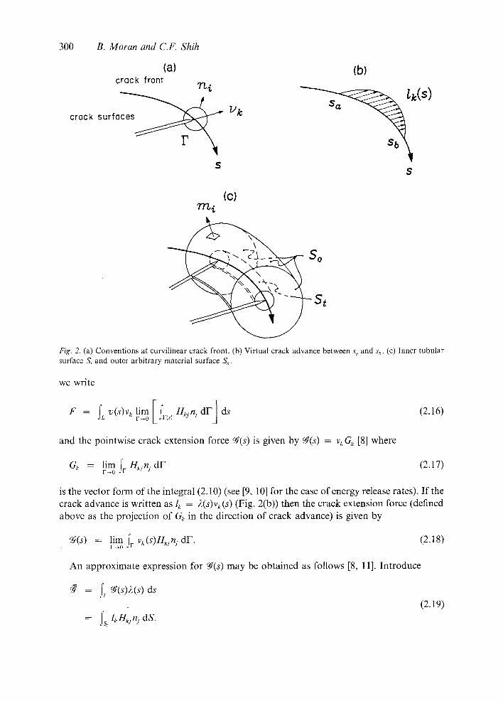
Consider a crack front defined in rectangular coordinates by ~k(s, t), at any time t where s is the arclength measured from some arbitrary point. The crack velocity is denoted by ~k(s, t) = v(s, t)Vk(S, t) where v(s, t) is the crack speed and vk(s, t) is the direction of crack propagation. Now consider the tubular surface S, enclosing the crack edge and moving with it. This surface may be defined as follows. In the plane, normal to the crack front at s define a small crack tip contour F, which begins on one side of the crack and ends on the other (Fig. 2(a)). The tubular surface S, is then specified by the condition that its intersection with the plane normal to the crack front is given by the same contour F(s) for all time, t (see also Fig. 2(c)). The flux through St is given by
F = lim fs, (@ + O~J)nJ dS ( 2 . 1 3 )
where the limiting process consists of shrinking the tube radius to zero. We note that the local steady state condition (2.6) is now given as
f + f j ~ j = o ( f j ~ j ) a s r ~ 0 + (2.14)
where r is the radial distance from the crack, in the plane normal to the crack front. Now in analogy to (2.11) define Hkj as
Hkjv~ ~ ((bj + Ik~j)/v(s) as r ~ 0 +. (2.15)
The conditions (2.12) for local path-independence now refer to the contour integral F(s) taken in the plane locally perpendicular to the crack front. For a length L of the crack front,
300 B. Moran and C.F. Shih
(a) (b) crack front
crack s u r f a ~ ~k
S $
(c)
So
St
Fig. 2. (a) Conventions at curvi l inear crack front. (b) Vi r tual crack advance between s,, and s h. (c) Inner tubu|ar surface S t and outer arbi t rary material surface S~.
we wri te
and the pointwise crack extension force ~(s) is given by ~(s) = vkGk [8] where
= lim I~ H~jnj dF (2.17) Gx F ~ 0 j l
is the vector form of the integral (2.10) (see [9, 10] for the case of energy release rates). If the crack advance is written as lk = 2(s)vk(s) (Fig. 2(b)) then the crack extension force (defined above as the projection of Gk in the direction of crack advance) is given by
~f(s) = lim fr v~(s)HkjnJ dF. (2.18) F ~ 0
An approximate expression for N(s) may be obtained as follows [8, 11]. Introduce
= fL ds (2.19)
= o~,f° l eH~,nj dS.
C r a c k tip contour integrals 301
Now assume that fg(s) is approximately constant over some region of the crack front sa < s < sb. Perturb the crack front an amount lk = 2(s)vk(s) in this interval, where 2 = 0 outside of the interval. Then, using (2.18) and (2.19), we obtain
A more accurate procedure for evaluating the pointwise value fg(s) along a three-dimensional crack front is discussed by Li et al. [12] and Shih et al. [13] in the context of energy release rate calculations using finite elements. This approach is based on the domain integral representation of the contour or surface integral. We discuss the domain integral method in Section 5. In the following section we will present results for the planar case (2.10).
3. Example integrals
When q~j and q~ are appropriately identified a number of crack tip integrals, in current use in fracture analysis, can be extracted from the general approach of the previous section. To illustrate the general approach we derive the crack tip energy flux and associated energy release rate integrals and comment on some specializations of these results. Using a similar approach we derive an integral expression which reduces to the C( t ) integral for power law creeping solids. Crack tip integrals for conduction/diffusion problems may be derived using the general approach outlined above. We illustrate with an application to heat conduction in a cracked body.
To facilitate interpretation of these integrals, it is useful to comment briefly on conser- vation integrals. For reversible processes, the thermomechanical response of a continuum is determined by the free energy. A prototype for this class of response is the elastic solid. Under isothermal or adiabatic conditions, a strain energy function, W, may be defined, and the stress is given by
0 (3.1)
and the Eshelby-Rice elastic energy-momentum tensor is written [14]
Pkj = W6k; - aijui, k. (3.2)
For inherently dissipative systems, the free energy alone is insufficient to describe the response of the continuum. In this case the dissipation function qb supplements the free energy. We refer to a process as purely dissipative if the thermomechanical response is determined solely by the dissipation function. A prototype for this class of response is the viscous fluid, where q~ depends only on the rate of deformation ~ij, i.e. qb(~t) = aijgij. Here, the thermodynamic force associated with the flux ~j is proportional to the stress tensor, e.g., for a power law viscous material
aij = 2 c3~(~k') (3.3) O~ij

302 B. Moran and C.F. Shih
where 2 = n/(n + 1). In this case we can define a dissipation tensor analogous to the energy-momentum tensor (3.2) (see Kachanov [15] for example)
Pk/ = 2 ~ 6 k / - aqil:.k. (3.4)
The conservation law associated with the above energy momentum and dissipation tensors follows from
0 Ox~ Pk/ = 0
and is written as
: s P k j n / d S = 0 (3.5)
where S is a closed surface, not enclosing any singularities or inhomogeneities. In crack problems the energy momentum tensor, (3.2), yields the energy release rate integral, while the dissipative counterpart, (3.4), yields the increase in dissipation per unit crack advance [15].
3.1. Crack tip energy f l ux - J-integral
We restrict our attention to small strains and the strain displacement relation takes the usual form ei j= (u: / + u/i)/2- In the absence of body forces the equation of motion (or balance of linear momentum) is written as
a/:,: = Pfii (3.6)
where ¢ is the mass density, aq = a:: is the Cauchy stress and a superposed dot denotes the (material) time derivative. We take the inner product of (3.6) with the velocity field, hi, and rearrange the resulting expression to give
(~/: u:) : = PUi hi + <~/:hi,:
= (/2 + w ) (3.7)
where W = ~' aqdq dt is the stress work density and L = ~' p~iti: dt is the kinetic energy density. Equation (3.7) is a differential form of mechanical energy balance, valid for any material response. Referring to (2.1) we make the identifications q~/ = aqu: and
= (W + L). The mechanical energy flux to the crack tip is given by (2.9) as
= lim fv [(W + L)v61/ -I- ~Tiihi]fl/dF. (3.8) I ' ~ 0 " "
Using (2.10), the energy release rate expression is obtained by invoking the steady state condition ui ~ - vui: , giving
= lira fv [(W + L ) g ) l j - - aqui, a]n/dF. (3.9) F r O

Crack tip contour integrals 303
The result in (3.9) was proposed by Atkinson and Eshelby [1] and subsequently derived by Kostrov and Nikitin [2] and Freund [3] for elastic solids. The generalization to arbitrary material response was discussed by Willis [4] and by Nakamura et al. [5]. Various special- izations of (3.9) are discussed in [5]. In particular it is shown that for a stationary crack in a homogeneous nonlinear elastic material (3.4) reduces to Rice's path-independent J-integral [16, 17] and Hi: can be interpreted as the x, component of Eshelby's energy-momentum tensor [14] (see also (3.2)). A J-based phenomenological approach to the initiation of crack growth and subsequent quasi-static crack growth in elastic-plastic solids has been reviewed by Hutchinson in [18].
The total energy flux/release rate integral is obtained on using total energy balance instead of mechanical balance in the derivation above, i.e.,
( a : : ~ - h:)/ = 0 + /~ (3.10)
where hj is the heat flux vector and U is the internal energy per unit volume. We make the identifications q~j = ag: i 6 - h: and ~p = U + L and from (2.10) we obtain
= lim fF [(U + L)fi,/ - (a:/ui,~ + h//v)]n: dF. (3.11) F ~ 0 . . . .
The above expression for the energy release rate was given in [2] and was further discussed in the review articles [4, 19]. For a discussion of thermodynamics of crack growth and the role of the total energy flux to the crack tip see [4, 20, 21].
3.2. Dissipation integral for inelastic response
The energy integrals (3.8) and (3.9) above and integral results derived from these by appropriate restriction on crack tip motion and material response, have led to many important and useful results in fracture mechanics. Among these are results on the form of crack tip singularities and the strength of singular fields in elastic, elastic-plastic and sufficiently rate sensitive inelastic solids. These successful applications have a common feature, namely the behaviour at the crack tip is dominated by the instantaneous response of the material. In problems where the form of the crack tip fields is influenced by the material rate sensitivity these integrals do not appear to be adequate. For inherently dissipative systems, where the near tip fields are influenced by the dissipative behaviour, we consider a dissipation integral in which the tensor Hkj involves an additional time derivative. The C(t) and C* integrals which have applications to viscoplastic solids including power law creeping solids, follow immediately from the general result which is derived below.
For convenience we denote the velocity field as vi. Taking the inner product of the equation of motion with 75i and rearranging the resulting expression, a differential relation of the form (2.1) is again obtained, where now we identify 4~: = a~jT)~ and ~ = I~ + /2, with
= ~k: a: /d~/and/~ = ~r p~¢~: dt. The expression (2.9) yields
= lim fr [(ffz + L)v6,/ + aijiJi]n: dF. (3.12) F ~ 0
where we have used the symbol ~ (instead of ~ ) to denote the crack tip flux. Employing the steady state condition (2.6) for the time derivative of the velocity field we write (2.10) as

304 B. Moran and C.F. Shih
(using the symbol cg instead of (~)
= lim ;r [ ( ~ + L ) ~ I / - - ~ijvi, l)]nj dF. (3.13) F~0
We now show that the C(t) integral for power law creep can be formally derived from the crack tip integral expression (3.13). The integral (3.13) may be appropriate for an elastic- viscoplastic material where the natural time of the material response has a role in determin- ing the nature of the crack tip fields. It is well known that for a material deforming according to an elastic-power law creep relation (e.g., Riedel and Rice, [22]), the creep strain rate necessarily dominates at the tip of a stationary crack when the power law exponent n is greater than unity. Under this condition
"" and I ~ W* - n ., 0+ (3.14) ~: qi n + 1 °-i: el: as r
where W* is the creep potential, and a superscript c denotes the creep part of a quantity. Note that W* is n/(n + 1) times the dissipation per unit volume. In this sense we refer to (3.12) and (3.13) as dissipation integrals. In the absence of inertial terms and noting the result (3.14), the integral in (3.13) reduces to the C(t) integral for power law creeping solids which, using (3.14), is written as
V~O ~ (Tikg'ik(~l/ - - (Ti/£1i 1 l~j d F . (3.15)
It may be noted that the first term in the above integral is the creep potential only when (3.14) holds.
The above integral was employed by Bassani and McClintock [6] to investigate the creep relaxation of crack tip stresses in an elastic-nonlinear viscous solid subject to a (quasi-static) step loading at t = 0. Under steady state conditions, t ~ o% the creep potential W* is applicable everywhere and it follows that (3.15) is independent of the contour path (see also (3.4)). The steady-state or long-time value of C(t) has been denoted as C* and is the creep analogue of the path-independent J-integral [22 24]. In the cited references, C and C* are interpreted as the amplitude of the HRR-type singularity fields. In other words the role of C and C* in creep crack growth is analogous to the role of J as the characterizing parameter for crack initiation and limited amounts of growth in an elastic-plastic solid. Riedel [25] has reviewed the use of K and C* parameters for correlating creep crack growth rates under small scale and extensive creep.
3.3. Conduction~diffusion problems
Crack tip integrals for a class of conduction/diffusion problems can be readily derived using the general approach. To illustrate, consider the case of heat conduction in a body with an insulated crack or strip. The governing equation is
-h/,: = c,~ (3.16)

Crack tip contour integrals 305
where h: is the heat flux vector, 0 is the absolute temperature and c is the specific heat. Multiplying (3.16) by ,9 and following the usual steps, we make the identifications O~ = -h :O , : and ~ = • + 5~, where W --- - ~ hjO: dt and ~ = ~' d),9 dt. It follows from (2.9) that the associated crack tip integral can be written
= lim fr [(~ + 05¢)v6~/ - h:Oln: dF. (3.17) F ~ 0
Using the steady state relation (2.6), write ~) = - v O z and (2.10) yields
W = lim fr [(tp + ~)~ l j -~- hj~ l]n j dF (3.18) F ~ 0
where we have used E = ~ / v . For steady heat conduction 5¢ = 0. Assume heat conduction is governed by Fourier 's Law, i.e., hj = - ~c0,j where ~c is the conductivity. In this case tI' is a potential for the heat flux vector, i.e., h: = - 0 ~ / 0 ~ . : . I f in addition, the material is homogeneous in the x~ direction it follows that (3.18) is globally path-independent.
The case of electric current conduction in a cracked body can be treated in an analogous fashion. In this case we replace h~ by the electric current vector and 0 by the electrostatic potential. For ~ = 0 (steady current flow) and with tp as defined above, (3.18) corresponds to the j~*-integral derived by Saka and Ab6 [26].
4. Complementary integrals
Complementary integrals for arbitrary constitutive response have been discussed by Carlsson [27] who restricted attention to steady state formulations. Under the assumption of nonlinear elastic material response, Bui [7] has shown that the energy release rate and complementary energy release rate are equal. In this section we illustrate how the complementary counter- parts of the integrals in the previous section can be derived from the general balance approach. In the following subsection we demonstrate that Bui's observation holds under quite general conditions.
We take the inner product of the rate form of momentum balance with the displace- ment field ui and write the resulting expression in the form (2.1) with ~b/ -- 6-ijui and
= (W c + L c) where W C = a~/e~/ - W a n d L c = Oi;~ui -- L are the complementary stress work and kinetic energy densities respectively. The associated crack tip integrals are derived following the procedure in Section 2. In particular (2.10) yields the complementary energy release rate integral
N~' - lim fv [(We q- LC)c~lJ - aiJ, lui]n/dF (4.1) V~0
where we have used the local steady state condition (2.6) for the material time derivative of the stress field, i.e. ~:: ~ -va~:, l as r ~ 0 + . A minus sign has been introduced into the definition of Nc for convenience. We refer to the energy release rate integral (3.9) and its complementary counterpart (4.1) as dual integrals.
Similarly we introduce the enthalpy per unit volume, H = U - a~/ei:, into the total energy balance relation (3.10) and rearrange the resulting expression to obtain the form (2.1)

306 B. Moran and C.F. Shih
with qS/ = 6-i:u~ + h: and ~, = (L ~ - H) . Following the usual procedure, the associated crack tip integrals are given by (2.9) and (2.10). The latter is written
~' - lim;v[(U-H)~l/-a~/,'u:+~ln/dFv~o (4.2)
where U = O0:u, - L is a complementary kinetic energy distribution. A minus sign has again been introduced into the definition. The integral (4.2) is the complementary total energy release rate.
To derive the complementary counterpart of (3.13) we take the inner product of the rate form of momentum balance with the velocity field v~. The appropriate identifications are ~b: = 6-!/v:and ~ = (ff/~ + /~0 where IY ~'= r;~:~j - W'andF, ~ = OOivi- L. The resulting integrals are obtained from (2.9) and (2.10) in the usual manner and we write
~" = - lim fr [ ( l ~ + / ~ ) 6 1 : - ai/,~v~]n/dF. ( 4 . 3 ) V ~ 0
Again, a minus sign has been introduced. We note that an identical argument to the one made in Section 3 leads to the complementary form of the creep integral. Here, for creep dominated response, ~ " '" %sv/(n + 1) and in the absence of inertia terms we obtain
L' 1 C"(t) = - limv~0 ;r ~ a'~S~kfiV -- O'i:lZ):, n /dF . (4.4)
Taking the rate form of (3.16) and multiplying by 0 we obtain the following expression for the complementary integral E t
4*' - lim fr [(~" + ~ c ) f i l / + h/lO]n: dF. (4.5)
where ~ = - ~'/z:O: dt and L~ ~ = ~' c'O0 dt. The above integral can be specialized to steady state heat conduct ion governed by Fourier 's Law in an analogous fashion to the treatment of the expression (3.18). Similarly h / can be identified with the electric current vector and 0 with the electrostatic potential as outlined in the previous section, and (4.5) represents the je integral for electric current conduct ion [28].
4.1. Equality of dual integrals"
We now demonstrate the equality of the dual integrals considered above. First consider the energy release rate integral (3.9) and its complementary counterpart (4.1). We write the difference between these dual integrals as
I = N - N~ = l ira ~r [(ai/sJJ + oii~u:)nl - ( ( y i i U i ) l H j ] d F . ( 4 . 6 ) F ~ 0 . . . .
Using the equation of mot ion as well as symmetry of a~/we rearrange (4.6) as
I = lim iv [(G/ui)/nl - (~i/u:)ln)] dF. F ~ 0 . . . .
(4.7)

Let t ing~ = ¢Tijui, (4.7) can be written as
Crack tip contour integrals 307
I = l i m f [ ( V ' f ) n 1 - n ' f , 1 ] d F . (4.8) F ~ O F
The above result (4.8) is also obtained on subtracting the complementary total energy integral (4.2) from the total energy integral (3.11). The difference between the rate integrals (4.3) and (3.13) has exactly the same form upon setting fj = aij ~i while for the conduction/ diffusion integrals, (4.5) and (3.18), we t ake~ = - h i 0. A finite value of the crack tip integral is obtained if the integrand is order 1/r. We note that the integrand of (4.8) is divergence free and therefore I is globally path-independent. However we will illustrate that I is identically zero under quite general conditions thus demonstrating the equality of the dual integrals.
We write f in the form
f = fret + foeo (4.9)
where r is the radial distance from the crack tip and 0 is the angular coordinate measured from the x~-axis, and take F to be a circular contour of radius r with outward unit normal n = er. Not ing that
~3 0 sin 0 ~? - cos 0
~?x~ 0r r •0
we can write (4.8) as
I : f~_~ [(fr sin 0)' + (fo cos 0)' l dO
= f sin Ol~ - fo cos Ol~
(4.10)
where a prime denotes differentiation with respect to 0. F rom (4.10) we have the result I = 0 iffr(+_ ~Z) is bounded andf0(rc) = f o ( - tO. Indeed the result I = 0 can be expected for most crack problems. For example, if the crack faces are traction free, or if the crack face loading is bounded we have f0(_+ re) = 0. Thus we have established, in a direct manner, the equality of the dual integrals considered, under quite general conditions. The implication of the result is that no new information can be extracted from the complementary integrals that is not already given by the more standard integrals. Nevertheless for certain problems and formulations, it may be more convenient to use the complementary integral. As noted in [7], when a variational principle exists dual integrals may be employed in conjunction with approximate and numerical field solutions to provide approximate bounds for the crack tip parameter.
5. Domain integral representation
The path integral (2.10) may be equivalently expressed in terms of an integral over a finite area of the solid. Similarly the surface integral in (2.20) can be expressed in terms of an

308 B. Moran and C.F. Shih
equivalent volume integral. We refer to these alternative representations as domain integrals. We will show that the domain integral representation is a particular application of Signorini's theorem of stress means (see Truesdell [29], for example). The integral identities generated by this approach may be useful from both an analytical and a computational point of view. We will return to these aspects after the derivation, below.
Consider the identity
(Hk/qi),j = H k i q i , i --l-- Hkj, jq, (5.1)
where q~ is an arbitrary, sufficiently smooth function defined over some portion V of the volume. Contracting on the indices i and k we obtain
(Hkjqk),j = Hkjqk,.j + Hk/dqk. (5.2)
Integrating (5.2) over the volume V and using the Divergence Theorem we obtain
is Hk./qknj dS = fv (HkJ qk,.j + bkqk) dV (5.3)
where we have written, Hkj, j = bk.* Various identities can be derived from (5.3) by appro- priate choice of the function qk. This approach has been utilized in computational fracture mechanics where (5.3) forms the basis for an efficient and accurate means of calculating energy release rates [12, 13]. We discuss this aspect below.
The evaluation of crack tip contour integrals in numerical studies is a potential source of inaccuracy. The limiting contour integral (F ~ 0) can only be approximately defined due to the finite nature of the spatial discretization. In addition it is precisely in the crack tip region that the field quantities are least accurate. The result (5.3) may be used to represent path or surface integrals in domain form which is ideally suited for efficient and accurate evaluation of the crack tip quantity. To illustrate we consider the form (2.20), in which any of the integrals above may be expressed. We take S to consist of the tubular surface S, surrounding the crack and a remote fixed material surface So as depicted in Fig. 2(c). For simplicity we ignore crack face contributions. Now choose qk = lk on S,, q~ ---- 0 on So and varying arbitrarily but smoothly in the enclosed volume V. Referring to (2.19) and (2.20), and using (5.3), it follows that
- fv (HkJqkO + bkqk) d V (5.4)
with
N(s) = cS/f 2(s) ds. (5.5)
This approach was first adopted by Li et al. [12] and in the work of Shih et al. [13] some further developments were presented. As indicated in the above mentioned works the domain integral method is a suitable means of extending the virtual crack extension method
t If we regard this last expression as a partial differential equation then (5.3) is its weak or variational form, and the steps above can be regarded as a virtual work type argument.

Crack tip contour integrals 309
(VCE) (for example, see Parks [11]) to arbitrary crack tip motion and material response. Previous treatments were in connection with the calculation of energy release rates. The treatment here outlines the approach for arbitrary integrals stemming from quite general balance laws.
Integral identities, derivable from (5.1) and (5.2), have recently been discussed by Hill [30] in the context of finite elastostatics where Hkj is the energy momentum tensor. Here we are interested in a general momentum or flux tensor Hkj. For example if we choose qi = xi in (5.1), where xi is the position vector of a material particle, and integrate over the volume V, we readily obtain the following expression for the mean value of Hki throughout the domain, i.e.,
IYIki - V fs xiHkjnJ dS - fv xib, k d . (5.6)
It is noted in [30] that for the case of energy release rates, the term
fv bkqk dV = fs Hkjqkn/dS - fv (Hkjqk,j) dV (5.7)
may be interpreted as the energy released due to the arbitrary variation of the distributed heterogeneities in the volume V. For the general case being considered here, this term may be regarded as the energy released due to arbitrary variation of the non-conserved contri- bution bk, or alternatively the energy dissipated in the volume.
6. Conclusions
The fundamental crack tip energy flux integral was derived by Kostrov and Nikitin [2] and Freund [3]. Nakamura et al. [5] extended the derivation to arbitrary material response. An extension of these earlier works has been presented in this paper. Given a fundamental balance law, an expression for the associated crack tip flux integral is derived. The conditions for which a physically meaningful result is obtained are examined. A number of crack tip integrals in current use in fracture mechanics are derived to illustrate our point of view that crack tip integrals follow directly from the fundamental balance laws. Complementary integrals can be derived in an analogous fashion. Bui [7], showed that for elastic solids the complementary energy release rate and energy release rate integrals are equal. We have shown that complementary integrals are equal to their counterparts under quite general conditions and thus provide no new information in themselves.
The crack tip integrals presented here form the basis for the derivation of appropriate crack tip integrals for various material response and crack tip motion. These aspects have been dealt with more thoroughly elsewhere (see Nakamura et al. [5] and Shih et al. [13] for example). In the general case only local path independence holds (i.e., in the crack tip region r ~ 0+). The evaluation of the contour integrals (3.9) and (3.15) for example presents a fundamental problem in numerical application since it is precisely in the crack tip region that the field solutions are less accurate. Finite domain integral representations have been introduced to circumvent this problem. This approach has been presented in detail by Li et al. [12] and Shih et al. [13]. We discuss the domain integral representation of arbitrary

310 B. Moran and C.F. Shih
c r a c k t ip i n t e g r a l s in the c o n t e x t o f S i g n o r i n i ' s t h e o r e m o f s t ress m e a n s a n d we s h o w h o w
s o m e a s s o c i a t e d i n t e g r a l i den t i t i e s m a y be de r ived . T h e a p p l i c a t i o n o f c r a c k t ip i n t e g r a l s to
f r a c t u r e m e c h a n i c s p r o b l e m s a n d f u r t h e r de ta i l s o f the d o m a i n i n t e g r a l r e p r e s e n t a t i o n h a v e
b e e n g i v e n b y M o r a n a n d Sh ih [31].
Acknowledgements
W e g r a t e f u l l y a c k n o w l e d g e the r e s e a r c h s u p p o r t o f the N S F M a t e r i a l s R e s e a r c h L a b o r a t o r y
a t B r o w n U n i v e r s i t y t h r o u g h G r a n t D M R 8 3 - 1 6 8 9 3 .
References
1. C. Atkinson and J.O. Eshelby, International Journal of Fracture Mechanics 4 (1968) 3 8. 2. B.V. Kostrov and L.V. Nikitin, Archiwum Mechaniki Stosowanej 22 (1970) 749-775. 3. L.B. Freund, Journal of Elasticity 2 (1972) 341-349. 4. J.R. Willis, The Mechanics and Physics of Fracture, The Metal Society (1975) 57-67. 5. T. Nakamura, C.F. Shih and L.B. Freund, International Journal of Fracture 27 (1985) 229-243. 6. J.L. Bassani and F.A. McClintock, International Journal of Solids and Structures 17 (1981) 479 492. 7. H.D. Bui, Engineering Fracture Mechanics 6 (1974) 287-296. 8. T. Nakamura, C.F. Shih and L.B. Freund, to appear in ASTM STP. 9. J.K. Knowles and E. Sternberg, Archive for Rational Mechanics and Analysis" 44 (1972) 187-2l 1.
10. B. Budiansky and J.R. Rice, Journal of Applied Mechanics 40 (1973) 201-203. 11. D.M. Parks, Computer Methods in Applied Mechanics and Engineering I2 (1977) 353-364. 12. F.Z. Li, C.F. Shih and A. Needleman, Engineering Fracture Mechanics 21 (1985) 405 421. 13. C.F. Shih, B. Moran and T. Nakamura, International Journal of Fracture 30 (1986) 79-102. 14. J.D. Eshelby, in Inelastic Behavior of Solids, M.F. Kanninen et al. (eds.), McGraw-Hill, New York (1970)
77-114. 15. L.M. Kachanov, Mekhanika Tverdogo Tela I3 (1978) 97 i02. 16. J.R. Rice, in Fracture. An Advanced Treatise, H. Liebowitz (ed.), Vol. 2, Academic Press (1968) 191 311. 17. J.R. Rice, Journal of Applied Mechanics 35 (1968) 379-386. 18. J.W. Hutchinson, Journal of Applied Mechanics 50 (1968) 1042 1051. 19. F. Nilsson, in Proceedings of the 3rd Conference on Mechanical Properties at High Rates of Strain, Institute
of Physics (1984) 185 204. 20. J.R. Rice, in Proceedings of the 8th U.S. National Congress of Applied Mechanics, R.E. Kelly (ed.), Western
Periodicals (1974) 191 216. 2I. Q.S. Nguyen, in Proceedings o/ the IUTAM Symposium on Three-Dimensional Constitutive Relations and
Ductile Fracture, S. Nemat-Nasser (ed.), North-Holland Publishing Co. (198l) 315-330. 22. H. Reidel and J.R. Rice, ASTM STP 700, American Society for Testing and Materials (1980) 112 130. 23. N.L. Goldman and J.W. Hutchinson, International Journal of Solids and Structures 11 (1975) 575 591. 24. J.D. Landes and J.A. Begley, ASTM STP 590, American Society for Testing and Materials (1976) 128 148. 25. H. Reidel, Fracture at High Temperature, Springer-Verlag, Berlin-Heidelberg-New York (1986). 26. M. Saka and H. Ab6, International Journal of Engineering Science 24 (1986) 455 459. 27. A.J. Carlsson, in Prospects in Fracture Mechanics, G.C. Sih et al. (eds.), Leyden: Noordhoff (1974) 139 158. 28. M. Saka and H. Ab6, International Journal of Engineering Science 21 (1983) 1451-1457. 29. C. Truesdell, A First Course in Rational Continuum Mechanics, Academic Press (1977). 30. R. Hill, Journal oJ the Mechanics and Physics of Solids 34 (1986) 305-317. 31. B. Moran and C.F. Shih to appear in Engineering Fracture Mechanics.
R6sum~. Une expression pour l'int6grale de flux 5, l'extr6mit6 d'une fissure est obtenue sur base d'un 6tat g~n6ral d'6quilibre. On souligne les conditions pour lesquelles l'int6grale a un sens physique et ne m6ne pas fi des r6sultats triviaux. L'approche adopt6e est illustr6e par l'6tablissement d'une s6rie d'int6grales bien connues, utilis6es en m6canique de rupture. On d6montre que l'on peut tirer d'une mani6re similaire des contreparties compl6mentaires
ces int6grales et on pr6sente un r6sultat indiquant que les int6grales doubles ainsi 6tablies sont 6gales dans des conditions tr6s g6n~rales. On discute de la m6thode d'int6gration sur un domaine comme variante de repr6sentation des int6grales fi l'extr~mit6 d'une fissure et on montre que cette m~thode peut ~tre interpr~t~e comme une forme particuli6re du th6or6me de Signorini des contraintes m6dianes. On pr6sente enfin une discussion sur diverses formes d'int6grales associ6es.