0E 000 - Nuclear Regulatory Commission
439
0E 000
-
Upload
khangminh22 -
Category
Documents
-
view
0 -
download
0
Transcript of 0E 000 - Nuclear Regulatory Commission

0E 000

List of Calculations: Volume III
Tab Calc. No. Title Rev. 1 VSC02.6.2.3.10 MTC Lifting Device 0 2 VSC02.6.2.3.11 MTC Thermal Stress Analysis 0 3 VSC02.6.2.3.12 MTC Cover Plate 0 4 VSC02.6.2.3.14 Yoke Analysis 0 5 VSC02.6.2.3.15 VSC-24 Hypothetical Tip-Over 5-Foot 0
Drop Analysis 6 VSC02.6.2.3.16 3/16-inch MSB Storage Sleeve 0 7 VSC02.6.2.3.18 VCC Thermal Stress Analysis 0 8 VSC02.6.2.3.19 VSC Flood, Tornado, and Earthquake 0
Analysis 9 VSC02.6.2.3.20 Brittle Fracture Evaluation 0 10 VSC02.6.2.3.21 Normal, Off-Normal Handling 1
Analysis 11 VSC02.6.2.3.24 MSB Shield Lid Weld Analysis 0 12 VSC02.6.2.3.25 MSB Dead Weight and Vertical Drop 1
Bottom Plate Bending Stress Analysis 13 VSC02.6.2.3.31 Calculation for Stress on Structural 0
Lid for a Lifting Bolt Radius of 26.5" 14 VSC02.6.2.3.33 Impact on Fuel Sleeve 0 15 VSC02.6.2.5.01 MTC, MSB, and VCC Weights and 0
Centers of Gravity B&W Fuel

CALULAION Caic. Pkg No. VSCO2.6.2.3.10 I BNFL CALCULATION File No.: VSC02.6.2.3.10
Fuel Solutions PACKAGE Revision: 0
PROJECT/CUSTOMER:
VSC02/BNFL Fuel Solutions
TITLE:
MTC Lifting Devices.
SCOPE:
Product: [] Wesflexr' -1 TranStorT [ VSC-24 [] Other
Service: [ Storage [] Transportation [- Other
Conditions: [ Normal []Off-Normal [] Accident [] Other
Component(s):
MTC trunnions and shell.
Prepared by: Verified by:
Name: po•6gTr e*'-f,- Name: c rI(•- rC
Signature: Aý1 ,9 Sgntue:.&Date: i/7/.2ooc. Date:_ __ 1 9_00_
Engineering Manager Approval:
Name: Y" srv t ý \/,n S Q c Vs \
Signature:
Date: I is! 0 0
Page 1 of 14

RECORD OF REVISIONS
This calculation has been prepared in accordance with QAP 3.2, Revision 8, except that because this calculation is a revision of an existing calculation, the format is essentially based on the superceded calculation. The title page, record of revision page, and record of verification page are per QAP 3.2, Revision 8. Other format requirements of QAP 3.2 have been included where this could be readily accomplished. This approach was approved in BFS Memorandum 99-528, dated December 21, 1999.
(.ialc. 1'kzg No. VMJU2.t.2.3.IU 1'age2ot 14 Revision 0
AFFECTED AFFECTED NAMES (print or type)
REV. PAGES MEDIA DESCRIPTION PREPARER CHECKER
0 1-14 Replaces Calculation Adegr kj 6k.
Appendix Pages WEPI09-002.10, Rev. 2- " • Al -A9 'Pr Oen W•,: VN-•O I- - 0 I _S_1_____ frremo)1
Note:
tualc. Ykg No. V bSC2.6.2.3. 10 Page 2 of 14 Revision 0

RECORD OF VERIFICATION
Circle: (a) The objective is clear and consistent with the analysis. NO (b) The inputs are correctly selected and incorporated into the design. y ) NO N/A (c) References are complete and accurate.J NO N/A (d) Basis for engineering judgments is adequately documented. NO N/A (e) The assumptions necessary to perform the design activity are adequately
described and reasonable. (YES) NO N/A (f) Assumptions and references which are preliminary are noted as being
preliminary. YES NO (C/I (g) Methods and units are clearly identified. (M ) NO N/A (h) Any limits of applicability are identified. YES NO (i) Computer calculations are properly identified. NO N/A (j) Computer codes used are under configuration control. (Y NO N/A (k) Computer codes used are applicable to the calculation. NO N/A (1) Input parameters and boundary conditions are appropriate and correct. NO (m) An appropriate design method is used. (• NO (n) The output is reasonable compared to the inputs. NO (o) Conclusions are clear and consistent with analysis results. YE NO COMMENTS:
Verifier: DeaI1I rkdc&I) -
Laic. PRg No. VSCUL(.23.1(J Page 3 ot 14 Revision 0Calc.Pkg No.V V02.6.2.3.10 Page 3 of 14 ReiSion 0

TABLE OF CONTENTS
.1. INTR ODU CTION ............................................................................................................................... 5
2. REQUIREM EN TS ............................................................................................................................... 6
2.1 D esign Inputs ................................................................................................................................... 6 2.2 Regulatory Com m itm ents ................................................................................................................ 6
3. RE FEREN CES .................................................................................................................................... 7
3.1 BFS Calculation Packages ...................................................................................................... 7 3.2 General References .......................................................................................................................... 7
4. A SSUM PTION S .................................................................................................................................. 8
4.1 D esign Configuration ....................................................................................................................... 8 4.2 D esign Criteria ................................................................................................................................. 8 4.3 Calculation Assum ptions ........................................................................................................ 8
5. CA LCU LATION M ETH OD OLOGY ......................................................................................... 10
6. CALCU LA TION S ............................................................................................................................. 10
6.1 M TC Trunnion ............................................................................................................................... 10 6.2 M TC Shell ...................................................................................................................................... 11
7. CON CLU SION S ................................................................................................................................ 14
8. ELECTRON IC FILES ....................................................................................................................... 14
8.1 Com puter Runs .............................................................................................................................. 14 8.2 Other Electronic Files .................................................................................................................... 14
9. ATTACHMENT A - ANSYS INPUT AND OUTPUT FOR MTC SHELL .............................. Al
LIST OF TABLES
Table 4-1: D esign Param eters ..................................................................................................................... 8
LIST OF FIGURES
Figure 4-1: M TC Trunnion ......................................................................................................................... 9
Figure 6-1: Trunnion Force Couple on MTC Inner and Outer Shells ................................................ 12
Figure 6-2: M TC Shell Finite Elem ent M odel ..................................................................................... 12
Calc. Pkg No. VSC02.6.2.3.10 Page 4 of 14 Revision 0

1. INTRODUCTION
The design of MTC liffing devices must meet the requirements of NUREG 0612, Control of Heavy Loads at Nuclear Power Plants [Reference 3.2.1]. In addition to development of the safe load paths, procedures, etc., the NUREG also requires that special lifting devices and lifting points on heavy loads qualify as "single-failure proof"; otherwise, consequences of the drop must be evaluated. The purpose of this calculation is to determine whether the MTC lifting devices support the single-failure proof design. The scope of the calculation is an analysis of the MTC trunnions and shell.
This calculation was prepared to address technical issues concerning Calculation WEP109-002.10, Revision 2 discussed in CAR 98-50 (date 10/2/98) and the Design Review Record (dated 7/31/98). This calculation supercedes WEP109-002.10, Revision 2. The principal differences between the new and old calculations are:
"* The weight of the loaded MTC used as an input has been updated in the new calculation to bound the nominal weight provided in the referenced calculation.
"* The MTC load application point in the new calculation has been revised to produce a moment arm of 5=2.25" as compared to the moment arm of 6=3.00" in the old calculation.
"* The correct dimensions have been used to calculate the length from the inner shell centerline to the outer shell centerline in the new calculation.
No calculations are known to be affected by this modified calculation.
talc. Fkg No. V�tO2.t�2.3.1U rage ' ot 14 Revision 0C~alc. Pkg No. V•SCU2.6.2.3. 10 Page 5 of 14 Revision 0

2. REQUIREMENTS
2.1 Design Inputs
2.1.1 NUREG 0612, "Control of Heavy Loads at Nuclear Power Plants", 1980. (Specifies the following criteria for single-failure proof devices:)
a) The ANSI N14.6 [Ref. 3.2.2] requirements must be met. For a dual load path design (i.e., a single-failure does not result in uncontrolled movement of the load), the stresses at any point shall not exceed 1/3 of material yield strength or 1/5 of its ultimate strength (safety factors of 3 on yield and 5 on ultimate). As an alternative, the double factors of safety of 6 and 10 must be provided if the lift point system does not have a load path redundancy. This alternative has been applied in this calculation.
b) On top of the ANSI N14.6 criteria above, the design shall include the dynamic load factor (this factor is not specified by NUREG 0612). Based on discussions with the NRC, the increase of 10% was selected to meet this requirement.
2.2 Regulatory Commitments
See Section 2.1.
Calc. Pkg No. VSC02.6.2.3.10 Page 6 of 14 Revision 0

3. REFERENCES
3.1 BFS Calculation Packages
3.1.1 VSC02.6.2.5.01, Rev. 0, MTC, MSB, and VCC Weights and Centers of Gravity B&W Fuel. (Weight of wet loaded MTC).
3.2 General References
3.2.1 NUREG 0612, Control of Heavy Loads at Nuclear Power Plants, 1980.
3.2.2 ANSI N14.6, Special Lifting Devices for Shipping Containers Weighing 10,000 Pounds or More, 1986.
3.2.3 Dwg MTC-24-002, Rev. 3, Cask Wall Assembly.
3.2.4 1986 ASME Boiler and Pressure Vessel Code, Section III, Division I, Volume II, Appendices.
3.2.5 1992 ASME Boiler and Pressure Vessel Code, Section II, Part D - Properties.
3.2.6 1986 ASME Boiler and Pressure Vessel Code, Code Cases: Nuclear Components, Volume I, Code Case N-71-14.
Calc. Pkg No. VSC02.6.2.3.10 Page 7 of 14 Revision 0

4. ASSUMPTIONS
4.1 Design Configuration
Table 4-1: Design Parameters
Item Material Value Reference
Weight of loaded N/A P = 198,000 lbs Bounds the MTC (MSB with weight found in water) Ref. 3.1.1
Inner and Outer A 588, Gr. A or Sy - 45.6 ksi 3.2.6, Table 3 Shell Material B at 300°F Su = 70 ksi 3.2.6, Table 3
Middle Shell A 36 Sy= 31.9 ksi 3.2.4, Table 1-2.1, Material at 300°F
Su = 58 ksi 3.2.5, Table Y-1
A 516, Gr 70 at Diameter = 10.75" 3.2.3 200°F Thickness = 1.5" 3.2.3
Trunnion Sy = 34.8 ksi 3.2.4, Table 1-2.1 Su = 70 ksi 3.2.4, Table 1-3.1
4.2 Design Criteria
None.
4.3 Calculation Assumptions
4.3.1 The MTC load application point is assumed to be at the center of yoke arm when the arm is in its center position on the trunnion. This produces the moment arm of 8=2.25" used herein. See Figure 4-1.
4.3.2 To obtain section properties, the MTC trunnion is approximated as a pipe with a diameter of 10.75" and a thickness of 1.5".
Cale. PkgNo. VSCO2.6.2.3.l0 Page 8 of 14 Revision 0Calc. Pkg: No. VSC02.6.2.3. 10 Page 8 of 14 Revision 0

Figure 4-1: MTC Trunnion
Caic. Pkg No. VSCO2.6.2.3.1O Page 9 of 14 Revision 0
H- 10
0.75
Calc. Pkg No. VSC02.6.2.3. 10 Page 9 of 14 Revision 0

5. CALCULATION METHODOLOGY
To determine whether the MTC trunnion and shell are single-failure proof, as specified by criteria in NUREG 0612, factors of safety are calculated for the trunnion and shell. The calculated factors of safety are then compared to values specified in Section 2.1.
MTC trunnion stresses are calculated by hand by approximating the trunnion as a pipe with an outer diameter of 10.75", and a thickness of 1.5". The outer shell stresses are calculated using ANSYS/PC LINEAR Version 4.3 A-2. These stresses are used along with ultimate strength and yield strength of the trunnion and shell materials to calculate actual factors of safety.
6. CALCULATIONS
6.1 MTC Trunnion
Considering a 10% increase in load, the MTC design load is:
P = 1.1'198,000 = 217,800 lbs
Assuming a pipe of dimensions 10.75" x 1.5" thick,
Area of section: S=43.6 in2
Section modulus: W= 89.0 in3
Shear stress:
P 217,800 = 2.5 ksi 2S 2.43.6
Bending stress:
P 1 217,800 1 2h = 92.25- 2.75 ksi 2 W 2 89.0
iJaic. 1'kg No. V�LU2.(2.3.1U Page lOot 14 Revision 0Caic. P~cg No. VSbC02.6.2.3.10 Page 10 of 14 Revision 0

Principal stress:
S,= 2h + F(r2 =4.2ksi
22
3- • + 2 -l.5ksi 2 1(2 +
SI=8 -S 3 = 5.7 ksi
34.8 K= - = 6.1> 6.0 O.K.
5.7
70 K2 - =12.3> 10.0 O.K. 5.7
6.2 MTC Shell
To evaluate the MTC shell stresses, the trnnion moment was represented by a force couple on the inner and outer shells at the centerlines. The calculated reactions are then applied to the shell model using finite element analysis. Since the force distribution around the trunnion circumference is not known, the loads are applied as weights with the trunnion area supported. This allows the FEA program to achieve the correct distribution automatically. See Figure 6-1.
The reaction on the outer shell is:
R= (1 2.75 4.7k~ 9.125 )=141.7kips
ANSYS/PC-LINEAR Version 4.3 A-2 code was used for the calculation of the stresses in the outer shell. 2-D STIF42 elements were used. The nodes on the trunnion were simply supported and symmetry conditions provided along x = 0. Refer to Figure 6-2 for a diagram of the finite element model.
Ijaic. Ylcg No. V�5LU2X2J.1U Page 11 of 14 Revision 0C~ale. F~cg No. VbSUO2.6.2.3.1U Page 11 of 14 Revision 0

Figure 6-1: Trunnion Force Couple on MTC Inner and Outer Shells
Figure 6-2: MTC Shell Finite Element Model
Laic. .t'Kg INO. VMiUL.�.L3.1U L'age 1� ot 14 Revision 0
S1_1T1T
C~aic. l-MgN _. V iULU/.O./-.J.1U P'age 12 of 14 Revision 0

The plate thickness is 1".
The weight of the modeled 72"-long piece was modeled as density.
The weight is [Ref. 3.1.1]:
W=( + Wo, + WRx + Wlmd + W 7i 2 )X - =40.3 kips
Density to adequately represent that in the model:
W 1 1 l+ - 2 -1.I=0.0056 Yin 4 36 72 9.125
The weight of the remaining portion of the loaded MTC is represented by the pressures at the top and bottom of the modeled piece. These pressures are calculated as follows:
q, - load due to the weight of the upper ring and cover plate (weights from Ref. 3.1.1)
( 2.75 1 1 q,= 1+9.125) (1.30+0.40) 4 36
q2 - load due to the rest of the loaded MTC (not accounted for above)
198-40.3-1.30-0.40 5 -1.1=1.55ksi q2 ý 4 +-.15 ) 3-6--11 .5 s
The ANSYS input/output is attached (Attachment A). The ANSYS analysis was run using a weight Wof 40.2 kips and a reaction R of 140.1 kips. This resulted in a q, of 0.018 ksi and a q2 of 1.53 ksi. The ANSYS results are scaled up by the ratio of the current q2 to the q2 previously evaluated.
From the ANSYS output, the highest stress intensity is at node 2:
6.84 ksi x 1.55 / 1.53 = 6.93 ksi.
45.6 K 4. = 6.6> 6 O.K.
6.93
70 K2 6.93 = 10.1> 10 O.K. 6.93
'.�aic. r�g INO. vM6U2X.L.5.Iu Fage 13 01 14 Revision 0•alC. YKg r-40. V •t5u2,.o.2,.J.1 U P'age 13 of 14 Revision 0

7. CONCLUSIONS
The calculation presented in Section 6.0 shows that MTC trunnion and shell are single-failure proof as specified in NUREG 0612. Both the trunnion and shell have safety factors greater than 6 and 10 against yield and ultimate, respectively.
8. ELECTRONIC FILES
8.1 Computer Runs
Copies of computer input and output from ANSYS PC/Linear Version 4.3A-2 for outer shell calculations is provided for convenience in Attachment A. This computer input and output is taken from Reference 3.1.1.
8.2 Other Electronic Files
None.
�.aic. 1-'Kg No. V�5LULA.L.5.1U Page 14 of 14 Revision 0Csalc. rKg No. V tSU0Z.O.2.3.10 P'age 14 of 14 Revision 0

9. ATTACHMENT A - ANSYS INPUT AND OUTPUT FOR MTC SHELL
Calc Package VSC02.6.2.3.10 Rev. 0
Page Al of A9

Pog A2 .A9LIST ALL SELECTED NODE DSYS= 0
Nc
NO
4 4 4 4 A
5 5
ODE X 1 0.20924E-10 2 1.3899 3 2.6850 4 3.7972 5 4.6506 6 5.1870 7 5.3700 8 5.1870 9 4.6506
10 3.7972 11 2.6850 12 1.3899 13 0.20924E-10 14 0.28717E-10 15 1.9075 16 3.6850 17 5.2114 18 6.3826 19 7.1189 20 7.3700
)DE X 21 7.1189 22 6.3826 23 5.2114 >4 3.6850 25 1.9075 26 0.28717E-10 27 0.40407E-10 28 2.6840 29 5.1850 30 7.3327 31 8.9807 32 10.017 33 10.370 ( 34 10.017 35 8.9807 36 7.3327 37 5.1850 38 2.6840 39 0.40407E-10 t0 0.59889E-10
DE X 1i 3.9780 12 7.6850 3 10.868 4 13.311 5 14.846 6 15.370 0
14.846 3 13.311 9 10.868 0 7.6850 1 3.9780
y -5.3700 -5.1870 -4.6506 -3.7972 -2.6850 -1.3899 0.OOOOOE+00
1.3899 2.6850 3.7972 4.6506 5.1870 5.3700
-7.3700 -7.1189 -6.3826 -5.2114 -3.6850 -1.9075 0.OOOOOE+00
y 1.9075 3.6850 5.2114 6.3826 7.1189 7.3700
-10.370 -10.017 -8.9807 -7.3327 -5.1850 -2.6840 ).OOOOOE+00 2.6840 5.1850 7.3327 8.9807 10.017 10.370 15.370 (
y "14.846 ( 13.311 C 10.868 C 7.6850 C 3.9780 C .OOOOOE+00 0 3.9780 0 7.6850 0 10.868 0 L3.311 0 14.846 0
z 0.OOOOOE+00 0.OOOOOE+00 0.OOOOOE+00 0.OOOOOE+00 0.OOOOOE+00 0.OOOOOE+00 0.OOOOOE+00 0.OOOOOE+00 0.OOOOOE+00 0.OOOOOE+00 0.06"000E+00 0.OOOOOE+00 0.OOOOOE+00 O.OOOOOE+00 O.OOOOOE+00 O.OOOOOE+00 0.OOOOOE+00 O.OOOOOE+00 O.OOOOOE+00 0.OOOOOE+00
z 0.OOOOOE+00 0.OOOOOE+00 0.00000.E+00 0.OOOOOE+00 O.OOOOOE+O0 O.OOOOOE+O0 O.OOOOOE+0O O.OOOOOE+00 0.OOOOOE+O0 O.OOOOOE+00 0.OOOOOE+O0 O.OOOOOE+00 O.OOOOOE+O0 O.OOOOOE+00 O.OOOOOE+00 O.OOOOOE+00 O.OOOOOE+00 0.OOOOOE+00 O.OOOOOE+00 ).OOOOOE+00
z ).OOOOOE+00 ).OOOooE+00 ).OOOOOE+O0 ).00000E+00 ).OOOOOE+00 ).OOOOOE+00 .OOOOOE+00 '.OOOOOE+00 .OOOOOE+00 .OOOOOE+00 .OOOOOE+00
THXY 0.00 0.00 0.00 0.00 0.00 0.00 0.00 0.00 0.00 0.00 0.00 0.00 0.00 0.00 0.00 0.00 0.00 0.00 0.00 0.00
THXY 0.00 0.00 0.00 0.00 0.00 0.00 0.00 0.00 0.00 0.00 0.00 0.00 0.00 0.00 0.00 0.00 0.00 0.00 0.00 0.00
THXY 0.00 0.00 0.00 0.00 0.00 0..00 0.00 0.00 0.00 0.00 0.00
THYZ 0.00 0.00 0.00 0.00 0.00 0.00 0.00 0.00 0.00 0.00 0.00 0.00 0.00 0.00 0.00 0.00 0.00 0.00 0.00 0.00
THYZ 0.00 0.00 0.00 0.00 0.00 0.00 0.00 0.00 0.00 0.00 0.00 0.00 0.00 0.00 0.00 0.00 0.00 0.00 0.00 0.00
THYZ 0.00 0.00 0.00 0.00 0.00 0.00 0.00 0.00 0.00 0.00 0.00
THXZ 0.00 0.00 0.00 0.00 0.00 0.00 0.00 0.00 0.00 0.00 0.00 0.00 0.00 0.00 0.00 0.00 0.00 0.00 0.00 0.00
THXZ 0.00 0.00 0.00 0.00 0.00 0.00 0.00 0.00 0.00 0.00 0.00 0.00 0.00 0.00 0.00 0.00 0.00 0.00 -0.00 0.00
THXZ 0.00 0.00 0.00 0.00 0.00 0.00 0.00 0.00 0.00 0.00 0.00

52 0.59889E-10 53 0.91061E-10 54 6.0486 55 11.685 56 16.525 57 20.239 58 22.574 59 23.370 60 22.574
NODE X 61 20.239 62 16.525 63 11.685 64 6.0486 65 0.91061E-10 66 0.00000E+00 67 9.6462 68 20.785 69 36.000 70 36.000 71 36.000 72 36.000 73 36.000 74 36.000 75 36.000 76 20.785 77 9.6462 78 O.OOOOOE+00
15.3/0 -23.370 -22.574 -20.239 -16.525 -11.685 -6.0486 0.OOOOOE+00
6.0486
y 11.685 16.525 20.239 22.574 23.370
-36.000 -36.000 -36.000 -36.000 -20.785 -9.6462 0.OOOOOE+00 9.6462 20.785 36.000 36.000 36.000 36.000
0.OOOOOE+00 O.OOOOOE+00 O.OOOOOE+00 O.OOOOOE+00 O.OOOOOE+00 O.OOOOOE+00 0.OOOOOE+00 O.OOOOOE+00 0.OOOOOE+00
z 0.OOOOOE+00 0. OOOOOE+00 0.OOOOOE+00 0. OOOOOE+00 0.00000E+00 0.OOOOOE+00 0.OOOOOE+00 0.OOOOOE+00 0.OOOOOE+00 0.OOOOOE+00 0.OOOOOE+00 0.OOOOOE+00 0.OOOOOE+00 O.OOOOOE+00 0.OOOOOE+00 O.OOOOOE+00 0.OOOOOE+00 O.OOOOOE+00
L 'ALL SELECTED ELEMENTS. (LIST NODES)
,LEM MAT TYP REL NODES
1 2 3 4 5 6 7 8 9
10 11i 12 13 14 15 16 17 18 19 20
1 1 1 1 1 1 1 1 1 1 1 1 1 1 1 1 1 1 1 1
1 1 1 1 1 1 1 1 1 1 1 1 1 1 1 1 1 1 1 1
1 2 3 4 5 6 7 8 9
10 11 12 14 15 16 17 18 19 20 21
14 15 16 17 18 19 20 21 22 23 24 25 27 28 29 30 31 32 33 34
15 16 17 18 19 20 21 22 23 24 25 26 28 29 30 31 32 33 34 35
I X MAT TYP REL
22 23
1 1 1
1
1
NODES
1 1 1
22 23 24
35 36 37
Ccodtc 3. sv•o -i .2$.. 5
Pg. A75ý Al36 37 38
23 24 25
0.00 0.00 0.00 0.00 0.00 0.00 0.00 0.00 0.00
THXY 0.00 0.00 0.00 0.00 0.00 0.00 0.00 0.00 0.00 0.00 0.00 0.00 0.00 0.00 0.00 0.00 0.00 0.00
0.00 0.00 0.00 0.00 0.00 0.00 0.00 0.00 0.00
THYZ 0.00 0.00 0.00 0.00 0.00 0.00 0.00 .0.00 0.00 0.00 0.00 0.00 0.00 0.00 0.00 0.00 0.00 0.00
0.00 0.00 0.00 0.00 0.00 0.00 0.00 0.00 0.00
THXZ 0.00 0.00 0.00 0.00 0.00 0.00 0.00 0.00 0.00 0.00 0.00 0.00 0.00 0.00 0.00 0.00 0.00 0.00
2 3 4 5 6 7 8 9
10 11 12 13 15 16 17 18 19 20 21 22

24 25 26 27 28 29 30 31 32 33 34 35 36 37 38 39 40
1
1 1 1
1 1
1 1 1
1 1
1 1 1 1 1 1 1 1 1 1 1 1 1 1 1 1 1
1 1 1 1 1 1 1 1 1 1 1 1 1 1 1 1 1
ELEM MAT TYP REL
41 42 43 44 45 46 47 48 49 50 31 52 53 54 55 56 57 58 59 60
1 1 1 1 1 1 1 1 1 1 1 1 1 1 1 1 1 1 1 1
1 1 1 1 1 1 1 1 1 1 1 1 1 1 1 1 1 1 1 1
25 27 28 29 30 31 32 33 34 35 36 37 38 40 41 42 43
38 40 41 42 43 44 45 46 47 48 49 50 51 53 54 55 56
39 41 42 43 44 45 46 47 48 49 50 51 52 54 55 56 57
NODES
44 45 46 47 48 49 50 51 53 54 55 56 57 58 59 60 61 62 63 64
57 58 59 60 61 62 63 64 66 67 68 69 70 71 72 73 74 75 76 77
58 59 60 61 62 63 64 65 67 68 69 70 71 72 73 74 75 76 77 78
IST DISPLACEMENTS FOR ALL SELECTED NODES
NODE LABEL12 12
2 2 3 3 4 4 5 5 6
8 8
UY Ux Ux UY Ux UY Ux UY Ux UY Ux UY Ux UY Ux UY
DISP0.OOOOOOOOE+00 0.OOOOOOOOOE+00 0.OOOOOOOOOE+00 0.OOOOOOOOE+00 0.OOOOOOOOOE+00 0.000000000E+00 0.OOOOOOOOOE+00 0.000000000E+00 0.OOOOOOOOOE+00 0.OOOOOOOOOE+00 0.OOOOOOOOOE+00 0.OOOOOOOOOE+00 0.OOOOOOOOOE+00 0.000000000E+00 0.OOOOOOOOOE+00 0.OOOOOOOOE+00
CDISP 0.000000000E+00 0.000000000E+00 0.000000000E+00 0.OOOOOOOOOE+00 0.000000000E+00 0.OOOOOOOOOE+00 O.OOOOOOOOOE+00 0.OOOOOOOOOE+00 0.000000000E+00 0.OOOOOOOOOE+00 0.OOOOOOOOOE+00 0.OOOOOOOOOE+00 0.OOOOOOOOOE+00 O.OOOOOOOOOE+00 0.000000000E+00 O.OOOOOOOOOE+00
O Pok , \1.s 2 2
AoVA26 28 29 30 31 32 33 34 35 36 37 38 39 41 42 43 44
45 46 47 48 49 50 51 52 54 55 56 57 58 59 60 61 62 63 64 65

Cale, VS COT (o,2-,3, 10
Al
O.OOOOOOOOOE+00 O.OOOOOOOOOE+00 O.OOOOOOOOOE+00 O.OOOOOOOOOE+00
0.00000000019+00 O.OOOOOOOOOE+00 0.000000000E+00 O.OOOOOOOOOE+00
CDISP O.OOOOOOOOOE+00 0.000000000E+00 O.OOOOOOOOOE+00 O.OOOOOOOOOE+00 O.OOOOOOOOOE+00 O.OOOOOOOOOE+00 O.OOOOOOOOOE+00 O.OOOOOOOOOE+00 O.OOOOOOOOOE+00 0.000000-600E+00 O.OOOOOOOOOE+00 O.OOOOOOOOOE+00 O.OOOOOOOOOE+00 O.OOOOOOOOOE+00 O.OOOOOOOOOE+00 O.OOOOOOOOOE+00 0.000000.000E+00 O.OOOOOOOOOE+00 O.OOOOOOOOOE+00 O.OOOOOOOOOE+00
9 Ux 9 UY
10 Ux 10 UY
LABEL DISP ux O.OOOOOOOOOE+00 UY 0.000000000E+00 Ux O.OOOOOOOOOE+00 Ux O.OOOOOOOOOE+00 Ux O.OOOOOOOOOE+00 Ux O.OOOOOOOOOE+00 Ux O.OOOOOOOOOE+00 Ux O.OOOOOOOOOE+00 Ux 0.000000000E+00 Ux O.OOOOOOOOOE+00 Ux O.OOOOOOOOOE+00 Ux O.OOOOOOOOOE+00 Ux O.OOOOOOOOOE+00 Ux O.OOOOOOOOOE+00 Ux O.OOOOOOOOOE+00 Ux O.OOOOOOOOOE+00 Ux O.OOOOOOOOOE+00 Ux O.OOOOOOOOOE+00 Ux O.OOOOOOOOOE+00 Ux O.OOOOOOOOOE+00
ODE
13 14 26 27 39 40 52 53 65 66 7B 69 70 71 72 73 74
NODE LABEL DISP CDISP 75 UX O-OOOOOOOOOE+00 O.OOOOOOOOOE+00
I f ALL REAL SETS
PEAL CONSTANT SET I ITEMS 1 TO 6 1.0000 O.OOOOOE+00 O.OOOOOE+00 O.OOOOOE+00 O.OOOOOE+00 O.OOOOOE+00
LIST ALL MATERIALS PROPERTY= ALL
PROPERTY TABLE EX MAT= TEMPERATURE DATA
O.OOOOOE+00 29000.
PROPERTY TABLE NUXY MAT= TEMPERATURE DATA
0.00000E+00 0.30000
I NUM. POINTS= 2 TEMPERATURE
2300.0 29000.
1 NUM. POINTS= 2 TEi4PERATURE
2300.0 0.30000
DATA
DATA
PROPERTY TABLE DENS MAT= 1 NUM. POINTS= 2 TEMPERATURE DATA TEMPERATURE DATA
0-00000E+00 0.560OOE-02 2300'.0 0.560OOE-02
!JST PRESSURES FOR ALL SELECTED NODES
ELEN 49 So 51 38 59
'-150
FACE 2 2 2 2 2 2
VALUE (S) -1.5300 -1.5300 -1.5300 0.180OOE-01 0.18000E-01 0.18000E-01
FACE NODES 66 67 67 68 68 69 75 76 76 77 77 78
O.OOOOOE+00 O.OOOOOE+00 O.OOOOOE+00 O.OOOOOE+00 O.OOOOOE+00 O.OOOOOE+00
IST ALL EIMMNT-TYPES

-NO. STIF 1 42
KEYOPT VALUES INOTPR 0 0 3 0 00 0 0 0 0 ISOPAR. STRESS SOLID, 2-D
Cai e _- V,00o2.(,.2.3. 1o AVIM. Q

* PRINT PRIN NODAL STRESSES PER NODE
***** POST1 NODAL STRESS LISTING *****
LOAD STEP 1 ITERATION= 1 SECTION= -....TIME= 0.00000E+00 LOAD CASE= 1
Rem .0 PC2&Z.I Pq, Al of
1
SIGI 3.3473660 6.8453732 5.5715628 5.1167762 4.6108287 3.9286908 3.1183928 2.2423823 1.3683977
0.54976655 0. 9 7 719115E-01 0.OOOOOOOOE+00 0.40275774
SIG2 0.OOOOOOOOE+00 1.2860227
0.54872319 0. 8 4 780321E-01 0.OOOOOOOOE+00 0.OOOOOOOOE+00 0.00000000E+-00 0.OOOOOOOOE+00 O.OOOOOOOOE+00 0.OOOOOOOOE+00
-0.25772231 -0.68442538 0.OOOOOOOOE+00
SIG3 -0.64271214 0.OOOOOOOOE+00 O.OOOOOOOOE+00
-0.46294371 -1.3048075 -2.1152612 -2.7473579 -3.1702544 -3.3926991 -3.4493303 -3.4793174 -4.0356456 -1.9644186
***** POST1 NODAL STRESS LISTING *****
LOAD STEP 1 ITERATION= 1 SECTION= 1 TIME= 0.OOOOOE+00 LOAD CASE= 1
SI 3.9900782 6.8453732 5.5715628 5.5797199 5.9156362 6.0439520 5.8657507 5.4126367 4.7610968 3.9990968 3.5770365 4.0356456 2.3671763
SIGI 2.9148414 5.7174623 4.8400640 4.3197731 3.7873358 3.2065456 2.6057631 2.0107673 1.4543242
0.96468081 0.60921995 0.34787796 0.69893260
SIG2 0.22167840 0.11119332 0.OOOOOOOE+00 0.OOOOOOOOE+00 O.OOOOOOOOE+00 O.OOOOOOO0E+00 0.OOOOOOOOE+00 0.OOOOOOOOE+00 0.OOOOOOOOE+00 0 .O0000000E+00 O.OOOOOOOOE+00 0.OOOOOOOOE+00 0.OOOOOOOOE+00
1SIG3 -1.0177637 -0.10688824 -0.23306014 -0.52143064 -0.95038302
-1.4067184 -1.8448343 -2.2206919 -2.5131812 -2.7243668 -2.9032346 -3.3069453 -1.5872372
***** POSTI NODAL STRESS LISTING *****
LOAD STEP 1 ITERATION= 1 SECTION= 1 TIME= 0.OOOOOE+00 LOAD CASE= 1
SI 3.93260505.8243506 5.0731242 4.8412037 4.7377189 4.6132640 4.4505973 4.2314593 3.9675054 3.6890476 3.5124545 3.6548233 2.2861698
SIGI 3.7583257 3.7394854 3.7604706 3.1732198 2.5923582 2.0211890 1.5627681 1.2299526
0.96913710 0.77085502 0.61730963
SIG2 0-OOOOOOOOE+00 0.00000000E+00 0.OOOOOOE+00 0.00000000E+00 0.00000000E+00 0.OOOOOOOOE+00 0.00000000E+00 0.0OOOOOOOE+00 0.O0000000E+00 0.OOOOOOOOE+00 0.OOOOOOOOE+00
SIG3 -0. 9 7 257052E-01 -0.10446868 -0.11331048 -0.14167572 -0.21642303 -0.41054231 -0.71057501 -1.0981647 -1.4964010 -1.8142004 -2.0958388
SI 3.8555828 3.8439541 3.8737810 3.3148955 2.80.87812 2.4317313 2.2733431 2.3281173 2.4655381 2.5850554 2.7131484
NODE 1 2 3 4 5 6 7 8 9
10 11 12 13
s 3.710 6.302 5.332 5.337 5.408 5.340 5. 11a 4.739 4.271,
...3.775' 3.415! 3.742: 2.193'
NODE 14 15 16 17 18 19 20 21 22 23 24 25 26
Si 3.5821 5-.7213 4.9636 4.6144 4.3610 4.1181 3.8941 3.6859 3.4935 3.3256 3.2554 3.4975 2.1330
NODE 27 28 29 30 31 32 "13 34 35 36 37
SI 3.8086 3.7933 3.8189 3.2468 2.7104 2.2629 2.0267 2.0271 2.1583 2.3032 2.4683

2.5353868 2.4890279
.3 0.51204339 U-00000000E+00 -2.0233434 39 0.47553410 0 -00000000E+00 -2.0134938
***** POST1 NODAL STRESS LISTING *
)AD STEP 1 ITERATION= 1 SECTION= 1 °IME= 0.00000E+00 LOAD CASE= 1
SIGI 3.0468203 2.9640688 2.7287900 2.3886742 1.8522461 1.3746748 1.0407459
0.83628919 0.72996233 0.62438246 0.51283663 0.46630661 0.44827564
SIG2 0. 3 9178471E-01 0. 4 6446972E-01 0. 8 0002060E-01 0.10356107 0.13564379 0.1.2525912 0.34426880E-OI O.OOOOOOOOE+00 0.00000000E+00 0 -00000000E+00 O-OOOOOOOOE+00 0.00000000E+00 0.00000000E+00
SIG3 -0.71706691E-01 -0.57876753E-01 -0.22451331E-01 0.OOOOOOOOE+00 0.00000000E+00
-0.20508359E-01 -0.16014997 -0.46665531 -0.81909363
-1.1422495 -1.2744969 -1.3616556 -1.3949995
SI 3.1185270 3.0219455 2.7512414 2.3886742 1.8522461 1.3951831 1.2008958 1.3029445 1.5490560 1.7666320 1.7873336 1-8279622 1.8432751
***** POST1 NODAL STRESS LISTING *****
LOAD STEP 1 ITERATION= 1 SECTION= 1 TIME= 0.OOOOE+00 LOAD CASE= 1
SIGI 2.4295669 2.2910060 1.9684818 1.6706429 1.2988938
0.99749249 0.80246290 0.66301445 0.49031091 0.37777399 0.32567447 0.30693449 0.31898511
SIG2 0.11523352 0.16067299 0.25388314 0.42112942 0.51716444 0.41696246 0.14284715 0.00000000E+00 0-OOOOOOOOE+00 0.00000000E+00 0.O0000000E+00 0 .00000000E+00 0.00000000E+00
SIG3 0.0OOOOOOE+00 0.OOOOOOOOE+00 0.OOOOOOOOE+00 0.OOOOOOOOE+00 0.0000OOO0E+00 O.OOOOOOOOE+00 O.OOOOOOOOE+00
-0.17540891 -0.37674294 -0.51242585 -0.56722586 -0.75306710 -0.84809555
***** POST1 NODAL STRESS LISTING *****
LOAD STEP 1 ITERATION= 1 SECTION= 1 TIME= 0.OOOOOE+00 LOAD CASE= 1
si 2.4295669 2.2910060 1.9684818 1.6706429 1.2988938
0.99749249 0.80246290 0.83842336 0.86705386 0.89019983 0.89290033 1.0600016 1.1670807
SIGI 2.2205576 2.0371177 1.6266459 1.2369702 1.0760286
0.85053623 0.74318393 0.66165790 0.50137409 0.29332373 0. 4 2881620E-01
SIG2 0.29449263 0.41784524 0.65625868 0.68679011 0.63012472 0.52456663 0.20874145 0.00000000E+00 0.OOOOOOOOE+00 0.OOOOOOOOE+00
-0.20297801E-01
SIG3 0.OOOOOOOOE+00 0.OOOOOOOOE+00 0.OOOOOOOOE+00 O.OOOOOOOOE+00 0.OOOOOOOOE+00 0.OOOOOOOOE+00 0.0000000E+00
-0.12285001 -0.27094964 -0.26275665 -0.32851353
SI 2.2205576 2.0371177 1.6266459 1.2369702 1.0760286
0.85053623 0.74318393 0.78450791 0.77232374 0.55608037 0.37139515
2.3248 2.2910
NODE 40 41 42 43 44 45 46 47 48 49 50 51 52
SI 3.0648
2.9712 2.7016 2.3387 1.7915 1.3339 1.1210 1.1536 1.3515 1.5589 1.6021 1.6526 1.6718
NODE 53
4 55
56 57 58 59 60 61 62 63 64 65
SI 2.3746 2. 2159 1.8592 1.5235 1.1512
0.88348 0.74565 0.76928 0.76371 0.80088 0.79217 0.95032 1.0496
NODE 66 67 68 69 70 71
75 76
SI 2.0889 1.8670 1.4250 1.0736
0.93784 0.74365 0.66425 0.73086 0.67889 0.48652 0.34421
2.. 291
P9,AZ. PCA9\~O (o23c

77 0.71676836E-01 -u.74004593E-02 -0.52055376 78 0.15015510 0.0OOOOOoE+00 -0.65766729
NAXIMUMS
,UE2
6.84537322
1.286022712
-4.0356456
0.59223060 0.80782239
2 6.8453732
Co e.. Icka V WW~(,62.I F ",0 -,/. i M
ý. MI of Al
0.55941 0.74419
2 6.302

CALCULATION Calc. Pkg No. VSCO2.6.2.3.11
BNFL CALCULATION File No.: VSC02.6.2.3.11 Fuel Solutions PACKAGE Revision: 0
PROJECT/CUSTOMER:
VSC02/BNFL Fuel Solutions
TITLE:
MTC Thermal Stress Analysis
SCOPE:
Product: -] WesflexTM F- TranStorTM M VSC-24 -- Other
Service: 1 Storage n] Transportation [] Other
Conditions: [ Normal n Off-Normal E] Accident E] Other
Component(s):
MTC Outer and Inner Shell
Prepared by: Verified by:
Name: Af E-, r /f I•<r',wr c Name:.Ad ,(dIJJ ,. 9V iw 'i-3
Signature: 4 - Signature:.fl-% jI§/,•A/WM)
Date: I ]1t /,2ooe. Date: 1/12)O0(
Engineering Manager Approval:
Name: ic• rv S'd-viivcosa
Signature:
Date: 'J ./oo
Page 1 of 17

RECORD OF REVISIONS
_________ ___________ I ___________ I _____________________ J. __________ I __________
Note: This calculation has been prepared in accordance with QAP 3.2, Revision 8, except that because this calculation is a revision of an existing calculation, the format is essentially based on the superceded calculation. The title page, record of revision page, and record of verification page are per QAP 3.2, Revision 8. Other format requirements of QAP 3.2 have been included where this could be readily accomplished. This approach was approved in BFS Memorandum 99-528, dated December 21, 1999.
Page 2 oIl] Revision 0
AFFECTED AFFECTED NAMES (print or type)
REV. PAGES MEDIA DESCRIPTION PREPARER CHECKER
0 1 - 17 This calculation supercedes R. Keating M. Heinz
& Attachment I SNC Calculation /eo a r AkL& Pages A] -A14 WEP-109-002.11 &-nn
(Reference 3.1.2).
______ ____ ____ _ _____ _ ~ r eNL No.: ________ _______
t t I 4- I
tCalc. YKg NO. V iUUZ.()./-.J.1 1 Page 2 of 17 Revision 0

RECORD OF VERIFICATION
(a) The objective is clear and consistent with the analysis. (b) The inputs are correctly selected and incorporated into the design. (c) References are complete and accurate. (d) Basis for engineering judgments is adequately documented. (e) The assumptions necessary to perform the design activity are adequately
described and reasonable.
(f) Assumptions and references which are preliminary are noted as being preliminary.
(g) Methods and units are clearly identified. (h) Any limits of applicability are identified. (i) Computer calculations are properly identified. (j) Computer codes used are under configuration control. (k) Computer codes used are applicable to the calculation. (1) Input parameters and boundary conditions are appropriate and correct. (m) An appropriate design method is used.
(n) The output is reasonable compared to the inputs. (o) Conclusions are clear and consistent with analysis results.COMMENTS:
T
Circle:
E NO
YES NO ý NO
K NO
YES
YES
YES
YES
YES
NO
NO
NO
NO
NO
NO
NO
NO NO
NO
Caic. Pkg No. VSCO2.6.2.3.l 1 Page 3 of 17 Revision 0
N/A N/A
N/A
N/A
N/A
Verifier: Na ii rIae00
Name/Signature/Date
Calc. Pkg No. VSC02.6.2.3.11 Page 3 of 17 Revision 0

TABLE OF CONTENTS
1. IN TRODU CTION ............................................................................................................................... 6
2. REQU IREM EN TS ............................................................................................................................... 6
2.1. D esign Inputs ................................................................................................................................... 6 2.2. Regulatory Com m itm ents ........................................................................................................ 6
3. RE FEREN CES .................................................................................................................................... 7
3.1. BFS Calculation Packages ..................................................................................................... 7 3.2. General References .......................................................................................................................... 7
4. A SSU M PTION S .................................................................................................................................. 8
4.1. D esign Configuration ....................................................................................................................... 8 4.2. Design Criteria ................... ..................................... 10 4.3. Calculation A ssum ptions ............................................................................................................... 10
5. CALCULATION M ETH OD OLO GY ......................................................................................... 11
6. CA LCU LATION S ............................................................................................................................. 13
7. CON CLU SION S ................................................................................................................................ 17
8. ELECTRON IC FILES ....................................................................................................................... 17
8. 1. Com puter Runs .............................................................................................................................. 17 8.2. Other Electronic Files .................................................................................................................... 17
9. A TTA CHM EN T A- AN SY S Output ......................................................................................... A l
Calc. Pkg No. VSC02.6.2.3.11 Page 4 of 17 Revision 0

LIST OF TABLES
Table 4-1. Summary of Design Parameters ................................................................................................ 8
Table 4-2. MTC Temperature Profile ..................................................................................................... 9
Table 6-1. Thermal Stress Intensities for MTC .................................................................................. 16
LIST OF FIGURES
Figure 5-1. Finite Element Model ................................................ 12
uaic.1 "IKT NO. V UUZX" J.11 t rag 5 1 ... evsin.Csatc. rkg No. V S5•U2.6.2.3. 11 P-age 5 of 17 Revision 0

1. INTRODUCTION
The purpose/objective of this calculation is to perform a thermal stress analysis of the MTC. The scope of the analysis includes the MTC inner and outer shells.
Since the MTC is exposed to a thermal load, the thermal stress analyses were performed to demonstrate that stresses due to temperature gradients are not excessive. These thermal stresses are secondary, thus, they are not added to stresses due to other service loads.
This Calculation supercedes SNC Calculation WEP-109-002.11, "MTC Thermal Stress Analysis", Revision 1 (Reference 3.1.2). This revision was performed to correct inconsistencies in the temperature properties and allowable stresses. The revision was also performed to update the analysis to new calculation format requirements.
2. REQUIREMENTS
2.1. Design Inputs
2.1.1 1986 ASME Boiler and Pressure Vessel Code, Section III, Division I, Subsection NC. (Specifies design rules and service limits).
2.1.2 1986 ASME Boiler and Pressure Vessel Code, Section III, Appendices. (Specifies design rules and service limits).
2.2. Regulatory Commitments
None.
Laic. PRig No. VSCUL62.3.1 II Page 6 of 17 Revision 0C~ate. tPkg No. VSC2U2.6.2.3.1 1 Page 6 of 17 Revision 0

3. REFERENCES
3.1. BFS Calculation Packages
3.1.1 SNC Calculation WEP- 109.003.07, "VSC Demonstration Project MTC Thermal-Hydraulic Analysis," Revision 3. (Provides the temperature profile used in the thermal stress analysis).
3.1.2 SNC Calculation WEP-109.002.1 1, "MTC Thermal Stress Analysis", Revision 1. (Provides the ANSYS computer run results).
3.2. General References
3.2.1 Marks, Standard Handbook for Mechanical Engineers, Fourth Edition. (Provides material properties for the MTC finite element model).
3.2.2 BNFL Drawing MTC-24-001, Rev. 3, MSB Transfer Cask (MTC). (Provides general arrangement for the MTC finite element model).
3.2.3 BNFL Drawing MTC-24-002, Rev. 3, Cask Wall Assembly. (Provides dimensions for the MTC finite element model).
3.2.4 BNFL Drawing MTC-24-003, Rev. 1, Outer Shell. (Provides dimensions for the MTCfinite element model).
3.2.5 BNFL Drawing MTC-24-005, Rev. 2, Inner Shell. (Provides dimensions for the MTCfinite element model).
3.2.6 BNFL Drawing MTC-24-004, Rev. 2, Middle Shell. (Provides dimensions for the AMTCfinite element model).
t__...1 r D 141 NT '.J...3I a eI0Revision 0%1 lL. g_ 0•. V 01-UL.O.L.J.oI I rage / of 17

4. ASSUMPTIONS
4.1. Design Configuration
Table 4-1. Summary of Design Parameters
Item Variable Value Reference MTC Outer Shell
Outside Diameter ODouter 83.5 in 3.2.4 Thickness touter 1.0 in 3.2.4 Height (Approximate value used) H 176.75 in 3.2.4
MTC Inner Shell Inside Diameter IDinner 63 in 3.2.5
(Assumption 4.3.4) Thickness (Note 1) tinner 1 in 3.2.5
(Assumption 4.3.4) MTC Middle Shell
Outside Diameter ODmiddle 73.5 in 3.2.6 Thickness tinner 0.25 in 3.2.6
Gap at Top of Lead Shielding (Note 1) Gap 1.0 in 3.2.2 MTC Shell Material A-588 3.2.3
Elasticity Es 28.0 x 10³ ksi 3.2.1 Thermal Expansion ocst 6.67 x 10⁻⁶ in/in-F 3.2.1
Yield Strength Sy 50 ksi 3.2.1 Tensile Strength S" 70 ksi 3.2.1
Gamma Shielding Lead 3.2.3 Elasticity Eiead 2.0 x 10³ ksi 3.2.1 Thermal Expansion alead 29 x 10-6 in/in-F 3.2.1
Neutron Shielding Rx-277 3.2.3 Elasticity Ep 3.64 x 10³ ksi 3.1.2 Thermal Expansion CC• 6.67 x 10-' in/in-F 3.1.2
Input Temperature Distribution See Table 4-2 3.1.1
The MTC model is based on the original cask design and does not reflect two important modifications: 1) a 1" thermal expansion gap at the top of lead shielding (the model assumes that lead completely fills the cavity) and 2) the inner shell is modeled as 1" thick while it is 0.75" thick in the final design. Effect of these modifications on the stresses is addressed in Section 4.3.
fage �s ol: 1 / Revision 0Caw.t, P-Kg INo. V SC02.6U2..Z.I I rage 8 of 17 Revision 0

The input temperature distribution is based on the MTC thermal calculation [Reference 3.1.1] The axial profile is generated using the MSB axial profile: it is assumed that all heat is transferred radially so that the gradient through the MTC wall is proportional to the gradient through the MSB at the same elevation. The temperature profile is shown in Table 4-2.
Table 4-2. MTC Temperature Profile
Node ] Position Inside Surface Number (inches from Bottom) Temperature
1 1 230 6 2 230 15 4.75 230 23 20.75 231 31 36.75 302 39 52.75 324 47 68.75 322 55 84.75 318 63 100.75 309 71 116.75 296 79 132.75 268 87 148.75 212 95 164.75 211 103 174.75 210
rage !i of VI Revision 0Calc. rKg 1No. vtSUCO2.6.-3.1 I1 P-age 9 of 17 Revision 0

4.2. Design Criteria
The ASME Code is used for service level definitions (per Reference 2.1.1) and allowable stresses. The limit for primary membrane plus secondary stress is (Reference 2.1.2, Section XIII- 1140)
Pm +Q • 3 Sm
4.3. Calculation Assumptions
4.3.1 The allowable stresses are based on a bounding temperature of the MTC Shell of 3500 F.
4.3.2 Temperature distribution is axisymmetric and an axisymmetric model was used for the MTC.
4.3.3 It was assumed that the MTC bottom has a uniform temperature and a thermal stress analysis for the bottom was not performed.
4.3.4 The MTC model is based on the original cask design and does not reflect two important modifications:
* There is a 1-inch thermal expansion gap at the top of the lead shielding while the model assumes that lead completely fills the cavity. This is conservative since the gap will tend to reduce the expansion stresses due to the growth of the lead.
* The inner shell is modeled as 1" thick while it is 0.75" thick in the final design. This is also conservative. The stress in the inner shell results primarily from displacement of the lead which grows more than the inner shell. Therefore, stresses in the inner shell are displacement limited. If the actual shell is thinner, less stress will result from the compatibility of the displacements.
111 fli �T � -. Laic. r�g INO. VMJULt.2.i.1 I Page lU ot 17 Revision 0Cale. Y'Kg INO0. V ýSUUZ. O.Z.J.1 I1 Page 10 of 17 Revision 0

5. CALCULATION METHODOLOGY
ANSYS/PC Version 4.3A-2 finite element code was used for this analysis. The axisymmetric model used is shown in Fig. 5-1. Gap elements are to model the interaction between steel and lead, lead and RX-277, and RX-277 and steel in the radial direction. There is no interaction between them in the axial direction, except in the bottom nodes for lead and RX, and the top nodes for lead only. All bottom nodes are supported in the axial direction.
ANSYS output is presented in Attachment 1. The computer run was made as part of the original calculation (Reference 3.1.2). The adequacy of the inner and outer shell is determined by first calculating stresses resulting from the temperature profile. Thermal stresses are calculated using ANSYS Version 4.3A-2.
The stresses resulting from the above load conditions are combined according to the ASME Code for Service Level A. The combined loads are compared to ASME allowables.
�Ja1c. 1'kg No. V�3CU2.6.2.3.l 1 Page 11 of 17 Revision 0¢Cale. Pkg No. VSC02.6.2.3.11 Page I11 of 17 Revision 0

SISI LJ~. ' 36 114i
I O'�
11
31r Sj
'3
5-s
Figur
(Reference 3.1.2)
6aj1 43 joIUS-
~ I!Twt t
:29
Is D
13 s
'11
6 M27 _1zo
5 [
I I q
11 ' 2.~
e 5-1.
'.�aic. t'KgINo. V�JU2k2J.1I Page I'2 of 17 Revision 0
114
Finite Element Model
aic..rKg No. VSC02.6.2.3.11 Page 12 of 17 Revision 0
144' 75'
1 S'2 7
;L O.7
It It
A

6. CALCULATIONS
The resulting stresses from ANSYS output are summarized below.
Bottom: Nodes 3, 10
1.26 + 1.14 x 2 1.2 ksi
orY = 12.9 ksi c = 0
2.66 + 2.76 crz- 2 = -2.7 Z 2
S.I= 1.2- (-12.9) = 14.1 ksi
Outer shell:
Near bottom nodes 29, 30
0.99 + 0.14 =2 -0.57
30.36 + 30.09 01;Y= 2 -=30.2 r----0.74
35.2 + 34.4 - 2 = 34.8
30.2-057 + (30.2 + 0.571)2 +0.742
S= 30.2; -2 = -0.6; q3= q- = 34.8 ksi
S. = 34.8- (-0.6) = 35.4 ksi
Middle: nodes 45, 46
1.16+0.02_ c, =- 1 -0.59ksi
2 29.73 +30.71 cry = 2 = - 3 0.2ksi -cxy = -0.2 8
2 47.44 + 46.8_
= -=47.1 2
S. = 47.1-(- 0.6) = 47.7ksi
Calc. Pkg No. VSC02.6.2.3.11 Page 13 of 17 Revision 0

nodes 69, 70
1.06 -0.03 = o~ - - -0.52 2
30.3+30.1 cry = = 30.2ksi y =0.36
45 + 44 Z' 2 -- -4 4 . 5k s i
2
S.1 = 44.5 -(- 0.52) = 44.0ksi
Near top: nodes 101, 102
-4.8-4.5 x - 2 4.6 ksi
42.5+18.1 uy=- 2 -30.3 ksi
6.5- 1 a,=-2 = 2.75 ksi
S.1 = 30.3- (-4.6) = 34.9 ksi
T- = -0.27
Inner Shell:
Near bottom nodes 23, 24
14+13.7 cr =0; oy= 2 -13.9; cz = 3.8
S.I = 13.9- 0 = 13.9 ksi
Middle nodes 47, 48
13.4 + 14.3 0.3+.0.96ksi ox =0; c0Y = 2 =13.9; % 2
r• = 0.34; S.I = 13.9- 0 = 13.9 ksi
fl1. fl1� K1½ ,rnnnt% r a ', 1 - ,. �aic. rxg INO. V�UZ.O.L.J.I I fage 14 01: 1/ Revision 0
Irxy = -0.26;
C.ale. rKg 1-40. V IZOZJ I P-age 14 of 17 Revision 0

Near top nodes 95,96
0.7 + 0.42 q;, 2 =0.55 ksi
20.5 + 7.3 OY = -2 = 13.9 ksi
-17.5-21 a-z- 2 =-19.3 ksi
13 .9 + 0 5 (139-05 26
2 2 3
o= 14.1; -2 = 0.3; q"3 = 0- = -19.3 ksi
S.1 = 14.1- (-19.3) = 33.4 ksi
nodes 107, 114
-33+ 37 q, = 2 - 2 ksi
-9.7 - 4.6 -5.9 - 6.7
-Y - 2 =-7.2 ksi T-• - 2 -6.3
31.4-16 - 2 - 7.7 ksi
2-7.2 ± (2+ 2 + 6.32
o =-10.4; 2= 5.2; c3= = 7.7 ksi
S.1= 7.7-(-10.4) = 18.1 ksi
Cover Plate: nodes 113, 120
17.7+ 30.3 a'- 2 = 24
-12.9-9.9
-y=- 2 = -11.4 ksi5.9 + 4.8
2 5.4
22.3 + 39.5 - 2 = 30.9
2 2 ,= 2 4 .8; a2= -12,2; q3= 30.9
S.I = 30.9-(-12.2) = 43. 1 ksi
The highest stresses in the steel components of the MTC are shown in Table 6-1. The stresses in the lead and Rx-277 are of no concern because these materials are for shielding only and have no structural function.
rage l "!' •r"I~h" " •" ) of I Revisio 0
r• = 1.6 ksi
Top Plate:
ý-ale. -rKg 1"N0. Vol-_UL.O.Z.J.11 P'age 15 of 17 Revision 0

Table 6-1. Thermal Stress Intensities for MTC
The allowable stress for thermal loading is based on the ASME Code allowable for secondary stresses. For A-588 Steel, the allowable stress intensity is the lesser of (Reference 2.1.2, Section 111-3210):
Sm = Su/3 = 70ksi/3 = 23.3 ksi
Sm = 2 Sy/3 = 2 * 50ksi/3 = 33.3 ksi
The allowable secondary stress limit is (Reference 2.1.2, Section XIII-1 140):
P + Q = 3 Sm = 3 * 23.3 ksi =69.9 ksi
Caic. Pkg No. VSCO2.6.2.3.1 1 Page 16 of 17 Revision 0
I/Shell I/Shell I/Shell O/Shell O/Shell O/Shell Bottom Top Cover near middle top near middle top Plate Plate Plate bottom bottom
S.1 13.9 13.9 33.4 35.4 47.7 34.9 14.1 18.1 43.1
Calc. Pkg No. VSC02.6.2.3.11 Page 16 of 17 Revision 0

7. CONCLUSIONS
It can be seen that all stresses are below the allowable secondary stress for the A-588 steel. Since these stresses are secondary (self-limiting), they were not considered in load combination.
8. ELECTRONIC FILES
8.1. Computer Runs
For convenience, copies of the computer run results are provided in Attachment 1. The computer results are from the original analysis provided in Reference 3.1.2.
8.2. Other Electronic Files
None.
Caic. Pkg No. VSCU2.62.3.1 1 Page 17 otl7 Revision 0C~alc. Pkg No. VSC02.6.2.3.11 Page 17 of 17 Revision 0

9. ATTACHMENT A-ANSYS Output
Attachment 1 VSCO2.6.2.3.1 1, Rev 0 Page Al of A14

(
LIST ALL SELECTED NODE DSYS-
ANODE 4 x a • (3se.sOO) I I2 V
3 2.s000
;Sý%36.6251 4 J40.75olit, 5 ) 41.75,J 6 31.500 7 32.500 a 32.600 9 36.500 10 36.623 It 36.75o 12 40.700 13 40.750 14 41.750 15 31.500 16 32.500 17 32.600 is 36.500 19 36.75o 20 40.700
MORE (YES.NO OR CONT:
y 1.0000 1.0000 1.0000 1.0000 1.0000 2.0000 2.0000 2.0000 2.0000 2.0000 2.0000 2.0000 2.0000 2.0000 4.7500 4.7500 4.7500 4.7500 4.7500 4.7500
1 NUOUS)N
MORE (YES.NO OR CONTINUOUS)-v
NODE 21 22 23 24 25 26 27 28 29 30 31 32 33 'V.4
0
>o<
x 40.750 41.750 31.500 32.500 32.600 36.500 36.750 40.700 40.750 41.750 31.:500 32.500 32.600 14. 5nn
M T. . , .....
0
z O*00000EiO 40 0.-00000E000 OO0000E'00
0.000OOE'00 0.00000Ev00 0.0000E400 0.0000OE400 0.00000j-f, 00 0. OOO0oEOO O.00OOEI00 0.000OOE$00 O.OOOOOE'00 0.O000Ei00 0. O0000E*O0 0.O00000E400 0.O0000EO00 O.OOOOOE+OO O.OOOOOEi 00 O. OOOOOE*00 0.00000E+OO
0.*00 0. 00
0.00 0.00 0.00 0.00 0.00 0.00 0.00 0.00 0.00 0.00 0.00 0.00 0.*00 0.00 0.00 0.00 0.00 0.00
IIIYi
0.00 0.00 0.00 0.00 0.00 0.0(0 0.00 0.00 0.00 0.00
0.00 0.00 0.00 0.00
0. ('0
0.00
0.00
0.00 0.00
llIxz
"(.00 0.00 0.00 0.00
0.00 0.00 0.00 0.00o 0.00 0.00 0.00 0.00 0.00 0.o0 0.00
0. (O0
0.00 0.00 0.00
y 4.7500 4.7500 20.750 20.750 20. 750 20.750 20.750 20.750 20.750 20.750 36.750 36.750 36.750 36.750
z
0. OOOOOEi 00 O.O0000E-#00 0.O00OOE400 0.000OE4'00 0.O0000E,00 0.O0000EO
0. 00000E400 0.0000E,$OO
0.O00OOE400 0.O00OOE400
0. 00000E O
TIIXY 0.00 0. (0 0.00 0.00 0.00 0.00 O.O0 0.00 0.00 0.00 0.00 0.00 0.00 0. (03
"fllYz 0.00 0.00 0.00 0.00 0.00 0.00
0.00 0.00 0.00 0.00
0.003
(O 00
Tix
0.00 dO. O0
0d.0 0 0.O0 ý-oo
0.00
o. oo
(.0o
(.oo
0 ,(10 0 oo
(O00
01•. oo

81 0'-'
62 ) 93 .3. 150 84 40.700 85 40.750 96 41. 756 87 31.5Q0 B8 32. 500 B9 32.600 90 3ý6.500 91 36. 750 92 40, 700 93 40. 750 94 41.750 95 31. 500 96 32. 500 97 32.,600 98 36.561) 99 36.750
1o0 40.700 MORE (YES.NO (11%
y 132.75 132.75 132.75 132.75 132.75 132.75 148.75 148.75 148.75 148.75 148.75 146.75 148.75 148.75 164.75 164.75 164.75 164.75 164.75 164.75
CINT TINUOUS)=
MORE (YES.NO OiR CONTINUOUS)-v
NODE X 101 40.750 102 41.750 103 31.500 104 32.500 105 32.600 106 36.500 107 36.625 108 36.750 109 40.700 110 40.75'0 111 41.750 112 31.500 113 32.500 114 36.625 115 40.750 116 41.750 117 20.00(1 118 20.01's 119 31.500 120 32. 5'0
MORE (YES.NO (IR
Y 164.75 164.75 174.75 174.75 174.75 174.75 174.75 174.75 174.75 174.75 174.75 176.75 176.75 176.75 176.75 176.75 176.75 177.75 177.75 177.75
CONTINUOUS)-
120 32.500 177.75 MORE (YES.NO OR CONTINUOUS)=v
2 O.00000E+00 O.o0000E+O0 0.00000E+00 0.00000E+00 O. (000OE+00 O.00006E+00 O.00000E+00 0.00000E400 0.00000E+00 O.00006E+00 0. 00000E+00 0.00000E+00 O.00006E+00 O.00000E+00 0.00000EO0 0.O00000E+00 0. 00000E -<00 0. 0000EQO0 0. 0000E+C0 O.000006E00
0.00000E+00
THXXY 0.00 0.00 0.00 0.00 0.00 0.00 0.00 0.00 0.00 0.00 0.00 0.00 0.00 0.00 0.00 0.00 0.00 0.00 0.00 0.00
0.00
THYZ 0.00 0.00 0.00 0.00 0.00 0.00 0.00 0.00 0.00 0.00 0.00 0.00 0.00 0.00 0.00 0.00 0.00 0.00 0.00 0,00
-THXZ 00.00 0.00 .0.00 0.00 0.00 0.00 0.00 0.00 0.00 0.00 0.00 0.00 0.00 0.00 0.00 0.00 0.00 0.00 0.00 0.00
0.00 0.0(0
NODE 121
x 36. 62.5
PREP7 -INP~eikt.I.13
Y Z 177.75 0. O0000E+00
THXY THYZ THXZ 0.00 0.00 0.00
LIST SELECTED CIEMENTS IN RANGE I TO 13 BY I
ELEM MAT TYP IREL
I I I I"0NODES
1 2 7 6
0o 00000E+00 0. O000OE+00 0 -00000E+00
0. 00000E+00 O. O0000E+00 0. 00000E+O0
O. OQ000E+O,0 0. 00000E+00 O. 00006E+00 O. O00006E+0
O.00006E+00 0.0(0000E+00 O. OOOOOE+00 0.00000E+00 0.0O00006+00
0. 00000E+00
0.0of)(1000+00 0.0O00006+00 O.001006+00
TH).'. 0.00 0. 00 0.00 0.00 0.00 0.00 0.o0 0.00 0.00 0.00 0.00 0.00 0.00 0.00 0.00 0.00 0.00 0.00 0.00 0.00
0. (It
0.00
0 *001
0.00 0.00
0.00 0.00 0.00 0.00 0.00 0.*00 0.00 0.00 0.00 0.00 0.00 0.00
0. O00
-.00 1.00 1.00
0.00 0.00 1.00 *.00 0.00 0.00 0.00 0.00
0.00 0.00
0.00
0.00

a N N � � 0 N � 4. �1 4 '0 N 0 D 0 - - -
4 C'4 0 � 4 4. 0 0 4 4. N C. W 4 4. ti -. ?7 4 V� 4Nm 0 p� I'l 4. �) 4 N NW U' 0 - - -
0 4. N 0 - 4 NO 4 4. N 0 0 4 4. N 4. N 0 �? 4 N N l'2 4. V3 4 N NW U' 0 0 0
U �2 I'� - 0' N V� - U' N �1 i� 0' N ti P� - L� 4. N CD o� 4 N N 0 0' 14 N I) 'V2 4 4 N W 0' 0 0 0 0
az -o U
�0
0
..................- z in La 4.�14N2�'
-NflNNNNNNNNflflp7 fl w
0
z
A.
O '0NO V V i 0 No (P- 0 No [P. No"i
0a 0 m - 0'4N '0 0C4 0 0 o.
0 NN "Mn winbfl ::!:0N 0@
- - - - - - -- - - -0
c
Us
in Ca C z
- Q N d� f 4 N 0 0'
N0044N 0244N00'
4. N 00 4 4. 4.�144N0
- 0' N � 4.b2 b�4NW
AITACEIi~ENT I VSCO2.6.3.1 1, REV. 0 PAGE A4 OF A14
&
4. �s
4. z
in
- E
.0 La
U b -a. u x w La in
.:I CD
0.
a. a
C r r aa -J La
Ca 0
aa- �np�a� C
� 4.b14N0�' La U�b2flflfla1 -I La

I
0'
V V
0 - - -- - - - - -
==mom -. WL u cc Ix NNN~N00a 0CO OWW
r. a
I -N ai
zI .GN00 4N03 q ~ IL
W w
wOOO~OOOeOOOOC
ma. Id
w %ul b- O O OO O O
............ae 0 ?a :0Q ,
ra
A1TACHMIENT I VSCO2.6-3.1 1, REV. 0 PAGE A5 OF A14

C,00 0 0 00 0 0 0 00 0 o00 0 0 0 00 0 0 0 0000 0
-.00 000000000 00 000 0O00= O000000000000000o
o o 6,3zo
0
C4 t
w
W t~ r~4NP) 4N7 0 jr glowNP . ~- N C N N NN N N ~ ~ ) flt ~?~ II P~4.
a CO
0
LU
ZOOO080000000~. 00000
W000 000 0 00D0 000 00
tCO000000 0 0 0 0 0 0 0 0 0 0 0 0
w
ww CI p .V 0 .C ."- N V 4 I' O0
C . . ..4.4.4 4 h I I IVIVIV V V I 0W 0w
")00a0, > 000.
- = 000N . x 00
ATFACHMAENT I VSCO2.6.3.1l1, REV. 0 PAGE A6 OF A14
-4O
NNN W
z
w t
w
k. V

i
0000000000000000 000000000000000000 w w '�j U �j WW'.J W W W UJ W W U
* �0 00000000000W - - 300000000000003
* 0000.0000*00000000 '00 0 0000000 0 0 0 0 0 0
'000000000000000000z 0 U
30 00 0 0 0 00000000000 � 00 00 03 0 00000000 0 000
0
0 w
'�-.2 '0,� '0 ..� '0NNZ"NI'.WW
0
II
z
0
08000000000000000000 00000000000000 0000000000000000000 00000000000000
Z000O000000 0000000000- G 2 Q00 0000000000 W:000000000 000800000000 0w0000 0000000 3000000000 8 CQ 00000 - 0000 0000008000
00.000800800800090 030800 00000000000 30008 000 U. 0 00 000 0 00000000000000000000- o 0000000000
lu .2 z us
~0000~000000%088 00 =000000 0000000
00 0 I 0:=-NNN~u z us00S=2
000-0w .Co.O0. 0 r.0- g- 00 U a 00000000=
z a0Z
ATI'ACHMENT I VSCO2.6.3.1 1, REV. 0 PAGE A7 OFA14

I LU 21. uU . (it vtodHoti.fs
120 201.GO 0. (10000UL 411(0
MtI)NE 4yI4u.NI (jig CLINIH I IIII.,))
LIUT SEL.&CIEO NUDES IN lIlL RANGE IZ1 III 121 IsY IlY.0
NODIE x y z TIIXY Ili~vi IBixt 121 36.625 177.75 0.(I.00'E 4 0 0.00 0.001 0.o0
PREP? -INP-diet.atl
LIST DISPLACEMENTS FOR Al~l. SELECIEU NODUES
NEIUE I-ABEL 016SP CDI~SP a UY 0. 00000000064 00 0. 00000000OE 400 2 INY 0. 0000000006 100 0. 000000(jo.U, 4 00 a UY 0. O00000000E4 00 0. 000g.000oo(lj s 00 4 UY 0*. 0000000006400 0.*000000000E 400 5 liv 0.OOO000000Efoo 0.000000000E400
PREP7 -INP-rilat.aII
LIST ALL REAL SETS
REAL CONSTANT SET 2 ITEMS I IU 6 0.S00OOE40S 0.OOOOOE+00 3.0000o 0.O000EOOE0 0.0O0uuE400 t,.00OOOO1iOO
PREP7 -INP
PROPERTY TABLE EX MAT- I NUK. PO)INTS- 2 TEMPERATURE DAT~A I EIMIORATURE DIATA
0.00000E400 218000. 2300.0 28000.
PROPERTY TABLE ALPX MAT-' I NUM. POINTS= 2 TEMPERATURE DATA TEWI'LRATURE DATA
0. C0000OE400 0. &6700E-03 2300.0 0. 66700E-05
PROPERTY TABLE ALPX MAT- 2 NUMl. PtIINrS- 2 TEMPERATURE DATA 1MIlERATIIME DATA
0.000006.00 0.293006-04 2300.0 0.29300E-04
PROPERTY TABLE EX MAT-$(* 2 UIM. POINTS- 2 TEMPERATURE DATA TEMPERAT URE DIATA
0.000006.00 2000.0 2300.0 2000.0
PROPERTY TABLE EX MAT- 3 NUM. PUINr'S- 2 TEMPERATURE D)ATA TEMPERATURE DATA
0.000006400 3640.0 2300.0 3640.0
PROPERTY TABLE ALP)) MAT- 3 HUM. POINTS- 2 TEMPERATURE DATA TEIIPLRATIIRE DATA
0.00000E400 0. 6500OLF-05 2300. (0 0 6b.0(Ic (.05 PREP7 -I~m
ooP

**#No
& �Ve�e�
POST I -INP-Drnstr.camn
PRINT COMP NODAL STRESSES PIER NODE
**I**f POSTI NODAL STRESS L.ISTING
NN
LOAD STEP 1: ITERAATIfN 10' SECTION-I TIMK- 0.O00Q0E0~O0 LOAD) 1,115C- I
TIIE FOLLOWING X.Y.Z HIRESSES AM-.~ IN U1.CDAI CO01101NPAfES
NODE 5K SY 1sz 1 2.700 12.77 3.b-, 2 2.504 -3.552 -1.190
4 2.253 14.ay !i. . ti 3.402 2S.1'4 217.61 6 -O0.9369 1 1. ý 2.Z5i tj 7 -0.10 3.o ts5; ./
9 -0.2645 -16,40: -11.95
-0.8 a t5 0. (000)E 0 0
-0. 2226EI-O 1 u. 0('C'oE i ts
- 1.296 0'. 00000 00" -0. t3766 0. 0000E I00
0. 276!5E-(,1 0. 0000E I(10 0.7439E-01 0.0000E6C00
10 1 - 5 ;: 14 .l -..73. !??.. 0. vOW0i10 0.O0000Ebf 0 i1.O, 3 - . 201 -0).33 351*-E-O-O.-2ftF3-Oi j-6:6~i5Ei 6'.*
MORE (YES.NO OR CONTINUOUIIS)-
(if *.'(E 1 00
0. (k. 0E 4,00 0. 3(000E #00 0.0000OE4(O0
0. oo00&W6o
10 1.145 -12.89 -2.672 0.9909E-'01 0.0000E,000 0.0000OE4C00 11 0.3336 : -1.207 -0.313'.E-01-0.2113E-01 0.000OEIUO 0.00OOE400
I-lORE (YES.NO OR CONE INUI(JUS)-'v
MMIPOSTI NODAL STRESS LISTING ovomI
LOAD) STEP I: I .TERATI ON- 10 SECTION- I TIME- 0.OOOOOE*00 LOAD CASE- I
MIE FOLLOWING X!.Y.Z SiRESSES A14E IN GSIODA1. 1I00101HAIES
NODE BK 12 0.!S09U
SY Sz Bxv s-a Sxz 1.166 3.15i4 -0.23b9E-01 0,0004il1,0011 0.0O00E,00
1".�
0>

2
0�
c --00
70 0..
to C4~00
N J -.
- 7 10 z2'
p Nq
N. l00 uZ
w.�i
00
00
00
2
0
0
00
2..
�4 4. NOO 3� U2 Z C*4
I 2..
- N N N LU
C 0 r
0 z
0
�13
.JJ
-J C
z
22 0 a.
z
6U
3 p
-w -3
C A
C
2J
-I
-v
-oroooo d 0'000
"0100000 001000o W0j0,0.002018000
Oo00-00 000 00 C,0!0 0 000 0 C0 0 0
coJ 0I0000.0
0 ~ ~ ~~ ' )-',w',''. N aC
f r N - I-. .D0M
00 0jOO -O 1 0
pr;" - f, 0 x
> 23 I Z 2 0
"" aI1 NI 0N - A 23 In 4 I 3 Ip-0
LU ?I win1 '03N 0 -*0;- N i W ~NN N N N Nj3'.P" W )L
X
ATTACHMENT I VSCO2.6.3.1 1, REV. 0 PAGE A10OF A14
00 00
tuLUW 00 00 00
00
..'0 00 00 00
29 0
0
2
0
0
02
z
-J
U,
N .0 0)'n 0 t
10
00
I, N
cc
00 IEI
z
LU
0
I-0
-0
LU -0
(L0
LU
93 0 u
ccW

V
CA
01
-C-
00000000000 00000000000
W UWWW WLuzww
.woooo zoo0c. w 00003000c, Lfl00000.
0 000o(oc ý ,
0000000000
LULU xUL ~ UL
w0 00 00 00 0000'4C C4 0 00000000
-n ý) Nn 0 00 00000V:0AN
4. LU w n~ 4 0 0 (P' N I ' w n""wWV
0r
ATTAGHMENT I VSCO2.6.3.1 1, REV. 0 PAGE AllI OF A14
W 0
00
51C
LU
'Ic
m .1 w 0. "a
010
00 0
00
:103
00
N0
30>
00 X
00
1in00
N-C = 00 = 00 =
* - =
*0 0 z
0 000 N . 0 *� 0 N- LU
C
3 0 O -j 0 0 0-00 0
C **z z WN�
- - I-
-NC.2 C 00 �.
NN 0*00 a
00w
* 1>
NO
C 0
It
-0
CL
0 z
.3) 0 LU
0
0 0
U.
JJ
.1 0'a -0
C
0
C
-0 -0
LU -0
0 0 0 0
c-0 'U LA
It Ow

41 *07Ott,-o 111-01 -16.. 41 0. 2t(1 S *'.(i 411. / $041; 01 0. (11!hi (1, ( OkiA
'iiI Lb. * *II.b1. 4*1(1
0.,'* '("iL 4(141
54 (0.3907L -0I ao.3s/ 46. 41 0. 20'03 0. ('k()tO('C jID(.I''44j4 55 -0. 790512-0(2 Ii. sta -.. c4~ ao t2~ .ooE' o. u. 'ocnl '(S MOIRE (VES,NU Oill CIINI INIaJaWD-v
LOAD STEP Ia *ERAIIOlN- 10 SECIAlON- a TIME- 0.00000E400, LOAD CA*IE- I
iIIE FOLLIOWING )C.Y.Z S11'rS*Uc'S ARE IN G(.OUAL- C(UaRDINAaLS
NODE aSYSi 56 0,6641E-03 14.16 0'.4063 57 -O.0103E-ol -12.85 -35.74 58 -1.639 -12.24 -13.64 59 -1.501 -3.160 -0.1252 60 -1.079 3.0:53 5.729 61 -1.140 291.06 4;1.07 L2 -0-1175E-01 30.50 46.34 63 0-6119E-02 13.tsa -0.2201 64 0.7oo6E-02 14.16 0.3450 65 -0.3369E-ol -12.79 -15.31 66 -1.54T -12.30 -13.29
MaNE (YES,NO OR CONTaNO0119a.
0. 7645E-O a 0. 0000It- 0(i j . 0 ooE eo 0 *-0. 243&JE-01 0.0OOOEioo o. 4 t.ioE &0,OC -0. 2467E-01 0.OOOOE .00 o"w."'0E000 -0. 1164E-01 0.0000iEsoo (). o,--)E4)c 4 -0.7072E-02 0.0O000000 0. "otvoz 00 --0. 1439 0.000oE000 0.C000OE400 -0.1471 0.0000E400 0. (000E *00 --0. 7332C--0aI 0.OOOOE4OO 0. 6000E 4O0 -O0.7450E-01 0.OOOOE400 0.Cu00joE -0, -0. 3769E-01I 0. 0000Eu1 s00 0. ()(.uO(E 400o -0. 4018E-01 0.00OOE400 0.'0000E 100
65 -0-3369E-01 -12.79 -15.31 -0-3769E-01 0.OO00E1oo 0.000OOE400 66 -1.Z49 -12.30 -13.29 -0.401SE-01 0-0000E100 0.0000E-600 MORE (YES.NU OR CONrIN1*OuSh-v
**I** POSTI NODAL STRESS L.ISTING3~. LOAD STEP I I TEIIAl I ION- W0 SECTION- I TIMlE- 0.0000OE*O0 LOAD8 CASE- I
TOlE FOLLOWING X,Y,Z STRESSES ARE IN 131-00AL CU(IRDINAES
NODE Sx SY si aXY BYZ tixz 67 -1.744 -3.231 -(0.2351 0.22:14E--01 0.0000L'q00 0.00(41IL40.Oo 60 -1.331 3.123 b.493 0.1042E-01 0-0000E400 0.0001)(140 6.9 -1-064-- t.Qooeo 0 _ 16 75ri 30.I 44.04 0.367 ___ 0T 0-00~ bt 150E 4 0 -. 4 04 -S 39 2 09.OOO02666 zi0u~j6Ti()0 72 -0.3ti3E-ol 14. 1 0'.12.i1 -0. 1312 0.O00OE400 0. 0,,oOOE 6 0 73 -0.1023 - 12.139 - 14. 65 -0-6547E-01 0.0ooE~olo o.Q.kioC # 00 74 -1.541 -12.20 - 12. 65 -0-7046E-01 0.00OOE400 0.(('(,)OE 400 75 -1.229 -2.766 Q- 7
H4 9
1Z--C1-0.3245E-0I 0.0QOOE40o 0. CX.o)OE+oO0 76 -0.8441 2.67* 5.229 -0.2293E-01 0. 0000E 100 0.('oOO~oll40 77 -1.003 29. 45 44.14 -0. 3339 0.OOOOCOOO 0, (3,.OE 0 MlORE (YES,NU OR CONTINWjOS11-
76 -0.8441 2.671 77 -3.083 29.45
MORE 4VES.14(i DR COIN)INlI(*Ilr,).v
***I*U POSTI NODAL. UTIRatS I *511(41* owa%
LOAD STEP I 1rERI~* ION- 10 WiC1,1f114* I T IME- 0. L'0000ajg.#(,(, a uOA CASI;i I
0- )
(
(L C 3- M 4 10 , It 4000 14
5,. 22'Y -0.'229,3E-01 0-00000E00 0.0,100E1O0 44.,14 -0.1I 359 0. 000017100 0.o,001E i00

I""N'us" 3uSra NOD)AL EIR3ESS LI13TINU %%
LOAD SUEP I ITERAVIJN.. 19. SECTION'. I TIME- 0.OOOOOE+00 LOAD CASE-s I
THlE FOLLOWING3 X.Y.Z 51RESSES ARE IN G10001 COORDINATES
NODE SX 710 -0.3176E-01. 79 0.9009E-O1 00 0.3345 01 0.2607E-01 02 -1.255 133 -1.670 84 -1.313 05 -0.9510 06 -0.13349E-01 87 -0.4001 08 -0.4777
MORE 4YES,NO 03R COI
30.99 13.33 14.33 -12.60 -12.41 -2.692 2.596 30.61 29.134 12.96 14.71
NJT3N13OI333)-
Sz 43.74
0. 5921 13.003
-13.34 -11.61 -0. 8492E-01
4.403 30. 05 37.07 2.487 Z$.275
01 -0.4001 12.96 2.407 no --0.4777 14.71 3.275
MORE (YES.NO OR CONTINUOUS3mv
Sxv -0.13401 -0.6522 -0. 6626 -0.1663 -0.13716 0.3052E-scs 0. 302 7E-0 1 0.7466 0.7591
-0.8764 -0. 8905
SYZ sxz 0. 0000E 00 0.- 0000E 14) 0. O0OOE400 0.00r.A~OE 0.00 *OOE400 0s. 0(1ooE.. (04 0.- 00(10E '0(0 0. - 000E 1'('0 0. 0000E 400 0. 0:oooE ' 00 0.0000E100 O.0000E400 0. 0000E, 00 0. 10(.'OE'400 0.0000E#00 0,0000E#00 0.O0OOE1'00 0. OOOOE, 00 0. OOOOE '00 0. O000E+00 0. O00E '00 0. 000QE400
-0.8764 0.OOOOEtOO O.O(ooOE#0c) -0.0905 0.OOO0E400 O.(4000E400
il'ossPUSTI NODAL STRESS LISTING 0-00%,
LOAD STEP I ITERATION.. 10 SECTION- I TIME-. 0.OOO00E+00 LOAD CASE- I
TIIE FOLLOWING X.Y,Z STRESSES ARE IN GLOBAL COORDINATES
NODE Sx BY SZ SXY SYZ Sxz 8? -0.3696 -13.53 -10.26 0.2472E-01I 0-0000OE#00 0. 0000E i 0 90 -1.332 -11.58 --0.312 0-1003E-01 0- 0000E 100 0.('OOOE f 0 91 -0.7660 -2.500 0.7350 0-7051E-01 0.0)E0 .OOOOEeO 0000E0 92 -0.5251 2.430 4. 509 0-067DE-01 0-0000E400) 0.0OOOEf00 93 --0.241 IE-oj 27.32 37.15 0. 245.3 0.OOOOEs0o 0. Q000E i(Ott 94 0.7367 33.10 30.31 0.2425 0. 0000E I Q 0. OOOOE't o( 95 0.7030 20.47 -LZ.51,-,.567 0. 000OE)E-O 0. (.1000E4 00o 7.276 -23.02 1.634
973~~9W ý.539 -- 2.03 -- Z-760 0 OOE.00.Ol 98 -0.(3266 -36.05 -32.78 -0.7113 0. OOOOE 4o0 0. (0000V. . 0 99 -0.9923 1.433 -2.767 -0.2734E-01 0.0OOOEtoo o.(ooOvl .r'() MORE (YES.NO OR CONTINIIOiS11
90 -0.9266 -16.05 -32.78 -0.73133 0. 0000E 100 0.O 0900L., I I 99 -0.9923 1.433 -2.7437 -0-2734E-01 0.0000Ee00 o.0'400E.(,,4 MORE (yE9.NO OR cowmIuous).v
sitliils F'OSTI NODAL D111ESII LISTING seems
LOAD SIEP I I JEAIliA s 314 It SECI IOIN- I T IME- 0. 000015 iE0o INA!) CAIIE- I
W1lE FIJI I UWINU X- Y. Z SIRlE3353 Alir. IN Ul-Il3'Al. (Ilf3IA33
NIIIWE lIE Gy 300 -0.9211o -1.13011 101 -4.014. 4.4
3(04 Ill. li7 6'.1 3 44% 4, p334is-ot41I
-1.*476 -04.3190E-01 (4.Oooo(:ioo o, i i '4'"(t'OE'i' 6. 411 -0. 3073 (1.000K!Ni t(o o ~o~.o
S-- 3.6 1, lisp I4444 I4if4i (i. I44(3 f".4 *I3. 43 0. 117 41.11#1411443 44i4o 44. 4444, 44. 101. 344,'.. 1,4 Is mit"I4, 044.4 go. .49 4..I,.
m0
111,11V 1: (1-11 "e, Is/ 'N o 3

AT1TACHMENT I VSCO2.6.3.1l1, REV. 0 PAGE A14OF A14
00
0 00
0
00
0
wl
00
N I
*00
to
0
0
0
z
'C
0 3
3
0:�j
C
10
-J
La �0
0 0
0
".1
-0
5
0 0 CO o 00010
005000 10
C- C 0 6c
0 008 0000 00 o0 0 lO00001
w W W ZI U L :U
to1 00001
L, * .4 :.
> , 41 N 31
"*GN 34601 >n N
C-00
nip, ta 03N~~.3Nj

CALULAION Cale. Pkg No. VSC02.6.2.3.12
BNFL CALCULATION File No.: VSC02.6.2.3.12 Fuel Solutions PACKAGE Revision: 0
PROJECT/CUSTOMER:
VSC02/BNFL Fuel Solutions
TITLE:
MTC Cover Plate.
SCOPE:
Product: R- WesflexTM E]- TranStorTM M VSC-24 [] Other
Service: X Storage [] Transportation [] Other
Conditions: R Normal -] Off-Normal I Accident -] Other
Component(s):
MTC cover plate and cover plate bolts.
Prepared by: Verified by:
Name:- A01i3+•ei erm-nwC Name: At'(A £. tAA r 1•2L Signature: ,.% A& Signature: $Prq,, ; bAI)
Date: 1//z Izoe-t Date: O/daIO0
Engineering Manager Approval:
Name: -i--, S I VA S-,•j
Signature: aoC4Aý
Date: i/2, /Do
Page 1 of 12

RECORD OF REVISIONS
This calculation has been prepared in accordance with QAP 3.2, Revision 8, except that because this calculation is a revision of an existing calculation, the format is essentially based on the superceded calculation. The title page, record of revision page, and record of verification page are per QAP 3.2, Revision 8. Other format requirements of QAP 3.2 have been included where this could be readily accomplished. This approach was approved in BFS Memorandum 99-528, dated December 21, 1999.
Caic. Pkg No. VSCO2.6.2.3.12 Page 2 ofl2 Revision 0
AFFECTED AFFECTED NAMES (print or type)
REV. PAGES MEDIA DESCRIPTION PREPARER CHECKER
0 1 - 12 Replaces Calculation )?o6rz*a . t&(cM/J.L, Nl OVI WEPI09-002.12, Rev. 3 - h ~ tiV:".r
er 6_n W_ 'o.. WePoI- c--C,(%
Note:
Cale. Pkg No. VSC02.6.2.3.12 Page 2 of 12 Revision 0

RECORD OF VERIFICATION
Circle: (a) The objective is clear and consistent with the analysis. Y NO (b) The inputs are correctly selected and incorporated into the design. YES NO N/A (c) References are complete and accurate. ES NO N/A (d) Basis for engineering judgments is adequately documented. NO N/A (e) The assumptions necessary to perform the design activity are adequately
described and reasonable. (9 ) NO N/A (f) Assumptions and references which are preliminary are noted as being
preliminary. YES NO (g) Methods and units are clearly identified. 4 ) NO N/A (h) Any limits of applicability are identified. YES NO (i) Computer calculations are properly identified. YES NO /A (j) Computer codes used are under configuration control. YES NO /A (k) Computer codes used are applicable to the calculation. YES NO (1) Input parameters and boundary conditions are appropriate and correct. NO (in) An appropriate design method is used. NO (n) The output is reasonable compared to the inputs. ,NO (o) Conclusions are clear and consistent with analysis results. NO COMMENTS:
Verifier: (h.Ai" o.,,. -un6&.4. .t-i
Name/Signature/Date
Caic. PkgNo. VSCO2.6.2.3.12 Page 3 ofl2 Revision 0Revision 0Calc. Pkg No. VSC02.6.2.3.12 Page 3 of 12

TABLE OF CONTENTS
1. IN TRODU CTION ............................................................................................................................... 5
2. REQU IREM EN TS ............................................................................................................................... 5
2.1 D esign Inputs ................................................................................................................................... 5 2.2 Regulatory Com m itm ents ........................................................................................................ 5
3. RE FEREN CES .................................................................................................................................... 6
3.1 BFS Calculation Packages ...................................................................................................... 6 3.2 General References .......................................................................................................................... 6
4. A SSU M PTION S .................................................................................................................................. 7
4.1 D esign Configuration ....................................................................................................................... 7 4.2 D esign Criteria ................................................................................................................................. 8 4.3 Calculation A ssum ptions ........................................................................................................ 8
5. CA LCU LATION M ETH ODOLO GY ............................................................................................ 9
6. CA LCU LATION S ............................................................................................................................... 9
6.1 Cover Plate Stresses ......................................................................................................................... 9 6.2 M TC Cover Plate Bolts .................................................................................................................. 10
7. CON CLU SION S ................................................................................................................................ 12
8. Electronic Files .................................................................................................................................. 12
8.1 Com puter Runs .............................................................................................................................. 12 8.2 Other Electronic Files .................................................................................................................... 12
LIST OF TABLES
Table 4.1-1 : D esign Param eters ........................................................................................................ 7
LIST OF FIGURES
Figure 4.1-1: M TC Cover Plate Loading ................................................................................................. 7
Figure 4.1-2: M TC Cover Plate M odel ................................................................................................... 7
Figure 6.2-1: M TC Cover Plate Bolt Prying Load ................................................................................ 10
Calc. Pkg No. VSC02.6.2.3.12 Page 4 of 12 Revision 0

1. INTRODUCTION
The cover plate of the MTC is designed to prevent inadvertent lifting of the MSB while the loaded MTC is on the concrete cask. It is desirable to ensure against undue radiation exposure to nearby workers. The lifting could be caused by crane malfunction or by mistake of a crane operator. The entire weight of the empty MTC would be taken by the cover plate, thus the adequate strength of the cover plate and the bolts must be provided.
The purpose/objective of this calculation is to compare MTC cover plate and MTC cover plate bolt stresses and loads to AISC code allowable values. This comparison ensures the entire weight of the empty MTC can be safey supported during an inadvertent lifting event. Because this is a very unlikely accident condition, NUREG 01612 safety factors do not have to be met.
This calculation was prepared to address technical issues concerning Calculation WEP 109-002.12, Revision 3 discussed in CAR 98-50 (date 10/2/98) and the Design Review Record (dated 7/31/98). This calculation supercedes WEP109-002.12, Revision 3. The principal differences between the new and old calculations are:
"* The weight of the empty MTC used as an input has been updated in the new calculation to bound the nominal weight provided in the referenced calculation.
"* MTC component dimensions used as inputs in the new calculation have been correctly taken from the referenced drawings.
"* Material properties have been assessed at a temperature of 210OF in the new calculation as compared to 100°F in the old calculation.
No calculations are known to be affected by this modified calculation.
2. REQUIREMENTS
2.1 Design Inputs
2.1.1 1986 ASME Boiler and Pressure Vessel Code, Section III, Division I, Volume II, Appendices. (Material Properties)
2.1.2 AISC Manual, Edition 9 (Material Properties)
2.2 Regulatory Commitments
None.
Calc. Pkg No. VSCO2.6.2.3.12 Page 5 of 12 Revision 0Calc. Pkg No. VSC02.6.2.3.12 Page 5 of 12 Revision 0

3. REFERENCES
3.1 BFS Calculation Packages
3.1.1 VSC02.6.2.5.01, Rev. 0, MTC, MSB, and VCC Weights and Centers of Gravity B&W Fuel. (Bounding weight of empty MTC).
3.2 General References
3.2.1 1986 ASME Boiler and Pressure Vessel Code, Section III, Division I, Volume I, Appendices.
3.2.2 AISC Manual, Edition 9.
3.2.3 Drawing MTC-24-001, Rev. 3, MSB Transfer Cask.
3.2.4 Drawing MTC-24-006, Rev. 2, MTC Lid and Shim Rings.
3.2.5 MSB-24-001, Rev. 5, MSB Assembly.
3.2.6 Roark, Formulas for Stress and Strain , Edition 4.
Calc. Pkg No. VSCO2.6.2.3.12 Page 6 of 12 Revision 0Calc. Pkg No. VSC02.6.2.3.12 Page 6 of 12 Revision 0

4. ASSUMPTIONS
4.1 Design Configuration
TABLE 4.1-1: DESIGN PARAMETERS
Item Material Value Reference
Weight of N/A P = 120 kips Bounds value empty MTC from Ref. 3.1.1
MTC Cover A-516, Grade 70 Douter = 74" 3.2.4 Plate Thickness = 1"
Dinner = 60.5"
Sy = 34.,5 ksi 3.2.1, Table 1-2.1
MTC Cover I"-8UNC A-325 Number of bolts = 16 3.2.3, 3.2.4 Plate Bolts RadiUSbolt circle = 35.5"
Sallow = 44.0 ksi 3.2.2 MSB Diameter = 62.5" 3.2.5
The cover plate loading is 4.1-2.
shown in Figure 4.1-1. The cover plate model is shown in Figure
FIGURE 4.1-1: MTC COVER PLATE LOADING
FIGURE 4.1-2: COVER PLATE MODEL
..... ..... ..... 7 g......
Calc. Pkg No. VSC02.6.2.3.12 Page 7 of 12 Revision 0

4.2 Design Criteria
None.
4.3 Calculation Assumptions
4.3.1 Because most of the heat is transferred out of the MTC radially, the cover plate and bolt temperatures are expected to be only slightly above the ambient. However, a temperature of 21 0°F is conservatively assumed for this analysis.
Calc. Pkg No. VSCO2.6.2.3.12 Page 8 of 12 Revision 0Calc. Pkg No. VSC02.6.2.3.12 Page 8 of 12 Revision 0

5. CALCULATION METHODOLOGY
To determine whether the MTC cover plate and cover plate bolts can adequately support the weight of the empty MTC during an inadvertent lifting event, cover plate stresses are compared to allowable values, and the bolt tension load is compared to the allowable value specified in the AISC Code.
6. CALCULATIONS
6.1 Cover Plate Stresses
From Roark [Reference 3.2.6] p. 232, #60, the stresses on the inner edge are:
S =S -- 3W (m+l 2 1na+ r0 . 2 _6M[a2(m- 1)_b2(m+l)| i47Cmt 2 [ l ro a 2 t 2La 2(M -1)±b 2(m±+
and the stresses on the outer edge are:
So=S=t 2 t2t 1 +- - a2(m 1)+b2(m+M)]
w a1 (2 2 _ Where M= l21n
For our case: r0 =31.25"; a =35.5"; b=30.25"; W= 120kips; m=- =3.33 V
120 C 35.5 31.25 2 873.33 31.25 35.52 0.186 kips
Inside edge:
3-120 (3 In 35.5 + 31.252 1 4rc(3.33).12 (3.33+1)(2• 1 2 5 35•5 2
6- 0.186 35.52 (3.33-1)-30.252(3.33+1) 1 12 35.52 .(3.33-1)+30.252 -(3.33+1) -
Revision 0Calc. Pkg No. VSC02.6.2.3.12 Page 9 of 12

Outside edge:
3-120 1 31.252 +6"3.33"0.186 2.30.252 13.9ksi
S 2 12 35.5 + 12 35.52 .2.33+30.252 -4.33
S•< 0.75SY = 0.75(34.5ksi) = 25.9ksi
Shear stress on the outer edge:
W 120 T =- - = 0.5ksi • 0.4SY = 0.4(34.5ksi) 13.8ksi
2lat 2zc. 35.5.1
6.2 MTC Cover Plate Bolts
Load on one bolt due to the reaction force:
W 120 FF - =- = 7.5kips h 16
FIGURE 6.2-1: MTC COVER PLATE BOLT PRYING LOAD
Prying load on the bolt due to bending of the plate:
F., M,2;ra _ t2Sr* -2 a _1 213.9-2f- 35.5 = 21.5kips 16-5 6-16.1.5 6-16-1.5
Calc. Pkg No. VSCO2.6.2.3.12 Page 10 of 12 Revision 0
F I I I I z r I - r
I I I - .
3- ... . 3. ..... 1 1 : ,....
I L I I I J !
1 ! I
Calc. Pkg No. VSC02.6.2.3.12 Page 10 of 12 Revision 0

Total load on the bolt:
F=FF+ FM = 7 .5 +21. 5 = 2 9 .0 aips
The allowable tension for A-325 bolt per AISC Code:
F. _ (linch)2 . 4. = 34.6kips > F = 29.Okips OK 4 4
Caic. Pkg No. VSCO2.6.2.3.12 Page 11 of 12 Revision 0Page I11 of 12 Revision 0Calc. Pkg No. VSC02.6.2.3.12

7. CONCLUSIONS
Because the calculated stresses for the MTC cover plate and the calculated tension load for the MTC cover plate bolts are less than specified allowable values, the MTC cover plate and cover plate bolts are adequate to support the MTC load. Should the inadvertent attempt to lift the MSB out of the MTC occur, the MTC will be lifted with the MSB so that workers will not be subjected to increased radiation doses.
8. ELECTRONIC FILES
8.1 Computer Runs
None.
8.2 Other Electronic Files
None.
Calc. PkgNo. VSCO2.6.2.3.12 Page 12 of 12 Revision 0Revision 0Calc. Pkg No. VSC02.6.2.3.12 Page 12 of 12

CACLCac. Pkg No. VSC02.6.2.3.14 BNFL CALCULATION File No.: VSC02.6.2.3.14 Fuel Solutions PACKAGE Revision: 0
PROJECT/CUSTOMER:
VSC02/BNFL Fuel Solutions
TITLE:
Yoke Analysis.
SCOPE:
Product: r-] WesflexTM E- TranStorm Z VSC-24 -] Other
Service: [ Storage - Transportation [] Other
Conditions: ] Normal [ Off-Normal [- Accident - Other
Component(s):
MTC lifting yoke lifting pin, beam, link, hook, and lifting arm.
Prepared by: Verified by:
Name." POeBET Asntj67 Name: A4 i(dAd4Jl&U{4 A. Vei z
Signature: ____ ___Signature. J A" IR .&A)
Date: i i//govC' Date: I/I2.100
Engineering Manager Approval:
Name: Ra osc -' vw o 5o
Signature:
Date: 1/17"/oo
Page 1 of 20

RECORD OF REVISIONS
This calculation has been prepared in accordance with QAP 3.2, Revision 8, except that because this calculation is a revision of an existing calculation, the format is essentially based on the superceded calculation. The title page, record of revision page, and record of verification page are per QAP 3.2, Revision 8. Other format requirements of QAP 3.2 have been included where this could be readily accomplished. This approach was approved in BFS Memorandum 99-528, dated December 21, 1999.
Calc. Pkg No. VSC02.6.2.3.14
AFFECTED AFFECTED NAMES (print or type)
REV. PAGES MEDIA DESCRIPTION PREPARER CHECKER
0 1-19 Replaces Calculation /g'a•'ef A t-l It& 1WEP109-002.14, Rev. 1 - [ e4- r_&
4__r ____ _50_ _.-- _w Pet'-cg-c__
Note:
+ I -t
Page 2 of 20 Revision 0

RECORD OF VERIFICATION
Circle: (a) The objective is clear and consistent with the analysis. Y NO (b) The inputs are correctly selected and incorporated into the design. S NO N/A (c) References are complete and accurate. YES NO N/A (d) Basis for engineering judgments is adequately documented. NO N/A (e) The assumptions necessary to perform the design activity are adequately
described and reasonable. NO N/A (f) Assumptions and references which are preliminary are noted as being
preliminary. YES NO (g) Methods and units are clearly identified. f NO N/A (h) Any limits of applicability are identified. YES NO /A (i) Computer calculations are properly identified. YES NO N/A (j) Computer codes used are under configuration control. YES NO N/A (k) Computer codes used are applicable to the calculation. YES NO (1) Input parameters and boundary conditions are appropriate and correct. S NO (in) An appropriate design method is used.Y NO
(n) The output is reasonable compared to the inputs. YES NO (o) Conclusions are clear and consistent with analysis results. ES NO COMMENTS:
(Jaic. Pkg No. VSCO'2.6.2.3.14 Page 3 ot2O Revision 0
Verifier: 0Aa(eIiIatrf /21
Name/Signature/Date
Calc. Pkg No. VSC02.6.2.3.14 Page 3 of 20 Revision 0

TABLE OF CONTENTS
1. INTRODU CTION ............................................................................................................................... 6
2. REQUIREM ENTS ............................................................................................................................... 7
2.1 Design Inputs ................................................................................................................................... 7 2.2 Regulatory Com m itm ents ........................................................................................................ 7
3. REFERE N CES .................................................................................................................................... 8
3.1 BFS Calculation Packages ...................................................................................................... 8 3.2 General References .......................................................................................................................... 8
4. A SSUM PTION S .................................. ................................................................................................ 9
4.1 D esign Configuration ....................................................................................................................... 9 4.2 D esign Criteria ................................................................................................................................. 9 4.3 Calculation Assum ptions ........................................................................................................ 9
5. CALCULATION M ETHODOLOGY .......................................................................................... 11
6. CALCULATION S ............................................................................................................................. 11
6.1 Lifting Pin ...................................................................................................................................... 11 6.2 Beam s ............................................................................................................................................. 12 6.3 Link ................................................................................................................................................ 14 6.4 Hook ............................................................................................................................................... 15 6.5 Lifting Arm (Optional) ........................................................................................................ 17
7. CON CLU SION S ................................................................................................................................ 20
8. ELECTRONIC FILES ....................................................................................................................... 20
8.1 Com puter Runs .............................................................................................................................. 20 8.2 Other Electronic Files .................................................................................................................... 20
LIST OF TABLES
Table 4-1: Design Param eters ..................................................................................................................... 9
Calc. Pkg No. VSC02.6.2.3.14 Page 4 of 20 Revision 0

Figure 4-1:
Figure 6-1:
Figure 6-2:
Figure 6-3:
Figure 6-4:
Figure 6-5:
Figure 6-6:
Figure 6-7:
LIST OF FIGURES
M TC Lifting Y oke D esign ................................................................................................ 10
M TC Lifting Pin .................................................................................................................... 11
M TC Lifting Y oke Beam s ................................................................................................ 12
H ole in Lifting Y oke Beam s .............................................................................................. 13
Lifting Y oke Link .................................................................................................................. 14
Lifting Yoke Link Top ....................................................................................................... 15
Lifting Yoke H ook ................................................................................................................. 16
Lifting Y oke Lifting Arm .................................................................................................. 19
Caic. Pkg No. YSCO2.6.2.3.14 Page 5 ot2O Revision UCalc. Pkg No. VSC02.6.2.3.14 Page 5 of 20 Revision 0

1. INTRODUCTION
This calculation package presents the stress analysis of the Lifting Yoke for the MSB Transfer Cask. The analyzed design is typical and subject to site-specific modifications. The purpose/objective of this calculation is to show that the yoke meets requirements of NUREG 0612 [Reference 3.2.1] for singlefailure proof devices. The scope of the calculation includes the lifting yoke lifting pin, beams, link, hook, and lifting arm.
This calculation was prepared to address technical issues concerning Calculation WEP109-002.14, Revision 1 discussed in CAR 98-50 (date 10/2/98), CAR 98-19 (dated 4/24/99), and the Design Review Record (dated 7/31/98). This calculation supercedes WEP 109-002.14, Revision 1. The principle differences between the new and old calculations are:
"* The lifting pin material has been correctly reported as A-514 steel in the new calculation.
"* The material ultimate strength for the lifting yoke is assumed to be greater than the minimum specified for this material. This is true for existing yokes based on a BNFL review of Certified Material Test Reports. The drawing for the hook should be revised to specify the minimum strength required to be consistent with this calculation.
"* The weight of the wet loaded MTC used as an input has been updated in the new calculation to bound the nominal weight provided in the referenced calculation.
"* The section modulus used to calculate the stresses in the center of the beams takes into account the hole in the beam in the new calculation.
"* The shear stress at the edge of the beam hole has been correctly calculated in the new calculation.
" Bending stress in the hook is calculated as it would be for a truss structure, i.e., a correction factor for a curved beam is not considered to be applicable.
" Stress at the hook section with a cut-out is calculated with a assuming a moment couple in
the two parallel arms of the hook.
No BFS calculations are affected by this modified calculation.
Caic. Pkg No. VSCO2.6.2.3.14 Page 6 of 20 Revision 0Cale. Pkg No. VSC02.6.2.3.14 Page 6 of 20 Revision 0

2. REQUIREMENTS
2.1 Design Inputs
2.1.1 NUREG 0612, "Control of Heavy Loads at Nuclear Power Plants", 1980. (Specifies the following criteria for single-failure proof devices:)
a) The ANSI N14.6 [Ref. 3.2.2] requirements must be met. For a dual load path design (i.e., a single-failure does not result in uncontrolled movement of the load), the stresses at any point shall not exceed 1/3 of material yield strength or 1/5 of its ultimate strength (safety factors of 3 on yield and 5 on ultimate). As an alternative, the double factors of safety of 6 and 10 must be provided if the lift point system does not have a load path redundancy. This alternative has been applied in this calculation.
b) On top of the ANSI N14.6 criteria above, the design shall include the dynamic load factor (but this factor is not specified by NUREG 0612). Based on discussions with the NRC, the increase of 10% was selected to meet this requirement.
2.2 Regulatory Commitments
See Section 2.1.
Calc. Pkg No. VSCO2.6.2.3.14 Page 7 of 20 Revision 0Calc. Pkg No. VSC02.6.2.3.14 Page 7 of 20 Revision 0

3.
3.1
3.1.1
3.2
3.2.1
3.2.2
3.2.3
3.2.4
3.2.5
3.2.6
Calc. Pkg No. VSC02.6.2.3.14
REFERENCES
BFS Calculation Packages
VSC02.6.2.5.01, Rev. 0, MTC, MSB, and VCC Weights and Centers of Gravity B&W Fuel. (Bounding weight of wet loaded MTC).
General References
NUREG 0612, Control of Heavy Loads at Nuclear Power Plants, 1980.
ANSI N14.6, Special Lifting Devices for Shipping Containers Weighing 10,000 Pounds or More, 1986.
Drawing LY-001, Cask Lifting Yoke Arm Type, Rev. B.
Roark, Formulas for Stress and Strain, Edition 4.
ASTM A 514, 1989.
Drawing LY-002, Cask Lifting Yoke Hook Type, Rev. B.
Page 8 of 20 Revision 0

4. ASSUMPTIONS
4.1 Design Configuration
Table 4-1: Design Parameters
Item Material Value Reference
Weight of wet N/A P = 198.5 kips Bounds value loaded MTC from Ref. 3.1.1
Lifting Pin, A-514 Steel Sy= 90 ksi 3.2.5, Table 2 Link, Lifting [References 3.2.3 Su = 100 ksi (Thickness over Arm, and Hook and 3.2.6] 2.5") Beams A-514 Steel Sy = 100 ksi 3.2.5, Table 2
[Reference 3.2.3] S,= 110 ksi (Thickness bet. 0.75" and 2.5")
Figure 4-1 provides the MTC lifting yoke hook design from Reference 3.2.6. Designs for other yoke components from References 3.2.3 and 3.2.6 are provided in Section 6.0. The thickness of the lifting yoke is 4 inches (Reference 3.2.6).
4.2 Design Criteria
None.
4.3 Calculation Assumptions
4.3.1 It is assumed that the hook minimum material ultimate strength is 110 ksi. This is greater than the minimum specified ultimate strength of 100 ksi for this material when the thickness is greater than 2.5 inches (lifting hook thickness is 4 inches). Existing hooks meet this assumption based on a BNFL review of Certified Material Test Reports.
CaIc. Pkg No. VSC02.6.2.3.14 Page 9 of 20 Revision 0

Figure 4-1: MTC Lifting Yoke Design
R2. 0 TYP S~7,25
R7 ,25 8,2 15
R5,6 R19.o
0 R5.6
R1.5
J-1
14.5R24,0 --
Calc. Pkg No. VSC02.6.2.3.14 Page 10 of 20 Revision 0

5. CALCULATION METHODOLOGY
To determine whether the MTC lifting yoke meets the requirements of NUREG 0612 for single-failure proof devices, safety factors against yield and ultimate are calculated for the lifting yoke lifting pin, beams, link, hook, and lifting arm. These safety factors are compared to those values specified in Section 2.0 for yield and ultimate.
6. CALCULATIONS
6.1 Lifting Pin
Figure 6-1: MTC Lifting Pin
Note: Dimensions are per Reference 3.2.3.
Load with dynamic increase factor: P = 198.5-1.1 = 218.4kips
Max shear:
V = = 109.2;A = 72 3 38.5in2;.r- - 3.8ksi 4 34A
Bending: (Roark, Table III, #14 [Reference 3.2.4])
2 2-8.5-in
W = l;rR3 = 33.6in 3 -_> -b = 7.7ksi 4
Calc. Pkg No. VSC02.6.2.3.14
T I7
Section A
Page I11 of 20 Revision 0

In the Middle:
"= 0, SI = Ub Sy 90
- 11.7 >6O.K. SI 7.7 S, 100 - -1 =13.0 > 10 O.K. $1 7.7
At Location of Section A (Assumed worst case with hook against one side)
M=P- . (8.5 -7.5) = 109.2kips - in 2
ob = 3.3ksi;S= -- +2
Stress Intensity = 5.8 - (-2.5) = 8.3 ksi
Sy SI
= +5.8ksi;-2.5ksi
90 90 =10.8> 60.K. 8.30 - =12.0 > 10 O.K.
SI 8.3
6.2 Beams
Figure 6-2: MTC Lifting Yoke Beams
Note: Dimensions are per Reference 3.2.3.
Stresses at the center of the hole, assuming the hole is centered in the plate: P
F=- = 109.2kips 2 Fg
M =- = 2,402kip - in 4
Calc. Pkg No. VSC02.6.2.3.14
F
88 -
Page 12 of 20 Revision 0

9 A(). 107= 10.87ksi
1 2 -(13 1 3.5)3 +2.9.5.8.252
T=0, SI =b
S y 100 = 9.2 > 6 O.K. SI 10.87
S" 110 = =10.1 >10 O.K. SI 10.87
Stresses at the edge of the hole:
Figure 6-3: Hole in Lifting Yoke Beams
M cr W
Note: Dimensions are per Reference 3.2.3.
2,402 -109.2- 3.
2 [2 2 = 9.8ksi
2[61
F 1 109.2 1 2 2(14-3.5) 2. 2(14-3.5)
2= a +T 2 = +10.4ksi;-0.6ksi
SI = +10.4 - (-0.6) = 11.0 Sy 100 SY = -0 9.1 > 6 O.K. S 11.0
S. S
110 =10.0 > 10O.K.
11.0
Caic. Pkg No. VSCO2.6.2.3.14 Page 13 of2O Revision 0
I
AlAf,-
Calc. Pkg No. VSC02.6.2.3.14 Page 13 of 20 Revision 0

6.3 Link
Figure 6-4: Lifting Yoke Link
Moment = 0;F A
Note: Dimensions are per Reference 3.2.3.
tension only
Section A:
S = or = 2 6ksi 4.(14.5-4)
Sy
S
90 -2 34.6 > 6 O.K. 2.6
S. 100 S 26 = 38.5 > 10O.K. S 2.6
Section B:
109.2 46ksi
4. (14.5-8.5)
S,, 90 SY 4. =19.6 > 6O.K. S 4.6
S _ 100 S =46 = 21.7 > 10O.K. S 4.6
Calc. Pkg No. VSC02.6.2.3.14
AL
6-.5 -
Page 14 of 20 Revision 0

Figure 6-5: Lifting Yoke Link Top
Link top (above the beam holes):
109.2 1 c = -= 4.6ksi 2 4".3"
Pure shear:
0.57- Sy 0.57-90
S 4.611.2 > 6O.K.
0.57-S. 0.57-100
S - 4 =12.4 > 10O.K. S 4.6
6.4 Hook
The maximum bending moment arm is
23.8 R=5.6+ + 17.5in
2
Caic. Pkg No. VSCO2.6.2.3.14 Page 15 ot2O Kevision UPage 15 of 20 Revision 0Calc. Pkg No. VSC02.6.2.3.14

Figure 6-6: Lifting Yoke Hook
Note: Dimensions are per Reference 3.2.6.
The bending stress is
M 17.5.1092 o'Yh -- 5.5s
W 23.82
6 F 109.2
at -c - - 1.15 A 4-23.8
o" = crb + , = 6.2ksi
Shear stresses are negligible. Therefore, SI u o
S,, 90 - - 14.5 > 6O.K. S 6.2
Su 110_ S -6. -17.8 > I0O.K. S 6.2
CaIc. Pkg No. VSC02.6.2.3.14
B
Page 16 of 20 Revision 0

Section B:
M =109.2 (19cos35o;10.4 -5.6) + 5.6j =,724kips -in
The moment is reacted by a force couple in the two parallel arms of the hook. The force acts at the middle of the arm section. The force is
F= 1,724kps- in = 98.3kips 21.3in + 13.7in)
2
109.2 -- 98.3 V + F 2- =10.05ksi
2 -A A ~21.3 -13.7j) 4
S,,_ 110 =10.9>100.K. a- 10.05
_9 -go=9.0>60.K. ar 10.05
6.5 Lifting Arm (Optional)
Tension (Section A)
at 109.2 - .kiS a
"or, 4.(19-14) 5.5 ksiS=o
Sy 90 - = 16.4 > 60.K. S 5.5
Su 100 S- - 18.2 > 10O.K. S 5.5
Calc. Pkg No. VSC02.6.2.3.14 Page 17 of 20 Revision 0

Shear(SectionB)
109.2 2. (9.5 -5.6). 4= 3.ksi S
0.57 -Sy 0.57-90 - =14.7 > 60.K.
T- 3.5
O.57- S,, 0 .57-100 - =16.3 > 10O.K. T- 3.5
Calc. Pkg No. VSC02.6.2.3.14 Page 18 of 20 Revision 0

Figure 6-7: Lifting Yoke Lifting Arm
Note: Dimensions are per Reference 3.2.3.
Calc. Pkg No. VSC02.6.2.3.14
9.5
S19 •_,
Page 19 of 20 Revision 0

7. CONCLUSIONS
The MTC lifting yoke lifting pin, beams, link, hook, and lifting arm meet the requirements of NUREG 0612 for single-failure proof devices. The calculated safety factors are greater than the required minimums specified in Section 2.0.
8. ELECTRONIC FILES
8.1 Computer Runs
None.
8.2 Other Electronic Files
None.
Caic. Pkg No. VSCO2.6.2.3.14 Page 20 of 20 Revision 0Revision 0Calc. Pkg No. VSC02.6.2.3.14 Page 20 of 20

U CF
L Calc. Pkg No. VSC02.6.2.3.15
SBNFL CALCULATION File No.: VSC02.6.2.3.15 Fuel Solutions PACKAGE Revision: 0
PROJECT/CUSTOMER:
VSC02/BNFL Fuel Solutions
TITLE:
VSC-24 Hypothetical Tip-Over and 5-foot Drop Analysis
SCOPE:
Product: n WesflexTM I] TranStorTM M VSC-24 L] Other
Service: M Storage Eli Transportation I Other
Conditions: [ Normal [ Off-Normal ] Accident - Other
Component(s):
VSC-24 concrete cask.
Prepared by: Verified by:
Name: a, TY-X 4. Name.; C~Lh e L ". 4'a r12-t
Signature: .. ,-, . Signature: 4I ' .LJ a
Date: k"".- 0 0 Date: 1/12-100
Engineering Manager Approval:
Name: RAM -S(M•Ak•A-t'3
Signature:
Date: i/7/
Page 1 of 20

RECORD OF REVISIONS
This calculation has been prepared in accordance with QAP 3.2, Revision 8, except that because this calculation is a revision of an existing calculation, the format is essentially based on the superceded calculation. The title page, record of revision page, and record of verification page are per QAP 3.2, Revision 8. Other format requirements of QAP 3.2 have been included where this could be readily accomplished. This approach was approved in BFS Memorandum 99-528, dated December 21, 1999.
Calc. Pkg No. VSCO2.6.2.3.15 Page 2 of 22 Revision 0
AFFECTED AFFECTED NAMES (print or type)
REV. PAGES MEDIA DESCRIPTION PREPARER CHECKER
0 1 -22 Replaces Calculation Attachment A WEP 109-002.15, Rev. 3 - AI'• [e
p. A1-A9 "- V'r N-C -o1. Attachment A.1 % 000p. A.l.1-A.1.26
Note:
Cale. Pkg No. VSC02.6.2.3.15 Page 2 of 22 Revision 0

RECORD OF VERIFICATIONI.
Circle:
(a) The objective is clear and consistent with the analysis. • S NO
(b) The inputs are correctly selected and incorporated into the design. Y NO N/A
(c) References are complete and accurate. Y NO N/A
(d) Basis for engineering judgments is adequately documented. S NO N/A
(e) The assumptions necessary to perform the design activity are adequately described and reasonable. 41 NO N/A
(f) Assumptions and references which are preliminary are noted as being preliminary. YES NO (N
(g) Methods and units are clearly identified. NO N/A
(h) Any limits of applicability are identified. YES NO ([•
(i) Computer calculations are properly identified. f NO N/A
(j) Computer codes used are under configuration control. JYjEII1 NO N/A
(k) Computer codes used are applicable to the calculation. NO N/A
(1) Input parameters and boundary conditions are appropriate and correct. c I NO
(in) An appropriate design method is used. NO
(n) The output is reasonable compared to the inputs.S NO
(o) Conclusions are clear and consistent with analysis results. NO COMMENTS:
Caic. Pkg No. VSCO2.6.2.3.15 Page 3 of 22 Revision 0
Verifier: i4A I uel a U, 1 161' Name/Signature/Date
Calc. Pkg No. VSC02.6.2.3.15 Page 3 of 22 Revision 0

1.0 INTRODUCTION
Although it has been shown that no credible event could tip over the VCC, the tipover accident is postulated and analyzed per the NRC request. In addition, a hypothetical 5-foot drop of the VCC is also considered despite the fact that the cask is never lifted that high.
This calculation replaces Calculation WEP109-002.15, Rev. 3. There are no deficiencies identified in CAR 98-50 for this calculation. The principal differences between this calculation and the previous calculation are:
"* Updated dimensions and masses used as inputs.
"• Corrected the VCC shear and moment calculations. The hand calculation approach was replaced with an ANSYS analysis.
"• Corrected the VCC natural frequency calculation.
"* Corrected the footprint radius for the vertical drop evaluation.
"* Used the shear strength of the liner to calculate the shear capacity of the VCC.
2.0 DESIGN INPUT AND ASSUMPTIONS
The cask geometry is obtained from the MSB and VCC drawings.
D VCC:= 132-in VCC OD, Reference 1
h vsc := 214.in Bounding value for height of VCC, Reference 1
od liner:= 74-in VCC liner OD, Reference 8
t liner:= 1.75 -in VCC liner wall thickness, Reference 8
od MSB := 62.5 in MSB OD, Reference 14
CaIc. Pkg No. VSCO2.6.2.3.15 Page 4 of 22 Revision 0Cale. Pkg No. VSC02.6.2.3.15 Page 4 of 22 Revision 0

The following mass and cg data bound the values in Reference 2:
P VSC := 278000 .b Weight of loaded VCC
hcg := 112.in Loaded VCC center of gravity
"PMSB 70000 .b Weight of loaded MSB
" vcc 205500 lb Weight of empty VCC
" cover:= 2500 lb Weight of VCC cover
Other assumptions are stated in Section 3.0.
CaIc. Pkg No. VSCO2.6.2.3.15 Page 5 of 22 Revision 0Calc. Pkg No. VSC02.6.2.3.15 -Page 5 of 22 Revision 0

3.0 .CALCULATIONS
3.1 Tip-Over Analysis
Two parameters are important as tip-over consequences: VSC concrete crush depth, and MSB deceleration level.
The geometry of the VSC tip-over is shown below.
The height of the cask cg above ground when the cask is balanced on its corner is calculated below. The calculation assumes that the MSB is at the cask centerline. The mass of the MSB is small compared to the mass of the VCC, so a shift in the MSB centerline is assumed to have a negligible effect on this calculation.
h :=J hc2, (J;C C )
h V = 130.00-in
The thickness of the concrete cask wall is
D VCC - od liner t VCC. " 2
t VCC = 29.00-in
Calc. Pkg No. VSC02.6.2.3.15 Revision 0Page 6 of 22

The height of the cask cg above ground when the cask is horizontal is calculated below. It is assumed that the MSB has slid inside the VCC such that the MSB OD is contacting the liner ID.
hh
IýodMSB D vcc °MSB ) + cover 2
2S" -• + CC +tliner/k"(PVCCP .VC
P VSC
hh =64.99-in
Then, the potential energy is
AE :=P ysc.(hv- h h),'1g
7 AE =1.81-10 7in Ibf
VSC Concrete Crush Depth
It was conservatively assumed for this calculation that the VSC hits a rigid surface so that all impact energy is absorbed by the cask. Since the motion is rotational and the rotational velocity at impact is linearly distributed along the VSC length, a linear distribution was assumed for the crush depth. The governing equation and geometry are shown below.
Calc. Pkg No. VSCO2.6.2.3.15 Page 7 of 22 Revision 0
~~~~~~~~~~ 7 :t '
Calc. Pkg No. VSC02.6.2.3.15 Page 7 of 22 Revision 0

Parameters for the calculation are as follows:
Length of cask
Radius of cask
L := h VSC
L = 214.00-in
D VCC r VSC.- 2
r VSC= 66.00-in
T u := 4000-psi
A
S(A)
•max
AE
Compressive strength of the VCC concrete, Ref. 13
Distance from ground into cask wall
Width of contact area as a function of the depth A
Maximum crush depth
Potential energy loss due to cask tip-over
The energy of the impact is set equal to the energy absorbed by the crushed concrete.
AEL max U'S (A) dA dx
•0
The width of the contact area as a function of the depth is:
.(Al =?-9, -r?,,- . - -A)'=2. E .... A - A2

Substituting gives
"[ max
AE=auf 2- 2r VScdAdx
Integrating gives *L 3
2 x 2
ziE=clu-f 21-2-rVSCAJI'T.ax dx
3 5
4 1 72j AE=-• 2 -rVSC'Cr'--S"max -L
3 3 ma 5
Simplifying
3 82 E1=--L'•'
2 rVSC•u'max 15
Solving for 8max gives 2
SA __ _ _ _ _ 15 3 4max := -85
( u. -L-2 r VSC 8
3 max = 2.28-in
This depth of crushed concrete was obtained using the very conservative assumption that the target surface is rigid and all the energy is absorbed by crushing the VCC concrete. In reality, the crushing strength of the storage pad or road asphalt is lower than the crushing strength of the cask concrete, and therefore, the impacted surface would be crushed instead of the VSC concrete.
Caic. Pkg No. VSCO2.6.2.3.15 Page 9 of 22 Revision 0Cale. Pkg No. VSC02.6.2.3.15 Page 9 of 22 Revision 0

Deceleration Resulting from the Postulated Tip-over
For this calculation the crushing assumption is reversed: the cask is assumed to be rigid and the target absorbs the energy. As calculated above, the potential energy of impact is:
AE = 1.S1.O7.in-lbf
This energy is assumed to be absorbed by the target.
Find the equivalent height of the horizontal drop.
AE=P Vscg'h eq
h eq A he =P VSC'g
h = 65.0-in eq
The methodology presented in EPRI report NP-4830, "The Effects of Target Hardness on the Structural Design of Concrete Storage Pads for Spent-Fuel Casks" [Ref. 3] was used for these calculations.
The following conservative assumptions were made about a typical ISFSI storage pad:
Slab Thickness:
Reinforcement
Concrete Pad
d:= 36"in #11 @ 12 top and bottom two-way, under 2 inch cover
E steel := 28.106
S : 60000.psi
f c 3000 psi
v c:= .17
"E c: 57000 psi---.
"E c= 3.12"1066psi
ACI 349, Reference 4, Paragraph 8.5.1
Calc. Pkg No. VSC02.6.2.3.15 Page 10 of 22 Revision 0

Soil Es := 60000.psi
v s= .45
These assumptions are conservative. (It is noted that a typical pad is only 2' thick and has #6@ 18" reinforcement; thus, the typical pad is not as rigid as assumed above and would produce lower acceleration values.)
Find the slab moment capacity (Reference 9, Eq. 12.3.5):
A 1.56-in2 No. 11 rebar cross section area, Ref. 9, Table 12.3.1
A 11-S y a :
0.85"L'fc
a =0.1715.in
0:= 0.9 Strength reduction factor for bending from Ref. 9, p. 12-49
Mu =3.03"106in'lbf
The slab moment of inertia is
L -d3 c 12
I = 832032-in4
The parameter 03 is (Ref. 3): 1
1 J3 = 0.00872'
in
The recommended value for D from Reference 3 is
D := 10-in
CaIc. Pkg No. VSCO2.6.2.3.15 Page 11 of 22 Revision 0Calc. Pkg No. VSC02.6.2.3.15 Page I11 of 22 Revision 0

The area is
A :=D'L
A = 2140.in2
Now the target hardness number can be calculated (Ref. 3):
s2-A-ESMU I
(P vscg)3f
S = 12445
Conservatively using the curve for 70" drop from Ref. 3, p. 2-40, the deceleration is
a := 20-g
3.2 FIVE-FOOT DROP ANALYSIS
The assumptions and notations used for this analysis are the same as for the tip-over calculations. The potential energy from a 5 foot drop impact is
h := 60 in
AE := P Vsc-g'h
AE = 1.67-107 in lbf
Calc. Pkg No. VSC02.6.2.3.15 Page 12 of 22 Revision 0

3.2.1 Horizontal Drop
VSC Concrete Crush Depth
Again, it is conservatively assumed that all energy is absorbed by crushing of the cask concrete.
A E = I5,L O "8 m ax2
S(A) dA dx
S(A)=2jr VSC - (rV sc- A)2=2-j 2 "rVSCA - A2
which is approximately equal to
S(A)=2-12.rVsc.A
For the horizontal drop, all points have the same velocity, so the crush depth is assumed to be constant along the cask length. Therefore, D is not a function of x.
Thus,
Srmax2 AE=L.au.2.f 2rS.
3
AE=2L��S .2 2AE=2.L- VSC 3max2
CaIc. Pkg No. VSCO2.6.2.3.15 Page 13 of 22 Revision 0Revision 0Calc. Pkg No. VSC02.6.2.3.15 Page 13 of 22

Solving for 6nax gives 2
8max:ý . A 3
4mxj F2 r VSC -L- T U
8max2 = 1.17 °in
This depth of crushed concrete was obtained using the very conservative assumption that the target surface is rigid and all the energy is absorbed by crushing the VCC concrete. In reality, the crushing strength of the storage pad or road asphalt is lower than the crushing strength of the cask concrete, and therefore, the impacted surface would be crushed instead of the VSC concrete.
Deceleration
The target hardness number was calculated above for the tipover case. Using a hardness number of
S = 12445
and using the curve for a 60" drop height from Ref. 3 gives a deceleration of
ah := 20.g
Caic. Pkg No. VSCO2.6.2.3.15 Page 14 of 22 Revision 0Page 14 of 22 Revision 0Calc. Pkg No. VSC02.6.2.3.15

3.2.2 Vertical Drop
VSC Concrete Crush Depth
R 66.00
R 6.00 'tTT1T ttTtT1t1 1T t
Again,
AE=a u.Area-5 max3= u u.r'(r VSC - r corner)2" max3
where rcomer:= 6.in cask corner radius, Ref. 1
Solving for 8max3 gives
AE 3 max3 :=-A
SU. 7(r VSC- r comer)2
Smax3 = 0.369 -in
Using the EPRI methodology (Ref. 3)
2-r-A k-M I'c
Calc. Pkg No. VSC02.6.2.3.15
(P SC~g)3_(i _ e frCOS(f3r))
Page 15 of 22 Revision 0

where
r := r VSC - r cormer Radius of the footprint accounting for the corner radius at the bottom of the cask, Ref. 1
r = 60.00 -in
2 A := zc- Cask footprint area
A = 11310.in2
Mu = 3.03.106 in-lbf
7r.E s k "
1- S2
Target moment capacity calculated above
Foundation modulus, Ref. 3
k =236358opsi
E cd "3 D D 12-(1-VC2)
D c =1.25-10 1-in -bf
1 ]:=/4-in -D c]
13 = 0.0331.in
fc =3000 -psi
Slab rigidity, Ref. 3
Assumption about storage pad concrete strength
S2.r.A k.Mufc
(P VSC.g)3.(l - ef'Pr.cos(c.r))
S = 128405
Using the curve for a 60" drop from Ref. 3 gives
a v := 54-g
Caic. Pkg No. VSC02.6.2.3.15
Then,
Page 16 of 22 Revision 0

3.3 Concrete Cask Evaluation
Shear and moment in the cask section for the horizontal drop are calculated below. It is assumed that the horizontal drop is the drop orientation that has the most potential to damage the cask.
The methodology is based on allowable ductility ratios (ACI-349 [Ref. 4], Appendix C), dynamic response curves from Biggs' "Structural Dynamics" [Ref. 6] and formulas from Timoshenko [Ref. 7].
The model is presented below. Since the concept is based on crushing of concrete, the maximum force will occur at the maximum crush depth.
The cask is treated as a shell. The average radius is (Ref. 1 and 8)
66 + 37 R av~ :- n
2
R av = 51.50-in
Angle 0 can be calculated using results from above.
8max2 = 1.174-in
o= S(o) 2"r VSC
0 2* VS C" 6 max2
r VSC
e = 0.189
Caic. PkgNo. VSCO2.6.2.3.15 Page 17 of 22 Revision 0Calc. Pkg No. VSC02.6.2.3.15 Page 17 of 22 Revision 0

The deceleration was calculated earlier to be a h = 20og. Impact time can be found using conservation of momentum.
mass-velocity =force -time
P VCC-2•g-h=a h-P VCCt i
Solving for the time gives
t -12g-h ah
t =0.0279-sec
The natural frequency of the shell is calculated using a formula from Timoshenko & Young "Vibration Problems in Engineering," Equation 202 (Ref. 7).
where
i :=2 Fundamental mode of flexural vibration
I is the section moment of inertia (calculation is based on a one foot length of the cask). Use of the gross section moment of inertia is conservative because it produces a higher natural frequency.
b:= 1-ft Cask basis length of one foot
h (66- 37)-in
h =29.00-in
b-h3
I:
12
I =24389-in4
Cask concrete wall thickness, Ref. 1 and 8
Calc. Pkg No. VSC02.6.2.3.15 Page 18 of 22 Revision 0

The section area is
A :=h'b
A = 348.00 -in2
The density of the VCC concrete from Reference 13 is
lb P vsc := 144- -
ft 3
The modulus of elasticity for the VSC concrete is calculated from Reference 4, Paragraph 8.5.1.
1.5
EVS:=3 .pI. b psi
E~ vsc 33" -piu
~ft 3
E vsc =3.61-106 psi
The natural frequency and period are
f= 174-Hz
1 T: f
T = 0.00574 sec
The ratio of the impulse time to the natural period is
ti -=4.86 T
Assume that the impulse load is a triangular load impulse. Using the dynamic response curve from Reference 6, Figure 2.8, the dynamic load factor is about 1.0, i.e., no dynamic amplification of the load is required.
CaIc. Pkg No. VSCO2.6.2.3.15 Page 19 of 22 Revision 0Calc. Pkg No. VSC02.6.2.3.15 Page 19 of 22 Revision 0

Shear and moment in the cask wall due to the drop are calculated in Appendix A. The maximum shear and moment are:
Vmax:= 74.1 kip
ftshear and moment are per foot of cask length
Mmax := 1 15 7 in'kip ft
The shear and moment capacities are calculated below. The shear capacity is based on the strength of the liner and the moment capacity is based on the strength of the reinforced concrete.
Shear Capacity of Liner:
Sy := 32.3 ksi
t := 1.75-in
F=339 kip
ft
Liner yield strength at bounding temperature of 250'F (Reference 11); liner material is A-36 steel from Reference 8; yield strength from Reference 10
Liner thickness from Reference 8
per foot of cask length
The shear capacity F =339okipis greater than the applied shear Vm:= 74.1-kip
ft f
Bending Capacity of Liner:
The strength of the concrete and reinforcing steel are increased with a Dynamic Increase Factor (DIF) from Appendix C.2 of Reference 4. The reinforcing steel yield strength is S = 60.ksi from Reference 12.
DIFsteel:= 1.1
DIE conc bend:- 1.25
As :2 (.44 in2) Area of reinforcing steel; Two No. 6 bars in one foot per Ref. 12; rebar area from Ref. 9, Table 12.3.1
Caic. Pkg No. VSCO2.6.2.3.15 Page 20 of 22 Revision 0
F:= 2-t 2
Calc. Pkg No. VSC02.6.2.3.15 Page 20 of 22 Revision 0

A s'DIFsteel'Sy a
.85-DIF cone bend"7 u'b
a = 1.139°in
The moment capacity of the VSC reinforced concrete is
Mu = 1486 in .kip per foot of cask length ft
The moment capacity M -= 1 4 8 6 oink i is greater than the applied moment Mmax 1157 ft ft
4.0 CONCLUSION
The postulated tip-over and 5 foot drop will not cause significant damage to the VCC concrete.
The results of this calculation are used for the structural design of the MSB components. The calculated decelerations for the horizontal drop and vertical drop are conservatively increased by the maximum dynamic amplification factor of 2 (see the dynamic load factors for different shaped impulse loadings in Ref. 6, Figures 2.6-2.9) and applied statically as follows:
a hdif :=2 a h
ah_dif 40og
a vdif 2-a
aK dif =108g
CaIc. Pkg No. VSCO2.6.2.3.15 Page 21 of22 Revision 0Calc. Pkg No. VSC02.6.2.3.15 Page 21 of 22 Revision 0

5.0 REFERENCES
1. BNFL Drawing No. VCC-24-001, Sh. 1/2, Rev. 3, "VCC Assembly." 2. BNFL Calculation No. VSC02.6.2.5.01, "MTC, MSB, and VCC Weights and Centers of
Gravity (B&W Fuel)," Revision 0. 3. EPRI Report NP-4830, The Effect of Target Hardness on Structural Design of Storage
Pads for Spent Fuel Casks, 1986. 4. ACI 349, Code Requirements for Nuclear Safety-related Concrete Structures, 1985.
5. Roark, "Formulas for Stress and Strain," McGraw-Hill Book Company, 4th Edition. 6. Biggs, "Introduction to Structural Dynamics," McGraw-Hill Book Company, 1964.
7. Timoshenko, "Vibration Problems in Engineering," Van Nostrand Company, 2nd Edition. 8. BNFL Drawing No. VCC-24-002, "Cask Liner and Lid Assembly," Revision 3.
9. Marks' Handbook for Mechanical Engineers, McGraw-Hill Inc., 9th Edition. 10. 1986 ASME Code, Section III, Division I, Appendices, Table 1-2.1. 11. BNFL Calculation No. WEP-109-003.4, "VSC-24 Thermal Hydraulic Analysis," Revision 2. 12. BNFL Drawing No. VCC-24-006, "VCC Reinforcement," Revision 3. 13. BNFL Document No. A2VCC-99-001, "Specification for the Construction of a VSC-24
Ventilated Concrete Cask," Revision 1. 14. BNFL Drawing No. MSB-24-001, Sh 1/2, "MSB Assembly," Revision 5.
Caic. Pkg No. VSCO2.6.2.3.15 Page 22 of 22 Revision 0Calc. Pkg No. VSC02.6.2.3.15 Page 22 of 22 Revision 0

APPENDIX A
FINITE ELEMENT CALCULATION OF SHEAR LOAD AND MOMENT IN CASK WALL
Calc. Pkg No. VSC02.6.2.3.15 Revision 0Page Al of Al

A.1.0 PURPOSE
The purpose of this attachment is to document a finite element analysis of the Vented Concrete Cask (VCC). The analysis provides the bending moment and shear load in the wall of the cask due to loads applied to the cask when it is dropped on its side from a 5 foot elevation.
A.2.0 SUMMARY OF RESULTS
The maximum moment and shear loads in the concrete wall of the cask are provided below in Table A.2-1. Note that the results are provided on a per inch of cask length basis.
Table A.2-1 Calculated Loads
A.3.0 FINITE ELEMENT MODEL
A.3.1 Geometry
The cask is modeled using a three dimensional finite element model. The model is a half model cut along a plane of symmetry parallel to the axis of the cask. The model includes the concrete cask and the carbon steel liner. Figure A.3-1 shows a dimensioned drawing of the cask and Figure A.3-2 shows the finite element model. The model is meshed with ANSYS SOLID45 elements (8-node bricks with 3 degrees of freedom per node).
The steel liner and concrete cask are modeled as though they were glued together (tensile loads are allowed to be carried across the interface). In reality, a small gap may exist between the concrete and the liner. This assumption will not have a significant effect on the results.
Calc. Pkg No. VSC02.6.2.3.15
Result Maximum Value
Bending 96,435 in-lbs/in
Shear Load 6,177 lbs/in
Page A2 of A2 Revision 0

.i .03. --1
t - '-I
Figure A.3- 1. Cask Dimensions (References A. I and A.2)
Caic. Pkg No. VSCO2.6.2.3.15 Page A3 of A3 Revision 0Calc. Pkg No. VSC02.6.2.3.15 Page A3 of A3 Revision 0

Figure A.3-2. Finite Element Model
Calc. Pkg No. VSC02.6.2.3.15 Page A4 of A4 Revision 0

A.3.2 Material Properties
Table A.3-1 shows the material properties used in the model. The cask is made of concrete (Reference A.1) and the liner is A36 carbon steel (Reference A.2).
Table A.3-1 Material Properties
Material Elastic Modulus Density Poisson's Ratio
I (psi) (lb/in3) 1
A36 Carbon Steel 28.6 x 10⁶ 0.29 0.3 (Reference A.3 at (assumed) (assumed)
250°F)
Concrete 3.61 x 10⁶ 0.0833 0.17 (see main (see main (see main
I calculation) calculation) calculation)
A.3.3 Boundary and Loading Conditions
The model is loaded with a 20g acceleration (see main calculation). The motion of the cask is restrained along the edge of the cask where it would contact the ground. The region of restraint extends the full length of the cask. The width of the modeled region is calculated based on the 1/2 angle over which the contact occurs (as calculated in the main calculation):
Width = 0 R = (0.189)(66) = 12.5 in (assuming angle is small)
Where R = cask outside radius = 66 in (Reference A. 1) 0 = ½ angle = 0.189 rad (See main calculation)
Nodes on the plane of symmetry are restrained in the direction normal to the plane of symmetry and a single node on the plane of symmetry is restrained in the cask's axial direction for solution purposes. Figure A.3-3 shows the loading and boundary conditions.
Caic. Pkg No. VSCO2.6.2.3.15 Page AS of A5 Revision 0Revision 0Calc. Pkg No. VSC02.6.2.3.15 Page A5 of A5

y
re~*ri&(OtA lovt (wY-O)
Figure A.3-3. Loading and Boundary Conditions
Calc. Pkg No. VSC02.6.2.3.15 Page A6 of A6 Revision 0

A.4.0 ANALYSIS RESULTS
The finite element model was analyzed using the ANSYS Computer Program version 5.5. This program is on the BFNL Fuel Solutions Computer Software List (see Reference A.5).
Filename File Date Computer Category Version Platform Machine Code
DROPL.OUT 1/5/00, 12:22 ANSYS 2 5.5 NT ANSYS #4
The analysis output file is documented in Reference A.4 and portions of the output are provided as Attachment A. 1 to this appendix. Bending moment and shear load are calculated using the linearized membrane plus bending stress and the shear stress in the concrete wall. Linearized stress is calculated using the ANSYS PRSECT command, which provides an analysis of the stresses along a defined path through the component thickness. Results are obtained at paths located along the edge of the region of restraint near the open end of the cask. Maximum stresses occur near the open end. Figure A.4-1 provides the displaced shape of the cask with path locations shown on the figure. From Attachment A. 1, the maximum stresses are:
Membrane plus Bending = 707 psi Shear = 213 psi
Bending moment and shear forces are calculated based on the stresses calculated using the finite element model. The moment and load are calculated on a per inch of cask length basis. For bending in the wall of the cask:
6M 1 21 2 O'= 6M , thus, M = = I-(707)(29)' = 99,098 in-lbs/in
Where: M = moment per unit length of cask, t = wall thickness = 29 in (Reference A. 1, A.2) o-= membrane plus bending stress = 707 psi
The shear load in the wall is:
V - thus, V ='r.P=(29)(213)=6,177 lbs/in
t
Where: V = shear load per unit length of cask r= shear stress = 213 psi
CaIc. Pkg No. VSCO2.6.2.3.15 Page A7 of A7 Revision 0Revision 0Calc. Pkg No. VSC02.6.2.3.15 Page A7 of A7

Figure A.4-1. Displaced Shape Plot
Calc. Pkg No. VSCO2.6.2.3.15 Page A8 of A8 Revision 0

A.5.0
A.1
A.2
A.3
A.4
A.5
REFERENCES
BNFL Drawing No. VCC-24-001, "Ventilated Concrete Cask (VCC) Assembly," Sh. 1, Revision 3.
BNFL Drawing No. VCC-24-002, "Cask Liner and Lid Assembly," Revision 3.
ASME Boiler and Pressure Vessel Code, Section III, Division 1, Appendices, 1986 Edition.
ANSYS Output File, "DROPL.OUT", 1/5/00, 12:22.
BNFL Fuel Solutions Computer Software Listing-ANSYS Mechanical Version 5.5 (PC), File Number: Soft.001.001, Revision 0.
kg No. VSC02.6.2.3.15 Page A9 of A9 RevisionCalc. P 0

ATTACHMENT A.1
Selected Analysis Output
Caic. Pkg No. VSCO2.6.2.3.15 Page A.1.1 ofA.1.26 Revision 0Cale. Pkg No. VSC02.6.2.3.15 Page A.1. 1 of A. 1.26 Revision 0

WELCOME TO THE ANSYS PROGRAM i
*------------------------------------*
* ANSYS 5.5 NOTICES *
* Copyright 1998 SAS IP, Inc. All rights reserved. *
* Unpublished---rights reserved under the Copyright Laws of *
* the United States. *
* U.S. GOVERNMENT RIGHTS *
* Use, duplication, or disclosure by the U.S. Government is *
* subject to restrictions set forth in the ANSYS, Inc. *
* license agreement and as provided in DFARS 227.7202-1(a) *
* and 227.7202-3(a) (1995), DFARS 252.227-7013 (c) (1) (ii) (OCT *
* 1988), FAR 12.212(a)(1995), FAR 52.227-19, or FAR52.227-14 * (ALT III), as applicable. ANSYS, Inc. *
* THIS SOFTWARE CONTAINS CONFIDENTIAL INFORMATION AND TRADE *
* SECRETS OF SAS IP, INC. USE, DISCLOSURE, OR REPRODUCTION *
* IS PROHIBITED WITHOUT THE PRIOR EXPRESS WRITTEN PERMISSION *
* OF SAS IP, INC. *
************** ** ********************************** *************
* The Program also contains the following licensed software: *
* PCGLSS: Linear Equations Solver *
* (C) Copyright 1992-1995 Computational Applications and *
* System Integration Inc. *
* All Rights Reserved. *
* CA&SI, 2004 S. Wright Street, Urbana, IL 61821 *
* Ph (217)244-7875 *
* Fax (217)244-7874 *
"* CA&SI DOES NOT GUARANTEE THE CORRECTNESS OR USEFULNESS OF *
"* THE RESULTS OBTAINED USING PCGLSS. CA&SI IS NOT LIABLE FOR *
"* ANY CONCLUSIONS OR ACTIONS BASED ON THE RESULTS. IT IS THE *
Calc. Pkg No. VSC02.6.2.3.15 Page A. 1.2 of A. 1.26 Revision 0

"* RESPONSIBILITY OF THE USER TO CONFIRM THE ACCURACY AND * "* USEFULNESS OF THE RESULTS. * ************ ****************•***•**************** ******** **•***** *
* Elan License Manager: License Management portion *
* (C) Copyright 1989-1996 Elan Computer Group, Inc. * * All Rights Reserved. * * "Elan License Manager" is a trademark of * * Elan Computer Group, Inc. *
Completing ANSYS Load Process.
ANSYS/Mechanical U
***** ANSYS COMMAND LINE ARGUMENTS * INITIAL JOBNAME = dropl MEMORY REQUESTED (MB) = 200 BATCH MODE REQUESTED = LIST START-UP FILE MODE = READ STOP FILE MODE = READ LANGUAGE = Default DATABASE SIZE REQUESTED (MB) = 64
* NOTE * CP= 0.030 TIME= 11:25:5 6 There are no parameters defined.
00107763 VERSION=INTEL NT RELEASE= 5.5.3 UP19990405 CURRENT JOBNAME=dropl 11:25:57 JAN 05, 2000 CP= 0.030
1 /batch,list 2 /filnam,dropl 3 /prep7 4 5 liner=l 6 7 rl=70.5/2 8 r2=rl+1.75 9 r3=132/2
10 11 z1=22 12 z2=zl+2 13 z3=213.7 14 15 cylind,0,r3,0,zl,0,180 16 *if,liner,eq,1,then 17 cylind,0,r3,zl,z2,0,180 18 nummrg,kp
Caic. Pkg No. VSCO2.6.2.3.15 Page A.1.3 of A.1.26 Revision 0Page A. 1.3 of A. 1.26 Revision 0Calc. Pkg No. VSC02.6.2.3.15

19 vsel,none 20 asel,none 21 lsel,none 22 ksel,none 23 *endif 24 cylind,r2,r3,0,z3,0,180 25 *if,liner,eq,1,then 26 cylind,rl,r2,0,z3,0,180 27 nurnmrg,kp 28 *endif 29 alisel 30 vovlap,all 31 32 wprota..,,90 33 vsbw,all 34 35 et,1,solicl45 36 type,1 37 eshape,2 38 !csys,1 39 !lsel,s,loc,y,1,89 40 !lsel,a,loc,y,91,179 41 !lsel,a,loc,x,0,rl-1 42 !1esize,a11,,, 10 43 ilsel, s, loc,x, r2+1, r3-1 44 !lesize,all,,, 6 45 esize,5 46 csys,1 47 lsel,s,loc,x,r3 48 lsel,a,loc,z,0 49 csys,0 50 asll,s,1 51 vsla 52 cm,coct, volu 53 vatt,1 54 *if,liner,eq,1,then 55 vsel,inve 56 cm,steel,volu 57 vatt,2 58 *endif 59 save,solid,db 60 alisel 61 vinesh,all 62 63 mp,ex,1,3.61e6 64 mp, nuxy, 1, .17 65 mp,dens,1,144/1728 66 mp,ex,2,28.6e6 67 mp, nuxy, 2, .3 68 mp,dens,2,.29 69 70 csys,1
Caic. Pkg No. VSCO2.6.2.3.15 Page A.1.4 ofA.1.26 Revision 0Calc. Pkg No. VSC02.6.2.3.15 Page A. 1.4 of A. 1.26 Revision 0

71 nsel,s,loc,x,r3 72 nsel,r,loc,y,-1,90 73 csys,0 74 nsel,r,loc,y,-1,.189*r3 75 d,all,ux,0 76 d,node(r3,0,0),uz,0 77 nsel,s,loc,y,0 78 d,all,uy,0 79 allsel 80 81 acel,-20,0,0 82 83 fini 84 /solu 85 solve 86 save 87 88 fini 89 90 /postl 91 file,,rst 92 set,l 93 csys,l 94 dsys,l 95 rsys,l 96 cmsel,s,concrete 97 eslv 98 nsle 99 *doiiz3-100,z3,20
100 lpath,node(r2,10,ii),node(r3,10,ii) 101 prsect 102 *enddo
RUN SETUP PROCEDURE FROM FILE= C:\ansys55\docu\startS5.ans
/INPUT FILE= C:\ansys55\docu\start55.ans LINE= 0
CURRENT JOBNAME REDEFINED AS dropl 1
*** ANSYS - ENGINEERING ANALYSIS SYSTEM RELEASE 5.5.3 * ANSYS/Mechanical U 00107763 VERSION=INTEL NT 11:25:57 JAN 05, 2000 CP= 0.080
*** ANSYS ANALYSIS DEFINITION (PREP7) *
Caic. Pkg No. VSCO2.6.2.3.15 Page A.1.5 ofA.1.26 Revision 0Calc. Pkg No. VSC02.6.2.3.15 Page A. 1.5 of A. 1.26 Revision 0

PARAMETER LINER
PARAMETER R1
PARAMETER R2
PARAMETER R3
PARAMETER Z1
PARAMETER Z2
PARAMETER Z3
- 1.000000
= 35.25000
= 37.00000
= 66.00000
= 22.00000
- 24.00000
- 213.7000
CREATE A CYLINDRICAL INNER RADIUS OUTER RADIUS STARTING THETA ANGLE ENDING THETA ANGLE END Z-DISTANCES FROM
OUTPUT VOLUME =
*IF liner
1
CREATE A CYLINDRICAL INNER RADIUS OUTER RADIUS STARTING THETA ANGLE ENDING THETA ANGLE END Z-DISTANCES FROM
VOLUME WITH 0.000000000 66.00000000 0.000000000 180.0000000 0.000000000 TO 22.00000000
1
(= 1.00000 ( = 1.00000
VOLUME WITH 0.000000000 66.00000000 0.000000000 180.0000000 22.00000000 TO
EQ THEN
24.00000000
OUTPUT VOLUME = 2
MERGE COINCIDENT KEYPOINTS WITHIN TOLERANCE OF 0.10000E-03 KEYPOINT 4 USED FOR KEYPOINT(S) 8 KEYPOINT 5 USED FOR KEYPOINT(S) 9 KEYPOINT 6 USED FOR KEYPOINT(S) 7 LINE 4 USED FOR LINE(S) 12 LINE 5 USED FOR LINE(S) 11 LINE 6 USED FOR LINE(S) 10 AREA 2 USED FOR AREA(S) 6
NONE SELECT FOR ITEM=VOLU COMPONENT= IN RANGE 1 TO 2 STEP 1
0 VOLUMES (OF 2 DEFINED) SELECTED BY VSEL COMMAND.
NONE SELECT FOR ITEM=AREA COMPONENT= IN RANGE 1 TO 10 STEP
Caic. Pkg No. VSCO2.6.2.3.15 Page A.1.6 ofA.1.26 Revision 0
1
) )
Calc. Pkg No. VSC02.6.2.3.15 Page A. 1.6 of A. 1.26 Revision 0

9 DEFINED) SELECTED BY ASEL COMMAND.
NONE SELECT FOR ITEM=LINE COMPONENT= IN RANGE 1 TO 18 STEP 1
0 LINES (OF 15 DEFINED) SELECTED BY LSEL COMMAND.
NONE SELECT FOR ITEM=KP COMPONENT= IN RANGE 1 TO 12 STEP 1
0 KEYPOINTS (OF 9 DEFINED) SELECTED BY KSEL COMMAND.
*ENDIF
CREATE A CYLINDRICAL VOLUME INNER RADIUS = OUTER RADIUS STARTING THETA ANGLE = ENDING THETA ANGLE = END Z-DISTANCES FROM
WITH 37.00000000 66.00000000 0.000000000 180.0000000 0.000000000 TO 213.7000000
OUTPUT VOLUME =
*IF liner
1
3
(= 1.00000
= 1.00000
CREATE A CYLINDRICAL VOLUME INNER RADIUS OUTER RADIUS STARTING THETA ANGLE = ENDING THETA ANGLE = END Z-DISTANCES FROM
WITH 35.25000000 37.00000000 0.000000000 180.0000000 0.000000000 TO 213.7000000
OUTPUT VOLUME = 4
MERGE COINCIDENT KEYPOINTS WITHIN TOLERANCE OF 0.10000E-03 KEYPOINT 9 USED FOR KEYPOINT(S) 21 KEYPOINT 8 USED FOR KEYPOINT(S) 18 KEYPOINT 16 USED FOR KEYPOINT(S) 23 KEYPOINT 17 USED FOR KEYPOINT(S) 22 LINE 11 USED FOR LINE(S) 31 LINE 22 USED FOR LINE(S) 32 LINE 27 USED FOR LINE(S) 37 LINE 26 USED FOR LINE(S) 36 AREA 13 USED FOR AREA(S) 18
*ENDIF
SELECT ALL ENTITIES OF TYPE= ALL AND BELOW
ALL SELECT IN RANGE
FOR ITEM=VOLU COMPONENT= 1 TO 4 STEP
�aic. rKgiNo. VSIJU2At'.2J.E Page A.1.7 otA.I.26 Revision 0
EQ THEN
1
0 AREAS (OF
) )
tCaic, F-Kg _No. V StgU2.6.2.3.15 Page A. 1.7 of A. 1.26 Revision 0

4 DEFINED) SELECTED BY VSEL COMMAND.
ALL SELECT FOR ITEM=AREA COMPONENT= IN RANGE 1 TO 21 STEP 1
20 AREAS (OF 20 DEFINED) SELECTED BY ASEL COMMAND.
ALL SELECT FOR ITEM=LINE COMPONENT= IN RANGE 1 TO 39 STEP 1
35 LINES (OF 35 DEFINED) SELECTED BY LSEL COMMAND.
ALL SELECT IN RANGE
FOR ITEM=KP 1 TO
COMPONENT= 25 STEP
21 KEYPOINTS (OF
ALL SELECT IN RANGE
21 DEFINED) SELECTED BY KSEL COMMAND.
FOR ITEM=ELEM COMPONENT= 0 TO 0 STEP
0 ELEMENTS (OF
ALL SELECT IN RANGE
1
0 DEFINED) SELECTED BY ESEL COMMAND.
FOR ITEM=NODE COMPONENT= 0 TO 0 STEP 1
0 NODES (OF 0 DEFII
OVERLAP VOLUMES INPUT VOLUMES = 1 2 INPUT VOLUMES WILL BE DELETED OUTPUT VOLUMES = 5 6
qED) SELECTED BY NSEL COMMAND.
3 4
7 8 9 10 11 12
ROTATE WORKING 0.0000 0.0000 90.000
PLANE DEGREES ABOUT WORKING PLANE'S Z DEGREES ABOUT WORKING PLANE'S X DEGREES ABOUT WORKING PLANE'S Y
AXIS AXIS AXIS
(X TOWARDS (Y TOWARDS (Z TOWARDS
SUBTRACT WORKING PLANES FROM A VOLUME VOLUME NUMBERS TO BE OPERATED ON =
9 VOLUME NUMBERS TO BE OPERATED ON = VOLUMES OPERATED ON WILL BE DELETED OUTPUT VOLUMES = 1 2 3
.8 OUTPUT VOLUMES = 19 20 21
ELEMENT TYPE 1 IS SOLID45 3-D KEYOPT(I-12)= 0 0 0 0 0 0
5 6 7
10 11 12
4 13 14 15 16 17
22 23 24
STRUCTURAL SOLID 0 0 0 0 0 0
CURRENT NODAL DOF SET IS UX THREE-DIMENSIONAL MODEL
Caic. Pkg No. VSCO2.6.2.3.15 Page A.1.8 of A.1.26 Revision 0
1
1
Y) z) X)
8
UY UZ
4 VOLUMES (OF
Cale. Pkg No. VSC02.6.2-3.15 Page A. 1. 8 of A. 1.26 Revision 0

ELEMENT TYPE SET TO 1
FOR ELEMENT TYPE(S) ALLOWING MULTIPLE SHAPES: PRODUCE ALL QUADRILATERAL OR BRICK ELEMENTS. (MAPPED)
DEFAULT ELEMENT DIVISIONS PER LINE BASED ON ELEMENT SIZE
ACTIVE COORDINATE SYSTEM SET TO 1 (CYLINDRICAL)
SELECT FOR ITEM=LOC COMPONENT=X BETWEEN 66.000 6.000
KABS= 0. TOLERANCE= 0.330000
17 LINES (OF 86 DEFINED) SELECTED BY LSEL COMMAND.
ALSO SELECT FOR ITEM=LOC COMPONENT=Z BETWEEN 0.0000 .0000
KABS= 0. TOLERANCE= 0.100000E-05
30 LINES (OF 86 DEFINED) SELECTED BY LSEL COMMAND.
ACTIVE COORDINATE SYSTEM SET TO 0 (CARTESIAN)
SELECT ONLY AREAS COMPLETELY CONTAINED WITHIN LINE SET
12 AREAS (OF 64 DEFINED) SELECTED FROM 30 SELECTED LINES BY ASLL COMMAND.
SELECT ALL VOLUMES HAVING ANY AREA IN AREA SET.
10 VOLUMES (OF 16 DEFINED) SELECTED FROM 12 SELECTED AREAS BY VSLA COMMAND.
DEFINITION OF COMPONENT = CONCRETE ENTITY=VOLU
SET ATTRIBUTES FOR ALL SELECTED VOLUMES MAT = 1 REAL= 0 TYPE = 0 ESYS= 0 ATTRIBUTES SET FOR 10 VOLUMES (OUT OF 10 SELECTED)
*IF liner 1
5.00
AND 6
AND 0
= 1.00000 ) EQ = 1.00000 ) THEN
INVERT FOR ITEM=VOLU COMPONENT= IN RANGE 1 TO 24 STEP 1
6 VOLUMES (OF 16 DEFINED) SELECTED BY VSEL COMMAND.
DEFINITION OF COMPONENT = STEEL ENTITY=VOLU
SET ATTRIBUTES FOR ALL SELECTED VOLUMES MAT = 2 REAL = 0 TYPE = 0 ESYS= 0
Caic. Pkg No. VSCO2.6.2.3.15 Page A.1.9 ofA.1.26 Revision 0Page A. 1.9 of A. 1.26 Revision 0Calc. Pkg No. VSC02.6.2.3.15

ATTRIBUTES SET FOR 6 VOLUMES (OUT OF 6 SELECTED)
*ENDIF
ALL CURRENT ANSYS DATA WRITTEN TO FILE NAME= solid.db FOR POSSIBLE RESUME FROM THIS POINT
SELECT ALL ENTITIES OF TYPE= ALL AND BELOW
ALL SELECT FOR ITEM=VOLU COMPONENT= IN RANGE 1 TO 24 STEP 1
16 VOLUMES (OF 16 DEFINED) SELECTED BY VSEL COMMAND.
ALL SELECT FOR ITEM=AREA COMPONENT= IN RANGE 1 TO 84 STEP 1
64 AREAS (OF 64 DEFINED) SELECTED BY ASEL COMMAND.
ALL SELECT FOR ITEM=LINE COMPONENT= IN RANGE 1 TO 98 STEP 1
86 LINES (OF 86 DEFINED) SELECTED BY LSEL COMMAND.
ALL SELECT FOR ITEM=KP COMPONENT= IN RANGE 1 TO 39 STEP 1
39 KEYPOINTS (OF 39 DEFINED) SELECTED BY KSEL COMMAND.
ALL SELECT FOR ITEM=ELEM COMPONENT= IN RANGE 0 TO 0 STEP 1
0 ELEMENTS (OF 0 DEFINED) SELECTED BY ESEL COMMAND.
ALL SELECT FOR ITEM=NODE COMPONENT= IN RANGE 0 TO 0 STEP 1
0 NODES (OF 0 DEFINED) SELECTED BY NSEL COMMAND.
GENERATE NODES AND ELEMENTS IN ALL SELECTED VOLUMES
NUMBER OF VOLUMES MESHED = 16 MAXIMUM NODE NUMBER = 21282 MAXIMUM ELEMENT NUMBER = 17908
MATERIAL 1 EX 3610000.
MATERIAL 1 NUXY = 0.1700000
MATERIAL 1 DENS = 0.8333333E-01
CaIc. Pkg No. VSCO2.6.2.3.15 Page A.1.1O of A.1.26 Revision 0Page A.1. 10 of A. 1.26 Revision 0Calc. Pkg No. VSC02.6.2.3.15

2 EX = 0.2860000E+08
2 NUXY = 0.3000000
2 DENS = 0.2900000
ACTIVE COORDINATE SYSTEM SET TO 1
SELECT FOR ITEM=LOC COMPONENT=X 6.000
KABS= 0. TOLERANCE= 0.330000
2025 NODES (OF 21282 DEFINED)
RESELECT FOR ITEM=LOC COMPONENT=Y 0.000
KABS= 0. TOLERANCE= 0.910000E-06
1035 NODES (OF 21282 DEFINED)
ACTIVE COORDINATE SYSTEM SET TO 0
RESELECT FOR ITEM=LOC COMPONENT=Y 2.474
KABS= 0. TOLERANCE= 0.134740E-06
135 NODES (OF 21282 DEFINED)
(CYLINDRICAL)
BETWEEN 66.000 AND 6
SELECTED BY NSEL COMMAND.
BETWEEN -1.0000 AND
SELECTED BY NSEL COMMAND.
(CARTESIAN)
BETWEEN -1.0000 AND
SELECTED BY NSEL COMMAND.
SPECIFIED CONSTRAINT UX 1
FOR SELECTED NODES 1 TO 21282 BY
REAL= 0.00000000 IMAG= 0.00000000
SPECIFIED CONSTRAINT UZ FOR SELECTED NODES 6518 TO 6518 BY 1
REAL= 0.00000000 IMAG= 0.00000000
SELECT FOR ITEM=LOC COMPONENT=Y BETWEEN 0.0000 AND 0 .0000
KABS= 0. TOLERANCE= 0.100000E-05
1021 NODES (OF 21282 DEFINED) SELECTED BY NSEL COMMAND.
SPECIFIED CONSTRAINT UY FOR SELECTED NODES 1 TO 21282 BY 1
REAL= 0.00000000 IMAG= 0.00000000
SELECT ALL ENTITIES OF TYPE= ALL AND BELOW
Caic. Pkg No. VSCO2.6.2.3.15 Page A.1.11 ofA.1.26 Revision 0
MATERIAL
MATERIAL
MATERIAL
9
1
Revision 0Calc. Pkg No. VSC02.6.2.3.15 Page A.1. 11 of A. 1.26

ALL SELECT FOR ITEM=VOLU COMPONENT= IN RANGE 1 TO 24 STEP 1
16 VOLUMES (OF 16 DEFINED) SELECTED BY VSEL COMMAND.
ALL SELECT FOR ITEM=AREA COMPONENT= IN RANGE 1 TO 84 STEP 1
64 AREAS (OF 64 DEFINED) SELECTED BY ASEL COMMAND.
ALL SELECT FOR ITEM=LINE COMPONENT= IN RANGE 1 TO 98 STEP 1
86 LINES (OF 86 DEFINED) SELECTED BY LSEL COMMAND.
ALL SELECT FOR ITEM=KP COMPONENT= IN RANGE 1 TO 39 STEP 1
39 KEYPOINTS (OF 39 DEFINED) SELECTED BY KSEL COMMAND.
ALL SELECT FOR ITEM:ELEM COMPONENT= IN RANGE 1 TO 17908 STEP 1
17908 ELEMENTS (OF 17908 DEFINED) SELECTED BY ESEL COMMAND.
ALL SELECT FOR ITEM=NODE COMPONENT= IN RANGE 1 TO 21282 STEP 1
21282 NODES (OF 21282 DEFINED) SELECTED BY NSEL COMMAND.
ACEL= -20.000 0.0000 0.0000
* ROUTINE COMPLETED ***** CP = 50.553
*** ANSYS SOLUTION ROUTINE *
* ANSYS SOLVE COMMAND *
*** NOTE * CP= 50.993 TIME= 11:26:5 7 There is no title defined for this analysis.
1
* ANSYS - ENGINEERING ANALYSIS SYSTEM RELEASE 5.5.3 * ANSYS/Mechanical U 00107763 VERSION=INTEL NT 11:27:00 JAN 05, 2000 CP= 53.497
Cale. Pkg No. VSCO2.6.2.3.15 Page A.1.12 ofA.1.26 Revision 0Calc. Pkg No. VSC02.6.2.3.15 Page A.1. 12 of A. 1.26 Revision 0

SOLUTION OPTIONS
PROBLEM DIMENSIONALITY ........ ............. 3-D DEGREES OF FREEDOM ......... .. UX UY UZ ANALYSIS TYPE ............. ................. STATIC (STEADY-STATE)
CP=*** NOTE ***
054.048 TIME= 11:27:0
Present time 0 is less than or equal to the previous time.
Time will default to 1.
LOAD STEP OPTIONS
LOAD STEP NUMBER .......... .............. TIME AT END OF THE LOAD STEP .... ........ NUMBER OF SUBSTEPS ........ ............. STEP CHANGE BOUNDARY CONDITIONS ......... INERTIA LOADS X
ACEL ....... ............ -20.000 PRINT OUTPUT CONTROLS ....... ........... DATABASE OUTPUT CONTROLS ...... ..........
.. 1 1.0000
1 NO
Y Z 0.0000 0.0000
NO PRINTOUT ALL DATA WRITTEN FOR THE LAST SUBSTEP
NONLINEAR MONITORING INFO IS WRITTEN TO FILE= dropl.mntr
* CENTROID, MASS, AND MASS MOMENTS OF INERTIA .....
CALCULATIONS ASSUME ELEMENT MASS AT ELEMENT CENTROID
TOTAL MASS = 99587.
CENTROID
XC = 0.11684E-08 YC = 31.516 ZC = 103.32
MOM. OF INERTIA ABOUT ORIGIN
IXX = 0.1587E+10 IYY = 0.1587E+10 IZZ = 0.2560E+09 IXY = -0.3442E-02 IYZ = -0.3308E+09
MOM. OF INERTIA ABOUT CENTROID
IXX = IYY = IZZ =
IXY = IYZ =
0.4248E+09 0.5237E+09 0.1570E+09 0.2251E-03
-0.6510E+07
Caic. Pkg No. VSCO2.6.2.3.15 Page A.1.13 ofA.1.26 Revision 0Revision 0Cale. Pkg No. "VSC02.6.2.3.15 Page A. 1. 13 of A. 1.26

IZX = -0.1474E-01
*** MASS SUMMARY BY ELEMENT TYPE ***
TYPE 1
MASS 99587.2
Range of element maximum matrix coefficients in global coordinates Maximum= 40162757.8 at element 17582.
Minimum= 2613078.73 at element 2652.
*** ELEMENT MATRIX FORMULATION TIMES TYPE NUMBER ENAME TOTAL CP AVE CP
1 17908 SOLID45 42.782 0.002Time at end of element matrix formulation CP= 101.726275.
Estimated number of active DOF= 62689.
Maximum wavefront= 2126.
Time at end of matrix triangularization CP= 2136.17166.
Equation solver maximum pivot= 112636347 at node 20647 UY.
Equation solver minimum pivot= 1460212.73 at node 5573 UZ.
* ELEMENT RESULT CALCULATION TIMES
TYPE NUMBER ENAME TOTAL CP AVE CP
1 17908 SOLID45 22.613 0.001
*** NODAL LOAD CALCULATION TIMES TYPE NUMBER ENAME TOTAL CP AVE CP
1 17908 SOLID45 * LOAD STEP 1 * TIME = 1.00000
IX
*** NOTE ***
7 Page file used.
1.642 0.000 SUBSTEP 1 COMPLETED.
TIME INC = 1.00000
CP= 2187.
CUM ITER = 1 NEW TRIANG MATR
465 TIME= 12:18:1
Caic. Pkg No. VSCO2.6.2.3.15 Page A.1.14 of A.1.26 Revision 0Calc. Pkg No. VSC02.6.2.3.15
IZX = -0.2717E-02
Revision 0Page A.l1.14 of A. 1.26

*** PROBLEM STATISTICS ACTUAL NO. OF ACTIVE DEGREES OF FREEDOM = 62689 R.M.S. WAVEFRONT SIZE = 1732.7
*** ANSYS BINARY FILE STATISTICS BUFFER SIZE USED= 4096
92.594 MB WRITTEN ON ELEMENT MATRIX FILE: dropl.emat 60.938 MB WRITTEN ON ELEMENT SAVED DATA FILE: dropl.esav
799.953 MB WRITTEN ON TRIANGULARIZED MATRIX FILE: dropl.tri 35.609 MB WRITTEN ON RESULTS FILE: dropl.rst
ALL CURRENT ANSYS DATA WRITTEN TO FILE NAME= dropl.db FOR POSSIBLE RESUME FROM THIS POINT
FINISH SOLUTION PROCESSING
***** ROUTINE COMPLETED ***** CP = 2191.932
***** ANSYS - ENGINEERING ANALYSIS SYSTEM RELEASE 5.5.3 * ANSYS/Mechanical U 00107763 VERSION=INTEL NT 12:20:21 JAN 05, 2000 CP=
191.932
***** ANSYS RESULTS INTERPRETATION (POST1) *****
*** NOTE *** CP= 2191.932 TIME= 12:20:21 Reading results into the database (SET command) will update the curren
t displacement and force boundary conditions in the database with the
values from the results file for that load set. Note that any
subsequent solutions will use these values unless action is taken to
either SAVE the current values or not overwrite them (/EXIT,NOSAVE).
DATA FILE CHANGED TO FILE= dropl.rst
USE LOAD STEP 1 SUBSTEP 0 FOR LOAD CASE 0
Caic. Pkg No. VSCO2.6.2.3.15 Page A.1.15 of A.1.26 Revision 0
I
2
Revision 0Calc. Pkg No. VSC02.6.2.3.15 Page A. 1. 15 of A. 1.26

SET COMMAND GOT LOAD STEP= 1 SUBSTEP= 1 CUMULATIVE ITERATION = 1
TIME/FREQUENCY= 1.0000 TITLE=
ACTIVE COORDINATE SYSTEM SET TO 1 (CYLINDRICAL)
DISPLAY COORDINATE SYSTEM SET TO 1 (CYLINDRICAL)
RSYS KEY SET TO 1
USE COORDINATE SYSTEM 1 FOR SOLUTION RESULTS
SELECT COMPONENT CONCRETE
SELECT ELEMENTS CREATED FROM SELECTED VOLUMES.
15466 ELEMENTS (OF 17908 DEFINED) SELECTED FROM 10 SELECTED VOLUMES BY ESLV COMMAND.
SELECT ALL NODES HAVING ANY ELEMENT IN ELEMENT SET.
18801 NODES (OF 21282 DEFINED) SELECTED FROM 15466 SELECTED ELEMENTS BY NSLE COMMAND.
*DO LOOP ON PARAMETER= II FROM 113.70 TO 213.70 BY 20
.000
DEFINE A PATH FOR SUBSEQUENT CALCULATIONS THROUGH NODES: 15528 14502
PRINT LINEARIZED STRESS THROUGH A SECTION DEFINED BY LPATH COMMAND. D SYS= 1 1
*** ANSYS - ENGINEERING ANALYSIS SYSTEM RELEASE 5.5.3 * ANSYS/Mechanical U 00107763 VERSION=INTEL NT 12:21:41 JAN 05, 2000 CP= 2
210.038
*** POST1 LINEARIZED STRESS LISTING * INSIDE NODE = 15528 OUTSIDE NODE = 14502
LOAD STEP 1 SUBSTEP= 1 TIME= 1.0000 LOAD CASE= 0
Caic. Pkg No. VSCO2.6.2.3.15 Page A.1.16 ofA.1.26 Revision 0Calc. Pkg No. VSC02.6.2.3.15 Page A. 1.16 of A. 1.26 Revision 0

THE FOLLOWING X,Y,Z STRESSES ARE IN COORDINATE SYSTEM
** MEMBRANE **
SY -203.7 -7
S2 -92.35 -5
Sx I 526.2
C 0.000
0 -526.2
I C 0
S1 528.4 0.000
-163.0
** BENDING ** I=INSIDE SY SZ
435.3 163.1
0.000
-435.3
S2 433.3 0.000
-433.3
0.000
-163.1
S3 163.0 0.000
-528.4
C=CENTER SXY 14.13
0.000
-14.13
SINT 365.4 0.000 365.4
O=OUTSIDE SYZ 4.779
0.000
-4.779
SEQV 328.4 0.000 328.4
Sx I 132.4
C -393.8
0 -920.0
I C 0
Sl 387.9
-71.90 -237.0
** MEMBRANE SY
231.6
-203.7
-639.0
S2 89.71
-92.35 -558.1
PLUS BENDING Sz
89.02
-74.09
-237.2
S3 -24.54 -507.3 -1001.
** I=INSIDE SXY 199.7
185.6
171.5
SINT 412.5 435.4 764.2
C=CENTER SYZ 1.699
-3.080
-7.859
SEQV 368.9 425.5 664.6
O=OUTSIDE Sxz
-10.67
-6.960
-3.253
Sx I -141.6
C 93.53
0 -151.6
I C 0
Sl -36.36 96.06
-79.10
Sx I -9.191
** PEAK **
SY -71.85
47.55
-312.7
S2 -70.06 45.06
-150.2
** TOTAL **
SY 159.8
I=INSIDE Sz
-36.40
24.08
-79.11
S3 -143.5 24.05
-314.1
I=INSIDE SZ
52.62
C=CENTER O=OUTSIDE SXY SYZ
-11.38 -0.5865
11.06
-14.68
S INT 107.1 72.00 235.0
0.5263
-1.568
SEQV 94.84 64.14 208.7
C=CENTER O=OUTSIDE SXY SYZ 188.3 1.112
Calc. Pkg No. VSC02.6.2.3.15
Sx -393.8
S1 -71.90
Sz 4.09
S3 07.3
SXY 185.6
SINT 435.4
SYZ -3.080
SEQV 425.5
Sxz -6.960
Sxz -3.707
0.000
3.707
Sxz 1.373
-0.7521
0.1078
Sxz -9.294
I
Page A. 1. 17 of A. 1.26 Revision 0

C -300.3
0 -1072.
Si I 281.8
C -17.45 0 -316.1
-156.1
-951.7
S2 52.93
-51.25 -844.0
-50.01
-316.3
S3 -131.5
-437.7 -1180.
196.6
156.8
SINT 413.3
420.2 863.4
-2.554
-9.428
SEQV 358.6
404.4 753.9
*ENDDO INDEX= II I
***** ANSYS - ENGINEERING ANALYSIS SYSTEM RELEASE 5.5.3 ANSYS/Mechanical U 00107763 VERSION=INTEL NT 12:21:42 JAN 05,
211.0492000 CP=
***** POST1 LINEARIZED STRESS LISTING ***** INSIDE NODE = 15524 OUTSIDE NODE = 14498
LOAD STEP TIME=
1 SUBSTEP=1.0000
1LOAD CASE= 0
THE FOLLOWING X,Y,Z STRESSES ARE IN COORDINATE SYSTEM
** MEMBRANE ** SX SY SZ SXY S
-402.6 -210.4 -70.92 190.1 -2.5
Sl S2 S3 SINT S] -69.73 -94.64 -519.5 449.8 437
YZ 92
EQV .9
Sx I 540.5
C 0.000
0 -540.5
I C 0
Sl 542.8 0.000
-166.0
** BENDING ** I=INSIDE SY SZ
450.3 166.1
0.000
-450.3
S2 448.1 0.000
-448.1
0.000
-166.1
S3 166.0 0.000
-542.8
C=CENTER SXY 14.68
0.000
-14.68
SINT 376.8 0.000 376.8
O=OUTSIDE SYZ 4.067
0.000
-4.067
SEQV 339.5 0.000 339.5
** MEMBRANE PLUS BENDING ** I=INSIDE C=CENTER O=OUTSIDE
Caic. Pkg No. VSCO2.6.2.3.15 Page A.1.18 ofA.1.26 Revision 0
-7.712
-3.145
TEMP 0.000
0.000
2
1
SXZ -5.804
SxZ -2. 861
0.000
2.861
Revision 0Calc. Pkg No. VSC02.6.2.3.15 Page A.1. 18 of A. 1.26

Sx I 137.9
C -402.6
0 -943.0
I C 0
Sl 400.0
-69.73 -236.8
Sx S-145.5
C 96.07
0 -01
I C 0
-155.6
S1 -37.44
98.61 -81.50
** PEAK **
SY -72.87
48.39
-320.2
S2 -71.07
45.87 -154.2
I=INSIDE SZ
-37.47
24.83
-81.51
S3 -147.4 24.80
-321.6
C=CENTER O=OUTSIDE SXY SYZ
-11.65 -0.6700
11.29
-14.91
SINT 109.9 73.81 240.1
0.5599
-1.699
SEQV 97.55 65.85 213.2
Sx I -7.629
C -306.5
0 -1099.
S1 I 291.7
C 0
-19.23 -318.4
** TOTAL SY
167.0
**
-162.0
-980.9
S2 57.89
-47.12 -868.9
I=INSIDE SZ
57.69
-46.09
-318.5
S3 -132.5
-448.3 -1211.
C=CENTER O=OUTSIDE SXY SYZ 193.1 0.8047
201.4
160.5
SINT 424.2
429.0 892.4
-2.032
-8.359
SEQV 368.0
415.8 779.8
***** ANSYS - ENGINEERING ANALYSIS SYSTEM RELEASE 5.5.3ANSYS/Mechanical U00107763
212.071VERSION=INTEL NT 12:21:43 JAN 05, 2000 CP=
***** POST1 LINEARIZED STRESS LISTING ***** INSIDE NODE = 15520 OUTSIDE NODE = 14494
Caic. Pkg No. VSCO2.6.2.3.15 Page A.1.19 ofA.1.26 Revision 0
SY 239.9
-210.4
-660.7
S2 95.61
-94.64 -576.9
Sz 95.16
-70.92
-237.0
S3 -22.66 -519.5 -1027.
SXY 204.8
190.1
175.4
S INT 422.7 449.8 790.2
SxZ -8.665
-5.804
-2.943
SYZ 1.475
-2.592
-6.659
SEQV 377.7 437.9 686.5
Sxz 1.096
-0.6174
0.3550E
1
SxZ -7.570
-6.421
-2.907
TEMP 0.000
0.000
2
Calc. Pkg No. VSC02.6.2.3.15 Page A.1. 19 of A. 1.2 6 Revision 0

LOAD STEP TIME=
1 SUBSTEP= 1.0000 L
1 OAD CASE= 0
THE FOLLOWING X,Y,Z STRESSES ARE IN COORDINATE SYSTEM
** MEMBRANE ** Sx SY Sz SXY S
-411.9 -216.9 -67.58 194.2 -2.6
Sl S2 S3 SINT S] -67.03 -97.62 -531.7 464.7 450
YZ 10
EQV .2
Sx I 554.3
C 0.000
0 -554.3
I C 0
Sl 556.6 0.000
-167.1
** BENDING ** I=INSIDE SY Sz
463.2 167.2
0.000
-463.2
S2 461.0 0.000
-461.0
0.000
-167.2
S3 167.1 0.000
-556.6
C=CENTER SXY 14.72
0.000
-14.72
SINT389.5 0.000 389.5
O=OUTSIDE SYZ 3.939
0.000
-3.939
SEQV 351.6 0.000 351. 6
SX I 142.4
C -411.9
0 -966.2
I C 0
Sl 409.7
-67.03 -234.6
Sx I -149.3
C 98.55
0 -159.5
I C 0
Sl -38.72 101.1
-84.29
** MEMBRANE SY
246.4
-216.9
-680.1
S2 99.77
-97.62 -593.8
** PEAK **
SY -74.13
49.29
-327.6
S2 -72.33
46.75 -158.1
PLUS BENDING ** I=INSIDE C=CENTER O=OUTSIDESz
99.60
-67.58
-234.8
S3 -21.12 -531.7 -1053.
I=INSIDE SZ
-38.73
25.75
-84.30
S3 -151.2 25.74
-329.0
SXY 208.9
194.2
179.5
SINT 430.8 464.7 818.0
SYZ 1.329
-2.610
-6.549
SEQV 384.9 450.2 710.2
C=CENTER O=OUTSIDE SXY SYZ
-11.82 -0.5279
11.49
-15.20
SINT 112.4 75.36 244.7
0.4500
-1.507
SEQV 99.96 67.36 217.4
Calc. Pkg No. VSC02.6.2.3.15
1
Sxz -3.474
Sxz -1.480
0.000
1.480
Sxz -4.954
-3.474
-1.994
Sxz 0.4441
-0.2159
-0.2889
Page A. 1.20 of A. 1.26 Revision 0

Sx I -6.953
C -313.4
O -1126.
Sl 1 299.2
C -21.49 0 -318.9
** TOTAL **
SY 172.2
-167.6
-1008.
S2 60.94
-42.57 -892.3
I=INSIDE SZ
60.87
-41.83
-319.1
S3 -134.0
-458.7 -1241.
C=CENTER O=OUTSIDE SXY SYZ 197.1 0.8007
205.7
164.3
SINT 433.1
437.2 922.3
-2.160
-8.057
SEQV 375.7
427.1 806.6
***** ANSYS - ENGINEERING ANALYSIS ANSYS/Mechanical U 00107763 VERSION=INTEL NT
213.072
SYSTEM RELEASE 5.5.3 *
12:21:44 JAN 05, 2000 CP=
***** POST1 LINEARIZED STRESS LISTING ***** INSIDE NODE = 15516 OUTSIDE NODE = 14490
LOAD STEP TIME=
1 SUBSTEP=1.0000
1LOAD CASE= 0
THE FOLLOWING X,Y,Z STRESSES ARE IN COORDINATE SYSTEM
** MEMBRANE ** SX SY SZ SXY S5
-420.6 -220.9 -61.74 197.1 -3.7
S1 S2 S3 SINT SI -61.62 -99.91 -541.8 480.2 462
3Z 39
EQV .2
Sx I 568.4
C 0.000
0 -568.4
I C 0
Sl 570.4 0.000
-158.6
** BENDING SY
476.0
0.000
-476.0
S2 474.1 0.000
-474.1
** I=INSIDE C=CENTER SZ SXY
158.7 13.78
0.000
-158.7
S3 158.6 0.000
-570.4
0.000
-13.78
SINT 411.8 0.000 411.8
O=OUTSIDE SYZ 5.593
0.000
-5.593
SEQV 373.1 0.000 373.1
Calc. Pkg No. VSC02.6.2.3.15
1
SxZ -4.510
-3.690
-2.283
TEMP 0.000
0.000
2
1
SXZ 2.844
SxZ 1.860
0.000
-1.860
Page A. 1.21 of A. 1.26 Revision 0

Sx I 147.7
C -420.6
0 -989.0
I C 0
Sl 419.1
-61.62 -220.2
** MEMBRANE SY
255.1
-220.9
-696.9
S2 96.95
-99.91 -608.8
PLUS BENDING ** I=INSIDE C=CENTER O=OUTSIDE Sz SXY SYZ Sxz
96.95 210.9 1.855 4.704
-61.74
-220.4
S3 -16.26 -541.8 -1077.
197.1
183.3
SINT 435.3 480.2 857.2
-3.739
-9.332
SEQV 391.2 462.2 743.4
2.844
0.9841
Sx I -153.3
C 101.0
0 -163.1
I C 0
Sl -40.87
103.5 -89.05
Sx I -5.524
C -319.7
O -1152.
Sl I 307.2
C 0
-23.82 -309.4
PEAK * SY
-74.79
49.85
-334.2
S2 -73.10 47.36
-161.8
** TOTAL SY
180.3
I=INSIDE C=CENTER O=OUTSIDESz
-40.89
27.43
-89.07
S3 -155.0
27.41 -335.6
**
-171.1
-1031.
S2 56.02
-34.32 -913.3
I=INSIDE Sz
56.06
-34.31
-309.5
S3 -132.4
-466.9 -1270.
SXY -11.70
11.55
-15.45
SINT 114.1 76.07 246.5
SYZ 0.2676
-0.7728E-01
-0.4237
Sxz -1.433
1.044
-1.444
SEQV 101.9 68.32 219.4
C=CENTER O=OUTSIDE SXY SYZ 199.2 2.122
208.7
167.9
SINT 439.7
443.1 960.8
-3.816
-9.756
SEQV 382.0
438.0 841.2
Sxz 3.272
3.888
-0.4599
TEMP 0.000
0.000
1
SANSYS - ENGINEERING ANALYSIS SYSTEM RELEASE 5.5.3ANSYS/Mechanical U 00107763
214.094VERSION=INTEL NT 12:21:45 JAN 05, 2000 CP=
Caic. Pkg No. VSCO2.6.2.3.15 Page A.1.22 of A.1.26 Revision 0
2
Page A. 1.22 of A. 1.26Calc. Pkg No. VSC02.6.2.3.15 Revision 0

***** POST1 LINEARIZED STRESS LISTING ***** INSIDE NODE = 15512 OUTSIDE NODE = 14486
LOAD STEP TIME=
1 SUBSTEP=1.0000
1LOAD CASE= 0
THE FOLLOWING X,Y,Z STRESSES ARE IN COORDINATE SYSTEM
** MEMBRANE **
SY-218.5
S2 -99.72
SX I 578.1
C 0.000
0 -578.1
I C 0
S1 579.9 0.000
-116.3
** BENDING ** I=INSIDE SY SZ
488.1 116.9
0.000
-488.1
S2 486.8 0.000
-486.8
0.000
-116.9
S3 116.3 0.000
-579.9
C=CENTER SXY 12.18
0.000
-12.18
SINT 463.7 0.000 463.7
O=OUTSIDE SYZ 13.31
0.000
-13.31
SEQV 424.8 0.000 424.8
SX I 154.7
C -423.3
0 -1001.
I C 0
Sl 429.6
-46.58 -163.7
Sx I -156.1
C 102.6
0 -165.3
I C
S1 -44.68
105.0
** MEMBRANE SY
269.5
-218.5
-706.6
S2 73.00
-99.72 -618.7
** PEAK **
SY -72.66
49.25
-336.4
S2 -71.84 47.52
PLUS BENDING ** I=INSIDE C=CENTER O=OUTSIDESZ
69.33
-47.60
-164.5
S3 -8.979 -543.2 -1090.
I=INSIDE SZ
-45.53
30.95
-99.11
S3 -157.8 30.32
SXY 208.4
196.3
184.1
SINT 438.6 496.6 926.5
SYZ 5.093
-8.215
-21.52
SEQV 403.9 472.3 802.4
C=CENTER O=OUTSIDE SXY SYZ
-11.02 3.291
11.01
-14.83
SINT 113.1 74.64
-1.998
5.122
SEQV 102.3 67.70
Caic. PkgNo. VSCO2.6.2.3.15 Page A.1.23 of A.1.26 Revision 0
Sx -423.3
Sl -46.58
SZ-47.60
S3 -543.2
1
SxZ 19.17
SXY 196.3
SINT 496.6
SYZ -8.215
SEQV 472.3
SxZ 9.228
0.000
-9.228
SXZ 28.40
19.17
9.943
SxZ -5.751
4.077
-3.988
Calc. Pkg No. VSC02.6.2.3.t15 Page A. 1.23 of A. 1.26 Revision 0

0 -98.72
I
C
0
I
C 0
Sx -1.356
-320.7
-1167.
Si 319.9
-13.10 -263.3
-164.3
** TOTAL ** SY
196.9
-169.3
-1043.
S2 24.08
-26.51 -924.8
-337.8
I=INSIDE Sz
23.80
-16.65
-263.6
S3 -124.7
-467.0 -1285.
239.1 214.0
C=CENTER O=OUTSIDE SXY SYZ 197.4 8.385
207.3 -10.21
169.3 -16.40
SINT SEQV 444.6 392.0
454.0 447.4 1022. 897.8
***** ANSYS - ENGINEERING ANALYSIS ANSYS/Mechanical U 00107763 VERSION=INTEL NT
215.105
SYSTEM RELEASE 5.5.3
12:21:46 JAN 05,
***** POST1 LINEARIZED STRESS LISTING ***** INSIDE NODE = 14786 OUTSIDE NODE - 13723
LOAD STEP 1 SUBSTEP= 1 TIME= 1.0000 LOAD CASE= 0
THE FOLLOWING X,Y,Z STRESSES ARE IN COORDINATE SYSTEM
** MEMBRANE ** SX SY SZ SXY SY:
-361.1 -189.8 -10.39 213.1 -6.58:
Sl S2 S3 SINT SE( -8.518 -46.78 -505.9 497.4 479.
** BENDING ** I=INSIDE C=CENTER O=OUTSIDI SX SY SZ SXY SY
I 475.5 401.1 14.09 45.06 11
C 0.000 0.000 0.000 0.000 0.
O -475.5 -401.1 -14.09 -45.06 -11
Sl S2 S3 SINT SE( I 496.7 380.5 13.43 483.3 43'
1
Z 3
QV 4
E Z
.72
o00
.72
QV 6.9
Calc. Pkg No. VSC02.6.2.3.15
1
SxZ 22.65
23.25
5.955
TEMP 0.000
0.000
2000 CP= 2
Sxz 20.67
SxZ -10.45
0.000
10.45
Page A. 1.24 of A. 1.26 Revision 0

C 0
0.000 -13.43
Sx I 114.4
C -361.1
0 -836.5
I C 0
S1 425.8
-8.518 -23.03
Sx I -122.7
C 78.77
0 -124.6
I C 0
Sl -26.20 87.30
-26.01
0.000 -380.5
** MEMBRANE SY
211.3
-189.8
-590.9
S2 3.640
-46.78 -505.6
** PEAK **
SY -79.96
49.52
-317.0
S2 -72.20 41.68
-122.8
0.000 -496.7
0.000 483.3
PLUS BENDING ** I=INSIDE C=CENTER O=OUTSIDESXY 258.1
213.1
168.0
SINT 525.7 497.4 900.2
0.000 436.9
SZ 3.697
-10.39
-24.49
S3 -99.98 -505.9 -923.3
I=INSIDE SZ
-26.88
9.892
-27.61
S3 -131.1 9.197
-320.4
SYZ 5.133
-6.583
-18.30
SEQV 482.4 479.4 780.3
C=CENTER O=OUTSIDE SXY SYZ
-20.02 0.2724
17.47
-25.52
SINT 104.9 78.10 294.4
0.6566
2.453
SEQV 91.11 67.96 259.9
SX I -8.304
C -282.3
0 -961.1
Sl I 310.4
C 0
30.44 -49.91
** TOTAL SY
131.4
-140.2
-907.8
S2 -23.10
-0.4711 -789.8
** I=INSIDE SZ
-23.18
-0.5019
-52.10
S3 -187.4
-453.0 -1081.
C=CENTER O=OUTSIDE SXY SYZ 238.1 5.406
230.5
142.5
SINT 497.7
483.5 1031.
END OF INPUT ENCOUNTERED *****
NUMBER OF WARNING MESSAGES ENCOUNTERED= NUMBER OF ERROR MESSAGES ENCOUNTERED=
-5.927
-15.85
SEQV 439.3
468.8 920.9
0 0
Caic. Pkg No. VSCO2.6.2.3.15 Page A.1.25 ofA.1.26 Revision 0
SXZ 10.22
20.67
31.12
Sxz 7.872
-6.233
12.56
Sxz 18.09
14.43
43.68
TEMP 0.000
0.000
Calc. Pkg No. VSC02.6.2.3.15 Page A. 1.25 of A. 1.26 Revision 0

PROBLEM TERMINATED BY INDICATED ERROR(S) OR BY END OF INPUT DATA
*** PAGE FILE USED *** NUMBER OF R/W OPERATIONS= MAXIMUM RECORD NUMBER =
RECORD SIZE (1*4 WORDS) =
PAGE FILE SIZE (MB) =
59 273
16384 17.063
--------------------------------------------------------------------
ANSYS RUN COMPLETED
I--------------------------------------------------------------------- - -I
RELEASE 5.5.3 UP19990405
CP TIME (sec) =
ELAPSED TIME (sec) =
2215.115
3362.000
TIME = 12:21:46
DATE = 01/05/2000
*-------------------------------------------------------------------------------------------------------
Calc. Pkg No. VSC02.6.2.3.15
INTEL NT
Page A. 1.26 of A. 1.26 Revision 0

CA CL O Calc. Pkg No. VSC02.6.2.3.16 CDBNFL CALCULATION File No.: VSC02.6.2.3.16
Fuel Solutions PACKAGE Revision: 0
PROJECT/CUSTOMER:
VSC02/BNFL Fuel Solutions
TITLE:
3/16-inch MSB Storage Sleeve
SCOPE:
Product: -- WesflexTM F-1 TranStorTM E VSC-24 E] Other
Service: E Storage LI] Transportation [] Other
Conditions: EINormal -- Off-Normal H Accident E] Other
Component(s):
MSB storage sleeve
Prepared by: Verified by:
Name: - L. L-•- o.rAk Name:.AA lC1t.tL, Aej le P
Signature: S '.-I .&, '- Signature: 4Jt 4A€
Date: Date: 1/1 2.00 /
Engineering Manager Approval:
Name: S Fi i N I'VA-3A-1J
Signature: w?0a
Date: I/I ý/C!o
Page 1 of 11

RECORD OF REVISIONS
This calculation has been prepared in accordance with QAP 3.2, Revision 8, except that because this calculation is a revision of an existing calculation, the format is essentially based on the superceded calculation. The title page, record of revision page, and record of verification page are per QAP 3.2, Revision 8. Other format requirements of QAP 3.2 have been included where this could be readily accomplished. This approach was approved in BFS Memorandum 99-528, dated December 21, 1999.
Calc. Pkg No. VSCO2.6.2.3.16 Page 2 of 11 Revision 0
AFFECTED AFFECTED NAMES (print or type)
REV. PAGES MEDIA DESCRIPTION PREPARER CHECKER
0 A e. 11Replaces Calculation A 46M V,
WEP109-002.16, Rev. 3 4- Az1.2• /41 ________ _______ __ __________ Per ~ein No.-, ~ I& I3 _ _ _ _ _ _ _ _ _
Note:
Calc. Pkg No. VSC02.6.2.3.16 Page 2 of I11 Revision 0

RECORD OF VERIFICATION
(a) The objective is clear and consistent with the analysis.
(b) The inputs are correctly selected and incorporated into the design.
(c) References are complete and accurate.
(d) Basis for engineering judgments is adequately documented.
(e) The assumptions necessary to perform the design activity are adequately described and reasonable.
(f) Assumptions and references which are preliminary are noted as being preliminary.
(g) Methods and units are clearly identified.
(h) Any limits of applicability are identified.
(i) Computer calculations are properly identified.
(j) Computer codes used are under configuration control.
(k) Computer codes used are applicable to the calculation.
(1) Input parameters and boundary conditions are appropriate and correct.
(in) An appropriate design method is used.
(n) The output is reasonable compared to the inputs.
(o) Conclusions are clear and consistent with analysis results.
COMMENTS:
I.
Circle:
ýSYES 6Eýý KYýE
ýYRD
NO
NO
NO
NO
N/A
N/A
N/A
NO N/A
NO
NO
NO
NO
NO NO
NO
NO NO NO
N/A
YES
YES
YES
YES
YES IE
CaIc. Pkg No. VSCO2.6.2.3.16 Page 3 of 11 Revision 0
Verifier: /4I(-/ f.b[Ž_Aiqd&24V14]U. _ ) / /1Z/CO
Name/Signature/Date 6)
Calc. Pkg No. VSC02.6.2.3.16 Page 3 of I11 Revision 0

1.0 PURPOSE AND RESULTS
Purpose
This calculation determines the minimum allowable thickness of the MSB sleeve wall based on the two sleeve design criteria: (1) deflection less than 0.5 inch so that fuel can be removed after an accident drop, and (2) stress less than ultimate strength.
This calculation supersedes WEP109.002.16, Revision 3. This calculation incorporates comments from CAR 98-50.
The principal differences between the new and old calculations are:
"* Calculated the sleeve assembly collapse load for the vertical drop with the approach in the AISC Code, which is conservative. (The old calculation used the Euler collapse load, which is not conservative for the sleeve slenderness ratio of about 45; a slenderness ratio of at least 120 is required to apply the Euler collapse formula).
"* Corrected the temperature used for the sleeve assembly yield and ultimate strength.
"* Corrected the moment of inertia calculation for the sleeve assembly.
"* Updated the sleeve mass used for the calculations. Updated the 5-foot drop deceleration.
Results
The sleeve stress is the controlling parameter. The calculated minimum allowable wall thickness is 0.181 inches for a maximum stress of ultimate strength. The deflection of the sleeve with a 0.181-inch wall thickness is 0.23 inches, which is less than the allowable of 0.5 inches. It is concluded that the stress and the deflection of the sleeve are acceptable for a sleeve thickness of 0.181 inches.
Buckling was also considered for the horizontal and vertical drops in Attachment 1. For the vertical drop case, the Pu' = 169 kips (critical load) is much greater than the actual load of 37.4 kips. For the horizontal drop case, Pu' = 3.28 kips/in (critical load) is greater than the actual load of 2.83 kips/in. It is concluded that the sleeve will not buckle due to the vertical or horizontal drops.
Attachment 2 evaluates the acceptable size of pockmarks in the sleeve material. The maximum allowable size pockmark is 1/4 inch x 1/4 inch, with at least a 3 inch centerline to centerline spacing between adjacent pockmarks, and a minimum allowable wall thickness in the pockmark of 1/8 inch.
Calc. Pkg No. VSC02.6.2.3.16 Page 4 of 11 Revision 0

2.0 DESIGN INPUT AND ASSUMPTIONS
The licensing basis sleeve stresses and sleeve geometry are:
Calculated maximum stress 57 ksi Reference 2 Calculated maximum elastic deflection 0.12 inch Reference 2 Used wall thickness 0.20 inch Reference 6 A 516 Gr. 70 Sy 28.1 ksi at 600'F Reference 5 A 516 Gr. 70 Su 70 ksi at 600°F Reference 5
The 600°F design temperature for the sleeve bounds the temperature in Reference 7.
3.0 METHODOLOGY
It is noted that only the horizontal drop affects the required sleeve wall thickness. During the vertical drop, the sleeve is loaded only in compression by its self-weight; the load, therefore, is reduced together with the section area, i.e., there is no change in stresses or deflections from a reduction in the sleeve wall thickness.
For the horizontal drop, the sleeve assembly criterion is that plastic deformation of the sleeves shall not prevent removal of the fuel assembles (Reference 2). This means that the maximum stress intensity resulting from the drop should not exceed the sleeve ultimate stress (no structural failure) and the maximum deflection should be smaller than the gap between sleeve wall and fuel assembly (no interference between the sleeve and the fuel).
The original ANSYS run (presented in Reference 2) was an elastic analysis, and calculated the maximum equivalent stress of 57 ksi. This is well within the minimum ultimate strength of 70 ksi for A 516, Gr. 70 steel, but the stress is over the minimum yield strength of 28.1 ksi. Accordingly, the calculated elastic deflection of 0.12 inch was adjusted to account for plastic deformation. The absorbed energy from the elastic stress/strain curve (Area A) was balanced with the absorbed energy based on an ideal elasto-plastic material (Area B). This approach is illustrated below. The resulting formula for total deflection is derived in Reference 2.
5 ydA Area A =Area B L.t"
Strain
CaIc. Pkg No. VSCO2.6.2.3.16 Page 5 of 11 Revision 0Calc. Pkg No. VSC02.6.2.3.16 Page 5 of I11 Revision 0

The total plastic deformation is
6+ 1 ( SY) + o" S 0= an 2 a S an Sa y an
When the sleeve wall thickness is changed, it affects both the stress and deflection. The values are
scaled as follows:
Stress
The stress consists of two components - membrane stress and bending stress. Membrane stress is
inversely proportional to thickness, bending stress is inversely proportional to thickness squared (section
modulus = bt /6). Therefore, it is conservative to scale the stress using the ratio of wall thicknesses squared.
Deflection
The total deflection also consists of two components - membrane and bending. Membrane deflection is
inversely proportional to thickness, but bending deflection is inversely proportional to thickness cubed
(moment of inertia = bt3/12). Therefore, it is conservative to scale the elastic deflection using the cubed
ratio of wall thicknesses.
4.0 CALCULATIONS
Calculate the minimum wall thickness based on a stress equal to the minimum ultimate strength:
thickness = (57 / 70)112 x 0.20 = 0.181 inch
Calculated the maximum elastic deflection of a sleeve assembly with this wall thickness:
3 elastic deflection = 0.12 x (.20/.181) = .162 inch
Using the formula from above, calculate the plastic deformation:
elasto-plastic deflection = .162 x (28.1/70) + 1/2 x .162 [70/28.1 - 28.1/70]
= 0.23 inch < 0.5 inch OK
Calc. Pkg No. VSCO2.6.2.3.16 Page 6 of 11 Revision 0Revision 0Calc. Pkg No. VSC02.6.2.3.16 Page 6 of I11

5.0 REFERENCES
1. BNFL Calculation No. VSC02.6.2.3.15, "VSC-24 Hypothetical Tip-over and 5-foot Drop Analyses," Revision 0.
2. BNFL Calculation No. VSC02.6.2.3.08, "MSB-24 Drop Analysis," Revision 0.
3. AISC Manual of Steel Construction, 6h Edition.
4. Marks' Standard Handbook for Mechanical Engineers, McGraw-Hill Inc., 9 th Edition.
5. 1986 ASME Boiler and Pressure Vessel Code, Section III, Division I, Volume II, Appendices.
6. BNFL Drawing No. MSB-24-004, Revision 4, Sheet 1/3, "Storage Sleeve Assembly."
7. BNFL Calculations WEP-109-003.4, "VSC-24 Thermal Hydraulic Analysis," Revision 2, and WEP109-003.5, "MSB-24 Thermal Hydraulic Analysis," Revision 5.
8. BNFL Calculation No. VSC02.6.2.5.01, "MTC, MSB, and VCC Weights and Centers of Gravity B&W Fuel," Revision 0.
Calc. Pkg No. VSCO2.6.2.3.16 Page 7 of I11 Revision 0

ATTACHMENT 1
Vertical Drop
The force from deceleration of the sleeve in the vertical drop is the sleeve mass (350 lb bounds the value from Reference 8) times the acceleration (Reference 1).
Sleeve Load: W = 350 lb x 108 g = 37,428 lbf = 37.4 kip
Calculate moment of inertia for the tube (dimensions from Reference 6):
_[94 (9 - 2x.1 81)4
1 12
I = 82.8 in4
Calculate the collapse load from Reference 3, Page 5-16, Paragraph 1.5.1.3, Formula 1. The tube cross sectional area and radius of gyration are (radius of gyration from Reference 4, Table 5.2.6)
Winside = 9 in- 2..181 in = 8.64 in
Area = (9 in)2 -(9-in--2..181. in)2 = 6.38- in2
r (92 + 8.642) = 3.60in
S12
The slenderness ratio is (sleeve length from Reference 6)
= 164 in 45.5 r 3.60- in
The constant C, is (the modulus of elasticity is from Reference 5 for SA 516 Gr. 70 steel at 600'F; Reference 6 for material and Reference 7 for temperature)
Cc 2"ir2 E _ ]2", 2 -26.7"10 6_
S= 2 28,100 137.0
Assuming pinned-pinned end conditions (K=1, Reference 3, Table C 1.8.1, Page 5-117) and a factor of safety equal to 1 (FS=1) gives the following collapse load:
1 KL 2 Sy 1 1-164 2 28,100 2 r-C• FS 2 3.60-137 1.0
Put1 >> W = 37.4 kip
Calc. Pkg No. VSC02.6.2.3.16 Page 8 of 11 Revision 0

This approach is very conservative because the tubes are actually welded together and the moment of inertia is much higher.
Horizontal Drop
The design basis fuel assembly weight is 1,600 lb (Reference 8). The horizontal deceleration is 40g (Reference 1).
T~~~ A C~ L.- eJC NI e: .-LC
Figure A-1. Critical Wall for Buckling Evaluation
Load for the critical wall:
W= 40g x +- 4 1,600+ 350) =351 kip 2 2
Calc. Pkg No. VSCO2.6.2.3.16 Page 9 of II Revision 0Calc. Pkg No. VSC02.6.2.3.16 Page 9 of I11 Revision 0

Assume the column is fixed at the top (sleeves are welded together) and simply supported at the bottom (in reality some moment resistance is provided by the horizontal wall). Use the Euler formula to calculate the collapse load. The radius of gyration is (Reference 4, Table 5.2.6):
0.181-in r= = 0.0523 inch
The length of the column is 9". Then, the 1/r ratio is 172, which is large enough to use the Euler collapse formula for slender columns (Reference 4, p. 5-42).
Euler force per inch of length (use Roark 4th Edition, Table XV, Case 3)
r 2 l EI I= 1(0.181) -4.9-10-4 in L=9" (.7L) 2
12
p 2 (26.7 x 10 ) (4.910-) -328k!
(.7 X 9) 2 in
The top support for the wall is provided across the entire length. However, the bottom support is only provided along 28 x 3 = 84 inches.
Use the average length of (164 + 84)/2 = 124. Then the load per inch is:
P = 351 124 = 2.83 k/in
P < P,1 =3.28 k/in
Calc. Pkg No. VSC02.6.2.3.16 Revision 0Page 10 of I11

ATTACHMENT 2
Evaluate the acceptance size of a potential pockmark in the sleeve material.
From the review of calculation VSC02.6.2.3.8, the highest stress occurs during horizontal drop in Node 225. From review of the ANSYS output, the highest stress in the neighbor node is 47.5 ksi in Node 226. The sleeve wall thickness for this calculation was 0.20 inch.
Assuming the sleeve wall thickness is 0.181 inch, the stresses can be scaled as follows. Stress is scaled as explained on Page 6 of this calculation. A scale factor is also included for the change in deceleration from 44 g to 40 g (References I and 2).
Node 225:
Node 226:
57 x (.20/ .18)2 x 40/44 = 63.3 ksi
47.5 x (.20 1.18)2 x 40/44 = 52.7 ksi
From the ANSYS model, the distance between Nodes 225 and 226 is 2.3 inch. The average force on the metal between these nodes is [(63.3 + 52.7) / 2] x 2.3 x .181 = 24.2 kips.
It is postulated that there are pockmarks at each of these nodes. The pockmark diameter is assumed to be 0.25 inch and the remaining wall thickness is assumed to be 0.125 inch. Then, the cross section area between Nodes 225 and 226 is:
A = (.125 + .125) (.125) + (2.30- 2 x 1.25) (.181) = .402 in2
.S'7 <. ý
Il�E- 2 � o
The average stress at the section with the postulated pockmark is 24.2 kips/.402 = 60.2 ksi < 70 ksi
Based on this calculation, use the following limitation: the maximum pockmark size is 1/4 x 1/4 inch at a minimum spacing of 3 inches with a minimum remaining wall thickness of 0.125 inches.
Calc. Pkg No. VSC02.6.2.3.16 Revision 0Page 11 of 11
D2-4 79
B CALCULATION File No.: VSC02.6.2.3.18
Fuel Solutions PACKAGE Revision: 0
PROJECT/CUSTOMER:
VSC02/BNFL Fuel Solutions
TITLE:
VCC Thermal Stress Analysis
SCOPE:
Product: [ WesflexTM •] TranStorTM 0 VSC-24 [- Other
Service: [ Storage [- Transportation [] Other
Conditions: ] Normal [-Off-Normal [- Accident [- Other
Component(s):
VCC concrete, rebar, liner, bottom plate, and cover plate
Prepared by: Verified by:
Name: *P4?e, iemr- Name: AP c6Jt •.• rtz
Sign ature: ~ 4 ~Signature:_ __________
Date: / ___._ __._?o _ Date: 17/-1W
Engineering Manager Approval:
Name: A-J S2 i tJi VA S ¢A-,J
Signature: a-. 6,o
Date: (121 k<o
Page 1 of 16

RECORD OF REVISIONS
This calculation has been prepared in accordance with QAP 3.2, Revision 8, except that because this calculation is a revision of an existing calculation, the format is essentially based on the superceded calculation. The title page, record of revision page, and record of verification page are per QAP 3.2, Revision 8. Other format requirements of QAP 3.2 have been included where this could be readily accomplished. This approach was approved in BFS Memorandum 99-528, dated December 21, 1999.
CaIc. PkgNo. VSCO2.6.2.3.18 Page 2 of 16 Revision 0
AFFECTED AFFECTED NAMES (print or type)
REV. PAGES MEDIA DESCRIPTION PREPARER CHECKER
0 1-16 Replaces SNC Calculation A e M Arc4 cjLL, Appendix Pages WEP109-002.18, Rev. 2• ATJI- 400-iQ2:
Al -A79 EOhr Ge Cn rq'*lP0i-C-c,$
Note:
Page 2 of 16 Revision 0Cale. Pkg No. VSC02.6.2.3.1 8

RECORD OF VERIFICATION
Circle: (a) The objective is clear and consistent with the analysis. YES NO (b) The inputs are correctly selected and incorporated into the design. NO N/A (c) References are complete and accurate. 2 NO N/A (d) Basis for engineering judgments is adequately documented. ý NO N/A (e) The assumptions necessary to perform the design activity are adequately
described and reasonable. NO N/A (f) Assumptions and references which are preliminary are noted as being
preliminary. YES NO dA (g) Methods and units are clearly identified. 4 ) NO N/A
(h) Any limits of applicability are identified. YES NO (i) Computer calculations are properly identified. YES NO ( (0) Computer codes used are under configuration control. YES NO kLA/ (k) Computer codes used are applicable to the calculation. YES NO (1) Input parameters and boundary conditions are appropriate and correct. *NO (in) An appropriate design method is used. NO (n) The output is reasonable compared to the inputs. NO (o) Conclusions are clear and consistent with analysis results. NO COMMENTS:
Caic. Pkg No. VSCO2.6.2.3.18 Page 3 of 16 Revision 0
Verifier: 1J1A,- IA.efrn- z/•Th1 .d f€ 4A4, / 11z]O0
Name/Signature/Date
Calc. Pkg No. VSC02.6.2.3.18 Page 3 of 16 Revision 0

TABLE OF CONTENTS
1. INTRODU CTION ............................................................................................................................... 6
2. REQU IREM ENTS .............................................................................................................................. 6
2.1 D esign Inputs ................................................................................................................................... 6 2.2 Regulatory Commitments .................................................. 6
3. RE FERE N CES .................................................................................................................................... 7
3.1 BFS Calculation Packages ...................................................................................................... 7 3.2 General References ......................................................................................................................... 7
4. A SSUM PTION S ................................................................................................................................ 8
4.1 D esign Configuration ...................................................................................................................... 8 4.2 D esign Criteria ................................................................................................................................ 8 4.3 Calculation A ssum ptions ........................................................................................................ 8
5. CALCU LATION M ETH OD OLOGY ............................................................................................ 9
5.1 Tem perature Gradient ..................................................................................................................... 9 5.2 Tem perature D istribution ........................................................................................................ 9 5.3 Finite Elem ent M odel ...................................................................................................................... 9 5.4 VCC Liner Stresses ....................................................................................................................... 14
6. CALCU LATION S ............................................................................................................................ 14
6.1 Concrete ........................................................................................................................................ 14 6.2 Rebar ............................................................................................................................................. 14 6.3 Liner .............................................................................................................................................. 15 6.4 Bottom Plate .................................................................................................................................. 15 6.5 Cover Plate .................................................................................................................................... 15
7. CON CLU SION S ............................................................................................................................... 16
8. ELECTRON IC FILES ...................................................................................................................... 16
8.1 Com puter Runs .............................................................................................................................. 16 8.2 Other Electronic Files .................................................................................................................... 16
9. ATTACHMENT A - ANSYS INPUT AND OUTPUT FOR THERMAL ANALYSIS ........ Al
LIST OF TABLES
Table 4-1: D esign Param eters ..................................................................................................................... 8
Table 5-1: V CC Tem perature Gradients ................................................................................................ 9
Calc. Pkg No. VSC02.6.2.3.18 Page 4 of 16 Revision 0

LIST OF FIGURES
Figure 5-1: V CC Tem perature D istribution ......................................................................................... 10
Figure 5-2: Finite Elem ent M odel ............................................................................................................. 11
Figure 5-3: Rebar Area .............................................................................................................................. 12
Figure 5-4: Finite Elem ent M odel ............................................................................................................. 13
Caic. Pkg No. VSCO2.6.2.3.18 Page 5 of 16 Revision 0Calc. Pkg No. VSC02.6.2.3.18 Page 5 of 16 Revision 0

1. INTRODUCTION
Because the VCC is exposed to a thermal load, thermal stresses must be evaluated. The purpose/objective of this calculation is to perform an analysis to determine the thermal stresses of VCC components, and ensure these stresses are less than allowable values. These stresses are input to the VCC Load Combination Evaluation calculation to determine total loads and stresses. The scope of this calculation includes the VCC concrete, rebar, liner, bottom plate, and cover plate. This thermal analysis is performed for the case with the highest temperature gradient through the concrete wall, which bounds all other cases.
This calculation was prepared to address technical issues concerning SNC Calculation WEP109-002.18, Revision 2 discussed in CAR 98-50 (date 10/2/98) and the Design Review Record (dated 7/31/98). This calculation supercedes SNC WEP 109-002.18, Revision 2. The principal differences between the new and old calculations are:
"* The liner thermal stress is adjusted to account for differences in the liner thickness between the old and new calculation.
"* The correct yield strength for A-36 steel at 250'F is applied in this calculation.
"* Notes are added to this calculation addressing the correct concrete modulus of elasticity, the linking of the liner and concrete in the ANSYS model, and the correct ID of the liner.
Changes to this calculation affect stresses used as inputs to the VCC Load Combination Evaluation Calculation.
2. REQUIREMENTS
2.1 Design Inputs
2.1.1 ACI 349, "Code Requirements for Nuclear Safety Related Concrete Structures", 1985. (Material Properties)
2.1.2 1986 ASME Boiler and Pressure Vessel Code, Section III, Division I, Volume II, Appendices. (Material Properties)
2.2 Regulatory Commitments
2.2.1 "Licensing Requirements for the Independent Storage of Spent Nuclear Fuel and High Level Radioactive Waste", Code of Federal Regulations Title 10, Part 72.
(Jaic. 1-'kg No. V�iCO2.6.2.3.18 Page 6 ofl6 Revision 0Calc. lPkg No. VSC02.6.2.3.18 Page 6 of 16 Revision 0

3. REFERENCES
3.1 BFS Calculation Packages
3.1.1 SNC Calculation WEP-109.003.04, "VCC Thermal-Hydraulic Analysis", Revision 1. (Provides temperature gradient through the VCC wall).
3.1.2 SNC Calculation WEP-109.003.04, "VCC Thermal-Hydraulic Analysis", Revision 0. (Provides temperature distribution of the VCC).
3.1.3 SNC Calculation WEP- 109.002.18, "VCC Thermal Stress Analysis", Revision 2. (Source of ANSYS input and output included in Attachment A).
3.2 General References
3.2.1 BNFL Drawing VCC-24-002, "Cask Liner and Lid Assembly", Revision 2.
3.2.2 BNFL Drawing VCC-24-006, "VCC Reinforcement", Revision 3.
3.2.3 ACI 349, "Code Requirements for Nuclear Safety Related Concrete Structures", 1985.
3.2.4 1986 ASME Boiler and Pressure Vessel Code, Section III, Division I, Volume II, Appendices.
3.2.5 BNFL Document No. A2VCC-99-001, "Specification for the Construction of a VSC-24 Ventilated Concrete Cask", Revision 1, October, 1999.
3.2.6 Spiegel, Leonard, and George F. Limbrunner, "Reinforced Concrete Design", PrenticeHall, Inc., 1980.
Caic. Pkg No. VSCO2.6.2.3.18 Page 7 of 16 Revision 0Calc. Pkg No. VSC02.6.2.3.18 Page 7 of 16 Revision 0

4. ASSUMPTIONS
4.1 Design Configuration
Table 4-1 summarizes the design parameters used in this thermal analysis.
Table 4-1: Design Parameters
Item Material Value Reference
Concrete f,' = 4,000 psi 3.2.5 (minimum we' = 144 lb/ft3 strength and density)
S= 5.5 x 10⁻⁶/°F 3.2.3
Rebar A-615 Sy = 60.0 ksi 3.2.2 Grade 60
VCC liner A-36 Sy = 32.4 ksi 3.2.4, Table 1-2.1, at [Ref. 3.2.1] 250°F
tlfler = 1.75 in. 3.2.1 IDmer = 70.5 in. 3.2.1
VCC bottom plate A-36 Sy = 32.4 ksi 3.2.4, Table 1-2.1 at and cover plate [Ref. 3.2.1 ] 250°F
4.2 Design Criteria
None.
4.3 Calculation Assumptions
4.3.1 The discrepancy between References 3.1.3 and 3.2.1 concerning the inside diameter of the VCC liner (65.75" vs. 70.5") is expected to have a minimal effect on the liner thermal stresses obtained from ANSYS runs. Because the thermal stresses obtained for the liner from Reference 3.1.3 are much less than the allowable (1.8 ksi vs. 32.4 ksi), no safety impact is expected if ANSYS is run with the correct VCC liner inside diameter.
4.3.2 The concrete modulus of elasticity used as input in the ANSYS model (3.28 x 10⁶ psi) differs from the actual value (3.61x 10⁶ psi - Section 8.5, Reference 3.2.3). This difference will only impact the results by 10%. Because the stresses are small, the effect is not included in this calculation.
4.3.3 The stiffness of the gap elements in the ANSYS model is assumed to be 0.2 x 10⁷ kips/in, approximately twice the maximum stiffness of concrete elements.
Caic. Pkg No. VSC02.6.2.3.18 Page 8 of 16 Revision 0

5. CALCULATION METHODOLOGY
5.1 Temperature Gradient
ANSYS/PC - LINEAR 4.3A-2 is used to determine the thermal stresses for the VCC components. The maximum temperature gradient through the VCC wall used in the analysis was obtained from Reference 3.1.1. The temperature results from this reference are provided in Table 5-1.
Table 5-1: VCC Temperature Gradients
Case 750F -40°F 1000F 125 0F 750F 75°F normal 1/2 inlets no inlets
Inside 186 45 220 255 194 201 Surface
Outside 85 -32 135 187 86 87 Surface
AT 101 77 85 68 108 114
The maximum gradient through the wall exists in the case of complete inlet blockage. This temperature gradient case should be used for the VCC thermal stress analysis. The AT of 114'F, however, is less than the AT = 125°F case used in the analysis in Reference 3.1.2. The old temperature distribution (AT=1250F) case is therefore conservative and is applied in this thermal analysis.
5.2 Temperature Distribution
The ANSYS thermal stress analysis provided in Attachment A is based on the temperature distribution obtained from Reference 3.1.2. Figure 5-1 presents the temperature distribution used in this analysis.
5.3 Finite Element Model
ANSYS/PC - LINEAR 4.3A-2 was used to determine the thermal stresses for the VCC components. The finite element model is provided in Figure 5-2. Although the cask and its temperature distribution are axisymmetric, an 11.25' slice is used for the finite element model to include cracking of the concrete in the circumferential direction. The model includes 433 elements and 615 nodes. Air inlets and outlets were judged not to have a noticeable effect on the cask behavior and are not modeled in this analysis.
The outside rebars (both vertical and hoops) are #6 @ 6" [Reference 3.2.2]. They are bundled together at node locations and modeled using the equivalent areas: total rebar area within an element was split between two spars running along the element edges. This methodology is illustrated in Figure 5-3. The resulting areas are summarized in Figure 5-3. Each number corresponds to the appropriate real constant in ANSYS input.
Calc. Pkg No. VSC02.6.2.3.18 Page 9 of 16 Revision 0

Figure 5-1: VCC Temperature Distribution
10
I I�'F I'' Iii � �� _*�*���
i I I II I i I I I % i
i 
Figure 5-2: Finite Element Model
IV I_ JI_
I-I i __ __I __ f I Ii1IT _FA I i -1 JIMIA
I I ~~~~I ILL ~ i~' ~
I I I I I I I I I I I I ... ~ A' H'I t'I
i I I I I I I I I I 'I,~~' i' ~ 4 i' IMR
jHVI INH~IlI I%.-.~ I I I I I I I I I II u__ _ _ _
............... ......... i I * I I J I _ ___ _ _ _ _ _ _ _
I~~~~~~ý I A ~~I__ _.~_
~ I.I It I [ I ~ ___ ~ L ~~r1 1I'~ ~Cief
Li Ii~i1 KTI Ft1I r~'
ý. 1-r-
%-, C. rKg INO. Page I I of 16 Revision 0

Figure 5-3: Rebar Area
Gap elements are used to model concrete ineffectiveness in tension. The elements are located in the areas where tensile stresses are expected so that cracks transfer all load to the rebars. The gap elements are not shown in Figure 5-2 due to the lack of room, but the idea is presented in Figure 5-4, and all elements are listed in ANSYS output provided in Attachment A. The gap elements' stiffness is assumed to be 0.2 x 10⁷ kips/in (approximately twice the maximum stiffness of concrete elements). The element nodes are coupled in the radial direction to account for shear transfer between adjacent concrete elements.
t1..1. flt 'Li> *Tflflflfl.. - -L�aIC. ricg INO. V�LUL.c.L.5.1�5 Page 12 of 16Revision 0LAWc. J-rKg INO. I Z5Z..•.31 Page 12 of 16

Figure 5-4: Finite Element Model
004
U a.
AL
aj
L i. , 7•
1- 1.
-
Ii _/
.A
/0. \ • ;.:,-,.•:..•_.. ,. . . :_-._ . . .. ,
Is. S
('nIp w~~ Tcon,) <~ ') I 1 0 l 4b-pr
I, 1;
2
2
2
2
2
-J
Revision 0Page 1.5 of 16o

5.4 VCC Liner Stresses
Stress results from ANSYS runs are provided in Attachment A. These runs were originally made and included in Reference 3.1.3. The thickness of the VCC liner used as an input to this analysis was 2.0". According to Reference 3.2.1, the actual thickness of the VCC liner is 1.75". As a result of the liner thickness discrepancy, thermal stresses in the liner will increase. To account for this increase, the thermal stress in the liner obtained from the ANSYS output in Attachment A is multiplied by the ratio of the old VCC liner thickness and new VCC liner thickness in Section 6.0.
6. CALCULATIONS
6.1 Concrete
The following stresses for the VCC concrete are obtained from the ANSYS output provided in Attachment A:
Maximum compressive stress (allowable from sections 9.3 and 10.2.7 of Ref. 3.2.3):
-0.4 ksi < 0.7 (0.85f,') = 0.7 (0.85) (4 ksi) = 2.38 ksi OK
Maximum shear stress (allowable from equation 11-3 and section 9.3 of Ref. 3.2.3):
0.08ksi < 0.85- (2. -'1) = 0.1 lksi OK
Maximum tensile stress (allowable from section 9.3 of Ref. 3.2.3 and Page 5 of Reference 3.2.7):
0.26ksi < 0.9- 6.37R = 0.38ksi OK
6.2 Rebar
The following stresses for the rebar are obtained from ANSYS output provided in Attachment A:
Vertical stress:
4a = 28.8 ksi < Fy = 60 ksi OK
Hoop stress:
a = 14.6ksi <Fy=60ksi OK
Caic. Pkg No. VSC02.6.2.3.18 Page 14 of 16 Revision 0Calc. Pkg No. VSC02.6.2.3.18 Page 14 of .16 Revision 0

6.3 Liner
The following stress intensity for the VCC liner is obtained from the ANSYS output provided in Attachment A:
Maximum Stress Intensity, multiplied by ratio of old and new liner thickness values:
1.8 (2.0/1.75)=2.lksi < Fy = 32.4 ksi OK
6.4 Bottom Plate
The following stress intensity for the VCC bottom plate is obtained from the ANSYS output provided in Attachment A:
Maximum Stress Intensity:
6.2 ksi < Fy = 32.4 ksi OK
6.5 Cover Plate
The following stress intensity for the VCC cover plate is obtained from the ANSYS output provided in Attachment A:
Maximum Stress Intensity:
5.3 ksi < Fy = 32.4 ksi OK
Caic. Pkg No. VSCO2.6.2.3.18 Page 15 of 16 Revision 0Calc. Pkg No. VSC02.6.2.3.18 Page 15 of 16 Revision 0

7. CONCLUSIONS
The calculation presented in Section 6.0 shows that VCC component thermal stresses are less than allowable values. These stresses will be used as input to the MSB-24 Load Combination Evaluation.
Summary of conservatisms:
"* The VCC liner and concrete are linked in the ANSYS model, adding conservatism to the calculated stresses.
"* This analysis is performed for the case of a temperature gradient of AT = 125'F. This is conservative as compared to the actual temperature gradient of AT = 114'F from Reference 3.1.1 (see Table 5-1).
8. ELECTRONIC FILES
8.1 Computer Runs
Copies of computer input and output from ANSYS PC/Linear Version 4.3A-2 for the thermal stress analysis is provided for convenience in Attachment A. This computer input and output is taken from Reference 3.1.3.
8.2 Other Electronic Files
None.
Caic. Pkg No. VSCO2.6.2.3.18 Page 16 of 16 Revision 0Calc. Pkg No. VSC02.6.2.3.18 Page 16 of 16 Revision 0

9. ATTACHMENT A - ANSYS INPUT AND OUTPUT FOR THERMAL ANALYSIS
Laic. k-icg No. V�SLUZ.(.L3.18 Page Al o� Revision 0C~ale. rKg No. VS 02Z.6.2.3.18 Page Al of A79 Revision 0

A Tr-,h c- vi k -% /LTST ALL SELECTED NODE DSYS= 0
"•DE X 1 0.00000E+00 2 20.000 3 30.000 4 34.000 5 36.000 6 38.000 7 48.000 8 55.000 9 63.000 10 66.000 11 0.OOOOOE+00 12 20.000 13 30.000 14 34.000 15 36.000 16 37.875 17 48.125 18 55.000 19 63.000 20 66.000
NODE X 21 0.OOOOOE+00 22 19.875 23 20.000 24 29.875 25 30.000 26 33.875 27 34.000 28 35.875 29 36.000 30 37.875 31 38.000 32 48.000 33 48.125 34 54.875 35 55.000 36 62.875 37 63.000 38 66.000 39 0.00000E+00 40 19.875
NODE X 41 20.000 42 29.875 43 30.000 44 33.875 45 34.000 16 35.875
-- 47 36.000 48 37.875 49 38.000 50 48.000
48.125
y 0.00000E+00 0.00000E+00 0.00000E+00 0.OOOOOE+00 0.00000E+00 0.OOOOOE+00 0.00000E+00 0.OOOOOE+00 0.OOOOOE+00 0.OOOOOE+00 0.OOOOOE+00 0.OOOOOE+00 0.OOOOOE+00 0.OOOOOE+00 0.OOOOOE+00 0.OOOOOE+00 0.OOOOOE+00 0.60000E+00 0.OOOOOE+00 0.OOOOOE+00 0.OOOOOE+00 0.12500 0.OOOOOE+00 0.12500 0.OOOOOE+00 0.12500 0.OOOOOE+00 0.12500 0.OOOOOE+00 0.12500 0.OOOOOE+00 0.12500 0.OOOOOE+00 0.12500 0.OOOOOE+00 0.12500 0.00000E+00 0.12500 0.00000E+00 0.12500
y 0.OOOOOE+00 0.OOOOOE+00 0.OOOOOE+00 0.OOOOOE+00 0.OOOOOE+00 0.OOOOOE+00 0.OOOOOE+00 0.OOOOOE+00 0.OOOOOE+00 0.OOOOOE+00 O.OOOOOE+00 0.OOOOOE+00 0.OOOOOE+00 0.OOOOOE+00 0.OOOOOE+00 0.OOOOOE+00 0.OOOOOE+00 0.OOOOOE+00 0.OOOOOE+00 0.OOOOOE+00
y 0. OOOOOE+00 0.OOOOOE+00 0. OOOOOE+00 0. OOOOOE+00 0. OOOOOE+00 0. OOOOOE+00 0. OOOOOE+00 0. OOOOOE+00 0. OOOOOE+00 0.OOOOOE+00 0.OOOOOE+00
z 13.000 13.000 13.000 13.000 13.000 13.000 13.000 13.000 13.000 13.000 13.000 13.000 13.000 13.000 13.000 13.000 13.000 13.000 13.125 13.125
z 13.125 13.125 13.125 13.125 13.125 13.125 13.125 13.125 13.125 13.125 13.125
THXY 0.00 0.00 0.00 0.00 0.00 0.00 0.00 0.00 0.00 0.00 0.00 0.00 0.00 0.00 0.00 0.o00 0.00 0.00 0.00 0.00
THXY 0.00 0.00 0.00 0.00 0.00 0.00 0.00 0.00 0.00 0.00 0.00 0.00 0.00 0.00 0.00 0.00 0.00 0.00 0.00 0.00
THXY 0.00 0.00 0.00 0.00 0.00 0.00 0.00 0.00 0.00 0.00 0.00
THYZ 0.00 0.00 0.00 0.00 0.00 0.00 0.00 0.00 0.00 0.00 0.00 0.00 0.00 0.00 0.00 0.00 0.00 0.00 0.00 0.00
THYZ 0.00 0.00 0.00 0.00 0.00 0.00 0.00 0.00 0.00 0.00 0.00 0.00 0.00 0.00 0.00 0.00 0.00 0.00 0.00 0.00
THYZ 0.00 0.00 0.00 0.00 0.00 0.00 0.00 0.00 0.00 0.00 0.00
THXZ 0.00 0.00 0.00 0.00 0.00 0.00 0.00 0.00 0.00 0.00 0.00 0.00 0.00 0.00 0.00 0.00 0.00 0.00 0.00 0.00
THXZ 0.00 0.00 0.00 0.00 0.00 0.00 0.00 0.00 0.00 0.00 0.00 0.00 0.00 0.00 0.00 0.00 0.00 0.00 0.00 0.00
THXZ 0.00 0.00 0.00 0.00 0.00 0.00 0.00 0.00 0.00 0.00 0.00
o CDco
0
iC.) 0
,4
00

52 54.875 O.OOOOOE+00 13.125 0.00 0.00 0.00 53 55.000 O.00000E+O0 13.125 0.00 0.00 0.00 54 62.875 O.00000E+00 13.125 0.00 0.00 0.00 55 63.000 0.OOOOOE+00 13.125 0.00 0.00 0.00 56 66.000 0.OOOOOE+00 13.125 0.00 0.00 0.00 57 0.OOOOOE+00 O.OOOOOE+00 22.000 0.00 0.00 0.00 58 19.875 0.OOOOOE+00 22.000 0.00 0.00 0.00 59 20.000 0.OOOOOE+00 22.000 0.00 0.00 0.00 60 29.875 0.OOOOOE+00 22.000 0.00 0.00 0.00
NODE X Y Z THXY THYZ THXZ 61 30.000 0.OOOOOE+00 22.000 0.00 0.00 0.00 62 33.875 0.OOOOOE+00 22.000 0.00 0.00 0.00 63 34.000 0.OOOOOE+00 22.000 0.00 0.00 0.00 64 35.875 0.OOOOOE+00 22.000 0.00 0.00 0.00 65 36.000 0.OOOOOE+00 22.000 0.00 0.00 0.00 66 37.875 0.OOOOOE+00 22.000 0.00 0.00 0.00 67 38.000 0.OOOOOE+00 22.000 0.00 0.00 0.00 68 48.000 0.OOOOOE+00 22.000 0.00 0.00 0.00 69 48.125 0.OOOOOE+00 22.000 0.00 0.00 0.00 70 54.875 0.OOOOOE+00 22.000 0.00 0.00 0.00 71 55.000 0.OOOOOE+00 22.000 0.00 0.00 0.00 72 62.875 0.OOOOOE+00 22.000 0.00 0.00 0.00 73 63.000 0.OOOOOE+00 22.000 0.00 0.00 0.00 74 66.000 0.OOOOOE+00 22.000 0.00 0.00 0.00 75 33.875 0.OOOOOE+00 22.125 0.00 0.00 0.00 76 34.000 O.OOOOOE+00 22.125 0.00 0.00 0.00 77 35.875 O.OOOOOE+00 22.125 0.00 0.00 0.00 78 36.000 O.OOOOOE+00 22.125 0.00 0.00 0.00 79 37.875 0.OOOOOE+00 22.125 0.00 0.00 0.00 80 38.000 0.OOOOOE+00 22.125 0.00 0.00 0.00
NODE X Y Z THXY THYZ THXZ 81 48.000 0.OOOOOE+00 22.125 0.00 0.00 0.00 82 48.125 0.OOOOOE+00 22.125 0.00 0.00 0.00 83 54.875 0.OOOOOE+00 22.125 0.00 0.00 0.00 84 55.000 0.OOOOOE+00 22.125 0.00 0.00 0.00 85 62.875 0.OOOOOE+00 22.125 0.00 0.00 0.00 86 63.000 0.OOOOOE+00 22.125 0.00 0.00 0.00 87 66.000 0.OOOOOE+00 22.125 0.00 0.00 0.00 88 33.875 0.OOOOOE+00 37.125 0.00 0.00 0.00 89 34.000 0.OOOOOE+00 37.125 0.00 0.00 0.00 90 35.875 0.OOOOOE+00 37.125 0.00 0.00 0.00 91 36.000 O.OOOOOE+00 37.125 0.00 0.00 0.00 92 37.875 0.00000E+00 37.125 0.00 0.00 0.00 93 38.000 0.OOOOOE+00 37.125 0.00 0.00 0.00 94 48.000 0.OOOOOE+00 37.125 0.00 0.00 0.00 95 48.125 0.OOOOOE+00 37.125 0.00 0.00 0.00 96 54.875 0.OOOOOE+00 37.125 0.00 0.00 0.00 oYQ 97 55.000 0.OOOOOE+00 37.125 0.00 0.00 0.00 > 98 62.875 0.OOOOOE+00 37.125 0.00 0.00 0.00 99 63.000 0.OOOOOE+00 37.125 0.00 0.00 0.00 100 66.000 0.OOOOOE+00 37.125 0.00 0.00 0.00
0
MDE X y z THXY THYZ THXZ 101 35.875 0.OOOOOE+00 37.250 0.00 0.00 0.00 102 36.000 0.OOOOOE+00 37.250 0.00 0.00 0.00 103 37.875 0.00000E+00 37.250 0.00 0.00 0.000 104 38.000 0.OOOOOE+00 37.250 0.00 0.00 0.00 105 48.000 0.OOOOOE+00 37.250 0.00 0.00 0.00

106 48.125 0.OOOOOE+O0 37.250 0.00 0.00 0.00 107 54.875 O.OOOOOE+00 37.250 0.00 0.00 0.00 108 55.000 O.00000E+00 37.250 0.00 0.00 0.DO
)9 62.875 0.00000E+00 37.250 0.00 0.00 0.00 -O0 63.000 0.O0000E+00 37.250 0.00 0.00 0.00 ill 66.000 O.00000E+00 37.250 0.00 0.00 0.00 112 33.875 O.00000E+00 62.125 0.00 0.00 0.00 113 34.000 0.OOOOOE+00 62.125 0.00 0.00 0.00 114 35.875 O.OOOOOE+00 62.125 0.00 0.00 0.00 115 36.000 0.OOOOOE+00 62.125 0.00 0.00 0.00 116 37.875 0.OOOOOE+00 62.125 0.00 0.00 0.00 117 38.000 0.OOOOOE+00 62.125 0.00 0.00 0.00 118 48.000 0.OOOOOE+00 62.125 0.00 0.00 0.00 119 48.125 0.OOOOOE+00 62.125 0.00 0.00 0.00 120 54.875 0OOOOOE+00 62.125 0.00 0.00 0.00
NODE x y Z THXY THYZ THXZ 121 55.000 0.OOOOOE+00 62.125 0.00 0.00 0.00 122 62.875 0.OOOOOE+00 62.125 0.00 0.00 0.00 123 63.000 0.OOOOOE+00 62.125 0.00 0.00 0.00 124 66.000 0.OOOOOE+00 62.125 0.00 0.00 0.00 125 35.875 0.OOOOOE+00 62.250 0.00 0.00 0.00 126 36.000 0.OOOOOE+00 62.250 0.00 0.00 0.00 127 37.875 0.OOOOOE+00 62.250 0.00 0.00 0.00 128 38.000 0.OOOOOE+00 62.250 0.00 0.00 0.00 129 48.000 0.OOOOOE+00 62.250 0.00 0.00 0.00 130 48.125 0.OOOOOE+00 62.250 0.00 0.00 0.00 131 54.875 0.OOOOOE+00 62.250 0.00 0.00 0.00
"2 55.000 0.OOOOOE+00 62.250 0.00 0.00 0.00 ýý_$33 62.875 O.OOOOOE+00 62.250 0.00 0.00 0.00
134 63.000 O.OOOOOE+00 62.250 0.00 0.00 0.00 135 66.000 O.OOOOOE+00 62.250 0.00 0.00 0.00 136 33.875 O.OOOOOE+00 112.12 0.00 0.00 0.00 137 34.000 0.OOOOOE+00 112.12 0.00 0.00 0.00 138 35.875 O.OOOOOE+00 112.12 0.00 0.00 0.00 139 36.000 0.OOOOOE+00 112.12 0.00 0.00 0.00 140 37.875 0.OOOOOE+00 112.12 0.00 0.00 0.00
NODE X y Z THXY THYZ THXZ 141 38.000 0.OOOOOE+00 112.12 0.00 0.00 0.00 142 48.000 0.OOOOOE+00 112.12 0.00 0.00 0.00 143 48.125 O.OOOOOE+00 112.12 0.00 0.00 0.00 144 54.875 O.OOOOOE+00 112.12 0.00 0.00 0.00 145 55.000 0.OOOOOE+00 112.12 0.00 0.00 0.00 146 62.875 0.OOOOOE+00 112.12 0.00 0.00 0.00 147 63.000 0.OOOOOE+00 112.12 0.00 0.00 0.00 crQ . 148 66.000 0.OOOOOE+00 112.12 0.00 0.00 0.00 149 35.875 0.OOOOOE+00 112.25 0.00 0.00 0.00 150 36.000 0.OOOOOE+00 112.25 0.00 0.00 0.00 151 37.875 0.OOOOOE+00 112.25 0.00 0.00 0.00 4 Z 152 38.000 0.00000E+00 112.25 0.00 0.00 0.00 I 0 153 48.000 0.OOOOOE+00 112.25 0.00 0.00 0.00 154 48.125 0.OOOOOE+00 112.25 0.00 0.00 0.00 0
C0 .5 54.875 0.OOOOOE+00 112.25 0.00 0.00. 0.00 ,6 55.000 0.OOOOOE+00 112.25 0.00 0.00 0.00 '-:57 62.875 0.OOOOOE+00 112.25 0.00 0.00 0.00
158 63.000 0.OOOOOE+00 112.25 0.00 0.00 0.00 159 66.000 0.OOOOOE+00 112.25 0.00 0.00 0.00 160 33.875 0.OOOOOE+00 162.12 0.00 0.00 0.00

NODE X Y Z THXY T1YZ THXZ 161 34.000 0.OOOOOE+00 162.12 0.00 0.00 0.00 162 35.875 0.00000E+00 162.12 0.00 0.00 0.00 A63 36.000 O.00000E+00 162.12 0.00 0.00 0.00 ,164 37.875 0.00000E+00 162.12 0.00 0.00 0.00 165 38.000 0.00000E+00 162.12 0.00 0.00 0.00 166 48.000 0.00000E+00 162.12 0.00 0.00 0.00 167 48-.125 0.00000E+00 162.12 0.00 0.00 0.00 168 54.875 0.OOOOOE+00 162.12 0.00 0.00 0.00 169 55.000 0.OOOOOE+00 162.12 0.00 0.00 0.00 170 62.875 0.OOOOOE+00 162.12 0.00 0.00 0.00 171 63.000 0.OOOOOE+00 162.12 0.00 0.00 0.00 172 66.000 0.00000E+00 162.12 0.00 0.00 0.00 173 35.875 0.OOOOOE+00 162.25 0.00 0.00 0.00 174 36.000 0.OOOOOE+00 162.25 0.00 0.00 0.00 175 37.875 0.OOOOOE+00 162.25 0.00 0.00 0.00 176 38.000 0.OOOOOE+00 162.25 0.00 0.00 0.00 177 48.000 0.OOOOOE+00 162.25 0.00 0.00 0.00 178 48.125 0.OOOOOE+00 162.25 0.00 0.00 0.00 179 54.875 0.OOOOOE+00 162.25 0.00 0.00 0.00 180 55.000 0.OOOOOE+00 162.25 0.00 0.00 0.00
NODE X y Z THXY THYZ THXZ 181 62.875 0.OOOOOE+00 162.25 0.00 0.00 0.00 182 63.000 0.OOOOOE+00 162.25 0.00 0.00 0.00 183 66.000 0.OOOOOE+00 162.25 0.00 0.00 0.00 184 33.875 0.OOOOOE+00 187.12 0.00 0.00 0.00 185 34.000 0.OOOOOE+00 187.12 0.00 0.00 0.00 .86 35.875 0.OOOOOE+00 187.12 0.00 0.00 0.00
""187 36.000 0.OOOOOE+00 187.12 0.00 0.00 0.00 188 37.875 0.OOOOOE+00 187.12 0.00 0.00 0.00 189 38.000 0.OOOOOE+00 187.12 0.00 0.00 0.00 190 48.000 0.OOOOOE+00 187.12 0.00 0.00 0.00 191 48.125 0.OOOOOE+00 187.12 0.00 0.00 0.00 192 54.875 0.OOOOOE+00 187.12 0.00 0.00 0.00 193 55.000 0.OOOOOE+00 187.12 0.00 0.00 0.00 194 62.875 0.OOOOOE+00 187.12 0.00 0.00 0.00 195 63.000 0.OOOOOE+00 187.12 0.00 0.00 0.00 196 66.000 0.OOOOOE+00 187.12 0.00 0.00 0.00 197 35.875 0.OOOOOE+00 187.25 0.00 0.00 0.00 198 36.000 0.OOOOOE+00 187.25 0.00 0.00 0.00 199 37.875 0.OOOOOE+00 187.25 0.00 0.00 0.00 200 38.000 0.OOOOOE+00 187.25 0.00 0.00 0.00
NODE X Y Z THXY THYZ THXZ 201 48.000 0.OOOOOE+00 187.25 0.00 0.00 0.00 202 48.125 0.OOOOOE+00 187.25 0.00 0.00 0.00 0 C 203 54.875 0.OOOOOE+00 187.25 0.00 0.00 0.00 > 204 55.000 0.OOOOOE+00 187.25 0.00 0.00 0.00 C> 205 62.875 0.OOOOOE+00 187.25 0.00 0.00 0.00 0 206 63.000 0.OOOOOE+00 187.25 0.00 0.00 0.00 > 207 66.000 0.OOOOOE+00 187.25 0.00 0.00 0.00 0 208 33.875 0.OOOOOE+00 202.12 0.00 0.00 0.00 '09 34.000 0.OOOOOE+00 202.12 0.00 0.00 0.00 -10 35.875 0.OOOOOE+00 202.12 0.00 0.00 0.00 0 211 36.000 0.OOOOOE+00 202.12 0.00 0.00 0.00 212 37.875 0.OOOOOE+00 202.12 0.00 0.00 0.00 213 38.000 0.OOOOOE+00 202.12 0.00 0.00 0.00 214 48.000 0.OOOOOE+00 202.12 0.00 0.00 0.00 215 48.125 0.OOOOOE+00 202.12 0.00 0.00 0.0C

216 54.875 O.OOOOOE+00 202.12 0.00 0.00 0.00 217 55.000 0.O0000E+00 202.12 0.00 0.00 0.00 -118 62.875 O.O0000E+00 202.12 0.00 0.00 0.00
19 63.000 0.O0000E+00 202.12 0.00 0.00 0.00 -220 66.000 0.00000E+00 202.12 0.00 0.00 0.00
NODE X Y Z THXY THYZ THXZ 221 35.875 O.OOOOOE+00 202.25 0.00 0.00 0.00 222 36.000 0.OOOOOE+00 202.25 0.00 0.00 0.00 223 37.875 0.OOOOOE+00 202.25 0.00 0.00 0.00 224 38.000 O.OOOOOE+00 202.25 0.00 0.00 0.00 225 48.000 0.OOOOOE+00 202.25 0.00 0.00 0.00 226 48.125 0.OOOOOE+00 202.25 0.00 0.00 0.00 227 54.875 0.OOOOOE+00 202.25 0.00 0.00 0.00 228 55.000 0.OOOOOE+00 202.25 0.00 0.00 0.00 229 62.875 0.OOOOOE+00 202.25 0.00 0.00 0.00 230 63.000 0.OOOOOE+00 202.25 0.00 0.00 0.00 231 66.000 0.OOOOOE+00 202.25 0.00 0.00 0.00 232 33.875 0.OOOOOE+00 208.12 0.00 0.00 0.00 233 34.000 0.OOOOOE+00 208.12 0.00 0.00 0.00 234 35.875 0.OOOOOE+00 208.12 0.00 0.00 0.00 235 36.000 0.OOOOOE+00 208.12 0.00 0.00 0.00 236 37.875 0.OOOOOE+00 208.12 0.00 0.00 0.00 237 38.000 0.OOOOOE+00 208.12 0.00 0.00 0.00 238 48.000 0.OOOOOE+00 208.12 0.00 0.00 0.00 239 48.125 0.00000E+00 208.12 0.00 0.00 0.00 240 54.875 0.00000E+00 208.12 0.00 0.00 0.00
DE X y z THXY THYZ THXZ -. 41 55.000 0.OOOOOE+00 208.12 0.00 0.00 0.00
242 62.875 0.OOOOOE+00 208.12 0.00 0.00 0.00 243 63.000 0.OOOOOE+00 208.12 0.00 0.00 0.00 244 66.000 0.OOOOOE+00 208.12 0.00 0.00 0.00 246 19.616 3.9018 0.OOOOOE+00 11.25 0.00 0.00 247 29.424 5.8527 0.OOOOOE+00 11.25 0.00 0.00 248 33.347 6.6331 0.OOOOOE+00 11.25 0.00 0.00 249 35.308 7.0233 0.OOOOOE+00 11.25 0.00 0.00 250 37.270 7.4134 0.OOOOOE+00 11.25 0.00 0.00 251 47.078 9.3643 0.OOOOOE+00 11.25 0.00 0.00 252 53.943 10.730 O.OOOOOE+00 11.25 0.00 0.00 253 61.789 12.291 0.OOOOOE+00 11.25 0.00 0.00 254 64.732 12.876 0.OOOOOE+00 11.25 0.00 0.00 256 19.616 3.9018 0.12500 11.25 0.00 0.00 257 29.424 5.8527 0.12500 11.25 0.00 0.00 258 33.347 6.6331 0.12500 11.25 0.00 0.00 259 35.308 7.0233 0.12500 11.25 0.00 0.00 0 260 37.147 7.3890 0.12500 11.25 0.00 0.00 261 47.200 9.3887 0.12500 11.25 0.00 0.00 C> 262 53.943 10.730 0.12500 11.25 0.00 0.00 0
z NODE X y Z THXY THYZ THXZ 263 61.789 12.291 0.12500 11.25 0.00 0.00 264 64.732 12.876 0.12500 11.25 0.00 0.00 "-66 19.493 3.8774 13.000 11.25 0.00 0.00
67 19.616 3.9018 13.000 11.25 0.00 0.00 -- 268 29.301 5.8283 13.000 11.25 0.00 0.00
269 29.424 5.8527 13.000 11.25 0.00 0.00 270 33.224 6.6087 13.000 11.25 0.00 0.00 271 33.347 6.6331 13.000 11.25 0.00 0.00 272 35.186 6.93$7 13.000 11.25 0.00 0.00

273 274 17 5
76 --2•77
278 279 280 281 282 284
NODE 285 286 287 288 289 290 291 292 293 294 295 296 297 298 299
.00 S.. 02
303 304 305
NODE 306 307 308 309 310 311 312 313 314 315 316 317 318 319 320 321 322 323 324 ,25
NODE 326 327 328
35.308 37.147 37.270 47.078 47.200 53.821 53.943 61.667 61.789 64.732 19.493
x 19.616 29.301 29.424 33.224 33.347 35.186 35.308 37.147 37.270 47.078 47.200 53.821 53.943 61.667 61.789 64.732 19.493 19.616 29.301 29.424
x 33.224 33.347 35.186 35.308 37.147 37.270 47.078 47.200 53.821 53.943 61.667 61.789 64.732 33.224 33.347 35.186 35.308 37.147 37.270 47.078
x 47.200 53.821 53.943
7.0233 7.3890 7.4134 9.3643 9.3887 10.706 10.730 12.266 12.291 12.876 3.8774
y 3.9018 5.8283 5.8527 6.6087 6.6331 6.9989 7.0233 7.3890 7.4134 9.3643 9.3887 10.706 10.730 12.266 12.291 12.876 3.8774 3.9018 5.8283 5.8527
y 6.6087 6.6331 6.9989 7.0233 7.3890 7.4134 9.3643 9.3887 10.706 10.730 12.266 12.291 12.876 6.6087 6.6331 6.9989 7.0233 7.3890 7.4134 9.3643
Y 9.3887 10.706 10.730
13.000 13.000 13.000 13.000 13.000 13.000 13.000 13.000 13.000 13.000 13.125
z 13.125 13.125 13.125 13.125 13.125 13.125 13.125 13.125 13.125 13.125 13.125 13.125 13.125 13.125 13.125 13.125 22.000 22.000 22.000 22.000
z 22.000 22.000 22.000 22.000 22.000 22.000 22.000 22.000 22.000 22.000 22.000 22.000 22.000 22.125 22.125 22.125 22.125 22.125 22.125 22.125
z 22.125 22.125 22.125
11.25 11.25 11.25 11.25 11.25 11.25 11.25 11.25 11.25 11.25 11.25
THXY 11.25 11.25 11.25 11.25 11.25 11.25 11.25 11.25 11.25 11.25 11.25 11.25 11.25 11.25 11.25 11.25 11.25 11.25 11.25 11.25
THXY 11.25 11.25 11.25 11.25 11.25 11.25 11.25 11.25 11.25 11.25 11.25 11.25 11.25 11.25 11.25 11.25 11.25 11.25 11.25 11.25
THXY 11.25 11.25 11.25
0.00 0.00 0.00 0.00 0.00 0.00 0.00 0.00 0.00 0.00 0.00
THYZ 0.00 0.00 0.00 0.00 0.00 0.00 0.00 0.00 0.00 0.00 0.00 0.00 0.00 0.00 0.00 0.00 0.00 0.00 0.00 0.00
THYZ 0.00 0.00 0.00 0.00 0.00 0.00 0.00 0.00 0.00 0.00 0.00 0.00 0.00 0.00 0.00 0.00 0.00 0.00 0.00 0.00
THYZ 0.00 0.00 0.00
0.00 0.00 0.00 0.00 0.00 0.00 0.00 0.00 0.00 0.00 0.00
THXZ 0.00 0.00 0.00 0.00 0.00 0.00 0.00 0.00 0.00 0.00 0.00 0.00 0.00 0.00 0.00 0.00 0.00 0.00 0.00 0.00
THXZ 0.00 0.00 0.00 0.00 0.00 0.00 0.00 0.00 0.00 0.00 0.00 0.00 0.00 0.00 0.00 0.00 0.00 0.00 0.00 0.00
THXZ 0.00 0.00 0.00
-- I
o •'
'.0
0l
00

329 330 "131
32 -...333
334 335 336 337 338 339 340 341 342 343 344 345
NODE 346 347 348 349 350 351 352 353 354
55 -56 357 358 359 360 361 362 363 364 365
NODE 366 367 368 369 370 371 372 373 374 375 376 377
78 79
380 381 382 383 384
61. 667 61.789 64.732 33.224 33.347 35.186 35.308 37. 147 37.270 47.078 47.200 53.821 53.943 61.667 61.789 64.732 35.186
x 35.308 37.147 37.270 47. 078 47.200 53.821 53.943 61. 667 61.789 64.732 33.224 33.347 35. 186 35.308 37.147 37.270 47.078 47.200 53.821 53.943
x 61. 667 61.789 64.732 35.186 35.308 37. 147 37.270 47.078 47.200 53.821 53.943 61.667 61.789 64.732 33.224 33.347 35.186 35.308 37.147
12.266 12.291 12.876 6. 6087 6.6331 6.9989 7. 0233 7.3890 7.4134 9.3643 9.3887 10.706 10.730 12.266 12.291 12.876 6.9989
y 7.0233 7.3890 7.4134 9.3643 9.3887 10.706 10.730 12.266 12.291 12.876 6.6087 6.6331 6.9989 7.0233 7.3890 7.4134 9.3643 9.3887 10.706 10.730
Y 12.266 12.291 12.876 6.9989 7.0233 7.3890 7.4134 9.3643 9.3887 10.706 10.730 12.266 12.291 12.876 6.6087 6.6331 6.9989 7.0233 7.3890
22. 125 22.125 22.125 37.125 37.125 37.125 37. 125 37.125 37.125 37. 125 37.125 37.125 37.125 37.125 37.125 37.125 37.250
z 37.250 37.250 37.250 37.250 37.250 37.250 37.250 37.250 37.250 37.250 62.125 62. 125 62.125 62.125 62. 125 62.125 62.125 62.125 62. 125 62.125
z 62.125 62.125 62.125 62.250 62.250 62.250 62.250 62.250 62.250 62.250 62.250 62.250 62.250 62.250 112.12 112.12 112.12 112.12 112. 12
11.25 11.25 11.25 11.25 11.25 11.25 11.25 11.25 11.25 11.25 11.25 11.25 11.25 11.25 11.25 11.25 11.25
THXY 11.25 11.25 11.25 11.25 11.25 11.25 11.25 11.25 11.25 11.25 11.25 11.25 11.25 11.25 11.25 11.25 11.25 11.25 11.25 11.25
THXY 11.25 11.25 11.25 11.25 11.25 11.25 11.25 11.25 11.25 11.25 11.25 11.25 11.25 11.25 11.25 11.25 11.25 11.25 1.25
0.00 0.00 0.00 0.00 0.00 0.00 0.00 0.00 0.00 0.00 0.00 0.00 0.00 0.00 0.00 0.00 0.00
THYZ 0.00 0.00 0.00 0.00 0.00 0.00 0.00 0.00 0.00 0.00 0.00 0.00 0.00 0.00 0.00 0.00 0.00 0.00 0.00 0.00
THYZ 0.00 0.00 0.00 0.00 0.00 0.00 0.00 0.00 0.00 0.00 0.00 0.00 0.00 0.00 0.00 0.00 0.00 0.00 0.00
0.00 0.00 0.00 0.00 0.00 0.00 0.00 0.00 0.00 0.00 0.00 0.00 0.00 0.00 0.00 0.00 0.00
THXZ 0.00 0.00 0.00 0.00 0.00 0.00 0.00 0.00 0.00 0.00 0.00 0.00 0.00 0.00 0.00 0.00 0.00 0.00 0.00 0.00
THXZ 0.00 0.00 0.00 0.00 0.00 0.00 0.00 0.00 0.00 0.00 0.00 0.00 0.00 0.00 0.00 0.00 0.00 0.00 0.00
0• o o
Sz 0
00
o'
00

7.4134 112.12 11.25
• ")DE "$86 387 388 389 390 391 392 393 394 395 396 397 398 399 400 401 402 403 404 405
NODE 406 407 408 09
--410 411 412 413 414 415 416 417 418 419 420 421 422 423 424 425
NODE 426 427 428 429 430 431
32 ,33
434 435 436 437 433
x 47.078 47.200 53.821 53.943 61.667 61.789 64.732 35.186 35.308 37.147 37.270 47.078 47.200 53.821 53.943 61.667 61.789 64.732 33.224 33.347
x 35.186 35.308 37.147 37.270 47.078 47.200 53.821 53.943 61.667 61.789 64.732 35.186 35.308 37.147 37.270 47.078 47.200 53.821 53.943 61.667
x 61.789 64.732 33.224 33.347 35.186 35.308 37.147 37.270 47.078 47.200 53.821 53.943 61.667
y 9.3643 9.3887 10.706 10.730 12.266 12.291 12.876 6.9989 7.0233 7.3890 7.4134 9.3643 9.3887 10.706 10.730 12.266 12.291 12.876 6.6087 6.6331
y 6.9989 7.0233 7.3890 7.4134 9.3643 9.3887 10.706 10.730 12.266 12.291 12.876 6.9989 7.0233 7.3890 7.4134 9.3643 9.3887 10.706 10.730 12.266
y 12.291 12.876 6.6087 6.6331 6.9989 7.0233 7.3890 7.4134 9.3643 9.3887 10.706 10.730 12.266
z 112.12 112.12 112.12 112.12 112.12 112.12 112.12 112.25 112.25 112.25 112.25 112.25 112.25 112.25 112.25 112.25 112.25 112.25 162.12 162.12
z 162.12 162.12 162.12 162.12 162.12 162.12 162.12 162.12 162.12 162.12 162.12 162.25 162.25 162.25 162.25 162.25 162.25 162.25 162.25 162.25
z 162.25 162.25 187.12 187.12 187.12 187.12 187.12 187.12 187.12 187.12 187.12 187.12 187.12
THXY 11.25 11.25 11.25 11.25 11.25 11.25 11.25 11.25 11.25 11.25 11.25 11.25 11.25 11.25 11.25 11.25 11.25 11.25 11.25 11.25
THXY 11.25 11.25 11.25 11.25 11.25 11.25 11.25 11.25 11.25 11.25 11.25 11.25 11.25 11.25 11.25 11.25 11.25 11.25 11.25 11.25
THXY 11.25 11.25 11.25 11.25 11.25 11.25 11.25 11.25 11.25 11.25 11.25 11.25 11.25
THYZ 0.00 0.00 0.00 0.00 0.00 0.00 0.00 0.00 0.00 0.00 0.00 0.00 0.00 0.00 0.00 0.00 0.00 0.00 0.00 0.00
THYZ 0.00 0.00 0.00 0.00 0.00 0.00 0.00 0.00 0.00 0.00 0.00 0.00 0.00 0.00 0.00 0.00 0.00 0.00 0.00 0.00
THYZ 0.00 0.00 0.00 0.00 0.00 0.00 0.00 0.00 0.00 0.00 0.00 0.00 0.00
THXZ 0.00 0.00 0.00 0.00 0.00 0.00 0.00 0.00 0.0o 0.00 0.00 0.00 0.00 0.00 0.00 0.00 0.00 0.00 0.00 0.00
THXZ 0.00 .o00
0.00 0.00 0.00 0.00 0.00 0.00 0.00 0.00 0.00 0.00 0.00 0.00 0.00 0.00 0.00 0.00 0.00 0.00
THXZ 0.00 0.00 0.00 0.00 0.00 0.00 0.00 0.00 0.00 0.00 0.00 0.00 0.00
>
o o
~-j qQ
--3 0
00
00
385 37.270 0.00 0.00

439 61.789 12.291 187.12 11.25 0.00 0.00 440 64.732 12.876 187.12 11.25 0.00 0.00 441 35.186 6.9989 187.25 11.25 0.00 0.00 142 35.308 7.0233 187.25 11.25 0.00 0.00
•443 37.147 7.3890 187.25 11.25 0.00 0.00 444 37.270 7.4134 187.25 11.25 0.00 0.00 445 47.078 9.3643 187.25 11.25 0.00 0.00
NODE X Y Z THXY THYZ THXZ 446 47.200 9.3887 187.25 11.25 0.00 0.00 447 53.821 10.706 187.25 11.25 0.00 0.00 448 53.943 10.730 187.25 11.25 0.00 0.00 449 61.667 12.266 187.25 11.25 0.00 0.00 450 61.789 12.291 187.25 11.25 0.00 0.00 451 64.732 12.876 187.25 11.25 0.00 0.00 452 33.224 6.6087 202.12 11.25 0.00 0.00 453 33.347 6.6331 202.12 11.25 0.00 0.00 454 35.186 6.9989 202.12 11.25 0.00 0.00 455 35.308 7.0233 202.12 11.25 0.00 0.00 456 37.147 7.3890 202.12 11.25 0.00 0.00 457 37.270 7.4134 202.12 11.25 0.00 0.00 458 47.078 9.3643 202.12 11.25 0.00 0.00 459 47.200 9.3887 202.12 11.25 0.00 0.00 460 53.821 10.706 202.12 11.25 0.00 0.00 461 53.943 10.730 202.12 11.25 0.00 0.00 462 61.667 12.266 202.12 11.25 0.00 0.00 463 61.789 12.291 202.12 11.25 0.00 0.00 464 64.732 12.876 202.12 11.25 0.00 0.00
65 35.186 6.9989 202.25 11.25 0.00 0.00
NODE X y Z THXY THYZ THXZ 466 35.308 7.0233 202.25 11.25 0.00 0.00 467 37.147 7.3890 202.25 11.25 0.00 0.00
S468 37.270 7.4134 202.25 11.25 0.00 0.00 469 47.078 9.3643 202.25 11.25 0.00 0.00 470 47.200 9.3887 202.25 11.25 0.00 0.00 471 53.821 10.706 202.25 11.25 0.00 0.00 472 53.943 10.730 202.25 11.25 0.00 0.00 473 61.667 12.266 202.25 11.25 0.00 0.00 474 ,.61.789 12.291 202.25 11.25 0.00 0.00 475 64.732 12.876 202.25 11.25 0.00 0.00 476 33.224 6.6087 208.12 11.25 0.00 0.00 477 33.347 6.6331 208.12 11.25 0.00 0.00 478 35.186 6.9989 208.12 11.25 0.00 0.00 479 35.308 7.0233 208.12 11.25 0.00 0.00 480 37.147 7.3890 208.12 11.25 0.00 0.00 481 37.270 7.4134 208.12 11.25 0.00 0.00 482 47.078 9.3643 208.12 11.25 0.00 0.00 483 47.200 9.3887 208.12 11.25 0.00 0.00 484 53.821 10.706 208.12 11.25 0.00 0.00 0 485 53.943 10.730 208.12 11.25 0.00 0.00
NODE X y Z THXY THYZ THXZ 86 61.667 12.266 208.12 11.25 0.00 0.00 ±87 61.789 12.291 208.12 11.25 0.00 0.00 0 488 64.732 12.876 208.12 11.25 0.00 0.00 489 19.999 -0.17453 13.000 -0.50 0.00 0.00 490 29.999 -0.26180 13.000 -0.50 0.00 0.00 491 33.999 -0.29670 13.000 -0.50 0.00 0.00 00 492 35.999 -0.31416 13.000 -0.5C •.CC 0.00

493 54.998 -0.47996 13.000 -0.50 0.00 0.00 494 62.998 -0.54977 13.000 -0.50 0.00 0.00 495 65.997 -0.57595 13.000 -0.50 .0.00 0.00 196 19.999 -0.17453 22.000 -0.50 0.00 0.00
-- 497 29.999 -0.26180 22.000 -0.50 0.00 0.00 498 33.999 -0.29670 22.000 -0.50 0.00 0.00 499 35.999 -0.31416 22.000 -0.50 0.00 0.00 500 37.999 -0.33161 22.000 -0.50 0.00 0.00 501 47.998 -0.41887 22.000 -0.50 0.00 0.00 502 54.998 -0.47996 22.000 -0.50 0.00 0.00 503 62.998 -0.54977 22.000 -0.50 0.00 0.00 504 65.997 -0.57595 22.000 -0.50 0.00 0.00 505 35.999 -0.31416 37.125 -0.50 0.00 0.00
NODE X Y Z THXY THYZ THXZ 506 37.999 -0.33161 37.125 -0.50 0.00 0.00 507 47.998 -0.41887 37.125 -0.50 0.00 0.00 508 54.998 -0.47996 37.125 -0.50 0.00 0.00 509 62.998 -0.54977 37.125 -0.50 0.00 0.00 510 65.997 -0.57595 37.125 -0.50 0.00 0.00 511 35.999 -0.31416 62.125 -0.50 0.00 0.00 512 37.999 -0.33161 62.125 -0.50 0.00 0.00 513 47.998 -0.41887 62.125 -0.50 0.00 0.00 514 54.998 -0.47996 62.125 -0.50 0.00 0.00 515 62.998 -0.54977 62.125 -0.50 0.00 0.00 516 65.997 -0.57595 62.125 -0.50 0.00 0.00 517 35.999 -0.31416 112.12 -0.50 0.00 0.00 518 37.999 -0.33161 112.12 -0.50 0.00 0.00
"19 47.998 -0.41887 112.12 -0.50 0.00 0.00 ,20 54.998 -0.47996 112.12 -0.50 0.00 0.00 521 62.998 -0.54977 112.12 -0.50 0.00 0.00 522 65.997 -0.57595 112.12 -0.50 0.00 0.00 523 35.999 -0.31416 162.12 -0.50 0.00 0.00 524 37.999 -0.33161 162.12 -0.50 0.00 0.00 525 47.998 -0.41887 162.12 -0.50 0.00 0.00
NODE X y Z THXY THYZ THXZ 526 54.998 -0.47996 162.12 -0.50 0.00 0.00 527 62.998 -0.54977 162.12 -0.50 0.00 0.00 528 65.997 -0.57595 162.12 -0.50 0.00 0.00 529 35.999 -0.31416 187.12 -0.50 0.00 0.00 530 37.999 -0.33161 187.12 -0.50 0.00 0.00 531 47.998 -0.41887 187.12 -0.50 0.00 0.00 532 54.998 -0.47996 187.12 -0.50 0.00 0.00 533 62.998 -0.54977 187.12 -0.50 0.00 0.00 534 65.997 -0.57595 187.12 -0.50 0.00 0.00 535 35.999 -0.31416 202.12 -0.50 0.00 0.00 < 536 37.999 -0.33161 202.12 -0.50 0.00 0.00 537 47.998 -0.41887 202.12 -0.50 0.00 0.00 0 OQ 538 54.998 -0.47996 202.12 -0.50 0.00 0.00
>-2. Z 539 62.998 -0.54977 202.12 -0.50 0.00 0.00 1 . 540 65.997 -0.57595 202.12 -0.50 0.00 0.00 1.0 541 35.999 -0.31416 208.12 -0.50 0.00 0.00 542 37.999 -0.33161 208.12 -0.50 0.00 0.00 43 47.998 -0.41887 208.12 -0.50 0.00 0.00 644 54.998 -0.47996 208.12 -0.50 0.00 0.00
545 62.998 -0.54977 208.12 -0.50 0.00 0.00
NODE X y Z THXY THYZ THXZ 546 6=.997 -0.57595 208.12 -0.50 0.00 0.00

547 548 949 50
--J51 552 553 554 555 556 557 558 559 560 561 562 563 564 565
NODE 566 567 568 569 570 571 572
-73 ;4
S75 576 577 578 579 580 581 582 583 584 585
NODE 586 587 588 589 590 591 592 593 594 595
'7 A98 599 600 601 602
19.581 29.371 33.288 35.246 53.848 61.680 64.617 19.581 29.371 33.288 35.246 37.204 46.994 53.848 61.680 64.617 35.246 37.204 46.994
x 53.848 61.680 64.617 35.246 37.204 46.994 53.848 61.680 64.617 35.246 37.204 46.994 53.848 61.680 64.617 35.246 37.204 46.994 53.848 61.680
x 64. 617 35.246 37.204 46.994 53.848 61.680 64.617 35.246 37.204 46.994 53.848 61.680 64.617 35.246 37.204 46.994 53.848
4.0728 6.1093 6.9238 7.3311 11.200 12.829 13.440 4.0728 6.1093 6.9238 7.3311 7.7384 9.7748 11.200 12.829 13.440 7.3311 7.7384 9.7748
y 11.200 12.829 13.440 7.3311 7.7384 9.7748 11.200 12.829 13.440 7.3311 7.7384 9.7748 11.200 12.829 13.440 7.3311 7.7384 9.7748 11.200 12.829
y 13.440 7.3311 7.7384 9.7748 11.200 12.829 13.440 7.3311 7.7384 9.7748 11.200 12.829 13.440 7.3311 7.7384 9.7748 11.200
13.000 13.000 13.000 13.000 13.000 13.000 13.000 22.000 22.000 22.000 22.000 22.000 22.000 22.000 22.000 22.000 37.125 37. 125 37.125
z 37.125 37.125 37.125 62.125 62.125 62.125 62.125 62.125 62.125 112.12 112.12 112.12 112.12 112.12 112.12 162.12 162.12 162.12 162.12 162.12
z 162.12 187.12 187.12 187.12 187.12 187.12 187.12 202.12 202.12 202.12 202.12 202.12 202.12 208.12 208.12 208.12 208.12
11.75 11.75 11.75 11.75 11.75 11.75 11.75 11.75 11.75 11.75 11.75 11.75 11.75 11.75 11.75 11.75 11.75 11.75 11.75
THXY 11.75 11.75 11.75 11.75 11.75 11.75 11.75 11.75 11.75 11.75 11.75 11.75 11.75 11.75 11.75 11.75 11.75 11.75 11.75 11.75
THXY 11.75 11.75 11.75 11.75 11.75 11.75 11.75 11.75 11.75 11.75 11.75 11.75 11.75 11.75 11.75 11.75 11.75
0.00 0.00 0.00 0.00 0.00 0.00 0.00 0.00 0.00 0.00 0.00 0.00 0.00 0.00 0.00 0.00 0.00 0.00 0.00
THYZ 0.00 0.00 0.00 0.00 0.00 0.00 0.00 0.00 0.00 0.00 0.00 0.00 0.00 0.00 0.00 0.00 0.00 0.00 0.00 0.00
THYZ 0.00 0.00 0.00 0.00 0.00 0.00 0.00 0.00 0.00 0.00 0.00 0.00 0.00 0.00 0.00 0.00 0.00
0.00 0.00 0.00 0.00 0.00 0.00 0.00 0.00 0.00 0.00 0.00 0.00 0.00 0.00 0.00 0.00 0.00 0.00 0.00
THXZ 0.00 0.00 0.00 0.00 0.00 0.00 0.00 0.00 0.00 0.00 0.00 0.00 0.00 0.00 0.00 0.00 0.00 0.00 0.00 0.00
THXZ 0.00 0.00 0.00 0.00 0.00 0.00 0.00 0.00 0.00 0.00 0.00 0.00 0.00 0.00 0.00 0.00 0. 0
o to
i-4 > Z So
C) 0 l'3
i0
00

603 61.680 12.829 208.12 11.75 0.00 0.00 604 64.617 13.440 208.12 11.75 0.00 0.00 605 0.00000E+00 O.00000E+00 208.13 0.00 0.00 0.00
-40DE X Y z THXY THYZ THXZ 606 6.0000 0.00000E+00 208.13 0.00 0.00 0.00 607 18.000 0.00000E+00 208.13 0.00 0.00 0.00 608 36.000 0.00000E+00 208.13 0.00 0.00 0.00 609 38.000 0.OOOOOE+00 208.13 0.00 0.00 0.00 610 48.125 0.OOOOOE+00 208.13 0.00 0.00 0.00 611 5.8847 1.1705 208.13 11.25 0.00 0.00 612 17.654 3.5116 208.13 11.25 0.00 0.00 613 35.308 7.0233 208.13 11.25 0.00 0.00 614 37.270 7.4134 208.13 11.25 0.00 0.00 615 47.200 9.3887 208.13 11.25 0.00 0.00
LIST ALL ELEMENT TYPES
NO. STIF KEYOPT VALUES INOTPR 1 45 0 0 0 0 0 0 0 0 0 0 ISOPAR. STRESS SOLID, 3-D 2 63 0 0 0 0 0 0 0 0 0 0 QUAD. FLAT SHELL 3 8 0 0 0 000 0 0 0 0 SPAR, 3-D 4 52 0 0 1 0 0 0 0 0 0 0 INTERFACE ELEM. 3-D
LIST ALL SELECTED ELEMENTS. (LIST NODES)
ELEM MAT TYP REL NODES
1 2 2 2 2 246 1 1 2 2 2 2 3 247 246 2 3 2 2 2 4 248 247 3 4 2 2 2 5 249 248 4 5 2 2 2 6 250 249 5 6 2 2 2 31 275 250 6 7 2 2 2 32 276 275 31 8 2 2 2 7 251 276 32 9 2 2 2 8 252 251 7
10 2 2 2 9 253 252 8 11 2 2 2 10 254 253 9 12 1 1 1 12 256 11 11 22 266 21 21 13 1 1 1 13 257 256 12 24 268 267 23 14 1 1 1 14 258 257 13 26 270 269 25 15 1 1 1 15 259 258 14 28 272 271 27 16 1 1 1 16 260 259 15 30 274 273 29 n 17 1 1 1 18 262 261 17 34 278 277 33 18 1 1 1 19 263 262 18 36 280 279 35 19 1 1 1 20 264 263 19 38 282 281 37 20 1 1 1 40 284 39 39 58 302 57 57
ELEM MAT TYP REL NODES <
21 1 1 1 42 286 285 41 60 304 303 59 C 22 1 1 1 44 288 287 43 62 306 305 61 23 1 1 1 46 290 289 45 64 308 307 63 24 1 1 1 48 292 291 47 66 310 309 65
.25 1 1 1 50 294 293 49 68 312 311 67 26 1 1 1 52 296 295 51 70 314 313 69 27 1 1 1 54 298 297 53 72 316 315 71 28 1 1 1 56 300 299 55 74 318 317 73 29 2 2 3 3Z 321 319 75

30 2 2 3 31 2 2 3 32 2 2 3 33 2 2 3 34 2 2 3 35 2 2 3 36 1 1 1 37 1 1 1 38 1 1 1 39 1 1 1 40 1 1 1
ELEM MAT TYP REL
1 1 1 1 1 1 1 1 1 1 1 1 1 1 1 1 1 1 1 1 1 1 1 1 1 1 1 1 1 1 1 1 1 1 1 1 1 1 1 1 1 1 1 1 1 1 1 1 1 1 1 1 1 1 1 1 1 1 1 1
112 356 136 380 160 404 184 428 208 452 232 476
77 321 79 323 81 325 83 327 85 329
NODES
87 101 103 105 107 109 il1 125 127 129 131 133 135 149 151 153 155 157 159 173
ELEM MAT TYP REL
331 345 347 349 351 353 355 369 371 373 375 377 379 393 395 397 399 401 403 417
NODES
175 419 177 421 179 423 181 425 183 427 197 441 199 443 201- 445 203 447 205 449 207 451 221 465 223 467 225 469 227 471 229 473 231 475
34 83 278 327
34 37
ELEM MAT TYP REL
418 420 422 424 426 429 442 444 446 448 450 453 466 468 470 472 474
174 176 178 180 182 185 198 200 202 204 206 209 222 224 226 228 230
188 190 192 194 196 210 212 214 216 218 220 234 236 238 240 242 244
432 434 436 438 440 454 456 458 460 462 464 478 480 482 484 486 488
431 433 435 437 439 453 455 457 459 461 463 477 479 481 483 485 487
187 189 191 193 195 209 211 213 215 217 219 233 235 237 239 241 243
Cal. Pckg. No. VSCO2.6.2.3.18 Rev. 0 Pg. A14 of A79
332 356 380 404 428 452 320 322 324 326 328
330 333 346 348 350 352 354 357 370 372 374 376 378 381 394 396 398 400 402 405
88 112 136 160 184 208
76 78 80 82 84
86 89
102 104 106 108 110 113 126 128 130 132 134 137 150 152 154 156 158 161
41 42 43 44 45 46 47 48 49 50 51 52 53 54 55 56 57 58 59 60
90 92 94 96 98
100 114 116 118 120 122 124 138 140 142 144 146 148 162 164 166 168 170 172 186
334 336 338 340 342
344 358 360 362 364 366 368 382 384 386 388 390 392 406 408 410 412 414 416 430
333 335 337 339 341
343 357 359 361 363 365 367 381 383 385 387 389 391 405 407 409 411 413 415 429
89 91 93 95 97
99 113 115 117 119 121 123 137 139 141 143 145 147 161 163 165 167 169 171 185
61 62 63 64 65 66 67 68 69 70 71 72 73 74 75 76 77 78 79 80
1 1 1 1 1 1 1 1 1 1 1 1 1 1 1 1 1 2 2 2
1 1 1 1 1 1 1 1 1 1 1 1 1 1 1 1 1 3 3 3
1 1 1 1 1 1 1 1 1 1 1 1 1 1 1 1 1 4 4 4
NODES

81 2 3 82 2 3 83 2 3 84 2 3 85 2 3 86 2 3 87 2 3 88 2 3 89 2 3 90 2 3 91 2 3 92 2 3 93 2 3 94 2 3 95 2 3 96 2 3 97 2 3 98 2 3 99 2 3
100 2 3
4 4 4 4 4 4 4 4 4 4 4 4 4 4 4 4 4 4 4 5
ELEM MAT TYP REL
101 2 3 5 102 2 3 6 103 2 3 6 104 2 3 7 105 2 3 7 106 2 3 8
'_-107 2 3 9 108 2 3 10 109 2 3 11 110 2 3 12 il1 2 3 13 112 3 4 14 113 3 4 14 114 3 4 14 115 3 4 14 116 3 4 14 117 3 4 14 118 3 4 14 119 3 4 14 120 3 4 14
ELEM MAT TYP REL
121 3 4 14 122 3 4 14 123 3 4 14 124 3 4 14 125 3 4 14 126 3 4 14 127 3 4 14 128 3 4 14 129 3 4 14 130 3 4 14 131 3 4 14 132 3 4 14 133 3 4 14 134 3 4 14
.37 73 73 99 99 123
123 147 147 171 171 195 195 230 230 227 227 192 278 281 281 317 317 343 343 367 367 391 391 415 415 439 439 474 474 471 471 436 502 560
NODES
532 493 538 494 539 503 509 515 521 527 533
22 24 26 28 34 36 58 60 62
590 551 596 552 597 561 567 573 579 585 591
23 25 27 29 35 37 59 61 63
NODES
64 65 66 67 68 69 70 71 72 73 90 91 92 93 94 95 96 97 98 99
114 115 116 117 118 119 120 121
Cal. Pckg. No. VSCO2.6.2.3.18 Rev. 0 Pg. A15 of A79

135 3 4 14 136 3 4 14 137 3 4 14 138 3 4 14
S139 3 4 14 140 3 4 14
ELEM MAT TYP REL
122 123 138 139 140 141 142 143 144 145 146 147
NODES
141 142 143 144 145 146 147 148 149 150 151 152 153 154 155 156 157 158 159 160
4 14 4 14 4 14 4 14 4 14 4 14 4 14 4 14 4 14 4 14 4 14 4 14 4 14 4 14 4 14 4 14 4 14 4 14 4 14 4 14
162 164 166 168 170 186 188 190 192 194 210 212 214 216 218 234 236 238 240 242
ELEM MAT TYP REL
161 3 4 14 162 3 4 14 163 3 4 14 164 3 4 14 165 3 4 14 166 3 4 14 167 3 4 14 168 3 4 14 169 3 4 14 170 3 4 14 171 3 4 14 172 3 4 14 173 3 4 14 174 3 4 14 175 3 4 14 176 3 4 14 177 3 4 14 178 3 4 14 179 3 4 14 180 3 4 14
""LEM MAT TYP REL
•-' 181 3 4 14 182 3 4 14 183 3 4 14 184 3 4 14 135 3 4 14
266 268 270 272 278 280 302 304 306 308 310 312 314 316 334 336 338 340 342 358
163 165 167 169 171 187 189 191 193 195 211 213 215 217 219 235 237 239 241 243
NODES
267 269 271 273 279 281 303 305 307 309 311 313 315 317 335 337 339 341 343 359
NODES
360 361 362 363 364 365 366 367 382 383
Cal. Pckg. No. VSC02.6.2.3.18 Rev. 0 Pg. A16 of A79

186 3 187 3 188 3 189 3 190 3 191 3 192 3 193 3 194 3 195 3 196 3 197 3 198 3 199 3 200 3
4 14 4 14 4 14 4 14 4 14 4 14 4 14 4 14 4 14 4 14 4 14 4 14 4 14 4 14 4 14
ELEM MAT TYP REL
201 3 202 3 203 3 204 3 205 3 206 3 207 3 208 3 209 3 210 3 211 3 212 3 213 3 214 3 215 3 216 3 217 3 218 3 219 3 220 3
4 14 4 14 4 14 4 14 4 14 4 14 4 14 4 14 4 14 4 14 4 14 4 14 4 14 4 14 4 14 4 14 4 14 4 14 4 14 4 14
384 385 386 387 388 389 390 391 406 407 408 409 410 411 412 413 414 415 430 431 432 433 434 435 436 437 438 439 454 455
NODES
456 458 460 462 478 480 482 484 486 489 490 491 492 493 494 495 496 497 498 499
ELEM MAT TYP REL
221 3 222 3 223 3 224 3 225 3 226 3 227 3 228 3 229 3 230 3 231 3 232 3 233 3 234 3 235 3 236 3 237 3 238 3 239 3
4 14 4 14 4 14 4 14 4 14 4 14 4 14 4 14 4 14 4 14 4 14 4 14 4 14 4 14 4 14 4 14 4 14 4 14 4 14
500 501 502 503 504 505 506 507 508 509 510 511 512 513 514 515 516 517 518
457 459 461 463 479 481 483 485 487
23 25 27 29 35 37 38 59 61 63 65
NODES
67 68 71 73 74 91 93 94 97 99
100 115 117 113 121 123 124 139 141
Cal. Pckg. No. VSCO2.6.2.3.18 Rev. 0 Pg. A17 of A79

240 3 4 14
ELEM MAT TYP REL
241 242 243 244 245 246 247 248 249 250 251 252 253 254 255 256 257 258 259 260
3 3 3 3 3 3 3 3 3 3 3 3 3 3 3 3 3 3 3 3
4 14 4 14 4 14 4 14 4 14 4 14 4 14 4 14 4 14 4 14 4 14 4 14 4 14 4 14 4 14 4 14 4 14 4 14 4 14 4 14
519 142
NODES
520 521 522 523 524 525 526 527 528 529 530 531 532 533 534 535 536 537 538 539
ELEM MAT TYP REL
261 262 263 264 265 266 267 268 269 270 271 272 273 274 275 276 277 278 279 280
3 3 3 3 3 3 3 3 3 3 3 3 3 3 3 3 3 3 3 3
4 14 4 14 4 14 4 14 4 14 4 14 4 14 4 14 4 14 4 14 4 14 4 14 4 14 4 14 4 14 4 14 4 14 4 14 4 14 4 14
540 541 542 543 544 545 546 267 269 271 273 279 281 282 303 305 307 309" 311 312
145 147 148 163 165 166 169 171 172 187 189 190 193 195 196 211 213 214 217 219
NODES
220 235 237 238 241 243 244 547 548 549 550 551 552 553 554 555 556 557 558 559
ELEM MAT TYP REL
3 4 14 3 4 14 3 4 14 3 4 14 3 4 14 3 4 14 3 4 14 3 4 14 3 4 14 3 4 14
315 560 317 561 318 562 335 563 337 564 338 565 341 566 343 567 344 568 359 569
Cal. Pckg. No. VSCO2.6.2.3.18
Rev. 0 Pg. A18 of A79
NODES
281 282 283 284 285
'286 287 288 289 290

291 3 4 14 292 3 4 14 293 3 4 14 294 3 4 14 295 3 4 14 296 3 4 14 297 3 4 14 298 3 4 14 299 3 4 14 300 3 4 14
ELEM MAT TYP REL
301 3 4 14 302 3 4 14 303 3 4 14 304 3 4 14 305 3 4 14 306 3 4 14 307 3 4 14 308 3 4 14 309 3 4 14 310 3 4 14 311 3 4 14 312 3 4 14 313 3 4 14 314 3 4 14 315 3 4 14 316 3 4 14 317 3 4 14 318 3 4 14 319 3 4 14 320 3 4 14
ELEM MAT TYP REL
321 3 4 14 322 3 4 14 323 3 4 14 324 3 4 14 325 3 4 14 326 3 4 14 327 3 4 14 328 3 4 14 329 3 4 14 330 3 4 14 331 3 4 14 332 3 4 14 333 3 4 14 334 3 4 14 335 3 4 14 336 3 4 14 337 3 4 14 338 3 4 14 339 3 4 14 340 3 4 14
ELEM MAT TYP REL
361 570 362 571 365 572 367 573 368 574 383 575 385 576 386 577 389 578 391 579
NODES
392 580 407 581 409 582 410 583 413 584 415 585 416 586 431 587 433 588 434 589 437 590 439 591 440 592 455 593 457 594 458 595 461 596 463 597 464 598 479 599
NODES
481 482 485 487 488
21 23 25 27 29 35 37 38 63 65 67 69 71 73 74
600 601 602 603 604
39 41 43 45 47 53 55 56 76 78 8o 82 84 86 87 Cal. Pckg. No. VSC02.6.2.3.18
Rev. 0 Pg. A19 of A79NODES
341 3 4 14 91 102

342 343 344 345 346 347 348 349 350 351 352 353 354 355 356 357 358 359 360
3 3 3 3 3 3 3 3 3 3 3 3 3 3 3 3 3 3 3
4 14 4 14 4 14 4 14 4 14 4 14 4 14 4 14 4 14 4 14 4 14 4 14 4 14 4 14 4 14 4 14 4 14 4 14 4 14
ELEM MAT TYP REL
361 362 363 364 365 366 367
• 368 369 370 371 372 373 374 375 376 378 379 380 381
4 14 4 14 4 14 4 14 4 14 4 14 4 14 4 14 4 14 4 14 4 14 4 14 4 14 4 14 4 14 4 14 4 14 4 14 4 14 4 14
ELEM MAT TYP REL
382 383 384 385 386 387 388 389 390 391 392 393 394 395 396
3 3 3 3 3 3 3 3 3 3 3 3 3 3 3
4 14 4 14 4 14 4 14 4 14 4 14 4 14 4 14 4 14 4 14 4 14 4 14 4 14 4 14 4 14
93 95 97 99
100 115 117 119 121 123 124 139 141 143 145 147 148 163 165
104 106 108 110 i1 126 128 130 132 134 135 150 152 154 156 158 159 174 176
NODES
167 178 169 180 171 182 172 183 187 198 189 200 191 202 193 204 195 206 196 207 211 222 213 224 215 226 217 228 219 230 220 231 267 285 269 287 271 289 273 291
NODES
279 297 281 299 282 300 307 320 309 322 311 324 313 326 315 328 317 330 318 331 335 346 337 348 339 350 341 352 -• -254
Cal. Pckg. No. VSC02.6.2.3.18 Rev. 0 Pg. A20 of A79

397 3 4 14 398 3 4 14 399 3 4 14 400 3 4 14
• 401 3 4 14
ELEM MAT TYP REL
402 3 4 14 403 3 4 14 404 3 4 14 405 3 4 14 406 3 4 14 407 3 4 14 408 3 4 14 409 3 4 14 410 3 4 14 411 3 4 14 412 3 4 14 413 3 4 14 414 3 4 14 415 3 4 14 416 3 4 14 417 3 4 14 418 3 4 14 419 3 4 14 420 3 4 14 421 3 4 14
---ELEM MAT TYP REL
344 355 359 370 361 372 363 374 365 376
NODES
367 368 383 385 387 389 391 392 407 409 411 413 415 416 431 433 435 437 439 440
378 379 394 396 398 400 402 403 418 420 422 424 426 427 442 444 446 448 450 451
NODES
455 466 457 468 459 470 461 472 463 474 464 475 606 611 605 605 607 612 611 606 232 476 612 607 608 613 476 232 609 614 613 608 610 615 614 609
Cal. Pckg. No. VSCO2.6.2.3.18 Rev. 0 Pg. A21 of A79
LIST ALL REAL SETS
REAL CONSTANT 0.25000
SET 2 ITEMS 1 TO 60.OOOOOE+00 O.OOOOOE+00 0.OOOOOE+00 O.OOOOOE+O0 0.OOOOOE+00
REAL CONSTANT SET 3 ITEMS 1 TO 6 2.0000 0.OOOOOE+00 0.OOOOOE+00 0.OOOOOE+00 0.OOOOOE+00 0.00000E+00
REAL CONSTANT SET 4 ITEMS 1 TO 6 .44000 0.OOOOOE+00 0.OOOOOE+00 0.OOOOOE+00 0.OOOOOE+00 0.OOOOOE+00
-PEAL CONSTANT SET 5 ITEMS 1 TO 6 0.44000 0.OOOOOE+00 0.OOOOOE+00 0.OOOOOE+00 0.OOOOOE+00 0.OOOOOE+00
REAL CONSTANT SET 6 ITEMS 1 TO 6 0.44000 0.00000E+00 0.OOOOOE+00 0.OOOOOE+00 0.OOOOOE+00 0 .0000•E-+--)
422 423 424 425 426 427 428 429 430 431 432 433
3 3 3 3 3 3 2 2 2 2 2 2
4 14 4 14 4 14 4 14 4 14 4 14 2 15 2 15 2 15 2 15 2 15 2 15

REAL CONSTANT SET 7 ITEMS 1 TO 6 0.77000 0.OOOO0E+00 0.00000E+00
-.... EAL CONSTANT SET 8 ITEMS 1 TO 6 0.88000 0.OOOOOE+00 0.OOOOOE+00
REAL CONSTANT SET 9 ITEMS 1 TO 6 1.5000 0.OOOOOE+00 0.OOOOOE+00
REAL CONSTANT SET 10 ITEMS 1 TO 6 2.7500 0.00000E+00 0.00000E+00
REAL CONSTANT SET 11 ITEMS 1 TO 6 3.7000 0.OOOOOE+00 O.OOOOOE+00
REAL CONSTANT SET 12 ITEMS 1 TO 6 2.7500 0.OOOOOE+00 0.00000E+00
REAL CONSTANT SET 13 ITEMS 1 TO 6 1.1400 0.OOOOOE+00 0.OOOOOE+00
REAL CONSTANT SET 14 ITEMS 1 TO 6 0.20000E+07 0.OOOOOE+00 0.00000E+00
REAL CONSTANT SET 15 ITEMS 1 TO 6
0.75000 0.OOOOOE+00 0.00000E+00
T T ALL MATERIALS PROPERTY= ALL
0.OOOOOE+00
0.OOOOOE+00
0.OOOOOE+00
0.OOOOOE+00
0.OOOOOE+00
0.OOOOOE+00
0.00000E+00
0.000O0E+00
O.OOOOOE+00
O.OOOOOE+00 0.00000E+00
0.OOOOOE+00 0.00000E+00
O.OOOOOE+00 0.00000E+00
O.OOOOOE+00 0.OOOOOE+00
O.OOOOOE+00 0.OOOOOE+00
0.OOOOOE+00 0.OOOOOE+00
0.OOOOOE+00 0.OOOOOE+00
0.OOOOOE+00 0.00000E+00
0.OOOOOE+00 0.OOOOOE+00
PROPERTY TABLE EX MAT= TEMPERATURE DATA
70.000 3640.0 200.00 3280.0
PROPERTY TABLE ALPX MAT= 1 TEMPERATURE DATA
70.000 0.55000E-05 200.00 0.55000E-05
PROPERTY TABLE EX MAT= TEMPERATURE DATA
70.000 29500. 200.00 28800.
PROPERTY TABLE ALPX MAT= TEMPERATURE DATA
70.000 0.55300E-05 200.00 0.58900E-05
1 NUM. POINTS= 3 TEMPERATURE
100.00 3640.0DATA
NUM. POINTS= 3 TEMPERATURE DATA
100.00 0.55000E-05
2 NUM. POINTS= 3 TEMPERATURE
100.00 29500.DATA
2 NUM. POINTS= 3 TEMPERATURE DATA
100.00 0.55300E-05
LIST DISPLACEMENTS FOR ALL SELECTED NODES
LABEL DISP UZ 0.OOOOOOOOOE+00 UZ 0.OOOOOOOOOE+00 UZ 0.OOOOOOOOOE+00 UZ 0.OOOOOOOOOE+00 UZ 0.OOOOOOOOOE+00 UZ 0.OOOOOOOOOE+00 UZ 0.000000000E+00
CDISP 0.OOOOOOOOOE+00 0.0000OOOE+00 0.OOOOOOOOOE+00 0.OOOOOOOOOE+00 0.000000OOE+00 0-00001C0000E+00 0.00cc•c c0 GZcc
Cal. Pckg. No. VSCO2.6.2.3.18 Rev. 0 Pg. A22 of A79
NODE
2
4 5 6 7

8 9
10
247 248 249 250 251 252 253 254 489
uz uz uz uz uz uz uz uz uz uz uz uz UY
O.OOOOOOOOOE+00 O.OOOOOOOOOE+00 O.OOOOOOOOOE+00 O.OOOOOOOOOE+00 O.OOOOOOOOOE+00 O.OOOOOOOOOE+00 O.OOOOOOOOOE+00 O.OOOOOOOOOE+00 O.OOOOOOOOOE+00 O.OOOOOOOOOE+00 O.OOOOOOOOOE+00 O.OOOOOOOOOE+00 O.OOOOOOOOOE+00
O.OOOOOOOOOE+00 O.OOOOOOOOOE+00 O.OOOOOOOOOE+00 O.OOOOOOOOOE+00 O.OOOOOOOOOE+00 O.OOOOOOOOOE+00 O.OOOOOOOOOE+00 O.OOOOOOOOOE+00 O.OOOOOOOOOE+00 O.OOOOOOOOOE+00 O.OOOOOOOOOE+00 O.OOOOOOOOOE+00 O.OOOOOOOOOE+00
CDISP O.OOOOOOOOOE+00 O.OOOOOOOOOE+00 O.OOOOOOOOOE+00 O.OOOOOOOOOE+00 O.OOOOOOOOOE+00 O.OOOOOOOOOE+00 O.OOOOOOOOOE+00 O.OOOOOOOOOE+00 O.OOOOOOOOOE+00 O.OOOOOOOOOE+00 O.OOOOOOOOOE+00 O.OOOOOOOOOE+00 O.OOOOOOOOOE+00 O.OOOOOOOOOE+00 O.OOOOOOOOOE+00 O.OOOOOOOOOE+00 O.OOOOOOOOOE+00 O-OOOOOOOOOE+00 O.OOOOOOOOOE+00 O.OOOOOOOOOE+00
NODE LABEL DISP490 491 492 493 494 495 496 497 498 499 500 501 502 ;03
-604 505 506 507 508 509
UY UY UY UY UY UY UY UY UY UY UY UY UY UY UY UY UY UY UY UY
O.OOOOOOOOOE+00 O-OOOOOOOOOE+00 O.OOOOOOOOOE+00 O-OOOOOOOOOE+00 O.OOOOOOOOOE+00 O-OOOOOOOOOE+00 O-OOOOOOOOOE+00 O-OOOOOOOOOE+00 O-OOOOOOOOOE+00 O-OOOOOOOOOE+00 O-OOOOOOOOOE+00 O-OOOOOOOOOE+00 O-OOOOOOOOOE+00 O-OOOOOOOOOE+00 O-OOOOOOOOOE+00 O-OOOOOOOOOE+00 O-OOOOOOOOOE+00 O-OOOOOOOOOE+00 O-OOOOOOOOOE+00 O-OOOOOOOOOE+00
NODE LABEL DISP CDISP O.OOOOOOOOOE+00 O.OOOOOOOOOE+00 O.OOOOOOOOOE+00 O.OOOOOOOOOE+00 O.OOOOOOOOOE+00 O.OOOOOOOOOE+00 O.OOOOOOOOOE+00 O.OOOOOOOOOE+00 O.OOOOOOOOOE+00 O.OOOOOOOOOE+00 O.OOOOOOOOOE+00 O.OOOOOOOOOE+00 O.OOOOOOOOOE+00 O.OOOOOOOOOE+00 0.000000000E+00 O.OOOOOOOOOE+00 O.OOOOOOOOOE+00 O.OOOOOOOOOE+00 O.OOOOOOOOOE+00 O.OOOOOOOOOE+00
510 511 512 513 514 515 516 517 518 519 520 521 522 523 524 525 '2 6
-528 529
UY UY UY UY UY UY UY UY UY UY UY UY UY UY UY UY UY UY UY UY
O.OOOOOOOOOE+00 O.OOOOOOOOOE+00 O.OOOOOOOOOE+00 O.OOOOOOOOOE+00 O.OOOOOOOOOE+00 O.OOOOOOOOOE+00 O.OOOOOOOOOE+00 0.000000000E+00 O.OOOOOOOOOE+00 O.OOOOOOOOOE+00 O.OOOOOOOOOE+00 O.OOOOOOOOOE+00 O.OOOOOOOOOE+00 O-OOOOOOOOOE+00 O-OOOOOOOOOE+00 O-OOOOOOOOOE+00 O.OOOOOOOOOE+00 O.OOOOOOOOOE+00
.0.000000000E+00 O.OOOOOOOOOE+00 Cal. Pckg. No. VSC02.6.2.3.18
Rev. 0 Pg. A23 of A79NODE LABEL DISP CDISP
530 UY O.OOOOOOOOOE+00 O.OOOOOOOOOE+00

531 UY 532 UY 533 UY .534 UY
-535 UY 536 UY 537 UY 538 UY 539 UY 540 UY 541 UY 542 UY 543 UY 544 UY 545 UY 546 UY 547 UY 548 UY 549 UY
O.OOOOOOOOOE+00 O.OOOOOOOOOE+00 O.OOOOOOOOOE+00 O.OOOOOOOOOE+00 O.OOOOOOOOOE+00 O.OOOOOOOOOE+00 O.OOOOOOOOOE+00 O.OOOOOOOOOE+00 O.OOOOOOOOOE+00 O.OOOOOOOOOE+00 O.OOOOOOOOOE+00 O.OOOOOOOOOE+00 O.OOOOOOOOOE+00 O.OOOOOOOOOE+00 O.OOOOOOOOOE+00 O.OOOOOOOOOE+00 O.OOOOOOOOOE+00 O.OOOOOOOOOE+00 O.OOOOOOOOOE+00
O.OOOOOOOOOE+00 O.OOOOOOOOOE+00 O.OOOOOOOOOE+00 O.OOOOOOOOOE+00 O.OOOOOOOOOE+00 O.OOOOOOOOOE+00 O.OOOOOOOOOE+00 O.OOOOOOOOOE+00 O.OOOOOOOOOE+00 O.OOOOOOOOOE+00 O.OOOOOOOOOE+00 O.OOOOOOOOOE+00 O.OOOOOOOOOE+00 O.OOOOOOOOOE+00 O.OOOOOOOOOE+00 O.OOOOOOOOOE+00 O.OOOOOOOOOE+00 O.OOOOOOOOOE+00 O.OOOOOOOOOE+00
CDISP O.OOOOOOOOOE+00 O.OOOOOOOOOE+00 O.OOOOOOOOOE+00 O.OOOOOOOOOE+00 O.OOOOOOOOOE+00 O.OOOOOOOOOE+00 O.OOOOOOOOOE+00 O-OOOOOOOOOE+00 O.OOOOOOOOOE+00 O.OOOOOOOOOE+00 O-OOOOOOOOOE+00 O.OOOOOOOOOE+00 O.OOOOOOOOOE+00 O.OOOOOOOOOE+00 O.OOOOOOOOOE+00 O.OOOOOOOOOE+00 O.OOOOOOOOOE+00 O.OOOOOOOOOE+00 O.OOOOOOOOOE+00 O.OOOOOOOOOE+00
CDISP O.OOOOOOOOOE+00 O.OOOOOOOOOE+00 O.OOOOOOOOOE+00 O.OOOOOOOOOE+00 O-OOOOOOOOOE+00 O-OOOOOOOOOE+00 O.OOOOOOOOOE+00 O.OOOOOOOOOE+00 O-OOOOOOOOOE+00 O-OOOOOOOOOE+00 O-OOOOOOOOOE+00 O.OOOOOOOOOE+00 O-OOOOOOOOOE+00 O-OOOOOOOOOE+00 O.OOOOOOOOOE+00 O.OOOOOOOOOE+00 0.000000000E+00
NODE LABEL 550 UY 551 UY 552 UY 553 UY 554 UY 555 UY 556 UY 557 UY
5 8 UY 559 UY 560 UY 561 UY 562 UY 563 UY 564 UY 565 UY 566 UY 567 UY 568 UY 569 UY
NODE LABEL 570 UY 571 UY 572 UY 573 UY 574 UY 575 UY
.576 UY 577 UY 578 UY 579 UY 580 UY 581 UY
----582 UY 583 UY 584 UY 585 UY 586 UY
DISP O.OOOOOOOOOE+00 O.OOOOOOOOOE+00 O.OOOOOOOOOE+00 O.OOOOOOOOOE+00 O.OOOOOOOOOE+00 O.OOOOOOOOOE+00 O-OOOOOOOOOE+00 O.OOOOOOOOOE+00 O.OOOOOOOOOE+00 O-OOOOOOOOOE+00 O.OOOOOOOOOE+00 O.OOOOOOOOOE+00 O-OOOOOOOOOE+00 O.OOOOOOOOOE+00 O.OOOOOOOOOE+00 O.OOOOOOOOOE+00 O-OOOOOOOOOE+00 O-OOOOOOOOOE+00 O-OOOOOOOOOE+00 O.OOOOOOOOOE+00
DISP O-OOOOOOOOOE+00 )-000000000E+00 ).OOOOOOOOOE+00 )-000000000E+00 )-000000000E+00 )-000000000E+00 ).OOOOOOOOOE+00 )-000000000E+00 )-000000000E+00 ).OOOOOOOOOE+00 )-000000000E+00 ).OOOOOOOOOE+00 ).OOOOOOOOOE+00 ).OOOOOOOOOE+00 ).OOOOOOOOOE+00 .OOOOOOOOOE+00 -000000000E+00
Cal. Pckg. No. VSC02.6.2.3.18 Rev. 0 Pg. A24 of A79

587 UY 588 UY 589 UY
O.OOOOOOOOOE+00 O.OOOOOOOOOE+00 O.OOOOOOOOOE+00
O.OOOOOOOOOE+00 O.OOOOOOOOOE+00 O.OOOOOOOOOE+00
CDISP O.OOOOOOOOOE+00 O.OOOOOOOOOE+00 O.OOOOOOOOOE+00 O.OOOOOOOOOE+00 O.OOOOOOOOOE+00 O.OOOOOOOOOE+00 O.OOOOOOOOOE+00 O.OOOOOOOOOE+00 O.OOOOOOOOOE+00 O.OOOOOOOOOE+00 O.OOOOOOOOOE+00 O.OOOOOOOOOE+00 O.OOOOOOOOOE+00 O.OOOOOOOOOE+00 O.OOOOOOOOOE+00 O.OOOOOOOOOE+00 O.OOOOOOOOOE+00 O.OOOOOOOOOE+00 O.OOOOOOOOOE+00 O.OOOOOOOOOE+00
CDISP O.OOOOOOOOOE+00 O.OOOOOOOOOE+00 O.OOOOOOOOOE+00 O.OOOOOOOOOE+00 O.OOOOOOOOOE+00 O.OOOOOOOOOE+00 O.OOOOOOOOOE+00 0.000000000E+00 O.OOOOOOOOOE+00 O.OOOOOOOOOE+00 O.OOOOOOOOOE+00 O.OOOOOOOOOE+00 O.OOOOOOOOOE+00 O.OOOOOOOOOE+00 O.OOOOOOOOOE+00 O.OOOOOOOOOE+00 O.OOOOOOOOOE+00 O.OOOOOOOOOE+00 O.OOOOOOOOOE+00 O.OOOOOOOOOE+00
CDISP O.OOOOOOOOOE+00 O.OOOOOOOOOE+00 O.OOOOOOOOOE+00 O.OOOOOOOOOE+00 O.OOOOOOOOOE+00 O.OOOOOOOOOE+00 O.OOOOOOOOOE+00 O.OOOOOOOOOE+00 O.OOOOOOOOOE+00 O.OOOOOOOOOE+00 O.OOOOOOOOOE+00
"-IODE LABEL DISP590 591 592 593 594 595 596 597 598 599 600 601 602 603 604
75 76 88 89
112
UY UY UY UY UY UY UY UY UY UY UY UY UY UY UY UY UY UY UY UY
0.000000000E+00 O.OOOOOOOOOE+00 O.OOOOOOOOOE+00 O.OOOOOOOOOE+00 O.OOOOOOOOOE+00 O.OOOOOOOOOE+00 O.OOOOOOOOOE+00 O.OOOOOOOOOE+00 O.OOOOOOOOOE+00 O.OOOOOOOOOE+00 O.OOOOOOOOOE+00 O.OOOOOOOOOE+00 O.OOOOOOOOOE+00 O.OOOOOOOOOE+00 O.OOOOOOOOOE+00 O.OOOOOOOOOE+00 O.OOOOOOOOOE+00 O.OOOOOOOOOE+00 O.OOOOOOOOOE+00 O.OOOOOOOOOE+00
DISP O-OOOOOOOOOE+00 O-OOOOOOOOOE+00 O.OOOOOOOOOE+00 O.OOOOOOOOOE+00 O-OOOOOOOOOE+00 O-OOOOOOOOOE+00 O-OOOOOOOOOE+00 O-OOOOOOOOOE+00 O.OOOOOOOOOE+00 O-OOOOOOOOOE+00 O.OOOOOOOOOE+00 O-OOOOOOOOOE+00 O.OOOOOOOOOE+00 O.OOOOOOOOOE+00 O-OOOOOOOOOE+00 O.OOOOOOOOOE+00 O-OOOOOOOOOE+00 O-OOOOOOOOOE+00 O-OOOOOOOOOE+00 O-OOOOOOOOOE+00
NODE LABE113 .36
--137 160 161 184 185 208 209 232 233 319 320 332 333 356 357 380 381 404
UY UY UY UY UY UY UY UY UY UY UY UY UY UY UY UY UY UY UY UY
NODE LABEL DISP405 428 429 452 . 53
,76 -ý77
21 39
UY UY UY UY UY UY UY ux ux
O.OOOOOOOOOE+00 O-OOOOOOOOOE+00 O.OOOOOOOOOE+00. O-OOOOOOOOOE+00 O-OOOOOOOOOE+00 O.OOOOOOOOOE+00 O-OOOOOOOOOE+00 O.OOOOOOOOOE+00 O-OOOOOOOOOE+00 O.OOOOOOOOOE+00 0-000000000E+00
Cal. Pckg. No. VSC02.6.2.3.18 Rev. 0 Pg. A25 of A79

57 57 39 21
1 2 3 4 5
ux UY UY UY UY UY UY UY UY
O.OOOOOOOOOE+00 O.OOOOOOOOOE+00 O.OOOOOOOOOE+00 O.OOOOOOOOOE+00 O.OOOOOOOOOE+00 O.OOOOOOOOOE+00 O.OOOOOOOOOE+00 O.OOOOOOOOOE+00 O.OOOOOOOOOE+00
O.OOOOOOOOOE+00 O.OOOOOOOOOE+00 O.OOOOOOOOOE+00 O-OOOOOOOOOE+00 O.OOOOOOOOOE+00 O.OOOOOOOOOE+00 O.OOOOOOOOOE+00 O.OOOOOOOOOE+00 O.OOOOOOOOOE+00
CDISP O.OOOOOOOOOE+00 O.OOOOOOOOOE+00 O-OOOOOOOOOE+00 O.OOOOOOOOOE+00 O.OOOOOOOOOE+00 O.OOOOOOOOOE+00 O.OOOOOOOOOE+00 O-OOOOOOOOOE+00 O.OOOOOOOOOE+00 O.OOOOOOOOOE+00 O.OOOOOOOOOE+00 O.OOOOOOOOOE+00 O.OOOOOOOOOE+00 O.OOOOOOOOOE+00 O.OOOOOOOOOE+00 O.OOOOOOOOOE+00 O.OOOOOOOOOE+00 O-OOOOOOOOOE+00 O.OOOOOOOOOE+00 O.OOOOOOOOOE+00
CDISP O.OOOOOOOOOE+00 O.OOOOOOOOOE+00 O.OOOOOOOOOE+00 O.OOOOOOOOOE+00 O.OOOOOOOOOE+00 O.OOOOOOOOOE+00 O.OOOOOOOOOE+00 O.OOOOOOOOOE+00 O.OOOOOOOOOE+00 O.OOOOOOOOOE+00 O.OOOOOOOOOE+00 O.OOOOOOOOOE+00 O.OOOOOOOOOE+00 O-OOOOOOOOOE+00 O.OOOOOOOOOE+00 O.OOOOOOOOOE+00 O-OOOOOOOOOE+00 O-OOOOOOOOOE+00 O-OOOOOOOOOE+00 O-OOOOOOOOOE+00
CDISP O.OOOOOOOOOE+00 O.OOOOOOOOOE+00 O-OOOOOOOOOE+00 O-OOOOOOOOOE+00 O-OOOOOOOOOE+00
NODE LABEL DISP6 7 8 9
10 11
605 615 614 613 612 611 610 609 608 246 247
48 -z49 250
UY UY UY UY UY UY ux UY UY UY UY UY UY UY UY UY UY UY UY UY
O.OOOOOOOOOE+00 O.OOOOOOOOOE+00 O.OOOOOOOOOE+00 O.OOOOOOOOOE+00 O.OOOOOOOOOE+00 O.OOOOOOOOOE+00 O.OOOOOOOOOE+00 O.OOOOOOOOOE+00 O.OOOOOOOOOE+00 O.OOOOOOOOOE+00 O.OOOOOOOOOE+00 O.OOOOOOOOOE+00 O.OOOOOOOOOE+00 O.OOOOOOOOOE+00 O.OOOOOOOOOE+00 O.OOOOOOOOOE+00 O.OOOOOOOOOE+00 O.OOOOOOOOOE+00 O.OOOOOOOOOE+00 O.OOOOOOOOOE+00
DISP O.OOOOOOOOOE+00 O.OOOOOOOOOE+00 0.00000000'DE+00 O.OOOOOOOOOE+00 O.OOOOOOOOOE+00 O.OOOOOOOOOE+00 O.OOOOOOOOOE+00 O.OOOOOOOOOE+00 O.OOOOOOOOOE+00 O.OOOOOOOOOE+00 O-OOOOOOOOOE+00 O.OOOOOOOOOE+00 O-OOOOOOOOOE+00 O.OOOOOOOOOE+00 O-OOOOOOOOOE+00 O-OOOOOOOOOE+00 O-OOOOOOOOOE+00 O-OOOOOOOOOE+00 O-OOOOOOOOOE+00 O.OOOOOOOOOE+00
NODE LABE251 252 253 254 607 606 605 264 263 262 261 260 259
31 32
276 275
11 12 13
UY UY UY UY UY UY UY uz uz uz uz uz uz UY UY UY UY uz uz uz
,DE 14 is 16 17 18
LABEL DISP uz O.OOOOOOOOOE+00 uz O.OOOOOOOOOE+00 uz O.OOOOOOOOOE+00 uz O.OOOOOOOOOE+00 uz O.OOOOOOOOOE+00
Cal. Pckg. No. VSC02.6.2.3.18 Rev. 0 Pg. A26 of A79

19 UZ O.OOOOOOOOOE+O00 .OOOOOO000E+O0 20 UZ O.OOOOOOOOOE+O00 .OOOOOOOOOE+0O
256 UZ O.OOOOOOOOOE+O00 .OOOOOOOOOE+O0 257 UZ 0.OOOOOOOOOE+00 O.OOOOOOOOOE+00
---.-- 258 UZ O.OOOOOOOOOE+00 0.OOOOOOOOOE+00
LIST ALL COUPLED SETS
COUPLED SET=NODES=
COUPLED NODES=
COUPLED NODES=
COUPLED NODES=
COUPLED NODES=
COUPLED NODES=
COUPLED NODES=
JPLED NODES=
COUPLED NODES=
COUPLED NODES=
COUPLED NODES=
COUPLED NODES=
COUPLED NODES=
COUPLED NODES=
COUPLED NODES=
C"UPLED )ES=
COUPLED
NODES=
COUPLED
22
SET= 24
SET= 26
SET= 28
SET= 30
SET= 32
SET= 34
SET= 36
SET= 38
SET= 23
SET= 25
SET= 27
SET= 29
SET= 35
SET= 37
SET= 63
SET=
64
SET=
1 DIRECTION=40
2 42
3 44
4 46
5 31
6 33
7 52
8 54
9 56
10 41
11 43
12 45
13 47
14 53
15 55
16 75
17 77
1 l
DIRECTION=
DIRECTION=
DIRECTION=
DIRECTION= 48 49
DIRECTION= 50 51
DIRECTION=
DIRECTION=
DIRECTION= 495
DIRECTION=
DIRECTION=
DIRECTION=
DIRECTION=
DIRECTION= 493
DIRECTION= 494
DIRECTION= 76
DIRECTION=
Ux
Ux
Ux
Ux
Ux
Ux
Ux
Ux
Ux
Ux
Ux
Ux
Ux
Ux
Ux
Ux
Ux
Ux
TOTAL NODES=
TOTAL NODES=
TOTAL NODES=
TOTAL NODES=
TOTAL NODES=
TOTAL NODES=
TOTAL NODES=
TOTAL NODES=
TOTAL NODES=
TOTAL NODES=
TOTAL NODES=
TOTAL NODES=
TOTAL NODES=
TOTAL NODES=
TOTAL NODES=
TOTAL NODES=
TOTAL NODES=
TOTAL NODES=
2
2
2
2
4
4
2
2
3
2
2
2
2
3
3
3
2 Cal. Pckg. No. VSC02.6.2.3.18 Rev. 0 Pg. A27 of A79
2

NODES= 66
-1UPLED SET= DES= 68
COUPLED SET= NODES= 70
COUPLED SET= NODES= 72
COUPLED SET= NODES= 74
COUPLED SET= NODES= 65
COUPLED SET= NODES= 67
COUPLED SET= NODES= 69
COUPLED SET= NODES= 71
COUPLED SET= NODES= 73
.JPLED SET= NODES= 90
COUPLED SET= NODES= 92
COUPLED SET= NODES= 94
COUPLED SET= NODES= 96
COUPLED SET= NODES= 98
COUPLED SET= NODES= 100
COUPLED SET= NODES= 91
COUPLED SET= NODES= 93
r -PLED SET= ,)ES= 95
COUPLED SET=
NODES= 97
COUPLED SET=
79
19 81
20 83
21 85
22 87
23 78
24 80
25 82
26 84
27 86
28 101
29 103
30 105
31 107
32 109
33 i1
34 102
35 104
36 106
37 108
DIRECTION= UX
DIRECTION= UX
DIRECTION= UX
DIRECTION= UX 504
DIRECTION= UX
DIRECTION= UX
DIRECTION= UX
DIRECTION= UX 502
DIRECTION= UX 503
DIRECTION= UX
DIRECTION= UX
DIRECTION= UX
DIRECTION= UX
DIRECTION= UX
DIRECTION= UX
DIRECTION= UX
DIRECTION= UX
DIRECTION= UX
DIRECTION= UX
TOTAL
TOTAL
TOTAL
TOTAL
TOTAL
TOTAL
TOTAL
TOTAL
TOTAL
TOTAL
TOTAL
TOTAL
TOTAL
TOTAL
TOTAL
TOTAL
TOTAL
TOTAL
TOTAL
NODES=
NODES=
NODES=
NODES=
NODES=
NODES=
NODES=
NODES=
NODES=
NODES=
NODES=
NODES=
NODES=
NODES=
NODES=
NODES=
NODES=
NODES=
NODES=
2
2
2
2
38 DIRECTION= UX TOTAL NODES= 3
Cal. Pckg. No. VSCO2.6.2.3.18 Rev. 0 Pg. A28 of A79

NODES= 99 110 509
r-JPLED SET=)ES=
COUPLED NODES=
COUPLED NODES=
COUPLED NODES=
COUPLED NODES=
COUPLED NODES=
COUPLED NODES=
COUPLED NODES=
COUPLED NODES=
k.JPLED NODES=
COUPLED NODES=
COUPLED NODES=
COUPLED NODES=
COUPLED NODES=
COUPLED NODES=
COUPLED NODES=
COUPLED NODES=
' •PLED ES=
COUPLED NODES=
114
SET= 138
SET= 162
SET= 186
SET= 210
SET= 116
SET= 140
SET= 164
SET= 188
SET= 212
SET= 118
SET= 142
SET= 166
SET= 190
SET= 214
SET= 120
SET= 144
SET= 168
SET=
39 DIRECTION= UX125
40 149
41 173
42 197
43 221
44 127
45 151
46 175
47 199
48 223
49 129
50 153
51 177
52 201
53 225
54 131
55 155
56 179
57192 203
DIRECTION=
DIRECTION=
DIRECTION=
DIRECTION=
DIRECTION=
DIRECTION=
DIRECTION=
DIRECTION=
DIRECTION=
DIRECTION=
DIRECTION=
DIRECTION=
DIRECTION=
DIRECTION=
DIRECTION=
DIRECTION=
DIRECTION=
DIRECTION=
UX
UX
UX
UX
Ux
UX
UX
UX
UX
UX
UX
UX
UX
UX
UX
UX
UX
UX
TOTAL NODES=
TOTAL NODES=
TOTAL NODES=
TOTAL NODES=
TOTAL NODES=
TOTAL NODES=
TOTAL NODES=
TOTAL NODES=
TOTAL NODES=
TOTAL NODES=
TOTAL NODES=
TOTAL NODES=
TOTAL NODES=
TOTAL NODES=
TOTAL NODES=
TOTAL NODES=
TOTAL NODES=
TOTAL NODES=
TOTAL NODES=
2
2
2
2
2
2
2
2
2
2
2
2
2
2
2
2
2
2
2 Cal. Pckg. No. VSC02.6.2.3.18 Rev. 0Pg. A29 of A7958 DIRECTION= U TOTAL NODES= 2COUPLED SET=
NODES= 216
STJPLED SET=
J.ES= 122
COUPLED SET= NODES= 146
COUPLED SET= NODES= 170
COUPLED SET= NODES= 194
COUPLED SET= NODES= 218
COUPLED SET= NODES= 124
COUPLED SET= NODES= 148
COUPLED SET= NODES= 172
COUPLED SET= NF,`DES= 196
.O-APLED SET= NODES= 220
COUPLED SET= NODES= 115
COUPLED SET= NODES= 139
COUPLED SET= NODES= 163
COUPLED SET= NODES= 187
COUPLED SET= NODES= 211
COUPLED SET= NODES= 117
COUPLED SET= NODES= 141
" 'PLED SET= ,.-,ES= 165
COUPLED SET= NODES= 189
COUPLED SET=
227
59 133
60 157
61 181
62 205
63 229
64 135
65 159
66 183
67 207
68 231
69 126
70 150
71 174
72 198
73 222
74 128
75 152
76 176
77 200
DIRECTION= UX
DIRECTION= UX
DIRECTION= UX
DIRECTION= UX
DIRECTION= UX
DIRECTION= UX
DIRECTION= UX
DIRECTION= UX
DIRECTION= UX 553
DIRECTION= UX
DIRECTION= UX
DIRECTION= UX
DIRECTION= UX
DIRECTION= UX
DIRECTION= UX
DIRECTION= UX
DIRECTION= UX
DIRECTION= UX
DIRECTION= UX
TOTAL NODES=
TOTAL NODES=
TOTAL NODES=
TOTAL NODES=
TOTAL NODES=
TOTAL NODES=
TOTAL NODES=
TOTAL NODES=
TOTAL NODES=
TOTAL NODES=
TOTAL NODES=
TOTAL NODES=
TOTAL NODES=
TOTAL NODES=
TOTAL NODES=
TOTAL NODES=
TOTAL NODES=
TOTAL NODES=
TOTAL NODES=
2
2
78 DIRECTION= UX TOTAL NODES= 2
Cal. Pckg. No. VSCO2.6.2.3.18 Rev. 0 Pg. A30 of A79

NODES= 213
COUPLED SET= )ES= 119
COUPLED SET= NODES= 143
COUPLED SET= NODES= 167
COUPLED SET= NODES= 191
COUPLED SET= NODES= 215
COUPLED SET= NODES= 121
COUPLED SET= NODES= 145
COUPLED SET= NODES= 169
COUPLED SET= NODES= 193
-.PLED SET= NODES= 217
COUPLED SET= NODES= 123
COUPLED SET= NODES= 147
COUPLED SET= NODES= 171
COUPLED SET= NODES= 195
COUPLED SET= NODES= 219
COUPLED SET= NODES= 266
COUPLED SET= NODES= 268
Cr'TPLED SET= FS= 270
COUPLED SET= NODES= 272
COUPLED SET=
224
79 130
80 154
81 178
82 202
83 226
84 132
85 156
86 180
87 204
88 228
89 134
90 158
91 182
92 206
93 230
94 284
95 286
96 288
97 290
DIRECTION= UX
DIRECTION= UX
DIRECTION= UX
DIRECTION= UX
DIRECTION= UX
DIRECTION= UX
DIRECTION= UX
DIRECTION= UX
DIRECTION= UX 532
DIRECTION= UX 538
DIRECTION= UX 515
DIRECTION= UX 521
DIRECTION= UX 527
DIRECTION= UX 533
DIRECTION= UX 539
DIRECTION= UX
DIRECTION= UX
DIRECTION= UX
DIRECTION= UX
TOTAL NODES=
TOTAL NODES=
TOTAL NODES=
TOTAL NODES=
TOTAL NODES=
TOTAL NODES=
TOTAL NODES=
TOTAL NODES=
TOTAL NODES=
TOTAL NODES=
TOTAL NODES=
TOTAL NODES=
TOTAL NODES=
TOTAL NODES=
TOTAL NODES=
TOTAL NODES=
TOTAL NODES=
TOTAL NODES=
TOTAL NODES=
2
2
98 DIRECTION= UX TOTAL aC:3=
Cal. Pckg. No. VSC02.6.2.3.18 Rev. 0 Pg. A31 of A79
2
2
2
2
2
2
2
2
3
3
3
3
3
3
3
2
2

NODES=
C-('PLED ,ES=
COUPLED NODES=
COUPLED NODES=
COUPLED NODES=
COUPLED NODES=
COUPLED NODES=
COUPLED NODES=
COUPLED NODES=
COUPLED NODES=
.iPLED NODES=
COUPLED NODES=
COUPLED NODES=
COUPLED NODES=
COUPLED NODES=
COUPLED NODES=
COUPLED NODES=
COUPLED NODES=
C 'PLED ES=
COUPLED NODES=
274
SET= 276
SET= 278
SET= 280
SET= 282
SET= 267
SET= 269
SET= 271
SET= 273
SET= 279
SET= 281
SET= 307
SET= 308
SET= 310
SET= 312
SET= 314
SET= 316
SET= 318
SET= 309
SET=
311
SET=
275
99 277
100 296
101 298
102 300
103 285
104 287
105 289
106 291
107 297
108 299
109 319
110 321
il 323
112 325
113 327
114 329
115 331
116 322
117 324
118
292 293
DIRECTION= UX 294 295
DIRECTION= UX
DIRECTION= UX
DIRECTION= UX
DIRECTION= UX
DIRECTION= UX
DIRECTION= UX
DIRECTION= UX
DIRECTION= UX 551
DIRECTION= UX 552
DIRECTION= UX 320
DIRECTION= UX
DIRECTION= UX
DIRECTION= UX
DIRECTION= UX
DIRECTION= UX
DIRECTION= UX 562
DIRECTION= UX
DIRECTION= UX
DIRECTION= UX
TOTAL
TOTAL
TOTAL
TOTAL
TOTAL
NODES=
NODES=
NODES=
NODES=
NODES=
x
Cal. Pckg. No. VSC02.6.2.3.18 Rev. 0 Pg. A32 of A79
TOTAL NODES=
TOTAL NODES=
TOTAL NODES=
TOTAL NODES=
TOTAL NODES=
TOTAL NODES=
TOTAL NODES=
TOTAL NODES=
TOTAL NODES=
TOTAL NODES=
TOTAL NODES=
TOTAL NODES=
TOTAL NODES=
TOTAL NODES=
TOTAL NODES=

NODES= 313
COUPLED SET= N"ES= 315
CudPLED SET= NODES= 317
COUPLED SET= NODES= 334
COUPLED SET= NODES= 336
COUPLED SET= NODES= 338
COUPLED SET= NODES= 340
COUPLED SET= NODES= 342
COUPLED SET= NODES= 344
COUPLED SET= NODES= 335
C LED SET= N .... S= 337
COUPLED SET= NODES= 339
COUPLED SET= NODES= 341
COUPLED SET= I.ODES= 343
COUPLED SET= •ODES= 358
OUPLED SET= IODES= 382
MOUPLED SET= 4ODES= 406
:OUPLED SET= IODES= 430
OUPLED SET= IC '3= 454
:OUPLED SET= [ODES= 360
326
119 328
120 330
121 345
122 347
123 349
124 351
125 353
126 355
127 346
128 348
129 350
130 352
131 354
132 369
133 393
134 417
135 441
136 465
137 371
DIRECTION= UX 560
DIRECTION= UX 561
DIRECTION= UX
DIRECTION= UX
DIRECTION= UX
DIRECTION= UX
DIRECTION= UX
DIRECTION= UX
DIRECTION= UX
DIRECTION= UX
DIRECTION= UX
DIRECTION= UX
DIRECTION= UX 567
DIRECTION= UX
DIRECTION= UX
DIRECTION= UX
DIRECTION= UX
DIRECTION= UX
DIRECTION= UX
TOTAL
TOTAL
TOTAL
TOTAL
TOTAL
TOTAL
TOTAL
TOTAL
TOTAL
TOTAL
TOTAL
TOTAL
TOTAL
TOTAL
TOTAL
TOTAL
TOTAL
TOTAL
TOTAL I
NODES=
NODES=
NODES=
NODES=
NODES=
NODES=
NODES=
NODES=
NODES=
NODES=
NODES=
NODES=
NODES=
NODES=
NODES=
NODES=
NODES=
NODES=
NIODES=
3
3
2
2
2
2
2
2
2
2
2
2
3
2
2
2
2
2
2 Cal. Pckg. No. VSC02.6.2.3.18 Rev. 0
L2 Pg. A33 of A79'OUPLED SET= 138 DIRECTION= UX TOTAL NCC£FS=

NODES= 384
rOUPLED SET= DES= 408
COUPLED SET= NODES= 432
COUPLED SET= NODES= 456
COUPLED SET= NODES= 362
COUPLED SET= NODES= 386
COUPLED SET= NODES= 410
COUPLED SET= NODES= 434
COUPLED SET= NODES= 458
COUPLED SET= NODES= 364
JPLED SET= NODES= 388
COUPLED SET= NODES= 412
COUPLED SET= NODES= 436
COUPLED SET= NODES= 460
COUPLED SET= NODES= 366
COUPLED SET= NODES= 390
COUPLED SET= NODES= 414
COUPLED SET= NODES= 438
C-7PLED SET= ES= 462
COUPLED SET= NODES= 368
CCUPLED SET=
395
139 419
140 443
141 467
142 373
143 397
144 421
145 445
146 469
147 375
148 399
149 423
150 447
151 471
152 377
153 401
154 425
155 449
156 473
157 379
DIRECTION= UX
DIRECTION= UX
DIRECTION= UX
DIRECTION= UX
DIRECTION= UX
DIRECTION= UX
DIRECTION= UX
DIRECTION= UX
DIRECTION= UX
DIRECTION= UX
DIRECTION= UX
DIRECTION= UX
DIRECTION= UX
DIRECTION= UX
DIRECTION= UX
DIRECTION= UX
DIRECTION= UX
DIRECTION= UX
DIRECTION= UX
TOTAL NODES=
TOTAL NODES=
TOTAL NODES=
TOTAL NODES=
TOTAL NODES=
TOTAL NODES=
TOTAL NODES=
TOTAL NODES=
TOTAL NODES=
TOTAL NODES=
TOTAL NODES=
TOTAL NODES=
TOTAL NODES=
TOTAL NODES=
TOTAL NODES=
TOTAL NODES=
TOTAL NODES=
TOTAL NODES=
TOTAL NODES=
2
2
2
2
2
2
2
2
2
2
2
2
2
2
2
2
2
2
2
158 DIRECTION= UX TOTAL NODES= 2
Cal. Pckg. No. VSCO2.6.2.3.18 Rev. 0 Pg. A34 of A79

NODES= 392
COUPLED SET= )ES= 416
COUPLED SET= NODES= 440
COUPLED SET= NODES= 464
COUPLED SET= NODES= 359
COUPLED SET= NODES= 383
COUPLED SET= NODES= 407
COUPLED SET= NODES= 431
COUPLED SET= NODES= 455
COUPLED SET= NODES= 361
PLED SET= NUDES= 385
COUPLED SET= NODES= 409
COUPLED SET= NODES= 433
COUPLED SET= NODES= 457
COUPLED SET= NODES= 363
COUPLED SET= NODES= 387
COUPLED SET= NODES= 411
COUPLED SET= NODES= 435
COCTPLED SET= i 7S= 459
COUPLED SET= NODES= 365
COUPLED SET=
403
159 427
160 451
161 475
162 370
163 394
164 418
165 442
166 466
167 372
168 396
169 420
170 444
171 468
172 374
173 398
174 422
175 446
176 470
177 376
178
DIRECTION= UX
DIRECTION= UX
DIRECTION= UX
DIRECTION= UX
DIRECTION= UX
DIRECTION= UX
DIRECTION= UX
DIRECTION= UX
DIRECTION= UX
DIRECTION= UX
DIRECTION= UX
DIRECTION= UX
DIRECTION= UX
DIRECTION= UX
DIRECTION= UX
DIRECTION= UX
DIRECTION= UX
DIRECTION= UX
DIRECTION= UX
DIRECTION= UX
TOTAL
TOTAL
TOTAL
TOTAL
TOTAL
TOTAL
TOTAL
TOTAL
TOTAL
TOTAL
TOTAL
TOTAL
TOTAL
TOTAL
TOTAL
TOTAL
TOTAL
TOTAL
TOTAL
TOTAL
NODES=
NODES=
NODES=
NODES=
NODES=
NODES=
NODES=
NODES=
NODES=
NODES=
NODES=
NODES=
NODES=
NODES=
NODES=
NODES=
NODES=
NODES=
NODES=
NODES=
Cal. Pckg. No. VSC02.6.2.3.18 Rev. 0 Pg. A35 of A79
2

NODES= 389
COUPLED SET= *)ES= 413
COUPLED SET= NODES= 437
COUPLED SET= NODES= 461
COUPLED SET= NODES= 367
COUPLED SET= NODES= 391
COUPLED SET= NODES= 415
COUPLED SET= NODES= 439
COUPLED SET= NODES= 463
COUPLED SET= NODES= 22
PLED SET= hIJES= 24
COUPLED SET= NODES= 26
COUPLED SET= NODES= 28
COUPLED SET= NODES= 30
COUPLED SET= NODES= 50
COUPLED SET= NODES= 34
COUPLED SET= NODES= 36
COUPLED SET= NODES= " 38
COUPLED SET= Y •S= 58
COUPLED SET= NODES= 60
COUPLED SET=
400
179 424
180 448
181 472
182 378
183 402
184 426
185 450
186 474
187 23
188 25
189 27
190 29
191 48
192 51
193 35
194 37
195 56
196 59
197
61
DIRECTION= UX
DIRECTION= UX 590
DIRECTION= UX 596
DIRECTION= UX 573
DIRECTION= UX 579
DIRECTION= UX 585
DIRECTION= UX 591
DIRECTION= UX 597
DIRECTION= UY 40 41
DIRECTION= UY 42 43
DIRECTION= UY 44 45
DIRECTION= UY 46 47
DIRECTION= UY 49
DIRECTION= UY 33
DIRECTION= UY 52 53
DIRECTION= UY 54 55
DIRECTION= UY
DIRECTION= UY
DIRECTION= UY
DIRE CTION= UY
TOTAL
TOTAL
TOTAL
TOTAL
TOTAL
TOTAL
TOTAL
TOTAL
TOTAL
TOTAL
TOTAL
TOTAL
TOTAL
TOTAL
TOTAL
TOTAL
TOTAL
TOTAL
TOTAL
TOTAL
NODES=
NODES=
NODES=
NODES=
NODES=
NODES=
NODES=
NODES=
NODES=
NODES=
NODES=
NODES=
NODES=
NODES=
NODES=
NODES=
NODES=
NODES=
NODES=
NODES=
2
3
3
3
3
3
3
3
4
4
4
4
3
3
4
4
2
2
2
2
Cal. Pckg. No. VSC02.6.2.3.18 Rev. 0 Pg. A36 of A79

NODES= 62
COUPLED SET= -)ES= 75
COUPLED SET= NODES= 64
COUPLED SET= NODES= 66
COUPLED SET= NODES= 68
COUPLED SET= NODES= 70
COUPLED SET= NODES= 72
COUPLED SET= NODES= 74
"COUPLED SET= NODES= 88
COUPLED SET= NODES= 90
,PLED SET= •'DES= 92
COUPLED SET= NODES= 94
COUPLED SET= NODES= 96
COUPLED SET= NODES= 98
COUPLED SET= NODES= 100
COUPLED SET= NODES= 112
COUPLED SET= NODES= 136
COUPLED SET= NODES= 160
COUPLED SET= ' ES= 184
COUPLED SET= NODES= 208
COUPLED SET=
63
199 76
200 65
201 67
202 69
203 71
204 73
205 87
206 89
207 91
208 93
209 95
210 97
211 99
212 ill
213 113
214 137
215 161
216 185
217 209
DIRECTION= UY
DIRECTION= UY 77 78
DIRECTION= UY 79 80
DIRECTION= UY 81 82
DIRECTION= UY 83 84
DIRECTION= UY 85 86
DIRECTION= UY
DIRECTION= UY
DIRECTION= UY 101 102
DIRECTION= UY 103 104
DIRECTION= UY 105 106
DIRECTION= UY 107 108
DIRECTION= UY 109 110
DIRECTION= UY
DIRECTION= UY
DIRECTION= UY
DIRECTION= UY
DIRECTION= UY
DIRECTION= UY
TOTAL
TOTAL
TOTAL
TOTAL
TOTAL
TOTAL
TOTAL
TOTAL
TOTAL
TOTAL
TOTAL
TOTAL
TOTAL
TOTAL
TOTAL
TOTAL
TOTAL
TOTAL
TOTAL
NODES=
NODES=
NODES=
NODES=
NODES=
NODES=
NODES=
NODES=
NODES=
NODES=
NODES=
NODES=
NODES=
NODES=
NODES=
NODES=
NODES=
NODES=
NODES=
2
4
4
4
4
4
2
2
4
4
4
4
4
2
2
2
2
2
2 Cal. Pckg. No. VSC02.6.2.3.18 Rev. 0
218 DIRECTION= UY TOTAL NODES= 4 Pg. A37 of A79

NODES= 114
COUPLED SET= ES= 138
COUPLED SET= NODES= 162
COUPLED SET= NODES= 186
COUPLED SET= NODES= 210
COUPLED SET= NODES= 116
COUPLED SET= NODES= 140
COUPLED SET= NODES= 164
COUPLED SET= NODES= 188
COUPLED SET= NODES= 212
PLED SET= ND.,ijES= 118
COUPLED SET= NODES= 142
COUPLED SET= NODES= 166
COUPLED SET= NODES= 190
COUPLED SET= NODES= 214
COUPLED SET= NODES= 120
COUPLED SET= NODES= 144
COUPLED SET= NODES= 168
COTTPLED SET= I' 'S= 192
COUPLED SET= NODES= 216
COUPLED SET=
115
219 139
220 163
221 187
222 211
223 117
224 141
225 165
226 189
227 213
228 119
229 143
230 167
231 191
232 215
233 121
234 145
235 169
236 193
237 217
238
125 126
DIRECTION= UY 149 150
DIRECTION= UY 173 174
DIRECTION= UY 197 198
DIRECTION= UY 221 222
DIRECTION= UY 127 128
DIRECTION= UY 151 152
DIRECTION= UY 175 176
DIRECTION= UY 199 200
DIRECTION= UY 223 224
DIRECTION= UY 129 130
DIRECTION= UY 153 154
DIRECTION= UY 177 178
DIRECTION= UY 201 202
DIRECTION= UY 225 226
DIRECTION= UY 131 132
DIRECTION= UY 155 156
DIRECTION= UY 179 180
DIRECTION= UY 203 204
DIRECTION= UY 227 228
DIRECT:CN= UY
TOTAL NODES=
TOTAL NODES=
TOTAL NODES=
TOTAL NODES=
TOTAL
TOTAL
TOTAL
TOTAL
TOTAL
TOTAL
TOTAL
TOTAL
TOTAL
TOTAL
TOTAL
NODES=
NODES=
NODES=
NODES=
NODES=
NODES=
NODES=
NODES=
NODES=
NODES=
NODES=
TOTAL NODES=
TOTAL NODES=
TOTAL NODES=
TOTAL NODES=
TOTAL NODES=
4
4
4
4
4
4
4
4
4
4
4
4
4
4
4
4
4
4
4
4
Cal. Pckg. No. VSC02.6.2.3.18 Rev. 0 Pg. A38 of A79

NODES= 122
COUPLED SET= ".DES= 146
-COUPLED SET= NODES= 170
COUPLED SET= NODES= 194
COUPLED SET= NODES= 218
COUPLED SET= NODES= 124
COUPLED SET= NODES= 148
COUPLED SET= NODES= 172
COUPLED SET= NODES= 196
COUPLED SET= NODES= 220
IPLED SET= •-•DES= 232
COUPLED SET= NODES= 234
COUPLED SET= NODES= 236
COUPLED SET= NODES= 238
COUPLED SET= NODES= 240
COUPLED SET= NODES= 242
COUPLED SET= NODES= 266
COUPLED SET= NODES= 268
COUPLED SET= Y ES= 270
COUPLED SET= NODES= 272
COUPLED SET=
123
239 147
240 171
241 195
242 219
243 135
244 159
245 183
246 207
247 231
248 233
249 235
250 237
251 239
252 241
253 243
254 267
255 269
256 271
257 273
258
133 134
DIRECTION= UY 157 158
DIRECTION= UY 181 182
DIRECTION= UY 205 206
DIRECTION= UY 229 230
DIRECTION= UY
DIRECTION= UY
DIRECTION= UY
DIRECTION= UY
DIRECTION= UY
DIRECTION= UY
DIRECTION= UY
DIRECTION= UY
DIRECTION= UY
DIRECTION= UY
DIRECTION= UY
DIRECTION= UY 284 285
DIRECTION= UY 286 287
DIRECTION= UY 288 289
DIRECTION= UY 290 291
DIRECTION= UY
TOTAL NODES=
TOTAL
TOTAL
TOTAL
TOTAL
TOTAL
TOTAL
TOTAL
TOTAL
TOTAL
TOTAL
TOTAL
TOTAL
TOTAL
TOTAL
TOTAL
TOTAL
TOTAL
TOTAL I
TOTAL I
NODES=
NODES=
NODES=
NODES=
NODES=
NODES=
NODES=
NODES=
NODES=
NODES=
NODES=
NODES=
NODES=
NODES=
NODES=
NODES=
NODES=
NTODES=
IODES=
4
4
4
4
2
2
2
2
2
2
2
2
2
2
2
4
4
4
4
3
Cal. Pckg. No. VSCO2.6.2.3.18 Rev. 0 Pg. A39 of A79

NODES=
COUPLED "" ES=
COUPLED NODES=
COUPLED NODES=
COUPLED NODES=
COUPLED NODES=
COUPLED NODES=
COUPLED NODES=
COUPLED "- NODES=
COUPLED NODES=
PLED N1-.DES=
COUPLED NODES=
COUPLED NODES=
COUPLED NODES=
COUPLED NODES=
SCOUPLED NODES=
COUPLED NODES=
COUPLED NODES=
COUPLED ES=
COUPLED
NODES=
COUPLED
274
SET= 277
SET= 278
SET= 280
SET= 282
SET= 302
SET= 304
SET= 306
SET= 319
SET= 308
SET= 310
SET= 312
SET= 314
SET= 316
SET= 318
SET= 332
SET= 334
SET= 336
SET= 338
SET= 340
SET=
292
259 294
260 279
261 281
262 300
263 303
264 305
265 307
266 320
267 309
268 311
269 313
270 315
271 317
272 331
273 333
274 335
275 337
276 339
277 341
278
293
DIRECTION= 295
DIRECTION= 296 297
DIRECTION= 298 299
DIRECTION=
DIRECTION=
DIRECTION=
DIRECTION=
DIRECTION=
DIRECTION= 321 322
DIRECTION= 323 324
DIRECTION= 325 326
DIRECTION= 327 328
DIRECTION= 329 330
DIRECTION=
DIRECTION=
DIRECTION= 345 346
DIRECTION= 347 348
DIRECTION= 349 350
DIRECTION= 351 352
DIRECTION=
UY
UY
UY
UY
UY
UY
UY
UY
UY
UY
UY
UY
UY
UY
UY
UY
UY
UY
UY
UY
TOTAL NODES=
TOTAL NODES=
TOTAL NODES=
TOTAL NODES=
TOTAL NODES=
TOTAL NODES=
TOTAL NODES=
TOTAL NODES=
TOTAL NODES=
TOTAL NODES=
TOTAL NODES=
TOTAL NODES=
TOTAL NODES=
TOTAL NODES=
TOTAL NODES=
TOTAL NODES=
TOTAL NODES=
TOTAL NODES=
TOTAL NODES=
TOTA: NCEES=
3
4
4
2
2
2
2
2
4
4
4
4
4
2
2
4
4
4
4 Cal. Pckg. No. VSCO2.6.2.3.18 Rev. 0
4 Pg. A40 of A79

NODES= 342
COUPLED SET= "-)ES= 344
COUPLED SET= NODES= 356
COUPLED SET= NODES= 380
COUPLED SET= NODES= 404
COUPLED SET= NODES= 428
COUPLED SET= NODES= 452
COUPLED SET= NODES= 358
COUPLED SET= NODES= 382
COUPLED SET= NODES= 406
PLED SET= 1iJES= 430
COUPLED SET= NODES= 454
COUPLED SET= NODES= 360
COUPLED SET= NODES= 384
COUPLED SET= NODES= 408
COUPLED SET= NODES= 432
COUPLED SET= NODES= 456
COUPLED SET= NODES= 362
COUPLED SET= F ES= 386
COUPLED SET= NODES= 410
CLUPLED SET=
343
279 355
280 357
281 381
282 405
283 429
284 453
285 359
286 383
287 407
288 431
289 455
290 361
291 385
292 409
293 433
294 457
295 363
296 387
297 411
353 354
DIRECTION= UY
DIRECTION= UY
DIRECTION= UY
DIRECTION= UY
DIRECTION= UY
DIRECTION= UY
DIRECTION= UY 369 370
DIRECTION= UY 393 394
DIRECTION= UY 417 418
DIRECTION= UY 441 442
DIRECTION= UY 465 466
DIRECTION= UY 371 372
DIRECTION= UY 395 396
DIRECTION= UY 419 420
DIRECTION= UY 443 444
DIRECTION= UY 467 468
DIRECTION= UY 373 374
DIRECTION= UY 397 398
DIRECTION= UY 421 422
TOTAL NODES=
TOTAL NODES=
TOTAL NODES=
TOTAL NODES=
TOTAL NODES=
TOTAL NODES=
TOTAL NODES=
TOTAL NODES=
TOTAL NODES=
TOTAL NODES=
TOTAL NODES=
TOTAL NODES=
TOTAL NODES=
TOTAL NODES=
TOTAL NODES=
TOTAL NODES=
TOTAL NODES=
TOTAL NODES=
TOTAL NODES=
298 DIRECTION= UY TOTAL NODES=
2
2
2
2
2
2
4
4
4
4
4
4
4
4
4
4
4
4
4 Cal. Pckg. No. VSCO2.6.2.3.18 Rev. 0
4 Pg. A41 of A79

NODES= 434
COUPLED SET= " )ES= 458
-AJUPLED SET= NODES= 364
COUPLED SET= NODES= 388
COUPLED SET= NODES= 412
COUPLED SET= NODES= 436
COUPLED SET= NODES= 460
COUPLED SET= NODES= 366
COUPLED SET= NODES= 390
COUPLED SET= NODES= 414
' PLED SET= ,.... ES= 438
COUPLED SET= NODES= 462
COUPLED SET= NODES= 368
COUPLED SET= NODES= 392
COUPLED SET= NODES= 416
COUPLED SET= .NODES= 440
COUPLED SET= NODES= 464
COUPLED SET= NODES= 476
COUPLED SET= N 3S= 478
COUPLED SET= NODES= 480
COUPLED SET=
435
299 459
300 365
301 389
302 413
303 437
304 461
305 367
306 391
307 415
308 439
309 463
310 379
311 403
312 427
313 451
314 475
315 477
316 479
317 481
318
445 446
DIRECTION= UY 469 470
DIRECTION= UY 375 376
DIRECTION= UY 399 400
DIRECTION= UY 423 424
DIRECTION= UY 447 448
DIRECTION= UY 471 472
DIRECTION= UY 377 378
DIRECTION= UY 401 402
DIRECTION= UY 425 426
DIRECTION= UY 449 450
DIRECTION= UY 473 474
DIRECTION= UY
DIRECTION= UY
DIRECTION= UY
DIRECTION= UY
DIRECTION= UY
DIRECTION= UY
DIRECTION= UY
DIRECTION= UY
DIRECTION= UY
TOTAL NODES=
TOTAL NODES=
TOTAL NODES=
TOTAL NODES=
TOTAL NODES=
TOTAL NODES=
TOTAL NODES=
TOTAL NODES=
TOTAL NODES=
TOTAL NODES=
TOTAL NODES=
TOTAL NODES=
TOTAL NODES=
TOTAL NODES=
TOTAL NODES=
TOTAL NODES=
TOTAL NODES=
TOTAL NODES=
TOTAL NODES=
TOTAL NODES=
4
4
4
4
4
4
4
4
4
4
4
2
2
2
2
2
2
2
2
2
Cal. Pckg. No. VSCO2.6.2.3.18 Rev. 0 Pg. A42 of A79

NODES= 482
COUPLED SET= DES= 484
.:OUPLED SET= NODES= 486
COUPLED SET= NODES= 2
COUPLED SET= NODES= 3
COUPLED SET= NODES= 4
COUPLED SET= NODES= 5
COUPLED SET= NODES= 6
COUPLED SET= NODES= 7
COUPLED SET= NODES= 8
JPLED SET= --,--,DES= 9
COUPLED SET= NODES= 10
COUPLED SET= NODES= 246
COUPLED SET= NODES= 247
COUPLED SET= NODES= 248
COUPLED SET= NODES= 249
COUPLED SET= NODES= 250
COUPLED SET= NODES= 251
COUPLED SET= 'ES= 252
tOUPLED SET= NODES= 253
COUPLED SET=
483
319 DIRECTION= UY485
320 487
321 12
322 13
323 14
324 15
325 16
326 17
327 18
328 19
329 20
330 256
331 257
332 258
333 259
334 260
335 261
336 262
337 263
:333
DIRECTION= UY
DIRECTION= UX
DIRECTION= UX
DIRECTION= UX
DIRECTION= UX
DIRECTION= UX
DIRECTION= UX
DIRECTION= UX
DIRECTION= UX
DIRECTION= UX
DIRECTION= UX
DIRECTION= UX
DIRECTION= UX
DIRECTION= UX
DIRECTION= UX
DIRECTION= UX
DIRECTION= UX
DIRECTION= UX
DIRECTION= UX
TOTAL NODES=
TOTAL NODES=
TOTAL NODES=
TOTAL NODES=
TOTAL NODES=
TOTAL NODES=
TOTAL NODES=
TOTAL NODES=
TOTAL NODES=
TOTAL NODES=
TOTAL NODES=
TOTAL NODES=
TOTAL NODES=
TOTAL NODES=
TOTAL NODES=
TOTAL NODES=
TOTAL NODES=
TOTAL NODES=
TOTAL NODES=
TOTAL NODES=
2
2
2
2
2
2
2
Cal. Pckg. No. VSCO2.6.2.3.18 Rev. 0 Pg. A43 of A79

NODES= 254
COUPLED SET= 'DES= 88
"LOUPLED SET= NODES= 112
COUPLED SET= NODES= 136
COUPLED SET= NODES= 160
COUPLED SET= NODES= 184
COUPLED SET= NODES= 208
COUPLED SET= NODES= 232
COUPLED SET= NODES= 332
COUPLED SET= NODES= 356
JPLED SET= ,----DES= 380
COUPLED SET= NODES= 404
COUPLED SET= NODES= 428
COUPLED SET= NODES= 452
COUPLED SET= NODES= 476
COUPLED SET= NODES= 22
COUPLED SET= NODES= 24
COUPLED SET= NODES= 26
COUPLED SET= -)ES= 28
COUPLED SET= NODES= 30
COUPLED SET=
264
339 89
340 113
341 137
342 161
343 185
344 209
345 233
346 333
347 357
348 381
349 405
350 429
351 453
352 477
353 23
354 25
355 27
356 29
357
31
358
DIRECTION=
DIRECTION=
DIRECTION=
DIRECTION=
DIRECTION=
DIRECTION=
DIRECTION=
DIRECTION=
DIRECTION=
DIRECTION=
DIRECTION=
DIRECTION=
DIRECTION=
DIRECTION=
DIRECTION=
DIRECTION=
DIRECTION=
DIRECTION=
DIRECTION= 48 49
DIRECTION=
UX
UX
UX
UX
UX
Ux
UX
UX
UX
UX
UX
UX
UX
Ux
UZ
UZ
UZ
UZ
UZ
UZ
TOTAL
TOTAL
TOTAL
TOTAL
TOTAL
TOTAL
TOTAL
TOTAL
TOTAL
TOTAL
TOTAL
TOTAL
TOTAL
TOTAL
TOTAL
TOTAL
TOTAL
TOTAL
TOTAL
TOTAL
NODES=
NODES=
NODES=
NODES=
NODES=
NODES=
NODES=
NODES=
NODES=
NODES=
NODES=
NODES=
NODES=
NODES=
NODES=
NODES=
NODES=
NODES=
NODES=
NODES=
2
4
4
Cal. Pckg. No. VSC02.6.2.3.1 8
Rev. 0 Pg. A44 of A79

NODES=
COUPLED )ES=
COUPLED NODES=
COUPLED NODES=
COUPLED NODES=
COUPLED NODES=
COUPLED NODES=
COUPLED NODES=
COUPLED NODES=
COUPLED NODES=
JPLED NDES=
COUPLED NODES=
COUPLED NODES=
COUPLED NODES=
COUPLED NODES=
COUPLED NODES=
COUPLED NODES=
COUPLED NODES=
CMUPLED IES=
COUPLED NODES=
COUPLED
32
SET= 34
SET= 36
SET= 40
SET= 42
SET= 44
SET= 46
SET= 52
SET= 54
SET= 58
SET= 60
SET= 62
SET= 64
SET= 66
SET= 68
SET= 70
SET= 72
SET= 75
SET= 77
SET= 79
SET=
33
359 35
360 37
361 41
362 43
363 45
364 47
365 53
366 55
367 59
368 61
369 63
370 65
371 67
372 69
373 71
374 73
375 76
376 78
377 80
378
50 51
DIRECTION= UZ
DIRECTION= UZ
DIRECTION= UZ
DIRECTION= UZ
DIRECTION= UZ
DIRECTION= UZ
DIRECTION= UZ
DIRECTION= UZ
DIRECTION= UZ
DIRECTION= UZ
DIRECTION= UZ
DIRECTION= UZ
DIRECTION= UZ
DIRECTION= UZ
DIRECTION= UZ
DIRECTION= UZ
DIRECTION= UZ
DIRECTION= UZ
DIRECTION= UZ
DIRECTICN= UZ
TOTAL
TOTAL
TOTAL
TOTAL
TOTAL
TOTAL
TOTAL
TOTAL
TOTAL
TOTAL
TOTAL
TOTAL
TOTAL
TOTAL
TOTAL
TOTAL
TOTAL
TOTAL
TOTAL
TOTAL
NODES=
NODES=
NODES=
NODES=
NODES=
NODES=
NODES=
NODES=
NODES=
NODES=
NODES=
NODES=
NODES=
NODES=
NODES=
NODES=
NODES=
NODES=
NODES=
NODES=
2
2
2
2
2
Cal. Pckg. No. VSCO2.6.2.3.18 Rev. 0 Pg. A45 of A79

NODES=
COUPLED )ES=
NODES=
COUPLED NODES=
COUPLED NODES=
COUPLED NODES=
COUPLED NODES=
COUPLED NODES=
COUPLED NODES=
COUPLED NODES=
PLED iDES=
COUPLED NODES=
COUPLED NODES=
COUPLED NODES=
.:COUPLED NODES=
COUPLED NODES=
COUPLED NODES=
COUPLED NODES=
COUPLED SES=
COUPLED NODES=
81
SET= 83
SET= 85
SET= 88
SET= 90
SET= 92
SET= 94
SET= 96
SET= 98
SET= 101
SET= 103
SET= 105
SET= 107
SET= 109
SET= 112
SET= 136
SET= 160
SET= 184
SET= 114
SET= 138
82
379 84
380 86
381 89
382 91
383 93
384 95
385 97
386 99
387 102
388 104
389 106
390 108
391 110
392 113
393 137
394 161
395 185
396 115
397 139
398 DIRECTION= UZ TOTAL NODES= 2
DIRECTION= UZ
DIRECTION= UZ
DIRECTION= UZ
DIRECTION= UZ
DIRECTION= UZ
DIRECTION= UZ
DIRECTION= UZ
DIRECTION= UZ
DIRECTION= UZ
DIRECTION= UZ
DIRECTION= UZ
DIRECTION= UZ
DIRECTION= UZ
DIRECTION= UZ
DIRECTION= UZ
DIRECTION= UZ
DIRECTION= UZ
DIRECTION= UZ
DIRECTION= UZ
TOTAL NODES=
TOTAL NODES=
TOTAL NODES=
TOTAL NODES=
TOTAL NODES=
TOTAL NODES=
TOTAL NODES=
TOTAL NODES=
TOTAL NODES=
TOTAL NODES=
TOTAL NODES=
TOTAL NODES=
TOTAL NODES=
TOTAL NODES=
TOTAL NODES=
TOTAL NODES=
TOTAL NODES=
TOTAL NODES=
TOTAL NODES=
2
2
Cal. Pckg. No. VSCO2.6.2.3.18
2 Rev. 0
Pg. A46 of A79COUPLED SET=

NODES= 162
COUPLED SET= IDES= 186
-A.OUPLED SET= NODES= 116
COUPLED SET= NODES= 140
COUPLED SET= NODES= 164
COUPLED SET= NODES= 188
COUPLED SET= NODES= 118
COUPLED SET= NODES= 142
COUPLED SET= NODES= 166
COUPLED SET= NODES= 190
JPLED SET= -. JDES= 120
COUPLED SET= NODES= 144
COUPLED SET= NODES= 168
COUPLED SET= NODES= 192
COUPLED SET= NODES= 122
COUPLED SET= NODES= - 146
COUPLED SET= NODES= 170
COUPLED SET= NODES= 194
COUPLED SET= )ES= 125
COUPLED SET= NODES= 149
COUPLED SET=
163
399 187
400 117
401 141
402 165
403 189
404 119
405 143
406 167
407 191
408 121
409 145
410 169
411 193
412 123
413 147
414 171
415 195
416 126
417 150
418
DIRECTION=
DIRECTION=
DIRECTION=
DIRECTION=
DIRECTION=
DIRECTION=
DIRECTION=
DIRECTION=
DIRECTION=
DIRECTION=
DIRECTION=
DIRECTION=
DIRECTION=
DIRECTION=
DIRECTION=
DIRECTION=
DIRECTION=
DIRECTION=
DIRECTION=
DIRECTION=
UZ
UZ
UZ
UZ
UZ
UZ
UZ
UZ
Uz
UZ
UZ
UZ
UZ
UZ
UZ
UZ
UZ
UZ
UZ
UZ
TOTAL
TOTAL
TOTAL
TOTAL
TOTAL
TOTAL
TOTAL
TOTAL
TOTAL
TOTAL
TOTAL
TOTAL
TOTAL
TOTAL
TOTAL
TOTAL
TOTAL
TOTAL
TOTAL
TOTAL
NODES=
NODES=
NODES=
NODES=
NODES=
NODES=
NODES=
NODES=
NODES=
NODES=
NODES=
NODES=
NODES=
NODES=
NODES=
NODES=
NODES=
NODES=
NODES=
NCDES=
2
2
2
2
Cal. Pckg. No. VSCO2.6.2.3.1 Rev. 0 Pg. A47 of A79

NODES= 173
COUPLED SET= DES= 197
COUPLED SET= NODES= 127
COUPLED SET= NODES= 151
COUPLED SET= NODES= 175
COUPLED SET= NODES= 199
COUPLED SET= NODES= 129
COUPLED SET= NODES= 153
COUPLEI SET= NODES= 177
COUPLED SET= NODES= 201
JPLED SET= 'x•DES= 131
COUPLED SET= NODES= 155
COUPLED SET= NODES= 179
COUPLED SET= NODES= 203
COUPLED SET= NODES= 133
COUPLED SET= NODES= 157
COUPLED SET= NODES= 181
COUPLED SET= NODES= 205
CnUPLED SET= )ES= 208
COUPLED SET=
174
419 198
420 128
421 152
422 176
423 200
424 130
425 154
426 178
427 202
428 132
429 156
430 180
431 204
432 134
433 158
434 182
435 206
436 209
437NODES= 210 211
COUPLED SET= 438
DIRECTION= UZ
DIRECTION= UZ
DIRECTION= UZ
DIRECTION= UZ
DIRECTION= UZ
DIRECTION= UZ
DIRECTION= UZ
DIRECTION= UZ
DIRECTION= UZ
DIRECTION= UZ
DIRECTION= UZ
DIRECTION= UZ
DIRECTION= UZ
DIRECTION= UZ
DIRECTION= UZ
DIRECTION= UZ
DIRECTION= UZ
DIRECTION= UZ
DIRECTION= UZ
TOTAL NODES=
TOTAL NODES=
TOTAL NODES=
TOTAL NODES=
TOTAL NODES=
TOTAL NODES=
TOTAL NODES=
TOTAL NODES=
TOTAL NODES=
TOTAL NODES=
TOTAL NODES=
TOTAL NODES=
TOTAL NODES=
TOTAL NODES=
TOTAL NODES=
TOTAL NODES=
TOTAL NODES=
TOTAL NODES=
TOTAL NODES=
2
2
2
2
2
2Cal. Pckg. No. VSCO2.6.2.3.18 Rev. 0
DIRECTION= UZ TOTAL NODES= 2 Pg. A48 of A79

NODES= 212
COUPLED SET= 7--DES= 214
tAJUPLED SET= NODES= 216
COUPLED SET=NODES= 218
COUPLED SET= NODES= 221
COUPLED SET= NODES= 223
COUPLED SET= NODES= 225
COUPLED SET= NODES= 227
COUPLED SET= NODES= 229
COUPLED SET= NODES= 266
PLED SET= _JES= 268
COUPLED SET= NODES= 270
COUPLED SET= NODES= 272
COUPLED SET= NODES= 274
COUPLED SET= NODES= 276
COUPLED SET= NODES= 278
COUPLED SET= NODES= 280
COUPLED SET= NODES= 284
COUPLED SET= F ES= 286
COUPLED SET= NODES= 288
COUPLED SET=
213
439 215
440 217
441 219
442 222
443 224
444 226
445 228
446 230
447 267
448 269
449 271
450 273
451 275
452 277
453 279
454 281
455 285
456 287
457 289
DIRECTION= UZ
DIRECTION= UZ
DIRECTION= UZ
DIRECTION= UZ
DIRECTION= UZ
DIRECTION= UZ
DITRECTION= UZ
DIRECTION= UZ
DIRECTION= UZ
DIRECTION= UZ
DIRECTION= UZ
DIRECTION= UZ
DIRECTION= UZ 292 293
DIRECTION= UZ 294 295
DIRECTION= UZ
DIRECTION= UZ
DIRECTION= UZ
DIRECTION= UZ
DIRECTION= UZ
TOTAL NODES=
TOTAL NODES=
TOTAL NODES=
TOTAL NODES=
TOTAL NODES=
TOTAL NODES=
TOTAL NODES=
TOTAL NODES=
TOTAL NODES=
TOTAL NODES=
TOTAL NODES=
TOTAL NODES=
TOTAL NODES=
TOTAL NODES=
TOTAL NODES=
TOTAL NODES=
TOTAL NODES=
TOTAL NODES=
TOTAL NODES=
2
2
2
2
2
2
2
2
2
2
2
2
4
4
2
2
2
2
2Cal. Pckg. No. VSCO2.6.2.3.18 Rev. 0 Pg. A49 of A79
458 DIRECTION= UZ TOTAL NODES= 2

NODES=
SUPLED DES=
COUPLED NODES=
COUPLED NODES=
COUPLED NODES=
COUPLED NODES=
COUPLED NODES=
COUPLED NODES=
COUPLED NODES=
COUPLED Nf"DES=
":•--UPLED NODES=
COUPLED NODES=
COUPLED NODES=
COUPLED NODES=
COUPLED NODES=
COUPLED NODES=
COUPLED NODES=
COUPLED NODES=
"IPLED JES=
COUPLED NODES=
CWUPLED
290
SET= 296
SET= 298
SET= 302
SET= 304
SET= 306
SET= 308
SET= 310
SET= 312
SET= 314
SET= 316
SET= 319
SET= 321
SET= 323
SET= 325
SET= 327
SET= 329
SET= 332
SET= 334
SET= 336
SET=
291
459 297
460 299
461 303
462 305
463 307
464 309
465 311
466 313
467 315
468 317
469 320
470 322
471 324
472 326
473 328
474 330
475 333
476 335
477 337
478
DIRECTION= UZ
DIRECTION= UZ
DIRECTION= UZ
DIRECTION= UZ
DIRECTION= UZ
DIRECTION= UZ
DIRECTION= UZ
DIRECTION= UZ
DIRECTION= UZ
DIRECTION= UZ
DIRECTION= UZ
DIRECTION= UZ
DIRECTION= UZ
DIRECTION= UZ
DIRECTION= UZ
DIRECTION= UZ
DIRECTION= UZ
DIRECTION= UZ
DIRECTION= UZ
DIRECTION= UZ
TOTAL.NODES=
TOTAL NODES=
TOTAL NODES=
TOTAL NODES=
TOTAL NODES=
TOTAL NODES=
TOTAL NODES=
TOTAL NODES=
TOTAL NODES=
TOTAL NODES=
TOTAL NODES=
TOTAL NODES=
TOTAL NODES=
TOTAL NODES=
TOTAL NODES=
TOTAL NODES=
TOTAL NODES=
TOTAL NODES=
TOTAL NODES=
TOTAL NODES=
Cal. Pckg. No. VSCO2.6.2.3.18 Rev. 0 Pg. A50 of A792
2

NODES= 338 339
COUPLED )ES=
COUPLED NODES=
COUPLED NODES=
COUPLED NODES=
COUPLED NODES=
COUPLED NODES=
COUPLED NODES=
COUPLED NODES=
COUPLED NODES=
JPLED 14ODES=
COUPLED NODES=
COUPLED NODES=
COUPLED NODES=
COUPLED NODES=
COUPLED NODES=
COUPLED NODES=
COUPLED NODES=
CnTJPLED ES=
COUPLED
SET= 340
SET= 342
SET= 345
SET= 347
SET= 349
SET= 351
SET= 353
SET= 356
SET= 380
SET= 404
SET= 428
SET= 358
SET= 382
SET= 406
SET= 430
SET= 360
SET= 384
SET= 408
SET=NODES= 432
COUPLED SET=
479 341
480 343
481 346
482 348
483 350
484 352
485 354
486 357
487 381
488 405
489 429
490 359
491 383
492 407
493 431
494 361
495 385
496 409
497 433
DIRECTION=
DIRECTION=
DIRECTION=
DIRECTION=
DIRECTION=
DIRECTION=
DIRECTION=
DIRECTION=
DIRECTION=
DIRECTION=
DIRECTION=
DIRECTION=
DIRECTION=
DIRECTION=
DIRECTION=
DIRECTION=
DIRECTION=
DIRECTION=
DIRECTION=
UZ
UZ
UZ
UZ
UZ
UZ
UZ
UZ
UZ
UZ
UZ
UZ
UZ
UZ
UZ
UZ
UZ
UZ
UZ
TOTAL NODES=
TOTAL NODES=
TOTAL NODES=
TOTAL NODES=
TOTAL NODES=
TOTAL NODES=
TOTAL NODES=
TOTAL NODES=
TOTAL NODES=
TOTAL NODES=
TOTAL NODES=
TOTAL NODES=
TOTAL NODES=
TOTAL NODES=
TOTAL NODES=
TOTAL NODES=
TOTAL NODES=
TOTAL NODES=
TOTAL NODES=
2
2
2
2
2
2
Cal. Pckg. No. VSC02.6.2.3.18 Rev. 0 Pg. A51 of A79
498 DIRECTION= UZ TCTAL NODES=

NODES=
C"rT PLED ES=
COUPLED NODES=
COUPLED NODES=
COUPLED NODES=
COUPLED NODES=
COUPLED
NODES=
COUPLED NODES=
COUPLED NODES=
COUPLED NODES=
_ -...PLED NhODES=
COUPLED NODES=
COUPLED NODES=
COUPLED NODES=
COUPLED NODES=
COUPLED NODES=
COUPLED NODES=
COUPLED NODES=
C-"'PLED ES=
COUPLED NODES=
COUPLED
362
SET= 386
SET= 410
SET= 434
SET= 364
SET= 388
SET= 412
SET= 436
SET= 366
SET= 390
SET= 414
SET= 438
SET= 369
SET= 393
SET= 417
SET= 441
SET= 371
SET= 395
SET= 419
SET=
443
rnT
363
499 387
500 411
501 435
502 365
503 389
504 413
505 437
506 367
507 391
508 415
509 439
510 370
511 394
512 418
513 442
514 372
515 396
516 420
517 444
=13
DIRECTION=
DIRECTION=
DIRECTION=
DIRECTION=
DIRECTION=
DIRECTION=
DIRECTION=
DIRECTION=
DIRECTION=
DIRECTION=
DIRECTION=
DIRECTION=
DIRECTION=
DIRECTION=
DIRECTION=
DIRECTION=
DIRECTION=
DIRECTION=
DIRECTION=
DIRECTION=
UZ
UZ
UZ
UZ
UZ
UZ
UZ
UZ
UZ
UZ
UZ
UZ
UZ
UZ
UZ
UZ
UZ
UZ
UZ
UZ
TOTAL
TOTAL
TOTAL
TOTAL
TOTAL
TOTAL
TOTAL
TOTAL
TOTAL
TOTAL
TOTAL
TOTAL
TOTAL
TOTAL
TOTAL
TOTAL
TOTAL
TOTAL
TOTAL
TOTAL
NODES=
NODES=
NODES=
NODES=
NODES=
NODES=
NODES=
NODES=
NODES=
NODES=
NODES=
NODES=
NODES=
NODES=
NODES=
NODES=
NODES=
NODES=
NODES=
NODES=
Cal. Pckg. No. VSCO2.6.2.3.18 Rev. 0 Pg. A52 of A79

NODES=
r '1PLED )ES=
COUPLED NODES=
COUPLED NODES=
COUPLED NODES=
COUPLED NODES=
COUPLED NODES=
COUPLED NODES=
COUPLED NODES=
COUPLED NrN)ES=
• ..JPLED NODES=
COUPLED NODES=
.-COUPLED NODES=
COUPLED NODES=
COUPLED NODES=
COUPLED NODES=
COUPLED NODES=
COUPLED NODES=
C 'PLED ES=
COUPLED NODES=
COUPLED
373
SET= 397
SET= 421
SET= 445
SET= 375
SET= 399
SET= 423
SET= 447
SET= 377
SET= 401
SET= 425
SET= 449
SET= 452
SET= 454
SET= 456
SET= 458
SET= 460
SET= 462
SET= 465
SET= 467
SET=
374
519 398
520 422
521 446
522 376
523 400
524 424
525 448
526 378
527 402
528 426
529 450
530 453
531 455
532 457
533 459
534 461
535 463
536 466
537 468
538
DIRECTION= UZ
DIRECTION= UZ
DIRECTION= UZ
DIRECTION= UZ
DIRECTION= UZ
DIRECTION= UZ
DIRECTION= UZ
DIRECTION= UZ
DIRECTION= UZ
DIRECTION= UZ
DIRECTION= UZ
DIRECTION= UZ
DIRECTION= UZ
DIRECTION= UZ
DIRECTION= UZ
DIRECTION= UZ
DIRECTION= UZ
DIRECTION= UZ
DIRECTION= UZ
DIRECTION= UZ
TOTAL NODES=
TOTAL NODES=
TOTAL NODES=
TOTAL NODES=
TOTAL NODES=
TOTAL NODES=
TOTAL NODES=
TOTAL NODES=
TOTAL NODES=
TOTAL NODES=
TOTAL
TOTAL
TOTAL
TOTAL
TOTAL
TOTAL
TOTAL
TOTAL
TOTAL
TOTAL
NODES=
NODES=
NODES=
NODES=
NODES=
NODES=
NODES=
NODES=
NODES=
NODES=
Cal. Pckg. No. VSCO2.6.2.3.18 Rev. 0 Pg. A53 of A79

NODES=
''UPLED DES=
COUPLED NODES=
COUPLED 'NODES=
COUPLED NODES=
COUPLED NODES=
COUPLED NODES=
COUPLED NODES=
COUPLED NODES=
•, COUPLED NODES=
UPLED N-6DES=
COUPLED NODES=
COUPLED NODES=
COUPLED NODES=
COUPLED NODES=
COUPLED NODES=
COUPLED NODES=
COUPLED NODES=
"-""UPLED DES=
COUPLED NODES=
COUPLED
469
SET= 471
SET= 473
SET= 232
SET= 234
SET= 236
SET= 238
SET= -240
SET= 242
SET= 476
SET= 478
SET= 480
SET= 482
SET= 484
SET= 486
SET= 608
SET= 609
SET= 610
SET= 613
SET=
614
SET=
470
539 472
540 474
541 233
542 235
543 237
544 239
545 241
546 243
547 477
548 479
549 481
550 483
551 485
552 487
553 235
554 237
555 239
556 479
557
481
558
DIRECTION=
DIRECTION=
DIRECTION=
DIRECTION= 608
DIRECTION= 609
DIRECTION= 610
DIRECTION=
DIRECTION=
DIRECTION=
DIRECTION= 613
DIRECTION= 614
DIRECTION= 615
DIRECTION=
DIRECTION=
DIRECTION=
DIRECTION=
DIRECTION=
DIRECTION=
DIRECTION=
UZ
UZ
UZ
UZ
UZ
UZ
Uz
UZ
UZ
UZ
UZ
UZ
UZ
UZ
Ux
Ux
Ux
Ux
Ux
iX
TOTAL
TOTAL
TOTAL
TOTAL
TOTAL
TOTAL
TOTAL
TOTAL
TOTAL
TOTAL
TOTAL
TOTAL
TOTAL
TOTAL
TOTAL
TOTAL
TOTAL
TOTAL
TOTAL
TOTAL
NODES=
NODES=
NODES=
NODES=
NODES=
NODES=
NODES=
NODES=
NODES=
NODES=
NODES=
NODES=
NODES=
NODES=
NODES=
NODES=
NODES=
NODES=
NODES=
NODES=
2
2
2
Cal. Pckg. No. VSC02.6.2.3.18 Rev. 0 Pg. A54 of A79

NODES= 615 483
'IMUM COUPLED SET NUMBER= 558
LIST TEMPERATURES FOR ALL SELECTED NODES
NODE TEMPERATURE 1 153.00 2 144.00 3 129.00 4 122.00 5 121.00 6 120.00 7 103.00 8 95.000 9 85.000
10 81.000 11 153.00 12 144.00 13 129.00 14 122.00 15 121.00 16 120.00 17 103.00 18 95.000 19 85.000 20 81.000
DE TEMPERATURE 21 155.00 22 148.00 23 148.00 24 139.00 25 139.00 26 131.00 27 131.00 28 129.00 29 129.00 30 124.00 31 124.00 32 104.00 33 104.00 34 96.000 35 96.000 36 85.000 37 85.000 38 81.000 39 155.00 40 148.00
NODE TEMPERATURE 41 148.00 42 139.00 43 139.00 44 131.00 45 131.00 46 129.00 47 129.00 48 124.00 49 124.00
FLUENCE 0.OOOOOE+00 0.OOOOOE+00 0.00000E+00 0.00000E+00 0.00000E+00 0.OOOOOE+00 0.OOOOOE+00 0.OOOOOE+00 0.OOOOOE+00 0.OOOOOE+00 0.00000E+00 0.00000E+00 0.OOOOOE+00 0.00000E+00 0.00000E+00 0.00000E+00 0.00000E+00 0.00000E+00 0.00000E+00 0.00000E+00
FLUENCE 0.00000E+00 0.00000E+00 0.00000E+00 0.00000E+00 0.00000E+00 0.00000E+00 0.00000E+00 0.00000E+00 0.00000E+00 0.00000E+00 0.00000E+00 0.00000E+00 0.00000E+00 0.00000E+00 0.00000E+00 0.00000E+00 0.00000E+00 0.00000E+00 0.00000E+00 0.00000E+00
FLUENCE 0.00000E+00 0.00000E+00 0.00000E+00 0.00000E+00 0.00000E+00 0.00000E+00 0.00000E+00 0.00000E+00 0.00000E+00
Cal. Pckg. No. VSC02.6.2.3.18 Rev. 0 Pg. A55 of A79

50 51 52 53 54 55 56 57 58 59 60
104.00 104.00 96.000 96.000 85.000 85.000 81.000 157.00 153.00 153.00 149.00
NODE TEMPERATURE 61 149.00 62 143.50 63 143.50 64 140.00 65 140.00 66 135.00 67 135.00 68 110.00 69 110.00 70 98.000 71 98.000 72 85.400 73 85.400 74 81.000 75 143.50 76 143.50 77 140.00 78 140.00 79 135.00 80 135.00
NODE TEMPERATURE 81 110.00 82 110.00 83 98.000 84 98.000 85 85.400 86 85.400 87 81.000 88 150.00 89 150.00 90 147.00 91 147.00 92 142.00 93 142.00 94 117.00 95 117.00 96 103.00 97 103.00 98 88.000 99 88.000
L00 82.000
NODE TEMPERATURE 101 147.00 102 147.00 103 142.00
0.OOOOE+00 0.OOOOOE+00 0.OOOOOE+00 0.OOOOOE+00 0.OOOOOE+00 0.00000E+00 0.00000E+00 0.OOOOOE+00 0.OOOOOE+00 0.00000E+00 0.OOOOOE+00
FLUENCE 0.OOOOOE+00 0.OOOOOE+00 0.OOOOOE+00 0.OOOOOE+00 0.OOOOOE+00 0.OOOOOE+00 0.OOOOOE+00 0.OOOOOE+00 0.OOOOOE+00 0.OOOOOE+00 0.OOOOOE+00 0.OOOOOE+00 0.OOOOOE+00 0.OOOOOE+00 O.OOOOOE+00 O.OOOOOE+00 0.OOOOOE+00 0.OOOOOE+00 0.OOOOOE+00 0.OOOOOE+00
FLUENCE 0.OOOOOE+00 0.OOOOOE+00 O.OOOOOE+00 0.OOOOOE+00 0.OOOOOE+00 0.OOOOOE+00 0.OOOOOE+00 0.OOOOOE+00 0.OOOOOE+00 0.OOOOOE+00 0.OOOOOE+00 0.OOOOOE+00 0.00000E+00 0.OOOOOE+00 0.OOOOOE+00 0.OOOOOE+00 0.OOOOOE+00 0.000O0E+00 0.OOOOOE+00 0.00000E+00
FLUENCE 0.OOOOOE+00 0.OOOOOE+00 0.00000E+00
Cal. Pckg. No. VSC02.6.2.3.18 Rev. 0 Pg. A56 of A79

104 105 "106 .07
108 109 110 1il 112 113 114 115 116 117 118 119 120
142.00 117.00 117.00 103.00 103.00 88.000 88.000 82.000 170.00 170.00 167.00 167.00 163.00 163.00 128.50 128.50 110.00
NODE TEMPERATURE121 122 123 124 125 126 127 128 129
30 ,L31 132 133 134 135 136 137 138 139 140
110.00 91.000 91.000 84.000 167.00 167.00 163.00 163.00 128.50 128.50 110.00 110.00 91.000 91.000 84.000 213.00 213.00 208.00 208.00 201.00
NODE TEMPERATURE141 142 143 144 145 146 147 148 149 150 151 152 "53 .54
155 156 157 158 159
201.00 150.00 150.00 123.00 123.00 97.000 97.000 87.500 208.00 208.00 201.00 201.00 150.00 150.00 123.00 123.00 97.000 97.000 87.500
O.OOOOOE+00 0.OOOOOE+00 O.OOOOOE+00 O.OOOOOE+00 0.OOOOOE+00 0.00000E+00 0.OOOOOE+00 0.00000E+00 O.OOOOOE+00 0.O0000E+00 O.OOOOOE+00 0.OOOOOE+00 0.OOOOOE+00 O.OOOOOE+00 O.OOOOOE+00 0.OOOOOE+00 0.OOOOOE+00
FLUENCE 0.OOOOOE+00 0.OOOOOE+00 0.OOOOOE+00 0.OOOOOE+00 0.OOOOOE+00 0.OOOOOE+00 0.OOOOOE+00 0.OOOOOE+00 0.OOOOOE+00 O.OOOOOE+00 O.OOOOOE+00 O.OOOOOE+00 O.OOOOOE+00 O.OOOOOE+00 0.OOOOOE+00 O.OOOOOE+00 O.OOOOOE+00 0.OOOOOE+00 0.OOOOOE+00 0.OOOOOE+00
FLUENCE O.OOOOOE+00 O.OOOOOE+00 O.OOOOOE+00 O.OOOOOE+00 O.OOOOOE+00 0.OOOOOE+00 O.OOOOOE+00 0.OOOOOE+00 0.OOOOOE+00 O.OOOOOE+00 0.OOOOOE+00 0.OOOOOE+00 0.OOOOOE+00 0.OOOOOE+00 0.OOOOOE+00 0.OOOOOE+00 0.OOOOOE+00 0.OOOOOE+00 0.OOOOOE+00
Cal. Pckg. No. VSC02.6.2.3.18 Rev. 0 Pg. A57 of A79

160 190.00
"-ODE TEMPERATUREj-6 1 162 163 164 165 166 167 168 169 170 171 172 173 174 175 176 177 178 179 180
190.00 187.00 187.00 182.00 182.00 139.00 139.00 115.00 115.00 94.000 94.000 86.000 187.00 187.00 182.00 182.00 139.00 139.00 115.00 115.00
NODE TEMPERATURE181 182 183
84 185 186 187 188 189 190 191 192 193 194 195 196 197 198 199 200
94.000 94.000 86.000 154.00 154.00 151.00 151.00 147.00 147.00 117.00 117.00 101.00 101.00 87.000 87.000 82.000 151.00 151.00 147.00 147.00
NODE TEMPERATURE201 202 203 204 205 206 "`07
08 -209
210 211 212 213
117.00 117.00 101.00 101.00 87.000 87.000 82.000 122.00 122.00 119.00 119.00 116.00 116.00
O.OOOOOE+O0
FLUENCE 0.OOOOOE+00 O.OOOOOE+00 0.OOOOOE+00 0.OOOOOE+00 0.OOOOOE+00 0.OOOOOE+00 0.OOOOOE+00 0.OOOOOE+00 0.OOOOOE+00 0.OOOOOE+00 0.OOOOOE+00 O.OOOOOE+00 0.OOOOOE+00 0.00060E+00 O.OOOOOE+00 0.OOOOOE+00 O.OOOOOE+00 O.OOOOOE+00 0.OOOOOE+00 O.OOOOOE+00
FLUENCE 0.OOOOOE+00 0.OOOOOE+00 0.OOOOOE+00 0.OOOOOE+00 O.OOOOOE+00 0.OOOOOE+00 O.OOOOOE+00 O.OOOOOE+00 O.OOOOOE+00 O.OOOOOE+00 O.OOOOOE+00 0.OOOOOE+00 0.OOOOOE+00 0.OOOOOE+00 O.OOOOOE+00 O.OOOOOE+00 O.OOOOOE+00 O.OOOOOE+00 O.OOOOOE+00 0.OOOOOE+00
FLUENCE 0. 0000E+00 O.OOOOOE+00 0.OOOOOE+00 O.OOOOOE+00 O.OOOOOE+00 0.OOOOOE+00 O.OOOOOE+00 O.OOOOOE+00 O.OOOOOE+00 O.OOOOOE+00 O.OOOOOE+00 0.OOOOOE+00 O.OOOOOE+00
Cal. Pckg. No. VSCO2.6.2.3.18 Rev. 0 Pg. A58 of A79

96.000 96.000 87.000 87.000 81.000 81.000 79.000
NODE TEMPERATURE119.00 119.00 116.00 116.00 96.000 96.000 87.000 87.000 81.000 81.000 79.000 117.00 117.00 114.00 114.00 111.00 111.00 88.000 88.000 81.000
NODE TEMPERATURE81.000 78.500 78.500 78.000 144.00 129.00 122.00 121.00 120.00 103.00 95.000 85.000 81.000 144.00 129.00 122.00 121.00 120.00 103.00 95.000
TEMPERATURE 85.000 81.000 148.00 148.00 139.00 139.00 132.00
214 215 '16 . 17 218 219 220
221 222 223 224 225 226 227 228 229 230 231 232 233 234 235 236 237 238 Z39 40
O.OOOOOE+00 0.OOOOOE+00 0.OOOOOE+00 0.OOOOOE+00 0.OOOOOE+00 0.000O0E+00 0.OOOOOE+00
FLUENCE 0.OOOOOE+00 0.OOOOOE+00 0.OOOOOE+00 0.OOOOOE+00 0.OOOOOE+00 0.OOOOOE+00 0.OOOOOE+00 0.OOOOOE+00 0.OOOOOE+00 0.OOOOOE+00 0.OOOOOE+00 0.OOOOOE+00 0.OOOOOE+00 0.OOOOOE+00 0.00000E+00 O.OOOOOE+00 O.OOOOOE+00 0.OOOOOE+00 0.OOOOOE+00 0.OOOOOE+00
FLUENCE 0.OOOOOE+00 O.OOOOOE+00 0.00000E+00 0.OOOOOE+00 O.OOOOOE+00 0.00000E+00 0.OOOOOE+00 0.00000E+00 0.OOOOOE+00 0.OOOOOE+00 O.000O0E+00 0.OOOOOE+00 0.OOOOOE+00 0.OOOOOE+00 0.OOOOOE+00 0.OOOOOE+00 0.OOOOOE+00 0.OOOOOE+00 0.OOOOOE+00 0.00000E+00
FLUENCE 0.OOOOOE+00 0.OOOOOE+00 0.OOOOOE+00 0.OOOOOE+00 0.OOOOOE+00 0.00000E+00 0.OOOOOE+00
Cal. Pckg. No. VSC02.6.2.3.18 Rev. 0 Pg. A59 of A79
241 242 243 244 246 247 248 249 250 251 252 253 254 256 257 258 259 260 261 262
NODE 63
.64 266 267 268 269 270

271 272 773
14 S75
276 277 278 279 280 281 282 284
131.00 129.00 .129.00 124.00 124.00 104.00 104.00 96.000 96.000 85.000 85.000 81.000 148.00
NODE TEMPERATURE285 286 287 288 289 290 291 292 293 294 295 296 297
-)8 )99
.300 302 303 304 305
148.00 139.00 139.00 131.00 131.00 129.00 129.00 124.00 124.00 104.00 104.00 96.000 96.000 85.000 85.000 81.000 153.00 153.00 149.00 149.00
NODE TEMPERATURE306 307 308 309 310 311 312 313 314 315 316 317 318 319 320 321 `22
'3 3-- 24 325
143.50 143.50 140.00 140.00 135.00 135.00 110.00 110.00 98.000 98.000 85.400 85.400 81.000 143.50 143.50 140.00 140.00 135.00 135.00 110.00
O.00000E+00 O.OOOOOE+00 O.OOOOOE+00 0.OOOOOE+00 0. OOOOOE+00 O.000O0E+00 0.OOOOOE+00 O.OOOOOE+00 O.OOOOOE+00 0.OOOOOE+00 O.OOOOOE+00 0.OOOOOE+00 0.OOOOOE+00
FLUENCE 0.OOOOOE+00 0.OOOOOE+00 O.OOOOOE+00 O.OOOOOE+00 0.OOOOOE+00 O.0000OE+00 0.OOOOOE+00 0.0000OE+00 0.0000OE+00 0.0000OE+00 O.0000OE+00 O.OOOOOE+00 0.OOOOOE+00 0.OOOOOE+00 0.OOOOOE+00 0.OOOOOE+00 0.OOOOOE+00 O.OOOOOE+00 0.OOOOOE+00 O.OOOOOE+00
FLUENCE 0.OOOOOE+00 O.OOOOOE+00 O.OOOOOE+00 O.OOOOOE+00 0.OOOOOE+00 0.000O0E+00 0.000O0E+00 O.OOOOOE+00 0.OOOOOE+00 0.OOOOOE+00 O.OOOOOE+00 O.OOOOOE+00 O.OOOOOE+00 O.OOOOOE+00 O.OOOOOE+00 O.OOOOOE+00 O.OOOOOE+00 O.OOOOOE+00 0.000O0E+00 O.0000E+00
Cal. Pckg. No. VSCO2.6.2.3.18 Rev. 0 Pg. A60 of A79NODE TEMPERATURE FLUENCE
326 110.00 0.OOOOOE+00

327 98.000 328 98.000 329 85.400 330 85.400
-.-..-331 81.000 332 150.00 333 150.00 334 147.00 335 147.00 336 142.00 337 142.00 338 117.00 339 117.00 340 103.00 341 103.00 342 88.000 343 88.000 344 82.000 345 147.00
NODE TEMPERATURE 346 147.00 347 142.00 348 142.00 349 117.00 350 117.00 351 103.00 352 103.00 '53 88.000
S354 88.000 355 82.000 356 170.00 357 170.00 358 167.00 359 167.00 360 163.00 361 163.00 362 128.50 363 128.50 364 110.00 365 110.00
NODE TEMPERATURE 366 91.000 367 91.000 368 84.000 369 167.00 370 167.00 371 163.00 372 163.00 373 128.50 374 128.50 375 110.00 176 110.00
77 91.000 -378 91.000
379 84.000 380 213.00 381 213.00 382 208.00
O.OOOOOE+00 O.OOOOOE+00 O.OOOOOE+00 O.OOOOOE+00 O.OOOOOE+00 O.OOOOOE+00 O.OOOOOE+00 O.OOOOOE+00 O.OOOOOE+00 O.OOOOOE+00 O.OOOOOE+00 O.OOOOOE+00 O.OOOOOE+00 O.OOOOOE+00 O.OOOOOE+00 O.OOOOOE+00 O.OOOOOE+00 O.OOOOOE+00 O.OOOOOE+00
FLUENCE O.OOOOOE+00 O.OOOOOE+00 O.OOOOOE+00 O.OOOOOE+00 O.OOOOOE+00 0.OOOOOE+00 O.OOOOOE+00 O.OOOOOE+00 0.OOOOOE+00 0.OOOOOE+00 0.OOOOOE+00 0.OOOOOE+00 0.OOOOOE+00 O.OOOOOE+00 O.OOOOOE+00 O.OOOOOE+00 O.OOOOOE+00 0.OOOOOE+00 0.OOOOOE+00 0.OOOOOE+00
FLUENCE 0.OOOOOE+00 0.OOOOOE+00 0.OOOOOE+00 0.OOOOOE+00 0.OOOOOE+00 0.OOOOOE+00 O.OOOOOE+00 0.OOOOOE+00 0.OOOOOE+00 0.OOOOOE+00 0.OOOOOE+00 0.OOOOOE+00 0.OOOOOE+00 0.OOOOOE+00 0.OOOOOE+00 O.OOOOOE+00 C.0000CE-+00
Cal. Pckg. No. VSCO2.6.2.3.18 Rev. 0 Pg. A61 of A79

383 384 785
208.00 201.00 201.00
-.. DE TEMPERATURE386 387 388 389 390 391 392 393 394 395 396 397 398 399 400 401 402 403 404 405
150.00 150.00 123.00 123.00 97.000 97.000 87.500 208.00 208.00 201.00 201.00 150.00 150.00 123.00 123.00 97.000 97.000 87.500 190.00 190.00
NODE TEMPERATURE406
2 37 •08 409 410 411 412 413 414 415 416 417 418 419 420 421 422 423 424 425
187.00 187.00 182.00 182.00 139.00 139.00 115.00 115.00 94.000 94.000 86.000 187.00 187.00 182.00 182.00 139.00 139.00 115.00 115.00 94.000
NODE TEMPERATURE426 427 428 429
30 31
-432 433 434 435 436
94.000 86.000 154.00 154.00 151.00 151.00 147.00 147.00 117.00 117.00 101.00
0.OOOOOE+00 0.OOOOOE+00 0.OOOOOE+00
FLUENCE 0.OOOOOE+00 0.OOOOOE+00 0.OOOOOE+00 0.OOOOOE+00 0.OOOOOE+00 0.OOOOOE+00 0.OOOOOE+00 0.OOOOOE+00 0.OOOOOE+00 0.OOOOOE+00 0.OOOOOE+00 0.OOOOOE+00 0.OOOOOE+00 0.OOOOOE+00 0.OOOOOE+00 0.OOOOOE+00 0.OOOOOE+00 0.OOOOOE+00 0.OOOOOE+00 0.OOOOOE+00
FLUENCE 0.OOOOOE+00 0.OOOOOE+00 O.OOOOOE+00 0.OOOOOE+00 O.OOOOOE+00 O.OOOOOE+00 O.OOOOOE+00 O.OOOOOE+00 0.OOOOOE+00 0.OOOOOE+00 0.OOOOOE+00 O.OOOOOE+00 0.OOOOOE+00 0.OOOOOE+00 0.OOOOOE+00 O.OOOOOE+00 0.OOOOOE+00 0.OOOOOE+00 0.OOOOOE+00 0.OOOOOE+00
FLUENCE 0.OOOOOE+00 0.OOOOOE+00 0.OOOOOE+00 0.OOOOOE+00 0.OOOOOE+00 0.OOOOOE+00 0.OOOOOE+00 0.OOOOOE+00 0.OOOOOE+00 0.OOOOOE+00 0.OOOOOE+00
Cal. Pckg. No. VSC02.6.2.3.18 Rev. 0 Pg. A62 of A79

437 438 439
40 441 442 443 444 445
NODE TEMPERATURE117.00 101.00 101.00 87.000 87,000 82.000 122.00 122.00 119.00 119.00 116.00 116.00 96.000 96.000 87.000 87.000 81.000 81.000 79.000 119.00
NODE TEMPERATURE119.00 116.00 116.00 96.000 96.000 87.000 87.000 81.000 81.000 79.000 117.00 117.00 114.00 114.00 111.00 111.00 88.000 88.000 81.000 81.000
TEMPERATURE 78.500 78.500 78.000 96.000 85.000
101.00 87.000 87.000 82.000 151.00 151.00 147.00 147.00 117.00
446 447 448 449 450 451 452 453 454 455 456 457 458 459 460 461 462
63 64
465
0.OOOOOE+00 0.OOOOOE+00 0.OOOOOE+00 0.OOOOOE+00 0.OOOOOE+00 0.OOOOOE+00 0.OOOOOE+00 0.OOOOOE+00 0.OOOOOE+00
FLUENCE 0.OOOOOE+00 0.OOOOOE+00 0.OOOOOE+00 0.OOOOOE+00 0.OOOOOE+00 0.OOOOOE+00 0.OOOOOE+00 0.OOOOOE+00 0.OOOOOE+00 0.OOOOOE+00 0.OOOOOE+00 0.OOOOOE+00 0.OOOOOE+00 0.OOOOOE+00 0.OOOOOE+00 0.OOOOOE+00 0.OOOOOE+00 0.OOOOOE+00 0.OOOOOE+00 0.OOOOOE+00
FLUENCE 0.0000OE+00 0.OOOOOE+00 0.O000OE+00 0.OOOOOE+00 0.OOOOOE+00 0.000O0E+00 0.0000OE+00 0.OOOOOE+00 0.OOOOOE+00 0.OOOOOE+00 0.OOOOOE+00 0.OOOOOE+00 0.OOOOOE+00 0.OOOOOE+00 0.OOOOOE+00 0.OOOOOE+00 0.OOOOOE+00 0.OOOOOE+00 0.OOOOOE+00 0.OOOOOE+00
FLUENCE 0.0000OE+00 0.00000E+00 0.00000E+00 0. OOOOOE±*OC 0.00000E-+0c 0. OOO0E+0¢C
Cal. Pckg. No. VSCO2.6.2.3.18 Rev. 0 Pg. A63 of A79
466 467 468 469 470 471 472 473 474 475 476 477 478 479 480 481 482 483 484 485
)E •--4'8 6 487 488 493 494

502 503 r09
15 j21 527 532 533 538 539 551 552 560 561 567
98.000 85.400 88.000 91.000 97.000 94.000 101.00 87.000 87.000 81.000 96.000 85.000 98.000 85.400 88.000
NODE TEMPERATURE573 579 585 590 591 596 597 605 606 607 608
09 10
611 612 613 614 615
91.000 97.000 94.000 101.00 87.000 87.000 81.000 101.00 105.00 114.00 114.00 111.00 88.000 105.00 114.00 114.00 111.00 88.000
O.OOOOOE+00 O.OOOOOE+00 O.OOOOOE+00 O.OOOOOE+00 O.OOOOOE+00 O.OOOOOE+00 0.0000OE+00 O.OOOOOE+00 O.OOOOOE+00 0.OOOOOE+00 O.OOOOOE+00 O.OOOOOE+00 0.O0000OE+00 0.OOOOOE+00 O.OOOOOE+00
FLUENCE O.OOOOOE+0O O.OOOOOE+0O O.OOOOOE+00 O.OOOOOE+00 O.OOOOOE+00 0.000O0E+00 O.OOOOOE+00 O.OOOOOE+00 O.OOOOOE+00 0.OOOOOE+00 0.OOOOOE+00 O.OOOOOE+00 O.O0000OE+00 O.OOOOOE+00 O.O0000OE+00 O.OOOOOE+00 O.OOOOOE+00 O.OOOOOE+00
Cal. Pckg. No. VSC02.6.2.3.18 Rev. 0 Pg. A64 of A79

PRINT PRIN NODAL STRESSES PER NODE
***** POST1 NODAL STRESS LISTING *****
LOAD STEP 1 ITERATION= 15 SECTION= 1 TIME= 0.OOOOOE+00 LOAD CASE= 1
SHELL STRESSES ARE AT MIDDLE
SIGI -0.49969945E-01 0.66613128E-01
-0.11947303E-01 -0.53031508E-02 -0.10790701E-01 0.49013964E-04 0.79430031E-01 0.64535384E-01
-0.36474643E-02 -0.25282781E-01 -0.50651531E-01
0.10967035E-01 0.17237465E-01
SIG2 -0.13814871 -0.19376230E-01 -0.37265571E-01 -0.97653133E-02 -0.19867322E-01 -0.15465408E-01 -0.79697430E-02 -0.41324532E-02 -0.12483041E-01 -0.64453641E-01 -0.20986708 -0.41951640E-01 -0.17769520E-01
SIG3 -0.31858959 -0.94825473E-01 -0.10727279 -0.57796446E-01 -0.67685445E-01 -0.44592701E-01 -0.46667070E-01 -0.58328765E-01 -0.78135768E-01 -0.94942964E-01 -0.36796355 -0.14649001 -0.13722075
SI 0.26861964 0.16143860 0.95325491E-01 0.52493295E-01 0.56894744E-01 0.44641715E-01 0.12609710 0.12286415 0.74488303E-01 0.69660183E-01 0.31731202 0.15745705 0.15445821
***** POST1 NODAL STRESS LISTING *****
LOAD STEP 1 ITERATION= 15 SECTION= 1 TIME= O.00000E+00 LOAD CASE= 1
F LL STRESSES ARE AT MIDDLE
SIGI -0.40070429E-01
0.31457235E-01 0.35978292E-01 0.35952740E-01 0.19261884E-01 0.85386734E-02 0.67876448E-02 0.86526928E-01 0.80135762E-01 0.64662160E-01 0.27618274E-01 0.14805323E-01 0.11088755E-01
SIG2 -0.65223028E-01 -0.11879897E-01 -0.52622014E-02
0.12645857E-01 0.73932221E-03
-0.53024690E-01 -0.44373130E-01
0.13397594E-01 0.17463633E-01 0.17129491E-02 0.22647205E-02 0.30764270E-02
-0.18785157E-01
SIG3 -0.15607547 -0.80004326E-01 -0.28758844E-01 -0.39327643E-01 -0.68556822E-01 -0.57111398E-01 -0.53664744E-01 -0.10769973E-01 -0.12896257E-01 -0.30720494E-02 -0.37436300E-01 -0.27305331E-01 -0.85966129E-01
SI 0.11600504 0.11146156 0.64737136E-01 0.75280383E-01 0.87818706E-01 0.65650072E-01 0.60452389E-01 0.97296902E-01 0.93032019E-01 0.67734209E-01 0.65054575E-01 0.42110654E-01 0.97054884E-01
"***** POST1 NODAL STRESS LISTING *****
LOAD STEP 1 ITERATION= 15 SECTION= 1 TIME= O.OOOOOE+00 LOAD CASE= 1
SHELL STRESSES ARE AT MIDDLE
Cal. Pckg. No. VSCO2.6.2.3.18 Rev. 0 Pg. A65 of A79
SIGI 0.83122416E-02
-0.19544488E-02 0.17269048E-02 0.19140163E-01 0.54665204E-01
-0.15710219E-01 -0.28979668E-01 -0.27896057E-01
SIG2 -0.15850198 -0.15841428E-01
0.28493896E-03 -0.51253706E-02 0.36587991E-02
-0.25415890E-01 -0.61177020E-01 -0.50866616E-01
SIG3 -0.33492294 -0.16390007 -0.11388169 -0.11520877 -0.15159298 -0.30745124 -0.24678768 -0.10689232
SI 0.34323518 0.16194562 0.11560860 0.13434893 0.20625819 0.29174102 0.21780802 0. 73996 257E-01
NODE 11 12 13 14 15 16 17 18 19 20 21 22 23
SI 0.23716 0.14239 0.86787 0.50430 0.53124 0.39255 0.11188 0.10701 0.70644 0.60483 0.27480 0.13878 0.14027
NODE 24 25 26 27 28 29 30 33 34 35 36 37 38
SI 0.10569 0.97320 0.56761 0.66751 0.80178 0.63705 0.56383 0.87745 0.82172 0.65472 0.56793 0.37642 0.86096
NODE 39 40 41
-42 43 44 45 46
SI 0.29728 0.15546 0.11489 0.12400 0.18607 0.28701 0.20362 0.70380

47 48 49 50 51
-0.11389460E-01 -0.49779608E-01 -0.92076246E-01 0.26922098E-01 -0.82632409E-02 -0.55194413E-01
-0.95642187E-02 -0.15132980E-01 -0.85363769E-01 0.37694522E-01 -0.23717571E-01 -0.85184636E-01 0.86820780E-01 0.15902609E-01 -0.30921566E-01
0.80686786E-01 0.82116511E-01 0.75799550E-01 0.12287916 0.11774235
***** POST1 NODAL STRESS LISTING *****
LOAD STEP 1 ITERATION= 15 SECTION= 1 TIME= 0.OOOOOE+00 LOAD CASE= 1
SHELL STRESSES ARE AT MIDDLE
SIGI 0.24739921E-01 0.30088766E-01 0.68547432E-01 0.59868786E-01 0.37848381E-01 0.13291929E-01 0.27904143E-01
-0.55302173E-02 -0.26171577E-02
0.74642218E-03 -0.48343456E-01 -0.62576267E-02 -0.51740335E-02
S IG2 -0.25383828E-01 -0.96823442E-02 0.10061291E-01 0.37852865E-01 0.10687460E-01
-0.12365803 -0.96057464E-02 -0.21284849E-01 -0.12971208E-01 -0.19272537E-01 -0.16235320 -0.14123116 -0.84284418E-01
SIG3 -0.72247674E-01 -0.49105357E-01 -0.97364017E-02 0.31750003E-01
-0.29188237E-01 -0.27702784 -0.10227562 -0.17469724 -0.17524808 -0.30459512 -0.36773295 -0.24924098 -0.15598193
SI 0.96987595E-01 0.79194123E-01 0.78283833E-01 0.28118783E-01 0.67036618E-01 0.29031977 0.13017976 0.16916703 0.17263092 0.30534154 0.31938949 0.24298335 0.15080790
***** POST1 NODAL STRESS LISTING *****
",-AD STEP 1 ITERATION= 15 SECTION= 1 TIME= 0.OOOOOE+00 LOAD CASE= 1
SHELL STRESSES ARE AT MIDDLE
SIGI -0.19551967E-01
0.18759591E-01 0.95092123E-02 0.37692947E-01 0.80177242E-01
-0.52143233E-03 0.60826986E-02 0.61632649E-01 0.59868502E-01
-0.66688738E-02 -0.68779254E-02 -0.39501260E-01 -0.11923994E-01
SIG2 -0.86658529E-01 -0.98763603E-02 -0.15137694E-01 -0.46440000E-02 0.23282054E-01
-0.18005245E-01 -0.18970002E-01
0.77370150E-03 0.78216935E-02
-0.13240860E-01 -0.12430433E-01 -0.53341363E-01 -0.55005767E-01
SIG3 -0.13351775 -0.13190172 -0.86137455E-01 -0.85961600E-01 -0.71583438E-01 -0.94290869E-01 -0.62402268E-01 -0.40124666E-01 -0.66645048E-02 -0.29188624E-01 -0.13282831 -0.13285821 -0.11850140
SI 0.11396578 0.15066131 0.95646667E-01 0.12365455 0.15176068 0.93769436E-01 0.68484967E-01 0.10175732 0.66533007E-01 0.22519750E-01 0.12595039 0.93356947E-01 0.10657741
***** POST1 NODAL STRESS LISTING *****
LOAD STEP 1 ITERATION= 15 SECTION= 1 TIME= 0.00000E+00 LOAD CASE= 1
SHELL STRESSES ARE AT MIDDLE
Cal. Pckg. No. VSC02.6.2.3.18 Rev. 0 Pg. A66 of A79
SIGI 0.34944792E-01 0.89231797E-02
-0.85565585E-02 0.47265849E-02 0.30!i 5C: i0-EC
SIG2 SIG3 0.12407973E-01 -0.11816741 0.29605297E-02 -0.90114882E-01
-0.11696620E-01 -0.90201475E-01 -0.34296769E-02 -0.54595503E-01
0.16454219E-02 -0.54428074E-01
SI 0.15311220 0.99038062E-01 0.81644917E-01 0.59322088E-01 0.84888194E-01
0. 69904 0.71357 0.73174 0.10641 0.10267
NODE 52 53 54 55 56 57 58 59 60 61 62 63 64
SI 0.84009 0.68584 0.70501 0.25618 0.58402 0.25155 0.11606 0.16186 0.16769 0.29584 0.28034 0.21086 0. 13065
NODE 65 66 67 68 69 70 71 72 73 74 76 77 78
SI 0.99215 0.13858 0.86013 0.10884 0.13279 0.86365 0.60017 0.88687 0.60602 0.20058 0.12326 0.87263 0.92861
)E
80 81 82 83
SI 0.14318 0.96195 0.80121 0.55693 0.74768

0.45257235E-01 0.38508626E-01 0.35036475E701
-0.88263918E-02 0.71575925E-01 0.30060206E-01 0.13466782E-01 0.18880056E-01
0.75571528E-02 -0.46935009E-02 -0.38843883E-03 -0.98017250E-02 0.35557533E-01 0.10123554E-01
-0.29187929E-01 0.17680715E-01
84 85 86 87 89 90 91 92
-0.23669392E-01 -0.24583885E-01 -0.88293604E-02 -0.15659234E-01 -0.34758840E-02 -0.53506000E-01 -0.56242802E-01 0.60918031E-02
***** POST1 NODAL STRESS LISTING *****
LOAD STEP 1 ITERATION= 15 SECTION= 1 TIME= 0.OOOOOE+00 LOAD CASE= 1
SHELL STRESSES ARE AT MIDDLE
SIGI 0.12786367E-01 0.71098119E-02 0.87910572E-02 0.30797108E-01 0.46646786E-01 0.40229448E-01 0.35036592E-01 0.31100509E-02 0.27438996E-01 0.28882356E-01 0.34316664E-01 0.16926529E-01 0.19843707E-01
SIG2 0.36521221E-02
-0.78755507E-02 -0.26773046E-04
0.57098944E-02 0.10588273E-01
-0.16623828E-02 0.10654368E-01 0.12411308E-02
-0.14705577E-01 -0.14056757E-01 0.32357534E-01
-0.54311410E-02 0.39417232E-02
SIG3 0.13636767E-02
-0.13655577E-01 -0.94965974E-02 -0.62632514E-02 -0.13950997E-01 -0.15196758E-01 0.31083177E-02
-0.15657930E-01 -0.28729220E-01 -0.26812152E-01 -0.18441923E-02 -0.12835657E-01 -0.74043000E-02
SI 0.11422690E-01 0.20765389E-01 0.18287655E-01 0.37060359E-01 0.60597784E-01 0.55426206E-01 0.31928275E-01 0.18767981E-01 0.56168216E-01 0.55694508E-01 0.36160857E-01 0.29762186E-01 0.27248007E-01
***** POST1 NODAL STRESS LISTING *****
LOAD STEP 1 ITERATION= 15 SECTION= 1 TIME= 0.OOOOOE+00 LOAD CASE= 1
SHELL STRESSES ARE AT MIDDLE
SIG1 0.99488308E-02 0.13515007E-02
-0.16755882E-02 0.38071595E-01 0.44615370E-01 0.59128333E-02 0.11480121 0.75685513E-02 0.56799678E-02 0.20935417E-01 0.52194381E-02 0.11258618E-01 0.13542376E-01
SIG2 0.46519893E-02
-0.28796794E-02 -0.33473970E-02 -0.76883557E-02 0.94133014E-02 0.48835033E-02 0.51581138E-01
-0.24973829E-01 -0.26272659E-01 0.16640967E-01
-0.10273284E-01 -0.90045938E-03
0.10619596E-01
SIG3 -0.17281327E-01 -0.21141931E-01 -0.22585063E-01 -0.15369283E-01 0.48817587E-02
-0.17386765E-01 -0.12735071E-01 -0.28947211E-01 -0.40193411E-01 -0.21545927E-01 -0.23263826E-01 -0.20954432E-01 -0.15047696E-01
SI 0.27230158E-01 0.22493432E-01 0.20909475E-01 0.53440878E-01 0.39733612E-01 0.23299598E-01 0.12753628 0.36515762E-01 0.45873379E-01 0.42481344E-01 0.28483264E-01 0.32213050E-01 0.28590072E-01
***** POST1 NODAL STRESS LISTING ***** Cal. Pckg. No. VSC02.6.2.3.18 Rev. 0
"-OAD STEP 1 ITERATION= 15 SECTION= 1 Pg. A67 of A79 'ME= O.OOOOOE+00 LOAD CASE= 1
zELL STRESSES ARE AT MIDDLE
NODE SIG1 SIG2 SIG3 SI SI 120 0.60106867E-02 0.26885883E-02 -0.19574602E-01 0.25585289E-01 0.24096 121 -0.57165731E-02 -0.86109093E-02 -0.26250937E-01 0.20534364E-01 >:-.'"5
0.68926627E-01 0.63092511E-01 0.43865835E-01 0.68328425E-02 0.75051809E-01 0.83566206E-01 0.69709584E-01 0.12788253E-01
0.59779 0.55869 0.40313 0.64011 0.66596 0.75595 0.60872 0.12232
NODE 93 94 95 96 97 98 99
100 101 102 103 104 105
SI 0. 10467 0.18563 0.15840 0.32758 0.52794 0.50050 0.28903 0. 17906 0.50634 0.50538 0.35222 0.26837 0. 23707
NODE 106 107 108 109 110 1il 113 114 115 116 117 118 119
SI 0.25006 0.20704 0.20125 0.50044 0.37672 0.22802 0.11077 0.34700 0.40737 0.40505 0.24698 0.28175 0.27246

122 123 124
25 ..26 127 128 129 130 131 132
0.37889911E-01 0.44615207E-01
-0.81582245E-02 0.31221734E-01 0.19890724E-01 0.31035716E-01 0.12067023E-01 0.28611691E-01 0.30294834E-01 0.14348527E-02 0.34252192E-02
-0.14620179E-01 -0.61362980E-02 -0.96367679E-02 -0.29982383E-01 -0.36006256E-01 0.19829149E-01
-0.42764245E-03 -0.76956539E-02 0.12370492E-01
-0.57255387E-03 0.44491664E-03
-0.21226146E-01 -0.81614754E-02 -0.17388433E-01 -0.41456245E-01 -0.51980486E-01 -0.36046046E-01 -0.35265249E-01 -0.23199059E-01 -0.19655462E-01 -0.49377780E-01 -0.47325552E-01
***** POST1 NODAL STRESS LISTING *****
LOAD STEP 1 ITERATION= 15 SECTION= 1 TIME= 0.OOOOOE+00 LOAD CASE= 1
SHELL STRESSES ARE AT MIDDLE
SIGI 0.13499415 0.14259168 0.38758334E-02 0.12608629 0.51039120E-02 0.14303940E-01 0.57467813E-01 0.20568435E-02 0.23863791E-01 0.28418114E-01
-0.17319143E-02 -0.89331471E-02
0.13472315
SIG2 0.68032672E-02 0.19233725E-01
-0.10847207E-01 0.47192401E-01
-0.32083552E-01 -0.25548388E-01 0.14229379E-01
-0.31261344E-03 -0.75800429E-02 0.92037705E-02
-0.96748395E-02 -0.13543433E-01 -0.25750702E-02
SIG3 -0.51258825E-02 0.38754584E-02
-0.58903219E-01 -0.40985277E-01 -0.81778798E-01 -0.47538479E-01 -0.47565281E-01 -0.47326858E-01 -0.40523531E-01 -0.29832476E-01 -0.52329182E-01 -0.51348592E-01 -0.25846298E-01
SI 0.14012003 0.13871622 0.62779052E-01 0.16707157 0.86882710E-01 0.61842418E-01 0.10503309 0.49383702E-01 0.64387322E-01 0.58250590E-01 0.50597268E-01 0.42415445E-01 0.16056944
***** POST1 NODAL STRESS LISTING *****
LOAD STEP 1 ITERATION= 15 SECTION= TIME= 0.OOOOOE+00 LOAD CASE= 1
SHELL STRESSES ARE AT MIDDLE
SIGI 0.14259167
-0.19088010E-02 0.38465856E-01 0.18604355E-01 0.53528307E-01 0.19071253E-02 0.13951546E-01 0.23665317E-01
-0.46345020E-02 -0.15911535E-01
0.78910402E-01 0.91677559E-01
-0.70896454E-02
SIG2 0.15685855E-01
-0.14395077E-01 0.34977782E-01
-0.16525936E-01 0.25499438E-02
-0.67041455E-02 -0.10231226E-01 0.17469880E-01
-0.11528573E-01 -0.17392751E-01 -0.94489480E-02 0.92528803E-02
-0.18541688E-01
SIG3 -0.19092006E-02 -0.58903249E-01 -0.25654388E-02 -0.33153410E-01 -0.35809859E-01 -0.37028145E-01 -0.33320776E-01 -0.21991964E-01 -0.35338629E-01 -0.37727150E-01 -0.32542883E-01 -0.70903814E-02 -0.32869779E-01
SI 0.14450087 0.56994448E-01 0.41031295E-01 0.51757764E-01 0.89338167E-01 0.38935270E-01 0.47272322E-01 0.45657281E-01 0.30704127E-01 0.21815615E-01 0.11145329 0.98767941E-01 0.25780134E-01
***** POST1 NODAL STRESS LISTING *****
LOAD STEP 1 ITERATION= 15 SECTION= TIME= 0.OOOOOE+00 LOAD CASE= I
SHELL STRESSES ARE AT MIDDLE
1Cal. Pckg. No. VSCO2.6.2.3.18 Rev. 0 Pg. A68 of A79
0.59116056E-01 0.52776682E-01 0.92302086E-02 0.72677979E-01 0.71871210E-01 0.67081762E-01 0.47332272E-01 0.51810749E-01 0.49950295E-01 0.50812632E-01 0.50750771E-01
0.56105 0.51793 0.85869 0.67674 0.65364 0.62239 0.42485 0.46059 0.43829 0.49839 0.49328
NODE 133 134 135 137 138 139 140 141 142
34 ý44
-..145 146
SI 0.13455 0.13171 0.56865 0.14699 0.75502 0.54296 0.91433 0.48242 0.55766 0.51410 0.47130 0.40308 0.15029
1
NODE 147 148 149 150 151 152 153 154 155 156 157 158 159
sI 0.13655 0.51890 0.39403 0.45768 0.77625 0.35423 0.40942 0.42896 0.27903 0.21114 0.10188 0.91695 0.22372

NODE 161 162
63 -£64
165 166 167 168 169 170 171 172 173
SIGI -0.17914887E-02
0.17456541E-01 0.15691305E-01 0.38723346E-01 0.22390019E-02 0.12126154E-01 0.22343689E-01
-0.14069061E-01 0.56769553E-02 0.79114324E-01 0.91677582E-01 0.13707774E-01 0.26242564E-01
SIG2 -0.32724488E-01 -0.69016619E-01 -0.31330897E-01 -0.25887576E-02 -0.11294568E-01 -0.98993443E-02
0.80353343E-02 -0.23997770E-01 -0.47729538E-02
0.13618533E-01 0.33128026E-01 0.53334562E-02 0.16610356E-01
SIG3 -0.13189430 -0.13683144 -0.96235701E-01 -0.96666499E-01 -0.69732628E-01 -0.68790293E-01 -0.58333340E-01 -0.60532422E-01 -0.27506088E-01 -0.11384938E-01
0.13707162E-01 -0.32869631E-01 -0.95559231E-01
***** POST1 NODAL STRESS LISTING *****
LOAD STEP 1 ITERATION= 15 SECTION= 1 TIME= O.OOOOOE+00 LOAD CASE= 1
SHELL STRESSES ARE AT MIDDLE
SIG1 0.18445110E-01 0.36735646E-01 0.34012251E-01
-0.13441345E-01 0.20827113E-01 0.14691001 0.15546267
-0.33981444E-01 -0.22957566E-01 0.12174295 0.18951375E-01 0.16127677E-01 0.24013591E-01
SIG2 -0.15548682E-01 0.25719562E-01
-0.21636680E-02 -0.17074159E-01 0.85980069E-02 0.25924195E-01 0.65966340E-02
-0.57669437E-01 -0.50930414E-01 0.15426926E-01
-0.88649936E-01 -0.34536640E-01 -0.80443502E-02
SIG3 -0.11746618 -0.11446699 -0.93631074E-01 -0.10585852 -0.63004477E-01 -0.38574017E-01 -0.62789964E-01 -0.25812625 -0.23629060 -0.22961376E-01 -0.16574261 -0.14569373 -0.94167165E-01
SI 0.13591129 0.15120264 0.12764333 0.92417178E-01 0.83831590E-01 0.18548403 0.21825264 0.22414481 0.21333303 0.14470433 0.18469398 0.16182141 0.11818076
***** POST1 NODAL STRESS LISTING *****
LOAD STEP 1 ITERATION= 15 SECTION= 1 TIME= 0.OOOOOE+00 LOAD CASE= 1
SHELL STRESSES ARE AT MIDDLE
SIGI 0.41004708E-01 0.41077258E-01 0.34320510E-02 0.20856208E-01 0.14793012 0.15957010 0.12209280E-01 0.50227081E-02 0.12174311 0.87873169E-01 0.67065534E-01 0.83637216E-01 0.71761933E-01
SIG2 0.33223896E-01 0.46349860E-02
-0.10275510E-01 0.92726958E-02 0.14369846E-01 0.31594136E-01
-0.32671907E-01 -0.18076779E-01 0.48280564E-01
-0.53039473E-01 -0.61201991E-02
0.11337580E-01 -0.36432273E-02
SIG3 -0.89868565E-01 -0.60187397E-01 -0.82223232E-01 -0.51780249E-01 -0.16111766E-01 -0.18148129E-01 -0.25556774 -0.23629055
0.50187897E-02 -0.16280053 -0.17663802 -0.16681082 -0.11983739
SI 0.13087327 0.10126466 0.85655283E-01 0.72636456E-01 0.16404189 0.17771823 0.26777702 0.24131325 0.11672432 0.25067370 0.24370355 0.25044804 0.19159932
***** POSTI NODAL STRESS LISTING *****
LOAD STEP 1 ITERATION=
Cal. Pckg. No. VSCO2.6.2.3.18 Rev. 0 Pg. A69 of A79
SI 0.13010281 0.15428798 0.11192701 0.13538985 0.71971630E-01 0.80916447E-01 0.80677030E-01 0.46463361E-01 0.33183044E-01 0.90499262E-01 0.77970421E-01 0.46577406E-01 0.12180180
SI 0.12077 0.13394 0.97343 0.12018 0.66249 0.72459 0.74559 0.42380 0.29386 0.80947 0.70301 0.43006 0.11728
NODE 174 175 176 177 178 179
80 81 8 2
183 185 186 187
SI 0.12250 0.14600 0.11394 0.90655 0.78435 0.16309 0.19314 0.21328 0.20081 0.12983 0.16103 0.14336 0.10585
NODE 188 189 190 191 192 193 194 195 196 197 198
)9 "•00
SI 0.12716 0.88838 0.79690 0.67593 0.15112 0.15880 0.24839 0.23063 0.10220 0.21764 0.21659 0.22325 0.16717
15 SECTION= 1

TIME= 0.00000E+00 LOAD CASE= 1 SHELL STRESSES ARE AT MIDDLE
SIGI 0.61209706E-01 0.41433124E-01 0.53958950E-01 0.70250168E-01 0.34967952E-01 0.26161623E-01 0.42762696E-02 0.13600617 0.11128295 0.11594574 0.12723214 0.97383170E-01 0.89448454E-01
SIG2 -0.63060945E-02
0.21477532E-01 -0.52278742E-01
0.10375233E-01 0.98575320E-02 0.36843287E-02
-0.15612325E-02 0.87153901E-01 0.45158380E-01 0.96026590E-02 0.27060439E-01 0.59585840E-03
-0.20669751E-02
SIG3 -0.12762354 -0.91496240E-01 -0.84078598E-01 -0.34719324E-01 -0.10138724 -0.74168821E-01 -0.56960421E-01 -0.92028700E-01 -0.13748698 -0.12740453 -0.11229205 -0.91183041E-01 -0.10158673
SI 0.18883325 0.13292936 0.13803755 0.10496949 0.13635520 0.10033044 0.61236690E-01 0.22803487 0.24876993 0.24335027 0.23952419 0.18856621 0.19103519
***** POST1 NODAL STRESS LISTING *****
LOAD STEP 1 ITERATION= 15 SECTION= 1 TIME= 0.OOOOOE+00 LOAD CASE= 1
SHELL STRESSES ARE AT MIDDLE
SIG1 0.64097142E-01 0.73214663E-01 0.59142477E-01 0.11199762E-01 0.12309986E-01 0.12776924E-01 0.12106383 0.10626410 0.11364530 0.10408537 0.79613402E-01 0.12421136 0.15499279
SIG2 0.41824489E-01
-0.31931789E-01 0.95406975E-03 0.43636591E-03
-0.24341033E-02 -0.30156824E-01 -0.90678096E-02 0.10438147E-01 0.46410454E-01 0.14968326E-01
-0.26071212E-01 0.49653578E-01
-0.16002987E-01
SIG3 -0.68220110E-01 -0.57394160E-01 -0.53858820E-01 -0.10786624 -0.73962047E-01 -0.56628778E-01 -0.57487711E-01 -0.80413274E-01 -0.70983432E-01 -0.94448090E-01 -0.12731402 -0.10882436 -0.79544516E-01
SI 0.13231725 0.13060882 0.11300130 0.11906600 0.86272033E-01 0.69405701E-01 0.17855154 0.18667737 0.18462873 0.19853346 0.20692742 0.23303572 0.23453730
***** POST1 NODAL STRESS LISTING *****
LOAD STEP 1 ITERATION= 15 SECTION= 1 TIME= 0.OOOOOE+00 LOAD CASE= 1
SHELL STRESSES ARE AT MIDDLE
Cal. Pckg. No. VSCO2.6.2.3.18 Rev. 0 Pg. A70 of A79
SIGI 0.44247578E-01 0.43687108E-01 0.64088269E-01 0.29136115E-01 0.11254257 0.82650394E-01 0.10693622 0.11426617 0.11907674 0.98320935E-01 0.24840616 0.26075538 0.41910583E-01
SIG2 0.41701871E-01 0.14978744E-01 0.10862298E-01
-0.19532454E-01 0.96020117E-01
-0.61739564E-01 -0.39318404E-01 -0.33461227E-02 -0.18915954E-01 -0.59952336E-01
0.13145998E-01 -0.97985617E-02
0.16223981E-01
SIG3 0.26188363E-02 0.25458540E-02
-0.89813961E-03 -0.11794450 -0.70760582E-01 -0.83667886E-01 -0.79935460E-01 -0.70454345E-01 -0.81556133E-01 -0.11814139 -0.57510786E-01 -0.52510743E-01 -0.30502005E-01
SI 0.41628742E-01 0.41141254E-01 0.64986409E-01 0.14708061 0.18330315 0.16631828 0.18687168 0.18472052 0.20063287 0.21646232 0.30591695 0.31326612 0.72412588E-01
)DE 201 202 203 204 205 206 207 209 210 211 212 213 214
SI 0.16573 0.12416 0.12520 0.91206 0.12569 0.91193 0.58536 0.20808 0.22317 0.21130 0.20835 0.16332 0.16548
NODE 215 216 217 "18
220 221 222 223 224 225 226 227
SI 0.12270 0.11992 0.97876 0.11406 0.79926 0.60668 0.15993 0.16168 0.16184 0.17223 0.17921 0.20613 0.21010
NODE 228 229 230 231 233 234 235 ?36 -37
--.238 239 240 241
SI 0.40416 0. 36546 0.59977 0.12978 0.17562 0.15651 0. 17023 0.16195 0. 17779 0.19402 0.27742 0.29424 0. 63587

***** POST1 NODAL STRESS LISTING *****
"-AD STEP 1 ITERATION= 15 SECTION= .1 ;ME= 0.00000E+00 LOAD CASE= 1
bxiELL STRESSES ARE AT MIDDLE
SIGI 0.41308134E-01 0.52079203E-01
-0.23884478E-01 0.66612679E-01
-0.11947183E-01 -0.53039603E-02 -0.10783402E-01
0.64161397E-04 0.79469938E-01 0.64589873E-01
-0.36466888E-02 -0.25283036E-01
0.10966174E-01
SIG2 -0.10509818E-01
0.93644177E-03 -0.29458207E-01 -0.19374487E-01 -0.37252834E-01 -0.97666486E-02 -0.19864721E-01 -0.15465397E-01 -0.79697585E-02 -0.41324899E-02 -0.12405399E-01 -0.64273326E-01 -0.41953394E-01
SIG3 -0.30522336E-01 -0.46110897E-01 -0.12214583 -0.94822502E-01 -0.10726734 -0.57773620E-01 -0.67676766E-01 -0.44591869E-01 -0.46610673E-01 -0.58259490E-01 -0.78047844E-01 -0.94939388E-01 -0.14649112
SI 0.71830470E-01 0.98190099E-01 0.98261351E-01 0.16143518 0.95320160E-01 0.52469660E-01 0.56893364E-01 0.44656031E-01 0.12608061 0.12284936 0.74401155E-01 0.69656353E-01 0.15745730
***** POST1 NODAL STRESS LISTING *****
LOAD STEP 1 ITERATION= 15 SECTION= TIME= 0.OOOOOE+00 LOAD CASE= 1
SHELL STRESSES ARE AT MIDDLE
SIGI 0.17237326E-01
-0.40070602E-01 0.31457246E-01 0.359783O0E-01 0.35952731E-01 0.19261878E-01 0.85386806E-02 0.67876545E-02 0.86578001E-01 0.80197407E-01 0.64763383E-01 0.27789254E-01 0.14999444E-01
SIG2 -0.17767324E-01 -0.65214936E-01 -0.11864264E-01 -0.52564341E-02
0.12649316E-01 0.75100120E-03
-0.53021735E-01 -0.44377980E-01 0.13397603E-01 0.17463643E-01 0.17139878E-02 0.22650956E-02 0.30761630E-02
SIG3 -0.13721053 -0.15606505 -0.80001774E-01 -0.28744073E-01 -0.39310353E-01 -0.68546611E-01 -0.57099161E-01 -0.53643913E-01 -0.10724766E-01 -0.12848118E-01 -0.30369023E-02 -0.37450571E-01 -0.27323900E-01
SI 0.15444785 0.11599444 0.11145902 0.64722373E-01 0.75263084E-01 0.87808488E-01 0.65637842E-01 0.60431567E-01 0.97302768E-01 0.93045525E-01 0.67800285E-01 0.65239825E-01 0.42323344E-01
***** POSTI NODAL STRESS LISTING *****
LOAD STEP 1 ITERATION= 15 SECTION= 1 TIME= 0.OOOOOE+00 LOAD CASE= 1
SHELL STRESSES ARE AT MIDDLE
Cal. Pckg. No. VSC02.6.2.3.18 Rev. 0 Pg. A71 of A79
SIGI 0.11287086E-01
-0.19529482E-02 0.17296291E-02 0.19139662E-01 0.54718505E-01
-0.15613787E-01 -0.28979700E-01 -0.27896112E-01 -0.11389516E-01 0.26922035E-01
-0.95642575E-02
SIG2 -0.18785405E-01 -0.15838265E-01 0.28972884E-03
-0.51130253E-02 0.36588788E-02
-0.25416037E-01 -0.61097145E-01 -0.50773991E-01 -0.49714590E-01 -0.82447840E-02 -0.15122095E-01
SIG3 -0.85980575E-01 -0.16389836 -0.11387014 -0.11519214 -0.15150925 -0.30739270 -0.24676547 -0.10687721 -0.92069285E-01 -0.55137137E-01 -0.85272674E-01
SI 0.97267661E-01 0.16194541 0.11559977 0.13433180 0.20622775 0.29177891 0.21778577 0.78981095E-01 0.80679769E-01 0.82059172E-01 0.75708416E-01
NODE 242 243 244 256 257 258 259 260 261 262 263 264 266
si 0.64207 0.85059 0.95596 0.14239 0.86785 0.50407 0.53121 0.39266 0.11188 0.10700 0.70591 0.60467 0.13878
1
NODE 67
_168
269 270 271 272 273 274 277 278 279 280 281
SI 0.14026 0.10568 0.97320 0.56749 0.66736 0.80172 0.63697 0.56372 0.87764 0.82194 0.65554 0.56943 0.37799
NODE 282 284 285 286 "87
88 289 290 291 292 293
sI 0.86257 0.15546 0.11488 0.12399 0.18602 0.28700 0.20363 0.70388 0.69899 0.71306 0.73088

294 0.37706548E-01 -0.23717634E-01 -0.85067831E-01 295 0.86838959E-01 0.15902619E-01 -0.30828263E-01
***** POSTI NODAL STRESS LISTING *****
LOAD STEP 1 ITERATION= 15 SECTION= 1 TIME= 0.OOOOOE+00 LOAD CASE= 1
SHELL STRESSES ARE AT MIDDLE
0.12277438 0.11766722
SIGI 0.24813568E-01 0.30139843E-01 0.68543479E-01 0.59897197E-01 0.38065889E-01 0.27905187E-01
-0.55252310E-02 -0.26182457E-02 0.78010535E-03
-0.48343354E-01 -0.62576574E-02 -0.51740758E-02 -0.19552022E-01
SIG2 -0.25383689E-01 -0.96818485E-02
0.10061930E-01 0.38060816E-01 0.10687314E-01
-0.96022219E-62 -0.21284547E-01 -0.12961968E-01 -0.19271783E-01 -0.16228926 -0.14114732 -0.84226864E-01 -0.86640975E-01
SIG3 -0.72194333E-01 -0.49020752E-01 -0.95774111E-02
0.31749915E-01 -0.29158072E-01 -0.10227381 -0.17468347 -0.17522775 -0.30449244 -0.36764217 -0.24922273 -0.15593176 -0.13346332
SI 0.97007901E-01 0.79160595E-01 0.78120890E-01 0.28147282E-01 0.67223960E-01 0.13017900 0.16915824 0.17260951 0.30527254 0.31929881 0.24296507 0.15075768 0.11391130
***** POST1 NODAL STRESS LISTING *****
LOAD STEP 1 ITERATION= 15 SECTION= 1 TIME= 0.OOOOOE+00 LOAD CASE= 1
F'•7LL STRESSES ARE AT MIDDLE
SIGI 0.18759530E-01 0.95091621E-02 0.37704957E-01 0.80187977E-01
-0.47654025E-03 0.61016745E-02 0.61624792E-01 0.59897077E-01
-0.64515379E-02 -0.68779128E-02 -0.39501212E-01 -0.11924036E-01
0.34944748E-01
SIG2 SIG3 -0.98639991E-02 -0.13183835 -0.15126837E-01 -0.86046321E-01 -0.46440623E-02 -0.85844781E-01 0.23281929E-01 -0.71482558E-01
-0.18005554E-01 -0.94208325E-01 -0.18970077E-01 -0.62284992E-01 0.77371680E-03 -0.39961147E-01 0.78216057E-02 -0.64567178E-02
-0.13241095E-01 -0.29158198E-01 -0.12408466E-01 -0.13278503 -0.53317613E-01 -0.13281314 -0.54995801E-01 -0.11844754
0.12421920E-01 -0.11811419
SI 0.15059788 0.95555483E-01 0.12354974 0.15167054 0.93731785E-01 0.68386666E-01 0.10158594 0.66353795E-01 0.22706660E-01 0.12590711 0.93311930E-01 0.10652350 0.15305894
***** POST1 NODAL STRESS LISTING *****
LOAD STEP 1 ITERATION= 15 SECTION= 1 TIME= 0.OOOOOE+00 LOAD CASE= 1
SHELL STRESSES ARE AT MIDDLE
Cal. Pckg. No. VSC02.6.2.3.18 Rev. 0 Pg. A72 of A79
SIGI 0.89258806E-02
-0.85571614E-02 0.47266416E-02 0.30468142E-01 0.45251426E-01 0.385014O1E-01 0.35026844E-01
-0.88525788E-02
SIG2 0.29605334E-02
-0.11693088E-01 -0.34220295E-02
0.16454901E-02 0.75571054E-02
-0.46935502E-02 -0.38842569E-03 -0.98017851E-02
SIG3 -0.90070927E-01 -0.90145466E-01 -0.54552980E-01 -0.54378891E-01 -0.23644669E-01 -0.24555043E-01 -0.88541292E-02 -0.15669010E-01
SI 0.98996807E-01 0.81588305E-01 0.59279621E-01 0.84847033E-01 0.68896095E-01 0.63056444E-01 0.43880974E-01 C. -31:4120E-02
0.10632 0.10261
NODE 296 297 298 299 300 302 303 304 305 306 307 308 309
Si 0.84028 0.68555 0.70387 0.25582 0.58550 0.11606 0.16185 0.16767 0.29575 0.28027 0.21084 0.13061 0.99169
cODE 310 311 312 313 314 315 316 317 318 320 321 322 323
SI 0.13852 0.85928 0.10874 0.13270 0.86312 0.59922 0.88549 0.60491 0.20187 0.12323 0.87228 0.92813 0.14313
NODE 324 325
26 227
328 329 330 331
SI 0.96153 0.80066 0.55654 0.74727 0.59754 0.55840 0.40320 0.63948

0.71575931E-01 0.30108668E-01 0.13507580E-01 0.18878603E-01 0.12789472E-01
0.35585197E-01 0.10123578E-01
-0.29187971E-01 0.17680754E-01 0.36522097E-02
-0.34729459E-02 -0.53485624E-01 -0.56219767E-01
0.61603304E-02 0.14071442E-02
0.75048877E-01 0.83594293E-01 0.69727347E-01 0.12718272E-01 0.11382328E-01
***** POST1 NODAL STRESS LISTING *****
LOAD STEP 1 ITERATION= 15 SECTION= 1 TIME= O.OOOOOE+00 LOAD CASE= 1
SHELL STRESSES ARE AT MIDDLE
SIGI 0.71491559E-02 0.87911143E-02 0.30806601E-01 0.46640252E-01 0.40221448E-01 0.35026949E-01 0.30839883E-02 0.27445684E-01 0.28892311E-01 0.34316701E-01 0.16941497E-01 0.19861907E-01 0.99565581E-02
SIG2 -0.78758024E-02 0.32057150E-06 0.57099627E-02 0.10588249E-01
-0.16623993E-02 0;10654383E-01 0.12411224E-02
-0.14716532E-01 -0.14064715E-01 0.32369394E-01
-0.54311481E-02 0.39417193E-02 0.46519923E-02
SIG3 -0.13635730E-01 -0.94735205E-02 -0.62155401E-02 -0.13925572E-01 -0.15167175E-01 0.30835611E-02
-0.15667882E-01 -0.28729223E-01 -0.26812152E-01 -0.18539886E-02 -0.12839755E-01 -0.74087753E-02 -0.17278209E-01
SI 0.20784886E-01 0.18264635E-01 0.37022141E-01 0.60565824E-01 0.55388623E-01 0.31943388E-01 0.18751870E-01 0.56174906E-01 0.55704464E-01 0.36170689E-01 0.29781251E-01 0.27270682E-01 0.27234767E-01
***** POST1 NODAL STRESS LISTING *****
AD STEP 1 ITERATION= 15 SECTION= 1 -rIME= 0.OOOOOE+00 LOAD CASE= 1
SHELL STRESSES ARE AT MIDDLE
SIGI 0.13638805E-02
-0.16756406E-02 0.38072491E-01 0.44614697E-01 0.59128334E-02 0.11480121 0.75771677E-02 0.56907547E-02 0.20935416E-01 0.52311883E-02 0.11271004E-01 0.13542385E-01 0.60106928E-02
SIG2 -0.28796717E-02 -0.33420536E-02 -0.76883499E-02 0.94133012E-02 0.48877292E-02 0.51586087E-01
-0.24986717E-01 -0.26281446E-01 0.16649759E-01
-0.10273292E-01 -0.90047138E-03 0.10627997E-01 0.27017433E-02
SIG3 -0.21141948E-01 -0.22586613E-01 -0.15365907E-01 0.48857658E-02
-0.17387498E-01 -0.12741549E-01 -0.28947210E-01 -0.40193414E-01 -0.21552617E-01 -0.23264706E-01 -0.20953085E-01 -0.15045258E-01 -0.19575393E-01
SI 0.22505829E-01 0.20910973E-01 0.53438398E-01 0.39728931E-01 0.23300331E-01 0.12754276 0.36524378E-01 0.45884169E-01 0.42488033E-01 0.28495894E-01 0.32224088E-01 0.28587642E-01 0.25586086E-01
***** POSTI NODAL STRESS LISTING *****
LOAD STEP 1 ITERATION= 15 SECTION= 1 TIME= O.OOOOOE+00 LOAD CASE= 1
SHELL STRESSES ARE AT MIDDLE
Cal. Pckg. No. VSCO2.6.2.3.18 Rev. 0 Pg. A73 of A79
SIGI -0.57122207E-02
0.37890629E-01 0.44614531E-01
-0.81539745E-02 0.3 122386E-01
SIG2 SIG3 -0.86109453E-02 -0.26251512E-01 -0.14620186E-01 -0.21222580E-01 -0.61362981E-02 -0.81574658E-02 -0.96367673E-02 -0.17389191E-01 -0.29988464E-01 -0.41456245E-01
SI SI 0.20539292E-01 0.19254 0.59113210E-01 0.56104 0.52771997E-01 0.51791 0.92352161E-02 0.85903 0.72685101E-01 0.67683
333 334 335
36 337
0.66599 0.75609 0.60891 0.12163 0.10442
NODE 338 339 340 341 342 343 344 345 346 347 348 349 350
SI 0.18586 0.15821 0.32731 0.52767 0.50022 0.28911 0.17901 0.50643 0.50550 0.35237 0.26854 0.23727 0.25008
NODE 351 352 353 354 355 357 358 359 360 361 362 363 364
SI 0.20712 0.20129 0.50043 0.37669 0.22805 0.11078 0.34713 0.40749 0.40515 0.24710 0.28183 0.27247 0.24102
)E -J65 366 367 368 369

370 371 372 373 374
375 376 377
0.19897187E-01 0.31035716E-01 0.12073905E-01 0.28619598E-01 0.30301605E-01 0.14348498E-02 0.34316100E-02 0.13499649
-0.36012106E-01 -0.51980487E-01 0.19835951E-01 -0.36052203E-01
-0.42764279E-03 -0.35271760E-01 -0.76956560E-02 -0.23206497E-01
0.12370492E-01 -0.19661871E-01 -0.56437881E-03 -0.49385540E-01
0.44490504E-03 -0.47330610E-01 0.68032634E-02 -0.51267072E-02
***** POST1 NODAL STRESS LISTING *****
LOAD STEP 1 ITERATION= 15 SECTION= 1 TIME= 0.OOOOOE+00 LOAD CASE= 1
SHELL STRESSES ARE AT MIDDLE
SIGI 0.14259202 0.38782406E-02 0.12608629 0.51086509E-02 0.14309804E-01 0.57467813E-01 0.20633788E-02 0.23870164E-01 0.28423906E-01
-0.17319205E-02 -0.89331709E-02
0.13472520 0.14259201
SIG2 0.19233724E-01
-0.10847206E-01 0.47196643E-01
-0.32083552E-01 -0.25548388E-01 0.14235553E-01
-0.31257951E-03 -0.75800408E-02 0.92037722E-02
-0.96655748E-02 -0.13535377E-01 -0.25750715E-02 0.15685855E-01
SIG3 0.38777354E-02
-0.58902881E-01 -0.40988256E-01 -0.81782496E-01 -0.47543730E-01 -0.47570809E-01 -0.47333058E-01 -0.40529438E-01 -0.29837907E-01 -0.52338029E-01 -0.51355303E-01 -0.25846840E-01 -0.19069233E-02
SI 0.13871428 0.62781122E-01 0.16707454 0.86891147E-01 0.61853533E-01 0.10503862 0.49396437E-01 0.64399602E-01 0.58261813E-01 0.50606108E-01 0.42422132E-01 0.16057204 0.14449893
***** POST1 NODAL STRESS LISTING *****
LOAD STEP 1 ITERATION= 15 SECTION= 1 TIME= 0.00000E+00 LOAD CASE= 1
SHELL STRESSES ARE AT MIDDLE
SIGI -0.19063923E-02
0.38465864E-01 0.18607692E-01 0.53528307E-01 0.19071285E-02 0.13957680E-01 0.23670104E-01
-0.46345076E-02 -0.15906735E-01 0.78908778E-01 0.91671501E-01
-0.71037374E-02 -0.17737702E-02
SIG2 -0.14395075E-01
0.34983521E-01 -0.16525936E-01
0.25548077E-02 -0.66964669E-02 -0.10231237E-01 0.17469885E-01
-0.11515975E-01 -0.17392896E-01 -0.94489527E-02 0.92528800E-02
-0.18541682E-01 -0.32724491E-01
SIG3 -0.58902913E-01 -0.25695629E-02 -0.33154007E-01 -0.35811841E-01 -0.37029876E-01 -0.33319382E-01 -0.21994446E-01 -0.35348588E-o1 -0.37739492E-01 -0.32550043E-01 -0.71037983E-02 -0.32876094E-01 -0.13190540
SI 0.56996521E-01 0.41035427E-01 0.51761699E-01 0.89340148E-01 0.38937005E-01 0.47277061E-01 0.45664550E-01 0.30714080E-01 0.21832757E-01 0.11145882 0.987753O0E-01 0.25772357E-01 0.13013163
***** POST1 NODAL STRESS LISTING *****
LOAD STEP 1 ITERATION= 15 SECTION= 1 !ME= 0.OOOOOE+00 LOAD CASE= 1
-. ELL STRESSES ARE AT MIDDLE
NODE 406 407
SIGI SIG2 SIG3 0.17457480E-01 -0.69016620E-01 -0.13683075 0.15692860E-01 -0.31330898E-01 -0.96234517E-01
Cal. Pckg. No. VSC02.6.2.3.18 Rev. 0 Pg. A74 of A79
SI0.15428823 0.11192738
0.13394
0.71877674E-01 0.67087919E-01 0.47345665E-01 0.51826095E-01 0.49963477E-01 0.50820390E-01 0.50762220E-01 0.14012320
0.65372 0.62248 0.42497 0.46072 0.43840 0.49850 0.49336 0.13455
NODE 378 379 381 382 383 384 385 386 387 388 389 390 391
SI 0.13170 0.56866 0.14699 0.75509 0.54306 0.91438 0.48252 0.55776 0.51420 0.47142 0.40318 0.15029 0.13655
NODE 392 393 394 395 396 397 398 399 400 401 402 403 405
sI 0.51891 0.39409 0.45771 0.77627 0.35427 0.40946 0.42901 0.27916 0.21128 0.10189 0.91697 0.22366 0.12079
SI

408 409 10 11
-412 413 414 415 416 417 418
0.38723345E-01 0.22390001E-02 0.12130006E-01 0.22346234E-01
-0.14069064E-01 0.56769312E-02 0.79113110E-01 0.91671523E-01 0.13693695E-01 0.26273452E-01 0.18474726E-01
-0.25868267E-02 -0.11290569E-01 -0.98993533E-02 0.80353342E-02
-0.23990783E-01 -0.47693955E-02
0.13618537E-01 0.33128025E-01 0.53334589E-02 0.16610351E-01
-0.15548700E-01
-0.96665548E-01 -0.69730675E-01 -0.68786620E-01 -0.58333574E-01 -0.60536772E-01 -0.27517311E-01 -0.11392517E-01
0.13693747E-01 -0.32875955E-01 -0.95577777E-01 -0.11746860
***** POSTI NODAL STRESS LISTING *****
LOAD STEP 1 ITERATION= 15 SECTION= 1 TIME= 0.OOOOOE+00 LOAD CASE= 1
SHELL STRESSES ARE AT MIDDLE
SIGI SIG2 SIG3 0.36763433E-01 0.25719545E-01 -0.11446618 0.34032047E-01 -0.21638090E-02 -0.93601762E-01
-0.13399594E-01 -0.17074347E-01 -0.10583823
SI 0.15122961 0.12763381 0.92438639E-01
p
0.13538889 0.71969675E-01 0.80916626E-01 0.80679809E-01 0.46467709E-01 0.33194242E-01 0.90505626E-01 0.77977776E-01 0.46569650E-01 0.12185123 0.13594333
0.12018 0.66249 0.72458 0.74561 0.42386 0.29397 0.80951 0.70304 0.43003 0.11731 0.12252
NODE 419 420 421
SI 0.14602 0.11393 0.90657

NODE 446 447 148
-449 450 451 453 454 455 456 457 458 459
SIGI 0.41500113E-01 0.54029137E-01 0.70308325E-01 0.35060378E-01 0.26161549E-01 0.43874751E-02 0.13602876 0.11133094 0.11597858 0.12726658 0.97447637E-01 0.89531310E-01 0.64175015E-01
SIG2 0.21477568E-01
-0.52278703E-01 0.10375134E-01 0.98574204E-02 0.37904728E-02
-0.15611467E-02 0.87192570E-01 0.45158414E-01 0.96026522E-02 0.27060431E-01 0.59572108E-03
-0.20671512E-02 0.41824519E-01
SIG3 -0.91481233E-01 -0.84055288E-01 -0.34689024E-01 -0.10137855 -0.74173372E-01 -0.56965358E-01 -0.92060187E-01 -0.13752555 -0.12742030 -0.11230853 -0.91204485E-01 -0.10161524 -0.68215981E-01
***** POST1 NODAL STRESS LISTING *****
LOAD STEP 1 ITERATION= 15 SECTION= 1 TIME= 0.OOOOOE+00 LOAD CASE= 1
SHELL STRESSES ARE AT MIDDLE
SIGI 0.73298611E-01 0.59190362E-01 0.11288176E-01 0.12415984E-01 0.12888213E-01 0.12114538 0.10638494 0.11377167 0.10417090 0.79724895E-01 0.12436637 0.15515671 0.44251854E-01
SIG2 -0.31931753E-01
0.95400102E-03 0.43629294E-03
-0.24341830E-02 -0.30156752E-01 -0.90677879E-02 0.10438159E-01 0.46410469E-01 0.14968154E-01
-0.26071361E-01 0.49653780E-01
-0.16002756E-01 0.41698411E-01
SIG3 -0.57384607E-01 -0.53818277E-01 -0.10785357 -0.73966446E-01 -0.56633785E-01 -0.57515913E-01 -0.80479864E-01 -0.71052731E-01 -0.94498213E-01 -0.12738086 -0.10885010 -0.79561045E-01 0.25905081E-02
SI 0.13068322 0.11300864 0.11914175 0.86382430E-01 0.69521998E-01 0.17866130 0.18686481 0.18482440 0.19866911 0.20710576 0.23321647 0.23471776 0.41661346E-01
***** POST1 NODAL STRESS LISTING *****
LOAD STEP 1 ITERATION= 15 SECTION= 1 TIME= 0.OOOOOE+00 LOAD CASE= 1
SHELL STRESSES ARE AT MIDDLE
SIGI 0.43687943E-01 0.64089237E-01 0.29116296E-01 0.11254225 0.82729558E-01 0.10705710 0.11439264 0.11916399 0.98431390E-01 0.24856363 0.26093818 0.41913521E-01 0.41311110E-01
SIG2 0.14978636E-01 0.10862317E-01
-0.19532563E-01 0.96092246E-01
-0.61739321E-01 -0.39318459E-01 -0.33461509E-02 -0.18915083E-01 -0.59951135E-01 0.13146118E-01
-0.98339721E-02 0.16223713E-01
-0.10509777E-01
SIG3 0.25136754E-02
-0.94434721E-03 -0.11797194 -0.70781812E-01 -0.83693923E-01 -0.80002016E-01 -0.70523694E-01 -0.81609026E-01 -0.11820854 -0.57538901E-01 -0.52510507E-01 -0.30532187E-01 -0.30556806E-01
SI 0.41174268E-01 0.65033584E-01 0.14708824 0.18332406 0.16642348 0.18705911 0.18491633 0.20077302 0.21663993 0.30610253 0.31344869 0.72445708E-01 0.71867916E-01
***** POST1 NODAL STRESS LISTING *****
LOAD STEP 1 ITERATION=
Cal. Pckg. No. VSCO2.6.2.3.18 Rev. 0 Pg. A76 of A79
SI 0.13298135 0.13808442 0.10499735 0.13643893 0.10033492 0.61352833E-01 0.22808894 0.24885650 0.24339888 0.23957511 0.18865212 0.19114655 0.13239100
SI 0.12418 0.12525 0.91233 0.12574 0.91230 0.58605 0.20814 0.22325 0.21134 0.20840 0.16339 0.16558 0.12275
NODE 460 461 462 463 464 465 166 *67
-468 469 470 471 472
I SI 0.11999 0.97883 0.11410 0.79997 0.60775 0.16003 0.16184 0.16201 0.17235 0.17937 0.20627 0.21027 0.40445
NODE 473 474 475 477 478 479 480 481 482 483 484
85 --486
SI 0.36571 0.60007 0.12979 0.17567 0.15660 0.17039 0.16212 0.17791 0.19418 0.27759 0.29443 0.63617 0.64235
15 SECTION= 1

TIME= 0.OOOOOE+00 LOAD CASE= 1 SHELL STRESSES ARE AT MIDDLE
SIGI SIG2 SIG3 0.52076058E-01 0.93630008E-03 -0.46152831E-01
-0.23898306E-01 -0.29458432E-01 -0.12217915
SI SI 0.98228889E-01 0.85092 0.98280841E-01 0.95622
MAXIMUMS NODE 484 21VALUE 0.26093818 -0.20986708
ESEL FOR LABEL=- TYPE FROM 2 TO
21 -0.36796355
I i
2 BY 1
39 0.34323518
24 ELEMENTS (OF
50 NODES (OF
432 DEFINED) SELECTED BY ESEL COMMAND.
610 DEFINED) SELECTED FROM 24 SELECTED ELEMENTS BY N
PRINT PRIN NODAL STRESSES PER NODE
***** POST1 NODAL STRESS LISTING *****
LOAD STEP 1 ITERATION= 15 SECTION= 1 TIME= 0.OOOOOE+00 LOAD CASE= 1
SHELL STRESSES ARE AT MIDDLE
SIGI O.OOOOOOOOE+00 O.OOOOOOOOE+00 0.97080359 2.0514487 2.1119983 2.1084328 4.3224602 4.8348788 5.7646625 6.1674020 1.8982293 4.5459302 0.OOOOOOOOE+00
SIG2 -3.8789619 -1.2312101 0.OOOOOOOOE+00 0.10949885 0.13134757 0.55161145E-01 1.3099720
0.86811748 1.0705878 1.1835111
0.33312611E-01 0.92069634
-0.53679007
SIG3 -3.8789715 -1.5541415
-0.40830314 -0.47181199E-01 0.OOOOOOOOE+00 0.OOOOOOOOE+00 0.OOOOOOOOE+00 0.OOOOOOOOE+00 0.OOOOOOOOE+00 0.OOOOOOOOE+00
-0.28563054E-02 -0.29051317E-02 -0.54295715
SI 3.8789715 1.5541415 1.3791067 2.0986299 2.1119983 2.1084328 4.3224602 4.8348788 5.7646625 6.1674020 1.9010857'\ 4.5488353
0.54295715
***** POST1 NODAL STRESS LISTING *****
LOAD STEP 1 ITERATION= 15 SECTION= 1 TIME= 0.OOOOOE+00 LOAD CASE= 1
SHELL STRESSES ARE AT MIDDLE
Cal. Pckg. No. VSC02.6.2.3.18 Rev. 0 Pg. A77 of A79
SIG1 0.30559899E-01 0.39733066E-01 0.OOOOOOOOE+00 0.000000OOE+00 0.OOOOOOOOE+00 0.70040191
1.7423364 0.OOOOOOOOE+00 0.97080359 2.0514487 2.1119983 2.1084328 4.3224602
SIG2 -0.45936070E-01 -0.19868935 -0.56818787
-1.5763491 -1.1451513 0.OOOOOOOOE+00 1.0781777
-1.2311875 O.OOOOOOOOE+00 0.10945444 0.13126032 0.55104367E-01 1.3098163
SIG3 -0.60563774 -0.92022432 -1.4538588 -1.6827548 -1.6097803
-0.44335733 -0.51210608E-01 -1.5541415
-0.40828155 -0.47195156E-01 0.OOOOOOOOE+00 0.00000000E+00 0. '000c000E+00
SI 0.63619764 0.95995738
1.4538588 1.6827548 1.6097803 1.1437592 1.7935470 1.5541415 1.3790851 2.0986439 2.1119983 2.1084328 4.3224602
"ODE 487 488
39 0.2972
NODE 1 2 3 4
6 7 8 9
10 31 32 75
SI 3.8789 1.4628 1.2531 2.0255 2.0509 2.0814 3.8677 4.4652 5.3118 5.6690 1.8834 4.2421
0.53990
NODE 88
112 136 160 184 208 232 146 -247 248 249 250 251
SI 0.60168 0.87209
1.2695 1.6327 1.4517 1.0251 1.6258 1.4628 1.2531 2.0256 2.0509 2.0814 3.8677

***** POST1 NODAL STRESS LISTING *****
IAD STEP 1 ITERATION= 15£ME= 0.00000E+00 LOAD CASE=
SHELL STRESSES ARE AT MIDDLE
SECTION= 1 1
SIGI 4.8348788 5.7646625 6.1674020 1.8982293 4.5459302 0.OOOOOOOOE+00 0.30559899E-01 0.39733066E-01 0.OOOOOOOOE+00 0.00000000E+00 0.OOOOOOOOE+00 0.70040191 1.7424303
SIG2 0.86779566
1.0698432 1.1823712
0.33298298E-01 0.92066873
-0.53674904 -0.45936070E-01 -0.19868935 -0.56818787 -1.5763504 -1.1451491 0.OOOOOOOOE+00
1.0781777
SIG3 0.OOOOOOOOE+00 0.OOOOOOOOE+00 0.OOOOOOOOE+00
-0.24849872E-02 -0.24360981E-02 -0.54295715 -0.60562260 -0.92022803
-1.4538584 -1.6827548 -1.6097803
-0.44336787 -0.51219084E-01
SI 4.8348788 5.7646625 6.1674020 1.9007143 4.5483662
0.54295715 0.63618249 0.95996110
1.4538584 1.6827548 1.6097803 1.1437698 1.7936494
***** POST1 NODAL STRESS LISTING *****
LOAD STEP 1 ITERATION= 15 TIME= 0.OOOOOE+00 LOAD CASE=
SHELL STRESSES ARE AT MIDDLE
SECTION= 1
"-ODE 105
-- 606
607 608 609 610 611 612 613 614 615
MAXIMUMS NODE VALUE
SIGI 3.4436507 2.6127054 2.4196213 2.0872626 2.4402242 5.3338550 2.6127054 2.4196278 2.0873145 2.4402242 5.3338550
10 6.1674020
SIG2 3.4434940 2.5659266 1.7610405 1.9983592 1.6192528 1.3426721 2.5659124 1.7610405 1.9983496 1.6194794 1.3432715
1 -3.8789619
SIG3 0.OOOOOOOOE+0i 0.OOOOOOOOE+01 0.OOOOOOOOE+0' 0.OOOOOOOOE+01 0.OOOOOOOOE+0' 0.OOOOOOOOE+0' 0.OOOOOOOOE+0i 0.OOOOOOOOE+0i 0.OOOOOOOOE+01 0.O0000000E+01 0.OOOOOOOOE+0O
1 -3.8789715
SI D 3.4436507 D 2.6127054 D 2.4196213 D 2.0872626 D 2.4402242 D 5.3338550 a 2.6127054 D 2.4196278 D 2.0873145 D 2.4402242 2 5.3338550
10 6.1674020
ESEL FOR LABEL= TYPE
34 ELEMENTS (OF 432 DEFINED) SELECTED BY ESEL COMMAND.
PRINT ELEMENT STRESS ITEMS PER ELEMENT
***** POST1 ELEMENT STRESS LISTING *****
LOAD STEP 1 ITERATION= 15 SECTION= 1 ME= 0.OOOOOE+00 LOAD CASE= 1
SIG 5.0192426 5.0197294
-0.20863126
Cal. Pckg. No. VSCO2.6.2.3.18 Rev. 0 Pg. A78 of A79
NODE 252 253 254 275 276 319 332 356 380 404 428 452 476
SI 4.4654 5.3120 5.6694 1.8832 4.2419
0.53987 0.60167 0.87210 1.2695 1.6327 1.4517 1.0251 1.6258
1
SI 3.4435 2.5899 2.1678 2.0450 2.1625 4.8053 2.5899 2.1678 2.0450 2.1625 4.8051
254 5.669
FROM 3 TO 3 BY 1
ELEM 78 79 30

81 0.34575605 82 4.1717945 83 8.3283509 84 11.357610
' 85 22.260990 86 28.770849 87 11.147482 88 3.8774260 89 7.7453509 90 -0.20670294 91 0.34562934
***** POST1 ELEMENT STRESS LISTING *****
LOAD STEP 1 ITERATION= 15 SECTION= 1 TIME= 0.OOOOOE+00 LOAD CASE= I
SIG 4.1720909 8.3283769 11.357609 22.260989 28.770446 11.147090 3.8792454 7.7452418 5.4677720 6.1714419 4.9486159 6.1672162 5.9807687 6.2699157
***** POST1 ELEMENT STRESS LISTING *****
LOAD STEP 1 ITERATION= 15 SECTION= 1 TIME= 0.OOOOOE+00 LOAD CASE= 1
SIG 6.6394128 7.7989740 10.026639 14.558004 11.366707 7.5203293
Cal. Pckg. No. VSCO2.6.2.3.18 Rev. 0 Pg. A79 of A79
ELEM 92 93 94 95 96 97 98 99
100 101 102 103 104 105
ELEM 106 107 108 109 110 1il
r,1% -"'>0 - yellf- ýr i C-m-t 1.01 a_,r.2
kkýzt'T 01.

CALCULATO Cac. Pkg No. VSC02.6.2.3.19 BNFL CALCULATION File No.: VSC02.6.2.3.19 Fuel Solutions PACKAGE Revision: 0
PROJECT/CUSTOMER:
VSC02/BNFL Fuel Solutions
TITLE:
VSC Flood, Tornado, and Earthquake Analysis.
SCOPE:
Product: [-] WesflexTM L] TranStorTM M VSC-24 L-] Other
Service: [ Storage L-- Transportation L-- Other
Conditions: [ Normal [ Off-Normal ] Accident -- Other
Component(s):
VSC-24 Concrete cask.
Prepared by: Verified by:
Name: A L - o NamL•t •z
Signature: - Signature: _j,
Date: \---oo Date: 1/t2/OO
Engineering Manager Approval:
Name: ZAM S F- I N \ VA SAQ
Signature: Qrl •.• ci- a
Date: 1i71 7 Q>
Page 1 of 29

RECORD OF REVISIONS
This calculation has been prepared in accordance with QAP 3.2, Revision 8, except that because this calculation is a revision of an existing calculation, the format is essentially based on the superceded calculation. The title page, record of revision page, and record of verification page are per QAP 3.2, Revision 8. Other format requirements of QAP 3.2 have been included where this could be readily accomplished. This approach was approved in BFS Memorandum 99-528, dated December 21, 1999.
Caic. Pkg No. VSCO2.6.2.3.19 Page 2 of 29 Revision 0
AFFECTED AFFECTED NAMES (print or type)
REV. PAGES MEDIA DESCRIPTION PREPARER CHECKER
0 1-29 Replaces Calculation AA c.heW te ________ WEP109-002.19, Rev. 2- •L..,4
_______ _ _______ _ _______ er &-n K6..~W P I(~ I _______ -_e_____
Note:
Revision 0Calc. Pkg No. VSC02.6.2.3.19 Page 2 of 29

RECORD OF VERIFICATION
Circle:
(a) The objective is clear and consistent with the analysis. Y NO
(b) The inputs are correctly selected and incorporated into the design. NO N/A
(c) References are complete and accurate. S NO N/A
(d) Basis for engineering judgments is adequately documented. NO N/A
(e) The assumptions necessary to perform the design activity are adequately described and reasonable. Y NO N/A
(f) Assumptions and references which are preliminary are noted as being preliminary. YES NO (1•
(g) Methods and units are clearly identified. (j NO N/A
(h) Any limits of applicability are identified. YES NO
(i) Computer calculations are properly identified. YES NO
(j) Computer codes used are under configuration control. YES NO N/
(k) Computer codes used are applicable to the calculation. YES NO PII
(1) Input parameters and boundary conditions are appropriate and correct. d ) NO
(in) An appropriate design method is used. NO
(n) The output is reasonable compared to the inputs. YES NO
(o) Conclusions are clear and consistent with analysis results. 1 NO COMMENTS:
Calc. Pkg No. VSC02.6.2.3.19
Verifier: AA 1eALPA. - /ef ID I ) /,/12/W Name/Signature/Date (9
Page 3 of 29 Revision 0

1.0 INTRODUCTION
In accordance with 10CFR72, Subpart E (Ref. 3.2.1) and ANSI 57.9 (Ref. 3.2.2), the VSC-24 cask is designed to withstand loads associated with the most severe environmental events postulated to occur at an ISFSI site. The purpose/objective of this calculation is to demonstrate that the cask can successfully withstand the loads from tornado, flood, and earthquake events.
This calculation supercedes WEP-109-002.19, Rev. 2. The prinicipal differences between the calculations are:
"* Revised weights and centers of gravity are used.
"* The rotational moment of inertia calculation calculation was corrected.
"* The calculation of tornado wind loads was updated to the latest revision of ANSI 7-93.
talc. PRig No. VSCU'L623.19 Page 4 0129 Revision 0C~alc. Pkg No. VSC02.6.2.3.19 Page 4 of 29 Revision 0

2.0 REQUIREMENTS
2.1 Design Inputs
2.1.1 10CFR72, "Licensing Requirements for the Independent Storage of Spent Nuclear Fuel and High Level Waste", 1987 (Specifies that the VSC-24 Cask must be designed to withstand loads associated with the most severe environmental events postulated to occur at an ISFSI site).
2.1.2 ANSI 57.9, "Design Criteria for an Independent Spent Fuel Storage Installation," 1984. (Specifies that the VSC-24 Cask must be designed to withstand loads associated with the most severe environmental events postulated to occur at an ISFSI site).
2.1.3 NUREG-0800, "Standard Review Plan for Nuclear Power Plants," 1981. (Provides methods to convert tornado and wind loadings into forces and provides a basis for loads due to tornado generated missiles).
2.1.4 Reg Guide 1.76, "Design Basis Tornado for Nuclear Power Plants," 1974. (Specifies design basis tornado characteristics).
2.2 Regulatory Requirements
See Section 2.1.
Calc. Pkg No. VSC02.6.2.3.19 Page 5 of 29 Revision 0

3.0 REFERENCES
3.1 BFS Calculation Packages
3.1.1 Calculation VSC02.6.2.5.01, "Weight and Center of Gravity," Revision 0. (Mass and c.g. of VCC)
3.1.2 Calculation VSC02.6.2.3.04, "MSB-24 Pressure Stress Analysis," Revision 0. (Allowable external pressure)
3.1.3 Calculation VSC02.6.2.3.05, "Normal, Off-Normal, and Maximum Accident Pressure in the MSB," Revision 0. (Bounding MSB internal accident pressure)
3.2 General References
3.2.1 10CFR72, 1987.
3.2.2 ANSI 57.9, "Design Criteria for an Independent Spent Fuel Storage Installation," 1984.
3.2.3 BNFL Drawing VCC-24-001, "Ventilated Concrete Cask (VCC) Assembly," Sheet 1/2, Revision 3.
3.2.4 BNFL Drawing VCC-24-002, "Cask Lid and Liner Assembly," Sheet 1/3, Revision 3.
3.2.5 BNFL Document No. A2VCC-99-001, "Specification for the Construction of a VSC-24 Ventilated Concrete Case," Revision 1.
3.2.6 BNFL Drawing VCC-24-006, "VCC Reinforcement," Sheet 1/2, Revision 3.
3.2.7 Reg Guide 1.76, "Design Basis Tornado for Nuclear Power Plants," 1974.
3.2.8 NUREG-0800, "Standard Review Plan for Nuclear Power Plants," 1981.
3.2.9 ANSI/ASCE 7-93, "Minimum Design Loads for Buildings and Other Structures."
Caic. Pkg No. VSCO2.6.2.3.19 Page 6 of 29 Revision 0Calc. Pkg No. VSC02.6.2.3.19 Page 6 of 29 Revision 0

3.2.10 EPRI Report NP-440, "Full Scale Tornado Missile Impact Tests," 1977.
3.2.11 EPRI Report NP-1217, "Local Response of Reinforced Concrete to Missile Impact," 1982.
3.2.12 Bechtel Report, "Design of Structures for Missile Impact," 1974.
3.2.13 ACI-349, "Code Requirements for Nuclear Safety Related Structures", 1980.
3.2.14 Deleted.
3.2.15 Roark and Young, "Formulas for Stress and Strain", 5th Edition.
3.2.16 Regulatory Guide 1.60, "Design Response Spectra for Seismic Design of Nuclear Power Plants," 1973 Edition.
3.2.17 1992 ASME Code, Section II, Materials, Part D, Properties, Table Y-1.
3.2.18 "Marks' Standard Handbook for Mechanical Engineers," McGraw-Hill Inc., 9th Edition.
3.2.19 Perry & Chilton, "Chemical Engineers' Handbook," McGraw-Hill Inc., 5th edition.
Caic. Pkg No. VSCO2.6.2.3.19 Page 7 of 29 Revision 0Calc. Pkg No. VSC02.6.2.3.19 Page 7 of 29 Revision 0

ASSUMPTIONS
Design Configuration
VCC Parameters
VCC and MSB Loaded mass
VCC and MSB c.g.
Cask Outside Diameter
Cask Height
VCC Liner Outside Diameter
VCC Liner Inside Diameter
Height of the Liner
VCC Lid Thickness
Concrete Strength
Number of Bars in Air Outlet Cross Section
Diameter of Bars in Air
Outlet Cross Section
Bar Yield Strength
P VCC 260000 lb
cg vcc :109 in
OD vcc := 132 in
h VCC := 213.7 in
OD liner:= 74 in
ID liner := 70.5 in
h liner:= 191.7 in
t VCC lid := 0.75 in
f c := 4000 psi
N bars 32
d bars 0.75 in
fy := 60000 psi
(Lower Bound Ref. 3.1.1)
(Lower Bound Ref. 3.1.1)
(Reference 3.2.3)
(Reference 3.2.3)
(Reference 3.2.4)
(Reference 3.2.4)
(Reference 3.2.4)
(Reference 3.2.4)
(Reference 3.2.5)
(Ref. 3.2.6, Part 3)
(Ref. 3.2.6, Part 3)
(Ref. 3.2.6, Part 3)
Caic. Pkg No. VSCO2.6.2.3.19 Page 8 of 29 Revision 0
4.0
4.1
4.1.1
Calc. Pkg No. VSC02.6.2.3.19 Page 8 of 29 Revision 0

4.1.2 Wind and Tornado Loads
Tornado design parameters used to evaluate the suitability of the cask include tornado winds, wind generated pressure differentials and tornado generated missiles. The design basis tornado characteristics have been selected to be consistent with Regulatory Guide 1.76 (Reference 3.2.7).
The methods used to convert the tornado and wind loadings into forces on the cask are based on NUREG-0800 (Reference 3.2.8), Section 3.3.1, "Wind Loadings" and Section 3.3.2, "Tornado Loadings". Loads due to tornado generated missiles are based on NUREG-0800, Section 3.5.3, "Barrier Design Procedures". All missiles are assumed to impact in a manner that produces the maximum damage to the cask. The tornado properties are as follows.
Maximum Wind Speed Windm ax 360 mph
Missile Velocity V missile 126 mph
Automobile Missile M auto 3960 lb
Armor Piercing Shell Mshell 275 lb
d shell 8 in
Steel Sphere (1 in dia) M sphere := 0.22 lb
Local damage of the cask body has been estimated using the National Defense Research Committee methodology presented in References 3.2.10 and 3.2.11. For the overall damage assessment, cask stability and stresses were evaluated. The tornado missile analysis is conservative in that the direction of the impact is assumed to be in-line with the cask axis.
4.1.3 Seismic Acceleration
The seismic acceleration was selected to bound the applicable accelerations at all sites East of the Rocky Mountains. All accelerations are assumed to act simultaneously with the worst possible sign combination. The assumed accelerations are as follows:
Horizontal Acceleration a h := 0.25 g
Vertical Acceleration av:= 0.17 g
CaIc. Pkg No. VSCO2.6.2.3.19 Page 9 of 29 Revision 0Calc. Pkg No. VSC02.6.2.3.19 Page 9 of 29 Revision 0

4.2 Design Criteria
4.3 Calculation Assumptions
4.3.1 The friction coefficient for steel on concrete is assumed to be a typical value of [ := 0.2.
4.3.2 The effective velocity pressure for the wind loads in the Tornado Accident Analysis is assumed constant with the height of the cask, and is assumed uniform over the projected area of the cask.
CaIc. Pkg No. VSCO2.6.2.3.19 Page 10 of 29 Revision 0Calc. Pkg No. VSC02.6.2.3.19 Page 10 of 29 Revision 0

5.0
5.1
5.1.1
CALCULATIONS
Tornado Accident Analysis
Wind Loads
The tornado wind velocity is transformed into an effective pressure applied to the cask using procedures outlined in Reference 3.2.9. The maximum velocity pressure is determined from the maximum wind speed as follows:
C p := 0.00256 lbf
ft mph
Kz:= 1.2
Reference 3.2.9, Eq. 3
Reference 3.2.9, Table 6, Exposure D, assume 0 to 15 feet above ground
Pressure := C p*K z Wind max2 Reference 3.2.9, Eq. 3
Pressure = 398-psf
The above effective velocity pressure is assumed constant with height and, since the cask is small in relation to the radius of the tornado, is assumed to be uniform over the projected area of the cask. Gust factors are taken as unity in evaluating effects of velocity pressures on cask surfaces.
The total tornado wind loading on the projected area of the cask is computed as follows:
A proj := OD Vcc'h VCC
OD VCC Pressure ft - 219
h VCC = 1.6 C V - 1 .6r p 7h
C
OD VCC
Aproj = 196"ft2
Parameters required for Table 12 in Reference 3.2.9.
Pressure coefficient, Ref. 3.2.9, Table 12, round and moderately smooth.
C = 0.51
Caic. Pkg No. VSCO2.6.2.3.19 Page 11 of 29 Revision 0Calc. Pkg No. VSC02.6.2.3.19 Page 11 of 29 Revision 0

P tornado :- Pressure-C v' A proj
P tornado =39800 oIbf
The sliding of the cask is resisted by friction between the steel bottom and the concrete pad. The resisting force is:
P friction := 1t P Vcc'g P friction = 52000 -Ibf
Criterionl = "FRICTION FORCE EXCEEDS TORNADO FORCE-ACCEPTABLE"
The overturning moment applied by the tornado wind load is the c.g. times the applied load. The potential for the cask to tip over is resisted by the mass of the cask times the moment arm from the c.g. to the cask corner.
6 M overturn :- P tornado'Cg VCC M overturn = 4.34 10 °in-lbf
M reit =P VCC~g ( OD VCC) M reit=1.724O - 07in -bf
Criterionla = "CASK DOES NOT TIP OVER DUE TO TORNADO FORCE -- ACCEPTABLE"
The shear force in the concrete between the cylindrical portion of the VCC and the VCC bottom is:
P tornado 4.(OD VCC2- OD liner2)
fv 4.2 -psi
This shear stress is negligible.
Calc. Pkg No. VSCO2.6.2.3.19 Page 12 of 29 Revision 0Calc. Pkg No. VSC02.6.2.3.19 Page 12 of 29 Revision 0

5.1.2 Tornado Missiles
Local Damage Prediction -- VCC Body
The armor piercing shell is considered to be the most critical for the local damage of the cask components. Local damage of the cask body has been assessed using the National Defense Research Committee (NDRC) formula. This formula has been selected as the basis for predicting depth of penetration and minimum thickness of concrete to prevent spalling and scabbing. Penetration depths computed by this method have been shown to provide reasonable correlation with test results. (Reference: EPRI Reports NP-440 and NP-1217; References 3.2.10 and 3.2.11). The depth of penetration (X) as predicted using this approach is computed as follows.
d shell = 8 -in
M shell = 275 -lb
V missile = 126 -mph
*5
K 180-psi
K = 2.85
N missile := 1.14
The depth of penetration is calculated as:
X missile
Diameter of the missile
Mass of the missile
Velocity of the missile
Factor depending on concrete strength
Missile Shape Factor 1.14 for Sharp nosed missiles (EPRI NP-1217 (Ref 3.2.11))
shell. d shell 0 missile 18 .
lb in / 1000 ftin
X missile = 5.69 -in
Caic. Pkg No. VSCO2.6.Z3.19 Page 13 of29 Revision 0Calc. Pkg No. VSC02.6.2.3.19 Page 13 of 29 Revision 0

The minimum depth to prevent spalling is selected as three times the value calculated above or:
Xspall := 3-X missile X spall = 17.1 -in
The minimum thickness of the concrete body of the VCC is:
OD VCC - OD liner
t VCC :2
t VCC = 29.0 -in
Criterion2 = "ACTUAL THICKNESS EXCEEDS REQUIRED THICKNESS -- ACCEPTABLE"
Local Damage Prediction - Cask Closure Plate
The VCC is closed with a steel cover plate which is bolted in place. The perforation thickness in a steel plate is given in Reference 3.2.12.
2
0.5- slug ft
sec I T perf 672-d shell
T perf = 0.52 -in
The VCC lid thickness is
t VCC-lid = 0.75 -in
Criterion3 = "ACTUAL THICKNESS EXCEEDS REQUIRED THICKNESS -- ACCEPTABLE"
Calc. Pkg No. VSCO2.6.2.3.19 Page 14 of 29 Revision 0

Figure 1
Sketch of Missile Cask Impact Geometry
Caic. Pkg No. VSC02.6.2.3.19 Page 15 of 29 Revision 0

Overall Damage Prediction
For the overall damage evaluation, the most critical missile is an automobile because it has the greatest mass. Since the cask is a freestanding structure, the tip-over analysis has been conducted using the principle of conservation of momentum during the impact event.
From the principle of conservation of momentum, the impulse force from the missile impact on the cask must equal the change in angular momentum of the cask. The impulse force due to the impact of the missile must equal the change in linear momentum of the missile. See Figure 1 for the cask geometry.
During the initial impact phase, the momentum of the missile is:
Momentum initial M auto'V missile
lb Momentum initial 731808 -ft--l
sec
The moment of inertia of the cask about it's center of gravity is (Reference 3.2.18, p. 3-10):
2 2 OD VCC h VCC2
1: P VCC" 16 + 12
9 .2 lo = 1.27.10 .1b-in
The distance from the comer of the cask to the center of gravity, R, is:
R cg VCC (ODvcc) 2 R = 127-in
The moment of inertia of the cask about the corner is (Reference 3.2.18, p. 3-10):
I cask:= Io + P Vcc.R2
9 2 1 cask = 5.49 -10 .lb -in
CaIc. Pkg No. VSCO2.6.2.3.19 Page 16 of 29 Revision 0Calc. Pkg No. VSC02.6.2.3.19 Page 16 of 29 Revision 0

It is assumed that the velocity of the missile after impact is zero and that there is a perfectly elastic collision between the missile and the cask, i.e., there is no energy loss due to deformation of the missile or spalling of the concrete. The angular momentum of the cask is:
Momentum angular Momentm initial' VCC
7 2 lb Momentum angular = 1.3032"10 ft .b
sec
Therefore the angular velocity is:
Momentum angular (0 :=
1 cask
rad 0o = 0 .34 2 _ -
sec
The kinematic energy of the cask is: 2
(0 E cask 1 cask 2
E cask 69177 *ft lbf
The energy required to overturn the cask is equal to the potential energy when the cask is balanced on it's edge minus the potential energy of the cask sitting flat on its bottom. This energy is given as:
R = 127.in
E tipover :=P Vccg-(R - cgvcc)
E tip_over 399197 -ft-lbf
Criterion4 = "ENERGY OF IMPACT LESS THAN ENERGY TO TIP OVER -- ACCEPTABLE"
Calc. Pkg No. VSCO2.6.2.3.19 Page 17 of 29 Revision 0Cale. Pkg No. VSC02.6.2.3.19 Page 17 of 29 Revision 0

Stress in the VCC During Impact
The overall VCC stresses are evaluated at the corresponding critical sections of the concrete cask. The most critical missile for this evaluation is the automobile because it has the most mass.
The force developed by the missile has been calculated using the methodology presented in Bechtel Report "Design of Structures for Missile Impact" (Ref 3.2.12). The maximum force is:
V missile M auto F impact 0.625 ft - - -Ibf
impct ft) lb
F impact 457380-1bf
For shear, the critical cask section is the one in the plane of the air outlets. The section capacity is calculated using the shear-friction formula per ACI-349, Section 11.7 (Ref 3.2.13).
=0.85 Shear Strength Reduction Factor (Ref. 3.2.13, Paragraph 9.3.2)
Rt 2 2 Av:N bars-4-d bars AV = 14.14 -in
Rc = 1.4 Monolithic Concrete (Ref. 3.2.13, Paragraph 11.7.5)
"U shear := A svA,(1.1 fy-) .c Ultimate shear capacity of the section (Note: use 1.1 fy per Ref. 3.2.13, Appendix C.2)
6 " shear =1.11106 .lbf
Criterion5 = "SHEAR CAPACITY EXCEEDS FORCE OF IMPACT -- ACCEPTABLE"
Caic. Pkg No. VSCO2.6.2.3.19 Page 18 of 29 Revision 0Calc. Pkg No. VSC02.6.2.3.19 Page 18 of 29 Revision 0

The maximum moment due to the impact of the cask exists in the cask section adjacent to the bottom of the cask. The maximum moment is given as:
M impact F impact h liner
M impact 8.768-10 *in -lbf
The moment of inertia of the cask liner at this section is:
'bottom := 44(OD liner 4- IDliner4)
I bottom = 259338 -in4
The strength of the liner is calculated conservatively ignoring the strength of the concrete. The yield strength of the SA-36 carbon steel liner is (Reference 3.2.4 for material; Reference 3.2.17 for yield strength at 300TF):
Sy := 31900-psi
U bending ;=Bending capacity of the liner, assuming that the outer fiber of the liner is at yield strength.
U 22 8 U bending = 2.23610 *in'lbf
Criterion6 = "BENDING CAPACITY EXCEEDS MOMENT DUE TO IMPACT -- ACCEPTABLE"
Calc. Pkg No. VSC02.6.2.3.19 Page 19 of 29 Revision 0

Combined Tornado Wind and Missile
The effects of tornado winds and missiles have been considered both separately and combined in accordance with NUREG-0800, Section 3.3.2.II.3.d (Reference 3.2.8). Calculate the maximum possible rotation of the cask for the case of tornado wind plus impact. The increase in the cask c.g. due to rotation is
E cask •5 cask :- c'
The rotation of the cask (cxask) is
R = 127-in
0 1 asin (c g VC C)
( cask:= asin ( -cask + vc9C - 0 1
a cask = 3.19 .in
0 1 = 58.8 -deg
Cc cask = 2.89 -deg
Applying the total tornado wind load to the cask in this configuration results in a net restoring moment of:
M restoring :=P VCC'g'(R'cas(a cask 0 1))- P tornado'(cgVCC + a cask)
M restoring = 1.12 .10 7 in -bf
Criterion7 = '"NO OVERTURING-NET RESTORING MOMENT POSITIVE-ACCEPTABLE"
MSB Under Tornado Missiles
Since the postulated tornado loading is not capable of overturning the cask, the tornado events have no effect on the MSB.
Calc. Pkg No. VSCO2.6.2.3.19 Page 20 of 29 Revision 0

5.2 Flood
5.2.1 Flood Analysis
Immersing Flood Analysis
The buoyancy force on the cask, assuming full immersion of the cask is computed from the weight of the displaced water.
lb P w := 62.4 -l
ft3
Density of water
V cask :=4(OD VCC) 2 "h VCC
V cask = 1692 -ft3
Fb ;= (V cask-P w) -4 -g
F b = 105605 *lbf Buoyancy force for the loaded VCC
The drag force required to topple the cask is calculated by equating the overturning moment created by the drag force and the restoring moment:
F tipover :=
PyCC- - Fb)- (D cC)
cg VCC
F tip_over = 93487 -lbf
Assuming the cask is fully immersed in a steady state flow condition, the stream velocity required to overturn the cask is:
Cd:= 1.2Drag coefficient for an infinite cylinder, which depends on the Reynolds Number. The value of 1.2 is bounding for Re > 103 (Reference 3.2.19, Figure 5-78).
-6 IMbfsec -w := 20.92-10-".f2 ft2 Viscosity of water at 680F, Ref. 3.2.18,
Table 3.3.3
Caic. Pkg No. VSCO2.6.2.3.19 Page 21 of29 Revision 0Calc. Pkg No. VSC02.6.2.3.19 Page 21 of 29 Revision 0

Outside Diameter of the VCC
A proj = 196oft2
v strm:-[F tip-over2 Vstream C dd p wA proj
ft V stream = 20.25 ---
sec
Check the Reynolds Number.
P w'V stream'OD VCC Re' P w
Re = 2.1O-17
Projected Area of the Cask
Velocity required to tip over the cask based on rearrangement of the drag equation.
The Reynolds Number is greater than 1,000 and the drag coefficient of 1.2 is bounding.
The calculated stream velocity is considered to bound the site flood velocity, and therefore, the VCC is acceptable for flood conditions
MSB Flood Analysis
The bounding MSB accident internal pressure from Reference 3.1.3 is 60 psig. From Reference 3.1.2, the ASME Code allowable external pressure is 210 psig. The flood height required to achieve the 60 psig limiting pressure is:
P limiting := 60 psi
P limiting d flood:= :
P w'g
MSB Shell Limiting Pressure
Flood Depth to Reach Limiting Pressure
d flood = 138oft
This flood depth is considered bounding and the MSB is acceptable for flood conditions.
Calc. Pkg No. VSCO2.6.2.3.19 Page 22 of 29 Revision 0
OD VCC = 132 cin
Calc. Pkg No. VSC02.6.2.3.19 Page 22 of 29 Revision 0

5.3 Earthquake Events
5.3.1 Earthquake Event
The VSC is a very stiff structure. Although free-standing, it has been analyzed as a cantilever fixed at the base. (Ref 3.2.15, Table 36, Case 3b).
The fundamental natural frequency of vibration of the cask is:
Kn := 3.52 First Modal Frequency
Ec := 57000 psi.-I-,psi
6 E c =3.605 "10 6psi
VSC - -(OD VCC4 - lD)iner4
Svsc = 1.34 -107 in4
P VCC w dist '
lb W dist = 1217
in
Elasticity of the concrete; Ref. 3.2.13, Paragraph 8.5.1
Moment of inertia of the cask
Distributed weight of the cask
:=Kn~ EC-IVSC f natural 2 W dist'h VCC4
fnatural = 48.1 -Hz
As shown in Reg. Guide 1.60 (Reference 3.2.16), the dynamic amplification is 1.0.
Calc. Pkg No. VSC02.6.2.3.19 Page 23 of 29 Revision 0

The VSC is evaluated for overturning by conservatively applying equivalent static loads to the cask in each of two orthogonal horizontal directions simultaneous with an upward vertical lift component.
ah2 2
P horizontal P VCC "a + ah
P horizontal = 91924 -lbf
Pvertical PVCC'av
P vertical = 44200 olbf
The margin of safety against overturning is:
(PVcc'g - Pvertical)( oDVcc)
Margin tip-over `P horizontal -cg VCC
Margin tipover = 1.421
Criterion8 = "NO OVERTURING BECAUSE MARGIN IS GREATER THAN 1.0 -- ACCEPTABLE"
Caic. Pkg No. VSCO2.6.2.3.19 Page 24 of 29 Revision 0Calc. Pkg No. VSC02.6.2.3.19 Page 24 of 29 Revision 0

The maximum kinematic energy that can possibly be imparted to the cask from seismic motion is computed to compare with the energy required to tip over the cask.
The maximum relative horizontal and vertical velocities are obtained from Figures 1 and 2 of Reg. Guide 1.60 respectively, based on 0.5% damping (Reference 3.2.16). Since the figures are based on a 1 g acceleration, the velocites are scaled to a h =0.25-g and a v 0.17 -g.
in a V hor rel 180 i-n (sec) 1ig
V hor rel 45*i sec
/ in av
V vert rel 125 in " g
in V vert rel 21 -
-- see
Since the maximum ground velocities are bounded by any amplified velocity spectrum, the maximum vertical ground velocities are taken from Figures 1 and 2, respectively, based on 10% damping (Reference 3.2.16).
( in ah
V hor abs:= 90 in ."a
in V hor abs 23
sec
I in\ av Vvert-abs : 6 5
in V vert abs 11- -i
sec
The maximum horizontal velocity (in two directions) is:
2 2 V hor ;= V hor-rel ÷ V horabs V hor = 50.3- in
sec
V hor max "- jV hor2 ÷ V hor2 V hor max = 71.2 sec
Caic. Pkg No. VSCO2.6.2.3.19 Page 25 of 29 Revision 0Cale. Pkg No. VSC02.6.2.3.19 Page 25 of 29 Revision 0

The maximum angular velocity is:
Vhor max V angular : g V cc
cg VCC
rad V angular = 0.653 -s
The maximum rotational energy is:
2 Erot cask-V angular Ertmax 2= E rot-max = 3.03-106*in .lbf
The maximum vertical velocity is:
V 2 2 Vin
vert max vert-rel + Vvertlabs vert-max se24cTo sec
The maximum translational energy is:
P VCC 2 E tran max := 2- V vert max -- ~2 E tran max = 193159 -in-lbf
The maximum total kinematic energy is:
E max := E tran max -E rot-max6
E max 3.225 -10 ~in -bf
The energy required to tip over the cask is
E tip_over = 399197 -ft lbf
Criterion9 = "ENERGY OF IMPACT LESS THAN ENERGY TO TIP OVER -- ACCEPTABLE"
Therefore, the worst possible combination of natural frequency, vibration mode, damping ratio, and loading combination will not impart sufficient kinematic energy to topple the cask. The cask is concluded to be stable under seismic loads. The MSB stresses, therefore, are negligible and bounded by the vertical and horizontal drop analyses.
Caic. Pkg No. VSCO2.6.2.3.19 Page 26 of 29 Revision 0Cale. Pkg No. VSC02.6.2.3.19 Page 26 of 29 Revision 0

VCC Seismic Stresses
The internal stresses due to the seismic loading are calculated below:
P horizontal seismic -(OD VCC2 - OD liner2) Sseismic = 9.8 -psi Shear Stress
horizontal. icg VCC - (h VCC - h liner) ](VCC
seismic= I VSCBending Stress
Sseismic = 39.3 -psi
Theses stresses are negligible and the VCC is acceptable for seismic loads.
Relative Ground Motion
Figure 2 shows the vertical ground displacement required to topple the cask:
0 ground := 0 ground = 58.8-deg
aground :=ODvCC'sin (90 deg - 0 ground)
Sground = 5.7 .ft
The type of ground motion and the required vertical ground displacement to tip over the cask are considered unrealistic. It is concluded that the cask will not topple due to permanent failure and vertical movement of the foundation.
Calc. Pkg No. VSCO2.6.2.3.19 Page 27 of 29 Revision 0

a =rc sin 109.9 109.9 - 19
S9 0-(3)V
•=132 (stn -,) = 68"
= 59*
(5.6)
Position if ground uplifts
- \ I, Cask
18" nominally 16" if zSB
to one side
Position if foundation fails downward
3' Foundati-on I (TYP)
S66"-
62" if MSB is completely over to one side
Figure 2
Cask Tip-Over Requirements
Caic. Pkg No. VSCO2.6.2.3.19 Page 28 of 29 Revision 0Cale. Pkg No. VSC02.6.2.3.19 Page 28 of 29 Revision 0

7.0 CONCLUSIONS
The analyses indicate that the cask will remain upright following all postulated natural phenomena. In addition, the loads associated with these events do not compromise the overall structural integrity of the cask (minor local damage to the concrete surface may occur but could be easily repaired). The VSC-24 cask can successfully withstand tornado, flood, and earthquakes that may occur at the ISFSI site.
8.0 ELECTRONIC FILES
8.1 Computer Runs
None.
8.2 Other Electronic Files
None.
Caic. Pkg No. VSCO2.6.2.3.19 Page 29 of 29 Revision 0Calc. Pkg No. VSC02.6.2.3.19 Page 29 of 29 Revision 0

CACLAIN Calc. Pkg No. VSCO2.6.2.3.20 BNFLCALCULATION File No.: VSC02.6.2.3.20 Fuel Solutions PACKAGE Revision: PROJECT/CUSTOMER:
VSC02/BNFL Fuel Solutions
TITLE:
Brittle Fracture Evaluation
SCOPE: Product: L-I WesflexTM L] TranStorTM M VSC-24 [] Other
Service: M Storage n] Transportation F] Other Conditions: [j]Normal L-] Off-Normal Z Accident [] Other.
Component(s):
MSB shell, bottom, and structural lid.
Prepared by: Verified by:
Name: .- •-: Jr•- Name: ____, ________A_
Signature: \ \- ..• • Signature:
Date: 2.- 2.•- Date: r-V5 -CQ
Engineering Manager Approval:
Name: XA-' r\J \Ac7:A4
Signature: _
Date: C _./o
Page I of 7

RECORD OF REVISIONS
Note: This calculation has been prepared in accordance with QAP 3.2, Revision 8, except that because this calculation is a revision of an existing calculation, the format is essentially based on the superceded calculation. The title page, record of revision page, and record of verification page are per QAP 3.2, Revision 8. Other format requirements of QAP 3.2 have been included where this could be readily accomplished. This approach was approved in BFS Memorandum 99-528, dated December 21, 1999.
Calc. Pkg No. VSCO2.6.2.3.20 Page 2 of 7 Revision 0

RECORD OF VERIFICATION
(a) The objective is clear and consistent with the analysis. (b) The inputs are correctly selected and incorporated into the design. (c) References are complete and accurate. (d) Basis for engineering judgments is adequately documented. (e) The assumptions necessary to perform the design activity are adequately
described and reasonable. (f) Assumptions and references which are preliminary are noted as being
preliminary. (g) Methods and units are clearly identified. (h) Any limits of applicability are identified. (i) Computer calculations are properly identified. (j) Computer codes used are under configuration control. (k) Computer codes used are applicable to the calculation. (1) Input parameters and boundary conditions are appropriate and correct. (in) An appropriate design method is used. (n) The output is reasonable compared to the inputs. (o) Conclusions are clear and consistent with analysis results. 7OMMENTS:
RECORD OF VERIFICATION
Verifier. Name/Signature/Date
Calc. Pkg No. VSCO2.6.2.3.20 Page 3 of 7 , (%~., Y a3j5 Mal
I
ICircle:
YES NO S NO NA
S NO N/A
S NO N/A
49) NO N/A
YES NO (g) (• NO N/A YES NO
YES NO N/A YES NO
YES NO N/A YES NO
S NO
ES NO AYEF NO

1.0 INTRODUCTION
This calculation package has been generated to resolve the NRC staff concern regarding a possibility of MSB brittle fracture. In general, since the MSB is loaded with a fuel, its temperature is such that brittle fracture cannot occur. However, the worst combination of conditions is investigated herein (combination of lowest ambient temperature, coolest fuel, and the highest stress due to the drop accident).
2.0 ASSUMPTIONS AND INPUT
The ANSYS Finite Element Analysis program was used in Reference 5 to calculate the MSB shell lowest temperature. The computer input - output from Reference 5 is provided for convenience in Attachment 1. Figure 1 shows the finite element model node and element numbers. No new finite element analysis was performed as part of the present calculation.
The lowest ambient temperature at which the drop has to be considered is -20'F (Reference 2). The drop accident is assumed to happen at the end of cask life, after 20 years of storage. The thermal finite element analysis in Reference 5 was performed with a heat load at 20 years of:
Q= 9.6 KWt
The methodology of NUREG 1815 [Ref. 3J is used to determine the ductility requirements for the MSB pressure boundary material.
3.0 RESULTS
From Reference 5, the lowest temperature of the MSB pressure boundary is 2.5 °F (the structural lid-to-shell junction).
The maximum stress for the MSB shell is for the horizontal drop (Reference 4). A stress of 50 ksi bounds the highest stress in Reference 4 for the MSB shell. The maximum stress for the MSB bottom plate and structural lid is the critical pressure cases (Reference 4), where a stress of 72 ksi bounds the highest stress for the MSB bottom plate and structural lid. The thickness of the MSB shell is 1.0 inch, the thickness of the MSB bottom plate is 0.75 inch, and the thickness of the MSB structural lid is 3.0 inch (Reference 1). Using the methodology of NUREG 1815:
MSB Shell: 50 0.74 '•Td (38 +30)
MSB Bottom Plate: -= 72 1.06 a.d (38+30)
Using Figure 3 from NUREG 1815 (see Figure 2), the minimum value for A is:
A = 35°F
Calc. Pkg No. VSC02.6.2.3.20 Page 4 of 7 Revision 0

Therefore, the NDT of 2.5 - 35 = -32.5°F is required. To achieve this NDT, we will specify the Charpy V-Notch test at -30'F; these temperatures are above the required NDT. Per NUREG 1815, Section 4.2 and Figure 2 (see Figure 3), the Charpy value needed is:
Cv KID2 12.6 ft - lb 5 - E 5-28x106
This requirement should be included in the MSB Fabrication Specification.
4.0 CONCLUSIONS
To prevent brittle fracture of the MSB pressure boundary, the shell, bottom plate, and structural lid materials must have a minimum Charpy V-Notch energy absorption of 12.6 ft-lbs at -30°F.
The NRC staff, during their review, imposed a stricter requirement of 15 ft-lbs at -50°F. This requirement was incorporated into the MSB fabrication Specification.
5.0 REFERENCES
1. BNFL Drawing No. MSB-24-002, "MSB Shell and Structural Plates," Sheet 1, Revision 4. 2. "Packaging and Transportation of Radioactive Material," Code of Federal Regulations, Title 10,
Part 71, 1999 Edition.
3. NUREG 1815, "Recommendations for Protecting Against Failure by Brittle Fracture in Ferritic Steel Shipping Containers up to Four Inches Thick," 1981.
4. BNFL Calculation No. VSC02.6.2.3.02, Revision 0, "MSB-24 Load Combination Evaluation."
5. BNFL Calculation No. WEP-109-002.20, Revision 1, "Brittle Fracture Evaluation." BNFL Calculation No. WEP-109-003.04, Revision 1, "VCC-24 Thermal Analysis."
Calc. Pkg No. VSCO2.6.2.3.20 Page 5 of 7 Revision 0

I 1A
lit* INNp~
Ir 0 U. :! F -
L~i.~ .; 4. L i~ 1 I I IiI 1 1 f ~~
Figure 1. Finite Element Model
Calc. Pkg No. VSCO2.6.2.3.20 Page 6 of 7 Revision 0

b
A J*F)100 0 I 1 2 3 4
0.625Thickness fin.)
Figure 2. Design Chart for Category I Fracture Critical Components (Reference 3
160
C
Temperature lelative to NDT (*F)
Figure 3. Design-reference Curve Relating KwD and the Temperature Relative to NDT (Reference 3)
Calc. Pkg No. VSC02.6.2.3.20 Page 7 of 7 Revision 01I

Attachment A
Finite Element Analysis Output
CaIc. VSC02.6.2.3.20 Rev. 0 Pg. Al of All

IEc' I109o.-oo02.20
A-TTAC-kM-LJ T
XDRMAt FLOV PATH INLET SNOW SKIRT uith screens iMET SECTION DOWN OUTSIDE BEND & ENTER. SKID CHANNELS SKID CHANNELS 3EM INTO 12 IN S9 TUBE 3ENDS AT CHANNEL AND INLET ASSY TI.AIGHT SECTION
INLET ASSEIIELT AND BEiD INTO ANN. ;DDEU EXPANSIDON INTO ANINULUS P-OU UP AIIULUS BEF-D&NTRCT INTO 3" by 52" SLIT 2 - BEND DUTI ET STRAIGHT SECTION
"ISE with screens
T TEIP ET TEIIP TEIIP T HEIGHT S DT=
)ENSITY .waI=
I FL.DV VIM
x POSITION
0 D-16 16-32 32-48 48-64 64-80 80-M6
96-112 112-128 12B-144
0(H)A - 11.87000
0.66700 11.87000 - 4.68000
1.08000 4.68000 - 4.00000 - 4.00000 1.00000 4.00000 - 4.47200 - 5.76000
0.66600 5.76000 - 4.33333 - 4.33333
1.87000 4.33333 - 4.33333
*L
3.00000
5.11833
I .33333
14.16667
2.66667
F
0.04000
0.03000
0.02600
0.03300
0.02600
K 0.77000 0.179?1 1.38000 0.14218 2.16000 0.38700 0.03467 1.38400 0.05000 0.70175 1 .20000 2.78000 0.03668 1.14000
AX12 140.90 140.?0
21.90 21.90 16.00 16.00 16.00 20.00 33.18
33.18 18.78 18.79 18.78 18.78
K/A02 0.00546 0.00128 0.06301 0.00649 0.13500 0.02417 0.00217 0.06020
0.0015i 0 .02116 0.063?1 0.14805 0.0015 0.06071
VEL Re 0.97
0.97 4.48E+03 2.4 2.46 1.84E+04 2.38 2.88 2.88 1.99E+04 2.57 2.00 2.00 ?.2!E+03 2.65 2.65 2.65 3.48E+04 2.65 -
0.60408 -20.00000
17.90000 -1.05000 15.00000 37.90000 32755.20 0.24100 0.9614 0.08662 0.10746 0. 1072?
37.90000 0.99614
227.46667
f REL POUER
0.69000000 1.08000000 1.20000000 1.19000000 1.17000000 1.12000000 1.05000000 0.O0000000 0.60000000
0(z) POWERIIN
156 .5200 245.66400 272.96000 270.68533 266.13600 254.76267 238.84000 204.72000 136.48000
Ox
2511.23 3930.62 4367.36 433037 4258.18 4076.20 3821.44 3275.52 2183.68
AIR TEN -20.00 -17.08 -12.52 -7.44 -2.41 2.54 7.27
11.71 15.52 18.06
OT TERP
2.92 4.57 5.07 5.03 4.95 4.74 4.44 3.81 2.54
Calc. VSC02.6.2.3.2 0 Rev. 0 Pg. A2 of Al1

LIST ELEMENT CONVECTIONS FOR ALL SELECTED ELEMENTS
ELEM 17 24 31 38 45 52 59 66 73 80 19 26 33 40 47 54 61 68 75 82
ELEM 171 172 164
96 95 94
3 32
153 154 155 156 157 158 159 160 161 162 163 165
LEM 173 173 179 176
FACE 3 3 3 3 3 3 3 3 3 3 5 5 5 5 5 5 5 5 5 5
FACE 6 6 3 6 6 6 6 6 3 3 3 3 3 3 3 3 3 3 3 3
FACE 3 6 3 3
VALUE (S) 2.00000000 2.00000000 2.00000000 2.00000000 2.00000000 2.00000000 2.00000000 2.00000000 2.00000000 2.00000000 2.00000000 2.O00000000 2.00000000 2.00000000 2.00000000 2.00000000 2.00000000 2.00000000 2.00000000 2.00000000
VALUE(S) 2.00000000 2.00000000 2.00000000 2.00000000 2.00000000 2.00000000 2.00000000 2.00000000 2.00000000 2.00000000 2.00000000 2.00000000 2.00000000 2.00000000 2.00000000 2.00000000 2.00000000 2.600000000 2.00000000 2.00000000
VALUE (S) 2.00000000 2.00000000 2.00000000 2.00000000
;T TEMPERATURES FOR ALL SELECTED NODES
)DE LABEL TEMPR "" TEMP -20.0000000
?EM? -20.00000000.000000000E+00 0.000000000E+00
'T ELEN HEAT GENERATIONS FOR ALL SELECTED ELEMENTS
Calc. VSC02.6.2.3.20 Rev. 0 Pg. A3 of All
-20.0000000 -20.0000000 -20.0000000 -15.0000000 -7.00000000 0.OOOOOOOOOE+00
9.00000000 16.5000000 18.0000000 18.0000000
-20.0000000 -20.0000000 -20.0000000 -15.0000000 -7.'00000000 0.000000000E+00 9.00000000 16.5000000 18.60ooooo 18.0000000
-20.0000000 -20.0000000 -20.0000000 -20.0000000 -20.0000000 -20.0000000 -20.0000000 -20.0000000 -20.0000000 -20.0000000 -20.0000000 -20.0000000 -20.0000000 -20.0000000 -20.0000000 -20.0000000 -20.0000000 -20.0000000 -20.0000000 -20.0000000
-20.0000000 -20.0000000
18.0000000 18.0000000
FACE NODES 43 36 59 52 75 68 91 84
107 100 123 116 139 132 155 148 171 164 187 180
37 44 53 60 69 76 85 92
101 108 117 124 133 140 149 156 165 172 181 188
FACE NODES 215 214 450 215 191 184 230 229 229 228 228 227 227 226 226 225
15 8 31 24 47 40 63 56 79 72 95 88
111 104 127 120 143 136 159 152 175 168 207 200
FACE NODES 475 471 216 450 489 483 486 479
52 68 84
100 116 132 148 164 180 479
60 76' 92
108 124 140 156 172 188 204
221 222 200 236 235 234 233 233
24 40 56 72 88
104 120 136 152 168 184 216
216 451 196 483
59 75 91
107 123 139 155 171 187 486
53 69 85
101 117 133 149 165 181 197
222 451 207 237 236 235 234 233
31 47 63 79 95
ill 127 143 159 175 191 223
223 223 203 489

37 44 51 58 65
Calc. VSC02.6.2.3.20 Rev. 0 Pg. A4 ofAl I
130.500000 161.400000 157.400000 148.000000 103.600000

RINT NODAL TEMPERATURES
POSTI NODAL TEMPERATURE LISTING *****
InAD STEP 1 ITERATION= 12 SECTION= I
"= 0.00000E+00 LOAD CASE= 1
NODE TEMP 1 10.528862 2 8.0809758 3 1.1418336 4 0.91076857 5 -0.67504239 6 -2.0284315 7 -9.3777614 8 -17.849450 9 8.0809794
10 1.1417585 11 0.91069905 12 -0.67505895 13 -2.0284210 14 -9.3777639
***** POST1 NODAL TEMPERATURE LISTING *****
,OAD STEP 1 ITERATION= 12 SECTION= 1 I]ME= 0.OOOOOE+00 LOAD CASE= 1
NODE TEMP 15 -17.849450
18.201884 "15.934369
19 11.415625 20 10.628605 21 6.5473116 22 5.3964418 23 -9.1953469 24 -17.816159 25 15.934362 26 11.415780 27 10.628749 28 6.5473465 29 5.3964202
**** POST1 NODAL TEMPERATURE LISTING *****
)AD STEP 1 ITERATION= 12 SECTION= 1 :ME= O.OOOOOE+00 LOAD CASE= 1
NODE TEMP 30 -9.1953419 31 -17.816159 33 18.456847 34 15.883332
11.807938 S- ii.429526 -. 5.8019143 Calc. VSC02.6.2.3.20
38 4.9572026 Rev. 0 39 -9.1589570 Pg. A5 of All

40 -17.790365 41 15.883283 42 11.808403 43 11.430089 44 5.8018472
**** POST1 NODAL TEMPERATURE LISTING *****
LOAD STEP 1 ITERATION= 12 SECTION= 1 TIME= 0.OOOOOE+00 LOAD CASE= 1
NODE TEMP 45 4.9571346 46 -9.1589424 47 -17.790365 49 20.651208 50 16.768760 51 13.474562 52 12.530077 53 5.0478368 54 4.7604405 55 -9.1436192 56 -17.787874 57 16.769147 58 13.477594 59 12.530521
***** POST1 NODAL TEMPERATURE LISTING *****
DOAD STEP 1 ITERATION= 12 SECTION= ?T•"= 0.00000E+00 LOAD CASE= 1
.DE TEMP 60 5.0477899 61 4.7603212 62 -9.1435927 63 -17.787876 65 20.875863 66 16.700852 67 13.787143 68 14.159950 69 4.2228388 70 4.2749708 71 -9-0824172 72 -17.782689 73 16.701022 74 13.792190
***** POSTI NODAL TEMPERATURE LISTING *****
DAD STEP 1 ITERATION= 12 SECTION= I IME= 0.OOOOOE+00 LOAD CASE= 1
NODE TEMP 75 14.148697
4.2228830 4.2746976 Cac. VSC02.6.2.3.20
-9.0823535 Rev. 0
79 -17.782695 Rev. 0
81 156.01884 Pg. A6 of All

83 30.666108 84 30.354084 85 1.5062096 86 1.5835151 87 -8.8290696 88 -17.740354 90 30.288404 •-91 30.017918
~**** POST1 NODAL TEMPERATURE LISTING *****
LOAD STEP 1 ITERATION= 12 SECTION= 1 TIME= 0.00000E+00 LOAD CASE= 1
NODE TEMP 92 1.5036572 93 1.5821389 94 -8.8287409 95 -17.740388 97 197.23205 99 56.223279
100 55.762471 101 2.7361548 102 2.6870989 103 -8.1387875 104 -17.575323 106 55.750676 107 55.338339 108 2.7306738
*~*** POST1 NODAL TEMPERATURE LISTING *****
j STEP 1 ITERATION= 12 SECTION= TIME= O.00000E+00 LOAD CASE= 1
NODE TEMP 109 2.6839771 110 -8.1380451 1il -17-575377 113 216.16313 115 67.426759 116 66.931016 117 8.0064575 118 7.9209098 119 -6.3720040 120 -17.174813 122 66.893302 123 66.454968 124 8.0003327 125 7.9174537
***** POST1 NODAL TEMPERATURE LISTING *****
JOAD STEP 1 ITERATION= 12 SECTION= fIE= 0.00000E+00 LOAD CASE= I
TEMP "- -6.3711816 Calc. VSC02.6.2.3.20 127 -17.174877 Rev. 0 129 222.75685 Pg. A7ofAlI

131 232 133 134 135 136
38 .39
140 141 142
LOAD STEP 1 ITERATION= 12 SECTION= TIME= 0 -00000E+00 LOAD CASE= 1 1
TEMP -16-659412 -20.000000 188-26758 70.361933 69-531398 18.691338 18.574070
-1-4339053 -16.398790 69.854315 69-088245 18-685185 18-570591
-1-4330777
***** POST1 NODAL TEMPERATURE LISTING **+:AD STEP 1 ITERATION= 12 SECTION IME= 0 -0 0000E+00 LOAD CASE= 1
TEMp -16-398851 156.68978 45.817749 45.002709 15-363814 15.264143
-3-1856065 -16.709285 45.465394 44. 7 03787 15-360532 15-262304
-3-2851687 -26.709320
***** POSTI NODAL TEMPERATURE LISTING *****
s p 1 ITERATION= 12SCON 1 O-00000E+00 LOAD CASE C I
"ODE TEMPCalc. VSCO2.6.2.3.20 Rev. 0 Pg. A8 ofAl I
73.248163 72. 901349 14.799039 14.713771
-3-0223393 -16.659352 72.762469 72-462912 14.793674 14.710729
-3-0216153
***** POSTI NODAL TEMPERATURE LISTING *****
NODE 143 144 145 147 148 149 150 151 152 154 155 156
1
NODE 159 161 163 164 165 166 167 168 270 171 172 173 174 L75

177 9.9938229 178 9.7747063 179 11.396873 180 11.817315 181 8.5027849 '82 8.3624418
3 -7.2436905 4 -17.549803
185 9.7694540 186 11.442326 187 11.847753 188 8.5042530 189 8.3632204 190 -7.2438757
***** POST1 NODAL TEMPERATURE LISTING *****
DAD STEP 1 ITERATION= 12 SECTION= 1 IME= 0.OOOOOE+00 LOAD CASE= 1
NODE TEMP 191 -17.549796 193 3.3689431 194 3.9923754 195 3.1684856 196 2.6271948 197 1.5838838 198 1.6503074 199 -12.398635 200 -18.604150
3.9923719 3-1684683 2.6273861
204 1.5835925 205 1.6501971
***** POST1 NODAL TEMPERATURE LISTING *****
)AD STEP 1 ITERATION= 12 SECTION= I -ME= O.OOOOOE+00 LOAD CASE= 1 NODE TEMP 206 -12.398609 207 -18.604150 209 -12.625305 210 -10.185625 211 -1.7947644 212 -1.3215028 213 -0.96864665 214 -1.7587605 215 -17.576772 216 -19.142915 217 -10.185627 218 -1.7947541 219 -1-3215723 2-- -0-96856954
***** POSTI NODAL TEMPERATURE LISTING * Calc. VSCO2.6.2.3.20
Rev. 0 AD STEP 1 T mV ...ZNZ-.JL _LVIV= rg. Ay' of Al1112 SECTION= 1

TIME= O-OOOOE+O0 LOAD CASE= 1
NODE TEMP 221 -1.7587585 222 -17.576772 '23 -19.142916
5 -12-692814 26 -10.191472
227 -1.9412206 223 -1.4703840 229 -1.1203322 230 -1-7434968 233 -10.191472 234 -1-9412174 235 -1-4704210 236 -1-1202809 237 -1-7434767
***** POST1 NODAL TEMPERATURE LISTING ***** LOAD STEP 1 ITERATION= 12 SECTION=1 rImE= 0-00000E+00 LOAD CASE= 1
NODE TEMP 241 -20.000000 242 -17-078291 243 -17.078291 258 -17.014775 259 -17-014773 274 -16-980666 - "• -16.980659
-16.972530 •1 -16.972524
306 -16.974876 307 -16-974879 322 -16.950658 323 -16.950724 338 -16.681453
***** POST1 NODAL TEMPERATURE..LISTING *****
OAD STEP 1 ITERATION= 12 SECTION= IME= O.00000E+00 LOAD CASE= I
NODE TEMP 339 -16.681581 354 -16.196217 355 -16.196363 370 -15-420412 371 -15-420541 386 -15-046945 387 -15.047089 402 -15.498147 403 -15.498226 418 -16.663369
"-16.663335
-18.189751 Calc. VSC02.6.2.3.20 4., -18-189758 Rev.0 450 -18-832282 Pg. A10 ofAl 1

***** POST1 NODAL TEMPERATURE LISTING ***** LOAD STEP 1 ITERATION= 12 SECTION= TIME= O.OOOOOE+00 LOAD CASE= 1
" TODE TEMP .1 -18.832281 -_68 -1.5325281
469 -17.352319 470 -18.789446 471 -19.161712 472 -1.5325296 473 -17.352319 474 -18.789445 475 -19-161713 476 9.3625431 477 10.236637 478 9.5283540 479 9.2010530 480 4.0916090
***** POST1 NODAL TEMPERATURE LISTING *****
LOAD STEP 1 ITERATION= 12 SECTION= 'IME= 0.00000E+00 LOAD CASE= 1..
NODE TEMP 481 3-5355492 482 4.9548205 483 5.4696433
10.238468 9.5153883 9.1947453
487 3.5356008 488 4-9544814 489 5.4680363
XIMUMS DE 129 LUE 222.75685
Caic. VSC02.6.2.3.20 Rev. 0 Pg. All ofAll

SBNFL CALCULATION File No.: VSC02.6.2.3.21
Fuel Solutions PACKAGE Revision: 1
PROJECT/CUSTOMER:
VSC02/BNFL Fuel Solutions
TITLE:
Normal and Off-normal Handling Analysis
SCOPE:
Product: L- WesflexT -- TranStorTM M VSC-24 -] Other
Service: [ Storage [] Transportation nI Other
Conditions: [ Normal [A Off-Normal -] Accident L- Other
Component(s):
MSB Components.
Prepared by: Verified by:
Name: _ A__j__7k__ I___ _ Name: 60 4- S? ' -"I'/]"
Signature: kAVYP,41 7ViC. Signature:
Date: o4- 14 00 Date: f__ _ _7-- 0 0
Engineering Manager Approval:
Name: A £,•(NJ• ,VA •,4•,
Signature: QJ&.,-. o.
Date: Z/ (-7 100
Page 1 of 14

RECORD OF REVISIONS
This calculation has been prepared in accordance with QAP 3.2, Revision 8, except that because this calculation is a revision of an existing calculation, the format is essentially based on the superceded calculation. The title page, record of revision page, and record of verification page are per QAP 3.2, Revision 8. Other format requirements of QAP 3.2 have been included where this could be readily accomplished. This approach was approved in BFS Memorandum 99-528, dated December 21, 1999.
fl1 fll hT �yflfln,-r,-,s,. -�aic. r�g P40. V�UL.txL.5.2I Page 2 of 14Revision 1
AFFECTED AFFECTED NAMES (print or type) REV. PAGES MEDIA DESCRIPTION PREPARER CHECKER
0 1 - 13 None Replaces Calculation J Hibbard M Heinz WEPI09-002.21, Rev. 1. Per ECN
No. WEP01-C-018
All None Incorporated changes due to W. Price G. Mukhim alternative support of MSB by ceramic tiles, as per ECN No. VSC02-ECN-003
Editorial re-write
Note:
•alc. r-Kg 1-40. VO •rU/.0./Z.J.Z I Page 2 of 14

RECORD OF VERIFICATION
(a) The objective is clear and consistent with the analysis. (b) The inputs are correctly selected and incorporated into the design. (c) References are complete and accurate. (d) Basis for engineering judgments is adequately documented. (e) The assumptions necessary to perform the design activity are adequately
described and reasonable. (f) Assumptions and references which are preliminary are noted as being
preliminary. (g) Methods and units are clearly identified. (h) Any limits of applicability are identified. (i) Computer calculations are properly identified. (j) Computer codes used are under configuration control. (k) Computer codes used are applicable to the calculation. (1) Input parameters and boundary conditions are appropriate and correct. (in) An appropriate design method is used. (n) The output is reasonable compared to the inputs. (o) Conclusions are clear and consistent with analysis results.UUMIVlIJMNIIS:
*1
Circle:
YE
YES
YES YES
NO
NO
NO
NO
N/A
N/A
N/A
NO N/A
NO
NO
NO
NO NO
NO
NO
NO NO
NO
N/A
N/A
(3)
Verifier: 7-or a
Name/Signafure/Date
'�ii1c. rig INO. V �tJJL.O.2.i.L1 1-'age 3 ot 14 Revision 1Calc. t'Kg No0. V bLC0.O.2.3.21 Page 3 of 14 Revision I
v- I I

1. INTRODUCTION
This purpose/objective of this calculation is to determine stresses in the MSB 24 for normal and offnormal handling loads while the MSB is being stored. A separate calculation combines stresses for different loading conditions and compares stresses to ASME Code allowable stresses. This revision incorporates the analysis results of alternative ceramic tile support configuration performed in Ref 3.1.1 and 3.1.3.
This calculation supersedes WEP109-002.21, Revision 1. This calculation addresses comments in CAR 98-50. The principal differences between this calculation and WEP109-002.21 are:
"* Updated the calculation for revised inputs from the references.
"* Revised the calculation of the deceleration for the off-normal handling impact.
"* Applied a dynamic load factor to stresses calculated for the off-normal handling impact.
"* Considered off normal handling for case of MSB in transfer cask, and MSB being lowered into storage cask.
2. REQUIREMENTS
2.1. Design Inputs
None.
2.2. Regulatory Commitments
2.2.1. "Licensing Requirements for the Independent Storage of Spent Nuclear Fuel and High Level Radioactive Waste", Code of Federal Regulations Title 10, Part 72.
Caic. Pkg No. VSCO2.6.2.3.21 Page 4 of 14 Revision 1Calc. Pkg No. VSC02.6.2.3.21 Page 4 of 14 Revision I

3. REFERENCES
3.1. BFS Calculation Packages
3.1.1. BFS Calculation VSC02.6.2.3.08, "MSB-24 Drop Analysis," Revision 1. (Stress results).
3.1.2. BFS Calculation VSC02.6.2.3.15, "VSC-24 Hypothetical Tip-Over and 5-foot Drop Analyses," Revision 0. (Five-foot drop deceleration, target hardness number).
3.1.3. BFS Calculation VSC02.6.2.3.25, "MSB Dead Weight and Vertical Drop Bottom Plate Bending Stress Analysis," Revision 1 (Stress Results)
3.2. General References
3.2.1. R. J. Roark, "Formulas for Stress and Strain," McGraw Hill, Fourth Edition.
3.2.2. John N. Biggs, "Introduction to Structural Dynamics," McGraw Hill, 1964.
3.2.3. EPRI Report NP-4830, "The Effect of Target Hardness on Structural Design of Storage Pads for Spent Fuel Casks," 1986.
4. ASSUMPTIONS
4.1. Design Configuration
No assumptions are made with regard to the design configuration.
4.2. Design Criteria
No assumptions are made regarding the design criteria.
Caic. Pkg No. VSCO2.6.2.3.21 Page 5 of 14 Revision 1Cale. Pkg No. VSC02.6.2.3.21 Page 5 of 14 Revision I

4.3. Calculations
"4.3.1. The normal operation acceleration is assumed to be 0.5 g, acting in the vertical, and the two horizontal directions simultaneously (per the NRC staff suggestion).
4.3.2. The off-normal acceleration for MSB transported inside the transfer cask results from an assumed impact of 2 ft/sec crane speed. The off-normal acceleration for the MSB being lowered into the storage cask is assumed to result from an impact at a lowering speed of 0.75 fVsec.
4.3.3. Stresses due to simultaneous vertical and horizontal deceleration are conservatively assumed to add. (A less conservative but still accurate approach is to SRSS the stress components.)
4.3.4. Assume that the target hardness for the off-normal impact is 128,405. This is the maximum target hardness calculated for the horizontal and vertical cask drops in Reference 3.1.2.
4.3.5. Assume that the dynamic load factor (DLF) for normal and off-normal handling is 2.0. This is conservative, since 2.0 bounds DLFs for typical impulse loads as shown in Figures 2.6 through 2.9 of Reference 3.2.2.
5. CALCULATION METHODOLOGY
"The MSB stresses due to handling loads are calculated by scaling the results from the drop analysis in Reference 3.1.1 as follows:
SI handlig = SI aandng L P drop _L
Where,
Slhandling = Stress Intensity for acceleration due to handling
SIdrop = Stress Intensity for acceleration load due to drop
ahandling = Acceleration due to handling
adrop Acceleration due to drop
DLF = Dynamic Load Factor
Caic. Pkg No. VSCO2.6.2.3.21 Page 6 of 14 Revision 1Calc. Pkg No. VSC02.6.2.3.21 Page 6 of 14 Revision I

6. CALCULATIONS
6.1. Normal Handling
The acceleration for normal handling is assumed to be 0.5 g acting simultaneously in the vertical and two horizontal directions.
ahandling vert 0 0.5g
ahandfinghoriz - 0.5gF-I
ahandlinghoriz 0.71 g
The accelerations for the vertical and horizontal drops in Reference 3.1.2 are as follows:
adeadweight - 1 g
aop onz = 40g
The stresses from the vertical and horizontal accelerations are assumed to add. A function for calculating the handling stress is as follows:
HandlingStress = [ahgveSlvert + + -ahandling-iz sihor DLF [y a deaeigt ) y a drop-hor i
Where,
Sieren = Stress Intensity due to I g dead weight analysis. (Ref 3.1.1 and Ref 3.1.3)
Slhorii = Stress Intensity due to 40g horizontal drop analysis. (Ref 3.1.1)
DLF = 2. Dynamic Load Factor, (Assumption 4.3.5)
Using the above calculation to combine vertical and horizontal normal handling, the final normal handling stresses are summarized in Table 6-1.
Horizontal stress intensity above is derived from the horizontal side drop analysis of Ref 3.1.1.
Since a dead weight analysis has been completed for two support configurations (MSB uniformly supported in the transfer cask, and MSB supported on ceramic tiles), the stresses of Table 6-1 are the bounding values of the two analyses. Dead weight stresses taken from Ref 3.1.3 are already unit g stresses and are used directly in this calculation, while stresses taken from Ref 3.1.1 are scaled by a factor of 1/108 since this is a vertical drop analysis, with a drop acceleration of 108g.
CaIc. Pkg No. VSCO2.6.2.3.21 Page 7 of 14 Revision 1Page 7 of 14Calc. Pkg No. VSC02.6.2.3.21 Revision 1

Table 6-1 Summary of Normal handling Stresses
Stress (ksi) LOCATION STRESS
CATEGORY Dead Horiz Vert Horiz Total Weight Drop Handling Handling Handling
MSB Shell P. 0.50 18.3 0.50 0.65 1.15
PL + Pb 1.50 42.6 1.50 1.51 3.01
Bottom Plate PM 0.35 27.8 0.35 0.99 1.34
PL+Pb 12.20 37.2 12.20 1.32 13.52
Structural Lid Pm 0.01 18.8 0.01 0.67 0.68
PL + Pb 0.04 40.4 0.04 1.43 1.47
Sleeve Assembly Pm 0.06 55.2 0.06 1.96 2.02
PL + Pb 0.06 57.3 0.06 2.03 2.10
Support Ring Weld Pm 0.14 0 0.14 0.00 0.14
PL + Pb 0.14 0 0.14 0.00 0.14
Structural Lid Pm 0.03 8.8 0.03 0.31 0.35 Weld
PL + Pb 0.08 40.4 0.08 1.43 1.51
Bottom Plate Weld Pm 0.50 24.5 0.50 0.87 1.37
PL + Pb 12.20 37.2 12.20 1.32 13.52
Shield Lid Pm 0.03 18.2 0.03 0.65 0.67
PL + Pb 0.30 32.4 0.30 1.15 1.45
Shield Lid Weld Pm 0.27 8.7 0.27 0.31 0.58
PL + Pb 0.27 19.4 0.27 0.69 0.96
Note: The sleeve assembly membrane and membrane plus bending stresses are from Reference 3.1.1, Attachment 1. The sleeve assembly membrane stress is the average of the Node 225 shell top and shell bottom stress intensities with a correction factor
58.38.ksi + 63.00.ksi 40.g to reduce the stress to a 40g acceleration from the 44g used in Attachment I ( - = 55.2 ksi).
2 44-g
This estimate of the membrane stress has significant margin since it includes the bending stress. The membrane plus bending
stress is the maximum stress intensity, which is occurs at Node 225, shell bottom ( 63. ksi. -40g = 57.3 ksi). 44-g
Cale. Pkg No. VSC02.6.2.3.21 Page 8 of 14 Revision 1

6.2. Off-Normal Handling
Off normal handling is considered for two scenarios.
1. The MSB is being moved via the transfer cask at an off normal crane velocity of 2 fl/sec.
2. The MSB is being lowered into the storage cask at an off normal lowering velocity of 0.75 ft/sec
Consider the off-normal load as impacts at handling velocities of 2 ft'sec, and 0.75 ftlsec. This is equivalent to a vertical drop from:
v2
2g
For v = 2 ft/sec
h =0.75 in.
and for v = 0.75 ft/sec
h=0.1 in.
Calculate the deceleration from the above impact velocities Using the approach and the results in Reference 3.1.2, where the deceleration was calculated for vertical and horizontal drops from five feet. The maximum target hardness calculated in Reference 3.1.2 was 128,405, for a vertical drop onto a 36" thick concrete storage pad. Assume that the target hardness for the off-normal impact is also 128,405. Reference 3.2.3, Figure 19 gives the deceleration for drop heights from 15 inches to 80 inches. Use the data to determine the deceleration for the drop heights of h = 0. 75 in, and h = 0. 1 in. Data from Reference 3.2.3, Figure 19 is as follows:
0
15
20
30
40
_50_
0
39
43
49
52
53
A fourth order polynomial curve fit was applied to the above data points using an Excel spreadsheet. Clearly, the drop heights of 0.75 and 0.1 inches are very small. For this reason the curve fit was restricted to the first 30 inches of drop height data. The equation of the polynomial was determined and the appropriate value of drop height (x) substituted into the equation (shown below), to yield the equivalent drop acceleration.
a= 0.0026x 3-0.1794x 2 + 4.7167x + I e - 11
CaIc. Pkg No. VSCO2.6.2.3.21 Page 9of14 Revision 1Calc. Pkg No. VSC02.6.2.3.21 Page 9 of 14 Revision I

Polynomial Fit Between Known Drop and Acceleration Data Points
. Data Points - Ref 3.2.3 - Best fit Polynomial curve I
60
50
40
C)
0 'U
30
20
10
0
0
y = 0.0026x3 - 0.1794x2 + 4.71 67x + 1 E-11
5 10 15 20 25 30 35
Drop Height (in)
It is noted that the curve fit is an approximation. For small drop heights such as those being dealt with in this analysis, it is very accurate up to a drop height of 20 inches, which easily bounds the drop heights considered of 0. 1 and 0.75 inches. A higher order polynomial or different curve fitting technique would be needed if interpolation at higher drop heights was being performed.
Using the polynomial equation for the curve, and substituting the value of the off-normal impact drop from h = 0.75 in, the drop accleleration is;
Calc. Pkg No. VSC02.6.2.3.21 Page 10 of 14 Revision I

3.438g conservatively use 3.5g
and for a drop height of 0.1 in
ao1 = 0.470g conservatively use 0.5g
Assume that the DLF for calculation of stress due off-normal handling loads is 2.0. The off-normal decelerations including the DLF are 7.Og and 1.Og for MSB off-normal handling in the transfer cask and storage cask respectively.
Stress for the off-normal impact is calculated by scaling either the horizontal drop stress or the dead weight stress. The stress to use for scaling is based on comparing the unit acceleration stress, i.e., the horizontal drop stress is divided by the horizontal drop acceleration, and compared with the dead weight stress - which already represents unit vertical acceleration. The maximum of the unit acceleration stresses provides the stress intensity to be scaled to give the off-normal handling stress. The calculations are performed separately for transfer cask and storage cask conditions due to different off-normal. handling accelerations.
Hence, for the condition of MSB in the transfer cask;
Stress Intensity = (Max unit g Stress)transfer cask x 3.5g x DLF
With DLF = 2, Stress Intensity = (Max unit g Stress)trasfer cask X 7.0
And for the condition of MSB lowered onto the ceramic tiles;
Stress Intensity = (Max unit g Stress)tiies x 0.5g x DLF
With DLF = 2, Stress Intensity = (Max unit g Stress),iles
A noted previously, two separate calculations for the off-normal handling stress are completed i.e. the MSB being moved via the transfer cask at a crane velocity of 2 fi/sec, and the MSB is being lowered into the storage cask at a lowering velocity of 0.75 fl/sec.
For the calculation with the MSB in the transfer cask the unit g vertical stress is based on factoring the vertical drop stresses of Refs 3.1.1 and 3.1.3 by 1/108. The off-normal handling stresses for the MSB inside the transfer cask are summarized in Table 6-2.
For the calculation with the MSB lowered into the storage cask the unit g vertical stress is taken from Ref 3.1.3 for the MSB shell, MSB base, and MSB base weld. Since these components are analyzed for a dead weight analysis, no scaling is applied. The remaining components are taken from Refs 3.1.1 and 3.1.3, with a scaling factor of 1/108 applied. The off-normal handling stresses for the MSB inside the storage cask are summarized in Table 6-3.
The unit g acceleration stress for the horizontal orientation applies to both off-normal conditions, and is calculated based on the horizontal side drop analysis of Ref 3.1.1 and scaled by 1/40.
Calc. Pkg No. VSC02.6.2.3.21 Page 11 of 14 Revision I
ao.75
v v

Table 6-2 Summary of Off Normal Handling Stresses Transfer Cask, Impact at 2 ft/sec
- MSB Inside
STRESS (ksi)
LOCATION STRESS DEAD HORIZ Unit g Unit g Max Off CATEGORY WT DROP Stress Stress Unit g normal
(Vert) Vertical Horiz- Stress handling ontal stress
MSB Shell Pm 0.10 18.30 0.10 0.46 0.46 3.20
PL + Pb 0.11 42.60 0.11 1.07 1.07 7.46
Bottom Plate Pm 0.04 27.80 0.04 0.70 0.70 4.87
PL + Pb 0.24 37.20 0.24 0.93 0.93 6.51
Structural Lid P. 0.01 18.80 0.01 0.47 0.47 3.29
PL + Pb 0.04 40.40 0.04 1.01 1.01 7.07
Sleeve Pm 0.06 55.20 0.06 1.38 1.38 9.66 Assembly
PL + Pb 0.06 57.30 0.06 1.43 1.43 10.03
Support Ring PM 0.14 0.00 0.14 0.00 0.14 0.98 Weld _________
PL + Pb 0.14 0.00 0.14 0.00 0.14 0.98
Structural Lid P. 0.03 8.80 0.03 0.22 0.22 1.54 Weld
PL + Pb 0.08 40.40 0.08 1.01 1.01 7.07
Bottom Plate P. 0.10 24.50 0.10 0.61 0.61 4.29 Weld
PL + Pb 0.24 37.20 0.24 0.93 0.93 6.51
Shield Lid Pm 0.03 18.20 0.03 0.46 0.46 3.19
PL + Pb 0.30 32.40 0.30 0.81 0.81 5.67
Shield Lid Pm 0.27 8.70 0.27 0.22 0.27 1.89 Weld
PL + Pb 0.27 19.40 0.27 0.49 0.49 3.40
Note: The sleeve assembly membrane and membrane plus bending stresses are from Reference 3.1.1, Attachment I. The sleeve assembly membrane stress is the average of the Node 225 shell top and shell bottom stress intensities with a correction factor
to reduce the stress to a 40g acceleration from the 44g used in Attachment I ( 58.38.-si + 63.00.ksi.-40"g = 55.2 ksi). 2 44-g
This estimate of the membrane stress has significant margin since it includes the bending stress. The membrane plus bending
stress is the maximum stress intensity, which is occurs at Node 225, shell bottom (63.ksi -40"g = 57.3ksi). 44-gf
Caic. Pkg No. VSCO2.6.2.3.21 Page 12 ofl4 Revision ICale. Pkg No. VSC02.6.2.3.21 Page 12 of 14 Revision I

Table 6-3 Summary of Off Normal Handling Stresses - MSB Lowered onto Ceramic Tiles, Impact at 0.75 ft/sec
STRESS (ksi)
LOCATION STRESS DEAD HORIZ Unit g Unit g Max Off CATEGORY WT DROP Stress Stress Unit g normal
Vertical Horiz- Stress handling (Vert) ontal stress
MSB Shell Pm 0.50 18.30 0.50 0.46 0.50 0.50
PL + Pb 1.50 42.60 1.50 1.07 1.50 1.50
Bottom Plate Pm 0.35 27.80 0.35 0.70 0.70 0.70
PL + Pb 12.20 37.20 12.20 0.93 12.20 12.20
Structural Lid Pm 0.01 18.80 0.01 0.47 0.47 0.47
PL + Pb 0.04 40.40 0.04 1.01 1.01 1.01
Sleeve P. 0.06 55.20 0.06 1.38 1.38 1.38 Assembly
PL+Pb 0.06 57.30 0.06 1.43 1.43 1.43
Support Ring P. 0.14 0.00 0.14 0.00 0.14 0.14 Weld
PL+Pb 0.14 0.00 0.14 0.00 0.14 0.14
Structural Lid Pm 0.03 8.80 0.03 0.22 0.22 0.22 Weld
PL + Pb 0.08 40.40 0.08 1.01 1.01 1.01
Bottom Plate Pm 0.50 24.50 0.50 0.61 0.61 0.61 Weld
PL + Pb 12.2 37.20 12.20 0.93 12.20 12.20
Shield Lid Pm 0.03 18.20 0.03 0.46 0.46 0.46
PL + Pb 0.30 32.40 0.30 0.81 0.81 0.81
Shield Lid Pm 0.27 8.70 0.27 0.22 0.27 0.27 Weld
PL + Pb 0.27 19.40 0.27 0.49 0.49 0.49
Note: The sleeve assembly membrane and membrane plus bending stresses are from Reference 3.1.1, Attachment 1. The sleeve assembly membrane stress is the average of the Node 225 shell top and shell bottom stress intensities with a correction factor
58.38.ksi + 63.00.ksi 40-9 to reduce the stress to a 40g acceleration from the 44g used in Attachment I ( .- = 55.2 ksi).
2 44-g This estimate of the membrane stress has significant margin since it includes the bending stress. The membrane plus bending
stress is the maximum stress intensity, which is occurs at Node 225, shell bottom ( 63.ksi. 40"g = 57.3 ksi). 44-NP
Page 13 of 14 Revision ICale. Pkg No. VSC02.6.2.3.21

7. CONCLUSIONS
The calculated stresses are combined with stresses due to other loads in a separate calculation.
8. ELECTRONIC FILES
8.1. Computer Runs
None.
CaIc. Pkg No. VSCO2.6.2.3.21 Page 14 of 14 Revision 1Revision ICalc. Pkg No. VSC02.6.2.3.21 Page 14 of 14

DZý9030 CALCUA O Cac. Pkg No. VSC02.6.2.3.24
BNFLCALCULATION File No.: VSC02.6.2.3.24 Fuel Solutions PACKAGE Revision: 0
PROJECT/CUSTOMER:
VSC02/BNFL Fuel Solutions
TITLE:
MSB Shield Lid Weld Analysis
SCOPE:
Product: [l WesflexTM [- TranStorTM M VSC-24 El Other
Service: M Storage E- Transportation F] Other
Conditions: M Normal [ Off-Normal 0 Accident -- Other
Component(s):
MSB shield lid weld
Prepared by: Verified by:
N a m e : ' ' . \ 'A a '.k o ..e • , N a m e : A A IO A d LP M . ý,I z
Signature: A Signaturelt&4Jbq(ywt,#
Date: __________ _Date: 1/ 17.100
Engineering Manager Approval:
Name: A-r •\ O. ,\A Sý4-•• j
Signature:
Date: 1- '1
Page 1 of 9

RECORD OF REVISIONS
This calculation has been prepared in accordance with QAP 3.2, Revision 8, except that because this calculation is a revision of an existing calculation, the format is essentially based on the superceded calculation. The title page, record of revision page, and record of verification page are per QAP 3.2, Revision 8. Other format requirements of QAP 3.2 have been included where this could be readily accomplished. This approach was approved in BFS Memorandum 99-528, dated December 21, 1999.
Calc. Pkg. No. VSC 02.6.2.3.24
AFFECTED AFFECTED NAMES (print or type)
REV. PAGES MEDIA DESCRIPTION PREPARER CHECKER
0 Pages 1-9 Replaces Calculation A4 i'ok4 It,
Appendix Pages A1-A7 • e WEP109-002.24, Rev. 3
and B13-B18 R kn 4'•: W9f'Ce-L-M
I -t *
Note:
Page 2 of 9 Revision 0

RECORD OF VERIFICATION
Circle: (a) The objective is clear and consistent with the analysis. S NO (b) The inputs are correctly selected and incorporated into the design. ( NO N/A (c) References are complete and accurate. NO N/A
(d) Basis for engineering judgments is adequately documented. • NO N/A
(e) The assumptions necessary to perform the design activity are adequately described and reasonable. (f ) NO N/A
(f) Assumptions and references which are preliminary are noted as being preliminary. YES NO (:Sa)
(g) Methods and units are clearly identified. Y NO N/A
(h) Any limits of applicability are identified. YES NO (SD (i) Computer calculations are properly identified. YES NO ( (j) Computer codes used are under configuration control. YES NO (k) Computer codes used are applicable to the calculation. YES NO
(1) Input parameters and boundary conditions are appropriate and correct. j NO
(m) An appropriate design method is used. 1) NO
(n) The output is reasonable compared to the inputs. S NO (o) Conclusions are clear and consistent with analysis results. _______ NO COMMENTS:
Calc. Pkg. No. VSC 02.6.2.3.24
Verifier: M I C A .V-(- . 'd& w / Ili 2100 Name/Signature/Date 4)
Page 3 of 9 Revision 0

TABLE OF CONTENTS
1. INTRODU CTION ............................................................................................................................... 5
2. REQU IREM ENTS .............................................................................................................................. 5
2. 1. D esign Inputs ................................................................................................................................... 5 2.2. Regulatory Com m itm ents ........................................................................................................ 5
3. REFEREN CES .................................................................................................................................... 6
3.1. BFS Calculation Packages ...................................................................................................... 6 3.2. General References ......................................................................................................................... 6
4. A SSUM PTION S ................................................................................................................................. 6
4.1. D esign Configuration ...................................................................................................................... 6 4.2. D esign Criteria ................................................................................................................................ 6 4.3. Calculation A ssum ptions ........................................................................................................ 6
5. CALCU LATION M ETH OD OLOGY ............................................................................................ 7
6. CAL CULATION S .............................................................................................................................. 7
6. 1. Therm al Stress ................................................................................................................................. 7 6.2. Accident Pressure Stress .......................................................................................................... 8
7. CON CLU SION S ................................................................................................................................. 8
8. ELECTRON IC FILES ........................................................................................................................ 9
8. 1. Com puter Runs ................................................................................................................................ 9 8.2. Other Electronic Files ...................................................................................................................... 9
9. ATTACHMENT A - ANSYS Input And Output For Thermal Load Case ................................. Al
10. ATTACHMENT B - ANSYS Input And Output For Accident Pressure Load Case .................. BI
LIST OF FIGURES
Figure 6-1 - Finite Elem ent M odel ................................................................................................ ........ 7
Calc. Pkg. No. VSC 02.6.2.3.24 Page 4 of 9 Revision 0

1. INTRODUCTION
The purpose/objective of this calculation is to provide a stress analysis of the 1/4-inch partial penetration weld between the MSB shield lid and shell. The scope is an evaluation of the shield lid weld for normal, off normal, and accident conditions while the MSB is being stored. The calculated shield lid weld stresses are used as inputs in other calculations.
This calculation supercedes WEP109-002.24, Revision 3. This calculation addresses comments in CAR 98-50. The principal differences between this calculation and WEP109-002.24 are:
" Removed stress calculations for the following load conditions: deadweight, vertical drop, horizontal drop, normal handling, off normal handling, and off normal pressure. These calculations were duplications of calculations provided in other references.
" Removed the comparison of weld stresses to ASME Code allowable stresses. This comparison was a duplication of a comparison made in the load combination calculation.
2. REQUIREMENTS
2.1. Design Inputs
None.
2.2. Regulatory Commitments
None.
Caic. Pkg. No. VSC 02.6.2.3.24 Page 5 of 9 Revision 0Calc. Pkg. No. VSC 02.6.2.3.24 Page 5 of 9 Revision 0

3. REFERENCES
3.1. BFS Calculation Packages
3.1.1 BNFL Calculation No. WEP-109-003.24, Revision 3 "MSB Shield Lid Weld Analysis." (ANSYS results included as attachments to this calculation).
3.1.2 BNFL Calculations WEP-109-003.4, "VSC-24 Thermal Hydraulic Analysis," Revision 2 (Referred to in this calculation).
3.2. General References
3.2.1 BNFL Drawing No. MSB-24-001, "MSB Assembly," Shts. 1 & 2, Revision 5.
3.2.2 BNFL Drawing No. MSB-24-002, "MSB Shell & Structural Plates," Sh. 1, Revision 4.
3.2.3 BNFL Drawing No. MSB-24-003, "Shield Lid Assembly," Sh. 1, Revision 4.
4. ASSUMPTIONS
4.1. Design Configuration
None.
4.2. Design Criteria
None.
4.3. Calculation Assumptions
4.3.1 The ANSYS analysis in Reference 3.1.1 used dimensions for the MSB that have since been revised. The dimensions that changed are as follows:
Parameter Value Used in Correct Value Reference 3.1.1 (References 3.2.1, 3.2.2, & 3.2.3)
MSB wall thickness 0.75 inches 1.0 inch
MSB ID 31 inches 30.25 inches
This calculation assumes that the design changes have a minor effect on the weld stress calculations, and that the stresses calculated in Reference 3.1.1 are still valid.
Calc. Pkg. No. VSC 02.6.2.3.24 Page 6 of 9 Revision 0

5. CALCULATION METHODOLOGY
Stress in the shield lid weld is calculated for the following load conditions:
"* Thermal
", Accident pressure
Thermal and accident pressure stresses are calculated using ANSYS Version 4.3A-2.
6. CALCULATIONS
6.1. Thermal Stress
Thermal stresses were calculated in Reference 3.1.1. This calculation used the ANSYS Version 4.3A-2 model, shown in Figure 6-1. The temperatures used for the calculation in Reference 3.1.1 were from the VCC thermal analysis (Reference 3.1.2). The most conservative case with an ambient temperature of -40' F was used. Input / output from Reference 3.1.1 are attached to this calculation for convenience (Attachment A). The ANSYS calculated thermal stress is 1.3 ksi.
Figure 6-1 - Finite Element Model
CaIc. Pkg. No. VSC 02.6.2.3.24 Page 7 of 9 Revision 0
47 43
42
46r
41 Structural 46lid
ED 40 S61.ld
lid
44
34I 36 36 37
34 3 36 37 38
Page 7 of 9 Revision 0Calc. Pkg. No. VSC 02.6.2.3.24

6.2. Accident Pressure Stress
The ANSYS model from Section 6.1 is used with somewhat different element sizes to evaluate bending more accurately. The analysis used a pressure of 28.5 psig. The actual accident pressure is higher, but this is accounted for in other calculations by scaling the stresses calculated below to the correct accident pressure. The ANSYS input/output is attached (Attachment B).
The calculated shear force of 13.7 kips / rad results in a stress of:
13.7 =1.8ksi
30.25- 0.25
The moment is 4.2 kips - in / rad
4.2 42 2 * 6 = 13.3ksi 30.25- 0.252
Note that the bending stress is secondary, since it is not needed to restrict stresses in the middle of the shield lid (ASME, Appendix XII). However, to be conservative it is included as PL + Pb.
Pm = 2T = 3.6ksi
PL + Pb = •a 2 + 4 2 = 13.8ksi
7. CONCLUSIONS
Stress in the shield lid weld has been calculated for the thermal and pressure conditions. The stresses are combined with stresses due to other loads and compared to ASME Code allowable stresses in a separate calculation.
Summary of Conservatisms
* The accident pressure bending stress is secondary, but is conservatively included in the calculation of PL + Pb for accident pressure.
Calc. Pkg. No. VSC 02.6.2.3.24 Page 8 of 9 Revision 0Cale. Pkg. No. VSC 02.6.2.3.24 Page 8 of 9 Revision 0

8. ELECTRONIC FILES
8.1. Computer Runs
No new computer calculations were prepared in this calculation. Computer calculations from WEP109-002.24, Revision 3 are used as an input to this calculation. For convenience, the computer printouts from WEP109-002.24, Revision 3 are provided in Attachments A and B.
8.2. Other Electronic Files
None.
CaIc. Pkg. No. VSC 02.6.2.3.24 Page 9 of 9 Revision 0Calc. Pkg. No. VSC 02.6.2.3.24 Page 9 of 9 Revision 0

9. ATTACHMENT A- ANSYS INPUT AND OUTPUT FOR THERMAL LOAD CASE
Cale. k'kg. No. VSC 02.6.2.3.24 Page Ado4P\7 Revision 0C.alc. Pkg. No. VSC 02.6.2.3.24 Page 1`10 of P!7 Revision 0

"LIST ALL SELECTED NODE DSYS= 0
uatlw. vav ro V NO vscu 01.3.24q R1ewo P0 -A2- ofA7
":ODE 1 2 3 4 5 6 7 8 9
I0 11 12 13 14 15 16 17 18 19 20
NODE 21 22 23 .4 5
27 28 29 30 31 32 33 34 35 36 37 38 39 40
NODE 41 42 43 44 45 46
7
x 0.OOOOOE+00 8.0000 16.000 24.000 28.000 30.000 31.000 31.000 31.000 31.000 31.000 31.000 31.000 31.000 31.000 31.000 31.000 31.000 31.000 31.000
x 31.000 31.000 31.000 31.000 31.000 31.000 31.000 31.000 31.000 31.000 31.000 31.000 31.000 31.000 31.000 31.000 31.000 31.000 29.000 25.000
x 17.000 9.0000
0O00000E+00 28.000 22.000 12.000
O.OOOOOE+00
Y 81.000 87.000 93.000 99.000 105.00 111.00 117.00 123.00 129.00 135.00 141.00 147.00 153.00 159.00 165.00 171.00 176.00 181.00 181.00 181.00
Y 181.00 181.00 181.00 176.00 176.00 176.00 176.00
Y 0.OOOOOE+00 0.OOOOOE+00 0.OOOOOE+00 O.OOOOOE+00 0.OOOOOE+00 0.0000OE+00 0.OOOOOE+00 3.0000 9.0000 15.000 21.000 27.000 33.000 39.000 45.000 51.000 57.000 63.000 69.000 75.000
z 0.OOOOOE+00 0.OOOOOE+00 0.OOOOOE+00 O.OOOOOE+00 0.OOOOOE+00 0.00000E+00 0.OOOOOE+00 0.OOOOOE+00 0.OOOOOE+00 0.OOOOOE+00 0.OOOOOE+00 0.OOOOOE+00 0.OOOOOE+00 0.OOOOOE+00 0.OOOOOE+00 0.OOOOOE+00 0.OOOOOE+00 0.OOOOOE+00 0.OOOOOE+00 0.OOOOOE+00
z 0.OOOOOE+00 0.OOOOOE+00 O.000O0E+00 O.OOOOOE+00 0.00000E+00 0.00000E+00 0.00000E+00
,&15 ALL ELEMENT TYPES
0. STIF KEYOPT VALUESINOTPR
z 0.OOOOOE+00 0.OOOOOE+00 0.OOOOOE+00 0.OOOOOE+00 0.OOOOOE+00 0.OOOOOE+00 0.OOOOOE+00 0.OOOOOE+00 O.OOOOOE+00 0.00000E+00 0.OOOOOE+00 0.OOOOOE+00 0.OOOOOE+00 0.OOOOOE+00 0.OOOOOE+00 0.OOOOOE+00 0.OOOOOE+00 0.OOOOOE+OQ 0.OOOOOE+00 0.00000E+00
THXY 0.00 0.00 0.00 0.00 0.00 0.00 0.00 0.00 0.00 0.00 0.00 0.00 0.00 0.00 0.00 0.00 0.00 0.00 0.00 0.00
THXY 0.00 0.00 0.00 0.00 0.00 0.00 0.00 0.00 0.00 0.00 0.00 0.00 0.00 0.00 0.00 0.00 0.00 0.00 0.00 0.00
THXY 0.00 0.00 0.00 0.00 0.00 0.00 0.00
THYZ 0.00 0.00 0.00 0.00 0.00 0.00 0.00 0.00 0.00 0.00 0.00 0.00 0.00 0.00 0.00 0.00 0.00 0.00 0.00 0.00
THYZ 0.00 0.00 0.00 0.00 0.00 0.00 0.00 0.00 0.00 0.00 0.00 0.00 0.00 0.00 0.00 0.00 0.00 0.00 0.00 0.00
THYZ 0.00 0.00 0.00 0.00 0.00 0.00 0.00
THXZ 0.00 0.00 0.00 0.00 0.00 0.00 0.00 0.00 0.00 0.00 0.00 0.00 0.00 0.00 0.00 0.00 0.00 0.00 0.00 0.00
THXZ 0.00 0.00 0.00 0.00 0.00 0.00 0.00 0.00 0.00 0.00 0.00 0.00 0.00 0.00 0.00 0.00 0.00 0.00 0.00 0.00
THXZ 0.00 0.00 0.00 0.00 0.00 0.00 0.00

1 51 0 0 0 0 1 0 0 0 0 0 PLASTIC AXISYM. CONIC SHELLLIST ALL SELECTED ELEMENTS.
`LEM MAT TYP REL
2 3 4 5 6 7 8 9
10 11 12 13 14 15 16 17 18 19 20
1 1 1 1 1 1 1 1 1 1 1 1 1 1 1 1 1 1 1 1
1 1 1 1 1 1 1 1 1 1 1 1 1 1 1 1
1 1 1
1 1 1 1 1 1 1 1 1 1 1 1 1 1 1 1 1 1 1 1
1 2 3 4 5 6 7 8 9
10 11 12 13 14 15 16 17 18 19 20
ELEM MAT TYP REL
21 22 13
--24 25 26 27 28 29 30 31 32 33 34 35 36 37 38 39 40
1 1 1 1 1 1 1 1
1 1 1 1 1 1 1 1 1 1
1 1 1 1 1 1 1 1 1 1 1 1 1 1 1 1 1 1 1 1
1 1 1 1 1 1 1 1 1 1 1 1 1 1 1 1 1 3 2 2
21 22 23 24 25 26 27 28 29 30 31 32 33 34 35 36 37 38 .39 40
(LIST NODES)
NODES
2 3 4 5
' 6 7 8 9
10 11 12 13 14 15 16 17 18 19 20 21
NODES
22 23 24 25 26 27 28 29 30 31 32 33 34 35 36 37 38 39 40 41
ELEM MAT TYP REL
41 1 1 2 42 1 1 2 43 1 1 5
1 1 4 1 1 4 16 1 1 4
5T ALL REAL SETS
NODES
41 42 37 44 45 46
42 43 44 45 46 47
Cal 0. P&, moN. v -.&2.232 Rewo
Pj. A3 A-7

REAL CONSTANT SET 1 ITEMS 1 TO 6 0.75000 0.OOOOOE+00 0.00000E+00 0.00000E+00 0.00000E+00 0.00000E+00
I CONSTANT SET 2 ITEMS 1 TO 6 .0000 0.OOOOOE+0 0 .OOOOOE+00 0.OOOOOE+00 0.OOOOOE+00 0.00000E+00
REAL CONSTANT SET 3 0.75000 3.0000
ITEMS 1 TO 6 O.OOOOOE+00 0.OOOOOE+00 0.OOOOOE+00 0.00000E+00
REAL CONSTANT SET 4 ITEMS 1 TO 6 7.0000 0.OOOOOE+00 0.OOOOOE+00 0.OOOOOE+00 0.0OOOOE+00 O.OOOOE+00
REAL CONSTANT SET 5 0.25000 7.0000
ITEMS 1 TO 6 O.OOOOOE+00 0.OOOOOE+00 0.00000E+00 0.OOOOOE+00
IST ALL MATERIALS PROPERTY= ALL
ROPERTY TABLE EX TEMPERATURE
70.000 200.00
292 292
IOPERTY TABLE ALPX MAT= TEMPERATURE DATA
70.000 0.55300E-05 200.00 0.58900E-05
MAT= 1 NUM.. POINTS= 3 DATA TEMPERATURE
:00. 100.00 29200. '00.
1 NUM. POINTS= 3 TEMPERATURE DATA
100.00 0.55300E-05
EST DISPLACEMENTS FOR ALL SELECTED NODES
LABEL DISP UX O.OOOOOOOOOE+00
43 UX O.OOOOOOOOOE+00 1 UY O-OOOOOOOOOE+00
47 UX 0 .000000000E+00
CDISP 0.OOOOOOOOOE+00 0.OOOOOOOOOE+00 O.OOOOOOOOOE+00 0.OOOOOOOOOE+00
'ST TEMPERATURES FOR ALL SELECTED NODES
TEMPERATURE 58.500.53.500 48.500 44.000 41.700 40.600 40.000 70. 000 88.600 98.900 109.20 119.50 129.80 139.10 147.40 155.60 158.40 160.00 161.80 163.50
FLUENCE 0.OOOOOE+00 0.OOOOOE+00 0.OOOOOE+00 0.00000E+00 0.00000E+00 0.00000E+00 0.00000E+00 0.00 OOOE+00 0.00000E+00 0.00000E+00 0.00000E+00 0.00000E+00 0.00000E+00 0.00000E+00 0.00000E+00 0.OOOOOE+00 0.OOOOOE+00 0.OOOOOE+00 0.OOOOOE+00 0.OOOOOE+00
COa1. Pck. ?%o- V.Z02-672&Z4RegWo
Mq- A+ofA7
DATA
ODE 1 2 3 4 5 6 7 8 9
20 11 12 23 14 -15
19
20

NODE TEMPERATURE21 22 23 24 25 26 27 28 29 30 31 32 33 34 35 36 37 38 39 40
NODE 41 42 43 44 45 46
7
165.10 165.00 163.00 161.00 159.00 157. 00 155.00 144.30 133.40 122.50 111.70 100.80 80.000 57.000 34.200 18.500 8.0000 4.6000 5.0000 5.5000
TEMPERATURE 6.4000 5.8000 5.2000 7.5000 6.5000 6.0000 6.0000
CaM, Fbk. NO. VSCJ)L.2. 3.2-4 P3. oAA7
f -
0.OOOOOE+00 0.OOOOOE+00 O.OOOOOE+00 0.OOOOOE+00 O.OOOOOE+00 0.00000E+00 0.OOOOOE+00 O.OOOOOE+00 0.OOOOOE+00 0.OOOOOE+00 0.OOOOOE+00 0.OOOOOE+00 0.00000E+00 0.OOOOOE+00 0.OOOOOE+00 0.OOOOOE+00 0.OOOOOE+00 0.OOOOOE+00 0.OOOOOE+00 0.OOOOOE+00
FLUENCE 0.OOOOOE+00 0.OOOOOE+00 0.OOOOOE+00 0.OOOOOE+00 0.0000OE+00 0.OOOOOE+00 0.OOOOOE+00
FLUENCE

PRINT ELEMENT STRESS ITEMS PER ELEMENT
***** POST1 ELEMENT STRESS LISTING *****
D STEP 1 ITERATION= 1 SECTION= TuME= 0.OOOOOE+00 LOAD CASE= 1
1
Q 0.33122102 0.40369000 0.84324196 1.2034220 1.3845015 1.4753769
0.18735827 1.0315863
0.33608688 0.48117278E-01 0.22033741E-01 0.25122956E-01 0.48638334E-01 0.47312766E-01
***** POST1 ELEMENT STRESS LISTING *****
LOAD STEP 1 ITERATION= 1 SECTION= TIME= 0.OOOOOE+00 LOAD CASE= 1
1
E' I Q 0.17076335
-,C6 0.20570861 17 0.45994719E-01 18 0.10926665E-01 19 0.72778753E-02 20 0.60121295E-01 21 0.11485653 22 0. 62677556E-01 23 0.58742439E-02 24 0.13821336E-01 25 0.38503086E-01 26 0.27295698 27 0.27393824 28 0.35364006E-01
***** POST1 ELEMENT STRESS LISTING *****
ýOAD STEP 1 ITERATION= 1 SECTION= I 'IME= O.OOOOOE+00 LOAD CASE= 1
fNo. V3C02&23 2 4 0. 3 4319743E-01 0.32558596E-01 R ,O 0.27971418 0.34865421 A -7 0.56813071E-01 0.17222198 0. 24519640 1.3419467 0 se. & =fir -,Ax ,
0.-27472392E-01(~ed;~.
ELEM 1 2 3 4 5 6
7 8 9
10
12 13 14
35
36 37

38 0.18077400 39 0.10722215 40 0.15500941E-01 41 0.50548760E-01 42 0.45274775E-01
***** POSTI ELEMENT STRESS LISTING ****
LOAD STEP 1 ITERATION= 1 SECTION= 1 TIME= 0.00000E+00 LOAD CASE= 1
ELEM Q 43 0.36078768 44 0.10985157 45 0.88172856E-01 46 0.93514038E-01
Caj C PMAE -1\NO, VSW02 ýb.2.3.2+ Reg, o Pq. -C A4 fA7

10. ATTACHMENT B - ANSYS INPUT AND OUTPUT FOR CRITICAL PRESSURE LOAD CASE
Laic. rKg. INO. V�L UZ.t�.3.24 Page �I Q� �$Revision 0t.a~c, r'kg. No. vtSC 02.6.2.3.24 Page t•1 oý 5,'S

C'a 10. ýtVý, o. PevUc.
P9,rtf 0/ BO
V\SU2.(o.2.:3.24
.IST ALL SELECTED NODE DSYS= 0
x Y z O.00000E+00 0.00000E+00 0.00000E+00
3 4 5 6 7 8 9
10 11 12 13 14 15 16 17 18 19 20
x 31.000 31.000 31.000 31.000 31.000 31.000 31.000 31.000 31.000 31.000 31.000 31.000 31.000 31.000 31.000 31.000 31.000 31.000 26.000 20.000
x 14.000 7.0000
0.OOOOOE+O0 31. 000 31. 000
O.OOOOOE+00 0.OOOOOE+00 O.OOOOOE+00 0.OOOOOE+00 0.OOOOOE+00 0.00000E+00 0.OOOOOE+00 0.00000E+00 0.00000E+00 0.00000E+00
8.0000 16.000 24.000 28.000 30.000 31.000 31.000 31.000 31.000 31.000 31.000 31.000 31.000 31.000 31.000 31.000 31.000 31.000 31.000
Y 81.000 87.000 93.000 99.000 105.00 111.00 117.00 123.00 129.00 137.00 146.00 155.00 163.00 170.00 173.00 175.00 177.00 178.00 178.00 178.00
Y 178.00 178.00 178.00 179. 00 181.00
0.00000E+00 0.OOOOOE+00 0.00000E+00 0.OOOOOE+00 0.00000E+00 0.00000E+00 0.OOOOOE+00 0.OOOOOE+00 0.OOOOOE+00 0.OOOOOE+00 0.00000E+00 0.00000E+00 0.00000E+00 0.00000E+00
z 0.OOOOOE+00 0.OOOOOE+00 0.OOOOOE+00 0.OOOOOE+00 0.OOOOOE+00 0.OOOOOE+00 0.OOOOOE+00 0.OOOOOE+00 0.OOOOOE+00 0.OOOOOE+00 0.OOOOOE+00 0.00000E+00 0.OOOOOE+00 0.OOOOOE+00 0.OOOOOE+00 0.OOOOOE+00 0.OOOOOE+00 0.OOOOOE+00 0.0000OE+00 0. OOOOOE+00o
z 0.00000E+00 0.OOOOOE+00 0.OOOOOE+00 0.OOOOOE+00 0.OOOOOE+00
0.OOOOOE+00 3.0000 9.0000 15.000 21.000 27.000 33.000 39.000 45.000 51.000 57.000 63.000 69.000 75.000
S iLL ELEMENT TYPES
KEYOPT VALUES INOTPR0 1 0 0 0 0 0 PLASTIC AXISYM. CONIC SHELL
THXY 0.00 0.00 0.00 0.00 0.00 0.00 0.00 0.00 0.00 0.00 0.00 0.00 0.00 0.00 0.00 0.00 0.00 0.00 0.00 0.00
THXY 0.00 0.00 0.00 0.00 0.00 0.00 0.00 0.00 0.00 0.00 0.00 0.00 0.00 0.00 0.00 0.00 0.00 0.00 0.00 0.00
THXY 0.00 0.00 0.00 0.00 0.00
NODE 21 22
26 27 28 29 30 31 32 33 34 35 36 37 38 39 40
'ODE 41 42 43 44 45
THYZ 0.00 0.00 0.00 0.00 0.00 0.00 0.00 0.00 0.00 0.00 0.00 0.00 0.00 0.00 0.00 0.00 0.00 0.00 0.00 0.00
THYZ 0.00 0.00 0.00 0.00 0.00 0.00 0.00 0.00 0.00 0.00 0.00 0.00 0.00 0.00 0.00 0.00 0.00 0.00 0.00 0.00
THYZ 0.00 0.00 0.00 0.00 0.00
THXZ 0.00 0.00 0.00 0.00 0.00 0.00 0.00' 0.00 0.00 0.00 0.00 0.00 0.00 0.00 0.00 0.00 0.00 0.00 0.00 0.00
THXZ 0.00 0.00 0.00 0.00 0.00 0.00 0.00 0.00 0.00 0.00 0.00 0.00 0.00 0.00 0.00 0.0o 0.000.00 0.00 0.00
THXZ 0.00 0.00 0.00 0.00 0.00
- 'STIF 51 0 0 0

LIST ALL SELECTED ELEMENTS
ELEM MAT TYP REL
1 2 3 4 5 6 7 8 9
10 11 12 13 14 15 16 17 18 19 20
1 1 1 1
1 1
1 1 1
1 1 1 1 1
1 1 1 1 1 1
1 1 1 1 1 1 1 1 1 1 1 1
1 1 1 1 1 1 1 1 1 1 1 1 1 1 1 1 1 1 1 1
1 2 3 4 5 6 7 8 9
10 11 12 13 14 15 16 17 18 19 20
ELEM HAT TYP REL
21 22 23 24 25 26 27 28 29 30 31 32 33 34 35 36 37 38 39 40
1 1
1 1 1 1 1
1 1 1 1 1 1 1 1
1 1 1 1 1 1 1 1 1 I 1 1 1 1 1 1 1 1 1 1
1 1 1 1 1 1 1 1 1 1 1 1 1 1 1 1 1 4 5 5
21 22 23 24 25 26 27 28 29 30 31 32 33 34 35 36 37 38 39 40
(LIST NODES)
NODES
2 3 4 5 6 7 8 9
10 11 12 13 14 15 16 17 18 19 20 21
NODES
22 23 24 25 26 27 28 29 30 31 32 33 34 35 36 37 38 39 40 41
ELEM MAT TYP REL
41 1 1 5 42 1 1 5 43 1 1 1 44 1 1 1
NODES
41 42 38
42 43 44
44 45
13 DISPLACEMENTS FOR ALL SELECTED NODES
NODE LABEL DISP CDISP I UX 0.000000000E+00 O.000000000E+0O
43 UX 0 -000000000E+00 O.OOOOOOOOOE+00
NO, Tk 3 O, NoVSc02.62.3.2 1CeA o

O.OOOOOOOOOE+00 0.O00000000E+O0 O.OOOOOOOOOE+00 0.O00000000E+O0
-IST ALL REAL SETS
I CONSTANT SET 1 ITEMS 1 TO 6 t1.75000 0.OOOOE+00 0.00000E+00 O.00000E+00 0.00000E+00
REAL CONSTANT SET 2 ITEMS 1 TO 6 3.0000 0.OOOOOE+00 0.OOOOOE+00 O.OOOOE+00 0.00000E+00
REAL CONSTANT SET 3 0.75000 3.0000
REAL CONSTANT SET 4 0.25000 7.0000
ITEMS 1 TO 6 0.OOOOOE+00 0.OOOOOE+00 0.OOOOOE+00
ITEMS 1 TO 6 0.OOOOOE+00 O.OOOOOE+00 0.OOOOOE+00
REAL CONSTANT SET 5 ITEMS 1 TO 6 7.0000 0.00000E+00 0.OOOOOE+00 0.OOOOOE+00 0.OOOOOE+00
0.OOOOOE+00
O.OOOOOE+00
0.OOOOOE+00
0.00600E+00
0.OOOOOE+00
.IST ALL MATERIALS PROPERTY= ALL
ROPERTY TABLE EX MAT= TEMPERATURE DATA
0.O0000E+00 28000.
1 NUM. POINTS= 2 TEMPERATURE
2300.0 28000.
ROPERTY TABLE ALPX MAT= 1 NUM. POINTS= 3 TEMPERATURE DATA TEMPERATURE DATA
70.000 0.55300E-05 100.00 0.55300E-05 200.00 0.58900E-05
lbSx PRESSURES FOR ALL SELECTED NODES
ELEM FACE 1 1 2 1 3 1 4 1 5 1 6 1 7 1 8 1 9 1
10 1 11 1 12 1 13 1 14 1 15 1 16 1 17 1 18 1 19 1 20 1
.-z 1 22 23 24
FACE 1 1 1
VALUE (S) 0.28500E-01 0.28500E-01 0.28500E-01 0.28500E-01 0.28500E-01 0.28500E-01 0.28500E-01 0.28500E-01 0.28500E-01 0.28500E-01 0.28500E-01 0.28500E-01 0.28500E-01 0.28500E-01 0.28500E-01 0.28500E-01 0.28500E-01 0.28500E-01 0.28500E-01 0.28500E-01
VALUE(S) 0.28500E-01 0.28500E-01 0.28500E-01 0.28500E-01
0.OOOOOE+00 0.OOOOOE+00 0.OOOOOE+00 0.OOOOOE+00 0.OOOOOE+00 0.OOOOOE+00 0.OOOOOE+00 0.OOOOOE+00 0.OOOOOE+00 0.OOOOOE+00 0.OOOOOE+00 0.OOOOOE+00 0.OOOOOE+00 O.OOOOE+00 0.OOOOOE+00 .O.OOOOE+00 O.OOOOOE+O0 O.OOOOOE+00 O.OOOOOE+O0. O.OOOOOE+O0
O.O0000OE+O0 O.OOOOOE+00 O.OOOOOE+O0 O.OOOOOE+O0
FACE NODES 1 2 3 4 5 6 7 8 9
10 11 12 13 14 15 16 17 18 19 20
FACE NODES 21 22 23 24
2 3 4 5 6 7 8 9
10 Li
12 13 14 L5 L6 L7 LS L9 ?0. 21
Cai kly No-. v=62.3. f~eAJ4o
1 UY 45 UX
DATA
22 23 24 •5

25 26 27 28 29 30 31 32 33 34 35 36 37 38 39 40
ELEM 41 42
1 1 1 1 1 1 1 1 1 1 1 1 1 1 1 1
0. 28500E-O1 0. 28500E-01. 0. 28500E-01 0. 28500E-oJ. 0. 28500E-0J. 0. 28500E-01 0. 28500E-01 0. 28500E-01 0. 28500E-01 0. 28500E-01 0. 28500E-01 ý0. 28500E-01 0.28500E-01 0. 28500E-01 0.28500E-01 0. 28500E-01
VALUE (S) 0. 28500E-01 0. 28500E-01
0. OOOOOE+00 0. OOOOOE+O0 0.OOOOOE+00 0. OOOOOE+00 0. OOOOOE+00 0. OOOOOE+00 0. OOOOOE+00 0.0000 OE+00 0. OOOOOE+00 0. OOOOOE+00 0.OOOOOE+00 0. OOOOOE+00 0.00000E+00 0. OOOOOE+00 0. OOOOOE+00 0.00000OE+00
0.00000OE+00 0. OOOOOE+00
FACE NODES 41 42 42 43
Ca1e.Po�. �0\1�D2&.2�3,2A�gAI.o
25 26 27 28 29 30 31 32 33 34 35 36 37 38 39 40
26 27 28 29 30 31 32 33 34 35 36 37 38 39 40 41
FACE

IRINT ELEMENT STRESS ITEMS PER ELEMENT
***** POST1 ELEMENT STRESS LISTING **
I STEP 1 ITERATION= 1 SECTION= 1 T-.,E= 0.O0000E+00 LOAD CASE= I
ELEM FORC 1 -0.30124026E-09 2 0.91200000 3 3.6480000 4 8.2080000 5 11.172000 6 12.825000 7 -26.554586 8 -16.775492 9 0.28702410
10 0.66117797 11 -0.23398780E-01 12 -0.25839920E-01 13 0.13983543E-02 14 0.10010862E-02
***** POST1 ELEMENT STRESS LISTING *****
ýOAD STEP 1 ITERATION= 1 SECTION= I 'IME= 0.OOOOOE+00 LOAD CASE= 1
'I - , FORC -0. 7 3712666E-04 -0. 3 8429414E-04
17 0. 3 6 254492E-05 18 0.14607783E-05 19 -0.1 7 052222E-06 20 -0. 5 4935269E-07 21 0. 7 7 718560E-08 22 0 - 2 0 973059E-08 23 -0. 3 9 7 94930E-09 24 - 0 - 1 4 5 49441E-08 25 0.1 9 664412E-08 26 O. 3 3 862503E-07 27 -0. 6 4 585464E-07 28 -0. 8 2 287928E-06
***** POST1 ELEMENT STRESS LISTING *****
DAD STEP 1 ITERATION= 1 SECTION= I IME= O.00000E+00 LOAD CASE= I
LEM FORC 29 0- 2 0 0 17250E-05 30 0 - 2 1 4 40652E-04 0 vscoZ~,2_.. 31 -0. 5 0 0 24221E-03
CoC Cý,N.VScZ ,-.2 30 0-.71 7 60172E-02 - 0 - 4 5513266E-01 ve.C "-0.15598279
3 0.33840166 36 1.1960088 37 2.5279699

38 39 40 41 42
-13.694250o +-os +ý*, \fIoe • +ke we- l -9.6330000 -5.7000000 -2.7930000
-0.69825000
***** POST1 ELEMENT STRESS LISTING *****
LOAD STEP 1 ITERATION= 1 SECTION= 1 TIME= 0.OOOOOE+00 LOAD CASE= 1
ELEM FORC 43 1.3592060 44 1.3237635
PRINT ELEMENT STRESS ITEMS PER ELEMENT
***** POST1 ELEMENT STRESS LISTING *****
LOAD STEP 1 ITERATION= 1 TIME= 0.OOOOOE+00. LOAD CASE=
SECTION= I I
MOM -0.33219955E-15
-16.746047 -15.454254 21.956691 59.850245 84.581135 98.516040 30.404941
-6.6718405 -1.0898688 0.28167621 0.35052442E-01
-0.14955520E-01 -0.42512949E-02
***** POSTI ELEMENT STRESS LISTING *****
LOAD STEP 1 ITERATION= I TIME= O.OOOOOE+00 LOAD CASE=
ELEM MOM 15 -0.24590179E-02 16 -0.29167512E-02 17 -0.29796416E-02 18 -0.29603176E-02 19 -0. 2 9581699E-02 20 -0-29589765E-02 21 -0.29590472E-02 22 -0.29590138E-02 23 -0.29590113E-02 24 -0. 2 9590163E-02 "ý5 -0. 2 9590220E-02
-0. 2 9589283E-02 -0. 2 9588278E-02
28 -0. 2 9 6 12308E-02
SECTION= 1 1
C C. ?c k3 . No0 V C g)2..2. .
Rev, o
***** POST1 ELEMENT STRESS LISTING *****
ELEM 1 2 3 4 5 6 7
10
11 12 13 14

LOAD STEP 1 ITERATION= 1 SECTION= TIME= 0.OOOOOE+00 LOAD CASE= 1
'EM 29 30 31 32 33 34 35 36 37 38 39 40 41 42
MOM -0.29626644E-02 -0.28508432E-02 -0.45035012E-02 0.13059531E-01
-0.17387464E-01 -0.97132314 -0.88485630 0.56526228 4.2242429 11.035433
-42.376447 -65.043764 -62.317236 -37.200590
***** POST1 ELEMENT STRESS LISTING ****
LOAD STEP 1 ITERATION= 1 SECTION= TIME= 0.OOOOOE+00 LOAD CASE= 1
MOM -3.9075539 -2.5627969
1
- < &. ? ,4fS- i,"./,-Q. d
1
,o , , , , . lPrC. o• -. '-~
ELEM 43 44
C .&I C ý .MO. .Vsc02 ,.•2•.24R~ev. o •.0

Calc. Pkg No. VSCO2.6.2.3.25 (I BNFL CALCULATION File No.: VSC02.6.2.3.25
Fuel Solutions PACKAGE Revision: 1
PROJECT/CUSTOMER:
VSC02/BNFL Fuel Solutions
TITLE:
MSB Dead Weight and Vertical Drop Bottom Plate Bending Stress Analysis
SCOPE:
Product: -- WesflexTM [- TranStorTM [ VSC-24 [-] Other
Service: [ Storage [- Transportation [] Other
Conditions: M Normal -] Off-Normal [ Accident L- Other
Component(s):
MSB structural lid and bottom plate, and ceramic tile supporting MSB bottom plate.
Prepared by: Verified by:
Name: VYAIe,4 i:.ic Name: ,'$oo tet BEEQ
Signature: k •i,, Signature: /]..•.L
Date: c4/ul /00 Date: 4t11/06
Engineering Manager Approval:
Name: RA-M\ S R I,,V• A f'A-cJ
Signature: Wi1 ý ý a o t'ovv
Date: #42 4-/17/-o
Page I of 45

RECORD OF REVISIONS
This calculation has been prepared in accordance with QAP 3.2, Revision 8, except that because this calculation is a revision of an existing calculation, the format is essentially based on the superceded calculation. The title page, record of revision page, and record of verification page are per QAP 3.2, Revision 8. Other format requirements of QAP 3.2 have been included where this could be readily accomplished. This approach was approved in BFS Memorandum 99-528, dated December 21, 1999.
Caic. Pkg No. VSCO2.6.2.3.25 Page 2 of 45 Revision 1
AFFECTED AFFECTED NAMES (print or type)
REV. PAGES MEDIA DESCRIPTION PREPARER CHECKER
0 1-18 Updates Calculation J.L. Hibbard Michelle Heinz
Appendix Pages WEP109-002.25, Rev. 1 AI-A33, B1-B5,
& C1-C5
All Editorial re-write. Warren Price Soo Bee Kok
Incorporated changes due to alternative support of MSB by ceramic tiles, as per ECN No. VSC02-ECN-003
Note:
Revision ICalc. Pkg No. VSC02.6.2.3.25 Page 2 of 45

RECORD OF VERIFICATION
(a) The objective is clear and consistent with the analysis. (b) The inputs are correctly selected and incorporated into the design. (c) References are complete and accurate. (d) Basis for engineering judgments is adequately documented. (e) The assumptions necessary to perform the design activity are adequately
described and reasonable.
(f) Assumptions and references which are preliminary are noted as being preliminary.
(g) Methods and units are clearly identified. (h) Any limits of applicability are identified. (i) Computer calculations are properly identified. (j) Computer codes used are under configuration control. (k) Computer codes used are applicable to the calculation. (1) Input parameters and boundary conditions are appropriate and correct. (in) An appropriate design method is used. (n) The output is reasonable compared to the inputs. (o) Conclusions are clear and consistent with analysis results.COMMENTS:
)q& f-7U
Circle:
Y-YES
YES YES
YES
YS
S
NO
NO
NO
NO
N/A
N/A N/A
NO N/A
NO
NO
NO NO NO
NO
NO
NO NO
NO
N/A
N/A
N/A N/A N/A
Veroifie: / / 4/11/co Name/Signature/Date
CaIc. Pkg No. VSCO2.6.2.3.25 Page 3 of 45 Revision 1Calc. Pkg No. VSC02.6.2.3.25 Page 3 of 45 Revision I

INDEX OF FIGURES
Figure 6-1 Finite Element Model for MSB Top .................................................................................. 14
Figure 6-2 Finite Element Models for MSB Top and Bottom Drop ................................................... 18
Figure 6-3 Plot of Finite Element M odel .............................................................................................. 25
Figure 6-4 Elasto-Plastic Stress Strain Curve ....................................................................................... 26
Figure 6-5 Plot of Displaced Shape of the MSB Under Dead Weight + Pressure Loading ................. 27
Figure 6-6 Contour Plot of Stress Intensity - Shell Top. Dead Weight Loading ................................. 28
Figure 6-7 Contour Plot of Stress Intensity - Shell Middle. Dead Weight Loading ............................ 29
Figure 6-8 Contour Plot of Stress Intensity - Shell Bottom. Dead Weight Loading ............................ 30
Figure 6-9 Plot of Displaced Shape of the MSB Under End Drop Loading ........................................ 33
Figure 6-10 Contour Plot of Stress Intensity - Shell Top. End Drop Loading .................. 34
Figure 6-11 Contour Plot of Stress Intensity - Shell Middle. End Drop Loading ............................... 35
Figure 6-12 Contour Plot of Stress Intensity - Shell Bottom. End Drop Loading ............................... 36
INDEX OF TABLES
Table 6-1 - MSB Base Plate - Top Ten Stress Intensities at Top, Middle, and Bottom Locations - Dead W eight (I g) .............................................................................................................................. 3 1
Table 6-2 - MSB Shell - Top Ten Stress Intensities at Top, Middle, and Bottom Locations - Dead W eight (I g) ............................................................................................................................. 32
Table 6-3 MSB Base Plate - Top Ten Stress Intensities at Top, Middle, and Bottom Locations- End Dr op (108g) ............................................................................................................................ 37
Table 6-4 MSB Shell - Top Ten Stress Intensities at Top, Middle, and Bottom Locations - End Drop (108g) ..................................................................................................................................... 38
Table 6-5 MSB With Uniform Support to Base, End Drop Loading .................................................. 40
Table 6-6 MSB Supported on Ceramic Tiles With Deadwt loading (Ig) ............................................. 41
Table 6-7 MSB Supported on Ceramic Tiles. End Drop Loading (108g) ............................................ 42
Caic. Pkg No. VSCO2.6.2.3.25 Page 5 of 45 Revision ICale. Pkg No. VSC02.6.2.3.25 Page 5 of 45 Revision I

1. INTRODUCTION
The objective/purpose of this calculation is to calculate the stresses in the vicinity of the MSB top and bottom regions for both normal operating and vertical drop conditions. This calculation was generated at the request of the NRC. The calculation scope includes an analysis of the MSB top and bottom regions for end drop onto base and end drop onto shield lid. In addition, the calculation evaluates the ceramic tile that supports the MSB bottom plate for normal operating conditions. This revision incorporates the analysis results of an alternative tile support configuration at the MSB bottom plate.
This calculation supersedes WEP109.002.25, Revision 1. This calculation incorporates comments from CAR 98-50 and the Design Review Record (dated 8/21/98) for Calculation WEP109-002.25, Revision 1.
CAR 98-50 indicates there is a discrepancy in the temperature used to establish the allowable stress for the sleeve. It appears that this comment is an error, since this calculation only models the MSB shell and does not include the sleeve. This comment in the CAR was not addressed in this calculation.
The principal differences between this calculation and WEP 109.002.25, Revision 1 are:
"* Dimensions for the MSB changed slightly. The ANSYS results were scaled to account for the dimensional changes.
"* Calculations were revised for the revised deceleration from the five foot drop calculation in Ref 3.1.2.
"* An evaluation was added to calculate the stresses in the bottom plate when the MSB is supported by ceramic tiles. The evaluation considers both normal operating and five foot drop conditions.
"* An evaluation was added to calculate the bearing stress in the ceramic tile for normal operating loads (1 g acceleration).
2. REQUIREMENTS
2.1. Design Inputs
2.1.1. American Society of Mechanical Engineers (ASME) Boiler & Pressure Vessel Code, Rules for Construction of Nuclear Power Plant Components, Section HI, Division 1, Appendix F, "Rules for Evaluation of Service Loadings with Level D Service Limits", 1992 Edition, 1994 Addenda.
2.1.2. American Society of Mechanical Engineers (ASME) Boiler & Pressure Vessel Code, Section II, "Materials Part D - Properties", 1992 Edition, 1994 Addenda.
2.1.3. ASME American Society of Mechanical Engineers (ASME) Boiler & Pressure Vessel Code, Rules for Construction of Nuclear Power Plant Components," Section III, Division 1, Subsection NC, "Class 2 Components," 1992 Edition, 1994 Addenda.
CaIc. Pkg No. VSCO2.6.2.3.25 Page 6 of 45 Revision 1Calc. Pkg No. VSC02.6.2.3.25 Page 6 of 45 Revision I

2.2. Regulatory Commitments
None.
3. REFERENCES
3.1. BFS Calculation Packages
3.1.1. VSC02.6.2.5.01, Rev. 0, "MTC, MSB, and VCC Weights and Centers of Gravity B&W Fuel". (Mass of shield lid, structural lid, and support lid)
3.1.2. VSC02.6.2.3.15, Rev. 0, "VSC-24 Hypothetical Tipover and Five-foot Drop Analyses." (Vertical deceleration from 5 foot drop)
3.1.3. WEP-109-002.25, Rev. 1, "MSB Vertical Drop Bending Analysis." (ANSYS results provided in Attachment A of this calculation)
3.1.4. WEP- 109-003.4, "VSC-24 Thermal Hydraulic Analysis," Revision 2, and WEP- 109-003.5, "MSB-24 Thermal Hydraulic Analysis," Revision 5. (MSB design temperature of 300'F)
3.1.5. VSC02.6.3.05, Rev 1, "Normal, Off-Normal, and Maximum Accident Pressure in the MSB".
3.2. General References
3.2.1. BNFL Drawing No. MSB-24-003, "Shield Lid Assembly," Rev. 4.
3.2.2. BNFL Drawing No. MSB-24-002, "MSB Shell and Structural Plates," Sh. 1, Rev. 4.
3.2.3. Roark & Young, "Roarks Formulas for Stress and Strain", 6th Edition, McGraw-Hill Book Company.
3.2.4. BNFL Drawing No. VCC-24-002, "Cask Liner and Lid Assembly," Sh. 1, Rev. 3.
3.2.5. BFS Computer Software Listing, File SOFT.001.001, Rev 0, ANSYS 5.5 (PC)
CaIc. Pkg No. V5C02.6.2.3.25 Page 7 of 45 Revision 1Page 7 of 45Calc. Pkg No. VSC02.6.2.3.25 Revision I

4. ASSUMPTIONS
4.1. Design Configuration
The main structural members of the MSB (basket) consists of the shell, structural lid, shield lid, and base plate and all associated seam welds and closure welds. Fuel is stored inside the basket, within the storage sleeve assembly. Once inside the concrete cask, the basket sits on a ring of ceramic tiles located around the periphery of the MSB base. The purpose of the ceramic tiles is to prevent contact between the MSB base and the cask liner during normal storage conditions.
Original calculations considered the MSB base to be in direct contact with the cask liner i.e the MSB base was uniformly supported by the cask.
Two support configurations for the MSB have been considered. These are;
"* Uniform support on MSB base for the end drop. This is in line with the original design configuration noted above.
"* Support to the MSB base for both normal operating and end drop onto base, is provided by ceramic tiles placed around the periphery of the MSB base.
For the end drop condition where the MSB is uniformly supported, the original ANSYS results from Ref 3.1.3 are scaled to account for some slight changes made to the MSB wall thickness.
For the support configuration with the MSB supported on ceramic tiles, additional ANSYS analyses have been completed. These additional analyses cover both the deadweight of the MSB, deadweight plus internal pressure, and five foot end drop onto the MSB base.
In addition, end drop of the MSB onto its structural lid has been considered, the resulting stresses in the MSB base being reported.
The design parameters for the analyses are listed on the following page.
Caic. Pkg No. VSCO2.6.2.3.25 Page 8 of 45 Revision 1Calc. Pkg No. VSC02.6.2.3.25 Page 8 of 45 Revision I

The design parameters for the MSB used in this analysis are as follows;
mshield:= 4368.1b
mshield:= 4400.1b
mstruct:= 2384.1b
mstruct:= 2400.1b
msupport:= 2003.1b
msupport:= 2100.lb
mmsb_e:= 21036.1b
rnMsB:= 70000.1b
tsU := 7.5.in
t2 7 7 := 2.0. in
odmsb 62.5.in
idmsb 60.5.in
tmsb:= 1.in
Lmsb:= 180.9.in
tbot :=. 75-in
Wcer := 1.70.in
Shield lid mass without support, Ref. 3.1.1
Bounding shield lid mass used in calculation
Structural lid mass, Ref. 3.1.1
Bounding structural lid mass used in calculation
Support lid mass, Ref. 3.1.1
Bounding support lid mass used in calculation
Mass of MSB, empty. Ref 3.1.1
Bounding mass of loaded MSB with shield lid and structural lid, Ref. 3.1.1
Thickness of steel in shield lid, Ref. 3.2.1
Thickness of RX-277 in shield lid, Ref. 3.2.1
od of msb, Ref. 3.2.2
id of msb, Ref. 3.2.2
Shell wall thickness of msb, Ref. 3.2.2
Length of msb, Ref. 3.2.2
Thickness of bottom plate, Ref. 3.2.2
Assumed Width of ceramic tile
Caic. Pkg No. VSCO2.6.2.3.25 Page 9 of 45 Revision 1Page 9 of 45Calc. Pkg No. VSC02.6.2.3.25 Revision I

4.2. Design Criteria
4.2.1. Allowable Stresses
The MSB basket shell is designed to the allowable stress design criteria of the ASME Code. Stresses resulting from the deadweight loading condition are evaluated against Subsection NC (Ref 2.1.3). Stresses resulting from the end drop condition are evaluated against the ASME service level D limits. In accordance with Table NC 3217-1, Note 4, the stress limits of Appendix F of the ASME code may be applied for Service Level D conditions when a complete analysis is performed.
For a bounding temperature of 300'F (Ref 3.1.4), the following properties of material SA-516 Gr.70 apply (Ref 2.1.2)
Sm
Sy
Su
= 22.5 ksi
= 33.7 ksi
= 70.0 ksi
4.2.1.1. Normal Operating
Stresses resulting from the deadweight loading condition are evaluated against Subsection NC (Ref 2.1.3) allowables. Hence,
Pm + 1Sm
PL +Pb•< 1.5 Smn
= 22.5 ksi
= 33.75 ksi
4.2.1.2. End Drop
In accordance with Appendix F, when elastic system analysis is used to determine loads on components, the stress acceptance criteria for general primary membrane (Pm), local primary membrane (PL), and primary membrane plus bending stress intensity (PL + Pb) is as follows:
Pm . lesser of 2.4Sm or 0.7S,
PL < 150% of Pm Allowable
PL + Pb < 150% of P. Allowable
[Ref 2.1.1, F-1331.1(a)]
[Ref 2.1.1, F-1331.1(b)]
[Ref 2.1.1, F-1331.1 (c)(1)]
Hence,
Allowable Primary Membrane, Pm =- 49.0 ksi
Allowable Local Primary Membrane plus bending, PL + Pb = 73.5 ksi
Calc. Pkg No. VSCO2.6.2.3.25 Page 10 of 45 Revision I

In accordance with Appendix F, when plastic system analysis is used to determine loads on components, certain stress acceptance criteria for general primary membrane (Pmo), Maximum Primary stress intensity, and Primary Shear must be satisfied. Since Appendix F does not specify the nomenclature for plastic system analysis Maximum Primary stress intensity or Primary Shear, the following symbols will be used in this calculation.
Maximum Primary Stress Intensity: (Pr,)
Maximum Primary Shear: (Pshear)
Code allowables for the above are as follows
Pm <0.7 Su
Pmax 0.9 Su
Pshear •0.42 S,
= 0.7. 70
= 0.9. 70
= 49.0 ksi
= 63.0 ksi
= 0.42.70 = 29.4 ksi
[Ref 2.1.11F-1341.2(a)]
[Ref 2.1.1 F-1341.2(b)]
[Ref 2.1.1 F-1341.2(c)]
Caic. Pkg No. VSCO2.6.2.3.25 Page 11 of 45 Revision IPage I11 of 45 Revision ICalc. Pkg No. VSC02.6.2.3.25

4.3. Calculation Assumptions
4.3.1. End Drops, Uniform Support
4.3.1.1. The density of RX-277 is assumed to be
lb P 277 = 0.06 -
in3
4.3.1.2. ANSYS results are scaled where appropriate to account for a decrease in the applied deceleration, and an increase in the MSB wall thickness. Membrane stress is assumed to be proportional to the applied load and inversely proportional to the wall thickness. Bending stress is assumed to be proportional to the applied load and inversely proportional to the wall thickness squared. These assumptions are consistent with classical hand stress analysis methods.
4.3.2. Dead Weight and End Drop, Ceramic Tile Support
4.3.2.1. For the purpose of this analysis the inner surface of the storage cask impacted by the MSB is considered to be infinitely rigid. Similarly, the ceramic tiles are considered to be infinitely rigid in providing support to the MSB. This simplification is considered to be conservative since both the concrete cask base and the media that the cask is postulated to drop onto contain finite stiffniess. The predicted loads will therefore be higher than those experienced by the MSB in a real drop situation.
4.3.2.2. The analysis assumes that the MSB is to be supported by a ring of 24 ceramic tiles of size 1.7 x 1.7 x 0.3 inches. The tiles are equi-spaced around the periphery of the MSB on a radius of 30 inches to the tile centerline.
4.3.2.3. Due to symmetry of MSB geometry as well as loading, a one eighth segment accurately simulates the behavior of the MSB under vertical drop loading.
4.3.2.4. A temperature of 300'F is assumed in the calculation of material properties and allowables.
4.3.2.5. For the elasto-plastic end drop analysis only, the following additional assumption is made.
Calculation of the material hardenability modulus due to plastic analysis is based on the conservative assumption that necking of a test specimen occurs at 2/3 elongation. This allows for inclusion of "true stress" and "true strain" to the hardenability calculation.
Calc. Pkg No. VSCO2.6.2.3.25 Page 12 of 45 Revision I

5. CALCULATION METHODOLOGY
The basket is analyzed using a combination of finite element analysis and hand calculations. The analytical approach is discussed below.
6. CALCULATIONS
6.1. MSB Top Region Analysis
The finite element model used for this analysis is shown in Figure 6-1. The bottom nodes of the structural lid have been coupled with the top nodes of the shield lid in the vertical direction to model support provided by the shield lid. Node 306 of the shield lid has been coupled with Node 450 of the shield lid support ring.
The shield lid is modeled as a 9.5" thick solid plate. In reality, it is 7.5" of steel plate and a 2" thickness of RX-277. The equivalent density calculated below has been used to correctly represent the weight of the shield lid.
lb Pstl:= .28.
.3 in
Pstl 'tstl + P 2 7 7 4t2 7 7 Pavg ts + t2 7 7
lb Pavg= 0.23
.3
The ANSYS input/output from Reference 3.1.3 is in Attachment A.
The maximum stress intensity in the MSB shell is 12.6 ksi at Node 431. The membrane stress at this section though the MSB wall is approximately the average of the stress intensities at Nodes 427 through 432.
(7.790+ 8.613+ 9.691 + 11.127 + 12.614 + 8.291).ksi crm-old "- 6
amold = 9. 6 9ksi
The approximate bending stress at the section is
-b_old:= 12.614.ksi - am_old
'b old= 2.93 ksi
CaIc. Pkg No. VSC02.6.2.3.25 Page 13 of 45 Revision I

' *1
I.. .......
- r - - ¶ �- I
Iii'
-i
I S.. . . .. .,
t! • : N
i
4.
- I I 7'I '- � �T � 3 1
iI
I TITY1�1-4-1 ii i 4 i -... I
ii- i -
.4
............
r-,•
C4 - ! ...
I0~
l
C,)
0
4-I
E
4-I
I
UL
V
•7 7 , . . . . . . . , . s
.3 A 1
II II: I I +
I
,I
¢,
0
kn
,,g
cc 0
6 Cli
bCD
14
F-------I L.... .. ... .....
S. . . .. . .' .. . . .. . .. . . ... .. . . . . . . . . .
S.... ........ ......

The revised membrane stress is calculated assuming that stress scales linearly with load and inversely proportional to wall thickness. The MSB wall thickness for the Ref. 3.1.3 ANSYS analysis was
t msbold:= 0. 75.in
The acceleration used for the analysis in Ref. 3.1.3 was
a v_old:= 124.g
The deceleration from the 5' vertical drop is (Reference 3.1.2)
av:= 108.g Vertical acceleration, Five-foot Drop Analysis, Ref. 3.1.2
The revised membrane stress is
av tmsb_old -mshellI :mold
avold tmsb
-reshelli = 6.3ksi
The revised bending stress is calculated assuming that stress scales linearly with load and inversely proportional to the square of the wall thickness.
av (tmsb old2 Obshelll := Ob_old. av-old L tmsb )
ObCshelll = I4ksi
The maximum stress intensity in the structural lid is 4.8 ksi at Node 162 (note that this is a local stress intensity and not a true membrane or membrane plus bending stress; it is conservative, however, to use this as a membrane plus bending stress). Scaling the stress for the new deceleration gives
av astruct:= 4.8.ksi-
avold
orstruct = 4.2 ksi
Caic. Pkg No. VSCO2.6.2.3.25 Page 15 of 45 Revision ICalc. Pkg No. VSC02.6.2.3.25 Revision IPage 15 of 45

The maximum stress in the structural lid weld is 9.4 ksi at Node 145. Scaling the stress for the new deceleration gives
av astruct weld:= 9.4.ksi .
av old
astructweld = 8. 2 ksi
6.2. MSB Bottom Region Analysis, Uniform Support on Base
The shield lid load is;
Fshield:= av.(mshield + msupport)
Fshield = 702kip
The structural lid load is;
Fstruct:= av'mstruct
Fstruct = 259.2kip
The finite element model of the bottom-to-shell junction is shown on Figure 6-2. Axisymmetric shell element STIF 51 has been used.
A uniform support condition is used for the MSB bottom plate. The MSB bottom plate is supported by ceramic tiles that are spaced intermittently, and thus the uniform support condition is approximate. Stress in the MSB bottom plate as it is supported by the ceramic tiles is evaluated in the following section.
Since all local effects die down away from the junction, only the lower 20" of the shell have been modeled with the upper part represented by the load of:
Lmodeled := 20.in
SF + F 2 2 Ftop : "Fshield + Fstruct + idmsblLmsb-Lmodeled)'Pstiavj
Ftop = 302.6 kip
rad
CaIc. Pkg No. VSCO2.6.2.3.25 Page 16 of 45 Revision 1Page 16 of 45 Revision 1Calc. Pkg No. VSC02.6.2.3.25

The load applied in the ANSYS analysis in Ref. 3.1.3 was
top old := 300.-p F - rad
The ANSYS input/output from Reference 3.1.3 is in Attachment B.
The maximum stress intensity in the MSB shell is 17.0 ksi at Element 10. The membrane stress at this element is
"a m old := 12.88.ksi
The approximate bending stress at the element is
ab old:= 17.03.ksi - o-m-old
Crb_old = 4.15ksi
The revised membrane stress is calculated assuming that stress scales linearly with load and inversely proportional to wall thickness. The revised membrane stress is
Ftop tmsbold Cm-she/12 am-old
Ftop"old tmsb
am_shell2 = 9.7 ksi
The revised bending stress is calculated assuming that stress scales linearly with load and inversely proportional to the wall thickness squared.
Ftop (tmsb old )2
absheIl2 := Ob-old~ Ftop old I tmsb )
"Gb shell2 = 2.4 ksi
The maximum membrane and bending stresses in the shell from the top and bottom models are:
m-shelf: max((o-r,,shell I shell2))
am_shell = 9.7ksi
O'bshell max((Gbshelll =b2she4k2))
'Th-shell 2.4 ksi
Calc. Pkg No. VSC02.6.2.3.25 Page 17 of 45 Revision 1

Figure 6-2 Finite Element Models for MSB Top and Bottom Drop.
(The Bottom Drop Model Covers the Uniform Support Condition)
CaIc. Pkg No. VSC02.6.2.3.25 Page 18 of 45 Revision 1

6.3. MSB Bottom Plate Supported by Ceramic Tiles
A further support configuration is where the MSB is supported by ceramic tiles resting on the liner of the concrete cask. The purpose of the ceramic tiles is to prevent contact between the MSB base and the cask liner during normal storage conditions. In this configuration, 24 ceramic tiles are placed equispaced around the periphery of the MSB base. In addition to determining the stresses in the MSB base due to normal operating dead weight loading it is also necessary to demonstrate that stresses in the MSB base as a result of a five foot end drop will still be within ASME design code allowables. The normal operating condition and the end drop analyses were completed using similar finite element models and assumptions.
6.3.1. Finite Element Models
A one eighth segment of the MSB has been modeled using the ANSYS finite element computer modeling code (Ref 3.2.5). Due to the geometric symmetry of the MSB and the symmetry of loading, a one eighth segment with appropriate symmetry boundary conditions is preferred to a larger and computationally more intensive full model. For the end drop analysis, ANSYS plastic shell element SHELL143 was used to model the MSB. Large deformation effects were included in the analysis. For the 1 g deadweight case, the plastic shell elements were replaced with elastic shell element SHELL63. In addition to the base plate, a section of the MSB wall has been included in the model, to ensure that any interaction effects between MSB base and shell wall are simulated. The length of shell wall included in the model is sufficient to ensure that the general pattern of stress is accurately modeled. This length needs to be sufficient to ensure that local effects at the shell to base interface dissipate. The ASME code uses the length L = 2.5,-R-I- (R = Radius and t = wall thickness), as that within which local effects are present - beyond this length local effects are diminished. For conservatism, this length has been doubled. Hence, the vertical length of MSB shell modeled is;
L = 5.0oR-.t
L = 5.0f31.25.1.0
L = 27.95 in.
The actual modeled length was rounded up to 30 in. The stress contour plots confirm the acceptability of this modeled length of MSB shell.
The gap between the underside of the MSB base plate and the inner surface of the storage cask liner plate was modeled using the ANSYS 3D point to point contact element CONTAC52. Contact elements were modeled on all nodes of the MSB base, with the exception of those coincident with the ceramic tiles -these nodes were constrained vertically. All gaps were set initially open, with a physical gap size of 0.3 in - this representing the actual thickness of ceramic tile. The contact stiffness was set at an arbitrarily high value of 1E6 lb/in, in accordance with the ANSYS users manuals.
The finite element model is shown in Figure 6-3.
Calc. Pkg No. VSC02.6.2.3.25 Page 19 of 45 Revision I

6.3.2. Boundary Conditions
The MSB is restrained from moving vertically at the location of the ceramic tiles. In addition, the contact elements are fixed at the surface simulating the cask boundary. Symmetric boundary conditions are imposed on the nodes positioned on "cut" edges of the MSB base and wall.
6.3.3. Applied Loading
The load due to the internal components within the MSB is modeled in the finite element analysis as a pressure load. The pressure load is calculated as follows;
Weight of the MSB
Weight of the structural lid
Weight of the shield lid
Weight of the MSB and its contents The analyses conservatively use
Weight of contents
For Finite Element model using shell Centerlines,
Pressure load on base plate due to contents
= 21036 lb
= 2384 lb
= 6371 lb
= 68191 lb. = 70000 lb.
= 70000- (21036 + 2384 + 6371) = 40209 Ib
40209
461.5 4
= 13.536 psi.
Since only a portion of the MSB shell has been modeled, a force must be added to the top nodes of this section to account for weight missing in the model. For the F.E model based on a one eighth symmetrical section, the following calculations apply;
Weight of MSB modeled (30 in vertical section) = 1r4 (62.52 -60.52)30.0 x 0.284) 8(
= 205.6 lb.
Weight of MSB base plate modeled
Weight of contents modeled as pressure load
Weight "missing" from F.E model
= 606 / 8 = 75.8 lb. [606 lb from Ref3.1.1]
= 40209 /8 = 5026.1 lb.
= 70000/ 8 - (205.6 + 75.8 + 5026.1)
= 3442.5 lb.
This above "missing" weight is evenly applied to the model as forces on the top nodes of the MSB shell.
Finally, a body load of 1 g is applied to the model.
(Jaic. 1'kg No. VSCO2.6.2.3.25 Page 20 of 45 Revision I
[Ref 3.1.1]
[Ref 3.1.1]
[Ref 3.1.1]
[Ref 3.1.1]
2al~c. Pkg No. VSC02.6.2.3.25 Page 20 of 45 Revision I

For the end drop analysis, the body load is increased to 108g. Also, pressure loads and nodal forces as calculated above are factored by 108g.
Reaction checks confirmed that the required weight was modeled. For the deadweight 1 g acceleration, the required model vertical (Fz) reaction would be expected to be,
Required Fz Reaction = 70000 / 8 = 8750 lb.
While the 108g end drop vertical (Fz) reaction would be expected to be,
Required Fz Reaction = (70000 x 108) / 8 = 0.945 E6 lb.
The finite element model reactions were found to be 8725.8 and 0.94196 E6 lb, for the Ig deadweight and 108g end drop analyses respectively. In each case this accounts for 99.7 % of the required total. This close agreement gives confidence in the accuracy of the finite element model results.
6.3.4. Elastic-Plastic Stress Strain Curve - End Drop Analysis
Due to the high drop acceleration (108g) and consequent high stresses in the MSB, the elastic limits of stress will be exceeded in small local regions. Bending in the unsupported regions of the base plate give rise to high bending stresses and it is these that force the development of limited plasticity in certain regions. An elasto-plastic analysis has therefore been performed to demonstrate that such limited plasticity still falls within the allowables set by the ASME code for such conditions.
The following values were used in representing the non-linear stress-strain curve.
Young's Modulus
Yield Stress
Tensile Strength
Elongation
= 28.3E6 psi
= 33.7E3 psi
= 70.0E3 psi
-21%
The Tangent modulus is calculated in accordance with the ANSYS theory manual. This takes into account the effect of true stress and true strain, with "necking" occurring at 2/3 elongation.
Strain at yield -yield Eyd
33.7E3 -yi ld 28.3E6
Eyield =0.00119 strain
True Strain, 6 = ln(I + -,)
CaIc. Pkg No. VSCO2.6.2.3.25 Page 21 of 45 Revision 1
[Ref 2.1.2]
[Ref 2.1.2]
[Ref 2.1.2]
[Ref 2.1.2]
[Ref 3.2.3]
Calc. Pkg No. VSC02.6.2.3.25 Page 21 of 45 Revision I

Where e, is the engineering strain.
Using the assumption that necking occurs at 2/3 elongation, calculate the true strain.
* = ln(i + (2/3.0.21))
8 = ln(1.14)
* = 0.131 strain
True stress (Cauchy stress) is calculated by converting engineering stress, using the assumption that plastic flow occurs at constant volume.
Hence,
Equation 6.3.4-1
Is the original cross sectional area. Is the original length. Is the deformed cross sectional area. Is the deformed length.
Re-arranging the above formula,
A- AoL. L
Also,
Engineering Strain = Change in length / Original length
i.e
or
Engineering Stress
_L-Lo
L
P
A
Equation 6.3.4-3
Substitute the value ofA from Equation 6.3.4-2
PL (7"= AoLo
Caic. Pkg No. VSCO2.6.2.3.25 Page 22 of 45 Revision 1
Where A, Lo,
A L
Equation 6.3.4-2
Calc. Pkg No. VSC02.6.2.3.25 Page 22 of 45 Revision I

Finally, substituting equation 6.3.4-3 into the above, the relationship between engineering stress and true stress is obtained.
err =II(lio)
or 07T -UE(1+ o)
Hence, True Max Tensile Strength Gmax,
aM,,= 70 ksi . 1.14 79.8 ksi
Tangent Modulus OrT (7M. -= 7fld
S- eyield
rT= 3 5 5 .lksi
The resulting stress strain curve is shown in Figure 6-4.
ANSYS input for the dead weight analysis and the end drop analysis is contained in Attachment D and E respectively.
6.3.5. Results for Ig deadweight Analysis
6.3.5.1. Displaced Shape
It is a design requirement that the MSB base and the cask liner do not come into contact during the normal storage condition. To check the maximum displacement, the maximum internal pressure under normal conditions of 8.9 psi (Ref 3.1.5) was added to the pressure (13.536 psi) simulating the presence of the MSB internals. The displaced shape of the MSB model is shown in Figure 6-5. This figure arbitrarily amplifies the actual displacement, allowing the displaced shape to be more readily observed. The maximum displacement is 0.254 inches at the MSB base center. This figure is conservative due to the assumptions made in the MSB loading, and the calculation of the operating pressure. Since the tile thickness is 0.3 inches, it can be concluded that the MSB base and the cask liner will not come into contact under the normal operating condition.
6.3.5.2. Stress Intensity
Stress intensities have been derived from the finite element model. Figure 6-6, Figure 6-7, and Figure 6-8 plot the contours of stress intensity for the shell top, middle, and bottom locations of the MSB model. Values of each of the above stress intensities for the MSB base are recorded in Table 6-1. The presence of the ceramic tiles supporting the base of the MSB is a structural discontinuity and causes high stresses local to the tiles. These local stresses are discounted and hence, not listed in the above tables, although the maximum values are listed for completeness. This is in line with the ASME code
Calc. Pkg No. VSC02.6.2.3.25 Page 23 of 45 Revision I

definition of primary stress which discounts those stresses occurring at local discontinuities and concentrations. Code allowables are therefore compared with the appropriate primary stress, and not a local stress. The top ten values of stress intensity for the MSB shell is recorded separately in Table 6-2. Since the stresses at the location of the bottom plate weld were found to be lower than those derived for the base plate, the weld stresses have conservatively been taken to be the highest of those used to evaluate the base and the shell.
Table 6-6 compares calculated stresses with allowable stress in the form of Design Margins (DM). The design margins are calculated based on the formula;
DM = ( Allowable StressCalculated Stress)
6.3.6. Results for 108g Five Feet End Drop Analysis
6.3.6.1. Displaced Shape
The displaced shape of the MSB model is shown in Figure 6-9. As with the normal loading displacement plot, this figure arbitrarily amplifies the actual displacement, allowing the displaced shape to be more readily observed. It is noticed that, as expected, the central portion of the MSB base "bottoms out" due its contact with the cask. The vertical displacement of the MSB base is equal to the gap between base and cask liner. The base remains undisplaced in the region where support is provided by the ceramic tiles.
6.3.6.2. Stress Intensity
Stress intensities have been derived from the finite element model. Figure 6-10, Figure 6-11, and Figure 6-12, plot the contours of stress intensity for the shell top, middle, and bottom locations of the MSB model respectively. The top ten values of each of the above stress intensities for the MSB base is recorded in Table 6-3, while the top ten values of stress intensity for the MSB shell is recorded separately in Table 6-4. The stress in the base plate weld is taken as the highest of the base plate and shell stress. Table 6-7 compares calculated stresses with allowable stress in the form of Design Margins (DM). The design margins are calculated as noted in section 6.3.5.2.
Section F1341.2(c) of (Ref 2.1.1), requires a comparison of calculatedpure shear with a given allowable value. Strictly speaking, neither the MSB base plate nor the MSB shell experience pure shear, rather, they experience a combination of bending and shear loading. The value for maximum shear stress, Pshear
is therefore compared with ASME code allowables for completeness. Psha is calculated as half the maximum stress intensity i.e Pmax / 2.
CaIc. Pkg No. VSC02.6.2.3.25 Revision IPage 24 of 45

Figure 6-3 Plot of Finite Element Model.
(Gap elements removed for Clarity)
CaIc. Pkg No. VSC02.6.2.3.25 Page 25 of 45 Revision 1

.4 1.2 2 3.6 4.4
(x 10**1)
4000
3600
3200
2800
2400
2000
1600
1200
800
400-/
0 .
St r a i n
Figure 6-4 Elasto-Plastic Stress Strain Curve
Caic. Pkg No. VSCO2.6.2.3.25 Page 26 of 45 Revision 1
0
co
TI
.0
Calc. Pkg No. VSC02.6.2.3.25 Page 26 of 45 Revision I

ANSYS 5.5.1 MAR 9 2000 15:20:59 PLOT NO. I NODAL SOLUTION STEP=2 SUB =1 TIME=2 USUM TOP RSYS=0 DMX =.253758 SEPC=9.115 SMN =.168E-04 SMX =.253758 A =.014114 B =.042307 C =.070501 D =.098694 E =.126888 F =.155081
ON G =.183275 H =.211468
I =.239662
Figure 6-5 Plot of Displaced Shape of the MSB Under Dead Weight + Pressure Loading
Caic. Pkg No. VSCO2.6.2.3.25 Page 27 of 45 Revision 1Calc. Pkg No. VSC02.6.2.3.25 Page 27 of 45 Revision I

ANSYS 5.5.1 MAR 9 2000 15:08:18 PLOT NO. 2 NODAL SOLUTION STEP=1 SUB =1 TIME=l SINT (AVG) TOP DMX =.152932 SMN =96.506 SMX =26670 SMXB=29193 A =1573 B =4525 C =7478 D =10431 E =13383
MN F =16336 G =19288 H =22241 1 =25194
LxC G
Figure 6-6 Contour Plot of Stress Intensity - Shell Top. Dead Weight Loading
Calc. Pkg No. VSC02.6.2.3.25 Page 28 of 45 Revision I

ANSYS 5.5.1 MAR 9 2000 15:08:23 PLOT NO. 3 NODAL SOLUTION STEP=1 SUB =1 TIME=1 SINT (AVG) MIDDLE DMX =. 152932 SMN =33.127 SMX =351.941 A =50.839 B =86.262 C =121.686 D =157.11 E =192.534 F =227.958 G =263.381 H =298.805
D I =334.229
MN
Figure 6-7 Contour Plot of Stress Intensity - Shell Middle. Dead Weight Loading
Calc. Pkg No. VSCO2.6.2.3.25 Page 29 of 45 Revision I

ANSYS 5.5.1 MAR 9 2000 15:08:29 PLOT NO. 4 NODAL SOLUTION STEP=1 SUB =1 TIME=1 SINT (AVG) BOTTOM DMX =.152932 SMN =97.148 SMX =26641 SMXB=29164 A =1572 B =4521 C =7471 D =10420 E =13369 F =16319 G =19268 H =22217 I =25167
Figure 6-8 Contour Plot of Stress Intensity - Shell Bottom. Dead Weight Loading
Caic. Pkg No. VSCO2.6.2.3.25 Page 30 of 45 Revision ICalc. Pkg No. VSC02.6.2.3.25 Page 30 of 45 Revision 1

Table 6-1 - MSB Base Plate - Stress Intensities at Top, Middle, and Bottom Locations - Dead Weight (lg)
Shell TOP
NODE 7
16 12
263 271 276 268 279
Shell MIDE
NODE 623 681 739 753 695 637 757 699 641 638
Si 26656. 26639. 26633.
12153. 12138. 12120. 12098. 12048.
ILE
SI 9.5408 9.2592 9.2584 6.2894 6.0382 6.0309
0.54954E-02 0.54210E-02 0.56052E-02 0.44508E-02
S2 15345. 15336. 15329.
1157.9 1110.8 1054.4 1025.1 985.39
S2 -0. 12302E-01 -0. 12634E-01 -0. 12675E-01 -0. 14272E-01 -0. 14753E-01 -0. 14857E-01 -29.174 -29.341 -29.087 -33.997
Shell BOTTOM
NODE 7
16 12
263 271 276 268 279
Sl 0.0000 0.0000 0.0000
0.0000 0.0000 0.0000
.0.0000 0.0000
S2 -15265. -15257. -15250.
-1111.7 -1065.1 -1009.1 -980.02 -940.57
83 -26641. -26624. -26618.
-12092. -12077. -12058. -12036. -11986.
SINT 26641. 26624. 26618.
12092. 12077. 12058. 12036. 11986.
SEQV 23154. 23139. 23134.
11576. 11581. 11587. 11577. 11544.
Caic. Pkg No. VSCO2.6.2.3.25 Page 31 of 45 Revision 1
S3 -13.536 -13.536 -13.536
-13.536 -13.536 -13.536 -13.536 -13.536
S3 -342.40 -342.16 -342.07 -340.87 -340.82 -340.80 -329.42 -329.37 -329.26 -327.81
SINT 26670. 26653. 26647.
12152. 12134. 12112. 12061.
SINT
351.42 351.33 347.16 346..85 346.83 329.43 329.37 329.26 327.82
SEQV 23185. 23171. 23165.
11625. 11630. 11636. 11627. 11594.
SEQV 347.26 346.88 346.79 344 .06
343.87 343 .85
315.85 315.72 315.72 312.21
Calc. Pkg No. VSC02.6.2.3.25 Page 31 of 45 Revision I

Table 6-2 - MSB Shell - Stress Intensities at Top, Middle, and Bottom Locations - Dead Weight (Ig)
Shell TOP
NODE 562 574 586 575 563 587 564 588 576 98 5
S1 1164.7 1164.3 1163.8 1156.1 1155.9 1155.3 569.46 569.68 569.36 563.61
Shell MIDDLE
NODE S1 589 0.30434E-01 565 0.30230E-01 577 0.30225E-01 560 0.33952E-01 572 0.33695E-01 584 0.33745E-01 564 -0.27225E-01 576 -0.27252E-01 588 -0.27191E-01 585 -0.26725E-01
Shell BOTTOM
NODE S1 562 -0.77529E-01 574 -0.77588E-01 586 -0.77534E-01 575 -0.76161E-01 563 -0.76068E-01 587 -0.76094E-01 576 -0.44233E-01 564 -0.44125E-01 588 -0.44092E-01 561 -0.51038E-01
S2 236.89 236.24 236.08 245.16 245.01 245.33
0.37271E-01 0.37483E-01 0.37424E-01 0.32936E-01
S2 -58.410
-58.618 -58.600 -56.340 -56.539 -56.496 -145.28 -145.37 -145.10 -146.94
S2 -385.21 -385.49 -385.18 -385.68 -385.32 -385.37 -243.70 -243.23 -243.35 -241.07
S3 0.55782E-01 0.55689E-01 0.55694E-01 0.55858E-01 0.55894E-01 0.55872E-01 -157.04 -155.99 -156.12 -160.16
S3 -462.47 -462.34 -462.30 -461.90 -461.47 -461.40 -370.02 -369.82 -369.61 -369.23
S3 -1523.8 -1523.7 -1523.3 -1516.6 -1516.3 -1516.1 -1200.0 -1199.8 -1199.8 -1195.5
Caic. Pkg No. VSCO2.6.2.3.25 Page 32 of 45 Revision I
SINT 1164.6 1164.3 1163.7 1156.1 1155.8 1155.2 726.49 725.66 725.48 723.77
SINT
462.37 462.33
461.94 461.51 461.44 369.99 369.80 369.59 369.20
SINT
1523.7 1523.6 1523.2 1516.5 1516.3 1516.0 1199.9 1199.8 1199.8 1195.5
SEQV 1066.1 1066.0 1065.5 1055.1 1054.9 1054.2 662.08 661.60 661.37 658.45
SEQV 436.22 436.02 435.98 436.49 435.98 435.93 322.88 322.69 322.53 321.95
SEQV 1372.3 1372.1 1371.8 1365.2 1365.0 1364.8 1098.5 1098.6 1098.5 1095.0
Revision 1Calc. Pkg No. VSC02.6.2.3.25 Page 32 of 45

ANSYS 5.5.1 MAR 7 2000 10:59:47 PLOT NO. 1 NODAL SOLUTION STEP=1 SUB =448 TIME=1 USUM TOP RSYS=0 DMX =.30349 SSMN =.00424 SMX =.30349 A =.020865 B =.054115 C =.087365 D =.120615 E =.153865 F =.187115
N G =.220365 H =253615
MX 1 =286865
Figure 6-9 Plot of Displaced Shape of the MSB Under End Drop Loading
Calc. Pkg No. VSC02.6.2.3.25 Revision IPage 33 of 45

ANSYS 5.5.1 MAR 72000 10:36:57 PLOT NO. i NODAL SOLUTION STEP=I SUB =448 TIME=I SINT (AVG) TOP DMX =.30349 SMN =2697 SMX =42055 A =4883 B =9257 C =13630 D =18003 E =22376 F =26749 G =31122 H =35495 I =39869
Figure 6-10 Contour Plot of Stress Intensity -,Shell Top. End Drop Loading
Caic. Pkg No. VSCO2.6.2.3.25 Page 34 of 45 Revision 1Calc. Pkg No. VSC02.6.2.3.25 Page 34 of 45 Revision 1
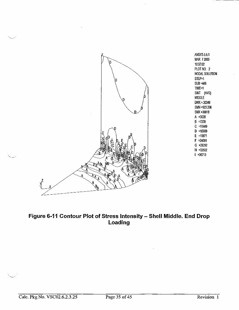
ANSYS 5.5.1 MAR 72000 10:37:02 PLOT NO. 2 NODAL SOLUTION
D STEP=I SUB =448 TIME=I SINT (AVG) MIDDLE DMX =.30349 SMN --923.206 SMX =38818 A =3028 B =7239 C =11449 D =15660 E =19871 F =24081 G =28292 H =32502 I =36713
Figure 6-11 Contour Plot of Stress Intensity - Shell Middle. End Drop Loading
Caic. Pkg No. VSCO2.6.2.3.25 Page 35 of 45 Revision ICalc. Pkg No. VSC02.6.2.3.25 Page 35 of 45 Revision I

ANSYS 5.5.1 MAR 72000 10:37:07 PLOT NO. 3 NODAL SOLUTION STEP=M SUB =448 TIME=1
E SINT (AVG) BOTTOM DMX =.30349 SMN --657.5 SMX =41837 A =2945 B =7521 C =12096 D =16672 E =21247 F =25823 G =30398 H =34974 1 =39549
m
Figure 6-12 Contour Plot of Stress Intensity - Shell Bottom. End Drop Loading
Caic. Pkg No. VSCO2.6.2.3.25 Page 36 of 45 Revision 1Cale. Pkg No. VSC02.6.2.3.25 Page 36 of 45 Revision I

Table 6-3 MSB Base Plate - Top Ten Stress Intensities at Top, Middle, and Bottom Locations- End Drop (108g)
Shell TOP
NODE S1 563 41855.586 587 562 575 574
14 1
29 23
41856. 41845. 41841. 41838. 41837. 40591. 40011. 39990. 40544.
Shell MIDDLE
NODE S1 2 9083.0
28 560 577 572 589 584 565
30 3
9096.4 7916.9 7898.4 7913.3 7895.2 7903.1 7883.8 7545.2 7541.2
Shell BOTTOM
S3 -3.8650 -2.5186 -8.3210
-0.32218 -1.0322
-0.57776 -0.64121E-01 -7.2713 -1.6575 -1.7699
Caic. Pkg No. VSCO2.6.2.3.25 Page 37 of 45 Revision 1
S2
16858.
16863. 16824. 16833. 16867. 16876. 36625. 37054. 37079. 36644.
S3
-1619.4 -1618.9 -1620.8 -1619.5 -1620.2 -1619.2 -1463.9 -2041.1 -2041.9 -1463.8
SINT
43474. 43466. 43460. 43458. 43456. 42055. 42052. 42031. 42008.
SEQV 37791. 37790. 37786. 37780. 37775. 37772. 40219. 40655. 40654. 40200.
S2 650.83 682.40 194.78 123.67 200.06 136.33 197.37 123.17 907.84 922.81
S3 -11666. -11648. -8681.7 -8695.4 -8673.9 -8689.4 -8670.0 -8688.7 -8426.3 -8417.0
SINT
20744. 16599. 16594. 16587. 16585. 16573. 16573. 15972. 15958.
SEQV 18074.
18072. 14386. 14380. 14377. 14373. 14364. 14362. 13897. 13887.
NODE 528 419 420 408 409 418 417 521 410 520
S1 41833. 41405. 41377. 41368. 41357. 41349. 41296. 41283. 41273. 41256.
S2 19719. 20005. 20363. 19483. 19413. 19711. 19575. 21211. 19814. 21000.
SINT 41837. 41407. 41385. 41369. 41358. 41350. 41296. 41290. 41275. 41257.
SEQV 36251. 35866. 35842. 35846. 35839. 35823. 35779. 35763. 35755. 35732.
Calc. Pkg No. VSC02.6.2.3.25 Page 37 of 45 Revision I

Table 6-4 MSB Shell - Top Ten Stress Intensities at Top, Middle, and Bottom Locations - End Drop (108g)
Shell TOP
NODE 2
28 11 20
4 10 19
8 26 17
S1 11.001 10.815 6.4605 6.4747 7.2946 7.6790 7.6391 7.5400 7.3142 7.6109
S2 -20518. -20480. -20505. -20503. -18366. -18357. -18350. -18371. -18362. -18380.
S3 -41294. -41279. -41281. -41280. -40091. -40076. -40075. -40059. -40059. -40058.
SINT 41305. 41290. 41288. 41286. 40098. 40084. 40083. 40066. 40066. 40066.
SEQV 35771. 35758. 35757. 35755. 34766. 34754. 34753. 34738. 34738. 34737.
Shell MIDDLE
NODE 2
11 20 28
4 10 19
8 17 26
S1 9.3288 4.7090 4.7226 9.1434 6.2332 6.5628 6.5180 6.4145 6.4942 6.2292
S2 -20944. -20942. -20940. -20913. -18509. -18509. -18510. -18533. -18529. -18513.
S3 -41805. -41801. -41799. -41792. -40434. -40429. -40429. -40414. -40411. -40406.
SINT 41814. 41806.
41804. 41801. 40440. 40435. 40435. 40421. 40418. 40412.
SEQV 36212. 36205. 36203. 36200. 35063. 35059. 35059. 35045. 35043. 35038.
Shell BOTTOM
NODE 2
11 20 28 19 10
4 8
17 26
S1 7.8136 3.1120 3.1249 7.6311 5.4559 5.5051 5.2261 5.3488 5.4363 5.2009
S2 -21368. -21379. -21377. -21344. -18665. -18655. -18647. -18689. -18674. -18658.
S3 -42317. -42320. -42318. -42306. -40788. -40787. -40782. -40775. -40769. -40758.
SINT F42325.1 42324. 42321. 42313. 40793. 40792. 40787. 40780. 40775. 40763.
SEQV 36655. 36654. 36652. 36645. 35370. 35370. 35366. 35357. 35353. 35343.
Calc. Pkg No. VSCO2.6.2.3.25 Page 38 of 45 Revision I

6.4. Ceramic Tile
This section calculates the bearing stress on the ceramic tile for normal operation. An evaluation of the ceramic tile for a vertical drop is not included because it is not important for the ceramic tile to remain intact for this accident.
-mMSB
Orbearing - Acer
Where Acer is the total area of the ceramic tiles in contact with the MSB.
70000 ('bearing = 24-1.72 = 1.0 ksi
The bearing stress on the tile is negligible.
6.5. MSB Drop Onto Shield Lid
Even though this analysis is not required for Part 72 license (upside down drop is not possible), the analysis has been performed for the future licensing under Part 71.
The same model was used as in Section 6.2, however, the loading was modified as showný on Figure 6-2. The ANSYS input/output from Reference 3.1.3 is in Attachment C. The maximum membrane stress, at Element 12, is
Smeold:= 5.88.ksi
The revised membrane stress is calculated assuming that stress scales linearly with load and inversely proportional to MSB wall thickness. The revised membrane stress is
a v t msb old Cm down:= ar m old'. " - - ~av oid t msb
am down= 3.8ksi
The approximate bending stress at Element 1 is (it is conservative to ignore the slight membrane stress at this element)
arb old := 24.99.ksi
The revised bending stress is calculated assuming that stress scales linearly with load. The revised bending stress is av
O-b_down := Ub~old' av old
ob_down= 21. 8 ksi
Calc. Pkg No. VSCO2.6.2.3.25 Page 39 of 45 Revision 1

6.6. Summary of Stress Results, Allowables, and Design Margins
Table 6-5 MSB With Uniform Support to Base, End Drop Loading. Summary of Stresses, Allowables, and Design Margins..
PRIMARY MEMBRANE PRIMARY MEMBRANE + BENDING
COMPONENT Pm Allowable D.M PL + Pb Allowable D.M
Pm PL + Pb Shell (1) 9.7 49.0 4.1 9.7 + 2.4= 73.5 5.1
12.1 Structural Lid N.A N.A N.A 4.2 73.5 16.5
Structural Lid N.A N.A N.A 8.2 73.5 8.0 Weld Bottom Plate 3.8 49.0 11.9 3.8 + 21.8= 73.5 1.87
1_ _25.6 1
Note: 1 Values tabulated are worst case for load cases considered. The stresses summarized above are also used in combination with other load cases in a separate calculation.
CaIc. Pkg No. VSCO2.6.2.3.25 Page 40 of 45 Revision 1Calc. Pkg No. VSC02.6.2.3.25 Page 40 of 45 Revision I

Table 6-6 MSB Supported on Ceramic Tiles With Deadwt loading (lg). Summary of Stresses, Allowables, and Design Margins.
MSB SHELL (ksi) Primary Membrane Stress Primary Membrane Plus Bending
Intensity (Pm) Stress Intensity (PL+Pb) Pm Allowable D.M PL+Pb Allowable D.M
Pm PL+Pb
0.5 49.0 Large 1.5 73.5 Large
MSB BASE (ksi) Primary Membrane Stress Primary Membrane Plus Bending
Intensity (Pmo) Stress Intensity (PL+Pb) Pm Allowable D.M PL+Pb Allowable D.M
Pm PL+Pb
0.35 49.0 Large 12.2 73.5 4.5
Note: The stresses summarized above are also used in combination with other load cases in a separate calculation. The bottom weld stress for both Pm and PL + Pb is conservatively taken as the worst of both the shell and base stresses.
Caic. Pkg No. VSCO2.6.2.3.25 Page 41 of 45 Revision 1Calc. Pkg No. VSC02.6.2.3.25 Page 41 of 45 Revision I

Table 6-7 MSB Supported on Ceramic Tiles. End Drop Loading (108g). Summary of Stresses, Allowables, and Design Margins.
Note: The stresses summarized above are also used in combination with other load cases in a separate calculation. The bottom weld stress forboth Pm and PL + Pb is conservatively taken as the worst of both the shell and base stresses.
CaIc. Pkg No. VSCO2.6.2.3.25 Page 42 of 45 Revision I
MSB SHELL (ksi)Primary Membrane Stress Maximum Primary Stress Maximum Primary Shear
Intensity (Pm) Intensity (P]max) (Pshear)
Pm Allowable D.M Prr. Allowable D.M Pshear Allowable DM Pm P..x _Phear
41.8 49.0 0.17 42.3 63.0 0.49 21.2 29.4 0.39
MSB BASE (ksi) Primary Membrane Stress Maximum Primary Stress Maximum Primary Shear
Intensity (Pro) Intensity (Pm) (Pshe) Pm Allowable D.M Pmax Allowable D.M Pshear Allowable DM
Pm Pmax P-bear
20.7 49.0 1.37 43.5 63.0 0.45 21.8 29.4 0.35
Page 42 of 45 Revision 1Calc. Pkg No. VSC02.6.2.3.25

7. CONCLUSION
The MSB components have been assessed for end drop loading for the uniform support condition. In this support configuration, the calculated stresses are within ASME code service level D allowables.
In addition, MSB components have been assessed for the both the dead weight and end drop conditions, while supported on a ring of ceramic tiles around the periphery of the MSB base. For the end drop condition, some local yielding occurs in regions where the ceramic tiles provide support to the MSB. The analysis has demonstrated that the calculated stresses are within ASME code allowables for acceptance criteria using plastic system analysis. Stresses due to deadweight analysis have also been shown to be acceptable.
It can be seen from the results that, as expected, the support condition of the MSB supported on the ceramic tiles has the smaller design margins, and therefore governs.
Calc. Pkg No. VSC02.6.2.3.25 Page 43of 45 Revision 1

8. ELECTRONIC FILES
Filename File Code Cat Version Platform Machine Date
Vscnorm.inp 3/6/00 ANSYS 1 5.5 NT 8834BW323307
Vscnorn.out 3/6/00 ANSYS 1 5.5 NT 8834BW323307
Vscnorm.db 3/6/00 ANSYS 1 5.5 NT 8834BW323307
Vscnorm.rst 3/6/00 ANSYS 1 5.5 NT 8834BW323307
Vscnorm-pp.inp 3/29/00 ANSYS 1 5.5 NT 8834BW323307
Vscnorm-pp.out 3/29/00 ANSYS 1 5.5 NT 8834BW323307
Vscnorm+press.inp 3/6/00 ANSYS 1 5.5 NT 8834BW323307
Vscnorm+press.out 3/6/00 ANSYS 1 5.5 NT 8834BW323307
Vscnorm+press.db 3/6/00 ANSYS 1 5.5 NT 8834BW323307
Vscnorm+press.rst 3/6/00 ANSYS 1 5.5 NT 8834BW323307
Vscedge.inp 3/6/00 ANSYS 1 5.5 NT 8834BW323307
Vscedge.out 3/6/00 ANSYS 1 5.5 NT 8834BW323307
Vscedge.db 3/6/00 ANSYS 1 5.5 NT 8834BW323307
Vscedge.rst 3/6/00 ANSYS 1 5.5 NT 8834BW323307
Vscedge-pp.inp 3/27/00 ANSYS 1 5.5 NT 8834BW323307
Vscedge-pp.out 3/27/00 ANSYS 1 5.5 NT 8834BW323307
File Description
Vscnorm.inp Vscnorn.out Vscnorm.db Vscnorm.rst Vscnorm-pp.inp Vscnorm-pp.out
ANSYS input data file. Deadweight (1 g). ANSYS output data file. Deadweight (1g). ANSYS database file. Deadweight (Ig). ANSYS results file. Deadweight (Ig). ANSYS post processing input file. Deadweight (I g). ANSYS post processing output file. Deadweight (Ig).
CaIc. Pkg No. VSC02.6.2.3.25 Revision IPage 44 of 45

Vscnorm+press.inp Vscnorm+press.out Vscnorm+press.db Vscnorm+press.rst
Vscedge.inp Vscedge.out Vscedge.db Vscedge.rst Vscedge-pp.inp Vscedge-pp.out
ANSYS input data file. Deadweight (1 g) + pressure (8.9 psig). ANSYS output data file. Deadweight (1g) + pressure (8.9 psig). ANSYS database file. Deadweight (I g) + pressure (8.9 psig). ANSYS results file. Deadweight (1 g) + pressure (8.9 psig).
ANSYS input data file. End Drop (108g). ANSYS output data file. End Drop (1 08g). ANSYS database file. End Drop (108g). ANSYS results file. End Drop (108g). ANSYS post processing input file. End Drop (108g). ANSYS post processing output file. End Drop (108g).
Calc. Pkg No. VSC02.6.2.3.25 Page 45 of 45 Revision 1

ATTACHMENT A
FINITE ELEMENT ANALYSIS INPUT AND OUTPUT
MSB TOP REGION
Calc Package VSCO2.6.2.3.25
Rev 1
PageAl of A33
ATTACHMENT B
FINITE ELEMENT ANALYSIS INPUT AND OUTPUT
MSB BOTTOM REGION
Calc Package VSC02.6.2.3.25
Rev 1
Page B of B5

ATTACHMENT C
FINITE ELEMENT ANALYSIS INPUT AND OUTPUT
MSB BOTTOM-DROP ONTO SHIELD LID
Calc Package VSC02.6.2.3.25
Rev 1
Page Cl of C5

ATTACHMENT D
FINITE ELEMENT ANALYSIS INPUT
MSB BOTTOM SUPPORTED BY TILES ON BASE, DEADWEIGHT LOADING (1g)
Calc Package VSCO2.6.2.3.25
Rev 1
Page Dl of D6

! * 3D ANALYSIS OF BASE PLATE STRESS WITH ! * MSB BASE SUPPORTED BY CERAMIC TILES AROUND EDGE ! * NORMAL OPERATING CONDITION Ig
/filname,vscnorm
/Prep7 /Title,VSC Base Plate Stress Analysis
! Elastic Shell elements ! 3-D Point to Point Gap Elements
Use soft spring across open gap ! Use reasonable time increment
!*** CHECK MATERIAL PROPERTIES
! Material Properties ! SA-516, Grade 70 Ferritic Carbon dens, 1, 0. 284 nuxy, 1,0.29 ex, 1,28.3E6
*afun,deg ! Angles
!*** Parameters ***
OD = 62.5 ! OutsidE ID = 60.5 ! Inside WTH = (OD-ID)/2 ! Wall tl BRAD = ID/2+WTH/2 ! C/L rac BTH = 0.75 ! Base p] LET = 1.7 ! Length TTH = 0.30 ! Ceramic TRI = 30.0 ! C/L rac THETA = asin((LET/2)/TRI) ! Angle I VLE = 30.0 ! Length
TOL = 0.001 ! Select
! Real constants r,I,BTH ! ThicknE r,2,BTH ! ThicknE r,3,WTH ! ThicknE r,4,leG,TTH,3 ! Contact
Steel, 300 deg.F
in degrees as default
diameter diameter hickness lius of basket late thickness of ceramic tile
tile thickness lius ceramic tiles )etween center & edge of tiles of modeled vertical portion of vessel tolerance
•ss of base plate (non tile regions) •ss of base plate (tiles region) •ss of basket wall
stiffness, MSB to base
! ****** ******* ****
!** Keypoints ***
csysl k,1, k,2,TRI-LET/2,0,0 k, 3,BRAD, 0,0 k,4,TR1-LET/2,THETA, 0 k,5,BRAD,THETA,0 k,6,TRI-LET/2,15-THETA, 0
Calc Package VSC02.6.2.3.25
Rev 1
Page D2 of D6
! Element Types et,l,shell63 et,2,contac52 keyopt,2,3,1 keyopt,2,7,1

k,7,BRAD,15-THETA,0 k,8,TRI-LET/2,15+THETA, 0 k,9,BRAD, 15+THETA, 0 k,10,TRI-LET/2,30-THETA, 0 k, 11,BRAD, 30-THETA, 0 k,12,TR1-LET/2,30+THETA, 0 k,13,BRAD,30+THETA, 0 k,14,TRl-LET/2,45-THETA, 0 k,15,BRAD,45-THETA, 0 k,16,TRl-LET/2,45,0 k,17,BRAD,45,0
ksel,s,loc,x,BRAD kgen,2,all ..... VLE/4,100 ksel,s,loc,z,VLE/4 kgen,2,all ..... VLE*3/4,100 ksel,all
Areas Tile areas first
csysl a,2,3,5,4 a,6,7,9,8 a,10,11,13,12 a,14,15,17,16 type,1 mat,1 real,2 esize,0.9 amesh, 1,4
! Rest of Base a,1,2,4,6,8,10,12,14,16 a,4,5,7,6 a,8,9,11,10 a,12,13,15,14
lsel,s,line,,22,24 lesize,all,,,7 Isel,all real,1 amesh, 5,8
! Basket shell numstr, area,21 a,3,103,105,5 a,5, 105, 107,7 a,7,107,109,9 a, 9,109,111,11 a,11,111,113,13 a 4 13,113,115,15 a,15,115,117,17
a,103,203,205,105 a,105,205,207,107
Calc Package VSC02.6.2.3.25
Rev 1
Page D3 of D6

a,107,207,209,109 a,109,209,211,111 a,11,211,213,113 a,113,213,215,115 a,115,215,217,117
esize,1.2 real,3 amesh,21,27 esize,2.0 amesh,28,34
!** Contacts ***
! Contact between basket base & cask ! Select nodes on ceramic tile elements esel,s,real,,l nsle,s ! Generate coincident set of nodes ngen,2,2000,all,,,0,0,-TTH ! Generate contact elements esel,s,real,,l nsle,s *get,numnodes,node,,count
nsel,a,node,,1999,3999 *get,nextnode,node,,num,min type,2 real,4 *do, i,l,numnodes
*if,i,eq,l,then e,nextnode,nextnode+2000 *getnextnode,node,nextnode,nxth
*elseif,i,ge,2,then e,nextnode,nextnode+2000 *get,nextnode,node,nextnode,nxth
*endif *enddo
! Remove contacts on periphery of tiles asel,s,area,,1,4 esla,s nsle,s,ext esln,s esel,r, type,,2 edel,all nall eall
*** ** ** **** ** ** **
!*** Constraints *** ! **** ****** ** *******
Symmetry BC's esel,s,type, ,l nsle, s
Calc Package VSCO2.6.2.3.25
Rev 1
Page D4 of D6

csys, 1 nsel,s,loc,y,45 nrotat,all dsym, symm,y,l esel,s,type,,l nsle,s nsel,s,loc,y,0 dsym, symnm,y
1 Contacts at ground esel,s,type,,2 nsle,s nsel,r,,,1999,3999 d,all,all,0 nall
1 Base of tiles esel,s,real,,2 nsle d,all,uz,0
** Applied Loads
! Pressure on basket base due to contents esel,s,real,,1,2 nsle,s sfe,all,2,pres,,13.536 nall eall
1 Force on side wall due to part of ! Basket not included in model. 1 Interior nodes first FORCE = 3442.5 ! Calculated mass missing in 1/8 model csys,l nsel,s,loc,x,BRAD nsel,r, loc,z,VLE *get,NUMNODES,node,,count
nsel,r, loc,y,1,44 NODEFORC = FORCE/(NUMNODES-l) f,all,fz,-NODEFORC nall ! Exterior nodes (half the load) csys,l nsel,s,loc,x,BRAD nsel,r, loc,z,VLE nsel, r, loc,y, 0 f,all,fz,-NODEFORC/2 nsel,s,loc,x,BRAD nsel,r, loc,z,VLE nsel,r,loc,y,45 f,all,fz,-NODEFORC/2 nall
Calc Package VSCO2.6.2.3.25
Rev 1
Page D5 o4 D6

! Drop Acceleration acel,,,l
allsel
1"** Solution ***
/solu
solve
finish
/postl set prrsol fini /exit
ig Body load acceleration
Calc Package VSC02.6.2.3.25
Rev 1
Page D6 of D6

ATTACHMENT E
FINITE ELEMENT ANALYSIS INPUT
MSB SUPPORTED BY TILES ON BASE, BOTTOM END DROP (108g)
Calc Package VSC02.6.2.3.25
Rev 1
Page El of E6

! * 3D ANALYSIS OF BASE PLATE STRESS WITH ! * MSB BASE SUPPORTED BY CERAMIC TILES AROUND EDGE
•-J- ! * END DROP ACCELERATION OF 108g
/filname,vscedge
/Prep7 /Title,VSC Base Plate Stress Analysis
! Element Types et,1,shell143 et,2,contac52 keyopt,2,3,1 keyopt,2,7,1
!*** CHECK MATERIAL PROPERTIES Material Properties SA-516, Grade 70 Ferritic Cai
dens, 1,0.284 nuxy, 1,0.29 ex, 1,28.3E6 tb,bkin,l,l tbdata,l,33.7E3,355.1E3 ! Yi•
*afun,deg
!*** Parameters ***
*-**OD = 62.5
ID = 60.5
WTH = (OD-ID)/2
BRAD = ID/2+WTH/2 BTH = 0.75
LET = 1.7
TTH = 0.30 TRI = 30.0 THETA = asin((LET/2)/TRI) VLE = 30.0 ACC = 108
TOL = 0.001
! Real constants r,I,BTH r,2,BTH r,3,WTH r,4,le6,TTH, 3
tic Shell elements Point to Point Gap Elements
soft spring across open gap reasonable time increment
rbon Steel, 300 deg.F
ýld Stress and Tangent Modulus
! Angles in degrees as default
Outside diameter Inside diameter Wall thickness C/L radius of basket Base plate thickness Length of ceramic tile Ceramic tile thickness C/L radius ceramic tiles Angle between center & edge of tiles Length of modeled vertical portion of vessel Acceleration due to end drop Select tolerance
Thickness of base plate (non tile regions) Thickness of base plate (tiles region) Thickness of basket wall Contact stiffness, MSB to base
I *******•*********
!*** Keypoints ***
csysl k,1, k,2,TRI-LET/2,0,0
Calc Package VSC02.6.2.3.25
Rev 1
Page E2 of E6
! !
!
!

k,3,BRAD,0,0
k,4,TRI-LET/2,THETA, 0 k, 5,BRAD,THETA, 0 k,6,TRl-LET/2,15-THETA, 0 k,7,BRAD, 15-THETA, 0 k,8,TRl-LET/2,15+THETA, 0 k,9,BRAD, 15+THETA, 0 k,10,TRl-LET/2,30-THETA,0 k, 1I,BRAD, 30-THETA, 0 k,12,TRI-LET/2,30+THETA, 0 k,13,BRAD,30+THETA, 0 k,14,TRI-LET/2,45-THETA, 0 k,15,BRAD,45-THETA, 0 k,16,TRI-LET/2,45,0 k,17,BRAD,45,0
ksel,s,loc,x,BRAD kgen,2,all,,, ,,VLE/4,100
ksel,s,loc,z,VLE/4 kgen,2,all ..... VLE*3/4,100 ksel,all
Areas Tile areas first
csysl a,2,3,5,4 a,6,7,9,8 a,10,11,13,12 a,14,15,17,16 type,1 mat,1 real,2 esize, 0.9 amesh, 1,4
! Rest of Base a,1,2,4,6,8,10,12,14,16 a,4,5,7,6 a,8,9,11,10 a,12,13,15,14
lsel,s,line,,22,24 lesize,all, ,,7 lsel,all real,1 amesh, 5,8
! Basket shell numstr,area,21 a,3,103,105,5 a,5,105,107,7 a,7,107,109,9 a,9,109,111,11 a,11,111,113,13 a,13,113,115,15
Calc Package VSC02.6.2.3.25
Rev 1
Page E3 of E6

a,15,115,117,17
a,103,203,205,105 a,105,205,207,107 a,107,207,209,109 a,109,209,211,111 a,111,211,213,113 a,113,213,215,115 a,115,215,217,117
esize,1.2 real,3
amesh,21,27 esize,2.0 amesh,28,34
!** Contacts ***
Contact between basket base & cask Select nodes on ceramic tile elements
esel,s,real,,l
nsle,s ! Generate coincident set of nodes ngen,2,2000,all,,,0,0,-TTH ! Generate contact elements esel,s,real,,l
nsle,s *get,numnodes,node,,count nsel,a,node,,1999,3999 *get,nextnode,node,,num,min type,2 real,4 *do, i,l,numnodes
*if,i,eq, l,then
e,nextnode,nextnode+2000 *get,nextnode,node,nextnode,nxth
*elseif,i,ge,2,then
e,nextnode,nextnode+2000 *get,nextnode,node,nextnode,nxth
*endif *enddo
1 Remove contacts on periphery of tiles asel,s,area,,1,4 esla,s nsle,s,ext esln, s esel,r,type,,2 edel,all nall eall
!*** Constraints ***
Caic Package VSCO2.6.2.3.25
Rev 1
Page E4 of E6

S* ************* *****
I Symmetry BC's esel,s,type,,l nsle,s csys,l nsel,s,loc,y,45 nrotat,all dsym, symm,y,l esel,s,type,,l nsle,s nsel,s,loc,y,0 dsym, symm,y
! Contacts at ground esel,s,type,,2 nsle,s nsel,r,,,1999,3999 d,all,all,0 nall
1 Base of tiles esel,s,real,,2
nsle d,all,uz,0
!*** Applied Loads I**********************
Pressure on basket base due to contents esel,s,real,,1,2 nsle,s sfe,all,2,pres,,13.536*ACC nall eall
! Force on side wall due to part of I Basket not included in model. ! Interior nodes first FORCE = 3442.5*ACC ! Calculated mass missing in 1/8 model csys,l nsel,s,loc,x,BRAD nsel,r, loc,z,VLE *get,NUMNODES,node,,count nsel,r, loc,y,1,44 NODEFORC = FORCE/(NUMNODES-I) f,all,fz,-NODEFORC nall ! Exterior nodes (half the load) csys,l nsel,s,loc,x,BRAD nsel,r,loc, z,VLE nsel,r, loc,y, 0 f,all,fz,-NODEFORC/2 nsel,s,loc,x,BRAD nsel,r, loc,z,VLE
Calc Package VSC02.6.2.3.25
Rev 1
Page E5 of E6

nsel,r,loc,y,45 f,all,fz,-NODEFORC/2 nall
! Drop Acceleration acel, .. ,ACC
allsel
!*** Solution **
/solu nlgeom, on autots,on nsubst,50,1000,10 solcon, on,on cnvtol,f,,0.01 cnvtol,m,,0.01
! Body load acceleration
Include large deformation effects Automatic time stepping 50 substeps 1000max 10min for load step
£ Convergence for force at 1% Convergence for moment at 1%
solve
finish
/postl set prrsol fini /exit
Calc Package VSC02.6.2.3.25
Rev 1
Page E6 of E6
! !
!

CACNFLN Cac. Pkg No. VSC02.6.2.3.31 BNFLCALCULATION File No.: VSC02.6.2.3.31 Fuel Solutions PACKAGE Revision: 0
PROJECT/CUSTOMER:
VSC02/BNFL Fuel Solutions
TITLE:
Calculation for Stress on Structural Lid for a Lifting Bolt Radius of 26.5"
SCOPE:
Product: F] WesflexTm -] TranStorm N VSC-24 [] Other
Service: [ Storage [] Transportation [] Other
Conditions: [ Normal -- Off-Normal nI Accident E] Other
Component(s):
MSB Structural Lid
Prepared by: Verified by:
Name: qaoOewr kFHn"ITc Name: IA ifCAIJJ L& A, Lej r? "
Signature: Wiýý19 ~ 4= Signature:%U g& I4¶ t I flA,&A,)
Date: / Iz /z/oo Date: I/(2.k-lD
Engineering Manager Approval:
Name: ?-A-A4 S• ITNJvAYA,-,1
Signature: USZ..,c2.j &,^A
Date: kJI-Ioo
Page 1 of 8

RECORD OF REVISIONS
This calculation has been prepared in accordance with QAP 3.2, Revision 8, except that because this calculation is a revision of an existing calculation, the format is essentially based on the superceded calculation. The title page, record of revision page, and record of verification page are per QAP 3.2, Revision 8. Other format requirements of QAP 3.2 have been included where this could be readily accomplished. This approach was approved in BFS Memorandum 99-528, dated December 21, 1999.
Page 2 ot 8 Revision 0
AFFECTED AFFECTED NAMES (print or type) REV. PAGES MEDIA DESCRIPTION PREPARER CHECKER
0 1-18 Replaces Calculation Romizr 44 i'iMW UWEP109-002.31, Rev. 0 - /fRr-ii6- i/q-h
_______zy 06. -. \Ai m-C-oi __ __
Note:
t.CalC..trKg 1-40. V b UU2.O.Z.-i.31 Page 2 of 8 Revision 0

RECORD OF VERIFICATION
Circle: (a) The objective is clear and consistent with the analysis. E NO (b) The inputs are correctly selected and incorporated into the design.Y NO N/A (c) References are complete and accurate. S NO N/A (d) Basis for engineering judgments is adequately documented. & S NO N/A (e) The assumptions necessary to perform the design activity are adequately
described and reasonable. NO N/A (f) Assumptions and references which are preliminary are noted as being
preliminary. YES NO ( ) (g) Methods and units are clearly identified. (& NO N/A (h) Any limits of applicability are identified. YES NO 4 ) (i) Computer calculations are properly identified. YES NO N/A (j) Computer codes used are under configuration control. YES NO (k) Computer codes used are applicable to the calculation. YES NO (1) Input parameters and boundary conditions are appropriate and correct. (j NO (in) An appropriate design method is used. NO (n) The output is reasonable compared to the inputs. NO (o) Conclusions are clear and consistent with analysis results. NO COMMENTS:
Laic. Pkg No. V�CU2.b2.331 Page 3 01 8 Revision 0
Verifier:/ Name/Signature/Date
CSalc. Pkg No. V•S 02.6.2.3.31 Page 3 of 8 Revision 0

1.0 INTRODUCTION
The purpose of this calculation is to determine the effect of moving the MSB Structural Lid lifting bolt holes to a radius of 26 inches (conservative compared to the actual value of 26.5") from their previously analyzed radius of 27 inches will have on the ability of the MSB lifting devices to lift a fully loaded MSB.
This calculation supercedes SNC Calculation WEP 109-002.31, Revision 0. This calculation addresses technical issues identified in CAR 98-50. The principal difference between this calculation and the superceded calculation is the weight of the fully loaded MSB used in the calculation.
2.0 DESIGN INPUTS AND ASSUMPTIONS
2.1 Design Inputs
Radius of MSB Structural Lid
Thickness of MSB Structural Lid
Radius of Lifting Bolt Holes (Case 1)
Radius of Lifting Bolt Holes (Case 2)
Weight per lifting bolt of MSB used in calculation of maximum stress for case 1. (Based on 6 lifting bolts)
a :=30 in
t:=3 in
rol :=27 in
ro2:=26 in
w 0:= 11692 lb
Number of Lifting Bolts
Maximum MSB Structural Lid Stress Smax:=2.210 3 psi
Material Properties (Taken at 300 degree F)
Material
Yield Strength
Ultimate Tensile Strength
Poisson Ratio
SA 516-70
Sy :33.7-103 psi
s :=70.10 3 psi
v :=0.33
1 n:=
V
n = 3.03
Calc. Pkg No. VSC02.6.2.3.31
Reference 3
Reference 3
Reference 4
Reference 4
Reference 3
Reference 4
Reference 3
Reference 5
Reference 5
Reference 5
Page 4 of 8 Revision 0

2.2 Assumption
A bounding MSB weight value of 70,000 lb will be used for conservatism. (This value corresponds to a fully loaded MSB with shield and structural lids. The basis is that the weight bounds the weight calculated in Reference 7). In addition, the weight of the MSB will be increased by a factor of 1.1, in accordance with NUREG 0612 (Reference 1). The weight of the MSB (w) is taken per lifting bolt.
70000 (1b) w:= 6 .(1.1)
w = 1.283.10 4 lb
3.0 CALCULATION
The MSB structural lid and bolt holes are modeled as a uniform load on a concentric circular ring on a flat plate. Based on this, the radial stress (st) and tangential stress (st) are as follows (Reference 6, page 218). Note that the stresses are calculated at radius (r). In both cases, r is assumed to be 30 inches, the point with the highest stress.
r:=30 in
(- 3 "w'n b) [(-n -t). (2"In(a) ra 2)1 r, 2j s r(nt I .2.n- -i
St:- (- 3 "w'n b) (n +l). 2.1n a o2 - (n-1).r-2--2
3.1 Case I (ro=27 inches)
Sri "-.w-n.t2 (n +l1) - 2.1n a) + ]+(n- 1)-r2--2.n
]b Sri = 776.1.*-b in
Calc. PkgNo. VSCO2.6.2.3.31 Page 5 of 8 Revision 0Page 5 of 8 Revision 0Calc. Pkg No. VSC02.6.2.3.31

st:= 4(-n3 w nlb)( 2n
lb stl = 256.1in---n
3.2 Case 2 (ro=26 inches)
(- 3"w'n b). (n + 1)'2"In(a) +r° 22]ý S -r-2n- 4".'22ln a- (7
Sr2= 1.10 lb
in
St2 3: - nb) (n+]) 2,n(a) +n-1).�~2
lb s t2 335 .5"i•o 7
in
3.3 Determination of Increased Stress
The fractional increase in radial and tangential stress due to the new lifting bolt hole placement is calculated below:
Sr2- Srl ASr
Sri
St2- Stl Ast-
As r = 0.3 09 9
As t = 0.3099
(Jaic. Vkg No. VSUULb.'2.3.31 Page 6 018 Revision 0Cale. Pkg No. VSC02.6.2.3.31 Page 6 of 8 Revision 0

Reference 4 documents a maximum stress of 2.2 ksi based on an evaluated MSB weight of 63,777 lb. Maximum stress based on the bounding weight can be calculated with the ratio of the bounding to the previously evaluated load. The stress will increase as a result of moving the lifting bolt holes in from a radius of 27 inches to a radius of 26 inches. This results in a new maximum stress of:
Snew:=[smax(1 sr w
s new = 3.2.103 3psi
References I and 2 specify minimum safety factors for yield and ultimate tensile strength of 6 and 10 respectively. Based on the maximum stress calculated above (Snew), safety factors are:
y:=- Y y = 10.7 Minimum +y=6
S new
su
newu = 22.1 Minimum +u=10 U snew
4.0 CONCLUSION
The yield strength ultimate tensile strength safety factors are both greater than their respective required minimums. Therefore, an MSB structural lid lifting bolt radius of 26 inches will result in acceptable safety factors with respect to yield and ultimate tensile strength.
'Jaic. k'Kg No. VSL02X2.3.31 1'age 1 ot � Revision 0Ualc. Flxg No. VtSCO2.6.2.3.31 Page 7 of 8 Revision 0

5.0 REFERENCES
1. NUREG-0612, "Control of Heavy Loads at Nuclear Power Plants-Resolution of Generic Technical Activity A-36", July, 1980.
2. ANSI N14.6-1993, "Special Lifting Devices for Shipping Containers Weighing 10,000 lb or more".
3. BNFL Drawing MSB-24-002, "MSB Shell and Structural Plates", Sheet 1/2, Revision 4.
4. BNFL Calculation VSCO2.6.2.3.03, "MSB-24 Lifting Devices", Revision 0.
5. ASME Boiler and Pressure Vessel Code, 1986 Edition.
6. Roark, R.J., Formulas for Stress and Strain, Fourth Edition, McGraw-Hill, 1965.
7. BNFL Calculation VSC02.6.2.5.01, "MTC, MSB, and VCC Weights and Centers of Gravity, B&W Fuel", Revision 0.
Calc. Pkg No. VSCO2.6.2.3.31 Page 8 of 8 Revision 0Calc. Pkg No. VSC02.6.2.3.31 Page 8 of 8 Revision 0

CCalc. Pkg No. VSC02.6.2.3.33 (I BNFL CALCULATION File No.: VSC02.6.2.3.33
Fuel Solutions PACKAGE Revision: 0
PROJECT/CUSTOMER:
VSC02/BNFL Fuel Solutions
TITLE:
Impact on Fuel Sleeve
SCOPE:
Product: -] WesflexT r ] TranStorTM [ VSC-24 [ Other
Service: M Storage [] Transportation [] Other
Conditions: ] Normal E] Off-Normal D] Accident E] Other
Component(s):
MSB Fuel Sleeve
Prepared by: Verified by:
Name: - KI3E•, /4'17- ,0 6 Name:. A1/ L e MflJ , Lk "t 17
Signature: , /// D E/k r Signature: ,•"itt•t !AI vIJ l ftt
Date: A % Date: L]I'2J/CD
Engineering Manager Approval:
Name: - Tiz r,.N I VAý;4A
Signature: • V" ,,aw,
Date: !1,7/,9o
Page 1 of 8

RECORD OF REVISIONS
L ________________ I ______________________________ A. ______________ I _______________
This calculation has been prepared in accordance with QAP 3.2, Revision 8, except that because this calculation is a revision of an existing calculation, the format is essentially based on the superceded calculation. The title page, record of revision page, and record of verification page are per QAP 3.2, Revision 8. Other format requirements of QAP 3.2 have been included where this could be readily accomplished. This approach was approved in BFS Memorandum 99-528, dated December 21, 1999.
�aic. rKg. NO. V�U2A.L.j.33 1�age � ot � Revision 0
AFFECTED AFFECTED NAMES (print or type)
REV. PAGES MEDIA DESCRIPTION PREPARER CHECKER
0 1-8 Replaces Calculation oA.4 i| U'e• Lt WEP 109-002.33, Rev. 0 - - , QJ"
T I + 4
Note:
ý-a c. rKg. 1-40. V •:ZOZ33 Page 2 of 8 Revision 0

RECORD OF VERIFICATION
Circle: (a) The objective is clear and consistent with the analysis. S NO (b) The inputs are correctly selected and incorporated into the design. YE NO N/A (c) References are complete and accurate. NO N/A (d) Basis for engineering judgments is adequately documented. NO N/A (e) The assumptions necessary to perform the design activity are adequately
described and reasonable. NO N/A (f) Assumptions and references which are preliminary are noted as being
preliminary. YES NO (g) Methods and units are clearly identified. YES NO N/A (h) Any limits of applicability are identified. YES NO N/A (i) Computer calculations are properly identified. YES NO (j) Computer codes used are under configuration control. YES NO (k) Computer codes used are applicable to the calculation. YES NO (1) Input parameters and boundary conditions are appropriate and correct. YES NO (in) An appropriate design method is used. YES NO (n) The output is reasonable compared to the inputs. NO (o) Conclusions are clear and consistent with analysis results. YE NO COMMENTS:
Laic. t'Kg. No. VMJU2.O.2.3.33 Page 3 of 8 Revision 0
Verifier:NaigateDate
Name/Signature/Date (
Calc. PKg. No. V SC02.6.2.3.33 Page 3 of 8 Revision 0

1.0 INTRODUCTION
"The purpose of this calculation is to verify the structural adequacy of the fuel sleeves in the event of an accidental drop or side impact of a fuel assembly onto a fuel sleeve during fuel loading.
This calculation was prepared to address technical issues concerning Calculation WEP 109-002.33, Revision 0, discusssed in Car 98-50 (dated 10/2/98) and the Design Review Record (dated 7/31/99). This calculation supercedes WEP 109-002.33, Revision 0. The prinicipal differences between the new and old calculations are:
"* A bounding fuel assembly weight is used in the new calculation. "• The correct fuel sleeve inner width is used in the new calculation. "* Material properties at 200OF used in the new calculation.
Changes to this calculation are not known to affect any other calculations.
2.0 DESIGN INPUTS AND ASSUMPTIONS
2.1 Design Inputs
Fuel Sleeve Dimensions (Reference 1)
Wall Thickness
Outer Width
Inner Width
Material
t := 0.2 in
W out := 9.2 in
w:= 8.8 in
SA 516-70
Material Properties: (Reference 2) Properties taken at 200OF (See Assumption 2.2.1)
Yield Strength
Poisson Ratio
Modulus of Elasticity
Modulus of Rigidity
s y := 34.6.103 psi
v :=0.33
E:=28.8.106 psi
Gr:=.02(1 7v)
G r = 1.083. 107. psi
Caic. Pkg. No. VSCO2.6.2.3.33 Page 4 of 8 Revision 0Calc. Pkg. No. VSC02.6.2.3.33 Page 4 of 8 Revision 0

2.2 Assumptions
2.2.1 Material properties are taken at an assumed temperature of 2000F. The postulated fuel assembly drop could only occur during fuel assembly loading or unloading while the MSB is submerged in the Spent Fuel Pool. Nominal Spent Fuel Pool temperature is approximately 90oF, and fuel assembly transfer with pool boiling is not likely. Therefore, this value is considered bounding.
2.2.2 A bounding fuel assembly weight of 1,600 lb is assumed (bounds the value calculated in Reference 4).
wt:= 1600 lb
2.2.3 For case 1, in which a vertical drop on top of the sleeve is considered, the following assumptions are made: * Speed of the dropped fuel assembly is 5 in/sec. * Impact time is 0.01 sec.
Only the top three inches of the sleeve are credited for the buckling calculation. • The dynamic amplification factor is 1.5.
in v 1 :=5 in time 1 :0.01 sec Ig 1 :=3 in amp i:=1.5
sec
2.2.4 For case 2, in which a horizontal impact on the side of the sleeve is considered, the following assumptions are made: • Speed of the dropped fuel assembly is 3 in/sec. * Impact time is 0.05 sec. This is due to the flexibility of the sleeve horizontally. • Only three inches on either side of the point of impact are credited. 0 The dynamic amplification factor is 1.1.
in v2 :=3 in time 2:= 0.05 sec amp 2 := 1.1 sec
3.0 CALCULATION
3.1 Case 1: Vertical Drop on Top of Fuel Sleeve
Case 1, in which a fuel assembly drops onto the top of one side of the sleeve, is evaluated as follows. An impulse due to the fuel assembly drop is calculated. This is used to determine the compressive stress. The stability of the sleeve is then evaluated by calculating a critical load, at which the sleeve will buckle, and comparing that to the weight of the fuel assembly.
Vl Imp I "- Wt.t Imp 1 = 2072-1bf
ti-mej
talc. Flg. No. VSCU2.623.33 Page 5 of 8 Revision 0(ale. Pkg. No. VSC02.6.2.3.33 Page 5 of 8 Revision 0

The dynamic amplification factor is applied to the impulse.
wtapplied := Imp 1 -amp I wtapplied = 3108*lbf
The compressive stress on one side of the sleeve, due to the impact on top of the sleeve, where w and t are the dimensions of the top of the sleeve, as defined in Section 2.1:
wtapplied a c w-t a c = 1766"psi
The compressive stress (ar) is less than yield strength (s y = 34600"psi).
The stability of the fuel sleeve is evaluated next. One wall of the fuel sleeve is modeled as a straight uniform beam with a center load applied at the centroid of the section (Reference 3, page 544, #13). As stated in Section 2.2, only the top three inches of the sleeve are credited in the stability calculation.
P
t
where:
a := 1.5 in Most Conservative
2.8. r/ _t _lr(1.7 4 -a).f :OE PCrt: e.t.. g 1 [1-0.63.I(Ig,) ].r-E. I
P crit = 7640.Ibf
As Prit>wt-applied, the stability of the fuel sleeve is adequate.
Calc. Pkg. No. VSC02.6.2.3.33 Page 6 of 8 Revision 0

3.2 Case 2: Horizontal Impact on Fuel Sleeve Wall
Case 2, in which a fuel assembly strikes the side wall of the fuel sleeve during loading, is solved as follows. The impulse due to the fuel assembly is calculated and corrected with the dynamic amplification factor, and used to determine the stresses on the fuel sleeve.
V 2 Imp 2:=wt',T-'me 2 amP 2 IMp 2 = 273.5-lbf
The stresses on the fuel sleeve are calculated crediting only three inches on either side of the point of impact (Assumption 2.2.4). This is conservative, as crediting the entire sleeve length would produce unreasonably low stresses.
imw,
~~*] 1*- 1g2-)b> l
As shown above, the section of fuel sleeve wall is modeled as a rectangular slab simply supported on either end. The following dimensions apply:
1g2 :=2-Ig 1
1g2 = 6cin
c :=0.5-t
c = 0.1oin
This credits 3 inches on either side of the point of impact
Distance to extreme fiber
Using these dimensions, the moment (Mom), moment of inertia (I), and normal stress (a), can be calculated.
Mom: = Imp 2"W
Ig 2 "t3
12
c G :=Mom-=
I
Mom = 601.7*in.lbf
I = 0.004in4
o = 15043 -psi
The normal stress (a) is less than the yield stress (s y = 34600-psi). This is acceptable.
Caic. Pkg. No. VSCO2.6.2.3.33 Page 7 of 8 Revision 0Calc. Pkg. No. VSC02.6.2.3.33 Page 7 of 8 Revision 0

The shear stress can be evaluated using the same dimensions as above.
- Imp 2 = 114-psi
The shear strength (Syshear) is calculated and compared to the case 2 shear stress (T).
S yshear := 0.57.s y s yshear = 19722-psi
The shear stress (T) is less than the shear strength (Syshear). This is acceptable.
4.0 CONCLUSION
This calculation evaluates the structural acceptability of the MSB fuel sleeves in the event of two postulated accidents, a vertical drop of a fuel assembly on top of the fuel sleeve, and a horizontal impact of a fuel assembly on the fuel sleeve wall. Both cases assumed a bounding fuel assembly weight of wt = 1600 lb and incorporated a dynamic amplification factor. In the first case, the compressive stress is calculated as a C = 1766-psi , which is less than the yield strength of s y = 34600-psi . The critical buckling load is calculated as P crit = 7640.1bf , which bounds the applied impulse of wt-applied = 3108olbf (generated by the fuel assembly weight of 1,600 lb). In the second case, normal and shear stresses of a = 15043 -psi
and = 114opsi , respectively, are calculated. The normal stress is less than the material yield strength s y = 34600 -psi, and the shear stress is less than the material shear strength s yshear = 19722 -psi.
5.0 REFERENCES
1. BNFL Drawing MSB-24-004, "Storage Sleeve Assembly", Sheet 1/3,
Revision 4.
2. ASME Boiler and Pressure Vessel Code, 1986 Edition.
3. Roark, R.J., Young, W.C., Formulas for Stress and Strain, Fifth Edition, McGraw-Hill, 1975.
4. BNFL Calcuation VSCO2.6.2.5.01, "MTC, MSB, and VCC Weights and Centers of Gravity B&W Fuel", Revision 0.
Caic. Pkg. No. VSCO2.6.2.3.33 Page 8 of 8 Revision 0Calc. Pkg. No. VSC02.6.2.3.33 Page 8 of 8 Revision 0

D-Z5 Mx- CULATION Caic. Pkg No. VSCO2.6.2.5.Ol BNFL C ULATION File No.: VSCO2.6.2.5.01
Fuel Solutions PACKAGE Revision: 0
PROJECT/CUSTOMER:
VSC02/BNFL Fuel Solutions
TIrTL:
MTC, MSB and VCC Weights and Centers of Gravity B&W Fuel
SCOPE: Product: L-]WesflexT L- TranStorTM ] VSC-24 L-i Other
Service: M Storage [] Transportation E] Other
Conditions: 0 Normal EL Off-Normal L] Accident LI Other
Component(s):
MSB, MTC and VCC, including all components and sub components.
Prepared by: l "_ 7- Verified by:
Name: Name: " eA• t -Pa r UM Signature:_____________ Signature:
Date: 117 A ooo Date: I f 7 / 2t 0 0 S/I
Engineering Manager Approval:
Name: 2--A Siz • I'•r'( fs 4
Signature:
Date: 1(21 Jo0
Page 1 of 28

RECORD OF REVISIONS
AFFECTED
MEDIAiDESCRIPTIO
1 -28
K\J' AY--i I I
Replaces Calculation
WEP109-004.1, Rev. 2
- -t I
+ 4
I ________________ I __
NAMES (print or type) PREPARER CHECKER
If pWZxI
This calculation has been prepared in accordance with QAP 3.2, Revision 8, except that because this calculation is a revision of an existing calculation, the format is essentially based on the superceded calculation. The title page, record of revision page, and record of verification page are per QAP 3.2, Revision 8. Other format requirements of QAP 3.2 have been included where this could be readily accomplished. This approach was approved in BFS Memorandum 99-528, dated December 21, 1999.
�aic. JfK� NO. VMUZA,22x01 Page 2 of 28Revision 0
REV.
I - - - I I TAFFEICED
PAGES
0
Note:
Page 2 of 28
I
DESCRIPTION
Caic. t'Kg _NO. V SCU2.6.2.5.01

RECORD OF VERIFICATION
Circle: (a) The objective is clear and consistent with the analysis. NO (b) The inputs are correctly selected and incorporated into the design. NO N/A (c) References are complete and accurate. . NO N/A (d) Basis for engineering judgments is adequately documented. NO N/A (e) The assumptions necessary to perform the design activity are adequately
described and reasonable. Y NO N/A (f) Assumptions and references which are preliminary are noted as being preliminary.
YES NO
(g) Methods and units are clearly identified. (T ) NO N/A (h) Any limits of applicability are identified. YES NO ( ) (i) Computer calculations are properly identified. YES NO (j) Computer codes used are under configuration control. YES NO A (k) Computer codes used are applicable to the calculation. YES NO (1) Input parameters and boundary conditions are appropriate and correct. NO (m) An appropriate design method is used. ( NO (n) The output is reasonable compared to the inputs. NO (o) Conclusions are clear and consistent with analysis results. •Yf NO COMMENTS:
Verifier: .0('A I 2 I'-~rSo 4• _2 - ]r0
Nam tignature/Date 2..0
Calc. Pkg No. VSC02.6.2.5.01 Page 3 of 28 Revision 0

1.0 INTRODUCTION
This Calculation determines the MSB, MTC, and VCC component weights, volumes and center of gravity. The information is required for different cask analyses as well as for handling of items when empty or loaded. This calculation also determines weights of MSB, MTC, and VCC components that are used by referencing calculations.
This analysis is bounding size (weight and height) and generic for the VSC-24 system. The calculation is the generic version of SNC Calculations WEP-109-004.1, Revision 2 (Ref 3.1.1) and ANO-109.002.001, Revision 5 (Reference 3.1.2). This generic analysis includes the resolution of discrepancies identified in Corrective Action Reports CAR 98-50 and CAR 98-51.
2.0 REQUIREMENTS
2.1 Design.Inputs
None.
2.2 Regulatory Commitments
None.
1..1�-. TbU XT� � TC1r�n� - '� e. ,.1 '��d1L. r�g INCJ. V �UL.O.L.�.UI Revision 0%-W.rttlKg I4o. vtzozDU P'age 4 ot Z8 Revision 0

3.0 REFERENCES
3.1 BFS Calculation Packages
3.1.1 SNC Calculation WEP-109-004.001, "MTC, MSB, and VCC Weights and Centers of Gravity (B&W Fuel), Revision 2.
3.1.2 SNC Calculation ANO-109-002.001, '"Weight and C.G. Calculation, Revision 5
3.2 General References
3.2.1 Deleted.
3.2.2 Deleted.
3.2.3 Marks Handbook
3.2.4 SNC Drawing MSB-24-001 (0110.005.001), "MSB Assembly", Sheet 1/2, Revision 5.
3.2.5 SNC Drawing MSB-24-001 (0110.005.002), "MSB Assembly", Sheet 2/2, Revision 5.
3.2.6 SNC Drawing MSB-24-002 (0110.005.003), "MSB Shell and Structural Plates", Sheet 1/2, Revision 4.
3.2.7 SNC Drawing MSB-24-002 (0110.005.004), "MSB Shell and Structural Plates", Sheet 2/2, Revision 3.
3.2.8 SNC Drawing MSB-24-003 (0110.005.005), "Shield Lid Assembly", Sheet 1/1, Revision 4.
3.2.9 SNC Drawing MSB-24-004 (0110.005.006), "Storage Sleeve Assembly", Sheet 1/3, Revision 4.
3.2.10 SNC Drawing MSB-24-004 (0110.005.007), "Storage Sleeve Assembly", Sheet 2/3, Revision 1.
Page 5 of 28 Revision 0Calc. Pkg No. VSC02.6.2.5.01

3.2.11 SNC Drawing MSB-24-004 (0110.005.008), "Storage Sleeve Assembly", Sheet 3/3, Revision 1.
3.2.12 SNC Drawing MTC-24-001 (0110.006.001), "MSB Transfer Cask (MTC)", Sheet 1/2, Revision 3.
3.2.13 SNC Drawing MTC-24-001 (0110.006.002), "MSB Transfer Cask (MTC)", Sheet 2/2, Revision 3.
3.2.14 SNC Drawing MTC-24-002 (0110.006.003), "Cask Wall Assembly", Sheet 1/2, Revision 3.
3.2.15 SNC Drawing MTC-24-002 (0110.006.004), "Cask Wall Assembly", Sheet 2/2, Revision 3.
3.2.16 SNC Drawing MTC-24-003 (0110.006.005), "Outer Shell", Sheet 1/2, Revision 1.
3.2.17 SNC Drawing MTC-24-003 (0110.006.006), "Outer Shell", Sheet 2/2, Revision 1.
3.2.18 SNC Drawing MTC-24-004 (0110.006.007), "Middle Shell", Sheet 1/1, Revision 2.
3.2.19 SNC Drawing MTC-24-005 (0110.006.008), 'Inner Shell", Sheet 1/1, Revision 2.
3.2.20 SNC Drawing MTC-24-006 (0110.006.009), "MTC Lid and Shim Rings", Sheet 1/1, Revision 2.
3.2.21 SNC Drawing MTC-24-007 (0110.006.010), "Rail Assembly", Sheet 1/1, Revision 3.
3.2.22 SNC Drawing MTC-24-008 (0110.006.011), "Trunion Assembly", Sheet 1/1, Revision 3.
3.2.23 SNC Drawing MTC-24-009 (0110.006.012), "Shield Door Assembly", Sheet 1/1, Revision 1.
Calc. Pkg No. VSC02.6.2.5.01 Page 6 of 28 Revision 0

3.2.24 SNC Drawing VCC-24-001 (0110.004.001), 'Ventilated Concrete Cask (VCC) Assembly", Sheet 1/2, Revision 3.
3.2.25 SNC Drawing VCC-24-001 (0110.004.002), "Ventilated Concrete Cask (VCC) Assembly", Sheet 2/2, Revision 2.
3.2.26 SNC Drawing VCC-24-002 (0110.004.003), "Cask Lid and Liner Assembly", Sheet 1/3, Revision 3.
3.2.27 SNC Drawing VCC-24-002 (0110.004.004), "Cask Lid and Liner Assembly", Sheet 2/3, Revision 3.
3.2.28 SNC Drawing VCC-24-002 (0110.004.005), "Cask Lid and Liner Assembly", Sheet 3/3, Revision 3.
3.2.29 SNC Drawing VCC-24-003 (0110.004.006), "Air Inlet Assembly", Sheet 1/1, Revision 2.
3.2.30 SNC Drawing VCC-24-004 (0110.004.007), "Air Outlet Assembly", Sheet 1/1, Revision 2.
3.2.31 SNC Drawing VCC-24-005 (0110.004.008), 'VCC Bottom Plate Assembly", Sheet 1/2, Revision 1.
3.2.32 SNC Drawing VCC-24-005 (0110.004.009), "VCC Bottom Plate Assembly", Sheet 2/2, Revision 1.
3.2.33 SNC Drawing VCC-24-006 (0110.004.010), "VCC Reinforcement", Sheet 1/2, Revision 3.
3.2.34 SNC Drawing VCC-24-006 (0110.004.011), 'VCC Reinforcement", Sheet 2/2, Revision 3.
3.2.35 SNC Drawing VCC-24-008 (0110.004.012), "Misc Steel Components", Sheet 1/1, Revision 3.
Calc. Pkg No. VSC02.6.2.5.01 Revision 0Page 7 of 28

4.0 ASSUMPTIONS
4.1 Design Configuration
4.1.1 Density of Materials
lbf Steel P st 0.281
lbf Concrete p c 150 -
lbf Rx-277 p Rx:= 0.06
lbf Lead P lead := 0.41
Reference 3.2.3
Reference 3.2.3
Reference 3.1.1
Reference 3.2.3
lbf W ater p W := 62.4 -b
4.1.2 Weight and Height of the Fuel Assembly
This analysis is based on an assumed bounding fuel weight with control components installed in the fuel assembly during storage. The assumed mass of the fuel bounds the mass in References 3.1.1 and 3.1.2 with some additional margin added.
M fuel := 1600 lbf
h fuel:= 151 in
N pins := 14
N fuel:= 24
lg fuel := 165 in
OD fuel:= 0.422 in
Mass of Fuel per Fuel Assembly
Height of Fuel Pin
Number of Pins Along One Side of Fuel Array
Number of Fuel Assemblies
Length of Fuel
Outside Diameter of Fuel Pin
C',-1,- DI. XT. 17C v . " Al rag 6 01 i.Revision 0, %_.:1,.. _F . V.tU O ., , ,L , I rage 8 or 28

4.1.3 MSB Geometry
OD MSB:= 62.5 in
ID MSB:= 60.5 in
h MSB 180.9 in
t Mbase 0.75 in
OD Mlid:= 60 in
t Mlid:= 3 in
N bar:= 12
lg bar:= 28 in
w bar := 1.45 in
h bar:= 2.0 in
N wall := 3
OD wall := 59.2 in
t wall := 0.5 in
1g wall := 28 in
1g sleeve := 164.0 in
W sleeve:= 9.2 in
t sleeve := 0.20 in
OD shield:= 60.1 in
t shieldtop := 2.5 in
t shieldbot := 2.5 in
t neutron := 2 in
t ring:= 0.5 in
OD support:= 60.25 in
t support := 2.5 in
d support := 12.55 in
CA... fll KT ,Tflflfla r .-� r ,x, -�
Page 9 ot '28 Revision 0
Outside Diameter of MSB-24 (Ref 3.2.6, Part 1)
Inside Diameter of MSB-24 (Ref 3.2.7, Part 1)
Overall Height of MSB-24 (Ref 3.2.6)
Thickness of Base of MSB-24 (Ref 3.2.7, Part 2)
Conservative (i.e. maximum) Outside Diameter of MSB-24 Structural Lid (Ref 3.2.6, Part 4)
Thickness of MSB-24 Structural Lid (Ref 3.2.6, Part 4)
Number of Support Bars (Ref 3.2.9, Part 4)
Length of Support Bar (Ref 3.2.9, Part 4)
Width of Support Bars (Ref 3.2.9, Part 4)
Height of Support Bars (Ref 3.2.9, Part 4)
Number of Support Wall Courses (Ref 3.2.9)
Outside Diameter of Support Walls (Ref 3.2.10, Part 2)
Thickness of Support Wall (Ref 3.2.9, Part 2)
Length of Support Wall (Ref 3.2.9 Part 2)
Length of Storage Sleeve (Ref 3.2.9, Part 1)
Width of Storage Sleeve (Ref 3.2.9, Part 1)
Thickness of Storage Sleeve (Ref 3.2.9, Part 1)
Outside Diameter of Shield Lid (Ref 3.2.8)
Thickness of Shield Top Plate (Ref 3.2.8, Part 1)
Thickness of Shield Bottom Plate (Ref 3.2.8, Part 2)
Thickness of Neutron Shield in Top (Ref 3.2.8, Part 4)
Thickness of Side Ring (Ref 3.2.8, Part 3)
Outside Diameter of Support Plate (Ref 3.2.8, Part 8)
Thickness of Support Plate (Ref 3.2.8, Part 8)
Distance from Top of MSB to Top of Shield Lid Support Ring (Ref 3.2.6)
Caw.a, rKg N"o. v Suz.o.2.5.0 I Page 9 of 28 Revision 0

4.1.4 MTC Geometry
OD inner:" 65 in
ID inner:= 63.5 in
h MTC := 178.7 in
OD outer:= 83.5 in
ID outer:= 81.5 in
OD middle:= 73.5 in
ID middle:= 73 in
t Ttop := 2 in
tThot:= I in
OD TId:= 74 in
ID Tlid = 60.5 in
tTlid:= I in
N door:= 2
w door:= 42.7 in
1g door:= 70 in
t door:= 9 in
w door-cut:= 17.7 in
1g door cut:= 15 in
N Wmion:= 2
OD trunion := 10.75 in
ID trunion:= 7.75 in
fl1 at �r �rnnna.-,,-.. �aic. r'xg INO. V�5UUL.t�.2.ZxU1 Page 11.) of 28 Revision 0
OD of the MTC Inner Shell (Ref 3.2.19, Part 1)
ID of the MTC Inner Shell (Ref 3.2.19, Part 1)
Height of MTC Cask Shell (Ref 3.2.14)
OD of the MTC Outer Shell (Ref 3.2.16, Part 3)
ID of the MTC Outer Shell (Ref 3.2.16, Part 3)
OD of the MTC Middle Shell (Ref 3.2.18, Part 1)
ID of the MTC Middle Shell (Ref 3.2.18, Part 1)
Thickness of the Top of the MTC (Ref 3.2.15, Part 4)
Thickness of the Bottom of the MTC (Ref 3.2.15, Part 5)
OD of the MTC Lid (Ref 3.2.20, Part 1)
ID of the MTC Lid (Ref 3.2.20, Part 1)
Thickness of MTC Lid (Ref 3.2.20, Part 1)
Number of MTC Doors (Ref 3.2.23, Part 1)
Width of MTC Doors (Ref 3.2.23, Part 1)
Length of the MTC Doors (Ref 3.2.23, Part 1)
Thickness of MTC Doors (Ref 3.2.23, Part 1)
Width of MTC Door Cutout (Ref 3.2.23, Part 1)
Length of the MTC Door Cutout (Ref 3.2.23, Part 1)
Number of Trunions (Ref 3.2.22)
OD of Trunion Cylinder (Ref 3.2.22, Part 2)
ID of Trunion Cylinder (Ref 3.2.22, Part 2)
C.alc. rKg Nxo. V 1SU0Z.6.2.5.UI Page 10 of 28 Revision 0

t trunionshield :4 in
t trunionplates = 2.0 in
1g trunion 15.6 in
N rail:= 2
W rail:= 9.125 in
1g rail:= 105 in
trail:= 6.5 in
W railsup := 9.25 in
t rail-sup := 1.5 in
Thickness of each of the Trunion Shielding (lead and Rx) (Ref 3.2.22, Parts 6 and 7)
Total Thickness of all three Trunion Plates (Ref 3.2.22,
Parts 1, 3 and 8)
Total Trunion Length (Ref 3.2.22)
Number of MTC Rails (Ref 3.2.21, Part 1)
Width of MTC Rails (Ref 3.2.21, Part 1)
Length of the MTC Rails (Ref 3.2.21, Part 1)
Thickness of MTC Rails (Ref 3.2.21, Part 1)
Width of MTC Rail Supports (Ref 3.2.21, Part 2)
Thickness of MTC Rail Support (Ref 3.2.21, Part 2)
r�g INU. V �A)L.O.L.�.UI rage i i 01: 2�i Revision 0Caic. 1-kg INV. I rage I I or 2-8 Revision 0

4.1.5 VCC Geometry
OD VCC := 132 in
h VCC := 213.7 in
OD liner:= 74 in
ID liner:= 70.5 in
t liner bot := 2 in
h liner:= 191.7 in
OD liner fig := 90 in
t liner flg:= 2 in
N skid:= 2
W skid:= 12 in
h skid:= 12.2 in
Ig skid:= 100.3 in
OD VCC bot:= 120 in
t VCC bot:= 0.25 in
N air out:= 4
w air out:= 47.8 in
Ig air out:= 36.3 in
h air out := 3 in
t air-out:= 0.5 in
e out := 8 in
fl1 fl1� KT TCNtNt�r.rnrr�.
Page Vi 0128 Revision 0
Outside Diameter of the VCC (Ref 3.2.24)
Height of the VCC (Ref 3.2.24)
Outside Diameter of VCC Steel Liner (Ref 3.2.26, Part 1)
Inside Diameter of the VCC Steel Liner (Ref 3.2.26, Part 1)
Thickness of the VCC Steel Liner Bottom (Ref 3.2.26, Part 2)
Overall Height of the VCC Steel Liner (Ref 3.2.26)
Outside Diameter of Liner Flange (Ref 3.2.26, Part 3)
Thickness of the Liner Flange (Ref 3.2.26, Part 3)
Number of Skid Channels (Ref 3.2.31)
Width of the Skid Channel (Ref 3.2.31)
Height of the Skid Channel (Ref 3.2.31)
Average Length of Skid Channels (Ref 3.2.31)
Outside Diameter of VCC Bottom Steel Plate
(Ref 3.2.31, Part 1)
Thickness of VCC Bottom Steel Plate (Ref 3.2.31, Part 1)
Number of Air Outlets (Ref 3.2.30)
Width of the Air Outlet Channels (Ref 3.2.30)
Length of Air Outlet Channels with 3 inches of overlap between high and low channels (Ref 3.2.30, Part 7)
Height of Air Outlet Channels (Ref 3.2.30)
Thickness of Air Outlet Channel Liners (Ref 3.2.30)
Approximate distance from top of VCC to midpoint of outlet assembly. Estimated as the dimension from the top of the VCC to the top of the outlet on the ID of the liner, per Ref 3.2.28 Detail A
Ctac. YKg A•0. Vok-UZ.O.Z.3.UI Page 12 of 28 Revision 0

N air in:= 4
w in-tube := 12 in
1g in tube:= 40 in
h in tube = 12 in
w in ch := 4.5 in
h in ch:- 5 in
angle in ch := 71 deg
r in ch := 35.25 in
t air in 0.5 in
OD VCClid:= 82 in
t VCC lid := 0.75 in
OD shield ring:= 66 in
ID shield ring := 60 in
h shield-ring := 6 in
Number of Air Inlet Assemblies (Ref 3.2.29)
Width of the Air Inlet Tubes (Ref 3.2.29, Part 4 and 5)
Approximate Length of Air Inlet Tubes with based on the average length of Parts 4 and 6 (Ref 3.2.29)
Height of Air Inlet Tubes (Ref 3.2.29, Part 6)
Width of the Air Inlet Channels (Ref 3.2.29, Part 1 and 3)
Height of Air Inlet Channels (Ref 3.2.29, Part I and 3)
Angular Extent of Air Inlet Channel (Ref 3.2.29, Part 1)
Outer radius of Air Inlet Channels (Ref 3.2.29, Part 1)
Thickness of Air Inlet Channel Liners (Ref 3.2.29)
Outside Diameter of VCC Lid (Ref 3.2.26, Part 6)
Thickness of the VCC Lid (Ref 3.2.26, Part 6)
Outside Diameter of the VCC Shield Ring (Ref 3.2.35, Part 3)
Inside Diameter of the VCC Shield Ring (Ref 3.2.35, Part 1)
Height of the VCC Shield Ring (Ref 3.2.35, Part 1)
4.2 Design Criteria
None.
4.3 Calculation Assumptions
None.
Caic. Pkg No. VSC02.6.2.5.01 Page 13 of 28 Revision 0

5.0 CALCULATION METHODOLOGY
The MSB, MTC, and VCC component weights and centers of gravity are determined using appropriate component dimensions and densities from section 4.1 above. The following weights and centers of gravity are calculated for each component, with the exception of the second bullet:
Empty (no fuel) w/o any lids Loaded w/ fuel w/ shield lid w/o structural lid (calculated for MSB only) Loaded w/ fuel and all shield lids and structural lids Loaded w/fuel and water w/ shield lids and structural lids
The weight of the VCC is calculated based on the gross concrete weight and the weight of the liner. The internal concrete voids are subtracted from the gross weight. The rebars and the thin steel liners are accounted for by use of an appropriate density for the reinforced concrete.
6.0 CALCULATIONS
6.1 Weight of Multi-Assembly Storage Basket (MSB)
Weight of Individual Components in the MSB
MMSB_shell :•- (OD MSB2 - ID MSB2) h MSB "P st M MSB shell = 9821 olbf
M MSB3-base :=(2 -1D MSB 2 .t Mbase) 1) st
MMSBlid:= "OD Mlid 2"t Mlid'P st
M MSB lid = 2384-lbf
M per-sleeve:= (w sleeve.4.1g sleeve't sleeve) "P st
M sleeve (N fuel'w sleeve. 4.g sleeve t sleeve) P St
M bar:= (N bar-lg bar.W barfh bar) P st
M MSB base = 606 -lbf
M per-sleeve = 3391bf
M sleeve = 8140-lbf
M bar = 274 lbf
0-,1, D1, T- 1700r..~'af. ~i4%.V~'A)Z.JLJU aei 1ZRevision 0
0
0
0
0
rage 1,4 of 25

M wall:= (N wall "i'OD wall't wall-Ig wall) "P st Mwall = 2195 olbf
M sleeve-assy:= M bar + M wall t M sleeve M sleeveassy = 1.061.10 4 *Ibf
M shield IT OD shield2 (t shieldtop st shieldbot) st
+ [I.(OD shield - 2trinng)2t neutronjIP Rx..
(+ *OD shield't ring't neutron +- T0.OD support 2.t support) - st
M shield = 6371 *lbf
M spor -O support.t support'P st M support = 2003 .lbf
M shieldwosupport M shield - M support
M shieldwosupport = 4368 -lbf
Weight of MSB Empty without any lids
P MSB empty M MSBshell + M MSBbase + M sleeve ÷ M bar + M wall
"P MSB-empty 21036 olbf
Weight of a Fully Loaded MSB with the Shield Lid, but not the Structural Lid
P MSBnolid:= P MSB empty + M shield + N fuel-M fuel
P MSB nolid = 65807 °lbf
Weight of a Fully Loaded and Closed MSB
P MSB -P MSB nolid + M MSB lid
P MSB 68191 *1bf
P~iln P1t-~ MT- 'A710f'A) 4 l-Ir Pn1~.VO.JVZ..Irg ~ozRevision 0r .uz~.i_,L i V. .OmU .U .- I.VJ.U rage 1 5 or 2-5

6.2 Weight of MSB Transfer Cask (MTC)
Weight of Individual Components of the MTC
M inner :{(OD inner2 - ID inner2) -h MTC'P st M inner = 7602 -lb
lea" T(ID middle - OD nner )-h MTC'P lead M lead = 63528 -lb
M middle:= •(OD middle2 - ID middle2 ) .h MTC'P st M middle = 2889o
7t. ( u 20 _ iddl2).MTPRxx MRx:= • (ID outer - middle2 )hMTCpM RJ = 10442 olbf
Ic 2 ID M outer:= T OD outer -ID outer .h MTC'P st M outer 13015 *1
Ttop:= T(OD outer - inner .t Ttop'P st M Ttop 1298 dbf
MThot= 7(OD outer 2 ID inner 2) .t TbotP St M Thot 649 elbf
M Ttopbot:= M Ttop ÷ M Tbot M Ttopbot = 1947,
M inner tM lead + M middle ÷ M Rx t M outer lbf Pshell:= P shell = 0-216 07
OD outer ID inner() h MTC
M tnion"- N tnion" TOD-"2 ID trunlon 2 ).lgftrion--"P st hel + 7E.ID . 2, T trnmion .t tnion-plates
T rng ID tnio2 '.t tmunion shield'P lead ...
7c ID trnmion2 '.t trnmion shield'P Rx-.
--+ OD tmnion2] 2. (' ue Dinr.P shell
M tnion = 184.1bf
C11 - ft tT �rr1r1nar,,� - -r�g NO. VU2.�xL).U1 Page 16 0128 Revision 0
f
•f
lbf
bf
Lf
*Ibf
-,a]C. VKg NO. V NtSUUZ.0.2..b.UI Page 16 of 28 Revision 0

M MTCshell := M inner - M lead + M middle - M Rx + M outer... + M Ttopbot + M trnion
M MTC shell = 99606 -1bf
MM~j:= "(OD Tlid2 - ID Tlid2) t TlidjP St
M MTC lid = 401 .lbf
M door:= N door (w door-1g door - w doorcutlg door-cut).t door'P st
M door = 13775 *lbf
M rail -= N rail.w rail.1g rail't rail'P st M rail = 3500 lbf
M railsup N railw rail sup-lg rail't rail sup'P st M rail sup - 819-1bf
Weight of Empty MTC without any lids
P MTCempty := M MTCshell + M door + M rail + M rail-sup
P MTCempty = 117700 -1bf
Weight of MTC loaded with an Empty MSB (Dry with no lids)
P MTCnolid:= P MTCempty ÷ P MSB_empty
P MTC nolid = 138737-1bf
Weight of MTC with a Fully Loaded MSB (Dry with all lids)
P MTC:- P MTC empty + P MSB + M MTC lid
P MTC = 186292-1bf
1--i M, -~C1~V ~~ nV1.,at. r, INU. V Oý.AJL.O.L.J.Ui Revision 0r'age 17/of 28

Weight of the Ventilated Concrete Cask (VCC)
Weight of the Individual Components
M coneshell :T 4"(OD VCC2 - OD liner) hVCCpc
M cone-shell = 174075 .lbf
Meoncbot:= 4"OD liner2" (h VCC - h liner)"P c
M cone bot = 8213 -1bf
M linershell [T (OD liner- ID liner )h liner .. P st 7C
[+ - .(OD liner__flg - OD liner2)>t liner fig
M liner shell = 22555 .lbf
M liner bot :(ID liner2 t liner bot) "p st
M liner bot = 2194*1bf
M skid:- N skid'(- w skid-h skid-1g skid'P c + 2.h skidj'g skid-t VCCbot'P st)
M liner-shell = 22555 olbf
M skid = - 2205 lbf
M VCC-bot:= "TOD VCCbot2 "t VCC bot'P st M VCC bot = 795 .lbf
1.-ail ig[O W J...~V 'g 12Revision 0
6.3
c.rK91NO. Page 18 of 28

M air-out:. N airout'W- airoutflg airout~h airout'P c .. a [ (2.w air out -, 2.h air out) Ig air outt air out'P st
M air out = 265 -Ibf
M in-tube:= N air-in' - w intube'1g intubeh in-tub&P c
+ r (2.w in tube - 2.h in tube)}'1 in tube-t air-in'P st
M in tube -921-Ibf
Mn • [2 c angle in-ch M in__ch := N aire. -in. .r P_ch c e '
6an gle in ch W2nth-hin
+ 7-.r in ch'- -dei h inch2 airin'P st
M in ch -96-Ibf 7C
MVCC-lid:= -.OD VCC lid2 .t VCC lid'P st
M VCClid = 1113-1bf
M shield -ring (OD shieldring2 - ID shield ring2).h shield-ring'P st
M shield-ring = ilooi *bf
]
]
I I, U tU .. ~.irg 90 IRevision 0C. g.1-40. VolLIUL.O.L.D.Ul P'age 19t of 28•

Weight of empty VCC without the shield ring or lid
P VCC empty M conc shell ÷ M conc bot - M liner shell - M liner bot - M skid + M VCCbot ± M air-out ± M in-tube - M in ch
P VCC empty = 204875 -bf
The total weight of the empty VCC and an empty MSB without any lids on either component
P VCCMSB_empty P VCC__empty - P MSB_empty
P VCCMSBempty = 225912.1bf
The total weight of a VCC with a fully loaded MSB with all lids and shield rings installed
P VCC:= P VCCempty + P MSB - M shield-ring - M VCClid
P VCC = 275180-1bf
rý hg nilNU ~U....11aeL 1Revision 0%IoA. f 91•.L . V OI..LOZD Page 2-0 or 28

6.4 Free Volumes
Volume in between the MTC and the MSB
V gap := T (ID inner' OD MSB.) -h MSB ..
+ 1.ID inner2 ,(h MTC - t Ttop t t Thot - h MSB)
Volume inside of the MSB (without fuel or baskets)
V MSB empty := ID MSB2.h MSB V
Volume of the Basket and Base
M MSB base - M sleeve + M bar + M wall"basket :=
V gap = 20435 *in3
MSB empty = 520043.in3
V basket = 39911 ain 3
P st
Volume of the Shield Lid and Structural Support
V shield:= .OD shield 2.(t shieldtop + t shieldbot) .. 7E
"+- (OD shield - 2.t ring) .t neutron
"+ t.OD shield~t ring' t neutron ...
"+ TOD support.t support
Volume of the Fuel Bundle
V fuel := .OD fuel2 1g fuel.N pins.N fuel
V shield = 26987 -i 3
V fuel = 108559"in3
Total Free Volume in the MTC with fully loaded MSB (without Structural Lid)
V free:= V gap - V MSB empty - V basket - V shield - V fuel
V free = 365021 *in3
fl1.. flt. KT - -� TCflfl'% t t% r nt .- - -�,aic. rxg INO. V �A)LO.L2�.U1 FageZi 0128Revision 0Caic. rKg l'O. VS 02.6A.2.5.01 Page 21 of 28

6.5 Weights with Water
Weight of the water in a loaded MSB/MTC Assembly
P water:: V free'P w
P water - 13181 *Ibf
Weight of fully loaded and wet MSB (with shields but without Structural Lid)
The weight of the water in the gap between the MTC and the MSB is conservatively included
P MSB wet:= P MSB nolid + P water
Weight of MTC (without MTC lid) and a fully loaded and wet MSB (with shields but without Structural Lid)
P MTC wet:= P MSBnolid " P MTC empty + P water
P MTC wet = 196689o1bf
fl.1 flt1.T YTflflflfl,.�.�. -L-WC. r�g PlO. V�AJLA.2.�AJI Page 22 of 28
P MSB wet = 78988 1bf
Revision 0%-,Mc. rKg 1-40. V bOZ.0.2.5.0l Page 22 of 28

6.6 Centers of Gravity
Note: Centers of Gravity are relative to the bottom of the item or assembly evaluated
Center of Gravity of the MSB empty with no lids installed
h MSB t Mbase M MSBshell' 2 M MSBbase" 2
+ (M sleeve - M bar - M wall)" e 2 e t Mbase) c9 MSBMempSBy m _ S_empty
cg MSB empty = 84-in
Center of Gravity of MSB fully loaded with all lids installed
cg MSB:=
cg MSB = 100.3 .in
-1DI,- XT- AT~f(~-
P MSB empty:cg MSB empty + N fuel'M fuel(lg f2el t Mbase) .( t M lid) . +MMSBlidh MSB - -2t )
+ M shieldj h MSB - d support + t support ...
+ t shieldtop + t shieldbot + t neutron
+ M support" (h MSB) - dsupport -1- 2 P MSB
Revision 0t,'z. r, 0•. 0 OUZ.O.L.D.UI rage 223 ot 28

Center of Gravity of an MSB fully loaded and wet with shield lid, but no structural lid
c9 MSB wet :=
cg MsB.P MSB - M MSBlid. (h MSB
+ P water' (h MSB - t Mlid - t Mbase)
t Mlbd
tI t Mbase I
P MSB-wet
cg MSBwet = 96.1 -in
Center of Gravity of MTC empty with no cover
h MTC -t Ttop -t Thot M MTC rshell - d"2
+Mdoor' (t rail-sup i- t door--) .+ t Tbot + w rail + t rail_sup)
" / " W rail w rail't rail-(t rail-sup t -w a) ...
t rail sup +w rail sup't rail sup 2
+ M railt -I - w - UP r s w rail 't rail t w rail sup't rail-sup
cg MTC empty :--JIMTC-empty
cg MTC_ empty = 87.6 in
Center of Gravity of MTC with a fully loaded dry MSB with all lids installed
P MTC_empty' cg MTC empty '- P MSB -(cg MSB + w rail t trail_sup)
+ MMTC lid"jhMTC +-tTtop + tThot 1wrail t t rail sup t- -----
cg MTC = 96.4 cm
fl�1 fl1� �1> TrClCl t\nra,- a. -.- '�d1C. rKg INO. VMAJL.O.L.3.UI Page 24 01 2�Revision 0
P MTC
%_alG. Y'Kg 1r40. V I)..Z30 P'age 24 of 28

Center of Gravity of an MTC with a full loaded and wet MSB with shield lid, but no structural lids
P MTCempty'cg MTCempty
cg MTC- + P MSB-wet" (cg MSB-wet + w rail + trailsup)
Pw MTC wet
cg MTCwet = 95.3 .in
Center of Gravity with VCC empty, without shield ring or lid
h VCC h skid M conc shell'-- 2 M skid'-- 2 M air_out"(h VCC - e out) .-.
+ (M conc bot + M intube + M inch)( h VCC -h liner) ( ~h liner)h
+ M liner shell* (h VCC - h linerM bot" h VCC - h liner ...
t linerobot + 2
+ M VCC bot" t C-bo
cg VCC empty eP VCCempty
cg VCC empty = 104.6.oin
Center of Gravity with VCC with an empty MSB, with no cover shields or lids
P VCCempty'cg VCC empty .. + P MSBempty" (cg MSB empty + h VCC - h liner + t linerbot)
cg VCC_MSB_empty : P VCC empty + P MSBempty
cg VCCMSBempty = 104.9 -in
hale. 1'kg No. VSCU�.b2.ii�.U1 Page 25 of 28 Revision 0Idalc. l-kg No. VSC502.6.2.5.01 Page 25 of 28 Revision 0

Center of Gravity with VCC with a fully loaded MSB (dry) with all covers and lids
cg VCC_empty.P VCC empty . + P MSB.(cg MSB + hVCC - h liner + t liner bot) ...
+ M sCClidhrn' 2VCC lid)...
- e out - shield ring + M shield-ringjh VC -eot'- 2
'�,a1L,. £ INV. V i�.3'�-VL.O.Z.d.�JI rage Lt, or LZS (�.-J,-, D1� 1�L-. �TOC'(V� � � ft
Revision 0
cg9 VCCy:
cg VCC = 110.3.-in
1ý_ .• u -• L4U .L)..O..) rage 26 of 28
P VCC-empty +- P MSB + M VCC-lid + M shield-ring

7.0 CONCLUSIONS
A summary of the masses and centers of gravity is provided below.
CONDITION
Empty (no fuel) w/o any lids
COMPONENT
MSB
MTC
VCC
MTC/MSB
MSBNCC
WEIGHT CG
PMSBempty =21036.lbf cg MSBempty = 84-in
P MTCempty =117700*lbf cg MTCempty = 87.6-in
P VCC empty = 204875 -Ibf cg VCC empty = 104.6oin
P MTC nolid = 138737-1bf
P VCC_MSB empty = 225912-Ibf
Cg VCCMSBempty = 104.9-i
Loaded w/ fuel w/ shields lids w/o structural lids
Loaded w/ fuel and all shields lids and structural lids
Loaded w/ fuel and water w/ shields lids w/o structural lids
MSB P MSB nolid = 65807 -1bf
MSB
MTCIMSB
VCC/MSB
MSB
MTCIMSB
P MSB = 68191 .lbf
P MTC = 186292-lbf
P VCC = 275180o bf
P MSB wet = 78988 olbf
P MTC wet = 196689.lbf
eg MSB = 100.3 -in
cg MTC = 96.4 .in
C9 VCC = 110.3-in
cg MSBwet = 96.1 oin
cg MTC wet = 95.3 .in
�Ja1c. YRg No. V�StUi.b2.xtJI Page LI ot '2� Revision 0Ualc. PKg No. VSCUE.6.2.5.01 Page 2"7 of128 Revision 0

A summary of selected results that are used by referencing calculations is provided below, for convenience.
Weight of the Shield Lid Sandwich Assembly without the Support Plate
Weight of the MSB Shield Lid Support Plate
Weight of Shield lid and Support Plate
Weight of the MSB Structural Lid
Weight of a single fuel bundle
Weight of a single fuel sleeve
Weight of the fuel basket (i.e. all of the sleeves)
Weight of the complete sleeve assembly
Weight of the MTC rails support plates
Weight of the MTC doors
Weight of the MTC rails
Weight of the MTC Top Ring
Weight of the MTC Cover Plate
Weight of the VCC Cover Plate
Weight of the MSB Shield Lid without support
M shield - M support = 4368 °lbf
M support = 2003 -1bf
M shield = 6371 .lbf
M MSB lid = 2384-lbf
M fuel = 1600.lbf
M persleeve = 339-1bf
M sleeve = 814o-lbf
M sleeve ÷M bar -÷ M wall= 10609 -lbf
M rail sup = 819*lbf
M door = 13775 albf
M rail = 3500 Ilbf
M Ttop = 1298 .bf
M MTC lid = 401 .lbf
M VCC lid= l113olbf
M shield_wosupport = 4368 .1bf
rage zzs 01 2� Revision 0atlt. _rKg 1•~O. V t.U.DZDLI r'age 28 ot 28 Revision 0