WSRC.MS.934)37 - OSTI.GOV
12
WSRC.MS.934)37 ACCEPTANCE CRYrERIA FOR CORRODFA) CARBON STEEL PIPING CONTAINING WELD DEFECTS (U) G.E. Mertz, P.S. Lam and N.G. Awadalla Westinghouse Savannah River Company Aiken, South Carolina, 29808 A paper proposed for presentation at the 1993 ASME Pressure Vessel and Piping Conference Denver CO July 25 to 29, 1993 and for publication in the proceedings This paper was prepared in connection with work done under Contract No. DE-AC09-89SR18035 with the US Department of Energy. By acceptance of this paper, the publisher and/or recipient acknowledges the U.S. Government's right to retain a non-exclusive, royalty-free license in and to any copyright covering this paper, along with the right to reproduce aad to authorize others to reproduce all or part of this copyrighted paper. % .OIS'rRtBUT1ONOF:lr.4:S DOCU_,,JEItTkt..; Ui\tLIh4rrEL._
-
Upload
khangminh22 -
Category
Documents
-
view
0 -
download
0
Transcript of WSRC.MS.934)37 - OSTI.GOV

WSRC.MS.934)37
ACCEPTANCE CRYrERIA FORCORRODFA) CARBON STEEL PIPING
CONTAINING WELD DEFECTS (U)
G.E. Mertz, P.S. Lam and N.G. Awadalla
Westinghouse Savannah River CompanyAiken, South Carolina, 29808
A paper proposed for presentation at the1993 ASME Pressure Vessel and Piping ConferenceDenver COJuly 25 to 29, 1993
and for publication in the proceedings
This paper was prepared in connection with work done under Contract No. DE-AC09-89SR18035 with theUS Department of Energy. By acceptance of this paper, the publisher and/or recipient acknowledges theU.S. Government's right to retain a non-exclusive, royalty-free license in and to any copyrightcovering this paper, along with the right to reproduce aad to authorize others to reproduce all or part ofthis copyrighted paper.
%.OIS'rRtBUT1ONOF: lr.4:S DOCU_,,JEItTkt..;Ui\tLIh4rrEL._

i
DISCLAIMER
This report was prepared as an account of work sponsored by an agency of the UnitedStates Government. Neither the United States Government nor any agency thereof, norany of their employees, makes any warranty, express or implied, or assumes any legalliability or responsibility for the accuracy, completeness, or usefulness of any information,apparatus, product, or process disclosed, or represents that its use would not infringeprivately owned rights. Reference herein to any specific commercial product, process, orservice by trade name, trademark, manufacturer, or otherwise does not necessarilyconstitute or imply its endorsement, recommendation, or favoring by the United StatesGovernment or any agency thereof. The views and opinions of authors expressed hereindo not necessarily state or reflect those of the United States Government or any agencythereof.
This report has been reproduced directly from the best available copy.
Available to DOE and DOE contractors from the Office of Scientific and TechnicalInformation, P.O. Box 62, Oak Ridge, TN 37831; prices available from (615) 576-8401,FTS 626-8401.
Available to the public from the National Technical Information Service, U.S. Departmentof Commerce, 5285 Port Royal Rd., Springfield, VA 22161.

ACCEPTANCE CRITERIA FOR CORRODEDCARBON STEEL PIPING CONTAINING WELD DEFECTS
Greg E. Mertz, Poh Sang Lam and Bill G. AwadallaWestinghouse Savannah River Company
Aiken, SouthCarolina
ABSTRACT in the early 1960s consisted of checking the minimumAcceptance criteria for corroded low temperature, low measured wall thickness against the minimum wall thickness
pressure carbon steel piping containing weld defects is required by the construction code for internal pressure. Normalpresented along with a typical application of these criteria, operating bending stresses were limited by allowable spanThe acceptance criteria are intended to preclude gross rupture or guidelines, and seismic loading was not considered by therapidly propagating failure due to uniform wall thinning, local original code of construction.wall thinning, pitting corrosion and weld defects.
Over the past thirty years, the ISI program has evolved,The minimum allowable uniform wall thickness is based on increasing the number of lines inspected and the number of
the code-of-record allowable stress and fracture criteria. Weld inspection points on each line. Additionally, the use ofdefects are postulated as potential sites for fracture initiation, auto:hated UT inspection equipment is increasing, allowing aThe CEGB/R6 failure assessment diagram is used as the fracture better characterization of corroded piping. Modern pipingcriteria to determine the minimum allowable wall thickness, construction codes, which include limits on bending stresses
and ueismic loading, are considered. As part of the recent KThe design of a large portion of the low temperature, low Reactor safety upgrades, an as built stress analysis of the
pressure piping is dominated by axial stresses. Existing local secondary cooling water piping was performed, and thewall thinning acceptance criteria address high pressure piping cooling water piping has been seismically qualified.where hoop stress dominates the design. The existing criteriais over conservative, in some cases, when used on low pressure This paper presents acceptance criteria for corroded carbonpiping. Local wall thinning criteria is developed to limit the steel piping that is consistent with (1) the current capabilitiesaxial stress on the locally thinned section, based on a reduced of available UT inspection equipment, and (2) the currentaverage thickness. Limits on pit density are also developed to piping construction codes, as represented by the analysis ofprovide acceptance criteria for pitted piping, record. Additionally, the acceptance criteria consider local
buckling of a thinned section and fracture, both of which arenot usually addressed explicitly by piping construction codes.
INTRODUCTION
The K Reactor at the Savannah River Site (SRS) has been in The acceptance criteria are arranged into four tiers, as shownoperation since 1954. Carbon steel secondary cooling water in the following table. A section of piping that meets any onesystems have experienced corrosion over the reactor's life. As of these four tiers at the end of the next evaluation period isa pipe corrodes, the stresses in the remaining ligament acceptable for continued service.increase, reducing the structural margins of safety andincreasing the possibility of gross rupture or rapidly Screening Piping with a minimu, L wall thickness greaterpropagating failure. Instantaneous rupture of a second_,ry Criteria: than 87.5% on the nominal wall thickness iscooling water pipe has been postulated as an accident initiator, acceptable.
An inservice inspection (ISI) program began monitoring the Uniform Piping with a minimum wall thickness greaterthickness of critical lines in the early 1960s to detect thinned Thinning: than the minhnum uniform wall thickness requiredlines that could challenge reactor safety. Acceptance criteria
1 Greg E. Mertz

by the code-of-record, local buckling criteria and in these systems was less than the size of observed weldfracture criteria is acceptable, defects. Thus, weld defects are conservatively postulated as
crack initiation sites.
Local Piping with an average wall thickness greater thanThinning: the minimum required uniform wall thickness In the early 1980s, as part of the SRS L-Reactor reactivation
divided by a local thinning reduction factor is effort, an assessment of the carbon steel piping was made toacceptable, determine their suitability for continued service. Much of this
piping had been installed during the plant erection in the early
Pitting: Piping with a base thickness greater than the 1950s and is similar in construction to the piping in the Kminimum required uniform wall thickness divided Reactor. In accordance with the codes of construction, theby a pit density reduction factor is acceptable, carbon steel piping welds were accepted by visual inspection.
Radiographic examinations were not required.
DEGRADATION I DEFECT CHARACTERIZATION Visual, radiographic, magnetic particle and destructivemetallography were used to confirm the adequacy of theoriginal pipe welds for the intended service requirements [1,2]. The inspections did not reveal any evidence of cracking.
System Description, The combination of six postulated surface defects, 1" long byThe K-Reactor cooling water piping is a moderate energy
piping system with pressures less than 100 psig and 100% deep, 3"x85%, 5"x60%, 6"x45%, 9"x35% and 10"x25%bounds 99% of ali of the observed weld defects. The 5"x60%temperatu_'es between 40°F and 180°F. The piping carries river
flaw postulate has the largest stress intensity of the six defectswater in the reactor building to heat exchangers and then back
and is chosen as the design flaw postulate for circumferentialout of the building, flaws.
ASTM A53 piping and pipe fabricated from ASTM A285 Since axial flaws are shop welded under controlledplate are used in the K-Reactor cooling water piping. Thesesystems were designed to the 1950s B31.1 code with larger conditions as opposed to field welds, the quality of shop weldsis believed to be better than field welds, and the weld defectdiameter piping designed in accordance with the ASME SectionVIIY., Unfired Pressure Vessel code. Modifications to the data measured during the L-Reactor reactivation effort is notpiping system after 1981 are based on the B31.3 code. Recent applicable to axial welds. Two flaw postulates, consistent
with the flaw postulates used in ASME Section XI [3], wereas built piping stress analyses include pressure, deadweight, chosen for the design axial flaw postulate.and seismic loading. The 1950 vintage piping codes did not
include seismic loading. Thermal loading on these piping The design flaw postulates are based on nominal wallsystems is insignificant, thickness. Since the majority of the flaws observed were
interior surface flaws, the relative flaw depth (flaw depth
Dearadation divided by the actual wall thickness)decreases when corrosion- is on the inside of the pipe. Exterior corrosion removes the
A systematic assessment of degradation mechanisms was remaining ligament from an interior surface flaw increasingconducted to determine the potential for rapidly propagating the relative flaw depth and increasing the potential for fracture.failure or gross rupture. The degradation assessment Since exterior corrosion cannot be discounted on some lines, aconsidered the effect of fluid-material compat:,bility, operating compromise between the two thinning assumptions is made.conditions, and service history. General attack, galvanic Wall thinning is assumed to occur equally on both the insidecorrosion, pitting corrosion, and microbiologically-induced and outside surfaces. For the vast majority of lines, thiscorrosion (MIC) were identified as potential degradation assumption is conservative, as thinning and surface flaws aremechanisms. The cooling water piping is not susceptible to both on the inside of the pipe. The flaw length is assumed toerosion corrosion, primarily because of the high oxygen remain unchanged.content of the river water.
For the purposes of these acceptance criteria, damage caused SCREENING CRITERION
by corrosion, regardless of the mechanism, is classified as The screening criterion used in ASME Code Case N-480 iseither uniform thinning, local thinning, or pitting, adopted, and piping with a minimum wall thickness greater
than 87.5% of the nominal wall thickness is acceptable. Thisscreening criteria is consistent with the piping fabrication
Weld Defect Characterization tolerances.An initial crack or defect is required to initiate fracture.
Cracks in the carbon steel piping systems have not been
observed during the long operating history of the SRS UNIFORM WALL THINNING CRITERIA
reactors. Two potential fracture initiators are pits and weld The minimum required uniform wall thickness is thedefects. Pits and weld defects subject to fatigue may develop minimum thickness that satisfies (1) the code-of-recordcracks which could initiate fracture. An assessment of thermal allowable stresses, (2) local buckling criteria, and (3) fractureand mechanical fatigue in the piping concluded that fatigue criteria.c_'ackil_g was unlikely. Additionally, the largest pit observed
2 (;reg E. Mertz

The piping forces for SRS low pressure, low temperature where SE is the product of the allowable stress and jointpiping are typically dominated by seismic loading, which are a efficiency.function of the pipe's natural frequency. As a pipe thins, thestiffness and natural frequency also decrease, possibly causingan increase in the magnitude of piping forces. One possible, Local Bucklingbut cumbersome, solution would be to reanalyze each piping Local buckling is not a limiting failure mechanism insystem using the actual measured wall thicknesses to obtain common pipe sizes with R/t ratios ranging between 5 and 20.the thinned piping forces. Another, more tractable solution, Contrarily, large diameter low pressure piping may have R/tis to adopt the as-built reconciliation methodology [4], which ratios near 50, and severe thinning of this piping could raiseaccepts frequency shifts less than 10% and allows reanalysis the R/t ratio to 150. Reference 9 summarizes test data which
using simple structural models to bound the increase in pipin_ demonstrates that local buckling of straight pipe section canforces when the frequency shift exceeds 10%. The later reduce the ultimate load capacity of A53 piping with an R/tapproach is used in this analysis to conservatively increase ratio above 120. Thus, the minimum thickness is limited tothe thinned piping forces, as required, preclude local shell buckling (compressive wrinkling) of
thinned pipes by limiting the longitudinal compressive stressto the allowable stress for cylinders subject to axial
Analysis 9f Record compression.The minimum uniform thickness that meets the code-of-
record allowable axial stress is the thickness that satisfies the The maximum compressive stress is conservatively assumedfollowing three equations for dead, dead + seismic and thermal to be constant over the entire cross section. Bending stressesloading, are not intensified at tees and elbows because the intensified
stresses are peak stresses developed to predict fatigue life and
P D O 0.75i M a ") act over a small area. ASME Section III, NC-3133.6 is used to
4---_ + Z < SAllowable Normal _ determine the allowable compressive stress for pipes in axial
compression.
P Do 0.75i (Ma + Mb) >
4-----_+ Z < SAllowable Upsetf (1) Fracture Criteria!
J For the SRS cooling water system, the nii ductilityi M c transition temperature of archival A53 and A285 pipe is
Z < SAllowable Thermalapproximately equal to the minimum operating temperature.Previous fracture assessments have demonstrated that brittle
where P is the internal pressure, D O is the outer diaJneter, t fracture is not credible zt the minimum operating temperatures,is the minimum uniform thickness, i is a stress intensification based on the nominal pipe wall thickness [2].factor, Z is the section modulus, Ma, Mb and Mc are the deadload, seismic and thermal moments, and SAllowabl e is the The applied stresses in the remaining ligament of a pipeallowable stress for a given loading, as defined by the code-of- increase with wall thinning. A weld defect located in a regionrecord, with increased stresses could result in brittle fracture, ductile
tearing, or yielding through the remaining ligament,An alternate form of the pressure term in Equation 1, depending on the stress, flaw size and material properties. In
p di 2 this analysis, the CEGB/R6 failure assessment diagram (FAD)
D° 2 di 2 , where d i is the inside diameter, may also be used. is used to determine the minimum thickness that will not result- in failure through a weld defect [5, 6].The aJternate pressure term is more accurate and provides lower
stresses for thick wall piping. The stress strain curves for both A53 and A285 piping areela:_tic-plastic below 1.5% strain, as shown in Figure 1. A
Both the section modulus and stress intensification factor material specific FAD is used in this analysis, as shown invary with the minimum uniform thickness. At tees, the Figure 2 and is given byamount of wall loss in the header is assumed to be equal to the
amount of wall loss in the branch line when calculating the 1 __stress intensification factor. The left hand side of Equation 1 Kr_ for Lr < of (3)
._/ Oyis approximately linear when plotted on a log-log scale, and Lr 3 Oythe minimum thickness that satisfies these inequalities can be Eeref +determined in several iterations. _ Lr Oy 2E eref
The minimum uniform thickness that meets the code-of- where eref is the true strain corresponding to the true stress
record allowable hoop stress is Lr x Oy, Oy is the 0.2% yield stress, _3f is the flow stress, and E
p Do is Young's modulus. Also shown in Figure 2 is an evaluationt=2 (SE + 0.4 P) (2) point (Kr, Lr) where
3 Greg E. Mertz
!
80 I- _ _",,,,,,,,_ Unsafe
70. 0.8 .: _ -Safe • (Kr,l_.r) 1
Flow Stress 0.6
. ,...4
_. 50 Flow Stress0.4-
400.2-
30 " "1A53 0- . ..
l
0 0.2 0.4 0.6 0.8 1 1.2 .4
10 .-tb-. A285 Lr
0 T .... I .... I .... I ''_'l .... i .... FIGURE 2 FAILURE ASSESSMENT DIAGRAM0 0.025 0.05 0.075 0.1 0.125 0.15
True Strain (in/in) burst tests of corroded pipelines performed by Battelle in theearly 1960s [7, 8]. This criteria has been adopted in the ASME
FIGURE 1 STRESS STRAIN N-480 code case with an additional limitation on the amount ofR ELATIO N SHIP transverse wall thinning to preclude bending induced failure.
The limitation on transverse thinning imposed in the N-480code case is not adopted in the current local wall thinning
Kr = Applied Stress Intensity "_ criteria, because the current criteria explicitly checks axial
KIC l (4) stresses.Applied Stress
Lr = Limit Load Stress /B,xial Stress CriteriaAxial bending and pressure stresses are checked using the
The applied stress intensity includes both applied and actual thinned cross sectional geometry and the code-of-recordresidual stresses. For the part throughwall design weld defects allowable stressused in this analysis, a local limit load stress that causesplasticity across the remaining ligament is used for the limitload stress in the definition of Lr. Applied stresses in Equation P rc R 2 Moment + P r_ R 2 Y+ < Sallowabl e (5)4 are multiplied by the ASME Section XI Appendix tl factors of Athinned Zthinnedsafety.
where Y is the distance between the neutral axis and theEvaluation points corresponding to progressively thinner
pipe walls are determined. The last evaluation point below the centroid, and the thinned cross sectional area is equal toFAD failure surface is the minimum wall thickness that will not rc taverag e R2. A parametric study of piping with a sinusoidal
result in failure through a weld defect, variation in wall thickness [Appendix A] shows that thesection modulus of a thinned pipe is conservatively given by
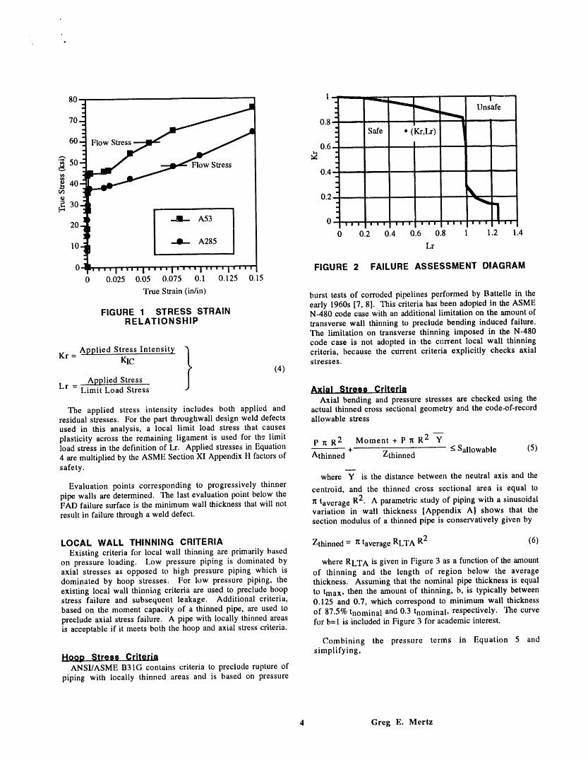
LOCAL WALL THINNING CRITERIA Zthinned = r¢taverage RLT A R2 (6)Existing criteria for local wall thinning are primarily based
on pressure loading. Low pressure piping is dominated by where RLT A is given in Figure 3 as a function of the amountaxial stresses as opposed to high pressure piping which is of thinning and the length of region below the averagedominated by hoop stresses. For low pressure piping, the thickness. Assuming that the nominal pipe thickness is equalexisting local wall thinning criteria are used to preclude hoop to tma x, then the amount of thinning, b, is typically betweenstress failure and subsequent leakage. Additional criteria, 0.125 and 0.7, which correspond to minimum wall thicknessbased on the moment capacity of a thinned pipe, are used to of 87.5% tnomina I and 0.3 tnomina 1, respectively. The curvepreclude axial stress failure. A pipe with locally thinned areas for b=l is included in Figure 3 for academic interest.is acceptable if it meets both the hoop and axial stress criteria.
Combining the pressure terms in Equation 5 and
Hoop Stress Criteria simplifying,ANSI/ASME B31G contains criteria to preclude rupture of
piping with locally thinned areas and is based on pressure
4 Greg E. Mertz
l OTO O O
ib=0.75 _ Pits Failure plane
.......................... 000<)0-,0--4_[t_ 0.6
11 ii ____ tmax "tmin O-- O O O
--_ 0.5 .............;............! .....b= tmax -- FIGURE 4 PIT ARRAY
- n0.4 ................................................. acts over tens of cycles, and that this local thinning,' , ,i w il w
-" 1LA• • , • acceptance criteria is appropriate for the K-Reactor cooling[b=l water piping. A detailed fatigue analysis would be indicated fox'0.3 i,,,,
piping dominated by thermal expansion.0 0.1 0.2 0.3 0.4 0.5
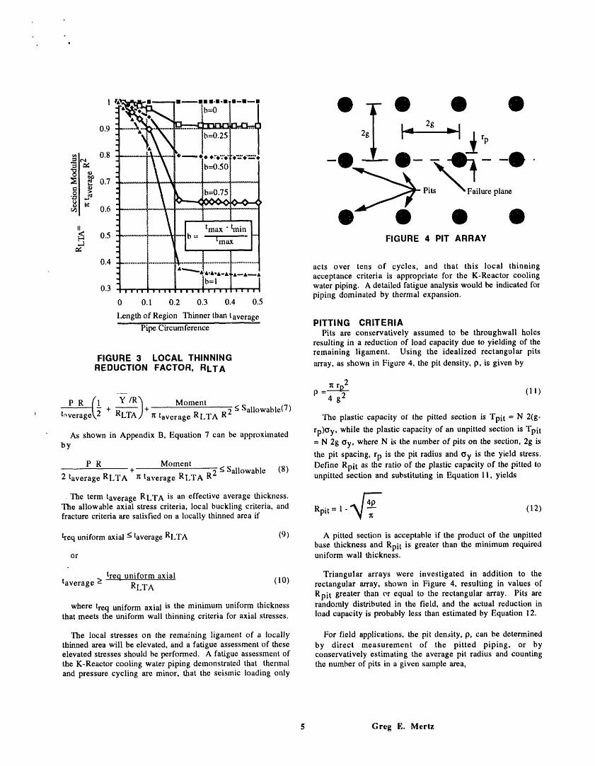
Length of Region Thinner than taverage PITTING CRITERIA
Pipe Circumference Pits are conservatively assumed to be throughwall holesresulting in a reduction of load capacity due to yielding of the
FIGURE 3 LOCAL THINNING remaining ligament. Using the idealized rectangular pitsREDUCTION FACTOR, RLT A array, as shown in Figure 4, the pit density, p, is given by
p (111P R (1__ Y /R'_ Moment -4 g2
t,-verage_.2 + _)+ rc taverag e RLT A R 2 <; Sall°wable(7) The plastic capacity oi the pitted section is Tpi t = N 2(g-
As shown in Appendix B, Equation 7 can be approximated rp)Oy, while the plastic capacity of an unpitted section is Tpitby = N 2g Oy, where N is the number of pits on the section, 2g is
the pit spacing, rp is the pit radius and Oy is the yield stress.P R Moment Define Rpit as the ratio of the plastic capacity of the pitted to+
2 taverag e RLTA _ taverage RLTA R2 < Sall°wable (8) unpitted section and substituting in Equation 11, yields
The term taverag e RLT A is an effective average thickness.
The allowable axial stress criteria, local buckling criteria, and Rpit = 1 _ ,_]2__ (12)fracture criteria are satisfied on a locally thinned area if
treq uniform axial < taverage RLTA (9) A pitted section is acceptable if the product of the unpittedbase thickness and Rpit is greater than the minimum required
or uniform wall thickness.
taverag e > tre.q uniform axial (10) Triangular arrays were investigated in addition to theRLTA rectangular array, shown in Figure 4, resulting in values ofRpit greater than er equal to the rectangular array. Pits are
where treq uniform axial is the minimum uniform thickness randomly distributed in the field, and the actual reduction inthat meets the uniform wall thinning criteria for axial stresses, load capacity is probably less than estimated by Equation 12.
The local stresses on the rema:'ning ligament of a locally For field applications, the pit density, p, can be determinedthinned area will be elevated, and a fatigue assessment of these by direct measurement of the pitted piping, or byelevated stresses should be performed. A fatigue assessment of conservatively estimating the average pit radius and countingthe K-Reactor cooling water piping demonstrated that thermal the number of pits in a given sample area,and pressure cycling are minor, that the seismic loading only
$ Greg E. Mertz
04
50- tmax = 100% tnomina I _ \taverage= 75% tnominal _ \
40-
10
00.3 0.4 0.5 0.6 0.7 0.8 0.9 1
Minimum Allowable Uniform Thick.hess ..... _ i
Nominal Thickness £,._o'_ __
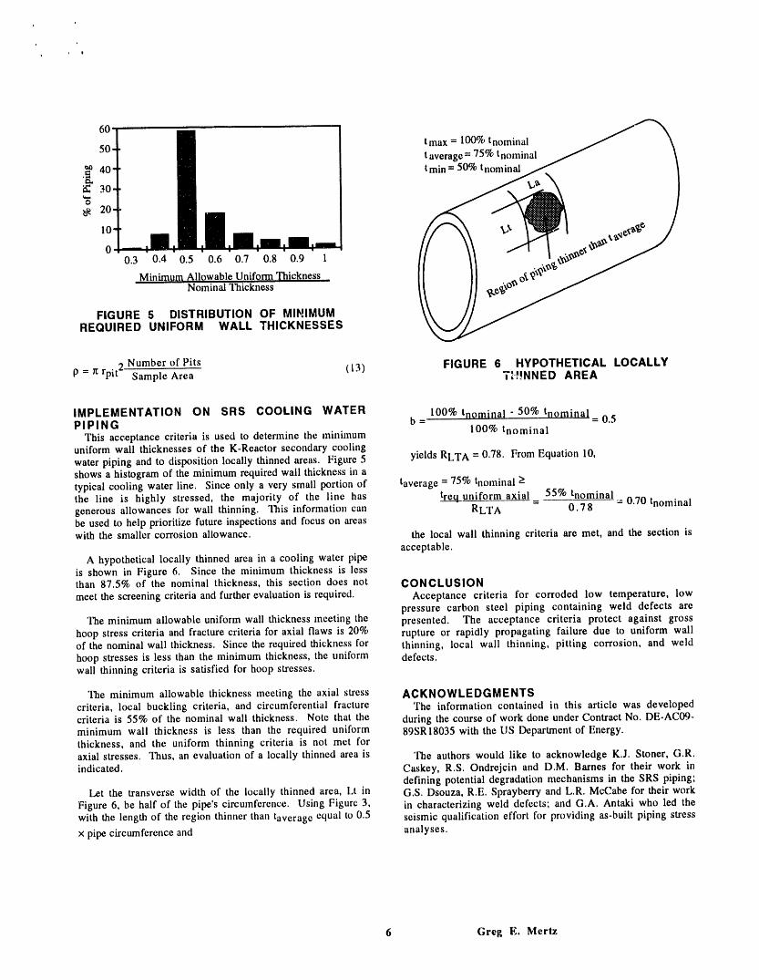
FIGURE 5 DISTRIBUTION OF MIHIMUMREQUIRED UNIFORM WALL THICKNESSES
2 Number of Pits (I3) FIGURE 6 HYPOTHETICAL LOCALLYp = r_rpi t - Sample Area TH!NNED AREA
IMPLEMENTATION ON SRS COOLING WATER 100%trlominal-50% tnomina 1 0.5PIPING b = =
This acceptance criteria is used to determine the minimum 100% tnominaluniform wall thicknesses of the K-Reactor secondary cooling
water piping and to disposition locally thinned areas. Figure 5 yields RLT A = 0.78. From Equation 10,shows a histogram of the minimum required wall thickness in atypical cooling water line. Since only a very small portion of taverage = 75% tnominal >the line is highly stressed, the majority of the line has treq uniform axial= 55% tnominal= 0.70 tnomina 1generous allowances for wall thinning. This information can RLT A 0.78be used to help prioritize future inspections and focus on areaswith the smaller corrosion allowance, the local wall thinning criteria are met, and the section is
acceptable.A hypothetical locally thinned area in a cooling water pipe
is shown in Figure 6. Since the minimum thickness is lessthan 87.5% of the nominal thickness, this section does not CONCLUSIONmeet the screening criteria and further evaluation is required. Acceptance criteria for corroded low temperature, low
pressure carbon steel piping containing weld defects areThe minimum allowable uniform wall thickness meeting the presented. The acceptance criteria protect against gross
hoop stress criteria and fracture criteria for axial flaws is 20% rupture or rapidly propagating failure due to uniform wallof the nominal wall thickness. Since the required thickness for thinning, local wall thinning, pitting corrosion, and weldhoop stresses is less than the minimum thickness, the uniform defects.wall thinning criteria is satisfied for hoop stresses.
The minimum allowable thickness meeting the axial stress ACKNOWLEDGMENTScriteria, local buckling criteria, and circumferential fracture The information contained in this article was developedcriteria is 55% of the nominal wall thickness. Note that the during the course of work done under Contract No. DE-AC09-minimum wall thickness is less than the required uniform 89SR18035 with the US Department of Energy.thickness, and the uniform thinning criteria is not met foraxial stresses. Thus, an evaluation of a locally thinned area is The authors would like to acknowledge K.J. Stoner, G.R.indicated. Caskey, R.S. Ondrejcin and D.M. Barnes for their work in
defining potential degradation mechanisms in the SRS piping;Let the transverse width of the locally thinned area, Lt in G.S. Dsouza, R.E. Sprayberry and L.R. McCabe for their work
Figure 6, be half of the pipe's circumference. Using Figure 3, in characterizing weld defects; and G.A. Antaki who led thewith the length of the region thinner than taverag e equal to 0.5 seismic qualification effort for providing as-built piping stress
x pipe circumference and analyses.
6 Greg E. Mertz

I
, , 9
REFERENCES tmax
1 N.G. Awadalla, D. A. Crowley, and W. F. Yau, taverage _Probabilistic Assessment of Weld Quality in SteelPiping Under Seismic Conditions, International tmin \
Journal of Pressure Vessels and Piping, Vol. 17, 1984. \
2 G.E. Mertz, K. J. Stoner, G. R. Caskey, and J. A.Begley, Fracture Assessment of Savannah River c=lReactor Carbon Steel Piping, PVP-Vol. 288, 1992.
3 R.R. Maccary, Nondestructive ExaminationAcceptance Standards Technical Basis andDevelopment of Boiler and Pressure Vessel Code,ASME Section XI, Division 1, EPRI NP-1406-SR,1980.
4 R.W. Mikitka, and R. F. Reedy, Guidelines for PipingSystem Reconciliation NCIG-05 Rev. 1, EPRI NP- FIGURE A.1 VARIATION IN WALL5639, 1988. THICKNESS
5 I. Miline, R. A. Ainsworth, A. R. Dowling, and A. T.Stewart, Assessment of the Integrity of Structures lt
Containing Defects, International Journal of Pressure I "_'2Vessels and Piping, Vol. 32, 1988. I = 2 R t(0) (R Cos0) 2 dO - A (A.3)6
6 I. Miline, R. A. Ainsworth, A. R. Dowling, and A. T.
Stewart, Background to and Validation of CEGB Report Z = I (A.4)R/H/R6-Revision 3, International Journal of Pressure R + I-y" IVessels and Piping, Vol. 32, 1988. I I
7 ANSI/ASME B31G, Manual for Detennining the where Y is the distance from the center of the section toRemaining Strength of Corroded Pipelines. 1984.
the neutral axis, R is the nominal radius, taverag e is the
8 T.L. Gerber, P. C. Riccardella, A. Y. Kuo, and D.R. average thickness, and t(0) is the angular variation in wallPitcairn, Acceptance Criteria for Structural Evaluation thickness. A parametric study is performed which varies theof Erosion-Corrosion Thinning in Carbon Steel thickness as a sinusq)idal function:Piping, EPRI NP-591 lM.
( 1 + Cos(c 0))t(0)=tma x 1 - b 2 forO<0<it (A.5)9 T.V. Galambos, Guide to Stability Design Criteria forMetal Structures, 4th Edition, 1988.
tma x - tmi nwhere b= , and c is the number of equal spaced
tmaxAPPENDIX A DEVELOPMENT OF LOCAL WALL locations around the circumference with a thickness below the
THINNING REDUCTION FACTOR, RLTA average thickness. The angular variatioii of thickness isThe elastic section properties of a thinned pipe, based on shown in Figure A.I for two cases of wall thinning. The
thin shell theory, can be calculated from angular variation of thickness is assumed to be symmetricabout the vertical axis.
Of Since the circumference of a pipe is ltD, the length of aA= _dA=2 Rt(0) d0=2ittaverage R (A.I) region with thickness lessa than the average thickness is
nD
n Lt<taverage = "_-c (A.6)
jAY = IydA = 2 R t(0) R Coso d0 (A.2) section modulus, Equation A.4, becan rewritten incompact form as
Z = RLT A It R2 taverag e (A.7)
7 Greg E. Mertz

q _ 0
° 9
I.I tmax
taverage ._
1 ..... _ " = .... "._j¢ train _\
1. 50.9
o.s J /I
FIGURE A.2 RLTA, b=0.50 .I
where RLT A is a reduction factor for locally thinned areas,and is given by FIGURE A.3 VARIATION IN WALL
THICKNESS, c=1.3I
RLTA = (A.8) 1.2
[R + {"y-]]_R2taverage /b=l
"Equation A.8 is shown graphically in Figure A.2 for b=0.50, el_t__ b=0.50Note that for integer values of c greater than 2, RLT A is equal 1 ......to 1. The minimum value of RLT A is at c=1.3, which +,e \ / 2! 4 6 8 10corresponds to the thinned geometry in Figure A.3. Note that [.2.1 0.9 I cas the size of the thinned area decreases (increasing c), the _ \effective average thickness, RLT A taverag e, approaches the
average thickness, taverag e. A conservative, lower bound 0.8 \ 1envelope of the thin shell analytical solutions for RLT A isgiven in Figure 3.
. Thick shell solutions, with double integration of Equations FIGURE B.1 PRESSURE MULTIPLIERA.1 to A.3, for 24" Schedule 20 (R/t=48) and Schedule 160(R/t=5) pipe yield RLT A within 3% of Figure A.2 for c=1.3 and
b=0.5. This limited study suggests that the reduction factor forlocal wall thinning may also be used for thick wall piping. At elbows and tees, the intensified pressure term is
APPENDIX B SIMPLIFICATION OF PRESSURE P R (1 + 0.75i Y lR /INDUCED AXIAL STRESS EQUATION taverage_. _ RLTA
(B.3))
The pressure induced axial stresses are given byFor intensification factors in the 2-3 range and moderate
(1 --Y p tRa (2_-) wall thinning, b < 0.5, then the approximation will be/R) RL'I'A+_ (B.1) accurate to about 10%. For larger intensification factors the
P R
taverage_,'2 + RL'I'_'A) = 2 RLTA verage accuracy or this approximation degrades. The accuracy of thisapproximation is a secondary issue for low pressure piping
The term RLTA+ 2 Y lR is shown in Figure B.I for b=0.5 systems, where the pressure term represents less than 10% ofthe allowable stress. Equation B.3 can be used as the pressure
and b=l. This term is typically less than 1.10, with a peak term for high pressure systems. Note, regardless of thevalue of 1.13 when c=1.3 and b=l.0. Recall that b=l.0pressure, as the size of the locally thinned area becomes
corresponds to tmi n = 0, which is only of academic interest, smaller (large c), then the distance to the neutral axisAccepting up to 10% error in the pressure term, allows approaches zero and the approximation is valid.Equation B.1 to be approximated by
e R (! v/R) PRtaverage\ 2 + RUI,Aj=2 RLTA taverag e (B.2)
8 Greg E. Mertz