CASTLE SERIES 1954 - OSTI.GOV
538
m DNA 6035F CASTLE SERl~S 407565 1954 ● r United States Atmospheric Nuclear Weapons ests Nuclear Test Personnel Review Prepared by the Defense Nuclear Agency as Executiv Agency for the Department of Defense I
-
Upload
khangminh22 -
Category
Documents
-
view
0 -
download
0
Transcript of CASTLE SERIES 1954 - OSTI.GOV

m DNA 6035F
CASTLE SERl~S 407565
1954●
rUnited States Atmospheric Nuclear Weapons ests
Nuclear Test Personnel Review
Prepared by the Defense Nuclear Agency as Executiv Agency
for the Department of Defense
I

UNCLASSIFIEDsECURITY CLASSIFICATION OF THIS PAGE (When DW.S Ent~,ed)
REPORT DOCUMENTATION PAGE1.REp0t3TNUMBER READ1?!
EfEFoREco2.GOVT ACCESSION NO. 3. RECIPIENT-S CA.DNA 6035F.
4.TITLE(md Subtit[@ Is.TYPE OF REPo R
CASTLE SERIES, 1954
Technical RcG.pERFORMING ORC
7. AU THOR(.J KT-81-0026(REdwin J. Martin a.CONTRACT OR GR
Richard H. RowlandDNA 001-79-c
9.PERFORMING ORGANIZATION NAME ANO AD ORESS
Kaman Tempo 10.PROGRAM ELEMEAREA & WORK UN
P. O. Drawer QQ (816 State Street)Santa Barbara, California 93102 Subtask U99Qj
11.CONTROLLINGOFFICENAME AND ADORESS
Director 12. REPORT DATE
1 April 1982Defense Nuclear AgencyWashington, DC 20305 13.NUMBEROF PAGE
5301●.MONITORING AGENCY NAkiE & AOORES~lf dltfer~tfmm Controllin#Offlce)
Is. SECURITY CLASS.
I I UNCLASSIFIED
lsa. DECLASSIFICATI<SCHEOULE
16. DISTRIBUTION STATEMENT (othfe Report) NIA Since UNC,
Approved for public release; distribution unlimited.
, 17. DISTRIBUTION STATEMENT (of the ●batract mteredfn Block 20, if dfffwwt from Repoti)
r
Ill. SUPPLEMENTARY NOTES
This work sponsored by the Defense Nuclear Agency under RDT&E RMSSB350079464 U99QAXMK50609 H2590D.
For sale by the National Technic,Information Service, Springfield, Virginia 22161.
g.KEY WOROS(C-tinu. mte~aeai&ffn-caaeq mdidentify~ btocknmber)
Nuclear TestingEnewetak, ENuclear Test Personnel Review (NTPR)
Pacific PrCCASTLE, BRAVO, ROMEO, KOON, UNION, YANKEE, NECTAR
i!~AOS~ACT~ -=mwrntie~-fd@tttlfyby blockn~b”)
CASTLE was an atmospheric nuclear weapons test series held in the MIslands at Enewetak and Bikini atolls in 1954. This is a report ofpersonnel in CASTLE with an emphasis on operations and radiological
w~ FORM
tJANm ~~ EDlmOMOF ?MOV6SlSO~LETE
UNCLASSIFIEDSECURITYCLASSIFICATION OFnfS PAGE
‘RUCTIONSLETINGFORNf-OGNUMSER
‘ERIoo COVEREO
)rtlEpORT NUMSER
T NUMSER(@
472
pROJECT, TASK‘NUMBERS
VK506-I)g
OOWNGRAOING
SSIFIED
ode
cini‘ng Ground
shallODafety.
I
I
I

“*
THIS PAGE
WAS
INTENTIONALLY
LEFT BLANK
IN
ORIGINAL
.- ..
(
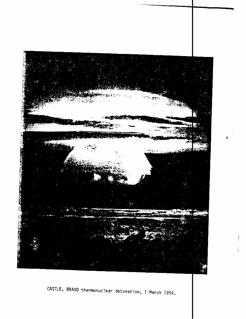
CASTLE, BRAVO thermonuclear detonation, 1 March 1954.

0-0
THIS PAGE
WAS
INTENTIONALLY
LEFT BLANK
IN
ORIGINAL

FACT SHEET
CASTLE was a six-detonation nuclear weapon test series (see tat
held at the Atomic Energy Commission’s (ABC) Pacific Proving Grounc
in Spring 1954. The PPG consisted principally of Enewetak* and Bil
atolls in the northwestern Marshall Islands in the Central Pacific
AssignedDate Name Location M.z
1 March BRAVO Bikini;
27 March ROMEO Bikini;
7 April KOON Bikini;
26 April UNION Bikini;
5 May YANKEE Bikini;
14 May NECTAR Enewetak; barge in MIKEb crater 1
sandspit off Nam Island
barge in BRAVO crater
surface of Eneman Island
barge in lagoon off Iroij Island
barge in UNION crater 1
)itude
.5 MTa
,1 MT
O KT
9 MT
I5 MT
9 MT
Notes:
aOne kiloton equals the approximate enefgy release of the explosion ofone thousand tons of TNT; one megaton equals the approximate energ~release of the explosion of one million tons of TNT.
b 1O.4-MT IVY series detonation in 1952.
HISTORICAL BACKGROUND
The CASTLE series was held to test large-yield thermonuclear, or ky-
drogen, devices. Work on this class of devices had progressed throug . the
GREENHOUSE, GEORGE experimental shot in 1951 and the IVY, MIKE shot o:‘
1952. MIKE was the first device that generated a substantial explosi!‘e
energy from the fusion, or joining, of hydrogen atoms. These explosi~e
* The spelling of Marshall Island place names has changed in recent yearsin order to more accurately render the sounds of the Marshall Islancnames using English spelling.
1
.

devices were developed by the AEC, the civilian agency authorized I
form this activity by the Atomic Energy Act of 1946.
The devices were tested at the PPG by a joint military and civ:
organization, designated as Joint Task Force 7 (JTF 7). This was 4
tary organization in form, but was populated by military, civil se]
and contractor personnel of the Department of Defense (DOD) and AE(
commander of this force was the appointed representative of the AE(
reported also to the Joint Chiefs of Staff (JCS) and the Commander
Chief, Pacific (CINCPAC). The peak DOD numerical strength at CASTI
approximately as follows:
Uniformed military 9,800
DOD civil servants 250
DOD contractors 60
Total personnel 10,110
Numerous technical experiments were carried out in conjunction
each of the six detonations. These experiments measured the power
r-
,i-
‘*
‘he
I
is
1
.’
Iefficiency of the devices and attempted to gauge the military effect of
tthe explosions. DOD personnel participated in this test operation a
individuals whose duty stations were at the ABC design laboratories, s
units performing separate experiments, and as units performing variou
support roles. The CASTLE operations placed almost all of the Navy -
port group at Bikini, where its ships provided living space for pers~
who were evacuated from the islands for the first test and then COU1
ret’.;rnto live there because of the potential radiation exposure.
An extensive radiological safety program was instituted whose ok
tives were:
1. Maintenance of personnel radiation exposure at thelowest possible level consistent with medical knowl-edge of radiation effects and the importance of thetest series.
2. Avoidance of inadvertent contamination of populatedislands or transient shipping.
2
)-
Iel
10t
*-.

The progr~ established an organization to provide radiological
(radsafe) expertise and services to the separate components of
force who were responsible for personnel safety within their c
Personnel were trained in radiological safety, and standards g
maximum permissible exposures (MPE) were established. Film ba
provided to a large portion of the participating personnel. P
likely to be exposed to radiation were badged as well as a rep
group of the remainder. An extensive weather forecasting grou
lished in order to predict wind directions and areas of potent
Personnel were evacuated from danger areas before each detonat
entry to contaminated areas was restricted to the personnel re
retrieve important data. The amount of radiation exposure for t]
sonnel was monitored.
TEST OPERATIONS AND EXPOSURES
The first event of this series, designated BRAVO, had a yiel<
and was the largest device ever detonated in atmospheric nuclear
by the U.S. Government. Significantly exceeding its expected yi(
detonated at Bikini Atoll, released large quantities of radioact
rials into the atmosphere, which were caught up in winds that sp:
particles over a much larger area than anticipated. This result(
contamination and exposure of some individuals either stationed ~
ing on distant atolls or aboard various vessels. Acute radiatiol
were observed among some of these people.
A limited number of JTF 7 personnel received radiation expos’
siderably in excess of the initially established CASTLE MPE. Th
tional limit was established at 3.9 roentgens (R) gamma within a]
period of the operation. In particular, three members of the U.:
Bikini Boat Pool had heavily exposed badges with readings from 8
and 28 Army and Air Force personnel had film badge exposures tha
high as 78 R. All these men were medically evaluated at Kwajale
sequently, follow-up on 29 of them was done at Tripler Hospital
3
ety
task
ds.
ing
were
s
tative
estab-
allout.
nd re-
d to
!per-
!15 MT
Iting
BRAVO,
mate-
1 the
.n the
‘esid-
!fects
; con-
}pera-
.3-week
[avy
) 95 R,
:ad as
Sub-
[awaii.

The results of these medical observations were reported as “essent
negative” or “generally negative.”
BRAVO fallout on some Navy ships also resulted in additional ~
who had exposures approaching or exceeding the CASTLE PIPEof 3.9 1
allow for operational completion of the remaining CASTLE shots, ii
necessary to issue a number of waiver authorizations permitting e]
of as much as 7.8 R. In a limited number of cases, even this levf
exceeded.
As a result of BRAVO, 21 individuals on the USS Philip (DDE-498
16 on the USS Bairoko (CVE-115) sustained small skin lesions resemb
burns that were definitely classified as beta burns. The affected
nel received radiological contamination while on the weather deck a
tioned near ventilation blowers. These all healed without complica
The USS Patapsco (AOG-1), a Navy gasoline tanker, which was approxil
180-195 nautical miles (333-360 kilaeters) northeast of BRAVO’S gr(
zero at the time of detonation, received fallout as it returned to 1
Harbor. Exposure estimates as high as 18 R are possible, assuming ~,
individual was on deck 24 hours a day with the ship retaining 100 p~
of all fallout radioactivity and using the highest reading from rad
surveys. For an individual who spent only 8 hours a day on deck an~
hours a day inside, and assuming that the storm conditions washed o
percent of the activity en route, the estimated dose is 3.3 R.
The other five CASTLE detonations, though extremely important a:
weapon tests, did not produce significant, unexpected personnel rad
exposures.
While small numbers of personnel at CASTLE did receive exposure
excess of imposed standards, by far the largest portion did not. 1]
the radiation exposure for JTF 7 personnel at CASTLE averaged about
1.7 R. The recorded CASTLE exposures are summarized in the table oi
following page.
4
ally
1
sonnel
To
ecame
mes
is
knd
lg
:son-
;ta-
)ns.
:ely
Id
irl
:ent
:ion
L6
50
:ion
in
Eact,
khe
I
i
I
1

CASTLE Exposures
No.of ExposureRange (R)Parcnnc n...- Zeroa 0.001- 1.001- 3.001- 5.001- Over
I c.,-------- . ,--- - -30 10.00 100CI
. -! +“,,J
ServiceUu>e
Badged Unavail Lxpu>ure L.UUU 3.000 5.OCArmy 1,503 8 27 1,276 121 60>l%b 2% 85% 8% 4%Navy 6,255 35 113 3,544 1,945
>1% 2%453
57% 31% 7%AirForce 844 15 12 494
2%208 59
1% 58% 25% 7%MarineCorps
193 2 131%
67 787% 35% 40% :;%
8>1%
1573%
253%
3>1%
8>1%
314%
oo%
HighRecorded
(R)
78c
96
52d
5.510
Other 2,175Govt
170 86 1,2218% 4%
323 29256%
81 2 27.825Contractor— _ _ 15% 13% 4% >1%—_Totals 10,970
—
% of Total230 251 6,6022% 2%
2,675 89360%
275 44 9624% 8% 3%
Notes:>1%
aZerodoseswerenot re$ordedin theConsolidatedListof CASTLERadiologiformanyunits.
bPercentof totalservicepersonnelin eachgroup.
cThreeunbadgedArmypersonnelon RongerikIslandoriginallywereassigned98 R, whichwas takenfroma badgemountedon a tentpole.
‘Thehighvaluecomesfrombadgeswornby AirForcepersonnelon Rongerik.AirForcehas assignedan estimatedtotaldoseof 86 R to eachmemberof igroup.
se of
Us.ongerik

PREFACE
Between 1945 and 1962, the U.S. Atomic Energy Commission (AEC) cor
ducted 235 atmospheric nuclear weapon tests at sites in the United Sta
and in the Pacific and Atlantic oceans. In all, about 220,000 Departn
of Defense (DOD) participants, both military and civilian, were preser
the tests. Of these, approximately 142,000 participated in the Pacifi
test series and approximately another 4,000 in the single Atlantic tes
series.
In 1977, 15 years after the last aboveground nuclear weapon test,
Center for Disease Control (CDC) of the U.S. Department of Health and
Services noted more leukemia cases than would normally be expected amc
about 3,200 soldiers who had been present at shot SMOKY, a test of the
PLUMBBOB Series. Since that initial report by the CDC, the Veterans $
istration (VA) has received a number of claims for medical benefits f~
former military personnel
by their participation in
In late 1977, the DOD
who believe their health may have been affec
the weapon testing program.
began a study that provided data to both the
and the VA on potential exposures to ionizing radiation among the mili
and civilian personnel who participated in the atmospheric testing 15
30 years earlier. In early 1978, the DOD also organized a Nuclear Te:
Personnel Review (NTPR) to:
● Identify DOD personnel who had taken part in theatmospheric nuclear weapon tests
● Determine the extent of the participants’ exposure toionizing radiation
● Provide public disclosure of information concerningparticipation by DOD personnel in the atmosphericnuclear weapon tests.
6

This report on Operation CASTLE is one of many volumes that ale the
product of the NTPR. The DOD Defense Nuclear Agency (DNA), whose Director
is the executive agent of the NTPR program, prepared the reports, which
are based on the military and technical documents reporting variols aspects
of each of the tests. The reports of the NTPR provide a public rfcord of
the activities and associated radiation exposure risks of DOD per:onnel
for interested former participants and for use in public health r{search
and Federal policy studies.
The information from which this report was compiled was prima.ily ex-
tracted from planning and after-action reports of Joint Task Fore 7
(JTF 7) and its subordinate organizations. What was desired were docu-
ments that accurately placed personnel at the test sites so that heir
degree of exposure to the ionizing radiation resulting from the t !Sts
could be assessed. The search for this information was undertake in
archives and libraries of the Federal Government, in special CO1l !ctions
supported by the Federal Government, and, where reasonable, by di ;cussion
or review with participants.
<For CASTLE, the most important archival source is the Modern 1ilitary
Branch of the National Archives in Washington. The Naval Archive s at the
Washington Navy Yard also was helpful, as was the collection of d >cuments
assembled by the Air Force Weapons Laboratory (AFWL) Historian, tle col-
lection now being housed in the AFWL Technical Library at Kirtlani Air
Force Base, Albuquerque, New Mexico. Other archives searched wer? the
Department of Energy archives at Germantownr Maryland, its Nevada Opera-
tions Office archives at”Las Vegas, and the archives of the Test )ivision
of the LOS l&unos Scientific Laboratory (LASL).
JTF 7 exposure records were retrieved from the archives, and n addi-
1
tional file of exposure-related documents that had been microfil d by the
Reynolds Electrical and Engineering Company, Inc. was also usefu
7
The major gap in information sources is in primary documents ‘on of
I
personnel movement in areas of potential radiation exposure. Th” has

been compensated for, where possible, with inferences drawn from se
sources and the exposure records themselves.
The work was performed under RDT&E RMSS B350079464 u99 QAXMK 50
H2590D for the Defense Nuclear Agency by personnel from Kaman Tempo
merlY General Electric--TEMPO) and R.F. Cross Associates as subcont
Personnel contributing research, editing, and graphics and not list
the DD-1473 form include:
S. Bruce-Henderson, Kaman Tempo, Santa Barbara
F.R. Gladeck, Kaman Tempo, Alexandria
J.H. Hallowell, Kaman Tempo, Santa Barbara
F.W. McMullan, Kaman Tempo, Albuquerque
R.H. Miller, Kaman Tempo, Albuquerque
R.E. Pozega, Kaman Tempo, Albuquerque
W.E. Rogers, Kaman Tempo, Santa Barbara
C.F. Shelton, Kaman Tempo, Alexandria
P. Sturman, Kaman Tempo, Alexandria
B.L. Treloar, Kaman Tempo, Santa Barbara
L. Berkhouse, R.F. Cross Associates ,
S. Davis, R.F. Cross Associates
P. Dean, R.F. Cross Associates
M.K. Doyle, R.F. Cross Associates
C.B. Jones, R.F. “CrossAssociates.
Guidance was provided by the Biomedical Advisor of the Defense Nucl
Agency, Dr. Edwin T. Still, and Mr. Kenneth W. Kaye of his office.
8
ndary
09
for-
ctor.
on

TABLE OF CONTENTS
FACT SHEET
PREFACE
ILLUSTRATIONS
TABLES
Chapter
1 OVERVIEW
Introduction
Purpose
Historical Background
Report Organization’
Nuclear Tests and Radiation Exposures
Experimental Program
.Weapon Development
Yield Measurements
Diagnostic Measurements
Effects Experiments
Environmental Measurements
Systems Response Experiments
Oceanic Testing Operations
Marshall Islands Setting
Physical Conditions in 1954
Radiological Conditions in 1954
Special Problems in Oceanic Testing
Page
1
6
17
21
25
25
25
26
26
27
31
31
32
33
35
35
36
37
37
42
47
51
9

CONTENTS (continued)
1 (continued)
Joint Task Force 7
Task Group 7.1 (Scientific)
Task Unit 1 -- LASL Programs
Task Unit 2 -- Production
Task Unit 3 -- Special Materials andFacilities
Task Unit 4 -- LASL Assembly
Task Unit 6 -- Firing Party
Task Unit 7 -- Radiological Safety
Task Unit 8 -- Technical Photography
Task Unit 9 -- Documentary Photography
Task Unit 12 -- UCRL Program
Task Unit 13 -- DOD Programs
Task Unit 14 -- UCRL Assembly
Task Un\t 15 -- Timing
Task Group 7.2 (Army)
Task Group 7.3 (Navy)
Task Group 7.4 (Air Force)
Task Group 7.5 (Base Facilities)
RADIOLOGICAL SAFETY
Radsafe Planning
Organization and Responsibilities
Task Group 7.1
Radiation Control
Decontamination
Laboratory Analysis
Task Group 7.2
Task Group 7.3
Task Group 7.4
10
C&
53
55
55
56
56
56
56
56
57
57
57
57
57
57
58
61
69
71
74
75
76
79
81
82
82
83
84
85

CONTENTS (continued)
Wr?w2 (continued)
Training
Task Group 7.1
Task Group 7.2
Task Group 7.3
Task Group 7.4
Safety Criteria
Radsafe Standards
Radiation Exposure Waivers
Radsafe Monitoring and Instrumentation
Radsafe Instrumentation
Personnel Film Badges and Records
Pre-event Safety Measures
Hazard Zones
Fallout Prediction w
Holographs
Particle Trajectory Forecasts
Weather
Radex Areas
Offsite Monitoring
Command Briefings
Radiation Protection Modifications
Evacuation, Disposition, and Reentry
Bikini Shots
Enewetak Shot
Postevent Safety Measures
General Procedures
Cloud Tracking
Cloud Sampling
Sample Recovery Techniques
u
—-———
Page
87
87
92
92
94
94
95
96
100
100
101
107
107
108
109
110
112
115
116
118
120
123
123
125
125
125
132
132
139

CONTENTS (continued)
2 (continued)
Personnel Decontamination
Naval Vessel Decontamination
Equipment Decontamination
Aircraft Decontamination
Task Group 7.4 Aircraft
Other Aircraft
3 DOD EXPERIMENTAL PARTICIPATION
Weapon Development
Effects Experiments
Blast and Shock (Program 1)
Nuclear Radiation (Program 2)
Blast Effects (Program 3)
Response of Humans to Accidental FalloutRadiation< (Program 4)
Operations
Radiation Exposure Potential
Staffing
Project Reports
Tests of Service Equipment and Techniques(Program 6)
Burst Detection Studies (Program 7)
Cloud Photography (Program 9)
4 BRAVO TEST
Decision to Shoot
Preparations
DOD Activities
The Test
Reentry to Bikini
Evacuations
12
1I
i

I
CONTENTS (continued)
!&P&E
4 (continued)
Patapsco Contamination
Operations Afloat
Offsite Operations
BRAVO Fallout Exposures
Task Group 7.3 Exposures
Enewetak-Based Personnel
Task Groups 7.1 and 7.5 Bikini Personnel
5
Task Group 7.4 Exposures
Personnel Exposures -- Rongerik
Patapsco Crew
Marshallese Population
Radiation Effects and Medical Observation ofTask Force Personnel
TESTS AFTER BRAVO #
Schedule Changes
Operational Implications
ROMEO
“Preshot Preparation
DOD Activities
The Test
Contamination
Aircraft Decontamination
Personnel Exposures
KOON
Preshot Preparation
DOD Activities
The Test
Contamination
Aircraft Decontamination
13
Page
230
232
232
235
235
235
238
238
238
240
241
241
246
246
248
250
250
254
255
255
267
267
267
271
275
276
276
283

CONTENTS (continued)
5 (continued)
UNION
Preshot Preparation
DOD Activities
The Test
Contamination
Aircraft Decontamination
YANKEE
Preshot Preparation
DOD Activities
The Test
Contamination
Aircraft Decontamination
NECTAR
Preshot Preparation
DOD Activi~ies
The Test
Contamination
Aircraft Decontamination
6 SUMMARY OF U.S. ARMY PARTICIPATION IN CASTLE
Headquarters Joint Task Force 7
Task Group 7.1 (Scientific)
Task Group 7.2 (Army)
7 SUMMARY OF U.S. NAVY PARTICIPATION IN CASTLE
Headquarters Joint Task Force 7
Task Group 7.1 (Scientific)
Task Group 7.2 (Army)
Task Group 7.3 (Navy)
Task Unit 7.3,0 (Special Devices Unit)
14
I

CONTENTS (continued)
e
7 (continued)
Task Unit 7.3.1 (Surface Security Unit)
Task Unit 7,3.2 (Carrier Unit)
Task Unit 7.3.3 (Patrol Plane Unit)
Task Unit 7.3.4 (Flagship Unit)
Task Unit 7.3.5 (Utility Unit)
Task Unit 7.3.6 (Atomic Warfare ShipCountermeasures Unit)
Task Unit 7.3.7 (Bikini Harbor Unit)
Task Element 7.3.7.2 (Mine Project Unit)
Task Unit 7.3.8 (Enewetak Harbor Unit)
Task Unit 7.3.9 (Transport Unit)
Other Naval Units in the PPG or in Nearby Watersduring CASTLE
8 SUMMARY OF U.S. AIR FORCE PARTICIPATION IN CASTLE
Headquarters Joint Task Force 7
Task Group 7.1 (Scientific)
Task Group 7.4 (Air Force)
9 SUMMARY OF U.S. MARINE CORPS PARTICIPATION IN CASTLE
Task Group 7.1 (Scientific)
Task Group 7.3 (Navy)
10 SUMMARY OF JOINT OEFENSE AGENCY, OTHER GOVERNMENT,CONTRACTOR, ANO FOREIGN PARTICIPATION IN CASTLE
Headquarters Joint Task Force 7
Task Group 7.1 (Scientific)
Task Group 7.2 (Army)
Foreign Participation
11 PERSONNEL EXPOSURES
REFERENCES
15
-——
Paqe
340
349
351
353
355
363
366
368
372
372
373
384
384
388
390
397
397
397
400
400
401
407
408
409
413
1

CONTENTS (continued)
Appendix
A COPIES OF CASTLE DOCUMENTS
B TERMS, ABBREVIATIONS, ACRONYMS, AND UNITS
c ISLAND SYNONYMS
D INDEX OF PARTICIPATING ORGANIZATIONS
16

LIST OF ILLUSTRATIONS
Lm!!xFrontispiece: CASTLE, BRAVO thermonuclear detonation, 1 Marc
1
2
3
4
5
6
7
8
9
10
11
12
13
14
15
16
17
18
19
20
21
22
23
24
25
The Central Pacific.
Enewetak Atoll, 1954.
Bikini Atoll, 1954.
Aerial view of Parry during CASTLE.
Typical metal buildings used at Enewetak during CAST
Tents on Parry during CASTLE.
Assembly area on southern tip of Parry looking south
Enewetak airfield looking west.
Eneman camp, Bikini, looking south-southwest.
Enewetak detonation sites.
Organization chart, Joint Task Force 7.
Organization and functions of the task force Radsafe
Radsafe or~anization for Task Group 7.1.
Task Group 7.2 radsafe organization.
Organization and responsibilities for Task Group 7.4
Pacific Proving Ground search areas and security zonOperation CASTLE.
Joint Task Force 7 weather element organization.
“Booties” worn for radiation protection during radiasurvey on Rongelap after BRAVO.
Three types of protective suits used during CASTLE.
Protective clothing being worn during CASTLE instrumrecovery on Adrikan Island.
Wilson 1 sector search mission for cloud tracking.
Wilson 2 sector and vector search for cloud tracking
F-84G sampler aircraft.
F-84G sampling panel.
F-84G samplers parked at Enewetak airstrip.
17
1954.
..
)ffice.
i for
on
It
--—
Paqe
38
39
40
43
44
44
46
46
48
50
54
78
81
84
86
109
113
129
130
130
133
133
135
138
139

ILLUSTRATIONS
Q9.xs26
27
28
29
30
31
32
33
34
35
36
37
38
39
40
41
42
43
44
45
46
47
48
49
50
517.&
Samp
(continued)
e rec[
Cutting fi”
Removal of
Deposition
Preparing 1
very schematic,
ter paper retaining wire in left tank.
filter paper from left tank.
of filter paper in shielded cave.
o roll filter paper.
Filter paper being rolled.A Ilpig,ll a shielded container for sample transport.
Lifting pig containing filter paper.
Removal of gas sample from “snap-bag” through samplingprobe.
Personnel monitoring after removal of contaminated clothing.
Scrubbing to remove radioactivity before suit removal.
Shipboard decontamination using high-pressure seawaterand scrub brushes.
Parry contaminated storage area.
Decontamination equipment on Parry.
Tent for changing contaminated clothing it Parry.
B-36 decontamination.
B-36 decontamination.
B-36 decontamination.
F-84G decontamination.
Placement of anchored fallout collector buoys.
Preparation of fal?cmt collector tray.
Recovery of sea mines by the USS Reclaimer (ARS-42)following UNION shot.
Decontamination hosedown of the Granville S. Hall (YAG-40)bythe Molala (ATF-106).
Deck crew continuing washdown of YA6-40 (Granville S. Hall).
Further washdown of YAG-40 (Granville S. Hall); YAG-39(Georqe Eastman) alongside.
Project 6.4 test aircraft being decontaminated.
Scrubbing Project 6.4 test aircraft.
18
9s40
41
42
42
43
43
45
45
46
48
49
.50
51
53
54
,62
63
.63
,64
.80
,81
.87
,94
.94
.95
.95
.96

ILLUSTRATIONS (continued)
H9AG53
54
55
56
57
58
59
60
61
62
63
64
65
66
67
68
69
70
71
72
73
74
75
76
77
78
79
BRAVO search vectors and track of Daigo Fukuryu Maru
Locations of instrument stations for DOD experiments
Ship positions at detonation time, BRAVO.
BRAVO blast damage to Eneman Island building.
Fire damage at Eneman Island from BRAVO-induced elecjshort circuit.
Cloud dimensions for BRAVO.
BRAVO close-in gamma fallout pattern at H+l.
BRAVO reconstructed fallout at H+3.
BRAVO reconstructed fallout at H+6.
BRAVO reconstructed fallout at H+12.
Layout of Rongerik installations.
Photo of Rongerik installations.
Ship positions on 2 March, 24 hours after BRAVO.
Ship positions on 3 March, 48 hours after BRAVO.
Post-BRAVO survey personnel at Rongelap.
USS Nicholas (DDE-449) crewman holding sick rat at Rafter BRAVO.
Estimated total (accumulated) dose contours, BRAVO H
ROMEO predicted fallout pattern.
ROMEO instrumentation stations for the DOD scientifiprojects on Bikini Atoll.
Ship positions at detonation time, shot ROMEO.
ROMEO cloud dim@sions.
ROMEO fallout pattern.
ROMEO atoll exposure rates at H+l.
Ship positions at detonation time, KOON.
KOON predicted fallout pattern.
KOON instrumentation stations for the DOD scientificprojects on Bikini Atoll.
KOON close-in garmnafallout pattern.
19
/AVO.
:al
erik
.
-—— -—
,
Page
204
206
207
209
209
211
212
214
216
219
222
222
223
225
233
234
236
254
256
257
259
262
264
274
275
277
281

ILLUSTRATIONS (continued
w80
81
82
83
84
85
86
87.
88
89
90
91
92
93
94
95
96
97
UNION predicted fallout pattern.
UNION instrumentation stations for the DOD scientificprojects on Bikini Atoll.
Ship positions at detonation time, UNION.
UNION cloud dimensions.
UNION close-in gamna fallout pattern.
YANKEE predicted fallout pattern based on the method ofelliptical approximations.
YANKEE instrumentation stations for the DOD scientificprojects at Bikini Atoll.
Ship positions at detonation time, YANKEE.
YANKEE cloud dimensions.
Areal extent of YANKEE fallout cloud.
YANKEE heavy fallout area.
NECTAR predicted fallout pattern based on the methodof elliptical approximations.
NECTAR instrumentation stations for the DOD scientificprojects at Enewetak Atoll.
Ship positions at detonation time, NECTAR.
NECTAR cloud dimensions.
NECTAR close-in gamna
NECTAR fallout areas.
Exposure rates versus
fallout pattern.
time at six locations on Bikini Atol
20
Page
287
288
289
291
294
301
302
303
305
307
309
314
316
317
319
321
322
412

Table
1
2
3
4
5
6
7
8
9
10
11
12
13
14
15
16
17
18
19
20
21
22
23
24
25
LIST OF TABLES
CASTLE detonations, 1954.
Task Group 7.1 population at the Pacific Proving Ground, 1
Task Group 7.2 population at the Pacific Proving Ground, 1
Task Group 7.2 military police detachment locations.
Operation CASTLE, functions and complements of Task Group
Estimated Task Group 7.3 personnel at Enewetak Atoll, 1954
Task Group 7.4 personnel strength at the Pacific ProvingGround, 1954.
CASTLE Maximum Permissible Limits for radiation exposure.
CASTLE airborne monitoring survey schedule of the AECNew York Operations Office.
Sunrnaryof Bikini radsafe activities.
Shipboard radsafe activities.
F-84G sampling systems. ,
CASTLE aircraft.
Cloud-sampler aircraft decontaminated in CASTLE.
Number of aircraft that obtained usable cloud samples, CA5
CASTLE Task ”Group 7.4 aircraft decontamination materials u
Radiological contamination of Patrol Squadron 29 aircraftas of 18 May 1954.
Approximate unit strengths of Task Group 7.1 at the PacifiProving Ground.
DOD scientific personnel radiation exposures.
BRAVO aircraft.
Average topside intensities of Task Group 7.3 shipsfollowing BRAVO.
Offsite fallout sunanary.
Summary of fallout exposures for BRAVO Navy elements.
Task Group 7.4 BRAVO aircraft decontamination.
Surnnaryof estimated fallout exposure for BRAVO.
‘-r
21
—
Page
25
58
60
60
64
69
72
97
117
126
127
137
155
159
160
161
165
167
170
208
215
231
237
239
242

TABLES (continued)
Table
26
27
28
29
30
31
32
33
34
35
36
37
38
39
40
41
42
43
44
45
46
47
48
49
50
Contamination readings of Rongerik personnel after BRAVO.
Planned and final sequence of CASTLE events and locations.
Summary of the status of transient shipping in the PacificProving Ground area on or about 27 March 1954.
Aircraft participating in ROMEO.
Aircraft positioning data for ROMEO.
ROMEO radiation summary.
Average topside radiation intensities of Task Group 7.3ships at various times following ROMEO.
ROMEO airborne monitoring survey results of the AECNew York Operations Office.
Selected film badge readings.
Task Group 7.4 ROMEO aircraft decontamination.
Summary of the status of transient shipping in the PacificProving Ground on or about 7 April 1954.
Aircraft participating in KOON.
Aircraft positioning data for KOON.
KOON radiation summaryu
KOON airborne monitoring survey results of the AEC New YorkOperations Office.
Task Group 7.4 KOON aircraft decontamination.
Summary of the status of transient shipping in the PacificProving Ground area on or about 26 April 1954.
Aircraft positioning data for UNION.
UNION radiation summary.
UNION atoll survey by Wilson 3 and 4 on shot day.
Secondary UNION fallout on vessels of Joint Task Force 7on shot day.
UNION airborne monitoring survey results of the AEC NewYork Operations Office.
Task Group 7.4 UNION aircraft decontamination.
Summary of the status of transient shipping in the PacificProving Ground area on or about 5 May 1954.
YANKEE radiation summary.
22
297
298
299
308

TABLES (continued)
Table
51
52
53
54
55
56
57
58
59
60
61
62
63
64
65
66
67
68
69
70
71
YANKEE airborne monitoring survey results of the AEC NewYork Operations Office.
Task Group 7.4 YANKEE aircraft decontamination.
Summary of the status of transient shipping in the PacifProving Ground area on or about 14 May 1954.
Shot-time aircraft position data for NECTAR.
NECTAR radiation summary.
NECTAR airborne monitoring survey results of the AEC NewYork Operations Office.
Task Group 7.4 NECTAR aircraft decontamination.
CASTLE personnel exposure, U.S. Army organizations.
CASTLE personnel exposure, U.S. Navy organizations.
USS Curtiss (AV-4) operational activities during CASTLEtest series.
USS Epperson (DDE-719) operational activities during CAS-test series.
USS Nicholas (DDE-449) operational activities during CAStest series.
USS Renshaw (DDE-499) operational activities during CASTtest series.
USS Philip (DDE-498) operational activities during CASTLtest series. IUSS Grosse Point (PC-1546) operational activities duringCASTLE test series.
IEvacuation and resurvey activities, March-April 1954. IUSS Bairoko (CVE-115) operational activities during CASTLEtest series.
IPatrol squadron 29 (VP-29) operations. IUSS Estes (AGC-12) operational activities during CASTLEtest series.
USS Gypsy (ARSD-1) operational activities during CASTLEtest series.
USS Mender (ARSD-2) operational activities during CASTLEtest series.
23 I
——
Page
311
312
313
318
320
323 (
324
326
333
341
342
343
344
345
346
348
350
352
354
356
357
I

TABLES (continued)
Table
72
73
74
75
76
77
78
79
80
81
82
83
84
85
86
87
88
89
90
91
92
USS Apache (ATF-67) operational activities during CASTLEtest series.
USS Cocopa (ATF-101) operational activities during CASTLEtest series.
USS Molala (ATF-106) operational activities during CASTLEtest series.
USS Sioux (ATF-75) operational activities during CASTLEtest series.
USS Tawakoni (ATF-114) operational activities during CASTLEtest series.
YAG-39 (USS George Eastman) and YAG-40 (USS Granville S. Hall)operational activities during CASTLE test series.
USS Belle Grove (LSD-2) operational activities during CASTLEtest series.
USS Reclaimer (ARS-42) operational activities during CASTLEtest series.
USS Shea (DM-30) operational activities during CASTLE test-
USS Terrell County (LST-1157) operational activities duringtest series. f
USNS Fred C. Ainsworth (T-AP-181) operational activitiesduring CASTLt test series.
LST-551 operational activities during CASTLE test series.
LST-762 operational activities during CASTLE test series.
LST-1146 operational activities during CASTLE test series.
CASTLE personnel exposure, U.S. Air Force organizations.
Task Group 7.4 parent organizations.
CASTLE personnel exposure, U.S. Marine Corps organizations.
Helicopter transport squadron (HMR-362) operationalstatistics.
CASTLE personnel exposure, jointgovernment, and contractors.
Exposure by task group for shotsand NECTAR.
defense agencies, other
ROMEO, KOON, UNION, YANKEE
Exposure by service branch and other organizations forentire CASTLE test series.
24
W&
358
359
360
361
362
365
367
369
370
371
374
375
376
377
385
392
398
399
402
410
410
CHAPTER 1
OVERVIEW
INTRODUCTION
Purpose
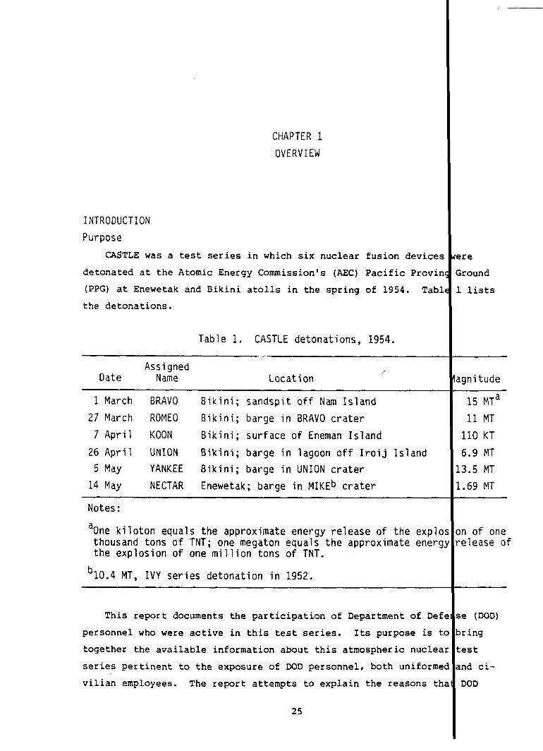
CASTLE was a test series in which six nuclear fusion devices
detonated at the Atomic Energy Commission’s (AEC) Pacific Provin
(PPG) at Enewetak and Bikini atolls in the spring of 1954. Tabl
the detonations.
Table 1. CASTLE detonations, 1954.
?ere
Ground
1 lists
AssignedDate
,/Name Location Iagnitude
1 March BRAVO Bikini; sandspit off Nam Island
27 March ROMEO Bikini; barge in BRAVO crater
7 April KOON Bikini; surface of Eneman Island
26 April UNION Bikini; barge in lagoon off Iroij Island
5 May YANKEE Bikini; barge in UNION crater
14 May NECTAR Enewetak; barge in MIKEb crater
15 MTa
11 MT
110 KT
6.9 MT
13.5 MT
1.69 MT
Notes: I
IaOne kiloton equals the approximate energy release of the explos on of onethousand tons of TNT; one megaton equals the approximate energy release ofthe explosion of one million tons of TNT.
b10.4 MT, IVY series detonation in 1952. I
This report documents the participation of Department of Defelse (DOD)
personnel who were active in this test series. Its purpose is to bring
together the available information about this atmospheric nuclear test
series pertinent to the exposure of DOD personnel, both uniformed and ci-
vilian employees. The report attempts to explain the reasons that DOD
25
personnel were present at these tests, lists the DOD organizations repre.
sented, and describes their activities. It discusses the potential radii
tion exposure involved in these activities and the measures taken for th~
protection of personnel from these participating DOD organizations. It
presents the exposures recorded by the participating DOD units. The in-
formation is limited to these points.
Historical Background
CASTLE was the culmination in the development of the super, or hydro
gen, bomb that began in 1950. Fusion, or thermonuclear, reactions had
been used in 1952 to generate a very powerful detonation of the MIKE de-
vice in Operation IVY, but MIKE was not a deliverable nuclear weapon. 1!
BRAVO, the first test of the CASTLE series, a device more powerful than
MIKE was exploded that, although not a weapon, was capable of delivery b!
an aircraft (Reference 1).
The BRAVO detonation also generated a cloud of device debris and tori
particles that brought unexpected heavy exposures of ionizing radiation t
some of the U.S. servicemen aiding in the conduct of the tests, to forei$
fishermen,
to some in
CASTLE
and to Marshall Islands residents. Radiation injuries result{
the latter groups.
also was the first Pacific test in which the University of CaU
ifornia Radiation Laboratory (UCRL) at Livermore provided a nuclear devil
for testing, detonated as the KOON event Of the series. All previous nu
clear test devices had been designed at the Los Alamos Scientific Labora
tory (LASL), New Mexico.
Report Organization
Subsequent sections of this overview chapter discuss the form of ex-
perimental nuclear weapon test programs with the emphasis on the potential
radiation exposure of participating DOD personnel. The experimental ac-
tivities are considered first without particular reference to the geo-
graphic location of the testing, and are then related to the geographic
26

limitations on such activities at the Pacific Proving Ground (
portion of the experimental program of heaviest DOD participant
emphasized.
The chapter concludes with a description of Joint Task For
the organization that conducted Operation CASTLE, and indicate
elements within JTF 7 functioned.
Chapter 2 is concerned with the radiological safety (radsa
of the tests. This chapter documents the procedures, training
ment used to protect participants from the radiation exposure
the test operations.
Chapter 3 focuses
of CASTLE in general,
on the role of the DOD in the experiment
leading to a discussion of the DOD opera
the test events in particular in Chapters 4 and 5. Chapter 4
the BRAVO detonation, and Chapter 5 presents the detonations f
BRAVO.
Chapters 6 through 9 report participation by the Army, Nav
and Marine Corps, respectively. Chapter 10 summarizes the par
of other government agencies and contractors. A listing of pa
units and a statistical characterization of their personnel ex
included in these chapters. The personnel exposures are discu
Chapter 11.
Appendixes include: A -- Radsafe-related documents prepar
CASTLE; B -- Glossary of Terms, Abbreviations, Acronyms, and U
c -- Island Synonyms; and D -- Index of Participating Organiza
NUCLEAR TESTS AND RADIATION EXPOSURES
Nuclear testing before 1963 usually consisted of the uncon
nation of nuclear devices (usually not weapons) in the atmosph
devices might be placed on a platform or a barge on the surfac
atop a tower, supported by a balloon, dropped from an airplane
27
‘G). The
m is
! 7 (JTF 7),
how the DOD
!)aspects
and equip-
~herentin
.program
.onsfor
.scusses
lowing
Air Force,
.cipation
:icipating
}suresare
;ed in
I for
.ts;
.ons.
.neddeto-
e. The
placed
or flown

on a rocket. ,Onoccasion, devices were detonated underwater or buri
the earth.
In theory, personnel could be exposed either by the radiation en
at the time of explosion and for about 1 minute thereafter -- usual]
ferred to as initial radiation -- or the radiation emitted later (r~
radiation). In practice, however, there was no involuntary direct c
sure of personnel to initial radiation during testing. This is part
the violent nuclear explosion process itself; close enough proximity
initial radiation exposure would place an observer within the area :
by lethal blast and heat waves.
The neutron component of initial radiation did indirectly contri
to the possibility of personnel exposure. Neutrons are emitted in 1
amounts by nuclear weapon explosions. They have the property of alt
certain nonradioactive materials so that they become radioactive. T
process, called activation, works on some forms of sodium, silicon,
cium, manganese, and iron, as well as other common materials. The a
tion products thus formed were added to the inventory of the radioac
products formed in the explosion process. The radiation emitted by
inventory is referred to as residual radiation.
The potential for personnel exposure to residual radiation was m
more of a real problem. In the nuclear explosion process, fissionin
of the heavy elements, uranium and plutonium, split into lighter ele
releasing energy. These lighter atoms are themselves radioactive an
cay, forming another generation of descendants from the original fis
This process is rapid immediately after the explosion but slows late
continues for years at very low levels of radioactivity.
d in
tted
re-
idual
po-
Of
for
ept
lute
rge
ring
,is
al-
!tiva-
,ive
his
!h
atoms
nts,
de-
ons.
and
The overall radioactivity of all the fission products formed dec s at
[
a rate that is closely approximated by a rule that states that for e h
sevenfold increase in time the ‘intensityof the radiation will decre se by
a factor of ten. Thus, a radiation rate of 1 roentgen per hour (R/h ) at
28
1 hour after the burst would be expected to be 0.1 R\hr after
0.01 R/hr after 49 hours. This rule seems to be valid for ab
following an explosion, after which the observed decay is som
than that predicted by this relationship. The activation pro
general, decay at a faster rate than the fission products.
Fission products and the activation products, along with
uranium or plutonium from the device, are the components of t
material in the fallout cloud, and this cloud is the primary
tential exposure to residual radiation.
In a nuclear airburst in which the central core of intens
terial, or fireball, does not touch the surface, the bomb res
ing the fission products, the activation products resulting f
interaction with device materials, and unfissioned uranium an
nium) are vaporized. These vapors condense as the fireball r
cools, and the particles formed by the condensation are small
like. They are carried up with the cloud to the altitude at
rise stops, usually oalled the cloud stabilization altitude.
of this material then depends on the winds and weather. If t
is small, the cloud stabilization altitude will be in the low
and the material will act like dust and return to the Earth’s
matter of weeks. Essentially all debris from bursts with yie
lent to kilotons of TNT will be down within 2 months (Referen
areas in which this fallout material will be deposited will a
as bands following the wind’s direction. Larger bursts (yiel
to megatons of TNT) will have cloud stabilization altitudes i
sphere (above about 10 miles [16 km] in the tropics); the rad
terial from such altitudes will not return to Earth for many
its distribution will be much wider. Thus, airbursts contrib
potential for radiation exposure to personnel at the testing
there may be some residual and short-lived radiation coming f
surface materials under the burst if the burst altitude is su
for neutrons to reach the surface.
29
‘hours and
it6 months
Thatfaster
lets,in
~fissioned
!radioactive
~urceof po-
.y hot ma-
Iues (includ-
>mneutron
‘orpluto-
~esand
md smoke-
Iich its
;hespread
!burst size
atmosphere
;urfacein a
ISequiva-
! 2). The
~earon maps
;equivalent
the strato-
~activema-
nths and
;elittle
ea, although
~mactivated
:icientlylow

Surface and near-surface bursts pose larger potential radiation ex o-
sure problems. These bursts create more radioactive debris because mo:e
material is available for activation within range of the neutrons gene.“-
ated by the explosion. In such explosions, the extreme heat vaporizes
device materials and activated Earth materials as well. These materia.s
cool in the presence of additional material gouged out of the burst cr .ter.
This extra material causes the particles formed as the fireball cools :0
be larger in size, with radioactivity embedded in them or coating thei:
surfaces. The rising cloud will lift these particles to altitudes tha:
will depend on the particle size and shape and the power of the rising air
currents in the cloud, which in turn depend on the energy of the burst,
The largest particles will fall back into the crater or very near the
burst area with the next largest falling nearby. It has been estimatei
that as much as 80 percent of the radioactive debris from a land-surfs:e
burst falls out within the first day following the burst (Reference 2).
Bursts on the surface of seawater generate particles consisting m nly
/
Iof salt and water drops that are smaller and lighter than the fallout ar-
ticles from a land burst. As a consequence, wdter-surface bursts pro ce
less early fallout than similar weapons detonated on land. The large ield
surface bursts in the PPG over relatively shallow lagoon waters or on ery
little truly dry land probably formed a complex combination of land-s face-
and water-surface-burstparticle-size characteristics.
Several surface detonations at the PPG were of such a large size that
they formed underwater craters. These craters retained a fraction of the
weapon~s radioactive debris and activated materials. The water that cver-
lay these craters acted as a shield to protect surface operations fron the
radiation from this material, but it also provided a means for the ma r ial
to move from the craters into the general circulation system of the 1;goon
waters. The craters were subject to washing and silt plumes were obs~rved
to come from them for long periods after the shots; it is reported th:t
plumes from the MI~ crater were visible a year after the detonation Ref-
erence 3, p. 207).
30

Detonations on towers may be considered as low airbursts
bursts, depending upon the relative height of the detonation
A larger burst will create more fallout than a smaller burst
or (
and
on i
height tower not only because of the additional fission products
debris, but also because it will pull up more Earth materials, 01
a crater. In addition, the materials of the tower itself provid~
of easily activated materials. The particles of the tower mater.
also act as centers for the debris vapors to condense on to form
particles that lead to heavier early fallout. Devices that fiss.
or plutonium inefficiently will cause more of these radioactive ~
of the device residue to be dispersed.
EXPERIMENTAL PROGRAM
Central to the test series was the experimental program. Th
and its requirements dictated the form of the test organization ,
detail of personnel participation. Like most of the preceding n
series, CASTLE’s experimental program incorporated two aspects,
important of which was the development of the weapons themselves
ondary experiments involved the
effects.
These two aspects can serve
measurement of the explosive and
as a rough measure of differenti
interest between the major participants: the AEC interest in we~
velopment, and the DOD interest in the military application of tl
of the explosions. The several parts of the weapon development <
effects studies each had particular features that led to the pos:
of radiation exposure.
Weapon Development
In testing devices, weapon designers are interested in two c
measurements: the total energy release, or equivalent explosive
the device, and the rate of release. The total energy release m(I
ments are called yield measurements, and the rate of release mea
are called diagnostic measurements.
31
d
yield.
:ual
weapon
m form
;ource
lay
larger
lranium
ments
ogram
:he
m test
lost
! sec-
:ation
) of
de-
ifects
:he
Lity
?s of
Ld, of
~e-
Irements

YIELD MEASUREMENTS. Device yield is usually determined by several
methods, two of which involve photo-optical techniques. Growth of the i
tensely hot and radiating mass of device debris and air that constitute
the nuclear fireball varies with its yield. Cameras were therefore used
to record this growth, and film records subsequently analyzed to infer
yield. The duration and the intensity of the energy pulse in the optics
thermal spectral region also vary with yield; thus, light detectors cou-
pled to recorders were also used to derive yield.
In addition, yield may be determined by collecting and analyzing a
representative sample of the device debris. Inferences are then drawn
regarding the yield, based on knowledge of the materials in the unexplod
device.
The construction, instrumentation placement, and data recovery for t
photo-optical yield determinations did not usually require personnel to
in areas with a high potential for exposure to radiation. Cameras and
light detectors need only a clear field of view of the burst point and
enough breadth of view to encompass the fireball. Camera placement did,not involve personnel at times and places of heavy contamination. Film
recovery generally did not involve high exposure potential, as the photc
stations were usually at ranges and in directions not heavily contaminant
by fallout.
The sampling
tact with higher
of device debris, however, necessitated much closer cor
levels of radioactivity. The technique used in CASTLE
and most atmospheric tests was to fly aircraft with collectors directly
through portions of the radioactive cloud. About 90 percent of the fis-
sion debris was usually considered to be in the upper portion of the
radioactive cloud (Reference 2). Several aircraft were used to obtain z
representative sample. The aircrews were exposed to the radiation emitt
by the radioactive particles in the cloud as they flew through. The air
craft flying these sampling missions picked up significant amounts of r?
dioactive material on their surfaces, posing additional and continuing
32
II

radiation,exposures to the aircrews as they returned to base, as
to decontamination ground crews. The samples collected were radi
tally “hot” and required special handling as they were taken from
craft and prepared for shipment to the laboratory for analysis.
DIAGNOSTIC MEASUREMENTS. The explosion of a nuclear device i
gressive release of increasing amounts of nuclear radiation, some
directly escapes the device. The rest of the radiant energy inte
with the associated material of the device itself and is converte
differing forms of radiation and into the kinetic energy of the r
materials in a small fraction of a second. The intensely hot cor
reradiates, heating the surrounding air and creating a shock wave
propagates outward from the burst point.
The weapon diagnosticians used sophisticated techniques to fc
processes that occur during the device explosion. Detectors and
tors were run up to, and sometimes inside, the device case so tha
diation being sampled could be directly channeled some distance a
there be recorded by instrumentationdesigned to survive the ensu
To enhance its transport, radiation was conducted through pipes (
evacuated or filled with special gases) from the device to static
recording instrumentation was located or where the information cc
retransmitted to a survivable recording station.
Radiation measurements are based upon the effects that result
interaction of the radiation with matter. Fluorescence is one su
Materials that fluoresce with radiation exposure were placed in v
cameras or light detectors to provide a record of the variation c
escent intensity with time, thereby providing an indirect measure
the radiation environment.
other methods of detecting radiation involve the shielding (a
tion) properties of earth materials, water, and other substances.
materials are also used to baffle or collimate radiation to ensur
radiation is directed toward the detecting instrument.
33
!11as
.ogi-
:heair-
a pro-
tfwhich
ICts
into
\aining
then
:hat
,OWthe
tllec-
the ra-
ky and
Igblast.
!ten
;where
.dbe
rom the
effect.
w of
fluor-
nt of
:enua-
These
that

_—-
Radiofrequency energy produced by the explosion can be detected by
radio receivers and, with the addition of filtering and processing cir-
cuitry, can also provide information about the energy flow from the ex-
plosion. Such measurements permit remote placement of receiving and
recording instruments.
Preshot preparation included the hazards normally associated with heav
construction, and some exposures of workers to radiation occurred in areas
contaminated by earlier tests.
The potential for radiation exposure of personnel associated with
weapon diagnostic experiments depended upon the proximity of the measure-
ment or data recovery point to ground zero and the time lapse between the
detonation and the data collection.
The primary radiation exposure potential is from fission* products and
materials made radioactive by neutron activation of device and Earth mate-
rials in the vicinity of ground zero. Thus, the distance from ground zero
is a principal factor in assessing exposure to persons engaged in the ex-
perimental program..
Since radioactive material decays with time, the time lapse between
the explosion and exposure is a critical factor in dose assessment. Pri-
mary recording media for these“experimentswere photographic films from
oscilloscope, streak, or framing cameras located in survivable bunkers
near the detonation point. Because radiation fogs film in time, these
films and other time-sensitive data were removed from the bunkers by
helicopter-borne personnel within hours of the detonation to minimize
damage by fogging. This recovery constituted the main potential for ex-
posure of weapon diagnostics participants.
* Although the CASTLE devices were thermonuclear, or fusion~ devicesl asignificant portion of their energy release resulted from fissionprocesses.
34
-—

Effects Experiments
AU the CASTLE shots tested new weapon developments. Prioriti
time and space and go or no-go considerations favored the weapon d
ment experiments over the effects experiments. Although the effec
periments were clearly secondary, they directly involved a relativ
large number of DOD organizations and individuals and are therefor
prime importance for this report. In fact, the total support requ
for the effects
ment (Reference
The effects
experiments were 60 percent of the total support r
4, p. 57).
experiments were intended to acquire urgently need
tary data that could not be obtained from the smaller yield tests
Nevada Proving Ground (NPG), now called the Nevada Test Site (NTS)
experiments may be classed into two general kinds. The first clas
measurements was made to document the hostile environment created
nuclear detonation. The second class of effects experiments docum
the response of systems to the hostile environment; these measurem
termed systems response experiments.
ENVIRONMENTAL MEASUREMENTS. The purpose of environmental mess
was to gain a comprehensive view of the hostile environment create
nuclear detonation to allow military planners to design survivable
tary hardware and systems and train personnel to survive. Example
environmental measurements include static (crushing)and dynamic (
wind) air pressures in the blast wave, heat generated by the deter
and fallout radiation. The measurement techniques employed for C~
varied with the effect being measured, but usually measuring devic
gauges were placed at a variety of ranges from ground zero and the
urement recorded in some way. A wide variety of gauges and data K
techniques was used. In some cases, measurements were similar to
being made by the weapon designers, but at greater distances or lC
after the detonation, which simplified the recording of the data,
the recovery problems were by no means trivial.
35
Df
lop-
ex-
E
nents
ire-
nili-
the
These
f
the
ed
s are
ments
Iy a
li-
f
St
on,
,E
or
meas-
mding
Ise
!r
:hough

Rugged, self-recording gauges
radiation measurements by 1954 so
ect would not occur if instrument
had been developed for blast and t
that complete loss of data from a
recovery were delayed, for example
heavy fallout. For nuclear radiation measurements, however, prompt
recovery was still desirable because the gauges used might be thin f
of material that would be made radioactive by the burst-time neutron
hence, early observation was necessary, before the information conta
in the induced radiation pattern decayed away.
The potential for radiation exposure of personnel responsible fo
vironmental measurements in general depended on their proximity to t
vice and the time that elapsed between detonation and instrument rec
as was the case for weapon development experimentation: the nearer
space or time to the detonation, the greater the potential for expos
SYSTEMS RESPONSE EXPERIMENTS. To document the response of syste
the hostile environment, military hardware (such as aircraft or nava
mines) was exposed to the effects of nuclear detonations.
The techniques used for ‘thesystems response experiments were co
ually simple: exposure of the system of interest and observation of
response. Actual conduct of the experiments was far more complex.
level of the threat to which the system was exposed almost always re
documentation so that the response could be properly understood, nec
tating an environmental experiment along with the systems response e
ment. It was often not enough to know whether the system survived,
rather, the response of the component parts and their interactions w
required, entailing the placement of sophisticated instrumentation a
recording devices.
While the potential radiological exposure for these systems resp
experiments was governed primarily by the closeness in space or time
additional problem arose. Often, when the subject of the exposure i
was recovered for closer examination, it could be contaminated by de
36
rmal
oj-
by
ta
1s
ed
en-
de-
eryr
e.
to
ept-
ts
e
ired
si-
eri-
t
se
an
elf
ce

debris or even be radioactive because of the activating effects of the
device’s neutron output.I
OCEANIC TESTING OPERATIONS
The implications of oceanic testing have only incidentally een re-
marked upon.
t
These are now discussed, especially as they relat to DOD
operations during CASTLE.
Marshall Islands Setting
The Marshall Islands are in the easternmost part of the ar
I
known as
Micronesia (“tiny islands”). The Marshalls cover about 770 th sand mi2
(2 million km2) of the Earth’s surface but the total land area “s only
about 70 mi2 (180 km2). Two parallel chains form the islands: Ratak (or
Sunrise) to the east, and Ralik (or Sunset) to the west; both ewetak and
Bikini are in the Ralik chain at its northern extreme. Figure 1 shows
these islands in the Central Pacific, Figure 2 is a map of Ene etak Atoll,
and Figure 3 is a map of Bikini Atoll.
Typical atolls, Enewetak and Bikini are coral caps set on ‘runcated,
submerged volcanic peaks that rise to c~nsiderable heights fror the ocean
floor. Coral and sand have gradually built up narrow islands .ntoa ring-
like formation with open ocean on the outside and a relatively sheltered
lagoon on the inside. Both atolls have two passages, a wide pissage and a
deep one, that permit access to their lagoons from the sea. Elewetak also
has a third. All the islands are low-lying, with elevations s?ldom over
20 feet (6 meters) above high tide.
During nuclear testing, the more populated, support-orien d sections
were the south and southeast areas of the atoll where the lar
1
r islands
exist. Devices were detonated on the northern islands and ov the north-
ern reefs. The western sections of the atoll were not involv in test
activities except for limited use as instrumentation sites.
Elliptically shaped, Enewetak is approximately S50 nmi (1
/
20 km)
southwest of Wake Island and 2,380 nmi (4,410 km) southwest o Honolulu.
37

I
I
___ ----- _ Lau’7aJeUlWoaje”,aJu,--- 4––––
I I
/’
38
I
I

ENEVVETAK
~BOKAIDRIKDRIKDRIDRILBWIJ
MIKE CRATERBOKINWOTME ENJEBI
LOUJKIRUNU !JIIJIKADREK
BOKOMBAKO
90 KOLU0BOKENELAB
RUNIT
JIN
JAPTP
SOUTHWEST\PASSAGE ‘
\
NKIDRENEN
o~5NAuTICAL MILES
‘~:
‘~KILOMETERS
Figure 2.
PARRY .\//
))\
)-
/
EN EWETAK
1{
WIDEENTRANCE ,TO’2~.pJo~l
+
I162°20’ EAST
Enewetak Atoll, 1954.
39
JINEDROL
/
)
ANANIJ
l/
*
\8
P
IEEpNTRANCE

~ —–” ‘-
BIKINI
IROIJ
//
ODRIK
N LO MILIK
‘+/130KDROLUL
EIOKAETOKTOK
/
OROKEN
n / ADRIKAN
LUKOJPASS
0~6
0-6
:~KILOMETERS
COCA
EN IDRIK/ ENEMAN
!-g+=LELE
BIKDRIN YAEROKOJLOL /
AEROKOJ
ENEUk
16!j0]04 EAST \
Ii
,,0 so. NoRTH,— +—
ENEU CHANNEL
Figure 3. Bikini Atoll, 1954.
It encloses a lagoon 23 miles (37 km) in diameter and has a total land
2 (7.12 km2), with elevationsarea of 2.75 mi averaging 10 feet (3 meter:
above mean sea level. The support section of Enewetak (Enewetak, Parry,
and Japtan islands) constitutes about 34 percent of the atoll’s land SUI
face. The string of islands from Runit to Bokoluo, the detonation area
constitutes about 32 percent. The VaKiOUS names used for the islands o
the atoll are listed in Appendix C, “Island Synonyms.”
40
i
[ ‘%

Bikini is 189 nmi (350 km) east of Enewetak. Its islands c)nsist of
about 2.7 mi2 (7 km2) of surface area and encircle a lagoon tha: is 25
miles (40.2 km) long and 15 miles (24.1 km) wide, with a maximul depth of
about 200 feet (61 meters). The land area is concentrated in t~e eastern
islands, from Bikini to Eneu islands, which form about 53 percelt of the
land total, with 24 percent taken up by the southern section of Enidrik to
Aerokoj. The detonation area in the north occupies about 19 percent of
the land area.
The climate of Enewetak and Bikini is tropical marine, gen ally warm
and humid.
1
Temperature changes are slight, ranging from 70° t 90°F (21°
to 32°C). Rainfall is moderate, and prolonged droughts may oc r. NOrth
of both atolls is open ocean for a thousand miles, with the on inhabited
island being Wake. Storms are infrequent, although typhoons ur; never-
theless, both wind and sea are continuous erosional agents. though pOS-
sible at any time, most tropical storms occur from September t December.
Much cumulus cloud cover exists in the area.
The Enewetak-Bikini region incorporates three basic wind
northeast trade winds extend from the surface to 25,000 to 30
(7.6 to 9.1 km), the upper westerlies from the top of the tra
base of the tropopause at 55,000 to 60,000 feet (16.8 to 18.3
Krakatoa easterlies from the tropopause up into the stratosph
systems are all basically east-to-west or west-to-east curren
day changes reflect the relatively small north-south componen
markedly variable. Greatest variation occurs in the upper we
particularly during late summer and fall.
The steady northeast trade winds in the lower levels caus
at the surface of the lagoons to flow from northeast to south
it sinks to the bottom and returns along the lower levels of
rising to the surface along the eastern arc of the reefs and
where it is moved by the winds to the southwest again. The 1
41
——
stems. The
00 feet
s to the
m), and the
e. These
1. Day-to-
,,which are
.erlies,
the water
st, where
~e lagoons,
;lands,
loonwaters

moving in this closed loop also mix with those of the open ocean, resba
ing in a flushing action.
At Bikini, ocean water flows in over the northern and eastern reef
and flows out of the western portion of the Eneu Channel. The water e
changes over the western reefs with the tides, the ocean water flowing
and mixing with the flocd and lagoon water flowing out with the lows.
net rate of flushing of Bikini waters is such that half of the lagoon
ters are replaced by ocean water in 22 days and the original volume wi
account for only 10 percent of the lagoon volume after 2+ months.
At Enewetak, the flushing is more rapid and has two major routes.
first is directly through the eastern reefs to the western reefs; the
ond is through the Deep Passage between Japtan and Parry and out the W
Passage west of Enewetak. These two routes also function to keep the
ters of the northern part of the lagoon separate from the southern wat
The land areas of Enewetak and Bikini atolls, their lagoons, and t
waters within 3 miles (4.8 km)of their seaward sides constituted the P
These islands are part of thd Trust Territory, a strategic area truste
ship of the United Nations, administered by the United States. The U.
agency in charge of the PPG itself was the AEC.
The Test Division of the AEC Division of Military Applications, Sa
Fe Operations Office, administered the test site through its Enewetak
Branch Office, which supervised engineering, construction, maintenance
operation, and management activities performed by its contractor, HOIIT
Narver, Inc. (H&N), of LOS Angeles.
Physical Conditions in 1954
Enewetak had been the site of nuclear testing since 1948: the isl
in the southeast quadrant served as the base for the task forces, and
* After 1956, the PPG was designated the Eniwetok Proving Ground, or
42
t-
I
in
The
a-
1
The
ec-
de
‘a-
rs.
,e
IG.*
I
I
II
1.
Lta
!s&
ds
e
G.
islands from,north through east-northeast were used for the tests t
selves. The principal base islands were Enewetak, which bordered t
Passage, and Parry, northeast of Enewetak, which bordered the Deep
age. These two islands account
area.
Parry and Enewetak had been
the home and working facilities
for about 30 percent of the atoll’:
densely populated during IVY, servj
for Joint Task Force 132 (JTF 132)
predecessor of JTF 7) except for the Air Force task group (’N 132.4
those living aboard ships. Included in the working facilities was
field occupying the southern end of Enewetak. Shops, warehouses, 1
tories, and living space occupied most of the rest of the island’s
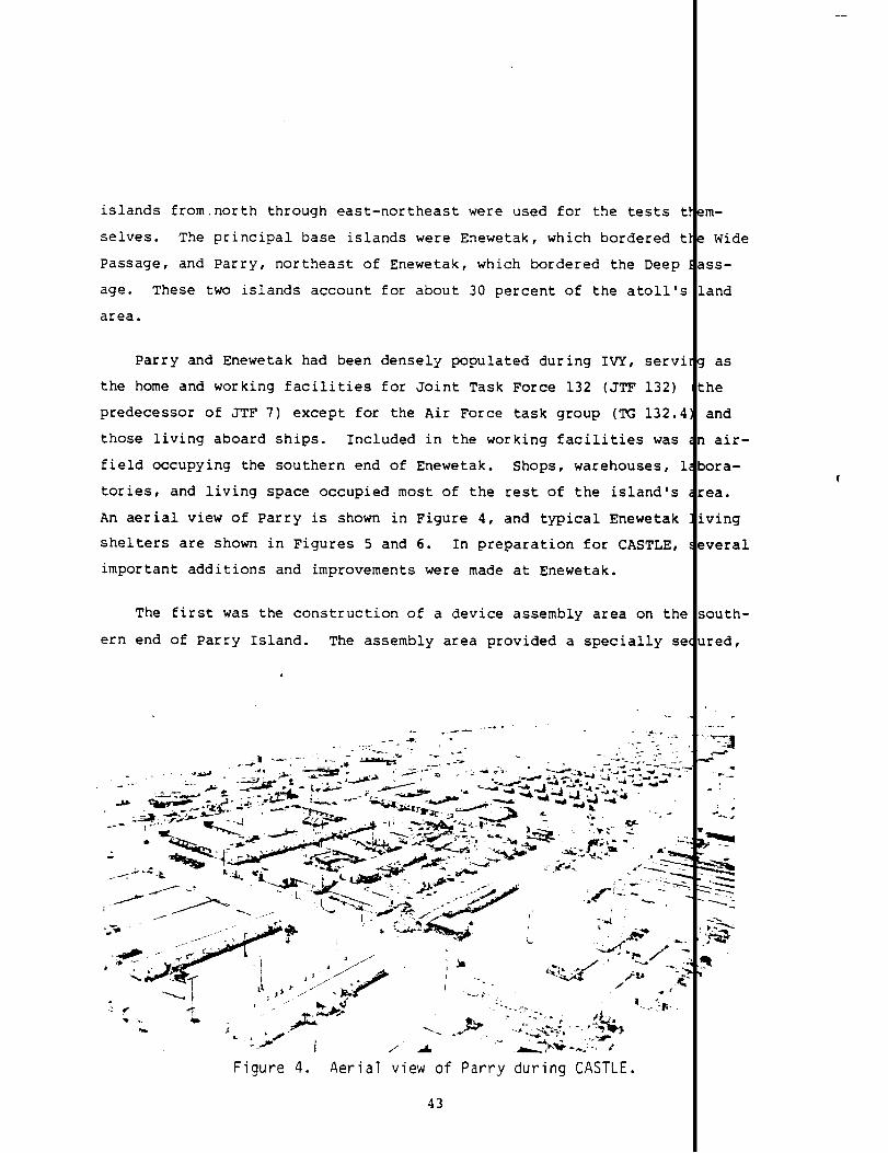
An aerial view of Parry is shown in Figure 4, and typical Enewetak
shelters are shown in Figures 5 and 6. In preparation for CASTLE,
important additions and improvements were made at Enewetak.
The first was the construction of a device assembly area on th{
ern end of Parry Island. The assembly area provided a specially S(
... . . ... . .. — .-” 4.. ,...-*; .. ...: -.! . .-
.- ‘.-i. -----.— - ,. -- . -.. , . -----
. .. %ygjT’+’-v”;-.’~;,, . ..-----._----s - .4” +. ~~ ~.&4-. . .--- ‘“’+=.—. “=x- Y“.-” ‘<y* .Gr.&-J”f_.4h----- -+.,$s--= -.
--i----
‘--.:-$-..-----..b.,*>+-% --I*.
4
Figure 4. Aerial view of Parry during CASTLE.
43
m-
Wide
ss-
and
as
he
and
air-
ora-
ea.
ving
veral
outh-
red,
....
24e ..._-.
1’...-.
~.
->%\-i
.>:%?
R
.-

.
—— ‘-
Figure 5. Typical metal buildings used at Enewetak during CASTLE
J
r
-.&. .. .-----
--
Figure 6.
,... . -. -..
Tents on Parry, CASTLE.
44
—..— ---.< ..&
~ J.. . ---- ..7’----Y:---.4.* .*4.”
. . . .
~-
—-
i

single location for working on the
and shelter of the assembly teams,
explosive magazines at hand. This
ence 5, p. 2-199).
nuclear devices. It included s
machine tool facilities, and hi
was completed in March 1954 (Re
The devices were largely assembled in this area and then trans
by water to the test location. A ramp was available within the ar
that an LST could take devices aboard by truck. The barge-detonat
vices were assembled in a shelter (called a cab) on the barge, whi
moored in a specially constructed slip equipped with a large overh
crane to handle heavy loads (Figure 7). After completion of work,
device barges were towed to their final destinations.
The Air Force component of the joint task force, based on Kwaj
previous operations, was moved to Enewetak for CASTLE. This move
considerable improvement in the airfield that occupied the souther
of Enewetak Island. Figure 8 shows the extreme western end of the
looking west. The light area near the right wing of one of the pa
B-36s is a decontamination area that was constructed for CASTLE.
In the northeastern arc of the islands, a causeway constructed
GREENHOUSE (1951) to link Eleleron, Aomon, Bigire, and Lojwa islan
widened. A major construction camp was built on the Lojwa end of
complex. This required some work that is more properly described
following subsection (p. 47) on the radiological condition of EneM
Generally, the northern and eastern islands involved in the sh
shot-su~ort activities had been graded extensively. Japtan, lyin
across the Deep Passage from Parry, still contained a considerable
of coconut palms, pandanus, scaevola, and other tropical vegetatic
In October 1952, H&N, acting as the resident contractor for th
began construction of a camp on Eneman Island on the southern peri
Bikini. An airstrip to serve Bikini-Enewetak traffic was also beg
neighboring islands of Aerokojlol and Aerokoj and on the causeway
45
port
r-
rted
so
de-
wss
d
he
ein in
quired
half
sland
ed
or
was
is
the
ak.
or
just
tand
AEc ,
ter of
on the
at was

-...—. ~- —.- . . -.. . .... . ---- . . .—+------- _. ”-,.. I
Figure 7. Assembly area on southern tip of Parrylooking south, CASTLE.
..-,,-
.?~~zg-.-~y~::~$:=. ‘=?%
- “- ‘“--”5’”’:’1’ ‘* %-
‘~-,:.~,,,=., .-. -----..-1.. - ..-=...
..... -._
.* ,%J
:;’-’ - .& ‘.‘-
-... -.
J
k
&!!J$ ::<’: -“- “’ -~ -..%.%.
.,- .- .........”.@..*-.-. :,:. -% “-:%&m...-%. - .,- ‘.....6 .
. . -< }
Figure 8. Enewetak airfield looking west, CASTLE.
46
I

built td link them. This causeway was constructed from onsit
and shored on either side by bulkheads. Before the CASTLE se
underway, Eneman, Lele, and Bikdrin islands had also been lin
airstrip islands to form a complex 3 miles (4.8 km) long, tra
wheeled vehicles. Additional causeways were constructed in 1
joined Iroij, Odrik, Lomilik, and Aomen islands in the northe
the Bikini islands. A causeway westward over the reefs from
northwest portion of Bikini was also built during 1953, termi
artificial island that became the detonation point for BRAVO*
test of the CASTLE series.
Camps were also built on Nam, Lomilik, and Eneu to house
workers building the test-related structures on or near these
island complexes. According to the directives of the ABC, al
tion was to be of an expendable nature. A petroleum, oil, an
(POL) storage area was also built on Lele to serve the main c
kini at Eneman. Figure 9 shows the Eneman base camp viewed f
goon looking south-southwest. The large building in the cent
for the KOON device. The island to the’right is Enidrik and
line shaved down its center for the KOON test.
—
materials
.esgot
!dwith the
!rsableby
13 that
Item arc of
m in the
~tingat an
he first
Instruction
,slandsand
construc-
lubricants
[pon Bi-
Imthe la-
is the cab
,sa blast
Radiological Conditions in 1954
1
The CASTLE planning literature refers to a detailed and c prehensive
survey of the radiological condition of the islands at Enewet k in 1954
JUSt before CASTLE. NO record, however, has been found of th . There-
fore, in order to assess the possibility of task force person 1 exposure
to ionizing radiation while preparing for CASTLE, it is possi le only to
discuss the test activities that had taken place at Enewetak d introduce
any anecdotal or partial information that is available.
Enewetak had been used for nuclear tests in 1948, 1951, a
SANDSTONE (1948) detonations on Enjebi, Aomon, and Runit left
theseislands contaminated. In February 1949, a survey party
Hanford, Oak Ridge, and LOS Alamos laboratories of the AEC fo
47
1952. The
ortions of
rom the
d “a very

- —.,’
. .-. &__, . -
—-— -- ..__ _ — -.,-, ~~-,> ,-: r.- .. ...-;;’& -..:,,. . ..-,
.3. ~+<a ~;:- ..,-. .. ...,/,.. . .-“.
,. ’.,,“ F
Figure 9.
low activity of
Eneman Camp,
alpha” on the
-..._ ..-.
tivity within 1,000 feet (305
- ..- . . . - --- .--. ---:-.. .-.
Bikini, looking south-southwest, CASTL
shot islands and only small “pools” of
meters) of the craters formed by the e
sions. These areas were covered with soil during that year; a radic
survey in March 1950 showed less than 0.001 R\hr on Enjebi and Aomon
an average of 0.002 R/hr on Elereron. On Runit the general radioact
was 0.0015 R\hr, but some of the old shot tower footings showed 0.01
After a third survey in April and May of that year, it was concluded
no possibility of overexposure to gamma radiation existed on any isl
the
and
and
atoll and the wearing of film badges was discontinued (Reference
The GREENHOUSE (1951) detonations were on Enjebi, Eleleron, and
apparently left these islands and other areas contaminated. The
Im tower residues were left in place on Enjebi after GREENHOUS
Shot GEORGE of GREENHOUSE left a large radioactive crater on Elelero
MIKE, the first thermonuclear device, detonated on Eluklab in 19
during Operation 1~, destroyed the island and left an underwater cr
48
I

Eluklab had been located just west of Boken, at the northernmost: extension
of the atoll. A large air-dropped device was exploded over the reef just
off Runit as the second event of the IVY series. The locations of all
these pre-CASTLE detonations are shown in Figure 10.
A qualitative measure of the radiological conditions at En etak be-
1
fore CASTLE is available in the form of a joint task force TG 7 1 planning
discussion held at LASL in March 1953. A LASL spokesman said at Enjebi
“was still quite hot” at that time and that this should be tak into con-
sideration in planning instrument placement for CASTLE (Refere e7).
A slightly more quantitative description of the contaminatem from
prior tests and the subsequent work necessary to make it possikle to work
in the area is recorded in the final report for CASTLE of the base support
contractor (Reference5). An advance camp was to be set up on Lojwa in
the Eleleron-to-Lojwa complex, and it was,necessary to fill the crater on
Eleleron resulting from the GEORGE detonation of GREENHOUSE. ‘1he “average
radiation level in this area [presumably near the crater] was c~ to 95 mr
per hour in December [1952]. . . . Some experimental work was done toward,
decontaminating the areas and it was found that the most satisfactory re-
sults were obtained by removal of vegetation and up to 12 inchfs of top
soil.m The disposal of this contaminated layer of soil is not discussed
in Reference 5. The crater itself is a likely prospect. The crater was
being filled in the spring of 1953 and by May 1953 the radiaticn level was
low enough that “construction forces could live ashore in camp: indefi-
nitely~ within allowable dosage” (Reference 5? PO 2-51). Befole this, the
construction personnel had been flown from Parry to Lojwa dail~, or had
lived in the lagoon on an LCU equipped as a houseboat. The actual camp-
site at Lojwa had to be scraped to a depth of about 3 inches ([ cm) and
backfilled with uncontaminated coral to ensure its long-term h?bitability.
49
The MIKE detonation was many times larger than any prior E ewetak
tests, and the crater formed was probably still radioactive.
I
he crater,
however, was thickly blanketed by seawater that provided a hig degree of

ENEWETAK
}
DRIDRILBWIJ1952–MIKE (10.4 MT), _MIKE CRATERSURFACE, ELUKLAB
\\ T’””” \
1948–X. RAY, 3- “- “
ENJEBI 1951 –DOG, ” TCl/ Kl, l<3WER
/ 1951 -ITEM,” TOWER
BOKOLUO
LUJO R
bBIKE”
4
\\SOUTHWEST\ \
PASSAGE ‘
‘k
N
(1948–YOKE, 49 ‘T, TOWER) AOMON’w
f
?
UNIE6R\.
/
\
1948–ZEBRA, 18 KT, TOWER1951 –EASY, 47 ‘T, TOWER (
\— RUNIT
1952–KING. 500 KT. AIR
o 1 2 3 4 5 6 7\ I 1 ! I I I I
NAUTICAL MlLES
o 1 2 34 56 7 8
STATUTE MILES
o~
KILOMETERS
Figure 10.
)\
I
JAPTAN ,
\PARRY\* ●
/
EN EWETAK \
\ (
WIDEENTRANCE ,,02~.~o~~~
+-
162°20,EAST
“YIELO NOTA
Enewetak detonation sites.
50
:R
“ TOWER)
ANANIJ/
\NCE
OUNCEO

shielding from the crater’s nuclear radiation to the surface (
Scientific stations were built on Dridrilbwij for CASTLE, the
to the Eluklab crater, and no mention of special difficulties
ation is made in the construction report, although personnel
were still
Bikini
JuIY 1946,
required.
was the location of the first postwar nuclear detol
the CROSSROADS tests were conducted in the lagoon.
devices were detonated: one airburst over a target fleet, ant
burst underwater in the lagoon about 2 nmi (3.7 km) west of B
There was no continuing radiological exposure of personnel on
at Bikini from these tests,
tion in the lagoon bottom.
Special Problems in Oceanic
although there was very-low-level
Testing
Testing in the Marshalls offered a large uninhabited area
tivities and for the favorable disposition of the test debris
were in the right direction. However, the area was almost al
fering little dry space to place shot towers, instrumentation
test structures, or places to live. At’Enewetak Atoll the to
is only about 1,800 acres (730 hectares), and the prime acrea
southeastern quadrant (about one-third of the total) housed t
the task force not based on ships. The land area of Enewetak
largest of the atoll, is only about 320 acres (130 hectares),
half of this was occupied by an airstrip and associated activ
thermore, the land suitable for testing was not necessarily d
the appropriate directions and sizes for instrument placement
land area was one of the factors necessitating use of both Bi
wetak atolls, starting in 1954 with CASTLE. The addition of
precluded damage to the Enewetak facilities by very-large-yie
The lack of land was compensated for in part by civil eng
ects. Causeways were constructed that linked strings of isla
the long pipe runs of some experiments over thousands of feet
51
rations.
land next
e to radi-
m badges
ion. In
WO 23-KT
he second
ni Island.
e surface
ntamina-
r test ac-
the winds
ater, of-
elters,
land area
in the
part of
land, the
d about
es. Fur-
,ributedin
Lack of
Iiand Ene-
,inialso
devices.
!eringproj-
; to support
These also

permitted land transportation from construction camps to propased zero
points, thus allowing more time during the workday to be expended on the
job rather than in commuting by water from base islands. Some artifici a.
islands were created as shot points and instrument locations.
Floating data-collection stations compensated for the lack of land
zrea. These were used extensively in the nuclear radiation program. An .
chored rafts and buoys, serving as fallout-collection stations, were
placed in the lagoon and in the open sea. Ships also acted as fallout
collectors. These offered the advantage of moving to the most desirable
collection areas, that is, areas of heaviest fallout, and following the
fallout within the limits of their speed. Two ships were modified for
remote operation and control from other locations or below decks, where
heavily shielded quarters protected skeleton crews and scientific parties.
Barge-mounted test devices, a technique first used in CASTLE, also
compensated for the lack of land at the PPG. This allowed the available
land area to be used for the placement of measurement instrumentation and
reuse of the same burst point without the long delays required for radio-.
logical cooling by natural decay and expensive and long decontamination
procedures, as described for the GEORGE crater of Operation GREENHOUSE.
Reuse of zero points also allowed use of instrument locations and record-
ing shelters for multiple tests, saving construction costs and time and
increasing test-scheduling flexibility.
The use of shot barges, however, precluded the acquisition of some
weapon development data that required a precise line of sight between the
test device and the recording instrumentation. Barge movement by lagoon
currents was minimized by special mooring techniques, but not to the de-
gree necessary for some measurements. The barges also precluded use of
the pipe runs required for some other diagnostic measurements.
Shot barges fitted well into the two-atoll testing scheme that was de-
v~”~ped for CASTLE. Enewetak was the base of operations and Bikini was
52
I

like another shot island, except that its remoteness allowed \
yield tests without endangering the permanent facilities at Er
requiring its evacuation. Bikini was without permanent facili
depended on Enewetak for its overhead support. Part of this s
the combination of personnel, equigment, and materials require
ble the test devices themselves. The new assembly area at EnE
the barge-zero stations allowed most of the support functions
Enewetak.
JOINT TASK FORCE 7
JTF 7 was established as a permanent organization in 1953
nuclear weapon testing in the Pacific. It existed through 195
conducted HARDTACK, the last test series before the 1958 throu
clear test moratorium. JTF 7 was the
ducted the IVY test series in 1952.”
The joint task force incorporated
the four services, other governmental
vilian organizations,undercontract.
for nuclear energy development by the
successor to JTF 132, wh
into its organizat
agencies including
The AEC, charged w
Atomic Energy Acts
on el
the P
th re
of 1?
designated Commander JTF 7 (CJTF 7) as its representative. J’1
a subordinate command of the Commander-inlChief of the Pacific
who provided overall security and logistic support. The Chief
Forces Special Weapons Project (AFSWP)exercised technical diz
weapon effects tests of primary concern to the Armed Forces.
ity of these relationships is illustrated in Figure 11.
The resulting organization, though complex, worked well en
conformed with the realities of the situation. The realities
the tests were being conducted to develop nuclear weapons, an
limited by law to a civilian agency, the AK. The tests were
ducted in an area that came under the jurisdiction of the AEC
sense that the AEX2was the U.S. government agency primarily re
53
— -——
-large-
tak or
s and
ort was
3 assem-
ak and
remain at
conduct
hen it
1961 nu-
had con-
nts of
and ci-
nsibility
and 1954,
was also
INCPAC),
the Armed
ion of the
complex-
h, as it
e that
ivity
ng con-
the
risible
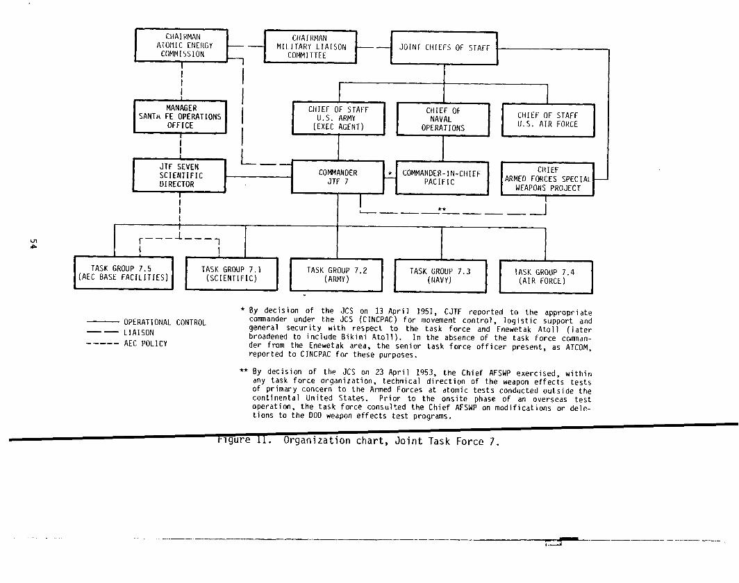
I
*
I
I
II I
1
CHIEFOF STAFF CHIEF OF1
U.S. ARMY NAVAL CHIEF OF STAFF
(EXECAGENT) OPERATIONS U.S. AIR FORCE
IA
I1 I 1
JTF SEVENL
SCIENTIFIC COt@lANDER * COMMANDER-IN-CHIEF
DIRECTOR JTF 7 PACIFIC
II I I =i
I— **. . —. _ -J
Ir I
r_–_L–_,I I
TASK GROUP 7.5 TASK GROUP 7.1 TASK GROUP 7.2 TASK GROUP 7.3 TASK GROUP 7.4(AEC BASEFACILITIES) (SCIENTIFIC) (ARMY) (NAVY) (AIR FORCE)
b
— OPERATIONAL CONTROL—— LIAISON----- AEC POLICY
.
* By decision of the JCS on 13 April 1951, CJTF reoorted to the appropriatecomnander under the JCS (CINCPAC) for movement control, logistic support andgeneral security with respect to the task force and Enewetak Atoll (laterbroadened to include Bikini Atoll). In the absence of the task force command-er from the Enewetak area, the senior task force officer present, as ATCOM,reported to CINCPAC for these purposes.
** By decision of the JCSon 23April1953, the Chief AFSWP exercised, within
any task force organization, technical direction of the weapon effects testsof primary concern to the Armed Forces at atomic tests conducted outside thecontinental United States. Prior to the onsite phase of an overseas testoperation, the task force consulted the Chief AFSWP on modifications or dele-tions to the DOO weapon effects test programs.
t-lgure 11. Organization chart, Joint Task Force 7.
.- —.—— — ~ ——— —...—__1.—.--4
for the islands that were included in the PPG). The United St
ever, did not actually own the territory being used, but rath(
held in trust. Furthermore, the territory was remote from the
States and required special supply and security arrangements d
to military operations. Finally, the organization for which t
were being developed was the U.S. military establishment.
The DOD requirements for nuclear weapons were apparently f
the AEC weapons laboratories through the Military Liaison Comn
Figure 11). The AEC laboratories then designed the devices
tested at the appropriate proving ground, either the NPG or
special location of the PPG required a miltary operation to
tests. The JTF 7 Scientific Director actually directed the
CJTF 7 enforced his decisions. The joint task force was divid
functional and service-branch oriented units, each of which re
CJTF 7 through separate task group commanders.
Task Group 7.1 (Scientific)
TG 7.1 was the centerpiece of the operation. It contained‘tives of the organizations providing the devices and the repre
of the DOD laboratory organizations interested in the effects
vices. All the other groups at the PPG were there to assist T
TG 7.1 was primarily led by LASL. The newer laboratory, UI
, how-
was
ted
?riate
?apons
:ded to
? (see
sre.3. The
t the
md
lto
ad to
resenta-
~tives
~e de-
1.
did
provide one test device in CASTLE and a large contingent of perscnnel, but
most of the key positions in TG 7.1 were held by LASL personnel. There
was a “Deputy for UCRL,””a position that recognized both the new .abora-
tory and its junior position. The task group was organized into :ask
units with special functions. There were 12 task units, but they were
designated 1 through 15, with no task units corresponding to 5, 1 , and 11.
TASK UNIT 1 -- LASL PROGRAMS. The function of this unit was .Omake
diagnostic measurements of the LASL-designed nuclear devices. DOlIperson-
nel did participate to a certain extent in this task unit, as fur‘her dis-
cussed in Chapter 3. TU 1 personnel totaled about 145.
55I

TASK UNIT 2 -- PRODUCTION. This unit produced special materials fo
use in the nuclear devices of both TU 1 and TU 12 (UCRL Program). TU 2
worked at Parry. Its pezronnel were from an AEC contract organization,
Herrick L. Johnston, Inc., of Columbus, Ohio. This group left the PPG
April. TU 2 personnel totaled about 45.
TASK UNIT 3 -- SPECIAL MATERIALS AND FACILITIES. The mission of thi
unit was the handling and delivery of the special materials produced by
TU 2 to the users in TU 4 (LASL Assembly) and TU 14 (UCRL Assembly). Li
TU 2, this unit was composed of employees Of an AEC contractor, the Cam-
bridge Corporation of Denver, Colorado. This group also left the PPG ir
April. TU 3 personnel totaled about 60.
TASK UNIT 4 -- LASL ASSEMBLY. This unit was composed of LASL persol
nel and personnel from its contractor, American Car and Foundry, Inc.
(ACF). The LASL-designed devices were actually assembled by ACF except
for the NECTAR device, which was fabricated at LASL. This unit worked
primarily at Parry. TU 4 personnel totaled about 75.
TASK UNIT 6 -- FIRING PARTY. TU 6 armed and ;ired the devices. Its
work involved checking the various electromechanical links that prevente
premature device detonation and removing them just before activating the
firing mechanism. All the Bikini devices were detonated by signals sent
over a wire system from the bunker at Station 70 on Eneu, which was mann
by TU 6 for BRAVO, but the remaining Bikini tests were initiated by a ra
signal from the USS Estes to the evacuated bunker. The test at Enewetak
NECTAR, was wire-detonated from Parry. The single person identified wit
TU 6 was from LASL.
TASK UNIT 7 -- RADIOLOGICAL SAFETY. This unit was made up of Army
personnel from the 1st Radiological Safety Support Unit (RSSU) from Ft.
McClellan, Alabama, commanded by a military officer from LASL, and was
supplemented by personnel from DOD and AEC agencies. The activities of
TU 7 are described in Chapter 2. TU 7 personnel numbered about 54.
56
I

TASK UNIT 8 -- TECHNICAL PHOTOGRAPHY. This task unit provi
and motion picture services for the scientific and technical op
It was composed of LASL personnel with DOD supplements and numb
20.
TASK UNIT 9 -- DOCUMENTARY PHOTOGRAPHY. This task unit, ma
personnel from the Air Force 1352nd Motion Picture Squadron ba.s
out Mountain Laboratory, took motion pictures and still photogr
operations, including crater survey and cloud photography. Bes
camera crews and up to four aircraft stations, TU 9 also had si
camera installations. TU 9 personnel numbered 51.
TASK UNIT 12 -- UCRL PROGRAM. This task unit was the UCRL
parable to TU 1 (LASL Programs). TU 12 and TU 14 (UCRL Assembl
numbered about 272.
TASK uNIT 13 -- DOD PROGRAMS. This task unit is described
ter 3.
TASK UNIT 14 -- UCRL ASSEMBLY. This task unit, composed en
UCRL employees, did assembly work on the KCON device in the sho
Eneman and on the device that was to be used for the ECHO test
Most of the work on the K(3ONdevice was finished before BRAVO.
for the ECHO event”was nearly completely assembled when the eve:
celled on 13 April.
TASK UNIT 15 -- TIMING. This unit provided timing signals
by wire and radio that were primarily intended to coordinate thl
firing systems; however, the unit also serviced all experiments
preshot instrument starting and reference timing signals. Pers(
Edgerton, Germeshausen, and Grier (EG&G), an AEC contractor, ma)
task unit and numbered about 70 persons.
The geographic distribution of TG 7.1 personnel as CASTLE p
is shown in Table 2.
57
;till
.ons.
about
) of
: Look-
of the
five
fiote
com-
)mbined
)ap-
.y of
> on
Leleron.
device
~s can-
;mitted
rice
liring
from
this
!ssed
f

Table 2. Task Group 7Ground, 1954
.1 population at the Pacific Proving
.
OtherDate Enewetak Bikini Locations Total I
1 Jan
1 Feb
15 Feb
1 Mar
29 Mar
5 Apr
26 Apr
5 May
15 May
59
404
513
520
595
617
441
344
393
32
327
342
485
294
211
178
152
0
0
5
16
17
2
0
0
0
0
91
736
871
1,022
891
828
619
496
393
Source: Reference 8, April and May Installments.
Task Group 7.2 (Army) ‘
This group, the successor to TG 132.2, was the permanent garrison
force in the PPG and had been present during Operation IVY. Its lineae
dated back to the inception of nuclear weapon testing at Enewetak in 1 )48
(OperationSANDSTONE). The bulk of TG 7.2 was the 7126th Army Unit (Al’),
which had been formed from several Army units (listed in Chapter 6) thi.t
had made up TG 132.2.
TG 7.2 missions included control of all task force military person el!
!remaining in the forward area after the close of IVY, reestablishment f
the normal ga~rison force functions, provision of base facilities for
tenant units, serving as the representative of the CINCPAC at Enewetak
and providing internal military security and ground defense for the at 1.
1The tasks as finalized by CJTF 7 Operation Plan 3-53 (Reference 9) wer as
follows:
58

1.
2.
3.
4.
5.
6.
7.
8.
9.
10.
11.
12.
13.
14.
15.
,
Provide for the ground security of Enewetak and Bi-kini atolls
Prevent unauthorized entry into exclusion areas, co-ordinating this activity with CTG 7.5
With transportation support furnished by TG 7.3 andTG 7.4, guard Enewetak and Bikini atolls to preventunauthorized removal of significant samples from shotislands and unauthorized photography and trespassing
Deny entry of uncleared personnel to Enewetak and Bi-kini atolls
Coordinate security and stevedoring support require-ments with CTG 7.5
Provide and operate the overall system for all for-ward area task force interatoll and long-haul commun-ications except air operations, air weather, internalnaval communications, and the TG 7.1 interatoll radiocircuit
Continue to operate all base facilities at EnewetakIsland, except those specifically allocated to CTG 7.and CTG 7.5
Conduct port and stevedoring operations at EnewetakAtoll with the assistance of CTG 7.5
Operate and maintain a TG 7.2 Boat Pool at Enewetak
Provide support services for Hq JTF 7 as required
Provide monitoring and decontamination services
Conduct emergency postshot evacuation of all EnewetakAtoll personnel if ordered by CJTF 7
With assistance from TG 7.4, provide logistic supportfor those elements of JTF 7 based on Enewetak Island
Ship all surplus equipment and materiel in accordancewith instructions from CJTF 7
Support TG 7:1 as directed by CJTF
The population of TG 7.2 is shown in Table
was at Enewetak Island; however, some military
located elsewhere (see Table 4).
59
7.
3. Most TG 7.2 ac
police detachments
.- ..-..——-_
.ty
:e

— —.. — .—
Table 3. Task Group 7.2 population at thePacific Proving Ground, 1954.
DateNavy
Army (Enewetak TotalBoat Pool)
1 Jan 1,190 48 1,2381 Feb 1,235 37 1,2721 Mar 1,259 28 1,2871 Apr 1,214 62 1,2761 May 1,123 52 1,175
19 May 1,012 42 1,054
Source: Reference 10.
Table 4. Task Group 7.2 military police detachmentlocations, CASTLE.
Pre-BRAVO post-BRAVO
Number ofLocation personnel
Number ofLocation Personnel
Enewetak 66 Enewetak 70Parry 75 Parry 67Bijire 28 Bijire 36Eneman 52 Other 29Nam
Lomilik
13
3Eneu 4
TOTAL 202
TOTAL 241
Source: Reference 10.
60 I /?’

Task Group 7.3 (Navy)
This group provided the living support at Bikini as well
specialized sea transport and scientific experiment support e
The TG 7.3 tasks as they were finalized in JTF 7 Operatic
(Reference9) were as follows:
1.
2.
3.
4.
5.
6.
7.
8.
9.
10.
11.
12.
Provide for the security of Enewetak-Bikini dangearea.
Operate a boat pool at Bikini.
Provide a forward area interatoll surface transpction system.
Control harbor operations at Enewetak and Bikini.
Detail two PBM amphibians and required personnelthe operational control of CTG 7.4 to provide amFious airlift services between Enewetak and Bikiniwhen required.
Provide shipboard assembly facilities for the e-mental devices and laboratory, shop, and office sfor TG 7.1.
Transport the experimental devices and associatedpersonnel between and within Enewetak and Bikiniatolls. ‘Providesuitable escort in transit andconduct rehearsals of this activity as required.
Operate a ship-to-shore and intra-atoll helicoptelift system at Bikini to support preshot operaticand postshot flights for damage survey and recoveof scientific data. Assist CTG 7.4 in this activat Enewetak upon conclusion of Bikini operations.
Provide space on the USS Bairoko for a mobile radichemical laboratory and a photodosimetry trailer a
f
the associated operations of the radsafe unit (m 7of TG 7.1.
;everal
?ities.
Lan 3-53
.
?
Conduct all aircraft decontamination operationsaboard the Bairoko without outside assistance; con.duct aircraft decontamination operations ashore atBikini with assistance from CTG 7.1.
Provide decontamination crews for ~ 7.3 aircraft a
I
Enewetak Atoll; assist with TG 7.4 aircraft deconta -ination when required.
Provide shipboard command, control, and communica-tions facilities for CJTF 7; staff, communications,
I61

13.
14.
15.
16.
17.
18.
19.
20.
21.
22.
23.
24.
25.
26.
27.
and electronic facilities for TG 7.4 aircraft con-‘trol;and command and administration space for HqTG 7.1 and Hq TG 7.5.
IProvide shipboard housing for all task force ele-ments at Bikini.
IProvide emergency postshot evacuation of personnel(for less than 48 hours) if necessary. IProvide for radiological safety of all embarked taskforce personnel.
IProvide alternate emergency communication channelsfor the task force if needed.
IProvide facilities and serological personnel aboardthe Estes for the Task Force Weather Central andfacilities for communications security monitoringpersonnel.
IAssist CTG 7.5 in positioning and mooring devicebarges and provide standby support for moored bargesduring bad weather. IPosition, service, and recover tethered and free-floating buoyage systems and instrumentation forTG 7.1 projects. IAssist in carrying out crater surveys as required. IDirect the movement of drone veqsels during shotperiods, in coordination with CTG 7.1, and assist inlarge-scale decontamination of these vessels and ef-fects aircraft loaded thereon.
IAssist CTG 7.4 in search and rescue (SAR) operationsas required.,
IStation one DDE between Enewetak and Bikini atollsduring the Bikini shot phases to assist in aircraftcontrol. ICoordinate with CTG 7.4 to integrate TG 7.3 aircraftinto shot-time aircraft positioning plans. IControl TG 7.3 aircraft in shot areas in accordancewith shot-time positioning plans and orders from theJTF Air Operations Center (AOC) on the Estes. Assumecontrol of shot area as necessary for a~fense andalert CTG 7.4 to remove test aircraft from the areaif necessary.
Augment CTG 7.2 personnel as necessary to supportTG 7.3 elements on Enewetak Island. IProvide additional support for TG 7.1 as directed byCJTF 7.
62
I

In order to carry out this long list of functions, TG 7.3 as orga-
nized into task elements. The task elements with their functicls, the
naval units involved, and numbers of persons are presented in ’13ble 5.
Throughout Operation CASTLE, the vast majority of the 6,351 personnel
of TG 7.3 remained on board the ships to which they were assign!d. Prior
to BRAVO, ~etonated on 1 March at Bikini Atoll, only a few men ?ere sta-
tioned on Eneman Island at Bikini. These included the personne and air-
craft of the Bikini Fighter Element, TE 7.3.2.2, the Bikini Boa .Pool
dispatcher (who worked on board the boat pool houseboat YFN-934;, and
approximately half of the personnel of HMR-362 with six HRS-2 h(1icop-
ters. Following shot BRAVO, Eneman was abandoned, TE 7.3.2.2 w;S trans-
ferred to Enewetak Island, and the HMR-362 personnel moved thei1 equipment
from the island back on board the Bairoko and continued to operate from
the carrier. The boat pml dispatcher continued to work on boar3 YFN-934
in the interim periods between Bikini shots.
Since Navy activities were concentrated at Bikini, particul ly after
shot BRAVO, the majority of the task grqup ships remained there
1
lmost
constantly. Originally, the flagship, Estes, was to be based at Enewetak
between Bikini shots. However, when all Bikini operations moved afloat
after 1 March, the Estes remained at Bikini for most of the oper tion.
IRelatively few TG 7.3 personnel were stationed on shore at E ewetak
Atoll during the shot phase of Operation CASTLE. A rough estima e of the
number of people and their location is shown in Table 6.
1The Surface Security Unit, 7.3.1, always had two destroyer e orts
stationed at Enewetak. Similarly, the Utility Unit, 7.3.5, had least
two tugs (ATFs) there. Ships assigned to the atoll rotated at r ular
intervals. The LSTS of the Transport Unit, 7.3.9, were based at newetak.
YAG-39 (USS George Eastman) and YAG-40 (USS Granville S. Hall) we e a150
based at Enewetak because the personnel of project 6.4 were locat d on
Parry Island. On several occasions other task group ships came o er from
63

Table 5. Operation CASTLE, functions and complements of Task Group 7.3.
mI&
— ..—___ _—_______ __ - _________Personnel In
Task Element/Un]tConsolidated
Comp 1wwn [aShip Name,
Llstb—— —— —..Number Name Hu11 Number Off EY Civ off EM C}v Comment5—._.—_7.3.0
——. —SPECIAL DEVICESUNIT
7.3.0.0 Special Devices Curtiss (AV-4) 40Element
/.3.0.1 Escort Element Destroyers as assigned(See 7.3.1)
7.3.1 SURFACE SECURITY Comnander EscortUNIT Division 12
NA
Nicholas (DDE-449) 16——Philip (DDE-495)—— 17
Renshaw (DDE-499) 1~——
Epperson (oDE-719)—— ?0
PC-1546 5
———
668
NA
257
246
?42
287
55
0
NA
0
0
0
0
0
51
3
17
[819
25
5
——NA -- Not llva!l~hle.
$OUICPS:J~ Tr 7
1,... , c-ot?llLP 11) or Operdtlon Plan 1-53 (Reference 12),
594 0
5 0
255 0
?56 o
250 0
?F33 o
57 0
Provided surface tran’jpf~rtat],00furshot dev}ce> frmn tht,UnlLcd StJtesto the PPG; in the PPG prov]ied L~b-orahory and !nach]ne >h,)pfdc]1ItIeSto TG 7.1, as~istf,d IIIposit lonlnqa]rcraft at shot time osIng a RdydlstSyStFM; served ds d rddsafe check-point and decontdmindtlnn station.
Escort Dlvislon Twelve prov~ded ascreen fnr Curtiss (AV-4) from tfa,i.ilito the PPG.
On board Epperson (DDE-719); unitprovided surface security for bothatolll, a plane 9uard for Ba)roko(CVE-115), a control ship for TG 7.4
— ._
~ircrdft during shots, sc]ent]flcproject support , dnd escorts for7.3.0 and 7.3.9 as required.
Assisted Project 2.5J in r-ecoverlngfallout hooys.
A>s isted Project ?.5a In recover inrlfallout buoy>.
~,lpported JTF 7 flnnyer]kwedther\tat]on and Project 6.6 personnel tatRrrnqerlk At{]l1 for shots”YANKEE an,jNECTAR.
-——. —. —— —__
l)FromConso] IIl,ItI!d[Listof Fxposljr,:s(Rfferenct~ 13).——— .—. .— ._—____ —_________ _
(L(!lltln!ltvj)

Table 5. Operation CASTLE, functions and conlplements of Task Group 7.3 (continued).
.———Personnel in
Task Element/UnitConsolidated
Comp 1ementa ListbShip Name,
Nomber Name Hull Number Off EM Civ off EM Civ
7.3.1.0
7.3.,?
7.3.2.0
7.3.2.1
7.3.2.2
7.3.3
Enewetak Surface Ship(s) as asslqnedSecurity Unit (See 7.3.1)
CARRIER UNIT
Carrier Element Bairoko (CVE-115) 69
15 HMR-362 helicopters 21
Bikini Fighter VC-3, 3 F4U-5NSElement
Enewetak Fighter VC-3, 3 F4U-5NSE1ement
PATROL PLANE UNIT VP-29 (augmented)
12 P2V-6S
P2V-5
P4Y-2
2 PBM-5AS
4
4
53
.
3
3
6
823
97
15
15
365
5
5
10
0
0
0
0
0
0
0
0
69
21
NA
NA
52
817
57
NA
NA
176
0
0
NA
NA
o
Included in vP-29
Included in VP-29
Included in VP-29
—- .— —
Cominents———_ —______
Operated the lntrd-atoll system atB]klni; provided space for the taskforce R,idsafeCenter at Bikini.
Ptovided intrd-atr)llhelicopter }lftsystem at Bikini from Bairoko(CVE-115).
Based at Eneman airstrip originally;provided air security at BikiniAtoll until shot BRAVO; moved toEnewetak following shot BRAVO.
Based at Enewetak; provided air se-curity at Enewetak Atoll; combi!ledwith TE 7.3.2.1 following shot BRAVO.
Based at Naval Air Station, Kwaja -le!n; provided air searches andsecurity for the PPG danger area;assisted Project 2.5a in recoveringfallout buoys.
Based at Enewetak; supported Project6.4.
Based at Enewetak; supported Project1.4.
Based at Enewetak; provided ioter-atoll air transportation.
NA -- Not Available.
afrom TG 7.3 Final (Reference 11) or Operation Plan 1-53 (Reference 12).
%rom Consolidated List of Exposures (Reference 13).
([onllmIvd)

Table 5. Operation CASTLE, f~nctions and complements of Task Group 7.3 (continued).
.—_—___Personnel in
Task Element/UnitCcmsolldated
Complement a— Ship Name,
,LI$fb
Number Name Hu11 Number Off EM Civ Off EM Clv Comments_____
7.3.4
7.3.5
7.3.6
7.3.6.0
7.3.6.1
7.3.7
JOINT TASK FORCEFLAGSH1P UNIT
UTILITY UNIT
AW SHIPCOUNTERMEASURESTEST UNIT
Orone ShipElement
Tcw+]ngandDecontamlnat ionElement
Bl~.lNI HARBORUNIT
Estes(AGC-12) 46
Mender (ARSD-2)
W (ARsD-I )
Apache (ATF-67)
Sioux (ATF-75)
Cocopa (ATF-101)
Molala (ATF-106)
Tawakoni (ATF-114)
5
6
5
5
5
6
6
Georqe Eastman (YAG-39) 4
Granvllle S. Hall (vAG-40) 4
ATFs as assigned(See 7.3.5)
—_—
bU1
595677817680?5
47
48
2
0000000
0
0
45
5655766
4
3
513
67557881758274
55
51
.——
0
0000000
0
0
Provided headquarters factIlties fnrJTF 7, TG 7.1 through 7.4, th~ R,jd-safe Off Ice, and d]r control ~tBikini Atoll.
Provided towing and related scrvlcesto the joint task force
Supported Project 1.4.
Supported ProJect 1.4.
SuPPorted Projects 1.4 and 2.5.
Supported Projects 1.4, 2.5, and 2.7.
Supported Project 1.4.
Supported Project 6.4 as TE 7.3.6.1.
Supported Projects 1.4 and 6.4 asTE 7.3.6.1.
Provided support for ProJects 6.4and 6.5.
Provided harbor services, inclod lnqfuel replenishment facilities atBikini Atoll,
———. —
‘From TG ?.3 Final (Reference 11) or Operat]on Plan 1-53 (Reference 12).
1)ftom Crm~olldated List of Fxnn<,ro. {O..* f..—__— ——— ——.——.
(crIntinued)
A .. ... ... ..

Table 5. Operation CASTLE, functions and colnplements of Task Group 7.3 (continued).
Cn4
T,iskElement/Unit Comp 1ement.aShitIName. ——— .
Numlwr Name Hul\ Numb~r Off EM——T.3.7.O
7.3.7.1
7.3.7.2
7.3.7.3
7.3.7.4
1.3.8
1and Inq Sh ip DockEIement
Boat Pool Element
Mine ProjectE1ement
Mine Laying andRecovery Element
Mine Readying andPnalysis Element
ENEWETAK HARBORLINIT
Belle Grove (LSO-2) 20
15 LCMS, 5 LCUS, 2 LCPRS, 41 LCP1, 1 28-ft WE, 1 AVR, .YCV-9,YFN-934
Shea (DM-30) 16
Explosive Ordnance 2Disposal Unit One
Naval Beach Group One o
LST-1157 7
Reclaimer (ARS-42) 6
LST-1157 (see 7.3.7.3)
M]ne Project SIX 2
YOG-fJl oYO-120 oYOGN-132 o1 AVR NA
.
318
233
256
ft
9
127
88
30
10116
NA
Clv.—
0
0
0
0
0
0
0
2
000NA
P[?rsonnel inCOIISOI]dalrd
listb—Off fM (:IV—.————19
4
16
2
NA
11
6
2
NANANANA
321
215
263
8
NA
173
88
30
N/lNANANA
0
0
0
1
NA
2
0
2
NANANANA
———. _
[;ommeflts
Boat Pool rmother sh 1P; Air,o tl-,+n,-pnrted shot devices from Ent,w(tak toIl]kinlas TE 7.3.9.0.
Prnv]ded lntta-atoll s[lrf~re ]Ift atIjiklniAtnll, in conjunction wlttll{&N. YFN-934 served as the houseboatfor the heat pool durinq ]nter~m pe-riods; YCV-9 served as a hel]{opterl~nding platform to dssist in prepal-dtion of the stlots]tes.
All Mine Project Elements supportedProject 3.4.
Probably on LST-1157 roster.
[nclodes Explosive Ordnance DisposalUnit One, Mineprobably Navalperjonnel.
Project Six, andBeach Group (JOe
On LST-1157 roster.
Provided harbor and fuel services atEnewetak Atoll .
.———NA -- Nnt Available.
Lotlrc(,,:
“~rom TG 7.3 Final (R,~ft.rence11)orOpcr,]tion Plan 1-53 (Reference 12). I
‘]lrtwlf’t)ilr,olidtll(vi1 ),t of fxpl)>orf?s(R[)f{?rcnce13)..— —. ——————. ——— —— —_. _________________ _
([onl ,,l,l(. (1)
I

mco
Table 5. Operation CASTLE, functions and complements of Task Group 7.3 (continued).
——Personnel in
Task Element/UnitConsolidated
Complementa ListbShip Name,
Number Name Hu11 Number off EM Civ off EM Civ Comments
?.3.8.0
7.3.9
7.3.9.0
7.3.9.1
7.3.9.2
7.3.9.3
7.3.9.4
7.3.9.5
7.3.9.6
UnderwaterDetection Unit
TRANSPORT UNIT
Special DevicesTransport Element
Special DevicesTransport Element
Escort Element
Escort Element
MaterialTransport Element
MaterialTransport Element
Personne 1Transport Element
1 LCM 1 22
Belle Grove (LSD-2)See 7.3.7 .0)
LST-762
o 1 12 0 Operated a hydrophore system atEnewetak Atol 1.
6 122 0 6 118 0 Transportedshot devices fromEnewetak to Bikini; prov]ded inter-atoll surface transportation.
Ship(s) as assignedSee 7.3.1
Ship(s) as assignedSee 7.3.1
LST-551 6 99
LST-825 6 102(Replaced LST-551) .
LST-1146 NA NA
Fred C. AinsworthlT-AP-18~
7 23
0 6 99 0 Provided interatol1 surfacetransportation.
o NA NA NA
NA 6 89 0
167 8 21 169 Provided afloat housing for TG 7.5at Bikini Atoll; served as a radsafecheckpoint and dt?contaminationstation.
NA -- Not Available.
Sources:
aFrom TG 7.3 Final (Reference 11)orOperationPlan1-53(Reference 12).
bFrom Co!lsolidated List of Exposures (Reference 13).
.-— . .. —... — .-.-.. -- ....4 -.. ..-. . . . . -“+ -—-.... -“.-. --, ...,. ..—-- i-------- -. - +.. -4 4 .4...-.- -A.

t
iTable 6.
I
Estimated Task Group 7.3 personnel at Enew ak
Atoll, 1954.
EnlistedMen I Officers
Enewetak Island (236 total)
TG 7.2 Boat Pool Detachment
Underwater Detection Unit, 7.3.8.0
Enewetak Harbor Unit, 7.3.8
Serving in Army Post Office 187
Enewetak and Bikini Fighter Elements,7.3.2.1, 7.3.2.2
Project 1.4 P4Y-2 aircraft (1)
Project 6.4 P2V-5 aircraft (1)
PBM-5A aircraft (2)
Parry Island (5 total)
Task Group Hq Communications(boat pool personnel )
112
22
27
3
30
5
‘i
10
5
Sources: Reference 9, p. D-3; Reference 11, p. 7c-l; Ref -
1
ence’ 14, April Installment, p. 59, May Installme t,pp. 212-213, 238.
Bikini to assist in sorties for shot NECTAR, which was cancelled
\
number
of times before it was finally detonated on 14 May.
Task Group 7.4 (Air Force)
1
The Air Force task group had not been based at Enewetak durin IVY,
the previous test series at the PPG, but at Kwajalein. The missi of
this task group was generally to provide air transport, aircraft d crews
for cloud sampling, air operations control, and general air supper . The
specifics of the JTF 7 Operation Plan 3-53 (Reference 9) were:I
1. Provide, maintain, and operate aircraft in support ofthe following scientific missions
a. Cloud sampling and cloud tracking
b. Measurements of blast, gust, and thermal effectson aircraft
I69 I

2.
3.
4.
5.
6.
7.
8.
9.
10.
11.
12.
13.
14,
15.
16.
17●
c. Technical and report photography
d. Airborne direction of sampling aircraft.
Conduct weather reconnaissance flights to provideTask Force Weather Central with required data.
Operate task force weather stations at Enewetak,Ponape, Rongerik, Majuro, and Kusaie, and supportlG 7.1 requirements at weather stations.
Administer and logistically support the Task ForceWeather Central.
Resupply weather islands utilizing PBM aircraft madeavailable by Rwajalein Naval Air Station.
Operate an interatoll air transport system betweenEnewetak and Bikini and dispatch C-47 flights toKwajalein and other atolls as required.
Operate an intra-atoll airlift system at Enewetak,utilizing liaison aircraft and helicopters.
As required, detail helicopters and associated per-sonnel to CTG 7.3 to augment the TG 7.3 intra-atollairlift system at Bikini.
Conduct task force administrative flights and flightsto maintain the proficiency of rated task forcepersonnel.
Provide SAR coverage in the forwatd area with theassistance of CTG 7.3.
Control and position flights for official observersas required by CJTF 7.
Operate and maintain an AOC on Enewetak Island.
Provide supervisory personnel for the task force AOCaboard the Estes during shot phases.
Provide the senior naval aviator of TG 7.3 -- AirDefense Element at Enewetak -- with data and com-munications facilities to maintain air security ofthe Enewetak portion of the Enewetak-Bikini area.
Operate airdrome facilities at Enewetak and Bikiniatolls, except for POL storage facilities at bothlocations.
Provide and operate complete Military Air TransportService (MATS) terminal facilities at Enewetak andcoordinate MATS traffic management with CTG 7.2.
Provide Airways and Air Communications Service (AACS)as required in support of task force operations.
70
-7.i
+i
.j
i
.—

18.
19.
20.
21.
22.
23.
Prepare shot-time aircraft positioning plans andcoordinate the integration of TG 7.3 aircraft wit]CTG 7.3.
During shot periods, assume overall positioning C(trol of task force aircraft, other than securityforces, operating in shot areas. Relay instructi(to TG 7.3 test aircraft through CTG 7.3 on the Ba:roko. In the event of interception of unidenti~aircraft in the shot area, relinquish control in Iarea to CTG 7.3 for the duration of the defensiveeffort.
Augment CTG 7.2 personnel as necessary to supportTG 7.4 at Enewetak Island.
Provide decontamination crews and facilities forTG 7.4 aircraft at Enewetak Atoll and assist TG 7in aircraft decontamination as required.
Assist TG 7.2 in emergency evacuation of personne;based on Enewetak Island.
Support TG 7.1 as directed by CJTF 7.
To implement these functions, the task group was organize{
units, the Test Aircraft Unit (TAU), the Test Services Unit (’
Test Support Unit (TSUU). ,
The function of the TAU was to operate and maintain the a
in support of the TG 7.1 scientific program. The TSU’S funct
operate and maintain the aircraft used in support of the test
e.g., weather reconnaissance, documentary photography, and se,
cue. The TSU also supplied airways communications services al
the major air facility of the PPG at Enewetak and the airstril
The TSUU’S function was to operate and maintain the aircraft
Enewetak-Bikini airlift, weather island resupply, and the int
lift on Enewetak. Personnel strength for TG 7.4 is shown in ‘
Figure 15 (see Chapter 2, p. 86) illustrates the relationship
several units.
Task Group 7.5 (Base Facilities)
TG 7.5 built the scientific stations
and other support facilities required by
71
required by TG 7.1 a
the task force, exce
into three
U), and the
craft used
n was to
perations,
ch and res-
operated
at Bikini.
ed in the
-atoll air-
ble 7.
mong the
the camps
for some

Table 7. Task Group 7.4 personnel strength at PaciProving Ground, 1954.
Jan Feb Mar Al
Organization
Headquarters
Test Aircraft Unit (TAU)
Test Services Unit (TSU)
Test Support Unit (TSUU)
Total
Location
Enewetak
Bikini
Weather I
Kwajalein
Hawaii-CONUS
99
306
737
581
1,723
1,514
62
87
34
26
103
343
738
601
1,785
1,571
63
88
31
32
101
299
747
610 (
1,757 1,’
1,599 1,[
o
63
56
39
Source: Reference 15, January-May 1954 installment.
,
construction activities by TG 7.2 on Enewetak Island. Since
administered by the AEC, TG 7.5 was an AEC organization. TG
and maintained the base facilities, a function that had been
TG 132.1 in IVY. Consistent with the AEC policy of using con
much as possible, lY37.5 was made up primarily of H&N employe
functions assigned to TG 7.5 were listed in the JTF 7 Operati
(Reference 9) as follows:
1.
2.
3.
4.
Support CTG 7.1 in the accomplishment of TG 7.1missions.
Operate, manage, and direct camp facilities at Bikinand on all occupied islands of Enewetak Atoll, excepEnewetak Island.
Conduct necessary liaison with CTG 7.2 to enable himto prevent unauthorized entry into exclusion areas.
Operate and maintain local communications systems atBikini and at Enewetak atolls, except Enewetak Islan
72
May
94
310
392
568
1,364
1,206
6
60
11
81t-
?PG was
>rovided
of
:ors as
The
.an 3-53

5.
6.
7.
8.
9.
10.
11.
12.
13.
14.
Assist CTG 7.2 in port and stevedoring operation:Enewetak.
Conduct port and stevedoring operations at Bikin,
Operate and maintain a TG 7.5 boat pool at Eneweland Bikini atolls.
Be responsible for removal of l’G7.5 personnel (;supporting military personnel) and equipment frorshot-site danger area.
Evacuate TG 7.5 personnel (and supporting milita]personnel) from Bikini Atoll when directed by CLJ!
Be prepared, upon directive from CJTF 7, to condlemergency postshot evacuation of ‘lW7.5 personne;from islands of Enewetak Atoll other than Enewet~Island. Assume responsibility for the emergencyevacuation of TG 7.2 military police from ElelertIsland.
Assist CTG 7.1 in decontamination of AEC facilit:and equipment as necessary.
Augment the shipboard housekeeping personnel ofCTG 7.1 as necessary to support TG 7.1 and 7.5 e]ments afloat.
Provide support services for Hq JTF 7, as requir(
Redeploy contractordite construction.
The number of H&N personnel
over 2,300. There were about 1,
personnel as necessary to eq
at PPG peaked in December 19:
230 on Enewetak, with the ren
Bikini camps. During the active phase of testing, the Enewel
declined slightly, but the Bikini numbers dropped sharply. 1
Bikini contingent was down to about 560, by April it was dowr
by May down to 100 (Reference 5, pp. 4-6, 4-7).
73
,t
he
7.
at slightly
riderat the
contingent
1 March the
o 300, and

CHAPTER 2
RADIOLOGICAL SAFETY
Radiological safety for the tests was based on adapting then-curl
safety principles and procedures to the environment of a large field
ation. The protective measures were derived from:
1. Recommendations of national and international advi-sory bodies on radiation exposure limits
2. Regulations issued by Commander, Joint Task Force 7(CJTF 7) based on these recommendations
3. Administrative rules and controls that implementedthese regulations.
Methods to limit human exposure to radiation were based on the use oj
physical safeguards, e.g., barriers to restrict access to radiation [
sion (radex) areas, and procedural controls, e.g., training to acqua:
personnel with the problems o# radiation. This chapter explains the
lations, administrative rules, and procedures used by JTF 7 to limit
sure and measure the effectiveness of the controls.
The concept of radiological safety (radsafe)for Operation CASTLI
quired each task unit to provide for its own safety under directives
sued by CJTF 7. Each task unit was delegated support functions for I
benefit of the task force as a whole, but task units were basically !
sufficient in manpower, maintenance, and training (Reference9, Appel
dix B).
The CJTF 7 radsafe directives had three underlying objectives (R{
ence 16, p.
1.
5):
Maintenance of personnel radiation exposures at thelowest possible level consistent with medical knowl-edge of radiation effects and the importance of thetest series
74
r-
th
u-
u-
D-

2. Avoidance of inadvertent contamination of populalislands or transient shipping
3. A rapid evaluation of the relationship between ftcast and actual cloud travel utilizing aerial tri
ing of the fallout radiation cloud.
Initial radsafe planning was based on the limited Pacifif
Ground (PPG) experience. Only 11 nuclear tests had occurred
cific and of these only 2, during Operation IVY, were large-:
The IVY experience did not indicate the widespread radiologi{
tion that could be caused by a large-yield weapon. BRAVO, tl
nation in Operation CASTLE, contaminated the shot islands to
that one observer concluded “Operation CASTLE must be report~
nightmare of radiological safety test operations” (Reference
Nevertheless, the organization and planning proved flexible (
accommodate even this unanticipated major radiological contal
the additional precautionary measures and monitoring efforts
sarily ensued. No personnel were allowed to live on any par’
Atoll throughout the remainder of the test series, but were ;
Enewetak and aboard the task force ships. Access to the Bik
restricted to those with official duties, and lengths of vis
controlled.
The radsafe planning and safety criteria used by CJTF 7
units, as they evolved to meet the objectives of CJTP 7 duri:
tion, are the subject of this chapter.
RAOSAFE PLANNING
Radiological safety was a major joint task force
planning and operational phases of the CASTLE tests.
* The author of this comment, after an additional 25the field of radiation protection, no longer holds
concern
Originl
years ethis vi
states that the radiol~ical safety problems of CASTLE prelenge in protecting the 17,000 task force personnel that wmet (Reference 18).
75
roving
Lthe Pa-
id devices.
contamina-
first deto-
,eextent
as the
, p. fj)O*
Iughto
~ationand
Iatneces-
~fBikini
Isedat
Atoll was
Iwere
I the task
the opera-
Iringthe
planning
!rience inbut rather
l-teda chal-admirably

was for four very-high-yield detonations. As plans progressed, the ched-
1ule was enlarged to seven shots (reduced during the operation to six .
Since each extra event was potentially dose-additive to many of the ar-
ticipants, the permissible exposure per event decreased as the numbe of
shots increased. Radsafe planning was designed, in part, to minimiz the
number of people who might be exposed above the general criteria lev 1
(Reference16, p. 17). This required either exposure of a greater9
of people, or provisions for exposure waivers for some personnel.
The Joint Task Force Radiological Safety Plan was cognizant of
points. Published as Annex N to Reference 9, Task Force Operation
3-53 (see Appendix A), the plan established radiation safety as a c
responsibility,as did Annex I to Reference 19, Operation Order 1-$
Appendix A). The plan also specified safety criteria for the entiz
force and defined specific task group responsibilities and missions
applying these criteria. Information developed during preceding te
ries, particularly Operation IVY, formed the basis for the plan.
The radsafe plan for each task group was derived from the Joint.
Force Plan. It laid out in detail the application of safety critez
the context of operations for each service and outlined procedures
plementing them, including training, installation of equipment aboc
group ships, monitoring, and decontamination of personnel and equiF
Organization and Responsibilities
Overall organizational planning and authority for radiological
rested with the CJTF 7. The Commander’s staff coordinated radsafe
mation collected before and during shot operations and alsd maintai
liaison with the Commander-in-Chief of the Pacific (CINCPAC) regart
radiological exposures outside the PPG. Elements of control existc
all command levels, and operational control was applied through noz
command channels.
A decentralized system of operational control, utilizing elemer
the CJTF 7 staff and units within each task group, was established
76
r
d
e
k
m-
sk
Y

— .
Operation CASTLE. A Radsafe Office was located in IiqJTF 7
responsibility for the CASTLE radsafe program. This office
to be the primary task force shot-time authority for all rac
requiring headquarters staff action and for all radsafe inff
fecting various operational decisions that were expected to
functions of the office included preparation and presentati<
safe portion of the command briefings before a shot and con!
naissance of the area to determine the relatively close-in z
fallout aspects after a shot. Additional responsibilities :
necessary liaison with representativesof the Hq USAF; with
Energy Commission (AEC) Health and Safety Laboratory, New Yc
Office (HASL, NYKOPO); with the task force Biomedical Advise
Surgeon; and with other special advisors to CJTF 7. Figure
organization and functions of the task force Radsafe Office,
Each task group established a self-sufficient radsafe ur
tion to routine task group radsafe matters, each task group
provided some general support to the joint task force. Thes
functions were as follows: ,
Task Group 7.1. Execution of the major function:cerning onsite recovery operations, operation ofradiochemistry laboratories, and operation of a cplete photodosimetry service for the entire task
Task Group 7.2. Provision of monitors for securisweeps and maintenance of a pool of trained monitand decontamination operators to back up K 7.1.
Task Group 7.3. Provision of facilities afloat f .ship-based recovery operations, together with thenecessary helicopter services and execution of thelagoon water-sampling plan.
Task Group 7.4. Execution of the radsafe portion cthe aircraft cloud-sampling program and provision caircraft and personnel to conduct the task force c1tracking program.
Task Group 7.5. Assumption of radsafe responsibilities for the entire PPG (except Enewetak Island) duing interim operational periods.
77
— .
:h ultimate
; designed
:e matters
~tionaf-
.se. The
~f the rad-
ial recon-
long-ran~l~’
~lved the
!Atomic
Operation:;
md Staff
shows the
In addi-
[safeunit
lupport
m-ld
ce.
ud-

l===LLfi=~- ‘;’:iJk:[:Fp;::R“ RADSAFE ADVISOR ANDASSISTANT OFFICER
‘~;, –●
SCIENTIFIC AND MILITARYTESTS OFFICER
* b .- Technical advisories to JCS,
USA, and Chairman, AEC-Movement of device material-Sample return- Technical briefings‘Technical reports
mr OFFSITE AND BIOMEDICAL OFFICER
rGeneral supervisionGeneral situation (air w
and surface)Command briefingsSurface radex (preparation)Heavy nuclide samplingOnsite situationTransient shipping
I I
IOnsite situationchartsRecovery operationsLagoon water sampling“Low order” or “HEonly” emergency planTelemetered radiationdata
[
Weather island dataWater sampling at popu-lated atolls
Air sampling at Enewetakand BikiniWaiver of MPEStaff action on over-exposures
t{ealthaspects of heavynuclide samplingNYKOPO-AEC flight infoOffsite surface informa-
RADSAFE AIR OPERATIONS OFFICER
II
CHIEF CLERK
I
kWB-29 cloud-tracking reportsMultiengined a/c radsafereports (“sweet-sour”)
[
Cloud-sampling team and controlB-36 radsafe reports (GILDAreports )
Air radexConstant-altitude balloon dataAir situation charts
Administrative assistance(including clericalsupport for Radsafe Office)
Chronological log of eventsSpecial correspondence andTWX files for shot timesTape recording and trans-cription
tion charts
Figure 12. Organization and functions of the task force Radsafe Office, CASTLE.
...__ .... . .. . ...— ..—— —— ------ .-. __ –t

——--.—-—
With the exception of TG 7.1, radsafe assignment for mo
was “additional duty;” positions existed for only a few “pr
staff and supervisory personnel. Each task group was assig
one fully trained radiological defense engineer who supervi
tivities of the task group. Thus, the Army task group trair
personnel from each activity in its group, the Navy task grc
radiological safety under Damage Control in accordance with
organizational practices, and the Air Force task group utilj
crewmernbersas monitors and ground personnel for aircraft d<
The one exception, TG 7.1, had been designated the major rac
onsite operations and was given the responsibility for specj
ized and highly technical radsafe services. Considerable st
lems had to be solved before assembling the necessary TG 7.1
duty” technicians, most of whom were military personnel on t
assignments. Bven for this unit, however, the “additional c
phy was utilized where possible for personnel economy (Refel
dix B).
TASK GROUP 7.1. cA radsafe unit, TU 7, was continued fr<
IVY. The unit became a technical service group for ‘IG7.1 ~
the unit and supervisory personnel of each scientific proje{
technical advice and training for project personnel designal
(Reference 17, p. 13). In addition, TU 7 was the radsafe 01
‘lW7.5 as well as the technical radsafe unit for JTF 7.
By direction of Reference 9, Operation Plan 3-53, CTG 7,
vide for:
● Radiological protection of TG 7.1 and TW 7.5 per:
● Maintenance of operational efficiency for TG 7.1‘N 7.5 in the presence of radiological contaminal
● Technical assistance to other JTF 7 elements on 1medical matters pertaining to radiological safet!
To accomplish the above mission, the Commander, TU 7, pi
following tasks (Reference 19):
79
~ersonnel
‘yduty”
at least
the ac-
adsafe
laced
ine Navy
flight
amination.
unit for
central-
ng prob-
imary
rary duty
philoso-
9, Appen-
leration
ssisted
‘providing
s monitors
zation for
s to pro-
1
med the

1.
2.
3.
4.
5.
6.
7.
TU7
Organized and commanded a radsafe unit
Supervised all ground-monitoring services associatedwith scientific missions; this included monitoring ofwater supplies at inhabited distant atolls (if neces-sary) and establishing suitable tables of allowableresidual radiation levels for equipment, personnel,vehicles, boats, etc.
Furnished laboratory services and technical assist-ance to all task groups, including:
a. Procurement, storage, and issuance of film badgesand specified items of radsafe personnel equipment
b. Development and interpretation of exposed filmbadges
c. Maintenance of film badge exposure records
d. Provision of facilities at the Parry Radsafe Cen-ter and aboard the USS Bairoko for calibration,repair, and maintenance of monitoring instrumentsand for storage And issuance of spare radiacequipment parts
Procured radsafe clothing for JTF 7 personnel
Procured and issued special high-density goggles tospecified personnel of JTF 7
Provided decontamination facilities for personnel andequipment
,
Conducted laboratory studies to determine the natureof radiological hazards.
also issued a safety bulletin to be read by all personnel,
eluding visitors, at PPG. The bulletin stressed the need for cmperation
by all groups to minimize radiation exposures by following AEC guidelines
regarding radiation protection, decontamination, and contaminated waste
disposal. The bulletin also stressed individual responsibility for keep-
ing personal radiation exposures to a minimum. Restricted entry to con-
taminated areas? prop= use of monitoring equipment and protective cloth-
ing, and sanitary eating and drinking habits were all listed as elements
of individual responsibility.
The organization of TU 7 is shown in Figure 13. Major functions of
the unit were radiation control, decontamination, and laboratory analysis
80
,
I{
i
: (#f

rADMINISTRATION
SUPPLY
I
i
RADIATIoNf
CONTROL LABORATORY
●
I
E=mcDECON
Figure 13. Radsafe organization for Task Group 7.1,
Radiation Control. The Radiation Control Group was orgarvide for the radiological safety of personnel entering contan
The group established operations stations for all radsafe act
several centers. At these stations, radiological situation dgathered and information required by monitors was maintained
and situation maps. The situation maps delineated areas cleasafe personnel~ as well as those areas requiring monitor esco
Two radsafe centers were established for Operation CASTLE
Parry and one aboard the Bairoko in Bikini Lagoon.Each was f
81
----1
L ADVISORS
--——
I
-JfINATIoN
ASTLE.
zed to prO-
Iated areas.
Tities at
:a were
1memoranda
d by rad-
.
one at
~ipped to

accomplish the Unit mission independently. TU 7 personnel moved bet
the two centers as the radiological situation warranted.
Subcenters of the Bikini Radsafe Center were established aboard
barge adjacent to the USNS Fred C. Ainsworth, aboard the USS Curtiss
aboard the USS Estes. These substations were primarily control and
sonnel decontamination points for TG 7.1 and TG 7.5.
Since the concept of subcenters had not been considered in initi
staffing procurement plans, full staffing was not
sonnel were thinly scattered throughout, reducing
some areas, but this did permit decentralized and
available. Tu7p
their effectiveness
controlled recover
operations.
Dual communications
ters were maintained by
frequency radsafe net.
between the Bairoko Radsafe Center and the s
the task group administrative net and a dedi
These nets permitted direct communication b~
control points and the dosimetry record unit aboard the Bairoko.
Decontamination. The Decontamination Group of TU 7 was to provide
the protection of personnel against radiological contamination and to e
tablish effective contamination control. The following arrangements we
made for this:
● Personnel decontamination stations were set up at theParry Radsafe Center, aboard the Bairoko and theCurtiss, and aboard a barge alongside the Ainsworth
● Equipment decontamination areas were demarcated atParry
o Entry and exit checkpoints were established at Parry,aboard the Bairoko and the Curtiss? and aboard a bargealongside the Ainsworth.
●
Laboratory Analysis. The Laboratory Group provided technical assis
ante to the Radiation Control and Decontamination Groups and laboratory
services to all JTF 7 radsafe organizations. The group maintained all
radsafe instrumentation for JTF 7 and processed and interpreted all fil
82
i

—.
badges. In addition, one section collected, interpreted, an
data on the radioactivity of contaminants.
TASK GROUP 7.2. TG 7.2 performed all radsafe monitoring9
ination services for Enewetak Island, provided couriers to a
aerial movement of radioactive cargo, and operated contamina
facilities for TG 7.4. The organization of TG 7.2 Radsafe (
consisted of 39 personnel, exclusive of personnel assigned t
pool. Unit radsafe officers and NCOS, together with 50 AEC
cleared (“Q”-cleared)men, 10 decontamination personnel? and
cal safety engineer (placed on temporary duty with TG 7.2 by
as TG 7.2 Radsafe Officer during CASTLE), were trained to su
missions for TG 7.1. Because of the unexpectedly large requ
emergency backup monitors, unforeseen restrictions on the or
tors, and rotation of personnel during CASTLE, it became nec
train more unit radsafe officers, unit radsafe NCOS, and bac
locally. Within ‘N 7.2, the motor pool personnel were train
monitors.d
After BRAVO, because of the change in operational method
by the contamination of Bikini Atoll, TG 7.2 was instructed
many backup monitors. By BRAVO D+1O, 34 backup monitors had
TG 7.1. Through March and April, 39 more were trained. Sin
key personnel (i.e., Q-cleared) hampered some units, CTG 7.2
that the requirement for radsafe backup monitors be minimize
possible consistent with the emergency. CTG 7.1 agreed, but
the problem would continue indefinitely. CJTF 7 then ordere~
munication personnel not be used for radsafe monitoring, whit
reduced the number of trained, cleared monitors. The overal.
declined steadily after KOON, and by NECTAR only 17 monitors
porary duty assignment to TG 7.1.
While assigned to TG 7.1, the TG 7.2 monitors’ duties inl
disseminated
decontam-
pany the
laundry
Figure 14)
e monitor
rity-
adiologi-
F 7 to act
t radsafe
ent for
al moni-
ry to
nonitors
s backup
essitated
urnish
n sent to
he loss of
uested
much as
ted that
at com-
urther
1
uirement
on tem-
1 I
d work in
Ithe dosimetry section, decontamination work, supply work, and re every
83 I

—--- .
I DEPOT SUPPLY1 OFF (5 EM) 1-
I LAUNDRY1 OFF (2EM)t-
1 1
r 4
I HEADQUARTERS COMPONENT1 OFF (4 EM)F
rCOMMANDERTG 7.2
\
TASK GROUPRADSAFE SECTION1 OFF
MONITOR POOLa
IORDNANCE FIELO MAINTENANCE1 OFF (2 EM)F
,
iEEz1,
work from the islands.
cates that designated
The Third Installment of Unit History TG 7.2
decontamination personnel without Q-clearances
bMENT5 ~’.l)
SIGNAL DETACHME T
TRUCK DETACHMEN— 1 OFF 2 EM)
PORT DETACHMENT
MILITARY POLICE DETA(iMENT1 OFF (? EM)
SERVICE DETACHMENr— 1 OFF (~ EM)
●
aUpon completion of training; personnel from the monitor pool were givenemergency assignments by name in numbers indicated in radsafe organizationstructure. Remaining trained personnel constituted an emergency reserveto be comitted at the direction of ConrnanderTG 7.2.
Figure 14. Task Group 7.2 radsafe organization, CASTLE.
in{i-
wele
unacceptable; therefore, backup monitors were used as decontamination
personnel (Reference10, April Installment).
TASK GROUP 7.3. Responsibility for overall coordination of TG 7.3
radsafe activities lay with the task group commander.
I
Two officers in h s
plans and Operations Division (N-3) were specifically assigned as atomic
defense officers, with advisory assistance from the staff medical office .
84 I

Their duties were to oversee and evaluate compliance of indi
with task group radsafe requirements.
In addition to providing their own radsafe monitors (inc
airborne monitor for each ~ 7.3 multienginedaircraft) and r,
ment (with
●
●
o
●
●
●
●
●
responsibility for its repair and calibration) TG
Monitors and decontamination crews aboard each shwithin the task group
5ual units
5ing one
iac equip-
,3 provided:
Facilities for personnel decontamination on the Bai
Facilities for the radsafe unit (RadsafeCenter) ofTG 7.1 when the task force was embarked
Decontamination crews and facilities for all aircrajat Bikini Atoll
Decontamination crews and facilities for TG 7.3 air-craft aboard the Bairoko at Enewetak Atoll; limitedassistance ashore was furnished by c= 7.4 as requil
Helicopter air service for radiological surveys andpostshot recovery operations (monitors furnished byTG 7.1)
Collection of lagoon water samples for radioactivit~analyses
.Water-spray equipment aboard all vessels likely to kin the fallout area
Air-to-ground reporting of approximate air radiatiorintensities encountered by all aircraft operating between Enewetak and Bikini from H-hour to H+24 duringthe Bikini phase.
TASK GROUP 7.4. Within TG 7.4, each of the three subordinaI
shown in Figure 15 had specific operational responsibiities. Th
Support Unit (TSUU) responsibilitieswere:
. Provision of helicopter and liaison air service forradiological surveys and postshot recovery operationswith monitors furnished by m 7.1; monitors also gavefull mission instructions
● Provision of radiac equipment, decontamination equip-ment, and protective clothing throughout TG 7.4
Inits
St
● Maintenance of ~ 7.4 radiac equipment (repair, spareparts, calibration)
85 I

. .. -—
COMMANDERTG 7.4
●
F%Fl
w+!%%!!4mI PACKAGING I
I CLOUD TRACKINGII
RADSAFE BRIEFIriCFOR TG 7.4 AIRCRE
IMAINTENANCE OF
AIRCRAFTRADIAC EQUIPMEN’
wFigure 15. Organization and’responsibilities for Task Group 7.4, CAST1
Provision of primary decontamination crews and facili-ties for aircraft at Bnewetak Island and limited crewsand facilities at the Bikini airstrip
Assistance to TG 7.3 in aircraft decontamination withTG 7.4 equipment when needed
Promulgation of the air radex area for each shot
Performance of ground monitoring on Enewetak Island,except in those areas or activities assigned to othertask groups
Monitoring of sample filter loading operations andtheir subsequent removal and packaging.
The Test Services Unit (TSU)
to collect postshot radiological
about H+6 up to H+54.
conducted cloud-tracking aircraft fligt
data; these flights were in the air frc
86
1111
3
I
The Test Aircraft Unit (TAu) gave radsafe briefings for
aircrews and maintained the specialized radiac equipment ins
aircraft. The TAU also performed the aerial sample filter i
removal, and packaging.
Training
Annex N to JTF 7 Operation Order 3-53 (see Appendix A) s:
directed that two .evels of training -- basic indoctrination
-- be required, but allowed each task group to vary the stop
tion according to the group’s operational requirements. Bas
nation included nontechnical instruction in radiological mea
techniques. Such instruction was to be given to all task fo
to encourage efficient performance of duties within the allo’
levels for radioactive contaminants. Technical training was
all personnel who staffed the task force radsafe organization
formed the monitoring and other technical operations, such a
tion and instrument repair. The technical instruction was t
through existing service courses and at training sessions es
the task group level. ,
Little information has been found on the
content of the basic indoctrination given by
level of instru
the various tas
course instituted”by the Army (describedon p. 9’2)is probab
tive, however.
TASK GROUP 7.1. The technical radsafe group depended on
from the ~ and the serv’ices both trained personnel and the
training the task group required. The sources for technical
health physics personnel were the Health Division of Los Ala
Laboratory (LASL) and special organizations within the Depar
fense (DOD). In the interim between IVY and CASTLE, the DeF
Army authorized the Chief Chemical Officer to establish the
Support Unit (RSSU) with the mission of supporting test oper
the Nevada and Pacific Proving Grounds. This organization w
87
TG 7.4
.ed in its
lllation,
.fiedand
I technical
: instruc-
.ndoctri-
!s and
personnel
.e exposure
[uiredof
md per-
!contamina-
} obtained
.ishedat
m or the
coups; the
representa-
taining
ecialized
qualified
Scientific
nt of De-
nent of the
Radsafe I
>ns at both
established

—
at the Chemical Corps Training Command, Ft. McClellan, Alabama, in ear
1953 and provided the bulk of Army personnel for ‘Ill7.
The technically trained Navy personnel were provided to TG 7.1 fro]
the National
Armed Forces
Radiological
was obtained
ence 17).
Naval Medical Center; Special Weapons Unit, Pacific Fleet
Special Weapons Project (A.FSWP),Sandia Base; and the Navi
Defense Laboratory. One Marine Co=ps noncommissioned off,
frOm the 2nd Marine Division, Fleet Marine Force (Refer-
Initial ‘IG7.1 personnel requirements were for 14 officers and 86 e
listed men. In late March, after a conference with the TG 7.1 Scientif
Deputy and the task group commander, this requirement was reduced to 12
officers and 36 enlisted men. This reduction in personnel was directed
a PolicY through which:
1. Training programs would be initiated by the taskgroup radsafe officer to qualify program and projectpersonnel in radsafe principles and techniques ofmonitoring
2. The radsafe organizations of TG 7.1 and m 7.5 wouldbe consolidated
13. An increase of the military support mission of CTG 7.1
would be made so that the following services could beprovided to TG 7.1 and N 7.5:
a. Support of the overall radsafe program by train-ing and providing radsafe monitors as needed
b. Support of the overall radsafe program by train-ing and providing decontamination personnel asneeded.
In mid-August the 1st RSSU received its initial notice of TU 7 person
nel requirements. This created a strain on the organization since the
RSSU had only nine men available for duty. Additional difficulties were
encountered by the release of experienced men from military service. In
spite of these problems, 2 officers and 28 enlisted men were designated b
1 September for clearance and assignment to ~ 7. The Navy (op-36) re-
ceived notice and initiated action in the latter part of August. The Air
88
1
I
I

-——— —.., _
Force declined to participate in the radsafe support operat:
ence 16, p. 17).
The Chemical Corps Training Command issued orders for 1:
nel in October 1953. The Army Chemical Center issued order!
biological safety engineers in November 1953. The Chief of
issued orders for naval personnel in October 1953. CTU 7, t
tion, secured the services of three LASL health physicists ~
advisors.
Owing to staff delays in procuring military personnel, 7w
(Refer- ‘
RSSU person-
x three ra-
val Personnel
mgh invita-
technical
7 performed
its mission with a shortage of three control officers, one la* ratory of-
ficer, and one photodosimetry technican. The lack of the thr
\
officers materially hampered the unit’s effectiveness in condu
tralized controlled recovery operations. The void was partly
using supply and laboratory officers in secondary control func
erence 16).
Between November 1953 and April 1954, three classes were e:,
to qualify Project 7.1 and Holmes & Narver (H&N) supervisory P(
radsafe monitors: one at the Nevada Proving Ground (November 1
on Eneman Island, Bikini Atoll (February 1954); and one at Parj
Atoll (April 1954). About 200 individuals were qualified as ri
tors by these schools. Comparable training sessions were condl
health physics organizations of Edgerton, Germeshausen & Grier
(ECWG); UCRL, Livermore site; and the U.S. Naval Radiological 1
oratory (Reference17).
Instructions for the conduct of the initial course were pr(
the LASL Health Division, UCRL, EG&G, 1st RSSU, and JTF 7. Tr~
eluded an examination of the fundamentals of radiological safel
room instruction, and a series of practical field exercises. !
fundamentals included:
89
ontrol
ng decen-
led by
ns (Ref-
blished
onnel as
3); one
Enewetak
afe moni-
ed by the
nc.
ense Lab-
ded by
ing in-
class-
se

1. Radioactivity
a. Concept of radioactivity resulting from atomicdetonations
b. Definition of the following terms: radiation,alpha particle, beta particle, gamma radiation,decay, fission, curie, roentgen, milliroentgenper hour, radiation intensity, and attenuation
c. Range and energy relations of fission-productradiations
2. Biological effects
a. Concept of ionization
b. External and internal radiation effects
c. Radiation doses
1) Lethal (acute and chronic)
2) Probable early effects of acute radiationdose over the whole body
3) Local effects, beta-ray burns
4) Symptoms of radiation sickness
3. Recognition of radiation effects
a. Methods of detecting of nuclear radiation byfilm, crystal, ionization, and heat
b. Survey meters
c. Pocket dosimeters
d. Photographic film badges
4. Protection of personnel from radiation effects
a. Shielding characteristics of materials
b. Control of radiation dose
c. Clothing and equipment
d. Decontamination facilities
e. Safety indoctrination.
Exercises and problems were of 2 or 4 hours’ duration with 12 peOplc
in each instructional group. The eight sessions were as follows:
1. Dosimetry: Familiarization with film badges andpocket dosimeters as radiation-dose-measuringdevicesand practice in charging, reading? and determiningthe correction factor on dosimeters
90
.-

2.
3.
4.
5.
6.
7.
8.
Ion-chamber-type survey meter: Operation, use, <calibration
Geiger-Mueller-type survey meter: Operation, us{and calibration
Shielding properties of common materials: Effectvarious absorbers of gamma radiation and determirof their absorption coefficient and half-thickne:
Maintenance of instruments: Basic concepts of m:tenance and some of the details of maintenance a~cable to the Geiger-Mueller counter and ion-chanttype instruments
Decontamination: Familiarization with some of tkmethods used in the decontamination of radiologiccontaminated materials, use of a few of these metods, and comparisons of the results
Field monitoring: Practice in monitoring of lar~contaminated areas and plotting of isointensity 1by comparing the results of rapid and detailed s~
Problems: Introduction to the calculations nece~for the solution of exposure and time-of-stay prclems through the use of radiation-calculatorslitrules and tables.
The second and third schools at Bikini and Enewetak were
much smaller groups that received a l-day condensed version c
cises. These secondary courses were considered emergency SUE
instruction. Instructors were TU 7 personnel.
The lack of continuity in operations and the loss of experi
sonnel between operations necessitated the establishment of a t
program for unit laboratory technicians, photodosimetry technic
radiological-instrumentrepairmen. Schooling for instrument re
arranged through JTF 7 and AFSWP at the Naval Schools Comrrrand~
Island, San Francisco, and consisted of 1 month of instruction
maintenance and repair of military radiac instruments. All TG
men were graduates of this school.
Arrangements were made with the Nucleonics Branch of the Si
Engineering Laboratories to conduct familiarization courses wit
field laboratories for the laboratory and photodosimetry techni
91
~ed by
exer-
?tary
sd per-
~ing
s, and
rmen was
asure
the
repair-
L Corps
Dbile
ns.

Photodosimetry’technicians attended
nicians attended a 2-week course at
ber 1953 (Reference17).
TASK GROUP 7.2. A radiological
stituted for all TG 7.2 personnel.
the following subject areas:
● Basic physics; theory of
a l-week course, and laboratory
Evans Signal Laboratory early ir
safety indoctrination program wz
The program included instruction
nuclear explosions
● Explosion phenomena, including blast, heat, nuclearradiation, and fallout
● Details of an airburst
● Comparison of air, surface, and subsurface bursts
● Danger of radiation to personnel
c Accumulated dose and tolerance exposure levels
● Decontamination procedures.
The unit radsafe officers attended the atomic defense course at t]
Fleet Training Center at Pearl Harbor or were trained locally.
.A memorandum entitled “Radiological Safety Monitors Procedures” wi
published by CTG 7.2 on 23 February 1954. It served as a monitor’s hi
book and was distributed to each radsafe officer, radsafe noncommissit
officer, monitor, and backup monitor of TG 7.2.
It became the practice to hold several briefings before each shot
apprise personnel of their responsibilities and action to be taken in
event of radioactive fallout. On the day preceding each shot, staff f
cerst detachment commanders, and radsafe officers were briefed on gen~
radsafe rules, dosimetry, and instrumentation for the officer courier:
radiological samples. A special bulletin from CTG 7.2 issued to each
ber of TG 7.2 on the day preceding each shot included individual safel
and security precautions.
TASK GROUP 7.3. In August 1953, 4 months before the Navy Radiolo
Safety Plan was distributed, Hq N 7.3 promulgated instructions descr
:-
1
92

the atomic defense preparations that would be required (Refer nce 14, May
Installment, p. 128).
I
To implement these requirements, the “ avy Task
Group placed radsafe under Damage Control in accordance with outine or-
ganizational Practices” (Reference9, P. 83). It was the res risibility
of the commanding officer of each ship or unit to ensure that his person-
nel obtained adequate training in atomic defense measures and adiological
effects, that washdown systems were properly installed and fu tioning,
and that the ship’s Atomic Defense Bill (includingallotments f radiac
instruments and protective clothing) was properly filled.
1Schools for radiological defense were located at the Fleet Training
Centers at San Diego and Pearl Harbor, but specific information on train-
ing activities before deployment of individual units is sparse The Under-
water Detection Unit, 7.3.8.0, sent 1 man to San Diego for a 1 eek course
at the Radiological Safety School, and the Boat Pool Unit, 7.3. .1, sent
40 men to the same facility for 2 weeks of training. Furtherm e, all boat
pool petty officers were given 2 weeks of training at the radsa e school.F
Otherwise, the final report of TG 7.3 simply states that ship c mmanders
1
were responsible foi the training of their men and reporting th m ready
“to carry out their radsafe missions” (Reference11, pp. 3b-2 t rough
3b-5).
No information has been found on the literature or curricul!
that in-
structors used in the Navy courses. According to the Radiologi~l Safety
Plan the basic guidance for conducting radsafe operations was in the Navy
Bureau of Medicine and Surgery publication, Radiological Safety 1emula-
tions (NavMed P-1325; Reference 20). This was to be applied to .estoper-
ations with some reservations, however, since (Reference21, Ann(x G-I-4):
. . . its provisions do not apply for special operationssuch as field tests and . . . for such operations navalpersonnel will operate under regulations set forth by thTask Force commander as approved by the Chief of NavalOperations.
193

.-—. .— ______ _.. ——_______
In addition,
tions USF 82 and
and contaminated
task group personnel were to be guided by Navy Instj
85, which dealt with standard decontamination procet
waste disposal (Reference 12, Annex G).
TASK GROUP 7.4. Each unit of TG 7.4 was required to train radsal
monitors, including one airborne monitor for each multienginedaircra~
Although all assigned personnel were supposed to receive basic radsaj
training, there is no indication that this actually occurred.
SAFETY CRITERIA
Radsafe criteria based on AEC industrial safeguards were approve~
the Surgeons General of the Army and Air Force, the Chief of the Nay
Bureau of Medicine and Surgery, and the Director, AEC Division of Bi{
and Medicine. CJTF 7 disseminated operational rules for radiological
uations as an Annex to the JTF 7 Operation Order (Reference 19). Ei
task group implemented the annex with its own orders or plans.
The radsafe criteria measuring units were the roentgen (R) and t]
The roentgen, a measure of radiation in air, denotes an exposure intt●
The rem is a unit of radiation dose, i.e., a measure of radiation e]
deposited within the body that takes into account its capability of t
ing an effect. It is measurable in fractions of a rem, such as a mi
(mrem),which is l\1,000th of a rem. For most forms of ionizing rad
such as beta and gamma, the rem dose is less than the roentgen expos{
for not all of the energy measurable in air penetrates body tissues.
ther unit often used in discussing radiation doses is the rad. The ~
a measure of radiation energy deposited in any material; for biologi~
tissue, a rad of low-quality radiation such as from gamma- or X-rays
sentially equals a rem.
At the time of the CASTLE series
between exposure (properly expressed
dose (properlyexpressed in units of
.
.
#
the distinction was usually not made
in units of roentgens) and absorbed
rem, although at the time often ex-
1
pressed in roentgens); presumably external whole-body exposure and absorb d
dose were assumed equivalent. This history expresses the measured data i
—
I
94 I

exposure units (Roentgen). Although the original reference
ferred to dose, there is no evidence that whole-body energy
determined, nor that dose was indeed measured.
In this report all measurements of exposure intensity (r
given in whole units and decimal fractions. This is not the
these are reported in the source literature. The lower expo
ties were usually reported in milliroentgens (mR) and the hi
intensities in roentgens (R). Often the same measuring devi
ure
and
ften re-
Dsition was
tgen) are
mmon way
}intensi-
1exposure
ould meas-
both the lower and higher intensities but with different di 1 settings
thus differing accuracies.
Personnel records show the same sort of differentiation. T1
individual exposures are usually recorded in millirem but the la
mums allowed or permitted are stated in whole rem. This use of
measuring units for different levels of radiation could cause so
sion to readers who are unfamiliar with the field; therefore, th
unit convention is used.
Rac!safe Standards
In accordance with the safety criteria prescribed by the JTF
tion Plan, two kinds of radsafe standards were established; Maxi
missible Exposures.and Maximum Permissible Limits. Maximum Perm
Exposure, usually abbreviated MPE and sometimes referred to as t
dose,” set 3.9 rem (gamma) over a 13-week period as the maximum
accumulation of whole-body gamma radiation per individual during
CASTLE. This total would increase automatically by 0.3 rem (gan
week for each week the operation extended beyond 13 weeks (Refer
Annex G). For recordkeeping purposes, the operation was assumed
lower
er maxi-
fferent
confu-
whole-
Opera-
m Per-
sible
“rule
lowable
I
eration
) per
e 9?
begin
15 days before the first detonation. The MPE for CASTLE was ident cal to
\
the federal standard approved by the National Committee on Radiati n Pro-
tection (NCRP) for those in radiologically hazardous occupations. This
standard permitted accumulation of radiation exposure at the rate f 0.3
rem per week to a total of no more than 15 rem in one 12-month per d.
95
— ——

A higher dose, based
planning for tactical or
gave broad guidelines to
100 R would result in no
on prompt health effects, was incorporated
emergency situations. The tactical dose co
assist command decisions, i.e., an exposure
acute effects, an exposure of 450 R would b
thal to half those exposed, etc. (The tactical dose rationale assure
dose would be received as a single lifetime exception to the potenti,
cupational dose.)
Planning documents warned the task groups that previous exposure
oralsshould be checked to assure that individuals with prior exposur,
not exceed the MPE. This warning was probably directed to the scien
projects of TG 7.1, whose personnelI
tory, since the previous field test
ing Ground (later named Nevada Test
before CASTLE.
The crewmembers
20 R for the entire
20 R maximum was to
might have been exposed in the 1
(UPSHOT-KNOTHOLE)at the Nevada
Site) had been completed about 9
of TG 7.4 sampling aircraft were authorized an M
period of Operation CASTLE. Anyone exposed to t;
be removed from further work with radioactive ma
als until sufficient time elapsed to bring his average exposure
0.3 R per week. It was planned to expose the sampling crews to
of only 10 R in order to reserve the remainder as a contingency
accident (Reference 16, p. 26).
In addition to the overall exposure limit, specific Maximum
down
a ma.
agai
Perm
sible Limits (MPLs) related to radioactive contamination on parts of
body, clothing and personal effects, food, water, air, vehicles and
ment, and materials. These MPLs specified either the level of decon
nation required or the upper limit for restriction of activity. Tab
lists the CASTLE MPLs.
Radiation Exposure Waivers
Absolute adherence to the radiological standards prescribed for
tine laboratory or industrial use was recognized as unrealistic for
special conditions of a field test Reference 9). Provision was mad
96
3
?t
~-
the
>c-
.-.
id
ic
ca-
v-
lths
>f
i-
.un
~
ip-
i-
3
Dr

Table 8. CASTLE Maximum Permissible Limits for radiatio n exposured.
Personnel
Skin
Hands
Clothing
Outer clothing
Under clothing
Vehicles and equipment
Vehicles, interior surfaces
Vehicles, exterior surfaces
Ships and boats, fixed alpha
Ships and boats, final clearance
Aircraft, cloud {racking
Aircraft, occupied section
Respirators, interior surfaces
Air
Particles smaller than 5 microns
Particles larger
Total
Water (Potable)
than 5 microns
i0.001 R/hr (about 1,00 CPM)
I30 rep (6) for the oper tionalperiod
0.007 R/hr
0.002 R/hr
0.007 R/hr (I3and y)
T0.007 R/hr (y only mess ed at5 to 6 inches; 13 to 15 m)
I2,500 DPM/150 cm2 for en losedareas
I5,000 DPM/150 cm2 for op nsurfaces
0.015 R/day (= 0.0006 R/~r) (no a)
3.0 R/hr I
0.007 R/hr I0.002 R/hr I1o-6 ~Ci/cc (B and y 24-
1
average)
10-4 pCi/cc (B and y 24-h average)
5 x 10-12 pCi/cc (a only)
5 x 10⁻³ pCi/cc (B and y alculatedat 3 days after burst)
10-7 pCi/cc (a only)
Note:
aThe acronyms CPM, rep, and DPM are defined in the glossary (Appe~dix B).
Source: Reference 19, Annex I.
97

exceeding the MPE when the commander determined that requirements for t Ie
successful completion of the operation required a departure from normal.y
acceptable safety standards. Such a decision was thus a command respol
bility, and authorization for a departure from the accepted standard d
not constitute a reassessment of procedures normally considered safe (1
erence 17, p. 40).
The intent of the CASTLE waiver plan was to achieve a reasonable C(
promise between individual doses expected during necessary operational
activities and the MPE, where these activities carried potential for a
higher exposure than permitted by the MPE. CJTF 7 was expected to con
1sider conservation of personnel exposures, the knowledge of initial ra(
tion effects, the international import of the tests, and the cost aspei
of delays due to conservative radiological precautions, both in appropl
ated funds and lost test data. The plan established criteria for MPE
waiver in certain cases, taking into full consideration individual saf{
and the need for completion of the CASTLE mission. The MPE waiver prol
sion was cleared with and approved by the Surgeons General of the Army
the Air Force, Navy BuMed, and the AEC (Referenge 22).
After the heavy Bikini contamination, a number of waiver authoriza
were granted for higher exposure levels for the operation. The waiver!
were primarily for TG 7.1 scientific personnel, the TG 7.5 support per~
nel, and TG 7.3 personnel already exposed, and were initially granted t
after deliberation at high task force levels. For example, after shot
BRAVO fallout produced some high exposures among TG 7.3 personnel, the
task group commander initiated a request to the CJTF 7 to waive the 13
week 3.9-R MPE established for CASTLE. A conference on board the Este~
12 March reviewed the situation, and subsequently CTG 7.3 formally “re!
mended that the Maximum Permissible Exposure (MPE) of personnel of cer
critical groups of TG 7.3 be increased to 7.8 R (a 26-week integration
Groups included in the waiver were (Reference 23):
● Helicopter and fixed-wing aircraft pilots
. Boat pool crews
98
II
I
!
II

“o Flight deck crew of the Bairoko
● Entire crew of the USS Phili~
o “Certain individuals,” 40 in all, whose names werbe forwarded to joint task force headquarters atlater date.
Nine days later, on 21 March, CJTF 7 sent a message from
the Chief, AEC Division of Military Applications, CINCPAC, a
Chief of Staff, who was the Joint Chiefs of Staff’s Executiv
CASTLE, stating that he was acting on the advice “from my st
radiological safety advisors, and scientific director” and w
the request for a waiver of MPE for the groups CTG 7.3 listed
concurred that these individuals should be assigned “to activ
ing minimum or no exposure.”
As the operation progressed, more waivers were requested.
der, TG 7.4 wrote (Reference 24, p. 72):
The present maximum ex~sure of 3.9 r per 13-week tesperiod is not a realistic MPE in consideration of heawork loads in extensively contaminated areas. The uswaivers to aver exposures in excess of this KPE becoa needless routine without much significance when opetions are conducted in large contamination areas with{much interval between detonations. A large number ofdividuals did exceed 3.9 r, but very few exceeded 6.0
TG 7.1 noted in the final radsafe report that the require!
military projects to work in contaminated areas and with cent
equipment soon led to block requests for an authorized exposu
for the test series. The waiver of the MPE early in the seri
loss of confidence in the established limit of 3.9 R, which w
fleeted in the actions of the nonmilitary task groups. When
wetak to
he Army
ent for
surgeon,
ccepting
He also
es requir-
FieComman-
ts of the
nated
I
f 7.8 R
reated a
oon re-
ecame
apparent that an MPE waiver could be obtained upon application,
1
he prac-
tices of conservation of exposure and wide utilization of recove y and
contractor personnel became minimal. In many cases, waivers wer re-
quested after overexposure, and in others approved waivers were ver
utilized. Although 10.8 percent of TG 7.1 exceeded the M.PE,onl 33 per-
cent of the overexposures were covered by waivers, and 22 percen of the
99

waivers granted were not utilized. For TG 7.5, 14.2 percent excee
MPE, with less than 3 percent covered by waivers (Reference17, p.
\
The Commander, TG 7.1, soon realized the deteriorating situatio
decided to relieve any TG 7.1 or TG 7.5 individuals exceeding 6.0 R
duty and return them to the United States. This policy greatly ass:
the Control Group in minimizing personnel exposures.
Radsafe Monitoring and Instrumentation
The overall radiation protection plan was based on the premise {
Enewetak Atoll was the primary base of operation and Bikini was the
ward shot area (Reference 22, Appendix B). All personnel working a!
kini were evacuated from the atoll before each shot (except for the
detonation firing party).* The ships, with evacuees, were statione{
side of the anticipated fallout area. All islands near the shot PO,
were considered too contaminated for reentry until cleared by a rad:
survey.
RADSAFE INSTRUMENTATION. The standard radsafe survey meter used
TU 7 was the AN/PDR-39 ion chamber.t’ Other instruments in use includ
AN/PDR TIB and the AN/PDR-18A or -18B ion chamber, for survey in high
contaminated areas, and lower range Geiger-Mueller type instruments c
sisting of various models of the AN/PDR-27, the Beckman MX-5, and the
clear Corporation 2610 (Reference 17, p. 42).
For the tW2TAR shot on Enewetak, no evacuationvice was not detonated until it was determinedwould not contaminate the inhabited islands of
The Navy’s Bureau of Ships was responsible for
was necessary. Thethat fallout radiatithe atoll.
procuring and distriting sufficient radiac equipment for all elements of TG 7.3 to havefull complement. A complete accounting of the types and numbers ofradiac instruments employed by TG 7.3 has not been found. Evidentlneither the AN/pDR-39 instrument nor the similar AN/PDR-TIB was iss(Reference11, p. llB-1). The primary instrument for ‘lYG7.3 was thAN/PDR-27F, with the AN/PDR-18A available for use in higher radiatifields (Reference11, p. 115).
100
the
).
and
E
ted
at
3r-
Bi-
RAvo
Dut-
,
,
I the
r
1-
Iu-
!-1
1-
d

At Enewetak, TG 7.2 used an “electronic” radiation monitcr (presumably
recorder. In eddition, a
Electrolum sampler were in
Radsafe Officer.
page 138) was itstalled in
the TG 7.4 sampler aircraft to alert pilots to both dose rat{
an ion chamber) coupled to an Esterline-Angus
cascade impactor driven by a Gast pump and an
operation under the supervision of the TG 7.2
Specialized instrumentation (describedon
tive dose.
Three types of pocket dosimeter, the Victoreen (O to 5 R
bridge (O to 1 R), and the Keleket (O to 0.2 R), were used b
were found to be unreliable. The dosimeters reportedly gave
were consistently high by a factor of two;
became inoperative or were lost (Reference
mented that about 15 percent of its pocket
charge and generally proved to be “awkward
ence 11, p. llb-1).
of those used, 63
17, pp. 43-4’4).
dosimeters would
and slow” in oper
No information has been found regarding the methods used*
the survey meters except for a paragraph in Reference 25 tha
1. Some meters may not have been calibrated before u
2. The calibration may have been against60Co or 226
3. The low range on the AN/PDR-39 and the AN/PDR-TIBnot calibrated.
PERSONNEL FILM BADGES AND WORDS. Personnel film badge
ployed badges that combined two types of film to achieve an
of exposure readings. DuPont 502 provided low dose coverage
accurate between 0.1 R and 3.0 R and usable to about 10 R.
cumula-
cam-
tors but
ngs that
nt either
3 com-
ld a
(Refer-
librate
cates:
etry em-
ed range
onably
t 606,
Iwith a range of approximately 10 R to 300 R, ensured high dose c verage;
however, this particular combination of films had decreased accu acy in
the region of 10 R to 15 R. Both films were probably used in ev lusting
this range (Reference 17, p. 43).
The initial plan was to badge “all personnel expected to rec ive sig-
nificant amounts of radiation . . . [and]. . . a representative O% of
101
—

other personnel” (Reference11, p. lla-11). Shot BRAVO “contaminatcd some
of the ships to the point that it would have been most desirable to issue
film badges to all personnel on them . . . [because] . . . many peop.e with
no film badges received significantradiation” (Reference11, pp. 1la.11 and
lla-12). Sufficient badges were not available, however, and further lore
TU 7 lacked the personnel to process a larger number of badges. Eve] so,
the TU 7 technicians attempted to estimate the doses of those withou
badges “based on film badges of similarly exposed personnel, but it kas
impossible to do this accurately in many cases.” After BRAVO, more kadges
became available, with assignment priorities given to “people expectei to
receive significant radiation and people who had already received a rela-
tively large amount of radiation” (Reference11, p. lla-12).
Additionally, after BRAVO, a notice from CINC!PACdirected al1 shi-~s
entering a circular area within 450 nmi (833 km) of a point near Bikili to
have 5 percent of their crews wear film badges or dosimeters until out of
the area. Processing was to be performed when specifically directed
CINCPAC (Reference16, Tab C). There is no indication that it was ne
sary to process the badges. .!
Two methods of film badging were used in normally noncontaminated
areas, i.e., areas not under control of the TG 7.1 Radiation Control
Group. The first was area badging. This system involved “spotting” a
island or vessel with film badges in key places to provide coverage of
living and working areas. Efforts were coordinated with the Radsafe
Officer to ensure coverage of areas assigned to each task group.
The second method was personnel badging. Film badges to be worn
throughout presumed fallout periods were issued to certain individuals
for example, detachment radsafe commissioned and noncommissioned offi-
cers. The readings of the personnel and area badges for each detachme
were averaged to make a blanket assessment of total radiation dose to
member of the detachment.
I
102
;-
ch

Some types of activities required badging an entire gro~
pie, film badges were issued on D-1 of each shot to all creu
TG 7.4 sampling aircraft and to crewmernbersof any other air
to fly within 100 nmi (185 km) of the shot site at H-hour.
Badges were issued at the radsafe centers to parties ent
logical exclusion (radex) areas. The records do not specif~
badge was issued to each member of a party or a single badg{
represent doses for the entire party.
For exam-
All film badge processing and maintenance of dose recorc
personnel was performed by TU 7 of TG 7.1 in compliance witt
tions. Personnel Exposure Sheets were used by a large percc
and groups during CASTLE to keep track of personal identific
issue and return date for individual film badges, and recorc
exposure. In some cases these sheets were also modified to
I
lude date
of pocket dosimeter issue and the exposure reading upon ret~ that same
day. Although established procedures called for transfer of in ividual
badge information to 5- x 8-inch recoti cards, only about 50 p rcent of
CASTLE dosimetry data were entered on these record cards. In eneral,
most TG 7.3 dose data were cumulated on lists of shipboard per nnel ra-
ther than the 5x8 cards.
nbers of
aft expected
ing radio-
nether a
as used to
ards for all
rF 7 regula-
age of units
t
“on data?
radiation
The 5x8 record cards, “Individual Accumulative Radiation E
ord,” were developed in two different formats. One version of
included badge number, date of development of the badge, the f
reading in milliroentgens, and an accumulated dose [sic] colun
milliroentgens). Another format provided issue dates of both
and pocket dosimeters, the exposure in milliroentgens for both
corded), and an accumulated exposure column in milliroentgens
total film badge readings. Although attempts were made to pro
data on the cards or Personnel Exposure Sheets, not all fields
completed.
103
sure Rec-
e form
badge
also in
m badges
f re-
d to
e all
re always

IThe 5x8 record cards and the Personnel Exposure Sheets were UK
with exposure information (when possible) as soon as it was avail:
ter developing and/or reading. The 5x8 record cards were used as
rent tabulation of personnel exposure. This system was designed t
the monitors of the total dose received by any task group member.
so, overexposures sometimes occurred because of the time required
cessing, posting the results, and notifying affected personnel.
At the conclusion of CASTLE, the record cards and Personnel E2
Sheets were transferred to CTG 7.1, who was responsible for keepir
dose records on the entire task force. For most units where 5x8 I
cards were not used, rosters of shipboard personnel were used to 1
total all badge readings for each individual. These unit master 1
the 5x8 record cards were used to develop the Consolidated List of
Radiological Exposures (Reference 13), which was used as the basis
dose tabulations in Chapters 6 through 10. Although the Consolid:
does not distinguish between exposures determined from filmbadges
those calculated or assessed, these data are often obtainable from t
record cards or the Personnel Exposure Sheet’s.
In the process of
some badges with zero
ual who had only zero
This practice was not
record (Reference87)
accumulating the names for the Consolidated Li
readings were ignored. Therefore, a badged in
readings may not appear on the Consolidated Li
uniform, but a cursory examination of the micr
that contains the Personnel Exposure Sheets, t
cards, and the rosters of shipboard personnel reveals that men with
issued at the Enewetak airfield with zero readings do not appear on
Consolidated List unless, of course, they were issued another badge
another time that did indicate exposure. The extent of this is cliff
to judge without examining all the microfilmed records. Personnel o
TG 7.4 (Air Force) were primarily affected, and the Consolidated Lis
roneously indicates that less than half were badged: the Naval Air S
at Xwajalein also ignored zero readings in
This has no significance for assessing the
104
cumulating badged personn
!d
af-
lr-
~form
!n
pro-
~re
}tal
d
and
\and
;TLE
the
List
I
5x8
~id-
.lm
5x8
Iges
!
llt
!r-
:ion
\
total radiological exposur “

however, it does mean that any average exposure extracted f
idated List data will be
After shot BRAVU the
of each task group, with
high because some zero readings we
maintenance of exposure records be
TU 7 serving as the task force int
Each task group “ . . . was required to send an alphabetic
sonnel in triplicate to Task Unit 7.” The exposure records
only exposures of persons with film badges, but also estim~
of other persons based on film badge readings of people sin
(Reference 11, p. lla-12).
the Consol-
ot included.
a function
repository.
ster of per-
cluded not
exposures
ly exposed”
TG 7.3 employed two different systems for categorizing th e exposures.
Under the first regime, used within TG 7.3 only, units filed
!
ekly reports
with task group headquarters, which separated the accumulated xposures
into nine categories: O-1 through 6-7 in 1-R increments, 7-7. R, and over
7.8 R. At a later date (not determined), the joint task force command in-
stituted a different reporting system, requiring that reports f individual
accumulated exposures from all task groups “four days after ea shot” be
organized into the following categories: O-2.5, 2.5-3.9, 3.9- .8, and over
7.8 R. Both systems, however, continued in use, and all Navy its filed
two separate reports of personnel exposures (Reference 11, pp. la-13 and
11.a-14).
IRoughly 40 percent of TU 7 activities involved the maintena ce of
these exposure records for more than 10,000 individuals.I
Their accuracy
reflected the accuracy of the individual task group personnel s
\
tions,
individual cooperation in designating proper home stations, and oopera-
tion in returning film badges for processing.
Duplicate sets of exposure records for E 7.1 and TG 7.5 wer maintained
at the Bikini and Enewetak Radsafe Centers.
4
Usually, these dupl cate rec-
ords were available about 36 hours after exposure. TG 7.2 and 7.4 main-
tained operational control files within their
TG 7.3 maintained operational control records
pletion of Operation CASTLE, the records were
105 Irespective headqua ters.
aboard each ship. pon com-
disposed of as fol WS:
I
I

A consolidated list of personnel exposures, togetherwith exposed film badges and control film badges, wasforwarded to the Chief, AFSWP
A consolidated list of personnel exposures was for-warded to the Director, Division of Biology and Medi-cine, AEC
Individual records of Navy and Air Force personnelwere forwarded to their unit of permanent assignmentfor inclusion in the health record of the individual
Individual records of Army military and civilian per-sonnel were forwarded in accordance with SR-4O-1O25-66,dated 21 April 1953, for inclusion in the individual’sfield military 201 file or the civilian 201 file
Individual records of AEC-administered and -controlledpersonnel were forwarded to each laboratory or agencyhaving administrative jurisdiction over such personnel.
The completion of records was delayed 6 weeks because TG 7.3 film
badges from several ships were not received until 1 month after the en
the operation. The development and recording of these badges required
special arrangements with the Health Division of LASL since TU 7 had b
deactivated.
Difficulties were encountered in notifying Air Force units of expo
sures because some of these units were disbanded shortly after complet
of the operation.
The following indicates some of the problems confronting radsafe p
sonnel and film badging (Reference 17):
Daily knowledge of activities throughout the Atollwhen personnel were traveling by small boat and helicop-ter from a number of housing areas and the maintenance ofdaily current exposure records at five control stationson two atolls with limited transportation and communica-tion facilities proved to be the most difficult controlproblems.
In many instances records were from 24 to 48 hoursbehind the activities of the individual. When the rec-ords were made current, the individual was listed as anoverexposure, and the Control Officer was criticized fornot informing the individual of his current exposure at
106
\\\

time of entry. This time delay was caused by the PXtice of issuing film badges at Eniwetok and developithe film at Bikini and by a lack of night transport:in the lagoon.
The practice of entry control by film-badge expcleft much to be desired, but it was the only methodable in the absence of reliable self-reading dosimetdevices. The practice of issuance and development cbadges may have penalized many individuals because cherent inaccuracies of the film badge in the presentlow-energy radiation and low dosages.
PRE-EVENT SAFETY MEASURES
Hazard Zones
A security zone, 150 x 300 nmi (278 x 556 km)t was estal
Enewetak and Bikini prior to CASTLE (Reference 26),* and th:
as a radsafe precaution area. The area was patrolled by P21
destroyers to assure that no unauthorized vessels were pres(
also diverted shipping from within a sector S00 nmi (926 km)
zero in an arc extending from the southwest, clockwise to tl
volving primarily U.S. shipping, this was done on all shots
H+24.
After BRAVO,
trol shipping in
.
maximum cooperation with other nations was
the hazard zone. The area was officially t
danger zone and redefined as the sector centered on 12°N# 1(
clockwise to 95°, with a radial distance 450 nmi (833 km).
(designatedArea Green) was defined as the region bounded b
16°401N, 160°10’E? and 17.0°20’E,which was subject to more
and sea search prior to a shot than the rest of the danger
tionally, all U.S. shipping that passed within 600 nmi (1,1
kini came under the operational control of CTG 7.3 (for rad
if necessary).
m
eslil-
!ilm.n-)f
;hed around
dso served
.rcraftand
The Navy
;om ground
!ast. In-
>m H-hour to
]ght to con-
Lgnated a
3, from 240°
;ubsector
1°15’N,
?nsive air
s-. Addi-
(m) of Bi-
z diversiOn
* The area was bounded by 160°35’ to 166°16’E and 10°15’ to
I
2°45’N.
107

P2V aircraft swept the forecast fallout sector, using visual sigh
and search radar out to 800 nmi (1,482 km) on D-2, out to 600 nmi (1,
km) on D-1, and, if necessary, in front of the cloud on D-day. Since
reliable range of the P2V search radar was taken as 30 to 50 nmi (56
km), the effective round-trip sweep width of a single P2V was 120 to
nmi (222 to 370 km). The P2V aircraft crews were instructed to repor
shipping sighted in the D-2 sweeps and to attempt to divert ships sig
on D-1 and D-day.
The area involved was huge, and a single (or even two or more) ai
craft could search only a small portion of it. The search plan was m
fied after BRAVO to search Area Green intensively with three P2V airc
on D-1, and to make a parallel search with two P2V aircraft out to 60
(1,111 km) with a 240-nmi (444-km) sweep width centered on the foreca
direction of significant fallout. This procedure was expected to con
centrate the search effort in the areas where the maximum fallout wou
occur. The capability was also maintained, and used on some shots, t
search on D-day in advance of the cloud. Another danger area (Evelyn
defined for the one shot a~ Enewetak, NECTAR, to avoid excessive drai
aircraft availability owing to numerous shot cancellations. Area Eve
was centered on Enewetak Lagoon, 270° clockwise through north to 90°,
a radius of 300 nmi (556 km), plus a rectangular strip 60 nmi (111 km
and 600 nmi (1,111 km) long, immediately adjacent to the south. Sine
upper airborne particle trajectories normally moved toward the east,
smaller area could be searched faster (and therefore at a later start
time before H-hour) and with fewer aircraft, taking advantage of the
tively clear easternmost portion of the 450-nmi (833-km) danger zone
out necessitating detailed searching. Figure 16 shows the locations
these various areas.
Fallout Prediction
The Radsafe Office prepared the fallout predictions, delineated t
danger zone and radex areas, and presented the predictions at command
briefings before each shot.
108
ings
11
the
o 93
00
ted
di-
aft
nmi
t
d
was
on
yn
with
wide
the
his
ng
ela-
‘ith-
f

b \AR EA GREEN I
II
\
\
0!TAONGI i
II
PRE.CASTLE SECURITY ZONE.
I ‘\131KAR
ENEWETAKAILUK
UJELANG
Q’0-
,NAUTICALMl
0-. KILOMETEF
155U E 1600 1650 I 7Q~
Figure 16. Pacific Proving Ground search areas and secur
for Operation CASTLE.
Fallout predictions were based on weather observations anc
suits of previous operations, primarily those in Nevada, for k
most data were available. TWO types of analyses of weather-wi
used in preparing the fallout predictions: holographs and tra
casts of the paths that would be assumed by particles falling
height through the various wind layers.
HODOGMPHS . A hodograph is a plot of wind speeds and dire
presents a vector diagram representing the horizontal projecti
path of a wind-sounding balloon rising in the atmosphere at a
rate. The hodograph may also be considered to represent the h
109
175°
:y zones
m the re-
.ch the
i data were
~ctoryfore-
:om a given
:ions. It
i of the
)nstant
:izontal

Iprojection of the path of a particle falling from some level in the s bi-
lized cloud at a constant fall rate. The associated points on the su ace
represent the locations where the particles would land if they origin ed
over ground zero at the given altitude. For the CASTLE Series, vecto
were drawn for 5,000-foot (1,524-meter) increments of altitude, showi
I
wind direction, and with lengths proportional to the time that 100-mi on
particles would travel while falling through the layer. These wind-v tor
diagrams graphically illustrated the favorable or unfavorable wind pa ems
at the two shot atolls.
/
Using a hodograph, direct time and distance as-
urements could be calculated (or “normalized”) in terms of 100-micron ar-
ticles, and the behavior of any smaller sized particles could be esti ted
by taking multiples of the distances. Before BRAVO it was thought th
particle sizes down to 70 microns were significant (which amounted to ou-
1
bling the distances taken directly from the normalized holograph). A er
BRAVO, however, particle sizes down to 50 microns were considered sig f-
icant, and appropriate adjustments were made in the predicted fallout
pattern,
PARTICLE TRAJECTORY FORhCASTS.
IMaps of the path that a particle a a
constant altitude would take due to the winds were known as particle t a-
jectory forecasts. These forecasts of trajectories from the shot site
covered the period from H-hour to H+72 in 10,000-foot (3.05-km) increm nts
ranging from 10,000 to 60,000 feet (3.05 to 18.30 km). The initial fo e-
1cast was for H-hour and revised trajectories for the same 72-hour peri d
were issued at H+6 and H+15. Radsafe personnel used the forecasts to s-
1sist in analysis of the long-range fallout aspects and to alert sampli g
units of probable locations and altitudes of areas with airborne radio
active particles.
Data from past exercises used in fallout prediction consisted of
Iparticle-size measurements (which gave the rate of fall from various a ti-
tudes) and observations of downwind and crosswind variation of radiati n+
intensity with distance from ground zero.+
Additional considerations i -
eluded initial size of the radiation source (that is, the areal extent ofb
110

——
the cloud before transport by winds) and the diffusion rate o
as it was moved by the winds.*
The primary fallout plot technique initially used on CAST
joint analysis of the hodograph and the 72-hour airborne part
tory forecast to define the fallout area for the first 12-hou:
assess the orientation and areal extent of the cloud after thl
hours. For BRAVO, the method of elliptical approximations wa~
tempted; its use was extremely limited, however, because of u]
in its application to high-yield events. The BRAVO data were
fine this method for subsequent events.
The method of elliptical approximations drew ellipses eve!
graph between wind levels. The minor axes of the ellipses we!
by the amount of change in wind direction between wind layers
tion intensity associated with the ellipses was based on seal
experience. The method was based largely on empirical data f
vada Proving Ground (NPG), and it had been used successfully
the fallout fields from low-yield PPG detonations.,
As the tests began, it became apparent that a more accura
needed to clearly define the fallout from high yields. The 1,
ences between NPG and PPG shot yields and cloud heights made
of using elliptical approximations for CASTLE shots suspect.
assurance that the high-yield fallout mechanisms were describ,
For example, the trapping characteristics of
the stratosphere (the tropopause) could only
* Because little was known about the fallout
the atmospheric I
be conjectured, ,
mechanism of higland because of errors in other parameters of the fallout foadditional safety factor was assumed necessary, even thoughthe factor could not be precisely stated. For CASTLE, the {the diffusion-caused widening of the fallout-contaminatedatance was increased by the addition of a 150 sector on eachcalculated fallout area. In previous operations the factor(Reference 16, p. 61).
111
le cloud
#as a
: trajec-
>riod and
Lrst 12
Lrst at-
:tainties
?d to re-
le hodo-
ieterrnined
rhe radia-
and past
the Ne-
predict
nethod was
~ differ-
accuracy
zre was no
at all.
ldary with
even if
ield eventsast, somea value ofimate ofwith dis-ie of the~d was 10°

the tropopause were discounted as a barrier, no reliable indications
significance of the height of the above-tropopause cloud existed. F
more, even if these factors had been known, the only available long-
fallout data on land-surface bursts were limited to a single low-yie
(SUGAR of the 1951 JANGLE series), which meant that the assignment o
sonable values to isodose lines derived from the prediction system w
difficult and possibly inaccurate. Consequently, although the ellip
approximations system of fallout forecasting was used on BRAVO to au
other data, it was limited to discussions of the relative merits of
assumptions and scaling upon which it was based. Since there was no
basis for asswing the system was valid, it did not override the man
factors involved in shot decisions. Nevertheless, as the eests prog
and observed fallout effects answered some of the many questions inv
the system was relied upon to a much greater extent (Reference 16, p
and 58).
The elliptical approximations method, or any other extension of
surface radex area beyond about 6 to 12 hours, was also limited by b
based on the ground-zero winds. A new method was needed to accommod
the changes in wind systems as particles drifted farther from ground
Thus, during CASTLE a new technique was developed that utilized airb
particle trajectory analyses and progressive forecasts of wind patte
accordance with time
methods were devised
for a valid forecast
Weather
and displacement aspects of the cloud. Practic
to apply such a system to the last three CASTLE
period of H-hour to H+24 (Reference 16, Tab D).
Because fallout forecasts depend primarily on forecasts of wind
the accuracy of the CASTLE fallout predictions was related to the ac
of weather predictions. CJTF 7 in Operation Plan 3-53 (Reference 9)
signed responsibility to CTG 7.4 to administer and logistically supp
weather elements to provide meteorological data and to perform radsa
missions required to conduct CASTLE operations. TG 7.4 was responsi
for a four-island ground weather reporting element, an aircraft weat
112
the
ler-
;e
:hot
~a-
)oth
)1
lt
11
:her
;ed
?d,
j7
3
:0.
:
in
)ts
Lds,
icy
.

reconnaissance element, and manning support for a Task Force beather Cen-
tral. The organization of the JTF 7 weather element is shown in Figure 17.
The Task Force Weather Central, located on Parry, was under operational
control of CJTF 7. When CJTF 7 transferred his command post t~ the Estes
for each of the five shots fired at Bikini, the Task Force We
was moved aboard the Estes to provide him with the direct sup
to make the “go” or “no go” firing decision (Reference16, Ta
The weather observational network for CASTLE consisted of
\Parry, Bikini, Rongerik, Majuro, Xusaie, Ponape, and Xwajalein
tional data coming from Midway, Wake, Marcus,
r=l
Guam, Iwo Jima,
‘E5a---@
&-----’1‘--ii!!%r ——— —.. ——
Ti——— —.–———
TI
*1 I I, I
1I
MAJURO KUSAIE
1 OFF 18AMN 1 OFF 19 ANN4 BE
— COMMAND——— NEATHER
++ MANNING
INFORMATION
aINCLUDES NORMAL T/O STRENGTHENEWETAK WEATHER DETACHMENT.
Figure 17. Joint Task Force 7
FOR
weather element organization
113
>r Central
: required
●
ttionsat
#ith addi-
1 Johnston
-1s
-—1
EATHER RECONUNIT
OFF 385 AMN
1\MN
CASTLE.
islands, and some elements of TG 7.3. Weather balloons were routinel
leased twice daily to check winds aloft, with the releases increasing
eight per day prior to a shot. The maximum height attained by the ba
loons was 120,000 feet (36.60 km), and they averaged about 85,000 fee
(25.91 km).
Additional TG 7.3 meteorological support was supplied by weather
connaissance observations made every half-hour by P2V-6 aircraft whil
their security patrols. The Curtiss and the Bairoko reported surface
servations hourly and radar wind soundings (rawinsondes)twice daily
erence 22, pp. M-1 through M-3).
All units using balloons to obtain upper wind readings encounter
equipment problems. The Curtiss relied on radiosondes as well as raw
sondes to gather meteorological information. Rawinsonde tests determ
the winds aloft patterns by radar observation of a balloon. Radioson
in contrast, used a balloon-mounted radio transmitter to automatically
send meteorological information to a weather
the Curtiss to take hourly surface and twice
fore each shot and report at 2200 to CJTF 7.
however, with balloons freezing and bursting
station. CTG 7.3 planned
daily radiosonde readings,Problems were encounter
before reaching the tropo
pause. Also, because of the number of shot cancellations resulting fr
inauspiciousweather, by the fifth shot (YANKEE) the Curtiss had deple
its supply of weather balloons. The consequence of balloons icing and
bursting was that critical wind observations were sometimes terminated
fore reaching the maximum altitudes where wind patterns were significa
(Reference16, p. 90).
Preshot planning forecasts issued at H-48 and H-36 hours consisted
wind forecasts for the shot site at 10,000-foot (3.05-km) increments f
the surface to 90,000 feet (27.40 km). Following the selection of a s
cific shot time, forecasts were issued at 24, 12, 8, and 4 hours before
H-hour. These forecasts were more detailed: winds were forecast to th
nearest 10° and to the knot for each 2,000-foot (0.61-km) increment frc
114

the surface to 20,000 feet (6.10 km), for each 5,000-foot (1.52
ment from 20,000 to 70,000 feet (6.10 to 21.30 km), and for the
and 90,000-foot (24.40- and 27.40-km) levels.
Radex Areas
Radiological exclusion (radex) areas were determined by the
fice. These were usually defined as locations where significant
could occur within 6 hours after detonation. The plots were de
SO-R (10-R for some shots) contours based upon the predicted in
The radex areas were used to define dangerous areas and to deny
task force units into certain areas except by specific authoriz
m) incre-
o,ooo-
.adsafeOf-
fallout
neated by
nite dose.*
ntry to
ion.I
The surface radex area was constructed using the basic forec3st hodo-
graph limiting bearings of resultant winds to all significant le7els. An
additional 15° sector was added to each side of these limiting b ?arings
to allow for diffusion, changes in the forecast wind pattern, an i devia-
tion from a point-source origin of fallout. Usually, the radex xea con-
sisted of two sectors. One defined the low-level trade wind por :ionof
the cloud, and the o<therdefined the midlevels. For all surface radex
areas, the radial distance of the sectors was taken as that aver ~gedis-
tance representing 6 hours of particle fall at 5,000 ft/hr (1.52 km/hr).
This established outer limits of surface contamination that cons .deredthe
fall of particles of all sizes during the 6-hour period. The su.-facera-
dex was valid from H-hour to H+6 and revised as necessary when ftrecast
winds changed.
The forecast air radex areas were constructed in two regions
ing the volumes of contaminated air above 10,000 feet (3.05 km)
40,000 feet (12.20 km). The first volume was needed for test an
aircraft operating in the shot area to assist them in avoiding c
nated regions. The second volume was primarily for use in cloud
* The infinite dose is the dose from external sources that a perreceive by remaining within fallout contamination until it natdecayed (that is, infinitely long).
115
describ-
nd above
service
ntami-
sampling
I
m wouldally

operations to assist aircraft in finding the best sampling areas. PreI-
aration of the air radex area consisted of selecting an altitude at thc
bottom of the volume under consideration, considering this altitude as a
surface plane, and constructing a hodograph using appropriate winds abcve
the surface. Areas of possible contamination were then predicted by tke
use of diffusion factors applied to the resultant winds obtained, and nsd-
ified to account for deviation from a point-source origin of fallout (R2f-
erence 16, pp. 66 and 67).
Offsite Monitoring
Much of the CJTF 7 planning correspondence (Reference16, Tab C)
) clearly shows concern for the safety of the native population on the va?-
ious atolls in the PPG. An 11 December 1953 communication to CINCPAC
stated, “The decision to shoot should be reached with the understanding
that no health hazard to . . . ~pulated islands . . . will ensue.” HO q-
ever, CJTF 7 did not believe it necessary to monitor the islands for ralio-
activity, or to sample the drinking water of distant atolls -- a procedIre
followed during Operation IVY in 1952. CINCPAC did not completely cone lr.
A 31 October 1953 letter directed CJ~ 7 to s~le drinking water in th?
event “that radiological conditions require.” A later letter (11 Febru .ry
1954) directed CJTF 7 to assist the ~ New york operations Office, Hea .th
and Safety Laboratory (NYKOPO, HASL) in aerial monitoring of inhabited
atolls in the Marshall, Mariana, and Western Caroline islands. The sur!Teys
were to be made only of those atolls where the possibility of contamina :ion
existed, rather than of all atolls as was done during Operation IVY.
The aerial monitoring was conducted by aircraft operating from Kwaj -
lein and Guam (VP-29) and from Oahu (w-1).
I
The radiation detection eq ip-
ment was provided by the AEC, but ~ staff members did not participate in
the monitoring flights. Table 9 lists the potential flights and the is
lands each flight was expected to monitor.
Ground monitoring stations were established by HASL at Truk, Yap,
Ponape, Kusaie, Majuro, Rongerik, Ujelang, Wake, and Midway. AutomaticIrecorders continuously monitored gamma radiation: however, the upper li it1
116

Table 9. CASTLE airborne monitoring survey schedule of the AEC New York Operations Office.
Kwajalein Flights (D+l) Guam Flights (D+l to D+4)
Able Baker Charlie Dog Easy Fox
KwajaleinLaeUjaeWothoBikiniAilinginaeRongelapRongerikTaongiBikarUtirikTaku
w+ Ailuk4 Likiep
KwajaleinNamAilinglapalapNamerikEbonJaluitMiliArnoMajuroAurMaleolapErikubWotje
Kwajalein GuamMok i1 RutaPonape AgiguamUjelang Tinian
- SaipanFarallon de MedinillaAnatahanSairguanGoguanAlamaganPaganAgrihanAsuncionMaugFarallon de Pagaros
GuamNamonuitoTrukLosapNamolukLukunorSatawanKuopPulap
GuamGaferutFaraulepWest FayuIfalikWoleaiEauripikPalauNguluYapUlithi
Hawaiian Flights (0+2 to D+6)
George How Item
Pearl Midway PearlMidway Pearl Lanai(Over south beaches enroute, (Over north beaches enroute, Kahaoulawepassing all islands in passing all islands in HawaiiHawaiian chain) Hawaiian chain) Maui
rloloKa1(Over south beaches enroute,north beaches on return)
Source: Reference 16.

of this equipment was 0.1 R/hr. Additionally, the Air Force estab;
monitoring stations at C)ahu,Guam, Luzon, Tokyo, Okinawa, Shemya, i
Anchorage where gamma intensity readings were planned at 12-hour i]
using a 261OA portable survey meter.
HASL also established a worldwide network of 122 stations that
gummed film to trap fallout particles for subsequent analyses. !lW
Weather Bureau operated 39 of the stations in the continental Unit~
States and 14 at overseas locations; the Air Weather Service opera{
overseas stations; the State Department operated 31; 3 were operatt
the Navy and Coast Guard; and 2 were operated by the Atomic Bomb Ci
Commission. The Canadian Meteorological Service cooperated by opel
stations, and the Canadian Atomic Energy Commission operated 1 sta{
All stations were scheduled to make two simultaneous 24-hour gummet
collections starting at 1230 (GMT) each day.
In addition, single gummed-film stands were installed on most :
the Military Sea Transportation Service (MSTS) scheduled to be on I
in the Pacific Ocean. we ship collections were made daily (Refer(
Command Briefings
The decision to detonate a particular test device was made at t
of command briefings beginning at
was critical to the shot, no-shot
sented by a senior representative
briefing included:
H-36 hours. Fallout exposure evi
decisions. The evaluations were
of the Radsafe Office. The rads,
● Forecast winds for H-hour, holographs, and resultantwind diagrams. For each briefing, holographs wereconstructed with the latest wind information in orderto show the development of the wind pattern.
● Surface radex areas, limiting bearings, radial dis-tances, hot area, cool area, and long-range falloutplot. The surface radex area was drawn using thehodograph for forecast H-hour winds. A 15° sectorwas added to each limiting bearing. A representativeradial distance was indicated for a 6-hour falloutperiod. A hot and a cool area were indicated. The
118
hed
rvals
ed
.s.
23
by
alty
ing 9
n.
il.m
ps of
tes
e 27).
cries
ation
e-

●
●
●
hot area was the sector from surface to 60,000 f~(18.30 km) and the cool area was that area enclosbearing lines from winds at 60,000 to 90,000 feet(18.30 to 27.40 km). The long-range (24-hour) feplot was drawn to show its location relative to ratolls and populations and was presented in conjution with the surface radex area.
Seventy-two-hour airborne particle trajectory forThe airborne particle trajectory forecast (constrby Weather Central) was used to evaluate contaminon air routes and to extend the surface radex areyond H+6.
Air radex area. The air radex area normally didaffect the shot decision, and it was not directlyat briefings unless requested. (This radex areaplotted and kept displayed at the Radsafe Office.
Radiation hazard outlooks. The following specifipotential hazards were evaluated at each briefing
--
-.
--
--
--
--
Bikini and Enewetak. The outlook was determinfrom the forecast hodograph for the shot atoll
Ujelang. Both the long-range fallout plot andatoll holographs were used to evaluate the outfor Ujelang.
Native atolls in the southeast quadrant. Bothfallout plot and shot atoll holographs were usevaluate the outlook for native atolls in theeast quadrant.
Aircraft control destroyer. The shot atoll hcgraph was used to recommend safe positioning ccontrol destroyer for at least 6 hours and retment in the most favorable direction in the evfallout was experienced.
Fleet tugs (ATFs) and YAGs. This was presenteindicate the major activity (drone liberty shiProject 6.4) taking place within or near the sface radex area, and within close range of thearmed device prior to H-hour.
Air routes through Wake and Kwajalein. The imon the air routes was determined by the 72-houairborne particle trajectory forecast. The trtories at 10,000, 20,000, and 30,000 feet (abc6, and 9 km) were considered to have the majorpact on these routes between H-hour and H+24.
119
. .
--
-.
--
A general
Surface routes inside 500 nmi (926 km), about 1 dayof cloud travel. A display of all known transientshipping was presented in conjunction with both thesurface radex area and the long-range fallout plot.
CINCPAC advisories (72-hour trajectory, native pop-ulation outlook, air and surface routes). The gen-eral features of the proposed advisories to CINCPACwere presented for coordination and concurrence ofCJTF 7.
Position of task force ships. Recommended posi-tioning of the task force ships was based on thesurface radex area. (Operationalproblems relativeto the surface radex area and fleet positioningwere resolved by the commander and staff based onthe radsafe briefing information.)
Cloud-tracking plan. The plan was reviewed asnecessary to adjust to changes in forecast windpatterns.
overall statement of favorability or unfavorability of th[
radsafe shot conditions was given as summary and conclusion to the radsz
briefing.
Radiation Protection Modifications .
Special radiation protection measures were available to TG 7.4 clout
tracking and -sampling aircrew members. In Operation IVY, pilots of th<
F-84G sampling aircraft wore a lead-cloth suit and a lead-covered helmel
for radiation protection. Because the lead-cloth suits were bulky and
restricted movement, protective clothing for pilots was redesigned for
Operation CASTLB. The 4926th Test Squadron at Kirtland AFB, New Mexico
developed a nylon sleeveless vest with a chest-size section of fibergla:
and lead. Later, the vest was modified by adding more lead material to
the sides for torso protection. The final vest weight was about 6 pounf
(2.72 kg). The vest proved satisfactory for escape in water when testet
in the Kirtland AFB swimming pool. Also, a lead vest weighing about 14
pounds (6.35 kg) was developed for WB-29 crewmembers.
In addition to the lead vests for pilots, the seat backs and bottom!
of F-84G sampler aircraft were sheathed with lead. (The thickness is ni
120
II
i
known. ) Sampler aircraft were also pressurized and fitted wil’ . .
filter to prevent the entry of radioactive particles. All TG
members were required to breathe 100 percent oxygen during an
ling missions to reduce the possibility of inhaling radioacti
Certain temporary modifications to the task group ships w
to comply with the regulations set forth in the Radiological
In 1954, Navy ships were not normally equipped with a washdow
Instead, ships ordered to support nuclear testing relied upon
arrangement “of hoses and special nozzles, connected to the f
tern.” For the CASTLE operation, the equipment necessary to r
paratus was supplied by the Navy Bureau of Ships (BuShips) an
the PPG on board the Bairoko for installation aboard the shiF
ence 11, p. ha-l). A BuShips representative assigned to the
TG 7.3 supervised the work on all ships except the fleet tug,
which reported ‘with a washdown system already installed by t
force from standard firefighting equipment” (Reference11, p.
In addition to $ts own washdown system, the Bairoko also c
helicopter decontamination “bathtub” to be used by helicopters
The bathtub was a 60- by 20-foot (18.3- by 6.1-meter) canvas r
constructed of 20-ounce canvas, and was described by the TG 7.
port (Reference11, p. ha-3) as follows:
The tarpaulin was treated with canvas preservative forwaterproofing. When the tarpaulin was in place aft ofelevator the sides were raised by use of stanchions anwire cable to form a so-called “bathtub.” Fresh waterunder pressure was provided on the flight deck by usinP-500 pump connected to fresh water mains below decks.
The bathtub was equipped with two drains. The function of the
to collect the wash water
spilling it on the flight
After installation of
lecture on radiological safety, followed by an “atomic defense
and duct it directly over the side K
deck.
ship washdown systemsf the crews wez
121
speclai
crew-
ter samp-
articles.
required
ty Plan.
stem.
emporary
nain sys-
his ap-
rived in
efer-
Ef of
Tawakoni?
hip’s
-1).
ied a
HMR-362.
angle
inal re-
e
thtub was
er than
iven a
spection.”

The inspection began with an atomic defense exercise that simulated t
counter with radiological contamination under conditions likely to O(
during the CASTLE tests rather than in battle. Staff and ship’s off.
according to the TG 7.3 final report (Reference11, p. ha-3), obserl
and evaluated the
..* ship’s closure of gas tight envelope, decontamina-tion stations, washdown systems in operation, RadiologicalDefense Bill, radiac equipment, decontamination equipment,and pre-contamination preparation of the ship.
During the inspection, observers did uncover “numerous small deficiel
which were corrected.” The judgment expressed in TG 7.3’s final rey
(Reference11, p. ha-4) was that:
The inspections instilled in shipts personnel confidencein their ability to protect themselves from radiation andthus improved morale in many cases. All inspections wereconsidered satisfactory, and subsequent events provedtheir worth.
Operation of ship washdown systems during fallout was a constant
of exposure to radiation for some personnel, according to the TG 7.3,
report (Reference11, p. ha-3):
During operation of the washdown systems it was foundnecessary to have a few personnel topside and exposed toradiation in order to clear the fire main strainers, re-place ruptured hoses, and to take the kinks out of thehoses when the washdown system was first turned on.
r
:e
L
IFurthermore, when a ship encountered fallout, the crew was required to
close off all ventilation to spaces below decks. Crews found this rais
temperatures beyond tolerable levels in the engineering spaces. Conse-
quently, according to a report filed from the Philip after CASTLE, “fro
time to time it was necessary to relax the material condition in order
resume ventilation of these spaces.” The result was unavoidable exposu
of personnel in those areas to airborne radiation. As one ship later r
ported (Reference28):
122

—— —-.— —
. . . personnel directly in front of the blowers latedeveloped minor radiation burns on the neck and arounthe beltline. These burns were not immediately disceible but showed up a few days after exposure. Succesfully treated as ordinary skin irritations, these burwere no more serious than to cause some discomfort inhot climate.
Evacuation, Disposition, and Reentry .
BIKINI SHOTS. Bikini personnel evacuations before shots
standard procedure. Once a shot device was armed, no major s
permitted within its vicinity. Eneu Island served as a stagi
the personnel who were ashore preparing for a shot. Ships sc
take on passengers anchored off the island at about 1300 on D
passengers were on board before nightfall and in time to cond
ough muster. The following ships received the majority of ev
●
●
●
●
●
Fred C. Ainsworth: H&N construction personnel
Curtiss: scientific and technical personnel
Bairoko: personnel scheduled for early reentry vihelicopter, such as radsafe monitors, the teams responsibletfor restoring basic services in the shorcamps, and firing party boat crews
Estes: staff personnel from the task force and tagroup headquarters and their commanders, firing papersonnel, and, when required, firing party boat c
USS Belle Grove: H&N small craft dispatcher and bpool personnel from both TG 7.3 and TG 7.5.
Most ships left the lagoon for their assigned operating al
the shot device was armed. The only exceptions were the Bell(
tug assigned to tow the shot-site support barge (YC!V)to sea,
Estes, which evacuated the firing party (Reference 11, p. ha’
other than the Estes was permitted within 20 nmi (37 km) of g ,
e
lowed a
s were
area for
uled to
All
a thor-
ees:
s
s before
rove, the
d the
L
No ship
d zero
once the firing circuit for the shot device was ready to activa
T
(Refer-
ence 11, p. 6-5).
After the task group ships cleared the lagoon, they proceed
I
to as-
signed operating areas in a sector generally southeast of the 1 eon.
123
Their activities once outside the lagoon are found in the TG 7.3 fir
report (Reference 11, p. 6-7):
During the night ships operated independently in theirassigned areas which were roughly 5 miles square, exceptfor certain project ships which were carrying out theirspecial functions in other areas.
Shots were usually detonated about one-half hour before sunrise.
shot time approached, ships were maneuvered to new areas, if the pre
radiological situation required, which would put them into safe area
or shortly before the detonation (Reference 11, p. 6-7). These “she
positions” were at least 30 nmi (56 km) distant from the shot site (
erence 11, p. 6-6). According to the TG 7.3 installment history (Re
ence 14, p. 127):
Operational considerations required that the ships bepositioned at a distance no greater than was requiredfor safety, and demanded that some ships be stationeduntil after shot time on bearings involving a slightrisk of being in the fallout area. To maintain voicecommunications and thereby tactical control, all oper-ating areas had to be adjacent to one another.,
The prevailing winds and predicted blast and thermal effects wer
major considerations in positioning of task group ships outside the
ipated fallout area at a safe distance from ground zero.
Reentry hour was established after several postshot surveys were
ducted. About 2% hours after the detonation, a helicopter from HMR-
left the Bairoko for the Estes to pick up the CTG 7.1. This flight
performed the preliminary radiological survey and returned to the ~
Other helicopter radiological surveys followed shortly. TG 7.4 Clou
fallout tracking missions provided additional information on the ear
biological environment for the Radsafe Office on the Bairoko (Refere
p. 6-7).
When the task force commander authorized reentry, the Estes moved
into the lagoon, followed by the Belle Grove and the Bairoko. This OK
124
;
:ed
,me
.
.
le
ic-
1-
)
co.—
Id
:a-
11,
irst
er
Ienabled helicopter and LCM recovery missions to begin as soon as possible.
Crews began decontaminating the small craft left behind in th lagoon dur-
ing the shot. Likewise, personnel on board the Bairoko decon
[
inated
HMR-362 helicopters as they returned aboard the carrier from rvey or re-
covery missions. A returning helicopter would land in the ca as bathtub,
where it was scrubbed and hosed down with fresh water (Referene llr
p. 6-7). IAfter initial survey and recovery efforts were underway, t e Curtiss
i
and the Ainsworth returned to the lagoon, followed by the rest of the task
group ships. These vessels entered last since many of their stshot ac-
tivities were dependent upon radiological surveys of the water in the vi-
cinity of the shot site (Reference 11, p. 6-7).
I
!Table 10 summarizes radsafe-related activities at Bikini n ar each
shot time.
ENEWETAK SHOT. Shot NECTAR, fired on 14 May at 0620, did
1
t require
a full-scale evacuation of Enewetak Atoll. Instead, personnel oved to
Enewetak, Parry, and other islands in ‘thesouthern portion of e atoll.
Nevertheless, “all ships were evacuated to nearby operating ar s at sea
as a precautionary measure.” Reentry began immediately after t e detona-
tion and within an,hour all ships had returned to their berths n the la-
goon in readiness to evacuate the atoll should fallout pose a d nger to
personnel (Reference 11, p. 6-8).
POSTEVENT SAFETY MEASURES
General Procedures
I
All personnel on Bikini were evacuated before each detonati n. Early
reconnaissance by helicopter established the radiological level in the
lagoon and on the islands of the atoll. All islands were consi red con-
taminated until cleared by TG 7.1 Radsafe Control personnel.
125
Preoperation planning called for Enewetak postshot control
I
d decon-
tamination activities to be centered at Enewetak and Parry isla s. On

Table 10. Summary of Bikini radsafe activities, CASTLE.
Time Activity
D-5
D-3
D-2
(0900)
(1100)
(H-36)
D-1
(1100)
(1130)
(1200)
(H-18)
(1300)
(1800)
(1900)
D-day
(0000)
(H-5)
(H-3)
(H-hour)
(H-hourto H+4)
(H+3)
(H+4)
(H+5)
(H+9)
Sweepof Bikini Atoll by LCM. Begin personnelreductionatsites.
Weathercentraltransfersoperationsfrom Parry to the Este(AGC-12). Air and groundsweep of BikiniAtoll.
Air and group sweepof BikiniAtoll. TG 7.3 begins24-hourpatrol. -
Shot-day weather outlook givento CJTF 7.
RadsafeCenteroperationalon the Bairoko(CVE-115).
First comnand briefing.a Shot-day holographs andtransitplotspresented.
P2Vsearchof possiblefalloutareasto 600nmi (111km).
Secondcomnandbriefing.a Weather,existingand forecastholography,72-hourair particletrajectoryplot, transitplots.
Forecastair and surfaceradex areas for H-hourto H+6.,
Bikinievacuationcomplete.
Advisoryto CINCPACre fallout.
All task groups accountforpersonnelto CJTF7.
s
s
Final accountingof task force personnelto evacuationoffi
Ships leaveBikiniLagoon.
Finalcomnandbriefing.a
Modifyforecastradex areas
.
if necessary.
Informalweatherbriefingto CJTF 7.
Detonation.
Radiationdata telemeteredfrom Enemanand other critical1tions. Resultsreportedperiodicallyto CJTF 7.
Modifyair and surfaceradex areas.
Wilson2 cloud trackerdirectedto begin task. Radsafeandical damagesurvey. Recoverytimetableestablished.Reco~areasof lowcontaminationbegins. TG 7.3helicopterobtaigoon water samples.
RadsafeCenteraboardtheBairoko(CVE-115)reportsresultsinitialatollsurveyto CJ~
SamplereturnflightsNo. 1 andNo.2 departfromEnewetak.
Note:
aAtearly comnand briefings, the execute order was confirmed.
126

Bikini, the Eneman base camp was to be the center of operatior
recovering scientific data soon after the shot would operate f
vessels in the lagoon, until early radiological surveys detern
the atoll environment was safe ~nough to move data-recovery OF
ashore.
When shot BRAVO, the first CASTLE shot at Bikini, was detc
1 March, it contaminated the base facilities on Eneman Island
operation plan was abandoned. To provide for personnel safety
covery operations, four Navy ships served as platforms for TU
activities (Reference 9, Annex N). These functions are indica
ble 11.
Table 11. Shipboard radsafe activities, CASTLE.
Radsafe Radsafe DecLocation Center Checkpoint
Bairoko (CVE-115) x x
Curtiss (AV-4) x
Fred C. Ainsworth (T-AP-181) ‘ x
Estes (AGC-12) x
and
A barge moored “alongside
decontamination station.
The task force conducted
the Ainsworth provided the radsa~
radsafe operations from these ve:
remaining four shots at Bikini. To alleviate the crowded worl
conditions, the Curtiss and the Ainsworth’s radsafe barge wer(
as radsafe subcenters, primarily for the use by, and control c
from TG 7.1 and ~ 7.5 (Reference17, p. 14).
Because the entire atoll had been contaminated to some ext
force personnel stationed at Bikini lived aboard ship for the
the Bikini shots. No personnel left shipboard without permisf
and exit at contaminated areas were strictly controlled throu<
127
Parties
ImNavy
ledthat
ations
ted on
d the pre-
,uringre-
radsafe
d in Ta-
taminationtation
x
x
x
checkpoint
!1s for the
lg space
Designated
personnel
It,all task
!mainderof
m. Entry
radsafe

checkpoints under the supervision of the TG 7.1 Control Officer. In se
eral cases, the Control Officer is reported to have posted additional m
itors on lightly contaminated islands to advise working parties of cond
tions and to ensure that all workers wore the proper protective clothin
All personnel entering moderately or heavily contaminated areas were re
ported to be accompanied by a trained monitor and the personnel were
badged. Records do not indicate the exposure levels that defined “ligh
“moderate,n or “heavy” contamination. Cumulative personnel dose record
were maintained at the checkpoints. Each center maintained current rad
logical situation maps of the atoll, so that the accompanying monitor c
advise the party leader of the allowable stay time in any area. In lig
contaminated areas only foot protection was required (Figure 18), but i
more heavily contaminated areas fuller covering was provided. This rad
protective clothing was of cloth or plastic material with tight closure
around the wrists and ankles, and also the neck if it did not fully cov
the head. Although these clothes did not protect the wearer from gamma
neutron radiation, the layer of cloth did protect from beta radiation.
Their function was to trap emitting particles, which would lodge in the
cloth instead of on the wearer’s skin. This made decontamination much
easier and also prevented the inadvertent transport of the contaminated
particles back to the base areas. Respirators were sometimes worn with
these protective garments te prevent the wearer from inhaling radioacti
particles. Figure 19 shows three different types of protective suits.
Figure 20 shows the suits being worn during instrument recovery operati
on a contaminated island.
Checkpoints were also established aboard the Bairoko and at the ail
strip on Parry Island. Aircraft departing on missions into highly cent
inated areas had their interiors lined with paper. Upon return, the pa
liners were removed and the interiors decontaminated using brushes and
dustrial-type vacuum cleaners.
n-
●
o-
uld
tly
afe
r
or
e
ns
,-
r
One report (Reference 17, p. 58) noted that “everyone and everythin
I
in the northern Marshall Islands had become radiologically contaminated to
128

Figure 18.
t
“Booties” worn for radiation protection during adiationsurvey on Rongelap after CASTLE, BRAVO.
129

Figure 19. Three types of protective suits used during CASTLE.,
.. .
Figure 20.
. ., - ,.
/
Protective clothing being worn during CASTLE instrumentrecovery on Adrikan Island.
130
I{
I

some extent.” All packages, persons, and letters returning fr
were probably contaminated in excess of background radiation.
reason, the sale to the general public of shipping containers
was restricted.
Interstate Commerce Commission regulations required that z
of radioactive isotopes in commercial carriers be packaged so
nificant alpha or beta radiation would be emitted from the ext
package, and the gamma radiation emission at any surface of tk
required to be less than the equivalent of 0.010 R of radium $
tion (filtered through 0.5 inch [1.27 cm] of lead) for 24 hour
meant, in many cases, a holding period in excess of 4 months f
lease from contaminated storage to the acceptable shipment of
mon carrier in the United States. Because agencies often COUI
out this decay period, courier service was utilized. Courier
not subject to ICC regulations unless a common carrier was use
shipments had to comply to CJTF regulations on transport of rs
materials..
Charts and maps were displayed at the Radsafe Office on tl
on Parry Island to keep CJTF 7 staff apprised of the radiologj
tion. This display included (Reference17, Tab C):
●
●
●
●
●
●
●
●
●
●
●
●
Holographs and surface radex
Airborne particle trajectory forecast
Long-range fallout forecast chart
Danger area and search area chart
Transient shipping chart
Native population chart (i.e., number of people oneach populated atoll)
Air radex chart
Cloud-tracking chart (recordsof inflight reports)
Onsite radsafe situation charts
Offsite radsafe situation chart
Radiation intensities of task force ships
Status of recovery of scientific experiments.
131
n the area
For this
cornthe PPG
1 shipments
hat no sig-
rior of the
package was
mma radia-
. This
Dm the re-
tems by.com-
not wait
ervice was
. These
ioactive
Estes and
al situa-

Cloud Tracking
Tracking the debris with aircraft was the primary method plannec
verify radioactive cloud travel in the predicted direction. Three t
of survey were used to determine the cloud location: (1) “Wilson” f
of wB-29s scheduled specifically for tracking purposes, (2) inflight
from all aircraft flying between Bikini and Enewetak for the first ;
hours after detonation, and (3) radio intercept of reports from and
tween cloud-sampler aircraft.
The major areas of concern were (in order of importance
1. Downwind,* especially Enewetak and Ujelang
2. Upwind
:
3. Upwind of the native-populated atolls to the southeast
4. Air and surface transportation routes through Wakeand the Marshall Islands.
Figures 21 and
tracking aircraft.
ciently dissipated
into a distance of
Cloud Sampling
Cloud-sampling
22 show the planned flight paths of the Wilson cl
Clouds more than 24 hours old were considered S1
to be harmless. The 24-hour time period translat
approximately 500 nmi (926 km).
operations were undertaken to obtain scientifical
valuable data for the evaluation of nuclear explosions. These data
collected as gaseous fractions and samples of particulate material 1
the nuclear clouds. Operation IVY was a significant milestone in tl
of manned aircraft for cloud-sampling operations. LASL scientists I
a heavy support requirement on the Air Force to sample the cloud prf
by the world’s first thermonuclear device, IVY-MIKE, and this requil
was carried over into the CASTLE series.
Planning between the LASL and the Air Force Special Weapons Cenf
(AFSWC)was undertaken in 1951. Several different types of aircrafl
eluding the B-36, B-47, B-45, F-89, and F-84 models were considered
* Refers to the low-altitude trade winds, rather than winds aloft..
132
>
?s
Jhts
ita
i-
i-
re
n
use
zed
zed
ent
in-
r
I
I

,,
,.
15 nmi(28 km)\ /
---1F--25‘“’(4’‘m)/:~~5”J——tl I V“/i”” \\——
b50 nmi ‘(93 km) #/\
/ ?“0’ (FOR ENEWETAK PHASE FROMGJELANG H+2 to H+5
J-.-u
\
(FOR BIKINI PHASE FROMH+2 to H+5
NOTE: ALTITUDE NORMALLY 10,UNLESS OTHERWISE SPE(
Figure 21. Wilson 1 sector search mission for cloud trackin
18”N 16”N160”E 170”E
,
SECTOR PORTION OF NILSON 2 WAS FIRM.
\
15”N172”EVECTOREO PORTION IS EXAMPLE ONLY AND
OEPENOED UPON FORECAST CONDITIONSAT SHOT TIME.
NOTE: ALTITUOE NORMALLY 10,000 feeUNLESS OTHERWISE SPECIFIED.
oBIKINI
t (3.05 km) t
A////
500 nmi(925 km)
d~y
//
/
// //”
$&k
RONGERIK
Figure 22. Wilson 2 sector and vector search mission for C1OU(CASTLE.
133
——
\
1;/
0
/AVERAGE
PREVAIL ITiGEASTERLIES
_——
) FEET (3.05 km)“EO.
CASTLE.
,/
AVERAGEPREVAILING
~EASTERLIES
\ //-
tracking,
I
I

suitability. In early 1952 a decision was made to employ the F-84G sir gle-
place fighter-bomber. This aircraft had an ejection seat, anti-G suit ?ro-
visions, windshield defroster system, automatic fuel transfer system, aId
an inflight refueling system. First accepted by the Air Force in June
1951, it was considered a first-line combat aircraft (Reference 29). six-
teen of these aircraft were specially modified for IVY sampling operati>ns
under the supervision of the Air Materiel Command (Reference29, p. 66)
These aircraft received four new avionics systems, radiac instruments, nd
dual cloud-sampling systems. A filter was also installed in the cabin
pressurization system to prevent nuclear cloud particulate from enteri lg
the cockpit.
One of the two sampling systems was called a “snap-bag.” This con-
sisted of a plastic bag mounted in the gun deck of the aircraft nose. !‘he
system was actuated by a trigger switch on the control stick enabling C(11-
lection of gaseous samples for 10 to 20 seconds (Reference 29, Chapter I
et seq). A second sampling system involved modifications to the wingti~
fuel tanks for the purpose of collecting particulate matter in the nucl(ar
clouds. A diagram of this wingtip system is shown in the inset of Fig-
ure 23. The operation was fairly simple; the pilot could open the valv(
behind the air scoop to admit ram air through the scoop. This air pass<d
through filter paper, where particulate matter was collected, and then vas
vented. An ion chamber was mounted in the tiptank as a sensor to measuze
radioactivityof the filter paper and indicated the amount of sample co1-
lected at any given time.
Figure 23 also shows the major modifications made to these F-84G ai
craft to include the four avionics systems:
t
the ARA-8 homing device, -3
VHF radio transceiver, the APX-6 IFF transponder, and the F-5 autopilot.
Note also the sampling probe on the nose, which fed to the snap-bag.
In January 1953, shortly after Operation IVY was concluded, AFSWC r -
resentativesmet with LASL representatives to discuss CASTLE sampling r
qulrements (Reference 29, p. 94). The sampling project manager outline
i134
‘1

d!!lGTIP TANK SA:.lPLI?G Si’STEY
LOADING SLOTVENT
/% “>
{
SULKHEADVALVE
AIR FLOW JET FUEL
AIR SCOOP\
FILTER PAPER ION CHAMBER
SAMPLING PROBE SAMPLING PANEL ARC-3 RAOIO
/ GAS SAklPLESYSTEM / \ APX-61FF )
/ ARA-8”OF / /--\ JET FUEL
/F-5 AUTO PILOT ‘ ‘?CABIN PRESSURIZATION
FILTER
PARTICLE SAMPL’ER
Figure 23. F-84G sampler aircraft, CASTLE.
general requirements that were
tific Director and approved by
later formalized by the IVY/CAS
the laboratory. A new emphasis
altitude sampling was specified by the sampling project manage
sions required an aircraft capable of operating at or about 55
(16.76 km) for at least one-half hour (Reference 29, p. 95).
was made in August 1953 to use the same 15 (one was lost durin
aircraft that were used in Iw and two featherweight B-36 airc
All the F-84G aircraft were rewired, fitted with new elect
eluding a new type gamma intensity rate meter, and ten were eq
a new gas-sampling device called a “double-squeegee.” The rem
135
!->
;Scien-
Lhigh-
such mis-
10feet
!ecision
VY) F-84G
t.
its, in-
ped with
ing five
I
1
IL/cl

retained the snap-bag gas-sampling devices used in IVY. The B-36s we
fitted with a filter installed in the cabin pressure system and each
ceived both a double-squeegee gas-sampling system and a particulate-
sampling device.
tronics to serve
F-84Gs, was also
were equipped to
One of these B-36s was equipped with an array of el
as backup to the primary B-36 controller, which, lik
used in IVY (Reference29, pp. 97-98). The WB-29 ai
perform “heavy nuclide” sampling. The WB-29S carrie
“shoe box- in each wing; each box had two filter panels but the aircr
had no special instrumentation,controls, or sampling indicators. Th
only proof of sample collection while airborne was the aircraft backg
as measured by a T1-B radiac meter (Reference 29, Chapter 8, et seq).
The double-squeegee was designed for operation at altitudes of 36
to 50,000 feet (10.97 to 15.24 km). Two air-cooled, four-stage radia
pressers, operated electrically, exhausted a portion of the jet engin
take
(211
Both
air into a 500-in3 (8,193-cm3)collection vessel at 3,oOO lb/in2
kg/cm2). Each compressor was rated at 1,728 in3/min (28,317 cm3
compressors operated in parallel, pumping into a single collecti
vessel. There were two versions of the double’-squeegeethat differed
with respect to filtering the compressor input air. A “special” doub
squeegee was used on three F-84Gs, which contained a special filter i
gral to the sampling system. The other seven F-84G systems used the
in the cabin pressurization system (Reference 29~ Chapter 8 et seq).
passing through the filter was not used for breathing during cloud sa
operations; TG 7.4 policy required sampler aircraft personnel to brea
100-percent oxygen from the time of cloud entry to mission completion
Enewetak.) Table 12 summarizes the sampling systems installed on the
F-84Gs.
The RB-36 that served as the airborne saiiplercontroller was No.
(radio call sign Cassidy). The radio compartment contained two ART-1
transceivers;one operated in the range of 3.3 to 18.1 MHZ, the other
200 to 600 kHz. The TG 7.4 Technical Advisor rode in this compartment
had selection switches enabling monitoring or communication with samp
136
he
aft
nd
o
n-
n).
ly
ter
ir
ing
6
F
om
nd
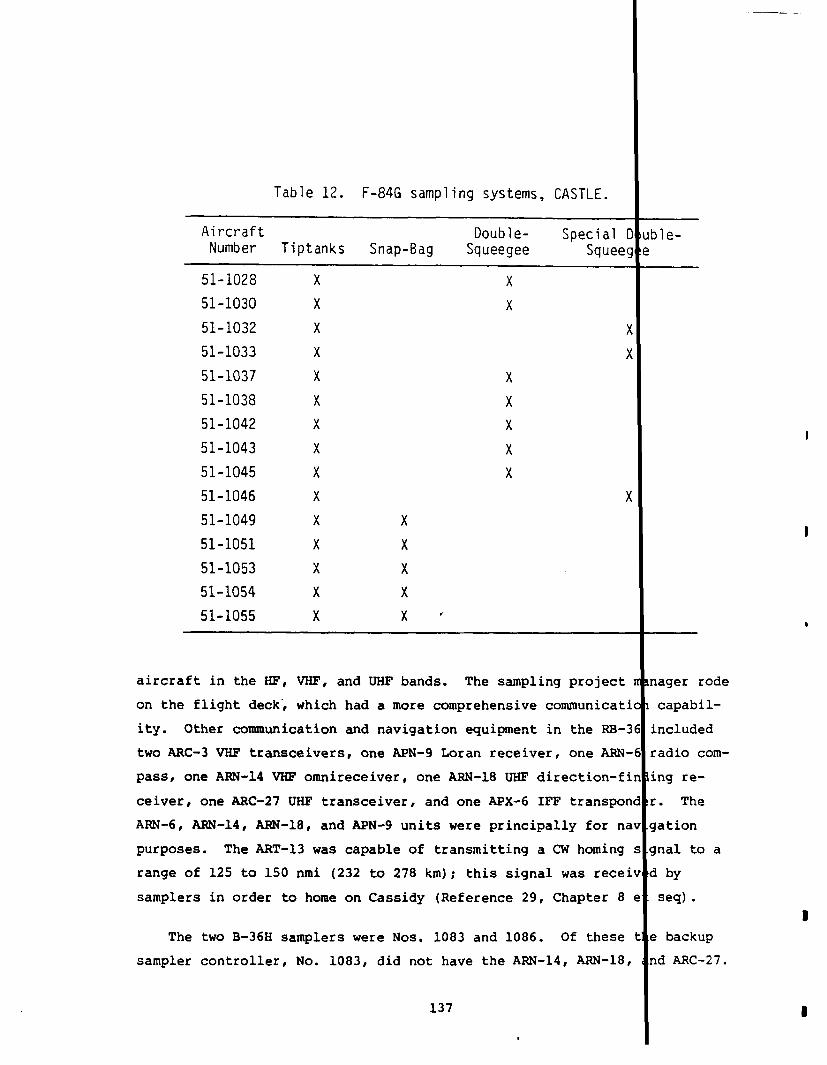
Table 12. F-84G sampling systems, CASTLE.
Aircraft Double-
1Special D uble-
Number Tiptanks Snap-8ag Squeegee Squeeg e
51-1028
51-1030
51-1032
51-1033
51-1037
51-1038
51-1042
51-1043
51-1045
51-1046
51-1049
51-1051
51-1053
51-1054
51-1055
x
x
x
x
x
x
x
x
x
x
x
x
x
x
x
x
x
x
x
x
x
x
x
x
x“
aircraft in the HF, VHF, and UHF bands. The sampling project rmager rode
on the flight deck8 which had a more comprehensive communication1 capabil-
ity. Other communication and navigation equipment in the RB-36 included
two ARC-3 VHF transceivers, one APN-9 Loran receiver, one ARN-6 radio com-
pass, one ARN-14 VHF omnireceiver, one ARN-18 UHF direction-fin ing re-
ceiver, one ARC-27 UHF transceiver, and one APx-6 IFF transpond?r. The
ARN-6, ARN-14, ARN-18, and APN-9 units were principally for nav .gation
purposes. The ART-13 was capable of transmitting a CN homing s .gnalto a
range of 125 to 150 nmi (232 to 278 km); this signal was receiv !d by
samplers in order to home on Cassidy (Reference 29, Chapter 8 e“:seq).
The two B-36H samplers were Nos. 1083 and 1086. Of these t e backup
sampler controller, No. 1083, did not have the ARN-14, ARN-18,
I
nd ARC-27.
137
,

Based on the decontamination data given in Chapters 4 and 5, it appeal
that different wB-29s served as the heavy nuclide sampler on various !
and the shoe boxes were easily moved from one aircraft to another. T]
B-36H double-squeegee systems had six compressors pumping into six 90(
(14,743-cm3)containers at 3,000 lb/in2 (211 kg/cm2) (Reference 9, An.
nex D).
The F-84Gs were equipped with a sampling panel mounted atop the m;
instrument panel. The sampling panel is shown in Figure 24. This pal
contained radiac instruments and indicator lights for each sampling s~
The rate meter for the tiptank ion chamber (see Figure 24) had a thre{
stage scale: O-1 R/hr, 0-10
meter was transmitted by the
the sampling project manager
R/hr, or 0-100 R/hr. The reading from t]
pilot to the sampler control aircraft wh(
maintained control of each mission.
The top center of the sampling panel had an integrating dosimeter
tegron). The Integron meter recorded the total cockpit dose in the r~
of O-7.5 R with an
ence 29, Chapter 8
(JA5pER)III-71/PDPATE ~4ETER FORCOCKPIT Ir{TE!JSITY
\
error of t20 percent during sampling missions (Reft
et seq). The IM-71/PD (Jasp@r) rate meter measuret
/ \f’ \ WINGTIP TANK SAMPLING SYSTEI
CO!JTROLAND INDICATORSINTEGRON
@~@ U@:
T’
—. ——
GAS SAMPLESYSTEM INDICATORS \ \
DOSIMETER RATE METER TO
SNAP SAMPLER
rCONTROL SWITCH—
CONTROL STICK
Figure 24. F-84G sampling pane”
138
—
WING TANK
, CASTLE.
.s
3
m.
,-
\
II
I
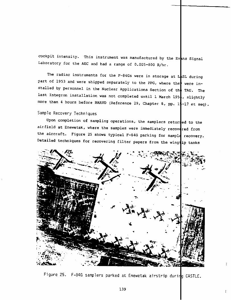
cockpit intensity. This instrument was manufactured by th
Laboratory for the AEC and had a range of 0.005-800 R/hr.
The radiac instruments for the F-84Gs were in storage *
part of 1953 and were shipped separately to the PPG, where
stalled by personnel in the Nuclear Applications Section 01
last Integron installation was not completed until 1 March
more than 4 hours before BRAVO (Reference 29, Chapter 8, p~
Sample Recovery Techniques
Upon completion of sampling operations, the samplers r~
airfield at Enewetak, where the samples were immediately re
the aircraft. Figure 25 shows typical F-84G parking for se
Detailed techniques for recovering filter papers from the u
Figure 25. F-84G samplers parked at Enewetak airstrip d
139
ns Signal
3L during
were in-
TAU. The
, slightly
-17 et seq)
?d to the
:ed from
recovery.
,p tanks
. .
.*
-. -
CASTLE.
.

were published by LASL and forwarded to the AFSWC just
(Reference29, pp. 220-225). Figure 26 is a schematic
setup for sample recovery.
before REDWING
illustration of t]
A Filter Recovery Subsection in the Nuclear Applications Section of
the TAU was manned by one officer and three airmen. These personnel wer[responsible for removing all gaseous and filter paper samples (Refer-
ence 29, Chapter 8).
,
0NINGTIP TANK GUN DECKPARTICLE SAMPLER GAs SAMPLER
t25-50feet(8-15meters)
SHIELDED
/
SHIELDED BOXPERSON 10, / 9/
TOW ,
VEHICLEI
/ TRAILER 1 - \ TRAILER 2
CAVE
oPERSON 3
TOOLS
Figure 26. Sample recovery schematic illustration, CASTLE.
140

Three people were directly engaged in particle sample rem<
fourth person served as an overall supervisor to ensure complj
sample removal procedures. A minimum distance of 25 feet (8 n
used as a criterion for separation of sample removal equipment
hot sample pod, as well as for personnel while not removing sa
son No. 1 advanced to the pod, cut the filter-retainingwire (
then returned to his initial position, still holding long-hant
Person No. 2 advanced with a 9-foot (3-meter)removal pole, se
sample (Figure 28), and deposited it in the shielded “cave~n c
(Figure 29). Person No. 1 stood by to help No. 2 by using the
tongs if the sample should fall to the ground. After the samF
posited in the cave, he returned the tongs to the tool trailer
a hook tool. He then joined No. 2 and opened the sample holde
to insert a rolling tool over the filter paper (Figure 30). A
rolled the filter paper (Figure 31), No. 1 and No. 2 stood “we
the cave, aircraft, and other radiation sources.” Person No.
i;..-
!.
--.–-
ils. A
Ice with
:ers) was
From the
>les. Per-
:gure 27),
:d tongs.
lred the
enclosure
.ong-handled
!was de-
md secured
for No. 3
No. 3’
clear of
put the
Figure 27. Cutting filter paper retaining wire in left tank
141
CASTLE.

---..,.-
~----- .“.. ..,.. .~ .....
Figure 28. Removal of filter paper from left tank, CASTLE.
-Bllii7.,,30
I!!.
l—“k La.
---
,.. . .-‘,’.,..&-i. ..- ~
Figure 29. Deposition of fi ter paper in shielded cave, CASTLE.
142

Figure 30. Preparing to roll filter paper, CASTLE
..- _ _)_y__
Figure 31. Filter paper being rolled, CASTLE.
143
.,/
I
I
rolled paper.in a “pig,” a shielded container for sample transport I
32), and returned his tool. Person No. 1 measured the radiation thr
the pig using a long-handled tool and this information was recorded.
son No. 1 returned the tool, then both No. 1 and No. 2 lifted the pi
whose lid closed automatically, from the cave with a carrying pole (
33), carried it to a third trailer 25 feet (8 meters) away, and depc
it in a shielded box. This operation was repeated on the second san
pod? then the next aircraft, until all filters were removed.
‘igure
ugh
Per-
?
‘igure
ited
Ile
Since double-squeegee samples were already bottled and the syste used
I
quick-disconnect couplings, recovery time was generally less than 2 inutes
after opening the gun-deck hatch (Reference 29, Chapter 8). Snap-ha sam-
ples were recovered by pumping the sample bag contents through the s pling
probe as illustrated in Figure 34.
Some of the filter paper samples were loaded aboard R-6D aircraf
departure to the continental United States at about H+6 (Flyaway 1).
filter paper samples and gas samples were ferried by TG 7.4 light ai
to the TG 7.1 laboratory on Parry Island for immediate analysis and/.cessing. Additional filter paper samples left the PPG at about H+1O
Flyaway 2. Flyaway 3 departure was between H+24 and H+36 and normal
ried only gas samples. Flyaway 4 departed between D+4 and D+5. U.S
Force involvement with samples in the continental United States was
the 1009th Special Weapons Squadron team at McClellan APB, Californi
contractor laboratories in Chicago and Boston (Reference 22, Annex D
Personnel Decontamination
TU 7 of TG 7.1 (7.1.7) organized decontamination operations to p
personnel against the effects of radiological contamination by reduc
the amounts of radioactive material carried into nonradioactive area
Checkpoints throughwhichall entries and exits were controlled enab
Personnel, protective gear, and equipment to be directed to one of t
decontaminationcenters if required.
144
for
Other
!raft
pro-
Iboard
Pcar-
Air
Irough
and
ect

!. .
THIS PAGE
WAS
INTENTIONALLY
LEFT BLANK
IN
ORIGINAL

//
J
/’ ,’
Figure 32. Filter being placed in a “pig,” a shielded C(for sample transport, CASTLE.
Figure 33. Lifting pig containing filter paper, CAST
145
----- --1
“r
tainer
I
1</

Figure 34. Removal of gas sample from “snap-bag” throughsampling probe, CASTLE.
146
Personnel decontamination stations were established at the
Center, aboard the Bairoko and the Curtiss, and aboard the bar
the Ainsworth. Equipment decontamination areas were made avai
and at the Kwajalein airstrip (the Kwajalein decontamination w
by the Naval Air Station).
These stations included a clean-clothing change room, a co
clothing change area, a shower area, and a monitoring point.
Radsafe Center the clean-clothing change room, showers, and mo
checkpoint were all located within the same building, whereas
nated clothing change area was located in a squad tent adjacen
shower area. All persons who were found to be contaminated in
the background radiation readings were required to shower with
residual contamination had been removed. Figure 35 shows the
procedure aboard the Curtiss, and Figure 36 shows initial deco
of personnel at Parry. The Bairoko decontamination station co
salt-water showers and contaminated-clothingstorage container
catwalk adjacent to the flight deck, with the change room cons
cabin just off the catwalk. The Curti;s decontamination stati
aft shower facilities for a change and shower area. The radsa
alongside the Ainsworth, which handled the greatest number of
was equipped with a control tent~ clean-clothing change tent~
issue area, and outside salt-water showers. All persons retur
Ainsworth were monitored before being permitted to board the s
ensured that all contamination was removed aboard the barge.
Parry Radsafe
e alongside
able at Parry
s provided
aminated-
the Parry
toring
contami-
to the
xcess of
oap until
,nitoring
amination
isted of
on the
,tingof a
Lused the
barge
:rsonnel,
,othing
,ngto the
P* This
Personnel decontamination progressed satisfactorily, altho h there were
I
reportedly objections to slightly contaminated lagoon water be ng used for
salt-water showers (Reference17, p. 58). Other than aboard t Ainsworth,
the arrangement of change room and shower facilities aboard sh did not
completely prevent the spread of contamination. Contaminated dividuals,
in many cases, had to walk through the ships to reach the cent inated-
clothing change room or showers. The barge facilities adjacen to the
147 I

Figure 35. Personnel monitoring after removal of contaminateclothing (also note removable covering on deck an[ladder in background), CASTLE.
148
II
I
I
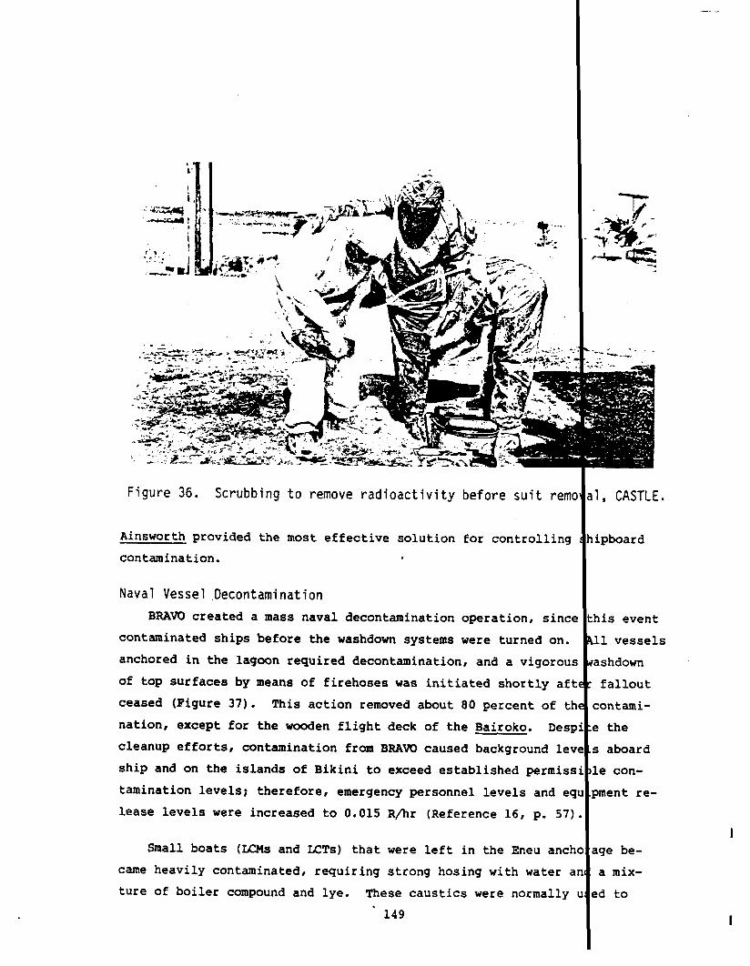
.
i
.-.
Figure 36. Scrubbing
Ainsworth provided the
contamination.
to remove radioactivity before suit rem
most effective solution for controlling
Naval Vessel Decontamination
BRAVO created a mass naval
,
decontamination operation, sine
contaminated ships before the washdown systems were turned on.
anchored in the lagoon required decontamination, and a vigorou
of top surfaces by means of firehoses was initiated shortly af
ceased (Figure 37). This action removed about 80 percent of t
nation, except for the wooden flight deck of the Bairoko. Des
cleanup efforts, contamination from BRAVO caused background le
ship and on the islands of Bikini to exceed established permis
lamination levels; therefore, emergency personnel levels and e~
lease levels were increased to 0.015 R/hr (Reference16, p. 57
Small boats (LCMS and KTs) that were left in the Eneu ancl
came heavily contaminated, requiring strong hosing with water ,
ture of boiler compound and lye. These caustics were normally
‘ 149
T-<“%
-.%- ‘.:=”:+“*
.
.. .. .--___::
1, CASTLE.
ipboard
Iis event
D vessels
~shdown
fallout
:ontami-
! the
; aboard
.econ-
>mentre-
Igebe-
a
!d
mix-
to

,- .+.* ,_--~e - .-’ -
. .-----
Figure 37. Shipboard decontamination using high-pressure seawatand scrub brushes, CASTLE.
remove paint and iron rust ~nd were an effective supplement to strong
hosing. Fresh-water flushing and repainting, however, were required
following decontamination. In dry dock, steam was utilized to remove
grease and oil from bearing surfaces. As expected, the most difficul
items to decontaminate were canvas covers, tarpaulins, ropes, and fab
bumpers. In most cases, these items were simply moved to a storage a
on Parry and the radioactivity allowed to decay (Figure 38). Versene
scrubbing was attempted on the large canvas bathtub on the flight dec
the Bairoko, but was abandoned when it was found that the treatment d
solved the radioactive particles and caused a spread of contamination
an increase in contaminated areas.
Equ~pment Decontamination
Other than for marine equipment, little decontamination was atteml
at Bikini. Construction and technical equipment was washed and isola
150

;
,.-.:. ...
{“._— -- -
~— --—-”- _- T-L
/ W&iii-””;;’G
Figure 38.
at the time of shipment
sel were decontaminated.
main base for equipment
Parry contaminated storage area, CAST
to Enewetak. The equipment and its t
at Enewetak after the equipment was u
decontamination was established at th
contaminated storage area (see Figure 38). All Bikini equipmen
cessive readings was washed with a high-powered spray from a fi
Navy tug and transferred to Enewetak for final decontamination.
landing checkpoint on Parry, vehicular or other mobile equipmen
charged was monitored. If below the permissible contamination
equipment was moved to its destination; if not, the equipment w
the decontamination area for storage or decontamination.
At Enewetak, the decontamination area was soon filled with
ment of items that varied from personal luggage to heavy cranes
time more than l,ZOO items were awaiting decontamination. A st
practice of flushing, scrubbing, steaming, and storing was foil
most of the metal items. Wooden, plastic, rubber, and fabric m
were stored until decay reached the acceptable release level of
151
.— —+
. ..—
ort ves-
ed. The
ry Island
ith ex-
ruck or
,ta boat
eing dis-
iit, the
moved to
assort-
At one -
lard
!d for
!rials
010 R/hr.

Daily rain showers, typical of the Marshalls in the spring, provided ddi-
tional decontamination for articles stored outdoors.
The release of vehicles and equipment contaminated at 0.010 R/hr {r
less still presented a problem when these items were removed from sto:age
for use at Enewetak or shipped to the United States. Even these low (,mis-
sion levels jeopardized low-level decay measurements in sensitive arei s;
therefore, low-level contaminated equipment was excluded from them. F~rther
decontamination of these items would have been difficult and impracti(al.
Scientific experiments were usually decontaminated by brushing or a
water spray before transport to Parry.
I
In some cases, however, the e tire
decontamination procedure (e.g., TG 7.4 aircraft) was conducted at Pa ry
(Figure 39).
Figure 40 shows a tent for changing contaminated clothing at Parr .
Contaminated clothing was removed at this and similar checkpoints to&oid
the spread of contamination into uncontaminated areas.
[
TG 7.2 used t ee
mobile laundry units to de~ontaminate clothing for TG 7.4. The laund
plant on Enewetak Island employed 41 men on the day shift and 17 men
the evening shift. The contaminated wastewater drained directly into he
lagoon.
1Radiation of personnel and material was measured with side-window ype
Geiger counters. The instruments, which contained counter tubes with all
thicknesses of about 30 mg/cm2, were used with the beta shield open.
I
en
possible, the surface of the probe was held from 1 to 6 inches (2.5 to 15
cm) from the surface under observation.
IAircraft Decontamination
Table 13 lists all aircraft involved in CASTLE. In addition to th?TG
7.4 cloud tracking and sampler aircraft, P2v-6 aircraft required decon :ami-
nation, as did the amphibious aircraft used to evacuate weather statio1 per-
sonnel from Rongerik and natives from Rongelap. The RAF Canberra sap .er
152 I

- \
. 1t*I\
-. ...-_ ---. .. .. ... . . .
>*-. . . . .,-------- ~..al __
----- r>...... .::$
k. _DIWGER -
‘ADJArION
--- ..“--v-’;;i$i&$8&’8:.
-.,
“-- #B._.r
.-
“:Q%-&-’/“’-’” ‘w ‘&m?J( -../>.- ,/,s...
Figure 39. Decontamination equipment on Parry, CASTLE
153I

Figure 40. Tent for changing contaminated clothing at Parry, CASTLE
I
aircraft and four unmanned F4U aircraft used in Project 6.4 (Proof Test g
of Atomic Weapons Ship Countermeasures) also required decontamination.,
rTASK GROUP 7.4 AIRCRAFT.
1
Decontamination of sampler aircraft used “
CASTLE was required after each test shot. Other aircraft occasionally -
quired decontamination. Within TG 7.4, aircraft decontamination was a
mission for the Aircraft Decontamination Section of the TAU which, duri
the buildup phase, had one officer and three airmen, two of whom had co
siderable experience from th~ee previous operations (Reference 30).
Procedures for decontamination operations underwent constant revisi
from event to event as experience increased.
1
TG 7.4 issued a new Annex ,
dated 16 March 1954, which superseded the 26 February 1954 annex. The w
annex required all units of TG 7.4 to furnish personnel for decontaminateon
operations using revised procedures (Reference31, Operation Order 2-54)
From the experience gained following shot BRAVO in decon-lamination of assigned aircraft, it was apparent that thetechniques and utilization of personnel must be revised.
l!34Ii
JJ,_

Table 13. CASTLE aircraft.
Aircraft Type/Serial No. Task Force
(No. of Aircraft) Affiliation Call Sign CASTLE Base Function Home Organization
(u)B-29/335(W)B-29/11319(W)E1-29/2195(w)B-29/2202(W)B-29/7264(W)B-29/7271(W)B-29/7335(W)B-29/7343(U)B-29/7740
(R)B-36/1386(F)8-36/1083
(F)6-36/10B6
B-360/49-2653
G B-47/50-037w
B-50(3)
c-47(4)
c-54(3)
c-54(1)
F-B4G/028F-B4G/030F-84G/032F-84G/033F-84G/037F-B4G/038F-84G/042F-84GI043F-84G/045F-84G/046F-84G/049F-84G/051F-84G/053F-84G/054
7.4 TSU
7.4 TAU
7.4 TAU
7.4 TAU
7.4 TAU
7.4 TSUU
7.4 TSU
JTF 7
7.4 TAU
Wilson
Cassidy
Floyd
Elaine-1
Elaine-2
Hardtime
Reflector
Pewter
Lord Calvert
Tiger
Enewetak
Enewetak
Enewetak
Enewetak
Guam
Enewetak
Enewetak
Enewetak
Enewetak
Weather recon, cloud track, sampler 77111Strategic Rucun Sq,Ellsworth AFB
57th Strategic Recon Sq,March AFB
57th Strategic Weather Recon Sq,Hickdm AFB
.
(2) RB-36 samplercontroller(and 7th Bomb Wing, 9th and 3bLhphoto plane for Projects 3.2 and 9.1) Bomb Sq, Carswell AFB
(1) Featherweight 8-36 cloud sampler
Project 6.2a effects experiment WAOC and llthBomb Wing,Carswell AFB
Project 6.2b effects experiment WADC
Project 6.1 IBDA experiment 97th Bomb Wing, Biggs AFB
Enewetak-Bikini airlift 4931st Test Support Sq, Enewetak
Project 9.1 and documentary photo 4931st Test Support Sq, Enewetak
Use of CJTF 7 4931st Test Support Sq, Enewetak
Cloud sampler 4926th Test Sq, Kirtland AFB
.—— — —.—— .-—_ —-. —..__ —-_ __(centInued)
I
i

Table 13. CASTLE aircraft (continued).
Aircraft Type/Serial No. Task Force
(No. of Aircraft) Affiliation Call Sign CASTLE Base Funct ion Home Organization
F4U5N(3)
F4U5N(3)
F4U(4)
H-13(3)H-19(7)
HRS-2(12)
L-13(1O)
P2V-5
P2V-6/12622P2V-6/12632P2V-6/12634
E P2V-6/12635m P2V-6/12637
P2V-6/12638P2v-6/12639P2V-6/12640P2V-6/12641P2V-6/12642P2V-6/12643P2V-6/12644
P4Y2/59763
PBM5Aa(2)
SA-16a(3)
SA-16a(2)
UF-la(l)
--------(1)
UK Canberra(2)
7.3.2.1
7.3.2.2
7.3
7.4 TSUU
7.3.2
7.4 TSUU
7.3.3
7.3.3
7.3.3
7.4 TSUU
7.4 TSU
7.4 TSUU
RAF
Bikini
Enewetak
None Enewetak
Peanut Enewetak
Dago Bairoko— -Mosquito Enewetak
NAS Kwajalein
NAS Kwajalein
Enewetak
Lena Enewetak
Stable Enewetak
Enewetak
NAS Kwajalein
Viking
Eager Beaver NAS Kwajalein
Fighter element VC-3(on Enewetak post-8RAVO)
Fighter element VC-3
Project 6.4 washdown experiments NAS, Alameda
Intra-atoll airlift - Enewetak 4931st Test Support Sq, Enewetak
Intra-atoll airlift - Bikini HMR-362
Intra-atoll airlift 4931st Test Support Sq, Enewetak
Controller for YAG exp (Proj 6.4)
Transient Ship Search, VP-29, Whidby Island NASNYKOPO flights
Project 1.4 telemetry receiver NAS, Patuxent River
Inter-atoll airlift
Search and rescue (SAR) 78th ARS Sq
Enewetak-Bik ini airlift post-BRAVO
Weather island resupply NAS, Kwajalein
VIP aircraft
Cloud sampler United Kingdom
Note:
amphibious aircraft.

—-
.
Entirely too much time was used to decontaminate aircand excessive exposures were being accumulated by airmaintenance personnel who participated in decontamina
Maintenance crews in the 4930th Test Support Group (Test
did not assist with aircraft decontamination after the BRAVO
subsequent shots, although personnel from the TSUU were still
nonmaintenance personnel were used. These men were assigned
nation teams of 15 men each that operated on 6-hour shifts. ‘
was primarily responsible for aircraft operations~ was most i:
this.
Holmes & Narver constructed the Enewetak decontamination ]
the CASTLE aircraft. This pad drained toward a 24-inch (61-cI
catch basin that drained into the lagoon through an 8-inch (21
The general procedure for decontamination operations was:
1.
2.
3.
4.
5.
6.
On D-day sampler F-84G, wB-29, and FB-36 aircraftwere parked in the designated hot decay area.
All other aircraft were checked on landing for evdence of radiological contamination. If an aircriwas contaminated ahve 0.025 R/hr, it was isolatetand posted.
Sampler FB-36 aircraft were parked on the decontanation pad and checked for radiation intensities.
Unless urgency was a factor, no decontamination Wi
undertaken until D+l. Sampler aircraft were give]decontamination priority over those accidentallycontaminated.
Decontaminated aircraft were released to maintenalpersonnel before release to flying crews.
Before aircraft were cleared for flying again, th(radiation intensity at crew positions had to be 1(than 0.010 R/hr.
Following sequential operations for decontaminating variol
radiation intensity measurements sometimes increased rather t]
Three primary causes were proposed (Reference30):
1. Wash watertaminants)
(containinga concentrated amount of ccollected in engine cowlings
157
—.
tft,n.
port Unit)
t* For
volved,
decontami-
7.4, which
lved in
used for
central
m) pipe.
aircraft,
decreased.

2. Instruments were faulty
3. ‘The recorded measurement was the highest reading ob-tained on measuring several different points on theaircraft.
Table 14 summarizes the individual TG 7.4 aircraft and identit!
tail number for which detailed decontamination data are available
TAU source document (Reference 30).
Table 15 lists sampler aircraft totals from a different source
ence 29). There are some discrepancies between References 29 and 1
others exist as well. For example, History of Task Group 7.4 (Ref~
ence 15) indicates that 14 F-84G sampler aircraft participated in 1
yet the 4926th document (Reference 30) details decontamination dat<
only 10 for this shot. The fact that no decontamination data are i
able for a specific aircraft, however, does not necessarily imply
aircraft was not airborne or not contaminated.
An important factor that must be borne in mind concerning the rad
tion intensity readings or data is that the recorded data for the surl
of any one aircraft at any one time represent the highest reading obtz
from measuring several points on the aircraft. Not known are the numl
of points surveyed, the location of these points, the average decay rz
and the effect of activation products on the gross fission product. E
spite these factors and the lack of an accurately known decay rate laht-1.2
decay rate is used in Chapters 4 and 5 to make some estimates of
aircraft initial contamination levels.
Tables 24, 35, 41, 48, 52, and 57 contain detailed aircraft decent
ination data for each shot. Each table lists the aircraft type and it
identification number with radiological survey and decontamination inf
mation. Date and time for each survey were not always recorded. Ques
marks appear in the tables where this occurred. Following the last sc
the aircraft were released to maintenance operations. The decontamina
procedures used were (Reference 30):
158
he
!fer-
and
v,
k
1-
: the
a-
r
led
!r
.
a
u-
.-
,on
reyf
;on

Table 14. Cloud-sampler aircraft decontaminated during
Type Tail 1 Mar 27 Mar 7 Apr 26 Apr 5 MayA/C No. BRAVO ROMEO KOON UNION YANKEE
B-36
B-36
B-36
B-29
B-29
B-29
B-29
B-29
B-29
B-29
B-29
B-29
F-84
F-84
F-84
F-84
F-84
F-84
F-84
F-84
F-84
F-84
F-84
F-84
F-84
F-84
F-84
1083
1086
1386
7335
2195
7740
1819
7269
7271
7343
2202
335
028
030
032
033
037
038
042
043
045
046
049
051
053
054
055
x
x
x
x
x
x
x
x
x
x
x
x
x
x
x
x
x
x
x
x
x
x
x
x
x
x
x
x
x
x
x
x
x
,x
x
x
x
x
x
x
x
x
x
x
x
x
x
x
x
x
x
x
x
x
x
x
x
x
x
x
x
x
x
x
x
x
Totals 13 17 11 11 14
Source: Reference 30.
159
TLE.
14 MayNECTAR
x
x
x
x
x
x
x
x
x
x
x
x
x I
13
I

Table 15. Number of aircraft that obtained usable cloud samples, CA
Aircraft Type BRAVO ROMEO KOON UNION YANKEE NEC
B-36 2 2 2 1 1 2
B-29 1 1 1 1 1 1
F-84 12 12 14 ~ ~ 7. — — —
TOTAL 15 15 17 9 9 10
Source: Reference 29.
1.
2.
3.
4.
Reportedly,
Aircraft were parked in an isolated area and alloweda cooling off (decay) period of 20 hours.
Stands were positioned and cowling removed. A 1:5mixture of gunk-kerosene was applied over the air-craft exterior surface and engines. This was washedoff using a warm water and detergent mixture followedby a plain warm water wash. After 30 minutes for thesurfaces to drain, radiation measurements were made.
Radiation measurements were made using AN/PDR-39instruments.
The procedure in (1) to (3) above was repeated.
after two such washings the contamination level could not
noticeably reduced further.
more than two washings.
For the first two shots,
Nevertheless, many aircraft were subject
BRA~ and ROMEO, the F-84G samplers were
washed with a citric acid solution. This type of decontamination was
gested by a LASL scientist as a means of collecting potentially valua
radioanalysis data on certain heavy radionuclidest but the procedure
scrapped after ROMEO. Decontamination of the F-84GS required up to 3
gallons (114 liters) of gunk, 150 gallons (568 liters) of kerosene, 1
gallons (379 liters) of soapy water, and 300 gallons (1,140 liters) o
rinse water for each aircraft, depending upon the degree of contamina
Larger aircraft required commensurately more materials. Table 16 sum
izes the decontamination materials used.
160
t
I

—
Table 16. CASTLE TG 7.4 aircraft decontamination mater i used.
BRAVO ROMEO KOON UNION YANKEE ! 4R Total
Aircraftdecontaminated
Kerosene(gallons)a
Gunk (gallons)a
Detergent(pounds)b
Rubber Gloves(pair)
. Aprons (each)
RespiratorFilters (each)
Water(gallons)a
19 17 15 11 14 12 88
2,320 2,375
594 475
7,250 3,490
1,450 820
3,214
623
)0 21,649
35 4,547
14 14.5 14.5 14 14 14 85
12 8
3 4
5 10
3 3
10
5
8 53
4 22
280 120 70 70 70 70 680
11,900 15,852 8,100 8,840 )0 76,19216,500 1
Notes:
aOne gallon equals 3.79 liters.
bOne pound equals 0.46 kg. v
Source: Reference 30.
Figures 41 through 43 show decontamination operations for
the overhead cable and safety harnesses for personnel working
Also, the need for supporting personnel, equipment, and vehic
Figure 44 shows a scrubbing operation on the wing of an F-84C
I
3-36. Note
the wings.
is evident.
rcraft.
OTHER AIRCRAFT. Contaminated aircraft were also a problem
roko and at the Kwajalein Naval Air Station. On the Bairoko tk
was the landing gear of HMR-362 helicopters returning from deli
work parties to contaminated sites. Helicopters returning fron
sions were landed in a canvas bathtub to hose off their landing
(Reference 32).
n the Bai-
problem
cries of
such mis-
gear
VP-29 aircraft and the two RAF Canberra cloud samplers base
lein Naval Air Station during CASTLE received decontamination.
at Kwaja-
The NAS
161 I

Figure 41. B-36 decontamination, CASTLE.
162

——
Figure 42. B-36 decontamination, CASTLE.
I.. . . . . . . . ..
r,
,
/.. .-——————
, /; ./”
Figure 43. B-36 decontamination, CASTLE.
163
I
I

Figure 44. F-84G
report of operations during CASTLE
ing the evacuation of Rongerik and
decontamination, CASTLE.
states that station aircraft used
Rongelap also required this treat
Levels of contamination are not given, although a summary of the rad
ical condition of VP-29 aircraft at the end of the series was publis
and is shown in Table 17. The VP-29 P2v-6 searching for transient s
ping during BRAVO was so heavily contaminated that it was forced to
to its base, but the levels are not in the accounts (Reference 33).
The RAF Canberras based at Kwajalein sampled all CASTLE events e
UNION. Selected contamination readings are available for these airc
and show for BRAvU D+3 a high reading of 0.180 R/hr around the engin
which dropped to 0.120 R/hr after one washing with gunk and soap and
After ROMEO, a high reading of 0.900 R/hr, again around the engines,
recorded after sample removal (Reference 34).
Decontamination at Kwajalein was done at the pad used by TG 132.
Operation IVY. VP-29 and NAS personnel decontaminated their own air
and supervised the w personnel working on the RAF aircraft.
164
v
?iil2.*
.
-:
r-
t.
3g-
urn
pt
t
ter.
s
n
Et
I
1
i?o

-;-.
Table 17. Radiological contamination of Patrol Squadron 29 (VP-29)aircraft as of 18 May 1954, CASTLE.
Highest Highest Average
i
Av ageAircraft Gamna Ganma plus Beta Garoma Beta p us GammaNumber (R/hr) (R/hr) (R/hr) (R r)
126544
126534
126537
126539
126541
126543
126532
126535
126538
126540
126542
126522
0.0014
0.0015
0.0004
0
0.0015
0.0006
0.0047
0.0003
0.0009
0.0002
0.0002
0.00035
0.0042
0.003
0.0015
0.001
0.0019
0.0013
0.0049
0.001
0.002
0.0012
0.0015
0.003
0.0008
0.0007
0.0002
0
0.0002
0.0004
0.0025
0.0016
0.0004
0.00015
0.00015
0.00015
0.(015
0.(014
O.(006
0.(006
0.(007
0.(006
0.(013
0.(004
0.(007
0.(005
0.(004
0.(015
Source: Referenqe 33. I
Apparently, in the decontamination process fallout products were spread
Iaround the airfield and recontaminated other aircraft to low le els. The
B-36 used in the effects experiments did not come into contact ith shot
debris clouds during its flights, but when it returned to the U ited
States, its undercarriage was found to be contaminated with fal out prod-
ucts in oil and paint, which required special cleaning to remov . The
level of this contamination was “1O mr [per hr]” (Reference 35, p. 133).
165

CHAPTER 3
DOD EXPERIMENTAL PARTICIPATION
The CASTLE experimental program primarily focused on development’
usable thermonuclear weapons, with secondary interest on their effet
The DOD participated both in weapon development and effects experim(
but concentrated on the latter. Within JTF 7, execution of the exp~
mental program was the function of the scientific task group (~ 1)
WEAPON DEVELOPMENT
TG 1 was subdivided into 12 task units that conducted
Both of the AEC weapon design laboratories had task units
that conducted their experiments; an additional task unit
ducted DOD weapon effects experiments. Support for these
provided by nine additional task units.
the progr
(TU 1 and
(Tu 13) c
experimen
The 12 task units are,described in Chapter 1. The names of the
units and the number of persons who participated in each are shown
Table 18.
The DOD had several administrative and special reporting units
military personnel on active duty who participated in weapon design
periments at Los A3.amosand Livermore. Some of these units were th
8451st Area Administrative Unit, Washington, D.C.
8452nd Area Administrative Unit, Sandia Base, New Mexico
Naval Administrative Unit, Sandia Base, New Mexico
1090th USAF Special Reporting Group, Sandia Base, New Mexic
l146th USAF Special Activities Squadron, Fort Myer, Virgini
The Naval Research Laboratory (NRL) provided personnel and cond
experiments for LOS Alamos in the Los Alamos Scientific Laboratory
weapon development program (References 36 through 39). The Air For
ported the weapon development program through cloud-sampling operat
166
of
s.
ts
i-
●
u 12)
was
ask
r
x-
!ted
XL)
sup-
ms to

Table 18. Approximate unit strengths of Task Group 7.1Pacific Proving Ground, CASTLE.a
UniformedElement DOD Civilian’
Connander
Scientific DeputyAdvisory GroupClassificationDeputy AdministrationDeputy for UCRL (in TU 12)J-1J-3J-4J-6
Task Units
1234678
1;
::15
Totals
LASL ProgramsProductionSpecial Materials & FacilitiesLASL AssemblyFiring PartyRadiological SafetyTechnical <Photography
Documentary Photography
UCRL Programs
DOD Programs
UCRL Assembly (in TU 12)Timing and Firing
Total with exposure recordsc
2
1
3019263
26
44
2:
13:
4
1
11431
119456075110
264258
66
325
311
974
933
Sources and Notes:
aReference 8, April Installment, p. 15.
bIncludes both DOD and AEC civil servants and contractor pelThe data do not permit disaggregation, although some infer
drawn from the duties of the task units. (See Chapter 1, ~
“Task Group 7.1 [Scientific]”.)
consolidated List of CASTLE Radiolo~ical Exposures TG 7.1,
Reference 13.
167
t the
Total
3
11432
33203111
1454560751
542051
272388
70
1,299
1,244
onnel .ces can beerview,
u 7, I
I

provide essential data to weapon designers. This task entailed a la
commitment of Air Force equipment and personnel in an important and
ently high-radiation-exposureactivity (Reference 29). There was, f
the contribution of all the services to the weapon design experiment
the joint task force as a whole through providing the support servic
cessary to conduct these experiments.
EFFECTS EXPERIMENTS
DOD effects experiments were conducted by the Armed Forces Spec
Weapons Project (AFSWP),a Joint Defense agency. -~ solicited se
requirements for weapon effects information, assisted DOD laboratory
the design of experiments, and coordinated planning and execution wi
AEC during the planning of the weapon design experiments (Reference
During test preparations, special construction requirements for the
fects experiments were coordinated with the AEC base-support contrac
(TG 7.5). The following guidelines were established as preselectior
teria for proposed experiments (Reference 40, p. 15):
1.
2.
3.
Each project must be justified on the basis of a mil-itary requirement
Each project must be such that its objectives couldnot be attained except by a full-scale test, and notat NTS; furthermore, its objectives must be attain-able at the PPG without unreasonable supportrequirements
Each project had to conform to the shot schedule(yields,-locations, burst heights) established forthe developmental program of the AH2.
The DOD effects program was organized as TU 13 and subdivided ir
programs for the execution of experiments with functionally similar
objectives.
Blast and Shock (Program 1)
The blast and shock program was designed to investigate blast w{
propagation through the air, ground, and water. A description of tl
168
~
3er-
311y ,
of
ne-
1
ice
in
the
.
r
ri-

.
experiments and projects within this program follows, limited
elusive of those aspects pertinent to radiological exposure.
are available, the actual exposures of TU 13 participants have
vialed;however, reports found seldom identify exposures in thi
Table 19 summarizes what can be derived from TU 13 reports on
of DOD experiment participants. The exposures reported in thi
suggestive of those of the particular projects rather than an
reporting.
Ibut in-
ere data
een pro-
detail.
e exposure
table are
act
Projects l.la, l.lb, and l.ld
I
-- Blast Pressures and Shock Phe omensMeasurements by Photography
Agencies: Naval Ordnance Laboratory (NOL)Sandia Corporation (SC)
IOperations: Documentation of peak shock overpressures, vi
wave effects, and motion of shock wave on water by smoke-~
direct-shock photography.
ble shock-
!ketand
Shots: All.I
Radiation Exposure Potential:
‘1
This project should have PO d a mini-
mum potential exposure for the project personnel, as film ta from
Edgerton, Germeshausen, & Grier, Inc. (EG&G) and the Air F ce Lookout
Mountain Laboratory (LML) were used. The only identifiable radiation
potential was from the placement of the rocket launchers f the smoke
rockets on Iroij and Enidrik for KOON and UNION, since thi could have
exposed project personnel to residual radiation from BRAVO.
Staffinq: Eight people were associated with this project,
4
even from
NOL (five civilians and two military), and one civilian fr SC.
Project Report: Reference 41.
Project l.lc -- Base Surge Measurements by Photography
IW!EY: Naval Ordnance Laboratory (NOL)
169

Table 19. DOD scientific personnel radiation exposures, CASTLE._.—— .— .
No.ofExposure Ranges (R)
——— Collective Mean.Persons No
Element Badged Reading O 0.001-0.5 0.5-1 1-1.5 1.5-2 2-2.5 2.5-3Over Over
3-4 4-5 5-1o 10-15 15 S.ga—.—
Exposure ExposureHigh (man-R) (R)
—.—Project l.ld,b,d
1.lC2
24
1
3
12
17.1
15
41
211
9
11.5
11.3
3
1
1
13
4.3
8
1
;
2
1
9
11.5
24.8
1
21
24
53
1
11 715.710.039 32
11
44 ;
1:
1
13 916.711.445.540.5
21
3.63.21.34.3
1.2a1.2b
H
5
4
9
12.9
16
1
:
1111
11
14.1
19.3
1
3
3
1
710.016
2
1
21
6
7.7
13.5
4
4
19 0Same Personnel as Project 1.2a
28 2 5Offsite3 1 1
1
11.4
8
1
22
5
6.4
37.5
1
5.14
2
7
10.05
15~31
1114.18.3
2
1.51.6
:::
2.517
70
;
2:1313673
7a
1A2
io57.1
3.4
5.1Program1 TotalPercentCollectiveExp (man-R)
8
11.4
2
8
11.4
137 1.95
3.76.3
1::/6.29.23.8
Project 2.1
:::2.5a2.5b2.6a2.6b2.7
2
1 273
11!o0
1 4.92.52.7a
Program 2 Total
Percent
Collective Exp (man-R)
1 3
3.9
0.8
1 15
1.3 19.2
12.5
11.91.3
214 2.74
1.65.73.0
Project 3.13.23.3
000
12
. —.Note:
aMaximum Permissible Exposure——— .— - . —.
(cent inued)–-

Table 19. DOD scientific personnel radiation exposures, CASTLE (continued).— _——— —
Exposure Ranges (R)No. of Collective MeanPersons No
ElementOver Over Exposure Exposure
Badged Reading O 0.001-0.5 0.5-1 1-1.5 1.5-2 2-2.5 2.5-3 3-4 4-5 5-1o 10-15 15 3.9a High (man-R) (R)—. — .——.
Project 3.43.5
Program 3 Total
Percent
Collective Exp (man-R)
Program 4 Total
Project 6.16.2a6.2b
::!6.6
Program 6 Total
PPercent
2Collective Exp (man-R)
Project 7.1
;::
Program 7 Total
Percent
Collective Exp (man-R)
Project 9.1
Other 000
TOTAL Al 1 Programs
Percent
Collective Exp (man-R)
o 0I o
14 0
0
0 063 :905 :5 0
109 54.6
1 0Off site
5 1
6 1
16.7
1 0
8 0
286 12
4.2
;
4
3.7
1
1
16.7
5
1.8
2
10.3
0.5
3
10
13
11.9
3.3
2
12
33.3
0.5
1
29
10.1
7.3
13
21.4
2.3
5
;
8
7.3
6
1
1
2
33.3
1.5
1
32
11.2
24
3 1 1 3
28.4 7.1 7.1 21.4
3.8. 1.8 2.8 10.5
6 96 4 111 2 1
6 97 6 12
5.5 8.3 6.4 5.5 11.07.5 15.815.8 16.542.0
2 2
32 30 22 19 39
11.2 10.5 7.7 6.6 13.6
40 52.544.5 52.3136.5
17.17.5
11 24
11 2410.1 22.049.5 180
3
27 349.4 11.9121.5255
17.1
1 36
33
1 3 39
0.9 2.8 35.8
125 234
3
2 3 62
0.7 1.121.725 234
1.05.7
29 2.07
0.1
1;.83.6
78
78
583 5.4
0.9
0.70.9
2 0.33
7.1
78
998 3.49
12.2 25.6 2.5 23.5
Note:
al%ximum Permissible Exposure———

Operations: Evaluation of photographic data to predict
fects from surface detonations. Photography from other
used.
Shots: All.
base-surge
projects w
Radiation Exposure Potential: Slight (data for the project were f
other units).
Staffing: Two civilians from NOL, attached to this project, recei
total exposures of 0.120 R and 3.165 R. The individual receivin9
3.165 R also participated in Projects l.la, l.lb, and l.ld, and pr
ably did not receive significant exposure as part of this project.
Project Report: Reference 42.
Project 1.2a -- Ground Level Pressures from Surface Bursts
-: Sandia Corporation (SC)
Operations: Instrumentation was installed on various islands of b
atolls for this project and Projects 1.3 and 1.7. Measurements fa
this project were obtained on blast pressure versus time at ground
levels with Wiancko gauges.
Shots: All.
Radiation Exposure Potential: Placement of instruments in areas c
taminated by prior shots and recovery of data would have posed a E
tential moderate exposure.
Staffing: ~ civilians from SC
they had total readings of 1.315
in Project 1.3.
Project Report: Reference 43.
were associated with this project
R and 1.195 R, but also ParticiP~
Project 1.2b -- Ground Surface Air Pressure versus Distance fromHigh-Yield Detonations
Agencies: Ballistic Research Laboratories (BRL)9301st Test Support Unit, Aberdeen Proving Ground
172
f-
m
d
:h
,-
d

1090th USAF Special Reporting Group1083rd USAP Special Reporting Squadron
Operations: A total of 71 self-recording instrument stati(
installed at islands and reefs of both atolls.
Shots: ml.
Radiation Exposure Potential: Moderate (gauge installation
pickup).
Staffinq: Nineteen men were associated with this project,
BRL; two from the 1090th, one from the 1083rd, and eleven :
9301st (six Air Force and five Army). Those from BRL were
the rest, military. The group’s exposures are presented i]
Project Report: Reference 44.
Project 1.3 -- Dynamic Pressure Measurements
w: Sandia Corporation (SC)
Operations: Instrumentationwas installed at various stat
measure the theoretical relationship between dynamic press!
overpressure to evaluate gauges.
Shots: All.
Radiation Exposure Potential: Moderate (data recovery and
placement in contaminated areas).
Staffing: Two civilians from SC received totals of 1.315 1
1.195 R; however, this should not be uniquely associated w
project as the same two men are also cited in the project
Project 1.2a.
Project Report: Reference 43.
Project 1.4 -- Underwater Pressure Measurements
Agencies: Office of Naval Research (ONR)NavalDavidNaval
Research Laboratory (NRL)Taylor Model Basin (DTMB)Ordnance Laboratory (NOL)
173
——-—
were
md
ve from
m the
vilians~
‘able19.
Isto
Iand
Iuge
,nd
I this
Drt for

Sandia Corporation (SC)1090th Air Force Reporting Group8451st Area Administrative UnitTask group units as noted
Operations: Measurements of water pressures were taken from floati
moored buoys. The installation of the mooring system and the servi
ing of the clocks and batteries in the instrumented buoys required
participation of the USS GypSX, the USS Mender, the USS Cocopaf and
the USS Tawakoni, as well as the support of a barge, several miscel
laneous small boats, and swimmers. The gauges were self-recording
except for some information telemetered to a PB4Y-2 aircraft (No.
59763) that was due south of the instrument array at a nominal dis-
tance of 40 statute miles (64.4 km) and an altitude of 10,000 feet
(3.05 km).
Shots: BRAVO, ROMEO, UNION, YANKEE (Bikini);NECTAR (Enewetak).I
Radiation Exposure Potential: High.
1
Recovery of the buoys through ut
the series and, after BRAVO, the laying of the moors for the Bikini
shots required ship operations in contaminated waters. AS the shot
1
were postponed by weather’,the buoys had to be hoisted and their c1 cks
and batteries serviced. The average time to lay the moor was 1* ho rs
and the recovery required 1 hour.I
The buoys themselves were radiologically contaminated.I
Inane-
treme case of recovery (a buoy from the UNION event that contained
{
film-type recorder and thus required early retrieval), the buoy’s e -
terior was reading 1.200 R/hr and the interior was reading 0.500 R r,
as was the seawater.
The project report states that between UNION and YANKEE the “am
bient radioactive level aboard [Cocopa] became higher than the perm s-
sible limit” and the work had to be completed by the Tawakoni. Thi
was a result of *radioactive silttm perhaps churned up in the forma
tion of the UNION crater, lodging in the seawater pipes. The same
document reports that protective clothing was worn in handling theI
contaminated buoys and that the support ships were rotated to equal ze
the expcsure.t
174
I
I

and
and
For NECTAR at Enewetak, Holmes & Narver (H&N) handled
buoy recovery. After recovery, the buoys were placed
taken to a decontamination area.
Staffing: Twenty-eight TG 7.1 personnel were definitely a
with this project, although an exposure record was not 10C
of them. Of the remaining 27, the distribution is as foil
vilian from ONR, 2 civilians from NRL, 4 civilians from D’I
tary from 1090th, 1 military from 8451st, 1 civilian from
from NOL (1 military and 12 civilians).
Project Report: Reference 45.
Project 1.5 -- Acoustic Pressure Signals in Water
Agencies: Office of Naval Research (ONR)Bureau of Ships (BuShips)
Operations: Observations were made at several Underwater
mission Experimental Facilities (USTEF) stations in the P?
Atlantic oceans to detect long-distance transmission of ur
sound. Sites were remote from the test area and there is
tion that project personnel visited the PPG.
Shots: ROMEO, UNION, YANKEE (Bikini);NECTAR (Enewetak).
Radiation Exposure Potential: None.
Project Report: Reference 46.
Project 1.6 -- Water Wave Measurements
Aqencies: Scripps Institution of Oceanography (S10)USS Sioux
Operations: Underwater gauges were used to record hydros!
sure vibrations in Bikini Lagoon. Divers placed some insi
and recovery was made by LCM~ buoy boat? and helicopter
indicators were established at Ailinginae Atoll to measurt
tion of the land.
Shots: All Bikini shots.
175
2 mooring
a barge
>ciated
?d for one
5: 1 ci-
, 5 mili-
, and 13
und Trans-
fic and
rwater
indica-
ic pres-
mentationf
undation
he inunda-
1
/$[

Radiation E’xposurePotential: High because of instrument placemer
and recovery in contaminated waters.
Staffing: Three civilians were associated with the project, all f
S10 or University of California. No exposure is listed for one ps
son; the others received 1.530 R and 0.035 R. Exposures are giver
Table 19. Exposures for the Sioux appear in Table 59.
Project Report: Reference 47.
Project 1.7 -- Ground-Motion Studies on Operations IVY and CASTLE
-: Sandia Corporation (SC)
Operations: Accelerometer stations were established at about
(4.5-meter)depths on Eneman and Lele to record ground motion
KOON.
Shots: KOON (Bikini).
Radiation Exposure Potential: Moderate.
Staffing: One person definitely associated with this project.
is-f
fron
was
civilian from SC, but no exposure record is available for him.
Project Report: Reference 48.
Project 1.8 --
Agencies:
Dynamic Pressure Investigation
Ballistic Research Laboratories (BRL)9301st Test Support Unit (Ordnance)Naval Administrative Unit (NAU)
Operations: Jeeps and self-recording gauges were installed on Aez
kojlol, Enidrik, and Boken (for KOON), and Runit (for NECTAR) to c
termine dynamic pressure as a damage parameter.
Shots: KOON (Bikini);NECTAR (Enewetak).
Radiation Exposure Potential: Moderate; resulting from data recok
and the inspection of the jeeps for damage and evidence of their II
ment. Six of the jeeps used in KOON
port to Enewetak for use at NECTAR.
176
were too contaminated to tral
m
n
t
.
:Y
re-
.
Staffinq: Seven were associated with this project, three from BRL
(two military, one civilian), three from the 9301st TSU (tkD military,
one civilian), and one military from NAU.
Project Report: Reference 49.
INuclear Radiation (Program 2)
This program had two major objectives: (1) documentation cf the ini-
tial neutron and gamma radiation from large-yield nuclear deter3tions, and
(2) documentation of fallout from large-yield surface detonatic1s. Fall-
out information from large-yield detonations was available only from the
MIKX detonation of Operation IVY (1952), and this was limited t2 data up-
wind and crosswind from the burst point. An ambitious program tiasinsti-
tuted for CASTLE to study the downwind deposition of weapon dekKis. This
planned effort and unplanned incidents following BRAVO resulted in much
information about fallout from the CASTLE shots.
Project 2.1 -- Gamma Radiation Dosimetry
I2W!SY: Signal Corps Engineering Laboratories (SCEL)
.Operations:
I
Films and chemical-dosimetry vials were insta ed in shel-
ters from 1 to 15 nmi (1.9 to 27.8 km) from ground zero on “slands and
reefs of both atolls (18 islands and throughout the perime r of
Bikini and 10 along the northern section of Enewetak). St ions were
activated as late as possible and information was recovere as soon as
radsafe conditions permitted. Helicopters were used to the extent
possible.
Shots: BRAVO, ROMEO, KOON, UNION (Bikini);NECTAR (Enewet ).t
Radiation Exposure Potential:
t
Exposure potential existed f r those
activating the stations subsequent to BRAVO and for all per onnel
involved in recovery.
Staffinq: Three people were associated with this project,
I
11 from
SCEL. One was a civilian, and the others were military.
Project Report: Reference 50.
177I
Project 2.2 --
-:
Gamma Rate versus Time
Signal Corps Engineering Laboratories (SCEL)
Operations: Scintillation detectors were used to measure ini
residual gamma rates as a function of time and distance. The
ment stations were self-contained and required only timing si
turn them on at predetermined times. Instrumentationwas ins
14 islands along the northern, southern, and southwestern per
of Bikini Atoll and on Bokoluo at Enewetak.
Shots: BRAVO, ROMEO, KOON, UNION (Bikini);NECTAR (Enewetak)
Radiation Exposure Potential: High during instrument recover
Staffinq: Two civilians associated with this project, both f
received 4.040 and 6.280 R.
Project Report: Reference 51.
Project 2.3 -- Neutron Flux Measurements
Agencies: Naval Research Laboratory (NRL)Oak Ridge National Laboratory (ORNL)Headquarters, Military District of Washington
Operations: Neutron flux was measured by installing fission
at sites on islands in northern Bikini Atoll, although only t
tions on Bokbata and the reef were used.
shots, occurring on D+5 for BRAVO and D+3
were counted in the field in two trailers
flown to NRL.
Shots: BRAVO, ROMEO (Bikini).
Recovery was delaye
for ROMEO. Some s:
set up on Parry; ot
Radiation Exposure Potential: Some exposure potential to the
covery operations. The project report states that no serious
culties were encountered despite the rather high residual rac
In addition, there may have been some potential for personnel
trailers on Parry.
178
31 and
lstru-
31s to
Lied on
sters
n SCEL~
tectors
sta-
on both
les
rs were
in re-
iffi-
tion.
n the
-...
I
11
Staffing: Six were associated with the project, including
vilians from NRL, two civilians from ORNL, and one military
Military District of Washington.
Project Report: Reference 52.
Project 2.5a -- Distribution and Intensity of Fallout
Agencies: Naval Radiological Defense Laboratory (NRDL)Naval Receiving Station, Treasure Island (NRS T]USS Sioux, USS Apache, USS Tawakoni, USS mP erscUSS Renshaw, and VP-29
Operations: Fallout was collected from arrays of buoys ane
shot in the lagoon (Figure 45) and floating free in the ope
and from “below gradea collecting stations located on nine
throughout Bikini Atoll, except for the northwest section,
islands (Bokoluo,Enjebi, Elle, and Biken) at Enewetak Atol
ery occurred as soon as possible after shots; sample analys
reduction were performed at PPG.
Shots: BRAVO, ROMEO, KOON, and UNION (Bikini);NECTAR (Erie, ..
Radiation Exposure Potential: Potential exposure existed f
sonnel involved in recovery operations and setting of array
first shot. The pertinent project report notes that instru
stated that although *every effort should be made to recove
portant stations as early as possible . . . if recovered bu
dangerously high radiation fields aboard ship, it may be ne
break off and return to Eniwetok to off-load.”
Staffin~: Twenty-four were definitely associated with this
twenty-one civilians and one military from NRDL and three rr
from NRS TI. Their exposures are given in Table 19. Expos
the personnel of ships and aircraft assisting in this proje
given in Table 59.
Project Report: Reference 53.
179
ree
rom
red
ci-
Hq,
pre-
ocean,
lands
d four
Recov-
and data
tak).
all per-
after the
ions
the im-
s produce
ssary to
rojectl
itary
es for
are
,{;

. .. . ..
‘Q...-=;. -,.‘....,..
—.. . ,,!
II1
; ____ --’.
-*”
..
.,,.
.,. , .>-. ...s...-..“44
Figure 45. Placement of anchored fallout collector buoys,CASTLE .
180
,
I

Project 2.5b -- Fallout Studies
&E!EY: Army Chemical Center (ACC)
Operations: Fallout was collected on trays located at sit(
out the atolls, including about 17 islands at Bikini and 9
(Figure 46). Recovery commenced between D+l and D+9, depex
fallout conditions for each shot. TWO 2-man teams recover~
from land stations by helicopter and from raft stations by
pies were packaged in windy and usually contaminated areas,
Shots: BRAVO, ROMEO, KOON, UNION (Bikini);~TAR (Enewet?
Radiation Exposure Potential: High, particularly for thost
in recovery operations and packaging of samples.
Staffing: Thirteen people participated in the project, si>
and seven military, all from ACC.
Project Report: Reference 54.
\
.---
-.. - -. -.---- --— .. .C-.:-.-.-“-- &.:=, :- . sw--, ,,, ,.4.-... .,,+-+,. ~;~.. ---- .
. .-----. ..’” .-
Figure 46. Preparation of fallout CO1
181
1 I-s%- -“
ector tray, CA!
through-
t Enewetak
ing upon
samples
240 sam-
1.
involved
:ivilians
I
.E.
f

Project 2.6a -- Chemical, Physical, and Radiochemical Characteristicsof the Contaminant
&EKY: Naval Radiological Defense Laboratory (NRDL)I
Operations:
I
Analysis of samples provided by Projects 2.5a and .4,
with laboratory operations at NRDL and probably Parry.
Shots: All.I
Radiation Exposure Potential:
I
Likely for any personnel involve in
field work and perhaps some potential for those performing anal sis
later. IStaffinq:
I
Fifteen were associated with this project, but expos res
are not given for one civilian and one military. Exposures for the
others (13 civilians from NRDL) are given in Table 19.
Project Report: Reference 55.
IProject 2.6b -- Radiochemical Analysis of Fallout
I
Ms!EY: Army Chemical Center (ACC)I
Operations: Sampler~ on eight islands at Bikini Atoll, two isl
I
ds at
Enewetak Atoll, Unibor in the Enewetak Lagoon, and on a barge c lected
data for analysis in the laboratory trailer at Parry. Much of is
was done by Project 2.5b personnel who normally employed helico ers.
Shots: BRAVO, ROMEO, KOON, UNION (Bikini);NECTAR (Enewetak).I
Radiation Exposure Potential: High during recovery operations;
r
oder-
ate during analysis.
Staffinq: Six were associated with this project, three civilia
T
and
three military, all from ACC.
Project Report: Reference 56.
IProject 2.7 -- Distribution of Radioactive Fallout by Survey and
Analysis of Contaminated Sea WaterI
182
Agencies: Scripps Institution of Oceanography (S10)Naval Radiological Defense Laboratory (NRDL)
I

Atomic Energy Commission (AEC), New York OperatiUSS Sioux and other vessels from TG 7.3
Operations: Water-sampling and submerged radiation-meter t
were used to obtain fallout data in free ocean areas. Foil
YANKEE and NECTAR, vessels traversed fallout fields, collec
used in conjunction with aircraft surveys conducted by the
(Times involved were H+6 to D+4 for YANKEE, with completion
tions for NBCTAR by 0530 on D+a.)
Shots: YANKEE (Bikini);NECTAR (Enewetak).
Radiation Exposure Potential: High for all personnel cone
pies, less severe for those performing the aerial survey or
shipping samples to NRDL for analysis.
Staffing: Seven civilians were associated with this projec
from S10 and three from NRDL. Exposures for crews of the n
sels appear in Table 59.
Is Office
:hniques
ring
,ngdata
z.
~fopera-
Project Report: Reference 57.
I
Project 207a -- Radi&activity of Open-Sea Plankton SamplesI
I:ingsam-
‘orthose
Agencies: Scripps Institution of Oceanography (S10)Naval Radiological Defense Laboratory (NRDL)USS Sioux
four
‘alves-
Operations: Two samples (on 7 and 9 May) were taken from t
t
Sioux
while traversing the fallout pattern subsequent to YANKEE. amples
were collected from widely dispersed locations; but most an
T
ysis
occurred in the continental United States.
Shots: YANKEB (Bikini).
Radiation Exposure Potential: High for all personnel invol
ple collecting, both naval crews and scientific personnel.
I!d in sam-
Staffinq: Three civilians from S10 were associated with th’t
project.
Project Report: Reference 58.
183

Blast Effects (Program 3)
This program consisted of five projects.
Project 3.1 -- Air Pressure Measurements
-: Stanford Research Institute (SRI)
Operations: A concrete structure instrumented to measure blast 1(
ing was built on Enidrik. Equipment records were recovered on D+;
D+8, with gauge recovery later by project 3.2 personnel.
Shots: KOON (Bikini).
Radiation Exposure Potential: A potential existed for personnel I
ing initial recoveries.
Staffing: One SRI employee was associated with this project; he :
ceived 1.615 R.
Protect Report: Reference 59.
Project 3.2 -- Crater Survey
Agencies: Stanford Res<earchInstitute (SRIArmy Map Service (AMS)Lookout Mountain Laboratory (LMLRaydist Navigation CorporationHolmes & Narver, Inc. (H&N)LCU-1348
Operations: Fathometer traverses, lead-line soundings, and photo
terpretation were used to measure apparent craters. The fathomet
was mounted on an LCU that traversed the craters. Raydist provid
some of the location aids, LML provided photography, usually take
burst day from an RB-36 of TG 7.4 TAU, and H&N provided lead-line
soundings. BRAVO crater was surveyed on D+6; surveys for KOON an
UNION were modified and the data supplemented by information obta
from other agencies.
Shots: BRAVO, KOON, UNION (Bikini).
Radiation Exposure Potential: Exposure was possible for survey p
personnel. For example, during the post-BRAVO survey, the radiat
184
i-
ind
c-
.
n-
2n
ed
ty
n

level 10 feet (3 meters) above the water surface was 0.025 0 0.075k
R/hr. IStaffing: One military and nine civilians, six from SRI, o e from
i
kMS, one from Raydist, and one from H&N; were associated wi h this
project. Their exposures appear in Table 19.t
Exposures fo person-
nel from other task groups appear in Tables 58, 86, and 90.I
Project Report: Reference 60.
Project 3.3 -- Blast Effects on Tree StandI
Agencies: U.S. Forest Service (USFS)Ballistic Research Laboratories (BRL)
IOperations: To determine blast effects on tree stands, nat ral stands
1
on Jelete, Lukoj, and Enidrik were used as indicators of ef ects. Be-
cause of expected contamination from BRAW and ROMEO, all p eject work
was completed before BRAVO except arming of gauges. BRL (P ject 1.2b)
installed self-recording, static, overpressure, and dynamic ressure
gauges. Participation was planned for KOON only, but the u xpectedly
large radius of bffects from BRAVO provided additional data
Shots: BRAVO, KOON (Bikini).I
Radiation Bxposure Potential: Possible exposure for those
t
king post-
shot inspection photographs of tree stands.
Staffinq: ‘rwocivilians, both from USFS, were associated w
project and received 3.040 and 2.825 R.
Project Report: Reference 61.
IProject 3.4 -- Sea Minefield Neutralization by Means of a
‘ Surface-DetonatedNuclear ExplosionI
Agencies: Bureau of OrdnanceUSS Shea, USS Reclaimer, USS Terrell County
Operations: One hundred twenty-one inert sea mines were pla
seven rows between 3,000 feet (914 meters) and 13,800 feet (
:h this
ted in
,206
meters) from ground zero. Mines were laid on 10 to 13 April and onI185

25 April. ‘Recoverywas begun on 27 April with mines closest to ~
zero, but then switched to outer strings because of high radiatit
levels (10 R/hr). The inner string was left for several days. 1
were recovered by the Reclaimer, washed down as necessary to redl
radioactivity,and then transferred to the Terrell County. Figul
shows such a recovery.
Shots: UNION (Bikini).
Radiation Exposure Potential: High for personnel involved in rec
operations.
Staffinq: No personnel from TG 7.1 were specifically associated
this project. Exposures for personnel from other naval task grol
units are presented in Table 59.
Project Report:
Project 3.5 -- Blast
?W!EY: Armed
Reference 62.
Effects on Miscellaneous Structures
Forces Special Weapons Project (AFSWP)
Operations: Survey of accidental damage to base camp structures
Eneman and Aerokoj, airfield facilities on Aerokojlolt and Concr(
instrument shelters on Bokbata and Nam following BRAVO.
Shots: BRAVO (Bikini).
Radiation Exposure Potential: Potential exposure present for an!
sonnel involved in damage surveys.
Staffing: One military person from AFSWP was associated with th:
project. He received 1.000 R, although this was probably not acc
solely in the Project 3.5 effort.
Project Report: Reference 63.
Response of Humans to Accidental Fallout Radiation (Program 4)
Immediately after the accidental exposure of the Marshall Islander
Rongelap, Ailinginae, and Utirik, and the 28 task force personnel on R
gerik following BRAVO (see Chapter 4), Project 4.1 was organized. The
on
1-
1
186 I
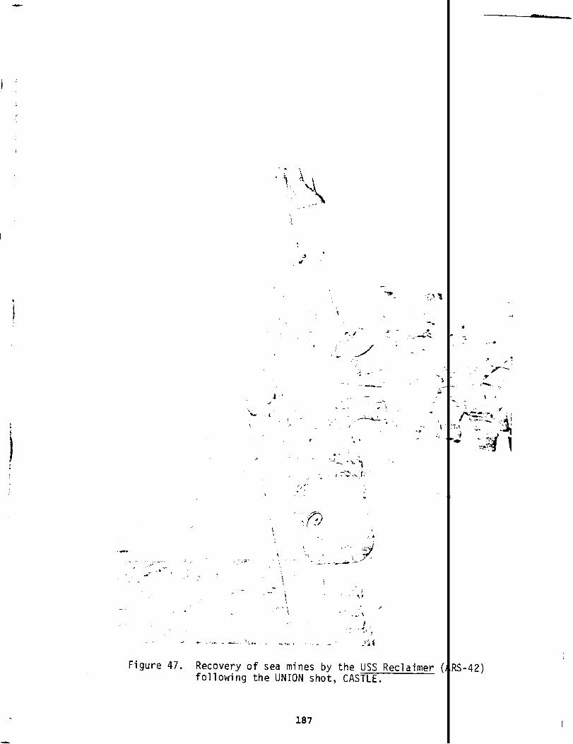
-..,
s \,,-i,
( %......+’
I
—
....-., . .6“’”:.
-> ‘,,d’
.; 1--’
,
.. —- &.- ,...
. . ‘.,
< ‘.! . . ‘1‘.*
/,. ,.,> .
. . . .,1 --\
f. ..3.J. . .$
. A. . . . - -.. , ‘:..=. -, -,, _)~~.-
Figure 47. Recovery of sea mines by the USS Reclaimerfollowing the UNION shot, CASTLE.
;.. .,.s
?S-42)
I

purposes of this project were to (1) evaluate the severity of radiatj
injury to the human beings exposed, (2) provide for all necessary mec
care, and (3) conduct
beings.
The organizations
Naval Medical
a scientific study of radiation injuries to hun
and ships involved were:
Research Institute
Naval Radiological Defense Laboratory (NRDL)
Patrol Squadron 29 (vP-29)
Naval Air Station, Kwajalein
hs Alamos Scientific Laboratory (LASL)
USS Nicholas
USS Renshaw
USS Philip
Applied Fisheries Laboratory, University of Washington
Hanford Atomic Power Operations
OPERATIONS. The primary operation was the evacuation and decent;
nation of the people involved from 28.5 to 78’hours after BRAVO was c
nated. This process and the operational units involved are describec
Chapter 4. The evacuees were taken to Kwajalein where immediate medj
needs were attended to and initial scientific studies made. Residual
diation at the cont~inated atolls was surveyed during March to estak
the exposure levels of the natives. These missions are summarized ix
ble 66. The people of Rongelap were later taken to Majuro in the Mal
where they remained until 1957, when they returned to Rongelap. Util
which was less heavily contaminated, was reoccupied by its evacuated
habitants in June of 1954. Medical followup studies on the Marshall
landers have continued from 1956 to the present, under the supervisic
the Brookhaven National Laboratory (Reference 64). The U.S. service
sonnel were taken to Tripler General Hospital in Honolulu for bioass:
observation, but they have not been included in the medical reviews t
Brookhaven.
188
1
h
11s
f
nd

RADIATION R(POSURE POTENTIAL.
IThe radiation exposures of reject per-
sonnel (as opposed to the people inadvertently exposed) were 1 mited to
exposure at the contaminated atolls at the time of evacuation, exposure at
the time of surveys made somewhat later, and exposures during econtamina-
tion of evacuation equipment (primarily aircraft) at Kwajalein
STAFFING.
I
Individuals involved in all aspects cannot be a ertained
from project documentation, nor can the exposures recorded in e Consoli-
dated List (Reference13) for identifiable Project 4.1 personn be iso-
lated to exposure from their participation in Project 4.1 acti “ties. The
exposures presented in Chapters 8 and 9 should be consulted fo the organ-
izations involved.
PROJECT REPORTS. References 25, 65, 66, 67, and 68.
ITests of Service Equipment and Techniques (Program 6)
This program covered a miscellaneous group of six projects.
I
Project 6.1 -- Test of Interim Indirect Bomb Damage AssessmentProcedures * I
Agencies: 97th Bombardment Wing, Strategic Air Command,Biggs AFB, Texas
IOperations: Three B-50s and crews of the 97th Bombardment ing posi-
tioned on Guam flew to Enewetak 2 to 3 days before each tes
1
to pick
up radiofrequency crystals, film badges, and dosimeters. A detona-
tion they were normally 15, 23, and 30 nmi (27, 42, and 56 ) from
the burst, recording the burst on radarscope photographs. ly two
aircraft were in position for UNION and YANKEE. One of the -50s was
also required to do crater photography (Reference69, Numbe 2-54
Change 5).
Shots: AU.I
Radiation Exposure Potential: The aircraft were at a long s ant ranget
from these burst points and the potential for initial radiat on ex-
posure appears small.1
The aircraft returned to Enewetak to ick up
189

Isupport crews and drop off instrumentationafter each shot before
LCCULIIW W L.ZUZWI, UUL 4S 110 ~a~or K@U~QU~ LIKl=enES occurrea ?i~ ~
wetak the potential for exposure to residual radiation was small.
Staffing: No personnel from TG 7.1 were associated with this pro
The exposures for the 97th Bombardment Wing are listed with TG 7.
but are obviously not for the crews of the Project 6.1 aircraft,
these aircraft were Guam-based.
Project Report: Reference 70.
Project 6.2a -- Blast and Thermal Effects on B-36 Aircraft In Flight
Aqencies: Allied Research Associates (ARA)Wright Air Development Center (WADC)Strategic Air Command Test Detachment (SAC)University of Daytonllth Bombardment Wing
Operations: A specially instrumented and maintained B-36D aircra.
(No. 49-2653) was flown in most of the shots to confirm predicted
sponses. The same aircraft was used in similar experiments in IV
UPSHOT-KNOTHOLE. .
Shots: BRAVO, ROMEO, UNION, YANKEE (Bikini);NECTAR (Enewetak).
Radiation Exposure Potential: The range of the aircraft from burl
limited the possibility of initial radiation exposure for the flit
crew. Aircraft altitudes and slant ranges at burst time for the v
ous shots were:
BNiVQ -- 33,000 feet (10.06 km), slant range 60,580 feet(18.46 km)
ROMEO -- 37,000 feet (11.28 km), slant range 63,580 feet(19.38 km)
KOON -- 40,000 feet (12.19 km), slant range 56,570 feet(17.24 km)
UNION -- 37,100 feet (11.31 km), slant range 62,700 feet(19.11 km)
YANKEE -- 40,000 feet (12.19 km), slant range 56,990 feet(17.37 km)
190
~Y
t.
.
Id
i-

—
NECTAR -- 33,000 feet (10.06 km), slant range 126,38((38.52 km).
On YANKEE, 0.020 R/hr was recorded in the aircraft for a
seconds. After the tests, the aircraft was returned to t
turer for work and was found to be radiating about 0.010
spots on the landing gear, perhaps due to operating from
way used by sampler aircraft, as the Project 6.2a B-36D c
near the cloud.
Staffing: Six civilians were associated with this projec
the University of Dayton and two from WADC. Their exposl
in Table 19. Included in this is the aircraft commander
0.100 R, but the
project report.
Project Report:
rest of the aircrew cannot be identified
Reference 35.-
Project 6.2b -- Thermal Effects on B-47B Aircraft In
Agencies: Allied Research Associates (ARA)Wright Air Development Center (WADC)Cook Research Laboratories (CRL)Naval Radiological Defense Laboratory
Operations: A B-47B aircraft (No. 50-037), used
Flight
(NRDL)
in simil?
ments during IVY, was flown in five shots to determine th{
fects. Instrunientationand aircraft positioning were detf
WADC, NRDL provided measurements, and CRL installed and rni
instrumentation.
Shots: BRAVO, ROMEO, KOON, UNION (Bikini);NECTAR (Enewel
Radiation Exposure Potential: The range of the aircraft :
limited the possibility of initial radiation exposure of I
crew. Aircraft positions at burst time for the various s]
BRAVO -- 35,000 feet (10.67 km), slant range 61,800 f{(18.84 km)
ROMEO -- 35,000 feet (10.67 km), slant range 83,500 f[(25.45 km)
191
?t
.odof 20
lanufac-
- at hot
same run-
lot fly
\ourfrom
are given
received
~mthe
?xperi-
31 ef-
Lned by
:ained the
1.
m bursts
flight
; were:

I(OON-- 35,000 feet (10.67 km), slant range not reported
UNION -- 35,000 feet (10.67 km), slant range 64,500 feet(19.66 km)
YANKEE -- did not participate
NECTAR -- 35,000 feet (10.67 km), slant range 45,800 feet(13.96 km).
The aircraft flew away from the cloud and was not exposed to sigr
cant residual radiation exposure potential.
Staffing: Three civilians were associated with this project, twc
CRL and one from WADC. Their exposures are given in Table 19. E
sures for the aircrew are included in Table 87.
Project Report:
Project 6.4 -- Proof
Reference 71.
Testing of Atomic Weapons Ship Countermeasures
Agencies: Bureau of Ships (BuShips)Naval Radiological Defense Laboratory (NRDL)Army Chemical Center (ACC)Mare Island Naval Ship Yard (MINSY)Naval Unit, Chemical Corps School (NUCCS)Naval Schools Command, Treasure Island (NSC TI)YAG-39 (USS George Eastman)YAG-40 (USS Granville S. Hall)USS Molala, USS Tawakoni, USS Bairoko, USS EstesP2V5 aircraft8542nd AAU
Operations: Equipped for remote control, YAG-39 and YAG-40 maneu
in the fallout patterns of four Bikini shots. YAG-39 carried a k
down system, but YAG-40 did not. Each was instrumented for radia
measurements and each carried an unmanned F4U aircraft secured tc
weather deck, also instrumented for radiation measurements. The
were unmanned during the first two shots, with control provided t
P2v5 aircraft, as well as the Molala and pcssibly the Bairoko. DI
the last two shots, a crew aboard the YAG-39 in a heavily shielde<
control room controlled both the YAG-39 and the unmanned YAG-40, I
some assistance from the P2V5 and the Bairoko. Both ships were ti
to Enewetak for decontamination, with the Instrument Group boardil
soon as possible to retrieve radiation records. Various operatiol
192
.
)m
?d
n
e
ps
ng
h
n
as

I
and experimental decontamination procedures were followec
mately 300 men from various ships of TG 7.3 assisted in :
recovery, and ship and aircraft decontamination work. Cc
this effort was done on the Estes.
Figures 48, 49, and 50 show the sequence of decontami
YAG-40. Figure 48 shows the tug, Molala, hosing the shig
returned to Enewetak. Figures 49 and 50 show crews dress
tive clothing on the YAG-40 using hoses from the YAG-39 t
the sequence. Figures 51 and 52 show one of the aircraft
the YAG decks being decontaminated at Parry (thesewere a
Alameda NAS that had been scheduled for salvage; four wer
tests).
Shots: BRAVO, ROMEO, UNION, YANKEE (Bikini).
Radiation ExPosure Potential: High for personnel aboard
as well as for those engaged in recovery and decontaminate
tions. For example, the average exposures received by NE
personnel were 0.170 R for BRAVO, 1.030 R for ROMEO, 1.10
UNION, and 0.026 R for YANKEE.
Staffing: One hundred and five people are specifically a
with this project, including seven civilians for whom exg
are apparently unavailable. Of the remaining 98, 39 were
associated with TG 7.3. Of the TG 7.1 group, 43 were civil
NRDL, 5 BuShips, 1 MINSY, 1 APSWP, and 1 ACC) and 16 were m
NRDL, 4 NSC TI, 3 BuShips, 1 NUCCS, 1 AFSWP and 1 8542nd AAl
all exposures are presented in Table 19. Exposures for oth~
of ~ 7.3 participating in Project 6.4 appear in Table 59.
Project Report: Reference 72.
Project 6.5 -- Decontamination and Protection
Agencies: Army Chemical Corps (ACC)Corps of Engineers, Washington, D.C.Armed Forces Special Weapons ProjectYAG-39, YAG-40Barge (type YC-500)
193
AFSWP)
Approxi-
vey, sample
dination of
tion for
~wn as she
in protec-
continue
arried on
craft from
used in the
e vessels!
opera-
nd YAG
for
!iated
e records
,itary
,ns (35
itary (6
. Over-
members

.....
F
. .
~’u.- “ ‘“t-l” ---’.-
. . .. . .-ifJ------ .
. > ‘-
..,.. - ‘- w~yk’~:::%,,-‘--’..
., ..”-,:.
gure 48. Decontamination hosedown of YAG-40 (USS Granville S.by the USS Molala (ATF-106), CASTLE.
--._,.—___ ,. -.
‘\‘,
‘,s-./ .:?% .~.+~
.+-p. - ;’”,
‘:$5 ~“ ti ““’-::$:.-q—’ -,,—y,,!-_—
-...$.4 +.-a -,-7
~,.-
i..’’;i-;’.‘“’.....J ,:5%.+( ‘“ J
‘,. “;”<-..,.. .
.,—. .....,----- .— ___
. —.
Figure 49. Deck crew continuing washdown of YAG-40(USS Granville S. Hall), CASTLE.
194
-.1
Ian )

r.,
THIS PAGE
WAS
INTENTIONALLY
LEFT BLANK
IN
ORIGINAL
3-0/

-— —.._..
I
Figure 50.
+
Further washdown of YAG-40 (USS Granville S. H 11),YAG-39 (USS George Eastman) alongside; CASTLE
Figure 51. IProject 6.4 test aircraft being decontaminated CASTLE.
195

Figure 52. Scrubbing Project 6.4 test aircraft, CASTLE.)
Operations: Sets of panels of outdoor construction surfaces were
mounted on YAG-39 and YAG-40, which maneuvered through fallout pa
terns from Bikini shots, and on a stationary barge in the Eneweta
Lagoon to sample fallout from NECTAR. All surfaces were contamin
significantly. Decontamination was performed at Parry, using suc
procedures as high- and low-pressure hosing, scrubbing, and appli
tion of washing compounds.
Shots: BRAVO, ROKEO, UNION (Bikini);NECTAR (Enewetak).
Radiation Exposure Potential: High for those on the YAGs and for
personnel participating in decontamination procedures and experim
at Parry.
Staffing: Five were associated with this project, three civilian
(two from ACC, one from Corps of Engineers) and two military (one
AFSWP and one from ACC). Their exposures are given in Table 19.
posures for those involved from TG 7.3 are given in Table 59.
Project Report: Reference 73.
196
—
d
e
s
om

project 6.6 -- Effects of Nuclear Detonation on the Ionosphere
IAgencies: Signal Corps Engineering Laboratories (SCEL)
9471st TSUI
Operations: Ionospheric recorders were set up at Enewetak (Parry
Island) and Rongerik atolls in the Marshalls and at distant locations.
Following the fallout from BRAVO, operations at Rongerik we :e cur-
tailed; recorders were started before each shot and left to operate
unattended.
Shots: All.I
Radiation ExI
posure Potential: Although the potential for e posure ap-
peared quite low, owing to the remoteness of the stations, he actual
exposure turned out to be high at Rongerik because of BRAVOI
Staffing:I
Five people were definitely associated with this project,
one civilian and four military.I
Three of the military were the en-
listed personnel of the 9471st TSU who were on Rongerik and were ex-1
posed to the BRAVO fallout.I
They were assigned an exposure of 98 R in
Reference 13 baspd upon a badge on a tent pole in their wor1area, but
based on later research the exposures were reduced to 78 R Reference1
68).
Project Report: Reference 74.
Burst Detection Studies Program (Program 7)
.1
This program conducted a variety of experiments in nuclear xplosion
electromagnetic pulse generation, airborne low-frequency sound, and col-
lection of nuclear weapon debris.
Project 7.1 -- Electromagnetic Radiation CalibrationI
Agencies: National Bureau of Standards (NBS)Naval Electronics Laboratory (NEL)Signal Corps Engineering LabOratOrieS (SCEL)1009th USAF Special Weapons Squadron
197

Operations: Seventeen stations operated to obtain information c
radiofrequency signal generated by each shot. All stations wer<
tant from the PPG except for one operated remotely by NBS on En<
Following contamination by BRAVO, this station was removed and !
located on Runit.
Shots: al.
Radiation Exposure Potential: For the remotely located stations,
potential was slight. A greater potential existed, however, fol
sonnel moving the contaminated NBS trailer from the initial 10CZ
on Eneu to Runit after BRAVO.
Staffin?: One uniformed person was associated with this project
ceiving 0.915 R.
Project Report: Reference 75.
Project 7.2 --
Agencies:
Detection of Airborne Low-Frequency Sound fromNuclear Explosions
National Bureau of Standards (NBS)Naval Electronics Laboratory (NEL)Signal Corps Engineering Laboratories (SCEL)Office of Naval Research (ONR)
Operations: Fifteen acoustic stations were operated to measure
frequency sound. All stations were remote from the PPG.
Shots: All.
Radiation Exposure Potential: None, offsite operations.
Staffing: Not applicable, since all stations were remote from t
Project Report:. Reference 76,
Project 7.4 -- Calibration Analysis of Close-In Atomic Device Debris
Agencies: Hq USAF1009th USAF Special Weapons SquadronIas Alamos Scientific Laboratory (LASL)University of California Radiation Laboratory (UCRL)F-84, WB-29, and B-36 aircraft from TG 7.4 TAU
198
,-2?<

Operations: Sampling devices on F-84, WB-29, and B-36 ail
used to obtain nuclear debris samples close in to the det<
Long-range calibration samples were also collected by wB-;
Aircraft generally did not enter the cloud until 2 hours ~
the clouds were followed for 5 to 7 hours while samples wc
obtained. Collection of close-in particulate samples was
technical direction of LASL, gas sample collection was su~
Hq USAF, and gas separation and some analysis was performt
Shots: All.
Radiation Exposure Potential: Exposure potential existed
crews, as well as for those processing samples upon the al
turn and those decontaminating the aircraft.
Staffing: Five people were definitely associated with th~
three from the 1009th (two civilians, one military), one t
LASL, and one civilian from UCRL. Their exposures are pr(
Table 19. Exposures for personnel from other task groups,
TG 7.4, are given in Table 87.< 1Project Report: Reference 77.
Cloud Photography (Program9)
A single project, Project 9.1, made up this program in ort
mine the rise rate of the cloud and the height at which the c:
to rise.
Project 9.1 --
Agencies:
Cloud Photography
Edgerton, Germeshausen & Grier, Inc. (EG&G)Lookout Mountain Laboratory (LML)1090th USAF Special Reporting Group
Operations: Technical aerial photography was conducted b
backup ground photography by EG&G in conjunction with its
work for LASL. One RB-36 and three C-54 aircraft, each e
two cameras, flew one mission per aircraft for all six sh
lftwere
:ions.
lircraft.
!r burst;
being
Ier the
risedby
)yUCRL.
: aircraft
raft’s re-
xoject,
.lian from
\ted in
>tably
to deter-
i ceased
ML, with
~tography
pped with
. The
flights were 40 to 100 nmi (74 to 185 km) from ground zero.
199 I

Shots: A.11.
Radiation Exposure Potential: A slight potential existed for all air-
crews and for the personnel decontaminating aircraft after flights. The
exposures accrued by the RB-36 crew, however, while acting as photo
aircraft for this project for 10 minutes after burst, were far out-
weighed by those accrued over the next several hours while acting a;
the sampler controller aircraft. Burst-time altitude for the RB-36
was about 40,000 feet (12.19 km). The three c-54 aircraft were use{
by the Documentary photography element after H+l. They were at 10, 00
to 14,000 feet (3.05 to 4.27 km) altitude and 40 to 60 nmi (74 to 1:1
km) from ground zero, except on YANKEE when they were 90 to 100 nmi
(167 to 185 km) distant.
Staffinq: One person (military)was definitely associated with this
project, receiving 0.250 R. Exposures of other participants are gil n
in Tables 86 and 90.
Project Report: Reference 78.
,
{
200

CHAPTER 4
BRAVO TEST
The first event of the CASTLE series, BRAVO, was schedulec
tion on a small artificial island connected to Nam by a causev
land was built over the reef some 3,000 feet (914 meters) sout
The device, provided by Los Alamos Scientific Laboratory (LAS]
detonated on 1 March 1954 if meteorological conditions were f;
DECISION TO SHOOT
The preshot 5-day advisory message to the Atomic Energy Cc
(AEC), the Joint Chiefs of Staff (JCS), and the Commander-in-C
Pacific (CINCPAC) indicated that the BRAVO fallout would form
pattern from northwest to northeast if the predicted winds he]
this favorable wind pattern, a search for transient shipping u
northwest of ground zero on BRAm D-2.’ The flight pattern was
a bearing of 300° from ground zero and consisted of radar COVE
patrol aircraft of a rectangular corridor 200 nmi (370 km) wic
(1,480 km) long. On BRAVO D-1 a search sector was set up on ;
330°. With radar coverage, this search encompassed a trapezoi
(1,110 km) long with end lengths of 100 nmi (185 km) at grounc
200 nmi (370 km) at the outer end. Results of
tive (Reference 79).
On BRAVO D-1 at 1100 hours, the task force
visory to the CINCPAC) “no significant fallout
these searches
predicted (in 1
. . . for the ~
Marshals.” Moreover, the task force predicted that no safet~
muld exist except on air or surface routes in the sector 275<
clockwise to a range of 450 nmi (833 km) (Reference 16, p. K-1
~rdetona-
The is-
‘stof Nam.
was to be
able.
ssion
f of the
‘an-shaped
Based on
conducted
!nteredon
‘eby the
ly800 nmi
ading of
00 nmi
?ro and
:e nega-
H-18 ad-
llated
:oblems
) 80°
201

At the 1800 weather briefing, the predicted winds were less favorab
nevertheless, the decision to shoot was reaffirmed, but with another re
view of the winds scheduled for 2400. The USS Renshaw, acting as the a
controller between Enewetak and Bikini, was ordered repositioned from i
planned 270° bearing, 90-nmi (167-km) range from Bikini to a more south
erly 230° bearing 90-nmi (167-km) range from Bikini. The cloud track
flight, designated “Wilson 2,” was set up at 2200. It would hold west
Bikini at H+2 at 10,000 feet (3.05 km) in a position to intercept and w
of debris coming west toward Enewetak and Ujelang and then fly east aft
2 hours, searching a sector between 55° and 85° through ground zero to
find the cloud if it had not already appeared to the west (Reference8)
The midnight briefing indicated less favorable winds at 10,000- to
25,000-foot (3.05- to 7.52-km) levels. Winds at 20,000 feet (6.10 km)
were headed for Rongelap to the east. The predicted speed of these win
was low enough to be of no concern, although it was recognized that bot
Bikini and Eneman islands would probably be contaminated (Reference 16,
p. K-3). The decision to shoot was reaffirmed, at least until the 0430
briefing. A burst-day flig~t to search for transient shipping was add
at this time, to be centered on a 65° vector to a distance of 600 nmi
(1,110 km).
At 0430 “no significant changes” in the winds had occurred, except
Bikini where the lower level winds were showing more “northerly and we~
erly components.” The JTF Radsafe Office recommended that the fleet sc
tie area southeast of Bikini be moved outward from 30 to 50 nmi (56 to
km). This was ordered for smaller and slower units, but the larger ves
sels remained in their original areas to maintain good UHF communicatic
with the firing bunker on Eneu and to be in good position for prompt re
entry. The USS Estes also had to be within range for its role as the IT
ter Raydist navigation system station in controlling experimental aircr
flights near the burst point.
202
e;
r
s
f
rn
r
t
3
s
s-
ft

The change with time of the direction of interest is illus
the vectors shown in Figure 53, which shows the patterns flown
P2V aircraft based at the Kwajalein Naval Air Station in search
transient shipping on D-2 and D-1, and the special added flight
itself.
PREPARATIONS
The general plan for Bikini operations (includingBRAVO) w?
draw work and scientific parties to the fleet units in the lagc
ships could clear the lagmn and assume their night steaming st
southeast of the atoll before dark on the evening before the pI
In preparing for BRAVO,
weapon design laboratories,
vice and started the arming
the firing party, a small group frc
proceeded to the location of the en
process. This consisted of mechani
ing the device to create a circuit capable of carrying the firi
to the device. This circuit was still not complete, however, z
gap existed in the firing bunker at Station 70 on Eneu. After
device was completed, the firing party and the military police.
guard the device withdrew to Eneu. The fleet cleared the lagoc
the arming process was completed, thus ensuring that task force
(excePt for the firing party) were never in the atoll while thf
could be detonated.
The firing party was left on Eneu in the firing bunker and
boat or helicopter crew and military police that had provided t
tion and protection rejoined the fleet. Final links in the fil
were then closed, and the device was ready for detonation.
DOD ACTIVITIES
The DOD-sponsored experiments for BRAVO included 29 project
of TG 7.10 TU 13 projects were:
● Program 1, Blast and Shock; projects l.1a-1.ld,1.2a-b, 1.3, 1.4, 1.6
203
ated by
VP-29
I for
1 D-Day
:0 with-
so the
Lens
~wn shot.
:he AEC
iced de-
Uy alter-
signal
I similar
:k at the
:ailed to
)efore
?rsonnel
~vice
? small
3sporta-
J circuit
in TU 13
I1

C-4
/
/
/
IL

“o Program 2, Nuclear Radiation and Fallout; Projects2.1, 2.2, 2.3, 2.5a-b, 2.6a-b
● Program 3, Blast Effects; Projects 3.2, 3.3, 3.5
● Program 6, Systems Effects; Projects 6.2, 6.2a-b, 6,6.5, 6.6
. Program 7, Electromagnetic; Projects 7.1, 7.2, 7.4
● Program 9, Cloud Photography.
Chapter 3 contains a detailed description of these project:
a description of the participation of the DOD in other portionf
CASTLE experimental programs. The locations of instrument stal
these projects are indicated in Figure 54.
The locations of the ships of the fleet at burst time are :
Figure 55. Aircraft missions and positions are given in Table
THE TEST
At 0645 the firing signal was sent and the device exploded,
the energy equivalent of 15 million tons (MT) of TNT. This yif
greater than expected. In a few seconds, a fireball nearly 3 r
km) in diameter had formed, and a crater about 1 mile (1.6 km)
200 feet (60 meters) deep was gouged from the reef off Nam. T]
tion from the fireball was visible for nearly a minute on Rong[
nmi (250 km) east of the burst. It was also observed on a Japt
ing boat 85 nmi (157 km) east-northeast of Bikini. Within 1 m:
fireball had risen to 45,000 feet (13.7 km) and the pulverized
the crater was pulled up into a cloud that was already 3 miles
across with a stem 2,000 feet (600 meters) wide.
Within this first minute, the blast wave from the explosio[
outward from the burst point, stripping the nearby islands of !
The blast wave was received with diminished force 14
the lagoon at the evacuated camp on Eneman, where it
the lightweight temporary buildings (Figure 56). An
nmi (22.5
damaged c<
electrica~
cuit caused a fire, destroying much scientific equipment (Figul
205
t
3s well as
>f the
>ns for
wn in
).
releasing
i was much
Les (4.8
zross and
illumina-
ik, 13s
~se fish-
~te the
oral from
4.8 km)
had moved
getation.
n) across
siderably
short cir-
57). The

BIKIN
N
A
IROIJ I.la.b.d, 1.2b, 2,1, 2.5a.b
ODRIK 2.1, 2,2, 2.5b
LOMILIK l,2a, 2,1, 2.5a-b, 2,6b
OPEN OCEAN 2,5a
NAM l,la-bd, 1.2b, 2.1, 2.2, 2.5b, 3.5
&2.5a.b,2,6b BIKl~l
BOKDROLUL 2.1, 2.2, 2.5b, 2.6b BOKONFUAAKU —
/
COCABOKAETOKTOK 2,1, 2,2, 2.5b
YOM YARAN—
/
OROKEN 2,1, 2.2, 2.5a.b
Qe/
EN IAIRO—AD RIKAN 2,1, 2.2, 2.%-b, 2.6b 2.5b ROCHIKARAI—
/
<
b
JELETE 2.1, 2.2, 2.5a-b, 3.3 10 NCHEBl —
LUKOJ 2.5b, 2.6b, 3.3
%)
2.5a-b, 2,6b, 7.1 EN I
EN IDRIK l.la.bd, 2.1, 2.5a-b, 3.3 165°30, EAST4,
//
ENEMAN 2.5a-b, 3.5
‘“K”’’*S* y I ,~,”cHANNEL + “030’NORTH
LELE2.1 BIKORIN /
2.1,2 .2,3.5 AEROKOJLOL2.2, 2.5a-b, 2.6b AEROKOJ
‘~NAUTICAL MILES
0-KILOMETERS
Figure 54. Locations of instrument stations for DOD experiments
CASTLE , 8RAV0.
206
i

1201
11(
,@
~c
1
ENEWETAI( BIKINIATOLL ATOLL
/
)
●RENSHAW
t>
.
4\TAWAKONI
SiouxGRANVILLES.HALL ~U%T lSS~ >,& PC1546
LLST-762 s
BELLE GROVE (W/ 18 LCMS, 1 A\
GEORGE EASTMANBJyy- 1
ESTES~~ ●GypS’f
EP?ERSON
LST-:51.
b “NswOR’~;*
MOLALA
uSS APACHE (ATF67) – 65 nmi SE OF GZ, BEARING 13P\
/
USS BAIROKO (CVE.1 15) – 36 nmi SE OF GZ, BEARING 124°
1
/USS BELLE GROVE ILSO-2) (WITH 18 LCMS, 1 AVR) – 40 nmi SE OF GZ, BEARING 125° \
USS COCOPA [ATF-101 ) – 57.5 nmi SE OF GZ. 8EARING 153° \ 0’USS CURTISS [AV41 – 29 nmi SE OF GZ, BEARING 123° 1USS EPPERSON (ODE-719) -10 nmi SW OF ENEWETAK, BEARING 235° <AREA OF FLEET UNITS
USS ESTES (AGC-12) – 42 nmi SE OF GZ, BEARING 125° AFFECTED BY SECOND
USNS FRED C. AINSWORTH [T.AP-181)a –42 nmi SE OF GZ, BEARING 138° FALLOUT BEGINNING AT 1300
USS GEORGE EASTMAN (YAG-39)b – 35 nmi SW OF GZ, BEARING 230°USS GRANVILLE S. HALL (YAGdOJb – 35 nmi SW OF GZ, BEARING 233°USS GYPSY (ARSO-11 – 80 nmi SE OF GZ, BEARING 110°LST-551 -30 nmi SE OF EN EWETAK, BEARING 123°LST.762 – MOOREO AT PARRY ISLANOUSS MOLALA (ATF.108) – 46 nmi SW of GZ, BEARING 200°PC.1546 – STEAMING WITH THE TAWAKONIUSS PHILIP (ODE498) – 52 nmi SE OF GZ, 8EARING 133° ‘ o
USS RENSHAW [DOE499) -72 nmi W OF GZ, BEARING 270° -
USS SIOUX (ATF.75) – 42 nmi SE OF GZ. BEARING 110° NAUTICAL MILES
USS TAWAKONI (ATF.1 14) – 50 nmi SE OF GZ, BEARING 107° 02D4060B011xJ
NOTES. ) 1 1 1 I J
aFROM TG 7,3 OPERATION LETTER – BRAVO, 24 FEBRUARY 1954KILOMETERS
bFROM OPERATION CASTLE PROJECT 6,4 * SHOT LOCATION
SOURCE OF INFORMATION. SHIPS’ LOGS1
)C .,?.-.0 ..-.L 10J- 1ti4” 165” 166” 1[
I
I
i
Figure 55. Ship pos t ons at detonation, CASTLE, BRAVO.

—
Table 20. CASTLE, BRAVO aircraft.
AircraftBurst-time Loca
No. Type Mission Project Remarks
2
1
1
1
1
1
1
1
1
3
1
12-14b
2
2
P2V-6
P2V-5
P4Y-2
B-36D
B-47
6-50
B-50
6-50
RB-36
c-54
WB-29
F-84G
8-36
WB-29
1 Canberra
Shipping search
YAG controller
Telemetry receiver
Effects
Effects
Indirect BombDamage Assessment
Indirect BombDamage Assessment
Indirect BombDamage Assessment
Sampler control
Photo
Samp1er
Samplers
Samplers
Cloud track
Sampler
6.4
1.4
6.2a
6.2b
7.1
7.1
7.1
9.1’
9.1
One contaminatedeast at 350 metertitude at H+3
West of Bikini
Altitude 3 km, S1range 46 km south
Altitude 10 km, srange 18.5 km sou
Altitude 10.7 km,range 18.8 km eas
Altitude 10.4 km,range 27.8 km
Altitude 9.5 km,range 42.6 km
Altitude 9.1 km,range 55.6 km
Altitude 12.2 km,range 92 km north
Altitude 3 to 4.4slant range 92 kmwest, and north
Wilson 1
Sampled south andedge from H+2 to
Sampled H+2 to H+
H+2 to H+20; no sicant contact
UK aircraft, Kwajbased
Notes:
aOne meter = 3.28 feet; 1 kilometer = 3,281 feet.
bSources vary as to number; decontamination data available for ten
208
na/
km1-
t
ant
ant
,nt
,nt
antt
1,
luth,
.St
lif-
!in
‘Y”
a

-*..
- -=_ -... -.., -.+,./ ,.. ,,:, , ‘:.’ %’
[!-k, .., /’.-. ,...
i“ 6
\
‘, ‘{
\L“i,
-----‘ 5
● I‘.
“---””
.
/“’4;i,#A=. .__y .
.— :22?‘---+ %-’;‘:...!4-. —-=...-.-—....% , ..-- --’._-,
Figure 56. CASTLE, BRAVO blast damage to Eneman Island k-t
;’; ‘..*i
Figure 57. Fire damage at Eneman Island from CASTLE, BRAVOelectrical short circuit.
209
\
. . -z-.
..- 1
-._ -.
ding.
?“c.<. -:,,. . .. . . .,- -
.
duced
I

shock wave was perceived at the Japanese fishing boat as two loud
like rifle shots, arriving 7 or 8 minutes after the flash was seen
Rongerik the shock wave shook the windows in the buildings 11 minu
after the first blast was observed (Reference68).
The cloud formed was like a funnel with the narrowing at about
feet (19 km) altitude. The growth of the cloud is shown in Figure
early as 10 minutes after burst, the cloud was already more than 6
(106 km) across. At about H+30 minutes, aircraft from the cloud p
phy project visually observed material falling from the cloud from
point at which the funnel flared out (Reference26).
At Station 70 on Eneu, radiation readings began to rise within
hour of the burst and at 1 hour reached 250 R/hr (see Figure 59).
personnel within the bunker were well sheltered; during the fallou
the reading within the structure was 0.035 R/hr (Reference 16, p.
The fallout picture at Bikini at this time is summarized in Figure
At 0800, the fleet began to receive fallout, which resembled p
sized white and gritty snow. The USS Bairo~o and the USS Philip WI
paring for the reentry sequence to Bikini. A helicopter had been
from the Bairoko for radiological reconnaissance,but was recalled
the CIW 7.1 informed the Bairoko that the Eneman complex was radio
too hot for reoccupation. The source of information for CTG 7.1 m
been the Station 70 bunker on Eneu. Plans for the launch of four
helicopters, including one to aid the USS Molala in controlling th
lying west of Bikini, were also cancelled (Reference 80).
The radiation levels aboard the ships built up quickly, from O
1 R\hr on the Bairoko in 5 minutes. At this time the Bairoko was 31
(57 km) at 133° from the Bikini ground zero. Washdown systems were
on all affected ships, and CTG 7.3 ordered the vessels south to 50 n
km) from Bikini at “best speed” (Reference80).
210
rts
t
000
As
les
gra-
-half
ak
.
ad-
pre-
ched
n
tally
ave
r
>Gs
2 to
m i
ar ted
(93

120(36.58)
[
140(42.67} I I
/
LOWER LIMIT CLOUD TOP HEIGHT
114400 ft (34.74 km) /
2uEz? 60m (1829)
:
v~
CLOUD BOTTOM HEIGHT
u 55,300 ft (16.66 km)
i
g
$uG 40~ (12.19)a
;
u
STEM DIAMETER23,400 ft (7.13 km)
o 1 I I Io I I
1 2 3I I I
4 15 6 7 \
8 9I
TIME(minutes)
Figure 58. Cloud dimensions for CASTLE, BRAVO (source: Refere
211
~
350[106.68)
i
300(91 .44)
I
•1
I!33
(15.24)
110°
:e 81).
I

~-
024681012I I I I I I
, ,%,q ~
KILOMETERS 25 50
Figure 59. CASTLE, BRAVO close-in gamma fallout pattern at I0745 local time (R/hr).
The same gritty, snow-like material began to fall on the Japan(
fishing boat at about 0815. The crew, most of which was topside, 1
gun to retrieve its long fishing lines from the water soon after t]
wave passed. The crew secured the lines and remained on deck to PI
the catch during the fallout (Reference82). The ship proceeded nctoward its separate destiny, unobserved by the task force.
The nanthis ship was the Daigo Fukuryu Maru (FortunateDragon No. 5). Thememoire produced by the Japanese government detailing the ship’s mc
is reproduced in Appendix A of this report.
At 0949, a P2V aircraft from VP-29 on Kwajalein, sweeping the s
centered on a bearing of 65° from the shot pint for transient ship
became heavily contaminated and aborted its mission. The aircraft
212
1,500
‘ 1,000
250\100
be-
;hock
?ss
I
If
de
,ents
or
9r
ta

message stating that heavy contamination (0.5 to 1.0 R/hr) sho
petted on an 86° bearing, 238 nmi (441 km) from Enewetak. The
did not reach the JTI?7 Radsafe Center until 5 days later, alt
planation of this delay is given by the source documents (Refe
p. K-4).
The question of how far east the P2V was when it left its
returned to Kwajalein is of considerable interest. The accoun
radsafe compendium (Reference 16) says that “From the logs, it
that [it] . . . reached a position approximately 65 runidue ea
~the burst point] by 0950M only to abort” (p. K-4). The CTG 7
(Reference 79) states that “a relief aircraft was ordered . .
0 true from ground zero”.position 180 miles bearing 065 (The
position where the previous search had terminated.) If the fi
is correct, then the search broke off just before the Daigo Fu
would have come into view, whereas the second has the P2V flyi,
the fishing boat. Figure 53 shows the track of the Daigo Fuku
the P2V abort point from the first account. Figure 60 shows a
reconstructed fallouk pattern at the approximate time the P2V
Cloud sampling began 2 hours after the detonation and cent
5 hours, with aircraft wrking from 30,000 to 45,000 feet (9.1
on the south and southeast edge of the cloud (Reference 16, p.
This sampling was performed close to the burst point and, alth
sampler aircraft were in contact with radsafe personnel on the
tle concerning the picture of the cloud’s overall movement was 1
Twelve or fourteen F-84s and two B-36s were used in this samplin
one B-36 acting as controller.
Fallout reached some elements of the fleet later, depending
positions. The USS Gypsy did not receive fallout until 1400 and
units were less contaminated.
213
)e ex-
;age
1 no ex-
} 16,
: and
the
tars
!GZ
:mo
~]a
~ximate
Iccount
1Maru
.ght by
!aruand
: of the
:ed.
1 for
.3.7 km)
1).
the
“ned.
with
their
)me

I
I
I
t
~RONGERIK ATOLL
GE LAP ATOLL
,, -J“252
BIKAR
UTIRIK ATO
TAKA ATOLL &
u
O 10 20 3040 5060 7080I I I
NAuTICAL MILES
o 20 40 60 ao 100120140II[ I I I I
KILOMETERS
Figure 60. CASTLE, BRAVO reconstructed fallout at H+3; 0945 local t(R/hr) . Reconstruction is by NRDL and shows gamma fieldlevels that would have existed had the fallout been on lar
areas
Washdown on the
the Bairoko, one of
(source: Reference 53). ‘
ships was effective, but some problems did arise. C
the two ships most seriously exposed, the regular wz
down equipment was secured after 2 hours and firehoses were then used or
exposed areas throughout the day. At that time readings of 5 R/hr were
made in gutters on the flight deck. A reading of 25 R/hr was recorded j
a flight deck drain. The ventilation system was closed at the onset of
fallout, preventing much contaminated material from being carried below
decks. The captain reported that the engineering spaces never exceeded
readings of 0.008 R/hr (Reference80). The Bairoko was able to launch
helicopters at 1015 to retrieve the firing party still in the firing bun
on Eneu. The retrieval was completed at 1230.
The average readings for certain ships are presented in Table 21 for
several hours on D-day and at selected later times.
214
—— . .

~- ---- --- —”..-. ...
.. .... .. . . . . --------- --
NPm
Table 21. Average topside intensities (R/hr) of Task Group 7.3 ships following CASTLE, BRAVO.a
Local Curtiss Estes Ainsworth Belle Grove Cocopa Apache Sioux BairokoDate Time (AV-4) (AGC-12) (T-Ap-181) (LSD-2)
Philip(ATF-101)(ATF-67)(ATF-75) Pc-1546 (cvE-115) (DOE-498) (~;!til)
1 March 090010001100120013001400150016001700180019002000
2 March 000004000800120016002000
3 March 000004000800
4 March 0800
5 March 0800
6 March D800
7 March 0800
8 March 0800
0.0080.0050.0030.0020.0050.0180.0250.0450.0550.0500.0400.0370.0300.0250.0200.0150.0100.0100.0090.0080.0070.00320.00120.0010.0010.OD1
o.4oobo.2oobo.150b0.1000.1000.1100.1200.1400.1200.1200.1200.1200.1200.1200.0800.0500,0300.0200.0200.0180.0160.0070.0040.0040.00270.0021
------------0.0010.0020.0100.0160.0220.0190.0200.0200.0200.0200.0200.0200.0120.0100.0080.0070.0060.0050.0040.0030.0020.0015
---------0.0040.0050.0120.0200.0350.0750.1500.1900.3000.0800.0600.0600.0500.0500.0200.0200.0150.012
0.0080.0070.0050.0030.002
------------0.0050.0100.0140.0180.0200.0750.0750.1100.0750.0700.0300.0200.020
- 0.0180.0150.0120.0070.0050.0030.0020.002,0.0015
------------0.0030.0070.0020.0120.0500.0170.0200.0300.0300.0300.0250.0100.0100.0100.0080.0030.003
0.0020.0020.0020.0010.001
------------0.0040.0080.0090.0100.0220.0500.0340.0150.0400.0300.0120.0100.0090.0070.0060.0060.0050.0040.0040.0040.0040.004
---------0.0010.0030.0060.0150.0210.0250.0800.0900.0860.0800.0500.0400.0300.0200.0150.0140.0130.0120.0060.0030.0020.0010.001
Ui@o0.5000.5000.3500.3000.2400.2000.1700.1400.2000.1800.1800.1600.1450.1340.1080.0360.0300.0270.0250.022
0.0140.0090.0060.0040.003
0.7500.2650.1960.1450.1470.1380.1340.1800.2250.2620.1940.1990.0180.1560.1110.0780.0600.0470.0390.0410.0340.0170.0080.0070.0050.004
---------------0.0070.0300.2000.2300.2500.2000.1500.1300.1100.0800.0450.0400.0350.0350.0350.0250.0200.0140.0120.0100.008
Notes:,.
dAll ships not listed here received negligible contamination.
“Estimated.
Source: Reference 80.
u

After several hours, the snow-like material stopped falling on
fleet. This cessation of fallout indicated that the cloud dispens
particles, probably extending about 100 miles (160 km) across, had
eastward. The time of its passage over the inhabited atoll of Ron
105 nmi (194 km) east of Bikini, is not accurately known and can c
inferred from its arrival at about 1430 at Rongerik farther east.
fallout reconstruction shown in Figure 61 shows the front of the f
passing the easternmost portion of Rongelap at 1245 local time.
At Rongerik, 135 nmi (250 km) east of Bikini, 25 men of the 6t
Squadron operated a weather observatory for the Weather Reporting
(WREP), Test Support Unit, TG 7.4, and 3 men from the 9710th TSU ope
an ionospheric sounder for Project 6.6, TU 13, TG 1.
BIKA
antI
e///// \300
%; \50
-J
RONGELAPATOLLBIKINI‘ATOLL \ 70
s“) f&~~,,,~ A~~L,
AI LINGIN~E ATOLL
UTIRIK ATC
TAKAATOLL ,<
u“ IO 10 20 30 40 50 60 70 80 90 100
NAUTICAL MILES
o 20 40 60 80 100 120 140 160 185I i
KILOMETERS
Figure 61.
!
CASTLE, BRAVO reconstructed fallout at H+6; 1245 local ime(R/hr). Reconstruction is by NRDL and shows garmnafieldlevels that would have ~xi<td had t.h~fallout been on 1 nd. -—- ----- ..-areas (source: Ref~r~n~e’~3).
216
‘..
,.
?’
i!
I

IA fallout-recordingdevice had been left by a representati
:{ealthand Safety Laboratory (HASL) of the AEC, New York Opera
,/howas concerned with recording offsite fallout. The device
arated to record the low levels of radiation expected at offsi
its maximum reading was 0.100 R/hr and the HASL representative
the Rongerik personnel to contact him if the meter reading wer
(i.e., if the radiation exceeded the measuring capacity of the
Such a message was sent at 1515, was received at the Airways a
munications Service (AACS) Center at Enewetak at 1543, and del
the Army Communications Center at Enewetak at 1547 for retrans
JTF 7. Records do not show if this message was retransmitted
at
at
any rate, the command levels were unaware of the extent of
Rongerik (Reference83).
The personnel at Rongerik continued normal activities duri
mainder of the day. Most changed from the usual tropical shor
and shorts to long sleeves and long pants. The fallouk materi
to a depth of 1/4 to 1/2 inch (0.6 to 1.2 cm) deep in places a
visible layer on tables in
Those at Rongerik made
fallout. They observed it
the mess hall and barracks (Referen
some simple scientific observations
under a microscope, and they also F
made a cathode ray tube glow (Reference 68).
Meanwhile, at those fleet units arrayed in a sector bounde
and 155° bearings from ground zero at ranges from 20 to 70 nmi
km), a second fallout began about 1300 and continued into the
reached maximum at 1800 and had ceased by 2400. This fallout
be composed of much smaller particles that had taken considers
to fall from the great heights to which they had been carried
large particles from the morning fallout. Again washdown syst
turned on. A ~ 7.1 radsafe representative on the Bairoko adv
all nonessential personnel remain below decks to minimize the
of inhaling the small particles (Reference79).
217
of the
ms Office,
cali-
locations.
d warned
off-scale”
vice).
Air Com-
red to
tal to Hq
not but,
fallout
the re-
leeves
gathered
left a
68).
this
d that it
y 110°
7 to 130
ning. It
eared to
longer
n the
were
d that
sibility

After this second fallout episode, the task force decided I
the attempt to reenter Bikini Lagoon that day. The major unit:
vessels with TG 7.1 and TG 7.5 personnel aboard were sent west
to offload these people and to prepare for a return to Bikini <
ginning of operations afloat there. The USS Belle Grove remair
Bikini to reenter the following day if possible.
The cloud-tracking aircraft Wilson 2 had begun its flight ~
detonation and had been scheduled to fly for 3 hours in a racet
50 runi(93 km) west of Bikini to warn if the fallout was headec
It was then to fly eastward searching for the cloud in a secto!
the bearings 55° to 85° through the burst point. Owing to some
at the Air Operations Control (AOC) Center, Wilson 2 was held t
of Bikini for 6 hours. A portion of its flight path is shown ]
along with the reconstructed fallout at approximately this time
entire flight, Wilson 2 recorded only one radiation reading of
icance, and this was at 1550, 150 nmi (278 km) at a 60° bearin$
zero. The aircraft flew at 10,000 feet (3.05 km) throughout it
At 1553, the P2V a’ircraftdispatched to replace the transie
search P2V aircraft that had been forced to return because of cI
~andon
i those
Znewetak
the be-
south of
ms after
< course
;tward.
lnded by
Ifusion
te west
igure 62
[n its
signif-
~m ground
Light.
shipping
3mina-
tion picked up the desired heading to continue the sweep centered on the
65° bearing. In attempting to pick up the heading slightly earli(r, the
P2V had encountered radiation at 160 nmi (296 km) bearing 85° fror the
burst point. This had forced the P2V to swing east to pick up thc search
vector farther out from ground zero. This plane, based at Kwajalein, was
coming from the south toward the 65° bearing when it encountered tle radi-
ation. These flights were flown at a much lower altitude (1,000 f?et; 305
meters) than the Wilson flights.
The remainder of the flight was apparently uneventful until th? plane
sighted the USS Patapsco on a course of 30° (Reference 16). The P!V con-
tacted the Patapsco advising an “easterly” course so as to avoid t’,e65°
bearing. The Patapsco accepted this advice, leaving a course that would
218

/
/
WILSON 2
/INBOUND H+13
iWILSON3INBOUND H+22
jMAXIMUM EXTENT!OFPATTERNATH+12
BIKAR-ATOLL
O 10 20 30 40 50 60 70 80 90 100
1 I
NAUTICAL MILES
‘~’KILOMETERS
Figure 62. CASTLE, BRAVO reconstructed fallout at H+12; 1845 local time (R/hr). Reconstructionis by NRDL and shows gamma field levels thdt would have existed had the fallout beenon land areas (source: Reference 53).
— . ..,,.

I
have tended to minimize exposure to take a course that was probably
along the “hot line” of the BRAVO cloud.
At 1900 a second cloud-track aircraft, Wilson 3, was sent east
Enewetak. The flight path was nearly straight east until beyond Ro
and then the aircraft headed generally northeast while making sever
zag swings across this northeast vector in search of the cloud. At
southern tip of one of these swings, after 2200, Wilson 3 got two r
that may have been the northern edge of the cloud, but these readin
not much above the background readings taken throughout the flight.
readings were taken at 10,000 feet (3.05 km) over the Rongelap and
atolls shortly after 2000 hours.
It is clear that at this time Hq JTF 7 did not know where the c
was, nor where it had been. There was apparently no great concern
this, however, as the Wilson 4 cloud-track flight was cancelled at
(Reference26). The MIKE experience indicated that although less t
percent of the detonation’s radioactive debris had been accounted f
problems had occurred. The,controlling assumption was that the C1O
gone out on the 65° bearing and that the tracking aircraft were sim
behind it. The morning’s contamination of the fleet lying southeas
Bikini and the unquantified report of contamination by the VP-29 P2
aborted were not consistent, but this contamination was believed th
suit of a wind change at the 20,000-fwt (6.1-km) level. This wind
was presumed to have resulted in a widespread east-west distribution
fine particles (Reference 16, p. K-5) and was apparently assumed to
minor irritation, not a major problem.
ly
k,
3-
gs
re
rik
Q
d
t
ge
IDuring the briefing of the task force commander on the Estes at 20 0
a second message arrived from the Rongerik detachment. This message r -
iterated that the pen had been off the chart since 1450 and requested
acknowledgment (Reference83). At about the same time, messages were -
ceived from Wilson 3 indicating low readings above this area (Referent
16). At 2200 a reply was prepared explaining to the Rongerik detachmeI
220

-Vit their reported fallout should pose no significant hazard
~suring message was not actually sent from the ship until 05
;“.ringday.
A copy of the Rongerik message to JTF 7 was delivered to
NREP on Enewetak slightly later in the evening. He conferred
superior, the Commander, Test Services Unit, after which a me
sent to Rongerik ordering the cessation of all operations and
:entof all personnel in metal buildings. A layout of the is
:tions and a photograph of the stations at Rongerik, showing
‘:atalbuildings there, are shown in Figures 63 and 64. This
:ent just after 2400 on 2 March (Reference 84).
The TG 7.4 officers wanted more information on the situati
:srik. They decided that the most expedient way to obtain it
2 radsafe advisor to Rongerik aboard a regularly scheduled re:
Yrom Kwajalein the following morning. The advisor was sent fx
:0 Kwajalein on an 0300 Military Air
catch the resupply flight.
During the night, Enewetak Atoll
Transport Service (MATS)
experienced fallout that
maximum of 0.010 to 0.015 R/hr. It had commenced
at Parry and Enewetak islands with 0.003 to 0.004
REENTRY TO BIKINI
as early as
R/hr.
The position of the fleet 24 hours after the shot is showr
ure 65. The Belle Grove reentered Bikini Lagoon on 2 March.
barges, ten LCUS, and ten LCMS that had been left in the lagoc
were heavily contaminated by fallout of the previous day. Int
H+12 were “several roentgens per hour” (Reference80).
Decontamination of these small craft consisted of a primal
with high-pressure firehoses, followed by additional hosing ar
by decontamination personnel who were able to safely board tht
the primary hosing. The Gypsy was quite effective in working
221
his re-
he fol-
CTG 7.4
h his
e was
place-
instal-
of the
age was
m Ron-
to send
y flight
;newetak
Ihtto
!heda
; in rain
Fig-
three
!fEneu
ties at
shdown
:rubbing
Iftafter
Ie to the

N
‘PROJECT 6.6 VAN 3
BARRACKS TYPE BUILDIN(
TENTs
SAND OUNE
QUARTERS
QUARTERS
Dlsp AND SUPPLY4
Figure 63.MESSANO KITCHEN
Layout of Rongerik installations, CASTLE.
....-,
.4,..
-“”**-,
“’Y.,..-
, I1’
222
.. .. .,
‘- -:
----
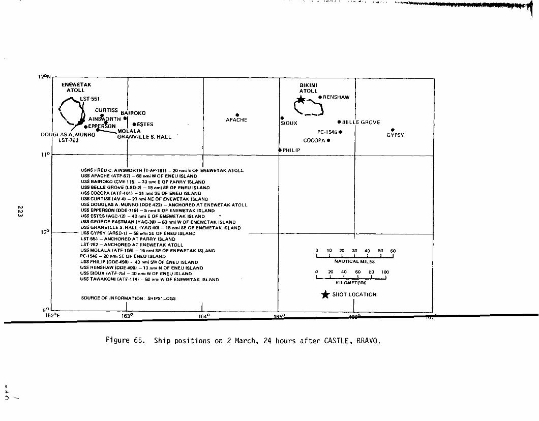
tor+w
120,
DC
11’
10(
~
\ AINStJRTI-I●L $
L ‘ “’s”’s●EPPR N
MOLALA;LASA.MUNROLST-762 GRANVILLES.HALL
I
APA:HE
IUSNS FRED C, AINSWORTH (T-AP.IE1 ) – 20 nmi E OF I%EWETAK ATOLL
USS APACHE (ATF67) – 68 nmi W OF ENEU ISLAND
USS BAIROKO (CVE.1 15) – 33 nmi E OF PARRY ISLAND
USS BELLE GROVE (LSD-2) – 15 nmi SE OF ENEU ISLAND
USS COCOPA (ATF-1OI) -21 nmi SE OF ENEU ISLAND
USS CURT18S (AV4) – 20 nmi NE OF ENEWETAK ISLAND
USS OOUGLAS A. MUNRO {DDE422) - ANCHORED AT ENEWETAK ATOLL
USS EPPERSON (DOE-719) -5 nmi E OF ENEWETAK ISLAND
USS ESTES IAGC-12) – 42 nmi E OF ENEWETAK ISLAND -
US6 GEORGE EAsTMAN (YAG.39} -60 nmi W OF ENEWETAK ISLAND
USS GRANVILLE S. HALL (YAG40) -15 nmi SE OF ENEWETAK ISLAND
— USS GYPSY (ARSD.1) – 5S nmi SE OF ENEU ISLAND
LST551 – ANCHORED AT PARRY ISLAND
LST.762 – ANCHORED AT ENEWETAK ATOLL
USS MOLALA (ATF-106) – 15 nmi SE OF ENEWETAK ISLANOPC-1546 – 20 nmi SE OF ENEU ISLANDUSS PHILIP IODE498) -43 nmi SW OF ENEU ISLANDUSS RENSHAW (ODE49) – 13 nmi N OF ENEU ISLAND
USS SIOUX (ATF.75) – 30 nml W OF ENEU ISLAND
USS TAWAKONI (ATF-1 14) – S0 nm~ W OF ENEwETAK ISLAND
SOURCE OF INFORMATION; SHIPS’ LOGS
I I
., .<. .,4 ..! ., .(, .,,
BIKINIATOLL
63●RENSHAW.
-~);Ioux ● BEL
PC.15460
COCOPA ●
PHILIP
iGROVE
G?PSY
I
o-
NAUTICAL MlLES
020406080 100
1 I 1 I IKILOMETERS
* SHOTLOCATION
I
162*E 163° 164° 166 0 0,“,
Figure 65. Ship positions on 2 March, 24 hours after CASTLE, BRAVO.

boats for additional hosing after the first hosings. Average intens
was down to 0.002 R/hr by 22 March (Reference80).
The location of the fleet 48 hours after BRAVO is shown in Figur(
At 0830 on 3 March, the Bairoko reentered Bikini Lagoon and anchored
Eneu. Helicopters operated throughout the day from the flight deck {
postponed data-recovery antiother missions. The helicopters landed
canvas ‘bathtub” on the carrier’s deck if they had been to an island
tion where they could have collected radioactivity on their wheels.
bathtub prevented washwater containing the contaminants from flowing
the flight deck (Reference 32).
Some flight deck drains were still clogged and “hot” from the BR
washdown. Readings were about 0.100 R/hr, with one as high as 0.500
Crews unclogged drains throughout the day. Other spots, such as par’
the antiaircraft guns, were decontaminated by hand scrubbing and rin!
Cocomat fenders and canvas were flushed to wash away contaminants, t]
located away from personnel to allow natural decay of residual radio,
ity. Decontamination for the Bairoko was considered complete by the
of 4 March (Reference 32). ‘
Contamination of Bikini lagoon water by radioactivity was consid
threat to fleet operations there after each shot. By ~ days after B:
contaminants on the order of 1 microcurie per liter (pCi/1) began to
pear; following a buildup, however, the level of contamination began
fall after 10 days. Drinking water distilled from lagoon waters sho
significant radioactivity. Some radioactivity built up outside ship
water pumps, drains, and other installations. The highest noted real
of this kind was 0.030 R/hr on the outside of a condenser on the USS
Curtiss (Reference80).
EVACUATIONS
The TG 7.4 radsafe officer sent by the Commander, Test Services Un
NP.EP,along with two other WREP personnel, to determine the radiologic
224
1.
I
L-
S
;0
~r.
)f
1.
v-
1
la
),
no
.t-
1

APACHE1201
11(
1of
ENEWETAKATOLL I
/’)Sioux
●
\&
f
MOLALAYAG-40CURTISS
I
NICHOLASEPPERSONLST.551AINSWORTH
uSNSFRED C. AINSWORTH (T-AP-181) –ANCHORED
TAWAKONIG:ORGEEASTMAN
● LST-762
1 ENEWETAK ATOLL
USSAPACHE(ATF671 –83nmiNEOF ENEWETAKISLANO
USSBAIROKO{CVE.1 15)–20nmlEOF ENEUISLANO
USSBELLEGROVE (LSD-2)–ANCHORED ATBIKINIATOLL
USSCOCOPA(ATF-1O1) –ANCHOREDAT BIKINI ATOLL
USSCURTISS(AV4) –ANCHOREDAT ENEWETAKATOLL
USSEPPERSON (OOE.7\9) -ANCHOREOAT ENEWETAKATO~L
USSESTES{AGC-12) –20nmiSWOF ENEUISLANO
USSGEORGEEASTMAN (YAG-39}–88nmi WOFENEUISLANO
USSGRANVILLE S.HALL(YAG40) –ANCHOREDAT ENEWETAKATOLL
USSGYPSY(ARSD-1) –ANCHOREDAT BIKINI ATOLL
LST-55\ –ANCHORED ATENEWETAK ATOLL
LST-762–72nmi SWOF ENEU ISLAND
USSMOLALA(ATF-1ON –ANCHOREDAT ENEWETAKATOLL
USSNICHOLAS (DOE449) –ANCHOREOAT ENEWETAKATOLL
PC-1546 -23nmi SEOF ENEUISLANO
USSSIOUX(ATF.75J -38nmiNEOF ENEWETAKISLAND
USSTAWAKONI {ATF-114) –S8nmiWOF ENEUISLANO
SOURCE OF INFORMATION. SHIPS’LOGS
bE 163° 164° 1
BIKINIATOLL
c>. BAII
‘- [GYPSY.
3K0
“BELLEGROVEEST?S ~ COCOPA
1
● PC-1’546
o 10 20 30 40 50 60
NAUTICAL MILES
o-wKILOMETERS
* SHOTLOCATION
ID 1660 167°
Figure 66. Ship positions on 3 March, 48 hours after CASTLE, BRAVO.

I
condition at Rongerik, left on the Navy UF-1 amphibian from Kwajaleir
t 0800 on 2 March. The aircraft was over Rongerik at 0945 and took fl~
measurements of the occupied island of the atoll and then the entire
at altitudes of 500 feet (153 meters) and below. The readings were (
I R/hr at 500 feet (153 meters) and 0.350 R/hr at 25 feet (7.6 meters)
erence 16, p. K-7).
The UF-1 then climbed to 5,000 feet (1.52 km) in an attempt to cc
municate directly with the Estes, then at Enewetak; the TG 7.4 radsaf
officer wanted an additional amphibious airplane from Enewetak to aic
evacuation. Some garbled and ineffective transmissions ensued, follc
by a message denying permission for evacuation and then one permittir
The radsafe officer had decided to evacuate the island on the basis c
own evaluation of the local situation; it is not clear whether any OK
of the Enewetak messages were received by the UF-1, which was descenc
to land in the lagoon at 1130.
On Rongerik, the radsafe officer quickly briefed the detachment ~
sonnel on what he knew, asked the warrant officer in charge to select
men for evacuation, and made a hasty radiological survey with the fol
results (Reference84):
1. Inside the building where the men spent most of theirtime (the reading, however, was regarded as low be-cause the building had been hosed down thoroughlyearly in the morning): 0.6 R/hr
2. Outside the same building at waist height as taken infront of the building on the pierced steel plankingplatform: 1.8 R/hr
3. Beside the same building at the sand surface: 2.4 R/hr
4. Surface of a bed in a living tent: 1.2 R/hr.
At about 1230 the arnphi.bian left the lagcxm and arrived at Kwajalei
at approximately 1400 with the eight evacuees and the three WREP repre-
sentatives aboard. The men were taken in the alphabetic order of their
last names.
226
.1
)
~-
:.
.s
~ht
.ng
two monitors were especially briefed to make readings at waist h
use several meters of the same type for comparison, and to use d
types for cross-checking.
Because no other amphibious aircraft were available, the :
‘:rewreturned after a brief lunch at Kwajalein, where the car$
.~eantfor Rongerik was offloaded. The UF-1 returned to Kwajal
1330 with the remaining 20 men from Rongerik (Reference84).
A conference was held at 1330 at which the task force rad:
the task force and task group commanders, and the Scientific [
viewed what was known of the fallout situation. A decision h?
~lbeit at the local level, to evacuate the U.S. personnel on I
now the other atolls in the vicinity had to be considered.
As part of the offsite fallout monitoring program of the $
and Safety Laboratory, postshot flights were conducted over al
shahs. Several patterns, designated Able, Baker and Charlie,
by VP-29. Able, a flight over the northern Marshalls, was unc
2 March.
Before the conference was over, an inflight report from f]
indicated 1.350 R/hr at 1340, 2 March, extrapolated to ground
Rongelap Island, 0.400 R/hr at 1328 at Ailinginae, and 0.001 1
at Wotho. It was decided that evacuation of Rongelap was necc
that other islands likely to be involved would be determined I
readings of the remaining portion of the flight Able pattern (
ence 26).
Accordingly, the destroyer Philip left for Rongelap immedi
structions were issued to dispatch an Air Force SA-16 amphibia
with two radsafe monitors to check surface conditions at Ronge
dark. The destroyer was directed to be off Rongelap ready to
ation at dawn the following day. A Trust Territory representa
interpreter were requested to move by PBM seaplane from Kwajal
rive at Rongelap at the same time. The SA-16 flight was set uwiyht, to
fferent
227
UF-1 and
riginally
at about
officer,
:tor re-
?en made?
?rik~ and
iealth
Ie Mar-
:e flown
sy on
t Able
51 at
at 1300
cy and
the
sr-
ly. In-
Light
before
(t evacu-
~ and an
to ar-
nd the

An average reading of 1.400 R/hr at approximately 1700 taken
living area of Rongelap Island by these monitors supported the de
that same night to order the Philip to commence evacuation operat
dawn. Evacuation began about 0730, 3 March, and was completed by
It developed that all the people on the atoll but away from the 1
area had returned home after BRAVO in order to discuss the unusuz
ena of the visible light and audible shock. This factor simplifi
ation by concentrating all natives on the home island of RongelaE
Interrogation of the Rongelap people disclosed that all were
except for 18, who were fishing at Ailinginae. Following the Ror
operation, the destroyer proceeded to Ailinginae, removed the ren
and proceeded to Kwajalein. A total of 17 male and 20 female adt
15 male and 14 female children were removed by destroyer and deb?
Kwajalein. An additional 16 old and sick were removed from Rongc
PBM at about 0930 and flown to Kwajalein. All evacuees underwent
lamination procedures during the trip to Kwajalein, and again on
(Reference 65).
The full report from flight Able, received at approximately 1
2 March, indicated Utirik ground contamination of 0.240 R/hr at 1
2 March, and contamination of 0.076 R/hr at about 1716, 2 March,
the nearest populated island to the south. Bikar, the nearest i:
the north, was contaminated to about 0.600 R/hr at about 1628, 2
but was determined to be unpopulated. Taongi, the next nearest :
the north, showed 0.014
these readings, another
anticipate an
flew monitors
destroyer was
for Rongelap,
Utirik people
order for
to Utirik
R/hr at 1525; it was also unpopulated. 1
destroyer (the Renshaw) was sent to Utir:
evacuation at dawn on 4 March. Meanwhil(
on 3 March to conduct a ground survey wh:
on the way. This ground survey, conducted similar:
indicated 0.160 R/hr at 1830, 3 March. The exposuj
was computed at 58 R if they remained on the atoll
228
I the
sion
ms at
030.
ping
\nom-
racu-
mt
)
lg 18
md
at
)y
m-
~lein
Lluk,
to
1,
i to
on
?BM
Ie
that
the

The destroyer was subsequently ordered to start evacuation
~ng morning, 4 March. Between 1100 and 1300, 157 people were
inderwent decontamination procedures on the destroyer en route
lein, and debarked on 5 March. Questioning of Utirik inhabita
closed that all had been evacuated. The destroyers evacuating
and Utirik were also directed to obtain drinking water samples
atolls. A check of these samples indicated the drinking water
from 2 to 28 times the task force standard allowance of radioa
:a,minants(for full-time usage) (Reference 65).
The status of Ailuk Atoll, with a reported population of 4
under consideration at approximately 2000 on 2 March. The exF
without evacuation was determined to be less than 20 R, i.e.,
the standard used by the task force for its sampling aircraft
was the major factor in the decision not to evacuate Ailuk. A
populated atolls on the flight Able pattern received less cent
than Ailuk (Reference 26).
During the afternoon of 2 March, a directive was issued to
offsite monitoring flights Baker and Charlie on 3 March. Thes
covered all Marshall Islands south of Kwajalein and were condu
termine whether winds at the 20,000-foot (6.1-km) level could
debris to the south.and west and contaminated some of the sout
shahs. The flights were executed on 3 March, but no signific
contamination was found. An additional flight (designated Kin
the Gilbert Islands on 6 March for the same reasons. At the r
the task force, CINCPAC obtained advance clearance from the Br
the Gilberts flight. A maximum of 0.00008 R/hr on 6 March was
through CINCPAC to the U.S. Naval Attache in London (ReferencC
p. K-10).
Throughout the actions involving evacuation of island inh~1
e follow-
oved,
Kwaja-
dis-
ngelap
om these
ntained
ve con-
came
ed dose
s than
#s● This
~ther
nation
acute the
Lights
3 to de-
s carried
n Mar-
ground
severed
Sst of
~h for
yx ted
t
ants, the
----+
standard reference used to determine whether an atoll was popula ed was
OpNav 122-1OO-M, June 1951, Trust Territor
229

Because of the 18 people on Ailinginae (reported to be unpopulated
firmation of the status of other atolls involved in significant f
was obtained from the Trust Territory representative at Kwajalein
particular interest were Bikar and Taka for BRAVO fallout and Tac
future shots. These atolls proved to be unpopulated as reported;
ple on Ailinginae were not permanent residents, but only temporar
Ailinginae to fish.
The offsite fallout findings, summarized by a member of the C
Advisory Group, are presented in Table 22.
PATAPSCO CONTAMINATION
The Patapsco, a gasoline tanker, was moored at Enewetak to un
ation gasoline 2 days prior to the BRAVO detonation. The ship wa
to leave and proceed at full speed from Enewetak to Pearl Harbor
it lacked adequate radiation equipment and protection gear. The
speed was reduced to one-third full speed on 28 February, however
of a cracked cylinder liner. The ship was about 180 to 195 nmi (
361 km) east of Bikini when BRAVO was detonated.
The ship had been vectored approximately along the BRAVO C1OU
line by the transient shipping search aircraft on D-day afternoon
early to mid-afternoon of the following day (H+31 to H+32.5), at
of about 565 to 586 nmi (1,051 to 1,084 km) from ground zero, it
receive fallout. The intensity of the fallout radiation is not a
known. Flight Able reported that a little later in the afternoon
(290 nmi 537 km east of Bikini) was reading about 0.600 R/hr.
made by analysts working with the rates measured when the ship ar
Pearl Harbor range from as high as 0.620 R/hr (Reference 85) to O
(Reference86).
No steps to decontaminate the ship were taken en route to Pea
because it appeared to those on board that the level of radiation
low to cause concern. The ship arrived at Pearl Harbor on 7 Marci
230
con-
Ut
f
for
pee-
at
avi-
dered
use
,1s
cause
to
t
[n the
mge
m to
:ately
:ar
mates
!d at
1 R/hr
larbor
s too
nd was

Table 22. Offsite fdllOllt su,n,,ldry,L;\>lL~, UI{?,L(J.
.— .— — _
AverageResultant
Fallout Infinity Mind SpeedTrue Distance Time of Intensity Dose Intensity
Location Bearing (nmi)bIntensity to Tropopause
Arrival (R/hr) (R) (R/hr) Time (R/hr) Time (knots)c
LaeUjdeWothoAilinginaeRongelap Atoll
Enewetak Is.Rongelap Is.
RongerikTaongiBikarUtirikTakaMejitAiluk
Nu Jemow Likiep
NamAilinglapalapArnoMajuroAurMaleolapErikubWotjeKusaiePonapeUjelangPingelap
160170154115
105109098052084096097104107110115142142127128122117119114200235245229
17416810079
98.5100133280285270261340291268262265338641441400387321321225503286426
Note:
H+39H+37H+13.2H+3.6
H+5.4H+5.6H+8
H+lfj.3H+21.6Ii+20.3H+30.2H+27.1H+24.8H+26.2
H+42.3H+40.()H+39.1)
0.000080.0001
0.0023 0.17 0.001012.000- 220 0.445 H+58
46.800 4,200 3.000a H+53.29.800 350 1.4ooa H+369.000 350 2.000 H+28.5
0.0014 H+32.61.400 120 0.600 H+330.450 48 0.160 H+550.290 0.160 H+34
0.110 13 0.076 H+34.80.018 H+34.70.006 H+34.90.000016H+48.50.00008 H+38.90.0006 H+51.60.0020 H+51.40.00036 H+50.90.0036 H+50.60.0040 H+50.20.0200 H+50.O0.0005 H+54.4
0.0020 H+49.5
3.23.2
0.400 H+2sI.7 ;:!/
8.91.350 H+3(3.9 8.9
10.4Fringe effect only
14.410.210.49.68.98.88.14.24.85.35.55.97.16.86.0
bOne nautical mile equals 1.85km.
I
cOneknot equals 1.85 kmjhr.
Source: Reference 26.

placed under restricted availability on 9 March. On 22 March, the P3tapsco
crewmen and Pearl Harbor Naval Shipyard personnel started to decentalinate
the ship.
OPERATIONS AFLOAT
By 4 March, most of the fleet units were again in Bikini Lagoon. The
major units had withdrawn to Enewetak to offload excess TG 7.1 and 7 5
personnel on 1 March and prepare for the BRAVO follow-on operations.
The land areas of Bikini, as well as the lagoon surface, had rec ived
I
a heavy fallout of the contaminated coral particles from the BRAVO s ot.
Readings in tenths of roentgens per hour on Eneu in the southeast of the
atoll, and in tens of roentgens per hour on Lomilik in the north, we e
made 10 days after BRAVO. This meant that personnel could go ashore nly
for short periods of time, but even then their cumulative doses buil up.
The situation aboard ships in the lagoon was such that long-term en-
ancy was possible.
I
The fallout particles sank to the bottom and the ver-
lying water shielded the ships from the particles! radioactivity.
1The land area in the southern string of islands had radiological de-
cayed sufficiently by this time that work crews could go ashore and s ay
long enough to clear the airstrip joining Aerokoj and Aerokojlol. T s
restored better air transportation between Bikini and Enewetak, which had
been reduced to flying boat service in the interim.
Task force personnel lived aboard the major ships at Bikini and c m-
muted via small boat or helicopter if work was required ashore.
I
Care ul
control of exposure was required to avoid buildup over the Maximum l?e-
missible Exposure.
OFFSITE OPERATIONS
BRAVO affected offsite operations. IMuch effort was spent in resu vey-
ing the atolls that were evacuated immediately following the test.
I
T e ob-
leCt was to better establish the doses the inhabitants received and t do
some preliminary research on absorption of radioactive materials by f ora
232
1

~.?tifauna. This was
‘ing similar work on.-.
The survey teams
7!S7.3.1). The vessels
surveyed were (Reference
5 Mar - 8 Mar
8 Mar - 12 Mar
25 Mar - 6 Apr
21 Mar - 3 Apr
performed by personnel, including DOD, WI
the Enewetak shot (NECTAR) in CASTLE (Re:
were carried aboard ships of the Surface
used, the dates of the surveys, and ~
16):
Renshaw Likiep, Jemo, Ailuk, Mej.
Nicholas Utirik, Bikar, Rongerik,Ailinginae, Rongelap
Nicholas Rongelap
* Rongelap, Ailinginae.
The 8 to 12 March survey disclosed that personnel protect
:equired in some areas. Figure 67 shows personnel leaving th(
~haleboat 9 March on Rongelap with feet wrapped in “booties” 1
picking up contaminated material on shoes. Figure 68 shows a
crewman on Rongerik the following day holding a sick rat. He
heavy gloves, but appears to be wearing ordinary sneakers wit]
#
Figure 67. Post-CASTLE, BRAVO survey personnel at Ronge
233
were plan-
ence 3).
curity Unit
islands
was still
icholas
n to avoid
cholas
wearing
t booties.
-.
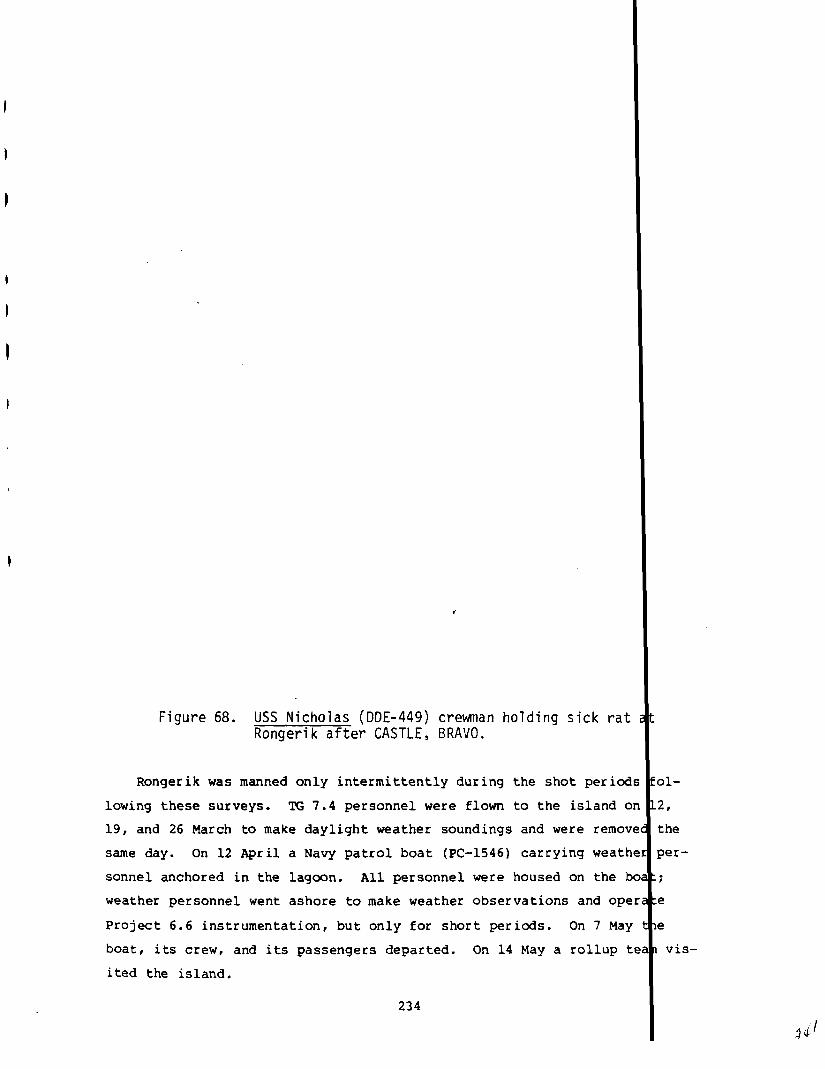
Figure 68. USS Nicholas (DDE-449) crevwnanholding sick rat atRongerik after CASTLE, BRAVO.
Rongerik was manned only intermittentlyduring the shot periOds fol-
lowing these surveys. TG 7.4 personnel were flown to the island on 12,
19, and 26 March to make daylight weather soundings and were removed the
same day. On 12 April a Navy patrol boat (PC-1546)carrying weather per-
sonnel anchored in the lagoon. All personnel were housed on the boat;
weather personnel went ashore to make weather observations and operate
Project 6.6 instrumentation,but only for short pericds. 0n7M ay tle
boat, its crew, and its passengers departed. On 14 May a rollup tea~ vis-
ited the island.
234

. .
.:~,~l{oFALLOUT EXPOSURES
3RAV0 was without question the worst single incident of fa
.I:resin all the U.S atmospheric testing program. The accumul
:zntours after 96 hours are shown in Figure 69. Not only were
:zcy personnel involved, but also foreign nationals and Marsha
out expo-
ed dose
‘.S.mili-
Islanders.
The cumulative nature of the Consolidated List of CASTLE Ra~iological
Zxposures (Reference13) makes it impossible to assign portions of the
~?rsonnel exposure to BRAVO, as opposed to the CASTLE series as a whole.
:ke microfilm file of cards (Reference87) on which it is presu1ably based
I~hows, in some cases, event-by-event exposures, and estimates w re made
for portions of the task force at the time. Other estimates ha
Oan be made for other personnel involved.
7ask Group 7.3 Exposures
In summing up BRAVO operations, the Navy prepared a tabulat
:xposures of the appropriate fleet units (Table 23), and the cc
~o the BRAVO collective exposure by TG 7.3 forces can be derive
This tabulation was through 22 March and contains exposures rec
potentially hazardou~ decontamination activities and the survey
the crews of the Renshaw and the Phili~ to the contaminated is]
Rongelap Atoll.
ENEWETAK-BASED PERSONNEL. Badges were exposed on Enewetak
locations and some of these, at least, are included in the micr
of 5x8 cards (Reference87) from which Reference 13 is derived.
these badges, marked 103and 106, were placed in the 8600th AAU
the “Laundry Area;” they read 0.075 R and 0.110 R, respectively
control film 4904-10). The cumulative exposure record of units
ence became unnecessary after BRAVO, (that is? TU 2 and 3 Of TG
Chapter 3) and probably left the PPG before the completion of t
is consistent with the two badges above. A credible exposure f
nel on Enewetak for the BRAVO period is 0.1 R.
235
e been or
n of the
ribution
from this.
ved in the
isits by
ds of
fixed
ilm file
Two of
rea and
Index 1020
hose pres-
.1; (see
series?
person-

.
EFFECTIVE ARRIVAL TIME (hours)
o 6 7 8 9 10 11 12 13 14 15 16 17 18 19 20
I I I I i I I I I I I I I I 1
BIKAR ATOLL
GROUND Q,l
%z=i!!!s
. ‘R?xiEILA’~
BIKINI \\~ // UTIRIK ATOLLAATOLL
\~– A;;RONGERIK TAKA ATOLL ~1&14
I I I AILINGINAE ATOLLI 1 1 I ! I I I
o 10 20 40 Go 80 100 120 140 160 180 200 220 240 260 280 300 320 340
DISTANCE FROM GROUND ZERO (statutemiles)
1, I I I I I I I I I i
o 50 100 150 200 250 300 350 400 450 500 547
DISTANCE FROM GROLJND ZERO (kilometers)
L I 1 I 1 I I I I I I Io 27 54 81 108 135 162 189 216 243 270 296
DISTANCE FROM GROUND ZERO (nauticalmiles)
Figure 69. Estimated total (accumulated) dose contours (rad), CASTLE, BRAVO H+96(source: Reference 88, p. 437).
—--,——- . . ,. ....--> .-..,4.,.?,-. ,,O--- —.V, --- . -— 1

Table 23. Summary of accumulated radiatiorl exposure tur CAL-ILL, LkA’tiONavy el,ll[~ll~s.a
——. .— ——Exposure (R)
o.o- 1.o- 2.0- 3.0- 4.0- 5.0- 6.0-Unit 0.999 1.999
7.0- Over2.999 3.999 4.999 5.999 6.999 7.8 7.8
TG 7.3StaffUSS Bairoko (CVE-115)~USS Curtiss (AV-4)VP-29USS Estes (AGC-12)USSBelle Grove (LSD-2)
. 3 Boat PoolLST-762LST-551USS E erson (DDE-719)
- (,,E-449)
IQ ~(DDE-499)
u4
w ‘DDE-498)
%?%%%%)
m
m
m
YAG-39 (Uss Geo;ge Eastman)YAG-40 (USSGranville $. Hall)TG 7.3 Underwater Detection Unit
10448
7094321451661041281042982922593053
47227 40 54 64 996 . 15 4 1
376 115 3 5 7148 2296 17 8 4 1
71 64632 29
1:
1
1
74 9 10 5
1
3 3
Project 1.4 AircraftProject 6.4 Aircraft :VC-3 20
Total Exposures 3,936
23
1,100 325 144 83 27 7 3 3Dm.-cA-h s T* 1
“. . J.I 1> . .)J 3 . II L . ~b 1.4/ O 48. 0.12 0.05 0.05
Note:I
aAsof 22March 1954.
Source: Reference 80.

TASK GROUPS 7.1 AND 7.5 BIKINI PERSONNEL. For the elements 0: TG 7.1
and TG 7.5 at Bikini, the mean value of the crew of the ship to w~ich they
were evacuated has been used to calculate collective exposure. Tlis may
result in both overestimates and underestimates, depending on ass mptions.
Task Group 7.4 Exposures
The contributions to the JTF 7 collective exposure from the s;mpler
aircraft flight crews and ground personnel have not been consider~d in this
summary, as they cannot be readily extracted from Reference 13 or simply
estimated. Detailed records, however, are available on cloud trac<er and
sampler aircraft contamination (Table 24).
For BRAVO, the initial radioactive decay period was 20 hours 0: more
before decontamination was undertaken. The reading of 12.000 R/hr on
4 March for WB-29 No. 7335 is probably a typographical error in th(isource
document (Reference 30). Other records (Reference 29) indicate th,t 4.755
R/hr was the highest contamination read on an aircraft from BRAVO, and
that was on 1 March. Since the figure of 4.755 R/hr is not shown :n Table
24, it was probably recorded on an aircraft for which there are no data in
the 4926th document (Reference 30). The reason a reading of 12.00C R/hr
on 4 March is of some concern is that it means the radiation intensity on
1 March-1.2
could have been 2,000 R/hr (t decay rate), a most unlikely leve.. If
0.120 mR/hr was the actual 4 March reading, then on 1 March the int?nsity
could have been 20.300 R/hrt which is within bounds for similar air:raft
on other events. Because of a reported immediate wash with a subse(:uent
reading of 0.065 R/hr, more validity can be associated with a readil[gof
0.120 R/hr for the first survey. Another late first survey was on I-84G
No. 038. Applying similar assumptions, the 1 March intensity could have
been around 1.520 R/hr. By the same token, B-36 No. 1086 on 1 Marck might
have had a reading of some 50.000 R/hr.
Personnel Exposures -- Rongerik
Twelve film badges were issued by TG 7.1 radsafe for
this remote weather station. These badges were numbered
238 Ithe person 1
00309 thro h
on

Table 24. Task Group 7.4 CASTLE, BRAVO aircraft decontam
First Survey SecondSurvey
Aircraft TypeType/ Reading of ReadingTailNo. (R/hr) Date(Time) Decon (R/hr) Date(Time)
%-3611083 1.400
i3-36/1086 1.100
W-2917335 12.000
F-84/030 2.800
F-84/032 2.800
F-84/033 3.800
F-84/037 3.400
F-84/038 0.009
F-84/042 0.090
F-84/043 0.190
F-84/045 0.190
F-84/046 0.400
F-84/053
1 Mar (1200)
2 Mar (0900)
4 Mar (0830)
1 Mar (1400)
1 Mar (1400)
1 Mar (1400)
1 Mar (1400)
4 Mar (1415)
4 Mar (1415)
4 Mar (1425)
4 Mar (1725)
1 Mar (1400)
4 Mar (1430)
Oecay
Decay
Wash
Decay
Decay
Decay
Decay
Acid
Acid
Acid
Acid
Decay
Acid
0.500
0.800
0.065
0.105
0.045
0.130
0.120
0.028
0.028
0.070
0.049
0.180
4Mar (0245)
4 Mar (???)
4Mar (1510)
4 Mar (0945)
2 Mar (0950)
4 Mar (0955)
4Mar (0940)
4Mar (1515)
4Mar (1515)
5 Mar (1400)
5 Mar (1530)
4Mar (1605)
5 Mar
ThirdSurvey FourthSurvey
‘Aircraft Type. ToType/ Reading of Reading DeTailNo. (R/hr) Date(Time) Decon (R/hr) Date(Time) Ho
B-36/1083
B-36/1086
F-84/030
F-84/032
F-84/033
F-84/037
F-84/038
F-84/042
F-84/043
F-84/045
F-84/046
F-84/053
0.280 4Mar (1130) Wash 0.080 5 Mar (???)
0.400 2 Mar Wash 0.400 3 Mar (???)
0.105 4 Mar (1400) Wash 0.060 5 Mar (0830)
0.018 4Mar (1127)
0.018 4Mar (1127)
0.030 4 Mar (1205)
0.020 5Mar (1500)
Released
0.060 Released
0.030 5 Mar (1630) Gunk Released
0.042 5Mar (1750) Released
Released
Note:
aAircraftmaintenancecrewsdecontaminatedthe aircraftafterBRAVO.practicewas changedfor therestof theCASTLEshots.
239
ation.a
TypeofDecon
Wash
Wash
Acid
Acid
Acid
Acid
Gunk
Gunk
Gunk
Acid
Gunk
TotalI Decon; Pet-s
17
17
16
5 16
5 16
5 16
16
5 16
16
16
.5 16
16

00320 and were sent to Rongerik on 25 February by the TG 7.4 Tech
Advisor (Reference 30). Four of these badges apparently were act
worn by four of the twenty-five men from the 6th Weather Squadron
Two others were placed on exposed positions on the island. One (
00315) was placed “between barracks,” presumably between the bloc
“l” and “2” on the sketch map (Figure 63), and recorded 82 R. Th
badge in an exposed location was 00314, which was placed on a ten
7 feet (2.1 meters) above the floor of the “Project 6.6 tent” and
98 R. The six remaining badges were stored in a refrigerator (pr
the “reefers,” on the map of Figure 63), and all recorded 37.5 to
(Reference65).
An assignment of exposure to personnel was made by the TG 7.4
cal Advisor and was recorded by the NCO in charge of dosimetry an
lamination in the TG 7.4 Nuclear Applications Section. This assi
has
can
been filed along with the 5x8 cards on which Reference 13 is
be found in the microfilm file (Reference 87).
Unfortunately, in this assignment of exposure, two errors wer
that in turn have been picked up in Reference 13. The first erro
that 15 of the 25 Air Force personnel established as being on Ron
were not assigned an exposure. The second error was the assignme
exposure to a surname not otherwise established as belonging to a
known to have been on Rongerik at the time. The person with this
not accompanied by given name, rank, or serial number, or other i
cation, was recorded in Reference 13 as having received 40 R. Th
ment of the other
of the 9710th TSU
badge (98 R), and
men’s exposures is straightforward. The three
were assigned the exposures from the “6.6 tent”
the ten Air Force men were assigned exposures b
40 R and 52!R, based perhaps on a knowledge of their activities.
PATAPSCO CREW. The contribution of the crew of the Patapsco
collective exposure is based on a recent estimate that considered
natural washdown provided by documented rain and the weather-deck
below-deck exposure (Reference 86).
240
31
Ly
Sre.
3e
narked
?cond
~le
corded
nably
.5 R
chni-
econ-
ent
ed and
ade
as
ik
of an
Ran
rname,
tifi-
ssess-
y men
le
een
the
e
rsus

HARSHALL ISLANDS POPULATION. Estimates for exposures to bcth U.S.
:sonnel and Marshall Islanders were made in the Project 4.1 Cfter-action
~~ort (Reference65) and have been used here. The unevacuate6 population
.Ailukwas not included in the Project 4.1 information, but it.- may be
i~ply estimated by comparing the intensity of the readings ma
and nearby Utirik at nearly the same time on 2 March. 1
All of these have been summed up in Table 25, which present
:sllectiveexposure as a result of BRAVO and how it was distrik
;Ioups. Comment on this table appears in Chapter 11.
‘ADIAT1ON EFFECTS AND MEDICAL OBSERVATION;,FTASK FORCE PERSONNEL
The Rongerik detachment of 28 that was evacuated to Kwajale
came in two groups, the first eight arriving at approximately 1
and the second group at about 1830 hours.
Upon arrival the men were checked for the presence of radic
terials on their bodies. There they showered to remove the mat
first group had from 7 to 11 showers an’dthe second group had 5
contamination present and the decontamination results of the sh
shown in Table 26.
After about a week at Kwajalein, the Air Force and Army per
evacuated from Rongerik were returned to Enewetak Atoll (Refere
It was decided by higher headquarters to bring the 2personnel to Enewetak for further physical examinationand to relieve the Kwajalein Hospital, whose facilitieswere limited in the field of radiological medicine, ofthe responsibility of those men. The first group arriv8 March and the remainder followed the next day, and alwere quartered in the Enewetak Post Infirmary where daiblood counts and physical checks were instituted.
On 17 March the group was moved back to Kwajalein to be “ex
specialists in radiological medicine in a location more remote
possibility of future contamination” (Reference 15). However,
241
t Ailuk
he total
d among
by air
hours
ive ma-
al. The
ch. The
rs are
ne1
15):
ned by
m the
13 March

Table 25. Summary of estimated fallout exposure for CASTLE,
Mean Collective Exposure
GroupGamma
Persons Exposure (R) (man-R) (%)JTF 7
Headquarters
Task Group 7.1
EnewetakBikini
Task Group 7.z
Task Group 7.3
Task Group 7.4
Task Group 7.5
EnewetakBikini
Rongerik Detachment
Total JTF 7
- (AOG-1)
Total U.S.
Rongelap Marshall Islanders
Rongelap Islanders onAilinginae
Utirik Marshall Islanders
Ailuk Marshall Islanders
Oaigo Fukuryu Maru
GrandTotal
86a
520c485c
l,287e
5,628f
1,7259
I,zohSgoh28
11OJ
64i
lsi
157i
401’23n
O.lb
o-lb0.5 - z.4d
O.lbIf
O.lb,o
o-lbO.sd
78i
3.3k
175i
egi
14i
4m
290n
9
52447
129
5,628
173
122295
2,184
9,039
363
9,948
11,200
1,242
2,198
1,604
6,670
<1
<11.4
<1
17.4
<1
<1<1
6.7
27.9
1.1
30.7
34.6
3.8
6.8
5
20.6
32.316 100SOUrCeS and Notes:
aConsolidated List of CASTLE Radiological Exposures (Reference 13).
bMicrofilm 5x8 cards (Reference 87, Index 1020 control film 4904-10).
CTG 7.1 Installment History, May Installment, p. 20 (Reference 8).‘Mean of ships used in evacuation weighted by number of personnel (Ibid)
‘TG 7.2 History (Reference 10, April-May Installment).
‘Table 23 (Source: Reference 80).
‘CTG 7.4 Final Report (Reference 24).
‘Completion Report (Reference 5, pp. 4-6, 4-7).
‘Reference64, p. 7.
‘Muster roll.
‘NOSC memo 25 Jan 1979 (Reference86).
‘RadSafe Vol 2 (Reference 16).
‘Estimated as ratio of Utirik.
‘Voyage of Lucky Oragon (Reference82, p. 158).
oooes not consider sampler aircraft Crew.
242
BR Jo.
I
,;

Table 26. Contamination readings of Rongerik pers[after CASTLE, BRAVO (R/hr).a
.001- .006- .011- .016- .026- .()!o .005 .010 .015 .025 .050 .Of
‘;arPreshower --- 624 6 2 1
After 1st Shower --- 11 9 6 2 --- -.
After Last Shower --- 12 10 5 1 --- -.
2 ;4ar --- 22 6 --- --- --- -..,. ,Apr 27 1 --- --- --- --- -.
ote:
?3Y AN/PDR 27C survey instrument.
Source: Reference 68.
kwo of the Air Force men had already returned to Kwajalein tc
repairing some U.S. Navy electronic equipment.
During this second period at Kwajalein the group was ohs<
medical personnel of the newly established Program 4. This ~
been hurriedly set Up after the BRA~ fallout incident to aic
the Marshall Islanders who were exposed on Rongelap, Ailingir
Utirik. These Marshall Islanders also were at Kwajalein durj
riod. This medical surveillance of the servicemen lasted unt
early April as information on their blood components is giver
gram 4 report until H+42 days (April 11, 1954) (Reference 65,
skin lesions for H+4T days (Reference 65, p. 40), and for beta a
urine for “44 days post detonation” (Reference66, p. 17).
Three men assigned to a Navy Bikini Boat Pool LCM that was w
the Belle Grove presented film badges with BRAVU readings of 85
These apparent high exposures were not discovered until the badg
developed 10 days after BRAVO. Thorough investigation at that t
to reveal how these three men could have received so much radiat
243
)ver,100 High
7 0.250
--- 0.025
--- 0.025
--- 0.010
‘-- 0.0005
.st in
by the
un had
observe
~nd
Iis pe-
t least
the Pro-
72), for
tivity in
rking off
> 95 R.
5 were
r,efailed
Dn. Some
I

discrepancy in badging or wearing of badges is likely, as careful exa
tion of the badges by densitometer revealed nothing unusual in the r~
tion to which they were subjected (Reference16, pp. J-38 and K-67).
men, however, were sent to Kwajalein on 16 March to be observed by tt
ical team. They were transferred on 29 April to Tripler Army Hospitz
Oahu, Hawaii, as part of a contingent of 29 men, where they were disc
to duty after complete, essentially negative, clinical and laborator~
ies were made.
The other personnel transferred on 29 April to Tripler for medic=
servation included 26 of the 28 Army and Air Force personnel exposed
Rongerik. (The History of TG 7.4 [Reference 15] identifies the form{
group of 28 as “Rongerik personnel, now TDY that station.”)
Of the two Air Force personnel who were not among those sent to ~
ler, one was a Warrant Officer and the other a Staff Sergeant. The v
t Officer, involved in electronic repair activity at Kwajalein, was al:
to Majuro on 17 March to assist there in electronic repair work. He
apparently at Majuro during,the week of 22 to 29 April. This probab~
counts for his not making the trip to Hawaii with the remaining perst
The Staff Sergeant returned to the United States early and was at Til
AFB, Oklahoma, on 27 March 1954. His departure from the PPG was an t
gency leave and not connected with his participation in the series.
definitely did not go to Tripler Hospital.
At Tripler the medical observations consisted of the following:
Radioanalysis of urine, feces and blood
Treatment of skin irritations
Psychological consultation
Ophthalmologic examination
Surgical consultation
General physical examination
Complete dental examination
Routine hematology and urinanalysis.
244
na-
3-
hese
ned-
rged
tud-
ob-
P-
rant
sent
s
ac-
el.
r
r-

-.
THIS PAGE
WAS
INTENTIONALLY
LEFT BLANK
IN
ORIGINAL

‘.ssedetails are inferred from a medical record of one of the
?:sonnel involved, since detailed hospital records are not av
a..-whole group.
Air Force
ilable for
The results of these observations were “essentially negati e“ (Refer-
ence 16, p. J-38) for the sailors and they were discharged to
1
uty. Re-
sults for the servicemen in general were described as “general y negative”
in the 15-year review of the medical findings of the Marshall
ho had been heavily exposed (Reference89); but in the 20-yea
slanders
survey,
::e same source simply relates that the
I
“American servicemen w re taken to
TEipler Army Hospital for further examination and later return d to duty”
,Reference64, p. 1). This latter source is an excellent sum
n.andlingand treatment of the Marshall Islanders and contains
:erm medical review of the crewnen of the Daigo Fukuryu Maru c
by Japanese medical authorities.
About 20 days after BRAVO, 16 personnel of the Bairoko and
nel of the Philip were reported to have small skin lesions rest
(Reference16, Annex J, p. J-38). The,lesions were most appar
neck and waist, and reportedly developed sometime between 3 Ma
15 March. When the affected personnel were examined (between
3 April) all lesions were in the process of healing (Reference
p. K-66). The lesions were definitely classified as beta burn
posures evidently occurred while personnel were on the weather
one case for as short a time as 7 minutes. Some below-deck pe
tioned near ventilation blowers may have been contaminated, ho
these units were intermittentlyoperated to reduce the below-d,
245
y of the
.s0a long-
Itributed
person-
ling burns
at the
and
March and
;,Annex K,
Most ex-
)ck-- in
mnel sta-
~er,when
: heat.

cal
CHAPTER 5
TESTS AFTER BRAVO
Test operations following BRAVO were seriously affected by th~
damage and radiological contamination from that burst and by 1
postponements and schedule changes due to unfavorable weather. T]
mander, TU 13 of TG 7.1 cited a number of BRAVO’s effects on subsf
operations (Reference40, p. 16). Among the more important were (
(1) gradual loss of personnel as their total cumulative radiation
exceeded the maximum limit because of radiological contamination f
Atoll land areas to which entry was mandatory for project purpose!
(2) loss of equipment by Projects 2.2 and 2.5 from a secondary fil
by BRAVO on the Eneman Island support facility; (3) conversion frf
based to ship-based operations at Bikini, with attendant difficull
personnel transport, communications, and equipment handling; (4) :
boating conditions at Bikini during delay periods because of unfalc
weather, which restricted maintenance of the experimental test st<
(5) deterioration of test stations caused by salt spray, humidity
and intense sun during the repeated shot-day postponements becaust
favorable weather;
yields.
SCHEDULE CHANGES
The pre-CASTLE
and (6) changes of shot sequence, sites, and p]
schedule called for seven shots as listed in Ti
This schedule reflected a concept designed to preserve the use of
Aerokojlol-Aerokoj airstrip and facilities on Eneman, and on thos
connected to it by causeways, until the last shot. The airstrip T
about 2.5 miles (4 km) from the burst point of this last shot, an{
storage facility was even closer on Lele. Since these would probi
come useless following the Eneman shot, it was placed last.
246
physi-
a many
Com-
~ent
p:
Kposure
Bikini
caused
land-
2s of
vere
cable
ions;
rain,
af un-
dicted
le 27.
he
islands
s only
an oil
ly be-

Table 27. Planned and final sequence of CASTLE events and locations.
Revised RevisedPre-CASTLE Date and Date andTarget Sequence Sequence Actual Originally
Shot Date and (as of (as of Date and Planned ActualName Sponsor Sequence 6 Mar 54) 13 Apr 54) Sequence Yield Location Location
BRAVO LASL lMar (1) ---- (1) ---- (1) lMar (1) 15MT Reef off Nam, Reef off Nam,Bikini Bikini.
UNION LASL 11 Mar (2) 29Mar (4) 16Apr (4) 26 Apr (4) 6.9MT Barge off Barge offIroij, Iroij,Bikini Bikini
YANKEE LASL 22Mar (3) 17Apr (6) 27Apr (6) 5May (5) 13 MT Barge off Barge inIroij, UNION crater,
Nlb Bikini Bikini4
ECHO UCRL 29Mar (4) 24 Apr (7) Cancelled Cancelled --- Eleleron, CancelledEnewetak (
NECTAR LASL 5Apr (5) 8Apr (5) 20Apr (5) 14May (6) 1.69MT Barge off Barge in MIKEIroij, (IVY series)Bikini crater,
Enewetak
ROMEO LASL 15Apr (6) 13Mar (2) ---- (2) 27 Mar (2) 11 MT Barge off Barge inIroij, BRAVO craterBikini
KOON UCRL 22 Apr (7) 22Mar (3) ---- (3) 7 Apr (3) 110 KT Eneman, Eneman,. . .R, b,n,
. . .lb Irll
ISource: Reference 4, pp. 32 and 33. I
IL.:. .: .. . .. . .. . ..... . ...”. .-J::.--,,..!:=:---.,. .,,,,........ .
.,” . ..-. ., ..-, W&-’_-”; .———,____
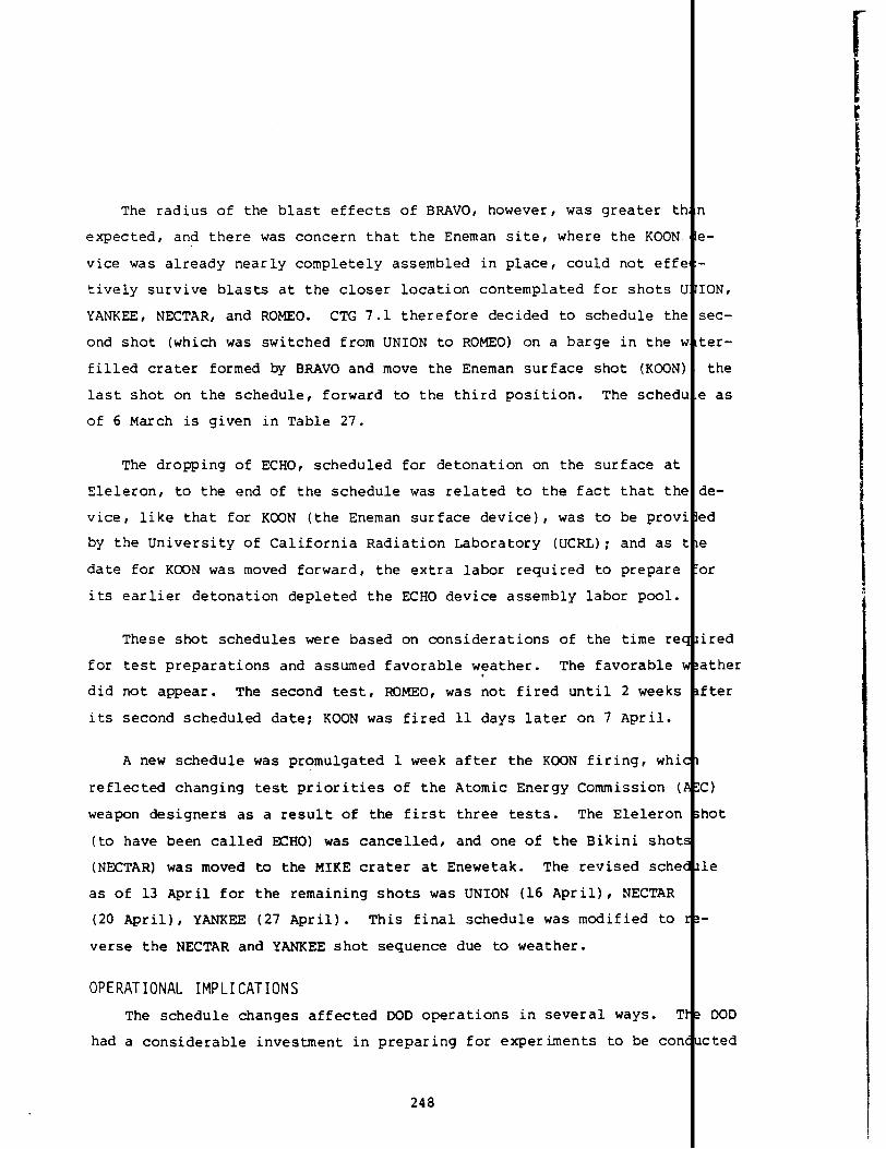
The radius of the blast effects of BRAVO, however, was greater tk
expected, and there was concern that the Eneman site, where the KOON
vice was already nearly completely assembled in place, could not efff
tively survive blasts at the closer location contemplated for shots c
YANKEE, NECTAR, and ROMEO. CTG 7.1 therefore decided to schedule th~
ond shot (which was switched from UNION to ROMEO) on a barge in the s
filled crater formed by BRAVO and move the Eneman surface shot (KOON)
last shot on the schedule, forward to the third position. The sched[
of 6 March is given in Table 27.
The dropping of ECHO, scheduled for detonation on the surface at
I Eleleron, to the end of the schedule was related to the fact
vice, like that for KOON (the Eneman surface device), was to
by the University of California Radiation Laboratory (UCRL);
date for K(2ONwas moved forward, the extra labor required to
that thf
be prov:
and as I
prepare
its earlier detonation depleted the ECHO device assembly labor pool.
These shot schedules were based on considerations of the time ret
for test preparations and assumed favorable weather. The favorable \.did not appear. The second test, ROMEO, was not fired until 2 weeks
its second scheduled date; KOON was fired
A new schedule was promulgated 1 week
reflected changing test priorities of the
weapon designers as a result of the first
(to have been called ECHO) was cancelled,
11 days later on 7 April.
after the KOON firing, whi~
Atomic Energy Commission (
three tests. The Eleleron
and one of the Bikini shot
(NECTAR)was moved to the MIKE crater at Enewetak. The revised sche(
as of 13 April for the remaining shots was UNION (16 April), NECTAR
(20 April), YANKEE (27 April). This final schedule was modified to
verse the NECTAR and YANKEE shot sequence due to weather.
OPERATIONAL IMPLICATIONS
The schedule changes affected DOD operations in several ways. T
had a considerable investment in preparing for experiments to be con
248
1
~-
.
[ON,
;ec-
ter-
the
z as
3e-
?d
~
m
ired
ather
fter
c)
hot
le
DOD
cted

, conjunction with the cancelled ECHO test, but the “loss” of
:’:~ablydecreased the radiological exposure of DOD personnel.
;.!oredisruptive to the DOD operations were the preparation:
subsequent postponements due to weather..2 ROMEO was schedul
‘.3th,the 15th, and the 21st of March; on each occasion instrun
bad to be prepared, timing devices reset, etc. The fact that n
ini was a radiological exclusion (radex) area, which required
“.tisafemonitor to accompany each working party, taxed the cape
::s radsafe unit. Individual projects were exposed to radiatic
-anticipatedways. For example, Project 1.4 reports the elabora
:luresrequired to service instrumentation if the shots were de]
:~an4 to 7 days (Reference 45). Such work was complicated by
:hat it had to be done in the radioactive environment caused by
Support instrumentation, such as Raydist slave stations use
positioning of experimental effects aircraft, had to be service
positioned due to the effects of BRAm and to the changing cone
operation. This required the personnel)from the Armed Forces ~
ons Project (AFSWP) to enter radiologically contaminated areas
equipment (Reference90).
Following BRAVO, the ships and small craft at Bikini assume
icant increase in responsibility. The original planning called
shot reentry to the camps on Eneman and Eneu, but this was impc
The change to an afloat operation at Bikini placed additional r
on TG 7.3. while anticipated as a possibility, this was never
probable before BRAVO (Reference9, p. 114). The single most s
operational effect was related to the employment of ships after
nation. All major vessels were required to remain permanently
for use as housing. Originally the USS Estes was to be station
wetak between detonations. The USS Bairoko had to prepare to c
Bikini helicopter operations from its flight deck. The Air For
ters and one L-13 were returned to Enewetak, and the responsibi
249
—... —.._._
effort
to fire
d on the
ntation
ch of Bi-
trained
ilities of
in un-
e proce-
yed longer
he fact
BRAVO.
in the
and re-
ltsof the
cial Weap-
retrieve
1 a signif-
for post-
;sible.
tquirements
:onsidered
.gnificant
the deto-
~tBikini
pd at Ene-
mduct all
:ehelicop-
.ityof

providing local air transportation at Bikini became solely that of ‘1
(Reference9, p. 134). The Bikini boat pool had a sharply increased
load in order to provide transportation between the shipboard living
ters and work sites.
All ships would evacuate the Bikini Lagoon before all scheduled
The movement of fleet units out of Bikini Lagoon during evacuation n
vers for postponed attempts did have some advantage because it helpe
flush out the contaminated lagoon waters from the ships’ seawater SI
with open ocean water (Reference16, p. L-3), preventing a large bui
of radioactive contaminants within the systems.
ROMEO
Romo, the second CASTLE test, was the first barge-mounted, wat
surface detonation. Because of concern that the experiments being
pared at Eneman for shot KOON might suffer blast damage from ROMEO,
scheduled site was changed from south of Iroij to the BRAVO craterr
was a greater distance from Eneman.
Preshot Preparation ‘
ROMEO was ready to fire on 13 March, and the sequence of sea an
searches, weather analyses, fallout predictions, briefings, and adv
messages to the Commander-in-Chief of the Pacific Fleet (CINCPAC) b
Unacceptable weather delayed the detonation for 2 weeks. During th
riod, the task force maintained an 18-hour standby capability to co
the test.
The weather-caused delays had two consequences for subsequent t
First, the method of conducting air searches for the protection of
sient shipping was changed when it was determined the search plan w
flexible enough to cope with the large geographic shifts in the lon
fallout forecast that could occur between successive tentative shot
The new procedures included specification of an expanded hazard zon
Green, see Figure 16) to control shipping, and the use of three or
250
;7.3
work-
quar-
hots.
neu-
tems
dup
e-
.ts
lhich
air
,ory
an.
,pe-
Iuct
Sts.
ran-
s not
-range
days.
(Area
lore

:adar-equippedsearch aircraft. Second, since initial BRAVO d~ta were
available, the method used to determine the air radex volume, cr area, was
:tiangedfor high-yield bursts. The new method considered the 1nitial ra-
iiation source as an area rather than a point.
On the morning of 26 March, a favorable forecast of H-hour
/
inds for
the following day set in motion once again the entire preshot hedule of
events. This forecast gave east-northeast winds to approximate y 8,000
Seet (2.4 km), southerlies to about 12,000 feet (3.7 km), sout asterlies
to 20,000 feet (6.1 km), southerlies to southwesterlies to abo 55,000
~eet (16.8 km), and east-southeasterlies to easterlies above 5 ,000 feet
(16.8 km). All units and external agencies were notified acco ingly that
the ROME(3schedule was firm for 27 March at 0630.
Following the noon command briefings, CINCPAC was advised c: the fore-
cast 72-hour air particle trajectories for 10,OOO, 30,000, 40,0)O, and
50,000 feet (3.05, 9.15, 12.19, and 15.25 km). The advisory st~ted that
no significant fallout was forecast for populated Marshall atolLs and rec-
ommended no closure ?f air routes. It also stated that no fallout problems
were forecast outside Area Green and that an intensive search was being
conducted in this area, plus a 240-nmi (445-km)wide sector out to 600 nmi
(1,110 km), centered on a true bearing of 340°. (The sector semch was
scheduled and run again ~stshot centered on 305° true fr~ zoo ml [370
km] to 600 nmi [1,110 km] from ground zero. Starting at H-2, f)ur search
aircraft were used on parallel flight tracks, with 60 nmi [111 m] cover-
age per aircraft, in advance of the cloud.) In addition, CINCP4C was re-
quested to divert all shipping from the sector covering 260° cl>ckwise to
90° true out to 450 nmi (833 km) from ground zero. The request included
a statement that no known shipping was in this area. Table 28 ;hows the
known transient shipping near the Pacific Proving Ground (PPG) m shot day.
At approximately 1500 the surface and air radex areas were nnounced1’
as follows:
251

Table 28. Summary of the status of transient shipping in theProving Ground area on or about 27 March 1954.
Vessel Location/Course
PC-1172
LST-1157
LSIL-9035, LSIL-9309(French vessels)
Fishing vessel
Kaiko Maru
Malika (British vessel)
Dai Maru
USS Genessee (AOG-8)
Japanese fishing boat,No. KN2482
Fishing boat
M/V Gunners Knot
M/V Roque
Kwajalein at 0600, 27 March
100401N, 1700141E, course 270, 9.5 kn~km/hr)
190311N, 1680421E, course 270, 10 knotkm/hr)
Last reported 7030’N, 168°E, course 3:further contacts in Area Green and secsearches)
Departed Wake 1545, 22 March; estimat~at 2000 26 March, lOoN, 1740E; destint100N, 1750E
Requested by ComNavFor Marianas at 19[to stay clear of enlarged danger area.
Departed Wake for Japan 0130 22 Marchpoint 20°N, 1650E
14010’N, 179039’W at 1200 on 27 March;Pearl 2200 on 30 March, course 082
Visual/radar search aircraft contact:167°53’E, course 116, 10 knots (18.5 \approximately 1300 on 22 March; patro’diverted vessel to course 90; no furtltact made with this boat
Visual/radar search aircraft contact i
21 March: 190451N, 1610181E, course 1knots (18.5 km/hr), nationality unknokdirection search aircraft turned vess[northeast at 1230; no further contact!with this boat
0600 on 27 March, position 7°10’N, 16[course 270, 10 knots (18.5 km/hr)
0600 on 27 March, Kwajalein
Source: Reference 16.
252

\
i
!
Surface Radex. True bearings from ground zero 2400clockwise to 50°; radial distance of 90 nmi (167 km)for H-hour to H+6, plus a circular radex around grounzero of 25 nmi (46 km) radius. It was recommended ththe air control DDE (the USS Renshaw) move to a truebearing of 2500 90 nmi (167 km) from ground zero.
Air Radex. For H+l, 10,000 feet (3.05 km) to about 4feet (12.19 km), 280° clockwise to 75° bearings fromground zero, maximum distance 20 nmi (6.1 km); 40,000(12.19 km) and up: 270° clockwise to 900 bearings frground zero, maximum distance 35 nmi (65 km). For H+multiply distances by six (210 nmi [389 km:).
On Enewetak, TG 7.2 radsafe officers were briefed, film b
and couriers instructed on monitoring duties. Plans were mad
all TG 7.2 personnel on the ocean side of Enewetak Island. T
abled the personnel to witness the detonation at Bikini Atoll
as a rehearsal for the type of muster to be performed if an e
were required.
The P2V patrol squadron assigned to TG 7.3 and stationed
was directed to assume CASTLE radsafe monitor responsibilitie.
lein from H-hour to H+24 and to report radiation intensities
0.01 R/hr to the task force headquarters by Operational Immed
dence. At Wake
station for the
At the 1800
were completely
was confirmed.
Island, TG 7.4 was directed to set up a speci
period H-hour to H+36.
command briefing the observed and forecast wi
favorable and the decision to shoot the follo
At approximately 2300, a directive was passed
on the cloud-tracking flights for the first 12-hour period on
Two WB-29 cloud trackers were to operate in a racetrack holdi
nmi (93 km) west of ground zero? one at 10,000 feet (3.05 km)
at approximately 5,000 feet (1.52 km). The directive specifi
by Wilson 2 from H+2 to H+14 fra base to a 3-hour holding pa
10,000 feet (3.05 km), and thence to a 500-~i (926-km) radiu
true bearings from ground zero of 60° and 90° at 10,000 feet
253
Iesissued~
:0muster
muster en-
~dserved
xlation
Kwajalein
!orKwaja-
excess of
;eprece-
monitor
patterns
Igmorning
ICTG 7.4
,otday.
pattern 50
he other
a flight
rn at
ector with
05 km).

Wilson 3 ‘wasdirected to search in the holding pattern from H+2
leased, at an altitude selected by the pilot to clear natural cl~
not in excess of 5,000 feet (1.52 km) (Reference 16, Tab L).
A complete command briefing was held at midnight and all pre’
tors, advisories, and decisions were confirmed. It was decided,
to recheck the winds at 0430 and just before shot time. The fort
out plot given at this briefing is shown
u!!10R
50 R
;m R
lJ ‘ ~ B,K,~,Al
UJELANG
Q
~ENEwETAK A;OLL _ >-
-01
in
.L
Figure 70.
r
-uRONGELAP
&wOTHO
LIKI
‘~NAUTICAL MILES KWAJALEIN
‘~”KILOMETERS -
Figure 70. CASTLE, ROMEO predicted fallout pattern; contfenclose the 100-, 50-, and 1O-R infinite dose(source: Reference 16).
DOD Activities
The DOD-sponsored experiments for ROMEO included 27 projects
of m 7.1. ‘IV13 projects were:
254
til re-
ds, but
ous fat-
owever,
ast fall-
VGI
BIKAR~
“s-eas
ITU13

s Program 1, Blast and Shock; Projects l.la, l.lb, 1.1l!,l.ld 1.2a, 1.2b, 1.3, 1.4, 1.5, 1.6
s Program 2, Nuclear Radiation and Fallout; Projects 2 1,2.2, 2.3, 2.5a, 2.5b, 2.6a, 2.6b
I● Program 6, System Effects; Projects 6.1, 6.2a, 6.2b,
6.4, 6.5, 6.6I
● Program 7, Electromagnetic; Projects 7.1, 7.2, 7.4I
. Program 9, Cloud Photography; Project 9.1.
IThe instrument station locations on the islands of the atol are shown
n Figure 71. Details of the experimental projects can be foun
I
in Chap-
:r 3. The locations of the TG 7.3 ships at burst time are sho in Fig-
~re 72. Aircraft participation is given in Table 29; the posit” ns of
:one of these aircraft at burst time are presented in Table 30.
‘Fe Test
The late checks of the weather/radsafe conditions indicated a more
~avorable shot-time wind pattern than forecast (i.e., deeper sou : ~erlies
in the levels between the trades and 55,000 feet [16.8 km]). RCm was
detonated at 0630 with a yield of 11 MT. The embarked task fore2 person-
nel and ships had no adverse incidents. Postshot advisories wer? issued
before H+30 minutes on 27 March 1954 to the Chairman, AEC; Army ;hief of
Staff; and CINCPAC indicating time of detonation and confirming >ersonnel
safety. The detonation produced a cloud whose upper limit reach?d an al-
titude of about 123,000 feet (37.5 km) (Figure 73). The lowest .evels
(surface to 6,000 feet [1.8 km]) of the stem moved to the southw!st at a
speed of approximately 11.5 mi/hr (18.5 km/hr). The next higher level (to
20,000 feet [6.1 ~]) moved to the west-northwest at about 13.7 lli/hr(22
km/hr). The upper levels and the stem moved out to the north. lutside
the PPG, all levels probably moved out to the east except the 1ol’estlev-
els, which continued in a westerly direction.
CONTAMINATION.
1
The first contact with cloud radiation was r ported at
0903 (H+2:33) by Wilson 3, flying at 5,000 feet (1.52 km) at the south end
of the racetrack pattern. The next report at 0933 at the north nd of the
255

BIKINI
IROIJ 16, 2.1, 2.2, 2,5a.b
N / ODRIK 1.6,2,1,2,5b
DELTA AND DELTA CAUSEWAY 2.3 LOMILIK 1.2a, 1.6, 2.1, 2.5a-b, 2.6b
/[... ..., ----
1.2a, 1.3, 1.6, 1.7, 2,1, 2.5b
OPEN OCEAN 2,5a, 6.4
&1.6, 2.5a-b, 2,6b BIKl~l ‘
BOKDROLUL 1.6, 2.1, 2,5b, 2,6b 1.6 BOKONFUAAKU —
/
COCABOKAETOKTOK 1.6, 2,1, 2,5b “
[
1.6 YOM YARAN— J
/
OROKEN 1.6, 2.1, 2.5a, 2.5b
Q@/AORIKAN 1,6, 2.1, 2.5a.b, 2.6b 1.6, 2.5b ROCHIKARAI—
/b
JELETE 1.6,%1, 2.5a.b 1.6 10 NCHE81—
LUKOJ 1.6, 2.5b, 2.6b
%4
1.6, 2.5a.b, 2,6 ENEU\
EN IDRIK 1.6, 2.l,2,5a.b 165°30 EAST
.b
//
ENEMAN 1.6, 2.5b
‘“’”’p’” ~ y
11°30’ NORTH+
/,, ,[,
ENEU CHANNEL1.6 LELE
1.6 BIKDRINo 1 2 32,2AEROKOJLOL
4 5 6,,
1,6, 1.2, 2.1, 2,2, 2.5a-b, 2.6b AEROKOJ NAUTICAL MILES
01234s6[ I I I 1 I
STATUTE MILES
o
~KILOMETERS
Figure 71. CASTLE, ROMEO instrumentation stations for the
DOD scientific projects on Bikini Atoll.
256
bJ’
8
-
2

.. . . . . . .
r+m--l
10<
(J(1
ENEWETAKGRANVILLES.HALLO
GEORGEEASTMANd BIKINIATOLL ATOLL
f
Y
LST-1146t>
.
\TAWAKONI
PHILIP--
L cuRTIss~OEPPERsONc APACHE ●BELLEGROVE [WITH18LCMS,1/1PC.1546 AINSWORTH:4<OBAIROK0LST-551
●MENDERRENSHAW MOLALA
y:::;LST-762 ● ● COCOPANICHOLAS
USS APACHE (ATF671 – 33 nmi SE OF GZ, BEARING 130°
USS BAIROKO (CVE-115) – 43 nmi SE OF GZ, BEARING 124°
USS BELLE GROVE (LSD-2} (WITH 18 LCMS, 1 AVR) – 37 nmi SE OF GZ. BEARING 120°
USS COCOPA (ATF.101) – 35 nmi SE OF Gz, BEARING 143°
USS cURTISS (AV-i) – 33 nmi SE OF Gz, BEARING 117°
USS EPPERSON [OOE-719) – 37 nmi SE OF GZ. BEARING 112°
USS ESTES (AGC-12) – 39 nmi SE OF GZ, BEARING 126° .
USNS FREO C. AINSWORTH (T.AP-181)a – 40 nm! SE OF Gz, BEARING 138°
USS GEORGE EASTMAN (YAG.391b -22 nmi NW OF GZ, BEARING 305°
uSS GRANVILLE S. HALL (YAG40)b – 24 nmi NWOF GZ, BEARING 305°
LST-551 - ANCHOREO AT ENEWETAK ATOLL
LST.762 - ANCHOREO AT ENEWETAK ATOLL
_ LST.1146 – BEACHEO AT PARRY ISLANO
uSS MENOER (ARS-2) – 77 nmi SE OF GZ, BEARING 110°
uSS MOLALA (ATF.1ON – 40 nmi SW OF GZ, BEARING 220°
USS NICHOLAS (DDE449) – 47.5 nm! SE OF GZ, BEARING 135°
PC-1546 – ANCHORED AT EN EWETAK ATOLLo
USS PHILIP (DOE498) – 28 .mi E OF ENEwETAK, BEARING 095°-
NAuTICAL MILESUSS RENSHAW (DOE499) – 95 nrni SW OF GZ, BEARING 250°
uSS SIOUX [ATF-75) – 42 nml SE OF GZ, BEARING 132°
USS TAWAKONI (ATF-114) – 32 nm] SE OF GZ, BEARING 115° ‘~m
NOTES:KILOMETERS
aFROM TG 1.3 OPERATION LETTER – ROMEO, 10 MARCH 1954+ SHOT LOCATION
SOURCE OF INFORMATION SHIPS’ LOGSI I
\— .a -,. –n -n
‘R)
‘E ,63” 164” lti5” 166” 167°
Figure 72. Ship positions at detonation time, CASTLE, ROMEO.
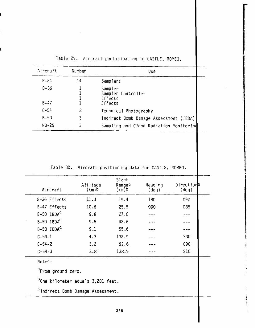
Table 29. Aircraft participating in CASTLE, ROMEO.
Aircraft Number Use
F-84 14 Samplers
B-36 1 Sampler1 Sampler Controller1 Effects
B-47 1 Effects
c-54 3 Technical Photography
B-50 3 Indirect Bomb Damage Assessment (IBDA
WB-29 3 Sampling and Cloud Radiation Monitoril
Table 30. Aircraft positioning data for CASTLE, ROMEO.
SlantAltitude Ran ea Heading Directit
Aircraft (km)b (km~b (deg) (deg)
B-36 Effects
B-47 Effects
B-50 IBDAC
B-50 IBDAC
B-50 IBOAC
c-54-1
C-54-2
c-54-3
11.3
10.6
9.8
9.5
9.1
4.3
3.2
3.8
19.4
25.5
27.8
42.6
55.6
138.9
92.6
138.9
180
090
---
---
---
---
---
---
090
085
---
---
---
330
090
210
Notes:
aFrom ground zero.
bOne kilometer equals 3,281 feet.
cIndirect Bomb Damage Assessment.
258

i JO.2.67) I I I
UPPER LIMITCLOUD TOP HEIGHT
LOWER LIMITCLOUD TOP HEIGHT110,000 ft (33.53 km) -~
f ‘/——-
12.1:
o
/~
OIAMETER135,000 ft (41.15 km)
,
CLOUD BOTTOM HEIGHT48,500 ft (14.78 km)
I I I I I I 1 I Iu I 2 3 4 5 6 7 8 9TIME (minutes)
Figure 73. CASTLE, ROMEO cloud dimensions (source: Referer
259
——.
:
280(85.34)
240(73.15)
i
(24.38)
140(12.19)
10I
? 81).
I
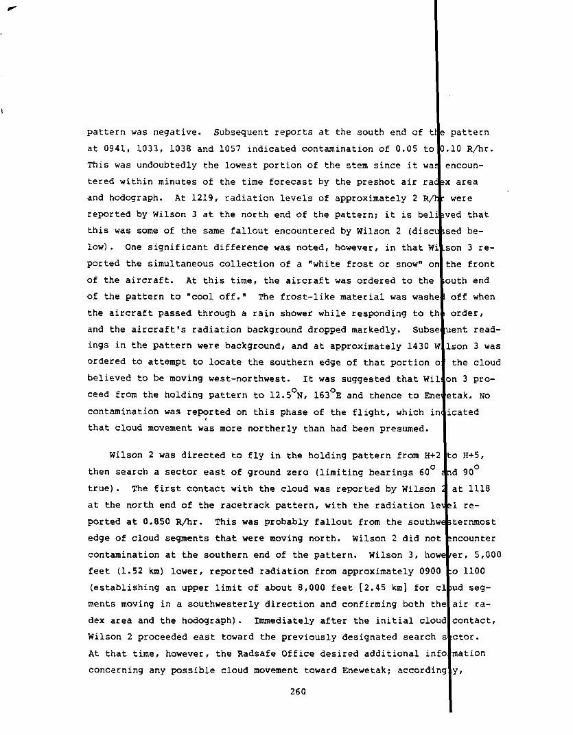
pattern was negative. Subsequent reports at the south end of 1
at 0941, 1033, 1038 and 1057 indicated contamination of 0.05 t~
This was undoubtedly the lowest portion of the stem since it Wi
tered within minutes of the time forecast by the preshot air r?
and hodograph. At 1219, radiation levels of approximately 2 R,
reported by Wilson 3 at the north end of the pattern; it is be:
this was some of the same fallout encountered by Wilson 2 (dis~
low)●
ported
of the
of the
One significant difference was noted, however, in that !
the simultaneous collection of a “white frost or snow” f
aircraft. At this time, the aircraft was ordered to th(
pattern to “cool off.” The frost-like material was was]
the aircraft passed through a rain shower while responding to t
and the aircraft’s radiation background dropped markedly. Sub:
ings in the pattern were background, and at approximately 1430
ordered to attempt to locate the southern edge of that portion
believed to be moving west-northwest. It was suggested that Wj
teed from the holding pattern to 12.5°N, 163°E and thence to Er
contamination was reported on this phase of the flight, which :
that cloud movement w~s more northerly than had been presumed.
Wilson 2 was directed to fly in the holding pattern from H-
then search a sector east of ground zero (limiting bearings 60(
true). The first contact with the cloud was reported by Wilson
at the north end of the racetrack pattern, with the radiation le
ported at 0.850 R/hr. This was probably fallout from the southu
edge of cloud segments that were moving north. Wilson 2 did not
contamination at the southern end of the pattern. Wilson 3, ho~
feet (1.52 km) lower, reported radiation from approximately 090C
(establishingan upper limit of about 8,000 feet [2.45 km] for c
ments moving in a southwesterly direction and confirming both tk
dex area and the holograph). Immediately after the initial c101
Wilson 2 proceeded east toward the previously designated search
At that time, however, the Radsafe Office desired additional inf
concerning any possible cloud movement toward Enewetak; accordir
260
attern
O R/kr.
coun-
area
ere
d that
d be-
n 3 re-
e front
th end
ff when
rder8
nt read-
on 3 was
he cloud
3 pro-
ak. No
ated
I H+5,
I90°
t 1118
re-
ernmost
Icounter
r, 5,000
) 1100
d seg-
Iirra-
!ontact,
!tor.
Iation
‘t

;3 ~ tdasordered at 1200 to return to the holding pattern.
~ 2 reported encountering cloud segments of approximately
‘-ckwest corner of the holding pattern.--- In order to eval
:.~ilityof fallout at Enewetak and also to determine aircr
:.s,this aircraft was also ordered to proceed to a positio
.:ch end of the pattern. Subsequent reports showed no cloud
:~ardEnewetak, and the aircraft’s background was 0.240 R/hr.
~ aircraft was directed to proceed to the originally specifi
‘? east of Bikini. No radiation above background was encoun
~sequent search out to 13.5°N, 171.5°E (100 nmi [185 km] wes
‘a thence to base. The crew exposure on Wilson 2 and Wilson
~se flights was of the order of 1.4 R (Reference 16, Tab L,
Wilson 4 was directed at H+12 to proceed from Enewetak at
:at (3.05-km) altitude to a sector bearing 60° to 90° from gr
=d search out to 500 nmi (926 km). From this sector the retu
5s via a point 16°N, 162°E. The flight was performed as orde
:Zdiationwas encountered.
,Wilson 1 collected heavy-element samples; it “encountered
tion necessitating immediate return to base.” The specific ra
els encountered are not known; however, the highest reading on
returning to base following ROMEO was 20 R/hr (Aircraft No. 21
Table 35).
Subsequent Wilson flights were cancelled when no appreciab
lamination appeared to exist at that time in the vicinity of t
No D-day fallout was deposited on task group ships in the
At approximately 1800, the USS Epperson, on security patrol 50
northwest of Bikini, reported fallout with average readings of
and maximums of 0.100 R/hr. The Epperson left the area at 190
unnecessary personnel exposure.
261
~t1215,
R/hr at
e the
back-
n the
ring
Lt 1430,
search
ed on a
IfBikar)
,uring
39).
0,ooo-
d zero
to base
, and no
vy radia-
tion lev-
y wB-29
see
air con-
test site
tie area-
~i (93 km
025 R/hr
:0 avoid
.

At 0900 two helicopters departed from the Bairoko for the init
safe survey and two other helicopters were sent to Eneman Island v
parties to clear debris from the airstrip. At 1000, radiation of
tensity, except at the crater, was reported. The lagoon was report
by the USS Belle Grove, and at 1315 ships began to reenter the la!
Bikini was not heavily contaminated after ROMEO, since the wir
ried most of the radioactivity to the northwest. Data from the fl
floating buoys of Project 2.5 were not sufficient to produce reli~
tours. Figure 74 presents estimates of the fallout pattern and ir
derived from these data. The maximum intensity was observed at 3!
km)
H+l
from ground zero; this corresponded to a land reading of 435 1
(Reference 40).
1 R/hr10 Rlhr. w
~ “h50R/hr “100R/hr, ●
1
\
Y . ‘! ‘\ t
Figure 74. CASTLE, ROMEO close-in gamma(source: Reference 53).
262
JL
fallout pattern at
rad-
work
in-
zlear
.
2ar-
con-
Sity
i (65
at
90 lW
160 185
77-I

‘t
A partial radsafe survey was conducted on D-day.Res~
‘~eyindicated no extensive recontamination of the atoll ex
Sokbata-Nm chain. Table 31 shows the results of early ra
Island exposure rates at H+l are shown in Figure 75.
Table 31. CASTLE, ROMEO radiation summary (R,
ExtrapolatedIsland H+4 D+l D+2
Eneu 0.03 0.03 0.06Bikinia 0.20 0.12 0.14Aomen 0.80 0.80 0.60Lomilika 1.6 1.7 0.75Odrika 0.8 - 1.4 1.4 0.85Iroija 0.8 - 1.0 1.3 1.0Nama 2,000 100Bokbataa 1,000 50.ob 55Oroken 0.04 0.10C 0.16CAdr ikan 0.02 0.40C 0.32CEnidrik 0.005 0.005 0.05Aerokoj 0.005 ().()05 0.04Eneman 0.012 0.012 0.06Crater l,loodShips 0.02 - 0.04
Notes:
acontamination by ROMEO shot.
b200-foot (60-meter) altitude.
cRadiation shine from water in Southwest Passage.
‘At 300 feet (90 meters).
Source: Reference 91.
263
,-
.
I
I
/)/](

BIKINI
IROIJ 14N
I
BRAVO CRATER
\
!)f30KDROLUL 9.1
/
EOKAETOKTOK 4,2
/OROKEN 4.3
Q@/ ADRIKAN 4.6
/%
JELETELUKOJ
%~ .
\
COCA
ENIDRIK
/. ENEMAN 3.4
%
BIKINI
BOKONFUAAKU
YOMYARAN e
EN IAIRO
ROCHIKARAI )
IONCHEBI
E EU
165°30, EAST \
I I
1<‘“K”JPASQ- ,NE”=J’’030’N0RTH‘///LELE
nlrnnfM- .1.-,,!,.
AEROKOJLOL’/o 1 2 3 4I I 5 6I 7
2.4AEROKOJ 1 I 1NAUTICALMlLEs
I
o 1 23456 ,8I I I I I I I I
STATUTE MlLESi
o 2 4 6I
81
10 12I I I 1 J
KILOMETERS
Figure 75.
}
CASTLE, ROMEO atol 1 exposure rates at H+l (R/hr).Individual cloud reading taken from aerial surveat about H+3 and normalized to H+l using t-1”2 dcay rate. The BRAVO contamination was subtractet
I
(source: Reference 81).
264

——. —
:afcxeseen fallout of small radioactive particles (less t
““red on the night of D+l and covered the atoll, raising r-A.
s by approximately 0.100 R/hr. The small radioactive fallc
:s more difficult to remove than the fallout from the large
:s. The secondary fallout stopped between 0700 and 0800 oc
-al topside levels for ships that received fallout are given
Fallout contaminated the western
.-.”31scomparable to those of BRAVO.
?st passage substantially increased
“.cinityof Oroken, Bokaetoktok, and
quarter of the lagoon wi
Lagoon flushing through
background radiation lev
Bokdrolul.
On shot day the low-intensity contamination moving to the
:asreported by Wilson 3, and accordingly an alert message wa
:0 the Enewetak garrison indicating the presence of a westerl
:~sntgen-rmge contamination approximately 60 nmi (111 km) we
~t ground zero. Although calculations indicated the contamir
?ass to the north of Enewetak, all personnel at that atoll we
to remain on alert Status until H+24. No significant fallout
quently experienced, a fact verified by a report at 1900 frcm
monitoring system indicating 0.001 R/hr maximum on Enewetak a
zero background on Lojwa. The low-intensity contacts southwe
zero were not ~nsidered significant for Ujelang.
Fallout began on Enewetak Island on D+2 at 1500, with pea
0.010 to 0.015 R/hr. There were also local “hot spots” with
high as 0.040 R/hr. These areas were posted with danger signs,
sonnel were not allowed to enter them. On D+5, the maximum int
0.010 R/hr at Enewetak Island.
On 31 March, the TG 7.3 unit on Kwajalein reported 0.009 Ri
on the windward side of tree trunks, averages of 0.001 to 0.00S
beaches, and 0.001 to 0.004 R/hr on windward sides of building:
erage Kwajalein background before 31 March was 0.00005 R/hr. 1
265
5 microns)
~tion lev-
>articles
tAVOparti-
).. Resid-
rable 32.
:adiation
? south-
in the
lthwest.
Lspatched
]vementof
lorthwest
m would
lirected
; subse-
? Enewetak
?arryand
>f ground
eadings of
~ings as.and per-
nsity was
r maximums
R/hr on
The av-
rcraft on

Table 32. Average topside radiation intensities (R/hr) of Task Group 7.3 shipsat various times following CASTLE, ROMEO.
Estes Bairoko Belle Grove Epperson Renshaw Philip Cocopa Mender Apache Sioux Molala Alnsworth
Date Time (AGC-12) (CVE-115) (LSD-2) (DDE-719) (rIOE-499) [DOE-498) (ATF-101) (ARso.2) (ATF-67) (ATF-75) (ATF-106) LST-551 (T-AP-181)
27 Mar
28 Mar
Nu!m
29 Mar
30 Mar
31 Mar
1 Apr
2 Apr
3 Apr
14001500161XJ1700180019002003
0000
04000800120016002ocil
Cooo04000800
08C43
0800
08E13
0800
0800
0.00030.0020
0,01200.01000.0080
0.0087
0.0063
0.0032
0.0025
0.0025
0.00030.0010 0.0040
0.0250 0.02000.0250 O.olm0.0250 0.0110
0.0110 0.0140
0.0070 0.0080
0.0060 0.0050
0.0050 0.0040
0.0030 0.0030
0.00050.00100.00150.02500.0100
0.00350.00400.01500.00700.00500.0045
0.00300.00350.0080
0.0050
0.0030
0.0010
0.0005
0.0002
0.00040.00160.00260.00250.00250.00240.0019
0.00180.00070.00130.00050.0007
0.0002 0.0008
0.0200 0.0120O.olrm- 0.02100.0090 0.0190
0.0070 0.0110
0.0030”0.0083
0.0025 0.0058
0.0015 0.0046
0.0010 0.0033
0.00030.0015
0.02500.02700.02000.02000.01000.0180
0.00500.0080
0.0050 0.0070
0.00300.0050
0.00300.0040
0.0030
0.00020.00200.00120.00180.00090.0006
0.00060.000350.00030.02800.04200.0200
0.02500.02000.0200
0.0100
0.0i180
0.0060
0.EX340
0.0030
0.00100.00200.08000.01600.01600.0300
0.01B410.01800.0300
0.0080
0.0040
0.0040
0.0030
0.0020
0.00200.01000.01300.00900.LM700.0054
0.00500.00350.0020
0.0020
0.CH320
0.0010
0.0010
0.0010
Note: Manned sh)ps other than those listed did not receive significant contamination.
Source: F]nal Report, Operation CASTLE, CTG 7.3 (Reference 11).
0.00010.00210.00250.00290.00280.0028
0.00110.00110.03030.00070.0008 0.00030.0027 0.0015
0.0150 0.02400.0250 0.01000.0220 0.0220
0.0100 0.0070
0.0075 0.0050
0.0050 0.0040
0.0028 0.0025
0.0020 0.0015
- .—-—-- .. . . .. ....-..”... . ,- . . . . . . . . .-..--— . ,.. .-.— -
f

-:-.ningflights in the local area were reportedly concentrate
:i~n to levels of 0.02 R/hr on engines.
Table 33 presents the preliminary results from the AEC New
;?s Office (NYKOPO) flights. Table 34 gives selected film-b
::cm Enewetak and Wake islands.*
decontamination. Maintenance personne
not participate in washing. Wash crew
each working a 6-hour shift with no br
AIRCRAFT DECONTAMINATION. The ROMEO shot saw a major than
:~.neluse for aircraft
,:qinecowlings but did
.ded into fOI.IrgroupS~
.;~htingwas improved and a trapeze-type safety harness was er
:orkerson the top of B-36 wings. Small holes were drilled in
ninimize accumulation of contaminated wash water. The cooling
:ay, period was increased from 20 to 44 hours, which significa
j
:srsonnel exposures (reportedly 25 to 44 percent). A B-29 (Nc
ing of 1 R/hr on 30 March had a level of 20 R/hr 52 hours earl
data of Table 35 indicate that two other aircraft (F-84Gs) wer
nated in excess of 10 R/hr after ROMEO.
Personnel Exposures
The records usually do not disaggregate the exposures to s
units by shot, and no large groups were identified as having F
solely in ROMEO. Data for some individuals are available, ho%
example, the Chairman of the AEC officially observed the deton
:~
recorded exposure of 0.03 R might be representative of individ
~ viewed the shot from the flagship or a VIP aircraft.
KOON
The third CASTLE event, KOON, was detonated at 0620, 7 Apri
Eneman Island, located on the southern rim of Bikini Atoll. Al
author has described this detonation as almost a “fizzle” (Refc
* Since shot KOON was scheduled to occur soon after ROMEO, somewere left out for both shots.
267
contami-
rk Opera-
~ readings.
in per-
~moved
ere di-
So Night
sd for
irlingsto
f, or de-
v reduced
195) read-
. The
3ntami-
ific
icipated
r. For
m. His
S who
1954, on
~ugh one
nce 92),
ilm badges

Table 33. CASTLE, ROMEO airborne monitoring survey results of theAE~ New York Operations Office.
Flight Able
Maximum MaximumLocal
Max mumGround Local Ground
TimeLocal Gro nd
LocationaReading
(19 March) ~~~;;~g (28TNSch) (R/hr)Time Rea ing
(31 March) (R/lr)
Kwajalein 1200 0.00010 0704 0 1435 0.0(020
Lae 1602 0.000012 0747 0 0832 0.0(308
Ujae 1615 0.00006 0754 0 0840
Wotho
o.0[324
1643 0.00005 0829 0 0910 0.0(170
Ailinginae (Sifo Island) 1710 0.02000 1123 0.00600 1005
Rongelap Island 1720 0.01500 1134 0.02800 1022
Rongerik Island 1739 0.08000 1153 0.03600 1036
Taongi .- -- 1315 0.00100 1158
Bikar 1848
O.oc )40
0.01200 1415 0.00008 1257 0.01 ;00
Utirik Island 1910 0.01200 1438 0 1320
Taka
O.oc ;80-- -- 1448 0.00080 1330 O.oci80
Ailuk 1938 0.00100 1503 0.00160 1345
Jemo 1951
O.oc!400.00002 1518 0.00080 1400 0.00!40
Likiep -- -- 1525 0.00040 1407 0.0000
Flight Baker Other NYKOPO F1 ights
MaximumLocal
MaximumGround .
TimeGround
ReadingLocationa
Reading(3 April) (R/hr) Flight Oate (R/hr)
Namu 0834 0.00040 Oogb 1 April oAiling lapalap 0857 0.00055 Foxb 3 April o
Namorik 0933. 0.00070
Ebon 959 0.00110
Kili 1004 0.00090
Jaluit 1035 0.00140
Mili 1125 0.00070
Arno 1146 0.00090
Majuro 1153 0.00090
Aur 1209 0.00090
Maloelap 1230 0.00050
Erikub 1253 0.00009
Wotje 1304 0.00140
Kwajalein 1354 0.00140
Notes:
aAto,l is spe~jfjed unless otherwise indicated.
bSee Table 9 for description of Oog and Fox flights.
Source Reference 16.
268
Ii
i
—

-9
Table 34. Selected film badge readings (R), 1954.
Enewetak IslandLocation 24 Mar
Wake Island- 9 Apra’b Location 24 Ma - 30 Mar
8600th PALIArea --- PAAC Living Area 0.290~aundry 0.495 sChOOllHouSing?rovost Area
0.290
1.570~tarshall’s
Bachelor HousingOffice 3.245Base Ops (indoors)Bldg 502 0.480 0.160
(Hq orderly rm) Fire Station(indoors)
3.160Loran station 0.375 3.160
Skeet range 1.010Motor pool 0.520“G” row tent #G , 0.380Chapel 1.235NCO mess 0.265(Maincargo pier 0.330
!Notes:
aTime span approximate.
bNote that shot KOON was detonated on 7 April.
cPan American Airways.
Source: Reference 87, Reel 9, various indexes.
269
I
1

Table 35. Task Group 7.4 CASTLE, ROMEO aircraft decontamination
First Survey Second Survey
Aircraft TypeType/
Ty~Reading of Reading 01
Tail No. (Rlhr) Date (Time) Decon (R/hr) Date (Time) Dec
B-36/1083 0.250 27 Mar (1600) Decay 0.060 29 Mar (1200) Wa:B-36/1086 3.200 27 Mar (1200) Decay 0.220 29Mar (0540) wasB-29/2195 20.000 27 Mar (1005) Decay 1.000 30 Mar (0050) Wa:B-29/7440 0.600 27 Mar (1600) Decay 0.050 30 Mar (0000) wasB-29/1819 1.000 27 Mar (2145) Decay 0.170 29 Mar (0000) wasF-84/030 5.500 27 Mar (1200) Decav 0.220 29 Mar (1840) Aci
n
F-84/032F-84/033F-84/037F-84/038F-84/042F-84/043F-84/045F-84/046F-84/053F-84/054F-84/055
1.20010.00022.0001.7002.2002.0000.6004.0005.5006.0003.900
27 Mar (1433j27Mar (1030)27 Mar (0955)27 Mar (1025)27 Mar (1335)27 Mar (1330)27 Mar (1340)27 Mar (1205)27 Mar (1215)27 Mar (1210)27 Mar (1052)
Deca>DecayDecayDecayDecayDecayDecayDecayOecayDecayDecay
0.0650.3450.6000.4400.8400.0800.0300.1900.1800.3000.150
29 Mar (1520)29Mar (1840)29Mar (1525)29Mar (1845)29 Mar (1720)29Mar (1515)29 Mar (1530)29Mar (1855)29 Mar (1705)29Mar (1710)29 Mar (1954)
AciAciAciAcicAcicAcidAcidAcidAcidAcidAcid
Third Survey Fourth Survey
Aircraft Type ,
I
Total To alType/ Reading Reading Decon De onTail No. (R/hr) Date (Time) D~~on (R/hr) Date (Time) Hours Pe s
B-36/1083 0.034 29 Mar (1453) ??? 0.030 ??? (???)I
2.33 6B-36/1086 0.120 29Mar (1145) Wash 0.060 29Mar (???) 5.5 6B-29/2195B-29/7740B-29/1819F-84/030F-84/032F-84/033F-84/037F-84/038F-84/042F-84/043F-84/045F-84/046F-84/053F-84/054F-84/055
0.1750.0180.0440.1700.0480.1650.4000.3000.0800.0900.0220.1150.1000.3000.060
30 Mar(0545j30Mar (0220)30 Mar (0150)29Mar (2130)29 Mar (1700)29Mar (2045)29Mar (1915)29Mar (2130)29 Mar (1845)29Mar (1700)29 Mar (1720)29 Mar (2030)29 Mar (1900)29Mar (1905)30 Mar (0040)
WashWashWashWashWashWashWashWashWashWashWash
0.1100.0600.1300.4000.2200.0500.0750.0200.1200.0900.240
30 Mar30 Mar30 Mar30 Mar30 Mar30 Mar30 Mar30 Mar30 Mar30 Mar30 Mar
0050)0045)0045)0035)0045)0045)0040)0030)
5
i
61.5 6
6:.750.75 :0.75 50.750.750.750.750.75
0030) 0.750035) 0.750040) 0.75
0.75 I
Source: Reference 30.
270
i
i

.
izs 11O-KT yield completed the destruction of the camp faciliti
?.anand resulted in the temporary closure of the Bikini Island a!
?reshot Preparation
Aerial searches of Area Green and a sector 240 nmi (444 km) T
to 600 nmi (1,111 km), centered on a 30° bearing from Eneman, be<
5 April. The series of preshot briefings continued until midnigl
the decision was made to postpone the shot 24 hours to await mor{
itileweather. By the morning of 6 April, the synoptic weather f<
indicated favorable conditions for the following day, and the se{
the preshot precautions began again.
At approximately 1400 on 6 April, the forecast surface and i
areas were announced as follows (Reference 16, Tab M):
Surface Radex. True bearings from ground zero, 240°clockwise to 70°; radial distance 90 nmi (167 km) forH-hour to H+6, plus a circular radex area around groundzero of 15 nmi (27.8 km) radius. It was recommended tha’the air control DDE move to 240° and 90 nmi (167 km) fromground zero, and the task force ships move to a positionsoutheast from ’groundzero as soon as possible after theshot.
Air Radex. For H+l, 10,000 feet (3.05 km) to 40,000 feet(12.19 km), 240° clockwise to 20° from ground zero for amaximum distance 20 nmi (37 km) and 20° clockwise to 85°from ground zero for a maximum distance of 30 nmi (56 km)
For 40,000 feet (12.19 km) and up, 240° clockwise to10° from ground zero for a maximum distance of 35 nmi (65km), and 10° clockwise to 95° from ground zero for a max-
The
imum distance of 45 nmi (83 km). - IFor H+6, multiply distances by 6. Due to initial
cloud growth, supplement the 10,000-foot (3.05-km) radexfor H+l with a sector bearing 85° true, clockwise to 240°true for a maximum distance of 5 nmi (9.3 km). Supplementthe 40,000-foot (12.20-km) radex for H+l with a sectorbearing 95° true, clockwise to 240° true for a maximumdistance of 15 nmi (27.8 km).
routine H-18 advisory was dispatched to CINCPAC announcing
Enc-
age.
out
m
fhen
‘or-
St
!eof
adex
he
KDON schedule. The advisory indicated that no known transient ship were
271
I
,,
,,F,i
.:
I

in the danger ‘areaand stated that a search centered on a 450
sector
would be conducted. The search sector was later cancelled because tl
search at 30” on the previous day had reported no vessels. The CJTF
decided that the sector search would be conducted in advance of the 1
out cloud “if necessary” (Reference16, Tab M). No indications are $
of the conditions that might require this search. Table 36 shows th<
known shipping activity near the PPG around shot time.
The officer-in-charge,Wake Island Weather Bureau Station, assure
radsafe monitor responsibility for Wake and was requested to make sp{
reports to the task force headquarters if intensities reached 0.010,
0.100, and 0.500 R/hr. Radiac instruments were supplied to the Wake
tion by TG 7.4. In accordance with operational requirements, the ta:
force fleet was positioned in a sector from 90° to approximately 120<
ground zero at a minimum distance of 26 nmi (48 km). Figure 76 show:
location of the fleet for KOON.
At the midnight command briefing, the forecast shot-time winds we
favorable, having considerable southerly flow,in the mid-levels. How
light to moderate scattered showers were forecast for H-hour and late
The decision to shoot was affirmed, pending the weather/radsafe situa
at 0430 on shot day. The forecast fallout plot by the method of ellipt
cal approximations is shofi in Figure 77.
Based on the recommendations contained in the surface radex area di
rective, CTG 7.3 informed all task groups of the following flagship (tk
Estes) movements near shot time:
● The H-hour position would be on a bearing from groundzero of 88° true at 25 nmi (46 km)
. At H+5 minutes (i.e., after completion of firing re-quirements), the ship would commence moving south at15 knots (28 km/hr)
● The H+2 position would be 134° true, 33 nmi (61 km)from ground zero, with a possibility of moving fromthat position at approximately
272
H+3 if required.
o,
in
r
.n

.
——— .—
Table 36. Summary of the status of transient shipping in ~
Proving Ground on or about 7 April 1954.
Vessel Location/Course
‘;SSReclaimer (ARS-42)
LST-1146
0SS Unadilla (ATA-182)
3SS Hanna (DE-449)
LISNSGen MortonI!-AP-138)
USS Karin (AF-33)
USNS Barrett (T-AP-196)
Japanese fishing boat
Japanese fishing boat
Japanese fishing boat
M/V Gunners Knot
M/V Roque
10°45’N, 1680E, course 270, 10 knot:at 1200 on 6 April; diverted to Kwa:0700, 7 April
9035’N, 1960E, course 94, 9 knots (11200 on 6 April; at 1400 on 6 Aprilcourse to 53; at 0110 on 7 April allto 90
7020’N, 169030’E, course 117, 10 kncat 1200 on 6 April; at 1530 on 6 Aprcourse to 94
At Matalanim Island at 1200 on 6 Aprto Ponape
20°37’N, 176012’E, course 267, 15.8km/hr) at 1200 on 6 April
At Enewetak at 1200 on 6 April
20°18’N, 169°40’E, course 87, 15.8 kkm/hr) at 1200 on 6 April
Visual/radar contact by search aircr171°56’E, course 125, 8knots (14.8approximately 1730 on 5 April; subscradar contact by search aircraft at1800 on 6 April, 1801ijlN,~72011tE,
6 knots (11.1 km/hr), evaluated as s
Visual/radar contact by search aircr171032’E, course 315, 10 knots (18.5approximately 1730, 5 April
Visual/radar contact by search aircr169°31E, course 335, 6 knots (11.1 kproximately 1600, 6 April; subsequenradar contact by search aircraft atmately 1900, 6 April, 15025’N, 16902340, 7 knots (13 km/hr), evaluated a
Truk at 1200, 6 April
Nukuoro at 1320, 6 April, scheduledmarangi and return to Ponape by 10 I
Source: Reference 16.
273
Pacific
!3.5km)in, ETA
km/hr) at?red~ course
(18.5 km)~ltered
thence
ts (29.2
; (29.2
, 19°28’N,It-)atIt visual/roximatelyrse 100,vessel, 190N,
/hr) at
, 15011N,
r) at ap-isual/roxi-, courseame vessel
(apinga-1 1
I I
2f/
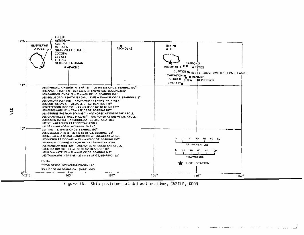
12ot
11(
w4I@
10(
~c1(
7ENEWETAKATOLL
/
‘\Y<
PHILIPRENSHAWKARINMOLALAGRANVILLES.HALLCOCOPALST.551LST762GEORGEEASTMAN
● APACHE
I NltHOLAS
.
USNS FRED C. AINSWORTH (TAP-181) – 25 nmi ESE OF GZ, BEARING 102°
uSS APACHE (ATF671 – 32.5 nmi E OF ENEWETAK, BEARING 090°
USS BAIROKO (CVE1 15) – 23 nmi SE OF GZ, BEARING 100°
uSS BELLE GROVE IWITH 18 LCMS. 1 AVR) – 30 nmi SE OF GZ, BEARING 115°
ussCOCOPA [ATF.101) – ANCH0t3E0 AT ENEWETAK ATOLLUSS CURTISS IAV4) - 2B nm, SE OF GZ, BEARING 115°USS EPPERSON (DDE-719) – 45 nmi SE OF GZ, BEARING 120°USS ESTES [AGC-12) – 32 nmi SE OF GZ, BEARING lDDOUSS GEORGE EASTMAN (YAG.39)a – ANCHORED AT ENEWETAK ATOLLUSS GRANVILLE S. HALL {YAG40)a - ANCHORED AT ENEWETAK ATOLLUSS KARIN (AF.33) - ANCHOREO AT ENEWETAK ATOLLLST.551 – BEACHED AT ENEWETAK ATOLLLST.762 – ANCHOREO AT PARRY iSLANDLST.i157 – 33 nmi SE OF GZ, BEARING 150°
IJSS MENDER (ARS.21 – 33 nmi SE DF GZ, BEARING 122°
uSS MOLALA (ATF-1D6) – ANCHORED AT ENEWETAK ATOLLuss NICHOLAS (DOE449) – 73 .mi Nw oF Gz. BEARING 2!30° ,
USS PHILIP (13DE498) – ANCHORED AT ENEWETAK ATOLL
USS RENSHAW (OOE499) – ANCHOREO AT ENEWETAK ATOLL
uSS SHEA (DM30) – 31 nml SE OF GZ, BEARING 130°
uSS SIOUX (AT F-75) – 26 nmi SE OF GZ, BEARING 147°USS TAWAKONI (ATF-1 141 – 27 nmi SE OF GZ, BEARING 138°
NOTE:
aFROM OPERATION CASTLE PROJECT 6.4
SOURCE OF INFORMATION: SH19S’ LOGSI
BIKINIATOLL
L3
.
BAIROI
AINSWORTHO ● ● E
CURT ISS~BEL
‘$l&U~ON ‘ ●. ● M El
SHEALsT.1157~
I
TESEGROVE (WITH 18 LCMS, 1 I
>EREPPERSON
I
oLuvQ_v7NAUTICAL MILEs
o
~mKILOMETERS
* SHOTLOCATION
1
‘E 163° 164° 165° 1660 1[
Figure 76. Ship positions at detonation time, CASTLE, KOON.
RJ
)
/—.— .-— . . . . ... ... .

I-.—c
o ENEWETAKATOLL
.ELANG
‘bo 50
RONGELAP
&WOTHO
100 T50I 1 I J
NAUTICAL MILES
o 100 200 300I I 1 I
KILOMETERS
KWAJALEIN
~
Figure 77. CASTLE, KOON predicted fallout pattern; contoL
the 100-, 50-, and 10-R’ infinite dose forecast
Reference 16).
The aircraft positioning ship (the USS Curtiss) was initially
of 120°, 25 mni (46”km) from ground zero, then moved south ap~
15 nmi (28 km) after H+1O minutes (i.e., after completion of t
navigation system requirements). All other ships except the c
moved south with the Cur.tisspostshot. The aircraft controll(
USS Nicholas) was at 240° true at 90 nmi (167 km) from ground
DOD Activities
The DOD-sponsored experiments for KOON included 27 project
of TG 7.1.
●
TU 13 projects were:
Program 1, Blast and Shock; Projects l.la, l.lb, 1.l.ld, 1.2a, 1.2b, 1.3, 1.4, 1.5, 1.6
275
1INGI
BIKAR~
UTIRIK6
AILUK~
&
mclose,ource:
I bearing
.mately
taydist
oyers
)E (the
).
i TU 13
I

● Program 2, Nuclear Radiation and Fallout; Projects2.1, 2.2, 2.3, 2.5a, 2.5b, 2.6a, 2.6b
. Program 6, Systems Effects; Projects 6.1, 6.2a, 6.2b,6.4, 6.5, 6.6
● Program 7, Electromagnetic; Projects 7.1, 7.2, 7.4
. Program 9, Cloud Photography; Project 9.1.
The locations of the instrument stations for these projects are
in Figure 78. Details of each project are given in Chapter 3. TG
aircraft participation is given in Table 37. Table 38 indicates th
tions of some of these aircraft at burst time.
The Test
At shot time (0620), a rain shower between the fleet and ground
possibly extended to ground zero. The debris cloud reached an alti
about 5S,000 feet (16.8 km). The lowest portion of the stem (estim
below 5,000 feet [1.5 km]) moved to the west at an average velocity
about 17.3 mi/hr (27.8 km/hr). (Contactwas made with this portion
cloud at H+5 by Wilson 2, about 59 nmi 109 km to the west of grou
zero. The intensity was 0.015 R/hr.) The middle segments of the c
(1.5 to 7.6 km) initially moved north, then east-northeast at about
mi/hr (28 km/hr). The top section of the cloud moved to the east-n
at approximately 34 mi/hr (55 km/hr) (Reference 16, Tab M).
CONTAMINATION. The Wilson 1 aircraft encountered radiation int
ties of 5 R/hr while collecting cloud samples.
Wilson 2, flying at 10,000 feet (3.05 km), made no contact with ,
cloud while in the racetrack pattern between Bikini and Enewetak/Ujel
Wilson 2 began a sector search at H+4 and located the cloud east of g
zero. This area was the forecast H+6 position of the 20,000- and 30,
fat (6.1- and 9.1-km) particle trajectories. A maximum reading of O
R/hr was reported at H+5.5 about 100 nmi (185 km) east-northeast of B
This layer of the cloud was probably responsible for the contamination
sequently noted at Rongerik and Rongelap atolls.
276
m
si-
3
of
at
the
4
east
~9●
Iund
lo-
,50
,ini.
sub-
1

————
BIKINI
IROIJ 2.2,2.5a.bN / ODRIK 2.5b
2,5b
OPEN 0(
()LAGOON 1.6,2,5a
2.5a.b,2.(
130KDROLUL 2.1,2.5b,2.6b
/
BOKAETOKTOK 2.1COCA 2,5a
/OROKEN 2.1,2.5a-b,
~@\ ~DR’KAN 2~25a.2.5b2.6b 2.5b ROCH
/N2 JELETE 1.2b,2.1,2.5a.b,3.3LUKOJ 1.2b,2.5b,2,6b,3.3
%4
2.%
● ,EN IDRIK l,2b, 1.8,2.1, 2.5a-b, 3.1,3.3 165°30 EAS
//
ENEMAN 1.2b,1,7,2.6b
‘“’”’PASS ~ ~
,,0—+—
(
ENEU CHANNEL1.2a,1.2b, 1.7, 2.1 LELE
1.2~-b, 1.3, 1.7, 2.1, 2.2 BIKDRIN
1.2a-b,1.3,1.8,2.1,2.2AEROKOJLOL1.2a-b,1.3,1.7,2.1, 2.2, 2.5a.b, 2.6b AEROKOJ ‘~
NAUTICAL r
o
~STATUTE M
‘~KILOMETER
Figure 78. CASTLE, KOON instrumentation stations for the DODprojects on Bikini Atoll.
277
iN 2.5a
/BIKINI
ARAl—
2.6b ENEU
NORTH
-
) 678I 1 I
is
Q-Y
:ientific
I

I
Table 37. Aircraft participating in CASTLE, KOON.
Aircraft Number Use
F-84 15 Samplers
B-36 1 Effects2 Samplers1 Sampler control
B-47 1 Effects
B-50 3 Indirect Bomb Damage Assessment (IB[A)
MB-29 2 Sampling and cloud tracking
c-54 3 Technical photography
Viking 3 VIP aircraft
SA-16 2 Search and rescue
c-47 1 Airlift
Table 38. Aircraft positioning data for CASTLE, KOON.
Slant ~Altitude Rangea Heading Directio na
Aircraft (km)b (km) (deg) (deg)
B-36 Effects 12.2 17.2 090 090
B-47 Effects 10.7 14.9 070
B-50 IBDAC 9.8 22.2 --- 229
B-50 IBDAC 9.5 37.1 --- 224
B-50 IBDAC 9.1 50.0 --- 225
C-54-I 4.3 139.0 --- 330
C-54-2 3.7 92.7 --- 090
C-54-3 3.2 139.0 --- 210
Notes:
aFrom ground zero.
bOne kilometer equals 3,281 feet.
cIndirect Bomb Damage Assessment.
278

The Wilson 3 aircraft, flying at 5,000 feet (1.5 km), contacc
cloud while in the racetrack ‘holdingpattern at H+5.25. The inte
.).015R/hr in a later sector search at an altitude of 8,900 feet
intensities of 0.050 R/hr were encountered at H+7 about 100 nmi (
aortheast of Bikini.
No aircraft flying
radiation. Subsequent
between Bikini
Wilson flights
and Enewetak encountered ai
were cancelled.
Based on a helicopter
imately H+2, all units of
as follows (Reference 16,.
preliminary damage and radsafe survey a
the task force were issued an advisory
Tab M):
. Lele through Aerokoj and Eneu not appreciablycontaminated
● Reentry hour expected to be 1100 on 7 April
● CTG 7.3 have task force vessels stand off the lagoonentrance at 1000 pending the outcome of the lagoonwater survey of the Eneman and Eneu anchorages
. Upon confirmation of reentry hour, all units reenterEneu anchorages in accordance with previousinstructions.
The results of the preliminary survey indicated that Bokbata,
Enidrik, and Bikini islands and the Iroij-Aomen chain were contain
Lagoon contamination was restricted to a V-shaped pattern with th,
Eneman and tips covering the Bokbata-Aomen area. A reading of 0.
was obtained over the Eneman anchorage at H+4. Eneu anchorage was
of contamination, whereas Bikini anchorage showed traces of contan
at H+4. Reentry and recovery occurred largely on shot day. Table
shows the radiation levels on various islands of the atoll.
A gamma-rate record was obtained at Iroij. The fallout arrive
about H+20 minutes, and a maximum exposure rate of 23 11/hrwas obs
H+40 minutes. The integrated exposure was 51 R until H+lS (Refert
p. 48).
279
“‘le
( was
km);
<m)
le
prox-
:tive
r
~d.
sx at
?/hr
ear
tion
t
ed at
40,

Table 39. CASTLE, KOON radiation summary (R/hr).
BRAVO and ROMEOExtrapolated Backgr lurid
Island H+4 D+l D+z at KO )N
Eneu
Bikinia
Aomena
Lomilika
Odrika
Iroija
Nama
Bokbataa
Orokena
Adrikana
Enidrika
Eneman
Aerokoj
Crater
0.03
5.0
20.0
10.0
5.0
5.2
250.0
600.0
0.60
0.50
210.0
0.02
5ooo.od
0.03
0.67
2.5
1.6
1.0
1.0
30.0
0.08
0.072e4b
0.02
50.OC r
Notes:
aContaminated by KOON shot. .
bReading at 100 feet (30 meters).
cReading at 200 feet (60 meters).
dAltitude not given.
Source: Reference 91.
0.03 0.0
0.07 0.11
1.6 0.3
0.80 0.51
0.60 1.47
0.60 1.4:
16.0 1.5
16.0 9.0
0.02 0.01
0.01 O.oc
1.8 O.oc
0.02 0.01
0.02 0.01
60.Od
The close-in fallout pattern is given in Figure 79. The exposurf
rates were extrapolated to H+l by using observed field decay rates.
The results of the NYKOPO airborne monitoring survey flights are
in Table 40.
280
—
i

.—. _ ._
Figure 79. CASTLE, KOON close-in gamma fallout pattern (R/hr(source: Reference 53, p. 78).
281
50
/ 25
at H+l
I
I

Table 40. CASTLE, KOON airborne monitoring survey results of the AEC New York Operations Office.
Flight Able
Maximum MaximumLocal Ground Local GroundTime Readings Time Readings
Locationa (8 April) (R/hr) (12 April) (R/hr)
Flight Baker
MaximumLocal GroundTime Readings
Locationa (12 April) (R/hr)
Lae 0915
Ujae 0930
Wotho 0956
Ailinginae 1022
Rongelap Island 1033
Rongerik 1047
Taongi 1210
Bikar 1312
Utirik 1332
Taka 1338
Ailuk 1356
0.00017
0.00025
0.0011
0.057
0.094
0.082
0
0.020
0.012
0.016
0.0017
0920
0930
0959
1059
1109
1124
1247
1345
1415
14~2
1441
0.00004
0.00002
0,00025
0.0077
0.0178
0.0186
0.00004
0.0080
0.0038
0.0019
0.0008
Jemo 1407 0.0020 1452 0.0004
Likiep 1414 0.0012 1457 0.00004
Kwajalein 1454 0.00053 1200 o.oo15b
Namu 0916 0.0004
Ailinglapalap 0937 0.0004
Namorik 1013 0.0003
Ebon 1037 0.0002
Kili 1104 0.0003 ~
Jaluit 1116 0.0003
Mili 1201 0.0008
Arno 1225 0.0012
Majuro 1245 0.0002
Ani 1245 0.0002
Maloelap 1328 0.0002
Erikub 1352 0.0002
Wotje 1404 0.0008
Kwajalein 1452 0.0004
Notes:
aAtoll unless otherwise indicated.
bGround observation (probably erroneously high reading).
- .—... - -. . —.. .,-. ,. -- $-- .—— !,, ., 4

Air Force flights collected radioactive samples to the sou
between 8 and 10 April. The debris was widely dispersed throu
area, but the maximum radiation levels were low (hundredthsof
roentgen per hour). One flight reported a peak 170 nmi (315 k
of Hawaii at H+56 at 14,000 feet (4.27 km). This air sample c
point was directly along the path of the 40,000-foot (12.19-km
particle trajectory. A second radioactive sample was collecte
(185 km) southeast of Hawaii 26 hours later at 19,000 feet (5.
Another less
fornia on 12
KOON debris.
AIRCRAFT
reduced from
active sample was obtained off the coast of South
April. Aircraft operating from Guam made no CO1l
DECONTAMINATEION.
that of the ROMEO
early turnaround requirement.
The decay period after the KOON
shot (to 20 hours) because of a
In addition, Table 41 indicates
aircraft were generally only lightly contaminated compared to
vious shots. Citric acid washings were discontinued starting
The first survey of 0.007 R/hr on F-84G No. 049, some 48 hours
first surveys on the other F-84s, indikates an intensity of ab
R/hr on 7 March, which is reasonable by comparison with other
UNION
The UNION
26 April from
Bikini Lagoon
device, with a yield of 6.9 MT, was detonated at
a barge anchored in 120 feet (37 meters) of wate
off Iroij Island.
Preshot Preparation
The UNION detonation was initially scheduled for 16 April.
priate JTF 7 staff moved from Enewetak to the Bikini area on 1
the midnight briefing, however, the weather was unfavorable an
delay was ordered. By 1500 on 16 April, it became obvious tha
ther would not improve within the foreseeable future and the s
postponed indefinitely, subject to the condition that the joir
maintain an 18-hour capability to conduct the test.
283
of Hawaii
out the
milli-
southwest
lection
airborne
100 nmi
km).
n Cali-
!tionsof
hot was
~ssible
hat the
[etwo pre-
,thKOON.
~fterthe
It 0.730
,rcraft.
I61Oon
in the
The appro-
April; at
a 24-hour
the wea-
>t was
task force
—.

,—
Table 41. Task Group 7.4 CASTLE, KOON aircraft decontaminate
First Survey Second Survej
Aircraft Type
Type/ Reading of Reading
Tail No. (R/hr) Date (Time) Decon (R/hr) Date (Time;
B-36/1083B-36/1086B-29/7269F-84/030F-84/033F-84/037F-84/038F-84/046F-84/049F-84/051F-84/053
0.220 7 Apr (1340)
0.800 7 Apr (1425)
0.240 7 Apr (1130)
0.800 7 Apr (1050)
0.460 7 Apr (1000)
0.800 7 Apr (1045)
0.305 7 Apr (1140)
0.180 7 Apr (1120)
0.007 9 Apr (1210)
0.225 7 Apr (1048)
0.200 7 Apr (1125)
DecayDecayDecayDecayDecayDecayDecayDecayDecayDecayDecay
0.100 8 Apr (111(
0.260 8 Apr (062(
0.021 8 Apr (142(
0.044 8 Apr (151!
0.035 8 Apr (145f
0.105 8 Apr (155!
0.039 8 Apr (153~
0.042 8 Apr (153~
0.005 9 Apr (133(
0.012 8 Apr (160(
0.024 8 Apr (145;
Third SurveyAircraft Total T[
I Type/ Reading Decon D(Tail No. (R/hr) Date (Time) Hours P(
B-36/1083B-36/1086B-29/7269F-84/030F-84/033F-84/037F-84/038F-84/046F-84/049F-84/051F-84/053
0.0660:2300.0110.0380.0230.1000.0350.040
0.0080.020
8 Apr (1343)8 Apr (0940)8Apr (1515)8 Apr (1635)8 Apr (1530)8Apr (1630)8 Apr (1604)8 Apr (1600)
8 Apr (16408 Apr (1532)
2.3340.511111111
Source: Reference 30.
The weather remained unfavorable through
conditions were predicted for the next day.
preshot activities began. The sector search
tered on a bearing of 40° from ground zero.
25 April, when accept
Accordingly, the sequ
for transient vessels
Two vessels were sigh
within the sector (but not in Area Green), but were judged not to
danger. The usual weather and command briefings were held and CIN
284
TypeofDecon
WashWashWashSoapSoapSoapSoapSoap
SoapSoap
alons
66666666666
)le
[ceof
:en-
d
in
AC was

advised of the decision to detonate. The advisory indicated
nificant fallout was expected on populated atolls and that no
air routes would be necessary. Known shipping in the area is
Table 42.
Table 42. Summary of the status of transient shipping inProving Ground area on or about 26 April 1954.
Vessel Location/Course
USNS Faribaut (T-AK-179) Kwajalein on 22 April
USS Wandank (ATA-204)
USNS Leo (T-AKA-60)
PC-1546
USNS Pvt J.F. MerrellT-AKV-4)
USNS Gen M.M. Patrick(T-AP-150)
LST-762
Freighter
Fishing boat
M/V Roque
llo7’N, 175019’E, course 76, 6.7 kn~km/hr) at 1200, 25 April
At Enewetak at 1200 on 25 April thr~27 April
Departed Rongerik 1330 on 26 A ril <!167027’E, 18 knots (33.3 km/hr , th(
Bikini via route points 10022’N, 16(100321N, 16604’E, 12 knots (30.6 km,Bikini 0500 on 27 April
21026’N, 168040’E, course 260, 16.5km/hr) at 12~0 on 27 April
7039’N, 156020’E, course 269, 14.9 I(27.6 km/hr)
ETD Enewetak 1300 on 27 April, to 1(5 knots (9.3 km/hr)
Visual contact by search aircraft al167040’E$ course 270, 10 knots (18.!2300 on 25 April
Radar contact by search aircraft, al1710E, 10 knots (18.5 km/hr), natiorunknown
Departed Ponape 25 April; 1200 on 2(position 8o18’N, 155027’E
Source: Reference 16.
In order to obtain more frequent UNION weather data from I
patrol boat (PC-1546) housed the weather detachment at the at<
than the group flying in and out for weather runs during dayl:
had been done since BRAVO. The boat was directed to take west
285
no sig-
sure of
ted in
‘acific
(12.4
1200 on
]0271N,to‘E and, ETA
:S (30.6
;
‘N, 1630E,
)121N,‘hr) at
)331N,
:Y
●il
erik, a I
rather
hours as
personnel
i

aboard after the midnight weather sounding and to be prepared to move south
at “best speed” in the event of fallout.
Based on the midnight weather forecast, the surface and air
I
adex
areas from H-hour to H+6 were:
Surface Radex. True bearings from ground zero: 2400clockwise to 700, radial distance of 75 nmi (139 km);270° clockwise to 80°, radial distance of 100 nmi (185km). Circular radex area around ground zero of 30 nmi(56 km) IAir Radex. For H+l, 10,000 feet (3.05 km) to 40,000 fee(12.19 km) (true bearings from ground zero): 950 clock-wise to 35°, maximum distance 10 nmi (18.5 km); 350clockwise to 950, maximum distance 35 nmi (65 km).
1For H+l, 40,000 feet (3.05 km) and up (true bearings
from ground zero): 85° clockwise to 50°, maximum dis-tance 25 nmi (46.3 km); 500 clmkwise to 85°, maximumdistance 60 nmi (111 km).
IFor H+6, 10,000 feet to 40,000 feet (12.19 km) (true
bearings from ground zero): 90° clockwise to 45°, maxi-mum distance 30 nmi (55.6 km); 450 clockwise to 900, max-imum distance 180 nmi (333 km).
IFor H+6, 40,000 feet (12.19) and up (true bearings
from ground zeio): 85° clockwise to 50°,”maximum dis-tance 80 nmi (148 km); 50° clockwise to 85°, maximumdistance 290 nmi (537 km). I
The radsafe situation was recommended as favorable at the O1OC .
(26 April) command briefing. Since light surface winds were predicted
to move south, it was recommended that the task force ships (exceFt those
required to be closer for operational reasons) move 50 nmi (93 km) south-
east of ground zero. It was also decided to make a final weather and rad-
safe check at 0400. The forecast fallout was based on midnight we ~ther,
using the method of elliptical approximations as shown in Figure 81.A
new fallout prediction technique, based on time and space changes .nthe
wind pattern, was also used for UNION, and the results presented a. the
command briefing. The pattern was similar to that shown in Figure 80 ex-
cept that the mid-line was reported to & a little farther south (:efer-
ence 16, Tab N).
286

c) ENEWETAKATOLL
RONGELAP
~WOTHO
‘s) o 50 100 150
NAuTICAL MILES
‘~KILOMETERS
Figure 80. CASTLE, UNION predic~ed faenclose the 50- and 1O-R(source: Reference 16).
KwAJALEIN
~
lout pattern; cornfinite dose are?
DOD Activities
The DOD-sponsored experiments for UNION included 28 project
of TG 7.1. TU 13 projects were:
. Program 1, Blast and Shock; Projects l.la, l.lb, 1.1l.ld, 1.2a, 1.2b, 1.3, 1.4, 1.5, 1.6
. Program 2, Nuclear Radiation and Fallout; Projects2.1, 2.2, 2.5a, 2.b, 2.6a, 2.6b
● Program 3, Blast Effects; Projects 3.2, 3.4
● Program 6, System Effects; Projects 6.1, 6.2a, 6.2b,6.4, 6.5, 6.6
● Program 7, Electromagnetic; Projects 7.1, 7.2, 7.4
. Program 9, Cloud Photography; project 9.1.
287
Q“AONGI
p
10R
BIKARd
UTIRIKO
]urs
in TU 13

The instrument station locations on the islands of the atol.
in Figure 81. Details of each project are given in Chapter 3.
tions of the task force ships at burst time are given in Figure
positions of the nonsampling aircraft at burst time are present{
Table 43.
BIKINI
IROIJ1.2b, l.6,2.2,2,5aN
//
ODRIK 1.2b, 1.6, 2.2BRAVO CRATER LOMILIK 1.2a.b, 1,6, 2.1, 2.2, 2,5a
/ /1.2a.b, 13, 1.6, 1,7, 2.
OPEN OCEAN z
\
/(BOK8ATA
LAGOON 1.4, 1,6,2.5a,3.4
b.
BOKDROLUL 1.6,2.1,2.5a-b
/
BOKAETOKTOK 1.6,2,1COCA 2.5a
/OROKEN 2.1,2.5a.b
~@\ ~DRIKAN 1.6,2.1, 2.5a.b
/b JELETE 1.6,2.1,2.5a.bLuKOJ 1.6,2,5b,2.6b
%& EN IDRIK 1.6,2.5a,2,6bD / ENEMAN 1,6
‘“’O’”ssT-&~1.6 LELE
/1,6 EIKDRIN /
1.2a AEROKOJLOL1.2a, 1.6, 2.5a.b, 2.6b AEROKOJ
1.6, 2.1, 2.5a.b, 2.6b B
1.6 BOKONFUAAKU
1.6 YOMYARAN
ENIAI
16,2.1, 2.5b ROCHIKAI
16 IONCHI
1.6, 2.5a-b,21
165°30 EAST
I 11°30. N—+—
ENEUCHANNELI
‘~NAUTICAL MILES
0 1 2 345I I I I I 1
STATUTE MILES
‘~KILOMETERS
Figure 81. CASTLE, UNION instrumentation stations for thescientific project instrument locations.
288
lre shown
le loca-
).. The
in
?.6b
2, 2.5b
6.4
\
/JI
——a
—,
—)
ENEu
\
H—
6 7

lIY
-
ENEWETAKATOLL
ON
(
LST-762
\1%
I
TAWAKONIS1OUXRENSHAWLEOLST-551
(WITH 18
NICHOLAS
uSS BAIROKO (CVE-1 15) – 57 nmi SE OF GZ, BEARING 155°
USSBELLE GROVE (LSD-2) {WITH 18 LCMS,40UKWS,1AVR) –30nmi SE OF GZ, BEARl NG146°
USSCOCOPA (ATF.101) (WITH YFN+1341 -63 nml SE OF GZ, BEARING 1720USS CURTISS (AV4) – 35 nmi SE OF GZ, BEARING 148°USS EPPERSON (ODE.719) -32 nmi NW OF ENEWETAK, BEARING 317°USS ESTES (AGC-12) – 53 nmi SE OF Gz, BEARING 150°
USNS FREO C. AINSWORTH (T-AP-181)a – 35 nmi SE OF GZ, BEARING 138°
USS GEORGE EASTMAN (YAG.39)b – 26 nmi NE OF GZ, BEARING 055°
USS GRANVILLE S. HALL (YAG40)b – 25 nml NE OF GZ, BEARING 055°
USNS LEO (T.AKA60) - ANCHORED AT ENEWETAK AToLL.
LSG.551 – ANCHORED AT ENEWETAK ATOLL
LST-1157 – 59 .mi SE OF GZ, BEARING 171°
USS MENDER (ARs.21 -60 mni SE OF GZ, BEARING 175°
USS MOLALA (ATF.106) – 36 nmi SE OF GZ, BEARING 136°
USS NICHOLAS [DoE449} -90 nmi SW OF GZ, BEARING 245°
USS PHILIP (DDE498)a – 64 nmi SE OF GZ, BEARING 152°
USS RECLAIMER (ARS42} -51 nmi SE OF GZ, BEARING 150°
USS RENSHAW IOOE49B) – ANCHORED AT ENEWETAK ATOLL
USS SHEA (DM.301a – 40 nmi SE OF GZ, BEARING 133°
USS SIOUX (ATF-75) – ANCHORED AT ENEWETAK ATOLL
USS TAWAKONI (ATF-1 14) – ANCHORED AT ENEWETAK ATOLL
NOTES:
aFROM TG 7.3 OPERATION LETTER – uNION, 11 APRIL 1954
bFROM OPERATION CASTLE PROJECT 6.4
SOURCE OF INFORMATION. SHIPS’ LOGS
1
BIKINI GR%NVI1ATOLL WITH GEOf
c?--BELLE GROVE
;Ms, 4 DUKWS, 1 AV$) MOL,4
$*S
cuRT’sso AINS
RECLAIMER~Es
LST1157 ● BAI
MENOERO@ ● F
C;COPA WITH
E S. HALLIE EASTMAN
H
:sDUOILIP
FN.934
I
o-
NAUTICAL MILES
020406080100
) I 1 I I IKILOMETERS
k SHOT LOCATION
Iu 1660 167°
Figure 82. Ship positions at detonation time, CASTLE, UNION. I

Table 43. Aircraft positioning data for CASTLE, UNION.
SlantAltitude Rangea Heading
I
Directio aAircraft (km)b (km)b (deg) (deg)
B-36 Effects
B-47 Effects
B-50 IBDAC
B-50 IBDAC
B-50 IBDAC
c-54-1
C-54-2
c-54-3
12.2
10.7
abort
9.4
9.1
4.3
3.2
3.8
19.1
20.0
---
42.6
55.6
138.9
92.6
138.9
188
180
---
174
------
---
---
315
270
225
---
---
---
---
---
Notes:
aFrom ground zero.
bOne kilometer equals 3,281 feet.
cIndirect Bomb Damage Assessment. I,
The Test
The UNION cloud reached an altitude of about 94,000 feet (28.65 kmI
(Figure 83). Cloud travel was influenced by three winds.4
The low-alt tude
portion moved toward the west, the middle portion moved east-northeast andI
the mushroom cap is believed to have moved to the north and west.
I
Non of
the cloud-tracking aircraft made contact with fallout from the cloud m h-
broomcap (Reference16, Tab N, p. 33).
CONTAMINATION. The Wilson 2 and Wilson 3 flights, in the air until
about H+13~ detected rm contamination moving toward Enewetak or Ujelan$
and at H+15 Wilson 2 proceeded to monitor the upwind sector of the patt
Wilson 2 noted low-level contamination in the vicinity of Rongelap; acc
ingly, PC-1546 was ordered to move south out of the area and return to
kini. An early report (H+3) from a sampling aircraft indicated an aeri
reading in the roentgen-per-hour range 10 nmi (18.5 km) south of the sl
n.
d-
I
I290 I

,
ii
(36’5: I I1
3 40g “2”’9)
0
/
CLOUD TOP HEIGHT94,000 ft (28.65 km)
CLOUD DIAMETER110,000 ft (33.53 km}
——.C~D~TOM HEIGHT
51,500 ft (15.70 km)
STEM DIAMETER11,5CK3ft (3.51 km)
o 1 2 3 4 5 6 7 8
F
TIME [mmutes)
gure 83. CASTLE, UNION cloud dimensions (source: Refel
island. Wilson 3 was directed to monitor the area, then retur
holding pattern. Based on the Wilson 3 report of insignificar
nation of the southern islands, the fleet approached to a poir
(18.5 km) south of Eneu to prepare for the preliminary damage
tion survey. The radsafe report (Reference 17) notes:
291
!240(73.15)
/
f2.19)
i9°
Ice 81).
to the
contami-
10 nmi
[dradia-

In view of the small amount of experience with water sur-face shots, cautious actions were imperative. Subsequentmovements and events”on shot day were delayed for approx-imately one to two hours, a factor of considerably lessimportance than taking an unnecessary risk with the em-barked task force.
At H+4, the radiological survey helicopters were launched fro
Bairoko. Based on this survey, reentry to the lagoon was set at
The survey covered the eastern and northern islands of the atoll
conclusive enough to limit scientific recovery to Eneu, Bikini, a
koj on the first day. The survey on D+l indicated that recontami
was limited to the Iroij-Aomen and the Bikini-Eneu sequence of is
No significant secondary fallout was encountered at Bikini as a r
this detonation.
?
fas
?ro-
>n
j.
: of.
Lagoon water was substantially contaminated with radioactive set”
D-day readings of 4.2 R/hr were obtained at an altitude of 500 feet
150 meters) over ground zero. This contamination moved to the west
southwest, allowing small-boat operations in the area of ground zer~
goon water movement toward the Southwest Pqssage increased radiatiol
in the vicinity of Oroken, Bokaetoktok, and Bokdrolul. Table 44 sh~
diation intensity on the various islands. Figure 84 gives the radi,
contours at H+l.
At 1400, Wilson 3 (and later Wilson 4, flying from H+12 to H+26
directed to make a low-altitude (300 to 600 feet; 92 to 183 meters)
at various atolls southeast of ground zero. Table 45 lists the re.s
this survey.
During the shot day and throughout the night, secondary fallout
encountered by some of the ships as indicated in Table 46 (Referencf
Tab N).
Enewetak Atoll reported a maximum reading of 0.004 R\hr. Weath
connaissance flights on D+l to the west, south, and northeast encou<
292
ent.
bout
d
La-
evels
ra-
on
as
rvey
s of
s
7,
re-
red
1
2JA ‘

Table 44. CASTLE, UNION radiation summary (R/hr)
ExtrapolatedIsland H+4 D+l l-J+4 B
Eneua
Bikinia
Aomena
Lomilika
Odrika
Nam
Iroija
Bokbata
Oroken
Adrikan
Enidrik
Eneman Crater
Aerokoj
Cratera
0.75 0.10
70.00 8.50
140.00 15.00
140.00 15.00
85.00 10.00
85.00 10.00
1.20
0.01
0.01
0:06
6.50
0.01
4.20C
0.03
0.80
2.00
2.40
1.00
1.00
1.00
2.20
o.50~
0.60b
O.lob
4.00
0.01
0.01
Notes:
aContaminated by UNION.
bRadiation from contaminated water.
cReading at 500 feet (150 meters).
Source: Reference 91.
293
ground
0.01
0.03
0.40
0.40
0.36
2.50
0.40
4.00
0.01
0.01
0.90
)0.00
0.01
0

BIKINI
1 5 10 50 100 200
/
I
ATOLL
024681012
I I I 1 I I [KILOMETERS
Figure 84. CASTLE, UNION close-in gannnafallout pattern at H+(source: Reference 53).
294
~200
3
i
100
50
10
\5
~1
(R/hr)

.. .
THIS PAGE
WAS
INTENTIONALLY
LEFT BLANK
IN
ORIGINAL

ii1}
Table 45. CASTLE, UNION atoll survey by Wilson 3 an
Wilson 4 on shot day.
ReadingAto 11
AltitudeTime (R/hr) (feet/meters
Ailinginae 1500 0.005 300/92Rongelap 1507 0.007 450/137Rongerik 1525 0.007 450/137Bikar 1632 0.005 600/183Utirik 1655 0.004 600/183Taka 1702 0.006 600/183Ailuk 1725 0.004 600/183Jemo 1732 0.003 600/183Wotje 1803 0.003 400/122Mejit 1848 0.003 ---Likiep 1901 <0.001 ---Wotho 2341 0.001 200/61
Table 46. Secondary CASTLE, UNION fallout noted onvessels of JTF 7 on shot day.
VesselAverage Maximum
Time (R/hr) (R/hr)
USS Cocopa (ATF-101) 2200 0.002 0.004USS Mender (ARSD-2) 2100 0.002 0.004USS Shea (C)M-30) 0730 0 ● 003 0.005LST- 1157 1930 0.002 0.003USS Nicholas (DDE-449)a 1320 0.002 0.004
1416 0.037 0.110
Note:
aNicholas reported all clear at 1443; departed for‘~~ETA 1745, 26 Apri 1)
295

no contami.nation except for a single contact of 0.001 R/hr, 800 n
km) northeast of ground zero ‘atH+33. Air Force sample collectic
from D+4 to D+7 near Hawaii and off the California coast detected
levels of radiation.
The results of the NYKOPO
atolls are shown in Table 47.
AIRCIUU?TDECONTAMINATION.
monitoring survey flight over the i
Because of a possible early turnar
after the UNION shot, the cowlings of a B-36 control aircraft (No
were removed 10 minutes after landing and decontamination was sta
mediately without a decay period. Its initial survey of 0.090 R/
comparatively low (see Table 48), justifying the procedural chang
other aircraft were ‘cooled” for 26 to 44 hours before decontamin
started. The 26-hour period was used for those aircraft schedule
YANKEE. As a consequence, some aircraft were released to mainten
radiation readings as high as 0.400 R/hr. Even after a 44-hour 6
riod, some of the other aircraft were released with high readings
aircraft No. 7271 preseqted considerable difficulty with contamin
its nose area where soft putty had been used as a sealer and appa
entrapped some radioactive particulate material. It was releaseti
reading of 1.700 R/hr, which was quite high but considerably down
initial intensity of 40.000 R/hr.
.,480
~de
r low
.ted
16)
im-
is
ill
1 was
with
pe-
i-29
1 on
Ly
la
I its
YANKEE
YANKEE, the final CASTLE detonation at Bikini, was fired at 061C on
5 May 1954. The 13.5-MT device was detonated on a barge anchored scuth of
Iroij at the same location as the UNION shot. C.JTF7 intended to detonate
NECTAR at Enewetak prior to YANKEE; however, unfavorable Enewetak wiIds
concurrent with favorable Bikini weather led to a 4 May cancellationn of
NECTAR and the scheduling of YANKEE.
Preshot Preparation
An initial informal command briefing was held at 1100 on 4 May 01
Parry. No significant fallout was predicted outside the danger area and
296 I 9.-!/-’

Table 47. CASTLE, UNION airborne monitoring survey results of the AEC New York Operations Office.
Flight Able Other NYKOPO Flights
Maximum Maximum Maximum MaximumLocal Ground Local Ground Local GroundTime
GroundReading Time Reading Time Reading Reading
Locationa (21 April) (R/hr) (27 April) (R/hr) (1 May) (R/hr) Flight Date (R/hr)
Lae 0824
Ujae 0834
Notho 0901
Ailinginae 0952
Rongelap Island 1006
Rongerik 1020Nw4 Taongi 1145
Bikar 1241
Utirik 1259
Taka 1304
Ailuk 1323
Jemo 1332
Likiep 1343
Kwajalein 1435
0.00030
0
0
0.00240
0.01200
0.00800
0.00004
0.00040
0.00080
0.00040
0.00010
0.00008
0.00004
0
0853
0903
0930
1029
1041
1055
1223 .
1318
1335
1342
1402
1410
1422
1510
0
0.00020
0
0.00160
0.00800
0.01100
0.00020
0
0.00200
0.00240
0.00040
0
0.00060
0
0655
0707
0737
0830
0845
0858
1014
1111
1135
1138
1159
1209
1216
1200
0.00004 Baker 21 April 0.00040
0.00008 Baker 2 May 0.00012
0.00030 Charlie 2 May 0.00007
0.00004
0.02000
0.00800
0.00004
0.00370
0.00170
0.00070
0.00060
0.00012
0.00008
0.0001ob
Notes:
Ato11 unless otherwise indicated
bGround observation.
Source: Reference 16.

P“-
tTable 48. Task Group 7.4 CASTLE, UNION aircraft decontamir
First Survey Second Sur
Aircraft Type
Type/ Reading of Reading
Tail No. (R/hr) Date (Time) Decon (R/hr) Date (Ti
B-36/10866-36/1386WB-29/7269WB-29/7271F-84/028F-84/030F-84/032F-84/033F-84/037F-84/038F-84/054
1.0000.0900.20040.00036.0004.0008.0006.0001.8004.2002.600
26 Apr (1215)26 Apr (1300)26 Apr (2120)26 Apr (0945)26 Apr (1010)26 Apr (1151)26 Apr (1015)26 Apr (1103)26 Apr (1225)26 Apr (1149)26 Apr (1223)
DecayWashDecayDecayDecayDecayDecayDecayDecayDecayDecay
0.210 27 Apr (10.085 27 Apr (10.140 27 Apr (12.200 28 Apr (12.100 28 Apr (O0.440 27 Apr (O0.360 28 Apr (00.600 27 Apr (O0.300 27 Apr (O0.340 28 Apr (O0.445 27 Apr (O
Third SurveyAircraft TotalType/ Reading DeconTail No. (R/hr) Date (Time) Hours
B-36/1086 0.210 27 Apr (1930) 3.5B-36/1386 . 3WB-29/7269 0.080 27 A~r (1445) “ i 1:WB-29/7271F-84/028F-84/030F-84/032F-84/033F-84/037F-84/038F-84/054
1.7000.6000.2400.1100.2400.0700.1100.160
28 Apr (1320j28 Apr (1130)27 Apr (1400)28Apr (1130)27 Apr (1515)27 Apr (1400)28 Apr (1130)27 Apr (1400)
2.5 1:1 [1.5 I1 I0.75 (1.5 I1 I1 (
Source: Reference 30.
no transient ships were known to be in the danger area (Table 49).
fore, the decision to detonate was communicated to CINCPAC. An ai
of Area Green was initiated and orders were given for a 0615 posts
tor search centered on 50°. The headquarters and task group comma
staffs then flew to Bikini.
298
ion.
Y
Type
) D;gon
Wash
WashWashWashWashWashWashWashNashWash
There-
search
t sec-

Table 49. Summary of the status of transient shipping in t ]e PacificProving Ground area on or about 5 May 1954.
w
Vessel Location/Course
LSTS 762 and 975 Approximately 650 nmi (1,200 klnortheast of ground zero at H-’route to Pearl Harbor
USS Navasota (AOG-1O6) Arrived Kwajalein 0735 onMidway 5 May
USS Shea (DM-30) Arrived Kwajalein 1900 onPearl Harbor 5 May
5 Ma
4 Ma
USNS Leo (T-AKA-60) and~uipa (AF-31)
At Enewetak 1200 on 4 May
USS Reclaimer (ARS-42) Departed Bikini to Guam 1200 0100401N, 1G501o1E, 100401N, 15(20km/hr); ETA Guam 18000n 9
Destroyera Radar contact from search aircon 4 May, 10°45’N, 162°54’E, c
Oestroyera Visual contact from search airon 4 May, 10°31’N, 165°51’E, ctrue, 10 knots (18.5 km/hr)
M/V Roque < Departed area 27 April; 5 May
Note:
a~ype of ship unclear from reference, given as “1 DD.”
Source: Reference 16.
At 1700 on 4 May, the following radex areas were announce
Surface Radex. True bearings from ground zero 240° cwise to 90°, radial distance of 60 nmi (110 km) for Hto H+6, plus a circular radex area around ground zerc15 nmi (27.8 km) radius. This was later modified toclockwise to 70° for a maximum distance of 60 nmi (11km), 70° clockwise to 200° for a maximum distance ofnmi (56 km), and 200° clockwise to 260° for a maximumdistance of 70 nmi (130 km), plus a circular radex arground zero of 15 nmi (27.8 km) radius.
It was recommended that the air control destroyer(the Nicholas) move to a true bearing from ground zer270° and 90 ~i (167 km).
299

.
I
I
Air Radex. For H+l, 10,000 feet (3.05 km) to 40,000 fee(12.19 km), 2250 clogkwise to 290° from ground zero formaximum distance of 25 nmi (46 km), 2900 clockwise to 30for a maximum distance of 20 nmi (37 km), 30° clockwiseto 100o for a maximum distance 30 nmi (56 km), and 100oclockwise to 225° for a maximum distance of 5 nmi (9.3km).
For H+l, 40,000 feet (12.19 km) and up, 230° clockwiseto 320° from ground zero for a maximum distance of 30 nmi(56 km), 320° clockwise to 50° for a maximum distance of15 nmi (27.8 km), 50° clockwise to 115° for a maximumdistance of 55 nmi (102 km), and 115° clockwise to 230°for a maximum distance of 15 nmi (27.8 km).
For H+6, 10,000 feet (3.05 km) to 40,000 feet (12.19km), 245° clockwise to 290° from ground zero for a maxi-mum distance of 110 nmi (204 km), 2900 clockwise to 300for a maximum distance of 75 nmi (139 km), and 30° clock-wise to 85° for a maximum distance of 130 nmi (241 km). I
For H+6, 40,000 feet (12.19 km) and up, 230° clockwiseto 3200 from ground zero for a maximum distance of 110nmi (204 km) and 50° clockwise to 115° for a maximumdistance of 250 nmi (463 km). I
Command briefings at 1830 and at midnight confirmed the favora le wea-1
ther predictions for shot time.i
The forecast fallout pattern, bas d on
the midnight briefing, is shown in Figure 85. The task force fleeIwas
located east-southeast of ground zero at 25 to 35 nmi (46 to 65 km ; rad-1
safe recommended that the slower ships move to 50 nmi (93 km) on a bearingI
!of 120° and that the other ships move south after the H-hour firin re-
quirements were completed.I
DOD ActivitiesI
The DOD-sponsored experiments for YANKEE included 20 projects “
T
TU 13
of TG 7.1. TU 13 projects were:
● Program 1, Blast and Shock; Projects l.la, l.lb, 1.c,l.ld, 1.2a, 1.2b, 1.3, 1.4, 1.5, 1.6
I● PrOgram 2, Nuclear Radiation and Fallout; Projects
2.6a, 2.7, 2.7a I● Program 6, System Effects; Projects 6.1, 6.2a, 6.4
I. Program 7, Electrcmagnetics; Projects 7.1, 7.2, 7.4
I● Program 9, Cloud Photography; Project 9.1. I
300

c)ENEWETAK ATOLL
T)TAONGI
RONGELAPUTI
BIKARe
QWOTHOAILUK~
0 50 100I 150 IKIEP
I J&
NAu TIc AL MILESKWAJALEIN
o 100I
200I 300
KILOMETERSJ
9
Figure 85.
ICASTLE4 YANKEE predicted fallout pattern, based on the methodof elliptical approximations; contours enclose the 100-, 50-,and 1O-R infinite dose areas (source:
Reference 1 ).
The instrument station locations on the islands of the atol
I
are shownin Figure 86. The details of each project are given in Chapter 3.
Thelocations of the task force fleet are given in Figure 87.
The aerial sampling effort for YANKEE was reduced to about
1
e-halfthe normal activity. This was done to enable TG 7.4 to partici
te in theEnewetak detonation within 24 hours, if required.
Nine F-84s, e FB-36,and one WB-29 sampler were used in YANKEE.
1The B-36 effects aircraft at detonation time was flying a 18 0 heading
at a 40,000-foot (12.2-km) altitude and a slant range of 58,000 eet (17.7
km) from ground zero. The B-47 effects aircraft aborted with a uel leak.
At burst time, one of the B-50 indirect bomb damage assessment ( BDA)
301 I

BIKIN
N
t
IROIJ l,2b
/
ODRIK 1.2b
/ LOMILIK 1.2b
1.2a,1.3, 1 7
OpEN OCEAN 2.7, 2.7a
bBIK1/
COCA
Q@
b
*
b
I
Q
EN IDRIK 165°30, EAST
/‘;”O’”s ~ d
I11°30’NORT
/’,
—+—
ENEU CHANNEL
o 1 2 3 4 5,,
AEROKOJ NAUTICAL ,MILES
0123q56I 1 I , I 1
STATUTE MlLES
‘~K! LO!JETERS
Figure 86. CASTLE, YANKEE instrumentation stations for the DOD scienprojects at Bikini Atoll.
302

uow
● EPPERSON
IENEWETAKATOLL
I NICHOLAS ]
w IBIKINI GEORGE EASTMAN
ATOI. L WITH GRANVILLE S. HALL
.I ESTEShNSWORTH
BELLEGROVE(WITH18LCtvls,1AVR). ~~ I ●MOLALABAIRoKOLsT.l157*
MENDER&CURT~~’OUX
USS AREOUIPA (AF-31) – ANCHORED AT ENEWETAK ATOLL
USS BAIROKO {CVE.115) – 34 nmi SE OF GZ, BEARING 150°
USS BELLE GROVE (LSD-2) (WITH 18 LCMS, 1 AVR) – 30 nmi SE of GZ, BEARING 152
USSCOCOPA (ATF-101) – 38 nm, SE OF GZ, BEARING 159°
USS CURTISS (AV41 - 35 nmi SE OF Gz, BEARING 149°
USS EPPER80N (ODE.719) – 41 nmi NW OF ENEWETAK, BEARING 348°
USS ESTES (AGC-12) --32 nmi SE OF Gz, BEARING 141°
USNS FREOC. AIN8WORTH (T-AP-181)* -35 nmi SE OF GZ, BEARING 138°
USS GEORGE EASTMAN lYAG-39)b – 58 nmi SE OF GZ. BEARING 145°
— uSS GRANVILLE s. HALL tYAGqo)b – 33 nmi NE OF GZ. BEARING 060°
USNS LEO (T-AKA601 - ANCHOREO AT ENEWETAK ATOLL
LST-551 - ANCHOREO AT ENEWETAK ATOLL
LST1157 – 35 nmi SE OF GZ, BEARING 157°
USS MENDER (ARS.2) -37 nmi SE OF GZ, BEARING 160°
USS MOLALA (ATF.106) – 50 nmi SE OF GZ, BEARING 120°
USS NICHOLAS (DDE449) – 1IB nmi SW OF Gz, BEARING 245°
USS PHILIP (OOE49B) -49 nml SE OF GZ, BEARING 143°
USS RENSHAW (OOE498) –60nm, SE OF GZ. 8EARING 144°
USS SIOUX IATF.751 – 43 nmi SE OF GZ, BEARING 134°
uSS TAWAKONI (ATF-114) – 58 nmi SE OfGZ,BEARING 145°
I 1‘162°E 163° 164°
“-COCO~A ● PHILIP
t
TAWAKONI RENSHAW
NOTES:
@FROM TG 7.3 OPERATION LETTER – YANKEE, 1 MAY 1954
bFRoM OPERATION CASTLE PROJECT 6.4
SOURCE OF INFORMATION: SHIPS’ LOGS
I
oLuvQuJF
NAuTiCALMILES
O2O4O6O8O1OO
I 1 I I I JKILOMETEFfS
SHOT LOCATION
II
) 1660 1
Figure 87. Ship positions at detonation time, CASTLE, YANKEE.

aircraft was at a 32,000-foot (9.8-km) altitude and a slant range
feet (27.8 km). A second B-50 IBDA aircraft was at a 30,000-foot
altitude and a slant range of 182,000 feet (55.5 km). The third
aborted. A maximum radioactivity reading of 0.020 R/hr was recor
10 to 15 seconds onboard the B-36 effects aircraft; this was the
diation noted by the effects aircraft during the CASTLE series.
‘f91,000
9.l-km)
DA B-50
d for
ly ra-
The Test
The early cloud dimensions following the 0610 detonation are
\
own in
Figure 88. The lowest level of the stem (surface to 15,000 feet [ .6 km])
was influenced by 17.3-mi/hr (27.8-km/hr)winds from the east. T is movem-
ent was confirmed by a cloud-tracking aircraft reporting a maxim inten-
sity of 0.063 R/hr at H+4, 60 nmi (111 km) west-southwest of grou zero
at 10,000 feet (3.05 km).
CONTAMINATION. Based on the position of cloud tracker contact and the
forecast air trajectories, this contamination is believed to have ?assed
to the south of Enewetak Atoll. The peak activity reported at Ene~etak
was 0.002 R/hr. Remnants of this portion,of the cloud probably ac:ount
for the 0.005 R/hr radiation level reported 460 nmi (852 km) soutttiestof
ground zero during a weather reconnaissancemission on D+l. The middle
level of the cloud (16,000 to 60,000 feet [5 to 18 km]) moved to t1e east-
northeast at 17.3 mi/hr (27.8 km/hr). Several contacts were subse~uently
made with fallout from this segment. Between H+5 and H+7, the tra.ling
edge of the cloud was clearly defined by one of the cloud-tracking air-
craft; maximum intensities of 2 Vhr were reported 300 nmi (556 km east-
northeast of Bikini. The cloud top moved initially to the north ald west.
In the fallout process, however, this debris was carried back tow a:d the
east and intercepted several times. The first was at H+15, when a tracker
aircraft was able to completely delineate a fallout area that was :entered
340 nmi (630 km) to the east-northeast of ground zero (92 nmi [17O km]
north of Bikar Atoll); the maximum reading inside this area was ab)ut 0.5
R/hr. At the same time, another cloud-tracking aircraft located r dio-
activity of 6 R/hr in this same generalarea, but at an altitude o: 1,500
304

140(42.67) I I I I I
CLOUD TOP HEIGHT110,000 ft (33.53 km)
f
—--
$ CLOUD DIAMETER123,700 ft (3923 km)
zz~
2 60 —~ (24.38)
a“u5
d
2~a CLOUD BOTTOM HEIGHTz 61,300ft {18.68 km)?m 60 —a (1828)za
.
~
~
1-
$w
40 —~ (12.19)y
u
STEM DIAMETER17,400 (’t (5.30 km) . _
(6.1%vobo 1 z 3 4 5 6 7 8 f
/I I I
TIME (minutes)
Figure 88. CASTLE, YANKEE cloud dimensions (source: Ref
305
:
280(85.34)
240(73.15)
+.O
:e 81).

feet (457 meters) (Reference 16, Tab O). Figure 89 shows the dimens.ons
of the cloud based on the aerial tracking observations.
At 0900 the Bairoko, 10 nmi (19 km) off Eneu, launched radsafe s r-
vey helicopters. This survey covered the islands of the atoll and w!s
conclusive enough to limit data-recovery operations to Eneu and Aero ;ojon
the first day. This survey indicated that recontaminationwas exteni,ive
throughout the atoll and lagoon both to the east and west. The radi{tion
intensities on islands of the atoll are shown in Table 50. No signil
secondary fallout was encountered at Bikini as a result of this deter
Lagoon water was heavily contaminated with radioactive sediment.
ings of 1 R/hr were obtained at a 100-foot (30.5-meter)altitude in t
cinity of ground zero on D+l. Floating objects revealed readings of
3 R/hr on shot day. Small boats and barges in Bikini-Eneu anchorage
contaminated to a moderate degree (1 to 6 R/hr). The initial radsafe
ports indicated that the lagoon was too contaminated for reentry by t
fleet. Following a conference, the decision was made for the Estes t
turn to Enewetak while other ships remained at sea in the Bikini area
short sortie from 1600 to 2040 into the lagoon was made by the Estes,
tiss, and Belle Grove in order to use the Belle Grove~s boats to exch
passengers. Reentry to the lagoon was made at 0815 on 6 May. The Q
departed that evening foi Enewetak, landing CTG 7.3 at Parry Island t
following morning (Reference 14, pp. 174-175). Lagoon water movement
ward the Southwest Passage s~bstantially increased radiation levels i
Enidrik-Bokdrolul area.
The YANKEE fallout pattern is shown in Figure 90.
Two LSTS, 762 and 975, en route in company from Enewetak to Hawai
encountered the fallout cloud about 700 nmi (1,300 km) east-northeast
ground zero at H+35 to H+41. LST-762 was equipped with standard task
washdown equipment, but LST-975 had Only standard firefighting equipn
At 12°56’N, 176°511E at 1300 on 6 my, radiation intensities of 0.015
306
ant
ion.
:ead-
;vi-
to
tre
e-
re-
A
!ur-—
Ige
:iss
~
:o-
the
,
)f
:orce
tt●

165°E 170°E 175°E
I-1+5 POSITION OF FA150,000TO 60,000feet (‘
18 R/hr AT 1(
wo4
●ENEWETAK ATOLL
I of.LOUT FROM!4 TO 18.28 km) \
O feer (3 05 km) \\~
-%--
Figure 89. Areal
.
● m IBIKINI ATOLL
R; NGERIKL
I
\\
\ Ht15POSIT10N OF FALLOUT FROM
\ 50,000 T060,0001ee[ (1524 TO 1828kml
% 002 Rlhr AT 10,000 tee,(305 km)
\I
03 Rfhr AT 10,0001 eet(305 km)
~=/ 0.5 Rfhr AT lo,ooofeeI(305 km)
/./ /
BIKAR
●
ki+14 POSITION OF FALLOUT FROM50,000 TO 60,000 fee[ [15.24 TO 1828 km)
6 R/hr AT 1,500 feet (45/ meters)
1 R/hr Al 1,500 feet (457 meters)
I00 200 Xio
I 1 INAUTICAL MILES
o 200 400 556I I
● KWAJALEIN 1 IKILOMETERS
extent of CASTLE, YANKEE fallout cloud (source: Reference 16, Tab D).

Table 50. CASTLE, YANKEE radiation summary (R/hr).
ExtrapolatedIsland H+4 D+l D+5a Background
Eneub 18.00 2.00 0.44 C.02Bikinib 225.00 25.00 2.00 C,32
Aomenb 50.00 6.00 0.80 1,00
Lomilikb 65.00 7.50 1.20 100
Odrikb 95.00 12.00 2.00 0 25
Iroijb 95.00 12.00 4.00 1 00
Namb 10.00 1.00 0 80Bokbata 0.95 3 00Orokenb 3.50(?) 0.50C 0.12C o 01Adrikanb 1.30 0.60C O.olc 0,08
Enidrikb 0.18 0.01 0.1 - 1.0 0<03
Aerokojb ‘0.505 0.01 ‘0.01 0.01
Crater 1.Ood
Lagoon 80.00 (west)
Notes:
aFinal aerial survey.
bContaminated by YANKEE.
cRadiation shine from water in Southwest Passage.
‘Reading at 100 feet (30.5 meters).
Source: Reference 91.
308

/EIKIMI
/ I AREA O~HEAVY FALLOUT
I 1 I Io 50 100 150 200 250
DISTANCE FROM 8URST POINT (statute mjfe~)
Figure 90. CASTLE, YANKEE heavy fallout area. The alwithin the contour would have been a fullarea 24 hours after the shot had the fall~been over dry land (after Reference 81) .
R/hr (and increasing),werenoted. The LSTS carried out deconta!
procedures. At 1700, readings averaged 0.020 R~r (0.040 R/hr I
with the highest readings on wind-exposed surfaces. The ships’
at 2000 was 13°16@N, 177°97’E. A steady decrease in radiation :
was noted after 2330, and decontamination continued throughout 1
LST-762 reported a maximum of 0.040 R/hr; LST-975, 0.096 R/hr.
7 May (position14°30’N, 178°40’E)~ intensities had dropped to t
of 0.00S R/hr and a maximum of 0.OIS R/hr. At 0700 on 8 May at
15°5’N, 178°441E, LST-762 indicated an average of 0.003 R/hr anc
of 0.008 R/hr; LST-975 reported 0.007 and O.O1O R/hr, respective
No individual exposures are available for this incident. Ii
clear whether the cumulative exposures reported for the crew of
and reported in Reference 13 included this radiation, or whethel
ship’s film badges had been given to TU 7 for processing before
departed Enewetak.
309
;dex
ation
imum)f
sition
ensity
night.
0800 on
average
sition
maximum
●
s not
T-762
he
e ship

The preliminary results of the off-atoll surveys by NYKOPI
in Table 51.
AIRCRAFT DECONTAMINATION. After YANKEE, the B-36 (No. 131
aircraft, with an initial radiation reading of 0.100 R/hr, wa!
contaminated without a cooling period but all other aircraft ~
about 24 hours before decontamination was started. The other
1086) had the highest recorded contamination for the test ser
ing 42 R/hr shortly after landing (see Table 52). Some aircr(
were released with relatively high contamination levels (0.231
R/hr). Priorities were also changed to decontaminate five F-1
NECTAR
NECTAR (1.69 MT), the final shot of Operation CASTLE, was
~e shown
control
?ain de-
Led for
36 (No.
, measur-
again
) 0.800
I first.
ed at
0620 on 14 May from a barge anchored in the MIKE crater (formerl Eluklabi
Island) at Enewetak Atoll. NECTAR was ready for detonation on 2iApril,
ahead of YANKEE, and detailed preshot preparations were made on+
5, and
11 May.+
At each date, the shot was postponed because of unaccep ble wind
patterns..
Preshot PreparationI
At noon on 13 &iaythe weather forecast indicated acceptable c nditions4
Ifor firing the following day; consequently, the appropriate messa es were
transmitted to the task force and external agencies indicating a cision
to fire. Air search was initiated in Area Evelyn.* No known tra ient
shipping was within the danger area (Table 53). No postshot sect
1
search
was scheduled.
I* Area Evelyn had been designated 1 May when it became apparent th t dailysearches of the entire Area Green were difficult with the aircra tavailable. Evelyn was defined as a semicircular sector of 300 n i (555km) radius to the north of an east-west line through the center f Ene-wetak, plus an additional 60-nmi (ill-km)wide strip south of thsemicircle.
310
I
I

Table 51. CASTLE, YANKEE airborne monitoring survey results of the AEC New York Operations Office.
Flight Able Other NYKOPO Flights
Maximum Maximum Maximum MaximumLocal Ground Local Ground Local GroundTime Reading
GroundTime Reading Time Reading
Locationa (6 May) (R/hr)Reading
(7 May) (R/hr) (9 May) (R/hr) Flight Date (R/hr)
Lae
Ujae
Wotho
Ailinginae
Rongelap Island
Rongerik
Taongi
w BikarPP Utirik
Taka
Alluk
Jemo
Likiep
Kwajalein
0830
0845
0912
1024
1038
1052
1215
1315
1335
1340
1400
1410
1415
1455
0
0
0.00008
0.00080
0.00800
0.00300
0.00020
0.01500
0.00080
0.00080
0.00020
0.00020
0.00020
0.00040
0822 0.00120
0832 - 0.00080
0857 0.00160
1005 0.01000
1019 0.03000
1033 0.02160
1151 0.00020
1247 0.03400
1318 0.00600
1312 0.00560
1330 0.00070
1339 ‘ 0.00320
1346 0.00320
1800 o.oo450b
0726
0737
0810
0916
0928
0943
1111
1203
1223
1226
1245
1245
1302
1335
0.00010 Baker 9 May 0.00040C
0.00016 Charlie 9 May 0.00020
0.00020 Easy 12 May 0.00060
0.00120
0.00650
0.00400
0
0.00400
0.00120
0.00150
0.00070
0.00030
0.00050
0.00020
Notes:
aAtoll unless otherwise indicated.
cAt Wotje; next highest 0.00030 R/hr at Ani.
Source: Reference 16.

If
Table 52. Task Group 7.4 YANKEE aircraft decontamination .
First Survey Second Survey I
Aircraft Type
I
TypeType/ Reading of Reading of
Tail No. (R/hr) Date (Time) Decon (R/hr) Date (Time) Decon
B-36/1086B-36/1386WB-29/774014B-29/7343WB-29/7269WB-29/1819tiB-29/2202F-84/032F-84/037F-84/042F-84/043F-84/046F-84/049F-84/051
42.0000.1001.00020.0000.6000.3100.2808.00038.00010.0008.0001.10011.00018.000
5 May (1158)5May (1250)5 May (1100)5 May (1050)5 May (2245)6 May (0503)5 May (2105)5 May (1045)5 May (0915)5 May (1138)5 May (1139)5 May (1025)5 May (1100)5 May (1050)
DecayWashDecayDecayDecayDecayDecayDecayDecayDecayDecayDecayDecayDecay
None
0.050 5May (1700)
0.220 6 May (0900)
3.200 6May (0905)0.300 6 May (0850)
0.140 6 May (0852)0.100 6 May (0845)
0.210 6May (0800)
1.700 6 May (0825)
0.900 6May (0817)
0.700 6 May (1520)0.090 6May (1520)
1.200 6 May (0821)
1.600 6 May (0832)
Wash
WashWashWashWashWashWashWashWashWashWashWashWash
Third Survey FourthSurvey
Aircraft Type Tot
i
TotalType/ Reading of Reading Deco DeconTail No. (R/hr) Date (Time) Decon (Rjhr) Date (Time) Hou Pers
B-36/1086B-36/1386WB-29/7740WB-29/7343WB-29/7269WB-29/1819WB-29/2202F-84/032F-84/037F-84/042F-84/043F-84/046F-84/049F-84/051
0.340
0.1601.0000.1400.0800.060???0.800???
0.2300.0500.4600.600
6May (1450)
6May (1610)7 May (0815) Decay 0.3206 May (1635)6May (1145)6May (1145)
6 May (1655) Decay 0.2206 May (1039)6 May (1030)?????????
241
9May (1600) 111.0.
10 May (0900) :
;1
;:
262613131313136666666
Source: Reference 30. I
312

Table 53. Summary of the status of transient shipping in tProving Ground area on or about 14 May 1954.
Vessel Location/Course
USS Namakaqon (AOG-53) ETD Enewetak 1200 on 13 May for K
USS Epping Forest (LSD-4) 9040!N, 17201O)E, 13 knots (24 kfl
Kwajalein 1200 on 14 May
USS Apache (ATF-67) Departed Bikini 2200 on 13 May witow via route points 10055’N, 16(thence great circle to Pearl Harkon 25 May
USNS Merrell (T-AKV-4) ETA Guam 15 May.
Source: Reference 16.
The forecast surface and air radex areas were issued as fc
Surface Radex. True bearing from ground zero 250° CICwise to 80°, radial distance 60 nmi (111 nmi) for H-heto H+6, plus a circular radex area around ground zero10 nmi (18.5 km) radius.
Air Radex. For H+l, 10,000 feet (3.05 km) to 40,000 f(12.19 km), 2750 clockwise to 300 for a maximum distarof 15 nmi (27.8 km) from ground zero, .300clockwise tc100o for a maximum distance of 35 nmi (64.9 km), and 1clockwise to 2750 for a maximum distance of 5 nmi (9.1
For H+l, 40,000 feet (12.19 km) and up, 240° clockto 330° for a maximum distance of 25 nmi (46.3 km) frcground zero, 330° clockwise to 40° for a maximum dist~of 15 nmi (27.8 km), 40° clockwise to 110° for a maxindistance of 60 nmi (111 km), and 110° clockwise to 24(for a maximum distance of 15 nmi (27.8 km).
For H+6, 10,000 feet (3.05 km) to 40,000 feet (12,km), 275° clockwise to 30° for a maximum distance of 1nmi (129.6 km) from ground zero, and 30° clockwise tofor a maximum distance of 180 nmi (333.4 km).
For H+6, 40,000 feet (12.19 km) and up, 260° clockto 300° for a maximum distance of 70 nmi (129.6 km) f~ground zero, and 40° clockwise to 100° for a maximum ctance of 300 nmi (555.6 km).
A destroyer (the mP erson) was stationed near Ujelang Atol
ate the population there if necessary. The cloud-tracking ai:
deployed to detect any movement of contamination
313
Ii
toward Ujelar
? Pacific
kjalein
lr), ETA
I YC-1081 in!O’N, 1750E;“, ETA0800
LOWS:
c-.
i
?t?
)0
<m).
ise
:en
3
)00
isen;-
to evacu-
:aft were
.

The command briefing held at 0030 on 14 May confirmed the decis.on to
shoot. Figure 91 shows the forecast fallout pattern presented at t le
briefing.
oT ONGI
81KARU
ENEWETAK ATOLL
u
RONGERIKEIKINI ATOLL Q
UTIRIK6= RONGELAP
AILuKt?
~WOTHO
LI KI E&
0-” ~NAuTICAL MILES
KWAJALEIN
‘~”KILOMETERS -
Figure 91. CASTLE, NECTAR predicted fallout pattern based on the Iethodof elliptical approximations; the contours enclose the 100-,50-, and 1O-R infinite dose areas (source: Referent e .6).
DOD Activities
The DOD-sponsored experiments for NECTAR included 25 projects in TU 13
of TG 7.1. TU 13 projects were:
● Program 1, Blast and Shock; Projects l.la, l.lb, 1.lc,l.ld, 1.2a, 1.2b, 1.3, 1.4, 1.5, 1.8
. Program 2, Nuclear Radiation and Fallout; Projects2.1, 2.2, 2.5a, 2.5b, 2.6a, 2.6b, 2.7
. Program 6, System Effects; Projects 6.1, 6.2a, 6.2b,6.6
UJELANG
Q
314

● Program 7, Electromagnetic; Projects 7.1, 7.2~ 7.4
● Program 9, Cloud Photography; Project 9.1.
The instrument station locations on Enewetak Atoll are shown in Fig-
ure 92. The project details are described in Chapter 3. I
IThere was no preshot evacuation of Parry and Enewetak, alth gh task
force ships remained in the vicinity to provide an evacuation c ability
if required. TG 7.2 was mustered on the beach at Parry to view he shot.
The shot countdown was broadcast in the area and the task group ersonnel
were instructed to turn away from the burst and cover their eye prior to
zero time. The locations of the ships of the fleet at burst t“ are
shown in Figure 93. The positions of TG 7.4 effects aircraft a shown in
Table 54.
The Test
Heavy rain showers in the Enewetak area when NECTAR was detcnated may
have affected the close-in deposition of the fallout. The C1OLX reached
an altitude of about 71,000 feet (21.6 km). The lower portion below
20,000 feet [6 km]) df the cloud moved to the west-northwest, a d the up-
per cloud moved north. Figure 94 gives the cloud dimensions. :‘ewcontacts
were made with the cloud by either the TG 7.4 sampler aircraft ~r the Wil-
son cloud-tracking aircraft. No postshot weather reconnaissance!flights
were made.
An F-84 sampler aircraft veered off the runway while landin after a
sampler mission and nosed into a sand dune.
I
The crash crew arr ved before
TG 7.4 could remove the radioactive samples. When the latter rived at
the aircraft, they had to move the crash crew well away before emoving
the samples. TWO U.S. Army personnel were reported to be sitt” g on the
wing of the “hot” airplane (Reference 29); however, they could ot be
identified.
CONTAMINATION. Following the shot, the fleet returned to
/
e atoll
and by 0745 was anchored in the lagoon. A damage and radiatio survey of
315

ENEWETAK
BOKAIORIKORIK 1.2a.b1 2ab OR ID RI LBWIJ
MIKE CRATER BOKEN 1.2ab,l .3,1 .7,1 .8,2,1,2.5b
2.1 BOKINWOTME2,1 LOUJ
&~
ENJEBI 2.1, 2.5a. b,2.6b
2.1, 2.5b KIRUNU12b,2.1,2.5b BOKOM8AK0
2.1, 2.2,2.5a-b BOKOLUO
\;*-P’%i::;:::::b
~
i
BIKEN 2.5a-b
/*,
\SOUTHWEST I‘A=*GE‘i\
N
\\
\\
.
>1b,
‘ ll\\L~LERONd,
“wl~ ,
-4
/ ‘:,AOMON
~
/
2,5b BIJIRE ~LOJWA / OPENOCE N2.5a,2.7
/’ALEMBEL’
BILLAE
.UNIBOR 2.5a
\
\
OR EKAT;MON 2.5a
/
%
RUNIT 7,1
LAGOON 1.4,1.7,2,5a
)JINEOROL
/ ANANIJ
*/JINIMI t
JAPTAN ,
\1.2b, 6.6 PARRY , ‘
\
fll
E %*NcE
EN EwETAK [
KID RENEN
\ RIBEWON
./BOKEN\ MIIT
,;l; ;;%:RENWIDE ~oENTRANCENAUTICALMILES 11020’NORTH+
‘~ STATUTEMILES
‘~ 162° ti’ EAST
KILOMETERS IFigure 92. CASTLE, NECTAR instrumentation stations for the DOD
r
ientificprojects at Enewetak Atoll.
316

uf-J-1
12or
11’
1O(
ENEWETAKATOLL I
7●GEORGEEASjMAN
( ● SIOUX
●ESTES L5T.1157NSHA> . ●—
● L5T-551CURTISS
!M% LALAWI H GRANVILLES. HALL
I
.
NICHOLAS I I● I I
USS BAIROKO (CVE-115) – 40 nml SE OF ENEU, BEARING 187°
usscocoPA lATF-101) – AN12H0RE0 AT BIKINI ATOLLUSS CURTISS {AV4) – 28 nml SE OF GZ, BEARING 150°USS EPPERSON {DOE-719) -123 nmi SW OF GZ, BEARING 210°USS ESTES (AGC-121 – 5 nmi SE OF GZ, BEARING 145°uSS GEORGE EASTMAN {YAG.39)a -16 nmi E OF GZ, BEARING 095°uSSGRANVILLE S. HALL tYAG40)a – 39 nmi SE OF GZ, BEARING 140°LST-551 – 37.5 nm! SE OF GZ, BEARING 130°LST.1157 – 31 nmi SE of GZ, BEARf NG 140°
USS MOLALA (ATF.106) – 39 nmi SE OF GZ, f3EARf NG 140°
uSS NICHOLAS (DOE449) –69 nmi SE OF GZ, BEARING 120°
uSS PHILIP (OOE498) – ANCHORED AT BIKINf ATOLL
uSS RENSHAW (ODE499) – 23 nmi SE OF GZ, BEARING 152°
USS SIOUX (ATF-75) – 28 nml SE OF GZ, BEARING 123°
USNS FRED C. AINSWORTH “T.AP.1811 – 27 nmi SSE OF GZ, BEARING 153°I I
NOTE :
aFROM OPERATION CASTLE PROJECT 6,4
SOURCE OF fNFORMATION : SHfPS’ LOGS
‘E 163° 164° 1
BIKINIATOLL
BAIR&.O
o-
NAUTICAL MlLES
020406080100
Kilometers
A SHOT LOCATION
Q 1660 167°
Figure 93. Ship positions at detonation time, CASTLE, NECTAR.

Table 54.1
Shot-time aircraft position data for CASTLE, N CTAR.
SlantAltitude Rangea Heading
(km)b I
Dir ctionaAircraft (km)b (deg) ( eg)
B-36 Effects 10.2 38.5 360
I
--
B-47 Effects 10.7 14.0 120 21
B-50 IBDAC 9.8 22.2 --- --
B-50 IBDAC 9.5 37.0 --- --
B-50 IBDAc 9.1 50.0 --- --
Notes: .
aFrom ground zero.
bOne kilometer equals 3,281 feet.
cIndirect Bomb Damage Assessment.
318

I I I 11 I [1 I Ilr ~
I
I
I
I
(3.0}’
CLOUDTOPHEIGHT —
II1II
I/
71,000 ft (21 .64 km)
r/
—
—
—
—
—
—
/
——
—
———.
CLOUD=TT~HEIGHT –40,500 ft[1234 km) —
—
—
CLOUD DIAMETER32j300 ft (9.75 km) —
—
—
—
—
—
—
—
——
o I I I I I I I I I I Io 1 2 3 4 5 6 7 8 9’
TIME (minutes)
Figure 94. CASTLE, NECTAR cloud dimensions (source: Refe’
319
;08.77
102.67)
m16,58)
o12.19)
D;.10)
nce 81).

the atoll islands was conducted at approximately H+4. This survey
conclusive enough to limit scientific recovery to the southern and
islands. The survey, whose readings are shown in Table 55, indica
radioactive contamination extended north of a line from Bokoluo tc
Secondary fallout, amounting to 0.002 R/hr, was experienced at Par
the evening of the detonation. Lagoon water was moderately contain
in the vicinity of the Bokoluo-Dridrilbwij chain but cleared withi
Table 55. CASTLE, NECTAR radiation summary (R/hr).I
was
eastern
:ed that
Billae.
y on
,nated
I 2 days.
Island H+4a D+lb 13+2 Island H+4a D+lb
EnewetakParryJaptanJinimiAnanijJinedrolRunitBillaeAlembelLojwaBijireAomonEleleronLujorAejElleBokenelab
o 0 00 0
: 0 00
: ; o0
: : 00.05 0.006 0.0060.08 0.01 0.010.10 0.01 0.010.12 0.614 0.010.17 0.02 0.020.17 0.02 0.020.10 0.012 0.020.14 0.016 0.020.17 0.02 0.020.17 0.02 0.02
Kidrinen 0.35 0.04Mijikadrek 0.42 0.04Enjebi 0.70 0.08Boken 0.98 0.12Bokaidrikdrik 0.22Dridrilbwij 60.0 6.8Louj 70.0 8.0Bokinwotme 75.0 8.4Kiruna 8.0 0.80Bokombako 0.44Bokoluo ,. ::; 0.26BikenKidrenen : :RibewonBoken : :Mut oIkuren : 0
D+2
0.040.060.080.140.607.00
12.001.000.360.360.28
Notes:
aExtrapolated.
bPeriod preceded by heavy rainfall.
Source: Reference 91.
The fallout pattern on the northern end of Enewetak Atoll (Fig
was documented by fallout samples from land and raft stations, and
safe surveys on land. The aerial survey operated north of the ato
determine NECTAR fallout areas and contours, which are shown in Fi
re 95),
by rad-
1 to
ure 96.
320 I

Fi
50
.0.5
\
..
0
\ENEWETAKATOLL
‘-/
NAUTICAL MILES
024 681012I 1 I I I 1 I
KILOMETERS
gure 95. CASTLE, NECTAR close-in gamma fallout pattern (R(source: Reference 53).
321
at H+l

-. —
-n
u)m.
o0
DISTANCE FROM BURST POINT (statute miles)
.
I
v

The results of the NYKOPO flights are given in Table 56.
detected low-level activity at numerous locations in the mid-E
H+50 to H+113, but the samples may not have been from the NEC’I
(Reference 16, Tab P, p. 33).
Table 56. CASTLE, NECTAR airborne monitoring survey resultsNew York Operations Office.
e Air Force
ific from
:detonation
f the AEC
Flight Able Other NYKO[O Flights
Maximum Maximum MaximumLocal Ground Local GroundTime Reading Time
GroundReading Reading
Locationa (15 May) (R/hr) (16 May) (R/hr) Flight Oatf? (R/hr)
Lae 0722
Ujae 0733
Wotho 0800
Ailinginae 0854
Rongelap Island 0907
Rongerik 0925
Taongi 1046
Bikar 1142
Utirik 1204
Taka 1208
Ailuk 1228
Jemo 1248
Likiep 1335
Kwajalein 1335
0.00020
0.00008
0.00008
0.00140
0.00580
0.00580
0
0.00300
0.00100
0.00100
0.00040
0.00040
0.00010
0.00010
0647
0657
0722
0823
0836
0854
1006,
1103
1124
1125
1134
1157
1202
1236
0.00008 Baker 16 P
0.00006 Charlie 16 !
0.00008
0.00080
0.00420
0.00300
0
0.00170
0.00080
0.00060
0.00010
0.00020
0.00010
0.00008
0.00015
0.00010
Note:
aAtoll unless otherwise indicated.
Source: Reference 16.
AIRCMFT DECONTAMINATION. Following NECTAR, the aircraft sa : for 24
hours while the contamination decayed to lower levels. The airc ‘aftwere
contaminated less by NECTAR than any other CASTLE series event (ieeTable
57). Releases were made with intensity levels on all aircraft b~low 0.400
R/hr as the series concluded.
323 I

Table 57. Task Group 7.4 NECTAR aircraft decontamination,
I First Survey Second Surve
I Aircraft TypeType/ Reading of ReadingTail No. (R/hr) Date (Time) Decon (R/hr) Date (Time
B-36/10838-36/1086B-36/1386WB-29/1819WB-29/7269WB-29/335F-84/030F-84/038F-84/043F-84/045F-84/046F-84/054F-84/055
3.0000.1700.0324.5000.0420.0460.1050.1200.1800.1600.1800.1950.250
14 May (1200)14 May (1405)14 May (1435)14 May (1425)14 May (2035)14 May (2040)14 May (1600)14 May (0950)14 May (1605)14May (1610)14 May (1620)14May (1615)14 May (1615)
DecayDecayDecayDecayDecayDecayDecayDecayDecayDecayDecayDecayDecay
0.420 15 May (1030.120 15 May (0940.016 15 May (0700.800 15 May (1110.026 15 May (1040.020 15 May (1040.033 15 May (0730.050 15 May (0800.070 15 May (0730.060 15 May (0730.070 15 May (0730.050 15 May (0730.090 15 May (073
Third SurveyAircraft ., Total ToType/ Reading Decon De
Tail No. (R/hr) Date (Time) Hours Pe
B-36/1083B-36I1086B-36/1386WB-29/1819WB-29/7269WB-29/335F-84/030F-84/038F-84/043F-84/045F-84/046F-84/054F-84/055
0.2600.0600.0070.3990.0200.0140.0250.0180.0200.0200.0200.0300.012
15 May15 May15 May15 May15 May15 May15 May15 May15 May15 May15 May15 May15 May
1555) 3.5 21400) 2.5 2;;:; { 1.33 2
1.33 21750) 1.33 21740) 1 2;:;;; 0.5 2
0.5 21055) 0.5 21100) 0.5 z1059) 0.5 21012) 0.5 21010) 0.5 2
Source: Reference 30.
324
TypeofDecon
WashWashWashWashWashWashMashWashWashWashWashWashWash
I
—

}
CHAPTER 6
SUMMARY OF U.S. ARMY PARTICIPATION IN CASTLE
HEADQUARTERS JOINT TASK FORCE 7
I
The following Army organizations had personnel who receive badges as
part of Hq JTF 7. Their exposures are presented in Table 58.
CIC, Washington, D.C. One civilian. IDepartment of the Army, G-3. Two officers are listed who were
I
robably
observers.
Office of Chief Signal Officer.
!
One civilian is listed -- pro bly an
observer.
Walter Reed Hospital, Washington, D.C.
t
One officer whose funct on has not
been identified was badged with Hq JTF 7.
..
TASK GROUP 7.1 (SCIENTIFIC)I
Personnel from the following Army organizations were badged with
Te 7.1. ITheir functions are listed in terms of scientific proj ct activ-
ity, and where established, with a reference to the project numler. These
projects are further described in Chapter 3. Personnel exposures for the
Army participants appearing in the Consolidated List of CASTLE 1adiologi-
Cal Exposures (Reference13) are presented in Table 58.
Army Map Service, Washington, D.C.
I
One civilian from this orga “zation
participated in Project 3.2. His exposure was low.
Army Chemical Center, Radiological Division, Chemical and Radiol>gical
Laboratories, Edgewood Arsenal, Maryland. Twelve civilians md thir-
teen military participated in projects 2.5b, 2.6b, 6.4, and ;.5.
These projects involved the collection of fallout contaminant.on and
325

Table 58. CASTLE personnel exposure, U.S. Army organizations.
. —— ———-——__ —____ ____ _Exposure Ranges (R)
No. ofPersons No
Collective Mean
Element Listed ReadingO;;r Over
O 0.001-0.5 0.5-1 1-1.5 1.5-2 2-2.5 2.5-3 3-4Exposure Exposure
4-5 5-1o 10-15 3.9a High (man-R) (R)—_
Hq JTF 7
CIC (Civ)
Oept Army G3
OCSig O (Civ)
Halter Reed Hospital
Total Hq JTF/7 Army
TG 7.1
Army Map Svc (Civ)
ACC (Civ)
ACC (Mil)w
AA&GN&
BRL (Civ)
BRL (Hil)
Corps of Eng (Civ)
MOU-Hq
SCEL (Civ)
SCEL (Mil)
1stGMB Ft. Bliss
Ist RSSU
4th Army Hq
531st AAA
4050th ASU
12
1
1
5
112
13
3
7
8
1
1
8
8
1
28
1
1
1
0000
0
000000000100000
11 1
t1
1 4
11
1 12
2 1
1
12 1
3 2
3 1.
1
1
2 1
1
1
11
1
4
1
1
1
12
1
4
7
3
1
2
6
13
21
11
5
0000
0
01 3 6.2
1 4 5.5
0
2 4.3
1 4.1
0
0
1 2 6.3
1 2 6.8
0
1 7 5.1
1 0.20
000
Note:
at4ax imum Permissible Exposure.
Source: = i dated List of CASTLE Radiological Exposures, Reference 13..
tconl lnued)

--”’ —~ --------------
uM4
Table 58. CASTLE personnel exposure, U.S. Army organizations (continued).
Exposure Ranges (R)No. of — Collective t4ednPersons No
Element Listed ReadingOver Over Exposure Exposure
O 0.001-0.5 0.5-1 1-1.5 1.5-2 2-2.5 2.5-3 3-4 4-5 5-1o 10-15 15 3.9a Hiqh (man-R) (R}
lG 7.1 (continued)
4052ndASU
4054th Ft. 81 iss
7125th MU
8451st AAU
8452nd AAU
9423rd TSU
9465th TSU
9471st TSU
9577th TSU
Total TG 7.1 Army
TG 7.2
7126th tiq Oet7126th MP Oet7126th Port Oet7126th Service Oet7126th Signal Oet7126th Truck Oet
7126th Tota 1
8600th AAU
CIC Oet
C1O Oet
Misc.
Total TG 7.2 Army
Army Total
4211371181
150
239218145309248135
1,2943553
11
1,348
1,503
0000.1
0000
2
:000033000
6
7
1
2
22
14 4656
; 13
26 267
5
9
26 281
27 307
2
10
1
23
192
1:;24818111691225531
946
969
1
5 4
1
18 12
23 232
1
23 26
41 38
1
4
14
43
;9
9
22
1
12
51
2
El
8
20
1
3
1
24
54
2
12
12
36
1
1
16
;
18
8
24
000001 4.1
0
3478
0
5 3 26 558 3.?2
1: 5.954 5.60a1 4.91
3 15
0000
3 15 5.95 99? 0.74
8 3 41 78 1,556 1.03
Note:
Source: Consolidated List of CASTLE Radiological Exposures, Reference 13.-—

evaluation of decontamination techniques; the exposures were t
reflected in the Table 58.
Anti-Aircraft Artillery and Guided Missile (AA&GM)Center, Ft. Bli
Texas. Three men from this unit were badged with TG 7.1. The
[h,as
Iprobably personnel on temporary duty for radsafe (TU 7). Duri 953
TG 7.1 recruited from Ft. Bliss (Reference 8, September 1953 I
ment). No other activity has been associated with these men.
Ballistic Research Laboratories, Aberdeen, Maryland. BRL, supper
9301st Test Support Unit (Ordnance)at Aberdeen Proving Groun
Projects 1.2b and 1.8. A total of 18 BRL and 9301st TSU pers
shown in the Consolidated List of CASTLE Radiological Exposur
erence 13) but only 10 are identified with the projects by nal
posures for two exceeded 3.9 R. Four of the military were Ai
enlisted men, not soldiers, and their exposures are listed in
under non-Air-Force organizations in TG 7.1. The exposures f!
Army personnel and the civilians from BRL and the 9301st are
combined under BRL in Table 58..
Corps of Engineers, Washington, D.C. One civilian participant in
6.5, Decontamination and Protection, was exposed to 2.275 R.
Military District of Washington, Hq. One officer participated wi
Project 2.3 making neutron measurements. His exposure was 2.’
Signal Corps Engineering Laboratories (and Evans Signal Laborator
Monmouth, New Jersey. Eight civilians and eight military par
in Projects 2.1 and 2.2 in gamma dosimetry and in Projects 6.
and 7.2 in electromagnetic effects. The latter two projects
offsite participation; the exposures of the civilian associat
Project 6.6 was 0.200 R. The gamma dosimetry projects involv
ment recovery in contaminated areas; four persons were expose
3.9 R.
328
:all-
by the
staffed
al are
(Ref-
Ex-
Srce
>le 86
the
m
eject
1RL in
‘t.—
}ated
1,
,ved
th
lstru-
over

1st Guided Missile Brigade, 2nd Guided Missile Group, Ft. Bliss, Texas.
One military, for whom no activity has been discovered, is
t
isted.
His exposure was low. He may have been on temporary duty th the
radsafe (TU 7) activity.
1st Radiological Safety Support Unit, Ft. McClellan, Alabama.
I
his unit
provided the core of TU 7 for TG 7.1. Twenty-eight militar partici-
pated; the details of their activities are found in Chapter 2. Expo-
sures for seven of these men exceeded 3.9 R for the series.
4th Army Hq, Ft. Sam Houston, Texas.
I
One military with no iden ified par-
ticipation. A joint task force representative visited 4th rmy Hq to
4solicit radsafe personnel for temporary duty at CASTLE (Ref rence 8,
September 1953 Installment), and perhaps this man’s service as ak
result.
531st AAA Battalion, Ellsworth AFB, South Dakota.
t
One military ith no
identified participation.
4050th ASU Hq Battery, Ft. sill, oklahoma. one military with 1
T
exposure
and no identified participation.
4052nd ASU Hq and Hq Battery, 9th Training Battalion, Ft. Bliss, Texas.
Four military badged with TG 7.1, but no specific activity w 1S docu-
mented for tke group. Probably on temporary duty with TU 7.ISee note
above under AA&GM.
4054th Staff and Faculty, Department of Tactics and Combined Arm:, Ft. Bliss,
Texas. The two military listed are probably TU 7 temporary tuty person-
nel (see note under AA&GM above). IRecorded exposure for one was high.
7125th AAU JTF 7, Washington, D.C.
I
TWO men identified with TG 7 1, but
only one man was badged.
8451st AAU, AFSWP, Washington, D.C. One man with a low exposure
I
See
8452nd AAU below.
329

I
I8452nd AAU, Sandia Base, New Mexico. Thirty-seven military lis d. This
I
organization and the one above (8451st AAU) were apparently dministra-
tive support units serving U.S. Army personnel in the Armed orces Spe-
cial Weapons Project (AFSWP) and the men were probably stati ned at LOS
Alamos Scientific Laboratory (LASL). Personnel of the 8452n are cre-
dited with participation in Project 6.4.
93(llstTest Support Unit, Aberdeen Proving Ground, Maryland. Se BRL
above. 1-
9423rd Test Support Unit, Ft. Myer, Virginia. One military with
\
high
expasure was badged with TG 7.1, but no particular activity s been
associated with this individual.
9465th TSU (home station unidentified). One military with a low xposure
and no identified project activity was badged with TG 7.1. I
9471st TSU, Ft. Monmouth, New Jersey.
I
Eight men from this unit e cuted
Project 6.6, which involved offsite ionosondes. Three men we on
Rongerik during the BRAVO fallout incident and were assigned expo-
sure of 98 R based upon a badge exposed in their tent. A lat recon-
struction assigns them 78 R (Reference68), and this has been isted
in Table 58.
9577th TSU (home station unidentified).
I
One military from this un t was
badged with TG 7.1, but his function has not been identified.
TASK GROUP 7.2’(ARMY)
\
Most of the Army personnel in the task force were in this grou . Only
a portion of the men in this group were badged, but the list of pe onnel
in Reference 13 closely approximates the total number of persons i TG 7.2,
which leads to the conclusion that most of the readings are the “c culated
estimates” referred to in the introduction to that document (Referece 13,
p. 2) rather than badge readings. The values given for the men and used
in Table 58 are usually rounded to even tenths of roentgenst giving evi-
dence of ratio taking and rounding off. This was probably done on he
330

[iI
I!
I
basis of badges worn by a few individuals, supplemented by re
badges at fixed locations on Enewetak. A supplementary list ~
entitled ‘“lW7.2 (Miscellaneous)”is appended to the TG 7.2 p
Reference 13. Fourteen of these names can be identified with
units listed below, but eleven cannot. These eleven have bee)
Table 58 under TG 7.2 Misc.
7126th AU, Enewetak Atoll. This organization was the success(
Army units in Operation IVY. These were absorbed into th~
detachments of the 7126th. The detachments, with the uni
sorbedl were:
Hq and Hq Detachment
Service Detachment
Signal Detachment (absorbed 7131st AU Signal Detachmel
Military Police Detachment (absorbed516th MP Service
Port Detachment (absorbed511th Transport Port Compan~
Truck Detachment (absorbed 4th Transport Truck Compan~
Exposures for the whole 7126th were low, reflecting their
operating location at Enewetak. ‘
8600th AAU Communications Security Detachment. This unit arr
ber 1953 and was in the Pacific Proving Ground (PPG) throl
CASTLE Series with operating locations at Enewetak and Bil
group had 35 military; its exposures appear to be low and
uniform, indicating that most were estimates.
CIC Provisional Detachment, Ft. Holabird, Maryland. Five per
assigned to TG 7.2. The exposures appear to be calculate,1
actual readings.
18th MP Criminal Investigation Detachment (CID). Three warrant
were assigned to the Hq 7126th from this organization. Thei
appear to be identical to those of a large group of 7126th H
personnel.
331
3s from
Kposures
3n of
Army
tered in
> several
reral
~ey ab-
?any)
nary
in Decem-
~t the
, This
?emely
al were
ther than
fficers
exposures

CHAPTER 7
SUMMARY OF U.S. NAVY PARTICIPATION ORGANIZATIONS IN CAST
Naval organizations and individuals participated in CASTLE ir
quarters, JTF 7; in TG 7.1 (Scientific); in TG 7.2 (Army); in TG
(Navy); and as units that had missions that took them to or near
Pacific Proving Ground (PPG) during CASTLE. Most naval participa
occurred in the TG 7.3 activities. These activities supported tk
tific programs directly by providing instrumentationplatforms ar
recovery operations and indirectly by providing evacuation and sc
capability.
This chapter lists the naval organizations given as the affil
for personnel appearing in the Consolidated List of CASTLE Radiol
Exposures (Reference13). It also gives the number of uniformed
ian persons shown as being with that organization, and the functi
organization in the CASTLE operation. Table 59 statistically sun
all Navy Consolidated List personnel exposures for each organizat
The order of presentation of these participating organization
task force group, followed by non-task-force naval units that apE
the PPG during CASTLE. Appendix D (Index of Participating Organi
an alphabetical arrangement of all organizations covered in this
can be used by readers unfamiliar with the task force structure t
naval units.
HEADQUARTERS JOINT TASK FORCE 7
Bureau of Ships, Code 588, Washington, D.C. One civilian. No fu
identified; may have been an observer or connected with BuShi
ities in TG 7.1.
332
‘ead-
3
e
on
scien-
data
ift
tion
ical
civil-
of the
rizes
n.
is by
red at
tions),
port,
locate
tion
activ-

—-. .. . . . ___ .- —...—— ...— -..———. ---
Table 59. CASTLE personnel exposure, U.S. Navy organizations.—— .
EXpO\U~e Rdnges (R)No. of .— ----- —------- CollectivePersons No
EIement Listed ReadingOver Over
O 0.001 -0.5 0.5-1 1-1.5 1.5-2 2-2.5 2.5-3Expn$t,re
3-4 4-5 5-10 10-15 15 3.9a H]gh (man-R)
M~,>n[xpo~ure
(R)-. -—
0.166
2.433
———— —Hq JTF 7
BuShips 88CNO(3P 36-----
Total Hq JTF 7 Navy
TG 7.1
B. Ships (CIV)BuShips (Mil)OTMB(C IV)HO (Civ)MlNSY ICiv)
o000
;25
53412291
1:176833631
:
:1
200
0.
1
1
3
1
5
2
11
11
17
1 4 0.370 1
1 11
1
4
1
513
1
16
121
9.69.34.3
112
2
1 i21
8 111
4i
1 1
116 22
11
8 5 21 10.8
4.9NAU (f4il) ‘NM&DSONav Med SchNOL (Civ)NOL (t4il)NROL (Civ)NRDL (Mil)NRL (Civ)NRL (Mil)NRS TINav Sta N.O.Nav SUpply ActivityNav Schl CmdNUCCSONR (Civ)SUU-NAS San Oiego
3
2 5 3 1
6 11
i
1:
1:1
4.5
9.2
7.8
4.3
2 6 103 1 ;5 4 41 2 1
1
5 51
io0
1
6000
TG 7.1 Total Navy
TG 7.2
2 30 30 20 3918 18 2 11.1 486.6
(see Enewetak Boat Pool, 7.3.8, below)
Note:
aMaximumPermlsslble Exposure.
—(CIJflt j(wed)

la)w*
Table 59. CASTLE personnel exposure, U.S. Navy organizations (continued).
No. ofPersons No
EIement Listed Reading o 0.001-0.5
TG 7.3
7.3.0 Special Oevices Unit
Curttss (AV-4)b 645
7. 3.1 Surface Security Unit
Epperson (DOE-719) 308
Nicholas (DDE-449) 272Renshaw (ODE-499) 269Phll\p (DOE-498) 274
Grosse Point(PC-1546) 62
7.3.2 Carrier Task Unit
Bairoko (CVE-115) 886HMR-362 77
VC-3 57.3.3Patrol Plane Unit
VP-29 228NAS-Kwdja]eln 13VU-7 19
7.3.4 Flagship Unit
Estes (AGC-12)b 558
7. 3.5 Utlllty Unit
Apache (ATF-67) 83Cocopa (ATF-101) 82GYPSY (ARSO-1) 61Mender (ARSD-2) 72Molala (ATF-106) 88SICIUX (ATF-75)Tdwakonl (ATF- 114) X
Notes:
12 489
25 1871184
2
2
18 1366 3
22212
13
9
2
1 15
‘Maximum Permissible Exposure.
.
0.5-1 1-1.5 1.5-2
80
2:?14714
44
212
4
4
19
178
;;264222228
—
?7
336
1;
13
14612
1
1
179
91684
182227
32
12
:J
2
1019
64
622
7173910
Exposure Ranqe> (R)- –––—---- Co) lect ive Mt.an
Over Over Exposure Exposure2-2.5 2.5-3 3-4 4-5 5-1o10-1515 3.9aH~gh (man-R) (R)
2
1523 5:
1
105 7513 3
1
)5 16
171
4417
24
1:
;9
1
0
:0
37 40 83
0
12 59;: 4 17
0
5 4 13
2 63 1
2 5 93 4
c?o——. —-_ ——._ _________
—.
0.436
10.5
0.3690.8b60.7593.65
0.946
7.52 1.575.5 2.54
0.9b6
0.1120.400.06’3
6.95 1,46
8.58 1.605.12 2.01
1.587.03 1.70?.57 2.40
1.291.26
bInclude> U.S. Marln? Corps personnel In ship’s company.
Source: Consol]datt>d List of CASTLE Radloloqlcal Fxon.llre. (Rafora”c. = 1?)
.—
(Col!t ln,!ed)

Table 59. CASTLE personnel exposure, U.S. Navy organizations (continued).—
No. ofExposure Ranges (R)
Collective MeanPersons No
Element ListedOver Over
ReadingExposure
O 0.001- 0.5 0.5-1 1-1.5 1.5-2 2-2.5 2.5-3Exposure
3-4 4-5 5-1o 10-15 15 3,9a Hiah (man-R) (R)
uuul
TG 7.3 (continued)
7.3.6 Atomic Uarf are Countermeasures
YAG-39 59YAG-40 54 :
7.3.7.1 Bikini Harbor Element
Eelle Grove(LSD-2) 340 0 2
Boat Pool 220 0
7.3.7.2 Mine Project Element
Shea (OM-30) 279Reclaimer (ARS-42) 94 ! 1;
7.3.7.3 Mine Laying and Recovery Element
Terrel 1 County(LST-1157) /
Mine Proj 6Beach Grp 1
~18606
7.3.7.4 Mine Readying and Analysis Element
EODU 11 2
7.3.8 Enewetak Harbor Unit
TG 7.2 Boat Pool 112 1WI Detection 13 i 7
7.3.9 Transport Unit
Ainsworth(T-AP-181) 198 0
LST-551 105 0LST-762 124LST-1146 95 : 11
6k 1
4 27
12 21
26468 7
86 55
4 1
61 496
19467 3:75 284
TG 7.3 Total 6,058 26 110 1,937 1,358
:
114
26
2
21
2
1:
735
755
23
122
34
2
14
.
1
12
534
550
23
30
20
1
2
1
110
369
384
21
22
19
1
16
237
255
18 1
41 23 16 3
1
3033
249
00
1
0
00
0
fo
273 140 139 1 5 320
295 158 156 4 5 389
24.39 5.708.58 6.65
4.57 1.71
96 3.91
0.1710.272
16.05 0.727
1.00
0.3970.060
4.124.090.290
0.2300,5230.900.86
96 10,182 1.681
96 10,670 1.704Total Navy 6,263 35 113 1,971 1,388
Note:
Source: Consolidated List of CASTLE Radiological Exposures (Reference 13).

Office Chief of Naval Operations, Op 36, Washington, D.C. Two o
may have been observers. They were from the CNO office, whit
primarily concerned with nuclear weapons.
U.S. Navy, Washington, D.C. TWO additional naval officers who W(
signed to JTF 7 appear in the Consolidated List (Reference 1:
organizational affiliation listed. Exposures for naval pers<
Hq JTF 7 are shown in Table 59.
TASK GROIJp 7.1 (Scientific)
The following organizations appear in the
TG 7.1 (Scientific). The description of each
Consolidated List 1
organization’s act:
may be limited to a reference to a TU 13 project. These project:
scribed as a group in Chapter 3, “DOD Experimental Participation
sures for naval personnel in TG 7.1 are given in Table 59.
Bureau of Ships, Washington, D.C. Five civilians and three milil
this organization participated in project 6.4, which evaluatt
down systems on the ships YAG-39 and YAG-40.,
David Taylor Model Basin, Carderock, Maryland. Four civilians f]
participated in Project 1.4, which involved underwater press[
urements.
Hydrographic Office, Washington, D.C. One civilian is named whos
tion has not been identified.
Mare Island Naval Ship Yard, California. ‘IWocivilians are list(
credited with participation in Project 6.4.
Naval Administrative Unit, Sandia Base, New Mexico. This organil.
:ers;
fas
as-
vith no
:1 in
>r
:y here
:e de-
Expo-
? from
#ash-
DTMB
meas-
:unc-
one is
ion ap-
1pears to be a unit that administered the naval personnel who w re on
duty assignments at LOS Alamos Scientific Laboratory (LASL) an the
Armed Forces Special Weapons Project (AFSWP) Field Command. T is in-
ference is based on the fact that at least one officer, design ted NAU
336

on the Consolidated List, is credited with being from AFS
Project 1.8 after-action report (Reference49). Furtherxr
Consolidated LISt of REDWING Radiological Exposures (1956
the NAU designation is not used, four of the twelve naval
the CASTLE listing reappear in REDWING as naval officers
zation is simply “LASL,” and a fifth is listed as a civil
Twenty-nine officers and men from NAU appear in the TG 7.
the CASTLE listing; their activities are assumed to have
and TU 13 (LASL and DOD).
Naval Medical and Dental Supply office, Brooklyn Navy Yard, N
representative from this group was badged with TG 7.1; hi
has not been identified.
Naval Medical School, Bethesda, Maryland. Two representative
ganization were included in the Consolidated List for TG
function has not been identified.
Naval Electronics Laboratory, San Diego, California. Partici
ect 4.1 at remote offsite locations; NEL personnel were n
radiation during CASTLE operations.
Naval Ordnance Laboratory, White Oak, Silver Spring, Maryland
nization was one of the three major naval laboratory orga
represented at CASTLE. Sixteen civilians and four milita
pated. Seven of these were associated with Project 1.1 a
with Project 1.4, both of which were in the Blast and Sho
Two civilians worked with Project 3.4 with Mine Project 6
military in the NOL contingent on Project 1.1 were Air Fo
personnel, as was one on Project 1.4. Their exposures ar
in the NOL exposures in Table 591 but are included in the
exposures given in Table 86 under TG 7.1 non-Air-Force organ
337
in the
, in the
in which
ficers on
se organi-
at LASL.
ortion of
ninTVl
York. One
unction
f this or-
. Their
ed in Proj-
exposed to
This orga-
ations
partici-
thirteen
Program.
TWO of the
enlisted
~tincluded
Force
zations.

Naval Radiological Defense Laboratory, San Francisco, California. This
naval laboratory was the largest naval group in TG 7.1, with
I
civil-
ians and 8 military involved in nuclear radiation projects (P jects
2.5a, 2.6ar 2.7, and 6.4). These experiments had an inherent greater
potential for exposure to nuclear radiation both in data-reco ry op-
erations and the associated laboratory operations than others, as il-
lustrated by the higher than average exposures for these pers nel
(Table 59).
Naval Research Laboratory, Washington, D.C.
I
NRL was the third maj r naval
laboratory organization participating in CASTLE. Thirty-three civil-
1ians and six military manned two projects in TU 13, Projects 1 4 and
2.3, and four interrelated experiments for LASL in ‘ITJ1.
Naval Receiving Station, Treasure Island, California.
I
This organi ation
furnished three enlisted personnel to NRDL for Project 2.5a. hese,
1judging from their ratings, were seamen and were likely used i buoy-
recovery operations. One received 11 R, well over the Maximum Per-1
missible Exposure (,~E) of 3.9 R.
INaval Station, New Orleans, Louisiana.
1
One individual from this s tion
appears on the Consolidated List for TG 7.1, but his test acti ity
cannot be identified.
Naval Supply Activity, Brooklyn, New york.
f
One individual from th” or-
ganization was badged with TG 7.1, but his test activity canno be
identified.
Naval Schools Command, Treasure Island, California. Four men from :his
organization were used by NRDL in Project 6.4, all in the “Persmnel
Protection” (radsafe) activity. Exposures for this group are s >mewhat
lower than for others who participated in this same activity fo: Proj-
ect 6.4. Exposures for Naval Schools Command men are given in Table
59, which includes a fifth man whose activity cannot be definit !ly
associated with any test project or other discrete activity.
338

Naval Unit, Chemical Corps School, Ft. McClellan, Alabama. Th
vialedone officer who worked in the ship contamination stul
ity of Project 6.4. His exposure recorded on the Consolid
was 1.950 R (see Table 59).
Office of Naval Research, Washington, D.C. One civilian parti(
Project 1.4. His exposure is given in Table 59.
Special Weapons Unit, Naval Air Station, San Diego, California
cer from this unit appears on the Consolidated List; he se:
radsafe task unit (TU 7).
TASK GROUP 7.2 (ARMY)
Boat Pool Detachment. This group, remaining at Enewetak from {
IVY, provided small boat support for the garrison force at
Administrative control of the unit appears to have remaine{
even after the arrival of CTG 7.3 at the PPG. The unit pr
atoll sealift service for Enewetak in cooperation with the
service provided by the Holmes & Narver (H&N) boat pool.
111 men and 1 of’ficeron the Consolidated List. The expos
are all less than 1 R and were assessed on the basis of th
tests in which individuals had been involved. The assessme:
from O R for one individual who participated only in shot N
0.800 R for members of the detachment who were considered p
in the entire CASTLE series. The exposure entries are inch
TG 7.3 (TU 7.3.8) in Table 59.
TASK GROUP 7.3 (NAVY)
The personnel exposures from the
Table 59 for naval units of TG 7.3.
Consolidated List are presl
Task Unit 7.3.0 (Special Devices Unit)
The USS Curtiss arrived at Enewetak on 24 January carrying
devices. The Curtiss, under escort by the USS Estes, departed
fornia at 1530 on 14 May. During its stay at Enewetak, the Cur’
339
nit pro-
activ-
List
ted in
ne offi-
in the
ation
wetak.
th TG 7.2
led intra-
L1lboat
Iunit has
; recorded
unberof
~ ranged
‘ARto
:icipants
d with
;ed in
! special
Cali-
~swas

responsible for receiving, transporting, and safeguarding spec]
providing shipboard facilities for assembly of these devices ar
N 7.1 administration and laboratories; acting as the flagship
en route to the forward area (after 6 March); providing transpt
the forward area for approximately 100 officers and 50 enlistec
of JTF 7; and assisting JTF Weather Central by taking surface 1
hourly, and radiosonde balloon and radar wind readings twice d:
sonnel decontamination facilities were located near the ship’s
proved to be an awkward location because personnel requiring d(
tion had to walk through the ship. Due to overcrowding on the
CTG 7.3 shifted his flag to the Curtiss on 6 March.
The.operational activities of the Curtiss for each CASTLE s
described in Table 60. The Curtiss’ assigned duties should no{
posed it to radioactive material, as the ship’s crew did not a:
decontamination of other units. The Curtiss was contaminated 1
BRAVO, however; from 0800 to 1800 on 1 March, it was exposed tc
and was required to use its washdown system. No crewmen recei~
sures in excess of 3.9 R. .
Task Unit 7.3.1 (Surface Security Unit)
This unit consisted of four escort destroyers of Escort Divis
the USS EPPerson, the USS Nicholas, the USS Renshaw, and the USS
and one patrol craft, the USS Grosse Point. Escort Division 12 p
screen for the Curtiss from Hawaii to Enewetak, acting as Task El
7.3.0.1. The general function of the unit was to assure the atol
curity. The operational activities of each vessel during the GAS
are described in Tables 61 through 65.
At Bikini, the destroyers were assigned to search and rescue
missions to investigate submarine contacts in conjunction with th
Plane Unit 7.3.3, to warn and divert unauthorized shipping from t
area, and
escorting
Tables 61
to function as Task Element 7.3.9.2 of Transport Unit 7
ships transporting shot devices from Enewetak to Bikini
through 65).
340
devices;
space for
r CTG 7.3
ation to
ersonnel ‘
dings
Y* Per-
ern, which
ntamina-
S Bairoko,
are
e ex-
in
Dt
lout
xpo-
n 12,
ilip~
vialeda
ent
‘ se-
E shots
AR)
Patrol
danger
.9,
see

Table 60. USS Curtiss (AV-4) operational activities during the CASTLE test series.
Time Ship Location/ActivitiesShot of
Shot Date Det. Preshot At Shot Time Postshot_——
BRAVO (B) lMar Q645 28 February at 1750 left berth Steamed in assignedN-2, Bikini, for assigned oper- operating areasting area
.
ROMEO (B) 27 Mar 0630 26 March at 1956 left berthN-6, Bikini, for operating areaBF 24-29-L;launchedweatherballoonat 2235;27Marchat0245Nicholas(DOE-449)assumedposit~O yards(900me-ters)asternCurtiss(AV-4)
KOON (B) 7 Apr 0620 5 April at 1238 left Eneman,8ikini. for operatinq areaBG 28-34-L; 6“April it 1436rendezvoused with Epperson(DOE-719)
UNION (B) 26 Apr 0605 25 April at 1931 left Eneu,Bikini, for operating areaBG 30-35-R; 26 April at 0408on station in operating areaBH 35-40-L
YANKEE (B) 5 May 0610 4 May at 1616 left IroiJ,Bikini, for operating areaAG 30-35-R; at 2222 Phili(DDE-498) on station *yards (900 meters) astern
Steamed in operatingarea
Steamed independentlyin operating areaBG 2B-36-L
Steamed on station inassigned operatingarea
In assigned operatingarea with Philip
At 1323 set condition Able throughout ship; at1757 deDarted assiqned area for Enewetak Atoll”,,,2 March’ Fred C. Ai~sworth (T-AP-181) on station1,000 yards meters) astern; at 0848 an-chored berth C-2, Enewetak
At 1535 anchored berth N-6, Bikini; at 1600embarked 78 passengers for transportation toEnewetak; at 1957 departed Bikini; at 2031rendezvoused with Nicholas; 28 March at 0750anchored off Parry Island, Enewetak, and dis-charged 78 passengers
At 1138 anchored berth N-6, Bikini; at 1948left berth en route to Enewetak; at 2305 anunidentified luminousobject passed over shipfrom bow to stern, yellowish-orangein color,traveling at a high rdte of speed and a lowaltitude
At 0728 on station in operating areaBH 50-55-R; at 1653 anchored in berth N-6,
I
Bikini
At 1318 conducted transfer of personnel withEstes (AGC-12);at1653anchored N-5, Bikini;=20 left anchoraqe for operating areaBH 35-40-L
I
B-2. Enewetak. for operatinq in operating areaarea EH 16-21- -
Source: uSS Curtiss (AV-4) Deck Log.[

Table 61. USS Epperson (DDE-719) operational activities during the CASTLE test series.
Time Ship Location/ActivitiesShot of
Shot Date Det. Preshot At Shot Time Postshot
BRAVO (B)
ROMEO (B)
KOON (B)w
E
UNION (B)
YANKEE
1Mar 0645
27 Mar 0630
7 Apr 0620
26Apr 0605
5 May 0610
28February steamed on ASW patrol Cent i nued onoff Enewetak Atol 1; at 0730 made patrolbat hythermograph (B/T) drop; at0735 recovered B/T; 1 March con-tinued on ASW patrol; at 0120 CICobtained unidentified radar contact,left patrol area to investigate; at0230 identified contact as LST-551,returned to DE-1 and DB-2 .
26 March at 0829 underway to patrol Steamed as before;area off Nam Island; at 2305 ren- at 0617 exerciseddezvoused with Bairoko (CVE-115), crew at generalproceeded aster~500 yards quarters; at 0656(1.4 km) secured from gen-
eral quarters
Steamed in company of Bai roko at Steamed as beforeStation Baker off Biki~
Steamed independent lYnorth of Enewetak; atmenced westward sweeparea
on ASW patrol Steamed as before0420com-of patrol ,
4 May at 1630 underway to patrol Steamed as be’ ore
At 0743proceeded to investigate unident ified radarcontact; at 0821 identified contact as LST-551; 2 Marchsteamed as a unit of TU 7.3.1; at 0214 relieved byRenshaw (ODE-499), proceeded to patrol area 08-2; at-cured to mooring N-3, Enewetak; from 1310-1416received fuel from the Karin (AF-33); at 1506 securedto mooring N-3, Enewetak; 3 March at 0700 underway toBikini Atoll
At 1317 released by Bairoko; at 1420 secured mooring—.N-13, Bikini; LCM came alongside; at 1557 underwayfrom harbor; from 1933-1950 washdown system activated;28 March steamed north of 8ikini; at 0740 made B/Tdrop; at 0800 B/T drop satisfactory; from 0810 to 1527searched for buoys by visual and DF means; at 1416sighted buoy; at 2008 anchored in Bikini Lagoon.
At 0830 followed Bairoko during helicopter operations;at 1045 proceeded to eastern end of Eneman Island forsearch and rescue (SAR) duty; 8 April at 0555 maderadar contact with Karin; at 0842 received provisionsfrom Karin in Eneu =el; at 1234 underway for ASWpatrol south of Bikini
At 0630 resumed westward sweep of patrol area; at 0808began eastward sweep of northern patrol area; at 0954left northern area for sweep to south of Enewetak; at1255 returned to patrol area north of Enewetak; con-tinued sweeps throughout the day
At 800 secured to mooring N-3, Enewetak agoonarea north of Enewetak Atol 1; at2001 ship returned to find LVCPwith crew of 3 men; at 2202 noti-fied 3 men found; steamed to pa-trol area north of Enewetak
At 1252 Droceeded to Enewetak Atol 1; at 1600 8/T drop;Steamed as before
Atoll E,lewetak; at 2203 underway for Pear 1 Harbor
Source: USS Epperson (DDE-719) Deck Log.
—

-:.
Table 62. USS Nicholas (ODE-449) operational activities during the CASTLE test series.
Time Ship Location/ActivitiesShot of
Shot Date Det. Preshot At Shot Time Postshot
BRAVO(B) 1 Mar 0645
ROMEO (B) 27 Mar 0630
w&u KOON (B) 7 Apr 0620
UNION (B) 26 Apr 0605
YANKEE (B) 5 May 0610
NECTAR (E) 14 May 0620
Steamed as Dartof TU 32.6.4
wn!%f&%)!AKw-awea (OE-70)on searchandrescue (SAR’) south ofKwajaleinfordownedRAFCanberra bomber
.26March at 0821 anchored Ron-gelap Atoll; left Bikini at1910; steered various coursesto retrieve whaleboats at 2052;27 March, steaming en routefrom Rongelap Atoll to joinTG 7.3; 0200 rendezvoused withCurtiss
Steamed independently between”Bikini and Enewetak as DDEair control
At 154125April left berthN-7, Bikini, for DDE air con-trol station
4 May at 1448underway fromberth Q-5, Enewetak Atoll, toassigned patrol area as aircontrol DDE
Steamed with Mispil lionas guide
On station 1,000 yards(900 meters) asternCurtiss (AV-4) inmng area
Steamed independentlybetween Bikini andEnewetak
Steamed independentlyon DDE station bearing2500 90miles (165km) from Bikini Atoll
Steamed independentlyon assigned station
-—At 0800 position 06U36’N, 161U44’E;steaming through day; at 1950, PC-1141joined formation outboard HMNZS Hawea;continued on SAR until returning toEnewetak on 3 March
At 1307 independently on patrol south-east of Bikini; anchored berth N-13,Bikini, at 1747; underway at 1956 aheadof Curtiss
At 1915anchored berth N-8, Bikini
At 1318turned on washdown system; at1429 system secured; at 1825 anchoredberth N-8, 8ikini
Steamed for remainder of the day
13May at 0829 left berth At 0935 conducted ASW drills; at 1623anchored berth N-3, Enewetak; fueled
Steamed independentlyas air control DDE off
assigned operating area asair control DOE wetak a; 2130 with ~pperson (DOE-719),
Renshaw (DDE-499)
Source: USS Nicholas (DDE-449) Deck Log. I

—
Table 63. USS Renshaw (DDE-499) operational activities during the CASTLE test series.
Time Ship Location/ActivitiesShot of
Shot Date Det. Preshot At Shot Time Postshot
BRAVO (B) 1 Mar 0645 Arrived at control station at 0832; at 2054 controlduties completed, proceeding to Enewetak; on 2 Marchat 0945 received small boat along starboard to dis-embark a passenger; 3 March remained at sea on pa-trol off Enewetak; 4 March underway in the earlymorning to Utirik Atoll; arrived off Utirik about0800; executive officer and landing party wentashore in gig at 0810 and returned at 1055 withfirst evacuees; motor whaleboat also employed inevacuation; evacuated and decontaminated 154 na-tives of Utirik Atoll between 1055-1256; at 1314underway for Kwajalein Atol 1
26 February at 1100,underway fromberth N-5, Enewetak, to air con-trol station, 10°41’N, 164°06’E;1 March proceeded to new controlstation, llo42’N, 164°06’E at 0531
Steamed to controlstation
ROMEO (6) 27 Mar 0630
7 Apr 0620
26 ADr 0605
26 March at 1601 underway fromBikini for DOE air control stationat llO1O’N, 1630501E; 27 Marchsteaming on station at 0032; pro-ceeding to new control station1(3042 IN, 164007 ‘E at 051)0
Steamed on controlstation
At 1344 released from control stat ion, proceeded topatrol area south of Enidrik Island; at 1845 on pa-trol station
(A&& KOON (B) Anchored at berth K-2, Enewetak Anchored at berth
K-2, EnewetakRemained anchored
UNION (8) Moored at berth N-3, Enewetak with Mi50red at berth N-3,Enewetak
Remained anchoredLeo (T-AKA-60) and other smal 1craft of the Pacific fleet
4 May steaming on a random patrolnorth of Bikini; at 1914 ceasedpatrolling; rendezvoused withBairoko (CVE-115) at 2117
Steamed on patrolsoutheast of Bikiniwith Bairoko inassigned sector
At 1030 proceeded to 1ifeguard station asternCurtiss (AV-4); at 1055 returned to plane guardstation with Bairoko; at 1318 proceeded to 1ife-_——.guard station with ~tes (AGC-12); at 1442 returnedto station 100 yards w meters) astern Bairoko; at1602 proceeded to remain 5,000 yards (4.-ffEneu Channel, Bikini; at 1857 proceeded to assignedsector southeast of 8ikini
YANKEE (B) 5 May 0610
NECTAR (E) 14 May 0620 13 May left anchorage K-2, Enewe- Steamed on assigned Entered Enewetak Lagoon at 0633; anchored at berthtak, for area southeast of Enewe -tak at 1900: arrived on station
station B-2, Enewetak at 0820; moved to berth C-Z, Enewetak,at 0840; moved to berth B-2, Enewetak, at 1727;
Source: USS Renshaw (DDE-499) Oeck Log.

!. .
THIS PAGE
WAS
INTENTIONALLY
LEFT BLANK
IN
ORIGINAL
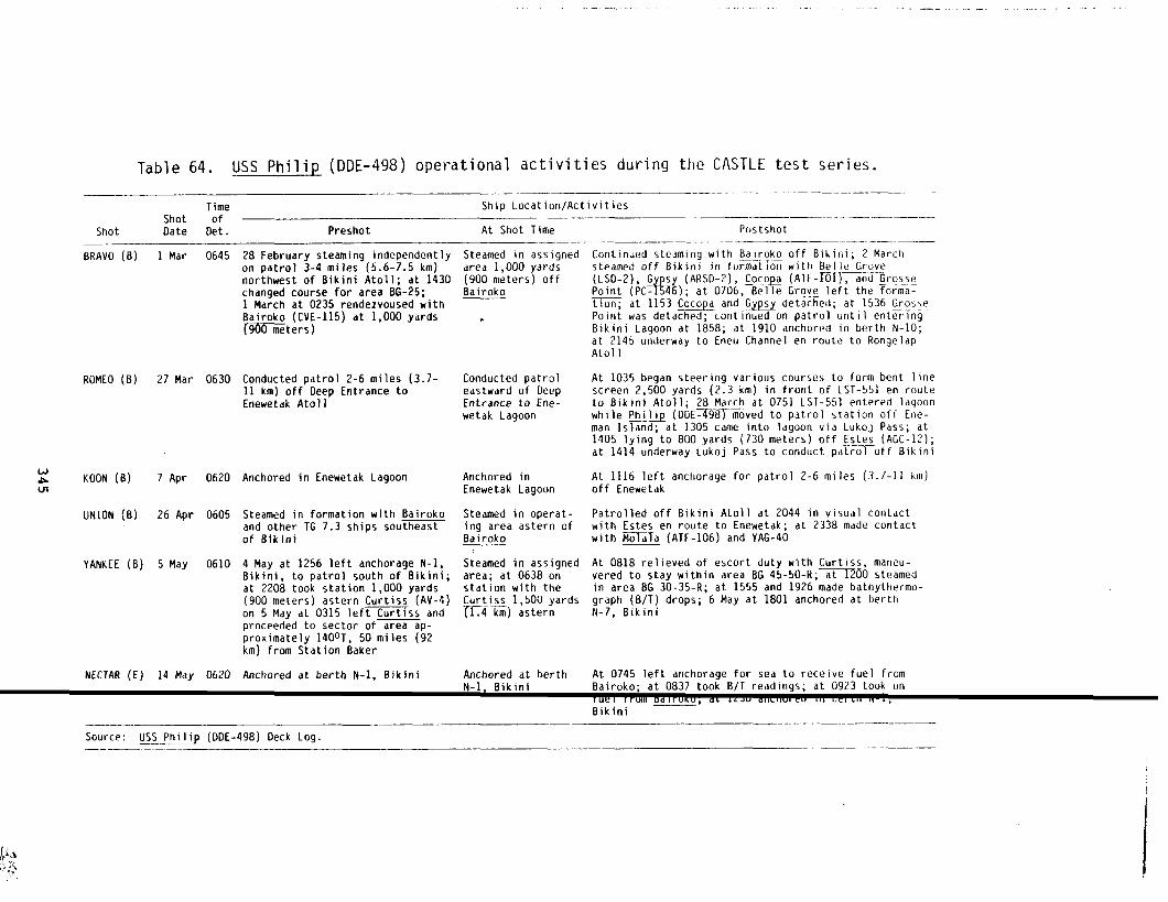
.. ... . . . . ..—.. . . .. . . --
Table 64. USS Philip (DDE-498) operational activities during the CASTLE test series._—-——
Time Ship Location/ActivitiesShot of _— ..— — .—— ——
Shot Date Det. Preshot At Shot Time
BRAVO (B)
ROMEO (B)
(&l& KOON (B)m
UNION (B)
YANKEE (B)
NECTAR (E)
1 Mar 0645
27 Mar 0630
7 Apr 0620
26 Apr 0605
5 May 0610
14 May 0620
28 February steaming independentlyon patrol 3-4 miles (5.6- 7.5 km)northwest of Bikini Atoll; at 1430changed course for area BG-25;1 March at 0235 rendezvoused withBairoko (CVE-115) at 1,000 yards~XiOXZters)
Conducted patrol 2-6 miles (3.7-11 km) off Oeep Entrance toEnewetak Atoll
Anchored in Enewetak Lagoon
Steamed in formation with Bairokoand other TG 7.3 ships southeastof Bikini
4 May at 1256 left anchorage N-1,Bikini, to patrol south of Bikini;at 2208 took station 1,000 yards(900 meters) astern Curtiss (AV-4)on 5 May at 0315 left Curtiss andproceeded to sector of area ap-proximately 1400T, 50 miles (92km) from Station Baker
Anchored at berth N-1, Bikini
Steamed in assignedarea 1,000 yards(900 meters) offBairoko
.
Conducted patroleastward of OeepEntrance to Ene-wetak Lagoon
Anchored inEnewetak Lagoon
Steamed in operat-ing area astern ofBairoko
Steamed in assignedarea; at 0638 onstation with theCurtiss 1,500 yards
m) astern
Anchored at berth
Postshot-. -— —. —_. _— .—.
Continued ste~ming with &arok~_ off Bikini; 2 Marchsteamed off Bikini in formation with Belle Grove
(LSO-2), G sy (ARSD-?), ~oco~ (ATF-rdl), and ~rosse—.
+Point (PC- 5 6); at 0706, Belle Grove left the forma-tion; at 1153 Cocopa and G_v~ detached; at 1536 GrossePoint was detached; continued on patrol until enteringBikini Lagoon at 1858; at 1910 anchored in berth N-10;at 2145 underway to Eneu Channel en route to Ronge lapAtol 1
At 1035 began steering various courses to form bent linescreen 2,500 yards (2.3 km) in front of LST-551 en routeto Bikini Atoll; 28 March at 0751 LST-551 entered lagoonwhile Philip (OOE-498~ moved to patrol station off Ene -man Island; at 1305 came into lagoon via Lukoj Pass; at1405 lying to 800 yards (730 meters) off Estes (AGC-12);at 1414 underway Lukoj Pass to conduct patro~off Bikini
At 1116 left anchorage for patrol 2-6 miles (3.7-11 km)off Enewetak
Patrolled off Bikini Atoll at 2044 in visual contactwith Estes en route to Enewetak; at 2338 made contactwith M=a (ATF-106) and YAG-40
At 0818 relieved of escort duty with Curtis~, maneu-vered to stay within area BG 45-50-R; at E?OO steamedin area BG 30-35-R; at 1555 and 1926 made bathythermo -graph (B/T) drops; 6 May at 1801 anchored at berthN-7, Bikini
At 0745 left anchorage for sea to receive fuel fromBairoko: at 0837 took B/T readinas: at 0923 took onN-1 Bikini . .Iuel ff’;l, Dal,, ”K”; *L L’2ua,,Ll,”, L” ,,, “c, .,, b, i,Bikini
Source: USS Ph~lj~ (OOE-498) Oeck Log.—. —— ———

-“--1
Table 65. USS Grosse Point (PC-1546) operational activities during the CASTLE test series.
Time Ship Location/ActivitiesShot of
Shot Date Det. Preshot At Shot Time PostshotI
BRAVO (B) 1 Mar 0645 28 February underway
to conduct ASW patrol
off Bikini; 1 March indesignated operating
i Steamed in designatedoperating area
At 2120commenced screening BelleGrove (LSD-2), TU 7,3.7; 2 March2 March joined formation withPhilip (DDET498) and other ships;left formation at 1541 to proceedto Bikini Lagoon; at 1634 moored tostarboard side of Coco@ (ATF-101),berth N-1,Bikini Lagoon
Remained anchored
At 0928 departed Ailinginae Atollen route Bikini; at 1203 arrivedassigned area; at 1928 anchored inberth N-7, Bikini
area with Tawakoni(ATF-114)
ROMEO (B) 27 Mar 0630 Anchored at Enewetak Anchored at Enewetak
KOON (B) 7 Apr 0620 6 April at 1600 under-way from AilinginaeAtoll for assignedarea southwest ofatoll .
Steamed in assignedoperating area; at0633 began firingilluminating shells;at 0635 completedfiring
uAm
UN1ON (B) 26 Apr 0605 Anchored in lagoon atRongerik Atoll
Anchored in lagoonat Rongerik Atoll
Underway from Rongerik Atoll toBikini at 1326; 27 April arrivedBikini Atoll at 0401; anchored inberth N-8, Bikini
Underway to assigned station at1255
No log available, presumably moored
YANKEE (B)
NECTAR (E)
5 May 0610 Anchored in lagoon atRongerik Atoll
Anchored in lagoonat Rongerik Atoll
14 May 0620 13 May anchored at No log available,berth Able-3, PearlHarbor
presumably mooredin Pearl Harbor
in Pearl Harbor
Source: Grosse Point (PC-1546) Deck Log.

During the Bikini shots, one ship always provided the carri
with a plane guard; another escorted the Curtiss; and two ships
assigned to Enewetak to provide security for the atoll. One of
sortied from Enewetak on shot day at Bikini to a station halfw~
the atolls, where it served as an aircraft control station. Th
ried an Air Force officer from ~ 7.4, who acted as an air cent
Renshaw served in this capacity for the first two shots and the
for the last four.
The Surface Security Unit, in conjunction with the Patrol P
also provided postshot support to the sea-phase portion of Proj
which consisted of assisting in locating fallout collector buoy
with radio transmitters.
In addition to these planned activities, elements of the Su
curity Unit searched on two occasions for downed RAF Canberra b
were incoming to Kwajalein from the Admiralty Islands (the firs
at sea; the second was forced to land on the beach at Ailinglap
provided interatoll transportation following the temporary C1OS
Bikini airstrip after BRAVO, supported weather station activiti
gerik for UNION and YANKEE, and were scheduled to act as a fall
tion unit and evacuation ship at Ujelang during shot NECTAR if
ities had been required.
After shot BRAVO, the Philip was heavily contaminated by fa
serving as plane guard for the Bairoko. Eighty-three of the sh
received exposures of more than 3.9 R, with a maximum exposure
recorded. Consequently, the CTG 7.3 recommended that the Phili
crew receive a waiver of the MPE, and that the ship be assigned
likely to expose the crew to further contamination. Neverthele
ship received additional slight contamination after ROKBO while
from Enewetak to Bikini on 28 March.
r, Bairoko,
were always
these ships
between
ship car-
oiler. The
Nicholas
ane Unit,
ct 2.5av
equipped
face Se-
mbers that
was lost
lap Atoll),
re of the
s on Ron-
,utdetec-
uch activ-
out while
I’S crew
10.5 R
s entire
,utiesun-
, the
n route
The heavy contamination of the atolls to the east of Bikini after BRAVO
required evacuation of the Marshall Islander populations, whichIas done by
347

units of the Surface Security Unit. These atolls were also su
resurveyed in order to establish the degree of contamination,
tablish how the fallout may have been taken up in the food cha
and animals. This required several returns to the atolls, whi(
radiologically hot enough to require that shore parties be bad~
activities are summarized in Table 66.
Table 66. CASTLE evacuation and resurvey activities, March-
Dates Ship Activity Location(s)
3 Mar
4 Mar
5-8 Mar
8-12 Mar
25-26 Mar
21-23 Apr
N98)Renshaw=99)
Renshaw7-9 )
Nicholas~)
(
Nicholas‘~)
W98)
Evacuation
Evacuation
Resurvey
Resurvey
Resurvey
Resurvey
Rongelap and Ailinginae a
Utirik Atoll
6 March: Likiep, Jemo IsAiluk Atoll; 7 March: Mei
9 March: Utirik and AonUtirik Atoll, and Bikar IBikar Atoll,; 10 March: En~Island at Rongerik Atoll,nae Atoll; 11 March: norlap Atoll
Rongelap Atoll
21-23 April: Rongelap At23 April: Ailinginae Ato
Source: Reference 16, Appendix H.
Rongerik remained too radioactive for continuous occupancy
and required evacuation because of the contamination of the we
!d and
:0 es-
7 plants
!re still
These
1 1954.
)
and,sland
Ids atI at~k IslandAilingi-I Ronge-
sr BRAVO
r sta-1
tion and the Project 6.6 station there. However, because JTF 7
I
ill
required weather information from this station, it was operated “ termit-
tently to make daylight soundings before shots ROMEO and KOON by ersonnel
flown in and out by seaplane. For shots UNION and YANKEE, perso el were
348

conveyed to the site by the Grosse Point, which was used to ho lse them
while off duty.
ITask Unit 7.3.2 (Carrier Unit)
During CASTLE, the Carrier Unit was composed of the escort
Bairoko, Marine Helicopter Transport Squadron HMR-362 with 12
HRS-2 helicopters, and Fleet Composite Squadron VC-3 with six
sair fighter aircraft. The latter was divided into the Bikini
Element, 7.3.2.1, and the Enewetak Fighter Element, 7.3.2.2, c
three aircraft. The Bairoko and HMR-362 participated in all f
Bikini and remained there when shot NECTAR was fired at Enewet
tional activities of the Bairoko are summarized in Table 67.
carrier
ikorsy
‘4U-5NCor-
Fighter
ch with
ve shots at
k. Opera-
The most important mission of the Bairoko and HMR-362 was o operateI
the ship-to-shore and interisland airlift at Bikini, which pro ided trans-t
{portation to working parties before shots, and to damage-surve and data-
recovery parties following shots. The Bairoko also transport
washdown equipment to the PPG for installation on task group s
addition, it furnished space, facilities, and assistance in sh
contamination of HMR-362 aircraft in a canvas “bathtub” erecte
flight deck. It provided administrative and working facilitie
radsafe task unit of TG 7.1, which included a photodosimetry t
trailer housing a radiochemical analysis laboratory.
all the
ps. In
board de-
on the
to the
,ilerand a
During shot-phase activities, the Bairoko evacuated TG 7.1 ersonnel
twho required quick reentry into the area via helicopter, inclu “ng radsafe
monitors and the Task Force Radiological Safety Center personn
I
required
to operate the photodosimetry and radiochemical analysis labor ories.
The carrier also took aboard the men and equipment of the Biki “ Fighter
Element, the personnel and equipment of HMR-362, and CTG 7.3. fter shot
BRAVO on 1 March, the Bairoko removed the Bikini Fighter Eleme
I
to Enewe-
tak, where it operated for the remainder of CASTLE. On 6 Marc cm 7.3
shifted his flag to the Curtiss because of overcrowding on the
Due to the contamination on Eneman Island, HMR-362 continued t
349
,airoko.
berth and

Table 67. USS Bairoko (CVE-115) operational activities during the CASTLE test series.
Time ShipLocatloniActivitiesShot of
Shot Date Det. Preshot At ShotTime Postshot
BRAVO (B) 1 Mar 0645
ROMEO (B) 27 Mar %30
KOON (B) ? Apr 0620
UNION (B) 26 Apr 0605
YANKEE (B) 5 Mdy 0610
NECTAR (E) 14 May 0620
28 February at 2307 underwayfrom Bikini to operatingarea; 1 March at 0243 rendez-voused with Philip (ODE-498)
26 Apri 1 at 2024 underwayfrom Bikini Lagoon to oper-ational area off Bikini
Steamed in the company of theEpperson (ODE-719) in theoperational area off Bikini
25Apri } at 1853 underway forBikini operating area with
!X.!.Q
4 May at 1555 underway withRenshaw (ODE-499) from Bikini~gned operating area
13May at 1746underway fromKwajalein Atoll to BikiniAtoll
At 0645 38 nmi (70 km) bear-ing 1326 from shot; at 0803material condition Able setwhen heavy fallout detected;washdown system operated from0810-0931; firehoses usedafter securing washdown sys-tem; at 1800 a second falloutbegan; firehoses continued inuse until 1845; steamed fromfrom Bikini to Enewetak
At 0630, 43 nmi (80 km) bear-ing 124° from shot; from0700-0710, washdown gearoperating, but no new fall-out received
At 0620 23 nmi (43 km) bear-ing 1006 from shot
At 0605, 57 nmi (105 km)bearing 155° from shot
At 0610, 34 nmi (63 km)bearing 150° from shot; at0625 set modified conditionAble; between 0652-0702 wash-down gear on
At 0620, steaming from Kwa-.jalein to Bikini. 40nmi
2 March decontamination efforts startedagain after OBOO radiological monitoring;use of high-pressure hoses and scrubbingcarried on all day; 3 March iw’rived Bikini,launched helicopter radsafe surveys
At approximately 0900 launched two hel i-copters for initial radiological survey;at 1405 anchored in berth N-5, Bikini;28 March at 0859 after shifting moored tobuoy T-2, Bikini; 29 March wdshdown systemoperated 0130-0215; reactivated at 0320
At 1104 anchored in berth N-5, Bikini
At 1611 anchored in berth N-5, Bikini
At 1643 anchored in berth N-6, Bikini
From 0912-1045 Philip alongside to fuel;at 1206 anchored in berth N-3, Bikini; at
174 km) SE of Eneu
c
.,.,- .

i
I
mess on board the Bairoko and to operate the helicopter lift
the carrier. Seventeen personnel from HMR-362 received expos
than 3.9 R (with a maximum of 5.5 R) because of the heavy fal
Bairoko encountered after shot BRAVO.
that these individuals be given an MPE
operations.
Consequently, CTG 7.3
waiver to avoid impair
The Consolidated List for VC-3 includes only five of the
enlisted maintenance personnel are not shown. It is assumed
personnel, if badged, were included in some other list, perha
Bairoko’s list. Rowever, their duty stations would have been
F4U aircraft at Enewetak after shot BRAVO. Table 23, which p
cumulated radiological exposure of TG 7.3 personnel by ships
of 22 March 1954, shows VC-3 with 20 personnel. All personne
lowest category, 0.()to 0.999 R. VC-3 ground personnel could
to have radiological exposures similar to or lower than the A
ground personnel, who also operated out of
There is no record of VC-3 flight missions
logical exposure.,
Task Unit 7.3.3 (Patrol Plane Unit)
This unit consisted of Patrol Squadron
the Enewetak air f
into areas of pote
VP-29 with twelve
aircraft, a P2V-5 Neptune assigned to Project 6.4, a P4Y-2 Pr
craft assigned to Project 1.4, and two specially configured P
aircraft. The patrol squadron was based at the Naval Air Sta
Kwajalein, for the duration of CASTLE. The other four aircra
from the Bnewetak Island”airstripat Enewetak Atoll.
VP-29 flew security sweeps of the PPG danger area to warn
sient shipping and aircraft prior to shots. The squadron als
biological reconnaissancemissions in the northern Marshall I
support of the ABCls World Wide Fallout Monitoring Program (s
VP-29 assisted in locating Project 2.5a fallout-collectorbuo
PBMs, operating under the control of TG 7.4 (Air Force), were
351
ternfrom
s of more
t the
xnmended
continued
2 pilots;
t these
the
th the six
ides ac-
units as
ce in the
expected
Force
lity.
al radio-
-6 Neptune
keer air-
5A Mariner
I (NAS),
~perated
ay tran-
Lew ra-
ids in
rable 68).
The two
ecially

Table 68. Patrol Squadron 29 (VP-29) operations, CASTL
Number ofType Flight Flights Hours Flown Night Hours D
Cargo and admin 22
Antisubmarine warfare 53
Survey 27
Escort 28
Recon 72
Buoy recovery 4
Buoy evaluation 2
HASL (AEC)special project 8
TOTAL 216
50.6
579.3
197.5
266.1
712.5
36.6
12.7
86.3
4.2
326.4
1.9
154.9
274.0
1.7
0.0
3.8
1,941.6 766.9
Source: Reference 14.
configured to increase their passenger capacity to provide inter
passenger service. The P2V-5 was airborne at shot time on shots
ROMEO, UNION, and YANKEE, providing airbor’neremote control capa
operation of the test ships YAG-39 and YAG-40. The P4Y-2 was ai
shot time on all shots except KOON, serving as an airbfirnetelem
tion for data from instrumentation placed in the lagoon for Proj
Its nominal position was 50 nmi (93 ksi~)south cf the bl.]rstat sh
time at 10,000 feet (3.05 km) a’ltitude. Ttiereare no instances
icant contamination among personnel of tilePatr(oi?lane Unitr eil
VP-29 aircraft was sufficiently coritamifiatedi>y t~c W!!.VOCiotia
mission was aborted.
\
Kwajalein NAS, besides providing basing support for VP-29, g
the aircr~ft ad crew following shGt 3RAL”CJfor the evacuation of
gerik Weather Station and the Project 6.$ perscanel. Aircraft f
ours
6.4
2.9
5.6
1.2
8.5
4.9
2.7
2.5
4.7
1 air-
.s70,
ty for
ne at
1 sta-
1.4.
a::~.;:+i
;ignif--
]gh a
: ics
tied
? Ron-
this
station also provided the airlift for the evacuation of the Rongel
I
and
Ukirik natives. The exposed natives were decontaminated, fed, hou d, and
352
.—
clothed by Kwajalein NAS. The aircraft used in these evacuatl
quired considerable decontamination.
The R?@ Canberras that were permitted to sample the CASTL1
clouds were based and supported at Kwajalein NAS. Kwajalein 1
also included supervision of the decontamination of the samplj
Thirteen personnel from Kwajalein NAS, including one civilian,
sures reported in the Consolidated List. The exposures were r
(less than 0.500 R) , with the exception of the civilian, who x
most 3 R. These exposures probably were accrued from decontan
evacuation operations. VP-29 operational activities are summa
Table 68.
Task Unit 7.3.4 (Joint Task Force Flagship Unit)
The Estes, an amphibious force flagship with additional cc
equipment installed, served as the Flagship Element during CA!
provided command, control, and communications facilities for i
quarters, as well as for TG 7.1 and 7.4 during CASTLE. Durin!
operations, the
also located on
Originally,
JTF4ieather Central and Radiological Safety Of
board the Estes.
the Es_teswas to have been based at Enewetak 1
at Bikini. When the entire
BMVO on 1 March, the Estes
ries. The ship was present
for shot NECTAR on 14 May.
tivities for CASTLE shots.
Bikini operation had to move aflo~
remained at Bikini for most of th(
for all Bikini shots, and returnet
Table 69 summarizes the ship’s op(
The Estes was contaminated by radioactive fallout after B1
ROMEO. The peak intensity topside occurred about 2 hours aft{
when it was estimated at 0.400 R/hr (see Table 21). Fifteen c
were given an MPE waiver; however, none of these individuals z
ceeded 3.9 R. Thirteen other crewmen did have excessive expo:
of 6.95 R) without a waiver of MPE. These individualswere m
353
5 also re-
?tonation
suppert
aircraft.
we expo-
very large
?ived al-
%tion and
!ed in
onications
E. It
7 head-
ikini
ze were
#een shots
after shot
kSTLE se-
o Enewetak
kional ac-
3 and
3RAV0,
the crew
Jally ex-
?s (maximum
3 a group

Table 69. USS Estes (AGC-12) operational activities during the CASTLE test series.
Time Ship Location/ActivitiesShot of
Shot Date Det. Preshot At Shot Time Posts hot
BRAVO (B) 1Mar 0645
ROMEO (B) 27 Mar 0630
KCH3N (B) J Apr 0620
Umlb
UNION
YANKEE
B) 26 Apr 0605
(B) 5 May 0610
NECTAR (E) 14 May 0620
28 February at 1842 underway from Steamed as beforeBikini to operating area; at 2022arrived at assigned operatingarea; steamed independentlyoffBikini
.
26 March at 2039 underway from Steamed as beforeBikini to assigned operatingarea; at 2259 arrived at assignedposition
5 Apri1 at 1207 underway for Steamed on stationoperating area; 7 April steamedto remain on station
25 April at 2228 underway; at Steamed as before2348 arrived in operating area;26 Apri 1 steamed to remain onstation; at 0545 mustered crew
4 May at 2049 underway for oper- Steamed as beforesting area; at 2218 arrived inoperating area
13 May at 1857 underway from Steamed in assignedEnewetak to assigned operating assigned operat-area; at 2001 arrived in oper- ing areasting area
At 0830 set condition Purple II; at 1125set condition Purple III;at 1535 set con-dition Purple 11; 2 March steamed en routefrom Bikini to Enewetak; at 0845 mooredto buoy B-1, Enewetak; at 1831 Unclenqayfrom Enewetak to Bikini; 3 March anchoredat anchorage N-4, Bikini, at 0843
27 March at 1325 anchored at berth N-4,Bikini; 28 March at 0737 underway; at0934 anchored in berth A-6, Bikini
At 1101anchored at berth N-3, Bikini;8 April at 1845 received provisions fromKarin (AF-33)
At 1552 anchored at berth N-4, Bikini;at 1952 underway from Bikini to Enewetak;from 2220-2230 lost power to runninglights
At 1355 Curtiss (AV-4) approached star-board fomine transfer; at 1428CTG 7.3 arrived by highline; at 1708anchored at berth N-4, Bikini; at 1934underway to Enewetak; 6 May at 0823moored at buoy B-1, Enewetak; at 2015received provisions from the Arequipa(AF-31)
At 0741anchored in anchorage C-1,Enewetak; at 1526 underway en route toSan Diego

I
I
of twenty assigned to temporary duty on board
27 March and 15 April. They were probably on
decontamination.
Task Unit 7.3.5 (Utility Unit)
The Utility Unit consisted of two salvage
LST-762 at Enewe
temporary duty f
lifting vessels,
w and the USS Mender, and five fleet tugs~ USS Apache, USS
Molala, USS Sioux, and USS Tawakoni. The Mender replaced the
25 March 1954, when the Gypsy left for Pearl Harbor. Tabl~s 7
summarize each ship’s activity on a shot-by-shot basis.
The basic assignment of the Utility Unit was to provide ha
towing services to the joint task force. The unit also gave e
support to a number of scientific projects. The Sioux and the
planted fallout collection buoys prior to all shots except KOO
ect
all
but
and
—-— .
k between
YAG
he USS
!ES!EZ!’YES~ on
through 76
or and
,ensive
~pache
for Proj-
2.5a and retrieved the buoys after the shots. The Gypsy, @rider, and
the tugs except the Molala assisted Project 1.4 in a variet >f ways,
the primary support tug was the Cocopa. During all shots e
NECTAR, the Molala and the Tawakoni assisted Projects 6.4 a
prepositioning the YAGs in the predicted fallout area and retri
after the shot.
All these activities required the Utility Unit ships to ope
ters that had been contaminated by one or more shots. The Coco
drawn from support of Project 1.4 after UNION and before YANKEE
a buildup of background radiation in the tug from radioactive s
in her seawater piping; she was replaced in that activity by th
(Reference45). The sources of the radioactive silt were the n
formed at Bikini by BRAVO and UNION.
A number of ships also were contaminated by fallout from BR
GYPSY, Cocopa, Apache, and Sioux (Table 21). The Gypsy in part
most difficult to decontaminate because of corrosion on the dec
tended to retain fallout. Furthermore, all ships of the Utilit
355
?pt KOON
6.5 by
ing them
[e in wa-
was with-
?cause of
: retained
rawakoni
craters
): the
llar was
, which
Unit
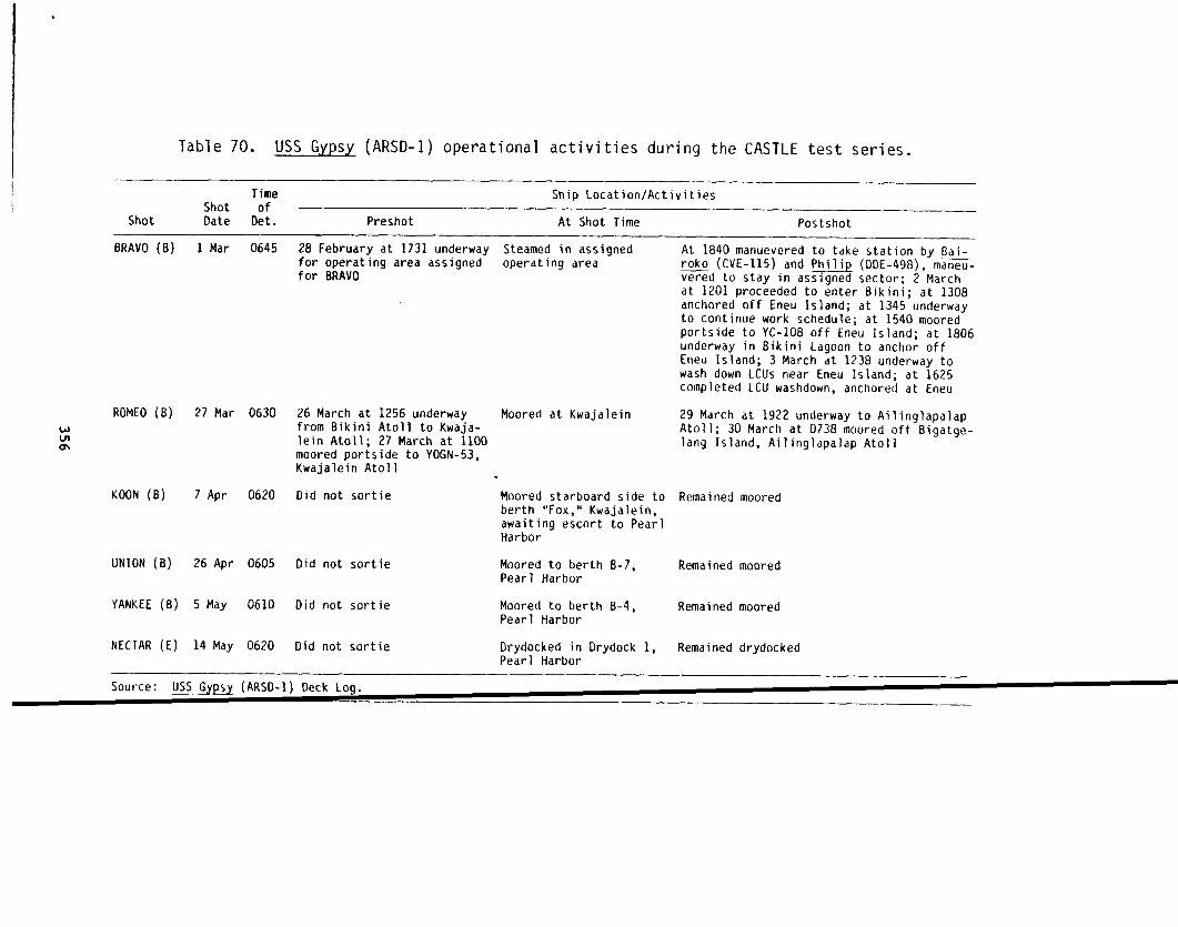
Table 70. USS Gypsy (ARSD-1) operational activities during the CASTLE test series.
Time Ship Location/ActivitiesShot of
Shot Date Det. Preshot At Shot Time Postshot
BRAVO (B)
ROMEO B)
KOON (B)
UNION(B)
1 Mar 0645 28 February at 1731 underwayfor operating area assignedfor BRAVO
27 Mar 0630 26 March at 1256 underwayfrom Bikini Atoll to Kwaja-lein Atoll; 27 March at 1100moored portside to YOGN-53,Kwajalein Atoll
7 Apr 0620 Did not sortie
26 Apr 0605 Did not sortie
Steamed in assignedoperating area
Moored at Kwajalein
Moored starboard side toberth “Fox,” Kwajalein,awaiting escort to PearlHarbor
Moored to berth B-7,
At 1840manuevered to take station by Bai-roko (cVE-115) and Philip (DDE-498), m~-vered to stay in assigned sector; 2 Marchat 1201 proceeded to enter Bikini; at 1308anchored off Eneu Island; at 1345 underwayto continue work schedule; at 1540 mooredportside to YC-108 off Eneu Island; at 1806underway in Bikini Lagoon to anchor offEneu Island; 3 March at 1238 underway towash down LCUS near Eneu Island; at 1625completed LCU washdown, anchored at Eneu
29 March at 1922 underway to AilinglapalapAtoll; 30 March at 0738 moored off Bigatge-lang Island, Ailinglapalap Atoll
Remained moored
Remained mooredPearl Harbor
YANKEE (B) 5 May 0610 Oid not sortie Moored to berth B-4, Remained mooredPearl Harbor
NECTAR (E) 14 May 0620 Did not sortie Drydocked in Drydock 1, Remained drydockedPearl Harbor
Source: ~ (ARsD-1) Deck LOg.

. . . ... .. . .. . .
wul-4
Table 71. Us$ fifelliel” ,,’ ::;- : ( ,. II .IUI:. il ~t:citii~ies during the CASTLE test series..—-.—_-——— -. -—. . ...——.—.————_ ._. _______ _
I‘I f(lt! Snip Locat~on/ActivitiesShut of -- -- ----------
Shbt Date tl?t. Frts!lot At Shot Time Postshot—-——.-. ——— .—-— —.— ..— ..——.—————
BRAVO (B) 1 Vial &545
ROMEO (B) 27 Mdr Or, ,
K(JON (B) 7 Apr
UNIW (L <( ‘
Yi\NKEE (h) ‘-,i
NEC[AR (t) ;4 Muy ;<>>.~
—. . . —..
r]9
[n Sasebo, Japan
Steamed inoperating area
Steamed to remainirioperating area
kitni Steamed to remainJred in operating area
Steamed en routeEile’.ict~~fot-Pearl Harbor to Pearl Harbor
. .——— . _—--_— —_______
1 March at 1555 underwayto Guam
27 March at 1409 anchoredin berth N-2, Bikini;30 March steamed in andout of Bikini Lagoonseveral times until 2010
At 1555 anchored inBikini Lagoon
26 April at 1847 mooredstarboard side to LCU-1224in Bikini Lagoon
6 May at 1847 anchored inEneu area, Bikini Lagoon
Continued steaming
Source: ,’S>;WICII.$::_ (r..~[)-!~!,i:~k LocJ.———. . .. -—.— .——____ .__

UWw
Table 72. USS Apache (ATF-67) operational activities during the CASTLE test series.
Time Ship Location/ActivitiesShot of
Shot Date Det. Preshot At Shot Time Postshot
BRAVO B)
ROMEO (B)
KOON (B)
UNION (B)
YANKEE (B)
NECTAR (E)
1 Mar 0645
27 Mar 0630
? Apr 0620
26 Apr 0605
5 May 0610
14 May 0620
Underway from Bikini torendezvous point withTG 7.3; at 0340 atrendezvous point
.
Underway from Bikini torendezvous with TG 7.3;at 0135 arrived inrendezvous area
Underway from Bikini toEnewetak
Underway from Enewetakto Kwajalein
Did not sortie
Underway independentlyfrom Bikini to PearlHarbor; at 0420 maderadar contact withMogiri Island
Main
ntained stationrendezvous area
Maintained stationin rendezvous area
Continued steamingfrom Bikini toEnewetak
Continued steamingfrom Enewetak toKwajalein
Moved to berthEasy, Kwajalein
Continued steamingfrom Bikini toPearl Harbor
At 1440 commenced maneuvering atvarious courses and speeds to washdown ship; at 1505 left rendezvouspoint to carry out operations; at1734 commenced steering variouscourses and speeds for washdown
At 0835 maneuvered in vicinity ofAinsworth (T-AP-181); between 0920and 0955 had motor launch in water;from 1602-1715 commenced steeringvarious courses and speeds to effectwashdown
At 0940 anchored in vicinity ofberth K-2, Enewetak
27 April at 0802 moored to berthEasy, Kwajalein
Remained moored
Steamed as before
.

. . .._ ___,_.. .. .. .._ ...__ .. . . -------- ____ - -.——. —.—--- — --
Table 73. USS Cocopa (ATF-101) operational activities during the CASTLE test series.
Time Ship Location/ActivitiesShot of
Shot Date Det. Preshot At Shot Time Postshot
BRAVO (B)
ROMEO
wul KOONw
UN1ON
(B)
B)
(B)
YANKEE (B)
NECTAR (E)
1 Mar 0645
27 Mar 0630
7 Apr 0620
26 Apr 0605
5 May 0610
14 May 0620
Underway from Bikini withfour YCVS on main tow andYFN-934 on starboard wingdrum .
26 March at 2012 underwayfor operating area withYFN in tow
Did not sortie
25 April at 1725 underwaywith YFN-934 in tow inassigned area off Bikini
4 May at 1430 underwayinassignedoperatingareafrom Bikini
Did not sortie
operating areaSteamed in Bikini At 1845 took station by Philip
fDDE-49g) in com~any with Belle&rove (L5D-2), GYPS” (ARSD~~and
+Grosse Point (PC- 5 6); 2 March at1405 released YFN-934; approachedYC-1081 at 1437; at 1527 anchoredin Bikini; from 1636-1807 fueled
Underway forassigned duties
Anchored berthAble, K-2,
Steamed inassigned area
Steamed inassiqned oper-ating area
Anchored west of
from Grosse Point; released YCNat 1710
At 1358 anchored at Eneu, Bikini;at 1424 sent diver over to inves-tigate propeller
At 0725 underway to shift berthsto Able berth B-1,EneweLak; at
0743 Enewetak anchored; at 1737underway from Enewetak to Bikini
At 1843 anchored at Bikini,transferred YFN-934 to LCM-42
Remained steaming in assignedoperating area until 6 May; at0751 anchored northeast of berthN-12, Bikini
Remained anchored
Bikini
Source: USS Cocopa (ATF-101) Deck Log.
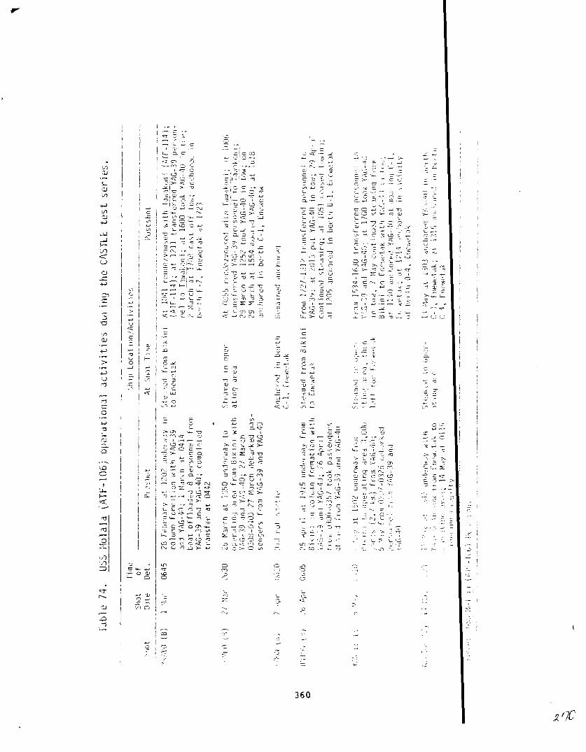
#-
I
I
I
I

— —. .. . ... . ,! . . . . . . . . . . . . . - . . . . . . . . . . . . ,, .,”.
.-. ”—., ”.,* - .- .,,
.—.-———-— ——. .——..
<t{, ?lllb,! 1(, 1> ,,1~1opt’1 $[ 111,] l-t.]
?0 M ,,’LII3t 1013 !Ill{ierwayfrOl,l‘I,[rlfrqA-7, ijll,ini,
I Pr,)j,,:tI(i, ,1:, n. : [1[;(, ,,%it I
-’.”)i; .IL 1613, 174J, i85[. ,‘)lh5, ??)2, 2?58 drorrprJ[,uOv5; ?1 [iIr.CllC[lrltIri!lc, 1dropp i IIg ibuoy>
.
‘,‘1,1,, ‘!.4!{)
[II),., ,;t. )n(j A,- .,] LF 1!). /3 opt,rdt inq 4ir-t:L1
I(’ )Y 1.? ,; d// [)1- I [Jtl
—.. — —.._ . ._ -. .
P-L—
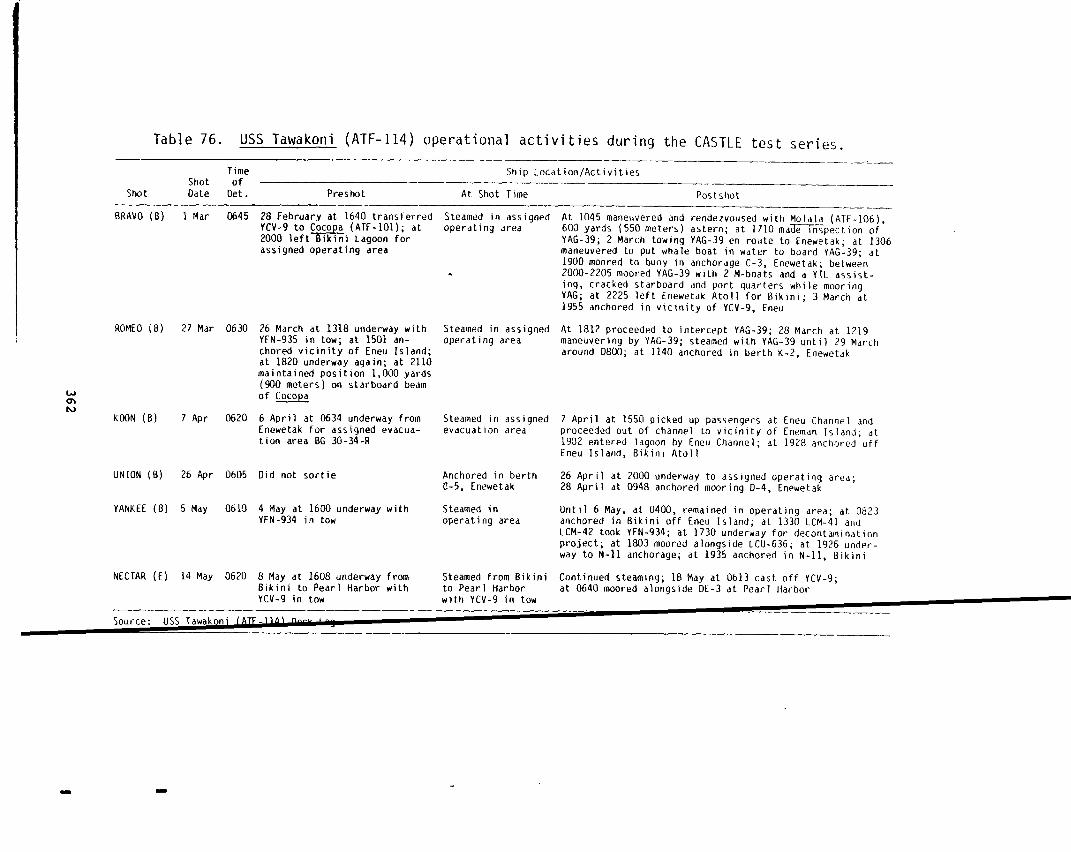
Table 76. USS Tawakoni (ATF-114) operational activities during the CASTLE test series.
Time—.-
Ship Location/ActivitiesShot of
Shot Date Det. Preshot At Shot Time Postshot
BRAVO (B)
ROMEO (B)
LAJalN
KODN (%)
UNION (B)
YANKEE (B)
NECTAR (E)
1Mar 0645
27 Mar 0630
7 Apr 0620
26 Apr 0605
5 May 0610
14 May 0620
28 February at 1640 transferredYcv-9to w (ATF-10l); at2000 left Bikini Lagoon forassigned operating area
26 March at 131B underway withYFN-935 in tow; at 1501 an-chored vicinity of Eneu Island;at 1820 underway again; at 2110maintained position 1,000 yards(900 meters) on starboard beamof Cocopa
6 April at 0634 underway fromEnewetak for assianed evacua-tion area BG 30-3~-R
Did not sortie
4 May at 1600 underwayYFN-934 in tow
8 May at 1608 underwayBikini to Pearl HarborYCV-9 in tow
with
fromwith
Steamed in assignedoperating area
.
steamed in assigned
operating area
Steamed in assignedevacuation area
Anchored in berth0-5, Enewetak
Steamed inoperating area
Steamed from Bikinito Pearl Harborwith YCV-9 in tow
At 1045 maneuvered and rendezvoused with Molala (ATF-106),
600 yards (550 meters) astern; at 1710 ma~pect ion ofYAG-39; 2 March towing YAG-39 en roi}te to Enewetak; at 1306maneuvered to put whale boat in water to board YAG-39; at]900 moored to buoy in anchorage C-3, Enewetak; between2000-2205 moored YAG-39 with 2 M-boats and a YTL assist-ing, cracked starboard and port quarters while mooringYAG; at 2225 left Enewetak Atoll for Bikini; 3 March at1955 anchored in vicinity of YCV-9, Eneu
At 1812 proceeded to intercept YAG-39; 28 March at 1219maneuvering by YAG-39; steamed with YAG-39 until 29 Marcharound 0800; at 1140 anchored in berth K-2, Enewetak
7 April at 1550 picked up passengers atproceeded out of channel to v]cinity of1902 entered lagoon by Eneu Channel; atEneu Island, Bikini Atoll
Eneu Channel andEneman Island; at192B anchored off
26 April at 2000 underway to assigned operating area;28 April at 0948 anchored mooring D-4, Enewetak
Until 6 May, at 0400, remained in operating area; at 0823anchored in Bikini off Eneu Island; at 1330 LCM-41 andLCM-42 took YFN-934; at 1730 underway for decontaminationproject; at 1803 moored alongside LCU-636; at 1926 under-way to N-11anchorage; at 1935 anchored in N-n,Bikini
Continued steamina: 18 Mav at 0613 cast off YCV-9;. .at 0640 moored alongside DE-3 at Pearl Harbor

I
i1
II
iI
1
I11
i
I
(
!
assisted in decontaminating the harbor craft and small boats
in Bikini Lagoon during shots detonated there. A total of 31
the Utility Unit received exposures greater than 3.9 R during
Task Unit 7.3.6 (Atomic
This unit contained
7.3.6.0, was made up of
Warfare Ship Countermeasures Test Uni
two task elements. The Drone Ship El
the specially modified Liberty ships,
George Eastman) and YAG-40 (USS Granville S. Hall). The Towi
lamination Element, 7.3.6.1, included the Molala, whose prima
bility was servicing the YAGs, and the Tawakoni, both of them
of the Utility Unit. The principal purpose of the unit was t
YAGs as data-collection platforms for Projects 6.4 and 6.5, w
both ships to be positioned in the area of heaviest fallout.
were instrumented with fallout-collectiondevices, as well as
test materials, in order to determine their susceptibility to
lamination and the ease with which they could be decontaminate
ship had a shielded control compartment and, in addition, cou
ated by remote control. While YAG-39 mounted a washdown syst
YAG-40 did not, thereby providing a coritrolsituation for the
being conducted on board both ships.
The YAGs were employed on shots BRAVO, ROMEO, UNION, and
Neither ship had a “crewon board for the first two shots, but
ter two YAG-39 carried a skeleton crew that controlled the sh
shielded control compartment. The usual pattern of operation
crews to sail both YAGs to Bikini Lagoon prior to the tests.
ships left the lagoon, most YAG crewmen were transferred to c
ships for evacuation sorties. Skeleton crews then sailed the
debarkation point in the anticipated fallout area accompanied
Molala. The tug removed the skeleton crews and took over the
mote control. (There is evidence that the Bairoko might alsc
remote-controlcapabilities.) An Enewetak-based P2V-5 aircra
with remote controls assumed control of the YAGs for the dura
time activities. The skeleton crew on board YAG-39 could als
363
: behind
:sonnelof
;TLE.
nt,
:-39 (Uss
md Decon-
:esponsi-
zet tugs
;e the
1 required
Lh YAGs
th various
Llout con-
Each
>e oper-
Lopside,
~riments
{EE.
the lat-
Erom the
s for
Eore the
r TG 7.3
;s to a
the
2s by re-
we had
~quipped
n of shot-
mtrol

YAG-40. After falloct ceased, the Molala ar.dthe Tawakoni reta—
CrC%S to YAG-39, if radiological conditions warranted. If ~g~-
reboarded, she returned under her own power; otherwise, both sh
towed back to the Enewetak Lagoon off Parry island, wi-.<reths z
derwent a radiological survey and, if necess?ry, 2f?CO!I~mlmkiQ
ship was positioned in the fallout area during BRAVO because of
culation in predicting the fallout locztion and thus did not re
decontamination;zor did shot LJN1OFJcontaminate either ship. Y
to be decontaminated following shot ROMEO, and both ships were
?.ztedafter shot YANKEE. Shot activities are summarized in T?b
Thirty men on boar~ Y?.G-39cnd thirty-three men on board YA
~lated exposurss in excess
24.39 R. This was made up
tests prior to YAN’KEZplus
of 3.3 ?.. The ;li~iie~t exposure asse
of 4.39 R frcm film bzd5e Czac!ingsf
an e:tim.ateof 20.O R for YANiKEEacc
~,edicalrecords. Individual.s;rcn other Gnits of ‘K 7.3 assist
contaminating these two ship~, ~OSS2”biyencountering rai!ioio~ic
sure. After the t?sts, the chips remained at Enewetak until 26 M
additional decontamination before sailir.q,toSan Francisco via W
bor. By 25 May the aver?ge tcpside reading for YAG-29 was C.007
~ith average interior a~d below-deck readings of 0.002 R/hr. The
were expected to be down to 0.004 R/hr and 0.001 R/hr, respective
the time of arrival at”Pearl Harbor, and 0.003 R/hr and 0.(!0!)5R,/
Francisco. Crekmembers were expected to receive 0.5 to 1 R on th
San Francisco. Readings for YAG-40 were higher: 0.040 R/hr topsi
0.003 R/hr inside on 25 May, with 0.025 R\hr and 0.004 R,/hrexpec
Pearl Harbor, and 0.014 R/hr and 0.002 R/hr at San Francisco. Th
tionai exposure for the crew was expected to be 3 to 5 R. Subseq
‘.’esti9ationsof the medical records of 41 of the 54 crewmen for t
thdt YAG-AO was in transit to San Francisco disclosed that their
posure was 1.676 2, with an exposure range Of 0.705 R to 4.56 R,
less than the initially expected exposure. These additional ‘2X>0
sot ref:ezted in the Consolidated List. For two of the YhG crew,
364
—.—
the
,re
lere
un-
:eithcz
,scal-
!IWjor
1had
:tami-
.
accu.m-
was
[e
,g to
~~ -
,~o-
Eor
Har-
:t
Levels
at
it San
rip to
and
at
ldi-
: in-
~eriod
n ex-
ewhzt
es ~re
e

YAG-:9 YAG
3RAV0
C5er2tions: f’perated frcm 2200 to 2400 at ranges from 10 to
~18 to 74 km) from shot point to H+6. ;;ot jn f
<red: ;Jone (remote C9ntr01~ None (remote
~~~o~~pr=y: ~~~akoni f-ow Molala tow
Decontamination: !ione reouired None required
-~;zro
Operations: Operated from 2200 to .3000at ranges of 25 to 5(46 to 92 km) from shot point to H+1O. In fall
Crew: None (remote control) None (remote
Recovery: Skeleton crew Nlolala tow
Decontamination: None required Required
KOOtl
Operations: .Neither ship participated; both ‘,iereat Eneweta
UNION..
OpeYati2ns: Cperated from 400 to 80~ at ranges of 20 ~0 5~(37t~ 9? km) from shot point to H+8.
~rpV~: Skeleton crew Nor,e (r~m~t~ ,
?ecovery: Full crew rejoined at H+ll };+~,?.-?fil;i~~,
!)e~ontamination: None r~q,,~red None “?ql!ifea
Y“ANKEE
operations: Operated at 600 to t?Ooat ranaes of 20 LO 55 nm{56 to 102 km) from shot point to H+i2. In :Gl
Crew: Skeleton crew None (rcnote
?ecovery: Full crew rejoined at H+9 ,Y+li?:nl]~,-.t:.——Decontamination: Required Required
‘:ECTAR
??erat;zns: D<d not participate.—-
~?ur~?: Ref?renc? 7?.—
365
nmiUt.
rol)
i
rol)
rol)
.
rol)
LA

projected additional exposure would have raised their total
these men did not return aboard the YAG.
Task Unit 7.3.7 (Bikini Harbor Unit)
The USS Belle Grove, as Task Element 7.3.7’.O,and the B
as Task Element 7.3.7.1, made up the Bikini Harbor Unit. T:
Pool operated 15 LCMS, 5 LCUS with permanent crews (LCU-637
-1225, and -1348), 2 LCPRS, an LCPL, a 28-foot motor whale ~
Air Force crash boat (AVR), and a covered barge, YFN-934. ‘
served as a dispatching facility and spare parts store for ~
ations between shots. Together with the H&N Boat Pool, the
provided interisland and ship-to-shore transportation to th
force at Bikini. The Belle Grove also transported shot dev
wetak to Bikini as the Special Devices Transport Element, 7
Iver15 R;
Boat Poola
kini Boat
8, -1224,
(FIFIB), an
atter
pool oper-
Boat Pool
nt task
from Ene-
, 0, of
TU 7.3.9, the Transport Unit.
During evacuations for Bikini shots, the Belle Grove took the 15 Navy
L(2Msand the AVR into its well deck. Remaining craft, includirg the five
LCUS, were moored in the lagoon in the lee of Eneu Island. A Ltility Unit
tug towed YFN-934 to’sea. Both Navy and H&N personnel, along with a TG 7.1
radsafe advisor, went aboard the Belle Grove, which was one of :he last
ships to leave the lagoon and one of the first to reenter durin shot Op-
erations, allowing critical construction and recovery operation ; to pro-
ceed with the least possible interruption. The Belle Grove’s activity for
each shot is described in Table 78.
After reentry following a shot, the Belle Grove put both bozt pools
into operation as soon as the lagoon was declared safe for bosting. At the
same time, Navy boat pool personnel, with assistance from ships’ crews,
began decontaminating the craft left behind. These assignments :reated a
far greater possibility of radiological exposure than for most o:her units.
This is reflected in the waiver of MPE for boat pool crews follo~ing shot
BRAVO. Altogether 49 members of the boat pool and 2 crewmen frol the
Belle Grove received exposures over 3.9 R.
366

Table 78. USS Belle Grove (LSD-2) operational activities during the CASTLE test series.
Time Ship Location/ActivitiesShot of
Shot Date Det. Preshot At Shot Time Po>tshot—
BRAVO (B) 1Mar 0645 28 February underway from an-chorage N-3, Bikini, to assignedoperating area BF 30-35-R with18 LCMS and 1 AVR in well deck
Steamed in assignedoperating area
At 1745 set the gals-tight envelope, repair parties mannedand crew at shelter stations; between 1252-1537 washdownsystem on; at 1651 closed in on Bairoko (CVE-115); at 1717helicopter left radiac cargo on ship; at 1720 helicopterleft 1 USAF officer on ship; at 2012 set gas-tight enve-lope; from 2025-2115 washdown system on; 2 March steamedin company with Philip (ODE-498), - (AR SD-1), Cocopa
(ATF- 101), Grosse Point (PC-1546); at 0706 detached from
unit, Droceeded to Bik~ni ; at 0804 anchored N-S: at 1??0
Steamed in assi~ned
debarked 13 LCMS
At 1328 anchored berth N-2, Bikin
.–. -——-
ROMEO (B) 27 Mar 0630
7 Apr 0620
26 Apr 0605
26 March at 2130 underway foroperating area BF 29-34-R, with14 boat pool LU4S, 4 civilianLCMS, 1 AVR below deck
operating area “
KOON (B) 5 April departed Bikini foroperating area 8G 32 36-L with14 boat pool LCMS, 4 civilianLCMS, 1 AVR
Steamed in assignedoperating area
At 1136 anchored berth N-2, Bikin
wm4 .
UNION (B) 25 April at 1937 underway fromberth N-2, Bikini, to assignedoperating area BG 25-30-R with1 AVR, 18 LCMS, 4 EIJKWs; at 0324took station 10 miles (18 km)from Curtiss (AV-4); at 0353proce&f&i% operating areaBH 45-50-R
Steamed in assignedoperating area
At 656 anchored berth N-2, Bikin
YANKEE (B) 5 May 0610 4 May at 1645 underway fromberth N-2, Bikini, to assiqned
Steamed in assignedoperating area
At 1743 anchored berth N-2. Bikini: at 2013 underwavfrom berth N-2 to operating area BG 35-40-R with LCMSand AVR still embarked; 6 May at 0743 anchored berthoperating area BG”25-30-R with
1 AVR and 18 LCMS; at 0310changed course for areaBG 35-40-R
N-2. Bikini
IL) .-l lmay Wcu Dy lJ Pldy steaming rrom tnewetak >tearned to Rongerlk 14 May at 0640 disembarked LCU-292; at 0640 disembarkedto Rongerik with LCU-292 (civil- LCU-637; at 0824 disembarked LCU-1348; from 1848 to 1903ian), LCU-637, LCU-1348 embarked LCUS; at 1955 departed from Ronut?rik en route to
Enewetak; 16 May at 0650 anchored berth 6-2, Enewetak
Source: USS Belle Grove (L SO-2) Deck Log.—
—
The film badges of three men indicated exposures of 85
These individuals are believed to have worked aboard an W
Belle Grove. During the washdown of the Belle Grove, cons
reportedly accumulated in the LCM alongside. Subsequently
uals were believed to have worked on decontaminating the L
sures were reportedly a result of concentrated fallout in
ough investigation,however, failed to reveal how they cou
this much radiation. It was later concluded that some dis
95, and 96 R.
alongside the
Ierablewater
these individ-
1
. Their expo-
e LCM. Thor-
have received
panty in badg-
ing or wearing of film badges must have occurred. Careful ecamination of
the badges by densitometer revealed nothing unusual in the r diation to
which they were subjected. Clinical and laboratory studies ~!onductedon
all three individuals at Tripler Army Hospital, Oahu, TerritCry of Hawaii,
were essentially negative, and they were discharged to duty Reference 16).
Task Element 7.3.7.2 (Mine Project Element)
The destroyer minelayer USS Shea, the salvage vessel USS ?eclaimer,
Explosive Ordnance Disposal Unit 1, Naval Beach Group 1, and .[ineProj-
ect 6 made up the Mine Project Element of TG 7.3., which was:nthep~
only for the conduct of Project 3.4, Sea Minefield Neutralization by Means,
of a Surface Detonated Nuclear Explosion. The project entailed laying
seven strings of mines, containing 121 in all, at specified distances from
ground zero. The mines were inert-loaded, but otherwise funct.onal, with
a detonator installed to assess the shot’s effects on the mine s compo-
nents. After the shot, the Mine Laying and Recovery Element, -.3.7.3,
recovered 100 mines and turned them over to the Mine Readying Cnd Analysis
Element, 7.3.7.4, which recorded the effects of blast and press~re on each
mine. Forty-eight of the test mines were returned to the Unitel States
for further study. The project was confined to one shot, UNION detonated
on 26 April. Tables 79, 80, and 81 describe activities of the ~eclaimer,
the Shea, and the USS Terrell County during the CASTLE test ser
Project personnel were exposed to radiation during the mine
process. On the day following shot UNION, 27 April, some mines .ndicated
1
368

.. ,.md.,,,. 4;~ miMliu,#i...,&.& ~
Table 79. USS Reclaimer (ARS-42) operational activities during the CASTLE test series.
—————. — ——— .——. ——— —_ -—-_Time Ship Location/Activities
Shot of –— ——
Shot Date Det. Preshot At Shot Time Postshot.—.. —. —
BRAVO (B) 1 Mar 0645
ROMEO (B) 2? Mar 0630
KOON (B) 7 Apr 0620
UNION (B) 26 Apr 0605umw
YANKEE (B) 5 May 0610
NECTAR (E) 14 May 0620
28February moored starboard sideto berth Baker 18 in Pearl Harbor
26 March moored starboard side toberth OE-4 in Pearl Harbor
6 April enroute from Pearl Harborto Bikini; at 1245 changed courseto Kwajalein
25 April at 1121 left Bikini an-chored to go alongside TerrellCounty (LST-1157) to re=mines to support Scientific Proj-ect 3.4; at 1420 completed takingon mines; from 1435-1450 laidmines; from 1620-1639 laid mines;at 1745 underway for assignedoperating area BH 25-30-L
4 May at 1445 underway for Guam
8 May modified destination;steamed to Sasebo, Japan; 13 Mayat 1441 moored in Sasebo, Japan
Moored starboard side Moored starboard side to berth Baker 18to berth Baker 18 in in Pearl Harbor through 8 MarchPearl Harbor
Moored starboard side 27 March at 1253 underway from Pearlto berth DE-4 in Pearl Harbor to BikiniHarbor
Approached Kwajalein; At 0754 anchored in berth 14, Kwaja-at 0646 entered Gea lein; at 1211 underway for BikiniPass
At 0620 cleared topsideof all nonessentialpersonnel; closed alldoors, hatches, andports from topside tointerior of ship;tested washdownequipment
Continued steamingto Guam
Moored in Sasebo,Japan; tested sprink-ling system
At 1006 changed station to 61 35-40-L;at 1505 beqan approaching Eneu Chan-nel; at 1811 anchored in N-1, Bikini;28 April at 1113 underway to recovermines; at 13?5 began recovery opera-tion, ceased activity by 2204; 29 Aprilremained anchored until 0730 when un-
derway to Aomen area for continued
mine recovery; at 0820 anchored inAomen area for mine recovery; continuedrecovery at least through 30 April
Continued steaming to Guam
Moored in Sasebo, Japan
——..—— —-———————————— .->ource: U>> Reclalmer (ARS-42) Deck Log.——.—--— .——— ._.——.— .—— -———_
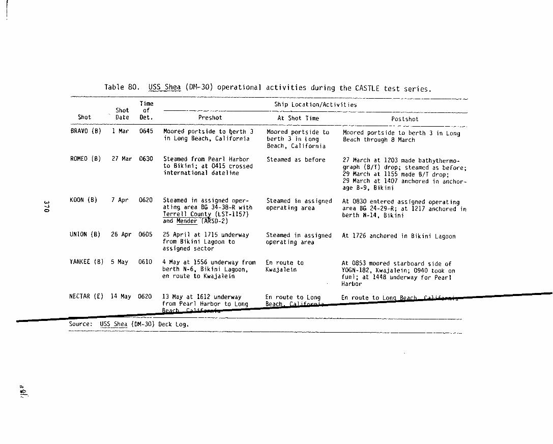
Table 80. USS Shea (DM-30) operational activities during the CASTLE test series.
Time Ship Location/Activities~ shot Of
Shot Date Det. Preshot At Shot Time Postshot
BRAVO (B)
ROMEO (B)
w KOON (B)40
UNION (B)
YANKEE(B)
NECTAR (E)
1 Mar 0645
27 Mar 0630
7 Apr 0620
26 Apr 0605
5 May 0610
14 May 0620
Mooredportsideto berth 3in Long Beach,California
Steamed from Pearl Harborto Bikini; at 0415 crossedinternational dateline
Steamedinassignedoper-atingareaBG 34-38-Rwith
%%%H%H-’15’)
25 April at 1715 underwayfrom Bikini Lagoon toassigned sector
4 May at 1556 underway fromberth N-6, Bikini Lagoon,en route to Kwajalein
13 May at 1612underwayfrom Pearl Harbor to Lonq
Moored portside toberth 3 in LongBeach, California
Steamed as before
Steamed in assignedoperating area
Steamed in assignedoperating area
En route toKwajalein
En route to Long
Moored portside to berth 3 in LongBeach through 8 March
27 March at 1203 made bathythermo-graph (B/T) drop; steamed as before;29 March at 1155 made B/T drop;29 March at 1407 anchored in anchor-age B-9, Bikini
At 0830 entered assigned operatingarea BG 24-29-R; at 1217 anchored inberth N-14, Bikini
At 1726 anchored in Bikini Lagoon
At 0853 moored starboard side ofYOGN-182, Kwajalein; 0940 took onfuel; at 1448 underway for PearlHarbor
En route to Lonq Beach ral+s~;”Beach. faljJnv-4-
Bearh r>l~$
~ USS Shea (DM-30) Deck Log.
wK!-,

Table 81. USS Terrell County (LST-1157) operational activities during CASTLE test series.
Time Ship Location/ActivitiesShot of
Shot Date Det. Preshot At Shot Time Postshot
BRAVO (B)
ROMEO (B)
KOON (B)
UNION (B)
YANKEE (B)
NECTAR (E)
1 Mar 0645
2? Mar 0630
7 Apr 0620
26 Apr 0605
5 May 0610
14 May 0620
Moored beside LST-1134 atberth B-23, Pearl Harbor
Underway from Pearl Harborto Bikini
Underway from Enewetak toassigned Bikini operatingarea with Curtiss (AV-4),Mender (AR~nd Sheam)
25 April at 1420 completedtransfer of mines for Sci-entific Project 3.4 toReclaimer (ARS-42); at 1753underway from Bikini toassigned operating areaBH 30-35-L;26 April at 0355commenced steering variouscourses and speeds to re-main in area BI 50-55-L
4 May at 1408 underwayfrom Bikini to operatingarea BH 30-35-L
13 May at 1854 underway
Moored beside LST-1134 Remained mooredat berth B-23. PearlHarbor
Steamed as before
Steamed as before
Steamed in area61 50-55-L; at 0622set condition Ableand mustered crew-to quarters andatomic defense
Steamed as before
Steamed as before
Steamed as before; 29 March at 1343 anchoredat B-10,Bikini
At 1350 moored starboard side Belle Grove(LSO-2) at N-2, Bikini; at 1514 cast off; at1546 anchored at N-14, Bikini
At 0646 secured from general quarters andset regular watch; remained steaming in areaBI 50-55-L until 1028; connnencedsteeringvarious courses and speeds to remain in areaB1 40-45-L; at 1331 changed course to ap-proach assigned area 61 30-35-L; at 1431approached assigned area BI 20-25-L; at 1800anchored in berth N-14. Bikini: 27 Aoril1800-1855 pumped fuel to Grosse Poink(PC-1546)
Steered at various courses and speeds to re-main in assigned”area BH 30-35-L; at 1200steamed on various courses and speeds in as-assigned area BH 15-20-L; 6 May steamed offBikini to remain in assigned area BH 45-50-R; ~at 0230 departed area BH 45-50-R for Bikini;at 0833 anchored at berth N-1, Bikini
At 0640 underway to berth K-2, Enewetak; at
area EG 20-25 underway; at 1643 anchored at ‘C-1,Enewetak;17Mayat1827left for Kwajalein
Source: Terrell County (LST-1157) Deck Log.

.
radiation intensities as high as 10 R/hr.
I
These were return d to the la-
goon immediately and left there for several days until radia ion levels
dropped.
in excess
16.055 R;
Task Unit
Only one individual involved in the project receiv
\
an exposure
of the MpE. He was aboard the Terrell County and s exposed to
how has not been determined.
7.3.8 (Enewetak Harbor Unit)
In general, the Enewetak Harbor Unit’s responsibilities i!eluded su-
pervision of port and harbor operations, fuel replenishment f.‘cilities,
SAR operations, and atoll security. The unit included an Air Force crash
boat (AVR), an LCM, and the fuel barges YOG-61, YoGN-8Z and Y0-120. In
addition, an Underwater Detection Unit with one LCM was assign:d as Task
Element 7.3.8.0 to operate and maintain hydrophore arrays acrO.:Sboth en-
trances to the lagoon.
Initially, the commanding officer of the Estes was to exercise admini-
strative and operational control over these forces. This assigmnent also
required administering and coordinating the activities of the N3vy detach-
ment that operated the Army’s boat pool at Enewetak (described .n this
chapter under TG 7.2). However, when t$e Estes was forced to r!main at
Bikini for long periods after shot BRAVU contaminated the at011 the re-
sponsibility for this assignment was assumed by the highest ranling Navy
officer among the ships present at Enewetak.
None of the members of the Enewetak Harbor Unit, Underwater >etection
Unit, or the personnel assigned to the Navy detachment of TG 7.2 exceeded
an exposure of 3.9 R. From the the readings given in the Consol dated
List, the exposures appear to have been assigned rather than individual
badge readings, as the exposures are in even tenths of a roentgel and are
restricted to a few values. Perhaps some badges were worn and tte remain-
ing exposures were based on representative badge readings.
Task Unit 7.3.9 (Transport Unit)
This unit consisted of permanently assigned ships and ships a;signed
from other task units on temporary duty. The latter included the Belle
372

Iii
Grove, which transported some shot devices between Enewetak an
the Special Devices Transport Element, 7.3.9.0, and escort des
which served to screen this activity as Task Element 7.3.9.2.
LST-551, both permanently assigned to the unit, also transport
vices under escort from Enewetak to Bikini. Otherwise, these
along with LST-1146 and the Terrell County (assignedto Task E
7.3.7.3), carried passengers and freight between the two atoll
Fred C. Ainsworth, a ship of the Military Sea Transportation S
with a civilian crew, was the other permanent member of the un
ship provided housing and mess facilities for H&N personnel~ T
Bikini. It also served as a radsafe center and decontamination
utilizing a barge moored alongside for these activities. Tabl
85 describe activities of each TU 7.3.9 ship during the shots
Typically, the LSTS remained at Enewetak for Bikini shots,
kini, the Ainsworth evacuated personnel from TG 7.5 and sortie
Bikini operating area. The ship returned to the lagoon only a
recovery operations had begun.
#The Ainsworth was slightly contaminated by BRAVO fallout o
(Table 21). LST-762 was also contaminated by YANKEE fallout w
tow by LST-975 en route to Pearl Harbor.
Two individuals in the unit recorded exposures slightly in
the MPE. One of them was a crewman on board LST-762, the othe
on board LsT-551. The LST-762 crewman was logged out from 25
at least 8 March on emergency leave to Treasure Island, Califo
reference is made to his returning. Neither crewmember had re
MPE waiver. No details have been found of any special mission
undertaken by either crewmember to account for the high readin
OTHER NAVAL UNITS IN THE PPG OR INNEARBY WATERS DURING CASTLE
Except for VR-7, no units in the following listing are rep
the personnel exposures of the Consolidated List. These units
373
ikini as
yers,
T-762 and
shot de-
LSTS,
ent
The USNS
ice (MSTS)
This
.5, at
Scility,
B2 through
CASTLE.
~ at Bi-
~r its
r initial
March
e under
cess of
crewman
ruary to
a, and no
ved an
signment
ented in
re not

I Table 82. USNS Fred C. Ainsworth (T-AP-181) operational activities during CASTLE test series,
Time
Shot ofShip Location/Activities
Shot Date Det. Preshot At Shot Time Postshot
BRAVO(B) 1 Mar 0645
ROMEO (B) 27 Mar 0630
KOON (B) 7 Apr 0620
w4Q UNION (B) 26 Apr 0605
YANKEE (B) 5 May 0610
NECTAR (E) 14 May 0620
28February left Eneman Islandfor Eneu and anchored in berthN-4, Bikini, for final loadingof passengers at 1100;underwayto evacuation area BG 30-35-Rat 1838
26 March departed Eneman forEneu anchorage and anchored inberth N-3, Bikini, at 1616;underway to evacuation area8G 29-34-L at 2011
On 5 April at 1310 departedBikini anchorage for assignedarea
On 25 April TG 7.5 LCMS removeddecontamination barge fromalongside and moored to buoyoff Eneu at 1638; sailed for as-signed operating area BG 30-35-Lat 1835 with 200 passengersonboard
On 4 May TG 7.5 LCMS removed de-contamination barge from along-side and moored to buoy offEneu at 1300; underway to areaBCi30-35-L at 1616
On 13 May at 1901 underway for
Steamed inassigned area
Steamed inassigned area
Steamed inassigned area
Steamed inassigned area
Steamed inassigned area
By ]300 began receiving BRAVO fallout; at 1800 enroute to Enewetak with Curtiss (AV-4) and Estes(AGC-12)toallowtaskforce to reorganize and re-sume Bikini operations afloat; on 2 March anchoredat Enewetak Atoll at 0943; on 4 March at 1847 de-parted for Bikini, arriving 5 March at 0900
On 27 March at 1336 anchored in Bikini Atoll
On 7 April at 10I9 departed evacuation station andanchored at N-4 in Bikini Atoll at 1150
On 26 april at 1100 departed assigned area for an-chorage number 3 in Bikini Atoll; anchored at 1710
On 5 May at 1210 departed evacuation station andanchored in 8ikini Atoll at 1838; at 1955 departedBikini for sea; on 6 May at 0725 reanchored inBikini Atoll; 11Mayat1819underway for Enewe-tak; 12 May at 1052 anchored in Enewetak Atoll
Steamed in On 14 May at 0730 departed ascim~~assigned-evacuation stati~n”
on 75 passenge~s and at 1715 departed for PearlHarbor; arrived Pearl Harbor on 21 May
Sources: Installment History of Operation CASTLE (Reference 14); Operation Letters for BRAVO, ROMEO, UNION, YANKEE, NECTAR;Ainsworth (T-AP-181) Deck Log.
—..

——— .— —— ———
Table 83. LST-551 operational activities during CASTLE test series..
Time Ship Location/ActivitiesShot of ——— ———
Shot Date Det. Preshot At Shot Time Postshot
BRAVO (B)
ROMEO (B)
KOON (B)
UNION (B)
YANKEE (B)
NECTAR (E)
1 Mar 0645 28 February underway forarea 30 nmi (56 km) westof Enewetak
27 Mar 0630 26 March at 2058 anchoredoff Parry Island at berthB-2, Enewetak
7 Apr 0620 6 April at 1744 beachedat Parry Island
.
26 Apr 0605 25 April at 1913 anchoredat berth N-4, Enewetak
5 May 0610 4 May at 0817anchoredat berthN-4,Enewetak
Steamed asbefore
Remainedanchored
Remainedbeached
Remainedanchored
Remainedanchored
At 1047 anchored at anchorage areaC-1, off Parry Island, Enewetak;at 1537 beached at Parry Island
At 0723 beached at Parry Island;at 0906 temporarily anchored atanchorage B-2, Enewetak; at 1017underway for Bikini
At 0713 underway for anchorage offEnewetak; at 0803 anchored
At 1340 underway to shift anchor-ages; at 1440 anchored at B-2,Enewetak; at 1603 underway toBikini; 27 April at 1425 anchoredat berth N-14, Bikini
Remained anchored
14 May 0620 13 May at 1853 underway Steamed as At 0812 anchored at berth C-1,from Enewetak to assigned before Enewetakoperating area
Source: LST-551 Deck Log.—————

Table 84. LST-762 operational activities during CASTLE test series.
Time Ship Location/ActivitiesShot of
Shot Date Det. Preshot At Shot Time Postshot
BRAVO (B)
ROMEO (B)
w KOON (8)4m
UNION (B)
YANKEE (B)
NECTAR (E)
1 Mar 0645
27 Mar 0630
? Apr 0620
26 Apr 0605
5 May 0610
14 May 0620
28 February at 1437 beachedParry Island, Enewetak
Anchored off EnewetakIsland
Anchored in anchorage Aoff Parry Island, Enewetak
Anchored off Bokaidri~drikIsland, Enewetak
4 May steamed en route forPearl Harbor; at 0835sighted LST-975
13 May under tow by LST-975for Pearl Harbor
Moored portsideto pier, ParryIsland, Enewetak
Remained anchored
Remained anchored
Remained anchored
Steamed as beforein company withLST-975
Entered Pearl
1 March at 1445 underway for an-chorage area A off Parry Island,Enewetak; anchored in anchoragearea A with O-4 at 1509; 2 Marchat 1713 underway for Bikini
Remained anchored
At 1233 underway for Bikini
26 April at 1142 underway foranchorage area A berth N-4, offEnewetak; 27 April at 1411 under-way for Pearl Harbor
In fallout from H+35 to H+41,700 nmi (1,296 km) east-northeastof Bikini; highest reading 0.096R/hr; washdown system activatedand decontamination proceduresused
Moored starboard side to pier,Harbor channel

Table 85. LST-1146 operational activities during CASTLE test series.
Time Ship Location/ActivitiesShot of
Shot Date Det. Preshot . At Shot Time Postshot
BRAVO (6) “1 Mar 0645
ROMEO (B) 27 Mar 0630
KOON (B) 6 Apr 0620
(AJ44
UNION
YANKEE
NECTAR
B) 26 Apr 0605
(B) 5 May 0610
(E) 14 May 0620
26 February left Japanfor PearlHarbor
Beachedand mooredportsideat ParryIsland
Underwayen routefromEnewetakto PearlHarbor
Steamed from PearlHarbor to San Diego,California
Drydocked in SanDiego, California
Orydocked in SanDiego, California
Destination 6 March arrived in Guamchanged to Guam
Beached at Parry Anchored off EnewetakIsland Island at 0737
En route to Pearl Passed Kapenor Island atHarbor 0834; passed Lukonor
Island and Likiep Atollat 0935; passed MejitIsland at 2054
Steamed as before Steamed as before
Remained drydocked Remained drydocked
Remained drydocked Remained drydocked
Source: LST-1146 Deck Log.——

assigned to JTF 7 and were primarily supply ships and tankers th,
the PPG between shots.
USS Arequipa (AF-31). Commander, Service Forces, Pacific Fleet ~
ated cargo ship. Operated out of Pearl Harbor to resupply xl
Enewetak, and Bikini. No potential for radiation exposure Wi
tered by this ship during its
Log Summary: On 1 May at
Bikini. On 2 May en route to
stay in the PPG from 1 May to f
0914 underway 120 nmi (222 km)
Enewetak. On 3 May anchored i]
Lagoon; at 1842 underway for rendezvous point with the USS Nav;
and the USNS Leo 3 nmi (5.6 km) from Eneu Channel. On 4 May at
ordered to proceed to Enewetak, anchored there at 0750. Shot 1
conducted on 5 May at Bikini. Remained at Enewetak until 6 Maj
underway at 1838 to Bikini. Arrived Bikini 8 May at 0800; at 1
underway for Wake Island.
USS Deliver (ARS-23). Commander, Service Forces, Pacific Fleet ca~
Operated out of Pearl Harbor to resupply Kwajalein. No radiatj
posure was encountered during its stays in late April and earl>, ,.
Log Summary: Remained at Kwajalein for shots UNION (26 Apr
YANKEE (S May); at the time of shot NECTAR on 14 May the ship Y
southeast of Enewetak, approximately 10°30’N, 176°20’E.
USS Douglas A. Munro (DDE-442). Temporarily assigned by Commander-
Chief, Pacific (CINCPAC), to Kwajalein. Assisted in an SAR mi:
i
entered
riger-
alein,
encoun-
f
tak
E
n
hip.
x-
.
and
ast-
.for an RAF Canberra bomber between 2 and 3 March as part of TU 32 6.4.
No radiation exposure was encountered.
Log Summary: Shot BRAVO conducted 1 March; ship well south o
I
radioactive cloud, under operational control of Commander, NAS, K ja-
lein, as part of TU 32.6.4. During 1 to 3 March searched area so h-
west of Kwajalein for RAF Canberra bomber lost on 23 February. O
4 March was ordered to assist in evacuation of Utirik Atoll; howev r,
the Renshaw had already completed this task; the ship returned to
Kwajalein.
378

I
i
i
USS Edmonds (DE-406). Ship stationed at Guam. As part of TU
assisted in an SAR mission between 24 February and 2 March
Canberra bomber inbound for Kwajalein from
The ship was well south of the radioactive
1 March.
USS Genesee (AOG-18). Gasoline tanker in area
the Admiralty I
cloud during sh~
from 17 to 22 M,
period during which no test shots were carried out.
Log Summary: On 17 March at 1722 underway for Bikini.
at 1144 moored to the side of the Bairoko at Bikini Lagoon
underway to Enewetak. On 19 March at 0820 moored at ancho,
remained at Enewetak until departure for Pearl Harbor on 2
USS Karin (AF-38). Commander, Service Forces, Pacific Fleet r{
cargo ship. Operated out of Pearl Harbor to resupply Kwaj;
Enewetak, and Bikini. No radiation exposure was encounter
its resupply mission to the PPG from 2 to 9 April.
Log Summary: On 2 April underway for Enewetak; arrive(#
remained anchored during shot KOON; at 1119 left buoy N-s,
for Bikini; on 8 April at 0754 anchored berth N-1, Bikini;
at 1807 underway for Wake Island.
USNS Leo (T-AKA-60).’Commander,
Operated out of Pearl Harbor
kini. No radiation exposure
Service Forces, Pacific Fleet
to resupply Kwajalein, Enewet
was encountered.
Log Summary: After arrival remained anchored until 22
underway for Enewetak, arriving 23 April. Remained at Enel
shot UNION on 26 April. Departed on day of shot YANKEE, 5
1414 for San Francisco.
LST-975. On 28 April steaming from Yokosuka, Japan, to Pearl Har
0255 was ordered to rendezvous with LST-762 at llON, 175°36’E
it in tow to Pearl Harbor. On 4 May rendezvoused at 0840, an
379
.4, it
an RAF
is.
?AVO on
,a
18 March
1559
F-1;
cch.
Jerated
1,
lring
4pril;
tietak,
9 April
JO ship.
md Bi-
il when
c during
, at
x; at
:0 take
commenced

towing at 1156. On 6 May at 1505 the crew was ordered to
ters and at 1540 began washing down the ship to decrease r
from shot YANKEE fallout; at 1556 secured from general qua
14 May arrived at Pearl Harbor.
In a message from CJTF 7 to the Chairman, ABC, dated O
1954, the shot YANKEE H+60 advisory stated that both ships
light fallout on 6 and 7 May. The highest intensity on LS
reported as 0.040 R/hr. At 0620002 May 1954, the average i
board was 0.015 R/hr, and the position of both vessels was
178°40’E, approximately 810 nmi (1,500 km) from ground zerc
USS Manatee (Ao-58). Task force oiler; in area from 13 to 19 N
from 11 to 15 April. No test events occurred during either
periods.
Log Summary: On 14 March departed Kwajalein to fueling
PPG to refuel ships of TG 7.3. On 15 March at 0734 anchore
tak until 2212 when underway
for Midway Island. NO shots
11 April refueled YAG-39 and
at 1918 to fueling area near
to Kwajalein, arriving 18 Marc
were conducted during this per
YAG-40 it Enewetak. On 12 Apr
PPG to refuel ships of TG 7.3.
April at 1839 secured at N-1, Bikini. On 14 April at 1205
Guam. NO shots were conducted during this period.
USS Merapi (AF-38). Commander, Service Forces, Pacific Fleet refr
cargo ship. Operated out of
wetak, and Bikini. No shots
Log Summary: On 6 March
destination to Bikini. On 8
ral quar-
activity
s. On
az May
reported
2 was
ssity on
31N,
~ and
these
sa near
t Enewe-
~eparted
. On
underway
[
13
rway to
gerated
IPearl Harbor to resupply Kwajalei , Ene-
were conducted during this period
underway for Enewetak; on 7 March
March at 0741 anchored off Eneman
Bikini. On 9 March at 1813 underway to Enewetak; on 10 March z
anchored off Parry Island.
USS Mispillion (AO-1O5). Task force oiler; in area from 21 Februaz
4 March. During the BRAVO test, the ship was well south of the
area.
380
hanged
sland,
1108
to
‘allout
8
4%.-4

Log Summary: Between arrival and 24 February, refuele
TG 7.3 at Bikini and Enewetak. On 24 February directed tc
lead SAR mission as Commander, TU 32.6.4, in area southwes
lein for downed RAF Canberra bomber. On 26 February arriv
and shortly thereafter departed for SAR mission, which was
at 1110 on 3 March with negative results, after which the
for Guam. During SAR mission, led TU 32.6.4, composed of
the Edmonds, the USS Silverstein, PC-1145, PC-1141, and ~
USS Namakagon (AOG-53). Gasoline tanker in area from 10 to 13
fueled POL buoys and barges at Enewetak; on 13 May departe
for Kwajalein, arriving on 14 May at 1727, the day of shot
radiation exposure was involved.
USS Navasota (AO-1O6). Task force oiler; in area from 30 Apri
time after 5 May.
Log Summary: Between arrival and 3 May refueled ships
at Bikini and Enewetak. On 3 May at 1744 underway to Kwaj
riving 5 May at 0840, the day of shbt YANKEE. No radiatio
occurred.
USS Patapsco (AOG-1). Gasoline tanker; departed Enewetak 27 F
1705. Subjected to shot
The Patapsco was not
liver a load of aviation
2 days before shot BRAVO
BRAVO fallout en route to Pearl H
part of TG 7.3. It was at Enewet
gasoline and was ordered to leave
because it lacked adequate radiat
ment and protective gear.
The ship proceeded from Enewetak toward Pearl Harbor.
ruary, however, the ship’s speed was reduced to one-third
because of a cracked cylinder liner. The ship was about 1
(333 to 361 km) east of Bikini when BRAVO was detonated; i
ceiving fallout about 1500 on 2 March, at a distance of ab
586 nmi (1,051 to 1,084 km) east of Bikini.
381
hips of
ajalein to
f Kwaja-
Kwajalein
npleted
? left
Nicholas,
5 Hawea.
tO Re-
t 1404
2TAR. NO
ltil some-
TG 7.3
in, ar-
cposure
Iary at
>r.
LO de-
?wetak
equip-
28 Feb-
1 speed
to 195 nmi
egan re-
565 to

No attempts to decontaminate the ship occurred en route
Harbor; the level of radiation appeared to those on board to
low to cause concern. The ship arrived at Pearl Harbor on 7
was placed under restricted availability on 9 March. On 22
Patapsco crewmen and Pearl Harbor Naval Shipyard personnel
decontaminate the ship.
The crew was not badged; however, exposure limits have b
estimated (References85 and 86), based upon the O.010-R/hr
readings of the radiation aboard ship upon its arrival at Pe
Harbor. The highest estimate was 18 R and the lowest was 3.
PC-1141. Stationed at Kwajalein. As part of TU 32.6.4, it assi
SAR mission between 1 and 3 March for an RAF Canberra bomber
BRAvO was conducted during this period; the ship was well so
fallout.
PC-1145. Stationed at Kwajalein. As part of TU 32.6.4, it assist
an SAR mission between 27 February and 3 March for the RAF Car
bomber. The ship was well south of any fallout when shot BRA}
fired 1 March.
USS Silverstein (DE-534). Temporarily assigned
As part of TU 32.6.,4,it assisted in an SAR
3 March for the RAF Canberra bomber in area
The ship was well south of the fallout area
by CINCPAC to Kwa~
mission between 2
southwest of Kwaj:
when shot BRAVO w:
nated on 1 March.
USS Unadilla (ATA-182).
ship. The Unadilla
Commander, Service Forces, Pacific Fleet
operated out of Pearl Harbor to resupply R
It visited Kwajalein on 8 and 9 April and encountered no radi;
left in company with the Gypsy for Pearl Harbor on 9 April.
VR-7. Nineteen officers and men of this transport squadron appeal
Consolidated List, although their mission has not been ascert?
They may have flown logistic support missions into Enewetak oz
382
?arl
:00
:h and
1 the
1 to
:age)
in an
lot
If any
in
:ra
Vas
?in.
i
in.
ieto-
:go
jalein.
m. It
1 the
id .
Lown
cloud samples
The exposures
back to the United
presented in Table
States
59 are
383
badged.

CHAPTER 8
SUMMARY OF U.S. AIR FORCE PARTICIPATION IN CASTLE
Air Force participation in CASTLE was primarily in TG 7.4, wilh some
participation in Hq JTF 7 and TG 7.1 (Scientific). The organizat]ons
listed below have been extracted from various documents generated during
the period, primarily the Consolidated List of CASTLE Radiological Expo-
sures (Reference13), and do not necessarily reflect Air Force or$aniza-
tional structure in the order or in the form that they are listed. Not
all Air Force personnel were badged, and since the list of such badges was
the primary source of this list, it is possible that Air Force organiza-
tions participated that are not listed below.
HEADQUARTERS JOINT TASK FORCE 7
~~ +
The following Air Force organizations had personnel who recei d badges
as part of the Hq JTF 7. Exposures for those appearing in the Co olidated
~ (Reference13) are,presented in Table 86.
Hq USAF Deputy Chief of Staff for Operations. One military offic
T
who was
probably an observer.
W strategic Air Command. One civilian who may have been an obse~
who may have had some liaison function involving the SAC indir
damage assessment (IBDA) or other SAC experiments.
lllOth Air Support Detachment~ lllOth Group, Hq~ USAF. A single c
described in a Lookout Mountain Laboratory photo caption as it
manding officer (Negative 22-2230) , was badged with Hq JTF 7.
(Reference93) called for nine from the group to form the deta
and be assigned to TG 7.4, but no personnel with this home sta
on the Consolidated List. The function of this detachment was
launch a series of balloons that would float at constant altit
aid in fallout prediction. Launch point and consequent locati
384
er or
ct bomb
ficer,
com-
Plans
hment
ion are
to
de to
n of

Table 86. CASTLE personnel exposure, U.S. Air Force organizations.
——
No. ofExposure Ranges (R)
CollectivePersons No
M’dn
ElementOver Over
Listed ReadingExposure Exposure
O 0.001-0.5 0.5-1 1-1.5 1.5-2 2-2.5 2.5-3 3-4 4.5 5-1o10-1515 3.9a (man-R) (R)
Hq JTF 7
Hq USAF OCS
Hq SAC
lllOth Air Support Oet
1254th Air Trans Grp
Total Hq JTF 7 Air Force
TG 7.1
AFWCLML (Civ)
LML (Hil)
SMAMATeam 101
LiAOC
5th Air Ease Group
1009th Special !dpns Sq
1083rd Special Reprtg Sq
1090th Special Reprtg Grp
1118
11
3
19
29
4
1
11
1
9
1
42
l146th Special Actvties Sq 6
6501st Support Sq 1
Non-AF ergs
ACF 18RL 6EG6G 2HAPO 1NOL 3
0000
0
03
4
003
0103
10
:
:0
117
9
2
1 5
J
4 3
1 2
1 8
1
1
1.
1
2
1
6
3
3
1
1
1
4
9
11
1
1
111
1
1
3 1
2
1
1
4 73 2 32
1 1 1
1 11 1 11
11 1
0
000
0 4 0.363
0000000003
1
0
:1 4.300
Note:
aMaxlmumPermissible Exposure
Source: Consolidated List of CASTLE Radiological Exposures (Reference 13).—.——
(cent )nued)

Table 86. CASTLE personnel exposure, U.S. Air Force organizations (continued).
——_—. — _________ _________Exp,, >ure Rdo9e\ (R)
1.Ielnent
rb 7.4
brystrvxi AFM
til\JIJS AFdY7th Ilombardment ding
34ist Bomb. Sq
Larswell AFBlth Lkmb. Winy 9tl, Sq
7Lh bulllb. #lny 43011) Sqlltt) Bomb. Wing
------
k. of —— ——_-. —____?ersons
——_— —____
No--—-——— Cl)lldctl”e Mddn
Llstc?(t ReaJlny O 0.130-O.5 0.5-1 1-1.5 1.5-2/-?.5 2.5.3Liver IJveI-
3-4Lxp05”r-~ EXPU>UIe
—4-5 5-1o 1O-I5 15 3.9~ (nmn-R)-.__ —____ (<)
—.. .— ______
kllsworth AF877th Strategic Recon Sq
.-----
1
41
1018118
(f
00
0
:0
1!0000
:000
0
000
0000—
7
1 231 21
921112
482
5125
35
2
2
1
36
.
11
121
4
2
?6
100
Enewetakum
49~Oth Test Support Cirp 29
m 4931s1 Test Support Sq 41493211d Test Support Sq 9950th Alr Trans Sq1500tll A\r Trans Sq d1500-3 Air Base M)ng 4LIC TG 7.4. . . . . . 3i
Ent AFB 5
Ramll ton AFlj1901st AACS Oet 2
tilckam AFB47ttl Alr Trans Sq 749tt] AIr Irans Sq 851st AIr Irans Sq 357111 SL~d[,,JIC WeaLl,er
I(<cofl Sq 22tJocu,l, otry I’tloto [Iement 12tlq TZU?. . . . . . 13:
—..—_
rd,~te:—___
d,,m, .,<<,,>.” v~)~l)r~.
StNIr, e: C[!ils[]lldaLedQof LASTLL Rdd Iolo~Ical Lxposures (Reference 13).
———.
(corlt lnued)
21 1 1 4 21
000
1
4 2 4 1 ~ 300
17 10 1 22 5 7

Table 86. CASTLE personnel exposure, U.S. Air Force organizations (continued).—
Exposure Ranges (R)No. of COllectivP MeanPersons No
EIement Listed Reading o 0.001-0.5
TG 7.4 (continued)
Kirtland AFBSpecial Upns Ctr 24926th Test Sq 1154932nd Test Support Sq-------- 1;
Lookout 14tn AFS 2
MdrCh AFB57th Strategic Recon Sq 3
Maxwell AFBAir University 2
McClellan AFBTeam 101 655th kleatner Recon Sq 1----- . . 1
Scott AFB 1
Tinker AFB6th Heather Sq 31
---------- 12
Travis AFB1960th MCS Oet 4
Walker AF8 2
Washington Nat’1 Airport1298th Air Trans Sq 1
uPAfB 2
Other 3
Total TG 7.4 Air Force 694
Total Air Force 845
00000
0
0
:00
1!o0
000
0
15
126
:
2
2
1
2
31 7
2
1
1
2
2
3 319
12 355
Over Over Exposure Exposure0.5-1 1-1.5 1.5-2 2-2.5 2.5-3 3-4 4-5 5-1o 10-15 15 3.9a (mdfl-11) (R)
26
2
3
104
.,2; 16 3 3 75 2
2 1
1
1
1
1
11
25
1
1
81 41 30 12 29 19 24 5 27
139 102 50 39 17 37 22 25 5 27
0700
0
1
0
010
0
250
1
0
0
0
0
27 2,882 4.15
32 3,042 3.74
aMaximum Permissible Exposure.
Source: Consolidated List of CASTLE Radiological Exposures (Reference 13).
\

personnel was ~0 be island or shipboard. The photo mentione,
was taken aboard the USS Curtiss on so April.
1254th Air Transport Group, Washington, D.C. Eight men from thi:
zation were badged with Hq JTF 7. They were a mixture of COI
and noncommissioned officers, which, considering their organ,
and its location, suggests that they were aircrew for one or
transport aircraft.
TASK GROUP 7.1 (SCIENTIFIC)
Personnel from the following Air Force organizations were ba{
TG 7.1. Their functions in terms of scientific project activitit
dicated where possible with a reference to a project number. Th(
are further described in Chapter 3. Exposures for these Air Fori
ipants are presented in Table 86.
Air Force Special Weapons Center, Kirtland APB, New Mexico. AFSl
parent organization of a number of the elements in TG 7.4. AF
tivities were pervasive, and while it is not completely clear
AFSWC personnel wer~ badged with TG 7.1, one of them is identi
the CTG 7.1 final report (Reference4) as working with the LAS
interested in sampling.
Lookout Mountain Laboratory, Hollywood, California. Nineteen civi
twenty-nine uniformed personnel from LML provided documentary
service for the task force and also participated in Project 9.
Photography.
Sacramento Air Materiel Area, McClellan AFB, California. Four mil
were badged with TG 7.1, although no function for this group i
lished in ‘K 7.1 reports. McClellan AFB is the home of a labo
where radiochemical analyses were performed, and this group ma
been concerned with preparations for sending samples there.
388
ove
gani-
sioned
ion
VIP
with
re in-
Ojects
artic-
as the
‘Cac-
:Ythree
ed in
group
ans and
oto
Cloud
ary
estab-
tory
have

Team 101, McClellan APB, California. One military from this uxit was
badged with TG 7.1, and four others were badged with TG 7.4. This
team was associated with the 1009th Special Reporting Squa on in
Projects 7.1 and 7.4.
{
The expcsure for this individual ha been
grouped with the other four Team 101 personnel in the ~ 7. section
of Table 86.
Wright Aeronautical Development Center, Wright-Patterson ~, o 1io. Three
civilians and eight military were badged. WADC participatei in Proj-
ects 6.2a and 6.2b, which involved the exposure of B-36 and B-47 in-
flight aircraft to weapon effects. Personnel exposures app !ar to be
modest, with one man 0.5 to 1 R and three men receiving 0.0 11to 0.5 R.
Exposure was probably due to elevated background radiation tt Enewetak.
5th Air Base Group, Travis AFB, California.
1
One military was b dged with
TG 7.1, but his function in the group is not evident.
1009th Special Weapons squadron~ Hq USAF, Washington? D.C.
I
Nin military
are on the TG 7.1 list from this group, of which one can be ssociated
with Project 7.1 and three with Pr~ject 7.4.
1083rd Special Reporting Squadron, Sandia Base, New Mexico.
1
On military
officer from this organization served as an assistant proje officer
on Project 1.2b. The squadron was apparently for administr ive sup-
port (e.g., pay, recordkeeping, and leaves) of Air Force per onnel
serving in non-Air-Force organizations. The officer on Proj ct 1.2b
was serving at the Army’s Ballistic Research Laboratories.
1090th Special Reporting Group, Sandia Base, New Mexico.t
This g oup, like
3.9 R.
389
the organization above, was set up to enable Air Force perso nel to
serve in non-Air-Force organizations.
1
Several of the office s among
the 42 officers and men of the group can be identified with L and
as program leaders for AFSklP. Three of the group were expos d to over

l146th Special Activities Squadron, Fort Meyerp Virginia. Six
this group were badged with TG 7.1. This squadron was anot
strative organization set up to provide support for Air For
nel on detached duty. TWO men with this unit can be associ
Naval Research Laboratory experiments for Los Alamos Scient
atory (LASL),and another has been associated with LASL act
6501st Support Squadron, Wright-Patterson AFB, ohio. One milit
eluded with the TG 7.1 list, but no function is identified.
location of his unit indicates that he may have been involv
WADC activities in the aircraft effects program.
Non-Air-Force Organizations. Air Force personnel served with c
Air Force organizations in TG 7.1. These included the foil
Energy Commission (AEC) contractors and organizations: Edg
meshausen and Grier, Inc. (EG&G),American Car and Foundry
the Hanford Atomic Power Operation. Air Force personnel al
with the Army’s Ballistic Research Laboratories and its SUE
the 9301st TSU, and with the Naval Ordnance Laboratory. Thisures are given in Table 86. Air Force personnel were alsc
but their exposures are included in Chapter 10 (Table 90),
vice affiliation.
TASK GROUP 7.4 (AIR FORCE)
The Consolidated List for CASTLE lists 53 home stations for
personnel. The 699 individuals named represented about 41 pert
TG 7.4 maXimUm operational strength. Apparently TG 7.4 did not
estimates of exposure for unbadged personnel as did TG 7.2 and
An inspection of the 53 home stations on the list shows tha
dozen are probably duplications of other units on the list, soI
from
admini-
erson-
with
Labor-.
ies.
is in-
e home
ith
than
3 Atomic
n, Ger-
), and
erved
unit,
expo-
WSWP ,
by ser-
Force
of the
vide
.3.
cmt a
number
is probably less. In addition, ten units are incompletely identif.ed, and
if these were completely identified they might also be duplication;.
390

The parent organizations and home stations of the TG 7.4 ~
listed in Table 87. These have been derived from the TG 7.4 ~
after-action documentation.
Iits are
.anningand
i-
The home stations and organizations derived from the Conso idated List
are listed alphanumericallyand described below. Personnel ex sures are
presented in Table 86.
Bergstrom Air Force Base, Austin, Texas. One person is listed
function is identified.
but no
Biggs AFB, Texas.
97th Bombardment Wing. Four men.
341st Bombardment Squadron. One man.
I
The 97th Bombardment Wing provided the three B-SO aircraft nd crews
fOr Project 6.1, Test of Indirect Bomb Damage Assessment ( DA) Proce-
dures. These aircraft were based on Guam, flying to Enewe k for 2 or
3 days before each test and returning to Guam afterward. ound crew
personnel were brought in with the aircraft. The few badge issued
may have been fok the flight crews, who may have been invol ed in
crater photography.
Carswell AFB, Texas.
7th Bombardment Wing, 9th Bombardment Squadron. Ten me
7th Bombardment Wing, 436th Bombardment Squadron. Eigk
llth Bombardment Wing. One man.
Unidentified Unit. Eighteen men.
Personnel from this Strategic Air Command (SAC) Base operat
tion of the SAC Detachment of the Test Aircraft Unit (TAU)
The 7th Bombardment Wing personnel operated B-36 clOud-Samr
sampler-control aircraft, and their records reflect these h
sure activities. The llth Bombardment Wing officer was ass
with Project 6.2a as the aircraft commander of the B-36 tha
posed to blast and thermal loading in flight during all the
shots. His exposure was low. This unidentified group may
ment of the llth Bombardment Wing.
391
●
een men.
d as a por-
f TG 7.4.
er and
h expo-
iated
was ex-
ASTLE
an ele-
dd

Table 87. Task Group 7.4 parent organizations, CAS’
Headquarters, TG 7.4
Test Support Unit (TSUU)
4930th Test Support Group
4931st Test Support Squadron
4932nd Test Support Squadron
Test Aircraft Unit (TAU)
4926th Test Squadron (Sampling)
SAC Test Detachment
Test Services Unit ~TSU)
Weather Reconnaissance Element
Weather Central Element
Weather Reporting Element
Communications Element
SAR Element
Documentary Photo Element
Task Group 7.4 Unit Parent Organization
Air Force Special WeaKirtland AFB, New Mex
Air Force Special WeaKirtland AFB, New Mex
Air Force Special WealKirtland AFB, New Mex
Air Force SpecialKirtland AFB, New
Air Force SpecialKirtland AFB, New
Air Force SpecialKirtland AFB, New
4925th Test GroupAir Force Speciali(irtland AFB, New
Wea!Mex
WealMexi
Wea~Mex i
(AtoWeapMexi
Wright Air DevelopmentWright-Patterson AFB,
8th Air ForceCarswell AFB, Texas
Hq Mil<tary Air TransplAndrews AFB, Washington
57th Weather Reconnais!Squadron, APO 953, SanCalifornia
6th Weather SquadronTinker AFB, Oklahoma
6th Weather SquadronTinker AFB, Oklahoma
1960th AACS SquadronAPO 953, San Francisco,
78th Air Rescue SquadroAPO 953, San Francisco,
Documentary Photo UnitAndrews AFB, Washington
Lookout Mountain LaboraHollywood, California
392
E.
‘Station
ns Centero
ns Centero
ns Centero
Os Center3
1s Center)
Is Center)
c)Is Center
‘enterio
t ServiceD.C.
ncerancisco,
;alifornia
‘alifornia
D.C.I
ry
I

Ellsworth APB, South Dakota.
77th Strategic Reconnaissance Squadron. Fifteen men.
Unidentified Unit. Ten men.
The 77th Strategic Reconnaissance Squadron (SRS) was subo
the 28th Strategic ReconnaissanceWing (SRW) at Ellsworth
sonnel orders (SO#l) issued by the 28th SRW on 4 January
worth APB named 18 men from the 77th SRS, 5 men from the
and Electrical Maintenance Squadron, 5 men from the 28th
tenance Squadron, and 2 men from the 28th Periodic Mainte
ron for duty as CASTLE participants. The 77th SRW flew a
craft for
the other
the TAU.
Enewetak (APO
sampler control and documentary photography mis
squadrons maintained the aircraft. These units
187).
4930th Test Support
4931st Test Support
4932nd Test Support
Group. Twenty-nine men.
Squadron. Forty-one men..
Squadron. Ninety-eight men.
50th Air Transport Squadron. One man.
1500th Air Transport Squadron. Eleven men.
1500-3 Air Base Wing. Four men.
Unidentified Unit. Thirty men.
APO 187, Enewetak, was the home station given by the unit
above. The first three are identical to the elements of
Support Unit (TSUU) that operated the Enewetak airfield, :
Enewetak and Enewetak-Bikini airlift for the task force.
Group was the headquarters element of the 4931st Squadron
ated the aircraft, and the 4932nd Squadron, which operatel
field service. The 4931st Squadron shows more exposures
ranges, undoubtedly due to flight operations in contamina
The 50th and 1500th Air Transport Squadrons were invo
logistic flights into the PPG and the personnel exposures
markable. The 1500-3 Air Base Wing was also involved in ~
393
ate to
● Per-
at Ells-
Armament
d Main-
e Squad-
-36 air-
s, while
e part of
steal
.4 Test
iding
4930th
ich oper-
e air-
he higher
areas.
with the
not re-
transpxtf

being a Military Air Transport Service (MATS) unit. one m
is not identifed received the maximum exposure of the Enew
Ent APB, Colorado. Five officers from this base, headquarters
Defense Command, were badged with TG 7.4, but their functi
been identified. Their recorded exposures are higher than
expected for simple liaison functions or observers. Offic
this base had served in IVY as radsafe personnel.
Hamilton AFB, California. Two men from the 1901st Airways and
cations Service (AACS) Detachment served in the Communicant
of the TSU. One received an exposure of 5 to 10 R.
Hickam APB, Territory of Hawaii.
47th Air Transport Squadron. Seven men.
49th Air Transport Squadron. Eight men.
51st Air Transport Squadron. Three men,
57th Strategic Weather Reconnaissance Squadron. Twent
Documentary Photo Element. Twelve men.
Hq, TSUP.* Five men. ,
The
Unidentified Unit. One hundred thirty-four men.
largest contingent of personnel from this base is not lis
lose unit
group.
:heAir
Iavenot.
.dbe
‘rem
Conununi-
Element
‘eemen.
being affiliated with any unit, so it is not possible to disc~ss its
function and consequent exposure. Five exposures of 5 to 10 E are
recorded; two other exposures exceeded 9.0 R. Identifiable ar?as of
participation include air transport, weather reconnaissance, ald docu-
mentary photo activity for the TSU (Provisional)of TG 7.4.
Kirtland AFBl New Mexico.
Hq Special Weapons Center. ‘Iwomen.
4926th Test Squadron. One hundred fifteen men.
4932nd Test Support Squadron. One man.
Unidentified Unit. Thirteen men.
* The initials ‘TSUP* presumably are for Test Services Unit (Provisional),although they also could be for Test Support Unit (Provisional).
394
I
I

Kirtland is the home base of the Air Force Special Weapon
which was the parent organization of several elements of
4926th Squadron operated the F-84 sampler aircraft. The
Squadron representativemay be a stray from the Enewetak
actually have been based at Kirtland AFB.
Lookout Mountain AFS, California. Two T..J4Lmen listed in TG 7.
with the larger group badged with ‘IG7.1, provided documen
services.
Center,
; 7.4. The
.ngle4932nd
.stor may
, along
ary photo
March AFB, California.
I
The 57th Strategic Reconnaissance Squa ron has
three men listed but their function has not been identifie . How the
57th SRS related to the 57th Strategic Weather Reconnaissa e Squadron
(SWRS), (Hickam AFB), if at all, is not clear.
Maxwell AFB, Alabama. Two men from the Air University are list
their function has not been established.
McClellan AFB, California.
Team 101. Six men. ,
55th Weather Reconnaissance Squadron. One man.
Unidentified Unit. One man.
Team 101 men were all associated with radioactive sample a
ducted at McClellan AFB.
Scott AFB, Illinois. One man from this base was badged with TG
his function has not been identified.
!dbut
lyses con-
7.4, but
Tinker Al%, Oklahoma.
\
The 6th Weather Squadron provided weathe personnel
for the Weather Reporting Element of the TSU of ‘1%7.4, inc ding the
25 Air Force men exposed to BRAVO fallout on Rongerik. Ele n men are
listed on the Consolidated List for this Rongerik contingen , but it
has been established in Chapter 4 that this list is incompl e and
contains one name improperly listed. In the exposures give in Table
86, this has been corrected.
395
—.

Travis APB, California. The 1960th AACS Detachment consisted t
who participated in the Communications Element of the TSU.
Walker AFB. Two men are listed; no function has been identifii
Washington National Airport. The 1298th Air Transport Squadrol
one man, whose function has not been identified.
Wright-Patterson AFB, Ohio. WPAFB supplied two
with MAW projects involving measurement of
on B-36 and B-47 aircraft. The majority of
ently badged with TG 7.1.
men, probably t
blast and therl
WADC personnel
Non-Air-Force Locations Listed. Majuro Atoll was listed as th(
tion of two men who were probably Weather Reporting Elemen
A single individual was listed with CINCPAC as a home stat
presumably at PPG on liaison duty.
396
—.
~reemen
~plied
:iated
!ffects
! appar-
ie sta-
‘sonnel.
Indwas

CHAPTER 9
SUMMARY OF U.S. MARINE CORPS PARTICIPATION IN CAS
TASK GROUP 7.1
One Marine
(SCIENTIFIC)
noncommissioned officer from the Second Battal
rines, Camp LeJeune, North Carolina, was badged with TG 7.1 b
ity has not been identified. He was probably with TU 7 (Rads
had worked in this area during the 1952 IVY series. Bxposure
in Table 88.
TASK GROUP 7.3 (NAVY)
Most Marine Corps participation was in TG 7.3.
HMR-362. This helicopter transport squadron, initially equip
twelve HRS-2 helicopters, provided ship-to-shore and othe
services at Bikini. This squadron was based on the USS B
BRAVO, having been shore-based at Eneu before shot operat
Operational statistics are summarized in Table 89.
USS Curtiss. A 63-man Marine contingent was part of the ship
Exposures are presented in Table 88. The Curtiss served
element of the task group, and providing guards was undou
portant Marine Corps function.
397
;, 6th Ma-
his activ-
), as he
re shown
with
,irlift
oko after
s began.
company.
the weapon
dly an im-

Table 88. CASTLE personnel exposure, U.S. Marine Corps organizations.——
Exposure Ranges (R)No. of —
PersonsCollective Mean
EIement ListedOver Over
O 0.001-0.5 0.5-1 1-1.5 1.5-2 2-2.5 2.5-3Exposure
3-4 4-5Exposure
5-1o 10-15 15 3.9a High (mdn-R) (R)
Task Group 7.1
2nd Battalion,6th Marines 1 1 0 1.6
TaskGroup7.3NMR-362 77 6 3 12 9 13 3 17 10 4 17 5.5 2.54
IJSS Curtiss 63 63 0 0.25
Total USMC 141 6 66 12 10 13 3 17 10 4 17 5.5 213 1.51
Note:
al’tdxlmum Permissible Exposure.
Source: Consolidated List of CASTLE Radiological Exposures (Reference 13).
.

Table 89. Helicopter transport squadron (HMR-362operational statistics, CASTLE.
Jan/Feb March Apr/May Tctal AvgAircraft assigned
Average number ofaircraft in commission
Aircraft availability (%)
Number of sorties
Number of hours
Number of passengers
Cargo (pounds)
Accidents
12 11 11 11.3.
11.7 10.3 9.4
I
10.597.5 93.6 85.5 92.2
1,123 730 825 678915 733.6 800.6 2 449.2
6,062 4,769 6,862 17 69374,555 24,395 48,555 147 505
1 0 0 1Casualties
*1 0 0 1
Source: RefPr~ne~ 11 llnnamA<. 71. 1
..
399
, Ifi-

#-
CHAPTER 10
SUMMARY OF JOINT DEFENSE AGENCY, OTHER GOVERNMENT,CONTRACTOR, AND FOREIGN PARTICIPATION IN CASTLE
HEADQUARTERS JOINT TASK FORcE 7
The following organizations had representatives badged as pt
JTF 7 headquarters. Unless otherwise noted, they are presumed 1
been at CASTLE as observers or as liaison personnel.
Armed Forces Special Weapons project (AFSWP), Washington, D.C.
cers, including the Chief, AFSWP.
Joint Task Force 7. The Hq List of JTF 7 has 34 persons whose t
is listed simply as “Wash DC;” these were probably personnel
nently assigned to the test organization. Fourteen were cil
twenty-two were military.
LOO, Kwajalein. One participant with an incompletely identifie{
tion. May be a typographical error for LNO, ,meaningLiaise]
NSC, Washington, D.C. One officer participant.
Office of the Secretary of Defense, Military Liaison Committee.
officers.
Office of the Secretary of Defense, Department of the Army. Ont
participant.
Office of the Secretary of Defense, Research & Development. On{
participant.
Personnel from the
tions were badged with
following Atomic Energy Commission (AEC)
Hq JTF 7.
400
of the
3ave
ree offi-
anization
erma-
ians and
rganiza-
fficer.
DU r
ivilian
ivilian
ganiza-

AEC, Washington
AEC, Division of Military Applications (two militaryofficers)
AEc ,
Am,
AEc ,
UC,
Los Alamos Scientific Laboratory
New York Operations Office
Oak Ridge National Laboratory
University of California Radiation Laboratory.
Personnel from the following Federal Government agencies
the AEC) were badged with Hq JTF 7.
Federal Civil
Department of
Exposures for the
in Table 90.
Defense Agency (one civilian participt
Justice (one civilian participant).
personnel of all these organizations al
TASK GROUP 7.1 (SCIENTIFIC)
Personnel exposures for those appearing in the Consolidate
CASTLE Radiological Exposures (Reference13) are presented al
Joint defense agency personnel badged as part of TG 7.1 were
Forces Special Weapons Project (AFSWP)personnel, as were the
task force.
Armed Forces Special Weapons Project. Eight military were ir
TG 7.1. Most of them were Program Directors for DOD effe
, ments in TU 13, directing and coordinating activities of
related projects. An exception to this was Project 3.4,
initiated after BRAVO to survey the unexpected blast dama
test islands, including Nam and the Bikini base island of
This project was handled directly by AFSWP without a proj
Joint Task Force 7. Three military identified simply as “JTF
badged with TG 7.1.
401
other than
t)
presented
I List of
Table 90.
le Armed
? of the
.uded in
:s experi-
weral
~ich was
? on several
Eneman.
Zt agency.
7“ were
,i}/

)’
lb0N
Table 90. CASTLE personnel exposure, joint defense agencies, other government, and contractors.———_
Exposure Ranges (R)No. ofPersons No
—— __ ____ COllectlve Mr~n
E Iement Listed ReadingOver Over
O 0.001-0.5 0.5-1 1-1.5 1.5-2 2-2.5 2.5-3Exposure Exposure
3-4 4-5 5-10 10-15 15 3.9a H}gh (man-R) (R)——
Hq
Hq
Hq
TG
TG
JTF 7 Joint Oefense
AFSUP 3JTF 7 34 iLOO Kwajalein oNSC Uashlngton i oOSD MLC 4 00S0 OA (Civ) o0S0 R&O (Civ) ; oTOtd 1 Joint Oefense 46 0
JTF ? Atomic Energy Comiss ion
WashingtonDf4A
3!03 0
LASL 3-NYO 3 8ORNL 1uCRL 3 :
Totdl AEC 16 0
JTF 7 Other Federal Government
FCDA 1 0Dept. of Just Ice 1 0
TotalOther Fed. Govt 2 0
7.1 Joint Oefense
AF SUPJTF 7
83 :
Totdl TG 7.1Joint Oefense 11 2
7.1 Atomic Energy Comntssion
Oiv Biol MedttAPO (Mil) I :LASL (C IV) 174 29LASL (Mil) 1 0ORNL 2 0Sdfldla Corp 37 3UCRL 252 38
3
2
5
:
2
1
1
3
30
2:11211
31
22
;
:
13
11
2
1
1
491
5?3
17 1
1
8 2.
1
1
15
4
0.326
0.250
0.5 0.250
2 1 1 21
2 1 11 2 12,5 1.136
1
30 1; 11 12 5 675 12
1 1
45556
2: 1: 1: :11
51 1,.6
“ ,U 2J [1 (> It! 16 13 11 24 502 1.073
Note:
aMdx lmum
Source:
Permissible Exposure.
Cofl\ol iddted 1 1st of CASTIE Rddiologlcal Exposures (Reference 13)..——.—.— ....———____———_ —(cf.mtm;;d)
.

Table 90. CASTLE personnel exposure, joint defense agencies, other government, and contractors(continued).
—————_ . -—.—.
TG 7,1AEC Contractors
ACFAFL U of Hash
- <amcoEG&GHLJ
Total TG 7.1AEC Contractors
TG 7.1 DODContractors
ARACook Res.Duke UniversityRaydistScrippsSR1Texas instrumentsUC BerkeleyUCLAU of DaytonUof LWashington Univ
Total TG 7.1DOO Contractors
271
10
435566741
212
;
:910
;
1;11
60
TG 7.1(noaffil listed) 10
0
:
2
17147
1;
84
3
io00110
;1
12
0
No. ofExposure Ranges (R)
.—Persons No
—— — Collective Medn
Element Listed ReadingOver Over Exposure
O 0.001-0.5 0.5-1 1-1.5 1.5-2 2-2.5 2.5-3txposure
3-4 4-5 5-1o 10-15 15 3.9a High (man-R)——
(R)
TG 7.1 Other Government Agent ies—. .-— —
uSFS USDANBSPHS
Total TG 7.1Other Govt Agencies
TG 7.2Other Government Agencies
USCG 9 0
7
8
1:
32
3
1
116
12
1
1
1
17
1
):
44
411
21
;1
18
7
2
2
2
2
3
5
3
3
1
7
2
2
2
6
8
5
5
.
1
6
7
;1
4
1
1
1
7
7
11
2
1
1
5
5
1
1
11 3
11 3
1
21
14
14
13 1.300
160 u. 755
40 0.666
4 0.400
5.7 0.633TG 7.5 AEC Organizations
Holmes L Narv~r 1 771 n 7“70/ L <Ul— .. .—. -
2,097 1.575Note;
‘Maximum Permissible Exposure.
Source: ~sol i dated List of CASTLE Radiological Exposures (Reference 13)..— .—.— —..__—

1st Naval District. One military participated whose unit identi ication
was incomplete and whose function was unknown.
AEC organizations were represented in TG 7.1 by large groups from the
weapon design laboratories. IDivision of Biology and Medicine, AEC.
IHanford Atomic Power Operation. One Air Force veterinary office from Han-
ford participated.
I
He assisted the University of Washington pplied
Fisheries Laboratory personnel in their Enewetak surveys and assisted
in the resurveys of Rongelap and Rongerik after BRAVO. His posure
is in Table 86 as well as Table 90.
ks Alamos Scientific Laboratory (LASL), New Mexico. One milika
r
who was
with LASL was primarily active in TU 1.
Oak Ridge National Lahratory (OWL), Tennessee. TWO civilians
T
rtici-
pated in Project 2.3.
.Sandia Corporation, Albuquerque, New Mexico.
I
This AEC captive o anization
participated as project agency in several DOD projects (1.la, l.lb,
l.ld, 1.2a, 1.3, 1.4, and 1.7) besides participating in its le as
the weaponizing agent for AEC.
University of California Radiation Laboratory (UCRL), Livermore,
California. IOther Federal Government agencies that participated in TG 7.1 are as
follows:
IU.S. Forest Service, Berkeley, California. Two civil servants ex!cuted
Project 3.3 on tree blowdown. They received exposures in the 2.5 to
3 and 3 to 4-R range.
404

National Bureau of Standards, Washington, D.C. and Boulder, Cc
Seven civilians participated in TG 7.1, and NBS participant
ects 7.1 and 7.2. No NBS personnel cited in the project r
on the TG 7.1 Consolidated List. This is understandable f
7.2 as it was offsite, but is not clear for Project 7.1, f
had stations on Eneu and Runit.
rado.
in Proj-
orts are
Project
which NBS
Public Health Service, Washington, D.C. One civilian with a 1
I
(o.ool-
to 0.5-R range) exposure.
Military personnel with AEC contractors participated in TG
1
.1 as
listed below.
American Car and Foundry Co., Albuquerque, New Mexico. One mi
I
“tary whO
worked on fabrication of weapon components was listed from his con-
tractor organization. He was an Air Force officer and his osimetry
is in Table 86 as well as combined in Table 90.
Applied Fisheries Laboratory, University of Washington.
I
Five c vilians
worked on a longrterm survey of radiological contamination n atoll
flora and fauna. They took part in the Rongelap and Ronger k re-
surveys in March following BRAVO.
Cambridge CorPoration, Denver, Colorado.
I
This organization par icipated in
TU 13, providing specialized services. After the cancellat on of the
ECHO event these services were not required, and its person el left
the PPG in April.
Edqertonr Germeshausen & Grier, Boston, Massachusetts.
I
EG&G wa given as
the affiliation for two Air Force personnel. EG&G provided timing and
firing electronics and technical film coverage. Exposures re given
in both Table 90 and Table 86.
Herrick L, Johnson, Inc., Columbus, Ohio.
1
This contractor prod ed special
materials as TU 2. Its personnel left the PPG after the ca ellation
of the ECHO event as these services were no longer required
405

Contractors to Department of Defense (DOD) organizations we!
sented in TG 7.1 and are listed below. Exposures are presented
in Table 90.
Allied Research Associates, Boston, Massachusetts. Seven civili
this group provided thermal measurement instrumentation for
craft effects experiments, Projects 6.2a and 6.2b, were list
TG 7.1 Consolid~ted List. Four received exposures; all were
0.5 R.
Cook Research Laboratories, Chicago, Illinois. A 9-man civiliar
installed and maintained thermal instrumentationon the B-47
of Project 6.2b.
Duke University, Durham, North Carolina. One individual from Du
badged with TG 7.1, but his function has not been determined
received an exposure of less than 0.5 R.
Raydist Navigation Corporation, Norfolk, Virginia. Three civili
vialednavigational,aid service for test aircraft in the Biki
part of Project 6.1. Raydist personnel also assisted inform
Project 3.2.
Scripps Institution of Oceanography, La Jolla, California. Nine
took part in Projects 1.6, 2.7, and 2.7a. Both sets of proj
high potential risks at times of data recovery and sample cc
The highest exposure recorded was in the 4- to 5-R range for
participant.
Stanford Research Institute, Menlo park, California. Ten civili
cerned with airblast and crater measurement participated in
3.1 and 3.2.
Texas Instruments? Dallas, Texas. One civilian was apparently
TG 7.1, but no reading was recorded. No function has been
for this person.
406
Lu
id
‘epre-
‘ these
; from
Iair-
in the
ss than
Intingent
rcraft
was
He
; pro-
area as
.y in
.vilians
:shad
!ction.
~e
Icon-
ljects
ledwith
tified

University of California, Berkeley, California. Two civilia]
pated; their functions are not established by the test 1:
other UC organizations, LASL and UCRL, had major roles, ~
stitution had a smaller role. Perhaps these individuals
to the laboratory or Scripps activities or were liaison ]
posure was recorded for either.
University of California, Los Angeles, California. Two civi:
whom was a Regent of the University. UCLA did some pret~
work for Project 6.2b, and perhaps this was the reason ff
One received an exposure of less than 0.5 R and the othel
zero.
University of Dayton, Ohio. Fourteen civilians assisted witl
craft effects experiments, Project 6.2a. Exposures recol
under 0.5 R.
University of L. One civilian with a low exposure was liste<
affiliation in the Consolidated List. The complete iden{
the university listed is not given in the source.
Washington University, St. Louis, Missouri. One civilian wi{
fied participation was badged with TG 7.1; no exposure wi
In addition, nine civilians and one military were listed
solidated List for TG 7.1 without any organizational affilia<
TASK GROUP 7.2 (ARMY)
NO joint defense agency contractors were badged with TG ‘
non-DOD Federal agency, the U.S. Coast Guard, was represent{
cer and eight enlisted men who manned the
These men did not participate in the test
out. Their exposures appear to have been
readings from the badges each man wore.
407
Loran station on E]
series, but were p;
estimates rather t]
3rtici-
~ture. Two
lcripps In-
? related
Le. No ex-
3, one of
malytical
:tendance.
; recorded
? B-36 air-
are all
:h this
:ation of
~ identi-
?corded.
:he Con-
but one
one offi-
tak Island.
It through-
actual

FOREIGN PARTICIPATION
The United Kingdom was
by the CASTLE detonations.
allowed to sample the debris clouds gt
This was done using RAF Canberra airt
based on Kwajalein. The NAS, Kwajalein, provided airbase suppor(
VP-29 personnel supervised aircraft decontamination activities.
force provided personnel film badges to the I@’ crews, but after
ing the film badges the information was apparently turned over t{
thorities as these readings were not published in the Consolidate
,
408
erated
aft
and
he task
evelop-
UK au-
List.

CHAPTER 11
PERSONNEL EXPOSURES
Estimated exposures for task force personnel for BRAVO are summarized
in Table 25. The estimates were made in several ways but the estimate for
the largest group exposed, that is, TG 7.3, is extracted frOH a Navy tabu-
lation (Table 23) through 22 March. Because the authorities naking this
had information not now available, this estimate has been, an~ is here,
accepted as accurate. The Navy estimate for ~ 7.3 was based primarily on
film badge readings. Recorded radiation exposure data are av,ilable for
85 to 90 percent of all TG 7.3 personnel, depending upon the iata sources
used for TG 7.3 personnel strength. Where film badge data fo: individuals
were lacking, exposure estimates were based on film badges of other exposed
personnel. It is because this estimate for this large group ras available
that the construction of Table 25, with its many assumptions f!oncerning
the smaller groups,,was considered worthwhile.
Given that Table 25 is a fair estimate of the BRAVO contr:bution to
the collective exposure from the CASTLE series, then this can be subtracted
from the whole-series data from the Consolidated List (RefereIce 13) to
yield an estimate of the contribution of the five shots that :ollowed (see
Table 91). Table 92, which summarizes Tables 58, 59, 86, 88 :nd 90, dis-
plays the information from the Consolidated List for the entile CASTLE
series. Table 25 shows that the JTF 7 total exposure for BRA13 was about .
9,000 man-R, and Tables 58, 59, 86, 88, and 90 show that the total JTF 7
exposure for the CASTLE series was about 17,300 man-R. Thus, BRAVO ap-
pears to have contributed a little over half of the exposure. Taking the
most accurate portion of Table 25, the ‘N 7.3 estimate, and ccnparing it
with the TG 7.3 total from Table 59 shows about the same relationship.
Fortunately, there were no non-task-force exposures for the 1ater events
that were comparable to those represented by the non-JTF J exp>sure sta-
tistics in the rest of Table 25.
409

Table 91. Exposures by task group for CASTLE shots ROMKOON, UNION, YANKEE, and NECTAR.
Number of MeanRecorded Exposure
Element Exposures (R)
Hq JTF 7 85 0.3TG 7.1 1,218 1.5TG 7.2 1,349 0.3TG 7.3 5,413 1.8TG 7.4 662 4.4TG 7.5 1,331 1.6All JTF 7 10,058 1.7
Table 92. Exposures by service branch and otherorganizations for the entire CASTLEseries.
.
Number of MeanRecorded Exposure
Element Exposures (R)
Joint DOD 57 0.5Army 1,464 0.6Navy-Marine 5,619 1.8Air Force 801 3.8AEC Organizations 484 1.0Other Government 21 0.9
AEC Contractors 1,543 1.5DOD Contractors 60 0.7All JTF 7 10,049 1.35
I
410

The number of recorded exposures, or more properly listing; in the
Consolidated List, does not always correspmd to other informa:ion in this
report on personnel strength. One of the major factors in thi:;is the
fact that not all personnel received a badge or an explicit es’imate of
CASTLE exposure. It may be possible to estimate exposures of .Iersonnel
not badged using the following assumptions:
1. Personnel received the exposure while working on tleislands of Bikini Atoll
2. Records may be found that indicate the dates and tjnesthe individuals were on the islands.
Accordingly, Figure 97 was prepared to show how exposure varied with time
during the series at various locations on Bikini Atoll.
411
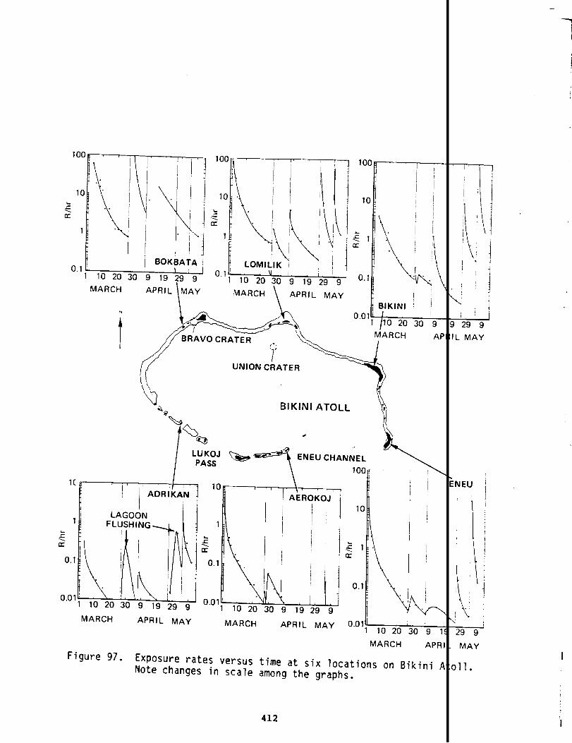
\ MARCH \ APRIL MAY
N
BIKINI ATC)LL \T
1(/’ J--
I ADRIKANJ
1/
~
FLUSHING.&2 t
0.11
t0.01!
1102030919299
MARCH APRIL MAY MARCH APRIL PAAY 0.011 i]
110203091
MARCH APR
Figure 97. Exposure rates versus time at six locations on Bikini /Note changes in scale among the graphs.
412

REFERENCES
AVAILABILITY INFORMATION
An availability code appears at the end of many referent
for those who wish to read or obtain copies. Availability st
rect at the time the reference list was prepared. Many docum
as unavailable will become available during the declassificat
process. The Department of Energy Coordination and Informati
(DOE CIC) and the National Technical Information Service (NTI
provided future DNA-WT documents bearing an “EX” after the re
Source documents with an availability code of DOE CIC ma
at the following address:
Department of EnergyCoordination and Information Center(Operatedby Reynolds Electrical & Engineering Co., IATTN: Mr. Richard V. Nutley ,2753 S. HighlandP.O. Box 14100Las Vegas, Nevada 89114Telephone: (702) 734-3194; FTS: 598-3194.
Source documents bearing an NTIS availability code may b
at the following address:
National Technical Information Service(SalesOffice)5285 Port Royal RoadSpringfield, Virginia 22161Telephone: (703) 787-4650.
When ordering
NTIS number.
number; e.g.,
by mail or phone, please include both the price
The price code appears in parentheses before th
(A07)AD 000 000.
413
——_.
tations
was cor-
indicated
review
enter
ill be
number.
reviewed
rchased
e and the
IS order

Additional ordering information or assistance
writing to the NTIS, Attention: Customer Service,
487-466I3.
may be obt~
or by call:
Reference citations with no availability codes may be av:
the location cited or in a library.
BASIC REFERENCES
1.
2.
3.
4.
5.
6.
“The Debate Ov~r the Hydrogen Bomb,”No. 4H.F. YorkOctober 1975
Scientific American,
Environmental Radioactivity, Second EditionM. EisenbudAcademic Press, New York1973
Bikini-Enewetak Studies, 1964. Part 1 -- Ecological ObsfA.D. Welander et al.Laboratory of Radiation BiologyUniversity of Washington15 September 1966 UWFL 93
Report of the Commander, Task Grou~ 7.1, March-May 1954, (CASTLETask Group 7.1June 1954 WT-940 EXRef. Copy: NTIS as AD 995 017*Completion Report (U)Holmes and Narver, Inc.1954(A19) AD A995 081*
History of Operation Greenhouse 1948-1951E.R. QuesadaJoint Task Force 3December 1951 WT-47(A02) AD 740 867*
*Available from NTIS; order number appears before the asteri
**Available at ME CIC.
***Not available.
414
by
703)
le at
. 233,
ions
ation

7. Summary of Notes of a Meeting of DOD Representatives atJ Division (u)March 1953***
8.
9.
10.
11.
12.
13.
14.
Installment History of Operation CASTLE (rJ)***Task Group 7.1
30 Sep 1953 Installment R-230031 Dec 1953 Installment CRD-316-54E10 Apr 1954 Installment30 May 1954 Installment
Operation Plan 3-53 (U)Hq JTF 710 Nov 1953***
Unit HistorY Task Group 7.2 (u)***Task Group 7.2
Ott 53-Jan 54 InstallmentFeb 54-7 Apr 54 Installment8 Apr 54-19 May 54 Installment
Final Report, Operation CASTLE (U)Commander, Task Group 7.31954***
Operation Plan 1-53 (U)Task Group 7.3 .18 April 19s4***
Consolidated List of CASTLE Radiological ExposuresJ.D. Servis, Commander TU-7Task Group 7.114 July 1954***
InstallmentHistory of Operation CASTLE (u)***Task Group 7.3
24 Jan 1954 Installment7 Apr 1954 Installment15 May 1954 Installment
*Available from NTIS; order number appears before the asteri:
**Available at DOE CIC.
***Not available.
415
— -..—— __ ._
SL—

15. History Of Task Group 7.4 (U)***Task Group 7.4
July-Aug 1953 InstallmentSept 1953 InstalhentOtt 1953 InstallmentNov 1953 InstalhentDec 1953 InstallmentJan 1954 InstalhentFeb 1954 InstallmentMar 1954 InstallmentApr 1954 InstallmentMay 1954 InstalhentJan 1953-26 Jun 1954 Installment
16. Final Report Radiological Safety, Operation CASTLE Spring
z vOlumeS o 1!
R.A. HouseJTF 7, Tech Branch J-3***
17.
18.
19.
20.
21.
Radiological SafetyJ.D. ServisLos Alamos Scientific LaboratoryAugust 1954(A04) AD A995 08G*
Letter, Col John Servis (Ret) to R. MillerNOV 1980
Operation Order 1-53 (U)Hq JTF 720 June 1953***
Radiological Safety RegulationNavMed P-13251951**
@X2Kations orders***Task GKOUP 7.3
Wnber-2-54Number 4-54Number 5-54Number 6-54Number 7-54Number 9-54Number 1o-54
9 Jun 19s415 Feb 195417 Feb 19s421 Feb 19546 Mar 19543 Apr 19s418 Apr 19s4
WT-942 EX
.
S-28-5.4-ESRb117-54ESRD-128-S4ES-l63-54ESRD-188-54ESRD-251-54SRD-281-S4E
~Available from NTIS; order number appears before the asterisk.
**Available at DOE CIC.
***Not available.
416
— _. ----
54 (U),

22.
23.
24.
25.
26.
27.
28.
29.
30.
History of Operation CASTLE (U)H.G. Bechanan, Lt USNR, and C.C).Jones, 2LT USAHq JTF 71954***
Maximum Permissible Exposures (Letter)Commander TG 7.3 to Commander JTF 718 Mar 1954
Final Report of Commander, Air Task Group (U)Task Group 7.41954***
Physical Factors and Dosimetry in the Marshall Island 1sures, Operation CASTLE, Report on Addendum Report forC.A. Sondhaust V.P. BondNaval Radiological Defense LaboratoryDecember 1955 WT-939(A03) AD 338 337*
BRAVO Shot, Operation CASTLE, Memo for Record with AttzA.C. Graves, R.W. ClarksonHq JTF 712 April 1954***
World-Wide Fallout from Operation CASTLE (U)R.J. List .U.S. Weather BureauMay 1955*** NYO-4645
Radiological Defense from USS Philip (DDE 498) taken frNotice 03500Office of the-Chief of Naval Operations**
History of Air Force Atomic Cloud Sampling (u)W.A. MingeAF Systems comm~d Publication Series 61-142-1January 1963***
Aircraft Decontamination4926th Sq, TG 7.41954
*Available from NTIS; order number appears before the aster
**Available at DOE CIC.
***Not available.
417
tion Expo-ect 4.1
nts (U)
FPNAV
.

31.
32.
33.
34.
35.
36.
Operation OrderTask Group 7.4
Number 1-53 15 Aug 1953**Number 2-53 6 Ott 1953**Number 1-54 9 Feb 1954**Number 2-54 26 Feb 1954**Number 3-54 1954Number 4-54 29 Mar 1954**Number 5-54 7 Apr 1954**Number 6-54 9 Apr 1954**Number 7-54 19 Apr 1954**Number 8-54 1 May 1954**
Dates as notedRef. Copy: AFWL Library
USS Bairoko (CVE-115);Radiological Contaminationcommanding Officer to CTG 7.37 March 1954Ref. Copy: National Archives
Participation of US NAS Kwajalein in Operation CASTLECommander NAS, Kwajalein, to CJTF 727 August 1954 JTF log S-428-54MRef. Copy: National Archives 374
British Participation . . . Memo for the RecordW.V. Hughs, Capt. USAF, JTF 7 Liaison Officer5 April 1954 59A-2946 BOX 3Ref. Copy: National Archives
Blast and Thermal Effects on B-36 Aircraft in Flight, OpertCASTLE, Project 6.2AG.C. Miller, E.J, Schlei, C.R. AndrewsAir Force Flight Dynamics LaboratoryJune 1956 WF925(A08)AD 338 333L*
Photoelectric Measurements of Time Interval . . . (U)W.L. Smith, LT USNR; J. Yandle, T/SGT, USAF: B.Caldwell, T/SGT, USAF; R. RichardsonNaval Research Laboratory1954*** NRL 4417
I*Available from NTIS; order number appears before the asterisk.
**Available at DOE CIC.
***Not available.
418

37. High Resolution Spectroscopy(u)
J.H. Beck; J.H. Campbell
38.
39.
40.
41.
42.
43.
Naval Research Labo~atoryMar 1955***
NRL 4519
The Chord ExperimentW.B. FussellNaval Research LaboratoryJune lg!js***
NW 4590
Color Temperature at Operation CASTLE (U)W.B. FussellNaval Research Laboratory1955
NRL 4616(A02) AD A995 118*
SummarY Report of the Commander, Task Unit 13 -- Militarl1-9 (u)AFSWPJanuary 19s9
W’I’-934EX(A06)AD A995 123*
Blast Pressures and Shock Phenomena Measurements by PhotcNaval Ordnance LaboratoryDecember 19SS
WT-902 EX(A05) AD A995 102*<
Base Surge Measurements by PhotographyNaval Ordnance LaboratorySeptember 1966
WT-903(A03)AD 361 766*
Dynamic Pressure MeasurementsC.D. Broyles and M.L. MerrettSandia Corporation27 Jan 1957(A03) AD 361 771* WT-906
44. Ground Surface Air Pressure Versus Distance from High YieJtions, Operation CASTLE, Pacific Provingproject 1.2B
Grounds, March-M~
J.J. Meszaros, C.N. KingeryArmy Ballistic Research LaboratoriesMay 1957
WT-905(A05) AD 341 053*
*Available from NTIS; order number appears before the asteris
**Available at DOE CIC.
***Not available.419
Programs
=
Detona-1954,

45.
46.
47.
48.
49.
50.
51.
Underwater Pressure Measurements, Operation CASTLE, Project 1.4W.J. ThalerNaval Research Laboratory, David Taylor Model Basin, NavalLaboratory, Office of Naval ResearchJune 1958 WT-908 EX(A12) AD A995 105*
:dnance
Ground Level Pressures from Surface Bursts (U)C.D. Broyles and M.L. MerrettSandia Corporation30 Ott 1957 WT-904 EX(A03) AD A995 108’
Water Wave Measurements (U)J.D. Isaacs and L.W. KiddScripps Institution of Oceanography29 Ott 1959 WT-91O(A03) AD 341 056*
Ground Motion Studies on Operations IVY and CASTLE (U)W.R. PerretSandia Corporation1954*** WT-9002
Dynamic Pressure Investigation, Operation CASTLE, Project 1E.J. BryantBallistic Research LaboratoriesMarch 1957 Wl?-911(A03) AD 361 767*
Gamma Radiation Exposure, Re~ rt to the Scientific Directortion CASTLE, Project 2.1R.H. Dempsey, R.G. Larrick, G.A. Baraff, O.E. JohnsonArmy Signal Engineering LaboratoriesMarch 1949 lT1’-9l2(A03) AD 341 055*
GarmnaRate Versus Time, Report to the Scientific Director, (CASTLE, Project 2.2 (U)P. Brown, G. CarpArmy Signal Engineering LaboratoryFebruary 1959 W-913(A03) AD 338 330*
*Available from NTIS; order number appears before the asterisk,
**Available at DOE CIC.
●**Not available.
420

52.
53.
54.
55.
56.
57.
58.
Neutron Flux Measurements, Operation CASTLE, Project 2.3the Scientific Director (U)T.D. HansCome, D.K. Willett, A. BrodskyNavy Research LaboratoryOctober 1955 WT-914 EX(A05) AD A995 099*
Distribution and Intensity of FalloutNaval Radiological Defense LaboratoryMarch 1956 wr-915(AO~) AD 361 836*
Fallout Studies, Operation CASTLE, Project 2.5B (U)E.F. Wilsey, R.J. Fsench, H.I. WestArmy Chemical CorpsFebruary 1956 WT-916 EX(A07) AD A995 116*
Chemical, Physical, and Radiochemical Characteristics ofContaminant, March-May 1954Naval Radiological Defense LaboratoryJanuary 1956 WT-917 EX(A08) AD A995 109*
Radiochemical Analysis of FalloutArmy Chemical and Radiological LaboratoriesApril 1956 WT-918AD 224 417*
Distribution of Radioactive Fallout by Survey and Analys;Water, Operation CASTLE, Project 2.7 (U)T.F. Folsom, L.B. WernerScripps Institution of Oceanography, Naval RadiologicalLaboratoryApril 1959 WT-935 EX(A05)AD A995 085*
Radioactivity of Open-Sea Plankton SamplesT.R. Folsom, F.D. Jennings, and M.W. JohnsonScripps Institution of OceanographyApril 1958 WT-954AD 465 307*
*Available from NTIS; order number appears before the aster
**Available at DOE CIC.
***Not available.
421
.—.. _

59. Air Pressure Measurements, Operation CASTLE, Project 3.1 (U)L.M. Swift and E.J. WellsStanford Research InstituteMay 1955*** WT-919
60. crater Survey (u)R.B. VaileStanford Research InstituteJan 1955***
WT-920
61.
62.
63.
64.
65.
Blast Effects on Tree StandW.L. Fens and T.G. StoreyU.S. Forest ServiceMar 1955AD 465 294*
WT-921
Sea Minefield Neutralization by Means of a Surface DetonatedExplosion, Operation CASTLE, Project 3.4 (U)G.M. Davidson, M.G. GeigerArmy Special Weapons ProjectMarch 1955(A03) AD 361 835*
WT-922
Blast Effects on Miscellaneous Structures, Operation CASTLE,3.5W.J. ChristensenAFSWPJuly 1955
,
(A04)AD 356 271*WT-901
Twenty-Year Review of Medical Findings in a Marshallese PopulAccidentally Exposed to a Radioactive FalloutR.A. ConardBrookhaven National LabratorySeptember 1975 BNL 50424
Study of Response of Human Beings Accidentally Exposed to SigFallout Radiation, Operation CASTLE, Project 4.1E.P. Cronkite, V.P. Bond, L.E. Browning, W.H. Chapman, S.H. CConard, C.L. Dunham, R.S. Farr, W.S. Hall, R. Sharp, N.R. ShuNaval Medical Research Institute, Naval Radiological Defensetory, Defense Atomic Support Agency, Oak Ridge National LaborOctober 1954 r.m—n~?(E05) AD 465 295*
n&-y&>
*Available from NTIS; order number appears before the asterisk.
**Available at DOE CIC.
***Not available.
422
uclear
coject
:ion
.ficant
m, R.A.Ian,bora-ory

66.
67.
68.
69.
70.
71.
Nature and Extent of Internal Radioactive Contamination I-Human
Beings, Plants, and Animals Exposed to Fallout, Operatio ASTLE,Project 4.1S.H. Cohn, R.W. Rinehart, J.K. Gong, J.S. Robertson, W.LChapnan, V.P. BondNaval Radiological Defense Laboratory, Naval Medical ResInstituteDecember 1955 WT-936(A02) AD 617 134*
Medical Examination of Rongelap People Six Months AfterFallout Operation CASTLEV.P. Bond, R.A. Conrad, J.S. Robertson, E.A. WedenNaval Medical Research Institute, Naval Radiological DefLaboratoryApril 1955 WT-937(A03) AD 465 292*
Exposure of Marshall Islanders and American Military PerFallout, Operation CASTLE, Project 4.1 AddendumR. Sharp, W.H. ChapmanNaval Medical Research InstituteMarch 1957 WT-938 EX(A03) AD A995 077*
Operation Plan (U)Task Group 7.4’
Number 1-54 28 Feb 1954 “’Number 2-54 16 Mar 1954**Number 3-54 24 Mar 1954**Number 4-54 15 Jun 1954**
Dates as notedRef. Copy: AFWL Library
Test of Interim IBDA Procedures, Operation CASTLE, ProjeR. TriantafelluAir Force Strategic Air CommandJanuary 1956 NT-924(A03) AD 361 832*
ilne, W.H.
ch
osure to
e
nel to
~
Thermal Effects on B-47B Aircraft, Operation CASTLE, Projcct 6.2B (u)C.W. LuchsingerCook Electric Company, Air Force Flight Dynamics LaboratoApril 1957 wT-926(A04) AD 338 026*
1
*Available from NTIS; order number appears before the asteri .
**Available at DOE CIC.
***Not available.
423

72.
73.
74.
75.
76.
77.
78.
Proof Testing of Atomic Weapons Ship Countermeasures,CASTLE (U) Opera
G.G. Molumphy, M.M. BiggerNaval Radiological Defense LaboratoryOctober 1957 WT-927(A20) AD 362 11O*
Decontamination and Protection, Operation CASTLE, Project 6J.C. Maloney, E.H. Dhein, M. MorgenthauArmy Chemical CenterSeptember 1955(A04) AD 465 306*
WT-928
Effects of Nuclear Detonations on the Ionosphere, OperationProject 6.6 (u)F.B. Daniels, A.K. HarrisArmy Signal and Research Engineering LaboratoriesMay 1956 WT-929(A04) AD 361 772*
Electromagnetic Radiation Calibration, Operation CASTLE, PacProving Grounds, March-May 1954, Project 7.1 (U)M.H. OlesonAir Force Office of Atomic EnergyJune 1958***
Detection of Airborne Low-Frequency Sound from Nuclear ExplcOperation CASTLE, Project 7.2 (U)G.B. OlmstedAtomic Energy CommissionMay 1955(A04) AD A995 117*
WT-931 EX
Nuclear Calibration Analysis of Atomic Device Debris (U)C.K. Reed, W. SinglevichAir Force HeadquartersJuly 1959 Wl?-932EX(A03) AD A995 084*
cloud Photography, Operation CASTLE, Project 9.1EG&GJanuary 1958 wr-933(A03) AD 357 960*
*Available from NTIS; order number appears before the asterisk.
●*Available at ME CIC.
**&Not available.
424
.on—
WSTLE,
Eic
.ons,

‘-”--r
79.
80.
81.
82.
83.
84.
85.
86.
87.
Radiological Fallout on Japanese Vessel Daigo Fukuryu M~BRAVO, Report and Analysis (U)CTG 7.3 to CJTF 717 Haxch 1954***
Radioactive Contamination of Ships and Radiological Exp<Personnel of Task Group 7.3 due to BRAVO (U)Commander TG 7.3 to Chief of Naval Operations22 lMarch1954***
Compilation of Local Fallout Data from Test DetonationsExtracted from DASA 1251; Vol. 2, Oceanic U.S. TestsH.A. Hawthorne, cd.,GE-TEMPOJune 1979 DNA 1251 EX2(A16)AD A079 31O*
The Voyage of the Lucky DraqonR.E. LappHarper & Bros., NY1957
Rongerik Incident: P.eportwith AttachmentsTask Group 7.41954**
Evacuation of Rongerik: Report with AttachmentsTask Group 7.4April 1954
Exposure Estimates of the Crew of the USS Patapsco -- MJ. McGahan, SAI, to D. Auton, DNA19 January 1979
‘ollowing
of
-1962
mdum
Gamma Dose Estimates for Patapsco CrewR.R. Hammond and W.W. PerkinsNaval Ocean Systems Center25 January 1979
Personnel Radiation Exposure Records -- Microfilm (Micrc
I
Iof 5x8cards from which the Consolidated List (CPO 7.lU7#3) was p obablyderived in large part)1954***
I*Available from NTIS; order number appears before the asteris .
**Available at DOE CIC.
***Not available.
I
425

88.
89.
90.
91.
92.
93.
Effects of Nuclear WeaponsS.Glasstone and P.J. Dolan, cd.,U.S. GPO1977
Medical Survey of the People of Ronqelap and Utirik Islands, Thirteen,Fourteen, and Fifteen Years after Exposure to Fallout Radi~ ion (March1967, 1968, 1969)R.A. Conard, et alBrookhaven National LaboratoryJune 1970(A07) BNL-50220*
Personal Recollection of Warren Fackenthall at Albuquerqu~February 1980
Report of Commander, Task Group 7.1, Operation CASTLE (U)A.C. GravesLos Alamos Scientific LaboratoryJune 1954 WT-940 EX(AO1) AD A995 017*
Blowing on the Wind, The Nuclear Test Ban Debate, 1954-191R.A. DevineOxford University Press1978
Operation Plan 3-53Hq USAFn.d.Ref. Copy: National Archives
READING LIST
This short list
DOD participation in
of books and documents
Operation CASTLE. The
categories: Background and
Action Reports. The latter
Force 7 or its components.
General; CASTLB
133-54-3
Mexico
.
is pertinent to th( _ect of
list is divided into L veral
Planning; and CASTLE+
ter-
1two are primarily reports issued by J nt Task
Some are included as basic references.
●Available from NTIS; order number appears before the asterisk.
**Available at DOE CIC.
***Not available.
426
Background and General
Effects of Nuclear WeaponsS. Glasstone and P.J. Dolan, cd.,U.S. GPO1977
Environmental Radioactivity, Second EditionM. EisenbudAcademic Press, New York1973
Compilation of Local Fallout Data from Test Detonations 1945-1952Extracted from DASA 1251; Vol. 2, Oceanic U.S. TestsH.A. Hawthorne, cd.,GE-TEMPOJune 1979 DNA 1251 EX2(A16) AD A079 31O*
Proving Ground: An Account of Radiobiological Studies in the P .cific1946-1961N.O. HinesUniversity of Washington Press, Seattle1962
“The Debate Over the Hydrogen Bomb,” Scientific American, Vol. :33, No. 4H.F. YorkOctober 1975 .
CASTLE Planning Documents
The task force prepared a series of documents in preparatior for
CASTLE. The basic ones were:
Operation Plan 3-53 (U)Hq JTF 710 Nov 1953***
Operation Order 1-53 (U)_Hq JTF 720 June 1953***
*Available from NTIS; order number appears before the asterisk
**Available at DOE CIC.
***Not available.
, 427

Other JTF 7 documents designated Movement Directives and Operat
Lists detailed the general instructions in the basic planning c
This sequence of operation plans and orders was reflected in tk
nate groups within the task force, for example:
Operation order (u)***Task Group 7.2
Number 1-53Number 3-53
Dates as indicated
Operation Plan 1-53 (U)
‘l’askGroup 7.318 April 19s4***
Operations Orders***Task Group 7.s
Number 2-54Number 4-54Number 5-s4Number 6-54Number 7-54Number 9-54Number 1o-s4
Dates as noted
13 Ott 195322 Dec 1953
9 Jun 195415 Feb 195417 Feb 195421 Feb 19546 Mar 19543 Apr 195418 Apr 1954
,Operation Plan (U)Task Group 7.4
Number 1-54Number 2-54Number 3-54Number 4-54
Dates as notedRef. Copy: AFWL Library
CASTLE After-Action Reports
28 Feb 195416 Mar 195424 Mar 195415 Jun 1954
The task force prepared a formal history of the
S-485S-683
S-28-54-ESRD-117-:SRD-128-ZS-163-54ESRD-188-5sRD-251-5sRD-281-5
Operation:
History of Operation CASTLE (U)H.G. Bechanan, Lt USNR, and C.O. Jones, 2LT USAHq JTF 71954***
*Available from NTIS; order number appears before the asterisk.
**Available at DOE CIC.
***Not available.
428
onal Check
cuments.
subordi-
I

-—. —.
Reports were prepared also by the subordinate commanders:
IReport of the Commander, Task Group 7.1, Mar-May 1954, Operatikn CASTLE (U)Task Group 7.1June 1954- WT-940 EX(AO1) AD A995 017’
IFinal Report of the Commander (U)Task Group 7.219 May 1954*** S-198-54w
IFinal Report, Operation CASTLE (U)Commander, Task Group 7.31954***
IFinal Report of Commander, Air Task Group (U)Task Group 7.41954***
IReport of the Commander (U)Task Group 7.51954*** S-349-54W
IOther units also prepared reports of their participation; examp es of
these are:t<
Final Report, Communications Security Detachment (U)8600th Area Unit8 May 1954***
Completion Report (U)Holmes and Narver, Inc.1’354(AO1) AD A995 081* IThe many scientific projects involved in the nuclear weapon testing
usually reported their activities in a series of reports usuall4desig-
nated the “~ Series.” For CASTLE, the WT reports numbered WT- 1 through
WT-956 were used.T
*Available from NTIS; order number appears before the asterisk
**Available at l13ECIC. I***Not available.
429

F’
Other after-the-fact reprts of direct interest to the subjzct matter
of this report are:
Radiological Safety (U)J.D. ServisLos Alamos Scientific LaboratoryAugust 1954 WT-942 EX(A04) AD A995 086*
Final Report Radiological Safety, Operation CASTLE,Spring 1954 (U), 2 volumesR.A. HouseJTF 7, Tech Branch J-3***
BRAVO Shot, Operation CASTLE, Memo for Record with Attachments u)A.C. Graves, R.W. ClarksonHq JTF 712 April 1954***
World-Wide Fallout from Operation CASTLE (U)R.J. ListU.S. Weather BureauMay 1955*** NYO-4645
The Voyage of the Lucky DragonR.E. LappHarper & Bros., NY ‘1957
Twenty-Year Review of Medical Findings in a Marshallese Populati(mAccidentally Exposed to a Radioactive FalloutR.A. ConardBrookhaven National LaboratorySeptember 1975 (A08) BNL 50424*
*Available from NTIS; order number appears before the asterisk.**Available at DOE CIC.
***Not available.
430 I
.,In

APPENDIX A
COPIES OF CASTLE DOCUMENTS
431

THIS PAGE
WAS
INTENTIONALLY
LEFT BLANK
IN
ORIGINAL
@2

10( nmv ❑ - m:
l“LIT:1413G
UNITED STATES
ATOMIC ENERGY COMMISSIONWAS HINGTON”2S. D. c.
JAN 2 i 7954
Ihjor General P. k’.Clarkson, USACorn7amierjJoint Task Force SEVENTemporary “W Euilding, Room 2MS12th and Constitution Avenue, N. W.?.~as~gtin 2s~ D. C.
De= General Clarkson:
Presidential approval has been received for executinhith Rarch Ij U?~ as the starting date. pe~+ ssimnbeen rzmntid to detonate seven shots ad ti ~pena 1and fusionable materials in the amounts lnaicated be
.
This letter shouldCASTLE as planned.
be construed as your authority b
Sincerely yours,
x q&K. D. ?{icholsGeneral Kanager
Enclosure:Cys IA & 2A fissionable and FusionableHatefial For CASTE Devices
433
CASTLEIasalsosionable,“d●
xecuti

-*
THISPAGE
WAS
INTENTIONALLY
LEFT BLANK
IN
ORIGINAL

-- RETYPED COPY --
HEADQUARTERS, Joint TaskWashington 25, D.C.20 June 1953, 1600 R
Annex I to CJTF SEVEN Operation Order No. 1-53
RADIOLOGICAL SAPETY
1.
2.
3.
4.
Radiological safety of all task force military and civiliais a command responsibility and radiological safety activiperformed through normal command channels.
The Commander, Joint Task Force SEVEN will:
a. Specify the measures necessary to insure the radiologictask force personnel and furnish technical advisory assistgroup radiological safety officers.
b. Inform CINCPAC of radiological hazards which may existoutside of task force responsibility.
c. Maintain an information center (RadSafeOffice) with dicurrent air and surface radexes, radiological situation maand peripheral aerial and surface areas and such other allmay be appropriate.
d. Designate monitors and couriers $0 accompany radioactivecial cargo shipments on sample return aircraft, and monitaand unloading of such cargo.
Prior to the on-site operational phase, task group command
a. Organize radiological safety units or elements within tgroups.
b. Require radiological safety personnel to review radiolcprocedures employed on previous operations and become thorquainted with existing training measures through attendantpriate Service schools.
c. Require radiological safety personnel to become qualificalibration and testing of standard RADIAC equipment.
d. Procure complete allowances of RADIAC equipment and SPCthing. The requirements of CTG 7.5 will be included in tkfor CTG 7.1 for necessary issue to TG 7.5 personnel durin$tional phase and for subsequent loan or sale to CTG 7.5 fcoperational use at the proving ground.
The Commander, TG 7.1, having major technical radiologicalsponsibilities,will prepare to perform the following radi
435
]rce SEVEN
~ersonnelSS will be
safety ofze to task
areas
Lays ofof atolls3 data as
and spe-loading
5 will:
ir task
Cal safetyghly sc-at appro-
in the
al clo-allowanceshe opera-post-
afety re-ogical

ft,.
.
safety services at ENIWETOK and BIKINI ATOLLS (using SECTG 7.3 at BIKINI):
a. All ground monitoring services associated with scierexcept those in conjunction with aircraft and airbornescientific data.
b. Laboratory services and technical assistance to allinclude:
(1) Procurement of film badges and specified supplerpersonnel radiological safety equipment.
(2) Laboratory
(3) Records offurnished task
(4) Laboratorysamples.
services to develop and interpret fi;
exposures from film badges. (Duplictgroup commanders).
services for the radio-chemical anal!
(S) Provision of primary facilities at PARRY ISLANDsafety building for calibration, repair and mainteniments and storage of spare parts of RADIAC equipmen{ited facilities will be maintained at BIKINI duringphase at that atoll.
(6) Monitoring the removal and packaging of radioacsamples except as indicated in paragraph 4a above.
c. Provision of radiological safety surface situation Itimes to the task force commander and the task groupsinformation.
d. Procurement of radiological safety clothing as neceTG 7.5 and specified recovery personnel.
e. Provision,of technical personnel to inspect radiololnated items for all task groups and certify destructionunserviceabilityof such items as required.
g. Provision of personnel and equipment decontamination,RadSafe survey and recovery operations.
h. Limited fall-out studies within the Pacific Provingradiological safety documentation only.
i. Assumption of radiological safety responsibilities,the overseas phase of operation.
j. The integration with TG 7.1 of key radiological safmade available by CTG 7.5. Such personnel will assistthe operational phase and will be assigned duties amenin the fundamental radiological safety services to beCTG 7.5 upon completion of the overseas phase of the o
5. The Commander, TG 7.2 will prepare to perform the foil
436
e provided by
fic missionsllection of
sk groups, to
tary items of
badges.
s will be
s of water
biologicale of instru-Similar lim-
e operational
e sources and
ISafter shotpiring the
~ryfor TG 7.1,
:allycontami-disposal, or
!acilitiesfor
‘oundfor
TG 7.5 during
~ personnel!G 7.1 during.e to training;umedby Iration.
.ng:

a. All ground monitoring services associated with ENIWETOK ISLAND,except in those areas or activities assigned to other task groups.
b. Provision and training of own radiological safety monit rs, 50 of
1
which will be “Q” cleared for emergency monitor support of TG 7.1 ifrequired.
c. Provision and training of own contamination personnel,
r
of which “will be designated for emergency decontamination support o TG 7.1 ifrequired.
d. Provision of own RADIAC equipment and protective clothi .+
t
e. Provision of own repair, spare parts and calibration fa “lities forRADIAC equipment.
f. Provision of contaminated clothing laundry facilities ft
TG 7.4.
6. The Commander, TG 7.3 will prepare to:I
ka. Provide and train own radiological safety monitors, incl ding oneairborne monitor for each multi-engine aircraft crew assign d toTG 7.3.
b. Provide own RADIAC equipment and protective clothing.‘1
c. Provide monitors and decontamination crews aboard each s ip withinthe tas~ group.
1d. Provide own repair, spare parts and calibration faciliti s forRADIAC equipment. t
i
e. While task fo~ce is embarked, provide space for use of t e radio-logical safety unit of TG 7.1.
f. Assume responsibility for decontaminationof all aircraf at BIKINIATOLL, assisted by CTG 7.1 ashore, as required.
Ig. Provide decontamination crews and facilities for own air raft atENIWETOK ATOLL.
!
Limited assistance will be furnished by CT 7.4, ifrequired.
h. Provide necessary helicopter air service for radiological surveys
1and post-shot recovery operations (monitors furnished by TG 7.1).
i. Provide water spray equipment aboard all vessels likely
t
be inthe fall-out area.
j. Collect lagoon water samples.I
7. The Commander, TG 7.4 will prepare to:I
a. Provide and train own radiological safety monitors, incl
*
ing oneairborne monitor for each multi-engine aircraft crew assign TG 7.4.
b. Provide own RADIAC equipment and protective clothing.I
437
—.._ _
c. Provide own repair, spare parts and calibration faciliti
1
forRADIAC equipment.

8.
9.
d. Provide primary decontamination crews and facilities forat ENIWETOK ISLAND and limited crews and facilities at theairstrip.
e. Assist TG 7.3 in aircraft decontamination with TG 7.4 eqrequired.
f. Provide necessary helicopter and liaison air service forcal surveys and post-shot recovery operations (monitors furTG 7.1).
g. Provide monitoring services for the removal and Packaqipactive samples cr data
h. Provide cloud track:“situation data” up tofor period of 48 hourseach shot. (See para.
collected by aircraft.
ng aircraft for post-shot radiologicradius of 500 miles in the significastarting at approximately H plus 62c(3) of Annex J).
i. Promulgate the air radex for each shot.
j. Establish a simple code to be used in conjunction with tweather reconnaissance reports to report approximate air ratensities encountered on regularly established weather reccor cloud tracking flights.
The Commander, TG 7.5 will prepare to:
a. Develop a schedule of requirements for radiological saferequired from CTG 7.1.
b. Provide and tr~in key radiological personnel for integraand training with the radiological safety organization of ‘1ing the overseas phase of the operation. The total numberfications of such personnel will be as determined necessarycommensurate with the assumption of responsibilities indicabelow.
c. Assume residual task force radiological safety functionsPacific Proving Ground upon completion of the overseas pha:operation. Required equipment and supplies will be made avthat time, to CTG 7.5 on a loan or sale basis from stocks ECTG 7.1.
Training. The inclusion of radiological safety organizaticout the task force will require two general levels of trairindoctrination and technical training. The scope of instrueach of these levels will vary in accordance with the requidifferent operational and staff levels. Basic indoctrinateelude primary, non-technical instruction in radiological saures and techniques. This must be imparted to all personnetask force to enable them to perform their assigned duties
craftNI
ent, if
iologi-ed by
radio-
afetyuadrants for
eriodicion in-ssance
ervices
into1 dur-quali-CTG 7.5in 8c,
thethe
ble atded by
hrough-basicn withinnts ofill in-meas-the
cientlywithin the allowable low exposures, regardless of the present
!
of ra-dioactive contaminants. Technical training will include the aining
438

of the majority of the personnel who will be required toforce radiological safety organizations and perform the tations involved. This will be accomplished through the uexisting Service courses and establishment of suitable cgroup level. This instruction will be designed to traindefense monitors, decontamination personnel-and radiologicment repairmen.
Original signedfor the
by the Assistant Chief of Staff, JCommander Joint Task Force 7
I
I
439
ff the tasknical oper-ization ofses at taskiologicalnstru-

-- RETYPED COPY --
HEADQUARTERS, Joint Task 1Washington 25, D.C.20 June 1953, 1600 R
Appendix to Annex IRadiological Safety, CJTF SEVEN Operation Order No. 1-53
RADIOLOGICAL SAFETY REGULATIONS
1.
2.
3.
4.
5.
6.
The Maximum Permissible Exposure (MPE) for personnel involv<operation is 3.9 roentgens, gamma only, unless reduced becalvious or anticipated future exposure. All exposure to extelradiation will be regarded as total body irradiation. Spec:20 roengtens, gamma only, is authorized for crew members ofpling aircraft. The maximum permissible exposures as state<applicable to a field experimental test of nuclear devices :time, wherein numbers of personnel engaged in these tests hipreviously exposed or will be continuously exposed to potenttion hazards. It may become necessary from a study of pers<oralsto reduce the MPE for certain individuals who have parlrecently in other atomic tests. Under a military tactical for emergency the maximum permissible exposures above do not
All atoll land and lagoon areas in or near which a detonaticplace will be considered contaminated until cleared for opelthe task force commander. Entry to and exi~ from contaminantwill be via RadSafe checkpoints only.
Contaminated land areas of intensities greater than 100 mr/1delineated as such; Personnel entering these areas must be ~by a monitor and will be subject to clearances by the RadSajTG 7.1. RadSafe clothing and equipment will be issued to tlpersonnel.
Contaminated land areas of intensities less than 100 mr/hr ~than 10 mr/hr will be controlled areas; Personnel entering Iwill be subject to clearance by the RadSafe Officer of TG 7,tors will not be required for entry into these controlled al
Contaminated land areas of intensities of less than iO mrlh]considered unrestricted from a RadSafe viewpoint. Areas corthis limitation will be designated specifically by CJTG SEVIunrestricted entry.
RadSafe monitors assigned to individuals or groups working :nated areas or with contaminated equipment during recovery <will act in an advisory capacity to keep the recovery party
440
? SEVEN
I this}f pre-gammaiPE ofsam-)ve are:ace-leenradia-~ rec->ated~tion-Y.
~kes>ns bylreas
ill benpanied:ficer,
greater? areasMoni-
11 bewithin:ior to
xltami-~tionsder

7.
8.
9.
10.
11.
12.
i’nformedof radiation intensities at all times. The reco’leader is expected to accept this advice and act accordimthe responsibilityof both the leader and the members ofparty to adhere to the limits established in these regula’
Film badges, dosimeters and protective clothing (coverallcaps, gloves, dust respirators, etc.) as deemed necessaryissued to personnel entering contaminated areas by appropgroup RadSafe supply sections.
All personnel within viewing distance of an atomic detonanot supplied with protective goggles will turn away fromtion point and close their eyes during the time of burst.seconds should be allowed before looking directly at the
The arrival and proposed use of radioactive sources at th{Proving Ground will be reported to the Task Force Radiolo!Officer.
All samples of radioactive materials which are couriered :will be packaged and loaded so as to reduce radiation to ~The RadSafe Officer of TG 7.4 will have a survey made of Ito determine if adequate precautions have been taken. Th(criteria will determine space and packaging requirements:
a. Prior exposure of aircraft and courier personnel.
b. Anticipated fiutureexposures on trip. ,,
c. Length of time of exposure on trip.
d. In all cases, crew members will be limited to exposureless than 20 mr/hr.
All air and surface vehicles or craft used in contaminate{be checked through the appropriate task group decontaminaupon return from such areas.
The Maximum Permissible Limits (MPLs) of contamination liare to be regarded as advisory limits for control of conttunder average conditions? and are subject to revision by Ithe task force commander in individually designated casessting circumstances indicate the need and justification treadings of surface contamination are to be made with Geiwith tube walls not substantially in excess of 30 mg/cm2 ‘open. The surface of the probe should be held one (1) ininches from the surface that is under observation unlessspecified. In all cases other than emergency or tacticalthe ultimate criteria will be limited by the authorized Msonnel, with measurements made using standard equipment afor such exposure. Special instances may arise after sho
441
—.
:y party7,. It is? recoveryIns.
booties,ill be~te task
m who are? detona-it least 10rst.
pacific
Zal Safety
aircraftninimum.s packagefollowing
ites of
lreas willm section
?d hereinLnationiver fromlen extenu-:efor. All? counters,th shieldto two (2)~erwiseituationss for per-techniquesand inside

the surface radex in which rescue operations will be carriedout regard to the radiological hazard. Monitors aboard restshall be required to determine the extent of the actual radizard experienced in order that appropriate medical tests mayted. For emergency operations, the criteria prescribed forsituation (para. 13 below) will be used as a guide. For opepur~ses the MPLs presented below will not be considered appspotty contamination provided such areas can be effectivelyfrom personnel.
a. Personnel and clothing MPLs are as follows:
(1) Skin readings should not be more than 1 mr/hr. Compllamination by bathing will be utilized for readings in exce:level. Beta radiation exposure to the hands should not exc~rep/week.
(2) Underclothing and body equipment such as the internalof respirators should be reduced to 2 mr/hr.
(3) Outer clothing should be reduced to 7 mr/hr.
ut with-craftion ha-leinitia-cticaltionalcable toelated
te decon-of hisd 30.0
surfaces
b. Vehicle MPLs: The interior surfaces of occupied section of vehi-cles should be reduced to 7 mr/hr.
\
The outside surfaces of ehiclesshould be reduced to less than 7 mr/hr, gamma only, at five (5) or six(6) inches from the surface.
c. Ship and Boat MPLs:I
(1) Operational clearances, implying that contamination ists and
/
special procedure= are required, will normally be granted b command-ing officers on the technical advice of radiological defens staffmembers. In peacetime, a maximum fixed contamination level f 300mr\week ordinarily will not be exceeded except for “Operati al Neces-sity”. For this operation an MPL of 600 mr/week will be us as theupper limit for “operational necessity” unless otherwise SP ificallyraised or lowered. Fixed alpha contamination should not ex eed 500cpm (counts per minute) per 150 cm2 of area.
(2) For ships and boats operating in contaminated waterable allowances will be made to differentiate between thecontribution to the total flux from fixed contamination anto “shine” from contaminated waters. For this operation iassumed that not more than ten percent of the radiation flthe vessel through the sides is due to contamination whichfixed on the vessel upon reentry to uncontaminated waters.boats encountering levels of contamination greater than dethe above will request special instructions.
(3) Final clearances, normally granted by commanding ofbe given upon completion of the operation provided no poincontamination is greater than 15 mr/day (beta and gamma) adetectable alpha exists.
442
reason-lativethat duewill beentering
‘illremainShips andrmined by
cers, willofIno

I
(4) In general, boats operating in waters near shot islshot times may become contaminated. Monitors shall be aboboats operating after shot time, either as passengers or mthe boat crew, until such time as radiological restriction
,dsafterd all~bersofare lifted.
I
I
i
i,
I
!&t
(5) No ships with personnel shall be permitted inside th2 1.5.p.s.i. line unless specifically directed otherwise. Bearin3s of dan-ger from immediate radioactive fall-out for ship operations will beestablished by CJTF SEVEN on the basis of forecast wind dir?ctions atthe intended time of detonation. This danger section will De desig-nated as surface radex. All ships of the task force shall De requiredto remain outside the surface radex - danger bearing, radiaL limita-tion and time restriction. However, if ships are directed tacticallyinto the surface radex, movement of ships shall be governec by tacti-cal exposure guides.
(6) Individuals on board ships of the task force shall k2 protectedcollectively from hazards of blast, heat and radioactivity by movementof the ships.
(7) It is desired to point out that the employment of tke ships andunits in TG 7.3, insofar as radiological safety is concernd , is notconsidered routine usage within the purview of NavMed P-1325 “Radio-logical Safety Regulations.” Current revision of NavMed P-1~25 indi-cates that its provisions will not apply for special operations suchas field tests and that for such operations naval personnel will oper-ate under regulations set forth by the task force commandel. The reg-ulations set forth herein have been designed as a reasonab.e and safecompromise considering conservation’of personnel exposures, the inter-national import of tests and the cost aspects of shot dela)s charge-able to excessive radiological precautions.
d. Aircraft MPLs:
(1) The interior surfaces of occupied sections of aircrtfk shouldbe reduced to 7 mr/hr.
(2) No aircraft in the air at H Hour will be at slant rtnges fromground zero less than as determined by the following effecls unlessspecifically directed otherwise. (Based on maximum predic’ed yieldand 20 mile visibility):
Blast (at predicted shock arrival): 0.5. p.s.i.Thermal (H Hour): Fabric control surfaces: 1.0 ca:/cm2
Metal control surfaces: 6.0 cal,‘Cmz
After detonation no aircraft shall operate inside the aircloser than 10 nautical miles from the rising or visible cspecifically directed otherwise. If a tactical or emergenarises where aircraft must enter the air radex, tactical elowance shall apply.
(3) All multi-engine task force aircraft in the air at100 miles of the detonation point shall carry a person des
443
adex oroud unlessy situationposure al-
;Hour withingnated as
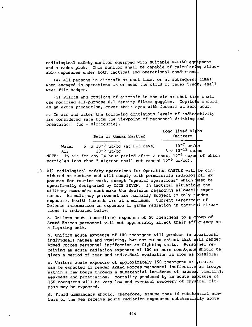
13.
radiological safety monitor equipped with suitable RADIAC ecand a radex plot. This monitor shall be capable of calculatable exposures under both tactical and operational conditior
(4) All persons in aircraft at shot time, or at subsequerwhen engaged in operations in or near the cloud or radex trzwear film badges.
(5) Pilots and copilots of aircraft in the air at shot t]use modified all-purpose 0.1 density filter goggles. Copilcas an extra precaution, cover their eyes with forearm at ze]
e. In air and water the following continuous levels of radicare considered safe from the viewpoint of personnel drinkin$breathing: (Uc - microcurie).
Long-lived ABeta or Gamma Emitter Emitters
Water 5 x 10⁻³ uc\cc (at H+3 days) 10-7 Uc,Air 10-6 uc/cc 6 X 10-12 U{
NOTE: In air for any 24 hour period after a shot, 10-4 uc/(particles less than 5 microns shall not exceed 10-6 uc\cc).
All radiological safety operations for Operation CASTLE willsidered as routine and will comply with permissible radiolocposures for routine work, except “special operations” whichspecifically designated by CJTF SEVEN. In tactical situaticmilitary commander must make the decision regarding allowab:sures. As military personnel are normally subject to only 1exposure, health hazards are at a minimum. Current Departm(Defense information on exposure to gamma radiation in tacti(tions is indicated below:
a. Uniform acute .(immediate)exposure of 50 roentgens to a ~Armed Forces personnel will not appreciably affect their efa fighting unit.
b. Uniform acute exposure of 100 roentgens will produce in ~individuals nausea and vomiting, but not to an extent that >Armed Forces personnel ineffective as fighting units. Perslceiving an acute radiation exposure of 100 or more roentgengiven a period of rest and individual evaluation as soon as
c. Uniform acute exposure of approximately 150 roentgens orcan be expected to render Armed Forces personnel ineffectivewithin a few hours through a substantial incidence of nauseweakness and prostration. Mortality produced by an acute e150 roengtens will be very low and eventual recovery of phyness may be expected.
d. Field commanders should, therefore, assume that if substhers of the men receive acute radiation exposures substanti
444
pmentg allow-
times:,shall
! shalli should,hour.
;tivitymd
la
—
::Cof which
le con-:al ex-~st be; theexpo-~dom: ofL situa-
)Up of:iency as
:asional11 renderlel re-;hould bexsible.
resteras troopsvomiting,osure ofcal fit-
tial num-ly above

,.●
THIS PAGE
WAS
INTENTIONALLY
LEFT BLANK
IN
ORIGINAL
M5

10.0roentgens there is a grave risk that their commands wbecome ineffective as fighting units.
e. Internal radiation hazards caused by entry of radioactthrough the mouth, through the lungs or through cuts or W(exist after an air burst. Internal hazards following a c<surface explosion may be avoided if ordinary precautions iOnly under unusual circumstances will there be internal hiresidual contamination. This eliminates the necessity folconsequent reduction of tactical efficiency.
14. This appendix has been designed for reduced security clas:order to facilitate wide dissemination.
Original signedfor the
by the Assistant Chief of Staff, ;Commander Joint Task Force 7
445
rapidly
substancess do notminatingtaken.d fromsking and
cation in

-- RETYPED COPY --
HEADQUARTERS, Joint TaskWashington 25, D.C.10 November 1953, 1600 R
Annex N to CJTF SEVEN Operation Order No. 3-53
RADIOLOGICAL SAFETY
1.
2.
3.
Radiological safsty of all task force military and civilianis a command responsibility and radiological safety activitperformed through normal command channels.
The Commander, Joint Task Force SEVEN will:
a. Specify the measures necessary to insure the radiologicaltask force personnel and furnish technical advisory assistagroup radiological safety officers.
b. Inform CINCPAC of radiological hazards which may exist ioutside the task force responsibility.
c. Maintain an information center (RadSafeOffice) with discurrent air and surface radexes, radiological situation mapand peripheral aerial and surface areas and such other allimay be appropriate.
d. Arrange for the designation of monitors and couriers toradioactive and s~ecial cargo shipments on sample return aito monitor loading and unloading of such cargo.
Task Group Commanders will:
a. Provide radiological safety units within their task gro~sure that these units are in the required condition of readcarry out the radiological safety missions of their respectgroups.
b. Provide complete allowances of radiac equipment and specthing. The requirements of CTG 7.5 will be included in the
? SEVEN
jonnelJill be
!ety of:0 task
?as
; ofatollsIta as
npany:t and
id in-: to:ask
:1o->wances
of CTG 7.1 for necessary issue to TG 7.5 personnel during the opera-tional phase and for subsequent loan or sale to CTG 7.5 for PO ;t-operational use at the Pacific Proving Ground.
c. Prior to the first shot minus 10 days, forward to CTG 7.1 (:or useof the RadSafe Center in conjunction with film badge radiation dosagecontrol) a listing of task group personnel to whom film badges will beissued during the overseas phase of the operation. Within fiv daysfollowing each shot, provide CTG 7.1 with additions to previou,,lists.Lists will indicate full name, rank or rate, serial or service numberif applicable and home station or laboratory as appropriate.
446

I
I
I
ii
i
4. The Conwtander, TG 7.1, having the major technical radiolounit, will:
a. Perform all ground monitoring services associated withmissions except those in conjunction with aircraft and ailection of scientific data.
b. Provide laboratory services and technical assistance tgroups, to include:
(1) Provision of standard type film badges and specifitary items of personnel radiological safety equipment.
(2) Laboratory services to develop and interpret film ;
(3) Records of exposures from film badges. (Duplicatefurnished task group commanders).
(4) Laboratory services for the radiochemical analysissamples.
(5) Provision of primary facilities at PARRY ISLAND rasafety building for calibration, repair and maintenance aand storage of spare parts of radiac equipment. Similarcilities will be maintained at BIKINI during the operatiorthat atoll.
(6) Monitoring the removal and packaging of radioactivesamples except, as indicated in paragraph 4a above, removtfrom aircraft will remain the radiological safety responsjthe task group b which the aircraft are assigned.
c. Provide radiological safety surface situation maps aftcto the task force and task group commanders.
d. Provide and issue special high density goggles to spec]nel of the task force.
e. Provide and maintain radiac equipment and protective clnecessary for TG 7.1, TG 7.5 and specified recovery persor
f. Provide technical personnel to assist task group commarinspection of radiologically ccmtaminated items and the ccof destruction, disposal or unserviceabilityof such item:
g. Maintain a radiological safety center (RadSafeCenter)trol of TG 7.1 radiological safety operations.
h. Provide personnel and equipment decontamination facilitradiological safety survey and recovery operations.
i. Perform limited fall-out studies within the Pacific Prcfor radiological safety documentation only.
L safety
?ntificle col-
task
lpplemen-
!s.
11 be
tiater
qicalstrumentsted fa-?hase at
~rces andperationsity of
lot times
3 person-
ing as.
5 in theficationrequired.
the con-
for
g Ground
]. Assume radiological safety responsibilitiesof TG 7.5 du “ng theoverseas phase of the operation.
1k. Integrate within TG 7.1 key radiological safety personnel madeavailable by CTG 7.5.
1Such personnel will assist CTG 7.1 du ing the
447

5.
6.
operational phase and will be assigned duties amenable to tr(the fundamental radiological safety services to be assumed b:upon completion of the overseas phase of the operation.
1. Assist CTG 7.3 to the extent of providing equipment, perssupervision for the rough operational decontamination of air(ashore at BIKINI ATOLL. Decontamination will be limited to ~of exterior and vacuum cleaning of interiors. NO detailed d~nation will be attempted by TG 7.1 personnel. Aircraft crew!assist in the operation.
The Commander, TG 7.2 will:
a. Perform all ground monitoring services associated with ENISLAND except in those areas or activities assigned to othergroups.
b. Provide ownbe “Q” cleared
c. Provide owndesignated for
d. Provide own
e. Provide own
radiological safety monitors, fifty (50) of WIfor emergency monitor support of TG 7.1 if re{
decontamination personnel, ten (10) of which 1emergency decontamination support of TG 7.1 i,
radiac equipment and protective clothing.
repair, spare parts and calibration facilitie:radiac equipment.
g in7.5
and
ownami-1
K
willd.
beuired.
1f. Provide contaminated clothing laundry facilities for TG 7.4.
g. Provide contaminated equipment storage area with the necessa ‘ysecurity. ‘ ..
The Commander, TG 7.3 will:
a. Provide own radiological safety monitors, including one airbcrnemonitor for each multi-engine aircraft crew assigned to TG 7.3.
b. Provide own radiac equipment and protective clothing.
C. Provide own repair, spare parts and calibration facilities fcrradiac equipment.
d. Provide monitors and decontamination crews aboard each ship withinthe task group.
e. Provide facilities for personnel decontamination on the CVE.
f. While the task force is embarked, provide space for use of th?radiological safety unit (R.adSafeCenter) of TG 7.1.
g. Provide decontamination crews and facilities for all aircraft atBIKINI ATOLL. Limited assistance ashore will be furnished by CT(,7.1in accordance with paragraph 49.,,as required.
h. Provide decontamination crews and facilities for own aircraftaboard the CVE at ENIWETOK ATOLL. Limited assistance sshore will befurnished by CTG 7.4, as required.
448
.

[i. Provide necessary helicopter air service for radiologi ‘ zurveysand post-shot recovery operations (monitors furnished by
j. Collect lagoon water samples.
k. Provide water spray equipment aboard all vessels likelthe fall-out area.
1. During the BIKINI phase provide for air to ground repoproximate air radiation intensities encountered by all aisting between ENIwETOK and BIKINI from H Hour to H plus 2is not contemplated that aircraft should be scheduled forfic requirement alone. Reports will be routed to the Radat the task force command post by the most expeditious mewill be prepared and coded in accordance with paragraph 7
7. The Commander, TG 7.4 will:
a. Provide own radiological safety monitors, including onmonitor for each multi-engine aircraft crew assigned to T
b. Provide own radiac equipment and protective clothing.
c. Provide own repair, spare parts and calibration faciliradiac equipment.
d. Provide facilities for personnel decontamination on EN
e. Provide decontamination crews and facilities for own aENIWETOK ATOLL.
f. At ENIWETOK A~OLL, assist TG 7.3 in aircraft decontamiTG 7.4 equipment, as required.
g. Provide necessary helicopter and liaison air service fcal surveys and post-shot recovery operations (monitors fTG 7.1).
h. Provide monitoring services for the removal (by TG 7.1of radioactive samples or data collected by aircraft.
i. Provide cloud tracking aircraft for post-shot radiolog
.1).
be in
3 of ap-Et oper-~rs. It; speci-OfficeReports
2low.
Fborne1.
for
)K ISLAND.
~ft at
m with
idiologi-Shed by
;onnel)
safety“situation data” up to radius of 500 miles in the significa
t
quadrantfor a period of 48 hours, starting at approximatelyH plus 6 hours.Reports will be prepared and coded in accordance with paragrbelow.
j. During the BIKINI phase, provide for air to ground reportproximate radiation (air) intensities encountered by all aircrating between ENIWETOK and BIKINI from H Hour to H plus 24It is not contemplated that aircraft should be scheduled forcific requirement alone. Reports will be routed to the P.adSat the task force command post by the most expeditious means
ng of ap-xaft op-hours.this spe-fe OfficeReports
will be prepared and coded in accordance with-paragraph 7k b 10W.
I
449

8.
k. Employ simple codes (to be furnished separately by CJTFconjunction with the periodic weather reconnaissance reportapproximate air radiation intensities encountered on regulalished weather reconnaissanceor cloud tracking flights andports required from aircraft operating during the BIKINI phENIWETOK and BIKINI from H Hour to H plus 24 hours. Reportdicate the approximate position, altitude and order of magnradiation encountered.
1. Develop the air RADEX for each shot.
The Commander, TG 7.5 will:
a. Develop a schedule of requirements for radiological saferequired from CTG 7.1 and assist CTG 7.1 in decontaminationcilities and equipment as necessary.
b. Provide key radiological personnel for integration intoing with the radiological safety organization of TG 7.1 duroverseas phase of the operation. The total number and qualof such personnel will be as determined necessary by CTG 7.surate with the assumption of responsibilities indicated in8c, below.
c. Assume residual task force radiological safety functionsPacific Proving Ground upon completion of the overseas phasoperation. Required equipment and supplies will be made avthat time to CTG 7.5 onCTG 7.1.
‘
Original signedfor the
a loan or sale basis from stocks pr
by the Assistant Chief of Staff, J-Commander Joint Task Force 7
450
EN) in;0 reportIestab-~rre-t betweenTillin-Ldeof
services:AEC fa-
1train-Ithecationsconunen-,ragraph
thelftheable atded by
*
I

-- RETYPED COPY --
HEADQUARTERS, Joint TaskWashington, 25 D.C.10 November 1953
Appendix I to Annex NRadiological Safety, CJTF SEVEN Operation Plan No. 3-53
IUDIOLOGICAL SAFETY REGULATIONS
1.
2.
General
a. Radiological Defense (RadDefense)operations or Radiolc(RadSafe)operations, short term RadOps, are general termsused to denote the means by which a unit can control and cdamage and radiological effects of an atomic explosion oractive material spread by other means, thereby preventinghealth hazards to personnel. They are interpreted to inclsuch as training, organization, distribution of radiologicnel, development of techniques and procedures, use of detement, protection or removal of exposed personnel and deconof personnel, structures and equipment.
b. Following each detonation there will be areas of surfaccal contamination and areas of air radiological contaminantareas are designated as Radiological Exclusion Areas (RADEto shot times, the forecast air an~ surface RADEX will beby CJTF SEVEN in the target area. These RADEXES will reprcast from H Hour until dissemination of a later surface anat about H plus 4 hours. The later RADEXES will be basedmaster radiological “situation map” maintained in the RadSof CJTF SEVEN. Since the air RADEX after shot times willmonitored tracking by aircraft over significant large oceaformation promulgated from the forecast air RADEX may havetended beyond the originally anticipated 4 hour period.
c. The surface RADEX will be determined by actual survey htion Detection, Indication and Computation (RADIAC) equipnshot time. The most rapid method of accomplishing surfacethe early stages will be by helicopter flight in and arounface of contaminated areas. From the radiation intensitieat a known altitude, it is possible to obtain an estimateation dosage rates which would be encountered on the surfaground or water. Actual water samples from the lagoon wilutilized. Ground survey will follow these guides to deternitely the contaminated regions and objects. Formal groumthe shot atoll, as feasible, will be accomplished on H plu
The Maximum Permissible Exposures (M.PEs)and Maximum Permi(MPLs) as stated herein are applicable to a field experim~
451
>rce SEVEN
zal SafetyThey aretine thea radio-3 avoidings measuresperson-ing equip-nination
radiologi-1. These. Priorsseminatedant a fore-air RADEXm thes Officebased onsreas, in-3 be ex-
h Radia-t afterurvey inthe sur-neasuredthe radi-of thealso bene defi-survey of24 hours.
ible Limitsal test of

3.
4.
5.
nuclear devices in peacetime wherein numbers of personnelthese tests have been previously exposed or will be contirposed to potential radiation hazards. It may become necesstudy of personnel records to reduce the MPE for certain iwho have recently been over-exposed to radiation. Furtherand MPLs are subject to revision by waiver from the task fder in individually designated cases when circumstances inneed and justification therefor.
Due to the special nature of field tests it is consideredicy of strict adherence to the radiological standards presroutine work is not realistic. The regulations set forthbeen designed as a reasonable and safe compromise considervation of personnel exposures, the international import ofand cost aspects of operational delays chargeable to exceslogical precautions. In all cases other than emergenciessituations the ultimate criteria will be limited by the MEsonne1. Special instances may arise such as in the case crescue within the RADEX or in the case of tactical situatioperations will be carried out without regard to the MPEs
gaged inusly ex-ry from aividualsthe MPEs:e comman-zate
at aibedrein
the
pol-forhave
> conser-le test?e radio-tacticalfor per-n air-sea, in whichMPLs
prescribed herein. For such emergency or tactical operation the cri-
1
teria prescribed below for tactical situations will be used s a guide.Wherever possible, however, film badges will be carried and adSafemonitors will accompany such operations to determine the ext nt of theactual radiation hazard experienced in order that ap”propriat medicalaction may be initiated.
Task force radiation dosage control Gill start on first shotfifteen (15) days and terminate upon departure of individualforward area or on the last shot plus fifteen (15) days, whicurs first. All personnel will be considered to have arrive
‘--1
Pacific Proving Ground by first shot minus fifteen (15) days.and subsequent to.this period, radiation dosage control willprescribed by CTG 7.5.
a. The MPE for personnel involved in this operation, as defin!paragraph 4, above, is 3.9 roentgens (gamma only). This expabe acquired at any time during a thirteen (13) week period oferation. Provided no previous over-exposure remains for compl3.9 roentgens may be acquired without regard to the individua,radiation history. This MPE will be considered further augmel(without separate action) by 0.3 roentgens per week for each ‘excess of thirteen (13) weeks required during the operationaldefined by paragraph 4, above.
b. A special MPE of 20 roentgens (gamma onlyoperational period as defined by paragraph 4of air sampling aircraft.
452
is authorized f{above, for crew
nusrom thever oc-t thePrioras
byre mayhe op-sationrs pastedek ineriod
theembers

c.,All exposure to external gamma radiation will be regarbody irradiation.
d as total
6. Those individuals exposed to ionizing radiation in excess f the valuecomputed by paragraph 5a, above, will be informed that ap
1
opriate re-marks will be included in their medical records. Militar personnelin this category will be advised that they should not be posed tofurther radiation until sufficient time has elapsed in or r to bringtheir average radiation dose down to 0.3 roentgens per we . Civilianpersonnel in this category will be informed that limitati s on fur-ther radiation exposure will be as determined by the labo tory oragency having administrative jurisdiction over such perso el.
7. All atoll land and lagoon areas in or near which a detonatplace will be considered contaminated until cleared for o~the task force commander. Entry to and exit from contamirwill be via RadSafe check pints only.
.ontakes!rationsby\tedareas
8. Contaminated land and water areas will be delineated as su h.
I
Person-nel entering these areas will be subject to clearances by he RadSafeOffice, TG 7.1, and will normally be accompanied by a RadS fe monitor.RadSafe clothing and equipment will be issued to the perso nel.
9. Contaminated land areas of intensities less than 10 mr/hrwill be considered unrestricted from a RadSafe standpoint.ing within this limitation will be designated specificallySEVEN prior to unrestricted entry.,
gamma only)Areas com-by CJTF
10. RadSafe monitors assigned to individuals or groups working in contami-nated areas or with contaminated equipment during recovery operationswill act in an advisory capacity to keep the recovery part:‘ leaderinformed of radiation intensities at all times. The recov(ry partyleader is expected to accept this advice and act according;y. It isthe responsibilityof both the leader and the members of t],erecoveryparty to adhere to the limits established in these regulat:ens. TheRadSafe monitor will limit his activities to monitoring anf will notengage in actual recovery operations.
11. Film badges, dosimeters and”protective clothing (coverallscaps, gloves, dust respirators, etc.) as deemed necessaryissued to personnel entering contaminated areas by approprgroup RadSafe supply sections. All personnel dosage filmbe procured from and returned to the laboratory of TU 7, Tall processing and recording will be accomplished.
12. All personnel within viewing distance of an atomic detonatnot supplied with protective goggles will turn away from ttion point and close their eyes during the time of burst.seconds should be allowed before looking directly at the b
453
booties,ill beate taskadges will7.1, where
m who are:detona-~tleast 10“St.

.
13. The arrival and proposed use of radioactive sources at the PacificProving Ground will be reported to the RadSafe Officer of ?G 7.1.
14. Transportati.on of radioactive material to and from the for ard area
I
shall be in accordance with AEC regulations for escorted s ipment ofsuch material. The assignment of couriers and RadSafe mon tors willbe the subject of separate instructions. No radioactive m terialshall be removed from the test site except as authorized i experi-mental projects.
15. All samples of radioactive material which are couriered inwill be packaged and loaded so as to reduce radiation to aPrior to departure of such aircraft, the RadSafe Officer,have a survey made of the aircraft cargo to determine if acautions have been taken. The following criteria will detand packaging requirements:
aircraftminimum.‘G7.4, will,equatepre-rmine space
a. Prior exposure of aircraft crew, courier and passengersI
b. Anticipated future exposures on trip, considering lengt of trip,
I
compartmental loading requirements and capability to isola e personnelfrom radioactive material.
16. All air and surface vehicles or craft used in contaminated areaswillIbe checked through the appropriate task 3roup decontaminateon section
upon return from such areas.
17. The MPLs listed herein are to be regarded as advisory limi~s for con-trol under average conditions. All readings of surface CO1laminationare to be made with Geiger counters, with tube walls not S(bstantiallyin excess of 30 mg/cm2 with shield open unless otherwise s~ecified.The surface of the probe should be held one (1) inch to twc (2) inchesfrom the surface that is under observation unless otherwis( specified.For operational purposes the contamination MPLs presented 1elow willnot be considered applicable to spotty contamination provi(ed suchareas can be effectively isolated from personnel.
a. Personnel and Clothing MPLsI
(1) Skin readings should not be more than 1.0 mr/hr. C plete de-contamination by bathing will be utilized for readings in
\
xcess ofthis level. If the body is generally contaminated and esp cially ifcontamination is on the eyes or gonads, special efforts sh uld be madeto reduce the contamination level. In general, however, i is notconsidered profitable to abrade the skin or epilate the sc lp in anattempt to reduce stubborn contamination below 1 mr/hr (a Ut 1000cpm). Beta radiation exposure to the hands should not exc d 30.0 repfor the operational period, as defined in paragraph 4, abo .
(2) Underclothing and body equipment such as the intern 1 surfacesof respirators should be reduced to 2 mr/hr. 1
454

(3) Outer clothing should be reduced to 7 mr/hr.
b. Vehicle MPLs. The interior surfaces of occupied secticcles should be reduced to 7 mr/hr. The outside surfaces cshould be reduced to less than 7 mr/hr (gamma only) at fiv(6) inches from the surface.
c. Ship and Boat MPLs
(1) It is desired to point out that the employment of tunits in TG 7.3, insofar as radiological safety is concernconsidered routine usage within the purview of NavMed P-13logical Safety Regulations”. Current revision of NavMed Fcates that its provisions do not apply for special operatifield tests and that for such operations naval personnel wunder regulations set forth by the task force commander asthe Chief of Naval Operations.
(2) In general, ships and boats operating in waters neaafter shot times may become contaminated. Monitors shallall such craft operating after shot time, either as passenhers of the crew, until such time as radiological restrictlifted.
(3) Task Group commanders will take necessary action tcpersonnel of ships and boats are not over-exposed to radiathat ships and boats are not contaminated excessively. Thin both cases is that no personnel will be over-exposed asparagraph 5a, above, except in eme~gencies or tactical opethat after the operational period no personnel will receiv0.3 roentgens per week from contaminated equipment.
(4) For ships and boats operating in contaminated waterable allowances will be made to differentiate between thecontribution to the total flux from fixed contamination anto “Shine” from contaminated waters. Fixed alpha contaminnot exceed 2500 dpm (disintegrationsper minute) per 150 cfor enclosed areas (cabins, etc.) and 5000 dpm per 150 cm2open surfaces where ventilation is good.
(5) At the conclusion of the operation, final clearancegranted by task group commanders or by commanding officersordered, to those ships and boats showing no point of centgreater than 15 mr/day (beta and gamma) and no detectableOther ships and boats will be granted operational clearancgroup commanders or by commanding officers, if so ordered.tional clearance implies that contamination exists and thaprocedures as necessary are instituted aboard ship.
(6) Individuals on board ships of the task force shallcollectively from hazards of blast, heat and radioactivityand positioning of the ships.
455
s of vehi-vehicles(5) or six
IIe ships and!d, is not!5, “Radio-‘1325indi-ms such as.11operateapproved by
shot sites~eaboardIersor mem-,onsare
ensure that;ionand!criteriondefined byations, and!more than
1,reason-elativeI that dueItionshould12of areaarea for
will beif so
,mination,lpha.s by taskAn opera-special
leprotectedby movement

i
(7) No ships with personnel shall be permitted insideline unless specifically directed otherwise. Bearings oimmediate radioactive fall-out for ship operations willby CJTF SEVEN on the basis of forecast wind directions atime of detonation. This danger section will be designaRADEX. All ships of the task force shall be required toside the RADEX - danger bearing, radial limitation and ttion unless specifically directed otherwise. However, idirected tactically into the surface RADEX, movement ofgoverned by tactical exposure guides.
d. Aircraft MPLs
(1) The interior surfaces of occupied sections of airbe reduced to 7 mr/hr.
(2) No aircraft in the air at H hour will be at slantground zero less than as determined by the following eff<specifically directed otherwise. (Based on maximum prediand 20 mile ~isibility).
he 1.5 p.s.i.danger fromestablishedthe intendedd as surfaceemain out-~erestric-ships arelipsshall be
aft should
anges from!tsunless:tedyield
Blast (at predicted shock arrival): 0.5 p.s.i.Thermal (H Hour): Fabric control surfaces:
1
1.0 c l\cm2Metal control surfaces: 6.0 C l/cm2
(3) After detonation no aircraft shall operate inside :he air RADEXor closer than 10 nautical miles from the rising or visib.e cloud un-less specifically directed otherwise. Non-excepted aircr~ft involvedin routine operations encountering unexpected regions of ~erialcon-tamination will, immediately upon ‘detectingsuch contamin tion, exe-cute a turnout. Cloud tracking aircraft will execute turlout fromcontaminated areas at a level of not more than 3.0 r/hr. If a tacti-cal or emergency situation arises where aircraft must ent!r the airRADEX or visible cloud, tactical exposure allowances shal. apply.
(4) All multi-engine task force aircraft in the air at100 miles of the detonation point shall carry a person deradiological safety monitor, equipped with suitable radiaand a RADEX plot. This monitor shall be capable of calcuable exposures under both tactical and operational condit
(5) All persons in aircraft at shot time or at subsequwhen engaged in operations in or neal the cloud or RADEXwear film badges.
(6) Crew members of aircraft in the air at zero hour wcial precautions to avoid (for at least 10 seconds) the dreflected light resulting from the burst. At the discretairplane commander this could be done with protective hig90991es, by turning away from the burst with eyes closed,the eyes with the forearm, by turning the cockpit lightsintensity or by any combination of the above.
456
H Hour within;ignatedas:equipment.atingallow-.ons.
nt times:rack shall
11 take spe-,rect andon of the1densityby coveringIp to highest

e. In air and water the following continuous levels of ra{inactivityare considered safe from the viewpoint of personnel drink:ng andbreathing (UC = microcurie):
Beta or Gamma Emitter
Water 5 x 10⁻³ uc\cc (calculated to H + 3 days)I
Air (24 hour average)Particles less than 5 micron diameter 10-6 uc/ccParticles greater than 5 micron diameter 10-4 uc/c4
18. In tactical situations the military commander must make t
!
decisionregarding allowable exposures. As military personnel are normallysubject to only random exposure, health hazards are at a inimum.Current Department of Defense information on exposure to mma radia-tion in tactical situations is indicated below:
a. Uniform acute (immediate)exposure of 50 roentgens to
}
group ofArmed Forces personnel will not appreciably affect their ficiency asa fighting unit.
b. Uniform acute exposure of 100 roentgens will produce i occasionalindividuals nausea and vomiting but not to an extent that
1
ill renderArmed Forces personnel ineffective as fighting units. Pe onnel re-ceiving an acute radiation exposure of 100 or more roentg s should begiven a period of rest and individual evaluation as soon possible.
c. Uniform acute exposure of approximately 150 roentgens
!
greatercan be expected to render Armed Forces personnel ineffect’ e as troopswithin a few hours through a substantial incidence of nau a, vomiting,weakness and prostration. Mortality produced by an acute xposure of150 roentgens will be very low and eventual recovery of p sical fit-ness may be expected.
d. Field commanders should, therefore, assume that if subs antial num-
I
hers of their men receive acute radiation exposures subst tially above100 roentgens there is a grave risk that their commands wi 1 rapidlybecome ineffective as fighting units.
e. Internal radiation hazards caused by entry of radioacti e substances
I
through the mouth, through the lungs or through cuts or wo nds do notexist after an air burst. Internal hazards following a co laminatingsurface explosion may be avoided if ordinary precautions a e taken.Only under unusual circumstances will there be internal ha ard fromresidual contamination. This eliminates the necessity for masking andconsequent reduction of tactical efficiency.
4!57
19. The RadSafe Officer, TG 7.1, will maintain standard type f .lmbadgerecords of radiation exposures for all task force personne.. Recordswill indicate full name, rank or rate, serial or service n mlher, ifapplicable organization, home station or laboratory, date of expo-sure, approximation duration of over-exposure in hours and minutes

(for,Armypersonnel only) and remarks such as limitations on assign-ment because of over-exposure. Upon completion of the opera :ion,dis-position of these records will be as follows:
a. A consolidated list of exposures listing military personncivilian personnel under military control by full name, rankserial or service number (if applicable), organization, homeor laboratory and exposure in milliroentgens, together withfilm badges and control film badges, will be forwarded to thAFSWP.
!1andor rate,stationfxposedIChief,
1b. A consolidated list of personnel and exposures as indicat d inparagraph 19a, above, including all AEC personnel, will be f rwardedto the Director, Division of Biology and Medicine, AEC.
c.
IIndividual records of Navy and Air Force military personn 1 and
civilian personnel will be forwarded to their unit of perman t as-signment for inclusion in the individual’s health record (Me ical His-tory Sheets, NavMed H-8 and the Individual Health Record for avy andAir Force personnel, respectively). For those military pers nel ex-posed to ionizing radiation in excess of that defined in par raph 5a,above, a statement will be included to the effect that the i ividualis not,to be subjected to ionizing radiation before a specif” date,the date to be computed by the RadSafe Officer, TG 7.1, to a ow suf-ficient time to elapse in order to bring thq average radiati dosedown to 0.3 roentgens per week. Limitations on Navy,and Air orcecivilian personnel with reference to over-exposures will be deter-mined by the laboratory or agency having administrative juri ictionover such personnel. r
d. Individual records of Army military and civilian personne will be
I
forwarded in accordance with SR 40-1025-66 dated 21 April 19 totheir unit of permanent assignment for inclusion in the indi dual’sfield military 201 file or the civilian personnel 201 file ( icheveris applicable). These records will indicate date of exposur amountof exposure in milliroentgens, approximate duration of over-e posurein hours and minutes and a space for remarks such as limitati ns onassignment (as indicated in paragraph 19c, above) because of ver-exposures.
e. Individual records of AEC controlled and administered civi ian per-
1
sonnel will be processed in accordance with special instructi ns pre-scribed by the laboratory or agency having administrative jur sdictionover such personnel.
f. Upon completion of provisions of paragraph 19a, b, c, d, al.d e,above, letter reports will be submitted through channels to t e Sur-geon General, USA; the Chief, Bureau of Medicine and Surgery, USN; theSurgeon General, USAF and the Director, Division of Biology a].dMedi-cine, AEC, indicating, in general, the action taken to dispos~!of in-dividual dose records, comments on over-exposures if applicab:e andany pertinent remarks considered of interest to the ahve off;ces.
458

20.
21.
22.
Training. The inclusion of radiological safety organizaticout the task force will require two general levels of trairindoctrination and technical training. The scope of instr~each of these levels will vary in accordance with the requjdifferent operational and staff levels. Basic indoctrinateelude primary, non-technical instruction in radiological s?ures and techniques. This must be imparted to all personnctask force to enable them to perform their assigned dutieswithin the allowable low exposures, regardless of the prexdioactive contaminants. Technical training will include tkof the majority of the personnel who will be required to sttask force radiological safety organizations and perform tkoperations involved. This will be accomplished through th~tion of existing Service courses and establishment of suit?at task group level. This instruction will be designed tobiological defense monitors, decontamination personnel andcal instrument repairmen.
These regulations have the concurrence of the Surgeon Gene!the Chief of Naval Operation; the Surgeon General, USAF anctor, Division of Biology and Medicine, AEC.
This appendix has been designed for reduced security classiorder to facilitate wide dissemination and may be downgradeRESTRICTED - SECURITY INFORMATION provided all references tTask Force SEVEN and its subordinate units are deleted.
Original signedfor the
.
by the Assistant Chief of Staff, J-Commander Joint Task Force 7
459
i through-g; basicion withinments ofwill in-
ty meas-of theficientlye of re-training‘fthetechnicalkiliza-,ecoursesain ra-,diologi-
,,USA;.heDirec-
,cationintoJoint
).-m

-- RETYPED COPY --
HEADQUARTERS, Joint T<Washington 25, D.C.10 November 1953
Appendix II to Annex NRadiological safety, CJTF SEVEN Operation Plan No. 3-53
1.
2.
RAD1OLOGICAL SAFETY OFFICE AND CENTER
A JTF SEVEN radiological safety office (RadSafeOffice)radiological safety center (RadSafe Center) will be estteach shot. The RadSafe Office, manned by personnel of {Branch of the task force Operations Division (J-3), willthe task force agency responsible for the disseminationradiological directives, the presentation of radiologic;ing material and the maintenance of displays of radiolo(tion having an impact on the overall task force mission,Center will be established by CTG 7.1 and will serve asheadquarters for the radiological safety activities of !ltinent data collected at the RadSafe Center will be forwRadSafe Office at the task force command post.
Detailed Duties
a. Radsafe Office
(1) The RadSafe Office, in coordination with CTG 7.4velop the air RADEX plot, will assemble the overall RAJXand disseminate the air and surface RADEX prior to shot t:cast) and will originate messages from time to time afterannouncing R (Reentry)Hour, radiological clearances of p]closed areas, radiological directives to task groups, adv:commands external to the task force and revisions of the ~face RADEX as required.
(2) The RadSafe Office will be responsible for the prelRadSafe forecast information for the shot briefings.
(3) The RadSafe Office will maintain displays of radio:formation pertinent to the test area and having an impactarea to include radiation levels on atoll islands and lagtinformation, cloud trajectories and their relation to OCCLand air and surface routes contiguous to the danger area,ments in the danger area, results of water sampling and SI
items of special radiological consideration as may be req~operation or the scientific projects.
(4) Physical Locations of the RadSafe Office
a. For BIKINI ATOLL shots: Conunandship
460
]rce SEVEN
~ TG 7.1led for?chnical:ate asIsk force)t brief-informa-: RadSafettions.. Per-i to the
#ill de-:uation(fore->t timeLouSly:ies toand sur-
ltionof
.cal in-:side this, RADEX!d atollsLp move-other?d by the

b. For ENIWETOK ATOLL shots: Operations Division (J-3), JTFSEVEN Headquarters building, PARRY ISLAND.
b. RadSafe Center
(1) The RadSafe Center will maintain radiological situatlagoon waters and islands of the shot atoll, based on air asurvey information, supplemented by monitor reports. Thiswill be the basis of periodic situation reports or maps andinformation furnished to the task force and task group comm
on data ond groundnformationbriefingriders.
(21 The RadSafe Center will provide information for the lanning ofTG 7.1 radiological safety operations and for the dispositi
\
of allworking parties within the contamination area. It will est lish ra-diological safety check points. It will maintain an operat ns tablegiving details for all groups who plan to enter contaminate areaseach day, including name of monitor, destination, general t e of mis-sion (programor project number) and time of departure and turn.
(3) The RadSafe Center will provide special clothing to
\
eviouslydesignated recovery personnel, have cognizance over working chedulesof the radiochemical laboratory, photodosimetry developing cilitiestcontaminated laundry, personnel decontamination facilities, adiac re-pair, etc. of TG 7.1. Personnel decontamination facilities float willbe coordinated with existing ship facilities.
(4) Physical Locations of RadSafe Center Ia. For BIKINI ATOLL shots:
I
The RadSafe Center will i itiallyoperate from the CVE facilities. At a later time, radiologi al condi-tions permitting, the center will provide a detachment at pr -preparedpositions ashore to operate all its activities except radioc emistryand photodosimetry.
b. For ENIWETOK ATOLL shots:
I
The RadSafe Center will operateall of its facilities from the radiological safety building n PARRYISLAND (Building 57).
Original signedfor the
by the Assistant Chief of Staff, J-3Commander Joint Task Force 7
461

Appendix III to Annex NRadiological Safety CJTF
-- RETYPED COPY --
HEADQUARTERS, JointWashington 25, D.C.10 November 1953
SEVEN Operational Plan No. 3-53
HAZARDS RESULTING FROM ATOMIC BOMB EXPLOSI
1. Nature of Hazards
a. When an atomic bomb explosion occurs, tremendous q~ergy in a variety of forms are released. This energyoutward in all directions.
b. The immediate reaction is intense emission of ultriand infrared (heat) radiation, gamma rays and neutron!companied by the formation of a large ball of fire. Ithe energy from the explosion is emitted as a shock wifire produces a mushroom shaped mass of hot gas, therises rapidly. In the trail below the mushroom caP, i
k Force SEVEN
,itiesof en-propagated
I
let, visiblehis is ac-ge part ofThe ball off which“n column is
left. The cloud and column are then carried downwind, th2 directionand speed being determined by the direction and speed of :he wind atthe various levels of air from the surface to base of mus ~room cap.Part of the energy from the explosion results in an ocean surface wavewhich is considered of minor nature directly to the task orce.
c. All personndl of the task force will be well outside Oi the rangeof all hazard at the time of detonation, except for the l:ght from thefire ball. The light of explosion is so intense that perranent injuryto the eye may result from viewing the ball of fire at clcse rangewith the naked eye or through binoculars. Ordinary dark c1asses willnot suffice and all personnel who do not have the specia1 ?rotectiveglasses, which will be issued in limited numbers by TG 7.1, must befacing 180 degrees from the detonation with the eyes C1Osei.
d. The emission of dangerous nuclear radiation can be sepa:ated intotwo time periods. The primary radiation which occurs at t ,e time ofthe flash is composed of gamma rays and neutrons. Casualt.es mayresult from this primary radiation if the exposure occurs 17ithin acertain range of ground zero. Secondary radiation is due ‘o the ac-tivation of the soil around ground zero and to fall-out.
e. Following the detonation, personnel entering shot areas will beexposed to beta particles and gamma rays coming from in duce3 neutronactivity in the soil and any fission products which might k3ve beendeposited on the ground. There may also be a potential alpla particlehazard from the unfissioned fissionable materials which may be depos-ited on the ground.
462

2. Protection
a. Against the primary radiological effects, distance wilprotection.
b. Against the secondary radioactivity hazards from radicsion products, induced radioactivity and unfissioned resition and avoidance provide the best protection. Suitableindicate both the presence and intensity of radioactivityplace. Area reconnaissance, the maintenance of contamination maps, the posting of areas of hazard and minimizingcontaminated material into uncontaminated areas constitutmeasures for reducing the radiological hazard.
c. Personnel within an operational radius of ground zerofacing in the direction of the flash will be required togoggles to protect their eyes against excessive light. Pwithin the above operational radius who are not providedface, with eyes closed, in the opposite direction from thAfter ten (10) seconds, such personnel may turn around anphenomena.
3. Anticipated Hazard Areas
a. Irmnediately under the bomb burst there will be an arearadioactivityextending downwind and, to some extent, craupwind with gradually decreasing intensity.
b. Extending downwind (and to some extent, crosswind andairborne radioactive hazard will exist. Its characteristpenalon the meteorological influences such as wind speedat various altitudes up to the maximum height reached by
c. Contaminated water in the lagoon adjacent to the shotof consequence and will be analyzed by the radiological sTG 7.1 immediately after shot time and at other intervals
d. Unless care is exercised, individuals or objects enternated areas may transfer radioactivity to clean areas.
e. By means of instruments such as Geiger-Mueller counterchambers it is possible to detect the area of contaminatemeasure the intensity of the radioactivity. Radiation innormally be measured and reported in roentgens per hour.those instruments,dosimeters and film badges will be usetors of the accumulated exposure to radioactivity. Onlyinvolved in work near, or in, radioactive areas will wearto provide a permanent record of exposure, except that fiwill be issued to ten (10) percent of ship crews to aid icrew dosage in the event of heavy fall-out.
f. The intensity of the radioactive hazard tends to decredue to decay of radioactive materials and dispersion andpending upon climatic conditions. As an approximation, t
463
tovide
ive fis-, detec-strumentsa givenn situa-spread ofPe active
are to ber specialmne 1gles willLash.xerve the
intenseind and
ind), anwill re-directioncloud.
s may bety unit of
contami-
%d ionmd to5ity willsides; indica-SonnelLm badges~adges5timated
with time~tion, de-intensity

of the surface contamination from the fission products decreases byradioactive decay inversely with the time after the detonation. As afurther approximation, the intensity of water containin:tion decreasesby radioactive decay and diffusion inversely with the cquare of thetime after the detonation.
4. This appendix has been designed for reduced security cl~ssification,inorder to permit wide dissemination to all personnel of :he command andmay be downgraded to RESTRICTED - SECURITY INFORMATION -rovided allreferences to Joint Task Force SEVEN and its subordinat( units aredeleted.
Original signed by the Assistant Chief of Staff, J-3for the ConunanderJoint Task Force 7
I

COPY OF AIDE MEMOIRE GIVEN TO THE U.S. AMBASSADOR ALBY THE VICE-MINISTER OF FOREIGN AFFAIRS, OKUMTJRI
MARCH 27, 1954
The following data has been obtained as a result of investconducted by the Japanese Government with regard to the Fukur]
The course of the Fukuryu Maru No. 5, its movement and cilthe accident as described hereunder are conclusions drawn fronments made by the vessel’s skipper, fishing master and other nthe crew; (2) entries in the ship’s log-book and fishing reco[(3) meteorological conditions at the time of the accident as ~the investigationby the Central Meteorological Observatory.and hours given here are Japan Standard Time.
I. Stricken Vessel:-
Name:
Type:
Registration No.:
Owner’s nameand address:
Skipper’s nameand address:
Number of crew:
Content and kindof cargo<
II. Course and Movement of the
1. The Fukuryu Maru No. 5ture, at 1130 hours on
Fukuryu Maru No. 5
Fishing boat, 99.9 tons
SO 2-893
Kakuichi Nishikawa13-724, Yaizu, Yaizu-shiShizuoka Prefecture
Hisakichi Tsutsui50, Ryoyashiki, Sakushima-MlHazu-Gun, Aichi Prefecture
23 persons
Tuna and other fishTotal 2,299.3 kan
Fukuryu Maru No. 5:-
left the port of Yaizu, Shiz~January 22 and headed south-e
or about January 27, and from a position in the nei$Lat. 27°36’N. and Long. 148°37’E. it shifted its colward. It started fishing on February 3, at Lat. 26Cand Long. 171°30’E. Fishing operation was made sevtuntil February 12. Later, in order to fish in the rof the Marshall Islands, the vessel changed its COU1while fishing on the way, it reached on February 23,in the proximity of Lat. 11°11.3’N. and Long. 17303:
2. After February 23, the vessel directed its course tcwest and engaged in fishing operations. On March 1,imately 0115 hours it arrived at the position of Latand Long. 166°56 l/2’E. and started to set lines. 1
465
)N
tionsaru No. 5.
stances of) state-ers ofandaled fromdates
Prefec-ward. Onrhood ofeast-l/2’N.times
htborhoodand,position
d theapprox-2°03 l/2’N.ompleted

3.
4.
setting lines at 0342 hours at Lat. 11o52 l/2’N. and Long.166035’E. Afterward it cruised for ten (10) minutes toward thenorth-east (estimatedcruising distance: 1 l/4 nauti :almiles),and drifted with its engine stopped. About 0412 houst after ithad drifted about twenty (20) minutes (estimatedwes’.wardtide-way, about one half (1/2) nautical mile), a streak 01 lightwhich seemed to have resulted from an atomic bomb exilosion wasseen. The vessel’s position at that time was approx:mately Lat.ll”53-1/4’N. and Long. 166°35-1/4’E.
About seven or eight minutes after the light had bee
!
seen, adetonation apparently resulting from an atomic bomb lesionwas heard and the vessel immediately started haulinglines. This operation ended at 1030 hours and the vetoward the north to get out of the area.
After 0440 hours, March 2 the vessel shifted its COUIthe north-west and headed for Yaizu. It entered theYaizu at 0600 hours on March 14.
III. Circumstances of the Accident:-
1. About 0412 hours on March 1, a reddish brilliant ligkin the direction of west-southwest of the vessel. Tkthis light gradually turned to white-yellow and agairred and faded away.
2. No wind resulting from the explosion was felt withinseven or eight minutes but two blasts were heard in :A cloud hav’ingthe shape of a mushroom was seen in tkwhere the light was first seen and this cloud starteccovering the sky with dark clouds.
3. AS the crew saw the light, some of them realized thatan atomic test, about which they remembered having rcnewspapers, might have occurred. Anticipating dangelstarted hauling in the lines at about 0430 hours, frction where they had previously finished setting the 1gressing in the opposite direction toward the northezlines were hauled in by machine using what is calledhauler. While hauling in the lines the vessel’s engithe process of “go slow ahead” and “stop” and the sanIn the present instance all hands with the exceptionengineers on watch were working on the upper deck ancwheel house.
itsel headed
towardrt of
was seencolor ofack to
e nextcession.directiona expand
robablyin the
theythe posi-es, pro-
1
. Theine-repeatedgain.a fewthe
4. In the midst of the operation of hauling lines, about t ree (3)
I
hours later than the moment the light had been seen, an at theestimated position of Lat. 11o56 3/41N. and Long. 16604 l\21E.ashes started to fall on the deck, which was turned whi e. Asthe hauling operation ended about 1030 hours in the vic nity ofthe estimated position of Lat. 12003’N. and Long. 166°5 ‘E. the
466

vessel headed for north in the direction where ashesfalling and cruised with a speed of seven (7) nauticper hr trying to evacuate the area. 1
5. The crew, after having hauled in the lines, worked cdeck engaging in processing the catch. The ashes k(until about noon, when the vessel reached the estim?of Lat. 12°14’N. and Long. 166053jE.
6. In the following two or three days all the crew suffslight headache and some of them felt nausea.
7. Seven or eight days after the accident, the crew be!painful irritations, from what looked like burns onface, ears and places where they wore “hachimaki” (ttowel wrapped around the head) which were exposed tc
IV. MisceUaneous:-
1. There is no evidence that the Fukuryu Maru No. 5 recings, by radio message or any other means, which beiarea before the accident occurred. (sic)
Investigation conducted so far showed no evidentceipt of any kind of warning by vessels other than tMaru No. 5.
2. The crew of the vessel did not hear any sound of ailtime of the accident.
,3. Matters Relating to Communications:
a. The communication log is found to have been dulerly entered.
b. The vessel had one (1) Licensed Radio OperatiorClassi who has a slight knowledge of English.
c. The condition of the radio equipment was good.
d. Listening hours of the vessel’s radio were unfi:
e. The communication waves were 2091 kc and 3251.5
v. Degree of the Damage:
The amount of damage suffered by the Fukuryu Maru No. 5investigation.
467
were not1 miles
Ie upperfallingposition
i from a
to feelneck,tton: ashes.
ad warn-in the
E any re-?ukuryu
Et at the
d prop-
cond
now under
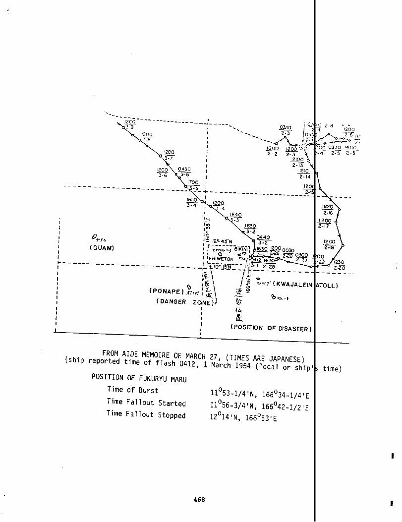
\
lam
-R-
1200
n
~.~----- --
------------- __+l _ ----q~I ‘. 0301 ‘.
-. xI
1-
; ‘=’;-..:?:;
I,2m .<.,
I m xI 2100I
\
m \1200 0430 Im x
1510I =4
170(3 I---- __ ---- --—— --- ~_ ~ 12C--------- ----- ----- z------ ----- ___
1650 I120(3m,=
I1
II I (po_sITION oF OISAsTER ]J !
FROM AIDE MEMOIRE OF MARCH 27, (TIMES(ship reported time of flash 0412, 1 March 1954
POSITIONOF FUKURYU MARU
ARE JAPANESE)(loCal or ship
Time of Burst 11°53-1/4’N, 166°34-1/4)ETime Fallout Started 11°56-3/4’N, 166°42-1/21ETime Fallout Stopped 12°14’N, 166°53’E

COPY OF AIDE-MEMOIRE PREPARED BY THETO THE UNITED STATES
APRIL 12, 1954
EMBASSY OF 3AE
It is reported that on March 31, Mr. Lewis L. Strauss, ChaAtomic Energy Commission, made the following statements, amongconcerning the thermonuclear test which took place at the BikiMarch 1, 1954.
I. . . A Japanese fishing trawler, the ‘FortunateDrag/appears to have been missed by the search but, based onstatement attributed to her skipper, to the effect thathe saw the flash of the explosion and heard the concus-sion six minutes later, it must have been well within tdanger area. . . .I. . . The situation with respect to the 23 Japanesefishermen is less certain due to the fact that our peoEhave not yet been permitted by the Japanese authoritiesto make a proper clinical examination. It is interestito note, however, that the reports which have recentlycome through to us indicate that the blood count of themen is comparable to that of our weather station per-sonnel. . . .’
The portion of Mr. Strauss’ statement quoted above not heirconsistent with information officially received here, the Japanwishes to place it on record that fact; ascertained by the Japaities on these points are as follows:
1. Upon investigation,it has been established that thcrew of the Fukuryu Maru No. 5 heard the detonationof the explosion seven or eight minutes after thecrew saw its flash. It is estimated that the pasi-tion of the vessel when they saw the flash and thespot where the ash fell upon them were respectively19 miles and 26 miles outside the danger-zone whichthe United States Government had previously estab-lished and publicized by the official publication‘Notice to Mariners’. For the details as to themovement of the vessel reference is made to the. . . Aide-Memoire handed in Tokyo to AmbassadorAllison by Vice Minister Okumura of Foreign Affairson March 27, 1954.
2. Dr. John J. Morton, of the Atomic Bomb Casualty Cornmission examined the Japanese crew members on the19th of March in Tokyo and on the 20th at Yaizu. EMerrill Eisenbud of the Atomic Energy Commissionviewed the affected persons, accompanied by Dr.
469
m of theaers,ltoll on
I
sntirely2 Embassyse author-

Morton, on March 25th in Tokyo and on the 26th atYaizu. Their visits included an examination of tinjured fishermen both by external observation anobtaining specimens of their blood and excreta.
The more thorough check-up offered by the dochas not yet been undertaken because of the speciapsychological situation in which these simple fismen find themselves. They resent and refuse theof clinical examination which they feel might plathem in the position of experimental objects. This especially true where the examination is to beconducted by physicians other than Japanese. TheJapanese authorities, however, are continuing theefforts to persuade the patients to undergo a morcomplete examination by American personnel at theearliest opportunity.
3. As to the question of the blood count of the expofishermen, information furnished to the American
bassy in Tokyo by the Japanese Government would apear to show that there is little ground to conclthe conditions of these fishermen are not seriousespecially when the extraordinary nature of thesecases are taken into consideration.
470 I

APPENDIX B
TERMS, ABBREVIATIONS, ACRONYMS, AND UNITS
Many of the definitions in this glossary relating to nuclear device and radlst ion pheno mc Ia ha~,e beenquated Or f?XtfdCtd from The Effects of N~clear tieapon$ (3rd edjt)ofl), S. Gla~St~ne and p.J . -Jo\a”, 1977.
AAA Anti-Aircraft Artil lery (Army).—.
AA&GM . Anti-Aircraft ,Artlllery and Guided Missile Center, Ft. Blisj, Texas (Army).
Iwcs. Airways and Air Communication Service (Air Force).
AAU . Administrative Area Unit (Army).—
ACC. Army Chemical Center, Edgewood Arsenal, Maryland.—
accelerometer. An instrument for determining the acceleration of the system with which it mo es.
ACF . American Car and Foundry, Inc. Later ACF Industries, Inc.—
AEC. Atomic Energy Commission, Washington, D.C.— Independent agency of the Federal governmen with sta-tutory responsibilities for atomic energy matters, No longer exists; its functions have been assumedby the Department of Energy and the Nuclear Regulatory Commission.
AF Store ship (Navy); also Air Force.—$
A&J. Air Force Special Weapons Center, Kirtland AFB, New Mexico.
&. Armed Forces Special Ueapons Project.
AGC . Amphibious force flagship;’ now LCC.—
airburst. The detonation of a nuclear device in the air at a height such that the expandi ng fireball doesnot touch the earth’s surface when the luminosity (emission of light) is at a maximum.
air particle trajectory. The direction, velocity, and rate of descent of windblown radio activl particles.
AKA Attack cargo ship; now LKA.—.
allowable dose. See MPE and MPL.
ALOO. Albuquerque Operations Office of the AEC (DOE).
alpha emitter. A radionuclide that undergoes transformation by alpha-particle emission.
alpha particle. A charged particle emitted spontaneously from the nuclei of some radioac tive I lements. Itis identical with a helium nuc Teus, having a mass of 4 units and an electrlc charge of 2 ositiveunits. See also radioactivity.
alpha rays. A stream of alpha particles. Loosely, a synonym for alpha particles.
AMN . Airman; enl isted Air Force personnel .—
AMS. Army Map Service, Washington, D.C.—
AN/PDR-39. An ion-chamber-type survey meter; this was the standard radsafe meter. Other s in 1Se includedthe Navy version, the AN/P DR-TIB, the AN/PDR-lBA and -lf3B, and lower range Geiger-Mu eller instruments(AN/PDR-27, Beckman MX-5, and Nuclear Corporation 261O) .
g. Oiler (Navy).
471

AOC . Air Operations Control Center.—
AOG . Gasoline tanker.I
—
AP . Transport jhip,—
APG.—
ARA—o
AL!S.—
ARSD.
ASA.—
ASU .—
ASW.—
Aberdeen Proving Ground, Maryland.
Allied Research Associates, Boston, Massachusetts.
Salvage ship.
Salvage lifting ship.
Army Security Agency.
Army Support Unit
Anti-Submarine Warfare.
.Au.xlliary ocean tug.
Atol 1 commander.
ATA.—
ATCOM,
ATF. Fleet ocean tug.—
~. A ring of coral reefs, usually with small islets, that surrounds a lagoon. Most arising from the deep sea that have bui It up on submerged volcanoes. They vary considthe largest atoll, Kwajalein in the Marshall Islands, has an irregular shape that e~t(135 km). See also coral reef.
~tomic bomb (or weapon), A term sometimes applied to a nuclear weapon utilizing fission e31s0 fission, nuclear device.
atomic explosion. See nuc lear explosion
attenuation. The process by which radiation is reduced in
It is due to absorption or scattering or both, but itfrom the source (inverse sauare law), which see.
<
~. Army Unit.
NJ. Seap lane tender.
AVR Aircraft rescue vessel—.
A!4 Distilling ship.—.
intensity when passing throughexcludes the decrease of intens
B-29. A 4-engine, propel Ier-driven bomber developed by Boeing, used for weather reconnaissatracking, aerial sampling and photography, and aerial refuel ing at the PPG. These versnated RB-29, MB-29, and KB-29.
~. A ?ong-range, strategic bomber powered by six pusher propel ler engines, supplementedengines. Developed by Consol idated Aircraft. Used as the subject of effects experimeosamPler controller aircraft. Also designated FB-36, RB-36, and MB-36.
~. A 6-jet-engine bomber with sweptback wings and a double-wheel bicycle landing gear, CBoeing. Used as the subject of effects experiments.
$SQ. A 4-engine bomber developed by Boeing, with some features 1ike those of the B-Z9, buttaller tail fin and larger engines and nacelles.
8-57. U.S. version of English Electrlc Canberra bomber used as cloud sampling aircraft.
background radiation. The radiation of man’s natural environment, consisting of that whichmlc rays and from the naturally radioactive elements of the EartO, Including that frombcdy. The term may also mean radiation extraneous to an experiment.
b~g ; A floating platform used as the support for the cab, or shelter, in which nuclear df
f19Prepared for testing.
472
ted reefsn size;84 miles
ly. See
.
erial.distance
loudlesig-
Ir jetIasa
]ed by
:g a
from cos -I man’>
were be-
L._

925: surge.
I
The partlcul~te d~st cloud th~t rolls out from the bottom of the cloud column rgduced by thec?!~na:!:rl of a ndcl ear cev}ce. For underwater t)ursts, the base surge 1s a cloud of ter droplets,anJ the t ,owlng p~’~pert[es are those of a homogeneous I~quld.
“U~tnt~D”. A wJShdowfl system used used on an aircraft carrier f light deck for decontaminate ng hel icopterllndlng gear. Tne oatht Lb’s purpose was to prevent water used to nose tne aircraft wh els from run-nllg onto the fllgnt df?Ck. [t was ~ low-walled canvas rectangle treated wltn waterpro flng preserva -tlvc!s.
hatnjt>]~r:io~raph ,B;T) .
I
A devlcs for obta]nlng a record of temperature with depth In the u per 1,000 feett300 meters, ot [he ocean, tr.om a snip underway.
:ecquerei (3qj. See cure (Clj.I
oeta burns. 2eta particles that come into contact with the skin and remain for an apprecia le time can——caJse a rs,’m of r~oia~lon l~~ury sometimes referred to as “beta burn. ” In an area offiilcut,
I
xtenslve earlythe wnoie surface of the iJody may ne exposed to beta particles.
>~ta ~,r,,t~e~. A radlonucl {de that d]slntegrates by beta particle emlsslon. Ail beta-actlv elements
I
exlstlng In nature expel neqatlve particles, l.s. , electrons or, more exactly, negatro . aeta-emltt]ng part lc)es are narmfui lf Inhaled or Ingested.
b~t~ particle (ray). X charged particle of very smal I !mass emitted spontaneously from the
1
clei of cer-tain rj:ilodct]ve elements. i:lost(if not all) of the direct fission products emit (neg jve) betaparticles. ?hyslcal, y, tile beta particle 1s ldent]cal to an electron moving dt high v ocity.
b}:st. Tne detonation of a nuclear dev!ce,
I
1Ike the detonation of a nigh explosive such as NT, results‘in the s~dden tormat; ,onof d pressure or shock wave, called a blast wave in the alr an a shock wave
fi!lefithe energy is imparted to water or Earth.
blast ~ave. An alr pulse in wh]ch the pressure increases sharply at the front accompan]erl
!
windsp:opagateo frm an explosl on.
~l]st y]eld. That portion of the total energy of a nuclear exploslon tnat man] fests Itself s blast andshock waves. .
bor, b cebr)s. See weapon debris.r
I?RL Bll IIstlcs Research Laboratories, Aberdeen ?rovlng Ground, Maryland (Army).—.I
ilukleo. tureau of Medicine and Surgery (Navy).
~. Explosl on; or detonation. See also airburst, high -altitude burst, surface burst.
EJsn~. Bureau of Ships (Navy).—
J-4J. IA twin-englnd transport aircraft manufactured by Llouglas Aircraft Company (Air Force ersion of the3C-3).
~, A 4-engine mi litary cargo and personnel transport manufactured by Douglas Aircraft Co any (AirForce version of the DC-4).
?’cab. The shelter that covers a nuclear device being prepared for test. May be located on a ower, on tne—
Earth’s surface, or on a barge.1
Canberra. An RAF twin -twbojet, all-weather, tactical bomber developed by English Electrlc.
I
Also bu]lt ]nthe iJn\ted States and used by the Air Force as the 6-57.
cathode-ray tube. A vacuum tube in which cathode rays (electrons) are beamed upon a fluores nt screen to—prouuce a lumlnous image. The character of this image is related to,
1
and control led by, one or moreelectrical signals app iled to the cathode-ray Oeam as Input information. The tubes are sed In meas -~rlng Instruments such as oscilloscopes and in radar and television displays.
c3ve. A heavily shielded enclosure in which radioactive mate’riJls can be remotely manipulat
1
to avoidr~ulatlon e~posure of personnel .
1. ? Aburevl]t]on for curie, which see.z-—~— .
I
[:1 IS preferred now but c was the abbreviation us d in the1950s.
Clc.— Counter-Intel 1igence Corps (Army).
473

.,
~. Criminal Investigation Detachment (Army) .
ClNCPAC. Commander-In-Chief of the Pacific.
CJTF ? Comnander, Joint Task Force 7.— .
cloud column (funnel). The visible column of weapon debris (and possibing upward from the point of a nuclear burst.
closed area. The land areas of Bikini and Enewetak and the water areasUnited States closed to unauthorized persons.
cloud phenomena. See fallout, fireball, radioactive cloud.
y dust or water d
within 3 miles of
collimate. To align nJclear weapon radiant outputs within an assigned solid angle througfles in order to ennance measurements.
:NO, Chief of Naval Operations.—
~. Chemical symbol for cobalt.
cabal:. Metallic element tiith radlonuclide 60c0 used as calibration source for ganma ins——
Condition “Purple” . See Purple conditions.
Consolidated List. Consolidated List of Radiological Exposures. The list that covers al~vloual radiological exposures for all joint task force participants (see Reference 1
contamination. The deposit of radioactive material on the surfaces of structures, areas,sonnel followlng a nuclear detonation, This material gener~lly consists of falloutproducts and other device debris have become incorporated with particles of dust, vaof device platforms, etc. Contamination can also arise from the radioactivity inducstances by the action of neutrons from a nuclear explosion. See also decontaminationdebris.
coral reef. A complex ecological association of bottom-living and attached shelled marinthat form fringing reefs, barrier reefs, and atolls. The lagoons of barrier reefs aportant places for the deposition of fine -grained calcium carbonate mud.
*
~. Counts per minute, a measure of radioactive material disintegration.
crater. The depression formed in the surface of the Earth by a surface or underground exformation can occur by vaporization of the surface material. by the scouring effectthrowout of disturbed-material , or by subsidence.
:RL Cook Research Laboratories, Chicago, 111 inois.—.
cryogenic materials. Materials used for producing very
c/s. Chief of Staff.—
CTG Cormnander,Task Group.—.
low temperatures.
~~”x ~O~~i~~~f~~Y!~~~~t~~~~~ar disintegrations occur per second (approximately th; it is the activity of a quantity of any radioactive
of 1 gram of radium) , The gamma c~rie is sometimes defined correspondingly as the arial in which this number of gamna-ray photons is emitted per second. This unit is
the becquerel (Bq) , which is equal to one disintegration per second.
CVE Escort aircraft carrier.—“
CW net. Carrier wave network . An organization of stations capable of direct radio communicacortnon channel or frequency.
) extand -
?at the
;e of baf -
s.
~ed indi -
S, and per -T fissioncomponents:rtain sub-3ut, weapon
1 fossils1s are im-
Crateriast, by
s in whichactivityof mate-
eplaced by
Ions on a
Daigo Fukuryu Maru (Fortunate Dragon No. 5).
I
Japanese fishing trawler in Bikini Atoll area on 1 March
D-dav. The term used to designate the unnamed day on which a test takes place. The equivalen‘plies to H-hour. Time In plans is indicated by a letter which jho,vs the Jnit Of :lme emc
figures, with a minus or plus sign to indicate the amount of time Defare or after the refe.g. , D+7 means 7 days after !l-day, il+2means 2 hours after H-hour.
474
rule ap-lyed i~‘ence even:.

ODE. Escort destroyer.—
g. Destroyer escort.
debris (radioactive). See weapon debris.
decay (radioactive). The decrease in acti~ity of any r~dthe spontaneous emiss]on from the atomic nuclei of epanied by gamma radlatlon, or by garmna photons alone.
oactive mater
ther alpha or
Every decay
ialwith the pass?beta particles, sprocess has a def
decontamination. The reduction or removal of contaminating radioactive material from a stroDJect, or person. Decontamination may be accompl ished by (1) treating the surface todecrease the contamination; (?) letting the material stand :0 that the radioactivity ia result of natural decay; and (3) covering the contamination in order to attenuate tnemitted.
f t],me dae toimes accom -e half -llfe.
ture, area,emove ~rdecreased asradiation
device. Nuclear fission and fusion materials, together with their arming, f~zing, firing, c emlcal-,.
explosive, and effects-measuring components, that have not reached the development stal f an
operational weapon.
y. Minelayer destroyer. Converted destroyers designed to conduct high-speed minelaying o
30D . Department of Defense. The Federal executive agency responsible for the defense of t—States. Includes the four services and special joint defense agencies. Reports to ththrough the Secretary of Oefense.
dose. A general term denoting the quantity of ionizing radiation absorbed. The unit of abthe rad (whicn see). In soft body tissue the absorbed dose in rads is essentially equsure in roentgens. The biological dose (also called the REE dose) in reins is a measur
effectiveness of the absorbed radiation. Dosage is used in older literature as well a
and simply exposure, ad Care should be exercised in their use. See also exposure.
dose rate. As a general rule, the amount of ionizing (or nuclear) radiation that an indiviwoufd receive per unit of time. It is usual ly expressed as rads (or reins) per hour ordivisions of these units such as mill irads per hour. The dose rate is commonly used tlevel of radioactivity in a contaminated area. See survey meter.
dosimeter. An instrument for m&asuring and registering the total accumulated dose of (or elzing radiation. Instruments worn or carried by individuals are called personnel dosl
The measurement and recording of radiation doses and dose rates.%;rious types of radiation instruments with which measurements are macl~! ‘~e~”!;~~n
vey meter.
DPM Disintegrations per minute, a measure of radioactivity, literal ly atoms disintegrating—.Difficult to directly compare with roentgens per hour for mixtures of radionucl ides.
~. DavidTaylorModel Basin,Carderock,Maryland(Navy).
dynamic pressure. Air pressure that results from the mass air flow (or wind) behind the shblast wave.
~. Edgerton, Germeshausen & Grier, Boston, Massachusetts (now EG&G, Inc.). An AEC centvialed timing and firing electronics and technical film coverage.
electromagnetic radiation. Electromagnetic radiations range from .X-rays and gansna rays oflength (high frequency), through the ultraviolet, visible, and infrared regions, to rawaves of relatively long wavelength.
elliptical app roximations. Method of predicting fallout areas. Data received that have thare plotted from a vertical S1 ice of the atmosphere. The equal or near-equal conditiofound to form a closed path that appears roughly elliptical in shape. The ellipticalis the ellipse drawn through these data points having nearly the same values. The ellso that the set of data comes closest to the curve.
q’3DLJ. Explosive Ordnance Oisposal Unit (Navy).
ETA Estimated time of arrival .—.
~. Estimated time of departure.
475
itedsident
d dose isthe exob-
iologicalosure dose
or materialiples oricate the
re to) ion-s.
th the use,eter, sur -
minute.
rent of a
,r. Pro-
wavend radio
Ie valuese general ly,ximationis drawn

.-
I~~A measure expressed in roentgens of the ionization produced by gan’ma rays (or%-exposure rate is the exposure per unit time (e.g., roentgens per hour). See dos “) ‘““r
roentgen.
exposure rate contours. Lines joining points whlc~ have the same radiation intensity thdout pattern, represented In terms of roentgens per hour.
F4u A single-engine Navy fighter developed by Vought-Sikorsky and Chance Vought. Six F—.used in CASTLE as a fighter element. An additional four earlier models scheduled fcused for unmanned fal lout experiments in CASTLE Project 6.4.
~. Single-engine jet fighter developed by Republic Aircraft and used from IVY (1952)(1956) as C1OUCI sampler aircraft.
FB-36. Featherweight 8-36 bomber; i.e., a B-36 bomber stripped of equipment (such as armcrease its performance in a noncombat mode.
fallout. The process or phenomenon of the descent to the Earth’s surface of particles ccradioactive material from the radioactive cloud. The term is also applied in a CO1lthe contaminated particulate matter itself. The early (or local) fallout is definectrarily, as particles reaching the Earth within 24 hours after a nuclear explosion.worldwide) fallout consists of the smaller particles, which ascend into the upper trstratosphere and are carried by winds to all parts of the Earth. The delayed fa! 10L
Earth,mainlyby rain and snow, over extended periods ranging from months to years.
fathometer. A depth-sounding instrument. The depth of water is measured by noting the tsound takes to return from the bottom.
film badges. Used for the indirect measurement of ionizing radiation. Generally contairpieces of film of different radiation sensitivities. They are wrapped in paper (orri al) that blocks light but is readily penetrated by gamma rays. The f] lms are dev{degree of fogging (or blackening) observed is a measure of the gamma-ray exposure, fabsorbed dose is calculated. Fi lm badges can also measure beta and neutron radiatic
fireball. The luminous sphere of hot gases that forms a few mi 11ionths of d second aftersion as the result of the absorption by the surrounding medium of the thermal X-ray!extremely hot (several tens of mil lions of degrees) device residues. The exterior <air is initially sharply defined by the luminous shock front and later by the limit:themselves.
,
fission. The process of the nucleus of a particular heavy element splitting into two nu{elements, with the release of substantial amounts of energy. The most important fi,are uranium-235 and plutonium-239; fission is caused by the absorption of neutrons.
~se rate,
Ine a fall-
models werefvage ~ere
Iugh REDWING
:) to in-
nated with~e sense tolewhat arbi -delayed (or)here andbrought to
:he echo of a
or three- thin mate-i and the!hich the
Jclear explo -‘ted by the
I
fireball inhe hot gases
1f lighterle materials
fis$ion detectors. Radiation pulse detector of the proportional counter type in which a foi 1 r film offissionable materials is incorporated to make it respond to neutrons.
fission products. A general term for the complex mixture of substances produced as a result o nuclearfission. A distinction should be made between these and the direct fission products or f ssion frag-ments that are formed by the actual spl itting of the heavy-element nuclel into nuclei ofweight.
.edium atomicApproximately 80 different fission fragments result from roughly 40 different moi s of fis-
sion of a given nuclear species (e.g., uranium-235 or plutonium-239). The fission fragme Its, beingradioactive, intnediately begin to decay, forming additional (daughter) products, with the ‘esult thatthe complex mixture of fission products so formed contains over 300 different radionucl id~ i of 36elements.
fixed a~ ha.+of a 1013-cm~”area.
Alpha ra loactivity that cannot be easily removed as evidenced by no measured cha ge in a
fluorescence. The emission of light (electromagnetic radiation) by a material as a result of t e absorp-tion of energy from radiation. The term may refer to the radiation emitted, dS wei ~ as to the emis-sion process.
FOPU . Fallout Prediction Unit.
forward area. The PPG and adjoining areas (e.g., Kwajalein).
fusion. The combination of two 1ight nuclei to form a heavier nucleus, with the release of the ifferenceof the nuclear binding energy of the fusion products and the ~um of the binding energl es of the twolight nuclei.
476
I

gamna rays. Electromagnetic radiations of high photon energy originating in atomic nucleilng many nuclear reactions (e.g., fission, radioactivity, and neutron capture). Physrays are identical with X-rays of high energy; the only essential difference is that ~ariginate from atomic nuclei of high energy. Gamma rays can travel great distances tlcan penetrate considerable thickness of material , although they can neither be seen mbeings except at very high intertsities, which cause an itching and tingl ing sensationThey can produce harmful effects even at a long distance from their source (The Effec’
!Q22!$ 3rd edition).
Geiger-Mue 1ler counter. A gas discharge pulse counter for ionizing radiation. See also Alion-chamber-type survey meter.
GMT . Greenwich Mean Time.—
~. A recently introduced ICRP term; 1 Gy equals 100 rad.
ground zero (GZ) . The point on the surface of land or water at, or ~ertically below or abtof the burst of a nuclear weapon.
%. A viscous comnerclal preparation that is soluble both in water and petroleum deriva’as a wetting agent in removing grease and particulate matter from metal and other nory
H-13. U.S. Army helicopter developed for close support with landing-skid-mounted armamentfor Enewetak alrl ift.
H-19. Large utility helicopter manufactured by Sikorsky Aircraft Division of United AircrUsed in CASTLE for Enewetak airlift.
H-hour. Time zero, or time of detonation. When used in connection with planning operatiolc1fic hour on which the operation event consnences. See D-day.
half-life. The time required for a radioactive material to lose half of its radioactivityEach radionuclide has a unique half-life.
HASL , NYKOPO. Atomic Energy Cormnission’s Health and Safety Laboratory, New York Operation
~. High explosive.
high-altitude burst. Defined, somewhat arbitrarily, as a detonation in or above the stratdistribution of the energy of the explosion between blast and thermal radiation changwitn increasing altitude.
HMNZS. His (Her) Majesty’s New 2ealand Ship.
HMR . Marine Hel icopter Transport Squadron.—
hodograph. A contnon hodograph ‘in meteorologytitude increments.
hot; hot spot. Consnonly used colloquialtermadjacentarea.
represents the
meaning a spot
speed and direction of winds
or area relatively more radio
~. Helicopter manufactured by Sikorsky Aircraft. Used in CASTLE for Bikini airlift.
IBDA. Indirect BcunbDamage Assessment. A revised target analysis based on new data such— yield, burst height, and ground zero obtained by means other than direct assessment.
~. International Consnission on Radiological Protection.
initial radiation. Also known as prompt radiation. Electromagnetic radiations of high enboth the fireball and the radioactive cloud within the first minute after a detonationeutrons and garmna rays given off almost instantaneously, as well as the ganuna rays elfission products and other radioactive species in the rising cloud. Initial radiatioor near-ground bursts activate both Earth materials and device debris to create contal
inverse square law. The decrease in radiation intensity with distance from a single-pointproportional to the square of the distance removed.
477
accompany -y, gammas do not1 air andlt by humanle skin.Nuclear
19 and
e center
It actssurfaces.
I in CASTLE
poration.
s the spe-
:0 decay.
:e.
!. The“eciably
‘erent al-
than some
ial weapon
nitted frominc;udesby them groundm.
? is in-

I
ion-chamber-type survey meter. A device for measuring the amount of ionizing radiation.gas-fi lled chamber containing two electrodes (one of which may be the chamber wall) tpotential difference is maintained. The radiation ionizes gas in the chamber and annetted to one electrode measures the ionization current produced.
ionization. The process of adding electrons to, or knocking electrons from, atoms or mol~creating ions. High temperatures, electrical discharges, and nuclear radiation can c
ionizing radiation. Any particulate or electromagnetic radiation capable of producing ior]nd]rectly, in its passage through matter. Alpha and beta particles produce ion pairgamna rays and X-rays 1iberate electrons as they traverse matter, which in turn prodLtheir paths.
~, in which there is aoprsc=>:i< icnzation.ionos here. The region of the atmosphere, ext?nding from roughly 40 to 250 miles (64 to t
The presence of charged particles iprofoundly affects !re p:’!piqdt lm of’ radio and radar waves.
irradiation. Exposure of matter to radiation.
isodose lines. Dose or dose-rate contours. In fa?lcut, contours plotted on a radiation~hich the dose rate or the total accumulated dose is the same.
isotope. Atoms with the same at~mic number (same chemical element) but different atomic ~nuclei have the same number of protons but a different number of neutrons.
JCS Joint Chiefs of Staff.—.
~. Joint Task Force 7 and its predecessor, JTF 132, was a combined force of personnelpartment of Defense (Air Force, Army, Marine Corps, Navy), the AEC, and their contra<responsible for al 1 aspects of nuclear weapon tests in the Pacific testing area fromThe last atmospheric nuclear test in the Pacific was conducted by JTF 8.
KB-29. Aerial refuel ing version of the B-29.
L-13. Single-engine, 2-place light aircraft used in Enewetak airlift.
kinetic enerqy. Energy associated with the motion of matter.
~. Los Alamos Scientific Laboratory, Los Alamos, New Mexico,v
LCM. Landing craft, mechanized.—
LCP(L). Landing craft, personnel (large).
LCP(R). Landing craft, personnel (ramp).
LCT. Landing craft, tank..
LCU . Utility landing craft.—
LML Lookout Mountain Laboratory, HoI lywood, California (Air Force).—@
Loran. Long-range navigation system. One Loran station was maintainedEnewetak Island.
LSD. Landing ship, dock.—
~. Landing ship, infantry (large).
LST Landing ship, tank.—.
by the U.S. Coast
MATS . Mil itary Air Transport Service; later, Military Airlift Conunand (joint Air Force).
me9at0n (ener9Y). Approximately the amount of energy that would be released by the explo’mill ion tons of TNT.
microcurie. One-millionth of a curie.
micron. One-millionth of a meter (i.e., 10-6 meter or 10-4 ~entimeter); it is roughlyf.thousandths (4 x 10⁻⁵) of an inch.
478
$Ofd
#hich a?nt con-
therebylization.
:tly ortly, whilezation in
~bove the,egion
ithin
i.e. , the
De-JTF 7 was1958.
tationon
one
undred-
I
I
[iI1i
I
mill iroentqen. One-thousandth of a roentgen.
MINSY. Mare Island Naval Ship Yard, California.
MPE Maximum Permissible Exposure (rule dose).—< That exposure to ionizing radiation thaiauthorities as the maximum over certain periods without resulting in undue risk to I
MPL Maximum Permissible Limit. That amourt of radioactive material in air, water, fool—.is established by authorities as the maximum that would not create undue risk to hur
mR; mr. Abbreviation for mi 11iroentgen.
~. Mi 1itary Sea Transportation Service, (Navy) .
mushroom cap. Top of the cloud formed from the firebal 1 of a nuclear detonation.
M/V. Motor vessel..
MWB. Motor whale boat.—
NAS . Naval Air Station.—
NAU. Naval Administrative Unit, Sandia Base, New Mexico.—
NavMed. Naval Medical School, Bethesda, Maryland.
NBS. National Bureau of Standards.—
NCO. Nonconsnissioned off icer.—
~. National Corrsnitteeon Radiation Protection and Measurements. Before 1956 simply ‘mittee on Radiation Protection.
NEL. Naval Electronics Laboratory.—
neutron. A neutral elementary particle (i.e.,~.e.,
with neutral electrical charge) of approxthe mass of a proton) that is present in all atomic nuclei, except those of (
hydrogen. Neutrons are required to initiate the fis,sion process, and large numbersproduced by both fission and fusion reactions in nuclear explosions.
neutron flux. Th intensity of neutron radiation.through 1 cm? in 1 second.
It is expressed as the number of neu
NM&DSO . Navy Medical and Dental Supply Off ice, Brook lyn Navy Yard, New York.
NPG. Nevada Proving Ground, now the Nevada Test Site (NTS) .—
NRDL . Naval Radiological Oefense Laboratory.
NRL . Naval Research Laboratory.—
NRS TI. Naval Receiving Station, Treasure Ssland, California.
NSC TI. Naval Schools Ccmsnand, Treasure Island, California.
~. Nuclear Test Personnel Review.
NTS Nevada Test Site.—.
NUCCS . Naval Unit, Chemical Corps School, Ft. McClellan, Alabama.
nuclear cloud. See radioactive cloud.
nuclear dev ice (or weapon or bomb )-. Any device in which the explosion results from the en[reactions involving atomic nuclei, either fission or fusion, or both. Thus, the A. ([and the H- (or hydrogen) bomb are both nuclear weapons. It would be equally true to [weapons, since the energy of atomic nuclei is involved in each case. However, it hasless customary, although it is not strictly accurate, to refer to weapons in which al’suits from fission as A-bombs. In order to make a distinction, those weapons in whlct
479
tablished byealth.
, etc. thatlth.
ional Com-
unit massy (light)trons are
assing
released byomi c ) bombthem atomicme more orenergy re-
t of the

energy results from thermonuclear (fusion) reactions of the isotopes of hydrogen
H-bombs or hydrogen bombs.
nuclear explosion. Explosive release of energy due to the splitting, or joining, of t
is observable by a violent emission of ultraviolet, visible, and infrared (heat)
rays, neutrons, and other particles. This is accompanied by the formation of a f
part of the energy from the e~plosion is emitted as blast and shock waves when dE
Earth’s surface or in the atmosphere. The firebal 1 produces a mushroom-shaped m?debris, the top of which rises rapidly. See also radiation, gamma rays, fireballfission, fusion, blast.
nuclear fusion. See thermonuclear fusion.
nuclear radiation. Particulate and electromagnetic radiation emitted from atomic nuclnuclear processes. The important nuclear radiations, from the weapons standpointparticles, gan%na rays, and neutrons. All nuclear radiations are ionizing radiatiis not true; X-rays, for example, are included among ionizing radiations, but theradiations since they do not originate from atomic nuclei.
nuclear tests. Tests carried out to supply information required for the design and in
weapons and to study the phenomena and effects associated with nuclear explosions
nuclide. Any species of atom that exists for a measurable length of time. The term rscribe any atomic species distinguished by the composition of its nucleus; i.e. ,tons and the number of neutrons. Isotopes of a given element are nuclides havin$protons but different numbers of neutrons in this nuclei . A radionucl ide is a r?
NYKOPO. New York Operations Office (Atomic Energy Commission).
off-scale. Radiation (or other physical phenomena) greater than the capacity of a metmeasure.
ONR Office of Naval Research, Washington, D.C.—-
N. Office of the Chief of Naval Operations.
~. Oak Ridge National Laboratory, Tennessee.
oscilloscope. The name generally applied to a cathode-ray device.
overpressure. The transient pressure, usual ly expressed in pounds per square inch, exce[pressure, manifested in the shock (or blast) wave from an explosion.
P2v5 and 6. Twin-engine patrol bcinber used for maritime patrol and antisubmarine warfarfLockheed for the U.S. Navy. Used in CASTLE as controller and transient ship search,
P4Y2 . Four-engine patrol bomber developed by Consolidated from the Air Force 8-24 for ttUsed in CASTLE as a telemetry receiver for Project 1.4.
PBM5A. Twin-engine, patrol-bomber flying boat, developed by Martin for the U.S. Navy. IJ!
airlift.
~. Patrol craft.
peak overpressure. The maximum value of the overpressure (which see) at a given locatiof
m called
“he explosionm, gmna
A largeat thet gases andr weapon,
Iriouspha and betathe reverse
It nuclear
It of nuclear
s used to de-Iumber of pro‘ma1 number of,e nuclide.
Ievice to
e ambient
loped by
Navy.
:ASTLE for
permissible contamination or dose. That dose of ionizing radiation that is not expected e appre-ciable bodil y in,jury to a person at any time during his lifetime.
I
P&!E!E’A volume of material closely approximating the density and effective atomic oumber f tissue.
i
The phantom absorbs ionizing radiation in the same manner as tissue, thu$ radiat’ofl dos measurementsmade within the phantom provide a means of approximating the radiation dose within a hu n or animal
body under simi lar exposure conditions. Materials comnonly used for phantoms are water, mason ite,pressed wood, and beeswax.
A heavily shielded container (usually lead) used to ship or store radioactive materials
Petroleum, oil, and lubricants. The storage area for these products is referred to as
?GPw . Position operational , meteorological aircraft report..—
480
)
POL farm.

I
PPG Pacific Proving Ground (after 1956 designated the Enlwetok Proving Ground, or EPG).—.
I‘,drp’e cor,d~t lens. A shipboard warning system used in radiological defense. Various numb red condltlcns
.~re ~odnd~d ~h~n radl~a~tlve f~llout was erl~ountered.
I
Responses to the sounoed warn ngs included:]o$iqg of /d~loJ\ hdt~hes Jnd fittings, turning off parts of the ventilation system, and removingpersonnel fr~m a s!lip’s open decks. The +igher the purple condltl~n n~mber, the more severe therlcl;:]loglcal slt~atl on.
“Q’’- clearance. A security clearance granted by the Atomic Energy Commission, based upon a investigation~n~d by the FBI.
1~. $,~bol f~r roentgen.
?.3. Chemical symool fw radium.—I
Fjd. ?ad~at)on absorbed dose.— A unit of absorbed dose of radi~tion; It represents the ab rption of 100i.rgs of ion$z~ng radiation per gram (or 0.01 J/kg) of absorlzing materlll, sl~ch aS bod
1
tissue. This~nit is presently being replaced in sc~entlfic literature by the Gray (Gy), numerical qual to theabsorption of 1 joule of energy per kilogram of matter.
Rad Def.?nse. Radiological defense. Defense against the effects of radioactivity from atomi weapons. It)ncludes the detection and measurement of radioactivity,
I
the protection of persons fro radioacti’{ity,
and decontamination of areas, places, and equipment. See also radsafe.
radex area. Radiological exclusion area.
I
Fol lowing each detonatio~ there were areas of su face radiologi-cal contamination and areas of air radiological contamination. These a.eas were desig ated as radexare?s . Radex areas were used to chart actual or predicted fallout and also used for c ntrol of entryand exit.
r?diztl on.
I
The emissinn of any rays, electromagnetic waves, or particles (e.g., ganrna rays alpha parti-cles, beta particles, neutron<) from a source.
radiatisn decay. See decay (radioactive).I
radiat~on detectors . Any of a wide variety of materials or instruments that provide a sign 1 when stimu-lated by the passage of ionizing radiation; the sensitive element in radiation detecti
1
instruments.The most widely used media for the detection of ionizing radiation are photographic fi and ioniza-tion of gases in detectors (e.g., Geiger counters), followed by materials in which rad tion inducesscintillation.
radiation exposure. Exposure to radiation may be described and modified by a number of ter . The typeof radiation 1s important: alpha and beta particles,diation.
neutrons, gamma rays and X-rays,
/
nd cosmic ra -Radiation exposure may be from an external radiation source, such as garmna r s, X-rays, or
neutrons, or it may be from radionucl ides retained within the body emitting alpha, betdiation.
cr gamma ra-The exposure may result from penetrating or nonpenetrating radiation in rela on to its
aDil ity to enter and pass through matter -- alpha and beta particles being considered nonpenetrat -Ing and other types of radiation as penetrating, Exposure may be related to a part of he body or tothe whole body. See also whole body irradiation.
radiation intensit~., ~egree of radiation.
I
Measured and reported in roentgens (R), rads, re s, and rep,mu tlp es and dlvlslons of these units, and multiples and divisions of these units as a function ofexposure rate (per hour, day, etc. ) .
p~dioactive (or nuclear) cloud. An al l-inclusive term for the cloud of hot gases. smoke, du t, and otherparticulate matter from the weapon itself and from the environment, Iwhich is carried al ft in conjunc-tion with the rising f irebal 1 produced by ttle detonation of a nuclear .deapon.
radioactive nuclide. See radionucl ide.
radioactive particles. See radioactivity.I
radioactive pool . A disk-l ike pool of radioactive water near the surface t~rmsd by a water. rface or sub-surface detonation. The pool gradually expands into an annular form,
I
then reverts to a larger irreg-ular disk shape at later times with a corresponding attenuation of radioactivity. Poo 1 formed byCASTLE shots over water contained radioactive Earth particulate as wel 1 as other radio .tive mate-rials because of the shallowness of the water.
481

radioactivity. The spontaneous emission of radiation, generally alpha or beta part icl ?5, often acczmpan, ejby garrna rays, from the nuclei of an (unstable) nuclide. As a result of this em] ,slon the radiodctldenuclide is converted (decays) into the isotope of a different (daughter) eleme nt, which may (or nay
not) also be radioactive. Ultimately, as a result of one ~r more stages of radio ctive decay, a s?a -ble (nonradioactive) end product is formed.
radiological survey. The directed effort to determine the distribution and dose rate ( radiation in anarea.
radionuclide. A radioactive nuclide (or radioactive atomic species).
radios onde. A bal loon-borne instrument for the simultaneous measurement and trans missi n of meteorologicaldata, consisting of transducers for the measurement of pressure, temperature, and umidity; a modula-tor for the conversion of the output of the transducers to a quantity that control a property of theradio frequency signal ; a se~ector switch, #hich determines the sequence in wh ich t e parameters areto be transmitted; and a transmitter, which generates the radio frequency carr ier.
radiosonde balloon. A balloon used to carry a radiosonde aloft. These bal loons have di {time burstingaltitudes of about 80,000 feet {25 km) above sea level . The bal loon measure s about 5 feet (1.5 me-ters) in diameter when first inflated and may expand to 20 feet (6 meters) or more )efore bursting athigh altitude.
radium. A radioactive element with the atomic number 88 and an atomic weight of 226. 1 nature, radium isfound associated with uranium, which decays to radium by a series of alpha and beta emissions. Radiumis used as a radiation source for instrument calibration.
radops. Radiological safety operations.
radsafe. Radiological safety. General term used to cover the training, operati ens, and ?quipment used toprotect personnel from potential overexposures to nuclear radiation during nuclear t !sts.
RM Royal Air Force (Britain).—4
rainout. Removal of radioactive particles from a nuclear cloud by rain.
rawin. Radar wind sounding tests that determine the winds aloft patterns by radar observ; :ion of aballoon.
rawinsonde. Radar wind sounding and radiosonde (combined).
w. A Norfolk, Virginia firm called Raydist Navigation Corporation that provided nav gational aidservice for test aircraft in the Bikini area during CASTLE. Also the equi pment made y this firm.
Raydist slave stations. Support instrumentation used in the positioning of experimental
RR-29. Reconnaissance version of the B-29.
R8--36. Reconnaissance version of the B-36.
R8E. Relative biological effectiveness. A factor used to compare the biological effect— radiation doses (i.e., rads) due to different types of ionizing radiation. For rad
the term has been superseded by Qual ity Factor.
reefer. Slang for refrigerator.
rem. A special unit of biological radiation dose equivalent; the name is derived from t—of the term “roentgen equivalent man (or mammal ).” The number of reins of radiat ionnumber of rads absorbed multipl ied by the R8E of the given radi at ion ( for a specif i
rem is also the unit of dose equivalent, which is equal to the product of the numbe
multiplied by the “quality factor” and distribution factor for the radiation. The
being replaced by the sievert (Sv) .
9“ An obsolete special unit of absorbed dose.
residual nuclear radiation. Nuclear radiation, chiefly beta particles and ganna rays, ta time following a nuclear explosion. The radiation is emitted mainly by the fissiother bomb residues in the fal lout, and to some extent by Earth and water constitueterials, in which radioactivity has been induced by the ~apture of neutrons.
R-hour. Reentry hour.
482
s aircraft.
of absorbedDrOteCti Ofl
iai lettersal to theet). Theds absorbedpresently
sists foructs andd other ma- I

roentgen. (R; r) A special unit of exposure to gamna (or X-) radiation. It is defined pr e isely as the
quantity of gamna (or X-) rays that will produce electrons (in ion pairs) with a tota 1 charge of 2.58x 10⁻⁴ coulomb in i kilogram of dry air .nder standard conditions. An exposure of 1 r entgen resu?tsIn the deposition of about 94 ergs of energy in 1 gram of soft body tissue. Hence, an exposure of1 roentgen is approximately equivalent to an absorbed dose of 1 rad in soft tissue.
RSSU. Radiological Safety Support Unit (Army).
RT7Y . Radio teletype.
~. Air Force general purDose amphibian for air-sea rescue work. Manufactured by Grunmlig AircraftEngineering Corporation, New York. Redesignated UY-16. Used in CASTLE for search and rescue.
SAC. Strategic Air Comnand (Air Force) .—
sampler aircraft. Aircraft used for CO1 lection of gaseous and particulate samples from nuC’ ?ar clouds todetermine the level of radioactivity or the presence of radioactive substances.
y. Sandia Corporation, Albuquerque, New Mexico.
scattering. The diversion of radiation (thermal, electromagnetic and nuclear) from its orig nal path as aresult of interactions (or collisions) with atoms, molecules, or larger particles in th ! atmosphereor other media between the source of the radiations (e.g. , a nuclear explosion) and a p}int somedistance away. AS a result of scattering, radiations (especially gamma rays and neu tro s) will bereceived at such a point from many directions instead of only from the direction of the source. Seealso skyshine.
Q. Signal Corps Engineering Laboratories, Ft. Monmouth, New Jersey (Army).
scintillation. A flash of light produced by ionizing radiation in a fluor or a phosphor, wh ch may becrystal, plastic, gas, or liquid.
shear (wind). Refers to differences in direction (directional shear) of wind at differen t a titudes.
shielding. Any material or obstruction that absorbs (or attenuates) radiation and thus tend, to protectpersonnel or equipment from the effects of a nuclear explosion. A moderately thick lay r of anyopaque material wi 11 provide satisfactory shielding from thermal radiation, but a consi(e rable thick-ness of material of high density may be needed for gansna radiation shielding. See a1s0 attenuation.
%. Term used to describe a ‘destructive force moving in air, water, or Earth caused by detonation of anuclear detonation.
shock wave. A continuously propagated pressure pulse (or wave) in the surrounding medium, w “ch may be
I
air, water, or Earth, initiated by the expansion of the hot gases produced in an explos n.
sievert (Sv). A recently introduced ICRP measure of “dose equivalent” that takes into accou the “qualityfactor” of different sources of ionizing radiation. One sievert equals 100 rem.
S10. Scripps Institution of Oceanography, La Jo1 la, California.—
m“ Radiation, particularly gatmnarays frcfn a nuclear detonation, reaching a target fr m many direc-tions as a result of scattering by the oxygen and nitrogen in the intervening atmosphere
The straight-1 ine di$tance of an aircraft at any altitude from ground zero or t e distance-~ airburst to a ,ocation on the ground.
SRI Stanford Research Institute, Stanford, California.—.
Upper portion of the atmosphere,-surface, in which temperature changes but little with a,titude and C,oud formati ~ns are rare.
approximately 7 to 40 miles (11 to 64 km) abo e the
surface burst. A nuclear explosion on the land surface, an island surface or reef, or on a b,rge.
surface zero. See ground zero. Also the location on the ground surface directly above an un[erground zeropoint.
survey meters. Portable radiation detection instruments especial ly adapted for surveying or lspecting anarea to establish the existence and amount of radiation present,logical protection.
usually from the standp c int of radio-Survey instruments are customarily powered by self-contained batter -?s and are
designed to respond quickly and to indicate directly the exposure rate conditions at the joint of in-terest. See AN/PDR-36, Geiger-Mueller counter, and ion-chamber-type survey meter.
483

survey, radiation. Evaluation of the radiation hazards associated with radioactive mat er. ils.
“sweet-sour”. Aerial survey radsafe reports made during the test series; connotes unto ntz Tinated (sweet)or contaminated (sour) serological conditions.
SWU-hAS, S.0. Spncial Weapons Unit, Naval Air Station, San Diego, California.
~. Personnel transport (Mil itary Sea Transport ion Service).
TAU. Test Aircraft Unit.—
TDY Temporary duty ass ignment.—.
~, Task Element.
thermal radiation. Electromagnetic radiation emitted in two pulses from a surface or airbu st from thefireball as a consequence of its very high temperature; it consists essentially of ult aviolet, visi-ble, and infrared radiation. In the first pulse, when the temperat~re of the fireball is extremelyhigh, ultraviolet radiation predominates; in the second pulse, the temperatures are lo~er and most ofthe thermal radiation lies in the visible and infrared regions of the spectrum.
thermonuclear fusion. Refers to the processes in which very high temperatures are used to t- ing about thefusion of light nuclei, such as those of the hydrogen isotopes (deuterium and tr itium), with the ac-companying liberation of energy. The high temperatures required to initiate the fusior reaction areobtained by means of a fission explosion. See also fusion.
TNT equivalent. A measure of the energy released as the result of the detonation of a nucle r device orweapon, expressed in terms of the ma$s of TNT that would release the same amoun t of ene gy when ex.ploded. The TNT equivalent is usually stated in kilotons (1,000 tons) or megat ons (1 m 11 ion tons).The basis of the TNT equivalence is that the explosion of 1 ton of TNT is assureed to re ease 1 billioncalories of energy. See also megaton, yield.
tropopause. The boundary dividing the stratosphere from the lower part of the atmos phere, tt ? troposphere.The tropopause normally occurs at an altitude of about 25,000 to 45,000 feet (7.6 to 13.7 km) in polarand temperate zones, and at 55,000 feet (16.8 km) in the tropics. See also stratosphere, troposphere.
troposphere. The region of the atmosphere, immediately above the Earth’s surface and up to t e tropopause,in which the temperature falls fairly regularly with increasing altitude, C1OU ds form, c nvection isactive, and mixing is continuous and more or less complete.
Trust Territories. The Marsha17 Islands were Trust Territories under”’the jurisdict ion of the United Na-tions. Assigned by the United Nations to the United States in trust for admin istration, development,and training.
~. Task Unit.
TSU. Test Services Unit.—
TSUP . Test Support Unit Provisional .
TSUU. Test Support Unit.
Twx Pronounced “twix”; teletypewriter exchange.—.
~pe cotnnander. The officer or agency having cognizance over al1 Navy ships of a given type. rhis is inaddition to the particular ship’s assignment in a task force or Fleet.
UCLA. University of California, Los Angeles.
g. University of California Radiation Laboratory, Livermore, California.
~. The Navy designation for the SA-16A. Used in CASTLE for weather, island resupply, and V P aircraft.
UHF U1 tra-high frequency.—.
~. United Kingdom.
ultraviolet. Electromagnetic radiation of wavelengths between the shortest visi ble violet (abou: 3,850angstroms) and soft X-rays (about 100 angstroms ).
484

uSFS. U.S. Forest Service.
~s~s. United States Navy Ship; vessels of this designation are manned by civilian crews.
uSTEc. Undewater Sound Transmission Experimental Facilities.
Vc Fleet compos~te squadron (formerly VU).—.
Versene. A detergent.
Viking. Radio call sign of VIP aircraft.
~. Kwajalein-based naval patrol squadron that flew security sweeps in P2V-6aircraft
~. Navalalr transportsquadron.
~. Airborneearlywarningsquadron. Used for aerialmonitoringof radiationduringCA
‘iaclc. Wright Air Development Center, Wright-Patterson AFB, Ohio (Air Force).
k3-29. Weather reconnaissance version of B-29 used for cloud tracking and sampling.
;IB-35. Weather reconnaissance version of B-36.
weapon debris. The radioactive residue of a nuclear device after it has been detonated, cfission products. various products of neutron capture, weapon casing and other compon,or plutonium that has escaped fission.
#hole bodv irradiation. Exposure of the body to ionizing radiation from external radiatio
1cal organs for the who e body are the lens of the eye, the gonads, and the red-blood-As 1itt le as only 1 cm of bone marrow constitutes a whole-body exposure. Thus, thenot be exposed to be classed as a whole-body exposure.
Wi Ison. Radio cal 1 sign for wE-29 cloud tracker aircraft.
Wilson cloud. A mist or fog of minute water droplets that temporarily surround~ a firebalnuclear detonation in a humid atmosphere. This is caused by a sudden lowerlng of thetemperature) after the passing of the shock wave and quickly dissipates as temperaturereturn to normal .
worldwide fallout. Consists of the smaller radioactive nuclear detonation particles thatuPPer troposphere and the stratosphere and are carried by winds to al 1 parts of the Elayed (or worldwide) fallout is brought to Earth, mainly by rain and snow, over extening from months to years.
~. Weather Reporting Element Provisional .
WT—,
YAG—.
~.
YFti.—
Prefix of Weapon Test (MT) report identification numbers. These reports were prepareresults of scientific experiments.
Miscellaneous auxiliary ship (Navy).
Open 1ighter (nonself -propel led; Navy).
Covered 1ighter (nonself -propel led; Navy).
u!!!. The total effective energy released in a nuclear detonation. It is usual lY expresthe equivalent tonnage of TNT required to produce the same energy release in an exploenergy yield is manifested as nuclear radiation (including residual radiation), thermand blast and shock energy, the actual distribution depending upon the medium in whitoccurs and also upon the type of weapon. See TNT equivalent.
yield (blast). That portion of the total energy of a nuclear detonation that is identifieor shock wave.
/ield (fission). That portion of the total explosive yield attributable to nuclear fissiofusion. The interest in fission yield stems from the Interest in fission product forrelationship to radioactive fallout.
Yo. Fuel oil barge; self -propelled.—
485
:ing ofand urani urn
.ces. Criti -lg marrow.! body need
lowing a;ure (andi m-essures
j into theThe de-
?riods rang-
‘ecord the
1 terms ofThe total
liation,explosion
:he blast
opposed to\ and its

&.=
YOG .— Gasolinebarge; self-propelled.
YOGN. Gasol ine barge; nonself-propel led.
~. Zone of Interior (contermi nous United States).
486
I

INDEX OF UNITS
Conversion Factors -- U.S. to Metric (S1) Units
To Convert from To Multir
angstrom
atmosphere (normal)
bar
barn
British thermal unit(thermochemical)
cal (thermochemical)/cm*
calorie (thermochemical)
calorie (thermochemical)/g
curie
degree Celsius5
degree (angle)
degree Fahrenheit
electron volt
erg
erg/second
foot <
foot-pound-force
gallon (U.S. liquid)
inch
jerk
joule/kilogram (J/kg)(radiation dose absorbed)
kilotons
meters (m)
kilopascal (kPa)
kilopascal (kPa)
meter2 (m*)
joule (J)
megajoule/m2 (MJ/m2)
joule (J)
joule per kilogram (J/kg)*
gigabecquerel (GBq)t
degree kelvin (K)
radian (rad)
degree kelvin (K)
joule (J)
joule (J)
watt (W)
meter (m)
joule (J)
meter3(m3)
meter (m)
joule (J)
gray(Gy)*
terajoules (TJ)
1.000 000
1.013 25 )
1.000 000
1.000000
1.054 350
4.184 000
4.184 000
4.184 000
3.7000 Ooc
‘k =t:i
1.745 329
t = ($4
1.602 19 x
1.000 000
1.000000
3.048 000
1.355 818
3.785 412
2.540 000
1.000000
1.000 000
4.183
● The gray (Gy) is the accepted S1 unit equivalent to theenergyimparteing radiation to a mass of energy corresponding to one joule/kilogram.
t The becquerel (Bq) is the S1 unit of radioactivity; 1 8q = 1 disintegr
5 Temperature may be reported in degrees Celsius as well as degrees kelv
487

Conversion Factors (continued)
To Convert from To Mu 1
kip (1000 Ibf)
ktap
micron
mi 1
mile (international)
ounce
pound-force (lbf avoirdupois:
pound-force inch
pound-force/inch
pound-force/foot2
Pound-force/inch* (psi)
pound-mass (Ibm avoirdupois)
pound-mass-foot2(moment of inertia)
pound-mass/foot3
rad (radiation dose absorbed
rem
roentgen
shake
slug .
torr (mm Hg, O°C)
newton (N) 4.448 2;
newton-second/m2 (N*s/m2) 1.000 0(
meter (m)
meter (m)
meter (m)
kilogram (kg)
newton (N)
newton-meter (N=m)
newton/meter (N/m)
kilopascal (kPa)
kilopascal (kPa)
kilogram (kg)
kilogram-meter2(kgom2)
ki logram-meter3 (kg”m3)
gray(Gy)
sievert (SV)*
coulomb/kilogram
second (s)
kilogram (kg)
kilopascal (kPa)
(C/@)
,.
1.000 Oc
2.540 OC
1.609 34
2.834 95
4.448 22
1.12984
1.751 2[
4.788 0;
6.894 7!
4.535 9;
4.214 01
1.601 8<
1.000 0[
1.000 --
2.579 760
1.000000
1.459 390
1.333 22 )
* The sievert (Sv) is the S1 unit of measure for “dose equivalent” thatinto account the quality factor of different sources of ionizing radilSV= 100 rem
488
+3
+2
-6
-5
+3
-2
-1
+2
-2
-1
-2
+1
-2
-2
4
3
1
;
I fw

Commonly Used Nuclear Energy Units and Abbreviations
Prefixes and Numerical V
MeasuredPico {Micro Mini
Basic Unit Property 10-12 10-6 10-3 1 K
barn
curie
dose rate
electron volt
gram
meter
rad (radiationabsorbed dose)
roentgen
rem (roentgenequivalent man)
rep (roentgenequivalent physical)
second
ton (TNTequivalent)
watt
cross section Mb
radioactivity pl.ICi; Ilci;ppc DC
radiation dose
energy
mass Wg
length
radiation
radiationdose
radiationdose
radiationdose
, time
device energy
power ppw
P9
urad
pR;pr
urem
prep
us
w
489
mb
mCi;mc
mR/hr;mr/hr
mg
mll
mrad
mR;mr
mrem
mrep
ms
mw
b
Ci; kc k
R/hr;rfhr,rem/hr
eV k
9 k
m k
rad
R; r
rem
rep
s
K
w k
2s
Mega
104
MC iMc
MeV
MT
Mw

,..
THIS PAGE
WAS
INTENTIONALLY
LEFT BLANK
IN
ORIGINAL

APPENDIX C
ISLAND SYNONYMS
CAPITALIZED entries are the code names used by the joint tfor the islands. Underscored entries are the names of the islin this report.appear in other
AaraanbiruABLEAdrikan~Aeroko~AerokojlolAirukiijiAirukiraruAitsuAlembelAMAALICEALVIN
=AnerowijAniyaaniiAomenAomoenAomonArambiruArriikan
BAKERBELLEBigirenBiijiriBijile
X2A!2BikdrinBikenBikileBikiniBillaeBilleeBogairikk
Bogallua
All other entries are spellings of the islandliterature.
m- Alembel - Arambiru (EnewetakAtoll)Bokbata - Bokobyaada (Bikini Atoll)YOKE - Arriikan (BikiniAtoll)OLIVE - Aitsu (EnewetakAtoll)OBOE - Airukiiji (BikiniAtoll)PETER - Airukiraru (BikiniAtoll)OBOE - Aerokol (BikiniAtoll)PETER - Aerokojlol (BikiniAtoll)OLIVE - ~ (EnewetakAtoll)vERA- Aaraanbiru - Arambiru (EnewetakAtoll)Bokaetoktok - Bokoaetokutoku (BikiniAtoll)Bokoluo - Bogallua (EnewetakAtoll)Jinedrol - Chinieero (EnewetakAtoll)BRUCE - Aniyaanii (EnewetakAtoll)TQM - N!!Qx - Munjur iEnewetak Atoll)BRUCE - M (EnewetakAtoll)GEORGE - Aomoen (BikiniAtoll)GEORGE - Aomen (BikiniAtoll)SALLY (EnewetakAtoll)vERA- Alembel - Aaraanbiru (EnewetakAtoll)YOKE - Adrikan (BikiniAtoll)
Bokonejien (BikiniAtoll)Bokombako - Bogombogo (EnewetakAtoll)ROGER - Bikdrin (BikiniAtOll)
TI~A --- Bijile - Bikile (EnewetakAtTILDA - - Biijiri - Bikile (EnewetakATILDA - Bijile - Biijiri - Bikile (EnewetakAROGER - Bigiren (BikiniAtoll)LEROY - Rigile - Rigili (EnewetakAtoll)
~~-U-Bijile -Biijiri (EnewetakA- (Bikini Atoll)
WILMA - Piiraai - Piirai (EnewetakAtoll)LUCY - Kidrinen - Kirinian (EnewetakAtoll)HELEN - Bokaidrikdrik - Bogeirik - BskaidrikAtoll)ALICE - Bokoluo (EnewetakAtoll)
491
L forceis as used:hatmay
.)
.1
.1
.1
lewetak

BoganBogeirik
BogenBogombogoBogonBokaetoktokBokaidrik
BokaidrikdrikBokandretokBokbataBokdrolulBokenBokenBokenelabBokinwotmeBokoBokoaetokutokuBokobyaadaBokoluoBokombakoBokonaarappuBokonarppuBokonejienBokonfuaakuBokororyuruBRAVOBRUCEBuganegan
CHARLIEChieereteChinieeroChinimiCLARACLYDECocaCochita
DAISYDAVID
DrekatimonDridrilbwij
EASYEberiruEDNAEleleronElle
IRWIN - Boken - Pokon (EnewetakAtoll)HELEN - Bokaidrikdrik - Bogairikk - BokaidAtoll)
- Jedrol - Jieroru (EnewetakAtoll)BELLE - Bokombako (EnewetakAtoll)IRENE - Boken (EnewetakAtoll)IUFA - Bokoaetokutoku (Bikini Atoll)HELEN - Bokaidrikdrik - Bogairikk - BogeirAtoll)
rik (Enewetak
ik ~Enewetak
HELEN - Bogairikk - Bogeirik - Bokaidrik (Ene~letakAtoll)
WALT (EnewetakAtoll)ABLE - Bokobyaada (BikiniAtoll)BRAVO - Bokororyuru (Bikini Atoll)IRENE - Bogon (EnewetakAtoll)IRWIN - Pokon - Bogan (EnewetakAtoll)MARY - Bokonaarappu - Bokonarppu (EnewetakAtc11)EDNA - Sanildefonso (EnewetakAtoll)SAM (EnewetakAtoll)ALFA - Bokaetoktok (BikiniAtoll)ABLE - Bokbata (BikiniAtoll)ALICE - Bogallua (Enewetak Atoll)BELLE - Bogombogo (EnewetakAtoll)MARY - Bokenelab - Bokonarppu (EnewetakAtoll)MARY - Bokenelab - Bokonaarappu (EnewetakAto11)BAKER (Bikini Atoll)ITEM (Bikini Atoll)BRAVO - Bokdrolul (BikiniAtoll)Bokdrolul - Bokororyuru (Bikini Atoll)
w - Aniyaanii (EnewetakAtoll)HENRY - Mut - Mui (EnewetakAtoll)
Nam - Namu (BikiniAtoll)=LIAM - Jelete (Bikini Atoll)ALVIN - Jinedrol (EnewetakAtoll)CLYDE - Jinimi (EnewetakAtoll)Kirunu - Eybbiyae - Ruchi (EnewetakAtoll)Jinimi - Chinimi (EnewetakAtoll)(BikiniAtoll)DAISY - - - Lidilbut (EnewetakAtoll)
Louj - Cochita - Lidilbut (Enewetak Atoll)QE!FSZ! - Mutl (Enewetak Atoll)w - Yurochi (Bikini Atoll)OSCAR (Enewetak Atoll)GENE - Teiteiripucchi (Enewetak Atoll)
Uorikku - Odrik (Bikini Atoll)RUBY - Eleleron (EnewetakAtoll)Bokinwotme - Sanildefonso (EnewetakAtoll)RUBY - Eberiru (Enewetak Atoll)
NANCY - Yeiri (EnewetakAtoll)
492

ELMERElugelab
Eluklab
Eneman
Eneu–~etakEngebiEniairoEnidrikEniirikkuEninmanEniwetok
=EnyuEybbiyae
FLORAFOXFRED
GENEGEORGEGiriinienGLENNGrinem
HELEN
HENRYHOW
IgurinIkurenInedralIonchebiIRENE
mIRWIN
JAMESJANET
=
JeleteJieroruJIGJinedrolJinimi
KATEXEITH
2!?LSY- Medren (EnewetakAtoll)FLORA - Eluklab (EnewetakAtoll)FLJIIU- Elugelab (EnewetakAtoll)TARE - Eninman (BikiniAtoll)NAN - Enyu (BikiniAtoll)FRED - Eniwetok (EnewetakAtoll)JANET - m (EnewetakAtoll)KING (BikiniAtoll)UNCLE - Eniirikku - (BikiniAtoll)UNCLE - Enidrik (BikiniAtoll)TARE - Eneman (BikiniAtoll)FRE) - Enewetak (EnewetakAtoll)JANET - Engebi (EnewetakAtoll)NAN - Eneu (BikiniAtoll)CLARA 7Zrunu - Ruchi (EnewetakAtoll)
Eluklab - Elugelab (EnewetakAtoll)Lomilik - Romurikku (BikiniAtoll)Enewetak - Eniwetok (EnewetakAtoll)
Dridrilbwij_- Teiteiripucchi (EnewetakAtoll)Aomen - Aomoen (BikiniAtoll)KEITH - Kidrenen - Grinem (EnewetakAtoll)Ikuren - Igurin (EnewetakAtoll)KEITH - Kidrenen - Giriinien (EnewetakAtoll)
Bokaidrikdrik - Bogairikk - Bogeirik - Bokaid(EnewetakAtoll)Mut - Buganegan - Mui ‘(EnewetakAtoll)=ini (Bikini Atoll)
GLENN - Ikuren (EnewetakAtoll)GLENN - Igurin (EnewetakAtoll)URIAH (EnewetakAtoll)MIKE (BikiniAtoll)Boken - Bogon (EnewetakAtoll)DoG- Yurochi (BikiniAtoll)Boken - Bogan - Pokon (EnewetakAtoll)Bokonfuaaku (BikiniAtoll)
Ribewon - Libiron - Ribaion (EnewetakAtoll)
M - Engebi (EnewetakAtoll)DAVID - Muti (EnewetakAtoll)FU%x- Jieroru - Bogen (EnewetakAtoll)WILLIAM - Chieerete (BikiniAtoll)REx- Jedrol - Bogen (EnewetakAtoll)Yomyaran (Bikini Atoll)ALVIN - Chinieero (EnewetakAtoll)CLYDE - Chinimi (EnewetakAtoll)
Mijikadrek - Mujinkarikku - Muzinbaarikku (EnKidrenen - Giriinien - Grinem (EnewetakAtoll
493
tak Atoll)

KidrenenKidrinenKINGKirinianKirunu
LeleaYLibironLidilbut
=LomilikLou~
LOVE
LUCY
-wMACKMARYMedrenMijikadrekMIKEMuiMujinkarikku
MutZliZiMuzinbaarikku
l--lamNamuNAN
NANCY
OBOEOdrikOLIVEOrokenOSCARCmrukaen
=
PERCYPETERPiiraaiPiiraiPokon
KEITH - Giriinien - Grinem (EnewetakAtLUCY - Billee - Kirinian (EnewetakAtolEniairo (BikiniAtoll)LUCY - Kidrinen - Billee (EnewetakAtolCLARA - Eybbiyae - Ruchi (EnewetakAtol
SUGAR - Reere (Bikini Atoll)Biken - Rigile - Rigili (EnewetakAtollJAMES - Ribewon - Ribaion (EnewetakAtoDAISY - —~ - Cochita (EnewetakAtoll)URSULA - Rojoa (EnewetakAtoll)FOX - Romurikku (BikiniAtoll)DAISY - Cochita - Lidilbut (EnewetakAtRochikarai (Bikini Atoll) -Kidrinen - Billee - Kirinian (EnewetakAt~ Rujiyoru - Rujoru (EnewetakAtollVICTOR - Rukoji (BikiniAtoll)
Unibor (EnewetakAtoll)Bokenelab - Bokonaarappu - Bokonarppu (Er
‘MR ‘~ (EnewetakAtoll)KATE - Mujinkarikku - Muzinbaarikku (EnehIonchebi (BikiniAtoll)HENRY - Mut - Buganegan (EnewetakAtoll)KATE - M~kadrek - Muzinbaarikku (EnewetmM - Anerowij - Munjur (EnewetakAtoll)TOM - u - Anerowij (EnewetakAtoll)HENRY - Buganegan - Mui (EnewetakAtoll)DAVID - Jawan (Enewetak Atoll)KATE - Mijikadrek - Mujinkarikku (Eneweta
CHARLIE - Namu (BikiniAtoll)CHARLIE - Nam (BikiniAtoll)Eneu - EnyfiBikini Atoll)Elle - Yeiri (EnewetakAtoll)
Aerokol - Airukiiji (BikiniAtoll)EASY - Uorikku (BikiniAtoll)~ - Aitsu (EnewetakAtoll)ZEBRA - Ourukaen (BikiniAtoll)Drekatimon (EnewetakAtoll)ZEBRA - Oroken (BikiniAtoll)
ELMER - Medren (EnewetakAtoll)
u - Rujiyoru - Rujoru (EnewetakAtoll)Taiwel (EnewetakAtoll)Aerokojlol - Airukiraru (BikiniAtoll)WILMA - Billae - Piirai (EnewetakAtoll)WILMA - Billae - Piiraai (EnewetakAtoll)IRWIN - Boken - Bogan (EnewetakAtOll)
494
c Atoll)
itoll)
>11)
.1)

,.●
THISPAGE
I’M-s
INTENTIoNALLY
LEFT BLANK
IN
ORIGINAL

ReereRExRibaion
Ribewon
Rlglle
Rlglli
RochikaraiROGERRojoaRomurikkuRUBYRuthiRujiyoruRujoruRukojiRunit
SALLYSAMSanildefonsoSUGAR
TaiwelTARETeltelrlpucchi
T ILDA
TOM
UNCLEUniborUorikkuURIAHURSULA
VANVERAVICl?OR,
WALTWILLIAMWILMA
YeiriYOKEYomyaranYurochiYVONNE
ZEBRA
SUGAR - Lele (BikiniAtoll)Jedrol - Bogen - Jieroru (EnewetakAtoll)JAMES - Ribewon - Libiron (EnewetakAtoll)JAMES - Libiron - Ribaion (EnewetakAtoll)LEROY - Biken - Rigili (EnewetakAtoll)LEROY - Biken - Rigile (EnewetakAtoll)LOVE (BikiniAtoll)Bikdrin - Bigiren (BikiniAtoll)URSULA - LQ.@4 (En’=w’etakAtoll)FOX - Lomilik (BikiniAtoll)Eleleron - Eberiru (EnewetakAtoll)CLARA - Kirunu - Eybbiyae (EnewetakAtoll)PEARL - = - Rojoru (EnewetakAtoll)PEARL - - - Rujiyoru (EnewetakAtoll)VICTOR - = (BikiniAtoll)YVONNE (EnewetakAtoll)
Aomon (EnewetakAtoll)Boko (EnewetakAtoll)EDNA - Bokinwotme (EnewetakAtoll)Lele - Reere (BikiniAtoll)
PERCY (EnewetakAtoll)
Eneman - Eninman (BikiniAtoll)GENE - Dridrilbwi~ - (EnewetakAtoll)
w - Bijile - Biijiri - Bikile (Enewetak
- - Anerowij - Munjur (EnewetakAtoll)
En~drik - Eniirikku (BikiniAtoll)MACK (EnewetakAtoll)EASY - Odrik (BikiniAtoll)Inedral (EnewetakAtoll)
w - Rojoa (EnewetakAtoll)
(EnewetakAtoll)Alembel - Aaraanbiru - Arambiru (EnewetakAtLukol - Rukoji (BikiniAtoll)
Bokandretok (EnewetakAtoll)Jelete - Chieerete (BikiniAtoll)Billae -’Piirai - Piiraai (EnewetakAtoll)
NANCY - Elle (EnewetakAtoll)Adrikan - Arriikan (BikiniAtoll)JIG (BikiniAtoll)DOG - Iroii (BikiniAtoll)— -.Runit - (Enewetak
Oroken - Ourukaen
Atoll)
(BikiniAtoll)
495
!toll)
,1)

BLANK PAGE
496
\ —..——. —
I
I

APPENDIX D
INDEX OF PARTICIPATING ORGANIZATIONS
AACS. See Airways and Air CommunicationsServXe.
AAG&i4. See Anti-Aircraft Artillery andGuided~issile School.
ACC. See Army Chemical Center.—
ACF. See American Car and Foundry.—
AEC. _See Atomic Energy Conrnission.
AFL U of Mash. See Applied Fisheries Lab-oratory, Univ=ity of Washington.
AFSWC. See Air Force Special WeaponsCenter=
AFSWP. See Armed Forces Special WeaponProje~
AFWL. See Air Force Weapons Laboratory.—
USNS Fred C. Ainsworth (T-AP-181). Opera-tions: Table ~). 123. 125. 341(Table 60), “358 (Table 72),’ 361 (Table75), 373, 374 (Table 82); Radsafe Activ-ities: 82, 127 (Table 11), 147, 149;Fallout Involvement: 215 (Table 21), 266(Table 32); Personnel Exposure: 237 (Ta-ble 23), 335 (Table”59); Position Data:207 (Figure 55), 223 (Figure 65), 225(Figure 66), 257 (Figure 72), 274 (Fig-ure 76), 289 (Figure 82), 303 (Figure87), 317 (Figure 93).
Air Defense Hq. See Ent Air Force Base,—
Air Force. 5, 69-71, 384-396. See also en-tries for individual Air Force units.
Air Force Headquarters (Hq USAF). 77.
Air Force Special Weapons Center. Opera-tions: 132, 133, 134, 140, 388, 392(Table 87), 394; Personnel Exposure: 385(Table 86), 387 (Table 86), 390.
Air Force Weapons Laboratory. 6 (archivalsource for CASTLE data).
Air University. 387 (Table 86), 395.
Airways and Air Communicant21?, 394. See also 1!AAcs.
Allied Research Associate!(Table 90), 406.
American Car and Foundry.86), 390, 403 (Table 90
AMS. &Army Map Service
Anti-Aircraft Artillery arSchool (Army). 326 (Tal
USS A ache (ATF-67). Opet* 179, 355, 358
(Table 25); Position Da(Figure 66); 274, 313 (out Involvement: 215 1Personnel Exposure: 237(Table 59).
‘ Applied Fisheries LaboratolWashington. 188, 403 (’
ARA. See Allied Research i—
Army. 5, 58-60, 325-331.for individual Army uni’
Army Chemical Center. Rads89; Experimental Part182, 192, 196, 325; Per326 (Table 58).
Army Chief of Staff. 54255.
Army Communications Center
Department of the Army G-ble 58).
Army Map Service. 184, 18558).
Armed Forces Special Wear
JTF 7: 54 (Figure 11);
497
Service. 70,t and 1960th
90, 191, 403
385 (Table;5.
Jided Missile58), 328.
Ins: 66 (Ta-ble 22), 361207, 223, 225Ie 53); Fall-Ie 21), 266;ible 23), 334
University ofe 90), 405.
ciates.
.ble 49), 303, 378.
also entries
nonitors: 88,lation: 181,lel Exposure:
ure 11), 99,
17.
25, 326
5, 326 (“
Pro.iect
(Ta-
able
And~saf~ Activi-
5fq .

ties. 88, 91, 196; Experimental Activ-ity: 168, 193; Personnel Exposure: 336,337, 400, 401, 402 (Table 90). See also8541st and 8452nd AAU.
Atomic Bomb Casualty Commission, 118.
Atomic Energy Commission. Role in WeaponsDevelopment: 1, 2, 5, 25, 31, 53, 55,248; In JTF 7: 54 (Figure 11), 72; Rad-safe Activities: 98, 351; Contractors:390, 400; Personnel Exposure: 402 (Table90). See also divisions of the AEC.
Atomic Energy Commission, Oivision of Biol-ogy and Medicine. 94, 106, 402 (Table90), 404.
Atomic Energy Commission, Division of Mili-tary Applications. Test Site Administra-tion: 42, 45, 47; Personnel Exposure:99, 401, 402 (Table 90).
Bergstrom Air Force Base.391.
Biggs Air Force Base. SeeWing and 341st Bomba~me
Boat Pool Detachment, Bikble 5), 93, 243, 366.
Boat Pool Detachment, Eneh(Table 5), 69 (Table23), 372.
Boat Pool, Task Group 7.2Unit. 69 (Table 6), 335
13RL. See Ballistic Researc—
8uMed. See Navy Bureau tSurge=
BuShips. See Navy Bureau o—I
Atomic Energy Commission, Military LiaisonConunittee. 54 (Figure 11), 55.
USS 8airoko (CVE-115). Activities: 61, 63,64 Tabre 5), 71, 80, 85, 114, 156 (Ta-ble 13), 249, 340, 347, 349, 350, 356(Table70), 363, 367 (Table78), 379,397: RadsafeActivities:81. 82. 121.126” (Table 10), 127 (Table” n): 128;147, 149, 150, 16L, 224, 262, 292, 306;Personnel Exposure: 4, 98, 124, 214,215 (Table 21), 237, 245, 334 (Table59), 351; Position Oata: 123, 207 (Fig-ure 55), 210, 223 (Figure 65), 225 (Fig-ure 66), 274 (Figure 76), 289 (Figure82), 303 (Figure 87), 317 (Figure 93),342, 343, 345.
Ballistic Research Laboratories. Experi-mental Participation: 122, 173, 176,177, 185; Personnel Exposures: 326 (Ta-ble 58), 328, 330, 385; Air Force Per-sonnel in BRL: 390.
USNS Barrett (T-AP-196). 273 (Table 36).
Beach Group One (Navy). 67 (Table 5), 335,(Table 59), 368.
USS Belle Grove (LSO-2). Activities: 67Table (Table 5), 123, 124, 221,262, 306,’ 345 (Table 64), 346 (Table65), 359 (Table 73). 366. 367 (Table78); 372, 373; PersorinelE~posure~:”237(Table 23), 243, 335 (Table 59), 368;Fallout Involvement: 215 (Table 21), 266(Table 32); Position Data: 218. 221. 223(Figure 66), 257 (Figure 72),-274 ~Fig-ure 76), 289 (Figure 82), 303 (Figure87), 306.
Table 86),
bombardment]adron.
1, 67 (Ta-
(Navy). 67237 (Table
!tak Harbor? 59), 339.
watery.
~icine and
IS.
ICambridge Corporation. 56, 40 (Table 90),405.
Cameo. ISee Cambridge Corporat on.—
ICanadian Atomic Energy Commiss on. 118.
ICanadian Meteorological Servic . 118.
Carswell Air Force ”Base. Seement Wing, 9th Bombardme~Bombardment Wing, 436th
, Squadron; and llth Bomb?36th Bombardment Squadron.
‘th Bombard-quadror?;7thBombardmentdment Wing,
IChief of Naval Operations. 54 (Figure 11)333 (Table 59).
IChief of Staff, U.S. Air Force 54 (Figure11).
CIC Provisional Detachment.
f
5, 326-327(Table 58), 331.
ICIC,Task Group 7.4. 386 (Tabl 86).
CICWashington, D.C. 325.I
CID. See 18th Military Police..—
CINCPAC. See Comnander-in-Chic. Pacific.
IU.S. Coast Guard. 118, 403 (Tabl 90), 407.
498 I% 3~$T~~%~” fJi~lYJ1 ~abl~k;y~
. . .
355, 359 (Table 73), 362 (Tab e 76), 367
1Table 78); Fallout Involv ment: 215Table 21), 266 (Table 32), 295 (Table
I

46); Personnel Exposure: 237 (Table 23),334 (Table 59); Position Data: 223 (Fig-ure 65), 225 (Figure 66), 257 (Figure72), 274 (Figure 76), 289 (Figure 82),303 (Figure 87), 317 (Figure 93).
Commander-in-Chief, Pacific. And JTF 7: 2,53, 54 (Figure 11), 58 (Table 10); Noti-fications and Advi- series: 102, 120,126 (Table 10), 201, 229, 250, 251, 255,271, 284, 289; Radsafe Activities: 76,99, 116; Personnel Exposure: 396.
CNO. See Chief of Naval Operations.—
Corm’tunicationsElement. See 1950th AACSSquadron, 1960th AACS. —
Cook Research Laboratories. 191, 192, 403(Table 90), 406.
Corps of Engineers (Army). 193, 196, 326(Table 58), 328.
CRL. See Cook Research Laboratory.—
USS Curtiss (AV-4). Activities: 65 (Ta-114, 123, 125, 275, 339, 341
(T~ble ‘1O), 343 (Table 62), 344 (Table63), 345 (Table 64). 347. 349. 354 [Ta-ble-69), 366 (Table-78), 371 “(tableilj,374 (Table 82); Radsafe Activities: 82,127 (Table 11); Fallout Involvement: 215(Table 21), 224; Personnel Exposure: 257(Table 23), 334 (Table 59), 398 (Table88); Position Data: 207 (Table 55), 223(Figure 65), 222 (Figure 66), 257 (Fig-ure 72), 274 (Figure 76), 275, 289 (Fig-ure 82), 303 (Figure 87), 317 (Figure93).
Daigo Fukuryu Maru (Japanese vessel). Posi-tion Data: 204 (Fiqure 53). 465-468:Personnel Exposure: >, 212,”_.242(Table25), 245, 469-470.
Dai Maru (Japanese vessel). 252 (Table 28).
David Taylor Model Basin (NaYy). 173, 175,333 (Table 59), 336.
DBM. See Atomic Energy Commission, Divisionof~ology and Medicine.
USS Deliver (ARS-23). 170 (Table 19), 171,.
Department of Justice. 401, 402 (Table 90).
Oivision of Biology and Medicine. SeeAtomic Energy Commission.
—
Division of Military AiAtomic Energy Comnissiol
DMA, ~Atomic Energy Coml
of Military Application
Documentary Photo ElemenForce Base. 386 (Table
Documentary Photo Element,Base. 394.
Documentary Photo Unit, ABase. 392 (Table 87).
OTMB. ~David Taylor Mo,
Duke University. 403 (Tab
Edgerton, Germeshausen amties: 169, 199, 405; Ra(57, 89; Personnel Expo86), 390, 403 (Table 90
USS Edmonds (DC-406). 343.
EG&G. See Edgerton, Germel—
Ellsworth Air Force 8ase.gic Reconnaissance Squaf
Enewetak, APO-187. 393.
Ent Air Force Base. 386 (“*
USS E erson (DDE-719). Op,~79. 261.313.
342 ~~able ’61),” 343-(Table 67); Fallout(Table 32); Personnel E,ble 23), 333 (Table 59207, 223 (Figure 65),257, 274 (Figure 76),303 (Figure 87), 317 (F
499
USS Eppinq Forest (LSD-4).
EODU. See Explosive Ordnan—
USS Estes (AGC-12). Operat~able 5), 70, 113
220,’226, 249; 272, 30660), 344 (Table 63),353, 354 (Table 69),82); Radsafe Activities(Table 10), 131, 193,volvement: 215 (Table32); Personnel Exposure334 (Table 59); Positiolure 55), 223 (Figure 166), 257, 274 (Figure82), 303 (Figure 87), 3
cations. See—
ion, Oivision
Hamilton Air.
kam Air Force
ws Air Force
Basin.
0), 406.
‘ier. Activi-e Activities:: 385 (Table
ble 62), 379,
en and Grier.
77th Strate-.
e 86), 394.
ions: 64 (Ta-(Table 60),
~le 62), 350lvement: 266ure: 237 (Ta-~sition Data:(Figure 66),(Figure 82),e 93).
3 (Table 53).
isposal Unit.
: 56, 62, 63,3, 124, 202,9, 341 (Table(Table 64),374 (Table
; 85, 98, 126Fallout In-266 (Table
~ (Table 23),ta: 207 (Fig-225 (Figure289 (Figure
Figure 93).
z./

Eva~~8 Signal Laboratory (Army). 92, 139,.
Explosive Ordnance Disposal Unit (Navy). 67(Table 5), 335 (Table 59), 368.
USNS Faribaut (T-AK-179). 285 (Table 42).
FCDA. See Federal Civil Defense Agency.—
Federal Civil Defense Agency. 92, 93, 401,402 (Table 90).
Fleet Composite Squadron (Navy). Opera-tions: 65 (Table 5), 156 (Table 13),349, 351; personnel Exposure: 237 (Table23), 334 (Table 59).
Fleet Training Center. 92 (Pearl Harbor),93 (San Diego).
U.S~o[orest Service. 185, 403 (Table 90),.
USS Genesee (AOG-18), 252 (Table 28), 379.
USS George Eastman. See YAG-39..
USS Granville S. Hall. See YAG-40.—
USS Grosse Point (PC-1546). Operations: 64(Table 5), 234, 285 (Table 42), 340,345 (Table 64), 346 (Table 65), 349, 359
(Table 73), 366 (Table 78), 371 (Table81); Fallout Involvement: 215 (Table21), 290; Personnel Exposure: 237 (Table23), 334 (Table 59): Position Oata: 207(Figure 55), 225 (Figure 66); 257 (Fig-ure 72), 285 [Table 42).
MV Gunners Knot. 252.
USS Gypsy (ARSD-1).5), 345 (Table 64359 (Table 73).
(Table 28),
Operations:, 355, 356367 (Table
Fallout Involvement: 213, ;21), 221; Personnel Exoosure:
273 (Table
HAPO, See Hanford At(—
HASL. See New YorkHeal~and Safety L
Herrick L. Johnson,90), 405.
Hickam Air Force Basea
Air Transport SquadWeather Reconnaissimentary Photo Elemel
HLJ. See Herrick L. J—
HO. See Hydrographic 1—
Holmes & Narver, Inc.67 (Table 5), 72,184, 366, 373; Rad
Power Operation.
erations Office,‘story.
56, 403 (Table
: 74th, 49th, 51st~; 57th StrategicSquadron; Docu-
and Hq, TSUP.
on, Inc.
Irations: 42, 45,123, 157, 175,Activities: 89,
157; Personnel”Exposure 339, 403 (Table90).
HMNZS Hawea (DE-70) (New343 (Table 62), 381.
HMR-362. See Marine HellSquadro~62.
Hq USAF Deputy Chief oftions. 384, 385 (Table
Hq TSUP. 386 (Table 86),
F Hydrographic Office (Navy)336.
Interstate Comnerce Commis
JCS. See Joint Chiefs of—
Joint Chiefs of Staff. 54203, 213.
66 (TableTable 70), Joint Task Force 132. 43.78), 382;15 (Table237 (Table
23), 334-(Table 59); Position Data: 207(Figure 55), 223 (Figure 65), 225 (Fig-ure 66).
H&N. See Holmes & Narver, Inc.—
Hamilton Air Force Base. See 1901st AACSDetachment.
—
Hanford Atomic Power Operation. 47, 188,385 (Table 86), 390, 402 (Table 90),404.
USS Hanna (OE-449). 273 (Table 36).
500
, — --
KN2483 (Japanese fishing I28).
Kaiko Maru (Japanese ves28).
USS Karin (AF-33). Operattion Oata: 273 (Table76), 342 (Table 61), 35
Kirtland Air Force Base. Seecial Weapons Center, ~[dron, and 4932nd Test Sup
LASL. See Los Alamos Scientif—
nd vessel).
- Transport
for Opera-
(Table 59),
131.
e 11), 201,
252 (Table
252 (Table
379; Posi-~~6~~igure
- Force Spe-Test Squa-
‘t Squadron.
Laboratory.

LCM-41. 362 (Table 76).
LCM-42. 359 (Table 73)
LCLI-292. 367 (Table 78
L.CU-636. 362 (Table 76
362 (Table 76).
LCU-637. 366, 367 (Table 78).
LCU-638. 366.
LCU-1224. 366.
LCU-1335. 366.
LCU-1348. 184, 366, 367 (Table 78).
LDO, Kwajalein. 400, 402 (Table 90).
USNS Leo (T-AKA-60). Operations: 344 (Table~378, 379; Position Data: 285 (Table
42); 289 (Figure 82), 299 (Table 49),303 (Figure 87).
LML. See Lookout Mountain Laboratory.—
Lookout Mountain Laboratory. 57, 169, 184,199, 384, 385 (Table 86), 387 (Table86), 388, 392 (Table 87), 395.
Los Alamos Scientific Laboratory. Opera-tions: 26, 55, 56, 57, 132, 134, 139-140, 166, 167 (Table 18), 198, 201, 247(Table 27), 330, 390, 401, 404, 407;Radsafe Activities: 47, 87, 89, 106;Personnel Exposure: 336, 337, 338, 402(Table 90).
LSIL-9035 (French vessel). 252 (Table 28).
LSIL-9309 (French vessel). 252 (Table 28).
LST-551. Operations: 68 (Table 5), 335 (Ta-ble 59), 342 (Table 61), 345 (Table 64),373, 375 (Table 83); Personnel Exposure:237 (Table 23), 335 (Table 59); PositionData: 207 (Figure 55), 223 (Figure 65),225 (Figure 66), 257 (Figure 72), 274(Figure 76), 289 (Figure 82), 303 (Fig-ure 87), 217 (Figure 93).
LST-762. Operations: 68 (Table 5), 373, 3j6(Table 84), 379; Radsafe Activities:380; Fallout Involvement: 306, 380; Per-sonnel Exposure: 237 (Table 23), 335(Table 59); Position Data: 207 (Figure55), 223 (Figure 65), 225 (Figure 66),257 (Figure 72), 274 (Figure 76], 285(Table 42), 299 (Table 49).
LST-825. 68 (Table 5).
LST-975. Operations: 373,volvement: 306, 379; Pt(Table 49).
LST-1134. 371 (Table 81).
LST-1146. See USS Summit—
LST-1157. See USS Terrell—
Mtilika (British vessel).
USS Manatee (AO-58). 380.
Mare Island Naval Shipyar(Table 59), 336.
Marine Corps. 397-398. $under individual Marin6
Marine Helicopter Transpf(Marine Corps). Operati156 (Table 13), 349,89); Radsafe ActivitiesPersonnel Exposure: 23;(Table 59), 351, 398 (T
MATS. See Military Air T—
Maxwell Air Force Base. Se—
McClellan Air Force Base55th Weather Reconnaiss
MDW-HQ. See Military Dist. ton. —
USS Mender (ARSD-2). Opera5], 355, 357 (Table 71)371 (Table 81); Fallout(Table 32), 295 (TablExposure: 344 (Table 59257 (Figure 72), 274(Figure 82), 303 (Figur
USS Merapi (AF-38). 380.
USNS Pvt. J.F. Merrell (Tble 42), 313 (Table 53)
Military Air Transport :(Table 87).
Military District of Wasi326 (Table 58), 328.
Military Sea Transportati373.
Mine Project Element (Task
Mine Project Six (Navy).(Table 59), 337, 368.
501
; Fallout ln-ion Oata: 299
IQ.
~
(Table 28).
192, 193, 333
also entries~nits.
Squadron 362; 63, 65, 124,
399 (Table;4, 125, 161;able 23), 334? 88).
port Service.
ir University.
lee Team 101,~quadron.
L of Washing-
1s: 66, (Table70 (Table 80),tolvement: 2666); Personnel‘osition Oata:]ure 76), 289‘).
1-4). 285 (Ta-
ice. 70, 392
m. 178, 179,
Service. 118,
)Up 7.3). 368.
,Table 5), 335

MINSY. See Mare Island Naval Shipyard.—
USS Mispillion (AO-1O5). 343 (Table 62),
,.
USS Molala (ATF-106). Operations: 66 (Table5) 192, 210, 345 (Table 64), 353, 360(T~ble 74), 362 (Table 76), 365 (Table77); Radsafe Activities: 193, 194 (Fig-ure 48), 363; Fallout Involvement: 266(Table 32); Personnel Exposure: 237 (Ta-ble 23), 334 (Table 59); Position Data:207 (Figure 55), 223 (Figure 65), ,225(Figure 66), 257 (Figure 72), 274 (Fig-ure 76), 289 (Figurs 82), 303 (Figure87), 317 (Figure 93).
USNS General Morton (T-AP-138). 273 (Table.
MSTS. See Military Sea Transportation Ser-vic~
USS Douglas A. Munro (DDE-442), 223 (Figure65), 378.
USS Namaka on (AOG-53). 313 (Table 53),~
NAS, Alameda. See Naval Air Station, Ala-.med a.
NAS, Kwajalein. See Naval Air Station,Kwajalein. —
National Bureau of Standards. 197, 198, 403(Table 90), 405.
,
National Committee on Radiation Protection.95.
NAU . See Naval Administrative Unit.—
Nav Schl Cmd. See Naval Schools Comnand.—
Nav Sta N.O. See Naval Station, New Or-leans. —
Naval Administrative Unit. Operations: 166,176; Personnel Exposure: 333 (Table 59),336, 337.
Naval Air Station, Alameda. 156 (Table 13),193.
Naval Air Station, Kwajalein. Operations:65 (Table 5), 156. 351, 352, 378, 408;Radsafe Activities: 147, 161, 164, 353;Personnel Exposure: 104, 334 (Table 59).
Nav;:)~i$3;tation, New Orleans. 333 (Table.
502
INaval Air Station, Pa xent River. 156 (Ta-ble 13).
IU.S. Naval Attache, Lo don. 229.
\
Naval Electronics La orat,ory. 197, 198,337.
Naval Medical and Dent Supply Office. 333(Table 59), 337.
Naval Medical Center. !8.
Naval Medical Researchbstitute. 188.
Naval Medical School.+
3 (Table 59), 337.
\
Naval Ordnance Laborator . Operations: 169,172, 173, 175, 39o; rsonnel Exposure:333 (Table 59), 337, 85 (Table 86).
INaval Radiological Defen e Laboratory. Op-
erations: 88, 179, 1 3, 191, 192, 216(Figure 61), 219 (Fi ure 62); RadsafeActivities: 84; Person el Exposure: 188,333 (Table 59), 338.
kNaval Receiving Station, Treasure Island. I179, 333 (Table 59), 3 .
\
Naval Research Laboratory. Operations: 166,173, 178, 179; Person 1 Exposure: 333(Table 59), “338.
INaval Schools Comnand, Tre sure Island. 91,193, 333 (Table 59), 33 .
t
!NavalSupPly Activity, Bro lyn. 333 (Table59), 338.
t
Naval Unit Chemical Corps S hool. 192, 193,333 (Table 59), 339.
-4USS Navasota (AOG-1O6). 2 9 (Table 49),
378, 381.
Navy. 61-68, 332-383. See a so entries forindividual Navy units.
Navy Bureau of Medicine an\
Surgery. 94,98.
\
Navy Bureau of Ships. Operati ns: 175, 192,193, 332; Radsafe Activit s: 100, 121;Personnel Exposure: 333 (T ble 59), 336.
N8S. See National Bureau of tandards.—
See Naval Electronics L oratory.NEL. _)
New York Operations Office, Health andSafety Laboratory (AEC). Op rations: 77,

116, 118, 183, 217, 267, 268 (Table 33),2~0, 282 (Table 40), 296, 297 (Table47), 310-311 (Table 51), 323 (Table 56),352 (Table 68); Radsafe Activities; 77;Personnel Exposure: 401, 402 (Table 90).
USS Nicholas (DDE-449). Operations: 65 (Ta-ble 5), 188, 233, 234 (Figure 68), 276(Figure 77), 340, 341 (Table 60), 343(Table 62), 347, 348 (Table 66), 381;Fallout Involvement: 295 (Table 46),
299; Personnel Exposure: 237 (Table 23),
333 (Table 59); Position Data: 225 (Fig-ure 66), 257 (Figure 72), 274 (Figure
76), 289 (Figure 82), 299, 303 (Figure87), 317 (Figure 93).
NM&DSO. See Naval Medical and Dental Supplyilffic~
NOL . See Naval Ordnance Laboratory.—
NRDL. See Naval Radiological Defenseorat~y.
NRL. See Naval Research Laboratory.—
Lab-
NRS TI. See Naval Receiving Station, Trea-sure ~and.
NSC TI. See Naval Schools Comnand, Trea-sure Is~nd.
NSC, Washington, D.C. .400, 402 (Table 90).
NUCCS. See Naval Unit Chemical CorpsSchoo~
NYKOPO. See New York Operations Office,Health%d Safety Laboratory.
Oak Ridge National Laboratory, AEC. Rad-safe Activities: 47; Experimental Par-ticipation: 178, 179; Operations: 401,404; Personnel Exposure: 402 (Table 90).
Office, Chief of Naval Operations, Op 36.336.
Office of Chief Signal Officer (Army). 325,326.
Office of Naval Research. Experimental Par-ticipation: 173, 175, 198; Personnel Ex-posure: 333 (Table 59), 339.
Office of the Secretary of Defense. 400,402 (Table 90).
ONR. See Office of Naval Research.—
ORNL . See Oak Ridge National Laboratory.—
503
0S0. See Office of thefen=
uSS F’atapsco (AOG-1). Fal4; Position Data: 218,tivities: 232, 240, 242O~erations: 381.
USNS Gen. M.M. Patrick(Table 42).
Patrol Plane Unit 7.3.3.
Patrol Squadron 29 (Navy)(Table 5), 116, 156188, 203, 204 (Figure 5ble 68), 353, 408; Ra[161, 220, 227; Fallout165 (Table 17), 212, 3posure: 164, 188, 237(Table 59).
PC-1141. 343 (Table 62),
PC-1145. 343 (Table 62),
PC-1152. 252 (Table 28).
PC-1546. See USS Grosse P—
USS Phili (DDE-498). Oper+0, 227,228,233
64), 345 (Table 64),66), 350 (Table 67), 35(Table 73), 367 (Tablevolvement: 266 (Table 3posure: 4, 99, 122, 235245, 334 (Table 59); P(Figure 55), 223, 257(Figure 76), 289 (Figuure 87), 317 (Figure ‘Participation: 188.
PHS. See U.S. Public Heal—
Project 1.4 Aircraft (Ni23).
Project 6.4 Aircraft (Ni
23).
U.S. Public Health Service405.
Radiological Safety Schoo”
Raydist Navigation Corpor403 (Table 90), 406.
USS Reclaimer (ARS-42). OFble 5), 187 (Figure 47)79), 371 (Table 81); Pe
?tary of De-
[nvolvement:; Radsafe Ac-~le 25), 382;
4P-150). 285
Ierations: 64Ie 13), 179,351, 352 (Ta-: Activities:lvement: 164,‘ersonnel Ex-jle 23), 334
382,
382.
IS: 64 (Table1, 341 (Table
348 (Tableable 70), 359Fallout In-
~ersonnel Ex-7 (Table 23),Ion Data: 207ure 72), 274?), 303 (Fig-Experimental
ervice.
237 (Table
237 (Table
3 (Table 90),
m Diego. 93.
n. 184, 185,
ions: 67 (Ta-8, 369 (Tablenel Exposure:

335 (Table 59); Experimental Participa-tion: 185, 186; Position Data: 273 (Ta-ble 36), 289 (Figure 82), 299 (Table49).
USS Renshaw (DDE-499). Operations: 64 (Ta-
179, 188, 202, 228, 253, 340,34; (Ta’ble 61), 343 (Table 62), 344 (Ta-ble 63), 347, 348 (Table 66), 360 (Table
67), 37S; Fallout Involvement: 266 (Ta-ble 32); Personnel Exposure: 2’35, ’237(Table 23), 333 (Table 59); PositionData: 207 (Figure 55), 223 (Figure 65),
253, 257, 274 (Figure 76), 289 (Figure82), 303 (Figure 87), 317 (Figure 93).
Rongerik Weather Station. 352.
%i?-fL;5:JTa;;;;;:;;’:p’e 36)’,RSSU. See 1st Radiological Safety Support
Unit~
5AC. See Stragetic Air Conrnand.—
SAC Test Detachment. See Strategic Air Com-—mand.
Sacramento Air Material Area. 385 (Table
86), 388.
sdndia Corporation. operations: 404; ~xPet--imental Participation: 169, 172, 173,174, 175, 176; Personnel Exposure: 402(Table 90). ~
Sc. See Sandia Corporation.—
SCEL. ~ Signal Corps Engineering Labora-tory.
Scott Air Force Base. 387 (Table 86), 395.
Scripps Institution of Oceanography. Exper-imental Participation: 175, 176, 182,
183; Operations; 406, 407; personnelExposure: 403 (Table 90).
USS Shea (DM-30). Operations: 67 (Table 5),~370, 371 (Table 81); Fallout In-
volvement: 295“(Table--46);PersonnelExposure:335 (Table59);PositionData:274 (Figure76), 289 (Figure82), 299(Table49}; ExperimentalParticipation:185.
Signal Corps Engineering Laboratories~ArmY). Radsafe Activities: 91; Experi-,nental Participation: 177, 178, 197,i9!3;Personnel Exposure: 326 (Table 58),
328.
IUSS Silverstein (DE-5 4). 381, 382.
S10. ~ Scripps I titution of oceano-graphy.
USS Sioux (ATF-75).
I
perations: 66 (Table~9, 183, 237 (Table 23), 355, 361
(Table 75); Fall t involvement: ~’;
(’able 21); positi n Dzta: 207 (Eigj;j55), 223 (Figure 6 225 (Figure 66),257 (Figure 72), (Figure 76), 2s9(Figure 82), 303 ( Ire 87), 317 (Fig-ure 93); Personnel59).
10Sure: 334 (Ta~]e
Siww . See Sacramento—
Special Weapons Centercial Weapons Center.
Special Weapons Unit,San Diego. 88, 333
SRI. See Stanford Rese—
Stanford Research Ins:Participation: 184,sure: 403 (Table 90)
Strategic Air Comnand.(Table 37); FallouiPersonnel Exposure:
ir Material Area.
;ee Air Force Spe-—
aval Air Station,able 59).
ch Institute.
ute. Experimental5; Personnel Expo-
~06.
?rations: 384, 392Involvement: 190;
r
(Table 86), 391,
my, Navy, and Airsurp~;:g General of the94, 98.
USS “’su~it County (LS1
i
46). Operations:68 (Table 5), 373, 377 (Table 85); Posi-tion Oata: 257 (Figure 72), 273.
SWU-NAS, San Diego.
1
See Special WeaponsUnit, Naval Air Stat~, San Diego.
\
USS Tawakoni (ATF-114). O rations: 66 (Ta-ble 5}, 192, 346 (Tab e 65), 355, 360(Table 74), 362 (Tabl 76), 363, 365;Radsafe Activities: 121 ?ersonne] :XPO-Sure: 237 (Table 23), 334 (Table s9);Position Data: 207 ( igtire 55), 223(Figure 65), 225 (Figu 66), 257 (Fig-ure 72), 274 (Figure ), 289 (Figure82), 303 (Figure 87); t perimental Par-ticipation: 179.
ITeam 101 (Air Force). 385 (Table 36), 387(Table 86), 389, 395.
‘1LISS6Terrell Count (LST-11 7). Operations:
(Table 5), 85, 186, 68, 369 (Tau]e79), 370 (Table 30), 1 (Table 81);Fallout Involvement: 29 , (Table 46);personnel Exposure: 335 ( able 59), 372;
504

Position Data: 252 (Table 28), 274 (Fig-ure 76), 289 (Figure 82), 303 (Figure87), 317 (Figure 93).
T:xas Instruments. 403 (Table 90), 406.
T’inker Air Force Ease. See 6th WeatherSquadron.
—
Travis Air Force Base. See 1960th AACS..
Tripler General Hospital, Honolulu. 3, 188,368.
Hq, TSUP, Hickam Air Force Base. 386 (Ta-ble 86).
UC Berkeley. See University of California,Berkeley. —
UCLA. See University of California, LosAnge~.
UCRL. See University of California Radia-tion~aboratory.
USS Unadilla (ATA-182). 273 (Table 36),322.
Underwater Detection Unit (Navy). Opera-tions: 69 (Table 6), 372; Radsafe Activ-ities: 93. Personnel Exposure: 237 (Ta-ble 23), 335 (Table 59).
University of California. 176.
Un
Un
.versity of California, Berkeley. 403(Table 90), 407.
versity of California, Los Angeles. 403(Table 90), 407.
University of California Radiation Labora-tory, Livermore. Role in Weapon Develop-ment: 26; Operations: 55, 57, 167, 404,407; Radsafe Activities: 89; PersonnelExposure: 402 (Table 90).
University of Dayton. 190, 191, 403 (Table90), 407.
University of L. 403 (Table 90), 407,
USCG. See U.S. Coast Guard.—
USFS. See U.S. Forest Service.—
U.S. Navy, Washington, D.C. 336.
UW Detection Unit. See Underwater Detec-—tion Unit.
VC-3. See Fleet Camposite Squadron.—
.
VP-29. See Patrol Squadro—
vR-7. 334 (Table 59), 373
‘VW-I. 166.
WB-29. Operations: 198, 1Activities: 159; Positi
WADC. See Aright AeronautCent=.
Wake Island Weather Bureau
Walker Air Force Base. 387
Walter Reed Hospital, \(Army). 325, 326 (Table
USS Wandank (ATA-204). 28
Washington National AirporTransport Squadron.
Washington University. 403
U.S. Weather Bureau. 118.
Weather Central Element.Squadron.
Weather Reporting ElemenUnit. Operations: 216,395, 396; Fallout Invol
WREP . ~ Weather Reporti
Wright Aeronautical Oev~Operations: 155 (Table87), 396; Fallout [nvolPersonnel Exposure: 385
Wright Patterson Air Force86), 392 (Table 87), 39
YAG-39 (USS Georqe Eastm63, 66 (Table 5), 192,74), 362 (Table 76),77), 380; Radsafe Acti\(Figure 49), 195 (Figurtion Data: 223 (Figure66), 257 (Figure 72),289 (Figure 82), 303(Figure 93); Personne(Table 23), 335 (Tablevolvement: 364.
YAG-40 (USS Granville S. H63, 66 (Table 5), 192,64), 2S1, 360 (Tab?e 74Radsafe Activities: 1$4a), 195 (Figure 50);sire: 237 (Tabl,j 23), 3
505
.
?38; Radsafeta: 253.
Development’
ion. 272.
le 86), 396.
~gton, D.C.
~le 42).
? 1298th Air
le 90), 407.
6th Weather
?St Support(Table 87),t: 221, 224.
sment.
!nt Center.392 (Table
t: 190, 191;le86), 389.
387 (Table
Operations:360 (Table365 (Table: 193, 194,, 196; Posi-225 (FigureFigure 73),-e 87), 317>osure: 237Fallout In-
Operations:345 {TdDle
1, 365, 3S3;194 (Fig~re,onnel ExPo-(TatIls 59),

364, 366; Posit65), 225 (Figure274 (Fiqure 76),
on Data: 223 (Figure66), 257 (Figure 72),289 (Fiqure 82). 303
(Figure-87), 317”(Figure 9j).
YC-108. 356 (Table 70).
YC-500. 193.
YC-1081. 359 (Table 73).
YCV-9. 67 (Table 5), 362 (Table 76).
YFN-934, 63, 67 (Table 5), 359 (Table 73),361 (Table 75), 362 (Table 76), 366.
YFN-935. 362 (Table 76).
YO-120. 67 (Table 5), 372.
YOG-61. 67 (Table 5), 372.
YOGN-53. 356 (Table 70).
YOGN-82. 67 (Table 5), 372.
YOGN-182. 370 (Table 80).
1st Guided Missile Brigade(Table 58), 329.
1st Naval District. 404.
(Army). 326
1st Radiological Safety Support Unit(Army). Operations: 56, 87, %, 89, 353,Personnel Exposure: 3225(Table 58), 329.
2nd Marine Division. 88.
4th Army Headquarters. 326 (Table 58), 329.
4th Transport Truck Company (Army). 331.
5th Air 8ase Group (Air Force). 385 (Table86), 389.
6th Marines. 397, 398 (Table 88).
6th Weather Squadron (Air Force).Opera-tions:216,392 (Table87),395;Person-nel Exposure:240,387 (Table86).
7thBombardmentWing, 9th Bombardment Squa-dron (Air Force). 155 (Table 13), 386(Table 86), 391.
7th Bombardment Wing, 36th BombardmentSquadron (Air Force). 155 (Table 13).
7th Bombardment Ming, 436th bombardmentSquadron (Air Force). 155 (Table 13),386 (Table 86), 391.
8th Air Force. 392 (Table
llth Bombardment Wing (Airble 13), 190, 386 (Table
18th Military Police, Crirtion Detachment (Army).331.
28th Field MaintenanceForce). 393,
28th Periodic MaintenanceForce). 393.
28th Strategic ReconnaissForce). 393.
47th Air Transport Squadl86), 394.
49th Air Transport $quadl86), 394.
50th Air Transport Squadror86), 393.
51st Air Transport Squadror86), 394.
55th Weather ReconnaissanceForce). 387 (Table 86), 39
57th Strategic ReconnaissanceForce). 155 (Table 13), 3394, 395.
57th Strategic Weather Reconndron (Air Force). 155 (T(Table 86), 387 (Table 86)
77th Strategic ReconnaissanceForce). 155 (Table 13), 31393.
78th Air Rescue Squadron (A(Table 13).
97th Bombardment Wing (Air Itions: 155 (Table 13), 189nel Exposure: 190, 386 (Ta
341st Bombardment Squadron (A(Table 86), 391.
511th Transport Port Compan3
516th Transport Port Compan)
531st Anti-Aircraft Artill(Army). 326 (Table 58), U
506
). 155 (Ta-
Investiga-Table 58),
dron (Air
idron (Air
Wing (Air
386 (Table
386 (Table
56 (Table
36 (Table
dron (Air
idron (Airrable 86),
ante Squa-13), 386
5.
adron (Airrable 86),
wee). 156
?). Opera-1; Person-86).
orce). 386
‘my). 330.
-my). 331.
Battalion

1009th Special Weapons Squadron (Air Force)Operations: 144, 197, 198, 199, 3S9;Personnel Exposure: 385 (Table 86).
1083rd Special Reporting Squadron (AirForce). 173, 385, 389.
1090th Special Reporting Group (Air Force).Operations: 166, 173, 174, 175, 199;Personnel Exposure: 385 (Table 86), 389.
lllOth Air Support Detachment, lllOth Group(Air Force). 384, 385 (Table 86).
l146th Special Activities Squadron (AirForce). 166, 385 (Table 86), 390.
1254th Air TransDort GrouD (Air Force).385 (Table 86); 388. ‘
1289th Air Transport Squadron387 (Table 86), 396.
1352nd Motion Picture Squadron57.
1500th Air Transport Squadron386 (Table 86), 393.
(Air Force).
(Air Force).
(Air Force).
1500-3 Air Base wing (Air Force). 386 (Ta-ble 86), 393.
1901st Airways and Air Communications Ser-vice Detachment (Air Force). 386 (Table86), 394. ,
1960th AACS (Air Force).392 (Table 87), 396.
4050th Army Support Unit.329.
4052nd Army Support Unit.329.
58), 329.
4925th Test Group392 (Table 87).
387 (Table 86),
326 (Table 58),
4926th Test Squadron (Airtions: 155 (Table 13); Eticipation: 120; Rads158; Personnel Exposure:394, 395.
4930th Test Support Group I386 (Table 86), 392 (Tat
4931st Test Support SquadrcForce). 155 (Table 13),392 (Table 87), 393.
4932nd Test Support Squad386-387 (Table 86), 392394.
6501st Support Squadron ((Table 86), 390.
7125th AAU (Army). 327 (Ti
7126th Army Unit. 58, 327 (
7131st Army Unit Signal Del
8451st AAU (Army). 166,58), 329.
8452nd Administrative Ar(166, 192, L93, 327 (Tab’
8600th Administrative Ar(235, 269 (Table 34),330.
9301st Test Support Unit ([Operations: 173, 176,Personnel Exposure: 328
9423rd Test Support Unit (I58), 330.
327 (Table 58),9465th Test Support Unit (/
58), 330.4054th Staff and Faculty, Dept. of Tactics
and Combined Arms (Army). 327 (Table
Atomic) (Air Force).
9471st Test Support Unit(Table 58), 330.
9577th Test Support Unit (I58), 330.
9710th Test Support Unit [
507
‘cc). Opera-imental Par-Activities:(Table 86),
Force). 157,7), 393.
newetak (Air(Table 86),
(Air Force).de 87), 393,
Force). 385
58), 329.
e 58), 331.
lent. 331.
327 (Table
nit (Army).l), 330.
Init (Army).(Table 58),
mce) (Army)., 330, 390;
. 327 (Table
327 (Table
Y). 197, 327
. 327 (Table
). 216, 240.

BLANK PAGE
m
c“., >
-—-—- .—

QE’?ARTMENT OF DEFENSE
Anneal Forces Staff CollegeATTN : Library
DISTRIBUTION LIST
Assistant Secretary of Oefense, Public AffairsATTN: PACI
Jefense Nuclear AgencyATT!{: PAOATT)I: GCATT:{: BA
5 cy ATT!/: NTPR25 cy ATT)4: TITL
Cefense Technical Information Center12 CY ATTN: 00
Field Command~efense Nuclear )gency
ATT!J: FCLSATTN: FCLS, Maj D. Norton
interservice Nuclear Weapons SchoolATTN: TTV
;Iational Defense UniversityATTN : !CAF Tech Library
DEPARTMENT OF THE ARMY
Army LibraryATTN : Military Doc Sec
Army NuC]edr Test Personnel Review2 CY ATTN: OAAG-AMR-R TAGO
U,S. Army Center of Military HistoryATTN : DAMH-HSO ,
U.S. Army Chemical SchoolATTN: ATZN-CM-CSATT! : ATZN-CM-AL
U.S. Army Cored & General Staff CollegeATTN: Library
U.S. Army Nuclear i%Chemical AgencyATTN: Library
u.S. Army War CollegeATTN: Library
DEPARTMENT OF THE NAVY
Aviation History UnitDepartment of the Navy
ATTN : Library
Bureau of Medicine and SurgeryDepartment of the Navy
ATTN : Asst for Med Surgery
Engineering Duty Officer SchoolZJepartment of the Navy
ATTN: Library
509
DEP#RTME!iT OF THE YAVY
James Carson 3reckinriDepartment of the Navy
ATTN: Library Cl
Marine Corps !luclear TATTN: Code MSRB
~:erchant blarine Acad~
Naval
Naval
Naval
Naval
Naval
Naval
)iavalNaval
Naval
Naval
Naval
Naval
Naval
Naval
ATTN : Director
Aviation SchoolATTN: Library
Hospital Corps SATTV: Library
Ocean Systems CcATTN : Library
oceanographic OfATTN : Code 025,
Postgraduate SetATTN: Code 14.24
Research LaboratATTN : Library
SchoolConstruction BalATTN : Commandir
School of HealtlATTN : Library
Sea Systems CormATTN: Nuclear
Surface WeaponsATTN: Library
War CollegeATTN: Professo
hJeapons CenterATT?;: Code 233
Weapons EvaluatATT~l: Library
Navy Dept LibraryATTN: Librn
Navy Nuclear Power SC,ATTN : Library
Navy tluclear Test Per2 cy ATTN: W. Loeff
U.S. !Iaval Academy!!imitz Library
ATTN: Document
Marine CorIJs BaseATTN: Document
ltinued)
.ibrary
‘ersonnel Review
ibraries
)nd
torian
Orary
on Centerficer
ences
ology Div
er
ibraries
acility
!1Review
!eports Dept
todian

z
DEPARTMENT OF THE NAVY (Continued)
Office of the Judge Adv GenDepartment of the Navy
ATTN : Code 73
Marine Corps Historical Center2 cy ATTN: Code HDti-2
U.S. l!erchant Marine AcademyATTN: Librn
U.S. Naval Air Station LibraryDepartment of the Navy
ATTN : Library
DEPARTMENT OF THE AIR FORCE
Academy Library OFSELDU.S. Air Force Academy
ATTN : Library
Aerospace Defense Command
Air
,Air
Air
Air
Air
Air
Air
AirAir
Air
Air
ATTN : Historian
Force Conanunications CommandATTN : Historian
Force Institute of TechnologyATTN: Library
Force Logistics CommandATTN : Historian
Force Nuclear Test Personnel ReviewATTN : HQ USAF/SGES
Force School of Aerospace MedicineATTN : Strughold Library
Force Systems ComnandATTN: Historian
Force Technical Applications CenterATTN: Historian
.
Force Weapons LaboratoryForce Systems CommandATTN: Tech Library
National GuardATTN : Historian
Traininq CommandATTN:- Historian
Air University LibraryDepartment of the Air Force
ATTN : AUL-LSE
Military Air Lift CommandATTN: Historian
Comnander-in-ChiefPacific Air Forces
ATTN : Historian
Tactical Air CommandDepartment of the Air Force
ATTN : Historian
510
+
DEPARTMENT OF THE A
Strategic Air CommaDepartment of the Ai
ATTN : NRI-ST1ATTN : Histori
U.S. Air Force Occup,ATTN: NTPR
DEPARTME!{T OF ENERGY
Department of EnergyATTN: OhlA
Department of EnergyNevada Operations Of
ATTN: Health I2 Cy ATTN: R. Nutl(
Department of EnergyHuman Health & Asses:
ATTN : EV-31
OTHER GOVERNMENT AGE?
Centers for DiseaseU.S. Public Health S
ATTN : G. Cald
Central Intelligence A!ATTN: Office of
Department of Health &ATTN : Office of
Exec Ofc of The PresideManagement & Budget Off
ATTN : Librn
Library of CongressATTN: Library SeATTV : Science &ATTN : Serial & t
National Atomic MuseumATTN: Historian
Department of CommerceNational Bureau of Star
ATTN: Librn
National Technical Inft12 CY ATTN: Customer :
Occupational Safety & tATTN: C. Wright
Office of Health & DisiATTN : R. Copelar
Ofc of Workers CompensateDepartment of Labor
ATTN: R. Larson
u-s.
Us.
Coast Guard AcademyATTN: Librn
House of RepresentatATTN: Committee on
~ (Continued~
?)rary
~ & Env Health Lab
; 3iv
Division
Services
Svcs1 Counsel
Divisionlogy Divblication
n Services
Admin
f (ASPER)
og ram
ry
d SVCS
1

OTHER GO’U’ERNME!ITAGENCIES (Continued)
U.S. House of RepresentativesCommittee on Interstate & Foreign Conmerce
ATTN: Subcommittee on Health & Envir
U.S. Militarv AcademvATTN: “
U.S. SenateCommittee on
ATT?{:
U.S. SenateATT;{:
Director of Libraries
Armed ServicesConvnittee on Veterans Affairs
Committee on Veterans Affairs
Veterans Administration-ROProvidence, RI
ATTN : Director
k’eterans Administration-ROiflontgomery, AL
ATTN : Director
‘veterans Administration-ROAnchorage, AK
ATTN: Director
Veterans Administration-ROPhoenix, AZ
ATTN: Director
‘Veterans Administration-RO
Little Rock, ARATTN: Director
Veterans Administration-20Los Angeles, CA
ATTN: Director
Veterans Administration-ROSan Francisco, CA
ATTN : Director .
Veterans Administration-RODenver, CO
ATTN : Director
Veterans Administration-ROHartford, CT
AT TN: Director
Veterans Administration-ROWilmington, DE
ATTN : Director
Veterans Administration-OFC CentralWashington, D. C.
ATTN : Dept Veterans Benefit, Central OfcATTN : DirectorATTN : Board of Veteran Appeal
Veterans Administration-ROSt. Petersburg, FL
ATTN : Director
Veterans Administration-ROAtlanta, GA
ATTN : Director
511
OTHER GOVERNMENT AG NCIES (Continued)
Veterans Administra ion-ROHonolulu, HI
ATTN: Directf r
Veterans Administra’ ion-ROChicago, IL
ATTN: Direct( r
Veterans Administra tion-ROSeattle, WA
ATTN: Oirect c-
Veterans ,Administration-ROIndianapolis, IN
ATTV: Direct cr
Veterans Administration-RODes Moines, IA
ATTN : Direct c“
Veterans Administra t on-ROlWichita, KS
ATTN : Direct 0“
Veterans Administra t on-ROLouisville, KY
ATTN: Direct 0“
Veterans Administra t on-RONew Orleans, LA
ATTN: Direct 0’
Veterans Administra t on-ROTogus, ME
ATTN : Direct 0’
Veterans Administra t on-ROBaltimore, MD
ATTN : Direct o“
Veterans Administra t on-ROBoston, MA
ATTN : Direct o’
Veterans Administra t on-ROSt. Paul, MN
ATTN : Direct o’
Veterans Administra t on-ROJackson, MS
ATTN : Direct o’
Veterans Administra t on-ROHuntington, WV
ATTN : Oirect o
Veterans Administra t on-ROSt. Louis, MO
ATT?{: Direct o
Veterans Administr at on-ROFt. Flarrison, Ill
ATTN : Oirec to
National ArchivesATTN : Librn
.

OTHER GOVERNMENT AGENCIES (Continued)
Veterans Administration-ROLincoln, NE
ATTN : Director
Veterans Administration-ROReno, NV
ATTN : Director
Veterans Administration-ROManchester, NH
ATTN : Director
Veterans Administration-RONewark, NJ
ATTN: Director
Veterans Administration-ROMilwaukee, WI
ATTN: Director
Veterans Administration-ROAlbuquerque, NM
ATTN: Director
Veterans Administration-ROBuffalo, NY
ATTN : Oirector
Veterans Administration-RONew York, NY
ATTN : Director
Veterans Administration-ROWinston-Salem, NC
ATTN : Oirector
Veterans Administration-ROFargo, ND
ATTN : Director
Veterans Administration-ROCleveland, OH
ATTN : Director ‘
Veterans Administration-ROMuskogee, OK
ATTN : Oirector
Veterans Administration-ROPortland, OR
ATTN : Oirector
Veterans Administration-ROPittsburgh, PA
ATTN : Director
Veterans Administration-ROPhiladelphia, PA
ATTN : Director
Veterans Administration-ROSan Francisco, CA
ATTN: Director
Veterans Administration-ROSan Juan, Puerto Rico
ATTN : Director
512
OTHER GOVERNMENT /2ENCIES (Continued)
Veterans Administ ration-ROColumbia, SC
ATTN: Dire c :or
IVeterans Administr tion-ROSioux Falls, SD
ATTN: Direc or
Veterans Administr tion-ROHouston, TX
ATT!{: Direc or
Veterans Administr ion-ROkfaco, TX
t’ATTN: Direc r
i
Veterans Administr ion-ROSalt Lake City, UT
ATTN: Direc r
IVeterans Administra ton-ROWhite River Junctio , VT
ATTN: Oirect r
IVeterans Administra ion-RORoanoke, VA
ATTN : Direct r
4Veterans Administra ion-ROCheyenne, MY
ATTN: Direct r
1Veterans Administra “on-ROSan Diego, CA
ATTN: Oirect
IVeterans Administra on-ROBoise, ID
ATTN : Direct
Veterans Administrate on-RODetroit, MI
ATTN : Directo
IVeterans Administrate on-RONashville, TN
ATTN : Directo
The White HouseATTN : 4Oomesti Policy Staff
DEPARTMENT OF ENERGY ~ONTRACTORS
t
Lawrence Liver-more N ional LabATTN: Tech In Dept Library
!Los Alamos National b
ATTN: LibraryATTN : ADPA MM 195
Sandia National L~bATTN :
\
W. Here rdATTN : Central ibrary
IReynolds Electrical & Engr Co., ICCATTN: CICATTN : ‘A. Brady

OTHER
Adams State CollegeATTN : Librn
Akron Public LibraryATTN : Librn
Alabama State Dept of Archives & HistoryATTN: Military Records Oiv
University of AlabamaATTN: Reference Dept. Dralier 3ATTN: Director of Libraries (Reg)
University of Alaska Library at AnchoraqeATTN: Librn
University of AlaskaATTN : Dir of Libraries
Albany Public LibraryATTN: Librn
Alexander City State Jr CollegeATTN: Librn
Allegheny CollegeATTN: Librn
Allen County Public LibraryATTN: Librn
Altoona Area Public LibraryATTN: Librn
American Statistics IndexCongressional Info Service, Inc
ATTN: Cathy Jarvey
Anaheim Public LibraryATTN: Librn
College of WoosterATTN : Gov OOCS
Angelo State University LibraryATTN : Librn
Angelo Iacoboni Public LibraryATT~!: Librn
Anoka County LibraryATTN : Librn
Appalachian State UniversityATTN: Library Dots
Arizona State University LibraryATTN: Librn
University of ArizonaATTN : Gov Doc Dept/C. Bower
Arkansas College LibraryATTN : Library
Brooklyn CollegeATTN: Doc Div
513
OTHER (Continued)
Arkansas Library Comm
ATTN: Library
Arkansas State UniverATTN : Library
University of ArkansaATTN : Gov DOCS
Austin CollegeATTN : Librn
Atlanta Public Librar,ATTN : [van All
Atlanta UniversityATTN: Librn
Auburn University LibATT!{: Librn
C. W. Post Ctr Long IATTN: Librn
Bangor Public LibraryATTN : Librn
Bates College LibraryATTN : Librn
Baylor University LitATTN : Dots De;
Beloit College LibrarATTN: Serials
Bemidji State Colleg[ATTN : Library
State University Col’ATTN : Gov DoC!
Akron UniversityATTN: Gov DoC’
Boston Public Librar:ATTN: Dots De
Bowdoin CollegeATTN : Librn
Bowling Green StateATTN : Lib Gov
Bradley UniversityATTN : Librn
Brandeis UniversityATTN: Dots Se
Brigham Young UniverATTN: Librn
Brigham Young UniverATTN : Dots cc
Brookhaven NationalATTN : Tech Li
Y
)t
‘t Mongomery (F?eg)
University
Dept
1)
‘sityServices
“Y
ion
atory

~Ti,ER (Continued)
3roward County Library SysATTN : Librn
Brown UniversityATTN : Librn
Bucknell UniversityATTN: Reference Dept
Bdffalo & Erie Co Public LibraryATTN : Librn
State University Library of California at FresnoATTN : Library
University Library of California at Los AngelesATTN: Pub Affairs Serv U.S. Dots
University of California at San DiegoATTN : Dots Dept
State College Library of California at StanislausATTN : Library
California State polytechnic University LibrarytlTTN: Librn
California State University at NorthridgeATTN : Gov DOC
California State Library (Reg)ATT!{: Librn
California State University at Long Beach LibraryATT:I: Librn
California State UniversityATTN : Librn
California State UniversityATTN: Librn
California University LibraryATTN : Gov Pub Dept
California University LibraryATTN : Librn
California University LibraryATTN: Gov Dots DePt
California University LibraryATTN: Dots Sec
University of CaliforniaATTN : Gov DOCS Dept
Calvin College LibraryATTN : Librn
Kearney State COlle9eATTN : Gov Dots Dept
Cambria County Library SysATTN : Librn
Carleton College LibraryATTN : Librn
514
12~HER (Continued)
Carnegie Library of PittsburATTN: Librn
Carnegie Mellon UniversityATTN: Dir of Librarit
Carson Regional LibraryATTN: Gov Pubs Unit
Case Western Reserve Univer:ATTN: Librn
Casper CollegeATTN: Librn
University of Central FloricATTN : Library Dots D(
Central Michigan UniversityATTN: Library Dots S(
Central Missouri State UnivATTN : Gov CIOCS
Central State UniversityATTN: Lib Dots Dept
Central Washington UniversilATTN: Lib Dots Sec
Central ‘dyoming College Lib)ATTN : Librn
Charleston County LibraryATTN : Librn
Charlotte & Mechlenburg COUIATTN : E. Correll
Chattanooga Hamilton CountyATTN : Librn
Chesapeake Public Library SATTN : Librn
Chicago Public LibraryATTN : Gov Pubs Dept
State University of ChicagoATTN : Librn
Chicago University LibraryATTN : Dir of LibrariesATTN : Dots Processing
Cincinnati University LibraryATTN : Librn
Citadel, Daniel LibraryATTN : Librn
Claremont Colleges LibrariesATT!4: Doc Collection
Clemson UniversityATTN : Dir of Libraries
Iblic Library
~ntennial Library

OTHER (Continued~
Cleveland Public LibraryATTN : Dots Collection
Cleveland State University LibraryATTN : Librn
Coe LibraryATTN: Dots Div
Colgate University LibraryATTN: Ref Lib
Colorado State University LibrariesATTN : Librn
University of Colorado LibrariesATTN: Dir of Libraries
Columbia University LibraryATTN : Dots Svc Ctr
Columbus & Franklin Cty Public LibraryATTN: Gen Rec Jiv
Compton LibraryATTli: Librn
Connecticut State Library (Reg)ATTN: Librn
University of ConnecticutATTN : Gov’t of Connecticut
University of ConnecticutATTN: Dir of Libraries
Cornell University LibraryATTN: Librn
Corpus Christi State University LibraryATTN: Librn
,Culver City Library
ATTN : Librn
Curry College LibraryATTN : Librn
University of North Carolina at AshevilleATTN : Librn
Dallas County Public LibraryATTN: Librn
Dallas Public LibraryATTN: Librn
Dayton & Montgomer:ATTN: Librn
University of DaytlATTN : Librn
Oecatur Public LiblATTN: Librn
Dekalb Community C(ATTN: Librn
Delaware Pauw Univ~ATTN: Librn
University of DelalATTN : Librn
Delta College LibrATTN : Librn
Delta State UniverATTN : Librn
Oenison UniversityATTN : Librn
Denver Public LibrATTN: 00CS
Oept of Library &ATTN : Librn
Detroit Public LibraryATTN : Librn
Dickinson College Librar:ATTN : Librn
Dickinson State CollegeATTN : Librn
Alabama Agricultural MecATTN: Librn
Drake UniversityATTN : Cowles Libr
Drew UniversityATTN : Librn
Duke UniversityATTN : Pub DOCS
Duluth Public LibraryATTN : Dots Sec
De
Dalton Junior CollegeATTN: Librn
Library East Carol ina UniversityATTN : Lib Dots De
Dartmouth CollegeATTN : Librn
Davenport Public LibraryATTN: Librn
Davidson CollegeATTN: Librn
515
East Central UniversityATTN : Librn
East Islip Public LibraryATTN : Librn
c Library
Ius
‘9)
II University & Coil

~THER (Continued)
Edst Orange Public LibraryATTN: U.S. Gov’t Depository
East Tennessee State University Sherrod LibraryATTN : Dots Dept
East Texas State UniversityATTN : Library
tlonmouth County Library Eastern BranchATTN : Librn
Eastern Illinois UniversityATTN : Librn
Eastern Kentucky UniversityATTN: Librn
Eastern Michigan University LibraryATTN : Library
Eastern Montana College LibraryATTN: Dots Dept
Eastern New Mexico UniversityATTN: Librn
Eastern Oregon College LibraryATTN: Librn
Eastern Washington UniversityATTN : Librn
El Paso Public LibraryATTN : Dots & Geneology Dept
Elko County LibraryATTN : Librn
Elmira CollegeATTN : Librn
Elon College Library ‘ATTN: Librn
Enoch ~ra;t Free Library: Dots Ofc
Emory UniversityATTN : Librn
Evansville & Vanderburgh Cty Public LibraryATTN : Librn
Everett Public LibraryATTN: Librn
Fairleigh Dickinson UniversityATTN: Depository Dept
Florida A & M UniversityATTN : Librn
Florida Atlantic University LibraryATTN : Div of Pub Dots
516
OTHER (Continued )
Florida Institut e of TechnologyATTN: Lib r,ry
Florida Internat iATTN :
ATTN :
ATTN : Librn
ATTN :
ATTN : Librn
Ft Hays State UnivFt Hays Kansas Sta
ATTN : Librn\
Ft Worth Public LibATTN : Librn
Free Public LibraryATTN: Librn
Free Public LibraryATTN : Librn
Freeport Public LibATTN : Librn
Fresno Cty Free LibATTN : Librn
Gadsden Public LibrATTN : Librn
Garden Public Libra.. ATTN : Librn
Gardner Webb CO11 esATTN: Dots 1
Gary Public LibrarJATTN : Librn
Geauga Cty Public IATTN: Librn
Georgetown Univers’ATTN : Gov D(
Georgia Institute {ATTN : Librn
Georgia Southern C(ATTN : Librn
Georgia Southwest’ATTN : Dir o
Georgia State UnivATTN: Librn
1ege
lizabeth
‘Y
‘Y
ibrarylom
:hnology
,
11egeraries
Library
Library
)
i

I
JTHER (Continued)
University of GeorgiaATTN : Dir of Libraries (Reg)
Glassboro State CollegeATTN: Librn
Gleeson LjbraryATTN : Librn
:raceland CollegeATTN : Librn
Grand Forks Public City-County LibraryATTN: Librn
Grand Rapids Public LibraryATTN: Dir of Lib
Greenville County LibraryATTN : Librn
Grinnell College LibraryATTN : Librn
Guam RFK Memorial University LibraryATTN : Fed Depository Coil
University of GuamATTN : Librn
Gustavus Adolphus CollegeATTN: Librn
South Dakota UniversityATTN: Librn
Hardin-Simnons UniversityATTN: Librn
Hartford Public LibraryATTN: Librn
Harvard College LibraryATTN: Dir of Lib
Harvard College LibraryATTN : Serials Rec
Library
,
Div
University of Hawaii LibraryATTN : Gov DOCS coil
Hawaii State LibraryATTN : Fed Dots Unit
University of Hawaii at MonoaATTN : Dir of Libraries (Reg)
University of HawaiiHilo Campus Library
ATTN : Librn
Haydon Burns LibraryATTN: Librn
Hennepin County LibraryATTN : Gov DOCS
t{enry Ford Community College LibraryATTN : Librn
517
OTHER (Continued).—
Herbert H. Lehman CoilATTN: Lib DOCS
Hofstra University LibATTN : Dots Dept
Hollins CollegeATTN: Librn
Hopkinsville ComnunitjATTN : Librn
Wagner CollegeATTN: Librn
University of HoustonATTN: Dots Div
Houston Public LibrarjATTN : Librn
Tulane UniversityATTN : Dots Oepl
Hoyt Public LibraryATTN : Librn
Humboldt State Colleg(ATTN : Dots Depl
Huntington Park LibralATTN : Librn
Hutchinson Public LiblATTN : Librn
Idaho Public LibraryATTN : Librn
Idaho State LibraryATTN : Librn
Idaho State UniversitATTN : Dots Dep
University of IdahoATTN: Dir of LATTN : Dots Sec
University of IllinoisATTN : Docs Sec
Illinois State LibraryATTN: Gov DOCS [
Illinois University atATTN: P. Watson
Illinois Valley CommunATTN: Library
Illinois State UniversATTN: Librn
Indiana State LibraryATTN : Serial Se{
Indian;T;;ate Universi: Dots Libr,
be.9
“Y
mmation Center
ary
es (Reg)
‘ary
lna-Champaign; Lib
;ollege
JTI{ER (Continued)
Indiana University LibraryATT?J: Dots Dept
Indianapolis Marion County Public LibraryATTN: Social Science Oiv
Iowa State University LibraryATTN: Gov Dots Dept
!owd University LibraryATTN: Gov Dots Dept
Butler UniversityATTN : Librn
Isaac Delchdo CollegeATTN: Librn
James Nadison UniversityATTN: Librn
Jefferson County Public LibraryLakewood Regional Library
ATTN: Librn
Jersey City State CollegeATTN: F. A. Irwin Library Periodicals
Ooc Sec
Johns HoDkins UniversityATTN: Dots Library
La Roche CollegeATTN : Librn
Johnson Free Public LibraryATTN: Librn
Kalamazoo Public LibraryATTN: Librn
Kansas City Public LibraryATTN : Dots Div .
Kansas State LibraryATTN: Librn
Kansas State University LibraryATTN : Dots Dept
University of KansasATTN : Dir of Library (Reg)
University of TexasATTN : Lyndon B. Johnson School of Public
Affairs Library
Maine Maritime AcademyATTN : Librn
University of MaineATTN: Librn
518
QTPER (Continue d
Kent State Univ e sity LibraryATTN : Do c: Div
Kentucky Dept of .ibrary & ArchivesATTN : Docs Sec
University of Ken uckyATTN: GOv ub DeptATTN : Dir cfLib (Reg)
Kenyon College Lit”aryATTN: Librr
Lake Forest CollegtATTN : Librn
Lake Sumter Connnun ty College LibraryATTN : L ibrn
Lakeland Publi c Lit~aryATTN : Librn
Lancaster RegionalATTN: Librn
Lawrence UniversitATTN : Dots
Brigham Young UnivATTN: DOCS
Lewis University LATTN : Librn
Library and Statut2 cy ATTN: Librn
Earlham CollegeATTN: Librn
Little Rock PublicATTN: Librn
Long Beach PublicAT TN : Librn
Los Angeles PublicATTN : Seri a
Louisiana State UnATTN: GOV D,ATTN: Dir o
Louisville Free PuATTN : Librn
Louisville UniversATTN: Librn
Hoover InstitutionATTN : J. Bingha
Y
ec
t & Svc
Y
YU.S. Dots
Y
ries (Reg)
brary
,rary
L—..” --
CITFER (Continued)
Manchester City LibraryATTN : Librn
Mankato State CollegeATTN : GOV Pubs
University of Maine at FarmingtonATTN: Dir of Libraries
Marathon County Public LibraryATTFi: Librn
Principia CollegeATTN: Librn
University of MarylandATTN: McKeldin Library Dots Div
University of MarylandATTN: Librn
University of MassachusettsPTTN : Gov ~OCS Coil
i~aui public LibraryKabul’ji Branch
ATTN: Librn
McNeese State UniversityATTN : Librn
Hemphis & Shelby County Public Library &Information Center
ATTN: Librn
Memphis State UniversityATTN : Librn
Mercer UniversityATTN : Librn
Mesa County Public LibraryATTN : Librn
Miami Dade Cotnnunity CollegeATTN : Librn
University of Miami LibraryATTN : GOV Pubs
Miami Public LibraryATTN: Dots Div
Miami University LibraryATTN: Dots Dept
University of Santa ClaraATTN: Dots Div
Michigan State LibraryATTN : Librn
Michigan State University LibraryATTN : Llbrn
MurrayA::jte University Library; Lib
519
QTHER (Continued)
Michigan Tech Univers tyATTN: Lib Dots Dept
University of Michiga I
ATTN: Acq Sec lOCS Unit
Middlebury College LitraryATTN: Librn
Millersville State Co “1egeATTN: Librn
State University of NCv YorkATTN: DOCS Librl
,Milwaukee Public Libra -yATTN : Librn
Minneapolis Public Lib .aryATTN : Librn
University of Minneso tATTN : Dir of Li,raries (Reg)
Minot State CollegeATTN : Librn
Mississippi State Univ rsityATTN: Librn
University of Mississ i piATTN: Dir of Lilraries
Missouri University at Kansas City GeneralATTN : Librn
University of Missout- i .ibrary
ATTN:’ GOV DOCS
M.I.T. LibrariesATTN : Librn
Mobile Public LibraryATTN : Gov Info [iv
Midwestern UniversityATTN : Librn
Montana State LibraryATTN : Librn
Montana State Univers itl LibraryATTN: Librn
University of MontanaATTN : Dirof Libtaries (Reg)
Vi.mtebello LibraryATTN : Librn
Moorhead State CollegeATTN : Library
Mt Prospect Public Libri ryATTN : Gov’t Info Ctr
‘## \

OTHER (Continued)
:Iassau Library SystemATTN : Librn
Natrona County Public LibraryATTN : Librn
Nebraska Library CommunityNebraska Public Clearinghouse
ATTN: Librn
University of )iebraska at OmahaATTN: Univ Lib Dots
:{ebraska ‘Nestern College LibraryATTN: Librn
University of NebraskaATTN: Oir of Libraries (Reg)
University of Nebraska LibraryATT!{: Acquisitions Dept
University of Nevada LibraryATTN: Gov Pubs DeDt
University of Nevada at Las VegasATTN: Oir of Libraries
!Iew Hampshire University LibraryATTN : Librn
I{ew Hanover County Publ ic LibraryATTX: Librn
;{ew Mexico State LibraryATTN: Librn
New F!exico State UniversityATTN: Lib Dots Div
University of New MexicoATTN: Dir of Libraries (Reg)
University of New Orleans LibraryATTN: Gov Dots Div
New Orleans Public LibraryATTN: Librn
Vew York Public LibraryATTN: Librn
!/ew York State LibraryATTN : DOCS Control Cultural Ed Ctr
State University of New York at Stony BrookATTN : Main Lib Dots Sec
State (University of New York Col Memorial Libat Cortland
ATTN : Librn
State University of New YorkATTN: Lib Dots Sec
:iorth Texas State University Library:7TN: Librn
~THER (Continued)
State University ofATTN : Librn
New
New York State UniversitATTN: Dots Ctr
State University of NewATTN: Dots Dept
New York University LibrATTN: Dots !lept
Newark Free LibraryATTN : Librn
Newark Public LibraryATTN: Librn
Niagara Falls Public LitATTN : Librn
Nicholls State UniversitATTN : Dots Div
Nieves M. Flores MemoriaATTN: Librn
Norfolk Public LibraryATTN: R. Parker
North Carolina AgricultlUniversity
ATTN: Librn
University of North CartATTN: Atkins Lib
University Library of ?{<ATTN: Lihrn
University of North Car{ATTN: Librn.
North Carolina Central ~ATTN: Librn
North Carolina State UniverATTN: Librn
University of North CarolirATT?l: 6A SS Div Dot:
North Dakota State UniversiATTN : Dots Librn
University of North Dakota,4TTN: Librn
North GeorfliaCollegeATTN: Librn
Minnesota Div cf Erne~gencyATTN: Li brn
520
Y
Y
ch State
Charlotte
lina at Gi’eensboro
Nilrnington
Y
brary

pTHER (Continued)
?Iortheast Missouri State UniversityATTN : Librn
Northeastern Oklahoma State UniversityATTN: !-ibrn
Northeastern UniversityATTN: Dodge Library
Northern Arizona University LibraryATTN : Gov Oocs Dept
Northern Illinois UniversityATTN: Librn
Northern Michigan UniversityATTN: DOCS
Northern Montana Colleqe LibraryATTN :
NorthwesternATTN :
NorthwesternATTN :
NorthwesternATTN :
NorthwesternATTN :
Librn -
Michigan CollegeLibrn
State UniversityLibrn
State University LibraryLibrn
University LibraryGov Pubs De~t
Norwalk Public LibraryATTN: Librn
Northeastern Illinois UniversityATTN : Library
University of Notre DameATTN: Doc Ctr ,
Oakland Community CollegeATTN : Librn
Oakland Public LibraryATTN : Librn
Oberlin College LibraryATTN : Librn
Ocean County College
Ohio
Ohio
Ohio
ATTN: Librn
State LibraryATTN: Librn
State UniversityATTN: Lib Oocs Div
University LibraryATTN: tics Dept
Oklahoma City University LibraryATTN : Librn
Oklahoma City University LibraryATTN: Librn
521
OTHER (Continued)
Oklahoma Department ofATTN: U.S. Gov
University of OklahomaATTN : Dots Div
Old Dominion UniversitATTN : Doc Dept
Olivet College LibrarjATTN: Librn
Omaha Public Library (ATTN : Librn
Onondaga County PublicATTN : GOV DOCS
Oregon State LibraryATTN: Librn
University of OregonATTN : Dots Sec
Ouachita Baptist Univ(ATTN : Librn
Pan American UniversilATTN: Librn
Passaic Public Librar:ATTN: Librn
Queens CollegeATTN: Dots Depl
Pennsylvania State LilATTN: GOV Pubs
Pennsylvania State UnATTN : Lib Doc
University of PennsylATTN : Oirof L
University of DenverATTN: Penrose
Peoria Public LibraryATTN: Business
Free Library of PhilaATTN : GOV Pubs
Philipsburg Free PublATTN : Library
Phoenix Public LibrarATTN: Librn
University of PittsburghATTIJ: Dots Office
Plainfield Public LibrarATTN : Librn
raries
Lib
Branch
ra ry
Y
brary
ity
ies
ry
ence & Tech Dept.
Iia
brary
G8

‘!
:--
:
Popular Creek Public Library DistrictATTN: Librn
Association of Portland LibraryATTN : Librn
Portland Public LibraryATTN: Librn
Portland State University Library,ATTN: Librn
Pratt Institute LibraryATTN: Librn
Louisiana Tech UniversityATTPI: Librn
Princeton University LibraryATTN: Dots Div
Providence College
ATTN: Librn
Providence Public LibraryATTN: Librn
Public Library Cincinnati & Hamilton CountyATT}J: Librn
Public Library of Nashville and Davidson CountyATTN: Librn
University of Puerto RicoATTN: Doc & Maps Room
Purdue University LibraryATTN: Librn
Quinebaug Valley Coimnunity CollegeATTN: Librn
Auburn UniversityATTN: Microforms & Doc~ Dept
Rapid City Public LibraryATTN: Librn
Reading Public LibraryATTN: Librn
Reed College LibraryATTN : Librn
Augusta CollegeATTN : Librn
Univer~~~~ of Rhode Island Library: GOV Pubs Ofc
University of Rhode IslandATTN: Dir of Libraries
C)THER (Continued~
Richland County PublATTN: Librn
Riverside Public LibATTN: Librn
University of RochesATTN: Dots Se
University of RutgerATTN: Librn
State University ofATTN: Librn
Rutgers UniversityATTN: Dir of ~
Rutgers University LATTN: Fed Doc
Salem College LibrarATTN: Librn
Samford UniversityATTN : Librn I
“ary
rary
n Library
es (Reg)
a ry
San Antonio Public LibraATTN: Bus Science
iTech Dept
San Diego County Library IATTN: C. Jones, Ac
San Diego Public LibraryATTN: Librn
San Diego State UniversiATTN: Gov Pubs De
San Francisco Public LibATTN : Gov Dots De
San Francisco State CoilATTN : GOV Pubs CO
San Jose State College LATTN : Dots Dept
San Luis Obispo City-CouATTN : Librn
Savannah Public & EffingLibrary
ATTN: Librn
Scottsbluff Public LibraATTN : Librn
Scranton Public LibraryATTN: Librn
Seattle Public LibraryATTN: Ref Docs AS
tions
rary
brary
berty Regional
Rice UniversityATTN : Dir of Libraries
Louisiana CollegeATTN : Librn
522

OTHER (Continued)
Selby Public LibraryATTN : Librn
Shawnee Library SystemATTN: Librn
Shreve Memorial LibraryATTN : Librn
Silas 3ronson Public LibraryJTTN: Librn
Sioux City Public LibraryATTii: Librn
Skidmore CollegeATTN : Librn
Slippery Rock State College LibraryATTN : Librn
South Carolina State LibraryATTN: Librn
University of South Carol inaATTN : Librn
University of South CarolinaATTN: Gov DOCS
South Dakota School of Mines & Technical LibraryATTN: Librn
South Dakota State Library.ATTN: Fed Dots Dept
University of South DakotaATTN : Dots Librn
South Florida University LibraryATTN : Librn
Southeast Missouri State UniversityATTN: Librn
Southeastern Massachusetts University LibraryATTN : Dots Sec
University of Southern AlabamaATTN : Librn
Southern California University LibraryATTN: DOcs Dept
Southern Connecticut State CollegeATTN: Library
Southern Illinois UniversityATTN : Librn
Southern Illinois UniversityATTN : Dots Ctr
Southern Methodist UniversityATTN : Librn
University of Southern MississippiATTN : Library
OTHER (Continued
Southern Oregon Col1egeATTN: Library
Southern University in‘1wOrleans LATTN : Librn
!Southern Utah State Coil ge Library
ATT~l: Dots Dept
Southwest Missouri Stat CollegeATTN: Library
I
University of Southwest n LouisianaATTN: Librn
Southwestern UniversityATTN: Librn
Spokane Public LibraryATTN : Ref Dept
Springfield City LibraryATTN : Dots Sec
ISt Bonaventure Universit,
ATTN: Librn
St Johns River Junior Co 1egeATTN : Library
St Joseph Public LibraryATTN : Librn
St Lawrence UniversityATTN : Librn
St Louis Public LibraryATTN : Librn
ISt Paul Public Library
ATTN: Librn
Stanford University Libr; ryATTN : Gov Dots Del t
State Historical Soc Libr iryATTN : DOCS Serials Sec
State Library of MassachlSettSATTN: Librn
State University of New Y]rkATTN: Librn
Stetson UniversityATTN: Librn
University of Steubenvil1?ATTN: Librn
t
Stockton & San Joaquin P Iic LibrarATTN : Librn
IStockton State College Li rary
ATTN : Librn
Albion CollegeATTN: Gov Dots Lib n
ibrary
Librari
“Y
es
523

.
‘&3-.
QTi{ER (Continued)
Superior Public Library
ATTN : Librn
Swarthmore College LibraryATTN: Ref lle~t
Syracuse University LibraryATTN: DOCS DiV
Tacoma Public LibraryATTN: Librn
Hill sborough County Public Library at TampaATTN’: Librn
Temple UniversityATTN: Librn
Tennessee Technological UniversityATTN: Librn
University of TennesseeATTN: Dir of Libraries
College of IdahoATTN: Librn
Texas A & M University LibraryATTN : Librn
University of Texas at ArlingtonATTN: Library Dots
University of Texas at San AntonioATTN : Library
Texas Christian iJniversityATTN: Librn
Texas State LibraryATTN: U.S. Dots Sec
Texas Tech University LibraryATTN: Gov Dots Dept
Texas University at AustinATTN : !klCs Coil
University of Toledo LibraryATTN: Librn
Toledo Public LibraryATTN : Social Science Dept
Torran~~T~ivic Center Library: Librn
Traverse City Public LibraryATTN: Librn
Trenton Free Public LibraryATTN: Librn
Trinity College LibraryATTN : Librn
Trinity University LibraryATTN: DOCS CO~l
524
~THER (Continued)
Tufts University LATTN: DOCS
University of TulsATTN : Librn
UCLA Research LibrATTN: Pub A
Uni formed ServicesSciences
ATTN: LRC L
University LibrariATTN: Dir o
University of MainATTN: Librn
University of NortATTN: Libra
Upper Iowa Col 1egeATTN: DOCS
Utah State UniversATTN: Librn
University of UtahATTN: Speci
University of UtahATTN: Dir c
Utica Public LibraATTN: Librr
Valencia LibraryATTN: Librr
Valparaiso Univer:ATTN: Librr
Vanderbilt UniversATTN: (iov [
University of VerrATTN: Dir t
Virginia ComnonweiATTN: Librl
Virginia MilitaryATTN: Librn
Virginia PolytechnicATTN : Dots De
Virginia State LibraATTN : Serials
University of VirginATTN: Pub DOC
Volusia County PubliATTN: Librn
svc/u.s. Cots
rsity of the Health
reno
owa
lections
ary
brary!C
aries
Iiversity
:ute
stitute Library
c
ibrary
I

OTHER (Continued)
Washington State LibraryATTN : Dots Sec
~THER (Continued)
Whitman CollegeATTN: Librn
Wichita State Universi
r
LibraryATTN: Librn
Washington State universityATTN: Lib Oocs SeC
Williams & Mary CollegATTN: Dots Dept
1
Washington IJniversityLibrariesATTN: Dir of Lib
1Emporia Kansas State C llegeATTN: Gov Oocs iv
University of WashingtonATTN: Dots Div
William College LibrarATTN : Librn 4Willimantic Public Li raryATTN : Librn
Wayne State University LibraryATTN : Librn
Wayne State University Law LibraryATTN : Dots Dept
Weber State College LibraryATTN : Librn
Winthrop CollegeATTN : Dots Dept
I
1University of Wisconsi at WhitewaterATTN : Gov Dots ib
Wesleyan UniversityATTN : Dots Librn
West Chester State CollegeATTN: Dots Dept
I
University of Wisconsi at MilwaukeeATTN : Lib Dots
West Covina LibraryATTN : Librn
i
University of Wisconsi at OshkoshATTN : Librn
University of West FloridaATT!l: Librn IUniversity of Wisconsi at Platteville
ATTN : Doc Unit ib
West Georgia CollegeATTN : Librn
I
University of Wisconsi at Stevens PointATTN : Dots Sec
West Hills Community CollegeATTN: Library
University of WisconsiATTN :
IGovPubs ept
West Texas State UniversityATTN : Library
University of WisconsiATTN :
IAcquisiti ns Dept
West Virginia College of G$ad Studies LibraryATTN : Librn IWorcester Public Libra y
ATTN : Librn
University of West VirginiaATTN : Dir of Libraries (Reg) IWright State Universit Library
ATTN: Gov Dots ibrn
Westerly Public LibraryATTN : Librn
Wyoming State LibraryATTN: Librn
IUniversity of Wyoming
ATTN: Dots DivI
Westen Carolina UniversityATTN: Librn
Western Illinois University LibraryATTN : Librn
Yale UniversityATTN :
IDir of Li raries
Western Washington UniversityATTN: Librn
Yeshiva UniversityATTN : Librn
Yuma City County Libra ‘yATTN : Librn
Simon Schwob Mem Lib, olumbus ColATTN : Librn
Western Wyoming Comnunity College LibraryATTN : Librn
Westmoreland City Community CollegeATTN : Learning Resource Ctr
525

DEPART’.IE?ITOF DEFENSE CONTRACTORS
Ad~anced Research & Applications Corp
~TTN: H. Lee
JAYCORATTN : A. Nelson
I(I cy ATTN: Health & Environment OiV
‘L3man TempoAT7:~: !2ASi..lCATTN: E. ;jartln
Science Applications, IncJR5 Associates Djv10 cy ATT?{: L. :/ovotney
526
—... —..
DEPARTMENT OF OEFENSE ITRACTSRS (Continued)
Kaman TempoATTN : C. Jones
I
National Academy of Sc encesATTN: C, Robinp teATT!4: Ned Fo11o up Agency
ATTN: Nat Mat A isory Bd
Pacific-Sierra Researc Corp
ATTN: H. Brode, hajman ‘SAGE
1Science Applications, I cATT?~: Tech Lib
R & D AssociatesATTN: P. Haas I


![3} tj- 7] - OSTI.GOV](https://static.fdokumen.com/doc/165x107/631c4c86b8a98572c10cd705/3-tj-7-ostigov.jpg)