Transactions - OSTI.GOV
216
CH04AD001 WAM--MM Transactions Oral Presentations and Posters V. 1st International Topical Meeting on Research Reactor Fuel Management February to 71997 Bruges, Belgium Organized by the European Nuclear Society
-
Upload
khangminh22 -
Category
Documents
-
view
1 -
download
0
Transcript of Transactions - OSTI.GOV

CH04AD001
WAM--MM
TransactionsOral Presentations and Posters
V.
1st International Topical Meeting onResearch Reactor Fuel ManagementFebruary to 71997Bruges, BelgiumOrganized by the European Nuclear Society

European Nuclear SocietyBelpstrasse 23P.O. Box 5032CH-3001 Berne/Switzerland
Phone Number: 41 31 32061 1Fax Number: +41 31 3824466

RRFM'97
1st International Topical Meeting on
Research Reactor Fuel Management
Holiday Inn Crowne Plaza, Bruges, Belgium
February 57, 1997
Organised by the European Nuclear Society
in cooperation with the Belgian Nuclear Society
anfjAe International Atomic Energy Agency
Invited and Contributed Papers
Oral and Poster Presentations

RRFM'97 PROGRAM COMMITTEE
Chairman: Jean-Louis Robert, CERCA, France
Vladimir L. Afanasjev, Novosibirsk Chemical Concentrates Plant, Russia
J.W. de Ves, Interfaculty Reactor Institute, The Netherlands
Lucien Gilles, CEA CE Saclay, France
Pol Gubel, SCK/CEN, Belgium
Albert K. Panyushkin, Electrostal, Russia
Matjaz Ravnik, Jozef Stefan Institute, Slovenia
lain G. Ritchie, nternational Atomic Energy Agency, Austria
Gerd Thamm, Research Centre Jillich, Germany
David Thom, UKAEA, Great Britain
Claude Vandenberg, Belgonucl6aire, Belgium
Published by the European Nuclear Society (ENS)
Belpstrasse 23, P.O. Box 5032, CH-3001 Berne (Switzerland)
Phone: 41 31 320 61 11 Fax: 41 31 382 44 66
(NOEX
Session 1: Research Reactors and Fissile Materials Supply
Invited Papers Page
The New German Research Reactor FRM-11 IA. Axmann, K. ning and M. Rottmann, TU Munich, Germany
Reactor Jules Horowitz: A new material testing reactor project 4F. Merchie, S. Frachet, P. Martel, B. Maugard and P. Raymond, CEA, France
The current status and future trends in the use of Russian research reactors 5N. Arkhangelsky, Ministry for Atomic Energy of the Russian Federation, Russia
Supply of LEU and HEU for research reactors 8H. MOller, NUKEM Nuklear GmbH, Germany
Uranium supply and licensing progress at CERCA 1 2G. Harbonnier, CERCA, France
Recovery of uranium from manufacturing scraps and blending of recycled MTR uranium IsD. Skea and P. Cartwright, UKAEA, Great Britain
Highly enriched uranium recycle and conversion facility at COGEMA Pierrelatte 21S. Bouchardy and J.F. Pauty, COGEMA, France
The Novosibirsk Chemical Concentrates plant as manufacturer of nuclear fuel and fissilematerials for research reactors 26V.L. Afanasiev, A.B. Aleksandrov, A.A. Yenin and G. G. Sidorenko Novosibirsk ChemicalConcentrates Plant, Russia
Contributed Papers
The RERTR Program 29A. Travelli, Argonne National Laboratory, USA
Session 2 Fuel Fabrication
Invited Papers
Different types of research reactor plate fuel and their possible optimisation 35J.-P. Durand, CERCA, France
The manufacture of MTR fuel elements and Mo-99 production targets at Dounreay 39J. Gibson, UKAEA, Great Britain
Contfibuted Papers
Development of very-high-density low-enriched uranium fuels 46J.L. Snelgrove, G.L. Hofman, C.L. Trybus and T.C. WiencekArgonne National Laboratory, USA

TRIGA INTERNATIONAL - A new TRIGA fuel fabrication facility at CERCA 52G. Harbonnier, CERCA, France
Thermal compatibility in U-2wt.%Mo and U-10wt.Mo fuel prepared by centrifugalatornization for high density research reactor fuels 56Ki-Hwan Kim, D.B. Lee, C.K. Kim and I.H. KukKorea Atomic Energy Research Institute, Republic of Korea
Session 3 Reactor Operation and Fuel Safety
Contributed Papers
Requirements on fuel management for a safe and optimum operation of the Germanresearch reactor FRJ-2 60R. Nabbi, H.J. Bormann, K. Koizlik and J. Wolters, Research Centre Jillich, Germany
Fuel shuffling optimization for the Delft research reactor 65R. van Geemert, A.J. Quist, J.E. Hoogenboon and H.P.M. GibcusDelft University of Technology, The Netherlands
Advanced fuel in the Budapest research reactor 701. Vidovszky and T. Hargitai, KFKI Atomic Energy Research Institute, Hungary
BR2 mixed core management 74B. Ponsard and A. Beekmans, CEN/SCK, Belgium
Fuel management strategy for the new equilibrium, silicide core designof RSG Gas (MPR-30) 78Liern Peng Hong, Bakri Arbie and T.M. Sembiring, National Atomic Energy Agency(Batan), Indonesia
Theffnal hydraulic model validation for HOR mixed core fuel management 82H.P.M. Gibcus, J.W. de Vries and P.F.A. de Leege, Delft University of Technology,The Netherlands
Reactivity variations associated with the core expansion of the MARIA research reactorafter modernisation 86G. Krzysztoszek, Institute of Atomic Energy Research Reactor Centre, Poland
OSIRIS: An example of gradual conversion 90J. Guidez, Mr. Beylot and Mr. Joly, CEA, France
Session 4 Back-end Options and Transportation
Invited Papers
MTR Spent Fuel Reprocessing - The Cogema Answer 94P. de I'Epine, COGEMA, France
Handling of spent fuel from research reactors in Japan 96K. Kanda, Research Reactor Institute, Kyoto University, Japan
Fuel transportation for research reactors 99S. Hdrin, H. Libon and H. Sannen, TRANSNUBEL, Belgium
Contributed Papers
World-wide French experience in research reactor fuel cycle transportation 100D. Raisonnier, TRANSNUCLEAIRE, France
US foreign research reactor spent nuclear fuel return policy - status quo 104G. Gruber, NUKEM, Germany
Reprocessing of MTR fuel at Dounreay 108N. Hough, UKAEA, Great Britain
Current activities on improving storage conditions of the research reactor "RN'spentfuel 115M. Matausek, Z. Vukadin, R. Pavlovic and N. MadnkovicInstitute of Nuclear Siences "VINCA', Yugoslavia
Dry vault for spent fuel depository - basic outsets, operating results and safetyof the "CASCAD" plant 119P. Bardelle, CEA, France
Dry storage experiment with spent materials testing reactor fuel elements 123K. Kroth, H. BrOcher and F. Kreutz, Research Centre Alich, Germany
Behavior of spent aluminum cladded metallic uranium fuel in concentrated salt brines 127J. Fachinger, H. BrOcher and H. Rainer, Research Centre Alich, Germany

Pbsters Page
1. Isotope c(234U)/c(235U) relation in PIK reactor fuel elements 131K. Konoplev, P.A. Sushkov, D.V. Tchmshkyan, G.Ja. Vasiliev and A.S. ZakharovSt. Petersburg Nuclear Physics Institute, Russia
2. Non-destructive control of cladding thickness of fuel elementsfor research reactors 134Y. Karlov, Y. Zhukov and S. Chashchin, Novosibirsk Chemical Concentrates Plant, Russia
3. Improved HOR fuel managent by flux measurement data feedback 137J.E. Hoogenboom, LV. Serov, P.F.A. Leege, H.P.M. GibcusDelft University of Technology, The Netherlands
4. Core management, operational limits conditions and safety aspectsof the Australian high flux reactor (HIFAR) 141S. L. Town, HIFAR, ANSTO, Australia
S. In-core fuel management practice in HANARO 145Hark Rho Kim, Choong Sung Lee and Ji Bok LeeKorea Atomic Energy Research Institute, Republic of Korea
6. Operation of the FRG research reactors at Geesthacht 149A. Reymann and W. Krull, GKSS Research Centre, Germany
7. Calculations of fuel element bum-up for mixed TRIGA core 153M. Ravnik, T. Zagar and A. Persic, Institute 'Jozef Stefan", Slovenia
8. Some aspects of accidental criticality safety of TRIGA reactor spent fuel pool 157M. Logar, B. Blumac and M. Ravnik, University of Maribor, Slovenia
9. The IR-8 reactor operation 161E.P. Ryazantsev, P.M. Egorenkov and A.F. Yashin, RCC Kurchatov Institute, Russia
10. Fuel and fuel cycle of the SM-2 reactor 165V.B. Ivanov, A.V. Klinov, V.A. Kuprienko and V.A. TsykanovResearch Institute of Atomic Reactors, Russia
11. Design and experience of HEU and LEU fuel for WWR-M reactor 168AX Erykalov, A.A. Enin, A.S. Zakharov, V.S. Zvezdkin, G.A. Kirsanov, K.A. Konoplev,V.S. Uvov, Yu.V. Petrov and Yu.P. Saikov, St. Petersburg Nuclear Physics Institute, Russia
12. Lead-shielded spent fuel transport casks - The thermal switch concept 172R. Bera and C. Bochard, ROBATEL, France
13. Experiences from operation, shut down and dismantlement of the MTRresearch reactor SAPHIR 174E.H. Lehmann, R. Christen, J. Hammer and H. Heyck, Paul-Scherrer-institute, Switzerland
14. Concepts for the interim storage of spent fuel elements from research reactorsin the Federal Republic of Germany 178D. Niephaus, P. Quassdorff, S. PAtzer and D. Bensch, Research Centre JOlich, Germany
15. The reprocessing of irradiated MTR fuel and the nuclear material accountancy -Dounreay, UKAEA 182T.R. Barrett and R. Harrison, UKAEA, Great Britain

16. An analysis of burnup reactivity credit for reactor RA spent fuel storage 188M.J. Milosevic and M.P. Pesic, Institute of Nuclear Sciences'VINCA'
17. Defuelling of the UTR-300 research reactor (video) 192R.D. Scoft, H.M. Banford, BW East, M.A. Ord and A.P. GaffkaScottish Universities Research and Reactor Centre, Great Britain


Session :
Research Reactors and Fissile Materials Supply


CH04AO002
The New German Research Reactor FRM-11
A. Axrnann, K. 1136ning and M. Rottmann
Technische Universifilit MfinchenZBE FRM-11 Bau, Reaktorstation, D-85747 Garching
ABSTRACT
A new German high-flux research reactor is presently being built in Garching by theTechnical University of Munich. The new reactor, called FRM-11, shall replace the exi-sting "Forschungsreaktor MOnchen" FRM which has been operating very successfullyfor about 40 years now. The new reactor has been optimized primarily with respect tobeam tube applications of slow neutrons, but will also allow to irradiate samples withthermal neutrons. So the FRM-11 has been designed to provide a high flux of thermalneutrons in a large volume outside of the reactor core, where the neutron spectrum canbe locally modified by using special spectrum shifters. The goal was further to obtainthis high flux at a reactor power being as low as possible since this represents the bestchoice because of lowest background radiation for the experiments, lowest nuclear riskpotential, lowest costs and superior inherent safety features.
The essential design feature of the FRM-11 is a very compact reactor core consisting ofa single fuel element only, which is cooled by light water and surrounded by a largeheavy water moderator tank. The cylindrical fuel element is made up of two concentrictubes, the outer one having a diameter of about 24 cm. A total of 1 1 3 fuel plates is wel-ded between the two tubes. They are all indentical and curved to involute shape so thatthe cooling channels between them have a constant width of 2.2 mm. Each of the pla-tes is 1. 36 mm thick and structured as a three layers' sandwich with two cladding layersat the surfaces and the fuel zone in between. Since it is not easy at all to provide suffi-cient excess reactivity for such a small core, the new high-density uranium silicide fuelhas to be used in combination with highly enriched uranium. Fuel density grading and aring of burnable poison are provided to flatten the power density profile in the fuel ele-ment. The fuel element is placed in a vertical core channel tube, which separates thelight water of the primary cooling circuit (down flow) from the surrounding heavy watermoderator tank which has both 250 cm diameter and height.
More than 50% of the fast fission neutrons immediately leak out of the small core intothe large heavy water moderator tank where they slow down and thermalize to build upa high flux of thermal neutrons. The design values of the FRM-11 are: a reactor power of20 MW, an unperturbed thermal flux maximum of 8'1 014 WCM2 S in the moderator tank,and a cycle length of about 50 full power days. The average power density in the activezone of the core is about 1. 1 MW/liter. The ratio of thermal flux (outside of the core) topower is highest of all reactors in the world.

The moderator tank is placed in the center of a big reactor pool filled with light water.1 0 horizontal beam tubes penetrate the concrete of the biological shield of this pooland lead the neutrons to the scattering instruments in the experimental hall of the reac-tor building and in an adjacent neutron guide hall. Some of the beam tube noses are incontact with "spectrum shifters", i.e. with a large "cold source" filled with liquid deuteri-um or with a "hot source" containing graphite of more than 20000 C temperature, butthere is also an uranium converter to produce fission neutrons for one beam tube.Further there are two inclined beam tubes and one vertical guide tube. Several verticalchannels allow to insert samples to get irradiated in a high thermal neutron flux. Thefields of applications of this "multipurpose neutron source" range from fundamental re-search in physics, biophysics and chemistry to applied research (e.g. material scien-ces), medical research and treatments, up to environmental applications (e.g. traceimpurities detection by activation analysis) and industrial utilization (as e.g. silicon do-ping and radioisotopes production).
The FRM-I I reactor will be controlled by a single hafnium control rod which moves wit-hin the inner tube of the fuel element; at its lower end it is connected with a berylliumfollower. It can be decoupled from the control rod drive mechanism to fall down and actas a fast shutdown system. A second, redundant and diverse fast shutdown system isprovided by five hafnium shutdown rods in the moderator tank which are fully withdrawnduring reactor operation, however. Four of the five rods would suffice to shut down thereactor even if the control rod would totally move out of a fresh fuel element. Additional-ly the "compact core" reactor is characterized by pronounced inherent safety featureswhich would, e.g., make the reactor subcritical under all postulated severe accidentconditions.
The primary cooling circuit is a virtually closed loop which however is connected withthe reactor pool through a strainer located underneath the core; in this way the largepool water reservoir is made use of as a pressurizer of the primary circuit and for thecore cooling after shutdown.There are four primary pumps which are all equipped withflywheels and with check valves against reverse flow. They are mounted - together withthe heat exchangers to the secondary circuit - in a water-tight "primary cell" of smallvolume.
After reactor shutdown core cooling is still provided by the forced flow of the primarypumps. Three independent battery buffered shutdown pumps are installed, one ofwhich would be sufficient to maintain the forced flow through the fuel element if theprimary pumps were not available. The shutdown-pumps suck water from the pool, feedthis water via check valves into the collector of the primary circuit and, after havingpassed the fuel element, back info the pool. Three hours after shutdown the fuel ele-ment can be cooled by natural convection: the pumps are shut ff, with the decreasingpressure in the collector two natural circulation flaps open automatically and the waterflow through the fuel element reverses. If the external heat sink were not available, thedecay heat could be stored completely in the pool water, no recooling of which wouldbe needed.

The FRM-11 reactor building is 30 m high and has the form of a 40 x 40 M2 square in itslower and of an octagon in its upper part. It provides full protection against earthquakesand - a new feature for research reactors - against an air plane crash. For that the ou-ter walls and the roof of the building consist of reinforced concrete of 1.8 m thickness,and the reactor pool is decoupled from the outer building structure such that the poolwater would not be lost. The confinement of the reactor building also represents theultimate barrier against an uncontrolled release of radioactive fission products to theenvironment in case of an accident. On one side the reactor building is connected witha neutron guide hall which is about 60 x 46 M2 wide and 1 1 m high.
Finally, the project status is as follows. While the conceptual design work for the FRM-11 was started by the Technical University of Munich JUM) as early as 1980, the safetyanalysis report was completed and the application for nuclear licensing of the FRM-11was submitted to the licensing authority in February 1993. All this has been done bythe TUM together with the Siemens company which was nominated to become the ge-neral contractor in June 1994. In April 1996 the project obtained the first partial nuclearlicence which covered the general safety concept acceptance, the site opening and theconstruction of the reactor building. mmediately after that the construction work hasbeen started. A dummy fuel element, which is now subject to hydraulic testing, has be-en fabricated by the company CERCA, France. The final (i.e. third) partial nuclear li-cence is expected for the year 2001 which will be followed by the nuclear start-up, afifty days full power test run and, finally, routine operation of the research reactor forthe benefit of the user community.

CH04AO003
REACTEUR-JULES HOROWITZ: A NEWMATERIAL TESTING REACTOR PROJECT
S.FRACHETP.MARTEL
B.MAUGARDP. RAYMONDF. MERCHIE
CEADirection des R6acteurs Nucl6aires
31, 33 Rue de la 6d6ration75752 PARIS Udex 15
ABSTRACT
The "REACTEUR JULES HOROWITZ" is a new research reactor project entirely dedicated tomaterials and nuclear fuels testing, the location of which is foreseen at the CEA-CADARACHEsite, and the start-up in 2005.
The launching of this project arises from a double finding
the development of nuclear power plants aimed at satisfying the energy needs of the nextcentury cannot be envisaged without the disposal of experimental reactors which are unrivalledfor the validation of new concepts of nuclear fuels, materials, and components as well as fortheir qualification under irradiation.
c* the present park of experimentals reactors is 30 to 40 years old and it is advisable to examinehenceforth the necessity and the nature of a new reactor to take over and replace, at thebeginning of next century, the reactors shut-down in the mean time or at the very end of theirlives.
Within this framework, the CEA has undertaken, in the last years, a reflection on the mid and longterm irradiations needs, to determine the main features and performances of this new reactor.
The selected reactor project, among several different concepts, is finally a light water open poolconcept, with 100 MW thermal power, characterized by an in-core central loop. It could reachneutronic fluxes twice those of present french reactors, and allows many irradiations in the core,in the central loop, and around the core, under high neutron fluxes. But to obtain suchperformances, it is necessary to settle high forced flow rates and upward flow in the core, in orderto preserve the operating flexibility of the reactor; this leads to design a specific fuel assembly.

CH04AO004
The Current Status and Future Trendsin the Use of Russian Research Reactors
N.V. ArkhangelskyMinistry for Atomic Energy of the Russian Federation
Staromonetny, 26 101000 Moscow, Russia
INTRODUCTION
The report presents a survey of the current situation in using, modernization and upgrading ofoperating Russian research reactors. Also the report throws light upon the problems of thedevelopment of fuel elements and assemblies for research reactors. The perspectives of up-grading of operating research reactors and constructing of new reactors are discussed in con-nection with future plans in developing of nuclear science and technology.
MODERN SITUATION IN USING OF RUSSIAN RESEARCH REACTORS
In Russia, the first research reactor was started in 1946. Since then many research reactors,differing as to type, power level and experimental programmes, were developed andconstructed. In total, there are 18 civilian steady power research reactors in operation inRussia, not counting several dedicated and prototype reactors and critical assemblies (or zero-power-reactors).
The important peculiarity of Russian research reactors is the large variety of types of fuel as-semblies that are used in different reactors. At the present time, more than ten types of fuelassemblies are in use. The fuel elements distinguish on the geometrical types, the enrichmentof uranium, the height of the active part, the types of fuel materials.
Clearly, to construct and operate for a long time so many reactors, it was essential to create anational school of designing, construction and operation of research reactors. It is importantthat an ingeneous domestic fuel fabrication technology was developed for research reactors.This technology has some advantages over the technology for fabricating MTR type fuelbecause the amount of structural materials uses in the core is minimized and not more thanthe amount necessary for fuel elements fabrication.
In the former Soviet Union it was developed three generations of fuel elements andassemblies for research reactors on the basis of using of various aluminum materials (alloysand oxides).
Enrichment U-235 Thickness Specific heat transferGenerations Years /1 Concentration (diameter) of fuel surface [m2lu
[gAj MIFirst 1954-1970 10-36 50 10 0.098Second 1963-1985 36-90 58-70 3.2-2.0 0.2-0.362IThird 11972-till now 190 168-130 11.4-1.25 10.45-0.66 1
Also the Russian Reduced Enrichment Research Reactors Program that was started late in the70ies, continuing now. The main results of this work would be increase the density of the fuel
5

meat in the composition on the basis of uranium dioxide and the change of the fuel composi-tion with high uranium density in aluminum matrix.
Russian research reactors are used to perform numerous studies in different areas of scienceand technology: nuclear physics (NP); neutronic studies on condensed-matter physics (CMP);irradiation material testing for fission and fusion reactors (MT) in experimental loops and rigs;applied studies (AS) such as radioisotope production, irradiation silicone doping, neutronactivation analysis, neutron radiography. Every scientific program is supported by big quantityof unique experimental facilities.
With so many research reactors in operation in Russia, it proved possible to enlargeexperimental capabilities based on upgrading them rather than constructing new ones. That iswhy Russian research reactors underwent numerous rconstructions during their lifetime.All reconstructions pursued the objective of increasing the neutron fluxes in experimentalfacilities. Naturally, this called for improving the core neutronics and thermal hydraulics,updating the cooling system parameters. Core neutronics improvement consisted mainly inincreasing uranium-235 content in the core and limiting harmful neutron absorption. Thisallowed to minimize ctical and working core volume, hence increasing the ratio of the neutronflux to the reactor power. So the development of new fuel elements and assemblies is the keyproblem of every reconstruction.
One recent example of reconstruction of research reactor is the renovation of a very high fluxreactor - SM-2 in RIAR (Dimitrovgrad). The upgraded reactor, called now SM-3, is much saferthan it was prior to modernization. During upgrading, a new reactor vessel was installed insidethe existing one to avoid core dewatering during accidents with leakage in the main vessel.Now Russian design institutes develop the design of the reconstruction of the material testingreactor MIR in RIAR (Dimitrovgrad), pool type reactor - WWR-TS in Obninsk and severalanother reactors.
In the nearest future it is possible to develop and to construct of new research reactors. Nowthe design of new pulse type reactor - MIGR is in progress.
FUTURE TRENDS
The general opinion of the Russian specialists and official persons is that the maintaining ofresearch reactors is absolutely necessary for to guarantee the safe operation of NPIP and de-velopment of new NPP; to develop fundamental and applied research using neutrons; to pro-duce radioisotopes.
The irradiation possibilities of Russian research reactors in general are sufficient for today andfor the nearest future but it is necessary to realize some modifications of experimental facili-ties. The main direction of upgrading of experimental possibilities of Russian research reactorsis reconstruction and modernizabon (SM-3, MIR, WWR-TS, IVV-2M, R-50). The another rea-son for the modernization of Russian research reactors is the ageing of the equipment of re-actors because the majority of reactors is very old.
The new fuel elements and assemblies for Russian research reactors shall be developed.We also propose to convert the composition using in the fuel elements of Russian researchreactors in connection with the problem of the reduction of enrichment of uranium in researchreactors.
6

CONCLUSIONS
During fifty years many research reactors were developed and constructed in Russia.Thesereactors have different types, power levels and experimental programmes.
Russian research reactors are used to perform numerous studies in different areas of scienceand technology such as: nuclear physicsneutronic studies on condensed-matter physics,irradiation material testing for fission and fusion reactors in experimental loops and rigs andapplied studies (radioisotope production, irradiation silicone doping, neutron activationanalysis, neutron radiography).
Russian research reactors underwent numerous reconstructions during their lifetime. Allreconstructions pursued the objective of increasing the neutron fluxes in experimental facilities.Now the experimental possibilities of Russian research reactors are sufficient for Russiannuclear power program, fundamental investigations and applied works.Ageing of the equipment and the problem of insufficient funding of research reactors requirethe necessity of shutdown of some reactors.
REFERENCES
1. ARKHANGELSKY N.V., ADEN V.G., STETSKIY Y.A. et al. "State-of-the Art and Trends inthe Development of the Fuel Elements for Russian Research Reactors in Russia". The reportpresented to the 1993 nternational Meeting on Reduced Enrichment for Research and TestReactors. Oarai, Japan.
2. ADEN V.G., ARKHANGELSKY N.V., STETSKIY Y.A., YENIN A.A. et al. "The Current Stateof the Russian Reduced Enrichment Research Reactors Program". The report presented to the1994 nternational Meeting on Reduced Enrichment for Research and Test Reactors. Wil-liamsburg, Virginia, USA.
3. ARKHANGELSKY N.V. "The Problems of Treatment of Irradiated Fuel at Russian ResearchReactors. IAEA-TECDOC-786, Experience with Spent Fuel Storage at Research and Test Re-actors, 1995.

CH04AO005
SUPPLY OF LOW ENRICHED (LEU)and HIGHLY ENRICHED URANIUM (HEU)
FOR RESEARCH REACTORS
Hans M011er
NUKEM Nuklear GrnbHFuel Cycle Services Division
Abstract
Enriched uranium for research reactors in the form of LEU low enricheduranium at 19.75 % U-235) and HEU = highly enriched uranium at 90 to 93 U-235) was and is - due its high U-2S5 enrichment - a political fuel other thanenriched uranium for power reactors.
The sufficient availability of LEU and HEU is a vital question for researchreactors, especially in Europe, in order to perform their peaceful research reactorprograms.
In the past the USA were in the Western hemisphere sole supplier of LEU andHEU.
Today the USA have de facto stopped the supply of LEU and HEU, for HEUmainly due to political reasons.
This paper deals, among others, with the present availability of LEU and HEU forEuropean research reactors and touches the following topics:
- Historical US supplies
- Influence of the RERTR-Program
- Characteristics of LEU and HEU
- Military HEU enters the civil market
- What is the supply situation for LEU and HEU today?
- Outlook for safe supplies of LEU and HEU
8

1. Historical US-supplies of LEU and HEU
Following President Eisenhower's "Atoms for Peace" initiative 1953) andsubsequent US legislation (Atomic Energy Act), the USA transferred to Europe a"flood" of secret information about the peaceful use of atomic energy, and thefirst research reactors were constructed in Western Europe. The enricheduranium in the fuel elements was in most cases at the beginning below 20 %, Le. 19.75 U-235 (LEU).
In the sixties the U-235 assay in the fuel elements could be easily adapted to theassay of weapons grade material of 93 U-235 (HEU) and the USA madewithout difficulties HEU available to research reactors in Western Europe. Until1974 the HEU could be leased from the former US Atomic Energy Commission(AEC); the research reactor operators had only to pay a relatively low leasecharge of less than per year on the value of the HEU.
In 1974 the former AEC changed its supply policy and research reactor operatorshad to purchase the HEU. In 1977, however, US-President Carter becameconcerned about the "wide spread of weapons usable material" in researchreactors. He initiated the International Fuel Cycle Evaluation NFCE) and speciallyits working group to minimize the traffic of HEU. As a result of the workinggroup it was decided that the ideal U-235 assay in the sense ofnon-proliferation should be less than 20 %, namely 19.75 +/- 02 %. Thedevelopment of such a high density fuel was initiated by the ReducingEnrichment in Research and Test Reactors (RERTR) Program of theUS-Department of Energy (DOE) with international cooperation.
2. Influence of the REM-Programme on LEU and HEU supplies
What influence/success has now the RERTR-Program on the supplies of LEU andHEU outside the USA?
Table contains a breakdown of US-HEU exports from the 50ties until 1991which was prepared by the United States Regulatory Commission (NRC) to theUS Congress in 1993. After checking of these figures I personally came to theconclusion that the report includes under the HEU amounts also 19.75 U-235uranium and intermediate assays such as 35 and 45 U-235 which havealso been exported together with HEU. EURATOM countries are said to havereceived from the USA around 21 metric tons (mt) of HEU and non-EURATOMcountries around 46 mt, totally to approx. 26 mt of HEU (which I believecontain the figures for LEU). If you are looking more close to these figures (seeTable 6 it can be easily noted that Germany received the biggest portion (around11.3 mt) followed by France 7.2 mt) and UK 2 mt).
Where can now the influence of the RERTR programme be seen in the presentsupply situation?
Table 7 shows the annual average exports of LEU (1 9.75 %), MEU 45 %) andHEU 93 U-235) by the US-DOE to Europe.
My comments with regard to these figures are as follows:
19.75 enriched uranium:
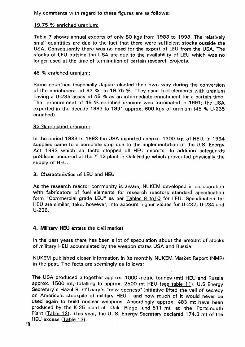
Table 7 shows annual exports of only 80 kgs from 1983 to 1993. The relativelysmall quantities are due to the fact that there were sufficient stocks outside theUSA. Consequently there was no need for the export of LEU from the USA. Thestocks of LEU outside the USA are due to the availability of LEU which was nolonger used at the time of termination of certain research projects.
45 enriched uranium:
Some countries (especially Japan) elected their own way during the conversionof the enrichment of 93 to 19.75 %. They used fuel elements with uraniumhaving a U-235 assay of 45 as an intermediate enrichment for a certain time.The procurement of 45 enriched uranium was terminated in 1991; the USAexported in the decade 1983 to 1991 approx. 600 kgs of uranium 45 U-235enriched).
93 enriched uranium:
In the period 1983 to 1993 the USA exported approx. 1300 kgs of HEU. In 1994supplies came to a complete stop due to the implementation of the U.S. EnergyAct 1992 which de facto stopped all HEU exports. In addition safeguardsproblems occurred at the Y- 2 plant in Oak Ridge which prevented physically thesupply of HEU.
3. Characteristics of LEU and HEU
As the research reactor community is aware, NUKEM developed in collaborationwith fabricators of fuel elements for research reactors standard specificationform "Commercial grade LEW as per Tables 8 to10 for LEU. Specification forHEU are similar, take, however, into account higher values for U-232, U-234 andU-236.
4. Military HEU enters the civil market
In the past years there has been a lot of speculation about the amount of stocksof military HEU accumulated by the weapon states USA and Russia.
NUKEM published closer information in its monthly NUKEM Market Report (NMR)in the past. The facts are seemingly as follows:
The USA produced altogether approx. 1000 metric tonnes (mt) HEU and Russiaapprox. 1 500 mt, totalling to approx. 2500 mt HEU (see table 1 1). U. S EnergySecretary's Hazel R. O'Leary's "new openess" initiative lifted the veil of secrecyon America's stockpile of military HEU - and how much of it would never beused again to build nuclear weapons. Accordingly approx. 483 rnt have beenproduced by the K-25 plant at Oak Ridge and 51 1 mt at the PortsmouthPlant (Table 12). This year, the U. S. Energy Secretary declared 174.3 mt of theHEU excess (Table 13).
10

This excess material plus additional declassified material is so far is in the orderof 259 mt, leaving the U.S. government with 735 mt. If one were to subtractHEU requirements for past government bomb testing, nuclear navy and research, the amount in the U. S, stockpile would drop to about 500 mt of highly qualitymaterial.
In 1993 a government-to-government agreement was concluded between the U.S. and Russian and calling for USD 12 billion worth of LEU from Russianweapons-grade HEU (500 mt) to be converted into 15.000 mt of LWR-fuel over aperiod of 20 years (Tables 14 and 15). The blended 44 U-235 enricheduranium has a content of 152.000 mt of natural uranium equivalent whichcorresponds to a factor of 44 of the world production of natural uranium(34.200 mt in 1995, Table 16).
The enormous quantity of natural uranium equivalent contained in thedownblended 500 mt of HEU of Russian origin will certainly influence the marketfor natural uranium in the following years.
5. What is the supply situation for LEU and HIEU today?
Table 17 shows the suppliers of LEU today.
US-DOE can at the moment not supply due to safeguards problems at the Y12plant. Resumption of production of LEU is anticipated in 1998.
QKAEA remains a supplier for LEU and performs processing and recoveryservices.
Russia, by several suppliers, remains supplier for LEU and performs processingand recovery services.
NUKEM disposes of large stocks of LEU.
China is not in the market.
Cogdma remains a supplier for LEU and performs processing and recoveryservices.
6. Outlook for safe supplies of LEU and HEU and conclusion
Due to available stocks and production possibilities the supply of LEU forresearch reactors is safe far beyond the year 2000.
Certain European Research Reactors, however, must furthermore use HEU inorder not to stop reactor operation. Since the USA de facto have stopped after1993 exports of HEU. Ways have to be found to ensure its availability in Europe;i. e. by using available stockpiles, even if the enrichment is less than 93 andpurchases from other sources.
It was a great pleasure to present this paper to you and I thank you for yourattention.

CH04AO006
URANIUM SUPPLYAND LICENSING PROGRESS AT CERCA
by G6rard HARBONNIER
ZI les B6rauds26104 ROMANS cedex - FRANCE
1- INTRODUCTION
Over the past years, uranium licensing for use in the facility has been increasinglydifficult under the pressure of tighter rules for radiation and contaminationmonitoring.
This contribution intends to summarize the status of licensing in our workshop.
2- AVAILABLE URANIUM SOURCES
2.1. Fresh Uranium
It is very difficult, or almost impossible to find sources of real resh Uranium withno Fission Products or Transuranics, especially if 93% material is needed.
2.2. Uranium from critical experiments
A large quantity of Uranium used at CERCA these past years has been issued fromcritical experiments, mainly from the KNK SNEAK experiments in KARLSRUHE.
12
This material comes generally in the form of nickel plated metal plates, or puremetal with various enrichments. The material has either to be diluted with depleteduranium to reach an enrichment of 19.75 or may be used "as it is' in the caseof higher isotopic composition (around 90
The very low irradiation levels achieved during the experiments, and hence thevery low burn-up, are very favourable in term of Fission products, and Transuranicproducts. Furthermore, when dealing with original enrichments of 30 or 90 %, thedilution factor adds a safety margin to the allowable limits.
2.3. Reprocessed and reenriched Uranium
Other sources of Uranium are from reprocessed and/or reenriched material.
In most cases the spent fuel in a MTR reactor has an enrichment in the range of50 to 65%. After reprocessing, three choices are possible for further use
4> The reprocessed Uranium may be used "as it is' for element fabrication withhigh TU content resulting from The life history of the Uranium, which mayexceed certain allowable limits. Some other problems may occur during thestorage of fresh fuel elements.
4> The reprocessed uranium may be reenriched. This possibility is not used now,because of the non availability of dedicated enrichment lines, which should beotherwise polluted by all by-products. Furthermore, this leads to high U-232content (as it is lighter, U2 is even more easily separated than U5). However,it should be noted that 93 Uranium coming from the US in the 80' and early
90' was probably reenriched from rather clean material, if we examinecarefully its isotopic composition.
The reprocessed Uranium may be diluted down to an enrichment of 19.75 .In that case the dilution factor has a benefic influence on the U-232, TU andFP content.
Due to the very high content of radioisotope, great care must be taken whenexamining the possibility to use Uranium coming from reprocessing to avoidlicensing problems.
13

3- LICENSING EXPERIENCE OF CERCA
The Safety Anlysis Report applicable to the MTR workshop was amended someyears ago to consider the possibility to use 19.75% Uranium coming from criticalexperiments.
4- FUTURE DEVELOPMENTS
Since the mid 80', and in the progress of the RERTR program, CERCA has usedthousands of kilograms of LEU. Some of this material was provided by US DOE,some came later from critical experiments as explained before. Some are nowcoming from Russian plants.
The trend is now to use the available material, CERCA decided to ask for a largeincrease in the limits presently authorised for U-232, Transuranic and Fissionproducts.
A new specification, so called "Uranium Commercial" has been issued andsubmitted to French Safety Authorities. This specification takes into considerationacceptable limits for CERCA's fabrication unit without any significant increase inprices.
At the time of the writing of this presentation, we are expecting a positive issueon this subject which will ease the acceptance of available Uranium batches inCERCA's workshop.
As soon as this specification will be accepted and put into force, it will be possiblefor CERCA to work with a new set of characteristics concerning the fissilematerials, wider than previously allowed. This specification shall become astandard for the short term future.
The new values will open the way to new safety working conditions, and at thesame time to softer acceptance criteria.
14

CH04AO007
RECOVERY OF URANIUM FROM MANUFACTURING SCRAPS ANDBLENDING OF RECYCLED MTR URANIUM
Dr Donald Skea, UKAEA, Dounreay, ThursoMr Philip Cartwright, UKAEA, Dounreay, Thurso
1 INTRODUCTION
1.1 To ensure the continued operation of some research reactors requires the careful use ofthe High Enriched Uranium (BEU) resource currently within the ivil nuclear cycle.For these reactors, either a suitable fuel cannot be made with Low Enriched Uranium(LEU) or conversion to LEU would lead to sufficient operational and financialpenalties to render the reactor economically unviable. To maximise the use of thecurrent civil stockpile of HEU, there is a need for a uranium recovery plant, able torecover uranium suitable for reuse in reactor fuel, from a wide variety of feedstocks.Such a plant has been operated at Dounreay for more than 30 years.
1.2 The uranium recovery plant D1203) was historically associated with the MTR fuelcycle in the United Kingdom, and to a lesser extent with MTR reactors in other parts ofthe world. The announcement of the closure of the Harwell MTR reactors in 1990 leftthe Dounreay recovery plants with a reduction in fuel scrap recovery, and consequentlyled to spare capacity. Some of this spare capacity has been filled with uraniumrecovery and supply work from overseas, the remainder has been programmed to beused for the recovery of the United Kingdom uranium stockpile.
1.3 The uranium recovery plant has successfully recovered and processed uranium for re-use in the MTR cycle from many different feedstocks;
• UF6• U/Al alloys• U/Al/Si alloys• U/Th oxide in graphite• impure uranium metal and uranium oxide• recycled MTR uranium• metal reduction slaas• other uranium alloys.
1.4 The uranium recovery plant is the focal point for the Dounreay uranium product. Notonly does it convert its own uranyl nitrate product, but it also handles the uraniumproducts from the mixed oxide reprocessing plant and the MTR fuel reprocessing plant.
2 THE DOUNREAY URANIUM RECOVERY PLANT D1203)
2.1 Modular construction has given this plant considerable versatility. The plant consists ofa number of separate, but interconnected, facilities which can be used in manycombinations. There are three main uranyl nitrate precipitation/uranium oxideproduction lines and two metal production lines, which enable work to proceed on
15

different enrichments simultaneously. A recent period of plant operation saw thefollowing simultaneous activities:
• recovery of 90% enriched uranium through dissolver/solvent extraction/billet line B.
• dry blending to 20% enriched uranium metal on billet line A (part).
• wet blending to 20% enriched U30s through blending dissolver/billet fine A (part)/oxidation furnace.
• receipt/evaporation of 0% enriched uranyl liquor ftom iadiated MM fuelreprocessing, followed by precipitation on billet line A (part).
• receipt/evaporation of depleted uranyl liquor &om the MOX reprocessing plant.
Technical description
Dissolution
2.2 The plant has twin stainless steel dissolvers which feed a single solvent extraction line.The dissolver conditions are varied markedly depending on the type of feedstock.Dissolver liquor can be clarified by the use of filters or centrifuge. The dissolvers willbe replaced during 1997 to provide a more flexible system for processing low uraniumcontent feedstocks.
Solvent extraction
2.3 The solvent extraction system utilises the successful 100 mm channel geometry mixersettlers (Figure 1) used in the other processing plants on the Dounreay site. Thesolvent extraction system, in the recovery plant can be used as either a single or a dualcycle system to separate one or two products from the feedstock. The flowsheets usedto achieve the necessary separations are all based on the TBP in odourless kerosene,but the concentrations of TBP and the inactive feeds used are varied, to suit thefeedstock.
Where there is the need for the addition of mercury to assist in the dissolution of analuminium rich feed, the raffinate is treated to remove the mercury.
The inactive feed system to the solvent extraction system permits the addition ofseveral different feeds to enhance product purity. An example of this is ferroussulpharnate, which enables the removal of trace level of plutonium.
16

Figure I
Pulsed air line Pulsed air lineSoNent inlet
Aqueousouft
Mixing dsamber
Sattlingdvarnber Solvent dannel
Solvent flow
Solventouft Solvent �r
Mixed O"e port a-4 baftwd baft
kqueous flow A Mixer-SeMer
Aqueous inlat
Evaporation
2.4 There are four evaporators in the uranium recovery plant, one of which is used solelyfor the processing of Fast Reactor depleted uranium, and another is used for thespec'fie task of evaporating high thorium containing liquor from the processin ofTHTR uranium. There is a titanium evaporator for the uranium product from thesolvent extraction system, and a lass evaporator for the uranium product from thereprocessing of irradiated MTR fel. The duties of these last two evaporators can beinterchanged throu-h their internal pipework connections. All of the evaporators areused for the concentration of the dilute products from the solvent extraction systems.
Precipitation/drying
2.5 The concentrated uanyl nitrate frorn the evaporator systems are fed to one of threeprecipitators. There, the uranium is precipitated, by the addition of ammonia toproduce Ammonium Diuranate (ADU). The ADU is filtered from the solution and thesupernate is sampled and analysed before being discharged to drain. The ADU is driedat ' )20 T in an oven Linder an air atmosphere, to produce U03. The depleted uraniumfrom the Fast Reactor reprocessing is dummed for storacre at this stage. MTR cycleuranium may be processed further to produce a high specification product on one ofthe two billet lines.
17

Reduction/fluorination
2.6 There are two reduction furnaces on each of the two uranium billet lines. First stagereduction uses hydrogen at high temperature. If cooling is allowed under hydrogen theend product i U02. The introduction of air at furnace temperatures after the reductionstage yields U30s. Second stage reduction utilises anhydrous hydrogen fluoride toproduce UF4, the intermediate product for the metal production process used. Whenthe required product is uranium oxide, whether U02, U03 or U308, with a specific
particle size distribution, equipment is available for the grading and analysis of the
particles to produce the required product.
Uranium metal reduction
2.7 There is a sinale metal reduction furnace on each of the billet lines. The UF4 is mixed
with calcium and packed in magnesium oxide crucibles. The mixture is then heated in a
vacuum furnace to produce a pure uranium metal product, suitable for use in MrR
fuel.
Uranium size reduction
2.8 To meet the requirements of MTR fuel fabricators it is necessary to produce metal in
pieces of uniform size and of a weight range normally between 150 and 300 grammes.
To achieve this, the billets from metal reduction are melted in an induction frnace and
poured into 20 mm diameter moulds. The resulting bars are cropped into short pieces
to meet the necessary size and weight requirements.
Blending
2.9 Blendin- of uranium is undertaken to produce the necessary enrichment. This has been
done successfully by three methods. The first is using a small stand-alone dissolver
designed specifically for blending purposes. Enriched and depleted uranium oxides are
dissolved in calculated proportions to give the required enrichment. Fine tuning of the
blending process is often accomplished by the subsequent addition of measured
volumes of depleted uranyl nitrate liquor. The second method used is the dry blending
of enriched and depleted 4 powder. There must be efficient mixing of the powder if
the process is to run smoothly. Fine enrichment adjustments are often made at the size
reduction stage, during vacuum melting/casting. Thirdly, uranium enrichment can be
adjusted by direct wet blending of liquor product from scrap recovery or irradiated
MTR reprocessing.
Wastes
2.10 As all of the material processed in the recovery plant has low plutonium content (less
than 10 ppm) and low fission product content (less than 37000 B/gm U), the waste
streams are all low active. Liquid waste is discharged to sea under the Dounreay site
18

liquid waste discharge authorisation and solid waste is compacted and disposed of onthe Dounreay site.
Plant capacities
2.11 Plant capacities are dependent on the different combinations of facilities being used.The following are indicative values:
• recovery (dissolution/solvent extraction/metal production) 250-1200 kg U per yeardepending on type of feedstock.
• blending to produce 19.75% enriched uranium, 900 kg U per year.
Interaction with other Dounreay plants and programmes
2.12 The following are the major interactions with other plants:
• MTR Element Fabrication Plant - the uranium recovery plant recovers scraps fromthe fabrication process.
• Irradiated MTR Fuel Reprocessing Plant - purified uranyl liquor is passed to theuranium recovery plant for precipitation, or blending then conversion to oxide andmetal product.
• MOX Reprocessing Plant - purified uranyl liquor is passed to the uranium recoveryplant for precipitation to oxide product. This route provides the option for therecovery of enriched uranium from HEU MOX. The uranium product is convertedto the necessary form for use in the MTR fuel cycle.
• the uranium recovery plant is also recovering material from early United Kingdomuranium fuel development programmes, from zero energy reactors, and fromspallation targets. This allows the recovery of product for sale and ensures that thewaste streams are consistent and do not require special consideration.
3 PRODUCTS
3.1 The uranium recovery plant at Dounreay has the following products:
• for - U metal, U02, U308, U03
• enrichment - up to 90%+
• ori-in - manufacturing scraps, uranium from irradiated MTR reprocessing,customers uranium/U oxide, uranium from MOX reprocessing.
19

the products are all produced to specifications which are agreed in advance with thecustomer. Typical values of the main analysis are;
impurities - less than 1500 ppmplutonium content - less than 250 Bq/gm Ufission products - less than 600 Bq/gm U.
3.2 The products are all checked for their compliance with the agreed specification bychemical analysis undertaken in the analytical laboratories at Dounreay. Theselaboratories are fumished with the equipment and analytical techniques to allowconfirmation of all of the specification values.
4 DISCUSSION
4.1 The uranium recovery plant at Dounreay has a number of standard products relevant tothe MTR fuel cycle. It is, however, in a unique position to recycle/blend reprocesseduranium due to its close link with other plants on site.
4.2 MTR fuel element manufacturers have specific requirements for uranium feedstocks,depending on their individual production facilities. There are, therefore, strict limits forimpurities, transuranic elements, fission product content and the uranium isotopes U232,
U234 and U236.
4.3 The uranium recovery plant at Dounreay can produce the uranium oxide and metalproducts from a large variety of feedstocks to allow continued fabrication of MIR fuelfor both LEU and EU fuels.
4.4 The uranium recovery plant at Dounreay can also provide essential support services tofuel manufacturers, permitting the recovery of fabrication scraps and with itsconnection to the mixed oxide and MTR fuel reprocessing plants, permits the recoveryof most irradiated and unirradiated fuels allowing a secure future for MTRs within thecurrent civil nuclear fuel cycle.
4.5 For national programmes to clear old fuel development wastes, the uranium recoveryplant at Dounreay offers the opportunity to recover the uranium for re-use and toproduce waste streams which are suitable for either discharge or disposal.
20

CH04AO008
HIGHLY ENRICHED URANIUMRECYCLE AND CONVERSION FACILITY
AT COGEMA PIERRELATTE
S. Bouchardy and .F.PautyCOGEMA, Uranium Division
78140 Velizy Villacoublay, France
ABSTRACT
Enriched uranium inventories (over % U 235) exist under various chemicalforms and enrichments. The reuse of these materials for Research Reactor Fuel,Experimental Reactors or as raw material for Research Laboratories requires achange in the chemical form and/or a change in the enrichment level and/or animprovement in the chemical purity. The COGEMA Pierrelatte facility (Recycleand Conversion Facility) is well suited to perform these tasks. Its experience in thisfield has been acquired over the last 30 years.
This paper presents the capabilities of this facility.
INTRODUCTION
The Plerrelatte gaseous diffusion plant which was commissioned about thirty yearsago to produce highly enriched uranium metal for the French Defense Departmenthas definitively stopped production in June 1996.
The adjacent facility (Recycle and Conversion Unit, named a URE)) in French)designed from the outset to convert enriched UF6 into metal and recyclefabrication scraps from the Defense Department is also active since over fifteenyears in the civil sector recycling metal from the fabrication scraps received fromMTR fuel fabrication plants, chemical conversion to the chemical forms of oxide -or metal - irrespective of the isotopic uranium content, for various ResearchLaboratories, Experimental Reactors or Fuel Fabricators.
This facility will stay in operation. The functions, the equipment and theinput/output products of this versatile facility will be described.
21

FUNCTIONS OF THE FACILITY
This versatile facility is able to convert uranium from one chemical form intoanother, to purify the material if required and to perform isotopic adjustment.
a) Conversion from one chemical form into another.
Basically, all the classical transformations are possible
• UF6 into UF4, UF4 into U metal, U metal into U308
• U oxides or U alloys or U metal into uranyl nitrate,
• Uranyl nitrate into U308 or into U02 (sinterable powder) or into R
b) Chemical purification of the material.
Under the uranyl nitrate form, uranium is purified using solvent extractiontreatment of the PUREX process. After one or two purification cycles therequired purity is obtained.
c) Isotopic adjustment
Isotopic adjustment is performed in liquid phase uranyl nitrate solution ormelted uranium metal. Clean natural or depleted uranium is used to obtain thedesired enrichment level.
Typically, material with enrichment levels higher than 20 are downgradedinto 19.75 material. But other isotopic levels can also be obtained.
THE EXISTING EQUIPMENT
Figure I presents a simplified flowsheet of this facility. It is structured along twomain process lines the Dry Process (gas and solids) and the Wet Process (uranylnitrate in aqueous solution).
a) Dry process
This process leads to the production of U metal from UF6. Highly enrichedUF6 is first reduced to UF4. By calcium reduction and remelting the metal iscast into kg ingots.
In an independent melting furnace, isotopic adjustment is performed undermolten metal fon-n. Each batch represents approximately 30 kg U cast intosmall ingots of 300 g U.
22

b) Wet process
The input products are first dissolved into uranyl nitrate, after possibleroasting. Other uranium bearing chemical forms may demand more complextreatment.
The obtained solution undergoes, if necessary, one or two solvent extractionpurification cycles in Mixer-Settlers using TBP.Isotopic adjustment can be performed on this purified solution.
The following steps of the process are
precipitation in the form of ADU and calcination in the form of U308
• reduction in the form of U02 (a sinterable product which can be used tofabricate fuel pellets).
• fluoridation into UF4 (the UF4 thus produced returns to the dry processfor metal production by calcium reduction).
c) Licens
The facility is licensed to process uranium on the entire isotopic content range,from depleted uranium up to 99 U 235. In terms of radioisotopicpolluants, the facility is authorlsed to process uranium with
Transuranic elements < 250 Bq/gUFission Products < 9250 Bq/gUU 232 < 5 ppb/U.
INPUT PRODUCTS
A great variety of products are processed in this facility. They originate fi-omdefabrication of unirradiated fuels or are scraps from fuel fabrication.
From fuel plates UAI, UAI, U3 Si2, U/Nickel
From fuel pellets: U02, U02/Steel
Reprocessed uranium as uranyl nitrate has also been processed.
Processing of special fuels is under development UZr, UC2
23

OUTPUT PRODUCTS
Most of the production is under the forrn of U metal, generally 19.75 enriched, for reuse by Fuel Fabricators.
Large quantities of U308 have also been produced. U308 is a convenientchemical form for transportation and this easy to dissolve chemical forrn isgenerally preferred for later use.
Sinterable U02, for pellets production is required by some reactors.
On request, U metal of any isotopic level can be obtained.
CONCLUSIONS
The Recycle and Conversion Facility of COGEMA Pierrelatte is a modular,versatile facility, well suited to recycle existing stockpiles or fuel fabrication scraps.Its long past experience of more than 30 years will be now fully made available tothe civil sector. Specific needs can be examined and if necessary development workundertaken by a Research and Development team working on the Site.
24

INPUT e al UF6 U alloys Special UN Clean UNPRODUCTS enriched U metal Products reproce sed natural or
U oxides depleted
Burning
U308 erDissolution
Red ion sso u on lu on impure
Pure UF4
ur caton
Of Scraps Solvent
calcium Extraction
Reduction Pure UN
Rough U metal
Vacuum
Remelting 7soitop CAdjustment
sotop
Adjustment
a c nat on
Melting Pure uF4 Reduction
Furnace Fluori ation
N 00,OUTPUT U metal r UF4 U02
PRODUCTS
11303EWY 3P3Et004C3093S VV30W IFOXWoCD"MSS
UN = Uranyl NitrateCA
FIg.1 COGEMA PIERRELATTE HEU RECYCLE AND CONVERSION FACILITY

CH04A00og
NOVOSIBIRSK CHEMICAL CONCENTRATESPLANT, INC. IS A MANUFACTURER OFNUCLEAR FUEL AND FISSILE MATERIALSFOR RESEARCH REACTORS
Vladimir L Afanasiev, Aexander B. AeksandrovAnatoly A. Yenin, Gennady G. SidorenkoNCQ Novosibirsk
Novosibirsk Chemical Concentrates Plant, Inc (iNCCP) was founded in 1948. During this period theplant worked te way frorn concentrates reprocessing and uranium and its compositionsproduction o compounds fabrication of fel assemblies (FAs) for power, researchreactors and other types of reactors. Te accumulated experience of handlingnuclear materials, fuel element (FE) design, developed technologies, suchtraditions as to place Customers interests over the own ones, to'Work providingquality assuarance and high engineering, level of items are realized in theproduction of FAs for research reactors.
In 1973 NCCP began to deliver FEs and Fas for majority of research reactors built accordingto the Russian projects both on te former USSR territory and beyond it (SeeAppendix, fig.1).
In contrast to the plate type FEs used in ost foreign research reactors, the FE design ofRussian origin was based on three-layer seamless tubular design where middlelayer is a fuel composition and outlying layers are claddings. it is possible tomeet any and all Customers requirements to the FA operational characteristicsby means of changing te profile and the tube wll thickness, the active layerand cladding thickness. Te technological basis of such design principlesrealization is considered to be te development of technologies of hot coextrusionand gas reduction wich were patented and implemented in Russia.
26

With the aim to improve FA technical level and quality, NCCP in cooperation with Institutesdeveloping FEs and FAs, such as Research and Developernent Institute of Power Enginee-ring (RDIPE), All-Russian Institute of Inorganic materials VNIINM), Kurchatov Institute(RINC K) are constantly improving the FE and FA design. In the course of our itemsmodification the FAs with EK-10, S-36 rod type fuel elements have developedin to FAs with tubular FEs with double-side heat-bearing agent cooling. These
are VVR-M2, IRT- 2M, MR FAs of second generation with ca. 150 g/dm3 uraniumconcentration in FA volume and ca 35 cm' /crn3 specific heat-pickup surface.Further te conversion was made to the third generation FAs with thin- walltubular FEs of the VVR-M 5, IRT-3M, IVV-10 and other types with up to 350 g/dm3 uranium concentration in the reactor core volume unit and up to 65 cm/CM3 specific heat-pickup srface.
Uranium-aluminiurn alloy that made it possible to increase te uranium concentration up
to 13 0C,/CM3 Was sed as a fuel component of the first generation FEs. Thefurther uranium concentration increase becarne possible thanks to the conversionto ceramic uranium-aluminiur fel core.
It was decided at e NCCP in cooperation wit te VNIINM. to use as the fuel corecomponent the uranium dioxide tat makes it possible to provide for practicallyTasteless technology. Such choice simplifies resolution of tecnological problemspertaining to te spent nclear fuel utilization.
In the 70 ies when startina Lo use the ceramic fuel core, te uranium concentration wasincreased up to 17 g/cm3. In the 0 ies the 25 g/CM3 concentration was mastered.
The improvement of FA technical level proceeds with the requirement of maintainin FAhigh quality level. The certified quality assuarance system being in effect at theplant conforms to te international ISO 9000-9004 standard and guarantees highquality of FAs produced at te NCCP. The available quality control program isbased on the multi-pararneter control of FEs and FAs quality at different productionstages. Torough technological control of FE state during the intermediateoperations is performed. FE routine control consists of the assessment of visualappearance, cladding material structural state, control of fuel layer length andits continuity, as well as fuel layer homogeneity, control of cladding thicknessand fuel, control of cladding-to-core adjoining quality. All these types of control
are performed sing non-destructive methods. In addition to non-destructivemethods the periodical ality control is carried out by means of destructivemethods.
The created control system demonstrated full correspondence of FEs to the specificationrequirements and provided teir operational capability. Since 1973 till the presenttirne our plant has produced more tan 25000 FAs with 56 modifications for 31reactors; and with pride we state the fact that te plant received no claims from the
Cuctomers for replacement of defective goods.NCCP production complex producing FAs for research reactors includes the following productions:
chernical-metalkirgical production, production of alluminium component parts,instrumentation production, central plant laboratory, engineering scientific-technicaldepartments.
27

• Chernical-mecallurgical production includes uranium hexafluoride processing,removing different impurities from uranium containing mixtures, production ofuranium monoxide-oxide, dioxide, teti-afluoride, uranium metal and its alloys. Typicalquality of uranium compounds produced at the plant is presented in the table. (SeeAppendix, fig. 2 It is possible to provide for individual terms of deliveryand characteristics of uranium compounds according to users requirements.
• Production of FAs for research reactors includes FEs fabrication (SeeAppendix, fig 3 and their assembling. At present NCCP, Inc. manufacturesthe following types of research reactor FAs. (See Appendix, fig.4).
• The production of aluminium component parts where the component parts for FEsand FAs are fabricated is available at the plant. It includes extrusion ofrequired profile billets conforming to component parts profile; -andsubsequently they are machined to size by means of metal-cuttingequipment. (See Appendix, fig 5).
• Too] making production meets demands in high-precision technological measuring instruments of all manufacturing divisions of the NCCP.
• Central Plant Laboratory is a testing centre certified by GOSSTANDART ofthe Russian Federation in te National System of Testing Laboratories GOSTR; it fulfills certification of all items of chemical-metallurgical production.
Engineering scientific-technical departments staffed with high-skilled specialistsprovide development and maintaining of a high level FAs design andtechnology and carry out research works in regard to putting into productionprospective achievements of science and engineering.
Nowadays, NCCP, Inc. in cooperation with VIIINM is developing and mastering production processof FEs based on ranium dioxide with fuel concentration of up to 4 g/CM3 in terms oftotal uranium, with up to 20% U,35 enrichment; it is fulfilled within the framework ofRussian Research Reactors Conversion Program. Fabricated pilot batches of FAs aredelivered for performing in-pile tests.
In addition to FAs for research reactors our plant produces FAs for power, pulse, industrial reactors,FEs and micro-FEs for gas-cooled reactors. On te basis of technologies developed at ourenterprise the targets for Mc,99 CW Ir,92 production, irradiation-alloyed siliconand dozens of other radionuclides are turned OUE. Moreover, our plant carriesout works on usaae of more uraniurn-consurning compositions on the basis ofuranium silicide and UZrNb, and produces different in-pile instrumentation withor without uranium.
The production process is equipped with up-to-date installations for chemical, thermal treatmentand machining of uanium materials with up to 91 U235 enrichment, which guaranteesnuclear safety and full biological protection of nuclear personnel.
NCCP, Inc. welcomes all domestic and foreign enterprises of nclear fuel cycle to mutuallybenefitial cooperation and is ready to satisfy the additional Customers
28 requirements to is produce.
CH04AO010
THE RERTR PROGRAMA. Travelli
Argonne National LaboratoryArgonne, Illinois, USA
INTRODUCTION
The Reduced Enrichment Research and Test Reactor (RERTR) Program wasestablished in 1978 at the Argonne National Laboratory (ANL) by the Department of Energy(DOE), which continues to fund the program and to manage it in coordination with theDepartment of State (DOS), the Arms Control and Disarmament Agency (ACDA), and theNuclear Regulatory Commission (NRC). The primary objective of the program is to developthe technology needed to use Low-Enrichment Uranium (LEU) instead of High-EnrichmentUranium (HEU) in research and test reactors, and to do so without significant penalties inexperiment performance, economic, or safety aspects of the reactors. Research and testreactors utilize nearly all the HEU that is used in civil nuclear programs, either in their fuel orin irradiation targets for the production of medical radioisotopes. Eliminating the continuingneed of research and test reactors for HEU supplies and usage would remove a seriousnuclear proliferation concern, and has been for many years an integral part of U.S.nonproliferation policy. This paper reviews the main accomplishments of the programthrough the years, emphasizing last year's progress and the next planned activities.
DISCUSSION
I Fuel Developmen
An important goal of the RERTR program is to develop new LEU fuels with muchhigher uranium density than those used in the past with HEU. In the course of this work, thequalified uranium densities of the three main fuels which were in operation with HEU inresearch reactors when the program began (UAl -Al with up to 17 g U/cm3; U308-Al withup to 13 g U/cm3; and UZrHx with 0.5 g U/ 0) have been increased significantly. Thenew qualified uranium densities extend up to 23 g U/cm3 for UAIx-Al 32 g U/cm3 forU308-Al, and 37 g U/cm3 for UZrHx. Each fuel has been tested extensively up to thesedensities and, in some cases, beyond them. All the data needed to qualify these fuel typeswith LEU and with the higher uranium densities have been collected.
New important fuel types have also been developed. For U3Si2-A1, which is the mostimportant fuel so far developed by $1 program, the U.S. Nuclear Regulatory Commission(NRC) has issued a formal approval of its use in research and test reactors with uraniumdensities up to 48 g/cm3. A whole-core demonstration using this fuel was successfullycompleted in the ORR using a mixed-core approach. Plates with uranium densities of up to6.0 g/cm3 have been fabricated by CERCA with a proprietary process, are being tested inSILOE, and will soon be tested in OSIRIS. For another new fuel, U3Si-Al, miniplates withup to 61 g U/CM3 have been fabricated by ANL and the CNEA and irradiated to 84-96 inthe Oak Ridge Research Reactor (ORR). PIE of these miniplates have given good results, buthave shown that burnup limits would need to be imposed for the higher densities. Four full-
29

size plates fabricated by CERCA with up to 60 g U/cm3 have been successfully iadiated to53-54% burnup in SILOE, and a full-size U3Si-Al 6.0 g U/cm3) element, also fabricated byCERCA, has been successfully irradiated in SILOE to 55% burnup. However, conclusiveevidence indicating that U3 Si becomes amorphous under irradiation has convinced theRERTR Program that this material could not be used safely in plates beyond the limitsestablished by the SILOE irradiations.
RERTR activities related to the development of fael plates with much higher effectiveuranium loadings were interrupted in 1989 by DOE guidance to concentrate on theimplementation of the fuels which had already been developed by that time. This guidance,however, was reversed during the past year. Near the end of March 1996, after a pause ofover six years during which no fuel development could be pursued by the RERTR program,the U.S. Department of Energy provided both the funding and the guidance needed by theprogram to resume the development of advanced LEU fuels to improve the options andperformance of research reactors undergoing conversions. The DOE action, which provided$1.4 million for fiscal year 1996, was supplemented by a 1.5 million contribution from theUS Department of State. DOE plans to support this effort with 3.0 million in fiscal year1997 and has committed itself, in written testimony to Congress, to continue to support thefuel development effort for several years until its objectives are met.
As a result of these events, the RERTR program is now deeply involved, for the firsttime in many years, in fuel development activities. The first and foremost task is toreestablish a cadre of skilled fuel developers building on the expertise of the previous fueldevelopment effort. Two groups with complementary strengths have been formed for thispurpose, one at the Argonne-East site in Illinois and the other at Argonne-West in Idaho.Orders have been placed to procure new equipment, several uranium-bearing materials havebeen evaluated for their potential application in high-density fuels, and a preliminary plan hasbeen developed for the initial phase of the fuel development effort. Initial efforts will beconcentrated on the production of microplates containing dispersion fuels formed with U-Moand U-Zr-Nb alloys, in addition to other uranium compounds, in combination with variousmatrix materials. Irradiation of the first microplates is planned to begin in the Advanced TestReactor (ATR), in Idaho, during April 1997.
2. Reactor Analysis
The RERTR program has upgraded, modified, and developed many methods andcomputer codes to assess the performance and safety aspects of research reactors using theLEU fuels developed by the program. These methods and codes address many aspects ofresearch reactor operation, including neutronics, fuel cycle, thermal-hydraulics, transientanalysis, and radiological consequences. Many generic and specific analyses havedemonstrated the validity of these methods. The results were published in three IAEAGuidebooks (TECDOC-233 for light-water research reactors, TECDOC-324 for heavy-waterreactors, and TECDOC-643 for safety and licensing). The program's computational anddesign capabilities have created a standard which is internationally recognized.
Extensive studies have been conducted, with favorable results, on the performance,safety, and economic characteristics of LEU conversions. These studies include many jointstudy programs, which have been in progress for about 29 reactors from 18 differentcountries. A study to assess the feasibility of using LEU in the fuel of a modified version of
30

the FRM-II reactor, which is being designed with HEU at the Technical University ofMunich, has identified an alternative LEU design which could provide the same experimentperformance and the same fael lifetime as the HEU core currently planned for the FRM-lI.
The RERTR program has also provided coordination of the safety calculations andevaluations for the US university reactors planning to convert to LEU as required by the 1986NRC rule. In addition, during the past year the RERTR program was tasked by theDepartment of Energy to assess the feasibility of converting to LEU each of the DOEfacilities which currently use HEU.
3. '99Mo Production from LEU.
The RERTR program is pursuing an analytical/experimental program to determir4§ thefeasibility of using LEU instead of HEU in fission targets dedicated to the production of Mofor medical applications. 99 Mo is by far the most important medical radioisotope which iscurrently produced in research reactors through the use of HEU targets. The goal of theprogram is to develop and demonstrate during the next few years one or more viabletechnologies compatible with the processes currently in use with HEU at various productionsites throughout the world. This activity is conducted in cooperation with several otherlaboratories including the University of Illinois and the Indonesian National Atomic EnergyAgency (BATAN). Procedures have been developed for dissolution and processing of bothLEU silicide targets and LEU metal foil targets. These procedures are ready fordemonstrations on full-size targets with prototypic burnups.
Significant progress was achieved in this area during the past year. For the first time,LEU metal-foil target prototypes were irradiated and, after irradiation, were easily extractedfrom other target materials for separate dissolution and processing. This constituted a veryimportant milestone in the development of a viable process based on the use of LEU metal-foil targets.
4. Russian RERTR Program
The scope and main technical activities of a plan for the equivalent of a Russian RERTRprogram have been agreed upon by the RERTR Program and several major Russian institutesled by the Research and Development Institute for Power Engineering (RDIPE). The objectiveof this program is to develop and demonstrate within the next five years the technical meansneeded to convert from HEU to LEU fuels approximately 26 research reactors designed andsupplied by institutes of the Russian Federation. The main Russian institutes taking part in thiscooperative undertaking, beside RDIPE, are the All-Russia Research and Development Instituteof Inorganic Material VNIINM), the Novosibirsk Chemical Concentrates Plant (NZChK), andthe Yekaterinburg Branch of RDIPE. Both Mrs. Hazel O'Leary, Secretary of the U.S.Department of Energy (DOE), and Mr. Viktor N. Michailov, Minister of Atomic Energy of theRussian Federation (MINATOM), have expressed strong support for this initiative which hasexpanded the scope of the RERTR program and enabled it to address the problems created byuse of HEU in civil nuclear programs nearly everywhere in the world.
31

5. Reactor Conversions.
Twelve research reactors outside the U.S., which used to require HEU supplies of USorigin when the program began, have been fully converted to the use of LEU fuels. Thesereactors include ASTRA (Austria), DR-3 Denmark), FRG I (Germany), MTR (Japan),NRCRR (Iran), NRU (Canada), OSIRIS (France), PARR (Pakistan), PRR-1 (Philippines),RA-3 (Argentina), R-2 (Sweden), and THOR (Taiwan).
Nine research reactors in the U.S. have also been fully converted to the use of LEUfuels. These reactors reactors include FNR (Michigan), RPI (New York), OSUR (Ohio),WPIR (Massachusetts), ISUR (Iowa), MCZPR (New York), UMR-R (Missouri), RINSC(Rhode Island), and LTVAR (Virginia).
Three foreign reactors, including IEA-R1 (Brazil), SSR (Romania), and TR-2(Turkey), have been partially converted, and two more, GRR I (Greece) and HOR(Netherlands), have fabricated LEU cores. Safety evaluations for four additional domesticreactors have been completed, and calculations for four more reactors are in progress.Approximately 60% of the work required to eliminate use of HEU in US-supplied researchreactors has been accomplished
6. Spent Fuel Disposition
The need to ensure that the fuel irradiated in research and test reactors can be properlydisposed of has always ranked high among RERTR program priorities. In 1983, earlyreprocessing studies at the Savannah River Laboratory concluded that the fuels thendeveloped by the RERTR program could be successfully reprocessed at the Savannah RiverPlant, and DOE had defined the terms and conditions under which those fuels would beaccepted for reprocessing. These results were rendered moot, however, by DOE's decision tophase out reprocessing at the Savannah River Plant and by the expiration of the Off-site FuelPolicy at the end of 1988.
Since then, the RERTR program has contributed to the best of its ability to theresolution of this crucial problem affecting many of the reactors with which it wascooperating. After overcoming significant legal obstacles, 153 urgent-relief elements fromseveral European countries were received at the Savannah River Site under the provisions ofan Environmental Assessment published in April 1994. A second urgent-relief shipment of99 spent fuel elements from Greece and Switzerland was received in November 995, stillunder the provisions of the Environmental Assessment. Publication of the FinalEnvironmental Impact Statementl2l for the return of spent research reactor fel occurred inFebruary 1996 and was followed, on May 13, 1996, by publication of the related Record ofDecision. E31 These documents, and the favorable conditions which they established for thereturn of spent research reactor fuel, paved the way for a great number of fuel sipmentswhich are expected to eliminate, over a thirteen-year period, the large inventories of spentfuel which currently fill the pools and storage facilities of many research reactors. Thisaction will resolve urgent operational problems of the reactor sites while, at the same time,eliminating a serious proliferation concern. The first shipments under the provisions of theRecord of Decision, containing 280 spent research reactor fuel elements coming from reactorsin Germany Switzerland, Sweden, Chile, and Colombia, were received at the Savannah RiverSite during September 1996.
32

PLANNED ACTIVITIES
1. Complete the orders for the new fuel fabrication equipment needed to developadvanced fuels, and set up the fuel fabrication laboratory at ANL-W.
2. Produce a first series of microplates, including samples of the main materials ofinterest for the advanced fuel development.
3. Conduct out-of-pile tests on some of the fuel materials, to assess their properties andlikely performance.
4. Begin irradiation testing of inicroplates in the ATR.
5. In collaboration with the Russian RERTR program, continue to implement thestudies, analyses, fuel development, and fuel tests needed to establish the technicaland economic feasibility of converting Russian-supplied research and test reactors tothe use of LEU fuels.
6. Continue calculations and evaluations about the'technical and economic feasibility ofutilizing reduced-enrichment fuels in reactors that require such assistance, and inreactors of special interest.
7. Continue development of one or more viable processes, based on LEU, for theproduction of fission 99 Mo in research reactors.
8. Complete testing, analysis, and documentation of the LEU fuels which have alreadybeen developed, support their implementation, and transfer their fabricationtechnology to countries and organizations which require such assistance.
SUMMARY AND CONCLUSION
The RERTR program has made, and continuesto make, excellent progress. Closecooperation with international organizations has been the cornerstone of the program since itsinception. This cooperation and the high quality of the technical contributions which manypartners have brought to the overall effort are to be credited for much of the progress whichthe program has achieved.
The past year, in particular, has marked a turning points for several important RERTRprogram activities, and has left the program well prepared to face the challenges ahead.
(a) In the area of U.S. acceptance of spent fuel from foreign research reactors, a secondshipment of 99 urgent-relief spent fuel elements was completed. The FinalEnvironmental Impact Statement was published in February 1996, and the Record ofDecision was published in May 1996. The first shipments under the Record of Decisionwere received at the Savannah River Site in September 1996.
(b) In the area of advanced fuel development, adequate ftinding and guidance werereceived by the RERTR program near the end of March 1996. Fuel developmentactivities are now in progress, including procurement of equipment, screening ofcandidate materials, and preparations for the production of a first series of microplates.The first irradiations are planned to begin in the Advanced Test Reactor, in Idaho, duringApril 1997.
33
(c) In the area of reactor analyses, the RERTR program has been tasked by the Departmentof Energy to assess the feasibility of converting to LEU fuel each of the DOE researchreactors which currently use HEU fuel. A preliminary assessment resulting from thisstudy has been prepared. The study of an alternative LEU core for the FRM-II designhas been extended to address, with excellent results, several controversial performanceand safety questions.
(d) The Russian RRTR program, which aims to develop and demonstrate within the nextfive years the technical means needed to convert Russian-supplied research reactors toLEU fuels, has made significant progress.
(e) Significant progress was made on several aspects of 99Mo production ftorn fissiontargets utilizing LEU instead of HEU. In particular, LEU metal-foil target prototypeswere irradiated and, after irradiation, were easily extracted from other target materials forseparate dissolution and processing. This was an important milestone in thedevelopment of a viable process based on the use of LEU metal-foil targets.
The most important events affecting the program's future are unquestionably thoserelated to the return of the spent fel and to the advanced fuel development.
The Record of Decision, and the successful completion of the first related shipments,brings to an end a long period of concern for many research reactors. However, it must benoted that the U.S. spent fuel acceptance policy is valid only for ten more years of operation.Reactor operators would be wise to plan now for the final disposition of their spent fuel whenthe ten years have elapsed.
Resumption of advanced fuel development means that new fuels can be developed toenable conversion of the reactors which cannot be converted today, to ensure better efficiencyand performance for all research reactors, and to allow the design of more powerful newadvanced LEU reactors. Because of the provision of the Atomic Energy Act, as amended in1992, it also satisfies one of the conditions that would enable the U.S. to export HEU for theoperation of those reactors which need it.
We are beginning our new tasks in earnest. Old agreements are been renewed, andnew ones are being forged. Especially in the fuel development area, our success will depend,as in the past, on cooperation and free exchange of ideas and information. Once more, I askfor the international friendship and cooperation that have been a trademark of the RERTRprogram since its inception, so that we can attain together President Clinton's goal tominimize and eventually eliminate the use of highly-enriched uranium in civil nuclearprograms.
REFERENCESI US Nuclear Regulatory Commission: "Safety Evaluation Report Related to the Evaluation
of Low-Enriched Uranium Silicide-Aluminum Dispersion Fuel for Use in Non-PowerReactors," US. Nuclear Regulatory Commission Report NUREG-1 313 (July 1988).
2. US. Department of Energy, Assistant Secretary for Environmental Management, "FinalEnvironmental Impact Statement on a Proposed Nuclear Weapons Nonproliferation PolicyConcerning Foreign Research Reactor Spent Nuclear Fuel," DOE/EIS-0218F, Feb. 1996.
3. US. Department of Energy, Assistant Secretary for Environmental Management, "Recordof Decision on a Nuclear Weapons Nonproliferation Policy Concerning Foreign ResearchReactor Spent Nuclear Fuel," May 13,1996.
34

Session 2:
Fuel Fabrication


CH04AO01 I
DIFFERENT TYPES OF RESEARCHREACTOR PLATE FUEL AND THEIR
POSSIBLE OPTIMISATION
by Jean-Pierre DURAND
ZI les B6rauds26104 ROMANS cedex - FRANCE
- INTRODUCTION
For new reactors, and of course for existing reactors which need to be upgraded,there is an important variety of design choices to be done on the fuel point ofview.Parameters such as power density, neutron flux distribution, irradiation cycle,reactivity of the fuel during irradiation, can be optimised.
The aim of this paper is to provide an inventory of fuel manufacturing technicalpossibilities. This inventory cannot be exhaustive but, at least, gives a guidelinefor conception or optimisation of fuels.
2- DIFFERENT TYPES OF FUEL COMPOUND
Nowadays, mainly two metallurgical compounds are used as uranium fuel, namelyUAIx (UA13 + UA14) or U3Si2. Those fuels can be used with enrichment such as19,75 %, 90 and 93 U-235. In the case of uranium coming fromreprocessing, an intermediate enrichment can be considered leading to an increasein the manufacture cost because of the non standard enrichment which request aspecific management from Uranium account point of view UAIx fuel compound can be used to obtain uranium densities up to 22 g UT/CM3
rather than U3Si2 allows to reach 6 g UT/CM'.
35

Uranium amount within a plate is adjusted by means of volume fraction of fuelcompound in the given meat volume, leading to a corresponding Uranium density.For a same density, U3Si2 fuel plates will contain less volume of fuel compoundand less porosity as compared to UAIx fuel. Consequently, U3Si2 fuel plates areexpected to have a better thermal conductivity for a same Uranium content as
compared to UAIx plate.
3- DIFFERENT TYPES OF FUEL MEAT
The meat of the plate is in fact a dispersion of Uranium compound (UAIx or ML)
within an Aluminium matrix. The meat itself is cladded with Aluminium alloys.
CERCA has a large background of the use of A5, AG3 NE or AFeNi cladding
alloys. But, for special cases new claddings can be developed or tested.
For the optimisation of the fuel performances, several configurations can be
considered concerning the meat.
Increase in Uranium content
If the aim is to increase the uranium content per plate without changing the
external dimensions, three technical ways can be used. First, increase in the
volume fraction of fuel particles leading to an increase in Uranium density (a
maximum of 6 g UT/Cm3 with LI3Si2 fuel compound can be reached). Second
solution, increase in the volume of the meat leading to a reduction of the average
cladding thickness. Third solution, the use Of U3Si2 instead of UAIx (because it
contains more Uranium, 92 wt % instead of 71 wt
Uranium distribution
If the aim is to adjust the U-235 distribution in the plate, as a function of flux
performances, mainly two solutions can also be considered. First, the meat iscomposed of several areas which have their own Uranium density (g UT/CM3) In
this case, the fuel meat thickness remains constant. This is the case of the FRM-11
fuel reactor design. Second solution the Uranium density (g UT/Cm') remains
constant but U-235 distribution is adjusted by means of meat thickness which is
varying. This was the case of the ANS fuel reactor design.
36

4- DIFFERENT TYPE OF FUEL ASSEMBLIES
For optimisation purposes, it can be considered to change the ratio H/U. This isdirectly connected to the plate (and meat) thickness and the water gap.
From the plate thickness point of view, there are almost no practical upper limits.For the time being, the minimum plate thickness is about 127 mm with a meatthickness of 0,51 mm but there are no technical reasons to not reduce slightlyfurthermore those values which are considered as a standard.
Concerning the water gap, which is a cooling and moderator parameter, there areno practical upper limits whatever fuel design is chosen (square, cylindrical,involute fuel shape).However, the minimum water gap is related to the assembly technology and thefuel shape. From our background, for square fuel shape, below 2 mm, specialtools must be developed and tests must be carried out.For cylindrical fuel shape, a minimum water gap of 3 mm is considered to be areasonable limit. In other respects, a diameter of about 30 mm for the inner fuelplate corresponds to a practical limit from the plate and fuel manufacture point ofview. Below those values, manufacture test must be carried out.For involute fuel shape, a minimum water gap of 1.8 mm is expected to be areasonable limit.
5- DIFFERENT NEUTRON POISONS
In order to adjust the reactivity of fuel assemblies all along irradiation or todecrease locally the fuel reactivity, it is possible to load fuels with neutronabsorber or poison in different locations of the fuel such as
1- Cadmium wires in the side plates all along the fuel plate.
2- Boron or Samariurn at the end of the fuel meat, or within the fuel meat itself,or in the side plates.
It must be pointed out that the amount of Boron or Samariurn can be adjusted asneeded. Nevertheless, in the case of neutron absorbers located within the fuelmeat, this solution leads to an extra cost of reprocessing due to an additionalpurification step needed to get back Uranium available for fuel manufacture.If Boron is chosen as neutron poison, it can be Boron natural or enriched withBoron 1 0.
37

6- INSTRUMENTATION
Most of the time, the design of an improved fuel is followed by irradiation tests ofprototypes.In order to compare calculations forecasts and real behaviour, fuel prototypes canbe equipped with measurement devices such as pito tubes for pressuremeasurements or with thermocouples for temperature measurements.
More particularly, CERCA has developed an original manufacture procedureallowing to locate thermocouple within the plate cladding itself. With thattechnique, no thermocouples can be seen from the outside of the fuel plate.Consequently, no flow perturbation is introduced.
7- CONCLUSION
This paper gives technological ways available to improve fuel with theirmanufacture limits. Nevertheless, each case is a particular case, therefore theglobal limits given as a guideline must be analysed regarding the tolerancesrequested by the fuel designer.
A partnership study is strongly recommended with the fuel manufacturer in orderto reach the most suitable solution on the cost and technical point of view.In this case, CERCA offers it's 30 years background in the fuel manufacture with avery large variety of fuel (more than 60 types of IVITR fuel plate assemblies).
In some cases, if it is needed to go beyond the global given limits, R&D team ofCERCA is able to assume specific programs in connection with his customers.
38

CH04AO012
THE MANUFACTURE OF MTR FUEL ELEMENTS AND Mo99PRODUCTION TARGETS AT DOUNREAY
Mr John Gibson, UKAEA, Dounreay, Thurso
INTRODUCTION
Uranium/alurninium alloy elements have been produced at Dounreay for nearly 40 years. InApril 1990 the two 131130-type reactors operated by the United Kingdom Atomic EnergyAuthority (UKAEA) at Harwell were closed, with the result that a large portion of the thencurrent customer base disappeared and, to satisfy the needs of the evolving market, thedecision was taken to invest over Y I m in new equipment for the manufacture of dispersed fuelsand molybdenum production targets.
BACKGROUND
Until 1990, the fuel elements produced by the UKAEA were of the following types:
I Tubular-type alloy elements for reactors in the United Kingdom, Germany and Australia:
with extruded fuel tubes (approximately 4000 elements produced)with the plates electron beam welded to form fuel tubes (approximately 5000elements produced)with the plates roll swaged into continuous combs to form a tube-like structure 50elements produced).
2. Plate-type alloy elements for reactors in the United Kingdom, South Affica and SouthAmerica:
0 with flat plates assembled into a box section (approximately 200 elements produced)0 with either flat or curved plates roll swaged into slotted side plates to form a box-
like structure (approximately 800 elements produced).
Combined with the decision to invest in the dispersed fuel line, there was a commitment todevelop new techniques and products such as:
1. dispersed High Enriched Uranium (HEU) (uranium aluminide) elements2. dispersed Low Enriched Uranium (LEU) (uranium silicide) elements3. dispersed HEU targets for Mo99 production (uranium aluminide).
The production of dispersed fuel was a new product for the UKAEA and required theinvestment of considerable time and technical expertise for the development of newmanufacturing techniques. This led to the successful completion of a number of projectsincluding:
1. 6 HEU qualification elements (produced from re-cycled HEU) for the BR2 reactorin Mol in Belgium. These elements have successfully undergone the necessaryirradiation to qualify the product.
39

2. 6 HEU qualification elements for irradiation in the High Flux Reactor (BFR inPetten in Holland.
3. 2 EU qualification control elements for irradiation in the BIR in Petten.4. 2 LEU (silicide) qualification elements for irradiation and Post Irradiation
Examination in the HFR in Petten. These elements are currently being irradiated.5. 1700 Mo99 production targets (flat plates) produced for ECN, Petten.
UKAEA continue to fabricate fuel elements for customers based on the alloy production routeand intend to fabricate further elements using the dispersed fuel line.
The overall market for MTR fuel elements is reducing, however the LTKAEA has a goodpotential baseload for the manufacturing plant for many years and intends to maintain amanufacturing capability to continue to satisfy the needs of the NITR community.
CURRENT PRODUCT DETAILS
The production of dispersed-type and alloy-type fuel plates and targets
The production of both types of fuel consists of the following processes:
Dispersed Fuel Alloy Fuel
Uranium metal casting and size reduction Uranium metal casting and size reductionUAI,,/U3Si2 button production U/Al alloy billet castingUAl./U3Si2 powder production Fuel core blankingPowder sieving, weighing and blending Fuel pack assembly
Z D
Powder compaction Fuel pack rollingFuel pack assembly Fuel plate blankingFuel pack rolling Fuel plate inspectionFuel plate blankingFuel plate inspection
All fuel element and molybdenum tar-et production in the plant begins with the primary castingof uranium billets (typically three billets weighing 25 kg each) into rods 20 mm diameter. Thebillets are loaded into a graphite crucible and induction heated under vacuum, the heating ratebeing closely controlled to allow the evolution of gas from the billets. When gas evolution iscomplete, after two to three hours, the furnace temperature is raised until the uranium hasmelted. The melt is then bottom-poured into a graphite mould. When the mould has cooled,the uranium product, in the form of 20 mm diameter rods, is cropped into short lengthssuitable for further processing.
ALLOY-TYPE FUEL PLATE PRODUCTION
The correct proportions of aluminium and uranium, of the required enrichment, are firstweighed out and then cast into a uranium/aluminium billet using a similar method to that forprimary casting. Gas evolution is not a problem with alloy casting but it is important to obtaincomplete solution of the uranium in the aluminiurn to obtain an even distribution of uranium inthe alloy billet. This is achieved by superimposing a 0 Hz component on the high frequencyinduction coil. Eddy currents are induced in the molten metal and good stirring of the alloy is
40
achieved. The temperature is then raised to approximately 100 Celsius above the melting pointof the alloy and the charge is then bottom-poured into a rectangular graphite mould.
After cooling, the billet is removed from the mould, weighed and transferred to an air re-circulating oven where it is heated to 600 Celsius and rolled down to the required thickness ona rolling mill. Rectangular fuel core plates are then blanked out from the rolled strip.
Each fuel core plate is then checked for U235 content by gamma counting. The results of thegamma count are compared with those from an accurately calibrated standard core to give theprecise U23' content of each fiiel core plate to an accuracy of 0.01g. One fuel core plate in onehundred produced is dissolved and analysed to confirm the U" content.
Each fuel core plate is then assembled in a pure aluminium frame and between two purealuminium cladding plates. Prior to assembly, the surfaces of the cladding plates, frame andfuel core plate are scratch brushed and degreased to remove the oxide layer, which forms onthe surfaces of aluminium, to ensure that a good metallurgical bond is obtained at thecomponent interfaces during fuel plate rolling. The assembly is then machine argon arc weldedalong the longitudinal edges.
The welded fuel packs are heated to 600 Celsius and rolled to the required thickness(approximately 1.5 mm) following a rolling schedule that produces a fuel plate containing afuel core of the required length, width and thickness (around 650 mm x 50 mm x 07 nun butdepends on customer requirements). Rolled fuel plates are placed in a Core Location Unitwhere the outline of the fuel core within the cladding is revealed on an x-ray fluoroscope andpositioned against an appropriate graticule. If the fuel core outline is in accordance with the
I Imanufacturing drawing, locating holes are punched in the surplus aluminium at the ends of thefuel plates. These holes match locating pins in tools on a blanking press where the plates areblanked to final size.
FUEL PLATE INSPECTION
All components undergo rigorous inspection at each stage of the manufacturing process.
After rolling, the fuel plate is subjected to a blister test by heating to 425 Celsius and soakingat this temperature for one hour. After cooling, the surfaces of the plate are visually examinedfor blisters. The purpose of this test is to check the bond between the fuel core and thealurninium cladding. Any area of dis-bond may contain air which, after heating of the plate, willexpand, leading to the formation of a blister on the surface. The integrity of the bond is alsochecked using ultrasonic inspection equipment. Each fuel plate can be checked against astandard which can be used to ensure that any defects or indications are within specified limits.
Each plate is also radiographed to allow the filel core dimensions to be checked against themanufacturing drawing and to check that uranium or alun-�inium segregation in the fuel core iswithin specification. The radiographs are also assessed for uranium homogeneity. Any suspectarea can be checked using a gamma counter to ensure that the uranium concentration is withinspecified limits. The amma counter is also used to ensure that the distribution of uranium atspecified positions in the fuel plate is within specified limits.
41
After chemical cleaning, the fuel plates are checked for alpha contamination before theyundergo final inspection. This involves a dimensional check and an examination of the platesurfaces for defects such as inclusions, scratches or indentations.
Samples are taken from 1% of fuel plates produced for a destructive examination of the coreand cladding thickness. The samples are punched from the fuel plates, mounted in a resin blockand then polished and etched to allow examination using a microscope to ensure that thecladding thickness is within specified limits.
DISPERSED-TYPE FUEL PLATES AND Mo99 PRODUCTION TARGETS
Targets for molybdenum production are similar to the fuel plates for fuel elements but aremuch smaller measuring 150 mm x 40 mm x 1.5 mm. Each target plate has a AI,, fuel corecontainin- about 5.2g of HEU. Targets follow the same manufacturing route as dispersed-typefuel plates.
Production of dispersed-type fuel plates and targets begins with the arc-melting of uranium andalum�inium to form UAI,,, for BEU aluminide fuel, and uranium and silicon to form USi2, forLEU silicide fiiel, in the form of buttons.
The buttons are then ground into powder which, after impurity analysis, is sieved to obtain therequired range of particle sizes. After sieving, sufficient material to give the required uraniumcontent in one fiiel plate is weighed out. Sufficient aluminium powder to make up the volumeof the fuel core of one fuel plate is then blended with the fuel powder in a small aluminiumcontainer. A operations within the powder processing lines are carried out in an argonatmosphere which is continuously monitored to maintain the oxygen content at ess than 1%.
Several of these containers are transferred to a hydraulic compaction press where, again underargon, the powder is carefully poured into precision machined dies and the press activated tofollow an automatic sequence to produce fuel compacts of the required dimensions.
To reduce the incidence of blisters on fuel plates after the blister test, it is necessary to vacuumdegas the compacts prior to fuel pack assembly. Each compact is then placed inside analuminiurn frame which is then assembled between two aluminiurn cladding plates and weldedto form a fuel pack.
The type of cladding material used for dispersed-type fuel plate manufacture requires therolling temperature to be lower than that for alloy fuel. The fuel packs are heated to 425Celsius and rolled to the required thickness, as with alloy fuel plate manufacture.
After core location and blanking to size, the fuel plates undergo similar inspection operationsto alloy-type plates.
CLADDING MATERIALS
For alloy fuel, type 1050A aluminium 99.5% purity) is used. With dispersed fuel, there can bea tendency for fuel particles to penetrate the cladding. As a result, stronger cladding material isrequired and type 5251 aluminium alloy is used 17 to 24 magnesium). For Mo99
42

production targets, although a dispersed fuel, 1050A aluminium is used for the cladding. Thisis necessary to maintain the purity of the product after the molybdenum extraction process.
The rollin- characteristics are different for different cladding materials. The bonding of the fuelplate components is more difficult with the aluminium alloys required for dispersed fuel due tothe formation of magnesium oxide on the surfaces of the components at elevated temperatureswhich interferes with the bonding process. Different rolling parameters are required, ie. pre-heat and re-heat temperatures, soak times, number of passes through the rolls, and percentagereduction in roll gap between each pass and much time has been spent in determining theprocess variables.
The type of cladding material used also affects the shape of the fuel core within the aluminiumcladding. The rolling process has the effect of localised thickening of the fuel core at thetrailing end of the rolled fuel plate (a phenomenon known as dog-boning), which can result in areduction of the thickness of the aluminium cladding. Cladding component design and platerolling procedures must ensure that the effect of dog-boning is accounted for and the fuel platecladding thickness is within specification
ELEMENT TYPES
The fiiel elements produced are, in general, either of the concentric tubular or plate-typedesign.
• Concentric Tube Fuel Element
Electron Beam Welded (see Fig 1)
Three of the roll-bonded fuel plates are formed into 1200 curves and then electron beamwelded along the longitudinal edges to produce a circular fuel tube. Four tubes, of differentdiameters, are assembled concentrically using support combs to maintain coolant channelgaps between the tubes. This assembly is then enclosed in an aluminiurn outer tube and topand bottom end fittings to form a complete fuel element. The outer aluminium tube can bealloyed with a small quantity of boron (typically 0.4g).
Roll-swaged (see Fig 2)
Three curved fuel plates are assembled into three continuous slotted combs and grooves arecut along the length of the combs thus securing the fuel plates in position. The depth of thegrooves is controlled to achieve the required swaging strength.
Plate-type Fuel Elements (see Fig 3)
The individual fuel plates (either flat or curved depending on customer requirements) areassembled into slotted side plates and then secured by roll-swaging. Typically up to 21 fuelplates are secured in this fashion to form a rectangular-section fuel box. End fittings arefixed to the box, by welding or riveting, to complete the fuel element assembly.
43

QUALITY ASSURANCE
To give our customers value we aim to achieve the highest quality and best performance andmust out-perform our competitors whilst reducing costs. The MTR Fuel Fabrication Plantcontinues with the philosophy of providing accurate documentation to assure customers ofquality products and compliance with areed manufacturing methods and parameters.
As a result of these efforts, in July 1994 the Quality Management System of the MTR FuelFabrication Plant was approved by Lloyd's Register Quality Assurance Limited to ISO9002:1994,
Customer audits indicate that we are achieving good results and continue to meet programmeddelivery dates.
CONCLUSION
MTR fuel elements have been fabricated at Dounreay for nearly 40 years for customers on fivecontinents. To date approximately 10,000 fuel elements have been manufactured, comprising atotal of around 150,000 fuel plates.
The UKAEA has invested over Elm in new plant and equipment in support of dispersed fuelproduction and have developed the necessary manufacturing techniques to enable quality fuelof this type to be fabricated on a production basis. High levels of investment in recent yearshave been geared to reducing costs and developing new business as well as improving safetyand quality.
The UKAEA will continue to work alongside customers and suppliers, offering technicalsupport and endeavouring to respond appropriately to customer feedback, establishing andmaintaining working relationships that ensure that such feedback is absorbed into our planningand quality management strategies. This is achieved by ensuring that our organisationalstructure enables us to be accessible, agile and responsive to customer needs and that key staffare available.
For the immediate future, three main priorities will shape our efforts - safety, quality and cost.The long term future of the MTR Fuel Fabrication Plant at Dounreay rests firmly in the beliefthat we have the vision, the people, the capabilities and the commitment to satisfy ourcustomers needs well into the next century.
44

0
AO
000(
oG)o(
000(
000(
01?0(
0
v
F19 2 Roll Staged f.b.1a, type e! efe�e-f
t
Fig. 1Electron beam welded tubular type fuel element
C-d pL.,e
Am pwt.
I0 to ID
F19 3 Roll aged bo, �Ipe Net el�-m
45

CH04AO013
DEVELOPMENT OF VERY-HIGH-DENSITYLOW-ENRICHED-URANIUM FUELS
J. L. Snelgrove, G. L. Hofman, C. L. Trybus, T. C. Wiencek
Aroonne National LaboratoryArgonne, Illinois U.S.A.
INTRODUCTION
Fuel development has been a cornerstone of the U.S. Reduced Enrichment for Research and TestReactors (RERTR) program since its inception in 1978. This development work, performedcooperatively with many partners internationally, resulted by 1987 in the qualification of severaldispersion fuels having significantly increased densities: UAI,,-Al at 23 g U/crn', U308-Al at3.2 U/CM3, and U3Si2-Al at 48 g U/cm3. Approximately 20 reactors have been converted fromhi-h-enriched uranium (HEU) to low-enriched uranium (LEU), and several new LEU reactors havebeen built usin- these fuels. In most cases the uranium silicide fuel has been used.
Although a fuel with a uranium density of 48 U/CM3 i sufficient to convert approximately90% of the research reactors outside te U.S. which used HEU of U.S. origin in 1978, conversion ofthe remaining reactors, which use a significant quantity of HEU, require fuels having considerablyhigher densities. Therefore, the REKIR program continued to develop methods to fabricate platescontaining higher loadings of uranium silicide fuels until funding constraints forced an end to thiswork at the end of September 1989. CERCA, one of the RERTR program's key partners in thedevelopment of uranium silicide dispersion fuel, continued its development efforts and announced in1993 that it had developed an advanced fabrication process which allowed the loading Of U3Si2-A1
0- U/CM3 [1fuel to be increased to 60 �
Even though development of higher-density fuels was stopped, analysis of the irradiationexperiments performed earlier in the RERTR program continued, resulting in a better understandingof the fundamental behavior of these fuels. Also, work continued to better understand and refinedispersion fuel fabrication techniques. Papers reporting these results have been presented annually atthe RERTR international meetings. During this period of decreased fuel development activity withinthe RERTR program, development of uranium silicide dispersion fuel in the U.S. continued under theauspices of Oak Ridge National Laboratory's (ORNL's) Advanced Neutron Source (ANS) project,with Argonne National Laboratory (ANL) designated as the lead fuel development laboratory 2] Aseries of three irradiation experiments in the High Flux Isotope Reactor (HFIR) at ORNI, provideddata on fuel behavior at high temperatures and high fission rates, and revealed that there are limits tothe use Of U3Si2-Al under these conditions. Results from the most recent of these experimentsprompted a major new analysis Of U3Si2-Al fuel irradiation behavior 3]. Irradiation performancemodeling was also emphasized since fuels could not be tested at or beyond ANS conditions. Theadvances made during this interim period have helped provide a good basis for further developmentof dispersion fuels.
In 1994 the Department of Energy announced its intention to resume the development of very-high-density fuels to address needs of existing and new research and test reactors. However, owingto pressures of a shrinking federal budget, funding for this work could not be made available until lastMarch. This paper describes the plans and schedule of this new development work.
GOAL AND APPROACHto U/CM3We have set a goal of achieving a uranium density in a dispersion fuel meat of
We think that such a density is achievable from the fabrication point of view, and it matches the
46

RERTR program's assessments of uranium densities needed to convert the reactors not convertibleusing 48 U/cm 3 U3Si2 fuel. Of course, irradiation behavior and fabrication costs will ultimatelydetermine the success of any proposed fuel.
We think that the best chance of successfully developing a fuel with acceptable fabrication costlies with extension of the current aluminum-based dispersion fuel concept. Since CERCA'sexperience with highly loaded U3Si2-Al [1] and UN-Al 41 fuels indicates that one is not likely to
achieve a fuel volume loading greater than 55% in a commercially viable process, fuel dispersants
with very-high uranium densities, 15 g U/CM3, must be used. With the exception of U6Fe and U6Mn,
which were tested earlier in the RERTR program and shown to be subject to breakaway swelling at
relatively low bumups [5 6, and the similar compounds U6Co and U6Ni, which are also expected to
exhibit poor swelling behavior, no uranium compound meets our density requirement.
Therefore, only pure uranium metal or alloys of uranium and small amounts of o&r metals can
be considered as fuel dispersants. Although pure uranium is a notoriously poor performer under
irradiation, a series of alloys wich maintain uranium in the metastable phase have shown good
irradiation performance in bulk form under fast reactor conditions. Examples of such alloys are listed
in Table .
Table 1. Densities of Representative y-Phase Uranium Alloys
Alloy* Density, g/cm3 U Density, g/cm�
U-9mo 17.0 15.5
U-5Mo 17.9 17.0
U-3Zr-9Nb i6.2 14.3
U-4Zr-2Nb 17.3 16.3
*Alloying element amount given in wt.%.
Our experience with the U3Si27A1 dispersion fuel taught us that the key issues which must be
addressed are the reaction of the fuel alloys with the matrix and the irradiation behavior of the fuel
alloys and of any reaction products. Should reaction of the fuel alloys with an aluminum matrix be
excessive, we will investigate the use of a magnesium matrix while retaining the aluminum cladding
since magnesium does not form compounds with uranium. We have also considered using zirconium
as both matrix and cladding material, but we do not currently plan to pursue this option owin toconcerns about fabrication cost.
PLANS AND SCHEDULE
Fabrication
During the early stages of the RERTR program, fabrication development was performed at
ANL's Illinois site (ANL-East), at Oak Ridge National Laboratory (ORNL), and at the Idaho
National Engineering Laboratory (INEL). However, by early 1996 only a very small developmentgroup at ANL-East remained. Therefore a major increase in our fabrication development capacity
was required to support an aggressive fuel development effort. In order to utilize best the resources
available within ANL, we decided to augment the fabrication development group at ANL-East and to
establish a new fabrication development laboratory and group at ANL's Idaho site (ANL-West). The
procurement process for most of the equipment needed at ANL-West is underway, and detailed
installation plans are being prepared. In addition, we have reached the currently required staffing
levels at both sites. At ANL-West we have already begun to produce fuel alloys and expect to begin
47

producing fuel powder, by mechanical means, and compacts for small test plates by the end ofNovember 1996. We anticipate that the development laboratory will be ready for full use before theend of CY 1997, when the installation of the longest-lead item, the rolling mill, will have beencompleted. In the meantime, we will carry out all rolling operations at ANL-East. In particular, thefirst rolling experiments have aready been performed and fuel plates for the initial irradiation tests(discussed below) are scheduled to be rolled during the first quarter of CY 1997.
We plan to follow the development pattern that worked so successfully for the uranium silicidefuel, that is, to limit our fabrication development to the study of basic issues and to the production ofsmall fuel plates for iadiation testing and to depend on the commercial fabricators to adapt andextend ourresults to the fabrication of full-sized fuel plates or tubes. We have held preliminarydiscussions with both Babcock and Wilcox (B&W) and CERCA. Both are interested in participatingtDbut will need to assess further the commercial potential of the proposed fuels before deciding theamounts of company resources which can be committed to the required development work.
ANL and the Korea Atomic Energy Research Institute (KAERI) are setting up a cooperationagreement under which the use of atomized fuels will be explored. KAERI recently completed astudy of fuel-matrix reaction rates in dispersions of U-Mo alloys in aluminum, with encouragingresults 7 KAERI has a-reed to provide a small quantity of U-Mo powder for fabricationdevelopment work at ANL.
Materials Properties Studies
In order to address the key issues stated above, a number of studies are planned on the phasestructure of the uranium alloys and diffusion of the matrix materials into the alloys. We expect tomake substantial progress in this work over the next year. ANL is also negotiating a cooperationa-reement with the A. A. Bochvar All-Russian Research and Development Institute of InorganicMaterials in Moscow, under which phase studies of interacting materials is one area of possiblecollaboration.
Irradiation Behavior Experiments
Little is known about the irradiation behavior of the proposed fuel alloys when they aredispersed in aluminum or about the behavior of the fuel itself at the hiah burnups typical of researchand test reactors. Our highest priority is to begin irradiation screening tests of the proposeddispersions. We are planning to perform these irradiations in the Advanced Test Reactor (ATR atINEL and to perforin the postirradiation examinations at ANL-West. All of the preparatory activitiesrequired for the irradiations are underway, including design of the experiment rig, safety analysis ofthe experiment, and coordination with the ATR experiment staff.
Because of space limitations in irradiation holes near the core, the fuel plates (which we arecalling microplates) must be much smaller than the miniplates irradiated previously by the RERTRprogram in the Oak Ridge Research Reactor (ORR). The current design calls for microplates withoutside dimensions 76 mm x 22 min x 13 mm, compared to the 114 mm x 51 m x 13 nundimensions of a typical ORR miniplate. The microplates will be produced using 9.5-mm-diametercylindrical compacts, resulting in an elliptical-shaped fuel zone with nominal dimensions of 57 mm x9.5 mm x 0.5 mm and an area of 500 MM2, whereas the rectangular fuel zone of the typical miniplatemeasured 102 m x 46 m x 0.5 mm and had an area of 4692 MM2 . Nevertheless, mechanicalanalyses have shown that the fuel zone area of the microplate is large enough to behave in the samemanner as that of a much-larger plate.
Since the first tests will focus on fuel particle-matrix interactions and fuel particle swelling, it isnot necessary to test plates with uranium densities approaching the to 9 U/cm 3goal. In fact, it ismuch more important to obtain results as quickly as possible. Therefore, in order to minimize heatremoval problems in the design of the irradiation rig and to minimize fuel plate fabrication problems,
3we will limit the uranium density to no more than 48 g U/cm .
48

The uranium alloy fuels to be tested are listed in Table 2 We know that both the resistance toreaction with aluminum and the y-phase stability of these alloys increases with increasing amounts ofalloying addition; so we designed this test matrix to establish the types and minimum amounts ofalloying additions necessary. We also plan to test a U2MO-Al dispersion, Since U2MO may be formedduring te irradiation of the U-Mo alloys, and U3Si2-Al, in order to compare the performance of themicroplates with that of previously irradiated miniplates and full-sized plates. The current designallows 16 microplates to be iadiated in one module and three modules to be irradiated in one ATRirradiation position. We currently plan to begin the irradiation near the end of April 1997. We willirradiate two sets of plates-one to about 40% bumup and the other to about 80% burnup. The firstset will require two 45-day ATR cycles. Assuming that we meet this schedule, postirradiationexaminations are expected to start around October 1997.
Table 2 Fuel Alloys Being Prepared for Irradiation Screening Tests
(Alloying element amount given in wt.%)
U-10MO U-IOMo-0.05Sn U-9Nb-3Zr
U-8Mo U-4Mo-O.lSi U-2Mo-INb-lZr
U-6Mo U-5Nb-3Zr U-2Mo-INb-lZr-lV
U-4Mo U-6Nb-4Zr U-6Mo-2Ru
After the screening tests, we will test one or more successful candidate fuels in full-sized plates,irradiated either individually or in full elements. Since the U.S. has no facilities suitable to performsuch irradiations, we must look to our international partners for such tests. Very preliminarydiscussions have been held with representatives of the CEA in France and BATAN in Indonesia.Irradiation of single plates may be feasible in KAERI's HANARO reactor.
Out-of-reactor irradiation tests Of U3Si2 have provided valuable insight into the changes takingplace in the fuel particles in the very early stages of irradiation (see, for example, Ref. 8). Thesestudies have included neutron irradiations at ANL's Intense Pulsed Neutron Source (IPNS) and ion-beam irradiations at ANL's High-Voltage Electron Microscope (HVEM) facility. We plan tocontinue such work with the new fuels. A recent improvement in the ability to measure aluminumdiffusion rates at the HVEM facility was funded by the RERfR program and should proveparticularly useful.
Irradiation Behavior Modeling
As mentioned previously, modeling has become a very important part of our development work,since it is impossible to anticipate all conditions under which the fuels we develop might be used.We are currently modifying the DART code 9 to incorporate swelling models for uranium alloydispersion fuels, based on data available from previous irradiations of bulk fuel. We will use themodel as a tool to help us understand the observed irradiation behavior of the new fuels. We will bepursuing improvements to our model, especially in the area of mechanical deformations, under thea-reement with the Bochvar Institute in Moscow, mentioned earlier.
OTHER FUELS
The RERTR program maintains an interest in several fuels which do not have sufficiently highuranium densities to qualify as very-high-density fuels, namely, U3Si2, U02, and UN. Currentactivities are briefly discussed below.
49
U3Si2-A1
Because U3Si2-Al fuel is being used in many research and test reactors today and is being chosenas fuel for new reactors being designed, the RERTR program remains committed to provide supportfor current and potential users of this fuel. Our current emphasis is on obtaining a betterunderstanding of the limits to the applicability Of U3Si2-Al fuel in certain high-temperature, high-fission rate situations 3]. More data are needed to further define those limits. The French CEA iscurrently irradiating some 5.8 and 60 g U/CM3 plates in SELOE, and we have been discussing acollaboration with the CEA in performing postirradiation examinations of these plates. In addition,we are considering the possibility of perfori-ning another irradiation in the HFIR.
The ANL-KAERI cooperation agreement also calls for the irradiation in HANARO ofminiplates fabricated in the U.S., some containing aton-dzed U3Si2 powder produced by KAERI andsome containing the traditional comminuted U3Si2 powder in order to demonstrate the acceptableirradiation characteristics of the atomized fuel. A miniplate iradiation rig for HANARO is currentlybeing designed, and preliminary thermal-hydraulic safety calculations for the experiment have beencompleted.
U02
Considerable experience in the behavior Of U308-Al dispersion fuel was obtained during theearly phases of the RERTR pro-ram. Our interest in U02-Al fuel has been kindled by ourcollaboration with the Russian RERTR program, in which that fuel is being tested up to 38 g UCM3
for use in converting certain Russian-designed research reactors to use LEU. We have revised theDART code to include a model for uranium oxide, based on the U308 data 10]. We expect tocontinue to work with our Russian colleagues to evaluate the results of irradiation tests planned tobegin within the next year.
UN
In 1994, CERCA reported that uranium densities of about 70 g U/CM3 could be achieved in UN-Al dispersion fuel by a commercially acceptable process 4]. Although this achievement representeda significant advance in uranium density, a study performed at ANL [I 1 ] has shown that the rather-large then-nal neutron absorption cross section of nitrogen substantially reduces the advantage of UN-Al fuel over U3Si2-Al fuel at the same fuel volume loading. We understand, however, that concernsabout problems presented by uranium silicide fuels in the back end of the fuel cycle have promptedsome consideration of the use of N as a substitute for U3Si2- We have found only one reference toirradiation of UN-Al fuel 12]. The swelling of UN-Al fuel at about 14 vol.% loading was found tobe greater than that Of U308-Al fuel at a similar volume loading. Irradiation behavior data at highloadings of UN are not available; however, based on the low-loading data and our evaluation ofU308-Al swelling [10], we think that severe burnup limits will be required for high-density UN-Alfuel. Nevertheless, the RERTR program will be happy to collaborate in evaluating the usefulness ofthis fuel as an alternative to U3Si2-
CONCLUSIONS
The RERTR program has recently begun an aggressive effort to develop dispersion fuels forresearch and test reactors with uranium densities of to g U/CM3 , based on the use of y-stabilizeduranium alloys. Fabrication development teams and facilities are being put into place, andpreparations for the first irradiation test are in progress. The first screening irradiations are expectedto be-in in late April 1997 and the first results should be available by the end of 1997. Discussionswith potential international partners in fabrication development and iradiation testing have begun.
50

REFERENCES
1. J. P. Durand and Y. Fanjas, "LEU Fuel Development at CERCA: Status as of October 1993,"Proc. 16th International Meeting on Reduced Enrichment for Research and Test Reactors,October 47, 1993, Oarai, Japan, JAERI-M 94-02, pp. 71-78, March 1994.
2. G. L. Copeland, "Fuel Qualification Plan for the ANS Reactor," ORNL/M-4324, July 1995.
3. G. L. Hofman, J. Rest, J. L. Snelgrove, T. Wiencek, and S. Koster van Groos, Aluminum-U3Si2 Interdiffusion and Its Implication for the Performance of Highly Loaded Fuel Operatingat Higher Temperatures and Fission Rates," paper presented at the 19t Iternational Meetingon Reduced Enrichment for Research and Test Reactors, October 610, 1996, Seoul, Korea.
4. J. P. Durand, P. Laudamy, and K. Richter, "Preliminary Developments on MTR Plates withUranium Nitride," Proc. 1994 International Meeting on Reduced Enrichment for Research andTest Reactors, September 18-23, 1994, Williamsburg, Virginia, ANL/RERTRITM-20, in press.
5. G. L. Hofman, R. F. Domagala, and G. L. Copeland, Irradiation Behavior of Low-EnrichedU6Fe-AI Dispersion Fuel Elements," J. Nucl. Mater. 150, 238-243, 1987.
6. G. L. Hofman and L. A. Neimark, "Prospects for Stable High-Density Dispersion Fuels," Proc.X International Meeting on Reduced Enrichment for Research and Test Reactors, BuenosAires, Argentina, September 28 - October 1, 1987.
7. K. H. Kim, D. B. Lee, C. K. Kim, and I. H. Kuk, "Development of High Loading U-Mo AlloyFuel by Centrifugal Atornization," paper presented at the 19th International Meeting onReduced Enrichment for Research and Test Reactors, October 610, 1996, Seoul, Korea.
8. R. C. Birtcher, J. W. Richardson, and M. H. Mueller, "Amorphization Of U3Si2 by Ion orNeutron Irradiation," J. Nucl. Mater. 230, 158-163, 1996.
9. J. Rest, "The DART Dispersion Analysis Tool: A Mechanistic Model for Predicting Fission-Product-Induced Swellin- of Aluminum Dispersion Fuels," ANL-95/36, August 1995.
10. G. L. Hofman, J. Rest, and J. L. Snelgrove, "Irradiation Behavior of Uranium Oxide-AluminumDispersion Fuel," paper presented at the 19th International Meeting on Reduced Enrichmentfor Research and Test Reactors, October 610, 1996, Seoul, Korea.
11. M. M. Bretscher, J. E. Matos, and J. L. Snelgrove, "Relative Neutronic Performance ofProposed Higb-Density Dispersion Fuels in Water-Moderated and D20-Reflected ResearchReactors," paper presented at the 19th International Meeting on Reduced Enrichment forResearch and Test Reactors, October 610, 1996, Seoul, Korea.
12. M. J. Graber, W. F. Zelezny, and R. A. Moen in Annual Progress Report on Reactor Fuels andMaterials Developmentfor FY 1965, W. C. Francis, Ed., IDO-17154, p. 1 1, February 1966.
51

CH04AO014
TRIGA INTERNATIONALA NEW TRIGA� FUEL FABRICATION
FACILITY AT CERCA
by G6rard HARBONNIER
ZI les 136rauds26104 ROMANS cedex - FRANCE
1- INTRODUCTION
Since the beginning of CERCA in the early 60', the company has always beinvolved in the development and the manufacturing of nearly all kind of nuclearfuel, either for power reactors or for research reactors.
Among these developments, we may note that CERCA has worked and getinvolved in the industrial development of graphite moderated fuel, PWR fuel, HTGRfuel, UAIx and U3Si2 fuels for research reactors.
Under the diversity of reactor worldwide, one type, which was designed byGENERAL ATOMICS in SAN DIEGO (CALIFORNIA, USA), TRIGAO, has known avery special and important development, mainly among universities and also otherusers.
At the time when GENERAL ATOMICS expressed its intention to cease fuelfabrication on its site of SAN DIEGO, CERCA has been chosen to carry on thefabrication of TRIGAO fuel.
After negotiations in 1994 and 1995 a partnership 5 - was decided,and on July 1995 a new company was founded, with the name TRIGAINTERNATIONAL SAS, head office in Paris and fuel fabrication facility at CERCA inRomans (France).
The intent of this presentation is, after a short reminder about TRIGAO fuel designand fabrication and to describe the new facility with special emphasis on thesafety features associated with the modification of existing fabrication buildings.
52

2- BRIEF DESCRIPTION OF TRIGA� FUEL TYPES
The nuclear fuel used in TRIGAO reactors is based on an Uranium/Zirconium alloywith an enrichment in U-235 of 19,75 %, and a mass fraction of U in the alloyvarying from 8,5 to 45 .Additionally the U/Zr alloy is hydrided (a Zirconium hydride is formed) to be in aposition to get internal moderation in the fuel, which gives to TRIGAO reactorstheir special safe behavior. Also Erbium is eventually added in small quantities as aburnable poison intended to smooth the neutron flux all along the life of the fuel.
Three types of fuel elements, with a .5' diameter, are used in the low powerreactors which are "Standard", 'Instrumented', and "Fuel Follower ControlRods'.
The Standard elements may be used as individuals, or combined in 'Fuel Clusters"in case of a TRIGAO converted MTR reactor.
In the case of more powerful reactors (as the Romanian reactor), the fuel elementconsist of fuel pins 1/2' in diameter) assembled in bundles.
3- TRIGA� FUEL FABRICATION PROCESS
TRIGAO fuel fabrication requires special skills and know-how gained by GENERALATOMICS along the years, and which were part of the technology transfer, andspecial training of CERCA technicians before the closure of SAN DIEGO workshopand during the start-up of the fabrication at CERCA's workshop.
3.1. Fuel meats fabrication
The Uranium/Zirconium alloy is first cast in an induction furnace at hightemperature under controlled atmosphere. Prior to casting all components(Uranium, Zirconium, Erbium, recyclable material) have been carefully weighed andchecked by Quality department.
After fusion of components in a graphite crucible, the bath is poured in a graphitemold and allowed to cool down to room temperature. A second fusion is thenperformed to allow for homogenization and structural quality of the alloy in themold.
After cooling, the casting is removed from the mold, the fuel meats are brought tolength and diameter with a lathe, and identified with the casting number. Duringmachining chips are sampled and used for chemical analysis.
53

The meats are then hydrided for this purpose they are placed in an electricallyheated furnace at high temperature under a hydrogen atmosphere. Aftercompletion, fuel meats are controlled for quality of hydriding, ground down to finaldiameter in a centerless grinder, controlled for surface defects and dimensions,then approved by Quality and stored before being assembled.Some meats used for instrumented elements are eventually machined on a surfacegrinder to allow the routing of thermocouple leads up to the upper fitting of theelement.
3.2. Fuel elements fabrication
Fuel elements are assembled by sliding the fuel meats in the cladding. Eventuallythe graphite reflectors or the thermocouples have to be installed prior to introducethe meats in the element.
The end fittings are welded and a Helium leak test is performed to check thetightness of the welds. In the Fuel Follower Control Rods, the 134C rod and spacersare hold at the right position by swaging the cladding in the spacer with amagnetoforming equipment.
Finally the elements are controlled for their dimension and a contaminationmeasurement is performed.
4-THE NEW TRIGA� WORKSHOP AT CERCA ROMANS
4.1. The workshop in CERCA facility
The new TRIGAO workshop at CERCA has been installed in the same building asthe MTR fuel workshop, in a section which was previously used by otherfabrications no longer supported in Romans.Prior to beginning of construction, this part of the facility has been freed of allremaining equipment, which had to be disposed of according to the safetyregulations, part of the walls and ground had also to be scraped out and disposedof in containers.
After clearance of Safety Authorities, construction began in August 1995, andCivil Work was completed by January 1996.
On the US side, packing of all equipment began at SAN DIEGO in November 1995and the containers were delivered at ROMANS in February 1996.
54

After completion of the building, all machines were installed between May andJuly 1996, and first tests with depleted Uranium began in July. Finally the lastclearance to allow work with enriched Uranium was granted on October 31 1996,and real work began shortly after.
4.2. Safety report
To start construction work, a letter describing the main safety options, which wereto be described with more detail in the Safety Report, was sent to authorities whoin return listed all rules to be followed during the construction of the building.
A preliminary Safety Report was necessary to get the operational license. This waswritten between October and December 95, and was officially transmitted to the
safety authorities at the beginning of January 96.This report was completed during the first half of 96 with the seismic and thecriticality calculations.Additionally to the said calculations, the report includes all assessments aboutcontamination, fire hazard and prevention.
5- TRIGA INTERNATIONAL
The workshop is the property of TRIGA INTERNATIONAL, the JV created 50/5 byGENERAL ATOMICS and CERCA.CERCA was appointed by TRIGA INTERNATIONAL to operate the workshop.
The contacts with TRIGA INTERNATIONAL customers are mastered by acommercial team including experts from GENERAL ATOMICS and CERCA.
We think that this new workshop will ensure to the customers of GENERALATOMICS a very good liability for the future and the insurance for delivery on duetime of that fuel elements.
55

CH04AO01
Thermal Compatibility of U-2wt.%Mo and U-10wt.Mo Fuel Preparedby Centrifugal Atomization for High Density Research Reactor Fuels
Ki Hwan Kim, Don Bae Lee, Chang Kyu Kim and II Hytin KukKorea Atomic Energy Research Institute
Taejon, 305-353, Republic of Korea
Gerard E. HofmanArgonne National Laboratory, Argonne, Illinois, 60439-4841 USA
1. Introduction
Research on the intermetallic compounds of uranium was revived in 1978 with the decision bythe international research reactor commurdty to develop proliferation-resistant fuels. The reduction of93% mU igh Enrichment Uranium or HEU) to 20% 2 (Low Enrichment Uranium or LEU)necessitates the use of higher U-Joading fuels to accommodate the additional 2-sU in the LEU fuels.While the vast majority of reactors can be satisfied with USi2-A1 dispersion fuel, several highperformance reactors require high loadings of up to 89 g U cm -3.
Consequently, in the renewed fuel development program of the Reduced Enrichment forResearch and Test Reactors (RERTR) Program, attention has shifted to high density uranium alloys.Early irradiation experiments with uranium alloys showed promise of acceptable irradiation behavior,if these alloys can be maintained in their cubic 7-U crystal structure [1]. It has been reported thathigh density aton-dzed U-Mo powders prepared by rapid cooling have metastable isotropic 7-Uphase supersaturated with molybdenium, and good phase stability, especially in U-IOwt.%Moalloy fuel 2 If the alloy has good thermal compatibility with aluminum, and ts metastablegamma phase can be maintained during irradiation, U-Mo alloy would be a prime candidate fordispersion fuel for research reactors. In this paper, U-2wt.%Mo and U-IOwt.%Mo afloy powderwhich have high density (above 15 -U/cm!), are prepared by centrifugal aton-dzation. The U-Mo alloyfuel meats are made into rods by extruding the atomized powders. The characteristics related to thethermal compatibility of U-2wt.%Mo and U-10wt.%Mo alloy fuel meat at 400'C for time up to 2000hours are exan-dned.
2. Experimental procedure
Depleted uranium lumps 99.9 pct pure) and molybdenium buttons 99.7 pct pure) were used inthe preparation of the U-Mo powders by rotating-disk centrifugal aton-dzation. The fuel meats areprepared with atornized powders by extruding at 400'C. U-2wt.%Mo and U-IOwt.%Mo alloy fuelmeat were annealed at 400'C at various times. After 'heat treatment, the dimensional changes in thespecimens were measured. The samples then were examined in a scanning electron n-croscope (SEN�to haracterize the morphology and the microstructure of fuel meat. Electron-probe -cro-analysis(EPMA), energy dispersive spectrometry X-ray analysis (EDX) and X-ray diffraction analysis (XRD)were applied to make identification of composition and phase.
3. Results and discussion
Table shows the dimensional changes of the A-24voI.% U-2wt.%Mo and U10M.Wo alloysamples annealed at 400'C during various times. U-Mo fuel meats in the as-fabricated conditioncontain a small amount of porosity. Sintering of fuel meats would explain the - 4 densificationduring the initiaI time of heat treatment. U-2wt.%Mo fuel meat shows a large volume increase up to26% after holding at 4001C for 2000 hours. However, the A-24vol.% U-1owt.%Mo fuel meat showsonly a slight 034%) volume change after annealing at 400'C for 2000 hours.
Backscattered electron ima-es of A-24vol.% U-2wt.%Mo samples after annealing at 4001C for2000 hours are illustrated in Fig. 2 Almost all particles in the U-2wt.%Mo annealed for 2000 hourssample exhibit an irregular interface resulting from diffusion between U-Mo particle and aluminum
56

matrix. Also, particle cracking, which is known to originate from the formation of brittle intermediatecompounds, is observed in the U-2wt.%Mo sample annealed for 2000 hours at the periphericalboundary of particle 3 Castleman attributes the cracks to stress enerated by volume dhangesduring the reaction into the intermetallic compounds 4 In the current study, it is thought thatcracks are formed as a result of the constraints imposed upon the brittle interinediate phase by thegeometry of the specimen configuration. On the other hand, this fuel meat shows two aspects of thepenetration of aluminum atoms resulting in volume expansion. Fuel particles, illustrated in Fig.1-(a), are mainly composed of large islands, unreacted regions located in the center of the particle,and small islands, somewhat penetrated regions directed toward the center. It is shown that the newphases developed in the peripherical boundary of the U-Mo particle, but did not develop greatly inthe center part of the particle, It implies that the new phase appears to have begun to form fromthe circumferential rim due to the diffusion routes penetrated along what was unstable paths such asthe original grain boundaries of the uranium solid solutions it is thought that large islands areregions unreacted with alurninum, which contain low Mo content according to the EDX results. Fuelparticles illustrated in Fig. 1b) is mainly composed of small islands, somewhat penetrated regionsdirected toward te center of U-2wt.%Mo power. It is shown that the penetration of aluminumatoms in the initial step proceeds mainly at the circumferential part of the U-Mo particle, but in thefinal step the formation of intermediate phases begins toward the center of the particle. The originaluranium grain has gradually been reduced to small islands surrounded by the new phase in thematrix of U-Mo particles. In the long run, all regions of fuel particles are filled with U-Alcompounds. The developed reactions cause an overall volume increase in the dispersion fuel.
Electron-probe n-dcro-analysis traces with backscattered electron images carried out on theseannealed U-2wt.%Mo samples for 100 hours (Fig. 2-(a)) confirms that there is no formation of anintermediate phase region between the U-Mo particle and the Al matrix. The sharp drop in Alcomposition shown in the probe trace of Fig. 2-(a) shows little penetration of Al atoms through theinterface between U-Mo particle and Al matrix. This is regarded as evidence of no volume change inthe annealed samples for 100 hours, as shown in Table 1. Electron-probe n-dcro-analysis traces onthese annealed samples for 2000 hours (Fig. 2-(b)) confirms little formation of a tck intermediatephase layer between U-Mo particle and Al matrix. The Al composition profile shown in the probetrace of Fig. 2-(b) illustrates a slow decrease around the interface, a considerable penetration of Alatoms through the interface, and little Al penetration in the large island, which is regarded asevidence of a large volume change 26%) in sample annealed for 2000 hours, as shown in Table .Area scan analyses of U-2wt.%Mo samples with EDX after annealing at 4001C for 2000 hours areillustrated in Table 2 It is detennined that the matrix regions of the particle mainly cnsists of UA13with dispersed voids, wle the large islands contain few aluminum atoms and the small islandsconsists of uranium penetrated by lots of aluminum atoms. Fig. 3 shows the XRD patterns forAl-24vol.% U-2wt.%Mo fuel meats after heat treatment at 400'C for 2000 hours. The phases ofU-2wt.%Mo fuel meats consists of Al, UAb, 7-U and a-U phase. It is worth noticing thaturanium-aluminide, mainly UA13, is formed in the original U-Mo particles due to the dfusion of Alatoms. his result also corresponds with area scan analyses with EDX on n-dcrostructures.
Electron-probe n-dcro-analysis traces with backscattered electron images carried out on thisannealed A-24vol.% U-10wt.%Mo sample for 2000 hours (Fig. 4-(a)) indicates little formation of athick reaction layer between U-Mo particle and Al matrix as in the case of U2wt.%Mo samples.The Al composition profile shown in the probe trace of Fig. 4-(a) illustrates a relatively sowdecrease around the interface, but a little diffusion of AI atoms through the interface, wch isregarded as evidence of few volume changes in samples annealed for 2000 hours as shown in Table1. Micrographs of U-10wt.%Mo fuel meat g. 4-(b)) show no prominent formation of irregularinterfaces, cracks and voids in the particles associated with swelling. Micrographs of U-10wt.%Mofuel meats annealed for 100 and 2000 hours show that the fine cellular structure below 5 pm in sizeremains without great coarsening of uranium grains despite long annealing. Also, the SEM images ofU-10wt.Mo powder like the rapidly solidified microstructure still reveal some Mo segregation orcored n-dcrostructure around the -rain boundary 6 EMA trace with backscattered electron imageand scan electron image carried out on these U-IOwt.%Mo samples annealed for 100 hours (Fig. 6)also illustrate that some Mo segregation around the grain boundary still exists. It is supposed thatmolybdenium atoms cored in the grain boundary ihibit the diffusion of aluminum atoms whichproceeds along the grain boundary into the U-Mo particle. Thence, it is thought that thediffusion-controlled swelling resulted from Al penetration can be retarded by a band barriersegregated with Mo atoms around the grain boundary 671.
57

4. Conclusion
The U-2wt.%Mo fuel meat shows reat dimensional changes, formations of uranium "islands",voids and new phase, and irregular interfaces after 2000 hours at 4001C, but the U-IOwt.%Mo fuelmeat doesn't show. The U-2wt.%Mo particles do react with the aluminum and cause great fuelswellin-. The amount of reaction and fuel swellin- increases with increases in time. The aluminum
0 0appears to diffuse into the U-2wt.%Mo particles along unstable pathways such as a bo daries toform the new U-Al compounds, resulted in an volume increase in the dispersion fuel. In thecontrast, the molybdenium segregated around the rain boundary of U-10wt.%Mo particles inhibit the0diffusion of aluminum alon- the -rain boundary into the particle, resulted in a slight swellin-0 0,
References
1. G. L. Hofman and L.C. Walters, Materials Science and Technology, Vol. 10A, Nuclear Materials,B.R.T. Frost ed. VCH Publishers, N.Y. 1994).
2. K. H. Kim, et. al., Pro. of 19th International Meetina on Reduced Enrichment for Research andTest Reactors, Seoul, South Korea, 1996).
3. L.S. Castleman, J. Nucl. Mat., 3 1 1961).4. M. A. Feraday, M.T. Foo, D. Davidson, and J. E. Winegar, Nucl. Technology, 9, 233 1982).5. D. Subramanyam, M. R. Notis, and J. 1. Goldstein, Metal. Trans. 16A, 589 1985).6. K. H. Ekelmeyer, Microstructural structure, Vol. 7 Fallen, McCall, eds., 1977).7. D. E. Thomas, et. al., Pro. of Second International Conference on Peaceful Uses of Atomic Energy,
5, 610 1958).
(Unit: )
Time U-2Mo Alloy U-10Mo Alloy
(hr) A d d A V
11 -0.15 -0.17 -0.49 -0.09 -0.18 -0.45
40 -0.03 -0.30 -0.63 -0.02 -0.06 -0.14
107 I +0 -0.23 -0.46 -0.14 -0.05 -0.24
350 +0.19 +0.06 +031 -0.07 0 -0.07
1000 +1.83 +0.39 +2.61 1 -1.04 -1.52 -4.08
2000 +4.28 i +10.86 +26 0 12 -0.11 -0.34
Table 1. Dimensional chances of Al-24vol.% U-Mo fuel meats after annealin- at 400'C0 0durin- various times.
(a) (b)
Fi-. 1. Backscattered electron ima-es of Al-24vol.% U-2wt.%Mo fuel meat after annealing at 400'C for0 0 02000 hours; (a) larae and small islands, (B) only small islands.
58

(a) (b)
Fig. 2. Electron-probe micro-analysis traces with backscattered electron images carried out on theannealed U-2wt%Mo fuel meats after annealing at 400 °C; (a) 100 hours, (b) 2000 hours.
Locations
Matrix
SmallIslands
LargeIslands
Composition(at.%)
Uranium
23.1
67.8
93.1
Molybdenium
0.2
3.2
6.9
Aluminum
76.7
29.1
0
Table 2. Area scan analyses of U-2wt.%Mo fuelmeat after 400 °C for 2000 hours.
(a)
Fig. 3. X-ray diffraction patterns for U-2wt.Mo fuel meat after heat treatmentat 400 °C for 2000 hours.
(b)
Fig. 4. Electron-probe micro-analysis traces (a) with backscattered electron image (b) carried out onthe annealed U-10wt%Mo fuel meat after annealing at 400 °C for 2000 hours.
Fig. 5. Electron-probe micro-analysis trace (a) and scanning electron image (b) carried out on theannealed U-10wt.% fuel meat at 400°C for 100 hours.


Session 3:
Reactor Operation and Fuel Safety
CH04AO016
Requirements on Fuel Management for a Safe and Optimum Operation ofthe German Research Reactor FRJ-2
R. NaW H. J. Bormann, and J Wolters
Central Division for Research Reactors and Nuclear Facilities
Research Center Ailich
52425 Jfilich, Germany
AbstractIn case of a failure of a coarse control arm (CCAs) at FRJ-2, reactivity is added to the reactor.
The amount of this reactivity depends on the efficiency of the individual CCAs which has been
measured as 180 % of the average reactivity of the six arms for the central arm For this design
basis accident, it is required that only 4 out of residual arms must be capable of shutting
down the reactor.This minimum shutdown reactivity is provided by an optimum fuel management including an
experimental reactivity determination. Calculation of fuel burnup and material densities is
performed by the depletion code SUSAN, which has been verified by separate calculations
using ORIGEN. The difference in the reactivity values (between calculation and measurement)
is mainly a consequence of the limitation of the of the inverse kinetic method, which is not
capable of covering the effects of the flux deformation and interaction of the CCAs and core in
the process of reactor scram.
IntroductionAccording to an official safety review of the Gernian research reactor FRJ-2 a certain
shutdown reactivity must be ensured at the beginning of every operating cycle/I/. This results
from the fact that Coarse Control arms (CCA) used for reactivity control are held by asupporting mechanism A failure of the supporting mechanism would aow an absorber ar to
swing out of the core and to cause a power excursion as a result of a positive reactivity/2/ if
the two independent scram systems (the residual coarse control arms and the fast scram
system) fail to operate in time. This design basis accident is extremely unlikely, but it is
required that only 4 out of residual arrns must be capable of controlling the accident and
shutting down the reactor. The reactivity absorption of the fast scram system which is inserted
in such a situation is not allowed to be taken into account for formal reasons. The guarantee of
this minnnum shutdown reactivity on the one hand and the provision of sufficient excess
reactivity for the whole period of the operating cycle on the other hand require a fuel
management that consists of a theoretical method with an experimental verification.
At first burnup calculations are performed for all fuel elements by the application of the
SUSAN code which calculates the density of the most important nuclides and absorber
material contained in the fuel element. The calculation of reactivity values resulting from the
60

fuel bumup and composition changes is performed on the basis of reactivity coefficients and
flux distribution in accordance with the perturbation model.To check the theoretical value of the calculated total shutdown and excess reactivity, a
measurement is performed after completing the loading steps using the inverse kinetic method.
Due to the space-independent character of the method, the results depend on the location of
the measuring device, so that the fal value is to be corrected regarding spatial effects. Due to
the uncertainties in the determination of reactivity, a criticality test is required at the beginning
of the operating cycle to experimentally verify shutdown of the reactor by 4 out of residual
CCAs in case of accident. For this airn, the most efficient CCA is withdrawn from the active
zone and the 2nd one is moved to the critical position(angle).
Description of the FRJ-2The FRJ-2 is a DIDO-class tank-type research reactor cooled and moderated by heavy water
passing through the core in the upward direction. The core consists of 25 so-called tubular
MTR fael elements accommodated within an aluminiurn tank (Fig. 1). The tank is closed at thetop by a solid shield plug and is surrounded by a raphite reflector enclosed within a double-walled steel tank as a second containment.
e e FMAE;
McontmiD20�� M=(CCA)
Zone
ChannelsWF
Vertical cross section of Al tankAlurninium Tank
D20-InIet
Fig. 1: Arrangement of fuel elements and coarse control arms inside the reactor tank
The active part of the tubular fuel elements is formed by four concentric tubes having a wal.1
thickness of 1.5 nun and a length of 063 m. Each tube is formed by three material testing fuel
plates containing high-enriched uranium a UAIx-matrix clad with pure aluminum. The tubes
are accommodated in a shroud tube of 103 mm diameter, to wch they are attached by four
combs at either end. The annular water gap between the tubes has a width of about 3 mm
around a central hole of 50 mm diameter.
61

The reactor is equipped with two independent and diverse shutdown systems, the coarse
control arms (CCAs) and the rapid shutdown rods (RSRs). In case of demand, the six CCAs
are released from their electromagnets and drop into the shutdown position by gravity,
whereas the three RSRs are shot in by their pneumatic actuators.
Calculational basis of fuel management
The bumup for each individual fuel element in the core configuration is calculated by the
application of the SUSAN code, which solves the differential equations for the most important
nuclides in the fuel composition including uranium, plutonium and neptuniurn isotopes as well
as for the absorber material contained in the fuel element as a fnction of the irradiation time.
The nuclide concentration is determined at each time step by application of a two-dimensional
shape function which is measured by the activation method. For this purpose, cobalt wires are
fixed along the active length of the fuel elements (axially) and irradiated at the nominal power.
The activity of Co-60 and the individual count rate is a measure of the neutron flux distribution
in the axial direction of each fuel element. Because of the averaging with the fission rates, the
ratio of the fuel element count rate to that of the core represents the flux shape function
(factors) of the respective fuel element. The reactivity changes resulting from fuel and absorber
burnup are calculated by applying the normalized squares of the flux shape factors in
accordance with perturbation model.
For the verification of the mathematical model of the SUSAN code, comparative calculations
were carried out with the ORIGEN code/3/. The calculation with SUSAN and ORIGEN was
performed for a BU (80 /ow enrichment) fuel element for a power of 092 MW and bumup
of 60 %w. According to Tab. I the results of the calculation with the two codes are in very
good agreement for U-235 and U-238. The maximum deviation amounts to 53 for the caseof Pu-239. The reason is to be found in the differences between the models for handling and
solving the burnup equations as well as in the consideration of a large number of subsequent
nuclides, in the case of the ORIGEN code.
Table 1: Nuclide densities fox the fuel element EU 170
SUSAN ORIGEN SUSAN ORIGEN Diff
Fluence 0.0 20.148E+20
TJ-235 (g) 170.0 170.0 68.020 68.000 0.03
U-236(g) - - 14.535 14.355 1.24
U-238(g) 42.5 42.5 40.442 40.435 0.02
Pu-239 (g) - - 0.1113 0.1067 4.13
NP-237(g) 0.3378 0.3200 5.27
Pu-241 (g) - - 0.09044 0.0884 2.26
Flux(nv) 1.727 1.725 4.2440 4.1740 1.65
62

Reactivity balance and kinetic measurementsAfter calculation of the neutron flux distribution and material densities, the total reactivity lossis determined for the whole period of the operating cycle. On the basis of the limiting valuesfor bumup and the minimum shutdown reactivity for the cold and xenon-free core, the numberand positions of the fuel elements for replacement are fixed. The total reactivity change of thecore is determined by the calculation of the reactivity values for each individual replacementresulting from changes in the density of U-235 and absorber. On the basis of the reactivityvalue of the core at the end of each operating cycle, the shutdown reactivity of the next core isdetermined with the consideration of all replacements.To check the final reactivity value and to determine the shutdown value of the whole bankunder normal operating conditions, a measurement is carried out using the inverse kineticmethod. For this purpose the CCAs are dropped from the critical angle after starting up andstabilizing the power at 2 MW. Normally, an acceptable agreement is found with the result ofthe measurement at a particular location of the measuring detector. In the case ofmeasurements using dferently located ionization chambers, the difference in the reactivityvalues amounts to a maximum of approx. I % dk/k for the same core and configuration.Theamount of the deviations depends on the location of the detector, burnup state of the CCAsand fuel elements (including loading inhomogeneity). The reason for the discrepancies is thatthe point kinetic approach for the reactivity determination does not cover the effect of fluxdeformation taking place in the course of dropping the CCAs. By inserting CCAs, the neutronflux is redistributed in such a way that the flux reduction at the detector position does notrepresent the same ratio as the average flux of the core. Because of spatial effects, a moresophisticated method is needed for the correction of the measured reactivity values.
Experimental verification of minimum shutdown reacgyj�:In the case of a loss of the most efficient CCA a fraction of the total excess reactivity of all 6CCAs will be released which is determined by the excess reactivity of an average CCA and theweighting factor of the CCA in question. The worth and also the weighting factor of theindividual CCAs depends primarily on the position, bumup and core condition. Due to thecomplexity of the calculational procedure and related uncertainties, the determination of theindividual worth is performed by measurement. To this end, the individual CCA is successivelykept at the shutdown position ffly down) and the remaining five are raised to the criticalposition 100 KW). The difference of the measured angle from the critical angle of al 6 CCAsis considered to be proportional to the worth of the CCA kept at the inserted position. Theindividual worths are determined by adjusting the efficiency curve of a CCAs to the CCAson the assumption that for the criticality of the reactor in any combination of the CCAs thesame reactivity value is needed. The individual worth and consequently the individualweighting factor results from the dference of the two efficiency curves for a given angle. Theresults of the measurement indicated in Fig. show that the efficiency of the central CCA with1.80 (above the average) is higher than that of the peripheral one by a factor of 4.14.
63

On the basis of a weighting factor of 1.80 for the central CCA and a total reactivity worth of -
17 %dk/k for a 6 CCAs, the reactivity insertion in case of accident will amount to 2.94
dk/k(for a shutdown reactivity of 7.2 dk/k). By comparison the insertion of 4 out of
CCAs will compensate the positive reactivity by absorbing 3.25% dk/k.
Due to the uncertainties in the determination of the worth of the CCAs and reactivity
coefficients as well as in the reactivity values resulting from the bumup calculation, a criticality
test is performed after completing the loading procedure and before starting the power
operation. The undercriticality of the reactor for the accident is proved by withdrawing the
most efficient CCA from the reactor core and raising the d one to the angle corresponding
to the criticality value of the whole bank. By this test, the configuration of the CCAs under
accident conditions is simulated and the reactor shutdown by 4 out of 5 CCA is proved.
ConclusionA comparison with the ORIGEN code shows that the depletion model of SUSAN is capable of
precisely calculating the bumup behavior of the fuel elements of FRJ-2. The accuracy of the
calculation depends on the other hand on the accuracy and influence of the flux distribution,
which is measured once in an operating cycle and is kept constant in SUSAN during the whole
irradiation tme. This also influences the reactivity values which are needed for an optimum andsafe operation with sufficient shutdown and excess reactivity. Verification of the reactivity
values by the inverse kinetic method represents an approximate procedure and needs flirther
correction due to the spatial eects.
References
/I/ EWI Eektrowatt Ingenieurunternelimung GmbH
'Oberphifung der Kemtechnischen Anlagen in Nordrhein-Westfalen
Vol. 5: Forschungsreaktor Rilich FRJ-2, August 1988
/2/ R. Nabbi and J. Wolters
Thermohydraulic Consequences of a Power Excursion Resulting from a Hypothetical
Reactivity AccidentProceedings of 30th Heat Transfer Conference, August 1995, Portland, USA, pp 179
/3/ M. J. Bell
ORIGEN, The ORNL Isotope Generation and Depletion Code
ORNL-4628, May 1973
64
CH04AO017
FUEL SHUFFLING OPTIMIZATION FOR THE DELFT RESEARCH REACTOR
R. van Geemert', A.J. Quist,LE. Hoogenboom', H.P.M. Gibcus'
'Delft University of Technology, Interfaculty Reactor InstituteMekelweg 15, 2629 JB Delft, The Netherlands
E-mail : vgeemert�iri.tudelft.nlhoogenboom�iri.tudelft.nlgibeusairi.tudelft.nl
'Delft University of Technology, Faculty of Applied Mathematics and InformaticsMekelweg 4 2628 JB Delft, The Netherlands
E-mail : aJ.quist�twi.tudelft.nl
ABSTRACT
A fuel shuffling optimization procedure is proposed for the Hoger Onder-wijs Reactor (HOR) in Delft, the Netherlands, a 2MWth swimming-pool typeresearch reactor. In order to cope with the fluctuatory behaviour of objectivefunctions in loading pattern optimization, the proposed cyclic permutationoptimization procedure features a gradual transition from global to local searchbehaviour via the introduction of stochastic tests for the number of fuel assem-blies involved in a cyclic permutation. The possible objectives and the safetyand operation constraints, as well as the optimization procedure, are discussed,followed by some optimization results for the HOR.
INTRODUCTION
The Hoger Onderwijs Reactor (HOR) is a 2MWth pool-type research reactor situatedat the Interfaculty Reactor Institute in Delft, the Netherlands. Its main purpose is to serveas a scientific facility for reactorphysical experiments and to supply neutron beams for usein neutron scattering experiments and neutron activation analysis. It contains highlyenriched MTR-type fuel elements, and features a core dimension of approximately 47 cmx 57 cm x 60 cm. The core grid plate has 42 positions, normally loaded with fuel ele-ments including control elements and several reflector elements, containing Be-metal. Thereactor is operated continuously days a week. The licensed excess-reactivity is 6,which requires replacement of a few elements and reshuffling at a three-month interval.The reshuffling operation usually consists of discharging the fuel element with the highestassernbly-averaged burnup, followed by a permutation of a limited number of fuel ele-ments such that the vacancy in the core created by discharging the highly-burrit fuelelement travels to a position somewhat nearer to the central region in the core, where it isfilled with a fresh fuel element.
65

F�11 I I 6 F I leempty position
experimentalFO-1 facility
ffilmifffli TIM standard fuel element
InF911NM Be element
MMMIINIT. control element
Fig, I Schematic view of the HOR core
THE OPTIMIZATION PROBLEM
We are interested in optimizing the trajectory along which the fuel element vacancy
travels to a position near or in the central reggion, and find both the loading schemeassociated with the highest average out-of-core leakage at the positions of the neutron
tubes and the loading scheme associated with the highest value of the effective multipli-
cation factor of the uncontrolled core kff(u')(EOQ (that is, the core with all control rodsfully withdrawn) at End-Of-Cycle. The safeiy constraints are the maximum core reactivityconstraint, the shutdown margin constraint and the power peaking constraint. The maxi-mum core reactivity constraint dictates that the effective multiplication factor of the
uncontrolled core (that is, the core with all control rods fully withdrawn) keff(")(BOC at
Begin-Of-Cycle should remain below 106. The shutdown margin constraint requires that
it should at all times be possible to shut the reactor down by dropping the two control
rods with the least worth, with the other two rods fully withdrawn. This last mentioned
constraint usually requires that a fresh fuel element be placed in the near vicinity of a
control rod. The power peaking constraint can be derived from thermal-hydraulic analysis.
The operation constraints are first of all related to a target cycle length of about threemonths, which requires a minimum core reactivity at BOC. For convenience reasons thenumber of fuel elements involved in the shuffling operation should be limited. This
number n can be added as a penalty to the objective function, and a hard constraint can be
implemented according to which n may not exceed a specified value (for example 12).
THE SEARCH ALGORITHM
The search method proposed by us consists of a stochastic multiple cyclic interchange(simulated annealing) approach'-'-', according to which the search for the refueling schemeassociated with the hi-best objective fnction value can be thought of as divided in multip-
le stages. The transition from the initial to the final stage is characterized by an increase
in the degree of locality of the search procedure. The general idea is that, during the first
66

stages, the "elite" cluster containing the group of best schemes must be located, afterwhich the solution space is sampled in a more and more local sense to find the localoptimum in this cluster. The transition from global to local search behaviour can be madegradual by introducing stochastic tests for the number of fuel elements involved in a cyclicinterchange.
The method is initiated with the definition of an initial reference refueling scheme H,after which one randomly permutes a stochastic number N of fuel elements and assessesthe effect of the permutation on the objective function value. The number N of fuelelements involved in the permutation is stochastic in the sense that it obeys a Boltzmann-like probability distribution which tends to gradually favour lower values of N as thesearch procedure proceeds. For each search step i, N is determined by the followingfunction
N (ri) = 2 + int N,, - I min exp fbe.,i I - fI) rdTi-I
The input variable ri is obtained from a random number generator that generates randomnumbers which are uniformly distributed on the interval [0, 1) ; fbet.i-1_f1 is the best functi-on value improvement found sofar with respect to the function value associated with theinitial, "trial" refueling scheme. The annealing temperatures T are determined by theinitial annealing temperature T, and by the recurrence relation T =a Ti-1, in which thecooling parameter" a is a number between and I (typically, 095 < < It is
obvious that in an early stage of the search procedure, when the annealing temperature isstill high, the N will be almost uniformly distributed between 2 and N,,,, (such as is thecase in Fig 2a for = 4 as the search procedure proceeds, the probability that morethan two fuel elements are involved in the cyclic interchanges decreases (Fig 2b).
Pr Pr
2 3 4 N 2 3 4 N
Fig. 2a. Probability distribution for Fig. 2b. Probability distribution forat a relatively high N at a relatively low
annealing temperature annealing temperature
The newly generated loading scheme is accepted as the next reference scheme with accep-tance probability
67
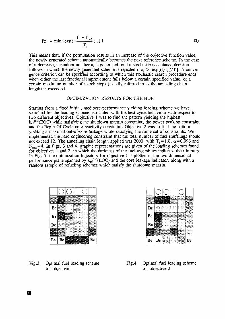
f. - f IPr+ =min (exp ( I Ti 2�1 (2)
This means that, if the permutation results in an increase of the objective function value,the newly generated scheme automatically becomes the next reference scheme. In the caseof a decrease, a random number a is generated, and a stochastic acceptance decisionfollows in which the newly generated scheme is rejected if a > exp[(fi-fi.1)/T-J A conver-gence criterion can be specified according to which this stochastic search procedure endswhen either the last fractional improvement falls below a certain specified value, or acertain maximum number of search steps (usually referred to as the annealing chainlength) is exceeded.
OPTIMIZATION RESULTS FOR THE HOR
Starting from a fixed initial, mediocre-performance yielding loading scheme we havesearched for the loading scheme associated with the best cycle behaviour with respect totwo different objectives. Objective I was to find the pattern yielding the highestkeff(")(EOC) while satisfying the shutdown margin constraint, the power peaking constraintand the Begin-Of-Cycle core reactivity constraint. Objective 2 was to find the patternyielding a maximal out-of-core leakage while satisfying the same set of constraints. Weimplemented the hard engineering constraint that the total number of fuel shufflings shouldnot exceed 12. The annealing chain length applied was 2000, with T=1.0, a =0.996 andN..X=4. In Figs. 3 and 4 graphic representations are given of the loading schemes foundfor objectives I and 2 in which the darkness of the fuel assemblies indicates their burnup.In Fig. 5, the optimization trajectory for objective is plotted in the two-dimensional
Uperformance plane spanned by k� )(EOC) and the core leakage indicator, along with arandom sample of refueling schemes which satisfy the shutdown margin.
00 0� �0 0....... . ......... .. .. .. ... .. .. ... .. ...........
.......................................
...... .. .. ......B e B e ... ..... . ......
.. . .... .. . .....Be ...... Be
B e ... . ... .... ........ .
Be Be
Fig.3 Optimal fuel loading scheme Ficy.4 Optimal fuel loading schemefor objective I for objective 2
68
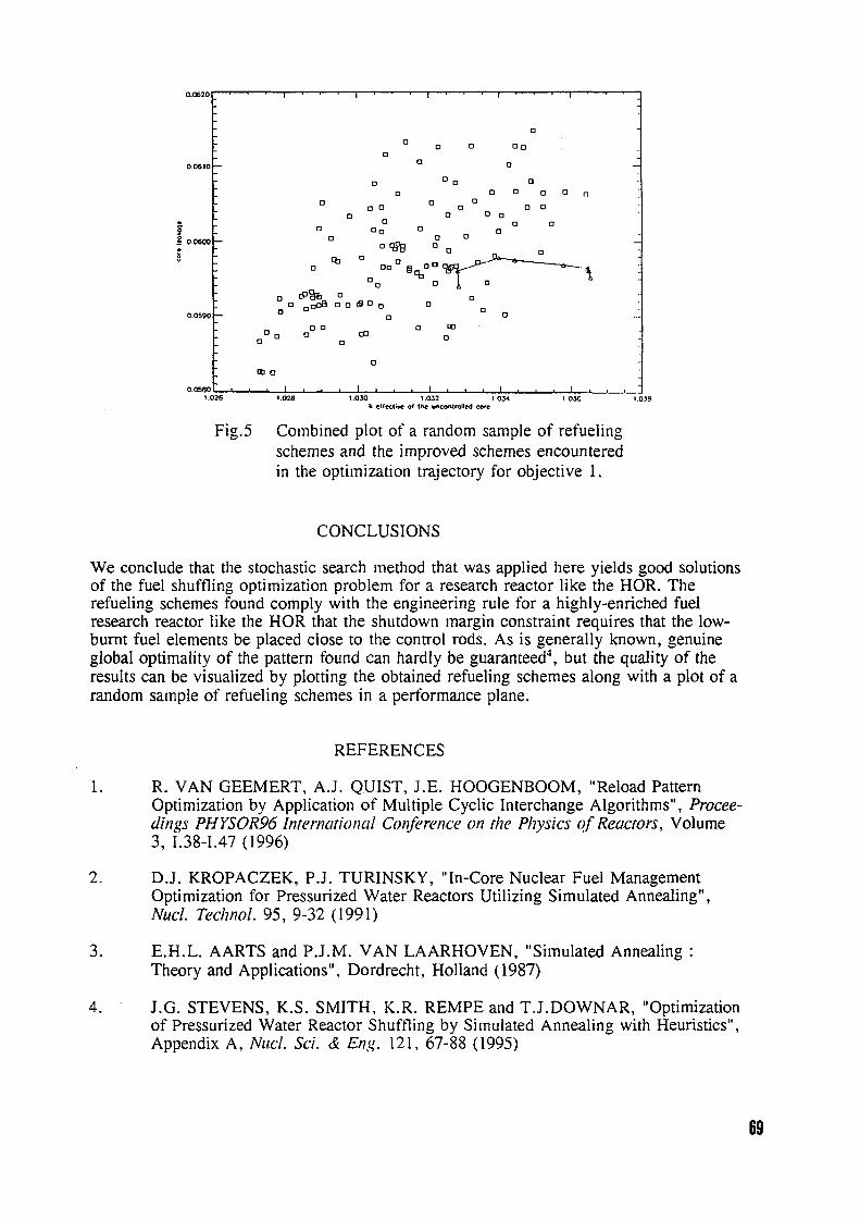
O.G620
0
0 0 013
0
0 0 0
0 a 0 0 00 0 a
00 0 a 0
0 C3 C713 C,13 0
0.0600 - 0tb% 13 a
Cb 0 o0 00 13
0
63& 00 OC301300 0 El 0
0.0590 - 0
0 0 0 ob1300 CP (3
0
0MI
0.0580 J1.026 1.028 1.030 1.032 1.034 1.036 1.038
k elf�t6e of the C�t.IW -.
Fig.5 Combined plot of a random sample of refuelingschemes and the nproved schemes encounteredin te optimization trajectory for objective .
CONCLUSIONS
We conclude that the stochastic search method that was applied here yields good solutionsof the fuel shuffling optimization problern for a research reactor like the HOR. Therefueling schemes found comply with the engineering rule for a highly-enriched fuelresearch reactor like the HOR that the shutdown margin constraint requires that the low-burnt fuel elements be placed close to te control rods. As is generally known, genuineglobal optimality of the pattern found can hardly be guaranteed', but the quality of theresults can be visualized by plotting the obtained refueling schemes along with a plot of arandom sample of refueling schemes in a performance plane.
REFERENCES
1. R. VAN GEEMERT, A.J. QUIST, J.E. HOOGENBOOM, "Reload PatternOptimization by Application of Multiple Cyclic Interchange Algorithms", Procee-dings PHYSOR96 International C�ference on the P17ysics qf Reactors, Volume3, I.38-1.47 1996)
2. D.J. KROPACZEK, P.J. TURINSKY, "In-Core Nuclear Fuel ManagementOptimization for Pressurized Water Reactors Utilizing Simulated Annealing",Nucl. Technol. 95 932 1991)
3. E.H.L. AARTS and P.J.M. VAN LAARHOVEN, "Simulated AnnealingTheory and Applications", Dordrecht, Holland 1987)
4. J.G. STEVENS, K.S. SMITH, K.R. REMPE and T.J.DOWNAR, "Optimizationof Pressurized Water Reactor Suffling by Simulated Annealing with Heuristics",Appendix A, Nucl. Si. & Eng. 121, 67-88 1995)
69

CH04AO018
Advanced fuel in the Budapest Research Reactor
Tibor Hargitai and IstvAn VidovszkyKFKI Atomic Energy Research Institute
Budapest
Extended Abstract
Introduction
The Budapest Research Reactor [1], the first nuclear facility of Hungary started to operatein 1959. The main goal of the reactor is to serve neutron research, but applications asneutron radiography, radioisotope production, pressure vessel surveillance test, etc. areimportant as well. The neutron research will get a much improved tool, when the coldneutron source will be put into operation. The Budapest Research Reactor is a tank typereactor, moderated and cooled by light water. The reactor core is in a cylindrical reactortank, made of a special alurninium alloy. The diameter of the tank is 2300 mm, the heightis 5685 mm. The heavy concrete reactor block is situated in a rectangular semi-hermeticallysealed reactor hall. The area of the reactor hall is approximately 600 ml. It is ventilatedindividually.
After a reconstruction and upgrading in 1967 the VVR-SM type fuel elements were used init. These fuel elements provided a thermal power of MW in the period 1967-1986 and 0MW after the reconstruction 2] from 1992.
In the late eighties the Russian vendor changed the fuel elements slightly, i.e. the mainparameters of the fuel remained unchanged, however a higher uranium content was reached.This new fuel is called VVR-M2. The geometry of VVR-SM and VVR-M2 are identical,allowing the user to load old and new fuel assemblies together to the active core. The firstnew type fuel assemblies were loaded to the Budapest Research Reactor in 1996.
The present paper describes the operational experience with the new type of fuel elementsin Hungary.
Old and new fuel
As it was said above, the VVR-SM and VVR-M2 fuel elements are rather similar to eachother. However some basic parameters of the two types differ. These differences arespecified in Table .
70

Table 1. Fuel specification
Fata Old VVR-SM) New VVR-M2)
Cladding thickness [mm] 0.9 0.75
Thickness of fuel [mm] 2.5 2.5
Fissile material composition Al-UA14eutectic, in U02 - Al mixtureAl ma
Thickness of fissile material in 0.7 1.0the fuel ("meat" thickness) [mm]
Number of fuel elements in the 3 3assembly
235U concentration in the active 61.2 69.2core Lg/assembly-litre]
235U concentration in the fissile 0.5 0.57material [g/cm]
Pressure drop in initial core [bar] 0.33 0.33
Average235U content of fuel 38.9 44.0assembly [g]
Maximal clad temperature [C] 104 104
Volumetric water content of the 54.2 54.2elementary cell [%]
H/U in elementary cell 235 208
k,,. 1.637* 1. 654'
Maximal allowed bum-up %] 60 60
according to recent (unpublished) calculations
The geometry of the two assemblies (old and new) are identical, e the elementary cell, theouter diameter, the active length, the assembly heads are identical. Consequently there is nodifference in the cooling surfaces of the assemblies. The cladding material is in both casesAl of reactor purity (SZAV-1), the fuel enrichment is 36% `U for both fuel element types.The data identic for both fuel element types are not given in Table .
As it can be seen from Table 1, the difference between the two fuel types is slight, buthowever mainly due to the reduction of the cladding thickness the fissile material contentof the fuel assemblies is significantly higher in the new fuel, than it was in the old one.
The licensing of the new fuel elements required reactor physics calculations for normal
71

operation and for accident conditions as well. The input data for these calculations are thenumber densities, given in Table 2.
Table 2 Number densities for the elementary cell
Type Isotope Number density [10'/cm']
Old New
"Meat" 235U 1.2912 10-3 0.94058 10'
238u 2.2955 10-3 1.64457 10-3
16o - 5.17030 10-3
27 Al 4.8430 10-2 4.91997 x 10⁻²
Clad 27AI 6.0226 x 10⁻² 6.02260 x 10⁻²
Analysis of accidents
All possible accidents were analyzed during the reconstruction period, before the new start-upprocedure began in 1992. These analyses, described in the Safety Analysis Report of thereactor, served as a basis for the licensing. The analyses were performed for the VVR-SMfuel, but the results of these analyses are valid for the VVR-M2 fuel as well. Only thefollowing assumptions had to be considered.
As a basic point of the safe operation of the research reactor is the protection of the fuelcladding. To protect the cladding, the boiling of the coolant is not allowed, because boilingcould lead to the formation of bubbles. The permanent presence of bubbles could causecavitation type corrosion in the cladding material.
Based on the data in the literature and on the results of our own research, boiling on fuelsurface can be avoided, if the cladding temperature does not reach 14 'C. This conservativevalue for a given power and for given coolant conditions is determined by two parameters.These two parameters are the allowed maximum of the power non-uniformity factor and theheat transfer value. These values obviously do not depend on the material properties, neitherof the fuel nor of the cladding.
Operation
The operation of the research reactor has to fulfil the various demands by research and otherapplications. The reactor was operated according to the pre-determined timetable throughoutits operation period. These timetables have always been revised and modified according tothe changes in the demand. The timetable was last modified for the year 1995. There werereactor operation periods of 112, 270 and 450 hours of continuous operation and one cycle
72

consists of 900 MWdays. It means, that one cycle was about 90 effective days, which wasfollowed by a refuelling period of two weeks. The 1995 timetable was planned for 4476operational hours for the year and this amount was exactly fulfilled. The total energyproduction was 1883 MW days. The reliability of the reactor was very good as in the 1995operation period only two unexpected shut downs occurred. The timetable for 1996 has thesame structure as that for 1995, the operation period will be somewhat shorter, e 3894hours are planned.
Operational experience with the new fuel
Operational experience in the Budapest Research Reactor is generally excellent, e.g. no fuelfailure has been detected since the last reconstruction 1992). The average bum-up levels(55 %) reached in the Budapest Research Reactor are relatively high in comparison to bum-uplevels reached in similar reactors.
There were only two cladding failures from 1967 up till the last reconstruction. These twofailures were slight leakages, they happened both at the beginning of a fuel cycle. Thisindicates, that the failures were caused by production failures, and are not related tooperation.
The first group of VVR-M2 (new) fuel elements 38 of the entire 229) were loaded inJanuary 1966 into the core. The second group of VVR-M2 fuel elements consists of 46elements, so there are now altogether 84 new elements in the core. The reactivity coefficientmeasurements in both cases resulted in the same values as in start-up measurements for coresloaded with VVR-SM (old) elements. Two differences have been detected anyhow. The firstone is in the power distribution due to the increased fuel amount, the second one is theincrease of the cladding temperature, due to the decreased cladding thickness. The measuredcladding temperatures were about 98 'C, the warning level is set to 104 'C (see Table 1.).
Conclusion
Experience (almost one year) has proved, that new (VVR-M2) and old VVR-SM) type offuel can be used together, without any problem.
References
I I. Vidovszky: Research Reactor in Budapest, ENS Regional Meeting: Nuclear Energyin Central Europe: Present and Perspectives, June 13 - 16, 1993, Portoroi, Slovenia,Proceedings 2
2 T. Hargitai: Dismantling and Reconstruction of the Budapest Research Reactor, EATopical Seminar on Management of Ageing of Research Reactors, Geesthacht,Germany, May 1995
73

CH04AO01 9
BR2 Mixed Core Management
Bernard Ponsard, Andr6 BeeckmansCEN.SCK, Boeretang 200, B-2400 Mol, Belgium
1. Introduction
The BR2 reactor is a high flux materials testing reactor, still using 93% enriched uranium in theform of aluminium cladded cylindrical plates. It is moderated by light water and beryllium. Thereactor core is composed of beryllium hexagons with central irradiation channels of 200, 84, 50or 33 mm diameter. The cooling water circuit is pressurized at 12 bar. The pressure vessel islocalized in a pool filled with demineralized water. The operating power is routinely between 0and 80 MWth so that unperturbed thermal neutron fluxes of IO 1 1 n/CM2.S can be achieved in thecentral channel of the core.
In order to optimize the utilization of the available HEU inventory, the CEN.SCK considers thepossibility to elaborate aMixed Core Strategy'based on the irradiation of standard 93% 231U fuelelements together with 72% 231U fuel elements using uranium recovered from the reprocessingof BR2 spent fuel. The exclusive use of 72% 231U fuel elements has also been considered.
2. Core configuration requirements
The BR2 core configuration management has to satisfy the following aspects:
- the experimental programme,- the safety criteria,- the economical use.
The experimental programme requires specific irradiation conditions: available volume, thermaland fast neutron fluxes, gamma heating, temperatures, irradiation time, ...
The safety criteria are fulfilled by the cooling capability, the negative reactivity available in thecontrol rods at any moment of the cycle (operation and shutdown), the regulation of the reactor,the hot spot on the fuel plates, ...
The main optimization parameters regarding the operating costs of the core are:
- the definition of a minimal core configuration satisfying the irradiation conditions,- the location of the control rods in the core (efficiency taking into account the
antireactivity of the experiments, the length of the cycle, ... ),- the choice of the right fuel element type (mass, density, burnable poisons,- the definition of the operating regime taking into account the irradiation programme,
the 'He poisoning level of the beryllium matrix,
74

3. Standard BR2 fuel elements
The standard cermet BR2 fuel elements of the type VIn G, presently manufactured by CERCA(France), consist of an assembly of 6 concentric cylindrical plates and are characterized by:
- total mass of 2U: 400 g; enrichment in 111U > 90%,- thickness of the fuel meat: 0.51 mm; density of 0.060 g 21U/CM2 or 131 g Ut",/CM3,
- burnable poisons: 38 g Bn�, in the form of B4C and 14 g Sm"at in the form Of SM203,
- thickness of the plates: 127 mm,- water gap thickness between the fuel plates: 3 mm.
The BR2 core configurations used with the second beryllium matrix from 1980 till 1995 wereoften centred around the central charmer H1. They were characterized by the loading of 28 to 39fuel elements, 6 or 7 control rods, one regulating rod and have produced a total energy of178 920 MWd.
The standard fuel elements allow a reactor operation at a power of about 60 MW during 21 dayswith or 6 batches of fuel elements (fresh and partially burnt). The theoretical evaluation of theconsumption of fresh fuel elements for the production of 000 MWd and a mean burnup of 50%at elimination is 62; the corresponding maximum burnup at mid-plane is about 62% or 16 21fission/cM3 'The experimental value for the exploitation of the second BR2 beryllium matrixgives a value of 57 fresh fuel elements loaded per 000 MWd for a mean burnup of 53 atelimination. This value depends on the operating regime, the configuration and the experimentalloading.
4. AEA test fuel elements
In the fi-ame of a 'Qualification Programme', 6 fuel elements were fabricated in 1994 byAEA-Technology (UK) with uranium recovered from the reprocessing of BR2 spent fuel atUKAEA-Dounreay. The prograrrune had to:
- define the fuel specifications C"U mass and density, burnable poisons,- define the technical specifications for fabrication,- define the neutronic specifications (reactivity of the fuel element,- follow the recommendations of the 'Safety Advisory Committee',- follow the QA/QC manufacture procedures,- perform reactivity effects measurements of the fuel elements before each BR2 start-up,- perform measurements during the irradiation (neutron fluxes, gamma heating,- analyse the final results.
The AEA test fuel elements of the type VIn E have the same geometry than the VIn G fuelelements and are characterized by:
- total mass of ... U: 330 g; enrichment in 111 = 72%,- thicknessofthefuelmeat:0.51mm;densityofO.050glIIU/CM2orl.3lgUt,,�cni3,- burnable poisons: 1.8 g B,,t in the form of B4C and 13 g Sm,,,t in the form Of SM203-
They were iradiated during cycles of 21 days in the BR2 reactor till a maximum mean burnupof 43% to 48% (about 13 e21 fission/CM3), without release of fission products.
75

5. Comparison between VIn G and VIn E fuel elements
In the typical configuration IOU, illustrated in the figure 1, the standard VIn G fuel elements(93% ... U) are routinely irradiated during cycles of 21 days at a power of 60 MW, as follows:
- meanbumupofp=12%afterleycleinaC-channel,- mean burnup of p=35% after 2 additional cycles in a A- or B-channel,- mean burnup of 45% after the fourth cycle in a D-channel,- mean burnup, of p=52% after a last cycle in a F- or G-charmel.
This "theoretical" irradiation profile is in reality perturbed by the requirements of theexperimental programmes. For example, the extension of the configuration 10 to satisfy theirradiation conditions of the LVvR-CALLISTO loop required the loading of 3 additional fuelelements in G-channels, each for or 2 more cycles; the mean bumup at elimination reachedsometimes p=60%.
The VIn E test fuel elements underwent a typical irradiation profile of cycles of 21 days at apower of about 60 MW in the IOU configuration, as follow:
- meanbumupofp=12%afterleycleinaC-channel,- mean bumup of p=25% after a second cycle in a A- or B-channel,- meanbumupofp=35%afterthethirdcycleinaD-channel,- mean burnup of 48% after 2 additional cycles in a F- or G-channel.
The comparison of the measured reactivity curves of both types of fuel elements as a unctionof their mean burnup allows the definition of equivalences between'batches of burnups':
BATCH VIn G 93% 235U) VIn E (72%131U)
I 0% 0%
2 12% ------3 25 12%4 35 25 %5 45 35
--------- ------------- -------------
6 elimination 52 % 42 %
Three important conclusions can be drawn from the table above:
there is no equivalence between a P=12% VIn G 93% 231U) fuel element., characterizedby the maximum of reactivity, and a VIn E 72% 115U) fuel element; this creates anunbalanced inventory of the partially burnt fuel elements,the mean bumup at elimination is p=52% for the VIn G 93% ... U) fuel elements andp=42% for the VIn E 72% 231U),
the inventory of VIn E 72% 131U) fuel elements is limited to 4 'batches of burnups inplace of for the VIn G 93 % 115U) fuel elements.
76

6. Mixed Core Management
The preliminary study made with the help of the calculation code GEXBR2-TRPT3-REAC2showed the possibility to elaborate a strategy based on the exclusive utilization of VIn E 72%231U) fuel elements. Nevertheless this core management is not optimal because:
- the length of the cycle is mostly shorter than 21 full power days,- the mean consumption of fresh fuel elements is about 9 fuel elements per 000 MWd,- thereisabuild-upofp=35%fuelelementsinthepartiallybumtfuelelementsinventory;
this results in a reduction of the mean burnup at elimination from 42% to 3 5%<p <42%.
A ftu-ther study showed that the mixed utilization of both types of fuel elements VIn G 93%"'U) and VIn E 72% ... U) can optimize the fuel utilization. Indeed this alternate strategy allows:
- a well balanced management of the irradiated fuel elements inventory,- a mean consumption of 6.2 fresh fuel elements per I 000 MWd,- the possibility to alternate the loading of 6 VIn G 93% ... U) fresh fuel elements for a
cycle with 6 VIn E 72% "'U) fresh fuel elements for the next cycle.
7. Conclusion
The BR2 fuel cycle management can be optimized by the fabrication and the irradiation of fuelelements with uranium recovered from the reprocessing of BR2 spent fuel. The VIn E fuelperformances could be upgraded by increasing the aount of burnable poisons, the fuel mass,the fuel density, ... in order to obtain a higher reactivity effect at a burnup of about p=12% anda longer cycle duration. The preliminary results of the calculations need however to be confirmedby measurements on effective reactor loads.
T4
-,,T7
4FUEL CDOff
CONTROL PM0 IL
MANKEL0 -O,
RI
C) POOL SEE TUBE
TANGENTIAL BEAM TUBE
RADIAL BEAM USE
Tfi
Figure I Typical BR2 Configuration (IOU) 77

CH04AO020
FUEL MANAGEMENT STRATEGY FOR THE NEW EQUILIBRIUMSILICIDE CORE DESIGN OF RSG GAS (MPR-30)
Liem Peng Hong, Bakri Arbie, T.M. Sernbiring
Center for Multipurpose Reactor, National Atomic Energy Agency (Batan),Puspiptek, Serpong, Tangerang, Indonesia 15310.
Tel. 62-21-7560908, Fax. 62-21-7560573
ABSTRACT
The design procedure and fuel management strategy were proposed for converting the oxide coreof RSG GAS (MPR-30) to the new equilibrium silicide core using higher uranium loading. Theobtained silicide core gave significant extension of the core cycle length and thus increasing thereactor availability and utilisation.
INTRODUCTION
One research activity with high priority in the Center for Multipurpose Reactor, NationalAtomic Energy Agency, is the RSG GAS (MPR-30) core conversion program from oxide to silicidefuel. Among other advantages of silicide fuel, its high loading of fissile material is expected toincrease the operation cycle, hence, higher reactor availability and utilization can be achieved.RSG GAS is a Be reflected, light-water moderated and cooled, 30 MWth (max.) multipurposereactor. Presently RSG GAS uses MTR4ype LEU (I 975 w/o) oxide fuel elements (FEs) Asshown in Fig. 1, on the 1 0 x 1 0 core grid positions there are 40 standard FEs (each consists of 21fuel plates), control elements (CEs, each consists of 15 fuel plates) initially loaded with 250 and178.6 g 235U respectively, Be reflector elements and other irradiation facilities. These fuel loadingcorresponds to uranium meat density of 296 gU/cc. With the original nominal core cycle of 25days, 7 bum-up classes with burn-up step of approximately loss of 235 U the core producesenergy of 750 MWD per cycle.
This research activity has been coordinated with research and development programs inNuclear Fuel Element Development Center of the Agency, and three experimental silicide fuelelements, with 250 g 235U loading per FE produced by the Center, have been irradiated in theoxide core of RSG GAS. From the economic and licensing point of view, the core conversionprogram puts rather strict limitation on the new silicide core design, that is, no major modificationshould occur on the reactor balance of plant and core main structural components. Consequently,several useful free design parameters can not be manipulated to obtain the optimal silicide coredesign, however, many works can still be done to extend the core cycle and increase the coreperformance. This paper discusses some part of the work in the neutronic design of the newsilicide core, especially, from the fuel management aspects.
DESIGN OBJECTIVE AND CONSTRAINTS
Our design objective for the new silicide core of RSG GAS is to aximize the core cyclelength without violating the following constraints:1 . No major modification may occur on the reactor balance of plant, shielding, core main structural
components and civil buildings.2. The number as well as the performance of irradiation positions and facilities must be
maintained.3. The existing one-stuck-rod margin reactivity and thermal-hydraulic safety requirements must
be fulfilled.4. Maximum discharge bum-up is limited to 70 for licensing purpose.
The first constraint includes the use of the existing Ag-ln-Cd control rods. In the presentoxide core, the eight (fresh) control rods have a total worth of around 14.5 while our preliminaryinvestigation showed that the worth decreased as the neutron spectrum in the silicide corebecomes slightly harder.
78
The second constraint prevents the reduction of the number of central irradiation position(CIP), irradiation position (IP), and on top of that, the position of other irradiation facilities (PRTF,rabbit system) must be maintained. Although as a consequence the total number of FEs and CEsare identical with the present oxide core, several free parameters of fuel management are stillopen to be changed: initial loading of FE/CE, number of bum-up classes and refuelling/reshufflingstrategy. These three parameters will be manipulated in the present work to maximise the corecycle length.
The third constraint, in fact, is not imposed solely on the new silicide core design only butalso for the present oxide core design, therefore, same design procedure will be adopted. Oneproblem associated with the lower control rod worth previously mentioned is the one-stuck-rodreactivity margin. Fortunately, our preliminary investigation showed that the radial power peakingfactor (PPF) for the new silicide core was not a significant problem.
SILICIDE CORE DESIGN PROCEDURE RESULTS
Design Codes
A fuel management code for obtaining directly the equilibrium core of a research reactorwas developed for the present work (Liem, 1996, Bakri et al., 996). Few group neutron diffusiontheory in 2-D, XY and RZ reactor geometry is adopted as the framework of the code. The bum-updependent fuel cross section library for the code was prepared with WIMS/D4 cell alculation code(Askew et al., 1966). The validation of the code for the present work was checked throughbenchmark calculations defined in the IAEA-TECDOC,233 (IAEA, 1980) and iAEA-TECDOC-643(IAEA, 1992). Since most of the calculations were done in 2-D XY reactor geometry accurateaxial buckling values must be found. These values were determined through rigorous 3-D XYZdiffusion alculations with Batan-3DIFF code (Liem, 1995).
Fuel Management Strategy
First, the 40 FEs and CEs are grouped into burn-up classes (batches or zoning).Consequently, at BOC 5 FEs and CE are loaded after discharging the same number of old FEsand CE from the core. The refuelling/reshuffling scheme proposed can be categorised as scatterloading, as shown in Fig.1 and indicated by Table 1. The zoning shown is selected to flatten thePPF. Increasing the number of bum-up classes from 7 (for the oxide core) to for the new silicidecore is a mean to suppress the excess reactivity at BOC in the one hand, and to increase the fueldischarge bum-up on the other hand. The second step is to determine the optimal initial 235 U
loading of the fresh FE and CE.Parametric survey works on the initial 235 U loading up to 350 g /FE (fuel meat density of
3.74 gU/cc) have been done to estimate the possible range of core cycle length by first neglectingthe constraints previously mentioned (Fig. 2. In general, increasing the initial fuel loading indeedincreasing both the cycle length and BOC excess reactivity of the equilibrium core. However, for asame core cycle length, the discharged bum-up tends to decrease with higher initial fuel loading.This is a logical consequence since we use no burnable poison.
The three horizontal lines in the figures representing the imposed constraints, i.e.criticality, maximum discharge burn-up and maximum BOC excess reactivity under one-stuck-rod(OSR) condition. By imposing these constraints the feasible core cycle lengths were found to be30 - 32.5 days and 35 - 37.5 days for U meat density of 355 gU/cc and 474 gU/cc, respectively.Compared with the present oxide core cycle length of 25 days a significant extension can beattained, especially for U meat density of 474 gU/cc. To select the optimal core cycle length for acertain U meat density, some trade-off must be made. For a shorter core cycle length thereserved EOC excess reactivity (for experiment, irradiation and partial Xe overfide) becomeslarger but the safety reactivity margin for OSR condition decreases.
Although it is not discussed in this work, the direct conversion from 296 to 474 gU/cc willface many problems in the transition cores. Therefore, the first step of the conversion is toachieve the silicide equilibrium core with 355 gU/cc meat density and followed with 474 gU/cc.For the former equilibrium core the fuel burn-up distributions at BOC and EOC is shown in Fig. 3
79

while the radial PPF distribution at BOC is shown in Fig. 4 The scatter loading strategy and highernumber of bum-up classes were effective in minimising the radial PPF so that there was no needfor modification of the primary cooling system. Table 2 shows the comparison of the reactivitybalances between the present oxide typical working core and the equilibrium silicide core. It canbe observed that the equilibrium silicide core is suffered from smaller excess reactivity at EOC.However, in the calculation the Be positive feedback reactivity was not taken into account so thatthe EOC excess reactivity might be higher than the value predicted here.
CONCLUDING REMARKS
The fuel management strategy for converting the oxide core of the RSG GAS to silicidecore with higher fissile loading has been proposed to extend the core cycle length so that thereactor availability and utilisation can be enhanced. The analyses showed that the conversionprogram can be done successfully without major modification except for the fuel meat density andstill the obtained equilibrium silicide core met the imposed design constraints and safetyrequirements.
REFERENCES
Askew, J.R. et a., "A General Description of the Code WIMS", Jour. of Brit. Nuc. Energy Soc. 5(1966)Bakri, A., Liern, PH. and Prayoto, 'A Procedure for Searching the Equilibrium Core of aResearch Reactor, 19-th Reduced Enrichment for Research and Test Reactor, Seoul, SouthKorea (1 996).Batan, RSG GAS Safety Analysis Report Rev. 7 1987)IAEA, "Research Reactor Core Conversion from the Use of Highly Enriched Uranium to the Use ofLow Enriched Uranium Fuels Guide Book", IAEA-TECDOC-233, Vienna 1980)IAEA, "Research Reactor Conversion Guide Book - Vol. 3 Analytical Verification ", AEA-TECDOC-643, Vienna 1992)Liem, P.H., 'Development of An In-Core Fuel Management Code for Searching Core EquilibriumCondition in 2-D Reactor Geometry (Batan-EQUIL-2D)', Atom Indonesia 23,1, 1997)Liem, P.H., 'engembangan Program Komputer Standard Batan Difusi Neutron BanyakKelompok 3-D (Batan-3DIFF)', Risalah Lokakarya Komputasi dalam Sains dan Teknologi NuklirV, Batan, Jakarta 1995)
CYCLE LENGTH (day) CYCLE LENGTH (day)25 30 35 40 25 30 35 40
1 2 0130C(cold Xe free) - 12 -
----------- ---------
- Disch. U 80 >-8 Disch. SU so---- -------- - Ld Ld
Mcx. Disch. 70,.- a 5: -- -----60X SU < 70% 60
< L)LJJ4 40U 4 40ix OC(hot, Xe equfl.) LdW ix VI
PEOC(hot, Xs quil. lo
0-------- 0 -----------
I f750 900 1050 1200 750 goo 1050 1200
ENERGY (MWD) ENERGY(MWD)
Figure 3 Some design parameters of the equilibrium silicide core of the RSG GAS as function ofcore cycle length for uranium meat density of 3.55 gU/cc (left) and 474 gU/cc (right).
80

K B&� BE 5� $St �B BEPR Table 1. Reshuffling and refueling strategy.
J SEBSt TFFrom TO From TO From To
�H E H-9 F-1 0 F-5 F-8 C-7 B-8H-8 C-4 F-4 F-6 C-6 G-5H-7 F-7 F-3 C-10 C-5 D-4BE lp �i BS*V E�H-6 D-10 E-1 0 B-4 C-4 D-5H-5 E-5 E-9 G-6 C-3 H-8
F H-4 F-9 E-8 D-3 B-9 C-9RS G-9 E-8 E-5 A-8 B-8 out
E 155- iP �BE HY G-8 out E-3 A-7 B-7 out,3 CIP G-6 B-7 D-10 G-4 B-5 out
Ip BE,,, HY G-5 G-8 D-8 out B-4 A-6J1 RS G-4 C-7 D-5 H-5 A-9 A-4
T&I �'CE, F-1 0 G-9 D-4 E-9 A-8 B-5C RS, -5 -3 -6 -7 -7F A D G A HF-8 C-5 C-10 E-3 A-6 B-9B B4I-E"'�'FIM4' E" IP �EE!I , HY F-7 F-4 C-9 D-8 A-5 H-6F-6 out C-8 F-5 A-4 E-I 0M4, RS77= 77 77777
A BE F FE F&i TEATEF-I
10 a 8 7 z � �4 I 2
Beryllium Block Reflector
Figure 1. Core-reflector configuration of RSG-GASwith burn-up class in the second rows (FE:fuelelement, CE:control element, BE:Be reflectorelement, BS+:Be reflector element with plug,IP:irradiation position, CIP:central irradiationposition, PNRS:pneumatic rabbit, HYRS:hydraulicrabbit, PRTF:power ramp test fcility).
BE H BE A'O
BE IP `58�0 MM" G BE il�'!Al t.83 IPTobago
F AbM 9A7 2103� 44.50 ��5a!05� �AOV �NQ'�.Oo� F 7177 :bi�3� 20.451�32.54 5324_ I&W11 N 401 �ii6� ��'6. V 86�` 3
E Z0.44,13M81- IP E 777 IP US40 CIP44L CIP
D IP 5�* DA M 0.96, 049011 A.12 0'67n' 0.76�1 O
Z4 0.0 51.81 AT'9'R 7R$O� C *019 0.92 I 02�',Abli �57.43� 11.31 58�99 �t&06 41.7V
BS+ 44.11 5&99 6525 IP ;593Z B JIB 72 1� m ;,BE5t �20,178; lp'6 IM i� Ot950.'6 64M 71 M ags,� 2�
A BE 60'�' �54�A-3'1 20" '94,1", BE A BE 0.96 !iO-67�� 0�54 _7V9
10 9 8 7 6 5 4 3 1 0 9 8 7 6 5 4 3
Figure 3 BOC (upper row) and EOC (lower row) fuel Figure 4. Radial PPF distributions of the equilibriumburn-up distributions of the equilibrium silicide core of silicide core of RSG GAS (first and second rowsthe RSG-GAS. represent all control rods up and down conditions,
respectively).
81

111111111111111011111111111111CH04AO021
THERMAL HYDRAULIC MODEL VALIDATION FOR HORMIXED CORE FUEL MANAGEMENT
H.P.M. Gibcus, JW. de Vries, PF.A. de LeegeInterfaculty Reactor Institute (IRI), Delft University of Technology
Mekelweg 15, 2629 B Delft, The Netherlands
INTRODUCTION
A thermal-hydraulic core model has been developed for the Hoger Onderwijsreactor (HOR) a 2MW pool-type uiversity research reactor. The model was adopted for safety analysis purposes inthe framework of HEUILEU core conversion studies. It is applied in the thermal-hydraulic compu-ter code SHORT (Steady-state HOR Therrnal-hydraulics wch is presently in use in designingcore configurations and for in-core fuel management. An elaborate measurement program wasperformed for establishing the core hydraulic characteristics for a variety of conditions. Thehydraulic data were obtained with a dummy fuel element with special equipment allowing ao.direct measurement of the true core coolant flow rate. Using these data the thermal-hydraulicmodel was validated experimentally. The model, experimental tests, and model validation arediscussed.
STEADY-STATE HOR THERMAL-HYDRAULICS (SHORT)
thermal hydraulic modelThe HOR is cooled by forced convection down- coolant flowward flow of pool water sucked into the coreregion and circulated by the primary pumpthrough the heat exchanger. During forced flowconditions a vertically movable suction header isseated to the bottom of the gid plate (Fig. 1).'Me core hydraulics are modelled in the SHORTcode system.
The SHORT program 1 is composed of the two reactor coreestablished computer program modules LAC[2] and COBRA4II 3 LAC solves theequations for the flow and pressure distribution grid platein arbitrarily aanged hydraulic resistance net-works and COBRA-HIC carries out thermal-hy- movabledraulic calculations in an array of heated chan- suction headnels with or without links for cross-flow. Tomake the application for the HOR user-friendly,FLAC and COBRA411C are coupled in SHORT.Appropriate empirical functions for heat tranferand fluid friction are used on a preselected basis, Figure 1. HOR core cooling systemas well as basic geometry data. Only core opera-ting conditions and the core configuration are to be specified as input data by the user. From thesethe SHORT program then calculates the data required for running LAC and COBRA411C.
Once the input data are provided SHORT starts to generate a flow resistance network wchconsists of resistances in the axial and transverse direction simulating the flow of pool water intothe interconnected system of gaps between core components which is then sucked through thesmall holes in the grid plate. The flow through the core components is also modelled. Leakageflow of pool water into the suction head plenum through small gaps is accounted for by an ad-
82

dftional resistance connecting the plenum below the grid plate with the pool. FLAC then iterativelycalculates the pressure and flow distribution in the network and gives a breakdown of the flowthrough the small holes in the grid plate, the flow tough the interior of te core components andthe leakage flow.
For the thermal-hydraulic calculations to be performed by COBRA-IIIC only the relevant flow inthe heated section of the fuel element cooling channels is taken from the FLAC analysis. On thebasis of the channel axial power profiles tat follow from the core neutronic calculations, COBRA-HIC then evaluates the flow distribution in the array of heated cooling cannels. These axial powerprofiles are calculated with the 3D Monte Carlo code KENO V.a 4 If hot channels are speci-fied, hot channel and hot spot factors are applied to the temperature rise in the coolant, thevelocity and the heat flux. These odified values are ten used to calculate the safety margin withrespect to the occurence of flow instabilities.
Finally SHORT allows for an analysis of the outer fuel plate temperatures at the fuel elementboundary. For an unshrouded core like the HOR, the heat rmoval conditions of such outer fuelplates are quite different from those of te inner plates. This is mainly due to te deviating coolantvelocity profile for the channels in between fuel assemblies. For tese channels there is a signifi-cant increase in coolant velocity downwards from top to bottom.
Code installation and verificationThe SHORT code system was developed in the framework of safety analysis studies performed forthe HOR [5]. It had been designed to run on the developer's platform for performing this kind ofcomputer calculations. After completion te code system was ported to IRI's computing environ-inent, so adequate testing and verification of the installed odules was necessary. Test input andoutput was supplied by the authors of te code system. For managing te programming environ-ment different soffivare tools are in use at IRI. First: for quality asssurance purposes te QA FOR-TRAN package is used for checking te source code. It is a toolset for analyzing, proving andmaintaining the quality of FORTRAN pro- ....................... .. ................ ............................ ............ ...gram s. Second: a softw are engineering too] ............................................ ....... ....................... ... .... ............... ...
.. ... . .. ... .......... ....(DECset) is available. It can be used to deve- ......... . .... ....
lop, install, and to maintain a code system in......... .......... .a systematic way. ........ ........... ............. . .... ............................ .. ...
......... ...... :.. ............. .......... .. . .. ........ ....... . . . . . ..................... .. .. ..............................To verify the correct installation of SHORT .. .............................. .. .. .................. ......... .............................. ...... ......................... . ................. ........ . .... ....... ........ .. . . .....these tools were applied to te system and a ............ ............
number of test runs were perfornied. Someminor problems were detected and subse-quently corrections were made. Finally forvalidat'ing purposes, the results of test caseswhich had been run on the designers platform ..... .....were reproduced successfully.
EXPERIMENTAL TESTS -------------
MethodThe ydraulic data were obtained wth a spe-cial device, designed for te purpose of in-core measurements, e.i a dummy fuel elementassembly was equipped with a turbine-typeflow meter in te lower end fitting as sownin Figure 2 Te device was calibrated and Figure 2 Dummy fuel element ith flow me-
ter dismounted from bottom nozzlecerti led 6 ndependently off-site a dedi
83

cated test and calibration loop, owned and operated by the Dutch national calibration institute res-ponsible for maintaining the national measurement standards. The influence of the turbine flowmeter was assessed separately by taking pressure difference data of the dummy fuel assembly withand without the turbine.
Measurement programWith the reactor shutdown, in-core measurements were performed under steady-state conditions fortwo different core types at a large number of grid positions for nominal settings of 67, 80 and 89dm'ls for te primary loop flow rate. For determining the influence of the suction head gap bypassflow on incore coolant velocity, measurements were taken with and without temporarily sealing ofthe suction head gap. Additional to tese steady-state measurements transient measurements havebeen performed in the framework of contributions to the safety analysis report [5]. They consistedof determining the influence of deliberately and instantaneously forcing down the suction headwhile the primary pump kept running and recording flow coast down after shutting-off the primarypump.
ResultsFrom the measurement data, a.o. te core flow rate distribution and the true core coolant flow ratewere determined. Figure 3 displays the measured in-core coolant velocity distribution for a nomi-nal primary flow rate of 80 dm'/s for te (mixed) compact core. The average coolant velocity was0.961 m/s. It can be seen tat in general, the coolant velocity is highest in the central core region,whereas at the core boundary velocities are somewhat lower. The spread of te relative flow rate isfrom 0978 to 1025. Figure 3 also displays the relative increase of the incore flow rate whensealing of te suction head gap. It can be seen that the influence is only marginal.
��2 �F�C81 §6-4-12.2 1 1 Beryllium refiector element
;;�t ! 4 Control element97.8 94.3
94.7 98.12.9 1.3
��O n ��fflo Fuel element
J] '�_1.7' M=ured coolant velocity [cm/sl6 Percentage increase with sealed suction head gap
12.9
Figure 3 Coolant velocity distribution
EVALUATION OF MEASUREMENTS AND IMPACT ON MODEL
Fuel elementflow ateTo evaluate the validity of te SHORT program, calculations were performed for the experimentaltest conditions of the simulated compact core. Compared to the experimental test results, thesuction head bypass flow rate was overpredicted substantially wth underprediction of the activecore flow. According to tis an adjustment of the flow network, in SHORT was made. The suctionhead bypass of originally 5.5% of total flow for the compact core model was reduced by adjusting
84

the flow resistance of the specific flow path of the resistance network to eet the measured by-pass. No other changes in the input or modelling were made. The calculated fuel element activeflow rate increased due to the reduction of the suction head bypass by 34 %. It is concluded thatafter the adjustment the true active coolant velocity is still conservatively underpredicted bySHORT by 39 %. The results are presented in Table .
Table 1. Comparison between test results and apriori and posteriori SHORT-calculation forthe flow paths in the simulated compact core.
Flow path Flow [kg/s]
Test SHORT apriori SHORT posteriori
Active cooling chan- 68.43 86.2%) 63.57 (80.1 %) 65.73 82.8 )nels
Absorbers and small 9.26 11.7 %) 11.46 14.4 %) 11.85 14.9 )holes in grid plate
Suction head bypass 1 17 2.1 %) 4.37 (5.5 %) 1.80 2.3 %) ____J I
Flow distribution across the coreThe fuel element flow rate was measured at 17 grid positions in the simulated mixed core. Theseresults were compared to an apnon' assumed design value of 103 for a nuclear hot channel subfac-tor used in the SHORT program. This subfactor relates to the nonuniform mass velocity at the coreinlet affecting individual fuel elements A value of 103 corresponds to an assumed flow reductionof 3 at the inlet of te fuel element containing the hot channel. Since the radial nuclear hotchannel factor occurs in te central region of te core te aprion' design value is conservative forthe planned core configurations and loading patterns. Thus tis factor could be set to 1.0 thusincreasing the design value of the fuel element flow rate by 3 .
CONCLUSIONS
The true core coolant flow rate for different core conditions and flow distribution was assessed byexperimental methods for validating the thermal-hydraulle code SORT. This code is used forcore design and in-core fuel management purposes for the HOR. The in-core fuel management ofmixed HEU/LEU cores requires special attention with respect to power peaking constraints. Basedon the results entioned above and the experiences so far, the code SHORT is considered to be avaluable asset as a design tool for in-core fuel anagement, serving proper guidance during theHOR conversion process.
REFERENCES
[11 Gysler, Kohtz, ijnenschloB, "Description of te Code SHORT for Thernial-HydraulicAnalysis of the HOR of IRI/TU Delft". Siemens Technical Report KWU BT71/92/0052a(1992)
[2] Malek, G.J., Development of the Flow Analysis code FLAC", GA-9482 1969)P] Rowe, D.S., "COBRA-IIIC - A Digital computer Program for Steady State and Transient
Thernial-Hydraulic Analysis of Rod Bundle Nuclear Fuel Elements", BNWL-1695 1973)[4] Petrie, LM., and Landers, N.F., "KENO V.a: An Iproved Monte Carlo Criticality Pro-
grain with Supergrouping", ORNL, 0RNL/NUREG/CSD-2/R4 1993)[5] "Contributions to the Safety Analysis Report of HOR Interfacultair Reactor Instltuut TU
Delft", Siemens Ident-No. KWU-Nls2/93/0013 16 November 1993)[6] Certificate Number VL-93626, Nederlands Mectinstituut 1993)
85

CH04AO022
Reactivity variations associated with the core expansion of the ARIA research reactorafter modernisation.
Grzegorz Krzysztoszek, Head Reactor ARIA Operation DepartmentResearch Reactor Centre, 05-400 OTWOCK - Swierk, POLAND
tel. 048 22) 7798488, fax 048 22) 7799700
ABSTRACT.
Polish high flux research reactor MARIA is a pool type reactor moderated with beryllium and waterand cooled with water. The fuel is 80% enriched uranium, in the shape of multitube fuel elements, each tubemade up of UAI,, alloy in aluminium. cladding.
MARIA reactor has been operated in the year of 1977 - 85 and then it was modernised and again putinto operation in December of 1992. The modernisation as regarded the reactor core comprised a berylliummatrix expansion from 20 to 48 blocks.
Within the fame of the power start-up and tal operation the reactor has been extended from 12 to 18fuel channels.
On that stage of reactor operation the power of mostly loaded fuel channels was constrained to 16MW.
Reactor has been operated within the 100-hrs campaigns for an irradiation of target materials and forperforming measurements at the horizontal channels outlets.
In the previous time it has been noticed substantial differences in reactivity changes of the core insimilar campaigns of reactor operation. It concerns the reactivity losses during poisoning period of the reactorwithin the first 30 - 40 hrs of operation as well as in the fuel burning up process.
An analysis of the reactivity variations during the core extension will made possible the fuelmanagement optimisation in further reactor operation system.
1. INTRODUCTION.
Modernisation of the MARIA research reactor as related to the core was connected with extension ofberyllium matrix from 20 to 48 blocks which was accomplished by the substitution of the retired graphitereflector blocks with the new beryllium ones.
In the first stage of the power start-up and the trial operation the work of reactor has been based on the12 fuel rods core configuration. After that the reactor core was extended until the aimed configuration has beenachieved which enabled to produce the radioisotopes and perform the neutron beams investigation at thehorizontal channels' outlets.
The overall reactor power resulted from the fuel channels' thermal power of which the most thermalloaded channel was operated with a power which did not exceed 16 MW.
Reactivity excess of the core during the irradiation process had to be contained within the limits of pmin providing the continuity of the reactor operation duration of 100, 120 or260-hrs, and p max. being imposed by the operational constraints of Safety Report.
The conclusions following from the presented work, will allow to optimise the fuel managementduring the further reactor operation.
2. DESCRIPTION OF REACTOR MARIA.
A vertical cross section across the reactor pool is shown in Fig.l. The reactor core, fuel and loopchannels, headers, and connections between the headers and fuel channels are all submerged in the pool undera layer of water ensuring sufficient radiation shielding above the core.
86

1 2 3 4 The characteristic design feature ofthe core is a conical arrangement of fuelchannels. The fuel channels are situated inberyllium matrix made of blocks of 11 cmheight and enclosed by a lateral reflector madeof graphite blocks in aluminium cans. Some ofthe blocks contain horizontal holes for..........extraction of neutron beams fom the reflectorto the horizontal beam tubes penetrating thereactor lateral shield. A view of the reactorcore and reflector from above is shown in......... ... ......... Fig.2.
In area of reactor core and reflector9 6 there is a number of vertical iadiation
10 channels, made of aluminium tubes. The8 reactor core layout, shown in Fig. 3 gives an
examsle of core management, -which fulfidsthe needs of radioisotope production and
__1E3,H 1358 cm
El -115 cm several experimental programs.H4, H5, -95.... ..................
.........
. ..........
4 5 6 7 8 9 101. control rod drive mechanism S. bam tube sutter %,2. = plate 9 fel channel 0 L3. chamber channel 10. ionization chambers shield4. ionization chamber dive mech IL ooze and support structure5. fuel and loop channels supportalume 12. core ad reflector supporrplants k6' plate support onsole 13. reflector blocks 0 K7. horizontal beam tube shutte dive mechanism 14. bearn tube compensatorjoint
Fig. 1. Vertical cross-section of the MAMA reactor PCO4 W
0 W
h3 4 H
9
U U Pe G
f
F
e
0 0 E
dV 14 Vil Vill M X
0W." W� -da-
O0$0 025 Yd�-
FA
Fig. 3 Reactor MARIA core layout
12%.2.=Iipk p.Eh. M. 7 t-= U.&
bt
Fig. 2Horizontal cross-section of the MARIAreactor
87

3. REACTIVITY VARIATIONS DURING THE REACTOR CORE LAY-OUT DEVELOPMENT.The subject of this analysis is relevant to the typical reactor operation cycles (No. 1 2 3 and 4 in the
consecutive stages of the core extension during power start-up and the trial operation. A reactivity marginenabling the accomplishment of the assumed reactor operational cycles must cover reactivity losses caused bythe poisoning effects and the fuel bum-up.
The data concerning the fuel channel position inside the reactor core, specific fuel burn-up andthermal power are contained in Table .
Table I[MW/0/1
Cycle No I Cy 2 Cycle No 3 Cycle 45 6 7 8 5 6 7 1 8 5 6 7 1 8 5 6 7 8 9
i 0,69 0,65 0,64 0,56 0,81 0,89 0,74 0,59 1,08 0,660,18 0 6,87 3 0 27,7 15,6 4,0 39,2
i 0,98 1,11 0,88 0,50 0,98 1,27 1,04 0,64 1,17 1,54 1,11 0,71 0,90 1,37 0,97 0,51d0,50 0,55 0,39 0 9,15 1,04 8,52 4,76 25,3 15,8 25,6 28,1 24,5 15,3 26,2 37,1
h [_ ,2 J 1,32 1,01 1,35 1,53 1,31 1,4 1,45 1,5 1,15 1,40 1,21 0,39F 0-,9 9 -F 0, 96 0,68 1 11,1 11,6 9,43 18,6 24,8 17,7 1 18,4 14,0 24,3 2,8
9 0,7 0,74 0,51 1,33 I'll 1 0,59 1,33 1,50 1,16 0,59 1 1,18 1,17 0,54F 05 8 0,56 0,40 8,96 6,78 1 0,22 21,8 20,5 26,2 26,0 22, 25,5 14,8 32,6
-788 0,71 0,92 1,13 0,84 0,761 0,81 0,02 29,3 20,0 29,5 25.9 -86
3.1. BASIC CHARACTERISTICS OF THE CONSECUTIVE CONFIGURATION OF REACTORCORE.
Thefirst operational configuration of reactor core comprised 12 practically new fel elements. In theconsidered first cycle (No 1) the reactor has been operated for 4 days with an overall power of 12 NTW, and thepower of the most loaded fuel channel was 132 MW.
This core had a large built-in reactivity which in the initial state was pi = 8 $. Reactivity loss caused
by the reactor poisoning achieved its steady state after 40 hrs from the start-up time. In this time the poisoning
effects and the fuel bum-up caused the negative reactivity effect Ap = 59 $. Reactor was shut down after 97 hrs
of operation when the reactivity excess was p = 19 $. Due to that the fuel bum-up coefficient was equal to
0,007 $/MWd.
7he second configuration of reactor core consisted of 15 fuel channels featured with low burn-up
(< 12%) because in the meantime the reactor was operated with a variable power of -15 Nff within 430 hs.
In the example being considered cycle (No 2 the reactor was operated with an overall power of about
19 MW, and the power of the most loader fuel channel was 153 MW.
In the initial state reactivity excess of the core was p = 54 $. The reactivity drop caused by the
phenomenon of reactor poisoning reached the study state after 32 hours of the reactor operation and the
combined effect together with fuel bum-up was 38 .
The final reactivity margin was p = 147 when the reactor has been shut down after 82 hours of its
operation.Bearing in mind aforementioned data one can determine the fuel bum-up coefficient which was equal
to 0,005 $/MWd.
The third reactor core configuration contained 17 fel channels with a fuel bum-up of about 20% In
the mean time the reactor was being operated with a power of ca.23MW in 100, 120 and 264-
hours cycles,,Aithin about 925 hrs.
In the considered working cycle (No 3 the reactor has been operated with power of about 24 MW and
the power of the most loaded fuel channel was 154 MW. In the initial state reactivity margin was 57 $. After
30 hrs of reactors operation the reactivity margin due to the fuel poisoning approached the saturation state and
the total reactivity loss (due to fuel poisoning and burn-up) was equal to Ap = 38 $. In the further period of
reactor operation for about 70 firs reactivity loss was equal to about $. From the above data one couldconcludes that the burn-up coefficient was 0,0 1 4 $/MWd.
The fourth reactor core configuration was set up with 18 fuel channels and an average fuel bum-up
level was similar to that one previously considered. In the mean time reactor has been operated for about
2500 hs with a power of 20+23 ff. In the approaching time for the actual configuration, 18 spent fuelchannels with an average bum-up of about 42% have been gradually unloaded from the reactor coreand they were substituted by the new ones.
hi the considered cycle (No 4 reactor was being operated at a power of about 23 MW and thepower of the most loaded fuel channel was equal to 14 MW. Initial reactivity margin was 54 and the
88

reactivity loss approached a steady state due to fuel poisoning after ca. 30 hours and was equal to Ap = 37 $-The fin-ther reactivity drop was caused by the fuel bum-up within the next consecutive 75 hours and was equal
to 09 .
3.Z COMPARATIVE ANALYSIS OF REACTIVITY VARIA TIONS DURING THE CORE EXPANSION.In the first working stage the reactor core has been characterised by a large reactivity margin which
followed from the state of fuel being practically fresh. This core was also featured by the largest reactivityefficiencies of the control rods. For this configuration within the first operation hours the reactor poisoning wasmainly created by the production of Xe 13 5 which quantity approached the saturation state after 40 hours, andthe magnitude of the poisoning was equal to about 5,5 $.
The further reactor operation resulted in the overall reactor poisoning in which a bigger share wasconstituted by the built-up of Sm 149. Due to that the reactivity loss for the considered cycle No 4 within thefirst several dozen hours of reactor operation was substantially smaller than for cycle No 1 3,5 in comparisonwith 5,5 $ wich is illustrated in Fig.4.
The core expansion was accompanied by the time iminished from 40 to 30 hours in which thepoisoning phenomenon reached the steady state.
In the first trial operation period the reactivity loss was significantly lower, after the reactor saturationpoisoning was achieved (Fig. 4.
This effect has been caused by burning-up of the poisons' (He-3) being accumulated in berylliumblocks which were used in the reactor before its modernisation, i.e. up to 1985.
The lowest reactivity losses connected with reactor operation have been noticed for 15-fuel channels'configuration. In that system the reactor core constituted relatively compact lay-out.
P
8.00
Cycle No
6.00 Cycle No 4
4.00
2.00
0.00
1 0 30 50 70 900 20 40 60 so 100
t[h]Fig. 4 The reactivity variations during reactor operation.
4. SUMMARY.A beryllium matrix expansion by means of applying the new beryllium blocks instead of the graphite
reflector improved the reactivity balance of the reactor core.During the core expansion one has to endeavour to achieve the compact lay-out of the fuel channels
for which the reactivity losses are getting to be lower.The basic constraint for optimisation of fuel management in the MAPUA reactor core is connected with
providing the opportune conditions for isotopes' irradiation in vertical channels and for neutrons physicsinvestigation at the outlets of horizontal channels.
For the bigger core configurations it is possible to achieve large specific fuel bum-up by applying theprinciple that the fresh fuel channels are installed in central area of the core, whereas the fuel channels with ahigher bum-up on the core boundary.
89

OSIRIS: AN EXAMPLE OF GRADUAL CONVERSION
Mr. Guidez, Mr. Beylot and Mr. oly CH04AO023
SRO - CEA - Saclay - FRANCE
Paper presented at the RRFM conference in Bruges, to 7 February 1997
- RECAP OF CONVERSION OF OSIRIS TO SELICIDE
The conversion of the Osiris core from "Caramel" to silicide forms part of the move towardsstandardising a well-known fuel, developed in the context of the RERTR programme, and used by themajority of reactors. Tis standardisation makes it possible to anticipate reduced manufacturing andreprocessing costs in the long term. When the reactor went critical in 1966, the core was loaded 93%in UAl and an initial conversion was made in 1985 towards Caramel fuel 7.5%). This conversion wascarried out in one go, and involved certain reactor modifications (increase of core flowrate etc.).
For the conversion to silicide, two modes have been considered:
- either the conversion in one go, by creating a core entirely composed of new U3Si2 elements. Forthis initial core, the uranium masses of the various elements must be different, so as to bestsimulate the bumup (expressed in megawatt days per tonne of total uranium, MWd/t) of theelements constituting a core in the steady state (in Osiris the most reactive elements are placedaround the edges of the core).
or gradual conversion, consisting of introducing an increasing number Of U3Si2 elements in the coreas the spent Caramels are unloaded. Therefore, with this system Caramel elements and silicideelements co-habit until the core has been completely converted.
Following financial analysis, the second mode was adopted, as it allows the complete stock ofCaramel elements to be gradually used up.
The saving corresponds to the cost of around thirty Carainel-type fuel elements (which it would havebeen necessary to bum incompletely) and around twenty "exotic" silicide elements, with a lower 2-5 Uload (which would have needed to be specially manufactured for a limited lifetime). Thecorresponding financial gain was estimated in 1990 as being around 20 million French Francs.
2 - OVERVIEW OF PREPARATORY WORK REQUIRED TO OBTAIN SAFETYAUTHORITY APPROVAL AND TO START THE CONVERSION
2.1 - Reactor compatibility
An identical outside geometry, a similar flowrate and line-loss, and a comparable hafnium basketmake the whole silicide core compatible with the reactor in its current state. Furthermore, this enablesthe core to be converted gradually. Therefore, the following consequences can be reiterated:
• compatibility with the existing shell,
• no need to modify main and secondary coolant systems,
• identical control rod drop drive mechanism and control rod drop time (after counter-weight hasbeen modified),
• no modification to instrumentation and control,
• identical operating mode and rules,
• fuel storage and handling rules retained.
go

With reaard to the differences, the following points are to be noted:
• the weight of the element is lower. The core overall is thus lighter. Change from around 13 to 0.8 t,
• the control rod counter-weight needs to be modified,
• the body of the element is no longer zircaloy, but AG3. With regard to the materials, thisconstitutes a return to a familiar situation for the operating rganisation (UAI).
2.2 - Neutron studies
We adopted the "conventional" solution, already used at Osiris, with the highly-enriched U-Al fuel, ofplacing boron in the side plates of the standard fuel elements and the followers of control elements.
This studie revealed:
• an increase in the number of elements consumed of around 30%,
• an increase in y heating (to be taken into account for the experimental devices),
• little variation in thermal flux over the outside surfaces 9% to 7%),
• a very advantageous increase in thermal flux inside the core 20% to 36%).
2.3 - Hydraulic tests
The basic principle adopted when the silicide ftiel characteristics were being adopted was to retain acirculation flowrate in the core and thus a line loss comparable to that of the Caramel core.
Full scale hydraulic tests were then conducted on a standard element to confirm its line losscharacteristics and to check its behaviour under forced circulation.
These tests made it possible to confirm the final positioning adopted with 22 plates. The line lossmeasured for the element is slightly lower than that of the Caramel element.
2.4 - Thermal hydraulic studies
2.4.1 - Core in steady-state thermal hydraulic regime
The thermal hydraulic calculation of the core was carried out with the FLICA 3 code for the wholecore, and for a hot channel of each type of fuel present in the core (standard element and controlelement).
The calculations were carried out for several mixed cores.
It can be seen that the removable thermal power on the silicide element is systematically greater thanthat calculated on the standard Caramel elements.
2.4.2 - Core in transient thermal hydraulics regimes
The calculations modelling the whole core plus the main coolant system were made using theSIRENE code, so as to characterise the thermal hydraulic behaviour of the fuel.
The calculations were carried out in three transient situations:
• main coolant system pumps coasted down,
• jamming of an impeller of one of the pumps,
• guillotine break of a pin header
91
Five mixed cores were studied in these situations:
It thus appears that the core plates are correctly cooled in all situations.
From the 23 silicide core, the behaviour of the all-silicide core is better than that of the all-Caramelcore with better cooling characteristics.
This is due to the fact that the heat capacities of the cores studied decrease during the conversion. Thesilicide core thus discharges the accumulated energy faster than the Caramel core.
2.5 - Studies relating to control rods
The principle adopted for the follower elements is to retain the hafniurn baskets of the Caramel fuelrods with a slightly different mass and design.
In practice, the "neutron weight" of these two follower elements is comparable, which explains thepossibility of using the Caramel follower elements until the end of conversion to silicide.
By taking the weight of the Hafhiurn basket into account, the whole weighs around 10 kg less. Theflowrate and the hydraulic thrust are comparable. This leads to a corresponding modification of thecontrol rod counter-weights, to compensate for this variation. Tests were carried out with the newcontrol rod, in particular to qualify the drop time.
The neutron characteristics of the new control rod were also qualified during specific tests on ISIS.
2.6 - Radiological consequences of accidents
The radiological consequences of a Borax type accident and an accident involving fusion of a fuelelement in air were studied.
The radiological consequences of the fusion of a plate underwater are similar to those of the Boraxaccident divided by IO3(the fuel consisting of around 919 fissile plates).
These studies show that the upper-bound accident consists of-
• fusion in air as regards internal exposure to the thyroid,
• the Borax accident for the other cases of exposure.
2.7 - Other studies
Other studies have been conducted on the following points:
• storage and handling,
•reprocessing,
•reactivity accidents,
•behaviour in event of cladding rupture (Epsilon tests at Silod),
•tests in the reactor on fuel assemblies with modified manufacturing specifications,
9etc..
92

3 - PROGRESSION OF CONVERSION
The conversion authorised in 1994 began in January 1995 to be ended in November 96 (it remainsonly one control rod in Caramel).
The AP measured for the core changed from one cycle to the next, as predicted in the calculation.
4 4
• The neutron parameters changed as predicted. In particular, the flux measured by calorimeterchanged from one cycle to the next to reach the calculated value. This led to gradual adjustmentsthroughout the year of conversion, of the thermal adjustments of the test devices.
• A fuel assembly was specially equipped with a plate containing five then-nocouples set into thecladding.
This will make it possible, during the tests planned for May 1997, to validate the plate temperaturechanges predicted in the thermal hydraulic calculations for several positions in the core, severalpower levels and several transients.
In conclusion, the gradual conversion took place as expected and complied with the initialpredictions.
4 - OVERVIEW AND CONCLUSION
Progressive conversion presents a certain number of disadvantages:
• safety dossier more unwieldy to manage (calculation of a great number of cores),
• more restricted design of new fuel because it must meet certain imposed hydraulic (line loss) orneutron parameters,
• difficulties throughout the transient period (around I year) for experiments whose parameters arechanged (in particular, gradual increase of around 80% of heating in the core in the case of theOsiris conversion).
However, this formula, when it is possible, presents a definite financial advantage (minimisation ofreactor modifications and fuel saving) which largely justifies the disadvantages mentioned above.
93


Session 4:
Back-end Options and Transportation
CH04AO024
MTR SPENT FUEL REPROCESSINGTBE COGEmA ANSWER
byPhilippe de TPINE
Ddputy DirectorContract Transport and Plannina
Reprocessing Branch
COGEMA2, rue Paul Dautier
78140 Velizy VillacoublayFrance
Both the biggest nuclear fel reprocessing facility and the most modem one, the La Hagueplant is know world-wide by a the actors involved in the nuclear industry. High technologysolutions which are implemented in the plant's two reprocessing lines combined with verygood level of performance have led to an indisputable leadership. The first line, named UP2,entered industrial service in 1966. Since then, its design annual capacity has been increasedfrom 400 to 800 tons. The new, improved unit, which is now known as UP2-800, has beenoperating for 2 years. Another reprocessing line, UP3, was commissioned in 1990 and is nowdelivering its nominal 800 t/y capacity after only five years of service. However, despite thesetremendous achievements, some of La Hague activities, mainly in the research reactors spentfuels reprocessing, remain less known.
COGEMA has gained a great experience in material testing reactor MTR) fuels reprocessing.The UP2 plant, for instance, has processed several different types of fuel since it begun itsoperations. Although most of them were Light Water Reactors fuels from BWRs and PWRs,some <( exotics >> fuels like those coming from RNR were also reprocessed. -Also variable are the weights of the elements which can be handled by La Hague. They rangefrom 150 to 550 kg. The same flexibility could be observed in the bum-up field as thereprocessing plant is able to manage elements from IO 000 to 45 000 Mwd/t.The plant is already available for aluminides spent fuels coming from MTRs. Research anddevelopment works are under way to reprocess sicides, Metallic Natural Uranium, U02 andsome other special fuels. COGEMA has also a significant experience in Highly EnrichedUranium fuels as it has already reprocessed for many years those coming from theCommissariat A 'Energie Atornique's (CEA) Orphee and Siloe MTRs in COGEMA's UPIplant in Marcoule.
94
Ideally located near the European countries which operate MTRs the La Hague reprocessingplant is the best solution for the reprocessing of their spent fuel. The facility could offer thesame benefit than those already offered to the European utilities' nuclear power plant:
• Reduction of the ultimate waste overall toxicity and volume• Reprocessing of the depleted uranium which could be re-enriched• Recovering of the plutonium. Current reprocessing operations on PWR spent fuels recover
99,88% of the Pu contained.• Safe and reliable confinement of the final waste through a proven, efficient
vitrification process. Glass is the solution retained for High Level Waste storage. Thisprocess, which has been developed by France for more than 30 years, is todayinternationally recognised as the best solution for High Level Waste storage as itconfines over 99% of the activity present in the spent fuel.
After being vitrified, the ultimate residues are conditioned in a standardised container calledthe << Universal-Canister )> UQ. This canister could accommodate either vitrified residues orcompacted wastes. Its weight is around 500 kg for glass products and 800 kg for compactedresidues. The UC is 134 in high and has a diameter of 43 cm.COGEMA's efforts to reduce the final volume of ultimate waste makes it possible today togenerate only two Universal Canister (one for vitrified fission products and one for compactedresidues) for every ton of aluminides spent fuel reprocessed. Compared to the direct disposaloption, the reprocessing solution, as offered by COGEMA to the MTR operators, represents areduction by a factor of 50 of the waste's volume which will have to be disposed in ageological repository.
MTR's operators can rely on a mature industrial process. From a production stand-point,9 645 t of LWR fuel have been reprocessed at La Hague by July 31, 1996 among which 987t where reprocessed at UP2-800 and 3 658 t at UP3. Since last year, both plants have reachedtheir full capacity of 1600 t/yr. However, thanks to innovative design and technical solutions,the La Hague facilities benefit from outstanding adaptability and flexible capacities.
La Hague facilities are under EURATOM and AIEA's control. In 1995, almost 700/man/day of international inspections have been performed at La Hague thus making thisfacility one of the most, not to say the most, safeguarded civil nuclear place in the world.
The environmental issue is as satisfactory. Environment protection is regularly monitoredby COGEMA. More than 20 000 samples of water, soil, air, sand, meat and vegetablesare collected annually around the La Hague plants which lead to 80 000 analysis eachyear. The occupational doses to workers are, in average, a hundred times less than thosecurrently authorised in France and about I times less than natural exposure.
Both the experience gained throughout the years and the large scale operations done atUP2-800 and UP3 enable COGEMA to offer its customers the most efficient solution fortheir spent fuels.
The paper will focus on the technology used at La Hague and its application to thereprocessing ofMTRs spentfuels.
95

CH04AO025
Handling of Spent Fuel &om Research Reactors in Japan
Keiji Kanda
Research Reactor Institute, Kyoto UniversityKumatori-cho, Sennan-gun, Osaka 590-04, Japan
Phone +81-724-53-2145Fax +81-724-51-2604E-mail kanda�kuca.rri.kyoto-u.acjp
ABSTRACT
In Japan eleven research reactors are in operation as shown in Table .After the 19th International Meeting on Reduced Enrichment for Research andTest Reactors (RERTR) on October 610, 1996, Seoul, Korea', the FiveAgency Committee on Highly Enriched Uranium, which consists of theScience and Technology Agency, the Ministry of Education, Science andCulture, the Ministry of Foreign Affairs, Japan Atomic Energy ResearchInstitute JAERI) and Kyoto University Research Reactor Institute (KURRI),was held on November 7 1996, where the handling of spent fuel from researchreactors in Japan was discussed as follows:
1. So far, the number of spent fuel elements in JAERI and KURRI to bereturned to the US are shown in Table 2 There are some more spentfuel from other institutes, but it was not discussed in details in thiscommittee.
2. Advantages and disadvantages to return them to the US in comparisonwith that to Europe are also discussed.
3. The first shipment to the US is planned for 60 HEU elements fromJMTR in 1997. The shipment from KURRI is p1wmed to start in 1999.
96

Table 1. Japanese Research Reactors in Operation
Name Owner Site Type and enrichment Max. Power Start-up date
JRR-2 JAERI Tokai D20 (CP-5) U-Al 93% 10MW 1960. 10UAIX-Al 45% IOMW 1987. 11
UTR KNKI Kinki University Higashi-osaka H20 (UTR) U-Al 90% 1W 1961. 11
TRIGA-11 Rikkyo University Yokosuka H20 (TRIGA) U-ZrH 20% 100kW 1961 12RIKKYO
TTR-1 Toshiba Kawasaki H20 Pool) U-Al 20% 100kW 1962 3
D20 (tank) U Natural 10MW 1963 9JRR-3 JAERI Tokai U02 1.5% 10MW 1972. 1
H20 (pool) UAIX-Al 20% 2OMW 1990. 3
MuITR Musashi Inst. Tech. Kawasaki H20 (TRIGA) U-ZrH 20% 100kW 1962. 3
KUR KURRI Kumatori H20 (tank) U-Al 93% 5MW 1964. 6
JRR-4 JAERI Tokai H20 (Pool) U-Al 93% 3.5MW 1965. 1
U-Al 93% 5OMW 1968. 3JMTR JAERI Oarai H20 (MTR) UAIX-Al 45% 5OMW 1986. 7
U3S'2-Al 20% 5OMW 1994. 1
fastYAYOI University of Tokyo Tokai (horizontally U 93% 2kW 1971. 4
movable)
NSRR JAERI Tokai H20 (TRIGA) U-ZrH 20% 3OOkW 1975.

Table 2 Spent Fuel Elements to Be Returned to the US
Enrichment Reactor Name Number of Elements
JRR-2 155
HEU or MEU JRR-4 44JMTR 738KUR 232
Subtotal 1,169
JRR-3M 237LEU JRR-4 1
JMTR 184
Subtotal 422
Total 1,591
Reference
1. K. Kanda. et al., "Status of Reduced Enrichment Program for Research Reactors inJapan", presented at the 19th RERTR Meeting, Oct. 610, 1996, Seoul, Korea.
98

CH04AO026
Fuel transportation for research reactors.
S. 1-16rin H Libon, H. SannenTRANSNUBEL
Abstract
The requests of transporters are not always Well understood by thosepeople who are responsible for sending nuclear material on the road. Thisis also true for the operators of research reactors. This presentation willtry to clear up the origins and the object of such requests.
A first part is devoted to the regulatory requirements imposed on thetransportation of nuclear fuel.The regulatory requirements applicable tothe transportation of radioactive material find their origin in the socalledUnited Nations Orange Book. This is the basis of the present IAEAregulations, which in turn are put into force by the member states end bythe modal organisations (ADR, IMO, ICAO . ..... ) in their own regulations orlaws. The packages themselves are the center of the safety of transports.The packages must fulfill a set of requirements such that they retain theircharacteristics of leak tightness, shielding, heat dissipation and, in thecase of fissile material, the absence of criticality risk, even in accidentconditions. The way this can be proved and achieved (tests, calculations,analogies, ... ) is described. The requirements for the performance of thetransport itself are analysed as well.A particular emphasis is made on the necessity of Quality Assurance onthe design, fabrication, maintenance and use of packagings as well as onthe preparation and the performance of the transports themselves.As we are dealing with such sensitive material as Uranium (sometimeshighly enriched) or Mixed Oxide Fuel very strict rules must be applied forthe protection of that material. The minimum requirements for the physicalprotection of nuclear material are set forth in the New York and VienneConventions signed by most of the States all over the world. Theapplication of those rules are described.
The second part of this paper outlines the main features (dimensions,weight, contents and their limitations) of commonly used packagings forthe transport of research reactors fuel, a distinction being of course madebetween the transport of fresh fuel (packagings such as MTRD, G131612,TNB145, FS13, ... ) and of irradiated fuel (packagings such as Unifetch,Pegase, TN6, TN7, ... ).
In the last part, some words are given over the various modes oftransportation (mainly road, sea and air) and their limitations.
99

CH04AO027
WORLD-WIDE FRENCH EXPERIENCE INRESEARCH REACTOR FUEL CYCLE TRANSPORTATION
DaniMe Raisonnier - TransnucMaire
ABSTRACT
Since 1963 Transnuel6aire has safely performed a large number of national and internationaltransports of radioactive material. Transnucl,6aire has also designed and supplied suitablepackagings for all types of nuclear fuel cycle radioactive material from front-end and back-end products and for power or for research reactors.
Transportation of the nuclear fuel material for power reactors is made on a regular andindustrial basis. The transportation of material for the research reactor fuel cycle is quitedifferent due to the small quantities involved, the categorisation of material and the numerousplaces of delivery world-wide.
Adapted solutions exist, which require a reactive rganisation dealing with all thetransportation issues for LEU (Low Enriched Uranium) and HEU (Highly Enriched Uranium)products as metal, oxide, fresh fuel elements, spent fuel elements including supply ofnecessary transport packaging and equipment.
This presentation will
• explain the choices made by Transnueldaire and its associates to provide and optimise thecorresponding services,
• demonstrate the capability to achieve, through reliable partnerships, transport operationsinvolving new routes, specific equipment and new political constraints while respectingsophisticated Safety and Security regulations.
INTRODUCTION
Leading supplier of containers for the nuclear industry, Transnucldaire has a broad experiencein the design, licensing and manufacture of all the packagings required. Transnucl6aireprovides <( door to door >> transport services for all types of radioactive material for researchreactors.
100
CURRENT ISSUES ON TRANSPORTATION OF NUCLEAR MATERIAL FORRESEARCH REACTOR
The transport of fresh and irradiated material from Light Water Reactors (LWR) is made onan industrial scale in Europe and from Japan to Europe. The French experience gained in thisfield has demonstrated its maturity in terms of safety, reliability, cost-efficiency andenvironment impact.
The transportation of fresh MTR or Triga material (metal or oxide fuel elements) is subject tothe same basic regulations regarding safety with more stringent requirements with regard tosecurity (physical protection aspects). The transportation of MTR spent fuel is subject to thesame regulations as LWR spent fuel.
To be able to provide and optimise the transports services in full compliance with applicableregulations and customers requirements it is our role to pay a special attention to thefollowing issues
Transport Regulations
The transport of all radioactive materials is regulated by the IAEA International AtomicEnergy Agency) Regulations (Safety series n 6 which are generally incorporated in nationaland international regulations. Following a comprehensive review by panels of experts arevised version of the IAEA Regulations for the Safe Transport of Radioactive Material wasapproved by the Board of Governors in October 1996. This updated regulation will be in forceat the turn of the century and incorporated in national and international regulations at the sametime.
The basic principle of the IAEA Regulations is that the safety is vested in the packagepermitting the transport by all conventional modes (road, rail, air and water). It is neverthelessimportant to take now into consideration two key amendments of this 1996 revision regardingair transport:
• a more robustly designed packages (type C package) will be required for high activitymaterial
• additional subcritical conditions are imposed for packages containing fissile material.
With regard to marine transport the International Maritime Dangerous Goods (IMDG) Codehas been supplemented in early 1995 by the INF Code laying down stringent requirements forships transporting Irradiated Nuclear Fuel, Plutonium and High-Level Radioactive Waste.This code is not a mandatory instrument but is now implemented in numerous countries. TheINF Code should be kept under review and be aended as necessary to cover other issuessuch as route planning, notifications, tracking and third-party liability.
101

Cisk licensing
A special attention has also to be paid to the renewal of certificates of approval for packagesin use for several decades. Most of the competent authorities are taking this opportunity toreview more deeply the safety assessments (particularly criticality aspect and drop accidentconditions) under full Quality Assurance program, keeping in mind their enhancedCompliance Assurance obligations.
TRANSNUCLEAIRE ANSWERS
Cask developments
* Transport of uranium components (fresh and reprocessed material)
For material enriched to 20 or more we have developed the TN BGC-1. The TN BGC I is atype B(U)F package designed for the transport and storage of fissile materials such as highlyenriched uranium. It is licensed in France -F/313/B(U)F- to accommodate 13 different typesof contents. Validations and or approval certificates have been obtained in the UnitedKingdom, in Spain and in the CIS. Approval is presently under review by the U.S.Department of Transportation (DOT) and should be issued shortly. This package is in ftillcompliance with the 1985 IAEA Regulations and will meet the requirements of the 1996IAEA Regulations for the transport of Uranium components by all modes of transport.
The packaging consists of a cylindrical body made of stainless steel and resin fitted with aspecial closure system. The body is surrounded by a protective cage in aluminium. Duringtransport, the top part of the packaging is protected by a shock absorbing cover.
The main features are the following - overall dimensions 600 x 600 x 1821 mm- empty weight: 280 kg- maximum loaded weight: 396 kg.
The currently approved contents, as concerns Uranium, are:• a maximum of 40 kg of uranium enriched in U 235 to any degree, in the form of uranium
oxide powder (UO2 or U308).• ingots or compact assemblies of non-cladded plates with a maximum weight of 45 kg
metallic uranium content• uranyl nitrate up to 95 enrichment (capacity 10 liters)• uranium oxide pellets (about 45 kg of U02)• uranium in any solid form (up to 17 kg of U235).
The transport of reprocessed uranium is also authorised by this certificate. Transport of othercontents as Triga fuel elements should also be considered with additional safety/criticalityanalysis.
More than 200 TN BGC 1 packagings have been manufactured and are now in operation.
102

We are working on a new package design for fresh MTR fuel elements in order to complywith the new regulations and to cover the needs of customers asking for better performancesand capacity and to cover new fuel design.
o Transport of spent fuel
A new family of casks meeting the last requirements of the IAEA Regulation is underdevelopment. A cask to replace the IU04 cask with a better capacity will be made available in1998 to meet several needs French programs (CEA, ILL) and international programs such asMTR spent fuel return to the U. S. and delivery to COGEMA reprocessing plant.
TRANSPORTATION SERVICES
The quantities of material to be transported for the whole research reactor fuel cycle are notvery important in weight, but the problems to solve are numerous. This activity will probablynot become a routine activity. Considering the evolution of the situation in several fields(sources of uranium supply, political constraints, evolution of the regulations) it is importantfor the reactor operators to rely on transport companies having a good knowledge about allinternational transportation aspects.
Shipments of fresh uranium (metal or fuel elements) are regularly performed between severalplaces in Europe and to Eastern countries and the U.S. All the transport modes can be useddepending on the specific requirements of each country. Details about recent transportdevelopments will be presented during the Conference (transport of Fort St Vrain ftiel toFrance for processing and blending, transport of material from Russia to France).
The new possibilities offered to the reactor operators to send back to the U. S. their US-spentfuel assemblies for storage and or to France for reprocessing at La Hague COGEMA plantwill increase the number of ocean transports.
To transport this spent fuel (INF material) in fall compliance with IMO A 748 Resolution,Transnucl6aire proposes now several INF 2-certified ships. Two of them (< Bouguenais and<< Beaulieu >>, are operated under an exclusive contract with a French ship-owner. These shipsare not exclusively dedicated to the transportation of nuclear material in order to keep theocean transport at a reasonable level of price.
These ships have been used for several transports in Europe (Spain, Sweden, France), fromJapan to the U.S. and from Europe to the U. S. for delivery of MTR spent fuel to the U. S.Department of Energy Savannah River Site through the military port of Sunny Point in 1995,and Charleston Naval Weapons Station in September 1996.
In conclusion, Transnucl6aire and its affiliates demonstrate their capabilities to achievethrough reliable partnerships transport programs involving new routes, dedicated equipmentand new political constraints while meeting sophisticated regulations.
103

CH04AO028
US Foreign Research Reactor Spent Nuclear FuelReturn Policy - status quo
Gerhard J. Gruber
NUKEM GmbHFuel Cycle Services Division
D-63754 AlzenauGermany
The Back-end of the Research Reactor (RR) fuel cycle used to be a matter of great
concern since the beginning of 1989 when the U.S. Department of Energy (DOE)
had suspended its Spent Nuclear Fuel (SNF) return policy, the former so-called
"Off-Site Fuels Policy". Under this policy the U.S. accepted, temporarily stored and
reprocessed the SNF of U.S. origin from overseas and returned uranium credits to the
RR operator for new uranium procurements with DOE.
In Mai 1996, DOE established a new SNF return policy covering SNF of defined RR
which is already stored or generated over the next 1 0 years of the new policy period.
The first shipments, one from Europe with 231 SNF elements and one from South
America with 53 SNF elements arrived in the U.S. end of September 1996.
Research Reactor Spent Nuclear Fuel (SNF) Return to the U.S.
Policy
- 'Off-Site Fuels Policy' (OFP), former return policy
- OFP expiration: 1988-12-31 for HEU and 1992-12-31 for LEU
104
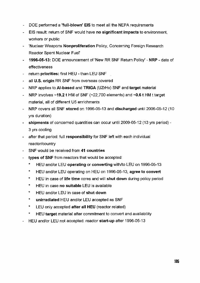
DOE performed a 'full-blown' EIS to meet all the NEPA requirements
EIS result: return of SNF would have no significant impacts to environment,
workers or public
'Nuclear Weapons Nonproliferation Policy, Concerning Foreign Research
Reactor Spent Nuclear Fuel'
1996-05-13: DOE announcement of'New RR SNF Return Policy'- NRP - date of
effectiveness
return priorities: first HEU - than LEU SNF
all U.S. origin RR SNF from overseas covered
NRP applies to Al-based and TRIGA (UZrHx) SNF and target material
NRP involves 19.2 t HM of SNF (-22,700 elements) and 0.6 t HM t target
material, all of different U5 enrichments
NRP covers all SNF stored on 1996-05-13 and discharged until 2006-05-12 (1 0
yrs duration)
shipments of concerned quantities can occur until 2009-05-12 13 yrs period) -
3 yrs cooling
after that period: full responsibility for SNF left with each individual
reactor/country
SNF would be received from 41 countries
types of SNF from reactors that would be accepted:
HEU and/or LEU operating or converting with/to LEU on 1996-05-13
HEU and/or LEU operating on HEU on 1996-05-13, agree to convert
HEU in case of life time cores and will shut down during policy period
HEU in case no suitable LEU is available
HEU and/or LEU in case of shut down
unirradiated HEU and/or LEU accepted as SNF
LEU only accepted after all HEU (reactor related)
HEU target material after commitment to convert and availability
HEU and/or LEU not accepted: reactor start-up after 1996-05-13
105

Shipments and Ports of Entry
- reduce shipments/risks by coordination - max. casks/ship
- DOE estimate: 150-300 ships to Charleston, to Concord
- settlement DOE/INEL 61 shipments of foreign SNF until 2000
- shipments by charter or regular container ships
- military ports: Charleston, S.C. 80 %) and Concord, Cal. (-5 %)
- military ports for safety and security reasons (proven infrastructure)
- target material: mainly overland from Canada
- transport from U.S. ports to site: by truck or rail
- DOE preference for rail
Management Sites
- 2 sites prepared for interim storage of SNF
- Al-based SNF: managed in SRS, Savannah River, S.C.
- TRIGA SNF: managed in INEL, Idaho
- treatment after storage: packaged or chemically separated and blended down
<20 wto 5
Fees
- HEU and TRIGA SNF: USD 4500 per kg tot metal (element related)
- LEU (silicide): USD 3750 per kg tot metal (element related)
- fees are subject to escalation subsequent adaptation
- for signed contracts only escalation can apply
- fees only apply for high-income economy countries transportation)
- fees for take over include: receipt, management, interim storage, chemical
separation or geological disposal
- U.S. take over the cost (incl. transport) for all other concerned countries
106

Storage Technologies
- wet or dry storage in existing facilities (SRS + INEL)
- new dry storage concepts/facilities under development
- final disposal: repository in Yucca Mountain, Nevada?
- Nuclear Waste Policy Act of 1982 authorizes geological disposition
- decision on final disposal: under NEPA requirements
Contract
- contract conclusion between DOE and reactor operator
- title transfer to the U.S.: at the ports of entry (off-loading) or continental border
with exceptions, if appropriate
- Appendix A: description of SNF
- Appendix B: description of transport cask
- Appendix C: description of SNF history
Actual Shipment
- Ist European shipment: Aug/Sep 1996
- 231 SNF elements in 6 casks from Germany, Sweden, Switzerland
- in parallel: 1 st shipment 2 casks) from S-America (Chile and Columbia)
- arrival at Charleston/SRS: 1996-09-22
- further shipments from overseas: not before Feb 1997
Legal Process
- S.C. governor filed a lawsuit against DOE's NRP
- main argument: EIS is insufficient in respect to long term storage in SRS
(L-Basin integrity, earthquake)
- trial date: 1996-11-25
- judge promised decision by 1996-12-01
107

CH04AO029REPROCESSING OF MTR FUEL AT DOUNREAY
Nicole HoughUKAEA, Dounreay
ABSTRACT
UKAEA at Dounreay has been reprocessing MTR fuel for over 30 years. During that timeconsiderable experience has been gained in the reprocessing of traditional HEU alloy fuel and morerecently with dispersed fuel. Latterly a reprocessing route for silicide fuel has been demonstrated.Reprocessing of the fuel results in a recycled uranium product of either high or low enrichment and aliquid waste stream which is suitable for conditioning in a stable form for disposal. A plant to providethis conditioning, the Dounreay Cementation Plant is currently undergoing active commissioning.
This paper details the plants at Dounreay involved in the reprocessing of MTR fuel and the treatmentand conditioning of the liquid stream.
INTRODUCTION
The MTR reprocessing plant at Dounreay has operated for over 30 years and has just completed its61 st campaign. During that time nearly thirteen thousand elements from all over the world have beenreprocessed. The plant was originally designed to reprocess fuel from the UKAEA MTR reactors atHarwell and Dounreay and from the university research reactors at East Kilbride, Manchester andAscot. The first reprocessing of overseas fuel took place in 1962 when 25 Danish HEU elementsformed part of the 17th reprocessing campaign. Since 1962 fuel from Australia, France, Germany,South Africa, Greece, Japan and Sweden has been reprocessed at Dounreay. A list of MTR elementsreprocessed to date is shown in Table .
COUNTRY NO. ELEMEENTS URANIUM (kg)United Kingdom 9306 1438.3Belgium 240 59.5Spain 6 10.8Denmark 950 105.6France 289 98.1Australia 264 32.2India 83 14.0Germany 918 135.4South Africa 216 29.5Greece 39 29.6Sweden 168 24.8Japan 410 82.7TOTAL 112889 1 2060.5
Table 1: Elements Reprocessed 1958-1996
The reprocessing plant at Dounreay has traditionally been run on a campaign basis. A typicaloperating campaign is between six and nine months in duration and may involve the reprocessing ofanything between 300 and 900 elements. The operating mode of the plant is dictated by the workload:for a small campaign the plant can be operated for five days a week, employing a two shift system; forlarger campaigns 24 hour, 7 day a week working on a three shift system is used.
As the scope of activities carried out in the Dounreay MTR Reprocessing facility are of a standardnature it has been possible to develop, over the years, a "Standard MTR Reprocessing Contract." Themain historical variance from contract to contract concerns the ftiel details and transport arrangements.
108
Commercial ContractsThe UKAEA will help customers, to arrange for the transport of the fuel to Dounreay. Flask receipt atDounreay is charged at a per flask rate, flask return is at the customers expense. On receipt of the flaskthe UKAEA will unload the flask and store the fuel pending reprocessing. Prior to reprocessing theUKAEA will, if possible, crop the customers elements to remove excess aluminium, for a fixed chargeper element. The activities carried out in reprocessing the fuel include; weighing, element cropping,dissolution, uranium recovery as uranyl nitrate, accountancy and analysis. These reprocessingactivities are charged at a fixed rate per kg total metal. On completion of the reprocessing the UKAEAwill convert the customer product to either oxide or metal, this is charged at a standard conversion rateper kg of product, depending on the product required. Should the customer wish for his product to beat a lower enrichment, down blending can be carried out as part of the conversion and will not incur anadditional charge. The product will be stored at Dounreay for up to 3 months, as part of thereprocessing price; beyond 3 months, storage will be charged at a per kg U235 rate. Also included inthe reprocessing price is the storage of liquid ILW, for up to years, and the cementation of the ILW.Storage of the cemented ILW will be charged at a drum rate per year. All UKAEA reprocessingcontracts contain a standard clause requiring commitment to Return of Waste as required by the UKGovernment and as supported by intergovernmental agreements.
THE DOUNREAY MTR REPROCESSING FUEL CYCLE
Fuel Transport
Fuel is transported from the reactor sites to Dounreay under 1AEA transport regulations. A number oftransport routes are available, with flasks being transported by road and rail to a port, by sea to theUnited Kingdom and by road to the site.
Once on site the flasks are unloaded to a dedicated storage pond. The pond has the capacity to holdover a thousand elements and this enables fuel to be stockpiled before a reprocessing campaign iscommenced. The storage pond is equipped with a 25 tonne crane and is designed to allow the handlingof most MTR flasks.
Fuel Transfer for Breakdown
Once a campaign is commenced the elements are transferred for reprocessing using internal transportflasks. For standard elements the fuel break down is carried out in the fuel handling pond of thereprocessing plant. For larger elements a dedicated disassembly cell in one of the other facilities onthe Dounreay site is used.
THE MTR REPROCESSING PLANT
The reprocessing plant contains the facilities necessary to cut up the elements, dissolve them andseparate the uranium from the actinides and fission products. The process results in two waste streams,a ILW raffinate which contains over 99.9% of the fission products and a low active raffinate whichresults from the purification of the uranyl nitrate product.
Experience has shown that alloy and dispersed fuels of a variety of enrichments are most successfullyprocessed by tailoring the element handling, cropping, dissolution and extraction processes to suit thedifferent fuel types.
HEU Alloy Fuel
HEU alloy has been the traditional feed-stock of the MTR plant. The elements may be either tube orplate type but are essentially treated in the same way.
109

The elements are transferred to the plant and loaded into a buffer storage matrix in the fuel handlingpond. Depending on the uranium content and the weight of the elements either one, two or threeelements are processed as a batch.
Element DismantlingTo prepare a batch of fuel for dissolution the elements are weighed under water using an electronicbalance. The elements are then fed through a hydraulic cropper which cuts them into cm pieces. Thepieces are then re-weighed to ensure that all of the fuel is charged to the dissolver. The elementweights are recorded and corrected to show the true weight of the elements to take account of thebuoyancy effect of the water. This weight provides the basis for flowsheet calculations and for chargesto the customer.
During the cropping process there is some leaching of activity from the elements into the pond water.To ensure that the radiation from the pond is minimised there is aPond Clean-Up Unit. This unitconsists of two parallel filters and ion exchange columns. The filters remove any particulate from thewater, whilst the ion exchange columns remove dissolved activity. The Pond Clean-Up Unit is able toreduce the pond water activity by a factor of ten on a single pass and is very successful in reducing theradiation levels in the pond water.
DissolutionThe plant contains two dissolvers each with a 160 litre capacity. The cropped pieces of fuel arecharged to the dissolver using an elevator which lifts the fuel from the pond and deposits it into acharge chute, through which it enters the dissolver. Uranium dissolves readily in nitric acid, however amercury atalyst is used to ensure that the aluminium dissolves.
The dissolution conditions are adjusted so the hydrolysis of aluminium nitrate can take place toproduce an anion deficient solution which contains the AI(NO3) (O 3 complex. There are a numberof advantages to using an anion deficient flowsheet: the removal efficiency of fission products isextremely high and the solubility of the aluminium is improved, enabling the volume of raffinate to bereduced. The equilibrium diagram for the acid/aluminium system is shown in Figure 1. This clearlyillustrates the increased solubility of aluminium on the acid deficient side.
Figure 1: Equilibirum Phase Dagram -Aluminium/Acid System
0 HETEROGENEOUS
03
r
0 HETEROGENEOUS0,E
HOMOGENEOUSSOLUTIONE< 19
5 c
SOLUTION NOT POSSIBLE
.3 0 2 3
Anion Deficiency (mol) Acid Conentration (mol)
The ratio of acid to aluminium. added to the dissolver is carefully controlled to ensure that the resultantsolution always lies in the homogenous phase of the equilibrium system.
The dissolution reaction takes place over six hours during which time the dissolver is continuallyrefluxed.
110

Solvent ExtractionThe solvent extraction plant operates with two cycles, the first cycle removes over 99.9% of the fissionproducts and the second cycle purifies the product. Mixing is achieved through the use of motordriven paddles.
In Cycle I the dissolver liquor is fed to the extractor box with a ferrous sulphamate solution andcontacted with 3 tri-butylphosphate(TBP)/kerosene. The ferrous sulphainate converts any in-bredplutonium to the PuIll oxidation state which prevents it being extracted into the solvent, The loadedsolvent is then fed to the strip box where it is contacted with an aluminium nitrate solution to transferthe fission products back to the aqueous phase. The uranium bearing solvent is then back-washedunder low acid conditions to give a uranyl nitrate product.
The second cycle of the solvent extraction plant works in the same way as the first but with thepercentage of TBP in kerosene increased to 6.
Dispersed Fuel
Dissolution and solvent extraction operations for dispersed fuel are carried out using standardflowsheets that have been developed at Dounreay. However experience has shown that, when exposedto pond water, dissolution of Cs-137 from the fuel elements takes place, increasing pond activitylevels. Alternative procedures are now adopted for the element handling of dispersed fuel to limit thedissolution of caesiurn. The ion exchange columns of the pond clean up unit are able to remove thedissolved activity from the water.
There is also fission gas release from dispersed fuel elements during cropping. This gas has beenanalysed and the results are shown in Table 2 The table shows that the gases which are released arenot in themselves radioactive and the rise in pond water radiation is purely due to the dissolution ofceasium.
ELEMEENT % CONTORTIONKrypton 0.68Xenon 3.16Hydrogen 19.4Helium 75.6Argon 1.13
Table 2 Composition of Evolved Gas from Dispersed Fuel Elements
Element HandingElement handling procedures are adjusted for dispersed fuel to minimise the time the fuel is exposed topond water. Normal handling involves weighing the elements for the batch, cropping the batch and re-weighing the pieces. The batch is then charged to the dissolver.
For dispersed fuel the elements are cropped and the pieces charged immediately. This ensures that thetime that the fuel is in contact with the water is minimised and the increase in pond water activity islimited.
Silicide Fuel
A considerable amount of research into the reprocessing.of silicide fuel has been undertaken by theUKAEA at Harwell. This has indicated that finely divided silica remains as a solid after dissolutionand that polysilicic acid is present in solution. Both these factors have the potential to interfere withthe solvent extraction process and the presence of finely divided solid material can affect the operationof valves and transfer systems. In addition silicide fuel contains far more plutonium than HEU fueldue to the material in-bred in from the U23 8.

At Dounreay we have recently undertaken the reprocessing of sicide fuel in the MTR reprocessingplant. The elements reprocessed originated from the RERTR programme to develop sicide fuels in theNetherlands.
The reprocessing of these elements as proved tat HI scale reprocessing of silicide fuel is possiblealthough the plant would require some modification before a large reprocessing campaign of silicide felcould be commenced, to enable the removal Of Sl1CeOLIs aterials prior to solvent extraction.
For the purpose of this trial the dssolution and solvent extraction procedures were adjusted to allow thesilicide fuel to be processed through te plant.
DissolutionResearch has shown tat the effects of silicic acid on solvent extraction are increased for an aniondeficient flowsheet. Dissolution of sicide fel therefore akes place on an acid flowsheet to give asolution which contains Al(N03)3 and a excess of HN03, This type of flowsheet has been usedfrequently in the past in the MTR reprocessing plant and is used as a standard flowsheet in otherreprocessing plants. The standard dissolution tme of 6 hours is used ad sparges are operated until theliquor is transferred from the dissolver to the next process vessel to rnininuse te settling of silica.
Solvent ExtractionTo mImise the effect of silicic acid o the solvent flowsheet the flowsheet is modified. The feed to theplant is diluted by the co-feeding of three molar acid to the extraction box. The feed rate of ferroussulphamate is also doubled to ensure tat all the plutonium in-bred from the U-238 is converted to thePu III form and rejected in the raffinate.
The Optimised FlowsheetThe flowsheet for silicide reprocessing uderwent development during the recent campaign. Theoptimised flowsheet resulted in a uranium etraction efficiency of 98% a plutonium content in theproduct of less than 10 parts per million and a similar raffinate volume per kg of uranium processed asthat produced by the reprocessing of HEU alloy ftiel.
THEPRODUCT
The solvent extraction process produces a very pure product. The specification for a typical product isshown in Table
I Boron Equivalence < 25 pprn2 Uranium Isotopics -- as detemilned
Total Impurities less than 1500 ppm4 Fission Product Content < 37 E4 Bq/g5 Plutonium I < 250 Bq/g
Table ): Typical MTR Uranium Product after Reprocessing
The enrichment of the fel Is maintained throughout reprocessing and the ranium can be re-used inseveral ways. Uranium as recovered or at a slightl oer erichment can permit certain reactors toachieve continuity of fuel supply until low enriched fuels of sufficient density are available. Forreactors already converted to LiU. facilities are available at Dounreay for down blending recovereduranium to the desired enriclinient and to prodLiCe uranium In the required forrn.
WASTE
There are two liquid aste tpes produced by te solvent extraction plant.
112

The waste stream produced from Cycle I raffinate contains over 99.9% of the fission products and isheld as a liquid in underground storage tanks for at least five years. It is then transferred to theDounreay Cementation Plant for immobilisation.
A low active waste stream is produced from cycle 11 raffinate which contains very small quantities offission products. This waste stream is sampled and is discharged to sea with other plant effluent thesite discharge authorisation.
Environmental DischargesRadioactive discharges to the environment from the reprocessing of irradiated fuel at Dounreay arecontrolled under an authorisation issued by the UK Government's Scottish Office. In assessment ofthe permitted discharge from the site, the Scottish Office considers the effect of individual radioactivespecies on the environment and on critical groups of individuals. The limits that are indicated fromthis study are then reduced to give a site discharge limit which must be adhered to.
The discharges resulting from the 1996 reprocessing campaign were:
Alpha BetaLiquid Discharges: 1.2 E9 Bq 4.8 E10 BqGaseous Discharges 7.7 E3 Bq 2.7 E6 Bq
These represent a maximum of I% of the site discharge limits in terms of alpha and beta activity.
ILW WASTE TREATMENT IN THE DOUNREAY CEMENTATION PLANT (DCP)
The Dounreay Cementation plant is currently undergoing active commissioning. The plant is designedto accept MTR raffinate after five years storage and to immobilise it in a cement matrix for disposal.
EHI F--,--j F71:7.L S- F�
MTR LiQ=
f� D1208 Chemkcal CeR
oppe,[��j
P-� F- F�
0 n
Main Handfing Gen
H.Pp -- - - -- -- - -- - - -- - - Z ------------LAD I
: T. S101.9t
Stbn
- -- - -- -- - - -- -
- -- - - -- - -- - - - -'Y D-
(SCO B. d-) Deco.U.n
--------------
Figure 2 Schematic Diagram of DCP Process
The Cementation process essentially consists of the receipt of MTR raffinate from the undergroundstorage tanks via a dedicated transfer line into a reception vessel. There it is sampled and analysed todetermine the volume of sodium hydroxide required to neutralise the solution.
The neutralised liquor is mixed in precise drum volume batches with blast furnace slag, PortlandCement and hydrated lime in a 00 litre drum and allowed to cure for a minimum of 24 hours.
The drum is progressively transferred through the cementation plant until it arrives at the grout cappingstation. he remaining drum ullage is filled with cement and the drum lid locked. The drum ischecked for external contamination before being transferred for storage.
113

An interim drum store is available at Dounreay for the storage of the cemented waste before transportto the final repository. For UK fuel this will be the NIREX repository and for overseas fuel it will be arepository in the country of origin.
Figure 2 shows a schematic diagram of the Dounreay Cementation Plant.
RADIATION DOSE UPTAKE TO THE WORKFORCE
The monitoring of dose uptake to the workforce is an essential part of the management of fuelreprocessing. Dose restraint objectives are set at the beginning of a reprocessing campaign based on adetailed dose budget. Dose is monitored on a daily basis and is controlled against the dose restraintobjectives.
For the reprocessing campaign that has just been completed the total dose to the twelve operators was42.86 mSv. This is equivalent to an average operator dose of 357 mSv and a dose per elementreprocessed of 0.2 mSv. This is well within the corporate dose limit of 15 mSv.
Continual improvements are made to the plant and to operating procedures to minimise the dose uptaketo personnel.
SAFEGUARDS
Operation of the reprocessing plant at Dounreay is subject to constant surveillance by EuratornInspectors. Euratorn spend approximately 500 mandays on site and are always on hand to witness andrecord material transfers and smpling procedures.
CONCLUSION
Dounreay has traditionally reprocessed EU alloy, however, in recent years, the MTR plant hasdiversified and reprocessed a significant quantity of dispersed fuel. The reprocessing of the twosilicide elements in the recent campaign shows a clear commitments to a future for the plant whichincludes the reprocessing of high density LEU silicide fuel.
114

CURRENT ACTIVITIES ON IMPROVING STORAGE CONDITIONSOF THE RESEARCH REACTOR "RA" SPENT FUEL
M. V. Matau�ek, Z. Vukadin, R. Pavlovid, N. MarinkovidThe VINdA Institute of Nuclear Sciences, Belgrade, Yugoslavia
1. Introduction CH04AO030
.After 25 years of successful operation, the 65/1 MW thermal heavy water moderated and cooledresearch reactor RA at the VINCA Institute was shut down for refurbishment in 1984. Since for anumber of reasons this refurbishment has not yet been completed, and having in mind the long shut-down period, the future status of the RA reactor is presently a subject of serious reconsideration.
Closely related to the problem of future use, or eventual decommissioning, of the research reactorRA is the problem of safe and reliable storage of fuel irradiated so far, as well as disposal of the newirradiated fuel if and when the reactor is re-started.
Basic facts about operation, ageing, reconstruction and spent fuel storage of the research reactorRA have been presented and discussed in detail in some earlier papers [ 1 31. The following paragraphsdescribe current activities on improving storage conditions of the research reactor RA spent fuel.Recent results are presented concerning identification and minimization of corrosion processes. Optionsfor permanent resolving of the spent fuel storage problem are discussed and a possible scenario forbuilding a new long term research reactor RA spent fuel storage is proposed.
2. The Present Status of the Spent Fuel Storage Pool at the Research Reactor RA
Research reactor RA fuel element (slug) is an 11.3 cm long cylinder, with 372 cm of outerdiameter, consisting of an outer tube with 2 mm thick fissionable material and mm thick inner andouter Al cladding, and an mm thick inner Al tube which serves as cooling intensifier. Fuel elementsare inserted into a 2 mm thick Al tube (1 0 or 1 1 slugs/tube), thus forming a fuel channel. The reactorcore consists of up to 82 channels in a square lattice with 13 cm pitch. Until 976 the reactor wasoperated with 2 enriched uranium metal fuel, when new fuel with 80% enriched uranium oxidedispersed in aluminium was bought from USSR.
The six meters deep temporary spent fuel storage pool, consists of four connected basins, havingthick concrete walls cladded with stainless steel. It is filled with approximately 200 m' of stagnantordinary water. 304 channel-type stainless steel fuel containers, receiving up to 1 8 spent fuel elementseach, are placed vertically in the pool, Fig. 1. Initially, it was planned to transfer spent fuel back to theSoviet supplier, after 45 years of cooling in the temporary storage pool. Since this did not happen,in order to increase the storage capacity, the oldest spent fuel was gradually taken out of the originalstainless steel containers and repacked into aluminium barrels, each containing 30 aluminium tubesreceiving up to 6 irradiated fuel elements per tube. At present, there are 30 such barrels, placed in twolayers in the annex of the basin 4 Fig. 2 Cadmium strips were inserted into the barrels to assurenecessary subcriticality. Both the barrels and the channel-type fuel holders were filled withdemineralized water and hermetically closed.
According to the original design, the RA reactor spent fuel storage had no system for pool waterpurification. A simple system with a mechanical filter and an ion-exchange column, purchased justseveral years ago, is neither adequate, nor operable. Monitoring and maintaining of pool waterradiochemical parameters were not imposed, and were even considered unnecessary by the operatingstuff since the pool water was not supposed to be in direct contact with the spent fuel. For manyyears nothing has been done to prevent or slow down corrosion of the spent fuel containers, nor toexamine the state of the spent fuel inside the containers.
Due to the obvious lack of concern for the conditions of the reactor RA spent fuel storage, it isnow in a very bad condition. Water in the pool is dirty and its chemical parameters are such that theyfoster rather than inhibit corrosion. At the bottom of the pool there is a lot of sludge which had evenconcealed a lost spent fuel slug since 970. Simple visual inspection shows that all steel constructionelements have heavily corroded, Fig. 3 Corrosion can also be noticed on stainless steel walls of thebasins and transport channels, especially at welded parts, Fig. 4.
A serious concern about the conditions of the spent fuel storage pool was first expressed by theauthor of the present paper in 994 [1 A possibility of fuel leakage inside the containers and eventual
115

fission products release from the containers, was pointed out. Since the VINCA Institute had noexpertise nor the material resources for solving the problem of safe long term disposal of irradiatednuclear fuel, an international help and support were asked for through IAEA. Actions taken so far andplans for future activities are presented in the following paragraphs.
3. Activities on Identifying and Improving Conditions in the RA Reactor Spent Fuel Storage Pool
Radiological and chemical analyses of the water from the RA reactor spent fuel storage pool werefirst made during the visit of IAEA fact finding mission to the VINCA Institute 4]. Radioactivity of thepool water 35.2 to 41.8 B/ml "'Cs) was then ascribed to the presumable leaking of the lost fuelelement. Repeated analyses of water samples taken at the same points as about a year ago now showan increase of pool water radioactivity approximately by a factor of 3 93 to 140 Bq/ml "'Cs).
During last year, water samples were also taken on several occasions from channel type stainlesssteel spent fuel containers selected so as to represent different typical storage conditions: channelscontaining normally disposed spent fuel from different periods (1 969-1 979), channels containing fuelwith corrosion deposits noticed at the time of disposal, channels containing fuel whose corrosiondeposits were removed before the disposal, as well as a channel containing one fuel slug which wasleaking already at the time of disposal (1 970). Increased specific activity of these samples, rangingfrom about ten to several hundreds Bq/ml "'Cs in most of the channels, reaching up to several hundredthousand /ml "'Cs in some channels with normally disposed fuel, and even up to two orders'Ofmagnitude more in the channel containing the fuel slug which was leaking already at the time ofdisposal, is a clear indication that at least one fuel element is leaking in most of the channel type spentfuel containers. It is assumed that the situation in alurninium barrels can only be worse.
Strings of spent fuel elements were taken out from some channel-type containers and brought tothe hot room in the reactor shield to be visually inspected through the protective glass window. Thickcorrosion deposits can be notices on the Al cladding of all fuel slugs, Fig. 5. The lost fuel slug hasrecently been located and taken out from the bottom of the pool. Visual inspection through the sameprotective glass window shows that it is heavily corroded, Fig. 6 Yet, in spite of the fact that this fuelelement has spent almost twenty years in the corrosively very aggressive sludge at the bottom of thepool, the uranium metal has not been uncovered, which mostly removed the concern expressed earlierby IAEA experts 41 that uranium hydride had been formed in such an amount that it could cause fireif the spent fuel is exposed to air.
Aluminiurn barrels probably represent the main radiological and safety problem in the RA reactorspent fuel storage pool. The analyses and inspections described above indicate that massive leakageof spent fuel must be taking place in the barrels. On the other hand, oxidation of a large surface ofaluminium in contact with water (about 14 m') inside hermetically closed barrels could result in highinternal hydrogen pressure. A sudden release of this pressure could spread fission products in the poolwater and its surrounding and cause unpermitted irradiation of personnel.
Action is therefore initiated in two directions. First, to improve the safety of the existing spent fuelstorage. Second, to consider transferring spent fuel into another, presumably dry storage space.
4 A New Project for Safe Disposal of Research Reactor RA Spent Fuel
A new project has recently been formulated, engaging several laboratories of the VINCA Institute(reactor physics, chemistry, radiation protection, nuclear engineering, material sciences), in order tosolve the problem of safe disposal of research reactor RA spent fuel. The following management planfor implementation of this project is foreseen.
4. 1. Phase 1. Improving conditions in the existing reactor RA spent fuel storage pool
Measuring the pressure inside the aluminium barrels, controlled release of possible overpressureand establishing regular monitoring and control of this pressure will remove direct danger of aradiological accident, caused by a sudden release of a larger amount of gas carrying the long livedfission products from the leaking fuel. These complicated operations can only be performed with thetechnical assistance of the IAEA.
In order to minimize further corrosion and preserve integrity of the stainless steel channels andaluminiurn barrels, which now obviously contain leaking spent fuel, the following actions are planned:removing of the sludge from the bottom of the pool (estimated amount 3 m') and disposing of thissludge in the cemented form at the VINCA low and intermediate waste disposal site; improving thequality of the water in the pool; isolating the failed lost fuel slug from the pool water and regular
116

monitoring of the pool water activity in order to identify eventual leakage of the spent fuel containers;starting of the new system for pool water purification; establishing rgular monitoring and control ofthe pool water chemical parameters (pH and conductivity). Minimum duration of these activities isabout six month.
4.2. Phase 2 Transfer of the RA reactor spent fuel into another storage space
Prompt actions to minimize further corrosion processes in the existing temporary RA reactor spentfuel storage are mandatory for improving its safety, in the sense that the probability of uncontrolledfission products release into the reactor building, and eventually to the environment is reduced to theminimum possible value. However, the only long-term solution to the interim storage of aluminiumcladded spent fuel should be to transfer it to a dry storage facility.
Since transfer of spent fuel back to the supplier is not likely to occur, construction of anindependent facility for spent fuel storage is to be considered. The following activities will be necessaryfor realization of this project: decision-making about the future status of the research reactor RA-decision-making about the most adequate solution for safe disposal of the fuel irradiated so far;producing project documentation and building of a new dry storage facility with the assistance ofdomestic construction organizations; transfer of the irradiated research reactor RA fuel from theexisting temporary storage pool to the newly built longer-term spent fuel storage space in specialcontainers designed for the purpose; adopting regulations, procedures and an adequate organizationfor long-term supervision, monitoring and control of the newly built facility. Duration of the aboveactivities is estimated to be 23 years.
Factors that may cause delays or prevent implementation of the proposed project are lack ofexpertise and know-how in the field of safe disposal of irradiated nuclear fuel, lack of necessaryequipment and material resources, as well as general economic difficulties in the country. Internationalcooperation and support, presumably through the IAEA, or on multilateral and/or bilateral basis, wouldbe highly appreciated and desired.
5. Conclusion
The present status of the research reactor RA spent fuel storage pool at the VNCA Institutepresents a serious safety problem. Activities have therefore been initiated to improve conditions in thetemporary storage pool in order to minimize further corrosion of the spent fuel containers, as well asto enable transfer of spent fuel into another dry storage space.
Immediate objective these activities are expected to achieve is increased safety of the researchreactor facility in the sense that the probability of uncontrolled fission products release will be reducedto the minimum possible value. By storing the previously irradiated fuel of the research reactor RA ina newly built storage space, sufficient free space will be provided in the existing spent fuel storagepool for the newly irradiated fuel when the reactor starts operation again. In the case that it is decidedto decommission the research reactor RA, the newly built storage space will provide safe disposal ofthe fuel irradiated so far.
Solving the problem of safe disposal of research reactor irradiated fuel is a difficult task for acountry with no long term nuclear power program, and with limited potentials and resources.International cooperation through the IAEA, or on multilateral or bilateral basis, would be highlyrecommended and appreciated.
6. References
1 .M. V. Matautek, Research Reactor RA at VINCA Institute of Nuclear Sciences, NUKLEARNATEHNOLOGIJA Journal, Vol. 10 21995)3.
2. M. V. Matautek, N. Marinkovid, R. Simovi6, Criticality Safety of Fresh and Irradiated Fuel of the6.5 MW Heavy Water Research Reactor, Proc. of International Symposium on Nuclear EnergySIEN'95, Bucharest, 1995, p. 27.
3. M. V. Matautek, N. Marinkovi6, Z. Vukadin, Research reactor RA at VINCA Institute of NuclearSciences. Ageing, Refurbishment and Irradiated Fuel Storage, Proc. of a Topical MeetingRESEARCH FACILITIES FOR THE FUTURE OF NUCLEAR ENERGY, World Scientific Publishing,1996, p. 69.
4. 1. Ritchie, D. Litai, Travel Report: A "Fact-finding Mission to the RA Research Reactor at VINCA,IAEA, November 1995.
117

Fig. Channel-type spent fuel containers Fig.2 Barrels with repacked spent fuel
Fig.3 Construction element in the storage pool Fig.4 Wall of the storage pool
Fig.5 A string of spent fuel elements from Fig.6 The lost fuel slug taken froma channel-type container the bottom of the pool
Ila

INICH04AIII0103111111111111,11I
Dry Vault For Spent Fuel DepositoryBasic Outsets, Operating results and
Safety of the CASCAD plant
Philippe BARDELLE
Ddpartement d'Etudes des Combustilbles Direction des R6acteurs Nucl6aires
Commissariat A Energie Atornique Centre dEtudes de Cadarache
13108 SAINT-PAUL-LEZ-DURANCE CEDEX FRANCE
1. Introduction
Reprocessing and recycling of fissile materials is the prefered approach to spent fuel management in
France. However, a number of spent fuel elements from prototype and experimental nuclear reactors annot
be reprocessed in the existing industrial facilities, either because such facilities are booked to full capacity, or
due to technical factor's such as non standard nature of fuel or limited series of fuel.
The CEA therefore built a facility in which spent fuel can be stored for a few decades (50 years), until
favourable conditions prevail for its disposal. The main features of this project consist in a dry depositary
which presents a low cost of working, against a wet one which is more expensive due to the circulation and
the continuous controls of the water. Therefore, this is a fair solution because the experimental fuels will
present a rather low residual heat power after decay in the nuclear reactor. At this stage, it becomes possible
to cool the fuel elements by a fully passive air circulation. This process allows a good efficiency without
mechanical equipernent and works all the better as the amount of heat to exhaust is great, in the limits of the
design. However, we will see that this concept may be extended to a depository of standard spent fuel
elements.
This facility, known as "CASCAD" (shortening for CASemate (--vault) CADarache) started up in 1990,
and received its first anister of fuel on May th 990.
This paper reviews the basic design data of the facility, outlines the main techniques used for its construction,
draws the safety concepts and presents the first results determined by a looking-back over 4 years of working.
II. Principles and Criteria for Basic Design
The flexibility to deposit a whole range of fuel types with various characteristics is a key feature of the
"CASCAD" design. For example, the storage facility enables the fuel assembly to be retrieved during interim
depository for reprocessing or final geological disposal
• containement by tight-canisters (to accept failed cladding too),
• stainless steel wells with tightness and non-contamination controls,
• a windowless storage cell made in concrete for biological shielding which involves 315 storage wells,
119

• a handling hall with biological shielding in concrete and viewing through a lead-glass window and
through a video amera. When any nuclear fuel element is in op6ration, the staff may go into this
cell which is always clean in regard to an eventual radionuclids contamination.
• cask or canisters check-in and inspection areas.
The building in which the facility is housed is 35 meter long, 25 meter wide and 6 meter high. It is a
concrete structure erected on a ground slab, 2 meter's thick, extending 2 meters beyond the south and north
walls. The main part of the building structure consists of the storage vault with wall thickness of 125 meter;
Stiffness is provided by transverse and axial webs of rod-reinforced concrete. The concrete slab between the
vault and hall hold up the entire load of the wells including fuel elements and is itself supported by the webs,
since the need to provide free air circulation precludes the use of supporting columns. Then, this slab is
subjected to heavy stress due to loading by wells and to the temperature prevailing in the vault.
The "CASCAD" building is designed to receive (at present time), to send (in the future), to handle and
to prepare casks up to 400 M prior or next to the transfert of the canisters to or from the handling hall. The
system comprises a wheeled carriage on rail tracks and supports for securing the casks during the motion.
Chek-in and check-out for contamination and damaged fuel detection are realized in a special room equipped
with a nuclear ventilation to get dynamic containment.
The main item of equipment for canisters transfer is the 50 M overhead crane installed in the handling
hall. This crane is equipped with a multi-purpose handling head which can carry a number of grip modules. Its
electrical supply is controlled automatically from the front zone and this programmable unit drives the crane
over the wells. The final step of the handling process, the gentle driving down inside the pre-determined well
is conducted in a manual mode with the help of a video camera.
Other items are available in the handling hall such as 2 remote handler's or a 50 M hook.
The storage vault and the wells 7 meter useful length) are cooled by natural open-convection a cold
air inlet is provided at the bottom part of the vault, the air heated by contact with the wells is discharged
through a 42 meter high stack outside the building. A general thermosiphon effect is created, which extracts
the heat released. This ventilation system is designed for various conditions, namely
• thermal loading,
• prevailing winds,
• atmospheric pressure.
Each well accepts 600 Wafts maximum in thermal power, and consequently, the maximum heat loading
of the vault is about 200 kW. In this case, the flow rate of air may reach 19,000 cubic meter per hour.
111. Safety Concepts
The integrity of the canister, first barrier, is monitored by sampling regularly the internal atmosphere of
the wells.
If the contamination control is positive, it is possible to pick up the canister for examination and send it
in a specialized facility located nearby "CASCAD" for substitution. If the well is not contaminated, it may be
used again. On the contrary, the well is closed waiting for a decontamination operation.
120

The stack of air cooling extraction is equipped with a continuous air control device. If the air control is
positive, a valve avoids a radioactive pollution risk in shutting the stack. In this case, a mechanical ventilation
insures the exhaust of the heat through HEPA filter battery. The canisters are picked up from the well and are
put in one of the four safe-keeping wells. Then, the leaky well is shut for good.
Concrete biological shielding takes account of fuel elements irradiated at 45,000 MWd per ton and
having previously cooled off for five years. The requirements for maximum dose-rate at work station settle the
value at 25 micro-Sv/hour.
For these same fuel elements, criticality CEA codes led to a depository tube layout in the form of a
triangular pattern with 00 mm spacing. The absence of distortion in the facility stuctures, in the wells and for
the canisters, even in case of an earthquake, was demonstrated by calculations using approved codes. About
this topic, the facility and its safety-related equipments have been calculated through a dynamic structural
analysis based on acceleration diagrams selected as the most representative following a survey of local
earthquake history. Such acceleration diagrams are in category 9 of the MSK scale which goes from to 12,
for a maximum historically-probable earthquake of intensity on the same scale.
During dry storage, the temperature of the concrete slab between the vault and hall must be limited to
1 00 C for reasons of mechanical strain. Air ducts for natural convection cooling were designed using models
and codes developed by the CEA, based on local weather data and on possible disturbances in the close
environment. Nevertheless, before deci ding to build the "CASCAD" facility, CEA considered as necessary to
confirm the calculation by experimentation. Analysis covering heat transfer around a storage well, and the
overall heat dissipation process were respectively validated using a full scale model of a complete well and a
1/12 scale model of the vault and cooling system.
Now, a large set of measurement points survey, continuously, the variations of the temperature of
slabs, webs and wells.
The 50 M crane and its auxiliary equipments in the handling cell present a high reliability. In the event
of failure of one of the geared motors or their power supplies, the system is so designed that the operation
under way can be ended. To that end, axial and transverse drives are equipped with double and separate
motor systems and supplies. Even in case of an earthquake, intensity 9 the crane remains available.
Each well owns a shock absorber intended to minimize the consequences of the dropping of a canister
during handling. Full scale tests were done by dropping a 350 kg weight into the well.
IV. Operating Results
Today, the "CASCAD" building contains Brennilis EL4 fuels 89 wells) and navy spent fuels coming from
French nuclear submarines. The Brennilis nuclear reactor fuel was stored in the plant pools as it was unloaded
from 1971 through 1985. It consists in 5300 "clusters" of low-enrichment uranium oxyde rods with zirconium
cladding.
The loading of the storage vault reaches 50 Tons shared out on 134 wells, 43% of the total physical
capacity.
The natural open-conveGtion exhausts 53 M, 27% of the maximum heat loading. In regard of this ratio,
the flow rate and temperatures recorded in the vault in summer and winter are the following 121
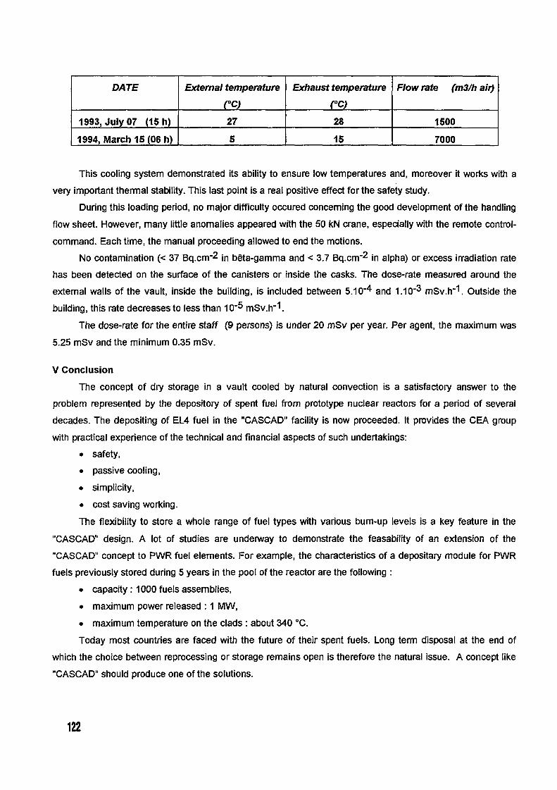
DATE Evternal temperature Exhaust temperature Flow rate (M31h air)
rc) rc)1993, July 07 1 h) 27 28 1500
1994, March 15 06 h) I 5 is 1 7000
This cooling system demonstrated its ability to ensure low temperatures and, moreover it works with a
very important thermal stability. This last point is a real positive effect for the safety study.
During this loading period, no major difficulty occured concerning the good development of the handling
flow sheet. However, many little anomalies appeared with the 50 M crane, especially with the remote control-
command. Each time, the manual proceeding allowed to end the motions.
No contamination (< 37 Bq.cm-2 in b6ta-gamma and < 37 Bq.cm-2 in alpha) or excess irradiation rate
has been detected on the surface of the canisters or inside the casks. The dose-rate measured around the
external walls of the vault, inside the building, is included between 510-4 and 110-3 mSv.h-1. Outside the
building, this rate decreases to less than -5 mSv.h-1.
The dose-rate for the entire staff 9 persons) is under 20 mSv per year. Per agent, the maximum was
5.25 mSv and the minimum 035 mSv.
V Conclusion
The concept of dry storage in a vault cooled by natural convection is a satisfactory answer to the
problem represented by the depository of spent fuel from prototype nuclear reactors for a period of several
decades. The depositing of EL4 fuel in the "CASCAD" facility is now proceeded. It provides the CEA group
with practical experience of the technical and financial aspects of such undertakings:
• safety,
• passive cooling,
• simplicity,
• cost saving working.
The flexibility to store a whole range of fuel types with various bum-up levels is a key feature in the
"CASCAD" design. A lot of studies are underway to demonstrate the feasability of an extension of the
"CASCAD" concept to PWR fuel elements. For example, the characteristics of a depositary module for PWR
fuels previously stored during year's in the pool of the reactor are the following
• capacity:1000fuelsassemblies,
• maximum power released: MW,
• maximumtemperatureontheclads:about340'C.
Today most countries are faced with the future of their spent fuels. Long term disposal at the end of
which the choice between reprocessing or storage remains open is therefore the natural issue. A concept like
"CASCAD" should produce one of the solutions.
122

CH04AO032
Dry storage experiment with spent materials testing reactorfuel elements
K. Kroth, H. BrUcher, F. KreutzForschungszentrum JUlich GmbH,
Institute for Safety Research and Reactor Technology, Mlich
1. Introduction
Irradiated fuel elements from German research reactors have been in the past reprocessed in DOEand UKAEA facilities, respectively. Since this was discontinued in 1988 due to availability reasons,and because no national reprocessing capacity will be installed in Germany, an alternative conceptfor the management of these fuels was developed including dry interinediate storage on surfacefollowed by permanent disposal in the deep geologic underground. R & D work to support this con-cept covering both intermediate storage and disposal was initiated in the Forschungszentrum Rilich(KFA-Research Centre Juelich). The results of the dry storage experiment are reported hereafter.
2. Dry storage experiment
2.1 Objectives
For transport and intermediate dry storage of spent research reactor fuel the gernian GNB companyhas designed the CASTOR MTR-2 cask, the licensing of which is under way. The cask has a bodymade from cast iron, an inner nickel plating and double metallic sealing, which can be tested forthightness. It has a mass of 16 metric tons and is designed to hold e.g. 33 box-shaped MTR fuelassemblies.
A literature review was made about the behaviour of research reactor fuel elements at storage con-ditons /I/. Positive experiences with the wet storage of these elements for periods of up to 30 yearsas well as with the dry handling or storage for short periods at ambient temperature were reportedtherein.
For long-term intermediate storage purposes the casks will be vacuum dried (less than 10 gramswater after drying) and refilled with helium. These conditions will limit the corrosion attack on theAl cladding substantially and hence prevent a loss of mechanical integrity of the fuel elements forsure.
On the other hand a possible release of airborne radionuclides into the cask's atmosphere at ele-vated temperature has to be taken into account. Based upon Fick's law of diffusion, the release ofgaseous (H-3, Kr-85) and metallic fission products (Cs, Sr) through the cladding was estimated tobe insignificantly low at temperatures up to 300'C, which is far below the blistering temperature.Even for the most mobile radionuclide, tritium, an integral release of not more than 35 kBq per yearfrom one MTR fuel assembly was assessed 2/.
123

sampling agd circulationgas pump To support this evaluation, an integral storage
experiment was initiated at the KA, theprinciple of which is outlined in figure .flow meter
Helium feed 2.2 Experimental setupsamplecontainer
A CASTOR-MTR transport cask, which hasa design similar to that foreseen for inter-mediate storage, is equipped with an outer
4 i electrical heating and covered with a thermaldata lgging insulation. The cask is connected to a gas
measurement of and control circuit in order to provide homogenisation oftemperature swam the gas atmosphere as well as sampling adCastor transport analysing. Tests showed a leakage rate ofcask 6 3 -I
better than I - cm . s (NTP) for the entireelectrical heating experimental setup.insulation
car Gas samples were taken periodically andanalyzed by gas- and radio gas-chromatography, thus showing the chemicalcomposition of the -as as well as ist
Fig. :Dry storage experiment concentration in H-3 C14 and Kr-85.1= t)
In addition, the concentration of Kr-85 was continuously measured by y-spectroscopy in the gascircuit. Aerosol-bound radioactivity was filtered from the gas circuit, the filter being periodicallychecked for e.g. I 129 by y-spectroscopy.
Moreover, the integral release of H-3 and C14 was measured by leading the gas through severalwash bottles, thus scrubbing the radioactivity from gas circuit. Oxidizable species (FIT, CO, CH3)
were oxidized on a copper-oxide bed.Table 1: Averaaed nuclear data of the 15 DIDO fuel assemblies The wash solutions were processed and
Before irradiation analyzed by P/,y-spectroscopy.enrichment (U-235) 80 %U-235 inventory per assembly 1 75 The fuel under investigation is MR
Post irradiation fuel of the DIDO type, which is beingused in the Juelich FR-2 reactor. Table
enrichment (U-235) 60% 1 summarizes some details. The fuelbum-up 50 %U-235 inventory per assembly 78.4 contains, on average, 20 wt % U-Altotal activity per assembly 2) 90.6 TBq alloy with an initial enrichment of 80 %decay heat per assembly 2 11.7 W in U-235. The fuel alloy plates with a
1) Dischar- thickness of 06 mm (meat) are covered2 ge from reactor: June to October, 1990 on both sides with aluminium claddings) Figures as of June 30, 1994 f of 038 mm, the total thickness is then
1.36 mm. Three plates each are welded to form a tube. A fuel element assembly consists of fourconcentric tubes of approximately 6 7 and 9 cm diameter, mounted onto structural parts. Aftercutting off these structural parts, it is about 63 cm long.
On January 31, 1995 fifteen of these spent fuel element assemblies were loaded under water intothe CASTOR-MTR transport cask. The cask was covered, the water sucked off, the casks atmos-
124

phere vacuum dried and then refilled with helium. Gas samples taken during vacuum dryingrevealed radioactivity levels in general accordance with the contamination of the spent fuel storagepool water.
During the 1.5 year measuring programme, which was running from early May 1995 until October1996, the temperature at the outer shell of the cask was raised in steps up to 180'C. According to athermal analysis, the temperature of the fuel element assemblies inside will then be 200'C at themaximum. This is a conservative limit covering all normal and accident conditions during transpor-tation and storage of spent research reactor fuel in a CASTOR-MTR 2 cask, even for short-cooledfuel with high burnup producing a thermal power of 825 W per cask.
3. Results and conclusions
Any airborne particulate activity possibly contained in the gas plenum of the container was filteredoff when gas samples were taken. The filter elements were carefully checked for P/y-active aerosolsby y-spectrometry. None of the filter elements contained any detectable 0/7-activities.
The gas samples periodically taken from the plenum of the container were analysed by gas-chroma-tography. The gas atmosphere of the container was found to contain more than 90% of inert He, afew percent of N2 and spurious amounts of H2, 02 C02 and water vapour.
The gas samples taken from the container were analysed by special radiometric and radiochemicaltechniques as well as by radio gas-chromatography. Moreover, the samples were checked for anyKr-85 by y-spectrometry.
In the water vapour pumped off from the container by vacuum drying 20 C I day, pressure <1 hPa) only very small amounts of tritiated water and C14 were found. During the 1.5 years drystorage experiment at temperatures ranging from room temperature to 180 C some H-3 and C14was released from the fuel elements into the gas plenum of the container. The release of bothradioactive species seems to rapidly increase when temperature exceeds 160 'C. At temperaturesbelow 180 'C no release of Kr-85 was observed. Table 2 shows a compilation of the gaseousactivities contained in the gas plenum of the dry storage cask.
Table 2 Accumulated activities of gaseous radionuclides in the gas plenum of the dry storagecask
experiment temperature time of total time activity in gas plenumno. 10C] storage of storage [MBq]
[days] [days]H-3 C-14 Kr-85
drying by 20 - 0 0.13 0.001vacuum
1 22-28 110 110 0.03 0.092 90 107 217 2.4 0.063 130 110 327 1.2 0.254 160 118 445 1.4 1.1 -5 180 118 563 19 3.1 1.9
H-3 was found to exist predominantly as tritiated hydrogen, C 14 as 14CO, 125

These results can be interpreted as follows:The Juelich FRJ-2 is a heavy water reactor whose cooling water is highly contaminated with triti-ated water. During reactor operation, the alurninium cladding may chemically bind some of thetritiated water in the outer passivation layer of the fuel elements as A1203 H20 or A1203 3 H20
Under dry storage condition at elevated temperatures part of the thus chemically bound tritium mayhave been released to the gas atmosphere.
C-14 is formed during reactor operation mainly by (ny)-reactions with nitrogen impurities in thecooling water and the fuel elements. At elevated temperatures some of the C14 contained in theouter corrosion layer of the fuel elements may have been released to the gas plenum. Attemperatures up to 160 C, no release of the fission noble gas Kr-85 was observed. The aluminiumcladding of the fuel elements must thus have been absolutely gas-tight at temperatures below180 'C. During the storage test at 180 'C a very small amount of Kr-85 was observed. It can thusnot be excluded that some extremely small cracks in the cladding material have opened during thestorage test at 180 C. As an aternative, Kr-85 or blisters may also be produced by fission ofuranium impurities of the cladding material.
According to the German radiation protection regulations the maximum permissible activity con-centration of air in a controlled area amounts to Io9 Bq /M3 , 3. 106 Bq /M3 and 3 106 Bq /M3 for
H-3 C14 and Kr-85, respectively. The gaseous activities found in the dry storage container areextremely small as compared to these maximum concentrations of the breathing air. Radiationhazards should thus not be important, when dry storage containers with fuel elements from theRilich FRJ-2 reactor have to be opened.
In conclusion, it can be stated that spent fuel element assemblies from the Juelich DIDO reactor canbe safely stored in a dry cask with neither impairing their structural integrity, nor imposing anundue risk to the operating personnel and to the general public. Whether this result can be extendedto fuel elements from other research reactor types with different burnup history will have to bediscussed.
4. References
/I/ Dietrich, M.; Brikher, H.:State of knowledge about the behaviour of aluminium-clad MTR fuel elements underintermediate storage conditionsInternal KA report KA-ICT-IB-535/92, March 1993 (in German)
/2/ Nabbi, R.:Release of radioactivity from MTR fuel elements at transport conditionsInternal KA note KFA-ZFK/ZFR-2/93 A3, March 1993 (in German)
126

CH04AO033
Behavior of spent aluminum cladded metallic uranium fuel inconcentrated salt brines
J. Fachinger, H. BAIcher, H. RainerForschungszentrum. iifich GmbH, Inst. f Sicherheitsforschung und Reaktortechnik, Mlich
I. Abstract
The fmal disposal of spent material test reactor fuel elements is being discussed in the FederalRepublic of Germany as an alternative to reprocessing. A possible repository under considerationis a salt mine and the accident scenario for long-term safety analysis is a hypothetical wateringress. This water ingress involves the formation of highly concentrated salt brines. The design ofthe disposal casks ensures a fetime of 500 year in such brines. After this time the brine willpenetrate into the cask and corrode the M`IR-FE.Experiments with the different cladding materials show, that aluminum alloys will not resist theattack of brine solution, especially in the presence of iron. Although differences in the corrosionrates of about two orders of magnitudes were observed, the destruction must be considered asinstantaneous in geological ten-ns.Radionuclides are mobilized from spent MTR fuel, when the "meat" becomes accessible to thebrine. But after a short period with increasing activity the radionuclide concentration remains in astable equilibrium or even decreases.
11. Introduction
Spent fuel elements from German Material Test Reactors (MIRs) have in the past beenreprocessed in DOE facilities in the USA. As tis has been discontinued since 1988, and becauseno proprietary reprocessing capacity is available in Germany, such material is being considered forfinal disposal in the deep geologic underground. A possible repository under consideration is asalt mine.An accident scenario for long-term safety analysis is a hypothetical water ingress through crevicesin the main anhydride. Water with a low salt concentration may migrate into the salt dome andsolve salts, until the solution is saturated. The disposal casks are designed to resist the corrosiveattack of such brines for about 500 years. After the container has failed the brine penetrates thecask wall and comes into contact with the spent fuel elements and finally mobilizes radionuclides.The subject of our investigations is NM fuel of the DIDO type, wich is used in the Jiffich FRJ-2reactor. It contains, on average, 20 wt% U-Al alloy with an initial erichment of 80% in 235U. Thefuel alloy plates with a thickness of 06 mm (meat) are covered on both sides with aluminumcladdings of 0. 3 8 mm, the total tickness is then 1. 3 6 mm. Three plates each are welded to for atube. A fuel element assembly consists of four concentric tubes of approximately 6 7 and 9 cmdiameter, mounted onto structural parts, and after cutting off the structural parts, is about 63 cmlong.Our work is divided into three main parts:1. Corrosion behavior of the aluminum cladding2. Leaching of radionuclides from the spent fuel3. Influence of the aluminum corrosion products on the solubility of radionuclides in the near field
127

III. Experirnental
1. Corrosion of the cladding material Table 1: Brine compositions
Aluminum alloy plates of A199,5, AMg1 and salts concentration [mol/1000 molAlMg2 were cut into pieces of 40 x 20 x 25 brine at 55'C brine 2 brine 3mm and immersed in different salt brines (Table � � (Q brine)1) at room temperature and 90'C. Depending NaCl 6.8 1.49 311.57on the progress of corrosion, the samples were KCI 17.4 0.4
MgSO, 3.2 1.95removed from the brine, freed from corrosion MgC,2 77.3 97.21products, dried, weighed and reimmersed in the CaCl, 5.68brine. The experiments were performed in pure I KIS04 2.82brine or with addition of cast iron (GGG40), rC�a04 0.01 2.54stainless steel 14541 or Hastelloy C4.
2. Leaching of spent MM fuel element pieces
Pieces form a spent MTR-FE 40 x 20 m) were immersed in Q-brine (either in pure brine or inthe presence of metallic additives) and stored at 90'C. At intervals, varying from days to weeks,the pH value was measured and an aliquot of 25 ml was taken from the brine. 1111117CS weremeasured by y-spectrometry directly, 106 Ru/Rh, 125 Sb, 141/144 Ce, '44Pr, "'Eu and Co afterseparation from Cs with ammonium phosphomolybdate. For a-spectrometry the samples wereelectrodeposited from I M NH4CI solution on polished, Ni-coated brass plates. Pu and Am wereseparated by a TRU-Spec extraction procedure.
3. Influence of the aluminum corrosion products to the solubility of radionuclides in the near field
First orientating experiments were started in the mid of 1996. Aluminumoxide was ixed brine 2and different radionuclides. In periods of several days an aliquot of the solution was taken and theAmericium concentration determined with Liquid Scintilation Counting.
IV. Results
1. Corrosion of the cladding material
The corrosion rate, surface related mass 100loss divided by the density' depends 90mainly from the temperature, the brine 80composition and combination with .R 70metallic additives. An increase from room cn
cn 60 -temperature to 90'C causes a grow of the CU &A[99.5 without addtivescorrosion rate from 071 m a-' at room 50 o A199.5 14541temperature to 13 5 gm a' at 900C. The o A199.5 + Hastelloy C440 -first figure shows the corTosion-promoting 'iu e A199.5 + GGG40
2 30 -effect caused by the presence of storage D sAI99.5+1.4541+GGG40rycontainer materials. Hastelloy C4 and 20 - A A1995 Hastelloy C4 + GGG40SS1.4541 increase the corrosion rate to 10 about 300 gm a7'. The highest corrosion 0 ____ I I Ipromoting effect was obtained by adding 0 100 200 300cast iron GGG40. The experiments had to Time (d)be stopped after 5 - 100 days, becausethe test specimens had disintegrated. Figure 1: Mass loss depending on metallic
additives in Q-brine128

Table 2 Corrosion rates 100
Additives Corrosion rate 90(P' a 80
no additives 135 701.4541 270 CO
320 CO 60 -- x Brine 3 with GGG40GGG40 7200 50
--a- Bri1.4541+GGG40 4500 40 ne I with GGG40HasteRoy C4 + GGG40 2900 cn 30 -- Brine 2 with GGG40
20 --
The corrosion rate (Table 2 increases 1 0by about one order of magnitude. 0Furthermore pit corrosion becomes the 0 40 80 120main corrosion mechanism. We assume Time (d)
that the iron was oxidized and in a Figure 2 Mass loss depending on brine compositionsecond reaction the iron ions werereduced to metal iron, forming a local element on the aluminum surface.The influence of the brine composition is shown in figure 2 In brine 3 the corrosion nearly stopsafter a period of 50 days and the test specimens had lost only about 10% of their mass. Theresults obtained in brine 2 were compatible with the corrosion in Q-brine. The corrosion ratesdepend on the magnesium concentration.
2. Mobilization of radionuclides
Figure 3 displays the mobilization of y- 1 E6 -emitters from an M`IR-FE in pure Q-brine at 900C. After a prompt 1 E5 -appearance in the leachate, the y- =3
activities remain almost unchanged or 4--�0 I E4 -even decrease by up to two orders of a- ?a
mmagnitude. The shapes of the leaching -curves for the a-emitters are quite < 1 E3 - Cs-1 37 Ce-1 44
Pr-144 Ru/Rh-1 06similar to those obtained for the y- x b125 X Eu-1 54emitters. The activity value for the a 1 E2 i I iemitters is in the order of 10- - 10' 0 40 80 120Bq/g fuel. The instantaneously leached Time (d)radionuclides are mobilized from the Figure 3 Mobilization of y-emitters from MTR-FE insurface of the meat or may result from a pure Q-brinecontamination of the strips during thecutting procedure. In the presence of cast iron a corrosion effect is obvious. Figure 4 and Figure show the influence of metallic additives. The release rate of most of the radioactive nuclidesincrease by a factor 102 _ 10'. Within 24 days, 350 GBq of 137Cs have been released in thepresence of GGG40. After this period the activity increases only slowly and reaches a constantlevel after about 40 days. Tis equilibrium activity represents a leaching rate of about 6 of thetotal sample activity. The leaching rate of the other measured y-ernitters is about one order ofmagnitude lower. The actinide concentration reaches its equilibrium level within 10 days. Theleaching rate of the total a-activity is less than 0.1% of the initial inventory. The low leachingrates can be explained by coprecipitation with the aluminum and iron hydroxides formed.
129

10000 1 E10
1000 W t out I 1 E09 without additives
:3 1 E08 - GGG40-w- GGG40 .2
100 1.4541 .12)1 E07 - 14.541O_ Hastelloy C4m M
oy C4 1 I E06 -< 1 0 <
1 E05
1 I E042 12 22 32 0 40 80 120
Time (d) Time (d)
Figure 4 Influence of metallic additives on Figure 5: Influence of metallic additives onthe mobilization Of 239/24OpU the mobilization Of 137CS
3. Influence of the aluminum corrosion products to the solubility of radionuclides in the near field
The results obtained in the leachingexperiments lead us to assume, that the -radionuclides had been adsorbed on the - *� -- * - *.- 0-- -4 - 0
4corrosion products of the aluminum U -Theoretical amount of Np-237cladding. To characterize such solid m -6--Activity of Np-237
phases we started some orientationexperiments to describe the sorption of
radionuclides on aluminumoxide in brine <
2. The Figure 6 shows the sorption of 0 -237 Np.The sorption depends on the chemical 0 2 4 6
properties of the different radionuclides, Time [Weeks]
their oxidation state and the composition Figure 6 Sorption of 237 Np on A1203
of the solution. A set of experiments to
investigate all these effects had been stared and further results will be available in late 1997.
V. Conclusions:
The results obtained from the corrosion experiments show, that the aluminum cladding has no
barrier function in the case of an accidental water ingress into the final repository. The MTR fuelelements will be dissolved in the salt brines imediately with respect to the time scale of the long
time safety consideration. However the mobilized radionuclides will be immobilized by the
corrosion products of the storage cask and the fuel cladding. Therefor the subject of our furtherwork will be to investigate the interactions between solid aluminum phases and the differentradionuclides, which is important concerning the long time safety.
This work is financed by the Federal Nfinistry for Education, Science, Research and Technolygyunder Contract No. 02 E 8654 7.
130

Posters


CH04AO034
ISOTOPE C(2114U)/C(235U) RELATION
IN PIK REACTORFUEL ELEMENTS
K.A.Koiaoplev, P.A.Sushkov, D.V.Tchmshkyan, G.Ja.Vasiliev, A.S.Zakharov
St.Petersburg Nuclear Physics Institute, RUSSIA
Reseaxch PIK reactor has light water core with central irradiation chan-
nel and heavy water reflector in which experimental channels axe located [1].
Rod type reactor fuel elements contain 90% enrichment uranium with den-sity of 22 g/cm 2 Uranium-234 contained in fuel elements influences thereactivity. Its content can be changed depending on a method of enrichmentand technology of fuel mix preparation. In a natural uranium isotope relationC(231U)/,C(235U = 0.764 ± 0069) 3 With the increase of C234U)/C(231U)
from up to 1% PIK reactor reactivity, calculated by MCU code 41, decreasesby 04%.
In the present work, on the prof. Yu.Petrov's proposal, isotope c 234u)lc(235u)
relation in PIK reactor fresh fuel elements is investigated by undestructible-y-spectroscopic method. These data axe necessary for increasing the PIK
reactor q f (or critical loading) calculation accuracy Energies and the absolute intensities of the strong 234 U and 235U ylines
axe listed in the table. The wea'k 231U ylines close in energy to the strong231U ylines axe also indicated in the table.
To control the radionuclides impurity from chains of uranium decay (hav-ing ynes with Ey 121 keV), PIK fuel elements spectra were measured
with the help of the x-ray spectrometer with the resolution of 0.4 keV. The
analysis of experimental spectra and tabulated data on the chains of decayhave shown that there axe no radionuclides like that in the chains of uraniumdecay. The experimental intensity of the 'U yline with Ey=119.88 keVequalls (1.5 ± 07)% concerning the 234U -y-line with E.,=120.912 keV.
131

Table.
Energies and absolute intensities of the 234 U and "'U ylines 31
Uranium-234 Uranium-235E., keV LY) % E-T I keV *)Lr1 %
53.23 0.119 (10) 51.179 0.0254.201 <0.03
120.912 0.041 4) 119.98 -,0.026143.786 10.5(8)
1 1 1 185.739 1 53(7)*) the systematic error -10%
To measure the isotope c("U)1c("U) relation the 'Uy-line with EY=120.9keV and 31U eye with Ey=143.8 keV have been chosen. The relative con-tent of 31 U was supervised on y-bne with E., = 185.739 keV. The -y-spectrometerwith Ge-Li detector with 30 cm' in volume having the resolution of 25 keVat Ey=186 keV and 144 keV was used during the measuring process.
As PIK fuel elements have significant thickness on uranium and copperand strongly absorb yradiation with energies of 121, 144 and 186 keV (atEy=121 keV for PIK fuel element lid ct 2, the factors of absorption forthese energies were measured by using tablets from bench mark PIK fuelelement and exemplaxyy-sources. Tablets were 02 mm, 0.5 mm and 1.2,mmthick. From measurements of -y-quantum. with E=121 keV and E-, =144 keVaccounting speeds coming from the tablets and experimental lid the isotopeC(234U)/C(235U) relation in bench mark PIK fuel element was determined Itequalls 0.79 0.05)%.
The necessary accuracy of the 'U content in fuel elements measurementis assessed fro 2U influence on reactivity and acuracy of reactivity cal-culations and measurements. As the accuracy of reactivity calculations andmeasurements on PIK critical assembly equalls 0.05% of reactivity, it is neces-
234U)/C(131U) C(234U)/C(231U)saxy to measure c( with an error of <0.0012 (aschange by 00012 results in reactivity changing by 0.05%).
In measuring the content of IU in PIK fuel elements the relative root-mean-squaxe error equalls �-_8%. Therefore if C1U)1C(131U)=0.008 the errorequalls 00006. This results in the additional error of 0025% in definingreactivity.
132

Isotope CIU)IC(21U ) relation in PIK fuel elements is measured relativeto bench maxk PIK fuel element, where 21U content was measured. Each fuelelement was measured from two sides, turning it to 180' at the second mea-surement, which reduces a systematic error from absorption 'Y-radiation inuranium and construction materials. As -y-quanta with E,=121 keV and 144keV have different factors of absorption, the change of the uranium contentinfluences the relation of their accounting speeds.
Changing the uranium content (determined from measurements of 21U y_
quanta with Ey=186 keV accounting speed) in measured fuel elements equall<2%. In this cases amendment to changing -the absorption (self-shielding)E.y=121 keV and Ey=144 keV relation equalls <0.5%. These amendmentswere not taken into account and were included in the measurement errors.
The 60 PIK fuel elements were measured. Isotope c(2MU)/C(235U) rela-tion in PIK fuel elements equall 0.82 ± 007)%.
References
[11 Erykalov AX et.al. Peprint PNPI-1784, St.-Petersburg, 1992
[21 Evdokimov I.A. et.al., Preprint PNPI-2080, Gatchina, 1995
[3] Browne E. and Firestone R., Table of Radioarctive Isotopes, New York,1986
[41 Majorov L.V., MCU code abstract, //VANT 7 1985, P.61
133

CH04AO035
Non-destructive control of cladding thicknessof fuel elements for research reactors
Y. Karlov, Y. Zhukov, S. Chashchin
1. Introduction
For supply of production with non-destructive automation control means thespecial subdivision - Central scientific-research automation laboratory (CSRAL) wasfounded at the plant. 150 specialists of CSRAL in the fields of ultrasonic, radiometric,eddy current and optical control develop techniques and equipment of non-destructiveitems control according to the designers' and product engineers' requirements.Cooperation of laboratory employees and scientists of the Siberian Branch of theRussian Academy of Sciencies yields high results.
Scince 1975 several generations of automatic equipment for non-destructivecontrol of nuclear fuel elements for research and power reactors have been developed atthe plant.
2. Technique and equipment
For provision of non-destructive automatic control of internal and externalcladding thicknesses of nuclear fuel elements our specialists have developed andproduced radiometric equipment on the basis of a beta back scattering method.
Specifications on fuel elements demand measuring of cladding thickness in therange of 02 mm up to 0,8 mm with accuracy at 095 confidence level. In this case, fuelelements have the diameter (wrench dimension) of 60 mm up to 70 mm and the lengthof 600 mm up to 1400 mm, as well as various thicknesses of fuel layer and uraniumamount in it depending on nuclear reactor type).
Measurement method of cladding thickness of a fuel element is based onrecording with detector the ionizing radiation intensity of a beta back scattering by thesystems "cladding - fuel layer ". The interrelation between a number of back scatteredbeta particles (n) and the cladding thickness (d) is described by a well- known formula:
n = no (nn - no) I - exp - kpd) ], where
no - average number of back scattered beta particles in the absence of fuelcladding and by the thickness of the fuel layer exceeding saturation thickness;
nn - average number of back scatterd beta particles by the cladding thicknessexceeding saturation thickness;
k - coefficient of back scattering;p - density.
Elaborators have carried out investigations of the interrelation between thenumber of back scattered beta particles and the surface density of the fuel layer [g/CM2]
for cladding thickness in the range of 02 mm up to 0,8 mm. 147PM, 201 TI and Sr 90Yradiation sources were used as beta particles sources. In the course of theseinvestigations it appeared that the majority of fuel element types had different reflectingcapability of fuel layer beta particles because of the difference in uranium amount.
134

Therefore, calibration samples with nominal value of surface density of the fuel layerwere fabricated for each type of fuel elements.
Scintillation detectors with photoelectron multiplier (PEM) are used for recordingof back scattered beta particles.
Measuring sensor with organic scintillator made of stilbene is used for externalfuel cladding thickness control. Stilbene crystal has a central hole where the containerwith colliminator for Sr + 90Y beta radiation sources is placed. To control internalcladdina thickness measuring sensors are used. They contain a small size source of betaradiation, detector of Bi4 Ge3 012 monocrystal or synthetic diamond connected with
IPEM by means of a fibre-optical or glass light conductor. Such transducer design allowsto aet an access to the inner claddinc, of the fuel element with minimum diameter of
z:'6,0 mm.
The simplified block-diagram of radiometric equipment for control of fuelelement internal cladding thickness is given in fig. . The equipment consists ofmechanical scanninc, table with electric drive, measuring sensor with beta-ray source,pulse amplifier, amplitude discriminator and computer. The scanning table has carriagewith movable unit for fuel elements fixturing. Removable clamping elements designedfor round, square and hexagonal profiles are used for fuel element fixturing. Thecarriage makes possible to fix one till four fuel elements of the same length. Scanning ofinternal cladding by means of measuring sensor is performed automatically during linearmovement through the preset number of generating lines. Scanning is controlled bycomputer according to the pro-ram selected by operator. The measuring sensor slides onthe internal surface of fuel element. The information on claddina thickness presented inthe form of recorded back scattered beta particles is input into the computer. Calibrationfunctions for all types of manifactured fuel elements are entered into the computermemory. Taking into consideration the calibration function computer calculates themeasured claddina thickness value.
Block-diaa-ram and operation of radiometric equipment for external claddingthickness controfare identical to the above described. I
Metrological operation of the equipment shall be checked in automatic modeusino, calibration samples in accordance with the metrological program entered into thecomputer memory.
Accuracy of cladding thickness measurement is 0,05 mm with 095 confidencelevel.
Control rate is 3 mm/s and 6 mm/s.
3. Conclusion
The shortly described method of control of fuel elements for research reactors bymeans of measuring beta particles back scattering made possible to perform completeautomatic non-destructive control of internal and external claddinas at our plant.
Availability of this type of control gives high guarantees of the fuel elementcorrespondence to the requirements.
This method can be used to control the three-layer items of different geometry,including plates.
135
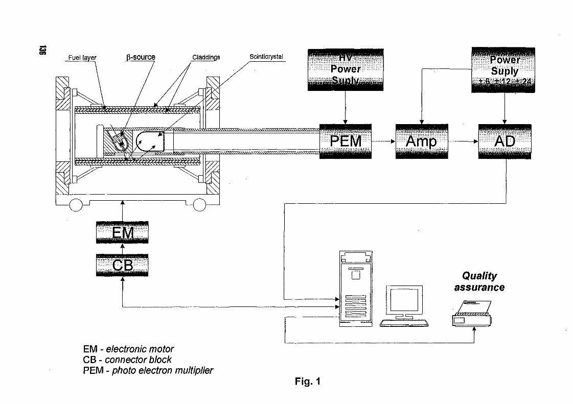
Fuel la er 0-source Claddings Scinficrystal :Owe .............. ..... .... .... .... .... . ........ ..... ...................bwev::::::::,-............... .... ... . .... .... ..
............... ...... ... .. .......
.... ... ...... .... ....
........ . ... ... ... ... ...... .... ........ .... ........ ...... ........PM PA",P�A,, f 42,4� 7
Qualityassurance
r ---------- I
EM - electronic motorCB - connector blockPEM - photo electron multiplier
Fig. I

CH04AO036
IMPROVED HOR FUEL MANAGENT BYFLUX MEASUREMENT DATA FEEDBACK
I.V.Serov, P.F.A. de Leege, J.E. Hoogenboorn, H.P.M. GibcusReactor Physics Department, nterfaculty Reactor Institute,
Delft University of Technology, Delft, The Netherlands
ABSTRACTFlux distribution in a nuclear reactor can be obtained by utilizing diffe-rent calculational and experimental methods. The obtained flux distribu-tions are associated with uncertainties and therefore always differ fromeach other. By combining information from the calculation and experi-ment using the confluence method', it is possible to obtain a morereliable estimate of the flux distribution than exhibited by the calculati-on or experiment separately. As a feedback, the fuel burnup distributi-on, which is used as initial data to the calculation can be improved aswell. The confluence method is applied to improvement of the burnupdistribution estimates for the HOR research reactor of the Delft Univer-sity of Technology. An integrated code system CONHOR2 is developedto match the CITATION3 results of in-core foil activation rate calculati-ons with in-core experimental data through confluence. The systemforms the basis for the advanced fuel management of the reactor.
INTRODUCTIONAccurate determination of the power and fuel burnup distributions is important forreactor design, safety inspection and fuel management. Lack of accurate knowledgeabout these distributions leads to a situation the reliable and safe operation of theresearch reactor and its fuel elements under the specified constrains is far from optimal.In addition, considerable uncertainties associated with reactor states can propogate toconclusions drawn from research. In case of a power station, underloading of thereactor core leads to a considerable increase of the production costs. The demand ofhigh cost savings, safety and proper operation assurance motivate developments ofaccurate power and fuel management systems. A modern management systemincludes experimental devices and computers for measurements and processing of in-core neutron reaction rate data. It also includes computers employing physical models,nuclear and design data to perform flux, power and burnup distribution calculations. Atrustworthy information system justifies the corresponding expenses by allowing tooperate the reactor optimally.Informational sources (calculations and experiments) of the control system haveassociated errors. Different informational sources give different estimates of the samequantity. If the average characteristics of the random uncertainty of each particularinformational source are known, then better estimates for the desired quantities can bederived through informational confluence founded on Bayesian conditioning 4. Properties
137

of these approaches have been studied recentlyl,5,'5 for power distribution determinati-on. An integrated CONHOR system is based on this approach and developed for theHOR research reactor of the Delft University of Technology in the Netherlands to matchthe calculational results with the in-core experimental data through confluence.
BURNUP ADJUSTMENT BY FEEDBACK FROM CALCULATIONAL ANDEXPERIMENTAL DATA CONFLUENCE AT THE HOR REACTOR
The HOR (Hoger Onderwijs Reactor) is a 2 MWth pool-type research reactor situated atthe nterfaculty Reactor Institute in Delft, The Netherlands. The core grid plate has 42positions, normally loaded with fuel elements including 4 control ones and severalreflector elements. The reactor is operated continuously days a week. The licensedexcess-reactivity is 6. This requires replacements of one or two elements andreshuffling at a three-month interval. After completion of the reshuffling operation thepower distribution is calculated. This distribution is used in burnup calculations whichare also performed quarterly. An approach used to determine the power distributionemploys the product of the neutron flux density and the fission cross section. Foilactivities are measured to determine the flux density distributions and power distributi-ons by the PEp7 code. The code BUPNEW8 , based on approximate relationshipsbetween the isotopic composition of the fuel to the total energy produced by fission ineach fuel element is used for burnup determination. Neither broadness and accuracy ofavailable nuclear data nor power of modern computer codes is used in the employedmethods. The confluence procedure, as described below, supplies a principal possibilityof developing a comprehensive informational code system working in a reactormaintenance system. For example, burnup data of the HOR reactor can be significantlyimproved by flux measurement data feedback through confluence with calculations.Distributions of the foil activation rates for some reactor state of the HOR reactor arenormally available from both calculation and experiment. The experimental activationrates are obtained by converting the measured in-core gold foil activity counts usingappropriate cross sections. The calculated activation rates are computed by theCITATION diffusion code using cross sections and nuclide densities as initial data. Fuelburnup values are obtained from PEP-BLIPNEW calculations for previous cycles whichcould introduce considerable errors. The burnup uncertainty is estimated in Ref. 6 to bean increasing function of the burnup.We denote the error vectors of the calculational and experimental activation rates as cand e, respectively. The vector c is non-zero due to both burnup inaccuracies andcalculational model itself, denoted respectively by the vectors d and m. The vector c isapproximated by a linear dependence on d; the model error m is summed with the errorpropagated from the burnup data d:
e =Ad m
where A is a sensitivity matrix of the calculational activation rates to the burnup data.The model errors m are estimated in Ref. 1 as 10% of the absolute values of thecalculated activation rates. The experimental activation rates are subject to uncertaintyestimated in Ref. 1 as 3 of the absolute values. The vector of statistical differencesbetween the calculational and experimental activation rates is given by the difference inthe uncertainties:
138

= - e (2)
The diagonal variance matrices corresponding to the vectors c, m, d, e, and y aredenoted respectively as C, M, D, E, and Y and describe the uncertainties of the errorvectors. The matrix Y describes the properties of the total error uncertainty and can beexpressed as
Y = ADAT + M + E (3)
where the superscript T denotes transposing the matrix. When both calculation andexperiment are performed and we hold the observed value y. of the vector of differen-ces y, Bayesian conditioning can be employed' for the description of this posteriorcase. For example, for the burnup error vector d we secure the posterior non-zero mean
d = DA T y-ly, (4)
and the posterior variance matrix:
Do = D - DA Y-'A D (5)
where the superscript -1 denotes inversion of the matrix. In spite of the seemingcomplexity of the cited formulas, the annotation is quite modest. The vector d containsthe statistically weighted observed differences %. The posterior variances D areobtained by subtracting from tho prior variances Do some statistically weighted part ofit. It means, that by applying the confluence procedure we secure adjustment d for theburnup vector. Uncertainties of the posterior values are given by Do and appear to besmaller than the prior ones. The CONHOR program system is developed to apply theconfluence procedure for determination of the improved burnup for the HOR reactorand to serve as an instrument of fuel management support. The CITATION code is usedas a main calculational tool for within the CONHOR system. CONHOR is responsible forcreating automatically CITATION input files in accordance with the purpose of thecalculation to be executed, for implementation of the confluence procedures andgeneral management of all data flows. The general informational flow of CONHOR ispresented in Fig.l. The corresponding calculational flow of the system can be describedas follows. CONHOR creates a CITATION input file and performs a calculation of theactivation rate distributions at the beginning of cycle (BOC). Then the described aboveadjustment procedure can be requested. It includes calculations of the sensitivity matrixA by perturbing burnup values. Adjusted burnup values at BOC are obtained using Eq.(4) and Eq. (5) and stored in a library. Afterwards, a depletion calculation based on theadjusted burnup values can be performed. Alternatively a depletion calculation can bedone without the burnup adjustment. If burnup is executed, then another burnup libraryat the end of cycle (EOC) is produced. It can be a library based on either adjusted orunadjusted burnups at BOC, so that all types of comparisons can be made. Suchcomparisons were made for a number of subsequent HOR cyclesi and showedconvergence of the CONHOR results at EOC of the last cycle. Calculations performedby the CONHOR system for a number of HOR cycles showed the average reduction ofthe relative burnup uncertainty by a factor of 3 The corresponding relative differencebetween calculational and experimental activation rates reduced from 10% down to2-3%.
139

Prior CalculatfonalActivation Rates
Prior Sensitivfty Posterior PosteriorBLrnLp Conf luenoe BLrn Activation Rate andBOG-1 90 Burnup
Prior Expertmrital Activation Pates
Depletion tlonBLrn and go BLrnLp
and BOCT BOG-2
Reshuffling Peshufffing
Fig. 1. Informational flow of CONHOR. BOC-1: beginning of first cycle studied;BOC-2: beginning of second cycle studied.
CONCLUSIONS
The confluence technique provides a framework for a comprehensive reactor datasystem, which can utilize all the available informational sources to offer optimalestimates of the required quantities and their uncertainties. The confluence techniqueproved to be useful for a burnup adjustment for a small research reactor as HOR. TheCONHOR system is expected to become a routine instrument of the HOR reactor fuelmanagement support.
REFERENCES1I.V. Serov and J.E. Hoogenboom, "Confluence of Calculational and ExperimentalInformation for determination of Power Distribution and Burnup', Ann. Nucl. Energy 23(1996).21 V.Serov and J.E. Hoogenboom, "CONHOR code System for Determination of PowerDistribution and Burnup for the HOR Reactor", report IRI-131-93-008, Interfaculty
Reactor Institute, Delft (1 993).3T.B. Fowler, D.R. Vondy, G.W. Cunningham, "CITATION - Nuclear Reactor AnalysisCode', report TM-2496, Rev.2, Oak Ridge National Laboratory (1 971).4B.S.Koroluk, Reference Book on Probability Theory and Mathematical Statistics,
p. 1 38, Science, Moscow, 1985.5James W. Bryson, John C. Lee, and Jerd A. Hassberger, Nuc/. Sci. Eng. 114, 238(1993).el.V. Serov and J.E. Hoogenboorn, "A General Technique for Confluence of calculatio-nal and Experimental Information with Application to Power Distribution Determinati-on", Proc. nt. Conf. on the Reactor Physics and Reactor Calculations, Tel-Aviv,January 23-26 1994)7P.Brand et al.,"Flux-, Power- and Burnup Determination for Pool-Type Reactors,"report IRI-130/131-71-01, nteruniversity Reactor Institute, Delft 1971) (in Dutch).8j W. de Vries, P. de Leege, B.J.Stiger, BUPNEW - Program for the HOR-Reactor FuelConsumption Bookkeeping", report IRI-INT-80-RBG, Interuniversity Reactor Institute,
Delft (1 980).
140
CH04AO037
Core Management� operational Limits Conditions and SafetyAspects of The Australian High Flux Reactor (HIFAR)
Dr Sue L TownHIFAR Reactor Physicist
Nuclear Technology DivisionANSTOPMB IMenai
NSW 2234AUSTRALIA
ABSTRACT
HIFAR is a DIDO class reactor which commenced routine operation at
approximately IOMW in 1960. It is principally used for production of
medical radio-isotopes, scientific research using neutron scattering facilities
and Irradiation of silicon ingots for the electronics industry. The license to
operate HIFAR is granted by an independent Government body, the Nuclear
Safety Bureau.
The HIFAR reactor uses six neutron absorbing coarse control arms to
maintain and control criticality. These move in vertical planes between the
rows of 25 fuel elements. A detailed description of the core, including fuel
types in use, will be presented. Until 1992, the arms used were cadmium
coated stainless steel blades'. The cadmium (Cd) coarse control arms use
the Cd 1 3 isotope, which has a thermal resonance giving an extremely high
effective cross section of approximately 27600 bams, thus making it a great
candidate for neutron absorption and hence control of criticality.
141

However,, the limitation with these type of control arms is the short lifetime
in the core (transmutation of Cd1]3 tCd 14necessates changing frequently)
and, more importantly from a safety point of view, the rapid fall off of
absorption capacity. Detailed information on these operational limitations
and te safety implications will be presented. In order to extend control
arm lifetimes and improve the safety implications for HIFAR, a move was2,3made to the use of europium (Eu) tipped control arms Following the
45,preparation of safety submission the first Eu tipped coarse control am
was loaded into the HIFAR core in November 1992. Inverse kinetics
measurements were performed in order to assess the differential reactivity
worth of the control am bank prior to and after installation of this (and
subsequent) Eu control arms. These measurements, in addition to reactivity
measurements, will be presented and discussed in detail. During the period
from November 1992 to date, any Cd control arms which have required
changing have been replaced with new Eu tipped blades. The last Cd
control an-n was removed from the core in October this year.
The HIFAR Safety Case was first formulated and reviewed in approximately
1970. As part of the review of the HIFAR Safety Case in 1996 a full
analysis of control arm operational delay, drop and insertion time data was
performed 6. This allowed a Safety Case to be developed, providing the
basis for HIFAR's operational limits and conditions. Relevant physics
related Operational Limits and Conditions have been revised 7 to be
consistent with the current HIFAR Safety Case and the use of Eu tipped
control arms. These will be discussed in detail.
8Details will be given of the current fuel management program, HIFUEL
used by the Reactor Analysis Group to predict the reactivity loss due to
142

bum up of fuel and the power distribution in fuel elements. Reactivity
accounting is performed using HIFUEL in addition to maintaining a
running reactivity total. This includes allowing for reactivity changes due
to at power loads and unloads of targets from within hollow fuel element9positions in the core and reactivity loss with bum up of Eu control arms
Details will be provided of reactivity accounting and how this has been
computerised, including fitting of reactivity loss data for Eu. control ams
with varying degree polynomials and computerisation of this to calculate the
reactivity loss of the entire control arm bank. HIFAR is currently looking at
moving to a new fuel management program HIFAM 1, which includes a D
flux calculation and more accurate reactivity accounting.
Details of all experimental measurements associated with reactor physics
analysis of HIFAR will be discussed, including coarse control an
differential reactivity measurements, rig reactivity measurements and
control arm delay, drop and insertion time measurements. Differences
between predicted and measured excess reactivity figures for various control
arm calibrations (and different U235 core masses) will be presented. Quality
System documentation (procedures and instructions) relating to reactor
physics will be discussed.
1. RWS Carlson, The Current Limits for Cadmium Absorber Lifetime
(Burnup) For The Coarse Control Ams in HIFAR, Technical Note TNI54,
September 1990.
2. AC Chenery NW Crick, EA Tarrant, Europium Tips for Coarse Control
Arms in DIDO and Pluto, DIDO Users Meeting 74, October 1974.
143

3. MG Silk and BO Wade, The Bum Up of Rare Earth Absorbers, AERE,
R6526,1970.
4. RM Godfrey, Introduction of Eu Tipped Coarse Control Ams into
HIFAR, I st 2nd and 3rd Stage Submission, June 1992.
5. SL Town, Introduction of Eu Tipped Coarse Control Arms into HIFAR,
4th Stage Submission, 1995.
6. SL Town, Review of Operational Coarse Control Arm delay, drop and
insertion time measurements, 1995
7. SL Town, Review of Physics Related Operational Limits and Conditions,
1996.
8. GS Robinson, A Brief Description of HIFUEL a fuel management
program for HIFAR, Technical Note TN26, April 1987.
9. GS Robinson, 3D Diffusion Calculations of HIFAR, E703, September
1991.
1 0. GS Robinson, HIFAM A Computational Model for HIFAR Fuel
Management, TN 92, October 1994.
144

CH04AO038
In-Core Fuel Management Practice in HANARO
Hark Rho K Urn, Choong Sung Lee and Ji Bok LeeHANARO Center, Korea Atomic Energy Research Institute
P.O. Box 105, Yusong, Taejon, Korea 305-600Tel:82-42-868-2285, Fax:82-42-861-0209, E-rnai1:hrkim�nanurrLkaeri.re.kr
I. Introduction
KAERI(Xorea Atornic Energy Research Institute) completed the system performance testsfor the HANARO(Hi-flux Advanced Neutron Application Research Reactor) on December,1994. Its initial criticality was achieved on February 8, 1995 A variety of the reactor physicsexperiments were performed in parallel with configuring the first cycle core and nowHANARO is in the third cycle operation. The in-core fuel management in HANARO isperformed on the following strategy[l]:
1) the cycle length of the equilibrium core is at least 4 week PDs.2) the maximum linear heat generation rate should be within the design limit.3) the reactor should have shutdown margin of 1%,Jklh at inimum.4) the available thermal flux should satisfy the users' requirements.
This paper presents the fuel management practice in HANARO. Section II brieflydescribes the design feature of the HANARO and the method of analysis follows in sectionIII and Section IV describes In-core fuel management practice and the conclusion is remarkedin the final section.
IL Brief Description of the HANARO
The HANARO is a tank-in-pool type reactor of MW power and is now operated at itsthird cycle. The fuel meat is 19.75% USi-Al. The fuel elements are clustered into the fuelassemblies. Two types of fuel assemblies are loaded in HANARO: H-type having 36elements in hexagonal array and C-type having 18 elements in circular array.
The reactor core is separated from the reflector through the reactor inner shell. Thecore like a honeycomb inside the reactor inner shell is cooled and moderated by H20. Thecore has 31 flow tubes; 23 hexagonal and circular. Eight circular flow tubes in core hasrooms for accepting 45 mm thick cylinder of natural hafnium to regulate or shutdown thereactor. There are reserved additional eight circular flow tubes srounding the reactor innershell near the core to increase core excess reactivity by fuel loading and to irradiate thetargets especially requiring the high epi-thermal neutrons.
In the reflector tank, total of 25 vertical holes with different sizes are arranged inreasonable positions, and 7 tangential beam tubes are horizontally allocated in optimalorientation.
145

III. Method of Analyses
To design the HANARO, KAERI itself set up HANAFMS (HANARO Nuclear Analyses
and Fuel Management System). The major component of HANAFMS is WIMS/D4[21 and
BOLD-VENTURE[31 and several auxiliary codes such as REGAV-K, WIMPAK, MAPHEX,
HEXSHUF support the system. The VffMS nuclear data library was processed using
NJOY[41 mainly with ENDF/B-IV and partly with ENDF/B-V. And then the WIMS with its
library was benchmarked by comparing some key parameters such as criticality and reaction
rate ratios against internationally authorized and recommended critical experiments. The test
result for criticality shows 100303 ± 000519. The reaction rate ratios are also in good
agreement with the experimental values[5]. By modelling the local structures of the reactor
constituents, the macroscopic cross sections are generated and tabulated as a function of
operating condition such as burnup, reactor power, fuel moderator temperature, moderator
density, reflector density and temperature, reflector impurity, etc. Based on the macroscopic
cross sections, the BOLD-VENTURE was used to predict the core criticality, flux power
distribution in fuel assemblies, the reaction rates in the target materials, the detector
responses. To simulate the neutronics properties of the HANARO, 3-dimensional H-Z model
was adopted. The full core is divided into 253 x 253 x 4 grid and each fuel element is
described by a single node. This give us the pin power history during depletion.
To validate and verify the HANAFMS prior to applying to the practical design work, the
uncertainties of the HANAFMS were analyzed against the results from MCNP4 full core
model, which treats the HANARO structure as real as possible[6]. Through this comparison,
HANAFMS ensured the prediction capability with reasonable accuracy[7].
IV. In-core fuel management practice with HANAFMS
The major objective of nuclear fuel management lies in ascertaining the reactor safety and
performance characteristics along with fuel bumup such as the power distribution of the fuel
and excess reactivity, control capability. Based on above objective, the loading patter is
searched and analysed with the HANAFMS. The HANAFMS was benchmarked for criticality
calculation with 14 critical experiments. The criticality experiments were performed in the
course of construction of the first cycle core. The calculation result is 1002112 ± 003099 for
the 14 critical experiments[81. The power distribution calculation is important to verify the
reactor safety. It was compared with the gamma scanning data of 16 H-type fuel assemblies.
The fuel assemblies were irradiated in the core for 17 hours at 150kW. The relative power
for the fuel assemblies which was calculated by the HANAFMS compared with experimental
results. The deviation was less than 6. Fig.1 shows the operation history of HANARO until
the end of its second cycle. The first cycle was operated 35.72 PD at 1MW. The second
cycle has 3 sub cycles, called 21 22 23 cycle. Each cycle was operated 42.74 FPD at
15MW, 22.86 FPD at 22MW, 18.23 FPD at 22MW. The citicality calculation of the
HANAFMS along with fuel burnup was validated with experiment at BOC of the each cycle.
The criticality was calculated for the critical control rod position which was measured at
the BOC of 21 22 23 cycle. The result shows 1005922 ± 0000794. The calculation of the
control rod worth is very important to verify excess reactivity and shutdown margin. The
four control rods of the HANARO move individually keeping same height in operation but we
146

700 35
600 30
500 25
A40000300 15
200 f-I I F 110 0-1100 5
0 0
I-Jan 31-Jan 1-Mar 31-Mar 30-Apr 30-May 29-Jun 29-Jul 28-Aug 27-Sep
Date
CAR Position - Reactor Power
Fig. I The operation history of the HANARO
applied the rod swapping method to measure the control rod worth. While two rods are fixed
at a designated position, the other two rods are moved in different direction to keep the
reactor critical. Fig. 2 shows the measured and calculated control rod worth by the rod
swapping method at BOC of the second cycle. From ts result, we can produce the control
rod worth curve wich will be used in interpreting the other reactivity worth.
5.0
4.5
4.0
3.5 ----------3.0
02.5
2.0
1.5
1.0
0.5
0.0
0 100 200 300 400 500 600 700
CAR Height(mm)
- CAR-1(cxp.) ........... CAR-2(exp.) -- CAR-3(exp.) - CAR4(exp.)
z CAR-I(cal.) o CAR-2(cal.) t3 CAR-3(cal.) * CAR-4(cal.)
Fig. 2 The control rod worth by calculation and experiment
147

V. Conclusion
The HANARO is a newly bom research reactor in the world. Various kinds of reactor
physics tests and experiments have been carried out. To support those experimentalactivities and to predict the safe operation of the HANARO, the core follow up calculationusing HANAFMS is always simulated along with the cycle operation. Up to now, theHANAFMS shows good predictability, but it has some problems. In operation, various testmaterials and targets for irradiation are loaded in the core. Sometimes they have complexgeometry. VIMSID-4 has a restriction to model in detail to produce cross section data of
them. So, we have a plan to use HELIOS[91 to produce the cross section data becauseHELIOS has a capability to model the irradiation targets regardless of geometry. Since theVENTURE is a finite-difference diffusion theory code and its HANARO model is too large, itcan not forsee the neutron behavior in strong absorber or high scattering medium and takestoo much time to predict the neutronics behavior of the HANARO. Therefore someadjustments or fudging in cross section is needed to predict the CAR worth more accuratelyand we endeavor to implement a new time saving system by adopting the nodal method as a
core analyser.
References
[11 H. R. Kim, et al., "The In-Core Fuel Management of the HANARO", KM-031-RT-KO45,KMRR Project, KAERI, 1993.
[21 J. R. Askew, et al., "A General Description of the Lattice Code", J. Brit. Nucl. Energy
Soc., 5, 56.4, 1966.[31 D. R. Vondy, et al., "The BOLD-VENTURE Computational System for Nuclear Reactor
Core Analysis", Version III, ORNL-5711, ORNL, 1981.[4) R. E. MacFarlane, et al., "The NJOY Nuclear Data Processing System", LA-9303-M,
Vol.1, 1982.[51 J. D. Kim, et al., "Nuclear Data Evaluation and Group Constant Generation for Reactor
Analysis", KAERI/RR-750/88, Research Report, KAERI, 1988. (in Korean)[61 J. F. Briesmeister (ed.), `MCNP - A General Monte Carlo Code for Neutron and Photon
Transport", LA-7396-M, Rev. 2 1986.[71 W. S. Park, et al., "Uncertainty Evaluation of WIMS-VENTURE Code in the Peak Power
and Control Rod Worth Calculation", KAERL/TR-391/93, Technical Report, KAERI, 1993.[81 C. S Lee, et al., "Criticality Measurement and Benchmark Calculation in HANARO",
ASRR-V/203p, The 5th Asian Symposium on Research ReactorTaejon, Korea, 1996.[91 E. A. Villarino, et al., "HELIOS Angularly dependent collision probabilities", Nucl. Sci.
Eng. 112, 16-31, 1992.
148

8 ICH04AIII Hil III I0039
operation of the FRG-Research Reactors at Geesthacht
A. Reymann, W. Krull
GKSS Research Centre Geesthacht GmbH
D-21494 Geesthacht
Federal Republic of Germany
Introduction
Two research reactors have been operated very successful by the GKSS research Centreover decades in a connected pool system.
FRG-1: 5 MW, criticality October 1958FRG-2: 15 MW, criticality March 1963 and decommissioned February 1995
The FRG-2 was scheduled to stop operation in 1991 for lack of scientific and technical inte-rest for future use [1]. The reactor has been used as Germany's largest material testing reac-tor for power reactor fuel and power reactor materials development and safety tests. TheFRG-2 has also played an important role in the conversion activities at the GKSS researchCentre.
The FRG-1 is being used with high availability for beam tube experiments for fundamentaland applied research in biology, membrane development, materials research, neutron radio-graphy, neutron activation analyses etc. To enable the sufficient and efficient use of longwave length neutrons a cold neutron source has been installed in one of the beam tubes 2].
The GKSS research entre, the advisory board, the scientific community and other clientsare demanding the ongoing operation of the FRG-1 for at least fill the year 2010. GKSS hastaken many actions to ensure the save operation with high ulization and availability for thenext 15 years.
Conversion of the FRG-1 from HEU to LEU
The conversion of the FRG- 1 from High Enriched Uranium (HEU) to Low Enriched Urani-um (LEU) was made in the year 1991 3]. For the users the conversion should bring a higherneutron flux at the beam tubes. Therefore the core size was reduced from 46 to 26 fuel ele-ments and an additional beryllium reflector around the beam tube heads was installed.
For decreasing the operation costs of the reactor it was nessessary to increase the burnup ofthe fuel elements and to have a longer fuel cycle. Therefore the uranium density waschanged from 044 to 37 U/cc and the weight of U-235 was increased from 180 to 323 g U-235/fuel element. Table I shows the comparison of high enriched and low enriched core.
In addition the design of the control rods have been changed from oval B4C and Cd absorb-
ers to fork absorbers with hafnium blades. So we have more reactivity for a longer operationcycle.
The design and all dimensions of. HEU and LEU fuel elements are identical. Only the con-trol fuel elements with fork absorbers has been new designed.
The conversion to LEU elements have been done in one step, without a mixed LEU/BEUcore. Some elements have been preburned in our FRG-2 reactor to approx. 12%. Ile pro-cess of conversion has been a standard procedure: measuring of the rod drop time for thecontrol rods; critical experiment; reactivity calibration of the control rods to be aware ofconditions for stuck rod criteria, minimum shutdown reactivity speed of control rods, max.excess reactivity; power calibration with foils, minature fission chambers and thermal cali-bration; flux mapping; measurement of reactivity worth of fuel elements, reflector elementsand iadiation samples; measurement of fuel plate temperature with instrumentated fuel ele-ments. 149
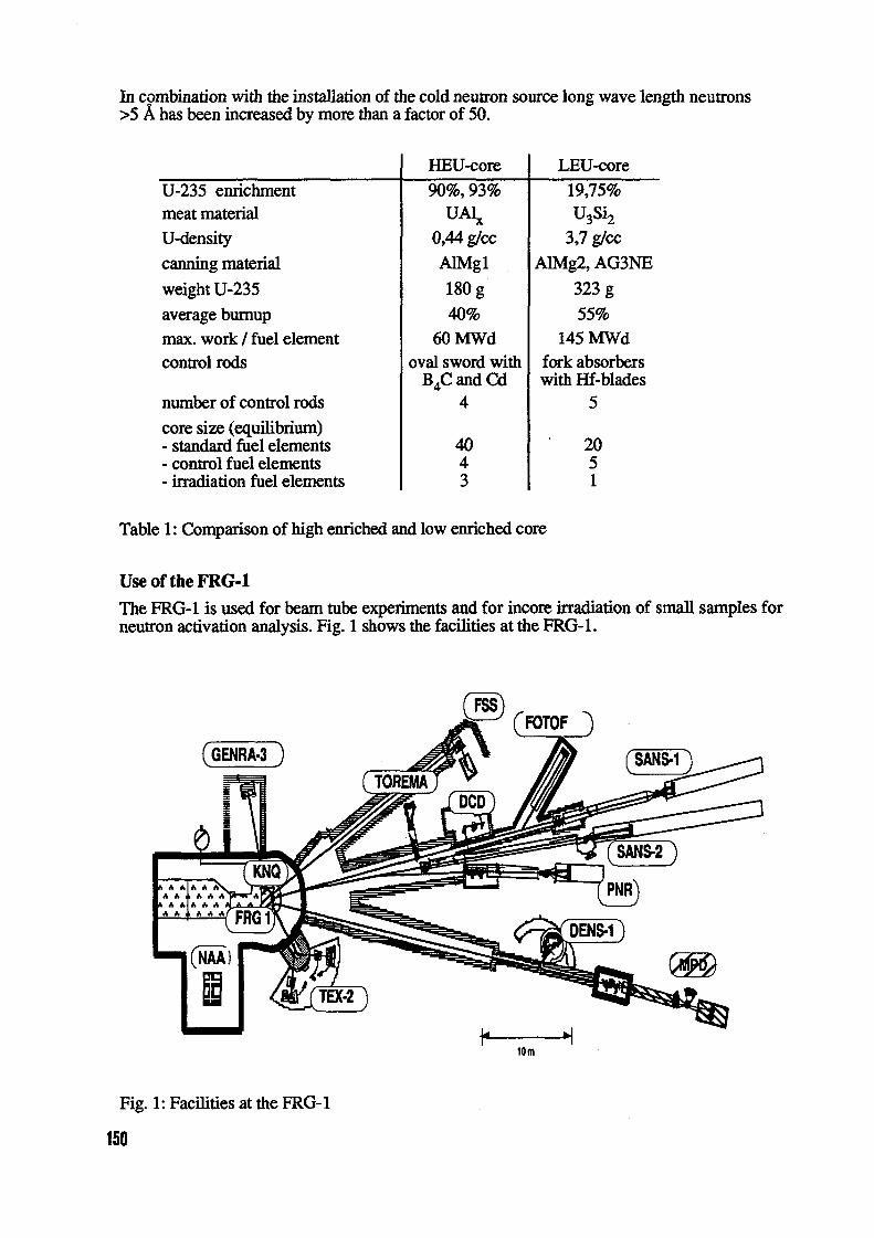
In combination with the istallation of the cold neutron source long wave length neutrons>5 A has been increased by more than a factor of 50.
HEU-core LEU-core
U-235 enrichment 90%,93% 19,75%meat material UA� U3Si2
U-density 0,44 g/cc V g/cc,canning material AIMg1 AIMg2, AG3NE
weight U-235 180 g 323 g
average burnup 40% 55%max. work fuel element 60 MWd 145 MWdcontrol rods oval sword with fork absorbers
B4C and Cd with Hf-bladesnumber of control rods 4 5
core size, (equilibrium)- standard fuel elements 40 20- control fuel elements 4 5- irradiation fuel elements 3 1
Table 1: Comparison of high enriched and low enriched core
Use of the FRG-I
'Me FRG-1 is used for beam tube experiments and for incore irradiation of sall samples forneutron activation analysis. Fig. shows the facilities at the FRG- 1.
(FOMF
(GENRA-3
A J%
(N-AA)
IOM
Fig. 1: Facilities at the FRG-1
150

The instruments are based mainly on elastic neutron scattering. They offer the possibility tostudy materials, semi-finished products and components with respect to their microstructuralconstituents, including defects with atomic dimensions as well as microcracks in the micro-meter range.
Fig. 2 shows a typical core configuratin with the possibilities for incore irradiation. There areone irradiation fuel element, four iradiation positions in beryllium elements and two posi-tions in alluminium tubes. The maximum thermal neutron flux in the iadiation positions isin the range from 1. 5 to E 13 n/cm2s.
The average availability of the FRG I during the last 6 years after conversion to LEU wasmore than 200 full power days/year with increasing trend.
10... 311 standard fuel element
344 control fuel element
30irradiation fuel element
U7--349 346
beryllium reflector element
3W 34 W 347
/b W 11 beryllium irradiation element=9 F3M IM3 [�W '11� rM
341 rM 1P- - irradiation tube331 W7 3W 9 3W FS
fission chamberS ri il
S Fs-] Plug
S IZF)Iz:)?N)Fig. 2 Typical core configuration
Future of the FRG-1
To prepare the FRG-1 for an efficient future use considerations and first calculations havebeen performed to reduce the core size again from 26 fuel elements to 12 fuel elements andto take some additional measures for further increase of the neutron flux at the beam tube po-sitions. Table 2 shows the comparison of present and future core.
First calculations indicate that the increase in thermal neutron flux for the beam tubes is be-tween 50% and 160% depending on the position of the beam tube in relation to the presentand future reactor core positioning. he maximum thennal neutron flux wl be at the posi-tion of the cold neutron source - the most used device- and increases there from 9 E13 to 5E+ 1 3 n/cm2s.
GKSS envisages to operate the FRG-1 at least until the year 2010. To keep this importantneutron source at a high level of interest for the scientific community GKSS will make all ef-forts to improve technical performance of the reactor and to develop the experimental facili-ties supplied with neutrons from the FRG- 1.
151

present core future corenumber of fuel elements (FE) 26 12
plates per FE 23 23
number of control rods 5 4fuel u3s� U3Si2
fuel density ( g U/cc) V 4,8
U-235 (g) content per FE 323 420reflector E�O, Be Be
tangential beam tube H20 Be
front end of beam tube optimized
Table 2: Comparison of present and future core
Literature[1] W. Krull: Farewell FRG-2, Nuclear Engineering International, Vol. 40, May 1995, p. 50
[21 W.KnopT.WedderienW.KruU:TheGKSScoldneutronsource,IAEA-SR-190/44Proceedings of the International Seminar on Management of Aging, GKSS, May 1995
[3] W. Krull, A. Reymann: Urnstellung des FRG- I auf Brennelemente mit niedrigerAnreicherung, atomwirtschaft, Jan. 1993
152
CH04AO040
Calculations of Fuel Element BUM-UP for Mixed TRIGA Core
Matjaf Ravnik, Toma2 2agar, Andreia Per§idJ. Stefan Institute, Ljubljana
1. Introduction
One of the most demanding tasks which is normally responsibility of the reactoroperation staff is the determination of fuel element bum-up. The task is particularlycomplicated if the reactor core was mixed and if the loading pattern was frequently changed.The following three methods of fuel element bum-up determination are commonl� applied:reactor calculations, reactivity measurements and the gamma scanning method 2 3 Thefirst two methods are relatively simple and convenient for determining bum-up of largenumber of fuel elements. The gamma scanning method is in practice normally used only as areference method for measuring small numbers of fuel elements as it requires specialequipment and high level of expertise.
Reactor calculations, which were not so long ago strictly in domain of reactormanufacturing companies or large national institutes are becoming more and more feasiblealso to the operators in small research reactor centers due to rapid development of smallcomputers and appropriate software. The purpose of this paper is to describe two computercode packages which were developed at J. Stefan Institute for practical, operator orientedbum-up calculations of TRIGA Mark 11 cores. Their application for mixed core bum-upcalculations is presented as well.
2. Description of Computer Codes
The first is TRIGAC package It is based on two -group diffusion equation in one-dimensional cylindrical geometry. It is solved in the finite differences approximation byfission density iteration method. The package is supplied with a cross-section library which iscalculated with the program WIMSD-4 5for all types of TRIGA fuel elements (FLIP, Standard8.5wO/ and 12w0/6 uranium concentration, aluminum and stainless-steel cladding, LEU). Thecross-sections are tabulated as a function of bum-up, fuel temperature and other operatingparameters. The group constants of the fuel elements (and other unit cells, e.g. irradiationchannels) in the same radial ring are homogenized by simple volume weighting. The physicalmodel is appropriate for simple uniform loading pattems with only one type of fuel elementsin the same ring. It is not appropriate for mixed rings or for regions near control rods andincore irradiation channels. TRIGAC was developed for the first generation of PC computersin 1982 for which any better physical model was not feasible. Running time was around 20minutes for the first generation of IBM-PCs. It is around I Osec for modern PC (e.g. Pentium13OMHz processor).
The code was recently redesigned. Our aim was to improve the physical model byusing more fine group structure and 2-D geometry. Four group diffusion approximation in r-Tcylindrical geometry was applied. Method of solution are finite differences and fission densityiteration. The geometry model represents full TRIGA Mark 11 cylindrical core with maximum 7rings and reflector. Every grid location either occupied by the fuel element, control rod,irradiation channel or left empty is treated explicitly as a unit cell. The group constants arecalculated with program WMSID-4, which is integrated in the package. In contrast to theoriginal version of TRIGAC, the group constants are not pre-calculated and stored in thelibrary but calculated for each unit cell in the core separately according to its particularcomposition, burn-up and temperature. In illustration: WIMS code is run more than 100 timesto produce the cross-sections for one diffusion calculation. As the phrical model of the codewas changed significantly we decided to rename it to TRIGLAV The running time onPenturn PC is typically 30-60 minutes for one burn-up step.
3. Comparison of Calculated and Measured Burn-up
TRIGLAV was tested on numerical benchmarks and by comparing it to the results ofother 2-D codes, e.g. EXTERMINATOR'. Numerical tests show that the accuracy better than
153

10pcm in kff and 0.1% in fission density distribution can be achieved even with relativelycoarse finite differences mesh containing approximately 50x150 mesh points to cover atypical completely heterogeneous TRIGA core with graphite reflector.
The integral test of the code was performed by comparing its results to the results ofthe measurements for our reactor. Our reactor is 25OkW TRIGA Mark 11 type operating since1966. The core consists of 6 concentric rings (denoted A-F). The reactor was originallyequipped with 3 boron graphite control rods. In 1991 they were replaced by the fueled-follower type control rods made of boron carbide (absorber part) and 12w0/6 uranium fuel (fuelpart). Additional pulse rod (boron carbide with air-follower) was installed. Several types offuel elements were used in 30 years of operation:1. Aluminum cladding, 8.5wO/o uranium, 20% enriched standard fuel elements2. Stainless-steel cladding, 8.5wO/o uranium, 70% enriched FLIP fuel elements3. Stainless-steel cladding, 8.5w% uranium, 20% enriched standard fuel elements4. Stainless-steel cladding, 12w% uranium, 20% enriched standard fuel elements.FLIP fuel elements were used in combination with 8.5w0/6 uranium standard fuel elements for15 years. Due to small number of FLIP elements 26 total) mixed rings could not be avoided.in 30 years of operation the core was reshuffled 146 times for fuel management and fluxoptimization purposes. The burn-up calculation was performed with TRIGAC and TRIGLAVfor entire operating history of the reactor. Bum-up of all fuel elements was alculated. The
2 3burn-up of selected fuel elements of all types was also measured by the reactivity methodResults for 8.5w%-U standard fuel elements are presented in the Figure.
Bum-up
35calculated with TRIGAC (ID)
calculated with TRIGLAV (2D)
30 reactivity measurement
25
20
15
10
5 t: rE 0 M / .
6b 6h bb 6b 66 bb 6b
06094 6097 6163 6170 6174 6175 6189 6197 6198 6200 7841 7844 7849 8528 8533 8535 8536 8537
Fuel element identification number
Figure: Calculated and measured bum-up of selected standard 8.5w0/6-U fuel elements
154

We selected for the measurement such fuel elements that were e pected to be influenced by2-D flux distribution effects: mixed rings, influence of control rods and irradiation channels,influence of incomplete F-ring. Comparison of measured and calculated results clearly showsthat 2-D calculations better predict the bum-up of mixed rings containing highly enrichedFLIP and low enriched standard fuel elements. 2-D calculations fail to reduce discrepancy forthe fuel elements close to the reflector (E and F rings). Consequently, the reason for thediscrepancy should be looked for in the unit cell alculations rather than in the globalgeometry model. Average deviation between measured and calculated results is estimated tobe around +/- 0.05, except for some particular ases discussed above.
Table: Comparison of bum-up calculated in 1-D (TRIGAC) and 2-D (TRIGLAV)approximation for low enriched (standard 8.5w/o-U and 12wO/o-U) and highly enriched (FLIP)fuel elements
Fuel element Fuel element Bur -up c Iculated with Difference Commentidentification type (11D) TRIGLAV (2D) 1%]
number [MWd1 [MWd]
6105 stand. 8.5% 4.43 2.42 82.8 D ring: mixed with FLIP6106 stand. 8.5% 0.24 0.25 -1.96107 stand. 8.5% 1.64 1.85 -11.5 6 ring: near control rod6108 stand. 8.5% 3.28 3.08 6.56109 stand. 8.5% 2.97 2.96 0.46110 stand. 8.5% 4.27 3.93 8.66111 stand. 8.5% 2.11 2.43 -13.2 F ring: partially filled6112 stand. 8.5% 2.45 2.82 -13.0 B ring: near control rod6113 stand. 8.5% 2.11 2.40 -12.3 F ring: partially filled6114 stand. 8.5% 2.11 2.44 -13.4 F ring: partially filled7214 stand. 12% 1.17 1.16 0.87219 stand. 12% 1.17 1.18 -0.87220 stand. 12% 1.17 1.15 1.77223 stand. 12% 0.93 0.93 07225 stand. 12% 0.93 1.01 -8.07228 stand. 12% 0.93 0.95 -2.17229 stand. 12% 0.93 0.97 -4.37233 stand. 12% 0.93 1.06 -11.8 D ring: asymmetric core7236 stand. 12% 0.93 1.04 -10.3 D ring: asymmetric core7245 stand. 12% 0.93 0.96 -2.68285 FLIP 7.26 7.11 2.18290 FLIP 9.53 8.70 9.68302 FLIP 7.26 7.25 0.18303 FLIP 7.26 7.73 -6.18304 FLIP 7.26 8.71 -16.6 D ring: near control rod8305 FLIP 7.26 7.66 -5.38307 FLIP 7.26 8.20 -11.5 D ring: near control rod8313 FLIP 9.53 8.41 13.3 C ring: with control rods8316 FLIP 9.53 8.65 10.2 C ring: with control rods8318 FLIP 9.53 1 9.98 -4.5
155

4. Analysis of Two-Dimensional Effects
Comparison of fuel element bum-up calculated with TRIGAC (1-D approx.) andTRIGLAV (2-D approx.) is presented in the Table for three groups of 1 0 elements of differenttypes. The groups were selected randomly out of more than 150 fuel elements that weretreated in the calculation. The elements that spent main part of their life at the positions of 2-D effects are denoted in the comments. The difference between 1-D and 2-D results exceeds1 0% for such elements. In some particular cases the difference is even higher (e.g. 83%).
S. Conclusions
Comparison of 1-D and 2-D calculations shows that 1-D models fail to predict thebum-up of those fuel elements that spent main part of their lives in mixed rings. The 1-Dcalculation based on homogenized rings systematically overpredicts the burn-up of lowenriched fuel elements and underpredicts the bum-up of the highly enriched if they wereused in the same ring for long time. The effect depends on the number of fuel elements ofeach type but it is typically in the order of 15% relative difference.
References
1 Determination of research reactor burn-up. nternational Atomic Energy Agency, IAEA-TECDOC-633, Vienna, January 19922 M. Ravnik, M.Strebl, H. oeck, A. Trkov, L Mele: Determination of the bum-up of TRIGAfuel elements by calculation and reactivity experiments. Kemtechnik 57 1992), 291-2963 M. Ravnik, H. Wimmer, A. Trkov, H. Boeck, L Mele: Burn-up measurements at TRIGA fuelelements containing strong burnable poison. Kemtechnik 58 1993), 289-2944 L Mele, M. Ravnik. TRIGAC A new version of TRIGAP code. IJS-DP-6424, J. StefanInstitute, Ljubljana, Slovenia, 19925 L Mele, S. Slavid, M. Ravnik: Use and adaptation of WMS code for TRIGA reactorcalculations. IJS-DP-6404, J. Stefan Institute, Ljubljana, Slovenia, 19926 A. Pertid, S. Savid, M. Ravnik: TRIGLAV - a computer program for research reactor coremanagement calculations. Nuclear energy in central Europe - Proceedings, 1 1 to 14September 1995, Portoroi, Slovenia, 48-567 A. Pertid: Testing of the EXTERMINATOR code for research reactor alculations. Nuclearenergy in central Europe - Proceedings, 1 1 to 14 September 1995, Portoro2, Slovenia, 68-75
156

CH04AO041
Some Aspects of Accidental Criticality Safety ofTRIGA Reactor Spent Fuel Pool
MARJANLOGAR', BOGDAN GLUAVC, fATJA2 R VNIK2
University ofMaribor, Facultyfor Eectrical Engineering and Computer Sciences,Smetanova 7 2000 Maribor, Slovenia
2 jef Stefan Institute, damova 39, POB I 0, I I I I Ljubljana, Slovenia
Criticality safety analysis of a pool type storage for TRIGA spentfuel at Vo2ef Stefan Institute inLjubljana, Slovenia, is presented. Previous results have shown that subcriticality is not guaranteed for somepostulated accidents. To mitigate this deficiency, a study was made about replacing a certain number offitelelements in the rack with absorber rods.
For this purpose Monte Carlo computer code MCNP4,4 with EA1DF-B/V library and detailed threedimensional fuel rack model was used At first the analysis was done about the number of uniformly mixedabsorber rods in the lattice needed to sustain the subcriticality of the storage when pitch is decreasedfromrack design pitch of8cm to contact, assuming that the absorbers retain their proper positions.
Because of supercriticality possibility due to random mixing of the absorber rods among the fuelelements during lattice compaction, a probabilistic study was made, sampling the probability densityfunctionsfor such random lattice loadings. The results show reasonably low probabilities for supercriticality even forfresh standard TPJGA fuel containing 12 wt % uranium stored in the pool.
1. Introduction
It was shown [ 11 for spent fuel storage pool, presented in Fig. 1, at 25 OkW TRIGA reactoroperated by "Joief Stefan" Institute Ljubljana, Slovenia, that for some accident conditions (e.g. anearthquake followed by total fuel rack disintegration where fuel elements pile together to their contactand water remains in the pool) subcriticality cannot be guaranteed. If the same pool would be used foremergency core uloading, the calculation with the most reactive, fresh 12 wt% standard TRIGA fuelwas done to cover the possibility for such unloading to occur in the very beginning of the core life. Tomitigate such a isk certain number of fuel elements should be replaced by absorber rods.
The aim of this contribution is to present results of probabilistic criticality safety analysisshowing that even if previously uniformly mixed additional absorbers would not remai ' their relativepositions during the supposed accident, only inimal probability for supercnitical configuration can beexpected.
II. Description of the pool and the absorber rods
'Me pool, excavated in the basement of the reactor hall, is 2.6x2.6m wide and 3.6m deep. It isfilled with pure demineralised water. The walls are made of reinforced concrete clad with stainless steel.The alurninium fuel rack is attached to the bottom of the pool, consisting of top and bottom supportplates connected by vertical props at the sides. Top support plate has 21xlO holes for inserting fuelelements. Pitch is 8cm and hole diameter is 4m. Holes are arranged in a square array. The rack isdivided three segments of 7x IO positions by aluminium-clad cadmium plates Fig. 1).
Due to its availability cadmium was chosen as absorbing material of the additional absorberrods as well. A short study, regarding the influence of the thickness of cadmium layer in the rod between0.000 Imm and l5mm is presented in Fig.2. It could be seen that its tickness has not much influence onthe multiplication factor kff) for values greater tan I mm 2]. The final shape of the absorber rod wasmodeled as with top and bottom plugs made of stainless steel and 6.2mm thick cadmium plate, rolled nthe form of hollow cylinder.
157

side view top view
support plate Al-Cd plates
0 0 0 0 0 0 0 0 a 0 0 0
0 0 0 0 0 0 0 0 a 0 0 0
0 0 0 0 0 0 0 0 0 0 0 0 0 0 0 0 0 0
0,0 0 0 0 0 0 0, 0 0 0 0 0 0 001Abottom support plate
fuel or absorber rod fuel or absorber rod
Fig. 1: Side and top views of the spent fuel pool rack at TRIGA Ljubljana
III. Calculational method
Monte Carlo computer code MCNP4 3 was used. A continuous neutron cross sectionlibrary, evaluated from ENDF/B-V data 4 was applied. The scattering functions for graphite,hydrogen in water molecule and hydrogen in zirconium were taken from the ENDF/B-IV library.
Detailed three-dimensional geometry was used. Both, the fuel elements and the additionalabsorber rods were exactly modeled, as well as the fuel rack and the walls of the pool, so that both,axial and radial leakage, were correctly described. The multiplication factor of such geometrical modelis denoted as k,ff.
1,02
0,98 F
0,94
0,90,0001 0,01 1 100
ttdckrmmlmrn]
Fig.2: keff for the pool with cadmium rods in each rack compartment versus thickness of cadmiumlayer in the rod
IV. Results
Critical number of 12 wt% fuel elements in contact
We started our calculation with a certain subcritical. number of fuel elements in arrangement ofsquare lattice. The fuel elements were in contact. The mass of the system was increased by sequentiallyadding fuel elements. At 35 fuel elements supercriticality was achieved. Other lattice locations containedwater.
158

Criticality for uniformly loaded absorber rods during pitch decrease
To show that uniformly mixed absorbers among the fuel assure subcriticality under postulatedaccident conditions, there were several absorber rods (8, 10, 12, 15, 17 and 20) mixed among the freshfuel elements in a more or less regular manner. The grid was considered completely filled. keff wascalculated for different pitches from the design pitch of 8cm down to square contact pitch for everychosen number of absorber rods.
Results show that even only uniformly positioned absorber rods among 62 fuel elementsassure subcriticality for all pitches down to contact (Fig. 4. Result for fuel elements all 70 positions(no absorber rods) is added as an illustration for supercriticality of such loading.
Supercriticality probability estimation
In the case of random mixing of fel elements and absorber rods as a consequence of the rackdisintegration the probability for supercriticality is estimated. here are N possible ways to load n equalabsorber rods and 70 - n equal fuel elements into tis lattice. N is given by:
70!
N n!(70 - n) (1)
For example, if n = 20, N is approximately 1.62- 1017. So the probability for the worst possibleloading, e.g. all fuel to one side and absorber rods to another side, would be negligibly low, i.e. 10-17.
Although that tis is an extreme case, there may be other supercritical loadings, too.
1,3 - 0,018--0- fuel only Number of Cd absorber rods: 8
--* 8 d absorbers 0,016 121,2 - -A-io cd absorbm 10
-T-12 Cd absorbers 0,014-#--15 Cd absorbers 17
i 17 Cd absorbers 0,012-X-20 Cd absorbers 0,0100'9 A A
L; :2 0,008
1,0,006X
0,7 - )W-X 0,004
0,6 - CL 0
0,5 -
0. . . . . . .0,002 0,7 O's O's I'D I'l
pttcb (cm) k4w
Fig. 4 k,ff for various numbers of uniformly Fig.5. Probability density fimctions 0p,,(kff)/-Dkff forloaded absorber rods versus lattice pitch various numbers of randomly loaded absorber rods
To determine the probability for supercriticality the probability density functions opn(kff)/Okffwere sampled. For each selected number of absorber rods n (8, 10, 12, 15, 17 and 20) 500 differentMCNP inputs were run with randomly distributed n absorbers and 70-n fuel elements. By retrieving keffand its standard deviation a the probability density functions were cumulatively built simply by addingunity to a vector between k - a and kff + cy with resolution of 0.0001. The accumulated probabilitydensity fimctions were normalized (Fig. 5), so defining the probability for supercniticality p(keff > 1) as:
Pnkff > 1) f Aeff (2)A:Cff>l aeff
159

The probabilities for supercriticality estimated with Eq.(2) are given in the second column ofTable 1. 500 MCNP runs were done for each number of absorber rods. he gaussian and exponentialleast squares fits were applied to the right hand side tail of the experimental" probability densityfunctions to avoid the still present scatter of the raw data. For n = and 10 fits were not done becauseof too high probabilities for supercriticality. Although that gaussian provides better fit 2 bothgaussian and exponential supercriticality probability estimations are included in Table I.
Number ofrandomly loaded Probability for keff I
Cd absorbersn Ilexperimental" gaussian exponential
data tail tail
8 0,7510 0,3512 0,062 0,069 0,1215 0,0026 0,0036 0,03317 0 0,0011 0,015
1 20 0 0,0000013 0,0045
Table 1: Probability for supercriticality for various numbers of randomly loaded absorber rods. Pitch:square, fuel elements in contact (3.75cm)
V. Conclusions
Subcriticality of the spent fuel storage pool cannot be guaranteed, if rack disintegration andlattice compaction to square contact pitch would occur and if, at that time, more than 34 ftesh 12 wt%standard TRIGA fuel elements would be stored in the pool. The criticality safety study shows thatadditional cadn-Lium absorber rods have to be used to assure subcriticality. The following conclusionsare summarized below:
• Without any absorbers only 34 fuel elements would be maximum number stored in each fuel rackcompartment, since any larger umber might lead to criticality under severe earthquake conditions.
• For absorber rods uniformly mixed with fuel elements in the case of postulated accident, only absorber rods per 62 fuel elements would assure subcriticality.
• Since random mixing of fuel elements and absorber rods during lattice disintegration can beexpected, the probability of supercriticality was estimated for randomly selected fuel absorbermixture patterns.
• When there are 20 absorber rods per compartment, the probability for supercriticality is below 10-6
for postulated accident, resulting in rack disintegration and unfavorable mode of fuel compaction.
REFERENCES
[1] RAVNIK, B. GLUMAC, "IRIGA Spent Fuel Storage Criticality Analysis", Nucl. Technol.,Vol. 1 14, p. 3 65 - 3 7 1, June 1996.
[21 B. GLUMAC, M. RAVNIK, M. LOGAR, "Criticality Safety Assessment of TRIGA ReactorSpent Fuel Pool Under Accident Conditions", Nucl. Technol., in print (I 996)
[3] BRIESMEISTER, MCAT - A General Monte Carlo N-Particle Transport Code, Version 4A",LA Report 12725 -M, Los Alainos National Laboratory (I 993).
[4] 'MCNPDAT, MCNP, Version 4 Standard Neutron Cross Section Data Library Based in Part onENDFIB- Y", RSIC Report DLC- 1 05, Oak Ridge National Laboratory (I 994).
160
CH04AO042
THE IR-8 REACTOR OPERATION
E.P.Ryazantsev, P.M.Egorenkov, A.F.YashinReactor Technology and Materials Research Institute
of RRC "KI", Moscow
INTRODUCTION
At the Russian Research Center "Kurchatov Institute" RRC "Ki" the IR-8reactor commissioning was carried out in 1981. [1]. The reactor was developed inreturn for earlier existing at RRC "KI" of the IRT-M reactor of modernized the RTreactor, constructed in 1957 ).The IRT-M reactor was used for investigations innuclear physics, solid state physics, radiation chemistry, biology as well as toproduce isotops. Under developing the IR-8 reactor the IRT reactor biologicalshielding with beam tubes and its the process systems were used. The IR-8 reactorcreation was founded on application developed by then new fuel assemblies A oflRT-3M type, having two times as great surface of heat transfer and 175 timeshigher U-235 load than the FA of the IRT-2M type, which were used in RT-Mreactor.
FEATURES OF REACTOR PHYSICAL SCHEME AND DESIGN
Under developing the IR-8 reactor the task on ensuring thermal neutron fluxhigh density in a geometrically big reflector area and a sufficiently high density offast neutron flux in the reactor core was posed. In this connection, to use FA oflRT-3M type with a high multiplication factor and small length of neutron migrationwas decided. It made it possible to obtain a small-sized reactor core and highneutron leaks into the reflector. As it is seen from fig.1, the 13-8 reactor loadconsists of 16 six-tube FA of the IRT-3M type (fig. 2 Into 12 FA channels withthe rods of control and protection system (CPS) are located. Into 4 FA experimentalchannels are located, in which it is possible to irradiate constructional and fuelmaterials, individual fuel elements (FE) or isotope targets.
As a reflector on the 113-8 reactor metallic beryllium is used. It was applied alsoat the IRT-M reactor, but its thickness was insufficient 7 cm) and it surrounded thecore not from all sides. In the IR-8 reactor the reflector thickness equals to 30 cm sothat it can be considered as physically infinite. The reflector consists of two parts: aninternal one formed by removable beryllium blocks and external one formed byprismatic beryllium blocks with holes for beam tubes and vertical experimentalchannels (a stationary reflector). The reflector is fixed in the vessel made ofaluminium.
161

_KE7 4� ----------
CD
b ) -------------
to co 00C,4 C-4N
co
eel lleeeeeeI
I 6-tube FA 2 Blocks of stationer beryllium I - fuel elements; 2 - displacement tube;reflector; 3 Removable beryllium block;y4 - Lead 3 - channel; 4 - CPS-rod
shield; - Channel with automatic regulating rod Fig.2. Cross section of the IRT-3Mof CPS; 6 - Channel with shim-safety rod of CPS;7 - Channel with safety rod of CPS; - Beam tube; fuel ssemblies9 - Vertical experimental channel a 8-tube FA
Fig.l. Load of the R-8 reactor core b 6-tube FA

Main parameters of the IR-8 reactor:
Power, MW 8.0Core volume, 47.4U-235 mass in the core, loaded "fresh" FA, kg 4.35Reactivity margin of the core with "fresh" FA, Deff 29.4Total reactivity worth of CPS rods, 0,ft:
- safety rods 5.7- shim-safety rods 30.5
Maximum density of 'neutron flux, CM-2 SeC-1:- thermal in holes filled with water of removable
beryllium blocks of the reflector 2.3 - 1014- fast E > 3 MeV in the core 5.7 - 1013
All existed at the IRT-M reactor 1 1 beam tubes are kept at the IR-8 reactor too. Inaddition a new curvilinear beam tube was designed to extract a beam of ultracoldneutrons. Considerable a number of vertical channels can be placed:
- up to 4 channels with an outside diameter of 28 mm or 41 mminstalled inside six or four tube FA;
- up to channels with 45 mm outside diameter in removable beryllium blocks;- up to 1 1 channels in blocks of stationary reflector with 25, 45 and
54 mm outside diameter;- up to 6 cahnnels beyond the vessel with 54 mm outside diameter.
THE IRT-3M TYPE FA FEATURES AND RESULTS THEIR USEIN THE IR-8 REACTOR
In the IRT-M reactor from 1968 the IRT-2M type FA with tube of square section wereused. FE wall thickness in IRT-2M FA was equal 2mm. In 1972 at RRC "KI" thespecification on the IRT-3M type FA were developed FE wall thickness in RT-3Mtype is equal 14 mm, FE core thickness of UAI alloy - 04 mm, FE cladding - ofaluminium alloy CAB-1, gap thickness between FE - 205 mm. The FE manufacturetechnology was developed by the Novosibirsk Chemical Concentrates Plant (NCCP).
Main parameters of the IRT-3M type FA:
- number of FE in the FA, pcs 8 6- uranium enrichment, 90 90- FE core length, cm 58 58- U-235 loading in FA, g 300 265- specific loading of the U-235, g/I 100 89- water volume fraction 0.624 0.548- specific surface of heat transfer, cm-1 0.525 0.462
163

The first 16 of IRT-3M type FA were manufactured by NCCP at the end of 1978-begining of 1979. In connection with shut down of the IRT-M reactor at RRC "KI",these FA were loaded into the WWR-CM reactor in Tashkent and into IRT-M reactorsin Riga and MEPhl (Moscow). In the IR-8 reactor the IRT-3M FA are used fromAugust of 1981. Before 1986 the IRT-3M FA with FE having core of UAI alloy wereused only. In 1985 NCCP ended developing for the IRT-3M FA of FE with core Of U02+ Al. From 1986 the IR-8 reactor began to operate with mixed core load.
From 1981 before October 1996 in the IR-8 reactor 102 1RT-3M FA were used:58 FA with FE having UAI alloy and 44 FA - with U02 Al core. In first FA averageburnup of U-235 is equal to 42-61% in second - 44-60%. 64 the 1RT-3M FA weresent on a reprocessing and 38 FA are in the pool-storage designed to store up to120 spent FA.
Now in the IR-8 reactor core the IRT-3M FA with FE having UAI alloy coreand 1 1 the IRT-3M FA with FE having U02 Al core are loaded.First of operation residence time (lifetime) the IRT-3M FA into the IR-8 reactoramounted 20-21 month, then it was reduced to 13-17 month.
CONCLUSION
Use in the IR-8 reactor of the IRT-3M type FA in course 15 years its operationconfirmed their high reliability to average (on volume FA) burnup of U-235 to 60%.
REFERENCES
1 . V.V.Goncharov, P.M.Egorenkov, N.V.Arkhangelsky, et al.Creation of the IR-8 reactor at the Kurchatov Institute of Atomic Energy(Reconstruction of the IRT-M reactor)Proceedings of the Conference of Specialists on Experience Exchangeon Reconstruction Research Reactors in COMECON Member CoutriesMoscow, 1982. M. SCAE, 1984, pp. 526
2. V.V.Goncharov, A.M.Gloukhov, P.M.Egorenkov, et al.Creation of Fuel Assemblies of IRT-3M type for Pool-Type Reactorsand Experience on Their OperationProceeding of ... M. SCAE, 1984, pp 270-301
164

CH04AO043
FUEL AND FUEL CYCLE OF THE SM-2 REACTOR
Ivanov V13., Klinov AV., Kuprienko V.A., and Tsykanov VA.Research Institute of Atomic Reactors, Dimitrovgrad
1. Brief descriptionThe paper dscribes the fuel pin and fuel assembly of the high flux research reactor
SM-2. The fuel assembly operating experience is summarised a brief characteristics of thefuel cycle common for the SM-2 and a complex of the three pool type reactors is given.
2. IntroductionThe SM-2 reactor design realized for the first time the concept of an experimental
volume wh the thermal neutron flux density more than 1011CM-2 4 using the neutron trapeffect. This concept was successfully embodied through the development of the activecore wh high energy release density, high fuel content and central neutron trap of theoptimal composition and dimensions. This required to resolve some engineering and scientificproblems, such as optimization of the fuel pin and fuel assembly manufacturingtechnology, providing high concentration of uranium-235 in the core, reliable operation atthe high - m/s) water rate and power density about 10 MW/M2 as well as theefficient facility operation including the efficient fuel use.
The problem has been solved step by step whin several years and mainly duringpreparation and performance of several reactor reconstructions. The fuel assemblyoperating experience demonstrated that their burnup potential is higher than it is requiredfor the optimal operating reactor cycle.
Thus, based on this the three pool type reactors-satellites of the Sm-2 have beenconstructed. These reactors of 6 to 10 MW output use the spent fuel assemblies of thehigh flux reactor as a fuel. This repot pursues the goal to summarize the operatingexperience wh the highly enriched fuel.
3. Fuel element and assembly 1:2.5
The reactor fuel element wasdeveloped by the All-Russian Institute ofInorganic Materials and the fuel assemblywas developed by the Scientific Research A-A 1.5
Design Institute of the Power Technology(Moscow). The manufacturer of the fuelassemblies is the Machinary Plant in Ba 51
Electrostal.Since 1964 the Sm-2 has been
using the fuel assemblies wh theselfspacing fuel pins (of rod type) ofcrucial cross-section (Fig.1). In plan thefuel assembly is a square of side 69 mm,and contains 188 pins placed in thetriangle grid junctions at 523 mm spacing.The core length of the assembly is 350mm. Uranium dioxide dispersed in thematrix of the copper-berilliurn alloy isused as the fuel element core material.The uranium enrichment in uranium-235 is90% and the uranium-235 mass in one Figl. Reactor SM-2 fuel rod andpin is g. The material cladding is stainless fuel assemblysteel 0.15mm thick.
165

The pin sircumcliameter is 515 mm. In rolling, the pin is given crucial shape simultaneouslywith twisting around the axis at 300 mm spacing. This provides:
- proper coolant mixing of the "cold" and "hot" cells, decrease of the specificenthalpy in the "hot" spots
- increase of the water flow turbulence and heat-transfer coefficient;- selfspacing in assembling and bending stress upgrading.The melting temperature of the cladding material is 1400'C, and of the matrix
material - 10000C. Because of the high core thermal conductivity the temperature dropbetween its centre and periphery at the nominal rate does not exceed 2500C The fuel pinsurface is cooled by the water under pressure of 5.0 MPa and 50'C at the fuel assemblyinlet. The water rate in the most intensive fuel assemblies reaches 12 m/s.
The average uranium-235 burnup in the discharged fuel assemblies reached 0 to35% and the maximum burnup reached 80%. The microcompaign duration is 0 12 days.The fuel achieves 30-35% of burnup after irradiation for 8 9 microcompaigns.
When operating at 100 MW, the average thermal flux density from the fuel pinsurface is about 26 ± 30 MW/M2 The special tests demonstrated that the heat transfercrisis occurs at the power density equal to 14 - 5 MW/M2. Moreover it is confirmed that itis possible to use f A pins at power density up to 11.5 MW/m' achieving in this case,about 33 40% of burnup.
Based on the information about the failures gained for the last 15 years, theevaluation of the fuel assembly realibility has been made. Whin the total operating periodof the fuel assemblies equal to 26 x 10' h. only failures have been registered thatcorresponds to the failure intensity2.0 X 106 h -'.The material science examination of the fuel assemblies discharged from thereactor in connection wh the high parameters of the cladding integrity control systemdemonstrated that in the most fuel assemblies only one fuel pin was found leaking. Thedefects were mainIv the small cracks (1 2 mm long) in the socket that is related to theimperfect manufacturing technology. Thus the share of the failed fuel pins does not exceed5 X 10-4.
4. Fuel cycleThe reactor core / 1 is composed of 28stationary and 4 movable fuel assembliesimmediately adjacent to one another intwo rows forming a cavity of a 140 mm
2
square in the centre (Fig.2). The movable 34
fuel assemblies are placed in the angle 5
cells and together wh an absorber 67
placed above them are used as controlrods. The central shim rod is displaced inthe gaps between the berillium insertsand central berillium block and is removed Fig. 2 Sectional view shcemeat the beginning of the campaign to of the SM-2 core.compensate the loss of reactivity for l.Reflector beryllium block.
poisoninig. 2Safety rod.As the most research reactors the 3.Central beryllium block.
SM-2 operates with partial f uel 4.Central shim rod.
refuellings. inside the reactor vessel there 5.Beryllium insert.are storages to keep the fresh fuel 6.Rod of automatic regulation system.
assemblies at the beginning of the 7.Peripheral control rod.campaign. 8. Experimental channel. 9.Fuel assembly.
166

With use of the fresh fuel assemblies, the spent fuel assemblies are loaded into thestorages. During refuelling the in-vessel pressure is not released up to the complete use ofthe fuel assembly reserve. The amount of the fresh fuel assemblies is sufficient for microcampaigns of 10 12 days duration. After that the reactor is shut down for 6 daysand the core is cooled up to the condition at which it is possible to decrease the pressure inthe primary circuit up to the atmosphere pressure, to discharge the spent fuel assembliesfrom the storages and core and to load the fresh ones. The time capacity factor is 0765,taking into account the shutdown for the scheduled 30 day repairing. The spent fuelassemblies, the annual amount of which achieves 100 are stored in the pool in the reactorbuilding and after one year cooling they are used as a fuel in the RBT-6, RBT-10/1 and RBT-10/2 reactors.
A large content of uranium-235 in the spent fuel assemblies and their reliableoperation even at the burnup exceeding the average burnup of the discharged f uelassemblies provided prerequisites for construction of a set of pool type reactors using thisfuel 2/. These reactors are used for investigations that do not require high rate forneutron fluence accumulation but can require high stability of the testing parameters. Therequired reactivity margin is provided therefore through the increase of the core volume andlocation of the fuel assemblies at a 9 mm water gaps that are used also for location of theshim rods loaded from the lateral side. This improves the core access for the experiments.The long continuous reactor operation up to 200 days) is provided by the low core powerdensity and burnup of samarium-149 accumulated in the SM-2 and acting as an burnableabsorber in the RBT reactors. The total amount of the fuel assemblies in the RBT-6 core is56 and in the RBT-10 - 76. The average burnup of uranium-235 in the loaded fuelassemblies is 30% and in the dischaged fuel assemblies - 47%.
The fuel assemblies discharged from these reactors are stored in the pools for notless than three years and then they are transported to the central storage of the Institute.The chemical reprocessing of the fuel assemblies is performed at the integrated plant"Mayak".
5. Conclusion.More than 30 years operating experience of the SM-2 fuel assemblies demonstrated
their ability to provide the efficient reactor operation. The use of the highly enricheduranium is justified by the necessity to have the high neutron flux density experimentalchannels in the reactor wh rather low power. It would be impossible to locate the requiredamount of uranium dioxide enriched in 20% in the fuel pin core volume even if it were notrequired to increase the amount of uranium-235 in the core when lowering the enrichment.
Due to the high rate of neutron fluence accumulation it became possible to conductthe accelerated radiation tests of nuclear material samples, to obtain practically applicableamount of the far transuranium element isotopes and -samples of the "light" radionuclide-based preparations having high specific activity. This provided an opportunity to makefurther improvements of the NPP equipment, to make some technological progress intreatment of the severe diseases, to improve the process monitoring methods in industry,etc.
The unified fuel cycle including the high flux reactor and three reactors of the smallpower increased the performance of highly enriched fuel.
6. Literature.1. Gremyachkin VA. et al. Redesign of the Sm-2Reactor Facility. Working Material of theTopical Committee Meeting on the Management of Research reactor Aging, Vienna, 1992.2. Tsykanov V.A. et al. The Research Reactor RBT-6. Atomic Energy, 1977, Vol.43, No.1, p 3.
167

CH04AO044
Design and experience of HEU and LEU fuel for WWR-Mreactor
A.A.Enin, A.N.Erykalov, A.S.Zakharov, V.S.Zvezdkin, G.A.Kirsanov,
K.A.Konoplev, V.S.L'vov, Yu.V.Petrov, and Yu.P.Saikov
Petersburg Nuclear Physics Institute Gatchina, St.Petersburg 188350, Russia
A research reactor for providing high neutron fluxes has to have a compact, well
breeding core with high specific heat removal. The WWR-M fuel elements meet
these demands. They have optimum metal-to-water ratio and the recordly devel-
oped specific heat-transfer surface providing in a pool-type reactor at atmospheric
pressure the unit heat of 900±100) kW/1 [1]. High 235U concentration in fuel
elements decreases fuel consumption in carrying out physical experiments. The
WWR-M5 assemblies have appeared after long research of jointless tabular fuel
elements of the WWR-M reactor which were proposed in 1956. Characteristics of
WWR-M assemblies are presented in Table and their performance - in Table
2. (Water temperature at the input of the core is equal to 50'C, its velocity does
not exceed 4 m/s). All the WWR-M assemblies are exchangeable. They axe col-
lected in a lattice; the lattice-hexagonal sell size being equal to 35 m. Such size
of the assemblies allows one to rearrange the core flexibly what is convenient by the
placement of experimental devices in the core. Single WWR-Ml and WWR-M2
assemblies consisted of three coaxial tubular fuel elements. A single WWR-M5 fuel
assembly has five tubular fuel elements and a central rod. The end spacing elements
of the assemblies have step-type construction for decreasing hydraulic resistance.
The active parts of the assemblies have no carrying details, this is an advantage
before assemblies of other types (for example, MTR-cassettes). The WWR-M5
assemblies of the last lots have ribs (height=0.5 mm) on the facets of the outward
fuel element to guarantee a warrant clearances. The fuel elements jackets have
been made of SAV-1 aluminium alloy, meats have been made as of U-Al alloy as
well Of U02 dispersed in an alumoceramic matrix. The WWR-M2 fuel elements
are used in Ukraine, fuel elements with an active length of 60 cm (WWR-SM) axe
used in Hungary, Vietnam and Poland. The core with WWR-M5 fuel elements at
90% enrichment is saturated by fuel sufficiently high, and further increasing fuel
concentration raises the value of K,,, = 179 relatively insignificantly[3]. The use of
meat with higher 235U concentration will not influence practically physical processes
168

in the core. By using fuel of less enrichment one should increase uranium concen-
tration in the elements for maintaining the reactivity margin. Some experimental
WWR-M2 and WWR-M5 assemblies with reduced enrichment and enlarged meat
uranium density have been produced and tested to study this problem (see Table
1). We found that characteristics of the WWR-SM (WWR-M2) fuel elements at
the 235U concentration in core being equal to 100 g/l have been improved even at
the decrease of the enrichment to 20%. During many years the permanent check-up
of the fuel elements hermeticity is carried out on the WWR-M reactor. Parameter
at unhermeticity is defined as a ratio of the Xe and Kr fragment activity yield into
the heat-transfer medium rate to the rate of their equlibrium. generation in fuel[4].
This prameter for new assemblies turned out to be equal to 1 - 3 - 10-7 mainly
for account of surface pollution. After the mean power production per an assembly
became > OMW day/assembly it increased up to 10-6. Such yield of Xe and Kr
practically does not influence dosimetry situation as the activity of the air over the
reactor tank and of the air discharged into the atmosphere (which is determined up
to (70--t-90)% by the activation of the "Ar contained in the air) is well below the
permissible levels. The fragment yield for the experimental assemblies with reduced
enrichment differs from the yield for the operational assemblies insignificantly In
conclusion we note that the WWR-M assemblies allow raising the capacity of a
pool-type reactor with an open water table up to 30 MW[5].
References
1. Erykalov A.N., Zvezdkin V.S., Kirsanov G.A., Konoplev K.A., Lvov V.S.,
Petrov Yu.V., and Ruzmanov A.P. Thin-walled WWR-M5 fuel elements for
research reactors. At. Energ., 60 1986) 103-105.
2. Zakharov A.S., Zvezdkin V.S., Konoplev K.A., Pikulik R.G., Orlov S.P., Lvov
V.S., and Saikov Yu.P. The assemblies of the WWR-M5 reactor with a ribbed
outward fuel element. At. Energ., 74 1993) 88-90.
3. Erykalov A.N., Zakharov A.S., Zvezdkin V.S., Konoplev K.A., Petrov Yu.V.,
and Saikov Yu.P. Decreasing of the enrichment in fuel element of the WWR-
M-type reactors. Proceeding of International Symposium on Research Reac-
tor Safety, Operations and Modification. Chalk River 1990) AECL-9926 2
709-726.
169
4. Konoplev K.A., Pkulik R.G., and Saikov Yu.P. The check-up of assembly
hermeticity on the WWR-M reactor of LNPI AN USSR. Methodical and
applied investigations of LNPI. Leningrad 1988) 129-130.
5. Erykalov A.N., Kirsanov G.A., Konoplev K.A., Petrov Yu.V., Pikulik R.G.,
Ploshchansky L.M., Semenov Yu.P., and Filimonov Yu.I. On the project of
the WWR-30 reactor. Leningrad, preprint LNPI-700 1981) 32.
170

Table 1 Caracteristics of WWR-M assemblies
235U Fuel element Specific Central rod 23SU con-
Assembly enrich- wall (meat) heat-transfer Compo- uranium centration
type ment, thicluiess, surface, sition density, in core,
% mm cm2/cM3 g/CM3 g/I
WWR-M1 20 2.3(0.9) 3.67 U02+AI 1.55 48.8
WWR-M2
(WWR-SM) 36 2.5(0.7) 3.67 U+AI 1.33 61.2
90 1.25(0.53) 6.6 U+AI 0.77 125
WWR-M5
90 1.25(0.39) 6.6 U02+AI 1.2 125
WWR-M2E') 36 2.5(0.9) 3.67 U02+Al 2.3 122
36 1.25(0.43) 6.6 U02+AI 2.14 102
WWR-M5E*)
21 1.25(0.43) 6.6 U02+Al 3 83
Number of the tested experimental assemblies is: WWR-M2E till burnup
of 43% - 9 assemblies; WWR-M5E (enrichment = 36%)ti11burnupof44% -
-3assemblies; WWR - -M5E(enrichment=21%) till burnup of 57% - 9 assem-
blies.
Table 2 Performance of WWR-M assemblies on the WWR-M reactor of PNPI
Characteristic WWR-Ml WWR-M2 WWR-M3 WWR-M5
Operation period 1959-63 1963-79 1973-80 1980-1.07.96
Reactor capacity MW 10 16 18
Mean (maximum) burnup, in
unloaded assemblies, % 47(76) 41(91) 28(73) 29(59)
Number of used single assemblies 184 2765 638 2184
Mean power production per
assembly, MW day/assembly 9.7 10 7.7 14.7
Total power production, GW - day 1.8 28 5 32.1
There is a project of increasing the capacity up to 3MW. Discounting 156
assemblies with various burnup in the core.
171

Lead-Shielded Spent Fuel Transport Casks - The Thermal Switch Concept
R.C. Bira and C.M. Bochard
ROBATEL Nuclear Department, Genas, France
INTRODUCTION CH04AO045
There are at least four families of transport casks designs depending on the selected gamma shieldingand construction materials lead casks, depleted uranium casks, forged steel casks, and cast ironcasks. These four designs co-exist in the tansport cask world market. he purpose of this paper isto provide an historical approach to the lead cask design through ROBATEL 40-year designexperience.
IM:PROVEMIENTS IN LEAD-SHIELDED CASKS DESIGN - THE THERIUAL SWITCHCONCEPT
IThe first spent-fuel transport casks were lead casks. In 1954, ROBATEL manufactured the first leadshielded container for transportation of spent fuel from the French reactor Zo6.
In 1964, the IAEA regulations set design requirements under hypothetical accident conditions andROBATE ivented te Thermal Switch' cncept to increase the fire resistance of lead casks.
The Thermal Switch is an integ,,rated thermal protection and neutron shielding placed in the lead caskmultilayer structure (from the inside out stainless steel, lead, Thermal Switch, steel). The hermalSwitch properties are : (1) good mechanical resistance to maintain lead geometry -under normal
0 Clconditions, 2 good thermal conductivity to- ensure heat evacuation under normal conditions andafter hypothetical accident conditions, 3) ood resistance to low temperatures, and 4) high thermalcapacity to absorb the heat durina a regulatory fire.
The first material used as a Thermal Switch was plaster. Increasing then-nal payload and neutronshielding requirements led to development along the years of more effective Thermal Switches.
In 1973, ROBATEL performed a fire test on a slice of a 32-ton cask to verify the Thermal Switchthermal properties. The results of this test, validating the concept, were presented to the PATRAM'74conference in Miami (Bochard, C.M. Improvements in the field of thermal transfer to type packagings for transportation of irradiated fuel elements with high residual power, PATRAM'74conference).
The next improvement was the development in 19 88 of "ROBATEL PNT7` compound. Thiscompound composed of hydrogenated and borated materials binded with a refractory materialcombines harmoniously thermal protection and neutron shielding functions. The PNT`7 compoundhas the following characteristics : (1) very good stability after a fast aging at normal temperature,
0 C, ;P C,(2) 100 to 1000 times better radiation resistance thm the best oraanic materials, 3) incombustibility,(4) good thermal conductivity, (5) no galvanic reaction with steel and lead, 6) ve good resistanceto freeze/thaw cycles, and 7) very high energy absorption capabilities. Copper fins embedded in thePNT7 compound improve thermal conductivity by a factor of 10, thereby increasing heat evacuationcapabilities.
172

The application of te Thermal Switch concept to lead cask design was validated by extensive testingand analysis during development of the BR-100 cask, a 100-ton rail-barge cask designed for the U.S.Department of Energy in cooperation with Babcock Wilcox and presented to the PATRAM'88conference in Washington DC (Mc Guinn, E.J., MIdress, P.C., Bochard, C.M. BR-100 spentfuelshipping cask, PATRAM'88 conference).
CONCLUSIONS
Lead casks provided with the ROBATEL Thermal Switch are a viable alternative to transportation.The Thermal Switch concept has been validated by testing and analysis. It has been extensively usedalong ROB
the years with 66 type casks licensed by ATEL between 1965 and 1996.
REFERENCES
Bochard, C.M. Improvements in thefield of thermal transfer to type packagingsfor transportation
ifirradiatedfuel elements ith high residual power, PATRAM'74 conference, Miami 1974).
Me uinn, E.J., Childress, P.C., Bochard, C.M. BR-100 spent fuel shipping cask-, PATRAM'88conference, Washington DC 1988).
173

CH04AO046
EXPERIENCES FROM OPERATION, SHUT DOWN ANDDISMANTLEMENT OF THE MTR-RESEARCH REACTOR SAPHIR
R. CHRISTEN, J. HAMMER, H. HEYCK and E. LEHMANN
Paul-Scherrer-institute, CH-5232 Villigen PSI, Switzerland
1. Introduction
The swimming pool research reactor SAPHIR (MTR type) became operational in 1957 ona power level of MW. For 37 years is was the strongest neutron source withinSwitzerland for research purposes and industrial applications. The power level of 10 MWwas reached in 1983 following the demands of the different facility users.
In the framework of the RERTR program the different steps of reducing the fuelenrichment were practically applied 12]. Because of the relative high U-235 content ofthe elements (HEU: 280 g/element; MEU: 320g/element and LEU: 412 g/element) thecore configuration and the cooling conditions have to be considered very carefully. Anumber of problems could be solved by improving the loading procedures and bymodifications of the cooling circuits.
1 2 3 4 S 6 7 8 9
0 Be reflektor element
2MTR standard lelement
4 element with control rod
S
6
7
L0 0
in=e irradiation position
Rg. 1: Core configuration of SAPHIR on a grid plate of 99 fuel element positions
In 1994 it was decided to shut down the reactor. The owner of the facility (PSI) plans thedecommissioning in several steps, starting with shipping all spent fuel elements back totheir ogin country USA and disposal in the DOE storage facilities. Considerations
174

regarding cticality safety during storage of the fuel elements in the reactor pool, handlingprocedures and shipping in suited containers were performed. The decommission of thereactor facility will be done during the next years depending on the demands of the futureusers of the building and the advances in the licensing procedure.
2. Core design and operation
The operation of the reactor SAPHIR was dedicated to the continues supply with neutronson a high flux level for users under the boundary conditions of high fuel burn up and safeoperation, regarding radiation protection and emission of activity. In this operation mode,about 6000 hours reactor operation per year could be achieved. The fuel burn up reachedbetween 60 and 70% depending on the type of fuel (HEU, LEU).
A typical SAPHIR core is shown in fig. 1, indicating a partly beryllium reflected core indirection to the neutron beam tubes and a relatively open core to the opposite side. Thisconfiguration was not only caused by a lack of sufficient Be reflector elements but mainlydue to the possibility of flexibility for irradiation equipments and experiments with fastneutrons. Empty positions inside the core enabled incore irraditions on a high flux level.
2.1. Operation conditions regarding coolant flow
The application of more accurate calculation methods showed unexpected high nonuniformities of the power density distribution in LEU-fuel elements next to watergaps dueto withdrawn control rod absorbers or water reflected elements. The corresponding heattransfer regime with the given flow rate resulted in a lower safety margin to onset ofnucleate boiling and flow instability under conservative assumptions. As a firstconsequence, the maximum thermal power was reduced from 1 0 to 6 MW until theimplementation of constructive measures to increase the coolant flow velocity in the core.
A higher flow velocity was achieved by increasing the speed of both reactor coolantpumps to their maximum. The higher flow rate in the pool induced stronger turbulences,which destabilised the inactive warm water stratification on the pool surface and causedhigher radiation levels. This problem was solved by distributing the coolant flow into thepool via a modified diffusor in a more uniform and laminar regime and by the installation ofan electric heater (1 0 kW) in the warm water outlet at the pool surface.
2.2. Core conversion experiences
Because of the relatively large amount of fuel elements available of all three types ofenrichments, the conversion to low enriched reactor cores was not really completed byswitching to only one pure core. Indeed, mixed cores were used in routine operation overseveral years. Having in mind the occurrence of high power densities of new fuelelements (especially LEU), core loading procedures were established based oncalculations with the reactor code system ELCOS 3], flux distribution measurements andoperational experience in core oadings over many years.
Especially the calculation of the power density distribution provided the possibility topredict hot positions" in a configuration, which was corrected in most cases by shuffling ofsome elements. In the last years of SAPHIR operation, nearly all core loadings wereprecalculated, before the operation on power level started. Most problems occurred nearthe water filled incore positions and at the core boundary, when fresh fuel was in direct
175

contact with the water reflector. At these positions the local coolant flow at the plates isreduced additionally because of the missing side plate of an adjacent element.
3. Utilisation of the facility and experiments at SAPHIR
The research reactor SAPHIR was operated as a multipurpose facility for neutronscattering experiments (5 spectrometers at beam lines with thermal neutrons), differentirradiation experiments, neutron activation analysis, isotope production, neutronradiography and a radiochemistry facility 4]. Furthermore, it was a tool for education ofstudents and the staff of nuclear facilities (mainly power plants) during the shut downperiods.
Irradiation were performed for silicon doping under commercial contracts for ingots up to4" diameter. The irradiation experiments were carded out for investigations of the materialbehaviour of structural materials of nuclear power plants and fusion reactor walls as well.
Most of the produced isotopes were : 1-1 31,Co-60, Na-24, Sm-1 53, Re-1 86, Y90, Ag- 1 1and Ta-182. Techniques and special capsules were developed for the generation of thisdifferent materials.
4. Problems after the shut down of the reactor
4.1. Criticality safety
After the decision to shut down the reactor permanently, most of the fuel elements fromyears of operation were stored in the reactor pool. Whereas a lot of them reached theburn up limits, a total amount of low burned up fuel, suited for about two ctical loadingsremained in the pool also. Therefore, the storage, movement and reloading had toprescribe on the basis of Criticality considerations. It was found that the storage racks atthe pool wall could be used without restrictions. To be sure that fuel elements couldn't beplaced in a reactive configuration on the reactor grid plate it was locked by a specialmechanical construction.
A minimum of about 6 licensed persons, familiar with the reactor and the fuel movementoperations is necessary for all procedures with fuel, including the transportation to the finaldisposal.
4.2. Inventory of fuel and fission products
It is planned to ship all spent fuel elements to the Savannah River repository facility withinthe framework of the Environmental Impact Statement (EIS) of the Department of Energyof the USA. A first shipment of SAPHIR elements reached the USA in October 1996. Thefinal shipment is scheduled for early in 1997. The specification of the fuel inventory wasdone also by calculations based on the code ORIGEN-2 under consideration of the fuelburn up history. Measurements of burnup were done in the past by gamma spectroscopyand by reactivity methods [5].
4.3. Transportation casks
For shipments of the spent fuel elements, different types of certified containers are in useworld-wide. The residual SAPHIR elements are foreseen to be transported with TN-7/2containers of the German company Nuclear Cargo Service (NCS). In the past, this caskswere used for HEU elements only. To get the licence for using the containers for elementswith lower enrichments and mixed loadings with elements of different enrichments,Criticality investigations had to be performed. This calculations were done by means of the
176

2D transport code BOXER of the code system ELCOS, which is validated for suchpurposes.
It could be confirmed that TN-7/2 containers, allowing transportation of up to 64 MTR fuelelements, do not exceed the prescribed cticality limit 0.95) under standard and accidentconditions. Contrary to the behaviour of infinite compositions of MTR elements in lightwater where HEU configurations show higher k. than LEU, for the transport containergeometry the effective eigenvalues of LEU reach the highest values. Furthermore, it couldbe shown that any change of the distance of the fuel plates (by external or internal forces)will enlarge the margin to cticality.
4A. Storage facilities
Some investigations were done for compact storage facilities suited for MTR elements.This storage racks with absorbing side plates made of borated steel, could be very flexibleand allow infinite storage volumes of fresh and burned MTR elements.
As there is no further demand for SAPHIR fuel storage in the future the storage rackswere not manufactured. However, the results of the investigations and the design of thecasks are available for other users. The borated steel plates are available for potentialusers.
5. Strategies of the dismantlement
After all fuel will be removed from the reactor pool, only the activation product of thereactor installations and experimental equipments has to be considered. From thismoment on there is no potential of a nuclear excursion but only the radiation protectionproblem of irradiation by activation products stored in the pool. Some beryllium reflectorelements could be used in other reactor facilities, but their radioactivity has to beconsidered in the case of transportation.
The level of activation and the amount and categories of activated materials will beanalyzed by calculations and measurements as well. After those inventory estimations,the path of each individual component will be specified and the disposal procedureproposed to the safety authority. In parallel to the dismantlement of components, the poolwater quality has to be maintained continuously in order to avoid corrosion.
6. Conclusions
Practical experiences with mixed MTR cores during operation on a high power level andthe handling of the fuel after the shut down were demonstrated supported by calculationsof the different fuel assemblies. From this investigations, some general evaluationsconcerning MTR fuel could be derived.
References[1] H. Winkler, J. Zeis, Benchmark Calculations for MTR reactors, IAEA-TECDOC-233
[2] E. Lehmann, P. Haenggi, J. Hammer, R. Christen, Studies of mixed HEU-LEU-MTR cores using Dmodels, RERTR-20, Williamsburg
[3] J. Parafte, P. Grimm, J. Hollard, ELCOS-The PSI Code System for LWR Core Analysis, PSI-Report96-08
[4] R. Chawla. et al., Irradiation techniques employed at the 10 MW,, SAPHIR reactor, Proc. Int. Conf onIrradiation Technology, Saclay, 1992
[5] J. Hammer, R. Christen, R. Chawla, Burnup Determination of LEU fuel elements at the SAPHIRreactor, ANLJRERTRfrM-18
177

CH04AO047
Concepts for the Interim Storage of Spent Fuel Elements fromResearch Reactors in the Federal Republic of Germany
byD. Niephaus, Forschungszentrum hilich GrnbH, Rilich
P. QuaaBdorff, Steag Kernenergie GmbH, EssenS. Plitzer, Steag Kernenergie GmbK Essen
D. Bensch, Forschungszentrum Rilich GmbH, Jiffich
1. IntroductionResearch reactors have been operated in the Federal Republic of Germany since the late fifties. These areMaterial Test Reactors (MTR) and Training, Research and Isotope Facilities of General Atomic (TRIGA).A total of seven research reactors, i.e. three TRIGA and four MTR facilities were still in operation at thebeginning of 1996. Provisions to apply to the back-end of the fuel cycle are required for their continuedoperation and for already decommissioned plants. This was ensured until the end of the eighties by thereprocessing of spent fiiel elements abroad.In view of impending uncertainties in connection with waste management through reprocessing abroad, thedevelopment of a national back-end fuel cycle concept was commissioned by the Federal Minister ofEducation, Science, Research and Technology in early 1990. Development work was oriented along thelines of the disposal concept for irradiated light-water reactor fuel elements from nuclear power plants.Analagously, the fiiel elements from research reactors are to be interim-stored on a long-term basis inadequately designed transport and storage casks and then be directly finally disposed without reprocessingafter up to forty years of interim storage.As a first step in the development of a concept for interim storage, several sites with nuclear riffastructureswere examined and assessed with respect to their suitability for interim storage. A reasonably feasiblereference concept for storing the research reactor fuel elements in CASTOR MTR 2 transport and storagecasks at the Ahaus interim storage facility (BZA) was evaluated and the hot cell facility and AVR store ofForschungszentrum Jiflich GmbH KFA) were proposed as an optional contingency concept for casks thatcannot be repaired at Ahaus /I/. Development work was continued with detailed studies on these twoconceptual variants 2/ and the results are presented in this paper.
2. Reference Concept for the Storage of Research Reactor Fuel Elements at the Ahaus InterimStorage facility (BZA)
The Ahaus interim storage facility completed by Brennelement-Zwischenlager Ahaus (BZA) GrnbH in late1990 was oginally intended for the interim storage of spent light-water reactor fuel elements until repro-cessing.
After the abandonnient of national reprocessing and termination of the precedence of reprocessing overdirect final disposal and in view of commitments to accept reprocessing waste, the interim store is todayintended to fulfil a temporal and technical buffer function until direct final disposal of the spent fuelelements from light-water reactors and for other spent fuel elements which cannot be reprocessed fortechnical and economic reasons.
2.1 Use of the BZA Interim Storage HallThe BZA interim storage hall has a surface area of approx. 7700 m2and comprises two storage areas withthe reception and maintenance area located in between. Each storage area is divided into 16 standard and edge segments. The capacity of the hall was first designed for the interim storage of a maximum of 420LWR fuel element casks of the types CASTOR Ia, a and Ic (class 1, Pth > kW).For the interim storage of spent fuel elements from the high-temperature reactor (rHTR) in CASTORTHTR/AVR transport and storage casks (class 2 Pth:5; 5 kW) it was possible to fill one standard segmentwith 64 casks stacked on two levels due to the small dimensions and mass of this type of ask.
178
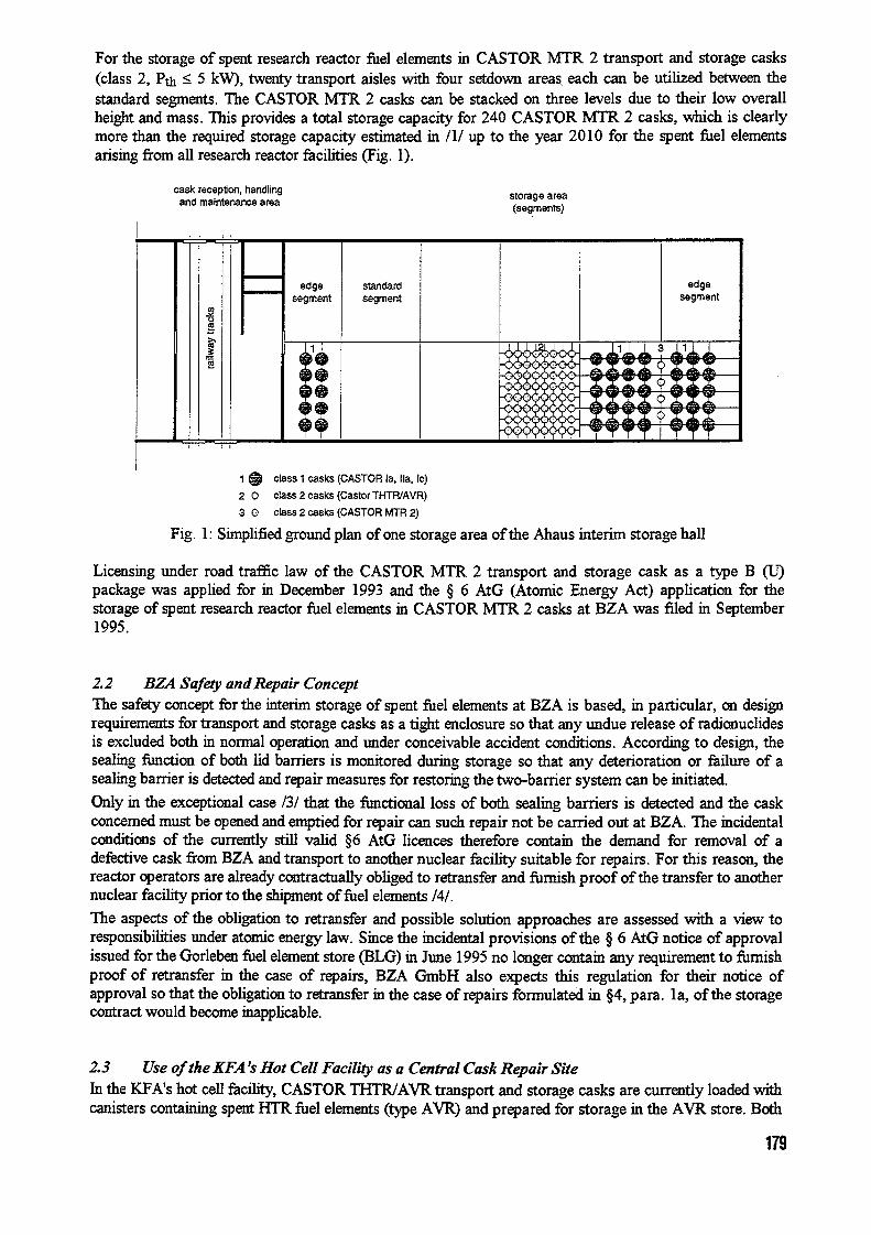
For the storage of spent research reactor fuel elements in CASTOR MTR 2 transport and storage casks(class 2 Pth kW), twenty transport aisles with four setdown areas each can be utilized between thestandard segments. The CASTOR MTR 2 casks can be stacked on three levels due to their low overallheight and mass. This provides a total storage capacity for 240 CASTOR MTR 2 casks, which is clearlymore than the required storage capacity estimated in /I/ up to the year 2010 for the spent fuel elementsarising from all research reactor facilities (Fig. 1).
cask reception, handling storage areaand maintenance area (segments)
edge standard edgesegment segment segment
co
'.Z
A6, Y A6 A6
90h Y 96 & gi�9 11 I 1 I TT 7
1 ID class casks (CASTOR la. Ila, le)
2 class 2 casks (Castor THTRtAVR)
3 0 cass 2 casks (CASTOR TR 2)
Fig. 1: Simplified ground plan of one storage area of the Ahaus interim storage hall
Licensing under road traffic law of the CASTOR M 2 transport and storage cask as a type (U)package was applied for in December 1993 and the 6 AtG (Atomic Energy Act) application for thestorage of spent research reactor fuel elements in CASTOR MTR 2 casks at BZA was filed in September1995.
2.2 BZA Safety and Repair ConceptThe safety concept for the interim storage of spent fuel elements at BZA is based, in particular, on designrequirements for transport and storage casks as a tight enclosure so that any undue release of radionuclidesis excluded both in normal operation and under conceivable accident conditions. According to design, thesealing function of both lid barriers is monitored during storage so that any deterioration or failure of asealing barrier is detected and repair measures for restoring the two-barrier system can be initiated.
Only in the exceptional case / that the functional loss of both sealing barriers is detected and the caskconcerned must be opened and emptied for repair can such repair not be carried out at BZA. The incidentalconditions of the currently still valid 6 AtG licences therefore contain the demand for removal of adefective cask from BZA and transport to another nuclear facihty suitable for repairs. For this reason, thereactor operators are already contractually obliged to retransfer and furnish proof of the transfer to anothernuclear facility prior to the shipment of fuel elements /.
The aspects of the obligation to retransfer and possible solution approaches are assessed with a view toresponsibilities under atornic energy law. Since the incidental provisions of the 6 AtG notice of approvalissued for the Gorleben fuel element store (BLG) in June 1995 no longer contain any requirement to flu-nishproof of retransfer in the case of repairs, BZA GmbH also expects this regulation for their notice ofapproval so that the obligation to retransfer in the case of repairs formulated in 4, para. I a, of the storagecontract would become inapplicable.
2.3 Use of the KFA's Hot Cell Facility as a Central Cask Repair SiteIn the KA's hot ell facility, CASTOR THTR/AVR transport and storage casks are currently loaded withcanisters containing spent HTR fuel elements (type AVR) and prepared for storage in the AVR store. Both
179

facilities are part of the KA's waste treatment and storage building. The installations required for thehandling and repair of casks are largely available. Any operating means, adaptation measures and modi-fications additionally required for research reactor fuel element handling, fuel element support and liftingsystems and CASTOR MTR 2 casks can be procured and installed or carried out with reasonable technicalexpenditure.
Even if it can be expected that the incidental provisions of the BZA licence wl no lnger contain anyrequirement to fi=sh proof of the availability of external repair facilities, a use of the hot cell facility forthe exceptional cases described in the BZA repair concept could be maintained as an option. Theincorporation of the BZA exceptional repair cases into the KA repair concept would permit the openingand emptying of MTR 2 casks and would make it possible to avoid such repair measures as the addition ofa welded lid at Ahaus.
wastetreatmentandstoragebuilding
shipping bay (VH)
access railway track access
hot call facUftc- shipping bay (VH) and,Ito hot cells (AZ) wtth
cask charging dscharging call (BEZ),BEZ storage call for waste packages Z),
LZ transfer call for waste packages (FS),
VAZ FS waste processing call (VAZ)
hot cell operating floor
29,30 m
Fig. 2 Simplified ground plan of the hot cell facility as part of the waste treatment and storage building
3. Contingency Concept for the Storage of Research Reactor Fuel Elements in the KFA's WasteTreatment and Storage Building
33 Investigation ofAlternative Interim Storage PossibilitiesIn examining and assessing aternative interim storage possibilities it was first checked from the staticsaspect whether the available storage areas in the storage hall of the waste treatment and storage buildingare suitable for the interim storage of CASTOR MTR 2 casks. The result was negative.
Since the CASTOR THTR /AVR casks in the AVR store are alternately stacked on one and two levels andsince 56 setdown positions on the second level remain free when the store is completely filled, it waschecked again with a view to the permissible floor load whether these setdown positions could be used forthe storage of CASTOR MTR 2 casks. This result was positive.
Stacking of the CASTOR MTR 2 casks on three levels causes a floor load approximately comparable tothat of the CASTOR THTR/AVR cask stack. The height in the case of stacking the MTR 2 casks on threelevels is approx. 53 in and thus lower than that of a THTR/AVR double stack of approx. 57 in, so thatpositioning with the existing bridge crane is possible.
In the case of a partial use of the reserve setdown area, which for reasons of store charging and possiblerepairs is not filled, sufficient storage capacity is available from a technical point of view.However, complete filling of the second lewal and filling of the reserve seltdown area is not proposed. In thatcase, the cask monitoring system would have to be modified to comply with the additional number of casks.
Apart from possible regulatory aspects, there -are also operational aspects speaking against an extended useof the AVR store for the interim storage of uel' elements from all research reactor facilities.
180

3.2 Interim Storage ofMTR Fuel Elementsftom the KFA's FRJ-2 Reactor in the A VR StoreAccording to KA demand assessments, a maximum of twenty-four CASTOR MTR 2 casks w beneeded up to the year 20 1 0 for disposal of the MfR fuel elements from the KA's FRJ-2 reactor (DIDO).On account of this small number a use of the AVR store offers itself for the storage of these fuel elements.
The casks could either be set down in free edge positions or on the reserve setdown area in the case ofstacking on three levels, involving reasonable extra operating expenditure.
3.3 Interim Storage of the Fuel Elements ftom all Research Reactor Facilities in an EidendedA VR Store
A storage area of 55 setdown positions can be provided by extending the AVR store by two building axes.The setdown area can then be defined and the base statically designed as in the existing store. Should thiscontingency concept be applied, the storage arrangement of the THTR/AVR casks can be adapted to theconstructional modifications to comply with the operation cycles. Moreover, the KA's own MTR fuelelements can then also be interim-stored there.
4. ConclusionsAccording to the reference concept, it is itended to temporarily store the fuel elements from Germanresearch reactors CASTOR MTR 2 transport and storage casks in the fuel element interim storage hallat Ahaus. The licensing application according to 6 AtG has been filed by BZA GmbH.
Since the BZA repair concept does not provide for the opening and eptying of casks to restore tightenclosure in the event of a possible loss of the casks' sealing function, the incidental provisions of the 6AtG licences currently valid for BZA contain the demand for removal of defective casks from BZA andtransport to another nuclear facility suitable for repairs. he reactor operators are therefore obliged inaccordance with the currently valid BZA storage contract, to retransfer such casks and to fin-nish proof ofthe txansfer to another nuclear facility.
The studies deal with the legal aspects of the obligation to retransfer and demonstrate in describing thereference concept that the KA could assume the function of a central cask repair site. Suitable nuclearinstallations for handling and repairing CASTOR MTR 2 casks are largely available in the hot cell facility.Installations additionally required for handling the research reactor fuel elements as well as technicalmodifications to the fuel element baskets of the UR 2 casks are described in the concept.
The studies for the description of a contingency concept as an alternative to the reference furthermore showthat the option for interim storage of the MTR fuel elements from the KA's FRJ-2 reactor (DIDO) in theexisting AVR store is given due to free storage capacity and that the option of an interim storage site as analternative to Ahaus could be opened up by extending the KFA's AVR store.
References/I/ QuaaBdorff, P., Pldtzer, S.: Vergleich von Zwischenlagerkonzepten flir Forschungsreaktorbrenn-elemente, Final Report prepared on behalf of the BMBF, reference no. 02 W 6162 2 Steag KernenergieGmbH, Essen, July 1994
/2/ Niephaus, D.: Etsorgung bestralilter Brennelememente aus deutschen Forschungsreaktoren-Zwischenlagerung der FR-BE an Brennelement-Zwischenlager Ahaus und Nutzung kerntechnischerEmnchtungen der KA as zentrale Behakerreparaturstelle sowie optional als Ausweichzwischenlager-,Final Report prepared on behalf of the BMBF, reference no. KWA 9502, Forschungszentrum JiffichGmbK Rilich, June 1996
/3/ V61zke, H.: Stellungnalune zu einem m6glichen Funktionsverlust von Barrieredichtungen derLagerbehaker im Transportbehiiherlager Gorleben, Ref. No. 93/20128 01-95), Bundesanstalt fiirMaterialforschung und -prdmg (BAM), Berlin, Feb. 1995
/4/ BZA: Zwiscbenlagervertrag f1ir Forschungsreaktoren, Ref. No. TEDI/Dr/St-944379A, Brenn-element-Zwischeniager Ahaus GmbH (BZA), Ahaus, June 1995
181

CH04AO048
THE REPROCESSING OF IRRADIATED MTR FUEL AND THE NUCLEAR MATERIALACCOUNTANCY - DOUNREAY, UKAEA
by
T R BARRETT Nuclear Materials Control Department, DounreayR IIARRISON UKAEA, Thurso, Caithness. W14 7TZ
A. INTRODUCTION
1 MTR irradiated fuel reprocessing has been carried out at Dounreay - since 1958. he mostrecent campaign was completed as recently as October 1996.
2. The original reprocessing policy arose from the strategic importance of HEU, its highmonetary value and supply shortages.
3. In the late 1950's the UKAEA had three HEU fuelled MTRs - two sited at Harwell (DIDOand PLUTO) and one (DMTR) at Dounreay. Similar low power reactors were located atother UK government research and educational establishments. The fuel elementmanufacturing facilities were sited at Dounreay together with the reprocessing plant andrelated support service facilities. A co-located MIR fuel cycle system was consequentlyavailable from the earliest days. The only external fuel requirement was for a supply of veryhighly enriched uranium for 'top-up' replacement of the burnt-up U235 and process losses.External component and material suppliers have been very much involved in the non-fuelcomponent supply and in the technological developments.
4. Over the last four decades, the Dounreay MTR fuel cycle capability was extended to thecommercial contract supply of fuel elements for foreign customers and the provision of acommercial reprocessing service.
5. With the passage of time and the progressive introduction of non-proliferation treaty (NPT)safeguards, the emphasis on the need for reprocessing has shifted. While the original threefactors continue to be important, a fourth is that of effective safeguarding - where bringingextraneous, otherwise waste, residues and irradiated fuel together and recovering it through aplant which is Safeguarded to International standards considerably reduces diversion risks.That is so whether the material is placed in secure storage or is reused in new fuel (againsafeguarded).
6. An additional issue is the sensible treatment of the radioactive waste - an issue that has beenof increasing environmental concern over the years. The essential design features of theMTR fuel are such that some treatment is needed prior to very long-term storage orengineered disposal due to the high fissile content. Reprocessing leads not only to therecovery of reusable fissile material (ie recycling) but thereby leads to waste streams of onlytrace fissile content. That leads to less restrictive waste disposal/storage requirements.
7. A present strategic issue is a shortage of HEU as the USA have adopted a policy of notreleasing EU onto the commercial market, even to fuel cycles and facilities fully coveredby NPT safeguards. Until such time as that policy is amended and until alternative supplies
182
become available, the HEU fuel requirements are being met in part by the recovery ofmaterial from existing stocks.
8. There is scope in the EU to continue to use US origin HEU subject to constraints and enduse. This arrangement is embraced within the recent 1996 Euratom US agreement. That,however, in itself does not lead to a release of new additional material into the market.
9. Consequent upon the international political upheavals and realignments over recent years,there is increasing concern over the security of nuclear materials - particularly HEU - that hasbecome surplus to individual nations' military needs. There are many NPT and diversionaryrisk advantages in recovering such material and bringing it under full internationalsafeguards. For unirradiated material, the Dounreay HEU recovery plant - the downstreamfacility associated with the irradiated fuel reprocessing plant - has a role in such anarrangement.
B. THROUGHPUT
10. The initial operations from 1958 were directed at servicing the UK domestic MTRs. Due inpart to the excellent performance of the plant, capacity was made available in the early1960's on a commercial basis to other reactor operators outside the UK.
11. Domestic priorities at Dounreay led to a reduction in foreign reprocessing in the early1970's. However, due to significant international demands for the service and increasedplant availability, foreign reprocessing was pursued more actively again from the late 1970's.Since the closure of the UKAEA MTR project in 1990, there has been increasing emphasison the provision of this service.
12. From 1973, the Dounreay reprocessing has been carried out under the safeguardssurveillance of Euratorn who have maintained an on-site inspection presence.
13. The first campaign processed unirradiated reject components from the Fuel Fabrication plantand can be considered to be an active commissioning run. The first irradiated elements werereprocessing in October 1958. Unirradiated material was frequently processed up to 1968.Since 1968 processing of this type of material has taken place in the downstream BilletProduction and Recovery Plant.
14. Up to 1962, only fuel from UK reactors was processed. September 1962 saw the firstprocessing (Run 17) of fuel from DR2/3 (Denmark). Fuel from non-UK reactors wasprocessed up to October 1975 (Run 5 1). This work was carried out for reactors fuelled byUS origin HEU either under the EURATOMIUS Agreement, for reactors within the EC, orfor nominated reactors under the US/UK Memorandum. The recovered uranium was eitherreturned as fuel to reactors, returned to the US, or put to the USAX Memorandum account.
15. Following closure of the UKAEA MTR project, the first of the second tranche of non-UKfuel was reprocessed in April 1992 (Run 59), which also saw the last UKAEA MTR reactorfuel reprocessing. The run 61) in March 1996 reprocessed UKAEA NESTOR zero energyfuel, the final inventory of the Scottish Universities Research Reactor fuel, fuel from theAustralian Hifar reactor, and fuel from the WI reactor. The latter part of this campaigninvolved trials on LEU silicide fuel from Petten.
183

6 In summary, the distribution of the reprocessing from the UK and other countries isillustrated in Figure .
No.-UK Ele,,MsPocessed
FIGUR ISP"' Belqw�
El�-N$ PDce�Sd iapa� 0 17% 6.60%11 28%
F a�95%
SedenNo,.UK 4.62%
28% G-u
1.07%
SOW, Aln
De-rk26.131A
72%
26.69%
C. ACCOUNTANCY STRUCTURE AND BACKGROUND 1�dia 7 262.28%
17. Within the Dounreay Site, the unit of accountancy is the 'Plant'. The responsibility fornuclear material, and accounting for it, rests with the 'Plant Manger' with the AnalyticalManager and Engineering Manager having responsibility for the analytical techniques andinstruments, The Nuclear Material Control Department collates and reports the informationgenerated and provides the Accountancy system structure, training and management. AComputerised Nuclear Material Accountancy System operates to support the control, withthe Plant Operators iputting te data. Accountancy and safeguards reports are generated forEuratom (and hence the 1AEA), Plant Management, UKAEA Management and UKGovernment.
18. The accountancy structural nomenclature for the 'Plant' unit has evolved through the yearsfrom the initial financial control structure (Cost Centre/Project based) to the presentOperational Accountancy Areas (OAAs). An OAA can be considered as a sub MaterialBalance Area (MBA). At Dounreay a Safeguards MBA can comprise one or more OAAs.The MTR Reprocessing Plant OAA equates to a single MBA (QDR2).
19. Since 1973, operations at Dounreay have been carried out under the surveillance of Euratorn.For the MTR Reprocessing Plant this involves Euratom witnessing transfers from the producttank and the analysis of the liquor. Random samples are also taken for independent analysisat TUI Karlsruhe. Euratom also use the VOPAN 'Blind Analysis' technique for verifying theUK analysis. A recent development has seen Euratom installing data-logger devices and astate of te art Hybrid K-Edge/gamma spectrometer to provide fully independentmeasurements of product transfer and head-end liquor analysis.
20. In the field of Accountancy and Safeguards, linked to MTR Reprocessing, Dounreay hasmade contributions to ISO Analytical Standard Methods (Davies and Gray), Tank Weighing(product tank) Verification of Operator Analysis (VOPAN) and 1AEA Inspector trainingunder the UK JAEA Support Programme. These demonstrate Dounreay's commitment toAccountancy and Safeguards.
184

21. The MTR Reprocessing plant accountancy boundaries are from element receipt at the DMTRPond (included as part of MTR reprocessing) for element storage, and the issues as the outputof the uranium product and the raffinate tanks. The accountancy model is:-
Inputs Measurements
Elements Shippers dataExcess Analytical Samples Volume, analysisRecycled Product Ex BPRP Volume, analysis
Outputs Measurements
Product Transfers Volume, analysisAnalytical Samples Volume, analysisWaste Liquors Volume, trace analysisSolid Waste NDA
Inventories Measurements
Elements (2) Shippers dataTank Heels Volume, analysis
(1) As the whole element dissolves solid waste is minimal(2) After wash out.
22. The Dounreay reprocessing plant consists of a head-end above ground pond for fuel handling
and preparation for dissolution. There are then two nominal 150t dissolvers operating inparallel. These are followed by conditioning vessels and then a series of transfer vesselsleading on to the solvent extraction stages.
23. The uranium aluminium alloy clad fuel is partially dismantled and then cropped into nominalSO to 100mm lengths. These are charged to the dissolver where they are dissolved inmercuric ion catalysed nitric acid to produce an anion deficient solution - that is a solution
containing an excess of aluminium above the stoichometric A NO3)3. The liquor istransferred to the next vessel - the conditioner - where process analysis is carried out. This isparticularly important in control accountancy terms.
24. The cropped plates containing not more than a total of 550gms of U23's are fed into thedissolver containing dilute boiling nitric acid. 12N nitric acid containing a small amount ofmercuric nitrate is fed to the dissolver over a period of about 25 hours and the resultantsolutions boiled under reflux for about hours. This method of dissolution produces asolution which is deficient in nitrate ion. The solution is transferred to a conditioning vesselwhere it is sampled and if necessary conditioned to between 20 and 30 molar aluminiumand 0.8 to 1.8N anion deficiency. (AD).
25. A particular issue arises from the higher rate of dissolution of the aluminium than that of theuranium alloy, the latter particularly as the nitric acid becomes depleted due to thealuminium dissolution. That leads to residual uranium being left in the dissolver at eachbatch. It is for that reason that the subsequent batch is first charged with a 'mop up' volumeof nitric acid to dissolve the residual uranium before adding the fresh fuel and the balance ofthe acid.
185

26. Process control accountancy of uranium is carried out over the dissolvers and head-endvessels in order to achieve criticality safety. These vessels are not geometrically criticalitysafe at all foreseeable U235 concentrations. It is therefore necessary to maintain a batch-by-batch cumulative assay of material resident in the dissolver in order to avoid an excessivecumulation and an unacceptably high concentration. This is done by sampling and analysingthe liquor in the downstream conditioner vessel.
D. ACCOUNTANCY REVICEW
27. The Dounreay accountancy periods are in financial years April - March. There is no directtie-up between campaigns and accountancy years, however, stocktaking timing is arrangedon a flexible basis so that they are carried out at the end of campaigns. In earlier years therewere many campaigns in a financial year. Latterly campaigns may straddle accountancyyears.
28. In the early days the fissile material accounts were prepared on a quarterly basis, this wasrelaxed to six monthly in the 1970s in order to better optimise the operational andaccountancy programmes.
29. Independently of the formal accountancy and safeguards recording and documented returns,the plant management produce run/campaign accounts to check plant performance and forprocess and contract control purposes. hese employ the same analytical data and are alwayssubject to ratification with the official returns.
30. For all accountancy and campaign returns, particular attention is given to any 'out-of-balance' discrepancy. This feature is identified in safeguards parlance as MUF (MaterialUnaccounted For) - a positive value is equivalent to a 'gain'. he concept of MUF has beensubject to considerable debate - in addition to any unknown losses or gains it embraces errorbands associated with assay uncertainties.
31. Reactor calculated data is now taken as the plant input. Therefore, shipper-receiverdifferences are not reported. The MUF that is reported comprises inaccuracies in fuelmanufacture, bum-up, instrumentation measurements, volumes, sampling and analysis.Quality Systems are maintained on all operating features and on all analysis. All instrumentsand tanks are calibrated and frequently re-checked. Plant operating instructions definemixing times to be used from tank mixing data generated for each tank duringcommissioning and calibration exercises.
32. Any single MUF is considered in terms of its magnitude and the plant throughput over whichit arose. The level of concern is considered against safeguards diversion limits for both thelong and short terms. A level of 2 of throughput has been a common 'limit' applied insafeguarding, but attention is now being applied to a new level of concern at a value of I%.This is in line with the adoption of International Target Values for all measurements andanalysis within the Nuclear Industry. (Similar approaches are being carried out in mostindustries which carry out such measurements). Dounreay is adopting this tighter approach,the first steps being a full review of measurements uncertainties.
33. The cumulative MUF over the life of the plant to date reflects an overall gain (+). This,however, relates to two phases over that time.
186

Consequent upon this review, the reactor bum-up algorithms were revised to accommodatenewer physics data.
35. The situation since April 1970 reflects the revised reactor physics calculations and indicatessince then a cumulative MUF significantly less than I%.
36. These results confirm that up to March 1970, there had been a very significant bias in theinput assessment which led to high positive M`UFs in the early years. The present MUFlevels are consistent with a predominantly random eor situation.
37. Occasional process and accountancy difficulties do occur. A 1992/1993 positive MUF washigher than normal and was traced in part to incorrect treatment of the product tank volumecalibration data and one abnormal liquor transfer to waste. Insufficient confirmed data wasavailable retrospectively to correct' the accounts. A computer program is now in place toprovide better control of product transfer recording. A 1993/1994 negative MUF wasattributed mainly to the uncertainties in material recycled from the downstream BRP plant.The recycle control arrangements and procedures have been revised to overcome thatproblem. The most recent campaign saw a low negative MUF within the 1 limit.
38. Overall the MUF assessments to an NMA accountant, suggests there is good control withinthe plant and the associated measurements of the various input and output streams.
CONCLUSIONS
39. The reprocessing of irradiated BEU MTR fuel is a sensible part of a Safeguards regime. Itbrings together fuel otherwise scattered around the world into a concerted accountancy andprotection arrangement.
40. From a Nuclear Material Accountants view the overall accountancy performance has beenexcellent. While investigations have been required for a few individual MUFs or trends, verylittle effort has required to be expended by the Nuclear Materials Control Department. Thatis a definition of a 'good plant'; it operates, measures and records input and output streams,and then the accountancy falls into place.
41. As identified in this paper, the accountancy of the nuclear material processed in the plant iswell founded and sound. The accountancy results over several decades confirm the adequacyof the safeguards arrangements at Dounreay.
42. The processing makes good commercial sense and meets the current philosophy of recyclingvaluable resource materials. The risks of operating the full fuel cycle are less than those ofextended storage of irradiated fuel at disparate diverse locations. The reprocessing atDounreay accords with all of these philosophies. The assessed risk is at a very low level,well within published UK HSE 'tolerability of risk' regulatory guidelines. The impact of theoperations are similarly low within the guidelines, for the operators and for the generalpublic.
187

CH04AO049
An Analysis of Burnup Reactivity Credit for Reactor RA Spent Fuel Storage
M.J. Milogevi ad M.P. Pdid
Institute of Nuclear Sciences - Mnea'Nuclear Engineering Laboratory - AET'
P. O.Box 522, AET150, 11001 Belgrade, Yugoslavia
Abstract - The needs for increasing the spent fuel storage capacity and for using higherfuel enrichments have led to the development of a validated methods for assessing thereactivity effects associated with fuel burnup. This paper gives an overview of thecriticality safety analysis methodology used to investigate the sensitivity of storagesystem reactivities to changes in fuel burnup. As an example of the application of thismethodology an analysis of the burnup reactivity credit for the three-dimensional modelof reactor RA spent fuel storage is described.
1. INTRODUCTION
As nuclear fuel is burned in a reactor, changes in reactivity are arisen from: reduction of fissilecontent, production of various actinides (some contributing positively toward reactivity, some behavingas neutron poison) and production of fission product poisons. The standard approach for criticality safetyanalysis of spent fuel transportation and storage problems assumes that all fuel under consideration isunirradiated. This assumption is conservative from a criticality safety point of view (except for somesituation of low-irradiated fuel with burnable poisons). As a result of this simplified approach, thetreatment needed to evaluate criticality safety to both the fresh and spent fuel storage is the same. Despiteproviding maximum operator flexibility, this intrinsic conservatism can results in a reduction in theefficiency of these operations, making the enrichment limit found for spent fuel usually more restrictivethan the fresh fuel limit. The recent concept'-' of allowing reactivity credit for the transmuted state ofspent fuel has been incited by the need to reduce the conservativism initially included in the calculationsin order to obtain more realistic ("best estimate") results to increase the operational flexibility of the fuelstorage facilities. One procedure that have been proposed is to use the major fissile nuclides and actinideswithout the fission product absorbers.' Neglecting fission product poisons has a conservative influenceon the calculated keff (i.e., results in a higher value, approximately for one third of the total burnupreactivity loss). Since the cost of the analysis is proportional to the number of fission product considered,an investigation' have been performed to identify nuclides important in criticality analyses and those tobe experimentally determined. This resulted in the set of 25 uclides (referred to as the "burnup creditnuelides") which is recommended for the use in criticality analyses associated with burnup credit.
The initial criticality safety analysis' of the spent fuel storage at the Institute 'Vin6a' wasperformed by using the WIMSD4 code,',' which is very suitable for fuel burnup calculations and infinitestorage configurations studies. However, this code has been developed for standard geometries, includingpin cell arrays and fuel clusters, so that its geometry requirements do not allow for the analysis of someaccident configurations, that must be calculated with complicated three-dimensional models. Monte Carlotechniques have merit of dealing with these geometries rather easily. The MCNP continuous-energyMonte Carlo code' is one of such codes which is widely used and has been accepted as adequate forcriticality assessment. From the calculation point of view, physical phenomenon can be correctlymodelled with MCNP, while the consideration of fuel burnup calls for the use of an external code tocalculate the evolution with burnup of the fuel isotopic composition. In the current criticality analysismethodology, VEGA-2 two-dimensional transport theory code,' based on an extended subgroup methodfor resolved resonance treatment, is used for this purpose. This paper summonses the burnup creditanalysis methodology founded on the use of VEGA-2 code as a complement to the MCNP code and givessome examples of special applications to demonstrate its flexibility.
188

II. CRITICALITY ANALYSIS METHODOLOGY
The VEGA cell/assembly code, used for burmip calculations is validated for a wide range of fuelenrichment and moderator ratios, including voided configurations." An extended subgroup methodenables a rigorous resolved resonance treatment in the practical cases where resonant nuclides are locatedin various media, such as the fuel double heterogeneity problems. A wide variety of situations can bemodelled ranging through the thermal reactors, storage systems and items of chemical plant. This includegeometry changes such as pin size and pin pitch and the effects of voidage, temperature and fuel burnup,which are an area where the Monte Carlo technique is difficult to use as well as being costly. On theother hand, the MCNP code is very suitable at representing both the spatial and the energy variations.Thus resonance can be accurately represented as well as the intricate detail of the complicated three-dimensional geometry.
Few fission product models for VEGA-2 code were studied and tested with benchmark results.The model containing 45 explicit nuclides, and one pseudo nuclide was selected as a reasonably best oneto predict the burnup reactivity with high precision for practically all types of fuel and reactor operatingconditions. To include the contribution of these fission product absorbers in the criticality calculationsbased on the MCNP code, a special evaluation represented by the average fission product for U-235 wasperformed. This evaluation is based on a study of burnup calculations for heavy water reactor RA at theInstitute WWa% which indices that only about a dozen fission product absorbers provide 80 ofnegative reactivity resulting from neutron poison buildup. The calculations also demonstrated thatalthough the relative importance of this poisons varied with time-out-of-reactor (cooling) they continuedto be responsible for about 80% of negative reactivity. Since a lower accuracy is permitted at a lowerburnup, it was assumed a constant cross section for average fission product throughout the bumup,ignoring its time dependence. The adopted cross section values, composed from explicitly the 10 mainmiclides which represent more than 80 % of total poisoning effect (Nd-143, Sm-149, Xe-131, Cs-133,Sm-151, Tc-99, Nd-145, Mo-95, Kr-83, Rh-103) at 10 GWd/t irradiation was chosen as a final values,and corresponding multigroup data for VEGA-2 code and point cross section data for MCNP code weregenerated with NJOY package." In these burnup credit analyses, the concentration of average fissionproduct absorber, used in the MCNP code, is determined by equating of the total fission productabsorption for the VEGA-2 fission product model (with 45 explicit nuclides; and one pseudo nuclide) andfor effective model with the average fission product. To the date, the current criticality analysismethodology is verified only for the fuel element used in reactor RA A precise treatment along this linewill be continued.
III. RESULTS
As a general rule, input data for the analysis of the reactor RA spent fuel storage are preparedfollowing hypothesis aimed to produce conservative results: geometrical and material compositionuncertainties are conservatively considered. Detailed design specifications for the spent fuel storage aremodeled as closely as possible.
Research reactor RA (nominal power 65 MW) is a heavy water moderated and cooled reactor.'Me fuel element (slug) is an aluminium cladded hollow cylinder (Figure 1). Temporary spent fuelstorage consists of four connected water pools 6 m deep) and one annex pool connected by waterpassage to the nearest pool. In order to increase the spent fuel storage capacity, some of the oldest metaluranium fuel elements has been taken out of the original stainless steel containers and repacked in 30sealed aluminium barrels (Figure 2, each containing 30 aluminium tubes receiving up to 6 irradiated fuelelements per a tube. The barrels are filled with demineralised water and placed in two layers in the annexpool. Irradiation of the fuel elements is given in Table 1. Cadmium strips were placed in some of thebarrels with aim to provide the necessary subcriticality.
In current analysis, the criticality calculations are carried out by MCNP code only for spent fuelelements stored in the barrels. As an conservative approach, it is assumed that each barrel is completelyfilled with irradiated fuel elements, there are no cadmium strips in the barrels, and30 barrels are placed in two layers in a hexagonal lattice (pitch 30 cm) that models, as close as possible,an irregular actual position of the barrels in the pool (Figure 3.
189

As an example of validation of adopted averageTable I Fuel irradiation history fission product model, burnup reactivity credit in single
pin cell of the stora e barrel, obtained by the MCNPBurnup Average Number of and VEGA-2 codes is shown in Figure 4 All results are[GWd/t] burnup elements in close agreement on the rate of the reactivity lost
[GWd/t] during ftiel burnup.The results of the MCNP calculation of the
- 2 1.8 100 reactivity for three-dimensional model of the annex pool2 - 4.6 1729 of the reactor RA spent fuel storage in function of fuel
- 7.2 2300 irradiation (after 30 year of cooling), obtained with the- 1 9.9 760 average fission product model and the BMCCS I nuclear
> 39 data library are given in Table II. Taking into accountthe Akff margins (due to the applied methodology and
geometrical and material uncertainties) it can be concluded that the k,ff of the spent fuel in the annex poolof the reactor RA storage has Kff that not exceeded the industry-accepted limit',' of kff < 095.
IV. CONCLUSION
This paper summarizes main features of the criticality safety analysis methodology used in theInstitute 'Vin6a' and gives some examples of special application which demonstrate its ability to accountburnup reactivity credit for the annular fuel type as used at the RA reactor.
ACKNOWLEDGEMENTS
The authors are grateful to 0.�ofid and Z.Vukadin from the RA reactor for their contributionin the evaluation of the reactor fuel irradiation istory. This work was funded by the Ministry of Scienceand Technology of Republic Serbia under Contract No. 08MO6.
REFERENCES
1. N.R.SMITH and M.H.WATMOUGH, "Progress in the Development of a Validated Method for Assessingthe Reactivity Effects Associated with Fuel Burnup, " Proc. of the Inter. Conf. on Nuclear Criticality Safety,ICNC'91, Oxford UK, 913 September, 1991, Vol. 1, p I-83 1991).2. M.C.BRADY and T.L.SANDERS, "A Validated Methodology for Evaluating Burnup Credit in Spent FuelCasks," Proc. of the Inter. Conf. on Nuclear Criticality Safety, ICNC'91, Oxford UK, 913 September,1991, Vol. 1, p I-68 1991).3. M.V.MATAUSEK, N.MARINKOVIC and R.SIMOVIC, "Criticality Safety of Fresh and Irradiated Fuelof the 65 MW Heavy Water Research Reactor," Proc. of International Symposium on Nuclear Energy,SIEN'95, Bucharest, 1995, p. 27 1995).4. J.R.ASKEW, F.J.FAYERS, and P.BXEMSHELL, "A General Description of the Lattice Code WIMS,"J. Brit. Nucl. Energy. Soc., 5, 564 1966).5. M.J.HALSALL, "A Summary of WIMSD4 Input Options," AEEW-M 1327, Atomic EnergyEstablishment, Winfrith UK 1980).6. J.F.BRIESMEISTER, Editor, "MCNP - A General Monte Carlo N-Particle Transport Code, Version 4A"LA-12625-M, Los Alamos National Laboratory 1993).7. M.J.MILO§EVI1t, "The VEGA Assembly Spectrum Code," Presented at Yugoslav Nuclear SocietyConference - YUNSC'96, Belgrade Yugoslavia, 79 October 1996.8. M.PE§I(�, N.ZAVAIJEVSKI, M.MILO§EVI�, D.STEFANOVI�,, D.POPOVI�, D.NIKOL16,P.MARINKOVI6, and S.AVD16, "A Study on Criticality of Coupled Fast-Thermal Core HERBE at RBReactor," Ann. Nucl. Energy, 18(7), 413 1991).9. M.MILO§EV163, M.PE�16, T.MILOVANOV16 and V.I-JUBENOV, "Verification of Void EffectCalculation," Trans. AL Nuc. Soc., 73(l), 404 1995).10. R.E.MacFARLANE, D.W.MUIR and R.M. BOICOURT, "The NJOY Nuclear Data Processing System,Volume II: The NJOY, RECONR, BROADR, HEATR and THERMR Modules," LA-9303-M, Vol. (ENDF-324) Los Alamos National Laboratory 1982).
190

3.70 At 'STAR' C60%) UOPMD HD
AL EXPELLER 75%) AlHO 23V
FLIEL
Li
AL CLADDING
it E
Z
At EXPELLER
'STAR' (0%)HO 40%)
TAR'
H20210P-40
Fure, I Vertical cross section of Vgure 2 Horizontal cross section ofthe real fuel slug and its MCNP model the storage barrel for irradiated fuel
CONCRETE WALL CONCRETE WALL
-j
H20 Li H2F]LiQf
U L)
r-Iu U
STAINLESS STEEL WALL
CONCRETE WALL CONCRETE WALL
LOWER LAYER UPPER LAYER
figure 3 Horizontal cross section of the storage pool with position of the barrels
1.20 -
Table 11 Results of the MCNP K calculation1.15 -
- VEGA-2
1.10 0000 MCNP4A
Burnup Kff[GWd/dj
1.00 ------------------------- -----------0 0.82550 + 0.00114
0.95 2 0.79128 ± 0.00132
0.90 4 0.76107 + 0.001066 0.72888 ± 0.00110
0.85 - 8 0.69320 + 0.00112
0.80 i .......... 10 0.65576 + 0.001076 ... 2000 4000 6000 Iia,06, Ikdc, 1,2000
B.,t.p (Mwd/t)
]Figure 4 A comparison of the results of theburnup reactivity credit in the single pin cell ofthe storage barrel

CH04AO050
DEFUELLING OF THE UTR-300 RESEARCH REACTOR
R. D. Scott, H. M. Banford and B. W. EastScottish Universities Research and Reactor Centre
East Kilbride, Glasgow, G75 OQF UK
and
M. A. Ord and A. P. GaffkaAEA Technology
Harwell, Didcot, Oxfordshire, X1 1 ORA, UK
1 INTRODUCTION
The UTR-300 reactor at the Scottish Universities Research and Reactor Centre was basedon the original Argonaut design with two aluminium core tanks set in a graphite reflectoreach containing six fuel elements cooled and moderated by water flowing up through thetanks in a closed primary circuit. The fuel plates in the original 13-plate elements wereuranium oxide-alurninium with a 22g loading of 90% I" U. After 7 years of operation at1 OOkW (1 kW average), the maximum power was increased to OkW 3OkW average)and, in order to maintain the operational excess reactivity, it was necessary to add anotherplate to each element progressively over the years until they all contained 14 plates. Theseextra plates were uranium metal-aluminium with 24.5g of 90% 231U . No furthermodification of the elements was possible and so, with reactivity steadily decreasing, andfor a variety of other reasons, a decision was taken to cease operation in September 1995.
This paper describes the procedures whereby the fuel was unloaded from the core into aUNIFETCH flask equipped with a specially designed rotating gamma ray shield and thentransported in two separate loads to Dounreay for reprocessing.
2. PRELIMINARIES
The operation was carried out as a plant modification in compliance with an arrangementmade against one of the site licence conditions and was assessed in terms of safety as acategory modification, having major significance. Such a modification requires a proposalcontaining a detailed safety case which, after consideration both by the SURRC NuclearSafety Committee and by an independent consultant, is submitted to the NuclearInstallations nspectorate Nil). Depending upon the response from N work may proceedimmediately or must not proceed without an agreement from N issued in the form of alicence instrument. In the latter case, 'hold points' usually have to be identified beyondwhich work may not proceed without the further agreement of Nil.
During annual maintenance the fuel is routinely transferred into shielded storage pits in thefloor of the reactor hall by means of a transfer flask, which holds one element, and it wasdecided that the loading into the LINIFETCH flask would be carried out in two stages, fromthe core to the storage pits and from there to the LINIFETCH. This meant that the fuelcould be kept in the reactor from shut-down until the transfer with the core ventillationrunning continuously and the fuel tanks dry. Also, the safety case for transfer to theUNIFETCH from the pits was simpler than it would have been for transfer directly from thecore.
192

2a. FISPIN Calculation
Doses from both shielded and unshielded fuel elements constituted an important aspect ofthe safety case and the activity of'the fuel was therefore calculated at AEA Winfrith bymeans of the FISPIN code. The calculation was performed with a value of neutron fluxmodified by the duty cycle of the reactor O hours per week) and it is interesting to notethat this gives an erroneous value for the activity at shutdown of fission (or activation)products with half-lives much less than the 'on' period of the duty cycle 6 hours) sincethey will saturate at a value corresponding to the true neutron flux. The effect is evidentlya function of the half-life of the species and a detailed calculation shows that for our dutycycle it can be ignored for half-lives in excess of a few days.
<
4 0
5:1N
FIGURE 1
2b. Design of the UNIFETCH basket and rotary shield
The UNIFETCH flask is usually loaded and unloaded under water but, since there is no fuelpond on site, it was necessary to do a dry loading through the specially designed shieldingarrangement shown in Figure 1. This consisted of a basket with six circumferentiaHydisposed fuel pockets and a blank position. A sewing ring, mounted on a ratchet ring,supported a rotating hub (capable of rotating in one direction only) to which was attacheda shield with a single hole in it matching the size of the fuel pocket. The idea was to lowerone fuel element at a time from the SURRC transfer flask into each of the six pockets byrotating the shield, ending up with the hole over the blank position and the six elementsshielded. To reduce the V-flash as the element passed from the transfer flask to theUNIFETCH basket, a further shield with a 25mm deep 'footprint' of the transfer flask wasmounted on top of the primary rotating shield. The position of a dowel pin on the primaryshield relative to the fixed wail of the UNIFETCH flask was marked with adhesive tape foreach of the six positions, and the blank, and this same dowel pin served to locate the top
193

shield. A much more precise alignment was necessary when loading fuel and this wasprovided by a spring plunger which dropped down through both shields to engage theratchet ring when the holes were aligned. A locking bar was also engaged in the ratchetring when a fuel element was being transferred. The shield, carrying the transfer flask,was always rotated to the next position before the flask was removed so that the elementswhich had already been loaded were shielded at all times (Figure 2.
FIGURE 2
2c. The safety case
This was produced by AEA Technology and consisted of a combined preliminary safetyreport, pre-commissioning safety report and pre-commencement safety report containinga hazard identification (hazops) study. It was backed by a quality plan, detailed operatinginstructions for the various tasks involved and a criticality calculation.
2d. Precommissioning Trials
The UNIFETCH flask equipped with the basket and shields was brought to SLIRRC twomonths before the date proposed for the transfer of active elements and the entireprocedure, including the erection of scaffolding around the low loader carrying the
UNIFETCH, was tested by transferring two dummy elements from the storage pits to the
UNIFETCH. The transfer of fuel elements from the core to the foor was performed
routinely by SURRC staff according to documented procedures and lay outside the safety
case. The division of labour between SURRC and AEA staff was based upon pastexperience: all operations involving the SURRC transfer flask were undertaken by SURRC
staff whereas the UNIFETCH was handled by AEA staff. It was possible to maintain this
practice even when the two flasks were mated during the transfer of a fuel element.
Tests were carried out with a 1 GBq 60CO source in the fuel pockets to ensure that there
were no shine paths between the basket and the rotating shields. There was no evidence
of scattered radiation and calculations of the dose rate in the pockets adjacent to the one
containing the source agreed well with the measurements. This in tu rn gave confidencein the estimated dose rates arising from the fuel elements.
194
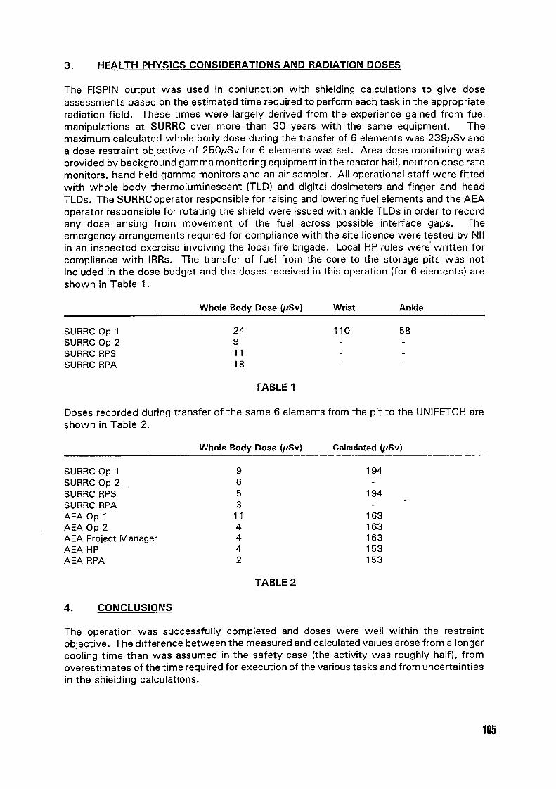
3. HEALTH PHYSICS CONSIDERATIONS AND RADIATION DOSES
The FISPIN output was used in conjunction with shielding calculations to give doseassessments based on the estimated time required to perform each task in the appropriateradiation field. These times were largely derived from the experience gained from fuelmanipulations at SURRC over more than 30 years with the same equipment. Themaximum calculated whole body dose during the transfer of 6 elements was 239/JSv anda dose restraint objective of 250,uSv for 6 elements was set. Area dose monitoring wasprovided by background gamma monitoring equipment in the reactor hall, neutron dose ratemonitors, hand held gamma monitors and an air sampler. All operational staff were fittedwith whole body thermoluminescent FLD) and digital dosimeters and finger and headTLDs. TheSURRCoperatorresponsibleforraisingandloweringfuelelementsandtheAEAoperator responsible for rotating the shield were issued with ankle TI-Ds in order to recordany dose arising from movement of the fuel across possible interface gaps. Theemergency arrangements required for compliance with the site licence were tested by NIIin an inspected exercise involving the local fire brigade. Local HP rules were written forcompliance with IRRs. The transfer of fuel from the core to the storage pits was notincluded in the dose budget and the doses received in this operation (for 6 elements) areshown in Table .
Whole Body Dose ISv) Wrist Ankle
SURRC Op 1 24 110 58SURRC Op 2 9 - -SURRC RPS 1 1SURRC RPA 18
TABLE
Doses recorded during transfer of the same 6 elements from the pit to the UNIFETCH areshown in Table 2.
Whole Body Dose /Sv) Calculated ISv)
SURRC Op 1 9 194SURRC Op 2 6 -SURRC RPS 5 194SURRC RPA 3 -AEA Op 1 1 1 163AEA Op 2 4 163AEA Project Manager 4 163AEA HP 4 153AEA RPA 2 153
TABLE 2
4. CONCLUSIONS
The operation was successfully completed and doses were well within the restraintobjective. The difference between the measured and calculated values arose from a longercooling time than was assumed in the safety case (the activity was roughly half), fromoverestimates of the time required for execution of the various tasks and from uncertaintiesin the shielding calculations.
195