6E#07351 - OSTI.GOV
100
6E#07351 FBT-00/l 1 RECEIVED IEA biomass agreement Task X. Biomass utilization Biomass thermal gasification activity Sub-task 6- Gasification of waste Summary and conclusions of twenty-five years of development E Rensfelt A Ostman Rap orterna kan bestallas h-tin (l Stu svikbiblioteket,611 82 Nykoping. Tel 0155-221084. Fax 0155-263044 e-post [email protected] Statens energimyndighet Box 310,63104 Eskdstuna -J& OFTHISDOCUh!ENT 1?[JNLIM. FOREKN ~ FRCHWH) (2 Energimyndigheten
-
Upload
khangminh22 -
Category
Documents
-
view
7 -
download
0
Transcript of 6E#07351 - OSTI.GOV

6E#07351
FBT-00/l 1
RECEIVED
IEA biomass agreementTask X. Biomass utilizationBiomass thermal gasification activitySub-task 6- Gasification of wasteSummary and conclusions of twenty-five years of development
E Rensfelt
A Ostman
Rap orterna kan bestallas h-tin(lStu svikbiblioteket,611 82 Nykoping.
Tel 0155-221084. Fax 0155-263044e-post [email protected]
Statens energimyndighetBox 310,63104 Eskdstuna
-J& OFTHISDOCUh!ENT1?[JNLIM.FOREKN~ FRCHWH)
(2Energimyndigheten

DISCLAIMER
Portions of this document may be illegiblein electronic image products. Images areproduced from the best available originaldocument.

00-04-27
(?Energimyndigheten
Titel:
Forfattare:
IEA biomass agreement
Task X. Biomass utilization
Biomass thermal gasification activity
Sub-task 6 – Gasification of Waste
Summary and Conclusions of Twenty-five Years
of Development
Erik Rensfelt TPS Termiska Processer
AB
Anders Ostman Kemiinformation AB
RAPPORT INOM OMIL&DET FORBtiNNING/FORGASNING
Rapportnummer: FBT 00/11
Projektledare: Erik Rensfelt
Projektnummer: P6603-1
Projekthandlaggarep~ Statens Energimyndighet: Sten ~feldt
Box310”63104 Eskilstuna● BesoksadressKungsgatan43Telefon016-5442000•Telefax016-5442099stem(i?slem.se● www.stem.se

I TPS-96/l 9 I
IEA B1OMASS AGREEMENT
TASK X. BIOMASS UTILIZATIONBIOMASS THERMAL GASIFICATION ACTIVITY
Sub-task 6- Gasification of Waste
Summary and Conclusions of Twenty-five Years of Development
Erik Rensfelt, TPS Termiska Processer ABAnders Ostman, Kemiinformation AB
tps)
— . . . -,. ,,. -- —..

TPS 96/19
IEA Biomass AgreementTask X. Biomass UtilizationBiomass Thermal Gasification and Gas Turbines Activity
Sub-Task 6- Gasification of WasteSummary and Conclusions of Twenty-five Years of Development
AbstractAn overview of nearly thirty years’ development of waste gasification and pyrolysistechnology is given, and some major general conclusions are drawn.
The aim has been to give new developers an overview of earlier major attempts to treatMSW/RDF with thermochemical processes, gasification or pyrolysis. Research work ingeneral is not covered, only R&D efforts that have led to substantial testing in pilot scaleor demonstration.
For further details, especially related to ongoing R&D, readers are referred to otherrecent reviews.
The authors’ view is that gasification of RDF with appropriate gas cleaning can play animportant role in the future, for environmentally acceptable and efficient energyproduction. A prerequisite is that some of the major mistakes can be avoided, such as:
1) too rapid scale-up without experimental base2) unsuitable pretreatment of MSW to RDF and poor integration with
material recycling3) too limited gas/flue gas cleaning.
tx9619

IEA Biomass AgreementTask X. Biomass Utilization
Sub-task 6- Gasification of Waste
IEA Biomass AgreementTask X. Biomass UtilizationBiomass Thermal Gasification and Gas Turbines Activity
Sub-Task 6- Gasification of WasteSummary and Conclusions of Twenty-five Years of Development
Table of Contents
Page
o.
1.
2.
3.
4.
5.
6.
Abstract
Summary and Conclusions
Products and MarketsEarly Efforts in Waste GasificationLater DevelopmentsConclusions
Scope and Limitations
Wastes and Trends in Waste Composition
Markets and Products
Overview Papers and Reports Waste Gasification
5.1 EEC Report 19845.2 Aston University/Ilk Technic 19935.3 Novem BGT/TNO 19945.4 Kraftverkstecknik 19945.5 The NREL/CDM Report 1996
Survey of Waste Gasification and Pyrolysis Processes
6.1 Early Developments (Prior to 1980)6.2 Waste Gasification 1980-90&3 Topical Processes Under Current Development6.4 Summary and Conclusions From the Early Developments
1
3-4
44-55-66
7-8
9-1o
11-12
13
1313-1616-171717
18
1819-222223-24
er9619]g960509

LEA Biomass AgreementTask X. Biomass Utilization
Sub-task 6- Gasification of Waste
7. Conclusions
7.1 Conclusions Regarding Function and Environmental Effects7.2 Comparisons Between Flue Gas Cleaning and Fuel Gas Cleaning7.3 Conclusions Regarding Products and Energy Efficiency7.4 Comparison Incineration and Pyrolysis/Gasification7.5 Aspects on Gasification/Pyrolysis Regarding Present Experiences
8. Enclosure Process Descriptions
8.1 The Sofresid/Caliqua Process (Andco-Torrax)8.2 Motala Pyrogas, Sweden8.3 The Purox Process8.4 The Landgard Process (Monsanto)8.5 The Destrugas Process8.6 The Omnifuel Process
(Eco-fuel, University of Sherbrooke)8.7 The Ebara Process8.8 The Flash Pyrolysis Process (Garrett-Occidental)8.9 The Erco/Power Recovery System Process8.10 Elajo/Tomegaard/Kom&o, Sweden8.11 The Voest Alpine Process8.12 Scanarc (Plasma) Process8.13 The Batelle (Ohio) Process8.14 The Termoselect Process8.15 The Lurgi CFB Processes (OKO-Gas, Wikonex)8.16 The TPS/Ansaldo RDF Gasification Process
The Gr6ve-in-Chianti Plant8.17 The TPS Gasification and Hot Gas Cleaning Process
(TPS Terrniska Processer AB, Nykoping, Sweden)8.18 The Kiener-Siemens Process8.19 Daneco
l?age
25
25-2626-2727-2929-3030-31
32
32-333435
36-3738
39-4041
42-4344-45
4647-4849-5051-5253-5455-56
57-58
59-606162
‘ tx!!61919960509
2

IEA Biomass AgreementTask X. Biomass Utilization
Sub-task 6- Gasification of Waste
Gasification of WasteSummary and Conclusions of Twenty-five Years of
Development
Erik Rensfelt, TPS Terrniska Processer ABAnders Ostman, Kemiinfomation AB
1. Summary and ConclusionsThe gasification - including pyrolysis - of different types of waste has been carried out at thedevelopment stage for at least twenty-five years. Occasionally, regular production units havebeen installed more or less as demonstration plants. The total number of pyrolysis/gasificationprocesses for waste during these twenty-five years exceeds forty, out of which some twentyhave been demonstrated at capacities of more than 1 ton per hour.
In some countries, second to deposition in disposal areas, incineration or combustiontechniques have been “conventional” treatments for waste since the sixties. With the increasingenvironmental consciousness, these incineration units have been subjected to tighteningemission limits and steadily increasing costs for the waste treatment. The reason for this is ofcourse the complex nature of the waste, and one could say in principle, that a responsiblecaretaking of waste must include the separation of the various components at some stage in theprocess.
The nature of these separations will depend on their location, from a flue gas cleaning afterincineration/combustion, to some kind of mechanical pre-treatmentheparation of the waste.
Basically this evaluation of thermal treatment of waste is to some extent an examination ofwhere the separation is advantageous, and what type of separation is appropriate. Moreover,there are fundamental differences between various gasification and pyrolysis processes whichhave a principle impact on the process performance - especially in the material handling aspect.A key question is thus the fuel considered (Municipal Solid Waste) MSW, or untreated RDF(Refuse Derived Fuels) of different qualities. In general, MSW-incinerations in grate-fuedboilers have been favoured due to the low pre-treatment cost. In many countries today pre-treatment is mandatory due to material recovery aspects including metals, glass and paper.Such schemes yield an RDF-type of waste, both when source separation before collection ormechanical separation after collection, is employed.
During the past two or three decades, there has also been an increasing concern about othertypes of waste. Today, hazardous waste (from the medical and veterinary sides, as well asfrom chemicals) are restricted in handling and tied to special incineration units. Specialtechniques have been investigated for plastic waste, where there is increasing attention to scrapfrom cars, boats, computers etc. The problems with spent rubber tyres and other forms ofrubber, are well-known. ‘
With the mentioned philosophy of recycling and separation at source, these waste streams arelikely to become more and more separate. This enables a more effective treatment of them,
3‘ er9619
19960509

IEA Biomass AgreementTask X. Biomass Utilization
Sub-task 6- Gasification of Waste
whilst at the same time the specific streams maybe smaller in volume. Consequently, there is aparameter of flexibility and scale introduced in treatment technologies.
Products and MarketsGasification and pyrolysis have a wider range of possibilities with regard to products, by-products and markets, compared with conventional mass bum burners. The main products aregas of different types and qualities, and liquids also of different qualities.
Gases are usually considered to have potential markets for instance in:
- ovens, limekilns, brick kilns, metallurgical furnaces, etc.- dryers- boilers
and for advanced gasification with gas cleaning, also in:
- power generation in engines and gas turbines (combined cycles)- power generation in fuel cells- synthesis of SNG
MethanolAmmoniaHydrocarbons (gasoline, diesel).
There is no requirement for high gas temperatures in gasification, enabling for instance counter-current flows (up-flow reactors). A high temperature may in turn be maintained in the bottom,providing a melted ash outlet (in contrast to “dry” ashes coming out of the combustion units).
Regarding the “markets”, a melted ash is superior to the common “dry” ash. It still cannot beattributed any value, but the costs are considerably lower for deposition as a result of lessvolume, as well as that melted ash is usually considered a non-leaching material
Further, severaI gasification processes have a potential advantage regarding the bottom ashquality not containing fermentable products. Due to the composition of waste, there aretemperature limitations in incineration. Chlorine and other compounds may induce severecorrosion on the superheaters etc., if the material temperatures are higher than 480°C in thesuperheater.
A gas cleaning in between the gasification and the gas combustion in a combined unit should beless costly than the corresponding flue gas cleaning after the combustion, since the gas flowmay be less than half the flow of flue gas. For oxygen-blown gasifiers the gas volume is evenlower and that gives further possibilities for low emissions after gas cleaning.
Assuming that gas cleaning between the gastilcation and the combustion is cheaper -or at anyrate not more expensive than flue gas cleaning - the effects of a combined system on thecombustion are considerable. With a clean fuel, and especially with a gaseous fuel, theinvestments will be lower and the energy efilciency of the combustion may be considerablyincreased. There is no longer a restriction on the temperatures on the superheaters.
Early Efforts in Waste GasificationIn the opening remarks it MIS stated that the gasification of waste started almost thirty yearsago. These efforts were by no means negligible. More than 20 processes were suggested ad
developed to some extent during the seventies, 13 of these were run at capacities of more than10 tons a day, and five were tested at between one and ten tons per day.
4‘ er9619
19960509

IEA Biomass AgreementTask X. Biomass Utilization
Sub-task 6- Gasification of Waste
Several of the early developments in the USA were later demonstratedtested in Europe and./orJapan (ANDCO-TORRAX, PUROX, Twin-bed pyrolysis/13 ailie).
The most striking point from the earlier developments of waste gasification is of course the factthat hardly any one of the processes remains today as a commercial product. The onlyexception may be the Andco-Torrax process which has had a certain success, with five plantsbeing erected. However only one, outside Paris, seems to be still in operation.
Behind the disappointing experiences with early waste gasification processes, several factorscan be identified:
1.
2.
3.
4.
5.
6.
Later
Most of the processes intended to gasify or pyrolyse the raw MSW, i.e. no separationwas envisioned. In combination with the proposed techniques, this often led to a moreor less endless number of mechanical problems, shut-downs, sintering and so on.
The basic knowledge about waste and gasification/pyrolysis was poor. In severalcases not even an acceptable analysis of the waste was at hand, and the heterogeneityof the raw material was underestimated. Both short-term (hours, day-to-day, andlong-term (seasonal) variations have to be considered.
Scaling-up in the capacities of the units was too fast. Today we know that there is avast difference between pre-treated material in laboratory reactors and smaller units(where a shredding is necessary due to the dimensions), and the real waste going into afull-scale reactor.
The fact that pyrolysis/gasification is a complex chemical conversion was seriouslyunder-estimated. Several of the processes were “inventions” treating the process as a“thermal process”.
Most of these process efforts included a fixed bed reactor, the ideas coming from coalgasification and old-time biomass gasification or metallurgical processes. The mostcommon equipment is a shaft reactor with a bottom temperature of about 1000°C. Theoverall experiences are transport problems from feeding, over to inbed problems in theshaft to the ash outlet (sinterings, etc.).
Most of the systems were pyrolysis/gasification producing tar or a mixture of tar andgas. Only a few of the processes included gas cleaning. The tar-rich gas causedproblems on the gas side as well as condensations, cloggings etc. in the pipes to thecombustor. The Garrett/Occidental process, with advanced recycling and thermaltreatment on the other hand, probably was before its time, and included many newtechnologies.
DevelopmentsWith regard to g~ification and pyrolysis techniques, it is obvious that development during theeighties and the nineties has focused to a considerable extent on specific waste streams includingRDF.
In some cases, e.g. Thermoselect, the further development has been trying to use untreatedMSW, but with excellent environmental performance, melted slag and low gaseous emission.
‘ er961919960509
5

IEA Biomass AgreementTask X. Biomass Utilization
Sub-task 6- Gasification of Waste
The more recent developments try to give solutions superior to incineration for:
emission problems (e.g. dioxins)inert solid residues
- higher efficiency to power- better product flexibility.
To achieve these goals, two stage processes e.g. Siemens-Kiener, TPS, and/or hightemperature processes are tested, e.g. Thermo select and Plasma Waste (Scan Arc). Severalprocesses have been tested on pilot scale, but very few are erected on demonstration scale.Both fuel gas cleaning (LURGI, TPS, DANECO) and flue gas cleaning (Siemens-Kiener,ScanArc), are under development.
ConclusionsJudging from estimated investment costs and energy efficiencies, combinations betweengasification and gas combustion units may be feasible, in comparison with incinerators for heatproduction. For power generation, the gasification processes with gas cleaning hold a potentialadvantage due to lack of high temperature corrosion on steam superheaters.
Pyrolysis processes producing liquid product, in combination with combustion, do not providean advantage since a cleaning of the liquid is far more complicated than cleaning of the gas, andthe energy efficiencies are markedly lower. Pyrolysis techniques yielding both char and liquidsfrom contaminated waste fuels have very low or negative product value.
High temperature processes have a strong advantage in the solid residue (slag) but are hamperedby a lower energy efficiency.
The final choice of process will depend on local circumstances such as recycling policy,MSWLRDF availability, heat and power price, emission limits to air and disposal costs fordifferent types of residues.
The later developments, and particularlynew attempts, should seriously examine the vastexperience from the past, and try to find new solutions to the identified problems.
‘ IX961919960509
6

IEA Biomass AgreementTask X. Biomass Utilization
Sub-task 6- Gasification of Waste
2. Scope and LimitationsGasification - including pyrolysis - of different types of wastes has been performed on adevelopment stage since at least twenty-five years. Occasionally, regular production processeshave been installed more or less as demonstration units. The total number ofpyrolysis/gasification processes during these twenty years exceeds forty, out of which sometwenty have been demonstrated at capacities more than 1 ton per hour.
The specific processes for rubber and plastics, back to monomer pyrolys and others, are notcovered in this overview. An overview is a Novem report 9305 “Studle Hoge TemperatuurVergassing (HVT) van kunststofafval” (In Dutch) by Aarssen and Temrnink.
This survey aims primarily at drawing conclusions from the past and present development forthe future. For that reason, the report focuses on principal and fimdamental points rather thaneconomic terms. Operational costs always reflect the the principles of the process butinvestments are often subjected to specific circumstances. In consequence, the total productioncosts - includlng financial costs for the investment - are difilcult to compare and very site-specific.
This is emphasized when gasification techniques under development are compared with fullycommercialized incineration or combustion processes - even if the gasification process has beendemonstrated on a larger scale. A new process cannot possibly have acquired the effects of amore mature technique when it comes to equipment costs, engineering, etc.
In addition, there are always business considerations in offers for a specific unit. They maybemarket motivated or raw material induced, but they could affect the investment by tenths of a percent on the investment.
Thus, in our opinion the investment is a tricky instrument for evaluations of differenttechniques. If investments are collected from installed plants, the above comments areapplicable. If, on the contrary they are estimated on a uniform basis, they tend to be somewhattheoretical and they suffer from discrepancies between new equipment and established pieces.Feasibility studies based on a uniform base for a wide range of processes are very expensive,and far outside the limitations of this study.
In our approach the review and the evaluation of the processes do not ornit the economics ofthem, but handle the economy as a result of the the technique rather than judging from reportedinvestments.
Second to deposition of wastes in disposal areas, incineration or combustion techniques havebeen “conventional” treatment since the seventies - at least in some countries like Sweden. Withthe increasing environmental awareness, these incineration units have been subjected to greatermeasures for environmental protection, steadily increasing the costs for the treatment. Thereason for this is of course the complex nature of the wastes, and in principle a responsible care-taking of wastes must include separation of various components somewhere in the process.
The following table shows where the separation steps can be installed. The nature of theseseparations will depend on the location of them; from a flue gas cleaning afterincineratiordcombustion to some kind of pretreatmentiseparation of the wastes.
: er961919960509
7.

IEA Biomass AgreementTask X. Biomass Utilization
Sub-task 6- Gasification of Waste
A.WASTES - - -- -- - Incineration - Flue gas
cleaning—B.WASTES - Separation - - -- - Incineration - Flue gas
cleaningn
;ASTES - - - Gasification - - - Combustion - Flue gascleaning
n
;ASTES - - Gasification - Gas - Combustion - -cleaning
nu.WASTES - Separation - Gasification - - - Combustion - Flue gas
cleaning
F.W-ASTES - Separation - Gasification - Gas - Combustion - -
cleaning
Taking this into consideration, the present evaluation of thermal treatment of wastes is to someextent an examination of where the separation is advantageous and what type of separation isamxomiate. Moreover, there are fundamental differences between various gasification andp~rol~sis processes which have a principle impact on the process performance - especially in thematerial handling aspect.
Technically, the comparisons are made primarily with reference to incineration processes.Methane extraction from deposits and other techniques are not forgotten, but considered lesscomparable.
Most of the basic material for the evaluations is extracted from reported experiences withgasification and pyrolysis of wastes on a larger scale during the past twenty years. Chapter 5.1reviews some recent overviews. Language barriers tend to affect review papers, and our reportdoes not properly cover the Japanese development. Japan has specifically tested and demon-strated dual fluidized bed systems (gasification/combustion); the units however seem to beclosed down.
‘ er961919960509
8

IEA Biomass AgreementTask X. Biomass Utilization
Sub-task 6- Gasification of Waste
3. Wastes and Trends in Waste CompositionThe concept “waste” incorporates a number of streams in a modem society. Relevant togasification and pyrolysis (and incineration) are streams such as chemical waste, medical waste,waste from autoshredder, industrial wastes and municipal wastes. Like other raw materials forindustrial processing these different materials require different processes for optimal operation.
“Municipal Wastes” is not a clear-cut definition either. In Europe an average composition wouldbe approximately:
Paper 25%Plastics 7%Green waste 30%Textiles 10%Metals 8%Glass 10%Other 10%
From this compilation it is obvious that “Municipal Wastes” requires special measures ifprocessed. In effect, several or most of the gasification and pyrolysis processes today dictateRDF - a treated fraction of the municipal waste.
In Europe and other places the recycle philosophy is gaining, leading to a markedly increasedwaste separation in industry as well as in the households. The result of this separation at sourceis a gradually changing municipal waste and in some respects a “refined” mixture.
Estimates on the future municipal waste in Sweden and test results from one Swedish city havegiven the following compositions:
Estimated Test
Paper 35-45% 67%Plastics 6-9% 13%Green wastes 25-35% 10%TextilesMetals 2-4% 6%Glass 6-8%Other 6-8% 1%
Judging from this, a future trend in composition of the municipal waste maybe something thatis more like RDF, even if it seems unlikely that for instance the metal and glass content willreach present standards for RDF. Some specifications on RDF require virtually no iron andglass in the product. It should also have less than 10% moisture and a heating value of >16MJ/kg. The last requirements maybe encountered in future separations, but are unlikely in thefirst ones.
During the past two or three decades there has also been an increasing concern about the othertypes of wastes. Hrrzardous wastes (from the medical and veterinary sides as well as fromchemicals) are restricted in handling and tied to special incineration units today. Specialtechniques have been investigated for plastic wastes where there is an increasing attention to
‘ er961919960509
9

_
IEA Biomass AgreementTask X. Biomass Utilization
Sub-task 6- Gasification of Waste
scrap from cars, boats, computers, etc. The problems with spent rubber tyres and other rubbersare well known.
With the mentioned philosophy of recycling and separation at source, these waste streams arelikely to become more and more separate. This enables a more effective treatment of them at thesame time as the specific streams may be smaller in volume. In consequence, there is aparameter of flexibility and scale introduced in the treatment technologies.
Recycling will limit the total amount of waste in the future, and can locally, in countries with alarge installed capacity for mass burning of waste, lead to lack of fuel and competition to get theavailable MSW/RDF. This is the local situation in Holland and Sweden.
Regarding the gasification and pyrolysis techniques, it is obvious that the development duringthe eighties and the nineties have focused to a considerable extent on these specific wastestreams.
‘ tx961919960509
10

IEA Biomass AgreementTask X. Biomass Utilization
Sub-task 6- Gasification of Waste
4. Markets and ProductsThe recycle concept includes more than separations at the source. In the idea also lies theperception of making as much use of the materials as possible and of minimizing what has to bedeposited. This touches on the present subject in two respects, firstly, incineration is often notregarded as a production process if “only” heat is gained - power production has to beincorporated. Secondly, the ashes or the solid residue after the process, have to be minimizedand made safe in their disposal. Environmentally acceptable MSW destruction including meltedsolid residues and a limited heat (hot water) or power production, have been the major goal forwaste processing. This has led to limitations on incineration as a “recycling” technology.
Future more efficient power process from RDF, including gasification, will put away thoseobstacles and place also the thermal treatment as apart of the recycling concept.
Incineration or combustion of wastes has the option of two main products - heat and power -and results in at least two by-products or residues, ash coming out of the furnace and fly ashcoming from the filters. In addition, the flue gas cleaning produces solids or water-bornecontaminants that are washed out of the gas. Despite great efforts, none of these by-productshave found a market where actual contributions to the economy are obtained. The nearest marketis gypsum board manufacture from dry flue gas cleaning (SOX)but this has not been appliedwith waste incineration. (In the future, gypsum boards will also be recycled which decreasesthis potential market). The melted bottom ash and probably also solidified fly ash, will be astrong requirement on future RDF technologies.
The gasification processes have a potential advantage regarding the ashes coming out of thebottoms. In gasification there is no requirement on high gas temperatures, enabling for instancecountercurrent flows (up-flow reactors). In turn a high temperature may be maintained in thebottom, providing a melted ash outlet (in contrast to “dry” ashes coming out of the combustionunits).
Regarding the “markets”, a melted ash is superior to the common “dry” ash. It can still not beattributed any value but the costs are considerably lower for deposition, as a result of smallervolumes as well as the melted ash usually being considered to be anon-leaching material.
Gasification and pyrolysis have a wider range of possibilities when it comes to products, by-products and markets. The main products are gas of different types and qualities and liquids -also of different qualities.
Usually, gases are stated to have potential markets in for instance:
- ovens, limekilns, brick kilns, metallurgical furnaces, etc- dryers- boilers- power generation in engines and gasturbines (combined cycles)- power generation in fuel cells- synthesis ofSNG
MethanolAmmoniaHydrocarbons (gasoline, diesel)I
Of these potential markets close coupling to industrial furnaces with an 8000h per year operationis of course a very suitable application. Short-term, the other major option seems to be powerproduction and cogeneration when possible.
11“ et9619
19960509

IEA Biomass AgreementTask X. Biomass Utilization
Sub-task 6- Gasification of Waste
Liquid products from pyrolysis (primarily), are suggested for use as fuels for heat and powergeneration and as chemical raw materials. In these cases more conventional markets are referredto, covering multiple customers at greater distances. This type of application seems to beappropriate for “clean wastes” such as forest wood waste, but hardly for contaminated fuels.
‘ er961919960509
12

IEA Biomass AgreementTask X. Biomass Utilization
Sub-task 6- Gasification of Waste
5. Overview Papers and Reports
5.1 EEC report 1984An excellent detailed review of the early developments in waste gasification/pyrolysis weremade in 1977 and updated in 1984:
“Thermal Methods in Waste Disposal - pyrolysis, gasification, incineration,RDF-firing” by A. Buekens and J. Schoeters, EEC Contract number ECI 101 l/B7210/83/13,Final Report 1984. Detailed process overviews and causes for failure of demonstration projectsin Japan, USA and Europe are reported.
5.2 Aston University/DK Teknik 1993The most extensive report covering gasification and pyrolysis processes currently beingdeveloped or commercialized is prepared by AV Bridgewater and GD Evans: An Assessmentof Thermochemical Conversion Systems for Processing Biomass and Refuse.Contracted from the Aston University and DK Teknik (Denmark) it is published in 1993 and itincludes a detailed description of 24 processes:
“ er961919960509
13

IEA Biomass AgreementTask X. Biomass Utilization
Sub-task 6- Gasification of Waste
Designation Gasification Keactor Waste fuel I’roduct; operation/ /PyroIysis technology (tested or gas/ /liquid
intended for I,
Ansaldo/ Gasification Atmospheric RDF Gas LHV Demo/Aerimpianti Fast fluidizedTPS -Ahlstrom, atm Gasification Atmospheric RDF? Gas LHV Commercial
Fast fluidized (not marketed
Ahlstrom,BioflowArizona StateUniversity
ASCAB/SteinIndustrie
BatelleColumbus
Egemin
Ensyn (RTPIII)IGT Renugas
Interchem
JWP EnergyProducts
Gasification
Gasification
Gasification
Gasification
Pyrolysis
Pyrolysis
Gasification
Pyrolysis
Gasification
PressurizedFast fluidizedAtmosphericFluidized,bubblingPressurized“Fastfluidized”Atmosphericl?luidized,bubblingAtmosphericEntrainedAtmosphericFast fluidizedPressurizedFluidized,bubblingAtmospheric“Vortex”AtmosphericFluidized,
for RDF)~F? Gas LHV Demo
Msw Liquid Pilot plant
Gas LHV abandoned
RDF Gas MHV Pilot plant
~F? Liquid Pilot plant ?
RDF? Liquid Commercial
RDF? Gas MHV Demo
=l=l=E-bubbling
Lurgi Gasification Atmospheric RDF, MSW Gas LHV CommercialFast fluidized (shredded for
metals)MTCI Gasification Atmospheric RDF? Gas MHV Demo
Fluidized.bubbling’
SEI Gasification Atmospheric
I Fluidi~ed,bubbling
14“ er9619
19960509
IEA Biomass AgreementTask X. Biomass Utilization
Sub-task 6- Gasification of Waste
I
Tampelkd I Gasification
Universit6 PyrolysisLavalUniversity of GasificationSherbrooke
Voest Alpine Gasification
Volund Gasification
Wastewater PyrolysisTech. Centre
Reactor Waste fuel Product; Operationtechnology (tested or gas/ /liquid
intended for(?))
Atmospheric RDF, MSW Gas LHV CommercialUpdraft -fi~ed bedAtmospheric RDF Gas LHV Pilot plantFast fl~idized I @em-o gasifier+ CFB cracker Gr6ve
Ansaldo)Pressurized RDF? Gas LHV Pilot plantFast fluidizedAtmospheric RDF? Liquid Pilot plantFast fl~idized(initiallybubbl.?)Atmospheric [RDF? I Liauid I Commercial -Fluidi~ed, I I closed downbubblingVacuum RDF, MSW Liquid Commercial -Moving bed closed downAtmospheric RDF Gas LHV Pilot plantFluidi~ed,bubblingAtmo.mheric RDF Gas LHV abandonedFixed bedAtmospheric RDF? Gas LHV Pilot plantFixed bedAtmospheric RDF?, MSW? Liquid Pilot plantFixed bed
As is seen, only 4 of the 24 Processes have been run on municipal waste (MSW). Another 6processes hav~tested refuse-derived fuel (RDF) of fluff type m-d pellets. (Still 2 more processes(IGT and JWl?) have tested what is called “urban waste” which is not described more closely)
Most of the processes are, however, regarded as suitable for RDF in different forms.
For MSW only the 3 processes that have tested the fuel are considered feasible for it and out ofthese one is a high temperature process (Sofrecid/Caliqua), one is a special vacuum process(Universit6 Laval) and one is a semi-pyrolysis process with a special product synthesis (ArizonaState University).
Regarding the above table and in addition to it the following short comments can be made:
Reactor TechniqueMost of the process concepts are based on fluidized beds; 8 with bubbling beds and 9 with fastfluidization. Four reactors are using fixed beds and three are designed with specific features(entrained, “vortex” and moving bed).
15‘ m9619
19960509
.

JEA Biomass AgreementTask X. Biomass Utilization
Sub-task 6- Gasification of Waste
A few of the processes are pressurized, use oxygen or indirect heating and produce medium Btugas. In most cases these processes are not tested with MSW or RDF.
Gasification/Pyrolysis and Product CleaningSeven processes are pyrolysis processes with liquids as main products. None of these include aproduct cleaning from contaminants that eventually will be discharged from a combustionwithout flue gas treatment.
From the gasification processes, a gas scrubbing is envisioned in 8 cases. For 2 processes a tarcracker is included as well. In the rest of the processes only a (hot) gas filter is used or no gascleaning is proposed.
The gas scrubbing creates a waste water problem. From the filters another solid waste is addedto the ash. The only process with an advantageous solid residue is the Sofrecid/Caliqua processwhich produces a molten slag.
InvestmentsFrom the survey the authors conclude that “There is no perceptible difference in capital costbetween atmospheric gasification and pyrolysis systems. Pressure gasification systems are morecostly by themselves but offer a potential cost saving at the power generation stage due to thelack of gas compression required and higher system efficiency.”
5.3 Novem BGT/TNO 1994In a Novem report, Gasification of waste. Evaluation of the waste processing facilities of theThermoselect and TPS/Gr6ve, these two gasification treatment processes are compared to anincineration technique for wastes. The study was conducted for (Novem) NetherlandsOrganisation for Energy and Environment and it was published in April 1994.
The Thermoselect process is a combined pyrolysis/high temperature (oxygen blown)gasification process. The MSW is fed into a pyrolysis chamber at a temperature of some600 ‘C. It is further pushed through this reactor into a fixed bed, oxygen blown gasifier whichhas a bottom temperature of 2000 “C. At this temperature a molten slag is obtained as a solidwaste.
The gas from the gasifier (and the preceding pyrolysis) is cleaned in three steps; acid scrubbing,alkaline scrubbing and activated carbon filtration. After that the gas is fed to a gas engine forpower production. Extensive processing is required for the scrubbing liquids.
In the TPS/Gr6ve process MSW is subjected to a separation and a conversion into RDF. TheRDF is gasified in a combined bubbling and fast fluidized bed. After a mechanical gas cleaning(cyclone) the gas is fired in a boiler with flue gas cleaning. The steam from the boiler is used forpower production.
The waste to the incineration technique is 63% MSW, some coarse rninicipal waste and someindustrial waste. The materiaI is combusted on a moving bed and the flue gases areconventionally treated in an electro-static precipitator and a wet scrubber. The steam (43 psig) isfed to a turbine to generate power.
The net energy efllciencies of the three processes are calculated at (power produced/energycontent MSW):
“ TPS/Gr6ve 7%Thermoselect 12%Incineration 22%
Ia-961919960509
16

IEA Biomass AgreementTask X. Biomass Utilization
Sub-task 6- Gasification of Waste
with the comments that the TPS/Gr6ve and the Thermoselect figures are based on pilot units andnot full scale, commercial plants and that the TPS/Gr~ve process is operating the turbine at 50%part-load.
As for the gaseous emissions the data for Thermoselect and the incineration comply with theBLA standard in the Netherlands. In general, the emissions from the Therrnoselect are lower.The gaseous emissions from the TPS/Gr~ve unit are higher and do not completely agree withthe BLA standard.
When costs are compared, the TPS/Gr_ve unit comes out with the lowest costs per ton ofprocessed waste. However, it has to be born in mind that this process only handles a part of theMSW and that disposal costs for the rest has to be added.
With this comment all three processes lie within +/- 15 % in costs per ton of waste processed.
5.4 R. Hauk and J. Poller; Kraftwerkstechnik, 1994In an article in VGB Kraftwerkstechnik 74 ( 1994), Heft 9, p790 ff, five processes for pyrolysisand gasification of MSW are described and disussed under the heading:Vergasungsverfahren fiir Ab~aUe (Gasification Technique for Wastes).
In two cases a pyrolysis of the wastes is carried out with direct combustion of the pyrolysis gaswithout intermediate cleaning. In the third case there is a mechanical cleaning of the gas in acyclone followed by a catalytic conversion in a “coal reactor” before power production in a gasengine.
The last two systems are the Thermoselect process and the Lurgi fast fluidized gasificationalready covered in the first over-views.
Another seven processes for other types of wastes are also listed in the article. However, theauthors do not draw any decisive conclusions from the material, due to lack of large scale data.
5.5 The NREL/CDM Report, June 1996Themost up-to-date review of waste gasification technologies is the NREL Report, Sub-Contract No. YAR-5-15 116-01 “Evaluation of Gasification and Novel ThermalProcesses for the Treatment of Municipal Solid Waste”. The study is undertaken byCamp Dresser and McKee Inc. Out of 40 possible processes, first 20 and then sevenprocesses were chosen for final evaluation including site visits. These seven processes are:
EPI (Energy Products of Idaho)TPS (Terrniska Processer M3)Proler International CorporationTherrnoselect Inc.Batelle (High Throughput Gasifier)Pedco Inc. (Combustion MSW)TherrnoChem Inc. (MCTI)
A draft final report was prepared in January 1996, and the final report is expected in June 1996.
I
‘ er961919960509
17

IEA Biomass AgreementTask X. Biomass Utilization
Sub-task 6- Gasification of Waste
6. Survey of Waste Gasification and Pyrolysis Processes
6.1 Early Developments in Waste Gasification (Prior to 1980)In the opening it was stated that gasification of wastes started almost thirty years ago. Theseefforts were by no means negligible. More than 20 processes were suggested and developed tosome extent during the seventies. Thirteen of these were run at capacities of more than 10 tons aday and five were tested between 1 and 10 tons per day.
(The source for this table is in-house information and data)
Designation Gasification Reactor Waste fuel Product; Operation/ /Pyrolysis technology (tested or gas/ /liquid
intended for(?))
Andco-Torrax Gasification Fixed bed MSW Gas CommercialPurox Gasification Fixed bed MSW Gas DemoPyrogas Gasification Fixed bed MSW Gas + Liquid DemoDestrugas Pyrolysis Fixed bed MSW Char Pilot plantLandgard Gasification Moving bed MSW Gas Demo ~Batelle Gasification Fixed bed Shredded Gas AbandonedSodetag Pyrolysis Multiple beds ? Char Abandoned?Garret Pyrolysis Fixed bed Shredded Liquid DemoOccidentalHercules Pyrolysis Fluidized, Shredded Char Lab.
bubblingLantz Pyrolysis Moving bed Shredded Char AbandonedWest Virginia Gasification Multiple Shredded Gas Lab.Univ. fluidized bedsCities Serv. Pyrolysis Moving bed Shredded Liquid, char, Lab.Od gasURDC Gasification Fixed bed MSW Gas Pilot PlantDevco Pyrolysis Moving bed Shredded Char Pilot PlantFink’s Gasification Molten bath MSW Gas Lab.“Miillhiitte”(CornmenC In most cases “Moving bed” refers to a rotary kiln)
Surprisingly many projects during the seventies did reach a Pilot Plant or Demo stage. Most ofthem were, however, abandoned during the last years of the decade or during the early eighties.
The following processes are covered in the Appendices:
Waste gasification before 1980ANDCO-TORRAXMOTALA PYROGASPUROXLANDGAA.RDDESTRU GASERCO (see below 1980-1990 “Power Recovery Systems”)ECO-FUEL (later O,~)EBARAGARRETT/OCCIDENTAL
18‘ H9619
19960509

IEA Biomass AgreementTask X. Biomass Utilization
Sub-task 6- Gasification of Waste
6.2 Waste Gasification 1980-90Whilst solid wastes were somewhat in focus for the gasification and pyrolysis activities around1970, biomass gasification took over the central role when the oil prices went up after 1973.This is reflected in the following table where most of the processes are designed for wood -orrather wood waste. Since some of these processes have also been proposed for RDF handlingthey are listed without further comments than that they were more adapted to thecommercialization trend during the eighties e.g. biomass gasification and pyrolysis.
The sources for this table are mainly two:
1. Biomass Conversion, Activity 4 in the IEA Bioenergy Agreement Task VII: ThermalGasification, 1990
2. Report to the IGU Sub-Committee B-II for the World Gas Conference in Berlin, 1991
19‘ IX9619
19960509

IEA Biomass AgreementTask X. Biomass Utilization
Sub-task 6- Gasification of Waste
Designation
Applied Eng.CompanyBatelle PacificNorthwestLab.Bio-Solar
C.H.H.TechnologyInc.CenturyResearch Inc.D.M.InternationalInc.Jib
ManufacturingCompany -Forest FuelsManufacturingInc.HalcyonAssociatesInc.Maschinenfabrik A. LambionMaschinenfabrik Augsburg-Ni.irnberg AGWestwoodPolygas LtdNationalSynfuels Inc.AlbertaIndustrialDevelopmentBatelleColumbus
EnergyProduct ofIdahoChnnifuel
Sur-LiteCorporationUniversalEnergyInternat. Inc.
Gasification Reactor Waste fuel/ /Pyrolysis technology (tested or
intended for(’?))
Gasification Fixed bed Wood Waste
Gasification Fixed bed MSW, woodwaste
Gasification Fixed bed Wood pellets
Gasification Fixed bed Wood waste
I I
Gasification I Fixed bed IAgirculturalwaste
Gasification Fixed bed Wastes
Gasification Fixed bed (co- Wood wastecurrent,upwards)
Gasification Moving bed Wood waste
Gasification Fixed bed Wood waste
Gasification Fixed bed Wood waste
Gasification Fixed bed Wood waste
,Gasification Fixed bed Wood waste
Pyrolysis/Gasi Moving bed Wood wasteficationGasification Fluidized, Wood waste
bubbling
Gasification Fluidized, Wood wastedual bubbling RDFbed
Gasification Fluidized, Wastesbubbling
Gasification Fluidized, Wood wasteatmos. bubbl. RDF?pressurized
Gasificatio~ Fluidized, Wastesbubbling
Pyrolysis Moving bed MSW
TGas Commercial
Gas Lab.Abandoned ?
Gas Commercial
Gas Commercial
Gas Commercial
Gas Commercial
Gas Demo
Gas Dev. unit
Gas Dev. unit
Gas Dev. unit
rr-1Gas Demo Plant
20‘ 4619
19960509
.

IEA Biomass AgreementTask X. Biomass Utilization
Sub-task 6- Gasification of Waste
Designation Gasification Reactor Waste fuel Product; Operation/ /Pyrolysis technology (tested or gas/ /liquid
intended for
EnergyResourcesCompany Inc.VynckeWarmte-techniekThermoquipDansk Termo[ndustriABBFritz Wernerh-nbertKHD-E-Iumboldt
Pyrolysis
Gasification
GasificationPyrolysis
GasificationGasificationGasificationGasification
Fluidized,bubbling
Moving bed//fluidized bedFixed bedFixed bed?
Fluidized bedFixed bedFixed bedFixed bed
----- rJ- ,-,.-.,-. ,------ ~.-.
IDeutsche
Wood waste
Wood waste
Wood wasteAgriculturalwastePlastic WasteWood wasteWood wasteWood waste
Gas Commercial
Gas Dev.Gas Commercial
WedagRotrmvr I Pvrolvsis I Movimz bed IPlastic and Liquid? Demo
rubber wasteI Pyrolysis I Moving bed IMSW Liquid? Demo
BabcockEFEU GmBH Gasification Fixed bed Wood waste Gas DemoChevet Gasification Fixed bed Wood waste Gas Dev.Touillet Gasification Fixed bed Wood waste Gas Dev.Creuzot-Loirel Gasification Fluidized bed Wood waste Gas DemoEkama I I I I I,T’NEE I Gasification I Fluidized bed IWood waste Gas DemoCEMAGREF I Gasification I Fixed bed IWood waste Gas Dev.CarbonizeGA-10 (20) Gasification Fixed bed Wood waste Gas Commercial(DUvant)Pillard Gasification Fixed bed Wood waste Gas Commercial
,ntrrmie SA Gasification Fixed bed Wood waste Gas Commercial— .— —.. -. ----uL---_ -- —--
BECE I Gasification I Hixed bed IWood waste IGasGotaverken I-Gasification I Fast fluidized IWood waste IGasEnergy I I I I
I I )emnI
—-----
I CommercialI
SystirnThalapnat AG Gasification Fixed bed Wood waste Gas CommercialCentury Gasification Fixed bed Wood waste Gas CommercialResea~h IncRolls, Univ of Gasification Fluidized bed Wood waste, Gas Dev.Missouri agricultural
wastesBiosyn Gasification Fluidized bed Wood waste Gas ?
EPI Gasification Fluidized bed Wood waste Gas CommercialPyrenco Gasification Fixed bed Wood waste Gas CommercialSYNGAS Gasification Fixed bed Wood waste Gas DemoBiotherm Gasification Fixed bed Wood waste Gas CommercialCross Cut Gasification Fixed bed Wood waste Gas CommercialDekalb ,Gasification Fixed bed Agricultural Gas CommercialAgriresearch ‘ I wasteHalyconAss.I Gasification I Fixed bed Wood waste Gas Commercial
i 21‘ tx9619
19960509

IEA Biomass AgreementTask X. Biomass Utilization
Sub-task 6- Gasification of WastePendu Gas Gasification Fixed bed Wood waste Gas CommercialPRM Gasification Moving bed Agricultural Gas Commercial
waste
The comments about operation in the above tables refer to the time in question and it is notablethatmost of the technologies are not being commercially avilable today. From the seventies,there seem to be none for MSW/RDF beside the Andco-Torrax process. Some other processeshave developed from early attempts like Kiener and Batelle Columbus.
Most of the fixed bed reactors have capacities less than 10 MW (updraft) or less than 1 MW(downdraft) and for most of the technologies gas cleaning is not incorporated. This reflects thelocal energy situation where small scale utilization of- primarily - wood waste is beneficial.Regarding MSW and RDF it can be argued whether the small scale (fixed bed) gasification is areasonable technique in relation to society’s handling of (waste) material. This, however,touches on a more system or political question - whether wastes should be handled locally or inlarge scale, centralized units.
In the Appendix, the following processes are further described:
Waste gasification 1980-90ANDCO-TORRAX (CALIGULA) (see before 1980)ELAJO/KOMAKOVOEST ALPINEK133NER (see below after 1990)POWER RECOVERY SYSTEMS
Basically, the choice of these processes is to reflect different features in the techniques inrelation to the main questions in this report as stated in the introduction. As earlier, theseprocesses have also been run on actual MSW or RDF - not solely on wood or agriculturalwastes as many of the other processes even if at least RDF has been proposed for them.
6.3 Topical Processes in the Current DevelopmentRegarding the purpose of this report, only some of the processes mentioned are being describedmore in detail. A selection is made covering on one hand processes that are actually being runon MSW and RDF (at least in pilot scale) and in addition, processes reflecting differenttechniques. Processes with similar technologies are not described repeatedly. The authors areaware that there are other attempts in pilot scale e.g. fixed bed updraft, downdraft, and rotarykilns, that have not been covered. We believe that the experiences are well in line with what wereport for the selected processes.
In the attachments, the following is covered
Waste gasification development (still active) 1990-95SKF PLASM.AMCANARCBATELLE COLUMBUSTERMOSELECTLURGI (with and without gas cleaning)TPS/ANSALDOTPS/Cracker (gas cleaning)SIEMENS KIENERDANECOBIOTHERMIA INT.INC. (University of Sherbrooke - See OMNIFUEL/ECO-
FUEL abovebefore 1980)I
: er961919960509
22 .
IEA Biomass AgreementTask X. Biomass Utilization
Sub-task 6- Gasification of Waste
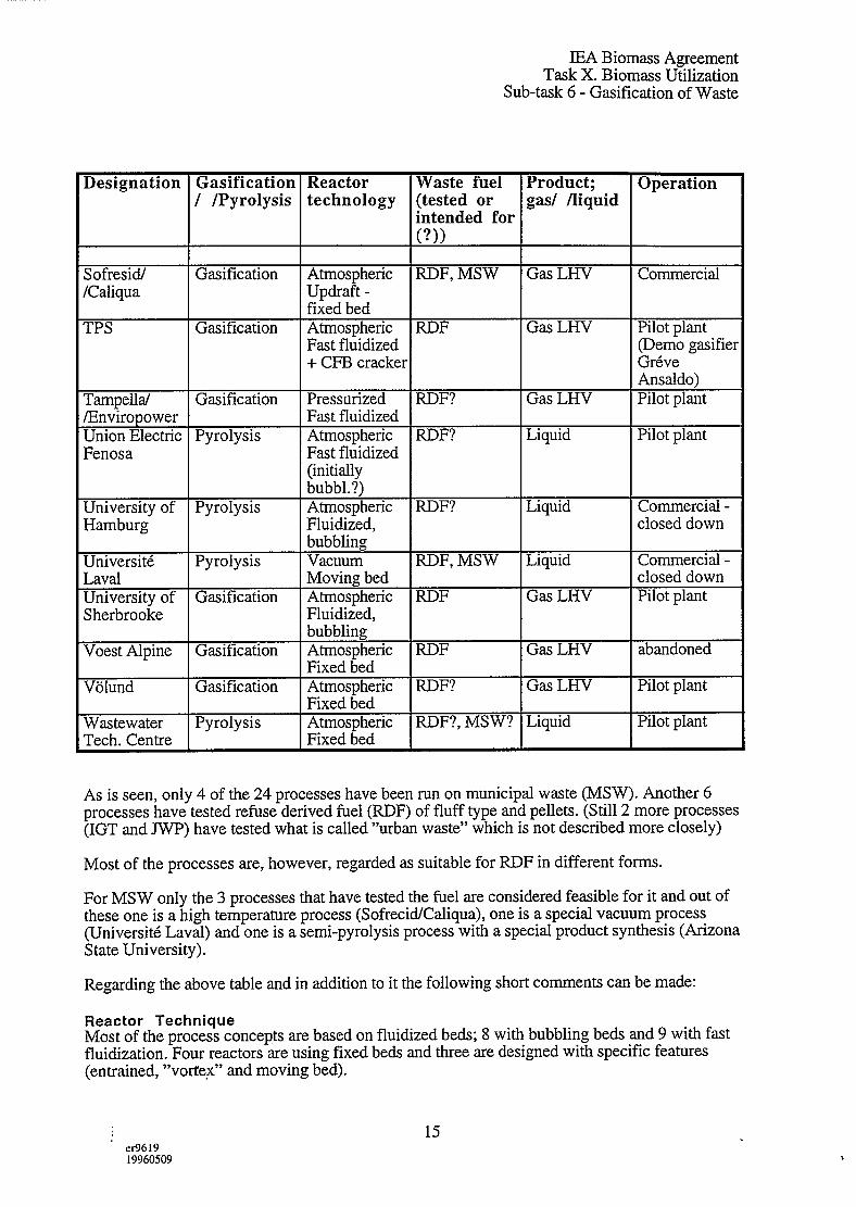
6.4 Summary and Conclusions From the Earlier DevelopmentThe most striking fact from the earlier developments of waste gasification of course is that veryfew of the processes remain today as a commercial product. In fact, in most cases even theerected units do not exist in operation.
The only exceptions may be the Andco-Torrax process - which has had a certain success withmore than five plants being erected (only one, however, seems to still be in operation).
Behind these disappointing experiences regarding MSW (and RDF?) at least six factors can beidentified:
1.
2.
3.
4.
5.
6.
Most of the processes intended to gasify or pyrolyse the raw MSW, i.e. no separationwas envisioned. In combination with the proposed techniques, this often led to a moreor less endless number of mechanical problems, shut-downs, sintering and so on.
The basic knowledge about waste and gasificatiordpyrolysis was poor. In severalcases not even an acceptable analysis of the waste was at hand, and the heterogeneityof the raw material was underestimated. Both short-term (hours, day-to-day, andlong-term (seasonal) variations have to be considered.
Scaling-up in the capacities of the units was too fast. Today we know that there is avast difference between pre-treated material in laboratory reactors and smaller units(where a shredding is necessary due to the dimensions), and the real waste going into afull-scale reactor.
The fact that pyrolysis/gasification is a complex chemical conversion was seriouslyunder-estimated. Several of the processes were “inventions” treating the process as a“thermal process”.
Most of these process efforts included a fixed bed reactor, the ideas coming from coalgasification and old-time biomass gasification or metallurgical processes. The mostcommon equipment is a shaft reactor with a bottom temperature of about 1000”C. Theoverall experiences are transport problems from feeding, over to inbed problems in theshaft to the ash outlet (sinterings, etc.).
Most of the systems were pyrolysis/gasification producing tar or a mixture of tar andgas. Only a few of the pr~cesses included gas cleaning. The tar-rich gas causedproblems on the gas side as well as condensations, cloggings etc. in the pipes to thecombustor. The Garrett/Occidental process, with advanced recycling and thermaltreatment on the other hand, probably was before its time, and included many newtechnologies.
The conclusions from these early process designs for gasificationlpyrolysis of wastes are quiteunambiguous: MSW is a complicated material to handle in a thermochemical process. On onehand the process produces tar and other sticky materials at fairly low temperatures. On the otherhand metals, glas and inorganic materials may sinter and melt at higher temperatures. In additionMSW contains several environmentally sensitive components and is of a very heterogeneouscomposition.
I
23“ tx9619
19960509

IEA Biomass AgreementTask X. Biomass Utilization
Sub-task 6- Gasification of Waste
This can be compared to the rather succesful development of wood waste gasification wheretenths of processes were commercialized. Beside initial technical problems - that should not beunderestimated - the main draw-back for these processes has been the development of energyprices (oil and gas).
Judging from the experiences with MSW, a shaft reactor seems feasible only if the temperatureis high enough to outmaneuver all the material problems at lower temperatures or if the MSW ispretreated into a more homogeneous raw material; e.g. a RDF-pellet.
Since the earlier efforts in development, the environmental concern has grown considerably.Today a simple combustion of tar and gas/tar is hardly feasible without a flue gas treatment. Inthis respect most of the (omitted) processes would be obsolete unless a gas treatment isinstalled.
24‘ IX9619
19960509

IEA Biomass AgreementTask X. Biomass Utilization
Sub-task 6- Gasification of Waste
7. Conclusions
7.1 Conclusions Regarding Function and Environmental EffectsFrom the numerous attempts with gasification and pyrolysis of wastes in different techniquesand at various scales, some principal conclusions maybe drawn. Below, they are structuredaccording to reaction and reactor parameters. The basic conditions then are that the wastes haveto be handled and treated according to forthcoming (or in some places existing) practice andrules; e.g. separation of wastes and environmental protection at the treatment of it.
It should be noted that the parameters below are interacting and that the separation of them ismade for practical text reasons.
Reaction TemperaturesRegarding the heterogeneous composition of wastes, it is obvious that the mechanicaltransportation of it through the reactor is severely hampered at some temperatures. If unsortedmaterial is used, melting and sintering is occurring at medium range of temperatures;approxiamtely 700-1.000 “C. At lower temperatures tar is formed. Both these effects result inpotential risk for clogging in the reactor.
At higher temperatures - over 1.000 “C and preferably above 1.200 “C - the ashes melt andrequire a special configuration in the bottom of the reactor. The intermediate temperatures 900-1200°C should preferably be avoided.
From environmental point of view, low temperature processes forming tar, create a problemsince the tar will contain several risk components. If the tar is incinerated or combusted withoutflue gas teatment, these contaminants will be let to the atmosphere. Tar separation is an akwardoperation where definitely energy is lost due to condensations, etc. For low temperatureoperation (c900”C) some kind of secondary tar treatment is necessary.
High temperature processes, on the other hand, result in a potential NOXformation, and reducedefficiency.
Bed ConfigurationsFixed beds are evidently more apt to problems than rotary kilns and even fluidized beds.
Unless a real high temperature (>1200 “C) is used most of the earlier efforts failed in thisrespect. This is also evident from the numerous small (and simpler) constructions that workwell with more suitable raw materials such as wood chips and charcoal. A close connectionbetween fuel quality (particle size) and bed pressure drop, gas distribution and soon givesinherent problems with MSW and even RDF fluff. RDF pellets might work better.
With MSW as feed, there has evolved a number of sophisticated devices for the transportationof the material through the reactor and for contacting hot medias to the material. Screwtransportations, rotating walls, piston forces and pneumatic devices are examples. Some of thehave been successful but the investments tend to increase considerably.
With fluidized beds the same problems are present but a little less restrictive. A coarser type offeed is accepted in these reactors but not as far as MSW. Fast fluidized beds are more tolerant toparticle size than bubbling beds, to a large fraction of fines mixed with courser particles.
: 461919960509
25

IEA Biomass AgreementTask X. Biomass Utilization
Sub-task 6- Gasification of Waste
The most advantageous reactor from this point of view seem to be the high temperature, meltedash reactors. In principle they are fixed bed reactors but the extremely high temperature setsaside the material problems providing the bed is not too high.
Environmentally, this parameter does seem to have direct implications on the effluents.Indirectly though, for instance a mechanical device gives a restriction on the reactortemperatures and thus effects are obtained. However, no principle conclusions can be drawn inthis respect.
Co-current or Counter-current, Updraft or Down-draftBeside the obvious effect that counter-current (up-draft) reactors create large amounts of tar inthe gas, the general experience from the reviewed processes is that co-current and down-draftreactor is limited to very small sizes (1 MW).
Regarding environmental effects, co-current and down-draft reactors require less gas cleaningalthough it can not be omitted. It is unlikely that a small plant cIMW can take the cost ofemission control equipment for MSW/RDF.
MSW and RDF as FeedFrom what is commented earlier, it is obvious that MSW is far more difllcult to process thansorted fractions from MSW; e.g. RDF. Broadly speaking, RDF fluff is suitable as feed influidized gasificatiotipyrolysis - at least in fast fluidized beds - whilst it is hardly suitable in afixed bed without higher temperatures (very shallow bed). In the latter case special features areusually applied in the reactor to secure fl.mctioning. Alternatively, RDF pellets are produced tosuit a fixed-bed gasifier.
Beside the heterogeneity of MSW, the improved heating value is another argument forupgrading to RDF. Very clean RDF-fractions (low Chlorine) might compete on the biomassfuel market.
7.2 Comparisons Between Flue Gas Cleaning and Fuel GasCleaning
The main conditions in making the comparison below include environmental restrictionsconcerning the emissions. As the final emissions from gasification and pyrolysis eventually willappear after a combustion, the presumed requirements are all given as emissions in flue gases inmg/m3. The following comparisons are made assuming that the emissions are lower than theBLA standard quoted from the NOVEM report (see page 16).
Compound Maximumemission
in fluegas
(mghn’)
HCIHFSoxNO=cPCDD/PCDFTEQ/m3ydustCdHg .Sb..Teco
101
407010
0.1 ng
0.0:0.05
5A
‘ eI?)61919960509
26

.
Volume ReductionEnergy Recovery ,Minimum ot Pretreatment
COMBUSTIONOF CLEANGASAT HIGH TEMPERATURE
Msw ‘- PRE- FUELGAS+
GASCLEANING Ind. kilns
TREATMENT GASIFICATION Tar, NH3, HCI Fired boilers1/4 of the flue-+ Combined Cyclesgas volume with Gas Turbine
-CaC12 -Condesateor Diesel Engine
0.
-CaF2 water-CaS -Heavy metals
CONVENTIONALCOMBUSTIONOF WAST~,.
d,
Combustion*
HEAT FLUEGAS CLEANING FLUEGAS* AT LOWTEMPERATURE RECOVERY “ HCI, Hg, Dioxins etc. Nox”
7(Electricity) Heat Residual Products
- Dioxins- Heavy metals

IEA Biomass AgreementTask X. Biomass Utilization
Sub-task 6- Gasification of Waste
If these restrictions are to be met in incineration (combustion) an advanced flue gas cleaning isrequired. A flue gas treatment to remove SoX,VOX, Dioxin etc., more than doubles the costsfor incineration of the waste. The investments for the environmental protection technique almostequal the investment for the combustion unit (50-100 %).
A gascleaning in between the gasification and the gas combustion in a combined unit, may beless costly than the corresponding flue gas cleaning after the combustion, since the gas flow isless than, or much less (depending on the process 1/2 - 1/5), than the flow of flue gas. (See theattached figure on the next page.)
If only the equipment size is considered, the gas cleaning would cost less than two thirds of thecorresponding flue gas cleaner in investment (with a scale-up factor of 0.65). However, thecleaning technique would not be the same since the compounds are in a reduced state after thegasification and in an oxidized state after the combustion. This induces different techniques -insome cases favorable to the gas, in others to the flue gas. SOZ is easier to scrub or absorb than~S, NH~ may be cracked whilst NOXis preferably chemically converted, HC1 is easier towash or absorb than Clz, etc.
No detailed evaluations seems to have been made on this subject or to have been reported. Withreference to the contaminants listed above, it is estimated that the flow effect will have thelargest impact on the costs.
Assuming that gas cleaning between the gasification and the combustion is cheaper -or at anyrate not more expensive than flue gas cleaning - the effects of a combined system on thecombustion are large. With a clean fuel, and especially a gaseous fuel, the investments will belower and the power production efficiency of the combustion maybe raised considerably. Thereis no longer a restriction on the temperatures on the superheaters. In addition the bottom designcan be made differently since there are no limiting design factors from the solid material.
Comparisons between gasfired and coalfired furnaces in the range og 50-100 MW -give aninvestment ratio of about 1:3 for smaIler boilers and about 1.5 for larger power umts.
These figures agree roughly with the data from the NOVEM report where the combinationThermoselect gasification+ gas engine carries a smaller investment than a modem incineration +steam turbine. The corresponding cost for a TPS gasifier + gas combustion + steam turbine isalso smaller. (The estimated investment for the latter is actually much smaller but the gasemissions are higher and as RDF is used instead of MSW as in the other cases. If these factorsare compensated for, the investment still seems lower)
Regarding the ash, all mass bum units give a dry ash. In the future, secondary ash treatmentwill be installed in even more plants (vitrification). The bulk density is usually in the region of500-1000 kg/m3 and metals can leach when the ash is deposited. Even fermentable (unburned)solids are present. The same type of by-product is obtained from low temperature gasification,but usually without fermentable material. High temperature gasification gives a vitrified materialdirectly. Gasification bottom ash and fly ash from fluid beds might have a lower leachabilityeven withhout melting. The volume of the melted ash is decreased to some 10-20 % and thesolid ash is non-leachable giving a considerably lower disposal cost. Even ash from gasifierswill probably be vitrified in the future in most countries.
7.3 Conclusions Regarding Products and Energy EfficienciesIn Chapter 4 the potential advantages of gasification and pyrolysis of wastes were sketched outregarding the products.
27‘ er9619
19960509

IEA Biomass AgreementTask X. Biomass Utilization
Sub-task 6- Gasification of Waste
From the experiences of earlier efforts, it can be concluded that liquid products emanating fromprimarily pyrolysis processes, have a rather limited market. In certain locations and at certaintimes they have been sold at resonable prices. However, this type of business have not beensustainable when oil prices have gone down or other circumstances have changed.
Oil products from waste will be diillcult to get clean enough to be sold at a price similar to oil orgas. Gas products has also had a limited market or use -up until now. In some lime fimacesand similar applications, gas has had a value. At present the situation seem to change in termsthat power generation from biomass has been focused especially as part of “recyclephilosophies” and COZabatement.
Power generation can be carried out also with conventional incineration. In consequence, aproduct discussion on this point has to be carried out as comparisons betweengasification/pyrolysis + combustiotipower generation and incineration with power production.
The energy efficiency for the incineration unit calculated as (energy in - losses in the combustionand in the flue gases and ash) / energy in is in the region of 80-85 % depending on technique.The flue gas cleaning may take an extra 5-10% in flue gas cooling/reheating and electricity,giving an overall result to steam or heat of 70-80 % efficiency.
With a gas fired furnace and a clean fuel the corresponding efficiency could be about 90%without less loss in flue gas cleaning and ash. In addition the steam data could be raised,increasing the eftlciency of a steam turbine.
For wxsification el%ciencies there is a number of alternatives, all collected from the above surveyand ~alculated
a)
b)
c)
d)
e)
a)-e)
as energy in product divided by energy in the wastes:
a simple gasification at atmospheric pressure and with air - without gas cleaning -can provide a hot gas with 90-95 % efficiency.
a high temperature gasification with oxygen gives an efficiency of 80-90’% tohot gas.
a gas cleaning via a scrubbing or washing and reheat of the gas will take 5-10 offthe efficiency.
a condensation of tar-rich gas and reheating of the gas will take 10-15 % off theefficiency.
pyrolysis to liquid product (condensed) gives an energy efficiency of 50-60 %.
all have the conditon that the wastes have <15 % moisture. Drying the wastesfrom 50 to 15 % moisture content takes some (0)5-20% of the efficiency,depending on technique and use of flue gases,”etc for drying. This, however, isthe same for incineration.
To compete with an incineration unit on efficiency basis, a gasification including gas cleaninghas to accomplish at least 80 % efficiency which seems to be possible for an airblown,atmospheric gasifier.
High temperature gasificati~n maybe able to compete but it is close to the restriction.
Pyrolysis processes and gasifiers producing a tar-rich gas can hardly achieve efficiency factorsin the range of incineration units.
28~ e19619 .
19960509

IEA Biomass AgreementTask X. Biomass Utilization
Sub-task 6- Gasification of Waste
..i.4<,----
. .. .~, . . .
..
“1.:,.7
.,..
All the above efficiencies are commented only regarding heat generation. If power production isfocused, the results are about the same providing steam turbines. In advanced powergeneration, the gasification techniques hold advantage due to the higher efllciencies in the laststep. Waste incineration integrated with for instance gas turbines still need development ofefficient gas cleaning before entering the gas turbine combustor.
7.4 Comparisons Between Incineration and Gasification/PyrolysisPotential advantages with gasification and pyrolysis have been implicated in some of the earlierparts - as well as the draw-backs or problems that have been experienced. A comparisonbetween incineration (with heat recove~ or power generation) and gasification/pyrolysis basedon fundamental aspects is shown below. The problem with economic effects of the fundamentaldifferences - which was touched on in the introduction - remains. However, this is maybehandled in relative terms; regardless of what the absolute costs are, the ratio between themshould be of a certain magnitude, etc.
QUALITATIVE COMPARISON BETWEEN GASIFICATION PROCESSES ANDCOMBUSTION PROCESSES
Gasification mocesses
Only certain processes can handle MSW
Potentially higher energy efficiency in powergeneraiton via combined cycles and engines.
Gas cleaning induces a 10SSof energycorresponding to 100-200 ‘C in the gas(providing heat exchange) and more if aquench system is used.
The design of the reactor is guided by the gasflow and the flow of wastes only
In some processes molten slag is obtained.Adaptable to dry RDF and high heating values(plastic).
FOR WASTE TREATMENT
Combustion urocesses
Can handle MSW (on grates)
In heat generation the energy efficiency maybesomewhat (= 59b) higher than in a combinationgasification-gas combustion. In powergeneration therer is a limit due totemperature/corrosion on the superheaters.
The flue gas treatment induces a loss of energythat corresponds to some 100 “C in the flue gas(2-3 times the flow of fuel gas= gas after agasification).
Tthe design of the combustion unit is guidedby the waste material (usually on movinggrates) and the flue gas flow in addition to theheat transfer areas.
One “reactor” unit in comparisonto two ingasification + gas combustion.
Judging from estimated investment costs and energy eillciencies, combinations betweengasification and gas combustion units may be feasible in comparison with incinerators in heatproduction.
In power generation the gasification processes hold a potential advantage.
Pyrolysis processes - p;oducing liquid product-in combination with combustion do notprovide an advantage since cleaning the liquid is far more complicated than cleaning the gas,and the energy efllciencies are markedly lower.
29er961919960509

IEA Biomass AgreementTask X. Biomass Utilization
Sub-task 6- Gasification of Waste
High temperature processes have an advantage in the solid residue (ash) but are hampered by alower energy efficiency.
7.5 Aspects on Gasification/Pyrolysis Regarding Present ExperiencesConsidering the information reported above, the following summarized aspects on gasification/-pyrolysis of Municipal Solid Waste can be given.
1. The material is extremely difilcult to handle with high energy el%ciencies in eitherincineration processes or with gasification/pyrolysis techniques.
2. The present trend or ambitions with separation of wastes at the source -or later in thechain - will improve the handling of the materials substantially.
Gasification/pyrolysis will gain the most from such developments as these processesare more specialized and tentatively result in higher energy efficiencies - providing asuitable RDF-type fuel. The latter is given by separations as proven by severaltechniques. Until recently, the economics of these processes are however, ruined bythe fact that the separation costs (and sometimes power consumption) are alsoincluded in the gasification processing.
In the waste systems of the future, it is likely that the separations will be included inthe handling costs in the total recycling concept. The incineration processes will gainless from this than gasificatiordpyrolysis. RDF combustion in fluidized bed is limitedby the chlorine corrosion as well as MSW-mass bum.
3. The question whether an incineration + conventional power generation (steamturbines) is superior or inferior to a gasification+ combustion+ (advanced) powergeneration (combined cycle) remains unanswered.
There are factors pointing in either direction and a definite answer will not beobtained until full-scale facilities are erected, and run for some time. It might even bethat the answer depends on other peripheral factors, such as feed type and localmarkets.
4. Some conclusions can be drawn from previous experiences for thegasification/pyrolysis systems in question.
A simple or single pyrolysis reactor is not generally feasible. Untreated liquidproduct cannot be used in a gas turbine or in a combustion unit without flue gascleaning, and then the costly treatment in a pyrolysis plant does not provide anyadvantage.
A special treatment of the liquid product will require condensation and a cumbersomeprocess for liquid purification. This will also ruin the economy, unless a noveltreatment of the liquid is proposed.
Gasification of MSW in fluidized beds is evidently not feasible. The techniquerequires a separated fraction of MSW; e.g. RDF. Under these circumstanceshowever, the processes are economically as well as technically feasible, providing thecosts for the separation are not all put on the gasification.
For an acceptable utilization of the gas, either a gas cleaning is required or a flue gastreatment after combustion. To effect the potential advantages with gasification, thegas cleaning is suggested, and an advanced power generation can be used. The gas
‘ er961919960509
30

IEA Biomass AgreementTask X. Biomass Utilization
Sub-task 6- Gasification of Waste
cleaning should not generate new waste streams that are diflicult to handle e.g. tarwater. Tar conversion catalytically or at high temperature is then a major option.
Gasification of wastes at high temperatures offers several advantages. The maindecisive disadvantages, are the lowered energy efficiencies and the investment costs.
On the one hand these costs are correlated to the fuel or oxygen to obtain the hightemperature, and on the other hand to the costs for primary gas treatment or cleaning.
Interesting techniques to achieve the latter are for instance the “coke gasifier” or“filter” used in some techniques, and possibly the plasma process which, however,decreases the energy efilciency still further.
5. A conclusive suggestion concerning the principle results from previous efforts withgasification/pyrolysis may be as follows:
As single techniques, all the gasificationlpyrolysis processes are hampered by somefactor(s). On the other hand, benefits from combinations of techniques are not ruledout. Using the simplicity of a pyrolysis reaction as a first step, the capability of asubsequent gasification unit as a gas treatment and a gasification unit for theremaining solids, might prove advantageous.
This is analogical with some of the later developments where high temperaturesecond steps are used however.
‘ (x961919960509
31

IEA Biomass AgreementTask X. Biomass Utilization
Sub-task 6- Gasification of Waste
8.
8.1
ENCLOSURE PROCESS DESCRIPTIONS
THE SOFRESID/CALIQUA PROCESS(ANDCO-TORRAX)
GeneralThe gasification is carried out in a fixed bed, updraft reactor by means of air. The slaggingconditions in the bottom of the shaft are achieved by the use of hot- preheated- air. The oxygencontent of the air is lowered by combustion of smaller amounts of gas in the air.
Municipal Solid Waste (MSW) can be introduced without separation - even (hazardous) hospitalwaste can be handled. The solids are fed in the top of the reactor and the gas leaving the gasifieris directly burnt in a conventional combustion unit. Heat is collected as steam for powerproduction and district heating. Some of the heat generated is recycled to the preheating of thegasification air.
The solids from the wastes are melted and quenched into slag in the gasifier and the combuste~
Process descriptionBy preheating the air to some 1.000 “C, the gasification temperature can be maintained wellabove 1200 ‘C in the bottom of the shaft and the countercurrent gas can leave the reactor at hightemperature. Combustion air is added before the combustion unit and the flue gases will haveimmediate temperature of- also - more than 1200 “C. Steam is produced in a conventional boilerand after an electrostatic precipitator the flue gases are discharged to the atmosphere.
The slag from the gasifier as well as from the combustor (gas-borne solids from the gasifier) isquenched by circulating water and collected as granules.
With a shaft size of a couple of meters the gasifier has a capacity of about 8 tons (da.f) per hour,consuming 6.000 m3 of air and an amount of natural gas as fuel for the preheating of the air.Adding the combustion air in the second stage, the flue gases amount to 30-45.000 m3/h.
No fuel gas is collected as a product - only power and steam (hot water) for district heating. Thesecondary product is granulated slag for which uses have been sought for years. Beside minoruses as fillings, etc they are being deposited. Calculations by Bridgewater and Evans show anelectricity production of about 1.8 MW from the 8 tons of fuelh and some 12 MW of districtheating. This is based on an energy efficiency of almost 70 %.
With only an electrostatic precipitator on the flue gases, all volatile - non-combustible -pollutants will be let to the atmosphere. From the Sofresid/Caliqua plant at Creteil almost 1 g ofHCI per m3, 5 mg of Hg and - for instance -0.01 mg of Cd per m3 is reported. (The feed ratethen is a little more than 8 tons an hour.)
Status .The first, commercial Andco-Torrax process was erected in the beginning of the 70’s and wasbased on a patent from 1968.
Since then, six units have b~en built but only one of them still running in 1993. This unit -inCreteil - suffered from some drawbacks and in 1987 some modifications were suggested; afiltering of the raw gas before the combustion to counteract fouling on the heat exchanger tubesand a recycle of particulate from the raw gas to the gasifier to reduce the fuel gas consumption.Since then no efflency data or availabilities of the unit have been reported.
32er9619
.
19960509

n’
,
-m”s

IEA Biomass AgreementTask X. Biomass Utilization
Sub-task 6- Gasification of Waste
Considering only the flexible costs, a revenue is obtained from the unit at “ordinary”incineration fees. If the fixed costs are added, however, a considerable subsidy is required.With the turn-key cost at Creteil (about 100 MFF in 1979-80), they amount to some2 M$ per year at today’s value (annuity= 15 %).
Present Situation and FutureWith six erected plants the Andco-Torrax technique was comparatively successful on the marketto start with. However, it seems that operational problems and the high costs for thegasification in comparison to incineration is hampering a further expansion. Furtherdevelopments of gas cleaning could be an option. With an added flue gas cleaning - nowadaysrequired - the costs will be still higher.
The basic reason for the costs seem to be the high temperature employed and the fact that a lot ofheat is quenched.
The advantages with the process include the fact that almost any waste may be handled intheory. In practice in-bed problems in shaft gasifiers are frequent.
33‘ tx9619
19960509

IEA Biomass AgreementTask X. Biomass Utilization
Sub-task 6- Gasification of Waste
8.2 MOTALA PYROGAS, SWEDEN
GeneralMotala Pyrogas was an atmospheric air-blown updraft fixed bed gasifier coupled to a boiler in arubber and tyre manufacturing plant. The fuel was waste rubber, MSW (not pretreated) andcoal. The co-gasification with coal was to try to stabilize the lower char layer in the bed.
Process DescriptionTo be able to feed the MSW stream anew robust lock hopper cell with lm3 volume wasdesigned and installed. The shaft was 3,6m and a rotating grate fed out the ash through a waterseal. The lower part of the reactor was cooled, and produced steam to moderate the ashtemperature thus limiting clinkering.
A two-stage design was used to control the tar condensation in the gas pipeline to the boiler. Alower hot gas exit mixed with the cool top gas which had also passed through a electrostaticfilter. The recovered tar was fired in a separate burner in the boiler.
After initial bed problems the upper part of the gasifier was separated from the lower part withanother water seal. The upper part could then rotate and stir the fuel bed.
StatusA demonstration plant with a fuel capacity of 15MW was erected in1974 in Gislaved, Sweden.Due to the physical properties and the pyrolysis behaviour of MSW, several problems withchanneling and “rat holes” (up to m3), and high pressure drops in the bed were encountered.The redesign (movable upper part) did not solve the problems, and the plant was shut down in1977.
Present Situation and FutureThe source of the technology was a conventional two-stage coal gasifier that Motala Verkstaddelivered before the fifties. A few pilot tests with MSE were also run in a coal gasifier, still inoperation in the early seventies. Despite very limited results, the positive conclusion was drawnthat the technology was applicable. The company was in a “down’ period and needed a newmajor product.
The channeling problems and bed distortion, led to that the temperature profiles could be almostinverted higher in the top than further down in the shaft. Even during rather stable bedperformance there were hot spots and “rat holes” with a volume of more than lm3. Despitemajor efforts to solve the fundamental problems in the bed, no major progress was made.
Several minor problems such as tar elimination and handling were solved during thedevelopment work.
The company reduced the number of employees, and was taken over by KMTV. There is noactivity in the field today.
34efi61919960509


Motala Pyrogas

IEA Biomass AgreementTask X. Biomass Utilization
Sub-task 6- Gasification of Waste
8.3 THE PUROX PROCESS
GeneralThe Purox process includes a high temperature gasification with oxygen. Molten slag isobtained and in the beginning untreated MSW (Municipal Solid Waste) was envisioned but thiswas altered into shredded waste.
A subsequent use of the product gas for ammonia or methanol production was proposed butsuch processes were never realized.
The development of the Purox process was carried out by Union Carbide completely as acommercial project without support from governments or other external funds. Despite twodemonstration units and considerable marketing efforts no further commercialization wasmanaged.
Process DescriptionThe MSW is stored and shredded before fed to the top of the high temperature updraft shaftfurnace which is blown with oxygen from the bottom. The reactor is similar to a shaft furnacesponge iron production in the steel industry.
Molten slag is quenched with water and constitutes a material that can easily be deposited.
The raw product gas is cleansed by conventional techniques from for instance the chemicalindustry. A small part of the product gas is fed to the reactor to ensure the high temperature andthe rest is a “clean fuel”. Tars and some of the contaminants in the water (from scrubbing) arereturned to the reactor.
The total thermal efficiency is reported to be more than 60%.
StatusAfter the pilot unit at Union Carbide, two cornmecial (demonstration) units were erected; one inCharleston, West Virginia (180 tons/d) and one in Japan (75 tons/d).
Since then, the mid-seventies, no further installations have been made.
Technical Situation and the FutureUsing shredded material the Purox process has performed quite successfully. The hightemperature secures a 100 % conversion which minimizes mechanical problems at least in thebottom of the reactor. The inert slag is a major advantage with the oxygen blown process. Adrawback is the relatively high power consumption for oxygen production. Later developmentstry to reduce the oxygen consumption by preheating the waste indirectly (e.g. Thermoselect).
Although successfully demonstrated, no further commercial units were sold and Union Carbideturned the business down. The system seems to have perhaps been ahead of time and later onincinerations captured a substantial market share.
35tx961919960509

/j’
>
.- 2..

IEA Biomass AgreementTask X. Biomass Utilization
Sub-task 6- Gasification of Waste
8.4 THE LANDGARD PROCESS(Monsanto)
GeneralThe Landgard process is in effect not an energy producing technique. It is more or less based onassumed advantages with pyrolysis versus conventional incineration in the handling of solidwaste where a decrease of volumes is one objective. As commented in the report smallervolumes for gas cleaning and better residues due to temperatures and reducing conditions areexamples of potential advantages.
These factors were achieved in the Landgard where MSW (Municipal Solid Waste) was treatedin rotary kiln heated by oil - much like a cement kiln.
The process was developed by Monsanto Enviro-Chem and already in the early seventies twopilot units of 30 tons/d were erected, one in the USA and one in Japan.
Process DescriptionMunicipal Solid Waste (MSW) is shredded and fed to a rotary kiln where it meets hot gasesfrom an oil burner. At a maximum temperature of 1000 ‘C a solid residue is collected in thelower part of the kiln while pyrolysis gases exit at the upper end (where the MSW is fed).
The gases are directly burned with steam production and the flue gases are scrubbed before letto the atmosphere. Although the steam represents a by-product little attention was drawn to thiswhen the Landgard projects were focused in the 70’s (before the so called “oil crisis”)
In the beginning the total MSW was intended to be fed to the reactor. By experiences this had tobe altered to a homogenized feed through shredding. See below.
StatusAfter the two rather successful pilot plants installations of the Landgaard process, a giant scale-up to a 900 tpd in Baltimore was erected in the mid-seventies..
Technical Situation and the FutureThe scale-up of the process was obviously too fast. A number of technical problems appeared inthe units:
. the storage of MSW caused problems; packing and solidification
. material problems; for instance the ceramic lining was worn out
. the energy balance in the rotary kiln was not sufficiently investigated or known
. slag was formed in the reactor and the slagging temperatures were not known enough
● etc. I
Attached is also a summary of all problems from Beukens and Schoeters (1984).
36er961919960509

—--- — -------- 7-- .%-.7- —. .- . . ..- -------- ------- ---- -.—.
. . . m
Landgard
The fundamentals of Lansigard
A
Landgard
Gasscrubber
r
i

IEA Biomass AgreementTask X. Biomass Utilization
Sub-task 6- Gasification of Waste
These factors in conjunction with the evolution of a number of competingcombustion/incineration processes, led to the withdrawal of Monsanto from the Landgaardprocess and since then it has not reappeared.
The plant was then operated as a combustor, but then finally replaced by mass burn technology.
37tx961919960509

. . . .-—.-.
The Landgard process (Figure. “) operated successfully at a 30 t/day scale,.both in the U.S.A and in Japan .(~Wasaki Heavy lnd~sEries)~ On the basis ofthe available operating experience a giant ~oo t/day plant Was proposed to the
Ci.Eyof’Baltimore and erected with financial support of EPA.
It proved to be impossible to operate the plant because of several fundamentalerrors at the level of its conception and desi==, namely
the concept was unproven at a commercial scale ‘1the scale-up factor used (from 30 to 900tpd) was not justifiable for at leastsome parts of the process. The cperation of the furnace, for example ceases ‘.to be controllable at capacities exceeding 25O-3OO tpdthe use of a single train throughout the thermal part of the plant. AnY
failure, however minor, forces the whole plant out of operationthe use of insufficiently proven mechanical systems and process operations.
Table ‘gives a detailed list of trouble areas,—— . spread over the complete plant !
.
a peer lay-out of the refuse reception bunkerthe repeated occurence of shredder explosionsthe solidification of the pile of shredded refuse after prolonged storagein the storage binthe incapacity of the mechanisms for extraction cf shredded refuse fromthis bin and the rapid weaying out of its concrete floorthe =hpossibility to control the partial oxidation process. The mixing ofair and flammable gases gave rise to small explosions. The temperaturerose higher than anticipated , melting part of the ash and generating saltcontaining aerosols. Still the burn-out of the residue was incompletethe obstruction of the ash extraction outlet, by solidifying slagthe failure of the low energy scrubber to eliminate dust and aerosol particlesfrom the flue gases. The scrubber also generated a fog, which was a nuisancefor a nearby highwaythe residue handling and separating system had to be modified in order to.-cope with its most essential. duties..-. ... - ..—---
Table .: Major problem arezs in Monsantofs Lanciga=d plant at Baltimore.
THEW!ALP!ETt!OiXIN I!ASTE!)ISPOSAL
- PYROLYSIS
- 6~sIFIcATION
- INCINERATION .
- R9F
PART I : PYROLYSIS
—..f
BY A, 5UEKENS AND J
STUDY PERFORMED FOR
- FIRING
Arm 5ASIFICA.TION
1 ~cHOETERS m~4
E,E,C,lJNDER COP!TRACT NUMBER
ECI 1011 / B 7210 / 83 / E

IEA Biomass AgreementTask X. Biomass Utilization
Sub-task 6- Gasification of Waste
8.5 THE DESTRUGAS PROCESS
GeneralThe Danish Destrugas process was developed partly on the basis of former coke technology. Ina downdraft (concurrent) with indirect heating (retort) reactor shredded MSW (Municipal SolidWaste) is fed at the top. ”
The process was demonstrated in Kolding in Denmark as early as 1967 (pilot scale 0,5 tpd) andattracted attention during the early seventies. The only demonstration unit was erected inKalundsborg, Denmark, 5 tpd (1970). Despite efforts in Germany as well as Japan it was notfurther commercialized.
After cleaning the excess gas was intented to be sold. Almost half of the produced gas was usedas fuel in the process. With the attitudes today, neither the gas cleaning through washing nor thequality of the gas would be acceptable from environmental points of view.
Process DescriptionThe shredded MSW flows downwards in the shaft while it is indirectly heated to about1000 OC.The energy required to obtain 900-1050 “C in the shaft is supplied indirectly throughthe walls and is originally formed by combustion of some of the gas. With this configuration thereactor can be called a retort (see the attached figure).
With the downdraft technique the tar content in the gas is lower than with updraft reactors. Thegas is further cleansed in a scrubber where the water - at that time - was considered no morepolluted that it could be sent to the communal sewage treatment.
After the scrubber the gas was considered a fuel gas. Some char and tar follows the gas and isseparated in the scrubber. Being a pyrolysis process a solid char containing residue was alsoproduced and had to be kmdfilled.
About 50 % of the energy in the MSW is obtained as gas. If the entire energy demand issupplied by this gas, the overall thermal efficiency drops to some 20-30 %.
StatusIn Kalundsborg in Denmark, two units were erected: one at 1 ton/d and one at 5 ton/d. Asmaller test unit was built in Berlin in 1978 and a larger in Japan 1976(5 tons/d).
Since then no further units have been built, and all those which had been erected were closedduring the seventies.
Present Situation and the FutureThe downdraft reactors and retorts suffer from comparatively low capacities and low thermalefflencies. In addition the material transport in the Destrugas reactor turned out to be a problemrequiring a uniform particle size and an even distribution of the material in the shaft. Thus,MSW could not be used as such but had to be pretreated to satisfy the pyrolysis reactor.
Apart from the marked problems in the seventies, the Destrugas would not be technicallyfeasible today. The cleaning of gas and water would be necessary as well as a handling systemfor the char/slag. The products have no market value and as a destruction process, it is neithereconomic nor efficient.
38Ia_961919960509

+ I
c

. .
I?estrugas reactor
1+
.
Battery of pyrolysis furnices (Destrugas)
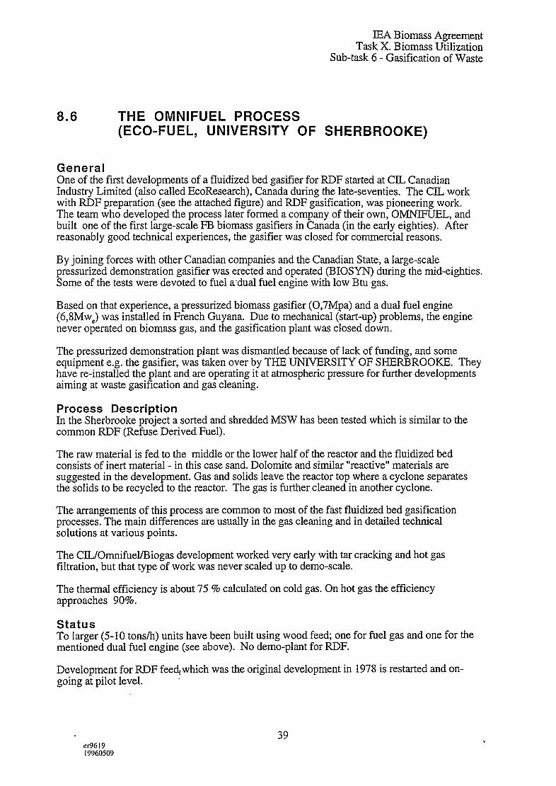
IEA Biomass AgreementTask X. Biomass Utilization
Sub-task 6- Gasification of Waste
8.6 THE OMNIFUEL PROCESS(ECO-FUEL, UNIVERSITY OF SHERBROOKE)
GeneralOne of the first developments of a fluidized bed gasifier for RDF started at CIL CanadianIndustry Limited (also called EcoResearch), Canada during the late-seventies. The CIL workwith RDF preparation (see the attached figure) and RDF gasification, was pioneering work.The team who developed the process later formed a company of their own, OMNIFUEL, andbuilt one of the first large-scale FE biomass gasifiers in Canada (in the early eighties). Afterreasonably good technical experiences, the gasifier was closed for commercial reasons.
By joining forces with other Canadian companies and the Canadian State, a large-scalepressurized demonstration gasifier was erected and operated (BIOSYN) during the mid-eighties.Some of the tests were devoted to fuel adual fuel engine with low Btu gas.
Based on that experience, a pressurized biomass gasifier (0,7Mpa) and a dual fuel engine(6,8MwC) was installed in French Guyana. Due to mechanical (start-up) problems, the enginenever operated on biomass gas, and the gasification plant was closed down.
The pressurized demonstration plant was dismantled because of lack of funding, and someequipment e.g. the gasifier, was taken over by THE UNIVERSITY OF SHERBROOKE. Theyhave re-installed the plant and are operating it at atmospheric pressure for further developmentsaiming at waste gasification and gas cleaning.
Process DescriptionIn the Sherbrooke project a sorted and shredded MSW has been tested which is similar to thecommon RDF (Refuse Derived Fuel).
The raw material is fed to the middle or the lower half of the reactor and the fluidized bedconsists of inert material - in this case sand. Dolomite and similar “reactive” materials aresuggested in the development. Gas and solids leave the reactor top where a cyclone separatesthe solids to be recycled to the reactor. The gas is further cleaned in another cyclone.
The arrangements of this process are common to most of the fast fluidized bed gasificationprocesses. The main differences are usually in the gas cleaning and in detailed technicalsolutions at various points.
The CJL/Omnifuel/Biogas development worked very early with tar cracking and hot gasfiltration, but that type of work was never scaled up to demo-scale.
The thermal efficiency is about 75 % calculated on cold gas. On hot gas the efficiencyapproaches 90?Z0.
StatusTo larger (5-10 tons/h) units have been built using wood fee@ one for fuel gas and one for thementioned dual fuel engine (see above). No demo-plant for RDF.
Development for RDF feed which was the original development in 1978 is restarted and on-going at pilot level.
er961919960509
39

. . ... .. —-. - . ___,
,
!
I
.
g~p%’
/
..:...”.”-”.:.........................................................-.......-.}.......:::..:.}..............................:...-...........................................-..:
.....-:..:........................-.:
....-..- ........................................
&fB
30
P-1
14/I4

IEA Biomass AgreementTask X. Biomass Utilization
Sub-task 6- Gasification of Waste
Present Situation and FutureThe OMNIFUEL/BIOSYN process (biomass) has initially been rather successful commerciallysince two larger units have been established. This development and Canada as a country, hada leading role in the world in biomass gasification in 1980-85. From the technical point of viewthe units have experienced some difficulties but the main obstacle for further commercializationand scale probably lies in the domestic Canadian market. Wood fuel in this form is still morecostly than oil gas fuel.
The renewed solid waste gasification activity has not yet led to any large scale <ommercial.project.

IEA Biomass AgreementTask X. Biomass Utilization
Sub-task 6- Gasification of Waste
8.7 THE EBARA PROCESS
GeneralVery early in the seventies, Bailie at West Virginia University developed the concept of twofluidized sand beds, one for combustion and one for steam gasification, with circulating sand asthe heat carrier between the two beds. This principle is later further developed in Japan, and byBatelle Columbus, USA.
Process DescriptionThe energy supply is carried out in the combustion reactor where residual char is burned. Theheat is transferred to the pyrolysis reactor by means of the fluidized bed material (sand), whichflows between the reactors. The energy balance requires some extra fuel to match deficiencies.
In the pyrolysis reactor RDF (Refuse Derived Fuel) is pyrolysed by means of the hot bedmaterial at 650-750 “C. As in all these fluidized systems a certain homogeneity of the feed isvital.
The outgoing raw gas from the pyrolysis unit contains tar and char and has to be cleaned. Thisis effected in a scrubber system where the upper tar layer is collected as fuel for the combustor.Char is also collected as fuel. The remaining water is sent to water treatment. The resulting gashas a high heating value and the overall thermal efficiency is reported 50 -60%. From bothreactors an ash fraction is continuously withdrawn to be Iandfilled.
Status
That technology was later scaled-up in Japan within a national programme “Star Dust 80”1979-1982 (EBARA 5 tpd to 100 tpd). In 1983 the Tsukisima Kikai company constructed a full-scaledemonstration (PYROX) 450 tpd, 3 x 150 tpd of a similar process, but based on other Japanesetechnologies (cracking of crude oil). It was in operation until 1990, when it was closed foreconomic reasons. No active further development is known to the authors.
Technical Situation and FutureThe information from the Ebara process indicates problems and development work in agreementwith other developments of fluidized beds for pyrolysis and gasification. It may possibly benoted that the bubbling beds seem to put even stronger restrictions on the feed than the fastfluidization beds do.
From earlier reports it seems that the developers of the Ebara process have overcome theseproblems and that a lack of further commercializations possibly is more connected to the lack ofmarket in the eighties.
41I@619[9960509

“7CRACKINGREACTOR
n
I
h!—,.
CRACKING
~ GAS SCRUBBER COMBUSTIBLE GAS
I
“CYCLONE + ‘As cLEANi ‘G P, I
1
I–JREGENERATOR
(Ty
i“.%.-~
cOMBUSTION
Ijyoy l\zONEly—r
MOVING DIRECTION~ OF SAND \
m!l~l “ II-T-T--II,—.
J*‘&/I . . ‘..JI
. ...”.. . . .
::.~ ; . . .. . . .
. . .
. . . .. . ...
, . . . . .. .. ,.
. . . . . . -.. .
. . d........ ....
STEAM. . . . .
.’1. ~.
(
cYCLONE -ExHAUSTGAS
o
—-
I -1 --
1. .
!COARSE MATERIALI
>
Two I~LUtD12ED BED REACTORS
..

—
qI
“$1’2
U2
O“;GQ’m
C(’
/
.’ -.
a.

IEA Biomass AgreementTask X. Biomass Utilization
Sub-task 6- Gasification of Waste
8.8 THE FLASH PYROLYSIS PROCESS(GARRETT - OCCIDENTAL)
GeneralThe flash pyrolysis process was developed for coal, and also as part of a more generalseparation system for Municipal Solid Waste (MSW). (See the attached figure.) Afterseparation of metals and other components in the wastes the combustible or carbon containingfraction was delivered to a pyrolysis unit where a liquid product was produced through flashpyrolysis. The reasoning for this was that a liquid product or fuel was easier to sell as an energycarrier than as gaseous or solid products.
Based on the basic idea that wastes ultimately had to be recycled and used in the society a fullscale separation unit was established in San Diego in the mid-seventies. For the organic part ofthe wastes a flash pyrolysis system, developed by Garrett and later Occidental, was chosen. Theprocess had been demonstrated in a smaller scale development unit before.
The object of the process was to produce as much tar -or liquid product -as possible from theorganic fraction and the flash pyrolysis had demonstrated a superior capacity in this respect. Thesame reaction thermo-chemistry has been studied later and developed for the pyrolytic oil fromwood production (ENSYN, SCOIT).
Process DescriptionAfter separation of metals, glas and minerals, the organic fraction of the wastes is milled andshredded into a fine material (RDF) - as homogeneous as possible (see the attached fib~re).
This raw material is fed to a reactor similar to a transport in a reactor. At a temperature of 450-500 “C and a short residence time (seconds) (and a slight over-pressure) some 40 % of pyrolyticoil (tar) is formed. The tar is in the vapor phase and the gases are separated from the char in acyclone.
Upon cooling tar condensates and it is separated from the lighter gases.
The lighter gases are used as fuel together with the solid char to provide the necessary heatingfor the process. The ash/char fraction was also used as a heat carrier. The actual pyrolysis Nslightly exothermic and the thermal efficiency of it is about 50 % (calculated on the oil). Theenergy losses were not attempted to be used in reality.
StatusThe San Diego plant was closed after a few years due to technical problems and lack ofcustomers for the fractions from wastes, not only the pyrolytic oil.
Similar attempts with fractionation and marketing of the fractions have been studied and triedelsewhere during the eighties, but none of them seem to have succeeded. Today, San Diegoappears to have been a little ahead of time. The general impression-is that the project tried to puttogether a lot of new technology in RDF preparation, recycling and flash pyrolysis in one earlyplant. Twenty years later some of those technologies have stall to be further developed.
Present Situation an,d FutureAs commented, the flash pyrolysis technique has been studied further- mainly for biomass -since the seventies, with different designs.
42IX961919960509

*. .. .. .
:
7.
yL... ..--..i
~“--”-”--;~<;”<’”’”-”’’””
~
dLL:‘-------- -F:* .. -----------------:
i_\ [4...*-...:1
[..-. .....*-...-)-------- -7...+J
~ *-”’.,, :@ :.*T._~._:> /‘- ,
R: /$@..........?--”’Jtl>
1‘“”.”--”-----.ya
..+-.
/’--”’ **.*..*e..**.*. .. . ..*A*
“p::””.\b’t ~““-””--”’””.”-”””-—--j4w*eu4*.b.a..9.*.e00w : :


IEA Biomass AgreementTask X. Biomass Utilization
Sub-task 6- Gasification of Waste
Flash pyrolysis of wood has been studied extensively and in evaluations it has been shown oneof the most economic ways of converting wood into a gaseous or liquid products. A similarapplication is being used commercially for pyrolysis of spent rubber tyres.
With strict emission limits, a relatively clean fuel or extensive secondary oil treatment is needed,to reach an oil product that can be used without extensive flue gas treatment.
43e1961919960509

IEA Biomass AgreementTask X. Biomass Utilization
Sub-task 6- Gasification of Waste
8.9 THE ERCO/POWER
General
RECOVERY SYSTEM PROCESS
This technology is an example of technology that has been marketed under different names overa long period of time. Originally developed as a directly heated pyrolysis in fluid bed (ERCO)for charcoal and tar liquid production in the seventies, Power Recovery Systems was anengineering company with a somewhat broader field of activities but with emphasis on fluidizedbeds and gasification, and they marketed and developed the technology in the eighties. Thisprocess is a complete process from MSW (Municipal Solid Waste) to power generation; e.g.considering all the subprocesses forming the entire system.
Beside the gasification process, the Power Recovery Systems proposed technologies for thepreparation of RDF (Refuse Derived Fuel), for gas cleanup, for combustion of the gas, etc.
The pyrolysis or gasification reactor in the ERCO processes is a fluidized bed with sand as bedmaterial. It has been installed in at least two commercial applications, one for charcoalproduction and one for energy (steam) production.
Process descriptionThe ERCO processes in principle look very much alike other gasification/pyrolysis systems.The MSW is upgraded into RDF and fed to the fluidized bed where it is primarily gasified by airat temperatures of 760-820°C. In waste gasification a “reactive” bed material is used instead ofthe former sand. The “reactive” material is claimed to include an adsorbent for SOZ.
The solids are separated from the gas in one or two cyclones. Whether they are recycled to thereactor or not is not clear. In some process configurations an ash bin is shown but it seemslikely that in practice at least some of the solids would be recycled. The gas is further cleansedin a multistage system including scrubbing and mist elimination. High-boiling -or solid - tarsare returned to the gasification and the rest is treated in the water.
When the gas is to be used in an engine for power production a fabric filter is also used in thegas cleansing. The thermal efficiency is reported up to 75% calculated on the raw gas.
StatusThe early attempts to market the pyrolysis process for RDF was not successful. The PowerRecovery System pyrolysis and gasification process has been commercialized in a couple ofoccasions for biomass fuel (charcoal and steamboiler). Southern Electric International (SCEI)erected two fluid bed gasifiers for clay drying. By-product charcoal was sold to a charcoalbriquette factory.
The development work evidently continued at least up til the late eighties. To achieve highcarbon conversion char recycling to the bed is necessary in FB as well as CFB reactors.
As far as known, no new plants have been erected despite offers in waste treatment as well asbiomass conversion.
Technical situation and futureThe information from ERCO and Power Recovery Systems is quite scarce. Problems evidentlyhave appeared but seem to have been successfully attended to. Comments have been made aboutthe restrictions on the feed; moisture content, size dkibutions, etc.
In the mid-eighties pilot tests with RDF were performed for engine applications.
44IM61919960509
.

fu

,-
r-Lowcalorificvalue gas 4
Moisture separatol
~ Gas cooler)
‘+-’ Fabric filter
separatorGas receiver
-%’ Compressor M
-Air/Fuel ratio control valveI
Gas carburetor
150kWgeneratorI I I
To stack-!Turbocharger
I
Schematic of the gas engine generator system
Processed +Lowcalorific ‘ -Lowcalorific powerMSW MSW MSW ~
Gasificationvalud.gas
* Gascleanupvaluegas
generationprocessing electricity
Blo;k diagram of the PRS process -.

IEA Biomass AgreementTask X. Biomass Utilization
Sub-task 6- Gasification of Waste
The companies are no longer in existence. The technology-rights, at least for biomassapplications, are owned by the Bioenergy Development Corporation, New York.
45u961919960509

IEA Biomass AgreementTask X. Biomass Utilization
Sub-task 6- Gasification of Waste
8.10 ELAJO/TORNEGAARD/KOMAKO, Sweden
GeneralThe Elajo gasifier is an airblown down-draft fixed bed gasifier. Based on experience withwoodchips gasification, a test unit for waste was designed. The intention was to combust thegas and then apply wetidry flue gas cleaning with a fabric filter. The raw material was initiallyRDF Fluff, and after testing only RDF pellets a small scale modular unit (2-5 MWth) wasplanned as standard. Power production with gas engine, steam engine or turbine was seen as afuture development for small scale technology.
Process DescriptionThe attached figure describes the gasifier. During earlier tests with the down-draft gasifierdifferent air injection and grate types were tested by the same inventor (Tomegaard). In thepresented design, a rotating movable grate should allow control of pressure drop and ashdischarge.
The Figure describes the whole system (excluding RDF pretreatment). Gas cooling/heatexchanger down to 500”C took place in the gasifier. The gasifier was directly coupled to aboiler without any cooling/cleaning. A bottom ash that could be partly treated and recycled wasanticipated, heavy metals should be retained in the ash, and dioxin formation should be low.The turn down ratio was promised to be one to ten.
DemonstrationFor woodchips a 2MWth gasifier was erected, close coupled to a boiler heating a hospital inFilipstad ( 1986). The fuel was green chips from whole tree harvesting. Several start-upproblems with supplementary systems such as feeding, ash discharge, control system, delayedthe operation of the unit, but all these problems were finally solved. The interesting problem ofhigh bed pressure drop due to fuel characteristics (particle size and distribution) was however,never solved. The maximum capacity achieved was 0,8MW and with considerable amounts oftar. The unit is now shut down but still ~nsitu. Despite these experiences, a seconddemonstration unit for RDF was erected in Kalmar. The operation was time limited, and afterexperiences similar to those in Filipstad, together with local problems such as odour, the unitwas dismantled.
Technology Background and FutureThe technology is a typical example of an inventor who in cooperation with different companiestries to commercialize a new technology. Based on Swedish Second World War experience, theinventor first operated a small pilot plant and then several demonstration units.
On the waste side, the same inventor together with VBB, tested a rotory drum pyrolyser in theearly eighties in Soderham. Overheating and deformation of the drum ended the testing. Thedown-draft demonstrations was managed by an electrical engineering company (ELAJO). Theactivities were stopped due to the poor results, and the Filipstad unit is for sale.
awl 19]9960509”
46

.-
11”
IIStack
Cl.)Jjj ~~
---- ~-- . ..-.HI.was~e
K55.“
Ash container ~
1“
.
Elajo/Komako

IEA Biomass AgreementTask X. Biomass Utilization
Sub-task 6- Gasification of Waste
8.11 THE VOEST ALPINE PROCESS
GeneralThe Voest Alpine process involves a fixed bed, updraft reactor where the gasification is carried
out at high temperature - more than 1500 ‘C (=1600). This high temperature is obtained with airas gasification medium by means of a fuel mixture to some extent including materials with highheat contents. With the high temperature a moken slag is quenched and collected in the bottomof the reactor.
The specific feature giving Voest Alpine a special character is a coke bed through which the gasis cleaned from certains components. This coke bed is built into the gasification reactor.
It is claimed that the raw gas from the gasifier can be used in a conventional combustion unit oran internal combustion engine (see the attached figure).
Process descriptionIn the pilot plant reactor a mixture of about a third of waste oil (including a part of fuel oil), alittle more than half of RDF and some ten percent of coke is used as fuel. These different partsare introduced at various positions: the oils at the bottom of the shaft, the RDF in the middle andthe coke at the top in a special shaft through which the top gas passes.
The hot coke bed acts as a catalytic bed where tar and other tar components are broken down.(This idea for gas cleaning is also used in a German process where, however, the coke bed isplaced in a separate reactor). Some of the coke is gasified during the processing and this is whyit is considered a fuel.
The raw gas leaving the coke bed is claimed to contain very small amounts of dioxins andfurans. The metal contents are not reported. After combustion they are less than 1 mg/m3 fluegas; for Cd, Hg, Ti, As, Co, Ni and Se less than 0.01 mg/m~. Although the gas is clean enoughto be used in an internal combustion engine, a flue gas cleaning is still suggested for theprocess.
For the molten slag approximately 1 m3 of water is used for quenching per ton of fuel. Theamounts of slag are less than 100 kg per three tons of fuel (28 kg per ton).
The energy efficiency of the process is reported 83 % and RDF as well as shredded car wastehas been run.
StatusThe pilot or demonstration unit of Voest Alpines high temperature gasification had a capacity of400 kg of feedstock per hour. The maximum capacity is claimed 3 tons/h.
Hardly any economic data seem to have been published but an investment on 24 M$ is indicatedfor the 3 tonslh unit (1991). This corresponds to almost 1.000 $/ton of feed which maybedouble the specific investment for an Andco-Torrax unit (some 250 $/ton in 1980). Thedifference seems large but the Voest Alpine gasifier is probably a more complicated constructionthan the Andco-Torrax gasifiev two fixed beds, three inlet positions, etc.
In addition to the compariti~ely high investment, the Voest Alpine technique also carries quitelarge operational costs in the form of high value fuels in combination with the RDF. The costsfor waste oil, fuel’ oil and coke is roughly 40-80 $/ton of RDF in the feedstock mixture that wasused in the 400 kglh unit.
47 ..l+xl19199(,0509

IEA Biomass AgreementTask X. Biomass Utilization
Sub-task 6- Gasification of Waste
Present situation and futureIf this economic assessment is correct, it maybe the reason why Voest Alpine has abandonedthe technique. According to the Bridgwater/Evans report the company is concentrating onmetallurgical processes.
48eI?)61919g60509
-.

>
IEA Biomass AgreementTask X. Biomass Utilization
Sub-task 6- Gasification of Waste
8.12 SCANARC (PLASMA) PROCESS
GeneralThe Plasma Gasification technique evolved from metallurgical process developments by SKFSteel in Sweden. In attempts to produce reducing gas for iron manufacture a plasma wasintroduced in the bottom of the shaft producing (~ and) CO from air and coal. Theeffectiveness of the plasma in this application was discovered, leading to a number of processesproposed.
Two of these processes were installed full-scale: the PlasmaZinc and the PlasmaChrome forhandling Zinc dust and Chrome materials. Several processes for coal gasification using thePlasma Gasification technique were designed during the early eighties. None of them werehowever realized.
Following the falling prices on energy, the interest during the eighties focused on the PlasmaGasification as a tool in waste handling, in particular special types of waste such as hazardouswastes, medical wastes, etc.
The Scanarc (former “SKF Plasma”) process is a fixed bed, high temperature process with amolten slag in similarity to the Andco-Tomx and Voest Alpine processes. In line, thegasification is also carried out in an updraft shaft. Differences between the processes are athand in the means to acheive the high temperature and in the cleaning of the raw gas.
In the ScanArc process the gas cleaning is obtained in a plasma where the gas is heated to veryhigh temperatures causing a decomposition of tar, chlorinated hydrocarbons and ammonia.
Process DescriptionThe ScanArc process uses a shaft reactor outlined as simple as possible and fed with a mixtureof air and oxygen in the bottom, or- rather - in the middle. Oxygen is needed when the effectiveheat content of the wastes is too low to result in a temperature of 1200 “C or more. For fuels tothe reactor with heat contents above 10-15 MJ/kg this constitutes no problem. These heatcontents are, however, not always met with MSW unless other wastes are added.
The raw gas is fed to a second reactor which in fact is more or less an empty shaft with a plasmagenerator on top. The electric plasma generates a theoretical temperature of more than 15.000 “Cthrough which the gas is passed (lowering the temperature) into the shaft. The fuel to the plasmais composed of power and air for combustion (oxidation). After the second reactor, chlorine ispresent as C12or HCI, nitrogen as Nz, etc; e.g. all organic compounds and several others medecomposed.
The gas after the plasma reactor is cooled and washed. The fly ash is collected and maybe sentfor recovery of some metals since they are separated in a reduced state. Beside the wash water,a “clean” gas and hot water is obtained. Available data do not provide information to what extenta flue gas treatment is required after combustion.
The molten slag is tapped from the bottom of the fiist reactor and as the slags from Andco-Torrax and Voest Alpine it is claimed non-leachable and easily disposable.
Only few data are revealed~rom the process. The power consumption for the plasma is reported200-400 kWh/ton of feed - depending on heat value of the feed. These figures imply an energyefficiency of roughly 65-80 % calculated on the gas and the hot water.
49tM61919960509
-.

SKF Plasma/Scanarc

IEA Biomass AgreementTask X. Biomass Utilization
Sub-task 6- Gasification of Waste
StatusThe ScanArc gasification is tested on MSW in a pilot unit. The gasification is designed forcapacities of 50-100.000 tons per year and in this interval the investments are indicated 700-1.000 $/ton of feed; e.g. less than the Voest Alpine but more than Andco-Tormx.
The cost for electricity in Sweden would be 10-20 $/ton of feed.
Up till now offers have been made for MSW but no unit has been installed. At present the Scan-Arc gasification focuses on hazardous wastes where the higher requirements on the process canafford the technique more easily.
Present Situation and FutureA close co-operation is established with Kvaemer to promote the process for hazardous waste.
As spin-off from these processes the Plasma has also been suggested for vitrification of fly ashfrom different processes; i.e. gasification processes. Another development has led to a blackliquor gasification process “Chemrec” today also a part of Kvaemer Pulping.
IX961919~60509
50

IEA Biomass AgreementTask X. Biomass Utilization
Sub-task 6- Gasification of Waste
8.13 THE BATELLE (OHIO) PROCESS
GeneralThe Batelle gasification process basically involves a fast fluidized reactor but instead ofgenerating the process energy internally in the reactor, it is generated separately throughcombustion of the char from the gasification.
The intention of this is to enable a Medium Heating Value (MEN) gas without the use ofoxygen. (In other MHV processes oxygen is used as air dilutes the MEW to LHV (Low HeatingValue) if other indirect methods are not used. A consequence of this process concept is thatthere must exist a balance between the energy requirements of the gasification and the energysupply in terms of char. For biomass such a balance exists and it is here assumed that at leastsome RDFs (Refuse Derived Fuel) may offer the same possibility.
As far as known, the Batelle gasification has been tested in the PDU unit for waste. Thus it isregarded as potentially feasible for some wastes, and the gasification is also described in thiscontext.
Process Description (Gasification)The gasification is carried out in a fast fluidized bed with sand as bed material - with biomassfeed or RDF.
The bed material is also the heat medium and it is heated in a separate reactor throughcombustion of the char. Thus, the inert bed material as well as the char is withdrawn from thetop of the gasification reactor and led to a bubbling fluidized bed combustion unit where air isintroduced. The combustion of the char raises the temperature of the solid bed material and it isrecycled to the gasification reactor.
To maintain a continous run of these operations the char (fuel) production in the gasificationmust balance the gasification requirements on energy (including losses of energy in transports,radiation, etc). With biomass as feed this has been proved providing the size of the equipment iswithin certain limits and the gasification are run at certain temperatures. (In addition, themoisture content of the biomass has to be controlled as well as other energy influencingparameters).
A specific feature of the process is that the gas heating value is not dependent on the fuelmoisture content. It is instead the amount produced that varies with the moisture content.
Some RDF’s are similar to biomass in properties and they should be feasible in thisgasification system. For biomass a possible “balance temperature” of some 850 ‘C has beenverified. This gasification temperature offers another degree of freedom in the design regardingdifferent feeds. The possibility of using external fuel -as gas (product gas) - represents anotherpossibility.
The method of heat supply limits the gasifier operational temperature and probably makesdownstream tar treatment necessary. In a gasification process for RDF, the pretreatment ofMSW (Municipal Solid Waste) is required in accordance with what is the case for other similargasification processes. Further, the same gas treatments are likely to be applied. The handling ofthe ashes may differ thoug~. In the Batelle gasification the ashes evolve in a critical part of theprocess not permitting too much deviations from the process requirements.
51tx961919960509

I
II II L
fLL--
~ @J.J
u)s
2

raw synthesis gas
Ku-k
(’
--
gas870
N air
tash
as
t up)
Isteam(recycle gas)
Multi-Solids Double Fluidized Bed Gasi-fi-er‘
(I?iattelle) ..

IEA Biomass AgreementTask X. Biomass Utilization
Sub-task 6- Gasification of Waste
StatusThe Batelle gasification has been run in a Pilot Unit since 1980. For different fuels the capacitycan be altered within quite a large range and the maximun capacity seems to be 4-5 MW.Different applications such as methanol and combined cycle have been considered. A firstdemonstration unit aiming at combjned cycle is currently under erection in Burlington, USA.The first stage includes the gasifier, and the gas will be burned in an existing boiler. A cost-sharing between DOE FERCO (Future Energy Resources Company) is established for the 25milj.$ project (200 tpd). RDF has been tested in the PDU unit in Columbus, Ohio.
Present Situation and FutureUntil now the Batelle gasification has focused on biomass as raw material. It is one of threeoften mentioned options for biomass gasification in the USA and it seems likely that the mainstream will continue to be biomass.
52u-961919960509
-,

IEA Biomass AgreementTask X. Biomass Utilization
Sub-task 6- Gasification of Waste
8.14 THE THERMOSELECT PROCESS
GeneralIn the Thermoselect process MSW (Municipal Solid Waste) is gasified and melted in two steps:first an indirect drying/pyrolysis step and secondly a high temperature gasification by means ofoxygen.
The high temperature treatment effects a molten slag and enables the process to handle a largerange of solid wastes. The product gas is treated in a rather complex gas cleaning systemresulting in a “pure” fuel gas which maybe used in power production; through a conventionalsteam cycle or a combined cycle.
Process descriptionThe high temperature gasification is achieved by oxygen and support fuel taken from theproduct gas but also - to some extent -by the preceding drying and pyrolysis of the wastes.This reaction is carried out in a compressing and feeding system attached directly to the hightemperature gasifier.
The solids (MSW) are mechanically compressed and transported through a “tube” by a piston.In the indirectly heated tube reactor the temperature is gradually raised to about 600 “C effectinga drying of the material and subsequently a pyrolysis (see the attached figure).
The pyrolysis solid residues are intermittently pushed into the gasification shaft where thetemperature is raised to 1200-2000 “C by means of oxygen and extra fuel provided from theproduct gas. The gases and volatiles (tars) are concurrently fed into the shaft together with thesolids. The required amount of “extra fuel” obviously is a function of the type of wastes fed tothe process.
Metals, minerals and other types of inorganic material in the wastes are melted in the gasifierand withdrawn as a liquid (= 1800°C) inte the bottom. After cooling, a harmless solid residue isclaimed which might even be used as a raw material source for certain metals but which isbasically deposited.
The exiting raw product gas consists to a large extent of carbon monoxide and hydrogen givinga fuel gas of medium heating value or what might be called a synthesis gas. The volume ofproduct gas is rather low as the heat is supplied indirectly and with oxygen. It is quenched withwater and the impurities are subsequently cleaned in a complex liquid washing. The lattercontains several steps with various liquids. Finally the gas is passed through an activated carbonfilter.
From the product gas a fraction is is used for heating the drying/pyrolysis reactor. The restconstitutes a clean fuel. The overall thermal efficiency is not revealed in general descriptions.However, judging from the stated net gas production it can hardly be larger than 50-60%calculated as gas before a potential power generation. I a clutch evaluation (llovem355 100/0023, 1994) the thermal efficiency to power was a little more than 20 % mainly due tohigh power consumption for oxygen production.
StatusThe Thermoselect process {s established in a 32.000 tons per year of MSW Pilot DemonstrationPlant in Verbania in Italy ( 100 tpd), The technology has been actively marketed in EuroPe for a
53er9619
..
19960509

[
} ;---------------------,~,$ ~nl I :i——--”
---— .-. . ____ ____ _ [I I !1
. ...——.—
--t---- “
a)u)o

,
..+.. ,
a)coo
Eb
a)

IEA Biomass AgreementTask X. Biomass Utilization
Sub-task 6- Gasification of Waste
couple of years, and an order for a demonstration in Switzerland is claimed. Several otherlocations have been discussed.
Present situation and futureThe environmental effects of the Thermoselect process have been discussed, some engineersdenying the “emission free process” - a marketing phrase used earlier by the Thermoselect Sri.The market effects of this dispute are not known but they may influence the future possibilities.
As other high temperature gasification, the Thermoselect process avoids some commonproblems in the treatment of Municipal Solid Wastes. The molten and solidified ash is a majoradvantage. The high temperature on the gases in combination with the thorough gas cleaningmeans that the risks for dioxines, etc are minimized. Thermoselect has the potential to be agood destruction process with minimal environmental impact.
These effects do have a cost though as the high temperature requires oxygen and/or supportfuel. The economic advantages still have to be demonstrated in several units.
erxI9I99(j05@)
54

IEA Biomass AgreementTask X. Biomass Utilization
Sub-task 6- Gasification of Waste
8.15 THE LURGI CFB PROCESSES (OKO-GAS, WIKONEX)
GeneralThese processes are applications of the Lurgi CFB (Circulating Fluidized Bed) gasificationprocess. Run at atmospheric pressure the fluidized bed is fed with biomass, RDF (RefuseDerived Fuel) or similar raw materials and fluidized by oxygen enriched air.
As in other similar CFB processes, the municipal waste has to be sorted and milledlscreenedinto a uniform product (RDF) to ensure the function of the process.
Lurgi has developed several process concepts around the CFB. Depending on the use andrequirements of the product gas? different gas treatments are applied when wastes are used asraw materials; clean gas in the Oko-Gas concept, power generation in the Wikonex (see theattached figures).
Process Description ‘The ffuidized bed reactor requires a certain homogeneity in the feed material. This has beenclearly experienced in several processes. Thus, the municipal waste has to be sorted, milled andsometimes dried into a RDF before entering the CFB gasifier.
In the fast fluidization shaft the material is gasified with air and oxygen in an inert bed. Thetemperature is about 900 “C and the reaction time averages some seconds. At the top unreactedmaterial and other solids are separated in a cyclone and recycled to the fluidization shaft. Fromthe bottom of the reactor ashes are taken out, cooled and separated from metals.
From the cyclone the raw product gas is fed to a gas “cracker” which operates at some 1400 ‘C.The temperature is raised by oxygen in the raw (fuel) gas. At these temperatures a cracking orrupture of dioxines, etc is ensured as well as no further formation of them. (In addition a moltenslag formation is obtained as described above.) The remaining fly ashes in the gas are thenintroduced into the high temperature gas cleaning reactor for melting into “moken/solidMedash”. By this measure a rest product similar to the product from high temperature gasificationis obtained.
The gas is cooled in a waste heat boiler and further quenched by water. After a subsequentscrubber where ammoni~ metals, etc are removed, specific cleaning of sulphur and mercury areapplied. A considerable amount of waste water has to be treated with precipitations andneutralizations.
With the extensive gas_treatment a pure fuel gas with medium heat value maybe distributed(Oko-Gas). Alternatively, the gas after the waste heat boiler maybe fed to a combustion unit. Aflue gas treatment then is required after this unit.
The thermal effiencies are reported roughly 60-70 %, calculated as energy in the cold gas,depending on - among other things - these alternate gas treatments.
StatusLurgi has been working with several CFB processes in a Pilot Unit of 1.7 MW since the rnid-eighties. For partly utilizatipn of specificwastes - slud~e,spentcarbon,rubber etc,units of 27(Polz limekiln wood residues) and 100 MW (Radersdorf cement kiln lignite) have been built. Ademonstration unit for biomass (12 MSV,) is also scheduled for 1998 (THERMIE project in ItalyPiss Electric). .
55 ..er961919960509

~------- –.
Pre-sortod waste
I--7.-
CFB R~;~ol&g Gas Steam drum,aasifkr reformer radlatlon heat
Ia
,.
offgas
Oxygen I I
coo!ln~screw Recycled
ash
Resources(metals, rocks)
Crusher/screen
1“ Ill
excnanger
.~ Saturated steam
Ai=i’erfeedwa’e’
t \ Y Molten
slag ‘ ‘‘ to effluent treatment
9ranu[ate Water quench
Slaa smdiment from aas cleamm
Lurgi
.

.,J.
-.
Alternate /: Oko-Gas-Process: production of clean LHV gas
“PWFP -’”?~~rnnlu Canfuasoconsuma
Wasla(for enaroy ganarallon, chemical plan%)
Racyclablas Condansalo Malals Coama ash SIa “P
StaamOranuato Waate water salt
trwatment ● Reslduas(hazardous waste)
I
Alternative 1/: Wikonex-Process: Gasiflcatlan/combus flon for power generation
“WWPP (:
Wasla Clean flue Oas
Racyclables Condonsala Malals Coama ash SIaP
Staam/olaclrlc Waste watergranu ate powar treatment (hazardous waste)
HCI.
.Lurgi Two Stage Pxocesses for Thermal Waste Disposal @IIm
.. . .
.- . . . . . . ... . . ... --- ..-.-.— .———__ —_— —. . .
.

IEA Biomass AgreementTask X. Biomass Utilization
Sub-task 6- Gasification of Waste
On RDF or other municipal wastes, however, there seem to be no reports on planned or erectedunits.
Present Situation and FutureThe CFB technique still reamins to be demonstrated on RDF in a commercial project. In thepilot unit the primary gasifier has been demonstrated. A co-operation with SCE (SouthernCalifornia Edison) has not yet led to any plants. The Lurgi process is one of the CFBgasification processes still waiting for a commercial breakthrough.
#
56eI?!619199605W

IEA Biomass AgreementTask X. Biomass Utilization
Sub-task 6- Gasification of Waste
8.16 THE TPS!ANSALDO RDF GASIFICATION PROCESSTHE GREVE-IN-CHIANT1 PLANT
GeneralSince the mid- 1980s, TPS has been working on the development of an atmospheric-pressuregasification process. The initial driving force for such development was the possibility offuelling lime kilns with biomass-derived gas. Although TPS was successful in developing aCFB (circulating fluidized bed) gasifier, no commercial units for this particular application weresold. However, in the late 1980s TPS licensed their CFB gasifier technology to Ansaldo ofItaly and provided the design for two RDF-fuelled CFB gasifiers for a commercial plant in Italy.(See the attached photographs and figure.)
A gasification plant in Gr6ve-in-Chianti, Italy, fuelled by RDF (Refuse Derived Fuel) pelletsemploys two CFB (circulating fluidized bed) gasifiers of TPS design. The gasifiers operate atatmospheric pressure and use air as gasification agent. The total process lay-out was designedby STING (Studio Ingegnaria Ambientale) and built by ANSALDO Aerimpiante. Plant owneris S .A.F.I. (Florence area Environmental Services).
Process DescriptionRDF fuel is delivered to the plant in pellet form. The pellets are fed into the lower sections ofthe two CFB gasifiers, each of 15MW fuel capacity. The TPS-desib~ed gasifiers operate atclose to atmospheric pressure at a temperature of approximately 850”C, employing air as thegasificationhluidizing agent. Part of the air is injected into the gasifier vessel through thebottom section, the remainder being injected part way up the vessel. This pattern of airdistribution creates a high-density bed in the lower part of the vessel which allows the gasifier tohandle relatively large-sized fuel particles. The maximum Ienb@hof the RDF pellets delivered tothe plant is 150 mm (Note: TPS has stated that its gasifier can operate on RDF fluff and thatfrom the gasification point of view there is no need to pelletize the fuel).
The raw gas from each gasifier passes through two stages of solids separation before being fedto a furnace/boiler. The gas heating value is high 8MJ/Nm3. Alternatively, part of this raw gasstream can be led to a nearby cement factory to be used as fuel in the cement kilns. The flue gasexiting the boiler is cleaned in a three-stage dry scrubber system (technology from Research-Cottrell) before being exhausted through the stack. Steam produced in the boiler drives a 6.7Mwe steam condensing turbine.
Due to local restrictions no flaring of the gas is permitted.
StatusThe Gr6ve plant was turned over the customer in 1993.
Pilot tests 2MW fuel in Studsvik 1989-90 with RDF pellets. Operational problems in the Gr6veplant have mainly been related to combustion of the gas with high dust content. Fuel supply tothe plant (RDF pellets) has been limiting for the operation of the plant.
Present Situation and FutureThe original process layout of the plant included a dedicated furnace/boiler and flue gas cleaningsystem for each gasifier. To date, only one such line has been installed. A decision on whether
57M9619191j605~9

TPS/ANSALDO RDF GAS1F1CATION GREVE ITALY

.ENVIRONMENTMONITORING
(:~~fgs)
\——. ——
L
11-
1IIIIIIIII
TREATMENT SYSTEM
L
rIIII
.LA—. — -1rIIIII
I
~[ PROCESS GAS
,‘GASIFICATION
SECTION.—— — —
POWER ;:PRODUCTION
SECTION 1
}1’-! “====+’l–– —1 I
J’ 1--,, - -.
“ fl. . . .r-’ ~’,.! ..-
l?,
r–0 —c) =w — ILY =
— —.
(r\
wI(n4
{
——
I 1-
15r
( --,, p!,,, [! ~- -. ,-.
(MULTt-UsE)
RDF GASIFICATION GREVE ITALY
LI
J
L 1
CEMENT INDUSTRYTPS/ANSALDO
I
.- .-—
.

TPS/ANSALDO RDF GASIFICATION GREVE
IEA Biomass AgreementTask X. Biomass Utilization
Sub-task 6- Gasification of Waste
to complete the plant as proposed originally or to install a proprietary TPS hot gas cleaningsystem is still to be taken.
An RDF-pellet production factory is being commissioned presently (May 1996) and shortlythereafter the Gr6ve-in-Chianti plant will again be taken into continuous operation.
58IM61919960509”

IEA Biomass AgreementTask X. Biomass Utilization
Sub-task 6- Gasification of Waste
8.17 THE TPS GASIFICATION ANDPROCESS(TPS TERMISKA PROCESSERSWEDEN)
HOT GAS CLEANING
AB, NYKOPING,
GeneralSince the mid- 1980s, TPS has been working on the development of an atmospheric-pressuregasification process. The initial driving force for such development was the possibility offuelling lime kilns with biomass-derived gas. Although TPS was successful in developing aCFB (circulating fluidized bed) gasifier, no commercial units for this particular application weresold. However, in the late 1980s TPS licensed their CFB gasifier technology to Ansaldo ofItaly and provided the design for two RDF-fuelled CFB gasifiers for a commercial plant in Italy.
Since the latter part of the 1980s, TPS has been working on the development of a hot gascleaning process for application to biomass and waste-derived gases. This hot gas cleaningtechnology was first demonstrated over long operational periods at pilot scale in the late 1980s,the gas being fired successfully in a dual-fuel engine. At that time, it was thought that a sizeablemarket existed in Sweden for the commercial application of TPS’s gasificatiodhot gas cleaningtechnology to small-scale electricity production plants (say 5 to 20 Mwe). Although TPS hasnot succeeded in selling any small-scale plants based on this gasificationhot gas cleaningtechnology, TPS still believes today that this technology can provide a good technical solutionfor biomass-based electricity production plants.
Since the early 1990s, TPS has concentrated its gasification development work on theapplication of its gasiflcatiodhot gas cleaning technology to IGCC systems. TPS is involved inseveral important projects aimed at proving the technical and commercial viability of biomass-fuelled IGCC systems.
Process DescriptionThe TPS gasifier is of CFB type and operates at close to atmospheric pressure and typicallybetween 850 and 900”C, using air as gasification/fluidizing agent. The raw gas leaving thegasifier passes through two cyclone solids separators arranged in series before it enters the hotgas cleaning vessel. Due to the dense bed section in the lower part of the gasifier the TPSgasifier is said to be able to handle relatively large-sized fuel particles.
The hot gas cleaning vessel is also of CFB type. The main fluidizing agent for this vessel is theraw gas from the gasifier. The vessel operates at close to atmospheric pressure and at atemperature of approximately 900”C. The main function of the hot gas cleaning vessel is tocatalytically convert the heavy hydrocarbons present in the raw gas to lighter compounds; thisis done by passing the raw gas through the vessel and over dolomite which forms the major partof the bed material within the vessel. Reducing the amount of tar in the gas in this mannerallows gas cooling and cold gas cleaning equipment to be positioned downstream without fearof them becoming clogged by tar that would otherwise condense and foul the equipment.Conventional cold gas cleaning equipment (e.g. filter and wet scrubber) can be used to removeparticulate, chloride (as CaC12), residual organics, alkali, ammonia, moisture, etc., from theproduct gas, as required.
M9619191)60509”
59

.
RDF
D...
DOLOMITEGASIFIER
‘-I m
GASCOOLER
TAR CRACKER
4
-I r-
11
II m
MII.-
FILTER
AIR
tps) GASIFICATION AND GAS CLEANING

.
Gasifier
%-lCracker
1 +
1~ “ GasGas turbine compressor
Scrubber~
+I
Chimney
+
Steaemturbine
tps) CFBG Combined-cycle Scheme
k,
.’ -
‘f;
:+. .1:.
!;
n--+_
-1’”.,.l::


IEA Biomass AgreementTask X. Biomass Utilization
Sub-task 6- Gasification of Waste
In the view of TPS, there are three main applications for cold tar-free biomass-derived gas forelectricity production:
firing of the gas in a finnace/boiler without further flue gas cleaning (see figure attached)firing of the gas in a gas engine/dual-fuel enginefiring of the gas in an IGCC system (see figure attached).
StatusThe TPS gasification/hot gas cleaning technology has been extensively tested in pilot plant scale(2MW fuel, see enclosed photograph), and is to be demonstrated in IGCC plants. The plantsare due for start-up in 1999. The fuel is woody biomass. For RDF pellets and to some extentfluff, initial pilot testing took place 1990-91, and fiu-ther pilot tests are planned in 1996.
The gas quality from biomass after gas cleaning is acceptable for gas turbine with LHV 6-7MJ/Nm3 low alkali, ammonia and dust content. For waste the heating value depends on thesource, but generally, similar heating values are expected.
Present Situation and FutureA World Bank/Global Environmental Facility (GEF) sponsored project in Brazil is aimed at theconstruction and operation of a eucalyptus-fuelled IGCC plant of 30 Mwe capacity. The gasturbine for the plant will be a General Electric LM 2500. Similar projects in both Sweden andHolland are under serious consideration.
An EU-sponsored project in the UK includes the construction and operation of an 8Mw~, shortrotation forestry-fuelled IGCC system. The company that owns the plant, ARBRE EnergyLimited, is the recipient of a 15 year contract which provides a guaranteed preferential price forelectricity generated (i.e. a so-called ‘NFFO contract’).
According to TPS, the aims of the company for the near future is to demonstrate the technicalfeasibility of its gasification/hot gas cleaning technology in biomass-fuelled IGCC systems.TPS believes that in the Iong-term biomass-fuelled IGCC systems will be able to compete withfossil-fired plants in terms of both plant efficiency and overall plant economics, especially in theperspective of the need for sustainable energy sources.
In the case of waste fuels, TPS believes that in the long-term their use in IGCC systems isfeasible. However, in the short-term TPS is concentrating on demonstrating its gasification/hotgas cleaning technology for the production of cold clean gas production as feedstock for aboiler/furnace; a project aimed at the construction of such a plant in Holland is in the earlyevaluation stage. The advantage of this option over conventional combustion boiler plants isthat higher electrical efficiencies can be achieved as HC1 is removed from the gas on dolomitepresent in the system, and thus superheater steam temperatures are not restricted due to worriesof corrosion by HCI in the gas, as is the case in conventional waste-fhelled combustion plants.
IM961919960509
60..

IEA Biomass AgreementTask X. Biomass Utilization
Sub-task 6- Gasification of Waste
8.18 THE KIENER-SIEMENS PROCESS
GeneralThe Kiener-Siemens process focuse on the handling of waste, the volumetric reduction of it andon the possibilities of using the end products. Basically, the energy considerations are similar towhat is achieved in an incineration technique.
The process may be regarded as an advanced combustion unit where the pyrolysis/gasificationis entered as a pretreatment to a conventional combustion. The latter part is equipped with fluegas cleaning, etc as incinerators are. Early attempts to clean the fuel gas were not successful (tarcracking, Kiener), and conventional flue gas treatment after gas combustion has been chosen.
Process DescriptionUnsorted wastes of different types such as MSW (Municipal Solid Waste), industrial waste andsludge are mixed and somewhat homogenized. They are then treated in a rotating pyrolysisdrum indirectly heated with flue gases to some 450 “C. In the drum a drying and pyrolysisoccur, producing gases (including tar) and solids.
In the end of the drum the gases are fed direcly to the air blown combustion unit running at hightemperature; some 1300 “C.
The solid residue is separated primarily into three fractions; a coarser fraction containing metalsand minerals and a “fine fraction” consisting almost exclusively of carbon or - at least -combustible material. This fraction is also fed to the high temperature combustion. The effectedtemperature is sufficient to obtain a molten ash or slag.
The flue gases from the combustion are subjected to a conventional flue gas cleaning. With themain object to handle the wastes effectively, the result of the process is a decrease in wastevolume from 1 to = 0.2-0.3. Up to 75 5%of the energy content in the wastes may be recovered.
StatusA Pilot Unit of 5-10 t/h was run in the late-eighties and in the begining of the nineties. Themarketed technology is close coupled gas combustion with flue gas cleaning.
A commercial unit on 100.000 ton per year is scheduled for 1998 with construction start 1995.
‘ er961919960509
61
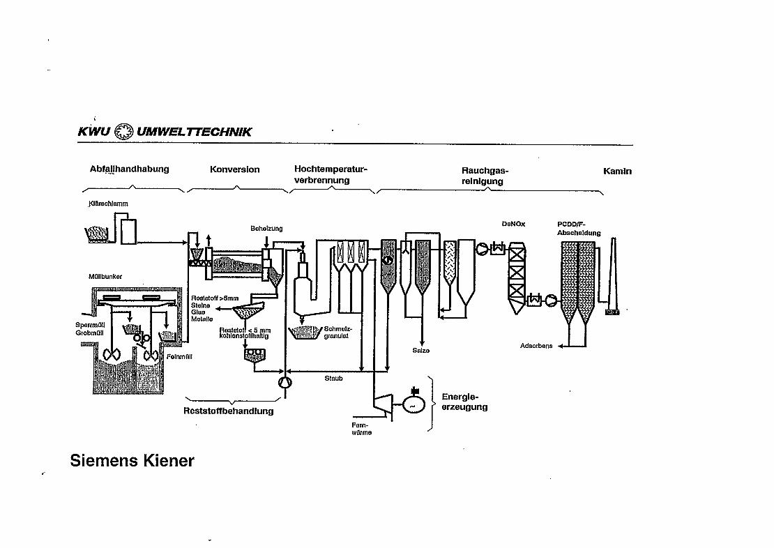
KWU ~ UMWEL7TECHN!K .
Abfa~handhabung Conversion Hochtemperatur- Rauchgas- KamInverbrennung reinigung
~ ~/—’—---\, \JU&bachlamm
yiJiJJu
Mdllbunker
+
Raatatoff>5mmSlelneGlas .-.“1v.Melalle
1201%toh5aE?
II
k
(
\v /
Reststoffbehandlung
iiStmib
Salze
DeNOx PCDDff-Abacheldung
Adsorbens 4-U
~ r erzeugung~1Fern-wlirme )
Siemens Kiener..

8.19
IEA Biomass AgreementTask X. Biomass Utilization
Sub-task 6- Gasification of Waste
DANECO
GeneralAn Italian waste treatment company, DANECO is now in addition to RDF plants also marketingan RDF pellets gasifier. The 10MW air blown updraft gasifier is coupled to a gas cleaningsystem with a novel tar cracking unit and fuel gas cooling and cleaning.
Process DescriptionA 10MW airblown updraft gasifier is fed with RDF pellets from the top. Air is fed through arotation bottom grate. The raw gas is fed to a fixed bed cracker with recycled ashes and fuel gascleaning residues (lime). The cracking temperature is around 800”C and soot is recycled to thegasifier. After gas cooling with air and steam heat exchangers to 600°C the gas enters arecovery boiler. A wet dry lime system operating at approximately 250”C precedes a baghousefilter.
After scrubbing/cooling the gas is sent to a dual fuel engine.
StatusThe authors have no information regarding the technology background or present test units.The process is actively marketed.
62er961919960509

.
k“
,
—
u r
o(Jw
..
,
.