Wireless Channels
31
Wireless Channels
-
Upload
independent -
Category
Documents
-
view
4 -
download
0
Transcript of Wireless Channels

Wireless Channels

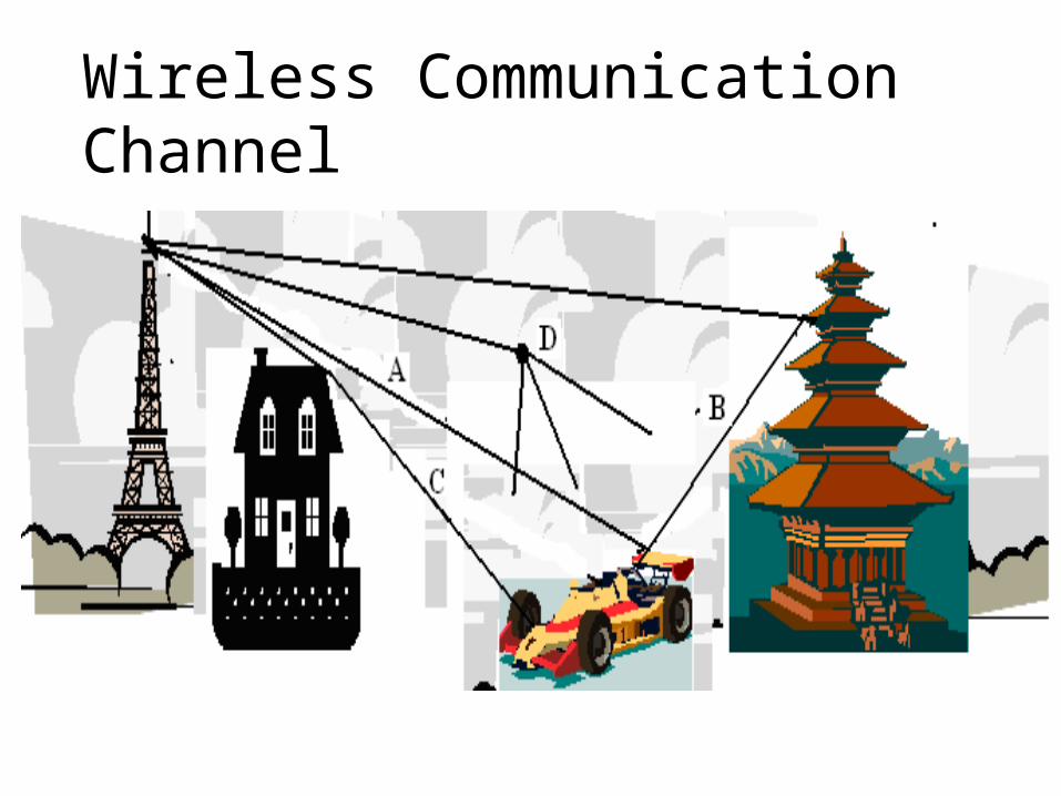
Wireless Communication Channel
In the channel on which wireless communication signals travel, the signal experiences attenuation, reflection, diffraction and scattering.
The path through which the signal propagates from the transmitter to the receiver may be a line-of-sight (LOS).
Transmitter
line-of-sight (LOS)
Receiver

Wireless Communication Channel Attenuation: When the power of the transmitted signal is observed at a distance of several kilometres away from the transmitter, we have a steady decrease in power. This is attenuation.
Reflection occurs when a propagating electromagnetic signal meets an object that is much larger than the signal’s wavelength.
Diffraction occurs when the surface encountered by the electromagnetic wave has irregularities such as sharp edges.
Scattering occurs when the medium through which the electromagnetic wave propagates contains a large number of objects smaller than the wavelength.
Wireless Communication Channel

Wireless Communication Channel
If the transmitted signal is observed at a few kilometres of separation, the power of the signal is observed to fluctuate around a mean value and these fluctuations have a somewhat long duration. This phenomenon is referred to as large-scale fading.
If the transmitted signal is observed after a few hundred meters of separation, a more rapid fluctuation in the power of the signal will be observed. This phenomenon is referred to as small-scale fading.

Attenuation
If there is a direct path between a transmitter and a receiver and in the absence of a substantial obstacle in the path of the signal, the received signal power, rP , follows the inverse square law:
2 dPr (1.1) where d is the distance between the transmitter and the receiver.

Attenuation
The received signal power is normally expressed as:
0)4( 22
2 d
LdGGPP trt
r (1.2)
The parameters tG and rG are the transmitted and the received gains, respectively. The operating wavelength is , and )1(L represents any additional loss in the system not related with the propagation loss. tP is the transmitted power, in milliwatts.

Attenuation
The product ttGP is referred to as the Equivalent Isotropic Radiated Power (EIRP). Free-space loss, freeL , is another parameter that is of interest. freeL is given as:
dL free
4
log20 10 dB (1.3)

Attenuation
If the received power at a reference distance, refd , is known, the received power at an arbitrary distance, d , can be expressed as:
2
)()(
dd
dPdP refrefrr (1.4)
where )( refr dP is the received power at the reference distance. Alternatively, )(dPr can be expressed as:
dd
dPdBmdP refrefrr 1010 log20)]([log10)( (1.5)

Attenuation
In reality, the wave propagates through non-free space medium. The relationship between the power of the received signal and the separation distance is not square. The relationship has an higher order of exponentiation. That is:
vr dP (1.6)
where the loss parameter, v, has a minimum value of 2 for free-space propagation and a higher value when free space propagation does not exist.

Attenuation
The general expression for )(dPr can be given as:
dd
vdPdBmdP refrefrr 1010 log10)]([log10)( (1.7)
The higher values of v corresponds to city and urban areas while the lower values of v corresponds to the suburban or rural areas.

Fading
Transmission characteristics are not determined by attenuation alone.
Attenuation observed may also fluctuate with distance and time FADING.
Fading is when a signal losses its deterministic nature and become random.

Fading
Fading can be described in terms of:Primary causes
•Multipath.•Doppler’s effect.
The statistical distribution of the received envelope.•Rayleigh•Rician•Log-normal•Nakagami etc.

Fading
The duration of fading
•Long-term•Short-term
Fast or slow fading
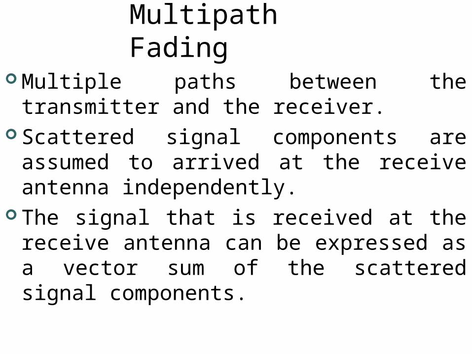
Multipath Fading
Multiple paths between the transmitter and the receiver.
Scattered signal components are assumed to arrived at the receive antenna independently.
The signal that is received at the receive antenna can be expressed as a vector sum of the scattered signal components.

Multipath Fading
That is:
where er(t) is the received signal, ai is the amplitude of the scattered component.
P(t) is the transmitted pulse shape. ti is the time taken by the pulse to reach the receiver.
N is the number of paths.
N
iiir ttPate
1)()(

Multipath Fading
We can also use phasor notation to represent the received signal:
where fo is the carrier frequency.The ith signal component has an amplitude of ai and a phase of ɸi.
N
iiir tfate
10 )2cos()(

Multipath Fading
The received signal can also be expressed in terms of the in-phase and the quadrature component.
ɸi is uniformly distributed in the range [0,2π]
N
iii
N
iiir atfatfte
10
10 )sin()2sin()cos()2cos()(
N
iii
N
iii
r
aYandaX
whereYtfXtfte
11
00
)sin( )cos(
)2sin()2cos()(

Multipath Fading
X and Y are independent, identically distributed Gaussian random variables.
The envelope of the received signal will be
The envelope of the received signal, A, is Rayleigh distributed.
22 YXA

Multipath Fading
The PDF, fA(a), of A is given as:
fuction. stepunit theis )( and Y)X(or variablesrandom theof variance theis
)(2exp)( 2
2
2
aU
aUaaafA

Characteristics of the Rayleigh Distribution
91.1][22
2][
2
22
A
A
AE
AE

Other Fading Models
Rician fading. In addition to the multipath component of the transmitted signal, it is possible to have a line-of-sight (LOS) component also.
The LOS component adds a deterministic component to the multipath signal.
The Gaussian random variables now have a nonzero mean.
The PDF of the envelope can be expressed as
component. LOS thefrom arisingcomponent theis
andfunction Bessel modified theis here2exp)(
0
20
20
2
2
AIw
aAIAaaaf
o
oA

Other Fading Models
Rician fading (contd).The ratio of the power of the direct component to the diffused component is defined as:
2
20
10 2log10)(AdBK

Dispersive Characteristics of the Channel
Fading may also affect the shape of the pulse as it is being transmitted through the channel.
The multipath effect can result in broadening of the transmitted pulse, leading to Inter Symbol Interference (ISI).
The average delay, , experienced by a pulse as it transverse the channel is
N
ii
i
N
ii
P
P
1
1
component. i by the taken time theis andpath i thealong comingpower therepresents where
th
th
i
iP

Dispersive Characteristics of the Channel
The rms delay spread,σd, is given by
the higher the value of σd, the more considerable the amount of pulse broadening.
The channel bandwidth, Bc, is approximately given by
N
ii
i
N
Ii
d
P
P
1
2
12
22
where
channel. theofbandwidth coherent theis 51
c
dc
B
B

Dispersive Characteristics of the Channel If Bc is larger than the message bandwidth, Bs, all the frequency components in the message will arrive at the receiver with little or no distortion and ISI will be negligible. <FLAT FADING CHANNEL>
If Bs is much larger than Bc, different frequency components in the message will be subjected to dispersive behaviour Broadening of pulses ISI
<FREQUENCY-SELECTIVE CHANNEL>
Doppler’s Effect
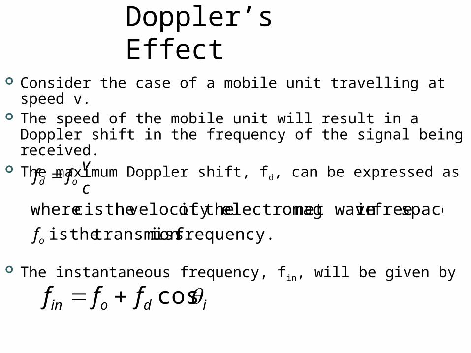
Consider the case of a mobile unit travelling at speed v.
The speed of the mobile unit will result in a Doppler shift in the frequency of the signal being received.
The maximum Doppler shift, fd, can be expressed as
The instantaneous frequency, fin, will be given by
frequency.ion transmiss theis space. freein net waveelectromag theof velocity theis c where
o
od
f
cvff
idoin fff cos

Doppler’s Effect
The received signal can be expressed as:
].[0,2 range over the ddistributeuniformly is arrival. of angles theare phases. theare
])cos(2sin[)2sin(])cos(2cos[)2cos()(11
ii
i
i
N
iidioi
N
iidior tfatftfatfte
i

Doppler’s Effect
The power spectrum, Sd(f), of er(t) can be expressed as
dd
dd ffffffS
otherwise 0
1)(2
"-fd" fd
)(fSd
Most of the energy is concentrated around fd

Doppler’s Effect
The motion of the mobile unit will introduce changes in the channel at a rate of fd Hz.
If the bandwidth of the signal measured in terms of the inverse of the pulse duration in much larger than the maximum Doppler shift, the channel will vary very slowly. <Slow-fading channel>.
For the transmission at a very low data rate, a moving unit will introduce fast fading if the bandwidth of the signal is not much larger than the maximum Doppler shift.

Doppler’s Effect
The coherent time, Tc, of the channel is measured in terms of fd as
If the pulse duration is smaller than Tc, the pulses are unlikely to undergo distortion <Slow-fading>.
If the pulse duration is larger than the coherent time, the pulse undergo fast fading and will be distorted.
dc fT
169