LTE channels
101
BY SANDEEP RATHORE & AMIT BUTOLA LTE CHANNEL CONCEPT & PHYSICAL LAYER DESIGN
-
Upload
independent -
Category
Documents
-
view
1 -
download
0
Transcript of LTE channels
BY SANDEEP RATHORE & AMIT BUTOLA
LTE CHANNEL CONCEPT & PHYSICAL LAYER DESIGN

AGENDAOFDMA & SC-FDMA ConceptLTE Resource StructureLTE Downlink Common Control Channels and Signals
LTE Downlink Physical Data ChannelLTE Uplink Physical Data and Control Channel
LTE Uplink Signals
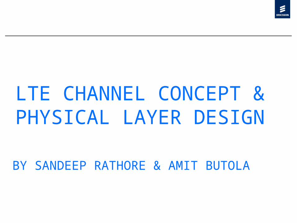
LTE EVOLUTION

Advancement in Access Techniques

CDMA & OFDMA Comparison

Frequency Domain Configurations

Frequency Domain Configurations
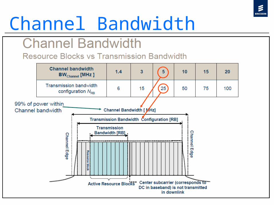
Channel Bandwidth

Frequency Domain Configurations
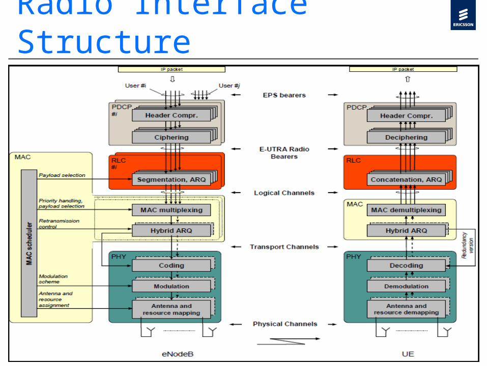
Radio Interface Structure
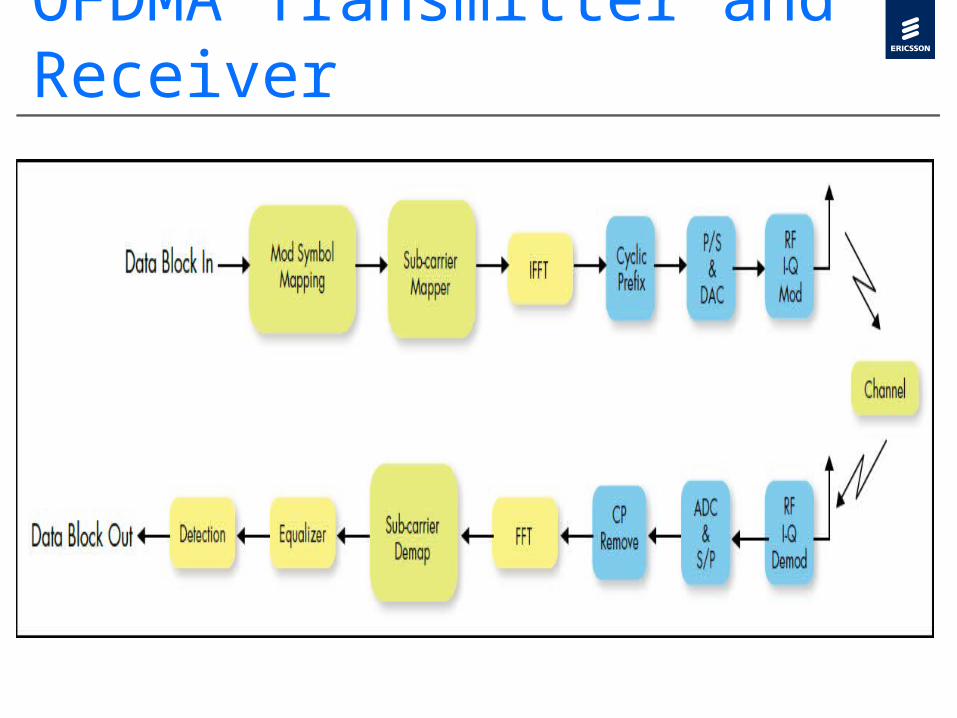
OFDMA Transmitter and Receiver

OFDMA Transmitter

OFDMA Receiver

SC-FDMA Transmitter and Receiver
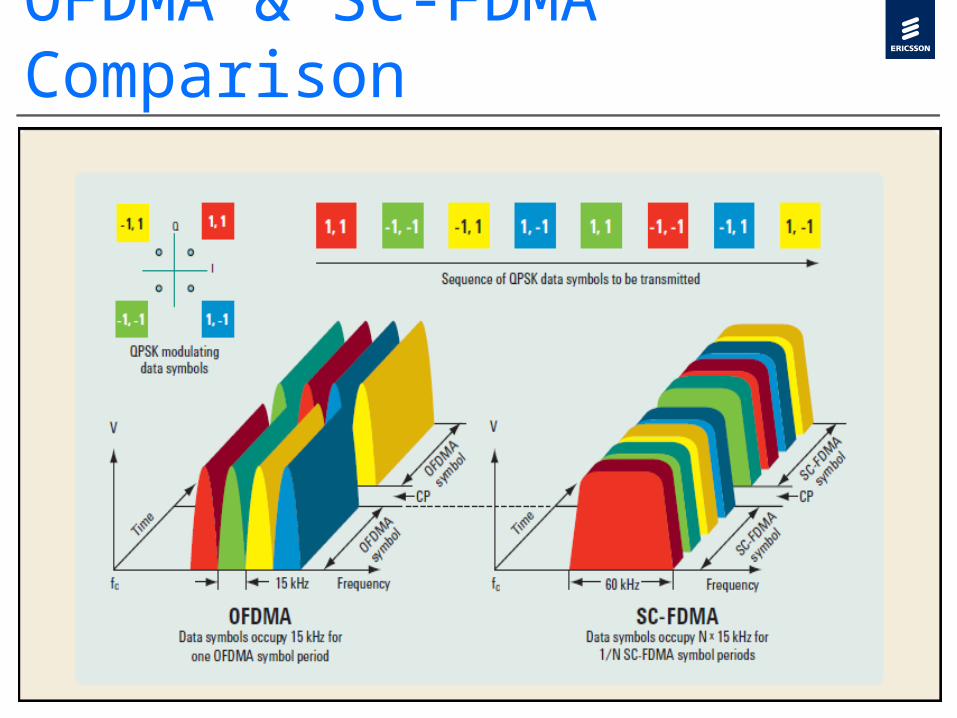
OFDMA & SC-FDMA Comparison

Peak to Average Power Ratio It is desired to operate the PA in the linear region. To avoid the high peaks, average input power may be decreased. Operating region of the PA is called input back-off and the resultant signal is guaranteed to be in output back-off range. High input back off reduces the power efficiency and would mandate the cost of the PA higher, since input back- off is usually greater than or equal to the PAPR of the signal. Ideally, the average and peak values should be as close as can be in order to maximize the efficiency of the PA. PAPR mitigation relaxes the PA back off requirements as well as the high resolution requirements on ADC and DAC.To have distortion less transmission, the PAs require a back off, which is approximately equal to the PAPR. This decreases the efficiency for amplifiers and increases the cost. High PAPR also requires high range and precision for the analog-to-digital converter (ADC) and digital-to-analog converter (DAC), as a result, reducing the PAPR of practical interest.

PA Characteristics
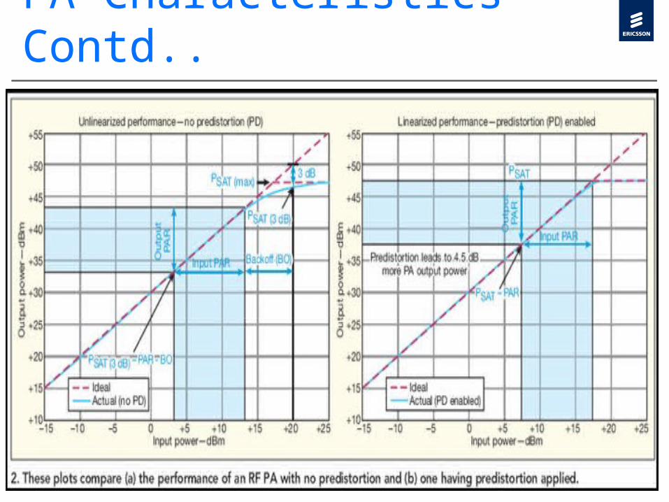
PA Characteristics Contd..

OFDMA BENEFITS AND DRAWBACKS
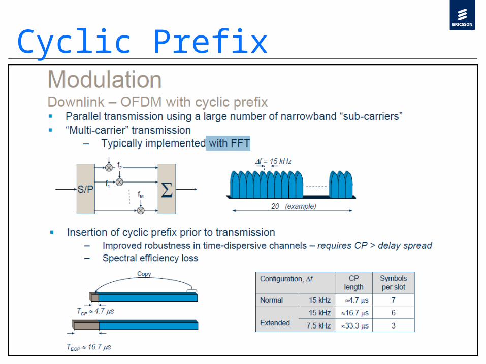
Cyclic Prefix

LTE Physical Resources

f = 15 kHz
LTE Physical Resources Contd..
One slot0.5 ms, 7 OFDM symbols
One Resource Block12 x 7 = 84 resource elements
12 sub-carriers
time
frequency
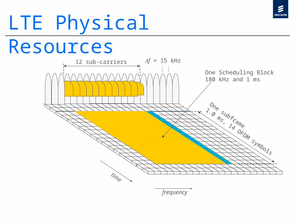
LTE Physical Resources
12 sub-carriers
One subframe
1.0 ms, 14 OFDM symbols
time
frequency
One Scheduling Block180 kHz and 1 ms
f = 15 kHz

LTE Physical Resources

LTE UL/DL Resource Grid Definitions

LTE UL/DL Resource Grid Definitions

LTE Frame Structure

DL Resource Allocation
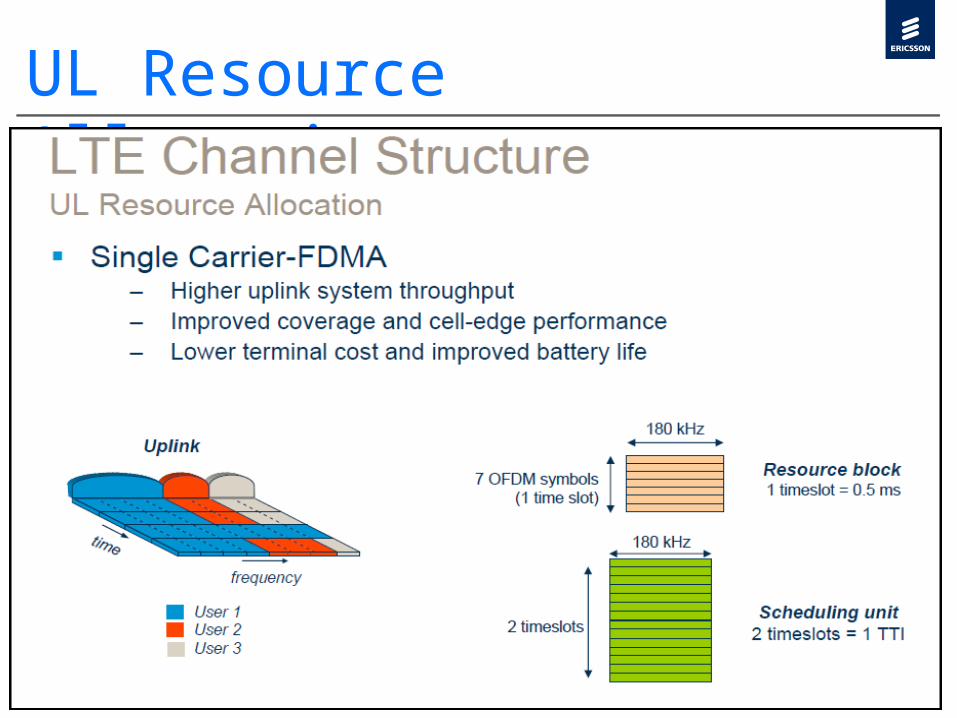
UL Resource Allocation
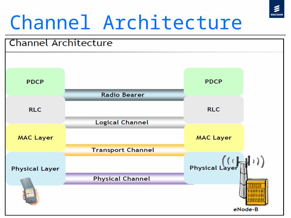
Channel Architecture
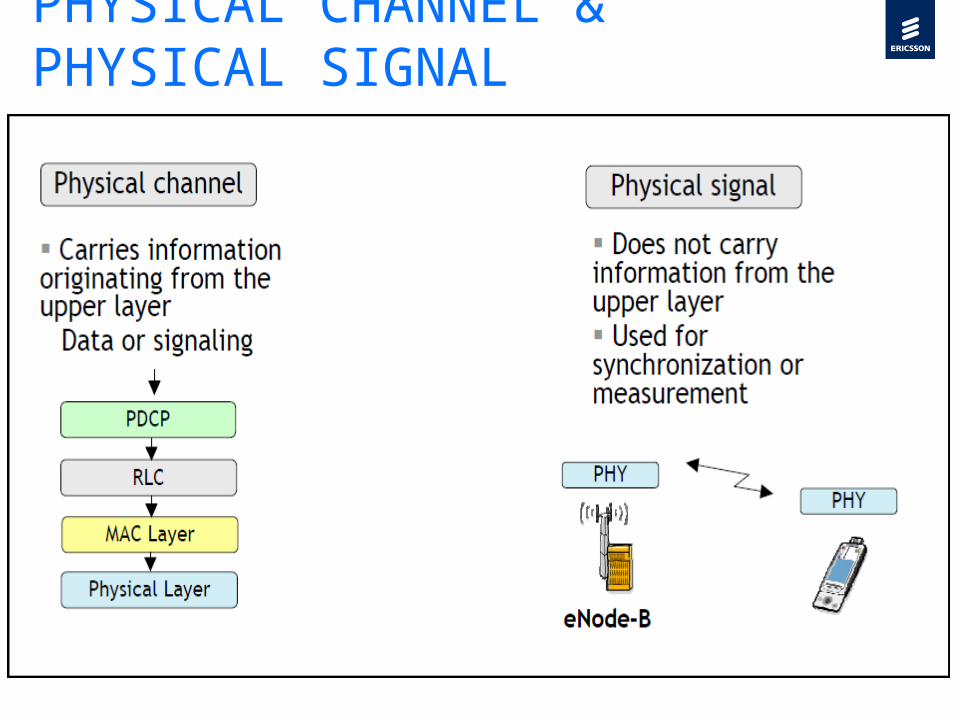
PHYSICAL CHANNEL & PHYSICAL SIGNAL

Channel Mapping
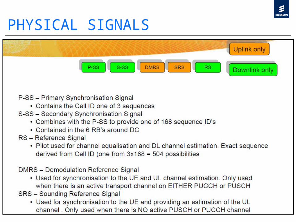
PHYSICAL SIGNALS

CHANNEL MAPPING DOWNLINK

CHANNEL MAPPING UPLINK
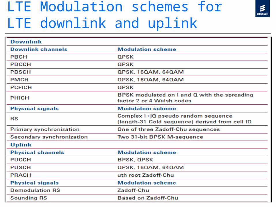
LTE Modulation schemes for LTE downlink and uplink

LTE Downlink Physical Signals
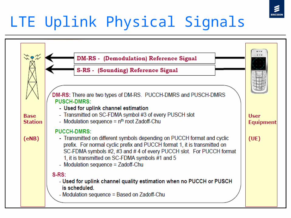
LTE Uplink Physical Signals

LTE Downlink Physical Channels

LTE Downlink Physical Channels Contd..

LTE Uplink Physical Channels

PBCH

PBCH Structure
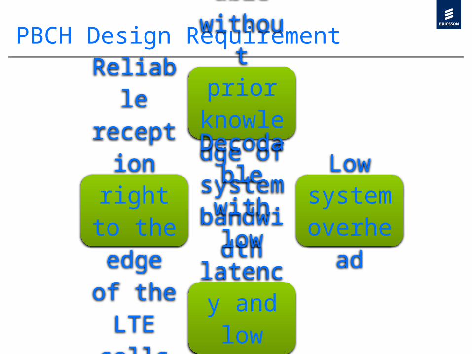
PBCH Design Requirement
Detectable
without
prior knowledge of system bandwidth
Low system overhead
Decodable with low
latency and low
impact on UE batter
y life.
Reliable
reception right to the edge
of the LTE cells

LTE NETWORK ARCHITECTURE
The PBCH only to the central 72 subcarriers of the OFDM signal (which corresponds to the minimum possible LTE system bandwidth), regardless of the actual system bandwidth. Low system overhead for the PBCH is achieved by deliberately keeping the amount of information carried on the PBCH to a minimum.The main mechanisms employed to facilitate reliable reception of the PBCH in LTE are time diversity, forward error correction coding and antenna diversity Low Latency is achieved: If SIR is low UE may decode the MIB correctly from transmission in less than Four radio frames than UE does not need to receive the other parts of the PBCH transmission in the remainder of the 40 ms period

BCCH MAPPING

Master Information & System Information Blocks

MIB & SIBs Contd..
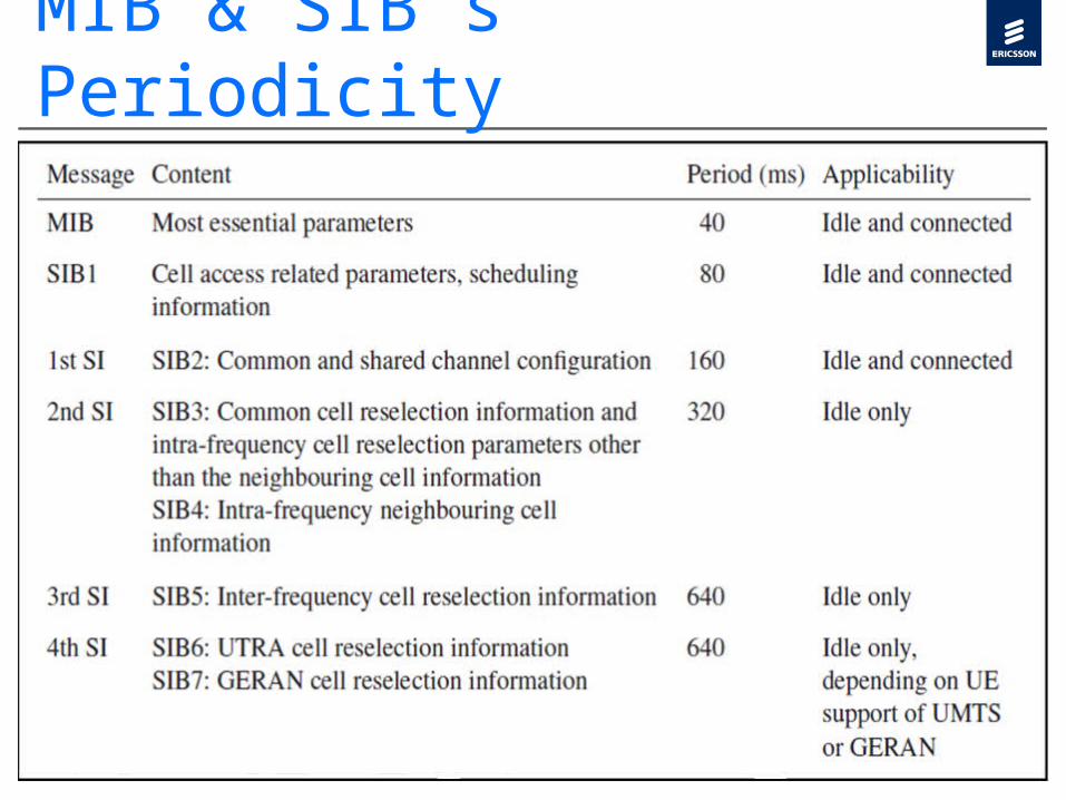
MIB & SIB’s Periodicity

LTE Control & Data Region
PCFICH The PCFICH carries a Control Format Indicator (CFI) which indicates the number of OFDM symbols (i.e. normally 1, 2 or 3) used for transmission of control channel information in eachsubframe. Correct decoding of the PCFICH information is thus essential. If the PCFICH is incorrectly decoded, the terminal will neither know how to process the control channels nor where the data region starts for the corresponding subframeThe size of the control region is unknown until the PCFICH is decoded, the PCFICH is always mapped to the first OFDM symbol of each subframe. PCFICH-to-resource-element mapping depends on the cell identity to reduce the risk of inter-cell PCFICH collisions. thereby improving the performance of PCFICH power boosting as a tool to control the error rate.The PCFICH is transmitted on the same set of antenna ports as the PBCH, with transmit diversity being applied if more than one antenna port is used.
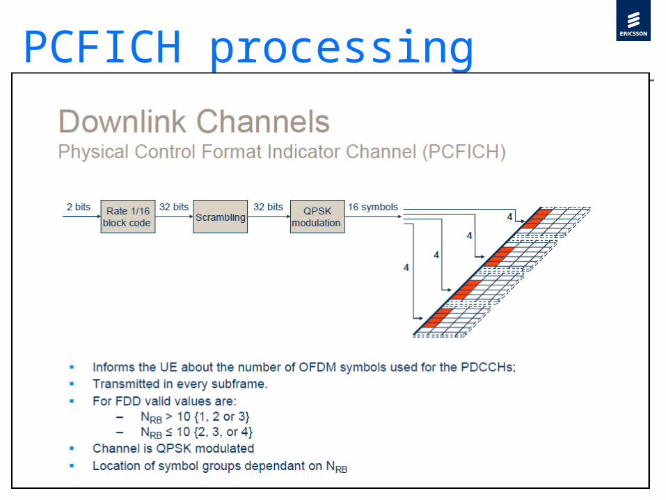
PCFICH processing
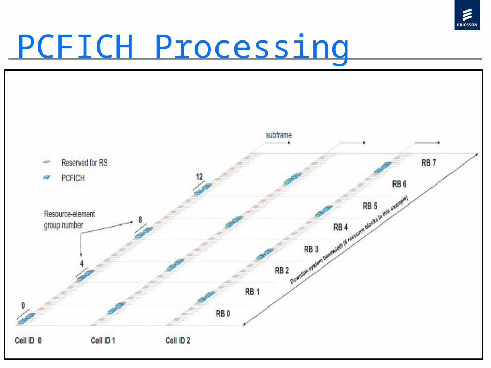
PCFICH Processing

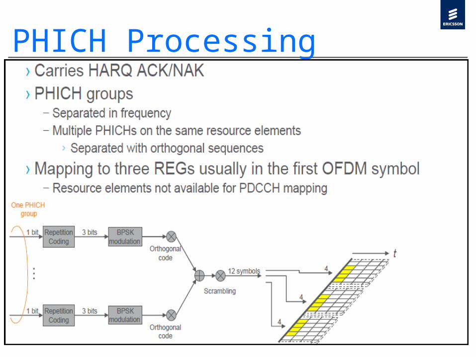
PHICH The Physical Hybrid-ARQ Indicator Channel (PHICH) in the downlink carries Hybrid ARQ (HARQ) acknowledgements (ACK/NACK) for uplink data transfers.PHICHs are located in the first OFDM symbol of each sub frame.Specific PHICH is identified by two parameters: the PHICH group number, and the orthogonal sequence index within the group.PHICHs which share the same resources are called a PHICH groupMultiple PHICHs can share the same set of REGs and are differentiated by orthogonal covers or orthogonal sequence index within the group. The scrambler is initialized only at the start of the subframe.

PHICH Processing
PHICH Processing
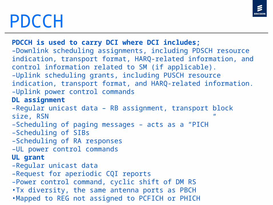
PDCCHPDCCH is used to carry DCI where DCI includes; –Downlink scheduling assignments, including PDSCH resource indication, transport format, HARQ-related information, and control information related to SM (if applicable). –Uplink scheduling grants, including PUSCH resource indication, transport format, and HARQ-related information. –Uplink power control commands DL assignment –Regular unicast data – RB assignment, transport block size, RSN –Scheduling of paging messages – acts as a “PICH” –Scheduling of SIBs –Scheduling of RA responses –UL power control commands UL grant –Regular unicast data –Request for aperiodic CQI reports –Power control command, cyclic shift of DM RS •Tx diversity, the same antenna ports as PBCH •Mapped to REG not assigned to PCFICH or PHICH
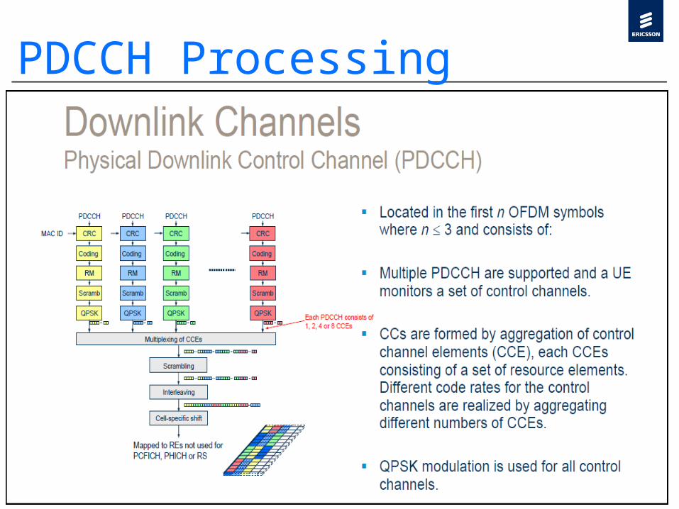
PDCCH Processing

DCI Format

DCI Format Contd..

DCI FORMAT 0›DCI format 0 is used for the transmission of UL-SCH assignments.
›The following information is transmitted by means of the DCI format 0:
›- [Flag for format0/format1A differentiation – 1 bit]›- Hopping flag – 1 bit›- Resource block assignment and hopping resource allocation – bits
›- Transport format›- Retransmission sequence number›- TPC command for scheduled PUSCH – 2 bits›- [Cyclic shift for DM RS]›- [Transmit antenna selection]›- UL index (this field just applies to TDD operation)
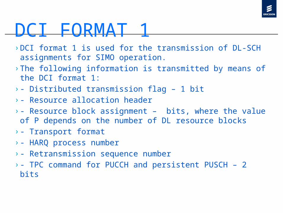
DCI FORMAT 1›DCI format 1 is used for the transmission of DL-SCH assignments for SIMO operation.
›The following information is transmitted by means of the DCI format 1:
›- Distributed transmission flag – 1 bit›- Resource allocation header›- Resource block assignment – bits, where the value of P depends on the number of DL resource blocks
›- Transport format›- HARQ process number›- Retransmission sequence number›- TPC command for PUCCH and persistent PUSCH – 2 bits

DCI FORMAT 1A›DCI format 1A is used for a compact transmission of DL-SCH assignments for SIMO operation.
›The following information is transmitted by means of the DCI format 1A:
›- [Flag for format0/format1A differentiation – 1 bit]›- Distributed transmission flag – 1 bit›- Resource block assignment – up to bits›- Transport format›- HARQ process number›- Retransmission sequence number›- TPC command for PUCCH and persistent PUSCH – 2 bits

DCI FORMAT 2› DCI format 2 is used for the transmission of DL-SCH assignments for MIMO operation.
› The following information is transmitted by means of the DCI format 2:
› In general: › - Distributed transmission flag – 1 bit› - Resource allocation header› - Resource block assignment – bits, where the value of P depends on the number of DL resource blocks.
› - TPC command for PUCCH and persistent PUSCH – 2 bits› - [Number of layers]› For the first codeword: › - Transport format› - HARQ process number› - Retransmission sequence number› For the second codeword:› - Transport format› - [HARQ process number]› - [Retransmission sequence number]

DCI FORMAT 3›DCI format 3 is used for the transmission of TPC commands for PUCCH and PUSCH with 2-bit power adjustments.
›The following information is transmitted by means of the DCI format 3:
›TPC command for user 1, user 2,…, user N

DCI FORMAT 3A›DCI format 3A is used for the transmission of TPC commands for PUCCH and PUSCH with single bit power adjustments.
›The following information is transmitted by means of the DCI format 3A:
›- TPC command for user 1, user 2,…, user 2N
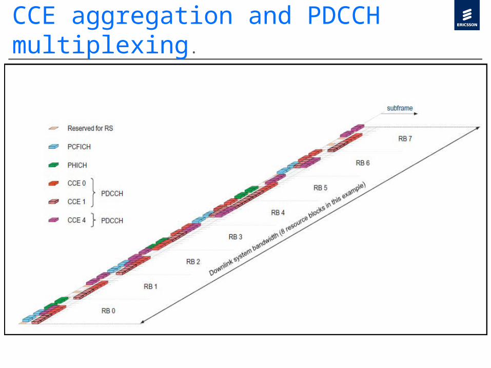
CCE aggregation and PDCCH multiplexing.
Why do we need multiple aggregation levels›First, to increase the granularity of the resource utilization, instead of a "one size fits all" solution.›Second, to accommodate different RF conditions. The ratio between the DCI size and the PDCCH size indicates the effective coding rate. With the DCI format fixed, higher aggregation levels provide more robust coding and reliability for the UEs under poor RF conditions. For a UE in good RF conditions, lower aggregation levels can save resources.›Third, to differentiate DCIs for control messages and DCIs for UE traffic. Higher aggregation levels can be used for control message resource allocations to provide more protection. The aggregation level for control messages can be 4 or 8, while the aggregation level for UE-specific allocation can be 1 or 2 or 4 or 8.

Blind Decoding of PDCCHs
The UE is only informed of the number of OFDM symbol within the control region of a subframe and is not provided with the location of its corresponding PDCCH. The UE finds its PDCCH by monitoring a set of PDCCH candidates in every subframe. This is referred to as blind decoding. The UE de-masks each control candidate's CRC using its Radio Network Temporary Identifier (RNTI). If no CRC error is detected, the UE consider it as a successful decoding attempt and reads the control information within the successful candidate.

Blind Decoding of PDCCHsThe UE is required to perform blind decoding at PDCCH payload as it is not aware of the detailed control channel structure, including the number of control channels and the number of CCEs to which each control channel is mapped. Multiple PDCCHs can be transmitted in a single subframe which may and may not be all relevant to a particular UE. The UE finds the PDCCH specific to it by monitoring a set of PDCCH candidates (a set of consecutive CCEs on which PDCCH could be mapped) in every subframe. The UE uses its Radio Network Temporary Identifier (RNTI) to try and decode candidates. The RNTI is used to damask a PDCCH candidate's CRC. If no CRC error is detected the UE determines that PDCCH carries its own control information.

Search spaces in LTEThe Base Station (BS) determines a PDCCH format to be transmitted to the UE, creates an appropriate DCI and attaches a CRC. The CRC is then masked with an RNTI according to the owner or usage of PDCCH. If the PDCCH is for a specific UE, the CRC will be masked with a UE unique identifier, for example a Cell-RNTI (C-RNTI). If the PDCCH contains paging information, the CRC will be masked with a paging indication identifier i.e. Paging-RNTI (P-RNTI). If the PDCCH contains system information, a system information identifier i.e. a system information-RNTI (SI-RNTI) will be used to mask the CRC

Search spaces in LTESearch SpaceA search space is a set of candidate control channels formed by CCEs on a given aggregation level, which the terminal is supposed to attempt to decode.UE specificTwo terminals can not be addressed on same aggregation level as search spaces used by one terminal can not be used by other terminal so terminal specific spaces are requiredCommon search spaces To allow all terminals to be addressed at the same time, LTE has defined common search spaces in addition to the terminal-specific search spacesDynamic scheduling of system information & transmission of paging messages is not terminal specific.

Search spaces in LTEWith the possibilities of different RNTIs, PDCCH candidates, DCI and PDCCH formats, a significant number of attempts may be required to successfully decode the PDCCH. To overcome this complexity the UE first tries to blindly decode the first CCE in the control channel candidate set of a subframe. If the blind decoding fails, the UE tries to blindly decode the first 2, 4 then 8 CCEs sequentially, where the starting location is fixed for common search case and is given by hash function, as defined in TS 36.231 clause 9, for UE-specific case

CCE aggregation and PDCCH multiplexing.

The number of candidates and size of the search space for each aggregation level
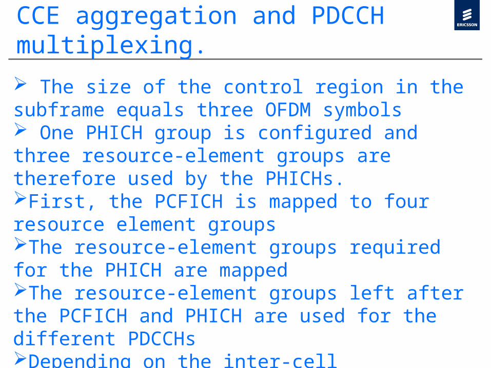
CCE aggregation and PDCCH multiplexing. The size of the control region in the subframe equals three OFDM symbols One PHICH group is configured and three resource-element groups are therefore used by the PHICHs.First, the PCFICH is mapped to four resource element groupsThe resource-element groups required for the PHICH are mappedThe resource-element groups left after the PCFICH and PHICH are used for the different PDCCHsDepending on the inter-cell interference situation, fractional loading of the control region may be desirableSome CCEs are left unused to reduce the average inter-cell interference.

Search spaces in two terminals.

DL-SCH processing

Cell search›Find a cell›Find timing of found cell›Find physical-layer cell identity of found cell
Downlink reference-signal structure of found cell -Timing-Sequence-Frequency shift
Possible to read BCH

Physical-layer Cell Identity›Corresponds to a specific reference-signal sequence– Similar to WCDMA CPICH– 510 different reference-signal sequences 510 different Cell Identities
›170 Cell-Identity groups with 3 Cell Identities per group 3 RS sequences ”per group”Group
#0 ID0
ID2ID1
Group #1 ID3
ID5ID4
Group #2 ID6
ID8ID7
Group #169ID507
ID509ID508
For normal CP: Cell IDs within a group correspond to the same Pseudo-random RS sequence, i.e. different Orthogonal RS sequences
Each Cell ID corresponds to a certain RS Frequency Shift
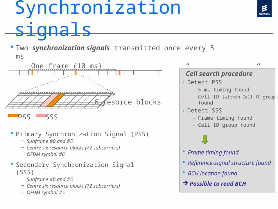
Cell search – Synchronization signals
”Cell search procedure”› Detect PSS
– 5 ms timing found– Cell ID (within Cell ID group) found
› Detect SSS– Frame timing found– Cell ID group found
Frame timing found Reference-signal structure found BCH location found Possible to read BCH
One frame (10 ms)
PSS SSS
Primary Synchronization Signal (PSS)– Subframe #0 and #5– Centre six resource blocks (72 subcarriers)– OFDM symbol #6
Secondary Synchronization Signal (SSS)
– Subframe #0 and #5– Centre six resource blocks (72 subcarriers)– OFDM symbol #5
6 resorce blocks
Two synchronization signals transmitted once every 5 ms

Introduction›Zadoff- Chu (CAZAC) sequence is widely used in LTE system, and this document gives a brief introduction of this sequence, illustrates its main properties, and help understand the reason why LTE uses this sequence in the system construction

Zadoff-Chu (CAZAC)›Definition
›Properties–constant amplitude: , this means the PAPR of the sequence is zero.
–self-invertible:
2 1( ) exp ( ) if L is odd2Mj M nc n n qn
L
22( ) exp ( ) if L is even2Mj M nc n qn
L
( ) 1Mc n
( ) ( )M Mc L n c n

Zadoff-Chu (CAZAC)–optimal autocorrelation features –ideal unfiltered and filtered Fourier transforms: the outputs of FFT (or IFFT) of CAZAC sequences are still CAZAC sequences, and the autocorrelation is still kept.
0 10 20 30 40 50 600
0.1
0.2
0.3
0.4
0.5
0.6
0.7
0.8
0.9
1
r
autocorrelation
valu
e (normalized)
FFT(CAZAC)
0 10 20 30 40 50 600
0.1
0.2
0.3
0.4
0.5
0.6
0.7
0.8
0.9
1
r
autocorrelation
valu
e (normalized)
CAZAC

Zadoff-Chu (CAZAC)–autocorrelation and cross-correlation feature compared with other Sequences
Note: sequence length is N=61
0 10 20 30 40 50 60
-10
0
10
20
30
40
50
60
r
autocorrelation
valu
e(r)
mG oldSKLKCAZAC
0 10 20 30 40 50 60 70-20
-15
-10
-5
0
5
10
15
r
cross-correlation
valu
e(r)
mG oldSKLKCAZAC
N
0N

UL control signaling
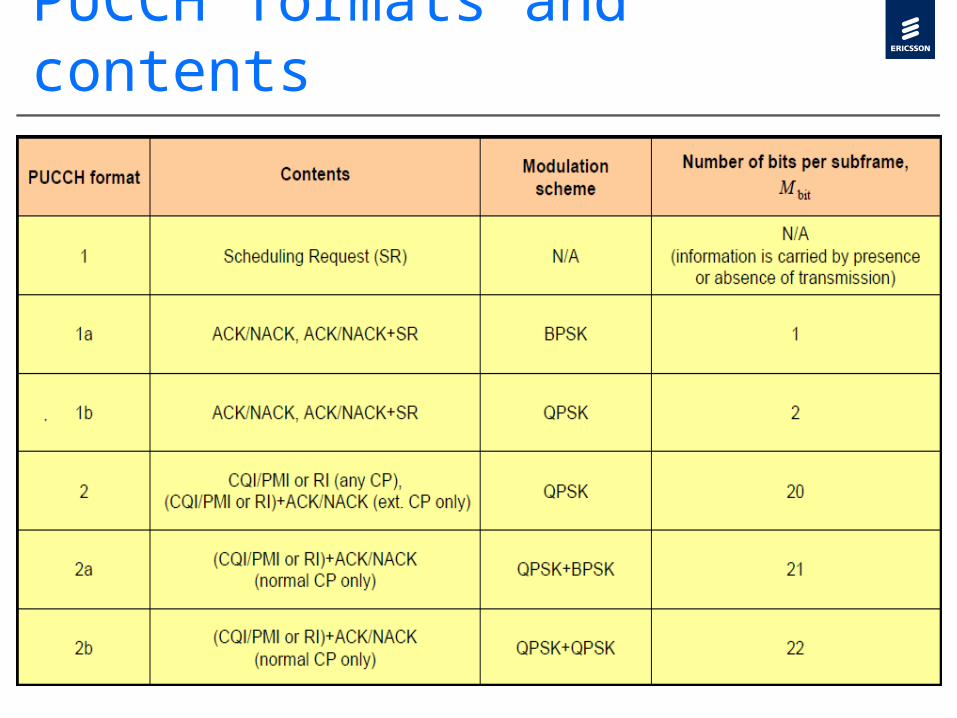
PUCCH formats and contents

PUCCH formats and contents

UL control signalingCQI (channel quality indicator) is an indication of the downlinkmobile radio channel quality as experienced by this UE. Essentially,the UE is proposing to the eNodeB an optimum modulation schemeand coding rate to use for a given radio link quality, so that theresulting transport block error rate would not exceed 10%. 16combinations of modulation scheme and coding rate are specifiedas possible CQI values. The UE may report different types of CQI.A so-called “wideband CQI” refers to the complete systembandwidth. Alternatively, the UE may evaluate a “sub-band CQI”value per sub-band of a certain number of resource blocks which isconfigured by higher layers. The full set of sub-bands would coverthe entire system bandwidth. In case of spatial multiplexing, a CQIper code word needs to be reported.
UL control signalingPMI (precoding matrix indicator) is an indication of the optimumprecoding matrix to be used in the base station for a given radiocondition. The network configures the number of resource blocksthat are represented by a PMI report. Thus to cover the fullbandwidth, multiple PMI reports may be needed. RI (rank indication) is the number of useful transmission layerswhen spatial multiplexing is used. In case of transmit diversity, rankis equal to 1.

CQI
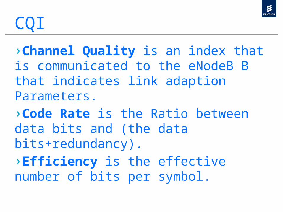
CQI›Channel Quality is an index that is communicated to the eNodeB B that indicates link adaption Parameters.›Code Rate is the Ratio between data bits and (the data bits+redundancy).›Efficiency is the effective number of bits per symbol.

Rank Transmission

Rank Transmission

Rank Transmission

Rank Transmission

CHANNEL MAPPING UPLINK
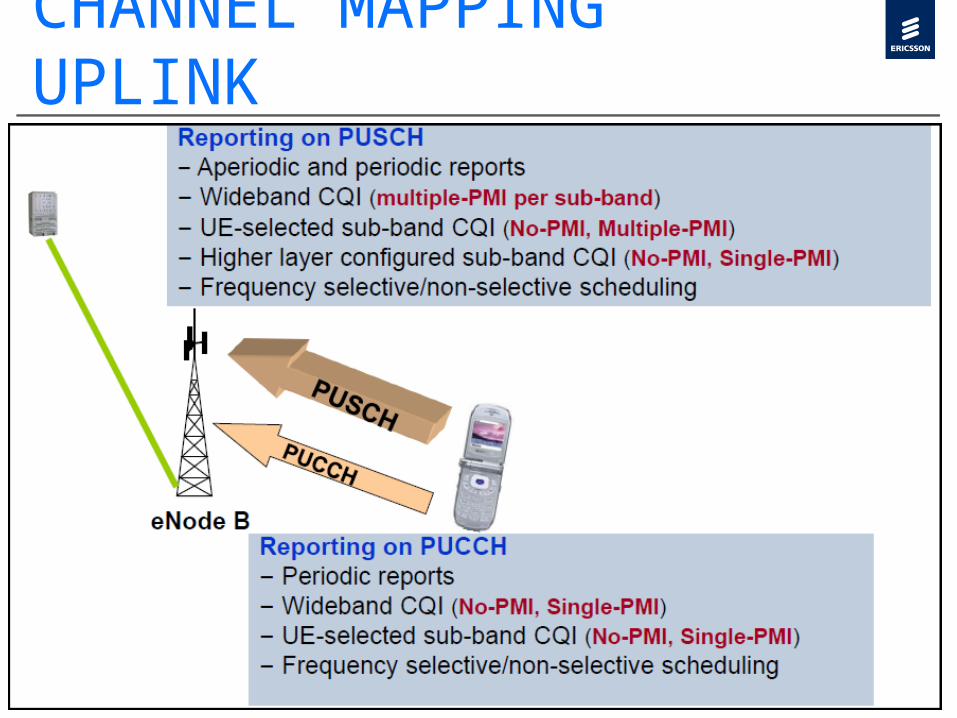
CHANNEL MAPPING UPLINK

UL control signaling

LTE Requirements