Water desalination by air humidification: Mathematical model and experimental study
7
Water desalination by air humidification: Mathematical model and experimental study Juan-Jorge Hermosillo a,b , Camilo A. Arancibia-Bulnes a,⇑,1 , Claudio A. Estrada a a Centro de Investigacio ´ n en Energı ´a, Universidad Nacional Auto ´ noma de Me ´xico, Priv. Xochicalco s/n, Col. Centro, Temixco, Morelos 62580, Mexico b Departamento de Procesos Tecnolo ´ gicos e Industriales, ITESO, Perife ´rico Sur 8585, Tlaquepaque, Jalisco 45604, Mexico Available online 19 October 2011 Communicated by: Associate Editor C. Estrada-Gasca Abstract A desalination system based on the humidification and dehumidification of air is studied. The evaporator unit is based on a treated cellulose paper substratum through which water flows, and which has a large area to favor evaporation. The condenser unit is a liquid– gas heat exchanger, where water vapor is condensed and the enthalpy of condensation is recovered to preheat the water. The mathemat- ical model and experimental results are presented and it is shown that they present a good agreement. Some operating conditions for better heat recovery are presented. Ó 2011 Elsevier Ltd. All rights reserved. Keywords: Solar desalination; Air humidification–dehumidification (HD); Multiple effect humidification–dehumidification; MEH 1. Introduction Seawater desalination is increasingly useful in several regions around the world because population is growing in places where there is not enough fresh water to support that growing. It is expected that by 2025, more than 60% of world’s population will have water shortages. Desalination is an energy intensive process that currently is made by means of membranes or via thermal processes. The most common desalination processes are energized directly or indirectly by fossil fuels (El-Dessouky and Ettouney, 2002). However, in many places near seashore, where desa- lination could be useful, there is plenty of solar energy, making an interesting combination of sunshine and seawa- ter as resources for the production of fresh water. The best known thermal processes for the desalination of seawater, namely multi-effect desalination (MED) and multistage flash (MSF), make an efficient use of energy because the heat released in each stage or effect is used in the next one, making multiple use of energy. However, those processes require a very precise control of tempera- ture and pressure in each stage, which must be constant in time in order to keep the conditions needed for the boiling process (El-Dessouky and Ettouney, 2002). This poses a problem when coupling desalination with solar energy, due to the intrinsic variability of insolation, thus requiring a thermal storage tank and/or a supplementary heat source from fossil fuels (Blanco and Alarco ´n, 2007; Rheinla ¨nder, 2002). On the other hand, solar stills have been used to treat saltwater at the household and small community scales and have been extensively studied since 1950s (Aybar, 2007, p. 207; Bo ¨er, 2005, pp. 19, 31; Delyannis, 2003; Rinco ´n Mejı ´a, 2005, p. 300). Solar stills are designed to directly catch the solar energy, and their rate of production is self adapted to available energy without the need of supplementary energy or storage. This is done by avoiding the boiling of water, using the internal air as a carrying gas between evaporating and condensing surfaces. However, in 0038-092X/$ - see front matter Ó 2011 Elsevier Ltd. All rights reserved. doi:10.1016/j.solener.2011.09.016 ⇑ Corresponding author. Tel.: +52 55 56229791. E-mail address: [email protected] (C.A. Arancibia-Bulnes). 1 On sabbatical leave at Departamento de Ingenierı ´a Quı ´mica y Metalurgia, Universidad de Sonora, Mexico. www.elsevier.com/locate/solener Available online at www.sciencedirect.com Solar Energy 86 (2012) 1070–1076
Transcript of Water desalination by air humidification: Mathematical model and experimental study
Available online at www.sciencedirect.com
www.elsevier.com/locate/solener
Solar Energy 86 (2012) 1070–1076
Water desalination by air humidification: Mathematical modeland experimental study
Juan-Jorge Hermosillo a,b, Camilo A. Arancibia-Bulnes a,⇑,1, Claudio A. Estrada a
a Centro de Investigacion en Energıa, Universidad Nacional Autonoma de Mexico, Priv. Xochicalco s/n, Col. Centro, Temixco, Morelos 62580, Mexicob Departamento de Procesos Tecnologicos e Industriales, ITESO, Periferico Sur 8585, Tlaquepaque, Jalisco 45604, Mexico
Available online 19 October 2011
Communicated by: Associate Editor C. Estrada-Gasca
Abstract
A desalination system based on the humidification and dehumidification of air is studied. The evaporator unit is based on a treatedcellulose paper substratum through which water flows, and which has a large area to favor evaporation. The condenser unit is a liquid–gas heat exchanger, where water vapor is condensed and the enthalpy of condensation is recovered to preheat the water. The mathemat-ical model and experimental results are presented and it is shown that they present a good agreement. Some operating conditions forbetter heat recovery are presented.� 2011 Elsevier Ltd. All rights reserved.
Keywords: Solar desalination; Air humidification–dehumidification (HD); Multiple effect humidification–dehumidification; MEH
1. Introduction
Seawater desalination is increasingly useful in severalregions around the world because population is growingin places where there is not enough fresh water to supportthat growing. It is expected that by 2025, more than 60% ofworld’s population will have water shortages. Desalinationis an energy intensive process that currently is made bymeans of membranes or via thermal processes. The mostcommon desalination processes are energized directly orindirectly by fossil fuels (El-Dessouky and Ettouney,2002). However, in many places near seashore, where desa-lination could be useful, there is plenty of solar energy,making an interesting combination of sunshine and seawa-ter as resources for the production of fresh water.
The best known thermal processes for the desalinationof seawater, namely multi-effect desalination (MED) and
0038-092X/$ - see front matter � 2011 Elsevier Ltd. All rights reserved.
doi:10.1016/j.solener.2011.09.016
⇑ Corresponding author. Tel.: +52 55 56229791.E-mail address: [email protected] (C.A. Arancibia-Bulnes).
1 On sabbatical leave at Departamento de Ingenierıa Quımica yMetalurgia, Universidad de Sonora, Mexico.
multistage flash (MSF), make an efficient use of energybecause the heat released in each stage or effect is used inthe next one, making multiple use of energy. However,those processes require a very precise control of tempera-ture and pressure in each stage, which must be constantin time in order to keep the conditions needed for theboiling process (El-Dessouky and Ettouney, 2002). Thisposes a problem when coupling desalination with solarenergy, due to the intrinsic variability of insolation, thusrequiring a thermal storage tank and/or a supplementaryheat source from fossil fuels (Blanco and Alarcon, 2007;Rheinlander, 2002).
On the other hand, solar stills have been used to treatsaltwater at the household and small community scalesand have been extensively studied since 1950s (Aybar,2007, p. 207; Boer, 2005, pp. 19, 31; Delyannis, 2003;Rincon Mejıa, 2005, p. 300). Solar stills are designed todirectly catch the solar energy, and their rate of productionis self adapted to available energy without the need ofsupplementary energy or storage. This is done by avoidingthe boiling of water, using the internal air as a carrying gasbetween evaporating and condensing surfaces. However, in
Nomenclature
a specific area of evaporator, m2 m�3
AC external area of condenser envelope, m2
Acond condenser area of heat transfer, m2
AE external area of evaporator envelope, m2
Cp brine heat capacity, J kg�1 s�1 �C�1
Cpa heat capacity of air, 1.009 kJ kg�1 �C�1 (NISTChemistry Web Book)
Cpw heat capacity of liquid water, 4.193 kJ kg�1
�C�1 (NIST Chemistry Web Book)D rate of condensed water, kg s�1
e correction factor for cross-flow heat and masstransfer, nondimensional
f factor of humidity, nondimensionalG dry air mass flow rate, kg s�1
Hi enthalpy of saturated air at temperature Ti,J kg�1 dry air
K mass transfer coefficient, kg s�1 m�2
L brine mass flow rate, kg s�1
Ma molecular mass of air, 0.028966 kg mol�1
Mw molecular mass of water, 0.018016 kg mol�1
P atmospheric pressure, PaP 0
i vapor pressure of water at temperature of pointi, Pa
Tamb ambient temperature, �CTavgC average surface temperature of condenser, �CTavgE average surface temperature of evaporator, �CTi temperature at point i, �CTd distillate temperature, �CUcond overall coefficient of heat transfer at condenser,
J s�1 m�2 �C�1
ULC overall heat loss coefficient of condenser,J s�1 m�2 �C�1
ULE overall heat loss coefficient of evaporator,J s�1 m�2 �C�1
V evaporator volume, m3
Wi humidity of saturated air at temperature Ti,kg water/kg dry air
DHvap enthalpy of vaporization of water, 2332.20 kJkg�1
J.-J. Hermosillo et al. / Solar Energy 86 (2012) 1070–1076 1071
order to condense water, common solar stills lose the heatof condensation of water to the surroundings, throughtheir condensing surface which works at the same time asthe transparent cover of the solar collector. This arrange-ment makes heat recovery and the improvement of theoverall efficiency very difficult, resulting in a technologywith important limitations (Chaibi and El-Nashar, 2009,p. 140; Tiwari and Tiwari, 2008, p. 218). Specifically, ithas been noted that simple solar stills do not show econ-omy of scale, making them economically infeasible at med-ium to large scale (Al-Hallaj et al., 2006, p. 172).
In the humidification–dehumidification (HD) systems,as in solar stills, the self-adaptability to available energyis reproduced by avoiding the boiling of water, using theinternal air as a carrying fluid. However, in this case,regions of the system for evaporation and condensationare designed and built separately, and connected to solarcollectors that can be designed and optimized (Hermannet al., 2002) without the compromise to perform simulta-neously as evaporators and condensers. A few variants ofthe HD system are being studied (Chafik, 2003; Ettouneyand Rizzuti, 2007, p. 10; Muller-Holst, 2007, p. 215). Inaddition to the possibility of designing each componentseparately, the HD concept offers the feasibility of recover-ing the latent heat released by condensing vapor instead oflosing it to the surroundings, as happens in solar stills.Thus, a better overall use of energy can be achieved; i.e.,productivity of the system is increased. This may be thebasis of a more competitive solar desalination technology(Al-Hallaj et al., 2006, p. 184; Mathioulakis et al., 2007,p. 354). However, while some HD systems have been called“multi-effect humidification” (MEH), most studied sys-
tems, including the one presented in this paper, are not“multi-effect” in the sense used in MED and MSF, wherethe heat can be reused 10 or 15 times to produce vapor(Ettouney and Wilf, 2009).
The objective of this paper is to present the results of astudy on a new HD system, with the air working in a closedloop and the evaporator made of treated cellulose papersubstratum. The new system is designed to improve theheat recovery at the condenser. The study is done with amathematical model and an experimental system to vali-date the model.
The purpose of the system is to desalinize water recover-ing the heat released by vapor condensation. Thus, it isinteresting to find conditions with high heat recovery.
2. Description of the physical model
In the air humidification–dehumidification system stud-ied in this work, the air acts as a carrying fluid, i.e., evap-oration occurs without boiling of water. Air is humidifiedin one of the system’s regions and moved to a cooler regionwhere water condenses releasing its enthalpy of condensa-tion. In the condenser this heat can be recovered and usedto preheat the seawater.
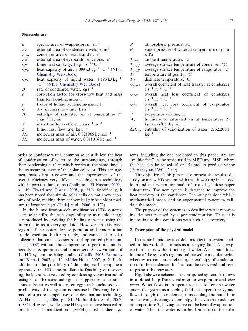
Fig. 1 shows a scheme of the proposed system. Air flowsin a closed loop from condenser to evaporator and vice
versa. Water flows in an open circuit as follows: seawaterenters the system as a cooling fluid at temperature T1 andflows through the condenser, thus cooling the humid airand catching its change of enthalpy. It leaves the condenserat temperature T2 having recovered the heat of evaporationof water. Then this water is further heated up in the solar
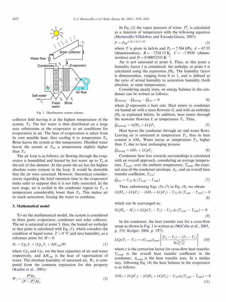
Fig. 1. Desalination system scheme.
1072 J.-J. Hermosillo et al. / Solar Energy 86 (2012) 1070–1076
collector field leaving it at the highest temperature of thesystem, T3. The hot water is then distributed on a largearea substratum at the evaporator to set conditions forevaporation in air. The heat of evaporation is taken fromits own sensible heat, thus cooling it to temperature T4.Brine leaves the system at this temperature. Distilled waterleaves the system at TD, a temperature slightly higherthan T1.
The air loop is as follows: air flowing through the evap-orator is humidified and heated by hot water up to T6 atthe exit of this element. At this point the air has the highestabsolute water content in the loop. It would be desirablethat the air were saturated. However, theoretical consider-ations regarding the brief retention time in the evaporatormake safer to suppose that it is not fully saturated. In thenext stage, air is cooled in the condenser region to T5, atemperature considerably lower than T6. This makes airto reach saturation, forcing the water to condense.
3. Mathematical model
To set the mathematical model, the system is consideredin three parts: evaporator, condenser and solar collector.The air is saturated at point 5, thus, the humid air enthalpyat that point is calculated with Eq. (1), which considers thecondition of liquid water, T = 0 �C and zero humidity, as areference point for H = 0:
Hi ¼ CpaT i þ ðCpwT i þ DH vapÞW i ð1Þ
where Cpa and Cpw are the heat capacities of air and waterrespectively, and DHvap is the heat of vaporization ofwater. The absolute humidity of saturated air, Wi, is com-puted from the common expression for this property(Kuehn et al., 2001):
W i ¼P 0
i Mw
ðP � P 0i ÞMa
ð2Þ
In Eq. (2) the vapor pressure of water, P 0i , is calculated
as a function of temperature with the following equation(Hermosillo-Villalobos and Estrada-Gasca, 2007):
P ¼ P 0eAþBTþC ln TþDT ð3Þ
where T is given in kelvin and P0 = 7.384 kPa, A = 67.35(dimensionless), B = �7218.15 K, C = �7.9939 (dimen-sionless) and D = 0.00052333 K�1.
Air is not saturated at point 6. Thus, at this point ahumidity factor f is considered: the enthalpy at point 6 iscalculated using the expression fH6. The humidity factoris dimensionless, ranging from 0 to 1, and is defined asthe ratio of actual humidity to saturation humidity (bothabsolute, at same temperature).
Considering steady state, an energy balance in the con-denser can be written as follows:
_Qentering � _Qleaving � _Qloss ¼ 0 ð4Þwhere _Q represents a heat rate. Heat enters to condenservia humid air with a mass flowrate G, and with an enthalpyfH6 as explained before. In addition, heat enters throughthe seawater flowrate L at temperature T1. Thus,
_Qentering ¼ GfH 6 þ LCpT 1 ð5ÞHeat leaves the condenser through air and water flows.
Leaving air is saturated at temperature T5, thus its heatcontent is GH5. Water leaves at temperature T2, higherthan T1 due to heat exchanging process:
_Qleaving ¼ GH 5 þ LCpT 2 ð6ÞCondenser heat loss towards surroundings is calculated
with an overall approach, considering an average tempera-ture, TavgC, over the ambient temperature, Tamb, the exter-nal area of the condenser envelope, AC, and an overall heattransfer coefficient, ULC:
_Qloss ¼ ULCACðT avgC � T ambÞ ð7ÞThen, substituting Eqs. (5)–(7) in Eq. (4), we obtain
ðGfH 6 þ LCpT 1Þ � ðGH 5 þ LCpT 2Þ � U LCACðT avgC � T ambÞ ¼ 0
ð8Þwhich can be rearranged as:
GðfH 6 � H 5Þ þ LCpðT 1 � T 2Þ � U LCACðT avgC � T ambÞ ¼ 0
ð9ÞIn the condenser, the heat transfer rate for a cross-flow
setup as shown in Fig. 1 is written as (McCabe et al., 2005,p. 333; Kroger, 2004, p. 197):
LCpðT 2 � T 1Þ ¼ eU condAcond
ðT 6 � T 2Þ � ðT 5 � T 1Þln T 6�T 2
T 5�T 1
" #ð10Þ
where e is the correction factor for cross-flow heat transfer,Ucond is the overall heat transfer coefficient in thecondenser, Acond is the heat transfer area. In a similarway, following Eq. (4) the heat balance in the evaporatoris as follows:
ðGH 5 þ LCpT 3Þ � ðGfH 6 þ LCpT 4Þ � ULEAEðT avgE � T ambÞ ¼ 0
ð11Þ
J.-J. Hermosillo et al. / Solar Energy 86 (2012) 1070–1076 1073
or
GðH 5 � fH 6Þ þ LCpðT 3 � T 4Þ � ULEAEðT avgE � T ambÞ ¼ 0
ð12Þwhere TavgE is the average temperature in the evaporator,ULE is the overall heat transfer coefficient and Acond isthe external area of condenser.
The mass transfer rate in the evaporator is written as(Kroger, 2004, p. 277; Treybal, 1980, p. 276):
GðfH 6 � H 5Þ ¼ eKaVðH 3 � fH 6Þ � ðH 4 � H 5Þ
ln H3�fH6
H4�H5
" #ð13Þ
where K is the mass transfer coefficient, a is the evaporatorsubstratum specific area, V is the evaporator volume, thusaV is the evaporator mass transfer area.
In addition, a model for the heat input is needed. Theheat, _Q (J s�1) is added between the condenser outputand evaporator input, i.e. between points 2 and 3:
_Q ¼ LCpðT 3 � T 2Þ ð14Þ
To simulate this desalination system coupled with asolar collector, another model is needed to describe thesolar irradiance along the day and the collector efficiencyas a function of the operating temperatures. However, inthis paper we consider the heat input, _Q, as a constantvalue.
The flow rate for the distillate is obtained from a massbalance, considering the change of water content betweenthe air entering and leaving the condenser. This isexpressed by the next equation:
D ¼ GðfW 6 � W 5Þ ð15Þ
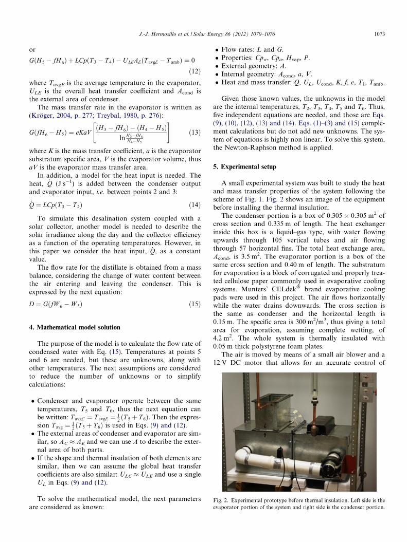
Fig. 2. Experimental prototype before thermal insulation. Left side is theevaporator portion of the system and right side is the condenser portion.
4. Mathematical model solution
The purpose of the model is to calculate the flow rate ofcondensed water with Eq. (15). Temperatures at points 5and 6 are needed, but these are unknowns, along withother temperatures. The next assumptions are consideredto reduce the number of unknowns or to simplifycalculations:
� Condenser and evaporator operate between the sametemperatures, T5 and T6, thus the next equation canbe written: T avgC ¼ T avgE ¼ 1
2ðT 5 þ T 6Þ. Then the expres-
sion T avg ¼ 12ðT 5 þ T 6Þ is used in Eqs. (9) and (12).
� The external areas of condenser and evaporator are sim-ilar, so AC � AE and we can use A to describe the exter-nal area of both parts.� If the shape and thermal insulation of both elements are
similar, then we can assume the global heat transfercoefficients are also similar: ULC � ULE and use a singleUL in Eqs. (9) and (12).
To solve the mathematical model, the next parametersare considered as known:
� Flow rates: L and G.� Properties: Cpw, Cpa, Hvap, P.� External geometry: A.� Internal geometry: Acond, a, V.� Heat and mass transfer: Q, UL, Ucond, K, f, e, T1, Tamb.
Given those known values, the unknowns in the modelare the internal temperatures, T2, T3, T4, T5 and T6. Thus,five independent equations are needed, and those are Eqs.(9), (10), (12), (13) and (14). Eqs. (1)–(3) and (15) comple-ment calculations but do not add new unknowns. The sys-tem of equations is highly non linear. To solve this system,the Newton-Raphson method is applied.
5. Experimental setup
A small experimental system was built to study the heatand mass transfer properties of the system following thescheme of Fig. 1. Fig. 2 shows an image of the equipmentbefore installing the thermal insulation.
The condenser portion is a box of 0.305 � 0.305 m2 ofcross section and 0.335 m of length. The heat exchangerinside this box is a liquid–gas type, with water flowingupwards through 105 vertical tubes and air flowingthrough 57 horizontal fins. The total heat exchange area,Acond, is 3.5 m2. The evaporator portion is a box of thesame cross section and 0.40 m of length. The substratumfor evaporation is a block of corrugated and properly trea-ted cellulose paper commonly used in evaporative coolingsystems. Munters’ CELdek� brand evaporative coolingpads were used in this project. The air flows horizontallywhile the water drains downwards. The cross section isthe same as condenser and the horizontal length is0.15 m. The specific area is 300 m2/m3, thus giving a totalarea for evaporation, assuming complete wetting, of4.2 m2. The whole system is thermally insulated with0.05 m thick polystyrene foam plates.
The air is moved by means of a small air blower and a12 V DC motor that allows for an accurate control of
0.0
0.2
0.4
0.6
0.8
1.0
1.2
1.4
1.6
1.8
0.0 0.2 0.4 0.6 0.8 1.0 1.2 1.4 1.6 1.8Measured Rate of Distillation, kg/h
Cal
cula
ted
Rat
e of
Dis
tilla
tion,
kg/
h
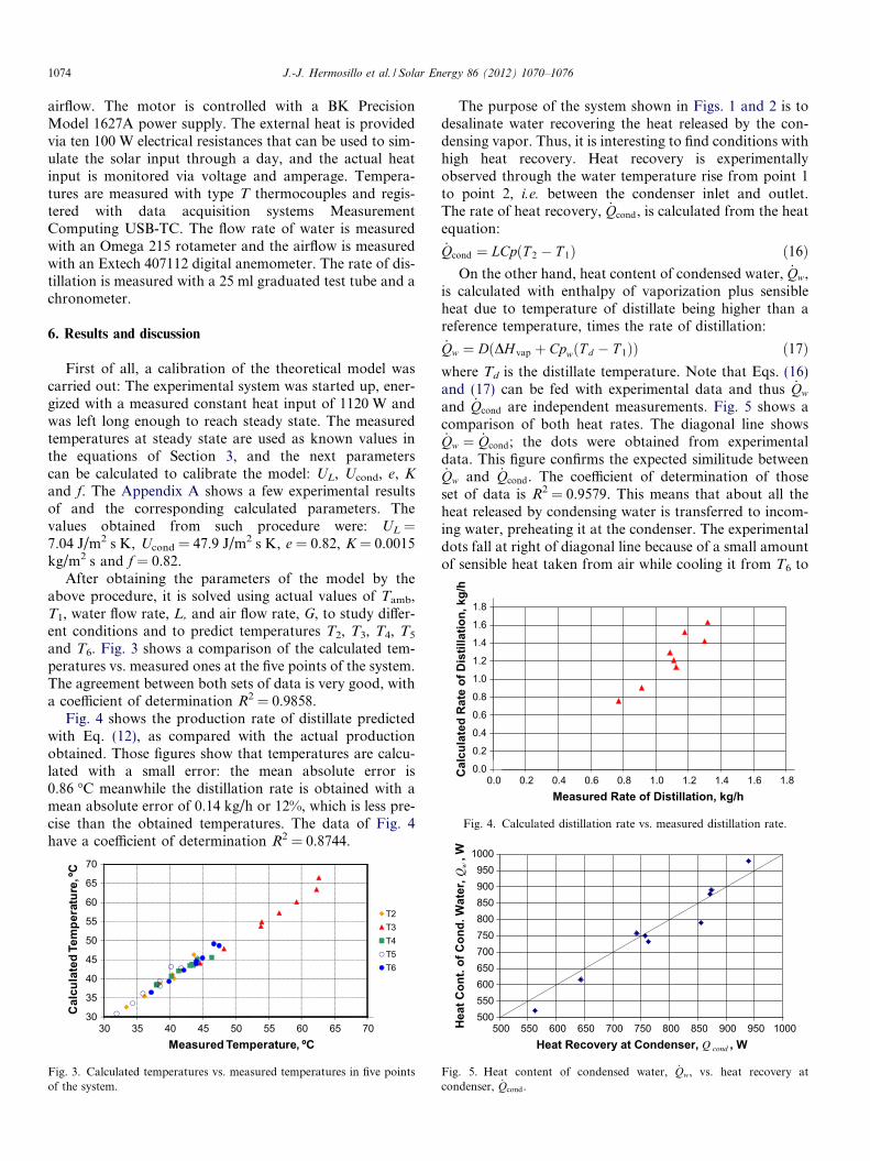
Fig. 4. Calculated distillation rate vs. measured distillation rate.
1074 J.-J. Hermosillo et al. / Solar Energy 86 (2012) 1070–1076
airflow. The motor is controlled with a BK PrecisionModel 1627A power supply. The external heat is providedvia ten 100 W electrical resistances that can be used to sim-ulate the solar input through a day, and the actual heatinput is monitored via voltage and amperage. Tempera-tures are measured with type T thermocouples and regis-tered with data acquisition systems MeasurementComputing USB-TC. The flow rate of water is measuredwith an Omega 215 rotameter and the airflow is measuredwith an Extech 407112 digital anemometer. The rate of dis-tillation is measured with a 25 ml graduated test tube and achronometer.
6. Results and discussion
First of all, a calibration of the theoretical model wascarried out: The experimental system was started up, ener-gized with a measured constant heat input of 1120 W andwas left long enough to reach steady state. The measuredtemperatures at steady state are used as known values inthe equations of Section 3, and the next parameterscan be calculated to calibrate the model: UL, Ucond, e, Kand f. The Appendix A shows a few experimental resultsof and the corresponding calculated parameters. Thevalues obtained from such procedure were: UL =7.04 J/m2 s K, Ucond = 47.9 J/m2 s K, e = 0.82, K = 0.0015kg/m2 s and f = 0.82.
After obtaining the parameters of the model by theabove procedure, it is solved using actual values of Tamb,T1, water flow rate, L, and air flow rate, G, to study differ-ent conditions and to predict temperatures T2, T3, T4, T5
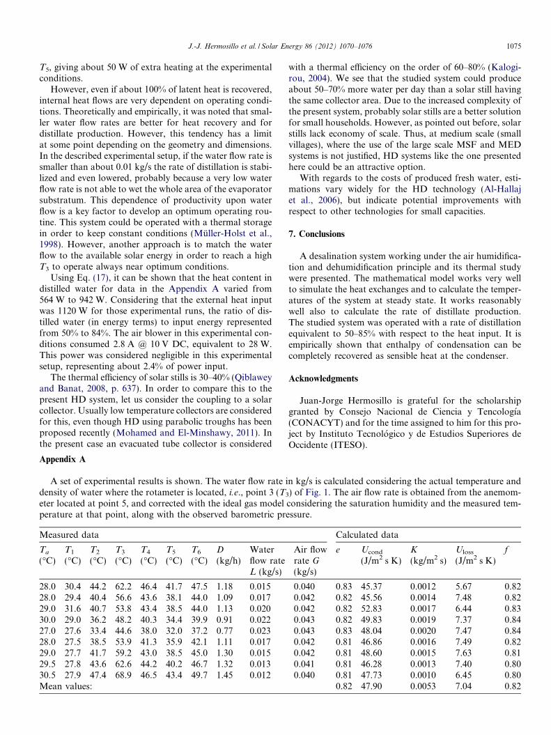
and T6. Fig. 3 shows a comparison of the calculated tem-peratures vs. measured ones at the five points of the system.The agreement between both sets of data is very good, witha coefficient of determination R2 = 0.9858.
Fig. 4 shows the production rate of distillate predictedwith Eq. (12), as compared with the actual productionobtained. Those figures show that temperatures are calcu-lated with a small error: the mean absolute error is0.86 �C meanwhile the distillation rate is obtained with amean absolute error of 0.14 kg/h or 12%, which is less pre-cise than the obtained temperatures. The data of Fig. 4have a coefficient of determination R2 = 0.8744.
30
35
40
45
50
55
60
65
70
30 35 40 45 50 55 60 65 70
Cal
cula
ted
Tem
pera
ture
, ºC
Measured Temperature, ºC
T2T3T4T5T6
Fig. 3. Calculated temperatures vs. measured temperatures in five pointsof the system.
The purpose of the system shown in Figs. 1 and 2 is todesalinate water recovering the heat released by the con-densing vapor. Thus, it is interesting to find conditions withhigh heat recovery. Heat recovery is experimentallyobserved through the water temperature rise from point 1to point 2, i.e. between the condenser inlet and outlet.The rate of heat recovery, _Qcond, is calculated from the heatequation:
_Qcond ¼ LCpðT 2 � T 1Þ ð16ÞOn the other hand, heat content of condensed water, _Qw,
is calculated with enthalpy of vaporization plus sensibleheat due to temperature of distillate being higher than areference temperature, times the rate of distillation:
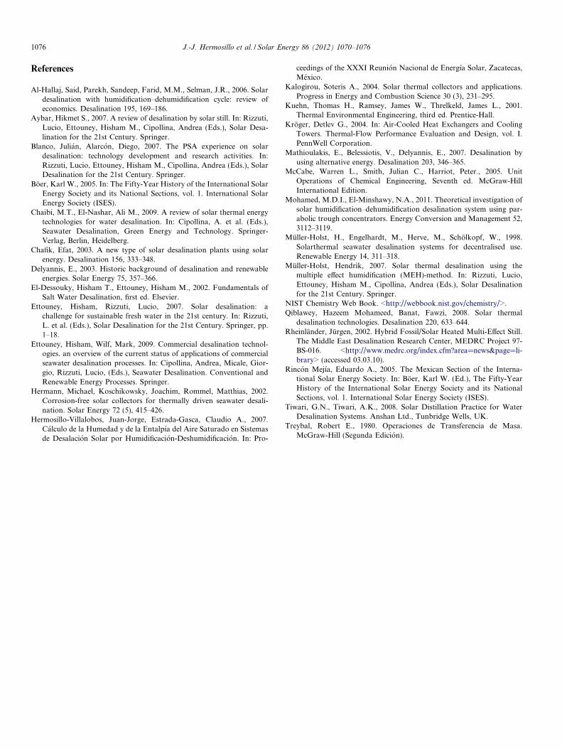
_Qw ¼ DðDH vap þ CpwðT d � T 1ÞÞ ð17Þwhere Td is the distillate temperature. Note that Eqs. (16)and (17) can be fed with experimental data and thus _Qw
and _Qcond are independent measurements. Fig. 5 shows acomparison of both heat rates. The diagonal line shows_Qw ¼ _Qcond; the dots were obtained from experimentaldata. This figure confirms the expected similitude between_Qw and _Qcond. The coefficient of determination of thoseset of data is R2 = 0.9579. This means that about all theheat released by condensing water is transferred to incom-ing water, preheating it at the condenser. The experimentaldots fall at right of diagonal line because of a small amountof sensible heat taken from air while cooling it from T6 to
5005506006507007508008509009501000
500 550 600 650 700 750 800 850 900 950 1000Heat Recovery at Condenser, Q cond , W
Hea
t Con
t. of
Con
d. W
ater
, Qw
, W
Fig. 5. Heat content of condensed water, _Qw, vs. heat recovery atcondenser, _Qcond.
J.-J. Hermosillo et al. / Solar Energy 86 (2012) 1070–1076 1075
T5, giving about 50 W of extra heating at the experimentalconditions.
However, even if about 100% of latent heat is recovered,internal heat flows are very dependent on operating condi-tions. Theoretically and empirically, it was noted that smal-ler water flow rates are better for heat recovery and fordistillate production. However, this tendency has a limitat some point depending on the geometry and dimensions.In the described experimental setup, if the water flow rate issmaller than about 0.01 kg/s the rate of distillation is stabi-lized and even lowered, probably because a very low waterflow rate is not able to wet the whole area of the evaporatorsubstratum. This dependence of productivity upon waterflow is a key factor to develop an optimum operating rou-tine. This system could be operated with a thermal storagein order to keep constant conditions (Muller-Holst et al.,1998). However, another approach is to match the waterflow to the available solar energy in order to reach a highT3 to operate always near optimum conditions.
Using Eq. (17), it can be shown that the heat content indistilled water for data in the Appendix A varied from564 W to 942 W. Considering that the external heat inputwas 1120 W for those experimental runs, the ratio of dis-tilled water (in energy terms) to input energy representedfrom 50% to 84%. The air blower in this experimental con-ditions consumed 2.8 A @ 10 V DC, equivalent to 28 W.This power was considered negligible in this experimentalsetup, representing about 2.4% of power input.
The thermal efficiency of solar stills is 30–40% (Qiblaweyand Banat, 2008, p. 637). In order to compare this to thepresent HD system, let us consider the coupling to a solarcollector. Usually low temperature collectors are consideredfor this, even though HD using parabolic troughs has beenproposed recently (Mohamed and El-Minshawy, 2011). Inthe present case an evacuated tube collector is considered
Appendix A
A set of experimental results is shown. The water flow rate idensity of water where the rotameter is located, i.e., point 3 (T3
eter located at point 5, and corrected with the ideal gas modelperature at that point, along with the observed barometric pre
Measured data
Ta
(�C)T1
(�C)T2
(�C)T3
(�C)T4
(�C)T5
(�C)T6
(�C)D
(kg/h)Waterflow rateL (kg/s)
28.0 30.4 44.2 62.2 46.4 41.7 47.5 1.18 0.01528.0 29.4 40.4 56.6 43.6 38.1 44.0 1.09 0.01729.0 31.6 40.7 53.8 43.4 38.5 44.0 1.13 0.02030.0 29.0 36.2 48.2 40.3 34.4 39.9 0.91 0.02227.0 27.6 33.4 44.6 38.0 32.0 37.2 0.77 0.02328.0 27.5 38.5 53.9 41.3 35.9 42.1 1.11 0.01729.0 27.7 41.7 59.2 43.0 38.5 45.0 1.30 0.01529.5 27.8 43.6 62.6 44.2 40.2 46.7 1.32 0.01330.5 27.9 47.4 68.9 46.5 43.4 49.7 1.45 0.012Mean values:
with a thermal efficiency on the order of 60–80% (Kalogi-rou, 2004). We see that the studied system could produceabout 50–70% more water per day than a solar still havingthe same collector area. Due to the increased complexity ofthe present system, probably solar stills are a better solutionfor small households. However, as pointed out before, solarstills lack economy of scale. Thus, at medium scale (smallvillages), where the use of the large scale MSF and MEDsystems is not justified, HD systems like the one presentedhere could be an attractive option.
With regards to the costs of produced fresh water, esti-mations vary widely for the HD technology (Al-Hallajet al., 2006), but indicate potential improvements withrespect to other technologies for small capacities.
7. Conclusions
A desalination system working under the air humidifica-tion and dehumidification principle and its thermal studywere presented. The mathematical model works very wellto simulate the heat exchanges and to calculate the temper-atures of the system at steady state. It works reasonablywell also to calculate the rate of distillate production.The studied system was operated with a rate of distillationequivalent to 50–85% with respect to the heat input. It isempirically shown that enthalpy of condensation can becompletely recovered as sensible heat at the condenser.
Acknowledgments
Juan-Jorge Hermosillo is grateful for the scholarshipgranted by Consejo Nacional de Ciencia y Tencologıa(CONACYT) and for the time assigned to him for this pro-ject by Instituto Tecnologico y de Estudios Superiores deOccidente (ITESO).
n kg/s is calculated considering the actual temperature and) of Fig. 1. The air flow rate is obtained from the anemom-considering the saturation humidity and the measured tem-ssure.
Calculated data
Air flowrate G(kg/s)
e Ucond
(J/m2 s K)K
(kg/m2 s)Uloss
(J/m2 s K)f
0.040 0.83 45.37 0.0012 5.67 0.820.042 0.82 45.56 0.0014 7.48 0.820.042 0.82 52.83 0.0017 6.44 0.830.043 0.82 49.83 0.0019 7.37 0.840.043 0.83 48.04 0.0020 7.47 0.840.042 0.81 46.86 0.0016 7.49 0.820.042 0.81 48.60 0.0015 7.63 0.810.041 0.81 46.28 0.0013 7.40 0.800.040 0.81 47.73 0.0010 6.45 0.80
0.82 47.90 0.0053 7.04 0.82
1076 J.-J. Hermosillo et al. / Solar Energy 86 (2012) 1070–1076
References
Al-Hallaj, Said, Parekh, Sandeep, Farid, M.M., Selman, J.R., 2006. Solardesalination with humidification–dehumidification cycle: review ofeconomics. Desalination 195, 169–186.
Aybar, Hikmet S., 2007. A review of desalination by solar still. In: Rizzuti,Lucio, Ettouney, Hisham M., Cipollina, Andrea (Eds.), Solar Desa-lination for the 21st Century. Springer.
Blanco, Julian, Alarcon, Diego, 2007. The PSA experience on solardesalination: technology development and research activities. In:Rizzuti, Lucio, Ettouney, Hisham M., Cipollina, Andrea (Eds.), SolarDesalination for the 21st Century. Springer.
Boer, Karl W., 2005. In: The Fifty-Year History of the International SolarEnergy Society and its National Sections, vol. 1. International SolarEnergy Society (ISES).
Chaibi, M.T., El-Nashar, Ali M., 2009. A review of solar thermal energytechnologies for water desalination. In: Cipollina, A. et al. (Eds.),Seawater Desalination, Green Energy and Technology. Springer-Verlag, Berlin, Heidelberg.
Chafik, Efat, 2003. A new type of solar desalination plants using solarenergy. Desalination 156, 333–348.
Delyannis, E., 2003. Historic background of desalination and renewableenergies. Solar Energy 75, 357–366.
El-Dessouky, Hisham T., Ettouney, Hisham M., 2002. Fundamentals ofSalt Water Desalination, first ed. Elsevier.
Ettouney, Hisham, Rizzuti, Lucio, 2007. Solar desalination: achallenge for sustainable fresh water in the 21st century. In: Rizzuti,L. et al. (Eds.), Solar Desalination for the 21st Century. Springer, pp.1–18.
Ettouney, Hisham, Wilf, Mark, 2009. Commercial desalination technol-ogies. an overview of the current status of applications of commercialseawater desalination processes. In: Cipollina, Andrea, Micale, Gior-gio, Rizzuti, Lucio, (Eds.), Seawater Desalination. Conventional andRenewable Energy Processes. Springer.
Hermann, Michael, Koschikowsky, Joachim, Rommel, Matthias, 2002.Corrosion-free solar collectors for thermally driven seawater desali-nation. Solar Energy 72 (5), 415–426.
Hermosillo-Villalobos, Juan-Jorge, Estrada-Gasca, Claudio A., 2007.Calculo de la Humedad y de la Entalpıa del Aire Saturado en Sistemasde Desalacion Solar por Humidificacion-Deshumidificacion. In: Pro-
ceedings of the XXXI Reunion Nacional de Energıa Solar, Zacatecas,Mexico.
Kalogirou, Soteris A., 2004. Solar thermal collectors and applications.Progress in Energy and Combustion Science 30 (3), 231–295.
Kuehn, Thomas H., Ramsey, James W., Threlkeld, James L., 2001.Thermal Environmental Engineering, third ed. Prentice-Hall.
Kroger, Detlev G., 2004. In: Air-Cooled Heat Exchangers and CoolingTowers. Thermal-Flow Performance Evaluation and Design, vol. I.PennWell Corporation.
Mathioulakis, E., Belessiotis, V., Delyannis, E., 2007. Desalination byusing alternative energy. Desalination 203, 346–365.
McCabe, Warren L., Smith, Julian C., Harriot, Peter., 2005. UnitOperations of Chemical Engineering, Seventh ed. McGraw-HillInternational Edition.
Mohamed, M.D.I., El-Minshawy, N.A., 2011. Theoretical investigation ofsolar humidification–dehumidification desalination system using par-abolic trough concentrators. Energy Conversion and Management 52,3112–3119.
Muller-Holst, H., Engelhardt, M., Herve, M., Scholkopf, W., 1998.Solarthermal seawater desalination systems for decentralised use.Renewable Energy 14, 311–318.
Muller-Holst, Hendrik, 2007. Solar thermal desalination using themultiple effect humidification (MEH)-method. In: Rizzuti, Lucio,Ettouney, Hisham M., Cipollina, Andrea (Eds.), Solar Desalinationfor the 21st Century. Springer.
NIST Chemistry Web Book. <http://webbook.nist.gov/chemistry/>.Qiblawey, Hazeem Mohameed, Banat, Fawzi, 2008. Solar thermal
desalination technologies. Desalination 220, 633–644.Rheinlander, Jurgen, 2002. Hybrid Fossil/Solar Heated Multi-Effect Still.
The Middle East Desalination Research Center, MEDRC Project 97-BS-016. <http://www.medrc.org/index.cfm?area=news&page=li-brary> (accessed 03.03.10).
Rincon Mejıa, Eduardo A., 2005. The Mexican Section of the Interna-tional Solar Energy Society. In: Boer, Karl W. (Ed.), The Fifty-YearHistory of the International Solar Energy Society and its NationalSections, vol. 1. International Solar Energy Society (ISES).
Tiwari, G.N., Tiwari, A.K., 2008. Solar Distillation Practice for WaterDesalination Systems. Anshan Ltd., Tunbridge Wells, UK.
Treybal, Robert E., 1980. Operaciones de Transferencia de Masa.McGraw-Hill (Segunda Edicion).