Thermal Design of Humidification Dehumidification Systems ...
Upload
khangminh22Category
view
0download
0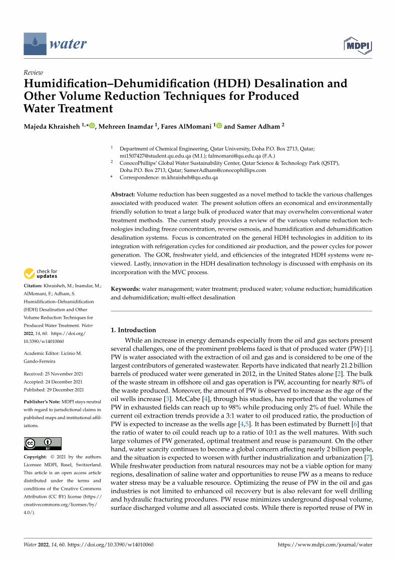
�����������������
Citation: Khraisheh, M.; Inamdar, M.;
AlMomani, F.; Adham, S.
Humidification–Dehumidification
(HDH) Desalination and Other
Volume Reduction Techniques for
Produced Water Treatment. Water
2022, 14, 60. https://doi.org/
10.3390/w14010060
Academic Editor: Licínio M.
Gando-Ferreira
Received: 25 November 2021
Accepted: 24 December 2021
Published: 29 December 2021
Publisher’s Note: MDPI stays neutral
with regard to jurisdictional claims in
published maps and institutional affil-
iations.
Copyright: © 2021 by the authors.
Licensee MDPI, Basel, Switzerland.
This article is an open access article
distributed under the terms and
conditions of the Creative Commons
Attribution (CC BY) license (https://
creativecommons.org/licenses/by/
4.0/).
water
Review
Humidification–Dehumidification (HDH) Desalination andOther Volume Reduction Techniques for ProducedWater TreatmentMajeda Khraisheh 1,* , Mehreen Inamdar 1, Fares AlMomani 1 and Samer Adham 2
1 Department of Chemical Engineering, Qatar University, Doha P.O. Box 2713, Qatar;[email protected] (M.I.); [email protected] (F.A.)
2 ConocoPhillips’ Global Water Sustainability Center, Qatar Science & Technology Park (QSTP),Doha P.O. Box 2713, Qatar; [email protected]
* Correspondence: [email protected]
Abstract: Volume reduction has been suggested as a novel method to tackle the various challengesassociated with produced water. The present solution offers an economical and environmentallyfriendly solution to treat a large bulk of produced water that may overwhelm conventional watertreatment methods. The current study provides a review of the various volume reduction tech-nologies including freeze concentration, reverse osmosis, and humidification and dehumidificationdesalination systems. Focus is concentrated on the general HDH technologies in addition to itsintegration with refrigeration cycles for conditioned air production, and the power cycles for powergeneration. The GOR, freshwater yield, and efficiencies of the integrated HDH systems were re-viewed. Lastly, innovation in the HDH desalination technology is discussed with emphasis on itsincorporation with the MVC process.
Keywords: water management; water treatment; produced water; volume reduction; humidificationand dehumidification; multi-effect desalination
1. Introduction
While an increase in energy demands especially from the oil and gas sectors presentseveral challenges, one of the prominent problems faced is that of produced water (PW) [1].PW is water associated with the extraction of oil and gas and is considered to be one of thelargest contributors of generated wastewater. Reports have indicated that nearly 21.2 billionbarrels of produced water were generated in 2012, in the United States alone [2]. The bulkof the waste stream in offshore oil and gas operation is PW, accounting for nearly 80% ofthe waste produced. Moreover, the amount of PW is observed to increase as the age of theoil wells increase [3]. McCabe [4], through his studies, has reported that the volumes ofPW in exhausted fields can reach up to 98% while producing only 2% of fuel. While thecurrent oil extraction trends provide a 3:1 water to oil produced ratio, the production ofPW is expected to increase as the wells age [4,5]. It has been estimated by Burnett [6] thatthe ratio of water to oil could reach up to a ratio of 10:1 as the well matures. With suchlarge volumes of PW generated, optimal treatment and reuse is paramount. On the otherhand, water scarcity continues to become a global concern affecting nearly 2 billion people,and the situation is expected to worsen with further industrialization and urbanization [7].While freshwater production from natural resources may not be a viable option for manyregions, desalination of saline water and opportunities to reuse PW as a means to reducewater stress may be a valuable resource. Optimizing the reuse of PW in the oil and gasindustries is not limited to enhanced oil recovery but is also relevant for well drillingand hydraulic fracturing procedures. PW reuse minimizes underground disposal volume,surface discharged volume and all associated costs. While there is reported reuse of PW in
Water 2022, 14, 60. https://doi.org/10.3390/w14010060 https://www.mdpi.com/journal/water
Water 2022, 14, 60 2 of 25
the oil and gas industries, PW can also be employed for livestock watering, irrigation, andstream augmentation; however, less than one percent of the generated PW is used for suchapplications. Promotion of the wider reuse of PW may be more applicable with furtherresearch and development of cost effective and ecofriendly technologies.
The present paper highlights the potential for desalination techniques to meet fresh-water requirements through various volume reduction techniques while placing emphasison the humidification–dehumidification (HDH) desalination system. The prime advan-tages offered by the HDH process lie in the simplicity of its design and low capital cost.In addition, the process is adequately flexible to be integrated with other technologies,requires low maintenance, utilizes low-grade energy, and can be applied in decentralizedareas [8]. The undeniable advantages provided by the HDH technology have promptedresearchers to further their existing knowledge on the system by integrating it with variousrefrigeration, power, and desalination cycles to increase productivity while optimizingenergy consumption.
2. Produced Water Treatment
With more than 21.2 billion barrels of PW being generated each year, it is essential totreat and reuse this water; however, what makes PW treatment and reuse challenging, apartfrom the large volume, is its complex and non-uniform mixture. The composition of PWcan vary in total dissolved solid concentration, organic content, and metal concentration de-pending on the place and position it was generated. The possible presence of heavy metalsfurther exacerbates treatment operations by causing corrosion of and scaling on equipment.Despite the obvious challenges, several studies each exploring the efficiency of repurposingPW have been conducted. Ahmadizadeh [1] conducted the studies on the efficiency ofhalophilic microorganisms and forward osmosis (FO) to reduce the volume of PW andpresent organic pollutants. They concluded that the FO process was capable of reducing thevolume of PW by 30% while a subsequent Osmosis Membrane Bio Reactor could extract66% of the organic matter. Visvanathan [9] suggested the use of reverse osmosis (RO)for the volume reduction of PW, provided that an appropriate pretreatment was selected.Adsorption as a treatment method was studied by Janks [10] using tailored zeolites. TheCrudersorb technology that employed a series of adsorption steps was reported to reduceoil and grease content to less than 29 ppm [11]. Although frequently applied for particleextraction from water samples, the prominent drawback of the adsorption methods is thefrequent regeneration of adsorbents and the waste generated. Adewumi [11] suggested theuse of sand filtering preceded by a set of pretreatments for the efficient removal of metalsfrom PW. While separators such as centrifuges and hydro-cyclones were industrially usedfor de-oiling PW, Van den Broek [12] hinted towards the low performance efficiency of thesystems, also commenting on the inability of the methods to extract hazardous components,thus requiring other post treatment options. Other physical PW treatment methods such asevaporation, C-TOUR, dissolved air precipitation (DAP), freeze concentration, and elec-trodialysis are available but are either patented designs or were inadequately researchedand applied.
Chemical treatment of PW in contrast to many physical treatment methods is lesstime-intensive and could be tailored for more efficient extraction of pollutants. Among theseveral materials available for chemical precipitation, FMA, a polynuclear polymer, displaysappreciative coagulation, and could de-oil PW with an efficiency greater than 92% [13].Studies conducted by Houcine [14] for the removal of heavy metals displayed a removalefficiency of more than 95% when lime was used. The method of chemical oxidationto reduce both the organic and inorganic compounds from PW through the applicationof oxidants and catalysts have been extensively used in several industries. Commonlyused oxidants such as H2O2, O3, K2FeO4, etc., are capable of reducing complex organicpollutants to smaller, more manageable forms. These oxidants fall under the category of anadvanced oxidation process [15], a technology that relies on the production of hydroxylradicals for the required oxidation. Despite the impressive effectiveness of the Fenton
Water 2022, 14, 60 3 of 25
chemical oxidation process, Ganiyu [16] and Zhang [17] remark that the precipitation ofthe iron ions severely impacts the efficiency of the process and produces undesired sludge.Hydrophobic ionic liquids, with their versality, were observed to display an affinity forextracting organic pollutants from water [18]; however, their application for commercialuse is restricted due to the limited technology required and lack of suitable post-treatmentoptions available.
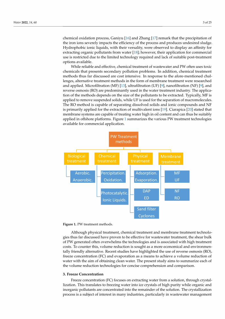
While reliable and effective, chemical treatment of wastewater and PW often uses toxicchemicals that presents secondary pollution problems. In addition, chemical treatmentmethods thus far discussed are cost intensive. In response to the afore-mentioned chal-lenges, alternative treatment methods in the form of membrane treatment were researchedand applied. Microfiltration (MF) [13], ultrafiltration (UF) [9], nanofiltration (NF) [9], andreverse osmosis (RO) are predominantly used in the water treatment industry. The applica-tion of the methods depends on the size of the pollutants to be extracted. Typically, MF isapplied to remove suspended solids, while UF is used for the separation of macromolecules.The RO method is capable of separating dissolved solids and ionic compounds and NFis primarily applied for the extraction of multivalent ions [19]. Ciarapica [20] stated thatmembrane systems are capable of treating water high in oil content and can thus be suitablyapplied in offshore platforms. Figure 1 summarizes the various PW treatment technologiesavailable for commercial application.
Water 2022, 14, x FOR PEER REVIEW 3 of 26
an advanced oxidation process [15], a technology that relies on the production of hydroxyl radicals for the required oxidation. Despite the impressive effectiveness of the Fenton chemical oxidation process, Ganiyu [16] and Zhang [17] remark that the precipitation of the iron ions severely impacts the efficiency of the process and produces undesired sludge. Hydrophobic ionic liquids, with their versality, were observed to display an affin-ity for extracting organic pollutants from water [18]; however, their application for com-mercial use is restricted due to the limited technology required and lack of suitable post-treatment options available.
While reliable and effective, chemical treatment of wastewater and PW often uses toxic chemicals that presents secondary pollution problems. In addition, chemical treat-ment methods thus far discussed are cost intensive. In response to the afore-mentioned challenges, alternative treatment methods in the form of membrane treatment were re-searched and applied. Microfiltration (MF) [13], ultrafiltration (UF) [9], nanofiltration (NF) [9], and reverse osmosis (RO) are predominantly used in the water treatment industry. The application of the methods depends on the size of the pollutants to be extracted. Typ-ically, MF is applied to remove suspended solids, while UF is used for the separation of macromolecules. The RO method is capable of separating dissolved solids and ionic com-pounds and NF is primarily applied for the extraction of multivalent ions [19]. Ciarapica [20] stated that membrane systems are capable of treating water high in oil content and can thus be suitably applied in offshore platforms. Figure 1 summarizes the various PW treatment technologies available for commercial application.
Figure 1. PW treatment methods.
Although physical treatment, chemical treatment and membrane treatment technol-ogies thus far discussed have proven to be effective for wastewater treatment, the shear bulk of PW generated often overwhelms the technologies and is associated with high treatment costs. To counter this, volume reduction is sought as a more economical and environmentally friendly alternative. Recent studies have highlighted the use of reverse osmosis (RO), freeze concentration (FC) and evaporation as a means to achieve a volume reduction of water with the aim of obtaining clean water. The present study aims to sum-marize each of the volume reduction technologies for concise comprehension and com-parison.
PW Treatment methods
Biological treatment
Aerobic. Anaerobic.
Chemical treatment
Percipitation.Oxidation.
Photocatalytic.Ionic Liquids.
Physical treatment
Adsorption.Evaporation.
DAPED
Sand filterCyclones
Membranetreatment
MFUF
NFRO
Figure 1. PW treatment methods.
Although physical treatment, chemical treatment and membrane treatment technolo-gies thus far discussed have proven to be effective for wastewater treatment, the shear bulkof PW generated often overwhelms the technologies and is associated with high treatmentcosts. To counter this, volume reduction is sought as a more economical and environmen-tally friendly alternative. Recent studies have highlighted the use of reverse osmosis (RO),freeze concentration (FC) and evaporation as a means to achieve a volume reduction ofwater with the aim of obtaining clean water. The present study aims to summarize each ofthe volume reduction technologies for concise comprehension and comparison.
3. Freeze Concentration
Freeze concentration (FC) focuses on extracting water from a solution, through crystal-lization. This translates to freezing water into ice crystals of high purity while organic andinorganic pollutants are concentrated into the remainder of the solution. The crystallizationprocess is a subject of interest in many industries, particularly in wastewater management
Water 2022, 14, 60 4 of 25
for its numerous advantages. The closed system is capable of handling solutions of varyingcompositions while preventing the loss of volatile compounds to the surrounding envi-ronment. The low temperatures of the process further prevent the corrosion of equipmentused [21]. The overall capital cost of the process is lowered as inexpensive materials forconstruction can be employed because of the low operating temperature of the system.More importantly, the process is highly energy efficient compared to thermal desalinationalternatives. This is attributed to the low latent heat of freezing as compared to the latentheat of evaporation [22].
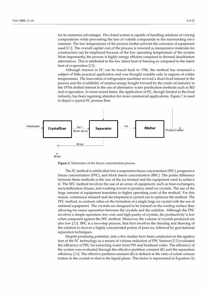
Although interest in FC can be traced back to 1786, the method has remained asubject of little practical application and was thought suitable only in regions of coldertemperatures. The innovation of refrigeration machines revived a short-lived interest in theprocess and the availability of surplus energy bought forward by the crude oil industry inthe 1970s shifted interest in the use of alternative water purification methods such as ROand evaporation. In more recent times, the application of FC, though limited to the foodindustry, has been regaining attention for more commercial applications. Figure 2 is usedto depict a typical FC process flow.
Water 2022, 14, x FOR PEER REVIEW 4 of 26
3. Freeze Concentration Freeze concentration (FC) focuses on extracting water from a solution, through crys-
tallization. This translates to freezing water into ice crystals of high purity while organic and inorganic pollutants are concentrated into the remainder of the solution. The crystal-lization process is a subject of interest in many industries, particularly in wastewater man-agement for its numerous advantages. The closed system is capable of handling solutions of varying compositions while preventing the loss of volatile compounds to the surround-ing environment. The low temperatures of the process further prevent the corrosion of equipment used [21]. The overall capital cost of the process is lowered as inexpensive ma-terials for construction can be employed because of the low operating temperature of the system. More importantly, the process is highly energy efficient compared to thermal de-salination alternatives. This is attributed to the low latent heat of freezing as compared to the latent heat of evaporation [22].
Although interest in FC can be traced back to 1786, the method has remained a subject of little practical application and was thought suitable only in regions of colder tempera-tures. The innovation of refrigeration machines revived a short-lived interest in the pro-cess. and the availability of surplus energy bought forward by the crude oil industry in the 1970s shifted interest in the use of alternative water purification methods such as RO and evaporation. In more recent times, the application of FC, though limited to the food industry, has been regaining attention for more commercial applications. Figure 2 is used to depict a typical FC process flow.
Figure 2. Schematics of the freeze concentration process.
The FC method is subdivided into a suspension freeze concentration (SFC), progres-sive freeze concentration (PFC), and block freeze concentration (BFC). The prime differ-ence between these methods is the size of the ice formed and the equipment used to achieve it. The SFC method involves the use of an array of equipment, such as heat ex-changers, recrystallization drums, and washing towers to produce small ice crystals. The use of the large amount of equipment translates to higher operating costs of the method. For this reason, continuous research and development is carried out to optimize the method. The PFC method, in contrast, relies on the formation of a single large ice crystal with the use of minimal equipment. The crystals are designed to be formed on the cooling surface thus allowing for easier separation between the crystals and the solution. Alt-hough the PFC involves a simple operation, low cost, and high purity of crystals, the productivity is low when compared against the SFC method. Moreover, the volume of crystals produced are also low [23]. BFC is a two-step process, that first involves the freez-ing and thawing of the solution to recover a highly concentrated potion of pure ice, fol-lowed by gravitational separation techniques.
Despite promising potential, only a few studies have been conducted on the applica-tion of the FC technology as a means of volume reduction of PW. Samsuri [21] evaluated
Figure 2. Schematics of the freeze concentration process.
The FC method is subdivided into a suspension freeze concentration (SFC), progressivefreeze concentration (PFC), and block freeze concentration (BFC). The prime differencebetween these methods is the size of the ice formed and the equipment used to achieveit. The SFC method involves the use of an array of equipment, such as heat exchangers,recrystallization drums, and washing towers to produce small ice crystals. The use of thelarge amount of equipment translates to higher operating costs of the method. For thisreason, continuous research and development is carried out to optimize the method. ThePFC method, in contrast, relies on the formation of a single large ice crystal with the use ofminimal equipment. The crystals are designed to be formed on the cooling surface thusallowing for easier separation between the crystals and the solution. Although the PFCinvolves a simple operation, low cost, and high purity of crystals, the productivity is lowwhen compared against the SFC method. Moreover, the volume of crystals produced arealso low [23]. BFC is a two-step process, that first involves the freezing and thawing ofthe solution to recover a highly concentrated potion of pure ice, followed by gravitationalseparation techniques.
Despite promising potential, only a few studies have been conducted on the applica-tion of the FC technology as a means of volume reduction of PW. Samsuri [21] evaluatedthe efficiency of PFC for extracting water from PW and biodiesel water. The efficiency ofthe system was evaluated through the effective partition constant (K) and the separationefficiency [24]. The effective partition constant (K) is defined as the ratio of solute concen-tration in the crystals to that in the liquid phase. This factor is represented in Equation (1).
Water 2022, 14, 60 5 of 25
The separation efficiency [24] can be used equally well to define the system efficiency andis defined is Equation (2).
K =CS
CL(1)
where CS represents the solute concentration in the crystals. CL is the solute concentrationin the liquid solution.
SE =CO − CS
CO∗ 100% (2)
where CO is the initial concentration of the solution. Higher values of SE translate to higherefficiency of the system while lower K values indicate improved efficiency.
While testing the effect of stirring on the water removal efficiency of the PFC process,it was observed that the K constant decreased as the stirring rate was increased. Theyconcluded that the rate of stirring decreases the advance rate in the ice front [21]. Thevigorous movement of the solution bought forward by stirring will cause a decline in aslower solidification rate, thereby resulting in lower amounts of solutes concentrated inice. Verifiable results were obtained by Halde [25] who further explained that aggressivestirring prevents solute build-up at the interface; however, care should be taken as excessivestirring can erode the ice crystals formed.
The dependency of the PFC method on the temperature was then evaluated. Theobserved trend was non-linear with the highest efficiency achieved at intermediate tem-peratures of 16–18 ◦C. It was justified that at such a suitable temperature, the theoreticalvelocity of mass diffusion supersedes the speed of heat removal, thus allowing for thediffusion of the solutes and escape from the freezing point [25].
Latent heat is released into the coolant and solution as the crystals proceed to grow.Therefore, lower coolant temperatures are justified to maintain a constant solution tem-perature; however, too low a coolant temperature can yield unsatisfactory results. Thisis because at such low temperatures the structure of ice is fragile and dendritic, therebytrapping solute particles in it.
Williams [26] studied the application of FC for desalination and reviewed the fourcategories of the freezing process generally applied in industries. This includes directcontract freezing, vacuum freezing and indirect contact freezing.
In direct contact freezing, a liquid hydrocarbon immiscible with water is used asthe refrigerant and bought into direct contact with seawater. Initially the refrigerant isunder high pressure. Upon expansion, the refrigerant evaporates, cooling the seawaterand forming ice. The hydrocarbon vapors are then compressed and recycled to the processwhile its heat is used to melt the obtained ice. This method provides the benefits of ahigh production rate per unit volume and low power consumption; however, since therefrigerant used is in contact with the water, there is a high possibility of retention of thehydrocarbon in the ice. Thus, further treatment is called for to make the water potable.
In the vacuum freezing method simultaneous evaporation and freezing occurs. Therefrigeration effect is bought forward by water which is vaporized by the high vacuum em-ployed. This causes the brine temperature to significantly drop and form ice. Theoretically,it is estimated that 1 kg of water evaporated could yield 7 kg of ice. This was based on thecalculation that the latent heat of vaporization is seven times greater than the latent heat offreezing [22]. Therefore, the system is associated with high production efficiency. By elimi-nating the use of other chemical refrigerants, contamination and separation problems areaverted, but the application of the method is severely hindered by the complex compressordesign required to process the large specific volume of water vapor [26].
To counter this Lu [27] suggested the hybridization of vacuum freezing. They recom-mended the vacuum-freezing vapor adsorption (VFVA) system and the vacuum-freezinghigh-pressure ice melting (VFHPIM) process. The VFVA involves the adsorption of watervapors followed by its reclamation from the adsorbent. By replacing the compressor withan adsorption system, energy is supplied to the system by the latent heat of steam in theabsorbent generator [27]. In contrast, the VFHPIM method employs neither a compressor
Water 2022, 14, 60 6 of 25
nor an absorbing solution for the low-pressure water vapor. These processes are efficientand cost competitive alternatives to conventional desalination processes.
In the indirect contact freezing process, as the name suggests, the refrigerant is keptaway from seawater in a conventional vapor compression refrigeration cycle. This cyclefirst absorbs heat from the seawater and then transfers it to the melting unit where icecrystals are present. In a sense, the freezer chamber and the melting unit represent theevaporator and the condenser of the refrigeration cycle, respectively, thereby optimizingthe process to a degree. Despite this, further optimization of the compressor is required.This is to ensure that the refrigerant temperature is well below that required by the freezingchamber and higher than that of the melting chamber [26]. Although straightforward in itsoperation, indirect contact freezing is associated with high energy consumption. Weiss [28]explains this is primarily due to the resistance to heat transfer between the refrigerant andseawater. Rahman [29] further elaborated that large metallic heat transfer surfaces wouldbe required for efficient operation of the freezing chamber and the melting unit. Thus, morecomplex equipment design is required and at a higher capital cost. The drawbacks of themethod far outweigh the benefits provided by it rendering the process infeasible for largescale commercial application.
Several papers have been dedicated to highlighting the advantages offered by freezeconcentration in various commercial fields, primarily for desalination and water treatment.While the FC process has lower energy consumption as compared to other desalinationprocesses and prevents the problems associated with equipment corrosion, its commercialapplication is limited. Rahman [30] explains that the large separation energy costs for thedevelopment of FC technology presents severe challenges to its industrial application. Toovercome this, further energy and economic analysis of the method should be conductedwhile also considering integration of the process with existing commercial processes.
4. Reverse Osmosis
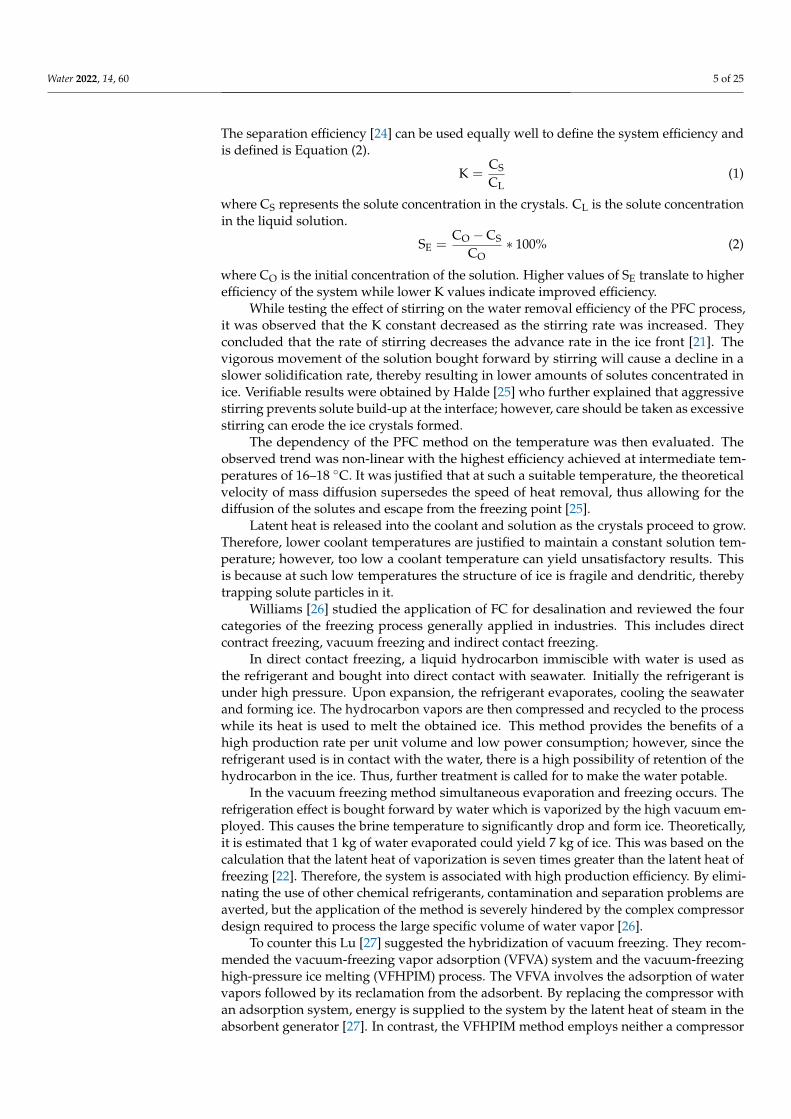
PW is a source of many organic and inorganic pollutants, metals, and other contami-nants; however, the major source of contaminants is the TDS. The presence of large amountsof TDS has promoted the use of reverse osmosis (RO) for PW treatment as a novel volumereduction technique. Visvanathan [9] claims that although RO is sensitive to fouling dueto the presence of organic matter, the use of appropriate pre-treatment methods can helpovercome the problem. Tao [31] suggested increasing the pH of PW before treating in theRO unit to prevent fouling. By controlling the pH of the solution, the solubility of oil can beincreased thus reducing RO membrane fouling; however, care must be taken, as increasingthe pH to higher levels may lead to membrane scaling. Despite the obvious drawbacks, ROtechnology has been used for water treatment at an industrial scale because of its lowercarbon footprint and energy cost. Furthermore, RO does not require the use of chemicalsand, therefore, post treatment methods if required are simplified. Figure 3 describes thesimple schematics of a RO process.
Water 2022, 14, x FOR PEER REVIEW 7 of 26
Figure 3. Reverse Osmosis process flow.
Visvanathan [9] conducted studies of several pre-treatment methods on a pilot-scale plant to select the technique most suitable for the RO process. Among the selected pre-treatment methods were microfiltration [13], ultrafiltration [9], and nanofiltration [9]. Multimedia gravity filtration was used prior to all pre-treatment methods to remove larger pollutants that could impede the process.
The experimental runs for the microfiltration employed 20 µm and 1 µm filter bags. A significant decline in RO flux was observed soon after operation. Moreover, microfil-tration was unable to remove oil contents completely from the feed water. Membrane au-topsies indicated irreversible fouling of the membranes used. In response to the failure of microfiltration as a pre-treatment method, the potential of ultrafiltration was tested. Two types of membranes were tested: a hollow fiber UF membrane and a spiral wound UF membrane. While the spiral wound membrane provided oil rejection of up to 85%, and the hollow fiber membrane rejected oil content up to 40%, there was a noticeable RO flux decline in both cases [32]. Irreversible membrane fouling occurred for both membrane types used after a few days of operation. It was concluded that fouling of the membranes was not only attributed to the presence of oil molecules but also other organic matter pre-sent in the water. Although the UF membrane performed better than the MF membranes, it was unable to extract low-molecular weight organic matter. Therefore, the performance of nanofiltration was tested for further comparison. Among the many NF membranes tested, polypiperazine-based membranes performed well especially with regards to foul-ing. The NF 45 membrane was also reported to be adequately resistant to fouling. Fur-thermore, the fouling was reversible in nature. Thus, Visvanathan [9] recommend RO treatment paired with NF and gravitational filtration as a pre-treatment for the volume reduction of PW. Their suggestion was further verified by the positive results obtained from the pilot-scale NF + RO plant treating PW. It was reported that the system could process irregularities in PW composition without any significant impact on the filtration efficiency and only periodic cleaning of the membrane was required.
Mondal [33] investigated the use of polymeric membrane nanofiltration and low-pressure, RO thin film composite (TFC) membranes for PW treatment. Among the differ-ent types of membranes tested, the NF 270 membrane provided the least reduction in flux, while the BW 30 membrane yielded the highest purity of permeate. It was concluded that for practical applications, the choice of membrane largely impacts the water quality, and that membrane filtration can be optimized to become a feasible PW treatment method.
McGinnis [34] and Chen [35] proposed the use of forward osmosis 1 as a means of volume reduction. They claimed that since PW is often characterized by high salinity it can thus be used as a draw solution (DS). Moreover, employing FO for PW treatment can offer high water recovery and reversibility in fouling. McGovern [36] counters the claim by highlighting the high energy consumption required for the regeneration of diluted draw solution post the FO process. Several studies have since then been dedicated to min-imizing the drawbacks of the FO process while optimizing the advantages offered by it. The most noticeable suggestion was the combination of two driving forces to attain high water recovery and energy efficiency [37,38]. This operating process was named osmotic assisted reverse osmosis (OARO) or osmotically enhanced dewatering [39] wherein the
Figure 3. Reverse Osmosis process flow.
Visvanathan [9] conducted studies of several pre-treatment methods on a pilot-scaleplant to select the technique most suitable for the RO process. Among the selected pre-treatment methods were microfiltration [13], ultrafiltration [9], and nanofiltration [9]. Mul-
Water 2022, 14, 60 7 of 25
timedia gravity filtration was used prior to all pre-treatment methods to remove largerpollutants that could impede the process.
The experimental runs for the microfiltration employed 20 µm and 1 µm filter bags. Asignificant decline in RO flux was observed soon after operation. Moreover, microfiltrationwas unable to remove oil contents completely from the feed water. Membrane autopsiesindicated irreversible fouling of the membranes used. In response to the failure of microfil-tration as a pre-treatment method, the potential of ultrafiltration was tested. Two types ofmembranes were tested: a hollow fiber UF membrane and a spiral wound UF membrane.While the spiral wound membrane provided oil rejection of up to 85%, and the hollowfiber membrane rejected oil content up to 40%, there was a noticeable RO flux decline inboth cases [32]. Irreversible membrane fouling occurred for both membrane types usedafter a few days of operation. It was concluded that fouling of the membranes was notonly attributed to the presence of oil molecules but also other organic matter present inthe water. Although the UF membrane performed better than the MF membranes, it wasunable to extract low-molecular weight organic matter. Therefore, the performance ofnanofiltration was tested for further comparison. Among the many NF membranes tested,polypiperazine-based membranes performed well especially with regards to fouling. TheNF 45 membrane was also reported to be adequately resistant to fouling. Furthermore, thefouling was reversible in nature. Thus, Visvanathan [9] recommend RO treatment pairedwith NF and gravitational filtration as a pre-treatment for the volume reduction of PW.Their suggestion was further verified by the positive results obtained from the pilot-scaleNF + RO plant treating PW. It was reported that the system could process irregularitiesin PW composition without any significant impact on the filtration efficiency and onlyperiodic cleaning of the membrane was required.
Mondal [33] investigated the use of polymeric membrane nanofiltration and low-pressure, RO thin film composite (TFC) membranes for PW treatment. Among the differenttypes of membranes tested, the NF 270 membrane provided the least reduction in flux,while the BW 30 membrane yielded the highest purity of permeate. It was concluded thatfor practical applications, the choice of membrane largely impacts the water quality, andthat membrane filtration can be optimized to become a feasible PW treatment method.
McGinnis [34] and Chen [35] proposed the use of forward osmosis [1] as a meansof volume reduction. They claimed that since PW is often characterized by high salinityit can thus be used as a draw solution (DS). Moreover, employing FO for PW treatmentcan offer high water recovery and reversibility in fouling. McGovern [36] counters theclaim by highlighting the high energy consumption required for the regeneration of diluteddraw solution post the FO process. Several studies have since then been dedicated tominimizing the drawbacks of the FO process while optimizing the advantages offered by it.The most noticeable suggestion was the combination of two driving forces to attain highwater recovery and energy efficiency [37,38]. This operating process was named osmoticassisted reverse osmosis (OARO) or osmotically enhanced dewatering [39] wherein theDS of a lower concentration than the feed solution [13] is used to replace a part of thehydraulic pressure as osmotic pressure [39]. Thus, OED can operate at hydraulic pressureslower than that required by a RO system resulting in increased energy efficiency and waterrecovery. Through their investigation on the effectiveness on OED on shale gas PW, Kim [38]concluded that the OED process offers improved water recovery, lower concentration of thediluted solution and greater reduction on the membrane area requirements as compared tothe FO system. They attribute the effectiveness of the OED to the enhanced water transportthrough the membrane without the impact of the internal concentration polarization seenin the FO process. Lastly, the OED process displayed satisfactory rejection of most ions withfeed water recovery reaching up to 67%. This indicated the potential of the OED processfor PW treatment; however, further economic evaluation and development of suitablemembranes are suggested.
Recent studies have seen the application of membranes for air humidification as wellas humidification–dehumidification desalination. Several membranes have been evaluated
Water 2022, 14, 60 8 of 25
for their application. In their studies, Zhang et al. [40] showed that hollow fiber membranesoffered significant advantages for air humidification over other conventional technologies.This was especially true when the mentioned membranes were coupled with counterflow heat and mass transfer. In membrane-based air humidification processes, moisturedroplets are prevented from mixing with air while the membranes effectively allow forwater to pass through them. A similar study conducted by Li et al. [41] tested hollowfiber membranes for humidification–dehumidification desalination. They studied the effectof membrane thickness, heat conductivity, membrane area and moisture diffusivity onthe performance of the membranes and validated it against experimental data. It wasconcluded that moisture diffusivity and membrane area were the prime parameters thateffected performance. Zhang et al. [42] conducted studies on composite hydrophobizedmembranes on polyvinylidene supports. The developed membranes displayed exceptionalantifouling properties without compromising the permeability. While currently limited,studies are available for membrane application for air humidification and interest in thefield is significantly growing.
5. Humidification and Dehumidification Desalination
Humidification–dehumidification desalination (HDH) is described as a novel volumereduction method that employs a carrier gas for the thermal desalination of water. Currentlyused for small scale desalination, the advantages provided by the HDH method are toogreat to be ignored. The benefits of the process include the use of low-grade energy andsimple design and construction.
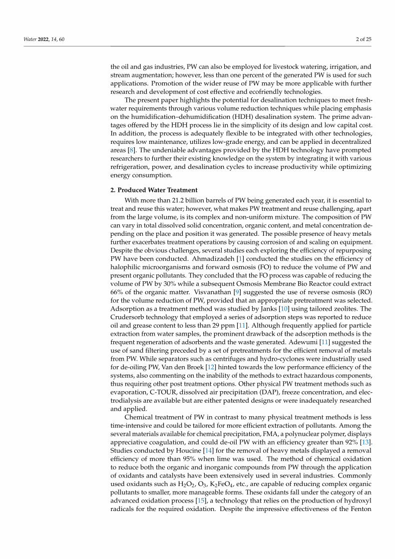
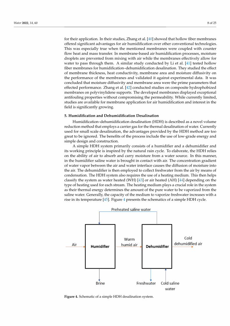
A simple HDH system primarily consists of a humidifier and a dehumidifier andits working principle is inspired by the natural rain cycle. To elaborate, the HDH relieson the ability of air to absorb and carry moisture from a water source. In this manner,in the humidifier saline water is brought in contact with air. The concentration gradientof water vapor between the air and water interface causes the diffusion of moisture intothe air. The dehumidifier is then employed to collect freshwater from the air by means ofcondensation. The HDH system also requires the use of a heating medium. This then helpsclassify the system as water heated (WH) [43] or air heated (AH) [44] depending on thetype of heating used for each stream. The heating medium plays a crucial role in the systemas their thermal energy determines the amount of the pure water to be vaporized from thesaline water. Generally, the capacity of the medium to vaporize freshwater increases with arise in its temperature [45]. Figure 4 presents the schematics of a simple HDH cycle.
Water 2022, 14, x FOR PEER REVIEW 9 of 26
Figure 4. Schematic of a simple HDH desalination system.
Kabeel [44] suggested the use of saline water as the cooling medium in the dehumid-ifier. Doing so aided in the recovery of the latent heat from the warm humid air, and so helped pre-heat the saline water to be fed to the HDH system. Despite the simple design of the process, several studies have been dedicated to providing variation in the compo-nents with the aim of further optimizing the process. El-Dessouky [46] suggested the use of waste heat from a gas turbine power plant for the HDH system while Al-Hallaj [47] studied the performance of a solar desalination unit using the HDH system.
While the performance of the HDH cycle can be represented in terms of yield, and cost of freshwater, the most common index of performance is the GOR. The gained output ratio (GOR) is defined as the ratio of the total latent heat of evaporation of freshwater produced to the energy provided to the HDH system. The GOR is calculated using the following equation: GOR = m . hQ (3)
where, m refers to the flowrate of freshwater produced, h is the latent heat of evaporation of freshwater, and Q is the energy input to the HDH process.
Higher GOR values indicate better performance of the HDH system. Studies were also dedicated to analyzing the HDH configurations for maximum ef-
ficiency and productivity. The three main configurations of the HDH are, namely, the closed-air open-water (CAOW) cycle, the open-air open-water (OAOW) cycle, and the open-air closed-water (OACW) cycle.
Narayan [48] and Mistry [49] aimed to discuss methods for the optimization of the HDH process by investigating its thermodyanmic behaviour using the first and second law of thermodynamics. Their studies, however, were limited to the optimization of the process to a single parameter. On the contrary, Mistry [50] claimed that HDH cycles are functions of various parameters, therefore more methodical optimzation calculations are required.
In their paper, Mistry [50] aimed to determine the operating conditions and configu-ration best suited to provide optimal results in terms of the GOR. They claimed that when using the WH cycles, OAOW configuration exhibited better performance when compared
Figure 4. Schematic of a simple HDH desalination system.
Water 2022, 14, 60 9 of 25
Kabeel [44] suggested the use of saline water as the cooling medium in the dehumid-ifier. Doing so aided in the recovery of the latent heat from the warm humid air, and sohelped pre-heat the saline water to be fed to the HDH system. Despite the simple design ofthe process, several studies have been dedicated to providing variation in the componentswith the aim of further optimizing the process. El-Dessouky [46] suggested the use of wasteheat from a gas turbine power plant for the HDH system while Al-Hallaj [47] studied theperformance of a solar desalination unit using the HDH system.
While the performance of the HDH cycle can be represented in terms of yield, andcost of freshwater, the most common index of performance is the GOR. The gained outputratio (GOR) is defined as the ratio of the total latent heat of evaporation of freshwaterproduced to the energy provided to the HDH system. The GOR is calculated using thefollowing equation:
GOR =mfreshwater.hfg
Qin(3)
where, mfreshwater refers to the flowrate of freshwater produced, hfg is the latent heat ofevaporation of freshwater, and Qin is the energy input to the HDH process.
Higher GOR values indicate better performance of the HDH system.Studies were also dedicated to analyzing the HDH configurations for maximum
efficiency and productivity. The three main configurations of the HDH are, namely, theclosed-air open-water (CAOW) cycle, the open-air open-water (OAOW) cycle, and theopen-air closed-water (OACW) cycle.
Narayan [48] and Mistry [49] aimed to discuss methods for the optimization of theHDH process by investigating its thermodyanmic behaviour using the first and second lawof thermodynamics. Their studies, however, were limited to the optimization of the processto a single parameter. On the contrary, Mistry [50] claimed that HDH cycles are functionsof various parameters, therefore more methodical optimzation calculations are required.
In their paper, Mistry [50] aimed to determine the operating conditions and configura-tion best suited to provide optimal results in terms of the GOR. They claimed that whenusing the WH cycles, OAOW configuration exhibited better performance when comparedto the CAOW configurations, regardless of the relative humidity. In a similar fashion,within the AH cycles, CAOW configuration yielded better results than OAOW cycles withthe exception of a condition of 100% relative humidity. While it was observed that both theWH and AH cycles provided comparable GOR, the AH cycles often required the use oflarger humidifiers and dehumidifiers than the WH cycles [51].
Several studies then integrated the HDH desalination process with other conventionalmethods with the aim of achieving a higher GOR value and therefore an improved perfor-mance of the system. Narayan [48] reported a GOR of greater than five for a multistageHDH system paired with thermal vapor compression (VC) cycles. Narayan [52] proposedincreasing the efficiency of the HDH system through integration with a RO unit. Theyreported that the combination could yield a GOR of up to 20, which is significantly higherthan that obtained by conventional HDH systems. The effect of pressure on the GOR wasinvestigated by Siddiqui [53]. It was reported that a maximum GOR of 8.2 was achievedwhen the humidifier was operated at a pressure of 50 kPa.
Heat pumps as a source of energy to be used in desalination systems has been garner-ing great attention over the recent years. The use of a solar assisted heat pump was studiedby Hawlader [54] using a single effect evaporation desalination unit. Studies conductedby Gude and Nirmalakhandan [55] combined solar assisted air conditioning systems withdesalination. The effectiveness of the adopted system yielded results in close competitionto the multi-stage flash distillation (MSF) process with a desalination efficiency of 80–90%.
Lawal [56] presented two layouts of HDH with heat pumps aiming to improve theperformance and the GOR of the HDH system. Through their experiments, the influence ofthe mass flowrate ratio (MR) on the GOR of the system was observed. It was noted thatincreasing the MR coincided with an increase in GOR until an optimum value before adecrease in the GOR with an increasing MR. They explain that high values of MR may
Water 2022, 14, 60 10 of 25
cause flooding in the HDH system with insufficient air supply in the humidifier. Thereforeresulting in a decreased GOR. The peak value of the GOR is attained when the humidifierhas an optimum flowrate of air and feedwater providing adequate water evaporation andthus higher productivity.
5.1. HDH Design Optimization
Further attempts to optimize the HDH process involved investigation on the typesof humidifiers and dehumidifiers available. The knowlegde that the humidity of the airentering the humidifier contributes to the performance of the unit prompted reseachers tooptimize the parameter through a variation in design. Kassim [57] performed a numericalanalysis of parallel plate channel humidifiers. They claimed the optimal performancewas recorded at a low inlet air humidity. Packed bed, spray towers, and bubble towerscould also be used as humidifiers; however, it was found that packed bed humidifiersenhanced the effectiveness of the system while direct contact dehumidifiers out-performedconventional dehumidifers [58]. The use of solar film humidifiers presented by Saidiet al. [59] provided mass and thermal yields of above 80%.
It was reported that dehumidifiers played a more crucial role in the production offreshwater as compared to humidifiers [60]. This prompted reseachers to investigatevarious types of heat exchangers to be used as a dehumidifer with an emphasis on thematerials and heat transfer surface to be used. Muller-Holst [61] investigated the use of flatplate heat exchangers while El-Agouz [62] proposed the use of a finned tube heat exchanger.The flat plate and the finned tube heat exchangers are also the most commonly used indehumidification processes; however, a copper coiled tube condenser tower has been inconsistent use as a condenser. The theoretical and experimanetal working of this condensercan be found in the works reported by Amer [63]. Research on the effectiveness of abubble column dehumidifier was carried out by Tow [64]. Among the various observationsreported by them, it was claimed that the effectiveness of the process decreased as theair flowrate and moist air temperature increased. Moreover, the use of smaller coils wasassociated with an increased parallel flow effectiveness. The use of a packed bed columnand spray towers as dehumidifiers was suggested as it promoted direct contact betweenhumid air and the cooling medium. This allowed for a greater thermal energy transfer withminimized resistance. In addition, direct contact dehumidifiers offer a higher specific areaof interface between the two mediums, thus minimizing the loss of humid air pressure.Eslamimanesh [65] theoretically modelled a HDH system to investigate the influence ofoperating parameters on the performance of the system. It was reported that an increasein the inlet airflowrate and recycled water flowrate led to an increase in freshwater yield.Increasing the temperature of the inlet air to the humidifier or decreasing the water inlettemperature of the dehumidifier helped achieve increased water productivity. On thecontrary, raising the flowrate ratio of water to air in the humidifier was not suggested as itled to a drop in the system’s productivity.
5.2. Humidification–Dehumidification (HDH) Desalination Hybridization
This section reviews studies conducted on the integration of the HDH desalinationsystem with other processes to improve performance, efficiency, and yield of the over-all process.
5.2.1. HDH and Refrigeration Cycles
Despite the undeniable advantages of the HDH system, evidently the process canbe greatly optimized through a combination of the system with different technologies.Nada [66] proposed the hybridization of the HDH desalination system with air conditioningto simultaneously produce freshwater and attain thermal comfort within the conditionedspace. The working prinicple behind this proposal was employing vapor compressionrefrigeration cycles (VCR). In their studies, Nada [66] coupled the HDH system with theVCR cycles to investigate the efficiency of using the VCR evaporator as a HDH system
Water 2022, 14, 60 11 of 25
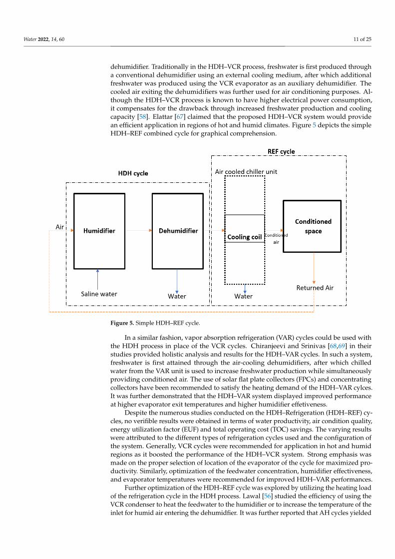
dehumidifier. Traditionally in the HDH–VCR process, freshwater is first produced througha conventional dehumidifier using an external cooling medium, after which additionalfreshwater was produced using the VCR evaporator as an auxiliary dehumidifier. Thecooled air exiting the dehumidifiers was further used for air conditioning purposes. Al-though the HDH–VCR process is known to have higher electrical power consumption,it compensates for the drawback through increased freshwater production and coolingcapacity [58]. Elattar [67] claimed that the proposed HDH–VCR system would providean efficient application in regions of hot and humid climates. Figure 5 depicts the simpleHDH–REF combined cycle for graphical comprehension.
Water 2022, 14, x FOR PEER REVIEW 12 of 26
Figure 5. Simple HDH–REF cycle.
In a similar fashion, vapor absorption refrigeration (VAR) cycles could be used with the HDH process in place of the VCR cycles. Chiranjeevi and Srinivas [68,69] in their stud-ies provided holistic analysis and results for the HDH–VAR cycles. In such a system, freshwater is first attained through the air-cooling dehumidifiers, after which chilled wa-ter from the VAR unit is used to increase freshwater production while simultaneously providing conditioned air. The use of solar flat plate collectors (FPCs) and concentrating collectors have been recommended to satisfy the heating demand of the HDH–VAR cyl-ces. It was further demonstrated that the HDH–VAR system displayed improved perfor-mance at higher evaporator exit temperatures and higher humidifier effetiveness.
Despite the numerous studies conducted on the HDH–Refrigeration (HDH-REF) cy-cles, no verifible results were obtained in terms of water productivity, air condition qual-ity, energy utilization factor (EUF) and total operating cost (TOC) savings. The varying results were attributed to the different types of refrigeration cycles used and the configu-ration of the system. Generally, VCR cycles were recommended for application in hot and humid regions as it boosted the performance of the HDH–VCR system. Strong emphasis was made on the proper selection of location of the evaporator of the cycle for maximized productivity. Similarly, optimization of the feedwater concentration, humidifier effective-ness, and evaporator temperatures were recommended for improved HDH–VAR perfor-mances.
Further optimization of the HDH–REF cycle was explored by utilizing the heating load of the refrigeration cycle in the HDH process. Lawal [56] studied the efficiency of using the VCR condenser to heat the feedwater to the humidifier or to increase the tem-perature of the inlet for humid air entering the dehumidfier. It was further reported that AH cycles yielded more favorable energy and exergetic results. He et al. [70,71] studied the thermodynamic performanc of the HDH–VCR system wherein the VCR was used to transfer heat from the discharged brine to raise the VCR condenser feedwater tempera-ture. It was reported that the GOR of this system increased from 4.91 to 5.14. An increase in freshwater productivity was observed at a lower pinch temperature difference of the VCR condenser. Furthermore, although elevated pressure was favorable in the VCR cycle to increase water production, it was essential to operate the cycle at optimal pressure as elevated pressures translates to higher power consumption. In their studies Rostamzadeh
Figure 5. Simple HDH–REF cycle.
In a similar fashion, vapor absorption refrigeration (VAR) cycles could be used withthe HDH process in place of the VCR cycles. Chiranjeevi and Srinivas [68,69] in theirstudies provided holistic analysis and results for the HDH–VAR cycles. In such a system,freshwater is first attained through the air-cooling dehumidifiers, after which chilledwater from the VAR unit is used to increase freshwater production while simultaneouslyproviding conditioned air. The use of solar flat plate collectors (FPCs) and concentratingcollectors have been recommended to satisfy the heating demand of the HDH–VAR cylces.It was further demonstrated that the HDH–VAR system displayed improved performanceat higher evaporator exit temperatures and higher humidifier effetiveness.
Despite the numerous studies conducted on the HDH–Refrigeration (HDH–REF) cy-cles, no verifible results were obtained in terms of water productivity, air condition quality,energy utilization factor (EUF) and total operating cost (TOC) savings. The varying resultswere attributed to the different types of refrigeration cycles used and the configuration ofthe system. Generally, VCR cycles were recommended for application in hot and humidregions as it boosted the performance of the HDH–VCR system. Strong emphasis wasmade on the proper selection of location of the evaporator of the cycle for maximized pro-ductivity. Similarly, optimization of the feedwater concentration, humidifier effectiveness,and evaporator temperatures were recommended for improved HDH–VAR performances.
Further optimization of the HDH–REF cycle was explored by utilizing the heating loadof the refrigeration cycle in the HDH process. Lawal [56] studied the efficiency of using theVCR condenser to heat the feedwater to the humidifier or to increase the temperature of theinlet for humid air entering the dehumidfier. It was further reported that AH cycles yielded
Water 2022, 14, 60 12 of 25
more favorable energy and exergetic results. He et al. [70,71] studied the thermodynamicperformanc of the HDH–VCR system wherein the VCR was used to transfer heat from thedischarged brine to raise the VCR condenser feedwater temperature. It was reported thatthe GOR of this system increased from 4.91 to 5.14. An increase in freshwater productivitywas observed at a lower pinch temperature difference of the VCR condenser. Furthermore,although elevated pressure was favorable in the VCR cycle to increase water production, itwas essential to operate the cycle at optimal pressure as elevated pressures translates tohigher power consumption. In their studies Rostamzadeh [72] mathematically modeleda HDH–VAR cycle using ammonia and water. In this system, the waste heat from thedischarged brine was recovered by the cooling effect of the VAR desorber while the heatingeffect of the VAR was used to heat the HDH cycle.
Dehghani [73] investigated the use of a direct contact humidifier in a HDH–REF cycle.They noted that a fully coupled HDH–REF could eliminate the need for additional coolersby adjusting the mass flowrate ratio of seawater to dry air or seawater to freshwater. A setup similar to that investiagted by Dehghani [73] was studied by Zhang [74]. In their set-up,however, the heating and cooling load of the VCR cycle was recovered through separate heatexchangers. They claimed that a maximized GOR is attained at an optimium air flowratevalue. Furthermore, the results indicated that the system’s productivity was influencedby the seawater inlet temperature at the dehumidifier while the air inlet temperaturehad negligible affect on the performance. Further studies conducted indicated that anincrease in seawater flowrate is linked with increase yield while maximum productivity isattained through an optimized air flowrate. Shafii [75] attempted to reduce the numberof heat exchangers used in the HDH–REF process by replacing the conventional HDHdehumidifier with the evaporator of the VCR cycle. An increase in freshwater yield andGOR was observed at a higher relative humidity and VCR evaporator air flowrate. Anincrease in the ambient temperature of the system aided in attaining a higher freshwateryield, although the GOR value decreased due to the increased energy consumption ofthe compressor.
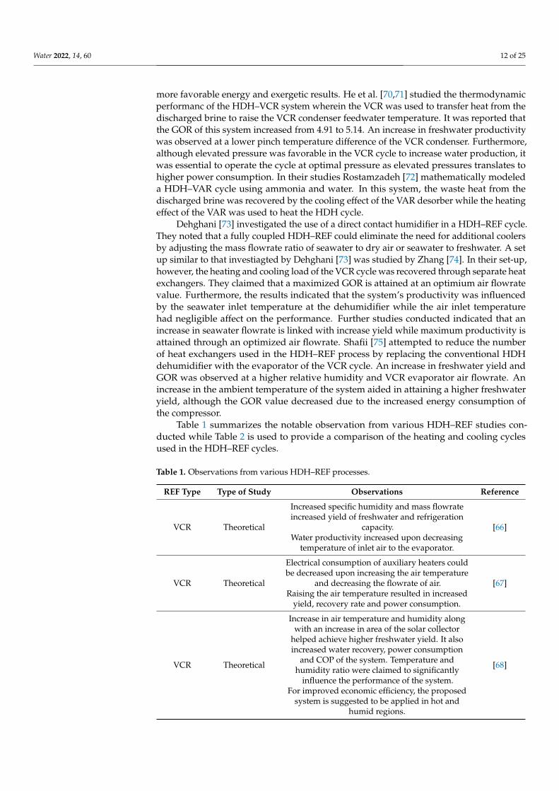
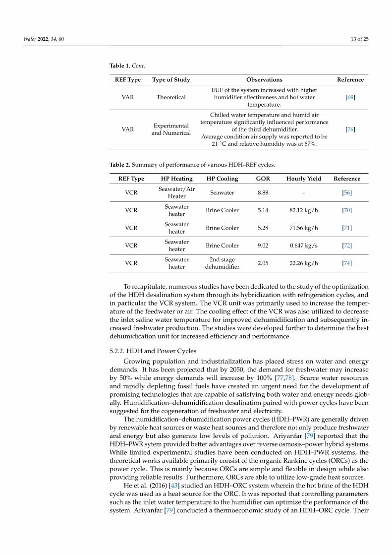
Table 1 summarizes the notable observation from various HDH–REF studies con-ducted while Table 2 is used to provide a comparison of the heating and cooling cyclesused in the HDH–REF cycles.
Table 1. Observations from various HDH–REF processes.
REF Type Type of Study Observations Reference
VCR Theoretical
Increased specific humidity and mass flowrateincreased yield of freshwater and refrigeration
capacity.Water productivity increased upon decreasing
temperature of inlet air to the evaporator.
[66]
VCR Theoretical
Electrical consumption of auxiliary heaters couldbe decreased upon increasing the air temperature
and decreasing the flowrate of air.Raising the air temperature resulted in increased
yield, recovery rate and power consumption.
[67]
VCR Theoretical
Increase in air temperature and humidity alongwith an increase in area of the solar collector
helped achieve higher freshwater yield. It alsoincreased water recovery, power consumption
and COP of the system. Temperature andhumidity ratio were claimed to significantly
influence the performance of the system.For improved economic efficiency, the proposed
system is suggested to be applied in hot andhumid regions.
[68]
Water 2022, 14, 60 13 of 25
Table 1. Cont.
REF Type Type of Study Observations Reference
VAR TheoreticalEUF of the system increased with higherhumidifier effectiveness and hot water
temperature.[69]
VAR Experimentaland Numerical
Chilled water temperature and humid airtemperature significantly influenced performance
of the third dehumidifier.Average condition air supply was reported to be
21 ◦C and relative humidity was at 67%.
[76]
Table 2. Summary of performance of various HDH–REF cycles.
REF Type HP Heating HP Cooling GOR Hourly Yield Reference
VCR Seawater/AirHeater Seawater 8.88 - [56]
VCR Seawaterheater Brine Cooler 5.14 82.12 kg/h [70]
VCR Seawaterheater Brine Cooler 5.28 71.56 kg/h [71]
VCR Seawaterheater Brine Cooler 9.02 0.647 kg/s [72]
VCR Seawaterheater
2nd stagedehumidifier 2.05 22.26 kg/h [74]
To recapitulate, numerous studies have been dedicated to the study of the optimizationof the HDH desalination system through its hybridization with refrigeration cycles, andin particular the VCR system. The VCR unit was primarily used to increase the temper-ature of the feedwater or air. The cooling effect of the VCR was also utilized to decreasethe inlet saline water temperature for improved dehumidification and subsequently in-creased freshwater production. The studies were developed further to determine the bestdehumidication unit for increased efficiency and performance.
5.2.2. HDH and Power Cycles
Growing population and industrialization has placed stress on water and energydemands. It has been projected that by 2050, the demand for freshwater may increaseby 50% while energy demands will increase by 100% [77,78]. Scarce water resourcesand rapidly depleting fossil fuels have created an urgent need for the development ofpromising technologies that are capable of satisfying both water and energy needs glob-ally. Humidification–dehumidification desalination paired with power cycles have beensuggested for the cogeneration of freshwater and electricity.
The humidification–dehumidification power cycles (HDH–PWR) are generally drivenby renewable heat sources or waste heat sources and therefore not only produce freshwaterand energy but also generate low levels of pollution. Ariyanfar [79] reported that theHDH–PWR sytem provided better advantages over reverse osmosis–power hybrid systems.While limited experimental studies have been conducted on HDH–PWR systems, thetheoretical works available primarily consist of the organic Rankine cycles (ORCs) as thepower cycle. This is mainly because ORCs are simple and flexible in design while alsoproviding reliable results. Furthermore, ORCs are able to utilize low-grade heat sources.
He et al. (2016) [43] studied an HDH–ORC system wherein the hot brine of the HDHcycle was used as a heat source for the ORC. It was reported that controlling parameterssuch as the inlet water temperature to the humidifier can optimize the performance of thesystem. Ariyanfar [79] conducted a thermoeconomic study of an HDH–ORC cycle. Their
Water 2022, 14, 60 14 of 25
study analyzed the impact of various system configurations and different organic fluids onthe performance of the process. It was concluded that coupling the HDH with the condenserof the ORC yielded more economical results and that n-heptane increased freshwater yieldat a lower unit cost. In a similar study, He et al. [43] conducted a thermodynamic analysis ofpairing the ORC condenser as the heater for the HDH cycle. They observed that freshwateryield could be increased by decreasing the pinch temperature of the ORC condesner. Heet al. [43] further reported that for an HDH–ORC system, in order to boost the performanceof the ORC, the brine entering the evaporator was reheated using a boiler. Moreover, themaximum efficiency and GOR was achieved as an optimal saline water to air mass flowrateratio. Thermoeconomic results of a regenerative HDH–ORC system powered by geothermalwater concluded that the ORC vapor generator displayed maximum irreversibility [70].Besides, rasising the ORC evaporator temperature yielded beneficial thermodynamic andeconomical results. Studies were also conducted on a HDH–PWR system that employed aflashing Rankine system instead of an ORC and geothermal water as a heat source.
The results showed that lower temperatures of seawater and a lower temperature dif-ference of saline water in the heat exchanger improved the performance of the process [70].Employing a single extraction ORC with a WH–HDH process displayed an increase infreshwater productivity while net power decreased when the extracton pressure of thesystem was raised [71]. The advantage of this system was in the various amounts of powerand water generated by controlling the extraction parameters, a benefit unseen in otherHDH–PWR systems.
Sayyaadi [80] proposed coupling the HDH process with a Stirling engine (SE) [24]for the cogeneration of water and power. In this HDH–SE system, waste thermal energyfrom the SE was supplied to the HDH unit. The objective to optimize the HDH–SE processfor maximized water productivity and power generation with minimal cost was achievdthrough a multi-extraction HDH–SE cycle. Furthermore, the mentioned system exhibited areliable performance at varying salinity levels of seawater.
Among the several studies conducted on the HDH–PWR systems, varying valuesof freshwater productivity and power generation have been reported. An importantparameter often not emphasized in these systems is the thermal efficiency, which is definedusing Equation (4):
η =mfreshwater.hfg + W
Qin(4)
where mfreshwater is the freshwater production rate, hfg is the latent heat of evaporation ofdesalinated water, and W and Qin are the power generated and input power, respectively.
The diverse results reported in the studies conducted on the HDH–PWR systemis mainly attributed to the difference in configuration, power cycles, heat sources, andoperating conditions employed in the study. Furthermore, while the HDH–PWR systemhas been studied from a thermo-economic standpoint, the cost of freshwater has beenneglected by many [81].
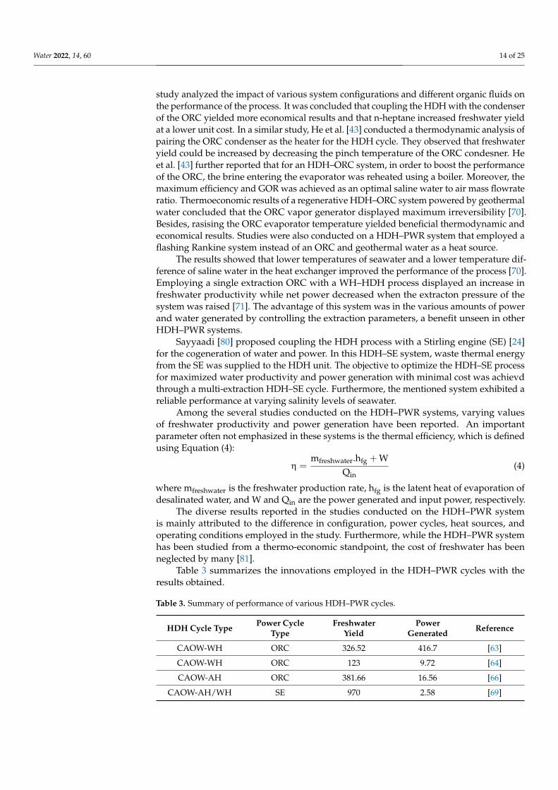
Table 3 summarizes the innovations employed in the HDH–PWR cycles with theresults obtained.
Table 3. Summary of performance of various HDH–PWR cycles.
HDH Cycle Type Power CycleType
FreshwaterYield
PowerGenerated Reference
CAOW-WH ORC 326.52 416.7 [63]
CAOW-WH ORC 123 9.72 [64]
CAOW-AH ORC 381.66 16.56 [66]
CAOW-AH/WH SE 970 2.58 [69]
Water 2022, 14, 60 15 of 25
5.2.3. HDH and Other Systems
Research to enhance the performance of the HDH combined cycles have led to theinclusion of multi-generation systems (MGR) that are capable of not only generatingfreshwater and power but also provide heating or cooling loads, and in some cases theproduction of hydrogen. Ghaebi [82] conducted a thermo-economic analysis of an MGRsystem consisting of a Kalina cycle, VAR refrigeration cycle and WH–HDH process. Theyaimed to maximize the energy efficiency of the system while lowering the cost. They re-ported a maximum thermal efficiency of 94.8% and exergy efficiency of 47.8%. Sadeghi [83]investigated the thermodynamic behavior of an HDH–ORC cycle integrated with an ejec-tor refrigeration cycle. They reported a maximum exergy efficiency of 17.1%. Althoughvarious PWR and REF cycles have been investigated for integration in HDH–MGR systems,the ORC, Kalina, and Rankine cycles were most studied. Similarly, VAR cycles were thepreferred option to provide cooling in the refrigeration cycles. Furthermore, it should behighlighted that the MGR cycles are compatible with different sources of heat such as air,water, geothermal energy, and biogas.
Investigation to improve the efficiencies of the desalination process showed thatcombining HDH cycles with other desalination (DES) processes improved the overallproductivity and efficiency of the process compared to the standalone systems. Mistry [50]conducted a theoretical analysis of an HDH–RO system with the aim of optimizing the hy-brid system. They observed that coupling the HDH–thermal vapor compressor (TVC) withan RO unit provided results that outperformed the multi-stage flash (MSF) evaporator andmulti-effect distillation (MED) in terms of GOR and energy consumption. Mahmoud [84]investigated the performance of the HDH system integrated with solar stills. They reportedthat the productivity declined with an increasing basin height and recommended modifi-cation to the hybrid system for improved performance. Integrating a flashing evaporator(FE) with the HDH system was suggested by Kabeel [85]. They claimed that the HDH–FEprocess paired with a solar air heater provided the most economical layout.
5.2.4. Innovations in HDH Design
Among the several innovations suggested to the HDH process, mechanical compres-sion of vapor is perhaps the most debated of them. HDH desalination integrated withvapor compression entails humidified air to be compressed to high pressures in orderto elevate its pressure and temperature. Condensation of the water vapor present in thehumidified air then occurs when the compressed air is cooled by the saline feedwater. Theprime disadvantage associated with the mechanical vapor compression (MVC) methodis its high-power consumption. El-Dessouky and Ettouney [86] claim that the power con-sumption of MVC may exceed that of single-effect MVC and RO processes without propercontrol and management. Limited research has been conducted on the potential of theHDH–MVC integrated system; however, the unexplored potential of an HDH–MVC systemis highlighted through the advantages provided by a MVC unit integrated with a multi-effect desalination (MED) unit. Therefore, the following sections are dedicated to detailingthe MED process and to presenting the benefits of an MED–MVC integrated system.
6. Multi-Effect Desalination
While freshwater sources are already scarcely available, domestic, and industrialpollution of these resources has further limited their use. Moreover, there is an unevennatural distribution of freshwater sources, with most regions and countries lacking access tothis. Considering the presented challenge, the desalination of sea water and brackish wateris thought to be a promising solution. While desalination makes potable water accessibleto all, the high energy input and in turn the high cost required by the process presentssevere challenges to several regions incapable of meeting the energy or capital demands.Increased dependence on desalination technologies has also placed stress on the fossilfueled energy sector, further creating environmental concerns. It has been reported that203 million tons of oil is required per year to generate 22 million cubic meters of desalinated
Water 2022, 14, 60 16 of 25
water a day [87]. Rapidly depleting fossil fuel sources and growing environmental concernshave promoted the research and development of novel technologies that meet freshwaterdemands while minimizing its carbon footprint. The use of renewable sources of energy fordesalination could potentially replace conventional desalination; however, without furthertechnological advancement these alternatives cannot compete with the production cost ofconventional methods.
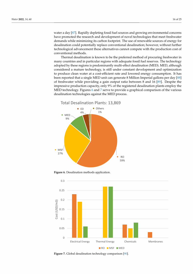
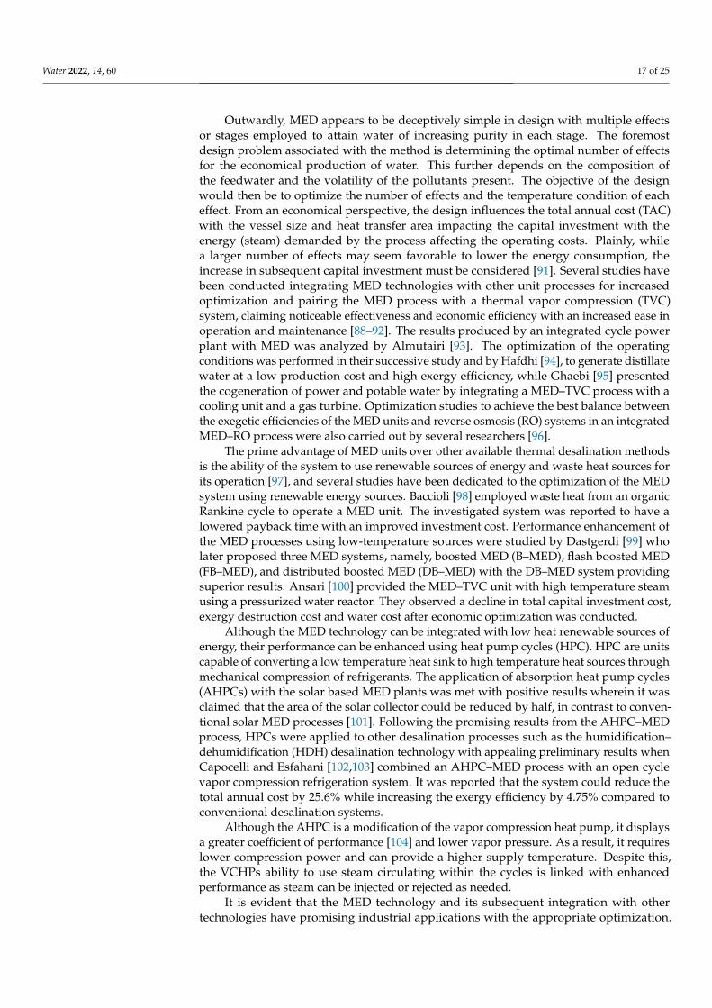
Thermal desalination is known to be the preferred method of procuring freshwater inmany countries and in particular regions with adequate fossil fuel reserves. The technologyadopted by these regions is predominantly multi-effect desalination (MED). MED, althoughconsidered a mature technology, is still under constant development and optimizationto produce clean water at a cost-efficient rate and lowered energy consumption. It hasbeen reported that a single MED unit can generate 8 Million Imperial gallons per day [88]of freshwater while providing a gain output ratio between 8 and 16 [89]. Despite theimpressive production capacity, only 9% of the registered desalination plants employ theMED technology. Figures 6 and 7 serve to provide a graphical comparison of the variousdesalination technologies against the MED process.
Water 2022, 14, x FOR PEER REVIEW 17 of 26
Increased dependence on desalination technologies has also placed stress on the fossil fueled energy sector, further creating environmental concerns. It has been reported that 203 million tons of oil is required per year to generate 22 million cubic meters of desali-nated water a day [87]. Rapidly depleting fossil fuel sources and growing environmental concerns have promoted the research and development of novel technologies that meet freshwater demands while minimizing its carbon footprint. The use of renewable sources of energy for desalination could potentially replace conventional desalination; however, without further technological advancement these alternatives cannot compete with the production cost of conventional methods.
Thermal desalination is known to be the preferred method of procuring freshwater in many countries and in particular regions with adequate fossil fuel reserves. The tech-nology adopted by these regions is predominantly multi-effect desalination (MED). MED, although considered a mature technology, is still under constant development and opti-mization to produce clean water at a cost-efficient rate and lowered energy consumption. It has been reported that a single MED unit can generate 8 Million Imperial gallons per day [88] of freshwater while providing a gain output ratio between 8 and 16 [89]. Despite the impressive production capacity, only 9% of the registered desalination plants employ the MED technology. Figures 6 and 7 serve to provide a graphical comparison of the var-ious desalination technologies against the MED process.
Figure 6. Desalination methods application.
RO59%
MSF27%
MED9%
ED4%
Others1%
Total Desalination Plants: 13,869
Figure 6. Desalination methods application.
Water 2022, 14, x FOR PEER REVIEW 18 of 26
Figure 7. Global desalination technology comparison [90].
Outwardly, MED appears to be deceptively simple in design with multiple effects or stages employed to attain water of increasing purity in each stage. The foremost design problem associated with the method is determining the optimal number of effects for the economical production of water. This further depends on the composition of the feedwa-ter and the volatility of the pollutants present. The objective of the design would then be to optimize the number of effects and the temperature condition of each effect. From an economical perspective, the design influences the total annual cost (TAC) with the vessel size and heat transfer area impacting the capital investment with the energy (steam) de-manded by the process affecting the operating costs. Plainly, while a larger number of effects may seem favorable to lower the energy consumption, the increase in subsequent capital investment must be considered [91]. Several studies have been conducted integrat-ing MED technologies with other unit processes for increased optimization and pairing the MED process with a thermal vapor compression (TVC) system, claiming noticeable effectiveness and economic efficiency with an increased ease in operation and mainte-nance [88–92]. The results produced by an integrated cycle power plant with MED was analyzed by Almutairi [93]. The optimization of the operating conditions was performed in their successive study and by Hafdhi [94], to generate distillate water at a low produc-tion cost and high exergy efficiency, while Ghaebi [95] presented the cogeneration of power and potable water by integrating a MED–TVC process with a cooling unit and a gas turbine. Optimization studies to achieve the best balance between the exegetic effi-ciencies of the MED units and reverse osmosis (RO) systems in an integrated MED–RO process were also carried out by several researchers [96].
The prime advantage of MED units over other available thermal desalination meth-ods is the ability of the system to use renewable sources of energy and waste heat sources for its operation [97], and several studies have been dedicated to the optimization of the MED system using renewable energy sources. Baccioli [98] employed waste heat from an organic Rankine cycle to operate a MED unit. The investigated system was reported to have a lowered payback time with an improved investment cost. Performance enhance-ment of the MED processes using low-temperature sources were studied by Dastgerdi [99] who later proposed three MED systems, namely, boosted MED (B–MED), flash boosted MED (FB–MED), and distributed boosted MED (DB–MED) with the DB–MED system providing superior results. Ansari [100] provided the MED–TVC unit with high temperature steam using a pressurized water reactor. They observed a decline in total
0
0.05
0.1
0.15
0.2
0.25
0.3
Electrical Energy Thermal Energy Chemicals Membranes
Cost
(USD
/m3)
RO MSF MED
Figure 7. Global desalination technology comparison [90].
Water 2022, 14, 60 17 of 25
Outwardly, MED appears to be deceptively simple in design with multiple effectsor stages employed to attain water of increasing purity in each stage. The foremostdesign problem associated with the method is determining the optimal number of effectsfor the economical production of water. This further depends on the composition ofthe feedwater and the volatility of the pollutants present. The objective of the designwould then be to optimize the number of effects and the temperature condition of eacheffect. From an economical perspective, the design influences the total annual cost (TAC)with the vessel size and heat transfer area impacting the capital investment with theenergy (steam) demanded by the process affecting the operating costs. Plainly, whilea larger number of effects may seem favorable to lower the energy consumption, theincrease in subsequent capital investment must be considered [91]. Several studies havebeen conducted integrating MED technologies with other unit processes for increasedoptimization and pairing the MED process with a thermal vapor compression (TVC)system, claiming noticeable effectiveness and economic efficiency with an increased ease inoperation and maintenance [88–92]. The results produced by an integrated cycle powerplant with MED was analyzed by Almutairi [93]. The optimization of the operatingconditions was performed in their successive study and by Hafdhi [94], to generate distillatewater at a low production cost and high exergy efficiency, while Ghaebi [95] presentedthe cogeneration of power and potable water by integrating a MED–TVC process with acooling unit and a gas turbine. Optimization studies to achieve the best balance betweenthe exegetic efficiencies of the MED units and reverse osmosis (RO) systems in an integratedMED–RO process were also carried out by several researchers [96].
The prime advantage of MED units over other available thermal desalination methodsis the ability of the system to use renewable sources of energy and waste heat sources forits operation [97], and several studies have been dedicated to the optimization of the MEDsystem using renewable energy sources. Baccioli [98] employed waste heat from an organicRankine cycle to operate a MED unit. The investigated system was reported to have alowered payback time with an improved investment cost. Performance enhancement ofthe MED processes using low-temperature sources were studied by Dastgerdi [99] wholater proposed three MED systems, namely, boosted MED (B–MED), flash boosted MED(FB–MED), and distributed boosted MED (DB–MED) with the DB–MED system providingsuperior results. Ansari [100] provided the MED–TVC unit with high temperature steamusing a pressurized water reactor. They observed a decline in total capital investment cost,exergy destruction cost and water cost after economic optimization was conducted.
Although the MED technology can be integrated with low heat renewable sources ofenergy, their performance can be enhanced using heat pump cycles (HPC). HPC are unitscapable of converting a low temperature heat sink to high temperature heat sources throughmechanical compression of refrigerants. The application of absorption heat pump cycles(AHPCs) with the solar based MED plants was met with positive results wherein it wasclaimed that the area of the solar collector could be reduced by half, in contrast to conven-tional solar MED processes [101]. Following the promising results from the AHPC–MEDprocess, HPCs were applied to other desalination processes such as the humidification–dehumidification (HDH) desalination technology with appealing preliminary results whenCapocelli and Esfahani [102,103] combined an AHPC–MED process with an open cyclevapor compression refrigeration system. It was reported that the system could reduce thetotal annual cost by 25.6% while increasing the exergy efficiency by 4.75% compared toconventional desalination systems.
Although the AHPC is a modification of the vapor compression heat pump, it displaysa greater coefficient of performance [104] and lower vapor pressure. As a result, it requireslower compression power and can provide a higher supply temperature. Despite this,the VCHPs ability to use steam circulating within the cycles is linked with enhancedperformance as steam can be injected or rejected as needed.
It is evident that the MED technology and its subsequent integration with othertechnologies have promising industrial applications with the appropriate optimization.
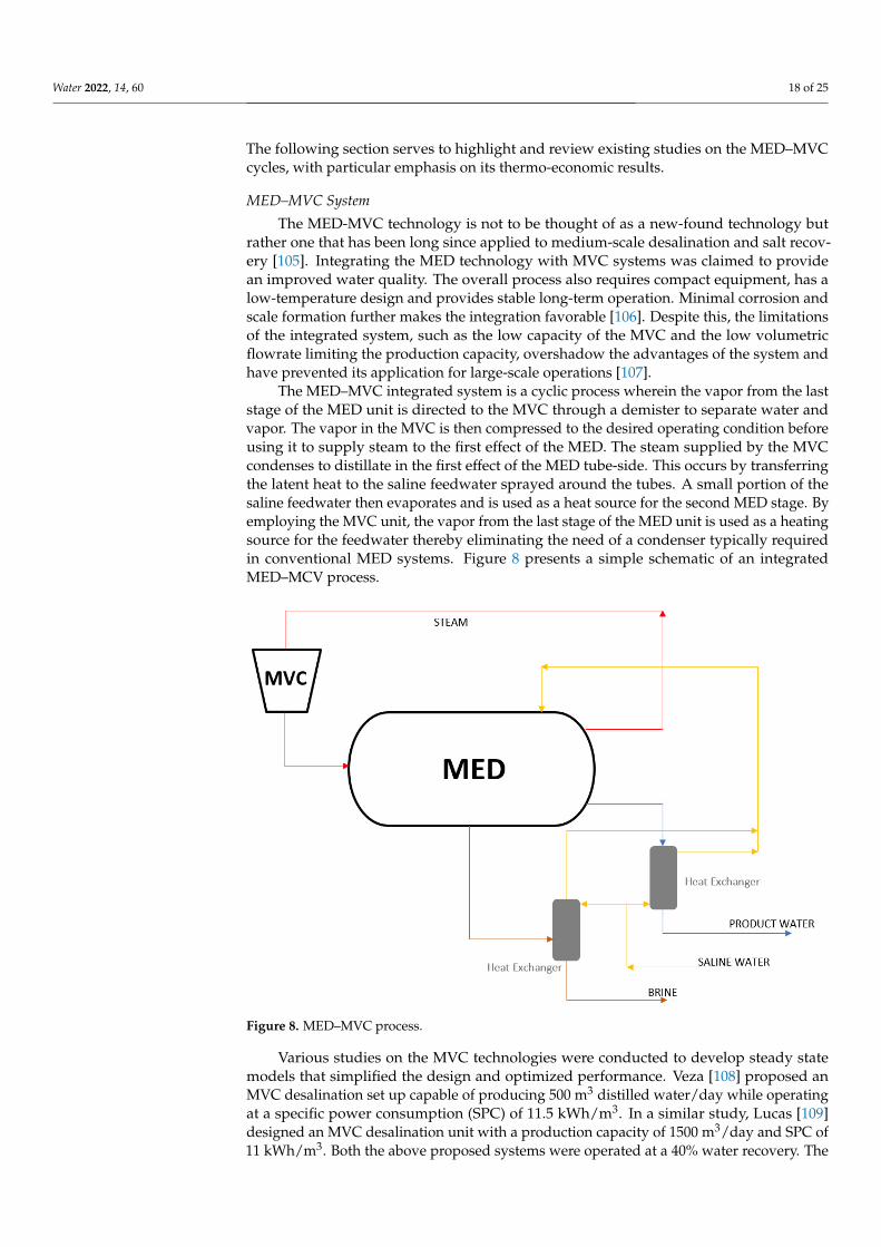
Water 2022, 14, 60 18 of 25
The following section serves to highlight and review existing studies on the MED–MVCcycles, with particular emphasis on its thermo-economic results.
MED–MVC System
The MED-MVC technology is not to be thought of as a new-found technology butrather one that has been long since applied to medium-scale desalination and salt recov-ery [105]. Integrating the MED technology with MVC systems was claimed to providean improved water quality. The overall process also requires compact equipment, has alow-temperature design and provides stable long-term operation. Minimal corrosion andscale formation further makes the integration favorable [106]. Despite this, the limitationsof the integrated system, such as the low capacity of the MVC and the low volumetricflowrate limiting the production capacity, overshadow the advantages of the system andhave prevented its application for large-scale operations [107].
The MED–MVC integrated system is a cyclic process wherein the vapor from the laststage of the MED unit is directed to the MVC through a demister to separate water andvapor. The vapor in the MVC is then compressed to the desired operating condition beforeusing it to supply steam to the first effect of the MED. The steam supplied by the MVCcondenses to distillate in the first effect of the MED tube-side. This occurs by transferringthe latent heat to the saline feedwater sprayed around the tubes. A small portion of thesaline feedwater then evaporates and is used as a heat source for the second MED stage. Byemploying the MVC unit, the vapor from the last stage of the MED unit is used as a heatingsource for the feedwater thereby eliminating the need of a condenser typically requiredin conventional MED systems. Figure 8 presents a simple schematic of an integratedMED–MCV process.
Water 2022, 14, x FOR PEER REVIEW 20 of 26
Figure 8. MED–MVC process.
Various studies on the MVC technologies were conducted to develop steady state models that simplified the design and optimized performance. Veza [108] proposed an MVC desalination set up capable of producing 500 m3 distilled water/day while operating at a specific power consumption (SPC) of 11.5 kWh/m3. In a similar study, Lucas [109] designed an MVC desalination unit with a production capacity of 1500 m3/day and SPC of 11 kWh/m3. Both the above proposed systems were operated at a 40% water recovery. The MVC pilot plant investigated by Bahar [110] involved the use of vertical double fluted tube evaporators of 1 m3/day capacity, and a top brine temperature (TBT) of 103 °C. The highest recorded performance ratio (PR) of this system was found to be 2.52. Aly [111] analyzed the performance of a single effect MVC system producing 5 m3 distilled wa-ter/day through mathematical modelling. The steam supply was regulated using feed sea-water temperature and the compressor power.
Shaffer [112] suggests the application of the MVC process beyond seawater desalina-tion and to produced water 1 and wastewater treatment. Koren [113] employed a single effect MVC system to separate oil and water from a high salinity mixture and their system was able to achieve a production capacity of 600 m3 freshwater/day operating at a SPC of 13.6 kWh/m3. Meanwhile, Wu [104] conducted studies on a novel MVC system for sewage treatment and their design separated the evaporator and condenser in an effort to over-come the shortcomings of traditional MVC systems with a capacity of 1.44 m3/day.
According to Sharqawy [114], exergy analysis involves identifying the components in a process with the highest thermodynamic irreversibility rate. Bearing in mind the aforementioned concept, Alasfour [115] studied the steady-state model of a single effect MVC unit using the second law of thermodynamics. They observed an increase in the unit’s exergy destruction with an increase in temperature difference across the stages, while a study conducted by Jamil [116] involved an exergo-economic analysis of a forward feed MED–MVC configuration. Using the second law of efficiency, the SPC and product cost were all reported to increase as the number of stages were increased from two to six. Furthermore, the exergy destruction obtained in their configuration was far lower than those stated in the literature [117].
Figure 8. MED–MVC process.
Various studies on the MVC technologies were conducted to develop steady statemodels that simplified the design and optimized performance. Veza [108] proposed anMVC desalination set up capable of producing 500 m3 distilled water/day while operatingat a specific power consumption (SPC) of 11.5 kWh/m3. In a similar study, Lucas [109]designed an MVC desalination unit with a production capacity of 1500 m3/day and SPC of11 kWh/m3. Both the above proposed systems were operated at a 40% water recovery. The
Water 2022, 14, 60 19 of 25
MVC pilot plant investigated by Bahar [110] involved the use of vertical double fluted tubeevaporators of 1 m3/day capacity, and a top brine temperature (TBT) of 103 ◦C. The highestrecorded performance ratio (PR) of this system was found to be 2.52. Aly [111] analyzed theperformance of a single effect MVC system producing 5 m3 distilled water/day throughmathematical modelling. The steam supply was regulated using feed seawater temperatureand the compressor power.
Shaffer [112] suggests the application of the MVC process beyond seawater desalina-tion and to produced water [1] and wastewater treatment. Koren [113] employed a singleeffect MVC system to separate oil and water from a high salinity mixture and their systemwas able to achieve a production capacity of 600 m3 freshwater/day operating at a SPCof 13.6 kWh/m3. Meanwhile, Wu [104] conducted studies on a novel MVC system forsewage treatment and their design separated the evaporator and condenser in an effort toovercome the shortcomings of traditional MVC systems with a capacity of 1.44 m3/day.
According to Sharqawy [114], exergy analysis involves identifying the componentsin a process with the highest thermodynamic irreversibility rate. Bearing in mind theaforementioned concept, Alasfour [115] studied the steady-state model of a single effectMVC unit using the second law of thermodynamics. They observed an increase in theunit’s exergy destruction with an increase in temperature difference across the stages,while a study conducted by Jamil [116] involved an exergo-economic analysis of a forwardfeed MED–MVC configuration. Using the second law of efficiency, the SPC and productcost were all reported to increase as the number of stages were increased from two to six.Furthermore, the exergy destruction obtained in their configuration was far lower thanthose stated in the literature [117].
The variation in design of an MED–MVC system predominantly comes from the con-figurations of the MED unit. Elsayed [117] analyzed four configurations to determine theireffect on the performance of a 4-effect MED–MVC system. The configurations consideredwere forward feed (FF), parallel feed (PF), backward feed (BF) and parallel/cross feed (PCF).The modelled MED–MVC design was validated against actual data obtained from plantslocated in Spain and India with an overall deviation within 7% in both cases [108–118].To gain a comparison of the different configurations studied from an exergo-economicperspective, the first and second laws of thermodynamics were employed. Using the firstlaw of thermodynamics it was reported that the FF and the PCF provided superior functionin terms of PR and utilized less power to produce the same amount of freshwater.
Few efforts have been taken to investigate the dynamic model of the MED–MVCsystem. El-Khatib et al. [119] proposed to study the transient behavior of a single effectMED–MVC unit by controlling various process input and outputs. By varying the distillateflowrate and the feed flow rate, the dynamics of the vapor temperature inside the stageswere analyzed; however, their results were not verified against actual data or experimentaloutputs. Studies conducted by Kishore et al. [118] aimed to understand the dynamicbehavior of the MED–MVC unit through a simulator and they found that the load had noobservable change on the system’s response. Conducting further research on the dynamicbehavior of the MED–MVC process is paramount since it aids in the enhancement ofthe performance.
Table 4 aims to summarize the application of the MED–MVC process in variouslocations with their production capacity and SPC.
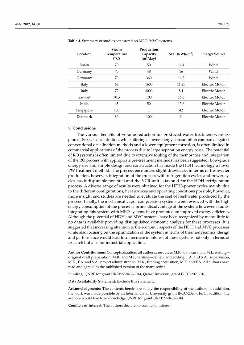
Water 2022, 14, 60 20 of 25
Table 4. Summary of studies conducted on MED–MVC systems.
LocationSteam
Temperature(◦C)
ProductionCapacity(m3/day)
SPC (kWh/m3) Energy Source
Spain 70 50 14.4 Wind
Germany 70 48 16 Wind
Germany 70 360 16.7 Wind
Italy 63 1600 11.25 Electric Motor
Italy 72 3000 8.1 Electric Motor
Kuwait 70.5 100 16.6 Electric Motor
India 65 50 13.6 Electric Motor
Singapore 105 1 42 Electric Motor
Denmark 80 100 11 Electric Motor
7. Conclusions
The various benefits of volume reduction for produced water treatment were ex-plored. Freeze concentration, while offering a lower energy consumption compared againstconventional desalination methods and a lower equipment corrosion, is often limited incommercial applications of the process due to large separation energy costs. The potentialof RO systems is often limited due to extensive fouling of the membranes and integrationof the RO process with appropriate pre-treatment methods has been suggested. Low-gradeenergy use and simple design and construction has made the HDH technology a novelPW treatment method. The process encounters slight drawbacks in terms of freshwaterproduction, however, integration of the process with refrigeration cycles and power cy-cles has indisputable potential and the VCR unit is favored for the HDH–refrigerationprocess. A diverse range of results were obtained for the HDH–power cycles mainly dueto the different configurations, heat sources and operating conditions possible; however,more insight and studies are needed to evaluate the cost of freshwater produced by theprocess. Finally, the mechanical vapor compression systems were reviewed with the highenergy consumption of the process a prime disadvantage of the system; however, studiesintegrating this system with MED systems have promoted an improved exergy efficiency.Although the potential of HDH and MVC systems have been recognized by many, little tono data is available providing distinguished economic analysis for these processes. It issuggested that increasing attention to the economic aspects of the HDH and MVC processeswhile also focusing on the optimization of the system in terms of thermodynamics, designand performance would lead to an increase in interest of these systems not only in terms ofresearch but also for industrial application.
Author Contributions: Conceptualization, all authors.; resources M.K.; data curation, M.I.; writing—original draft preparation, M.K. and M.I.; writing—review and editing, F.A. and S.A.; supervision,M.K., F.A. and S.A.; project administration, M.K.; funding acquisition, M.K. and F.A. All authors haveread and agreed to the published version of the manuscript.
Funding: QNRF for grant UREP27-040-2-014; Qatar University grant IRCC-2020-016.
Data Availability Statement: Exclude this statement.
Acknowledgments: The contents herein are solely the responsibility of the authors. In addition,the work was made possible by an Internal Qatar University grant IRCC-2020-016. In addition, theauthors would like to acknowledge QNRF for grant UREP27-040-2-014.
Conflicts of Interest: The authors declare no conflict of interest.
Water 2022, 14, 60 21 of 25
References1. Ahmadizadeh, R.; Shokrollahzadeh, S.; Latifi, S.M.; Samimi, A.; Pendashteh, A. Application of halophilic microorganisms in
osmotic membrane bioreactor (OMBR) for reduction of volume and organic load of produced water. J. Water Process. Eng. 2020, 37,101422. Available online: http://www.sciencedirect.com/science/article/pii/S2214714420303007 (accessed on 5 November 2021).[CrossRef]
2. Ground Water Protection Council. Produced Water Report: Regulations, Current Practices, and Research Needs; Ground WaterProtection Council: Oklahoma, OK, USA, 2019.
3. Kusworo, T.D.; Aryanti, N.; Qudratun; Utomo, D.P. Oilfield produced water treatment to clean water using integrated activatedcarbon-bentonite adsorbent and double stages membrane process. Chem. Eng. J. 2018, 347, 462–471. Available online: http://www.sciencedirect.com/science/article/pii/S1385894718307095 (accessed on 17 June 2021). [CrossRef]
4. Mccabe, P.J. Oiloiland Natural Gasnatural gas: Global Resourcesnatural Gasglobal Resources. In Encyclopedia of SustainabilityScience and Technology; Meyers, R.A., Ed.; Springer: New York, NY, USA, 2012; pp. 7446–7456, ISBN 9781441908513.
5. Global Water Intelligence. Produced Water Market: Opportunities in the Oil, Shale and Gas Sectors in North America; Media AnalyticsLtd.: Oxford, UK, 2011.
6. Burnett, D.B.; Siddiqui, M. Recovery of Fresh Water Resources from Desalination of Brine Produced during Oil and Gas ProductionOperations; Texas Engineering Experiment Station: Eastmark Dr, TX, USA, 2006.
7. United Nations. SDG 6 Synthesis Report 2018 on Water and Sanitation; United Nations: London, UK, 2018.8. Kang, H.; Wang, T.; Zheng, H. Comparative analysis of regenerative and air-extraction multi-stage humidification–
dehumidification desalination system using pinch technology. Desalination 2016, 385, 158–166. Available online: http://www.sciencedirect.com/science/article/pii/S0011916416300509 (accessed on 17 June 2021). [CrossRef]
9. Visvanathan, C.; Svenstrup, P.; Ariyamethee, P. Volume reduction of produced water generated from natural gas productionprocess using membrane technology. Water Sci. Technol. 2000, 41, 117–123. [CrossRef]
10. Janks, J.; Cadena, F. Investigations Into the Use of Modified Zeolites for Removing Benzene, Toluene, and Xylene from SalineProduced Water. In Produced Water; Ray, J.P., Engelhardt, F.R., Eds.; Springer: Boston, MA, USA, 1992; pp. 473–487.
11. Adewumi, M.; Erb, J.; Watson, R. Initial Design Considerations for a Cost Effective Treatment of Stripper Oil Well Produced Water.In Produced Water; Ray, J.P., Engelhardt, F.R., Eds.; Springer: Boston, MA, USA, 1992; pp. 511–522.
12. Van den Broek, W.M.; Plat, R.; van der Zande, M.J. Comparison of plate separator, centrifuge and hydrocyclone. In Proceedingsof the SPE International Oil and Gas Conference and Exhibition in China: Society of Petroleum Engineers, Beijing, China, 2–6November 1998.
13. Zhou, F.S.; Zhao, M.F.; Ni, W.X.; Dang, Y.S.; Pu, C.S.; Lu, F.J. Inorganic polymeric flocculent FMA for purifying oilfield producedwater: Preparation and uses. Oilfield Chem. 2000, 17, 256–259.
14. Houcine, M. Solution for heavy metals decontamination in produced water/case study in southern Tunisia. In Proceedings ofthe SPE International Conference on Health, Safety and Environment in Oil and Gas Exploration and Production: Society ofPetroleum Engineers, Kuala Lumpur, Malaysia, 20–22 March 2002.
15. Stepnowski, P.; Zaleska, A. Comparison of different advanced oxidation processes for the degradation of room temperature ionicliquids. J. Photochem. Photobiol. A Chem. 2005, 170, 45–50. Available online: http://www.sciencedirect.com/science/article/pii/S1010603004003727 (accessed on 23 December 2021). [CrossRef]
16. Ganiyu, S.O.; Zhou, M.; Martínez-Huitle, C.A. Heterogeneous electro-Fenton and photoelectro-Fenton processes: A critical reviewof fundamental principles and application for water/wastewater treatment. Appl. Catal. B Environ. 2018, 235, 103–129. [CrossRef]
17. Zhang, H.; Liu, J.; Ou, C.; Shen, J.; Yu, H.; Jiao, Z.; Han, W.; Sun, X.; Li, J.; Wang, L. Reuse of Fenton sludge as an iron source forNiFe2 O4 synthesis and its application in the Fenton-based process. J. Environ. Sci. 2017, 53, 1–8. [CrossRef]
18. McFarlane, J.; Ridenour, W.B.; Luo, H.; Hunt, R.D.; DePaoli, D.W.; Ren, R.X. Room Temperature Ionic Liquids for SeparatingOrganics from Produced Water. Sep. Sci. Technol. 2005, 40, 1245–1265. [CrossRef]
19. Madaeni, S. The application of membrane technology for water disinfection. Water Res. 1999, 33, 301–308. [CrossRef]20. Ciarapica, F.; Giacchetta, G. The treatment of produced water in offshore rig: Comparison between tradition installations and
innovative systems. In Proceedings of the 5th International Membrane Science & Technology Conference, University of NewSouth Wales, Sydney, Australia, 10–14 November 2003.
21. Samsuri, S.; Rizan, N.A.N.; Hung, S.H.; Amran, N.A.; Sambudi, N.S. Progressive Freeze Concentration for Volume Reduction ofProduced Water and Biodiesel Wastewater. Chem. Eng. Technol. 2019, 42, 1764–1770. [CrossRef]
22. Rogers, G.F.C.; Mayhew, Y.R. Thermodynamic and Transport Properties of Fluids; John Wiley & Sons: Hoboken, NJ, USA, 1995;ISBN 0631197036.
23. Samsuri, S.; Amran, N.A.; Yahya, N.; Jusoh, M. Review on Progressive Freeze Concentration Designs. Chem. Eng. Commun. 2015,203, 345–363. [CrossRef]
24. Oh, S.-Y.; Binns, M.; Cho, H.; Kim, J.-K. Energy minimization of MEA-based CO2 capture process. Appl. Energy 2016, 169, 353–362.[CrossRef]
25. Halde, R. Concentration of impurities by progressive freezing. Water Res. 1980, 14, 575–580. [CrossRef]26. Williams, P.M.; Ahmad, M.; Connolly, B.; Oatley-Radcliffe, D.L. Technology for freeze concentration in the desalination industry.
Desalination 2015, 356, 314–327. [CrossRef]27. Lu, Z.; Xu, L. Freezing desalination process. Therm. Desalination Process. 2010, 2, 10.
Water 2022, 14, 60 22 of 25
28. Weiss, P.A. Thermal Desalination Processes. Volume 2. 1973. Available online: https://openlibrary.org/works/OL19136062W/Practice_of_desalination (accessed on 24 November 2021).
29. Rahman, M.S.; Ahmed, M.; Chen, X.D. Freezing—Melting process and desalination: I. Review of the state-of-the-art. Sep. Purif.Rev. 2006, 35, 59–96. [CrossRef]
30. Shafiur Rahman, M.; Ahmed, M.; Chen, X.D. Freezingmelting process and desalination: Review of present status and futureprospects. Int. J. Nucl. Desalination 2007, 2, 253–264. [CrossRef]
31. Tao, F.T.; Curtice, S.; Hobbs, R.D.; Sides, J.L.; Wieser, J.D.; Dyke, C.A.; Tuohey, D.; Pilger, P.F. Reverse osmosis process successfullyconverts oil field brine into freshwater. Oil Gas J. USA 1993, 91, 38.
32. Ahmed, I. Importance and Significance of UF/MF Membrane Systems in Desalination Water Treatment; IntechOpen: London, UK, 2017.Available online: https://books.google.co.in/books?id=71ifzQEACAAJ (accessed on 24 November 2021).
33. Mondal, S.; Wickramasinghe, S.R. Produced water treatment by nanofiltration and reverse osmosis membranes. J. Membr. Sci.2008, 322, 162–170. [CrossRef]
34. McGinnis, R.L.; Hancock, N.T.; Nowosielski-Slepowron, M.S.; McGurgan, G.D. Pilot demonstration of the NH3/CO2 forwardosmosis desalination process on high salinity brines. Desalination 2013, 312, 67–74. [CrossRef]
35. Chen, G.; Wang, Z.; Nghiem, L.; Li, X.-M.; Xie, M.; Zhao, B.; Zhang, M.; Song, J.; He, T. Treatment of shale gas drilling flowbackfluids (SGDFs) by forward osmosis: Membrane fouling and mitigation. Desalination 2015, 366, 113–120. [CrossRef]
36. McGovern, R.K.; Lienhard, V.J.H. On the potential of forward osmosis to energetically outperform reverse osmosis desalination. J.Membr. Sci. 2014, 469, 245–250. [CrossRef]
37. Bartholomew, T.; Mey, L.; Arena, J.T.; Siefert, N.S.; Mauter, M.S. Osmotically assisted reverse osmosis for high salinity brinetreatment. Desalination 2017, 421, 3–11. [CrossRef]
38. Kim, J.; Kim, D.I.; Hong, S. Analysis of an osmotically-enhanced dewatering process for the treatment of highly saline(waste)waters. J. Membr. Sci. 2018, 548, 685–693. [CrossRef]
39. Kim, J.; Kim, J.; Kim, J.; Hong, S. Osmotically enhanced dewatering-reverse osmosis (OED-RO) hybrid system: Implications forshale gas produced water treatment. J. Membr. Sci. 2018, 554, 282–290. [CrossRef]
40. Zhang, L.-Z.; Huang, S.-M. Coupled heat and mass transfer in a counter flow hollow fiber membrane module for air humidification.Int. J. Heat Mass Transf. 2011, 54, 1055–1063. [CrossRef]
41. Li, G.-P.; Qi, R.-H.; Zhang, L.-Z. Performance study of a solar-assisted hollow-fiber-membrane-based air humidification-dehumidification desalination system: Effects of membrane properties. Chem. Eng. Sci. 2019, 206, 164–179. [CrossRef]
42. Zhang, T.; Zhang, L.-Z. Development of a MXene-based membrane with excellent anti-fouling for air humidification-dehumidification type desalination. J. Membr. Sci. 2022, 641, 119907. [CrossRef]
43. He, W.; Han, D.; Xu, L.; Yue, C.; Pu, W. Performance investigation of a novel water–power cogeneration plant (WPCP) based onhumidification dehumidification (HDH) method. Energy Convers. Manag. 2016, 110, 184–191. [CrossRef]
44. Kabeel, A.E.; Hamed, M.H.; Omara, Z.M.; Sharshir, S.W. Water Desalination Using a Humidification-Dehumidification Technique—A Detailed Review. Nat. Resour. 2013, 4, 286–305. [CrossRef]
45. Hamed, M.H.; Kabeel, A.; Omara, Z.; Sharshir, S. Mathematical and experimental investigation of a solar humidification–dehumidification desalination unit. Desalination 2015, 358, 9–17. [CrossRef]
46. El-Dessouky, H.T. Humidification-dehumidification desalination process using waste heat from a gas turbine. Desalination 1989,71, 19–33. [CrossRef]
47. Al-Hallaj, S.; Farid, M.; Tamimi, A.R. Solar desalination with a humidification-dehumidification cycle: Performance of the unit.Desalination 1998, 120, 273–280. [CrossRef]
48. Narayan, G.P.; Sharqawy, M.H.; Leinhard, V.J.H.; Zubair, S.M. Thermodynamic analysis of humidification dehumidificationdesalination cycles. Desalination Water Treat. 2010, 16, 339–353. [CrossRef]
49. Mistry, K.H.; Lienhard, J.H.; Zubair, S.M. Effect of entropy generation on the performance of humidification-dehumidificationdesalination cycles. Int. J. Therm. Sci. 2010, 49, 1837–1884. [CrossRef]
50. Mistry, K.H.; Mitsos, A.; Lienhard, J.H. Optimal operating conditions and configurations for humidification–dehumidificationdesalination cycles. Int. J. Therm. Sci. 2011, 50, 779–789. [CrossRef]
51. Sharqawy, M.H.; Antar, M.A.; Zubair, S.M.; Elbashir, A. Optimum thermal design of humidification dehumidification desalinationsystems. Desalination 2014, 349, 10–21. [CrossRef]
52. Narayan, G.P.; McGovern, R.K.; Zubair, S.M.; Lienhard, J.H. High-temperature-steam-driven, varied-pressure, humidification-dehumidification system coupled with reverse osmosis for energy-efficient seawater desalination. Energy 2012, 37, 482–493.[CrossRef]
53. Siddiqui, O.K.; Sharqawy, M.H.; Antar, M.A.; Zubair, S.M. Performance evaluation of variable pressure humidification-dehumidification systems. Desalination 2017, 409, 171–182. [CrossRef]
54. Hawlader, M.; Dey, P.K.; Diab, S.; Chung, C.Y. Solar assisted heat pump desalination system. Desalination 2004, 168, 49–54.[CrossRef]
55. Gude, V.G.; Nirmalakhandan, N. Combined desalination and solar-assisted air-conditioning system. Energy Convers. Manag.2008, 49, 3326–3330. [CrossRef]
56. Lawal, D.U.; Antar, M.; Khalifa, A.; Zubair, S.; Al-Sulaiman, F. Humidification-dehumidification desalination system operated bya heat pump. Energy Convers. Manag. 2018, 161, 128–140. [CrossRef]
Water 2022, 14, 60 23 of 25
57. Kassim, M.A.; Benhamou, B.; Harmand, S. Effect of air humidity at the entrance on heat and mass transfers in a humidifierintended for a desalination system. Appl. Therm. Eng. 2011, 31, 1906–1914. [CrossRef]
58. Faegh, M.; Behnam, P.; Shafii, M.B. A review on recent advances in humidification-dehumidification (HDH) desalination systemsintegrated with refrigeration, power and desalination technologies. Energy Convers. Manag. 2019, 196, 1002–1036. [CrossRef]
59. Saidi, S.; Ben Radhia, R.; Dhifaoui, B.; Ben Jabrallah, S. Experimental study of the inclined solar film evaporator. DesalinationWater Treat. 2014, 56, 2576–2583. [CrossRef]
60. Klausner, J.F.; Li, Y.; Mei, R. Evaporative heat and mass transfer for the diffusion driven desalination process. Heat Mass Transf.2005, 42, 528–536. [CrossRef]
61. Müller-Holst, H.; Engelhardt, M.; Herve, M.; Schölkopf, W. Solarthermal seawater desalination systems for decentralised use.Renew. Energy 1998, 14, 311–318. [CrossRef]
62. El-Agouz, S.; Abugderah, M. Experimental analysis of humidification process by air passing through seawater. Energy Convers.Manag. 2008, 49, 3698–3703. [CrossRef]
63. Amer, E.; Kotb, H.; Mostafa, G.; El-Ghalban, A. Theoretical and experimental investigation of humidification–dehumidificationdesalination unit. Desalination 2009, 249, 949–959. [CrossRef]
64. Tow, E.W.; Lienhard, J.H. Experiments and modeling of bubble column dehumidifier performance. Int. J. Therm. Sci. 2014, 80,65–75. [CrossRef]
65. Eslamimanesh, A.; Hatamipour, M. Mathematical modeling of a direct contact humidification–dehumidification desalinationprocess. Desalination 2009, 237, 296–304. [CrossRef]
66. Nada, S.; Elattar, H.; Fouda, A. Experimental study for hybrid humidification-dehumidification water desalination and airconditioning system. Desalination 2015, 363, 112–125. [CrossRef]
67. Elattar, H.; Fouda, A.; Nada, S. Performance investigation of a novel solar hybrid air conditioning and humidification-dehumidification water desalination system. Desalination 2016, 382, 28–42. [CrossRef]
68. Chiranjeevi, C.; Srinivas, T. Influence of vapor absorption cooling on humidification-dehumidification (HDH) desalination. Alex.Eng. J. 2016, 55, 1961–1967. [CrossRef]
69. Chiranjeevi, C.; Srinivas, T. Combined two stage desalination and cooling plant. Desalination 2014, 345, 56–63. [CrossRef]70. He, W.; Han, D.; Ji, C. Investigation on humidification dehumidification desalination system coupled with heat pump. Desalination
2018, 436, 152–160. [CrossRef]71. He, W.; Yang, H.; Han, D. Thermodynamic Analysis of A Novel Humidification Dehumidification Desalination System Driven by
Heat Pump. Energy Procedia 2019, 158, 6030–6037. [CrossRef]72. Rostamzadeh, H.; Namin, A.S.; Ghaebi, H.; Amidpour, M. Performance assessment and optimization of a humidification
dehumidification (HDH) system driven by absorption-compression heat pump cycle. Desalination 2018, 447, 84–101. [CrossRef]73. Dehghani, S.; Date, A.; Akbarzadeh, A. Performance analysis of a heat pump driven humidification-dehumidification desalination
system. Desalination 2018, 445, 95–104. [CrossRef]74. Zhang, Y.; Zhu, C.; Zhang, H.; Zheng, W.; You, S.; Zhen, Y. Experimental study of a humidification-dehumidification desalination
system with heat pump unit. Desalination 2018, 442, 108–117. [CrossRef]75. Shafii, M.B.; Jafargholi, H.; Faegh, M. Experimental investigation of heat recovery in a humidification-dehumidification desalina-
tion system via a heat pump. Desalination 2018, 437, 81–88. [CrossRef]76. Fouda, A.; Nada, S.; Elattar, H. An integrated A/C and HDH water desalination system assisted by solar energy: Transient
analysis and economical study. Appl. Therm. Eng. 2016, 108, 1320–1335. [CrossRef]77. Marale, S.; Chiranjeevi, C.; Srinivas, T.; Raj, R.T. Experimental and Computational Fluid Dynamics Studies on Dehumidifier in a
Combined Cooling and Desalination Plant. J. Therm. Sci. Eng. Appl. 2016, 9, 011007. [CrossRef]78. Sadeghi, S.H.; Moghadam, E.S. Renewable Energy in the Water, Energy & Food Nexus; IRENA: Abu Dhabi, United Arab Emirates,
2015; pp. 1–125.79. Ariyanfar, L.; Yari, M.; Aghdam, E.A. Proposal and performance assessment of novel combined ORC and HDD cogeneration
systems. Appl. Therm. Eng. 2016, 108, 296–311. [CrossRef]80. Sayyaadi, H.; Ghorbani, G. Conceptual design and optimization of a small-scale dual power-desalination system based on the
Stirling prime-mover. Appl. Energy 2018, 223, 457–471. [CrossRef]81. Rostamzadeh, H.; Ghiasirad, H.; Amidpour, M.; Amidpour, Y. Performance enhancement of a conventional multi-effect desali-
nation (MED) system by heat pump cycles. Desalination 2019, 477, 114261. Available online: http://www.sciencedirect.com/science/article/pii/S0011916419307556 (accessed on 9 July 2021). [CrossRef]
82. Ghaebi, H.; Namin, A.S.; Rostamzadeh, H. Performance assessment and optimization of a novel multi-generation system fromthermodynamic and thermoeconomic viewpoints. Energy Convers. Manag. 2018, 165, 419–439. [CrossRef]
83. Sadeghi, M.; Yari, M.; Mahmoudi, S.; Jafari, M. Thermodynamic analysis and optimization of a novel combined power and ejectorrefrigeration cycle—Desalination system. Appl. Energy 2017, 208, 239–251. [CrossRef]
84. Mahmoud, A.; Fath, H.; Ahmed, M. Enhancing the performance of a solar driven hybrid solar still/humidification-dehumidification desalination system integrated with solar concentrator and photovoltaic panels. Desalination 2018, 430, 165–179.[CrossRef]
85. Kabeel, A.; El-Said, E.M. A hybrid solar desalination system of air humidification dehumidification and water flashing evaporation:A comparison among different configurations. Desalination 2013, 330, 79–89. [CrossRef]
Water 2022, 14, 60 24 of 25
86. El-Dessouky, H.T.; Ettouney, H.M. Fundamentals of Salt Water Desalination; Elsevier: Amsterdam, The Netherlands, 2002;ISBN 0080532128.
87. Kalogirou, S. Seawater desalination using renewable energy sources. Prog. Energy Combust. Sci. 2005, 31, 242–281. Availableonline: http://www.sciencedirect.com/science/article/pii/S0360128505000146 (accessed on 24 November 2021). [CrossRef]
88. Choi, H.-S.; Lee, T.-J.; Kim, Y.-G.; Song, S.-L. Performance improvement of multiple-effect distiller with thermal vapor compressionsystem by exergy analysis. Desalination 2005, 182, 239–249. Available online: http://www.sciencedirect.com/science/article/pii/S0011916405004376 (accessed on 12 May 2021). [CrossRef]
89. Nannarone, A.; Toro, C.; Enrico, S. Multi-Effect Distillation Desalination Process: Modeling and Simulation. In Proceedings ofthe ECOS 2017—The 30th International Conference on Efficiency, Cost, Optimization, Simulation and Environmental Impact ofEnergy Systems, San Diego, CA, USA, 2–6 July 2017.
90. Lattemann, S.; Kennedy, M.D.; Schippers, j.; Amy, G. Chapter 2 Global Desalination Situation. In Sustainability Science andEngineering; Escobar, I.C., Schäfer, A.I., Eds.; Elsevier: Amsterdam, The Netherlands, 2010; Volume 2, pp. 7–39, ISBN 18712711.
91. Luyben, W.L. Dynamic simulation of multi-effect evaporators. Chem. Eng. Processing-Process Intensif. 2018, 131, 106–115. Availableonline: http://www.sciencedirect.com/science/article/pii/S0255270118304215 (accessed on 24 November 2021). [CrossRef]
92. Al-Najem, N.M.; Darwish, M.; Youssef, F. Thermovapor compression desalters: Energy and availability—Analysis of single- andmulti-effect systems. Desalination 1997, 110, 223–238. [CrossRef]
93. Almutairi, A.; Pilidis, P.; Al-Mutawa, N.; Al-Weshahi, M. Energetic and exergetic analysis of cogeneration power combined cycleand ME-TVC-MED water desalination plant: Part-1 operation and performance. Appl. Therm. Eng. 2016, 103, 77–91. Availableonline: http://www.sciencedirect.com/science/article/pii/S1359431116302642 (accessed on 24 November 2021). [CrossRef]
94. Hafdhi, F.; Khir, T.; Ben Yahia, A.; Ben Brahim, A. Exergoeconomic optimization of a double effect desalination unit used in anindustrial steam power plant. Desalination 2018, 438, 63–82. Available online: http://www.sciencedirect.com/science/article/pii/S001191641731665X (accessed on 9 July 2021). [CrossRef]
95. Ghaebi, H.; Abbaspour, G. Performance analysis and thermodynamic modeling of a poly generation system by integrating amulti-effect-desalination thermo-vapor compression (MED-TVC) system with a combined cooling, heating and power (CCHP)system. J. Therm. Eng. 2018, 4, 1963–1983. [CrossRef]
96. Sadri, S.; Ameri, M.; Khoshkhoo, R.H. Multi-objective optimization of MED-TVC-RO hybrid desalination system based on theirreversibility concept. Desalination 2017, 402, 97–108. Available online: http://www.sciencedirect.com/science/article/pii/S001191641630385X (accessed on 9 July 2021). [CrossRef]
97. Saldivia, D.; Rosales, C.; Barraza, R.; Cornejo, L. Computational analysis for a multi-effect distillation (MED) plant driven by solarenergy in Chile. Renew. Energy 2018, 132, 206–220. Available online: http://www.sciencedirect.com/science/article/pii/S0960148118309364 (accessed on 24 November 2021). [CrossRef]
98. Baccioli, A.; Antonelli, M.; Desideri, U.; Grossi, A. Thermodynamic and economic analysis of the integration of OrganicRankine Cycle and Multi-Effect Distillation in waste-heat recovery applications. Energy 2018, 161, 456–469. Available online:http://www.sciencedirect.com/science/article/pii/S0360544218314439 (accessed on 24 November 2021). [CrossRef]
99. Dastgerdi, H.R.; Whittaker, P.B.; Chua, H.T. New MED based desalination process for low grade waste heat. Desalination 2016,395, 57–71. Available online: http://www.sciencedirect.com/science/article/pii/S0011916416304350 (accessed on 15 May 2021).[CrossRef]
100. Ansari, K.; Sayyaadi, H.; Amidpour, M. Thermoeconomic optimization of a hybrid pressurized water reactor (PWR) power plantcoupled to a multi effect distillation desalination system with thermo-vapor compressor (MED-TVC). Energy 2010, 35, 1981–1996.Available online: http://www.sciencedirect.com/science/article/pii/S0360544210000150 (accessed on 24 November 2021).[CrossRef]
101. Alarcón-Padilla, D.C.; García-Rodríguez, L.; Blanco-Gálvez, J. Design recommendations for a multi-effect distillation plantconnected to a double-effect absorption heat pump: A solar desalination case study. Desalination 2010, 262, 11–14. Availableonline: http://www.sciencedirect.com/science/article/pii/S0011916410002936 (accessed on 24 November 2021). [CrossRef]
102. Capocelli, M.; Balsamo, M.; Lancia, A.; Barba, D. Process analysis of a novel humidification-dehumidification-adsorption (HDHA)desalination method. Desalination 2018, 429, 155–166. Available online: http://www.sciencedirect.com/science/article/pii/S0011916417317575 (accessed on 24 November 2021). [CrossRef]
103. Esfahani, I.J.; Kang, Y.T.; Yoo, C. A high efficient combined multi-effect evaporation-absorption heat pump and vapor-compressionrefrigeration part 1: Energy and economic modeling and analysis. Energy 2014, 75, 312–326. [CrossRef]
104. Wu, H.; Li, Y.; Chen, J. Research on an evaporator-condenser-separated mechanical vapor compression system. Desalination2013, 324, 65–71. Available online: http://www.sciencedirect.com/science/article/pii/S0011916413002737 (accessed on 24November 2021). [CrossRef]
105. Lu, H.; Wang, J.; Wang, T.; Wang, N.; Bao, Y.; Hao, H. Crystallization techniques in wastewater treatment: An overview ofapplications. Chemosphere 2017, 173, 474–484. Available online: http://www.sciencedirect.com/science/article/pii/S0045653517300802 (accessed on 24 November 2021). [CrossRef]
106. Zimerman, Z. Development of large capacity high efficiency mechanical vapor compression (MVC) units. Desalination 1994, 96,51–58. Available online: http://www.sciencedirect.com/science/article/pii/0011916494851565 (accessed on 24 November 2021).[CrossRef]
Water 2022, 14, 60 25 of 25
107. Sharaf, M.; Nafey, A.; García-Rodríguez, L. Thermo-economic analysis of solar thermal power cycles assisted MED-VC (multieffect distillation-vapor compression) desalination processes. Energy 2011, 36, 2753–2764. Available online: http://www.sciencedirect.com/science/article/pii/S0360544211000934 (accessed on 24 November 2021). [CrossRef]
108. Veza, J. Mechanical vapour compression desalination plants—A case study. Desalination 1995, 101, 1–10. Available online:http://www.sciencedirect.com/science/article/pii/001191649500002J (accessed on 24 November 2021). [CrossRef]
109. Lucas, M.; Tabourier, B. The mechanical vapour compression process applied to seawater desalination: A 1500 ton/day unitinstalled in the nuclear power plant of Flamanville, France. Desalination 1985, 52, 123–133. Available online: http://www.sciencedirect.com/science/article/pii/0011916485850037 (accessed on 24 November 2021). [CrossRef]
110. Bahar, R.; Hawlader, M.; Woei, L.S. Performance evaluation of a mechanical vapor compression desalination system. Desalination2004, 166, 123–127. Available online: http://www.sciencedirect.com/science/article/pii/S0011916404002930 (accessed on 24November 2021). [CrossRef]
111. Aly, N.H.; El-Figi, A.K. Mechanical vapor compression desalination systems—A case study. Desalination 2003, 158, 143–150.Available online: http://www.sciencedirect.com/science/article/pii/S0011916403004442 (accessed on 24 November 2021).[CrossRef]
112. Shaffer, D.L.; Chavez, L.H.A.; Ben-Sasson, M.; Castrillón, S.R.; Yip, N.Y.; Elimelech, M. Desalination and reuse of high-salinityshale gas produced water: Drivers, technologies, and future directions. Environ. Sci. Technol. 2013, 47, 9569–9583. [CrossRef][PubMed]
113. Koren, A.; Nadav, N. Mechanical vapour compression to treat oil field produced water. Desalination 1994, 98, 41–48. Availableonline: http://www.sciencedirect.com/science/article/pii/0011916494001308 (accessed on 24 November 2021). [CrossRef]
114. Sharqawy, M.H.; Lienhard, V.J.H.; Zubair, S.M. On exergy calculations of seawater with applications in desalination systems.Int. J. Therm. Sci. 2011, 50, 187–196. Available online: http://www.sciencedirect.com/science/article/pii/S1290072910002784(accessed on 24 November 2021). [CrossRef]
115. Alasfour, F.N.; Abdulrahim, H.K. The effect of stage temperature drop on MVC thermal performance. Desalination 2011, 265, 213–221. Available online: http://www.sciencedirect.com/science/article/pii/S0011916410005527 (accessed on 24 November 2021).[CrossRef]
116. Jamil, M.A.; Zubair, S.M. Design and analysis of a forward feed multi-effect mechanical vapor compression desalination system:An exergo-economic approach. Energy 2017, 140, 1107–1120. [CrossRef]
117. Elsayed, M.L.; Mesalhy, O.; Mohammed, R.H.; Chow, L.C. Performance modeling of MED-MVC systems: Exergy-economicanalysis. Energy 2019, 166, 552–568. [CrossRef]
118. Kishore, G.; Nisan, S.; Dardou, S.; Adak, A.K.; Srivastava, V.K.; Tewari, P.K. Development of a dynamic simulator (INFMED) forthe MED/VC plant. Desalination Water Treat. 2010, 21, 364–374. Available online: https://www.tandfonline.com/doi/abs/10.5004/dwt.2010.1752 (accessed on 24 November 2021). [CrossRef]
119. El-Khatib, K.M.; El-Hamid, A.S.A.; Eissa, A.H.; Khedr, M.A. Transient model, simulation and control of a single-effect mechanicalvapour compression (SEMVC) desalination system. Desalination 2004, 166, 157–165. Available online: http://www.sciencedirect.com/science/article/pii/S0011916404002978 (accessed on 24 November 2021). [CrossRef]
Copyright © 2022 FDOKUMEN