Long-term durability study of perfluoropolymer membranes in low humidification conditions
8
ORIGINAL PAPER Long-term durability study of perfluoropolymer membranes in low humidification conditions Alfonso Pozio & Alessia Cemmi & Francesco Mura & Amedeo Masci & Emanuele Serra & Rodrigo Ferreira Silva Received: 23 July 2010 / Revised: 2 September 2010 / Accepted: 6 September 2010 / Published online: 17 September 2010 # Springer-Verlag 2010 Abstract This paper reports a study on the understanding of the performance decrease mechanisms of polymer electrolyte fuel cells under critical operating conditions. In order to investigate the durability of perfluorosulfonate membranes at low humidification conditions, long-term fuel cell tests have been carried out. Results evidenced a strong effect of low relative humidity on the commercial polymer membrane lifetime. Prolonged dehydration of the membranes led to a decrease of the three-dimensional reaction zone due to the ionomer degradation in the catalytic layer and a continuous loss of material in the membrane evidenced by a thickness decrease. The last effect provoked a collapse of the electrode structure. Keywords Polymer membrane . PEFC . Degradation . Humidification . Fluoride release Introduction Polymer electrolyte fuel cells (PEFCs) based on proton exchange membranes are considered as the leading candi- date to replace the traditional power sources like the internal combustion engines and find application in the cogeneration power for both stationary and portable systems. In the cell, fuel is oxidized at the anode, oxygen is reduced to water at the cathode, and electrical energy is delivered with a very high yield in a production process having near-zero emissions. At present, one of the most common perfluorosulfonic acid-based membranes employed in fuel cells is DuPont®’s Nafion®. This membrane has many desirable properties, including good chemical stability, high mechanical strength and high ionic conductivity under high humidity conditions. However, the proton conductivity of perfluorosulfonate membrane is strongly dependent on water content, and it decreases considerably at low relative humidity (RH), leading to large relative losses and a reduction in the cell voltage and efficiency. Long-term experiments can give a good indica- tion of the severity of degradation mechanisms and their relative contribution to performance loss under various conditions [1]. According to Huang et al. [2], when proton exchange membranes are exposed to dry conditions over a long period of time, they can become brittle and develop crazes or cracks. The authors have also stated the necessity of understanding the membrane kinetics and the membrane electrode assembly (MEA) embrittlement process as a function of the local conditions, particularly temperature and relative humidity. Because membrane degradation is probably one of the main factors that reduce the fuel cell lifetime [3], it is important to study it in extreme RH conditions. Besides, operating a fuel cell at low relative humidity can result in several advantages [4]: (1) enable- ment of operation at elevated T which allows a more efficient heat removal; (2) no gas humidification subsystem is needed; (3) removal of water in vapour form reduces the amount of heat to be removed from the cell by the latent heat of vaporization; and (4) less condensed water, present in the fluid flow channels for the gases in the bipolar plates and gas diffusion electrodes, enhances the fuel cell performance. Therefore, there is a growing interest to develop and commercialize PEFCs that work under these conditions. Very few works were devoted to the long-term A. Pozio (*) : A. Cemmi : F. Mura : A. Masci : E. Serra : R. F. Silva ENEA, C.R. Casaccia, Via Anguillarese 301, S. Maria di Galeria, 00123 Rome, Italy e-mail: [email protected] J Solid State Electrochem (2011) 15:1209–1216 DOI 10.1007/s10008-010-1193-7 Author's Post-print
Transcript of Long-term durability study of perfluoropolymer membranes in low humidification conditions
ORIGINAL PAPER
Long-term durability study of perfluoropolymer membranesin low humidification conditions
Alfonso Pozio & Alessia Cemmi & Francesco Mura &
Amedeo Masci & Emanuele Serra &
Rodrigo Ferreira Silva
Received: 23 July 2010 /Revised: 2 September 2010 /Accepted: 6 September 2010 /Published online: 17 September 2010# Springer-Verlag 2010
Abstract This paper reports a study on the understandingof the performance decrease mechanisms of polymerelectrolyte fuel cells under critical operating conditions. Inorder to investigate the durability of perfluorosulfonatemembranes at low humidification conditions, long-termfuel cell tests have been carried out. Results evidenced astrong effect of low relative humidity on the commercialpolymer membrane lifetime. Prolonged dehydration of themembranes led to a decrease of the three-dimensionalreaction zone due to the ionomer degradation in thecatalytic layer and a continuous loss of material in themembrane evidenced by a thickness decrease. The lasteffect provoked a collapse of the electrode structure.
Keywords Polymer membrane . PEFC . Degradation .
Humidification . Fluoride release
Introduction
Polymer electrolyte fuel cells (PEFCs) based on protonexchange membranes are considered as the leading candi-date to replace the traditional power sources like theinternal combustion engines and find application in thecogeneration power for both stationary and portablesystems. In the cell, fuel is oxidized at the anode, oxygenis reduced to water at the cathode, and electrical energy isdelivered with a very high yield in a production processhaving near-zero emissions. At present, one of the most
common perfluorosulfonic acid-based membranesemployed in fuel cells is DuPont®’s Nafion®. Thismembrane has many desirable properties, including goodchemical stability, high mechanical strength and high ionicconductivity under high humidity conditions. However, theproton conductivity of perfluorosulfonate membrane isstrongly dependent on water content, and it decreasesconsiderably at low relative humidity (RH), leading tolarge relative losses and a reduction in the cell voltage andefficiency. Long-term experiments can give a good indica-tion of the severity of degradation mechanisms and theirrelative contribution to performance loss under variousconditions [1].
According to Huang et al. [2], when proton exchangemembranes are exposed to dry conditions over a longperiod of time, they can become brittle and develop crazesor cracks. The authors have also stated the necessity ofunderstanding the membrane kinetics and the membraneelectrode assembly (MEA) embrittlement process as afunction of the local conditions, particularly temperatureand relative humidity. Because membrane degradation isprobably one of the main factors that reduce the fuel celllifetime [3], it is important to study it in extreme RHconditions. Besides, operating a fuel cell at low relativehumidity can result in several advantages [4]: (1) enable-ment of operation at elevated T which allows a moreefficient heat removal; (2) no gas humidification subsystemis needed; (3) removal of water in vapour form reduces theamount of heat to be removed from the cell by the latentheat of vaporization; and (4) less condensed water, presentin the fluid flow channels for the gases in the bipolar platesand gas diffusion electrodes, enhances the fuel cellperformance. Therefore, there is a growing interest todevelop and commercialize PEFCs that work under theseconditions. Very few works were devoted to the long-term
A. Pozio (*) :A. Cemmi : F. Mura :A. Masci : E. Serra :R. F. SilvaENEA, C.R. Casaccia,Via Anguillarese 301, S. Maria di Galeria,00123 Rome, Italye-mail: [email protected]
J Solid State Electrochem (2011) 15:1209–1216DOI 10.1007/s10008-010-1193-7
Author'
s Pos
t-prin
t
Enea
Rettangolo
Enea
Rettangolo
Enea
Rettangolo

study of in situ membrane performance at low RH [4–7] inconstant current mode. In addition, such works have beencarried out using different materials (membrane, catalyst,etc.) and operative conditions (current, cell temperature,etc.), so it becomes complicated to understand whether thedifferences are due only to the effect of RH on themembrane or to the degradation of other components aswell.
Buchi and Srinivasan [4] have performed long-term tests ona 50-cm2 single cell using Nafion® 115 at 50 °C [4]. The levelof performance obtained is 20–40% lower than the conven-tional operation mode with both gases humidified tosupersaturation. The authors [4] observed a performancedecrease when a voltage of 0.61 V was applied over a periodof 1,800 h, and surprisingly, they attributed the observedcurrent decay to factors other than drying out of the cell (forexample, impurities in the gases fed to the cell). Yu et al. [5]have conducted a 2,700-h long-term test at 0.3 Acm−2 and75 °C on a 50-cm2 single cell using Nafion® 112 underpartially saturated humidification (RH 80%) and found adecrease of only −2.5 μVh−1 in the first 1,900 h. Similarly,we have obtained a decrease of only −2.3 μVh−1 for a 2,000-h long-term test at 0.142 Acm−2 and 70 °C performed on a50-cm2 single cell with Nafion® 112 (cathode at RH 80% andanode at supersaturated humidification).
In addition, Nakayama et al. [6] have conducted a 950-h long-term test at 0.3 Acm−2 and 80 °C on a 45-cm2 singlecell with an unspecified Nafion® membrane at low relativehumidity (26%) and measured a decrease of only −28 μVh−1.On the other hand, Wahdame et al. [7] have performed a 650-h ageing test at higher current (0.5 Acm−2) on a three-cell stackat 55 °C using a 100-cm2 Gore® 5510 membrane under verylow humidity (RH 20%) and found a decrease of −217 μVh−1.Short-side-chain (–OCF2CF2SO3H) ionic perfluoropolymers(Solvay Solexis) have also been proposed [8–10] as analternative to Nafion® long-side-chain (–OCF2CFCF3–OCF2CF2SO3H) in order to keep operation at higher temper-atures, but there are no literature results for long-term tests atlow RH.
The RH influence on the short-side-chain (SSC) polymerwas only previously supposed by Merlo et al. [10] whoobserved, through hydrogen crossover measurements, thatan increase of the degradation rate was strongly influencedby the low humidification level of the reactants.
As can be seen, literature results for commercialmembranes are poor and extremely discordant. In thepresent work, we aimed at investigating the durability ofperfluorosulfonate membranes at low humidification con-ditions. Assemblies containing two types of commercialmembrane were tested in a fuel cell work station to verifythe main aspects related to degradation in low humidifica-tion conditions and to evaluate strategies for their mitiga-tion [11, 12]. Long-term fuel cell tests were performed on
Nafion® 112 and Solvay SSC polymer in order to measurethe real degradation rate and to give a possible explanationfor the observed phenomena.
Experimental
Materials
Commercially available 30 wt.% Pt/C catalyst powders oncarbon black (Vulcan XC72) were purchased from E-TekInc. Three-layer (substrate/diffusive layer/catalyst layer) gasdiffusion anode and cathode were prepared using a spraytechnique described in detail in a previous work [13]. Thesubstrate was carbon paper (Toray TGPH090). The weightcomposition of the diffusion layer was 50 wt.% of carbonand 50 wt.% of PTFE, with carbon loading of about 2.5 mgcm−2. The catalyst layer was prepared by mixing appropri-ate amounts of carbon-supported catalyst (30 wt.%) and5 wt.% Nafion® ionomer solution from Aldrich. Theplatinum loading in all anodes and cathodes was keptconstant at 0.54 mgcm−2, together with a Nafion® amountof 0.9 mgcm−2. The MEAs were prepared using differentpolymeric electrolyte commercial membranes: Nafion® 112with an equivalent weight (EW) of 1,020 [11] and SolvaySSC with EW of 870, both with a hydrated nominalthickness of 50 μm. The membranes were used afterpurification treatment in 5% (w/v) H2O2 solution at 80 °Cfor 1 h, followed by a second treatment in 1 M H2SO4. TheMEAs were formed by hot pressing the electrodes (2 cm2)onto the membrane at 130 °C for 1–5 min and 50–100 kgcm−2.
Physicochemical characterisation
Long-term electrochemical tests have been carried out in a2-cm2 active area single cell FC2/40 Fuelcon quickConnect(Germany). The cell was inserted in a Globe Tech Inc. mod.850C station equipped with an integrated frequencyresistance analyzer for high-frequency resistance and anelectrochemical impedance spectroscopy equipment.
The cells were fed with low humidified H2/O2 gases (RH23%) under a pressure of 2 bar abs and a stoichiometric ratioof 1:2. The MEAs were submitted to galvanostatic polariza-tion by means of a programmable power supply interfacedwith a computer for data acquisition. All the measurementswere performed in the same operative conditions. The ohmiccell resistance was also measured continuously by theperiodic current pulse transient [14]. In this kind ofmeasurement, the cell current is rapidly removed and thecell voltage sampled after a time delay of 20 μs.
Long-term tests were carried out on MEA assemblies at50 °C and 250 mAcm−2 in H2/O2 flux at 50 and 100 ml
1210 J Solid State Electrochem (2011) 15:1209–1216
Author'
s Pos
t-prin
t
Enea
Rettangolo
min−1, respectively. In order to simulate periodic start-upsand to study the effect of such parameters on membraneageing, the cell was switched off and left in air at roomtemperature overnight or sometimes for an entire weekend.Cell voltage vs. time plots were recorded continuously andimpedance spectra were periodically acquired in thegalvanostatic mode with a DC current of 250 mAcm−2
and AC 10% DC between 10-kHz and 1-Hz frequency.Periodically, polarization curves were performed at RH100% for H2 and 46% for O2 in order to evaluate changesin the whole cell performance.
Water samples were collected periodically at theexhausts using plastic containers and stored for analysis,and their conductivity was measured by means of a Crisonmod. 525 conductivity meter. The fluoride amount releasedinto the product water was determined using a MettlerToledo F− ion-selective electrode. The thicknesses of theas-prepared samples as well as those submitted to long-termtests were acquired with a JEOL mod. JSM5510LVscanning electron microscope.
Impedance model
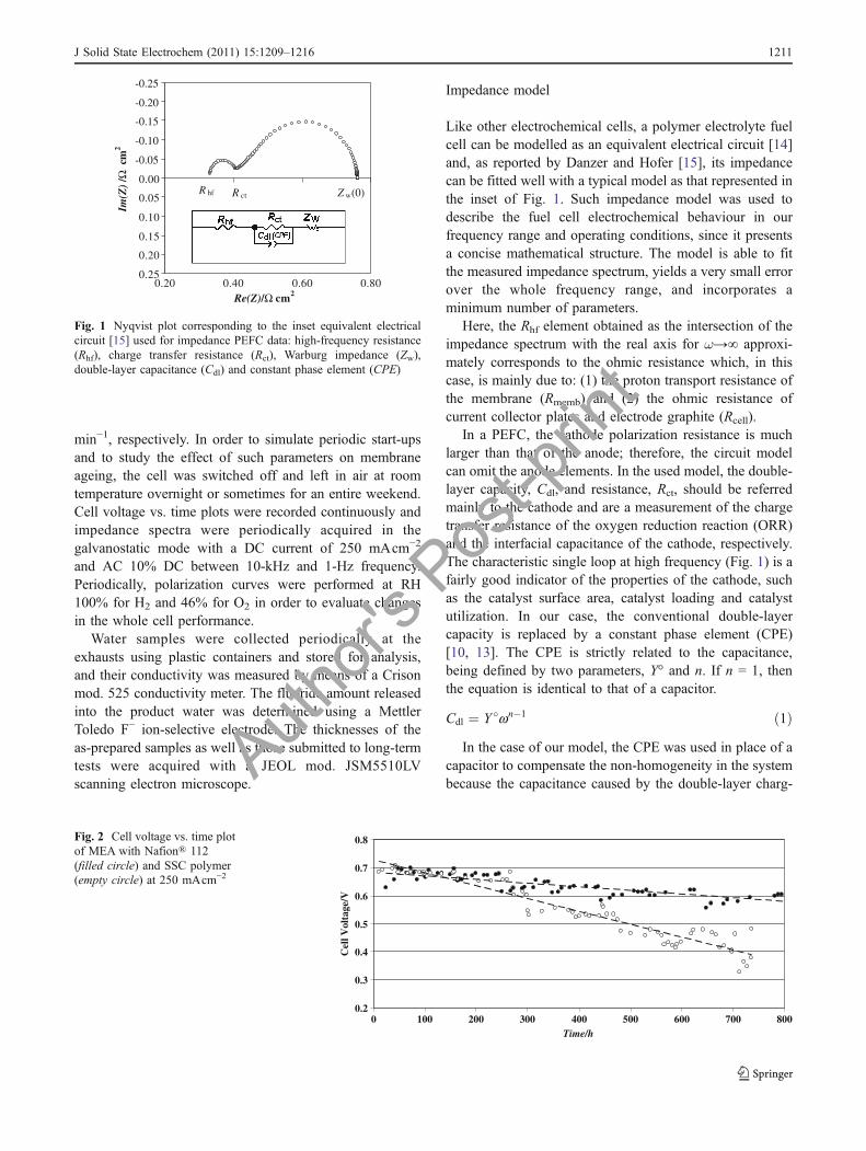
Like other electrochemical cells, a polymer electrolyte fuelcell can be modelled as an equivalent electrical circuit [14]and, as reported by Danzer and Hofer [15], its impedancecan be fitted well with a typical model as that represented inthe inset of Fig. 1. Such impedance model was used todescribe the fuel cell electrochemical behaviour in ourfrequency range and operating conditions, since it presentsa concise mathematical structure. The model is able to fitthe measured impedance spectrum, yields a very small errorover the whole frequency range, and incorporates aminimum number of parameters.
Here, the Rhf element obtained as the intersection of theimpedance spectrum with the real axis for ω→∞ approxi-mately corresponds to the ohmic resistance which, in thiscase, is mainly due to: (1) the proton transport resistance ofthe membrane (Rmemb) and (2) the ohmic resistance ofcurrent collector plates and electrode graphite (Rcell).
In a PEFC, the cathode polarization resistance is muchlarger than that of the anode; therefore, the circuit modelcan omit the anode elements. In the used model, the double-layer capacity, Cdl, and resistance, Rct, should be referredmainly to the cathode and are a measurement of the chargetransfer resistance of the oxygen reduction reaction (ORR)and the interfacial capacitance of the cathode, respectively.The characteristic single loop at high frequency (Fig. 1) is afairly good indicator of the properties of the cathode, suchas the catalyst surface area, catalyst loading and catalystutilization. In our case, the conventional double-layercapacity is replaced by a constant phase element (CPE)[10, 13]. The CPE is strictly related to the capacitance,being defined by two parameters, Y° and n. If n = 1, thenthe equation is identical to that of a capacitor.
Cdl ¼ Y �wn�1 ð1ÞIn the case of our model, the CPE was used in place of a
capacitor to compensate the non-homogeneity in the systembecause the capacitance caused by the double-layer charg-
-0.25
-0.20
-0.15
-0.10
-0.05
0.00
0.05
0.10
0.15
0.20
0.250.20 0.40 0.60 0.80
Re(Z)/Ω cm2
Im(Z
) /Ω
cm
2
R hf R ct Z w(0)
Fig. 1 Nyqvist plot corresponding to the inset equivalent electricalcircuit [15] used for impedance PEFC data: high-frequency resistance(Rhf), charge transfer resistance (Rct), Warburg impedance (Zw),double-layer capacitance (Cdl) and constant phase element (CPE)
0.2
0.3
0.4
0.5
0.6
0.7
0.8
0 100 200 300 400 500 600 700 800Time/h
Cel
l Vol
tage
/V
Fig. 2 Cell voltage vs. time plotof MEA with Nafion® 112(filled circle) and SSC polymer(empty circle) at 250 mAcm−2
J Solid State Electrochem (2011) 15:1209–1216 1211
Author'
s Pos
t-prin
t
Enea
Rettangolo

ing is distributed along the pore length in the PEFC porouselectrode.
Finally, the element ZW represents the finite-lengthWarburg impedance. This element was incorporated intothe model [15] to account for all the transport effect.Because of the Warburg impedance, this model is able todescribe the depressed semicircles. The second low-frequency arc in the Nyquist plot (Fig. 1) is related to thisslow mass transport (mainly oxygen) and can be describedby the finite-length Warburg impedance (Zw), as in Eq. 2[13]:
ZWðwÞ ¼ ZWð0Þ tahn Lffiffiffiffiffiffiffiffi
jwDpb c
Lffiffiffiffiffiffiffiffi
jwDp ð2Þ
where ω is the frequency, L the thickness of diffusion layerand D the diffusion coefficient of electroactive species,
respectively. The mass transport resistance, ZW(0) (i.e.ZW(ω) when ω → 0), can be obtained from Eq. 3:
ZWð0Þ ¼ RTL
n2F2DCð3Þ
where R is the gas constant, n is the electron number, F isthe Faraday constant, and C is the concentration of thediffusion species. All the values of these equivalent circuitcomponents are a function of the cell operating current orvoltage.
Results and discussion
Figure 2 depicts the cell voltage vs. time curves of MEAsprepared with N112 and SSC polymer membranes underparticular conditions of low humidity (RH 23%). For N112,the MEA performance at 50 °C and current density of250 mAcm−2 decreases at a rate of −129 μVh−1 after1,024 h with an average voltage of 0.63±0.04 V; however,in the first 600 h, a slightly higher decay (−154 μVh−1) wasobserved. Further analysis showed that in the first hours, avoltage increase until a maximum of 0.7 V has beenreached in about 72 h, and the voltage was kept constantuntil about 180 h. In the same conditions, the MEAwith SSCpolymer decreased at a rate of −451 μVh−1 after 736 h withan average voltage of 0.55±0.10 V. Also in this case, in thefirst hours, an increase until a maximum of 0.71 V has beenreached in about 40 h, and it was kept constant until about100 h. In the first 266 h, the decrease was only −104 μVh−1,and subsequently, a sharp decay was observed.
For a better understanding of the phenomena involved,impedance vs. time plots were acquired for the two cells.Figures 3 and 4 show the Nyquist plots for the twomembranes in different periods of time.
-0.25
-0.20
-0.15
-0.10
-0.05
0.00
0.05
0.10
0.15
0.20
0.250.25 0.45 0.65 0.85 1.05 1.25
Re(Z)/Ω cm2
Im(Z
)/Ω
cm
2
Fig. 3 Nyquist plots of MEAwith Nafion® 112 at 50 °C and 250 mAcm−2 after 40 h (triangle), 48 h (solid bar) 179 h (diamond) 617 h(square), and 1,019 h (circle)
-0.60
-0.50
-0.40
-0.30
-0.20
-0.10
0.00
0.10
0.200 0.4 0.8 1.2 1.6
Re(Z)/Ω cm2
Im(Z
)/Ω
cm
2
Fig. 4 Nyquist plots of MEA with SSC polymer at 50 °C and250 mA/cm2 after 5 h (triangle), 17 h (ex), 273 h (diamond), 474 h(square), 641 h (circle) and 734 h (plus sign)
0.00
0.20
0.40
0.60
0.80
1.00
1.20
1.40
1.60
1.80
2.000 1 2 3 4
log(f)/Hz
Re(
Z)/
Ω c
m2
Fig. 5 Bode plot of MEA with N112 (filled) and SSC polymer(empty) at 50 °C and 250 mA/cm2 after 40 h (filled circle and emptycircle) and 734 h (filled triangle and empty triangle)
1212 J Solid State Electrochem (2011) 15:1209–1216
Author'
s Pos
t-prin
t
Enea
Rettangolo

The Nyquist plots were characterized by the presence oftwo arcs at different frequencies. To explain the impedancebehaviour, we have carried out a deeper analysis based onthe model relative to the above-described equivalentelectric circuit [15].
The contributions of the current collector plates andgraphite were estimated by measuring the resistance of thecell fixture with two pieces of Toray carbon paper insertedand clamped with the same pressure of the MEAs; an Rcell
value of 0.3 Ωcm2 was obtained due to the ohmic resistanceof the current collector plates and graphite electrode.
In the first hours (Figs. 3 and 4), all the impedancecomponents decreased, except Rhf which increased mainlyin the case of the SSC polymer. This behaviour, known inthe initial working stage as “activation process”, can beexplained considering the water production in the cathodecatalytic layer and its effect on the whole conductivepolymer phase. Equations 4 and 5 evidence the importanceof diffusion of water into the polymeric phase (H2Opolymer)and its role in both the electrode reactions.
H2 þ 2H2Opolymer ! 2H3Oþpolymer þ 2e ð4Þ
1=202 þ 2H3Oþpolymer þ 2e ! 3H2Opolymer ð5Þ
In the first hours, we have observed a polarization resistancedecrease for two of the main contributions (activation Rct anddiffusive W) due especially to hydration of the perfluoro-
sulphonate membrane (ionomer and polymer) in direct contactwith the catalyst.
A deep analysis of the impedance Bode (Fig. 5) shows that afirst dramatic change occurred during the long-term test afterthe early hours with a continuous increase of Rhf in the real part.
The Rhf increase is directly related to the growth of theRmemb component due to membrane degradation in terms ofprotonic conductivity reduction. Figure 6 shows theresistance measured by means of a transient technique(RTT) for both samples. As reported by Yuan et al. [14], theimpedance and the current interruption method do notgenerate the same results, and it has been stated [16] thatthe membrane resistance measured with the current inter-ruption method is closer to the real values.
We have found that both cells showed a linear andirreversible increase: 0.52±0.03 mΩcm−2h−1 for N112 and0.58±0.04 mΩcm−2h−1 for the SSC polymer. The use ofthe continuous current interrupt technique demonstrated tobe very useful in order to evaluate the fuel cell long-termbehaviour. In fact, considering the reported Rcell value, thein situ low RH membrane resistance, Rmemb, and thecorresponding conductivity (σ) were easily calculated byEq. 6, where l represents the membrane thickness as afunction of working time. We have found a decrease ofconductivity from 71.6 to 6.1 mScm−1 for N112 and from103 to 8 mScm−1 for the SSC polymer.
s ¼ RTT � Rcellð Þl
ð6Þ
0.1
0.2
0.3
0.4
0.5
0.6
0.7
0.8
0.9
1.0
0 100 200 300 400 500 600 700 800 900 1000 1100Time/h
R T
T/Ω
cm
2
Fig. 6 Current interruptresistance vs. time plot of MEAwith N112 (filled circle)and the SSC polymer (emptycircle) at 250 mAcm−2
Fig. 7 SEM images of MEAwith N112 (left) and with theSSC polymer (right) afterlong-term test
J Solid State Electrochem (2011) 15:1209–1216 1213
Author'
s Pos
t-prin
t
Enea
Rettangolo
The decrease of conductivity due to membrane degrada-tion in the low humidity condition has been explained byseveral authors. Chen and Fuller [16] have observed astrong decrease in Nafion® 112 thermal stability after a120-h fuel cell OCV durability test at low humidity (RH36%). In particular, pinholes and delamination wereobserved near the anode side and close to the centre. Inaddition, a significant decrease of membrane thickness fromthe nominal 50 to 35 μm was observed together with an8.3% reduction in the ion exchange capacity that theyattributed to side chain degradation due to the S–O–S cross-linking [16]. By using SEM analysis (Fig. 7), we havefound a final average thickness of 35±3 μm for N112 witha 10% reduction with respect to that measured on thestarting MEA after the hot pressing process (39 μm) or on aN112 dried at 110 °C for 1 h [17]. In the case of the SSCpolymer, we have found a final average thickness of 24±3 μm with a 30% reduction with respect to that measuredon the MEA after the hot pressing process (34 μm).
It can then be concluded that the SSC polymer undergoes ahigher mass loss than N112 with a 20% increase of ratedegradation. Such thickness reduction higher than thatattributed simply to drying should be ascribed to a real massloss, as already proposed by the above-cited authors [16]. Bymeans of ex situ hygrothermal ageing on Nafion® 112 for400 days, Collette et al. [18] have reported membranedegradation through the modification of sulfonic acid end-groups consisting in the formation of sulfonic anhydridefrom condensation. Substitution of ionic-end group by lesshydrophilic anhydrides leads to a significant decrease ofwater uptake and conductivity, as evidenced in our previousmeasurements.
Although the SSC polymer demonstrated to be moreconductive, especially in the first hours as previouslyreported [9], it showed a weaker stability in long-term testswith a sharp performance decrease in low RH conditions.We cannot exclude the influence of the side chain chemicalstructure on the different degradation rates for the twopolymers. In addition, it can be supposed that the higherSSC degradation rate was also related to its differentmechanical properties, as reported by several authors [19–21]. In fact, during a normal fuel cell operation, theelectrodes are pressed against the polymer electrolytemembrane, and that leads to a mechanical stress on thepolymer. It is well known that the temperature and humidityinfluence strongly the mechanical properties of these
materials (tensile modulus, stress, elongation at break, tearresistance, etc.) [20–23]. Ghielmi et al. [9] have reportedthat only the tear resistance seems to be the same for N112and SSC. On the other hand, typical data of tensile modulusat low RH (50%) and 23 °C are 249 and 137 MPa for N112and SSC polymer, respectively [19, 20]. In the sameoperative conditions, stress at break values in the machineand transverse directions (MD/TD) are 43/32 and 30/23 MPa for N112 and SSC polymer, respectively [19, 20].Such data from the literature evidenced a differentmechanical resistance, which is higher for N112 withrespect to the SSC polymer in low RH conditions.
Fluoride emission and the water-related conductivitymeasured in the exhaust-collected water at the anodeand cathode (Table 1) confirmed the previous resultsevidencing a strong correlation between the membranemass loss in the exhaust-collected water and the degradationrate.
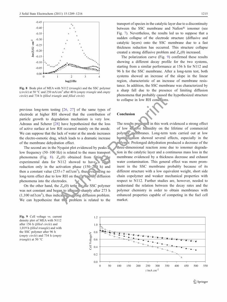
A second important change depicted in the Nyqvist plot(Figs. 3 and 4) was the increase of the first arc at highfrequency (3–5 kHz) as a function of time. From theinterpretation provided by the electric circuit model, thispeak growth observed for both MEAs in the Bode plot(Fig. 8) is due to the fast charge transfer phenomena relatedto the electrodes kinetic (mainly the ORR). The productRctCdl (see circuit in Fig. 1) represents the time constant (τ =RC), which is inversely related to the maximum frequency(fmax=1/τ). This relation implies that the RC product remainsconstant during the long-term degradation test. This effectcan be explained considering the presence of Nafion® in thecatalytic layer composition. As reported previously [24],electrode impregnation with a proton conductor extends thethree-dimensional reaction zone. An optimum Nafion®content in the electrode is necessary to minimize the chargetransfer resistance, as well as the ionic and gas transportlimitations. Nafion® long-term degradation due to lowhumidification occurred not only in the bulk membrane,but also in the catalytic layer, thus reducing its active contentand decreasing the three-dimensional reaction zone [1, 25].This reduction implies a symmetric increase of Rct and adecrease of Cdl keeping their product constant. Obviously,the reaction zone reduction could also be ascribed toplatinum dissolution and/or particle growth but, as has beendemonstrated extensively by many authors [1, 2, 25], thedominant degradation mechanisms at low RH conditions arerelated to the membrane and ionomer. In addition, our
Type [F−] (ppm) [χ] (μScm−1) [F−] (ppm) [χ] (μScm−1) Degradation rate (μVh−1)Cathode Cathode Anode Anode (600 h)
Nafion™ 112 0.40 6.7 0.47 18.7 −154SSC polymer 1.96 18.8 2.26 31.1 −471
Table 1 Fluoride emission andwater-related conductivitymeasured in exhaust-collectedwater
1214 J Solid State Electrochem (2011) 15:1209–1216
Author'
s Pos
t-prin
t
Enea
Rettangolo
previous long-term testing [26, 27] of the same types ofelectrode at higher RH showed that the contribution ofparticle growth to degradation mechanism is very low.Adreaus and Scherer [28] have hypothesized that the lossof active surface at low RH occurred mainly on the anode.We can suppose that the lack of water at the anode increasesthe electro-osmotic drag, which leads to a dramatic increaseof the membrane dehydration effect.
The second arc in the Nyquist plot evidenced by peaks atlow frequency (50–100 Hz) is related to the mass transportphenomena (Fig. 8). Zw(0) obtained from fitting theexperimental data for N112 showed to have a smallreduction only in the activation phase (150–200 h) andthen a constant value (235±7 mΩcm2), thus evidencing nolong-term effect due to low RH on the O2 and H2 diffusionphenomena into the electrodes.
On the other hand, the Zw(0) term for the SSC polymerwas not constant and began to increase sharply after 273 h(1,100 mΩcm2), thus indicating a strong diffusion problem.We can hypothesize that this problem is related to the
transport of species in the catalytic layer due to a discontinuitybetween the SSC membrane and Nafion® ionomer (seeFig. 7). Nevertheless, the results led us to suppose that asudden collapse of the electrode structure (diffusive andcatalytic layers) onto the SSC membrane due to a fastthickness reduction has occurred. This structure collapsecreated a strong diffusive problem and Zw(0) increased.
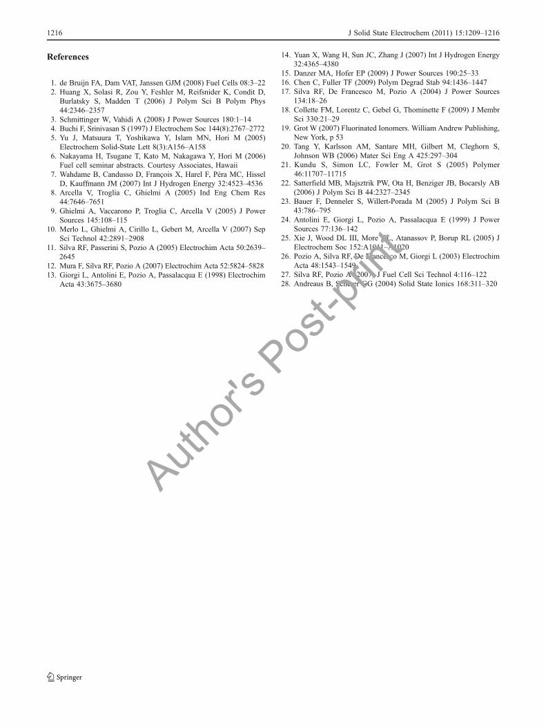
The polarization curve (Fig. 9) confirmed these resultsshowing a different decay profile for the two systems,starting from a similar performance at 156 h for N112 and96 h for the SSC membrane. After a long-term test, bothsystems showed an increase of the slope in the linearregion, characteristic of an increase of membrane resis-tance. In addition, the SSC membrane was characterized bya sharp fall due to the presence of limiting diffusionphenomena that probably caused the hypothesized structureto collapse in low RH conditions.
Conclusion
The results presented in this work evidenced a strong effectof low relative humidity on the lifetime of commercialpolymer membranes. Long-term tests carried out at lowhumidification showed several effects, especially in thepolymer. Prolonged dehydration produced a decrease of thethree-dimensional reaction zone due to ionomer degrada-tion in the catalytic layer and a continuous mass loss in themembrane evidenced by a thickness decrease and exhaustwater contamination. This general effect was more prom-inent in the SSC membrane probably because of itsdifferent structure with a low equivalent weight, short sidechain copolymer and weaker mechanical properties withrespect to N112. Further studies are, however, needed tounderstand the relation between the decay rates and thepolymer chemistry in order to obtain membranes withenhanced properties capable of competing in the fuel cellmarket.
0.0
0.2
0.4
0.6
0.8
1.0
1.2
0 50 100 150 200 250 300 350 400 450 500 550
i /mA cm-2
Cel
l Vol
tage
/V
Fig. 9 Cell voltage vs. currentdensity plot of MEA with N112after 156 h (filled circle) and1,019 h (filled triangle) and withthe SSC polymer after 96 h(empty circle) and 734 h (emptytriangle) at 50 °C
-0.45
-0.40
-0.35
-0.30
-0.25
-0.20
-0.15
-0.10
-0.05
0.000 1 2 3 4
log(f)/Hz
Im(Z
)/Ω
cm
-2
Fig. 8 Bode plot of MEA with N112 (triangle) and the SSC polymer(circle) at 50 °C and 250 mA/cm2 after 40 h (empty triangle and emptycircle) and 734 h (filled triangle and filled circle)
J Solid State Electrochem (2011) 15:1209–1216 1215
Author'
s Pos
t-prin
t
Enea
Rettangolo
References
1. de Bruijn FA, Dam VAT, Janssen GJM (2008) Fuel Cells 08:3–222. Huang X, Solasi R, Zou Y, Feshler M, Reifsnider K, Condit D,
Burlatsky S, Madden T (2006) J Polym Sci B Polym Phys44:2346–2357
3. Schmittinger W, Vahidi A (2008) J Power Sources 180:1–144. Buchi F, Srinivasan S (1997) J Electrochem Soc 144(8):2767–27725. Yu J, Matsuura T, Yoshikawa Y, Islam MN, Hori M (2005)
Electrochem Solid-State Lett 8(3):A156–A1586. Nakayama H, Tsugane T, Kato M, Nakagawa Y, Hori M (2006)
Fuel cell seminar abstracts. Courtesy Associates, Hawaii7. Wahdame B, Candusso D, François X, Harel F, Péra MC, Hissel
D, Kauffmann JM (2007) Int J Hydrogen Energy 32:4523–45368. Arcella V, Troglia C, Ghielmi A (2005) Ind Eng Chem Res
44:7646–76519. Ghielmi A, Vaccarono P, Troglia C, Arcella V (2005) J Power
Sources 145:108–11510. Merlo L, Ghielmi A, Cirillo L, Gebert M, Arcella V (2007) Sep
Sci Technol 42:2891–290811. Silva RF, Passerini S, Pozio A (2005) Electrochim Acta 50:2639–
264512. Mura F, Silva RF, Pozio A (2007) Electrochim Acta 52:5824–582813. Giorgi L, Antolini E, Pozio A, Passalacqua E (1998) Electrochim
Acta 43:3675–3680
14. Yuan X, Wang H, Sun JC, Zhang J (2007) Int J Hydrogen Energy32:4365–4380
15. Danzer MA, Hofer EP (2009) J Power Sources 190:25–3316. Chen C, Fuller TF (2009) Polym Degrad Stab 94:1436–144717. Silva RF, De Francesco M, Pozio A (2004) J Power Sources
134:18–2618. Collette FM, Lorentz C, Gebel G, Thominette F (2009) J Membr
Sci 330:21–2919. Grot W (2007) Fluorinated Ionomers. William Andrew Publishing,
New York, p 5320. Tang Y, Karlsson AM, Santare MH, Gilbert M, Cleghorn S,
Johnson WB (2006) Mater Sci Eng A 425:297–30421. Kundu S, Simon LC, Fowler M, Grot S (2005) Polymer
46:11707–1171522. Satterfield MB, Majsztrik PW, Ota H, Benziger JB, Bocarsly AB
(2006) J Polym Sci B 44:2327–234523. Bauer F, Denneler S, Willert-Porada M (2005) J Polym Sci B
43:786–79524. Antolini E, Giorgi L, Pozio A, Passalacqua E (1999) J Power
Sources 77:136–14225. Xie J, Wood DL III, More KL, Atanassov P, Borup RL (2005) J
Electrochem Soc 152:A1011–A102026. Pozio A, Silva RF, De Francesco M, Giorgi L (2003) Electrochim
Acta 48:1543–154927. Silva RF, Pozio A (2007) J Fuel Cell Sci Technol 4:116–12228. Andreaus B, Scherer GG (2004) Solid State Ionics 168:311–320
1216 J Solid State Electrochem (2011) 15:1209–1216
Author'
s Pos
t-prin
t
Enea
Rettangolo