The Green Roof: Common-Sense Advice on Durability
10
THE GREEN ROOF: COMMONSENSE ADVICE ON DURABILITY BY JEFFREY D. KERR, PE AND DANIEL A. DELISLE, LEED AP SIMPSON GUMPERTZ & HEGER, I NC. 2101 Gaither Road, Suite 250, Rockville, MD 20850 P: 3014170999 • F: 3014179825 • Email: [email protected]; [email protected] 26 TH RCI I NTERNATIONAL C ONVENTION AND T RADE S HOW • A PRIL 712, 2011 D ELISLE AND K ERR • 89
-
Upload
khangminh22 -
Category
Documents
-
view
7 -
download
0
Transcript of The Green Roof: Common-Sense Advice on Durability

THE GREEN ROOF: COMMONSENSE ADVICE ON DURABILITY
BY JEFFREY D. KERR, PE AND DANIEL A. DELISLE, LEED AP SIMPSON GUMPERTZ & HEGER, INC.
2101 Gaither Road, Suite 250, Rockville, MD 20850
P: 3014170999 • F: 3014179825 • Email: [email protected]; [email protected]
26 T H RC I I N T E R N AT I O N A L C O N V E N T I O N A N D T R A D E S H O W • A P R I L 7 1 2 , 2011 D E L I S L E A N D K E R R • 89

ABSTRACT
Waterproofing components of vegetated roofs are concealed under a relatively thick over-burden assembly, making waterproofing repairs and maintenance complicated and costly. Waterproofing systems for vegetated roofs require particularly robust construction and detailing, along with careful quality assurance during construction.
This presentation will review waterproofing design and construction advice for vegetat-ed roof assemblies; identify design considerations for the roof deck, waterproofing mem-brane, membrane-level drainage, insulation, and surface drainage; and draw on the authors’ experience investigating failed vegetated roof waterproofing installations to exam-ine common design and construction pitfalls that can cause premature failure of these sys-tems, along with strategies to avoid them.
SPEAKERS
DANIEL A. DELISLE, LEED AP — SIMPSON GUMPERTZ & HEGER, INC.
DANIEL A. DELISLE has more than four years of experience in investigation, construc-tion litigation, and rehabilitation construction administration. He specializes in waterproof-ing design of building enclosure systems, including curtain walls, windows, water penetra-tion and air infiltration field testing, and steep- and low-slope roofing. He received his B.S. in civil engineering from California Polytechnic State University. He is a registered LEED AP.
JEFFREY D. KERR, PE — SIMPSON GUMPERTZ & HEGER, INC.
JEFFREY D. KERR has more than ten years of project management and engineering experience. He specializes in waterproofing design of building enclosure systems, including foundations, wall systems, and low-slope roofing, and has extensive experience in commer-cial construction project management and consulting. He received a B.S. in civil engineer-ing from Cornell University. Kerr is a registered professional engineer in Virginia.
90 • D E L I S L E A N D K E R R 26 T H RC I I N T E R N AT I O N A L C O N V E N T I O N A N D T R A D E S H O W • A P R I L 7 1 2 , 2011

THE GREEN ROOF: COMMONSENSE ADVICE ON DURABILITY
INTRODUCTION “Green” roofing includes a wide variety
of practices intended to improve the impact of building construction on the natural environment. This article will discuss one type of green roofing, vegetative roofing (i.e., roofing systems with planted soil media overburden). The U.S. Green Building Council (USGBC) recommends vegetative roofing as one of the best ways to improve the environmental impact of a building and offer Leadership in Energy and Environmental Design (LEED) points for green roofing construction in several of its credit categories. Vegetative roofing is capa-ble of providing valuable engineering and architectural benefits, including stormwa-ter runoff management, urban heat island mitigation, reduced energy demand, and additional usable exterior space. Consequently, design and construction of vegetative roofing has become more com-mon.
The waterproofing components of vegetative roofing systems are con-cealed under a relatively thick overburden assem-bly (i.e., soil media and plantings), which, if designed and constructed properly, can serve to pro-tect the waterproofing, but that also makes perform-ing any repairs and main-taining the waterproofing membrane complicated and costly, compared to conventional exposed roof-ing membrane systems. This article will review design and construction considerations for water-proofing vegetative roofing systems.
BACKGROUND Roofing systems are
typically categorized into steep-slope and low-slope systems. Traditionally, steep-slope roofing sys-
tems are water-shedding roofing systems (i.e., do not always contain a continuous, watertight membrane as part of the roofing system) and rely on the roof slope (greater than 3 in over 12 in), underlayment, flash-ings, and a durable roof covering installed in a shingle-lapped fashion to resist water penetration. Low-slope roofing systems, while still requiring slope at the membrane level, lack the water-shedding capability of steep-slope systems and, therefore, require a durable and continuous waterproofing membrane to resist water penetration. Vegetative roofing systems always require continuous waterproofing because the soil media overburden can create conditions where the membrane is exposed to standing water, regardless of the roof slope. To enable repairs, the waterproofing design for vegetative roofing systems needs to consid-er the additional demand of a planted soil media overburden, plant roots, drainage, a high-moisture environment, and the lack of
access. A sound vegetative roofing system design requires the selection of a durable waterproofing membrane and accessories, robust design details, and quality assur-ance (i.e., activities implemented before exe-cution of the work in order to guard against defects) and quality control (i.e., procedures used to determine whether completed work meets the standard of quality established for the project) during construction for long-term waterproofing durability.
A typical vegetative roofing system will consist of the following components, from interior to exterior: roof structure, water-proofing membrane, protection board, root barrier, drainage board, insulation, water retention and/or reservoir layer, filter fab-ric, soil media overburden, and plantings (Image 1).
Conservative design elements, more common in waterproofing design than con-ventional exposed roofing membrane sys-tem design, are required to provide reliable
Image 1 – Typical vegetative roofing system.
26 T H RC I I N T E R N AT I O N A L C O N V E N T I O N A N D T R A D E S H O W • A P R I L 7 1 2 , 2011 D E L I S L E A N D K E R R • 91

vegetative roofing installations. We will use the term “waterproofing” and discuss water-proofing design concepts as they apply to vegetative roofing design.
This paper will focus on low-slope roof configurations. The waterproofing design considerations we discuss also apply to veg-etative roofing systems with steeper slopes, but these systems require special treatment of the overburden, including design of soil media retention systems to resolve slope stability considerations inherent in steeply sloped overburden configurations.
WATERPROOFING DESIGN CONSIDERATIONS FOR GREEN ROOFS
Vegetative roofing systems require designers to consider many aspects of the building design, including the additional load on the building structure, wind uplift loading on the overburden, and thermal insulation requirements. The following sec-tions discuss the waterproofing concepts that a design professional should consider when detailing a vegetative roofing system.
Waterproofing Membrane Selection In vegetative roofing systems, the water-
proofing membrane is concealed below planted soil media overburden. While the overburden will protect the membrane once it is installed, membrane access for mainte-nance or replacement is difficult, and iden-tifying the source of a leak can be particu-larly difficult; therefore, it is critical to select a durable waterproofing membrane with reliable seam construction and a track record of successful performance for a veg-etative roofing application.
When selecting a waterproofing mem-brane for a vegetative roofing application, the designer must consider the following aspects affecting membrane durability:
• Toughness: A membrane’s tough-ness is its ability to resist impact damage in application and resist deterioration in service. Vegetative roofing systems are typically consid-ered a type of protected membrane roofing system (i.e., once the over-burden is placed, the membrane is not exposed, and therefore protected from mechanical damage). Despite this protection, a tough membrane (combined with the appropriate pro-tection layers) is critical to with-stand overburden placement. Also, tougher membranes usually exhibit longer service lives. Manufacturers
market thicker membranes for applications that require more toughness; but in our experience, increasing membrane thickness alone does not always equate to a tougher membrane. Characteristics of a tough membrane also include the chemical composition, type and strength of reinforcing, and mem-brane installation method.
• Seam Construction: Most mem-brane seam construction methods fall into one of the following cate-gories: continuous mopping, hot-air or chemically welded, or adhered. Seams must be able to withstand the constant wet environment below planted soil media overburden. Without access to regularly inspect and perform repairs to membrane seams, selecting a reliable seam construction is critical to the long-term performance of a vegetative roofing system. Continuously mopped systems create a monolithic membrane (i.e., without distinct seams), which eliminates the con-cerns associated with seam con-struction in sheet membrane sys-tems.
• Bonding Method: Continuously bonded membranes (e.g., hot fluid-applied asphalt) and compartmen-talized systems (e.g., fully adhered membrane strips for membrane attachment) limit horizontal travel of water below the membrane and sig-nificantly reduce leak location efforts and water volume compared with loose-laid sheet membranes. Water that leaks through breaches in loose-laid membranes can migrate long distances, which com-plicates identification of the leak source and successful membrane repairs. In addition to difficulty identifying leaks within loose-laid membrane systems, leaks within these systems will be more severe; small openings in the membrane can lead to large amounts of water penetration because water that has breached the membrane can flow relatively unimpeded in the space between the membrane and the roof deck.
A variety of waterproofing membranes are suitable for vegetative roofing applica-tions; membrane durability, seam construc-
tion, and bonding method are not the only factors that contribute to a durable vegeta-tive roofing design. Regardless of the mem-brane selected, the designer must also con-sider the substrate construction, membrane protection, drainage, and a variety of perimeter flashing and penetration details. We examine these considerations in the fol-lowing sections.
Substrate Considerations In addition to supporting and transfer-
ring the weight of the overburden, and pro-viding the required roof slope, the water-proofing membrane substrate is important to membrane durability. In its Vegetative Roof Systems Manual, The National Roofing Contractors Association (NRCA) recom-mends that all waterproofing membranes used in vegetative roofing systems be installed as part of inverted roofing mem-brane assemblies (IRMA). IRMA configura-tions place the waterproofing membrane directly on the roof deck to provide a robust substrate, and below the insulation layer to protect the membrane from damage due to overburden placement.
The roof deck may be structural con-crete, structural steel with a composite con-crete-steel deck, structural steel with a steel deck overlaid with exterior-grade sheathing, or a wood-framed structure with wood sheathing. While each of these substrates can support a vegetative roofing assembly, concrete is more tolerant of moisture expo-sure than exterior-grade sheathing or ply-wood. Each of these systems requires spe-cific considerations during waterproofing membrane system selection and design.
Concrete Concrete is a durable, moisture-tolerant
substrate that is well suited for vegetative roofing systems. Concrete also provides a monolithic, seamless substrate, which is an important design consideration for mono-lithic waterproofing membranes (e.g., hot fluid-applied asphalt).
Concrete substrates must be properly cured and the surface must be dry prior to installing the waterproofing membrane to avoid trapping moisture below the mem-brane, which can affect membrane adhe-sion (see the Construction Considerations section for discussion of field testing for concrete moisture). The concrete finish (e.g., trowel, broom) can also affect mem-brane adhesion. Requirements for surface preparation vary among manufacturers, and the designer should be careful to coor-
92 • D E L I S L E A N D K E R R 26 T H RC I I N T E R N AT I O N A L C O N V E N T I O N A N D T R A D E S H O W • A P R I L 7 1 2 , 2011

Image 2 – Root damage to a hot fluidapplied asphalt base flashing. Note the root barrier rolled up on the lefthand side of the image did not turn up the parapet wall.
dinate the waterproofing manufacturer’s concrete finish requirements, as well as any compatibility concerns with concrete admixtures or curing compounds with the substrate preparation requirements for the project.
ExteriorGrade Sheathing and Plywood Fiberglass-faced gypsum sheathing and
plywood sheathing substrates include many fasteners and board-to-board joints. Monolithic waterproofing membranes that are continuously bonded to the substrate are vulnerable to the concentrated strain that occurs at sheathing joints; therefore, sheet membrane waterproofing systems are better suited to these substrates. Regardless of the waterproofing membrane system selected, the design must address the possibility of in-service movement at board joints and the potential for fasteners to back out, as both present a risk for the waterproofing membrane to sustain damage in service. Monolithic waterproofing mem-branes require special detailing when used over these types of substrates. Each joint must be reinforced with a strip flashing capable of accommodating the movement at these joints, and the boards must be installed with the appropriate fasten-ers/spacing. Similarly, joints between light-gauge metal-framed curbs with sheathing and a concrete roof slab are similar areas of concern and need to be addressed with a similar strip flashing to accommodate the movement potential at the base of a parapet or rising wall. We have seen leakage to the
building interior where these joints were not reinforced and only the waterproofing mem-brane was used to span the joint.
Membrane Protection Vegetative roofing membranes require a
protection layer to reduce the risk of mechanical damage to the membrane dur-ing initial overburden placement and in-ser-vice loads. Additional measures are required to protect the waterproofing mem-brane during the construction process (see the Construction Considerations section for discussion of temporary membrane protec-tion during construction). A dedicated pro-tection layer (i.e., separate from the water-proofing membrane) provides improved puncture resistance.
In vegetative roofing systems, a root barrier is also required to protect the water-proofing membrane from the potential of root penetration into the membrane. The two primary types of root barriers are high-density polyethylene sheets and bituminous sheets with embedded or applied chemical root inhibitors. High-density polyethylene sheet root barriers rely on the mechanical properties of the sheet (e.g., puncture resis-tance, tear strength) to protect the water-proofing membrane from root ingress. Chemical root barriers rely on embedded or applied chemicals to constrain root growth without killing the plants. Both root barrier types are required to be installed continu-ous over the waterproofing membrane, including at perimeter details and penetra-tions (e.g., the root barrier should be turned
up at base flashings to prevent roots from penetrating the roofing at these vulnerable conditions).
On a vegetative roofing project in Maryland, we observed deteriorated base flashings at parapet walls caused by the propagation of roots through the water-proofing membrane. The root barrier stopped at the base of the parapet wall. The roots penetrating the waterproofing mem-brane contributed to membrane deteriora-tion and leakage to the building interior (Image 2).
Drainage Considerations Most engineering materials, including
waterproofing membranes, will absorb water; this effect is accelerated when the materials are continually exposed to water. Water absorption will weaken and deterio-rate waterproofing membranes over time. Standing water on the membrane surface will increase the rate of membrane deterio-ration. Even without water standing at membrane seams, water draining across the surface of the membrane will attack membrane transitions (e.g., seams) and construction defects, which may contribute to leakage. Therefore, vegetative roofing sys-tems require slope at the membrane level to drain water from the membrane surface, an unobstructed membrane level drainage path to conduct water away from the mem-brane surface, and drains to collect water.
Model building codes require a mini-mum of ¼ in/ft slope for exposed roofing membranes in low-sloped applications.
26 T H RC I I N T E R N AT I O N A L C O N V E N T I O N A N D T R A D E S H O W • A P R I L 7 1 2 , 2011 D E L I S L E A N D K E R R • 93
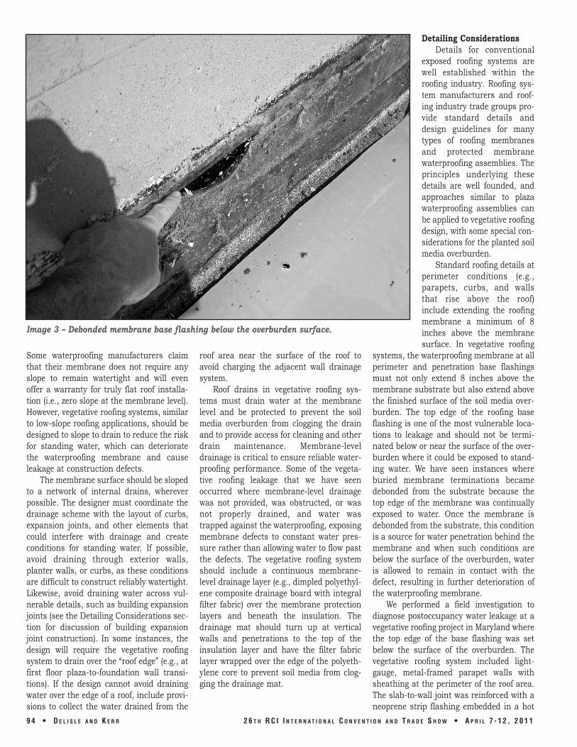
Image 3 – Debonded membrane base flashing below the overburden surface.
Some waterproofing manufacturers claim that their membrane does not require any slope to remain watertight and will even offer a warranty for truly flat roof installa-tion (i.e., zero slope at the membrane level). However, vegetative roofing systems, similar to low-slope roofing applications, should be designed to slope to drain to reduce the risk for standing water, which can deteriorate the waterproofing membrane and cause leakage at construction defects.
The membrane surface should be sloped to a network of internal drains, wherever possible. The designer must coordinate the drainage scheme with the layout of curbs, expansion joints, and other elements that could interfere with drainage and create conditions for standing water. If possible, avoid draining through exterior walls, planter walls, or curbs, as these conditions are difficult to construct reliably watertight. Likewise, avoid draining water across vul-nerable details, such as building expansion joints (see the Detailing Considerations sec-tion for discussion of building expansion joint construction). In some instances, the design will require the vegetative roofing system to drain over the “roof edge” (e.g., at first floor plaza-to-foundation wall transi-tions). If the design cannot avoid draining water over the edge of a roof, include provi-sions to collect the water drained from the
roof area near the surface of the roof to avoid charging the adjacent wall drainage system.
Roof drains in vegetative roofing sys-tems must drain water at the membrane level and be protected to prevent the soil media overburden from clogging the drain and to provide access for cleaning and other drain maintenance. Membrane-level drainage is critical to ensure reliable water-proofing performance. Some of the vegeta-tive roofing leakage that we have seen occurred where membrane-level drainage was not provided, was obstructed, or was not properly drained, and water was trapped against the waterproofing, exposing membrane defects to constant water pres-sure rather than allowing water to flow past the defects. The vegetative roofing system should include a continuous membrane-level drainage layer (e.g., dimpled polyethyl-ene composite drainage board with integral filter fabric) over the membrane protection layers and beneath the insulation. The drainage mat should turn up at vertical walls and penetrations to the top of the insulation layer and have the filter fabric layer wrapped over the edge of the polyeth-ylene core to prevent soil media from clog-ging the drainage mat.
Detailing Considerations Details for conventional
exposed roofing systems are well established within the roofing industry. Roofing sys-tem manufacturers and roof-ing industry trade groups pro-vide standard details and design guidelines for many types of roofing membranes and protected membrane waterproofing assemblies. The principles underlying these details are well founded, and approaches similar to plaza waterproofing assemblies can be applied to vegetative roofing design, with some special con-siderations for the planted soil media overburden.
Standard roofing details at perimeter conditions (e.g., parapets, curbs, and walls that rise above the roof) include extending the roofing membrane a minimum of 8 inches above the membrane surface. In vegetative roofing
systems, the waterproofing membrane at all perimeter and penetration base flashings must not only extend 8 inches above the membrane substrate but also extend above the finished surface of the soil media over-burden. The top edge of the roofing base flashing is one of the most vulnerable loca-tions to leakage and should not be termi-nated below or near the surface of the over-burden where it could be exposed to stand-ing water. We have seen instances where buried membrane terminations became debonded from the substrate because the top edge of the membrane was continually exposed to water. Once the membrane is debonded from the substrate, this condition is a source for water penetration behind the membrane and when such conditions are below the surface of the overburden, water is allowed to remain in contact with the defect, resulting in further deterioration of the waterproofing membrane.
We performed a field investigation to diagnose postoccupancy water leakage at a vegetative roofing project in Maryland where the top edge of the base flashing was set below the surface of the overburden. The vegetative roofing system included light-gauge, metal-framed parapet walls with sheathing at the perimeter of the roof area. The slab-to-wall joint was reinforced with a neoprene strip flashing embedded in a hot
94 • D E L I S L E A N D K E R R 26 T H RC I I N T E R N AT I O N A L C O N V E N T I O N A N D T R A D E S H O W • A P R I L 7 1 2 , 2011

fluid-applied asphalt waterproofing mem-brane.
The hot fluid-applied asphalt membrane was turned up the parapet wall, but did not extend above the surface of the soil media overburden. The parapet wall was covered with flat metal panels applied directly over the waterproofing membrane with lapped panel-to-panel joints. During our investiga-tion, we found that water penetrating the coping flashing and parapet metal panel joints was able to soak into the sheathing along the top edge of the waterproofing membrane. As the sheathing deteriorated in the presence of constant moisture, the top edge of the roofing membrane became unadhered from the substrate and, ulti-mately, allowed water to leak to the building interior (Image 3).
Base flashing conditions are a common source of problems in any roofing system, and these conditions should be designed to allow access for inspection, maintenance, and repair, as well as be designed to be durable for the expected service life of the waterproofing membrane. For example, installing a band of gravel ballast or row of precast concrete pavers on pedestals adja-cent to perimeter conditions and penetra-tions (e.g., drains) allows easier access to the waterproofing mem-brane than the planted soil media overburden (Image 4). All base flashings should be pro-tected from damage by a noncorrosive metal flashing that is integrat-ed with the particular perimeter condition or penetration. This is a critical consideration for vegetative roofing systems, given the land-scaping operations and other maintenance activity that will occur on roofs with planted soil media overburden. Metal flashing will pro-tect the waterproofing membrane from mechanical damage that may otherwise occur during such activities. The flashing should be constructed so that it can be removed for ease of
access to the waterproofing for mainte-nance, repairs, or future waterproofing membrane replacement without requiring deconstruction of adjacent enclosure sys-tems (e.g., a two-piece receiver and counter-flashing assembly).
Building expansion joints are often required to allow for independent movement of the building structure between adjacent buildings or distinct sections of larger buildings. Continuous waterproofing is still required where these joints intersect the building enclosure. The requirements for movement at these joints challenge the waterproofing continuity and require spe-cial detailing, which, if disregarded, can result in leakage. Frequently, building expansion joints in vegetative roof areas and pedestrian plazas are concealed within the overburden due to functional and aes-thetic considerations. If possible, avoid building expansion joint construction across vegetative roof areas. If the design cannot accommodate relocating such joints, the expansion joints should be elevated above the overburden (or located at a break in the overburden) to provide access for maintenance (similar to the perimeter con-ditions described above) and to improve the
waterproofing reliability of these challeng-ing details.
In some instances, it will not be reason-able to extend the expansion joint above the finished surface of the overburden. In such instances, the building expansion joint should be raised on a curb above the mem-brane level, the membrane surface should slope away from the building expansion joint, provide positive slope across the joint (e.g., convex bellows shape), cover the joint with a continuous waterproofing membrane (and root barrier where below the soil media overburden), and protect the membrane from damage with metal flashing or a pro-tection plate. Membrane protection must be designed to withstand overburden loads, and expansion joint details must be designed to accommodate the anticipated building movement while maintaining an effective water barrier (Expansion Joints in Deck Waterproofing Systems, Rutila and Ruggiero, 1994).
We performed a field investigation to diagnose postoccupancy water leakage on a vegetative roofing project in Maryland where we indentified leaks below a building expan-sion joint. We knew that water was entering at the building expansion joint. However,
Image 4 – Vegetative roof area (note the gravel ballast around the roof drains and along the roof perimeter).
26 T H RC I I N T E R N AT I O N A L C O N V E N T I O N A N D T R A D E S H O W • A P R I L 7 1 2 , 2011 D E L I S L E A N D K E R R • 95

Image 5 – Expansion joint membrane buried below several feet of soil media overburden (note the water standing on the expansion joint membrane).
Image 6 – Field adhesion test for a newly installed hot fluidapplied asphalt membrane.
the specific origin(s) of the leak were not readily apparent since the expansion joint membrane was concealed below the soil media overburden. We removed several feet of soil media overburden along the entire length of the expansion joint (approximate-ly 100 ft) to expose the expansion joint membrane (Image 5). The expansion joint membrane was integrated with the hot fluid-applied asphalt waterproofing mem-brane and was installed at the level of the roof deck, concealed below several feet of soil media overburden without any protec-tion from mechanical damage. We found that the expansion joint membrane was damaged in random locations throughout the length of the joint, and we found areas where the expansion joint membrane was poorly adhered to the roof slab. The expan-sion joint membrane construction leaked because it had sustained damage and the expansion joint assembly was not raised above the roof-drainage surface. The place-ment of the expansion joint membrane at the roof surface, the lack of slope away from the joint, and the lack of membrane protec-tion each contributed to the poor perfor-mance of the expansion joint waterproofing.
96 • D E L I S L E A N D K E R R
CONSTRUCTION CONSIDERATIONS ficient information to guide the construc-FOR GREEN ROOFS tion team’s quality assurance measures
Given the lack of access to the water- prior to waterproofing membrane installa-proofing membrane following overburden tion. These include engaging a trade con-placement, design and construction teams tractor with experience in installing the must provide vigilant quality assur- specified waterproofing product in vegeta-ance/control efforts during construction to tive roofing systems of similar complexity avoid costly repairs once the building is and requiring performance testing of the occupied. completed membrane prior to overburden
Design documents need to contain suf- placement. Project specifications should
26 T H RC I I N T E R N AT I O N A L C O N V E N T I O N A N D T R A D E S H O W • A P R I L 7 1 2 , 2011

Image 7 – Flood test over newly installed hot fluidapplied asphalt membrane.
require the construction team to provide shop drawings that develop project-specific details that are coordinated with adjacent building enclo-sure systems and the overburden configura-tion (e.g., base flashing heights above the sur-face of the overburden) and that are reviewed by the waterproofing manu-facturer for compliance with its recommended installation procedures, compatibility guidelines, and warranty require-ments.
The substrate below vegetative roofing sys-tems is frequently a cast-in-place concrete slab. Concrete can take a con-siderable time to dry enough to reach mois-ture equilibrium, partic-ularly when it is placed over metal roof decking. This drying time poses logistical and scheduling challenges for the contractor and should be accommodated by the project schedule. Monolithic water-proofing membranes that are continuously bonded to the substrate and adhered sheet membrane systems may blister or become unadhered if the membrane is applied over concrete with elevated moisture content. The waterproofing membrane installer should test the substrate in the field prior to membrane application to establish if the conditions present are sufficient to promote good adhesion. A standard test for concrete moisture (ASTM D4263, Standard Test Method for Indicating Moisture in Concrete by the Plastic Sheet Method), requires an 18-sq-in plastic sheet be taped to the surface of the concrete slab for 72 hours to observe if moisture collects under the plastic sheet.
In addition to the plastic sheet test, waterproofing manufacturers often recom-mend product-specific membrane field adhesion testing to determine substrate suitability (Image 6). Both of these tests are qualitative tests of the substrate condition; one tests membrane adhesion, and the other provides information regarding the substrate moisture content near the surface of the slab. These tests can be used to eval-uate whether the concrete substrate is
ready to receive the waterproofing mem-brane.
During membrane installation, the con-tractor should provide regular inspections by an individual with specific knowledge of the product, including the membrane man-ufacturer’s requirements.
Once the membrane is installed in an area of the roof, including final detailing at penetrations and perimeter conditions, the completed membrane installation should be water tested to identify and repair leaks prior to overburden placement. Flood test-ing and electric field vector mapping (EFVM) are two types of water tests used for contin-uously bonded waterproofing membranes. ASTM D5957, Standard Guide for Flood Testing Horizontal Waterproofing Installations, describes a procedure for field water testing of low-slope waterproofing installa-tions. Field water testing of the waterproof-ing membrane is typically done in zones (portions of the whole roof area centered on roof drains). In each zone, the waterproofing membrane should be covered with water to a depth of at least 2 inches against all base flashings for 48 hours (Image 7). During the test period, the membrane seams are inspected for bubbles coming from mem-brane seams or similar conditions below the
water level, and the underside of the roof structure is inspected for evidence of leak-age. Following the test period, the water is drained from the test area and membrane seams and flashings are inspected for defects (even if no evidence of leakage was observed during the test). Expansion joints, complicated flashings, and other conditions that do not lend themselves to flood testing should be water tested with spray racks or nozzles to demonstrate a watertight mem-brane installation prior to overburden placement. EFVM uses an electric generator connected to a wire loop on the surface of the waterproofing membrane and a thin layer of water over the surface of the water-proofing membrane to create an electric field at the membrane surface. An EFVM test technician then uses a potentiometer to identify changes in the electric field that correspond to breaches in the waterproofing membrane. Similar to flood testing, condi-tions that do not lend themselves to EFVM should be water tested with spray racks or nozzles.
It is not uncommon for membrane water tests to fail. The construction schedule should anticipate the need to make repairs to the waterproofing membrane and to repeat the corresponding water-testing
26 T H RC I I N T E R N AT I O N A L C O N V E N T I O N A N D T R A D E S H O W • A P R I L 7 1 2 , 2011 D E L I S L E A N D K E R R • 97

activities to confirm that the leaks have been successfully repaired.
Once the membrane has been inspected and successfully tested, protect it from con-struction traffic as soon as feasible to limit the potential for mechanical damage to the membrane. The best method for protecting the membrane is to place the overburden as soon after the membrane installation as practical. Other methods, such as placing temporary protection (e.g., rigid insulation or plywood sheathing) or restricting access to completed roof areas, have limited effec-tiveness against the abuse from other trades working above the completed roofing membrane. We have observed loose fasten-ers pressed through the protection layer into the roofing membrane and new pene-trations made through completed roofing membrane due to design changes during construction. If a completed and tested area of roofing membrane has seen significant construction traffic or construction changes to the waterproofing membrane configura-tion, then additional water testing should be performed to identify and repair any
membrane defects prior to overburden placement.
On a vegetative roofing project in California, we observed flood testing per-formed by the construction team. After the testing was complete and the waterproofing membrane was determined to be installed watertight, other trade contractors erected scaffolding to complete soffit construction above the tested waterproofing membrane (Image 8). Once the scaffolding was removed, the roofing contractor had to repair the damaged waterproofing. Repeat water testing of the waterproofing mem-brane following the completion of the select-ed repair work identified additional defects in the membrane. The additional defects were repaired and successfully water tested prior to overburden placement.
CONCLUSIONS The waterproofing components of vege-
tative roofing systems are concealed under a relatively thick overburden, making waterproofing repairs and maintenance complicated and costly, compared to
exposed membrane roofing systems. For “green” roof-ing initiatives to be suc-cessful, the waterproofing performance of these in-stallations must be reliable and durable for many years. Designers must focus on selecting a du-rable waterproofing mem-brane, providing drainage to direct water away from the membrane surface, and raising vulnerable details above the mem-brane surface and, where feasible, above the surface of the overburden. De-signers must also antici-pate the need for access for maintenance and repair. The construction team must provide vigilant qual-ity control efforts during construction and water test the membrane prior to overburden placement.
REFERENCES ASTM D4263 – Standard Test Method for
Indicating Moisture in Concrete by the Plastic Sheet Method, ASTM International, Conshohocken, PA, www.astm.org, 2005.
ASTM D5957 – Standard Guide for Flood Testing Horizontal Waterproofing Installations, ASTM International, Conshohocken, PA, www.astm.org, 2005.
D. Rutila, S. Ruggiero, “Expansion Joints in Deck Waterproofing Systems,” Science and Technology of Building Seals, Sealants, Glazing, and Waterproofing: 3rd Volume, ASTM STP 1254, James C. Myers, Ed., American Society of Testing and Materials, Philadelphia, 1994, pp. 57-70.
Vegetative Roof Systems Manual, (2nd ed.), NCRA, Rosemont, IL, www.nrca.net, 2009.
Image 8 – Scaffolding being installed over newly installed roofing membrane.
98 • D E L I S L E A N D K E R R 26 T H RC I I N T E R N AT I O N A L C O N V E N T I O N A N D T R A D E S H O W • A P R I L 7 1 2 , 2011