A Review on Sustainability, Durability, and Structural Properties
33
materials Review Green Concrete for a Circular Economy: A Review on Sustainability, Durability, and Structural Properties Abathar Al-Hamrani 1 , Murat Kucukvar 2, * , Wael Alnahhal 1 , Elsadig Mahdi 2 and Nuri C. Onat 3 Citation: Al-Hamrani, A.; Kucukvar, M.; Alnahhal, W.; Mahdi, E.; Onat, N.C. Green Concrete for a Circular Economy: A Review on Sustainability, Durability, and Structural Properties. Materials 2021, 14, 351. https://doi.org/10.3390/ma14020351 Received: 24 December 2020 Accepted: 5 January 2021 Published: 12 January 2021 Publisher’s Note: MDPI stays neu- tral with regard to jurisdictional clai- ms in published maps and institutio- nal affiliations. Copyright: © 2021 by the authors. Li- censee MDPI, Basel, Switzerland. This article is an open access article distributed under the terms and con- ditions of the Creative Commons At- tribution (CC BY) license (https:// creativecommons.org/licenses/by/ 4.0/). 1 Department of Civil and Architectural Engineering, Qatar University, Doha 2713, Qatar; [email protected] (A.A.-H.); [email protected] (W.A.) 2 Department of Mechanical and Industrial Engineering, College of Engineering, Qatar University, Doha 2713, Qatar; [email protected] 3 Qatar Transportation and Traffic Safety Center, Qatar University, Doha 2713, Qatar; [email protected] * Correspondence: [email protected]; Tel.: +974-4403-4332 Abstract: A primary concern of conventional Portland cement concrete (PCC) is associated with the massive amount of global cement and natural coarse aggregates (NCA) consumption, which causes depletion of natural resources on the one hand and ecological problems on the other. As a result, the concept of green concrete (GC), by replacing cement with supplementary cementitious materials (SCMs) such as ground granulated blast furnace slag (GGBFS), fly ash (FA), silica fume (SF), and metakaolin (MK), or replacing NCA with recycled coarse aggregates, can play an essential role in addressing the environmental threat of PCC. Currently, there is a growing body of literature that emphasizes the importance of implementing GC in concrete applications. Therefore, this paper has conducted a systematic literature review through the peer-reviewed literature database Scopus. A total of 114 papers were reviewed that cover the following areas: (1) sustainability benefits of GC, (2) mechanical behavior of GC in terms of compressive strength, (3) durability properties of GC under several environmental exposures, (4) structural performance of GC in large-scale reinforced beams under shear and flexure, and (5) analytical investigation that compares the GC shear capacities of previously tested beams with major design codes and proposed models. Based on this review, the reader will be able to select the optimum replacement level of cement with one of the SCMs to achieve a certain concrete strength range that would suit a certain concrete application. Also, the analysis of durability performance revealed that the addition of SCMs is not recommended in concrete exposed to a higher temperature than 400 ◦ C. Moreover, combining GGBFS with FA in a concrete mix was noticed to be superior to PCC in terms of long-term resistance to sulfate attack. The single most striking observation to emerge from the data comparison of the experimentally tested beams with the available concrete shear design equations is that the beams having up to 70% of FA as a replacement to OPC or up to 100% of RCA as a replacement to NCA were conservatively predicted by the equations of Japan Society of Civil Engineers (JSCE-1997), the American Concrete Institute (ACI 318-19), and the Canadian Standards Association (CSA-A23.3-14). Keywords: green concrete; cement; ground granulated blast furnace slag; fly ash; silica fume; metakaolin 1. Introduction With the increasing risks of climate change and the depletion of natural resources due to their utilization in the construction industry, sustainability has gained wide importance and the term circular economy (CE) has emerged as one of the most important factors leading to sustainable development [1]. In contrast to the prevailing traditional economy system, which is based on a methodology of make, use, and finally, dispose of, the CE aims at continuous use of products by recycling and reusing instead of disposing to create a closed-loop system and reduce the resource consumption [2]. Materials 2021, 14, 351. https://doi.org/10.3390/ma14020351 https://www.mdpi.com/journal/materials
-
Upload
khangminh22 -
Category
Documents
-
view
9 -
download
0
Transcript of A Review on Sustainability, Durability, and Structural Properties

materials
Review
Green Concrete for a Circular Economy: A Review onSustainability, Durability, and Structural Properties
Abathar Al-Hamrani 1, Murat Kucukvar 2,* , Wael Alnahhal 1 , Elsadig Mahdi 2 and Nuri C. Onat 3
Citation: Al-Hamrani, A.; Kucukvar,
M.; Alnahhal, W.; Mahdi, E.; Onat,
N.C. Green Concrete for a Circular
Economy: A Review on Sustainability,
Durability, and Structural Properties.
Materials 2021, 14, 351.
https://doi.org/10.3390/ma14020351
Received: 24 December 2020
Accepted: 5 January 2021
Published: 12 January 2021
Publisher’s Note: MDPI stays neu-
tral with regard to jurisdictional clai-
ms in published maps and institutio-
nal affiliations.
Copyright: © 2021 by the authors. Li-
censee MDPI, Basel, Switzerland.
This article is an open access article
distributed under the terms and con-
ditions of the Creative Commons At-
tribution (CC BY) license (https://
creativecommons.org/licenses/by/
4.0/).
1 Department of Civil and Architectural Engineering, Qatar University, Doha 2713, Qatar;[email protected] (A.A.-H.); [email protected] (W.A.)
2 Department of Mechanical and Industrial Engineering, College of Engineering, Qatar University,Doha 2713, Qatar; [email protected]
3 Qatar Transportation and Traffic Safety Center, Qatar University, Doha 2713, Qatar; [email protected]* Correspondence: [email protected]; Tel.: +974-4403-4332
Abstract: A primary concern of conventional Portland cement concrete (PCC) is associated withthe massive amount of global cement and natural coarse aggregates (NCA) consumption, whichcauses depletion of natural resources on the one hand and ecological problems on the other. As aresult, the concept of green concrete (GC), by replacing cement with supplementary cementitiousmaterials (SCMs) such as ground granulated blast furnace slag (GGBFS), fly ash (FA), silica fume(SF), and metakaolin (MK), or replacing NCA with recycled coarse aggregates, can play an essentialrole in addressing the environmental threat of PCC. Currently, there is a growing body of literaturethat emphasizes the importance of implementing GC in concrete applications. Therefore, this paperhas conducted a systematic literature review through the peer-reviewed literature database Scopus.A total of 114 papers were reviewed that cover the following areas: (1) sustainability benefits ofGC, (2) mechanical behavior of GC in terms of compressive strength, (3) durability properties of GCunder several environmental exposures, (4) structural performance of GC in large-scale reinforcedbeams under shear and flexure, and (5) analytical investigation that compares the GC shear capacitiesof previously tested beams with major design codes and proposed models. Based on this review,the reader will be able to select the optimum replacement level of cement with one of the SCMsto achieve a certain concrete strength range that would suit a certain concrete application. Also,the analysis of durability performance revealed that the addition of SCMs is not recommended inconcrete exposed to a higher temperature than 400 C. Moreover, combining GGBFS with FA in aconcrete mix was noticed to be superior to PCC in terms of long-term resistance to sulfate attack. Thesingle most striking observation to emerge from the data comparison of the experimentally testedbeams with the available concrete shear design equations is that the beams having up to 70% of FA asa replacement to OPC or up to 100% of RCA as a replacement to NCA were conservatively predictedby the equations of Japan Society of Civil Engineers (JSCE-1997), the American Concrete Institute(ACI 318-19), and the Canadian Standards Association (CSA-A23.3-14).
Keywords: green concrete; cement; ground granulated blast furnace slag; fly ash; silica fume;metakaolin
1. Introduction
With the increasing risks of climate change and the depletion of natural resources dueto their utilization in the construction industry, sustainability has gained wide importanceand the term circular economy (CE) has emerged as one of the most important factorsleading to sustainable development [1]. In contrast to the prevailing traditional economysystem, which is based on a methodology of make, use, and finally, dispose of, the CE aimsat continuous use of products by recycling and reusing instead of disposing to create aclosed-loop system and reduce the resource consumption [2].
Materials 2021, 14, 351. https://doi.org/10.3390/ma14020351 https://www.mdpi.com/journal/materials

Materials 2021, 14, 351 2 of 33
Evidence suggests that the increasing population growth rate is among the mostimportant factors for urban expansion [3]. Recently, records have shown that comparedto 1960, at which the population was only 3 billion, the population dramatically jumpedto 7.2 billion in 2017 [4]. This dramatic increase is pressing on the environment, andthus necessitates the allocation of more housing units and service and industrial facilities.As a result, countries are undergoing a revolution in terms of construction to meet thenecessary needs.
From a construction perspective, the Portland cement concrete (PCC) is recognized asthe most important material that is widely used in different structural applications withabundant raw material. Annually, more than six billion tons of concrete are producedglobally, which are equivalent to 1 ton/capita on the planet [5,6]. Previous studies [5,7]reported that in a cubic yard of concrete, 10% by weight contains cement and around0.9 tons of carbon footprint are generated per 1 ton of cement. In the manufacturing processof cement, two basic raw ingredients, namely calcareous material (i.e., limestone) and anargillaceous material (i.e., clay), are melted at high temperatures of 1400 to 1650 C, to betransferred to cement clinker [8]. Thus, this process consumes massive amounts of fossilfuels, resulting in a huge carbon footprint [5]. This is beside the carbon footprint induced bythe chemical reaction involved to decompose limestone (CaCO3) into (CaO + CO2) [9,10].The International Energy Agency (World Energy Outlook 2016) estimated the global carbonfootprint to be 21.6 billion tons, of which the cement production accounts for 8% of thetotal carbon footprint [9,11,12]. Furthermore, in the last decade, the cement industry hasbecome the second-fastest growing industry in releasing CO2 emissions due to the growingworldwide demand for concrete [7]. Meanwhile, recent statistics indicated an annualworldwide generation of slag and fly ash (FA) wastes of around 270 to 320 million tons and1 billion tons, respectively [13,14]. Moreover, in the United States and Norway, the annualoutput of silica fume (SF) was estimated to be of the order 2 × 10⁵ to 5 × 10⁵ tons [15].In Turkey, Baspinar and Demir [15] also stated that 700 to 1000 tons of SF were producedfrom one ferrosilicon production plant. Furthermore, the rice husk ash (RHA) is anotherhighly reactive pozzolanic material obtained as a residue from the pod of rice grains, witha tremendous global amount of 156 million metric tons [16].
Coupled with the cement issue is the tremendous worldwide construction and demo-lition (C&D) wastes originated from the demolition and reconstruction of old structures,which creates another source of environmental burdens. It has previously been observedthat annually, over 500 million tons of C&D wastes are generated worldwide [17]. Morerecently, Akhtar and Sarmah [18] stated that a global amount of C&D wastes exceeding3 billion tons are generated annually, where China, India, and the USA are the majorcontributors to this waste. Subsequently, more land areas are being occupied and pollutedwhen disposing C&D wastes into landfills [19,20]. With this in mind, the global annualconsumption of natural coarse aggregates (NCA) has reached 40 billion tons [21], and it isannually increasing by 5%, whereas the highest consumption was concentrated in Asia andthe Pacific [22]. This enormous consumption of non-renewable natural resources plays avital role in depleting natural resources in several countries [23]. As a result, green concrete(GC) has been an object of research since the last century [24]. It is usually referred to asconcrete that contributes toward better exploitation of waste materials, less consumptionof natural resources, and less carbon footprint [5,25–30]. According to Long et al. [31],different strategies were implemented to achieve eco-friendly concrete with improvedsustainability. One is reducing the depletion of natural resources by partial replacementof NCA with recycled coarse aggregate (RCA) generated from the C&D wastes. Anotherapproach is by partial substitution of ordinary Portland cement (OPC) with waste sup-plementary cementitious materials (SCMs), which were categorized according to Liewet al. [32] in three groups: 1—industrial wastes such as ground granulated blast furnaceslag (GGBFS), fly ash (FA), and silica fume (SF), 2—agricultural wastes such as RHA, corn-cob ash (CA), and sawdust ash (SA), and 3—municipal wastes such as glass and plastics.Furthermore, cellulose nanocrystals are other green materials extracted from plants and
Materials 2021, 14, 351 3 of 33
trees, which when partially substituted by OPC can cause a significant reduction in CO2consumption with improved compressive strength and fracture properties of concrete [33].
2. Novelty and Research Objectives
Knowing that PCC production is one of the leading causes of global warming and thatthere are extensive efforts worldwide to achieve a sustainable environment, this study aimsto contribute to the growing research area of GC by conducting a comprehensive reviewon the sustainability, strength, and durability properties of GC to check for its feasibilityas an eco-friendly and structural material instead of the PCC. The GC in this study willbe limited to concrete that incorporates RCA as a replacement to the NCA, and eitherGGBFS, FA, SF, or metakaolin (MK) as a replacement to the OPC. This review paper willallow the user to select the recommended GC constituents that would suit for either low-or high-strength applications by determining the strength ranges either above or below40 MPa obtained from several studies available in the Scopus database at a certain age,replacement level of cement with one of the SCMs, and water binder (W/b) ratio. Also,this paper will give insights into GC performance in terms of elevated temperature, sulfateattack, chloride ion penetration, and freezing and thawing exposures. Furthermore, thisstudy will analytically illustrate the accuracy of the available design codes and guidelines inpredicting the experimental shear capacities of the previously tested GC beams. Therefore,it is intended from this review study to reach for the following:
• Discuss the sustainability benefits of GC on the environment, then provide an overviewdiscussion of the most prominent findings concerned with the mechanical propertiesof GC in terms of compressive strength.
• Investigate the durability performance of GC under different harsh environmentalexposures and then discuss the structural findings on shear and flexural behavior oflarge-scale reinforced GC beams.
• Collect all shear behavior studies that partially incorporate RCA or SCMs to replaceNCA or OPC respectively, and then analytically compare their concrete shear capaci-ties with available design codes and proposed shear equations.
3. Literature Review3.1. Review Method
The flow chart of the review process is shown in Figure 1. Before commencing theanalysis, several research papers were collected through the peer-reviewed literaturedatabase Scopus. The total number of collected papers was 1279. The collection was donebased on five search categories: (1) GGBFS concrete, (2) FA concrete, (3) SF concrete, (4) MKconcrete, and (5) RCA concrete. Under each search category, a block of keywords related toeither of four topics was identified, namely, the sustainability benefits, the compressivestrength, the durability behavior, and the structural behavior of reinforced GC beams. Asshown in Figure 1, the subcategories under these topics referred to the main points thatwere discussed and reviewed in the paper. The keywords’ block for each search categorywas specified after refining author keywords or indexed keywords in Scopus. The logicoperator “OR” was used to combine the different search terms in each search block. Thesesearch blocks were separately searched in the article title, abstract, and keywords searchterm. Under the compressive strength category, studies were only included in terms ofreplacing the OPC with SCMs such as GGBFS, FA, SF, and MK, whereas the RCA concretepapers were excluded. However, the RCA concrete papers were included in the remainingcategories. Moreover, all non-English, numerical, and fiber-reinforced concrete articleswere excluded. Based on this selection criteria and after screening papers’ abstracts tocheck for relevant research, 114 papers were collected for this review study.

Materials 2021, 14, 351 4 of 33Materials 2021, 14, x FOR PEER REVIEW 4 of 36
Figure 1. The process used to conduct this review.
3.2. Sustainability Benefits of GC Worldwide, waste is a growing public health concern. However, recognizing it as a
potential source of raw material for the industry would enhance the resource efficiency, because following such a strategy could establish a CE system, by which the materials loops will be closed. Thus, minimizing natural resources depletion, reducing carbon foot-print, and eliminating wastes [6,34–36]. In the initial phase, the RC’s ingredients are man-ufactured after supplying the factories with the recommended raw materials, and waste by-products such as GGBFS, FA, and SF to partially replace the OPC and to avoid their disposal into landfills. This is followed by the construction processes and the service life of the building. Whenever needed, the building should be refurbished and repaired to extend its lifetime. At some stage, where the building would reach the end of its life, the demolition action will take place and the generated waste could be recycled for the same or another process.
In the history of sustainable development, the GC has been thought of as a key factor in improving the three sustainability pillars: environmental, economic, and social [25]. This is due to the circularity property found in the GC technique, which will conserve cement and natural resources for NCA, such as shale, limestone, natural rocks, and clay, reduce and save landfill areas and costs, and reduce carbon footprint by reducing the ce-ment demand, which reduces fossil fuels consumption in the cement manufacturing pro-cess [34]. Besides, utilizing GC would conserve the water storage capacity of the ground and protect the natural habitat. This is because aggregate deposits act as an underground water reservoir, and when extracted through mining processes, the ground’s storage ca-pacity will be lost. Also, the water drainage patterns will be changed because of the change in the slope of the land and vegetation [34]. Therefore, using an eco-friendly concrete, which utilizes RCA instead of NCA, or utilizes waste SCMs as one of its ingredients to partially replace cement, might have a pivotal role in creating a facility to improve the structural knowledge and maintaining a safe ecological and economical solution. Also,
Figure 1. The process used to conduct this review.
3.2. Sustainability Benefits of GC
Worldwide, waste is a growing public health concern. However, recognizing it as apotential source of raw material for the industry would enhance the resource efficiency,because following such a strategy could establish a CE system, by which the materialsloops will be closed. Thus, minimizing natural resources depletion, reducing carbonfootprint, and eliminating wastes [6,34–36]. In the initial phase, the RC’s ingredients aremanufactured after supplying the factories with the recommended raw materials, andwaste by-products such as GGBFS, FA, and SF to partially replace the OPC and to avoidtheir disposal into landfills. This is followed by the construction processes and the servicelife of the building. Whenever needed, the building should be refurbished and repaired toextend its lifetime. At some stage, where the building would reach the end of its life, thedemolition action will take place and the generated waste could be recycled for the sameor another process.
In the history of sustainable development, the GC has been thought of as a key factorin improving the three sustainability pillars: environmental, economic, and social [25]. Thisis due to the circularity property found in the GC technique, which will conserve cementand natural resources for NCA, such as shale, limestone, natural rocks, and clay, reduce andsave landfill areas and costs, and reduce carbon footprint by reducing the cement demand,which reduces fossil fuels consumption in the cement manufacturing process [34]. Besides,utilizing GC would conserve the water storage capacity of the ground and protect thenatural habitat. This is because aggregate deposits act as an underground water reservoir,and when extracted through mining processes, the ground’s storage capacity will be lost.Also, the water drainage patterns will be changed because of the change in the slope of theland and vegetation [34]. Therefore, using an eco-friendly concrete, which utilizes RCAinstead of NCA, or utilizes waste SCMs as one of its ingredients to partially replace cement,might have a pivotal role in creating a facility to improve the structural knowledge andmaintaining a safe ecological and economical solution. Also, the issue of disposing of these
Materials 2021, 14, 351 5 of 33
by-products into landfills is a major environmental problem, as they contain a significantamount of leachable toxic elements, which can cause ecological harm to the water, soil,and air [13].
To date, several studies have conducted a comparative life cycle assessment (LCA)between PCC and GC. For example, Knoeri et al. [34] analyzed the LCA of 12 concrete mixeswith RCA and found out that the environmental impact was mitigated by 30% comparedto their counterpart conventional concretes (CC) with NCA. This mitigation was due tothe avoidance of C&D wastes disposal in landfills and the recovered scrap iron from steelreinforcement. This matches well with Yazdanbakhsh et al. [37], where two environmentalimpact indicators of RCA including the acidification and smog formation were lower thanthat of NCA by 16% and 17%, respectively. In addition, in their study, Yazdanbakhshet al. [37] demonstrated a 35% lower environmental impact induced from transportingRCA to the ready-mix plants than transporting NCA. Faleschini and Pellegrino [38] alsoshowed that replacing NCA with electric arc furnace (EAF C) slag in concrete has decreasedgreenhouse gas emissions by 35%. According to Abbas et al. [39], implementing the RCA inconcrete has another advantage of reducing cost, as aggregates are obtained locally ratherthan being hauled from remote locations. The LCA of Shan et al. [40] was in line withprevious findings, where their results have shown a significantly lower environmental loadfor the local RCA than the NCA imported from overseas. Turk et al. [41] prepared GC mixesfrom three industrial by-products, which are (1) foundry sand, (2) EAF S (which were usedas manufactured aggregates), and (3) FA (which was used as a mineral admixture). Theirresults indicated a 25% reduction in environmental impacts in the case of FA, 15% in thecase of foundry sand, and 5% to 35% in the case of EAF S. Concerning CO2 emissions, thecase of EAF S showed only minor improvement, while it showed a very big improvementin Eutrophication. Gursel et al. [42] investigated the global warming potential (GWP) ofRHA and FA blend concrete mixes through a LCA approach. In comparison to CC, whichresulted in a GWP of 544 kg CO2-eq/m3, it emerged from their analysis that the mix with40% OPC, 40% FA, 15% RHA, and 5% limestone flour showed the lowest GWP of 284 kgCO2-eq/m3 without considerable effect on the compressive strength. This finding wasalso supported by Thomas [43], where an eco-friendly, economical, and durable concretewas presented with the partial replacement of OPC with RHA. While the carbon footprintfrom normal concrete strength mix was found by Flower and Sanjayan [44] to be 263 to290 kg CO2-eq/m3, the replacement of OPC with 25% FA in one mix, and 40% GGBFSin another mix, have shown a 15% and 22% reduction in carbon footprint, respectively.In comparison to cement production, less than a tenth of the carbon footprint is inducedfrom the GGBFS production, with less than a fifth of the energy required to producecement [45]. In a recent study by Yu et al. [46], the OPC was replaced by not less than 80%of FA targeting a low-strength concrete of 30 MPa. Two material sustainability indicatorswere adopted in their study focusing only on the manufacturing process of the materialused, which were the embodied energy and the embodied carbon content. Interestingly,the GC mix was observed to exhibit 1/4 to 1/3 of both the embodied energy and theembodied carbon footprint of the conventional M30 concrete mix. This environmentalimprovement was accompanied with a reduced cost by 35% of the M30 mix. A case studyby Elchalakani et al. [47] was carried out to prepare an efficient and low carbon footprintconcrete mix design to build the city of Masdar in the United Arab Emirates. For thispurpose, 13 different concrete mixes with 50% to 80% replacement of OPC with GGBFSwere prepared. The test results of concrete mixes made with GGBFS indicated a 60%reduction in the carbon footprint, and therefore, a mix with 80% GGBFS and 20% OPC wasnominated for the future construction of Masdar City.
3.3. Strength Properties of GC
In this section, the compressive strength properties of GC, which incorporate industrialSCMs such as GGBFS, FA, SF, or MK as one of its ingredients to replace the OPC, will bestudied and analyzed. Most of the collected compression tests in this section were done on

Materials 2021, 14, 351 6 of 33
100 mm × 200 mm cylinders and a few of the remaining were 150 mm × 300 mm cylinders,100 mm cubes, and 150 mm cubes.
3.3.1. Concrete with Ground Granulated Blast Furnace Slag (GGBFS)
The slag is a by-product produced during the manufacturing process of steel [48]. It ismade up of the same ingredients that make up the OPC, such as alumina, lime, and silica,but with different proportions [49]. As the slag leaves the blast furnace, it must be rapidlychilled to minimize the crystallization of the molten slag and convert it into fine glassy andgranulated particles that are smaller than 4.75 mm in size [50]. The granular product isthen ground into fine powder to obtain the GGBFS [51].
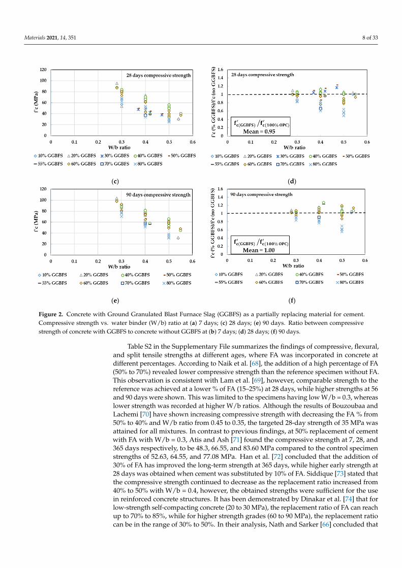
The results of compressive, flexural, and split tensile strengths for several studiesincorporating the GGBFS at different percentages in concrete are presented in Table S1in the Supplementary File. It has been recorded that compared to the control mixturewith 100% OPC, lower compressive strength at 7 days was attained when GGBFS waspartially incorporated in concrete [50,52–54]. However, the compressive strength of theGGBFS mixture specimens with 25% replacement was higher at 28 days [52]. For 55%replacement of GGBFS, similar and higher compressive strength to that of the controlspecimen was obtained at 56 and 90 days respectively [52], while the higher compressivestrength was obtained at both ages in References [53,55] when using 60% replacement ofGGBFS. The optimum level of GGBFS replacement which yields the highest compressivestrength was found by Oner and Akyuz [50] to be 55%. Interestingly, Oner and Akyuz [50]noticed that for the same concrete workability, the water binder (W/b) ratio reduces asthe GGBFS replacement increases, thus the GGBFS has a positive effect on workabilityas higher compressive strength can be achieved with lower water consumption. For theflexural strength, Khatib and Hibbert [53] showed that at 90 days of curing, the strengthof the 60% GGBFS specimen was enhanced by 19.6% compared to the control specimen.Keeping in mind that the flexural behavior is sensitive to microcracks, the finer particlesof GGBFS along with the secondary pozzolanic reaction can reduce the pore connectivityin hardened concrete and as a result, enhance the flexural strength [45,56]. A similarobservation was recorded by Guneyisi and Gesoglu [57], where higher compressive andsplit tensile strengths were achieved at a long time period of 90 days with a replacementlevel of 60% of GGBFS.
The lower strength of GGBFS concrete at early ages was mainly attributed to theslow pozzolanic reaction of GGBFS, which depends on the calcium hydroxide Ca(OH)2availability forms at later ages [50]. Through the pozzolanic reaction, an extra calciumsilicate hydrate (C-S-H) gel will be generated, which will densify the microstructure ofconcrete, thus higher compressive strength of GGBFS concrete is obtained [55]. To enhancethe early strength of GGBFS concrete and for further creation of the (C-S-H) gel, severalstudies suggested the addition of Ca(OH)2 as a hydrated lime [58,59]. Although the earlystrength of GGBFS concrete was low, this deficiency might be eliminated when addingsuperplasticizers (SP) at a low W/b ratio. The results for a 20% replacement of GGBFSobtained by Johari et al. [60] revealed higher 7-day compressive strength (79.6 MPa) thanthe control specimen (74.8 MPa) when 14 Kg/m3 of SP was incorporated at a 0.28 W/bratio. Whereas at 28 and 90 days, comparable and higher strength were obtained at the60% replacement level.
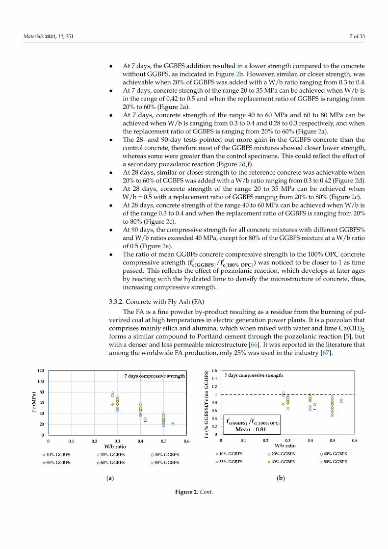
In Figure 2, the concrete compressive strength values obtained from several tests inthe literature [48,50,52,53,55,57,60–65] at 7, 28, and 90 days for different replacement levelsof GGBFS at different W/b ratios are plotted in Figure 2a,c,e. The ratios between concretecompressive strength at different replacement levels of GGBFS to the reference concretewithout GGBFS are also plotted in Figure 2b,d,f to show how close the GGBFS concretespecimens are to the control specimens. The total number of tested specimens is 65. Byreferring to Figure 2, the following conclusions can be observed:
Materials 2021, 14, 351 7 of 33
• At 7 days, the GGBFS addition resulted in a lower strength compared to the concretewithout GGBFS, as indicated in Figure 2b. However, similar, or closer strength, wasachievable when 20% of GGBFS was added with a W/b ratio ranging from 0.3 to 0.4.
• At 7 days, concrete strength of the range 20 to 35 MPa can be achieved when W/b isin the range of 0.42 to 0.5 and when the replacement ratio of GGBFS is ranging from20% to 60% (Figure 2a).
• At 7 days, concrete strength of the range 40 to 60 MPa and 60 to 80 MPa can beachieved when W/b is ranging from 0.3 to 0.4 and 0.28 to 0.3 respectively, and whenthe replacement ratio of GGBFS is ranging from 20% to 60% (Figure 2a).
• The 28- and 90-day tests pointed out more gain in the GGBFS concrete than thecontrol concrete, therefore most of the GGBFS mixtures showed closer lower strength,whereas some were greater than the control specimens. This could reflect the effect ofa secondary pozzolanic reaction (Figure 2d,f).
• At 28 days, similar or closer strength to the reference concrete was achievable when20% to 60% of GGBFS was added with a W/b ratio ranging from 0.3 to 0.42 (Figure 2d).
• At 28 days, concrete strength of the range 20 to 35 MPa can be achieved whenW/b = 0.5 with a replacement ratio of GGBFS ranging from 20% to 80% (Figure 2c).
• At 28 days, concrete strength of the range 40 to 60 MPa can be achieved when W/b isof the range 0.3 to 0.4 and when the replacement ratio of GGBFS is ranging from 20%to 80% (Figure 2c).
• At 90 days, the compressive strength for all concrete mixtures with different GGBFS%and W/b ratios exceeded 40 MPa, except for 80% of the GGBFS mixture at a W/b ratioof 0.5 (Figure 2e).
• The ratio of mean GGBFS concrete compressive strength to the 100% OPC concretecompressive strength (f′c(GGBFS)/f′c(100% OPC)) was noticed to be closer to 1 as timepassed. This reflects the effect of pozzolanic reaction, which develops at later agesby reacting with the hydrated lime to densify the microstructure of concrete, thus,increasing compressive strength.
3.3.2. Concrete with Fly Ash (FA)
The FA is a fine powder by-product resulting as a residue from the burning of pul-verized coal at high temperatures in electric generation power plants. It is a pozzolan thatcomprises mainly silica and alumina, which when mixed with water and lime Ca(OH)2forms a similar compound to Portland cement through the pozzolanic reaction [5], butwith a denser and less permeable microstructure [66]. It was reported in the literature thatamong the worldwide FA production, only 25% was used in the industry [67].
Materials 2021, 14, x FOR PEER REVIEW 7 of 36
• At 7 days, the GGBFS addition resulted in a lower strength compared to the concrete without GGBFS, as indicated in Figure 2b. However, similar, or closer strength, was achievable when 20% of GGBFS was added with a W/b ratio ranging from 0.3 to 0.4.
• At 7 days, concrete strength of the range 20 to 35 MPa can be achieved when W/b is in the range of 0.42 to 0.5 and when the replacement ratio of GGBFS is ranging from 20% to 60% (Figure 2a).
• At 7 days, concrete strength of the range 40 to 60 MPa and 60 to 80 MPa can be achieved when W/b is ranging from 0.3 to 0.4 and 0.28 to 0.3 respectively, and when the replacement ratio of GGBFS is ranging from 20% to 60% (Figure 2a).
• The 28- and 90-day tests pointed out more gain in the GGBFS concrete than the con-trol concrete, therefore most of the GGBFS mixtures showed closer lower strength, whereas some were greater than the control specimens. This could reflect the effect of a secondary pozzolanic reaction (Figure 2d,f).
• At 28 days, similar or closer strength to the reference concrete was achievable when 20% to 60% of GGBFS was added with a W/b ratio ranging from 0.3 to 0.42 (Figure 2d).
• At 28 days, concrete strength of the range 20 to 35 MPa can be achieved when W/b = 0.5 with a replacement ratio of GGBFS ranging from 20% to 80% (Figure 2c).
• At 28 days, concrete strength of the range 40 to 60 MPa can be achieved when W/b is of the range 0.3 to 0.4 and when the replacement ratio of GGBFS is ranging from 20% to 80% (Figure 2c).
• At 90 days, the compressive strength for all concrete mixtures with different GGBFS% and W/b ratios exceeded 40 MPa, except for 80% of the GGBFS mixture at a W/b ratio of 0.5 (Figure 2e).
• The ratio of mean GGBFS concrete compressive strength to the 100% OPC concrete compressive strength (𝐟𝐜(𝐆𝐆𝐁𝐅𝐒)/𝐟𝐜(𝟏𝟎𝟎% 𝐎𝐏𝐂)) was noticed to be closer to 1 as time passed. This reflects the effect of pozzolanic reaction, which develops at later ages by reacting with the hydrated lime to densify the microstructure of concrete, thus, in-creasing compressive strength.
(a) (b)
Figure 2. Cont.
Materials 2021, 14, 351 8 of 33Materials 2021, 14, x FOR PEER REVIEW 8 of 36
(c) (d)
(e) (f)
Figure 2. Concrete with Ground Granulated Blast Furnace Slag (GGBFS) as a partially replacing material for cement. Com-pressive strength vs. water binder (W/b) ratio at (a) 7 days; (c) 28 days; (e) 90 days. Ratio between compressive strength of concrete with GGBFS to concrete without GGBFS at (b) 7 days; (d) 28 days; (f) 90 days.
3.3.2. Concrete with Fly Ash (FA) The FA is a fine powder by-product resulting as a residue from the burning of pul-
verized coal at high temperatures in electric generation power plants. It is a pozzolan that comprises mainly silica and alumina, which when mixed with water and lime Ca(OH)2 forms a similar compound to Portland cement through the pozzolanic reaction [5], but with a denser and less permeable microstructure [66]. It was reported in the literature that among the worldwide FA production, only 25% was used in the industry [67].
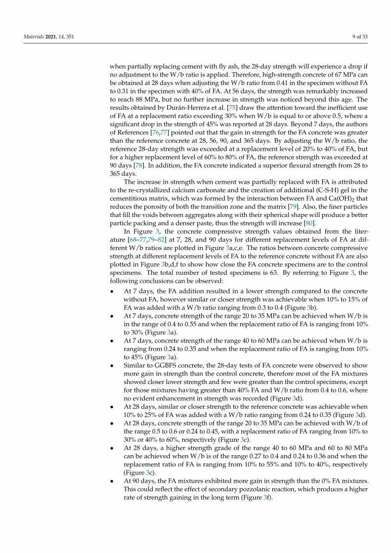
Table S2 in the Supplementary File summarizes the findings of compressive, flexural, and split tensile strengths at different ages, where FA was incorporated in concrete at dif-ferent percentages. According to Naik et al. [68], the addition of a high percentage of FA (50% to 70%) revealed lower compressive strength than the reference specimen without FA. This observation is consistent with Lam et al. [69], however, comparable strength to the reference was achieved at a lower % of FA (15–25%) at 28 days, while higher strengths at 56 and 90 days were shown. This was limited to the specimens having low W/b = 0.3, whereas lower strength was recorded at higher W/b ratios. Although the results of Bouzoubaa and Lachemi [70] have shown increasing compressive strength with decreas-ing the FA % from 50% to 40% and W/b ratio from 0.45 to 0.35, the targeted 28-day strength of 35 MPa was attained for all mixtures. In contrast to previous findings, at 50% replace-ment of cement with FA with W/b = 0.3, Atis and Ash [71] found the compressive strength at 7, 28, and 365 days respectively, to be 48.3, 66.55, and 83.60 MPa compared to the control specimen strengths of 52.63, 64.55, and 77.08 MPa. Han et al.[72] concluded that the addi-tion of 30% of FA has improved the long-term strength at 365 days, while higher early
Figure 2. Concrete with Ground Granulated Blast Furnace Slag (GGBFS) as a partially replacing material for cement.Compressive strength vs. water binder (W/b) ratio at (a) 7 days; (c) 28 days; (e) 90 days. Ratio between compressivestrength of concrete with GGBFS to concrete without GGBFS at (b) 7 days; (d) 28 days; (f) 90 days.
Table S2 in the Supplementary File summarizes the findings of compressive, flexural,and split tensile strengths at different ages, where FA was incorporated in concrete atdifferent percentages. According to Naik et al. [68], the addition of a high percentage of FA(50% to 70%) revealed lower compressive strength than the reference specimen without FA.This observation is consistent with Lam et al. [69], however, comparable strength to thereference was achieved at a lower % of FA (15–25%) at 28 days, while higher strengths at 56and 90 days were shown. This was limited to the specimens having low W/b = 0.3, whereaslower strength was recorded at higher W/b ratios. Although the results of Bouzoubaa andLachemi [70] have shown increasing compressive strength with decreasing the FA % from50% to 40% and W/b ratio from 0.45 to 0.35, the targeted 28-day strength of 35 MPa wasattained for all mixtures. In contrast to previous findings, at 50% replacement of cementwith FA with W/b = 0.3, Atis and Ash [71] found the compressive strength at 7, 28, and365 days respectively, to be 48.3, 66.55, and 83.60 MPa compared to the control specimenstrengths of 52.63, 64.55, and 77.08 MPa. Han et al. [72] concluded that the addition of30% of FA has improved the long-term strength at 365 days, while higher early strength at28 days was obtained when cement was substituted by 10% of FA. Siddique [73] stated thatthe compressive strength continued to decrease as the replacement ratio increased from40% to 50% with W/b = 0.4, however, the obtained strengths were sufficient for the usein reinforced concrete structures. It has been demonstrated by Dinakar et al. [74] that forlow-strength self-compacting concrete (20 to 30 MPa), the replacement ratio of FA can reachup to 70% to 85%, while for higher strength grades (60 to 90 MPa), the replacement ratiocan be in the range of 30% to 50%. In their analysis, Nath and Sarker [66] concluded that
Materials 2021, 14, 351 9 of 33
when partially replacing cement with fly ash, the 28-day strength will experience a drop ifno adjustment to the W/b ratio is applied. Therefore, high-strength concrete of 67 MPa canbe obtained at 28 days when adjusting the W/b ratio from 0.41 in the specimen without FAto 0.31 in the specimen with 40% of FA. At 56 days, the strength was remarkably increasedto reach 88 MPa, but no further increase in strength was noticed beyond this age. Theresults obtained by Durán-Herrera et al. [75] draw the attention toward the inefficient useof FA at a replacement ratio exceeding 30% when W/b is equal to or above 0.5, where asignificant drop in the strength of 45% was reported at 28 days. Beyond 7 days, the authorsof References [76,77] pointed out that the gain in strength for the FA concrete was greaterthan the reference concrete at 28, 56, 90, and 365 days. By adjusting the W/b ratio, thereference 28-day strength was exceeded at a replacement level of 20% to 40% of FA, butfor a higher replacement level of 60% to 80% of FA, the reference strength was exceeded at90 days [78]. In addition, the FA concrete indicated a superior flexural strength from 28 to365 days.
The increase in strength when cement was partially replaced with FA is attributedto the re-crystallized calcium carbonate and the creation of additional (C-S-H) gel in thecementitious matrix, which was formed by the interaction between FA and Ca(OH)2 thatreduces the porosity of both the transition zone and the matrix [79]. Also, the finer particlesthat fill the voids between aggregates along with their spherical shape will produce a betterparticle packing and a denser paste, thus the strength will increase [80].
In Figure 3, the concrete compressive strength values obtained from the liter-ature [68–77,79–82] at 7, 28, and 90 days for different replacement levels of FA at dif-ferent W/b ratios are plotted in Figure 3a,c,e. The ratios between concrete compressivestrength at different replacement levels of FA to the reference concrete without FA are alsoplotted in Figure 3b,d,f to show how close the FA concrete specimens are to the controlspecimens. The total number of tested specimens is 63. By referring to Figure 3, thefollowing conclusions can be observed:
• At 7 days, the FA addition resulted in a lower strength compared to the concretewithout FA, however similar or closer strength was achievable when 10% to 15% ofFA was added with a W/b ratio ranging from 0.3 to 0.4 (Figure 3b).
• At 7 days, concrete strength of the range 20 to 35 MPa can be achieved when W/b isin the range of 0.4 to 0.55 and when the replacement ratio of FA is ranging from 10%to 30% (Figure 3a).
• At 7 days, concrete strength of the range 40 to 60 MPa can be achieved when W/b isranging from 0.24 to 0.35 and when the replacement ratio of FA is ranging from 10%to 45% (Figure 3a).
• Similar to GGBFS concrete, the 28-day tests of FA concrete were observed to showmore gain in strength than the control concrete, therefore most of the FA mixturesshowed closer lower strength and few were greater than the control specimens, exceptfor those mixtures having greater than 40% FA and W/b ratio from 0.4 to 0.6, whereno evident enhancement in strength was recorded (Figure 3d).
• At 28 days, similar or closer strength to the reference concrete was achievable when10% to 25% of FA was added with a W/b ratio ranging from 0.24 to 0.35 (Figure 3d).
• At 28 days, concrete strength of the range 20 to 35 MPa can be achieved with W/b ofthe range 0.5 to 0.6 or 0.24 to 0.45, with a replacement ratio of FA ranging from 10% to30% or 40% to 60%, respectively (Figure 3c).
• At 28 days, a higher strength grade of the range 40 to 60 MPa and 60 to 80 MPacan be achieved when W/b is of the range 0.27 to 0.4 and 0.24 to 0.36 and when thereplacement ratio of FA is ranging from 10% to 55% and 10% to 40%, respectively(Figure 3c).
• At 90 days, the FA mixtures exhibited more gain in strength than the 0% FA mixtures.This could reflect the effect of secondary pozzolanic reaction, which produces a higherrate of strength gaining in the long term (Figure 3f).
Materials 2021, 14, 351 10 of 33
• The ratio of mean (f′c(FA)/f′c(100% OPC)) was recorded as 0.66 at 7 days and it keepsincreasing up to 0.93 at 90 days. Although this reflects the effect of pozzolanic reactionas in the case of GGBFS, the strength is developing at a slower rate.
Materials 2021, 14, x FOR PEER REVIEW 11 of 36
(a) (b)
(c) (d)
(e) (f)
Figure 3. Concrete with Fly ash (FA) as a partially replacing material for cement. Compressive strength vs. W/b ratio at (a) 7 days; (c) 28 days; (e) 90 days. Ratio between compressive strength of concrete with FA to concrete without FA at (b) 7 days; (d) 28 days; (f) 90 days.
3.3.3. Concrete with Silica Fume (SF) The SF is another efficient pozzolan with a highly fragmented structure, that when
used in the concrete, reacts with the lime produced from the hydrated cement to reduce the pore size volume and capillaries in the cement paste [83]. SF is a waste product pro-duced in the metallurgical industry from silicon alloys such as ferrosilicon, metallic sili-con, etc. [84]. Its tiny particles are characterized by microscopic spherical shape with a diameter ranging from 0.1 to 0.5 micrometers (μm) [85].
Figure 3. Concrete with Fly ash (FA) as a partially replacing material for cement. Compressive strength vs. W/b ratio at(a) 7 days; (c) 28 days; (e) 90 days. Ratio between compressive strength of concrete with FA to concrete without FA at(b) 7 days; (d) 28 days; (f) 90 days.

Materials 2021, 14, 351 11 of 33
3.3.3. Concrete with Silica Fume (SF)
The SF is another efficient pozzolan with a highly fragmented structure, that whenused in the concrete, reacts with the lime produced from the hydrated cement to reduce thepore size volume and capillaries in the cement paste [83]. SF is a waste product produced inthe metallurgical industry from silicon alloys such as ferrosilicon, metallic silicon, etc. [84].Its tiny particles are characterized by microscopic spherical shape with a diameter rangingfrom 0.1 to 0.5 micrometers (µm) [85].
In the Supplementary File, Table S3 lists the compressive, flexural, and split tensilestrength results at different ages for several studies incorporating the SF at different per-centages in concrete. The most prominent outcome to emerge from Table S3 is the higherearly compressive strength of SF concrete than the reference concrete at 7 days [83,86–91].The compressive strength continues to increase significantly up to 56 days, however, only amarginal increase was recorded beyond this age [86–88]. The flexural strength was alsoenhanced upon the SF addition, and the optimum amount of SF was found to be 15%. Thisis in complete agreement with reference [90]. Although exceeding this limit decreases thestrength, high-strength concrete of 77.5 MPa was still achievable at 25% of SF with a W/bratio of 0.3 and SP of 12.6 kg/m3 [86]. Wong and Razak [88] prepared several concretemixes having 0% to 15% by weight of cement as SF with different W/b ratios of 0.27, 0.3,and 0.33. Their results observed no immediate enhancement in strength at 3 days due tothe SF addition, but from 7 days onward, higher strength than the control concrete wasobtained at all ages until reaching 17% increment at 90 days for 10% SF concrete. This couldbe referred to the slow nature of pozzolanic activity at early ages and the dilution effectof pozzolan. It was also noticed that reducing W/b ratio from 0.3 to 0.27 did not excite asignificant increase in strength as expected. In their research, Bhanja and Sengupta [92]have also studied the effect of several W/b ratios, namely 0.27, 0.3, 0.38, and 0.42 onconcrete compressive, flexural, and tensile strengths with the SF incorporation at 0% to30% by weight of cement. It emerged from their results that the optimum replacementlevel of SF for tensile strength was a function of the W/b ratio in the mix, which confirmsthe previous finding [70]. The optimum replacement level for tensile strength at 28 dayswas found to be in the range of 5% to 10%, while for compressive and flexural strengths,it was found to be in the range of 15% to 25%. In comparison to split tensile strength, theflexural strength demonstrated greater improvement due to SF incorporation.
From the previous findings of GGBFS and FA, the 7- and 28-day strengths werereduced compared to the control specimens without GGBFS or FA, whereas comparable orhigher strengths were achieved at later ages of 56 and 90 days. In contrast, the early agestrengths at and after 7 days have shown a clear enhancement over the control concretewhen cement was partially replaced with SF. This was attributed to the smaller size particleof SF than the GGBFS and FA, which leads to an increase in the pozzolanic reactionbetween SiO2 from SF and Ca(OH)2 resulting from the hydration of cement [93–96], whichgenerates a C-S-H gel that grows into the capillary voids of the mortar, thus forming adenser microstructure. Furthermore, the physical role of SF as a filler also aids in thestrength development, as the fine particles of SF would lead to a reduction in porosity ofthe transition zone, and hence the interlocking mechanism between the paste and aggregateis boosted [89,97].
In Figure 4, the concrete compressive strength values obtained from the liter-ature [83,86–92,98,99] at 7, 28, and 90 days for different replacement levels of SF at differentW/b ratios are plotted in Figure 4a,c,e. The ratios between concrete compressive strengthat different replacement levels of SF to the reference concrete without SF are also plottedin Figure 4b,d,f to show how close the FA concrete specimens are to the control speci-mens. The total number of tested specimens is 78. By referring to Figure 4, the followingconclusions can be observed:
• Unlike GGBFS and FA, the SF addition resulted in approximately a similar and, inmost cases, a higher compressive strength compared to the concrete without SF at7 days (Figure 4b).

Materials 2021, 14, 351 12 of 33
• At 7 days, concrete strength of the range 20 to 35 MPa can be achieved when W/b isin the range of 0.36 to 0.57 and when the replacement ratio of SF is ranging from 5% to20% (Figure 4a).
• At 7 days, concrete strength of the range 40 to 60 MPa can be achieved when W/b isranging from 0.3 to 0.5 and when the replacement ratio of SF is ranging from 5% to15% (Figure 4a).
• The 28-day tests resulted in a higher gain in strength in the SF concrete than thecontrol concrete. Therefore, all the SF mixtures showed greater strength than thecontrol specimens (Figure 4d).
• At 28 days, most of the compressive strength values were >40 MPa. High-strengthgrades of the range 40 to 60 MPa and 60 to 90 MPa can be achieved when W/b is ofthe range 0.35 to 0.5 and 0.26 to 0.4 and when the replacement ratio of SF is rangingfrom 5% to 20% and 5% to 25%, respectively (Figure 4c).
• At 90 days, the SF mixtures continue to increase in strength beyond 100 MPa for 10%to 20% of SF concrete with a W/b ratio of 0.27 to 0.3 (Figure 4e).
• The ratio of mean (f′c(SF)/f′c(100% OPC)) was reported as 1.14 at 7 days, then it wasincreased up to 1.24 at 28 days, but at 90 days, the mean ratio remained as 1.24. Thisindicates the fast and minor strength development at early and later ages, respectively.
3.3.4. Concrete with Metakaolin (MK)
Unlike GGBFS, FA, and SF, the MK is not a by-product, but it is made by the calcinationof high-purity kaolin clay at a temperature ranging from 650 to 800 C [100]. The exposureof the kaolin clay to this range of temperature is done to break down the crystallinestructure and remove the chemically bound water from the interstices of the kaolin so thatthe material is converted into an amorphous aluminosilicate called MK [91]. During itsmanufacturing, the MK passes through a well-controlled process that carefully refines theparticles to drive off the inert impurities, lighten its color, and results in a high reactivitypowder with high consistency in performance and structure [91]. In comparison to acement particle size of 10 µm, the MK has a median particle size of 1.3 µm [101,102].
Different studies that partially substituted the OPC with MK are provided in Table S4of the Supplementary File. Zhang and Malhotra [101] reported that the compressivestrength of 10% MK concrete has exhibited higher compressive strength values than thecontrol concrete at all ages up to 180 days. This observation was further supported byReferences [103–106] and when compared to SF, the MK showed a faster increment instrength at the early ages of 3 days, which also concurs well with references [98,102]. Ata higher replacement level of 20% MK, Khatib and Hibbert [53] outlined that no furtherenhancement in strength was recorded. Also, Khatib and Hibbert [53] concluded that thereplacement level of 10% MK was the best, and it was found to be superior to SF in termsof strength development, particularly at an early age of 3 days, where higher strength thanthe control was triggered, while for SF, higher strength than control was triggered at orafter 7 days. Dinakar et al. [107] indicated that at an optimum replacement level of 10%MK, a strength value of 100 MPa can be obtained at a low W/b ratio of 0.3. The sameconcrete mix has resulted in 28 days splitting tensile strength of 5.15% of its compressivestrength with a relatively high elastic modulus. Ramezanianpour and Jovein [108] statedthat the gaining level of compressive strength was developed at lower W/b and withthe increasing curing period of concrete. In their study, the optimum amount of MK forconcrete with a W/b ratio of 0.35 and 0.4 were 10% and 12.5%, respectively. However,according to the literature, the optimum amount of MK for 40 to 50 MPa concrete at a0.5 W/b ratio was found to be 20% [53,102,109–111], whereas it was found to be 10% for 80to 100 MPa concrete at W/b of 0.3 [28,88,98,101,105]. The fast strength development of MKin concrete was mainly attributed to the pore filling effect and the fast pozzolanic reactionof MK with the liberated Ca(OH)2 during cement hydration, which creates more bondsamong the densely packed particles through the formation of C-S-H gel [112]. Moreover,

Materials 2021, 14, 351 13 of 33
this could also be attributed to a higher content of aluminum oxide (Al2O3), which causedmuch higher pozzolanic activity [113].
Materials 2021, 14, x FOR PEER REVIEW 13 of 36
• The 28-day tests resulted in a higher gain in strength in the SF concrete than the con-trol concrete. Therefore, all the SF mixtures showed greater strength than the control specimens (Figure 4d).
• At 28 days, most of the compressive strength values were >40 MPa. High-strength grades of the range 40 to 60 MPa and 60 to 90 MPa can be achieved when W/b is of the range 0.35 to 0.5 and 0.26 to 0.4 and when the replacement ratio of SF is ranging from 5% to 20% and 5% to 25%, respectively (Figure 4c).
• At 90 days, the SF mixtures continue to increase in strength beyond 100 MPa for 10% to 20% of SF concrete with a W/b ratio of 0.27 to 0.3 (Figure 4e).
• The ratio of mean (𝐟𝐜(𝐒𝐅)/𝐟𝐜(𝟏𝟎𝟎% 𝐎𝐏𝐂)) was reported as 1.14 at 7 days, then it was in-creased up to 1.24 at 28 days, but at 90 days, the mean ratio remained as 1.24. This indicates the fast and minor strength development at early and later ages, respec-tively.
(a) (b)
(c) (d)
(e) (f)
Figure 4. Concrete with Silica fume (SF) as a partially replacing material for cement. Compressive strength vs. W/b ratioat (a) 7 days; (c) 28 days; (e) 90 days. Ratio between compressive strength of concrete with SF to concrete without SF at(b) 7 days; (d) 28 days; (f) 90 days.
In Figure 5, the concrete compressive strength values obtained from the liter-ature [53,74,88,91,98,101–103,106,108] at 7, 28, and 90 days for different replacement levelsof MK at different W/b ratios are plotted in Figure 5a,c,e. The ratios between concrete com-pressive strength at different replacement levels of MK to the reference concrete withoutMK are also plotted in Figure 5b,d,f to show how close the MK concrete specimens are tothe control specimens. The total number of tested specimens is 51. By referring to Figure 5,the following conclusions can be observed:
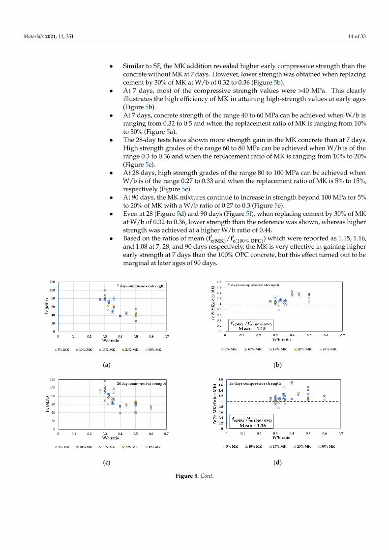
Materials 2021, 14, 351 14 of 33
• Similar to SF, the MK addition revealed higher early compressive strength than theconcrete without MK at 7 days. However, lower strength was obtained when replacingcement by 30% of MK at W/b of 0.32 to 0.36 (Figure 5b).
• At 7 days, most of the compressive strength values were >40 MPa. This clearlyillustrates the high efficiency of MK in attaining high-strength values at early ages(Figure 5b).
• At 7 days, concrete strength of the range 40 to 60 MPa can be achieved when W/b isranging from 0.32 to 0.5 and when the replacement ratio of MK is ranging from 10%to 30% (Figure 5a).
• The 28-day tests have shown more strength gain in the MK concrete than at 7 days.High strength grades of the range 60 to 80 MPa can be achieved when W/b is of therange 0.3 to 0.36 and when the replacement ratio of MK is ranging from 10% to 20%(Figure 5c).
• At 28 days, high strength grades of the range 80 to 100 MPa can be achieved whenW/b is of the range 0.27 to 0.33 and when the replacement ratio of MK is 5% to 15%,respectively (Figure 5c).
• At 90 days, the MK mixtures continue to increase in strength beyond 100 MPa for 5%to 20% of MK with a W/b ratio of 0.27 to 0.3 (Figure 5e).
• Even at 28 (Figure 5d) and 90 days (Figure 5f), when replacing cement by 30% of MKat W/b of 0.32 to 0.36, lower strength than the reference was shown, whereas higherstrength was achieved at a higher W/b ratio of 0.44.
• Based on the ratios of mean (f′c(MK)/f′c(100% OPC)) which were reported as 1.15, 1.16,and 1.08 at 7, 28, and 90 days respectively, the MK is very effective in gaining higherearly strength at 7 days than the 100% OPC concrete, but this effect turned out to bemarginal at later ages of 90 days.
Materials 2021, 14, x FOR PEER REVIEW 15 of 36
• At 7 days, concrete strength of the range 40 to 60 MPa can be achieved when W/b is ranging from 0.32 to 0.5 and when the replacement ratio of MK is ranging from 10% to 30% (Figure 5a).
• The 28-day tests have shown more strength gain in the MK concrete than at 7 days. High strength grades of the range 60 to 80 MPa can be achieved when W/b is of the range 0.3 to 0.36 and when the replacement ratio of MK is ranging from 10% to 20% (Figure 5c).
• At 28 days, high strength grades of the range 80 to 100 MPa can be achieved when W/b is of the range 0.27 to 0.33 and when the replacement ratio of MK is 5% to 15%, respectively (Figure 5c).
• At 90 days, the MK mixtures continue to increase in strength beyond 100 MPa for 5% to 20% of MK with a W/b ratio of 0.27 to 0.3 (Figure 5e).
• Even at 28 (Figure 5d) and 90 days (Figure 5f), when replacing cement by 30% of MK at W/b of 0.32 to 0.36, lower strength than the reference was shown, whereas higher strength was achieved at a higher W/b ratio of 0.44.
• Based on the ratios of mean (𝐟𝐜(𝐌𝐊)/𝐟𝐜(𝟏𝟎𝟎% 𝐎𝐏𝐂)) which were reported as 1.15, 1.16, and 1.08 at 7, 28, and 90 days respectively, the MK is very effective in gaining higher early strength at 7 days than the 100% OPC concrete, but this effect turned out to be marginal at later ages of 90 days.
(a) (b)
(c) (d)
Figure 5. Cont.

Materials 2021, 14, 351 15 of 33Materials 2021, 14, x FOR PEER REVIEW 16 of 36
(e) (f)
Figure 5. Concrete with Metakaolin (MK) as a partially replacing material for cement. Compressive strength vs. W/b ratio at (a) 7 days; (c) 28 days; (e) 90 days. Ratio between compressive strength of concrete with MK to concrete without MK at (b) 7 days; (d) 28 days; (f) 90 days.
3.4. Durability Performance of GC Durability is one of the most frequently stated concerns with concrete as the deterio-
ration of RC elements could be related, at most, to the harsh environmental exposures [65]. Hence, several durability studies will be presented in this section to discuss the du-rability performance of GC.
3.4.1. Elevated Temperature Poon et al. [114] evaluated the effect of elevated temperature up to 800 °C on the
performance of eight normal and high-strength concrete mixes, where MK replaced OPC at 0%, 5%, 10%, and 20%. To achieve high-temperature exposure, the test specimens were placed in an automatic electric furnace. Compared to concretes with OPC, FA, and SF, the MK concrete mixes attained higher compressive strength up to 400 °C, whereas beyond 400 °C, a sharp reduction in compressive strength was attained, followed by severe crack-ing and explosive spalling, which is attributed to its dense micro-structure that allows the build-up of pore pressure by steam [115]. However, the concrete mix with 5% of MK showed better performance than the corresponding concretes at all temperatures without spalling at failure [114].
The mechanical behavior of concrete, where the OPC was replaced by weight with 20%, 40%, and 60% of GGBFS and exposed to temperatures up to 350 °C has been explored in Reference [116]. It was pointed out in the authors’ analysis that the deterioration in compressive strength, splitting tensile strength, and elastic modulus of GGBFS concrete at all elevated temperatures (100, 200, and 350 °C) remained below 40% at 28 and 56 days compared to the mix at room temperature of 27 °C. Among all GGBFS mixes, the 20% GGBFS mix provided the best performance and it could be suitably implemented in nu-clear structures.
Li et al. [117] also utilizes GGBFS in concrete with replacement ratios of 10%, 30%, and 50% by weight of OPC to evaluate their performance under high-temperature expo-sures from 150 to 700 °C for 90 days. The mixes with a higher content of GGBFS have shown higher carbonation depth, and in comparison to the control mix with 100% OPC, the depth was measured as twice as great in the GGBFS concrete when the temperature was raised above 300 °C. The compressive strength was decreased with increased temper-ature, and this was more pronounced at temperatures higher than 400 °C. As an example, the reductions in compressive strengths for concrete with 0%, 10%, 30%, and 50% of GGBFS were measured at 500 °C as 40%, 38%, 56%, and 59% respectively, compared to the unheated specimens. Moreover, the deterioration in the elastic modulus of GGBFS
Figure 5. Concrete with Metakaolin (MK) as a partially replacing material for cement. Compressive strength vs. W/b ratioat (a) 7 days; (c) 28 days; (e) 90 days. Ratio between compressive strength of concrete with MK to concrete without MK at(b) 7 days; (d) 28 days; (f) 90 days.
3.4. Durability Performance of GC
Durability is one of the most frequently stated concerns with concrete as the deteriora-tion of RC elements could be related, at most, to the harsh environmental exposures [65].Hence, several durability studies will be presented in this section to discuss the durabilityperformance of GC.
3.4.1. Elevated Temperature
Poon et al. [114] evaluated the effect of elevated temperature up to 800 C on theperformance of eight normal and high-strength concrete mixes, where MK replaced OPCat 0%, 5%, 10%, and 20%. To achieve high-temperature exposure, the test specimenswere placed in an automatic electric furnace. Compared to concretes with OPC, FA, andSF, the MK concrete mixes attained higher compressive strength up to 400 C, whereasbeyond 400 C, a sharp reduction in compressive strength was attained, followed by severecracking and explosive spalling, which is attributed to its dense micro-structure that allowsthe build-up of pore pressure by steam [115]. However, the concrete mix with 5% of MKshowed better performance than the corresponding concretes at all temperatures withoutspalling at failure [114].
The mechanical behavior of concrete, where the OPC was replaced by weight with20%, 40%, and 60% of GGBFS and exposed to temperatures up to 350 C has been exploredin Reference [116]. It was pointed out in the authors’ analysis that the deterioration incompressive strength, splitting tensile strength, and elastic modulus of GGBFS concreteat all elevated temperatures (100, 200, and 350 C) remained below 40% at 28 and 56days compared to the mix at room temperature of 27 C. Among all GGBFS mixes, the20% GGBFS mix provided the best performance and it could be suitably implemented innuclear structures.
Li et al. [117] also utilizes GGBFS in concrete with replacement ratios of 10%, 30%, and50% by weight of OPC to evaluate their performance under high-temperature exposuresfrom 150 to 700 C for 90 days. The mixes with a higher content of GGBFS have shownhigher carbonation depth, and in comparison to the control mix with 100% OPC, thedepth was measured as twice as great in the GGBFS concrete when the temperature wasraised above 300 C. The compressive strength was decreased with increased temperature,and this was more pronounced at temperatures higher than 400 C. As an example, thereductions in compressive strengths for concrete with 0%, 10%, 30%, and 50% of GGBFSwere measured at 500 C as 40%, 38%, 56%, and 59% respectively, compared to the unheatedspecimens. Moreover, the deterioration in the elastic modulus of GGBFS concretes was

Materials 2021, 14, 351 16 of 33
more severe than the unheated specimens with percent retentions of 22%, 25%, and 27%respectively, for concretes with 10%, 30%, and 50% of GGBFS.
The mechanical and durability performances of high-performance concrete mixeswith 5% to 20% of MK and 20% to 60% FA were also studied under elevated temperaturesin Reference [118]. The concrete mixes were exposed to temperature values ranging from 27to 800 C followed by slow cooling in air or fast cooling in water. Generally, it was observedthat the exposure to 400 C followed by fast cooling caused more severe degradation incompressive strength. From a durability perspective, the values of sorptivity and chloridepermeability were significantly increased for all mixes between 400 to 600 C due to theincreased pore area fraction at a higher temperature. However, at normal temperature, theMK specimens demonstrated higher resistance against water penetration than the FA andCC specimens. On the other hand, the lowest sorptivity was attained for the 20% FA mix at600 C and above.
Recently, Rashad and Sadek [113] attempted to improve the compressive strength of70% GGBFS paste exposed to elevated temperatures, namely 400, 600, 800, and 1000 C for2 h. The authors suggested the addition of 2% to 10% of MK as a replacement ratio for theGGBFS by weight. Their results have shown that the compressive strength was enhancedwith the increased content of MK before and after the exposure to elevated temperatures.At 800 to 1000 C, the residual compressive strength for pastes with 2%, 4%, 6%, 8%, and10% of MK were 10%, 15%, 20%, 27%, and 35% higher respectively, than the control mixwith 0% MK.
3.4.2. Sulfate Attack, Chloride Ion Penetration, and Freezing and Thawing
Li and Zhao [119] assessed the short- and long-term resistance to sulfate attack ofthree concrete mixes, namely CC, concrete with 40% FA, and concrete with a combinationof 25% FA and 15% GGBFS (GGFAC). The test was carried following the Chinese StandardGBJ82-85 by immersing specimens with a size of 100 mm× 100 mm× 300 mm in a solutionwith 2% of H2SO4 at room temperature. After 50 weeks of exposure, the GGFAC wassuperior to CC and 40% FA concrete in terms of sulfate attack resistance. Moreover, thechange in weight of GGFAC was slow and remained below 8%. This was followed by 10%in the 40% FA mix, while in CC, the weight change reached as much as 16%.
McCarthy and Dhir [120] carried out durability-related tests including chloride dif-fusion, permeability, and absorption for concrete with 45% FA as a cement component.The chloride diffusion test was done on a concrete cylinder slice of 100 mm diameter and25 mm depth. The sliced concrete was placed between saturated 5 M NaCl and Ca(OH)2solutions at 20 C. Whereas, the permeability test was applied on a concrete core of 54 mmdiameter × 50 mm depth by recording the flow rates of air passing through the specimenat various inlet pressures. The water absorption of concrete was measured according to BS1881: Part 208 [121] by immersing a 150 mm concrete cube in a 200 mm head of water for 10min. In their analysis, McCarthy and Dhir [120] found an enhanced durability performanceof FA concrete over the CC in all tests, but for carbonation depth, the performance of FAconcrete was similar to that of CC, although, at low design strength, the FA concrete couldresult in more unsatisfactory performance.
Hossain and Lachemi [122] investigated the suitability of high content of volcanic ash(VA) up to 75% on the strength and durability properties and noticed that compared to thecontrol mix, the drying shrinkage (DS) of VA mixes was slightly lower, however, all mixesexperienced less than 600 micro-strains of DS. Moreover, increasing the VA content upto 40% showed a decreased 91-day permeability from 2.23 × 10⁻¹⁰ to 1.58 × 10⁻¹⁰ cm/s.Also, all VA mixes recorded a chloride ion resistance of 1000 to 3000 Coulombs, whichaccording to ASTM C1202 [123] were classified as low to moderate chloride ion penetra-bility. The mix with VA beyond 40% was not recommended as it caused a sharp drop incompressive strength.
Kim et al. [124] investigated the durability of concrete while incorporating 0%, 5%,10%,15%, and 20% of MK and SF. Properties such as chloride ion permeability was reduced

Materials 2021, 14, 351 17 of 33
as the proportions of MK and SF were increased. Up to 300 cycles of freezing and thawingapplied as per ASTM C666 [125], the relative dynamic elastic modulus of concrete mixeswith 0% to 10% MK or SF remain constant. The resistance of concrete to carbonation wasassessed by subjecting concrete to accelerated conditions involves 5% CO2, 30 C, and 60%relative humidity for 7, 14, 28, and 56 days. Regardless of admixture type (MK or SF) inconcrete, the carbonation depth was higher than that of the control mix (with no FA andSF) at all ages of the test from 7 to 56 days. When assessing the sulfuric acid attack of 2%acid solution for 56 days, the authors found a 20% reduction in compressive strength ofmortar specimens with 15% MK or SF compared to the control mix.
Hossain and Lachemi [126] replaced the OPC by 5%, 10%, 15%, and 20% of VA toassess concrete’s durability. Their analysis demonstrated higher resistance of all VA mixesagainst chloride diffusion than the control concrete with 0% of VA. This observation wasalso confirmed by performing differential scanning calorimetry tests, which revealed lessCa(OH)2 content in all VA mixes than the control mix. This indicated that the Ca(OH)2 wasconsumed due to the pozzolanic reaction and as a result, created a denser microstructurewith very low permeability.
Berndt [127] studied the effect of combining the partial replacement of OPC and NCAwith SCM and RCA, respectively. In their results, concrete mix with either NCA or RCAwas best performed in terms of mechanical and durability behavior when 50% of cementwas replaced with GGBFS. Also, the presence of GGBFS in recycled concrete has decreasedthe coefficient of chloride diffusion, however, this coefficient along with the permeabilitycoefficient was increased when FA and RCA were employed. In a similar investigationby Kou and Poon [128], concrete mixes with 0%, 50%, and 100% of RCA were prepared.In these mixes, the authors also incorporated FA at different percentages of 25%, 35%,and 55% to evaluate their long-term (10 years) performance in terms of mechanical anddurability characteristics. During this period, the concrete specimens were either curedby water or air. The control mixes with NCA have shown higher compressive strengththan the recycled concretes at all ages, but this difference was noticed to decrease with theincrease in the curing time. Although the recycled concrete had a more permeable structurethan the control specimens, the incorporation of FA has led to a significant enhancementin the chloride ion penetration resistance. As the RCA and FA contents were increased,the carbonation coefficient increased. In general, the authors concluded that the optimalconcrete mix was that with 50% RCA and 25% FA. In a more recent study, Faella et al. [129]combined the use of RCA with FA in concrete to investigate its durability performanceand found that although the addition of RCA induced lower resistance to chloride-ionpenetration due to high porosity of RCA, the addition of FA can achieve a significantattenuation of this phenomena.
Sabet et al. [130] measured the effect of FA and SF on the chloride permeability,electric resistivity, and water absorption of concrete. After 90 days of exposure to sodiumchloride (NaCl) solution, their analysis showed that the incorporation of 10% and 20% FAcaused a reduction in the chloride diffusion coefficient from 7.9 × 10⁻¹² to 4.7 × 10⁻¹² and3.2 × 10−12 m/s2, respectively. For concrete with 10% SF, the chloride diffusion coefficientwas reduced to 5.6 × 10⁻¹² m/s2. In addition, the 10% and 20% FA concrete enhanced theelectrical resistivity from 8.4 kΩ cm in the control mix to 30 and 50 kΩ cm, respectively.However, the 10% and 20% SF concrete resulted in the most significant enhancementwith 54 and 231 kΩ cm respectively, where kΩ refers to kilo-ohms. Moreover, the finalabsorption of water was reduced by 20% and 39% when 10% of FA and 10% of SF wasincorporated in concrete, respectively.
Chousidis et al. [131] employed lower replacement levels of FA, namely, 5% and 10%,to partially replace the OPC in RC specimens. These specimens were immersed for 130 daysin a 3.5% NaCl solution to investigate their mechanical and durability characteristics. Interms of durability, the FA mixes’ sorptivity and capillary absorption were decreased incomparison with the 100% OPC concrete. Moreover, the mass loss of steel reinforcementembedded in 5% FA mortar was measured theoretically to be equal to that of the control
Materials 2021, 14, 351 18 of 33
concrete after 13 months of exposure to NaCl. In terms of mechanical properties, thecompressive strength and elastic modulus at 100 and 130 days were higher in the FA mixesdue to the increased density caused by the formation of additional C-S-H.
Singh et al. [132] examined the durability effect of 3% incorporation of silica nanoparti-cles (SNPs) into concrete mixes having 30% to 50% FA. The main durability parameters werethe sulfate attack and the carbonation depth, both were applied for 28, 90, and 180 days.The sulfate attack test was carried out according to ASTM C1012 [133] by slicing prisms ofsize 100 mm × 100 mm × 500 mm into 50 mm × 100 mm × 100 mm and immersing theminside a solution with 5% magnesium sulfate. The carbonation depth test was applied inaccordance with the recommendations of RILEM CPC-18 [134] on specimen size of 100 mm× 100 mm × 500 mm. The specimens were placed in a 2% CO2 concentration chamberwith 65% relative humidity and a temperature of 20 C. In comparison to concrete with 30%of FA, the incorporation of 3% of SNPs in a 30% FA concrete has reduced the carbonationdepth and the sulfate attack by 73% and 39% respectively, while a 35% and a 30% reductionwas observed with the incorporation of 6% SF, respectively.
Wang et al. [135] investigated the durability characteristics of concrete, containing SFat 5%, 8%, and 11%, and FA at 10%, 15%, and 25% by weight to replace the OPC, underthe combined effect of sulfate attack and freezing–thawing cycles. Prismatic concretespecimens with a size of 100 mm × 100 mm × 400 mm were immersed in 5% and 10%sodium sulfate solutions and then exposed to 175 freezing–thawing cycles. Conformingto ASTM C666 [125], one freezing and thawing cycle involved 6 h, 3 h for freezing at−18 ± 2 C, and 3 h for thawing at 5 ± 2 C in water. The test results indicated significantimprovement in concrete durability for concrete with FA up to 25% and 5% to 8% SF. Morefreezing and thawing cycles (300 cycles) were applied by Uysal and Akyuncu [136] onconcrete mixes having 10% to 17% FA as a replacement to the OPC. The results indicatedno dramatic change in the weight of specimens, however, the weight loss in FA mixtureswas greater than that in the control mix with no FA. The authors also observed a 5.38% to29.83% loss in the flexural strength of specimens containing FA compared to the controlspecimens with 100% OPC.
3.5. Structural Performance of GC in Large-Scale RC Beams3.5.1. Partially Replacing OPC with SCM
As discussed in the previous sections, the compressive strength of GC has beenanalyzed by many studies; however, only a limited number of studies were published onits structural behavior. For example, Yoo et al. [137] evaluated the effect of high volumeFA (HVFA) with a 35% and 50% replacement ratio of OPC on the flexural behavior of RCbeams. Their results have shown a quasi-similar behavior to the RC members without FAin terms of cracking load, ultimate load, yielding load, and strain, however, results haveshown slightly lower elastic modulus and higher mid-span deflection in HVFA beams thanthe control beams without FA. This could be justified by the known 25% lower densityof FA than the cement material, which results in a 2 to 3% reduction in concrete’s unitweight. A similar observation was noticed by Hashmi et al. [138] where the ultimateand yielding state of RC beams with 60% FA were identical to the RC beams without FA,but the RC beams with FA have demonstrated higher deflection and strain values whichwere attributed to the lower elastic modulus and splitting tensile strength of FA concrete.Sangeetha and Joanna [139] observed that the moment capacity in RC beams with a 40%replacement ratio of GGBFS was comparable to that of the control RC beams withoutGGBFS at 28 days, however, interestingly it was increased by 21% at 56 days. This could bejustified by the enhanced durability [139–141] and corrosion resistance [142–144] resultedfrom the fine glassy shape particles of GGBFS, which reduces chloride-ion permeability,and increases the bond between particles [145–149]. Also, Sangeetha and Joanna [139]reported that the crack width at service loads was found to be in the range of 0.17 to0.2 mm, which is within the limits specified by IS 456-2000 [150]. A more recent study byHawileh et al. [151] involved a higher replacement level of GGBFS by 70% and 90%. Their
Materials 2021, 14, 351 19 of 33
results have shown a reduction in the strength and stiffness of beams with 90% of GGBFSby 6% and 16%, respectively, but those beams with 50% and 70% of GGBFS were foundpractical and increased the ultimate load capacity by 3% and 9%, respectively. Although90% of GGBFS had sacrifices the flexural strength and stiffness to a small degree, it hasincreased the RC beams ductility.
On the other hand, the shear behavior of RC beams when 50% of OPC was replaced byFA was studied by Rao et al. [152]. Their experimental findings have shown a slightly lowershear strength of the FA beams than the conventional concrete (CC) beams. On the contrary,Arezoumandi and Volz [153] tested 12 full-scale beams with two FA contents by weight(50% and 70%) and stated that the FA beams were virtually identical to the CC beamsin terms of cracking load, load-deflection diagram, and failure mode, however, beamswith FA were noticed to exceed the code-predicted shear capacities by a higher marginthan the beams without FA. This could be attributed to the higher fracture energy formedin the cementitious matrix of FA than the conventional OPC. Alghazali and Myers [142]investigated the shear behavior of large-scale beams with three replacement levels of FA byweight (50%, 60%, and 70%) and two different longitudinal reinforcement ratios ρ (1.59%and 2.71%). The FA beams exhibited higher shear strength than the CC ones at a lower ρ of1.59%, whereas no obvious increase in the ultimate shear capacity was observed at higherρ of 2.71% but the diagonal shear crack propagation was delayed between 10 to 24%. Thisobservation is referred to the use of a small aggregate size of 10 mm which decreases thecrack surface’s roughness and minimizes the effect of the longitudinal reinforcement toprevent slippage.
3.5.2. Partially Replacing NCA with RCA
Central to the entire discipline of sustainable construction is the concept of utilizingRCA in RC structures. In China, the RCA concrete was successfully implemented at variouspavements and building structures [154]. Hoffmann et al. [155] have also highlighted thatthe RCA was suitably used in a wide variety of reinforced concrete members. Numerousstudies have attempted to relate the inferior properties of RCA concrete to the weak inter-facial transition zone between the recycled aggregate and the new cement paste [156–163],which is mainly attributed to the old layer of mortar adhered to the surface of aggre-gate [164] that is characterized by loose, porous and micro-cracked surface [159,165]. Intheir study Han et al. [166] stated that the RC beams with 100% RCA showed larger de-flection and less shear strength than the control beams with virgin aggregate. However,Al Mahmoud [167] reported similar shear behavior of the RCA beams compared to theNCA beams in terms of the load-deflection diagram. González-Fonteboa and Martínez-Abella [168] have investigated the shear behavior of recycled concrete with 50% RCA andhighlighted little differences in terms of midspan deflection and ultimate load capacity.However, notable splitting cracks and premature cracking were observed along the tensionreinforcement of the recycled concrete beams. Etxeberria et al. [169] explored the possibilityof implementing the RCA as a structural material in RC beams by replacing the virginaggregates by 25%, 50%, and 100% of RCA. The beam specimens with 50% and 100% ofRCA demonstrated similar shear capacity as the control beams with 0% of RCA, but areduction of 13% was observed for beams with 25% of RCA. Also, it was noticed that theaddition of RCA has reduced the cracking load due to the occurrence of cracking at theweakest point which is the adhered mortar on the surface of RCA. Fathifazl et al. [170]observed that the shear capacity of recycled RC beams with 64% and 74% replacementlevel of RCA tended to increase at lower shear span to depth (as/d) ratio as a result ofthe arch action mechanism. Furthermore, Fathifazl et al. [170] observed that the shearcapacity tended to increase when the overall depth of the beam was decreased. Thesetwo observations indicated that the recycled RC beams conformed well to the knownbehavior of conventional RC beams. Knaack and Kurama [171] prepared two types ofrecycled concrete mixes, one with 50% of RCA, and one with 100% of RCA. These mixeswere utilized in full-scale RC beams to investigate their flexural and shear behavior. The
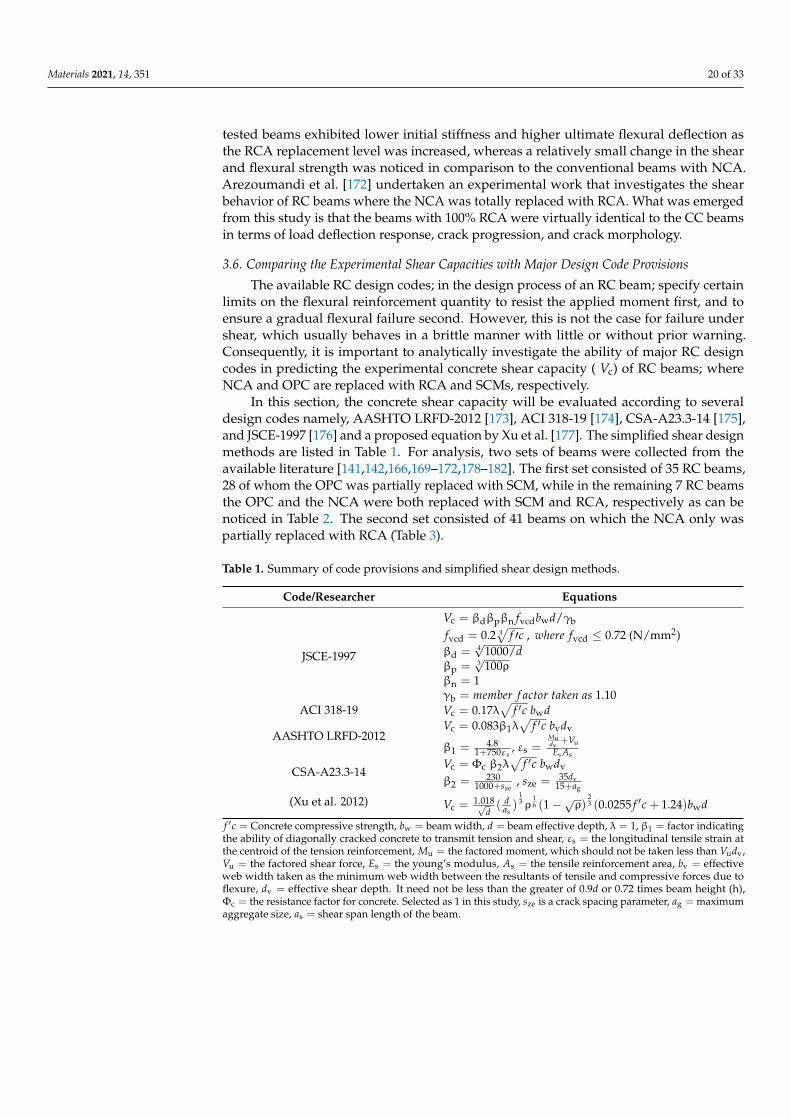
Materials 2021, 14, 351 20 of 33
tested beams exhibited lower initial stiffness and higher ultimate flexural deflection asthe RCA replacement level was increased, whereas a relatively small change in the shearand flexural strength was noticed in comparison to the conventional beams with NCA.Arezoumandi et al. [172] undertaken an experimental work that investigates the shearbehavior of RC beams where the NCA was totally replaced with RCA. What was emergedfrom this study is that the beams with 100% RCA were virtually identical to the CC beamsin terms of load deflection response, crack progression, and crack morphology.
3.6. Comparing the Experimental Shear Capacities with Major Design Code Provisions
The available RC design codes; in the design process of an RC beam; specify certainlimits on the flexural reinforcement quantity to resist the applied moment first, and toensure a gradual flexural failure second. However, this is not the case for failure undershear, which usually behaves in a brittle manner with little or without prior warning.Consequently, it is important to analytically investigate the ability of major RC designcodes in predicting the experimental concrete shear capacity ( Vc) of RC beams; whereNCA and OPC are replaced with RCA and SCMs, respectively.
In this section, the concrete shear capacity will be evaluated according to severaldesign codes namely, AASHTO LRFD-2012 [173], ACI 318-19 [174], CSA-A23.3-14 [175],and JSCE-1997 [176] and a proposed equation by Xu et al. [177]. The simplified shear designmethods are listed in Table 1. For analysis, two sets of beams were collected from theavailable literature [141,142,166,169–172,178–182]. The first set consisted of 35 RC beams,28 of whom the OPC was partially replaced with SCM, while in the remaining 7 RC beamsthe OPC and the NCA were both replaced with SCM and RCA, respectively as can benoticed in Table 2. The second set consisted of 41 beams on which the NCA only waspartially replaced with RCA (Table 3).
Table 1. Summary of code provisions and simplified shear design methods.
Code/Researcher Equations
JSCE-1997
Vc = βdβpβn fvcdbwd/γb
fvcd = 0.2 3√
f ′c , where fvcd ≤ 0.72 (N/mm2)βd = 4
√1000/d
βp = 3√
100ρβn = 1γb = member f actor taken as 1.10
ACI 318-19 Vc = 0.17λ√
f ′c bwd
AASHTO LRFD-2012Vc = 0.083β1λ
√f ′c bvdv
β1 = 4.81+750εs
, εs =Mudv
+Vu
Es As
CSA-A23.3-14Vc = Φc β2λ
√f ′c bwdv
β2 = 2301000+sze
, sze = 35dv15+ag
(Xu et al. 2012) Vc =1.018√
d( d
as)
13 ρ
16 (1−√ρ)
23 (0.0255 f ′c + 1.24)bwd
f ′c = Concrete compressive strength, bw = beam width, d = beam effective depth, λ = 1, β1 = factor indicatingthe ability of diagonally cracked concrete to transmit tension and shear, εs = the longitudinal tensile strain atthe centroid of the tension reinforcement, Mu = the factored moment, which should not be taken less than Vudv,Vu = the factored shear force, Es = the young’s modulus, As = the tensile reinforcement area, bv = effectiveweb width taken as the minimum web width between the resultants of tensile and compressive forces due toflexure, dv = effective shear depth. It need not be less than the greater of 0.9d or 0.72 times beam height (h),Φc = the resistance factor for concrete. Selected as 1 in this study, sze is a crack spacing parameter, ag = maximumaggregate size, as = shear span length of the beam.

Materials 2021, 14, 351 21 of 33
Table 2. Experimental and predicted shear capacities for reinforced concrete beams with partial SCM%.
Source SCM% RCA% ρ bw (mm) h (mm) d (mm) ag (mm) f′c (MPa) as/d Experimental
Shear, Vc (kN)
Vexp/Vpred
JSCE-1997
ACI318-19
AASHTOLRFD 2012
CSA-A23.3-14
Xu et al.[177]
Arezoumandiet al. [181]
50 (FA)
-
0.0126 305 457 396 19 30.7 3.0 127 1.36 1.12 0.70 1.16 1.0450 (FA) 0.0126 305 457 396 19 20.7 3.0 134.1 1.63 1.44 0.92 1.49 1.2650 (FA) 0.0199 305 457 375 19 30.7 3.2 163.9 1.56 1.52 0.91 1.56 1.3350 (FA) 0.0199 305 457 375 19 20.7 3.2 133.7 1.46 1.51 0.86 1.55 1.2550 (FA) 0.0266 305 457 375 19 30.7 3.2 164.8 1.43 1.53 0.85 1.57 1.3050 (FA) 0.0266 305 457 375 19 20.7 3.2 163.7 1.62 1.85 1.03 1.90 1.48
Arezoumandiet al. [182]
70 (FA)
-
0.0157 305 457 396 19 22 3.0 140.7 1.56 1.46 0.88 1.52 1.2670 (FA) 0.0199 305 457 375 19 22 3.2 131.9 1.41 1.45 0.82 1.48 1.2170 (FA) 0.0266 305 457 375 19 22 3.2 170.9 1.66 1.87 1.05 1.92 1.5270 (FA) 0.0266 305 457 375 19 21.6 3.2 162.9 1.59 1.80 1.00 1.85 1.4570 (FA) 0.0252 305 457 396 19 30.7 3.0 134.3 1.14 1.18 0.63 1.23 1.0270 (FA) 0.0252 305 457 396 19 20.7 3.0 122.8 1.19 1.31 0.69 1.37 1.0770 (FA) 0.0266 305 457 375 19 30.7 3.2 150.4 1.30 1.40 0.76 1.43 1.1970 (FA) 0.0266 305 457 375 19 20.7 3.2 168.1 1.66 1.90 1.06 1.95 1.5270 (FA) 0.0266 305 457 375 19 30.7 3.2 162.4 1.41 1.51 0.84 1.54 1.2870 (FA) 0.0266 305 457 375 19 20.7 3.2 201.5 1.99 2.28 1.34 2.33 1.82
Alghazaliand Myers
[142]
50 (FA)
-
0.0157 305 457 396 25 53.5 3.1 149.2 1.29 0.99 0.61 0.99 0.9350 (FA) 0.0199 305 457 375 25 53.5 3.3 143.8 1.19 1.01 0.58 0.99 0.9150 (FA) 0.0266 305 457 375 25 53.5 3.3 144 1.09 1.01 0.55 0.99 0.8960 (FA) 0.0157 305 457 396 25 45.9 3.1 142.5 1.24 1.02 0.62 1.02 0.9660 (FA) 0.0199 305 457 375 25 45.9 3.3 175.7 1.47 1.33 0.82 1.31 1.2160 (FA) 0.0266 305 457 375 25 45.9 3.3 150.6 1.14 1.14 0.62 1.12 1.0070 (FA) 0.0157 305 457 396 25 52.9 3.1 146.6 1.26 0.98 0.60 0.98 0.9270 (FA) 0.0199 305 457 375 25 52.9 3.3 162.2 1.35 1.15 0.69 1.13 1.0470 (FA) 0.0266 305 457 375 25 52.9 3.3 154.7 1.17 1.09 0.60 1.07 0.96
Sadati et al.[178]
50 (FA) 50 0.0126 305 460 396 25 30.8 3.0 120.5 1.29 1.06 0.65 1.05 0.9950 (FA) 50 0.0199 305 460 375 25 30.8 3.2 140.8 1.34 1.30 0.75 1.28 1.1550 (FA) 50 0.0266 305 460 375 25 30.8 3.2 136.3 1.18 1.26 0.68 1.24 1.07
Lisantonoet al. [182]
50 (FA) - 0.0106 150 260 214 25 15.3 3.5 57.3 2.64 2.68 2.24 2.36 1.7360 (FA) 0.0947 150 260 214 25 13.7 3.5 48.9 1.13 2.42 1.13 2.12 1.2570 (FA) 0.0947 150 260 214 25 11.7 3.5 41.9 1.02 2.24 1.03 1.97 1.11

Materials 2021, 14, 351 22 of 33
Table 2. Cont.
Source SCM% RCA% ρ bw (mm) h (mm) d (mm) ag (mm) f′c (MPa) as/d Experimental
Shear, Vc (kN)
Vexp/Vpred
JSCE-1997
ACI318-19
AASHTOLRFD 2012
CSA-A23.3-14
Xu et al.[177]
Sunayanaand Barai
[141]
20 (FA) 100 0.0038 200 300 267 20 47.26 2.6 82.15 2.33 1.32 1.86 1.23 1.1630 (FA) 100 0.0038 200 300 267 20 45.55 2.6 81.8 2.35 1.34 1.88 1.25 1.1820 (FA) 100 0.0074 200 300 267 20 46.11 2.6 101.72 2.33 1.65 1.73 1.55 1.3330 (FA) 100 0.0074 200 300 267 20 47.6 2.6 87.49 1.98 1.40 1.35 1.31 1.13
Mean - - - - - - - - - - 1.51 1.47 0.95 1.45 1.20
SD - - - - - - - - - - 0.40 0.42 0.41 0.38 0.22
COV% - - - - - - - - - - 26.35 28.72 42.78 26.30 18.61
Table 3. Experimental and predicted shear capacities for reinforced concrete beams with partial or total RCA%.
Source RCA% ρ bw (mm) h (mm) d (mm) ag (mm) f′c (MPa) as/d Experimental
Shear, Vc (kN)
Vexp/Vpred
JSCE-1997
ACI318-19
AASHTOLRFD 2012
CSA-A23.3-14
Xu et al.[177]
Han et al.[166] 100 0.011 170 300 270 25 39.6 1.5 83.5 2.05 1.70 1.40 1.96 1.08
- 100 0.011 170 300 270 25 30.6 2 65.2 1.74 1.51 1.11 1.53 1.03- 100 0.011 170 300 270 25 32.6 2 60.6 1.59 1.36 0.97 1.42 0.94- 100 0.011 170 300 270 25 31.2 3 42.7 1.13 0.98 0.62 1.00 0.77- 100 0.011 170 300 270 25 31.9 4 31.7 0.84 0.72 0.42 0.74 0.62
Belen andFernando
[179]50 0.030 200 350 303 25 39.7 3.3 90.6 1.24 1.40 0.76 1.64 1.09
Etxeberriaet al. [169] 25 0.030 200 350 303 25 42.4 3.3 104 1.39 1.55 0.88 1.89 1.21
- 50 0.030 200 350 303 25 41.3 3.3 89 1.20 1.34 0.73 1.62 1.05- 100 0.030 200 350 303 25 39.8 3.3 84 1.15 1.29 0.70 1.52 1.01
Ji et al.[179] 100 0.012 170 300 270 20 39.7 2.2 60 1.45 1.22 0.85 1.61 0.87

Materials 2021, 14, 351 23 of 33
Table 3. Cont.
Source RCA% ρ bw (mm) h (mm) d (mm) ag (mm) f′c (MPa) as/d Experimental
Shear, Vc (kN)
Vexp/Vpred
JSCE-1997
ACI318-19
AASHTOLRFD 2012
CSA-A23.3-14
Xu et al.[177]
Fathifazlet al. [170] 63.5 0.010 200 375 300 19 41.6 1.5 186.7 3.60 2.84 3.24 4.06 1.91
- 63.5 0.016 200 375 300 19 41.6 2 169.5 2.85 2.58 2.21 3.69 1.82- 63.5 0.014 200 375 309 19 41.6 2.7 103.9 1.77 1.53 1.09 2.21 1.23- 63.5 0.026 200 375 305 19 41.6 4 83.2 1.17 1.24 0.69 1.79 1.06- 74.3 0.010 200 375 300 19 49.1 1.5 195.3 3.62 2.73 3.21 4.25 1.85- 74.3 0.016 200 375 300 19 49.1 2 179 2.90 2.50 2.21 3.89 1.77- 74.3 0.026 200 375 305 19 49.1 4 105.6 1.43 1.45 0.86 2.27 1.24- 63.5 0.013 200 250 201 19 41.6 2.7 89.3 2.15 2.03 1.69 2.67 1.32- 63.5 0.014 200 375 309 19 41.6 2.6 103.9 1.77 1.53 1.09 2.21 1.21- 63.5 0.018 200 450 381 19 41.6 2.7 99.5 1.35 1.19 0.72 1.81 1.03- 63.5 0.017 200 550 476 19 41.6 2.7 104.6 1.22 1.00 0.58 1.63 0.98- 74.3 0.020 200 250 201 19 49.1 2.7 122.6 2.48 2.56 2.03 3.67 1.59- 74.3 0.018 200 450 381 19 49.1 2.7 111.7 1.46 1.23 0.77 2.04 1.07- 74.3 0.017 200 550 476 19 49.1 2.7 119.6 1.34 1.05 0.64 1.87 1.03
Knaack andKurama
[171]50 0.0134 150 230 200 19 41.8 3.8 44 1.41 1.33 0.92 1.76 0.97
- 50 0.0134 150 230 200 19 41.8 3.8 39.1 1.25 1.19 0.78 1.57 0.86- 50 0.0134 150 230 200 19 37.4 3.8 43.7 1.45 1.40 0.96 1.75 1.01- 50 0.0134 150 230 200 19 37.4 3.8 41.2 1.37 1.32 0.89 1.65 0.96- 100 0.0134 150 230 200 19 39.1 3.8 36.4 1.19 1.14 0.74 1.46 0.83- 100 0.0134 150 230 200 19 39.1 3.8 38 1.24 1.19 0.78 1.52 0.86- 100 0.0134 150 230 200 19 39.2 3.8 39.9 1.31 1.25 0.83 1.60 0.91- 100 0.0134 150 230 200 19 39.2 3.8 36.1 1.18 1.13 0.73 1.45 0.82
Arezoumandiet al. [172] 100 0.0125 305 460 400 25 30 3.1 114.8 1.23 1.01 0.61 1.10 0.96
- 100 0.0199 305 460 375 25 30 3.25 143.2 1.38 1.34 0.78 1.45 1.18- 100 0.0266 305 460 375 25 30 3.25 131.4 1.15 1.23 0.65 1.33 1.05- 100 0.0125 305 460 400 25 34.1 3.1 113 1.16 0.93 0.57 1.09 0.89- 100 0.0199 305 460 375 25 34.1 3.25 124.1 1.14 1.09 0.61 1.25 0.97- 100 0.0266 305 460 375 25 34.1 3.25 140.3 1.18 1.24 0.66 1.42 1.07
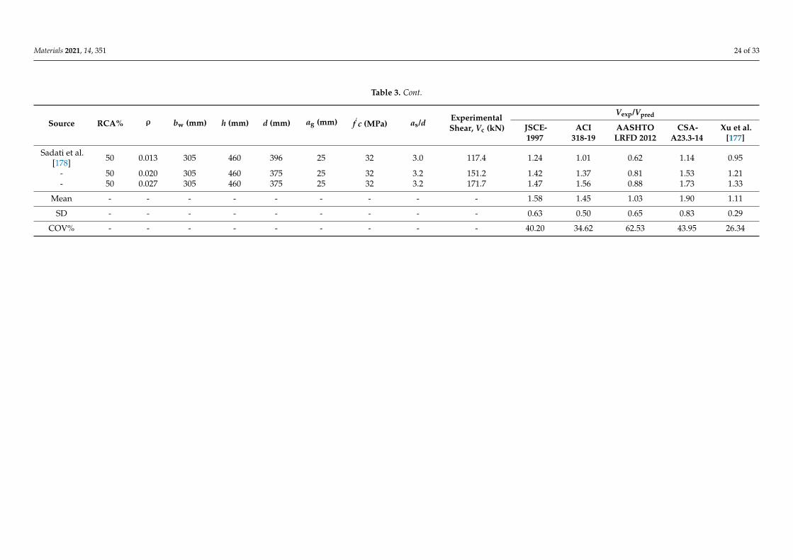
Materials 2021, 14, 351 24 of 33
Table 3. Cont.
Source RCA% ρ bw (mm) h (mm) d (mm) ag (mm) f′c (MPa) as/d Experimental
Shear, Vc (kN)
Vexp/Vpred
JSCE-1997
ACI318-19
AASHTOLRFD 2012
CSA-A23.3-14
Xu et al.[177]
Sadati et al.[178] 50 0.013 305 460 396 25 32 3.0 117.4 1.24 1.01 0.62 1.14 0.95
- 50 0.020 305 460 375 25 32 3.2 151.2 1.42 1.37 0.81 1.53 1.21- 50 0.027 305 460 375 25 32 3.2 171.7 1.47 1.56 0.88 1.73 1.33
Mean - - - - - - - - - 1.58 1.45 1.03 1.90 1.11
SD - - - - - - - - - 0.63 0.50 0.65 0.83 0.29
COV% - - - - - - - - - 40.20 34.62 62.53 43.95 26.34

Materials 2021, 14, 351 25 of 33
In reviewing the literature, no data was found on the shear behavior of RC beamswith GGBFS, SF, or MK as a cement component. On the other hand, several studies haveinvestigated the shear behavior of large-scale RC beams while utilizing FA as a partiallyreplacing material to the OPC, as summarized in Table 2.
Before analyzing the prediction accuracy of each design model, the various models inTable 1 will be qualitatively compared to highlight the difference among them. It is worthnoting that both models, the ACI 318-19 [174] and the CSA-A23.3-14 [175], are not consid-ering the reinforcement ratio (ρ) and the ( as
d ) effects on concrete shear capacity. Similarly, inJSCE-1997 [176], the ( as
d ) effect is not counted. In the literature, a strong relationship betweenthe shear capacity and varying (ρ) and ( as
d ) has been reported [141,142,166,169–172,178–182].Hence, the exclusion of these variables is expected to result in inconsistent predictions. Onthe other hand, AASHTO LRFD-2012 [173] and the proposed equation by Xu et al. [177]have considered these effects. One source of inaccuracy in Xu et al.’s [177] model couldbe that the proposed equation predicts zero shear strength for concrete sections withoutflexural reinforcement. However, this is not a major problem since reinforcement exists inpractical life applications.
As can be seen in Table 2, the replacement level of SCM with OPC is ranging between20% to 70%. The concrete shear strength models of ACI 318-19 [174], CSA-A23.3-14 [175],and JSCE-1997 [176] have shown very conservative predictions with average experimentalto predicted shear capacities (Vexp/Vpred) of 1.47 ± 0.42, 1.45 ± 0.38, and 1.51 ± 0.4,respectively. The proposed model of Xu et al. [177] also reported conservative predictionsbut with higher accuracy, where Vexp/Vpred = 1.2 ± 0.22. In addition, Xu et al.’s [177]model recorded the least coefficient of variation, COV% = 18.61, which indicates betterconsistency compared to other models. On the contrary, AASHTO LRFD-2012 [173] over-estimated the predictions with Vexp/Vpred = 0.95 ± 0.41 and COV% of 42.78. However,for those beams with 20% to 30% of FA, the AASHTO LRFD-2012 [173] has shown under-estimated predictions.
From the data in Table 3, it is apparent that RCA% is ranging from 25% to 100%. Asthe above observations, Xu et al.’s [177] model revealed the most accurate predictions withVexp/Vpred = 1.11 ± 0.29 and better consistency than the rest of the codes, with COV%of 26.34. On the other hand, AASHTO LRFD-2012 [173] demonstrated the least accuratepredictions with Vexp/Vpred = 1.03± 0.65 and COV% of 62.53. The predictions of AASHTOLRFD-2012 [173] appeared to be conservative for ( as
d ) less than 2.7, whereas the predictionswere over-estimated for ( as
d ) greater than 2.7. The results, as shown in Table 3, indicate thatthe CSA-A23.3-14 [175] revealed the most conservative and high variability in predictions,with Vexp/Vpred and COV% of 1.90 ± 0.83 and 43.95, respectively. Furthermore, both theJSCE-1997 [176] and ACI 318-19 [174] predictions in Table 3 were found to be consistentwith those in Table 2, with Vexp/Vpred of 1.58 ± 0.63 and 1.45 ± 0.50, and COV% of 40.20and 34.62, respectively. As expected, the high variability in predictions accords well withour earlier qualitative comparison of the presented models in Table 1, which might be dueto the exclusion of important factors such as ρ and as
d .
4. Conclusions
In this review, the sustainability benefits of GC were discussed first, then its me-chanical properties when incorporating GGBFS, FA, SF, or MK as a partially replacingmaterial for cement were analyzed at different replacement levels, different ages, anddifferent W/b ratios in terms of compressive strength. The durability properties of GCwere discussed under different environmental exposures. Following this, the structuralbehavior of GC in large-scale RC beams was analyzed and their concrete shear capacitieswere compared analytically to the available design codes, such as JSCE-1997 [176], ACI318- 2019 [174], AASHTO LRFD-2012 [173], and CSA-A23.3-2014 [175], and a proposedequation by Xu et al. [177]. Based on the above review, the main outcomes are summarizedas follow:

Materials 2021, 14, 351 26 of 33
• The SF and MK were very effective in gaining higher early strength than the controlmix with 100% OPC.
• At 90 days, the GGBFS concrete reported higher compressive strength than 40 MPa,except for concrete with 80% of GGBFS at W/b of 0.5.
• The analysis revealed that the 28-day strength of 20 to 35 MPa was achieved when theW/b range of 0.5 to 0.6 or 0.24 to 0.45 is implemented with a replacement level of FAof 10% to 30% or 40% to 60%, respectively.
• Higher strength grades (at 28 days) of the range 40 to 60 MPa and 60 to 80 MPa can beachieved when W/b ranges are 0.27 to 0.4 and 0.24 to 0.36 and when the replacementlevels of FA are 10% to 55% and 10% to 40%, respectively.
• At the age of 28 days, high strength grades of the range 40 to 60 MPa and 60 to 90 MPawere achieved when W/b is of the range 0.35 to 0.5 and 0.26 to 0.4 and when thereplacement ratio of SF is ranging from 5% to 20% and 5% to 25%, respectively.
• For concrete with MK, the 28-day strength of 60 to 80 MPa was achieved at W/b of 0.3to 0.36 and with a replacement level in the range of 10% to 20%. At lower W/b of 0.27to 0.33, the strength range of 80 to 100 MPa was achieved at replacement levels of 5%to 15%, respectively.
• At elevated temperatures higher than 400 C, the concrete mixes with either GGBFS,FA, or SF demonstrated a sharp reduction in compressive strength.
• The sorptivity in pozzolanic cement pastes is remarkably lower than that in Portlandcement paste.
• The long-term resistance to sulfate attack of concrete that combines GGBFS and FAwas observed to be superior to the CC mix and high-volume FA concrete mix. Also,the former mix experienced less change in weight.
• The carbonation depth was shown to increase with the increased content of SCMs,and regardless of SCM type in concrete, the carbonation depth was higher than that ofthe control mix (with no SCM).
• The incorporation of silica nanoparticles (SNPs) could result in a significant reductionin the carbonation depth and the sulfate attack.
• Although the RCA concrete had a more permeable structure than the NCA concrete,the incorporation of FA, GGBFS, or SF can lead to a significant enhancement in thechloride ion penetration resistance.
• The concrete shear strength models of JSCE-1997 [176], ACI 318-19 [174], and CSA-A23.3-14 [175] have shown very conservative predictions for concrete beams with FAor RCA, whereas predictions were over-estimated by AASHTO LRFD-2012 [173].
• Among all models, the model of Xu et al. [177] revealed the most accurate predictionswith Vexp/Vpred = 1.2 ± 0.22 and 1.11 ± 0.29 for beams with FA or RCA, respectively.
Continued efforts are needed to determine the stress-strain behavior of GC to accountfor the required design considerations. In addition, further research could also be conductedto determine the GC behavior in large-scale specimens such as beams and slabs undershear and flexure, to develop an understanding of how the combination of GC, bars, andstirrups can create a system that is functional and safe. Another important aspect ofresearch that might produce striking findings is to investigate the bond efficiency of GCwith the conventional steel or with fiber-reinforced polymer (FRP) bars. On a wider level,there is a need for a holistic, detailed, and accurate social, economic, and environmentalsustainability analysis of GC that considers all stages of GC product from cradle to grave.Finally, we believe that our research will serve as a base for analyzing other types ofsubstitutes in GC, such as agricultural and municipal wastes.
Supplementary Materials: The following are available in an excel sheet online at https://www.mdpi.com/1996-1944/14/2/351/s1, Table S1: GGBFS concrete, Table S2: FA concrete, Table S3: SFconcrete, Table S4: MK concrete.

Materials 2021, 14, 351 27 of 33
Author Contributions: Original draft preparation: A.A.-H.; Methodology A.A.-H., M.K. and W.A.;Investigation A.A.-H.; Resources: A.A.-H. and M.K.; Formal analysis A.A.-H. and M.K.; VisualizationA.A.-H.; Supervision M.K. and W.A.; Review and editing A.A.-H., M.K., W.A., E.M., and N.C.O. Allauthors have read and agreed to the published version of the manuscript.
Funding: This research was funded by the Graduate Sponsorship Research Award (GSRA) grantnumber GSRA6-1-0301-19005.
Institutional Review Board Statement: Not applicable.
Informed Consent Statement: Not applicable.
Data Availability Statement: Data is contained within the article or Supplementary Material. Thedata presented in this study are available in Al-Hamrani, A.; Kucukvar, M.; Alnahhal, W.; MahdiSaad, E.; Onat, N.C. Green Concrete for a Circular Economy: A Review on Sustainability, Durability,and Structural Properties.
Acknowledgments: The authors wish to express their gratitude to Qatar Foundation for theirfinancial support through the GSRA grant no. GSRA6-1-0301-19005 from the Qatar National ResearchFund (QNRF, a member of Qatar Foundation).
Conflicts of Interest: The authors declare no conflict of interest.
Abbreviations
CE Circular economyPCC Portland cement concreteC&D Construction and demolitionGC Green concreteNCA Natural coarse aggregatesRCA Recycled coarse aggregatesOPC ordinary Portland cementSCM Supplementary cementitious materialGGBFS Ground granulated blast furnace slagFA Fly ashSF Silica fumeMK MetakaolinRHA Rice husk ashLCA Life cycle assessmentCC Conventional concreteEAF Electric arc furnaceGWP Global warming potentialC-S-H Calcium silicate hydrateRC Reinforced concreteGGFAC Concrete with a combination of GGBFS and FAVA Volcanic ashDS Drying shrinkageSNPs Silica nanoparticlesHVFA High-volume FA
References1. Blomsma, F.; Brennan, G. The Emergence of Circular Economy: A New Framing Around Prolonging Resource Productivity. J. Ind.
Ecol. 2017, 21, 603–614. [CrossRef]2. Deschamps, J.; Simon, B.; Tagnit-Hamou, A.; Amor, B. Is open-loop recycling the lowest preference in a circular economy?
Answering through LCA of glass powder in concrete. J. Clean. Prod. 2018, 185, 14–22. [CrossRef]3. Khan, A.A.; Arshad, S.; Mohsin, M. Population Growth and Its Impact on Urban Expansion: A Case Study of Population Growth
and Its Impact on Urban Expansion: A Case Study of Bahawalpur, Pakistan. Univers. J. Geosci. 2014, 2, 229–241. [CrossRef]4. Guney, T. Population Growth and Sustainable Development in Developed- Developing Countries: An Iv (2sls) Approach. J. Fac.
Econ. Adm. Sci. 2017, 22, 1255–1277.

Materials 2021, 14, 351 28 of 33
5. Tafheem, Z.; Khusru, S.; Nasrin, S. Environmental Impact of Green Concrete in Practice ICMERE2011-PI-069. In Proceedingsof the 1st International Conference on Mechanical Engineering and Renewable Energy (ICMERE), Chittagong, Bangladesh,22–24 December 2011.
6. Marie, I.; Quiasrawi, H. Closed-loop recycling of recycled concrete aggregates. J. Clean. Prod. 2012, 37, 243–248. [CrossRef]7. Sergeant, G.; Lerut, E.; Ectors, N.; Hendrickx, T.; Aerts, R.; Topal, B. National Ready Mixed Concrete Association (NRMCA)
Concrete CO 2 Fact Sheet. Eur. J. Surg. Oncol. 2008. [CrossRef]8. Mamlouk, M.S.; Zaniewski, J.P. Materials for Civil and Construction Engineers; Pearson Prentice Hall: Upper Saddle River, NJ, USA,
2006; ISBN 9780136110583.9. Andrew, R.M. Global CO2 emissions from cement production. Earth Syst. Sci. Data Discuss. 2017, 195–217. [CrossRef]10. Ahmad, S.; Kumar, A.; Kumar, K. Axial performance of GGBFS concrete filled steel tubes. Structures 2020, 23, 539–550. [CrossRef]11. Imbabi, M.S.; Carrigan, C.; McKenna, S. Trends and developments in green cement and concrete technology. Int. J. Sustain. Built
Environ. 2012, 1, 194–216. [CrossRef]12. Karsan, K.R.; Hoseini, A.G. Investigating the Effectiveness of Using Green Concrete Towards Promotion of Sustainable Built.
Univ. Putra Malays. 2015, 8, 49–59.13. Rashad, A.M. An investigation of high-volume fl y ash concrete blended with slag subjected to elevated temperatures.
J. Clean. Prod. 2015, 93, 47–55. [CrossRef]14. Albitar, M.; Ali, M.S.M.; Visintin, P.; Drechsler, M. Effect of granulated lead smelter slag on strength of fly ash-based geopolymer
concrete. Constr. Build. Mater. 2015, 83, 128–135. [CrossRef]15. Baspinar, M.S.; Demir, I. Utilization potential of silica fume in fired clay bricks. Waste Manag. Res. 2010, 149–157. [CrossRef]
[PubMed]16. FAO. FAOSTAT Food and Agriculture Organization of the United Nations Statistic Division (FAOSTAT) Domains e Crops: Rice paddy,
Production Quantity, World Total; FAO: Roman, Italy, 2012.17. Younis, K.H.; Pilakoutas, K. Strength prediction model and methods for improving recycled aggregate concrete. Constr. Build. Mater.
2013, 49, 688–701. [CrossRef]18. Akhtar, A.; Sarmah, A.K. Construction and demolition waste generation and properties of recycled aggregate concrete: A global
perspective. J. Clean. Prod. 2018, 186, 262–281. [CrossRef]19. Behera, M.; Bhattacharyya, S.K.; Minocha, A.K.; Deoliya, R.; Maiti, S. Recycled aggregate from C & D waste & its use in
concrete—A breakthrough towards sustainability in construction sector: A review. Constr. Build. Mater. 2014, 68, 501–516.[CrossRef]
20. Mukharjee, B.B.; Barai, S.V. Statistical techniques to analyze properties of nano-engineered concrete using Recycled CoarseAggregates. J. Clean. Prod. 2014, 83, 273–285. [CrossRef]
21. Tam, V.W.Y.; Soomro, M.; Catarina, A.; Evangelista, J. A review of recycled aggregate in concrete applications (2000–2017).Constr. Build. Mater. 2018, 172, 272–292. [CrossRef]
22. Yehia, S.; Helal, K.; Abusharkh, A.; Zaher, A.; Istaitiyeh, H. Strength and Durability Evaluation of Recycled Aggregate Concrete.Int. J. Concr. Struct. Mater. 2015. [CrossRef]
23. Mukharjee, B.B.; Barai, S.V. Influence of Nano-Silica on the properties of recycled aggregate concrete. Constr. Build. Mater. 2014,55, 29–37. [CrossRef]
24. Al-mansour, A.; Chow, C.L.; Feo, L.; Penna, R.; Lau, D. Green Concrete: By-Products Utilization and Advanced Approaches.Sustainability 2019, 11, 5145. [CrossRef]
25. Suhendro, B. Toward green concrete for better sustainable environment. Procedia Eng. 2014, 95, 305–320. [CrossRef]26. Müller, H.S.; Breiner, R.; Moffatt, J.S.; Haist, M. Design and properties of sustainable concrete. Procedia Eng. 2014, 95, 290–304.
[CrossRef]27. Badogiannis, E.; Papadakis, V.G.; Chaniotakis, E.; Tsivilis, S. Exploitation of poor Greek kaolins: Strength development of
metakaolin concrete and evaluation by means of k -value. Cem. Concr. Res. 2004, 34, 1035–1041. [CrossRef]28. Roy, D.M.; Arjunan, P.; Silsbee, M.R. Effect of silica fume, metakaolin, and low-calcium fly ash on chemical resistance of concrete.
Cem. Concr. Res. 2001, 31, 1809–1813. [CrossRef]29. Ferraris, C.F.; Obla, K.H.; Hill, R. The influence of mineral admixtures on the rheology of cement paste and concrete.
Cem. Concr. Res. 2001, 31, 245–255. [CrossRef]30. Chan, W.W.J.; Wu, C.M.L. Durability of concrete with high cement replacement. Cem. Concr. Res. 2000, 30, 865–879. [CrossRef]31. Long, G.; Gao, Y.; Xie, Y. Designing more sustainable and greener self-compacting concrete. Constr. Build. Mater. 2015, 84, 301–306.
[CrossRef]32. Liew, K.M.; Sojobi, A.O.; Zhang, L.W. Green concrete: Prospects and challenges. Constr. Build. Mater. 2017, 156, 1063–1095.
[CrossRef]33. Ghahari, S.A.; Assi, L.N.; Alsalman, A.; Alyamaç, K.E. Fracture properties evaluation of cellulose nanocrystals cement paste.
Materials 2020, 13, 2507. [CrossRef] [PubMed]34. Knoeri, C.; Sanyé-Mengual, E.; Althaus, H.J. Comparative LCA of recycled and conventional concrete for structural applications.
Int. J. Life Cycle Assess. 2013, 18, 909–918. [CrossRef]35. Blengini, G.A.; Garbarino, E. Resources and waste management in Turin (Italy): The role of recycled aggregates in the sustainable
supply mix. J. Clean. Prod. 2010, 18, 1021–1030. [CrossRef]
Materials 2021, 14, 351 29 of 33
36. Leising, E.; Quist, J.; Bocken, N. Circular Economy in the building sector: Three cases and a collaboration tool. J. Clean. Prod. 2018,176, 976–989. [CrossRef]
37. Yazdanbakhsh, A.; Bank, L.C.; Baez, T.; Wernick, I. Comparative LCA of concrete with natural and recycled coarse aggregate inthe New York City area. Int. J. Life Cycle Assess. 2018, 1163–1173. [CrossRef]
38. Faleschini, F.; Pellegrino, C. Recycled concrete containing EAF slag: Environmental assessment through LCA. Eur. J. Environ.Civ. Eng. 2014. [CrossRef]
39. Abbas, A.; Fathifazl, G.; Isgor, O.B.; Razaqpur, A.G.; Fournier, B.; Foo, S. Environmental benefits of green concrete. In Proceedingsof the 2006 IEEE EIC Climate Change Technology Conference, EICCCC 2006, Ottawa, ON, Canada, 10–12 May 2006.
40. Shan, X.; Zhou, J.; Chang, V.W.; Yang, E. Life cycle assessment of adoption of local recycled aggregates and green concrete inSingapore perspective. J. Clean. Prod. 2017, 164, 918–926. [CrossRef]
41. Turk, J.; Cotic, Z.; Mladenovic, A.; Sajna, A. Environmental evaluation of green concretes versus conventional concrete by meansof LCA. Waste Manag. 2015, 45, 194–205. [CrossRef]
42. Gursel, A.P.; Maryman, H.; Ostertag, C. A life-cycle approach to environmental, mechanical, and durability properties of “green”concrete mixes with rice husk ash. J. Clean. Prod. 2016, 112, 823–836. [CrossRef]
43. Thomas, B.S. Green concrete partially comprised of rice husk ash as a supplementary cementitious material–A comprehensivereview. Renew. Sustain. Energy Rev. 2018, 82, 3913–3923. [CrossRef]
44. Flower, D.J.M.; Sanjayan, J.G. Green house gas emissions due to concrete manufacture. Int. J. Life Cycle Assess. 2007, 12, 282–288.[CrossRef]
45. Divsholi, B.S.; Yang, T.; Lim, D.; Teng, S. Durability Properties and Microstructure of Ground Granulated Blast Furnace SlagCement Concrete. Int. J. Concr. Struct. Mater. 2014, 8, 157–164. [CrossRef]
46. Yu, J.; Mishra, D.K.; Leung, C.K.Y. Very high volume fly ash green concrete for applications in India. Waste Manag. Res. 2018, 36,520–526. [CrossRef] [PubMed]
47. Elchalakani, M.; Aly, T.; Abu-Aisheh, E. Sustainable concrete with high volume GGBFS to build Masdar City in the UAE. Case Stud.Constr. Mater. 2014, 1, 10–24. [CrossRef]
48. Song, W.; Yi, J.; Wu, H.; He, X.; Song, Q.; Yin, J. Effect of carbon fi ber on mechanical properties and dimensional stability ofconcrete incorporated with granulated-blast furnace slag. J. Clean. Prod. 2019, 238, 117819. [CrossRef]
49. Sha, W.; Pereira, G.B. Differential scanning calorimetry study of hydrated ground granulated blast-furnace slag. Cem. Concr. Res.2001, 31, 327–329. [CrossRef]
50. Oner, A.; Akyuz, S. An experimental study on optimum usage of GGBS for the compressive strength of concrete. Cem. Concr.Compos. 2007, 29, 505–514. [CrossRef]
51. American Concrete Institute. Ground Granulated Blast-Furnace Slag as a Cementitious Constituent in Concrete. ACI 233R-95; AmericanConcrete Institute: Farmington Hills, MI, USA, 1995; pp. 1–18.
52. Yun, K.; Kyum, E. An experimental study on corrosion resistance of concrete with ground granulate blast-furnace slag.Cem. Concr. Res. 2005, 35, 1391–1399. [CrossRef]
53. Khatib, J.M.; Hibbert, J.J. Selected engineering properties of concrete incorporating slag and metakaolin. Constr. Build. Mater.2005, 19, 460–472. [CrossRef]
54. Patil, Y.O.; Patil, P.P.N.; Student, P.G.; Course, M.E.; Course, P.G. GGBS as Partial Replacement of OPC in Cement Concrete—AnExperimental Study Engineering. Int. J. Sci. Res. 2013, 2, 189–191.
55. Cheng, A.; Huang, R.; Wu, J.; Chen, C. Influence of GGBS on durability and corrosion behavior of reinforced concrete. Mater.Chem. Phys. 2005, 93, 404–411. [CrossRef]
56. Ozbay, E.; Erdemir, M.; Ibrahim, H. Utilization and efficiency of ground granulated blast furnace slag on concrete properties—Areview. Constr. Build. Mater. 2016, 105, 423–434. [CrossRef]
57. Guneyisi, E.; Gesoglu, M. A study on durability properties of high-performance concretes incorporating high replacement levelsof slag. Mater. Struct. 2008, 41, 479–493. [CrossRef]
58. Zhang, L.; Chen, B. Hydration and Properties of Slag Cement Activated by Alkali and Sulfate. J. Mater. Civ. Eng. 2017, 29, 1–8.[CrossRef]
59. Acharya, P.K.; Patro, S.K. Effect of lime and ferrochrome ash (FA) as partial replacement of cement on strength, ultrasonic pulsevelocity and permeability of concrete. Constr. Build. Mater. 2015, 94, 448–457. [CrossRef]
60. Johari, M.A.M.; Brooks, J.J.; Kabir, S.; Rivard, P. Influence of supplementary cementitious materials on engineering properties ofhigh strength concrete. Constr. Build. Mater. 2011, 25, 2639–2648. [CrossRef]
61. Khan, A.N.; Memon, F.A.; Rizvi, S.H.; Bhanbhro, Q.; Bheel, N. Fresh and Hardened Properties of Ground Granulated BlastFurnace Slag Made Concrete. Int. J. Mod. Res. Eng. Manag. 2018, 1, 1–7. [CrossRef]
62. Chen, X.; Wang, H.; Najm, H.; Venkiteela, G.; Hencken, J. Evaluating engineering properties and environmental impact ofpervious concrete with fl y ash and slag. J. Clean. Prod. 2019, 237, 117714. [CrossRef]
63. Bilim, C.; Atis, C.D.; Tanyildizi, H.; Karahan, O. Advances in Engineering Software Predicting the compressive strength of groundgranulated blast furnace slag concrete using artificial neural network. Adv. Eng. Softw. 2009, 40, 334–340. [CrossRef]
64. Ozbay, E.; Lachemi, M. Compressive strength, abrasion resistance and energy absorption capacity of rubberized concretes withand without slag. Mater. Struct. 2011, 1297–1307. [CrossRef]
Materials 2021, 14, 351 30 of 33
65. Jang, S.; Karthick, S.; Kwon, S. Investigation on Durability Performance in Early Aged High-Performance Concrete ContainingGGBFS and FA. Adv. Mater. Sci. Eng. 2017, 2017. [CrossRef]
66. Nath, P.; Sarker, P. Effect of Fly Ash on the Durability Properties of High Strength Concrete. Procedia Eng. 2011, 14, 1149–1156.[CrossRef]
67. American Coal Ash Association Coal Combustion Product (CCP) Production & Use Survey Report [Internet]. Farmington Hills.2012. Available online: http://www.acaa-usa.org/associations/8003/files/Final2011CCPSurvey.pdf (accessed on 9 October2020).
68. Naik, T.R.; Singh, S.S.; Hossain, M.M.; Fellow, P.; Science, A. Permeability of concrete containing large amounts of fly ash.Cem. Concr. Res. 1994, 24, 913–922. [CrossRef]
69. Lam, L.; Wong, Y.; Poon, C. Effect of fly ash and silica fume on compressive and fracture behaviors of concrete. Cem. Concr. Res.1998, 28, 271–283. [CrossRef]
70. Bouzoubaa, N.; Lachemi, M. Self-compacting concrete incorporating high volumes of class F fly ash Preliminary results.Cem. Concr. Res. 2001, 31, 413–420. [CrossRef]
71. Atis, C.D.; Ash, F. High-Volume Fly Ash Concrete with High Strength and Low Drying Shrinkage. J. Mater. Civ. Eng. 2003, 15,153–156. [CrossRef]
72. Han, S.; Kim, J.; Park, Y. Prediction of compressive strength of fly ash concrete by new apparent activation energy function.Cem. Concr. Res. 2003, 33, 965–971. [CrossRef]
73. Siddique, R. Performance characteristics of high-volume Class F fly ash concrete. Cem. Concr. Res. 2004, 34, 487–493. [CrossRef]74. Dinakar, P.; Babu, K.G.; Santhanam, M. Cement & Concrete Composites Durability properties of high volume fly ash self
compacting concretes. Cem. Concr. Compos. 2008, 30, 880–886. [CrossRef]75. Durán-herrera, A.; Juárez, C.A.; Valdez, P.; Bentz, D.P.; Ash, F. Evaluation of sustainable high-volume fly ash concretes. Cem. Concr.
Compos. J. 2011, 33, 39–45. [CrossRef]76. Çelik, B.; Özturan, T. Green Concrete Produced by Fly Ash and Silica Fume. Int. J. Eng. Sci. Appl. 2017, 1, 1–6.77. Huang, C.; Lin, S.; Chang, C.; Chen, H. Mix proportions and mechanical properties of concrete containing very high-volume of
Class F fly ash. Constr. Build. Mater. 2013, 46, 71–78. [CrossRef]78. Ahmaruzzaman, M. A review on the utilization of fly ash. Prog. Energy Combust. Sci. 2010, 36, 327–363. [CrossRef]79. Poon, C.S.; Lam, L.; Wong, Y.L. A study on high strength concrete prepared with large volumes of low calcium fly ash. Cem. Concr.
Res. 2000, 30, 447–455. [CrossRef]80. Kayali, O.; Ahmed, M.S. Assessment of high volume replacement fly ash concrete–Concept of performance index. Constr. Build.
Mater. 2013, 39, 71–76. [CrossRef]81. Rivera, F.; Martínez, P.; Castro, J.; Mauricio, L. Massive volume fl y-ash concrete: A more sustainable material with fl y ash
replacing cement and aggregates. Cem. Concr. Compos. 2015, 63, 104–112. [CrossRef]82. Saha, A.K. Effect of class F fl y ash on the durability properties of concrete. Sustain. Environ. Res. 2018, 28, 25–31. [CrossRef]83. Shekarchi, M.; Rafiee, A.; Layssi, H. Long-term chloride diffusion in silica fume concrete in harsh marine climates. Cem. Concr.
Compos. 2009, 31, 769–775. [CrossRef]84. Strzałkowski, J.; Garbalinska, H. The Influence of Silica Fume on the Mechanical and Thermal Parameters of Portland Cement
Concretes. J. Ecol. Eng. 2019, 20, 95–102. [CrossRef]85. Hewlett, P. Lea’s Chemistry of Cement and Concrete, 4th ed.; Butterworth-Heinemann: Brlington, VT, USA, 2003; pp. 907–1015.86. Khedr, S.; Abou-Zeid, M. Characteristics of silica-fume concrete. J. Mater. Civ. Eng. 1995, 6, 357–375. [CrossRef]87. Mazloom, M.; Ramezanianpour, A.; Brooks, J.J. Effect of silica fume on mechanical properties of high-strength concrete.
Cem. Concr. Compos. 2004, 26, 347–357. [CrossRef]88. Wong, H.S.; Razak, H.A. Efficiency of calcined kaolin and silica fume as cement replacement material for strength performance.
Cem. Concr. Res. 2005, 35, 696–702. [CrossRef]89. Behnood, A.; Ziari, H. Effects of silica fume addition and water to cement ratio on the properties of high-strength concrete after
exposure to high temperatures. Cem. Concr. Compos. 2008, 30, 106–112. [CrossRef]90. Amudhavalli, N.K.; Mathew, J. Effect of silica fume on strength and durability parameters of concrete. Int. J. Eng. Sci.
Emerg. Technol. 2012, 3, 28–35.91. Ding, J.; Li, Z. Effects of Metakaolin and Silica Fume on Properties of Concrete. ACI Mater. J. 2018, 99, 393–398.92. Bhanja, S.; Sengupta, B. Influence of silica fume on the tensile strength of concrete. Cem. Concr. Res. 2005, 35, 743–747. [CrossRef]93. Nochaiya, T.; Wongkeo, W.; Chaipanich, A. Utilization of fly ash with silica fume and properties of Portland cement–fly ash–silica
fume concrete. Fuel 2010, 89, 768–774. [CrossRef]94. Kou, S.; Poon, C.; Agrela, F. Cement & Concrete Composites Comparisons of natural and recycled aggregate concretes prepared
with the addition of different mineral admixtures. Cem. Concr. Compos. 2011, 33, 788–795. [CrossRef]95. Corinaldesi, V.; Moriconi, G. Influence of mineral additions on the performance of 100 % recycled aggregate concrete.
Constr. Build. Mater. 2009, 23, 2869–2876. [CrossRef]96. Emhemd, A.; Al, S.; Radonjanin, V.; Malešev, M. Green recycled aggregate concrete. Constr. Build. Mater. 2013, 47, 1503–1511.
[CrossRef]97. Blanco, F.; Garcia, M.P.; Ayala, J.; Mayoral, G.; Garcia, M.A. The effect of mechanically and chemically activated fly ashes on
mortar properties. Fuel 2006, 85, 2018–2026. [CrossRef]
Materials 2021, 14, 351 31 of 33
98. Poon, C.S.; Kou, S.C.; Lam, L. Compressive strength, chloride diffusivity and pore structure of high performance metakaolin andsilica fume concrete. Constr. Build. Mater. 2006, 20, 858–865. [CrossRef]
99. Özcan, F.; Atis, C.D.; Karahan, O.; Uncuoglu, E.; Tanyildizi, H. Comparison of artificial neural network and fuzzy logic modelsfor prediction of long-term compressive strength of silica fume concrete. Adv. Eng. Softw. 2009, 40, 856–863. [CrossRef]
100. Patil, B.B.; Kumbhar, P.D. Strength and Durability Properties of High Performance Concrete incorporating High ReactivityMetakaolin. Int. J. Mod. Eng. Res. 2012, 2, 1099–1104.
101. Zhang, M.; Malhotra, V. Characteritics of a thermally activated alumina-silicate pozzolanic material and its use in concrete.Cem. Concr. Res. 1995, 25, 1713–1725. [CrossRef]
102. Vu, D.D.; Stroeven, P.; Bui, V.B. Strength and durability aspects of calcined kaolin-blended Portland cement mortar and concrete.Cem. Concr. Compos. 2001, 23, 471–478. [CrossRef]
103. Kadri, E.; Kenai, S.; Ezziane, K.; Siddique, R.; Schutter, G. De Applied Clay Science In fl uence of metakaolin and silica fume onthe heat of hydration and compressive strength development of mortar. Appl. Clay Sci. 2011, 53, 704–708. [CrossRef]
104. Rovnaníková, P.; Vejmelková, E.; Pavlíková, M.; Keppert, M.; Sedlmajer, M.; Robert, C.; Ondrác, M. High performance concretewith Czech metakaolin: Experimental analysis of strength, toughness and durability characteristics. Constr. Build. Mater. 2010, 24,1404–1411. [CrossRef]
105. Batis, G.; Pantazopoulou, P.; Tsivilis, S.; Badogiannis, E. The effect of metakaolin on the corrosion behavior of cement mortars.Cem. Concr. Compos. 2005, 27, 125–130. [CrossRef]
106. Barbhuiya, S.; Chow, P.; Memon, S. Microstructure, hydration and nanomechanical properties of concrete containing metakaolin.Constr. Build. Mater. 2015, 95, 696–702. [CrossRef]
107. Dinakar, P.; Sahoo, P.K.; Sriram, G. Effect of Metakaolin Content on the Properties of High Strength Concrete. Int. J. Concr. Struct.Mater. 2013, 7, 215–223. [CrossRef]
108. Ramezanianpour, A.A.; Jovein, H.B. Influence of metakaolin as supplementary cementing material on strength and durability ofconcretes. Constr. Build. Mater. 2012, 30, 470–479. [CrossRef]
109. Qian, X.; Li, Z. The relationships between stress and strain for high-performance concrete with metakaolin. Cem. Concr. Res. 2001,31, 1607–1611. [CrossRef]
110. Lee, S.T.; Moon, H.Y.; Hooton, R.D.; Kim, J.P. Effect of solution concentrations and replacement levels of metakaolin on theresistance of mortars exposed to magnesium sulfate solutions. Cem. Concr. Res. 2005, 35, 1314–1323. [CrossRef]
111. Cassagnabère, F.; Escadeillas, G.; Mouret, M. Study of the reactivity of cement / metakaolin binders at early age for specific use insteam cured precast concrete. Constr. Build. Mater. 2009, 23, 775–784. [CrossRef]
112. Wild, S.; Khatib, J.M.; Jones, A. Relative strength, pozzolanic activity and cement hydration in superplasticised metakaolinconcrete. Cem. Concr. Res. 1996, 26, 1537–1544. [CrossRef]
113. Rashad, A.M.; Sadek, D.M. An investigation on Portland cement replaced by high-volume GGBS pastes modified with micro-sizedmetakaolin subjected to elevated temperatures. Int. J. Sustain. Built Environ. 2017, 6, 91–101. [CrossRef]
114. Poon, C.S.; Azhar, S.; Anson, M.; Wong, Y.L. Performance of metakaolin concrete at elevated temperatures. Cem. Concr. Compos.2003, 25, 83–89. [CrossRef]
115. Phan, L.T.; Carino, N.J. Fire performance of high strength concrete: Research needs. Adv. Technol. Struct. Eng. 2000, 1–8.116. Siddique, R.; Kaur, D. Properties of concrete containing ground granulated blast furnace slag (GGBFS) at elevated temperatures.
J. Adv. Res. 2012, 3, 45–51. [CrossRef]117. Li, Q.; Li, Z.; Yuan, G. Effects of elevated temperatures on properties of concrete containing ground granulated blast furnace slag
as cementitious material. Constr. Build. Mater. 2012, 35, 687–692. [CrossRef]118. Nadeem, A.; Memon, S.A.; Lo, T.Y. The performance of Fly ash and Metakaolin concrete at elevated temperatures.
Constr. Build. Mater. 2014, 62, 67–76. [CrossRef]119. Li, G.; Zhao, X. Properties of concrete incorporating fly ash and ground granulated blast-furnace slag. Cem. Concr. Compos. 2003,
25, 293–299. [CrossRef]120. McCarthy, M.J.; Dhir, R.K. Development of high volume fly ash cements for use in concrete construction. Fuel 2005, 84, 1423–1432.
[CrossRef]121. British Standard Institution. BS 1881 (part 208) Recommendations for the Determination of Initial Surface Absorption of Concrete; British
Standard Institution: London, UK, 1996.122. Hossain, K.M.A.; Lachemi, M. Strength, durability and micro-structural aspects of high performance volcanic ash concrete.
Cem. Concr. Res. 2007, 37, 759–766. [CrossRef]123. ASTM C1202. Standard Test Method for Electrical Indication of Concrete’s Ability to Resist Chloride Ion Penetration; ASTM International:
West Conshohocken, PA, USA, 2012; pp. 1–8. [CrossRef]124. Kim, H.S.; Lee, S.H.; Moon, H.Y. Strength properties and durability aspects of high strength concrete using Korean metakaolin.
Constr. Build. Mater. 2007, 21, 1229–1237. [CrossRef]125. ASTM C666/C666M. Standard Test Method for Resistance of Concrete to Rapid Freezing and Thawing; ASTM International: West Con-
shohocken, PA, USA, 2003; Volume 3, pp. 1–6. [CrossRef]126. Hossain, K.M.A.; Lachemi, M. Development of volcanic ash concrete: Strength, durability, and microstructural investigations.
ACI Mater. J. 2006, 103, 11–17. [CrossRef]
Materials 2021, 14, 351 32 of 33
127. Berndt, M.L. Properties of sustainable concrete containing fly ash, slag and recycled concrete aggregate. Constr. Build. Mater. 2009,23, 2606–2613. [CrossRef]
128. Kou, S.C.; Poon, C.S. Long-term mechanical and durability properties of recycled aggregate concrete prepared with the incorpora-tion of fly ash. Cem. Concr. Compos. 2013, 37, 12–19. [CrossRef]
129. Faella, C.; Lima, C.; Martinelli, E.; Pepe, M.; Realfonzo, R. Mechanical and durability performance of sustainable structuralconcretes: An experimental study. Cem. Concr. Compos. 2016, 71, 85–96. [CrossRef]
130. Sabet, F.A.; Libre, N.A.; Shekarchi, M. Mechanical and durability properties of self consolidating high performance concreteincorporating natural zeolite, silica fume and fly ash. Constr. Build. Mater. 2013, 44, 175–184. [CrossRef]
131. Chousidis, N.; Rakanta, E.; Ioannou, I.; Batis, G. Mechanical properties and durability performance of reinforced concretecontaining fly ash. Constr. Build. Mater. 2015, 101, 810–817. [CrossRef]
132. Singh, L.P.; Ali, D.; Tyagi, I.; Sharma, U.; Singh, R.; Hou, P. Durability studies of nano-engineered fly ash concrete. Constr. Build.Mater. 2019, 194, 205–215. [CrossRef]
133. ASTM C1012/C1012M-15 Standard Test Method for Length Change of Hydraulic-Cement Mortars Exposed to a Sulfate Solution; ASTM Int.:West Conshohocken, PA, USA, 2015; Volume 11, pp. 5–9. [CrossRef]
134. CPC-18 Measurement of hardened concrete carbonation depth. Mater. Struct. 1988, 21, 453–455. [CrossRef]135. Wang, D.; Zhou, X.; Meng, Y.; Chen, Z. Durability of concrete containing fly ash and silica fume against combined freezing-thawing
and sulfate attack. Constr. Build. Mater. 2017, 147, 398–406. [CrossRef]136. Uysal, M.; Akyuncu, V. Durability performance of concrete incorporating Class F and Class C fly ashes. Constr. Build. Mater. 2012,
34, 170–178. [CrossRef]137. Yoo, S.W.; Ryu, G.S.; Choo, J.F. Evaluation of the effects of high-volume fly ash on the flexural behavior of reinforced concrete
beams. Constr. Build. Mater. 2015, 93, 1132–1144. [CrossRef]138. Fuzail Hashmi, A.; Shariq, M.; Baqi, A. Flexural performance of high volume fly ash reinforced concrete beams and slabs.
Structures 2020, 25, 868–880. [CrossRef]139. Sangeetha, S.P.; Joanna, P.S. Open Access Flexural Behaviour of Reinforced Concrete Beams with Partial Replacement of GGBS.
Am. J. Eng. Res. 2014, 3, 119–127.140. Arezoumandi, M.; Volz, J.S. Effect of fly ash replacement level on the shear strength of high-volume fly ash concrete beams.
J. Clean. Prod. 2013, 59, 120–130. [CrossRef]141. Sunayana, S.; Barai, S.V. Shear behavior of fly-ash-incorporated recycled aggregate concrete beams. ACI Struct. J. 2020, 117,
289–303. [CrossRef]142. Alghazali, H.H.; Myers, J.J. Shear behavior of full-scale high volume fly ash-self consolidating concrete (HVFA-SCC) beams.
Constr. Build. Mater. 2017, 157, 161–171. [CrossRef]143. Bertolini, L. Steel corrosion and service life of reinforced concrete structures. Struct. Infrastruct. Eng. 2008, 4, 123–137. [CrossRef]144. Topçu, I.B.; Boga, A.R. Effect of ground granulate blast-furnace slag on corrosion performance of steel embedded in concrete.
Mater. Des. 2010, 31, 3358–3365. [CrossRef]145. Barnett, S.J.; Soutsos, M.N.; Millard, S.G.; Bungey, J.H. Strength development of mortars containing ground granulated blast-
furnace slag: Effect of curing temperature and determination of apparent activation energies. Cem. Concr. Res. 2006, 36, 434–440.[CrossRef]
146. Chidiac, S.E.; Panesar, D.K. Evolution of mechanical properties of concrete containing ground granulated blast furnace slag andeffects on the scaling resistance test at 28 days. Cem. Concr. Compos. 2008, 30, 63–71. [CrossRef]
147. Chen, Z.; Yang, Y.; Yao, Y. Quasi-static and dynamic compressive mechanical properties of engineered cementitious compositeincorporating ground granulated blast furnace slag. Mater. Des. 2013, 44, 500–508. [CrossRef]
148. Dinakar, P.; Sethy, K.P.; Sahoo, U.C. Design of self-compacting concrete with ground granulated blast furnace slag. Mater. Des.2013, 43, 161–169. [CrossRef]
149. Tsai, C.J.; Huang, R.; Lin, W.T.; Wang, H.N. Mechanical and cementitious characteristics of ground granulated blast furnace slagand basic oxygen furnace slag blended mortar. Mater. Des. 2014, 60, 267–273. [CrossRef]
150. Indian Standard. IS 456 2000: Plain and Reinforced Concrete. Code of Practice (4th Revision); Indian Standard: Mirzapur, India, 2000.151. Hawileh, R.A.; Abdalla, J.A.; Fardmanesh, F.; Shahsana, P.; Khalili, A. Performance of reinforced concrete beams cast with
different percentages of GGBS replacement to cement. Arch. Civ. Mech. Eng. 2017, 17, 511–519. [CrossRef]152. Rao, P.; Mohan, S.; Sekar, S. Shear resistance of high volume fly ash reinforced concrete beams without web reinforcement. Int. J.
Civ. Struct. Eng. 2013, 1, 986–993.153. Arezoumandi, M.; Volz, J.S.; Myers, J.J. Shear behavior of high-volume fly ash concrete versus conventional concrete. J. Mater.
Civ. Eng. 2013, 25, 1506–1513. [CrossRef]154. Li, X. Recycling and reuse of waste concrete in China: Part II. Structural behaviour of recycled aggregate concrete and engineering
applications. Resour. Conserv. Recycl. 2009, 53, 107–112. [CrossRef]155. Hoffmann, C.; Schubert, S.; Leemann, A.; Motavalli, M. Recycled concrete and mixed rubble as aggregates: Influence of variations
in composition on the concrete properties and their use as structural material. Constr. Build. Mater. 2012, 35, 701–709. [CrossRef]156. Ryu, J.S. Improvement on strength and impermeability of recycled concrete. J. Mater. Sci. Lett. 2002, 21, 1565–1567. [CrossRef]157. Savas, E.; Dawson, A.R.; Howard, T.N. Influence of the micro- and nanoscale local mechanical properties of the interfacial
transition zone on impact behavior of concrete made with different aggregates. Cem. Concr. Res. 2012, 42, 447–458.

Materials 2021, 14, 351 33 of 33
158. Tokyay, M.; Tahir, C. Assessing the ITZ microcracking via scanning electron microscope and its effect on the failure behavior ofconcrete. Cem. Concr. Res. 2005, 35, 358–363. [CrossRef]
159. Bao, J.; Li, S.; Zhang, P.; Ding, X.; Xue, S.; Cui, Y.; Zhao, T. Influence of the incorporation of recycled coarse aggregate on waterabsorption and chloride penetration into concrete (a) NCAs (b) RCAs. Constr. Build. Mater. 2020, 239, 117845. [CrossRef]
160. Poon, C.S.; Shui, Z.H.; Lam, L. Effect of microstructure of ITZ on compressive strength of concrete prepared with recycledaggregates. Constr. Build. Mater. 2004, 18, 461–468. [CrossRef]
161. Younis, K.H. Feasibility of Using Nanoparticles of SiO2 to Improve the Performance of Recycled Aggregate Concrete. Adv. Mater.Sci. Eng. 2018, 2018, 3–5. [CrossRef]
162. Li, W.; Xiao, J.; Sun, Z.; Kawashima, S.; Shah, S.P. Interfacial transition zones in recycled aggregate concrete with different mixingapproaches. Constr. Build. Mater. 2012, 35, 1045–1055. [CrossRef]
163. Otsuki, N.; Asce, M.; Miyazato, S.; Yodsudjai, W. Influence of Recycled Aggregate on Interfacial Transition Zone, Strength,Chloride Penetration and Carbonation of Concrete. J. Mater. Civ. Eng. 2003, 15, 443–451. [CrossRef]
164. Bai, G.; Zhu, C.; Liu, C.; Liu, B. An evaluation of the recycled aggregate characteristics and the recycled aggregate concretemechanical properties. Constr. Build. Mater. 2020, 240, 117978. [CrossRef]
165. Katz, A. Treatments for the Improvement of Recycled Aggregate. J. Mater. Civ. Eng. 2004, 16, 597–603. [CrossRef]166. Han, B.; Yun, H.; Chung, S. Shear Capacity of Reinforced Concrete Beams Made with Recycled Aggregate. ACI Symp. Publ. 2001,
200, 503–516.167. Al mahmoud, F.; Boissiere, R.; Mercier, C.; Khelil, A. Shear behavior of reinforced concrete beams made from recycled coarse and
fine aggregates. Structures 2020, 25, 660–669. [CrossRef]168. González-Fonteboa, B.; Martínez-Abella, F. Shear strength of recycled concrete beams. Constr. Build. Mater. 2007, 21, 887–893.
[CrossRef]169. Etxeberria, M.; Marí, A.R.; Vázquez, E. Recycled aggregate concrete as structural material. Mater. Struct. Constr. 2007, 40, 529–541.
[CrossRef]170. Fathifazl, G.; Razaqpur, A.G.; Burkan Isgor, O.; Abbas, A.; Fournier, B.; Foo, S. Shear capacity evaluation of steel reinforced
recycled concrete (RRC) beams. Eng. Struct. 2011, 33, 1025–1033. [CrossRef]171. Knaack, A.M.; Kurama, Y.C. Behavior of reinforced concrete beams with recycled concrete coarse aggregates. J. Struct. Eng. 2015,
141. [CrossRef]172. Arezoumandi, M.; Smith, A.; Volz, J.S.; Khayat, K.H. An experimental study on shear strength of reinforced concrete beams with
100% recycled concrete aggregate. Constr. Build. Mater. 2014, 53, 612–620. [CrossRef]173. AASHTO LRFD. American Association of State Highway and Transportation Officials. Bridge Design Specifications, 2nd ed.;
AASHTO LRFD: Washington, DC, USA, 2012; ISBN 9781560515234.174. American Concrete Institute ACI Committee. Building Code Requirements for Structural Concrete ACI 318-19 and Commentary
318R–19; American Concrete Institute ACI Committee: Farmington Hills, MI, USA, 2019; ISBN 9781641950565.175. CSA Group. Design of Concrete Structures (CSA A23. 3-14); Canadian Standards Association: Toronto, ON, Canada, 2014.176. JSCE (Japan Society of Civil Engineers). Recommendation for Design and Construction of Concrete Structures Using Continuous Fiber
Reinforcing Materials; JSCE: Tokyo, Japan, 1997.177. Xu, S.; Zhang, X.; Reinhardt, H.W. Shear capacity prediction of reinforced concrete beams without stirrups using fracture
mechanics approach. ACI Struct. J. 2012, 109, 705–713. [CrossRef]178. Sadati, S.; Arezoumandi, M.; Khayat, K.H.; Volz, J.S. Shear performance of reinforced concrete beams incorporating recycled
concrete aggregate and high-volume fly ash. J. Clean. Prod. 2016, 115, 284–293. [CrossRef]179. Ji, S.K.; Lee, W.S.; Do Yun, H. Shear Strength of Reinforced Concrete Beams with Recycled Aggregates; Taylor & Francis Group:
London, UK, 2008; ISBN 9780415475358.180. Arezoumandi, M.; Volz, J.; Myers, J. Effect of high-volume fly ash on shear strength of concrete beams. Transp. Res. Rec. 2013, 1–9.
[CrossRef]181. Arezoumandi, M.; Volz, J.S.; Ortega, C.A.; Myers, J.J. Shear behavior of high-volume fly ash concrete versus conventional concrete:
Experimental study. J. Struct. Eng. 2015, 141, 1–11. [CrossRef]182. Lisantono, A.; Wigroho, H.Y.; Purba, R.A. Shear Behavior of High-volume Fly Ash Concrete as Replacement of Portland Cement
in RC Beam. Procedia Eng. 2017, 171, 80–87. [CrossRef]