Investigation of Durability Issues of Selected Nonfluorinated Proton Exchange Membranes for Fuel...
11
Investigation of Durability Issues of Selected Nonfluorinated Proton Exchange Membranes for Fuel Cell Application Lei Zhang and Sanjeev Mukerjee * ,z Department of Chemistry and Chemical Biology, Northeastern University, Boston, Massachusetts 02115, USA Nonfluorinated sulfonic acid membranes are a group of promising candidate materials for the commercialization of proton exchange membrane fuel cell PEMFC technology. However, one of the main obstacles is that the harsh fuel cell environment may originate different modes of degradation and aging processes that result in either chemical or morphological alteration in these membranes. The effect of peroxide radicals on PEM durability is of particular interest because a common feature of many hydrocarbon-based membranes is that the building block consists of sulfonic acid-substituted aromatic rings, which are much more sensitive to radical attack than the Teflon-like backbone in perfluorinated sulfonic acid type materials. In this work, we attempt to provide answers to the hydroxyl radical initiated durability issues at the PEM and electrocatalyst interface by analyzing the performance of two novel membranes, sulfonated polyarylene ether sulfone and sulfonated polyether ether ketone, using a newly designed durability evaluation method under fuel cell-like conditions. This method is able to separate the membrane evaluation process into cathode and anode aspects. Under experimental conditions in this work, degradations in SPES-40 samples were found happening at the cathode oxygen side of the PEMFC. © 2006 The Electrochemical Society. DOI: 10.1149/1.2180715 All rights reserved. Manuscript submitted July 6, 2005; revised manuscript received January 2, 2006. Available electronically April 13, 2006. As proton exchange membrane fuel cell PEMFC technology approaches its commercialization stage, understanding long-term stability of the membrane electrode interface is of crucial impor- tance. The durability of the proton exchange membranes PEMs is not well-documented. Most prior membrane stability studies were focused on the state-of-the-art fluorocarbon-based materials. To mention a few, perfluorinated sulfonic acid Nafion membrane was demonstrated to achieve longevity of over 60,000 h under fuel cell conditions; 1 partially fluorinated membranes based on trifluorosty- rene and substituted trifluorostyrene copolymer composition, such as BAM 3G series Ballard, Canada, were reported to sustain a stable functional life over 14,000 h at 80°C 2 Such impressive durability of these fluorocarbon-based membranes can be attributed to their ro- bust, Teflon-like backbone. Chemically the strength of the C–F bond is around 485 kJ mol -1 , higher than the dissociation energy of the C–H bond that is typically in the range of 350–435 kJ mol -1 . 3 All these previous reports must be qualified on the basis of the fact that these measurements were almost all conducted under steady-state conditions either galvanostatic or potentiostatic mode. Recently, however, there is an increasing awareness that variation of param- eters such as overpotential under conditions of variable load and fuel starvation, start-up and shutdown, oxidant starvation, and tran- sitions to lower relative humidity can severely effect the lifetime of perfluorinated membranes. Because these variables are closer to ac- tual commercial operation, their relevance cannot be overempha- sized. In this context several recent publications have pointed to serious interfacial degradation, most notably those where morpho- logical changes to the membrane electrode assemblies are reported including dissolution of Pt 4 and alloying elements 5,6 from the cath- ode, and associate changes in membrane degradation perfluori- nated membrane, Nafion, as well as irreversible changes to the reaction layer catalyst layer, including catalyst migration and loss of hydrophobicity in the reaction zone. The exact role of the elec- trocatalyst dissolution both Pt and alloying element and the effect on the membrane still needs careful evaluation. It is well established that Pt dissolution increases with temperature hence, its potential effects on elevated temperature membranes and potential as pointed out recently. 4 However, its relative role in the overall membrane and interfacial degradation is dependent on operating conditions such as potential cycling, temperature, etc., a subject worthy of further study. Despite the relatively high stability as well as other desirable properties, including good mechanical strength, high proton conduc- tivity, etc., that have revolutionized PEMFC technology and enabled very high energy densities, perfluorinated membranes such as Nafion remain costly and have several limiting factors that restrict their application. In the context of fuel cell commercialization, where cutting costs is a fundamental driving force, good perfor- mance and long lifetime need to be accomplished with less expen- sive alternative membranes. Sulfonated nonfluorinated polyaromatic membranes, for example, represent one large group of promising and economically favorable candidate materials. The severe environment in PEMFCs can initiate various chemi- cal or morphological alterations in the PEMs. One issue related to hydrocarbon-based polymers is mechanical failure due to uncon- trolled swelling. Usually high sulfonation levels therefore greater water uptake are needed with these polyaromatic membranes to obtain comparable proton conductivities as to Nafion, because the acidity of the pendent perfluorosulfonic acid in the polymer electro- lyte is much stronger than those typically encountered in hydrocar- bon membranes such as the aryl sulfonic acid. 7 Under the circum- stance of excessive swelling, irreversible deformation of the hydrophilic regions of the polymer may cause a marked decohesion and disentanglement of the polymer chains, 8 thus rendering the membranes soft and mechanically weak, eventually leading to mem- brane rupture. Such problems related to excessive swelling can be alleviated by enhancing the membrane strength through cross- linking or making composites with certain inorganic reinforcement. 9 Another factor of considerable importance in PEM performance is thermal and thermohydrolytic stability, particularly for those novel materials tailored for operation at elevated temperatures up to 150°C. Fortunately, it has been shown that most of the candidate sulfonic acid-bearing aromatic-based polymers, such as derivatives of the polyetheretherketone PEEK, polyethersulfone PES, polyphenylquinoxaline PPQ, polybenzimidazole PBI, and poly- imide PI family etc., can survive at least 330°C under inert con- ditions and withstand 150–200°C in the harsh saturated water vapor conditions. 10 Thermal decomposition of these polymers has been found to occur primarily due to the desulfonation of the sulfonic acid side chains. 3,8,10 Albeit informative, these thermal stability studies can hardly be counted on to predict the long-term durability of these membranes in fuel cell conditions. Of greater importance to the lifetime of a PEMFC is the chemi- cal stability of the membrane under fuel cell operating conditions. It is widely accepted that in a working PEMFC, the most likely initia- tors of membrane chemical decomposition are hydroxy HO• and hydroperoxy HOO• radicals generated at the membrane–electrode interface. Both HO• and HOO• are very reactive with polymers and * Electrochemical Society Active Member. z E-mail: [email protected] Journal of The Electrochemical Society, 153 6 A1062-A1072 2006 0013-4651/2006/1536/A1062/11/$20.00 © The Electrochemical Society A1062 Downloaded 10 Mar 2011 to 129.10.186.126. Redistribution subject to ECS license or copyright; see http://www.ecsdl.org/terms_use.jsp
-
Upload
independent -
Category
Documents
-
view
0 -
download
0
Transcript of Investigation of Durability Issues of Selected Nonfluorinated Proton Exchange Membranes for Fuel...

Journal of The Electrochemical Society, 153 �6� A1062-A1072 �2006�A1062
Investigation of Durability Issues of Selected NonfluorinatedProton Exchange Membranes for Fuel Cell ApplicationLei Zhang and Sanjeev Mukerjee*,z
Department of Chemistry and Chemical Biology, Northeastern University, Boston, Massachusetts 02115,USA
Nonfluorinated sulfonic acid membranes are a group of promising candidate materials for the commercialization of protonexchange membrane fuel cell �PEMFC� technology. However, one of the main obstacles is that the harsh fuel cell environmentmay originate different modes of degradation and aging processes that result in either chemical or morphological alteration inthese membranes. The effect of peroxide radicals on PEM durability is of particular interest because a common feature of manyhydrocarbon-based membranes is that the building block consists of sulfonic acid-substituted aromatic rings, which are much moresensitive to radical attack than the Teflon-like backbone in perfluorinated sulfonic acid type materials. In this work, we attempt toprovide answers to the hydroxyl radical initiated durability issues at the PEM and electrocatalyst interface by analyzing theperformance of two novel membranes, sulfonated poly�arylene ether sulfone� and sulfonated poly�ether ether� ketone, using anewly designed durability evaluation method under fuel cell-like conditions. This method is able to separate the membraneevaluation process into cathode and anode aspects. Under experimental conditions in this work, degradations in SPES-40 sampleswere found happening at the cathode �oxygen� side of the PEMFC.© 2006 The Electrochemical Society. �DOI: 10.1149/1.2180715� All rights reserved.
Manuscript submitted July 6, 2005; revised manuscript received January 2, 2006. Available electronically April 13, 2006.
0013-4651/2006/153�6�/A1062/11/$20.00 © The Electrochemical Society
As proton exchange membrane fuel cell �PEMFC� technologyapproaches its commercialization stage, understanding long-termstability of the membrane electrode interface is of crucial impor-tance. The durability of the proton exchange membranes �PEMs� isnot well-documented. Most prior membrane stability studies werefocused on the state-of-the-art fluorocarbon-based materials. Tomention a few, perfluorinated sulfonic acid Nafion membrane wasdemonstrated to achieve longevity of over 60,000 h under fuel cellconditions;1 partially fluorinated membranes based on trifluorosty-rene and substituted trifluorostyrene copolymer composition, such asBAM 3G series �Ballard, Canada�, were reported to sustain a stablefunctional life over 14,000 h at 80°C2 Such impressive durability ofthese fluorocarbon-based membranes can be attributed to their ro-bust, Teflon-like backbone. Chemically the strength of the C–F bondis around 485 kJ mol−1, higher than the dissociation energy of theC–H bond that is typically in the range of 350–435 kJ mol−1.3 Allthese previous reports must be qualified on the basis of the fact thatthese measurements were almost all conducted under steady-stateconditions �either galvanostatic or potentiostatic mode�. Recently,however, there is an increasing awareness that variation of param-eters such as overpotential �under conditions of variable load andfuel starvation�, start-up and shutdown, oxidant starvation, and tran-sitions to lower relative humidity can severely effect the lifetime ofperfluorinated membranes. Because these variables are closer to ac-tual commercial operation, their relevance cannot be overempha-sized. In this context several recent publications have pointed toserious interfacial degradation, most notably those where morpho-logical changes to the membrane electrode assemblies are reportedincluding dissolution of Pt4 and alloying elements5,6 �from the cath-ode�, and associate changes in membrane degradation �perfluori-nated membrane, Nafion�, as well as irreversible changes to thereaction layer �catalyst layer�, including catalyst migration and lossof hydrophobicity in the reaction zone. The exact role of the elec-trocatalyst dissolution �both Pt and alloying element� and the effecton the membrane still needs careful evaluation. It is well establishedthat Pt dissolution increases with temperature �hence, its potentialeffects on elevated temperature membranes� and potential as pointedout recently.4 However, its relative role in the overall membrane andinterfacial degradation is dependent on operating conditions such aspotential cycling, temperature, etc., a subject worthy of furtherstudy.
Despite the relatively high stability as well as other desirable
* Electrochemical Society Active Member.z E-mail: [email protected]
Downloaded 10 Mar 2011 to 129.10.186.126. Redistribution subject to E
properties, including good mechanical strength, high proton conduc-tivity, etc., that have revolutionized PEMFC technology and enabledvery high energy densities, perfluorinated membranes such asNafion remain costly and have several limiting factors that restricttheir application. In the context of fuel cell commercialization,where cutting costs is a fundamental driving force, good perfor-mance and long lifetime need to be accomplished with less expen-sive alternative membranes. Sulfonated nonfluorinated polyaromaticmembranes, for example, represent one large group of promisingand economically favorable candidate materials.
The severe environment in PEMFCs can initiate various chemi-cal or morphological alterations in the PEMs. One issue related tohydrocarbon-based polymers is mechanical failure due to uncon-trolled swelling. Usually high sulfonation levels �therefore greaterwater uptake� are needed with these polyaromatic membranes toobtain comparable proton conductivities as to Nafion, because theacidity of the pendent perfluorosulfonic acid in the polymer electro-lyte is much stronger than those typically encountered in hydrocar-bon membranes such as the aryl sulfonic acid.7 Under the circum-stance of excessive swelling, irreversible deformation of thehydrophilic regions of the polymer may cause a marked decohesionand disentanglement of the polymer chains,8 thus rendering themembranes soft and mechanically weak, eventually leading to mem-brane rupture. Such problems related to excessive swelling can bealleviated by enhancing the membrane strength through cross-linking or making composites with certain inorganic reinforcement.9
Another factor of considerable importance in PEM performance isthermal and thermohydrolytic stability, particularly for those novelmaterials tailored for operation at elevated temperatures up to150°C. Fortunately, it has been shown that most of the candidatesulfonic acid-bearing aromatic-based polymers, such as derivativesof the polyetheretherketone �PEEK�, polyethersulfone �PES�,polyphenylquinoxaline �PPQ�, polybenzimidazole �PBI�, and poly-imide �PI� family etc., can survive at least 330°C under inert con-ditions and withstand 150–200°C in the harsh saturated water vaporconditions.10 Thermal decomposition of these polymers has beenfound to occur primarily due to the desulfonation of the sulfonicacid side chains.3,8,10 Albeit informative, these thermal stabilitystudies can hardly be counted on to predict the long-term durabilityof these membranes in fuel cell conditions.
Of greater importance to the lifetime of a PEMFC is the chemi-cal stability of the membrane under fuel cell operating conditions. Itis widely accepted that in a working PEMFC, the most likely initia-tors of membrane chemical decomposition are hydroxy �HO•� andhydroperoxy �HOO•� radicals generated at the membrane–electrodeinterface. Both HO• and HOO• are very reactive with polymers and
CS license or copyright; see http://www.ecsdl.org/terms_use.jsp

A1063Journal of The Electrochemical Society, 153 �6� A1062-A1072 �2006� A1063
contribute to their degradation. Especially the hydroxyl radical, oneof the most reactive chemical species known, has been found able togradually break the perfluoro polymer chains of Nafion over longperiods of time.11 On the basis of experimental evidence, there aretwo viewpoints regarding the location of the radical-initiated mem-brane degradation. The first assumes that radicals such as HO• andHOO• are formed at the anode �H2� side of the membrane electrodeassembly �MEA� as a result of oxygen diffusion across the mem-brane from the cathode to the anode side, followed by incompletereduction at the surface of the anode catalyst;12-15 the other supportsthe cathode �O2� side degradation mechanism, where oxygen reduc-tion at the cathode proceeds through a peroxide intermediate −H2O2�i.e., two-electron reduction occurring in a parallel pathway to thefour-electron reduction�, which after reacting with trace metal ionsin the membrane and/or carbon support results in the destructivehydroxyl radicals.16-19
A proper understanding of the membrane chemical deteriorationin terms of its location in the context of electrode polarization con-ditions �overpotential�, choice of electrocatalysts �extent of peroxidegenerated�, and point of polymer chain scission are essential fordesigning and preparing novel membrane materials as well as pre-venting PEMFC degradation by selective precautionary measures.Experimentally two methods have been used in prior PEM degrada-tion studies. One is referred to as the “Fenton test,” in which themembranes of interest were put into Fenton’s reagent �3% H2O2aqueous solution mixed with up to 4 ppm Fe2+� at 68°C.20 Radicalsare generated by iron-ion-catalyzed H2O2 decomposition, as shownbelow
Fe2+ + H2O2 → Fe3+ + ·OH + OH− �1�
Fe3+ + H2O2 → Fe2+ + ·OOH + H+ �2�
Although the Fenton test is straightforward and has been consideredas a benchmark for PEM evaluation, it has inherent limitations. De-terioration of the membrane in such a test involves no electrodeprocess and has nothing to do with variations in fuel cell operatingconditions such as operating potential, relative humidity, fuel andoxidant starvation, etc. An alternative approach that has more prac-tical relevance is to run a long-term fuel cell test and conduct post-mortem analysis to study the changes in membrane properties. How-ever, in a conventional sense, this method needs at a minimumhundreds of hours in order to obtain detectable degradation. Testingfuel cells for such lengthy periods of times is expensive and gener-ally impractical; further, the stability of other fuel cell componentscould become the dominating source of performance degradationduring such tests. Until now, only limited information concerninglong-term durability of the sulfonated polyaromatic membranes infuel cell operations was available.
In this work, we attempt to analyze the durability of the MEAfrom the perspective of radical-initiated chemical attack of the mem-brane. Extent of membrane degradation as a function of typical an-ode and cathode electrode polarization conditions is analyzed; inthis context the critical factor involving the choice of electrocata-lysts is also evaluated. Toward this goal, two different hydrocarbonmembranes with similar aromatic backbone structures, i.e., sul-fonated poly�arylene ether sulfone� and sulfonated polyetheretherke-tone �SPEEK� are considered in conjunction with the conventionalperfluorinated sulfonic acid polymer electrolyte �Nafion�, whichserved as a control. A novel segmented cell is employed for dura-bility characterization, which enables multiple working electrodes tobe analyzed �on the same membrane� such that specific half-cell�anode and cathode� conditions and choice of electrocatalysts aswell as overpotentials can be invoked under actual fuel cell operat-ing environments. Use of this cell and pre- and postanalysis of themembrane with the aid of infrared spectroscopy, scanning electronmicroscope, intrinsic viscosity, four-probe proton conductivity, andcorrelation with measured peroxide yield of the corresponding sup-ported electrocatalyst during oxygen reduction using a rotating ringdisk electrode method are presented. The objective is to understand
Downloaded 10 Mar 2011 to 129.10.186.126. Redistribution subject to E
membrane degradation from the perspective of PEMFC electrodeprocess, choice of electrocatalyst, and nature of polymer membranechain scission �point of radical initiated attack� and overall polymerbreakdown.
Experimental
Membrane preparation.— The sulfonated poly�arylene ether sul-fone� polymers �SPES-40, Scheme 1� in this work were preparedin-house in accordance with methodology described elsewhere; de-tailed synthesis conditions and membrane properties have been re-ported earlier.7,21 SPEEK �Scheme 2� polymers were prepared bysulfonation of PEEK �450 PF, Victrex� with concentrated sulfonicacid �98%, Fisher� at room temperature for 54 h according tomethod described in literature.22 Membranes were obtained by cast-ing filtered 10 wt % polymer in N-methylpyrrolidone �NMP� solu-tion onto a clean glass substrate followed by drying in vacuum at100°C for 48 h. Nafion 1135 membrane �Scheme 3� was boughtfrom Ion Power, Inc. �Delaware, USA�. Properties of these mem-branes are listed in Table I
Nafion membrane was cleaned by boiling in 3% H2O2 and1 mol L−1 H2SO4, respectively, at 80°C for 2 h. SPES-40 andSPEEK membranes were boiled at 80°C in 1 M H2SO4 for 2 h toensure full protonation. After acid treatment, the membranes werewashed in deionized water at 80°C for 1 h, then rinsed repeatedlyand stored in deionized water.
Experimental apparatus.— Durability experiment was per-formed using a modified fuel cell hardware based on a “highthroughput screening fuel cell assembly” �NuVant System, Inc., Il-linois, USA�.23 Figure 1 shows the original look of the fuel cellassembly. Its key components include an electronically conductingflow field block and an electronically insulating array block on theopposite sides of the MEA. The array block has 25 sensors gluedinto the block; each sensor has a flow field side facing one of thetesting spots on the array MEA and a pin jack on the other side usedfor electrical connection. Detailed descriptions of this device can befound in Ref. 23 The heating control and gas supplies to this fuelcell were built in-house. This enabled the cell to run at ambientpressure and constant temperature up to 50°C. Gases were passed
Scheme 1. Sulfonated poly�arylene ether sulfone� SPES-XX �XX= 100n/n + m = 40�.
Scheme 2. Sulfonated polyether ether ketone �SPEEK�.
Scheme 3. Nafion 1135.
CS license or copyright; see http://www.ecsdl.org/terms_use.jsp

A1064 Journal of The Electrochemical Society, 153 �6� A1062-A1072 �2006�A1064
through humidification bottles, which were kept at a temperature20°C higher than that of the fuel cell in order to ensure the 100%humidification of the MEA.
The MEAs in this work were customized for the purpose ofdurability tests. As shown in Fig. 2, the MEA was comprised of asingle piece membrane of interest with a size of approximately 11� 11 cm. Attached to one side of the membrane was a commoncounter electrode, similar to that in the NuVant array MEA.23 On theother side, the testing area of the MEA was divided into five testingunits. Each unit comprised of a strip of electrode as the workingelectrode, and two disk electrodes for configuring the reference elec-trode. This design enabled simultaneous evaluation of five samplesunder the same operating conditions. A four-channel potentiostat/galvanostat �Arbin Instruments, Texas, model BT2000� was used forpolarization of the individual working electrodes. Basic membraneproperties such as ion exchange capacity �Table I� were measuredaccording to procedures described in detail elsewhere.24
Durability test design criteria.— In prior publications concern-ing the susceptibility of PEMs to radical-initiated chemical attack,fuel cell experiments performed with either single-cell or multicellstack played an important role. These extended life testings reflectedthe combined impact from various factors �fuel cell component con-figuration, MEA fabrication, operating conditions, thermal and loadcycles, impurities, and uniformity, etc.� on the lifetime of the mem-brane. The interplay of these factors lead to inevitable difficulties ininterpreting and reproducing the data and inability to assign theobserved membrane failure to one particular factor without takingother possible triggers and/or enhancers into account. From thispoint of view, the membrane durability test was designed in such away so as to enable easier data interpretation. For the purpose of thiswork �i.e., understanding the radical-induced membrane degradationin fuel cell operation�, two types of durability tests were tailored forexamining the proposed mechanisms, respectively.Anode side durability test.— The “anode �hydrogen� side degrada-tion mechanism”12 proposed is based on the premise that during fuelcell operation, molecular O2 permeates through the membrane and
Figure 1. Segmented array fuel cell assembly designed for testing multipleworking electrodes, each with individual reference electrodes and a commoncounter. The overall arrangement is designed to enable operation in specificcathodic and anodic half-cell conditions. Original cell design based on Ref.23.
Table I. Basic membrane properties for Nafion (1135), SPES-40, andmembrane thickness, and glass transition temperatures.
Membrane
Ion exchangecapacity
�meq g−1�
Protoconducti
�S cm−1, at
SPES-40 1.52 0.089SPEEK 1.31 0.065Nafion 1135 0.91 0.091
a Intrinsic viscosity was determined using 1% LiBr/NMP as solvent at 25b H-form, data from Ref. 4.c H-form, data from Ref. 53.
Downloaded 10 Mar 2011 to 129.10.186.126. Redistribution subject to E
reacts with atomic hydrogen chemisorbed on the surface of the an-ode platinum catalyst, thus producing radicals which in conjunctionwith traces of transition metal ions �Fe2+, Cu2+. . . found in MEAand/or catalyst support �carbon black�� to produce free radicals. Thepossible reactions involved in this mechanism are12
H2 → 2H· �on Pt or Pt/M catalyst� �3�
H· + O2 �diffused from cathode side� → HOO· �4�
HOO· + H+ → H2O2 �5�
M2+ + H2O2 → M3+ + ·OH + OH− �6�
M3+ + H2O2 → M2+ + ·OOH + H+ �7�This proposed mechanism has been suggested on the basis of tests inregular fuel cell setups under open-circuit potential �OCP� condi-tions in early publications.15,25 However, it has been pointed out thata parallel possibility under OCP condition, i.e., reactions betweenO2 and crossover H2 on the cathode catalyst surface, may also gen-erate radicals;25 therefore, what happened on the cathode side is notnegligible in the data interpretation. Another earlier attempt to un-derstand the extent of this mechanism involved providing theelectrolyte/catalyst interface a predominantly H2 environment con-sisting of a small amount of O2. For example, to induce degradationof water-soluble polystyrenesulfonic acid �used as a model com-pound for hydrated polystyrenesulfonic acid �PSSA� membrane�,Hodgdon et al.26 purged hydrogen gas containing 5% oxygenthrough a PSSA polymer solution at the rate of 1.5 cm3 s−1 in thepresence of platinized platinum. Clearly, this method deviated fromfuel cell configuration; also it failed to mirror the O2 crossover be-havior, because O2 permeability through a membrane changes dra-matically with the chemistry of the polymer as well as temperatureand hydration.27,28
In order to investigate this mechanism under fuel cell-like con-ditions in the absence of interference from reactions of O2 withcrossover hydrogen, our approach involved conducting tests in the
Figure 2. Design of MEA for durability test showing the five individualworking electrodes �WEs� each with their reference electrode �RE� arrange-ment and counter electrode �CE�. The reference electrode during the cathodeside durability experiment was operated as a dynamic hydrogen electrode. Inthis arrangement, the electrode tip with hydrogen evolution was used as thereference and was the one closest to the working electrode.
EK membranes showing ion exchange capacity, proton conductivity,
�Thickness
�mm�
Intrinsicviscositya
�dL g−1�Tg
�°C�
0.06 0.692 271b
0.06 0.584 -0.085 - 110c
SPE
nvity30°C
°C.
CS license or copyright; see http://www.ecsdl.org/terms_use.jsp

A1065Journal of The Electrochemical Society, 153 �6� A1062-A1072 �2006� A1065
aforementioned fuel cell device running with pure hydrogen andpure oxygen �in a normal fuel cell mode� at ambient pressure. Asshown in Fig. 3a, humidified hydrogen was passed through the cata-lyzed working electrode and reference electrode side of the MEA,and humidified oxygen was passed through the noncatalyzed counterelectrode side. After full humidification of the MEA �on reachingequilibrium conditions�, the working electrodes were either held atthe usual anode potential of the PEMFC �0.1–0.2 V, vs a referencehydrogen electrode �RHE�� or left in OCP condition for a certainperiod of time. After the test, membranes in contact with the work-ing electrodes were detached for postmortem analysis. The resultswere then compared with the corresponding properties of the mem-brane before the test.Cathode side durability test.— Some recent publications16-19,29
have suggested that the vulnerable location to radical attack in anMEA is at the cathode �oxygen� side. This mechanism is based onthe preposition that oxygen reduction reaction �ORR� at the cathodeof the PEMFC proceeds via a parallel pathway where a two-electronreduction of oxygen occurs simultaneously with formation of H2O2intermediates30 along with the four-electron reduction to H2O. Theperoxides then react with trace transition metals ions�Fe2+, Cu2+. . . found in the membrane and/or carbon black catalystsupport� to form radicals
O2 + 2H+ + 2e → H2O2 �8�
M2+ + H2O2 → M3+ + ·OH + OH− �9�
M3+ + H2O2 → M2+ + ·OOH + H+ �10�
It has been pointed out that the metal ion and H2O2 concentrationsnecessary for the occurrence of hydroxyl radicals can be very low��10–25 mg L−1 H2O2 and 1 part Fe per 5–25 parts H2O2�w/w�11,31�. Apparently the challenge in this cathode durability testis in situ electrochemical generation of hydrogen peroxide at thepolymer/catalyst interface. With liquid electrolytes, study of ORRand yield of peroxides on the catalyst surface is measured by theconventional rotating ring-disk electrode �RRDE� method: the ORRtakes place on the central disk electrode and the H2O2 generated isdetected by the concentric ring electrode �Au ring�. In our case ofsolid electrolyte membrane, the cathodic ORR process is investi-gated by a half-cell configuration in similar lines to the correspond-ing anode side test. While the amount of H2O2 generated cannot bedetermined quantitatively in the fuel cell experiment, correlationwith values measured for the corresponding electrocatalysts using anRRDE experiment can used to interpret the extent of membranedamage.
Figure 3. Half-cell design of anode and cathode side durability test. In theanode side test, the cell was run as a normal PEMFC; however, the counterelectrode �oxygen electrode� was a standard carbon noncatalyzed gas diffu-sion layer. The reference in the working electrode side was a standard Pt�E-TEK, 20% Pt/C, 0.4 mg/cm2� electrode nearest to the working electrodeserving as a standard hydrogen electrode under hydrogen flow. In the cathodeside durability setup, the cell was operated with the counter electrode �astandard Pt foil electrode� subjected to fully humidified N2 flow. The refer-ence electrode in this case was a dynamic hydrogen electrode. Workingelectrodes were a combination of Pt/C, PtCo/C, and PtFe/C.
Downloaded 10 Mar 2011 to 129.10.186.126. Redistribution subject to E
Figure 3b shows our cathode durability test arrangement. Thecell was operated on pure oxygen and pure nitrogen at ambientpressure. Humidified oxygen was passed through the working andreference electrode side of the cell; humidified nitrogen, which isinert and therefore only functions to hydrate the MEA, was passedthrough the counter electrode side. The reference electrode used wasa solid-state dynamic hydrogen electrode �DHE�,32 which was con-structed by connecting two disk electrodes �E-TEK 30% Pt/C elec-trode� in series with a 9-V battery and a resistor. After the fullhydration of the MEA, the potential of the working electrodes washeld �vs DHE� at 0.4–0.5 V, which is the lower limit of the workingpotential of the PEMFC cathode, for the same period of time as inthe anode durability tests. Pre- and post-test analysis of the mem-brane in contact with the working electrode was conducted in simi-lar lines to those in the anode durability experiment described in theearlier section.
MEA fabrication.— Working electrodes were selected from acommercial 20 %Pt/C electrode �E-TEK, a division of De Nora,Somerset, NJ� or 20% PtCo/C and 20% PtFe/C electrocatalysts pre-pared in-house at Northeastern University �see Ref. 33 for details onmethods used for preparation and electrocatalytic activity�. Materialfor the reference electrode was 30%Pt/C electrode �E-TEK�. Thecounter electrode for anode side durability testing was noncatalyzedcarbon gas diffusion electrode �E-TEK�. For the cathode degradationtest a thin platinum foil �0.025 mm thick� was used.
To prepare the 20% PtCo and 20% PtFe electrodes, a mixture ofappropriated amount of the catalyst powder, 5 wt % ionomer �thesame as the testing membrane� in NMP solution and water wereblended ultrasonically for 30 min. Electrode loading was kept con-stant at 0.4 mg/cm2. The resulting catalyst ink was then brushed onthe carbon gas diffusion electrode �commercial electrode, single-sided ELAT, E-TEK�. The electrodes were dried in a vacuum ovenat 60°C overnight. For electrodes obtained from commercial ven-dors, a thin layer of corresponding ionomer was painted before theexperiment by brushing 5 wt % ionomer in NMP solution on theelectrode surface and then drying in the oven. Typical loading ofionomer in all electrodes was in the range of 0.9–1.0 mg/cm2. TheMEAs were prepared by hot-pressing the electrodes to the polymermembrane according to procedures described in detail earlier.34,35
Characterization techniques.— After the durability experiment,the MEA was uninstalled from the cell, and the working electrodeportions were carefully cut off from the MEA with the appropriateworking electrode side carefully labeled. The samples were thendipped in anhydrous ethanol so as to enable peeling of the electrodesfrom the membrane. The membrane samples so obtained, typically1 � 5 cm, were then washed thoroughly with deionized water be-fore analysis.
Fourier transform infrared spectroscopy.— Fourier transforminfrared spectroscopy �FTIR� is a handy, nondestructive technique toprobe changes in membrane chemistry due to degradation, utilizedin prior PEM stability studies.13,15,17 In this work, infrared spectra,in collaboration with other measurements, played an important rolein revealing the chemical mechanisms underlying degradation. AllFTIR spectra were recorded with a Nicolet Magna 860 spectrometerequipped with a microscope. Due to the thickness of the sample,attenuated total reflection �ATR� mode was employed instead oftransmission mode. For measurement, the dried sample �24 h invacuum at 60°C� was pressed against a 45° ZeSe ATR crystal withthe help of a force-sensing pressure applicator. This pressure appli-cator was equipped with an adjustable arm to easily deliver repeat-able and reproducible contact pressures. All spectra were collectedfrom 64 scans at 4-cm−1 resolution. Dry nitrogen gas was purgedaround the sample during the measurement to eliminate moisture inthe air. Peak heights in the spectra were determined using the base-line method36 with Omnic 6.1 software.
CS license or copyright; see http://www.ecsdl.org/terms_use.jsp

A1066 Journal of The Electrochemical Society, 153 �6� A1062-A1072 �2006�A1066
Conductivity measurement.— Proton conductivities were deter-mined from the water-vapor-equilibrated membrane samples at30°C using a four-probe conductivity cell setup described in ourprior publication.24 Measurements were carried out with a digitalpotentiostat/galvanostat �Autolab model PGSTAT30 equipped withFRA model, Ecochemie B.V.�.
Intrinsic viscosity measurement.— The viscosity of a dilutepolymer solution measured in a specific solvent is related to themolecular weight by the Mark–Houwink equation ��� = KMv
a,where Mv is the viscosity average molecular weight, and K and a areMark–Houwink constants that depend upon the type of polymer,solvent, and the temperature of the viscosity measurements. Intrinsicviscosity is chosen as a qualitative parameter of the molecularweight of the membranes in this work, because gel permeation chro-matography has been found ineffective in acquiring the molecularweight of sulfonated polyether sulfone copolymer.21 Intrinsic vis-cosities ��� of the membranes were determined according to thesingle point method developed by Solomon and Ciuta.37 TheSolomon–Ciuta equation for ��� is
��� = �2��sp − ln �rel�C
where �sp and �rel are the specific and the relative viscosity, respec-tively, and C is the concentration of the polymer solution. The mea-surements were conducted using a Ubbelohde viscometer in a 25°Cwater bath, using 1% lithium bromide in NMP �1% LiBr/NMP� asthe solvent.
The Fenton test.— Fenton testing was performed with SPES-40,SPEEK, and Nafion 1135 membranes. Prior to the experiment, themembrane was cleaned and converted to acid form followed bydrying in a vacuum oven at 60°C for 12 h. The initial dry membranesample weight was first measured and recorded, the sample was nextsoaked in a beaker containing 50 mL of 3% H2O2 aqueous solution�68°C, with stirring�, then enough ferrous ammonium sulfate�Fe�NH4�2�SO4�2·6H2O� was added to the 68°C H2O2 solution toyield a peroxide solution containing 4 ppm Fe2+ �Fenton’s reagent�.After a fixed time interval the membrane samples were removedfrom the solution and washed in deionized water in order to quenchthe degradation reaction, followed by drying at 60°C for 12 h priorto weighing.
Results and Discussion
Role of the Fenton test in the PEM chemical stabilitystudy.— Fenton tests were performed for all three membranes. Thedegradation rates of SPES-40 and SPEEK were found to be signifi-
Table II. Effect of cathode side durability tests with O2/N2, 50°C, 1 aelectrode) and a polarization potential of 0.4 V vs DHE. Listed are„S cm−1
…. Aratio is the peak height ratio of p-substituted aryl ether= „H�
„Ph−O−Ph……/„H�„SO3
−…
….a
SPES
���before 0.���after 0.���before − ���after� ���before 47%�before 0.�after 0.�before − �after��before 55%Aratio�before� 1.Aratio�after� 0.Aratio�before� − Aratio�after��Aratio�before� 35%
a Note: �i� Data obtained after cathode side durability test with O2/N2 �50�dL g−1�; �iii� �: proton conductivity �S cm−1�; �iv� Aratio: peak height rasulfonate group: Aratio = �H��Ph−O−Ph��/�H��SO3
−��.
Downloaded 10 Mar 2011 to 129.10.186.126. Redistribution subject to E
cantly higher, as indicated by the loss in mass following the test.After 30 min of testing, the weight loss reached 11% for SPES-40and 8% for SPEEK, and their intrinsic viscosities decreased to 52and 49% of the original value, respectively. After 1 h stirring inFenton’s reagent at 68°C, both SPES-40 and SPEEK membranesbroke down completely into dark, powder-like pieces. In contrast,the Nafion membrane remained intact and in reasonably good me-chanical shape after 24 h of testing.
The performances of SPES-40 and SPEEK membranes in theFenton test were apparently unsatisfactory, but to judge these mate-rials as unsuitable for fuel cell application is harsh and does notprovide any avenues for modifications. Even though the Fenton testmethod has been widely employed for chemical stability study ofPEMs, its applicability and reliability deserves discussion. This testexposed the membrane to an unrealistic amount of radicals; it over-looks the membrane/electrode interaction, effect of reactant gas,heating cycles, and mechanical pressure, etc., all factors involved inthe comprehensive chemical degradation process of the membraneunder actual fuel cell operation. It has been reported that somehydrocarbon-based membranes, such as polybenzimidazoles, cannotsurvive the Fenton test at all, but have a fuel cell lifetime of over5000 h at 150°C under continuous operation.38 For these reasons,we think that the Fenton test could still act as a fast preview, butmore sophisticated durability testing on the membrane of interest isindispensable.
Effect of radical-initiated degradation on membraneproperties.— Before a systematic investigation, it is important todetermine a proper testing duration for our durability experiments toenable proper diagnosis and prediction of long-term reliability of themembrane. After several trial runs, we found that a period of 72 h isa good measure from the perspective of the current polymers underconsideration. The time frame of 72 h allowed for significant repro-ducible changes in the hydrocarbon membranes without seriouslycompromising the mechanical integrity of the membrane. As a re-sult, in this work the membrane characteristics after 72 h of dura-bility testing were chosen as a reference point for comparing theperformance of the membranes. At the end of each durability test,the membrane was carefully separated from the electrodes; thechanges in its chemical structure, proton conductivity, intrinsic vis-cosity, and surface morphology were monitored in order to estimatethe extent of degradation. A representative analysis of the mem-branes before and after a durability test is shown in Table II anddiscussed as follows.
The results in Table II were obtained from cathode side degrada-tion tests with three parallel samples operated at 0.4 V �WE vsDHE�, 50°C cell temperature, and 1 atm pressure conditions, using20% PtFe/C as the working electrode for 72 h. Figure 4a compares
a duration of 72 h using 20% PtFe/C (0.4 mg/cm2 metal loading onanges in intrinsic viscocity †�‡ „dL g−1
… and proton conductivity �-O-Ph… vs symmetric stretching �s„SO3
−… of sulfonate group Aratio
SPEEK Nafion 1135
0.584 -0.328 -
44% -0.065 0.0910.033 0.090
49% 1%- -- -- -
atm, 72 h, 20% PtFe/C at 0.4 V vs DHE�; �ii� ���: intrinisic viscosityp-substituted aryl ether ��Ph-O-Ph� vs symmetric stretching �s�SO3
−� of
tm forthe ch
�„Ph
-40
692365
089040
28824
°C, 1tio of
CS license or copyright; see http://www.ecsdl.org/terms_use.jsp

A1067Journal of The Electrochemical Society, 153 �6� A1062-A1072 �2006� A1067
the corresponding FTIR spectrums of the SPES-40 membrane be-fore and after the degradation test described above. Peakassignments39,40 for the blank SPES-40 are listed in Table III. Themost significant difference observed in the pre- and post-treatedmembrane spectrums occur at the 1005 and 1022 cm−1 band. Theband at 1005 cm−1 is due to a ring vibration of p-substituted arylether ��Ph–O–Ph�. The band at 1022 cm−1 can be assigned to the
Table III. List of peak assignments and positions for IR spectrum corused in this investigation.
Wavenumber �cm−1� Peak a
3074, 3032 Aroma1582, 1484, 1466 Aroma1327, 1293 Doubl
OvSv1233 Antisy
aryl et1144 Symm
of sulf1102, 1070 Aroma1022 Symm1005 Ring v869 Out-of
H in 1826 Out-of
p-subs
Downloaded 10 Mar 2011 to 129.10.186.126. Redistribution subject to E
symmetric stretching of sulfonate group �s�SO3−�. Usually the
�s�SO3−� band in a dry, salt-form sulfonated polyether sulfone is
localized in the spectral region around 1040–1030 cm−1. The pres-ence of counter ion �Li, Rb, Cs, Ca . . . � usually imposes a strongelectrostatic field on the SO3
− ion. This polarizes the S–O dipole andconsequently, shifts the symmetric vibration to higher frequencies.41
Figure 4. IR spectrums of SPES-40 be-fore and after cathode side degradationtests with three parallel samples operatedat 0.4 V �WE vs DHE�, 50°C cell tem-perature and 1-atm pressure conditions,using 20% PtFe/C as the working elec-trode for 72 h. �a� The full spectrum, be-fore and after. �b� An expanded view ofthe spectrum showing the peak positionfor diphenyl ether band �1005 cm−1�,which remains unchanged, while the fre-quency of sulfonate symmetric stretchingshifts from 1022 to 1024 cm−1. Thechanges in the peak heights before and af-ter testing are also shown�H��Ph−O−Ph�/H�s�SO3
−��.
nding to various stretching modes as relevant to polymer electrolytes
ents
H stretchingC stretching
lting from antisymmetrictretching of sulfone groupsric C-O-C stretching of theoupvSvO stretching
roupg vibrationsvSvO stretching of sulfonate group
on of p-substituted aryl etherC–H deformation of isolated
ubstituted benzene ringC–H deformation characteristic ofphenyl
respo
ssignm
tic C-tic Cv
et resuO s
mmether gretric Oone gtic rinetric Oibrati-plane,2,4-s-planetituted
CS license or copyright; see http://www.ecsdl.org/terms_use.jsp

A1068 Journal of The Electrochemical Society, 153 �6� A1062-A1072 �2006�A1068
For example, the �s�SO3−� band in the sodium-form SPES-40 has
been reported to be at 1030 cm−1.7 In this study, because we dealtwith the dehydrated acid form �H-form� of SPES-40 membranes,this band appears at a lower frequency �1022 cm−1�. As can be seenmore clearly in Fig. 4b, in the FTIR spectra of degraded SPES-40,the peak position for the diphenyl ether band �1005 cm−1� remainsunchanged, while the frequency of sulfonate symmetric stretchingshifts from 1022 to 1024 cm−1. In addition, the peak height ratio ofthese two vibrations �H��Ph−O−Ph�/H�s�SO3
−�� decreased to 0.824 �af-ter test�, compared to H��Ph−O−Ph�/H�s�SO3
−� = 1.28 in the initialsample �Table II�.
The lowering of the ��Ph–O–Ph� intensity in the tested SPES-40sample suggested a likely breaking of ether link between two aro-matic rings in certain blocks of the polymer chain due to radicalattack. Further evidence confirming the decomposition of SPES-40is given by the reduced intrinsic viscosity resulting from a concomi-tant lowering of molecular weight in the tested sample, as shown inTable II. This has been predicted in a prior research by Hubner andRoduner.42 In their work, several sulfonated aromatics were chosenas model compounds for sulfonated membrane based onpolystryrene, PES, and PEEK. Those model compounds were put inphotolysis-generated hydroxyl radical solutions, and the products ofhydroxyl radical with these model compounds were identified byEPR. Their results indicated that for a sulfonated polystyrene-basedmembrane the dominant reaction point of the attack of HO• radicalis at the aromatic rings, particularly at the labile benzylic �-Hpositions,42 which is in good agreement with some earlier PEMstability studies with polystyrene-type membranes such as PSSA,26
partly fluorinated membranes like the trifluorostyrene-containingRAYMION14 membranes, and those based on fluorine backbone co-polymers grafted with PSSA �ethylene-tetrafluoroethylene �ETFE�or fluorinated ethylene propylene �FEP�-g-sulfonated polysulfone�SPS� type�.13 For polymers containing phenoxybenzene etherbridges, such as in sulfonated PES and poly�etherketone��PEK�-type membranes, Hubner et al. selected para-methoxybenzenesulfonic acid as the model compound and proposedthat the dominating reaction is the addition of HO• to the aromaticrings, preferentially in the ortho position to the ether linkage, due tothe effect of ortho activation by RO- substitutions in electrophilicaddition reactions.42 The loss of -OCH3 from the methoxy-substituted compound probably initiated by ipso-substitution of HO•is of relevance for the possible bond breaking in the ether linkagesin polymers containing phenoxybenzene ether bridges like PES orPEK.42
According suggestions based on this prior EPR study42 as well asour experimental results from FTIR and viscosity experiments, webelieve that in the case of SPES-40 membrane, the strong electron-withdrawing nature of sulfone �OvSvO� and pendent sulfonategroups �SO3
−� decreases the electron densities of nearby aromaticrings, hence stabilizing them from the electrophilic attack by radi-cals; therefore, the most sensitive sites for hydroxyl radical attackare the positions of the aromatic ring next to the ether bridge, asshown in Scheme 4.
After the addition of HO• to the sensitive sites, the ultimatescission of the ether link may be caused by ipso-attack of HO• to the-OR group, due to the activating effect of hydroxyl substituent in theortho position to -OR �Scheme 5�. Another possibility is the directipso-attack of HO• to the RO- groups of SPES-40 without the ad-dition of HO• to sensitive spots in its chain �Scheme 6�. These twoproposed degradation routes are shown below
Scheme 4. Sensitive sites for radical attack in SPES-40.
Downloaded 10 Mar 2011 to 129.10.186.126. Redistribution subject to E
For the hydroxyl radical-initiated degradation of PES- and PEK-type membranes, Hubner and Roduner also predicted that the fissionof Ph-O-Ph linkage in these polymers may be avoided at acidicenvironment, because in their experiments with MSA the resultingphenoxyl radical due to loss of OCH3 was not observed at pH� 5 due to the expected deactivation of MSA by the electron-withdrawing SO3
− group.42 This seems in contrast to the observeddecomposition of SPES-40 �pKa = −2.0424� in our work. We believethat due to the presence of the para-directed activation of the ben-zene group in the building block, the electrophilic reactions of HO•with the –O–Ph–Ph–O– blocks of the H-form SPES-40 polymerresults in the fission of ether linkage. In fact, ipso-substitutions ofthe OCH3 groups in different substituted methoxy compounds byHO• radicals as observed with MSA are well known.43-46 The samemechanism was proposed for phenoxy phenols like thyronines,where the rupture of the diphenyl ether link occurred.45
An analogous degradation mechanism may be applied to theSPEEK membrane. As can be noticed in the FTIR spectrums ofblank and degraded SPEEK samples �Fig. 5� obtained from a similardegradation test as SPES-40, the apparent decrease in the absorptionat 1010 cm−1 �assigned to p-substituted aryl ether.47,48� and loweringin intrinsic viscosity �Table II� also indicate the possible cleavage ofether bridges in the building block, which is in accordance with thepredicted mechanism for sulfonated PEK polymers.42
The shifting in �s�SO3−� peak to slightly higher frequency may be
attributed to a modest contamination of membrane by counter ions,because minor impurities from the gas diffusion electrodes, humidi-fication system, or fuel cell hardware are inevitable in the fuel celloperation. These metal ions usually have stronger affinity with thesulfonic acid group as compared to that of H+.49 It was demonstratedthat foreign cations incorporated in the perfluorinated sulfonic acidmembrane have less than one-fourth of the mobility as comparedwith H+.49 This may be used to explain the decrease of proton con-ductivity in the degraded SPES-40 sample, as shown in Table II.Nevertheless, proton conductivity of the PEM is also affected by thechemical nature of the polymer backbone, as well as parameterssuch as polymer molecular weight, molecular weight distribution,and micromorphology of the membrane.8 For example, Bai et al.50
recently reported the effect of molecular weight �Mw� on the protonconductivity of sulfonated poly�arylene thioether� sulfone polymers,
Scheme 5.
Scheme 6.
CS license or copyright; see http://www.ecsdl.org/terms_use.jsp

A1069Journal of The Electrochemical Society, 153 �6� A1062-A1072 �2006� A1069
in which higher Mw membrane has proton conductivity of0.42 S cm−1, while that for lower Mw polymer drops to 0.3 S cm−1.Therefore, impact from membrane chemistry alteration on the pro-ton conductivity of the membrane cannot be ruled out.
From the above analysis, it is clear that the intrinsic viscosity andproton conductivity properties are good parameters for monitoringthe extent of membrane degradation after the durability test. TheFTIR peak height ratio �H��Ph−O−Ph�/H�s�SO3
−�� can be used as areference as well, but we are aware that an accurate quantitativeanalysis based on the IR spectrum of these polymers is difficult inthe absence of a proper “internal standard.”36 Other characterizationtechniques such as NMR and Raman spectroscopy were also tried,but no useful information could be deduced. For these, systematicanalysis using model compounds would be necessary.
Figure 6 compares the scanning electron microscopy �SEM� pic-tures of SPES-40 membranes before and after the above-mentioneddurability test. The suspected radical-initiated degradation causedsignificant membrane surface morphological alteration in SPES-40.This is further confirmed by the SEM images in Fig. 7, where acomparison is made with a membrane �pretest sample� before hotpressing and after removal of electrode using our peeling methodol-ogy. It is evident from this comparison that sample processing pro-cedures �MEA hot-pressing before the test, and peeling off from theelectrode after the test� in our durability experiments were not re-
Figure 6. SEM pictures of SPES-40 and SPEEK membrane before and aftercathode side degradation tests with sample electrodes operated at 0.4 V �WEvs DHE�, 50°C cell temperature, and 1-atm pressure conditions, using 20%PtFe/C as the working electrode for 72 h.
Downloaded 10 Mar 2011 to 129.10.186.126. Redistribution subject to E
sponsible for the observed alterations in morphology. The embrittle-ment of the tested sample can be ascribed to the fine cracks that areobserved in the lower resolution image in Fig. 6.
Similar durability experiments were also performed with Nafion1135 samples. As expected, no significant changes in membraneproton conductivity �see Table II� and FTIR spectrums �not shownhere� were observed after such a short period �72 h� of testing.Although Nafion-type perfluorinated sulfonic acid polymer has dem-onstrated stable performance �lifetime up to 60,000 h� in fuel cellapplications, prior research found evidence of membrane thinningand fluoride ion release via detection in the product water afterlong-term operation, which indicates that the polymer may undergocertain chemical decomposition.51,52 It is thought that radicals canattack the H-containing terminal bonds �-CF2COOH� that areformed during membrane manufacturing process;53 moreover, me-chanical failures were ascribed to such fluoride loss in Nafion-typemembranes. The fluoride loss rate is considered an excellent mea-
Figure 5. Comparison of the FTIR spec-trums for blank and degraded SPEEKsamples using the same testing conditionas applied for the SPES-40 membranesample shown in Fig. 4. Briefly, it in-volved cathode side degradation tests withthree parallel samples operated at 0.4 V�WE vs DHE�, 50°C cell temperature and1 atm pressure conditions, using 20%PtFe/C as the working electrode for 72 h.
Figure 7. Comparison of the SEM images of SPES-40 membrane �preaccel-erated testing� before and after MEA preparation in order to evaluate theeffect of peeling of working electrode on the membrane morphology.
CS license or copyright; see http://www.ecsdl.org/terms_use.jsp
cond
A1070 Journal of The Electrochemical Society, 153 �6� A1062-A1072 �2006�A1070
sure of the health and life expectancy of the membrane.51 However,the fluoride loss can influence the Nafion stability only after longerperiods of time �hundreds to thousands of hours29�. Baldwin et al.51
reported a life prediction of 10,000 h for a fluoride release rate of5.38 � 10−5 mg� −F� cm−2 h−1 for a Nafion membrane with thick-ness of 200–250 �m working at 0.5 A cm−2. A corresponding SEManalysis of the membrane after 72 h of anode side durability testsexhibited minor changes �cracks, etc.� as compared to those shownin Fig. 6, corresponding to cathode side durability. Because the ef-fects of associated stresses were the same in both cases, we feel thatthe observed cracks were primarily caused by peroxide-initiatedradical attack. However, we do agree that these hydrocarbon mem-branes by virtue of their higher water uptake are more susceptible tostress-related failures.
Based on the present results, the likely modes of radical-initiateddecomposition in the samples were proposed. However, a detaileddegradation mechanism cannot be clarified until the radical speciesand decomposition products of the polymers are identified. Ad-vanced experimental setup and more sophisticated detection meth-odologies, including in situ radical-sensing and ex situ chemicalanalysis such as release water monitoring, have to be undertaken inthe future.
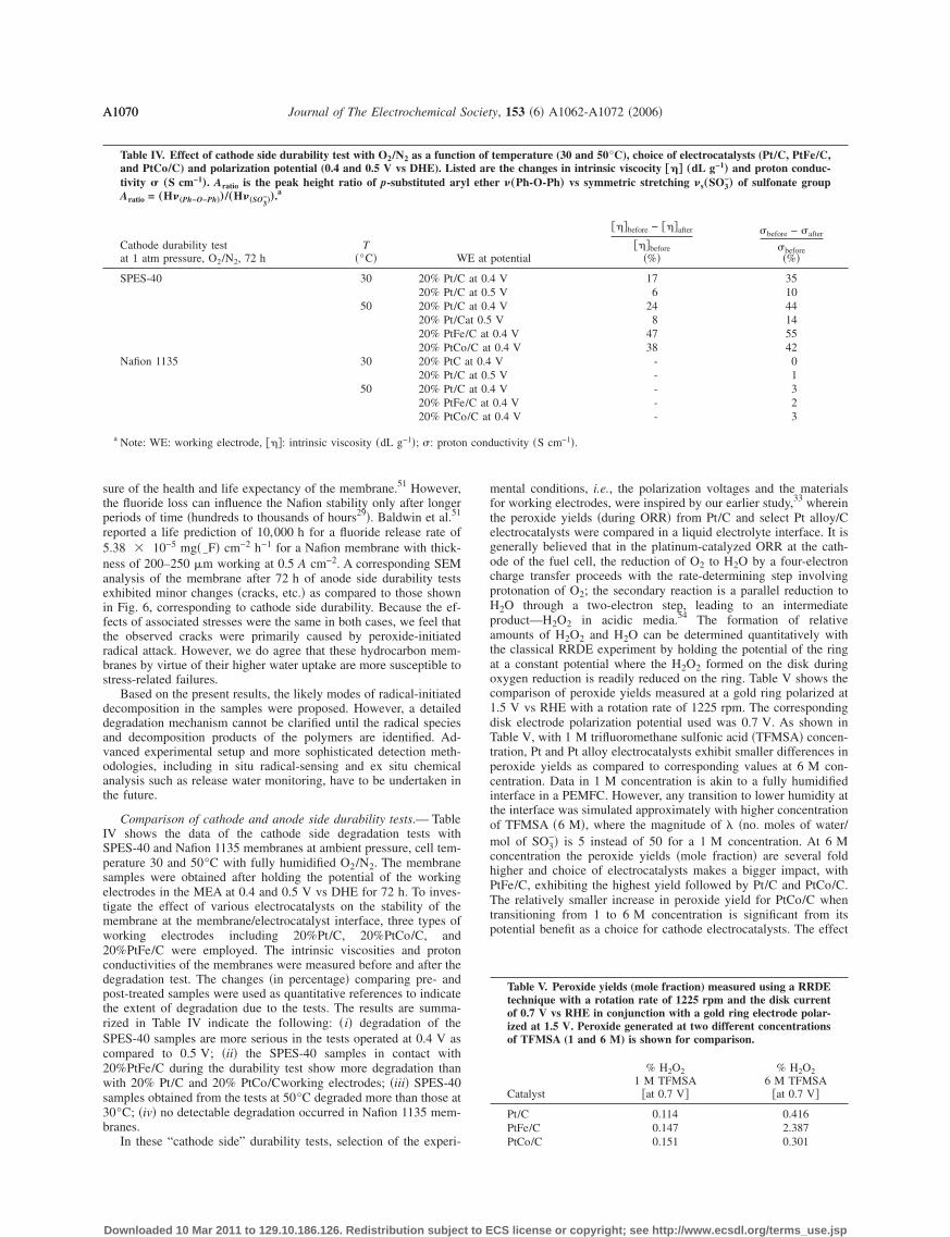
Comparison of cathode and anode side durability tests.— TableIV shows the data of the cathode side degradation tests withSPES-40 and Nafion 1135 membranes at ambient pressure, cell tem-perature 30 and 50°C with fully humidified O2/N2. The membranesamples were obtained after holding the potential of the workingelectrodes in the MEA at 0.4 and 0.5 V vs DHE for 72 h. To inves-tigate the effect of various electrocatalysts on the stability of themembrane at the membrane/electrocatalyst interface, three types ofworking electrodes including 20%Pt/C, 20%PtCo/C, and20%PtFe/C were employed. The intrinsic viscosities and protonconductivities of the membranes were measured before and after thedegradation test. The changes �in percentage� comparing pre- andpost-treated samples were used as quantitative references to indicatethe extent of degradation due to the tests. The results are summa-rized in Table IV indicate the following: �i� degradation of theSPES-40 samples are more serious in the tests operated at 0.4 V ascompared to 0.5 V; �ii� the SPES-40 samples in contact with20%PtFe/C during the durability test show more degradation thanwith 20% Pt/C and 20% PtCo/Cworking electrodes; �iii� SPES-40samples obtained from the tests at 50°C degraded more than those at30°C; �iv� no detectable degradation occurred in Nafion 1135 mem-branes.
In these “cathode side” durability tests, selection of the experi-
Table IV. Effect of cathode side durability test with O2/N2 as a functiand PtCo/C) and polarization potential (0.4 and 0.5 V vs DHE). Listtivity � „S cm−1
…. Aratio is the peak height ratio of p-substituted aryAratio = „H�
„Ph−O−Ph……/„H�„SO3
−…
….a
Cathode durability testat 1 atm pressure, O2/N2, 72 h
T�°C� W
SPES-40 30 20% Pt/C20% Pt/C
50 20% Pt/C20% Pt/C20% PtFe20% PtCo
Nafion 1135 30 20% PtC20% Pt/C
50 20% Pt/C20% PtFe20% PtCo
a Note: WE: working electrode, ���: intrinsic viscosity �dL g−1�; �: proton
Downloaded 10 Mar 2011 to 129.10.186.126. Redistribution subject to E
mental conditions, i.e., the polarization voltages and the materialsfor working electrodes, were inspired by our earlier study,33 whereinthe peroxide yields �during ORR� from Pt/C and select Pt alloy/Celectrocatalysts were compared in a liquid electrolyte interface. It isgenerally believed that in the platinum-catalyzed ORR at the cath-ode of the fuel cell, the reduction of O2 to H2O by a four-electroncharge transfer proceeds with the rate-determining step involvingprotonation of O2; the secondary reaction is a parallel reduction toH2O through a two-electron step, leading to an intermediateproduct—H2O2 in acidic media.54 The formation of relativeamounts of H2O2 and H2O can be determined quantitatively withthe classical RRDE experiment by holding the potential of the ringat a constant potential where the H2O2 formed on the disk duringoxygen reduction is readily reduced on the ring. Table V shows thecomparison of peroxide yields measured at a gold ring polarized at1.5 V vs RHE with a rotation rate of 1225 rpm. The correspondingdisk electrode polarization potential used was 0.7 V. As shown inTable V, with 1 M trifluoromethane sulfonic acid �TFMSA� concen-tration, Pt and Pt alloy electrocatalysts exhibit smaller differences inperoxide yields as compared to corresponding values at 6 M con-centration. Data in 1 M concentration is akin to a fully humidifiedinterface in a PEMFC. However, any transition to lower humidity atthe interface was simulated approximately with higher concentrationof TFMSA �6 M�, where the magnitude of �no. moles of water/mol of SO3
−� is 5 instead of 50 for a 1 M concentration. At 6 Mconcentration the peroxide yields �mole fraction� are several foldhigher and choice of electrocatalysts makes a bigger impact, withPtFe/C, exhibiting the highest yield followed by Pt/C and PtCo/C.The relatively smaller increase in peroxide yield for PtCo/C whentransitioning from 1 to 6 M concentration is significant from itspotential benefit as a choice for cathode electrocatalysts. The effect
temperature (30 and 50°C), choice of electrocatalysts (Pt/C, PtFe/C,e the changes in intrinsic viscocity †�‡ „dL g−1
… and proton conduc-er �„Ph-O-Ph… vs symmetric stretching �s„SO3
−… of sulfonate group
potential
���before − ���after
���before�%�
�before − �after
�before�%�
4 V 17 355 V 6 104 V 24 44V 8 140.4 V 47 550.4 V 38 42V - 0
5 V - 14 V - 30.4 V - 20.4 V - 3
uctivity �S cm−1�.
Table V. Peroxide yields (mole fraction) measured using a RRDEtechnique with a rotation rate of 1225 rpm and the disk currentof 0.7 V vs RHE in conjunction with a gold ring electrode polar-ized at 1.5 V. Peroxide generated at two different concentrationsof TFMSA (1 and 6 M) is shown for comparison.
Catalyst
% H2O21 M TFMSA
�at 0.7 V�
% H2O26 M TFMSA
�at 0.7 V�
Pt/C 0.114 0.416PtFe/C 0.147 2.387PtCo/C 0.151 0.301
on ofed arl eth
E at
at 0.at 0.at 0.
at 0.5/C at/C atat 0.4at 0.at 0.
/C at/C at
CS license or copyright; see http://www.ecsdl.org/terms_use.jsp

A1071Journal of The Electrochemical Society, 153 �6� A1062-A1072 �2006� A1071
of choice of electrocatalysts is exemplified in Fig. 8, which showsthe currents obtained on a gold ring electrode during oxygen reduc-tion with several electrocatalysts in 6 M CF3SO3H TFMSA at1225 rpm.33 The choice of TFMSA, especially 6 M concentration,therefore accentuates the differences in peroxide yields as a functionof choice of electrocatalysts. As reported previously by us, TFMSAenables variation of water activity at the electrocatalyst–electrolyteinterface with significantly lower interference from concomitant an-ion adsorption problems. The use of such comparison of ring cur-rents as shown in Fig. 8 is to provide a qualitative benchmark forresults obtained using the segmented half-cell arrangement used inthis investigation. It is important to note that the observed degrada-tion at the cathode as shown in Table IV, in terms of both thechanges in intrinsic viscosity as well as proton conductivity, showsthe same trend as observed with the peroxide yield measurementwith 1 M TFMSA �Table V�. Here the alloys exhibit a slightlyhigher �with PtFe/C being the highest� level of peroxide yield at0.7 V vs RHE. The same is true for membrane degradation underanalogous fully humidified conditions at 50°C using our segmentedhalf-cell simulating cathode side degradation. Values at 6 MTFMSA concentration �Table VI and Fig. 8�, however, point to thepossibility of enhanced degradation if water activity at theelectrode–polymer electrolyte interface is lowered �as roughly simu-lated using 6 M TFMSA�. Such a possibility can be envisioned onthe basis of various operating scenarios for a practical PEMFC. Inaddition, the observed maximum in peroxide generation at
Figure 8. Ring currents obtained on in Pt/C, PtCo/C, and PtFe/C duringORR in the cathodic sweep at room temperature with 6 M TFMSA electro-lyte at a disk rotation rate of 1225 rpm in room temperature.
Table VI. Effect of anode side durability test with O2/H2 as„Pt/C, PtFe/C, and PtCo/C…, and polarization potential (0.1 and OCproton conductivity � „S cm−1
….a
Anode durability test1 atm, 72 h
T�°C� WE at potential
SPES-40 30 20% Pt/C at 0.1 V20% Pt/C at 0.2 V
50 20% Pt/C at 0.1 V20% PtFe/C at 0.1 V20% PtCo/C at 0.1 V
Nafion 1135 30 20% PtC at 0.1 V20% PtC at 0.2 V
50 20% Pt/C at 0.1 V20% PtFe/C at 0.1 V20% PtCo/C at 0.1 V
a Note: ���: intrinsic viscosity �dL g−1�; �: proton conductivity �S cm−1�.b Data from Ref. 52.
Downloaded 10 Mar 2011 to 129.10.186.126. Redistribution subject to E
0.3–0.4 V vs RHE, as seen in Fig. 8, corresponds well with theresults of cathode side membrane degradation testing in the seg-mented cell. Here, the SPES-40 membrane tested at 0.4 V showsmore evidence of degradation than at 0.5 V. This makes the cathodeside durability test performed at 0.4 V a genuine “accelerated” modein PEM stability characterization. Moreover, according to the ex-perimental facts, increasing the testing temperature and choosinghigh peroxide yield electrocatalyst, such as 20%PtFe/C, help tostimulate the interfacial peroxide formation, therefore reducing thetime necessary for detectable degradation in the membrane of inter-est.
Further, as shown in Fig. 8, the ring currents are negligible in thepotential region above 0.75 V vs RHE, indicating that the reductionof oxygen proceeds almost completely by a four-electron transferabove this potential, which is relevant for the operating potential offuel cell cathodes. This is important with regard to the interfacialstability of the MEA, especially in the case of discontinuous fuelcell operation in which considerable voltage fluctuations take placefrequently.
Table VI shows the data of the anode side degradation tests forSPES-40 and Nafion 1135 membrane at ambient pressure, cell tem-perature 30 or 50°C with fully humidified H2/O2. The membranesamples were obtained in two types of conditions: �i� holding thepotential of the working electrodes in the MEA at 0.1 V for 72 hand �ii� in open-circuit voltage �OCV� condition for 72 h. The sametypes of working electrodes as the cathode side tests were used.Under given experimental conditions, no significant degradation inSPES-40 and Nafion 1135 samples were detected. The slight drop ofproton conductivity found in the tested sample is probably due tominor contamination by metal ions during the experiment. This is inagreement with the IR spectra of tested SPES-40, in which the bandof sulfonate group �s�SO3
−� shifts to a higher frequency �from initial1022 to 1023 cm−1�.
No significant degradation in our anode side durability tests maybe attributed to the short testing time �72 h� compared to at leastseveral hundreds of hours applied in early PEM durability study inlong-term fuel cell testing. In addition, the relatively low oxygenpermeation rates55 �see Table V of Ref. 55� of SPES-40 may alsoplay a role. In a prior long-term fuel cell performance study onradiation-grafted FEP-g-polystyrene-type membranes, Buchi et al.13
reported that the rate of radical-initiated degradation increases withincreasing gas crossover. They also claimed that gas crossover is aprominent factor for the degradation process, especially under OCVconditions; however, whether oxygen or hydrogen crossover is thepredominant contributor could not be ascertained in their regularfuel cell setup.13 In our case, the suspected formation of radicals due
ction of temperature (30 and 50°C), choice of electrocatalystsRHE). Listed are the changes in intrinsic viscocity †�‡ „dL g−1
… and
���before − ���after
���before�%�
�before − �after
�before�%�
O2 permeabilityb
�mol cm−1 s−1�
3 10 2.35 84 6 4.976 83 7- 2 7.96- 1- 2 14.52- 1- 3
a funV vs
CS license or copyright; see http://www.ecsdl.org/terms_use.jsp

A1072 Journal of The Electrochemical Society, 153 �6� A1062-A1072 �2006�A1072
to hydrogen crossover to the cathode side may be eliminated as asource of peroxides at the cathode, because no platinum electrocata-lysts were presented in the O2 side of our experimental setup.
The present results, however, cannot rule out the possible occur-rence of degradation at the anode side in longer testing periods.More research needs to be done in the future.
Conclusions
In this work the issue of radical-initiated membrane degradationat the electrocatalyst/electrolyte interface in PEMFCs was studiedby means of a newly designed durability test method. This method isable to separate the membrane evaluation process into cathode andanode electrode specific processes so that two formerly proposedPEM degradation mechanisms can be evaluated separately withoutinterference. Under experimental conditions �30–50°C, 1 atm, test-ing duration of 72 h�, deterioration in SPES-40 samples was ob-served primarily at the cathode side, particularly at 0.4 V vs DHE;PtFe/C initiated more serious deterioration than PtCo/C and Pt/C.This sensitivity of peroxide-originated PEM degradation with choiceof operating voltage, temperature, relative humidity, and electrocata-lyst has the potential of major impact on interfacial stability, espe-cially for the application of nonfluorinated membranes and novelelectrocatalysts in PEMFCs, especially those devices running in dis-continuous mode. No significant membrane degradation was foundin the anode side durability test under similar conditions as the cath-ode side test.
Acknowledgments
The authors gratefully acknowledge financial support from theArmy Research Office under a single investigator grant. One of us�L.Z.� gratefully acknowledges help from Dr. V. S. Murthi for theRRDE measurements and discussions.
Northeastern University assisted in meeting the publication costs of thisarticle.
References1. A. E. Steck, in New Materials for Fuel Cell Systems I, Proceedings of the 1st
International Symposium on New Materials for Fuel Cell Systems, Montreal, July9-13, 1995, pp. 74–94 �1995�.
2. A. E. Steck and C. Stone, in New Materials for Fuel Cell and Modern BatterySystems II, Proceedings of the 2nd International Symposium on New Materials forFuel Cell and Modern Battery Systems, Montreal, July 6-10, 1997, pp. 792–807�1997�.
3. Q. Li, R. He, J. O. Jensen, and N. J. Bjerrum, Chem. Mater., 26, 4896 �2003�.4. P. J. Ferreira, G. J. la O’, Y. Shao-Horn, D. Morgan, R. Makharia, S. Kocha, and H.
A. Gasteiger, J. Electrochem. Soc., 152, A2256 �2005�.5. J. Xie, D. L. Wood III, D. M. Wayne, T. A. Zawodzinski, P. Atanassov, and R. L.
Borup, J. Electrochem. Soc., 152, A104 �2005�.6. J. Xie, D. L. Wood III, K. L. More, P. Atanassov, and R. L. Borup, J. Electrochem.
Soc., 152, A1011 �2005�.7. F. Wang, M. Hickner, Y. S. Kim, T. A. Zawodzinski, and J. E. McGrath, J. Membr.
Sci., 197, 231 �2002�.8. D. J. Jones and J. Roziere, J. Membr. Sci., 185, 41 �2001�.9. B. Bonnet, D. J. Jones, J. Roziere, L. Tchicaya, G. Alberti, M. Casciola, L. Mass-
inelli, B. Bauer, A. Peraio, and E. Ramunni, J. New Mater. Electrochem. Syst., 2,87 �2000�.
10. R. W. Kopitzke, C. A. Linkous, and G. L. Nelson, Polym. Degrad. Stab., 2, 335�2000�.
11. P. Maletzky, R. Bauer, J. Lahnsteiner, and B. Pouresmael, Chemosphere, 10, 2315�1999�.
12. A. B. LaConti, M. Hamdan, and R. C. McDonald, in Handbook of Fuel Cells-
Fundamental, Technology and Applications, Vol. 3, W. Vielstich, H. A. Gasteiger,Downloaded 10 Mar 2011 to 129.10.186.126. Redistribution subject to E
and A. Lamm, Editors, pp. 647–662, John Wiley & Sons, Ltd., New York �2003�.13. F. N. Buchi, B. Gupta, O. Haas, and G. G. Scherer, Electrochim. Acta, 40, 345
�1995�.14. G. G. Scherer, Berichte der Bunsen-Gesellschaft, 94, 1008 �1990�.15. H. Wang and G. A. Capuano, J. Electrochem. Soc., 145, 780 �1998�.16. Q. Guo, P. N. Pintauro, H. Tang, and S. O’Connor, J. Membr. Sci., 154, 175
�1999�.17. J. Yu, B. Yi, D. Xing, F. Liu, Z. Shao, Y. Fu, and H. Zhang, Phys. Chem. Chem.
Phys., 3, 611 �2003�.18. H. Ericson, T. Kallio, T. Lehtinen, B. Mattsson, G. Sundholm, F. Sundholm, and P.
Jacobsson, J. Electrochem. Soc., 149, A206 �2002�.19. M. Watanabe, U. Hiroyuki, and E. Masomi, J. Electrochem. Soc., 145, 1137
�1998�.20. A. B. LaConti, M. Hamdan, and R. C. McDonald, Handbook of Fuel Cells: Fun-
damentals, Technology, Vol. 3, W. Vielstich, H. A. Gasteiger, and A. Lamm, Edi-tors, pp. 647–662, John Wiley & Sons, Ltd., New York �2003�.
21. W. Harrison, Chemistry Doctorial Dissertation, Virginia Polytechnic Institute andState University, Blacksburg, VA �2002�.
22. B. Yang and A. Manthiram, Electrochem. Solid-State Lett., 6, A229 �2003�.23. R. Liu and E. S. Smotkin, J. Electroanal. Chem., 535, 49 �2002�.24. C. Ma, L. Zhang, S. Mukerjee, D. Ofer, and B. Nair, J. Membr. Sci., 219, 123
�2003�.25. E. Endoh, S. Terazono, H. Widjaja, and Y. Takimoto, Electrochem. Solid-State
Lett., 7, A209 �2004�.26. R. B. Hodgdon, J. R. Boyack, and A. B. LaConti, Report TIS 65DE 5, General
Electric Company �1966�.27. L. Zhang, C. Ma, and S. Mukerjee, J. Electroanal. Chem., 568, 273 �2004�.28. V. I. Basura, C. Chuy, P. D. Beattie, and S. Holdcroft, J. Electroanal. Chem., 501,
77 �2001�.29. A. Pozio, R. F. Silva, M. De Francesco, and L. Giorgi, Electrochim. Acta, 48, 1543
�2003�.30. E. Yeager, Electrochim. Acta, 11, 1527 �1984�.31. E. Balanosky, J. Fernandez, J. Kiwi, and A. Lopez, Water Sci. Technol., 4-5, 417
�1999�.32. A. Parthasarathy, C. R. Martin, and S. Srinivasan, J. Electrochem. Soc., 138, 916
�1991�.33. V. S. Murthi, R. C. Urian, and S. Mukerjee, J. Phys. Chem. B, 108, 11011 �2004�.34. S. Mukerjee and R. C. Urian, Electrochim. Acta, 37, 3219 �2002�.35. S. Mukerjee, R. C. Urian, S. J. Lee, E. A. Ticianelli, and J. McBreen, J. Electro-
chem. Soc., 151, A1094 �2004�.36. R. T. Conley, in Infrared Spectroscopy, pp. 222–238, Allyn and Bacon, Inc., Bos-
ton, MA �1972�.37. O. Solomon and I. Z. Ciuta, J. Appl. Polym. Sci., 24, 683 �1962�.38. Q. Li, J. O. Jensen, R. He, G. Xiao, J.-A. Gao, R. W. Berg, H. A. Hjuler, E.
Hennesoe, and N. J. Bjerrum, Recent Res. Dev. Electrochem. 2003, 1.39. M. R. Pereira and J. Yarwood, J. Chem. Soc., Faraday Trans., 92, 2731 �1996�.40. W. Kujawski, N. Quang Trong, and J. Neel, J. Appl. Polym. Sci., 44, 951 �1992�.41. A. Einsenberg and M. Pineri, Structure and Properties of Ionomers, p. 360, NATO
Series, The Netherlands �1986�.42. G. Hubner and E. Roduner, J. Mater. Chem., 9, 409 �1999�.43. A. Valavanidis, B. C. Gilbert, and A. C. Whitwood, Chimika Chronika, 3, 217
�1995�.44. S. Steenken and P. O’Neill, J. Phys. Chem., 6, 505 �1977�.45. K. Omura and T. Matsuura, Tetrahedron, 8, 3475 �1968�.46. T. Matsuura, T. Nagamachi, and A. Nishinaga, J. Org. Chem., 14, 2016 �1971�.47. P. Xing, G. P. Robertson, M. D. Guiver, S. D. Mikhailenko, K. Wang, and S.
Kaliaguine, J. Membr. Sci., 229, 95 �2004�.48. J. B. Lambert, H. F. Shurvell, L. Verbit, R. G. Cooks, and G. H. Stout, Organic
Structural Analysis, Macmillan Publishing Co., Inc., New York �1976�.49. T. Okada, in Handbook of Fuel Cells-Fundamental, Technology and Applications,
Vol. 3, W. Vielstich, H. A. Gasteiger, and A. Lamm, Editors, pp. 627–646, JohnWiley & Sons, Ltd., New York �2003�.
50. Z. Bai, L. D. Williams, M. F. Durstock, and T. D. Dang, Polym. Prepr. (Am. Chem.Soc. Div. Polym. Chem.), 1, 60 �2004�.
51. R. Baldwin, M. Pham, A. Leonida, J. McElroy, and T. Nalette, J. Power Sources,29, 399 �1990�.
52. W. Liu, K. Ruth, and G. Rusch, J. New Mater. Electrochem. Syst., 4, 227 �2001�.53. D. E. Curtin, R. D. Lousenberg, T. J. Henry, P. C. Tangeman, and M. E. Tisack, J.
Power Sources, 131, 41 �2004�.54. A. Damjanovic, V. Brusic, and J. O. M. Bockris, J. Phys. Chem., 8, 2741 �1967�.
55. L. Zhang, C. Ma, and S. Mukerjee, Electrochim. Acta, 48, 1845 �2003�.CS license or copyright; see http://www.ecsdl.org/terms_use.jsp