
MASTER'S THESIS Wet clutch performance and durability
98
2009:040 CIV MASTER'S THESIS Wet clutch performance and durability Test bench design Martin Lund Luleå University of Technology MSc Programmes in Engineering Mechanical Engineering Department of Applied Physics and Mechanical Engineering Division of Machine Elements 2009:040 CIV - ISSN: 1402-1617 - ISRN: LTU-EX--09/040--SE
-
Upload
khangminh22 -
Category
Documents
-
view
4 -
download
0
Transcript of MASTER'S THESIS Wet clutch performance and durability
2009:040 CIV
M A S T E R ' S T H E S I S
Wet clutch performance and durabilityTest bench design
Martin Lund
Luleå University of Technology
MSc Programmes in Engineering Mechanical Engineering
Department of Applied Physics and Mechanical EngineeringDivision of Machine Elements
2009:040 CIV - ISSN: 1402-1617 - ISRN: LTU-EX--09/040--SE

Preface
This master thesis is the final part in the Master of Science degree in Mechanical Engineering at Luleå
University of technology. The work was performed at Luleå University of technology, department of
Applied Physics and Mechanical Engineering, Machine elements division on behalf of Volvo
Construction Equipment, Component division during the summer and autumn of 2008.
I would like to send my thanks to my supervisor Elisabet Kassfeldt for good advice and help, the head
of the project Erik Höglund for keeping the project on track, giving useful tips and information. Also I
would like to send special thanks to Jan Granström for his invaluable help and ideas.
I would also like to share my gratitude to my supervisor at Volvo CE, Rikard Mäki for his always
positive nothing is impossible attitude and help with the work. Also I would like to send a special
thanks to Joakim Lundin for all his invaluable help with this project.
I also like to thank all my family and friends for their help and support. I would like to give a special
thanks to my girlfriend Alexandra Boije Cipolla for her support.
Luleå, January 2009
Pi , /.^ /Martin Lund

II
Abstract
Volvo CE manufactures heavy duty machinery. In almost all of the applications a gearbox with a wet clutch can be found. To further increase the effectiveness of the clutches new research is necessary. A lot of research has been done concerning different types of friction materials, oil and temperature. But research concerning how the pressure is applied to the clutch and how much power the clutch transfer has not been investigated.
This thesis work aims to build test equipment that is able to control the pressure applied to the clutch. The test equipment should be able to measure load, pressure, temperature and wear of a clutch. Also the equipment should be designed with several of Volvo CE original components from the gearboxes.
The rig was designed and built with the help of a designer at Volvo, engineers at Lulea University of Technology and the in house machine shop Centralverkstan. The design aimed to use the standard Volvo parts, have easy access to sensors and easy assembly/disassembly of the clutch.
The test rig is operational and produces data that is comparable to the real applications. The performance of the rig is well within the requirements of specification. Approximately three engagements can be done in one minute. The acceleration of the rig can be done in less than 10 s and the engagement time is as low as 350 ms. With a hydraulic pressure of 2,4 MPa a torque of approximately 1080 Nm is generated with the specific running conditions of the rig.

III
Table of contents
Preface ......................................................................................................................................... I
Abstract ....................................................................................................................................... II
Table of contents ........................................................................................................................ III
1. Introduction ............................................................................................................................. 1
1.1 Background .................................................................................................................................... 1
1.2 Goal ............................................................................................................................................... 1
1.3 Method .......................................................................................................................................... 2
2. Wet clutch theory ..................................................................................................................... 3
3. The design ................................................................................................................................ 5
3.1 The setup ....................................................................................................................................... 5
3.2 The chassis ..................................................................................................................................... 6
3.2.1 Chassis layout ......................................................................................................................... 6
3.2.2 Clutch axel .............................................................................................................................. 8
3.2.3 Clutch .................................................................................................................................... 10
3.2.4 Oil divider and valve seat ..................................................................................................... 12
3.2.5 Drive axel .............................................................................................................................. 12
3.2.6 Gears ..................................................................................................................................... 14
3.2.7 Bearings ................................................................................................................................ 14
3.2.8 Seals ...................................................................................................................................... 15
3.3 Drive system ................................................................................................................................ 15
3.3.1 Electric motor ....................................................................................................................... 15
3.3.2 Control unit ........................................................................................................................... 16
3.4 Hydraulics .................................................................................................................................... 17
3.4.1 Load system .......................................................................................................................... 17
3.4.2 Cooling system ..................................................................................................................... 18

IV
3.5 Measure and control system ....................................................................................................... 20
3.5.1 CompactRIO computer ......................................................................................................... 20
3.5.2 Sensors ................................................................................................................................. 21
3.5.3 External control .................................................................................................................... 21
3.6 Electronics ................................................................................................................................... 23
3.7 Data acquisition ........................................................................................................................... 25
3.8 Safety system ............................................................................................................................... 25
4. Results ................................................................................................................................... 26
4.1 Chassis, axels and foundation ..................................................................................................... 26
4.2 Hydraulics .................................................................................................................................... 27
4.3 Measuring and control systems .................................................................................................. 27
4.4 Drive system ................................................................................................................................ 27
4.5 Data output ................................................................................................................................. 28
5. Discussion .............................................................................................................................. 34
6. Future work ............................................................................................................................ 35
6.1 Chassis ......................................................................................................................................... 35
6.2 Hydraulics .................................................................................................................................... 36
6.3 Measuring .................................................................................................................................... 36
6.4 Control ......................................................................................................................................... 37
7. References ............................................................................................................................. 38
Appendix 1: Drawings…………………………………………………………………………………………………………14 pages
Appendix 2: Material data and calculations………………………………………………………………………….6 pages
Appendix 3: Data sheet Bosch servo solenoid valve…………………………………………………………...13 pages
Appendix 4: Hydraulic diagrams……………………………………………………………………………………….….3 pages
Appendix 5: Data sheets cRIO and modules………………………………………………………………………....7 pages
Appendix 6: Data sheets sensors……………………………………………………………………………………..…12 pages

1
1. Introduction
This thesis work has been executed at Lulea University of Technology at the department of Applied Physics and Mechanical Engineering, Machine elements division
1.1 Background
for Volvo Construction Equipment AB.
Volvo Construction Equipment AB manufactures heavy duty machinery. In the gearbox of almost all the machinery there are wet clutches that transfer the torque from the different gears to the drive axel.
There has been a lot of research concerning different oils and different kinds of friction materials of the friction discs in the clutch. Mäki saw that different types of oil and additives greatly affect the friction characteristic [1]. Holgerson saw that drive torque and temperature affects the engagement and friction coefficient [2]. However more research concerning how the clutch is engaged and how the engagement characteristics such as load, energy and power affects the life span of a friction disc is needed. Therefore new test equipment is needed.
1.2 Goal
The main goal of this thesis work is to build a test rig that performs in several different areas. A specification of requirements was put together:
• Measure the wear of the clutch pack
• Control how the pressure is applied to the clutch
• Measure how much torque the clutch is transferring
• Measure the temperature inside the clutch
• Measure the rotation speed of the clutch
• Standard Volvo gearbox parts and oil are to be used
• The rig should accelerate in 10 s
• The energy of the system should correspond to the real application
• The engagement of the clutch should be finished in 0,7 s
• Easy assembly/disassembly of the clutch pack

2
1.3 Method
The test rig design is based on prerequisites formulas based on the operating condition identified in Volvo power-shift gear boxes. The design is foremost done so the standard Volvo parts were able to be fitted. Also consideration for the sensors placement was a high priority. The design and concept generation of the test rig was done in collaboration with a designer at Volvo CE. The manufacturing of the parts was done in house in the machine shop Centralverkstan. The connection and programming of the sensors and electronics was done with the help of a research engineer working on Lulea University of Technology.
The wear of the clutch pack was chosen to be measured with an inductive sensor toward the surface of the piston. The inductive sensor withstands high pressure and temperature. Also the sensor is not affected by the oil.
The torque is measured as a force with a load cell and then calculated into torque. With this method it was easy to implement the standard Volvo parts.
For the control of the pressure and the engagement of the clutch fast proportional servo solenoid valve was chosen. This valve will give good precision and fast engagements.
3
2. Wet clutch theory
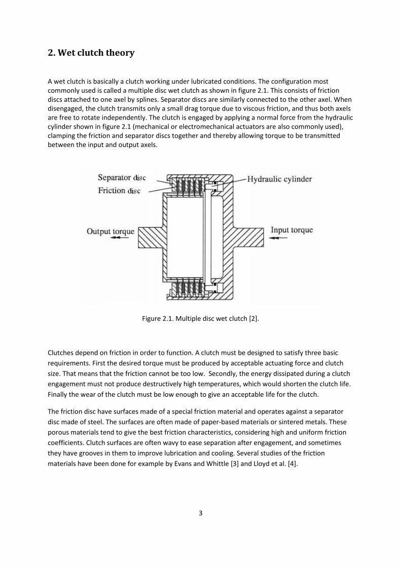
A wet clutch is basically a clutch working under lubricated conditions. The configuration most commonly used is called a multiple disc wet clutch as shown in figure 2.1. This consists of friction discs attached to one axel by splines. Separator discs are similarly connected to the other axel. When disengaged, the clutch transmits only a small drag torque due to viscous friction, and thus both axels are free to rotate independently. The clutch is engaged by applying a normal force from the hydraulic cylinder shown in figure 2.1 (mechanical or electromechanical actuators are also commonly used), clamping the friction and separator discs together and thereby allowing torque to be transmitted between the input and output axels.
Figure 2.1. Multiple disc wet clutch [2].
Clutches depend on friction in order to function. A clutch must be designed to satisfy three basic requirements. First the desired torque must be produced by acceptable actuating force and clutch size. That means that the friction cannot be too low. Secondly, the energy dissipated during a clutch engagement must not produce destructively high temperatures, which would shorten the clutch life. Finally the wear of the clutch must be low enough to give an acceptable life for the clutch.
The friction disc have surfaces made of a special friction material and operates against a separator disc made of steel. The surfaces are often made of paper-based materials or sintered metals. These porous materials tend to give the best friction characteristics, considering high and uniform friction coefficients. Clutch surfaces are often wavy to ease separation after engagement, and sometimes they have grooves in them to improve lubrication and cooling. Several studies of the friction materials have been done for example by Evans and Whittle [3] and Lloyd et al. [4].

4
The critical moment for a wet clutch is the engagement. In automatic transmissions the input and output axels have different angular velocities before the gear shift. This means that the clutch must stop this relative rotation and subsequently hold the axel together. When this action, called engagement, takes place, there will be major stresses acting on the clutch faces. The engagement behavior of a wet clutch has been studied both experimentally by Haviland et al. [5] and Risbet et al. [6], and theoretically by Ting [7] among others.
According to an explanation by Andersson [8] the engagement consists of three different phases. Hydrodynamic squeeze is the first phase, where the clutch disc approaches the separator disc and forces oil to flow over and through the paper-based material, thus creating a hydrodynamic squeeze pressure which supports the normal load and prevents physical contact. This means full-film lubrication. The friction coefficient versus time, µ(t), rises rapidly during the initial squeeze film phase. The oil film becomes thinner, the shear velocity increases and therefore the shear force and friction also increase. The next phase is called the squash film phase because oil is squashed out from the interior of the porous material. Here some asperities produce adhesive friction. Both the oil film pressure and the asperity contacts support the load. This is a form of mixed lubrication. At the beginning of the squash phase the sliding velocity is high. Oil is still retained in the porous material, but the film is thin. According to hydrodynamic theory, this leads to a high shear force and thus high levels of viscous friction. When the velocity decreases, the hydrodynamic forces will also decrease since the oil film is mainly constant. Increase temperature will lead to decreased viscosity and thus to decreased hydrodynamic forces. In this phase adhesive contact also takes place and must be added to the friction. While the friction is decreasing, the hydrodynamic action is dominant. Finally in the adhesive phase all the load is supported by physical contact and the hydrodynamic effects are minimal. This is a boundary lubrication situation. At the end of the adhesive phase the friction rises considerably. This is when the sliding velocity approaches zero and the friction approaches static friction. In the adhesive phase the material parameters and the additives have a dominant effect on friction, and bulk oil properties are less important. There are no distinct limits between these phases.
The oil used in automatic transmissions is called Automatic Transmission Fluid (ATF). ATFs are among the most complex multifunctional lubricants available, because they most fulfill many different purposes. An ATF must:
• Lubricate the gears and bearings of the transmission.
• Transfer power via the torque converter.
• Give good friction characteristics for the wet clutch.
• Serve as a hydraulic fluid in the control system.
In addition, ATFs must be compatible with all the transmission components. There are also high demands on other characteristics, such as heat dissipation, wear protection and foam inhibition. The ATF oil is dyed red for identification purposes.

5
3. The design
The design of the test rig can be divided into six sub systems. These sub systems are described below. The basic selections in consideration to the specification of requirements were done as follows. The axels are mounted horizontally to keep the rig compact and have easy access to the clutch and sensors. The clutch axel is not rotating to simplify the drive system and placement of sensors. The inertia of the system is variable with an exchangeable inertia outside the chassis mounted on the drive axel. The acceleration of the system is made with an electric motor to get high precision and keep noise low. The engagement of the clutch is done in the same way as in the original application. Drawings of all custom made parts can be found in appendix 1.
3.1 The setup
Almost all the components were fitted on top of a steel foundation (see figure 3.1.1). The foundation was in turn mounted on top of a steel frame and the frame sits on rubber feet on the floor. This setup will minimize the spreading of vibrations and the increase in height will improve access. The top of the foundation is a spread of bars that makes it easy to mount the components. The chassis is placed near the front right corner on the foundation both to have easy access to assemble/disassemble the clutch and so the cooling and lubrication oil can flow back to the tank. The electric driving motor is connected to the drive axel with a coupling that is able to compensate for misalignment between the motor and drive axel. Around the coupling a safety cover is mounted to the foundation. The hydraulic power system is connected to the chassis with soft hydraulic hoses and is placed near the chassis at the back left section of the foundation. An electronics cabinet is mounted in the back left corner of the foundation.
Figure 3.1.1. Layout view of the rig from the front right.

6
In the cabinet the measuring system, control system and all the electronics is placed. On the side of the cabinet the control unit for the electric motor is mounted. The hydraulic cooling and lubrication system is the only system that is not mounted on top of the foundation. It is placed on the floor and mounted on a frame next to the foundation so the return oil can flow back to the tank without the use of a pump. Over the coupling a safety cover is mounted. The electric cables are either put inside the foundation or inside the plastic rail. The white unit to the left in figure 3.1.2.
Figure 3.1.2. Layout view of the rig from the front left.
3.2 The chassis
The chassis is a frame which holds two axels, the clutch axel and the drive axel. The drive axel is connected to the clutch with gears. The chassis is bolted to the foundation.
3.2.1 Chassis layout
Two gables are mounted on a bottom plate (see figure 3.2.1). The gables and bottom plate are machined with high precision so good parallellity to each other is maintained. The gables and bottom plate is made of a construction steel with sufficient strength and is easily machined. The precision is needed to secure the positions of the bearing seats. The distance between the bearings in each gable is decided by the diameter of the gears. The positions of the gables on the bottom plate are secured

7
with guide pins and fastened with bolts. In one of the gables there is a door which gives access to assemble and disassemble the clutch. On top of the gables rings are mounted so the chassis can be lifted with a crane. The door’s position is secured with guide pins and fastened with bolts. The stiffness of the gables is increased with pull rods at the top corners of the gables. The pull rods have notches on the inside of the gables and are secured with nuts on the outside.
Figure 3.2.1. Top view of the chassis.
An oil sump encloses an area around the clutch axel and drive axel between the gables. The oil sump is sealed with steel sheets that fits in grooves in the gables and secured with bolts. The oil sump around the clutch axel is sealed at the rear edge of the clutch basket with a wall to permit the sensors to be in an oil free environment. The position of the wall is secured with guide pins and fastened with bolts. The bottom of the oil sump is a metal sheet that is at an angle and mounted to the gables with bolts. The bottom sheet ends with an oil collector that has a draining hole outside the chassis. The top of the oil sump is polysulfon (PSU) plastic which is a transparent plastic with high temperature and oil resistance (see figure 3.2.2). On the top cover of the oil sump a profile of aluminum is mounted length wise to the drive axel to lubricate the bearing furthest from the clutch. On the bottom plate between the back gable and middle wall a holder for the load cell is mounted so the load cell is aligned with the rotation center of the clutch axel. The load cell holder position is secured toward the bottom plate. For material data and calculations see appendix 2.

8
Figure 3.2.2. Side view of the chassis.
3.2.2 Clutch axel
The clutch axel is a standard part from Volvo CE. The axel contains two clutches three gears and two bearing seats. Two of the gears are used for the clutches and one is connected to the axel with a spline and shrinkage fit. Inside the axel there are passages to transport fluid to the clutches and lubricate and cool the parts. The passage for the cooling and lubrication is on the side of the axel and the passages for the hydraulic load system is connected to radial grooves (see figure 3.2.3). This setup requires only one clutch so one clutch basket has been machined away (see figure 3.2.4). The fluid passages that are not in use have been plugged. The gear connected to the axel has been modified and a torque arm has been fitted. The torque arm transmits the torque to a load cell (see figure 3.2.5). On the clutch wall two holders were fitted one is for the pressure sensor and one is for the position sensor (see figure 3.2.6). The holder for the positioning sensor is welded to the clutch wall. A groove is machined at the end of the holder and an O-ring is fitted to seal the sensor. The sensor is kept in place with a hollow bolt on the back side of the sensor. The holder for the pressure sensor is welded on the back of the clutch and threaded. The sensor is sealed with a copper washer. On the radial outside of the clutch basket a smooth surface was machined and a V-lip seal is fitted. In this setup the clutch axel is not rotating.

9
Figure 3.2.3. The hydraulic passages into the clutch axel.
Figure 3.2.4. Clutch axel with torque arm, clutch drum (sectioned), gear (sectioned) and clutch pack.
Figure 3.2.5. The torque arm and load cell in its holder.
Figure 3.2.6. Sensors mounted on the clutch drum.

10
3.2.3 Clutch
This setup only requires four friction surfaces so only two friction discs and three steel discs are used. To enable the use of the original layout of the clutch a thick washer was manufactured to replace the friction and steel discs that are not in use (see figure 3.2.7).
Figure 3.2.7. Parts of the clutch. (A) end plate, (B) distance washer, (C) & (D) steel and friction discs, (E) pressure plate, (F) balance piston, (G) spring support, (H) piston.
The piston is rubber coated with integrated lip seals toward the axel (inner diameter) and clutch drum (outer diameter) on the pressure side. On the other side of the piston the spring support is fixed on the piston. The spring rest on the support and is fixed and preloaded with the balance piston and a locking snap ring. The spring is a custom made Smalley wave spring that is not as stiff as the original and more linear than the original plate spring (see figure 3.2.8). The clutch pack begins with a pressure plate. This plate is designed to optimize the pressure distribution in the clutch pack so the load becomes the same over the entire friction surface. Then there is the friction pack which contains three steel discs and two friction discs. After the friction pack the machined washer that has the same thickness as the removed friction and steel discs is placed. The clutch pack has an end steel disc that is thicker. The clutch pack is kept in place with a spiral retaining spring. The end plate was

11
modified with a small groove so thermo couples could be placed inside the clutch pack. The steel discs are connected to the clutch basket and the friction discs are connected to the rotating gear. The gear is carried by roller bearings and axial bearings between washers fixes the position of the gear axial wise.
Figure 3.2.8. Smalley wave spring.

12
3.2.4 Oil divider and valve seat
Outside the chassis an oil divider is mounted with bolts (see figure 3.2.9). The oil divider connects the fluid to corresponding passages in the clutch axel. Also a standard Volvo filter holder is mounted on the side so the cooling fluid is filtered before entering the axel. The filter holder is sealed with a gasket. A ring is mounted with thread on the top side of the oil divider so during assembly/ disassembly of the clutch the door, oil divider and valve seat can be lifted from the chassis with a crane. The valve seat is mounted on the opposite side from the filter holder with bolts.
Figure 3.2.9. Oil divider with filter and valve seat with servo valve.
The valve pattern is a standard NG 6 and is placed on the front side of the valve seat. The valve is mounted to the valve seat. The connection between the valve seat and oil divider is sealed with an O-ring in a groove on the valve seat.
3.2.5 Drive axel
The drive axel is machined from one piece to minimize the risk of vibrations. The drive axel has a big mass integrated to simulate the inertia in the original application (see figure 3.2.10). Also a smaller mass can be mounted on the outside of the chassis. This mass is accessible from outside the chassis and can easily be changed. The drive axel has two bearing seats and a gear is mounted with a spline

13
joint. To keep the gear in place axial wise a hollow cylinder is mounted on the drive axel between the gear and the face of the big integrated mass. The hollow cylinder carries the axial load that the gear creates toward the face of the big integrated mass of the drive axel. Outside the external mass at the end of the axel the coupling connecting the axel with the electric motor is mounted.
Figure 3.2.10. Drive axel mounted in chassis.

14
3.2.6 Gears
The clutch axel gear is a standard Volvo gear and the gear on the drive axel is a modified standard Volvo gear with the same diameter as the clutch axel gear so the ratio 1:1 is kept. The spiral teeth cut of the gear is opposite to its original so it will match the clutch axel gear (see figure 3.2.11). The gear at the drive axel is connected to the axel with a spline joint. The gear at the clutch axel is carried by two roller bearings. The gear is integrated with a carrier for the friction discs.
Figure 3.2.11. To the right the clutch gear and to the left the gear on the drive axel.
3.2.7 Bearings
Taper roller bearings are used for both the clutch axel and the drive axel. The bearings are standard Volvo bearings. The preload of the bearings are adjusted with spacers that change the distance of bearing cages. The spacers and bearing cages are Volvo standard parts. The bearing cages are modified so they fit the thickness of the gables. There is one cage per axel. The preload was decided by testing. When the rig operates the bearings closest to the clutch get lubrication from the cooling fluid that exits the clutch but bearing on the drive axel furthest from the clutch was not lubricated enough. The aluminum profile mounted on the top of the oil sump works as a passage so the oil spray from the gears get collected and flows down to that bearing.

15
3.2.8 Seals
The clutch axel is sealed toward the middle wall with a V-lip seal. The V-lip seal is placed on a machined surface on the back edge of the clutch basket. The lip seals against a groove in the middle wall. The seal is of NBR rubber. The V-lip seal has a small sealing area and creates a very small force against the middle wall therefore the friction losses will be very small.
The bearing cages are sealed with rubber cups that are standard Volvo parts.
The oil sump is sealed with blue silicone between the gables and all the sheet metal. The sheet metal was mounted while the silicone still was wet. The run off sheet at the bottom was mounted and then sealed with silicone. At the top the silicone first dried before the top plastic cover was mounted so it will be easy to dismount. Blue silicone was also used to seal the area between the door and oil divider.
3.3 Drive system
The drive system that accelerates the rig consists of two parts, the electric motor and the control unit. The motor and control unit was chosen so it would have sufficient power to accelerate the system in the specified time. The choice of motor and control unit delivers a torque of 35 Nm all the way to 3000 rpm.
3.3.1 Electric motor
The electric motor is a SEW Eurodrive CV132S4 motor (see figure 3.3.1). The motor was chosen so the power would accelerate the system in a sufficient period of time and have a sufficient rotation speed. The motor has an incremental rotation sensor with 1024 pulses/revelation. The motor is also equipped with an electric cooling fan.

16
Figure 3.3.1. SEW Eurodrive CV132S4 motor.
The motor is connected with the coupling to the drive axel. The coupling is from Kedjeteknik. The coupling is torsional stiff and can compensate for axial and angular misalignment. The connection to the drive axel is with a clamping ring. The outgoing axel from the motor has a wedge and the coupling mounted with a wedge groove and secured with a bolt. To align the axel on the motor with the drive axel a support was milled for the motor so the height of the axels would align. The motor is mounted to the support. The support is mounted to the foundation so alignment in the horizontal plane is possible. Also the distance from the chassis can be changed.
3.3.2 Control unit
The control unit is a SEW Eurodrive Movidrive MDX61B (see figure 3.3.2). The control unit can regulate towards torque, rotation speed and motor position. In this setup the choice was to regulate toward rotation speed. The control unit regulates the rotation speed with the help of the incremental encoder mounted on the motor axel. Exactly the same signal that is fed to the control unit is forwarded to the measuring computer. The rotation speed is set from an external program and fed to the control unit as an analog signal. The unit is mounted on the side of the cabinet that holds the electronics.

17
Figure 3.3.2. SEW Eurodrive Movidrive 61B.
The control unit is fed with three phase current. The control unit in turn also feeds the motor with the same power. Because the control unit is a frequency converter shielded cables are used. The control unit is adjusted so the acceleration time of the rig will be as short as possible. The control has a control inhibit signal that needs to be connected to run the motor. When the control inhibit is cut no power goes to the motor and no acceleration or deceleration is done. Also when the control inhibit is cut programming of the control unit is possible.
3.4 Hydraulics
The hydraulics consists of two main systems, the load system and the cooling system. The load system is the high pressure system that engages the clutch. The cooling system is the system that provides cooling for the clutch but also lubricates the clutch, gears and bearings.
3.4.1 Load system
The load system is compact pump unit that is connected to the valve seat mounted on the oil divider on the chassis with soft hydraulic tubing (see figure 3.4.1). The pump unit is a tank integrated with
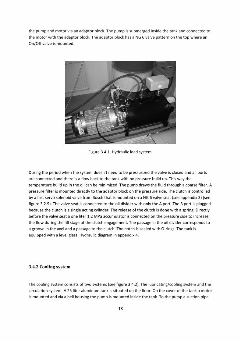
18
the pump and motor via an adaptor block. The pump is submerged inside the tank and connected to the motor with the adaptor block. The adaptor block has a NG 6 valve pattern on the top where an On/Off valve is mounted.
Figure 3.4.1. Hydraulic load system.
During the period when the system doesn’t need to be pressurized the valve is closed and all ports are connected and there is a flow back to the tank with no pressure build up. This way the temperature build up in the oil can be minimized. The pump draws the fluid through a coarse filter. A pressure filter is mounted directly to the adaptor block on the pressure side. The clutch is controlled by a fast servo solenoid valve from Bosch that is mounted on a NG 6 valve seat (see appendix 3) (see figure 3.2.9). The valve seat is connected to the oil divider with only the A port. The B port is plugged because the clutch is a single acting cylinder. The release of the clutch is done with a spring. Directly before the valve seat a one liter 1,2 MPa accumulator is connected on the pressure side to increase the flow during the fill stage of the clutch engagement. The passage in the oil divider corresponds to a groove in the axel and a passage to the clutch. The notch is sealed with O-rings. The tank is equipped with a level glass. Hydraulic diagram in appendix 4.
3.4.2 Cooling system
The cooling system consists of two systems (see figure 3.4.2). The lubricating/cooling system and the circulation system. A 25 liter aluminum tank is situated on the floor. On the cover of the tank a motor is mounted and via a bell housing the pump is mounted inside the tank. To the pump a suction pipe

19
and an outlet pipe are connected. The outlet pipe is connected to the cover. From the connection a T-joint is placed where one end is connected to the oil divider via soft hydraulic tubing. The other end is connected to a pressure relief valve mounted in a valve seat. The valve seat is connected back to the tank. From the oil divider the fluid is pumped through a filter before it is connected to the oil passage in the axel. The fluid lubricates the clutch, bearings and gears. The fluid also flows through the clutch for cooling. The fluid is collected buy the oil sump and flow down to the oil collector where a thick rubber hose is connected to the tank via a modified filter holder mounted on the cover of the tank.
Figure 3.4.2. Top view of the cooling and lubrication system. To the right circulation system.
The circulation system consists of a pump connected to the draining hole of the tank with soft hydraulic tubing. On the pressure side of the pump a T-joint is placed and connected to a pressure relief valve. The flow back from the pressure relief valve is connected directly to the suction side of the pump. The pump is connected to the oil cooler. The cooler is connected back to the tank via soft hydraulic hoses. The cooler is connected to a water flow. The water flow is regulated with a mechanical thermostat. The thermostats temperature element is connected at the cover and submerged into the tank. A filtered filling cap is also mounted on the cover. The tank is equipped with level glass that has an integrated level guard. Hydraulic diagram in appendix 4.

20
3.5 Measure and control system
The central part in the measure and control system is the CompactRIO computer. The computer is connected to all the sensors of the rig and also controls on/off signals to the motors and valves. The RIO computer is connected to an external control via a network link. The control is Labview based.
3.5.1 CompactRIO computer
The CompactRIO is National Instruments computer with its own CPU (see figure 3.5.1). The RIO has four slots hot swap modules. The hot swap means that the modules can be disconnected and changed when the RIO is active.
Figure 3.5.1. National instruments CompactRIO.
A separate 230 V to 24 VDC transformer feeds the RIO with power. The RIO is equipped with a network connection port, USB 2.0 port and a serial port. The real time processor runs at 400 MHz. It has 64 Mb DRAM memory and 128 Mb of disc storage. The RIO is equipped with a FTP server and a web based interface.
The modules that are used in this application are:
• NI 9485 relay module
• NI 9263 analog out +-10 VDC module
• NI 9205 analog in +-10 VDC module
• NI 9411 Digital in module
21
The relay module is used to control the motors for the hydraulic pumps, valves and control inhibit for the electric motor. The module has eight relays. The analog out module is used to control the rotation speed of the electric motor and the Bosch servo solenoid valve. The analog in module is connected to the thermo coupling, load cell, inductive position sensor, pressure sensor, position of the sleeve in the Bosch valve and the regulators out signal. The digital in module is used for the incremental encoder signal on the electric motor. For data of the modules and cRIO see appendix 5.
3.5.2 Sensors
Four main sensors are used in the rig. Thermo couple, inductive positioning sensor, load cell and pressure sensor. The thermo couple is 0.5 mm in diameter and placed in a drilled hole in the middle steel disc of the clutch pack. The hole is 0.8 mm in diameter and drilled on the edge of the disc. The sensor has a response time of 14 ms. The inductive positioning sensor is mounted on the back side of the clutch basket in its holder. The sensor is touching the piston when it is not pressurized. The maximum measuring distant of the sensor is 5 mm. An amplifier is connected to the sensor. The load cell is placed in its holder so the connection edge of the sensor is aligned with the rotation center of the clutch axel. The sensor has a measuring span from 0 to 20 kN. The pressure sensor is mounted on the back side of the clutch in its holder. The pressure sensor measures up to 10 MPa with a signal span of 4-20 mA. A separate 230 VAC to 12 VDC transformer supply the power to the position sensor and the load cell. For more data on the sensors se appendix 6.
3.5.3 External control
The external control is a Labview program on an external computer. The Labview interface is available in manual control (see figure 3.5.2) and sequence control (see figure 3.5.3) of the rig. The sequence control can be run in a loop with a preset number of cycles for long term testing. The sequence control also has the option of running the regulator towards pressure or load.

22
Figure 3.5.2. The interface of manual control.
In the top left corner with the orange background the analog out controls are situated. In this setup the analog out controls the servo solenoid valve and the drive motor. The bar for the valve opens the valve to pressurize the A port in one direction and release the pressure in the other. The motor control accelerates the motor clockwise in one direction and counter clockwise in the other. To the right of the analog out controls there are green buttons. This buttons are the relay controls for the motors and valves. In the middle the graphs for the sensors are situated. In the top right corner numerical values of the sensors and descriptions of the graphs are situated. Bellow the descriptions three indicators are situated. They indicate rotation speed, rotation acceleration and position of the axel. In the bottom right the regulator is situated. The regulator can be turned off and manually control the pressure to the clutch. It is also possible to manually decide when to save data to a file.

23
Figure 3.5.3. The interface of the sequence control.
The interface looks a bit different from the manual control but the same information is found here. The big difference is to the left where the programming of the sequence of a cycle is done. Each row is an operation in the program. The cycle can then be looped and a series of engagements can be done.
3.6 Electronics
All the electronics are housed inside the cabinet (see figure 3.6.1). The electronic components are mounted on DIN rails. The wiring is secured at the bottom of the cabinet with cable bushings. The power is controlled with contactors. The main power is connected with three phases to a main contactor, the ground and screen is connected to the back plate and the zero conductor is connected to a standalone connection block. The three phases and the zero conductor is jumpered in series to five contactors. The contactors are controlled from the CompactRIO and work as relay for the pump motors and the driving motor. The safety system cuts the power to the main contactor. The transformers used by the CompactRIO and the sensors are connected so that they are always powered. They are connected on one phase and the zero conductor which gives 230 V. The control unit for the driving motor is connected to the first contactor. The pump motor in the power hydraulic system is a three phase 400 V motor. The pump motors for the cooling and circulation system is one phase 230 V motors. Those are also connected on one phase and the zero conductor.

24
Figure 3.6.1. View inside the electronics cabinet.
At the bottom of the cabinet the contactors are placed on a DIN rail. The big contactor is to the left. On the DIN rail above two connection blocks are mounted. One is fed 12 V and one is fed 24 V. To the right of the connection blocks the transformers are mounted first the 12 V and then the 24 V.In the top left corner the CompactRIO is mounted on a DIN rail. On the top of the cabinet to the left the emergency stop button is mounted.

25
3.7 Data acquisition
The CompactRIO computer has an internal hard drive where sensor data is stored. The compactRIO also has a USB 2.0 connection where an external device can be connected. The data can also be acquired via the network connection. The format of the data are either a text file (see figure 3.7.1) with column separation or a binary file the can be handled with an external program. When the external Labview program is connected to the CompactRIO a text file is created. Each time a new save session is started the timeline starts from zero in the same file.
Figure 3.7.1. Part of a text file with data from an engagement.
The columns in the file have the same order as the graphs in the manual and sequence interface.
3.8 Safety system
The safety system is a standalone system that consists of a number of guards and a manual emergency stop button. The safety system cuts the incoming power. The guards and emergency stop button are connected in series with the activation current to the big contactor. The only system still running at an emergency stop is the measuring system. The cooling hydraulic system is monitored with a level guard. The hydraulic power system is monitored with a level/temperature guard. All the guards is connected in series so all guards need to be on to have main power.

26
4. Results
This section describes how the test rig is performing in different areas. Generally the rig performs very well. All the systems perform as intended and the data output from the rig is corresponding to the real application. A list with short description of the performance according to the specification of requirements is as follows:
• The wear of the clutch is measured
• The pressure to the clutch is controlled with good precision
• The torque the clutch is transferring is measured
• The temperature is measured inside the clutch
• The rotation speed of the system is measured
• Several standard Volvo parts is used
• The rig accelerates to its maximum speed in less than 10 s
• The energy of the rig corresponds to the real application
• The engagement of the clutch is done in less than 0,7 s
• It is easy to assembly/disassembly the clutch pack
4.1 Chassis, axels and foundation
Several of the standard transmission parts from the Volvo transmission are used in the rig. Access to the clutch is good and with the help of a crane and supports for the axel it is easy disassemble the door and get access to the clutch. The drive axel works well in all of the rotation speed spectra. No vibrations occur during the acceleration. The engagement of the clutch is distinct and the chassis is stiff enough to handle all forces generated during the engagement. The energy of the system is decided by the inertia and rotation speed. Both the inertia and rotation speed can be adjusted and the rig is capable of matching the energy level of the real application and also reach higher energy levels (see appendix 2).The layout is good and provides easy access to all the systems. The transparent cover of the oil sump provides good visibility of the clutch and axels. The foundation is stable and has provided a good platform for mounting the parts.

27
4.2 Hydraulics
The cooling/lubrication system works well. All rotating parts have sufficient lubrication and the cooling of the clutch is sufficient.
The power system engages the clutch in shorter time then the requirements of specification indicated. The system is stopped in 350 ms from that the servo solenoid valve is opened to the system is at rest (see test results in cap 4.5). Also the system can control how the pressure is applied. The pressure can be controlled either with a regulator toward any sensor but is now regulated towards pressure or with fixed ramps for the pressure build up. The clutch piston does not withstand the increase in pressure that was intended. The piston is deformed and leakage occurs with pressures exceeding 3 MPa. The pressure is how ever sufficient for initial measuring.
4.3 Measuring and control systems
The temperature sensor is very fast and gives good and fast readings inside the clutch.
The load cell works well and gives good readings.
The pressure sensor works well and gives good readings.
The positioning sensor has not been tested in detail. During initial testing the range seems to be sufficient. If the resolution is sufficient needs to be tested. With no good data from this sensor, the wear of the clutch have not been measured.
4.4 Drive system
The system can be accelerated to a maximum rotation speed of 3000 rpm in less than 10 s. With the inertia of the system and the rotation speed it is comparable with the real application. Also with higher rotation speed higher energy levels can be achieved (see appendix 2). The axel coupling works well.

28
4.5 Data output
This is a test done to see how the rig performs at its peak. When the clutch is engaged with 2,5 MPa as fast as possible when the rig is operating at its maximum rotation speed. The maximum rotation speed is 3000 rpm and the inertia of the system is 0.632 kgm2
0
2
4
6
8
10
12
0 0,1 0,2 0,3 0,4 0,5 0,6 0,7 0,8 0,9 1
0
50
100
150
200
250
300
350
Load[kN]
Valve pos[V]
Ctrl. signal[V]
Pressure[MPa]
Rotation[rpm]
Acc.[rev./s2]
Temp[C]
(the external mass is not mounted). The rig comes to a stop in approximately 350 ms (see figure 4.5.1). The sequence has preloaded the spring before the actual engagement because this will shorten the engagement time. The preloading of the piston generates an increase of temperature in the steel disc. When the piston is not preloaded the temperature in the steel disc is around 25°C or the same temperature as the oil. The rotation speed has been decreased 10 times so the diagram will be easier to view.
Figure 4.5.1. Data output. Engagement from 3000 rpm. Rotation, Acc and Temp are read of the right axis.
Load is the force measured with the load cell, Pressure is the pressured measured inside the clutch, Valve pos. is the position of the slide in the servo solenoid valve, Ctrl. signal is the signal the regulator sends to the servo solenoid valve, Rotation is the rotation speed of the motor, Acc is the angular acceleration of the motor and Temp is the temperature inside the middle steel disc. It is interesting to see how the valve pos. signal follows the Ctrl. signal. This shows how fast the valve is. The movement of the slide is almost instantaneous according to the signal from the regulator. Also the load curve has a characteristic appearance with the peak load as a “rooster tail” when the friction

29
goes towards static friction and rotation speed nears zero. The data gathered from the rotation sensor (Rotation and angular acceleration) shows that the sensor has a bit low resolution during such a short engagement time so the curve presented is not as smooth.
To get a better view of the data some specific information are presented. It can be seen how the pressure affect the load and get information of how much torque the clutch is transferring (see figure 4.5.2). The load increase very fast during the pressure build up but when the designated pressure is reached the curve level out and increase more slowly with the decrease of the rotation speed and reach its maximum when the speed nears zero.
Figure 4.5.2. Load and pressure output from a 3000 rpm engagment.
The maximum torque the clutch is transferring with this setup is 1080 Nm. The torque is calculated with the data from the load cell and the length from the rotation center of the clutch axel and the length of the torque arm.
With the information of the torque and the force the piston is putting on the clutch pack the friction force in the clutch can be calculated and from that also the friction coefficient.

30
The torque can also be presented as a diagram (see figure 4.5.3).
0
200
400
600
800
1000
1200
0 0,1 0,2 0,3 0,4 0,5 0,6 0,7 0,8 0,9 1
Torque[Nm]
Figure 4.5.3. Torque.
If the inertia of the system is increased the engagement time will be longer while an increase in pressure will result in a higher torque and a shorter engagement time.
With the measured data from this setup the friction coefficient can be calculated. With this information it is also possible to compare the measured result with the real application.
The friction coefficient is calculated as follows.
The measured load is calculated into to torque with the help of the length of the torque arm. That is the same torque that the clutch is transferring. But the torque in the clutch is calculated with the face pressure integrated over the friction disc surface.

31
∫⋅⋅⋅= drrPnM d22πµ
disconradiusrpressurefaceP
surfacesofnumberntorqueM
d
=
=
=
=
And the face pressure is related to the pressure on the piston with the difference in area and the negative force of the spring. Also it is assumed that the pressure is constant over the entire friction surface with the help of the pressure plate. The friction coefficient is then calculated as follows.
[ ] [ ]3333
2
323
IOF
S
F
PP
IOd RRAF
AAPn
LFRRPn
LF
−⋅⋅
−⋅
⋅⋅=⇒
−⋅⋅⋅⋅⋅
=π
µπ
µ
radiusinnerRradiusouterR
pistononpressuremeasuredPdiscfrictionofareaA
pistonofareaAforceSpringF
armtorqueoflengthLloadmeasuredF
I
O
P
F
P
S
=
=
=
=
=
=
=
=
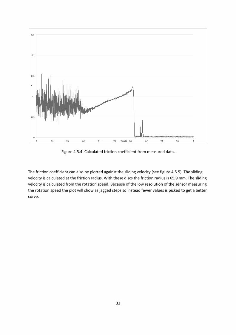
The calculated friction coefficient during an engagement is shown in figure 4.5.4.
32
0
0,05
0,1
0,15
0,2
0,25
0 0,1 0,2 0,3 0,4 0,5 0,6 0,7 0,8 0,9 1Time(s)
µ
Figure 4.5.4. Calculated friction coefficient from measured data.
The friction coefficient can also be plotted against the sliding velocity (see figure 4.5.5). The sliding velocity is calculated at the friction radius. With these discs the friction radius is 65,9 mm. The sliding velocity is calculated from the rotation speed. Because of the low resolution of the sensor measuring the rotation speed the plot will show as jagged steps so instead fewer values is picked to get a better curve.

33
Figure 4.5.5. Friction coefficient plotted against sliding velocity.
The red curve is from at test run at Volvo with their equipment and the blue curve is from this test rig. More about the friction coefficient in discussion.

34
5. Discussion
Losses in bearing gears and seals are hard to calculate so testing need to be done so these losses can be taken into account. In order to improve the results it’s important to calibrate all sensors to minimize errors in measured data. During testing the temperature is increasing so parts of the chassis and axels will expand. The stiffness in the chassis will then affect the preload of the bearings. Tests are planned to investigate if during longer test cycles the preload of the bearings needs to be changed so it not will result in errors.
When pressurizing the clutch the back wall may buckle a little so readings from the positioning sensor may give some error to the reading. If this becomes a problem it is possible to stiffen the back wall. This can be tested. If the clutch is pressurized so all the oil is forced out of from the discs and the piston has traveled its full distance. When this is done a reading is done from the positioning sensor. Then the pressure is increased to its maximum and a new reading is taken. This can then be compared to see if the error is so big it needs to be considered or the clutch needs to be modified.
The temperature sensor seams to give fast readings but the measuring probe is 0,5 mm and the hole that it is placed in is 0,8 mm. The oil inside the hole may help a little with transporting the heat from the disc. As seen in the diagram the derivate of the temperature curve is very sharp during the engagement. But how much of the reading that is lost is at this point unknown. Also it would be interesting to see how the temperature varies in the first and last steel disc.
As seen in the result the sensor measuring the rotation speed has not so good resolution. If measuring of the rotation is needed for regulation or that the precision is needed to be increased a new sensor with higher resolution is needed.
The test results concerning the calculated friction coefficient can be compared to the results Volvo is achieving. The test equipment at Volvo plots the friction coefficient against the sliding velocity. Because the sensor measuring the rotation speed specific values was picked out to get a better view of the plot. But the data can still be compared and the results are comparable. As seen the red curve is from test equipment at Volvo (see figure 4.5.5). And it follows the same characteristics as the curve produced by this rig. The Volvo result is a bit higher but it is probable that it is caused by how much the discs are worn, the temperature and oil status. This is a good measure that the rig produces good results.
In the next chapter additions and improvements to the rig is mentioned. Changes to sensors will improve the accuracy of the readings and will in turn also improve the control of the engagements of the clutch and give better results.

35
6. Future work
To optimize the test rig performance some improvements should be made.
6.1 Chassis
Placement of the securing bolt on the torque arm should be in the opposite direction (see figure 6.1.1). A different placement of the sensors on the back wall of the clutch would provide better access to the pressure sensor. This layout provides space for future additions of sensors to the clutch.
Figure 6.1.1. Securing bolt torque arm.
The door needs additional sealing because some leakage occurs there. The sealing of the oil sump can be improved. Small leakage occurs.

36
6.2 Hydraulics
The hydraulic power system has a very high noise level and it is because the pressure reducing valve mounted in the adaptor plate generates it when activated. The noise is too high in a laboratory environment. Possible solutions is that the valve can be changed to some other valve with lower noise level, build a housing around the power system to dampen the noise or rearrange the power system so the system pressure is not controlled by the valve so the valve works entirely as a safety valve.
The flow of the power system is to slow. When shorter clutch engagements are needed the flow is not sufficient to engage the clutch as fast as needed. The problem is there is a pressure drop of 3,5 MPa over the servo solenoid valve and the losses in the system. This has been helped a little with adding an accumulator near the valve seat. Other solutions are that a bigger servo solenoid valve is mounted. Change the pump to a pump with bigger displacement. Rebuild the system to minimize losses. Increase the system pressure. And also improve the system as it is with the accumulator. If higher pressures are to be tested a new piston needs to be manufactured.
Install a temperature controlled heater in the cooling tank to be able to control the temperature of the ingoing oil. This will give good possibility to test with different oil temperatures.
6.3 Measuring
The pressure sensor is a sensor with the range 0-10 MPa with an out signal of 4-20 mA. It has a bit too large range. When the pressure measured inside the clutch is never over 3 MPa. To increase the precision of the sensor a sensor with the range of 0-4 MPa should be mounted. This will also improve the accuracy of the regulator.
The out signal of the load cell is a bit noisy. The noise can cause problems with the regulator if control of the clutch is going to be regulated with the load. Solutions to this can be to change the load cell to one with smaller range. Now the range is 0-20 kN. There are options with the range of 0-10 kN. Investigate if there is options of amplifiers that can be connected as close to the load cell as possible.
More thermo couplings should be installed into the clutch. To get more data concerning generated temperature inside the clutch.
Investigate if there are other possible sensors with higher precision for measuring the movement of the piston and the wear of the clutch.

37
6.4 Control
Continued work with the engagement cycle that control the pressurizing of the clutch. Both with a fixed ramp of the pressure, and with the regulator controlling engagement towards pressure or load.

38
7. References
1. Mäki, R., Wet Clutch Tribology – Friction Characteristics in Limited Slip Differentials, Doctoral Thesis in Machine Elements. 2005, Lulea University of Technology: Lulea
2. Holgerson, M., Wet Clutch Engagement Characteristics, Doctoral Thesis in Machine Elements. 1999, Lulea University of Technology: Lulea.
3. E. M. Evans and J. Whittle, Friction in wet clutches, Proceedings of the Institution of Mechanical Engineers, vol. 182, part 3, 1968.
4. F. A. Lloyd, J. N. Anderson and L. S. Bowels, Effects of operating conditions on performance of wet friction materials: a guide to material selection, SAE technical paper 88128, 1988.
5. M. L. Haviland, J. J. Rodgers and E. D. Davison, Surface temperatures and friction in lubricated clutches, SAE technical paper 642B, 1963.
6. A. Risbet, P. Vogel, M. H. Crolet and D. Davison, Engagement of automobile clutches: experiments and theory, Proceedings of the 9th
7. L. L. Ting, Engagement behavior of lubricated porous annular disks. Part 2: Consolidating contact phase-poroelastic effect, Wear, vol. 34, 1975.
Leeds-Lyon Symposium on Tribology, Tribology of Reciprocating Engines, paper X(v), Leeds, England, Sept. 7-12 1982, 1982.
8. A. E. Anderson, Friction and wear of paper type wet friction elements, SAE technical paper 720521, 1972.

Appendix 1. Drawings. 14 pages


Appendix 2. Material data and calculations. 6 pages

Material data
Chassis, external mass, foundation drive motor and drive shaft are made of construction steel called UBH11.
Data:
Rm
R
640MPa
p0.2
Hardness 200HB
340MPa
The cover of the oil sump is a polysulfone plastic (PSU).
Data:
Tensile strength 70.3MPa
Deflection Temperature at 1.8 MPa 170°C
All bolts used for mounting parts of the chassis and foundations are of the quality 12,9.This means the tensile strength is 1200 MPa and the yield strength is 1080 MPa.

Calculations
Inertia
The inertia of this system was calculated from test results gathered from Volvo CE. The energy of an engagement in a test rig called MB-1000 gave the following results.
• Energy total dissipation = 531 KJ/m2
• Friction radius = 65,9 mm
(@ rubbing speed 12,9 m/s)
• Friction area = 6872 mm2
• Number of surfaces = 4
/surface
• Total area = 27488 mm2
• Total energy = 14,60 KJ
rv
=ω mmr
smv9,65
/9,12==
srad /75,195=ω
2
2ω⋅=
IW sradedAngularspe
KJEnergyWInertiaI
/75,19560,14==
===
ω
Total inertia I = 0,7618 Kg.m
2

The Inertia for each part in kgm2
• Drive shaft = 0,5136
. The inertia is calculated from the computer model.
• External mass = 0,1056 • Gear 1 (clutch axle) = 0,0490 • Gear 2 (drive shaft) = 0,0474 • Axel coupling = 0,0042 • Electric motor = 0,0146 • Friction disks = 0,0004• Stop cylinder gear on driveshaft = 0,0024
• Stop cylinder bearing on driveshaft = 0,0002
Total system inertia = 0,7375 kgm2
During initial testing the external mass is not used.
.
Total system inertia without external mass= 0,6318 kgm2
.
Energy
The kinetic energy of the system is at 3000 rpm with the initial setup of the rig:
2
2ω⋅=
IW
sradedAngularspeEnergyW
I
/2,314
6318,0
====
ω
The energy to brake is in this setup:
W = 31,2 KJ.
Compared with the real application that brakes 14,6 KJ.

Stress
With the inertia, engagement time and rotation speed assumed initially the design could be established.
• ωw
• ω = 3000 rpm = 100π rad/s
0
• J = 0,7618 kgm = 0 rpm
• t
2 ret
= 0,7 s
Nmt
JMret
9,3417,01007618,0
=⋅
=⋅
=πω
The torque was increased with a lot of safety margin and set to M = 2500 Nm.
The splines on the drive shaft are assumed to be subject to the highest stress.
• Number of teeth z = 28
• Reference Diameter D = 59,2667 mm
• Length of the spline L = 51 mm
• Torque M = 2500 Nm
• Nominal Pressure Pnom
= ?
22 /9,272 mmNP
LDMP nomnom =⇒⋅
⋅=
The material that is used is UHB11 from Uddeholm and has Rp0,2 = 340 N/mm2
.
The highest stress affecting the chassis is assumed to be the axial forces generated from the helical tooth affecting the door. The force is calculated to 1000 N. The analysis is performed with Ansys at Volvo CE by a construction engineer.
With the axial force 1000 N during the engagement the highest stress on the door is at the corners where the holes for the mounting screws to the gable are situated (see figure 1). The stress is 9,6 MPa which is much lower than the Rp0,2 = 340 MPa.

Figure 1. Stress analysis of the door.
The stress on the bolts securing the door are subject to a stress of 4,3 MPa when the axial force is 1000 N.
AF
=σ
areaAforceFstress
===σ
The stress area for M10 bolt is 58 mm2. And the yield strength is 1080 MPa.

Appendix 3. Data sheet Bosch servo solenoid valve. 13 pages

Servo solenoid valves with on-board electronics (OBE)
Type 4WRREH6
RE 29041/01.05 1/10
Replaces: 09.03
Size 6Unit series 1XMaximum working pressure P, A, B 315 bar, T 100 barNominal flow rate 4...40 l/min (∆p 70 bar)
List of contents
Contents Page
Features 1
Ordering data and scope of delivery 2
Preferred types 2
Function, sectional diagram 3
Symbols 3
Technical data 4 to 6
On-board trigger electronics 7
Performance curves 8 and 9
Unit dimensions 10
Features
– Directly operated High Response servo solenoid valve NG6,with control piston and sleeve in servo quality
– Double-stroke solenoid with integral position feedback and on-board electronics (OBE), calibrated at the factory
– Prepared as a pilot valve, e.g. for 3/2 control cartridge with position transducer, position-controlled
– Electrical connection 11P+PESignal input difference amplifier with interface B5 ±10 V
– Suitable for electrohydraulic controllers in production andtesting systems
– For subplate attachment, mounting hole configuration to ISO 4401-03-02-0-94
– Subplates as per catalogue section RE 45053 (order separately)
– Line sockets to DIN 43563-AM6,see catalogue section RE 08008 (order separately)
Variants on request
– For standard applications
– Special symbols for extending the module.

a 0 b
A B
P T
a 0 b
A B
P T
2/10 Bosch Rexroth AG Industrial Hydraulics Type 4WRREH6 RE 29041/01.05
Ordering data and scope of delivery
Preferred types (available at short notice)
Type 4WRREH6 Material no.
4WRREH 6 VB04L –1X/G24K0 / B5M 0 811 404 734
4WRREH 6 VB08L –1X/G24K0 / B5M 0 811 404 723
4WRREH 6 VB12L –1X/G24K0 / B5M 0 811 404 722
4WRREH 6 VB24L –1X/G24K0 / B5M 0 811 404 721
4WRREH 6 VB40L –1X/G24K0 / B5M 0 811 404 720
4WRREH 6 VB15P –1X/G24K0 / B5M 0 811 404 725
4WRREH 6 VB25P –1X/G24K0 / B5M 0 811 404 726
4WRREH 6 VB40P –1X/G24K0 / B5M 0 811 404 727
4WRR E H 6 V B – 1X / G24 K0/B5 M *
With on-board
trigger electronics = E
Control piston/sleeve = H
Size 6 = 6
Symbols
4/3-way version
= V
Side of inductive position transducer
(Standard) = B
1) Only in connection with flow characteristic “p”2) Kink 60% for NG6 with nominal flow rate “15” and “25”,
otherwise kink 40%
Further information
in plain text
M = NBR seals,
suitable for mineral oils
(HL, HLP) to DIN 51524
Interface for
trigger electronics
B5 = Setpoint input ±10 V
Electrical connection
K0 = without line socket, with plug
to DIN 43563-AM6
Order line socket separately
Voltage supply of trigger electronics
G24 = +24 V DC
1X = Unit series 10 to 19
(installation and connection dimensions unchanged)
Flow characteristic
L = Linear
P = Non-linear curve 2)
Nominal flow rate at 70 bar valve pressure difference
(35 bar/metering notch)
Size 6
041) = 14 l/min
081) = 18 l/min
121) = 12 l/min
151) = 15 l/min
241) = 24 l/min
25 1) = 25 l/min
401) = 40 l/min

RE 29041/01.05 Type 4WRREH6 Industrial Hydraulics Bosch Rexroth AG 3/10
Function, sectional diagram
Servo solenoid valve 4WRREH6
Symbols
Linear p: kink60% p: kink 40%
[qn 15, 25 l/min] [qn 40 l/min]
V
Standard = 1:1
Accessories, not included in scope of delivery
(4x) f M5x30 DIN 912–10.9 Fastening screws 2910151166
* Line socket 11P+PE, KS 1834484142
see also RE 08008
Pg16
Testing and service equipment
– Test box type VT-PE-TB3, see RE 30065
– Test adapter 11P+PE Type VT-PA-1, see RE 30067
EN 61000-6-2
EN 61000-6-3
Valve body Control solenoid with position transducer
Plug for possible
2nd stage
A B
P T
a 0 b
4/10 Bosch Rexroth AG Industrial Hydraulics Type 4WRREH6 RE 29041/01.05
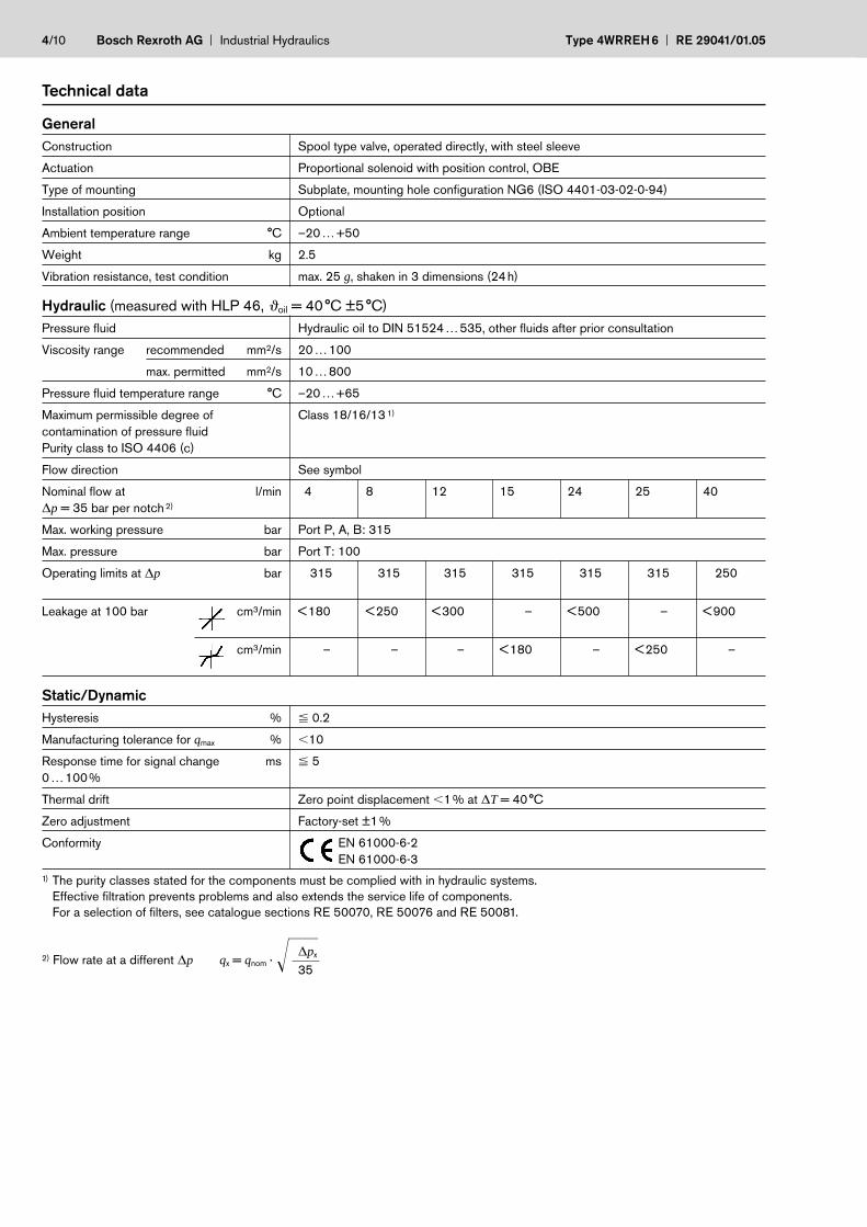
General
Construction Spool type valve, operated directly, with steel sleeve
Actuation Proportional solenoid with position control, OBE
Type of mounting Subplate, mounting hole configuration NG6 (ISO 4401-03-02-0-94)
Installation position Optional
Ambient temperature range °C –20…+50
Weight kg 2.5
Vibration resistance, test condition max. 25 g, shaken in 3 dimensions (24h)
Hydraulic (measured with HLP 46, oil = 40°C ±5°C)
Pressure fluid Hydraulic oil to DIN 51524…535, other fluids after prior consultation
Viscosity range recommended mm2/s 20…100
max. permitted mm2/s 10…800
Pressure fluid temperature range °C –20…+65
Maximum permissible degree of Class 18/16/13 1)
contamination of pressure fluid
Purity class to ISO 4406 (c)
Flow direction See symbol
Nominal flow at l/min 4 8 12 15 24 25 40
∆p = 35 bar per notch 2)
Max. working pressure bar Port P, A, B: 315
Max. pressure bar Port T: 100
Operating limits at ∆p bar < 315 < 315 < 315 < 315 < 315 < 315 < 250
Leakage at 100 bar cm3/min <180 <250 <300 <15– <500 <15– <900
cm3/min <15– <15– <15– <180 <15– <250 <15–
Static/Dynamic
Hysteresis % 0.2
Manufacturing tolerance for qmax % 10
Response time for signal change ms 5
0…100%
Thermal drift Zero point displacement 1% at ∆T = 40°C
Zero adjustment Factory-set ±1%
Conformity EN 61000-6-2
EN 61000-6-3
1) The purity classes stated for the components must be complied with in hydraulic systems.
Effective filtration prevents problems and also extends the service life of components.
For a selection of filters, see catalogue sections RE 50070, RE 50076 and RE 50081.
2) Durchfluss bei anderem ∆p ∆px2) Flow rate at a different ∆p qx = qnom · 35
Technical data

Electrical, trigger electronics integrated in the valve
Cyclic duration factor % 100, max. current input 30 VA (24 V DC)
Degree of protection IP 65 to DIN 40050 and IEC 14434/5
Connection Plug, 11P+PE Data
Power supply 1) 1 +24 V DCnom, fuse 2.5 AF (output stages)
24 V DCnom 2 0 V power ground
2) 9 +24 V DCnom signal part10 0 V signal ground
Input signal ±10 V 3) 4 UIN
5 UIN Difference amplifier Ri = 100 kΩ
Feedback signal (LVDT) 6 ±10 V DC, Ra = 1 kΩ7 0 V, reference point
Enabling input 3 > 8.5 V to 24 V DCnom (max. 40 V DC)
Ri = 10 kΩ
Signals 4) 8 Enabling acknowledgement +24 V DC11 Fault signal: no fault +24 V DC
Protective conductor Only connect when transformer of 24 V DC system does not conform to standard VDE 0551
Connecting cable Redommended Ø 12 ...14mm: screened
max. 20 m 0.75 mm2
max. 40 m 1.0 mm2
RE 29041/01.05 Type 4WRREH6 Industrial Hydraulics Bosch Rexroth AG 5/10
Technical data
11P+PE
24V DCnom – min. 21 V DC
– max. 40 V DC
1) UB (Pin 1) = output stage supply
– Valve “OFF” <13.4 V DC
– Valve “ON” >16.8 V DC
No fault signal (Pin 11)
2) US (Pin 9) = signal electronics supply
– Valve “OFF” <16.8 V DC
Fault signal (Pin 11)
– Valve “ON” >19.5 V DC
No fault signal (Pin 11)
3) Inputs: dielectric strength to withstand up to max. 50 V.
4) Signals can bear a load of max. 20 mA and are resistant to shorts to ground.

6/10 Bosch Rexroth AG Industrial Hydraulics Type 4WRREH6 RE 29041/01.05
Connection
For electrical data, see page 5 and
Operating Instructions 1 819 929 083
Technical notes on the cable
Version: – Multi-wire cable
– Extra-finely stranded wire to VDE 0295, Class 6
– Protective conductor, green/yellow
– Cu braided screen
Types: – e.g. Ölflex-FD 855 CP
(from Lappkabel company)
No. of wires: – Determined by type of valve,
plug types and signal assignment
Cable Ø: – 0.75 mm2 up to 20 m length
– 1.0 mm2 up to 40 m length
Outside Ø: – 9.4 ...11.8 mm – Pg11
– 12.7 ...13.5 mm – Pg16
Note
Electrical signals emitted via the trigger electronics
(e.g. actual values) must not be used to shut down
safety-relevant machine functions! (See European Standard,
“Technical Safety Requirements for Fluid-Powered Systems
and Components – Hydraulics”, EN 982.)
RE 29041/01.05 Type 4WRREH6 Industrial Hydraulics Bosch Rexroth AG 7/10
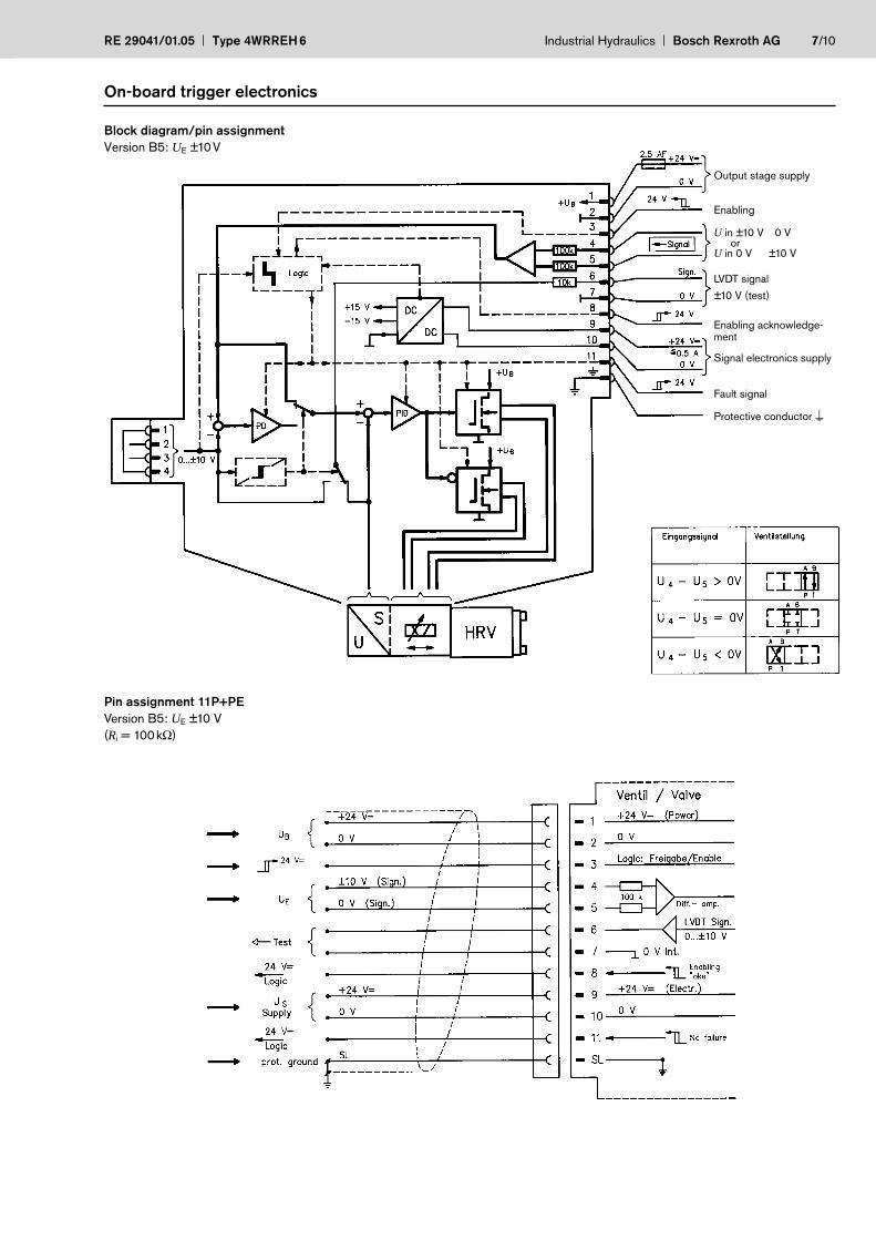
On-board trigger electronics
Block diagram/pin assignment
Version B5: UE ±10V
Pin assignment 11P+PE
Version B5: UE ±10 V
(Ri = 100kΩ)
Output stage supply
Enabling
U in ±10 V 0 Vor
U in 0 V ±10 V
LVDT signal
±10 V (test)
Enabling acknowledge-ment
Signal electronics supply
Fault signal
Protective conductor

8/10 Bosch Rexroth AG Industrial Hydraulics Type 4WRREH6 RE 29041/01.05
Performance curves (measured with HLP46, ϑoil = 40°C ±5°C)
Flow rate/Signal function Q = f (UE)
off off
off
L: Linear P: (kink 60%)
P: (kink 60%) P: (kink 40%)
[UE]
[UE]
[UE]
[UE]
Note
Highly dynamic servo solenoid valves do not have a safe basic
position when they are switched off. For this reason, many
applications require the use of “additional check valves”, which
must be taken into account during the On/Off switching sequence.
When switched off, the spool tends to rest in the P-B/A-T position.
This cannot be guaranteed if dirt is present.

RE 29041/01.05 Type 4WRREH6 Industrial Hydraulics Bosch Rexroth AG 9/10
Performances curves (measured with HLP46, ϑoil = 40°C ±5°C)
Pressure gain
Bode diagram
10/10 Bosch Rexroth AG Industrial Hydraulics Type 4WRREH6 RE 29041/01.05
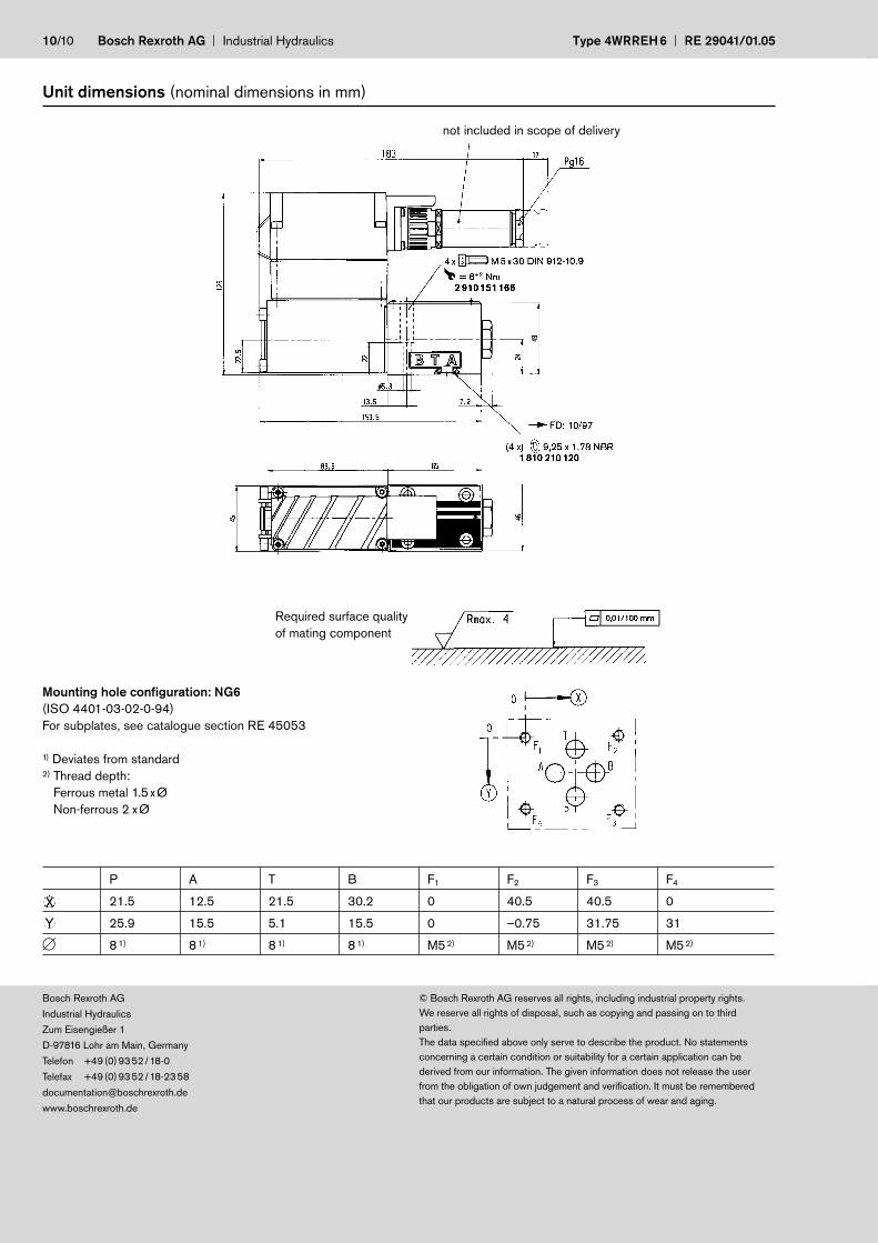
Unit dimensions (nominal dimensions in mm)
P A T B F1 F2 F3 F4
21.5 12.5 21.5 30.2 0 40.5 40.5 0
25.9 15.5 5.1 15.5 0 –0.75 31.75 31
8 1) 8 1) 8 1) 8 1) M5 2) M5 2) M5 2) M5 2)
X
Y
Mounting hole configuration: NG6
(ISO 4401-03-02-0-94)
For subplates, see catalogue section RE 45053
1) Deviates from standard2) Thread depth:
Ferrous metal 1.5xØ
Non-ferrous 2 xØ
not included in scope of delivery
Required surface quality
of mating component
Bosch Rexroth AG
Industrial Hydraulics
Zum Eisengießer 1
D-97816 Lohr am Main, Germany
Telefon +49(0)9352/18-0
Telefax +49(0)9352/18-2358
www.boschrexroth.de
© Bosch Rexroth AG reserves all rights, including industrial property rights.
We reserve all rights of disposal, such as copying and passing on to third
parties.
The data specified above only serve to describe the product. No statements
concerning a certain condition or suitability for a certain application can be
derived from our information. The given information does not release the user
from the obligation of own judgement and verification. It must be remembered
that our products are subject to a natural process of wear and aging.

Notes
RE 29041/01.05 Type 4WRREH6 Industrial Hydraulics Bosch Rexroth AG
Bosch Rexroth AG
Industrial Hydraulics
Zum Eisengießer 1
D-97816 Lohr am Main, Germany
Telefon +49(0)9352/18-0
Telefax +49(0)9352/18-2358
www.boschrexroth.de
© Bosch Rexroth AG reserves all rights, including industrial property rights.
We reserve all rights of disposal, such as copying and passing on to third
parties.
The data specified above only serve to describe the product. No statements
concerning a certain condition or suitability for a certain application can be
derived from our information. The given information does not release the user
from the obligation of own judgement and verification. It must be remembered
that our products are subject to a natural process of wear and aging.

Bosch Rexroth AG Industrial Hydraulics Type 4WRREH6 RE 29041/01.05
Notes
Bosch Rexroth AG
Industrial Hydraulics
Zum Eisengießer 1
D-97816 Lohr am Main, Germany
Telefon +49(0)9352/18-0
Telefax +49(0)9352/18-2358
www.boschrexroth.de
© Bosch Rexroth AG reserves all rights, including industrial property rights.
We reserve all rights of disposal, such as copying and passing on to third
parties.
The data specified above only serve to describe the product. No statements
concerning a certain condition or suitability for a certain application can be
derived from our information. The given information does not release the user
from the obligation of own judgement and verification. It must be remembered
that our products are subject to a natural process of wear and aging.

Appendix 4. Hydraulic diagrams. 3 pages

M
Clu
tch
Hyd
raul
ic c
oolin
g sy
stem
M
Wat
er fl
ow
Hyd
raul
ic c
ircu
latio
n sy
stem

M
Clu
tch
Hyd
raul
ic p
ower
sys
tem

Appendix 5. Data sheets CompactRIO and modules. 7 pages
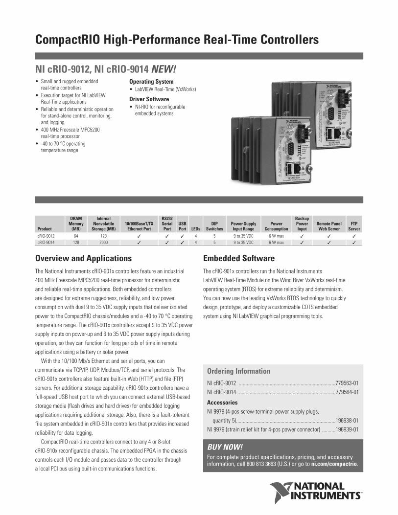
CompactRIO High-Performance Real-Time Controllers
Overview and ApplicationsThe National Instruments cRIO-901x controllers feature an industrial 400 MHz Freescale MPC5200 real-time processor for deterministic and reliable real-time applications. Both embedded controllers are designed for extreme ruggedness, reliability, and low powerconsumption with dual 9 to 35 VDC supply inputs that deliver isolatedpower to the CompactRIO chassis/modules and a -40 to 70 °C operatingtemperature range. The cRIO-901x controllers accept 9 to 35 VDC powersupply inputs on power-up and 6 to 35 VDC power supply inputs duringoperation, so they can function for long periods of time in remoteapplications using a battery or solar power.
With the 10/100 Mb/s Ethernet and serial ports, you can communicate via TCP/IP, UDP, Modbus/TCP, and serial protocols. ThecRIO-901x controllers also feature built-in Web (HTTP) and file (FTP)servers. For additional storage capability, cRIO-901x controllers have afull-speed USB host port to which you can connect external USB-basedstorage media (flash drives and hard drives) for embedded loggingapplications requiring additional storage. Also, there is a fault-tolerantfile system embedded in cRIO-901x controllers that provides increasedreliability for data logging.
CompactRIO real-time controllers connect to any 4 or 8-slot cRIO-910x reconfigurable chassis. The embedded FPGA in the chassiscontrols each I/O module and passes data to the controller through a local PCI bus using built-in communications functions.
Embedded SoftwareThe cRIO-901x controllers run the National Instruments LabVIEW Real-Time Module on the Wind River VxWorks real-timeoperating system (RTOS) for extreme reliability and determinism. You can now use the leading VxWorks RTOS technology to quickly design, prototype, and deploy a customizable COTS embedded system using NI LabVIEW graphical programming tools.
• Small and rugged embedded real-time controllers
• Execution target for NI LabVIEW Real-Time applications
• Reliable and deterministic operation for stand-alone control, monitoring, and logging
• 400 MHz Freescale MPC5200 real-time processor
• -40 to 70 °C operating temperature range
Operating System• LabVIEW Real-Time (VxWorks)
Driver Software• NI-RIO for reconfigurable
embedded systems
NI cRIO-9012, NI cRIO-9014 NEW!
Product
DRAMMemory
(MB)
InternalNonvolatile
Storage (MB) 10/100BaseT/TX
Ethernet Port
RS232 Serial Port
USB Port LEDs
DIPSwitches
Power SupplyInput Range
PowerConsumption
Backup Power Input
Remote Panel Web Server
FTP Server
cRIO-9012 64 128 4 5 9 to 35 VDC 6 W max
cRIO-9014 128 2000 4 5 9 to 35 VDC 6 W max
Ordering Information
NI cRIO-9012 ........................................................................779563-01NI cRIO-9014 ........................................................................ 779564-01
AccessoriesNI 9978 (4-pos screw-terminal power supply plugs,
quantity 5)..........................................................................196938-01NI 9979 (strain relief kit for 4-pos power connector) ..........196939-01
BUY NOW!For complete product specifications, pricing, and accessory information, call 800 813 3693 (U.S.) or go to ni.com/compactrio.

CompactRIO High-Performance Real-Time Controllers
2
BUY ONLINE at ni.com or CALL 800 813 3693 (U.S.)
SpecificationsMinimum Software Support Information
Specifications subject to change without notice. The followingspecifications are typical for the range -40 to 70 °C unless otherwise noted.
NetworkNetwork interface ................................... 10BaseT and 100BaseTX EthernetCompatibility ....................................... IEEE 802.3Communication rates .......................... 10 Mb/s, 100 Mb/s,
autonegotiatedMaximum cabling distance................. 100 m/segment
SMB ConnectorOutput CharacteristicsLogic high ............................................ 3.3 VLogic low............................................. 0 VDriver type........................................... CMOSSink/source current............................. ±50 mA3-state output leakage current ........... ±5 µA
Input CharacteristicsMinimum input level........................... -500 mVMaximum input low level ................... 990 mVMinimum input high level................... 2.31 VMaximum input level .......................... 5.5 VInput capacitance................................ 2.5 pFResistive strapping ............................. 1 kΩ to 3.3 V
USB PortMaximum data rate ............................ 12 Mb/sMaximum current................................ 500 mA
MemoryUse the following formula to determine the minimum life span in yearsof the nonvolatile storage of your cRIO-901x controller:
Minimum life span in years = [Amount of memory in controller (MB) x100,000 / 365 days] / [file size (MB) x write rate (per day)]
Power RequirementsCaution: You must use a National Electric Code (NEC) UL Listed Class 2power supply with cRIO-901x controllers.
Recommended power supply.............. 48 W secondary, 18 to 24 VDCPower consumption
Controller only ................................ 6 WController supplying power to
eight CompactRIO modules........ 20 WPower supply
On power-up ................................... 9 to 35 VAfter power-up ............................... 6 to 35 V
Note: The cRIO-901x controllers are guaranteed to power up when 9 Vis applied to V and C. After power-up, it can operate on as little as 6 V.
Physical CharacteristicsIf you need to clean the controller, wipe it with a dry towel.Screw-terminal wiring ........................ 12 to 24 AWG copper conductor
wire with 10 mm (0.39 in.) ofinsulation stripped from the end
Torque for screw terminals.................... 0.5 to 0.6 N · m (4.4 to 5.3 lb · in.)Weight................................................. Approx. 488 g (17.2 oz)
Safety VoltagesConnect only voltages that are within these limits.V-to-C .................................................. 35 V max,
Measurement Category I
Measurement Category I is for measurements performed on circuits notdirectly connected to the electrical distribution system referred to asMAINS voltage. MAINS is a hazardous live electrical supply system that powers equipment. This category is for measurements of voltagesfrom specially protected secondary circuits. Such voltage measurementsinclude signal levels, special equipment, limited-energy parts ofequipment, circuits powered by regulated low-voltage sources, and electronics.
Caution: Do not connect to signals or use for measurements withinmeasurement categories II, III, or IV.
Safety StandardsThis product is designed to meet the requirements of the followingstandards of safety for electrical equipment for measurement, control,and laboratory use:
• IEC 61010-1, EN 61010-1• UL 61010-1, CSA 61010-1
Note: For UL and other safety certifications, refer to the product label orvisit ni.com/certification, search by model number or product line, andclick the appropriate link in the Certification column.
CompactRIO Real-Time Controller
Minimum Version of LabVIEWReal-Time Module
Minimum Version of NI-RIO Driver
cRIO-9012 8.2 2.1cRIO-9014 8.2.1 2.1.3
CompactRIO Real-Time Controller Nonvolatile Storage DRAM
cRIO-9012 128 MB 64 MBcRIO-9014 2 GB 128 MB

Technical SalesSweden08 587 895 [email protected]
OverviewHigh-accuracy C Series analog input modules for National InstrumentsCompactRIO and NI CompactDAQ provide high-performance measurementsfor a wide variety of industrial, in-vehicle, and laboratory sensors andsignal types. Each module includes built-in signal conditioning and anintegrated connector with screw terminal or cable options for flexibleand low-cost signal wiring. All modules feature NI CompactRIO ExtremeIndustrial Certifications and Ratings.
System CompatibilityYou can use NI C Series modules in multiple system types depending on available software. See Table 1 for CompactRIO and NI CompactDAQmodule compatibility because not all modules work with both systems.Many of the advanced features described apply only to reconfigurableI/O systems and not to NI CompactDAQ.
Advanced FeaturesWhen used with CompactRIO, NI C Series analog input modules connect directly to reconfigurable I/O (RIO) FPGA hardware to create high-performance embedded systems. The reconfigurable FPGAhardware within CompactRIO provides a variety of options for customtiming, triggering, synchronization, filtering, signal processing, and
high-speed decision making for all C Series analog modules. Forinstance, with CompactRIO, you can implement custom triggering for any analog sensor type on a per-channel basis using the flexibility andperformance of the FPGA and the numerous arithmetic and comparisionfunction blocks built into NI LabVIEW FPGA.
Key Features • High-accuracy, high-performance analog measurements for any
CompactRIO embedded system, R Series expansion chassis, or NI CompactDAQ chassis
• Screw terminals, BNC, D-Sub, spring terminals, strain relief, high-voltage, cable, solder cup backshell, and other connectivity options
• Available channel-to-earth ground double-isolation barrier for safety,noise immunity, and high common-mode voltage range
• CompactRIO Extreme Industrial Certifications and Ratings• Built-in signal conditioning for direct connection to sensors and
industrial devicesVisit ni.com/compactrio or ni.com/compactdaq for up-to-date
information on module availability, example programs, application notes,and other developer tools.
C Series Analog Input Modules
• Signal conditioning for high voltage (±60 V), thermocouples, RTDs,accelerometers, microphones, strain gages, current inputs
• Advanced features such as smart TEDSsensor capability, antialiasing filters, open-thermocouple detection
• ±80 mV, ±10 V, or ±60 V analog input ranges
• 12-, 16-, or 24-bit (delta-sigma) resolution
• Up to 800 kS/s multiplexed or up to100 kS/s simultaneous-samplinganalog-to-digital converter (ADC)
• Up to 32 channels per module• Up to 2,300 Vrms isolation (withstand),
up to 250 Vrms isolation (continuous)• NIST-traceable calibration certificate
for guaranteed accuracy
NI 9201, NI 921x, NI 9221, NI 923x
North AmericanHazardous Locations
Model CompactRIO NI CompactDAQ Signal Type ChannelsResolution
(bits)Max Sampling
Rate (S/s)Signal
Input RangesSimultaneous
SamplingAntialiasing
Filters Isolation Connector Options
NI 9201 Voltage 8 12 500 k ±10 V – – Screw Terminal, D-SubNI 9203 Current 8 16 200 k ±20 mA, 0 to 20 mA – – Screw TerminalNI 9205 Voltage 32 SE/16 DI 16 250 k ±10, ±5, ±1, ±0.2 V – – Spring Terminal, D-SubNI 9206 CAT I Isolated
Voltage16 DI 16 250 k ±10, ±5, ±1, ±0.2 V – – Spring Terminal
NI 9211 Thermocouple 4 24 15 ±80 mV – Screw TerminalNI 9215 Voltage 4 16 100 k/ch ±10 V – Screw Terminal, BNCNI 9217 RTD 4 24 400 0 to 400 Ω – Screw TerminalNI 9221 Voltage 8 12 800 k ±60 V – – Screw Terminal, D-SubNI 9233 IEPE 4 24 50 k/ch ±5 V – BNCNI 9237 Bridge 4 24 50 k/ch ±250 mV RJ50
Table 1. C Series Analog Input Modules Selection Guide

C Series Analog Output Modules
OverviewHigh-performance analog output modules for National Instruments
CompactRIO embedded systems, R Series expansion chassis, and
NI CompactDAQ provide accurate signal generations. Each module
features built-in signal conditioning and an integrated connector with
screw terminal or cable options for flexible and low-cost signal wiring.
All modules feature the NI CompactRIO Extreme Industrial Certifications
and Ratings.
System CompatibilityYou can use NI C Series modules in multiple system types depending
on available software. Please see the table above for CompactRIO and
NI CompactDAQ module compatibility because not all modules work
with both systems. Many of the advanced features described apply
only to reconfigurable I/O systems and not to NI CompactDAQ.
Advanced FeaturesAdvanced features include ±30 V overvoltage protection and short-circuit
protection, simultaneous 16-bit per-channel digital-to-analog converters
(DACs), high-speed settling, excellent monotonicity and NIST-traceable
calibration. The NI 926x modules include a channel-to-earth ground double-
isolation barrier for safety and noise immunity. The NI 9265 provides high-
performance, 0 to 20 mA analog outputs ideal for controlling industrial
pressure, flow, and position actuators. The NI 9265 requires a 9 to 36 V
external power supply for driving the output current of the module.
When used in CompactRIO, C Series analog output modules connect
directly to reconfigurable I/O (RIO) FPGA hardware to create high-
performance embedded systems hat deliver the optimization and
flexibility of a custom electrical circuit completely dedicated to your
input/output application. The reconfigurable FPGA hardware within
CompactRIO provides a variety of options for timing, triggering,
synchronization, change detection, digital pattern matching, or digital
communication. For instance, with CompactRIO you can implement a
circuit to generate complex arbitrary waveforms, perform filtering or
splining to generate a smooth output signal based on a choppy low-
speed output command, simulate a nonlinear sensor, or implement
amplitude/phase modulation.
Key Features • High-performance analog output signal generation for CompactRIO
embedded system, R Series expansion chassis, or NI CompactDAQ
• Screw terminals, strain relief, high-voltage, and cable options
• NI CompactRIO Extreme Industrial Certifications and Ratings
• Channel-to-earth ground double-isolation barrier for safety
and noise immunity
Visit ni.com/compactrio or ni.com/compactdaq for up-to-date
information on module availability, example programs, application notes,
and other developer tools.
Typical certifications – Actual specifications vary from product to
product. Visit ni.com/certification for details.
NI 9263, NI 9265 NEW!
North AmericanHazardous Locations
• ±10 V and 0 to 20 mA analog output ranges, 16-bit resolution, 100 kS/s simultaneous update rate
• 4 channels per module• Isolation up to 2,300 Vrms (withstand),
up to 250 Vrms (continuous)• Per-channel digital-to-analog
converter (DAC) for simultaneous analog output
• ±30 V overvoltage protection and short-circuit protection for directconnection to actuators and industrial devices
• Excellent relative accuracy optimized for single-point control applications
• NIST-traceable calibration certificate for guaranteed accuracy
Compatibility Max Update SimultaneousProduct CompactRIO NI CompactDAQ Signal Type Channels Resolution (bits) Rate (S/s) Range Current Drive Updating Isolation Connector OptionsNI 9263 3 3 Voltage 4 16 100 k/ch ±10 V 1 mA/ch 3 3 Screw TerminalNI 9265 3 – Current 4 16 100 k/ch 0 to 20 mA 20 mA/ch 3 3 Screw Terminal
Table 1. C Series Analog Output Modules Selection Guide

C Series Digital Input and Counter/Timer Modules
OverviewHigh-performance digital input switching modules for National Instruments
CompactRIO embedded systems, R Series expansion chassis, and
NI CompactDAQ provide industrial logic levels for direct connection
to a wide array of industrial automotive switches and transducers. Each
module features an integrated connector junction box with screw terminal
or cable options for flexible and low-cost signal wiring. All modules
feature the NI CompactRIO Extreme Industrial Certifications and Ratings.
System CompatibilityYou can use NI C Series modules in multiple system types depending
on available software. See Table 1 for CompactRIO and NI CompactDAQ
module compatibility because not all modules work with both systems.
Many of the advanced features described apply only to reconfigurable
I/O systems and not to NI CompactDAQ.
Advanced FeaturesWhen used in CompactRIO, C Series digital input modules connect directly
to reconfigurable I/O (RIO) FPGA hardware to create high-performance
embedded systems. The reconfigurable FPGA hardware within CompactRIO
provides a variety of options for timing, triggering, synchronization, change
detection, digital pattern matching, or digital communication. For instance,
with CompactRIO you can implement a circuit to detect digital events
and record a timestamp, implement high-reliability digital control logic
in silicon, or perform redundant safety enforcement and interlocks. Unlike
traditional digital control devices, the performance of a CompactRIO
digital control system does not decrease as the amount of digital logic
increases because of the parallel nature of the RIO FPGA circuitry.
Key Features • High-performance digital and counter/timer input modules for CompactRIO
embedded system, R Series expansion chassis, or NI CompactDAQ system
• Screw terminal, D-Sub, strain relief, high-voltage cable,
solder-cup backshell, and other connectivity options
• NI CompactRIO Extreme Industrial Certifications and Ratings
• NI 9411 module that generates regulated 5 V power for quadrature
encoder or other devices
• Channel-to-earth ground double-isolation barrier for safety
and noise immunity and channel-to-channel isolation
Visit ni.com/compactrio or ni.com/compactdaq for up-to-date
information on module availability, example programs, application notes,
and other developer tools.
Typical certifications – Actual specifications vary from product to
product. Visit ni.com/certification for details.
NI 9401, NI 9411, NI 942x, NI 9435 NEW!
North AmericanHazardous Locations
• High- and low-speed 24 V logic (IEC 1131-2), 5 V/TTL, differential/single-ended inputs, or universal AC/DC inputs up to 250 VAC/VDC
• Isolation up to 2,300 Vrms (withstand), up to 250 Vrms (continuous)
• Channel-to-channel isolation up to 1,390 Vrms (withstand), up to 250 Vrms (continuous)
• Up to 100 ns input rate for ultrahigh-speed digital communication
• Up to 500 ns input rate for high-speed control or long-distance digital communication
• Internal current limiting and industrial logic thresholds for direct connection to a wide array of industrial switches, encoders, and transducers
CompatibilityProduct CompactRIO NI CompactDAQ Logic Channels Source/Sink I/O Delay Time Signal Levels Isolation Connector Options
NI 9401 3 3 5 V/TTL 8 Sink/Source 100 ns 5 V 3 D-SubNI 9411 3 3 Differential or 5 V/TTL 6 – 500 ns ±5 to ±24 V 3 D-SubNI 9421 3 3 24 V 8 Sink 100 µs 24 V 3 Screw Terminal, D-SubNI 9422 3 3 24 V 8 Sink/Source 250 µs Up to 60 V 3 (ch-to-ch) Screw TerminalNI 9423 3 3 24 V 8 Sink 1 µs 24 V 3 Screw TerminalNI 9425 3 3 24 V 32 Sink 7 µs 24 V 3 D-SubNI 9435 3 3 Universal 4 Sink/Source 3 ms ±5 to 250 VDC, 10 to 250 VAC 3 Screw Terminal
Table 1. C Series Digital Input and Counter/Timer Module Selection Guide

Appendix 6. Data sheets sensors. 12 pages

DEMOD-DC™Signal Conditioning Connector for DVRTs®
Technical Product Overview
Micro Sensors. Big Ideas.®
OverviewAdvanced microelectronics are packed within a miniature connector to provide complete conditioning of MicroStrain’s DVRT® sensors.
The DEMOD-DC™ makes inductive position sensors as easy to use as a potentiometer. With integral signal-conditioning electronics, the user connects power, ground and analog out, and the DEMOD-DC™ outputs a voltage proportional to linear position.
The high-level analog-output voltage is digitally trimmed under microprocessor control during the manufacturing process. This insures that every DVRT’s off set and gain values match one another. This allows DVRTs® to be used interchangeably in industrial automation & OEM applications.
DEMOD-DC™ cards will operate from a wide range of DC excitation voltages. They feature an input supply line that is internally regulated and reverse input protected, as well as a buff ered, high-frequency response analog-output voltage.
Features & Benefi ts• miniature size enables signal conditioner to be located close to
the transducer
• simple three wire connection provides easy plug and play implementation
• compatible with all DVRTs®
• confi guration available for MicroStrain’s wireless sensors
• low cost, rugged, compact design suitable for OEM applications
• digitally trimmed off set and gain
• frequency response up to 20 kHz
• confi guration available for high inertial loads, up to 10,000 g
• operates on wide range of input voltages
ApplicationsUsed with MicroStrain’s DVRTs® for:
• miniature control elements for automotive and robotic systems
• process control for production line monitoring
• dimensional gauging for quality control applications
• measuring strain and defl ection in materials science and civil structures
• linear/angular positioning of optical components
• miniature force, torque, acceleration sensors
• biomedical strain measurement in bone and soft tissue
www.microstrain.com

Copyright © 2006 MicroStrain Inc. DEMOD-DC is a trademark of MicroStrain Inc. Specifi cations are subject to change without notice.
MicroStrain Inc.310 Hurricane Lane, Unit 4 Williston, VT 05495 USAwww.microstrain.com
Specifi cations Sensor Types Inductive (DVRTs)
Excitation Regulated Sinewave, 75 kHz standard150 kHz optional
Demodulation Asynchronous, DC output
Output 0 to 5 V typical, digitally trimmed
Gain Factory Adjustable from 10 to 10,000
Low Pass Filter 2 Pole, 3 dB down @ 800 Hz standardFactory Adjustable 10 Hz – 8kHz
Supply Voltage + 6.0 to + 16 volts DC
Supply Current 22 milliamps
Warm-up Time 30 seconds recommended
Operating Temp. -40 to 85 °C
Enclosure Size 50 mm x 20 mm x 10 mm
Connections Power, ground, analog output
Connector micro-D (MIL-C-83513/5)mating connector included
DEMOD-DC™ Signal Conditioning connector for DVRTs®
How It WorksOperating from a DC power supply, the DEMOD-DC™ fi lters incoming transients from the line voltage, and supplies a sine wave excitation to the transducer. This excitation is used to measure minute impedance changes of the sensing elements.
Precision demodulator components provide rectifi cation and diff erential amplifi cation. Digital trimming insures conformity from sensor to sensor. The analog output is fi ltered and buff ered to provide clean, high level signals.
Patent Pending
ph: 800-449-3878 fax : 802-863-4093 [email protected]
TransducerBridge
AC Excitation (75 kHz Sinewave)
Oscillator
ACDemodulator
Low PassFilter
FactoryTrimmedGain

Technical Product Overview
Micro Sensors. Big Ideas.®
IntroductionIdeal for diffi cult sensing applications, this transducer can measure displacement & proximity of a metal target without physical contact. The measurement is unaff ected by interposed nonmetallic, non-conductive materials, such as polymers and biomaterials.
The stainless shell of the device houses two coils; one for sensing and the other for temperature compensation. The coils and tefl on cable are mounted on a stable PEEK substrate. This assembly is potted into the stainless housing using high-grade, vacuum-pumped epoxy and includes integral strain relief.
This packaging allows the sensor to be used in applications requiring long-term immersion in water and saline solutions.
Miniature “plug and play” signal conditioners provide linear DC output when supplied with unregulated DC power. Multichannel, OEM and digital display systems are also available.
Custom ranges are available on request.
Features & Benefi ts• available with sub-micron resolution
• operating temperature to 175 °C
• frequency response up to 20 kHz
• stainless steel and high-performance polymer design suitable for extremely harsh environments
• waterproof, suitable for submersion in corrosive media such as brake fl uid and hot saline
• non-contact design suitable for high duty-cycle applications
• easily customized to suit specifi c application
Applications• miniature control elements in automotive and robotic systems
• process control for production-line monitoring
• measurement of tissue deformation and implant micromotion in biomedical studies
• materials science, civil engineering: structural defl ections,strain extensometry
• optical components: linear/angular positioning
• miniature sensors: force, torque, acceleration
www.microstrain.com
Non-Contact DVRT®
Diff erential Variable Reluctance Transducer

Copyright © 2007 MicroStrain Inc. DVRT is a trademark of MicroStrain Inc. Specifi cations are subject to change without notice.Updated May 4, 2007
MicroStrain Inc.310 Hurricane Lane, Unit 4 Williston, VT 05495 USAwww.microstrain.com
Electrical Specifi cations(with MicroStrain’s DEMOD-DVRT)
Measurement rangeNC-DVRT-0.5NC-DVRT-1.0NC-DVRT-1.5NC-DVRT-2.5
0.5 mm1.0 mm1.5 mm2.5 mm
Nonlinearity exponential output
Sensitivity 5 volts/mm typical
Signal to noise Standard - 1000 to 1 with fi lter 3 dB down at 1 KHz
Resolution 0.1% minimum
Frequency response 800 Hz standard, 20 KHz optional
Temperature coeffi cient off set 0.0039%/°C (typical)span 0.016%/°C (typical)
Repeatability ±2 µm typical (at constant temperature)
Mechanical Specifi cationsSize NC-DVRT-0.5NC-DVRT-1.0NC-DVRT-1.5NC-DVRT-2.5
diameter x length (thread)2.84 mm x 8.4 mm (4-40 UNC-2A)4.83 mm x 19.0 mm (10-32 UNF-2A )6.35 mm x 19.0 mm (¼-28 UNF-2A)12.70 mm x 19.0 mm (½-20 UNF 2A)
Housing material 300 series stainless steel
Fixturing method threaded stainless nuts
Leadouts 45 cm, shielded, tefl on insulated
Strain Relief Stainless wire reinforcedmultistrand conductors
Connector Lemo 4-pin male with shrinkpolyolefi n covering
Operating temperature -55 to 175 °C
U.S. Patent No. 4,813,435 and Patents Pending
NC-DVRT-0.5 can only be used with DEMOD-DVRT - it is not compatible with
DEMOD-DC2.
Non-Contact DVRT® Diff erential Variable Reluctance Transducer
How it worksTwo coils within the non-contact DVRT’s housing form its sensing and compensation elements. When the face of the transducer is brought in close proximity to a ferrous or highly conductive material, the reluctance of the sense coil is changed, while the compensation coil acts as a reference.
The coils are driven by a high-frequency sinewave excitation, and their diff erential reluctance is measured using a sensitive demodulator. Diff erencing the two coils’ outputs provides a sensitive measure of the position signal, while cancelling out variations caused by temperature.
Ferrous targets change the sense coils’ reluctance by altering the magnetic circuit’s permeability; conductive targets (such as aluminum, see graph) operate by the interaction of eddy currents induced in the target’s skin with the fi eld around the sense coil.
Patents Pending
ph: 800-449-3878 fax : 802-863-4093 [email protected]
ferrous orconductivetarget
transducer
32100
1
2
3
4
5
Non-Contact DVRT Calibrationtarget: aluminum
Relative Position (mm)
)stlov(t
upt
uO
rotalu
dome
D

2007-11-22
Tunna manteltermoelement – från 0,1 mm
Tunna manteltermoelement ger två fördelar. De ger kort svarstid och kräverminimalt installationsutrymme. Utveckling av bränsleceller är ett exempel påanvändningsområde.
Pentronic erbjuder flera manteldiametrar under 1 mm. Svarstiderna i tabellengäller för rumstempererade givare som neddoppas i kokande vatten. Värdenaär approximativa och ska användas med stor försiktighet, särskilt om förutsätt-ningarna är annorlunda.
Termoelementen som är av typ K eller N finns i enkelutförande med isoleradmätpunkt.
Hölje ytterdiameter(mm)
0,1 0,15 0,25 0,5 0,8
Approximativ svarstid(63,2%) (ms)
1 2 5 14 29
Max arbetstemp(C)
400 400 500 600 700
ø 0,1 mm

Models: P3249 tecsis GmbH Carl-Legien-Straße 40 D-63073 Offenbach/Main T. ++49 (0) 69 / 5806-0
Sales National F. +49 (0) 69 / 5806-170
Sales International F. +49 (0) 69 / 5806-177
E. [email protected] I. www.tecsis.de
DE 705c
p. 1/4
| Force | Pressure | Temperature | Switch
Pressure Sensors Compact with internal diaphragm for gauge pressure and absolute pressure
accuracy 0.5 %
standard output: 4...20 mA; 2-wire system or 0...5 VDC; 3-wire system or 0...10 VDC; 3-wire system
Description
Pressure sensors Compact are top of the range pressure sensors.
Compact, sturdy, accurate and long-term stable, they perform industrial pressure measuring jobs reliable in the fields of production and development and in the laboratory.
The compact design with G ¼ B pressure connection enables space-saving and low-weight installation. The materials and technology used make these pressure sensors insensitive to chemically aggressive media and mechanical load.
Measuring ranges from 250 mbar up to 1000 bar, graded in accordance with EN, offer a wide range of possible applications. The overload limit up to 16 bar is 3.5-fold, between 16 and 600 bar 2-fold and above 600 bar 1.5-fold.
The short response time of the pressure sensors of < 1ms enables peak pressures with frequen-cies of up to 150 Hz to be measured. DIN plugs or cable outlets are used to pick up the electrical output signals.
The Compact pressure sensors meet the electromagnetic compatibility (EMC) to EN 61326.
Features
O Compact design
O Pressure connection G¼B
O High peak pressure resistance
O High alternating load resistance
O High long-term stability O Corrosion resistant stainless steel design O For dynamic and static measurements
Measuring ranges
gauge pressure negative -1...0 bar to -0.25...0 bar positive 0...0.25 bar to 0...1000 bar absolute pressure 0...0.25 bar to 0...16 bar
Applications
Process engineering, Hydraulics and pneumatics, Conveyor and lifting systems, General mechanical engineering, Development and laboratory applications.

DE 705c
p. 2/4
Technical data
Model P3249 Options Pressure type negative or positive gauge pressure absolute
pressure negative and positive gauge pressure
Output signal 4...20 mA - 2-wire system 0...5 VDC - 3-wire system 0...10 VDC - 3-wire system
0...20 mA - 3-wire system other siganls on request
Accuracy ± 0.5 % of F.S. 1) Ranges accord. to EN 0 ... 0.25 bar
to 0 ... 16 bar
0 ... 25 bar to
0 ... 1000 bar
0 ... 0.25 bar to
0 ... 16 bar
other measuring ranges on request
Sensor element piezoresistive thin film piezoresistive Repeatability ≤ ± 0.05 % of F.S. Stability (annual) ≤ ± 0.2 % of F.S. in rated conditions Case stainless steel Pressure connection G ¼ B to DIN 16288 other pressure connections
on request Wetted parts stainless steel 1.4571 and 1.4542 Overload limit ≤ 16 bar 3.5-fold; ≤ 600 bar 2-fold; > 600 bar 1.5-fold;
vacuum resistant
Electrical connection plug according to DIN 43650C with junction box cable outlet with1 m cable Power supply 10....30 VDC (14...30 VDC for output 0...10 V) Power consumption output 4...20 mA: signal current
output 0...20 mA: signal current + 4 mA voltage output: 8 mA
Load
0.020A10VUB −
≤ for output 4(0)...20 mA
> 5 kOhm for output 0...5 V > 10 kOhm for output 0...10 V
Temp. compens. range 0.... 80°C Temperature influence ± 0.3 % /10 K, on zero point and measuring range Adjustability on zero point and measuring range ± 10 % Response time ≤ 1 ms (within 10 % to 90 % of F.S.) Protection type IP 65 EN 60529 / IEC 529 IP 67 for cable outlet Emission 2) To EN 61326 Interference 2) To EN 61326 Electrical protection types polarity, overvoltage and short-circuit protection Temperature ranges − Storage − Media − Ambient
-40 .... 100 °C -30 .... 100 °C -30 .... 85 °C
Weight approx. 0.10 kg of F.S.= of full scale value
1) Terminal point adjustment according to DIN 16 086, incl. linearity and hysteresis 2) Declaration of conformity on request

DE 705c
p. 3/4
Dimensions (mm)
Case plug according to DIN 43 650C cable outlet
G1/4B17
1580
106
27
27
17
80
130
G1/4B
Screw-in aperture according to DIN 16288
G1/4
5,5
16,5
+1
13-0
,5
Min
.9,5
A0.1
A
S-002

DE 705c
p. 4/4
Electrical connection
Two-wire system
DIN 43 650 C plug cable outlet UB / S+
0V / S-
1
3 2
E-005
UB / S+
0V / S-
brown
green
E-016
Three-wire system
DIN 43 650 C plug cable outlet UB
0V / S-
S+
E-006
0V / S-
UB
S+
brown
green
white
E-018
Connection table for DIN plug or cable outlet 4...20 mA
(2 - wire) 0...10VDC (3 - wire)
Supply: UB 1 brown 1 brown Supply: 0V 2 green 2 green Signal: S+ - - 3 white Signal: S- - - 2 green
Order details 1. Model 2. Measuring range 3. Output signal 4. Options

FP-5960_EN.doc Page 1 on 2 Rev.:09/05/2005
5960-5962 MINIATURE COMPRESSION LOAD CELLS
- Miniature load cells - Protection IP 66 - Very competitive prices - Material : - Stainless steel (5960) - Aluminium (5962)
The SENSY’s load cells 5960-5962 are perfectly designed to the following applications :
- Industrial force applications where space is limited - Very low profile scales (for control use) - Anti-intrusion control - Force limitation on machines
AVAILABLE CAPACITIES : 5960 : (0.75) - 1 - (1.5) - 2 - (3) - 5 - (7.5) - 10 - (15) - 20 kN
5962 : 200 - 300 - 500 N
TECHNICAL DATA Accuracy class SL Linearity error % F.S. < ± 0.5 Hysteresis error % F.S. < ± 0.5 Non - repeatability % F.S. < ± 0.25 Creep error over 30 min. % F.S. < ± 0.2 Zero shift after loading % F.S. < ± 0,05 Reference temperature °C 23 Nominal temperature range °C - 10...+ 45 Service temperature range °C - 30...+ 70 Storage temperature range °C - 50...+ 85 Temperature coefficient of the sensitivity % /10°C < ± 0.1 Temperature coefficient of zero signal % F.S./10°C < ± 0.1 Nominal sensitivity mV/V 1…1,8 Zero balance mV/V ± 0.02 Sensitivity tolerance (g=9,8107 m/s²) % < ± 0.5 Input / Output resistance Ohm 350 ± 20 Insulation resistance (50V) MOhm > 5000 Nominal excitation voltage V 5 to 10 Nominal range of the excitation voltage V 2…15 Safe load limit % F.S. 120 Breaking load % F.S. > 300 Static lateral force limit % F.S. 5 Permissible dynamic loading % F.S. 50
F.S.: full scale Specifications subject to change without notice
Model 5960

FP-5960_EN.doc Page 2 on 2 Rev.:09/05/2005