Validation of a Fluid–Structure Interaction Model of Solute Transport in Pores of Cyclically...
12
Validation of a Fluid–Structure Interaction Model of Solute Transport in Pores of Cyclically Deformed Tissue Scaffolds Jorn Op Den Buijs, Ph.D., 1 Erik L. Ritman, M.D., Ph.D., 2 and Dan Dragomir-Daescu, Ph.D. 1 Convection induced by repetitive compression of porous tissue scaffolds enhances solute transport inside the scaffold. Our previous experiments have shown that pore size, shape, and orientation with respect to strain direction greatly influence loading-induced solute transport. The objective of this study was to develop a computational model of deformation-induced solute transport in porous tissue scaffolds, which included the pore geometry of the scaffold. This geometry consisted of a cubic scaffold with single channel in the middle of the scaffold, immersed in a fluid reservoir. Cylindrical pores with circular or elliptic cross section, and spheroid pores were modeled. The scaffold was cyclically compressed from one side, causing fluid motion and dispersion of solute inside the scaffold pore. Scaffold deformation was solved using the finite element method, and fluid flow and solute transport were solved using the finite volume method. The distortion of the scaffold–fluid interface was transferred as a boundary condition to the fluid flow solver. Both convection and diffusion were included in the computations. The solute transport rates in the different scaffold pore geometries agreed well with our previous experimental results obtained with X-ray microimaging. This model will be used to explore transport properties of a spectrum of novel scaffold designs. Introduction A rtificial tissue scaffolds are the basic building blocks in tissue engineering: these porous structures serve to guide tissue invasion either for anchoring the scaf- fold within the native tissue or, if they eventually degrade, for leaving behind a functional tissue. Among the major challenges presently holding back the development of re- placement tissues with clinically relevant sizes is the ade- quate supply of nutrients and removal of waste products inside the pores of the scaffolds to maintain cell viability. 1,2 Currently, one of the few commercially available tissue en- gineering products is a dermal substitute, 3 in which the cells in the thin layers of skin are within the diffusion distance (*500 mm). In thicker replacement tissues, lack of sufficient mass transport may result in cell density decreasing from the periphery to the center of the scaffold due to necrosis of cells beyond the diffusion distance, as observed in scaffolds for musculoskeletal, 4 bone and cartilage, 2,5,6 cardiac, 1,7 and adi- pose tissue engineering, 8 ultimately resulting in a dysfunc- tional tissue once the scaffold degrades. A potential solution to the mass transport problem is to generate mechanically deformable scaffolds, in which pores are distorted upon application of mechanical strain to the scaffold. 9 Most tissues in the human body are continuously undergoing cyclic mechanical strain: longitudinal strains as large as 20% were measured in the interventricular septum of the heart during peak systole, 10 peak deformations in knee cartilage during single-leg lunges were found to range from 22% to 30%, 11 and strains of up to 25% were measured in the wall of the human left anterior descending coronary artery. 12 Strains of these magnitudes could induce significant solute convection in scaffolds replacing such tissues, provided that the scaffold pore geometry allows for solute convection. Application of cyclic loading has been proven to promote tissue ingrowth and improve the mechanical properties of cartilage constructs, 13,14 cardiovascular constructs, 15–17 smooth muscle tissue, 18 bone, 19 and fibroblast scaffolds for tendon and ligament engineering. 20 A growing number of studies are linking aspects of porous structure to mass transport and biological performance of the tissue scaffold, thereby mainly focusing on pore size. For example, in vitro cellular infiltration rates in electrospun scaffolds for cardiovascular tissue engineering were shown to vary significantly with fiber diameter and, hence, pore size. 21 Optimal pore size for scaffolds manufactured with particulate leaching is thought to lie between 100 and 500 mm, 22 depending on cell type. Increased pore size and This work was performed at Mayo Clinic, Rochester, Minnesota. 1 Division of Engineering, and 2 Physiological Imaging Research Laboratory, Department of Physiology and Biomedical Engineering, Mayo Clinic College of Medicine, Rochester, Minnesota. TISSUE ENGINEERING: Part C Volume 16, Number 5, 2010 ª Mary Ann Liebert, Inc. DOI: 10.1089=ten.tec.2009.0685 1145
-
Upload
independent -
Category
Documents
-
view
2 -
download
0
Transcript of Validation of a Fluid–Structure Interaction Model of Solute Transport in Pores of Cyclically...
Validation of a Fluid–Structure Interaction Modelof Solute Transport in Pores
of Cyclically Deformed Tissue Scaffolds
Jorn Op Den Buijs, Ph.D.,1 Erik L. Ritman, M.D., Ph.D.,2 and Dan Dragomir-Daescu, Ph.D.1
Convection induced by repetitive compression of porous tissue scaffolds enhances solute transport inside thescaffold. Our previous experiments have shown that pore size, shape, and orientation with respect to straindirection greatly influence loading-induced solute transport. The objective of this study was to develop acomputational model of deformation-induced solute transport in porous tissue scaffolds, which included thepore geometry of the scaffold. This geometry consisted of a cubic scaffold with single channel in the middle ofthe scaffold, immersed in a fluid reservoir. Cylindrical pores with circular or elliptic cross section, and spheroidpores were modeled. The scaffold was cyclically compressed from one side, causing fluid motion and dispersionof solute inside the scaffold pore. Scaffold deformation was solved using the finite element method, and fluidflow and solute transport were solved using the finite volume method. The distortion of the scaffold–fluidinterface was transferred as a boundary condition to the fluid flow solver. Both convection and diffusion wereincluded in the computations. The solute transport rates in the different scaffold pore geometries agreed wellwith our previous experimental results obtained with X-ray microimaging. This model will be used to exploretransport properties of a spectrum of novel scaffold designs.
Introduction
Artificial tissue scaffolds are the basic buildingblocks in tissue engineering: these porous structures
serve to guide tissue invasion either for anchoring the scaf-fold within the native tissue or, if they eventually degrade,for leaving behind a functional tissue. Among the majorchallenges presently holding back the development of re-placement tissues with clinically relevant sizes is the ade-quate supply of nutrients and removal of waste productsinside the pores of the scaffolds to maintain cell viability.1,2
Currently, one of the few commercially available tissue en-gineering products is a dermal substitute,3 in which the cellsin the thin layers of skin are within the diffusion distance(*500 mm). In thicker replacement tissues, lack of sufficientmass transport may result in cell density decreasing from theperiphery to the center of the scaffold due to necrosis of cellsbeyond the diffusion distance, as observed in scaffolds formusculoskeletal,4 bone and cartilage,2,5,6 cardiac,1,7 and adi-pose tissue engineering,8 ultimately resulting in a dysfunc-tional tissue once the scaffold degrades.
A potential solution to the mass transport problem is togenerate mechanically deformable scaffolds, in which poresare distorted upon application of mechanical strain to the
scaffold.9 Most tissues in the human body are continuouslyundergoing cyclic mechanical strain: longitudinal strains aslarge as 20% were measured in the interventricular septumof the heart during peak systole,10 peak deformations in kneecartilage during single-leg lunges were found to range from22% to 30%,11 and strains of up to 25% were measured in thewall of the human left anterior descending coronary artery.12
Strains of these magnitudes could induce significant soluteconvection in scaffolds replacing such tissues, provided thatthe scaffold pore geometry allows for solute convection.Application of cyclic loading has been proven to promotetissue ingrowth and improve the mechanical properties ofcartilage constructs,13,14 cardiovascular constructs,15–17
smooth muscle tissue,18 bone,19 and fibroblast scaffolds fortendon and ligament engineering.20
A growing number of studies are linking aspects of porousstructure to mass transport and biological performance of thetissue scaffold, thereby mainly focusing on pore size. Forexample, in vitro cellular infiltration rates in electrospunscaffolds for cardiovascular tissue engineering were shownto vary significantly with fiber diameter and, hence, poresize.21 Optimal pore size for scaffolds manufactured withparticulate leaching is thought to lie between 100 and500mm,22 depending on cell type. Increased pore size and
This work was performed at Mayo Clinic, Rochester, Minnesota.1Division of Engineering, and 2Physiological Imaging Research Laboratory, Department of Physiology and Biomedical Engineering, Mayo
Clinic College of Medicine, Rochester, Minnesota.
TISSUE ENGINEERING: Part CVolume 16, Number 5, 2010ª Mary Ann Liebert, Inc.DOI: 10.1089=ten.tec.2009.0685
1145
porosity in mechanically deformable, salt-leached scaffoldsenhanced cell attachment and proliferation, most likely dueto increased mass transport.23 On the other hand, a studyusing solid freeform fabrication (SFF) scaffolds has shownlimited influence of pore size in the range of 350–800 mm onbone regeneration in vivo,24 suggesting that it may be ad-vantageous to explore the effects of, for example, pore shapeand interconnectivity to enhance tissue ingrowth.
Since both structural deformation and fluid flow are inti-mately connected to geometry, the question is how is masstransport affected by pore size and shape upon mechanicaldeformation of the scaffold? X-ray microimaging and micro-CT have become widely used imaging modalities in biomed-ical research,25 enabling imaging within opaque specimens atmicrometer spatial resolution without the need to destroythe sample. Various studies have used the accurate scaffoldpore geometry as obtained with micro-CT in combinationwith computational fluid dynamics to predict fluid trans-port.26–28 Gossl et al.29 used an X-ray absorbing tracer as asurrogate for nonradiopaque nutritional solutes to quantifytransendothelial transport. To measure mass transport inmechanically deforming scaffolds and investigate the effectof pore geometry, we have developed an X-ray microima-ging technique30 and showed that pore size, shape, and theorientation of the pore cross section with respect to the straindirection greatly influence mass transport.9
Our previously published experimental tests9 were chal-lenging and time consuming, because they required specialtechnologies, such as SFF, X-ray microimaging using an in-house-built X-ray scanner with custom-made compressiondevice, and fluids and X-ray contrast agents with similardensities and viscosities. To accelerate the design of scaffoldswith programmable pores, the experimental work can be re-duced and guided by using validated computational modelsdescribing solute transport in porous scaffolds undergoingcyclic mechanical strain. Previously, Mauck et al.31 developeda model of solute transport in dynamically loaded porousgels, which predicted that cyclic mechanical loading indeedenhances solute transport in gel-like materials such as naturalor tissue-engineered cartilage. In this and other models ofporous media,32,33 the mixture of solid matrix and fluid in thepores is described at a macroscopic scale, with representativeelementary volumes that are large enough to be consideredhomogenous. Although these models have been instrumentalin understanding the effect of cyclic deformation on globalmass transport in porous media, the detailed pore geometryitself is not described in these models and distributions ofsolutes at the pore level cannot be determined. Yet, particu-larly in scaffolds for tissue engineering, it is the local distri-bution of nutrients that determines where cells can or cannotsurvive. Further, the difficulty of imaging solute distributionsinside opaque porous tissue scaffolds has hindered the vali-dation of these models against experimental data.
To overcome these limitations, we aimed in this study todevelop and validate a computational model of solutetransport in deforming tissue scaffolds, which includes poregeometry. The model consists of a finite element formulationof the deformation of the scaffold material, coupled to a finitevolume description of fluid flow and solute transport insidethe scaffold pores and surrounding fluid reservoir. Themodeling approach was validated based on our previous X-ray microimaging experiments.
Materials and Methods
Summary of X-ray experiments
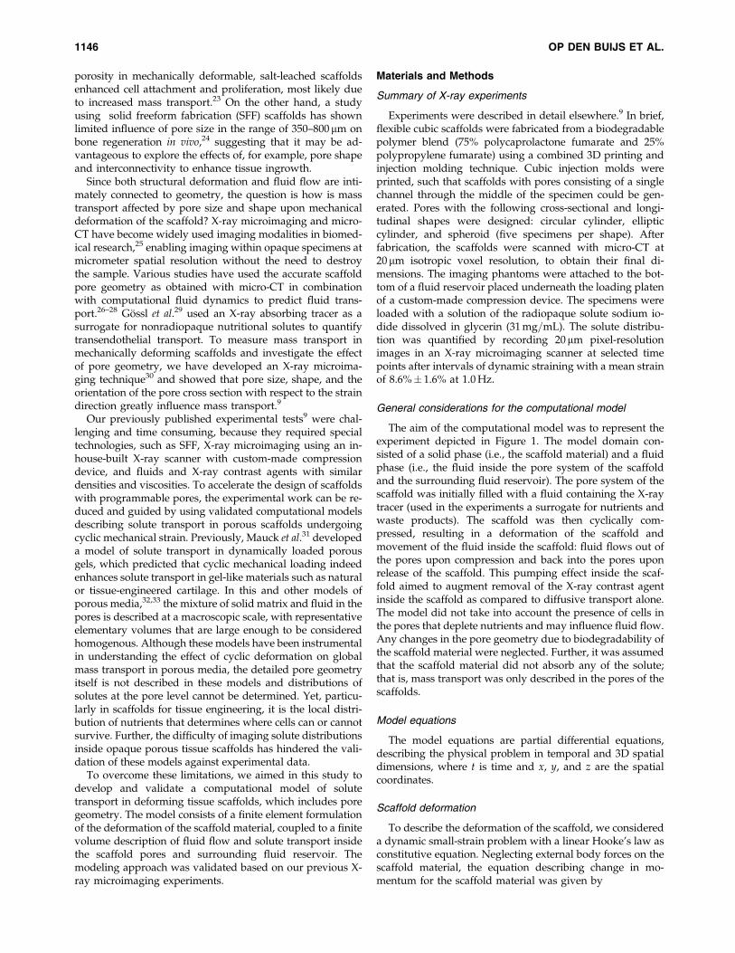
Experiments were described in detail elsewhere.9 In brief,flexible cubic scaffolds were fabricated from a biodegradablepolymer blend (75% polycaprolactone fumarate and 25%polypropylene fumarate) using a combined 3D printing andinjection molding technique. Cubic injection molds wereprinted, such that scaffolds with pores consisting of a singlechannel through the middle of the specimen could be gen-erated. Pores with the following cross-sectional and longi-tudinal shapes were designed: circular cylinder, ellipticcylinder, and spheroid (five specimens per shape). Afterfabrication, the scaffolds were scanned with micro-CT at20 mm isotropic voxel resolution, to obtain their final di-mensions. The imaging phantoms were attached to the bot-tom of a fluid reservoir placed underneath the loading platenof a custom-made compression device. The specimens wereloaded with a solution of the radiopaque solute sodium io-dide dissolved in glycerin (31 mg=mL). The solute distribu-tion was quantified by recording 20 mm pixel-resolutionimages in an X-ray microimaging scanner at selected timepoints after intervals of dynamic straining with a mean strainof 8.6%� 1.6% at 1.0 Hz.
General considerations for the computational model
The aim of the computational model was to represent theexperiment depicted in Figure 1. The model domain con-sisted of a solid phase (i.e., the scaffold material) and a fluidphase (i.e., the fluid inside the pore system of the scaffoldand the surrounding fluid reservoir). The pore system of thescaffold was initially filled with a fluid containing the X-raytracer (used in the experiments a surrogate for nutrients andwaste products). The scaffold was then cyclically com-pressed, resulting in a deformation of the scaffold andmovement of the fluid inside the scaffold: fluid flows out ofthe pores upon compression and back into the pores uponrelease of the scaffold. This pumping effect inside the scaf-fold aimed to augment removal of the X-ray contrast agentinside the scaffold as compared to diffusive transport alone.The model did not take into account the presence of cells inthe pores that deplete nutrients and may influence fluid flow.Any changes in the pore geometry due to biodegradability ofthe scaffold material were neglected. Further, it was assumedthat the scaffold material did not absorb any of the solute;that is, mass transport was only described in the pores of thescaffolds.
Model equations
The model equations are partial differential equations,describing the physical problem in temporal and 3D spatialdimensions, where t is time and x, y, and z are the spatialcoordinates.
Scaffold deformation
To describe the deformation of the scaffold, we considereda dynamic small-strain problem with a linear Hooke’s law asconstitutive equation. Neglecting external body forces on thescaffold material, the equation describing change in mo-mentum for the scaffold material was given by
1146 OP DEN BUIJS ET AL.
qrx
qxþ
qsxy
qyþ qsxz
qz¼ qs
q2us
qt2
qry
qyþ
qsxy
qxþ
qsyz
qz¼ qs
q2vs
qt2,
qrz
qzþ qsxz
qxþ
qsyz
qy¼ qs
q2ws
qt2
(1)
where sx, sy, and sz are the normal stresses, and txy, txz, andtyz are the shear stresses. Further, �s is the density of thescaffold material, and us, vs, and ws are the displacements ofa material point in the deforming scaffold. We consideredsmall deformations and described the relation between thestrains and the displacements using the linear relationships
ex¼qus
qxcxy¼
qvs
qxþ qus
qy
ey¼qvs
qycxz¼
qws
qxþ qus
qz
ez¼qws
qzcyz¼
qws
qyþ qvs
qz
(2)
Here ex, ey, and ez are the normal strains, and gxy, gxz, and gyz
are the engineering shear strains. Assuming linear, isotropicelastic behavior, the relation between stress and strain in thescaffold was described by Hooke’s law:
rx
ry
rz
syz
sxz
sxy
26666666666664
37777777777775
¼ E
(1þ v)(1� 2v)
1� v v v 0 0 0
v 1� v v 0 0 0
v v 1� v 0 0 0
0 0 0 12 � v 0 0
0 0 0 0 12 � v 0
0 0 0 0 0 12 � v
26666666666664
37777777777775
ex
ey
ez
cyz
cxz
cxy
26666666666664
37777777777775
,
(3)
where E is the Young’s modulus and v is the Poisson’s ratioof the scaffold material.
Fluid motion
Fluid pressure and velocity of the fluid phase were de-scribed by the Navier–Stokes equations. The continuityequation was given by
qqf
qtþ q(qfuf)
qxþ q(qfvf)
qyþ q(qfwf)
qz¼ 0, (4)
where qf is the fluid density, and uf, vf, and wf are the fluidvelocity components. It should be noted that, although thefluid was assumed to be incompressible, density differencesin time and space could occur due to mixing of the fluid withthe X-ray contrast agent. Further, we described laminar flowof a Newtonian fluid with viscosity � including a buoyancysource term to model density differences due to mixing withthe X-ray absorbing contrast agent, which has a higherdensity. The momentum balance of the Navier–Stokesequation was given by
q(qfuf)
qtþ uf
q(qfuf)
qxþ vf
q(qfuf)
qyþwf
q(qfuf)
qz
¼ � qp
qxþ l
q2uf
qx2þ q2uf
qy2þ q2uf
qz2
� �
q(qfvf)
qtþ uf
q(qfvf)
qxþ vf
q(qfvf)
qyþwf
q(qfvf)
qz
¼ � qp
qyþ l
q2vf
qx2þ q2vf
qy2þ q2vf
qz2
� �
q(qfwf)
qtþ uf
q(qfwf)
qxþ vf
q(qfwf)
qyþwf
q(qfwf)
qz
¼ � qp
qzþ l
q2wf
qx2þ q2wf
qy2þ q2wf
qz2
� �þ g(qf � qf, 0),
(5)
where p is the fluid pressure, �f,0 is the density of the fluidwithout contrast agent and g is the gravitation constant.
A
B
C
t = 0Piston
Piston
Piston
Compression
Release
Fluidreservoir
Fluidreservoir
Fluidreservoir
Scaffold
Scaffold
Scaffold
Tracer in Pore
FIG. 1. Schematic diagram of the model. (A) A deformablescaffold is immersed in a fluid reservoir underneath a com-pression device. The pore of the scaffold is initially filledwith contrast agent. Cycles of (B) compression and (C) re-lease are applied to the scaffold, inducing a convective fluidflow in the scaffold pore, thereby transporting the tracerfrom the pore into the surrounding fluid reservoir.
SOLUTE TRANSPORT IN CYCLICALLY DEFORMED TISSUE SCAFFOLDS 1147
Solute transport
Finally, solute transport was governed by the scalarconvection–diffusion equation:
qC
qtþ q(ufC)
qxþ q(vfC)
qyþ q(wfC)
qz¼D
q2C
qx2þ q2C
qy2þ q2C
qz2
� �,
(6)
where C is the concentration of X-ray contrast agent in thefluid and D is the diffusion coefficient. The fluid density wasdependent on the concentration of contrast agent (in densityunits [g=cm3]):
qf ¼ qf, 0þC (7)
Model geometry and mesh
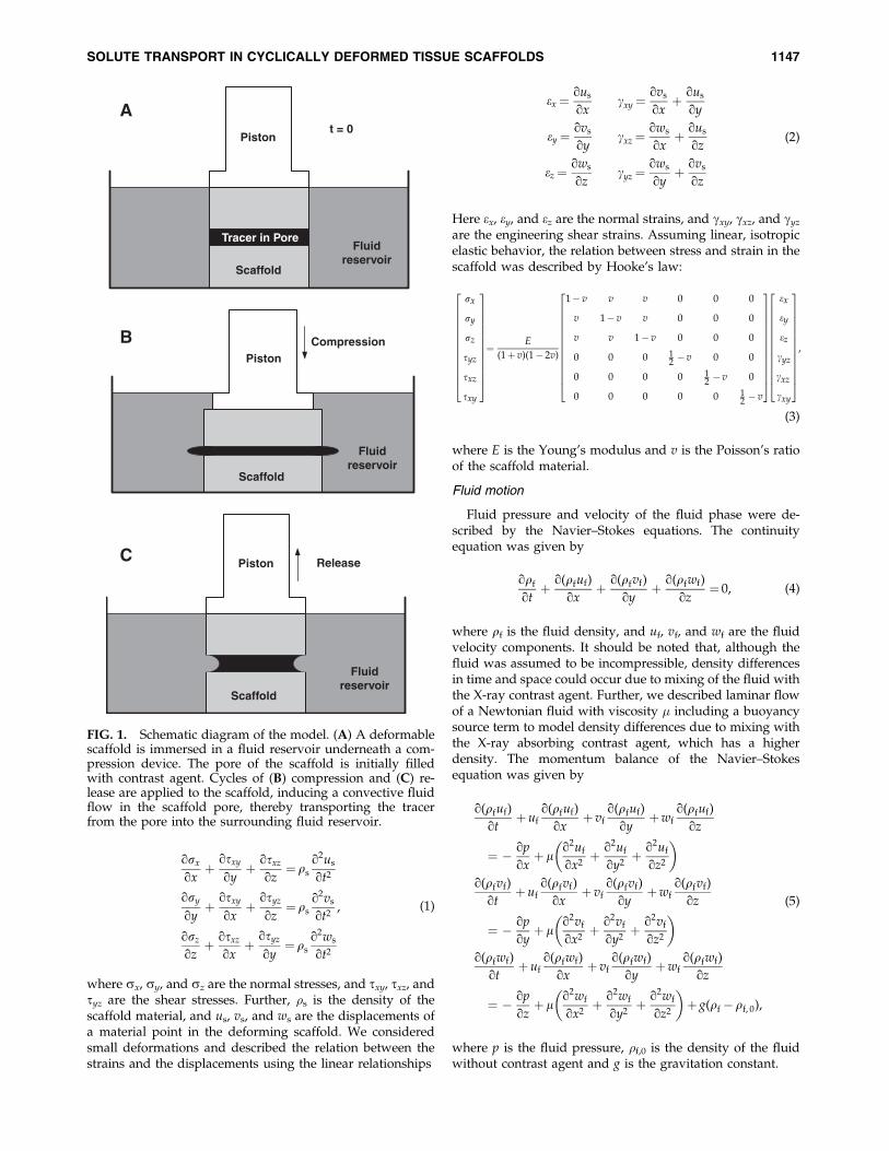
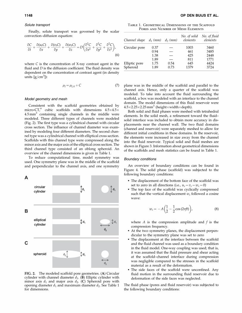
Consistent with the scaffold geometries obtained bymicro-CT,9 cubic scaffolds with dimensions 4.5�4.5�4.5 mm3 containing single channels in the middle weremodeled. Three different types of channels were modeled(Fig. 2). The first type was a cylindrical channel with circularcross section. The influence of channel diameter was exam-ined by modeling four different diameters. The second chan-nel type was a cylindrical channel with elliptical cross section.Scaffolds with this channel type were compressed along theminor axis and the major axis of the elliptical cross section. Thethird channel type consisted of an oblong spheroid. Anoverview of the channel dimensions is given in Table 1.
To reduce computational time, model symmetry wasused. One symmetry plane was in the middle of the scaffoldand perpendicular to the channel axis, and one symmetry
plane was in the middle of the scaffold and parallel to thechannel axis. Hence, only a quarter of the scaffold wasmodeled. To take into account the fluid surrounding thescaffold, a box was modeled with an interface to the channeldomain. The model dimensions of this fluid reservoir were4.5�2.25�2.25 mm3 (height�width�depth).
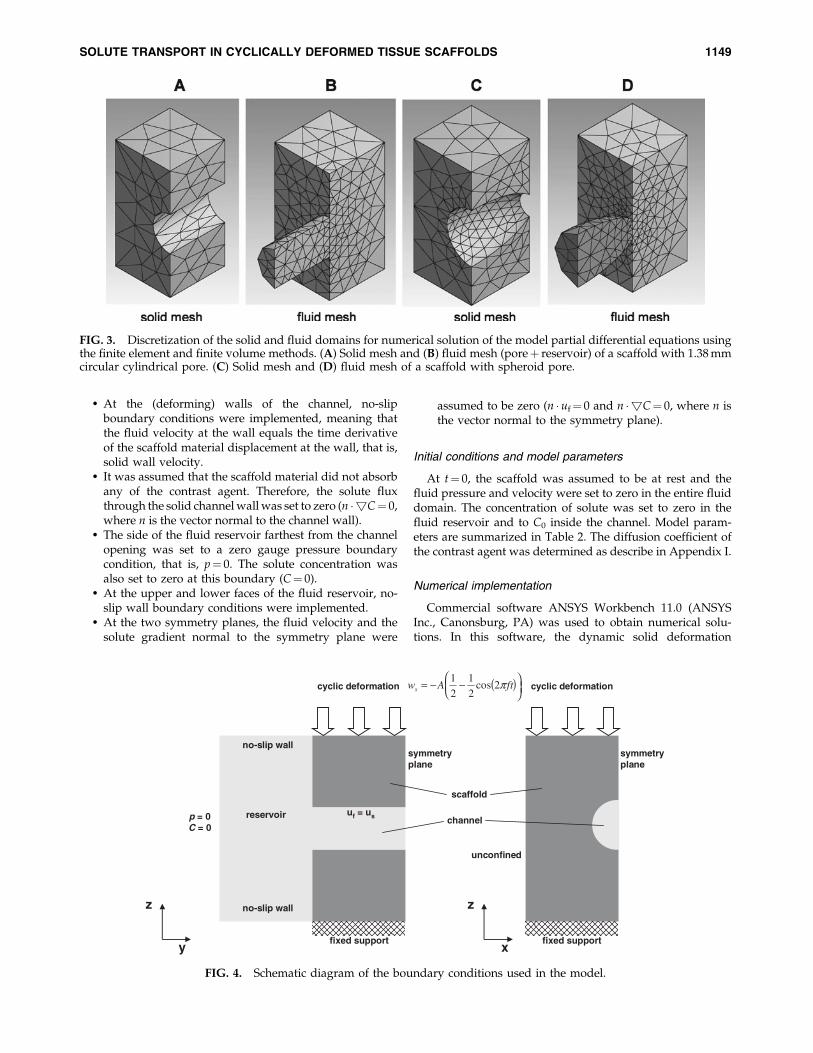
Both solid and fluid phases were meshed with tetrahedralelements. In the solid mesh, a refinement toward the fluid–solid interface was included to obtain more accuracy in dis-placements near the channel wall. The two fluid domains(channel and reservoir) were separately meshed to allow fordifferent initial conditions in these domains. In the reservoir,the elements were increased in size away from the channelinto the fluid reservoir. Typical solid and fluid meshes areshown in Figure 3. Information about geometrical dimensionsof the scaffolds and mesh statistics can be found in Table 1.
Boundary conditions
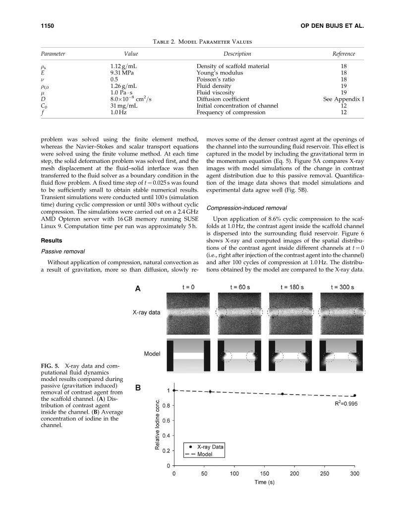
An overview of boundary conditions can be found inFigure 4. The solid phase (scaffold) was subjected to thefollowing boundary conditions:
� The displacement of the bottom face of the scaffold wasset to zero in all directions (i.e., us¼ vs¼ws¼ 0)
� The top face of the scaffold was cyclically compressedsuch that the vertical displacement ws followed a cosinewave:
ws¼ �A1
2� 1
2cos (2pft)
� �, (8)
where A is the compression amplitude and f is thecompression frequency.
� At the two symmetry planes, the displacement perpen-dicular to the symmetry plane was set to zero
� The displacement at the interface between the scaffoldand the fluid channel was used as a boundary conditionin the fluid model. One-way coupling was used; that is,it was assumed that the fluid pressure and shear actingat the scaffold–channel interface during compressionwas negligible compared to the stresses in the scaffoldmaterial as a result of the deformation.
� The side faces of the scaffold were unconfined. Anyfluid motion in the surrounding fluid reservoir due todeformation of the side faces was neglected.
The fluid phase (pores and fluid reservoir) was subjected tothe following boundary conditions:
circularcylinder
ellipticalcylinder
spheroid
d1
d1
d2d2
d1d2
d2
d1
d1 d1circularcylinder
ellipticalcylinder
spheroid
d1
d1
d2d2
d1d2
d2
d1
d1 d1
A
B
C
FIG. 2. The modeled scaffold pore geometries. (A) Circularcylinder with channel diameter d1. (B) Elliptic cylinder withminor axis d1 and major axis d2. (C) Spheroid pore withopening diameter d1 and maximum diameter d2. See Table 1for dimensions.
Table 1. Geometrical Dimensions of the Scaffold
Pores and Number of Mesh Elements
Channel shape d1 (mm) d2 (mm)No. of solid
elementsNo. of fluid
elements
Circular pore 0.37 — 1003 34600.94 — 461 34851.38 — 425 24481.89 — 811 1771
Elliptic pore 1.75 0.54 645 4424Spheroid 1.89 0.73 1379 3724
1148 OP DEN BUIJS ET AL.
� At the (deforming) walls of the channel, no-slipboundary conditions were implemented, meaning thatthe fluid velocity at the wall equals the time derivativeof the scaffold material displacement at the wall, that is,solid wall velocity.
� It was assumed that the scaffold material did not absorbany of the contrast agent. Therefore, the solute fluxthrough the solid channel wall was set to zero (n �!C¼ 0,where n is the vector normal to the channel wall).
� The side of the fluid reservoir farthest from the channelopening was set to a zero gauge pressure boundarycondition, that is, p¼ 0. The solute concentration wasalso set to zero at this boundary (C¼ 0).
� At the upper and lower faces of the fluid reservoir, no-slip wall boundary conditions were implemented.
� At the two symmetry planes, the fluid velocity and thesolute gradient normal to the symmetry plane were
assumed to be zero (n � uf¼ 0 and n �!C¼ 0, where n isthe vector normal to the symmetry plane).
Initial conditions and model parameters
At t¼ 0, the scaffold was assumed to be at rest and thefluid pressure and velocity were set to zero in the entire fluiddomain. The concentration of solute was set to zero in thefluid reservoir and to C0 inside the channel. Model param-eters are summarized in Table 2. The diffusion coefficient ofthe contrast agent was determined as describe in Appendix I.
Numerical implementation
Commercial software ANSYS Workbench 11.0 (ANSYSInc., Canonsburg, PA) was used to obtain numerical solu-tions. In this software, the dynamic solid deformation
FIG. 3. Discretization of the solid and fluid domains for numerical solution of the model partial differential equations usingthe finite element and finite volume methods. (A) Solid mesh and (B) fluid mesh (poreþ reservoir) of a scaffold with 1.38 mmcircular cylindrical pore. (C) Solid mesh and (D) fluid mesh of a scaffold with spheroid pore.
z
y
z
x
noitamrofedcilcycnoitamrofedcilcyc
fixed support fixed support
symmetryplane
symmetryplane
no-slip wall
no-slip wall
p = 0C = 0
uf = us
unconfined
reservoir
scaffold
channel
( )−−= ftAws π2cos21
21
FIG. 4. Schematic diagram of the boundary conditions used in the model.
SOLUTE TRANSPORT IN CYCLICALLY DEFORMED TISSUE SCAFFOLDS 1149
problem was solved using the finite element method,whereas the Navier–Stokes and scalar transport equationswere solved using the finite volume method. At each timestep, the solid deformation problem was solved first, and themesh displacement at the fluid–solid interface was thentransferred to the fluid solver as a boundary condition in thefluid flow problem. A fixed time step of t¼ 0.025 s was foundto be sufficiently small to obtain stable numerical results.Transient simulations were conducted until 100 s (simulationtime) during cyclic compression or until 300 s without cycliccompression. The simulations were carried out on a 2.4 GHzAMD Opteron server with 16 GB memory running SUSELinux 9. Computation time per run was approximately 5 h.
Results
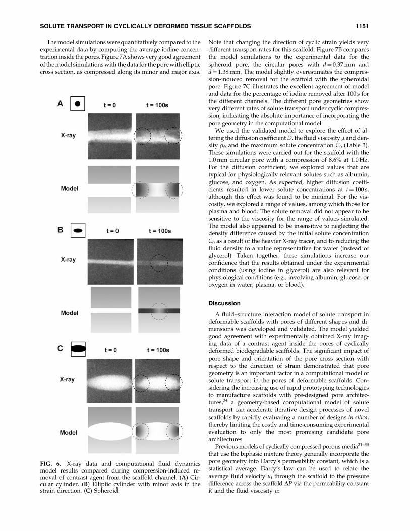
Passive removal
Without application of compression, natural convection asa result of gravitation, more so than diffusion, slowly re-
moves some of the denser contrast agent at the openings ofthe channel into the surrounding fluid reservoir. This effect iscaptured in the model by including the gravitational term inthe momentum equation (Eq. 5). Figure 5A compares X-rayimages with model simulations of the change in contrastagent distribution due to this passive removal. Quantifica-tion of the image data shows that model simulations andexperimental data agree well (Fig. 5B).
Compression-induced removal
Upon application of 8.6% cyclic compression to the scaf-folds at 1.0 Hz, the contrast agent inside the scaffold channelis dispersed into the surrounding fluid reservoir. Figure 6shows X-ray and computed images of the spatial distribu-tions of the contrast agent inside different channels at t¼ 0(i.e., right after injection of the contrast agent into the channel)and after 100 cycles of compression at 1.0 Hz. The distribu-tions obtained by the model are compared to the X-ray data.
Table 2. Model Parameter Values
Parameter Value Description Reference
�s 1.12 g=mL Density of scaffold material 18E 9.31 MPa Young’s modulus 18� 0.5 Poisson’s ratio 18�f,0 1.26 g=mL Fluid density 19� 1.0 Pa � s Fluid viscosity 19D 8.0�10�8 cm2=s Diffusion coefficient See Appendix IC0 31 mg=mL Initial concentration of channel 12f 1.0 Hz Frequency of compression 12
FIG. 5. X-ray data and com-putational fluid dynamicsmodel results compared duringpassive (gravitation induced)removal of contrast agent fromthe scaffold channel. (A) Dis-tribution of contrast agentinside the channel. (B) Averageconcentration of iodine in thechannel.
1150 OP DEN BUIJS ET AL.
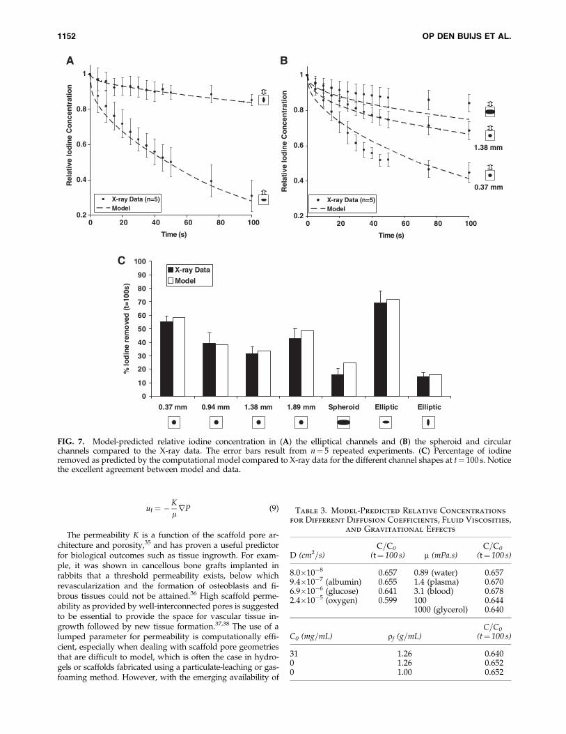
The model simulations were quantitatively compared to theexperimental data by computing the average iodine concen-tration inside the pores. Figure 7A shows very good agreementof the model simulations with the data for the pore with ellipticcross section, as compressed along its minor and major axis.
Note that changing the direction of cyclic strain yields verydifferent transport rates for this scaffold. Figure 7B comparesthe model simulations to the experimental data for thespheroid pore, the circular pores with d¼ 0.37 mm andd¼ 1.38 mm. The model slightly overestimates the compres-sion-induced removal for the scaffold with the spheroidalpore. Figure 7C illustrates the excellent agreement of modeland data for the percentage of iodine removed after 100 s forthe different channels. The different pore geometries showvery different rates of solute transport under cyclic compres-sion, indicating the absolute importance of incorporating thepore geometry in the computational model.
We used the validated model to explore the effect of al-tering the diffusion coefficient D, the fluid viscosity m and den-sity rf, and the maximum solute concentration C0 (Table 3).These simulations were carried out for the scaffold with the1.0 mm circular pore with a compression of 8.6% at 1.0 Hz.For the diffusion coefficient, we explored values that aretypical for physiologically relevant solutes such as albumin,glucose, and oxygen. As expected, higher diffusion coeffi-cients resulted in lower solute concentrations at t¼ 100 s,although this effect was found to be minimal. For the vis-cosity, we explored a range of values, among which those forplasma and blood. The solute removal did not appear to besensitive to the viscosity for the range of values simulated.The model also appeared to be insensitive to neglecting thedensity difference caused by the initial solute concentrationC0 as a result of the heavier X-ray tracer, and to reducing thefluid density to a value representative for water (instead ofglycerol). Taken together, these simulations increase ourconfidence that the results obtained under the experimentalconditions (using iodine in glycerol) are also relevant forphysiological conditions (e.g., involving albumin, glucose, oroxygen in water, plasma, or blood).
Discussion
A fluid–structure interaction model of solute transport indeformable scaffolds with pores of different shapes and di-mensions was developed and validated. The model yieldedgood agreement with experimentally obtained X-ray imag-ing data of a contrast agent inside the pores of cyclicallydeformed biodegradable scaffolds. The significant impact ofpore shape and orientation of the pore cross section withrespect to the direction of strain demonstrated that poregeometry is an important factor in a computational model ofsolute transport in the pores of deformable scaffolds. Con-sidering the increasing use of rapid prototyping technologiesto manufacture scaffolds with pre-designed pore architec-tures,34 a geometry-based computational model of solutetransport can accelerate iterative design processes of novelscaffolds by rapidly evaluating a number of designs in silica,thereby limiting the costly and time-consuming experimentalevaluation to only the most promising candidate porearchitectures.
Previous models of cyclically compressed porous media31–33
that use the biphasic mixture theory generally incorporate thepore geometry into Darcy’s permeability constant, which is astatistical average. Darcy’s law can be used to relate theaverage fluid velocity uf through the scaffold to the pressuredifference across the scaffold DP via the permeability constantK and the fluid viscosity �:
FIG. 6. X-ray data and computational fluid dynamicsmodel results compared during compression-induced re-moval of contrast agent from the scaffold channel. (A) Cir-cular cylinder. (B) Elliptic cylinder with minor axis in thestrain direction. (C) Spheroid.
SOLUTE TRANSPORT IN CYCLICALLY DEFORMED TISSUE SCAFFOLDS 1151
uf ¼ �K
lrP (9)
The permeability K is a function of the scaffold pore ar-chitecture and porosity,35 and has proven a useful predictorfor biological outcomes such as tissue ingrowth. For exam-ple, it was shown in cancellous bone grafts implanted inrabbits that a threshold permeability exists, below whichrevascularization and the formation of osteoblasts and fi-brous tissues could not be attained.36 High scaffold perme-ability as provided by well-interconnected pores is suggestedto be essential to provide the space for vascular tissue in-growth followed by new tissue formation.37,38 The use of alumped parameter for permeability is computationally effi-cient, especially when dealing with scaffold pore geometriesthat are difficult to model, which is often the case in hydro-gels or scaffolds fabricated using a particulate-leaching or gas-foaming method. However, with the emerging availability of
C
0
10
20
30
40
50
60
70
80
90
100
0.37 mm 0.94 mm 1.38 mm 1.89 mm Spheroid Elliptic Elliptic
% Io
din
e re
mo
ved
(t=1
00s)
X-ray Data
Model
A
0.2
0.4
0.6
0.8
1
Time (s)
Rel
ativ
e Io
din
e C
on
cen
trat
ion
X-ray Data (n=5)Model
1.38 mm
0.2
0.4
0.6
0.8
1
0 20 40 60 80 100 0 20 40 60 80 100
Time (s)
Rel
ativ
e Io
din
e C
on
cen
trat
ion
X-ray Data (n=5)Model
0.37 mm
B
FIG. 7. Model-predicted relative iodine concentration in (A) the elliptical channels and (B) the spheroid and circularchannels compared to the X-ray data. The error bars result from n¼ 5 repeated experiments. (C) Percentage of iodineremoved as predicted by the computational model compared to X-ray data for the different channel shapes at t¼ 100 s. Noticethe excellent agreement between model and data.
Table 3. Model-Predicted Relative Concentrations
for Different Diffusion Coefficients, Fluid Viscosities,
and Gravitational Effects
D (cm2=s)C=C0
(t¼ 100 s) m (mPa.s)C=C0
(t¼ 100 s)
8.0�10�8 0.657 0.89 (water) 0.6579.4�10�7 (albumin) 0.655 1.4 (plasma) 0.6706.9�10�6 (glucose) 0.641 3.1 (blood) 0.6782.4�10�5 (oxygen) 0.599 100 0.644
1000 (glycerol) 0.640
C0 (mg=mL) rf (g=mL)C=C0
(t¼ 100 s)
31 1.26 0.6400 1.26 0.6520 1.00 0.652
1152 OP DEN BUIJS ET AL.
solid freeform fabrication methods, it becomes possible toprogram the scaffold pore geometry with computer-aideddesign software,39,40 such that the scaffold mass transportproperties are reproducible and more accurately predictableat the pore level before actual fabrication of the scaffold.These accurate predictions require a thoroughly validated, 3Dnumerical model of mass transport in the scaffold pores, in-corporating the precise pore geometry from the initial com-puter-aided design data. Such a model will allow for the rapidexploration of transport properties of a wide range of pore ar-chitectures before actual fabrication and experimental testing.
Potential limitations
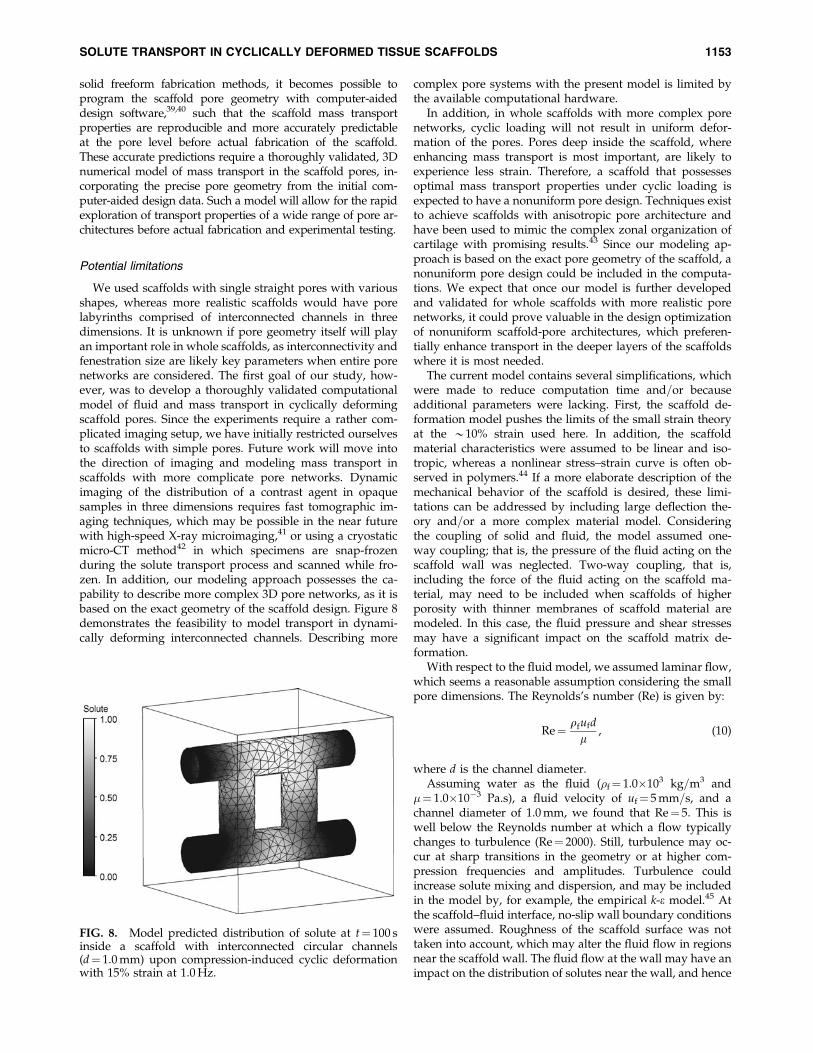
We used scaffolds with single straight pores with variousshapes, whereas more realistic scaffolds would have porelabyrinths comprised of interconnected channels in threedimensions. It is unknown if pore geometry itself will playan important role in whole scaffolds, as interconnectivity andfenestration size are likely key parameters when entire porenetworks are considered. The first goal of our study, how-ever, was to develop a thoroughly validated computationalmodel of fluid and mass transport in cyclically deformingscaffold pores. Since the experiments require a rather com-plicated imaging setup, we have initially restricted ourselvesto scaffolds with simple pores. Future work will move intothe direction of imaging and modeling mass transport inscaffolds with more complicate pore networks. Dynamicimaging of the distribution of a contrast agent in opaquesamples in three dimensions requires fast tomographic im-aging techniques, which may be possible in the near futurewith high-speed X-ray microimaging,41 or using a cryostaticmicro-CT method42 in which specimens are snap-frozenduring the solute transport process and scanned while fro-zen. In addition, our modeling approach possesses the ca-pability to describe more complex 3D pore networks, as it isbased on the exact geometry of the scaffold design. Figure 8demonstrates the feasibility to model transport in dynami-cally deforming interconnected channels. Describing more
complex pore systems with the present model is limited bythe available computational hardware.
In addition, in whole scaffolds with more complex porenetworks, cyclic loading will not result in uniform defor-mation of the pores. Pores deep inside the scaffold, whereenhancing mass transport is most important, are likely toexperience less strain. Therefore, a scaffold that possessesoptimal mass transport properties under cyclic loading isexpected to have a nonuniform pore design. Techniques existto achieve scaffolds with anisotropic pore architecture andhave been used to mimic the complex zonal organization ofcartilage with promising results.43 Since our modeling ap-proach is based on the exact pore geometry of the scaffold, anonuniform pore design could be included in the computa-tions. We expect that once our model is further developedand validated for whole scaffolds with more realistic porenetworks, it could prove valuable in the design optimizationof nonuniform scaffold-pore architectures, which preferen-tially enhance transport in the deeper layers of the scaffoldswhere it is most needed.
The current model contains several simplifications, whichwere made to reduce computation time and=or becauseadditional parameters were lacking. First, the scaffold de-formation model pushes the limits of the small strain theoryat the *10% strain used here. In addition, the scaffoldmaterial characteristics were assumed to be linear and iso-tropic, whereas a nonlinear stress–strain curve is often ob-served in polymers.44 If a more elaborate description of themechanical behavior of the scaffold is desired, these limi-tations can be addressed by including large deflection the-ory and=or a more complex material model. Consideringthe coupling of solid and fluid, the model assumed one-way coupling; that is, the pressure of the fluid acting on thescaffold wall was neglected. Two-way coupling, that is,including the force of the fluid acting on the scaffold ma-terial, may need to be included when scaffolds of higherporosity with thinner membranes of scaffold material aremodeled. In this case, the fluid pressure and shear stressesmay have a significant impact on the scaffold matrix de-formation.
With respect to the fluid model, we assumed laminar flow,which seems a reasonable assumption considering the smallpore dimensions. The Reynolds’s number (Re) is given by:
Re¼ qfufd
l, (10)
where d is the channel diameter.Assuming water as the fluid (�f¼ 1.0�103 kg=m3 and
�¼ 1.0�10�3 Pa.s), a fluid velocity of uf¼ 5 mm=s, and achannel diameter of 1.0 mm, we found that Re¼ 5. This iswell below the Reynolds number at which a flow typicallychanges to turbulence (Re¼ 2000). Still, turbulence may oc-cur at sharp transitions in the geometry or at higher com-pression frequencies and amplitudes. Turbulence couldincrease solute mixing and dispersion, and may be includedin the model by, for example, the empirical k-e model.45 Atthe scaffold–fluid interface, no-slip wall boundary conditionswere assumed. Roughness of the scaffold surface was nottaken into account, which may alter the fluid flow in regionsnear the scaffold wall. The fluid flow at the wall may have animpact on the distribution of solutes near the wall, and hence
FIG. 8. Model predicted distribution of solute at t¼ 100 sinside a scaffold with interconnected circular channels(d¼ 1.0 mm) upon compression-induced cyclic deformationwith 15% strain at 1.0 Hz.
SOLUTE TRANSPORT IN CYCLICALLY DEFORMED TISSUE SCAFFOLDS 1153
the nutrient supply of cells attached to the scaffold surface.Additionally, an improved fluid mesh in the model near thescaffold wall will yield a more accurate prediction of fluidshear stress, which, in addition to nutrient supply, couldhave an important effect on the proliferation, distribution,and differentiation of cells.46 Despite these limitations, thecurrent model yielded a good quantitative prediction of theaverage solute transport rate in scaffolds with different poregeometries, and could be further improved if more accuratequantitative information on, for example, scaffold mechani-cal behavior, turbulence, and wall shear stress is desired.
In conclusion, cyclic compression increases solute con-vection by cyclic fluid motion and subsequent spreading ofsolutes dissolved in the fluid. The efficiency of the cyclicpumping can be increased by considering the strain directionand manufacturing pores with highly deformable cross-sectional geometries. Thus, careful design and fabricationof deformable porous tissue scaffolds may be a strategythrough which solutes can be transported beyond the dif-fusion limit after implantation of constructs with clinicallyrelevant thicknesses. Our proposed computational modelwill aid such scaffold design.
Acknowledgments
This work was funded in part by Mayo Graduate Schooland NIH Grant EB000305. The authors thank the Division ofEngineering of Mayo Clinic for software and hardwaresupport for the model simulations.
Disclosure Statement
No competing financial interests exist.
References
1. Brown, D.A., MacLellan, W.R., Laks, H., Dunn, J.C., Wu,B.M., and Beygui, R.E. Analysis of oxygen transport in adiffusion-limited model of engineered heart tissue. Bio-technol Bioeng 97, 962, 2007.
2. Volkmer, E., Drosse, I., Otto, S., Stangelmayer, A., Stengele,M., Kallukalam, B.C., Mutschler, W., and Schieker, M. Hy-poxia in static and dynamic 3D culture systems for tissueengineering of bone. Tissue Eng Part A 14, 1331, 2008.
3. Mansbridge, J. Commercial considerations in tissue engi-neering. J Anat 209, 527, 2006.
4. Karande, T.S., Ong, J.L., and Agrawal, C.M. Diffusion inmusculoskeletal tissue engineering scaffolds: design issuesrelated to porosity, permeability, architecture, and nutrientmixing. Ann Biomed Eng 32, 1728, 2004.
5. Ramrattan, N.N., Heijkants, R.G., van Tienen, T.G., Schou-ten, A.J., Veth, R.P., and Buma, P. Assessment of tissue in-growth rates in polyurethane scaffolds for tissueengineering. Tissue Eng 11, 1212, 2005.
6. Silva, M.M., Cyster, L.A., Barry, J.J., Yang, X.B., Oreffo, R.O.,Grant, D.M., Scotchford, C.A., Howdle, S.M., Shakesheff,K.M., and Rose, F.R. The effect of anisotropic architecture oncell and tissue infiltration into tissue engineering scaffolds.Biomaterials 27, 5909, 2006.
7. Brown, D.A., Maclellan, W.R., Wu, B.M., and Beygui, R.E.Analysis of pH gradients resulting from mass transportlimitations in engineered heart tissue. Ann Biomed Eng 35,
1885, 2007.
8. Patrick, C.W., Jr. Adipose tissue engineering: the future ofbreast and soft tissue reconstruction following tumor resec-tion. Semin Surg Oncol 19, 302, 2000.
9. Op Den Buijs, J., Lu, L., Jorgensen, S.M., Dragomir-Daescu,D., Yaszemski, M.J., and Ritman, E.L. Solute transport incyclically deformed porous tissue scaffolds with controlledpore cross-sectional geometries. Tissue Eng Part A 15, 1989,2009.
10. Teske, A.J., De Boeck, B.W., Melman, P.G., Sieswerda, G.T.,Doevendans, P.A., and Cramer, M.J. Echocardiographicquantification of myocardial function using tissue defor-mation imaging, a guide to image acquisition and analysisusing tissue Doppler and speckle tracking. Cardiovasc Ul-trasound 5, 27, 2007.
11. Bingham, J.T., Papannagari, R., Van de Velde, S.K., Gross,C., Gill, T.J., Felson, D.T., Rubash, H.E., and Li., G. In vivocartilage contact deformation in the healthy human tibiofe-moral joint. Rheumatology (Oxf ) 47, 1622, 2008.
12. Liang, Y., Zhu, H., Gehrig, T., and Friedman, M.H. Mea-surement of the transverse strain tensor in the coronary ar-terial wall from clinical intravascular ultrasound images. JBiomech 41, 2906, 2008.
13. Mauck, R.L., Seyhan, S.L., Ateshian, G.A., and Hung, C.T.Influence of seeding density and dynamic deformationalloading on the developing structure=function relationshipsof chondrocyte-seeded agarose hydrogels. Ann Biomed Eng30, 1046, 2002.
14. Hung, C.T., Mauck, R.L., Wang, C.C., Lima, E.G., and Ate-shian, G.A. A paradigm for functional tissue engineering ofarticular cartilage via applied physiologic deformationalloading. Ann Biomed Eng 32, 35, 2004.
15. Boerboom, R.A., Rubbens, M.P., Driessen, N.J., Bouten, C.V.,and Baaijens, F.P. Effect of strain magnitude on the tissueproperties of engineered cardiovascular constructs. AnnBiomed Eng 36, 244, 2008.
16. Akhyari, P., Fedak, P.W., Weisel, R.D., Lee, T.Y., Verma, S.,Mickle, D.A., and Li, R.K. Mechanical stretch regimen en-hances the formation of bioengineered autologous cardiacmuscle grafts. Circulation 106, I137, 2002.
17. Engelmayr, G.C., Jr., Rabkin, E., Sutherland, F.W., Schoen,F.J., Mayer, J.E., Jr., and Sacks, M.S. The independent role ofcyclic flexure in the early in vitro development of an en-gineered heart valve tissue. Biomaterials 26, 175, 2005.
18. Kim, B.S., Nikolovski, J., Bonadio, J., and Mooney, D.J.Cyclic mechanical strain regulates the development of en-gineered smooth muscle tissue. Nat Biotechnol 17, 979, 1999.
19. Ignatius, A., Blessing, H., Liedert, A., Schmidt, C., Neidlinger-Wilke, C., Kaspar, D., Friemert, B., and Claes, L. Tissue en-gineering of bone: effects of mechanical strain on osteoblasticcells in type I collagen matrices. Biomaterials 26, 311, 2005.
20. Joshi, S.D., and Webb, K. Variation of cyclic strainparameters regulates development of elastic modulus infibroblast=substrate constructs. J Orthop Res 26, 1105, 2008.
21. Balguid, A., Mol, A., van Marion, M.H., Bank, R.A., Bouten,C.V., and Baaijens, F.P. Tailoring fiber diameter in electro-spun poly(varepsilon-caprolactone) scaffolds for optimalcellular infiltration in cardiovascular tissue engineering.Tissue Eng Part A 15, 437, 2009.
22. Ikada, Y. Challenges in tissue engineering. J R Soc Interface3, 589, 2006.
23. Jeong, S.I., Kim, S.H., Kim, Y.H., Jung, Y., Kwon, J.H., Kim,B.S., and Lee, Y.M. Manufacture of elastic biodegradablePLCL scaffolds for mechano-active vascular tissue engi-neering. J Biomater Sci Polym Ed 15, 645, 2004.
1154 OP DEN BUIJS ET AL.
24. Mantila Roosa, S.M., Kemppainen, J.M., Moffitt, E.N.,Krebsbach, P.H., and Hollister, S.J. The pore size of poly-caprolactone scaffolds has limited influence on bone regen-eration in an in vivo model. J Biomed Mater Res A 92,
359, 2010.25. Ritman, E.L. Micro-computed tomography-current status
and developments. Annu Rev Biomed Eng 6, 185, 2004.26. Sandino, C., Planell, J.A., and Lacroix, D. A finite element
study of mechanical stimuli in scaffolds for bone tissue en-gineering. J Biomech 41, 1005, 2008.
27. Jones, J.R., Poologasundarampillai, G., Atwood, R.C., Ber-nard, D., and Lee, P.D. Non-destructive quantitative 3Danalysis for the optimisation of tissue scaffolds. Biomaterials28, 1404, 2007.
28. Cioffi, M., Boschetti, F., Raimondi, M.T., and Dubini, G.Modeling evaluation of the fluid-dynamic microenviron-ment in tissue-engineered constructs: a micro-CT basedmodel. Biotechnol Bioeng 93, 500, 2006.
29. Gossl, M., Beighley, P.E., Malyar, N.M., and Ritman, E.L.Role of vasa vasorum in transendothelial solute transport inthe coronary vessel wall: a study with cryostatic micro-CT.Am J Physiol Heart Circ Physiol 287, H2346, 2004.
30. Op Den Buijs, J., Lee, K.W., Jorgensen, S.M., Wang, S.,Yaszemski, M.J., and Ritman, E.L. High resolution X-rayimaging of dynamic solute transport in cyclically deformedporous tissue scaffolds. Proc SPIE 6919, 1A, 2008.
31. Mauck, R.L., Hung, C.T., and Ateshian, G.A. Modeling ofneutral solute transport in a dynamically loaded porouspermeable gel: implications for articular cartilage biosyn-thesis and tissue engineering. J Biomech Eng 125, 602, 2003.
32. Gardiner, B., Smith, D., Pivonka, P., Grodzinsky, A., Frank,E., and Zhang, L. Solute transport in cartilage undergoingcyclic deformation. Comput Methods Biomech Biomed Eng10, 265, 2007.
33. Sengers, B.G., Oomens, C.W., and Baaijens, F.P. An integratedfinite-element approach to mechanics, transport and biosyn-thesis in tissue engineering. J Biomech Eng 126, 82, 2004.
34. Lu, L., and Mikos, A.G. The importance of new processingtechniques in tissue engineering. MRS Bull 21, 28, 1996.
35. O’Brien, F.J., Harley, B.A., Waller, M.A., Yannas, I.V., Gib-son, L.J., and Prendergast, P.J. The effect of pore size onpermeability and cell attachment in collagen scaffolds fortissue engineering. Technol Health Care 15, 3, 2007.
36. Hui, P.W., Leung, P.C., and Sher, A. Fluid conductance ofcancellous bone graft as a predictor for graft-host interfacehealing. J Biomech 29, 123, 1996.
37. Li, J.P., Habibovic, P., van den Doel, M., Wilson, C.E., deWijn, J.R., van Blitterswijk, C.A., and de Groot, K. Bone in-
growth in porous titanium implants produced by 3D fiberdeposition. Biomaterials 28, 2810, 2007.
38. Mastrogiacomo, M., Scaglione, S., Martinetti, R., Dolcini, L.,Beltrame, F., Cancedda, R., and Quarto, R. Role of scaffoldinternal structure on in vivo bone formation in macroporouscalcium phosphate bioceramics. Biomaterials 17, 3230, 2006.
39. Hollister, S.J. Porous scaffold design for tissue engineering.Nat Mater 4, 518, 2005.
40. Lee, K.W., Wang, S., Lu, L., Jabbari, E., Currier, B.L., andYaszemski, M.J. Fabrication and characterization ofpoly(propylene fumarate) scaffolds with controlled porestructures using 3-dimensional printing and injectionmolding. Tissue Eng 12, 2801, 2006.
41. Socha, J.J., Westneat, M.W., Harrison, J.F., Waters, J.S., andLee, W.K. Real-time phase-contrast x-ray imaging: a newtechnique for the study of animal form and function. BMCBiol 5, 6, 2007.
42. Kantor, B., Jorgensen, S.M., Lund, P.E., Chmelik, M.S.,Reyes, D.A., and Ritman, E.L. Cryostatic micro-computedtomography imaging of arterial wall perfusion. Scanning 24,
186, 2002.43. Woodfield, T.B., Van Blitterswijk, C.A., De Wijn, J., Sims,
T.J., Hollander, A.P., and Riesle, J. Polymer scaffolds fabri-cated with pore-size gradients as a model for studying thezonal organization within tissue-engineered cartilage con-structs. Tissue Eng 11, 1279, 2005.
44. Callister, W.D. Materials Science and Engineering: An In-troduction. New York: Wiley, 1997.
45. Versteeg, H.K., and Malalasekera, W. An Introduction toComputational Fluid Dynamics: The Finite Volume Method.Harlow: Pearson Prentice Hall, 2007.
46. Stiehler, M., Bunger, C., Baatrup, A., Lind, M., Kassem, M.,and Mygind, T. Effect of dynamic 3-D culture on prolifera-tion, distribution, and osteogenic differentiation of humanmesenchymal stem cells. J Biomed Mater Res A 89, 96, 2008.
Address correspondence to:Dan Dragomir-Daescu, Ph.D.
Division of EngineeringPlummer 2-46, Mayo Clinic College of Medicine
200 First St. SWRochester, MN 55905
E-mail: [email protected]
Received: October 16, 2009Accepted: February 4, 2010
Online Publication Date: March 10, 2010
SOLUTE TRANSPORT IN CYCLICALLY DEFORMED TISSUE SCAFFOLDS 1155
Appendix I. Measurement of the DiffusionConstant of Sodium Iodide
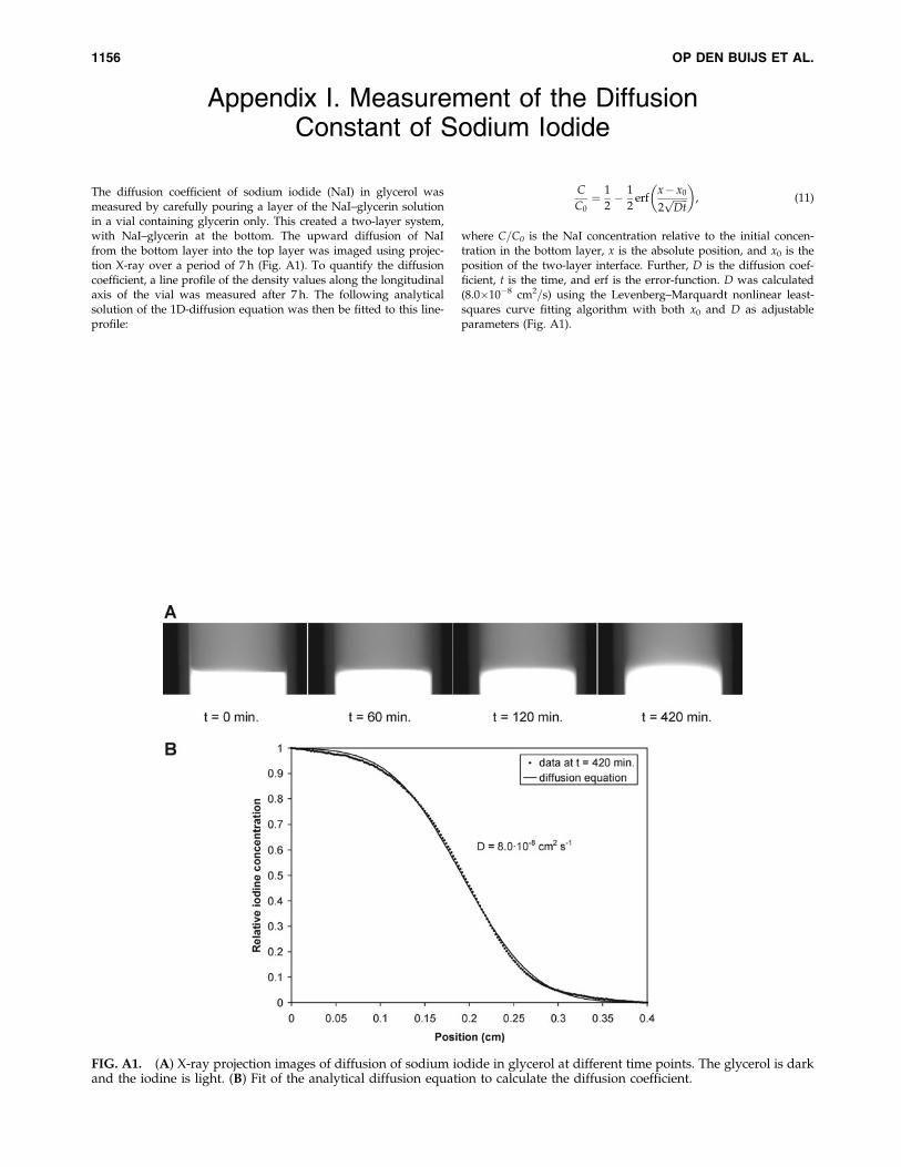
The diffusion coefficient of sodium iodide (NaI) in glycerol wasmeasured by carefully pouring a layer of the NaI–glycerin solutionin a vial containing glycerin only. This created a two-layer system,with NaI–glycerin at the bottom. The upward diffusion of NaIfrom the bottom layer into the top layer was imaged using projec-tion X-ray over a period of 7 h (Fig. A1). To quantify the diffusioncoefficient, a line profile of the density values along the longitudinalaxis of the vial was measured after 7 h. The following analyticalsolution of the 1D-diffusion equation was then be fitted to this line-profile:
C
C0¼ 1
2� 1
2erf
x� x0
2ffiffiffiffiffiffiDtp
� �, (11)
where C=C0 is the NaI concentration relative to the initial concen-tration in the bottom layer, x is the absolute position, and x0 is theposition of the two-layer interface. Further, D is the diffusion coef-ficient, t is the time, and erf is the error-function. D was calculated(8.0�10�8 cm2=s) using the Levenberg–Marquardt nonlinear least-squares curve fitting algorithm with both x0 and D as adjustableparameters (Fig. A1).
FIG. A1. (A) X-ray projection images of diffusion of sodium iodide in glycerol at different time points. The glycerol is darkand the iodine is light. (B) Fit of the analytical diffusion equation to calculate the diffusion coefficient.
1156 OP DEN BUIJS ET AL.