Validating Safety in Human–Robot Collaboration - MDPI
20
robotics Article Validating Safety in Human–Robot Collaboration: Standards and New Perspectives Marcello Valori 1, * , Adriano Scibilia 1 , Irene Fassi 1 , José Saenz 2 , Roland Behrens 2 , Sebastian Herbster 2 , Catherine Bidard 3 , Eric Lucet 3 , Alice Magisson 4 , Leendert Schaake 5 , Jule Bessler 5,6 , Gerdienke B. Prange-Lasonder 5,7 , Morten Kühnrich 8 , Aske B. Lassen 8 and Kurt Nielsen 8 Citation: Valori, M.; Scibilia, A.; Fassi, I.; Saenz, J.; Behrens, R.; Herbster, S.; Bidard, C.; Lucet, E.; Magisson, A.; Schaake, L.; et al. Validating Safety in Human–Robot Collaboration: Standards and New Perspectives. Robotics 2021, 10, 65. https://doi.org/10.3390/ robotics10020065 Academic Editor: Aman Behal Received: 15 February 2021 Accepted: 28 April 2021 Published: 29 April 2021 Publisher’s Note: MDPI stays neutral with regard to jurisdictional claims in published maps and institutional affil- iations. Copyright: © 2021 by the authors. Licensee MDPI, Basel, Switzerland. This article is an open access article distributed under the terms and conditions of the Creative Commons Attribution (CC BY) license (https:// creativecommons.org/licenses/by/ 4.0/). 1 Institute of Intelligent Industrial Technologies and Systems for Advanced Manufacturing, National Research Council of Italy, 20133 Milan, Italy; [email protected] (A.S.); [email protected] (I.F.) 2 Fraunhofer IFF, 39106 Magdeburg, Germany; [email protected] (J.S.); [email protected] (R.B.); [email protected] (S.H.) 3 Université Paris-Saclay, CEA List, F-91120 Palaiseau, France; [email protected] (C.B.); [email protected] (E.L.) 4 CEA, CEA Tech Grand Est, F-57075 Metz, France; [email protected] 5 Roessingh Research and Development, 7522 AH Enschede, The Netherlands; [email protected] (L.S.); [email protected] (J.B.); [email protected] (G.B.P.-L.) 6 Department of Biomedical Signals and Systems, University of Twente, 7522 NB Enschede, The Netherlands 7 Department of Biomechanical Engineering, University of Twente, 7522 NB Enschede, The Netherlands 8 Department of Robot Technology, Danish Technological Institute, 5230 Odense, Denmark; [email protected] (M.K.); [email protected] (A.B.L.); [email protected] (K.N.) * Correspondence: [email protected]; Tel.: +39-329-312-0837 Abstract: Human–robot collaboration is currently one of the frontiers of industrial robot implemen- tation. In parallel, the use of robots and robotic devices is increasing in several fields, substituting humans in “4D”—dull, dirty, dangerous, and delicate—tasks, and such a trend is boosted by the recent need for social distancing. New challenges in safety assessment and verification arise, due to both the closer and closer human–robot interaction, common for the different application domains, and the broadening of user audience, which is now very diverse. The present paper discusses a cross-domain approach towards the definition of step-by-step validation procedures for collaborative robotic applications. To outline the context, the standardization framework is analyzed, especially from the perspective of safety testing and assessment. Afterwards, some testing procedures based on safety skills, developed within the framework of the European project COVR, are discussed and exemplary presented. Keywords: robotic safety; collaborative robots; robot standards 1. Introduction The concept of human–robot collaboration (HRC), based on the synergic work of robots and humans, questions the traditional paradigm of physical barriers separating machines and workers, lowering fences and closing distances. This paradigm shift was enabled by two main technological factors: the integration of safety-related features in the robot architectures and control systems and the use of multi-modal interfaces for more intuitive, aware and safer human–robot interaction (HRI) [1,2]. Moreover, thanks to the advances in artificial intelligence, robots can adapt their tasks and behaviors, becoming suit- able to act in unstructured scenarios and interacting with unskilled and undertrained users. The statistics show that, in the last years, several robot fields are increasing their markets, such as: robots for domestic tasks, entertainment robots, logistic robots, robots for public environments, defense applications, inspection and maintenance robots, professional cleaning, field robots, powered human exoskeletons, medical robots, construction and demolition [3]. Focusing just on the medical and healthcare domain, a non-comprehensive Robotics 2021, 10, 65. https://doi.org/10.3390/robotics10020065 https://www.mdpi.com/journal/robotics
-
Upload
khangminh22 -
Category
Documents
-
view
1 -
download
0
Transcript of Validating Safety in Human–Robot Collaboration - MDPI
robotics
Article
Validating Safety in Human–Robot Collaboration: Standardsand New Perspectives
Marcello Valori 1,* , Adriano Scibilia 1, Irene Fassi 1 , José Saenz 2 , Roland Behrens 2, Sebastian Herbster 2,Catherine Bidard 3 , Eric Lucet 3 , Alice Magisson 4 , Leendert Schaake 5, Jule Bessler 5,6 ,Gerdienke B. Prange-Lasonder 5,7 , Morten Kühnrich 8, Aske B. Lassen 8 and Kurt Nielsen 8
�����������������
Citation: Valori, M.; Scibilia, A.;
Fassi, I.; Saenz, J.; Behrens, R.;
Herbster, S.; Bidard, C.; Lucet, E.;
Magisson, A.; Schaake, L.; et al.
Validating Safety in Human–Robot
Collaboration: Standards and New
Perspectives. Robotics 2021, 10, 65.
https://doi.org/10.3390/
robotics10020065
Academic Editor: Aman Behal
Received: 15 February 2021
Accepted: 28 April 2021
Published: 29 April 2021
Publisher’s Note: MDPI stays neutral
with regard to jurisdictional claims in
published maps and institutional affil-
iations.
Copyright: © 2021 by the authors.
Licensee MDPI, Basel, Switzerland.
This article is an open access article
distributed under the terms and
conditions of the Creative Commons
Attribution (CC BY) license (https://
creativecommons.org/licenses/by/
4.0/).
1 Institute of Intelligent Industrial Technologies and Systems for Advanced Manufacturing, National ResearchCouncil of Italy, 20133 Milan, Italy; [email protected] (A.S.); [email protected] (I.F.)
2 Fraunhofer IFF, 39106 Magdeburg, Germany; [email protected] (J.S.);[email protected] (R.B.); [email protected] (S.H.)
3 Université Paris-Saclay, CEA List, F-91120 Palaiseau, France; [email protected] (C.B.);[email protected] (E.L.)
4 CEA, CEA Tech Grand Est, F-57075 Metz, France; [email protected] Roessingh Research and Development, 7522 AH Enschede, The Netherlands; [email protected] (L.S.);
[email protected] (J.B.); [email protected] (G.B.P.-L.)6 Department of Biomedical Signals and Systems, University of Twente, 7522 NB Enschede, The Netherlands7 Department of Biomechanical Engineering, University of Twente, 7522 NB Enschede, The Netherlands8 Department of Robot Technology, Danish Technological Institute, 5230 Odense, Denmark;
[email protected] (M.K.); [email protected] (A.B.L.); [email protected] (K.N.)* Correspondence: [email protected]; Tel.: +39-329-312-0837
Abstract: Human–robot collaboration is currently one of the frontiers of industrial robot implemen-tation. In parallel, the use of robots and robotic devices is increasing in several fields, substitutinghumans in “4D”—dull, dirty, dangerous, and delicate—tasks, and such a trend is boosted by therecent need for social distancing. New challenges in safety assessment and verification arise, due toboth the closer and closer human–robot interaction, common for the different application domains,and the broadening of user audience, which is now very diverse. The present paper discusses across-domain approach towards the definition of step-by-step validation procedures for collaborativerobotic applications. To outline the context, the standardization framework is analyzed, especiallyfrom the perspective of safety testing and assessment. Afterwards, some testing procedures basedon safety skills, developed within the framework of the European project COVR, are discussed andexemplary presented.
Keywords: robotic safety; collaborative robots; robot standards
1. Introduction
The concept of human–robot collaboration (HRC), based on the synergic work ofrobots and humans, questions the traditional paradigm of physical barriers separatingmachines and workers, lowering fences and closing distances. This paradigm shift wasenabled by two main technological factors: the integration of safety-related features in therobot architectures and control systems and the use of multi-modal interfaces for moreintuitive, aware and safer human–robot interaction (HRI) [1,2]. Moreover, thanks to theadvances in artificial intelligence, robots can adapt their tasks and behaviors, becoming suit-able to act in unstructured scenarios and interacting with unskilled and undertrained users.
The statistics show that, in the last years, several robot fields are increasing theirmarkets, such as: robots for domestic tasks, entertainment robots, logistic robots, robots forpublic environments, defense applications, inspection and maintenance robots, professionalcleaning, field robots, powered human exoskeletons, medical robots, construction anddemolition [3]. Focusing just on the medical and healthcare domain, a non-comprehensive
Robotics 2021, 10, 65. https://doi.org/10.3390/robotics10020065 https://www.mdpi.com/journal/robotics
Robotics 2021, 10, 65 2 of 20
list includes: surgical robotics, boosting the transition from open surgery to laparoscopicand other minimally invasive surgical procedures [4]; bionic prostheses, enabling wearersto autonomously carry out their daily activities; the category of “RACA” robots, includ-ing a variety of devices, either wearable or static, to perform rehabilitation, assessment,compensation and alleviation (RACA); and caregiver robots, which are expected to play afundamental role in aging societies [5]. In the agri-food sector, autonomous mobile robotsprovided by navigation and perception technologies represent a breakthrough, with thepotential of performing mass phenotyping, crop management, and selective harvesting [6].
The importance of robots was underlined by the recent pandemic, as it is recognizedthat robot adoption can be extremely useful to support social distancing. Accordingly,robotic-assisted surgery has become a safe alternative, protecting the patient, the operatingteam, and saving resources for people with COVID-19 [7]. Due to their safe nature andpossibility of “learning from demonstration”, collaborative robots can be implementedas sterilizable physical mediators between patients and clinicians, for example, for massswabbing and physiotherapy treatments; at the same time, autonomous robots can per-form UV sterilization of the environments and optimize internal logistics of health fa-cilities [8]. Furthermore, from the perspective of social distancing, robotics can enablepandemic-sustainable travel, tourism and hospitality, performing environment sterilization,measuring body temperatures, welcoming and entertaining [9].
The aforementioned examples are characterized by different levels of HRI, spanningfrom teleoperation to workspace sharing and synergistic co-control. Taking a step back,one can observe that boundaries between industrial and service robotics are becomingblurred [10] and HRC is assuming a broader role, becoming applicable to a wide variety ofrobot applications in which the close interaction between human and robots is envisaged.However, the implementation of robots sharing space with humans, either to increaseproductivity rates, relieve us from heavy and repetitive tasks or mitigate certain hazardsources, always has to consider the mechanical hazards associated with HRC. Furthermore,the implementation and observance of safety is closely related to overall task performance,as safer interaction enables lower barriers and can help robots to reach their full potential.
In such a rapidly evolving landscape, in which industrial and service robotics be-come increasingly closer, identifying, interpreting and fulfilling the applicable standardsfor robot safety is critical. Based on the experience of the authors with robot end-users,manufacturers and integrators, the promotion of cobot technologies in different domainsis slowed down by the path towards ensuring safety. This is due to both the limitedknowledge about relevant standards and the absence of clear procedures to prove the com-pliance in these standards [11,12]. To address this need, a novel cross-domain validationapproach is proposed in this paper, based on testing procedures made available throughan online toolkit.
1.1. Safety in HRC
Increasing safety in collaborative robot operations is a goal pursued at differentlevels. Collaborative robots are intrinsically safer, but the implementation of externalsensing strategies further improves safety, and safety-related systems can be used to enableHRC with traditional robots [13]. The research community is addressing several issuesrelated to sensing, robot hardware and safeguarding measures; the main drivers concernincreasing the perception of both robots and humans, lowering the potential damagedue to mechanical features, control strategies or external protections, providing user-friendly programming strategies [1]. Aiming at increasing collaboration synergy and safety,human–robot interfacing can be enhanced by implementing different technologies, such asrobot integrated vision, voice recognition, head-mounted displays for augmented reality,haptic-based devices and even the detection of bio-signals [2].
Safety-related aspects have a relevant impact in the design of HRC application, ashazard identification, risk assessment and the identification of risk mitigation strategiesbecome even more crucial. In [14], a typical process is described, demonstrating that
Robotics 2021, 10, 65 3 of 20
an appropriate modeling of safety aspects can reduce both the design time and the finalworkspace required by the layout. In a recent review [15], it is shown how the researchoutputs concerning safety and ergonomics are increasing, in the last years, with the rise ofcollaborative robotics, identifying four main clusters of interest: contact avoidance, contactdetection and mitigation, physical ergonomics, cognitive and organizational ergonomics.Even if the two former categories are more widely addressed, the authors claim thatergonomic issues will play a major role when the advances in contact avoidance strategieswill push the limits of HRI, leading to a complementarity of these aspects towards safe andefficient HRC.
Concerning the evaluation of safety in HRC, some approaches use objective measuresto plan and evaluate the performance of applications featuring “speed and separationmonitoring” collaborative scenarios [16,17]. Unfortunately, they also demonstrate thedifficulties in identifying the point in time during a robot’s trajectory where a specificalgorithm is the least safe, requiring either a simulation or a test with the completed system.
Even if these approaches can provide a certain measure of the HRC safety, they are notaimed at the validation of robotic applications with reference to directives and standards.Furthermore, they are targeting robot experts dealing with HRC scenarios in the industrialdomain, while the ambition of the present work is to meet the needs of a diverse useraudience, operating in different domains with the potential for implementing cobots in awide range of tasks.
1.2. Paper Contribution
The risks related to an autonomous robot acting in a public environment are similarto the ones typical of a driverless mobile robot in industry. In the same way, similar riskscharacterize a manipulator for collaborative assembly and one implemented for delicatehealth diagnostic procedures. This leads the consideration that the specific safety-relatedtesting procedures could rely on a common base of knowledge and experience. It isalso worth observing that, even in the fields characterized by higher levels of expertise,close HRC brings new challenges for safety verification and validation. Accordingly, theanalogue hazards make the guidance for clear, step-by-step testing procedures a commonneed of both experienced and new users.
The aim of this paper is to outline emerging necessities and possible trends concerningsafety testing procedures for cobot applications, based on an overview of the landscapeof relevant standards for the validation of safety, and to describe a new cross-domainapproach based on safety skills and testing protocols. In this context, we refer to “safetyskills” as the capability of a robotic system to reduce a specific risk and to “protocols”as step-by-step instructions for executing validation measurements. It is a belief of theauthors, indeed, that clearer safety assessment processes allow cobots to be used with moreconfidence in more situations; this can be a valuable boost to increase the variety of cobotson the market and the variety of services cobots can offer to the general population. As aremark, the proposed protocols are not intended to substitute standards; they representinstead a tool to guide and facilitate the users in the identification of relevant standardsand their fulfillment.
The paper is organized as follows. In Section 2, the standard framework is addressed;building on the overview of all the relevant standards, some recent publications dealingwith detailed test procedures, are described and gaps with user needs are highlighted.Section 3 deals with the proposed cross-domain approach, which is based on the definitionof safety skills and the development of testing protocols, while in Section 4 some exemplarycases of protocol application are reported.
2. Robot Safety: The Regulatory Framework2.1. Overview
The main regulation in the European community dealing with robot safety is theMachinery Directive 2006/42/EC [18]. It is translated in all the national languages and
Robotics 2021, 10, 65 4 of 20
transposed into laws by each member country. A robot falls in the scope of the MachineryDirective, as it is composed of “linked parts or components, at least one of which moves”and being actuated by a drive system. A programmable robot supplied by a robot man-ufacturer is regarded by the Machinery Directive to be a “partly completed machinery”.This means that the robot itself is not CE-marked for Machinery Directive, but that all infor-mation needed by integrators to ensure safety is provided by the robot manufacturer. Tobe considered as a “completed” machinery, it must be designed or integrated for a specificapplication. In industrial robotics, the concept of machinery applies to robotics applicationsor robotic cells and whereby the integrator is considered to be the manufacturer. In otherfields, such as robots for consumers, assistive robotics or medical robotics, the intendeduse must be clearly defined.
The Medical Device Regulation EU 2017/745 [19] applies to rehabilitation and, moregenerally, to healthcare-related activities. It replaced the Medical Device Directive, whichfocused mainly on the design of the system, providing more safety considerations overthe entire device lifetime [20]. The Medical Device certification is strongly based on an“intended use” and valid only for this “intended use” for which clinical evidence mustbe provided. So, in accordance with the Machinery Directive, a generic robot without hisspecific application cannot be certified. It is worth noting that, for a robotic medical device,the Machinery Directive must also be observed. Other directives may apply depending onthe field of use, such as the General Product Safety Directive [21], when a robotic deviceis made available on the consumer market, or a type-approval regulation when a robotbecomes a vehicle (this category is outside the scope of this paper). Finally, there are moregeneral relevant directives, such as the Low Voltage Directive [22], the ElectromagneticCompatibility Directive [23], and the Radio Equipment Directive [24].
Standards are technical reference documents, representing the consensus on the stateof the art and compliance to them is not mandatory. Technical committees (TCs) are incharge of developing standards and the main committee within ISO for industrial andservice robotics (excluding toys and military applications) is the ISO TC 299 “Robotics”.Robotics ISO standards from this group mainly address vocabulary, performance and safety.Concerning safety, they describe solutions gathering a certain level of consensus within thespecific community. Indeed, robot manufacturers typically take part in standardizationcommittees, along with integrators, end-users and stakeholders representing public healthand health insurance. “Harmonized” standards are recognized by a European standardorganization as fully compliant with the relevant directive or regulation; thus, their appli-cation provides the so-called “presumption of conformity”. The most relevant standardsfor robot safety from the perspective of HRC are listed in Table 1.
Safety standards are categorized into: type A, providing the basic design principlesand valid for all machines; type B, which are generic standards concerning either specificaspects of safety or devices for safeguarding; and type C, covering particular classes ofmachines (i.e., robots) and having precedence over type A and B. Accordingly, for robotsbelonging to the categories of industrial robots or personal care robots, type C standardsare the main reference. The list reported in Table 1 is not comprehensive of all the robotics-relevant type B standards, as it is limited to standards dealing with HRC, either explicitlyor not. An up-to-date list of all the robotic standards, which can be filtered by applicationdomain and device type, can be found in COVR Toolkit [25].
The Machinery Directive sets out the “Essential health and safety requirements relatingto the design and construction of machinery”. Fulfilling these requirements is based onan “iterative process of risk assessment and risk reduction” for which one can rely onthe standard ISO 12100 [26] (type A). It should be noted that the medical device safety isaddressed by a dedicated standard for risk management, the ISO 14971 [27]. The MachineryDirective promotes the integration of safety in all design stages, giving priority to inherentsafety, followed by protective measures, and, lastly, by organizational measures, such asuser training and personal protective equipment.
Robotics 2021, 10, 65 5 of 20
The ISO 10218 is a type C standard for industrial robotics, divided into two parts:the first [28] dealing with robots considered as “partly completed machinery” and thesecond [29] addressing integrated applications, which are the machineries to be consideredin compliance with the Machinery Directive. Even though harmful HRI had already beenaddressed in the first versions, intended physical interaction has been introduced in 2009in both 10218-1 and -2, by describing “hand-guiding” (HG) and “power and force limiting”(PFL) operating modes. The possibility to avoid safeguards by the use of distance sensingwas introduced with “safety-rated monitored stop” (SRMS) and “speed and separationmonitoring” (SSM). The safety requirements for these collaborative modalities are currentlyunder development for the upcoming revision of ISO 10218 (to be published in 2022), aswill be addressed in the following paragraph.
Technical specifications (TS) and technical reports (TR) are different ISO deliverables.TS address work still under development but with a chance to be included in an interna-tional standard, while TR contain other kinds of information, for example, the perceivedstate of the art of a specific topic. ISO/TS 15066 [30] represented a milestone among HRCstandardization. Besides including information regarding collaborative robot system de-sign, hazard identification, risk assessment and the requirements for the applications, itprovides a more detailed description of the collaborative modes SRSM, SRSS, PFL, HG andlimit values for quasi-static and transient contact forces are illustrated.
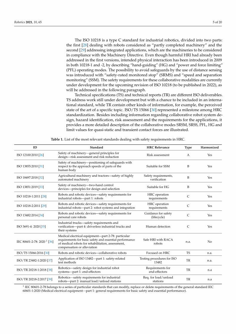
Table 1. List of the most relevant standards dealing with safety requirements in HRC.
ID Standard HRC Relevance Type Harmonized
ISO 12100:2010 [26] Safety of machinery—general principles fordesign—risk assessment and risk reduction Risk assessment A Yes
ISO 13855:2010 [31]Safety of machinery—positioning of safeguards withrespect to the approach speeds of parts of thehuman body
Suitable for SSM B Yes
ISO 18497:2018 [32] Agricultural machinery and tractors—safety of highlyautomated machinery
Safety requirements,verification B Yes
ISO 13851:2019 [33] Safety of machinery—two-hand controldevices—principles for design and selection Suitable for HG B Yes
ISO 10218-1:2011 [28] Robots and robotic devices—safety requirements forindustrial robots—part 1: robots
HRC operationrequirements C Yes
ISO 10218-2:2011 [29] Robots and robotic devices—safety requirements forindustrial robots—part 2: robot systems and integration
HRC operationrequirements C Yes
ISO 13482:2014 [34] Robots and robotic devices—safety requirements forpersonal care robots
Guidance for safety(lifecycle) C Yes
ISO 3691-4: 2020 [35]Industrial trucks—safety requirements andverification—part 4: driverless industrial trucks andtheir systems
Human detection C Yes
IEC 80601-2-78: 2020 1 [36]
Medical electrical equipment—part 2-78: particularrequirements for basic safety and essential performanceof medical robots for rehabilitation, assessment,compensation or alleviation
Safe HRI with RACArobots n.a. No
ISO/TS 15066:2016 [30] Robots and robotic devices—collaborative robots Focused on HRC TS n.a.
ISO/TR 23482-1:2020 [37] Application of ISO 13482—part 1: safety-relatedtest methods
Testing procedures for ISO13482 TR n.a.
ISO/TR 20218-1:2018 [38] Robotics—safety design for industrial robotsystems—part 1: end-effectors
Requirements forend-effectors TR n.a
ISO/TR 20218-2:2017 [39] Robotics—safety requirements for industrialrobots—part 2: manual load/unload stations
Req. for load/unloadstations TR n.a
1 IEC 80601-2-78 belongs to a series of particular standards that can modify, replace or delete requirements of the general standard IEC60601-1:2020 (Medical electrical equipment—part 1: general requirements for basic safety and essential performance).
Robotics 2021, 10, 65 6 of 20
2.2. A New Trend in Standardization?
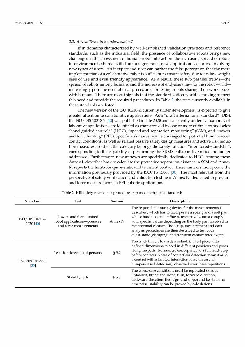
If in domains characterized by well-established validation practices and referencestandards, such as the industrial field, the presence of collaborative robots brings newchallenges in the assessment of human–robot interaction, the increasing spread of robotsin environments shared with humans generates new application scenarios, involvingnew types of users. An inexpert end-user can harbor the false perception that the mereimplementation of a collaborative robot is sufficient to ensure safety, due to its low weight,ease of use and even friendly appearance. As a result, these two parallel trends—thespread of robots among humans and the increase of end-users new to the robot world—increasingly pose the need of clear procedures for testing robots sharing their workspaceswith humans. There are recent signals that the standardization world is moving to meetthis need and provide the required procedures. In Table 2, the tests currently available inthese standards are listed.
The new version of the ISO 10218-2, currently under development, is expected to givegreater attention to collaborative applications. As a “draft international standard” (DIS),the ISO/DIS 10218-2 [40] was published in late 2020 and is currently under evaluation. Col-laborative applications are identified as characterized by one or more of three technologies:“hand-guided controls” (HGC), “speed and separation monitoring” (SSM), and “powerand force limiting” (PFL). Specific risk assessment is envisaged for potential human–robotcontact conditions, as well as related passive safety design measures and active risk reduc-tion measures. To the latter category belongs the safety function “monitored-standstill”,corresponding to the capability of performing the SRMS collaborative mode, no longeraddressed. Furthermore, new annexes are specifically dedicated to HRC. Among these,Annex L describes how to calculate the protective separation distance in SSM and AnnexM reports the limits for quasi-static and transient contact. These annexes incorporate theinformation previously provided by the ISO/TS 15066 [30]. The most relevant from theperspective of safety verification and validation testing is Annex N, dedicated to pressureand force measurements in PFL robotic applications.
Table 2. HRI safety-related test procedures reported in the cited standards.
Standard Test Section Description
ISO/DIS 10218-2:2020 [40]
Power- and force-limitedrobot applications—pressure
and force measurementsAnnex N
The required measuring device for the measurements isdescribed, which has to incorporate a spring and a soft pad,whose hardness and stiffness, respectively, must complywith specific values depending on the body part involved inthe potential contact. The setup, measurement and dataanalysis procedures are then described to test bothquasi-static (clamping) and transient contact force events.
ISO 3691-4: 2020[35]
Tests for detection of persons § 5.2
The truck travels towards a cylindrical test piece withdefined dimensions, placed in different positions and posesalong the path. Test success corresponds to a full truck stopbefore contact (in case of contactless detection means) or toa contact with a limited interaction force (in case ofbumper-based detection), observed over three repetitions.
Stability tests § 5.3
The worst-case conditions must be replicated (loaded,unloaded, lift height, slope, turn, forward direction,backward direction, floor/ground slope) and be stable, orotherwise, stability can be proved by calculations.
Robotics 2021, 10, 65 7 of 20
Table 2. Cont.
Standard Test Section Description
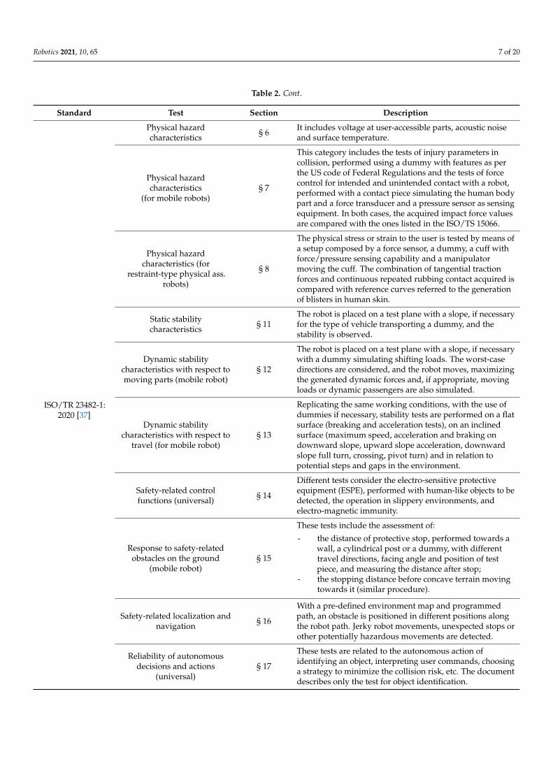
ISO/TR 23482-1:2020 [37]
Physical hazardcharacteristics § 6 It includes voltage at user-accessible parts, acoustic noise
and surface temperature.
Physical hazardcharacteristics
(for mobile robots)§ 7
This category includes the tests of injury parameters incollision, performed using a dummy with features as perthe US code of Federal Regulations and the tests of forcecontrol for intended and unintended contact with a robot,performed with a contact piece simulating the human bodypart and a force transducer and a pressure sensor as sensingequipment. In both cases, the acquired impact force valuesare compared with the ones listed in the ISO/TS 15066.
Physical hazardcharacteristics (for
restraint-type physical ass.robots)
§ 8
The physical stress or strain to the user is tested by means ofa setup composed by a force sensor, a dummy, a cuff withforce/pressure sensing capability and a manipulatormoving the cuff. The combination of tangential tractionforces and continuous repeated rubbing contact acquired iscompared with reference curves referred to the generationof blisters in human skin.
Static stabilitycharacteristics § 11
The robot is placed on a test plane with a slope, if necessaryfor the type of vehicle transporting a dummy, and thestability is observed.
Dynamic stabilitycharacteristics with respect tomoving parts (mobile robot)
§ 12
The robot is placed on a test plane with a slope, if necessarywith a dummy simulating shifting loads. The worst-casedirections are considered, and the robot moves, maximizingthe generated dynamic forces and, if appropriate, movingloads or dynamic passengers are also simulated.
Dynamic stabilitycharacteristics with respect to
travel (for mobile robot)§ 13
Replicating the same working conditions, with the use ofdummies if necessary, stability tests are performed on a flatsurface (breaking and acceleration tests), on an inclinedsurface (maximum speed, acceleration and braking ondownward slope, upward slope acceleration, downwardslope full turn, crossing, pivot turn) and in relation topotential steps and gaps in the environment.
Safety-related controlfunctions (universal) § 14
Different tests consider the electro-sensitive protectiveequipment (ESPE), performed with human-like objects to bedetected, the operation in slippery environments, andelectro-magnetic immunity.
Response to safety-relatedobstacles on the ground
(mobile robot)§ 15
These tests include the assessment of:
- the distance of protective stop, performed towards awall, a cylindrical post or a dummy, with differenttravel directions, facing angle and position of testpiece, and measuring the distance after stop;
- the stopping distance before concave terrain movingtowards it (similar procedure).
Safety-related localization andnavigation § 16
With a pre-defined environment map and programmedpath, an obstacle is positioned in different positions alongthe robot path. Jerky robot movements, unexpected stops orother potentially hazardous movements are detected.
Reliability of autonomousdecisions and actions
(universal)§ 17
These tests are related to the autonomous action ofidentifying an object, interpreting user commands, choosinga strategy to minimize the collision risk, etc. The documentdescribes only the test for object identification.
Robotics 2021, 10, 65 8 of 20
Table 2. Cont.
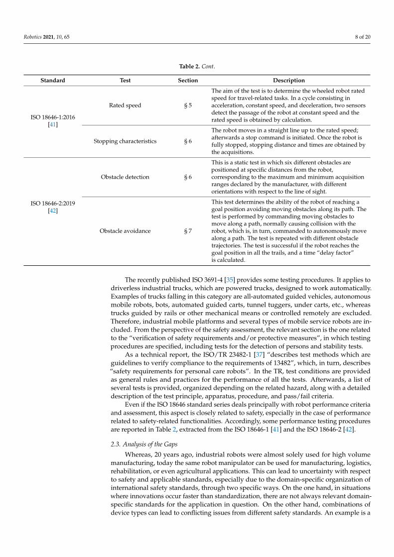
Standard Test Section Description
ISO 18646-1:2016[41]
Rated speed § 5
The aim of the test is to determine the wheeled robot ratedspeed for travel-related tasks. In a cycle consisting inacceleration, constant speed, and deceleration, two sensorsdetect the passage of the robot at constant speed and therated speed is obtained by calculation.
Stopping characteristics § 6
The robot moves in a straight line up to the rated speed;afterwards a stop command is initiated. Once the robot isfully stopped, stopping distance and times are obtained bythe acquisitions.
ISO 18646-2:2019[42]
Obstacle detection § 6
This is a static test in which six different obstacles arepositioned at specific distances from the robot,corresponding to the maximum and minimum acquisitionranges declared by the manufacturer, with differentorientations with respect to the line of sight.
Obstacle avoidance § 7
This test determines the ability of the robot of reaching agoal position avoiding moving obstacles along its path. Thetest is performed by commanding moving obstacles tomove along a path, normally causing collision with therobot, which is, in turn, commanded to autonomously movealong a path. The test is repeated with different obstacletrajectories. The test is successful if the robot reaches thegoal position in all the trails, and a time “delay factor”is calculated.
The recently published ISO 3691-4 [35] provides some testing procedures. It applies todriverless industrial trucks, which are powered trucks, designed to work automatically.Examples of trucks falling in this category are all-automated guided vehicles, autonomousmobile robots, bots, automated guided carts, tunnel tuggers, under carts, etc., whereastrucks guided by rails or other mechanical means or controlled remotely are excluded.Therefore, industrial mobile platforms and several types of mobile service robots are in-cluded. From the perspective of the safety assessment, the relevant section is the one relatedto the “verification of safety requirements and/or protective measures”, in which testingprocedures are specified, including tests for the detection of persons and stability tests.
As a technical report, the ISO/TR 23482-1 [37] “describes test methods which areguidelines to verify compliance to the requirements of 13482”, which, in turn, describes“safety requirements for personal care robots”. In the TR, test conditions are providedas general rules and practices for the performance of all the tests. Afterwards, a list ofseveral tests is provided, organized depending on the related hazard, along with a detaileddescription of the test principle, apparatus, procedure, and pass/fail criteria.
Even if the ISO 18646 standard series deals principally with robot performance criteriaand assessment, this aspect is closely related to safety, especially in the case of performancerelated to safety-related functionalities. Accordingly, some performance testing proceduresare reported in Table 2, extracted from the ISO 18646-1 [41] and the ISO 18646-2 [42].
2.3. Analysis of the Gaps
Whereas, 20 years ago, industrial robots were almost solely used for high volumemanufacturing, today the same robot manipulator can be used for manufacturing, logistics,rehabilitation, or even agricultural applications. This can lead to uncertainty with respectto safety and applicable standards, especially due to the domain-specific organization ofinternational safety standards, through two specific ways. On the one hand, in situationswhere innovations occur faster than standardization, there are not always relevant domain-specific standards for the application in question. On the other hand, combinations ofdevice types can lead to conflicting issues from different safety standards. An example is a
Robotics 2021, 10, 65 9 of 20
mobile platform equipped with a robot manipulator. The forces specified during contactare different when considering an industrial manipulator (in the ISO/TS 15066 [30]) oran autonomous truck (ISO 3691-4 [35]). Further challenges arise when considering whatseparation distances to apply, as the ISO/TS15066 [30] also specifies that the approachspeed of humans needs to be taken into account, whereas the ISO 3691-4 [35] does not.
While adherence to standards is not legally binding, they do represent the state ofthe art and can be extremely helpful for considering the safety of collaborative roboticsapplications. A streamlined approach that offers robotics stakeholders the means to con-ceptually talk about the safety of their system, regardless of the specific domain, would behelpful here. Furthermore, it would be extremely helpful to the robotics community if thesame approach were to extend to methods for validating the implemented risk reductionmeasures. This approach should, however, respect the fact that there are a wide variety oftechnical means available for implementing the safety.
3. Safety Skills and Testing Protocols in a Cross-Domain Perspective
In the consolidated practice, boundaries between different robotic domains are well-defined and recognized. One typical example is that HRI with robotic medical devices canalso generate physical benefits, balancing the risks associated to their operation, while thisis not applicable for other types of robots. However, this approach can represent a limitwhen similar hazards have to be addressed in different domains; in these cases, indeed,cross-domain fertilization can provide an extra gear to define the best practices for theverification of safety requirements. This section proposes a safety verification approachbased on the definition of cross-domain safety skills and the development of testingprotocols, drafted on the basis of practical needs and updated by expert consultations andby the examination and addressment of real application cases. In Section 3.1, the safety skillconcept and the skill-based approach is described, whereas the testing protocol structureand the list of the protocols are addressed in Section 3.2.
3.1. The Skill-Based Approach
When considering the safety of collaborative robotic systems, it is essential to startwith a risk assessment, whereby hazards specific to a concrete application are identifiedand risk reduction measures (RRM) are chosen. The operation methods for collaborativerobotics applications, such as the SRMS, SSM, PFL, HG, as currently defined by the ISO10218, can be implemented through a variety of technical means and offer the planner alevel of abstraction to discuss and consider the safety of the application. These definitionsmay become challenging when other device types and domains rather than manufacturingare considered, such as industrial robotics for rehabilitation or mobile robots for agriculture.
To overcome this challenge, the concept of safety skills has been proposed in [43].Safety skills are defined as an abstract representation of the ability of the robot systemto reduce some risk, i.e., to deploy suitable RRM. The implementation of the protectivemeasure can be executed in a number of ways. A safety skill therefore indicates whatkind of protection is desired and is independent of the execution of how this protection isdelivered. A further characteristic of safety skills is that they can be validated for specificapplications at a system level.
A two-pronged approach towards the definition of cross-domain safety skills wasapplied. In addition to an identification of existing operating modes from available stan-dards, an analysis of possible hazards and risk reduction methods for a large variety ofapplications featuring a combination of different robotic device types for six domains (man-ufacturing, rehabilitation, agriculture, civil, logistics, and consumer/home) was executed.While the latter analysis was quite large, it cannot be considered comprehensive, as roboticsare increasingly being used for new applications in an even wider variety of domainsthan those analyzed. Nevertheless, the concept of cross-domain safety skills is explicitlyconceived to deal with the novelty of future robotics applications and provide guidance
Robotics 2021, 10, 65 10 of 20
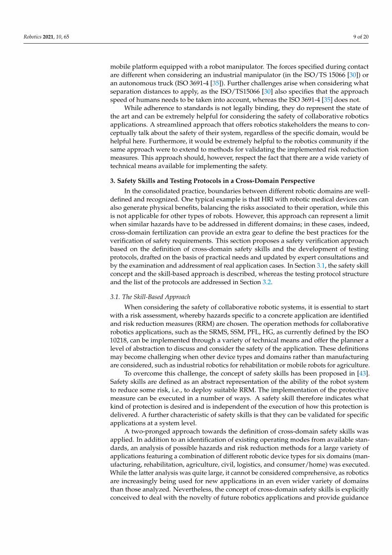
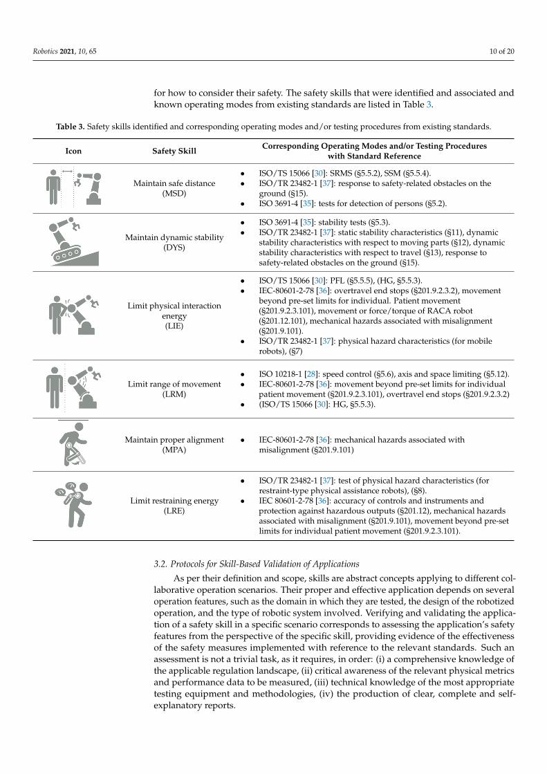
for how to consider their safety. The safety skills that were identified and associated andknown operating modes from existing standards are listed in Table 3.
Table 3. Safety skills identified and corresponding operating modes and/or testing procedures from existing standards.
Icon Safety Skill Corresponding Operating Modes and/or Testing Procedureswith Standard Reference
Robotics 2021, 10, x FOR PEER REVIEW 9 of 19
A two-pronged approach towards the definition of cross-domain safety skills was applied. In addition to an identification of existing operating modes from available stand-ards, an analysis of possible hazards and risk reduction methods for a large variety of applications featuring a combination of different robotic device types for six domains (manufacturing, rehabilitation, agriculture, civil, logistics, and consumer/home) was exe-cuted. While the latter analysis was quite large, it cannot be considered comprehensive, as robotics are increasingly being used for new applications in an even wider variety of domains than those analyzed. Nevertheless, the concept of cross-domain safety skills is explicitly conceived to deal with the novelty of future robotics applications and provide guidance for how to consider their safety. The safety skills that were identified and asso-ciated and known operating modes from existing standards are listed in Table 3.
Table 3. Safety skills identified and corresponding operating modes and/or testing procedures from existing standards.
Icon Safety Skill Corresponding Operating Modes and/or Testing Procedures with Standard Reference
Maintain safe dis-tance
(MSD)
• ISO/TS 15066 [30]: SRMS (§5.5.2), SSM (§5.5.4). • ISO/TR 23482-1 [37]: response to safety-related obstacles on the ground (§15). • ISO 3691-4 [35]: tests for detection of persons (§5.2).
Maintain dynamic stability (DYS)
• ISO 3691-4 [35]: stability tests (§5.3). • ISO/TR 23482-1 [37]: static stability characteristics (§11), dynamic stability characteris-
tics with respect to moving parts (§12), dynamic stability characteristics with respect to travel (§13), response to safety-related obstacles on the ground (§15).
Limit physical inter-action energy
(LIE)
• ISO/TS 15066 [30]: PFL (§5.5.5), (HG, §5.5.3). • IEC-80601-2-78 [36]: overtravel end stops (§201.9.2.3.2), movement beyond pre-set
limits for individual. Patient movement (§201.9.2.3.101), movement or force/torque of RACA robot (§201.12.101), mechanical hazards associated with misalignment (§201.9.101).
• ISO/TR 23482-1 [37]: physical hazard characteristics (for mobile robots), (§7)
Limit range of move-ment
(LRM)
• ISO 10218-1 [28]: speed control (§5.6), axis and space limiting (§5.12). • IEC-80601-2-78 [36]: movement beyond pre-set limits for individual patient move-
ment (§201.9.2.3.101), overtravel end stops (§201.9.2.3.2) • (ISO/TS 15066 [30]: HG, §5.5.3).
Maintain proper alignment (MPA)
• IEC-80601-2-78 [36]: mechanical hazards associated with misalignment (§201.9.101)
Limit restraining en-ergy
(LRE)
• ISO/TR 23482-1 [37]: test of physical hazard characteristics (for restraint-type physical assistance robots), (§8).
• IEC 80601-2-78 [36]: accuracy of controls and instruments and protection against haz-ardous outputs (§201.12), mechanical hazards associated with misalignment (§201.9.101), movement beyond pre-set limits for individual patient movement (§201.9.2.3.101).
3.2. Protocols for Skill-Based Validation of Applications As per their definition and scope, skills are abstract concepts applying to different
collaborative operation scenarios. Their proper and effective application depends on sev-eral operation features, such as the domain in which they are tested, the design of the robotized operation, and the type of robotic system involved. Verifying and validating the application of a safety skill in a specific scenario corresponds to assessing the application’s safety features from the perspective of the specific skill, providing evidence of the effec-tiveness of the safety measures implemented with reference to the relevant standards.
Maintain safe distance(MSD)
• ISO/TS 15066 [30]: SRMS (§5.5.2), SSM (§5.5.4).• ISO/TR 23482-1 [37]: response to safety-related obstacles on the
ground (§15).• ISO 3691-4 [35]: tests for detection of persons (§5.2).
Robotics 2021, 10, x FOR PEER REVIEW 9 of 19
A two-pronged approach towards the definition of cross-domain safety skills was applied. In addition to an identification of existing operating modes from available stand-ards, an analysis of possible hazards and risk reduction methods for a large variety of applications featuring a combination of different robotic device types for six domains (manufacturing, rehabilitation, agriculture, civil, logistics, and consumer/home) was exe-cuted. While the latter analysis was quite large, it cannot be considered comprehensive, as robotics are increasingly being used for new applications in an even wider variety of domains than those analyzed. Nevertheless, the concept of cross-domain safety skills is explicitly conceived to deal with the novelty of future robotics applications and provide guidance for how to consider their safety. The safety skills that were identified and asso-ciated and known operating modes from existing standards are listed in Table 3.
Table 3. Safety skills identified and corresponding operating modes and/or testing procedures from existing standards.
Icon Safety Skill Corresponding Operating Modes and/or Testing Procedures with Standard Reference
Maintain safe dis-tance
(MSD)
• ISO/TS 15066 [30]: SRMS (§5.5.2), SSM (§5.5.4). • ISO/TR 23482-1 [37]: response to safety-related obstacles on the ground (§15). • ISO 3691-4 [35]: tests for detection of persons (§5.2).
Maintain dynamic stability (DYS)
• ISO 3691-4 [35]: stability tests (§5.3). • ISO/TR 23482-1 [37]: static stability characteristics (§11), dynamic stability characteris-
tics with respect to moving parts (§12), dynamic stability characteristics with respect to travel (§13), response to safety-related obstacles on the ground (§15).
Limit physical inter-action energy
(LIE)
• ISO/TS 15066 [30]: PFL (§5.5.5), (HG, §5.5.3). • IEC-80601-2-78 [36]: overtravel end stops (§201.9.2.3.2), movement beyond pre-set
limits for individual. Patient movement (§201.9.2.3.101), movement or force/torque of RACA robot (§201.12.101), mechanical hazards associated with misalignment (§201.9.101).
• ISO/TR 23482-1 [37]: physical hazard characteristics (for mobile robots), (§7)
Limit range of move-ment
(LRM)
• ISO 10218-1 [28]: speed control (§5.6), axis and space limiting (§5.12). • IEC-80601-2-78 [36]: movement beyond pre-set limits for individual patient move-
ment (§201.9.2.3.101), overtravel end stops (§201.9.2.3.2) • (ISO/TS 15066 [30]: HG, §5.5.3).
Maintain proper alignment (MPA)
• IEC-80601-2-78 [36]: mechanical hazards associated with misalignment (§201.9.101)
Limit restraining en-ergy
(LRE)
• ISO/TR 23482-1 [37]: test of physical hazard characteristics (for restraint-type physical assistance robots), (§8).
• IEC 80601-2-78 [36]: accuracy of controls and instruments and protection against haz-ardous outputs (§201.12), mechanical hazards associated with misalignment (§201.9.101), movement beyond pre-set limits for individual patient movement (§201.9.2.3.101).
3.2. Protocols for Skill-Based Validation of Applications As per their definition and scope, skills are abstract concepts applying to different
collaborative operation scenarios. Their proper and effective application depends on sev-eral operation features, such as the domain in which they are tested, the design of the robotized operation, and the type of robotic system involved. Verifying and validating the application of a safety skill in a specific scenario corresponds to assessing the application’s safety features from the perspective of the specific skill, providing evidence of the effec-tiveness of the safety measures implemented with reference to the relevant standards.
Maintain dynamic stability(DYS)
• ISO 3691-4 [35]: stability tests (§5.3).• ISO/TR 23482-1 [37]: static stability characteristics (§11), dynamic
stability characteristics with respect to moving parts (§12), dynamicstability characteristics with respect to travel (§13), response tosafety-related obstacles on the ground (§15).
Robotics 2021, 10, x FOR PEER REVIEW 9 of 19
A two-pronged approach towards the definition of cross-domain safety skills was applied. In addition to an identification of existing operating modes from available stand-ards, an analysis of possible hazards and risk reduction methods for a large variety of applications featuring a combination of different robotic device types for six domains (manufacturing, rehabilitation, agriculture, civil, logistics, and consumer/home) was exe-cuted. While the latter analysis was quite large, it cannot be considered comprehensive, as robotics are increasingly being used for new applications in an even wider variety of domains than those analyzed. Nevertheless, the concept of cross-domain safety skills is explicitly conceived to deal with the novelty of future robotics applications and provide guidance for how to consider their safety. The safety skills that were identified and asso-ciated and known operating modes from existing standards are listed in Table 3.
Table 3. Safety skills identified and corresponding operating modes and/or testing procedures from existing standards.
Icon Safety Skill Corresponding Operating Modes and/or Testing Procedures with Standard Reference
Maintain safe dis-tance
(MSD)
• ISO/TS 15066 [30]: SRMS (§5.5.2), SSM (§5.5.4). • ISO/TR 23482-1 [37]: response to safety-related obstacles on the ground (§15). • ISO 3691-4 [35]: tests for detection of persons (§5.2).
Maintain dynamic stability (DYS)
• ISO 3691-4 [35]: stability tests (§5.3). • ISO/TR 23482-1 [37]: static stability characteristics (§11), dynamic stability characteris-
tics with respect to moving parts (§12), dynamic stability characteristics with respect to travel (§13), response to safety-related obstacles on the ground (§15).
Limit physical inter-action energy
(LIE)
• ISO/TS 15066 [30]: PFL (§5.5.5), (HG, §5.5.3). • IEC-80601-2-78 [36]: overtravel end stops (§201.9.2.3.2), movement beyond pre-set
limits for individual. Patient movement (§201.9.2.3.101), movement or force/torque of RACA robot (§201.12.101), mechanical hazards associated with misalignment (§201.9.101).
• ISO/TR 23482-1 [37]: physical hazard characteristics (for mobile robots), (§7)
Limit range of move-ment
(LRM)
• ISO 10218-1 [28]: speed control (§5.6), axis and space limiting (§5.12). • IEC-80601-2-78 [36]: movement beyond pre-set limits for individual patient move-
ment (§201.9.2.3.101), overtravel end stops (§201.9.2.3.2) • (ISO/TS 15066 [30]: HG, §5.5.3).
Maintain proper alignment (MPA)
• IEC-80601-2-78 [36]: mechanical hazards associated with misalignment (§201.9.101)
Limit restraining en-ergy
(LRE)
• ISO/TR 23482-1 [37]: test of physical hazard characteristics (for restraint-type physical assistance robots), (§8).
• IEC 80601-2-78 [36]: accuracy of controls and instruments and protection against haz-ardous outputs (§201.12), mechanical hazards associated with misalignment (§201.9.101), movement beyond pre-set limits for individual patient movement (§201.9.2.3.101).
3.2. Protocols for Skill-Based Validation of Applications As per their definition and scope, skills are abstract concepts applying to different
collaborative operation scenarios. Their proper and effective application depends on sev-eral operation features, such as the domain in which they are tested, the design of the robotized operation, and the type of robotic system involved. Verifying and validating the application of a safety skill in a specific scenario corresponds to assessing the application’s safety features from the perspective of the specific skill, providing evidence of the effec-tiveness of the safety measures implemented with reference to the relevant standards.
Limit physical interactionenergy(LIE)
• ISO/TS 15066 [30]: PFL (§5.5.5), (HG, §5.5.3).• IEC-80601-2-78 [36]: overtravel end stops (§201.9.2.3.2), movement
beyond pre-set limits for individual. Patient movement(§201.9.2.3.101), movement or force/torque of RACA robot(§201.12.101), mechanical hazards associated with misalignment(§201.9.101).
• ISO/TR 23482-1 [37]: physical hazard characteristics (for mobilerobots), (§7)
Robotics 2021, 10, x FOR PEER REVIEW 9 of 19
A two-pronged approach towards the definition of cross-domain safety skills was applied. In addition to an identification of existing operating modes from available stand-ards, an analysis of possible hazards and risk reduction methods for a large variety of applications featuring a combination of different robotic device types for six domains (manufacturing, rehabilitation, agriculture, civil, logistics, and consumer/home) was exe-cuted. While the latter analysis was quite large, it cannot be considered comprehensive, as robotics are increasingly being used for new applications in an even wider variety of domains than those analyzed. Nevertheless, the concept of cross-domain safety skills is explicitly conceived to deal with the novelty of future robotics applications and provide guidance for how to consider their safety. The safety skills that were identified and asso-ciated and known operating modes from existing standards are listed in Table 3.
Table 3. Safety skills identified and corresponding operating modes and/or testing procedures from existing standards.
Icon Safety Skill Corresponding Operating Modes and/or Testing Procedures with Standard Reference
Maintain safe dis-tance
(MSD)
• ISO/TS 15066 [30]: SRMS (§5.5.2), SSM (§5.5.4). • ISO/TR 23482-1 [37]: response to safety-related obstacles on the ground (§15). • ISO 3691-4 [35]: tests for detection of persons (§5.2).
Maintain dynamic stability (DYS)
• ISO 3691-4 [35]: stability tests (§5.3). • ISO/TR 23482-1 [37]: static stability characteristics (§11), dynamic stability characteris-
tics with respect to moving parts (§12), dynamic stability characteristics with respect to travel (§13), response to safety-related obstacles on the ground (§15).
Limit physical inter-action energy
(LIE)
• ISO/TS 15066 [30]: PFL (§5.5.5), (HG, §5.5.3). • IEC-80601-2-78 [36]: overtravel end stops (§201.9.2.3.2), movement beyond pre-set
limits for individual. Patient movement (§201.9.2.3.101), movement or force/torque of RACA robot (§201.12.101), mechanical hazards associated with misalignment (§201.9.101).
• ISO/TR 23482-1 [37]: physical hazard characteristics (for mobile robots), (§7)
Limit range of move-ment
(LRM)
• ISO 10218-1 [28]: speed control (§5.6), axis and space limiting (§5.12). • IEC-80601-2-78 [36]: movement beyond pre-set limits for individual patient move-
ment (§201.9.2.3.101), overtravel end stops (§201.9.2.3.2) • (ISO/TS 15066 [30]: HG, §5.5.3).
Maintain proper alignment (MPA)
• IEC-80601-2-78 [36]: mechanical hazards associated with misalignment (§201.9.101)
Limit restraining en-ergy
(LRE)
• ISO/TR 23482-1 [37]: test of physical hazard characteristics (for restraint-type physical assistance robots), (§8).
• IEC 80601-2-78 [36]: accuracy of controls and instruments and protection against haz-ardous outputs (§201.12), mechanical hazards associated with misalignment (§201.9.101), movement beyond pre-set limits for individual patient movement (§201.9.2.3.101).
3.2. Protocols for Skill-Based Validation of Applications As per their definition and scope, skills are abstract concepts applying to different
collaborative operation scenarios. Their proper and effective application depends on sev-eral operation features, such as the domain in which they are tested, the design of the robotized operation, and the type of robotic system involved. Verifying and validating the application of a safety skill in a specific scenario corresponds to assessing the application’s safety features from the perspective of the specific skill, providing evidence of the effec-tiveness of the safety measures implemented with reference to the relevant standards.
Limit range of movement(LRM)
• ISO 10218-1 [28]: speed control (§5.6), axis and space limiting (§5.12).• IEC-80601-2-78 [36]: movement beyond pre-set limits for individual
patient movement (§201.9.2.3.101), overtravel end stops (§201.9.2.3.2)• (ISO/TS 15066 [30]: HG, §5.5.3).
Robotics 2021, 10, x FOR PEER REVIEW 9 of 19
A two-pronged approach towards the definition of cross-domain safety skills was applied. In addition to an identification of existing operating modes from available stand-ards, an analysis of possible hazards and risk reduction methods for a large variety of applications featuring a combination of different robotic device types for six domains (manufacturing, rehabilitation, agriculture, civil, logistics, and consumer/home) was exe-cuted. While the latter analysis was quite large, it cannot be considered comprehensive, as robotics are increasingly being used for new applications in an even wider variety of domains than those analyzed. Nevertheless, the concept of cross-domain safety skills is explicitly conceived to deal with the novelty of future robotics applications and provide guidance for how to consider their safety. The safety skills that were identified and asso-ciated and known operating modes from existing standards are listed in Table 3.
Table 3. Safety skills identified and corresponding operating modes and/or testing procedures from existing standards.
Icon Safety Skill Corresponding Operating Modes and/or Testing Procedures with Standard Reference
Maintain safe dis-tance
(MSD)
• ISO/TS 15066 [30]: SRMS (§5.5.2), SSM (§5.5.4). • ISO/TR 23482-1 [37]: response to safety-related obstacles on the ground (§15). • ISO 3691-4 [35]: tests for detection of persons (§5.2).
Maintain dynamic stability (DYS)
• ISO 3691-4 [35]: stability tests (§5.3). • ISO/TR 23482-1 [37]: static stability characteristics (§11), dynamic stability characteris-
tics with respect to moving parts (§12), dynamic stability characteristics with respect to travel (§13), response to safety-related obstacles on the ground (§15).
Limit physical inter-action energy
(LIE)
• ISO/TS 15066 [30]: PFL (§5.5.5), (HG, §5.5.3). • IEC-80601-2-78 [36]: overtravel end stops (§201.9.2.3.2), movement beyond pre-set
limits for individual. Patient movement (§201.9.2.3.101), movement or force/torque of RACA robot (§201.12.101), mechanical hazards associated with misalignment (§201.9.101).
• ISO/TR 23482-1 [37]: physical hazard characteristics (for mobile robots), (§7)
Limit range of move-ment
(LRM)
• ISO 10218-1 [28]: speed control (§5.6), axis and space limiting (§5.12). • IEC-80601-2-78 [36]: movement beyond pre-set limits for individual patient move-
ment (§201.9.2.3.101), overtravel end stops (§201.9.2.3.2) • (ISO/TS 15066 [30]: HG, §5.5.3).
Maintain proper alignment (MPA)
• IEC-80601-2-78 [36]: mechanical hazards associated with misalignment (§201.9.101)
Limit restraining en-ergy
(LRE)
• ISO/TR 23482-1 [37]: test of physical hazard characteristics (for restraint-type physical assistance robots), (§8).
• IEC 80601-2-78 [36]: accuracy of controls and instruments and protection against haz-ardous outputs (§201.12), mechanical hazards associated with misalignment (§201.9.101), movement beyond pre-set limits for individual patient movement (§201.9.2.3.101).
3.2. Protocols for Skill-Based Validation of Applications As per their definition and scope, skills are abstract concepts applying to different
collaborative operation scenarios. Their proper and effective application depends on sev-eral operation features, such as the domain in which they are tested, the design of the robotized operation, and the type of robotic system involved. Verifying and validating the application of a safety skill in a specific scenario corresponds to assessing the application’s safety features from the perspective of the specific skill, providing evidence of the effec-tiveness of the safety measures implemented with reference to the relevant standards.
Maintain proper alignment(MPA)
• IEC-80601-2-78 [36]: mechanical hazards associated withmisalignment (§201.9.101)
Robotics 2021, 10, x FOR PEER REVIEW 9 of 19
A two-pronged approach towards the definition of cross-domain safety skills was applied. In addition to an identification of existing operating modes from available stand-ards, an analysis of possible hazards and risk reduction methods for a large variety of applications featuring a combination of different robotic device types for six domains (manufacturing, rehabilitation, agriculture, civil, logistics, and consumer/home) was exe-cuted. While the latter analysis was quite large, it cannot be considered comprehensive, as robotics are increasingly being used for new applications in an even wider variety of domains than those analyzed. Nevertheless, the concept of cross-domain safety skills is explicitly conceived to deal with the novelty of future robotics applications and provide guidance for how to consider their safety. The safety skills that were identified and asso-ciated and known operating modes from existing standards are listed in Table 3.
Table 3. Safety skills identified and corresponding operating modes and/or testing procedures from existing standards.
Icon Safety Skill Corresponding Operating Modes and/or Testing Procedures with Standard Reference
Maintain safe dis-tance
(MSD)
• ISO/TS 15066 [30]: SRMS (§5.5.2), SSM (§5.5.4). • ISO/TR 23482-1 [37]: response to safety-related obstacles on the ground (§15). • ISO 3691-4 [35]: tests for detection of persons (§5.2).
Maintain dynamic stability (DYS)
• ISO 3691-4 [35]: stability tests (§5.3). • ISO/TR 23482-1 [37]: static stability characteristics (§11), dynamic stability characteris-
tics with respect to moving parts (§12), dynamic stability characteristics with respect to travel (§13), response to safety-related obstacles on the ground (§15).
Limit physical inter-action energy
(LIE)
• ISO/TS 15066 [30]: PFL (§5.5.5), (HG, §5.5.3). • IEC-80601-2-78 [36]: overtravel end stops (§201.9.2.3.2), movement beyond pre-set
limits for individual. Patient movement (§201.9.2.3.101), movement or force/torque of RACA robot (§201.12.101), mechanical hazards associated with misalignment (§201.9.101).
• ISO/TR 23482-1 [37]: physical hazard characteristics (for mobile robots), (§7)
Limit range of move-ment
(LRM)
• ISO 10218-1 [28]: speed control (§5.6), axis and space limiting (§5.12). • IEC-80601-2-78 [36]: movement beyond pre-set limits for individual patient move-
ment (§201.9.2.3.101), overtravel end stops (§201.9.2.3.2) • (ISO/TS 15066 [30]: HG, §5.5.3).
Maintain proper alignment (MPA)
• IEC-80601-2-78 [36]: mechanical hazards associated with misalignment (§201.9.101)
Limit restraining en-ergy
(LRE)
• ISO/TR 23482-1 [37]: test of physical hazard characteristics (for restraint-type physical assistance robots), (§8).
• IEC 80601-2-78 [36]: accuracy of controls and instruments and protection against haz-ardous outputs (§201.12), mechanical hazards associated with misalignment (§201.9.101), movement beyond pre-set limits for individual patient movement (§201.9.2.3.101).
3.2. Protocols for Skill-Based Validation of Applications As per their definition and scope, skills are abstract concepts applying to different
collaborative operation scenarios. Their proper and effective application depends on sev-eral operation features, such as the domain in which they are tested, the design of the robotized operation, and the type of robotic system involved. Verifying and validating the application of a safety skill in a specific scenario corresponds to assessing the application’s safety features from the perspective of the specific skill, providing evidence of the effec-tiveness of the safety measures implemented with reference to the relevant standards.
Limit restraining energy(LRE)
• ISO/TR 23482-1 [37]: test of physical hazard characteristics (forrestraint-type physical assistance robots), (§8).
• IEC 80601-2-78 [36]: accuracy of controls and instruments andprotection against hazardous outputs (§201.12), mechanical hazardsassociated with misalignment (§201.9.101), movement beyond pre-setlimits for individual patient movement (§201.9.2.3.101).
3.2. Protocols for Skill-Based Validation of Applications
As per their definition and scope, skills are abstract concepts applying to different col-laborative operation scenarios. Their proper and effective application depends on severaloperation features, such as the domain in which they are tested, the design of the robotizedoperation, and the type of robotic system involved. Verifying and validating the applica-tion of a safety skill in a specific scenario corresponds to assessing the application’s safetyfeatures from the perspective of the specific skill, providing evidence of the effectivenessof the safety measures implemented with reference to the relevant standards. Such anassessment is not a trivial task, as it requires, in order: (i) a comprehensive knowledge ofthe applicable regulation landscape, (ii) critical awareness of the relevant physical metricsand performance data to be measured, (iii) technical knowledge of the most appropriatetesting equipment and methodologies, (iv) the production of clear, complete and self-explanatory reports.
Robotics 2021, 10, 65 11 of 20
A suitable methodology to validate safety skills relies on the application of testingprotocols, developed with the specific scope of providing a step-by-step guide on how toexecute a validation measurement to check the safety of a robotics application. To exploitthe potential of the cross-domain approach, protocols have to be general procedures,applicable in several domains and individuated only by two fundamental variables, thatare the safety skill to be validated and the robotic device involved in the specific task to beused for the validation. To maximize their impact, protocols have to pursue the followingscopes:
- increasing the familiarity in the robotics community with possible measuring tech-niques;
- informing protocol users of what aspects of their risk analysis and system behaviorare relevant for the validation.
In fact, the risk assessment, conducted as per the relevant standards, is a fundamental,preliminary step for the validation of a safety skill. It is necessary, indeed, to define theconditions in which protocol procedures must be applied; these conditions depend on thespecific installation, environment, task, user awareness, safeguarding measures providedby the manufacturer, prescribed protective measures, and so on.
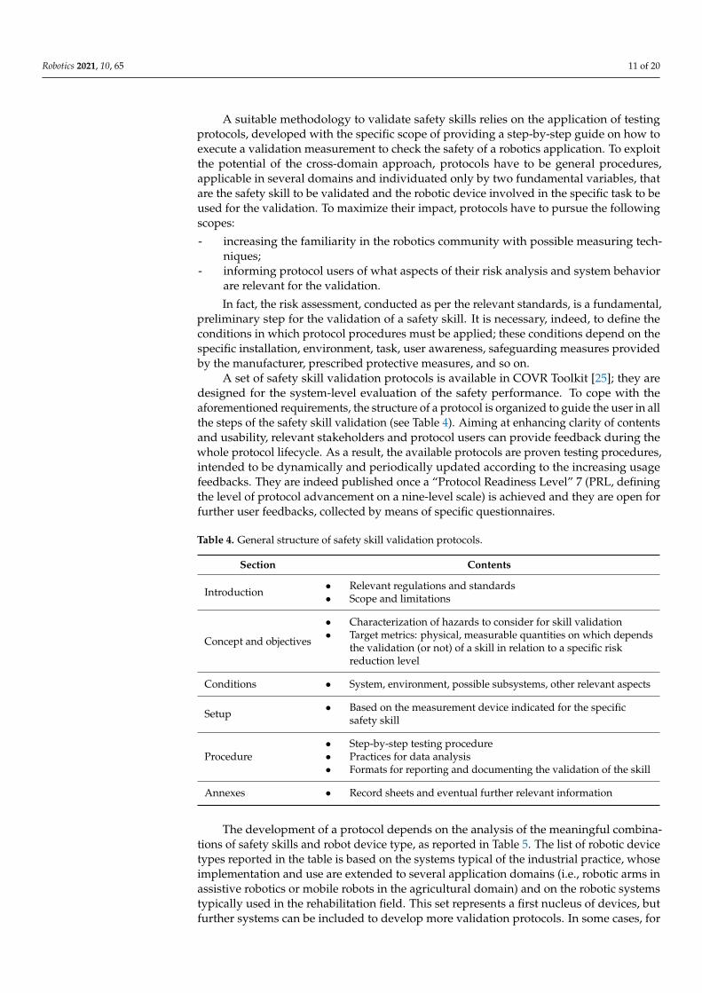
A set of safety skill validation protocols is available in COVR Toolkit [25]; they aredesigned for the system-level evaluation of the safety performance. To cope with theaforementioned requirements, the structure of a protocol is organized to guide the user in allthe steps of the safety skill validation (see Table 4). Aiming at enhancing clarity of contentsand usability, relevant stakeholders and protocol users can provide feedback during thewhole protocol lifecycle. As a result, the available protocols are proven testing procedures,intended to be dynamically and periodically updated according to the increasing usagefeedbacks. They are indeed published once a “Protocol Readiness Level” 7 (PRL, definingthe level of protocol advancement on a nine-level scale) is achieved and they are open forfurther user feedbacks, collected by means of specific questionnaires.
Table 4. General structure of safety skill validation protocols.
Section Contents
Introduction • Relevant regulations and standards• Scope and limitations
Concept and objectives
• Characterization of hazards to consider for skill validation• Target metrics: physical, measurable quantities on which depends
the validation (or not) of a skill in relation to a specific riskreduction level
Conditions • System, environment, possible subsystems, other relevant aspects
Setup • Based on the measurement device indicated for the specificsafety skill
Procedure• Step-by-step testing procedure• Practices for data analysis• Formats for reporting and documenting the validation of the skill
Annexes • Record sheets and eventual further relevant information
The development of a protocol depends on the analysis of the meaningful combina-tions of safety skills and robot device type, as reported in Table 5. The list of robotic devicetypes reported in the table is based on the systems typical of the industrial practice, whoseimplementation and use are extended to several application domains (i.e., robotic arms inassistive robotics or mobile robots in the agricultural domain) and on the robotic systemstypically used in the rehabilitation field. This set represents a first nucleus of devices, butfurther systems can be included to develop more validation protocols. In some cases, for
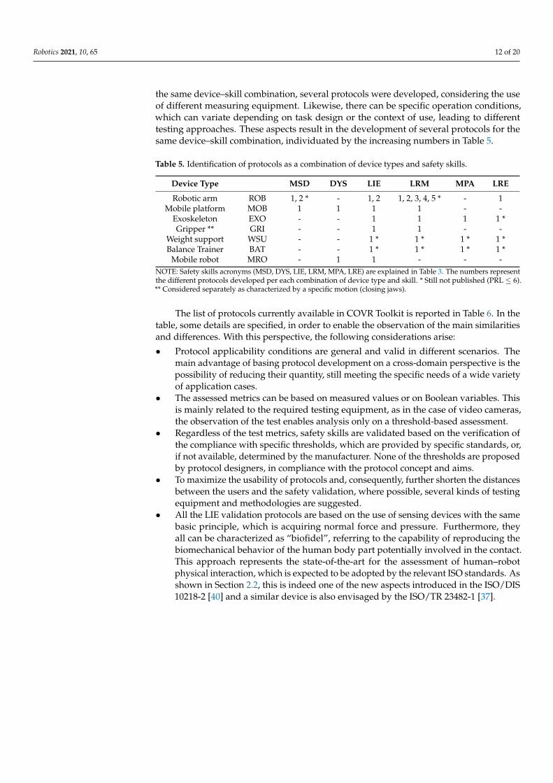
Robotics 2021, 10, 65 12 of 20
the same device–skill combination, several protocols were developed, considering the useof different measuring equipment. Likewise, there can be specific operation conditions,which can variate depending on task design or the context of use, leading to differenttesting approaches. These aspects result in the development of several protocols for thesame device–skill combination, individuated by the increasing numbers in Table 5.
Table 5. Identification of protocols as a combination of device types and safety skills.
Device Type MSD DYS LIE LRM MPA LRE
Robotic arm ROB 1, 2 * - 1, 2 1, 2, 3, 4, 5 * - 1Mobile platform MOB 1 1 1 1 - -
Exoskeleton EXO - - 1 1 1 1 *Gripper ** GRI - - 1 1 - -
Weight support WSU - - 1 * 1 * 1 * 1 *Balance Trainer BAT - - 1 * 1 * 1 * 1 *
Mobile robot MRO - 1 1 - - -NOTE: Safety skills acronyms (MSD, DYS, LIE, LRM, MPA, LRE) are explained in Table 3. The numbers representthe different protocols developed per each combination of device type and skill. * Still not published (PRL ≤ 6).** Considered separately as characterized by a specific motion (closing jaws).
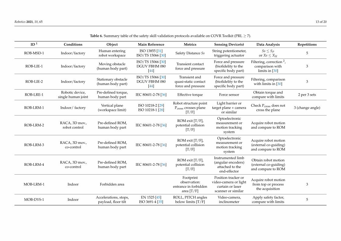
The list of protocols currently available in COVR Toolkit is reported in Table 6. In thetable, some details are specified, in order to enable the observation of the main similaritiesand differences. With this perspective, the following considerations arise:
• Protocol applicability conditions are general and valid in different scenarios. Themain advantage of basing protocol development on a cross-domain perspective is thepossibility of reducing their quantity, still meeting the specific needs of a wide varietyof application cases.
• The assessed metrics can be based on measured values or on Boolean variables. Thisis mainly related to the required testing equipment, as in the case of video cameras,the observation of the test enables analysis only on a threshold-based assessment.
• Regardless of the test metrics, safety skills are validated based on the verification ofthe compliance with specific thresholds, which are provided by specific standards, or,if not available, determined by the manufacturer. None of the thresholds are proposedby protocol designers, in compliance with the protocol concept and aims.
• To maximize the usability of protocols and, consequently, further shorten the distancesbetween the users and the safety validation, where possible, several kinds of testingequipment and methodologies are suggested.
• All the LIE validation protocols are based on the use of sensing devices with the samebasic principle, which is acquiring normal force and pressure. Furthermore, theyall can be characterized as “biofidel”, referring to the capability of reproducing thebiomechanical behavior of the human body part potentially involved in the contact.This approach represents the state-of-the-art for the assessment of human–robotphysical interaction, which is expected to be adopted by the relevant ISO standards. Asshown in Section 2.2, this is indeed one of the new aspects introduced in the ISO/DIS10218-2 [40] and a similar device is also envisaged by the ISO/TR 23482-1 [37].
Robotics 2021, 10, 65 13 of 20
Table 6. Summary table of the safety skill validation protocols available on COVR Toolkit (PRL ≥ 7).
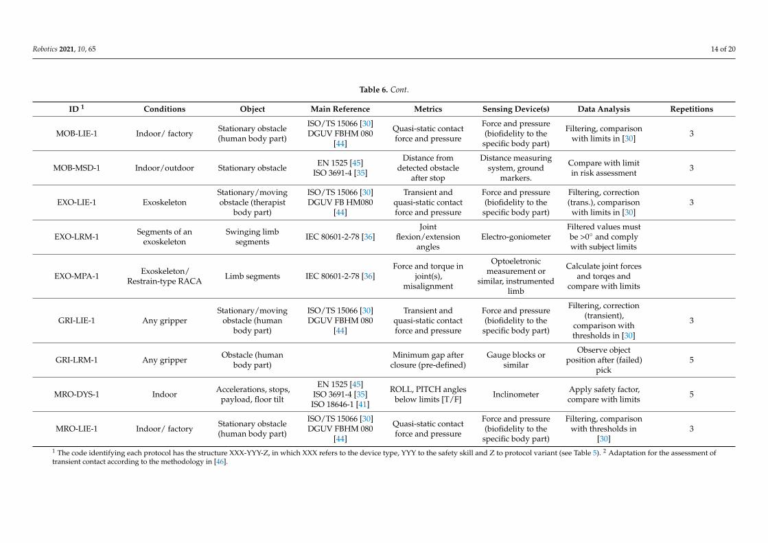
ID 1 Conditions Object Main Reference Metrics Sensing Device(s) Data Analysis Repetitions
ROB-MSD-1 Indoor/factory Human enteringrobot workspace
ISO 13855 [31]ISO/TS 15066 [30] Safety Distance Ss String potentiometer,
triggering actuatorSs ≤ SP
or Xs ≤ XH5
ROB-LIE-1 Indoor/factory Moving obstacle(human body part)
ISO/TS 15066 [30]DGUV FBHM 080
[44]
Transient contactforce and pressure
Force and pressure(biofidelity to the
specific body part)
Filtering, correction 2,comparison with
limits in [30]3
ROB-LIE-2 Indoor/factory Stationary obstacle(human body part)
ISO/TS 15066 [30]DGUV FBHM 080
[44]
Transient andquasi-static contactforce and pressure
Force and pressure(biofidelity to the
specific body part)
Filtering, comparisonwith limits in [30] 3
ROB-LRE-1 Robotic device,single human joint
Pre-defined torque,human body part IEC 80601-2-78 [36] Effective torque Force sensor Obtain torque and
compare with limits 2 per 3 sets
ROB-LRM-1 Indoor/ factory Vertical plane(workspace limit)
ISO 10218-2 [29]ISO 10218-1 [28]
Robot structure pointPcross crosses plane
[T/F]
Light barrier ortarget plane + camera
or similar
Check Pcross does notcross the plane 3 (change angle)
ROB-LRM-2 RACA, 3D mov.,robot control
Pre-defined ROM,human body part IEC 80601-2-78 [36]
ROM exit [T/F],potential collision
[T/F]
Optoelectronicmeasurement ormotion tracking
system
Acquire robot motionand compare to ROM
ROB-LRM-3 RACA, 3D mov.,co-control
Pre-defined ROM,human body part IEC 80601-2-78 [36]
ROM exit [T/F],potential collision
[T/F]
Optoelectronicmeasurement ormotion tracking
system
Acquire robot motion(external co-guiding)and compare to ROM
ROB-LRM-4 RACA, 3D mov.,co-control
Pre-defined ROM,human body part IEC 80601-2-78 [36]
ROM exit [T/F],potential collision
[T/F]
Instrumented limb(angular encoders)
attached to theend-effector
Obtain robot motion(external co-guiding)and compare to ROM
MOB-LRM-1 Indoor Forbidden area
Footprintobservation:
entrance in forbiddenarea [T/F]
Position tracker orvideo-camera or light
curtain or laserscanner or similar
Acquire robot motionfrom top or process
the acquisition3
MOB-DYS-1 Indoor Accelerations, stops,payload, floor tilt
EN 1525 [45]ISO 3691-4 [35]
ROLL, PITCH anglesbelow limits [T/F]
Video-camera,inclinometer
Apply safety factor,compare with limits 5
Robotics 2021, 10, 65 14 of 20
Table 6. Cont.
ID 1 Conditions Object Main Reference Metrics Sensing Device(s) Data Analysis Repetitions
MOB-LIE-1 Indoor/ factory Stationary obstacle(human body part)
ISO/TS 15066 [30]DGUV FBHM 080
[44]
Quasi-static contactforce and pressure
Force and pressure(biofidelity to the
specific body part)
Filtering, comparisonwith limits in [30] 3
MOB-MSD-1 Indoor/outdoor Stationary obstacle EN 1525 [45]ISO 3691-4 [35]
Distance fromdetected obstacle
after stop
Distance measuringsystem, ground
markers.
Compare with limitin risk assessment 3
EXO-LIE-1 ExoskeletonStationary/movingobstacle (therapist
body part)
ISO/TS 15066 [30]DGUV FB HM080
[44]
Transient andquasi-static contactforce and pressure
Force and pressure(biofidelity to the
specific body part)
Filtering, correction(trans.), comparison
with limits in [30]3
EXO-LRM-1 Segments of anexoskeleton
Swinging limbsegments IEC 80601-2-78 [36]
Jointflexion/extension
anglesElectro-goniometer
Filtered values mustbe >0◦ and complywith subject limits
EXO-MPA-1 Exoskeleton/Restrain-type RACA Limb segments IEC 80601-2-78 [36]
Force and torque injoint(s),
misalignment
Optoeletronicmeasurement or
similar, instrumentedlimb
Calculate joint forcesand torqes and
compare with limits
GRI-LIE-1 Any gripperStationary/moving
obstacle (humanbody part)
ISO/TS 15066 [30]DGUV FBHM 080
[44]
Transient andquasi-static contactforce and pressure
Force and pressure(biofidelity to the
specific body part)
Filtering, correction(transient),
comparison withthresholds in [30]
3
GRI-LRM-1 Any gripper Obstacle (humanbody part)
Minimum gap afterclosure (pre-defined)
Gauge blocks orsimilar
Observe objectposition after (failed)
pick5
MRO-DYS-1 Indoor Accelerations, stops,payload, floor tilt
EN 1525 [45]ISO 3691-4 [35]
ISO 18646-1 [41]
ROLL, PITCH anglesbelow limits [T/F] Inclinometer Apply safety factor,
compare with limits 5
MRO-LIE-1 Indoor/ factory Stationary obstacle(human body part)
ISO/TS 15066 [30]DGUV FBHM 080
[44]
Quasi-static contactforce and pressure
Force and pressure(biofidelity to the
specific body part)
Filtering, comparisonwith thresholds in
[30]3
1 The code identifying each protocol has the structure XXX-YYY-Z, in which XXX refers to the device type, YYY to the safety skill and Z to protocol variant (see Table 5). 2 Adaptation for the assessment oftransient contact according to the methodology in [46].
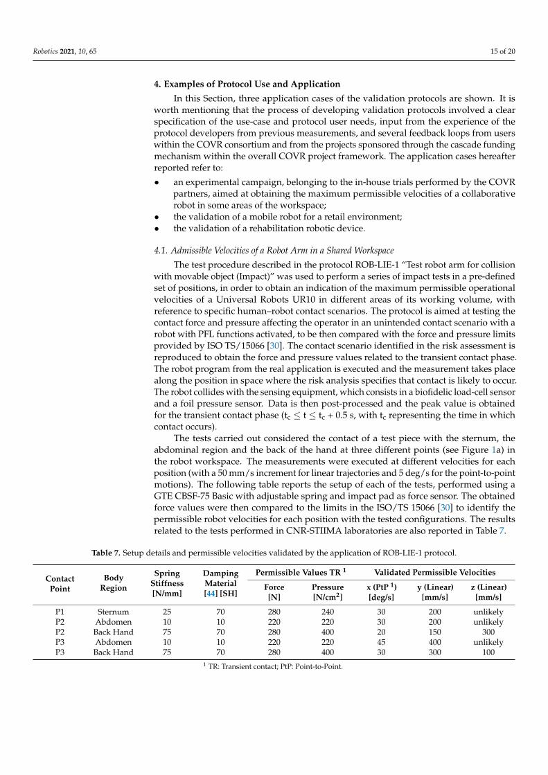
Robotics 2021, 10, 65 15 of 20
4. Examples of Protocol Use and Application
In this Section, three application cases of the validation protocols are shown. It isworth mentioning that the process of developing validation protocols involved a clearspecification of the use-case and protocol user needs, input from the experience of theprotocol developers from previous measurements, and several feedback loops from userswithin the COVR consortium and from the projects sponsored through the cascade fundingmechanism within the overall COVR project framework. The application cases hereafterreported refer to:
• an experimental campaign, belonging to the in-house trials performed by the COVRpartners, aimed at obtaining the maximum permissible velocities of a collaborativerobot in some areas of the workspace;
• the validation of a mobile robot for a retail environment;• the validation of a rehabilitation robotic device.
4.1. Admissible Velocities of a Robot Arm in a Shared Workspace
The test procedure described in the protocol ROB-LIE-1 “Test robot arm for collisionwith movable object (Impact)” was used to perform a series of impact tests in a pre-definedset of positions, in order to obtain an indication of the maximum permissible operationalvelocities of a Universal Robots UR10 in different areas of its working volume, withreference to specific human–robot contact scenarios. The protocol is aimed at testing thecontact force and pressure affecting the operator in an unintended contact scenario with arobot with PFL functions activated, to be then compared with the force and pressure limitsprovided by ISO TS/15066 [30]. The contact scenario identified in the risk assessment isreproduced to obtain the force and pressure values related to the transient contact phase.The robot program from the real application is executed and the measurement takes placealong the position in space where the risk analysis specifies that contact is likely to occur.The robot collides with the sensing equipment, which consists in a biofidelic load-cell sensorand a foil pressure sensor. Data is then post-processed and the peak value is obtainedfor the transient contact phase (tc ≤ t ≤ tc + 0.5 s, with tc representing the time in whichcontact occurs).
The tests carried out considered the contact of a test piece with the sternum, theabdominal region and the back of the hand at three different points (see Figure 1a) inthe robot workspace. The measurements were executed at different velocities for eachposition (with a 50 mm/s increment for linear trajectories and 5 deg/s for the point-to-pointmotions). The following table reports the setup of each of the tests, performed using aGTE CBSF-75 Basic with adjustable spring and impact pad as force sensor. The obtainedforce values were then compared to the limits in the ISO/TS 15066 [30] to identify thepermissible robot velocities for each position with the tested configurations. The resultsrelated to the tests performed in CNR-STIIMA laboratories are also reported in Table 7.
Table 7. Setup details and permissible velocities validated by the application of ROB-LIE-1 protocol.
ContactPoint
BodyRegion
SpringStiffness[N/mm]
DampingMaterial[44] [SH]
Permissible Values TR 1 Validated Permissible Velocities
Force[N]
Pressure[N/cm2]
x (PtP 1)[deg/s]
y (Linear)[mm/s]
z (Linear)[mm/s]
P1 Sternum 25 70 280 240 30 200 unlikelyP2 Abdomen 10 10 220 220 30 200 unlikelyP2 Back Hand 75 70 280 400 20 150 300P3 Abdomen 10 10 220 220 45 400 unlikelyP3 Back Hand 75 70 280 400 30 300 100
1 TR: Transient contact; PtP: Point-to-Point.
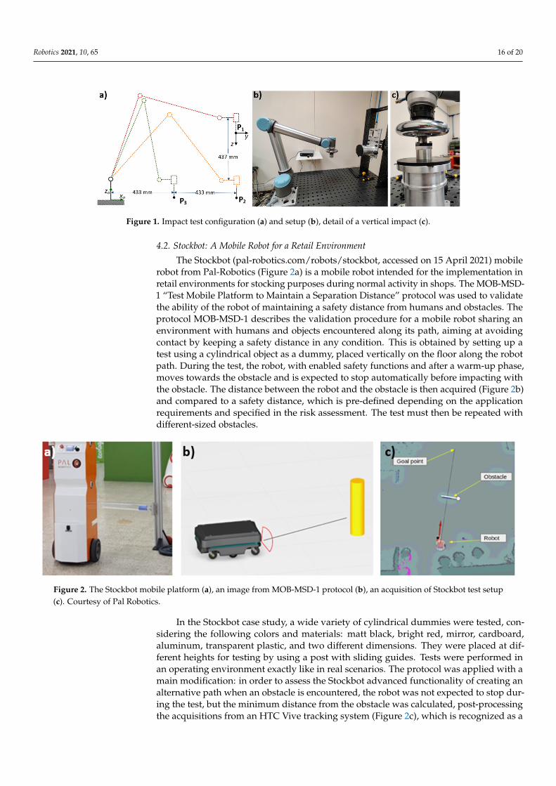
Robotics 2021, 10, 65 16 of 20
Robotics 2021, 10, x FOR PEER REVIEW 14 of 19
4. Examples of Protocol Use and Application In this Section, three application cases of the validation protocols are shown. It is
worth mentioning that the process of developing validation protocols involved a clear specification of the use-case and protocol user needs, input from the experience of the protocol developers from previous measurements, and several feedback loops from users within the COVR consortium and from the projects sponsored through the cascade fund-ing mechanism within the overall COVR project framework. The application cases here-after reported refer to: • an experimental campaign, belonging to the in-house trials performed by the COVR
partners, aimed at obtaining the maximum permissible velocities of a collaborative robot in some areas of the workspace;
• the validation of a mobile robot for a retail environment; • the validation of a rehabilitation robotic device.
4.1. Admissible Velocities of a Robot Arm in a Shared Workspace The test procedure described in the protocol ROB-LIE-1 “Test robot arm for collision
with movable object (Impact)” was used to perform a series of impact tests in a pre-de-fined set of positions, in order to obtain an indication of the maximum permissible oper-ational velocities of a Universal Robots UR10 in different areas of its working volume, with reference to specific human–robot contact scenarios. The protocol is aimed at testing the contact force and pressure affecting the operator in an unintended contact scenario with a robot with PFL functions activated, to be then compared with the force and pres-sure limits provided by ISO TS/15066 [30]. The contact scenario identified in the risk as-sessment is reproduced to obtain the force and pressure values related to the transient contact phase. The robot program from the real application is executed and the measure-ment takes place along the position in space where the risk analysis specifies that contact is likely to occur. The robot collides with the sensing equipment, which consists in a bio-fidelic load-cell sensor and a foil pressure sensor. Data is then post-processed and the peak value is obtained for the transient contact phase (tc ≤ t ≤ tc + 0.5s, with tc representing the time in which contact occurs).
The tests carried out considered the contact of a test piece with the sternum, the ab-dominal region and the back of the hand at three different points (see Figure 1a) in the robot workspace. The measurements were executed at different velocities for each posi-tion (with a 50 mm/s increment for linear trajectories and 5 deg/s for the point-to-point motions). The following table reports the setup of each of the tests, performed using a GTE CBSF-75 Basic with adjustable spring and impact pad as force sensor. The obtained force values were then compared to the limits in the ISO/TS 15066 [30] to identify the permissi-ble robot velocities for each position with the tested configurations. The results related to the tests performed in CNR-STIIMA laboratories are also reported in Table 7.
Figure 1. Impact test configuration (a) and setup (b), detail of a vertical impact (c). Figure 1. Impact test configuration (a) and setup (b), detail of a vertical impact (c).
4.2. Stockbot: A Mobile Robot for a Retail Environment
The Stockbot (pal-robotics.com/robots/stockbot, accessed on 15 April 2021) mobilerobot from Pal-Robotics (Figure 2a) is a mobile robot intended for the implementation inretail environments for stocking purposes during normal activity in shops. The MOB-MSD-1 “Test Mobile Platform to Maintain a Separation Distance” protocol was used to validatethe ability of the robot of maintaining a safety distance from humans and obstacles. Theprotocol MOB-MSD-1 describes the validation procedure for a mobile robot sharing anenvironment with humans and objects encountered along its path, aiming at avoidingcontact by keeping a safety distance in any condition. This is obtained by setting up atest using a cylindrical object as a dummy, placed vertically on the floor along the robotpath. During the test, the robot, with enabled safety functions and after a warm-up phase,moves towards the obstacle and is expected to stop automatically before impacting withthe obstacle. The distance between the robot and the obstacle is then acquired (Figure 2b)and compared to a safety distance, which is pre-defined depending on the applicationrequirements and specified in the risk assessment. The test must then be repeated withdifferent-sized obstacles.
Robotics 2021, 10, x FOR PEER REVIEW 15 of 19
Table 7. Setup details and permissible velocities validated by the application of ROB-LIE-1 protocol.
Contact Point
Body Region
Spring Stiffness [N/mm]
Damping Material [44]
[SH]
Permissible Values TR 1 Validated Permissible Velocities Force [N]
Pressure [N/cm2]
x (PtP 1) [deg/s]
y (Linear) [mm/s]
z (Linear) [mm/s]
P1 Sternum 25 70 280 240 30 200 unlikely P2 Abdomen 10 10 220 220 30 200 unlikely P2 Back Hand 75 70 280 400 20 150 300 P3 Abdomen 10 10 220 220 45 400 unlikely P3 Back Hand 75 70 280 400 30 300 100
1 TR: Transient contact; PtP: Point-to-Point.
4.2. Stockbot: A Mobile Robot for a Retail Environment The Stockbot (pal-robotics.com/robots/stockbot, accessed on 15 April 2021) mobile
robot from Pal-Robotics (Figure 2a) is a mobile robot intended for the implementation in retail environments for stocking purposes during normal activity in shops. The MOB-MSD-1 “Test Mobile Platform to Maintain a Separation Distance” protocol was used to validate the ability of the robot of maintaining a safety distance from humans and obsta-cles. The protocol MOB-MSD-1 describes the validation procedure for a mobile robot shar-ing an environment with humans and objects encountered along its path, aiming at avoid-ing contact by keeping a safety distance in any condition. This is obtained by setting up a test using a cylindrical object as a dummy, placed vertically on the floor along the robot path. During the test, the robot, with enabled safety functions and after a warm-up phase, moves towards the obstacle and is expected to stop automatically before impacting with the obstacle. The distance between the robot and the obstacle is then acquired (Figure 2b) and compared to a safety distance, which is pre-defined depending on the application requirements and specified in the risk assessment. The test must then be repeated with different-sized obstacles.
Figure 2. The Stockbot mobile platform (a), an image from MOB-MSD-1 protocol (b), an acquisition of Stockbot test setup (c). Courtesy of Pal Robotics.
In the Stockbot case study, a wide variety of cylindrical dummies were tested, con-sidering the following colors and materials: matt black, bright red, mirror, cardboard, alu-minum, transparent plastic, and two different dimensions. They were placed at different heights for testing by using a post with sliding guides. Tests were performed in an oper-ating environment exactly like in real scenarios. The protocol was applied with a main modification: in order to assess the Stockbot advanced functionality of creating an alter-native path when an obstacle is encountered, the robot was not expected to stop during the test, but the minimum distance from the obstacle was calculated, post-processing the acquisitions from an HTC Vive tracking system (Figure 2c), which is recognized as a suit-able 3D tracking system [47]. Besides the application of the MOB-MSD-1, the robot was
Figure 2. The Stockbot mobile platform (a), an image from MOB-MSD-1 protocol (b), an acquisition of Stockbot test setup(c). Courtesy of Pal Robotics.
In the Stockbot case study, a wide variety of cylindrical dummies were tested, con-sidering the following colors and materials: matt black, bright red, mirror, cardboard,aluminum, transparent plastic, and two different dimensions. They were placed at dif-ferent heights for testing by using a post with sliding guides. Tests were performed inan operating environment exactly like in real scenarios. The protocol was applied with amain modification: in order to assess the Stockbot advanced functionality of creating analternative path when an obstacle is encountered, the robot was not expected to stop dur-ing the test, but the minimum distance from the obstacle was calculated, post-processingthe acquisitions from an HTC Vive tracking system (Figure 2c), which is recognized as a
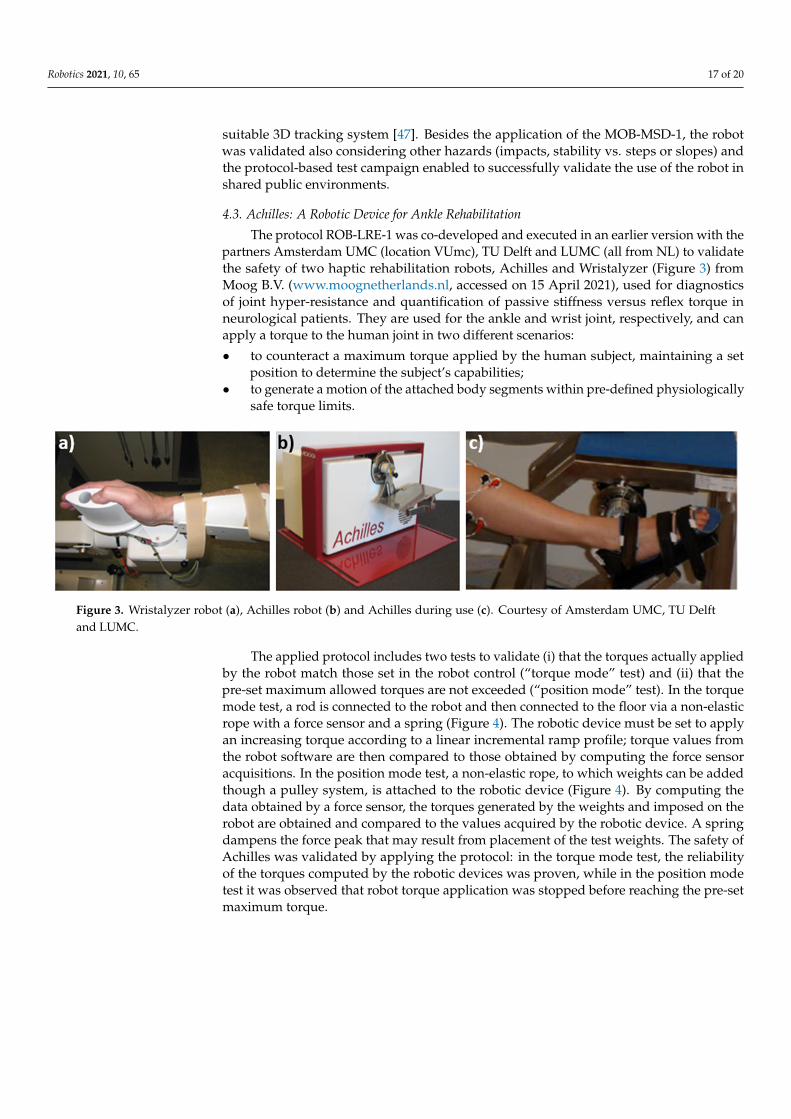
Robotics 2021, 10, 65 17 of 20
suitable 3D tracking system [47]. Besides the application of the MOB-MSD-1, the robotwas validated also considering other hazards (impacts, stability vs. steps or slopes) andthe protocol-based test campaign enabled to successfully validate the use of the robot inshared public environments.
4.3. Achilles: A Robotic Device for Ankle Rehabilitation
The protocol ROB-LRE-1 was co-developed and executed in an earlier version with thepartners Amsterdam UMC (location VUmc), TU Delft and LUMC (all from NL) to validatethe safety of two haptic rehabilitation robots, Achilles and Wristalyzer (Figure 3) fromMoog B.V. (www.moognetherlands.nl, accessed on 15 April 2021), used for diagnosticsof joint hyper-resistance and quantification of passive stiffness versus reflex torque inneurological patients. They are used for the ankle and wrist joint, respectively, and canapply a torque to the human joint in two different scenarios:
• to counteract a maximum torque applied by the human subject, maintaining a setposition to determine the subject’s capabilities;
• to generate a motion of the attached body segments within pre-defined physiologicallysafe torque limits.
Robotics 2021, 10, x FOR PEER REVIEW 16 of 19
validated also considering other hazards (impacts, stability vs. steps or slopes) and the protocol-based test campaign enabled to successfully validate the use of the robot in shared public environments.
4.3. Achilles: A Robotic Device for Ankle Rehabilitation The protocol ROB-LRE-1 was co-developed and executed in an earlier version with
the partners Amsterdam UMC (location VUmc), TU Delft and LUMC (all from NL) to validate the safety of two haptic rehabilitation robots, Achilles and Wristalyzer (Figure 3) from Moog B.V. (www.moognetherlands.nl, accessed on 15 April 2021), used for diagnos-tics of joint hyper-resistance and quantification of passive stiffness versus reflex torque in neurological patients. They are used for the ankle and wrist joint, respectively, and can apply a torque to the human joint in two different scenarios: • to counteract a maximum torque applied by the human subject, maintaining a set
position to determine the subject’s capabilities; • to generate a motion of the attached body segments within pre-defined physiologi-
cally safe torque limits.
Figure 3. Wristalyzer robot (a), Achilles robot (b) and Achilles during use (c). Courtesy of Amsterdam UMC, TU Delft and LUMC.
The applied protocol includes two tests to validate (i) that the torques actually ap-plied by the robot match those set in the robot control (“torque mode” test) and (ii) that the pre-set maximum allowed torques are not exceeded (“position mode” test). In the torque mode test, a rod is connected to the robot and then connected to the floor via a non-elastic rope with a force sensor and a spring (Figure 4). The robotic device must be set to apply an increasing torque according to a linear incremental ramp profile; torque values from the robot software are then compared to those obtained by computing the force sen-sor acquisitions. In the position mode test, a non-elastic rope, to which weights can be added though a pulley system, is attached to the robotic device (Figure 4). By computing the data obtained by a force sensor, the torques generated by the weights and imposed on the robot are obtained and compared to the values acquired by the robotic device. A spring dampens the force peak that may result from placement of the test weights. The safety of Achilles was validated by applying the protocol: in the torque mode test, the reliability of the torques computed by the robotic devices was proven, while in the posi-tion mode test it was observed that robot torque application was stopped before reaching the pre-set maximum torque.
Figure 3. Wristalyzer robot (a), Achilles robot (b) and Achilles during use (c). Courtesy of Amsterdam UMC, TU Delftand LUMC.
The applied protocol includes two tests to validate (i) that the torques actually appliedby the robot match those set in the robot control (“torque mode” test) and (ii) that thepre-set maximum allowed torques are not exceeded (“position mode” test). In the torquemode test, a rod is connected to the robot and then connected to the floor via a non-elasticrope with a force sensor and a spring (Figure 4). The robotic device must be set to applyan increasing torque according to a linear incremental ramp profile; torque values fromthe robot software are then compared to those obtained by computing the force sensoracquisitions. In the position mode test, a non-elastic rope, to which weights can be addedthough a pulley system, is attached to the robotic device (Figure 4). By computing thedata obtained by a force sensor, the torques generated by the weights and imposed on therobot are obtained and compared to the values acquired by the robotic device. A springdampens the force peak that may result from placement of the test weights. The safety ofAchilles was validated by applying the protocol: in the torque mode test, the reliabilityof the torques computed by the robotic devices was proven, while in the position modetest it was observed that robot torque application was stopped before reaching the pre-setmaximum torque.
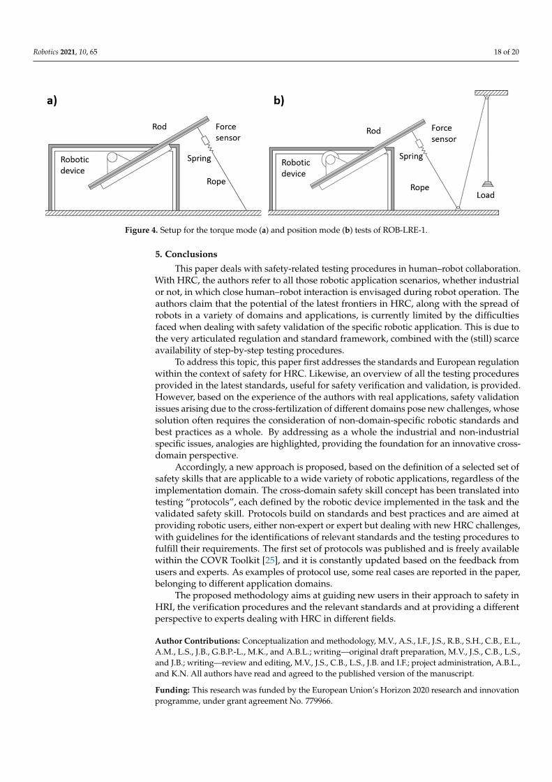
Robotics 2021, 10, 65 18 of 20Robotics 2021, 10, x FOR PEER REVIEW 17 of 19
Figure 4. Setup for the torque mode (a) and position mode (b) tests of ROB-LRE-1.
5. Conclusions This paper deals with safety-related testing procedures in human–robot collabora-
tion. With HRC, the authors refer to all those robotic application scenarios, whether in-dustrial or not, in which close human–robot interaction is envisaged during robot opera-tion. The authors claim that the potential of the latest frontiers in HRC, along with the spread of robots in a variety of domains and applications, is currently limited by the dif-ficulties faced when dealing with safety validation of the specific robotic application. This is due to the very articulated regulation and standard framework, combined with the (still) scarce availability of step-by-step testing procedures.
To address this topic, this paper first addresses the standards and European regula-tion within the context of safety for HRC. Likewise, an overview of all the testing proce-dures provided in the latest standards, useful for safety verification and validation, is pro-vided. However, based on the experience of the authors with real applications, safety val-idation issues arising due to the cross-fertilization of different domains pose new chal-lenges, whose solution often requires the consideration of non-domain-specific robotic standards and best practices as a whole. By addressing as a whole the industrial and non-industrial specific issues, analogies are highlighted, providing the foundation for an inno-vative cross-domain perspective.
Accordingly, a new approach is proposed, based on the definition of a selected set of safety skills that are applicable to a wide variety of robotic applications, regardless of the implementation domain. The cross-domain safety skill concept has been translated into testing “protocols”, each defined by the robotic device implemented in the task and the validated safety skill. Protocols build on standards and best practices and are aimed at providing robotic users, either non-expert or expert but dealing with new HRC chal-lenges, with guidelines for the identifications of relevant standards and the testing proce-dures to fulfill their requirements. The first set of protocols was published and is freely available within the COVR Toolkit [25], and it is constantly updated based on the feedback from users and experts. As examples of protocol use, some real cases are reported in the paper, belonging to different application domains.
The proposed methodology aims at guiding new users in their approach to safety in HRI, the verification procedures and the relevant standards and at providing a different perspective to experts dealing with HRC in different fields.
Author Contributions: Conceptualization and methodology, M.V., A.S., I.F., J.S., R.B., S.H., C.B., E.L., A.M., L.S., J.B., G.B.P.-L., M.K., and A.B.L.; writing—original draft preparation, M.V., J.S., C.B., L.S., and J.B.; writing—review and editing, M.V., J.S., C.B., L.S., J.B. and I.F.; project administration, A.B.L., and K.N. All authors have read and agreed to the published version of the manuscript.
Funding: This research was funded by the European Union’s Horizon 2020 research and innovation programme, under grant agreement No 779966.
Figure 4. Setup for the torque mode (a) and position mode (b) tests of ROB-LRE-1.
5. Conclusions
This paper deals with safety-related testing procedures in human–robot collaboration.With HRC, the authors refer to all those robotic application scenarios, whether industrialor not, in which close human–robot interaction is envisaged during robot operation. Theauthors claim that the potential of the latest frontiers in HRC, along with the spread ofrobots in a variety of domains and applications, is currently limited by the difficultiesfaced when dealing with safety validation of the specific robotic application. This is due tothe very articulated regulation and standard framework, combined with the (still) scarceavailability of step-by-step testing procedures.
To address this topic, this paper first addresses the standards and European regulationwithin the context of safety for HRC. Likewise, an overview of all the testing proceduresprovided in the latest standards, useful for safety verification and validation, is provided.However, based on the experience of the authors with real applications, safety validationissues arising due to the cross-fertilization of different domains pose new challenges, whosesolution often requires the consideration of non-domain-specific robotic standards andbest practices as a whole. By addressing as a whole the industrial and non-industrialspecific issues, analogies are highlighted, providing the foundation for an innovative cross-domain perspective.
Accordingly, a new approach is proposed, based on the definition of a selected set ofsafety skills that are applicable to a wide variety of robotic applications, regardless of theimplementation domain. The cross-domain safety skill concept has been translated intotesting “protocols”, each defined by the robotic device implemented in the task and thevalidated safety skill. Protocols build on standards and best practices and are aimed atproviding robotic users, either non-expert or expert but dealing with new HRC challenges,with guidelines for the identifications of relevant standards and the testing procedures tofulfill their requirements. The first set of protocols was published and is freely availablewithin the COVR Toolkit [25], and it is constantly updated based on the feedback fromusers and experts. As examples of protocol use, some real cases are reported in the paper,belonging to different application domains.
The proposed methodology aims at guiding new users in their approach to safety inHRI, the verification procedures and the relevant standards and at providing a differentperspective to experts dealing with HRC in different fields.
Author Contributions: Conceptualization and methodology, M.V., A.S., I.F., J.S., R.B., S.H., C.B., E.L.,A.M., L.S., J.B., G.B.P.-L., M.K., and A.B.L.; writing—original draft preparation, M.V., J.S., C.B., L.S.,and J.B.; writing—review and editing, M.V., J.S., C.B., L.S., J.B. and I.F.; project administration, A.B.L.,and K.N. All authors have read and agreed to the published version of the manuscript.
Funding: This research was funded by the European Union’s Horizon 2020 research and innovationprogramme, under grant agreement No. 779966.
Robotics 2021, 10, 65 19 of 20
Acknowledgments: The authors would like to thank the STOCKBOT team from PAL Robotics andspecifically Sarah Terreri, Alessandro di Fava, Sergio Ramos and Francesco Ferro, for the feedback andsurveys on the application of MOB-MSD-1 protocol, as well as the SAFEharbor team and specificallyMarjolein van der Krogt, Ad de Snaaier (both Amsterdam UMC), Winfred Mugge, Alfred Schouten(both TU Delft) and Jurriaan de Groot (LUMC) for their work on the ROB-LRE-1 protocol.
Conflicts of Interest: The authors declare no conflict of interest.
References1. Villani, V.; Pini, F.; Leali, F.; Secchi, C. Survey on human–robot collaboration in industrial settings: Safety, intuitive interfaces and
applications. Mechatronics 2018, 55, 248–266. [CrossRef]2. Ajoudani, A.; Zanchettin, A.M.; Ivaldi, S.; Albu-Schäffer, A.; Kosuge, K.; Khatib, O. Progress and prospects of the human–robot
collaboration. Auton. Robot. 2018, 42, 957–975. [CrossRef]3. IFR. World Robotic Report 2020. Available online: https://ifr.org/ifr-press-releases/news/record-2.7-million-robots-work-in-
factories-around-the-globe (accessed on 30 January 2021).4. Peters, B.S.; Armijo, P.R.; Krause, C.; Choudhury, S.A.; Oleynikov, D. Review of emerging surgical robotic technology. Surg.
Endosc. 2018, 32, 1636–1655. [CrossRef] [PubMed]5. Riek, L.D. Healthcare robotics. Commun. ACM 2017, 60, 68–78. [CrossRef]6. Duckett, T.; Pearson, S.; Blackmore, S.; Grieve, B.; Wilson, P.; Gill, H.; Hunter, A.J.; Georgilas, I. Agricultural Robotics: The Future of
Robotic Agriculture; UK-RAS Network: London, UK, 2018.7. Kimmig, R.; Verheijen, R.H.M.; Rudnicki, M. Robot assisted surgery during the COVID-19 pandemic, especially for gyne-cological
cancer: A statement of the Society of European Robotic Gynaecological Surgery (SERGS). J. Gynecol. Oncol. 2020, 31, e59.[CrossRef] [PubMed]
8. Tavakoli, M.; Carriere, J.; Torabi, A. Robotics, smart wearable technologies, and autonomous intelligent systems for healthcareduring the COVID-19 pandemic: An analysis of the state of the art and future vision. Adv. Intell. Syst. 2020, 2. [CrossRef]
9. Zeng, Z.; Chen, P.-J.; Lew, A.A. From high-touch to high-tech: COVID-19 drives robotics adoption. Tour. Geogr. 2020, 22, 724–734.[CrossRef]
10. Good Work Charter of the European Robotics Industry. EUnited Robotics. Available online: https://www.eu-nited.net/eunited+aisbl/robotics/news/european-charter-for-robots-and-humans-released-by-engineering-association-eunited.html (accessed on30 January 2021).
11. Vasic, M.; Billard, A. Safety issues in human-robot interactions. In Proceedings of the 2013 IEEE International Conference onRobotics and Automation, Karlsruhe, Germany, 6–10 May 2013; pp. 197–204.
12. Guiochet, J.; Do Hoang, Q.A.; Kaâniche, M.; Powell, D. Applying Existing Standards to a Medical Rehabilitation Robot: Limits andChallenges. In Proceedings of the 2012 IEEE/RSJ International Conference on Intelligent Robots and Systems (IROS), Vilamoura,Portugal, 7–12 October 2012.
13. Gopinath, V.; Johansen, K.; Derelöv, M.; Gustafsson, Å.; Axelsson, S. Safe collaborative assembly on a continuously moving linewith large industrial robots. Robot. Comput. Manuf. 2021, 67, 102048. [CrossRef]
14. Saenz, J.; Behrens, R.; Schulenburg, E.; Petersen, H.; Gibaru, O.; Neto, P.; Elkmann, N. Methods for considering safety in design ofrobotics applications featuring human-robot collaboration. Int. J. Adv. Manuf. Technol. 2020, 107, 2313–2331. [CrossRef]
15. Gualtieri, L.; Rauch, E.; Vidoni, R. Emerging research fields in safety and ergonomics in industrial collaborative robotics: Asystematic literature review. Robot. Comput. Manuf. 2021, 67, 101998. [CrossRef]
16. Kumar, S.; Savur, C.; Sahin, F. Survey of human–robot collaboration in industrial settings: Awareness, intelligence, and compliance.IEEE Trans. Syst. Man Cybern. Syst. 2021, 51, 280–297. [CrossRef]
17. Marvel, J.A. Performance metrics of speed and separation monitoring in shared workspaces. IEEE Trans. Autom. Sci. Eng. 2013,10, 405–414. [CrossRef]
18. European Parliament. Directive 2006/42/EC on Machinery; European Parliament: Brussels, Belgium, 2006.19. European Parliament. Regulation (EU) 2017/745 on Medical Devices; European Parliament: Brussels, Belgium, 2017.20. Bessler, J.; Prange-Lasonder, G.B.; Schaake, L.; Saenz, J.F.; Bidard, C.; Fassi, I.; Valori, M.; Lassen, A.B.; Buurke, J.H. Safety
assessment of rehabilitation robots: A review identifying safety skills and current knowledge gaps. Front. Robot. AI 2021, 8.[CrossRef]
21. European Parliament. Directive 2001/95/EC on General Product Safety; European Parliament: Brussels, Belgium, 2001.22. European Parliament. Low Voltage Directive 2014/13/EU; European Parliament: Brussels, Belgium, 2013.23. European Parliament. Directive 2014/30/EU on the Harmonization of the Laws of the Member States Relating to Electromagnetic
Compatibility; European Parliament: Brussels, Belgium, 2014.24. European Parliament. Radio Equipment Directive 2014/53/EU; European Parliament: Brussels, Belgium, 2014.25. COVR. Toolkit. Available online: https://www.safearoundrobots.com/home (accessed on 30 January 2021).26. ISO 12100:2010. Safety of Machinery—General Principles for Design—Risk Assessment and Risk Reduction; International Or-ganization
for Standardization: Geneva, Switzerland, 2010.27. ISO 14971:2019. Medical Devices—Application of Risk Management to Medical Devices; International Organization for Standardization:
Geneva, Switzerland, 2019.
https://ifr.org/ifr-press-releases/news/record-2.7-million-robots-work-in-factories-around-the-globe
Robotics 2021, 10, 65 20 of 20
28. ISO 10218-1:2011. Robots and Robotic Devices—Safety Requirements for Industrial Robots—Part 1: Robots; International Organizationfor Standardization: Geneva, Switzerland, 2011.
29. ISO 10218-2:2011. Robots and Robotic Devices—Safety Requirements for Industrial Robots—Part 2: Robot Systems and Inte-gration;International Organization for Standardization: Geneva, Switzerland, 2011.
30. ISO/TS 15066:2016. Robots and Robotic Devices—Collaborative Robots; International Organization for Standardization: Geneva,Switzerland, 2016.
31. ISO 13855:2010. Safety of Machinery—Positioning of Safeguards with Respect to the Approach Speeds of Parts of the Human Body;International Organization for Standardization: Geneva, Switzerland, 2010.
32. ISO 18497:2018. Agricultural Machinery and Tractors—Safety of Highly Automated Machinery; International Organization forStandardization: Geneva, Switzerland, 2018.
33. ISO 13851:2019. Safety of Machinery—Two-Hand Control Devices—Principles for Design and Selection; International Organi-zation forStandardization: Geneva, Switzerland, 2019.
34. ISO 13482:2014. Robots and Robotic Devices—Safety Requirements for Personal Care Robots; International Organization for Standard-ization: Geneva, Switzerland, 2014.
35. ISO 3691-4:2020. Industrial Trucks—Safety Requirements and Verification—Part 4: Driverless Industrial Trucks and Their Systems;International Organization for Standardization: Geneva, Switzerland, 2020.
36. IEC 80601-2-78:2020. Medical Electrical Equipment—Part 2-78: Particular Requirements for Basic Safety and Essential Performanceof Medical Robots for Rehabilitation, Assessment, Compensation or Alleviation; International Electrotechnical Commission: Geneva,Switzerland, 2020.
37. ISO/TR 23482-1:2020. Application of ISO 13482—Part 1: Safety-Related Test Methods; International Organization for Stand-ardization:Geneva, Switzerland, 2020.
38. ISO/TR 20218-1:2018. Robotics—Safety Design for Industrial Robot Systems—Part 1: End-Effectors; International Organization forStandardization: Geneva, Switzerland, 2018.
39. ISO/TR 20218-2:2017. Robotics—Safety Requirements for Industrial Robots—Part 2: Manual Load/Unload Stations; InternationalOrganization for Standardization: Geneva, Switzerland, 2017.
40. ISO/DIS 10218-2:2020. Robotics—Safety Requirements for Robot Systems in an Industrial Environment—Part 2: Robot Systems, RobotApplications and Robot Cells Integration; International Organization for Standardization: Geneva, Switzerland, 2020.
41. ISO 18646-1:2016. Robotics—Performance Criteria and Related Test Methods for Service Robots—Part 1: Locomotion for Wheeled Robots;International Organization for Standardization: Geneva, Switzerland, 2016.
42. ISO 18646-2:2019. Robotics—Performance Criteria and Related Test Methods for Service Robots—Part 2: Navigation; InternationalOrganization for Standardization: Geneva, Switzerland, 2019.
43. Saenz, J.; Lassen, A.B.; Bidard, C.; Burke, J.H.; Nielsen, K.; Schaake, L.; Vicentini, F. COVR—Towards simplified evaluation andvalidation of collaborative robotics applications across a wide range of domains using robot safety skills. In Proceedings of the9th International Conference on Safety of Industrial Automated Systems (SIAS), Nancy, France, 10–12 October 2018.
44. Collaborative robot systems. Design of Systems with "Power and Force Limiting" Function; Fachbereich Holz und Metall, GermanSocial Accident Insurance (DGUV): Heidelberg, Germany, 2017.
45. CEN. EN 1525-Safety of Industrial Trucks—Driverless Trucks and Their Systems; European Committee for Standardization: Brussels,Belgium, 1997.
46. Herbster, S.; Behrens, R.; Elkmann, N. A New Conversion Method to Evaluate the Hazard Potential of Collaborative Robots in FreeCollisions. Experimental Robotics; Springer International Publishing: Berlin/Heidelberg, Germany, 2021; pp. 222–232.
47. Diederick, C.; Niehorster, L.; Lappe, M. The accuracy and precision of position and orientation tracking in the HTC vive virtualreality system for scientific research. I-Perception 2017, 8, 2041669517708205.