Creating and Validating Embedded Assertion Statecharts
12
May 2007 (vol. 8, no. 5), art. no. 0704-o5003 1541-4922 © 2007 IEEE Published by the IEEE Computer Society Rapid System Prototyping Creating and Validating Embedded Assertion Statecharts Doron Drusinsky, Man-Tak Shing, and Kadir Alpaslan Demir • Naval Postgraduate School Integrating formal assertions into the modeling, implementation, and testing of statechart-based designs can enhance a system’s robustness by providing runtime monitoring and recovery from assertion failures. Formal specifications and lightweight formal methods help improve requirements specifications’ clarity and precision. 1 Formally specifying requirements enables developers to gain a deeper understanding of the system being specified and to uncover requirement flaws, inconsistencies, ambiguities, and deficiencies. 2 Unfortunately, formal methods users often discover late in the development process that their formal requirements are incorrect, making this approach much less effective. Runtime execution monitoring is a class of methods for tracking an underlying application’s temporal behavior, often expressed in the form of formal specification assertions. REM methods range from simple print-statement logging to runtime tracking of complex formal requirements (such as requirements written in temporal logic) for verification purposes. Using runtime monitoring and verification of temporal assertions in tandem with rapid prototyping helps debug the requirements and identify errors earlier in the design process. 3 NASA used REM to verify flight code for the Deep Impact project. 4 Recently, the US Ballistic Missile Defense System project adopted REM as the primary verification method for its new ballistic missile battle manager because of REM’s ability to scale and its support for temporal assertions that include real-time and time-series constraints. 5 System designers often use Harel statecharts for design analysis and implementation. 6 Bernd Bruegge and Allen Dutoit, for example, suggest using statecharts in the design-analysis phase of an object- oriented UML-based design methodology to specify dynamic behavior of complex reactive systems. 7 Although statecharts can effectively specify what a system should do (positive information), they’re generally less effective for specifying safety requirements (that is, negative information about what a system must not do). Hence, researchers have attempted to augment statechart specifications with other formalisms such as process algebra, 8 symbolic timing diagrams, 9 and temporal logic 10 and to demonstrate their designs’ correctness with formal methods (for example, theorem proofing, static model checking, or execution-based model checking) on the corresponding assertions. In such approaches, however, the lack of a unified formalism requires users to work with two models, with no guarantee that one model’s correctness implies the other’s. In earlier work, Drusinsky presented statechart assertions, a new formalism that combines UML-based prototyping, UML-based formal specifications, runtime monitoring, and execution-based model checking. 11,12 Unlike the text-based temporal assertions, statechart assertions are visual, intuitive, and resemble statechart design models. For example, statechart assertions are event driven like statechart models, whereas other specification languages, such as temporal logic, are purely propositional. Moreover, statechart assertions are Turing equivalent and are therefore significantly more expressive than temporal logic. StateRover, a commercially available tool for UML statechart design entry, code generation, and visual debug animation, supports this new formalism. The new formalism and tool let system designers embed deterministic and nondeterministic statechart assertions in statechart designs and execute the assertions in tandem with their primary UML statechart to provide runtime monitoring and recovery from assertion failures. Here, we focus on the correct development and early use of statechart assertions in rapid system prototyping. IEEE Distributed Systems Online (vol. 8, no. 5), art. no. 0704-o5003 1
Transcript of Creating and Validating Embedded Assertion Statecharts

May 2007 (vol. 8, no. 5), art. no. 0704-o5003 1541-4922 © 2007 IEEE Published by the IEEE Computer Society
Rapid System Prototyping Creating and Validating Embedded Assertion Statecharts Doron Drusinsky, Man-Tak Shing, and Kadir Alpaslan Demir • Naval Postgraduate School
Integrating formal assertions into the modeling, implementation, and testing of statechart-based designs can enhance a system’s robustness by providing runtime monitoring and recovery from assertion failures.
Formal specifications and lightweight formal methods help improve requirements specifications’ clarity and precision.1 Formally specifying requirements enables developers to gain a deeper understanding of the system being specified and to uncover requirement flaws, inconsistencies, ambiguities, and deficiencies.2 Unfortunately, formal methods users often discover late in the development process that their formal requirements are incorrect, making this approach much less effective.
Runtime execution monitoring is a class of methods for tracking an underlying application’s temporal behavior, often expressed in the form of formal specification assertions. REM methods range from simple print-statement logging to runtime tracking of complex formal requirements (such as requirements written in temporal logic) for verification purposes. Using runtime monitoring and verification of temporal assertions in tandem with rapid prototyping helps debug the requirements and identify errors earlier in the design process.3 NASA used REM to verify flight code for the Deep Impact project.4 Recently, the US Ballistic Missile Defense System project adopted REM as the primary verification method for its new ballistic missile battle manager because of REM’s ability to scale and its support for temporal assertions that include real-time and time-series constraints.5
System designers often use Harel statecharts for design analysis and implementation.6 Bernd Bruegge and Allen Dutoit, for example, suggest using statecharts in the design-analysis phase of an object-oriented UML-based design methodology to specify dynamic behavior of complex reactive systems.7
Although statecharts can effectively specify what a system should do (positive information), they’re generally less effective for specifying safety requirements (that is, negative information about what a system must not do). Hence, researchers have attempted to augment statechart specifications with other formalisms such as process algebra,8 symbolic timing diagrams,9 and temporal logic10 and to demonstrate their designs’ correctness with formal methods (for example, theorem proofing, static model checking, or execution-based model checking) on the corresponding assertions. In such approaches, however, the lack of a unified formalism requires users to work with two models, with no guarantee that one model’s correctness implies the other’s.
In earlier work, Drusinsky presented statechart assertions, a new formalism that combines UML-based prototyping, UML-based formal specifications, runtime monitoring, and execution-based model checking.11,12 Unlike the text-based temporal assertions, statechart assertions are visual, intuitive, and resemble statechart design models. For example, statechart assertions are event driven like statechart models, whereas other specification languages, such as temporal logic, are purely propositional. Moreover, statechart assertions are Turing equivalent and are therefore significantly more expressive than temporal logic. StateRover, a commercially available tool for UML statechart design entry, code generation, and visual debug animation, supports this new formalism. The new formalism and tool let system designers embed deterministic and nondeterministic statechart assertions in statechart designs and execute the assertions in tandem with their primary UML statechart to provide runtime monitoring and recovery from assertion failures. Here, we focus on the correct development and early use of statechart assertions in rapid system prototyping.
IEEE Distributed Systems Online (vol. 8, no. 5), art. no. 0704-o5003 1

The CARA statechart design The Walter Reed Army Institute of Research developed the safety-critical computer-assisted resuscitation algorithm software to improve life support for trauma cases and military casualties. Several software engineering research groups have used CARA as a case study.13,14 CARA aims to monitor a patient’s blood pressure and to automatically administer intravenous fluids via a computer-controlled pump at levels required to restore intravascular volume and blood pressure.
Prototype
The top-level statechart of the CARA software (figure 1) consists of three concurrent threads: Main,MonitorPlugIn, and MonitorOcclusion. The Main thread’s top-level statechart consists of two states: Manualand SoftwareControl, a composite state consisting of the AutoReady, AutoControl, and AutoFail substates.
Figure 1. Top-level page of the computer-assisted resuscitation algorithm (CARA) statechart.
CARA monitors the pump connector on the life support for trauma and transport (LSTAT) unit to determine when a pump is powered on and plugged in. When CARA determines that the pump is plugged in and the occlusion line is clear, it transitions to the AutoReady state.
CARA will transition back to the Manual state if it receives an unplug or occTrue signal from the environment while it’s in the AutoReady state. If CARA receives the start_control(desired_bp) message from the environment while it’s in the AutoReady state, it will enter the AutoControl state. While in this state, CARA continuously checks for continuity on all wires going to the pump. It will sound a level-one alarm and enter the AutoFail state if it receives unplug or occTrue signals from the environment.
The refined details of the AutoControl state are available in another portion (page) of the diagram file (see figure 2). AutoControl consists of three concurrent threads. A clock interrupt triggers an event at precise five-second intervals, signaling the necessity to check the back electromotive force (EMF) voltage, as shown in the MonitorEMF component in figure 2. It sounds a level-one alarm and transitions to the AutoFail state via the page connection C1 whenever the back EMF reading is zero or unavailable.
IEEE Distributed Systems Online (vol. 8, no. 5), art. no. 0704-o5003 2

Figure 2. AutoControl substate of the CARA statechart.
CARA attempts to use blood pressure information from various sources as the input for the CARA software to control the pump. For simplicity, we use only one blood pressure source in this version of the prototype—an arterial line sensor, which is an active device with a 1-Hz sampling rate. CARA adjusts the patient’s blood pressure by regulating the voltage driving the pump on the basis of the newest blood pressure reading, taken once every second. CARA will signal a lowBPAlarm if the reading is below a preset minimum critical value and will maintain a keep-vein-open rate at or above the threshold of four milliliters per minute when the blood pressure reaches desiredBP.
While under the arterial line pressure control, if CARA loses the arterial line signal for more than one minute, it will sound a level-one alarm and enter the ControlPump component’s LoseBP state, as figure 2 shows. If it loses the arterial line signal for another two minutes, a level-two alarm will sound, and CARA will transition to the AutoFail state via the page connection C2.
While in the SoftwareControl state, a reset event from the external environment will cause CARA to reset its alarms and transition back to the Manual state.
Target code generation and testing
The StateRover’s code generator produces one Java controller class for each statechart file. Our case study uses one statechart diagram file consisting of two pages, with the top-level statechart in the first page (figure 1) and the AutoControl substatechart in the second (figure 2). The StateRover’s code generator automatically connects the two statecharts into a single statechart and generates a single CARA class for the executable prototype. The controller class consists of a set of event handlers (one per transition event), the central event dispatcher execTReventDispatcher, and the source code
IEEE Distributed Systems Online (vol. 8, no. 5), art. no. 0704-o5003 3

of the local variable declarations and methods supplied by users via the StateRover’s statechart editor dialog boxes. The code generator also produces a Java interface, CARAIF, to let external environment test drivers or other systems interact with the CARA prototype.
The StateRover’s vanilla code generator implements statechart orthogonality using a fixed order of transition traversal. For example, the occTrue() event handler will realize the three orthogonal occTrue()transitions in figure 1 (two in the Main thread and one in the MonitorOcclusion thread) as three if-blocks. The order of these if-blocks induces a fixed firing order for corresponding transitions. In addition to the vanilla code generator, the StateRover has a concurrent code generator that generates multithreaded Java code for statecharts with Harel concurrence.
The generated code works with the JUnit test framework.15 System designers hand-code use-case scenarios for identifying user and system requirements as JUnit test cases and exercise them against the generated statechart code. For example, the test case in figure 3 describes a scenario in which CARA enters the AutoControl state after receiving the events plugIn(), occFalse(), and startControl(), and eventually ends up in the AutoFail state after receiving the events BPEvent(), BPEvent(), and occTrue().
import junit.framework.*;
public class TestCARA1 extends TestCase {
private CARA cara = null;
public TestCara1(String name) {
super(name);
}
protected void setUp() throws Exception {
super.setUp();
cara = new CARA();
}
protected void tearDown() throws Exception {
cara = null;
super.tearDown();
}
// Test Scenario:
public void testExecTReventDispatcher() {
cara.plugIn();
cara.occFalse();
cara.incrTime(30); //advance clock to 30s
this.assertTrue(cara.isState(“AutoReady”));
cara.startControl(70);
cara.incrTime(70); //advance clock to 100s
cara.BPEvent(50);
cara.incrTime(50); //advance clock to 150s
cara.BPEvent(52);
cara.incrTime(50); //advance clock to 200s
cara.occTrue();
this.assertTrue(cara.isState(“AutoFail”));
}
}
Figure 3. A test case describing a scenario in which CARA enters the AutoControl and AutoFail states after receiving specified events.
IEEE Distributed Systems Online (vol. 8, no. 5), art. no. 0704-o5003 4
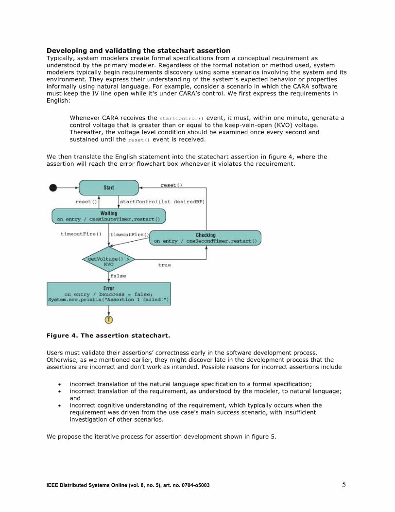
Developing and validating the statechart assertion Typically, system modelers create formal specifications from a conceptual requirement as understood by the primary modeler. Regardless of the formal notation or method used, system modelers typically begin requirements discovery using some scenarios involving the system and its environment. They express their understanding of the system’s expected behavior or properties informally using natural language. For example, consider a scenario in which the CARA software must keep the IV line open while it’s under CARA’s control. We first express the requirements in English:
Whenever CARA receives the startControl() event, it must, within one minute, generate a control voltage that is greater than or equal to the keep-vein-open (KVO) voltage. Thereafter, the voltage level condition should be examined once every second and sustained until the reset() event is received.
We then translate the English statement into the statechart assertion in figure 4, where the assertion will reach the error flowchart box whenever it violates the requirement.
Figure 4. The assertion statechart.
Users must validate their assertions’ correctness early in the software development process. Otherwise, as we mentioned earlier, they might discover late in the development process that the assertions are incorrect and don’t work as intended. Possible reasons for incorrect assertions include
incorrect translation of the natural language specification to a formal specification; incorrect translation of the requirement, as understood by the modeler, to natural language; andincorrect cognitive understanding of the requirement, which typically occurs when the requirement was driven from the use case’s main success scenario, with insufficient investigation of other scenarios.
We propose the iterative process for assertion development shown in figure 5.
IEEE Distributed Systems Online (vol. 8, no. 5), art. no. 0704-o5003 5

Figure 5. Iterative process for assertion development.
We first test the behavior of the assertion described by the statechart in figure 4 with the scenario in figure 6.
import junit.framework.*;
public class TestAssertion extends TestCase {
private Assertion1 assert1 = null;
public TestAssertion(String name) {
super(name);
}
protected void setUp() throws Exception {
super.setUp();
assert1 = new Assertion1 ();
}
protected void tearDown() throws Exception {
assert1 = null;
super.tearDown();
}
// Assertion 1, Test Scenario 1
public void testExecTReventDispatcher() {
assert1.startControl(70);
assert1.incrTime(30); //advance clock to 30s
assert1.setVoltage(KVO);
assert1.incrTime(31); //advance clock to 61s
assert1.setVoltage(KVO + 1);
assert1.incrTime(1); //advance clock to 62s
assert1.reset();
this.assertTrue(assert1.isSuccess());
}
}
Figure 6. A scenario describing an assertion’s typical behavior.
IEEE Distributed Systems Online (vol. 8, no. 5), art. no. 0704-o5003 6

Scenario 1 in figure 6 represents a typical case in which the control voltage is set at a level greater than or equal to the KVO voltage within one minute after the startControl() event’s arrival and remains greater than or equal to the KVO voltage until CARA receives the reset() event, resulting in a successful test outcome.
To ensure that the assertion works as intended, we create two more scenarios by replacing the body of the testExecTReventDispatcher() method with the code in figure 7.
// Assertion 1, Test Scenario 2
public void testExecTReventDispatcher() {
assert1.startControl(70);
assert1.incrTime(30); //advance clock to 30s
assert1.setVoltage(KVO);
assert1.incrTime(31); //advance clock to 61s
assert1.setVoltage(0);
assert1.incrTime(1); //advance clock to 62s
assert1.reset();
this.assertFalse(assert1.isSuccess());
}
// Assertion 1, Test Scenario 3
public void testExecTReventDispatcher() {
assert1.startControl(70);
assert1.incrTime(30); //advance clock to 30s
assert1.setvoltage(0);
assert1.reset();
this.assertTrue(assert1.isSuccess());
}
Figure 7. Scenarios for testing an assertion’s correctness.
Scenario 2 represents the case in which CARA sets the control voltage at a level greater than or equal to the KVO voltage within one minute after receiving the startControl() event, but fails to sustain the voltage level condition before receiving the reset() event. The entry action in the Error flowchart box in figure 4 sets the variable bSuccess to false, which in turn causes assert1.isSuccess() to return false and this.assertFalse() to return true.
Scenario 3 presents an interesting case. Although CARA constantly maintains the control voltage below the KVO voltage, the test outcome is still successful. This behavior relates directly to the process described in figure 5. Initially, this assertion’s success in this scenario surprised its developer. He followed the process in figure 5 to determine which reason for incorrect assertions this behavior represented and concluded that it might have resulted from incorrect cognitive understanding of the requirement. After discussing the situation with the customers, our developer decided that this behavior was acceptable and adjusted his cognitive expectation accordingly. If after discussing the situation with the customers, the developer decided the behavior was unacceptable, he would have needed to adjust the natural language requirement and assertion statechart accordingly.
This example highlights the subtleties of creating correct formal assertions and the value of testing executable formal assertions via JUnit-based simulations. The ability to test statechart assertions independent of the prototype design ensures that system designers truly understand the required system behavior without being tainted by any preconceived solutions. With the help of StateRover’s
IEEE Distributed Systems Online (vol. 8, no. 5), art. no. 0704-o5003 7
code generator, we can create a library of executable assertion patterns consisting of generic statechart assertions and the accompanying scenario-based test cases. The use of pretested generic statechart assertions will lessen the development time and improve the quality of the statechart assertions in rapid prototyping. In fact, we argue that the test suite for an assertion is an integral part of the assertion’s deliverables.
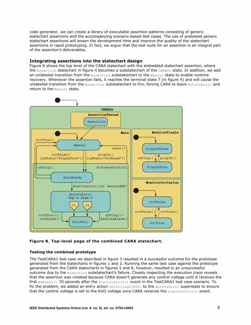
Integrating assertions into the statechart design Figure 8 shows the top level of the CARA statechart with the embedded statechart assertion, where the Assertion statechart in figure 4 becomes a substatechart of the CARAOn state. In addition, we add an unlabeled transition from the Assertion substatechart to the Manual state to enable runtime recovery. Whenever the assertion fails, it reaches the terminal state T (in figure 4) and will cause the unlabeled transition from the Assertion substatechart to fire, forcing CARA to leave AutoControl and return to the Manual state.
Figure 8. Top-level page of the combined CARA statechart.
Testing the combined prototype
The TestCARA1 test case we described in figure 3 resulted in a successful outcome for the prototype generated from the statecharts in figures 1 and 2. Running the same test case against the prototype generated from the CARA statecharts in figures 2 and 8, however, resulted in an unsuccessful outcome due to the Assertion substatechart’s failure. Closely inspecting the execution trace reveals that the assertion was violated because CARA doesn’t generate any control voltage until it receives the first BPEvent() 70 seconds after the startControl() event in the TestCARA1 test case scenario. To fix the problem, we added an entry action setVoltage(KVO) to the AutoControl superstate to ensure that the control voltage is set to the KVO voltage once CARA receives the startControl() event.
IEEE Distributed Systems Online (vol. 8, no. 5), art. no. 0704-o5003 8

Automatic white-box testing of the combined prototype
The StateRover’s automatic white-box test generator constructs a JUnit TestCase class from a given statechart model and associated embedded assertions. A typical JUnit white-box test case consists of hundreds of thousands of runs of the statechart under test (SUT). We use the autogenerated tests in three ways:
To search for severe programming errors that induce a JUnit error status, such as NullPointerException.To identify tests that violate temporal assertions. (To help statechart designers pinpoint specific errors, the white-box test case reports each failed test run with an identification number. The system designers can investigate the causes of failure for a specific run in detail by running the automatic white-box tester in single test/run mode. Such a mechanism helps developers efficiently eliminate errors in their design.) To identify input sequences leading the SUT to particular states of interest.
The StateRover-generated WBTestCase creates sequences of events and conditions for the SUT. The WBTestCase is nontrivial in that it creates only sequences consisting of events that the SUT or some embedded assertion is sensitive to. It does this by repeatedly observing all events that potentially affect the SUT when it’s in a given state configuration, selects one of those events, and fires the SUT using the selected event. The WBTestCase autogenerates three artifacts:
events, as we described earlier; time advance increments, for correctly generating timeoutFire events; and external data objects of the type that the statechart prototype refers to.
Although this process describes the model-based aspect of the StateRover’s white-box test generator, the WBTG actually observes all entities—namely, the SUT and all embedded assertions. It collects all possible events from all those entities, thus creating a hybrid model-based and specification-based WBTG.
The WBTG uses two algorithms for test generation. The stochastic WBTG algorithm creates a stochastic WBTestCase, which generates the artifacts using a random number generator. For each artifact of concern—the set of possible events, the set of objects the object factory can generate, and simulation time increments—the WBTG rolls the dice and makes a selection accordingly. In contrast, the deterministic WBTG algorithm creates a deterministic WBTestCase, which attempts to systematically cover all possible sequences by enumerating these artifacts and traversing new sequences one by one.
Both types of WBTestCase address SUT-loops by letting users specify
the maximal number of test sequences the WBTestCase may generate, denoted as the WB test budget, and the maximal length of any test sequence generated by the WBTestCase.
This lets the deterministic WBTestCase provide some coverage information. For example, if the user specifies that the SUT may visit a state configuration at most once, which amounts to exploring simple paths in the SUT, the WBTestCase could generate all such tests within its test budget, and the deterministic WBTestCase would then announce that it has covered all simple paths. When it can’t cover all possible paths of a given maximum length within its test budget, the deterministic WBTestCase will use the branching statistics of the test-tree traversal it has witnessed so far to estimate what percentage of tests it actually generated.
Using WBTG automates test generation but requires an automatic observer on the output side. We rely on assertion monitoring to provide such automatic observation.
IEEE Distributed Systems Online (vol. 8, no. 5), art. no. 0704-o5003 9

Say a devil’s advocate runs a test suite using an automatically generated WBTestCase on a SUT that contains no assertions. The WBTestCase will then succeed in all tests because no assertion exists that could ever fail. This is an extreme example of poor assertion coverage.
The StateRover’s WBTG estimates assertion coverage—that is, a numeric indication of the assertions’ suitability to the underlying SUT—using the notion of an assertion being touched by an event. This notion holds true if an assertion transition is traversed because of the event firing. Consequently, the StateRover’s WBTG provides the following assertion coverage information:
the ratio of cycles in which the assertion was touched, to all cycles; and the ratio of tests/runs in which the assertion was touched, to all runs.
We can also configure the StateRover’s WBTG to use NASA’s Java Pathfinder16 instead of its stochastic and deterministic methods. JPF uses a customized Java virtual machine to detect concurrency errors, such as deadlock, under varying firing schedules of concurrent transitions and actions. Moreover, we can view JPF as a sophisticated hybrid of the deterministic and stochastic methods. JPF makes sure to not revisit system states more than once by recording the state space being visited. The drawbacks of using JPF are that
it tends to run out of memory for complex systems, it wastes resources by model-checking the actions’ and activities’ assertions and methods, and it doesn’t work well with frameworks such as JUnit and Spring.17
Statechart assertions for distributed systems In earlier work,18 we classified formal assertions into three categories:
test-time assertions, which look for errors during system testing; runtime assertions, which are deployable assertions integrated with the target software’s runtime control flow to make the target software better able to detect and handle exceptions; andsimulation-time assertions, which use information about the environment that’s unavailable to the system at runtime.
Both test-time and runtime assertions use information present in the target software. The assertion statechart shown in figure 4 is an example of test-time and runtime assertions.
Simulation-time assertions are particularly useful for validating global, emerging behaviors of distributed systems, where the system’s global information is unavailable to individual nodes. Modeling and simulation hold the key to using these assertions early to validate distributed-system behaviors. For example, system designers often use prototypes with simulation-time assertions to force catastrophic behavior of the kind only available in simulation mode.
In addition to specifying the dynamic behavior of individual nodes using statecharts with embedded assertions, we’re currently extending the statechart formalism to let system designers intuitively specify global system behaviors in terms of message sequence charts. We’ll extend the StateRover to generate code based on the statechart and message sequence chart specifications to exercise OPNET (http://www.opnet.com) or OMNeT++ (http://www.omnetpp.org) simulation models under the WBTG’s control. We plan to publish our results in a sequel to this article.
Acknowledgments
This article is a revised version of a paper we presented at the Workshop on Rapid Systems Prototyping.19 A grant from the US Missile Defense Agency helped fund the research we reported here. The views and conclusions contained herein are those of the authors and shouldn’t be interpreted as necessarily representing the official policies or endorsements, either expressed or implied, of the US
IEEE Distributed Systems Online (vol. 8, no. 5), art. no. 0704-o5003 10

government. The US government is authorized to reproduce and distribute reprints for government purposes notwithstanding any copyright annotations thereon.
References
1. S. Easterbrook et al., “Experiences Using Lightweight Formal Methods for Requirements Modeling,” (http://doi.ieeecomputersociety.org/10.1109/32.663994) IEEE Trans. Software Eng., vol. 24, no. 1, 1998, pp. 4–14.
2. E. Clarke et al, “Formal Methods: State of the Art and Future Directions,” ACM Computing Surveys, vol. 28, no. 4, 1996, pp. 626–643.
3. D. Drusinsky and M. Shing, “Verification of Timing Properties in Rapid System Prototyping,” (http://doi.ieeecomputersociety.org/10.1109/IWRSP.2003.1207029) Proc. 14th IEEE Int’l Workshop Rapid Systems Prototyping, IEEE CS Press, 2003, pp. 47–53.
4. D. Drusinsky and G. Watney, “Applying Runtime Monitoring to the Deep-Impact Fault Protection Engine,” Proc. 28th Ann. NASA Goddard Software Eng. Workshop, IEEE Press, 2003, pp. 127–133.
5. D. Caffall et al., Formal Specification and Runtime Monitoring within the Ballistic Missile Defense Project, tech. report NPS-CS-05-007, Naval Postgraduate School, 2005.
6. D. Harel, “A Visual Formalism for Complex Systems,” Science of Computer Programming,vol.8, no. 3, 1987, pp. 231–274.
7. B. Bruegge and A.H. Dutoit, Object-Oriented Software Engineering: Conquering Complex and Changing Systems, Prentice Hall, 2000.
8. M.H. Park et al., “Equivalence Checking of Two Statechart Specifications,” (http://doi.ieeecomputersociety.org/10.1109/IWRSP.2000.855185) Proc. 11th Int’l Workshop Rapid System Prototyping, IEEE CS Press, 2000, pp. 46–51.
9. K. Lüth, J. Niehaus, and T. Peikenkamp, “HW/SW Co-Synthesis Using Statecharts and Symbolic Timing Diagrams,” (http://doi.ieeecomputersociety.org/10.1109/IWRSP.1998.676694) Proc. 9th Int’l Workshop Rapid System Prototyping, IEEE CS Press, 1998, pp. 212–217.
10. G. Graw, P. Herrmann, and H. Krumm, “Verification of UML-Based Real-Time System Design by Means of cTLA,” (http://doi.ieeecomputersociety.org/10.1109/ISORC.2000.839515) Proc. 3rd IEEE Int’l Symp. Object-Oriented Real-Time Distributed Computing (ISORC 2000), IEEE CS Press, 2000, pp. 86–95.
11. D. Drusinsky, “Semantics and Runtime Monitoring of TLCharts: Statechart Automata with Temporal Logic Conditioned Transitions,” Proc. 4th Runtime Verification Workshop (RV 04), Electronic Notes in Theoretical Computer Science, vol. 113, Elsevier, 2005, pp. 3–21.
12. D. Drusinsky, Modeling and Verification Using UML Statecharts, Elsevier, 2006. 13. R. Alur et al. “Formal Specifications and Analysis of the Computer Assisted Resuscitation
Algorithm (CARA) Infusion Pump Control System,” Int’l J. Software Tools for Technology Transfer (STTT), vol. 5, no. 4, Springer-Verlag, 2004, pp. 308–319.
14. D. Drusinsky and M. Shing, “TLCharts: Armor-plating Harel Statecharts with Temporal Logic Conditions,” (http://doi.ieeecomputersociety.org/10.1109/IWRSP.2004.1311092) Proc. 15th IEEE Int’l Workshop Rapid Systems Prototyping, IEEE CS Press, 2004, pp. 29–36.
15. K. Beck and E. Gamma, “Test Infected: Programmers Love Writing Tests,” Java Report, vol. 3, no. 7, 1998, pp. 37–50.
16. K. Havelund and T. Pressburger, “Model Checking Java Programs Using Java PathFinder,” Int’lJ. Software Tools for Technology Transfer (STTT), vol. 2, no. 4, 2000, pp. 366–381.
17. J. Arthur and S. Azadegan, “Spring Framework for Rapid Open Source J2EE Web Application Development: A Case Study,” (http://doi.ieeecomputersociety.org/10.1109/SNPD-SAWN.2005.74) Proc. 6th Int’l Conf. Software Eng., Artificial Intelligence, Networking and Parallel/Distributed Computing and the 1st ACIS Int’l Workshop on Self-Assembling Wireless Networks (SNPD/SAWN 2005), IEEE CS Press, 2005, pp. 90–95.
18. D. Drusinsky, M. Shing, and K. Demir, “Test-Time, Runtime, and Simulation-Time Assertions for RSP,” (http://doi.ieeecomputersociety.org/10.1109/RSP.2005.50) Proc. 16th IEEE Int’l Workshop Rapid Systems Prototyping, IEEE CS Press, 2005, pp. 105–110.
19. D. Drusinsky, M. Shing and K. Demir, “Creation and Validation of Embedded Assertions Statecharts,” (http://doi.ieeecomputersociety.org/10.1109/RSP.2006.12) Proc. 17th IEEE Int’l Workshop Rapid Systems Prototyping, IEEE CS Press, 2006, pp. 17–23.
IEEE Distributed Systems Online (vol. 8, no. 5), art. no. 0704-o5003 11

Doron Drusinsky is an associate professor at the Naval Postgraduate School in Monterey, California, and president of Time-Rover. His research interests are formal methods, requirement elicitation and validation, and sound construction of safety-critical systems. He received his PhD in computer science from the Weizmann Institute of Science. Contact him at the Computer Science Dept., Naval Postgraduate School, 1411 Cunningham Rd., GE-337, Monterey, CA 93943; [email protected].
Man-Tak Shing is an associate professor of computer science at the Naval Postgraduate School. His research interests include software engineering, modeling and design of real-time and distributed systems, and the specification, validation, and runtime monitoring of temporal assertions. He received his PhD in computer science from the University of California, San Diego. He’s a senior member of the IEEE. Contact him at the Computer Science Dept., Naval Postgraduate School, 1411 Cunningham Rd., GE-334, Monterey, California 93943; [email protected].
Kadir Alpaslan Demir is a PhD candidate in software engineering at the Naval Postgraduate School. His research interests include software project management, software development models and lifecycle models, software metrics and economics, formal methods, statecharts, and UML. He received master's degrees in computer science and software engineering from the Naval Postgraduate School. He’s a member of the IEEE and the IEEE Standards Association. Contact him at Naval Postgraduate School, Glasgow Hall E., GE-308, 1411 Cunningham Rd., Monterey, CA, 93943; [email protected].
Related Links
DS Online's Software Engineering community (http://dsonline.computer.org/portal/site/dsonline/index.jsp?pageID=dso_level1&path=dsonline/topics/software_engineering&file=index.xml&xsl=article.xsl) "Automatic Generation of Executable Assertions for Runtime Checking Temporal Requirements," Proc. HASE 05 (http://doi.ieeecomputersociety.org/10.1109/HASE.2005.6) "A Platform-Based Taxonomy for ESL Design," IEEE Design & Test of Computers(http://doi.ieeecomputersociety.org/10.1109/MDT.2006.112)
Cite this article:
Doron Drusinsky, Man-Tak Shing, and Kadir Alpaslan Demir, "Creating and Validating Embedded Assertion Statecharts," IEEE Distributed Systems Online, vol. 8, no. 5, 2007, art. no. 0705-o5003.
IEEE Distributed Systems Online (vol. 8, no. 5), art. no. 0704-o5003 12