A Review on Safe Human-Robot Collaboration in Industrial ...
20
Received September 26, 2017, accepted October 30, 2017, date of publication November 14, 2017, date of current version December 22, 2017. Digital Object Identifier 10.1109/ACCESS.2017.2773127 Working Together: A Review on Safe Human-Robot Collaboration in Industrial Environments S. ROBLA-GÓMEZ 1 , VICTOR M. BECERRA 2 , (Senior Member, IEEE), J. R. LLATA 1 , E. GONZÁLEZ-SARABIA 1 , C. TORRE-FERRERO 1 , AND J. PÉREZ-ORIA 1 , (Senior Member, IEEE) 1 Electronic Technology and Automatic Systems Department, School of Industrial and Telecommunications Engineering, University of Cantabria, 39005 Santander, Spain 2 School of Engineering, University of Portsmouth, Portsmouth PO1 3DJ, U.K. Corresponding author: S. Robla-Gómez ([email protected]) ABSTRACT After many years of rigid conventional procedures of production, industrial manufacturing is going through a process of change toward flexible and intelligent manufacturing, the so-called Industry 4.0. In this paper, human–robot collaboration has an important role in smart factories since it contributes to the achievement of higher productivity and greater efficiency. However, this evolution means breaking with the established safety procedures as the separation of workspaces between robot and human is removed. These changes are reflected in safety standards related to industrial robotics since the last decade, and have led to the development of a wide field of research focusing on the prevention of human–robot impacts and/or the minimization of related risks or their consequences. This paper presents a review of the main safety systems that have been proposed and applied in industrial robotic environments that contribute to the achievement of safe collaborative human–robot work. Additionally, a review is provided of the current regulations along with new concepts that have been introduced in them. The discussion presented in this paper includes multi- disciplinary approaches, such as techniques for estimation and the evaluation of injuries in human–robot collisions, mechanical and software devices designed to minimize the consequences of human–robot impact, impact detection systems, and strategies to prevent collisions or minimize their consequences when they occur. INDEX TERMS Safety, industrial robot, human-robot collaboration, industrial standards, Industry 4.0. I. INTRODUCTION In the last 50 years industrial robots have been widely used in the manufacturing industry, and they have substituted humans in various tasks, relieving workers from repetitive, unhealthy or dangerous jobs. A direct result of the deploy- ment of robots in industry is the rise of new risks of acci- dents for workers. The industrial regulations that incorporate these robot related risks for workers include the international standard ISO 10218 and the Technical Specification ISO/TS 15066:2016, the American ANSI/RIA R15.06, the European EN 775 which is adapted from the ISO 10218, and national standards such as the Spanish UNE-EN 755 which is adapted from the EN 755 by the Spanish Association of Normalisation and Certification. To prevent accidents the selection of a safety system must be based on the analysis of the afore- mentioned risks. Commonly in the past, safety systems have separated the robot and human workspaces. One instance of this separation was reflected in the standard UNE-EN 755:1996 [1] which established that sensor systems had to be incorporated to prevent the entrance of persons in a hazardous area, where the operating state of the robotic system could have caused dangers to the workers. According to traditional standards, authorised personnel can only be inside the robot workspace if the robot is not in automatic mode. The pursuit of more flexible and more efficient manufac- turing is driving significant changes in industry. The trans- formation from automatic manufacturing to Industry 4.0, which has been predominantly promoted from Germany, or to smart factories fostered from the USA [2], is based on the emergence of a new generation of systems that introduce the latest technological advances in information and communica- tion technologies (ICTs), data analysis, and devices such as sensors or robots. These transformations are causing that the tasks performed by industrial robots are no longer restricted 26754 2169-3536 2017 IEEE. Translations and content mining are permitted for academic research only. Personal use is also permitted, but republication/redistribution requires IEEE permission. See http://www.ieee.org/publications_standards/publications/rights/index.html for more information. VOLUME 5, 2017
-
Upload
khangminh22 -
Category
Documents
-
view
3 -
download
0
Transcript of A Review on Safe Human-Robot Collaboration in Industrial ...
Received September 26, 2017, accepted October 30, 2017, date of publication November 14, 2017,date of current version December 22, 2017.
Digital Object Identifier 10.1109/ACCESS.2017.2773127
Working Together: A Review on SafeHuman-Robot Collaboration inIndustrial EnvironmentsS. ROBLA-GÓMEZ 1, VICTOR M. BECERRA2, (Senior Member, IEEE), J. R. LLATA1,E. GONZÁLEZ-SARABIA1, C. TORRE-FERRERO1, AND J. PÉREZ-ORIA1, (Senior Member, IEEE)1Electronic Technology and Automatic Systems Department, School of Industrial and Telecommunications Engineering,University of Cantabria, 39005 Santander, Spain2School of Engineering, University of Portsmouth, Portsmouth PO1 3DJ, U.K.
Corresponding author: S. Robla-Gómez ([email protected])
ABSTRACT After many years of rigid conventional procedures of production, industrial manufacturing isgoing through a process of change toward flexible and intelligent manufacturing, the so-called Industry 4.0.In this paper, human–robot collaboration has an important role in smart factories since it contributes to theachievement of higher productivity and greater efficiency. However, this evolution means breaking with theestablished safety procedures as the separation of workspaces between robot and human is removed. Thesechanges are reflected in safety standards related to industrial robotics since the last decade, and have led tothe development of a wide field of research focusing on the prevention of human–robot impacts and/or theminimization of related risks or their consequences. This paper presents a review of the main safety systemsthat have been proposed and applied in industrial robotic environments that contribute to the achievementof safe collaborative human–robot work. Additionally, a review is provided of the current regulations alongwith new concepts that have been introduced in them. The discussion presented in this paper includes multi-disciplinary approaches, such as techniques for estimation and the evaluation of injuries in human–robotcollisions, mechanical and software devices designed to minimize the consequences of human–robot impact,impact detection systems, and strategies to prevent collisions or minimize their consequences when theyoccur.
INDEX TERMS Safety, industrial robot, human-robot collaboration, industrial standards, Industry 4.0.
I. INTRODUCTIONIn the last 50 years industrial robots have been widely usedin the manufacturing industry, and they have substitutedhumans in various tasks, relieving workers from repetitive,unhealthy or dangerous jobs. A direct result of the deploy-ment of robots in industry is the rise of new risks of acci-dents for workers. The industrial regulations that incorporatethese robot related risks for workers include the internationalstandard ISO 10218 and the Technical Specification ISO/TS15066:2016, the American ANSI/RIA R15.06, the EuropeanEN 775 which is adapted from the ISO 10218, and nationalstandards such as the Spanish UNE-EN 755 which is adaptedfrom the EN 755 by the SpanishAssociation of Normalisationand Certification. To prevent accidents the selection of asafety system must be based on the analysis of the afore-mentioned risks. Commonly in the past, safety systems haveseparated the robot and human workspaces. One instance
of this separation was reflected in the standard UNE-EN755:1996 [1] which established that sensor systems had to beincorporated to prevent the entrance of persons in a hazardousarea, where the operating state of the robotic system couldhave caused dangers to the workers. According to traditionalstandards, authorised personnel can only be inside the robotworkspace if the robot is not in automatic mode.
The pursuit of more flexible and more efficient manufac-turing is driving significant changes in industry. The trans-formation from automatic manufacturing to Industry 4.0,which has been predominantly promoted from Germany, orto smart factories fostered from the USA [2], is based on theemergence of a new generation of systems that introduce thelatest technological advances in information and communica-tion technologies (ICTs), data analysis, and devices such assensors or robots. These transformations are causing that thetasks performed by industrial robots are no longer restricted
267542169-3536 2017 IEEE. Translations and content mining are permitted for academic research only.
Personal use is also permitted, but republication/redistribution requires IEEE permission.See http://www.ieee.org/publications_standards/publications/rights/index.html for more information.
VOLUME 5, 2017
S. Robla-Gómez et al.: Working Together: Review on Safe Human-Robot Collaboration in Industrial Environments
to the transfer of objects, or other repetitive actions. Instead,there is an increasing number of tasks in which humans androbots combine their skills in collaborative work.
To facilitate effective collaborative work between a humanworker and an industrial robot, previously existing barriersthat established a inflexible separation between human androbot workspaces need to be eliminated. Instead, other typesof safety systems need to be introduced, so that collisions canbe prevented by detecting obstacles as well as their motion,applying appropriate avoidance strategies, and harm to thehuman can beminimized in case of an unexpected or unavoid-able impact. These changes in work practices in industrialenvironments are reflected in the updates that have appearedfrom the year 2006 in the the ISO10218 standard [3], andthe guidelines for the implementation of these regulations,such as [4]. In these updates new concepts are introduced,including the concepts of collaborative operation, collabora-tive workspace, and collaborative robot, which are of directrelevance to this review.
The latest update of the standard ISO 10218-1 [5], andISO 10218-2 [6] is focused on the above definitions, pro-viding details on collaborative operation requirements, andcooperation task typologies. The former includes for instancestart-up controls, functioning of the safety control system,motion braking, speed control, while the latter includes forexample manual guidance, interface window, and cooperativeworkspace.
The international standard ISO: 8373-2012 [7] specifiesthe vocabulary used in relation to robots and robotic devices.Here, new terms involved in the development of new collabo-rative tasks in industrial and non-industrial environments aredefined, such as human-robot interaction and service robot,in addition to more established terms, such as robot andcontrol system.
The recent Technical Specification ISO/TS 15066:2016[8] attempts to further specify human-robot collaboration bysupplementing the requirements and guidance established inISO 10218.
The way the standards have evolved in the last decadereflects the current trend towards what many researches havecalled human-robot collaboration (HRC) in an industrial con-text. Although other types of robots that perform collabora-tive tasks with humans have been developed within the lastfew decades (e.g. social robots, assistive robots and hapticdevices), these robots have different purposes from those ofthe industrial robots used for manufacturing and are thereforenot discussed in this review.
Previous review articles in the area of safety in human-robot collaboration have been published [9]–[11]. This articleprovides contributions beyond the previous reviews by cover-ing the latest standards in robot safety and reviewing the latestsafety systems, including light robots, motion capture sys-tems and simulated environments, the use different types ofcameras, and techniques for the fusion of visual information.Moreover, this article reviews ways of fitting robot safetywithin the framework provided by Cyber-Physical Systems.
II. A FRAMEWORK FOR SAFETY IN INDUSTRIALROBOTIC ENVIRONMENTSTo provide a structured framework for further discussion inthis article, a classification of the main safety systems inrobotic environments is provided in Table 1, including theaims pursued by the safety systems, hardware and softwaresystems that are employed, devices that are used, and theactions involved in each type safety system. Table 1 indicatesthe sections of the paper where each subject is covered.
TABLE 1. Classification of safety in industrial robot collaborativeenvironments.
In addition to such elements, the term of Cyber-PhysicalSystems (CPS) has been included due to the recent develop-ments in intelligent manufacturing have important implica-tions on the implementation of robot safety systems. In thisway, the incorporation of network computing, connecteddevices and data management systems in manufacturingprocesses, including active safety systems, have resulted ininstances CPS. Cyber-Physical System are defined as physi-cal devices which are provided with technologies to collectdata about themselves and their surroundings, process andevaluate these data, connect and communicate with othersystems and initiate actions to achieve their goals [2], [12].
The use of the CPS framework in the manufacturing indus-try has helped to bring the sharing of workspaces betweenhumans and robots from concept to reality. This has con-tributed to achieving a flexible, adaptable, reliable and highperforming production. CPS can be considered as a livingconcept from which variations such as Cyber Physical Pro-duction Systems (CPPS) are emerging [13]. CPPS is seen asa more specific concept that is geared to manufacturing [14],and not as a generalist as CPS which covers areas so diverse
VOLUME 5, 2017 26755
S. Robla-Gómez et al.: Working Together: Review on Safe Human-Robot Collaboration in Industrial Environments
as transport, infrastructure, health care, emergency response,defence, energy, or manufacturing.
Taking into account that, along with other applications,safety issues fall within the scope of Cyber Physical Systems(CPS), in [15] safety systems based onCPS for a human-robotcollaboration team were implemented. For this purpose, sev-eral safety approaches, which allow to have different levels ofHRC, have been proposed. For each proposed strategy, differ-ent types and combinations of sensors are used including laserscanners, proximity sensors, vision systems, or force sensors.The results show that there are technological limits on thesensor data rates and the number and type of feasible sensorsused in the implementation of the system. These drawbackshighlight the technological limits and challenges associatedwith the real-time implementation of CPS applied to human-robot collaboration.
In the context of intelligent manufacturing where alldevices are interconnected share information and make deci-sions and perform actions, safety is closely bounded up withsecurity. In the understanding that the concept of securityis related to threats or cyber attacks that CPS can suffer,the possible interdependences between safety and securityshould be taken into account to achieve a more robust hazardmanagement, as analysed in [16].
Another important aspect to achieve effective and safe co-working in smart factories is the psychological state of theoperator. It is necessary to ensure that the operator feelscomfortable and safe when cooperating with a robot, andthat mental strains associated with such tasks are bearable.In [17] an assessment of mental strains of a human operatorworking in a cellular manufacturing system was carried outthrough experiments in which three influential factors inoperator mental strain, including distance, speed and warn-ings of motion, were varied in order to define design criteriato improve operator comfort.
Suitable operator training clearly has an influence on theirconfidence and stress levels as well as their safety as issuggested by experimental results in [18] and [19], andthis is reflected in documents such as the guidelines forimplementing ANSI/RIA/ISO [4], and in standard ISO/TS15066:2016 [8]. Training can be considered as a safety mea-sure that does not depend on specific technologies being usedin robotic systems, thus falling out of the classification ofTable 1.
III. SEPARATING HUMAN AND ROBOT WORKSPACESTypical industrial robots are large, heavy and move at highspeeds. These circumstances make it necessary to preventimpacts between the robot and a human who may enterthe robot workspace, so as to avoid harm to the human.The approach prescribed by the previous standard ISO10218:1992 or its equivalent UNE-EN 775 [1] to preventsuch collisions or other incidents that may result in injuries,was to establish a compulsory separation between human androbot workspaces, by detecting human intrusions in robotworkspaces, and modifying the robot behaviour accordingly.
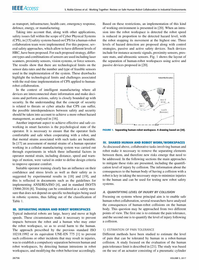
Based on these restrictions, an implementation of this kindof working environment is presented in [20]. When an intru-sion into the robot workspace is detected the robot speedis reduced in proportion to the detected hazard level, withthe robot stopping its movement at the highest one. Threelevels of hazard detection are proposed along with controlstrategies, passive and active safety devices. Such devicesinclude for instance acoustic signals, proximity sensors, pres-sure mats, and ultrasonic sensors. Fig. 1 shows the layout ofthe separation of human-robot workspaces using active andpassive devices proposed in [20].
FIGURE 1. Separating human-robot workspace. A drawing based on [20].
IV. SHARED HUMAN AND ROBOT WORK/WORKSPACESAs discussed above, collaborative tasks involving human androbot make it necessary to remove the separating elementsbetween them, and therefore new risks emerge that need tobe addressed. In the following sections the main approachesto mitigate these risks are presented, including the quantifi-cation level of injury by collision. The information about theconsequences to the human body of having a collision with arobot is key in taking the necessary steps to minimize injuriesto the human and can be used for testing new robot safetysystems.
A. QUANTIFYING LEVEL OF INJURY BY COLLISIONFocusing on systems whose principal aim is to enable safehuman robot collaboration, several researchers have analysedthe consequences of human-robot collisions on the humanbody. This question may be approached from two differentpoints of view. The first one is to estimate the pain tolerance,and the second one is to quantify the level of injury followinga collision.
1) ESTIMATION OF PAIN TOLERANCEDifferent methods have been studied to estimate the levelof pain that can be tolerated by human in a robot-humancollision. A study focused on the evaluation of the humanpain tolerance limit is described in [21]. The study was basedon the use of an actuator consisting of a pneumatic cylinder
26756 VOLUME 5, 2017
S. Robla-Gómez et al.: Working Together: Review on Safe Human-Robot Collaboration in Industrial Environments
delivering impacts to 12 parts of the body of human volun-teers to find a value of tolerable contact force.
The authors suggest further analysis of human pain toler-ance as simulations showed that if a conventional robot witha stiff surface was used, the value of impact force could eas-ily transcend the acceptable threshold at common operatingvelocities, even when a compliant covering was employed.
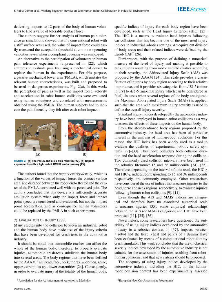
An alternative to the participation of volunteers in humanpain tolerance experiments is presented in [22], whichattempts to evaluate pain by using a mechanical device toreplace the human in the experiments. For this purpose,a passive mechanical lower arm (PMLA), which imitates therelevant human characteristics, was built and proposed tobe used in dangerous experiments, Fig. 2(a). In this work,the perception of pain as well as the impact force, velocityand acceleration in robot-human collisions were evaluatedusing human volunteers and correlated with measurementsobtained using the PMLA. The human subjects had to indi-cate the pain intensity they felt after each robot impact.
FIGURE 2. (a) The PMLA and a six-axis robot in [22]. (b) Impactexperiments with a light robot LWRIII and a dummy [23].
The authors found that the impact energy density, which isa function of the values of impact force, the contact surfacearea, and distance between the robot end-effector and the cen-ter of the PMLA, correlated well with the perceived pain. Theauthors concluded that this device is a sufficiently accurateemulation system when only the impact force and impactpoint speed are considered and evaluated, but not the impactpoint acceleration, and as consequence human volunteerscould be replaced by the PMLA in such experiments.
2) EVALUATION OF INJURY LEVELMany studies into the collision between an industrial robotand the human body have made use of the injury criteriathat have been developed for crash-tests in the automotiveindustry.
It should be noted that automobile crashes can affect thewhole of the human body, therefore, to properly evaluateinjuries, automobile crash-tests subdivide the human bodyinto several areas. The body regions that have been definedby the AAAM 1 are head, face, neck, thorax, abdomen, spine,upper extremities and lower extremities [24]. Consequently,in order to evaluate injury at the totality of the human body,
1Association for the Advancement of Automotive Medicine
specific indices of injury for each body region have beendeveloped, such as the Head Injury Criterion (HIC) [25].The HIC is a means to evaluate head injuries followingcar collisions that has become one of the most used injuryindices in industrial robotics settings. An equivalent divisionof body areas and their related indices were defined by theEuroNCAP2 [26].Furthermore, with the purpose of defining a numerical
measure of the level of injury and making it possible torank injuries resulting from motor vehicle crashes accordingto their severity, the Abbreviated Injury Scale (AIS) wasproposed by the AAAM [24]. This scale provides a classi-fication of injuries by body region according to their relativeimportance, and it provides six categories from AIS-1 (minorinjury) to AIS-6 (maximal injury which can be considered asfatal). In cases when several regions of the body are injured,the Maximun Abbreviated Injury Scale (MAIS) is applied,such that the area with maximum injury severity is used todefine the overall injury severity.
Standard injury indices developed by the automotive indus-try have been employed in human-robot collisions as a wayto assess the effects of these impacts on the human body.
From the aforementioned body regions proposed by theautomotive industry, the head area has been of particularinterest in the analysis of human-robot collisions. For thisreason, the HIC index has been widely used as a tool toevaluate the qualities of experimental robotic safety sys-tems [27]–[33]. This index considers both collision dura-tion and the head acceleration response during the collision.Two commonly used collision intervals have been used inthe robotics literature: 15 and 36 milliseconds [34], [35].Therefore, depending on the interval of time used, the HIC15and HIC36 indices, corresponding to 15 and 36 millisecondsrespectively, are commonly employed. Other researchershave considered the use of indices that measure injuries to thehead, torso and neck regions, respectively, to evaluate injuriesfollowing human-robot collisions [9], [11].
Even though the AIS and MAIS indices are categor-ical and therefore have no associated numerical scaleto measure injuries [35], some empirical relationshipsbetween the AIS (or MAIS) categories and HIC have beenproposed [11], [35], [36].
Nevertheless, some researchers have questioned the suit-ability of using injury indices developed by the automotiveindustry in a robotics context. In [37], impacts betweena robot and the head, chest and pelvis of a dummy havebeen evaluated by means of a computational robot-dummycrash simulator. This work concludes that the use of classicalseverity indices developed by the automotive industry is notsuitable for the assessment of injuries resulting from robot-human collisions, and that new criteria should be proposed.
The adequacy of using injury indices developed by theautomotive industry, including the HIC, in the human-robot collision context has been experimentally assessed
2European New Car Assessment Programme
VOLUME 5, 2017 26757
S. Robla-Gómez et al.: Working Together: Review on Safe Human-Robot Collaboration in Industrial Environments
in [23], [36], and [38]. Based on these works, the researchdescribed in [35] provides descriptions and mathematicalformulation of relevant injury classification metrics andbiomechanical injury measures for head, chest, neck andeye. In addition, the European testing protocol EuroNCAPwas applied experimentally in unconstrained and constrainedimpacts to the head, chest and neck using different robots,including a light robot LWR-III, illustrated in Fig. 2(b).The conclusions in [35] claim that the resulting EuroNCAP
index values do not exceed the safety thresholds and thussevere injuries are unlikely to occur, since the maximumspeeds reached by robots are considerably lower than typi-cal car speeds, concluding that HIC and similar criteria areapparently not suitable to be applied in robotics. However, atlow robot speeds, some severe injuries, such as fractures offacial and cranial bones, can result, and therefore require thesetting of appropriated injury indices.
Table 2 shows injury indices commonly used to assessrobot-human collisions, according to the body area of focus,along with references from the literature where the specificindices are mentioned or employed.
TABLE 2. Injury indices used to assess robot-human collisions.
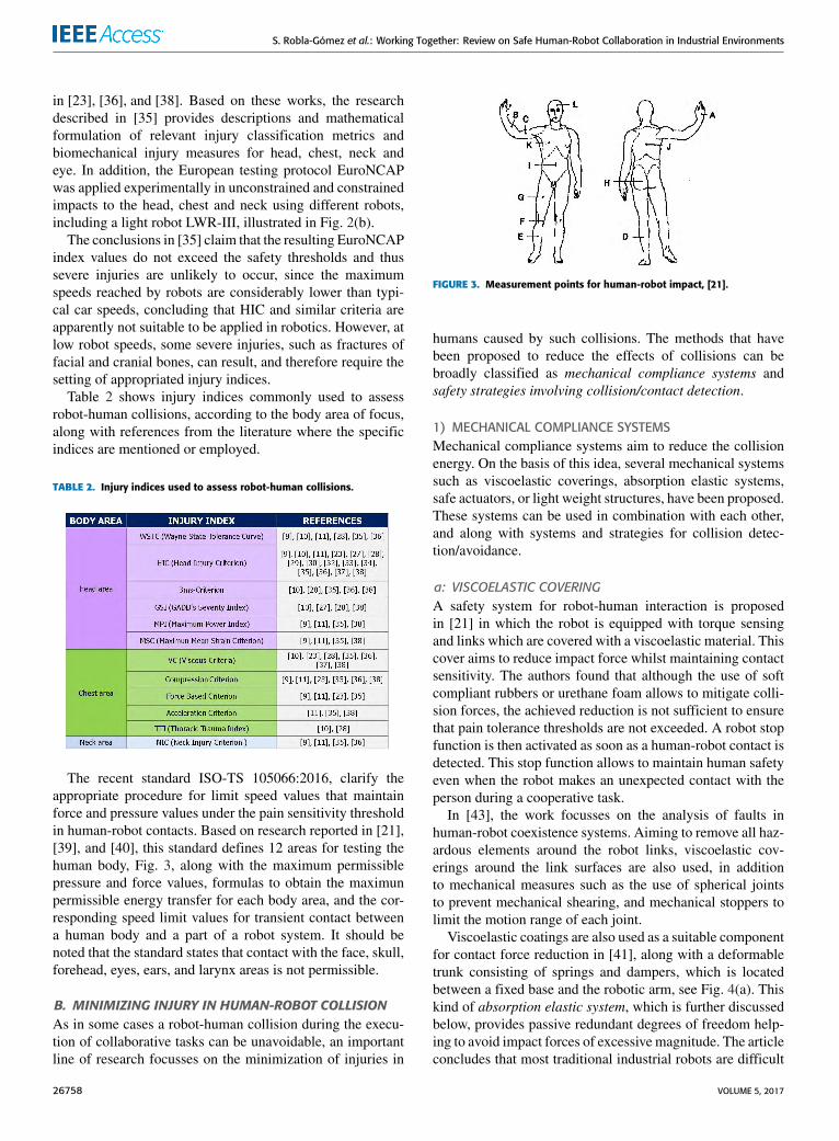
The recent standard ISO-TS 105066:2016, clarify theappropriate procedure for limit speed values that maintainforce and pressure values under the pain sensitivity thresholdin human-robot contacts. Based on research reported in [21],[39], and [40], this standard defines 12 areas for testing thehuman body, Fig. 3, along with the maximum permissiblepressure and force values, formulas to obtain the maximunpermissible energy transfer for each body area, and the cor-responding speed limit values for transient contact betweena human body and a part of a robot system. It should benoted that the standard states that contact with the face, skull,forehead, eyes, ears, and larynx areas is not permissible.
B. MINIMIZING INJURY IN HUMAN-ROBOT COLLISIONAs in some cases a robot-human collision during the execu-tion of collaborative tasks can be unavoidable, an importantline of research focusses on the minimization of injuries in
FIGURE 3. Measurement points for human-robot impact, [21].
humans caused by such collisions. The methods that havebeen proposed to reduce the effects of collisions can bebroadly classified as mechanical compliance systems andsafety strategies involving collision/contact detection.
1) MECHANICAL COMPLIANCE SYSTEMSMechanical compliance systems aim to reduce the collisionenergy. On the basis of this idea, several mechanical systemssuch as viscoelastic coverings, absorption elastic systems,safe actuators, or light weight structures, have been proposed.These systems can be used in combination with each other,and along with systems and strategies for collision detec-tion/avoidance.
a: VISCOELASTIC COVERINGA safety system for robot-human interaction is proposedin [21] in which the robot is equipped with torque sensingand links which are covered with a viscoelastic material. Thiscover aims to reduce impact force whilst maintaining contactsensitivity. The authors found that although the use of softcompliant rubbers or urethane foam allows to mitigate colli-sion forces, the achieved reduction is not sufficient to ensurethat pain tolerance thresholds are not exceeded. A robot stopfunction is then activated as soon as a human-robot contact isdetected. This stop function allows to maintain human safetyeven when the robot makes an unexpected contact with theperson during a cooperative task.
In [43], the work focusses on the analysis of faults inhuman-robot coexistence systems. Aiming to remove all haz-ardous elements around the robot links, viscoelastic cov-erings around the link surfaces are also used, in additionto mechanical measures such as the use of spherical jointsto prevent mechanical shearing, and mechanical stoppers tolimit the motion range of each joint.
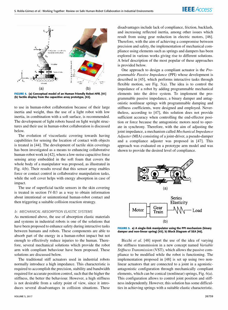
Viscoelastic coatings are also used as a suitable componentfor contact force reduction in [41], along with a deformabletrunk consisting of springs and dampers, which is locatedbetween a fixed base and the robotic arm, see Fig. 4(a). Thiskind of absorption elastic system, which is further discussedbelow, provides passive redundant degrees of freedom help-ing to avoid impact forces of excessive magnitude. The articleconcludes that most traditional industrial robots are difficult
26758 VOLUME 5, 2017
S. Robla-Gómez et al.: Working Together: Review on Safe Human-Robot Collaboration in Industrial Environments
FIGURE 4. (a) Conceptual model of an Human Friendly Robot HFR, [41](b) Tactile display from the capacitive array prototype, [42].
to use in human-robot collaboration because of their largeinertia and weight, thus the use of a light robot with lowinertia, in combination with a soft surface, is recommended.The development of light robots based on light weight struc-tures and their use in human-robot collaboration is discussedbelow.
The evolution of viscoelastic covering towards havingcapabilities for sensing the location of contact with objectsis treated in [44]. The development of tactile skin coveringshas been investigated as a means to enhancing collaborativehuman-robot work in [42], where a low-noise capacitive forcesensing array embedded in the soft foam that covers thewhole body of a manipulator was proposed, as illustrated inFig. 4(b). Their results reveal that this sensor array enablesforce or contact control in collaborative manipulation tasks,while the soft cover helps with energy absorption in case ofimpact.
The use of superficial tactile sensors in the skin coveringis treated in section IV-B3 as a way to obtain informationabout intentional or unintentional human-robot contact andthen triggering a suitable collision reaction strategy.
b: MECHANICAL ABSORPTION ELASTIC SYSTEMSAs mentioned above, the use of absorption elastic materialsand systems in industrial robots is one of the solutions thathave been proposed to enhance safety during interactive tasksbetween humans and robots. These components are able toabsorb part of the energy in a human-robot impact but notenough to effectively reduce injuries to the human. There-fore, several mechanical solutions which provide the robotarm with compliant behaviour have been proposed. Thesesolutions are discussed below.
The traditional stiff actuators used in industrial robotsnormally introduce a high impedance. This characteristic isrequired to accomplish the precision, stability and bandwidthrequired for accurate position control, such that the higher thestiffness, the better the behaviour. However, a high stiffnessis not desirable from a safety point of view, since it intro-duces several disadvantages in collision situations. These
disadvantages include lack of compliance, friction, backlash,and increasing reflected inertia, among other issues whichresult from using gear reduction in electric motors, [46].Therefore, with the aim of achieving a compromise betweenprecision and safety, the implementation of mechanical com-pliance using elements such as springs and dampers has beenexplored in various works giving rise to different solutions.A brief description of the most popular of these approachesis provided below.
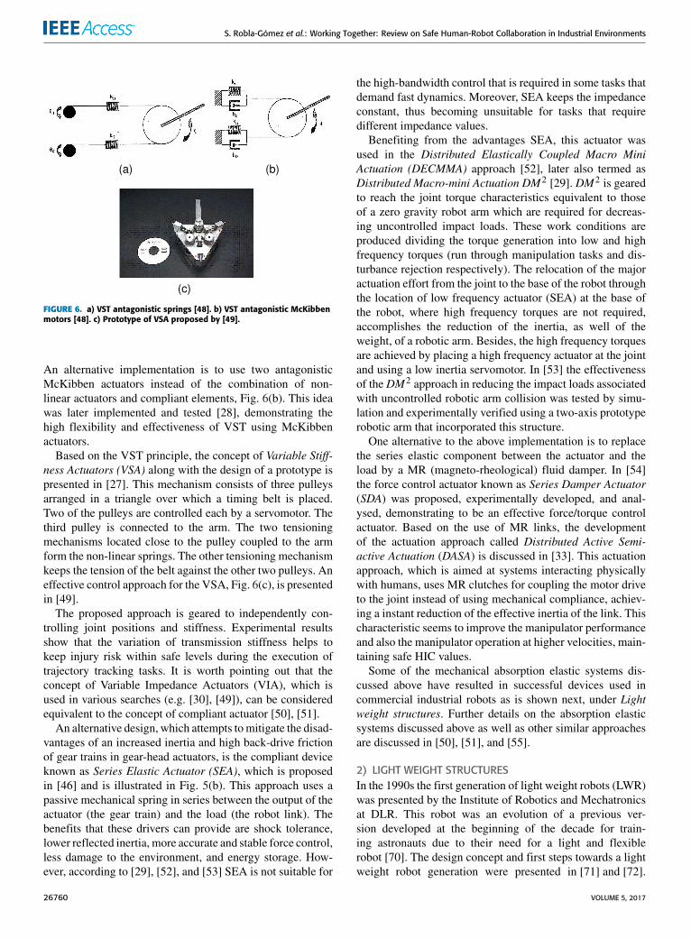
One approach to design a compliant actuator is the Pro-grammable Passive Impedance (PPI) whose development isdescribed in [45], which performs interactive tasks throughflexible motion, see Fig. 5(a). The idea is to control theimpedance of a robot by adding programmable mechanicalelements into the drive system. To implement the pro-grammable passive impedance, a binary damper and antag-onistic nonlinear springs with programmable damping andstiffness coefficients, were designed and employed. Never-theless, according to [47], this solution does not providesufficient accuracy when controlling the end-effector posi-tion or force because the antagonistic motors need to oper-ate in synchrony. Therefore, with the aim of adjusting thejoint impedance, a mechanism calledMechanical ImpedanceAdjuster (MIA) consisting of a joint-driver, a pseudo-damperand a compliance adjuster was proposed in [47]. Thisapproach was evaluated on a prototype arm model and wasshown to provide the desired level of compliance.
FIGURE 5. a) A single-link manipulator using the PPI mechanism (binarydamper and non-linear spring) [45]. b) Block Diagram of SEA [46].
Bicchi et al. [48] report the use of the idea of varyingthe stiffness transmission in a new concept named VariableStiffness Transmission (VST), which allows the passive com-pliance to be modified while the robot is functioning. Theimplementation proposed in [48] is set up using two non-linear actuators that are connected to a joint in a agonistic-antagonistic configuration through mechanically compliantelements, which can be conical (nonlinear) springs, Fig. 6(a).This configuration allows to control joint position and stiff-ness independently. However, this solution has some difficul-ties in achieving springs with a suitable elastic characteristic.
VOLUME 5, 2017 26759
S. Robla-Gómez et al.: Working Together: Review on Safe Human-Robot Collaboration in Industrial Environments
FIGURE 6. a) VST antagonistic springs [48]. b) VST antagonistic McKibbenmotors [48]. c) Prototype of VSA proposed by [49].
An alternative implementation is to use two antagonisticMcKibben actuators instead of the combination of non-linear actuators and compliant elements, Fig. 6(b). This ideawas later implemented and tested [28], demonstrating thehigh flexibility and effectiveness of VST using McKibbenactuators.
Based on the VST principle, the concept of Variable Stiff-ness Actuators (VSA) along with the design of a prototype ispresented in [27]. This mechanism consists of three pulleysarranged in a triangle over which a timing belt is placed.Two of the pulleys are controlled each by a servomotor. Thethird pulley is connected to the arm. The two tensioningmechanisms located close to the pulley coupled to the armform the non-linear springs. The other tensioning mechanismkeeps the tension of the belt against the other two pulleys. Aneffective control approach for the VSA, Fig. 6(c), is presentedin [49].
The proposed approach is geared to independently con-trolling joint positions and stiffness. Experimental resultsshow that the variation of transmission stiffness helps tokeep injury risk within safe levels during the execution oftrajectory tracking tasks. It is worth pointing out that theconcept of Variable Impedance Actuators (VIA), which isused in various searches (e.g. [30], [49]), can be consideredequivalent to the concept of compliant actuator [50], [51].
An alternative design, which attempts tomitigate the disad-vantages of an increased inertia and high back-drive frictionof gear trains in gear-head actuators, is the compliant deviceknown as Series Elastic Actuator (SEA), which is proposedin [46] and is illustrated in Fig. 5(b). This approach uses apassive mechanical spring in series between the output of theactuator (the gear train) and the load (the robot link). Thebenefits that these drivers can provide are shock tolerance,lower reflected inertia, more accurate and stable force control,less damage to the environment, and energy storage. How-ever, according to [29], [52], and [53] SEA is not suitable for
the high-bandwidth control that is required in some tasks thatdemand fast dynamics. Moreover, SEA keeps the impedanceconstant, thus becoming unsuitable for tasks that requiredifferent impedance values.
Benefiting from the advantages SEA, this actuator wasused in the Distributed Elastically Coupled Macro MiniActuation (DECMMA) approach [52], later also termed asDistributed Macro-mini Actuation DM2 [29]. DM2 is gearedto reach the joint torque characteristics equivalent to thoseof a zero gravity robot arm which are required for decreas-ing uncontrolled impact loads. These work conditions areproduced dividing the torque generation into low and highfrequency torques (run through manipulation tasks and dis-turbance rejection respectively). The relocation of the majoractuation effort from the joint to the base of the robot throughthe location of low frequency actuator (SEA) at the base ofthe robot, where high frequency torques are not required,accomplishes the reduction of the inertia, as well of theweight, of a robotic arm. Besides, the high frequency torquesare achieved by placing a high frequency actuator at the jointand using a low inertia servomotor. In [53] the effectivenessof the DM2 approach in reducing the impact loads associatedwith uncontrolled robotic arm collision was tested by simu-lation and experimentally verified using a two-axis prototyperobotic arm that incorporated this structure.
One alternative to the above implementation is to replacethe series elastic component between the actuator and theload by a MR (magneto-rheological) fluid damper. In [54]the force control actuator known as Series Damper Actuator(SDA) was proposed, experimentally developed, and anal-ysed, demonstrating to be an effective force/torque controlactuator. Based on the use of MR links, the developmentof the actuation approach called Distributed Active Semi-active Actuation (DASA) is discussed in [33]. This actuationapproach, which is aimed at systems interacting physicallywith humans, uses MR clutches for coupling the motor driveto the joint instead of using mechanical compliance, achiev-ing a instant reduction of the effective inertia of the link. Thischaracteristic seems to improve the manipulator performanceand also the manipulator operation at higher velocities, main-taining safe HIC values.
Some of the mechanical absorption elastic systems dis-cussed above have resulted in successful devices used incommercial industrial robots as is shown next, under Lightweight structures. Further details on the absorption elasticsystems discussed above as well as other similar approachesare discussed in [50], [51], and [55].
2) LIGHT WEIGHT STRUCTURESIn the 1990s the first generation of light weight robots (LWR)was presented by the Institute of Robotics and Mechatronicsat DLR. This robot was an evolution of a previous ver-sion developed at the beginning of the decade for train-ing astronauts due to their need for a light and flexiblerobot [70]. The design concept and first steps towards a lightweight robot generation were presented in [71] and [72].
26760 VOLUME 5, 2017
S. Robla-Gómez et al.: Working Together: Review on Safe Human-Robot Collaboration in Industrial Environments
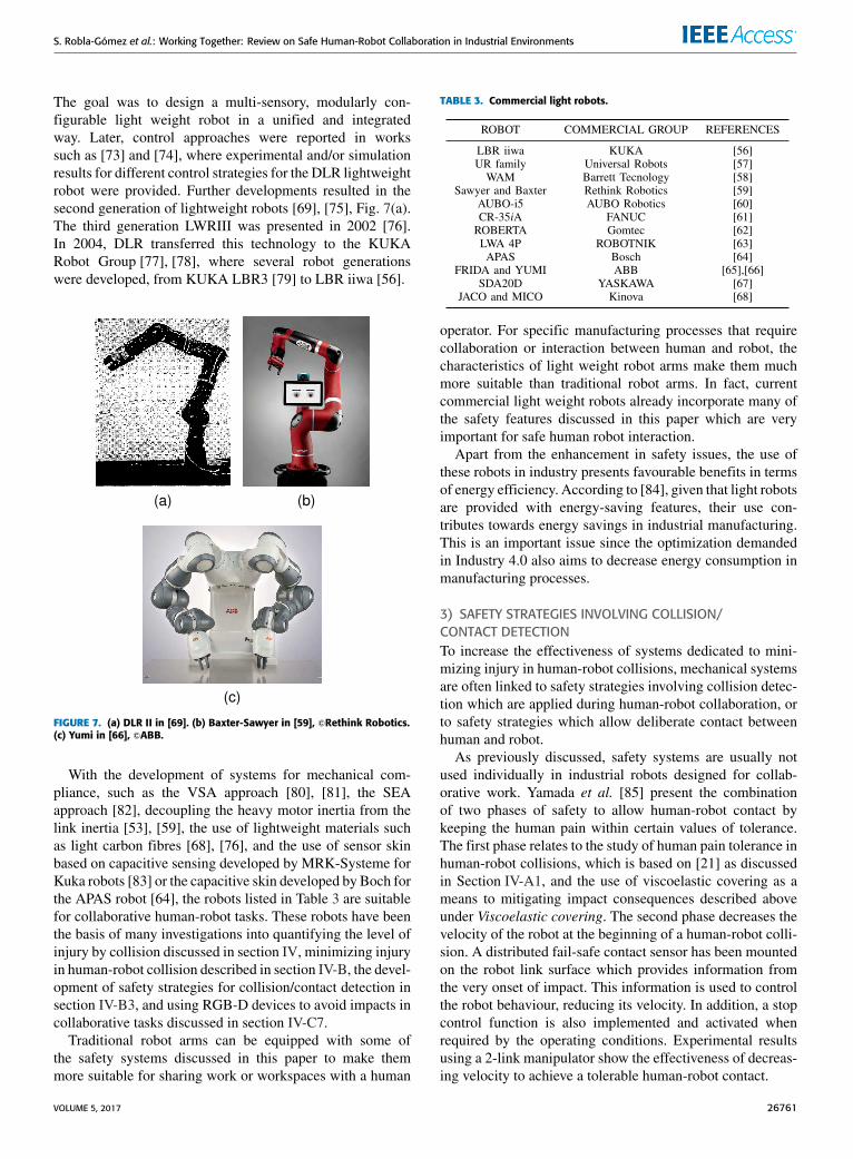
The goal was to design a multi-sensory, modularly con-figurable light weight robot in a unified and integratedway. Later, control approaches were reported in workssuch as [73] and [74], where experimental and/or simulationresults for different control strategies for the DLR lightweightrobot were provided. Further developments resulted in thesecond generation of lightweight robots [69], [75], Fig. 7(a).The third generation LWRIII was presented in 2002 [76].In 2004, DLR transferred this technology to the KUKARobot Group [77], [78], where several robot generationswere developed, from KUKA LBR3 [79] to LBR iiwa [56].
FIGURE 7. (a) DLR II in [69]. (b) Baxter-Sawyer in [59], Rethink Robotics.(c) Yumi in [66], ABB.
With the development of systems for mechanical com-pliance, such as the VSA approach [80], [81], the SEAapproach [82], decoupling the heavy motor inertia from thelink inertia [53], [59], the use of lightweight materials suchas light carbon fibres [68], [76], and the use of sensor skinbased on capacitive sensing developed by MRK-Systeme forKuka robots [83] or the capacitive skin developed by Boch forthe APAS robot [64], the robots listed in Table 3 are suitablefor collaborative human-robot tasks. These robots have beenthe basis of many investigations into quantifying the level ofinjury by collision discussed in section IV, minimizing injuryin human-robot collision described in section IV-B, the devel-opment of safety strategies for collision/contact detection insection IV-B3, and using RGB-D devices to avoid impacts incollaborative tasks discussed in section IV-C7.
Traditional robot arms can be equipped with some ofthe safety systems discussed in this paper to make themmore suitable for sharing work or workspaces with a human
TABLE 3. Commercial light robots.
operator. For specific manufacturing processes that requirecollaboration or interaction between human and robot, thecharacteristics of light weight robot arms make them muchmore suitable than traditional robot arms. In fact, currentcommercial light weight robots already incorporate many ofthe safety features discussed in this paper which are veryimportant for safe human robot interaction.
Apart from the enhancement in safety issues, the use ofthese robots in industry presents favourable benefits in termsof energy efficiency. According to [84], given that light robotsare provided with energy-saving features, their use con-tributes towards energy savings in industrial manufacturing.This is an important issue since the optimization demandedin Industry 4.0 also aims to decrease energy consumption inmanufacturing processes.
3) SAFETY STRATEGIES INVOLVING COLLISION/CONTACT DETECTIONTo increase the effectiveness of systems dedicated to mini-mizing injury in human-robot collisions, mechanical systemsare often linked to safety strategies involving collision detec-tion which are applied during human-robot collaboration, orto safety strategies which allow deliberate contact betweenhuman and robot.
As previously discussed, safety systems are usually notused individually in industrial robots designed for collab-orative work. Yamada et al. [85] present the combinationof two phases of safety to allow human-robot contact bykeeping the human pain within certain values of tolerance.The first phase relates to the study of human pain tolerance inhuman-robot collisions, which is based on [21] as discussedin Section IV-A1, and the use of viscoelastic covering as ameans to mitigating impact consequences described aboveunder Viscoelastic covering. The second phase decreases thevelocity of the robot at the beginning of a human-robot colli-sion. A distributed fail-safe contact sensor has been mountedon the robot link surface which provides information fromthe very onset of impact. This information is used to controlthe robot behaviour, reducing its velocity. In addition, a stopcontrol function is also implemented and activated whenrequired by the operating conditions. Experimental resultsusing a 2-link manipulator show the effectiveness of decreas-ing velocity to achieve a tolerable human-robot contact.
VOLUME 5, 2017 26761
S. Robla-Gómez et al.: Working Together: Review on Safe Human-Robot Collaboration in Industrial Environments
The use of superficial tactile sensors in the skin coveringis also treated in [86] as a way to obtain a faster triggeringof a collision reaction strategy, without loss of the passivereduction of impact.
This idea of obtaining information from the impact pointin a robot is currently under analysis. In [87] a conformablesensor skin made of optoelectronic components mounted ona flexible PCB was presented. This sensorized skin has thecapability of measuring not only the position of the contactpoint but also the three components of the applied force, andthus it allows to estimate the force vector of the impact. Theresults of experimental tests on a light robot show a suit-able behaviour of the robot in intentional and unintentionalhuman-robot contact situations, with a controlled human-robot interaction and a safe reaction in case of accidentalcontacts being guaranteed.
A different approach is to use a mathematical modelof the robot to mitigate the consequences of a collision.Focusing on reducing the impact force, a basic motion-planning/feedback-control algorithm, which relies on inertiareduction, passivity, and parametric path planning, was pro-posed in [88], where a conventional manipulator robot wasused. This work shows that the inertia reduction controllerenhances the safety of the robot and human working togetherby changing the apparent inertia of the robot by means ofa simple adjustment of the common PD position controlstrategy.
De Luca and Mattone [89] avoid using dedicated sensorsfor human-robot collision detection by treating these eventsas a faulty behaviour of the robot actuating system. Robotactuator fault detection and isolation techniques are used togenerate residual signals. Information of the components ofthe residual vectors allows to detect the link of the robotthat has impacted and, to a certain extent, the contact forcelocation and intensity. This information is used for developinga hybrid force/motion controller that manages what happensfollowing the detection of a collision. Simulation results fora two-link planar robot were presented in this work. On thebasis of this idea, in the work reported five collision reac-tion strategies were formulated and implemented on a lightrobot [90]. In the first strategy, the robot follows its trajectorywithout modifying its behaviour. In the second strategy, therobot is stopped at the time when the collision is detected.In the third strategy, the robot behaves in a very compliantway with zero-gravity torque reaction. The fourth strategyinvolves physical changes to the robot to make it lighterthrough the reduction of motor inertia and the link inertia. Inthe last strategy, the robot’s behaviour involves getting awayfrom the impact point. The assessment of the previously pro-posed collision detection and reaction strategies was carriedout in [91]. The results show that the use of these techniquesresults in a decrease of forces keeping them below dangerouslevel to humans. Furthermore, the third an fourth collisionreaction strategies where found to be very satisfactory for theoperator because they feel that they have full control of therobot.
In [92] a unified system for safety in human-robot collab-oration environments was proposed and successfully testedthrough experiments. Their main contribution is that theapproach includes a collision detection and reaction algo-rithm that pulls the robot away from the collision zone, whileallowing for intentional physical interaction. This algorithmis based on the use of residual signals proposed in [89]. Thesystem also includes a collision avoidance strategy, which isbased on the use of an RGB-D sensor. Moreover, the systememploys a safe collaboration phase that allows both contact-less interaction via voice and gesture recognition as well asthe intentional physical contact between human and robot,which combines the residual method for collision detectionwith the localization of the contact point obtained from theRGB-D sensor.
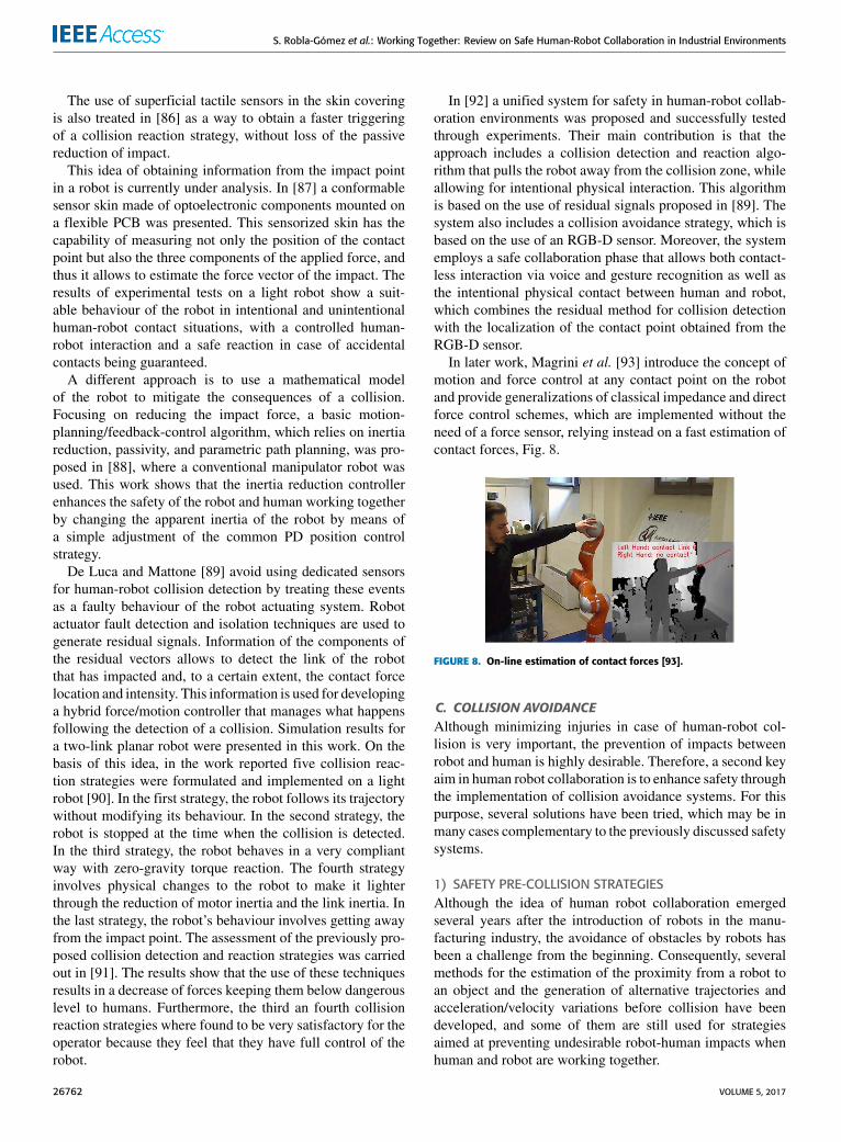
In later work, Magrini et al. [93] introduce the concept ofmotion and force control at any contact point on the robotand provide generalizations of classical impedance and directforce control schemes, which are implemented without theneed of a force sensor, relying instead on a fast estimation ofcontact forces, Fig. 8.
FIGURE 8. On-line estimation of contact forces [93].
C. COLLISION AVOIDANCEAlthough minimizing injuries in case of human-robot col-lision is very important, the prevention of impacts betweenrobot and human is highly desirable. Therefore, a second keyaim in human robot collaboration is to enhance safety throughthe implementation of collision avoidance systems. For thispurpose, several solutions have been tried, which may be inmany cases complementary to the previously discussed safetysystems.
1) SAFETY PRE-COLLISION STRATEGIESAlthough the idea of human robot collaboration emergedseveral years after the introduction of robots in the manu-facturing industry, the avoidance of obstacles by robots hasbeen a challenge from the beginning. Consequently, severalmethods for the estimation of the proximity from a robot toan object and the generation of alternative trajectories andacceleration/velocity variations before collision have beendeveloped, and some of them are still used for strategiesaimed at preventing undesirable robot-human impacts whenhuman and robot are working together.
26762 VOLUME 5, 2017
S. Robla-Gómez et al.: Working Together: Review on Safe Human-Robot Collaboration in Industrial Environments
An example of such early work is [94] in which a real-time obstacle avoidance approach was based on the conceptof Artificial Potential Field. The philosophy of the ArtificialPotential Field is that the manipulator moves in a field offorces, where there are attractive poles for the end-effector(e.g. the position to be achieved), and repulsive forces (obsta-cles to be avoided). Another example is [95], which proposedan impedance control method based on visual informationthat is able to regulate a virtual impedance, establishing vir-tual spheres between robot and objects, Fig. 9.
FIGURE 9. [95] (a) Virtual spheres located on a link or a joint of themanipulator. (b) Virtual force as a function of virtual non-contactimpedance at the ith sphere.
The work described in [96] used danger estimates obtainedin real time during HRC tasks to generate an alternativetrajectory when the estimated danger index exceeded a pre-defined threshold. The danger index, which is based on [97],was defined as the product of the distance, velocity and inertiafactors, and it was estimated for the nearest point betweeneach link and the human, activating a suitable evasive actionwhen the index exceeds a pre-defined threshold. Inspiredby [94] and [95], the alternative trajectory generation relieson a Virtual Force that aims to push the robot away from thedanger area. This virtual force is a function of the effectiveimpedance at the closest point, and a function of the relativedistance between the robot and the object.
To enhance this safety strategy a human monitoring sys-tem was added in subsequent work [98]. The informationobtained from this human monitoring system during human-robot interaction was integrated into the safety system, whichinvolves a safe path planner and a safe motion controller,to improve the safety of this operation. The monitoreddata includes physical features such as facial expression,head position, hand gestures or human eye gaze obtainedfrom vision systems; or psychological features such as skinconductance, heart rate, pupil dilation, brain and musclereactions. Results from the implementation of the integratedsystem in real-time human-robot interaction scenes reveal theefficacy of the proposed safety strategies.
The estimation of danger in the surroundings of the manip-ulator was also treated in [99], which introduced the conceptof Kinetostatic Danger Field whose value decreases withthe distance between the robot and a specific point in spaceand increases with linear link velocities. The position andvelocity of the robot arm were measured through proprio-ceptive sensors and used to compute the danger field at any
point of the workspace. Simulations carried out demonstratedthe usefulness of the Kinetostatic Danger Field as a tool toimprove safety strategies, since it helps to increase the levelof safety in human-robot interactions.
In [100] a reactive control strategy that integrates thedanger field concept with external information from theaforementioned distributed distance sensors (IV-C3), wasimplemented and experimentally validated. The reportedresults assert the benefit of the inclusion of the distance sen-sors to the robot’s control system together with the reactivecontrol strategy for enhancing human safety.
Other approaches use the concept of energy dissipation topropose an injury index to be integrated in a pre-collisioncontrol strategy [102], or to present a control algorithm thatincludes a safety indicator which is modulated by the dis-tance between human and the end-effector of the robot [103].In both cases experimental tests were carried out on light-weight robots.
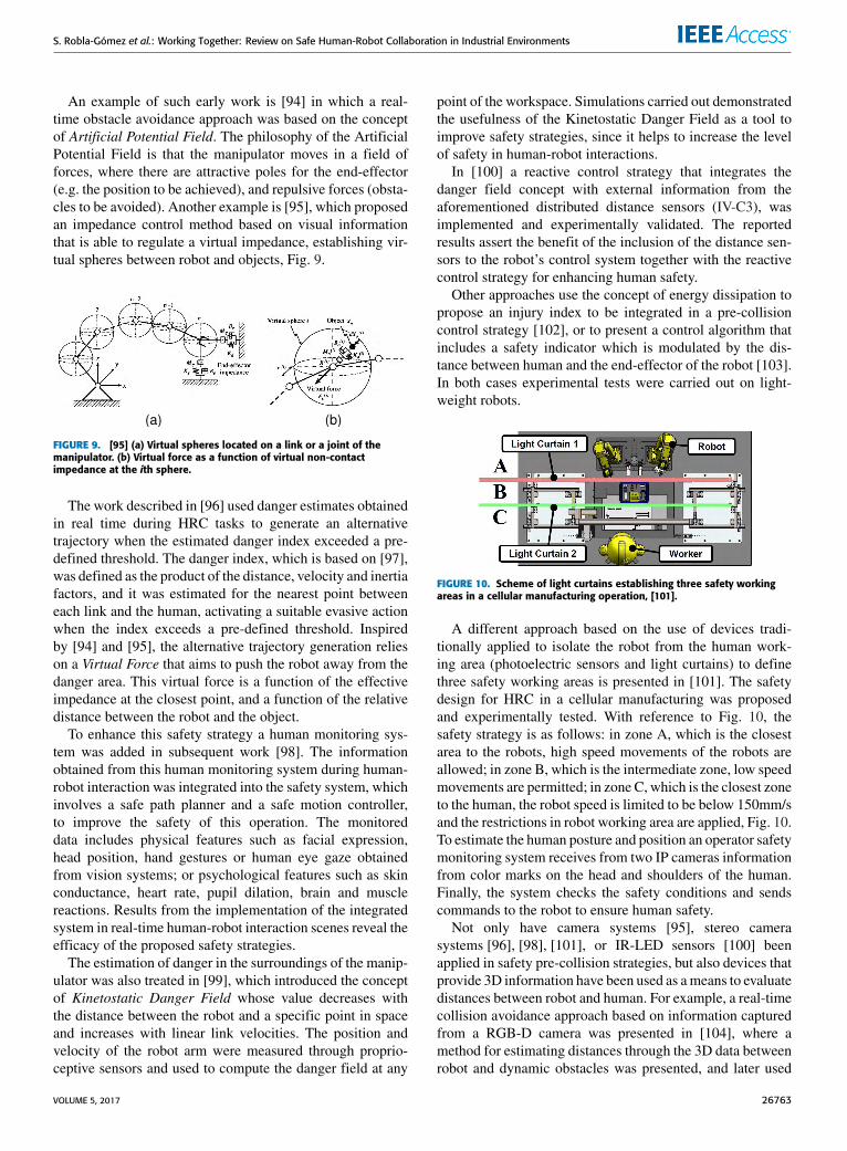
FIGURE 10. Scheme of light curtains establishing three safety workingareas in a cellular manufacturing operation, [101].
A different approach based on the use of devices tradi-tionally applied to isolate the robot from the human work-ing area (photoelectric sensors and light curtains) to definethree safety working areas is presented in [101]. The safetydesign for HRC in a cellular manufacturing was proposedand experimentally tested. With reference to Fig. 10, thesafety strategy is as follows: in zone A, which is the closestarea to the robots, high speed movements of the robots areallowed; in zone B, which is the intermediate zone, low speedmovements are permitted; in zone C, which is the closest zoneto the human, the robot speed is limited to be below 150mm/sand the restrictions in robot working area are applied, Fig. 10.To estimate the human posture and position an operator safetymonitoring system receives from two IP cameras informationfrom color marks on the head and shoulders of the human.Finally, the system checks the safety conditions and sendscommands to the robot to ensure human safety.
Not only have camera systems [95], stereo camerasystems [96], [98], [101], or IR-LED sensors [100] beenapplied in safety pre-collision strategies, but also devices thatprovide 3D information have been used as ameans to evaluatedistances between robot and human. For example, a real-timecollision avoidance approach based on information capturedfrom a RGB-D camera was presented in [104], where amethod for estimating distances through the 3D data betweenrobot and dynamic obstacles was presented, and later used
VOLUME 5, 2017 26763
S. Robla-Gómez et al.: Working Together: Review on Safe Human-Robot Collaboration in Industrial Environments
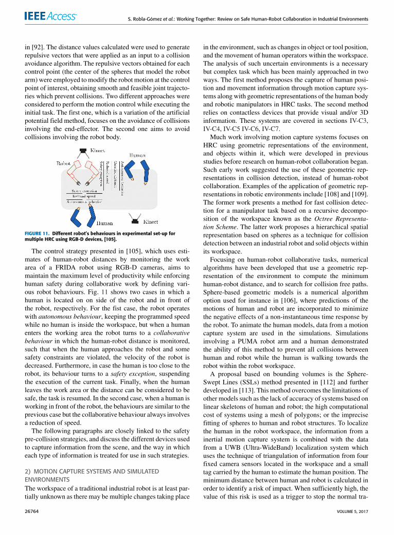
in [92]. The distance values calculated were used to generaterepulsive vectors that were applied as an input to a collisionavoidance algorithm. The repulsive vectors obtained for eachcontrol point (the center of the spheres that model the robotarm) were employed to modify the robot motion at the controlpoint of interest, obtaining smooth and feasible joint trajecto-ries which prevent collisions. Two different approaches wereconsidered to perform the motion control while executing theinitial task. The first one, which is a variation of the artificialpotential field method, focuses on the avoidance of collisionsinvolving the end-effector. The second one aims to avoidcollisions involving the robot body.
FIGURE 11. Different robot’s behaviours in experimental set-up formultiple HRC using RGB-D devices, [105].
The control strategy presented in [105], which uses esti-mates of human-robot distances by monitoring the workarea of a FRIDA robot using RGB-D cameras, aims tomaintain the maximum level of productivity while enforcinghuman safety during collaborative work by defining vari-ous robot behaviours. Fig. 11 shows two cases in which ahuman is located on on side of the robot and in front ofthe robot, respectively. For the fist case, the robot operateswith autonomous behaviour, keeping the programmed speedwhile no human is inside the workspace, but when a humanenters the working area the robot turns to a collaborativebehaviour in which the human-robot distance is monitored,such that when the human approaches the robot and somesafety constraints are violated, the velocity of the robot isdecreased. Furthermore, in case the human is too close to therobot, its behaviour turns to a safety exception, suspendingthe execution of the current task. Finally, when the humanleaves the work area or the distance can be considered to besafe, the task is resumed. In the second case, when a human isworking in front of the robot, the behaviours are similar to theprevious case but the collaborative behaviour always involvesa reduction of speed.
The following paragraphs are closely linked to the safetypre-collision strategies, and discuss the different devices usedto capture information from the scene, and the way in whicheach type of information is treated for use in such strategies.
2) MOTION CAPTURE SYSTEMS AND SIMULATEDENVIRONMENTSThe workspace of a traditional industrial robot is at least par-tially unknown as there may be multiple changes taking place
in the environment, such as changes in object or tool position,and the movement of human operators within the workspace.The analysis of such uncertain environments is a necessarybut complex task which has been mainly approached in twoways. The first method proposes the capture of human posi-tion and movement information through motion capture sys-tems along with geometric representations of the human bodyand robotic manipulators in HRC tasks. The second methodrelies on contactless devices that provide visual and/or 3Dinformation. These systems are covered in sections IV-C3,IV-C4, IV-C5 IV-C6, IV-C7.Much work involving motion capture systems focuses on
HRC using geometric representations of the environment,and objects within it, which were developed in previousstudies before research on human-robot collaboration began.Such early work suggested the use of these geometric rep-resentations in collision detection, instead of human-robotcollaboration. Examples of the application of geometric rep-resentations in robotic environments include [108] and [109].The former work presents a method for fast collision detec-tion for a manipulator task based on a recursive decompo-sition of the workspace known as the Octree Representa-tion Scheme. The latter work proposes a hierarchical spatialrepresentation based on spheres as a technique for collisiondetection between an industrial robot and solid objects withinits workspace.
Focusing on human-robot collaborative tasks, numericalalgorithms have been developed that use a geometric rep-resentation of the environment to compute the minimumhuman-robot distance, and to search for collision free paths.Sphere-based geometric models is a numerical algorithmoption used for instance in [106], where predictions of themotions of human and robot are incorporated to minimizethe negative effects of a non-instantaneous time response bythe robot. To animate the human models, data from a motioncapture system are used in the simulations. Simulationsinvolving a PUMA robot arm and a human demonstratedthe ability of this method to prevent all collisions betweenhuman and robot while the human is walking towards therobot within the robot workspace.
A proposal based on bounding volumes is the Sphere-Swept Lines (SSLs) method presented in [112] and furtherdeveloped in [113]. This method overcomes the limitations ofother models such as the lack of accuracy of systems based onlinear skeletons of human and robot; the high computationalcost of systems using a mesh of polygons; or the imprecisefitting of spheres to human and robot structures. To localizethe human in the robot workspace, the information from ainertial motion capture system is combined with the datafrom a UWB (Ultra-WideBand) localization system whichuses the technique of triangulation of information from fourfixed camera sensors located in the workspace and a smalltag carried by the human to estimate the human position. Theminimum distance between human and robot is calculated inorder to identify a risk of impact. When sufficiently high, thevalue of this risk is used as a trigger to stop the normal tra-
26764 VOLUME 5, 2017
S. Robla-Gómez et al.: Working Together: Review on Safe Human-Robot Collaboration in Industrial Environments
jectory of the robot and to generate an alternative trajectory,with the robot avoiding contact with the human. In [107] thisidea was developed further including the use of Axis-AlignedBounding Boxes (AABB) along the SSLs, Fig. 12, allowingto define a hierarchy of bounding volumes with three levels.This characteristic reduces the number of distance tests to beperformed. In addition, this safety strategy was successfullyimplemented and tested in three assembly and disassemblytasks, guaranteeing human safety in conditions of close prox-imity between human and robot.
FIGURE 12. (a) Sphere geometric model of human an robot in [106].(b) Use of SSLs for an assembly task based on the cooperation of tworobotic manipulators and a human operator in [107].
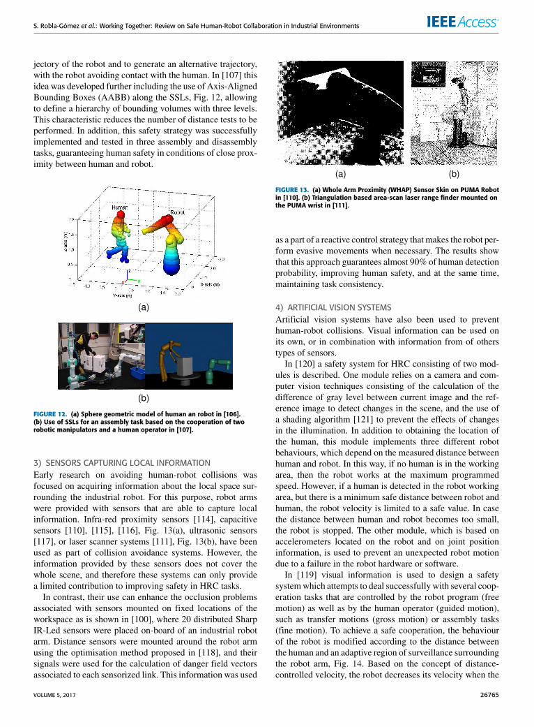
3) SENSORS CAPTURING LOCAL INFORMATIONEarly research on avoiding human-robot collisions wasfocused on acquiring information about the local space sur-rounding the industrial robot. For this purpose, robot armswere provided with sensors that are able to capture localinformation. Infra-red proximity sensors [114], capacitivesensors [110], [115], [116], Fig. 13(a), ultrasonic sensors[117], or laser scanner systems [111], Fig. 13(b), have beenused as part of collision avoidance systems. However, theinformation provided by these sensors does not cover thewhole scene, and therefore these systems can only providea limited contribution to improving safety in HRC tasks.
In contrast, their use can enhance the occlusion problemsassociated with sensors mounted on fixed locations of theworkspace as is shown in [100], where 20 distributed SharpIR-Led sensors were placed on-board of an industrial robotarm. Distance sensors were mounted around the robot armusing the optimisation method proposed in [118], and theirsignals were used for the calculation of danger field vectorsassociated to each sensorized link. This information was used
FIGURE 13. (a) Whole Arm Proximity (WHAP) Sensor Skin on PUMA Robotin [110]. (b) Triangulation based area-scan laser range finder mounted onthe PUMA wrist in [111].
as a part of a reactive control strategy thatmakes the robot per-form evasive movements when necessary. The results showthat this approach guarantees almost 90% of human detectionprobability, improving human safety, and at the same time,maintaining task consistency.
4) ARTIFICIAL VISION SYSTEMSArtificial vision systems have also been used to preventhuman-robot collisions. Visual information can be used onits own, or in combination with information from of otherstypes of sensors.
In [120] a safety system for HRC consisting of two mod-ules is described. One module relies on a camera and com-puter vision techniques consisting of the calculation of thedifference of gray level between current image and the ref-erence image to detect changes in the scene, and the use ofa shading algorithm [121] to prevent the effects of changesin the illumination. In addition to obtaining the location ofthe human, this module implements three different robotbehaviours, which depend on the measured distance betweenhuman and robot. In this way, if no human is in the workingarea, then the robot works at the maximum programmedspeed. However, if a human is detected in the robot workingarea, but there is a minimum safe distance between robot andhuman, the robot velocity is limited to a safe value. In casethe distance between human and robot becomes too small,the robot is stopped. The other module, which is based onaccelerometers located on the robot and on joint positioninformation, is used to prevent an unexpected robot motiondue to a failure in the robot hardware or software.
In [119] visual information is used to design a safetysystemwhich attempts to deal successfully with several coop-eration tasks that are controlled by the robot program (freemotion) as well as by the human operator (guided motion),such as transfer motions (gross motion) or assembly tasks(fine motion). To achieve a safe cooperation, the behaviourof the robot is modified according to the distance betweenthe human and an adaptive region of surveillance surroundingthe robot arm, Fig. 14. Based on the concept of distance-controlled velocity, the robot decreases its velocity when the
VOLUME 5, 2017 26765
S. Robla-Gómez et al.: Working Together: Review on Safe Human-Robot Collaboration in Industrial Environments
surveillance region around the robot approximates a human orobject. To achieve the guidedmotion required in collaborativetasks a force/torque sensor mounted on the robot wrist pro-vides information about the direction of the force and torquethat is used to generate the movement of the robot.
FIGURE 14. Adaptable area of surveillance on free fine motion [119]. (a)The robot is under surveillance. (b)The entire robot and the object areunder surveillance.
Following the work in [119], the enhanced method pre-sented in [122] includes several fixed cameras to preventocclusions in images. The captured visual information isgiven as the input to an algorithm that calculates image dif-ferences to detect the position of the human. To differentiatebetween robot and human, information from the robot posi-tion sensors is projected onto the images from each camera,which, together with the estimates of the human position,allows to calculate the distance between human and robot.
Other works have used visual information acquired bystatic cameras as a means to perform collision tests. Thesestrategies allow to determine whether the space at a requestedconfiguration of the robot is free or occupied by an object.An efficient collision test is presented in [123], where fourfixed cameras are used to monitor the workspace. Usingimage differencing based on binary scene images and severalmapping functions to generate the obstacle, intersection, andcollision images, a boolean outcome of the collision test isgenerated.
Occlusions in image sequences from fixed cameras usedto detect dynamic obstacles are common and undesirable.According to [124], and based on the work presented in [123],several improvements are made in the object reconstructionin cases involving occlusions. These improvements allowto apply the collision test as a basis for a collision-freepath planner. Moreover, a visual approach for image anal-ysis of unknown and known objects was proposed in [125]as an improvement over the earlier collision test methods.An enhanced image differencing method is proposed toobtain the classification of foreground and background pix-els. This enables the collision detection for gross motions(transfer or pick and place) and its application to plancollision-free paths for the robot.
In [126] two IP cameras provide information from colormarks located on the head and shoulders of the human. This
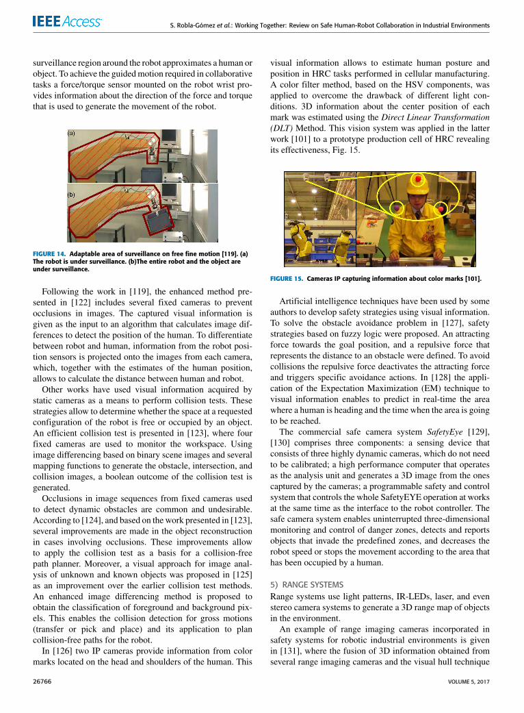
visual information allows to estimate human posture andposition in HRC tasks performed in cellular manufacturing.A color filter method, based on the HSV components, wasapplied to overcome the drawback of different light con-ditions. 3D information about the center position of eachmark was estimated using the Direct Linear Transformation(DLT) Method. This vision system was applied in the latterwork [101] to a prototype production cell of HRC revealingits effectiveness, Fig. 15.
FIGURE 15. Cameras IP capturing information about color marks [101].
Artificial intelligence techniques have been used by someauthors to develop safety strategies using visual information.To solve the obstacle avoidance problem in [127], safetystrategies based on fuzzy logic were proposed. An attractingforce towards the goal position, and a repulsive force thatrepresents the distance to an obstacle were defined. To avoidcollisions the repulsive force deactivates the attracting forceand triggers specific avoidance actions. In [128] the appli-cation of the Expectation Maximization (EM) technique tovisual information enables to predict in real-time the areawhere a human is heading and the time when the area is goingto be reached.
The commercial safe camera system SafetyEye [129],[130] comprises three components: a sensing device thatconsists of three highly dynamic cameras, which do not needto be calibrated; a high performance computer that operatesas the analysis unit and generates a 3D image from the onescaptured by the cameras; a programmable safety and controlsystem that controls the whole SafetyEYE operation at worksat the same time as the interface to the robot controller. Thesafe camera system enables uninterrupted three-dimensionalmonitoring and control of danger zones, detects and reportsobjects that invade the predefined zones, and decreases therobot speed or stops the movement according to the area thathas been occupied by a human.
5) RANGE SYSTEMSRange systems use light patterns, IR-LEDs, laser, and evenstereo camera systems to generate a 3D range map of objectsin the environment.
An example of range imaging cameras incorporated insafety systems for robotic industrial environments is givenin [131], where the fusion of 3D information obtained fromseveral range imaging cameras and the visual hull technique
26766 VOLUME 5, 2017
S. Robla-Gómez et al.: Working Together: Review on Safe Human-Robot Collaboration in Industrial Environments
are used to estimate the presence of obstacles within the areaof interest. The configurations of a robot model and its futuretrajectory along with information on the detected obstacles isused to check for possible collisions.
An extension of the above work is [132] where a generalapproach is introduced for surveillance of robotic environ-ments using depth images from standard colour cameras ordepth cameras. The fusion of data from CCD colour cam-eras or from ToF cameras is performed to obtain the objecthull and its distance with respect to the known geometryof an industrial robot. By means of a experimental setupconsisting of several range and colour camerasmonitoring theworkspace of an robot arm, the authors present a comparisonbetween distance information from colour and ToF cameras,and a comparison between a single ToF camera and ToF infor-mation fusion from several cameras. One of the conclusionsof this work is that the estimated distance between a robotmodel and the unknown object using depth information islonger than the distance obtained using information from onecolour camera. Another conclusion is that the fusion of infor-mation from several ToF cameras provides better resolutionand less noise than the information obtained from a singlecamera.
In [133] two anti-collision strategies are presented andvalidated on a 1D experimental setup. These methods arebased on a virtual force that is computed from informationcoming from a laser time-of-flight (ToF) sensor, and is usedto modify the trajectory of the robot.
In [135] an approach using a soft robot arm along with adepth sensor located at a fixed position of the work cell isdiscussed and implemented. Their results reveal that a colli-sion could happen when the velocity of a human movementexceeds a threshold related to the depth sensor bandwidth andcharacteristics. Despite of this, human safety is guaranteeddue to the passive compliance system of the soft robot. As aimprovement, the authors suggest the inclusion of multipledepth sensors as a means for reducing unmonitored areascaused by the presence of objects in the scene.
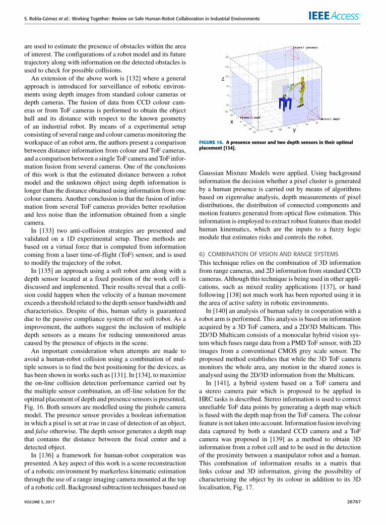
An important consideration when attempts are made toavoid a human-robot collision using a combination of mul-tiple sensors is to find the best positioning for the devices, ashas been shown in works such as [131]. In [134], to maximizethe on-line collision detection performance carried out bythe multiple sensor combination, an off-line solution for theoptimal placement of depth and presence sensors is presented,Fig. 16. Both sensors are modelled using the pinhole cameramodel. The presence sensor provides a boolean informationin which a pixel is set at true in case of detection of an object,and false otherwise. The depth sensor generates a depth mapthat contains the distance between the focal center and adetected object.
In [136] a framework for human-robot cooperation waspresented. A key aspect of this work is a scene reconstructionof a robotic environment by markerless kinematic estimationthrough the use of a range imaging camera mounted at the topof a robotic cell. Background subtraction techniques based on
FIGURE 16. A presence sensor and two depth sensors in their optimalplacement [134].
Gaussian Mixture Models were applied. Using backgroundinformation the decision whether a pixel cluster is generatedby a human presence is carried out by means of algorithmsbased on eigenvalue analysis, depth measurements of pixeldistributions, the distribution of connected components andmotion features generated from optical flow estimation. Thisinformation is employed to extract robust features than modelhuman kinematics, which are the inputs to a fuzzy logicmodule that estimates risks and controls the robot.
6) COMBINATION OF VISION AND RANGE SYSTEMSThis technique relies on the combination of 3D informationfrom range cameras, and 2D information from standard CCDcameras. Although this technique is being used in other appli-cations, such as mixed reality applications [137], or handfollowing [138] not much work has been reported using it inthe area of active safety in robotic environments.
In [140] an analysis of human safety in cooperation with arobot arm is performed. This analysis is based on informationacquired by a 3D ToF camera, and a 2D/3D Multicam. This2D/3D Multicam consists of a monocular hybrid vision sys-tem which fuses range data from a PMD ToF sensor, with 2Dimages from a conventional CMOS grey scale sensor. Theproposed method establishes that while the 3D ToF cameramonitors the whole area, any motion in the shared zones isanalysed using the 2D/3D information from the Multicam.
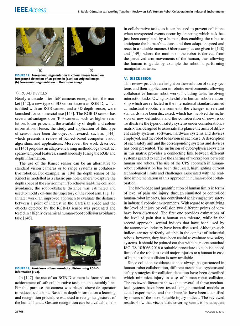
In [141], a hybrid system based on a ToF camera anda stereo camera pair which is proposed to be applied inHRC tasks is described. Stereo information is used to correctunreliable ToF data points by generating a depth map whichis fused with the depth map from the ToF camera. The colourfeature is not taken into account. Information fusion involvingdata captured by both a standard CCD camera and a ToFcamera was proposed in [139] as a method to obtain 3Dinformation from a robot cell and to be used in the detectionof the proximity between a manipulator robot and a human.This combination of information results in a matrix thatlinks colour and 3D information, giving the possibility ofcharacterising the object by its colour in addition to its 3Dlocalisation, Fig. 17.
VOLUME 5, 2017 26767
S. Robla-Gómez et al.: Working Together: Review on Safe Human-Robot Collaboration in Industrial Environments
FIGURE 17. Foreground segmentation in colour images based onforeground detection of 3D points in [139]. (a) Original image.(b) Foreground segmentation in the colour image.
7) RGB-D DEVICESNearly a decade after ToF cameras emerged into the mar-ket [142], a new type of 3D sensor known as RGB-D, whichis fitted with an RGB camera and a 3D depth sensor, werelaunched for commercial use [143]. The RGB-D sensor hasseveral advantages over ToF cameras such as higher reso-lution, lower price, and the availability of depth and colourinformation. Hence, the study and application of this typeof sensor have been the object of research such as [144],which presents a review of Kinect-based computer visionalgorithms and applications. Moreover, the work describedin [145] proposes an adaptive learningmethodology to extractspatio-temporal features, simultaneously fusing the RGB anddepth information.
The use of the Kinect sensor can be an alternative tostandard vision cameras or to range systems in collabora-tive robotics. For example, in [104] the depth sensor of theKinect is modelled as a classic pin-hole camera to capture thedepth space of the environment. To achieve real-time collisionavoidance, the robot-obstacle distance was estimated andused to modify on-line the trajectory of the robot arm, Fig. 18.In later work, an improved approach to evaluate the distancebetween a point of interest in the Cartesian space and theobjects detected by the RGB-D sensor was presented andtested in a highly dynamical human-robot collision avoidancetask [146].
FIGURE 18. Avoidance of human-robot collision using RGB-Dinformation [104].
In [147] the use of an RGB-D camera is focused on theachievement of safe collaborative tasks on an assembly line.For this purpose the camera was placed above de operatorto reduce occlusions. Based on depth information a learningand recognition procedure was used to recognize gestures ofthe human hands. Gesture recognition can be a valuable help
in collaborative tasks, as it can be used to prevent collisionswhen unexpected events occur by detecting which task hasjust been completed by a human, thus enabling the robot toanticipate the human’s actions, and then adapt its speed andreact in a suitable manner. Other examples are given in [148]and [149], where the motion of the robot is derived fromthe perceived arm movements of the human, thus allowingthe human to guide by example the robot in performingmanipulation tasks.
V. DISCUSSIONThis review provides an insight on the evolution of safety sys-tems and their application in robotic environments, allowingcollaborative human-robot work, including tasks involvinginteraction tasks. Owing to the shifts in human-robot relation-ship which are reflected in the international standards aimedat industrial robotic environments the changes in relevantstandards have been discussed, which has involved the inclu-sion of new definitions and the consideration of new risks.To illustrate the types of safety systems under consideration, amatrix was designed to associate at a glance the aims of differ-ent safety systems, software, hardware systems and devicesemployed, and the robot behaviour in each case. A descriptionof each safety aim and the corresponding systems and deviceshas been presented. The inclusion of cyber-physical-systemsin this matrix provides a connecting link between differentsystems geared to achieve the sharing of workspaces betweenhuman and robots. The use of the CPS approach in human-robot collaboration has been discussed, highlighting currenttechnological limits and challenges associated with the real-time implementation of this approach in human-robot collab-oration.
The knowledge and quantification of human limits in termsof level of pain and injury, through simulated or controlledhuman-robot impacts, has contributed achieving active safetyin industrial robotic environments.With regard to quantifyingthe level of injury by collision two different points of viewhave been discussed. The first one provides estimations ofthe level of pain that a human can tolerate, while in thesecond approach, several indices that have been used bythe automotive industry have been discussed. Although suchindices are not perfectly suitable in the context of industrialrobots, however, they have been useful to evaluate new safetysystems. It should be pointed out that with the recent standardISO-TS 105066:2016 a suitable procedure to stablish speedlimits for the robot to avoid major injuries to a human in caseof human-robot collision is now available.
Since collision avoidance cannot always be guaranteed inhuman-robot collaboration, different mechanical systems andsafety strategies for collision detection have been describedwhich minimize injury in case of human-robot collision.The reviewed literature shows that several of these mechan-ical systems have been tested using numerical models oractual experiments, and their benefits have been quantifiedby means of the most suitable injury indices. The reviewedresults show that viscoelastic covering seems to be adequate
26768 VOLUME 5, 2017
S. Robla-Gómez et al.: Working Together: Review on Safe Human-Robot Collaboration in Industrial Environments
to absorb impact energy. However, this covering in combina-tion with absorption elastic systems have produced clearlyimproved results. These ideas have been implemented incommercial light robots that seek to enable safe collaborativehuman-robot work. Moreover, software developments havebeen proposed and tested in combination with mechanicalcompliance systems as a method that not only helps to min-imize injuries, but also allows for intentional human-robotcontact in human-robot interaction, opening a wide field ofresearch.
Althoughmitigating the consequences of human-robot col-lisions is vital, the prevention of unintentional contact is mostadvisable. As a consequence, various safety systems focusingon collision prevention have been proposed. Various pre-collision strategies have been presented in this paper. Theirmain characteristic is that, based on information about therobot motion and configuration, together with informationabout the human that is obtained from vision systems andother sensingmodules, an alternative path for themanipulatorrobot is computed, moving the robot away from the dangerzone when a collision is predicted.
A way to collect information about unknown or uncertainparts of the environment is using motion capture systems andsimulated environments. Using this information, geometricrepresentations of human and robots are generated. Theserepresentations are usually based on bounding volumes.By using this simulated representation, the distance betweenhuman and robot can be estimated and incorporated into pre-collision strategies. When a risk of impact is identified, asafety protocol is activated to generate alternative trajectoriesand move the industrial robot away from the human.
A different way of acquiring information about the sur-roundings of the robot relies on contactless devices such assensors that capture local information or devices that allowcapturing global information from the work area. Infra-redproximity sensors, capacitive sensors, ultrasonic sensors, orlaser scanner systems, belong to the first type of contaclessdevices and were used in some of the early works in this area.However, constraints associated with capturing informationabout the environment surrounding the robot make theseapproaches not suitable by themselves. Yet, some researchershave found ways of avoiding occlusion problems associatedto sensors located on fixed placements through the use of thistype of devices.
Although the use of motion capture systems along withsimulated environments has produced good results in theimplementations that have been reported (and to overcomethe limitations of local sensors), fixed devices monitoring thework area seems to be a feasible alternative to the these acqui-sition systems. Using standard cameras and range systems,there is no need to place markers on the human body. More-over, they can give information about any unexpected objectthat may enter the working area. The section on artificialvision systems of this review paper discusses methods thathave been proposed to prevent robot-human impacts usingstandard cameras and computer vision techniques.
Finally, a review of recent research based on devices thatprovide 3D information which is used to achieve safety inrobotic environments is also provided. The emergence ofdevices such as ToF/PMD cameras, or RGB-D devices, hasresulted in a reduction of the efforts to extract 3D informationfrom the scene. Combining 3D information along with colourinformation has been proposed as a way of extracting morecomprehensive information about the area of interest. Severalalgorithms for the fusion of 3D and 2D information havebeen discussed. However, the technology is progressing anddevices that fuse automatically these kinds of informationhave emerged. Although these devices were not originallyintended to be used in robotic industrial environments, someresearch point to this possibility, as reflected in the discussionon RGB-D devices.
REFERENCES[1] AENOR. UNE-EN 755. Robots Manipuladores Industriales. Seguridad,
Asociación Española de Normalización y Certificación, Madrid, Spain,1996.
[2] K.-D. Thoben, S. Wiesner, and T. Wuest, ‘‘‘Industrie 4.0’ and smartmanufacturing—A review of research issues and application examples,’’Int. J. Autom. Technol., vol. 11, no. 1, pp. 4–16, 2017.
[3] ISO, ISO 10218-1: 2006 Robots for industrial environments. Safetyrequirements. Part 1: Robots, International Organization for Standardiza-tion, Genneva, Switzerland, 2006.
[4] RIA, Guidelines for implementing ANS/RIA/ISO 10218-1-2007. Forindustrial Robots and Robot Systems. Safety Requirements, RoboticIndustries Association, Ann Arbor, MI, USA, 2008.
[5] Requisitos de Seguridad Para Robots Industriales. Parte 1: Robots,document UNE-EN ISO 10218-1:2011, Asociación Española de Normal-ización y Certificación, 2011.
[6] Requisitos de Seguridad Para Robots Industriales. Parte 2: SistemasRobot e Integración, document UNE-EN ISO 10218-2:2011, AsociaciónEspañola de Normalización y Certificación, 2011.
[7] Robots and Robotic Devices—Vocabulary, 2nd ed., documentISO 8373-2012, ISO, Mar. 2012.
[8] Robots and Robotic Devices—Collaborative Robots, documentISO/TS 15066, International Organization for Standardization, 2016.
[9] R. Alami et al., ‘‘Safe and dependable physical human-robot interactionin anthropic domains: State of the art and challenges,’’ in Proc. IEEE/RSJInt. Conf. Intell. Robots Syst., Oct. 2006, pp. 1–16.
[10] A. Bicchi, M. A. Peshkin, and J. E. Colgate, ‘‘Safety for physical human-robot interaction,’’ in Springer Handbook of Robotics. Berlin, Germany:Springer, 2008, pp. 1335–1348, doi: 10.1007/978-3-540-30301-5_58.
[11] A. De Santis, B. Siciliano, A. De Luca, and A. Bicchi, ‘‘An atlas ofphysical human–robot interaction,’’ Mechanism Mach. Theory, vol. 43,no. 3, pp. 253–270, 2008. [Online]. Available: http://www.sciencedirect.com/science/article/pii/S0094114X07000547
[12] M. Hermann, T. Pentek, and B. Otto, ‘‘Design principles for Industrie 4.0scenarios,’’ in Proc. 49th Hawaii Int. Conf. Syst. Sci. (HICSS), Jan. 2016,pp. 3928–3937.
[13] A. Verl, A. Lechler, and J. Schlechtendahl, ‘‘Glocalized cyber physicalproduction systems,’’ Prod. Eng., vol. 6, no. 6, pp. 643–649, 2012.
[14] L. Monostori et al., ‘‘Cyber-physical systems in manufacturing,’’CIRP Ann.-Manuf. Technol., vol. 65, no. 2, pp. 621–641, 2016.[Online]. Available: http://www.sciencedirect.com/science/article/pii/S0007850616301974
[15] A. Khalid, P. Kirisci, Z. Ghrairi, J. Pannek, and K.-D. Thoben, ‘‘Safetyrequirements in collaborative human robot cyber physical system,’’ inDynamics in Logistics, 1st ed, M. Freitag, H. Kotzab, and J. Pannek, Eds.Springer, 2016, ch. 4, pp. 39–48, doi: 10.1007/978-3-319-45117-6_4.
[16] S. Kriaa, L. Pietre-Cambacedes, M. Bouissou, and Y. Halgand,‘‘A survey of approaches combining safety and security for indus-trial control systems,’’ Rel. Eng. Syst. Safety, vol. 139, pp. 156–178,Jul. 2015. [Online]. Available: http://www.sciencedirect.com/science/article/pii/S0951832015000538
VOLUME 5, 2017 26769
S. Robla-Gómez et al.: Working Together: Review on Safe Human-Robot Collaboration in Industrial Environments
[17] T. Arai, R. Kato, and M. Fujita, ‘‘Assessment of operator stressinduced by robot collaboration in assembly,’’ CIRP Ann.-Manuf.Technol., vol. 59, no. 1, pp. 5–8, 2010. [Online]. Available:http://www.sciencedirect.com/science/article/pii/S0007850610000442
[18] G. Charalambous, S. Fletcher, and P. Webb, ‘‘Identifying the keyorganisational human factors for introducing human-robot collaborationin industry: An exploratory study,’’ Int. J. Adv. Manuf. Technol.,vol. 81, nos. 9–12, pp. 2143–2155, 2015. [Online]. Available:http://dx.doi.org/10.1007/s00170-015-7335-4
[19] B. Matthias and T. Reisinger, ‘‘Example application of ISO/TS 15066 toa collaborative assembly scenario,’’ in Proc. 47th Int. Symp. Robot. (ISR),Jun. 2016, pp. 1–5.
[20] K. Kittiampon and J. E. Sneckenberger, ‘‘A safety control systemfor a robotic workstation,’’ in Proc. Amer. Control Conf., Jun. 1985,pp. 1463–1465.
[21] K. Suita, Y. Yamada, N. Tsuchida, K. Imai, H. Ikeda, and N. Sugimoto,‘‘A failure-to-safety ‘Kyozon’ system with simple contact detection andstop capabilities for safe human-autonomous robot coexistence,’’ in Proc.IEEE Int. Conf. Robot. Autom., vol. 3. May 1995, pp. 3089–3096.
[22] B. Povse, D. Koritnik, R. Kamnik, T. Bajd, and M. Munih, ‘‘Industrialrobot and human operator collision,’’ in Proc. IEEE Int. Conf. Syst. ManCybern. (SMC), Oct. 2010, pp. 2663–2668.
[23] S. Haddadin, A. Albu-Schäffer, and G. Hirzinger, ‘‘The role of therobot mass and velocity in physical human-robot interaction—PartI: Non-constrained blunt impacts,’’ in Proc. IEEE Int. Conf. Robot.Autom. (ICRA), May 2008, pp. 1331–1338.
[24] Association for the Advancement of Automotive Medicine. (2016). AIS2005: Update 2008 Clarification. [Online]. Available: https://www.aaam.org/wp-content/uploads/2016/06/AAAM-AIS-Clarification-Document.pdf
[25] SAE, ‘‘Human tolerance to impact conditions as related to motor vehi-cle design,’’ Soc. Automotive Eng., Warrendale, PA, USA, Tech. Rep.,Oct. 1966.
[26] EuroNCAP. (2004). Assessment protocol and biomechanical limits ver-sion 4.1. EuropeanNewCarAssessment Programme. [Online]. Available:https://goo.gl/4in82r
[27] A. Bicchi, G. Tonietti, M. Bavaro, and M. Piccigallo, ‘‘Variable stiffnessactuators for fast and safe motion control,’’ in Proc. Int. Symp. Robot.,2003, pp. 527–536. [Online]. Available: http://www.centropiaggio.unipi.it/sites/default/files/anthropic-ISRR03.pdf
[28] A. Bicchi and G. Tonietti, ‘‘Fast and ‘soft-arm’ tactics [robot armdesign],’’ IEEE Robot. Autom. Mag., vol. 11, no. 2, pp. 22–33, Jun. 2004.
[29] M. Zinn, O. Khatib, B. Roth, and J. K. Salisbury, ‘‘Playing it safe [human-friendly robots],’’ IEEE Robot. Autom. Mag., vol. 11, no. 2, pp. 12–21,Jun. 2004.
[30] G. Tonietti, R. Schiavi, and A. Bicchi, ‘‘Optimal mechanical/controldesign for safe and fast robotics,’’ in Proc. 9th Int. Symp.Experim. Robot., vol. 21. 2006, pp. 311–320. [Online]. Available:http://www.centropiaggio.unipi.it/sites/default/files/softarm-ISER04.pdf
[31] G. Boccadamo, R. Schiavi, S. Sen, G. Tonietti, and A. Bicchi,‘‘Optimization and fail-safety analysis of antagonistic actuation forpHRI,’’ in Proc. Eur. Robot. Symp., vol. 22. 2006, pp. 109–118 [Online].Available: http://www.centropiaggio.unipi.it/sites/default/files/softarm-EUROS06.pdf
[32] M. Bicchi et al., ‘‘Physical human-robot interaction: Dependability,safety, and performance,’’ in Proc. 10th IEEE Int. Workshop Adv. MotionControl (AMC), Mar. 2008, pp. 9–14.
[33] A. S. Shafer and M. R. Kerman, ‘‘On the feasibility and suitability ofMR fluid clutches in human-friendly manipulators,’’ IEEE/ASME Trans.Mechatronics, vol. 16, no. 6, pp. 1073–1082, Dec. 2011.
[34] D. Gao and C. W. Wampler, ‘‘Head injury criterion,’’ IEEERobot. Autom. Mag., vol. 16, no. 4, pp. 71–74, Dec. 2009.[Online]. Available: http://ieeexplore.ieee.org/stamp/stamp.jsp?tp=&arnumber=5306928&isnumber=5306913
[35] S. Haddadin, ‘‘Towards safe robots: Approaching Asimov’s 1stlaw,’’ Ph.D. dissertation, Inst. Robot. Mechatronics, Robot. Syst.,RWTH Aachen Univ., Aachen, Germany, Oct. 2011. [Online].Available: http://darwin.bth.rwth-aachen.de/opus3/volltexte/2011/3826/pdf/3826.pdf
[36] S. Haddadin, A. Albu-Schäffer, and G. Hirzinger, ‘‘Safety evaluationof physical human-robot interaction via crash-testing,’’ in Robotics Sci-ence and Systems, vol. 3. 2007, pp. 217–224. [Online]. Available:http://www.roboticsproceedings.org/rss03/p28.pdf
[37] S. Oberer and R. D. Schraft, ‘‘Robot-dummy crash tests for robotsafety assessment,’’ in Proc. IEEE Int. Conf. Robot. Autom., Apr. 2007,pp. 2934–2939.
[38] S. Haddadin, A. Albu-Schäffer, and G. Hirzinger, ‘‘Requirements for saferobots: Measurements, analysis and new insights,’’ Int. J. Robot. Res.,vol. 28, nos. 11–12, pp. 1507–1527, 2009.
[39] Industrial, Commercial and Garage Doors and Gates—Safety in Use ofPower OperatedDoors—Requirements, document EN 12453:2000, CEN,2000.
[40] D. Mewes and F. Mauser, ‘‘Safeguarding crushing points by limitationof forces,’’ Int. J. Occupat. Safety Ergonom., vol. 9, no. 2, pp. 177–191,2003.
[41] H.-O. Lim and K. Tanie, ‘‘Collision-tolerant control of human-friendlyrobot with viscoelastic trunk,’’ IEEE/ASME Trans. Mechatronics, vol. 4,no. 4, pp. 417–427, Dec. 1999.
[42] J. Ulmen and M. Cutkosky, ‘‘A robust, low-cost and low-noise artificialskin for human-friendly robots,’’ in Proc. IEEE Int. Conf. Robot. Autom.,May 2010, pp. 4836–4841.
[43] Y. Yamada, T. Yamamoto, T. Morizono, and Y. Umetani, ‘‘FTA-basedissues on securing human safety in a human/robot coexistence system,’’in Proc. IEEE Int. Conf. Syst., Man, Cybern. Conf. (IEEE SMC), vol. 2.Oct. 1999, pp. 1058–1063.
[44] Y. Yamada, T. Morizono, Y. Umetani, and H. Takahashi, ‘‘Highly softviscoelastic robot skin with a contact object-location-sensing capability,’’IEEE Trans. Ind. Electron., vol. 52, no. 4, pp. 960–968, Aug. 2005.
[45] K. F. Laurin-Kovitz, J. E. Colgate, and S. D. R. Carnes, ‘‘Design ofcomponents for programmable passive impedance,’’ in Proc. IEEE Int.Conf. Robot. Autom., vol. 2. Apr. 1991, pp. 1476–1481.
[46] G. A. Pratt and M. M. Williamson, ‘‘Series elastic actuators,’’ in Proc.IEEE/RSJ Int. Conf. Intell. Robots Syst., Human Robot Interact. Coop-erat. Robots, vol. 1. Aug. 1995, pp. 399–406.
[47] T. Morita and S. Sugano, ‘‘Development of one-DOF robot arm equippedwithmechanical impedance adjuster,’’ inProc. IEEE/RSJ Int. Conf. Intell.Robots Syst., Human Robot Interact. Cooperat. Robots, vol. 1. Aug. 1995,pp. 407–412.
[48] A. Bicchi, S. L. Rizzini, and G. Tonietti, ‘‘Compliant design for intrin-sic safety: General issues and preliminary design,’’ in Proc. IEEE/RSJInt. Conf. Intell. Robots Syst., vol. 4. Oct./Nov. 2001, pp. 1864–1869.[Online]. Available: http://ieeexplore.ieee.org/document/976345/
[49] G. Tonietti, R. Schiavi, and A. Bicchi, ‘‘Design and control of a variablestiffness actuator for safe and fast physical human/robot interaction,’’ inProc. IEEE Int. Conf. Robot. Autom., Apr. 2005, pp. 526–531.
[50] R. Ham, T. G. Sugar, B. Vanderborght, K. W. Hollander, and D. Lefeber,‘‘Compliant actuator designs,’’ IEEE Robot. Autom. Mag., vol. 16, no. 3,pp. 81–94, Sep. 2009.
[51] B. Vanderborght et al., ‘‘Variable impedance actuators: A review,’’ Robot.Auto. Syst., vol. 61, no. 12, pp. 1601–1614, 2013.
[52] M. Zinn, O. Khatib, B. Roth, and J. A. Salisbury, ‘‘A new actua-tion approach for human friendly robot design,’’ in Proc. Int. Symp.Experim. Robot. (ISER), 2002, pp. 113–122. [Online]. Available:http://www.prisma.unina.it/iser02/papers/91.pdf
[53] M. Zinn, B. Roth, O. Khatib, and J. K. Salisbury, ‘‘A new actuationapproach for human friendly robot design,’’ Int. J. Robot. Res., vol. 23,nos. 4–5, pp. 379–398, 2004.
[54] C.-M. Chew, G.-S. Hong, and W. Zhou, ‘‘Series damper actuator:A novel force/torque control actuator,’’ in Proc. 4th IEEE/RAS Int. Conf.Humanoid Robots, vol. 2. Nov. 2004, pp. 533–546.
[55] F. Flacco, ‘‘Modeling and control of robots with compliant actuation,’’Ph.D. dissertation, Dipartimento di Ingegneria Informatica, Automatica eGestionale, Sapienza Univ. Rome, Rome, Italy, 2012. [Online]. Available:goo.gl/soz2RH
[56] A. KUKA. (2017). LBR IIWA. [Online]. Available: https://www.kuka.com/en-gb/products/robotics-systems/industrial-robots/lbr-iiwa
[57] U. Robots. (2017). Collaborative Robots From Universal Robots,Universal Robots. Accessed: Mar. 9, 2016. [Online]. Available:http://www.universal-robots.com/GB/Products.aspx
[58] L. Barrett Technology. (2017) WAM Arm/Overview. [Online]. Available:http://www.barrett.com/products-arm.htm
[59] R. Rethink. (2016). Products and Software, Rethink Robotics.Accessed: Mar. 9, 2016. [Online]. Available: http://www.rethinkrobotics.com/products-software/
[60] R. AUBO. (2016). Product Center. [Online]. Available:http://auborobotics.com/Product-Center
26770 VOLUME 5, 2017
S. Robla-Gómez et al.: Working Together: Review on Safe Human-Robot Collaboration in Industrial Environments
[61] Fanuc. (2015). Collaborative Robot CR-35ia. Accessed: Mar. 9, 2017.[Online]. Available: http://www.fanuc.eu/es/es/robots/p%c3%a1gina-filtro-robots/collaborative-cr35ia
[62] GomTec. (2014). Roberta-Your Best Friend. Vers.2.1 10/2014, GomTec.Accessed: Mar. 9, 2016. [Online]. Available: http://www.gomtec.de/fileadmin/2-Downloads/Datenblaetter_Roberta/2014-10-29_Product_Information_Roberta_en.pdf
[63] Robotnik. (2014). Technical Data LWA 4P. Accessed: Mar. 9, 2016.[Online]. Available: http://www.robotnik.es/web/wp-content/uploads/2014/04/SCHUNK_Technical_data_LWA4P.pdf
[64] Bosch. (2015). APAS Assistant Flexible Production Assistant. Accessed:Oct. 31, 2017. [Online]. Available: http://www.bosch.com.au/media/au/divisions_2/bosch_manufacturing_solutions/BOSC_1024_A4_Flyer.pdf
[65] R. ABB. (2011). ABB Robotics Wins Red Dot ‘Best of the Best’ DesignConcept 2011 Award. Accessed: Mar. 9, 2016. [Online]. Available: http://www.abb.com/cawp/seitp202/e9e6e2e5b582aa86c125796d00351347.aspx
[66] ABB. (2014). YuMi—Creating an Automated Future Together. Youand Me. Accessed: Mar. 9, 2016. [Online]. Available: http://new.abb.com/products/robotics/yumi
[67] R. Motoman. (2013). Da20d. Solutions in Motion, Yaskawa America.Motoman Robotics Division. Accessed: Mar. 9, 2016. [Online]. Avail-able: http://www.motoman.com/datasheets/SDA20D.pdf
[68] Kinova. (2013).A New Era in Robotic Manipulation Has Just Begun.Online Robotics Trade Magazine Industrial Automation, Robots andUnmanned Vehicles. Accessed: Mar. 9, 2016. [Online]. Available:goo.gl/YdJAH2
[69] G. Hirzinger et al., ‘‘A mechatronics approach to the design of light-weight arms and multifingered hands,’’ in Proc. IEEE Int. Conf. Robot.Autom. (ICRA), vol. 1. Apr. 2000, pp. 46–54.
[70] Robotics and M. Center. (1995). DLR Light-Weight Robot 1.Accessed: Mar. 5, 2016. [Online]. Available: http://www.dlr.de/rmc/rm/en/desktopdefault.aspx/tabid-9467/16255_read-8930/
[71] B. Gombert, G. Hirzinger, G. Plank, and M. Schedl, ‘‘Modular con-cepts for a new generation of light weight robots,’’ in Proc. 20th Int.Conf. Ind. Electron., Control Instrum. (IECON), vol. 3. Sep. 1994,pp. 1507–1514.
[72] G. Hirzinger, ‘‘Mechatronics for a new robot generation,’’ IEEE/ASMETrans. Mechatronics, vol. 1, no. 2, pp. 149–157, Jun. 1996.
[73] J.-X. Shi, A. Albu-Schäffer, and G. Hirzinger, ‘‘Key issues in thedynamic control of lightweight robots for space and terrestrial appli-cations,’’ in Proc. IEEE Int. Conf. Robot. Autom., vol. 1. May 1998,pp. 490–497.
[74] A. Albu-Schäffer andG. Hirzinger, ‘‘State feedback controller for flexiblejoint robots: A globally stable approach implemented on DLR’s light-weight robots,’’ in Proc. IEEE/RSJ Int. Conf. Intell. Robots Syst. (IROS),vol. 2. Oct./Nov. 2000, pp. 1087–1093.
[75] G. Hirzinger, A. Albu-Schäffer, M. Hahnle, I. Schaefer, and N. Sporer,‘‘On a new generation of torque controlled light-weight robots,’’ inProc. IEEE Int. Conf. Robot. Autom. (ICRA), vol. 4. May 2001,pp. 3356–3363.
[76] G. Hirzinger et al., ‘‘DLR’s torque-controlled light weight robot III-arewe reaching the technological limits now?’’ in Proc. IEEE Int. Conf.Robot. Autom., vol. 2. May 2002, pp. 1710–1716.
[77] R. Bischoff, ‘‘From research to products: The development of theKUKA light-weight robot,’’ in Proc. 40th Int. Symp. Robot. (ISR),2009, pp. 1–21. [Online]. Available: https://pdfs.semanticscholar.org/b035/69ab1095d7f613c6b5b6d4fa6d407d40d719.pdf
[78] R. Bischoff et al., ‘‘The KUKA-DLR lightweight robot arm—A newreference platform for robotics research and manufacturing,’’ in Proc.6th German Conf. Robot. (ROBOTIK), 41st Int. Symp. Robot. (ISR),Jun. 2010, pp. 1–8.
[79] R. DLR and M. Center. (2017). DLR Light-Weight Robot III. [Online].Available: http://www.dlr.de/rmc/rm/en/desktopdefault.aspx/tabid-3803/6175_read-8963/
[80] F. Petit, M. Chalon, W. Friedl, M. Grebenstein, A. Albu-Schäffer, andG. Hirzinger, ‘‘Bidirectional antagonistic variable stiffness actuation:Analysis, design & Implementation,’’ in Proc. IEEE Int. Conf. Robot.Autom. (ICRA), May 2010, pp. 4189–4196.
[81] M. Grebenstein et al., ‘‘The DLR hand arm system,’’ in Proc. IEEEInt. Conf. Robot. Autom. (ICRA), May 2011, pp. 3175–3182. [Online].Available: http://ieeexplore.ieee.org/stamp/stamp.jsp?tp=&arnumber=5980371&isnumber=5979525
[82] R. Robotics. (2017). Collaborative Robot Safety and Compliance.[Online]. Available: http://www.rethinkrobotics.com/safety-compliance/
[83] P. Heiligensetzer. (2014). Expertise Description, MRK-SystemeGmbH. [Online]. Available: http://www.euroc-project.eu/fileadmin/EuRoC_2ndInfoDayPresentations/TP14_EuRoC_2nd_InfoDay_2014-10-24_SystemIntegrator_MRK-Systeme.pdf
[84] J. Čejka and J. Černohorský, ‘‘Optimization of robotic workplaces,’’in Proc. 17th Int. Carpathian Control Conf. (ICCC), May/Jun. 2016,pp. 146–150.
[85] Y. Yamada, Y. Hirasawa, S. Huang, Y. Umetani, and K. Suita, ‘‘Human-robot contact in the safeguarding space,’’ IEEE/ASME Trans. Mechatron-ics, vol. 2, no. 4, pp. 230–236, Dec. 1997.
[86] M. W. Strohmayr, H. Wörn, and G. Hirzinger, ‘‘The DLR artificial skinstep I: Uniting sensitivity and collision tolerance,’’ in Proc. IEEE Int.Conf. Robot. Autom., May 2013, pp. 1012–1018.
[87] A. Cirillo, F. Ficuciello, C. Natale, S. Pirozzi, and L. Villani, ‘‘A con-formable force/tactile skin for physical human–robot interaction,’’ IEEERobot. Autom. Lett., vol. 1, no. 1, pp. 41–48, Jan. 2016.
[88] J. Y. Lew, Y.-T. Jou, and H. Pasic, ‘‘Interactive control of human/robotsharing same workspace,’’ in Proc. IEEE/RSJ Int. Conf. Intell. RobotsSyst. (IROS), vol. 1. Oct./Nov. 2000, pp. 535–540.
[89] A. de Luca and R. Mattone, ‘‘Sensorless robot collision detectionand hybrid force/motion control,’’ in Proc. IEEE Int. Conf. Robot.Autom. (ICRA), Apr. 2005, pp. 999–1004.
[90] A. De Luca, A. Albu-Schäffer, S. Haddadin, and G. Hirzinger, ‘‘Collisiondetection and safe reaction with the DLR-III lightweight manipulatorarm,’’ in Proc. IEEE/RSJ Int. Conf. Intell. Robots Syst., Oct. 2006,pp. 1623–1630.
[91] S. Haddadin, A. Albu-Schäffer, A. De Luca, and G. Hirzinger, ‘‘Collisiondetection and reaction: A contribution to safe physical human-robotinteraction,’’ in Proc. IEEE/RSJ Int. Conf. Intell. Robots Syst. (IROS),Sep. 2008, pp. 3356–3363.
[92] A. De Luca and F. Flacco, ‘‘Integrated control for pHRI: Collisionavoidance, detection, reaction and collaboration,’’ in Proc. 4th IEEE RASEMBS Int. Conf. Biomed. Robot. Biomechatronics (BioRob), Jun. 2012,pp. 288–295.
[93] E. Magrini, F. Flacco, and A. De Luca, ‘‘Control of generalized contactmotion and force in physical human-robot interaction,’’ in Proc. IEEE Int.Conf. Robot. Autom. (ICRA), May 2015, pp. 2298–2304.
[94] O. Khatib, ‘‘Real-time obstacle avoidance for manipulators and mobilerobots,’’ in Proc. IEEE Int. Conf. Robot. Autom., Mar. 1985, pp. 500–505.
[95] T. Tsuji and M. Kaneko, ‘‘Noncontact impedance control for redun-dant manipulators,’’ IEEE Trans. Syst., Man, Cybern. A, Syst., Humans,vol. 29, no. 2, pp. 184–193, Mar. 1999.
[96] D. Kulić and E. Croft, ‘‘Real-time safety for human–robot interaction,’’Robot. Auto. Syst., vol. 54, no. 1, pp. 1–12, 2006.
[97] K. Ikuta, H. Ishii, and M. Nokata, ‘‘Safety evaluation method of designand control for human-care robots,’’ Int. J. Robot. Res., vol. 22, no. 5,pp. 281–297, 2003.
[98] D. Kulić and E. Croft, ‘‘Pre-collision safety strategies for human-robotinteraction,’’ Auto. Robots, vol. 22, no. 2, pp. 149–164, 2007.
[99] B. Lacevic and P. Rocco, ‘‘Kinetostatic danger field—A novel safetyassessment for human-robot interaction,’’ in Proc. IEEE/RSJ Int. Conf.Intell. Robots Syst., Oct. 2010, pp. 2169–2174.
[100] G. Buizza Avanzini, N. M. Ceriani, A. M. Zanchettin, P. Rocco, andL. Bascetta, ‘‘Safety control of industrial robots based on a distributeddistance sensor,’’ IEEE Trans. Control Syst. Technol., vol. 22, no. 6,pp. 2127–2140, Nov. 2014.
[101] J. T. C. Tan, F. Duan, Y. Zhang, K. Watanabe, R. Kato, and T. Arai,‘‘Human-robot collaboration in cellular manufacturing: Design anddevelopment,’’ in Proc. IEEE/RSJ Int. Conf. Intell. Robots Syst.,Oct. 2009, pp. 29–34.
[102] R. Rossi, M. P. Polverini, A. M. Zanchettin, and P. Rocco, ‘‘A pre-collision control strategy for human-robot interaction based on dissipatedenergy in potential inelastic impacts,’’ in Proc. IEEE/RSJ Int. Conf. Intell.Robots Syst. (IROS), Sep./Oct. 2015, pp. 26–31.
[103] A. Meguenani, V. Padois, and P. Bidaud, ‘‘Control of robots sharingtheir workspace with humans: An energetic approach to safety,’’ inProc. IEEE/RSJ Int. Conf. Intell. Robots Syst. (IROS), Sep./Oct. 2015,pp. 4678–4684.
[104] F. Flacco, T. Kröger, A. De Luca, and O. Khatib, ‘‘A depth space approachto human-robot collision avoidance,’’ in Proc. IEEE Int. Conf. Robot.Autom., May 2012, pp. 338–345.
VOLUME 5, 2017 26771
S. Robla-Gómez et al.: Working Together: Review on Safe Human-Robot Collaboration in Industrial Environments
[105] A. M. Zanchettin, N. M. Ceriani, P. Rocco, H. Ding, and B. Matthias,‘‘Safety in human-robot collaborative manufacturing environments: Met-rics and control,’’ IEEE Trans. Autom. Sci. Eng., vol. 13, no. 2,pp. 882–893, Apr. 2016.
[106] L. Balan and G. M. Bone, ‘‘Real-time 3D collision avoidance method forsafe human and robot coexistence,’’ in Proc. IEEE/RSJ Int. Conf. Intell.Robots Syst., Oct. 2006, pp. 276–282.
[107] J. A. Corrales, G. J. García Gómez, F. Torres, and V. Perdereau, ‘‘Coop-erative tasks between humans and robots in industrial environments,’’Int. J. Adv. Robot. Syst., vol. 9, no. 3, p. 94, 2012. [Online]. Available:http://journals.sagepub.com/doi/full/10.5772/50988
[108] V. Hayward, ‘‘Fast collision detection scheme by recursive decompositionof a manipulator workspace,’’ in Proc. IEEE Int. Conf. Robot. Autom.,vol. 3. Apr. 1986, pp. 1044–1049.
[109] A. P. del Pobil, M. A. Serna, and J. Llovet, ‘‘A new representationfor collision avoidance and detection,’’ in Proc. IEEE Int. Conf. Robot.Autom., vol. 1. May 1992, pp. 246–251.
[110] J. T. Feddema and J. L. Novak, ‘‘Whole arm obstacle avoidance forteleoperated robots,’’ in Proc. IEEE Int. Conf. Robot. Autom., vol. 4.May 1994, pp. 3303–3309.
[111] Y. Yu and K. Gupta, ‘‘Sensor-based roadmaps for motion planning forarticulated robots in unknown environments: Some experiments withan eye-in-hand system,’’ in Proc. IEEE/RSJ Int. Conf. Intell. RobotsSyst. (IROS), vol. 3. Oct. 1999, pp. 1707–1714.
[112] J. A. C. Ramón, F. Torres, and F. A. Candelas, ‘‘Safe human-robotinteraction based on a hierarchy of bounding volumes,’’ in Proc. IEEEICRA Workshop Multimodal Hum.-Robot Int., May 2010, pp. 74–79.[Online]. Available: https://www.goo.gl/cu96ob
[113] J. A. Corrales, F. A. Candelas, and F. Torres, ‘‘Safe human–robot inter-action based on dynamic sphere-swept line bounding volumes,’’ Robot.Comput. Integr. Manuf., vol. 27, no. 1, pp. 177–185, 2011.
[114] E. Cheung and V. Lumelsky, ‘‘Development of sensitive skin for a 3Drobot arm operating in an uncertain environment,’’ in Proc. IEEE Int.Conf. Robot. Autom., vol. 2. May 1989, pp. 1056–1061.
[115] J. L. Novak and J. T. Feddema, ‘‘A capacitance-based proximity sensor forwhole arm obstacle avoidance,’’ in Proc. IEEE Int. Conf. Robot. Autom.,vol. 2. May 1992, pp. 1307–1314.
[116] A. Hoffmann, A. Poeppel, A. Schierl, and W. Reif, ‘‘Environment-aware proximity detection with capacitive sensors for human-robot-interaction,’’ in Proc. IEEE/RSJ Int. Conf. Intell. Robots Syst. (IROS),Oct. 2016, pp. 145–150.
[117] J. R. Llata, E. G. Sarabia, J. Arce, and J. P. Oria, ‘‘Fuzzy controllerfor obstacle avoidance in robotic manipulators using ultrasonic sen-sors,’’ in Proc. 5th Int. Workshop Adv. Motion Control, AMC Coimbra,Jun./Jul. 1998, pp. 647–652.
[118] N. M. Ceriani, G. B. Avanzini, A. M. Zanchettin, L. Bascetta, andP. Rocco, ‘‘Optimal placement of spots in distributed proximity sen-sors for safe human-robot interaction,’’ in Proc. IEEE Int. Conf. Robot.Autom., May 2013, pp. 5858–5863.
[119] D. Henrich and S. Kuhn, ‘‘Modeling Intuitive behavior for safehuman/robot coexistence cooperation,’’ in Proc. IEEE Int. Conf. Robot.Autom. (ICRA), May 2006, pp. 3929–3934.
[120] A.-J. Baerveldt, ‘‘Cooperation between man and robot: Interface andsafety,’’ in Proc. IEEE Int. Workshop Robot Hum. Commun., Sep. 1992,pp. 183–187.
[121] K. Skifstad and R. Jain, ‘‘Illumination independent change detection forreal world image sequences,’’ Comput. Vis., Graph., Image Process.,vol. 46, no. 3, pp. 387–399, 1989.
[122] S. Kuhn, T. Gecks, and D. Henrich, ‘‘Velocity control for safe robotguidance based on fused vision and force/torque data,’’ in Proc. IEEE Int.Conf. Multisensor Fusion Integr. Intell. Syst., Sep. 2006, pp. 485–492.
[123] D. M. Ebert and D. D. Henrich, ‘‘Safe human-robot-cooperation: Image-based collision detection for industrial robots,’’ in Proc. IEEE/RSJ Int.Conf. Intell. Robots Syst., vol. 2. Sep./Oct. 2002, pp. 1826–1831.
[124] T. Gecks and D. Henrich, ‘‘Multi-camera collision detection allowingfor object occlusions,’’ in Proc. 37th Int. Symp. Robot. (ISR), 4thGerman Conf. Robot. (Robotik), 2006. [Online]. Available: https://pdfs.semanticscholar.org/d74d/e2296a3a008a77e5cc00f9e39a2ebf03b07d.pdf
[125] D. Henrich and T. Gecks, ‘‘Multi-camera collision detection betweenknown and unknown objects,’’ in Proc. 2nd ACM/IEEE Int. Conf. Distrib.Smart Cameras (ICDSC), Sep. 2008, pp. 1–10.
[126] F. Duan, J. T. C. Tan, and T. Arai, ‘‘Using motion capture data toregenerate operator’s motions in a simulator in real time,’’ in Proc. IEEEInt. Conf. Robot. Biomimetics, Feb. 2009, pp. 102–107.
[127] F. Brecht, W. Bart, B. Luc, L. G. J. Ramon, and T. F. Carlos, ‘‘Industrialrobot manipulator guarding using artificial vision,’’ in Robot Vision,U. Ales, Ed. Rijeka, Croatia: InTech, 2010, pp. 429–454.
[128] L. Bascetta et al., ‘‘Towards safe human-robot interaction in roboticcells: An approach based on visual tracking and intention estimation,’’in Proc. IEEE/RSJ Int. Conf. Intell. Robots Syst. (IROS), Sep. 2011,pp. 2971–2978.
[129] Pilz, Ria, and Robotic Industries Association. (2008). The FirstSafe Camera System SafetyEYE Opens up New Horizons for Safety& Security. [Online]. Available: https://www.robotics.org/new-product-detail.cfm?content_id=751
[130] Pilz and Pilz GmbH & Co. KG. (2016). Safe Camera SystemSafetyEYE, Monitoring And Control With A Single Safe CameraSystem. [Online]. Available: https://www.pilz.com/en-DE/eshop/00106002207042/SafetyEYE-Safe-camera-system
[131] M. Fischer and D. Henrich, ‘‘3D collision detection for industrial robotsand unknown obstacles using multiple depth images,’’ in Proc. GermanWorkshop Robot., Jun. 2009, pp. 1–12. [Online]. Available: https://pdfs.semanticscholar.org/b3dd/737beaaaab678355a1c7e50c83c0c78377cb.pdf
[132] M. Fischer and D. Henrich, ‘‘Surveillance of robots using multiple colouror depth cameras with distributed processing,’’ in Proc. 3rd ACM/IEEEInt. Conf. Distrib. Smart Cameras (ICDSC), Aug./Sep. 2009, pp. 1–8.
[133] L. Bascetta, G. Magnani, P. Rocco, R. Migliorini, and M. Pelagatti,‘‘Anti-collision systems for robotic applications based on laser time-of-flight sensors,’’ in Proc. IEEE/ASME Int. Conf. Adv. Intell. Mech. (AIM),Jul. 2010, pp. 278–284.
[134] F. Flacco and A. De Luca, ‘‘Multiple depth/presence sensors: Integrationand optimal placement for human/robot coexistence,’’ in Proc. IEEE Int.Conf. Robot. Autom., May 2010, pp. 3916–3923.
[135] R. Schiavi, A. Bicchi, and F. Flacco, ‘‘Integration of active and passivecompliance control for safe human-robot coexistence,’’ in Proc. IEEE Int.Conf. Robot. Autom. (ICRA), May 2009, pp. 259–264.
[136] S. Puls, J. Graf, and H. Wörn, ‘‘Cognitive robotics in industrial envi-ronments,’’ in Human Machine Interaction-Getting Closer, I. Maurtua,Ed. Rijeka, Croatia: InTech, 2012, pp. 213–234. [Online]. Available:https://www.intechopen.com/books/human-machine-interaction-getting-closer/cognitive-robotics-in-industrial-environments, doi: 10.5772/28130.
[137] A. Kolb, E. Barth, R. Koch, and R. Larsen, ‘‘Time-of-flight cameras incomputer graphics,’’ Comput. Graph. Forum, vol. 29, no. 1, pp. 141–159,2010, doi: 10.1111/j.1467-8659.2009.01583.x.
[138] M. Van den Bergh and L. Van Gool, ‘‘Combining RGB and Tof camerasfor real-time 3d hand gesture interaction,’’ in Proc. IEEE Workshop Appl.Comput. Vis. (WACV), Jan. 2011, pp. 66–72.
[139] S. Robla, J. R. Llata, C. Torre-Ferrero, E. G. Sarabia, V. Becerra, andJ. Perez-Oria, ‘‘Visual sensor fusion for active security in robotic indus-trial environments,’’ EURASIP J. Adv. Signal Process., vol. 2014, no. 1,pp. 1–88, Jun. 2014, doi: 10.1186/1687-6180-2014-88.
[140] S. E. Ghobadi et al., ‘‘Analysis of the personnel safety in a man-machine-cooperation using 2D/3D images,’’ in Proc. IARP/EURONWorkshop Robot. Risky Intervent. Environ. Surveill. Environ., vol. 4.2008, p. 59. [Online]. Available: http://citeseerx.ist.psu.edu/viewdoc/download?doi=10.1.1.452.8118&rep=rep1&type=pdf
[141] C. Walter, C. Vogel, and N. Elkmann, ‘‘A stationary sensor system tosupport manipulators for safe human-robot interaction,’’ in Proc. 6th Ger-man Conf. Robot. (ROBOTIK), 41st Int. Symp. Robot. (ISR), Jun. 2010,pp. 1–6.
[142] R. Lange, ‘‘3D time-of-flight distance measurement with custom solid-state image sensors in cmos/ccd-technology,’’ Ph.D. dissertation, Dept.Elect. Eng. Comput. Sci., Univ. Siegen, Siegen, Germany, 2000. [Online].Available: http://d-nb.info/960293825/34
[143] C. Beaumont. (2010). Microsoft Kinect and the Future of Gaming.Accessed: Jul. 7, 2016. [Online]. Available: http://www.telegraph.co.uk/technology/microsoft/8107915/Microsoft-Kinect-and-the-future-of-gaming.html
[144] J. Han, L. Shao, D. Xu, and J. Shotton, ‘‘Enhanced computer vision withmicrosoft Kinect sensor: A review,’’ IEEE Trans. Cybern., vol. 43, no. 5,pp. 1318–1334, Oct. 2013.
[145] L. Liu and L. Shao, ‘‘Learning discriminative representations fromRGB-D video data,’’ in Proc. 23rd Int. Joint Conf. Artif. Intell., 2013,pp. 1493–1500. [Online]. Available: http://www.goo.gl/qDxGie
26772 VOLUME 5, 2017
S. Robla-Gómez et al.: Working Together: Review on Safe Human-Robot Collaboration in Industrial Environments
[146] F. Flacco, T. Kroeger, A. De Luca, and O. Khatib, ‘‘A depthspace approach for evaluating distance to objects,’’ J. Intell.Robot. Syst., vol. 80, no. 1, pp. 7–22, 2015. [Online]. Available:http://dx.doi.org/10.1007/s10846-014-0146-2
[147] E. Coupeté, F. Moutarde, and S. Manitsaris, ‘‘Gesture recognition using adepth camera for human robot collaboration on assembly line,’’ ProcediaManuf., vol. 3, no. Suppl. C, pp. 518–525, 2015. [Online]. Available:http://www.sciencedirect.com/science/article/pii/S2351978915002176
[148] G. Du and P. Zhang, ‘‘Markerless human–robot interface for dualrobot manipulators using Kinect sensor,’’ Robot. Comput.-Integr. Manuf.,vol. 30, no. 2, pp. 150–159, 2014. [Online]. Available: http://www.sciencedirect.com/science/article/pii/S0736584513000628
[149] P. Liang, L. Ge, Y. Liu, L. Zhao, R. Li, and K. Wang, ‘‘An augmenteddiscrete-time approach for human-robot collaboration,’’ Discrete Dyn.Nature Soc., vol. 2016, 2016.
S. ROBLA-GÓMEZ received the degree in tech-nical industrial engineering (specialty: electronics)from the University of Cantabria, Spain, in 1997,the degree in automation and industrial electron-ics engineering from the University of Valladolid,Spain, in 2001, and the Ph.D. degree from theUniversity of Cantabria in 2013.
From 2003 to 2007, she was an Adjunct Profes-sor and from 2007 to 2011, she was a Lecturer withthe Electronics Technology, Systems and Automa-
tion Engineering Department, University of Cantabria, where she was hiredas a Researcher with the Control Engineering Group from 2002 to 2003 andfrom 2015 to 2017.
Her research interests include robotics, image processing, 3-D vision, andNDT ultrasound testing.
VICTOR M. BECERRA (M’94–SM’05) receivedthe degree in electrical engineering from SimonBolivar University, Caracas, Venezuela, and thePh.D. degree in control engineering from the City,University of London, U.K., in 1994.
From 1989 to 1991, he was an Electrical Engi-neer at C. V. G. Edelca, Caracas, Venezuela. From1994 to 1999, he was a Post-Doctoral ResearchFellow with the Control Engineering ResearchCentre, City, University of London. From 2000
to 2015, he was an Academic with the School of Systems Engineering,University of Reading, U.K., where he became a Professor of automaticcontrol in 2012. He is currently a Professor of power systems engineeringand the Deputy Head of the School of Engineering with the Universityof Portsmouth, U.K. He has co-authored two books, and over 140 journalarticles and international conference papers. His current research interestsconsider a range of issues related to electrical power systems, the methodsand applications of automatic control, the control of power systems, energystorage and its integration to power grids, computational intelligence forsmart grids, computational optimal control, nonlinear control, state estima-tion, and robotics.
He is a fellow of the IET and a Senior Member of the AIAA. During hiscareer, he has received external research funding from the EPSRC, the RoyalAcademy of Engineering, the European Space Agency, the TechnologyStrategy Board, the EU, and U.K. industry. He is an Associate Editor of theInternational Journal of Automation and Computing.
J. R. LLATA was born in Santander, Spain, in 1966.He received the B.S., M.S., and Ph.D. degreesin industrial engineering from the University ofCantabria in 1993 and 2000, respectively. Since1993, he has been an Assistant Professor of elec-tronic technology and automatic control at theUniversity of Cantabria. He is the author of threebooks and more than 20 articles, and he holds onepatent. His research interests include intelligentautomatic control and industrial robotics.
E. GONZÁLEZ-SARABIA was born in León,Spain. She received the B.S. degree in indus-trial engineering from the University of León in1991, and the M.S. degree in industrial engineer-ing and the Ph.D. degree from the University ofCantabria in 1996 and 2012, respectively. From1990 to 2001, she was an Assistant Lecturer. Since2002, she has been an Associate Professor with theElectronic Technology and System Engineeringand Automatic Control Department, University of
Cantabria. Her research interests include industrial robotics, 3-D artificialvision, and industrial control and automation.
C. TORRE-FERRERO received the Bachelor’sdegree in technical industrial engineering (spe-cialty: electronics) in 1997, the Master’s degreein industrial engineering in 2001, and the Ph.D.degree from the University of Cantabria, Spain,in 2010.
From 2001 to 2006 he was an Adjunct Profes-sor, from 2006 to 2014 as a Lecturer, and since2014 he has been an Associate Professor with theElectronics Technology, Systems and Automation
Engineering Department, University of Cantabria.His research interests include robotics, artificial intelligence and computer
vision applied to vision-guided robotic systems, and autonomous vehicles.
J. PÉREZ-ORIA (M’95–SM’17) received theM.Sc. and Ph.D. degrees in telecommunicationsengineering from the Polytechnic University ofMadrid, Spain. He has been a Full Professorwith the Electronic Technology, Systems andAutomation Engineering Department, Universityof Cantabria, since 1993. His research interestsinclude computer vision, artificial intelligent, andcontrol systems.
VOLUME 5, 2017 26773