UPCommons - CORE
170
UPCommons Portal del coneixement obert de la UPC http://upcommons.upc.edu/e-prints Aquesta és una còpia de la versió author’s final draft d'un article publicat a la revista Progress in Materials Science. URL d'aquest document a UPCommons E-prints: http://hdl.handle.net/2117/129157 Article publicat / Published paper: Abbasi, H., Antunes, M., Velasco, J.I. (2019) Recent advances in carbon-based polymer nanocomposites for electromagnetic interference shielding. Progress in Materials Science, Vol. 103, p. 319-373. Doi: 10.1016/j.pmatsci.2019.02.003
-
Upload
khangminh22 -
Category
Documents
-
view
0 -
download
0
Transcript of UPCommons - CORE
UPCommons Portal del coneixement obert de la UPC
http://upcommons.upc.edu/e-prints
Aquesta és una còpia de la versió author’s final draft d'un article publicat a la revista Progress in Materials Science.
URL d'aquest document a UPCommons E-prints: http://hdl.handle.net/2117/129157
Article publicat / Published paper:
Abbasi, H., Antunes, M., Velasco, J.I. (2019) Recent advances in carbon-based polymer nanocomposites for electromagnetic interference shielding. Progress in Materials Science, Vol. 103, p. 319-373. Doi: 10.1016/j.pmatsci.2019.02.003

1
Recent advances in carbon-based polymer nanocomposites for
electromagnetic interference shielding
Hooman Abbasi, Marcelo Antunes, and José Ignacio Velasco*
Centre Català del Plàstic. Department of Materials Science and Metallurgy, Universitat
Politècnica de Catalunya (UPC · BarcelonaTech). C/ Colom 114, E-08222, Terrassa
(Barcelona), Spain. Tel.: (+34)937837022; Fax: (+34)937841827.
*Corresponding author: [email protected] (José Ignacio Velasco)
Abstract
Carbon-based nanoparticles have recently generated a great attention, as they could
create polymer nanocomposites with enhanced transport properties, overcoming some
limitations of electrically-conductive polymers for high demanding sectors. Particular
importance has been given to the protection of electronic components from
electromagnetic radiation emitted by other devices. This review considers the recent
advances in carbon-based polymer nanocomposites for electromagnetic interference
(EMI) shielding. After a revision of the types of carbon-based nanoparticles and
respective polymer nanocomposites and preparation methods, the review considers the
theoretical models for predicting the EMI shielding, divided in those based on electrical
conductivity, models based on the EMI shielding efficiency, on the so-called parallel
resistor-capacitor model and those based on multiscale hybrids. Recent advances in the
EMI shielding of carbon-based polymer nanocomposites are presented and related to
structure and processing, focusing on the effects of nanoparticle’s aspect ratio and
possible functionalization, dispersion and alignment during processing, as well as the
*Manuscript
2
use of nanohybrids and 3D reinforcements. Examples of these effects are presented for
nanocomposites with carbon nanotubes/nanofibres and graphene-based materials. A
final section is dedicated to cellular nanocomposites, focusing on how the resulting
morphology and cellular structures may generate lightweight multifunctional
nanocomposites with enhanced absorption-based EMI shielding properties.
Keywords
EMI shielding; nanocomposites; graphene; carbon nanotubes; nanocomposite foams
Introduction
EMI shielding consists in the protection of a given component from electromagnetic
waves by using enclosures that are made of electrically-conductive or magnetic
materials. Due to the ever increasing demand and use of electronic devices that rely on
electromagnetic signals and hence the need to avoid possible interferences from other
devices, EMI protective elements have been increasingly used for isolating electrical
and electronic devices, many types of cables, guaranteeing radio frequency shielding
protection against possible interferences in medical and laboratory equipment, among
many other applications.
As electrical conductivity is a requirement for attaining proper EMI protection, common
EMI shielding materials are based on metal sheets, screens or foams made of steel,
copper, nickel or aluminium alloys, owing to their combination of high electrical
conductivity and dielectric constant. However, metal-based protective systems display

3
important drawbacks that limit their applications: high density, poor resistance to
corrosion, cost processing and an EMI shielding mechanism based on reflection,
preventing their use in applications where EMI absorption is dominant, such as in
stealth technology, or affecting the functionality and even cause damage to other
electronic circuits or components.
Although some of these drawbacks could be solved by the use of conductive polymers,
these commonly display some limitations such as low stability during processing, high
cost, low thermal stability and as consequence limited service temperature or globally
poor mechanical performance. That is why polymer composites containing conductive
carbon-based nanoparticles have been recently considered as possible alternative, as
they combine in one single material the advantages of polymers with those given by the
addition of carbon-based nanoparticles, mainly electrical conductivity while keeping a
good balance of mechanical performance and thermal stability (see Figure 1). Likewise,
under specific (micro)structural conditions, it has been shown that composites based on
polymers with carbon nanoparticles may display a change in the main shielding
mechanism against electromagnetic radiation from the typical reflection mechanism
observed in metals to a pure absorption or multiple reflection mechanism, allowing to
extend their applicability and enabling their consideration as materials for advanced
EMI shielding applications, as in the already mentioned stealth technology. Such is the
particular case of foams prepared from said polymer nanocomposites, more specifically
dealt in the final part of this review.
Figure 1

4
It has to be noted that the increasing interest in the last years for carbon-based polymer
nanocomposites as elements for EMI shielding applications has been possible first of all
by the advent of carbon-based nanoparticles, more specifically carbon nanotubes, CNTs
(single and multiwall carbon nanotubes, respectively SWNts and MWNTs) and more
recently graphene-based nanoparticles (monolayer/bilayer graphene, graphene
nanoplatelets (GnP), graphene oxide (GO), reduced graphene oxide (rGO), etc.), and
especially by the great developments that have been made in the synthesis processes of
these carbon-based nanoparticles, mainly in terms of production, a crucial requirement
for industrialization, but also in terms of controlling the characteristics of the
synthesized nanoparticles (crystalline characteristics, geometry and aspect ratio,
possible surface modification and functionalization), and developments in the processes
for incorporating carbon-based nanoparticles into polymers.
As metal-based materials are already in use and pretty much fulfil EMI protective
requirements, why the hype for carbon-based polymer nanocomposites in EMI
shielding? Besides the initially-driven purpose of overcoming the typical limitations of
metals (high density, high processing cost, poor corrosion resistance, and so on),
carbon-based polymer nanocomposites enable to combine several multifunctional
characteristics with the possibility of a tailor-made control of the EMI shielding
properties, which will depend, besides electrical conductivity, on characteristics such as
shielding mechanism, possible material orientation and hence protective directionality,
etc., all of which may be altered during compounding and processing in a much easier
way than in the case of metals.
5
Also, due to their multiphase nature, different scale relations may be considered in
polymer nanocomposites, starting with the microstructural characteristics of the matrix
(phase(s) morphology, possible crystallization, molecular orientation, …), which may
even include the possible generation of a cellular structure in the case of foams, the use
of nanoparticles having different aspect ratios and geometries or their combination with
other microparticles, etc. Polymer nanocomposites are also more versatile from a
processing point of view, enabling an even higher number of microstructural
possibilities and hence of final properties. All these considerations, which will be
addressed in this review, are extremely important in maximizing the EMI shielding
efficiency, explaining the fact that carbon-based polymer nanocomposites are already
being used in high technology sectors such as electronics or aerospace.
Nevertheless there is still a high scientific and technological interest in generating more
knowledge about these highly complex multiphase materials and further extend their
use. The key points to proper understand the scientific aspects are addressed in this
review and include the effects of the type of added carbon-based nanoparticles
(geometry and aspect ratio); their distribution, dispersion and possible alignment
throughout the matrix, and respective difficulties; their functionalization and/or surface
modification; the recent consideration on the use of nanohybrids and multiscale hybrids
by combining different types of nanoparticles and nano/micro/macro particles,
respectively; the optimization of the microstructure of the matrix by means of phase(s)
morphology control and/or development of a cellular structure; and last but not least the
development of new theoretical models, some of which addressed in this review, that
avoid approaches based on trial-and-error.

6
In terms of current sales figures and market potential of polymer nanocomposites, those
containing nanoclay are still the largest product segment, accounting for more than 50%
of global market volume in 2014 according to the Global Nanocomposites Market
Analysis done by Grand View Research [1]. In terms of volume, carbon-based
nanofillers and more specifically CNTs are expected to witness significant growth, with
an average annual growth rate higher than 19% until 2022, reaching a market revenue in
the USA over 400 million dollars (see Figure 2), boosted by the great interest in the
automotive industry for polymer-based materials with enhanced thermal and electrical
conductivities, as well as the growing use of nanocomposites in the manufacturing of
electrical components and semiconductors for supercapacitors and printed circuit
boards.
Figure 2
If CNTs are considered as material (MWNTs and SWNTs, the first being the most used
one), its market size was over 2.0 billion dollars in 2017, with annual expected growth
rates over 22% until 2024, with clearly polymers representing the most used application
(representing about 60% of CNT applications in 2017) [2]. Applications of CNT-
polymer nanocomposites in sensors and actuators have been growing in recent years,
with epoxy-CNT nanocomposites finding significant applications in the automotive
sector, aerospace, fuel cells, turbine blades, EMI shielding elements and radar-absorbing
materials. Owing to their extremely high electrical conductivity, the addition of CNTs to
polymers is expected to lead to novel electrically-conductive polymers, thus expected to
represent the most important application of CNTs among polymer nanocomposites in

7
terms of consumption (see Figure 3). However, expected market growth rate may be
hindered in part by the high costs associated to the production of a high amount of
CNTs with the required quality, as well as possible safety issues related to prolonged
exposure to nanoparticles by employees.
Figure 3
Being a newer material, graphene-based materials, namely GnP, GO and rGO, although
representing a lower market revenue than CNTs, are expected to reach almost 75
million dollars revenue and over 500 ton by 2022 (Figure 4), according to a recent
report by Grand View Research [3], with emerging economies like China or India
expected to boost its growth during the next 5 years, for both research and development,
as well as its expected use in various industries, including electronics and aerospace [4].
Figure 4
1. Carbon-based polymer nanocomposites for EMI shielding: composition,
microstructure and general properties
1.1. Types of carbon-based nanoparticles and general properties
Carbon-based nanoparticles have recently attracted a great deal of attention owing to
their inherently high mechanical performance and outstanding transport properties,
especially in leading sectors such as electronics. Due to their structure-dependent

8
conductivity, their addition into polymers could solve some transport properties-related
issues of composite materials at low or even extremely low concentrations for
applications that can go from electrostatic discharge, ESD (fuel system components,
packaging materials for ESD sensitive items, etc.) to electrostatic painting, up till EMI
shielding (fuel cells, gaskets for electronic devices, among others) [5-8]. Due to their
reduced density, the use of polymer-based composite materials with added
functionalities resulting from carbon-based particles has received a great deal of interest
for light-sensitive components [9-11].
Carbon-based nanoparticles may be classified according to their structure and
dimensions. The most common particles are carbon nanotubes (CNT) and more recently
graphene, alongside carbon nanofibres (CNF) and nanometric-sized carbon black (CB)
(see Figure 5). CNTs, graphene and their derivatives are low density materials in the
nano scale, making them suitable candidates to be used in the fabrication of high
performance polymer composites. Their geometric characteristics provide the
possibility of high surface interaction with polymers, which could result in significant
mechanical and/or transport properties enhancements.
Iijima’s study [12] on fullerenes in 1991 led to the discovery of CNTs, which have
attracted a great deal of scientific attention ever since due to their potential in various
applications, despite remaining issues such as availability and high cost of high quality
CNTs, limiting their use in the development of CNT-reinforced polymer
nanocomposites at industrial scale [13]. Individual CNTs can be seen as hollow
cylinders of a hexagonal network of single layer carbon atoms with the end capped with
half of a fullerene having a diameter between 1 and 50 nm [14]. Regarding the number
of graphitic layers forming the structure, CNTs are usually categorized in single and
multi-wall nanotubes (SWNT and MWNT, respectively). SWNTs are cylinders formed
9
by one single curved carbon layer with a typical diameter between 1 and 2 nm, whereas
MWNTs consist of multiple concentric cylinders with weak secondary van der Waals
bonds maintaining them together with a Russian-doll like structure [15-17]. The
diameter of MWNTs can vary depending on the number of layers, with typical outer
diameter in the order of 10-50 nm [5]. Depending on the orientation of the graphite
lattice relative to the axis of the cylinder, which defines the chirality or helicity of the
nanotube, CNTs may display variable structures: armchair, zig-zag or the so-called
chiral structure. CNTs having an armchair structure display a metal-like behaviour
(conductive), zig-zag CNTs behave as semiconductors, and those having a chiral
structure act as diodes.
Figure 5
Electrical conductivity enhancement by several orders of magnitude at very low carbon
nanoparticles concentration benefits the production of nanocomposite material for EMI
shielding applications [18-20]. The electrical properties of nanocomposites reinforced
with CNTs depend on nanotubes’ diameter, number of concentric carbon layers and
chirality, providing convenient tuning control for both electrical and magnetic response
[21].
The 2010 Noble prize in Physics, awarded to Andre Geim and Konstantin Novoselov
“for noble experiments regarding the two-dimensional material graphene”, was the
beginning of endless scientific research opportunities. Among carbon-based
nanoparticles, graphene has caught a large amount of attention due to its extraordinary
combination of properties, such as high surface area, aspect ratio, tensile strength,

10
electrical and thermal (5000 W/(m·K)) conductivities [22-24], high EMI shielding
efficiency, flexibility, transparency or low coefficient of thermal expansion [25-29].
Graphene, being a carbon allotrope, is formed by a honeycomb-like carbon lattice with
hexagonal oriented carbon atoms in a 2D layer, forming graphite when stacked together
[30]. Graphene could be a suitable substitute for CNT in terms of feasibility and cost
due to its excellent in-plane properties [31]. However, the struggle for obtaining
complete and homogenous dispersion of individual graphene layers in a solvent remains
unsolved [32], challenging the synthesis and processing of bulk-quantity graphene
sheets.
On the other hand, CNFs have received special attention owing to their large axial ratio,
besides good mechanical and transport performances. However, CNFs present a smaller
surface area, which could have a negative impact on some applications such as
catalysis. Nonetheless, previous studies demonstrate that their axial ratio favors the
catalytic performance, specifically in terms of electrons’ transfer-based processes such
as photocatalysis [33-37]. Other applications of CNFs include lithium ion batteries [37],
solar cells [38], supercapacitors [39] and fuel cells [40-41], among others. The diameter
of CNFs varies between that of CNTs and carbon fibres (around few hundred
nanometers). A major difference of CNFs when compared to CNTs is their graphene
layer orientation, as they show lower regularity. Besides that, CNFs also present
graphitic edge terminations on their surface, i.e., a higher level of imperfection, in
comparison with CNTs [5].
Carbon black (CB) is a filler commonly used for modifying the mechanical, electrical
and optical properties of polymers [42]. Besides its massive usage in automotive
industry at high concentrations, it has been investigated as a nanofiller for improving
electrical conductivity [43-45]. Commonly available CB particle diameter varies from

11
10 to 50 nanometers with a morphology composed of aggregates of spherical primary
particles with turbostratic disordered layering [46].
1.2. Surface modification/functionalization of carbon-based nanoparticles
As previously mentioned, a fine dispersion of the nanoparticles in the matrix, commonly
achieved by prolonging the duration of mixing during melt-compounding, facilitates the
enhancement of the mechanical and electrical properties of the final nanocomposite.
However, this can dramatically reduce the aspect ratio of the nanoparticles due to partial
rupture during processing or degradation. Other methods such as in-situ polymerization
and ultrasonication have proved effective in achieving homogeneous dispersion [47].
Another method for enhancing the dispersion level considers the prior modification and
functionalization of the nanoparticles, which is a possible strategy for enhancing the
electrical conductivity of carbon-based reinforced nanocomposites at lower nanofiller
concentration [48-49].
In the case of CNTs the improvement of the specific properties of the nanocomposites is
strongly influenced by the functionalization method and its extension [50]. The
modification of the CNTs can be divided in two main groups: firstly, utilizing
carboxylic acids [51] and secondly by means of a direct attachment of functional groups
to the carbon-carbon surface layer [52]. Concerning the first category, previous works
show that the introduction of carboxyl groups to prior oxidized CNTs can be useful due
to the possibility of further modifications as they enable the covalent coupling via the
creation of amide and ester bonds or other functional moieties for which purpose
bifunctional molecules (e.g. diamines) are often utilized as linkers to dendrimers,
nucleic acid, enzymes metal complexes, among others [53]. Using a mild oxidation of

12
CNTs in the presence of nitric acid minimizes the possible shortening of the nanotubes,
retaining the electronic and mechanical properties of the functionalized CNTs [54].
In the second category of functionalization, the addition of sidewall reactive groups has
been shown to lead to a better improvement of the electrical and mechanical properties
[55]. One of the most common thermally-activated chemical functionalizations used
with direct attachments consists of the fluorination of nanotubes [56-62] in order to
avoid agglomeration of CNTs in the matrix and to increase the surface energy and
adhesion properties of the CNTs [55]. The electrochemical modification in the bulk
form and single nanotube and photochemical functionalization have also been studied
by multiple researchers [63-68].
While graphene inherently possesses high electrical conductivity, some applications
require chemical surface modifications such as graphene oxidation, reduction, or other
functionalization methods to enhance properties such as stabilization via structural
tuning. Chemical modification of graphene can be achieved through both covalent and
noncovalent methods [69-71].
Attaching extended functionalities onto graphene’s surface using covalent bonds usually
happens through oxygen linkages or structural π-π network [69]. Common covalent
attachments on pristine graphene consider organic functionalities that can be a free
radical attached to sp2 carbon atoms of graphene [72-76], which can be used to tune its
physical and electrical conductivity properties. Alternative organic attachment
functionality can be done through covalent modification of graphene using dienophiles
[69]. This technique has applications in biotechnology, nanoelectronics, drug delivery
and solar cells using azomethine ylide reacting through 1,3-dipolar cycloaddition [77-
79] or, as He et al. presented in their work with various graphene functionalizations
13
using nitrene cycloaddition, resulting in improved chemical and thermal stability
compared to GO, while retaining its high electrical conductivity, with possibility of
further modifications [80].
Covalent modifications are commonly used in graphene derivatives such as GO. GO is a
layered material consisting of hydrophilic oxygenated graphene sheets carrying oxygen
functional groups [81] of hydroxyl, epoxy, carbonyl and carboxyl on their basal planes
and edges, which allows the attachment of other functional groups through typical
organic reactions, such as amidation, silanization, esterification, substitution and
cycloaddition [69]. Modification via amidation provides reaction of GO to functional
molecules such as amino acids [82], casein phosphopeptides [83], polyethylene glycol
(PEG) [84-85], chitosan [86], polyethyleneimine [87-89], acid pectinase [90], poly(L-
lysine), polyurethane [91], among others [92-94]. Likewise, amidation, esterification
[95-99] and silanization [100-104] are other approaches to modify GO with numerous
functionalities [69].
Additionally, due to the mechanisms of graphene synthesis via reduction of GO, the
residual epoxy and hydroxyl functional groups [105-107] can be a proper modification
for specific applications such as adsorption capacity for CO2 storage [108]. This method
provides a defect-free graphene surface compared to reactions with carbon-carbon
double bonds [69].
Non-covalent modification of graphene has attracted attention due to the fact that it does
not affect the inherent properties of the 2D sp2 carbon network [109-110]. These
modifications can be done by polynuclear aromatic rings [111-115], surfactant [116-
120] and ionic liquids [119-122], biomolecules and macromolecules [123-129] or
attachment of nanoparticles such as silver nanoparticles (AgNP) [130-132], Fe3O4
14
nanoparticles [133-134], gold nanoparticles [135-136] and palladium nanoparticles
[137] to graphene’s surface.
In order to induce a homogenous dispersion with strong interfacial interaction between
CB and the matrix, various surface modifications have been investigated [138]: thermal
[139], wet chemical or electrochemical oxidation [140-144], plasma treatment [145-
148], photochemical [149], ion or cluster bombardment, reaction with organic
compounds [150-152], silanization [153] or polymer grafting [139, 154-155]. CB’s
proper modification techniques are needed depending on the required properties and
application.
1.3. Effects of the dispersion of carbon-based nanoparticles in polymer
nanocomposites
Various research efforts have been directed towards the preparation of polymers
reinforced with carbon-based nanoparticles for various applications. The agglomeration
of nanoparticles during processing and inefficient interaction with polymer remains the
main issues for reaching the outstanding properties expected for these multifunctional
fillers. In order to overcome these obstacles, sufficient shear forces are required to
disperse the nanoparticles and homogenize their concentration in the host matrix.
Common methods to reach this goal include different forms of mechanical dispersion
such as ultrasonication, calendaring, ball milling, shear mixing, extrusion, roll milling,
etc. Nanoparticles’ surface functionalization, already discussed in the previous
subsection, has also been used for enhancing polymer-nanoparticle interaction. These
dispersion techniques can be used alongside the modification of carbon-based

15
nanoparticles to prepare functional nanocomposites for specific applications such as
EMI shielding.
1.3.1. Thermoset-based nanocomposites
In-situ polymerization is one of the major preparation techniques for thermoset-based
nanocomposites, as in presence of a given nanofiller good bonding can be achieved
between the nanoparticles and the matrix. In this method carbon-based nanofillers are
mixed with the monomer, polymerization taking place with addition of a curing agent
[156]. In this method, utilization of sonication or microwave can provide improved
exfoliation of the nanofiller (graphene, CNT, etc.) in liquid pre-polymer state where re-
agglomeration would be avoided following the termination of the process by curing.
Sharmila et al. [157] showed that microwave-exfoliated rGO in epoxy resin could be a
suitable candidate for EMI applications. A study by Yuki et al. [158] presented the
preparation of GO/polyurethane (PU)/epoxy nanocomposite with prior sonication of GO
in dimethylformamide (DMF) solvent, with the final nanocomposite showing
improvements in mechanical and thermal properties. Another study by Battisti et al.
[159] demonstrated the enhancement in electrical conductivity of CNTs in liquid state
polyester resin using various sonication powers. Mentioned research indicated that the
sonication at 100 W caused eventual damage to the nanotubes. The sonication can also
be applied in a solution containing both thermoset polymer and the filler in a common
solvent or can be utilized to disperse the filler in a solvent prior to mixing with the
dissolved polymer [160-163]. In these methods the solubility of the polymer and low
viscosity are the requirements that should be taken into consideration. On the other
16
hand, the sonication time, power and mode (probe or bath sonication) are the key factors
in governing the efficiency of sonication [156].
Brown et al. [164] presented the effect of sonication on SWNTs dispersion in D2000
(diamine) and epoxy, showing that the dispersion was not feasible in the absence of
sonication. Light microscopy of the material sonicated for 15 and 60 min showed that
the large bundles of SWNTs broke up, followed by a rupture of the agglomerates,
leading to a greater homogeneity.
Intensive stirring of nanofillers in thermosets such as epoxy is another method of
dispersion. However, nanofillers such as MWNTs tend to re-agglomerate following few
hours of curing [165]. Still, some studies managed the preparation of CNT/epoxy
nanocomposites with a conductive network using this method with percolation
thresholds as low as 0.0025-0.0050 wt% [166-167]. Similar studies claim that the
intensive shear forces employed during stirring are sufficient for achieving a good
dispersion level of nanofillers in epoxy resins to form a conductive network at low
percolation thresholds [167-169]. Shear mixing using twin-screw mixer has also been
used for preparing thermosets prior to addition of the curing agent. As an example,
Moniruzzaman et al. [170] showed that a high shear mixing of SWNT/epoxy provided
improved dispersion of already sonicated SWNT/resin solution.
Calendaring is another process to obtain a pre-cured mixture of thermosets and carbon-
based nanofillers [171], the most common one being three roll milling, which employs a
shear force induced by rollers to mix, disperse and homogenize viscous materials [156].
Chatterjee et al. [172] illustrated the preparation of epoxy with expanded graphite using
a combination of calendaring with ultrasonication, where the sonicated/calendared
samples presented higher mechanical properties. Another study by Gojny et al. [173]
17
presented good results in achieving well-dispersed CNT and CB in epoxy composites
while enhancing the stiffness and fracture toughness of the nanocomposites at low
nanotube contents using this technique.
Ball milling is another method that provides improvements in dispersion of carbon-
based nanofillers. Intensive pressure is locally generated using the collision of small,
rigid balls in a concealed container, which can be used for various purposes [156], e.g.
transformation of CNT to nanoparticles [174], generating highly curved or closed-shell
carbon nanostructures [175], enhancement of lithium saturation in SWNTs [176],
modification of cup-stacked CNTs [177], and generation of various carbon
nanoparticles from graphite [178]. A work by Xia and Song [179] demonstrated
improvements in mechanical properties of grafted SWNTs on PU with polycaprolactone
(SWCNT-g-PU/PCL) using ball milling as dispersion rout. Another study by Sui et al.
[180] showed that acid-treated CNT dispersed by ball milling in natural rubber
significantly enhanced the mechanical properties of the resulting nanocomposites. In
addition, due to radiation absorption of carbon-based fillers, these carbon-based
nanoparticles can also be used to cure thermosets by elevating the temperature by means
of microwave absorption [181-183].
1.3.2. Thermoplastic-based nanocomposites
As for thermosets, thermoplastics also take advantage of preparation techniques such as
in-situ polymerization and solution mixing. The solution containing the polymer and the
reinforcement particles can be prepared in a proper solvent using mechanical mixing,
magnetic agitation or sonication [26, 156]. Sonication can be applied either to the
solution of filler/solvent prior to addition into the polymer [184] or to a solution already
18
containing the polymer. Unfortunately, the dispersion of nanoparticles in host polymers
using sonication can damage their structure, due to the long sonication times usually
required to break the van der Waals’ interactions between nanoparticles, which might
not be desirable for some applications. In-situ polymerization can be beneficial to this
matter, highly depending on the used polymer [185-186].
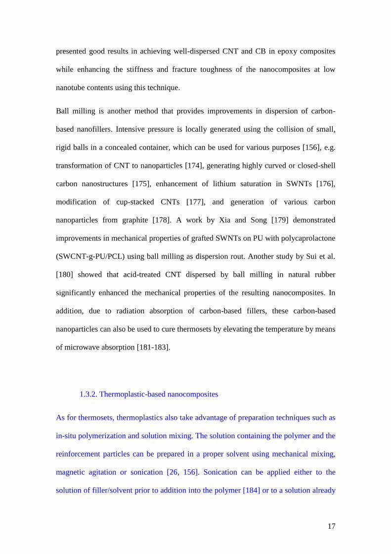
In terms of enhancing the electrical conductivity of functionalized nanocomposites,
methods such as the latex technology and dry-mixing are promising techniques for
preparing highly conductive materials (10-2
to 10 S/cm) for EMI shielding purposes
[156] (see Figure 6). Latex fabrication method consists of dispersing the filler in an
aqueous medium followed by the addition of colloidal dispersion of polymer particles
[187]. Besides high electrical conductivity at low percolation threshold, other two main
advantages of this method are simple mixing process and the use of water as solvent
[188-190]. Dry-mixing is, to some extent, very similar to the latex technology, as the
dispersion process consists of mixing the filler with a micro-sized polymer powder,
providing a covered polymer granule surface by the filler followed by sinterization
[191]. Electrical conductivity measurements done on nanocomposites prepared using
these two methods have shown that it is possible to reach higher values than that of
randomly dispersed fillers [188, 192].
Figure 6
Contrarily to thermosets, thermoplastics have fewer limits in processing for the
preparation of nanocomposites and dispersion of nanofillers in the matrix. In addition to
ball milling, ultrasonication, stirring and calendaring, carbon-based nanoparticles can
19
take advantage in thermoplastic nanocomposite preparations via melt-blending, both
using continuous processes such as extrusion or batch mixing methods [193], which
provide the advantage of avoiding any solvent employment to disperse the filler.
Although these methods do not facilitate the homogeneity of filler content in the matrix,
requiring the application of intense shear forces and higher temperatures, they are yet
the most promising techniques to prepare nanocomposites containing nanofillers at
industrial scale for thermoplastics such as polycarbonate (PC) [194], poly(lactic acid)
(PLA) [195], polyamide (PA) [196], polyethylene (PE) [197], poly(ethylene
terephthalate) (PET) [198], polypropylene (PP) [199], polystyrene (PS) [200], etc. In
order to reach a higher level of dispersion and exfoliation, sonication can be applied to
break the agglomerated particles prior to their addition into polymers and melt-mixing
[201].
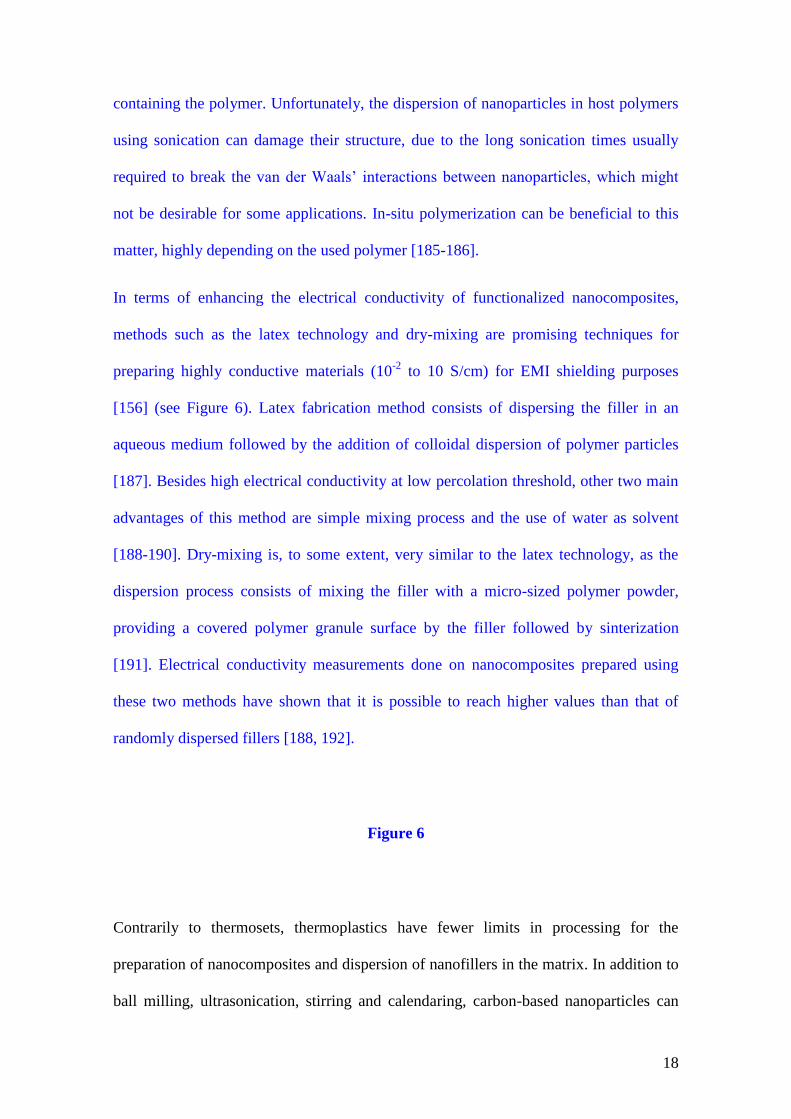
Hornbostel et al. [202] represented the different dispersion of SWNTs in PC using melt-
mixing and sonication vs. coagulation of PC/CNT in DMF solvent. The micrographs
presented in Figure 7 show that a homogeneously fine-doted composite structure was
seen in the melt-extruded material, while in the coagulated material a rather flake-like
distribution of nanofillers was observed.
Figure 7
As a matter of fact, continuous extrusion has been vastly considered as melt-mixing
method to prepare carbon-based polymer nanocomposites. For instance, polymer
nanocomposites reinforced with CNTs have been prepared using twin-screw extrusion
[203-204], with authors demonstrating the very good distribution and dispersion of
20
CNTs in the polymer matrix after melt-compounding. A vast selection of publications
that consider the preparation of carbon-based polymer nanocomposites by means of
continuous melt-mixing extrusion process are included in this review, especially when
dealing with the effect of nanoparticle dispersion by means of processing on the
electrical conductivity and hence EMI shielding behaviour of polymer nanocomposites.
In a recent review, Spitalsky et al. [205] considered the chemistry, processing,
mechanical and electrical properties of CNT-polymer nanocomposites, dedicating a
great deal of attention to nanocomposites processing and among processing methods to
melt-blending, always with the idea in mind that the effective use of carbon nanofillers
such as CNTs in composite applications strongly depends on their homogeneous and
individual dispersion throughout the matrix. Among batch melt-mixing techniques, Goh
et al. [206] used a laboratory mixing molder to melt-blend PMMA and CNTs,
afterwards compression-moulding the resulting mixes to films, and demonstrating the
viability of batch mixing to properly disperse CNTs. Zhang and co-workers [207]
prepared PA6-CNT nanocomposites containing a fix amount of 1 wt% CNT using a
Brabender Plasticorder internal mixer, showing homogeneous dispersion of the
nanotubes through PA’s matrix, leading to nanocomposites with enhanced mechanical
performance. Bocchini et al. [208] used the same type of internal mixer to prepare
LLDPE-CNT nanocomposites, in this case relating the enhanced dispersion of the
nanotubes due to the effective shear stresses applied inside the chamber of the internal
mixer with a final delay in the thermal and oxidative degradation of the nanocomposites
when compared to virgin LLDPE. High performance polymers have also been melt-
mixed with carbon-based nanofillers using batch mixing techniques. Such is the case of
the work of Kumar and co-workers [209], which used a Sigma high temperature internal
mixer equipped with two counter-rotating rotors to melt-mix at high temperature PEI

21
with untreated and acid-treated CNFs. The authors demonstrated that the combination of
proper shearing applied inside the internal mixer and acid-treatment of the nanofibres
prior to mixing led to improved nanofibre dispersion throughout PEI’s matrix and, as a
consequence, to enhanced nanocomposite tensile strength and electrical conductivity,
especially when using lower CNF loadings (up to a maximum of 1 phr CNF).
In terms of the influence of flow conditions on nanocomposite’s morphology, Martins et
al. [210] used different strategies to prepare nanocomposites of PVDF-PAni with
variable concentrations of nanotubes (0.25 to 2 wt%) using a batch mixer of the
Brabender type, i.e., a torque rheometer equipped with a mixing chamber, directly
adding the nanotubes into the polymer blend inside the mixer; dispersing the nanotubes
in the reaction medium during PAni polymerization, blending it afterwards with PVDF
in the mixer; or using a combination of both methods. Depending on the used strategy
CNTs were mainly located in PVDF’s phase, in PAni’s phase or in both phases, leading
to the formation of a percolated CNT network at a minimum of 1 wt% CNT in the first
case, no percolation in the second and percolated network at 2 wt% CNT in the last
case. Recently, Vilaverde and co-authors [211] analyzed the influence of flow
conditions on the dispersion and re-agglomeration of GnP in PP. For that purpose, they
used a prototype small scale modular extensional mixer, which enabled to apply a
sequential first mixing step, followed by melt relaxation and a second mixing step,
which authors used to reproduce the flow conditions of the first step or generate milder
flow conditions. While the gradual decrease in size and number of GnP agglomerates at
2 and 10 wt% GnP concentrations at the end of the first stage was done at a rate that
was independent of the applied flow conditions, the application of a second mixing
stage to a re-agglomerated GnP morphology material obtained at the end of the

22
relaxation step led to variable GnP dispersion results that were highly dependent on the
applied stress flow conditions.
As flow conditions strongly affect the final morphology of the resulting nanocomposites
and ultimately their final performance, a good number of research groups have
dedicated their investigation to the development of mixers with enhanced mixing
capability. In this sense, Sundararaj’s research group has developed a miniature mixer
with enhanced shear mixing and complex elongational flow modes required for
optimum dispersive mixing, which they called the “Alberta Polymer Asymmetric
Minimixer” (APAM), specifically thought for mixing multiphase polymer systems and
composites [212-213], demonstrating that the final morphology of polymer blends was
similar than that obtained in internal mixers or in twin-screw extruders, with the
advantage of requiring much lower material amounts [212]. Comparatively, both
experimentally [212] as well as using flow simulation [213], the authors demonstrated
that the APAM mixer allowed a proper dispersion of nanofibres in polymer matrices
comparable to the internal batch mixer and much better than other mixers such as the
MiniMAX, which relies only on simple shear flow patters, where nanofibres remained
aggregated and not fully covered by the matrix. Nevertheless, the high shear stresses
applied during mixing led to partial rupture of nanofibres.
As can be seen, researchers that have considered the preparation of carbon-based
polymer nanocomposites through melt-mixing have focused their work in counteracting
the main limitations of both continuous and batch melt-mixing methods, which are
related to the high shear stresses combined with relatively high processing temperatures
required to guarantee proper nanofiller dispersion in polymer matrices, especially when
compared to solution mixing methods, and the fact that nanofiller addition results in a

23
significant increase in viscosity, limiting processing and making it harder to guarantee a
proper nanofiller dispersion.
Recently, new methods for preparing nanocomposites reinforced with carbon-based
nanoparticles have been developed for materials with high filler contents, especially
CNT, to serve specific applications [156], which include densification [214], spinning
[215-216], layer-by-layer deposition [217] and pulverization [218].
1.4. Different morphologies and microstructures of nanocomposites from different
carbon-based nanoparticles
1.4.1. Carbon black-filled polymer nanocomposites
The morphology study of nanocomposites can identify the interaction of the filler with
the matrix, which strongly affects the properties of the final product. Scanning electron
microscopy (SEM), field emission scanning electron microscopy (FE-SEM), helium ion
microscopy (HIM), transmission electron microscopy (TEM), etc., are the common
instruments for morphology characterization of nanocomposites.
Generally speaking, the modification and functionalization of nanofillers improve their
interaction with the matrix. The type of nanofiller, preparation process and host matrix
are the other factors influencing the structure of the nanocomposites. Electrical
conductivity of the material is highly dependent on the structure of the created
conductive network throughout the nanocomposite. A study by Gubbels et al. [219]
showed the improved electrical conductivity of PE/PS polyblend nanocomposite filled
with CB by selectively localizing CB in PE. The opening size distribution of the PE
phase and the specific interfacial area of the PE/PS blends have been extracted from the
24
optical micrographs. In another study, the self-networking capability of CB in PLA was
firstly confirmed using TEM, displaying the network structure of CB at the same 3 wt%
loading in PLA matrix. For CB with low and medium self-networking capability, only
some discrete clusters with a size of 100-500 nm were formed in the PLA matrix, while
for CB with high self-networking capability, a continuous network structure was formed
in the PLA [220].
1.4.2. Carbon nanotubes-filled polymer nanocomposites
As with other carbon-based nanocomposites, the stacked morphology and
agglomeration of CNTs, alongside their size and dispersion level, can affect the
properties of nanocomposites. For instance, analyses of FE-SEM images have addressed
the size changes of CNTs depending on ball milling duration [221]. Another study used
TEM to reveal that MWNTs more readily disperse within a PC matrix and have higher
aspect ratios than SWNTs; extraction of the polymer from the composite prior to TEM
imaging helped overcome the common issue of poor atomic contrast between the
nanotubes and the organic matrix [222]. Additionally, morphology studies involving
polarized Raman spectroscopy and wide angle X-ray scattering (WAXS) using
synchrotron radiation showed reasonable levels of nanotube alignment.
In terms of evaluating the effects of functionalization and modification of the
nanocomposites, SEM and TEM results can be used to compare the dispersion level of
modified and pristine CNTs. In a study by Yuen et al. [223] SEM and TEM
micrographs revealed that acid-modified MWNT and amine-modified MWNT were
dispersed uniformly in a polyimide (PI) matrix, yet not improving the electrical
conductivity of the material.

25
In terms of mechanical performance, morphology analysis can provide an insight about
the matrix-filler interface. Functionalization of the fillers commonly improves bonding
between filler surface and matrix. In a work by Paiva et al. [224] SEM micrographs
showed an apparent good wetting of water-soluble PVA-functionalized nanotubes by
the PVA matrix.
1.4.3. Graphene-based polymer nanocomposites
The exfoliation and diameter of incorporated graphene-based materials in a matrix can
be addressed via morphology analysis using the techniques mentioned in the previous
sections. A study of Li et al. [225] illustrated that expanded graphite presents a loosely
bonded, porous and worm-like rod on a microscopic scale, which consists of
nanoscopically parallel carbon sheets that are collapsed and/or deformed following an
irregular pattern. In this study SEM micrographs showed that expanded graphite was
exfoliated into individual and/or bundles of GnP through ultrasonication. TEM
micrographs of these GnP after sonication suggested that the exfoliated graphene was
formed by stacks of 10-15 graphene layers. Through post analysis of a controlled
sonication process, the parameters including the duration, frequency and power could be
tailored in order to avoid an excessive rupture of graphite, which would result in
nanoparticles with lower aspect ratios and as a consequence probably lead to
nanocomposites with reduced electrical conductivity.
Similar to CNTs, graphene can also benefit from surface functionalization to improve
interaction with the matrix. Ramanathan et al. [226] claimed a better interaction of
graphene with oxygen functionalities with polar polymers in comparison with
unmodified SWNT and traditional expanded graphite, thereby imparting superior

26
mechanical and highly enhanced thermal properties at exceptionally low loadings. The
oxygen and hydroxyl functional groups on the functionalized graphene sheets are a
great candidate for preparing composites with polar polymers such as PMMA, PAN and
poly(acrylic acid) (PAA), giving rise to intimate nanosheet-polymer interactions and a
percolated interphase essential to mechanical and thermal enhancement. Given these
properties and the abundance of graphite, graphene-based fillers such as FGS or others
have excellent potential to revolutionize the use of nanocomposites and enable their
widespread use in large-scale applications [226].
Studies by Potts et al. [227] confirmed GO’s exfoliation using mechanical stirring with
much larger lateral dimensions and aspect ratio when compared to that of sonicated
using atomic force microscopy (AFM). TEM and WAXS analyses are most likely the
two most common means by which the state of dispersion can be assessed.
Immiscibility of the phases and/or insufficient exfoliation of the graphite or GO-derived
filler prior to mixing with polymer can result in large agglomerates consisting of
stacked platelets when observed by TEM, which may also be suggested by the presence
of a diffraction peak corresponding to the interlayer spacing of GO or graphite [227-
228].
Small-angle X-ray scattering (SAXS) and ultra-small-angle X-ray scattering (USAXS)
measurements have been used on a variety of nanocomposite systems to detect the
presence of fractal-like aggregates of filler at length scales beyond that of individual
particles, although only limited information of this nature exists on GO-derived polymer
composites [227, 229].
1.4.4. Polymer nanocomposites with nanohybrids

27
The unique electrical and mechanical properties as well as large surface area of
graphene nanosheets have enabled them to be a new class of conducting materials for
device, electrochemical and analytical applications. However, frequently used graphene
fillers obtained from chemical reduction suffer from surface defects and readily form
aggregated structures, greatly influencing their performance. Currently, improving the
conductivity of graphene-based films and obtaining good control of
architecture/property is an attractive topic for enhancing their application prospects. The
use of CNTs to physically separate graphene stacks to preserve the high surface area of
graphene and at the same time act as conducting carrier is an attractive and highly
desirable idea [230-232].
A study undertaken by Yu and Dai [233] reported on the fabrication of large-area
multicomponent hybrid films by sequential self-assembly of cationic polyethyleneimine
functionalized graphene nanosheets and MWNTs forming hybrid carbon films with
interconnected carbon structures of well-defined nanoscale pores. Therefore, this self-
assembly method can be used to fabricate large-area multicomponent hybrid films with
a well-defined architecture and tunable thickness on various substrates, suitable for
electrochemical applications. More recently, Hong et al. [234] developed a layer-by-
layer assembly technique for constructing transparent, flexible conducting hybrid
multilayer thin films of MWNTs with rGO, which employs the electrostatic interactions
of positively charged MWNTs and negatively charged rGOs. The obtained hybrid
multilayer exhibited a significant increase of controllable electronic conductivity.
Moreover, a more accurate control of the electrical conductivity was obtained for a
hybrid system with vertical CNTs grown on reduced graphene films composed of
overlapping and rGO platelets. Such carbon hybrid films have excellent flexibility and
stretchability, can be readily transferred to any substrate, including non-planar surfaces,
28
and were found to have ohmic electrical contacts throughout all junctions in the
CNT/metal-catalyst/graphene-film system [235]. In another study, Fan et al. [236]
managed the preparation of 3D CNT/graphene sandwich structures with CNT pillars
grown within the graphene layers using chemical vapor deposition (CVD). The special
structure endowed the high-rate transportation of electrolyte ions and electrons
throughout the electrode matrix, resulting in excellent electrochemical performance of
this hybrid material.
Recently, Van Thanh et al. [237] reviewed recent trends in the preparation and possible
applications of hybrid thin films resulting from the combination of CNTs and graphene,
which include applications such as transparent conductors, field-effect transistors or
supercapacitors. Authors showed that in most cases these 3D CNT-graphene hybrid
films displayed superior performances when compared to pristine GO, pristine graphene
or even pristine CNTs.
2. EMI shielding theoretical models
2.1. Theoretical models based on electrical conductivity
2.1.1. Percolation models
Due to their inherently high mechanical performance and high electrical and thermal
conductivities, carbon-based nanofillers (CNTs, nanosized CB, CNFs, graphene-based
materials, etc.) have been vastly considered as a possible strategy to enhance the
mechanical and/or transport properties characteristics of polymer nanocomposites,
commonly resulting in final materials with multifunctional characteristics. Particularly,
the extremely high electrical conductivity of carbon nanoparticles, reaching for instance
values as high as 2 × 10⁷ S/m for MWNTs [238], has generated a lot of interest in the
29
field of conductive polymer materials, coming as a strategy to overcome the high cost
and in many cases low thermal stability and relatively poor mechanical performance of
common electrically conductive polymers [5]. In this sense, a lot of recent works have
considered the modelling of the electrical conductivity and electrical behaviour of
polymer nanocomposites containing different types of carbon nanoparticles, from the
most common CNTs to the more recently considered graphene-based materials
(monolayer/bilayer graphene, GnP, GO, rGO, etc.). Most of these studies are aimed to
enhance the absolute value of electrical conductivity and/or minimize the critical
concentration of carbon nanoparticles required to attain electrical conduction.
Depending on its value and concentration dependence, this critical concentration may be
related to specific conduction models, being the most common the so-called electrical
percolation model [239-240], where electrical conductivity () of the nanocomposite
increases abruptly at a given nanoparticles concentration (the percolation threshold, c),
the polymer effectively passing from being insulating to electrically conductive, related
to the formation of a conductive network by physical contact between conductive
carbon-based nanofillers:
0
t
c , for c (1)
In this equation 0 is a physical parameter commonly related to the intrinsic
conductivity of the added carbon nanoparticles and t is the critical exponent that
considers the dimensionality of the conductive system (for instance, t = 2 for a 3D
direct-contact conductive network [241]).
A number of recent studies have considered the modelling of the electrical conductivity
of polymer-carbon nanoparticles nanocomposites by considering carbon nanoparticles,
especially CNTs, as random resistors dispersed throughout an insulating polymer
30
matrix. Models have been developed based on the dimensionality of these random
networks, from 2D [242-243] to 3D [244-245]. In the particular case of 3D models, a
representative volume element (RVE) is taken as being representative of the polymer
nanocomposite, meaning that its electrical conduction behaviour may be modelled by
periodically repeating RVE (an example of a cubic-like RVE is presented in Figure
8(a)). However, many of these approaches disregard the interconnectivity of carbon
nanoparticles, requiring RVEs with larger volumes. Additionally, most 3D models use
simplified cubic RVEs and assume isotropic percolation of carbon nanoparticles in the
matrix [244-246]. However, Shklovskii et al. [247] have demonstrated that in some
cases, especially when dealing with high aspect ratio nanofillers such as CNTs or
graphene, the conductive network may be anisotropic.
Fang et al. [248] have developed a model to describe CNT networks in polymer-CNT
nanocomposites, accounting for electrical conductance of the CNT network across the
boundary of adjacent representative volume elements, this way presenting a more
realistic representation of the interconnectivity between nanotubes. Additionally,
different RVE dimensions in different material directions were considered, this way
exploring the possibility of anisotropic percolation, giving a more realistic vision of the
structure-property relations of electrically conductive polymer-carbon nanoparticles
system. A cubic-like RVE was considered in this work (see Figure 8(a)) with electric
current being considered to propagate from the high voltage electrode to the low voltage
one and CNTs assumed to have a rod-like geometry with interconnected conductive
nodes (Figure 8(b)). Polymer nanocomposites’ electrical conductivity was modelled,
after considering the contribution of the interconnecting CNTs across the boundary
surfaces of adjacent RVEs (see Figure 9), as follows:

31
2 3 xrect RVE
y z
LG G
L L (2)
where Grect is the electrical conductance of the rectangular parallelepiped shown in
Figure 9, GRVE is the equivalent conductance of the conductive network and Lx, Ly and
Lz are respectively the edges of the cubic-like RVE in x, y and z axes (see Figure 9).
Figure 8
Figure 9
The effects of the orientation of the nanotubes on the percolation threshold and
electrical conductivity were also studied, with the proposed model suggesting that
perfectly random orientation of CNTs leads to lower threshold values, while high
alignment along the direction of the electric current results in higher conductivity values
at high CNT concentrations, as expected based on the formation of a conductive
network by direct physical contact between the nanotubes [249].
2.1.2. Tunnelling-percolation models
Although the percolation threshold and percolation approaches have been vastly
considered to model the electrical conductance behaviour of polymer nanocomposites
containing conductive nanoparticles, classical percolation approaches have been found
by many researchers to display a poor fit to most experimental results [250-252]. Other
approaches, as tunnel-like conduction based models, such as Tunnelling Percolation

32
(TPM), and the Two Exponent Phenomenological Percolation Equation (TEPPE) based
on the Generalized Effective Media (GEM) theory or even combined models, have been
considered [253].
Tunnel conduction considers the possibility of electron transport between neighbouring
conductive particles at very small gaps (a couple of nanometers), enabling modelling of
the junction resistance between conductive nanoparticles and insulating matrix
assuming a quantum tunnelling effect [254]. Nevertheless, as percolation threshold has
to be taken into account, tunnelling-percolation models (TPM) have been considered,
such as the one proposed by Rubin et al. [255]. In Hansen et al. [253], authors used a
simplified Hertz distribution for particle distribution assuming a distance between
conductors inversely proportional to the volume fraction of nanoparticles () and
directly proportional to the percolation threshold (c):
101
1
ctd
cf
c
K
, for c (3)
where t is the critical exponent (see Eq. 1), d is the characteristic tunnelling distance of
the system and K is a scaling correction factor that takes into account polymer
tunnelling characteristics (a larger K factor is required for systems with larger tunnelling
distances and higher percolation thresholds).
On the other hand, Generalized Effective Medium (GEM), an approach initially
developed by McLachlan [256-258] and later extended to consider complex electrical
behaviours [259] and expressed as the Two-Exponent Phenomenological Percolation
Equation (TEPPE) [260-264], has been used to account for conductivity behaviours
across the whole conductive particles concentration range, as it accounts for different
behaviours below and above the percolation threshold according to:

33
s
cp
c
, for c (4)
1
t
cf
c
, for c (5)
t s
s t s tp f , for c (6)
where p and f are the direct current (dc) conductivities of the polymer and conductive
filler, respectively.
As can be seen, these equations are the normalized standard percolation equations
adapted, using exponents s and t, to each concentration range taking c as reference.
Taking the best of both models, a combined TPM-TEPPE model was proposed by the
authors, based on the GEM approach explicitly considering electron tunnelling above
the percolation threshold, i.e., > c condition, as modelled by Rubin et al. [255].
Hansen et al. [253] demonstrated by modelling the electrical conductivity of several
types of polymer-based systems reinforced with conductive nanostrands that the
classical electrical percolation model as shown in Eq. 1 cannot distinguish between
differences in the percolation limit across polymers, not lying within the proper region
of conductivity (see Figure 10(a)). Also, the TPM model, though showing improved fit
over the classical percolation model, underestimates to some extent its value (see Figure
10(b)), besides only modelling electrical conductivity for values above c. This
problem is solved by the TEPPE approach (see Figure 10(c)), which fits well in the
regions of the percolation limit. However, the model does not fit so well at the
percolation limit. Only when combining TPM and TEPPE models it was possible to
have a proper fit across the whole concentration range (see Figure 10(d)), as separation

34
analysis of the different concentration regions is strengthened by the inclusion of
tunnelling approach (quantum tunnelling characteristics of the polymer matrix) above
the percolation threshold.
Figure 10
Although significantly improving the modelling of the electrical conductivity of
polymer-conductive nanoparticles nanocomposites by considering individual
conductivity predictions for each nanoparticles concentration range, i.e., < c, ~ c
and > c, and especially by incorporating the tunnelling-percolation approach to > c
condition, the TPM-TEPPE model proposed by Hansen et al. [253] or similar
approaches proposed by other authors still do not take into account the importance of
interface effects. Recent studies have extended the analysis considering the importance
of this conductor-insulator-conductor interface, as well as further characteristic
tunnelling distance measurements and other quantum properties of the insulating matrix
[265].
Wang et al. [266] have considered the modeling of the electrical conductivity of CNT-
reinforced polymer nanocomposites by considering three main elements: the percolation
threshold, approached by means of selecting an effective medium theory; possible
interface effects, modeled by introducing an interfacial conductivity assuming a “thinly-
coated” CNT; and tunneling-assisted interfacial conductivity, in order to take into
account the possible influence of electron tunneling on interface conductivity.
Particularly, the authors addressed tunnel-like conduction assuming a continuum
medium of CNT network formation as a statistical process represented by Cauchy’s

35
probability density function. As authors demonstrate, not considering the interface
effect leads to overestimated electrical conductivities and not accounting for the
additional tunnel-like contribution results in low predicted conductivity values beyond
the percolation threshold. Furthermore, authors show that despite CNTs conductivity
anisotropy, overall electrical conductivity is dominated by its axial component along
CNT’s direction:
11 1 2
c ii
i iic S R
(7)
ic being the enhanced conductivity for the “coated CNT”. This conductivity can be
used to calculate the effective conductivity (e) by replacing the value of ic in the
following equation:
0 1 31
1 11 3 33
1 20
1 3 1 3
e e e
e e e e e e
c n n n n nc
n n n n n S n n n S
(8)
which takes into account on the one hand the influence of CNT concentration (c1),
aspect ratio () and intrinsic conductivity (i), and second of all the intrinsic interfacial
resistivity (), percolation threshold (here depicted as c1*), and the already mentioned
probabilistic density parameter (), this way creating a continuum model that considers
percolation by physical contact between CNTs, the interface effects, and tunnel-
conduction.
Continuum model application was in good agreement with the experimental data of both
MWNTs and SWNTs-reinforced PI nanocomposites [267-268], also showing how a
not-fully perfect interface reduces the overall conductivity, while conduction by
electron tunneling significantly increases its value after the percolation threshold.

36
Leon-Gil and Alvarez-Quintana [269] have developed a model for predicting the
electrical conductivity of nanoresistors based on Landauer’s tunnel conduction model
[270-271]:
22e T
h R (9)
where T is the transmission probability and R the reflection one.
As the transmission probability term gets very small assuming tunnel conduction and
hence R is near 1, the above equation may be simplified to:
22eT
h (10)
where 2e2/h describes the quantum unit of the electrical conductance and T = e(-2kd)
,
being k the characteristic wave vector for tunnelling, d the distance between contacts
and is determined by the characteristics of the electrodes.
In a similar way as with carbon nanotubes [266], Wang and co-workers [272-273] have
considered the importance of the existence of an imperfect interface between
nanoparticles and insulating matrix, as well as interfacial tunnelling taking into account
the contribution of electron hopping between nanoparticles and using Cauchy’s
statistical function to predict increased tunnelling near the percolation threshold, on the
electrical conductivity of graphene-based nanocomposites. Authors initially used a 2D
model based on nanocomposites formed by distinct regions, one formed by graphene-
rich aggregates, and a second one poor in graphene (matrix-dominant region). Overall
conductivity, initially modelled considering these two regions, was then corrected
taking into account the presence of the imperfect interfaces and tunnel conduction by
37
using coated graphene or graphene aggregates instead of the original graphene layer or
graphene aggregate.
Model application to experimental data of graphene-reinforced PS nanocomposites
shows good accordance, in addition demonstrating that the percolation threshold for
electrical conduction is determined by the dispersion of graphene nanoparticles and the
aspect ratio of graphene aggregates, while, beyond percolation, overall conductivity is
determined by the interface characteristics and the intrinsic conductivity of graphene
and polymer matrix.
Feng et al. [265, 274] developed a mixed micromechanics model to predict the electrical
conductivity of CNT-polymer nanocomposites assuming electron hopping and
conductive networks as electrical conductivity mechanisms. Both interface layer and
effective aspect ratio of CNTs were considered. Simulation results, which fitted well the
experimental data for both single-wall and multi-walled CNT-polymer nanocomposites,
seemed to indicate that both electron hopping and conductive networks contribute to the
electrical conductivity, the second one becoming dominant with increasing CNT
concentration. Interestingly, authors showed that the size of CNTs have a significant
effect on the percolation threshold and hence on the overall electrical conductivity of
the nanocomposites. Similarly, Ren et al. [275-276] and Cattin and Hubert [277]
analyzed the piezoresistive response of CNT-reinforced polymer nanocomposites,
showing how different nanoscale mechanisms influence the overall electrical
conductivity and piezoresistive response through CNTs network, as mechanical
deformation induced change in the distribution of CNTs can be well described by a
strain-dependent conductivity exponent (mechanical deformation-related).

38
However, this work assumed a uniform random distribution of CNTs in the polymer,
i.e., it did not assume the typical formation of CNT aggregates, promoted by their large
aspect ratio and van der Waals surface attraction forces, nor the possibility of nanotubes
being curved. As it is known, the electrical conductivity of polymer nanocomposites is
highly dependent on nanofiller distribution and dispersion [278-279], as it has been
shown that for low nanofiller concentrations the best results in terms of electrical
conductivity are often reached by guaranteeing a combination of proper dispersion and
relatively bad distribution of nanofillers, this way assuring physical contact between
nanoparticles and the formation of a conductive network throughout the material (see
Figure 11).
Figure 11
In this sense, Gong et al. have considered the CNT aggregation effect on the electrical
conductivity modelling of polymer nanocomposites [280-281] and CNT deformation at
nanotube junctions [282], showing that the smaller the size of CNT aggregates the
closer the measured electrical conductivity of CNT-polymer nanocomposites to its
theoretical limit. Additionally, authors demonstrated that CNT aggregation is the main
reason behind the lower electrical conductivity of polymer-CNT nanocomposites than
expected based on the theoretical values of both CNT and polymer matrix. Local
deformation of CNT also plays a significant role in the electrical conductivity [282], as
the intrinsic resistance in the deformed part of CNT near a CNT-CNT junction increases
much faster than the decrease of CNT-CNT contact resistance at the same junction
when two CNTs get closer, resulting in a net increase of resistance at the junction (see
39
Figure 12). Nevertheless, by using a multi-scale CNT percolation network model (see
Figure 13), simulation predictions still showed some limitations previously overcame by
assuming tunnelling besides percolative behaviour.
Figure 12
Figure 13
Several authors have applied the molecular dynamics simulation method to study the
conductive properties of polymer nanocomposites containing carbon-based nanofillers
[283-285]. Four factors were taken into account: polymer-nanoparticle interaction,
grafting of nanoparticles, possible crosslinking of polymer molecules, and polymer
blending. Authors show that conductivity variation is not linear regarding the mentioned
factors. For instance, as interaction increases the dispersion of nanoparticles seems to
first increase and then drop, while the conductivity increases monotonously.
2.1.3. Models for nanohybrids
The addition of hybrid conductive fillers, typically based on the combination of two or
more types of carbon-based nanoparticles having different morphologies, has been
recently considered as a possible strategy to enhance the electrical conductivity of
polymer-based materials. In this sense, Chen et al. [286-287] have numerically studied
using Monte Carlo simulation the electrical percolation of polymer-based
nanocomposites containing CNT-CB hybrid nanofillers. By assuming CNTs as slender

40
capped cylinders and CB nanoparticles as sphere-like aggregates (see Figure 14),
authors found that on the one hand the addition of CB can decrease the required
concentration of CNT for achieving percolation (especially when already close to the
threshold with only CNT nanofiller) and on the other the percolation threshold may be
significantly reduced by increasing the aspect ratio of the nanotubes, as well as
increasing the diameter ratio of CB aggregates to CNTs, hence showing the synergistic
effect of using both conductive nanofillers, corroborated by experimental studies. The
nanocomposite percolation threshold (cCB&CNT
), defined as the volume fraction of both
nanofillers when the electrical conductivity of the nanocomposites abruptly increases
(threshold), was proposed by authors to be estimated using the following expression:
1 449 0 622 0 0531
1 1 1
CNT
CNT CB
d. . d . d
CB&CNT CB CNTc c CNTCNT
c
VV
(11)
where cCB
and cCNT
are respectively the percolation concentration if only CB or CNT
are present in the system, VCNT is the volume fraction of CNT at the percolation
threshold, and dCNT and dCB are respectively the diameter of the nanotubes and the
diameter of CB aggregate (see Figure 14).
Figure 14
Similarly, Safdari and Al-Haik [288-289] proposed a model for predicting the electrical
conductivity of polymer nanocomposites based on CNTs and GnP. They extended the
model for polymer nanocomposites containing one single nanofiller to nanocomposites
with hybrid nanofillers based on the combination of different nanofillers considering

41
tunnelling conduction as the more effective mechanism for insulator-conductor
transition, observing that enhanced electrical conductivities could be reached at lower
total nanoparticles volume fractions, related to a positive synergistic effect between both
conductive nanoparticles. Additionally, simulations revealed that the best system in
terms of attaining the lowest possible electrical percolation threshold was the one that
considered the addition of a minimum amount of a higher aspect ratio auxiliary
nanofiller to a lower aspect ratio main one.
2.2. Electromagnetic interference shielding efficiency (EMI SE)
Conventional shielding materials include metals such as steel, copper or aluminium,
which combine a high electrical conductivity and dielectric constant [290-292].
Nevertheless, they show some obvious disadvantages, such as high density, tendency to
corrosion or even cost processing [293]. Most importantly, metals mainly protect from
EMI by means of reflection, hence being out of use in applications where EMI
absorption is required, as for instance in stealth technology [294-295]. Electrically
conductive polymer composites could come as a possible alternative [296]. Among
these, polymer nanocomposites containing carbon-based nanofillers have been gaining
an increasing interest, especially in sectors such as electronics, automotive and
aerospace [297-299], mainly due to their already demonstrated combination of high
electrical conductivity and low percolation threshold.
EMI may be defined as a disturbance caused in an electronic system due to induced
false voltage and current by the electromagnetic radiation generated from external
sources [300]. Shielding from this electromagnetic radiation, which is emitted by
computer circuits, cellular phones, electric motors, radio transmitters, etc., is hence

42
required in order to protect electronic systems. This is done by attenuating the incident
electromagnetic radiation by means of reflection, which requires free mobile charge
carriers, and/or absorption, which happens due to mobile charge carriers and electric
and magnetic dipoles within the material [301], though more commonly a combined
reflection/absorption is used. An electromagnetic (EM) wave that strikes on a shielding
material divides into a reflected wave, an absorbed wave, an internal reflected wave and
a transmitted wave (see scheme presented in Figure 15).
Figure 15
The efficiency of a given material as electromagnetic attenuator can be expressed in
terms of the electromagnetic interference shielding efficiency (EMI SE) [302-303]:
R A MEMI SE (dB) = SE + SE + SE (12)
where SER is the shielding efficiency due to reflection loss, SEA is the shielding
efficiency due to absorption loss and SEM is the shielding efficiency due to internal
reflection loss (secondary reflection). In most shielding environments SEM has a very
low value compared to the other two terms [304], and so EMI SE may be estimated as
the sum of the reflection and absorption terms, i.e., R AEMI SE SE + SE .
Assuming PI (EI), PT (ET) and PR (ER) as respectively the power densities of the
incident, transmitted and reflected electromagnetic waves:
EMI SE (dB) = 10 log = 20 logI I
T T
P E
P E
(13)

43
RSE (dB) = 10 log = 20 logI I
R R
P E
P E
(14)
Considering a two-port network system, the scattering parameters (S11 and S12, and their
reciprocals S22 and S21) may be correlated to the reflection and transmission coefficients.
Hence, reflection (R), transmission (T) and, as a consequence, absorption (A) shielding
coefficients may be calculated according to [300]:
2
2 2
12 21T
I
ET S S
E (15)
2
2 2
11 22R
I
ER S S
E (16)
1A T R (17)
Assuming multiple reflections as negligible leads to an effective absorption coefficient
(Aeff) that can be described by the following equation [305]:
1
1eff
T RA
R
(18)
where SER and SEA are related to the reflection and transmission coefficients in the
following way:
R
1SE = 10 log
1- R
(19)
A
1 1SE = 10 log log
1 eff
R
A T
(20)
Also, according to [306-307]:

44
1 2
ac
H 0
RSE (dB) = 20 log4
r
(21)
ASE (dB) = 20 log expt
(22)
where ac is the ac electrical conductivity, is the dielectric
permittivity, 1 2
H = 2 ac is the depth of radiation penetration in the material, is
the magnetic permeability of the polymer nanocomposite, r the relative permeability of
the shielding material (r = 1), and H = 2fH, where fH is the radiation frequency in
MHz.
2.3. Parallel resistor-capacitor model
Several authors have demonstrated by using a parallel resistor-capacitor model (see
scheme embedded in Figure 16(a)) that the ac electrical conductivity (ac) of
nanocomposites, usually measured at microwave frequencies such as the X-band (8.2-
12.4 GHz), may be taken as a good predictor of their EMI SE, with EMI SE increasing
almost linearly with ac (see Figure 16(b)) [308]. Also, ac has been seen to vary
linearly with the concentration of added carbon nanoparticles, being higher than dc
even below the percolation threshold. Electrical conductivity has been found to be
frequency-dependent, and can easily be understood by using a simple parallel resistor-
capacitor model, with conductive carbon nanoparticles contributing to electrical
resistance and the insulating polymer matrix contributing to ac conductance.
45
Figure 16
It has been shown in the literature that the addition of small amounts of high aspect ratio
conductive nanofillers to polymers, such as CNTs or graphene, results in polymer
nanocomposites with enhanced electrical conductivity and as a consequence high EMI
shielding efficiency [301, 309-312]. As these nanofillers are highly conductive,
increasing their aspect ratio leads to longer conductive pathways within the insulating
polymer matrix, enhancing electrical conductivity (see comparison between high aspect
ratio and lower aspect ratio fillers presented in Figure 17).
Figure 17
Theilmann et al. [301] showed that, while for electrical conductivity in direct current
conditions (dc) physical connectivity between CNTs was required, EMI SE and ac did
not require it [313-314], as high frequency EM waves may couple between
neighbouring CNTs. Nevertheless, as EMI SE and ac are still dependent of physical
contact between CNTs, maximization of the connectivity through improved CNT
separation and dispersion throughout the insulating matrix is still a requirement [310,
315] (compare Figure 17(b) and (c) with (a), as separated and well-dispersed CNTs are
more likely to physically touch and form conductive paths). Nanofiller alignment,
especially in those cases where nanofillers have a platelet-like (such as graphene) or a
fibre-like geometry (such as CNTs), also affects the values of electrical conductivity
and as a consequence EMI SE. Nanoparticle alignment reduces the probability of
contact, hence being easier to attain an interconnected network with longer conductive

46
pathways under random nanofiller orientation (compare Figure 17(b) and (c)) [310,
315].
2.4. Multiscale hybrids
Multiscale hybrids based on the combination of highly reflective and highly absorptive
EM materials have been recently considered for EMI shielding applications. For
instance, Huynen and co-workers [316-317] have considered a CNT-reinforced polymer
foam, characterized by its high EM absorption, inserted into an aluminium honeycomb,
characterized by its high EMI shielding due to reflection, hence combining a low
dielectric constant (as close as possible to 1) with a moderately high absolute electrical
conductivity (around 1 S/m at the high frequencies required in EMI shielding, which
can be attained by adding low amounts of conductive nanoparticles such as CNTs to
polymers [318-319]) in one single material (see Figure 18). As the dielectric constant is
increased as a consequence of adding CNTs, detrimental in terms of EM reflection,
authors considered the strategy of using a polymer foam, which, due to its particular
cellular structure, globally reduces the dielectric constant, resulting in a nanocomposite
with a dielectric constant close to that of the polymer without nanotubes and an
electrical conductivity close to the optimum region for EMI shielding [320].
Interestingly, authors demonstrated the possibility of tuning the EM absorption
frequency by modifying the initial shape of the metallic honeycomb, as EM propagation
inside each cell of the honeycomb is directly affected by the metallic walls of the cell,
the problem being similar to that of a metallic waveguide filled with a material of
known complex permittivity, the propagation constant becoming dependent on the
width (a) and the height (b) of the waveguide. For instance, for rectangular cells and

47
thus waveguides (see Figure 19), the complex propagation constant () may be
determined by the following expression:
2 2 2 22 2 220
2 2
0 0
eff eff c
m n m nj j
c c a b a b
(23)
Figure 18
Figure 19
The insertion of a metallic honeycomb into the CNT-reinforced polymer foam further
reduced the real part of the effective dielectric constant, with the honeycomb effectively
acting reducing the reflected power, hence the hybrid displaying a lower effective
dielectric constant than the nanocomposite foam by itself.
3. EMI shielding behaviour of carbon-based polymer nanocomposites
3.1. Influence of the electrical conductivity
Improved dispersion of CNTs has been addressed in several works, as it has been shown
that proper nanotube distribution and dispersion is crucial in terms of forming an
effective conductive network, minimizing the percolation threshold and maximizing the
absolute electrical conductivity. Different approaches have been considered, particularly
the improvement of dispersion during processing, functionalization and surface

48
modification of the nanotubes (as a way to avoid nanotube aggregation) and selective
nanotube dispersion.
3.1.1. Effect of nanoparticle dispersion by means of processing
In terms of improving dispersion during processing, Espinosa-Martínez et al. [321]
analyzed the influence of the cooling rate during melt-compounding by twin-screw
extrusion in the morphological, structural and electrical properties of PEN-MWNT
nanocomposites, showing that the addition of increasingly higher concentrations of
MWNTs promoted PEN crystallization during cooling, leading to electrical
conductivities in the range of semiconductors (around 10-4
S/cm), which authors related
to the formation of an interconnected nanotubes network throughout the crystalline
structure formed in PEN nanocomposites.
Huang at al. [322] were able to prepare PA11-MWNT nanocomposites with enhanced
dielectric properties and electrical conductivities using a conventional melt-
compounding process. The uniform dispersion of MWNTs throughout PA11’s matrix
guaranteed during melt-mixing induced the crystallization of PA11 when quenching
from the melt, which, together with MWNTs, helped enhancing the dielectric properties
and electrical conductivities (reaching values as high as 10-3
S/m for 2.5 vol% MWNT)
of the nanocomposites by forming nanocapacitors within the nanocomposites and the
interfacial polarization effect resulting from the accumulation of charge carriers at the
interfaces between the nanotubes and PA11.
Melt-mixed HDPE-MWNT nanocomposites processed by compression-moulding and
blown film extrusion were investigated in terms of their structure and properties by
Xiang et al. [323]. Although authors demonstrated that blown film nanocomposites
49
exhibited better mechanical performance due to improved orientation and
disentanglement of MWNTs during processing, also, as a consequence, higher blow-up
ratios (BURs) led to the destruction of the conductive pathways formed by the
nanotubes and thus to nanocomposites with lower electrical conductivities (higher
resistivities), which they related to a distance between nanotubes that exceeded the
maximum critical distance for electron hopping (around 1.8 nm [324]). Interestingly,
authors demonstrated that these conductive pathways could be partially restored using a
controlled annealing process of the blown nanocomposite films by facilitating the
reformation of local contacts between nanotubes and MWNTs partial reaggregation,
showing that at a concentration of MWNTs of 8 wt% it was possible to maintain a
conductive network even at high BURs.
Fogel et al. [325] used a three-roll mill procedure to prepare MWNT-reinforced epoxy
nanocomposites and obtained a percolation threshold around 0.25 wt% MWNT and an
electrical conductivity of 10-2
S/m for an MWNT concentration of 0.75 wt%. This
percolation threshold, only slightly above some of the lowest percolation thresholds
found in the literature for this type of system (mechanically-dispersed nanotubes in an
epoxy matrix) [326-327], was related to the formation of a quite homogeneous 3D
nanotube network.
Wang and co-workers [328] prepared PI-MWNT nanocomposite films by in-situ
polymerization using a diamine as both comonomer as well as non-covalent dispersant
of the nanotubes through - interaction. Direct result of the good dispersion of
MWNTs achieved in solution as well as polymer matrix, electrical conductivity
increased at 0.50-0.75 wt% MWNT, reaching promising values of 6.8 × 10⁻⁷
S/cm at
0.75 wt% MWNT, showing that non-covalent dispersant may improve the affinity of
polymers to nanotubes (and it is expected to be similar with other carbon-based

50
nanofillers) and thus may be useful in the development of polymer nanocomposites with
enhanced functionalities, such as high electrical conductivity.
Singh et al. [329] developed PU-MWNT nanocomposite thin films with enhanced
dielectric properties using a solution grown method. As a result of a proper dispersion
of the nanotubes throughout the PU matrix, facilitated by using an initially liquid
system, the resulting nanocomposites displayed enhanced electrical conductivities with
a characteristic percolative behaviour.
Wang and co-workers [330] analyzed the electrical conductivity of nanocomposites
based on MWNTs and phthalocyanine polymer prepared by thermal annealing. The
addition of the nanotubes and the elevated annealing temperatures (from 300 to 500 ºC)
endowed the nanocomposites with high electrical conductivity. Particularly, the
combination of the highest annealing temperature (500 ºC) and addition of 5 wt%
MWNTs led to nanocomposites with an electrical conductivity of around 10-3
S/cm,
much higher than that of the unfilled polymer and approximately 7 orders of magnitude
higher than that of the nanocomposites annealed at 300 ºC, showing the synergistic
effect between processing (thermal annealing) and the addition of the conductive CNTs.
Similar results have been found when using graphene or graphene-based materials [331-
333]. Jan and co-workers [331] considered the preparation of TPU nanocomposites
containing high aspect ratio graphene nanosheets, GNS (up to a graphene concentration
of 0.55 vol%), previously prepared by liquid exfoliation, and showed that, result of the
homogeneous dispersion of said nanosheets within the TPU matrix the nanocomposites
displayed conductivities that were 10 to 1000 times higher and dielectric constants 5 to
6 times higher at 100 Hz when compared to the unfilled TPU. The authors related these

51
spectacular increases to interfacial and orientation polarization effects directly resulting
from the well-exfoliated and dispersed GNS.
Zhong et al. [333] used ultrasonication to enhance the dispersion of various graphene-
based materials, particularly, untreated graphite and expanded graphite in PEI, and
observed that, while ultrasonication showed little effects in changing the electrical
properties of PEI nanocomposites containing the untreated graphite, PEI nanocomposite
with 5 wt% of expanded graphite displayed a reduction in the electrical volume
resistivity of almost 3 orders of magnitude and a lower percolation threshold, which
authors related to a large particle size and partial aggregation of untreated graphite
particles within the PEI matrix.
Recently, Sundararaj and co-workers [334-335] have shown that, in order to have a
proper quantification of the dispersion state of the nanofiller throughout the polymer
matrix after nanocomposite preparation and thus proper assessment of the effect of
dispersion on the formation of an effective electrically-conductive network, TEM
analysis needs to be coupled with additional techniques, namely optical microscopy
(OM) and atomic force microscopy (AFM), the coupling of the three techniques
enabling a multiscale image of the dispersion state of the nanofiller. For instance, they
have shown that the addition of carbon nanotubes synthesized at a temperature of 650
ºC and having a combination of high carbon purity, high aspect ratio and high
crystallinity to a PVDF matrix led to a better micro-dispersion (assessed by OM) and
nano-dispersion (assessed by TEM) states within the polymer when compared to CNTs
synthesized using different conditions, comparatively resulting in nanocomposites with
significantly lower percolation thresholds (0.3 wt% CNT) and higher electrical
conductivities (maximum of 22 S/m at 3.5 wt% CNT), as well as higher EMI SEs (16.7
dB at 3.5 wt% CNT).

52
3.1.2. Effect of nanoparticle functionalization and/or surface modification
Functionalization and surface modification of the nanotubes has also been considered in
the literature as a strategy to avoid nanotube aggregation and thus improve nanotube
dispersion within polymers [335-339]. In this sense, Ayesh et al. [340] have recently
considered the addition of hydroxynaphthoic acid (HNA) to MWNT-PS
nanocomposites having a fixed concentration of nanotubes of 0.85 wt%. The authors
observed that there was an effective improvement of the dispersion of the nanotubes and
of the interfacial bond in the HNA-MWNT-PS nanocomposites up to the addition of 1
wt% of HNA, as HNA favoured the formation of an MWNT conductive network and as
a result led to enhanced electrical conductivities (around 3 orders of magnitude higher
when compared to the unfilled polymer).
Jang et al. [341] analyzed the influence of MWNT modification on the electrical
properties of PC-PLA blend nanocomposites. Particularly, the authors surface-modified
MWNTs by grafting lactic acid (LA-g-MWNT), this way compatibilizing the nanotubes
with PLA present in the polymer blends (see scheme of MWNT surface modification in
Figure 20(a)). As a result of the improved compatibility of the nanotubes with the PLA
phase (dispersed phase) due to the chemical modification of MWNT grafting lactic acid,
PC – PLA – LA-g-MWNT nanocomposites displayed increased electrical conductivities
(as high as ≈ 10-1
S/cm at a MWNT concentration of 1.0 phr of polymer), as there was
an increased connectivity of the MWNT-MWNT network structure.
Figure 20

53
Wang et al. [342] prepared by solution blending oleic acid-modified MWNT-reinforced
PS nanocomposites and observed that the surface modification of the CNTs with oleic
acid via covalent bonding between hydroxymethylated MWNT and the long-chained
molecules of oleic acid in xylene (see scheme presented in Figure 20(b)) guaranteed a
proper dispersion of the nanotubes throughout the PS matrix and as a consequence led
to nanocomposites with enhanced electrical conductivities, the nanocomposites showing
a transition from insulating to conductive at about 1.5 wt% modified MWNTs
(percolation threshold) and a maximum electrical conductivity of about 3 × 10⁻⁴
S/cm at
3.0 wt% modified MWNTs.
Zhang et al. [343] proved that the addition of low CNT content, when prepared by
coating the nanotubes on the surface of gelated/swollen soft PP pellets, promoted the
formation of electrically-conductive PP-CNT nanocomposites with a low percolation
threshold (0.3 wt% CNT - ≈ 10-2
S/cm) and a high electrical conductivity (as high as
10-1
S/cm with only adding 2 wt% CNT). This remarkable electrical conductivity was
attributed to the formation of an effective conductive CNT network at a low temperature
of compression (120 ºC), as at this temperature PP pellets coated with CNTs almost did
not deform and hence did not break the coating layer of CNTs, which were pressed
together forming the conductive network.
Tan et al. [344] proved that different proportions of functionalized MWNTs and
functionalized graphene dispersed throughout a poly(styrene-b-butadiene-b-styrene)
(SBS) matrix led to nanocomposites with enhanced electrical conductivities, with
maximum improvement attained at 50/50 nanofiller weight ratio (total: 1.5 wt% of each
nanofiller).

54
A recent review has been presented by Kaseem and co-workers about the fabrication
and resulting properties of PS composites containing CNTs [345]. In this review the
authors discuss the non-covalent and covalent modifications of CNTs and their later
addition to PS, focusing on the improved dispersion of the nanotubes and enhanced
compatibility with PS in the resulting nanocomposites, ultimately leading to
nanocomposites with higher electrical conductivities at lower CNT concentration, hence
extending their industrial applicability.
Similarly, Zarate-Triviño and co-workers [346] analyzed the effect of MWNT
functionalization on the electrical behaviour of MWNT-chitosan nanocomposite films.
Contrarily to most works, the authors showed that the strong interaction due to
hydrogen bonding between the chitosan matrix and hydroxylated-modified MWNTs led
to nanocomposites with higher electrical resistivities, i.e., lower electrical conductivities
(films showing a typical insulating behaviour), while the addition of unmodified
MWNTs resulted in nanocomposites which displayed a characteristic percolative
behaviour at a CNT concentration of 4 wt%, reaching a maximum electrical
conductivity of around 10-2
S/cm at 15 wt% MWNT. These results demonstrate the
importance of controlling surface modification/functionalization of CNTs in order to
guarantee proper nanotube dispersion within the polymer matrix and avoid excessive
interaction with said matrix, always with the objective of forming an effective
conductive network.
As with CNTs, graphene, GO, rGO or GnP have been surface-modified and/or
functionalized in order to regulate the electrical properties of polymer nanocomposites.
In this sense, Qian et al. [347] have functionalized GO nanosheets, particularly using 3-
aminopropyltriethoxysilane as modifier, and considered their use in the in-situ
polymerization of PI-based nanocomposites for enhancing their electrical properties. As

55
the functionalized nanosheets exhibited good dispersibility and compatibility with the PI
matrix due to strong interfacial covalent interactions, the resulting nanocomposites
displayed electrical conductivities at 1.5 wt% functionalized graphene that were 10
orders of magnitude higher than that of the insulating unfilled PI (2.63 × 10⁻³
S/m).
Similarly, Sefadi and co-workers [348] improved the dispersion of expanded graphite
nanosheets in an EVA matrix by previously surface-modifying them with sodium
dodecyl sulphate (SDS) and later on subjecting the melt-blended nanocomposites to
electron beam irradiation. Nanocomposites containing the SDS-modified expanded
graphite showed better interfacial adhesion than their non-modified expanded graphite
nanocomposites counterparts. As a result of this too strong interfacial adhesion, SDS-
modified expanded graphite nanocomposites displayed extremely low values of
electrical conductivity (much lower than the nanocomposites containing the non-
modified graphene) and much higher electrical percolation thresholds, hence showing
that an excessive interaction between matrix and conductive nanofiller(s), especially in
those cases where there is not a good balance between nanofiller distribution and
dispersion, can be counterproductive in the formation of an effective conductive
network.
In this sense, Santos and co-workers [349] used as-received and chemically-modified
GnP, the last ones PP-functionalized using PP-g-MA, to create by one-step melt-mixing
PP nanocomposites. Although intensive mixing enabled to disperse GnP in both cases,
the stability of the dispersion after melt-blending could only be guaranteed by using the
modified and functionalized nanoplatelets, delaying re-agglomeration due to stress
relaxation of the polymer melt. As chemically-modified nanoplatelets were also
functionalized before melt-mixing it was possible to improve their interfacial interaction
with the polymer matrix, leading to final nanocomposites with enhanced electrical

56
conductivity. Park et al. [350] reached similar conclusions in the case of PE-graphene
composites, as the non-polar nature of PE, as with PP, required the prior chemical
functionalization of graphene in order to guarantee its proper dispersion throughout the
polymer matrix and thus proper enhancement of the electrical conductivity, a 106-fold
reduction in electrical resistance regarding the pure PE being observed, much higher
than composites containing similar amounts of unmodified graphene.
3.1.3. Effect of nanoparticle selective dispersion
A recent strategy to enhance the electrical conductivity of CNT-reinforced polymer
nanocomposites has considered the selective dispersion of CNTs in a particular polymer
phase. For instance, Bera et al. [351] prepared polymer nanocomposites with high
electrical conductivities and low percolation thresholds (around 2.5 × 10⁻²
S/cm at 0.15
wt% MWNT) by selectively dispersing MWNTs in PCL through solution blending and
adding PCL beads into this solution, this way effectively creating an interconnected
MWNT-MWNT conductive network throughout the solution blended region (see
scheme showing the selective dispersion of MWNT in PCL-MWNT nanocomposites
presented in Figure 32, section 3.2.3.). The same research group [352] extended this
idea by selectively dispersing a conductive bi-filler consisting of MWNTs and expanded
graphite in HDPE and using this nanocomposite as minor phase in a PMMA
nanocomposite, reaching an electrical percolation threshold as low as 0.07 wt% MWNT
resulting from the formation of a highly effective MWNT-EG-MWNT conductive
network in the well dispersed HDPE throughout the PMMA matrix.
Gao et al. [353] prepared and analyzed the dielectric properties of PEEK-PI-MWNT
nanocomposites by selectively distributing and dispersing the nanotubes in one of the
57
polymer phases, in this case PI. The authors considered the concept of double
percolation by varying the ratio of PEEK-PI blends and keeping constant the amount of
MWNTs, with nanocomposites with a co-continuous phase exhibiting higher electrical
conductivities, and later keeping constant the proportion of PEEK and PI in the blends
and changing the concentration of MWNTs in the PI phase, once again the formation of
a co-continuous polymer phase up until an amount of 2 wt% MWNT favouring a higher
electrical conductivity (see scheme in Figure 21 showing the microstructural evolution
of PEEK-PI-MWNT blends with increasing the amount of PI and keeping a
concentration of 1 wt% MWNT).
Figure 21
Similarly, Nasti et al. [354] generated a double percolated morphology in which PS,
percolated by the prior addition of 2 wt% MWNTs, percolated a PLA phase. Authors
showed how this strategy promoted a bicontinuous morphology with a high selective
localization of MWNTs (in this case in the PS phase), facilitating the control of the
dispersion of these conductive domains and hence allowing to diminish the electrical
percolation threshold to a value as low as 0.45 vol% MWNT on total volume.
Moud et al. [355] selectively distributed and dispersed CNTs in PA6 phase in PA6-PP
polymer blends and compared the electrical conduction behaviour with that of PA6-
CNT nanocomposites where the nanotubes were randomly distributed (see micrographs
presented in Figure 22). Due to the good interaction and interfacial compatibility to PA6
and in contrast poor interaction with PP, carbon nanotubes were almost fully localized
and evenly distributed and dispersed in the PA6 phase in PA6-PP polymer blend
58
nanocomposites, creating an effective conductive network that resulted in electrical
conductivities that were 3 to 7 orders of magnitude higher than that of unfilled PA6.
Figure 22
Otero-Navas et al. [356] have investigated the effect of CNTs on the broadband
dielectric properties of PP-PS blends, showing that the selective localization of said
CNTs at the interface and inside the PS phase in both co-continuous as well as PP-rich
blends led to an improved conductive network and decreased the amount of PS-CNT
phase needed to percolate in PP phase. Particularly, CNTs located at the interface of
both PS and PP phases acted bridging CNT-rich PS phases dispersed throughout PP’s
phase, double percolation, primary in CNT-rich PS phase and secondary through
bridging said phases throughout PP’s phase, being observed with increasing the
concentration of nanotubes. While for low amount of CNT-rich PS phase the dispersed
conductive domains did not guarantee interconnectivity and hence led to materials
suitable for charge storage applications, co-continuous blends allowed interconnectivity
between CNT-rich PS domains, thus materials finding applications for EMI shielding.
Contrarily to Gao et al. [353], the same research group [357] has recently shown that the
selective localization of CNTs in PA6 in PS-PA6 blends, once again related to the
higher interaction of CNTs with PA6 when compared to PS, worked better in terms of
maximizing the electrical conductivity of the resulting nanocomposites at high CNT
loadings if the CNT-rich PA6 was in the form of dispersed droplets throughout the PS
matrix (i.e., if PA6-CNT phase was in a much lower amount) rather than co-continuous
one (50/50 proportion of PA-CNT and PS phases). For example, for a high CNT

59
concentration of 3.5 phr, the electrical conductivity of 90 PS/10 PA6 blend resulted 4
orders of magnitude higher than the co-continuous 50 PS/50 PA6 blend. Once again, a
double percolation mechanism was given as explanation, as a primary percolation
occurred by the selective localization and dispersion of CNTs in PA6 phase, and a
secondary one by the electrical bridging of excess CNTs localized in PS phase (see
Figure 23).
Figure 23
Similarly, Nair and co-workers [358] were able to reduce the rheological percolation
threshold, directly related to the electrical threshold, in PP-natural rubber (NR) blends
containing MWNTs by selectively localizing the nanotubes in the NR phase. The
authors observed that even at low NR contents the local concentration of MWNTs in the
dispersed NR phase was enough to guarantee the formation of an effective percolative
network with bridging of some MWNTs from the NR phase to the PP continuous phase.
At higher NR proportions (50PP-50NR), a double percolation behaviour was observed,
the MWNTs forming a percolation network inside the already continuous NR phase.
In this sense, Patra et al. [359] were able to reduce the electrical percolation threshold of
MWNT-reinforced nanocomposites based on PS-LDPE blends (to a value as low as
0.21 wt% MWNT) by selectively dispersing the nanotubes in the LDPE phase in the
cases where LDPE was the minor phase in the blend, the high electrical conductivity
values (around 10-4
S/cm at 0.5 wt% MWNT and about 10-3
S/cm at 1 wt% MWNT, in
both cases for a 70 wt% PS-30 wt% LDPE blend) being explained by a tunnel-like
mechanism.

60
Farahani et al. [360] considered the heterogeneous distribution of conductive MWNTs
during processing of bi-phasic polymer blends as strategy to enhance the electrical
conductivity of nanocomposite films, with bi-phasic nanocomposite films with a
heterogeneous distribution of nanotubes presenting electrical conductivities (around 2.2
× 10-3
S/cm) that were about two orders of magnitude higher than those corresponding
to nanocomposites containing homogenously distributed MWNTs (≈ 3.3 × 10⁻⁵
S/cm),
in both cases for a MWNT concentration of 1 vol%.
Very recently, Biswas and co-workers [361] presented a review that highlights recent
advancements in bi-phasic polymer blends with selective localization of conductive
nanomaterials thought for EMI shielding applications, concluding that selective
localization and dispersion of conductive nanoparticles reduces the electrical
percolation threshold, offer more possible interfaces that facilitate multiple internal
reflection of EM waves, and enable the tailor distribution of conductive nanomaterials
favouring the formation of an interconnected conductive network throughout the matrix.
3.1.4. Effect of nanoparticle’s aspect ratio
Alongside the already mentioned strategies to enhance the dispersion of CNTs
throughout polymer matrices in order to improve electrical conductivity, the influence
of the aspect ratio of said nanotubes has also been considered in the literature. As an
example, Verma et al. [362] studied the effect of adding long and short MWNTs
(respectively named l-MWNT and s-MWNT), i.e., nanotubes with very different aspect
ratios, in the case of the long MWNTs between 1356 and 1937 and in the case of the
short ones around 158, into a random PP copolymer using a twin-screw extrusion melt
recirculation approach. Direct consequence of the melt recirculation used during

61
blending the resulting nanocomposites displayed good nanotube dispersion, with a low
percolation threshold being attained for both the nanocomposite containing l-MWNT
(percolation threshold of 0.45 wt%) as well as the one containing s-MWNT (percolation
threshold of 1.07 wt%), reaching a maximum electrical conductivity between 10-3
S/cm
(s-MWNT) and 10-2
S/cm (l-MWNT). As can be seen, as both types of nanocomposites
showed a proper nanotube dispersion, the lower percolation threshold and higher
electrical conductivity of the nanocomposite containing l-MWNTs was primarily
attributed to the higher aspect ratio of l-MWNTs, as this higher aspect ratio led to a
higher probability of formation of an effective conductive network throughout the
polymer at the same concentration of nanotubes. As will be seen in the next section, as a
result of their higher conductivity, nanocomposites with l-MWNTs also displayed
higher EMI shielding efficiencies.
Shezhad et al. [363] mixed in different relative concentrations two types of carbon
nanotubes having different aspect ratios (CNT-1, with a diameter of 10-30 nm, and
CNT-2, with a diameter of 20-40 nm, in both cases having a length of 5-15 m) and
melt blended them with a PP-based thermoplastic elastomer, showing that it was
possible to tune the electrical percolation characteristics by changing the relative
concentrations of CNT-1 and CNT-2 towards the development of high efficient pressure
sensors.
Several authors have also analyzed the influence of the aspect ratio of graphene-based
materials on the electrical conduction properties of nanocomposites. Wang et al. [364]
studied the electrical conduction behaviour of syndiotactic PS-based nanocomposites
containing two types of graphene nanosheets having different thicknesses (average
thicknesses of 2 nm and 50 nm) and thus different aspect ratios. The authors observed
that the aspect ratio played a key role in the electrical percolation threshold, as

62
nanocomposites containing graphene nanosheets with the higher aspect ratio (lower
thickness of 2 nm) showed a much lower threshold (0.46 vol% graphene) than those
containing the thicker graphene nanosheets (3.84 vol% graphene). Similarly, although
varying the lateral dimension of graphene nanosheets instead of their thickness (50 and
500 m), Paszkiewicz et al. [365] showed that the addition of the nanosheets having the
higher aspect ratio (smaller lateral dimension) to poly(trimethylene terephthalate) (PTT)
resulted in conductive nanocomposites at 0.3-0.5 wt% graphene, while graphene flakes
having a higher lateral dimension of 500 m did not lead to conductive nanocomposites,
which was related to a combined effect of their higher aspect ratio and more uniform
distribution within the PTT matrix.
Sabzi et al. [366] added two types of GnP into PLA through solvent mixing and showed
that while one of the graphenes having a thickness of less than 1 nm was fully exfoliated
and homogeneously dispersed in the PLA matrix (see Figure 24(a) and (b)), GnP
(average thickness of about 10 nm) were poorly dispersed with aggregates formed by
stacks of graphene layers (see Figure 24(c) and (d)). The electrical conductivity of PLA
increased in both cases in more than 12 orders of magnitude up until 0.1 S/m, as both
types of graphene led to the formation of conductive paths in the polymer matrix.
Comparatively, the addition of graphene with the lower thickness and hence higher
aspect ratio (around 10000) resulted in nanocomposites with lower percolation
thresholds (0.7 wt%, when compared to 7.7 wt% GnP), once again related to a
combination of the higher aspect ratio of graphene and, as can be seen in Figure 24, its
more homogeneous dispersion in the polymer matrix.
Figure 24

63
In their review dedicated to the electrical percolation in carbon nanotube polymer
nanocomposites, Bauhofer and Kovacs [367] showed the viability of using the concept
of excluded volume to estimate the electrical percolation threshold of nanocomposites
containing dispersed non-spherical particles, which would enable this method to be used
also with GnP. As indicated by its name, the excluded volume concept relates the
percolation threshold not with the true volume of the nanofillers but instead to their
excluded volume. Once nanofiller particles are homogeneously distributed and
dispersed, which authors assumed to be a statistical percolation, the percolation
threshold resulted inversely proportional to the aspect ratio of the nanofiller,
comparatively spherical nanoparticles having a much lower aspect ratio than non-
spherical nanoparticles (such as tubular-like CNTs or platelet-like graphene) displaying
much higher electrical percolation thresholds. This theoretical approach is in good
agreement with the previously shown experimental results, as well as with the
theoretical models presented in section 2.
3.1.5. Effect of the use of nanohybrids
The use of nanohybrids based on the combination of carbon nanotubes and other
nanofillers has also been recently considered. Tsonos and co-workers [368] considered
the addition of nanohybrids based on carbon nanotubes and magnetite (Fe3O4)
nanoparticles into PVDF with the objective of creating multifunctional nanocomposite
films with improved transport properties. Particularly, the authors considered the
addition of magnetic Fe3O4 nanoparticles into nanocomposites with a concentration of
nanotubes already clearly above the percolation threshold, demonstrating that the

64
resulting nanocomposites not only displayed a ferromagnetic behaviour but also showed
a gradual increase of the electrical conductivity with increasing the amount of magnetite
up until 10 wt% Fe3O4 (electrical conductivity of 2.8 × 10⁻⁴
S/cm, more than two orders
of magnitude higher than that of equivalent PVDF-CNT nanocomposites without
magnetite).
In the same way, Zakaria et al. [369] introduced carbon nanotube-alumina (CNT-Al2O3)
nanohybrids chemically synthesized via chemical vapour deposition into an epoxy-
based system and showed that the resulting nanocomposite displayed a more
homogeneous nanohybrid dispersion than the equivalent physically mixed epoxy-CNT-
Al2O3 system, some filler aggregation being observed in this case, and, as a
consequence, the nanocomposite containing the chemically synthesized nanohybrids
had a higher electrical conductivity and a higher dielectric constant, with an
enhancement of around 20% when compared to the unfilled epoxy.
3.1.6. Effect of nanoparticles/nanohybrids alignment
As it has been shown, carbon-based nanofiller hybrids combined with different types of
polymers are excellent candidates for a broad range of applications, from thermal
management to energy storage. Nevertheless, said applications depend on their
performance and thus a precise control of their microstructure is of crucial importance.
As electrical conduction is highly dependent on the formation of an effective conductive
network between carbon nanofillers, the main efforts have been done towards
guaranteeing physical contact between the nanoparticles. One of the current strategies
considers the alignment of conductive nanofillers or nanohybrids to form “chain”
connections by means of applying an external electrical field, commonly to align

65
conductive nanoparticles in liquid-like systems such as epoxy. It has been shown that
said alignment and final efficiency in forming a conductive network and as a result in
enhancing electrical conductivity depends on the aspect ratio of the nanoparticles, the
viscosity of the mixture and the strength and frequency of the applied electrical field
[370].
In this sense, Gong and co-workers [371] studied the effects of CNT alignment on the
electrical conductivity behaviour of polymer nanocomposites using a percolation
network model that considers the possible distortion of adjacent nanotubes and their
influence in the electrical resistance of the nanocomposites. Simulation results were in
good agreement with experimental data, as shown in Figure 25, as the anisotropic
electrical conduction behaviour was mainly affected by the conductive pathway density
formed in each direction, dependent on CNT alignment in the matrix. As different levels
of CNT alignment can be easily attained during processing and as a consequence the
electrical conductivity easily adjustable, this type of system and process shows great
potential in the design of multifunctional nanocomposites for applications such as smart
sensing.
Figure 25
In a similar way, Endrödi et al. [373] analyzed the influence of vertically aligning
MWNT arrays in the properties of conducting polymers. The particular anisotropy
found in terms of the electrical conductivity of the resulting nanocomposites (50 times
higher electrical conductivities were observed in the direction parallel to the nanotubes
66
when compared to that measured perpendicularly), alongside similar thermal
anisotropy, makes them ideal candidates for thermal management applications.
Khan et al. [374] reported improved electrical conductivities for epoxy-based-MWNT
nanocomposites by inducing the alignment of the nanotubes as a result of dc electric
fields applied during the curing process, promoting the formation of a percolative
conductive network at much lower concentrations of MWNTs when compared to
randomly-distributed MWNT-reinforced epoxy systems (see Figure 26). Particularly,
the authors showed that it was possible to reach percolation thresholds as low as 0.0031
vol% MWNT when measuring the electrical conductivity parallel to the aligned
MWNTs, more than one order of magnitude lower than nanocomposites having a
random nanotube orientation (0.034 vol% MWNT) or when measuring in a direction
perpendicular to MWNT orientation (transverse direction).
Figure 26
Similarly to Khan and co-workers, Ladani et al. [375] used an ac electrical current to
align CNFs in an epoxy matrix and observed the formation of a chain-like CNF
structure in the resulting nanocomposites (see Figure 27), leading to important increases
in the electrical conductivity to as high as 10-2
S/m for 1.6 wt% of aligned CNFs, seven
orders of magnitude higher than the conductivity of unfilled epoxy. More importantly,
the alignment of CNFs allowed to significantly reduce the required CNF concentration
for attaining high electrical conductivities, as the addition of increasingly higher CNF
amounts reduced the conductivity increment advantage of aligning nanotubes, which the
authors related to the lack of free space available for the CNFs to orient in the direction

67
of the applied electrical field and hence higher probability of CNF aggregate formation
at higher loadings (see values presented in Figure 28).
Figure 27
Figure 28
Folowing a similar procedure, Wu et al. [370] considered the alignment of GnP using an
external ac electrical field with the objective of enhancing the electrical conductivity of
epoxy nanocomposites. Graphene alignment resulted in nanocomposites with electrical
conductivities that were 7 to 8 orders of magnitude higher than that of the unfilled
epoxy (Figure 29) and significantly higher than that of nanocomposites with the same
amount of randomly-oriented graphene, though differences started being less marked
above 0.8 vol% GnP, which authors related to an increased difficulty in aligning GnP
and higher probability of GnP aggregation.
Figure 29
3.1.7. Effect of the use of 3D carbon-based reinforcements
Besides favouring the formation of a highly electrically-conductive network throughout
the polymer matrix at lower percolation thresholds by controlling nanoparticle
dispersion during processing, by functionalizing/surface modifying the nanoparticles, by

68
promoting their selective dispersion, by using nanohybrids or by promoting the
alignment of said nanoparticles/nanohybrids, some researchers have recently focused
their work in developing more complex 3D CNT or graphene architectures prior to their
addition to polymers. In this sense, Yu and co-workers have focused their work [376-
377] in establishing highly electrically-conductive networks based on carbon materials
in polymer matrices by means of controlling the architecture of added CNT and/or
graphene, especially when compared to the significantly lower electrical conductivities
reached for polymer-based nanocomposites containing randomly dispersed carbon-
based conductive nanoparticles. As EMI shielding performance is directly related to the
electrical conductivity, these authors have shown the importance of forming highly
electrically-conductive 3D CNT or graphene architectures prior to addition to polymer
matrices in the development of novel materials for EMI shielding applications.
Particularly, Yu and co-authors [376] have considered the reinforcement of epoxy
matrices by an infiltration method using a conductive framework of a previously
prepared 3D CNT sponge, intended for EMI shielding purposes. Authors demonstrated
the high EMI SE with only adding 0.66 wt% of 3D CNT sponge (33 dB in the X-band),
higher than values commonly reached for epoxy nanocomposites containing much
higher amounts (10-20 wt%) of randomly dispersed CNTs. In a similar way, Yu and co-
workers [378] prepared porous graphene aerogels and effectively added these 3D
graphene networks to an epoxy matrix, once again demonstrating the importance of
forming a proper conductive reinforcement network prior to its addition to the matrix in
reaching a nanocomposite with a high electrical conductivity and high EMI SE (in this
case 35 dB) at concentrations of added aerogel as low as 0.33 wt%. In a later work
[379], the authors further developed this kind of graphene-based aerogel and showed its
outstanding EMI SE (around 83 dB in X-band), demonstrating their high potential to be

69
used as functional reinforcement at extremely low amounts to create high performance
EMI shielding polymer-based nanocomposites.
The same research group used other strategies for creating highly efficient electrically
conductive structures prior to their addition to polymer matrices, as for instance by
means of electrostatic assembling highly conductive transition metal
carbide/carbonitride (MXene) into PS microspheres, followed by compression-
moulding. In this way, Yu et al. [377] were able to establish a highly efficient
continuous conductive network of the highly electrically conductive MXene through the
PS matrix, leading to conductivities as high as 1081 S/m and to outstanding EMI SEs >
54 dB in X-band at extremely low percolation thresholds (0.26 vol% MXene).
3.2. Addition of carbon nanotubes/nanofibres
As previously mentioned, with the recent advancements in the fields of Materials
Science and Nanotechnology, polymer nanocomposites have been developed as
replacers of common metals for shielding electromagnetic waves, overcoming some of
their limitations such as high density, poor corrosion resistance or limited
electromagnetic absorption [380-381]. More recently, electrically-conductive
nanocomposites based on the combination of a given polymer with conductive carbon-
based nanoparticles, have been considered, especially derived from recent developments
in polymer nanocomposites processing and controlled carbon-based nanoparticles
syntheses, both in terms of production as well as architecture, morphology and
crystalline perfection, allowing a great versatility in terms of attaining conductive
nanoparticles with variable aspect ratios, geometries and chiralities [382].

70
It is well-known that the EMI shielding of nanocomposites depends mainly on the
aspect ratio of the conductive nanoparticles, their intrinsic conductivity, dielectric
constant, magnetic properties, geometry and chirality [383-385]. For that reason, two
aspects have specially been considered when addressing this type of nanocomposites for
EMI shielding applications: on the one hand proper nanoparticles dispersion throughout
the polymer matrix and, on the other, the aspect ratio of said nanoparticles, in both cases
with the objective of establishing a proper conductive network for electrical conduction
and absorption-dependent EMI shielding at the lowest possible nanoparticles
concentration. In the case of CNTs, given their variable structure and structure-
dependent electrical properties, specific importance has been initially given to the
influence of their structure, mainly chirality, on their electrical properties and hence
influence on the electrical properties of the resulting carbon nanotube-based polymer
nanocomposites.
3.2.1. Influence of carbon nanotube’s structure
Among CNTs, due to their particular structure and high dependence on chirality,
SWNTs are the ones that have been dealt with when analyzing the influence of
nanotube’s helicity on its electrical conduction behaviour and as a consequence possible
influence on the electrical properties of polymer nanocomposites. Nanot et al. [386]
have considered the structural, electronic, vibrational, optical, and transport, mechanical
and thermal properties of SWNTs, focusing a great deal of their book chapter in the
analysis of the electronic properties of this type of nanotubes, very sensitive to
microscopic atomic arrangements and symmetry, as well as diameter and chirality,
displaying behaviours from metallic (armchair) to semiconducting with varying band

71
gaps (zig-zag and chiral-type). In terms of CNTs use in polymer nanocomposites,
authors state that from the several possible types based on helicity, semiconducting zig-
zag are particularly promising for photonic device applications, with tailor-made
electrical properties based on diameter and direct electronic band gap; while metallic
armchair nanotubes are considered ideal for electronic applications such as power
transmission cables. Jain and co-workers [387] have reviewed the energy band structure
and density of states of SWNTs of different helicities, showing the importance of
structure in the electrical behaviour of the nanotubes and, as a result, in their possible
efficiency in developing novel electrically-conductive polymer-CNT nanocomposites.
Wang et al. [388] revealed the influence of SWNTs chirality and hence electronic
properties on the thermoelectric (TE) properties of composites, showing that
comparatively the addition of semiconducting SWNTs to PANI led to nanocomposite
films with a maximum TE power factor that was about three times higher than that of
nanocomposite films containing a similar amount of metallic SWNTs, which authors
related to ultra enhanced Seebek coefficient resulting from the effective energy filtering
effect at the interfaces between the semiconducting nanotubes and PANI.
Interestingly, Fujisawa and co-authors [389] demonstrated the importance of the
chiralities of the inner and outer tubes in double-walled carbon nanotube (DWNT)
assemblies, demonstrating the importance of the total fraction of the metallic inner and
outer tubes on the conduction mechanism of DWNT samples, with the results being
used to understand the conduction mechanisms of MWNTs, and supporting the
development of high-performance transparent conductive films and nanofillers to be
used in polymer nanocomposites [390].

72
3.2.2. Influence of dispersion
First of all, considering CNTs and their dispersion, Kumar et al. [391] analyzed the EMI
shielding of PVDF-MWNT nanocomposites in a wide range of frequencies, from 1 GHz
(L-band) to as high as 18 GHz (Ku-band). The authors showed that a simple acid
treatment of MWNT prior to addition into PVDF led to nanocomposites with
significantly lower percolation thresholds (0.15 wt% acid-treated MWNT compared to
0.35 wt% of untreated MWNT). Acid treatment significantly improved MWNT
dispersion and interfacial adhesion with the PVDF matrix, resulting in nanocomposites
with enhanced EMI shielding efficiencies. As acid treatment of MWNT enabled to
significantly reduce the percolation threshold for electrical conduction, similar values of
the EMI SE through the whole frequency range were attained for the nanocomposites
containing acid-treated MWNTs at much lower MWNT concentrations than
nanocomposites with untreated nanotubes (0.5 wt% treated-MWNTs compared to the 4
wt% of untreated MWNTs). Additionally, nanocomposites containing the acid-treated
nanotubes presented an absorption-dominated EMI shielding mechanism, enabling them
to be used in applications such as stealth or as radar absorbing material.
Pawar et al. [392] demonstrated that the grafting of MWNTs onto Fe3O4 nanoparticles
could be used to enhance the EMI shielding of nanocomposites based on PC-SAN
blends. Interestingly, the authors showed that by using a two step mixing process it was
possible to selectively localize and guarantee proper dispersion of the conductive
nanoparticles in a given polymer of the blends, particularly by solution blending the
nanoparticles with PC and later melt-mixing with SAN, significantly improving the
EMI shielding of the nanocomposites when compared to similar MWNT-reinforced
nanocomposites. Also, it was proven that while reflection was the main mechanism of
shielding in the blends with MWNTs, absorption dominated in the case of adding

73
MWNT-g-Fe3O4 nanoparticles, which could open up new possible applications for these
materials for microwave absorption.
In a similar way, Kar and co-authors [393] tailored the dispersion of MWNTs in blends
of PVDF-ABS with the objective of designing materials with enhanced EMI shielding.
In this study the authors modified the MWNTs using an amine terminated ionic liquid
that worked improving the interfacial interaction with PVDF and facilitated the
formation of a MWNT network structure. Additionally, in order to pass from a
reflection-dominated to an absorption-dominated EM shielding mechanism, a
ferroelectric phase (barium titanate nanoparticles chemically grafted onto GO) or a
ferromagnetic phase (Fe3O4 nanoparticles) was added to the MWNTs, a similar strategy
as the one used by Pawar et al. [392]. Ferroelectric-MWNT-filled nanocomposites
displayed an EMI SE that was 10 dB higher than that of the blends with only MWNTs,
showing the more effective mechanism of absorption when compared to reflection.
Nayak et al. [394] used CNFs (0.25 to 5 wt%) to enhance the electrical conductivity and
EMI SE of PI. The in-situ polymerization of PI in the presence of CNFs and continuous
sonication during said polymerization resulted in nanocomposites with a much lower
percolation threshold (0.5 wt% CNF) than reported for similar systems, which was
related to improved CNF dispersion. The addition of 5 wt% CNF led to nanocomposites
with an EMI SE above 12 dB in the X-band range (0.07 mm-thick film), suggesting
their possible use in thin ESD and EMI shielding components.
3.2.3. Influence of the aspect ratio
In terms of the influence of the aspect ratio of nanotubes, Theilmann et al. [301]
prepared nanocomposites by adding variable concentrations of MWNTs into a

74
polydimethylsiloxane (PDMS) elastomer and demonstrated the higher EMI SE and
permittivity of nanocomposites at lower loadings, for instance reaching an EMI SE of
80 dB at 5.7 vol% of MWNTs, than prior similar works found in the literature (see
comparison presented in Figure 30). This improved EMI SE was related to the use of
very high aspect ratio nanotubes and to an effective mixing process, which guaranteed a
proper dispersion of the nanotubes throughout the PDMS matrix by a combination of
pre-mixing and three-roll milling and as a result the formation of an effective
conductive network, resulting in extremely low percolation thresholds (0.06 vol% of
MWNT) and higher dc conductivities (1.5 S/m for 0.6 vol% MWNT and as high as 301
S/m for 5.7 vol% MWNT).
Figure 30
Verma et al. [362] analyzed the effect of the aspect ratio of MWNTs on the EMI
shielding in the X-band range of MWNT-reinforced ethylene-propylene random
copolymer nanocomposites prepared by melt-mixing in a twin-screw extruder with melt
recirculation. Two types of MWNTs having very different aspect ratios, long length
MWNTs (l-MWNT) with a diameter of 10-100 nm and length of 35-50 m (high aspect
ratio: 1356-1937), and short length MWNTs (s-MWNT) with a diameter of around 9.5
nm and an approximate length of 1.5 m (lower aspect ratio: ≈ 158), were considered.
Melt recirculation during processing was proven to guarantee a proper dispersion of the
MWNTs, as nanocomposites presented low percolation thresholds (0.45 and 1.07 wt%,
respectively for l-MWNT and s-MWNT-reinforced nanocomposites). Interestingly,
direct consequence of the higher absolute electrical conductivity and highly-disordered

75
structure of l-MWNT within the polymer matrix, l-MWNT-reinforced nanocomposites
presented better shielding at lower nanotube concentrations (up to 4 wt%) than s-
MWNT-reinforced nanocomposites, which displayed better attenuation behaviour at
higher MWNT loadings (compare Figure 17(c) with Figure 17(f)).
Al-Saleh [395] analyzed the influence of the formation of an effective conductive
percolation network on the EMI shielding of MWNT-polymer nanocomposites in the X-
band frequency range, comparing the experimental results of MWNT-reinforced
UHMWPE nanocomposites prepared by placing the CNTs at the external surface of
UHMWPE powder by wet mixing with other results found in the literature for similar
systems (see Table 1). As expected, EMI SE was found to increase with increasing the
amount of MWNTs, with an EMI SE as high as 50 dB being reported for a 1 mm thick
plate by adding 10 wt% of MWNTs. The particular nanocomposite structure resulting
from wet mixing was found to significantly reduce the percolation threshold (reaching
values as low as 0.054 vol% MWNT) and hence enhance EMI shielding by absorption
(thicker MWNT layer) and reduce the contribution due to reflection (decrease in the
external surface area of the conductive network), reaching values as high or even higher
than obtained for MWNT-reinforced polymer nanocomposites prepared by melt-mixing,
solution blending or a combination of both having a fine and well-dispersed MWNT
microstructure [396-400]. So, interestingly, the author was able to demonstrate that the
distribution of the conductive MWNTs and thickness of the conductive network play a
crucial role and may be tuned in order to enhance the EMI SE of nanocomposites by
promoting the absorption loss factor. The thicker the MWNT layer the higher the
absorption and as a result the lower the re-reflected EM waves (see scheme of EM wave
interaction with a shielding material presented in Figure 15).

76
Jia et al. [401] demonstrated that it is possible to some extent to devise specific CNT
networks in order to regulate the EMI SE of MWNT-reinforced PE nanocomposites.
Particularly, the authors prepared nanocomposites having three different conductive
networks (see Figure 31): a nanocomposite having a segregated MWNT structure (s-
CNT/PE), prepared by mechanical blending the nanotubes with previously crosslinked
PE granules and later applying hot compaction; a partially-segregated MWNT
nanocomposite (p-CNT/PE), prepared by mechanical blending the nanotubes with non-
crosslinked PE granules and later applying hot compaction; and a third nanocomposite
with a randomly-distributed MWNT structure (r-CNT/PE), prepared by mixing the PE
granules and nanotubes using solution blending and later applying hot compaction.
Comparatively, the s-CNT/PE nanocomposites exhibited lower percolation thresholds
and electrical conductivities that were up to two orders of magnitude higher than those
of p-CNT/PE and r-CNT/PE nanocomposites at the same MWNT concentration, related
to an increase in the effective CNTs that participate in the pathways of the conductive
network. As a consequence, s-CNT/PE nanocomposites showed higher EMI shielding
efficiencies, reaching values as high as 46.4 dB for a 5 wt% MWNT loading, in this
case related to the higher efficiency of the MWNT segregated structure (higher number
of CNT interfaces) to absorb the EM waves (absorption-dominated shielding
mechanism, highly effective at the high frequencies of the X-band range) (see Figure
32).
Figure 31
Figure 32

77
Bera et al. [351] considered the preparation of electrically-conductive PCL-MWNT
nanocomposites through solution blending of PCL and MWNTs in the presence of PCL
beads, selectively dispersing the nanotubes in the solution blended region and
guaranteeing the formation of an MWNT interconnected conductive network (see
scheme of nanocomposite preparation shown in Figure 33). As a result, electrical
conductivity (approximately 2.5 × 10⁻²
S/cm for 0.15 wt% MWNT) and EMI SE in the
X-band frequency range (around 24 dB at 1.8 wt% MWNT), in both cases in the
presence of 70 wt% PCL beads, were significantly increased at very low MWNT
concentration. The addition of the PCL beads acted concentrating the MWNTs in the
solvent dried PCL phase, helping to create a more effective conductive MWNT network
throughout the matrix. Hence, the addition of increasingly higher concentrations of PCL
beads helped to further increase the electrical conductivity and EMI SE even at low
MWNT loads (see EMI SE values presented in Figure 34).
Figure 33
Figure 34
Mohanty et al. [402] studied the EMI SE of MWNT-reinforced PES and PEI
nanocomposites prepared by mixing variable concentrations of MWNTs (from 0.5 wt%
to 5 wt%) using solution blending. Authors showed that the EMI SE measured in the X-
band range increased with frequency and MWNT concentration, with no significant

78
differences between polymer matrices. Comparatively, both PES and PEI
nanocomposites containing 5 wt% MWNT exhibited shielding efficiencies at 8 GHz
between 42 and 45 dB, clearly above the values of pure polymers (1-2 dB), with a
gradual shift from reflection to absorption as main shielding mechanism being observed
at higher frequencies with increasing MWNT concentration, once again attributed to an
increase in the dielectric loss values.
3.3. Addition of graphene and graphene-based materials
Besides CNTs and CNFs, graphene and graphene-based materials have recently been
considered as interesting possibilities to enhance the electrical conductivity and EMI SE
of polymers.
3.3.1. Influence of dispersion
Mohan et al. [403] designed PAN-graphene films for broadband EMI shielding
applications, the resulting nanocomposite films displaying shielding efficiencies of
around 42 and 32 dB, respectively in the C-band (4-8 GHz) and X-band frequency
ranges, in both cases corresponding to more than 99.99% microwave attenuation.
Nevertheless, shielding was mainly reflection-dominated, which could open even
further enhancements through finding the way to shift it to a more absorption-dependent
shielding mechanism.
Panwar et al. [404] studied the dielectric properties of PP-graphite composites prepared
by melt-mixing and hot compaction in low and radio frequency ranges, as well as the
EMI SE in the radio frequency range. Above the percolation threshold the prepared

79
composites presented high values of ac conductivity and exhibited almost no frequency
dependence, both at low as well as high frequencies, hence constituting good
possibilities for EMI shielding, though the main contribution to shielding was still
reflection. A maximum value around 44 dB was obtained at 2.76 GHz for composites
containing an amount of graphite of 0.075 vol%, which, together with the high dielectric
constant and dissipation factor, would enable the use of these materials in charge storing
devices or EMI shielding components.
Yao et al. [405] proved that graphene could be more properly dispersed in a PVC matrix
with the help of ferromagnetic Fe3O4 nanoparticles, which, not only helped improve the
fire retardancy of nanocomposites through the formation of a network-like structure due
to the good dispersion of graphene, but specially enhanced the electrical and magnetic
properties of the nanocomposites, showing high EMI SE in the X-band range (13 dB).
Still, as reflection mechanism dominated, EMI SE was a bit low when compared to
similar graphene-based systems (see values presented in Table 2), a problem that could
be partially solved by optimizing the proportion between graphene and Fe3O4
nanoparticles.
In a similar way as other authors that used MWNTs, Gupta et al. [411] modified the
surface of graphene in order to develop novel materials with improved absorption-
dominated EMI shielding efficiencies. Particularly, they considered multilayer graphene
anchored with titanium dioxide (TiO2) combined with already conductive polypyrrole
(PPY). By varying the amounts and proportions of graphene and TiO2, authors were
able to reach a maximum total SE of 53 dB in the high frequency range 12.4-18 GHz
(Ku band), the nanocomposite coming as a good alternative for EMI shielding
applications, specially those that are absorption-dominated.

80
3.3.2. Influence of the use of nanohybrids
Other hybrid fillers based on graphene or graphene-based materials have also been
considered as possible strategy to enhance the EMI SE of polymers. Such is the case of
silver decorated rGO, as shown by He and Tjong [412], which considered the addition
of said nanohybrids to PVDF and preparation of nanocomposites by solution blending.
A low percolation threshold was attained (0.17 vol%), as the hybrid nanofillers were
homogeneously dispersed throughout the polymer matrix, with the nanocomposites
displaying electrical conductivities that resulted one order of magnitude higher than that
of similar PVDF nanocomposites containing thermally-reduced graphene, related to the
high intrinsic electrical conductivity of silver. This global enhancement of electrical
conductivity could enable the use of these novel nanocomposites for EMI or RFI
shielding applications.
Similarly, Mural et al. [413] used nickel nanoparticles to decorate GO in order to create
nanohybrids to be used as EMI shielding enhancers in polymers. The authors added the
nanohybrids and, as Pawar et al. with MWNTs [392], were able to selectively localize
them in a specific phase of PE-PEO polymer blends, reaching values of EMI SE as high
as 70 dB for a 6 mm thick shield at a frequency of 17.1 GHz, which were partially
related to the simultaneous reduction of GO while synthesizing GO-Ni nanohybrids.
Also, the combination of GO-Ni nanohybrids with conductive MWNTs and later
addition to the blends led to nanocomposites with enhanced absorption-dominated EMI
SE.
Shahzad and co-workers [414] considered a method to enhance the EMI SE of rGO-PS
nanocomposites that consisted of doping the rGO with sulphur, particularly sulphur

81
having a thiophene-like structure by simply heating a mixture of GO and sulphur
powder. Direct consequence of the much higher electrical conductivity of the sulphur-
doped rGO than undoped rGO, nanocomposites containing the doped nanoparticles
presented much higher electrical conductivities than nanocomposites with undoped rGO
(150% higher) and, as a result, improved EMI SE (24.5 dB, compared to the 21.4 dB of
undoped rGO-PS nanocomposites, in both cases by adding a concentration of 7.5 vol%
of nanoparticles).
As the synergistic effect of magnetic loss and dielectric loss greatly contributes to the
improvement of EMI SE [415-420], it is necessary to review the most recent advances
on polymer nanocomposites containing carbon-based materials (dielectric components)
and magnetic nanoparticles, thought to enhance the microwave penetration and
absorption of dielectric components [421]. In this sense, Yu et al. [422] showed the
effect of adding magnetic Fe3O4 nanoparticles to PS/graphene composites in enhancing
their EMI SE. Fe3O4-RGO and Fe3O4-TGO hybrids were prepared and added to PS by
solution blending, the addition of Fe3O4-TGO leading to much higher electrical
conductivity and EMI SE values (> 30 dB, 9.8-12 GHz range at 2.24% of Fe3O4-TGO)
due to enhanced dispersion throughout the PS matrix. In a similar way, the
incorporation of combined carbonyl iron (CI) and TGO sheets to epoxy led to
nanocomposites with higher magnetic losses, which, combined with their higher
electrical conductivity, resulted in materials with improved EMI shielding
characteristics [423]. Comparatively, the addition of combined CI and TGO resulted in
EMI SEs that were much higher than that of epoxy nanocomposites with the same
amount of only TGO (> 36 dB compared to around 20 dB), the use of magnetic CI
resulting in wave absorption loss as the main EMI shielding mechanism.

82
Other authors have considered the combination of CNTs and graphene-based materials
to enhance the EMI SE of polymers. Recently, Singh and co-workers [424] have
considered not only the combination of both types of conductive carbon-based
nanoparticles having different morphologies, in their case tubular-like CNTs and
layered rGO, but also the influence of vertically aligning the nanotubes, modifying them
with magnetic Fe3O4 nanoparticles and sandwiching them between rGO layers (see
Figure 35), reaching shielding efficiencies higher than 37 dB in the Ku-band, above the
minimum value of around 30 dB recommended for many high frequency EMI shielding
applications.
Figure 35
Maiti and Khatua [425] optimized the ratio of GnP and MWNTs added to a PC matrix
and combined it with a high temperature of melt-mixing for preparing the
nanocomposites in order to reduce the melt viscosity of PC and favour nanoparticles
dispersion, and were able to reach a high EMI SE of around 21.6 dB at a relatively low
concentration of conductive nanofillers (4 wt%), higher than that reached when
individually using only graphene or only CNTs.
3.4. Post-processing of carbon-based polymer nanocomposites for EMI shielding
Advances in carbon-based polymer nanocomposites for applications requiring electrical
conduction and for EMI shielding applications need to consider recently used post-
83
processing techniques, namely due to their high interest and versatility three-
dimensional (3D) printing and electrospinning.
3.4.1. Three-dimensional printing
From all post-processing techniques that have considered the use of polymer
nanocomposites containing carbon-based nanoparticles for EMI shielding applications,
including more common transformation processes such as injection-moulding,
compression-moulding or solvent casting, 3D printing is the one that has gained more
interest from both academia and industry in recent years, mainly due to the great deal of
development of this technique, both in terms of hardware as well as in the study of
novel multifunctional materials adapted to 3D printing, as well as its capability for
fabricating complex shapes at moderate speeds without mould requirement. Although
fused deposition modelling (FDM) has been the most frequently used 3D printing
method, other techniques such as selective laser sintering (SLS) [426], micro-
stereolithography (MSL) [427-428], UV-assisted 3DP (UV3DP) and solvent cast 3DP
(SC3DP), have also been used.
Recent reviews have considered 3D printing as post-processing technique to develop
novel multifunctional components from carbon-based polymer nanocomposites [429-
430], focusing on the different available techniques and their characteristic features
(advantages and limitations), the importance in the preparation of the nanocomposites
for 3D printing, resulting multifunctional properties, especially in terms of electrical
conductivity and EMI shielding, potential applications and future scopes. Based on final
characteristics and especially high resulting electrical conductivity, the most widespread
use of 3D-printed carbon-based polymer nanocomposites is in electronics, including

84
energy storage devices, electronic components such as transducers, flexible conductors,
emitters, radio frequency inductors, EM wave absorbers, liquid sensors, and electrical
micro-interconnectors. Other interesting possibilities include 3D printable biomaterials
electrical stimuli to enhance cell functions for tissue engineering [429].
In terms of market, Ghoshal states in his review [429] that it is predicted that by 2019
the 3D-printing market could reach 10 billion dollars, with an average annual growth
rate of 32.2% from 2014 to 2019, with an expected importance being given to the
development of multifunctional materials, especially carbon-based polymer
nanocomposites [431-432].
Chizari et al. [433] have recently developed highly conductive polymer nanocomposites
based on CNTs and PLA and used them as the ink for SC3DP (see Figure 36(a)), a
technique characterized by its relatively low cost and the rather easy possibility of
adjusting the viscosity of the ink by modifying the amount of used solvent, hence
enabling to print nanocomposites with high nanofiller content. Interestingly, after
developing PLA-CNT inks with outstanding electrical conductivities reaching 5000
S/m, SC3DP of PLA-CNT scaffolds led to significant improvements of the specific
EMI SE when compared to equivalent nanocomposites prepared by hot-pressing
(around 70 dB·cm3/g compared to around 37 dB·cm
3/g), at the same time controlling
the transparency of the scaffold by modifying printing patterns and inter-filament
spacing, hence coming as good alternative for EMI shielding applications where
transparency may result advantageous, as in aerospace systems or in portable electronic
parts (see scaffolds with different printing patterns showing their transparency in Figure
36(b)) .

85
Figure 36
Prior to Chazari et al. [433], Guo and co-workers [434] had already developed PLA-
CNT nanocomposites, finding an electrical percolation threshold around 0.3 wt% CNT,
and prepared highly efficient helical liquid sensors using the SC3DP technique.
Gnanasekaran et al. [435] used the FDM technique to print electrically-conductive
CNT- and GnP-based PBT nanocomposites. Comparatively, printing of PBC-CNT led
to parts with higher electrical conductivity at much lower nanofiller concentration than
PBT-GnP (0.49 wt% CNT vs 5.2 wt% GnP in terms of electrical percolation threshold
and around 20 S/m vs 2 S/m in terms of electrical conductivity for maximum amount of
CNT and GnP, respectively). Authors explained this big percolation threshold
difference between CNT and GnP based on the dimensionality of the nanofiller particles
(1D for CNT and 2D for GnP) and higher GnP aggregation, increasing electrical
resistance. Interestingly, authors demonstrated that in order to attain a uniform electrical
connectivity between FDM’s deposition lines it is advisable to add nanofiller contents
clearly above the percolation threshold.
Schmitz and co-workers [436] used FDM to manufacture components based on more
common ABS considering the addition of variable amounts of CNTs, CB and a 50/50
CNT/CB nanohybrid. For this purpose, said nanofillers were previously melt-mixed
with ABS using an internal mixer, with preliminary rheological results indicating
optimum 3 wt% nanofiller for filament production for 3D printing. Although highly
dependent on 3D printing patterns, all nanocomposite 3D-printed components presented
higher electrical conductivities and higher EMI SEs than neat ABS, with ABS/CNT
showing the highest values (maximum EMI SE around 16 dB), followed by

86
ABS/CNT/CB and finally by ABS/CB nanocomposite. In all cases, authors
demonstrated that the commanding mechanism of shielding was absorption.
Kim and co-authors [437] have considered the use of FDM to print PVDF-based
nanocomposite films combining piezo-, pyro- and di-electric BaTiO3 with electrically-
conductive CNT, used to increase dielectric constant and guarantee a more uniform
dispersion of BaTiO3 nanoparticles. As CNT electrical percolation was found at 1.7
wt%, the most desirable combination of dielectric constant and loss properties (118 and
0.11 at 1 kHz, respectively) was achieved at said concentration of nanotubes and at 45
wt% BaTiO3, higher than equivalent solvent-cast PVDF films, as 3D printing limited
defect formation and facilitated molecular dipole alignment. Although the study
mentions that significant efforts are still required to reduce the dielectric loss by means
of enhancing the dispersion of nanoparticles, including surface modification, it
demonstrates the feasibility to integrate 3D printing to the production of dielectric
devices with almost freedom of design to be used in electronics or in energy storage
applications.
Researchers have set the following critical parameters for obtaining 3D-printed
components with high EMI SEs based on carbon-based polymer nanocomposites: first
of all, the need to prepare 3D-printable filaments with an electrical conductivity as high
as possible, which, as already seen in previous sections, will depend on nanofiller
selection, concentration and dispersion; secondly, the limitation of some printing
techniques in processing highly viscous nanocomposites (nanoparticle addition tends to
enhance the global viscosity of the material), leading to non-uniform printing due to
flux instability and even printing nozzle blockage, especially for methods like FDM
[438]; and third, a careful control of the printing pattern, in order to diminish as much as
possible the electrical resistance to the movement of charges, normally related in 3D-

87
printing components to lacunas, microvoids, low material compaction or structural
anisotropy. In the case of polymer nanocomposites, it has to be stated that preferential
and selective localization and alignment of the nanoparticles may be possible by
carefully controlling printing direction (see Figure 37).
Figure 37
3.4.2. Electrospinning
Besides 3D-printing, electrospinning has arisen in the last years as an interesting post-
processing technique to prepare novel multifunctional carbon-based polymer
nanofibres, particularly thought when high electrical conductivity and high EMI SE are
required for a given component. Besides versatile and cost-effective, when compared
with other processing techniques electrospinning allows under specific conditions to
properly disperse carbon-based nanoparticles throughout a polymer matrix with
nanofibrous structure on a quite large scale [439-441]. Given the particular final
nanofibre/nanowire-like structure, electrospinning has been used to fabricate
supercapacitors or Li-ion batteries, among other applications [442-445]. Nevertheless,
only recently this technique has been considered to develop novel nanofibrous
components with high electrical conductivities and EMI absorption characteristics based
on carbon-based polymer nanocomposites.
The research group of Nasouri has dedicated a lot of work to the design, modelling and
manufacturing of electrospun carbon-based polymer nanofibres, especially using carbon
nanotubes, specifically thought for EMI shielding applications and as microwave
absorbing materials. In this sense, Nasouri and co-authors developed PVA-CNT

88
nanofibres containing variable concentrations of nanotubes using electrospinning with
the aim of using them as EMI shielding material (typical surface morphology of PVA-
CNT electrospun nanofibres is presented in Figure 38 for different CNT concentrations)
[446-448]. Interestingly, authors demonstrated that that for a CNT content of 7.7 wt%
the final electrospun nanofibres displayed a high electrical conductivity and an
absorption-dominated EMI shielding mechanism, with an approximate high EMI SE
around 31.5 dB due to absorption and only around 8.8 dB due to reflection. The same
authors had previously compared the experimental electrical conductivity and EMI SE
values of PVP-CNT electrospun nanofibres [447], finding an electrical percolation
threshold of around 1 wt% CNT and an absorption-dominated EMI SE up to 42 dB
(obtained at 10 wt% CNT), with those calculated from theoretical models, showing that
the theoretical prediction agreed well with the experimental values obtained for the
electrospun nanofibres containing the highest amounts of CNT (7.5 and 10 wt%).
Interestingly, Wang and co-workers [449] have recently considered the already
mentioned strategy of combining carbon-based nanoparticles, in this case graphene,
with micrometric-sized particles, more specifically SiC nanowires, to tune the EM
absorption shielding of developed electrospun nanofibres. The hybrid nanowires
consisting of SiC encapsulated with graphene displayed enhanced EM shielding
performance due to the dielectric loss resulting from graphene and SiC defects,
interfaces between both materials, and dangling bond of nanowires surface, coming as
excellent combined reinforcements and EMI SE enhancers form polymers.
Figure 38

89
As has been seen, one of the current trends in polymer nanocomposites for electrical
and EMI shielding applications lies in guaranteeing on the one hand a proper dispersion
of the conductive nanofillers and formation of an effective conductive network, which
can be attained using different strategies, such as enhanced mixing, addition of higher
aspect ratio nanofillers or the use of nanohybrids, and, on the other, an absorption-
dominated EMI shielding mechanism. Although this has been reached in some polymer
nanocomposites, as already shown in this section, the next section will focus on one of
the most promising and already proven strategies: carbon-based nanocomposite foams.
4. Carbon-based cellular nanocomposites for EMI shielding
4.1. Preparation techniques
Current industrial trends have focused on the development of more efficient materials in
order to reduce manufacturing costs and save energy. In this sense, lightweight
materials with improved specific mechanical properties and functionalities are attracting
considerable attention, with polymer foams appearing as promising candidates with
possibility of customization for specific purposes by controlling their composition
[450]. With only slight variations, foaming processes used to prepare polymer
nanocomposite foams based on polymers with nano-sized carbon-based particles are
basically the same as the ones industrially available for producing polymeric foams [5].
Mentioned foams have received an increasing attention at scientific and industrial level
in comparison with metal-based EMI shielding material due to their reduced density,
high chemical stability and low-cost [451].
Utilizing foaming agents is the most common technique to generate a controlled cellular
structure in thermoplastic polymers. Depending on the application and polymer, various

90
techniques are used to introduce the physical or chemical blowing agent in the
liquid/melt state by extrusion, injection-moulding or compression-moulding, or in the
solid state where gas is forced into a solid polymer followed by depressurization or
heating to release the dissolved gas [452]. Said foaming techniques can be applied using
both discontinuous processes such as batch foaming and injection-moulding, as well as
continuous processes such as extrusion. Additionally, other foaming methods such as
phase separation [26, 453] and leaching [454] have been used to prepare porous
materials with carbon-based nanoparticles at the laboratory scale for specific purposes.
4.2. Morphology and cellular structure
Controlling the foaming process variables, the morphology and cellular structure of
foams can be tailored to serve in a specific application. The foaming process can also
modify the dispersion and orientation of the carbon-based fillers, causing network
assembly or exfoliation of the stacks. In batch foaming process the saturation of the
material with foaming agent can be carried out either below or above the glass transition
temperature (Tg) of the polymer. If the dissolving temperature is higher than the glass
transition temperature of the polymer, the release of pressure would result in
supersaturation and cell nucleation and growth. Cell structure is usually fixed by
cooling the materials below their Tg [452]. When the saturation temperature is lower
than the Tg the cells are not able to nucleate and grow after the release of pressure even
if gas is in the supersaturation state due to the glassy nature of the polymer and foaming
could occur when temperature is raised above the Tg and the cellular structure is again
fixed by cooling the material [452]. The major variables that control the cellular

91
structure are the saturation temperature, pressure, and pressure drop rate, and, in the
second case, the temperature ramp rate.
Gedler et al. [455-456] prepared PC/graphene nanocomposite foams with a closed-cell
structure via 1 and 2 step batch foaming using supercritical carbon dioxide and found
out that the 1-step foaming method led to improved dispersion and distribution of GnP
where the dispersion/exfoliation is believed to be the result of strong attractive
interaction of CO2 molecules and the graphitic structure. In both studies, the cellular
structure features of foamed nanocomposites were found to depend on the presence of
graphene, amount of dissolved supercritical CO2, and CO2 saturation/foaming
conditions. TEM micrographs of prepared samples using 1-step foaming method
showed that foaming led to improved dispersion and distribution of GnP. As can be
seen in Figure 39, foaming via 2-step process also resulted in partial exfoliation of the
graphene nanoplatelets when compared to the unfoamed material.
Figure 39
Antunes et al. [457] also showed that in the case of CO2 dissolution foams with
graphene, there was an important increment of the relative intensity between the
characteristic (002) graphene diffraction peak for the solid and that of the foam, and
most importantly the disappearance of this peak for some of the more expanded foams,
revealing an important exfoliation of GnP due to foaming. On the contrary, graphene-
reinforced chemical foams presented a much smoother increment of the relative
intensity of the (002) peak, presenting a lower exfoliation of GnP due to lower foam
expansion. A similar trend was observed for the CNF-reinforced foams in terms of the

92
characteristic CNF (002) crystal plane. Although this peak still appeared in the foams,
there was an important reduction with foaming, with the higher expanded CO2
dissolution foams leading to higher relative intensity increments than the less expanded
chemical foams, demonstrating that supercritical CO2 dissolution foaming promoted the
separation of the nanofibres.
Similar results have been found when using a chemical blowing agent based on
PVC/MWNTs, where the cell size and distribution of closed-cell structure were affected
by the chemical foaming agent and CNTs’ concentration [458]. It was also
demonstrated that when functionalized MWNTs are employed, the nanocomposite
foams display higher cell densities and smaller cell sizes than those of samples
containing non-functionalized MWNTs. Preparation of other polymeric foams such as
PMMA [459-460], ethylene propylene diene monomer rubber [461], PVDF [462], PU
[463-465], among many others, have been carried out for better understanding the EMI
shielding efficiency of polymer foams containing conductive carbon-based nanofillers.
4.3. EMI shielding behaviour
Significant improvements can be achieved through foaming of polymers in terms of
EMI shielding applications. First of all, the weight of the materials can be considerably
reduced, which is essential in some applications such as aircraft and telecommunication
technologies. Secondly, although the filler is diluted in total volume, the concentration
of particles within the cell walls of the foams keeps the average distance between them
almost the same, which is highly desirable when high electrical conductivity is required
at low carbon nanofiller loading. Finally, the presence of air inside the materials
decreases the real part of the permittivity, consequently reducing the reflectivity at the

93
nanocomposite’s surface [383, 466]. As expected based on the inherently high transport
properties of carbon-based nanoparticles, their incorporation into foams has been vastly
used as a possible strategy to enhance the intrinsically low electrical conductivity of
polymer foams. Among the mentioned carbon-based nanoparticles, MWNTs have been
the most common nanoparticle reinforcement in polymer foams, though CNFs have also
found various industrial applications due to their lower cost. Graphene-based materials
have been more popular among scientific works recently, due to some properties
derived from their platelet-like geometry.
Table 3 presents a selection of recent works on polymer foams with EMI shielding
ability and their electrical conductivity properties, taking into account the type of
polymer, the foaming process, optimum nanofiller content and the EMI shielding
efficiency and electrical conductivity of the resulting nanocomposites, as well as the
main shielding mechanism. Multiple studies mentioned in this section claim that
polymer foaming provides a great advantage in EMI SE with lightweight efficiency.
As, besides the absolute value of electrical conductivity, the EMI SE of a
nanocomposite depends on its thickness after processing [475-476], foaming may come
as a straightforward strategy to easily increase the thickness by introducing a controlled
cellular structure and, if electrical conductivity is not greatly reduced, improve the
overall EMI SE [477-478]. Yu and co-workers have proven the viability of this strategy
by foaming MXene-based nanocomposites and reaching EMI SEs of around 70 dB,
considerably higher than the already high EMI SE values of the unfoamed film
counterpart (53 dB), as thickness increase and controlled porous structure led to highly
efficient electromagnetic wave attenuation, facilitating a higher absorption attenuation
when compared to the unfoamed film counterpart by providing a higher number of
interfaces for multiple wave reflection and scattering (combination of absorption and
94
multiple reflection mechanisms [478-480] – for further explanation consult section “2.2.
Electromagnetic interference shielding efficiency (EMI SE)”). Besides the large surface
areas attained in porous/foamed materials, enhancing EMI shielding by promoting
multiple reflection, the high interfacial areas between carbon-based nanoparticles and
polymer matrices also contribute to multiple wave reflection, hence the combination of
the two strategies ultimately resulting in materials with extremely high EMI SEs [476].
Previous works have shown that the multiple reflection contribution to the EMI
shielding starts to be significant when the shielding efficiency due to absorption is less
than around 15 dB [459, 481-482].
Among high performance polymers, PEI has been the case of study for electrical
conductivity and electromagnetic shielding. Ling et al. [453] reported a facile approach
to produce lightweight microcellular PEI/graphene nanocomposite foams with a density
of about 0.3 g/cm3 by a phase separation process in which the in-situ generated
extensional flow induced the re-dispersion and orientation of GnP located on the cell
walls, decreasing the electrical percolation concentration and increasing the specific
EMI shielding efficiency (36.1 dB·cm3/g for 7 wt% graphene and 44.1 dB·cm
3/g for 10
wt% graphene, respectively 2.2 and 2.5 times higher than the specific EMI SEs of the
unfoamed counterparts). The authors demonstrated that the generation of a
microcellular structure further increased the contribution of EM absorption in detriment
of reflection, shielding due to wave absorption reaching in some cases almost a 99% of
the total shielding efficiency.
Yang and co-workers [471] used a simple solvent evaporation induced phase separation
to prepare microcellular PI foams containing a combination of rGO and MWNTs,
quantitatively demonstrating the synergistic effect of both nanofillers in enhancing both
the electrical conductivity as well as EMI SE of microcellular PI foams (respectively

95
reaching values of 1.87 S/m and 16.6-18.2 dB for a total nanofiller content of 8 wt%),
the dominating EMI shielding mechanism being absorption.
Shen et al. [483] proposed a theory of multiple reflection as the absorbing mechanism,
which mainly results from the reflection at multiple interfaces or surfaces of conducting
fillers in the foam. As illustrated in Figure 40(a), the microcells in the PEI/graphene-
Fe3O4 foams provided a large cell-matrix interface area. The incident electromagnetic
waves entering the composite foam could be repeatedly reflected and scattered between
these interfaces, hindering their escape from the composite foam until being dissipated
as heat. In addition, the layered structure and high aspect ratio of the filler can cause
multiple reflections, as demonstrated in Figure 40(b) and (c).
Figure 40
Similarly, Alkuh et al. [460] and Zhang et al. [484] showed that the respective addition
of MWNTs and Fe3O4-MWNTs hybrids to PMMA and control of the resulting cellular
structure after foaming by means of supercritical CO2 led to significant increases in the
specific electromagnetic absorption mechanism with increasing cell density and
reducing cell size, related to the previously mentioned enhancement of the multiple
reflection mechanism. For example, PMMA foams with 7 wt% of Fe3O4-MWNTs
hybrids displayed an EMI SE of 50 dB·cm3/g over the X-band, extending their possible
application in the electronics and aerospace sectors.
Furthermore, PS foams filled with CNFs and CNTs were studied by Yang et al. [485-
486] in terms of their EMI shielding response, with the foamed nanocomposites
presenting a specific EMI SE of 23 dB·cm3/g over that of copper metal sheets at 8-12
96
GHz (33 vs. 10 dB·cm3/g). An EMI SE of 20 dB resulted at much lower nanofiller
concentrations with CNTs in comparison with carbon fibres, owing to their higher
aspect ratio (7 wt% vs. 20 wt% at 8-12 GHz). However, the reflectivity of the CNTs
foams was only slightly reduced compared to that of unfoamed samples and maintained
the main shielding mechanism, probably due to a too high CNT fraction (7 wt%).
Gedler et al. [455-456] showed that the EMI shielding properties of PC/graphene
nanocomposite foams could be improved with increasing cell size, which promoted
isotropic/random orientation of graphene particles, in this case reflection being the
dominant EMI shielding mechanism. EMI shielding efficiency values were slightly
higher in PC/graphene foams prepared by 1-step batch foaming than that of foams with
considerably lower relative density prepared by the 2-step method due to larger cell
size. Previous studies state that increasing the filler content will be followed by an
increase of both reflection and absorption-based EMI shielding at low concentration
levels, whereas at high conductive filler concentrations the reflection properties would
be weakened maintaining a high absorption contribution [487]. Gedler et al. also
investigated the electrical conductivity of the foam claiming that the composite foam
conductivity did not improve drastically compared to neat PC and unfoamed PC with
0.5 wt% of graphene content and the crystallinity did not seem to affect this property of
the nanocomposite foam.
A similar study about PCL/CNTs nanocomposites foamed by supercritical CO2 batch
foaming [320] revealed a very high shielding effectiveness at very low CNT content (60
dB at 0.249 vol% and 20 dB at 0.107 vol% for a material thickness of 2 cm). Said
improvement of shielding efficiency response was assumed to be an effect of excellent
CNTs dispersion and of the improvement of the electrical conductivity upon foaming as
exemplified by a foam containing 0.107 vol% MWNTs that showed the same electrical

97
conductivity value as an unfoamed sample with 0.16 vol% MWNTs. Additionally, a
foam with 0.249 vol% of MWNTs presented a conductivity that was double the value of
an unfoamed nanocomposite filled with 0.48 vol% of MWNTs.
Several authors have recently considered the use of biodegradable polymers in order to
solve non-degradation issues of lightweight conductive polymer composites as
alternatives to metal-based EMI shielding materials. In this direction, Kuang and co-
workers [473] considered the combination of biodegradable PLLA and MWNTs and
later foaming by sc-CO2 foaming and were able to prepare highly electrically
conductive foams with an EMI SE as high as 77 dB·cm3/g with a lower electromagnetic
wave reflection in the X-band frequency region.
The group of Park [474] has developed porous PLA/MWNT nanocomposites with
extremely high EMI SEs by promoting the formation of a segregated conductive
MWNT network by coating previously expanded PLA beads with MWNTs and later
sintering the coated beads using hot-steam (see Figure 41). The combination of
extremely low density, together with the developed microcellular structure of expanded
PLA beads, and high electrical conductivity at extremely low MWCNT percolation
thresholds resulting from the formation of a 3D MWCNT continuous conductive
network throughout the material, promoted an absorption-dominated shielding
mechanism and induced a high EMI SE (up to 45 dB) and outstanding specific EMI SE
(as high as 1010 dB·cm3/g), superior than any other shielding material reported so far,
including common metals or conductive polymer composites and their foams. This
work demonstrates how once EM waves enter a microporous PLA bead they are
scattered or multi-absorbed by the formed cell walls and especially by the electrically-
conductive MWCNTs (see illustration presented in Figure 42), endowing the foams
with superior EMI SEs than similar materials.

98
Figure 41
Figure 42
Polypropylene foams containing CNTs have also been attracting scientific attention for
both electrical and EMI shielding efficiency studies. A study carried out on PP/CNT
nanocomposite foams by Tran et al. [470] illustrates the electrical and EMI performance
of samples containing 0.05 to 0.184 vol% CNTs in foamed material with volume
expansions of approximately 28. The obtained results indicate that the pore size
decreased with increasing CNTs’ content due to change of temperature and pressure
window for different amounts of CNTs in PP. Larger pore size and lower cell density
resulted in a reduction in the shielding efficiency and absorption of samples with
slightly lower CNT content due to a downfall in conductivity. The sample with 0.184
vol% acted as both shielding and absorptive material with highest shielding efficiency
among other samples. Contrarily to the mentioned work, where the electrical
conductivity was discussed using a percolation model, Antunes et al. [488] discussed
the electrical conductivity of PP/CNF nanocomposite foams where the conductivity was
only slightly increased for contents higher than the critical concentration, appropriate
assuming a tunnel-like conduction model. It was also mentioned that comparing the
electrical response from a tunnel conduction point of view foams presented a random-
distributed fibre-like system behavior, while solids presented a behavior similar to that
of random-distributed spherical particles, indicating that the foaming process globally
reduced CNF aggregation and brought fibres closer together.
99
Ameli and co-workers [489-490] have studied the electrical properties and EMI SEs of
PP foams containing carbon-based fillers, from more common micrometric-sized carbon
fibres (CF) [490] to nanosized carbon nanotubes [489]. In the case of the first, PP-CF
foams were prepared by injection-moulding using pressurized N2. Authors demonstrated
that cell growth resulting from foaming promoted fibre interconnectivity and changed
fibre orientation in the final injection-moulded parts, reducing the electrical percolation
threshold from 8.5 to 7.0 vol% CF, enhancing the through-plane conductivity up to six
orders of magnitude and the specific EMI SE up to 65% (> 20 dB in terms of EMI SE).
Although the dominant EM attenuation mechanism for both unfoamed and foamed parts
was absorption (around 80% for 10 vol% CF), increasing continuously with augmenting
CF’s content, comparatively PP-CF foams presented a higher contribution to EMI SE
from absorption when compared to the unfoamed counterparts, globally resulting in
higher total EMI SEs for the foams. The improved EMI SE due to absorption in the
foams was explained by the authors based on the combination of change of fibre
orientation during foaming and increased CF interconnectivity (enhanced electrical
conductivity and permittivity), and enhanced wave scattering due to the cellular
structure (see Figure 40). The same research group further extended their work to PP
nanocomposite foams containing variable amounts of MWNTs [489]. The addition of
said nanotubes, besides the generation of a uniform nanocellular/microcellular structure
through foaming, led to outstanding percolation threshold decreases from 0.5 vol%
MWNT (unfoamed specimens) to as low as 0.09 vol% MWNT (foams), and respective
electrical conductivity increases up to two orders of magnitude, which authors once
again related to the redistribution and interconnection of MWNTs through biaxial
stretching during foaming.
100
Although rarely reported when compared to thermoplastic-based nanocomposites,
thermosetting polymer nanocomposite foams, especially epoxy-based, have recently
generated interest for the design of EMI shielding materials due to epoxy’s good
adhesion to substrates, good chemical and heat resistances, low shrinkage during
processing, among other features. The main problem of these materials for EMI
shielding applications tends to be related to poor carbon-based nanoparticles dispersion
during processing, considerably limiting EMI shielding performance enhancement by
the combination of conductive nanoparticles addition and foaming [491]. That is why a
lot of effort has be done in terms of improving dispersion of carbon-based nanoparticles,
key in attaining the maximum effectiveness of the nanoparticles in terms of final
material properties, but also important in critical foaming issues such as guaranteeing an
efficient heterogeneous cell nucleation during foaming and hence proper control of the
developed cellular structures [492].
In this sense, following some of the strategies previously presented in section “3.1.2.
Effect of nanoparticle functionalization and/or surface modification”, researchers have
considered the functionalization of MWNTs prior to addition to epoxy in order to
promote proper dispersion of CNTs during processing. Li et al. [492] have recently
prepared epoxy-based microcellular foams containing functionalized MWNTs by means
of sc-CO2 foaming. As demonstrated by the authors, prior functionalization of the
nanotubes improved their dispersion in epoxy, promoting an effective heterogeneous
cell nucleation effect and leading to microcellular foams with comparatively smaller
cell sizes and higher cell densities. As expected, microcellular foams displayed higher
electrical conductivities and EMI SEs when compared to non-foamed nanocomposite
counterparts (20.5 dB compared to 17.2 dB), which was once again related to the
presence of the developed microcellular structure (enhanced absorbing capability),

101
alongside an increase in the final thickness of the nanocomposite with foaming. As
previously stated, besides enhanced EM absorption due to microcellular foaming,
reorientation of the conductive nanoparticles around cell walls caused by foaming
promoted a multiple wave reflection and scattering between the nanoparticles and cell-
matrix interfaces, the combination of the two phenomena leading to an overall
improvement of the EMI SE of the materials.
Pan et al. [493] used expandable microspheres to reduce the density of epoxy
nanocomposites containing a combination of MWNTs and nickel-plated carbon fibres
(NiCFs) and promote the formation of an effective conductive network, demonstrating
the synergistic effect of the multiscale hybrid reinforcements (nanometric-sized
MWNTs and micrometric-sized NiCFs – see Figure 43) in attaining specific EMI SE
values as high as 72.6 dB·cm3/g (compared to the 1.0-6.4 dB·cm
3/g of unfilled epoxy
foam) at relatively low filler content (for further information about the use of multiscale
hybrids consult section “2.4 Multiscale hybrids”).
Figure 43
5. Concluding remarks
This review summarizes the state-of-the-art and recent challenges in carbon-based
polymer nanocomposites for EMI shielding applications, focusing on the theoretical
models developed to predict the EMI shielding behaviour of these complex multiphase
nanocomposites and mainly on the relation between the structure and processing of
carbon-based polymer nanocomposites and respective cellular nanocomposites in terms
of maximizing the EMI shielding efficiency. More specifically, the effects of the aspect
102
ratio of the carbon-based nanoparticles (focusing on carbon nanotubes/nanofibres and
graphene-based materials), their surface modification/functionalization, the effects of
dispersion and possible preferential alignment throughout the polymer matrix during
processing, the use of nanohybrids, multiscale hybrids and 3D carbon-based
reinforcements, as well as the effects of polymer matrix morphology (phase(s)
distribution, polymer microstructure, cellular structure) are considered and related to the
dominant EMI shielding mechanisms (reflection, multiple reflection, absorption) and
efficiency. All these aspects play a major role in the development of EMI shielding
elements, increasingly required for avoiding problems of interference between
electronic devices, with enhanced shielding characteristics when compared to common
metals, besides obvious advantages of lower density, corrosion resistance and attained
multifunctionalities.
From the viewpoint of the theoretical models developed to predict the EMI shielding
behaviour of carbon-based polymer nanocomposites and avoid trial-and-error
approaches, some have been developed based mainly on electrical conductivity, one of
the main aspects of EMI shielding materials, others on the concept of EMI shielding
efficiency, some others on modified parallel resistor-capacitor models, and some others
on establishing multiscale hybrid systems.
Among models based on electrical conductivity the so-called electrical percolation
model, which assumes an abrupt change in the behaviour of the material from insulating
to (semi)-conductive at a critical conductive nanoparticle concentration (percolation
threshold) has been the most commonly used, considering modifications based on the
effects of possible nanoparticle’s orientation/alignment in the percolation threshold and
electrical conductivity. Nonetheless, researchers have recently opted for mixed models
that consider on the one hand possible conduction by percolation (physical contact

103
between conductive nanoparticles, usually observed at moderate/high concentrations)
and, under certain circumstances, tunnel-like conduction. Among these, tunnelling-
percolation method (TPM) combined with the Two-Exponent Phenomenological
Percolation Equation (TEPPE) has been proven fruitful to account for conductivity
behaviours across the whole conductive nanoparticles concentration range. Only
recently some researchers have extended the analysis considering the importance of
conductor-insulator-conductor interface, with interesting results being observed by
modelling possible interface effects by introducing in the model an interfacial
conductivity assuming a “thinly-coated” nanoparticle, particularly to CNT [266] and
graphene [272-273]. In this last case authors corrected the initial consideration of
“graphene poor-graphene rich” domains by taking into account the presence of
interfaces between the matrix and graphene using “coated-graphene” or “coated-
graphene aggregates” instead of the original graphene layer or aggregate. Similar works
have shown the importance of nanoparticle aggregate presence, one of the main causes
of experimental electrical conductivities clearly below theoretical expected values, and
even local nanoparticle deformation resulting from processing, in the electrical
conductivity of the nanocomposite and hence EMI shielding. In this sense, as these
novel models consider the presence of nanoparticle aggregate domains, they have also
been proven useful to predict the electrical conduction performance of nanocomposites
containing nanohybrids resulting from the combination of more than one type of
nanoparticles, commonly CNT and graphene. Particularly, models have proven that the
lowest possible percolation threshold is observed when combining a low amount of a
high aspect ratio nanoparticle with a higher concentration of a lower aspect ratio one.
Additionally, authors have demonstrated that it is possible to predict in an easier way
the EMI SE of nanocomposites using modified parallel resistor-capacitor models,

104
directly relating a higher predicted electrical conductivity to a higher EMI SE (linear
increase).
As carbon-based polymer nanocomposites are already materials with a multiscale
morphology, this concept has been further extended to the modelling of nanocomposite
systems containing multiscale hybrids, i.e., particles with different scale relations (nano
and micro/macroparticles), researchers taking advantage of the most recent and
previously mentioned models (tunnelling-percolation models that consider the
importance of interface effects and particularly the presence of different conductive
nanoparticle domains) to the tailor-made design of novel carbon-based nanocomposite
elements with maximized EMI shielding properties.
In terms of the structure-processing relations of nanocomposites and respective cellular
nanocomposites and how they can affect the EMI shielding properties and hence can be
controlled to maximize them, a bigger importance has been given to the analysis of the
effects of the morphology of the nanoparticles on the final nanocomposite, particularly
the effects of nanoparticle dispersion and possible alignment during processing, the
effects of nanoparticle aspect ratio and the possible use of nanohybrids, multiscale
hybrids and 3D carbon-based reinforcements, without disregarding the importance of
nanoparticle surface modification/functionalization (especially for improving dispersion
and matrix interaction), with less focus on the influence of polymer matrix morphology.
Among the effects of nanoparticle dispersion, researchers have clearly shown that
dispersion is crucial in attaining an effective conductive network at lower percolation
thresholds, maximizing electrical conductivity and EMI SE. Different approaches have
been considered to guarantee proper conductive nanoparticle dispersion in polymers:
dispersion enhancement during processing, nanoparticle surface modification and

105
functionalization prior to addition to avoid aggregation, and generation of polymer
domains with controlled nanoparticle dispersion. From these, considerable research has
been dedicated to the enhancement of nanoparticle dispersion during processing using
melt-mixing methods, in-situ polymerization or solution-based methods, the last ones
even considering the strategy of prior ultrasonication of the nanoparticles in solvents as
a way to improve the dispersion. In terms of melt-mixing, a great deal of attention has
been paid to the application of high local shear stresses, promoting the disentanglement
of carbon nanotubes and partial exfoliation of graphene layers. Nevertheless, besides the
possible partial rupture of the nanoparticles during processing and thus reduction of
their aspect ratio, the re-aggregation of carbon-based nanoparticles is still a possibility,
which has been limited by surface modifying and/or functionalizing the nanoparticles,
additionally thought to enhance the interaction and compatibility with the matrix. The
enhanced compatibility, while resulting in final nanocomposites with improved
functionalities and enhanced electrical conductivities at lower percolation thresholds
(optimization of the conductive network), has been shown by some authors to be
counterproductive in some systems, as an excessive matrix-nanoparticle interaction has
been proven counterproductive in maximizing the electrical conductivity and hence the
EMI SE [346, 348]. Interestingly, researchers have recently contemplated a strategy to
enhance the electrical conductivity of carbon-based nanocomposites based on the
selective dispersion of the nanoparticles in a particular polymer phase, i.e., generating
more complex polymer morphologies with polymer domains with controlled
nanoparticle dispersion. With this thought in mind researchers were able to obtain
nanocomposites with high electrical conductivities and high EMI SE at much lower
nanoparticle concentrations by promoting a double percolation behaviour in which a
lower amount of a nanoparticle-rich polymer phase (nanoparticles selectively localized

106
in this phase by means of prior mixing or by promoting a higher affinity of this phase
for the nanoparticles), acting as conductive domain, percolated the other polymer phase
present in a higher amount [354-355], facilitating to a great extent the control of the
dispersion of these conductive domains and as a result significantly reducing the
percolation threshold and increasing the electrical conductivities, in some cases in more
than 7 orders of magnitude.
Besides nanoparticle dispersion, crucial in defining the final morphology of the
nanocomposite and electrical and EMI shielding properties, researchers have also
shown the influence of the aspect ratio of the added nanoparticles as, assuming proper
dispersion, nanoparticles having higher aspect ratios have been shown to lead to more
effective conductive networks (lower percolation thresholds and higher electrical
conductivities and EMI SE), as they increase the probability of formation of an effective
conductive network at the same concentration of nanoparticles. Recent works have
shown the viability of tuning the electrical percolation of nanocomposites by changing
the relative concentrations of different carbon-based nanoparticles having different
aspect ratios (two types of carbon nanotubes or graphene-based materials) or different
morphologies (nanohybrids based on the combination of carbon nanotubes and
graphene), enabling the development of high efficient pressure sensors.
Last but not least, further EMI shielding efficiency enhancements have been shown by
some research groups when combining the strategy of adding conductive carbon-based
nanoparticles with generating a cellular structure through foaming, as not only the
significant density reduction would enable to extend the applicability of these materials
to sectors where weight reduction is crucial such as aerospace, but also a controlled
porosity would act as a strategy to selectively locate and disperse the conductive
nanoparticles through the cell walls, reducing their average distance and hence

107
optimizing the formation of an effective conductive network at lower nanoparticle
concentrations. Also, the generation of a microcellular structure has been shown to
promote multiple reflection as the main EMI shielding mechanism, as the larger cell-
matrix interface areas, together with the layered structure of graphene and high aspect
ratio of the carbon-based nanoparticles, promote the reflection and scattering of incident
electromagnetic waves, trapping them until being dissipated as heat, hence significantly
increasing EMI SE and extending their use to highly demanding electronics and
aerospace applications.
As a final note, it has to be pointed out that the addition of different types of carbon-
based nanoparticles to polymers and generation of a cellular structure through foaming
enable to combine several multifunctional characteristics with the possibility of a tailor-
made control of the EMI shielding properties, as the controlled assembly of the different
phases and careful engineering of the interfaces in such multiphase materials would
open new possibilities in a vast array of fields.
Acknowledgements
The authors would like to acknowledge the Spanish Ministry of Science, Innovation and
Universities for the financial support of Project MAT2017-89787-P.

108
References
[1] Global nanocomposites market analysis by product (carbon nanotubes, nanoclay,
metal/metal oxides, ceramics, others), by application (packaging, automotive,
electronics & electrical, aviation, energy, construction, military, others) and segment
forecasts to 2022. Grand View Research 2015, pp. 1-94.
[2] Carbon nanotubes market size by product (single-walled carbon nanotubes, multi-
walled carbon nanotubes), by application (polymers, energy, electrical & electronics),
industry analysis report, regional outlook (US, Canada, Germany, UK, France, Spain,
Italy, Russia, China, Japan, India, Australia, Indonesia, Malaysia, Brazil, Mexico, GCC,
South Africa), growth potential, price trends, competitive market share & forecast,
2018-2024. Grand View Research 2018.
[3] Graphene market size and trend analysis by product (nanoplatelets, oxide), by
application (electronics, composites, energy), by region (North America, Europe, Asia
Pacific, Rest of the World), and segment forecasts, 2018-2025. Grand View Research
2016, pp. 1-90.
[4] Mohan VB, Lau K-t, Hui D, Bhattacharyya D. Graphene-based materials and their
composites: A review on production, applications and product limitations. Compos Part
B 2018;142:200-220.
[5] Antunes M, Velasco JI. Multifunctional polymer foams with carbon nanoparticles.
Prog Polym Sci 2014;39(3):486-509.
[6] Maruyama B, Alam K. Carbon nanotubes and nanofibers in composite materials.
Sampe J 2002;38(3):59-70.
[7] Park SH, Bae J. Polymer composite containing carbon nanotubes and their
applications. Recent Pat Nanotechnol 2017;11(2):109-115.

109
[8] Ates M, Eker AA, Eker B. Carbon nanotube-based nanocomposites and their
applications. J. Adh Sci Technol 2017;31(18):1977-1997.
[9] Wang YM, et al. Flexible infrared responsive multi-walled carbon nanotube/form-
stable phase change material nanocomposites. ACS Appl Mater Inter 2015;7(38):21602-
21609.
[10] Yu Q, et al. Fabrication technologies and sensing applications of graphene-based
composite films: Advances and challenges. Biosen Bioelect 2017;89:72-84.
[11] Poduval RK, et al. Optical fiber ultrasound transmitter with electrospun carbon
nanotube-polymer composite. Appl Phys Lett 2017;110(22):223701.
[12] Iijima S. Helical microtubules of graphitic carbon. Nature 1991;354(6348):56-58.
[13] Shaffer MS, Sandler JK. Carbon nanotube/nanofibre polymer composites. In
Processing and properties of nanocomposites, 2007, World Scientific.
[14] Saito R, Dresselhaus G, Dresselhaus MS. Physical properties of carbon nanotubes.
Vol. 35, 1998, World Scientific.
[15] Breuer O, Sundararaj U. Big returns from small fibers: A review of polymer/carbon
nanotube composites. Polym Compos 2004;25(6):630-645.
[16] Kearns JC, Shambaugh RL. Polypropylene fibers reinforced with carbon
nanotubes. J Appl Polym Sci 2002;86(8):2079-2084.
[17] Harris PJF. Carbon nanotubes and related structures: New materials for the twenty-
first century, 2001, UK: Cambridge University Press.
[18] Prashantha K, et al. Present status and key challenges of carbon nanotubes
reinforced polyolefins: a review on nanocomposites manufacturing and performance
issues. Polym Polym Compos 2009;17(4):205-245.
[19] Munir A. Microwave radar absorbing properties of multiwalled carbon nanotubes
polymer composites: A review. Adv Polym Technol 2017;36(3):21617.
110
[20] Kausar A, Ahmad S, Salman SM. Effectiveness of polystyrene/carbon nanotube
composite in electromagnetic interference shielding materials: A review. Polym-Plast
Technol Eng 2017;56(10):1027-1042.
[21] Kane C, et al. Temperature-dependent resistivity of single-wall carbon nanotubes.
Europhys Lett 1998;41(6):683-688.
[22] Novoselov KS, et al. Two-dimensional gas of massless Dirac fermions in graphene.
Nature 2005;438(7065):197-200.
[23] Novoselov KS, et al. Electric field in atomically thin carbon films. Science
2004;306(5696):666-669.
[24] Balandin AA, et al. Superior thermal conductivity of single-layer graphene. Nano
Lett 2008;8(3):902-907.
[25] Geim AK, Novoselov KS. The rise of graphene. Nature Mater 2007;6(3):183-191.
[26] Abbasi H, Antunes M, Velasco JI. Graphene nanoplatelets-reinforced
polyetherimide foams prepared by water vapor-induced phase separation. Express
Polym Lett 2015;9(5):412-423.
[27] Wang G, et al. Facile synthesis and characterization of graphene nanosheets. J Phys
Chem C 2008;112(22):8192-8195.
[28] Wu H, et al. Graphene based architectures for electrochemical capacitors. Ener Sto
Mater 2016;5:8-32.
[29] Yang YK, et al. Graphene-based materials with tailored nanostructures for energy
conversion and storage. Mater Sci Eng R-Reports 2016;102:1-72.
[30] Singh V, et al. Graphene based materials: Past, present and future. Prog Mater Sci
2011;56(8):1178-1271.
[31] Fukushima H, Drzal LT. A carbon nanotube alternative: Graphite nanoplatelets as
reinforcements for polymers. ANTEC Conference Proceedings, 2003.

111
[32] Kotov NA. Materials science: Carbon sheet solutions. Nature 2006;442:254-255.
[33] Barakat NAM, et al. Influence of the nanofibrous morphology on the catalytic
activity of NiO nanostructures: An effective impact toward methanol electrooxidation.
Nanoscale Res Lett 2013;8(1):1-6.
[34] Barakat NAM. Effective Co-Mn-O nanofibers for ammonia borane hydrolysis.
Mater Lett 2013;106:229-232.
[35] Barakat NAM, et al. NixCo1-x alloy nanoparticle-doped carbon nanofibers as
effective non-precious catalyst for ethanol oxidation. Inter J Hydro Ene 2014;39(1):305-
316.
[36] Hiremath N, Mays J, Bhat G. Recent developments in carbon fibers and carbon
nanotube-based fibers: A review. Polym Rev 2017;57(2):339-368.
[37] Qie L, et al. Nitrogen-doped porous carbon nanofiber webs as anodes for lithium
ion batteries with a superhigh capacity and rate capability. Adv Mater
2012;24(15):2047-2050.
[38] Sebastián D, et al. Carbon nanofiber-based counter electrodes for low cost dye-
sensitized solar cells. J Power Sour 2014;250:242-249.
[39] Wang JG, et al. A high-performance asymmetric supercapacitor based on carbon
and carbon-MnO2 nanofiber electrodes. Carbon 2013;61:190-199.
[40] Sebastián D, et al. The influence of carbon nanofiber support properties on the
oxygen reduction behavior in proton conducting electrolyte-based direct methanol fuel
cells. Inter J Hydro Ene 2012;37(7):6253-6260.
[41] Qiao-Hui G, Huang J-S, Tian-Yan Y. Electrospun palladium nanoparticle-loaded
carbon nanofiber for methanol electro-oxidation. Chin J Anal Chem 2013;41(2):210-
214.
112
[42] Donnet J-B. Carbon black: Science and technology. 2nd
ed., 1993, New York:
Marcel Dekker.
[43] Zhang S, et al. Dynamic percolation in highly oriented conductive networks formed
with different carbon nanofillers. Coll Polym Sci 2012;290(14):1393-1401.
[44] Zhang C, et al. Temperature dependence of electrical resistivity for carbon black
filled ultra-high molecular weight polyethylene composites prepared by hot compaction.
Carbon 2005;43(12):2544-2553.
[45] Silva TA, et al. Electrochemical biosensors based on nanostructured carbon black:
A review. J Nanomater 2017:4571614.
[46] Roy N, Sengupta R, Bhowmick AK. Modifications of carbon for polymer
composites and nanocomposites. Prog Polym Sci 2012;37(6):781-819.
[47] Xie X-L, Mai Y-W, Zhou X-P. Dispersion and alignment of carbon nanotubes in
polymer matrix: A review. Mater Sci Eng R: Reports 2005;49(4):89-112.
[48] Daugaard AE, et al. Poly(ethylene-co-butylene) functionalized multi walled carbon
nanotubes applied in polypropylene nanocomposites. Eur Polym J 2012;48(4):743-750.
[49] Punetha VD, et al. Functionalization of carbon nanomaterials for advanced
polymer nanocomposites: A comparison study between CNT and graphene. Prog Polym
Sci 2017;67:1-47.
[50] Mallakpour S, Soltanian S. Surface functionalization of carbon nanotubes:
fabrication and applications. RSC Adv 2016;6(111):109916-109935.
[51] Chen L, Ozisik R, Schadler LS. The influence of carbon nanotube aspect ratio on
the foam morphology of MWNT/PMMA nanocomposite foams. Polymer
2010;51(11):2368-2375.
[52] Sun Y-P, et al. Functionalized carbon nanotubes: properties and applications. Acc
Chem Res 2002;35(12):1096-1104.
113
[53] Katz E, Willner I. Biomolecule-functionalized carbon nanotubes: applications in
nanobioelectronics. Chem Phys Chem 2004;5(8):1084-1104.
[54] Zhang J, et al. Effect of chemical oxidation on the structure of single-walled carbon
nanotubes. J Phys Chem B 2003;107(16):3712-3718.
[55] Balasubramanian K, Burghard M. Chemically functionalized carbon nanotubes.
Small 2005;1(2):180-192.
[56] Mickelson E, et al. Fluorination of single-wall carbon nanotubes. Chem Phys Lett
1998;296(1):188-194.
[57] Mickelson E, et al. Solvation of fluorinated single-wall carbon nanotubes in alcohol
solvents. J Phys Chem B 1999;103(21):4318-4322.
[58] Muramatsu H, et al. A selective way to create defects by the thermal treatment of
fluorinated double walled carbon nanotubes. Chin J Catal 2014;35(6):864-868.
[59] Kharitonov AP, et al. Reinforcement of bulk ultrahigh molecular weight
polyethylene by fluorinated carbon nanotubes insertion followed by hot pressing and
orientation stretching. Compos Sci Tech 2015;120:26-31.
[60] Krestinin AV, et al. Fabrication and characterization of fluorinated single-walled
carbon nanotubes. Nanotech Russia 2009;4(1-2):60-78.
[61] Ahmad Y, et al. NMR and NEXAFS study of various graphite fluorides. J Phys
Chem C 2013;117(26):13564-13572.
[62] Kharitonov AP, et al. Reinforcement of epoxy resin composites with fluorinated
carbon nanotubes. Compos Sci Tech 2015;107:162-168.
[63] Bahr JL, et al. Functionalization of carbon nanotubes by electrochemical reduction
of aryl diazonium salts: a bucky paper electrode. J Am Chem Soc 2001;123(27):6536-
6542.

114
[64] Marcoux PR, et al. Electrochemical functionalization of nanotube films: growth of
aryl chains on single-walled carbon nanotubes. New J Chem 2004;28(2):302-307.
[65] Nikolaev P, et al. Gas-phase catalytic growth of single-walled carbon nanotubes
from carbon monoxide. Chem Phys Lett 1999;313(1):91-97.
[66] Balasubramanian K, et al. Electrical transport and confocal Raman studies of
electrochemically modified individual carbon nanotubes. Adv Mater 2003;15(18):1515-
1518.
[67] Cui J, Burghard M, Kern K. Reversible sidewall osmylation of individual carbon
nanotubes. Nano Lett 2003;3(5):613-615.
[68] Moghaddam MJ, et al. Highly efficient binding of DNA on the sidewalls and tips
of carbon nanotubes using photochemistry. Nano Lett 2004;4(1):89-93.
[69] Lonkar S, Deshmukh Y, Abdala A. Recent advances in chemical modifications of
graphene. Nano Res 2015;8(4):1039-1074.
[70] Yang GH, et al. Functionalization of graphene and applications of the derivatives. J
Inorg Organomet Polym Mater 2017;27(5):1129-1141.
[71] Cheng C, et al. Functional graphene nanomaterials based architectures:
Biointeractions, fabrications, and emerging biological applications. Chem Rev
2017;117(3):1826-1914.
[72] Sinitskii A, et al. Kinetics of diazonium functionalization of chemically converted
graphene nanoribbons. ACS Nano 2010;4(4):1949-1954.
[73] Fang M, et al. Covalent polymer functionalization of graphene nanosheets and
mechanical properties of composites. J Mater Chem 2009;19(38):7098-7105.
[74] Feng Y, et al. Covalent functionalization of graphene by azobenzene with
molecular hydrogen bonds for long-term solar thermal storage. Sci Rep 2013;3: article
number 3260.

115
[75] Liu H, et al. Photochemical reactivity of graphene. J Am Chem Soc
2009;131(47):17099-17101.
[76] Wang QH, et al. Evolution of physical and electronic structures of bilayer graphene
upon chemical functionalization. J Am Chem Soc 2013;135(50):18866-18875.
[77] Georgakilas V, et al. Organic functionalisation of graphenes. Chem Comm
2010;46(10):1766-1768.
[78] Bourlinos AB, et al. Liquid-phase exfoliation of graphite towards solubilized
graphenes. Small 2009;5(16):1841-1845.
[79] Cioffi C, et al. Functionalisation of carbon nanohorns. Chem Comm 2006;20:2129-
2131.
[80] He H, Gao C. General approach to individually dispersed, highly soluble, and
conductive graphene nanosheets functionalized by nitrene chemistry. Chem Mater
2010;22(17):5054-5064.
[81] Dikin DA, et al. Preparation and characterization of graphene oxide paper. Nature
2007;448(7152):457-460.
[82] Mallakpour S, Abdolmaleki A, Borandeh S. Covalently functionalized graphene
sheets with biocompatible natural amino acids. Appl Surf Sci 2014;307:533-542.
[83] Fan Z, et al. Casein phosphopeptide-biofunctionalized graphene biocomposite for
hydroxyapatite biomimetic mineralization. J Phys Chem C 2013;117(20):10375-10382.
[84] Liu Z, et al. PEGylated nanographene oxide for delivery of water-insoluble cancer
drugs. J Am Chem Soc 2008;130(33):10876-10877.
[85] Jin L, et al. Functionalized graphene oxide in enzyme engineering: A selective
modulator for enzyme activity and thermostability. ACS Nano 2012;6(6):4864-4875.

116
[86] Depan D, Pesacreta T, Misra R. The synergistic effect of a hybrid graphene oxide-
chitosan system and biomimetic mineralization on osteoblast functions. Biomater Sci
2014;2(2):264-274.
[87] Kim H, et al. Graphene oxide-polyethylenimine nanoconstruct as a gene delivery
vector and bioimaging tool. Biocon Chem 2011;22(12):2558-2567.
[88] Liu H, et al. In situ synthesis of the reduced graphene oxide-polyethyleneimine
composite and its gas barrier properties. J Mater Chem A 2013;1(11):3739-3746.
[89] Tang X-Z, et al. Flexible polyurethane composites prepared by incorporation of
polyethylenimine-modified slightly reduced graphene oxide. Carbon 2016;98:432-440.
[90] Liu Y, et al. Immobilisation of acid pectinase on graphene oxide nanosheets. Chem
Papers 2014;68(6):732-738.
[91] Liu H-D, et al. Surperhydrophobic polyurethane foam modified by graphene oxide.
J Appl Polym Sci 2013;130(5):3530-3536.
[92] Karousis N, et al. Graphene oxide with covalently linked porphyrin antennae:
Synthesis, characterization and photophysical properties. J Mater Chem
2011;21(1):109-117.
[93] Zhu J, et al. Graphene oxide covalently functionalized with zinc phthalocyanine for
broadband optical limiting. Carbon 2011;49(6):1900-1905.
[94] Long F, et al. Hapten-grafted graphene as a transducer for homogeneous
competitive immunoassay of small molecules. Anal Chem 2014;86(6):2862-2866.
[95] Kumar NA, et al. Polyaniline-grafted reduced graphene oxide for efficient
electrochemical supercapacitors. ACS Nano 2012;6(2):1715-1723.
[96] Devi R, et al. Synthesis, characterization and photoluminescence properties of
graphene oxide functionalized with azo molecules. J Chem Sci 2014;126(1):75-83.

117
[97] Sayyar S, et al. Covalently linked biocompatible graphene/polycaprolactone
composites for tissue engineering. Carbon 2013;52:296-304.
[98] Li W, et al. A facile method to produce graphene oxide-g-poly(L-lactic acid) as a
promising reinforcement for PLLA nanocomposites. Chem Eng J 2014;237:291-299.
[99] Zhou J, et al. Fabrication and mechanical properties of phenolic foam reinforced
with graphene oxide. Polym Compos 2014;35(3):581-586.
[100] Yang H, et al. Covalent functionalization of chemically converted graphene sheets
via silane and its reinforcement. J Mater Chem 2009;19(26):4632-4638.
[101] Chen L, et al. A design of gradient interphase reinforced by silanized graphene
oxide and its effect on carbon fiber/epoxy interface. Mater Chem Phys
2014;145(1):186-196.
[102] Zhang W, et al. Primary and tertiary amines bifunctional graphene oxide for
cooperative catalysis. Nanoscale 2013;5(13):6030-6033.
[103] Hou S, et al. Formation of highly stable dispersions of silane-functionalized
reduced graphene oxide. Chem Phys Lett 2010;501(1):68-74.
[104] Lin Y, Jin J, Song M. Preparation and characterisation of covalent polymer
functionalized graphene oxide. J Mater Chem 2011;21(10):3455-3461.
[105] Gilje S, et al. Photothermal deoxygenation of graphene oxide for patterning and
distributed ignition applications. Adv Mater 2010;22(3):419-423.
[106] Boukhvalov D, Katsnelson M. Chemical functionalization of graphene with
defects. Nano Lett 2008;8(12):4373-4379.
[107] Gao X, Jang J, Nagase S. Hydrazine and thermal reduction of graphene oxide:
reaction mechanisms, product structures, and reaction design. J Phys Chem C
2009;114(2):832-842.

118
[108] Iqbal MZ, et al. Effect of solvent on the uncatalyzed synthesis of aminosilane-
functionalized graphene. RSC Adv 2014;4(13):6830-6839.
[109] Mann JA, Dichtel WR. Noncovalent functionalization of graphene by molecular
and polymeric adsorbates. J Phys Chem Lett 2013;4(16):2649-2657.
[110] Mann JA, et al. Multivalent binding motifs for the noncovalent functionalization
of graphene. J Am Chem Soc 2011;133(44):17614-17617.
[111] Parviz D, et al. Dispersions of non-covalently functionalized graphene with
minimal stabilizer. ACS Nano 2012;6(10):8857-8867.
[112] Su Q, et al. Composites of graphene with large aromatic molecules. Adv Mater
2009;21(31):3191-3195.
[113] Xue T, et al. Integration of molecular and enzymatic catalysts on graphene for
biomimetic generation of antithrombotic species. Nature Comm 2014;5:3200.
[114] Qu S, et al. Noncovalent functionalization of graphene attaching [6,6]-phenyl-
C61-butyric acid methyl ester (PCBM) and application as electron extraction layer of
polymer solar cells. ACS Nano 2013;7(5):4070-4081.
[115] Basiuk EV, et al. Noncovalent functionalization of graphene with a Ni (II)
tetraaza[14]annulene complex. Dalton Trans 2014;43(20):7413-7428.
[116] Lotya M, et al. Liquid phase production of graphene by exfoliation of graphite in
surfactant/water solutions. J Am Chem Soc 2009;131(10):3611-3620.
[117] Liang Y, et al. Dispersion of graphene sheets in organic solvent supported by
ionic interactions. Adv Mater 2009;21(17):1679-1683.
[118] Fernández-Merino MJ, et al. Investigating the influence of surfactants on the
stabilization of aqueous reduced graphene oxide dispersions and the characteristics of
their composite films. Carbon 2012;50(9):3184-3194.
119
[119] Khare V, et al. Graphene-ionic liquid based hybrid nanomaterials as novel
lubricant for low friction and wear. ACS Appl Mater Inter 2013;5(10):4063-4075.
[120] Ma W-S, et al. Non-covalently modified reduced graphene oxide/polyurethane
nanocomposites with good mechanical and thermal properties. J Mater Sci
2014;49(2):562-571.
[121] Yang Y-K, et al. Non-covalently modified graphene sheets by imidazolium ionic
liquids for multifunctional polymer nanocomposites. J Mater Chem 2012;22(12):5666-
5675.
[122] Li Y, Han G. Ionic liquid-functionalized graphene for fabricating an
amperometric acetylcholinesterase biosensor (retraction of vol. 137, pg. 3160, 2012).
Analyst 2013;138(24):7422-7422.
[123] Choi E-Y, et al. Noncovalent functionalization of graphene with end-functional
polymers. J Mater Chem 2010;20(10):1907-1912.
[124] Yang Q, et al. Fabrication of high-concentration and stable aqueous suspensions
of graphene nanosheets by noncovalent functionalization with lignin and cellulose
derivatives. J Phys Chem C 2010;114(9):3811-3816.
[125] Lee DY, et al. Blood compatible graphene/heparin conjugate through noncovalent
chemistry. Biomacromolecules 2011;12(2):336-341.
[126] Zhang Y, et al. Assembly of graphene oxide-enzyme conjugates through
hydrophobic interaction. Small 2012;8(1):154-159.
[127] Mann JA, et al. Preservation of antibody selectivity on graphene by conjugation to
a tripod monolayer. Angewandte Chemie 2013;125(11):3259-3262.
[128] Alwarappan S, et al. Comparative study of single-, few-, and multilayered
graphene toward enzyme conjugation and electrochemical response. J Phys Chem C
2012;116(11):6556-6559.
120
[129] De M, Chou SS, Dravid VP. Graphene oxide as an enzyme inhibitor: modulation
of activity of α-chymotrypsin. J Am Chem Soc 2011;133(44):17524-17527.
[130] Liu K, et al. Noncovalently functionalized pristine graphene/metal nanoparticle
hybrid for conductive composites. Compos Sci Technol 2014;94:1-7.
[131] Lu G, et al. Facile, noncovalent decoration of graphene oxide sheets with
nanocrystals. Nano Res 2009;2(3):192-200.
[132] Dutta S, et al. Silver nanoparticle decorated reduced graphene oxide (rGO)
nanosheet: a platform for SERS based low-level detection of uranyl ion. ACS Appl
Mater Inter 2013;5(17):8724-8732.
[133] Zhu G, et al. Flexible magnetic nanoparticles-reduced graphene oxide composite
membranes formed by self-assembly in solution. Chem Phys Chem 2010;11(11):2432-
2437.
[134] Fullerton RJ, et al. Graphene non-covalently tethered with magnetic
nanoparticles. Carbon 2014;72:192-199.
[135] Ma X, et al. Graphene oxide wrapped gold nanoparticles for intracellular Raman
imaging and drug delivery. J Mater Chem B 2013;1(47):6495-6500.
[136] Lu W, et al. Synthesis of Au nanoparticles decorated graphene oxide nanosheets:
Noncovalent functionalization by TWEEN 20 in situ reduction of aqueous chloroaurate
ions for hydrazine detection and catalytic reduction of 4-nitrophenol. J Hazar Mater
2011;197:320-326.
[137] Chen X, et al. Non-covalently modified graphene supported ultrafine
nanoparticles of palladium for hydrogen gas sensing. RSC Adv 2013;3(10):3213-3217.
[138] Zhang BB, et al. Surface modification of carbon black for the reinforcement of
polycarbonate/acrylonitrile-butadiene-styrene blends. Appl Surf Sci 2015;351:280-288.

121
[139] Tsubokawa N, et al. Grafting of hyperbranched poly(amidoamine) onto carbon
black surfaces using dendrimer synthesis methodology. Polym Adv Tech
2001;12(10):596-602.
[140] Sutherland I, et al. Effects of ozone oxidation on carbon black surfaces. J Mater
Sci 1996;31(21):5651-5655.
[141] Bandyopadhyay S, et al. Influence of surface oxidation of carbon black on its
interaction with nitrile rubbers. Polymer 1996;37(2):353-357.
[142] Manna AK, et al. Hysteresis and strain-dependent dynamic mechanical properties
of epoxidized natural rubber filled with surface-oxidized carbon black. J Appl Polym
Sci 1998;70(4):723-730.
[143] Bae J, Jang J, Yoon SH. Cure behavior of the liquid-crystalline epoxy/carbon
nanotube system and the effect of surface treatment of carbon fillers on cure reaction.
Macromol Chem Phys 2002;203(15):2196-2204.
[144] Park S-J, Kim J-S. Modifications produced by electrochemical treatments on
carbon blacks: Microstructures and mechanical interfacial properties. Carbon
2001;39(13):2011-2016.
[145] Takada T, et al. Surface modification and characterization of carbon black with
oxygen plasma. Carbon 1996;34(9):1087-1091.
[146] Park S-J, Cho K-S, Ryu S-K. Filler-elastomer interactions: influence of oxygen
plasma treatment on surface and mechanical properties of carbon black/rubber
composites. Carbon 2003;41(7):1437-1442.
[147] Park S-J, Kim J-S. Influence of plasma treatment on microstructures and acid–
base surface energetics of nanostructured carbon blacks: N2 plasma environment. J Coll
Inter Sci 2001;244(2):336-341.

122
[148] Probst N, et al. Quality and performance of carbon blacks from plasma process.
Rub Chem Tech 2002;75(5):891-906.
[149] Loh IH, Cohen RE, Baddour RF. Modification of carbon surfaces in cold plasmas.
J Mater Sci 1987;22(8):2937-2947.
[150] Toupin M, Bélanger D. Thermal stability study of aryl modified carbon black by
in situ generated diazonium salt. J Phys Chem C 2007;111(14):5394-5401.
[151] Belmont JA, Amici RM, Galloway CP. Reaction of carbon black with diazonium
salts, resultant carbon black products and their uses. US Patent 7294185 B2, 2007.
[152] Li Q, et al. Preparation of modified carbon black with nano-scale size and
enhanced stability in organic solvent by solid state method. Coll Surf A: Physicochem
Eng Asp 2008;317(1-3):87-92.
[153] Wang M-J, Mahmud K. Elastomeric compounds incorporating metal-treated
carbon blacks. US Patent 6017980, 2000.
[154] Vidal A, Riess G., Donnet J-B. Process for grafting polymers on carbon black
through free radical mechanism. US Patent 4014844, 1977.
[155] Jia D, Zhang X. Effect of MAH modified carbon black prepared by solid state
grafting in situ on the adhesion between nylon 66 cords and natural rubber and dynamic
mechanical properties of the vulcanizates. Rub Chem Tech 2002;75(4):669-681.
[156] Ma P-C, et al. Dispersion and functionalization of carbon nanotubes for polymer-
based nanocomposites: a review. Compos Part A: Appl Sci Manufac 2010;41(10):1345-
1367.
[157] Bindu Sharmila T, et al. Microwave exfoliated reduced graphene oxide epoxy
nanocomposites for high performance applications. Polymer 2014;55(16):3614-3627.
[158] Li Y, et al. In situ polymerization and mechanical, thermal properties of
polyurethane/graphene oxide/epoxy nanocomposites. Mater Design 2013;47:850-856.

123
[159] Battisti A, Skordos AA, Partridge IK. Monitoring dispersion of carbon nanotubes
in a thermosetting polyester resin. Compos Sci Tech 2009;69(10):1516-1520.
[160] Liao Y-H, et al. Investigation of the dispersion process of SWNTs/SC-15 epoxy
resin nanocomposites. Mater Sci Eng: A 2004;385(1-2):175-181.
[161] Qian D, et al. Load transfer and deformation mechanisms in carbon nanotube-
polystyrene composites. Appl Phys Lett 2000;76(20):2868-2870.
[162] Wu TL, Lo TS, Kuo WS. Effect of dispersion on graphite nanosheet composites.
Polym Compos 2010;31(2):292-298.
[163] Hu Y, et al. Comparison of the thermal properties between composites reinforced
by raw and amino-functionalized carbon materials. Compos Sci Technol
2010;70(15):2176-2182.
[164] Brown JM, et al. Hierarchical morphology of carbon single-walled nanotubes
during sonication in an aliphatic diamine. Polymer 2005;46(24):10854-10865.
[165] Li J, et al. Correlations between percolation threshold, dispersion state, and aspect
ratio of carbon nanotubes. Adv Funct Mater 2007;17(16):3207-3215.
[166] Moisala A, et al. Thermal and electrical conductivity of single- and multi-walled
carbon nanotube-epoxy composites. Compos Sci Tech 2006;66(10):1285-1288.
[167] Sandler JKW, et al. Ultra-low electrical percolation threshold in carbon-nanotube-
epoxy composites. Polymer 2003;44(19):5893-5899.
[168] Martin CA, et al. Formation of percolating networks in multi-wall carbon
nanotube-epoxy composites. Compos Sci Technol 2004;64(15):2309-2316.
[169] Schueler R, et al. Percolation in carbon black filled epoxy resin. Macromol Sym
1996;104(1):261-268.
[170] Moniruzzaman M, et al. Increased flexural modulus and strength in SWNT/epoxy
composites by a new fabrication method. Polymer 2006;47(1):293-298.

124
[171] Mas B, et al. Thermoset curing through Joule heating of nanocarbons for
composite manufacture, repair and soldering. Carbon 2013;63:523-529.
[172] Chatterjee S, et al. Mechanical reinforcement and thermal conductivity in
expanded graphene nanoplatelets reinforced epoxy composites. Chem Phys Lett
2012;531:6-10.
[173] Gojny FH, et al. Carbon nanotube-reinforced epoxy-composites: enhanced
stiffness and fracture toughness at low nanotube content. Compos Sci Tech
2004;64(15):2363-2371.
[174] Li Y, et al. Transformation of carbon nanotubes to nanoparticles by ball milling
process. Carbon 1999;37(3):493-497.
[175] Huang J, Yasuda H, Mori H. Highly curved carbon nanostructures produced by
ball-milling. Chem Phys Lett 1999;303(1):130-134.
[176] Gao B, et al. Enhanced saturation lithium composition in ball-milled single-
walled carbon nanotubes. Chem Phys Lett 2000;327(1):69-75.
[177] Kim Y, et al. Effect of ball milling on morphology of cup-stacked carbon
nanotubes. Chem Phys Lett 2002;355(3):279-284.
[178] Awasthi K, et al. Ball-milled carbon and hydrogen storage. Inter J Hydro Ene
2002;27(4):425-432.
[179] Xia H, Song M. Preparation and characterisation of polyurethane grafted single-
walled carbon nanotubes and derived polyurethane nanocomposites. J Mater Chem
2006;16(19):1843-1851.
[180] Sui G, et al. Curing kinetics and mechanical behavior of natural rubber reinforced
with pretreated carbon nanotubes. Mater Sci Eng: A 2008;485(1-2):524-531.
[181] Soesatyo B, Blicblau AS, Siores E. Effects of microwave curing carbon doped
epoxy adhesive-polycarbonate joints. Inter J Ad Ad 2000;20(6):489-495.

125
[182] Rangari VK, Bhuyan MS, Jeelani S. Microwave processing and characterization
of EPON 862/CNT nanocomposites. Mater Sci Eng B: Solid-State Mater Adv Tech
2010;168(1):117-121.
[183] Boey FYC, Lee WL. Microwave radiation curing of a thermosetting composite. J
Mater Sci Lett 1990;9(10):1172-1173.
[184] Mitchell CA, Krishnamoorti R. Dispersion of single-walled carbon nanotubes in
poly (ε-caprolactone). Macromolecules 2007;40(5):1538-1545.
[185] Ramasubramaniam R, Chen J, Liu H. Homogeneous carbon nanotube/polymer
composites for electrical applications. Appl Phys Lett 2003;83(14):2928-2930.
[186] Park C, et al. Dispersion of single wall carbon nanotubes by in situ polymerization
under sonication. Chem Phys Lett 2002;364(3-4):303-308.
[187] Moniruzzaman M, Winey KI. Polymer nanocomposites containing carbon
nanotubes. Macromolecules 2006;39(16):5194-5205.
[188] Ghislandi M, et al. Electrical conductive behavior of polymer composites
prepared with aqueous graphene dispersions. Appl Mater Today 2015;1(2):88-94.
[189] Grossiord N, et al. Toolbox for dispersing carbon nanotubes into polymers to get
conductive nanocomposites. Chem Mater 2006;18(5):1089-1099.
[190] Mittal V, Nuzzo R, Kroto H. Polymer-graphene nanocomposites, 2012,
Cambridge, UK: Royal Society of Chemistry.
[191] Mierczynska A, et al. Electrical and mechanical properties of carbon
nanotube/ultrahigh-molecular-weight polyethylene composites prepared by a filler
prelocalization method. J Appl Polym Sci 2007;105(1):158-168.
[192] Tian M, et al. Graphene encapsulated rubber latex composites with high dielectric
constant, low dielectric loss and low percolation threshold. J Coll Inter Sci
2014;430:249-256.
126
[193] Andrews R, Jacques D, Minot M, Rantell T. Fabrication of carbon multiwall
nanotube/polymer composites by shear mixing. Micromol Mater Eng 2002;287:395-
403.
[194] Gedler G, Antunes M, Velasco JI. Graphene-induced crystallinity of bisphenol A
polycarbonate in the presence of supercritical carbon dioxide. Polymer
2013;54(23):6389-6398.
[195] Villmow T, et al. Influence of twin-screw extrusion conditions on the dispersion
of multi-walled carbon nanotubes in a poly(lactic acid) matrix. Polymer
2008;49(16):3500-3509.
[196] Meincke O, et al. Mechanical properties and electrical conductivity of carbon-
nanotube filled polyamide-6 and its blends with acrylonitrile/butadiene/styrene.
Polymer 2004;45(3):739-748.
[197] McNally T, et al. Polyethylene multiwalled carbon nanotube composites. Polymer
2005;46(19):8222-8232.
[198] Anand K, Agarwal U, Joseph R. Carbon nanotubes-reinforced PET
nanocomposite by melt-compounding. J Appl Polym Sci 2007;104(5):3090-3095.
[199] Gorrasi G, et al. Carbon nanotube induced structural and physical property
transitions of syndiotactic polypropylene. Nanotech 2007;18(27):275703.
[200] Andrews R, et al. Fabrication of carbon multiwall nanotube/polymer composites
by shear mixing. Macromol Mater Eng 2002;287(6):395-403.
[201] Zhao D, et al. Melt process and performance of multi-walled carbon nanotubes
reinforced LDPE composites. Pig Resin Tech 2006;35(6):341-345.
[202] Hornbostel B, et al. Single-walled carbon nanotubes/polycarbonate composites:
basic electrical and mechanical properties. Phys Status Solidi (b) 2006;243(13):3445-
3451.

127
[203] McNally T, Potschke P, Halley P, Murphy M, Martin D, Bell SEJ, et al.
Polyethylene multiwalled carbon nanotube composites. Polymer 2005;46:8222-8232.
[204] Potschke P, Fornes TD, Paul DR. Rheological behaviour of multiwalled carbon
nanotubes/polycarbonate composites. Polymer 2002;43:3247-3255.
[205] Spitalsky Z, Tasis D, Papagelis K, Galiotis C. Carbon nanotube-polymer
composites: Chemistry, processing, mechanical and electrical properties. Prog Polym
Sci 2010;35:357-401.
[206] Jin Z, Pramoda KP, Xu G, Goh SH. Dynamic mechanical behaviour of melt-
processed multiwalled carbon nanotube/poly(methyl methacrylate) composites. Chem
Phys Lett 2001;337:43-47.
[207] Zhang WD, Shen L, Phang IY, Liu T. Carbon nanotubes reinforced nylon-6
composite prepared by simple melt-compounding. Macromolecules 2004;37:256-259.
[208] Bocchini S, Frache A, Camino G, Claes M. Polyethylene thermal oxidative
stabilisation in carbon nanotubes based nanocomposites. Eur Polym J 2007;43:3222-
3235.
[209] Kumar S, Rath ST, Mahaling RN, Reddy CS, Das CK, Pandey KN, Srivastava
RB, Yadaw SB. Study on mechanical, morphological and electrical properties of carbon
nanofiber/polyetherimide composites. Mater Sci Eng B 2007;141:61-70.
[210] Martins JN, Kersch M, Altstädt V, Oliveira RVB. Poly(vinylidene
fluoride)/polyaniline/carbon nanotubes nanocomposites: Influence of preparation
method and oscillatory shear on morphology and electrical conductivity. Polym Test
2013;32:1511-1521.
[211] Vilaverde C, Santos RM, Paiva MC, Covas JA. Dispersion and re-agglomeration
of graphite nanoplates in polypropylene melts under controlled flow conditions.
Compos: Part A 2015;78:143-151.

128
[212] Breuer O, Sundararaj U, Toogood RW. The design and performance of a new
miniature mixer for specialty polymer blends and nanocomposites. Polym Eng Sci
2004;44:868-879.
[213] Breuer O, Chen H, Lin B, Sundararaj U. Simulation and visualization of flow in a
new miniature mixer for multiphase polymer systems. J Appl Polym Sci 2005;97:136-
142.
[214] Wardle B, et al. Fabrication and characterization of ultrahigh-volume-fraction
aligned carbon nanotube-polymer composites. Adv Mater 2008;20(14):2707-2714.
[215] Vigolo B, et al. Macroscopic fibers and ribbons of oriented carbon nanotubes.
Science 2000;290(5495):1331-1334.
[216] Chen S, et al. Scalable non-liquid-crystal spinning of locally aligned graphene
fibers for high-performance wearable supercapacitors. Nano Ene 2015;15:642-653.
[217] Mamedov AA, et al. Molecular design of strong single-wall carbon
nanotube/polyelectrolyte multilayer composites. Nature Mater 2002;1(3):190-194.
[218] Masuda JI, Torkelson JM. Dispersion and major property enhancements in
polymer/multiwall carbon nanotube nanocomposites via solid-state shear pulverization
followed by melt mixing. Macromolecules 2008;41(16):5974-5977.
[219] Gubbels F, et al. Design of electrical composites: Determining the role of the
morphology on the electrical properties of carbon black filled polymer blends.
Macromolecules 1995;28(5):1559-1566.
[220] Xiu H, et al. Deep insight into the key role of carbon black self-networking in the
formation of co-continuous-like morphology in polylactide/ poly(ether)urethane blends.
Polymer 2016;82:11-21.
[221] Kim YA, et al. Effect of ball milling on morphology of cup-stacked carbon
nanotubes. Chem Phys Lett 2002;355(3-4):279-284.

129
[222] Fornes TD, et al. Morphology and properties of melt-spun polycarbonate fibers
containing single- and multi-wall carbon nanotubes. Polymer 2006;47(5):1704-1714.
[223] Yuen S-M, et al. Preparation, morphology and properties of acid and amine
modified multiwalled carbon nanotube/polyimide composite. Compos Sci Technol
2007;67(11-12):2564-2573.
[224] Paiva MC, et al. Mechanical and morphological characterization of polymer-
carbon nanocomposites from functionalized carbon nanotubes. Carbon
2004;42(14):2849-2854.
[225] Li J, et al. Morphology and properties of UV/ozone treated graphite
nanoplatelet/epoxy nanocomposites. Compos Sci Tech 2007;67(2):296-305.
[226] Ramanathan T, et al. Functionalized graphene sheets for polymer
nanocomposites. Nature Nanotech 2008;3(6):327-331.
[227] Potts JR, et al. Graphene-based polymer nanocomposites. Polymer 2011;52(1):5-
25.
[228] Kim H, Miura Y, Macosko CW. Graphene/polyurethane nanocomposites for
improved gas barrier and electrical conductivity. Chem Mater 2010;22(11):3441-3450.
[229] Kim H, Macosko CW. Morphology and properties of polyester/exfoliated graphite
nanocomposites. Macromolecules 2008;41(9):3317-3327.
[230] Guo S, Dong S. Graphene nanosheet: synthesis, molecular engineering, thin film,
hybrids, and energy and analytical applications. Chem Soc Rev 2011;40(5):2644-2672.
[231] Dasgupta A, et al. Covalent three-dimensional networks of graphene and carbon
nanotubes: synthesis and environmental applications. Nano Today 2017;12:116-135.
[232] Lin CY, et al. Synthesis, properties and applications of 3D carbon nanotube-
graphene junctions. J Phys D-Appl Phys 2016;49(44):443001.

130
[233] Yu D, Dai L. Self-assembled graphene/carbon nanotube hybrid films for
supercapacitors. J Phys Chem Lett 2010;1(2):467-470.
[234] Hong T-K, et al. Transparent, flexible conducting hybrid multilayer thin films of
multiwalled carbon nanotubes with graphene nanosheets. ACS Nano 2010;4(7):3861-
3868.
[235] Lee DH, et al. Versatile carbon hybrid films composed of vertical carbon
nanotubes grown on mechanically compliant graphene films. Adv Mater
2010;22(11):1247-1252.
[236] Fan Z, et al. A three-dimensional carbon nanotube/graphene sandwich and its
application as electrode in supercapacitors. Adv Mater 2010;22(33):3723-3728.
[237] Van Thanh D, et al. Recent trends in preparation and application of carbon
nanotube-graphene hybrid thin films. Adv Nat Sci-Nanosci Nanotechnol
2016;7(3):033002.
[238] Ebbesen TW, et al. Electrical conductivity of individual carbon nanotubes. Nature
1996;382:54-56.
[239] Kirkpatrick S. Percolation and conduction. Rev Mod Phys 1973;45:574-588.
[240] Ram R, Rahaman M, Khastgir D. Electrical properties of polyvinylidene fluoride
(PVDF)/multi-walled carbon nanotube (MWCNT) semi-transparent composites:
Modelling of DC conductivity. Compos Part A: Appl Sci Manufac 2015;69:30-39.
[241] Stauffer D, Aharony A. Introduction to percolation theory, London: Taylor &
Francis, 1992.
[242] Rahman R, Servati P. Effects of inter-tube distance and alignment on tunelling
resistance and strain sensitivity of nanotube/polymer composite films. Nanotech
2012;23(5):55703.
131
[243] Jack DA, et al. Electrical conductivity modelling and experimental study of
densely packed SWCNT networks. Nanotech 2010;21(19):195703.
[244] Hu N, et al. The electrical properties of polymer nanocomposites with carbon
nanotube fillers. Nanotech 2008;19(21):215701.
[245] Bao WS, et al. Modeling electrical conductivities of nanocomposites with aligned
carbon nanotubes. Nanotech 2011;(48):485704.
[246] Bao WS, et al. A novel approach to predict the electrical conductivity of
multifunctional nanocomposites. Mech Mater 2012;46:129-138.
[247] Shklovskii BI. Anisotropy of percolation conduction. Phys Stat Sol B
1978;85(2):K111-K114.
[248] Fang W, Jang HW, Leung SN. Evaluation and modelling of electrically
conductive polymer nanocomposites with carbon nanotube networks. Compos Part B
2015;83:184-193.
[249] Souier T, et al. How to achieve high electrical conductivity in aligned carbon
nanotube polymer composites. Carbon 2013;64:150-157.
[250] Xu S, et al. The viability and limitations of percolation theory in modeling the
electrical behavior of carbon nanotube-polymer composites. Nanotech
2013;24(15):155706.
[251] De Vivo B, et al. Numerical investigation on the influence factors of the electrical
properties of carbon nanotubes-filled composites. J Appl Phys 2013;113:244301.
[252] Micaela C, et al. Electrical conductivity phenomena in an epoxy resin–carbon-
based materials composite. Compos Part A: Appl Sci Manuf 2014;61:108-114.
[253] Hansen N, Adams DO, Fullwood DT. Evaluation and development of electrical
conductivity models for nickel nanostrand polymer composites. Polym Eng Sci
2015;55(3):549-557.

132
[254] Simmons JG. Generalized formula for the electric tunnel effect between similar
electrodes separated by a thin insulating film. J Appl Phys 1963;34:1793.
[255] Rubin Z, et al. Critical behavior of the electrical transport properties in a
tunnelling-percolation system. Phys Rev B 1999;59:12196.
[256] McLachlan DS. Equation for the conductivity of metal-insulator mixtures. J Phys
C: Solid State Phys 1985;18(9):1891.
[257] McLachlan DS. A new interpretation of percolation conductivity results with
large critical regimes. Solid State Commun 1986;60(10):821-825.
[258] McLachlan DS. An equation for the conductivity of binary mixtures with
anisotropic grain structures. J Phys C: Solid State Phys 1987;20(7):865.
[259] McLachlan DS, Blaszkiewicz M, Newnham RE. Electrical resistivity of
composites. J Am Ceramic Soc 1990;73(8):2187-2203.
[260] McLachlan DS, Sauti G. The AC and DC conductivity of nanocomposites. J
Nanomater 2007;2007:30389.
[261] McLachlan DS, et al. AC and DC percolative conductivity of single wall carbon
nanotube polymer composites. J Polym Sci Part B: Polym Phys 2005;43(22):3273-
3287.
[262] Elhad Kassim SA, et al. Modelling the DC electrical conductivity of
polymer/carbon black composite. J Electrostat 2014;72:187-191.
[263] Elhad Kassim SA, et al. Prediction of the DC electrical conductivity of carbon
black filled polymer composites. Polym Bull 2015;72(10):2561-2571.
[264] Sharma SK, Tandon RP, Sachdev VK. Pre-localized MWCNT network for a low
percolation threshold in MWCNT/ABS nanocomposites: experiment and theory. RSC
Adv 2014; 4(105):60733.

133
[265] Feng C, Jiang L. Micromechanics modelling of the electrical conductivity of
carbon nanotube (CNT)-polymer nanocomposites. Compos Part A: Appl Sci Manuf
2013;47:143-149.
[266] Wang Y, et al. A continuum model with a percolation threshold and a tunneling-
assisted interfacial conductivity for carbon nanotube-based nanocomposites. J Appl
Phys 2014;115:193706.
[267] Ngabonziza Y, Li J, Barry CF. Electrical conductivity and mechanical properties
of multiwalled carbon nanotube-reinforced polypropylene nanocomposites. Acta Mech
2011;220(1-4):289-298.
[268] McLachlan DS, et al. AC and DC percolative conductivity of single wall carbon
nanotube polymer composites. J Polym Sci Part B 2005;43(22):3273-3287.
[269] León-Gil JA, Álvarez-Quintana J. A model for engineering the electrical
conductance at nanoscale. Current Appl Phys 2015 ;15(6):683-690.
[270] Fayer MD. Elements of quantum mechanics, Oxford University Press Inc, 2001,
p. 62.
[271] Zhang X-G, Butler WH. Band structure, evanescent states, and transport in spin
tunnel junctions. J Phys Condens Matter 2003;15(41):1603-1639.
[272] Wang Y, Shan JW, Weng GJ. Percolation threshold and electrical conductivity of
graphene-based nanocomposites with filler agglomeration and interfacial tunnelling. J
Appl Phys 2015;118:065101.
[273] Hashemi R, Weng GJ. A theoretical treatment of graphene nanocomposites with
percolation threshold, tunnelling-assisted conductivity and microcapacitor effect in AC
and DC electrical settings. Carbon 2016;96:474-490.

134
[274] Feng C, Jiang LY. Micromechanics modeling of bi-axial stretching effects on the
electrical conductivity of CNT-polymer composites. Intern J Appl Mech
2015;7:1550005.
[275] Ren X, et al. Modeling of mesoscale dispersion effect on the piezoresistivity of
carbon nanotube-polymer nanocomposites via 3D computational multiscale
micromechanics methods. Smart Mater Struct 2015;24/6):065031.
[276] Ren X, Seidel GD. Computational micromechanics modeling of inherent
piezoresistivity in carbon nanotube-polymer nanocomposites. J Intell Mater Syst Struct
2013;24(12):1459-1483.
[277] Cattin C, Hubert P. Piezoresistance in polymer nanocomposites with high aspect
ratio particles. ACS Appl Mater Interfaces 2014;6(3): 1804-1811.
[278] Taherian R, Hadianfard MJ, Golikand AN. A new equation for predicting
electrical conductivity of carbon-filled polymer composites used for bipolar plates of
fuel cells. J Appl Polym Sci 2013;128:1497-1509.
[279] Bao H-D, et al. Effects of the dispersion state and aspect ratio of carbon
nanotubes on their electrical percolation threshold in a polymer. J Appl Polym Sci
2013;128(1):735-740.
[280] Gong S, Zhu ZH, Meguid SA. Carbon nanotube agglomeration effect on
piezoresistivity of polymer nanocomposites. Polymer 2014;55(21):5488-5499.
[281] Gong S, et al. Modeling and characterization of carbon nanotube agglomeration
effect on electrical conductivity of carbon nanotube polymer composites. J Appl Phys
2014;116:194306.
[282] Gong S, Zhu ZH, Haddad EI. Modeling electrical conductivity of nanocomposites
by considering carbon nanotube deformation at nanotube junctions. J Appl Phys
2013;114(7):074303.

135
[283] Feng Y, et al. Relationship between dispersion and conductivity of polymer
nanocomposites: a molecular dynamics study. J Phys Chem B 2012;116(43):13081-
13088.
[284] Gao YY, et al. Controlling the conductive network formation of polymer
nanocomposites filled with nanorods through the electric field. Polymer 2016;101:395-
405.
[285] Hoseini AHA, et al. Significance of interfacial interaction and agglomerates on
electrical properties of polymer-carbon nanotube nanocomposites. Mater Design
2017;125:126-134.
[286] Chen YL, et al. A numerical study on electrical percolation of polymer-matrix
composites with hybrid fillers of carbon nanotubes and carbon black. J Nanomater
2014;2014:614797.
[287] Chen Y, et al. Theoretical estimation on the percolation threshold for polymer
matrix composites with hybrid fillers. Compos Struct 2015;124:292-299.
[288] Safdari M, Al-Haik M. Electrical conductivity of synergistically hybridized
nanocomposites based on graphite nanoplatelets and carbon nanotubes. Nanotechnol
2012;23(40):405202.
[289] Safdari M, Al-Haik MS. Synergistic electrical and thermal transport properties of
hybrid polymeric nanocomposites based on carbon nanotubes and graphite
nanoplatelets. Carbon 2013;64:111-121.
[290] Yuping D, Shunhua L, Hongtao G. Investigation of electrical conductivity and
electromagnetic shielding effectiveness of polyaniline composite. Sci Technol Adv
Mater 2005;6(5):513-518.
[291] Luo X, Chung DDL. Electromagnetic interference shielding using continuous
carbon-fiber carbon-matrix and polymer matrix. Comp Part B: Eng 1999;30(3):227-231.

136
[292] Vulpe S, et al. PAN-Pani nanocomposites obtained in thermocentrifugal fields.
Thin Solid Films 2006;495(1-2):113-117.
[293] Rahaman M, Chaki TK, Khastgir D. Development of high performance EMI
shielding material from EVA, NBR, and their blends: effect of carbon black structure. J
Mater Sci 2011;46(11):3989-3999.
[294] Wang Y, Jing X. Intrinsically conducting polymers for electromagnetic
interference shielding. Polym Adv Technol 2005;16(4):344-351.
[295] Chandrasekhar P. Conducting polymers, fundamentals and applications: A
practical approach. London: Kluwer Academic Publishers, 1999, p. 330.
[296] Antunes M, Velasco JI. Polymer-carbon nanotube nanocomposite foams. In:
Polymer nanotube nanocomposites. Synthesis, properties, and applications, 2nd edition.
Wiley Scrivener Publishing, 2014, pp. 279-332.
[297] Das A, et al. Design and synthesis of superhydrophobic carbon nanofiber
composite coatings for terahertz frequency shielding and attenuation. Appl Phys Lett
2011;98(17):174101.
[298] Lee BO, et al. Influence of aspect ratio and skin effect on EMI shielding of
coating materials fabricated with carbon nanofiber/PVDF. J Mater Sci 2002;37(9):1839-
1843.
[299] Yang Y, et al. A comparative study of EMI shielding properties of carbon
nanofiber and multi-walled carbon nanotube filled polymer composites. J Nanosci
Nanotechnol 2005;5(6):927-931.
[300] Nayak L, Khastgir D, Chaki TK. A mechanistic study on electromagnetic
shielding effectiveness of polysulfone/carbon nanofibers nanocomposites. J Mater Sci
2013;48(4):1492-1502.

137
[301] Theilmann P, et al. Superior electromagnetic interference shielding and dielectric
properties of carbon nanotube composites through the use of high aspect ratio CNTs and
three-roll milling. Org Elect 2013;14(6):1531-1537.
[302] Saini P, et al. Polyaniline-MWCNT nanocomposites for microwave absorption
and EMI shielding. Mater Chem Phys 2009;113:919-926.
[303] Singh BP, et al. Designing of multiwalled carbon nanotubes reinforced low
density polyethylene nanocomposites for supression of electromagnetic radiation. J
Nanopart Res 2011;13(12):7065-7074.
[304] Kim BR, et al. Intrinsic electromagnetic radiation shielding/absorbing
characteristics of polyaniline-coated transparent thin films. Synth Met 2010;160(17-
18):1838-1842.
[305] Ohlan A, et al. Conjugated polymer nanocomposites: synthesis, dielectric, and
microwave absorption studies. J Appl Phys 2009;106(4):044305.
[306] Paligova MJ, et al. Electromagnetic shielding of epoxy resin composites
containing carbon fibers coated with polyaniline base. Physica A: Stat Mech Appl
2004;335(3):421-429.
[307] Colaneri NF, Shacklette LW. EMI shielding measurements of conductive polymer
blends. IEEE Trans Instrum Meas 1992;41(2):291-297.
[308] Park SH, et al. Enhanced dielectric constants and shielding effectiveness of
uniformly dispersed functionalized carbon nanotube composites. Appl Phys Lett
2009;94:243111.
[309] Tolokan RP, Nablo JC. EMI shielding via stainless-steel fibers. Plast Eng
1985;41(8):31-34.

138
[310] Arjmand M, et al. Electrical and electromagnetic interference shielding properties
of flow-induced oriented carbon nanotubes in polycarbonate. Carbon 2011;49(11):3430-
3440.
[311] Huang Y, et al. The influence of single-walled carbon nanotube structure on the
electromagnetic interference shielding efficiency of its epoxy composites. Carbon
2007;45(8):1614-1621.
[312] Jan R, et al. Flexible, thin films of graphene-polymer composites for EMI
shielding. Mater Res Exp 2017;4(3):035605.
[313] Al-Saleh MH, Sundararaj U. Electromagnetic interference (EMI) shielding
effectiveness of PP/PS polymer blends containing high structure carbon black.
Macromol Mater Eng 2008;293(7):621-630.
[314] Strümpler R, Glatz-Reichenbach J. Conducting polymer composites. J
Electroceram 1999;3(4):329-346.
[315] Arjmand M, et al. Comparative study of electromagnetic interference shielding
properties of injection molded versus compression molded multi-walled carbon
nanotube/polystyrene composites. Carbon 2012;50(14):5126-5134.
[316] Huynen I, et al. Multifunctional hybrids for electromagnetic absorption. Acta
Mater 2011;59(8):3255-3266.
[317] Bollen P, et al. Processing of a new class of multifunctional hybrid for
electromagnetic absorption based on a foam filled honeycomb. Mater Design
2016;89:323-334.
[318] White DRJ. A handbook on electromagnetic shielding materials and
performances. Germantown, Maryland: Don White Consultants, Inc., 1975.

139
[319] Thomassin JM, et al. Multiwalled carbon nanotube/poly(-caprolactone)
nanocomposites with exceptional electromagnetic interference shielding properties. J
Phys Chem C 2007;111(30):11186-11192.
[320] Thomassin JM, et al. Foams of polycaprolactone/MWNT nanocomposites for
efficient EMI reduction. J Mater Chem 2008;18(7):792-796.
[321] Espinoza-Martínez AB, et al. Effect of MWNTs concentration and cooling rate on
the morphological, structural, and electrical properties of non-isothermally crystallized
PEN/MWCNT nanocomposites. J Appl Polym Sci 2015;132:41765.
[322] Huang Y, et al. Enhanced dielectric properties of polyamide 11/multi-walled
carbon nanotubes composites. J Appl Polym Sci 2015;132(40):42642.
[323] Xiang D, et al. Structure, mechanical and electrical properties of high density
polyethylene/multi-walled carbon nanotube composites processed by compression
molding and blown film extrusion. J Appl Polym Sci 2015;132(42):42665.
[324] Li C, Thostenson ET, Chou TW. Dominant role of tunneling resistance in the
electrical conductivity of carbon nanotube-based composites. Appl Phys Lett
2007;91(22):223114.
[325] Fogel M, et al. Thermal, rheological and electrical analysis of MWCNTs/epoxy
matrices. Compos Sci Technol 2015;110:118-125.
[326] Gojny FH, et al. Evaluation and identification of electrical and thermal conduction
mechanisms in carbon nanotube/epoxy composites. Polymer 2006;47:2036-2045.
[327] Vavouliotis A, et al. DC and AC conductivity in epoxy resin/multiwall carbon
nanotubes percolative system. Polym Compos 2010;31(11):1874-1880.
[328] Wang N, et al. In situ preparation of reinforced polyimide nanocomposites with
the noncovalently dispersed and matrix compatible MWCNTs. Compos: Part A
2015;78:341-349.

140
[329] Singh R, Gaur MS, Tiwari RK. Development of polyurethane multiwall carbon
nanotubes (MWCNTs) novel polymeric nanodielectric material. J Electros 2015;76:95-
101.
[330] Wang Z, Jia K, Liu X. Temperature dependent electrical conductivity and
microwave absorption properties of composites based on multi-wall carbon nanotubes
and phthalocyanine polymer. J Mater Sci: Mater Electron 2015;26(10):8008-8016.
[331] Jan R, et al. Dielectric spectroscopy of high aspect ratio graphene-polyurethane
nanocomposites. Electron Mater Lett 2015;11(2):225-231.
[332] Wang H, et al. Electrical and mechanical properties of antistatic PVC films
containing multi-layer graphene. Compos Part B: Eng 2015;79:444-450.
[333] Zhong J, Isayev AI. Properties of polyetherimide/graphite composites prepared
using ultrasonic twin-screw extrusion. J Appl Polym Sci 2015;132(5):41397.
[334] Zamani Keteklahijani Y, Arjmand M, Sundararaj U. Cobalt catalyst grown carbon
nanotube/poly(vinylidene fluoride) nanocomposites: Effect of synthesis temperature on
morphology, electrical conductivity and electromagnetic interference shielding.
ChemistrySelect 2017;2:10271-10284.
[335] Pawar SP, Arjmand M, Gandi M, Bose S, Sundararaj U. Critical insights in
understanding effects of synthesis temperature and nitrogen doping towards charge
storage capability and microwave shielding in nitrogen-doped carbon nanotube/polymer
nanocomposites. RSC Advances 2016; 6:63224-63234.
[336] Gatti T, et al. Organic functionalized carbon nanostructures for functional
polymer-based nanocomposites. Eur J Org Chem 2016;6:1071-1090.
[337] Bhattacharya M. Polymer nanocomposites – A comparison between carbon
nanotubes, graphene, and clay as nanofillers. Materials 2016;9(4):262.

141
[338] Santos JPF, Arjmand M, Melo GHF, Chizari K, Sundararaj U, Bretas RES.
Electrical conductivity of electrospun nanofiber mats of polyamide 6/polyaniline coated
with nitrogen doped carbon nanotubes. Mater Design 2018;141:333-341.
[339] Arjmand M, Sundararaj U. Electromagnetic interference shielding of nitrogen-
doped and undoped carbon nanotube/polyvinylidene fluoride nanocomposites: a
comparative study. Compos Sci Technol 2015;118:257-63.
[340] Ayesh AS, et al. Electrical and mechanical properties of -hydroxynaphthoic
acid-multiwalled carbon nanotubes-polystyrene nanocomposites. J Thermopl Compos
Mater 2015;28(6):863-878.
[341] Jang MG, Lee YK, Kim WN. Influence of lactic acid-grafted multi-walled carbon
nanotube (LA-g-MWCNT) on the electrical and rheological properties of
polycarbonate/poly(lactic acid)/ LA-g-MWCNT composites. Macromol Res
2015;23(10):916-923.
[342] Wang LT, et al. Preparation of oleic acid modified multi-walled carbon nanotubes
for polystyrene matrix and enhanced properties by solution blending. J Mater Sci: Mater
Electron 2015;26(11):8667-8675.
[343] Zhang X, et al. Electrically conductive polypropylene nanocomposites with
negative permittivity at low carbon nanotube loading levels. ACS Appl Mater Interfaces
2015;7(11):6125-6138.
[344] Tan QC, et al. Functionalised graphene-multiwalled carbon nanotube hybrid
poly(styrene-b-butadiene-b-styrene) nanocomposites. Comp Part B: Eng 2016;90:315-
325.
[345] Kaseem M, Hamad K, Ko YG. Fabrication and materials properties of
polystyrene/carbon nanotube (PS/CNT) composites: A review. Eur Polym J
2016;79:36-62.
142
[346] Zarate-Triviño DG, et al. The effect of CNT functionalization on electrical and
relaxation phenomena in MWCNT/chitosan composites. Mater Chem Phys
2015;155:252-261.
[347] Qian Y, et al. In situ polymerization of polyimide-based nanocomposites via
covalente incorporation of functionalized graphene nanosheets for enhancing
mechanical, thermal, and electrical properties. J Appl Polym Sci 2015;132(44);42724.
[348] Sefadi JS, et al. Effect of surfactant and electron treatment on the electrical and
thermal conductivity as well as thermal and mechanical properties of ethylene vinyl
acetate/expanded graphite composites. J Appl Polym Sci 2015;132(32):42396.
[349] Santos RM, et al. Probing dispersion and re-agglomeration phenomena upon melt-
mixing of polymer functionalized graphite nanoplates. Soft Matter 2016;12(1):77-86.
[350] Park S, et al. Graphene-polyethylene nanocomposites: Effect of graphene
functionalization. Polymer 2016;104:1-9.
[351] Bera R, Maiti S, Khatua BB. High electromagnetic interference shielding with
high electrical conductivity through selective dispersion of multiwall carbon nanotube
in poly (-caprolactone)/MWCNT composites. J Appl Polym Sci 2015;132(26):42161.
[352] Raulo A, et al. Expanded graphite (EG) as a potential filler in the reduction of
percolation threshold of multiwall carbon nanotubes (MWCNT) in the
PMMA/HDPE/EG/MWCNT nanocomposites. Polym Comp 2016;37(7):2070-2082.
[353] Gao C, et al. Fabrication and dielectric properties of poly(ether ether
ketone)/polyimide blends with selectively distributed multi-walled carbon nanotubes.
Polym Int 2015;64(11):1555-1559.
[354] Nasti G, et al. Double percolation of multiwalled carbon nanotubes in
polystyrene/polylactic acid blends. Polymer 2016;99:193-203.

143
[355] Moud AA, et al. Effect of dispersion and selective localization of carbon
nanotubes on rheology and electrical conductivity of polyamide 6 (PA6), polypropylene
(PP), and PA6/PP nanocomposites. J Polym Sci Part B: Polym Phys 2015;53(5):368-
378.
[356] Otero-Navas I, Arjmand M, Sundararaj U. Carbon nanotube induced double
percolation in polymer blends: morphology, rheology and broadband dielectric
properties. Polymer 2017;114:122-134.
[357] Ahmadian AH, Arjmand M, Sundararaj U, Trifkovic M. Tunable electrical
conductivity of polystyrene/polyamide 6/carbon nanotube: significance of morphology
and polymer-filler interaction. Eur Polym J 2017;95:418-429.
[358] Nair ST, et al. Selective localisation of multi walled carbon nanotubes in
polypropylene/natural rubber blends to reduce the percolation threshold. Compos Sci
Technol 2015;116:9-17.
[359] Patra R, et al. Reduction of percolation threshold of multiwall carbon nanotube
(MWCNT) in polystyrene (PS)/low-density polyethylene (LDPE)/MWCNT
nanocomposites: An eco-friendly approach. Polym Compos 2015;36(9):1574-1583.
[360] Farahani RD, Klemberg-Sapieha JE, Therriault D. Enhanced conductivity of
nanocomposite films through heterogeneous distribution of nanofillers during
processing. Mater Design 2015;88:1175-1182.
[361] Biswas S, Panja SS, Bose S. Tailored distribution of nanoparticles in bi-phasic
polymeric blends as emerging materials for suppressing electromagnetic radiation:
challenges and prospects. J Mater Chem C 2018;6:3120-3142.
[362] Verma P, Saini P, Choudhary V. Designing of carbon nanotube/polymer
composites using melt recirculation approach: Effect of aspect ratio on mechanical,
electrical and EMI shielding response. Mater Design 2015;88:269-277.

144
[363] Shehzad K, et al. Effect of the carbon nanotube size dispersity on the electrical
properties and pressure sensing of the polymer composites. J Mater Sci
2016;51(24):11014-11020.
[364] Wang C, Chiu Y-C, Huang C-L. Electrical percolation and crystallization kinetics
of semi-crystalline polystyrene composites filled with graphene nanosheets. Mater
Chem Phys 2015;164:206-213.
[365] Paszkiewicz S, et al. Effect of exfoliated graphite nanoplatelets’ size on the phase
structure, electrical, and barrier properties of poly(trimethylene terephthalate)-based
nanocomposites. Polym Eng Sci 2015;55(10):2222-2230.
[366] Sabzi M, et al. Graphene nanoplatelets as poly(lactic acid) modifier: linear
rheological behavior and electrical conductivity. J Mater Chem A 2013;1(28):8253-
8261.
[367] Bauhofer W, Kovacs JZ. A review and analysis of electrical percolation in carbon
nanotube polymer composites. Compos Sci Technol 2009;69:1486-1498.
[368] Tsonos C, et al. Multifunctional nanocomposites of poly(vinylidene fluoride)
reinforced by carbon nanotubes and magnetite nanoparticles. Express Polym Lett
2015;9(12):1104-1118.
[369] Zakaria MR, et al. Improving flexural and dielectric properties of MWCNT/epoxy
nanocomposites by introducing advanced hybrid filler system. Compos Struct
2015;132:50-64.
[370] Wu S, et al. Aligning multilayer graphene flakes with an external electric field to
improve multifunctional properties of epoxy nanocomposites. Carbon 2015;94:607-618.
[371] Gong S, Zhu ZH, Meguid SA. Anisotropic electrical conductivity of polymer
composites with aligned carbon nanotubes. Polymer 2015;56:498-506.
145
[372] Wang Q, et al. The effects of CNT alignment on electrical conductivity and
mechanical properties of SWNT/epoxy nanocomposites. Compos Sci Technol
2008;68(7-8):1644-1648.
[373] Endrödi B, et al. Challenges and rewards of the electrosynthesis of macroscopic
aligned carbon nanotube array/conducting polymer hybrid assemblies. J Polym Sci Part
B: Polym Phys 2015;53(21):1507-1518.
[374] Khan SU, Pothnis JR, Kim J-K. Effects of carbon nanotube alignment on
electrical and mechanical properties of epoxi nanocomposites. Compos Part A Appl Sci
Manuf 2013;49:26-34.
[375] Ladani RB, et al. Improving the toughness and electrical conductivity of epoxy
nanocomposites by using aligned carbon nanofibres. Compos Sci Technol
2015;117:146-158.
[376] Chen Y, Zhang H-B, Yang Y, Wang M, Cao A, Yu Z-Z. High-performance epoxy
nanocomposites reinforced with three-dimensional carbon nanotube sponge for
electromagnetic interference shielding. Adv Funct Mater 2016;26:447-455.
[377] Sun R, Zhang H-B, Liu J, Xie X, Yang R, Li Y, Hong S, Yu Z-Z. Highly
conductive transition metal carbide/carbonitride(MXene)@polystyrene nanocomposites
fabricated by electrostatic assembly for highly efficient electromagnetic interference
shielding. Adv Funct Mater 2017;27:1702807.
[378] Chen Y, Zhang H-B, Wang M, Qian X, Dasari A, Yu Z-Z. Phenolic resin-
enhanced three-dimensional graphene aerogels and their epoxy nanocomposites with
high mechanical and electromagnetic interference shielding performances. Compos Sci
Technol 2017;152:254-262.

146
[379] Liu J, Liu Y, Zhang H-B, Dai Y, Liu Z, Yu Z-Z. Superelastic and multifunctional
graphene-based aerogels by interfacial reinforcement with graphitized carbon at high
temperatures. Carbon 2018;132:95-103.
[380] Chung DDL. Materials for electromagnetic interference shielding. J Mater Eng
Performa 2000;9(3):350-354.
[381] Chung DDL. Electromagnetic interference shielding effectiveness of carbon
materials. Carbon 2001;39(2):279-285.
[382] Joshi A, Datar S. Carbon nanostructure composite for electromagnetic
interference shielding. PRAMANA J Phys 2015;84(6):1099-1116.
[383] Thomassin JM. Polymer/carbon based composites as electromagnetic interference
(EMI) shielding materials. Mater Sci Eng R 2013;74(7):211-232.
[384] Joshi A, et al. Graphene nanoribbon-PVA composite as EMI shielding material in
the X band. Nanotechnol 2013;24(45):455705.
[385] Sadeghi S, Arjmand M, Otero I, Yazdi AZ, Sundararaj U. Effect of nanofiller
geometry on network formation in polymeric nanocomposites: comparison of
rheological and electrical properties of carbon nanotube and graphene nanoribbon.
Macromolecules 2017;50:3954-3967.
[386] Nanot S, Thompson NA, Kim JH, Wang X, Rice WD, Haroz EH, Ganesan Y,
Pint CL, Kono J. Single-walled carbon nanotubes. Handbook of nanomaterials. Springer
(Ed. Vajtai R) 2013, pp. 105-146.
[387] Jain N, Harsh, Sinha RK. Analysis of electrical conductance of carbon nanotubes.
Nanomaterials and devices: processing and applications. Advanced Materials Research
(Eds. Ray S, Nath SK, Kumar A, Agarwala RC, Agarwala V, Chaudhari GP, Daniel
BSS) 2009;67, 109

147
[388] Wang L, Yao Q, Qu S, Shi W, Chen L. Influence of electronic type of SWNTs on
the thermoelectric properties of SWNTs/PANI composite films. Org Elect 2016;39:146-
152.
[389] Fujisawa K, Komiyama K, Muramatsu H, Shimamoto D, Tojo T, Kim YA,
Hayashi T, Endo M, Oshida K, Terrones M, Dresselhaus MS. Chirality-dependent
transport in double-walled carbon nanotube assemblies: the role of inner tubes. ACS
Nano 2011;5(9): 7547-7554.
[390] Janas D, Rdest M, Koziol KKK. Free-standing films from chirality-controlled
carbon nanotubes. Mater Design 2017;121:119-125.
[391] Kumar GS, et al. Electromagnetic interference shielding in 1-18 GHz frequency
and electrical property correlations in poly(vinylidene fluoride)-multi-walled carbon
nanotube composites. Phys Chem Chem Phys 2015;17(31):20347-20360.
[392] Pawar SP, et al. Electromagnetic interference shielding through MWNT grafted
Fe3O4 nanoparticles in PC/SAN blends. J Mater Chem A 2015;3:656-669.
[393] Kar GP, et al. Tailoring the dispersion of multiwall carbon nanotubes in co-
continuous PVDF/ABS blends to design material with enhanced electromagnetic
interference shielding. J Mater Chem A 2015;3:7974-7985.
[394] Nayak L, Chaki TK, Khastgir D. Electrical percolation behaviour and
electromagnetic shielding effectiveness of polyimide nanocomposites filled with carbon
nanofibers. J Appl Polym Sci 2014;131(24):40914.
[395] Al-Saleh MH. Influence of conductive network structure on the EMI shielding
and electrical percolation of carbon nanotube/polymer nanocomposites. Synthetic
Metals 2015;205:78-84.
[396] Al-Saleh MH, Sundararaj U. Electromagnetic interference shielding mechanisms
of CNT/polymer composites. Carbon 2009;47(7):1738-1746.

148
[397] Arjmand M, et al. Comparative study of electromagnetic interference shielding
properties of injection molded versus compression molded multi-walled carbon
nanotube/polystyrene composites. Carbon 2012;50(14):5126-5134.
[398] Al-Saleh MH, Saadeh WH, Sundararaj U. EMI shielding effectiveness of carbon
based nanosctructured polymeric materials: A comparative study. Carbon 2013;60:146-
156.
[399] Pande S, et al. Improved electromagnetic interference shielding properties of
MWCNT-PMMA composites using layered structures. Nanoscale Res Lett
2009;4(4):327-334.
[400] Basuli U, et al. Electrical properties and electromagnetic interference shielding
effectiveness of multi-walled carbon nanotubes-reinforced EMA nanocomposites.
Polym Compos 2012;33:897-903.
[401] Jia L-C, et al. Electrically conductive and electromagnetic interference shielding
of polyethylene composites with devisable carbon nanotube networks. J Mater Chem C
2015;3(36):9369-9378.
[402] Mohanty AK, et al. Electromagnetic interference shielding effectiveness of
MWCNT filled poly(ether sulfone) and poly(ether imide) nanocomposites. Polym Eng
Sci 2014;54(11):2560-2570.
[403] Mohan RR, et al. Polyaniline/graphene hybrid film as an effective broadband
electromagnetic shield. RSC Adv 2015;5(8):5917-5923.
[404] Panwar V, et al. Electrical, dielectric, and electromagnetic shielding properties of
polypropylene-graphite composites. J Appl Polym Sci 2010;115(3):1306-1314.
[405] Yao K, et al. Flammability properties and electromagnetic interference shielding
of PVC/graphene composites containing Fe3O4 nanoparticles. RSC Adv
2015;5(40):31910-31919.

149
[406] Zhang HB, et al. The effect of surface chemistry of graphene on rheological and
electrical properties of polymethylmethacrylate composites. Carbon 2012;50(14):5117-
5125.
[407] Hsiao ST, et al. Using a non-covalent modification to prepare a high
electromagnetic interference shielding performance graphene nanosheet/water-borne
polyurethane composite. Carbon 2013;60:57-66.
[408] Li C, et al. The preparation and properties of polystyrene/functionalized graphene
nanocomposite foams using supercritical carbon dioxide. Polym Int 2013;62(7):1077-
1084.
[409] Yan DX, et al. Structured reduced graphene oxide/polymer composites for ultra-
efficient electromagnetic interference shielding. Adv Funct Mater 2015;25(4):559-566.
[410] Agnihotri N, Chakrabarti K, De A. Highly efficient electromagnetic interference
shielding using graphite nanoplatelet/poly(3,4-ethylenedioxythiophene)-
poly(styrenesulfonate) composites with enhanced thermal conductivity. RSC Adv
2015;5(54):43765-43771.
[411] Gupta A, et al. Enhanced electromagnetic shielding behaviour of multilayer
graphene anchored luminiscent TiO2 in PPY matrix. Mater Lett 2015;158:167-169.
[412] He L, Tjong SC. Facile synthesis of silver-decorated reduced graphene oxide as a
hybrid filler material for electrically conductive polymer composites. RSC Adv
2015;5(20):15070-15076.
[413] Mural PKS, et al. Engineering nanostructures by decorating magnetic
nanoparticles onto graphene oxide sheets to shield electromagnetic radiations. ACS
Appl Mater Interfaces 2015;7(30):16266-16278.
[414] Shahzad F, et al. Sulfur doped graphene/polystyrene nanocomposites for
electromagnetic interference shielding. Compos Struct 2015;133:1267-1275.
150
[415] Wang T, Liu Z, Lu M, Wen B, Ouyang Q, Chen Y, et al. Graphene-Fe3O4
nanohybrids: synthesis and excellent electromagnetic absorption properties. J Appl Phys
2013;113:024314.
[416] Ren YL, Wu HY, Lu MM, Chen YJ, Zhu CL, Gao P, et al. Quaternary
nanocomposites consisting of graphene, Fe3O4@Fe core@shell, and ZnO nanoparticles:
synthesis and excellent electromagnetic absorption properties. ACS Appl Mater
Interfaces 2012;4:6436-6442.
[417] Sun D, Zou Q, Qian G, Sun C, Jiang W, Li F. Controlled synthesis of porous
Fe3O4-decorated graphene with extraordinary electromagnetic wave absorption
properties. Acta Mater 2013;61:5829-5834.
[418] Hu C, Mou Z, Lu G, Chen N, Dong Z, Hu M, et al. 3D graphene-Fe3O4
nanocomposites with high-performance microwave absorption. Phys Chem Chem Phys
2013;15:13038-13043.
[419] Liu J, Cheng J, Che R, Xu J, Liu M, Liu Z. Double-shelled yolk-shell
microspheres with Fe3O4 cores and SnO2 double shells as high-performance microwave
absorbers. J Phys Chem C 2012;117:489-495.
[420] Liu J, Zhang H-B, Liu Y, Wang Q, Liu Z, Mai Y-W, Yu Z-Z. Magnetic,
electrically conductive and lightweight graphene/iron pentacarbonyl porous films
enhanced with chitosan for highly efficient broadband electromagnetic interference
shielding. Comp Sci Tech 2017;151:71-78.
[421] Wang C, Han X, Xu P, Zhang X, Du Y, Hu S, et al. The electromagnetic property
of chemically reduced graphene oxide and its application as microwave absorbing
material. Appl Phys Lett 2011;98:072906.
151
[422] Chen Y, Wang Y, Zhang H-B, Li X, Gui C-X, Yu Z-Z. Enhanced electromagnetic
interference shielding efficiency of polystyrene/graphene composites with magnetic
Fe3O4 nanoparticles. Carbon 2015;82:67-76.
[423] Chen Y, Zhang H-B, Huang Y, Jiang Y, Zheng W-G, Yu Z-Z. Magnetic and
electrically conductive epoxy/graphene/carbonyl iron nanocomposites for efficient
electromagnetic interference shielding. Comp Sci Tech 2015;118:178-185.
[424] Singh AP, et al. Probing the engineered sandwich network of vertically aligned
carbon nanotube-reduced graphene oxide composites for high performance
electromagnetic interference shielding applications. Carbon 2015;85:79-88.
[425] Maiti S, Khatua BB. Graphene nanoplate and multiwall carbon nanotube-
embedded polycarbonate hybrid composites: High electromagnetic interference
shielding with low percolation threshold. Polym Comp 2016;37(7):2058-2069.
[426] Li ZC, Wang ZH, Gan XP, Fu DH, Fei GX, Xia HS. Selective laser sintering 3D
printing: a way to construct 3D electrically conductive segregated network in polymer
matrix. Macromol Mater Eng 2017;302(11):1700211.
[427] Sandoval JH, Soto KF, Murr LE, Wicker RB. Nanotailoring photocrosslinkable
epoxy resins with multi-walled carbon nanotubes for stereolithography layered
manufacturing. J Mater Sci 2007;42:156-165.
[428] Zhang YY, Li HM, Yang X, Zhang T, Zhu KQ, Si W, Liu ZL, Sun HJ. Additive
manufacturing of carbon nanotube-photopolymer composite radar absorbing materials.
Polym Compos 2018;39:E671-E676.
[429] Ghoshal S. Polymer/carbon nanotubes (CNT) nanocomposites processing using
additive manufacturing (three-dimensional printing) technique: An Overview. Fibers
2017;5(4):40.

152
[430] Farahani RD, Dubé M, Therriault D. Three-dimensional printing of
multifunctional nanocomposites: manufacturing techniques and applications. Adv Mater
2016;28:5794-5821.
[431] McWilliams A. Advanced materials for 3D printing: technologies and global
markets. BCC Research:Wellesley, MA, USA, 2014.
[432] Varotto A. Global markets for 3D printing. Report number IAS102A. BCC
Research:Wellesley, MA, USA, 2015.
[433] Chizari K, Arjmand M, Liu Z, Sundararaj U, Therriault D. Three-dimensional
printing of highly conductive polymer nanocomposites for EMI shielding applications.
Mater Today Comm 2017;11:112-118.
[434] Guo S, Yang X, Heuzey M-C, Therriault D. 3D printing of a multifunctional
nanocomposite helical liquid sensor. Nanoscale 2015;7:6451-6456.
[435] Gnanasekaran K, Heijmans T, van Bennekom S, Woldhuis H, Wijnia S, de With
G, Friedrich H. 3D printing of CNT- and graphene-based conductive polymer
nanocomposites by fused deposition modelling. Appl Mater Today 2017;9:21-28.
[436] Schmitz DP, Ecco LG, Dul S, Pereira ECL, Soares BG, Barra GMO, Pegoretti A.
Electromagnetic interference shielding effectiveness of ABS carbon-based composites
manufactured via fused deposition modelling. Mater Today Comm 2018;15:70-80.
[437] Kim H, Johnson J, Chavez LA, Rosales CAG, Tseng T-LB, Lin Y. Enhanced
dielectric properties of three phase dielectric MWCNTs/BaTiO3/PVDF nanocomposites
for energy storage using fused deposition modelling 3D printing. Ceram Inter
2018;44:9037-9044.
[438] Wei XJ, Li D, Jiang W, Gu Z, Wang XJ, Zhang ZX, Sun ZZ. 3D printable
graphene composite. Sci Rep 2015;5:11181.

153
[439] Ji L, Toprakci O, Alcoutlabi M, Yao Y, Li Y, Zhang S, et al. Α-Fe2O3
nanoparticle loaded carbon nanofibers as stable and high-capacity anodes for
rechargeable lithium-ion batteries. ACS Appl Mater Interf 2012;4:2672-2679.
[440] Zhang J, Fu J, Li F, Xie E, Xue D, Mellors N, et al. BaFe12O19 single-particle-
chain nanofibers: preparation, characterization, formation principle, and magnetization
reversal mechanism. ACS Nano 2012;6:2273.
[441] Wang T, Wang H, Chi X, Li R, Wang J. Synthesis and microwave absorption
properties of Fe-C nanofibers by electrospinning with disperse Fe nanoparticles
parcelled by carbon. Carbon 2014;74:312-318.
[442] Zhang C, Yu S. Nanoparticles meet electrospinning: recent advances and future
prospects. Chem Soc Rev 2014;43:4423-4448.
[443] Li D, Xia Y. Electrospinning of nanofibers: reinventing the wheel? Adv Mater
2004;16:1151-1170.
[444] Jiang T, Carbone EJ, Lo K.W.-H., Laurencin C.T. Electrospinning of polymer
nanofibers for tissue regeneration. Prog Polym Sci 2015;46;1-24.
[445] Agarwal S, Greiner A, Wendorff J.H. Functional materials by electrospinning of
polymers. Prog Polym Sci 2013;38(6):963-991.
[446] Nasouri K, Shoushtari AM. Designing, modeling and manufacturing of
lightweight carbon nanotubes/polymer composite nanofibers for electromagnetic
interference shielding application. Compos Sci Technol 2017;145:46-54.
[447] Nasouri K, Shoushtari AM, Mohaddes Mojtahedi MRM. Theoretical and
experimental studies on EMI shielding mechanisms of multi-walled carbon nanotubes
reinforced high performance composite nanofibers. J Polym Res 2016;23:71.
[448] Salimbeygi G, Nasouri K, Shoushtari AM, Malek R, Mazaheri F. Fabrication of
polyvinyl alcohol/multi-walled carbon nanotubes composite electrospun nanofibres and
154
their application as microwave absorbing material. Micro Nano Letters 2013;8(8):455-
459.
[449] Wang P, Cheng L, Zhang Y, Yuan W, Pan H, Wu H. Electrospinning of
graphite/SiC hybrid nanowires with tunable dielectric and microwave absorption
characteristics. Compos: Part A 2018;104:68-80.
[450] Abbasi H, Antunes M, Velasco JI. Influence of polyamide-imide concentration on
the cellular structure and thermo-mechanical properties of polyetherimide/polyamide-
imide blend foams. Eur Polym J 2015;69:273-283.
[451] Zhou H, et al. Synthesis and electromagnetic interference shielding effectiveness
of ordered mesoporous carbon filled poly(methyl methacrylate) composite films. RSC
Adv 2013;3(45):23715-23721.
[452] Lee LJ, et al. Polymer nanocomposite foams. Compos Sci Tech 2005;65(15-
16):2344-2363.
[453] Ling J, et al. Facile preparation of lightweight microcellular
polyetherimide/graphene composite foams for electromagnetic interference shielding.
ACS Appl Mater Inter 2013;5(7):2677-2684.
[454] Yan D-X, et al. Efficient electromagnetic interference shielding of lightweight
graphene/polystyrene composite. J Mater Chem 2012;22(36):18772-18774.
[455] Gedler G, et al. Enhanced electromagnetic interference shielding effectiveness of
polycarbonate/graphene nanocomposites foamed via 1-step supercritical carbon dioxide
process. Mater Design 2016;90:906-914.
[456] Gedler G, et al. Electromagnetic shielding effectiveness of
polycarbonate/graphene nanocomposite foams processed in 2-steps with supercritical
carbon dioxide. Mater Lett 2015;160:41-44.

155
[457] Antunes M, Gedler G, Velasco JI. Multifunctional nanocomposite foams based on
polypropylene with carbon nanofillers. J Cell Plast 2013;49(3):259-279.
[458] Ghasemi I, Farsheh A, Masoomi Z. Effects of multi-walled carbon nanotube
functionalization on the morphological and mechanical properties of nanocomposite
foams based on poly (vinyl chloride)/(wood flour)/(multi-walled carbon nanotubes). J
Vinyl Add Tech 2012;18(3):161-167.
[459] Zhang H-B, et al. Tough graphene-polymer microcellular foams for
electromagnetic interference shielding. ACS Appl Mater Inter 2011;3(3):918-924.
[460] Alkuh MS, et al. The relationship between electromagnetic absorption properties
and cell structure of poly(methyl methacrylate)/multi-walled carbon nanotube
composite foams. Mater Design 2016;100:73-83.
[461] Mahapatra SP, Sridhar V, Tripathy DK. Impedance analysis and electromagnetic
interference shielding effectiveness of conductive carbon black reinforced microcellular
EPDM rubber vulcanizates. Polym Compos 2008;29(5):465-472.
[462] Eswaraiah V, Sankaranarayanan V, Ramaprabhu S. Functionalized graphene-
PVDF foam composites for EMI shielding. Macromol Mater Eng 2011;296(10):894-
898.
[463] Bernal MM, et al. Comparing the effect of carbon-based nanofillers on the
physical properties of flexible polyurethane foams. J Mater Sci 2012;47(15):5673-5679.
[464] Gavgani JN, et al. Lightweight flexible polyurethane/reduced ultralarge graphene
oxide composite foams for electromagnetic interference shielding. RSC Adv
2016;6(33):27517-27527.
[465] Zeng ZH, et al. Lightweight and anisotropic porous MWCNT/WPU composites
for ultrahigh performance electromagnetic interference shielding. Adv Funct Mater
2016;26(2):303-310.

156
[466] Li JT, et al. Morphologies and electromagnetic interference shielding
performances of microcellular epoxy/multi-wall carbon nanotube nanocomposite foams.
Comp Sci Technol 2016;129:70-78.
[467] Yan DX, et al. Electrical conductivity and major mechanical and thermal
properties of carbon nanotube-filled polyurethane foams. J Appl Polym Sci
2011;120(5):3014-3019.
[468] Shen B, et al. Fabrication of microcellular polymer/graphene nanocomposite
foams. Polym Inter 2012;61(12):1693-1702.
[469] Li C, et al. The preparation and properties of polystyrene/functionalized graphene
nanocomposite foams using supercritical carbon dioxide. Polym Inter 2013;62(7):1077-
1084.
[470] Tran MP, et al. Nanocomposite foams of polypropylene and carbon nanotubes:
preparation, characterization, and evaluation of their performance as EMI absorbers.
Macromol Chem Phys 2015;216(12):1302-1312.
[471] Yang H, Yu Z, Wu P, Zou H, Liu P. Electromagnetic interference shielding
effectiveness of microcellular polyimide/in situ thermally reduced graphene
oxide/carbon nanotubes nanocomposites. Appl Surf Sci 2018;434:318-325.
[472] Li Y, Pei X-L, Shen B, Zhai W-T, Zhang L-H, Zheng W-G. Polyimide/graphene
composite foam sheets with ultrahigh thermostability for electromagnetic interference
shielding. RSC Adv 2015;5(31):24342-24351.
[473] Kuang TR, et al. Facile preparation of lightweight high-strength biodegradable
polymer/multi-walled carbon nanotubes nanocomposite foams for electromagnetic
interference shielding. Carbon 2016;105:305-313.
[474] Wang G, Wang L, Mark LH, Shaayegan V, Wang G, Li H, Zhao G, Park CB.
Ultralow-threshold and lightweight biodegradable porous PLA/MWCNT with

157
segregated conductive networks for high-performance thermal insulation and
electromagnetic interference shielding applications. ACS Appl Mater Interfaces
2018;10:1195-1203.
[475] Simon RM. EMI shielding through conductive plastics. Polym-Plast Techn Eng
1981;17(1):1-10.
[476] Das NCh, Liu Y, Yang K, Peng W, Maiti S, Wang H. Single-walled carbon
nanotube/poly(methyl methacrylate) composites for electromagnetic interference
shielding. Polym Eng Sci 2009;49:1627-1634.
[477] Liu J, Zhang H-B, Sun R, Liu Y, Liu Z, Zhou A, Yu Z-Z. Hydrophobic, flexible,
and lightweight MXene foams for high-performance electromagnetic interference
shielding. Adv Mater 2017;29:1702367.
[478] Shen B, Li Y, Yi D, Zhai W, Wei X, Zheng W. Microcellular graphene foam for
improved broadband electromagnetic interference shielding. Carbon 2016;102:154-160.
[479] Paramanik PK, Saha TN, Khastgir D. Electro magnetic interference shielding by
conductive nitrile rubber composites containing carbon fillers. J Elastomers Plast
1991;23(4):345-361.
[480] Wang L, Huang Y, Sun X, Huang H, Liu P, Zong M, Wang Y. Synthesis and
microwave absorption enhancement of graphene@Fe3O4@SiO2@NiO nanosheet
hierarchical structures. Nanoscale 2014;6:3157-3164.
[481] Chen Z, Xu C, Ma C, Ren W, Cheng HM. Lightweight and flexible graphene
foam composites for high-performance electromagnetic interference shielding. Adv
Mater 2013;25(9):1296-1300.
[482] Saini P, Choudhary V, Singh BP, Mathur RB, Dhawan SK. Enhanced microwave
absorption behaviour of polyaniline-CNT/polystyrene blend in 12.4-18.0 GHz range.
Synth Met 2011;161:1522-1526.

158
[483] Shen B, et al. Lightweight, multifunctional polyetherimide/graphene@Fe3O4
composite foams for shielding of electromagnetic pollution. ACS Appl Mater Inter
2013;5(21):11383-11391.
[484] Zhang HM, et al. Lightweight, multifunctional microcellular
PMMA/Fe3O4@MWCNTs nanocomposite foams with efficient electromagnetic
interference shielding. Comp Part A: Appl Sci Manuf 2017;100:128-138.
[485] Yang Y, et al. Conductive carbon nanofiber-polymer foam structures. Adv Mater
2005;17(16):1999-2003.
[486] Yang Y, et al. Novel carbon nanotube-polystyrene foam composites for
electromagnetic interference shielding. Nano Lett 2005;5(11):2131-2134.
[487] Liu Z, et al. Reflection and absorption contributions to the electromagnetic
interference shielding of single-walled carbon nanotube/polyurethane composites.
Carbon 2007;45(4):821-827.
[488] Antunes M, Mudarra M, Velasco JI. Broad-band electrical conductivity of carbon
nanofibre-reinforced polypropylene foams. Carbon 2011;49(2):708-717.
[489] Ameli A, Nofar M, Park CB, Pötschke P, Rizvi G. Polypropylene/carbon
nanotube nano/microcellular structures with high dielectric permittivity, low dielectric
loss, and low percolation threshold. Carbon 2014;71:206-217.
[490] Ameli A, Jung PU, Park CB. Electrical properties and electromagnetic
interference shielding effectiveness of polypropylene/carbon fiber composite foams.
Carbon 2013;60:379-91.
[491] Li JT, Zhang GC, Ma ZL, Fan XL, Qin JB, Shi XT. Morphologies and
electromagnetic interference shielding performances of microcellular epoxy/multi-wall
carbon nanotube nanocomposite foams. Compos Sci Technol 2016;129:70-78.
159
[492] Li J, Zhang G, Zhang H, Fan X, Zhou L, Shang Z, Shi X. Electrical conductivity
and electromagnetic interference shielding of epoxy nanocomposite foams containing
functionalized multi-wall carbon nanotubes. Appl Surf Sci 2018;428:7-16.
[493] Pan J, Xu Y, Bao J. Epoxy composite foams with excellent electromagnetic
interference shielding and heat-resistance performance. J Appl Polym Sci 2018:46013.

160
Figure captions
Figure 1. Common EMI shielding materials and advantages of carbon-based polymer
nanocomposites as alternative material.
Figure 2. North America nanocomposites market revenue according to type of
nanoparticle. Adapted from [1].
Figure 3. CNT consumption in North America according to application. Adapted from
[2].
Figure 4. Graphene market volume in the US according to type of graphene-based
material. Adapted from [3].
Figure 5. Types of carbon-based nanoparticles: amorphous nanometric-sized carbon
black (CB), single-wall carbon nanotubes (SWNT), multi-wall carbon nanotubes
(MWNT) and graphene [5].
Figure 6. Schematic of filler dispersion using (a) latex technology and (b) dry-mixing
method.
Figure 7. Morphology of (a) melt-extruded and (b) coagulated PC nanocomposites with
5 wt% SWNTs. Adapted from [202].
Figure 8. (a) Scheme of a cubic-like RVE for modelling the electrical conductivity of
polymer-carbon nanotube nanocomposites (adapted from [248]) and (b) representation
of conductive nodes between CNTs (adapted from [248]).
Figure 9. CNTs distributed in a rectangular parallelepiped (CNTs penetrating across the
boundary surface appear in red). Adapted from [248].

161
Figure 10. Experimental results compared with the: (a) classical percolation model (Eq.
1), (b) TPM model, (c) TEPPE model and (d) combined TEPPE-TPM model. Adapted
from [253].
Figure 11. Effect of nanofiller distribution and dispersion on the electrical conductivity
of polymer nanocomposites. An effective electrical pathway is only guaranteed when
the nanofiller is poorly distributed and properly dispersed (indicated in red).
Figure 12. Scheme of CNTs wall deformation in the radial direction as result of CNT
separation below the van der Waals distance. Adapted from [282].
Figure 13. Scheme of multi-scale CNT percolation network model taking into account
CNT aggregates. Adapted from [280].
Figure 14. Scheme of the cubic-like RVE used by Chen et al. [286] for polymer
nanocomposites reinforced with CB-CNT hybrids and spherocylinder model used for
CNT filler and sphere-like model used for CB aggregates.
Figure 15. Scheme of EM wave interaction (reflection, absorption and transmission)
with a shielding material.
Figure 16. (a) Evolution of the ac conductivity of SWNT-reinforced polymer
nanocomposites with SWNT concentration. The inset shows the parallel resistor-
capacitor combination used to model ac; (b) shielding efficiency evolution with ac for
different SWNT concentrations at 12.4 GHz. Adapted from [308].
Figure 17. Representation of various MWNT-polymer nanocomposites (MWNT: black,
polymer: white) showing examples of conductive paths (dashed red line) and
capacitance between the conductive path and adjacent MWNTs (grey): (a) high aspect
ratio MWNT aggregates; (b) well-dispersed and aligned high aspect ratio MWNTs; (c)

162
well-dispersed and randomly-oriented high aspect ratio MWNTs; (d) lower aspect ratio
MWNT aggregates; (e) well-dispersed and aligned lower aspect ratio MWNTs; and (f)
well-dispersed and randomly-oriented lower aspect ratio MWNTs.
Figure 18. Multiscale hybrid for EMI shielding applications formed by a carbon
nanotube-reinforced polymer foam inserted into an aluminium honeycomb. Adapted
from [296].
Figure 19. Cross-section of a simplified rectangular cell of metallic honeycomb used in
combination with a carbon nanotube-reinforced polymer foam (multiscale hybrid). For
further information consult [316].
Figure 20. Scheme of MWNT modification from pristine MWNT to (a) lactic acid-
grafted MWNT (LA-g-MWNT). Adapted from [341]; and to (b) oleic acid-modified
MWNT. Adapted from [342].
Figure 21. Microstructural evolution of PEEK-PI-MWNT blends with increasing the
proportion of PI (in all cases the concentration of MWNT was kept constant at 1 wt%).
Adapted from [353].
Figure 22. Comparison between the (a) random distribution of CNTs in PA6-CNT
nanocomposite and the (b) selective distribution of CNTs in PA6’s phase in PA6-PP-
CNT nanocomposite. Adapted from [355].
Figure 23. Schematic depicting the selective localization of CNTs in 90 PS/10 PA6/3.5
CNT nanocomposite (values in phr). Adapted from [357].
Figure 24. Micrographs of high aspect ratio graphene ((a) and (b)) and graphene
nanoplatelets, xGnP ((c) and (d)) in PLA-based nanocomposites (graphene
concentration: 0.56 vol%). Adapted from [366].

163
Figure 25. Comparison of simulated electrical conductivity and the experimental data
of Wang and co-workers [372] measured parallel and perpendicular to the alignment of
CNTs. Adapted from [371].
Figure 26. (a) Scheme of MWNTs alignment in epoxy nanocomposites and
micrographs of MWNT networks in epoxy nanocomposites cured after (b) 5 min and (c)
15 min of electrical field application [374].
Figure 27. Alignment of 0.1 wt% CNFs in epoxy using an ac electrical field during (a)
0 min (randomly-oriented CNFs) and (b) 5 min (aligned CNFs). Adapted from [375].
Figure 28. Evolution of the electrical conductivity of CNF-reinforced epoxy
nanocomposites as a function of CNF concentration considering randomly-oriented or
aligned CNFs (in the case of aligned CNFs the electrical conductivity was measured
parallel to CNF alignment) [375].
Figure 29. Evolution of the electrical conductivity of GnP-reinforced epoxy
nanocomposites as a function of GnP concentration considering randomly-oriented or
aligned GnPs (percolation threshold values are included for measurements done parallel
to GnP alignment and assuming randomly-oriented GnPs) [370].
Figure 30. Evolution of SE with MWNT volume concentration for high aspect ratio
MWNT-PDMS and lower aspect ratio SWNT-RET nanocomposites. Adapted from
[301].
Figure 31. Scheme showing the three different MWNT-reinforced PE nanocomposite
conductive networks prepared by Jia and co-workers [401]: (a) segregated MWNT
structure (s-CNT/PE), (b) partially-segregated MWNT structure (p-CNT/PE) and (c)
randomly-distributed MWNT structure (r-CNT/PE). SEM micrographs have been added
on the right side (MWNT content: 0.8 wt%).

164
Figure 32. Variation of the shielding efficiencies with frequency due to (a) reflection
(SER) and (b) absorption (SEA), and (c) comparison between SER, SEA and SETotal at
10.3 GHz for the segregated MWNT structure (s-CNT/PE). Adapted from [401].
Figure 33. Scheme of PCL-MWNT nanocomposites preparation following the
procedure of Bera et al. [351].
Figure 34. (a) Variation of SE with frequency for PCL-MWNT nanocomposites
containing variable concentrations of MWNTs and (b) comparative SE values of PCL-
MWNT nanocomposites containing 1.4 wt % and 1.8 wt % MWNT with PCL beads (70
wt %) and without PCL beads. Adapted from [351].
Figure 35. Representation of the different stages of nanohybrid preparation based on
the combination of vertically-aligned MWNTs, Fe3O4 nanoparticles and rGO for EMI
shielding enhancement of polymers proposed by Singh and co-workers [424].
Figure 36. (a) 3D printing of scaffolds by SC3DP method using a 200 m inner
diameter nozzle. (b) Three 4-layered printed scaffolds with different printed patterns
and similar IFS, showing the transparency of the scaffolds. Adapted from [433].
Figure 37. (a) Schematic representation of nanofillers’ alignment material deposition.
(b) Optical image of a triangular honeycomb structure showing nanofiller orientation.
Scale bar in (b): 500 μm. Adapted from [430].
Figure 38. Surface morphology of electrospun PVA-CNT composite nanofibres for
different CNT concentrations: (a) 2.5 wt% CNT, (b) 5 wt% CNT, (c) 7.5 wt% CNT and
(d) 10 wt% CNT. Adapted from [446].
Figure 39. TEM micrographs of (a) foamed PC-GnP nanocomposite and (b) unfoamed
PC-GnP nanocomposite. Adapted from [456].

165
Figure 40. (a) Schematic description of electromagnetic wave transfer across
PEI/graphene-Fe3O4 foams; (b) schematic diagram representing the multireflection
route of electromagnetic wave between graphene-Fe3O4 sheets; (c) TEM image showing
two parallel graphene-Fe3O4 sheets in the matrix as well as the possible reflection path
of the electromagnetic wave. Adapted from [483].
Figure 41. Schematic for the fabrication procedure of porous PLA/MWNT with
segregated MWNT networks and detail of the segregated MWNT conductive network
formed at the boundaries of expanded PLA beads. Adapted from [474].
Figure 42. Representation of EM wave propagation across a PLA/MWNT
nanocomposite foam. Adapted from [474].
Figure 43. Schematic of foaming and structural illustration of multiscale conductive
network (reproduced with permission of Pan et al. [493]).

166
Table 1. EMI SE of MWNT-polymer nanocomposites in the X-band frequency range.
Polymer
Processing
method
Sample
thickness (mm)
MWNT
(wt%)
EMI SE
(dB)
Reference
PP Melt-mixing 1 13.6 35.0 [396]
PS Melt-mixing 2 10.0 50.0 [397]
ABS Solution blending 1 10.0 40.7 [398]
PMMA Solution blending 0.25-0.30 10.0 40.0 [399]
EMA
Solution blending
– melt-mixing
2 10.0 20.0 [400]
UHMWPE Wet mixing 1 10.0 50.0 [395]
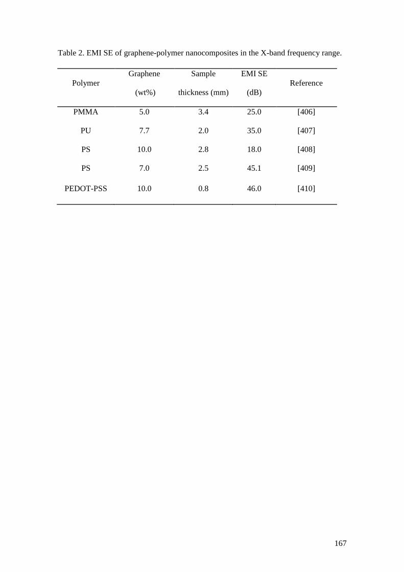
167
Table 2. EMI SE of graphene-polymer nanocomposites in the X-band frequency range.
Polymer
Graphene
(wt%)
Sample
thickness (mm)
EMI SE
(dB)
Reference
PMMA 5.0 3.4 25.0 [406]
PU 7.7 2.0 35.0 [407]
PS 10.0 2.8 18.0 [408]
PS 7.0 2.5 45.1 [409]
PEDOT-PSS 10.0 0.8 46.0 [410]
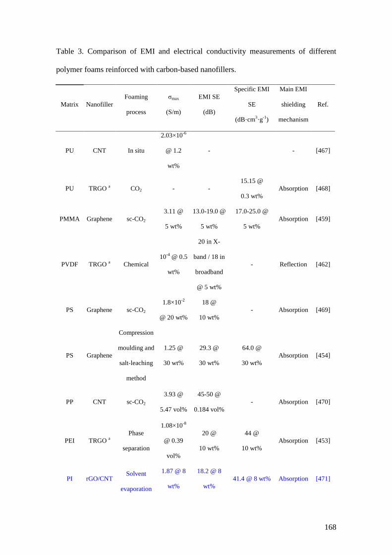
168
Table 3. Comparison of EMI and electrical conductivity measurements of different
polymer foams reinforced with carbon-based nanofillers.
Matrix Nanofiller
Foaming
process
σmax
(S/m)
EMI SE
(dB)
Specific EMI
SE
(dB·cm3·g
-1)
Main EMI
shielding
mechanism
Ref.
PU CNT In situ
2.03×10⁻⁶
@ 1.2
wt%
- - [467]
PU TRGO a CO2 - -
15.15 @
0.3 wt%
Absorption [468]
PMMA Graphene sc-CO2
3.11 @
5 wt%
13.0-19.0 @
5 wt%
17.0-25.0 @
5 wt%
Absorption [459]
PVDF TRGO a Chemical
10-4
@ 0.5
wt%
20 in X-
band / 18 in
broadband
@ 5 wt%
- Reflection [462]
PS Graphene sc-CO2
1.8×10⁻²
@ 20 wt%
18 @
10 wt%
- Absorption [469]
PS Graphene
Compression
moulding and
salt-leaching
method
1.25 @
30 wt%
29.3 @
30 wt%
64.0 @
30 wt%
Absorption [454]
PP CNT sc-CO2
3.93 @
5.47 vol%
45-50 @
0.184 vol%
- Absorption [470]
PEI TRGO a
Phase
separation
1.08×10⁻⁸
@ 0.39
vol%
20 @
10 wt%
44 @
10 wt%
Absorption [453]
PI rGO/CNT Solvent
evaporation
1.87 @ 8
wt%
18.2 @ 8
wt%
41.4 @ 8 wt% Absorption [471]

169
induced
phase
separation
PI rGO
Non-solvent
induced
phase
separation
1.0 @ 16
wt%
21.0 @ 16
wt%
75.0 @ 16 wt% Absorption [472]
PCL CNT sc-CO2
4.0 @
0.25 vol%
80.0 @ 0.25
vol%
258.0 @ 0.25
vol%
Absorption [320]
PLLA CNT sc-CO2
3.4 @ 10
wt%
23.0 @ 10
wt%
77.0 @ 10 wt% Absorption [473]
PLA CNT
Expandable
bead foaming
10.0 @
0.0054
vol%
50.0 @
0.0054
vol%
1010.0 @
0.0054 vol%
Absorption [474]
a Thermally reduced graphene oxide