Transmission improvement in fiber wireless links using fiber Bragg gratings
39
TRANSMISSION IMPROVEMENT IN FIBER WIRELESS LINKS USING FIBER BRAGG GRATINGS Submitted in partial fulfillment of the requirements for the award of the degree of Master of Technology in Applied Electronics & Instrumentation of COLLEGE OF ENGINEERING,TRIVANDRUM by DEVI V R Department of Electronics & Communication Engineering College Of Engineering Trivandrum 695 016
-
Upload
independent -
Category
Documents
-
view
2 -
download
0
Transcript of Transmission improvement in fiber wireless links using fiber Bragg gratings

TRANSMISSION IMPROVEMENT IN
FIBER WIRELESS LINKS USING
FIBER BRAGG GRATINGS
Submitted in partial fulfillment of the requirements
for the award of the degree of
Master of Technology
in
Applied Electronics & Instrumentation
of
COLLEGE OF ENGINEERING,TRIVANDRUM
by
DEVI V R
Department of Electronics & Communication
Engineering
College Of Engineering
Trivandrum 695 016

COLLEGE OF ENGINEERING
TRIVANDRUM
CERTIFICATE
Certified that this report titled TRANSMISSION IMPROVEMENT
IN FIBER WIRELESS LINKS USING FIBER BRAGG GRAT-
INGS is a bonafide record of the seminar done by DEVI.V.R, First Semester
M. Tech. Applied Electronics & Instrumentation , under our guidance and su-
pervision, in partial fulfillment of the requirements for the award of the degree,
M. Tech. Applied Electronics & Instrumentation .
Guide Coordinator
Dr.N.Vijayakumar Dr.M.R.Baiju
Professor Professor
Dept. of Electronics & Communication Dept. of Electronics & Communication
Mr.S.Shabu
Professor & HOD
Dept. of Electronics & Communication

ACKNOWLEDGEMENT
It is with great pleasure and pride that I present my work before
you. At this moment of triumph, it would be unfair to neglect those
who helped us in the successful completion of our venture.
First I thank the Professor and Head of the Department of Electron-
ics and Communication Engineering, Mr.S.Shabu for providing us
all the required facilities.
I am grateful to our seminar coordinator Dr.M.R.Baiju, Professor,
Department of Electronics and Communication Engineering for his
valuable suggestions and guidance.
I express my sincere gratitude to my guide, Dr.N.Vijayakumar,
Proffesor, Department of Electronics and Communication Engineer-
ing who gave me consistent guidance and support.
I also take this opportunity to thank all the Electronics depart-
ment staff members, my parents and friends for their overwhelming
and whole hearted encouragement and support.

Abstract
A simple and low-cost technique is developed to enhance the transmission
performance in fiber wireless links. Using a narrowband fiber Bragg grating
(FBG), which increases the modulation depth by suppressing the optical-carrier
power. The results demonstrate an improvement in receiver sensitivity of upto
a 7-dB for double and single sideband modulation schemes. The scheme is
applicable to a wide range of radio frequencies and modulation depths.
Contents
1 INTRODUCTION 1
1.1 Wireless Communication Systems . . . . . . . . . . . . . . . . . . 2
1.2 Broadband Wireless Communication Systems . . . . . . . . . . . 4
1.3 Challenges of Broadband Wireless Access Networks . . . . . . . . 6
2 RADIO-OVER-FIBER TECHNOLOGY 9
2.1 Benefits of RoF Technology . . . . . . . . . . . . . . . . . . . . . 12
2.1.1 Low Attenuation Loss . . . . . . . . . . . . . . . . . . . . 12
2.1.2 Large Bandwidth . . . . . . . . . . . . . . . . . . . . . . . 13
2.1.3 Immunity to Radio Frequency Interference . . . . . . . . 14
2.1.4 Easy Installation and Maintenance . . . . . . . . . . . . 14
2.1.5 Reduced Power Consumption . . . . . . . . . . . . . . . . 14
2.1.6 Multi-Operator and Multi-Service Operation . . . . . . . 15
2.1.7 Dynamic Resource Allocation . . . . . . . . . . . . . . . . 15
2.2 Limitations of RoF Technology . . . . . . . . . . . . . . . . . . . 15
2.3 Applications of RoF Technology . . . . . . . . . . . . . . . . . . 16
3 RADIO OVER FIBER 18
3.1 RF signal . . . . . . . . . . . . . . . . . . . . . . . . . . . . . . . 19
3.2 Light Source . . . . . . . . . . . . . . . . . . . . . . . . . . . . . 19
3.3 Mach-Zehnder Modulator (MZM) . . . . . . . . . . . . . . . . . . 19
3.4 Photodetector . . . . . . . . . . . . . . . . . . . . . . . . . . . . . 21
4 FIBER BRAGG GRATING(FBG) 22
5 TRANSMISSION PERFORMANCE IMPROVEMENT 24
5.1 Proposed System . . . . . . . . . . . . . . . . . . . . . . . . . . . 24
1

5.1.1 At Transmitter . . . . . . . . . . . . . . . . . . . . . . . . 25
5.1.2 At receiver . . . . . . . . . . . . . . . . . . . . . . . . . . 25
5.1.3 Experimental setup . . . . . . . . . . . . . . . . . . . . . . 26
6 CONCLUSION 29
7 Question and Answers 30
2

List of Figures
1.1 Global growth of mobile and fixed subscribers . . . . . . . . . . . 2
1.2 Evolution of the WLAN standards . . . . . . . . . . . . . . . . . 3
1.3 Overview of present and future wireless communication systems . 4
1.4 Schematic showing the components of a narrowband wireless ac-
cess network . . . . . . . . . . . . . . . . . . . . . . . . . . . . . . 6
1.5 Frequencies of broadband wireless communication systems . . . . 8
2.1 The Radio Over Fiber system concept . . . . . . . . . . . . . . . 10
2.2 900MHz Fiber-Radio system . . . . . . . . . . . . . . . . . . . . . 11
2.3 Using In-building fiber Infrastructure for integrated wired and
wireless system applications . . . . . . . . . . . . . . . . . . . . . 17
3.1 Radio over fiber system (a)direct modulated system (b)external
modulated system . . . . . . . . . . . . . . . . . . . . . . . . . . 19
3.2 mach-zender modulator . . . . . . . . . . . . . . . . . . . . . . . 20
4.1 In fiber bragg grating . . . . . . . . . . . . . . . . . . . . . . . . 22
4.2 Reflection and transmission in FBG . . . . . . . . . . . . . . . . 22
5.1 ROF Transmitter system with FBG . . . . . . . . . . . . . . . . 25
5.2 ROF Receiver system with FBG . . . . . . . . . . . . . . . . . . 26
5.3 Frequency response of improved system . . . . . . . . . . . . . . 27
5.4 Experimental setup . . . . . . . . . . . . . . . . . . . . . . . . . . 27
5.5 Optical spectra of the 35-GHz SSB signal (after optical amplifica-
tion), with (solid) and without (dotted) an FBG of 80% reflectivity. 28
5.6 BER versus received optical power for the 10-GHz DSB signal
and the 35-GHz SSB with and without an FBG of 80% reflectivity.. 28
3

Chapter 1
INTRODUCTION
Optical transport of microwave and millimeter wave signals have become very
attractive in high frequency wireless cellular networks.Typically, intensity mod-
ulators such as Mach-Zender modulators are used for superimposing the radio
signal information onto an optical carrier. The performance of wideband fiberop-
tic transmission and signal processing systems is improved by utilizing optical
amplifiers or by starting with high power sources. Due to the narrow linear re-
gion of intensity modulators and/or unavailability of high power radio frequency
amplifiers in the case of remote applications, it is necessary to weakly modu-
late the optical carrier. Therefore, a simple passive technique for increasing the
modulation depth would lead to lower cost and better transmission performance
for radio over fiber systems.
1

Figure 1.1: Global growth of mobile and fixed subscribers
1.1 Wireless Communication Systems
Wireless communication has experienced tremendous growth in the last decade.
In 1991 less than 1% of the world’s population had access to a mobile phone.
By the end of 2001, an estimated one in every six people had a mobile phone
. During the same period the number of countries worldwide having a mobile
network increased from just three to over 90%. In fact the number of mobile
subscribers overtook the number of fixed-line subscribers in 2002, as shown in
Figure 1.1. It is predicted that this growth will continue to rise, and by 2010
there will be more than 1700 million mobile subscribers worldwide
Apart from mobile telephone communications, Wireless Local Area Net-
works (WLANs), which came on the scene less than a decade ago (1997),
have also experienced phenomenal growth. The rapid proliferation of WLAN
hotspots in public places, such as airport terminals has been astounding. In
fact WLANs have now made their way into homes, riding on the back of xDSL
and cable access modems, which are now integrated with WLAN Radio Ac-
cess Points (RAPs). As a result, the number of wireless Internet subscribers is
expected to overtake the number of wired internet users quite soon, as shown
in Figure 1.1. The rapid growth of wireless communications is mainly at-
tributed to their ease of installation in comparison to fixed networks. However,
technological advancement, and competition among mobile operators have also
contributed to the growth. So far there have been three mobile telephone stan-
2

dards, launched in succession approximately every decade. The first-generation
(1G) mobile systems were analogue, and were commissioned in the 1980s. In the
1990s, second-generation (2G) digital mobile systems such as the Global System
for Mobile communications (GSM) came on the scene. The GSM standard has
been extremely successful, providing not only national, but international cov-
erage as well. Thus, GSM is currently the mainstream mobile communication
system.
Figure 1.2: Evolution of the WLAN standards
Both 1G and 2G systems were designed primarily to provide voice appli-
cations, and to support circuit-switched services. However, GSM does offer data
communication services to users, although the data rates are limited to just a
few tens of kbps. In contrast, WLANs originally designed to provide fixed data
network extension, support Mbps data transmission rates. The WLAN stan-
dard - IEEE 802.11, also known as Wi-Fi, was first commissioned in 1997 and
offered 2 Mbps. Since then, the standard has evolved several times responding
to the sustained user demand for higher bit-rates as shown in figure 1.2. Cur-
rently, WLANs are capable of offering up-to 54 Mbps for the IEEE 802.11a/g,
and HiperLAN2 standards operating in the 2.4 GHz and 5 GHz license-free
ISM bands. However, WLANs do not offer the kind of mobility, which mobile
systems do.
3

1.2 Broadband Wireless Communication Systems
The explosive growth of the Internet, and the success of 2G systems together
with WLANs have had a profound impact on our perception of communication.
First of all, the vast majority of users now believe in the new notion of ”always
on” communication. We are now living in the era of ubiquitous connectivity or
”communication anytime, anywhere, and with anything”. Secondly, the concept
of broadband communication has caught on very well. As fibre penetrates closer
to the end-user environment (Fibre To The Home/Curb/X, FTTH/C/X), wired
transmission speeds will continue to rise. Transmission speeds such at 100 Mbps
(Fast Ethernet) are now beginning to reach homes. The demand to have this
broadband capacity also wirelessly has put pressure on wireless communication
systems to increase both their transmission capacity, as well as their coverage.
Figure 1.3: Overview of present and future wireless communication systems
In general there is a trade off between coverage and capacity. Figure
1.3 shows the relationship between some of the various standards (present and
future), in terms of mobility (coverage), and capacity. For instance, the cell
size of Wireless Personal Area Networks (WPANs) is typically a few metres
(picocell), while their transmission rates may reach several tens of Mbps. On the
other hand 2G (e.g. GSM), and 3G (e.g. Universal Mobile Telecommunication
System (UMTS) and the International Mobile Telecommunications (IMT2000))
4
systems have cells that extend several kilometres,but have data rates limited
to less than 2 Mbps. Therefore, as mobile communication systems seek to
increase capacity, and wireless data systems seek to increase coverage, they will
both move towards convergence. A case in point is the IEEE 802.16, otherwise
known as WiMAX, which appears to lend weight to the notion of convergence,
as shown in Figure 1.3. WiMAX seeks to provide high-bit rate mobile services
using frequencies between 2 - 11 GHz. In addition, WiMAX also aims to provide
Fixed Wireless Access (FWA) at bit-rates in the excess of 100 Mbps and at
higher frequencies between 10 - 66 GHz .
5

1.3 Challenges of Broadband Wireless Access
Networks
Figure 1.4 illustrates the configuration of narrowband wireless access systems
(e.g. GSM) as we know them today. The central office handles call processing
and switching, while the Base Stations (BS) act as the radio interfaces for the
Mobile Units (MU) or Wireless Terminal Units (WTU). The BSs may be linked
to the central office through either analogue microwave links or digital fibre op-
tic links. Once the baseband signals are received at the BS, they are processed
and modulated onto the appropriate carrier. The radius covered by the signal
from the BS is the cell radius. All the MU/WTU within the cell, share the radio
frequency spectrum. WLANs are configured in a similar fashion, with the radio
interface called the Radio Access Point (RAP).
Figure 1.4: Schematic showing the components of a narrowband wireless access
network
In general, low carrier frequencies offer low bandwidth. Therefore, part
of the reason why narrowband wireless access systems (e.g. 2G) offer limited
capacity is because they operate at low frequencies. For instance GSM operates
at frequencies around 900 or 1800 MHz with 200 kHz allocated frequency spec-
trum. UMTS operates at frequencies around 2 GHz and has 4 MHz allocated
bandwidth. However, there is also stiff competition for frequency spectrum
6

among the many wireless communication systems using carrier frequencies be-
low 6 GHz. These include radio and TV broadcasts, and systems for (vital)
communication services such as airports, police and fire, amateur radio users,
wireless LANs, and many others. Low frequencies allow for low cost radio front-
ends (in the BS and the MU/WTU). In addition, the efficiency of RF active
devices (transistors) is higher at low frequencies, than at high frequencies. For
instance, at millimetre wave frequencies the efficiency of active devices can be
as low as 30 % . Therefore, the low-power consumption advantage of systems
operating at low frequencies is quite significant. Furthermore, low-frequency
RF signals allow for larger cells, due to the longer reach of the radio waves.
The larger cells enable high mobility, but lead to poor spectrum efficiency, since
the spectrum is shared by all MUs/WTUs operating within the cell. Therefore,
one natural way to increase capacity of wireless communication systems is to
deploy smaller cells (micro- and pico-cells). This is generally difficult to achieve
at low-frequency microwave carriers, but by reducing the radiated power at the
antenna, the cell size may be reduced somewhat. Pico-cells are also easier to
form inside buildings, where the high losses induced by the building walls help
to limit the cell size. In contrast, the high propagation losses, which radio waves
experience at mm wave frequencies, together with the line-of-site requirements,
help to form small cells. Another way to increase the capacity of wireless com-
munication systems is to increase the carrier frequencies, to avoid the congested
ISM band frequencies. Higher carrier frequencies offer greater modulation band-
width, but may lead to increased costs of radio front-ends in the BSs and the
MUs/WTUs. Smaller cell sizes lead to improved spectral efficiency through in-
creased frequency reuse. But, at the same time, smaller cell sizes mean that
large numbers of BSs or RAPs are needed in order to achieve the wide coverage
required of ubiquitous communication systems. Furthermore, extensive feeder
networks are needed to service the large number of BSs/RAPs. Therefore, un-
less the cost of the BSs/RAPs, and the feeder network are significantly low,
the system-wide installation and maintenance costs of such systems would be
rendered prohibitively high. This is where Radio-over-Fibre (RoF) technology
comes in. It achieves the simplification of the BSs/RAPs (referred to as Remote
Antenna Units - RAUs) through consolidation of radio system functionalities at
a centralised headend, which are then shared by multiple RAUs. In addition, a
further reduction in system costs may be achieved if low-cost multimode fibres
7

are used in the extensive feeder network. Therefore, for broadband wireless
communication systems to offer the needed high capacity, it appears inevitable
to increase the carrier frequencies and to reduce cell sizes. This is evident from
the new standards in the offing, which are aiming to use mm-waves. For exam-
ple the recently formed IEEE 802.15 WPAN standard Task Group 3c is aiming
to use the unlicensed mm-wave bands between 57 - 64 GHz for very-high-speed
short-range communication offering up-to 2 Gbps . The IEEE 802.16 (WiMAX)
standard specifies frequencies between 10 - 66 GHz for the first/last mile Fixed
Wireless Access (FWA). A summary of the operating frequencies for some of
the current and future (broadband) wireless systems is given in figure 1.5.
Figure 1.5: Frequencies of broadband wireless communication systems
8

Chapter 2
RADIO-OVER-FIBER
TECHNOLOGY
Radio-over-Fibre (RoF) technology entails the use of optical fibre links to
distribute RF signals from a central location (headend) to Remote Antenna
Units (RAUs). In narrowband communication systems and WLANs, RF signal
processing functions such as frequency up-conversion, carrier modulation, and
multiplexing, are performed at the BS or the RAP, and immediately fed into the
antenna. RoF makes it possible to centralise the RF signal processing functions
in one shared location (headend), and then to use optical fibre, which offers low
signal loss (0.3 dB/km for 1550 nm, and 0.5 dB/km for 1310 nm wavelengths)
to distribute the RF signals to the RAUs, as shown in Figure 2.1. By so doing,
RAUs are simplified significantly, as they only need to perform optoelectronic
conversion and amplification functions. The centralisation of RF signal process-
ing functions enables equipment sharing, dynamic allocation of resources, and
simplified system operation and maintenance. These benefits can translate into
major system installation and operational savings, especially in wide-coverage
broadband wireless communication systems, where a high density of BS/RAPs
is necessary as discussed above.
One of the pioneer RoF system implementations is depicted in Figure 1.5.
Such a system may be used to distribute GSM signals, for example. The RF
signal is used to directly modulate the laser diode in the central site (headend).
The resulting intensity modulated optical signal is then transported over the
9

Figure 2.1: The Radio Over Fiber system concept
length of the fibre to the BS (RAU). At the RAU, the transmitted RF sig-
nal is recovered by direct detection in the PIN photodetector. The signal is
then amplified and radiated by the antenna. The uplink signal from the MU
is transported from the RAU to the headend in the same way. This method of
transporting RF signals over the fibre is called Intensity Modulation with Direct
Detection (IM-DD), and is the simplest form of the RoF link.
While Figure 2.2 shows the transmission of the RF signal at its frequency,
it is not always necessary to do that. For instance, a Local Oscillator (LO) signal,
if available, may be used to down-convert the uplink carrier to an IF in the RAU.
Doing so would allow for the use of low-frequency components for the up-link
path in the RAU - leading to system cost savings. Instead of placing a separate
LO in the RAU, it may be transported from the headend to the RAU by the RoF
system. Once available at the RAU, the LO may then be used to achieve down-
conversion of the uplink signals. This results in a much simpler RAU. In this
configuration, the downlink becomes the crucial part of the RoF since it has to
transport high-frequency signals. The transportation of high-frequency signals
is more challenging because it requires highfrequency components, and large
link bandwidth. This means that high-frequency signals are more susceptible to
transmitter, receiver, and transmission link signal impairments. Apart from IM-
DD, other methods, which involve signal frequency up-conversion in addition to
distribution are also used. These methods, which include Remote Heterodyning
10
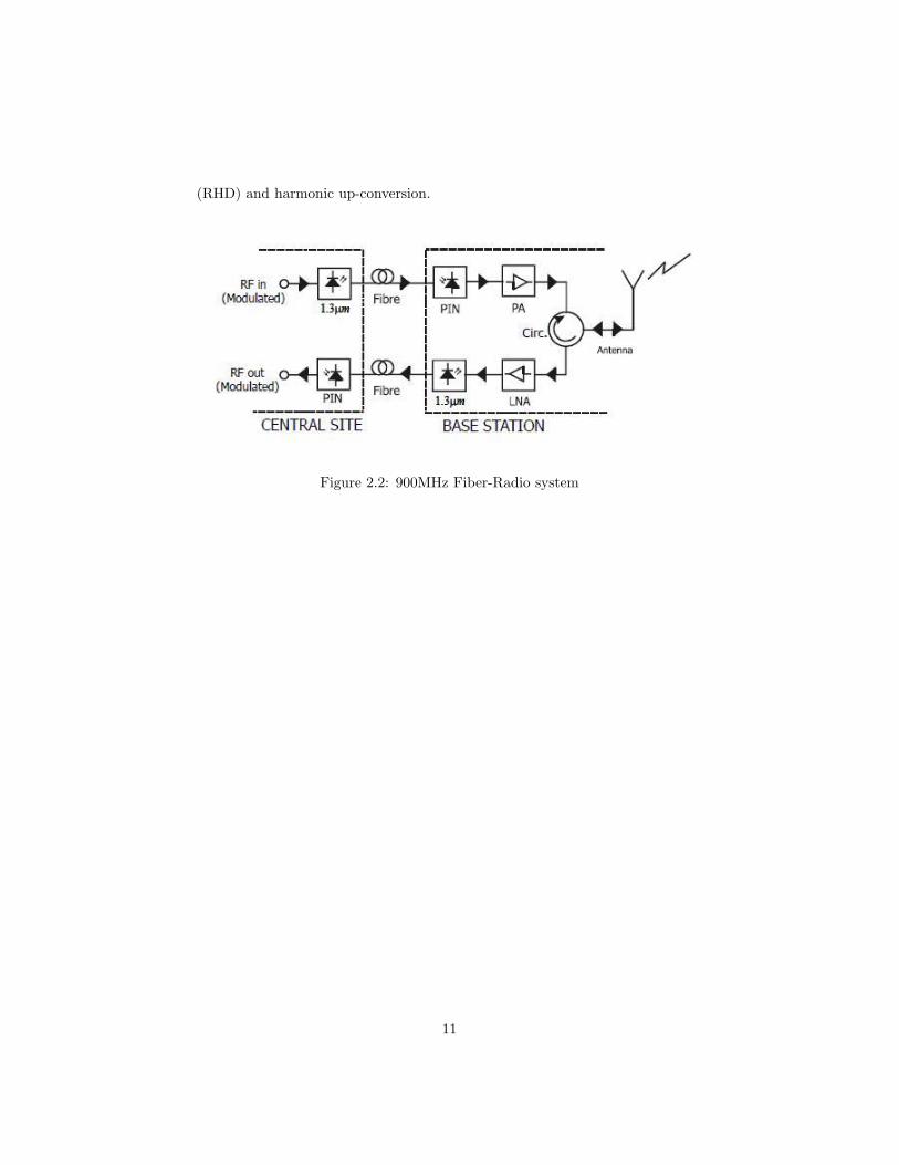
(RHD) and harmonic up-conversion.
Figure 2.2: 900MHz Fiber-Radio system
11
2.1 Benefits of RoF Technology
Some of the advantages and benefits of the RoF technology compared with
electronic signal distribution are given below.
2.1.1 Low Attenuation Loss
Electrical distribution of high-frequency microwave signals either in free space
or through transmission lines is problematic and costly. In free space, losses
due to absorption and reflection increase with frequency . In transmission lines,
impedance rises with frequency as well, leading to very high losses . Therefore,
distributing high frequency radio signals electrically over long distances requires
expensive regenerating equipment. As for mm-waves, their distribution via the
use of transmission lines is not feasible even for short distances. The alterna-
tive solution to this problem is to distribute baseband signals or signals at low
intermediate frequencies (IF) from the switching centre (headend) to the BS .
The baseband or IF signals are up-converted to the required microwave or mm-
wave frequency at each base station, amplified and then radiated. This system
configuration is the same as the one used in the distribution of narrowband mo-
bile communication systems shown in Figure 1.4. Since, high performance LOs
would be required for up-conversion at each base station, this arrangement leads
to complex base stations with tight performance requirements. However, since
optical fibre offers very low loss, RoF technology can be used to achieve both
low-loss distribution of mm-waves, and simplification of RAUs at the same time.
Commercially available standard Single Mode Fibres (SMFs) made from glass
(silica) have attenuation losses below 0.2 dB/km and 0.5 dB/km in the 1550
nm and the 1300 nm windows, respectively. Polymer Optical Fibres (POFs),
a more recent kind of optical fibre exhibits higher attenuation ranging from 10
- 40 dB/km in the 500 - 1300 nm regions. These losses are much lower than
those encountered in, say coaxial cable, whose losses are higher by three orders
of magnitude at higher frequencies. For instance, the attenuation of a inch
coaxial cable (RG-214) is ¿500 dB/km for frequencies above 5 GHz . Therefore,
by transmitting microwaves in the optical form, transmission distances are in-
creased several folds and the required transmission powers reduced greatly.
12
2.1.2 Large Bandwidth
Optical fibres offer enormous bandwidth. There are three main transmission
windows, which offer low attenuation, namely the 850 nm, 1310 nm, and 1550
nm wavelengths. For a single SMF optical fibre, the combined bandwidth of
the three windows is in the excess of 50 THz . However, today’s state-of-the-art
commercial systems utilize only a fraction of this capacity (1.6 THz). But de-
velopments to exploit more optical capacity per single fibre are still continuing.
The main driving factors towards unlocking more and more bandwidth out of
the optical fibre include the availability of low dispersion (or dispersion shifted)
fibre, the Erbium Doped Fibre Amplifier (EDFA) for the 1550 nm window, and
the use of advanced multiplex techniques namely Optical Time Division Mul-
tiplexing (OTDM) in combination with Dense Wavelength Division Multiplex
(DWDM) techniques. The enormous bandwidth offered by optical fibres has
other benefits apart from the high capacity for transmitting microwave signals.
The high optical bandwidth enables high speed signal processing that may be
more difficult or impossible to do in electronic systems. In other words, some
of the demanding microwave functions such as filtering, mixing, up- and down-
conversion, can be implemented in the optical domain . For instance, mm-wave
filtering can be achieved by first converting the electrical signal to be filtered
into an optical signal, then performing the filtering by using optical components
such as the Mach Zehnder Interferometer (MZI) or Fibre Bragg Gratings (FBG),
and then converting the filtered signal back into electrical form . Furthermore,
processing in the optical domain makes it possible to use cheaper low band-
width optical components such as laser diodes and modulators, and still be able
to handle high bandwidth signals . The utilization of the enormous bandwidth
offered by optical fibres is severely hampered by the limitation in bandwidth
of electronic systems, which are the primary sources and receivers of trans-
mission data. This problem is referred to as the ”electronic bottleneck”. The
solution around the electronic bottleneck lies in effective multiplexing. OTDM
and DWDM techniques mentioned above are used in digital optical systems. In
analogue optical systems including RoF technology, Sub-Carrier Multiplexing
(SCM) is used to increase optical fibre bandwidth utilization. In SCM, several
microwave subcarriers, which are modulated with digital or analogue data, are
combined and used to modulate the optical signal, which is then carried on a
single fibre. This makes RoF systems cost-effective.
13

2.1.3 Immunity to Radio Frequency Interference
Immunity to ElectroMagnetic Interference (EMI) is a very attractive property
of optical fibre communications, especially for microwave transmission. This is
so because signals are transmitted in the form of light through the fibre. Because
of this immunity, fibre cables are preferred even for short connections at mm-
waves. Related to EMI immunity is the immunity to eavesdropping, which is an
important characteristic of optical fibre communications, as it provides privacy
and security.
2.1.4 Easy Installation and Maintenance
In RoF systems, complex and expensive equipment is kept at the headend,
thereby making the RAUs simpler. For instance, most RoF techniques elim-
inate the need for a LO and related equipment at the RAU. In such cases a
photodetector, an RF amplifier, and an antenna make up the RAU. Modulation
and switching equipment is kept in the headend and is shared by several RAUs.
This arrangement leads to smaller and lighter RAUs, effectively reducing sys-
tem installation and maintenance costs. Easy installation and low maintenance
costs of RAUs are very important requirements for mm-wave systems, because
of the large numbers of the required RAUs. In applications where RAUs are
not easily accessible, the reduction in maintenance requirements leads to ma-
jor operational cost savings. Smaller RAUs also lead to reduced environmental
impact.
2.1.5 Reduced Power Consumption
Reduced power consumption is a consequence of having simple RAUs with
reduced equipment. Most of the complex equipment is kept at the centralised
headend. In some applications, the RAUs are operated in passive mode. For
instance, some 5 GHz Fibre-Radio systems employing pico-cells can have the
RAUs operate in passive mode . Reduced power consumption at the RAU is
significant considering that RAUs are sometimes placed in remote locations not
fed by the power grid.
14

2.1.6 Multi-Operator and Multi-Service Operation
RoF offers system operational flexibility. Depending on the microwave gener-
ation technique, the RoF distribution system can be made signal-format trans-
parent. For instance the Intensity Modulation and Direct Detection (IM-DD)
technique can be made to operate as a linear system and therefore as a trans-
parent system. This can be achieved by using low dispersion fibre (SMF) in
combination with pre-modulated RF subcarriers (SCM). In that case, the same
RoF network can be used to distribute multi-operator and multi-service traffic,
resulting in huge economic savings . The principle of Optical Frequency Mul-
tiplication (OFM), which is the focus of this thesis can also be used to achieve
multi-service operation in combination with either WDM or SCM, because it is
tolerant to chromatic dispersion.
2.1.7 Dynamic Resource Allocation
Since the switching, modulation, and other RF functions are performed at a
centralized headend, it is possible to allocate capacity dynamically. For instance
in a RoF distribution system for GSM traffic, more capacity can be allocated to
an area (e.g. shopping mall) during peak times and then re-allocated to other
areas when offpeak (e.g. to populated residential areas in the evenings). This
can be achieved by allocating optical wavelengths through Wavelength Division
Multiplexing (WDM) as need arises. Allocating capacity dynamically as need
for it arises obviates the requirement for allocating permanent capacity, which
would be a waste of resources in cases where traffic loads vary frequently and
by large margins. Furthermore, having the centralised headend facilitates the
consolidation of other signal processing functions such as mobility functions,
and macro diversity transmission.
2.2 Limitations of RoF Technology
Since RoF involves analogue modulation, and detection of light, it is funda-
mentally an analogue transmission system. Therefore, signal impairments such
as noise and distortion, which are important in analogue communication sys-
tems, are important in RoF systems as well. These impairments tend to limit
the Noise Figure (NF) and Dynamic Range (DR) of the RoF links . DR is a
15

very important parameter for mobile (cellular) communication systems such as
GSM because the power received at the BS from the MUs varies widely (e.g. 80
dB ). That is, the RF power received from a MU which is close to the BS can be
much higher than the RF power received from a MU which is several kilometres
away, but within the same cell. The noise sources in analogue optical fibre links
include the laser’s Relative Intensity Noise (RIN), the laser’s phase noise, the
photodiode’s shot noise, the amplifier’s thermal noise, and the fibre’s disper-
sion. In Single Mode Fibre (SMF) based RoF, systems, chromatic dispersion
may limit the fibre link lengths and may also cause phase de-correlation leading
to increased RF carrier phase noise . In Multi-Mode Fibre based RoF systems,
modal dispersion severely limits the available link bandwidth and distance. It
must be stated that although the RoF transmission system itself is analogue,
the radio system being distributed need not be analogue as well, but it may
be digital (e.g. WLAN, UMTS), using comprehensive multi-level signal modu-
lation formats such as xQAM, or Orthogonal Frequency Division Multiplexing
(OFDM).
2.3 Applications of RoF Technology
RoF technology is generally unsuitable for system applications, where high
Spurious Free Dynamic Range (SFDR = maximum output signal power for
which the power of the third-order intermodulation product is equal to the
noise floor) is required, because of the limited DR. This is especially true of
wide coverage mobile systems such as GSM, where SFDR of > 70 dB (outdoor)
are required. However, most indoor applications do not require high SFDR.
For instance, the required (uplink) SFDR for GSM reduces from > 70 dB to
about 50 dB for indoor applications . Therefore, RoF distribution systems
can readily be used for in-building (indoor) distribution of wireless signals of
both mobile and data communication (e.g. WLAN) systems. In this case the
RoF system becomes a Distributed Antenna System (DAS). For highfrequency
applications such as WPAN, the cell size will be small due to high losses through
the walls, bringing the benefits of RoF discussed above. The in-building fibre
infrastructure may then be used for both wired and wireless applications as
shown in Figure 1.6. Using MMF or indeed POF instead of SMF fibres to
feed the RAUs may further reduce system installation and maintenance costs,
16
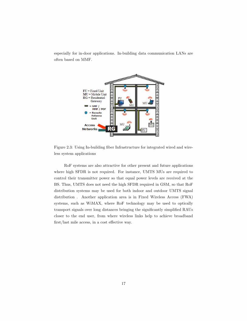
especially for in-door applications. In-building data communication LANs are
often based on MMF.
Figure 2.3: Using In-building fiber Infrastructure for integrated wired and wire-
less system applications
RoF systems are also attractive for other present and future applications
where high SFDR is not required. For instance, UMTS MUs are required to
control their transmitter power so that equal power levels are received at the
BS. Thus, UMTS does not need the high SFDR required in GSM, so that RoF
distribution systems may be used for both indoor and outdoor UMTS signal
distribution . Another application area is in Fixed Wireless Access (FWA)
systems, such as WiMAX, where RoF technology may be used to optically
transport signals over long distances bringing the significantly simplified RAUs
closer to the end user, from where wireless links help to achieve broadband
first/last mile access, in a cost effective way.
17
Chapter 3
RADIO OVER FIBER
Radio over Fiber (RoF) refers to a technology whereby light is modulated
by a radio signal and transmitted over an optical fiber link to facilitate wireless
access. In RoF systems, wireless signals are transported in optical form between
a central station and a set of base stations before being radiated through the
air. The main advantages of this technology are low attenuation, low complexity,
lower cost, large bandwidth, Immunity to Radio Frequency Interference, Easy
Installation and Maintenance, Reduced Power Consumption, Multi-Operator
and Multi-Service Operation, Dynamic Resource Allocation etc.
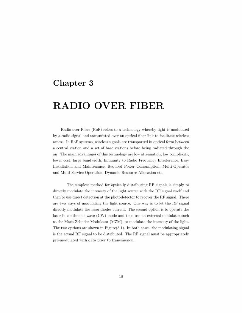
The simplest method for optically distributing RF signals is simply to
directly modulate the intensity of the light source with the RF signal itself and
then to use direct detection at the photodetector to recover the RF signal. There
are two ways of modulating the light source. One way is to let the RF signal
directly modulate the laser diodes current. The second option is to operate the
laser in continuous wave (CW) mode and then use an external modulator such
as the Mach-Zehnder Modulator (MZM), to modulate the intensity of the light.
The two options are shown in Figure(3.1). In both cases, the modulating signal
is the actual RF signal to be distributed. The RF signal must be appropriately
pre-modulated with data prior to transmission.
18
Figure 3.1: Radio over fiber system (a)direct modulated system (b)external
modulated system
3.1 RF signal
RF signals are the Radio frequency signals that are modulated form of the
data signals. The modulation may be Analog or digital type. The modulation
technique may be of Double Side Band Suppressed Carrier(DSBSC) and Single
Side Band Suppressed Carrier(SSBSC) modulations, or any digital modulation
techniques like ASK, FSK or PSK.
3.2 Light Source
There are two kinds of devices that are used as light sources: Lasers and
LEDs (Light Emitting Diodes). Laser is a light source gives coherent, high
energy beam of light. Lasers produce far and away the best kind of light for
optical communication.
3.3 Mach-Zehnder Modulator (MZM)
MACH-ZEHNDER external modulators provide superior signal quality and
are widely used in optical communication systems. Compared with direct mod-
ulation or electroabsorption modulators, Mach-Zehnder external modulators
yield smaller chirp, providing a narrower signal spectrum and usually resulting
in a larger tolerance to uncompensated chromatic dispersion. Mach-Zehnder
modulators (MZMs) can be made using various materials, and LiNbO is the
most popular material.
19

Figure 3.2: mach-zender modulator
Figure(3.2) shows a Mach-Zehnder modulator set up. In this case there
are conductive strips of metal close to one arm of the interferometer. An elec-
tric field is used to modulate the phase of the light in either of the arms of the
interferometer. In the figure the electric field is applied to one arm. The inter-
ferometer is built from a material which changes its refractive index (slightly)
under the influence of an electric field. When current is applied to the con-
ductive plates of the device the refractive index will be changed. A change in
refractive index implies a change in the speed of propagation and this changes
the phase of the signal. In a Mach-Zehnder interferometric modulator we use
the small changes in refractive index induced by an electric field to cause large
changes in signal amplitude at the output. In one arm the RI will increase and
in the other arm it will remains constant. This causes the signal in one arm to
be retarded in phase. When the signal is recombined at the output y-junction
the very small phase changes will cause interference effects. These interference
effects cause variations in the amplitude of the output signal. Thus we have
a device that will change the amplitude of the optical signal very significantly
according to an applied electric field. The usual material used to make interfero-
metric modulators is lithium niobate (LiNiO). The device requires considerable
precision in manufacture as each arm must be identical in length (or only very
slightly different). For this reason these are usually made in planar waveguide
technology rather than as fibre devices. The effect is very fast in responding
to changes in voltage and MZI based modulators are available at speeds up to
around 10 Mbps.
20

3.4 Photodetector
Photodetectors are devices used for the detection of light - in most cases
of optical powers. As the requirements for applications vary considerably, there
are many types of photodetectors which may be appropriate in a particular case:
Photodiodes are semiconductor devices with a p-n junction or p-i-n structure (i
= intrinsic material) (p-i-n photodiodes), where light is absorbed in a depletion
region and generates a photocurrent. Such devices can be very compact, fast,
highly linear, and exhibit a high quantum efficiency (i.e., generate nearly one
electron per incident photon) and a high dynamic range, provided that they are
operated in combination with suitable electronics. A particularly sensitive type
is that of avalanche photodiodes, which are sometimes used even for photon
counting.
21

Chapter 4
FIBER BRAGG
GRATING(FBG)
A fiber Bragg grating (FBG) is a type of distributed Bragg reflector con-
structed in a short segment of optical fiber that reflects particular wavelengths
of light and transmits all others. This is achieved by adding a periodic variation
to the refractive index of the fiber core, which generates a wavelength specific
dielectric mirror. A fiber Bragg grating can therefore be used as an inline optical
filter to block certain wavelengths, or as a wavelength-specific reflector.
Figure 4.1: In fiber bragg grating
Figure 4.2: Reflection and transmission in FBG
The fundamental principle behind the operation of a FBG, is Fresnel re-
22

flection. Where light traveling between media of different refractive indices may
both reflect and refract at the interface. The principle of the FBG is illustrated
in Figure(4.1)and figure(4.2). As light moves along the fibre and encounters the
changes in refractive index, a small amount of light is reflected at each bound-
ary. When the period of the grating and the wavelength of the light are the
same then there is positive reinforcement and power is coupled from the for-
ward direction to the backward direction. Light of other wavelengths ncounters
interference from out of phase reflections and therefore cannot propagate. The
grating will typically have a sinusoidal refractive index variation over a defined
length. The reflected wavelength (λB), called the Bragg wavelength, is defined
by the relationship,
λB = 2nΛ (4.1)
where n is the effective refractive index of the grating in the fiber core and
Λ is the grating period. In this case
n =n3 + n2
2(4.2)
23

Chapter 5
TRANSMISSION
PERFORMANCE
IMPROVEMENT
A number of techniques have been proposed for increasing the modulation
of signals. These include Brillouin scattering schemes [4] and the use of external
optical filters [2]. These schemes are either complex or cannot be applied to a
wide range of signal formats, modulation depths, and RFs.
5.1 Proposed System
Here we propose and experimentally demonstrate the use of narrow-band
fiber Bragg gratings (FBGs) with different reflectivities to enhance the modula-
tion depth, and consequently improve transmission performance of both double-
sideband (DSB) and single-sideband (SSB) fiber wireless signals, for given opti-
cal launch power [1]. This scheme is easy and low cost to implement as it simply
involves using an FBG in transmission to reduce the carrier power.
24

5.1.1 At Transmitter
An optical signal modulated with microwave data signals consists of the
optical carrier signal together with the modulation sidebands as shown in fig-
ure(5.3). In weakly modulated signals, the carrier- to-sideband ratio (CSR),
defined here as the ratio of optical power between the carrier and a first-order
sideband at a resolution bandwidth of 2.5 GHz, can typically be greater than 20
dB. When these signals are passed through an external FBG at the transmitter
as shown in Figure(5.1), the carrier signal is suppressed with respect to the
sideband/s. This improves the modulation depth leading to improved sensitiv-
ity and dynamic range. Ideally these filters should be monolithically integrated
into the modulators at the transmitter. If the optimum CSR is known for the
particular signal, the FBG with the appropriate transmission loss can be used
to change the CSR of the signal from the modulator to that which is optimum.
Typically, the optimum CSR is 0 dB, however, it may vary for specific systems.
Figure 5.1: ROF Transmitter system with FBG
5.1.2 At receiver
The second scenario is to use these gratings at the receiver. This will be
the ideal solution in passive links with wavelength reuse for uplink transmission.
In such a system, the FBG placed in conjunction with an optical circulator at
the transmitter drops the signal with reduced carrier for detection and passes
through the remainder of the carrier to be used in uplink transmission as shown
in fig(5.2). A narrow bandwidth allows a wide range of microwave frequencies,
however, depending on the stability and frequency requirements, the bandwidth
25
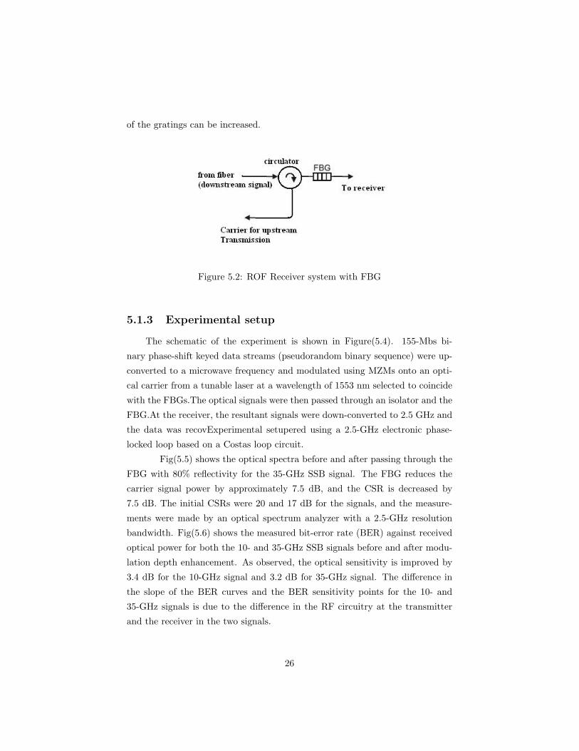
of the gratings can be increased.
Figure 5.2: ROF Receiver system with FBG
5.1.3 Experimental setup
The schematic of the experiment is shown in Figure(5.4). 155-Mbs bi-
nary phase-shift keyed data streams (pseudorandom binary sequence) were up-
converted to a microwave frequency and modulated using MZMs onto an opti-
cal carrier from a tunable laser at a wavelength of 1553 nm selected to coincide
with the FBGs.The optical signals were then passed through an isolator and the
FBG.At the receiver, the resultant signals were down-converted to 2.5 GHz and
the data was recovExperimental setupered using a 2.5-GHz electronic phase-
locked loop based on a Costas loop circuit.
Fig(5.5) shows the optical spectra before and after passing through the
FBG with 80% reflectivity for the 35-GHz SSB signal. The FBG reduces the
carrier signal power by approximately 7.5 dB, and the CSR is decreased by
7.5 dB. The initial CSRs were 20 and 17 dB for the signals, and the measure-
ments were made by an optical spectrum analyzer with a 2.5-GHz resolution
bandwidth. Fig(5.6) shows the measured bit-error rate (BER) against received
optical power for both the 10- and 35-GHz SSB signals before and after modu-
lation depth enhancement. As observed, the optical sensitivity is improved by
3.4 dB for the 10-GHz signal and 3.2 dB for 35-GHz signal. The difference in
the slope of the BER curves and the BER sensitivity points for the 10- and
35-GHz signals is due to the difference in the RF circuitry at the transmitter
and the receiver in the two signals.
26

Figure 5.3: Frequency response of improved system
Figure 5.4: Experimental setup
27
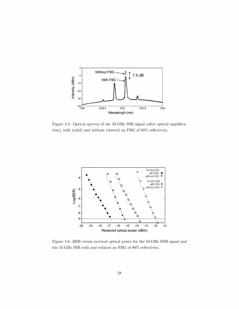
Figure 5.5: Optical spectra of the 35-GHz SSB signal (after optical amplifica-
tion), with (solid) and without (dotted) an FBG of 80% reflectivity.
Figure 5.6: BER versus received optical power for the 10-GHz DSB signal and
the 35-GHz SSB with and without an FBG of 80% reflectivity..
28

Chapter 6
CONCLUSION
We have demonstrated the use of a simple FBG used in transmission at the
output of the transmitter to significantly improve the transmission performance
of a microwave fiber wireless system. The technique improves receiver sensi-
tivity by using an FBG to reduce the optical carrier in the modulated signal
and, thus, improve the modulation depth. It is simple, potentially low cost,
and applicable to a variety of modulation schemes and over a wide range of
frequencies. Experimental results showed sensitivity improvements from 3 to 7
dB for both DSB and SSB modulation schemes.
29

Chapter 7
Question and Answers
(Qn) What is mean by brillion scattering?
(Ans)Brillouin scattering is an effect caused by the nonlinearity of a medium.
An incident photon can be converted into a scattered photon of slightly lower
energy, usually propagating in the backward direction, and a phonon. The
coupling of optical fields and acoustic waves occurs via electrostriction. The
effect can occur spontaneously even at low optical powers, then reflecting the
thermally generated phonon field. For higher optical powers, there can be a
stimulated effect, where the optical fields substantially contribute to the phonon
population. Above a certain threshold power of a light beam in a medium, stim-
ulated Brillouin scattering can reflect most of the power of an incident beam.
This process involves a strong nonlinear optical gain for the back-reflected wave:
an originally weak counterpropagating wave at the suitable optical frequency
can be strongly amplified. Here, the two counter-propagating waves generate a
traveling refractive index grating; the higher the reflected power, the stronger
the index grating and the higher the effective reflectivity. The frequency of the
reflected beam is slightly lower than that of the incident beam; the frequency
difference corresponds to the frequency of emitted phonons. This so-called Bril-
louin frequency shift.
(Qn)How can we remove the excess carrier frequency power?
30

(Ans)The Fiber bragg grating period is selected accordingly as the reflection
frequency becomes the carrier frequency. Also it is possible to use tunable laser
for the carrier frequency generation.
(Qn)Why this technique is called passive?
(Ans) This is a passive technique because the component or element used for
the transmission improvement is Fiber bragg grating which is a passive element,
where no active process is takes place only signal transmission and reflection are
the main processes.
(Qn)Can we increase the transmission distance through this techniques?
(Ans)We can increase the transmission distance to a certain limit since we
are increasing the received power. If we are ready to accept lesser received power
the transmission distance can increased to some kilometers
31

Bibliography
[1] M. Attygalle, C. Lim, G. Pendock, A. Nirmalathas and G. Edvell, ”Trans-
mission improvement in fiber wireless links using fiber Bragg gratings”, to
be published IEEE Photon. Tech. Lett., Jan (2005).
[2] R. D. Esman and K. J. Williams, ”Wideband efficiency improvement of
fiber optic systems by carrier subtraction,” IEEE Photon. Technol. Lett.,
vol. 7, no. 2, pp. 218-220, Feb. 1995.
[3] M. J. LaGasse, W. Charczenko, M. C. Hamilton, and S. Thaniyavarn,
”Optical carrier filtering for high dynamic range fiber optic links,” Electron.
Lett., vol. 30, pp. 2157- 158, 1994.
[4] S. Tonda-Goldstein, D. Dolfi, J.-P. Huignard, G. Charlet, and J. Chaze-
las, Stimulated Brillouin scattering for microwave signal modulation depth
increase in optical links, Electron. Lett., vol. 36, pp. 944946, 2000.
32