The use of fiber bragg grating sensors in biomechanics and rehabilitation applications: The...
37
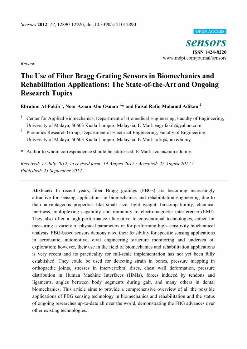
Sensors 2012, 12, 12890-12926; doi:10.3390/s121012890 sensors ISSN 1424-8220 www.mdpi.com/journal/sensors Review The Use of Fiber Bragg Grating Sensors in Biomechanics and Rehabilitation Applications: The State-of-the-Art and Ongoing Research Topics Ebrahim Al-Fakih 1 , Noor Azuan Abu Osman 1, * and Faisal Rafiq Mahamd Adikan 2 1 Center for Applied Biomechanics, Department of Biomedical Engineering, Faculty of Engineering, University of Malaya, 50603 Kuala Lumpur, Malaysia; E-Mail: [email protected] 2 Photonics Research Group, Department of Electrical Engineering, Faculty of Engineering, University of Malaya, 50603 Kuala Lumpur, Malaysia; E-Mail: [email protected] * Author to whom correspondence should be addressed; E-Mail: [email protected]. Received: 12 July 2012; in revised form: 14 August 2012 / Accepted: 22 August 2012 / Published: 25 September 2012 Abstract: In recent years, fiber Bragg gratings (FBGs) are becoming increasingly attractive for sensing applications in biomechanics and rehabilitation engineering due to their advantageous properties like small size, light weight, biocompatibility, chemical inertness, multiplexing capability and immunity to electromagnetic interference (EMI). They also offer a high-performance alternative to conventional technologies, either for measuring a variety of physical parameters or for performing high-sensitivity biochemical analysis. FBG-based sensors demonstrated their feasibility for specific sensing applications in aeronautic, automotive, civil engineering structure monitoring and undersea oil exploration; however, their use in the field of biomechanics and rehabilitation applications is very recent and its practicality for full-scale implementation has not yet been fully established. They could be used for detecting strain in bones, pressure mapping in orthopaedic joints, stresses in intervertebral discs, chest wall deformation, pressure distribution in Human Machine Interfaces (HMIs), forces induced by tendons and ligaments, angles between body segments during gait, and many others in dental biomechanics. This article aims to provide a comprehensive overview of all the possible applications of FBG sensing technology in biomechanics and rehabilitation and the status of ongoing researches up-to-date all over the world, demonstrating the FBG advances over other existing technologies. OPEN ACCESS
Transcript of The use of fiber bragg grating sensors in biomechanics and rehabilitation applications: The...
Sensors 2012, 12, 12890-12926; doi:10.3390/s121012890
sensors ISSN 1424-8220
www.mdpi.com/journal/sensors
Review
The Use of Fiber Bragg Grating Sensors in Biomechanics and
Rehabilitation Applications: The State-of-the-Art and Ongoing
Research Topics
Ebrahim Al-Fakih 1, Noor Azuan Abu Osman
1,* and Faisal Rafiq Mahamd Adikan
2
1 Center for Applied Biomechanics, Department of Biomedical Engineering, Faculty of Engineering,
University of Malaya, 50603 Kuala Lumpur, Malaysia; E-Mail: [email protected] 2 Photonics Research Group, Department of Electrical Engineering, Faculty of Engineering,
University of Malaya, 50603 Kuala Lumpur, Malaysia; E-Mail: [email protected]
* Author to whom correspondence should be addressed; E-Mail: [email protected].
Received: 12 July 2012; in revised form: 14 August 2012 / Accepted: 22 August 2012 /
Published: 25 September 2012
Abstract: In recent years, fiber Bragg gratings (FBGs) are becoming increasingly
attractive for sensing applications in biomechanics and rehabilitation engineering due to
their advantageous properties like small size, light weight, biocompatibility, chemical
inertness, multiplexing capability and immunity to electromagnetic interference (EMI).
They also offer a high-performance alternative to conventional technologies, either for
measuring a variety of physical parameters or for performing high-sensitivity biochemical
analysis. FBG-based sensors demonstrated their feasibility for specific sensing applications
in aeronautic, automotive, civil engineering structure monitoring and undersea oil
exploration; however, their use in the field of biomechanics and rehabilitation applications
is very recent and its practicality for full-scale implementation has not yet been fully
established. They could be used for detecting strain in bones, pressure mapping in
orthopaedic joints, stresses in intervertebral discs, chest wall deformation, pressure
distribution in Human Machine Interfaces (HMIs), forces induced by tendons and
ligaments, angles between body segments during gait, and many others in dental
biomechanics. This article aims to provide a comprehensive overview of all the possible
applications of FBG sensing technology in biomechanics and rehabilitation and the status
of ongoing researches up-to-date all over the world, demonstrating the FBG advances over
other existing technologies.
OPEN ACCESS
Sensors 2012, 12 12891
Keywords: fiber Bragg grating; Bragg sensors; biomechanics; rehabilitation
1. Introduction
In the last decade, fiber Bragg gratings (FBGs) have shown a great potential for applications in the
field of biomechanics and rehabilitation engineering due to their prominent advantages such as their
small size, biocompatibility, chemical inertness, immunity to electromagnetic interference (EMI) and
multiplexing capability [1,2]. These characteristics make FBGs suitable for human body uses that
adapt to the sensor material so that they can be used for in vivo measurement and can be left for
long-term monitoring [3]. They also offer high-performance alternative, in comparison to standard
technologies like electrical strain gauge (ESG), piezoelectric, resistive or other solid-state sensing,
either for measuring physical parameters or for performing high-sensitivity biochemical analysis [4].
Presently, FBGs are widely used for specific applications in aeronautics, the automotive industry,
structure monitoring in civil engineering and undersea oil exploration [5–7]; in order to measure various
parameters such as strain [8], force [9], pressure [10], displacement [11], temperature [12], humidity [13]
and radiation dose [14]. On the other hand, most studies towards synergizing optical FBG sensing
technology with biomechanics and rehabilitation applications are very recent [3] and have not been
commercialized yet. They have been demonstrated for measurement of a wide variety of parameters;
including strain inside and on the surface of intact and plated bones, shrinkage stresses in bone cement
during polymerization, pressure mapping in orthopaedic joints, stresses in intervertebral discs,
deformation in chest wall to study lung biomechanics, pressure distribution in Human Machine
Interfaces (HMIs), forces induced by tendons and ligaments, angles between body segments during
gait, and many others in dental biomechanics.
To the best of our knowledge, only two articles have partially discussed the general applications of
FBG sensing technology in biomechanics [3,15], however, they both did not fully cover all the
previously-reported and the very recent and emerging applications of FBGs in the field of
biomechanics and rehabilitation engineering. This article aims to provide a comprehensive overview of
the applications of FBG technology in biomechanics and rehabilitation in terms of the very recent
progress and the status of ongoing researches up-to-date all over the globe. Furthermore, a comparison
between FBGs and other conventional technologies is also presented in order to show that FBG
technology demonstrates greater feasibility for most of applications in this field.
2. FBG Working Principles
The FBG involves a spatially periodic modulation of the refractive index along specific region of a
fiber‘s core written in a short segment of a single mode optical fiber with a cladding diameter of
125 µm [16–18]. If light from a broadband source is coupled into an optical fiber containing the FBG,
a narrow spectrum is back-reflected and centred around the so-called Bragg wavelength λB
(Figure 1(a)) [19–22] which depends on the periodic variation Λ of the FBG and the effective
refractive index neff :
λB = 2neff Λ (1)
Sensors 2012, 12 12892
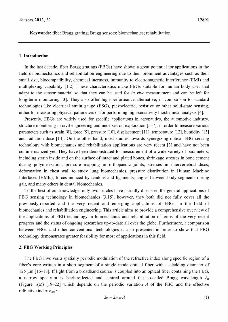
Figure 1. (a) The light source (Brown color) is transmitted through the FBG and a narrow
band (Green color) is back-reflected, centred around λB, and monitored by OSA. (b) The
back-reflected band is shifted (Δλ) shortly after applying external perturbations.
When the FBG sensor is subjected to external mechanical or thermal perturbations, the
back-reflected peak wavelength will be shifted (Figure 1(b)) according to the extent to which the
external perturbations influence the FBG sensor that is spectrally very sensitive when subjected to
axial strain [7,23–25]. The axial strain affects the FBG response directly through the compression and
expansion changes in the spacing of the periodic variation, Λ, and through the strain-optic effect which
induces a change in the effective index of the optical fiber, neff [2,17,18,20]. The temperature
increment ΔT also affects the refractive index and the grating period, resulting in a change in λB [22].
The influence of strain and ambient temperature on the grating period and the refractive index can be
expressed as follows:
(2)
where Δl is the change in FBG length caused by strain and ΔT is the temperature change.
To determine the Bragg wavelength λB, optical spectrum analyzers (OSA) are commonly used when
doing experiments inside laboratories, and, for experiments conducted outside, other specialized
interrogators are employed. With high-speed interrogation systems, the FBG sensors would be more
suitable for monitoring strains in locations subjected to dynamic loads [20].
Sensors 2012, 12 12893
3. Applications
3.1. Bone
Knowledge of the biomechanical behaviour of the musculoskeletal system is crucial in
understanding bone diseases and in designing medical devices [26]. The skeleton normally adapts to
mechanical loading, thus understanding of how bone deformation under load occurs is of interest.
Several methods have been proposed for the measurement of bone deformation under load. The strain
gauge (SG) was the gold standard whose electrical resistance varies proportionally to the amount of
strain. A research group based in Israel used SGs for in vivo measurement of strain in human bone in
six subjects during running, stationary bicycling, leg presses and stepping, using bone staples made of
electrical SGs [27,28]. Recently, several researchers have studied the potential of FBG sensors for
in vivo applications as a measurement tool for bone strain, concluding that FBGs have shown
competitive advantages over the conventionally-used SGs. FBGs are completely made of
biocompatible silicate (SiO2) glass ceramics materials [26,29] which have a smaller risk for infection,
whereas the SG itself represents a foreign body implant. They can also be used in locations where the
use of conventional SGs is technically inapplicable [3,26]. For example, when an SG is loaded, its
electrical resistance varies proportionally to the applied strain; therefore, it cannot be used in an
electromagnetic environment. Moreover, there are other distinguishing advantages of FBGs when
compared to the SGs: they can easily adhere to bone and other irregular surfaces [26].
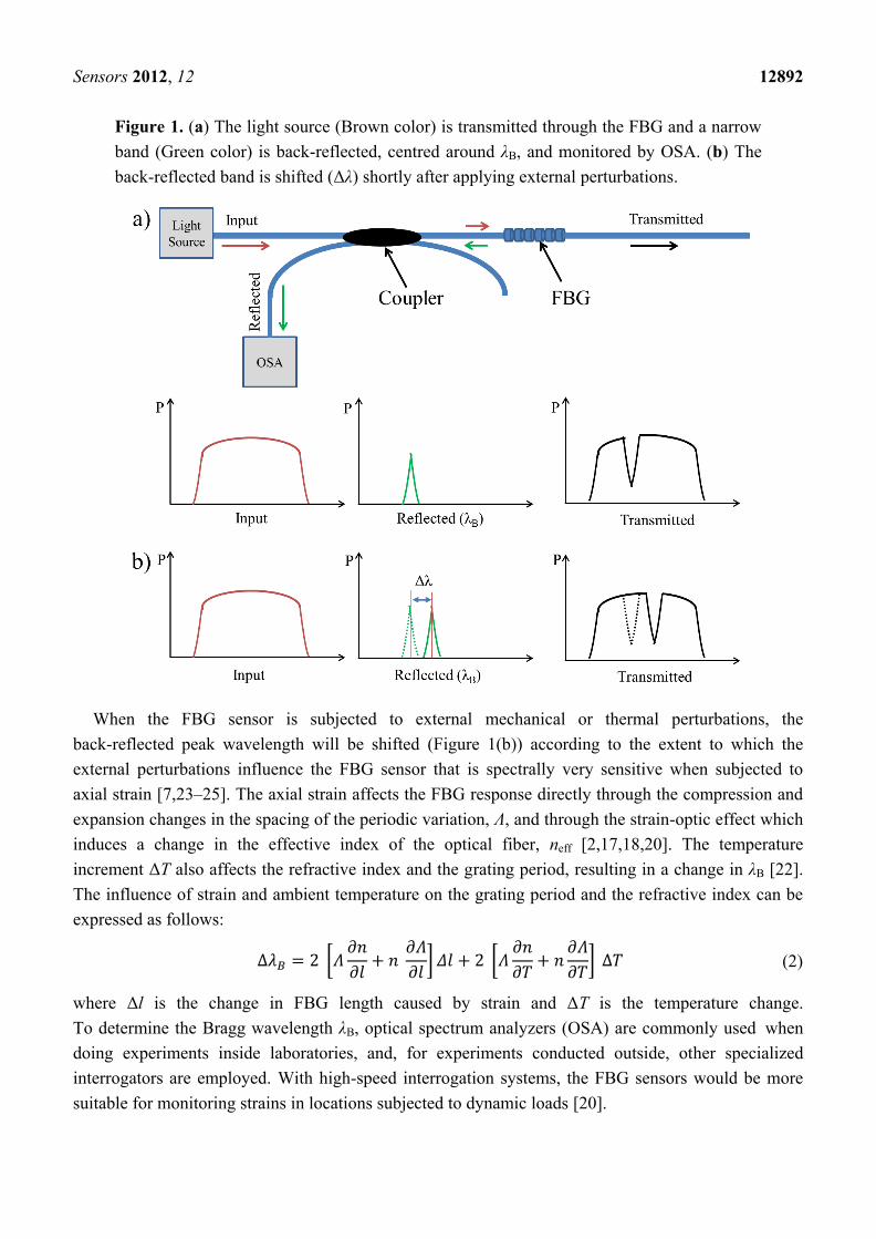
Talaia et al. [30] have determined bone strains in plated and intact synthetic femurs using FBGs and
SGs in order to study the effects of fracture fixation plates. For the intact femur, 20 axial SGs were
placed on the anterior, posterior, medial and lateral sides at different levels of cortex femur.
A simulated 45° fracture on the other femur sample was made and fixed using a 10-hole stainless steel
bone plate (Figure 2(a)). Seven FBGs were glued at different locations along the bone plate
(Figure 2(b)) and 13 SGs were fixed to the cortex femur (Figure 2(c)). A static load of 600 N was
applied to both the plated and intact synthetic femurs and bone strains were recorded at the same sites
on the cortex of the femurs and on the bone plate. The sensors have shown good linearity for the
different loads. However, FBGs made it much easier to measure strain on bone plates than with the
conventional SGs and were more feasible to monitor the evolution of the strain in bone. From the
biological point of view, FBGs are able to assess the stiffness of callus formation of fractured bones.
Fresvig et al. [26] have evaluated the use of FBG sensors to detect deformation in human cadaver
femur bone under in vitro loading conditions, with potential in vivo application. An acryl tube and a
human femoral bone sample of the same length were used in this study. Each sample was instrumented
with four polyamide coated FBG sensors and four SGs, interspersed at every 45°, which were placed
around the circumference at the central part of each sample. The two samples were loaded using a
Mechanical Testing Machine and the induced strains were recorded accordingly. The FBG
methodology showed its suitability for dynamic in vitro measurements. Generally, both types of
sensors, FBGs and SGs, produced no significant differences, suggesting that the FBG sensors could be
successfully implemented for in vivo measurements.
Sensors 2012, 12 12894
Figure 2. (a) The simulated 45° fracture and the locations of the SGs on the intact and plated
synthetic Femurs. (b) The locations of the FBGs on the bone plate. (c) Representation of the
experimental apparatus used and detail of bone plate with FBGs [30].
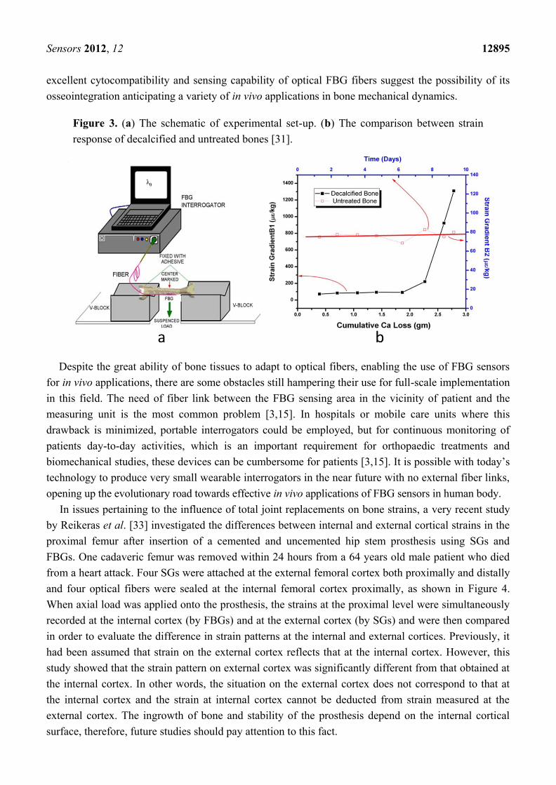
FBG sensors can also be used to understand to what extent the bone calcium loss affects strain
response of bone [31]. Two samples of goat tibiae were used; one decalcified in steps while the other
remained untreated for a comparative study. Two FBG sensors were directly attached at the midpoint
of both samples. Thereafter the two samples were stressed with loads ranging from 0.1 kg to 4 kg
using a three-point bending test as shown in Figure 3(a). The strain values were calculated from the
FBG wavelength shifts that had been recorded for both samples at the same time in order to understand
the effect of decalcification and that of degeneration with time. The strain generated for the untreated
sample remained largely unchanged during the experiment, while for the decalcified sample; strain values
for same loads increased and became much higher with more calcium loss (Figure 3(b)). By using FBG
technique, the strain response gives a direct indication of the degree of calcium present in bone.
All the above-mentioned studies suggested that FBG sensors have a potential to be used as a novel
approach to assess bone biomechanics in vivo. Recently, Carvalho et al. [32] investigated the sensing
capability of FBGs when placed in direct contact with human osteoblast cells cultured around the FBG
fiber and assessed the reaction of these cells to optical fibers. It was found that osteoblasts exhibited a
great capability to adhere and grow over the fiber and the protective polymer coating as well.
Furthermore, the FBG sensing capability was not affected throughout the culture period. Hence, these
Sensors 2012, 12 12895
excellent cytocompatibility and sensing capability of optical FBG fibers suggest the possibility of its
osseointegration anticipating a variety of in vivo applications in bone mechanical dynamics.
Figure 3. (a) The schematic of experimental set-up. (b) The comparison between strain
response of decalcified and untreated bones [31].
Despite the great ability of bone tissues to adapt to optical fibers, enabling the use of FBG sensors
for in vivo applications, there are some obstacles still hampering their use for full-scale implementation
in this field. The need of fiber link between the FBG sensing area in the vicinity of patient and the
measuring unit is the most common problem [3,15]. In hospitals or mobile care units where this
drawback is minimized, portable interrogators could be employed, but for continuous monitoring of
patients day-to-day activities, which is an important requirement for orthopaedic treatments and
biomechanical studies, these devices can be cumbersome for patients [3,15]. It is possible with today‘s
technology to produce very small wearable interrogators in the near future with no external fiber links,
opening up the evolutionary road towards effective in vivo applications of FBG sensors in human body.
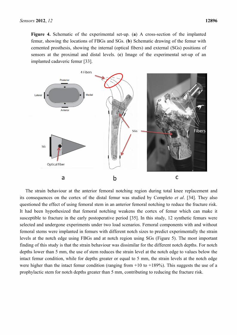
In issues pertaining to the influence of total joint replacements on bone strains, a very recent study
by Reikeras et al. [33] investigated the differences between internal and external cortical strains in the
proximal femur after insertion of a cemented and uncemented hip stem prosthesis using SGs and
FBGs. One cadaveric femur was removed within 24 hours from a 64 years old male patient who died
from a heart attack. Four SGs were attached at the external femoral cortex both proximally and distally
and four optical fibers were sealed at the internal femoral cortex proximally, as shown in Figure 4.
When axial load was applied onto the prosthesis, the strains at the proximal level were simultaneously
recorded at the internal cortex (by FBGs) and at the external cortex (by SGs) and were then compared
in order to evaluate the difference in strain patterns at the internal and external cortices. Previously, it
had been assumed that strain on the external cortex reflects that at the internal cortex. However, this
study showed that the strain pattern on external cortex was significantly different from that obtained at
the internal cortex. In other words, the situation on the external cortex does not correspond to that at
the internal cortex and the strain at internal cortex cannot be deducted from strain measured at the
external cortex. The ingrowth of bone and stability of the prosthesis depend on the internal cortical
surface, therefore, future studies should pay attention to this fact.
Sensors 2012, 12 12896
Figure 4. Schematic of the experimental set-up. (a) A cross-section of the implanted
femur, showing the locations of FBGs and SGs. (b) Schematic drawing of the femur with
cemented prosthesis, showing the internal (optical fibers) and external (SGs) positions of
sensors at the proximal and distal levels. (c) Image of the experimental set-up of an
implanted cadaveric femur [33].
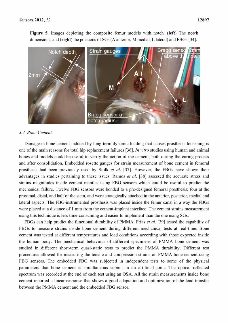
The strain behaviour at the anterior femoral notching region during total knee replacement and
its consequences on the cortex of the distal femur was studied by Completo et al. [34]. They also
questioned the effect of using femoral stem in an anterior femoral notching to reduce the fracture risk.
It had been hypothesized that femoral notching weakens the cortex of femur which can make it
susceptible to fracture in the early postoperative period [35]. In this study, 12 synthetic femurs were
selected and undergone experiments under two load scenarios. Femoral components with and without
femoral stems were implanted in femurs with different notch sizes to predict experimentally the strain
levels at the notch edge using FBGs and at notch region using SGs (Figure 5). The most important
finding of this study is that the strain behaviour was dissimilar for the different notch depths. For notch
depths lower than 5 mm, the use of stem reduces the strain level at the notch edge to values below the
intact femur condition, while for depths greater or equal to 5 mm, the strain levels at the notch edge
were higher than the intact femur condition (ranging from +10 to +189%). This suggests the use of a
prophylactic stem for notch depths greater than 5 mm, contributing to reducing the fracture risk.
Sensors 2012, 12 12897
Figure 5. Images depicting the composite femur models with notch. (left) The notch
dimensions, and (right) the positions of SGs (A anterior, M medial, L lateral) and FBGs [34].
3.2. Bone Cement
Damage in bone cement induced by long-term dynamic loading that causes prosthesis loosening is
one of the main reasons for total hip replacement failures [36]. In vitro studies using human and animal
bones and models could be useful to verify the action of the cement, both during the curing process
and after consolidation. Embedded rosette gauges for strain measurement of bone cement in femoral
prosthesis had been previously used by Stolk et al. [37]. However, the FBGs have shown their
advantages in studies pertaining to these issues. Ramos et al. [38] assessed the accurate stress and
strains magnitudes inside cement mantles using FBG sensors which could be useful to predict the
mechanical failure. Twelve FBG sensors were bonded to a pre-designed femoral prosthesis; four at the
proximal, distal, and half of the stem, and were strategically attached in the anterior, posterior, medial and
lateral aspects. The FBG-instrumented prosthesis was placed inside the femur canal in a way the FBGs
were placed at a distance of 1 mm from the cement-implant interface. The cement strains measurement
using this technique is less time-consuming and easier to implement than the one using SGs.
FBGs can help predict the functional durability of PMMA. Frias et al. [39] tested the capability of
FBGs to measure strains inside bone cement during different mechanical tests at real-time. Bone
cement was tested at different temperatures and load conditions according with those expected inside
the human body. The mechanical behaviour of different specimens of PMMA bone cement was
studied in different short-term quasi-static tests to predict the PMMA durability. Different test
procedures allowed for measuring the tensile and compression strains on PMMA bone cement using
FBG sensors. The embedded FBG was subjected in independent tests to some of the physical
parameters that bone cement is simultaneous submit in an artificial joint. The optical reflected
spectrum was recorded at the end of each test using an OSA. All the strain measurements inside bone
cement reported a linear response that shows a good adaptation and optimization of the load transfer
between the PMMA cement and the embedded FBG sensor.
Sensors 2012, 12 12898
3.3. Orthopaedic Joints
An embedded array of FBGs exhibited its feasibility to be used at orthopaedic joints interfaces for
pressure mapping and the measurement of contact forces and stresses. It is necessary for those
involved in prostheses research and biomechanics studies to understand the contact area and contact
stress at Orthopaedic joints as well as the alignment of the joint interface (i.e., tibiofemoral interface).
Measurements of contact area, contact force and stress distribution in the tibiofemoral joint have been
made using commercially available stress-sensitive films such as I-Scan and Fujifilm [40–43].
However, the biomechanics of knee joint might be altered after the insertion of these films at the
articulating surfaces.
Due to their flexibility and multiplexing capability, FBG sensors have shown an edge over these
conventional measurement systems as they are suitable to be used in any irregular-shaped interface
surfaces (i.e., knee joint) and, in some cases, they do not change the natural contact topology of joint
capsule (i.e., hip joint). The application of an FBG sensor for pressure mapping at the prosthetic knee
joints was first reported by Mohanty et al. [44,45]. In these cadaver studies, a rectangular array of FBGs
was embedded into a tibial spacer that was inserted at the tibiofemoral interface and the changes in the
contact stress distribution caused by joint misalignment in extension and flexion were monitored. This
spacer sensor can be used to correct malalignment during total knee arthroplasty. It can be used in vitro
for studying the biomechanics of the prosthetic knee joint especially for curved and conforming designs.
The commercial sensitive films were also used for stress measurement in hip joint [46], but their
application is severely limited by the amount of dissection required to insert them in this joint. This
insertion approach is considered to be too interventional when used in the natural hip [47]. FBG
sensors have shown their great potential to overcome some of the sensitive films limitations because
they have key advantages that make it more attractive for application in the hip joints such as the small
size, mechanical compliance and biocompatibility.
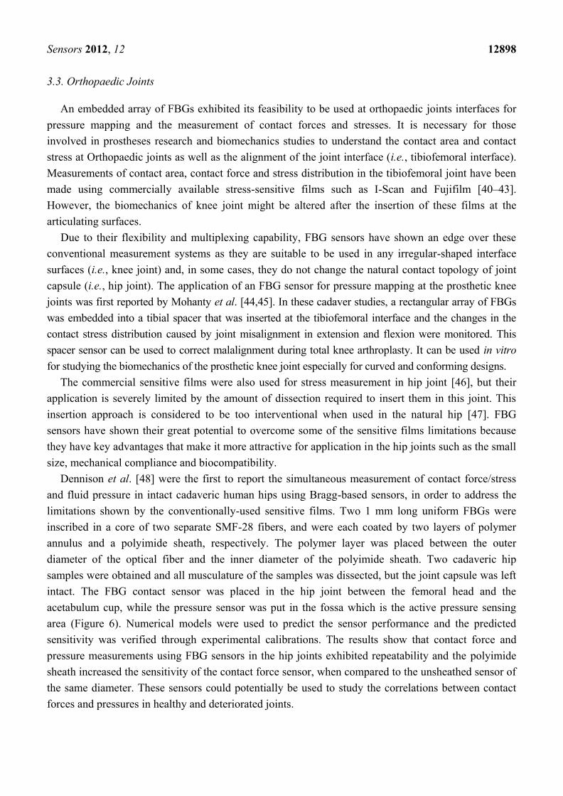
Dennison et al. [48] were the first to report the simultaneous measurement of contact force/stress
and fluid pressure in intact cadaveric human hips using Bragg-based sensors, in order to address the
limitations shown by the conventionally-used sensitive films. Two 1 mm long uniform FBGs were
inscribed in a core of two separate SMF-28 fibers, and were each coated by two layers of polymer
annulus and a polyimide sheath, respectively. The polymer layer was placed between the outer
diameter of the optical fiber and the inner diameter of the polyimide sheath. Two cadaveric hip
samples were obtained and all musculature of the samples was dissected, but the joint capsule was left
intact. The FBG contact sensor was placed in the hip joint between the femoral head and the
acetabulum cup, while the pressure sensor was put in the fossa which is the active pressure sensing
area (Figure 6). Numerical models were used to predict the sensor performance and the predicted
sensitivity was verified through experimental calibrations. The results show that contact force and
pressure measurements using FBG sensors in the hip joints exhibited repeatability and the polyimide
sheath increased the sensitivity of the contact force sensor, when compared to the unsheathed sensor of
the same diameter. These sensors could potentially be used to study the correlations between contact
forces and pressures in healthy and deteriorated joints.
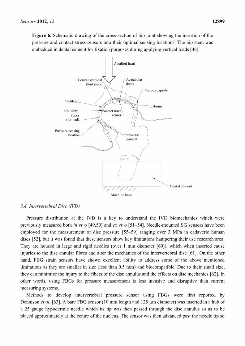
Sensors 2012, 12 12899
Figure 6. Schematic drawing of the cross-section of hip joint showing the insertion of the
pressure and contact stress sensors into their optimal sensing locations. The hip stem was
embedded in dental cement for fixation purposes during applying vertical loads [48].
3.4. Intervertebral Disc (IVD)
Pressure distribution at the IVD is a key to understand the IVD biomechanics which were
previously measured both in vivo [49,50] and ex vivo [51–54]. Needle-mounted SG sensors have been
employed for the measurement of disc pressure [55–59] ranging over 3 MPa in cadaveric human
discs [52], but it was found that these sensors show key limitations hampering their use research area.
They are housed in large and rigid needles (over 1 mm diameter [60]), which when inserted cause
injuries to the disc annular fibres and alter the mechanics of the intervertebral disc [61]. On the other
hand, FBG strain sensors have shown excellent ability to address some of the above mentioned
limitations as they are smaller in size (less than 0.5 mm) and biocompatible. Due to their small size,
they can minimize the injury to the fibers of the disc annulus and the effects on disc mechanics [62]. In
other words, using FBGs for pressure measurement is less invasive and disruptive than current
measuring systems.
Methods to develop intervertebral pressure sensor using FBGs were first reported by
Dennison et al. [63]. A bare FBG sensor (10 mm length and 125 µm diameter) was inserted in a hub of
a 25 gauge hypodermic needle which its tip was then passed through the disc annulus so as to be
placed approximately at the centre of the nucleus. The sensor was then advanced past the needle tip so
Sensors 2012, 12 12900
that its entire length was exposed to the nucleus pulposus and the needle was left in the annulus to
shield the fiber optic cable from any traction. Each lumbar spinal unit was loaded from 0 N to 2,000 N
to 0 N at 10 N/s. The sensor performance was investigated in five two-vertebra human cadaveric spinal
units. After each test with FBG sensor and for comparison purposes, the tests were repeated by using
two SGs instead. Although the pressure measurements using FBG sensors were in agreement with
those obtained in previous disc pressure studies, they were not always consistent with measurements
made using current standard SGs sensors. That is because bare FBG measurements have shown
poor pressure sensitivity, resulting in highly discretized data over the 3 MPa pressure ranges. These
drawbacks might come from the nucleus material inhomogeneity and from the length of the FBG (over
the 10 mm) which would interrupt pressure measurements. Improving the sensor design and sensitivity
and its spatial resolution is very important for obtaining better measurement results.
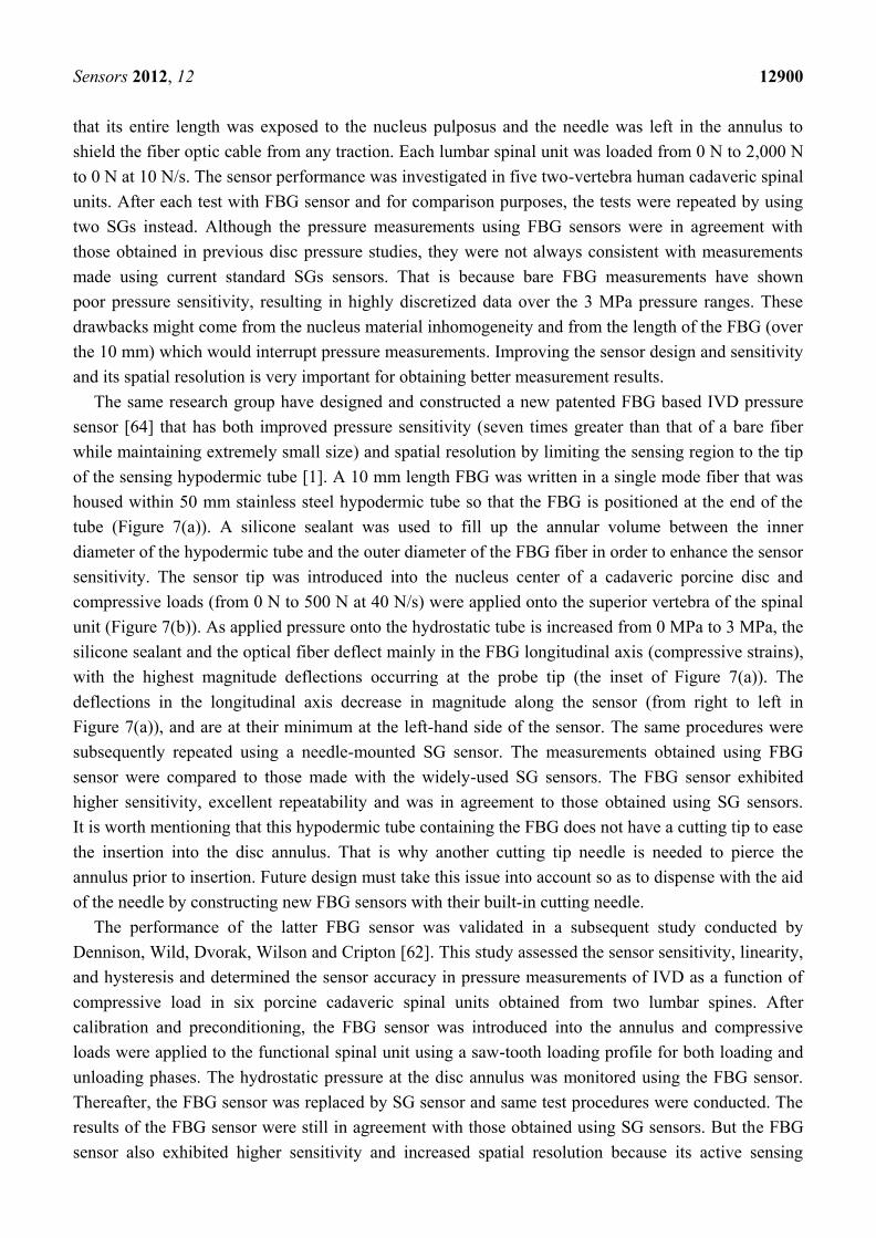
The same research group have designed and constructed a new patented FBG based IVD pressure
sensor [64] that has both improved pressure sensitivity (seven times greater than that of a bare fiber
while maintaining extremely small size) and spatial resolution by limiting the sensing region to the tip
of the sensing hypodermic tube [1]. A 10 mm length FBG was written in a single mode fiber that was
housed within 50 mm stainless steel hypodermic tube so that the FBG is positioned at the end of the
tube (Figure 7(a)). A silicone sealant was used to fill up the annular volume between the inner
diameter of the hypodermic tube and the outer diameter of the FBG fiber in order to enhance the sensor
sensitivity. The sensor tip was introduced into the nucleus center of a cadaveric porcine disc and
compressive loads (from 0 N to 500 N at 40 N/s) were applied onto the superior vertebra of the spinal
unit (Figure 7(b)). As applied pressure onto the hydrostatic tube is increased from 0 MPa to 3 MPa, the
silicone sealant and the optical fiber deflect mainly in the FBG longitudinal axis (compressive strains),
with the highest magnitude deflections occurring at the probe tip (the inset of Figure 7(a)). The
deflections in the longitudinal axis decrease in magnitude along the sensor (from right to left in
Figure 7(a)), and are at their minimum at the left-hand side of the sensor. The same procedures were
subsequently repeated using a needle-mounted SG sensor. The measurements obtained using FBG
sensor were compared to those made with the widely-used SG sensors. The FBG sensor exhibited
higher sensitivity, excellent repeatability and was in agreement to those obtained using SG sensors.
It is worth mentioning that this hypodermic tube containing the FBG does not have a cutting tip to ease
the insertion into the disc annulus. That is why another cutting tip needle is needed to pierce the
annulus prior to insertion. Future design must take this issue into account so as to dispense with the aid
of the needle by constructing new FBG sensors with their built-in cutting needle.
The performance of the latter FBG sensor was validated in a subsequent study conducted by
Dennison, Wild, Dvorak, Wilson and Cripton [62]. This study assessed the sensor sensitivity, linearity,
and hysteresis and determined the sensor accuracy in pressure measurements of IVD as a function of
compressive load in six porcine cadaveric spinal units obtained from two lumbar spines. After
calibration and preconditioning, the FBG sensor was introduced into the annulus and compressive
loads were applied to the functional spinal unit using a saw-tooth loading profile for both loading and
unloading phases. The hydrostatic pressure at the disc annulus was monitored using the FBG sensor.
Thereafter, the FBG sensor was replaced by SG sensor and same test procedures were conducted. The
results of the FBG sensor were still in agreement with those obtained using SG sensors. But the FBG
sensor also exhibited higher sensitivity and increased spatial resolution because its active sensing
Sensors 2012, 12 12901
region was confined to the needle tip. What is superior with this FBG sensor over the previous disc
pressure sensors is that it did not interfere with vertebral endplates and did not alter the disc
biomechanics and structure. In addition, this FBG sensor is 83% smaller and more flexible than any
previously-reported disc pressure sensor and can be used to make less invasive measurements of disc
pressure in vivo and during discography.
Figure 7. (a) Schematic showing the construction of the IVD pressure sensor. The
hydrostatic pressure over the hypodermic tube and at the sensing region whose dimensions
are shown (right inset). (b) Compressive loads applied to a functional spine unit embedded
between dental stones and the pressure sensor inserted into the annulus [1].
A very recent study by Roriz et al. [65] has proposed an FBG sensor to measure strain due to
bulging of the IVD under axial compression. This study introduced the least invasive sensor up-to-date
as the needle was used only for guiding and placing the sensor and could be then removed leaving the
sensor in direct contact with the disc material. A 2 mm length FBG was inserted into the disc center of
an ex vivo porcine dorsal spinal unit using a 25 gauge hypodermic needle that was removed after
placing the sensor and axial compression loads were applied causing strain in the FBG fiber which,
combined with strain due to lateral disc bulging, induced changes in the Bragg wavelength. The results
verified that the sensor is capable of measuring strain due to the applied loads and the bulging of the
annulus fibrosus as a consequence of axial compression. However, this sensor has shown a limitation.
Since the FBG fiber is stiffer than the IVD, the fiber will resist disc bulging and fail before maximum
disc elongation. Therefore, this technique is not suitable for measurement of tissue physiologic strain.
These new FBG sensors can potentially increase our understanding of the correlations between the
internal disc pressure and the degree of disc degeneration. These correlations may increase our
Sensors 2012, 12 12902
knowledge of disc biomechanics and potential disc injuries and degeneration. Further studies are
needed to address the effect of the sensor insertion into the disc on the load transfer and the
pressure measurements.
3.5. Dental Biomechanics
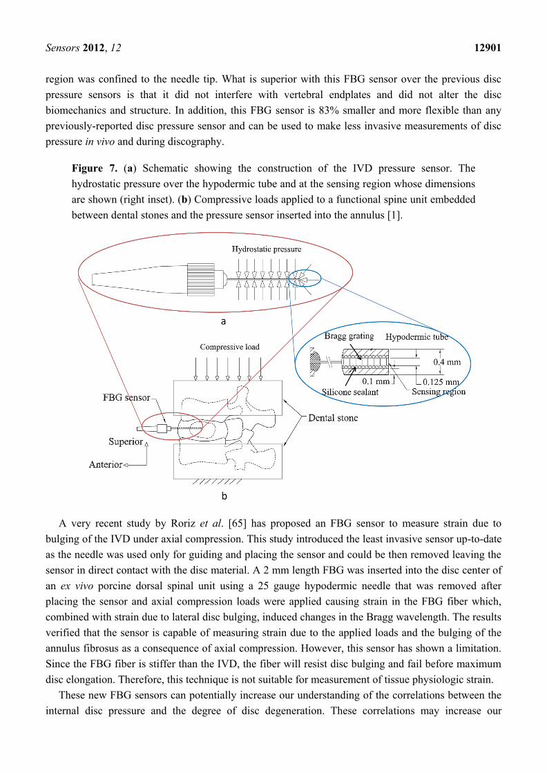
The application of FBG sensors in the area of dental biomechanics had been investigated earlier.
Tjin et al. [66] have reported the first application of FBG sensors to monitor the force and temperature
as a function of time in dental splints worn by patients suffering from sleep apnoea. Due to the small
size of FBG sensors, it is much easier to embed them within the splint while maintaining the splint
efficiency unaltered. These sensors can determine the correct use of splints when worn by the patient.
Two pre-calibrated FBGs inscribed in a single strand of an optical fibre were used; one embedded
within three layers of glass fibre composite materials to insulate the FBG pressure sensor from
temperature effect and the other bare FBG for temperature sensing. The sensors were carefully
embedded into the patient‘s dental splint; the pressure sensor located at the first molar and the
temperature sensor located further in, where there is minimum contact with the gums (Figure 8). As
the splint is being positioned in the patient‘s mouth, the results show an increase in both temperature
and force. The advantages of these sensors, besides their effectiveness in monitoring the proper usage
of the dental splints, are that they are unnoticeable due to their small size and multiplexing capability,
and inherently safer than the conventionally used methods (i.e., thermistors and piezo-electric pressure
sensor) due to their immunity to EMI.
Figure 8. Schematic diagram of dental splint with FBG embedded sensors [66].
Sensors 2012, 12 12903
Another important application of FBGs in dental biomechanics is to measure the properties of
dental materials like the stress-strain pattern. A few studies were reported on the possibility to use FBG
sensors to study dental materials such as resin-based composites and gypsum products. FBGs can be
used to measure the hardening of dental cement and the corresponding stress build-up and the
volumetric shrinkage of the resin cement during polymerization [67–69]. Milczewski et al. [70] have
used FBGs to determine the polymerization contraction and setting expansion of three types of gypsum
products (plaster, dental stone, and high strength dental stone) and to monitor the strain evolution and
temperature during the drying phase of the material. Two FBG sensors were used; one sensitive to the
strain and temperature variations during setting, and the other placed in a double needle to monitor
only the temperature variations during the reaction. The results show that the plaster of Paris
demonstrated higher expansion than orthodontic and dental stone. The FBG technique can be a good
tool for dentists to better manipulate a material and predict how it will behave in vivo.
A research group in Portugal has employed FBGs to measure strains at the surface of an implanted
cadaveric mandible caused by impact loads. Although they had previously used SGs in a few studies
pertaining to the mandible [71,72], they studied the potential use of FBG as a biomechanical sensor [73].
In one of their studies [74], they measured the dynamic strains at the mandible surface induced by
impact loads. A standardized dental implant was implanted in a dried human cadaveric mandible
embedded in a resin support, and an FBG was placed on the outer surface of the mandible near the
canine tooth position in a direction parallel to the implant longitudinal axis. The impact loads were
generated by striking the implant with a steel mass (52 g) dropped inside a steel tube. The obtained
results agreed with those previously reported studies using SGs, showing the ability of FBG sensors to
measure dynamic strain variations, with precision, in complex biomechanical systems.
In a subsequent work by the same group [75], they have measured the strains at the mandible
surface due to both static and impact loads, using FBGs and SGs, and two standardized implants were
implanted in the cadaveric mandible used in the previous study. Two uncoated FBGs and two uniaxial
SGs were placed on the mandible surface in the longitudinal axis of the implants (One FBG and SG
near each implant), as shown in Figure 9. For the static loads, the implant was step loaded up to a
maximum of 160 N, and strains at the surface were recorded by each sensor, FBG and SG. The impact
loads were generated in a manner similar to that used in the previous study [74] which was done by
striking the implant with 52 g a steel mass. The results of both types of sensors were compared,
showing very similar response when both static and dynamic loads were applied. The FBG sensor
exhibited better sensitivity with small strains compared to SG, showing its feasibility to be used as an
alternative method for measuring strains in dental biomechanical applications.
FBGs can also be used to study model mandibles that replicate the mechanical properties of human
bone. A synthetic model was used to study the strain distribution over the mandible branch and
articulation caused by the action of the muscles [76]. Four FBGs were glued at the outer surface of the
mandible and the strain patterns were assessed for different load configurations including the forces of
the masseter and temporal muscles and occlusion loads on different teeth. The same device was modeled
by Finite Element (FE) method to determine the strain at the mandible surface. The strains obtained from
the FBGs were correlated to identical ones obtained with a numerical FE model. The comparison of the
results is considered satisfactory. For symmetric loading the strains measured were identical. For the

Sensors 2012, 12 12904
non-symmetric loading, the FE boundary conditions must be simulated more accordingly. Such results
validate numerical methods used in the design of mandible and condoyle prosthesis.
Figure 9. (a) The set-up of the step loads. The FBGs and SGs attached to a cadaveric
mandible. The inset illustrating the strains measured by both techniques. (b) The set-up of
the measurement of dynamic strains and the inset showing the FBG versus SGs strains in
time-domain [75].
Measuring strains in the mandible bone helps predict the load transfer from the implant to the
surrounding bone, leading to design novel dental implants that minimize the strains induced in the
mandible. Macro-models of dental implants were studied with FBG sensors inserted in real bone using
samples from bovine femur [77,78]. Three types of dental implants; metallic, polymeric and polymer
coated metal implants, were compared in order to study the load transfer from the implant to the bone.
The FBGs were inserted into the bone in a direction parallel to the implant axis and the static and
dynamic strains were recorded as a function of loads. The results show that polymer coated implants
Sensors 2012, 12 12905
can be more appropriate due to better load transfer. FEM analysis can be performed in order to
compare and validate the experimental results.
FBG sensors have been used to measure the forces applied onto the surface of teeth and the
consequent displacement caused by the orthodontic systems. Low magnitude applied forces caused by
orthodontic systems are considered more effective for moving the teeth than impulsive loads.
Therefore, Milczeswki et al. [79] investigated the forces applied onto the surface of an incisor by
orthodontic system using FBG technology. The experiments were performed in an artificial maxilla
with dental wax and metal teeth and the teeth were instrumented with a fixed orthodontic appliance.
An FBG imprinted in a HiBi fiber was placed between the incisor surface and the orthodontic bracket,
and loads were applied representing the auxiliary appliance. The anterior-posterior force and
displacement of the tooth movement were measured, showing that the small size and the high
sensitivity of the FBG sensor allow for the determination of forces applied orthogonally to the surface
of the teeth. This technique is promising and can be used in the other types of orthodontic applications
for in vivo experiments.
Recently, Milczewski et al. [80] went a step further and applied a similar approach using FBGs to
study the magnitude and location of forces at the teeth roots and maxilla bone during applying load by
orthodontic appliance. A maxilla model was instrumented with FBGs, three pairs of FBGs positioned
along three artificial teeth roots, immersed in the elastomeric material, and the other four multiplexed
fiber sensors placed transversally along the teeth apex. Preconditioning tests were performed to
evaluate the sensitivity of the Bragg gratings in-situ. After the activation of the orthodontic appliance,
the teeth were loaded and the strain on the maxillary bone and dentition was monitored showing a
linear relationship between the strain and the applied load in the incisor, canine and molar teeth. This
also can show the transference of the forces to the teeth and finally to the internal maxillary structures.
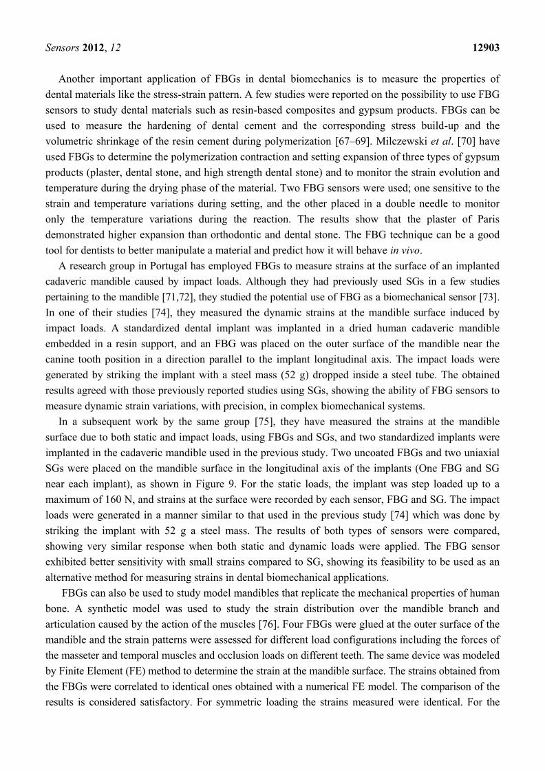
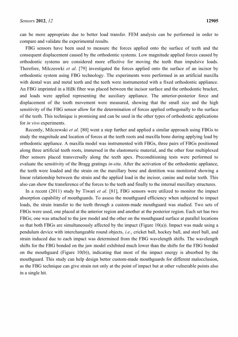
In a recent (2011) study by Tiwari et al. [81], FBG sensors were utilized to monitor the impact
absorption capability of mouthguards. To assess the mouthguard efficiency when subjected to impact
loads, the strain transfer to the teeth through a custom-made mouthguard was studied. Two sets of
FBGs were used, one placed at the anterior region and another at the posterior region. Each set has two
FBGs; one was attached to the jaw model and the other on the mouthguard surface at parallel locations
so that both FBGs are simultaneously affected by the impact (Figure 10(a)). Impact was made using a
pendulum device with interchangeable round objects, i.e., cricket ball, hockey ball, and steel ball, and
strain induced due to each impact was determined from the FBG wavelength shifts. The wavelength
shifts for the FBG bonded on the jaw model exhibited much lower than the shifts for the FBG bonded
on the mouthguard (Figure 10(b)), indicating that most of the impact energy is absorbed by the
mouthguard. This study can help design better custom-made mouthguards for different malocclusion,
as the FBG technique can give strain not only at the point of impact but at other vulnerable points also
in a single hit.
Sensors 2012, 12 12906
Figure 10. (a) The jaw model and mouthguard with FBGs. (b) The response of ball impact
portraying no changes for FBG bonded on jaw model (b right) as compared to FBG
bonded on the mouthguard (b left) [3,81].
3.6. Chest Wall Deformation
The monitoring of chest wall movement during respiration is crucial in understanding lung
biomechanics. The chest displacement due to respiration normally ranges from 4 to 12 mm [82,83].
Sensors composed of a bent optic fiber for the measurement of respiratory chest circumference
changes had been previously developed by Babchenko et al. [84]. This sensor was composed of a bent
optic fiber connected to a chest belt so that its radius of curvature would change during respiration due
to changes in the respiratory chest circumference and the light transmission was measured through the
bent fibre providing information on the curvature changes. However, this method was replaced with
FBG technique which was first reported by Wehrle et al. in 2001 [85]. In this study, the measurement
of dynamic strain on human chest during respiration was developed and tested. The FBGs were
embedded into a chest deformable strap which was strained in accordance with the deformation of
chest. This sensor showed its ability to detect deformation in the thoracic cage during respiration,
indicating the respiratory frequency spectrum. It can also be used to trigger a device for inducing
electrically assisted ventilation, when one lung is to be excited in phase with the other working lung, or
to monitor high frequency oscillatory ventilation. Moreover, the FBG sensors showed their capability
to measure the muscle movement in the chest.
Sensors 2012, 12 12907
It is no longer strange to combine electronics and textiles into a single structure to produce
electronic textiles (e-textiles) [86]. Recently, a new project supported by the Europe Union and called
―Optical Fibre Sensors Embedded into technical Textile for Healthcare (OFSETH)‖ was launched [87].
The aim of OFSETH is to take advantage of pure optical sensing technologies for extending the
capabilities of medical technical textiles for wearable health monitoring [88]. These wearable smart
textiles can be used to simultaneously monitor the vital physiological parameters such as respiratory
movements, cardiac activity, pulse oximetry, and temperature of the body. They exhibit advantageous
properties over other standard (non-optical) monitoring techniques, especially for monitoring the
anesthetized patients under Medical Resonance Imaging (MRI) [89–91].
The OFSETH project proposed three optical sensing techniques for monitoring the elongation in
textile fabrics worn by patients: the bending loss sensor, the FBG sensor and the optical time domain
reflectometry sensor. Grillet et al. [87] have reported on these three different techniques, all smart
textiles embedded. In this study, only the elongation of the abdominal circumstances during ventilation
was measured unlike the study by Wehrle et al. [85] which measured the thorax movement instead.
The textile was fixed to a load cell and a movable platform by clamping blocks to investigate the
stretching capabilities of the smart textile and the effective strain on the optical fiber was then
monitored during the stretching experiment by continuously recording the shifts in Bragg wavelength.
The FBG sensor performance during cyclic strains mimicking those normally induced by chest
movements was also tested to assess the suitability of this proposed design. The results showed that
these three techniques are able to sense the textile elongations between 0% and 3% and the stretching
properties of the textile was maintained during the measurement to ensure the patient comfort.
Moreover, the FBG sensor embedded in the textile is able to sense weak breathing movements with a
better resolution.
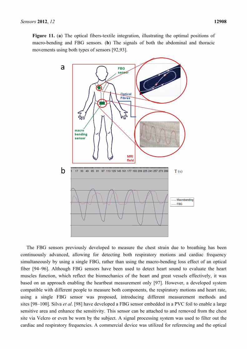
Another work by Jonckheere et al. [92] reported on only two pure optical sensing
techniques—macro-bending sensor and FBG sensor—embedded into textile fabrics to measure the
elongation of the technical textile caused by both the thoracic and abdominal movements during
ventilation. The aim is to ensure the proper position of the optical sensors in order for minimizing
parasitic effects such as mechanical strains and optical losses, and to convert all the textile elongation
into a mechanical force that will be transferred to the sensors. The typical positions of these two
sensors are shown in Figure 11(a). The combination of these two designs produces a device allowing
for continuous monitoring of both thoracic and abdominal movements. The two designs showed their
capability to measure the textile elongation between 0% to 3%. The thoracic and abdominal movements
signals obtained (Figure 11(b)) can indicate the respiratory system efficiency and breathing frequency
spectrum. This shows that optical sensors can be the golden solution for the measurement of vital signs
of patients during MRI examination as it shows immunity to electromagnetic radiations. However,
these sensors were then developed to be able to measure both the thoracic and abdominal movements
with increased elongation between up to 5% and to be connected to a hard monitor or to a mobile
device [93].
Sensors 2012, 12 12908
Figure 11. (a) The optical fibers-textile integration, illustrating the optimal positions of
macro-bending and FBG sensors. (b) The signals of both the abdominal and thoracic
movements using both types of sensors [92,93].
The FBG sensors previously developed to measure the chest strain due to breathing has been
continuously advanced, allowing for detecting both respiratory motions and cardiac frequency
simultaneously by using a single FBG, rather than using the macro-bending loss effect of an optical
fiber [94–96]. Although FBG sensors have been used to detect heart sound to evaluate the heart
muscles function, which reflect the biomechanics of the heart and great vessels effectively, it was
based on an approach enabling the heartbeat measurement only [97]. However, a developed system
compatible with different people to measure both components, the respiratory motions and heart rate,
using a single FBG sensor was proposed, introducing different measurement methods and
sites [98–100]. Silva et al. [98] have developed a FBG sensor embedded in a PVC foil to enable a large
sensitive area and enhance the sensitivity. This sensor can be attached to and removed from the chest
site via Velcro or even be worn by the subject. A signal processing system was used to filter out the
cardiac and respiratory frequencies. A commercial device was utilized for referencing and the optical
Sensors 2012, 12 12909
fibre system was tested on 12 healthy subjects who participated in this study. This system was reliable
and found an application niche in MRI environment, where no other types of sensors than optical ones
can be used due to EMI.
Wireless technology is widely used in biomedical and life monitoring, such as the monitoring of
breath motion. A great effort has been conducted throughout the World to develop mobile approaches
for chest movements monitoring. The use of optical fibers embedded into textiles for mobile
respiratory motion detection was first reported by D‘Angelo et al. [101]. This mobile system involves
a T-shirt with an integrated fibre sensor and a portable monitoring unit, and wirelessly connected to a
PC to enable the data analysis and visualization. The authors used the bending of the optical fibers to
recognize and analyse the respiration of the wearer‘s chest. However, a novel FBG with a
wireless-based approach was introduced by Xiaobin et al. [102]. In this study, the principle of ―Four
States Method with Combined Modulation‖ was used in the FBG demodulation, so that this new
method could have the features of small size, high integrality and portability. This proposed system
can monitor the respiratory movements with a sensitivity of about 41 µε. Furthermore, an alarm signal
can be transmitted wirelessly to a remote server when abnormal event occurs. These wireless
approaches satisfy the requirements to measure chest deformation during breathing, and, at the same
time, provide the convenience to the patients.
3.7. Human Machine Interfaces
Investigation of the pressure ulcer in the Human Machine Interfaces (HMI) is critical to understand
the mechanism of the body movement. An embedded array of FBG sensors can be employed in
diabetic foot/shoe interface, clinical beds, prosthetic sockets and wheelchair seating systems, targeting
pressure ulcer development and wound treatment [103]. Recently, the IASiS project was established,
aiming at bringing optical fiber sensing in rehabilitation engineering, especially at the area of HMI
research [104,105].
3.7.1. Insole Sensors
Properly-designed temperature-independent FBG sensors can be used to map the foot pressure
distribution of diabetic patient‘s plantar surface through the gait cycle, so as to understand the gait
mechanism and diagnose the foot pathology. This helps orthopedic surgeons and doctors determine the
actual normal forces exerted at the key pressure points under the patients‘ foot, the total applied force
and the center of pressure. Conventional insole pressure measurement systems employ capacitive [106],
conductive [107], piezoelectric [108], resistive [109], and magneto-resistive [110,111] types of
transducers which show limited performance and require a heavy shielding, causing an increase in the
cost and size of the sensors significantly [112]. The fibre-optic bend loss sensors were also
investigated [113], showing good reliability and acceptable accuracy. In contrast to the above systems,
FBG pressure sensors employ an all-passive dielectric approach offering many advantageous properties
such as electrical isolation from the patients, immunity to EMI, light weight and compactness [4]. In
addition, they exhibit higher sensitivity and the capability to be multiplexed and integrated.
A research group based in Singapore has investigated the potential use of FBG-based sensors for
monitoring the foot pressure of diabetic patients [112]. Five FBGs with five different wavelengths
Sensors 2012, 12 12910
were fabricated and spatially placed along a single strand of grating fiber in order to monitor different
pressure points under foot. They were sandwiched with eight layers of carbon/epoxy laminates on top
and two layers at the bottom to form the foot pressure sensor which can be cut into the shape of a
footpad. Clinical tests were conducted on a 26-year-old male patient with a body weight of 60 kg.
A comparison between the pressure distribution of a normal standing gait and an abnormal standing
gait on the right foot were conducted. This sensor shows a better performance than the conventional
foot pressure sensing systems in terms of sensitivity, cost and compactness.
Other researchers have also used FBG foot sensors to study the biomechanics of human balancing
on a vibrating floor [114]. Three multiplexed FBG sensors were used at the bottom of each foot to
provide information on areas where the pressure would be most concentrated. The pressure distribution
over different parts of the foot was obtained at different frequencies and different distances from the
vibrating source. All observations showed that most of movements occur on the right foot especially
around the heel area, which—in turn—show that the right foot is more sensitive to vibration which is
consistent with the natural behavior of a normal person whose one leg is more agile and sensitive than
the other. These findings show great potential for the application of FBG foot sensors to study the
reaction of the human being subjected to floor vibration. Furthermore, the system shows its robustness
and ability to work under harsh conditions.
FBG sensors also hold great potential for measuring the in-shoe shear stresses. Although several
methods for the shear measurements had been developed [110,111,115,116], they showed common
drawbacks which are the relatively large size of the sensors and difficulty in interrogating many
sensors at a time to achieve quasi-distributed sensing. In contrast, FBG sensing is attractive method
due to its small size and multiplexing capability. Koulaxouzidis et al. [117] investigated the feasibility
of FBG sensors to simultaneously measure the in-shoe normal and shear stresses to understand the
planter ulcer development after the onset of diabetes. With special configuration, three FBGs were
embedded in a block of an epoxy elastomer to be capable of measuring the vertical stresses as well as
the magnitude and direction of the shear stresses on its top surface. The experimental results showed
the applicability of this design and the effectiveness of the readout system. The good repeatability and
high resolution in both directions and its small size are key advantages as well.
3.7.2. Amputee Sockets
There is a potential use of 2D or 3D FBG sensor structures to measure the pressure and shear
stresses in the interface between amputee‘s socket and stump. Since the mid-1960s, researchers have
proposed a variety of measurement systems such as ESG based transducers [118–120], F-socket
transducer arrays [121], and FEA [122–124] in order to understand the pressure distribution in this
interface, leading to fabrication of amputee sockets that prevent discomfort and provide satisfactory
results. Despite these technological advances in the existing socket design and the measurement
systems, many amputees still complain that their prosthesis causes complications such as edema,
pressure ulcers, skin irritation and dermatitis [125]. However, the use of FBG sensors could show more
accurate results which can assist in the development of better socket designs that help amputees live
normal day-to-day lives with minimal complications. Kanellos et al. [126] developed a flexible 2D
FBG pressure sensing sheet suitable for biomechanical applications such as amputee socket/stump
Sensors 2012, 12 12911
interface. The sensor mechanical properties matched human skin behaviour and its operational
performance exhibited a maximum fractional pressure sensitivity of 12 MPa-1 with a spatial resolution
of 1 × 1 cm2 and demonstrated no hysteresis and real-time operation. These attractive properties meet
the requirements of HMI pressure measurements including amputee sockets.
In the EC FP7 project ―IASiS‖ studies have introduced an FBG based 2D sensing surface that
could continuously monitor the pressure and potentially shear applied to below-knee stump/socket
interface [127,128]. Pleros et al. [103] also demonstrated the evolutionary road towards smart
FBG-based HMI structures for pressure ulcer monitoring in amputee socket HMI systems. They
addressed the pressure and shear by using arrays of multiplexed FBG sensors by introducing two
parallel layers of 2D sensing FBG meshes allowing for shear sensing by correlating the differences in
the strain-induced deformation of the two FBG mesh layers. These two mesh layers form a 3D sensor
structure that could measure both the pressure and shear stress at a time. This developed sensor is
suited to be utilized in HMIs structures such as stump/socket interfaces.
A recent study by Kanellos, Tsiokos, Pleros, Childs and Pissadakis [105] presented the optimal
design of FBG sensing pad that exhibits enhanced durability and higher sensitivity and is suitable for
applications in HMI surfaces such as amputee sockets, medical beds and wheelchairs. They
investigated three case studies: fibre embodiment depth (centre and top position of pad cross-section),
pad thickness (2 and 3 mm) and fibre type (hydrogenated SMF-28 and non-hydrogenated GF1B). In
the first study case, two hydrogenated SMF-28 fibre FBG sensors were embedded in a 2 mm thick
PDMS sheet in the centre and top position of the cross-section. A series of vertical loads were applied
using a gauge test stage. The results revealed a 50% increased sensitivity and a 40% increased
durability for the FBG positioned in the center of the PDMS layer. In the second case study, they
compared the sensitivity and durability of hydrogenated SMF-28 fibre FBG sensors embedded in the
center of a 2 mm and 3 mm thick PDMS sheets respectively. After the test, it was found out that the
sensor sensitivity was increased with 50% and a marginal increase in the durability for the thicker
(3 mm) sensor pad. Finally they compared the sensitivity of two FBGs inscribed in two different fiber
types (hydrogenated SMF-28 and non-hydrogenated GF1B). The results exhibited 20% increased
sensitivity for the hydrogenated fiber and a 40% decrease in its dynamic range when compared to the
non-hydrogenated fiber. It is clear that the optimum sensor pad layout enhancing durability and
preserving required sensitivity and can be successfully implemented in HMI applications is when the
FBG is written in a non-hydrogenated fiber and embedded at the centre of the thicker (3 mm)
PDMS sheet.
The previous researches proposed sensors that could be suitable for simultaneous measurement of
the normal and shear stresses at the amputee socket/stump interfaces. To date, full-scale
implementation of these sensors in this area of research has not been established yet. In a project
entitled ―Synthetic Prosthetic Socket through Stump—Liner Interfacial Stresses Measurement‖ which
supported by the Ministry of Higher Education—Malaysia [129], our research group and in
collaboration with Photonics Research Group [130] in the department of electrical engineering at
University of Malaya aims to establish investigative studies on the capability of the optical FBG
sensors to measure socket/stump interface pressures, leading to the development of a novel interfacial
stresses measuring system that can also be applied over surfaces of irregular shapes. Currently, we are
focusing on designing an FBG sensor that can be used in transtibial amputee socket/stump interfaces
Sensors 2012, 12 12912
and capable to measure the normal and shear stresses simultaneously. We started to implement a single
FBG embedded in a polymeric material and bonded at the patellar tendon bar area in order to measure
the pressure at this most tolerant area within the amputee socket. This sensor was tested in real-time by
inserting a heavy duty balloon into the socket and inflating it via an air compressor in order for
simulating the pressure applied by real stump and for examining the sensor sensitivity and repeatability
in-situ (Figure 12). The results exhibited that the sensor has a good sensitivity and acceptable
hysteresis. We are currently working hard to involve subjects in our experiments in order to clinically
validate this design. Plans to implement experiments to map the pressure as well as the shear stress over
the whole inner socket wall and compare this system to the conventional ones are currently in progress.
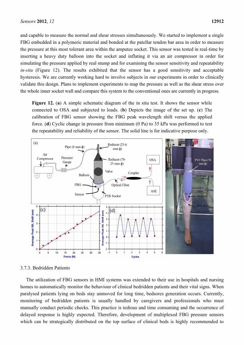
Figure 12. (a) A simple schematic diagram of the in situ test. It shows the sensor while
connected to OSA and subjected to loads. (b) Depicts the image of the set up. (c) The
calibration of FBG sensor showing the FBG peak wavelength shift versus the applied
force. (d) Cyclic change in pressure from minimum (0 Pa) to 35 kPa was performed to test
the repeatability and reliability of the sensor. The solid line is for indicative purpose only.
3.7.3. Bedridden Patients
The utilization of FBG sensors in HMI systems was extended to their use in hospitals and nursing
homes to automatically monitor the behaviour of clinical bedridden patients and their vital signs. When
paralysed patients lying on beds stay unmoved for long time, bedsores generation occurs. Currently,
monitoring of bedridden patients is usually handled by caregivers and professionals who must
manually conduct periodic checks. This practice is tedious and time consuming and the occurrence of
delayed response is highly expected. Therefore, development of multiplexed FBG pressure sensors
which can be strategically distributed on the top surface of clinical beds is highly recommended to
Sensors 2012, 12 12913
continuously monitor the patients sleeping and sitting pattern and to alert the nurse to help move the
patient‘s body when unmoved for long time, in order to prevent bedsore generation.
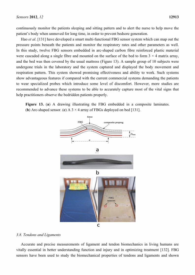
Hao et al. [131] have developed a smart multi-functional FBG sensor system which can map out the
pressure points beneath the patients and monitor the respiratory rates and other parameters as well.
In this study, twelve FBG sensors embedded in arc-shaped carbon fibre reinforced plastic material
were cascaded along a single fibre and mounted on the surface of the bed to form 3 × 4 matrix array,
and the bed was then covered by the usual mattress (Figure 13). A sample group of 10 subjects were
undergone trials in the laboratory and the system captured and displayed the body movement and
respiration pattern. This system showed promising effectiveness and ability to work. Such systems
show advantageous features if compared with the current commercial systems demanding the patients
to wear specialized probes which introduce some level of discomfort. However, more studies are
recommended to advance these systems to be able to accurately capture most of the vital signs that
help practitioners observe the bedridden patients properly.
Figure 13. (a) A drawing illustrating the FBG embedded in a composite laminates.
(b) Arc-shaped sensor. (c) A 3 × 4 array of FBGs deployed on bed [131].
3.8. Tendons and Ligaments
Accurate and precise measurements of ligament and tendon biomechanics in living humans are
vitally essential in better understanding function and injury and in optimizing treatment [132]. FBG
sensors have been used to study the biomechanical properties of tendons and ligaments and shown
Sensors 2012, 12 12914
encouraging results. Vilimek proposed the use of FBG sensors to investigate the in vitro biomechanical
properties of porcine tendons using a tensile machine (MTS Minibionix) in vertical orientation [133].
The FBG sensor was crosswise included by grouting point into the tendon whose ends were attached to
the actuator using the freeze clamping technique. The sensor was repeatedly loaded and unloaded in
steps using the MTS and the measurement was run until the tendon was destructed. In all of the trials,
the measured forces by MTS and measured signals from FBG sensor give the same proportional changes
and it is possible to estimate the loading force. The FBG sensors were more sensitive and accurate than
other fibre-optic methods based on decrement of light properties during pressing change of cross section
size. This approach is suitable for in vivo measurement of a musculotendon forces in humans for
validation the muscle force computational models because the injury after application is minor.
Ren et al. proposed a FBG-based displacement sensor for monitoring strains developed in tendons
and ligaments in different postures and in locomotion, and then compared the obtained results to those
obtained using traditional camera displacement sensors [134]. The FBG was embedded in a
micro-shape-memory-alloy tube which was then placed on an Achilles tendon surface extracted from
human cadaver and the whole system was mounted on a material testing device for loading test. After
sensor calibration in the laboratory, the performance of the FBG sensors and traditional camera
displacement sensors was compared. Additional experiments were performed in cadaveric knees to
assess the feasibility of the FBG sensors to measure ligament deformation in a variety of simulated
postures. The results demonstrate that the proposed FBG sensor is a highly accurate, easily
implantable, and minimally invasive method of measuring tendon and ligament displacement as
compared to the traditional measurement methods.
3.9. Human Body kinematics
The monitoring of different human body kinematics and the analysis of posture and gesture are
crucial in bioengineering and rehabilitation. It aims at improving athletic performance in competitions
and at evaluating frequently the patients undergoing therapeutic treatments to know the efficiency of
the prescribed therapy. Several systems have been previously proposed for monitoring human body
kinematics [135–139], however, they all are not able to withstand some specific environments like
chemical solutions, electromagnetic noise and high temperature, among other [140].
Recently, a research group based in Portugal has proposed a smart skin polymeric foil based on
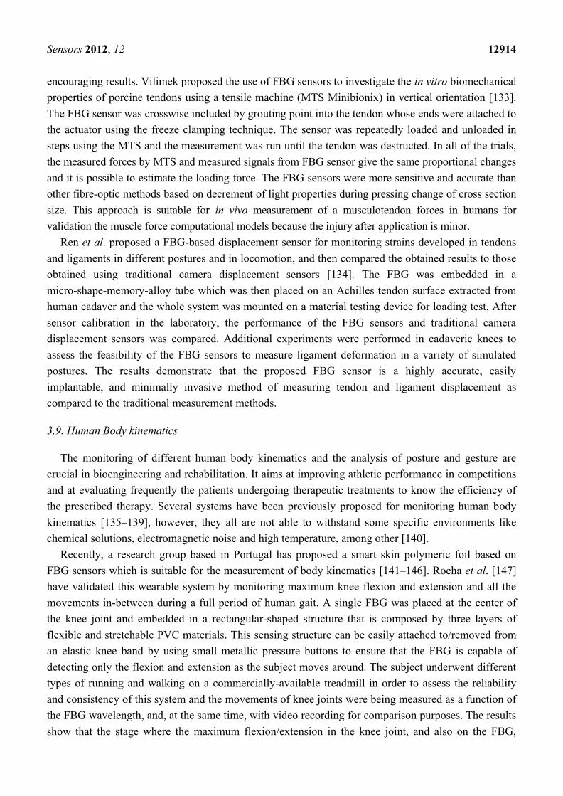
FBG sensors which is suitable for the measurement of body kinematics [141–146]. Rocha et al. [147]
have validated this wearable system by monitoring maximum knee flexion and extension and all the
movements in-between during a full period of human gait. A single FBG was placed at the center of
the knee joint and embedded in a rectangular-shaped structure that is composed by three layers of
flexible and stretchable PVC materials. This sensing structure can be easily attached to/removed from
an elastic knee band by using small metallic pressure buttons to ensure that the FBG is capable of
detecting only the flexion and extension as the subject moves around. The subject underwent different
types of running and walking on a commercially-available treadmill in order to assess the reliability
and consistency of this system and the movements of knee joints were being measured as a function of
the FBG wavelength, and, at the same time, with video recording for comparison purposes. The results
show that the stage where the maximum flexion/extension in the knee joint, and also on the FBG,
Sensors 2012, 12 12915
represents the maximum/minimum wavelength values as depicted in Figure 14(a,b). This sensing
structure shows a good sensitivity to accurately measure the knee flexion/extension during the walking
and running tests and is able to be used for any joint in human body. This FBG-based PVC foil opens
up the road for many applications in biomechanics and other arenas.
Figure 14. The wavelength values for a walking at 4 km/h. (a) and (b) show the minimum
and maximum deflections of the FBG, respectively [147].
The monitoring of hand gesture and posture of brain stroke patients is of interest in rehabilitation
engineering in order to assess the hand ability to perform action in a proper manner during therapeutic
sessions. Several wearable glove systems using different approaches have been proposed [148–152],
but demonstrated some concerns [153]. Silva et al. have designed a wearable sensing glove based on
FBGs in order to enable the measurement of angles between the finger phalanxes and to overcome the
limitations presented by other previously reported methods [153]. Fourteen FBGs accommodated in a
single optical fiber were strategically placed in a curvilinear layout and embedded in the middle layer
of a flexible PVC foil cut into the hand shape so that each FBG would be positioned over each of the
14 phalanx joints present in a single hand. Thereafter this customized hand-shaped sensing foil was
sewed to the upper face of a standard fabric glove (Figure15(a)) to guarantee that every FBG is
positioned in its intended place throughout the experiments. Tests to evaluate the FBGs performance
and functionality according to hand flexion and extension were performed. The sensor exhibited a
sinusoid-like response (Figure 15(b), left) where the positive and negative limits represent the hand
closing and opening actions, respectively. It is possible to estimate the strength from which the 1 nm
wavelength shift resulted from an applied load of 7.8 N, leading to retrieve information about joint
angles. A comparison between the real and measured angles produced a linear fit, representing the
system accuracy with R-square of 0.99929 and a slope of 0.99869 (Figure 15(b), right). In the second
part of this study, a hand motion capture system based in a 3-D virtual model of the hand was built
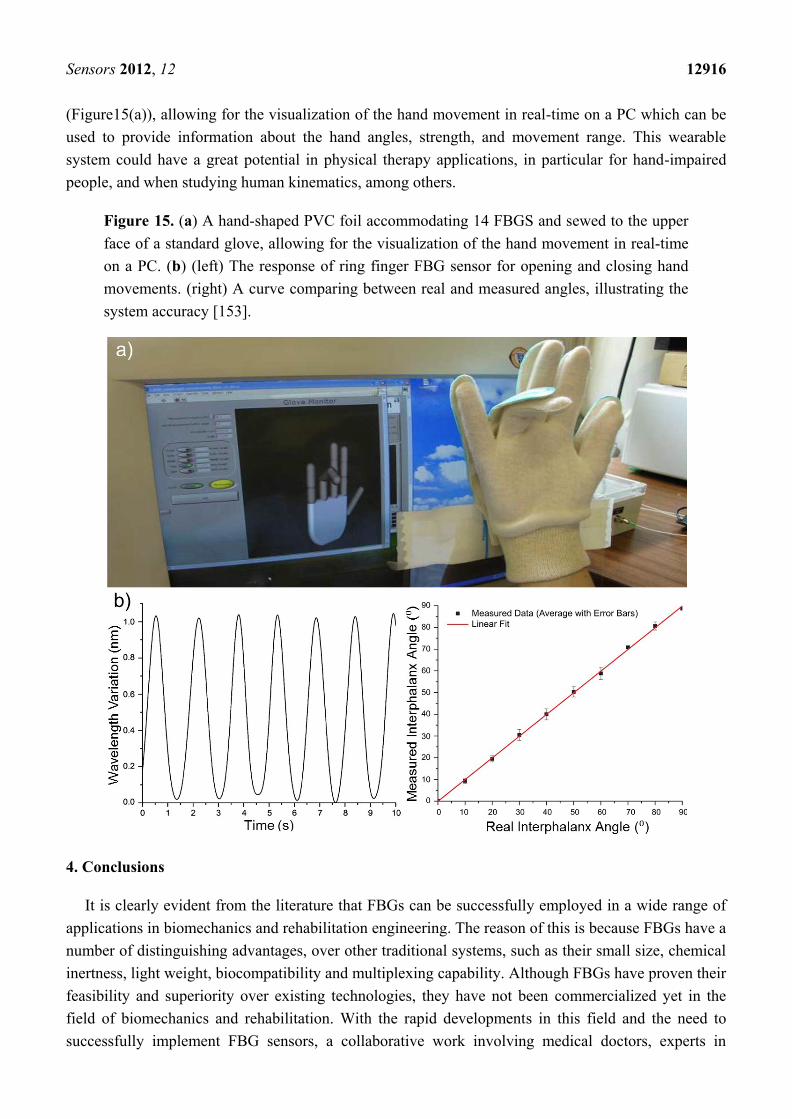
Sensors 2012, 12 12916
(Figure15(a)), allowing for the visualization of the hand movement in real-time on a PC which can be
used to provide information about the hand angles, strength, and movement range. This wearable
system could have a great potential in physical therapy applications, in particular for hand-impaired
people, and when studying human kinematics, among others.
Figure 15. (a) A hand-shaped PVC foil accommodating 14 FBGS and sewed to the upper
face of a standard glove, allowing for the visualization of the hand movement in real-time
on a PC. (b) (left) The response of ring finger FBG sensor for opening and closing hand
movements. (right) A curve comparing between real and measured angles, illustrating the
system accuracy [153].
4. Conclusions
It is clearly evident from the literature that FBGs can be successfully employed in a wide range of
applications in biomechanics and rehabilitation engineering. The reason of this is because FBGs have a
number of distinguishing advantages, over other traditional systems, such as their small size, chemical
inertness, light weight, biocompatibility and multiplexing capability. Although FBGs have proven their
feasibility and superiority over existing technologies, they have not been commercialized yet in the
field of biomechanics and rehabilitation. With the rapid developments in this field and the need to
successfully implement FBG sensors, a collaborative work involving medical doctors, experts in
Sensors 2012, 12 12917
fiber-optics and programming engineers must take place in order to establish the practicality of this
technology, taking into consideration that FBG sensors must be user-friendly, cheap in cost, and
easy-to-use products so as to satisfy the requirements of medical doctors and end users as well. Very
recently, portable interrogation systems with high-speed data acquisition (up to 5,000 Hz) were made
available, leading to broadened research areas and finding new niche applications. This article is a
comprehensive review that covers all the possible uses of FBG sensors and the ongoing researches
worldwide in biomechanics and rehabilitation engineering. It also exposes the superior advantages of
FBGs when compared to the other existing technologies. It is believed that FBG sensors will
undoubtedly have a major role in the future and provide effective solutions for a wide variety of
applications in biomechanics and rehabilitation engineering.
Acknowledgments
This work was jointly supported by UM/MOHE/HIR Grants, Projects No. (D000014-16001) and
(A000007-50001).
References
1. Dennison, C.R.; Wild, P.M.; Wilson, D.R.; Cripton, P.A. A minimally invasive in-fiber Bragg
grating sensor for intervertebral disc pressure measurements. Meas. Sci. Technol. 2008, 19, 085201.
2. Mihailov, S.J. Fiber Bragg grating sensors for harsh environments. Sensors 2012, 12, 1898–1918.
3. Mishra, V.; Singh, N.; Tiwari, U.; Kapur, P. Fiber grating sensors in medicine: Current and
emerging applications. Sensor. Actuator. A Phys. 2011, 167, 279–290.
4. Spillman, W.B., Jr. Fiber Optic Sensors: An Introduction for Engineers and Scientists, 2nd ed.;
Wiley: New York, NY, USA, 2011.
5. Kersey, A.D.; Davis, M.A.; Patrick, H.J.; LeBlanc, M.; Koo, K.; Askins, C.; Putnam, M.;
Friebele, E.J. Fiber grating sensors. J. Lightwave Technol. 1997, 15, 1442–1463.
6. Cheng, S.; Zhang, Y. Application of fiber grating sensor for oil leak detection in oil industry.
Appl. Opt. 2008, 29 , 441–443.
7. Hassan, M.; Tamchek, N.; Abas, A.; Johar, R.; Adikan, F. Dual-phase sensing for early detection
of prepreg structural failures via etched cladding Bragg grating. Sensor. Actuator. A Phys. 2011,
171, 126–130.
8. Schizas, C.; Stutz, S.; Botsis, J.; Coric, D. Monitoring of non-homogeneous strains in composites
with embedded wavelength multiplexed fiber Bragg gratings: A methodological study. Compos.
Struct. 2012, 94 , 987–994.
9. Zhao, Y.; Zhao, Y.; Zhao, M. Novel force sensor based on a couple of fiber Bragg gratings.
Measurement 2005, 38, 30–33.
10. Urban, F.; Kadlec, J.; Vlach, R.; Kuchta, R. Design of a pressure sensor based on optical fiber
bragg grating lateral deformation. Sensors 2010, 10, 11212–11225.
11. Ng, J.H.; Zhou, X.; Yang, X.; Hao, J. A simple temperature-insensitive fiber Bragg grating
displacement sensor. Opt. Commun. 2007, 273, 398–401.
12. Zhan, Y.; Xue, S.; Yang, Q.; Xiang, S.; He, H.; Zhu, R. A novel fiber Bragg grating
high-temperature sensor. Optik 2008, 119, 535–539.

Sensors 2012, 12 12918
13. Yeo, T.L.; Sun, T.; Grattan, K.T.V.; Parry, D.; Lade, R.; Powell, B.D. Characterisation of a
polymer-coated fibre Bragg grating sensor for relative humidity sensing. Sensor. Actuator. B
Chem. 2005, 110, 148–156.
14. Fernandez Fernandez, A.; Brichard, B.; Berghmans, F.; Decreton, M. Dose-rate dependencies in
gamma-irradiated fiber Bragg grating filters. IEEE Trans. Nucl. Sci. 2002, 49, 2874–2878.
15. Kalinowski, H.J. Fibre Bragg grating applications in Biomechanics. Proc. SPIE 2008, 7004,
700430.
16. Yan, C.; Ferraris, E.; Reynaerts, D. A pressure sensing sheet based on optical fibre technology.
Procedia Eng. 2011, 25, 495–498.
17. Luyckx, G.; Voet, E.; Lammens, N.; Degrieck, J. Strain measurements of composite laminates
with embedded fibre Bragg gratings: Criticism and opportunities for research. Sensors 2011, 11,
384–408.
18. Yan, C.; Ferraris, E.; Geernaert, T.; Berghmans, F.; Reynaerts, D. Development of flexible
pressure sensing polymer foils based on embedded fibre Bragg grating sensors. Procedia Eng.
2010, 5, 272–275.
19. Chen, Y.C.; Hsieh, C.C.; Lin, C.C. Strain measurement for composite tubes using embedded,
fiber Bragg grating sensor. Sensor. Actuator. A Phys. 2011. 167, 63–69.
20. Frieden, J.; Cugnoni, J.; Botsis, J.; Gmür, T.; Coric, D. High-speed internal strain measurements
in composite structures under dynamic load using embedded FBG sensors. Compos. Struct. 2010,
92, 1905–1912.
21. Kashyap, R. Fiber Bragg Gratings. 2nd ed.; Academic Press: Burlington, MA, USA, 2010.
22. Othonos, A.; Kalli, K. Fiber Bragg Gratings: Fundamentals and Applications in
Telecommunications and Sensing; Artech House: Norwood, MA, USA, 1999.
23. Rodrigues, C.; Félix, C.; Lage, A.; Figueiras, J. Development of a long-term monitoring system
based on FBG sensors applied to concrete bridges. Eng. Struct. 2010, 32, 1993–2002.
24. Tjin, S.; Suresh, R.; Ngo, N. Fiber Bragg grating based shear-force sensor: Modeling and testing.
J. Lightwave Technol. 2004, 22, 1728–1733.
25. Zhang, W.; Li, F.; Liu, Y. FBG pressure sensor based on the double shell cylinder with
temperature compensation. Measurement 2009, 42, 408–411.
26. Fresvig, T.; Ludvigsen, P.; Steen, H.; Reikerås, O. Fibre optic Bragg grating sensors: An alternative
method to strain gauges for measuring deformation in bone. Med. Eng. Phys. 2008, 30, 104–108.
27. Milgrom, C.; Finestone, A.; Segev, S.; Olin, C.; Arndt, T.; Ekenman, I. Are overground or treadmill
runners more likely to sustain tibial stress fracture? Brit. J. Sport. Med. 2003, 37, 160–163.
28. Milgrom, C.; Finestone, A.; Simkin, A.; Ekenman, I.; Mendelson, S.; Millgram, M.; Nyska, M.;
Larsson, E.; Burr, D. In vivo strain measurements to evaluate the strengthening potential of
exercises on the tibial bone. J. Bone Joint Surg. Brit.Vol. 2000, 82, 591–594.
29. Carlisle, E.M. Silicon: A possible factor in bone calcification. Science 1970, 167, 279–280.
30. Talaia, P.; Ramos, A.; Abe, I.; Schiller, M.; Lopes, P.; Nogueira, R.; Pinto, J.; Claramunt, R.;
Simões, J. Plated and intact femur strains in fracture fixation using fiber Bragg gratings and
strain gauges. Exp. Mech. 2007, 47, 355–363.
31. Mishra, V.; Singh, N.; Rai, D.; Tiwari, U.; Poddar, G.; Jain, S.; Mondal, S.; Kapur, P. Fiber Bragg
grating sensor for monitoring bone decalcification. Orthop. Traumatol. Sur. 2010, 96, 646–651.
Sensors 2012, 12 12919
32. Carvalho, L.; Alberto, N.J.; Gomes, P.S.; Nogueira, R.N.; Pinto, J.L.; Fernandes, M.H. In the
trail of a new bio-sensor for measuring strain in bone: Osteoblastic biocompatibility. Biosens.
Bioelectron. 2011, 26, 4046–4052.
33. Reikeras, O.; Aarnes, G.T.; Steen, H.; Ludvigsen, P.; Sagvolden, G. Differences in external and
internal cortical strain with prosthesis in the femur. Open J. Orthopedics 2011, 5, 379–384.
34. Completo, A.; Fonseca, F.; Relvas, C.; Ramos, A.; Simões, J. Improved stability with
intramedullary stem after anterior femoral notching in total knee arthroplasty. Knee Surg. Sports
Traumatol. Arthrosc. 2012, 20, 487–494.
35. Hirsh, D.; Bhalla, S.; Roffman, M. Supracondylar fracture of the femur following total knee
replacement. Report of four cases. J. Bone Joint Surg. Amer.Vol. 1981, 63, 162–163.
36. Mann, K.A.; Gupta, S.; Race, A.; Miller, M.A.; Cleary, R.J.; Ayers, D.C. Cement microcracks in
thin-mantle regions after in vitro fatigue loading. J. Arthroplasty 2004, 19, 605–612.
37. Stolk, J.; Verdonschot, N.; Cristofolini, L.; Toni, A.; Huiskes, R. Finite element and experimental
models of cemented hip joint reconstructions can produce similar bone and cement strains in pre-
clinical tests. J. Biomech. 2002, 3, 499–510.
38. Ramos, A.; Abe, I.; Schiller, M.; Lopes, P.; Nogueira, R.; Pinto, J.; Simões, J. On the use of fiber
bragg sensors to assess temperature and thermal induce strain profiles in cemented hip mantles.
J. Biomech. 2006, 39, S514.
39. Frias, C.; Frazão, O.; Tavares, S.; Vieira, A.; Marques, A.; Simões, J. Mechanical characterization
of bone cement using fiber Bragg grating sensors. Mater. Design 2009, 30, 1841–1844.
40. Harris, M.; Morberg, P.; Bruce, W.; Walsh, W. An improved method for measuring tibiofemoral
contact areas in total knee arthroplasty: a comparison of K-scan sensor and Fuji film. J. Biomech.
1999, 32, 951–958.
41. Kdolsky, R.; Arabid, B.; Fuchs, M.; Schabus, R.; Vécsei, V. Measuring the pressure pattern of
the joint surface in the uninjured knee. Wien. Klin. Wochenschr. 2004, 116, 196–200.
42. D‘Lima, D.D.; Townsend, C.P.; Arms, S.W.; Morris, B.A.; Colwell, C.W., Jr. An implantable
telemetry device to measure intra-articular tibial forces. J. Biomech. 2005, 38, 299–304.
43. Drewniak, E.I.; Crisco, J.J.; Spenciner, D.B.; Fleming, B.C. Accuracy of circular contact area
measurements with thin-film pressure sensors. J. Biomech. 2007, 40, 2569–2572.
44. Mohanty, L.; Tjin, S.C. Pressure mapping at orthopaedic joint interfaces with fiber Bragg
gratings. Appl. Phys. Lett. 2006, 88, 083901.
45. Mohanty, L.; Tjin, S.C.; Lie, D.T.T.; Panganiban, S.E.C.; Chow, P.K.H. Fiber grating sensor for
pressure mapping during total knee arthroplasty. Sensor. Actuator. A Phys. 2007, 135, 323–328.
46. Anderson, A.E.; Ellis, B.J.; Maas, S.A.; Peters, C.L.; Weiss, J.A. Validation of finite element
predictions of cartilage contact pressure in the human hip joint. J. Biomech. Eng. 2008, 130,
051008.
47. Wilson, D.R.; Mc Walter, E.J.; Johnston, J.D. The measurement of joint mechanics and their role
in osteoarthritis genesis and progression. Med. Clin. N. Amer. 2009, 93, 67–82.
48. Dennison, C.R.; Wild, P.M.; Wilson, D.R.; Gilbart, M.K. An in-fiber Bragg grating sensor for
contact force and stress measurements in articular joints. Meas. Sci. Technol. 2010, 21, 115803.
49. Nachemson, A. The load on lumbar disks in different positions of the body. Clin. Orthop.
Related Res. 1966, 45, 107–122.
Sensors 2012, 12 12920
50. Nachemson, A.; Morris, J.M. In vivo measurements of intradiscal pressure discometry, a method
for the determination of pressure in the lower lumbar discs. J. Bone Joint Surg. Amer.Vol. 1964,
46, 1077–1092.
51. Cunningham, B.W.; Kotani, Y.; McNulty, P.S.; Cappuccino, A.; McAfee, P.C. The effect of
spinal destabilization and instrumentation on lumbar intradiscal pressure: An in vitro
biomechanical analysis. Spine 1997, 22, 2655–2663.
52. Nachemson, A. Lumbar intradiscal pressure. Experimental studies on post-mortem material.
Acta Orthop. Scand. 1960, 43, 1–104.
53. Wilke, H.J.; Wolf, S.; Claes, L.E.; Arand, M.; Wiesend, A. Influence of varying muscle forces on
lumbar intradiscal pressure: An in vitro study. J. Biomechan. 1996, 29, 549–555.
54. McNally, D.; Adams, M. Internal intervertebral disc mechanics as revealed by stress
profilometry. Spine 1992, 17, 66–73.
55. Wilke, H.J.; Neef, P.; Caimi, M.; Hoogland, T.; Claes, L.E. New in vivo measurements of
pressures in the intervertebral disc in daily life. Spine 1999, 24, 755–762.
56. Yantzer, B.K.; Freeman, T.B.; Lee, W.E., III; Nichols, T.; Inamasu, J.; Guiot, B.; Johnson, W.M.
Torsion-induced pressure distribution changes in human intervertebral discs: An in vitro study.
Spine 2007, 32, 881–884.
57. Pospiech, J.; Stolke, D.; Wilke, H.J.; Claes, L.E. Intradiscal pressure recordings in the cervical
spine. Neurosurgery 1999, 44, 379–384.
58. Steffen, T.; Baramki, H.G.; Rubin, R.; Antoniou, J.; Aebi, M. Lumbar intradiscal pressure
measured in the anterior and posterolateral annular regions during asymmetrical loading.
Clin. Biomech. 1998, 13, 495–505.
59. Hattori, S.; Oda, H.; Kawai, S. Cervical intradiscal pressure in movements and traction of the
cervical spine. Z Orthop. 1981, 119, 568–569.
60. Cripton, P.; Dumas, G.; Nolte, L.P. A minimally disruptive technique for measuring intervertebral
disc pressure in vitro: Application to the cervical spine. J. Biomech. 2001, 34, 545–549.
61. Seo, K.S.; Derby, R.; Date, E.S.; Lee, S.H.; Kim, B.J.; Lee, C.H. In vitro measurement of
pressure differences using manometry at various injection speeds during discography. Spine J.
2007, 7, 68–73.
62. Dennison, C.R.; Wild, P.M.; Dvorak, M.F.; Wilson, D.R.; Cripton, P.A. Validation of a novel
minimally invasive intervertebral disc pressure sensor utilizing in-fiber Bragg gratings in a
porcine model: An ex vivo study. Spine 2008, 33, E589–E594.
63. Dennison, C.R.; Wild, P.M.; Byrnes, P.W.G.; Saari, A.; Itshayek, E.; Wilson, D.C.; Zhu, Q.A.;
Dvorak, M.F.S.; Cripton, P.A.; Wilson, D.R. Ex vivo measurement of lumbar intervertebral disc
pressure using fibre-Bragg gratings. J. Biomech. 2008, 41, 221–225.
64. Wild, P.M.; Dennison, C.R. Pressure Sensor for Biological Fluids and Use Thereof. U.S. Patent
070213, 2007.
65. Roriz, P.; Abe, I.; Schiller, M.; Gabriel, J.; Simões, J. Ex vivo intervertebral disc bulging
measurement using a fibre bragg grating sensor. Exp. Mech. 2011, 51, 1573–1577.
66. Tjin, S.; Tan, Y.; Yow, M.; Lam, Y.Z.; Hao, J. Recording compliance of dental splint use in
obstructive sleep apnoea patients by force and temperature modelling. Med. Biol. Eng. Comput.
2001, 39, 182–184.
Sensors 2012, 12 12921
67. Ottevaere, H.; Tabak, M.; Aznar, D.; Fernandez, A.; Van Ierschot, S.; Berghmans, F.; Thienpont, H.
Optical Fiber Sensors for Monitoring Stress Build-Up in Dental Cements. In Proceedings of the
16th International Conference on Optical Fibre Sensors, Nara, Japan, 13–17 October 2003.
68. Ottevaere, H.; Tabak, M.; Fernandez, A.F.; Berghmans, F.; Thienpont, H. Optical fiber sensors
and their application in monitoring stress build-up in dental resin cements. Proc. SPIE 2005,
5952, 204–216.
69. Fernandez, A.; Ottevaere, H.; Van Ierschot, C.; Panajatov, K.; Berghmans, F.; Thienpont, H.
Multi-Parameter Force Sensing with Fiber Bragg Grating Sensors. In Proceedings of the 2002
Symposium of the IEEE/LEOS Benelux Chapter, Amsterdam, The Netherlands, 9 December
2002; pp. 139–144.
70. Milczewski, M.; da Silva, J.; Abe, I.; Carvalho, L.; Nogueira, R.; Paterno, A.; Kalinowski, H.;
Pinto, J. Determination of setting expansion of dental materials using fibre optical sensing. Meas.
Sci. Technol. 2006, 17, 1152–1156.
71. Carvalho, L.; Vaz, M.; Simões, J. Mandibular strains induced by conventional and novel dental
implants. J. Strain Anal. Eng. Design 2004, 39, 291–297.
72. Carvalho, L.; Vaz, M.; Simões, J. Determination of strains due to impact loads on an implanted
cadaveric mandible. Acta Bioeng. Biomed. 2003, 4, 801–802.
73. Kalinowski, H.; Simoes, J.; Pinto, J.; Carvalho, L.; Nogueira, R.; Silva, J.; Milczewski, M.
Probing Dental Biomechanics with Fibre Bragg Grating Sensors. In Proceedings of the 7th
International Conference on Optoelectronics, Fiber Optics & Photonics, Cochin, India, 9–11
December 2004.
74. Silva, J.C.C.; Carvalho, L.; Nogueira, R.N.; Simoes, J.A.; Pinto, J.L.; Kalinowski, H.J. FBG
applied in dynamic analysis of an implanted cadaveric mandible. Proc. SPIE 2004, 5502, 226–229.
75. Carvalho, L.; Silva, J.C.C.; Nogueira, R.; Pinto, J.; Kalinowski, H.; Simúes, J. Application of
Bragg grating sensors in dental biomechanics. J. Strain Anal. Eng. Design 2006, 41, 411–416.
76. Silva, J.; Ramos, A.; Carvalho, L.; Nogueira, R.; Ballu, A.; Mesnard, M.; Pinto, J.;
Kalinowski, H.J.; Simoes, J. Fibre Bragg grating sensing and finite element analysis of the
biomechanics of the mandible. Proc. SPIE 2005, 5855,102–105.
77. Carvalho, P.; Abe, I.; Schiller, M.; Carvalho, L.; Simões, J.; Lopes, P.; Pinto, J. FEA and
experimental FBG sensing system for the analysis of different dental implant concepts.
J. Biomech. 2006, 39, S568–S568.
78. Schiller, M.W.; Abe, I.; Carvalho, P.; Lopes, P.; Carvalho, L.; Nogueira, R.N.; Pinto, J.L.;
Simões, J. A. On the Use of FBG Sensors to Assess the Performance of a Dental Implant System.
In Proceedings of the 18th International Conference on Optical Fibre Sensors, Cancún, México,
23–27 October 2006.
79. Milczeswki, M.; Silva, J.; Abe, I.; Simões, J.; Paterno, A.; Kalinowski, H. Measuring
Orthodontic Forces with HiBi FBG Sensors. In Proceedings of the 18th International Conference
on Optical Fibre Sensors, Cancún, México, 23–27 October 2006.
80. Milczewski, M.S.; Kalinowski, H.J.; Da Silva, J.C.C.; Abe, I.; Simões, J.A.; Saga, A. Stress
monitoring in a maxilla model and dentition. Proc. SPIE 2011, 7753, 77534V.
Sensors 2012, 12 12922
81. Tiwari, U.; Mishra, V.; Bhalla, A.; Singh, N.; Jain, S.C.; Garg, H.; Raviprakash, S.; Grewal, N.;
Kapur, P. Fiber Bragg grating sensor for measurement of impact absorption capability of
mouthguards. Dent. Traumatol. 2011, 27, 263–268.
82. Massagram, W.; Lubecke, V.M.; Boric-Lubecke, O. Microwave Non-Invasive Sensing of
Respiratory Tidal Volume. In Proceedings of the 31th Annual International Conference of the
IEEE Engineering in Medicine and Biology Society, Minneapolis, USA, 3–6 September 2009;
pp. 4832–4835.
83. Bai, Y.W.; Li, W.T.; Chen, Y.W. Design and Implementation of an Embedded Monitor System
for Detection of a Patient‘s Breath by Double Webcams. In Proceedings of the 2010 IEEE
International Workshop on Medical Measurements and Applications, Ottawa, ON, Canada, 30
April–1 May 2010; pp. 171–176.
84. Babchenko, A.; Khanokh, B.; Shomer, Y.; Nitzan, M. Fiber optic sensor for the measurement of
the respiratory chest circumference changes. J. Biomed. Opt. 1999, 4, 224–229.
85. Wehrle, G.; Nohama, P.; Kalinowski, H.J.; Torres, P.I.; Valente, L.C.G. A fibre optic Bragg
grating strain sensor for monitoring ventilatory movements. Meas. Sci. Technol. 2001, 12, 805–809.
86. Marculescu, D.; Marculescu, R.; Park, S.; Jayaraman, S. Ready to ware. IEEE Spectr. 2003, 40,
28–32.
87. Grillet, A.; Kinet, D.; Witt, J.; Schukar, M.; Krebber, K.; Pirotte, F.; Depré, A. Optical fiber
sensors embedded into medical textiles for healthcare monitoring. IEEE Sens. J. 2008, 8, 1215–1222.
88. Optical Fibre Sensors Embedded into Technical Textile for Healthcare. Available online:
www.ofseth.org (accessed on 12 July 2012).
89. De jonckheere, J.; Jeanne, M.; Grillet, A.; Weber, S.; Chaud, P.; Logier, R.; Weber, J. OFSETH:
Optical Fibre Embedded into Technical Textile for Healthcare, an Efficient Way to Monitor
Patient under Magnetic Resonance Imaging. In Proceedings of the 29th Annual International
Conference of the IEEE Engineering in Medicine and Biology Society, Lyon, France, 22–26
August 2007; pp. 3950–3953.
90. Narbonneau, F.; Kinet, D.; Paquet, B.; Depré, A.; de Jonckheere, J.; Logier, R.; Zinke, J.;
Witt, J.; Krebber, K. Smart Textile Embedding Optical Fibre Sensors for Healthcare Monitoring
during MRI. Adv. Sci. Technol. 2009, 60, 134–143.
91. De jonckheere, J.; Jeanne, M.; Narbonneau, F.; Witt, J.; Paquet, B.; Kinet, D.; Kreber, K.;
Logier, R. OFSETH: A Breathing Motions Monitoring System for Patients under MRI. In
Proceedings of the 32th Annual International Conference of the IEEE Engineering in Medicine
and Biology Society, Buenos Aires, Argentina, 31 August–4 September 2010, pp. 1016–1019.
92. De jonckheere, J.; Narbonneau, F.; Jeanne, M.; Kinet, D.; Witt, J.; Krebber, K.; Paquet, B.;
Depre, A.; Logier, R. OFSETH: Smart Medical Textile for Continuous Monitoring of
Respiratory Motions under Magnetic Resonance Imaging. In Proceedings of the 31th Annual
International Conference of the IEEE Engineering in Medicine and Biology Society,
Minneapolis, USA, 3–6 September 2009; pp. 1473–1476.
93. De Jonckheere, J.; Narbonneau, F.; D‘Angelo, L.T.; Witt, J.; Paquet, B.; Kinet, D.; Kreber, K.;
Logier, R. FBG-Based Smart Textiles for Continuous Monitoring of Respiratory Movements for
Healthcare Applications. In Proceedings of the 12th IEEE International Conference on e-Health
Networking Applications and Services (Healthcom), Lyon, France, 1–3 July 2010; pp. 277–282.
Sensors 2012, 12 12923
94. Davis, C.; Mazzolini, A.; Mills, J.; Dargaville, P. A new sensor for monitoring chest wall motion
during high-frequency oscillatory ventilation. Med. Eng. Phys. 1999, 21, 619–623.
95. Augousti, A.; Maletras, F.; Mason, J. Improved fibre optic respiratory monitoring using a
figure-of-eight coil. Physiol. Meas. 2005, 26, 585–590.
96. Dziuda, L.; Skibniewski, F.; Rozanowski, K.; Krej, M.; Lewandowski, J. Fiber-Optic Sensor for
Monitoring Respiration and Cardiac Activity. In Proceedings of the 2011 IEEE Sensors
Conference, Limerick, UK, 28–31 October 2011; pp. 413–416.
97. Gurkan, D.; Starodubov, D.; Yuan, X. Monitoring of the Heartbeat Sounds Using an Optical
Fiber Bragg Grating Sensor. In Proceedings of the 2005 IEEE Sensors Conference, Irvine, CA,
USA, 30 October–3 November 2005; pp. 306–309.
98. Silva, A.F.; Carmo, J.P.; Mendes, P.M.; Correia, J.H. Simultaneous cardiac and respiratory
frequency measurement based on a single fiber Bragg grating sensor. Meas. Sci. Technol. 2011,
22, 075801.
99. Kawamura, M.; Ishizawa, H.; Sato, S.; Koyama, S. Application to Vital Signs by Fiber Bragg
Grating Sensing. In Proceedings of SICE Annual Conference (SICE), Nagano, Japan,
13–18 September 2011; pp. 2702–2704.
100. Carmo, J.; Ferreira da Silva, A.; Rocha, R.; Correia, H. Application of fiber bragg gratings to
wearable garments. IEEE Sens. J. 2012, 12, 261–266.
101. D‘Angelo, L.T.; Weber, S.; Honda, Y.; Thiel, T.; Narbonneau, F.; Luth, T.C. A System for
Respiratory Motion Detection Using Optical Fibers Embedded into Textiles. In Proceedings of
the 30th Annual International Conference of the IEEE Engineering in Medicine and Biology
Society, Vancouver, BC, Canada, 20–25 August 2008; pp. 3694–3697.
102. Xu, X.B.; Zhang, C.X.; Hou, K.M.; Ding, H.; Diao, X.M. A New Wireless Fiber Optic Sensor
for Monitoring Breath Motion. In Proceedings of IEEE Conference on New Technologies,
Mobility and Security (NTMS), Tangier, Morocco, 5–7 November 2008; pp. 1–5.
103. Pleros, N.; Kanellos, G.T.; Papaioannou, G. Optical Fiber Sensors in Orthopedic Biomechanics
and Rehabilitation. In Proceedings of the 9th International Conference on Information Technology
and Applications in Biomedicine (ITAB), Larnaca, Cyprus, 4–7 November. 2009, pp. 1–4.
104. IASIS Project Description. Available online: http://www.iasis-project.eu (accessed on 12 July 2012).
105. Kanellos, G.T.; Tsiokos, D.; Pleros, N.; Childs, P.; Pissadakis, S. Enhanced Durability
FBG-Based Sensor Pads for Biomedical Applications as Human-Machine Interface Surfaces. In
Proceedings of International Workshop on BioPhotonics, Parma, Italy, 8–10 June 2011; pp. 1–3.
106. Chumanov, E.S.; Remy, C.D.; Thelen, D.G. Tracking the Position of Insole Pressure Sensors
during Walking and Running. In Proceedings of the 30th Annual Meeting of the American
Society of Biomechanics, Palo Alto, CA, USA, 22–25 August 2007.
107. Wertsch, J.J.; Webster, J.G.; Tompkins, W.J. A portable insole plantar pressure measurement
system. J. Rehabil. Res. Dev. 1992, 29, 13–18.
108. Cobb, J.; Claremont, D. Transducers for foot pressure measurement: Survey of recent
developments. Med. Biol. Eng. Comput. 1995, 33, 525–532.
109. El Kati, R.; Forrester, S.; Fleming, P. Evaluation of pressure insoles during running. Procedia
Eng. 2010, 2, 3053–3058.
Sensors 2012, 12 12924
110. Tappin, J.; Pollard, J.; Beckett, E. Method of measuring ‗shearing‘forces on the sole of the foot.
Clinical Phys. Physiol. Meas. 1980, 1, 83.
111. Lord, M.; Hosein, R.; Williams, R.B. Method for in-shoe shear stress measurement. J. Biomed.
Eng. 1992, 14, 181–186.
112. Hao, J.Z.; Tan, K.M.; Tjin, S.C.; Liaw, C.Y.; Chaudhuri, P.R.; Guo, X.; Lu, C. Design of a
Foot-Pressure Monitoring Transducer for Diabetic Patients Based on FBG Sensors. In
Proceedings of the 16th Annual Meeting of the IEEE Lasers and Electro-Optics Society, Tucson,
AZ, USA, 27–28 October 2003; pp. 23–24
113. Wang, W.; Ledoux, W.R.; Sangeorzan, B.J.; Reinhall, P.G. A shear and plantar pressure sensor
based on fiber-optic bend loss. J. Rehabil. Res. Dev. 2005, 42, 315–325.
114. Lim, T.K.; Tjin, C.S.; Tay, L.; Chua, C.; Wang, Y.; Brownjohn, J.M.W. Measurement of contact
forces between human and vibrating floors using fiber Bragg grating foot sensors. Proc. SPIE
2005, 4235, 161–172.
115. Lebar, A.M.; Harris, G.F.; Wertsch, J.J.; Zhu, H. Development of a Miniature Plantar Shear
Force Sensing Transducer. In Proceedings of the 15th Annual International Conference of the
IEEE Engineering in Medicine and Biology Society, San Diego, CA, USA, 28 – 31 October
1993, pp. 989–990.
116. Akhlaghi, F.; Pepper, M. In-shoe biaxial shear force measurement: The Kent shear system. Med.
Biol. Eng. Comput. 1996, 34, 315–317.
117. Koulaxouzidis, A.V.; Holmes, M.J.; Roberts, C.V.; Handerek, V.A. A Shear and Vertical Stress
Sensor for Physiological Measurements Using Fibre Bragg Gratings. In Proceedings of the 22th
Annual International Conference of the IEEE Engineering in Medicine and Biology Society,
Chicago, IL, USA, 23–28 July 2000, pp. 55–58.
118. Abu Osman, N.A.; Spence, W.D.; Solomonidis, S.E.; Paul, J.P.; Weir, A.M. The patellar tendon
bar! Is it a necessary feature? Med. Eng. Phys. 2010, 32, 760–765.
119. Goh, J.C.H.; Lee, P.V.S.; Chong, S.Y. Comparative study between patellar-tendon-bearing and
pressure cast prosthetic sockets. J. Rehabil. Res. Dev. 2004, 41, 491–502.
120. Abu Osman, N.; Spence, W.; Solomonidis, S.; Paul, J.; Weir, A. Transducers for the
determination of the pressure and shear stress distribution at the stump–socket interface of
trans-tibial amputees. Proc. Inst.Mech. Eng. B J. Eng. Ma. 2010, 224, 1239–1250.
121. Buis, A.; Dumbleton, T.; McHugh, B.; McFadyen, A.; McKay, G.; Murray, K.; Sexton, S.
Dynamic interface pressure distributions of two transtibial prosthetic socket concepts. J. Rehabil.
Res. Dev. 2009, 46, 405–415.
122. Zhang, M.; Roberts, C. Comparison of computational analysis with clinical measurement of
stresses on below-knee residual limb in a prosthetic socket. Med. Eng. Phys. 2000, 22, 607–612.
123. Portnoy, S.; Yarnitzky, G.; Yizhar, Z.; Kristal, A.; Oppenheim, U.; Siev-Ner, I.; Gefen, A.
Real-time patient-specific finite element analysis of internal stresses in the soft tissues of a
residual limb: A new tool for prosthetic fitting. Ann. Biomed. Eng. 2007, 35, 120–135.
124. Moo, E.K.; Osman, N.A.; Pingguan-Murphy, B.; Abas, W.; Spence, W.D.; Solomonidis, S.E.
Interface pressure profile analysis for patellar tendon-bearing socket and hydrostatic socket.
Acta Bioeng. Biomed. 2009, 11, 37–43.
Sensors 2012, 12 12925
125. Dou, P.; Jia, X.; Suo, S.; Wang, R.; Zhang, M. Pressure distribution at the stump/socket interface
in transtibial amputees during walking on stairs, slope and non-flat road. Clin. Biomech. 2006,
21, 1067–1073.
126. Kanellos, G.T.; Papaioannou, G.; Tsiokos, D.; Mitrogiannis, C.; Nianios, G.; Pleros, N. Two
dimensional polymer-embedded quasi-distributed FBG pressure sensor for biomedical
applications. Opt. Express 2010, 18, 179–186.
127. Papaioannou, G.; Mitrogiannis, C.; Nianios, G.; Fiedler, G. Towards a Novel ―SMART Socket‖
Design for Lower Extremity Amputees. In Proceedings of the HFM Symposium on Use of
Advanced Technologies and New Procedures in Medical Field Operations, Essen, Germany,
19–21 April 2010.
128. Papaioannou, G.; Mitrogiannis, C.; Fiedler, G.; Nianios, G. Assessment of Vacuum-Assisted
Trans-Tibial Amputee Socket Dynamics. In Proceedings of the 9th International Conference on
Information Technology and Applications in Biomedicine, Lamaca, Cyprus, 5–7 November 2009,
pp. 1–4.
129. Center for Applied Biomechanics, University of Malaya. Available online: cab.um.edu.my
(accessed on 12 July 2012).
130. Photonics Research Group, University of Malaya. Available online: photonics.um.edu.my
(accessed on 28 August 2012).
131. Hao, J.; Jayachandran, M.; Kng, P.L.; Foo, S.F.; Aung Aung, P.W.; Cai, Z. FBG-based smart bed
system for healthcare applications. Front. Optoelectron. China 2010, 3, 78–83.
132. Fleming, B.C.; Beynnon, B.D. In vivo measurement of ligament/tendon strains and forces:
A review. Ann. Biomed. Eng. 2004, 32, 318–328.
133. Vilimek, M. Using a fiber Bragg grating sensor for tendon force measurements. J. Biomech.
2008, 41, S511.
134. Ren, L.; Song, G.; Conditt, M.; Noble, P.C.; Li, H. Fiber Bragg grating displacement sensor for
movement measurement of tendons and ligaments. Appl. Opt. 2007, 46, 6867–6871.
135. De Rossi, D.; Lorussi, F.; Mazzoldi, A.; Orsini, P.; Scilingo, E.P. In Monitoring Body Kinematics
and Gesture through Sensing Fabrics; In Proceedings of the 1st Annual International
Conference On Microtechnologies in Medicine and Biology, Lyon, France, 12–14 October 2000;
pp. 587–592.
136. Lorussi, F.; Rocchia, W.; Scilingo, E.P.; Tognetti, A.; De Rossi, D. Wearable, redundant fabric-based
sensor arrays for reconstruction of body segment posture. IEEE Sens. J. 2004, 4, 807–818.
137. Rocha, L.A.; Correia, J.H. Wearable Sensor Network for Body Kinematics Monitoring. In
Proceedings of the 10th IEEE International Symposium on Wearable Computers, Montreux,
Switzerland, 11–14 October 2006; pp. 137–138.
138. Yamamoto, Y. An alternative approach to the acquisition of a complex motor skill: Multiple
movement training on tennis strokes. Int. J. Sport Health Sci. 2004, 2, 169–179.
139. Shany, T.; Redmond, S.J.; Narayanan, M.R.; Lovell, N.H. Sensors-based wearable systems for
monitoring of human movement and falls. IEEE Sens. J. 2012, 12, 658–670.
140. Werner, M.R.; Fahrner, W.R. Review on materials, microsensors, systems and devices for
high-temperature and harsh-environment applications. IEEE Trans. Ind. Electron. 2001, 48,
249–257.
Sensors 2012, 12 12926
141. da Silva, A.F.; Goncalves, A.F.; de Almeida Ferreira, L.A.; Araujo, F.M.M.; Mendes, P.M.;
Correia, J.H. PVC smart sensing foil for advanced strain measurements. IEEE Sens. J. 2010, 10,
1149–1155.
142. Ferreira da Silva, A.; Goncalves, A.F.; de Almeida Ferreira, L.A.; Araujo, F.M.M.;
Mendes, P.M.; Correia, J.H. A smart skin PVC foil based on FBG sensors for monitoring strain
and temperature. IEEE Trans. Ind. Electron. 2011, 58, 2728–2735.
143. Ferreira da Silva, A.; Goncalves, F.; Mateus Mendes, P.; Higino Correia, J. PVC formulation
study for the manufacturing of a skin smart structure based in optical fiber elements. Polym.
Advan. Technol. 2012, 23, 220–227.
144. Silva, A.F.; Mendes, P.M.; Correia, J.H.; Goncalves, F.; Ferreira, L.A.; Araujo, F.M. Smart
Sensing Polymeric Foil with Integrated Optic Fiber Sensors: Fabrication and Characterization of
a Polymeric Foil Sensitive to Strain. In Proceedings of the 3rd International Conference on
Sensor Technologies and Applications, Glyfada, Athens, Greece, 18–23 June 2009; pp. 90–93.
145. Silva, A.F.; Goncalves, F.; Ferreira, L.A.; Araujo, F.M.; Dias, N.S.; Carmo, J.P.; Mendes, P.M.;
Correia, J.H. Manufacturing Technology for Flexible Optical Sensing Foils. In Proceedings of
the 35th Annual Conference of IEEE Industrial Electronics (IECON), Porto, Portugal,
3–5 November 2009; pp. 1883–1886.
146. Silva, A.; Gonçalves, F.; Ferreira, L.A.A.; Araújo, F.M.; Mendes, P.; Correia, J.H. Fiber Bragg
grating sensors integrated in polymeric foils. Mater. Sci. Forum 2010, 636, 1548–1554.
147. Rocha, R.P.; Silva, A.F.; Carmo, J.P.; Correia, J.H. FBG in PVC Foils for Monitoring the Knee
Joint Movement during the Rehabilitation Process. In Proceedings of the 33th Annual
International Conference of the IEEE Engineering in Medicine and Biology Society, Boston,
MA, USA, 30 August–3 September 2011; pp. 458–461.
148. Nishiyama, M.; Watanabe, K. Wearable sensing glove with embedded hetero-core fiber-optic
nerves for unconstrained hand motion capture. IEEE Trans. Instrum. Meas. 2009, 58, 3995–4000.
149. Chin-Shyurng, F.; Herman, S. Development of a data glove with reducing sensors based on
magnetic induction. IEEE Trans. Ind. Electron. 2005, 52, 585–594.
150. Perng, J.K.; Fisher, B.; Hollar, S.; Pister, K.S.J. Acceleration Sensing Glove (ASG). In
Proceedings of the 3rd International Symposium on Wearable Computers, San Francisco, CA,
USA, 18–19 October 1999; pp. 178–180.
151. Enzo Pasquale, S.; Lorussi, F.; Mazzoldi, A.; De Rossi, D. Strain-sensing fabrics for wearable
kinaesthetic-like systems. IEEE Sens. J. 2003, 3, 460–467.
152. Lorussi, F.; Enzo Pasquale, S.; Tesconi, M.; Tognetti, A.; De Rossi, D. Strain sensing fabric for
hand posture and gesture monitoring. IEEE Trans. Inf. Technol. Biomed. 2005, 9, 372–381.
153. da Silva, A.F.; Goncalves, A.F.; Mendes, P.M.; Correia, J.H. FBG sensing glove for monitoring
hand posture. IEEE Sens. J. 2011, 11, 2442–2448.
© 2012 by the authors; licensee MDPI, Basel, Switzerland. This article is an open access article
distributed under the terms and conditions of the Creative Commons Attribution license
(http://creativecommons.org/licenses/by/3.0/).