Optical-Fiber Source of Polarization-Entangled Photons in the 1550 nm Telecom Band
Upload
khangminh22Category
view
6download
0
OPTICAL FIBERS
USPH303 unit 1
1 Mahesh Shetti, Wilson College
Image courtesy of TE Connectivity SubCom

Refraction of light
Snell’s law of
refraction:
Incident ray, refracted
ray and normal to the
surface at the point of
incidence are in the
same plane.
2
Mahesh Shetti, Wilson College
Incident ray Reflected ray
Refracted ray
i
r

Table of typical refractive indices ref: wikipedia.org
Vacuum 1
Gases at 0 °C and 1 atm
Air 1.000293
Helium 1.000036
Hydrogen 1.000132
Carbon dioxide 1.00045
Liquids at 20 °C
Water 1.333
Ethanol 1.36
Olive oil 1.47
Solids
Ice 1.31
Fused silica (quartz) 1.46
Window glass 1.52
Polycarbonate (Lexan™) 1.58
Flint glass (typical) 1.69
Sapphire 1.77
Cubic zirconia 2.15
Diamond 2.42
Moissanite 2.65
3
Mahesh Shetti, Wilson College

When light is incident from denser medium
on the boundary to rarer medium:
in this case, angle of refraction is larger than angle of incidence.
For angle of refraction to be 90, angle of incidence is
This is called critical angle.
If the angle of incidence is greater than this, then there is total internal reflection.
4
Mahesh Shetti, Wilson College
Image Credit: https://physics.stackexchange.com

Real life examples 5
Mahesh Shetti, Wilson College
Highway Mirage Fiber toys – total internal reflection along with optical leakage

Basic structure of optical fiber cable
Optical parts are core and cladding.
Core has greater refractive index than cladding.
Outer jackets are mainly to give mechanical strength to the optical fiber.
It also protects fiber from chemical erosion.
6
Mahesh Shetti, Wilson College Image: https://www.pinterest.com

Numerical aperture
There is a maximum angle of incidence max that ensures light
to remain inside the optical fiber.
7
Mahesh Shetti, Wilson College

Calculation
Mahesh Shetti, Wilson College
8
Find the numerical aperture for an optical fiber with core
refractive index of 1.500 and cladding refractive index of
1.480. Hence find the angle of acceptance.
n1 = 1.500
n2 = 1.480
N.A. = 0.1628 angle of acceptance is 922’

Multimode Fibers 9
Mahesh Shetti, Wilson College

Modes of transmission
Different rays travel making different angles with axis of the core.
Each different angle is different transmission mode.
The time required for each mode is different as it has to travel different
path lengths.
The colours shown here are only to differentiate them (they are not actual
colours of light passing through them.
10
Mahesh Shetti, Wilson College
cladding
cladding
core

Modal dispersion 11
Mahesh Shetti, Wilson College
cladding
cladding
core
L
This time difference for different modes causes signal to spread in time. It is called
modal dispersion.

Graded Index Optical Fiber
In the graded index, the refractive index of the core gradually reduces from axis to cladding.
Ray travelling closer to axis, travels less physical path, but since it is travelling through denser medium, it takes more time.
Ray travelling at larger angle to axis has to travel greater physical distance, but while passing near cladding, it passes through rarer medium and hence travel faster.
Hence the net time difference between different modes reduces.
12
Mahesh Shetti, Wilson College
Core
Cladding

V number
Mahesh Shetti, Wilson College
13
A fibre is frequently characterised by V number given by: V = 2a(N.A.)/0
Where 0 is wavelength, a is radius of core, N.A. is numerical aperture
V is dimensionless and is known as normalised frequency.
If V is large, the total number of modes in step index fibre is given by Ms = V2/2
For graded index optical fibre the total number of modes are V = /(+2) x V2/2
For parabolic profile = 2, hence modes are V2/4.

Modal dispersion 14
Mahesh Shetti, Wilson College
For Step Index:
For Graded index:
Modal dispersion is smaller by factor of
100 or more than step-index fiber.

Single mode fibers 15
Mahesh Shetti, Wilson College

Single mode optical Fiber
Mahesh Shetti, Wilson College
16
If there is just one mode = no modal dispersion!!
When optical fiber is very thin, it does not allow
different modes!
When wavelength of light is comparable to the
diameter of fiber, it acts as a waveguide and wave
travels with constraint of single mode.
Typical wavelength used is around 1.31 or 1.55
and diameter of single mode fiber is 8-10.
All international sub-sea optical fiber cables are
single mode.

Attenuation in Optical Fiber
Mahesh Shetti, Wilson College
17
Ref: https://www.thorlabs.com/newgrouppage9.cfm?objectgroup_id=3255

Sizes of optical fiber
Mahesh Shetti, Wilson College
18

Why glass fiber?
Mahesh Shetti, Wilson College
19
Its viscosity is variable for a wide range of temperatures, and can be well controlled. Hence it can be easily drawn into a thin fiber.
Highly pure silica has very low loss. For most commercially available silica fibers 96% power gets transmitted through 1km of fiber.
Glass is intrinsically strong. Its strength is 13.8GPa i.e. 125 thick fiber can support load of 17kg wt.
The exposure of glass with external atmosphere leads to formation of cracks and fracture. While manufacturing it is drawn in extremely clean environment and coated with polymer so it does not come in contact with atmosphere.

ILLUMINATION
Application 1 20
Mahesh Shetti, Wilson College

Advantage of fiber in illumination
Mahesh Shetti, Wilson College
21
It uses multimode optical fiber
Core diameter is large and refractive index
difference can be large
Claddingless plastic fibers can be used
Inexpensive LED can be used
Heat from the source can be avoided with filter at
the source end, hence it is called cold light
UV light is absorbed in plastic core fibers
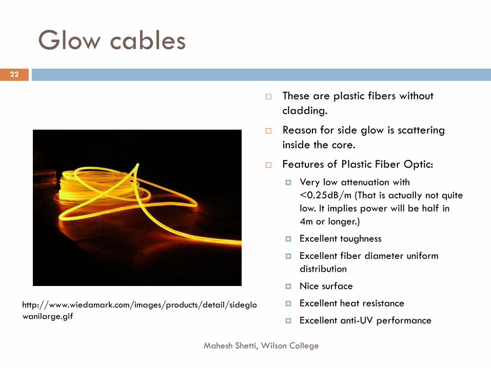
Glow cables
These are plastic fibers without
cladding.
Reason for side glow is scattering
inside the core.
Features of Plastic Fiber Optic:
Very low attenuation with
<0.25dB/m (That is actually not quite
low. It implies power will be half in
4m or longer.)
Excellent toughness
Excellent fiber diameter uniform
distribution
Nice surface
Excellent heat resistance
Excellent anti-UV performance
22
Mahesh Shetti, Wilson College
http://www.wiedamark.com/images/products/detail/sideglo
wanilarge.gif

Interior light decorations with cold light 23
Mahesh Shetti, Wilson College Ref://www.fibercreations.com/gallery/

Guiding Light
Mahesh Shetti, Wilson College
24
The light-detecting rods
and cones in the eye
(pencil-shaped cells
near the bottom) are
obscured beneath
several layers of cells
in the retina, shown in
this artist’s conception.
Computer simulations
suggest that a specific
set of cells can act like
optical fibers to
channel light through
these layers.
https://physics.aps.org/story/v25/st15
K. Franze et al., “Müller Cells are Living Optical Fibers in the Vertebrate Retina,” Proc. Natl. Acad. Sci. 104, 8287
(2007)

Communication
Application 2: 25
Mahesh Shetti, Wilson College

Some features
Mahesh Shetti, Wilson College
26
For short distance communication multi-mode fibers
are used.
For long distance communication single mode fiber
is the only choice.
The frequency for single mode fiber is selected such
that minimum absorption takes place in the core
medium.
Small core diameter and smaller acceptance angle,
single mode fibers use laser source.

Medical Applications
Application 3: 27
Mahesh Shetti, Wilson College

Endoscope parts
Mahesh Shetti, Wilson College
28
Endoscope is an optical device to see and operate inside any system.
There are typically two sets of the fibers.
The outer fiber supplies light, it is incoherent bundle. It is enclosed with sleeves to
protect it from water or moisture.
The inner coherent ring serves to transmit the image. The tiny lens connected to
the end of this bundle allows for light to be effectively focused so that reflected
light from the object of interest can be collected and transmitted for viewing.
Water pipes - The pipes serve to carry water which is used to wash the lens thereby
maintaining a clear view.
The operational channel - This is an opening on the device that is used to move
various accessories to the distil end (of the endoscope) for surgery purposes.
Control cables - This is used to control the direction that the distil end will bend as it
moves through body cavities.

A commercial Endoscope features
The scopes have high resolution
sensors with LED illumination
The Tele-View USB Endoscopes
come in 1.0m, 1.5m, 3.0m and
3.5m lengths with 8.7mm, 9.8mm
or 12.6mm diameters.
The insertion tube includes:
high resolution camera sensor,
super-bright LED lights
a working channel
an irrigation channel to clean the
lens
an air-water channel for lavage
or insufflation.
29
Mahesh Shetti, Wilson College
http://www.veteldiagnostics.com/products/endoscope
-gastroscope
Copyright © 2022 FDOKUMEN