Optical-Fiber Source of Polarization-Entangled Photons in the 1550 nm Telecom Band
11
arXiv:quant-ph/0402191v3 12 Aug 2004 Optical-fiber source of polarization-entangled photon pairs in the 1550 nm telecom band Xiaoying Li, Paul L. Voss, Jay E. Sharping, and Prem Kumar ∗ Center for Photonic Communication and Computing, ECE Department Northwestern University, Evanston, IL 60208-3118 (Dated: August 9, 2004) Abstract We present a fiber based source of polarization-entangled photon pairs that is well suited for quantum communication applications in the 1550 nm band of standard fiber-optic telecommuni- cations. Polarization entanglement is created by pumping a nonlinear-fiber Sagnac interferometer with two time-delayed orthogonally-polarized pump pulses and subsequently removing the time distinguishability by passing the parametrically scattered signal and idler photon pairs through a piece of birefringent fiber. Coincidence detection of the signal and idler photons yields biphoton interference with visibility greater than 90%, while no interference is observed in direct detection of either the signal or the idler photons. All four Bell states can be prepared with our setup and we demonstrate violations of the CHSH form of Bell’s inequality by up to 10 standard deviations of measurement uncertainty. PACS numbers: 03.67.Hk, 42.50.Dv, 42.65.Lm 1
-
Upload
independent -
Category
Documents
-
view
4 -
download
0
Transcript of Optical-Fiber Source of Polarization-Entangled Photons in the 1550 nm Telecom Band
arX
iv:q
uant
-ph/
0402
191v
3 1
2 A
ug 2
004
Optical-fiber source of polarization-entangled photon pairs in the
1550 nm telecom band
Xiaoying Li, Paul L. Voss, Jay E. Sharping, and Prem Kumar∗
Center for Photonic Communication and Computing, ECE Department
Northwestern University, Evanston, IL 60208-3118
(Dated: August 9, 2004)
Abstract
We present a fiber based source of polarization-entangled photon pairs that is well suited for
quantum communication applications in the 1550 nm band of standard fiber-optic telecommuni-
cations. Polarization entanglement is created by pumping a nonlinear-fiber Sagnac interferometer
with two time-delayed orthogonally-polarized pump pulses and subsequently removing the time
distinguishability by passing the parametrically scattered signal and idler photon pairs through a
piece of birefringent fiber. Coincidence detection of the signal and idler photons yields biphoton
interference with visibility greater than 90%, while no interference is observed in direct detection
of either the signal or the idler photons. All four Bell states can be prepared with our setup and
we demonstrate violations of the CHSH form of Bell’s inequality by up to 10 standard deviations
of measurement uncertainty.
PACS numbers: 03.67.Hk, 42.50.Dv, 42.65.Lm
1

Quantum entanglement refers to the nonclassical interdependency of physically separable
quantum subsystems. In addition to being at the heart of the most fundamental tests of
quantum mechanics [1, 2, 3, 4], it is an essential resource that must be freely available
for implementing many of the novel functions of quantum information processing [5, 6]. In
photonic systems, the ongoing developments in lasers, optical-fiber technology, single-photon
detectors, and nonlinear optical materials have led to enormous experimental progress in
both the fundamental [7, 8, 9, 10, 11] and applied domains [12, 13, 14]. A popular approach
to generating entangled pairs of photons is based on the nonlinear process of parametric
down conversion in χ(2) crystals [15, 16, 17]. Though much progress has been made using
this approach, formidable engineering problems remain in coupling the entangled photons
into standard optical fibers for transmission, storage, and manipulation over long distances.
The coupling problem can be obviated if the entangled photons can be generated in the
fiber itself, and desirably, in the fiber’s low-loss propagation window near 1.5µm, since that
would minimize losses during transmission as well. Apart from the inherent compatibility
with the transmission medium, a fiber based source of entangled photons would have other
advantages over its crystal counterparts [15, 16, 17, 18, 19, 20]. Particularly, the spatial mode
of the photon-pair would be the guided transverse mode of the fiber, which is a very pure
Gaussian-like single spatial mode in modern fibers. A well-defined mode is highly desirable
for realizing complex networks involving several entangling operations. In this Letter, we
describe the first, to the best of our knowledge, optical fiber source of polarization-entangled
photon pairs in the 1550 nm telecom band. A variety of bi-photon interference experiments
are presented that show the nature of the entanglement generated with this source. All
four Bell states can be prepared with our setup and the CHSH form of Bell’s inequality is
violated by up to 10 standard deviations of measurement uncertainty.
Recently, our group has demonstrated that parametric fluorescence accompanying non-
degenerate four-wave mixing (FWM) in standard optical fibers is an excellent source of
quantum-correlated photon pairs [21]. The quantum correlation arises from four-photon
scattering (FPS) events, wherein two pump photons at frequency ωp scatter through the
Kerr nonlinearity of the fiber to simultaneously create a signal photon and an idler photon
at frequencies ωs and ωi, respectively, such that ωs+ωi = 2ωp. For a linearly polarized pump
with wavelength close to the zero-dispersion wavelength of the fiber, the FWM process is
phase-matched and the accompanying parametric fluorescence is predominantly co-polarized
2

with the pump. Since the response time of the Kerr nonlinearity is almost instantaneous,
two such parametric scattering processes can be time and polarization multiplexed to cre-
ate the desired polarization entanglement. For example [see Fig. 1(a)], when the fiber is
pumped with two orthogonally polarized, relatively delayed pulses, the signal-idler photon
pairs scattered from each pulse are co-polarized with that pump pulse and relatively delayed
by the same amount. The distinguishing time delay between the orthogonally-polarized
photon pairs, however, can be removed by passing the pairs through a piece of birefringent
fiber of appropriate length, wherein the photon-pair travelling along the fast axis of the fiber
catches up with the other pair travelling along the slow axis. When the emerging signal and
idler photons are separated based on their wavelength, each stream of photons is completely
unpolarized because any polarizer/detector combination is unable to determine which pump
pulse a detected photon originated from. When the signal and idler photons are detected in
coincidence, it is still impossible to determine which pump pulse created the detected pair.
This indistinguishability gives rise to polarization entanglement in our experiment.
A schematic of the experimental setup is shown in Fig. 1(b). Signal and idler photon
pairs at wavelengths of 1547.1 nm and 1525.1 nm, respectively, are produced in a nonlinear
fiber Sagnac interferometer (NFSI) [21, 22]. The NFSI consists of a fused-silica 50/50 fiber
coupler spliced to 300m of dispersion-shifted fiber (DSF) that has a zero-dispersion wave-
length at λ0 = 1535 ± 2 nm. Because the Kerr nonlinearity is weak, for this length of fiber
only about 0.1 photon-pair is produced with a typical 5 ps-duration pump pulse contain-
ing ∼107 photons. Thus, to reliably detect the correlated photon pairs, a pump-to-signal
rejection ratio in excess of 100 dB is required. We achieve this by first exploiting the mirror-
like property of the Sagnac loop, which provides a pump rejection of > 30 dB, and then
sending the transmitted fluorescence photons along with the leaked pump photons through
a free-space double-grating spectral filter (DGSF) that provides a pump rejection ratio in
excess of 75 dB [21]. The filter consists of three identical diffraction gratings (holographic,
600 grooves/mm) G2, G3, and G4, whose diffraction efficiencies for the horizontally and the
vertically polarized light are 90% and 86%, respectively. The doubly-diffracted signal and
idler photons are then re-coupled into fibers, whose numerical apertures along with the geo-
metrical settings of the gratings determine the pass bands for the signal and idler channels.
The full-width at half-maximum (FWHM) bandwidth for both the channels is 0.6 nm.
During the experiment, for alignment and phase control purposes, input-signal and ref-
3

OP
O
APD1
G1
M4M3
Delay
QWP1
PZT
QWP2
Pump
300mDSF Loop
Out
FPC1
EDFA 90/1050/50
FPC2
4% BS
HWP2&QWP3
F
APD2Countingsystem
Sig. Det.
Ref. Det.
PM Fiber
Signal In
Ref. Light
50/50
FPC4
FPC3
P1
P3
P4 &
HWP3
G2
P5 &
HWP4
M5
M2
M1 G3
G4P2
HWP1
(b)
Delay
(a)
PM Fiber(3)
FWM
Hs Hi
Vi
Vs
f
sPH
PV
Temporally-delayedorthogonally-polarized
pump pulsesPolarization-entangled
signal/idler pairs
is
i
isHHeHH
Temporally-delayedorthogonally-polarized
signal/idler pairs
Signal
0 20 40 60 80 100 120 140 160 180 200
Time (s)
Ref.
(c)
FIG. 1: (a) Conceptual representation of the multiplexing scheme used in our experiment to
create polarization-entangled pairs of photons. (b) Schematic of the experimental setup. P1–
P5, polarization beam splitters; G1–G4, diffraction gratings; M1–M5, mirrors; FPC1–FPC4, fiber
polarization controllers; QWP, quarter-wave plate; HWP, half-wave plate; F, flipper mirror. (c)
Sinusoidal variations (or constancy at the peaks and troughs) of the photocurrents obtained from
the signal (top traces) and the reference detectors (bottom traces) upon linearly sweeping the
voltage (or maintaining a fixed voltage) on the PZT. The clarity of the traces demonstrates minutes-
long stability of the polarization interferometer formed between P1 and P3 (P2) for signal (reference)
light.
erence pulses are also needed that are temporally synchronized with the pump pulses. The
main purpose of the signal pulses is to ensure that the time distinguishability between the
orthogonally-polarized photon-pairs is effectively removed. By spectrally carving [22] the
∼150 fs-pulse train from an optical parametric oscillator (Coherent Inc., model Mira-OPO),
we obtain trains of 5-ps pump pulses with central wavelength at 1536 nm, 2.8-ps signal pulses
with central wavelength at 1547 nm, and 4-ps reference pulses with central wavelength at
1539 nm. The pump pulses are then amplified by an erbium-doped fiber amplifier (EDFA)
to achieve the required average pump power. Light at the signal and idler wavelengths from
4

the OPO that leaks through the spectral-carving optics and the amplified spontaneous emis-
sion from the EDFA are suppressed by passing the pump pulses through a 1 nm-bandwidth
tunable optical filter (Newport, TBF-1550-1.0).
A 30-ps relative delay between the two orthogonally-polarized pump pulses is introduced
by adding separate free-space propagation paths for the two pulses with use of a polarization
beam splitter (PBS) P1, quarter wave-plates (QWP) QWP1 and QWP2, and mirrors M1 and
M2. Mirror M2 is mounted on a piezoelectric-transducer-(PZT)-driven translation stage,
which allows precise adjustment of the relative delay and phase difference between the
orthogonally-polarized pump-pulse pairs. After the NFSI, the delay is compensated by
propagating the scattered photon pairs along the fast and slow polarization axes of 20m-
long polarization-maintaining (PM) fiber. A careful alignment procedure is implemented to
properly orient the axes of the PM fiber, taking into consideration the change of polarization
state incurred by an input signal-pulse pair upon maximally-amplified reflection from the
NFSI [23]. Alignment is performed prior to the actual experiment by injecting weak path-
matched signal-pulse pairs, having identical temporal and polarization structure as the pump
pulses, into the NFSI through the 50/50 and 90/10 couplers. First the signal amplification
is maximized by adjusting FPC2, while monitoring the signal gain on a detector (ETX500)
placed after P3. Then the fringe visibility of the polarization interferometer formed between
P1 and P3 is maximized by adjusting FPC3, HW2, and QWP3 while observing the fringes
in real time upon periodic scanning of M2. Once the alignment is completed, the injected
signal is blocked and further measurements are made only on the parametric fluorescence.
After compensation of the time delay, the following polarization-entangled state is gen-
erated at the output of the PM fiber: |Ψ〉 = |H〉s|H〉i + eiφ|V 〉s|V 〉i, where φ is the rel-
ative phase difference between the two-photon amplitudes |H〉s|H〉i and |V 〉s|V 〉i. In our
experiment φ = 2φp with φp being the relative phase difference between the two delayed,
orthogonally-polarized pump pulses. This source can produce all four polarization-entangled
Bell states. When φp = 0, π2, the states |Ψ±〉 = |H〉s|H〉i ± |V 〉s|V 〉i are created. The other
two Bell states |Φ±〉 = |H〉s|V 〉i±|V 〉s|H〉i can be prepared by inserting a properly oriented
HWP in the idler channel. Non-maximally entangled pure states with an arbitrary degree
of polarization entanglement can also be created with our setup by choosing the two pump
pulses to have unequal powers.
In order to actively monitor and control the relative phase φ during the course of data
5

0
1
2
3
4
5
0 50 100 150 200
HWP1 Orientation (deg.)
Sin
gle
Counts
(X
10
3/s
)
0
50
100
150
Coin
cid
ences (
/s)Signal
Idler
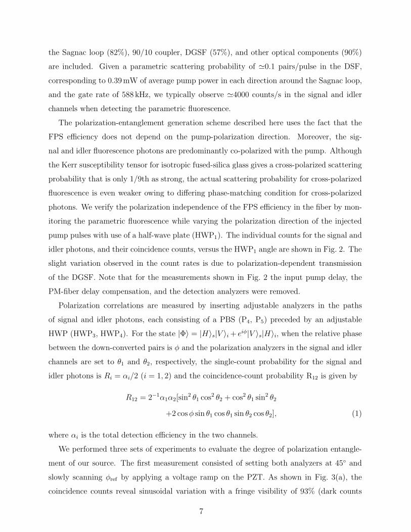
FIG. 2: Observed polarization (in)dependence of parametric fluorescence in the DSF.
taking, weak reference-pulse pairs of about 50µW average power are injected into the NFSI
through the 50/50 and 90/10 couplers. The reference-pulse pairs have identical temporal and
polarization structure as the pump pulses, except the temporal location of the reference-pulse
pairs is mismatched with respect to the pump-pulse pairs and their wavelength is slightly
detuned, so that they neither interact with the pump pulses nor are seen by the single-
photon detectors used in the signal and idler channels. During the course of measurements
on the polarization-entangled states, the relative phase between the reference-pulse pairs,
φref , is monitored by measuring the photocurrent from a low-bandwidth reference detector
placed after P2 to make observations on one output port of the polarization interferometer
[see Fig. 1(b)]. The voltage created by this photocurrent is compared to a reference voltage
and the difference is used to stabilize φref by feeding back on the PZT through an electronic
circuit. The excellent overall stability of the system is shown by the near-perfect classical
interference fringes displayed in the inset in Fig. 1(b), which were simultaneously obtained
with injected signal light and with reference light while scanning φref by ramping the voltage
on the PZT. The relative phase between the reference-pulse pairs, φref , is related to the
relative phase between the pump-pulse pairs via φp = φref+δ, where δ results from dispersion
in the DSF owing to slightly different wavelengths of the pulse pairs.
The photon-counting modules used for detecting the signal and idler photons consist of
InGaAs/InP avalanche photodiodes (APDs, Epitaxx, EPM 239BA) operated in a gated-
Geiger mode [21]. Gate pulses of 1 -ns duration are applied at 588 kHz rate, 1/128 of the
pump-pulse rate, to avoid after-pulsing in the detectors. The measured quantum efficiencies
for the two detectors are 25% and 20%, respectively. The overall detection efficiencies for
the signal and idler photons are about 9% and 7%, respectively, when the transmittance of
6
the Sagnac loop (82%), 90/10 coupler, DGSF (57%), and other optical components (90%)
are included. Given a parametric scattering probability of ≃0.1 pairs/pulse in the DSF,
corresponding to 0.39mW of average pump power in each direction around the Sagnac loop,
and the gate rate of 588 kHz, we typically observe ≃4000 counts/s in the signal and idler
channels when detecting the parametric fluorescence.
The polarization-entanglement generation scheme described here uses the fact that the
FPS efficiency does not depend on the pump-polarization direction. Moreover, the sig-
nal and idler fluorescence photons are predominantly co-polarized with the pump. Although
the Kerr susceptibility tensor for isotropic fused-silica glass gives a cross-polarized scattering
probability that is only 1/9th as strong, the actual scattering probability for cross-polarized
fluorescence is even weaker owing to differing phase-matching condition for cross-polarized
photons. We verify the polarization independence of the FPS efficiency in the fiber by mon-
itoring the parametric fluorescence while varying the polarization direction of the injected
pump pulses with use of a half-wave plate (HWP1). The individual counts for the signal and
idler photons, and their coincidence counts, versus the HWP1 angle are shown in Fig. 2. The
slight variation observed in the count rates is due to polarization-dependent transmission
of the DGSF. Note that for the measurements shown in Fig. 2 the input pump delay, the
PM-fiber delay compensation, and the detection analyzers were removed.
Polarization correlations are measured by inserting adjustable analyzers in the paths
of signal and idler photons, each consisting of a PBS (P4, P5) preceded by an adjustable
HWP (HWP3, HWP4). For the state |Φ〉 = |H〉s|V 〉i + eiφ|V 〉s|H〉i, when the relative phase
between the down-converted pairs is φ and the polarization analyzers in the signal and idler
channels are set to θ1 and θ2, respectively, the single-count probability for the signal and
idler photons is Ri = αi/2 (i = 1, 2) and the coincidence-count probability R12 is given by
R12 = 2−1α1α2[sin2 θ1 cos2 θ2 + cos2 θ1 sin2 θ2
+2 cosφ sin θ1 cos θ1 sin θ2 cos θ2], (1)
where αi is the total detection efficiency in the two channels.
We performed three sets of experiments to evaluate the degree of polarization entangle-
ment of our source. The first measurement consisted of setting both analyzers at 45◦ and
slowly scanning φref by applying a voltage ramp on the PZT. As shown in Fig. 3(a), the
coincidence counts reveal sinusoidal variation with a fringe visibility of 93% (dark counts
7

0
400
800
1200
-4.71 3.14
Coin
cid
ences (
/30s)
0
40
80
120
Sin
gle
Counts
(X
10
3/3
0s)
-4.71 -3.14 -1.57 0 1.57 3.14
Relative Phase Ref (rad)
Re
f. D
et.
ou
tpu
t (
a.u
)
(a)
(b)
FIG. 3: (a) Coincidence counts and single counts detected over 30 s when the relative phase φref is
varied. The solid curve a fit to Eq. 1. (b) Output from the reference detector versus φref showing
the ordinary one-photon interference with twice the fringe spacing as in (a).
and accidental-coincidence counts have been subtracted), while the single counts remain
unchanged. The output from the reference detector is also recorded simultaneously, which is
shown in Fig. 3(b). The relative shift of the sinusoidal variation of two-photon interference
in Fig. 3(a) from that of reference-light interference in Fig. 3(b) is a direct measure of the
phase shift δ, which is used below to properly set φ for measurements of the violation of
Bell’s inequality.
In the second set of measurements on polarization entanglement, we locked the generated
state to |Φ−〉 = |H〉s|V 〉i − |V 〉s|H〉i by applying an appropriate feedback on the PZT, fixed
the angle of the polarization analyzer in the signal channel to 45◦, and varied the analyzer
angle in the idler channel by rotating HWP4. The result is shown in Fig. 4. As expected,
the coincidence-count rate displays sinusoidal interference fringes with a visibility of 92%,
whereas the variation in the single-count rate is only 4% (once again, dark counts and
accidental coincidences have been subtracted).
In the third set of experiments, we characterized the quality of polarization entan-
glement produced with our source through measurements of Bell’s inequality violation.
By recording coincidence counts for 16 different combinations of analyzer settings with
θ1 = 0◦, 90◦,−45◦, 45◦ and θ2 = −22.5◦, 67.5◦, 22.5◦, 112.5◦, we measured the quantity S in
the CHSH form of Bell’s inequality [3], which satisfies |S| ≤ 2 for any local realistic descrip-
8

-20
180
380
580
780
-50 50 150 250 350
Relative angle 1- 2 (deg.)
Coin
cid
ences (
/20s)
0
20
40
60
80
Sin
gle
Counts
(X
10
3/2
0s)
FIG. 4: Measurement of polarization entanglement: Coincidence counts and single counts detected
over 20 s as the analyzer angle in the idler channel is varied while keeping the signal-channel analyzer
fixed at 45◦ relative to vertical.
TABLE I: Measured values of S for the four Bell states.
Bell state S Violation
(standard deviations)
|H〉s|H〉i + |V 〉s|V 〉i 2.75 ± 0.077 10 σ
|H〉s|H〉i − |V 〉s|V 〉i 2.55 ± 0.070 8σ
|H〉s|V 〉i + |V 〉s|H〉i 2.48 ± 0.078 6σ
|H〉s|V 〉i − |V 〉s|H〉i 2.64 ± 0.076 8σ
tion of our experiment. The results, which are presented in Table I, show that a) the CHSH
inequality is violated, i.e., |S| > 2, for all four Bell states produced with our setup and b)
the violation occurs by up to 10 standard deviations of measurement uncertainty.
In order to ascertain the degree of entanglement produced by the true FPS events in our
setup, the accidental coincidences resulting from the uncorrelated background photons and
the dark counts in the detectors were measured for each set of data acquired in the three
polarization-entanglement experiments described above. The rate of accidental coincidences
was as large as the rate of “true” coincidences plotted in Figs. 2–4 by subtracting the acci-
dental coincidences and the raw visibility of two-photon interference was only ≃ 30%. We
believe the majority of background photons in our setup arise from spontaneous Raman
scattering [24, 25]. Our recent measurements with a modified DGSF have shown that the
contribution of accidental coincidences can be made < 10% of the total measured coinci-
dences [26]. With these improvements, a raw two-photon-interference visibility of > 85%
9

would be obtained, i.e., without any post-measurement corrections.
In conclusion, we have developed and characterized a fiber-based source of polarization-
entangled photon pairs. The count rates in the experiment at present are limited by the
repetition rate of the APDs, which can be increased by at least an order of magnitude
by straightforward refinements of the detection electronics. The photon-pair production
rate, on the other hand, is limited by the 75MHz repetition rate of the pump laser. The
production rate can be dramatically increased by using state-of-the-art pulsed lasers that
have been developed for fiber-optic communications. These lasers operate at 10–40GHz
repetition rates and can have the requisite peak-pulse powers with use of medium-power
EDFAs. Bulk-optic implementations of the pump delay apparatus and the detection filters
were used in these proof-of-principle experiments for purposes of tunability and control. All-
fiber versions of these subsystems can be readily realized with use of PM fibers, wavelength-
division-multiplexing filters, and fiber polarizers. Finally, we have understood the origin
of the large number of accidental coincidences in the experiment and subsequent system
improvements are expected to significantly improve the degree of entanglement produced
with our system. Therefore, we believe that such fiber-based entangled-photon pairs will
prove to be an efficient source for developing quantum communication technologies.
This work was supported in part by the DoD Multidisciplinary University Research Ini-
tiative (MURI) Program administered by the Army Research Office under Grant DAAD19-
00-1-0177.
[1] A. Einstein, B. Podolsky, and N. Rosen, Phys. Rev. 47, 777 (1935).
[2] J. S. Bell, Physics 1, 195 (1964).
[3] J. F. Clauser, M. A. Horne, A. Shimony, and R. A. Holt, Phys. Rev. Lett. 23, 880 (1969).
[4] D. M. Greenberger, M. A. Horne, A. Shimony, and A. Zeilinger, Am. J. Phys. 58, 1131 (1990).
[5] C.H.Bennett and S. J. Wiesner, Phys. Rev. Lett. 69, 2881 (1992).
[6] C. H. Bennett, G. Brassard, C. Crepeau, R. Jozsa, A. Peres, and W. K. Wootters, Phys. Rev.
Lett. 70, 1895 (1993).
[7] A. Aspect, P. Grangier, and G. Roger, Phys. Rev. Lett. 49, 91 (1982).
10

[8] Z. Y. Ou and L. Mandel, Phys. Rev. Lett. 61, 50 (1988).
[9] Z. Y. Ou, L. J. Wang, X. Y. Zou, and L. Mandel, Phys. Rev. A 41, 566 (1990).
[10] Y. H. Shih and C. O. Alley, Phys. Rev. Lett. 61, 2921 (1988).
[11] J. W. Pan, D. Bouwmeester, M. Daniell, H. Weinfurter, and A. Zeilinger, Nature 403, 515
(2000).
[12] K. Mattle, H. Weinfurter, P. G. Kwait, and A. Zeilinger Phys. Rev. Lett 76, 4656 (1996).
[13] D. Bouwmeester, J. W. Pan, K. Mattle, M. Eibl, H. Weinfurter, and A. Zeilinger, Nature 390,
575 (1997).
[14] N. Gisin, G. Ribordy, W. Tittel, and H. Zbinden, Rev. Mod. Phys. 74, 145 (2002).
[15] P. G. Kwiat, K. Mattle, H. Weinfurter, A. Zeilinger, A. V. Sergienko, and Y. Shih, Phys. Rev.
Lett. 75, 4337 (1995).
[16] J. G. Rarity and P. R. Tapster, Phys. Rev. Lett. 64, 2495 (1990).
[17] J. Brendel, E. Mohler, and W. Martiennsen, Europhys. Lett. 20, 575 (1992).
[18] K. Sanaka, K. Kawahara, and T. Kuga, Phys. Rev. Lett. 86, 5620 (2001).
[19] J. Kim, O. Benson, H. Kan, and Y. Yamamoto, Nature 397, 500 (1999).
[20] C. Kurtsiefer, S. Mayer, P. Zarda, and H. Weinfurter, Phys. Rev. Lett. 85, 290 (2000).
[21] M. Fiorentino, P. Voss, J. E. Sharping, and P. Kumar, IEEE Photon. Technol. Lett. 14, 983
(2002).
[22] J. E. Sharping, M. Fiorentino, and P. Kumar, Opt. Lett. 26, 367 (2001).
[23] D. B. Mortimore, J. Lightwave Tech. 6, 1217 (1988).
[24] P. L. Voss and P. Kumar, Opt. Lett. 29, 445 (2004).
[25] P. L. Voss and P. Kumar, to appear in J. Opt. B: Quantum Semiclass. Opt. 6 (2004).
[26] X. Li, J. Chen, P. L. Voss, J. E. Sharping, and P. Kumar, Opt. Express. 12, 3337 (2004).
11